Embed Size (px)
Citation preview
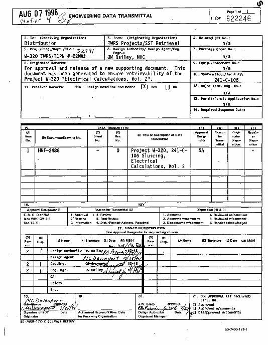
AUG 0 7 1330/pi ENGINEERING DATA TRANSMITTALPane 1 o( I
622246
2. To: (Receiving Organization)
Distribution5. Proj./Prog./Dept./Div.: p^.?"?/
W-320 TWRS/TCPN #-B2Mfti-8 . Or
FordocuProj1 1 . R
3 . From: (Or ig inat ing Organizat ion)
TWRS Projects/SST Retrieval6. Design Authority/ Design Agent/Cog.
Engr.:
JW Ba i ley , NHCginator Remarks:
approval and release of a new supporting document. Thisment has been generated to ensure re t r ievab i l i t y of theect W-320 "Electrical Calculations, Vol. 2".
re iver Remarks: 11A. Design Baseline Document? [ X ] Yes [ ] No
15. DATAIA)
Item. No.
1
(B) Document/Drawing No.
HNF-2488
(C)SheetNo.
rRANSMITTECID)
Rev.No.
0
(E) Title or Description of DataTransmitted
Project W-320, 241-C-106 Sluicing,ElectricalCalculations, Vol. 2
4. Related EOT No.:
n/a7 . Purchase Order No.:
n/a9 . Equip./Component No. :
n/a10. System/Bldg./Facility:
241-C-10612. Major Assm. Dug. No.:
n/a13. Permit/Permit Application No.:
n/a14. Required Response Date:
(F)Approval
Desig-nator
NA
CG>Reason
forTr«ns-mrttat
(K)Origi-natorDispo-sition
( I )Receiv-
erDispo-sition
16. KEY
Approval Designator IF)
E, S, Q, D or N/A(see WHC-CM-3-5,Sec.12.7]
Reason for Transmittal (G)
1. Approval ' 4. Review2.' Release 5. Post-Review3. Information 6. Dist. (Receipt Acknow. Required)
Disposition (H) & (1)
1. Approved 4. Reviewed no/comment2. Approved w/comment 5. Reviewed w/comment3. Disapproved w/comment 6. Receipt acknowledged
17. SIGNATURE/DISTRIBUTION(See Approval Designator for required signatures)
IG)Rea-son
2
22
IHIDiap.
/
|
(Jl Name |K) Signature ID Date IM) MSIN
Design Authority JU Baileyf lAfrevJ,1?&?9i
Design Agent fljC tl 0.0e/1«o f t • ^ / W ^ fC°9-Eng. -^r^S^4f,^SS %l^^Cog. Hgr. JU B a i l e y ^ V / . ^ '
OA / / '
Safety
Env.
18./H& £>a.venpori~
Signature of EDT bateOriginator
(A19.
/
Authorized Representative Datefor Receiving Organization
IG)Rea-
. son
y
IH)Disp.
20 .
J.W. Bailey *
Design Authority?Cognizant Manager
(J) Name IK) Signature (L) Date (M) MSIN
»W98- .
Date /
2 1 . DOE APPROVAL ( i f requirC t r l . Mo.
I] Approved[] Approved u/comments
•pU Disapproved w/conrments
ed)
BD-C4U0-172-2 (05 /96 ) GEF097
BD-7400-172-1
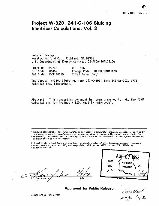
HNF-2488, Rev. 0
Project W-320, 241-C-106 SluicingElectrical Calculations, Vol. 2
John W. BaileyNumatec Hanford Co., Richland, WA 99352U.S. Department of Energy Contract DE-AC09-96RL13200
EDT/ECN: 622246Org Code: 8C452B&R Code: EW3130010
UC: 506Charge Code: D2991/HANA0600Total Pages:/•//
Key Words: W-320, Sluicing, Tank 241-C-106, Tank 241-AY-102, WRSS,calculations, Electrical.
Abstract: This supporting document has been prepared to make the FDNWcalculations for Project W-320, readily retrievable.
TRADEMARK DISCLAIMER. Reference herein to any specific comnercial product, process, or service bytrade name, trademark, manufacturer, or otherwise, does not necessarily constitute or imply itsendorsement, recommendation, or favoring by the United States Government or any agency thereof orits contractors or subcontractors.
Printed in the United States of America. To obtain copies of this document, contact: DocumentControl Services, P.O. Box 950, Mailstop H6-08, Richland UA 99352, Phone (509) 372-2420;Fax (509) 376-4989.
Be'l ea'sef Approva 1 /
Approved for Public Release
A-6400-073 (01/97) GEF321
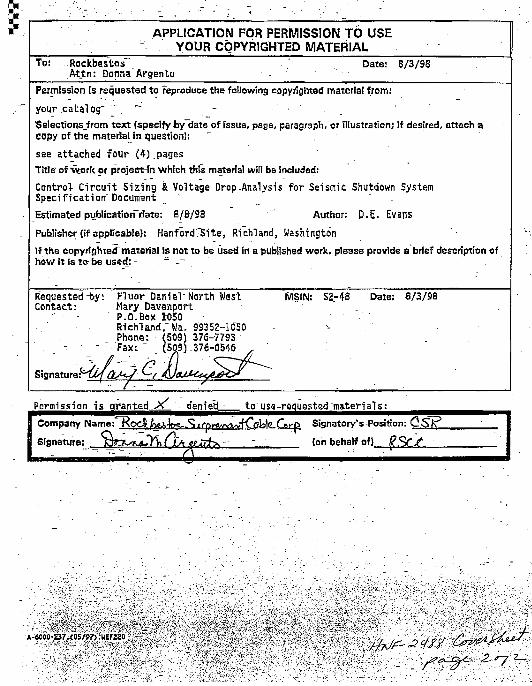
APPLICATION FOR PERMISSION TO USEYOUR COPYRIGHTED MATERIAL
To: Rockbestos ' Date: 8/3/98Attn: Donna'Argento •• -
Permission is requested to reproduce the following copyrighted material from!
your catalog" '". ~ • -Selectionsjf rom text (specify by date of.fssua, paga, paragraph, or illustration; if desired, attach acopy of the materiaMn question): ~ ,
see attached four (4)_pages
Title of vtork «r project-in which this material will bs included:
Control- Circuit Sizing & Voltage Drop-Analysis for Seismic Shutdown SystemSpecification" Document ' _ ' .
Estimated pyblicatirjrTdate: 8/8/98 Author: D.E. Evsns
Publisher (if applicable): HanfordTSite, Richland, Washington
If the copyrighted material Is not to be used in a published work, please provide a brief description ofhow it is to- be used: - - _-
Requested-by: Fluor Daniel" North West MSIN: S2-48 Date: 8/3/98Contact: Mary Davenport
- P.O.Box W50 • .Richland,"Wa. 92352-10~50 -Phone: (509) 376-7793
. - • - " F a x : " (509).376-0546
/• W
Permission is granted >>
Company Name: KocA fiai-lc**-
Signature: RttLsK*y\\lLA• ~ • • • : • • • • • •
dsrried - to use-requested"materi als:
lo\e C$y-p Signatory's Position: C S / \
(on behalf of} $?/•/•
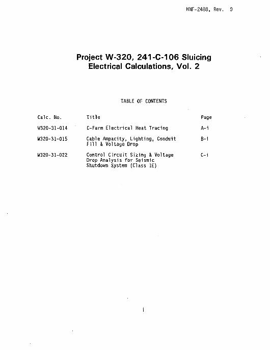
HNF-2488, Rev. 0
Project W-320, 241-C-106 SluicingElectrical Calculations, Vol. 2
Calc. No.
W320-31-014
W320-31-015
W320-31-022
TABLE OF CONTENTS
Title
C-Farm Electrical Heat Tracing
Cable Ampacity, Lighting, ConduitFill & Voltage Drop
Control Circuit Sizing & VoltageDrop Analysis for SeismicShutdown System (Class IE)
Page
A-i
B-i
C-i

HNF-2488, Rev. 0
W320-31-014
C-Farm Electrical Heat Tracing
A-i
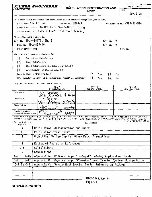
KAISER ENGINEERSHAN FORD
CALCULATION IDENTIFICATION ANDINDEX
Page i of 6
Date
09/19/95
This sheet shows the status and description of the attached Design Analysis sheets.
Discipline E l e c t r i c a l wo/job NO. ER4319 calculation NO. W320-3I-0I4
project NO. & Name W-320 Tank 241-C-106 SIu ic ing
calculation item C-Farm E l e c t r i c a l Heat Tracing
These calculations apply to:
Dwg. No. H - 2 - 8 1 8 6 7 8 , Sh . 3 Rev. No. 0
Dwg. No. H-2 -818690 Rev. No. 0
Other (Study, CDR) Rev. No.
The status of these calculations i s :
[ ] Preliminary Calculations
[ X ] Final Calculations
[ ] Check Calculations (On Calculation Dated )
[ ] Void Calculation (Reason Voided )
Incorporated in Final Drawings? [ X ] Yes [ ] No
This calculation ver i f ied by independent "check" calculations? [ ] Yes [ X ] No
Original and Revised Calculation Approvals:
Originator
Checked by
Approved by
Checked AgainstApproved Vendor Data
Rev. 0Signature/Date
S.A. 'Najjar , ,
Rev. 1Signature/Date
Rev. 2Signature/Date
APPRovep V£fJJof* 5v*7?j r* *T A^AW-A S • ^ ^ ^ ' ^ / ^ D THAT H EAT-T&AC £ \TE-fA-* VJERfi AcciVfREV W FlfcLP P£/Z
Design Analysis Description H-2-<S\3C1S,SH •=,Page No. .
i
i i
1
2
2-6
6
A-1 To A-16
B-1 To B-17
C-1 To C-8
Calculation Identi f icat ion and Index
Calculation Cross Index
Objective; Design Inputs; Given Data; Assumptions
Method of Analysis; References
Calculations
Conclusions
Appendix A: O'Brien Corp. "Tracepak" Catalog Application Guide
Appendix B: Raychem Corp. "Chemelex" Heat Tracing Systems Design Guide
Appendix C: Vendor Heat Tracing Design Information Package
HNF-2488 Rev f)
Page A-1KEH 0378.00 C06/92) KEF072
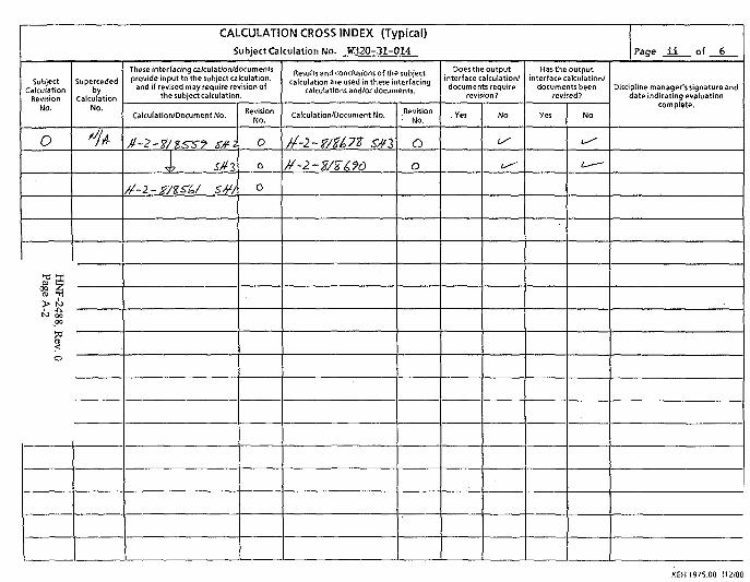
CALCULATION CROSS INDEX (Typical)
Subject Calculation No: W32O-31-OI4
SubjectCalculation
RevisionNO.
o
HN
F-2488, Rev. 0
Page A
-2
byCalculation
No.
These interfacing cakuiation/d
and if revised may require rethe subject calculation
Calculation/Document No.
tf-2-g-/tsru sM/
ocu meritsculation,ision of
RevisionNo.
O
0
0
Results and conclusions of the subjectcalculation are used in these interfacing
calculations and/or documents.
Catculation/Document No.
tf-2~Z/Z£?6
RevisionNo.
O
O
Does the outputinterface calculation/documents require
revision?
.Yes No
Has the outputinterface calculation/
documents beenrevised?
Yes No
Paae i i of 6
Discipline manager'ssignature anddate indicating evaluation
complete.
KEH 1975.00 (12/88
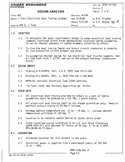
KAISER ENGINEERS * cau. no. W320-31-014HANFORD R e v . s f o n 0
D E S I G N A N A L Y S I S <>** N». 1 of 6Client WHC UO/Job No. W-320
subject C Farm E l e c t r i c a l Heat Tracing Systems Date 9/19/95 By R.H. Graeber .
checked 9/27/95 By S.A. Na j ja r " S T - " .
Location 200 E, C Farm Revised By
1.0 OBJECTIVE
1.1 To determine the power requirements needed to power electrical heat tracingsegments contained within three manufactured insulated tubing assemblies.To verify thermal adequacy of tubing assembly selection by others.
1.2 To size the heat tracing feeder and branch circuit conductors & conduits.To size protective circuit breaker and fuses.
1.3 To accomplish thermal design for two electrical heat tracing segments: One@ C-106 tank riser 7 (CCTV) and one at the exhaust hatchway (condensatedrain).
2.0 DESIGN INPUTS
2.1 Drawing H-2-S18559, Shts. 2 & 3, P&ID Tank 241-C-106.
2.2 Drawing H-2-818561, Shts. 1, P&ID Tank 241-C-106 HVAC.
2.3 NFPA-70, National Electrical Code (1993 edition).
2.4 "In Tank" CCTV, WHC Purchase Requisition No. 422301.
3.0 GIVEN DATA
3.1 All electrical heat tracing provided by others as a part of tubingassemblies shall be powered by a 120 VAC, 1 phase source.
3.2 All electrical heat tracing shall be for freeze protection only. Need tomaintain process piping at 40 Deg F minimum.
3.3 Minimum ambient temperature est. to be - 20 Deg. F., maximum ambienttemperature estimated at 110 Deg. F.
3.4 Location to be outdoors and/or buried 12 inches below grade.
3.5 Field installed piping insulation to be 1/2 inch thick fiberglass(ASTM C547-77) with maximum "K" factor at 50 Deg. F. to be 0.2497BTU-IN/HR-SQ FT-Deg.F.
4.0 ASSUMPTIONS
4.1 Estimated duration for this project is two years.
4.2 Electrical power is supplied from a panelboard source at 120 VAC. (+ or - 10%).
HNF-2488, Rev. 0Page A-3
KEH 0037.00 (06/92) KEF055
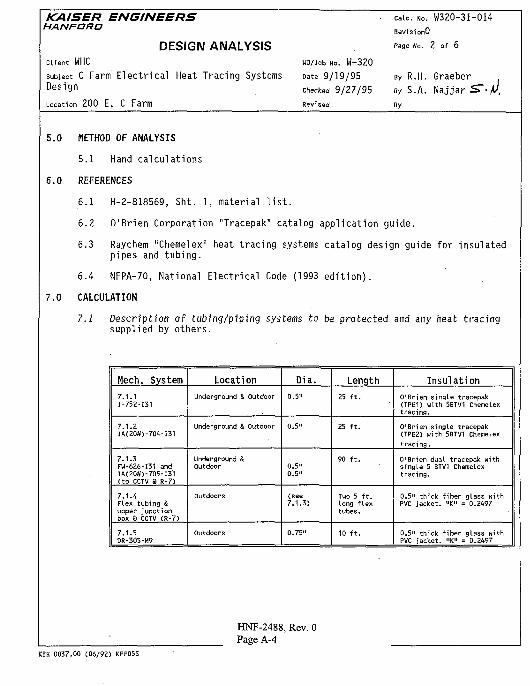
KAISER ENGINEERSHAN FOR O
DESIGN ANALYSISClient WHC UO/Job No. W-320
subject C Farm Electrical Heat Tracing Systems Date 9/19/95D e s i 9 n Checked 9/27/95
Location 200 E, C Farm Revised
caic. NO. W320-31-014
RevisionO
Page No. 2 of 6
By R.H. GraeberBY S.A. Najjar S~-t>By
5.0 METHOD OF ANALYSIS
5.1 Hand calculations
6.0 REFERENCES
6.1 H-2-818569, Sht. 1, material list.
6.2 O'Brien Corporation "Tracepak" catalog application guide.
6.3 Raychem "Chemelex" heat tracing systems catalog design guide for insulatedpipes and tubing.
6.4 NFPA-70, National Electrical Code (1993 edition).
7.0 CALCULATION
7.1 Description of tubing/piping systems to be protected and any heat tracingsupplied by others.
Mech. System
7.1.1I-752-I31
7.1.2IA(208)-704-I31
7.1.3FW-626-I31 andIA(20#)-705-I31(to CCTV 3 R-7)
7.1.4Flex tubing &upper junctionbox a CCTV (R-7)
7.1.5DR-305-M9
LocationUnderground & Outdoor
Underground & Outdoor
Underground &outdoor
outdoors
Outdoors
Dia.
0.5"
0.5"
0.5"0.5"
(see7.1.3)
0.75"
Length25 f t .
25 f t .
90 f t .
Two 5 f t .long flextubes.
10 f t .
InsulationO'Brien single tracepak(TPE1) uith 5BTV1 Chemelextracing.
O'Brien single tracepak(TPE2) with 5BTV1 Chemelextracing.
O'Brien dual tracepak withsingle 5 BTV1 Chemelextracing.
0.5" thick fiber glass withPVC jacket. "K" = 0.2497
0.5" thick fiber glass withPVC jacket. "<" = 0.2497
HNF-2488, Rev. 0Page A-4
KEH 0037.00 (06/92) KEFO55
KAISER ENGINEERS caic. NO. W320-31-014HAN FORD „ • - n
RevisionU
DESIGN ANALYSIS " » MO. 3 of 6Client WHC UO/Job No. W-320
subject C Farm E l e c t r i c a l Heat Tracing Systems Date 9/19/95 By R.H. GraeberD e s i 9 n checked 9/27/95 By S.A. Na j ja r 5 S . . V
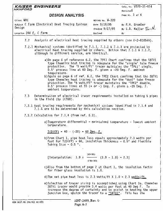
Location 200 E, C Farm Revised By7.2 Analysis of electrical heat tracing supplied by others (see H-2-818569).
7.2.1 Mechanical systems identified in 7.1.1, 7.1.2 & 7.1.3 are protected byelectrical heat tracing supplied by others. Notice that 7.1.1 & 7.1.2,although in different service, are identical.
a)0n page 6 of reference 6.2, the. TPE1 Chart confirms that the 5BTV1type Chemelex heat tracing is adequate for the "single" tube freezeprotection. The "5 watt/ft" tracer maintains the "TPE1" single,0.5" process line at 60 Deg. F. given a -20 Deg. F. ambienttemperature.
b)Again on page 6 of ref. 6.2, the TPE2 Chart confirms that the 5BTV1type Chemelex heat tracing is adequate for the "dual" tube freezeprotection. The "5 watt/ft" tracer maintains the "TPE2" double,0.5" process lines at 55 (+ or -) Deg. F. given a -20 Deg. F.ambient temperature.
7.3 Determination of electrical tracer requirements installed on tubing & pipesin the field (by ICFKH).
7.3.1 Heat tracing requirements for mechanical systems identified in 7.1.4 and7.1.5 are to be determined by this calculation section.
7.3.2 Calculation for 7.1.4 (from ref. 6.3).
a)Temperature differential = maintained temperature - lowest ambienttemperature.
T(Diff) = 40 - (-20) = 60 Peg. F.
b)From Chart 1 , pipe heat loss equals approximately 2.3 watts perfoo t f o r T ( D i f f ) = 60, Insu la t ion Thickness = 0.5" and F lex ib leTubing Size = 0.5 " .
(60-50)[ Interpolat ion: 1.9 + (3.9 - 1.9) = 2.3]
(100-50)
c)Also from the bottom of page 2 at Chart 1, the insulation factorfor fiber glass insulation is 1.0.
d)The net pipe heat loss is 2.3 watts/ft X 1.0 = 2.3 watts/ft.
e)Selection of tracer sizing is accomplished.using Chart 3a. Chemelex3BTV1 tracer would provide 3.4 watts per foot at 40 Deg F. To"increase the degree of certainty and to assist in heating the upperjunction box, upsize the tracer to a "5BTV1". This has the
KEH 0037.00 (06/92, KEFO55 HNF-2488, Rev. 0Page A-5
KAISER ENGINEERS caic. NO. W320-31-014HANFORD „ • • n
RevisionU
D E S I G N A N A L Y S I S P<*= "<>• 4 °f 6Client WHC UO/Job No. W-320
subject C Farm E l e c t r i c a l Heat Tracing Systems Date 9/19/95 By R.H. Graeber
Design checked 9/27/95 By S.A. Na j ja r S T . / .
Location 200 E, C Farm Revised By
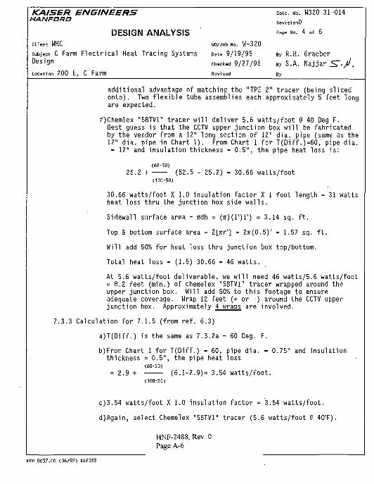
additional advantage of matching the "TPE 2" tracer (being slicedonto). Two flexible tube assemblies each approximately 5 feet longare expected.
f)Chemlex "5BTV1" tracer will deliver 5.6 watts/foot @ 40 Deg F.Best guess is that the CCTV upper junction box will be fabricatedby the vendor from a 12" long section of 12" dia. pipe (same as the12" dia. pipe in Chart 1). From Chart 1 for T(Diff.)=60, pipe dia.= 12" and insulation thickness = 0.5", the pipe heat loss is:
(60-50)25.2 + (52.5 - 25.2) = 30.66 w a t t s / f o o t
(100-50)
30.66 watts/foot X 1.0 insulation factor X 1 foot length = 31 wattsheat loss thru the junction box side walls.
Sidewall surface area = ffdh = (ir)(l')r) = 3.14 sq. ft.
Top & bottom surface area = Z[jrr'] = 2TT(0.5)! = 1.57 sq. ft.
Will add 50% for heat loss thru junction box top/bottom.
Total heat loss = (1.5) 30.66 = 46 watts.
At 5.6 watts/foot deliverable, we will need 46 watts/5.6 watts/foot= 8.2 feet (min.) of chemelex "5BTV1" tracer wrapped around theupper junction box. Will add 50% to this footage to ensureadequate coverage. Wrap 12 feet (+ or -) around the CCTV upperjunction box. Approximately 4 wraps are involved.
7.3.3 Calculation for 7.1.5 (from ref. 6.3)
a)T(Diff.) is the same as 7.3.2a = 60 Deg. F.
b)From Chart 1 for T(Diff.) = 60, pipe dia. = 0.75" and insulationthickness = 0.5", the pipe heat loss
(60-50)= 2.9 + (6 .1-2 .9)= 3.54 w a t t s / f o o t .
(100-50)
c)3.54 watts/foot X 1.0 insulation factor = 3.54 watts/foot.
d)Again, select Chemelex "5BTV1" tracer (5.6 watts/foot @ 40°F).
HNP-2488, Rev. 0Page A-6
KEH 0037.00 (06/92) KEFO55
KAISER ENGINEERSHANFtDRID
DESIGN ANALYSISClient WHC WO/Job No. W-320
subject C Farm E lec t r i ca l HeatTracing Systems Date 9/19/95Design Checked 9/27/95
Location 200 E, C Farm Revised
caic. NO. W320-31-014
RevisionO
Page No. 5 of 6
By R.H. Graeber
By S.A.
By
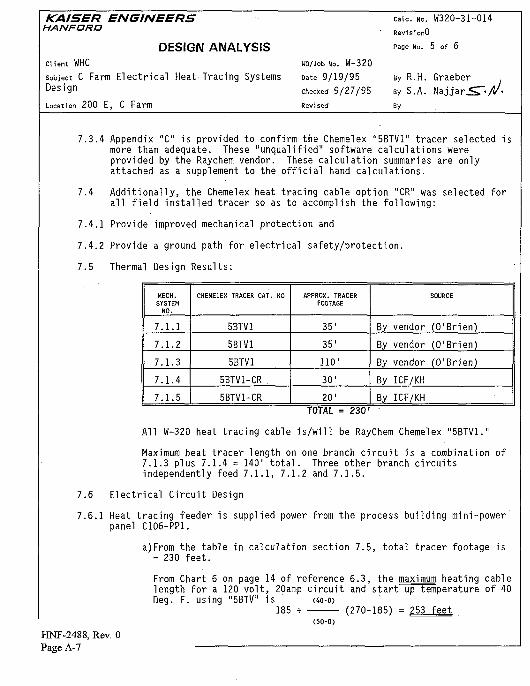
7.3.4 Appendix "C" is provided to confirm the Chemelex "5BTV1" tracer selected ismore than adequate. These "unqualified" software calculations wereprovided by the Raychem vendor. These calculation summaries are onlyattached as a supplement to the official hand calculations.
7.4 Additionally, the Chemelex heat tracing cable option "CR" was selected forall field installed tracer so as to accomplish the following:
7.4.1 Provide improved mechanical protection and
7.4.2 Provide a ground path for electrical safety/protection.
7.5 Thermal Design Results:
MECH.SYSTEM
NO.
7.1.1
7.1.2
7.1.3
7.1.4
7.1.5
CHEMELEX TRACER CAT. NO
5BTV1
5BTV1
5BTV1
5BTV1-CR .
5BTV1-CR
APPROX. TRACERFOOTAGE
35'
35'
110 '
30'
20'
SOURCE
By vendor (O'Brien)
By vendor (O'Brien)
By vendor (O'Brien)
By ICF/KH
By ICF/KHTOTAL = Z3O1
All W-320 heat tracing cable is/will be RayChem Chemelex "5BTV1."
Maximum heat tracer length on one branch circuit is a combination of7.1.3 plus 7.1.4 = 140' total. Three other branch circuitsindependently feed 7.1.1, 7.1.2 and 7.1.5.
7.6 Electrical Circuit Design
7.6.1 Heat tracing feeder is supplied power from the process building mini-powerpanel C106-PP1.
a)From the table in calculation section 7.5, total tracer footage is= 230 feet.
From Chart 6 on page 14 of reference 6.3, the maximum heating cablelength for a 120 volt, 20amp circuit and start up temperature of 40Deg. F. using "5BTV" is (4o-o>
185 + (270-185) = 253 feet(50-0)
HNF-2488, Rev. OPage A-7
KAISER ENGINEERS c=ic. NO. W320-31-014HAN FORD . . . n
RevisionUDESIGN ANALYSIS ^ •">• 6 »f 6
Client WHC UO/Job No. W-320
subject C Farm E l e c t r i c a l Heat Tracing Systems Date 9/19/95 • By R.H. GraeberD e s i 9 n checked 9/27/95 By S.A. Na j ja r J S
Location 200 E, C Farm Revised By
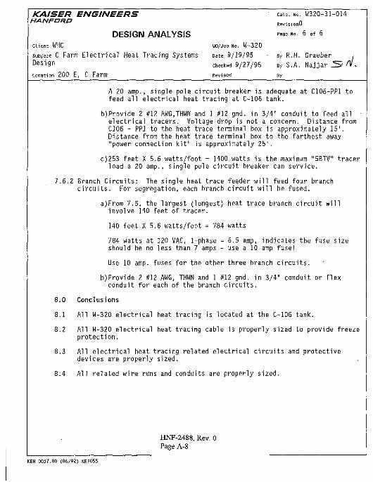
A 20 amp., single pole circuit breaker is adequate at C106-PP1 tofeed all electrical heat tracing at C-106 tank.
b)Provide 2 #12 AWG.THWN and 1 #12 gnd. in 3/4" conduit to feed allelectrical tracers. Voltage drop is not a concern. Distance fromC106 - PP1 to the heat trace terminal box is approximately 15'.Distance from the heat trace terminal box to the farthest away"power connection kit" is approximately 25'.
c)253 feet X 5.6 watts/foot = 1400. watts is the maximum "5BTV" tracerload a 20 amp., single pole circuit breaker can service.
7.6.2 Branch Circuits: The single heat trace feeder will feed four branchcircuits. For segregation, each branch circuit will be fused.
a)From 7.5, the largest (longest) heat trace branch circuit willinvolve 140 feet of tracer.
140 feet X 5.6 watts/foot = 784 watts
784 watts at 120 VAC, 1-phase = 6.5 amp, indicates the fuse sizeshould be no less than 7 amps - use a 10 amp fuse!
Use 10 amp. fuses for the other three branch circuits.
b)Provide 2 #12 AWG, THWN and 1 #12 gnd. in 3/4" conduit or flexconduit for each of the branch circuits.
8.0 Conclusions
8.1 Al l W-320 electr ical heat tracing is located at the C-106 tank.
8.2 Al l W-320 electr ical heat tracing cable is properly sized to provide freezeprotection.
8.3 Al l electr ical heat tracing related electrical c i rcu i ts and protectivedevices are properly sized.
8:4 Al l related wire runs and conduits are properly sized.
HNF-2488, Rev. 0Page A-8
KEH 0037.00 (06/92) KEF0S5
k
16 PAGES
HNF-2488, Rev. 0Page A-9
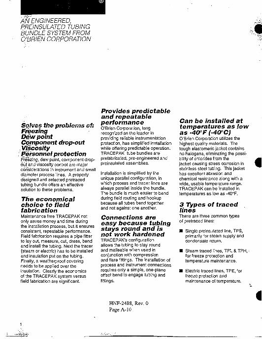
AN ENGINEERED,PREINSULATED TUBINGBUNDLE SYSTEM FROMO'BRIEN CORPORATION
Solves the problems of:FreezingDew pointComponent drop-outViscosityPersonnel protectionFreezing, dew point, component drop-out and viscosity control are majorconsiderations in instrument and smalldiameter process lines. A properlydesigned and selected pretraced.tubing bundle offers an effectivesolution to these problems.
The economicalchoice to fieldfabricationMaintenance free TRACEPAK notonly saves money and time duringthe installation process, but it ensuresconsistent, repeatable performance.Field fabrication requires a pipe fitterto lay out, measure, cut, dress, bendand install the tubing. Next the tracer(steam or electric) has to be installedand insulation put on the tubing.Finally, a weatherproof coveringneeds to be applied over theinsulation. Clearly the economicsof the TRACEPAK system versusfield fabrication are significant.
Provides predictableand repeatableperformanceO'Brien Corporation, longrecognized as the leader inproviding reliable instrumentationprotection, has simplified installationwhile offering predictable operation.TRACEPAK tube bundles areprefabricated, pre-engineered andpreinsulated assemblies.
Installation is simplified by theunique parallel configuration, inwhich process and tracer lines arealways parallel inside the bundle.The bundle is much easier to bendduring field routing and hookupbecause all tubes bend togetherand not against one another.
Connections areeasy because tubingstays round and isnot work hardenedTRACEPAK's configurationallows the tubing to stay roundand malleable when used inconjunction with compressionand flare fittings. The installation ofprocess and instrument connectionsrequires only a simple, one-planeoffset bend to engage tubing andfittings.
Can be installed attemperatures as lowas -40PF1-40PC)O'Brien Corporation utilizes thehighest quality materials. Thetough elastomeric jacket containsno halogens, eliminating the possi-bility of chlorides from thejacket causing stress corrosion instainless steel tubing. This jackethas excellent abrasion andchemical resistance along with awide, usable temperature range.TRACEPAK can be installed intemperatures as low as -40°F.
3 Types of tracedlinesThere are three common typesof pretraced lines:
• Single preinsulated line, TPS,primarily for steam supply andcondensate return.
• Steam traced lines, TPL & TPH, •for freeze protection andtemperature maintenance.
• Electric traced lines, TPE, forfreeze protection andmaintenance of temperature.
HNF-2488, Rev. 0Page A-10
S> v y W' S.SM
/
/ k
K#.HNF-2488, Rev. 0Page A-11
^>A
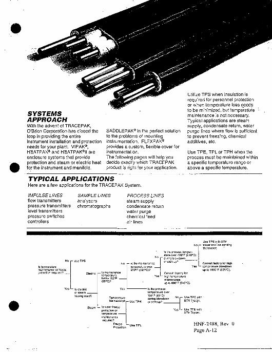
SYSTEMSAPPROACHWith the advent of TRACEPAK,O'Brien Corporation has closed theloop in providing the entireinstrument installation and protectionneeds for your plant. VIPAK®,HEATPAK® and HEATPAK®II areenclosure systems that provideprotection and steam or electric heatfor the instrument and manifold.
SADDLEPAK® is the perfect solutionto the problems of mountinginstrumentation. FLEXPAK®provides a custom, flexible cover forinstrumentation.The following pages will help youdecide exactly which TRACEPAKproduct is right for your application.
Utilize TPS when insulation isrequired for personnel protectionor when temperature loss deedsto be minimized, but temperature -maintenance is not necessary.Typical applications are steamsupply, condensate return, waterpurge lines where flow is sufficientto prevent freezing, chemicaladditives, etc.
Use TPE, TPL or TPH when theprocess must be maintained withina specific temperature range orabove a specific temperature.
TYPICAL APPLICATIONSHere are a few applications for the TRACEPAK System.
IMPULSE LINES SAMPLE LINES PROCESS LINESflow transmitters analyzers steam supplypressure transmitters chromatographs condensate returnlevel transmitters water purgepressure switches chemical feedcontrollers air lines
15 temperaturemaintenance or freezeprotection required? , _ Is maintenance
temperaturebelow 150°F _(65-C)?
r- Is tne maintenancetemperature over250<F(l21'C)?
• Is electricor steamtracing used?
No
Is the process temper-ature over « 0 * F (216°C)during blowdownor sian-up?
se TPE with XTVr- tracer and line sensin
thermostat.
Consult factory for high*- temperature Slowdown
up 10 100CTF (538°C).
up lo 660°F (349°C).
Maintenance ,_ r j s e T P H
temperature ov185'F (85°C)during blowdown
_ Is v.ater freezeprotection orlempe.-aluremaintenancerequires?
Freeze HNF-2488, Rev. 0Page A-12
A preinsulated tubing bundle withlight steam tracing
The process tubes and tracer tubesare individually wrapped withinsulation to purposely reduce heattransfer.
TPL can maintain temperaturesbetween 50cF (10°C) and 200°F(93°C). It provides a more constanttube temperature over a longerlength than heavy traced designs.
It is suited tor small diameterprocess lines such as thoseused for sampling and additives.
TPL is recommended for freezeprotection of instrument impulselines as well as the process linesfor analyzers.
Model Number
Product FamilyTPL1-Preinsulated Light Steam Traced
Single Process TubeTPL2-Preinsulated Light S1eam Traced
Dual Process Tubes
Process TubeA2 1/4- x 0.035 wall welded 316ssA3 3/8" x 0.035 wall welded 316ssA4 1/2" x 0.035 wall welded 3l6ssF1 1/8" x 0.035 wall seamless 316 ssF2 1/4" x 0.035 wall seamless 316ssF3 3/8" x 0.035 wall seamless 316ssB4 1/2" x 0.049 wall seamless 316ssJ2 1/4" x 0.030 wall copperC3 3/8" x 0.032 wall copperD4 1/2" x 0.035 wall copperG2 1/4" OD x 0.030 wall PFA Teflon*G3 3/8" OD x 0.030 wall PFA TeflonH4 1/2" OD x 0.062 wall PFA TeflonMA6, 8, 10, 12-6, 8, 10or12mmODx1
wall welded 316ss
' MF6, 8,10,12 - 6, 8, 10 or 12mm OD x 1mmwall seamless 316ss
MD6, 8,10,12 - 6, 8,10 or 12mm OD x 1mmwall copper
MG6, 8,10,12-6, 8, 10 or 12mm ODx 1mmwall PFA
TracerA2 1/4" x 0.035 wall welded 316ssA3 3/8" x 0.035 wall welded 316ssA4 1/2" x 0.035 wall welded 316SSF2 1/4" x 0.035 wall seamless 316ssF3 3/8" x 0.035 wall seamless 316ssB4 1/2" x 0.049 wall seamless 316ssJ2 1/4" x 0.030 wall copperC3 3/8" x 0.032 wall copperD4 1/2" x 0.035 wall copperMA6, 8,10,12-6,8,10 or 12mm OD x 1mm
wall welded 316ssMF6, 8,10,12-6, 8, 10, or 12mm ODx 1mm
wall seamless 316ssMD6, 8,10,12 - 6, 8, 10 or 12mm OD x 1mm
wall copper
Example:TPL2-A4-C3Two 1/2" x 0.035 wall 316 SS weldedprocess lines with a 3/8" x 0.032 wallcopper tracer.For specific information regarding eachot theseproducts, consult individual specification stteels.
TPL1- One 3/8" Process with 3/8" TracerTPL1- One 1/2" Process with 3/8" TracerTPL1- One 1/2" Process with 1/2" TracerTPL2- Two 3/8" Process with 3/8" TracerTPL2- Two 1/2" Process with 3/8" TracerTPL2- Two 1/2" Process with 1/2" Tracer
NOMINALWT.
LB/FT (KG/M)
0.5 (0.740.6 (0.890.7 (1.040.6 (0.890.8 (1.19)0.9 (1.34
NOMINALDIMENSIONS
A
1.61.91.92.32.62.6
4.1)4.8)4.8)5.8)6.6)6.6)
- IN (CM)
1.11.21.21.21.31.3
B
(2.8)(3.0;(3.o;(3.o;(3.3!(3.3)
0 30 60 90 120 150 180 210 240 270 300 o „_ 0 40
TWO 1/2" PROCESS LINES WITH 1/2" TRACER TYPICAL PERFORMANCERUN LENGTH - M RUN LENGTH - M
120 160 200 240 280 320 360 400f- 90 ', "• 200 -80 g £180-70 g =160-60 < <14O-
- 50 UJ UJ120-jlOO 'F (38°C)
^ 50 psig - o|-60°F(-5i°c"jfl(4.4 BAR)"1"
:- 40• - 3 0
200 400 600RUN LENGTH - FT
"ffi i
200 400 600 800 1000 1200 1400RUN LENGTH - FT
HNF-2488, Rev. 0Page A-13
Tellon is a registered trademark oi E.!. DuPont.
TPS is designed specifically for
liquid and gas transport lines where
heat loss and personnel protection is
important. TPS offers an
inexpensive alternative to field
insulation and weatherproofing of
small lines.
Model Number
Product FamilyTPS1-Preinsulated Single Process Tube
Process TubeA2 1/4" x 0.035 wall welded 316ssA3 3/8" x 0.035 wall welded 316ssA4 1/2" x 0.035 wall welded 316ssF2 1/4" x 0.035 wall seamless 316ssF3 3/8" x 0.035 wall seamless 316ssB4 1/2" x 0.049 wall seamless 316ssJ2 1/4" x 0.030 wall copperC3 3/8' x 0.032 wall copperD4 1/2'x 0.035 wall copperMA6, 8,10,12 - 6, 8, 10 or 12mm OD x 1mm
wall welded 316ssMF6, 8,10,12 - 6, 8,10 or 12mm OD x 1mm
wall seamless 316ssMD6, 8,10,12 - 6, 8,10 or 12mm OD x 1 mm
wall copper
Example:TPS1-C3One preinsulated 3/8" x 0.032 wall copperprocess line.
TPS1- One 1/4" Process LineTPS1- One 3/8" Process LineTPS1- One 1/2" Process Line
NOMINALWT.
LB/FT (KG/M)
0.8 (0.30)0.3 (0.45)0.4 (0.60)
NOMINALDIMENSIONS
A - IN (CM)
1.0(2.5)1.1(2.8)1.2(3.0)
3/8" TUBEAmbient Temperature - CC
-50-40 -30 -20 -10 0 10 20 30 40
1/2" TUBEAmbient Temperature - °C
•50 -40 -30 -20 -10 0 10 20 30 40
— 100"- 90L 805 70
I !§" 403 30
i n-20 0 20 40 60 80 100 120
Ambient Temperature - °F
^ ^ 200 psig (14.8 BAR) steam 388°F (198°C)^mm 125 psig (9.6 BAR) steam 353°F (178°C)• — 50 psig (4.4 BAR) sleam 299°F (148°C)• — 15 psig (2.0 BAR) steam 250°F (121°C)
• • • • • a *——
— •
•"Me
—a.
msm*•—f.« "»<•
fsmm
— - 1
• ^
—Ml
-60 -40 -20 0 20 40 60 80 100 120
Ambient Temperature - °F
HNF-2488, Rev. 0Page A-14
Creatingsolutions for uniqueapplicationrequirements.
Continuous EmissionsMonitoringPharmaceutical &SemiconductorCogenerationProcess AnalyzersStandard TRACEPAK, pretracedand preinsulated tubing bundles aredesigned to solve your applicationproblems. For other requirements,O'Brien will design and manufacturethe appropriate tubing bundle.For example, some applicationrequirements are best met by addinginsulation rather than increasing thewattage or steam pressure.
Withstand HighIntermittent ProcessTemperaturesBy using insulation to buffer thestandard self limiting tracer from theprocess tube, we can increase themaximum process exposuretemperature limit and still providefreeze protection.
CommunicationWiresCommunication, monitor andthermocouple wires may be addedto the bundle as specified by thecustomer.
MaintainHigh ProcessTemperaturesSpecialty tracers can be used toprovide temperature maintenanceup to and beyond 660°F (350°C).Depending on the specific tracerused, this product can alsowithstand process temperatures of1000°F(538eC).
Meet TubingSpecificationsTRACEPAK can be manufacturedwith tubing that conforms to yourrequirements including exotic alloys,uncommon materials, odd sizes andcoaxial tubing. For high purityapplications, we can also supplytubing that has been cleaned foroxygen service and/or electro-polished.
HNF-2488, Rev. 0Page A-15
Sample Transport Bundlesfor Continuous EmissionsMonitoringBundles with multiple process tubes, calibrationgas supply tubes, tracers, communication wiresand power wiring are designed to be incompliance with code. The sample transportbundle is developed to meet the needs of theapplication.
SEALING THE BUNDLEAlthough TRACEPAK products use a non-hygroscopic,non-wicking insulation, all bundle ends must be sealedto prevent any possible moisture contamination.
TPKES • Heat Shrink Entry SealThe heat-shrinkable entry seal provides a waterproof fitting whereTRACEPAK enters an enclosure. They can be added to parting line orsurface mounted plates on VIPAK enclosures or any enclosure with up to aVi" (13mm) wall. The thermally stabilized, modified polyolefin entry sealconsists of an O-ring assembly that seals at the enclosure and a heat-
3LS shrinkable nose that seals to the TRACEPAK bundle. '
TPKHS - Heat Shrink BootsThe heat-shrinkable boots providea weatherproof end seal forTRACEPAK tubing bundles. Theyare made of thermally stabilized,modified polyolefin. Using a heatshrink end seal boot is
recommended for all exposed ends.This installation will provide the bestweather seal protection. The siliconeend seal alone may be used to sealthe end of the bundle inside of aVIPAK enclosure.
HNF-2488, Rev. 0Page A-16
TPK.JP • Jacket PatchThe jacket patch kits are.used toseal a splice in a bundle or to extendthe insulation and weatherproofjacket should the bundle be cut backtoo far during installation. They areused as a repair patch for any
'. incidental field damage to bundles.The jacket patch kit is required withthe optional line temperature sens-ing thermostat. Each kit containsthermal insulation, fiberglass tapeand a self-sealing patch.
I f
TPKSK • Silicone SealantThis option is used to seal both endsof the tubing bundle from moisture.It is a black silicone RTV sealant.Cure time is approximately 24 hoursat77cF (25CC). Service temperatureranges from -50-'F (-45CC) to 400cF(205cC). TPKSK offers excellentresistance to weather, oil and manychemicals.
THERMOSTATSWhen used with electrically tracedtubing bundles, optional thermostatsare used to control the temperatureof the process tube or to turn on theheater at a specified ambienttemperature.
HNF-2488, Rev. 0Page A-17
Line SensingLine sensing thermostats directlycontrol the temperature of theprocess tubes. They have anadjustable set point of 75°F (24°C)to 200cF (94CC). The capillary andbulb are stainless steel. The SPDTswitch is rated for 15Aat120/240VAC. It is CSA certified andUL listed for Class I, Division 1 and2, Groups B, C and D.
Ambient SensingThis ambient sensing thermostat •has an adjustable set point from 0°F(-18°C) to 100cF (38CC). The SPDTswitch is rated for 15A at120/240VAC. It is CSA certified andUL listed for Class I, Division 1 and2, Groups B, C and D.
Note:Models shown are typical o! ifiermostaisreceived rnay differ.
POWERCONNECTION AND
iTERMINATION KITS"These components are used to'connect the electric tracer to the• power source and terminate thenon-powered ends in an approved
: manner.
LPD2Combination PowerConnection KitThis power connection kit is usedwith E and LE series electricheaters. It incorporates FMapproved and CSA certifiedcomponents to provide a powerconnection assembly for the TPEtracer and the enclosure heater.When used with a VIPAK enclosure,the LPD2 provides the convenienceof an external junction box with a3/4" NPT connection.
PMKG-LE and PMKG-LE-CSAEnd FittingThese end fittings are FM approvedor CSA certified"for XTV and BTVself-regulating tracer. • They areNEMA 4X fittings and are used toterminate the non-powered end ofthe tracer. With a CENELECaccepted electric tracer the endfitting must be approved by thecountry of use.
i
PMKGLP and PMKG-PC-CSAPower Connection FittingsThese fittings are used to power thetracer when the bundle is used byitself. They are also used when thebundle is powered from the endopposite the enclosure. They areFM approved or CSA certified forXTV or BTV self-regulating tracer.With a CENELEC accepted electrictracer the power fitting must beapproved by the country of use.
HNF-2488, Rev. 0Page A-18
TPC1 and PMKG-YCombination PowerConnection KitsThe TPC1 kit may be ordered aloneor as part of a Div. 1, E or LE seriesheater. It is CSA certified forDivision 1 applications.
The PMKG-Y kit is ordered as partof a Div. 2, LE series heater. It isFM approved for Division 2applications.
These kits are used with E and LEseries heaters to power the tracerfrom the heater junction box in the
instrument enclosure. If an outsjunction box is not required, the;^provide the most economical anpractical method of supplying pcto the TRACEPAK tracer.
TPC1
PMKG-Y
HNF-2488, Rev. 0Page A-19
A preinsulated tubing bundle withself regulating electric tracing
HNF-2488, Rev. 0Page A-20
TPE is designed to maintain freezeprotection, close temperaturetolerances or viscosity control.It provides an excellent means ofmaintaining very long, continuouslengths of impulse lines and pipingat consistent temperatures end-to-end. TPE should be chosen whensteam is not available or when thesteam supply could be interruptedsuch as during shutdowns.
Use TPE if the allowabletemperature ranges from 50°F(10°C) to 250°F (121 °C). Becauseit is self regulating, this system willlower its heat output as the materialsgets warmer. When closetemperature control is necessary,TPE can be utilized with an optionalline sensing thermostat.
TPE offers a choice of two standardtracers. A high temperature tracer(XTV) is capable of maintainingtemperatures of up to 250°F (121 °C)and withstanding blowdowntemperatures of 420°F (215°C). Alow temperature tracer (BTV) willmaintain temperatures up to 150°F(65°C) and withstand processtemperatures of up to 185°F (85°C).
Other designs are available tomaintain temperatures up to 660°F(350°C) and withstand 1000°F(538°C) blowdown conditions.Consult factory for specific design.
Electric tracerStandard TPE-Self Regulatingproducts utilizejgSegefexIelectric
| f raceTsf They are'FKi approved andCSA certified for use in hazardousareas when used with therecommended power connectionkits.
CENELEC accepted approvals forZone 1 and 2 heaters with T3temperature limits are available.
The high temperature, Self RegulatingXTV Tracer:
1. Withstands 420°F (215°C)intermittent blowdowntemperatures.
2. Can maintain temperaturesupto250°F(12rC).
The low temperature Self RegulatingBTV Tracer:
1. Withstands up to 185°F(85°C) blowdowntemperatures.
2. Can maintain temperaturesupto150°F(65°C).
The choice between XTV and BTVmust be made based on the desiredperformance and the conditions ofthe application. XTV and BTV arebacked by a 10 year performanceguarantee.
Dimensions
TPE1- One 1/4"TPE1- One 3/8"TPE1- One 1/2"TPE2-Two1/4"TPE2-TWO3/8"TPE2- Two 1/2"
Process TubesProcess TubesProcess TubesProcess TubesProcess TubesProcess Tubes
NOMINALWT.
LB/FT (KG/M)
0.3 (0.45)0.4 (0.60)0.5 (0.74)0.4 (0.60)0.6 (0.89)0.8 (1.19)
NOMINALDIMENSIONS - IN (CM)
1.11.31.41.31.51.7
(2.8(3.3(3.6(3.3(3.8(4.3
1.01.01.11.11.21.4
(2.5)(2-5:(2.8(2.8(3.0(3.6
TPE1 - ONE 1/2" PROCESSLINE WITH XTV TRACER
Ambient Temperature - °C-40 -30 - 2 0 - 1 0 0 10 20 30 40 50
~U12O
-40 -20 0 20 40 60 80Ambient Temperature - eF
TPE2 - TWO 1/2" PROCESSLINES WITH XTV TRACER
Ambient Temperature - °C-50 -40 -30 -20 -10 0 10 20 30 40 50
-60 -40 -20 0 20 40 60 80 100 120• 10 watt/ft Tracer Ambient Temperature - °F
I 5 watt/ft Tracer Chemelex is a registered trademark of Raychem Corporation.

HNF-2488, Rev. 0Page A-21
Model Number
Product Family- TPE1-Preinsulated Electrically Traced
Single Process TubeTPE2-Preinsulated Electrically Traced.
Dual Process TubesProcess TubeA2 1/4" x 0.035 wall welded 316ssA3 3/8" x 0.035 wall welded 316ss
- A4 1/2" x 0.035 wall welded 316ssF1 1/8' x 0.035 wall seamless 316ssF2 1/4" x 0.035 wall seamless 316ssF3 3/8" x 0.035 wall seamless 316ss
- B4 1 /2" x 0.049 wall seamless .316ssJ2 1/4' x 0.030 wall copperC3 3/8" x 0.032 wall copperD4 1/2" x 0.035 wall copperG2 1/4" OD x 0.030 wall PFA TeflonG3 3/8" OD x 0.030 wall PFA TeflonG2 1/4" OD x 0.030 wall PFA Teflon*G3 3/8" OD x 0.030 wall PFA TeflonH4 1/2" OD x 0.062 wall PFA TeflonMA6,8,10,12-6, 8, 10 or 12mm OD x 1mm
wall welded 316ssMF6, 8,10,12-6, 8, 10or12mmODx 1mm
wall seamless 316ssMD6, 8,10,12 - 6, 8, 10 or 12mm OD x 1mm
wall copperMG6, 8,10,12 - 6, 8, 10 or 12mm OD x 1mm
wall PFA
TracerXTVB5 - 5 watt per foot self-regulating heater
@50°F(10°C), 120 vacB10 -10 watt per toot self-regulating healer
@50°F(10°C), 120 vacN5 - 5 watt per foot self-regulating heater
<850=F(10°C), 240 vacN10 -10 watt per foot self-regulating heater
@50°F(10°C), 240 vacMN4,12 - 4 or 12 watt per foot @ 10°O,
220 vac
BTV- J5 - 5 watt per foot self-regulating healer
@50°F(10°C), 120 vacJ8 - 8 watt per foot self-regulating healer
@50°F(10°C), 120 vacP5 - 5 watt per foot self-regulating heater
@50°F(10=C), 240 vacP8 - 8 watt per foot self-regulating heater
@50°F(10°C), 240 vacMP5, 8 • 5 or 8 watt per foot @ 10BC, 220vac
All tracers have a tinned copper shieldand fluoropolymer outer jacket.FM approved for Class I, II, III Div. 2Gr. B, 0, D, F, G.CSA Certified for Class I, II Div. 1, 2Gr. A, B, C, D, E, F, G.CSA Certified for Class III Div. 2MN and MP designated tracers are approvedby CENELEC accepted agencies.
Typical Performanb LSEach graph shows typical . _ _ . . _ '
performance splitting summer/winterambients. Each line is separated at60=F(16°C) to designate the ' :
seasonal differences.Winter ambients, below 60°F
(16°C), assume a 25 mph (40 Km/H)wind and summer ambients, above60°F (16°C), assume a 10 mph (16Km/H) wind. For freeze protection,use 50°F (10°C) as the minimumallowable process tube temperature.This will provide a sufficient factor ofsafety.
Example:TPE2-A4-B5Two 1/2" x 0.035 wall 316 SS welded processlines with a 5 watt/foot tracer.
TPE1 - ONE 1/2" PROCESSLINE WITH BTV TRACER
Ambient Temperature • °C
-20. 0 20 40 60 80 100 120Ambient Temperature - 'F
TPE2 - TWO 1/2" PROCESSLINES WITH BTV TRACER
Ambient Temperature - °C-50 -40 -30 -20 -10 0 10 20 30 40 50
I 8 watt/ft Tracer •
I 5 wan/ft Tracer
•20 0 20 10 60 80 100 120Ambient Temperature - 6F
A preinsulated tubing bundle withheavy steam tracing
HNF-2488, Rev. 0Page A-22
TPH is recommended for use onimpulse lines for instrumentation,process lines for analyzers,sampling, additives and other smallprocess lines where highertemperature maintenance isnecessary. It is especially importantfor viscosity control.
Heavy tracing keeps the processtubing in direct contact with thetracer and maintains higher processtemperatures.
Model Number
Product FamilyTPH1-Preinsulated Heavy Steam Traced
Single Process TubeTPH2-Pfeinsulaied Heavy Steam Traced
Dual Process Tubes
Process TubeA2 1/4" x 0.035 wall welded 316ssA3 3/8" x 0.035 wall welded 316ssA4 1/2" x 0.035 wall welded 316ssF1 1/8" x 0.035 wall seamless 316 ssF2 1/4" x 0.035 wall seamless 316ssF3 3/8" x 0.035 wall seamless 316ssB4 1/2" x 0.049 wall seamless 316ssJ2 1/4" x 0.030 wall copperC3 3/8" X 0.032 wall copperD4 1/2" x 0.035 wall copperG2 1/4" OD x 0.030 wall PFA TeflonG3 3/8" OD x 0.030 wall PFA TeflonH4 1/2" OD x 0.062 wall PFA TeflonMA6, 8,10,12 - 6, 8,10 or 12mm OD x 1tt
wall welded 316ss
MF6, 8,10,12-6, 8, 10 or 12mm OD x 1mmwall seamless 316ss
MD6, 8,10,12-6, 8, 10 or 12mm ODx 1mmwall copper
MG6, 8,10,12-6, 8. 10 or 12mm OD x 1mmwall PFA
TracerA2 1/4" x 0.035 wall welded 316ssA3 3/8" x 0.035 wall welded 316ssA4 1/2" x 0.035 wall welded 316ssF2 1/4" x 0.035 wall seamless~316ss. . .F3 3/8" x 0.035 wall seamless 316ssB4 1/2" x 0.049 wall seamless 316ssJ2 1/4" x 0.030 wall copperC3 3/8" x 0.032 wall copperD4 1/2" x 0.035 wall copperMA6, 8,10,12-6, 8, 10 or 12mm OD x 1mm
wall welded 316ssMF6, 8,10,12-6, 8, 10 or 12mm OD x 1mm
wall seamless 3i6ssMD6, 8,10,12-6, 8, 10 or 12mm OD x 1mm
wall copper
Example:TPH2-A4-C3Two 1/2" x 0.035 wall 316 SS weldedprocess lines with a 3/8" x 0.032 wallcopper tracer.
Dimensions NOMINALWT.
LB/FT (KG/M)
TPH1- One 3/8" Process with 3/8" Tracer 0.5 (0.74)TPH1- One 1/2" Process with 3/8" Tracer 0.6 0.89)TPH1-One 1/2" Process with 1/2" Tracer 0.7 1.04)TPH2-Two 3/8" Process with 3/8" Tracer 0.6 0.89)TPH2-Two 1/2" Process with 3/8" Tracer 0.7 1.04)TPH2- Two 1/2" Process with 1/2" Tracer 0.8 1.19)
NOMINALDIMENSIONS-IN (CM)
A B
1.5 (3.8)1.6 (4.1)1.7 (4.3)2.0 (5.1)2.1 (5.4)2.2 (5.6)
1.2 (3.0)1.2 (3.0)1.2 (3.0)1.2 (3.0)1.2 (3.0)1.2 (3.0)
TWO 1/2" PROCESS LINES WITH ONE 3/8" TRACER TYPICAL PERFORMANCERUN LENGTH -M RUN LENGTH -M
10 20 30 40 50 60 70 80 90 , , „ 0 10 20 30 40 50 60 70 80 90 100 110 120
100 200RUN LENGTH - FT
100 200 300RUN LENGTH - FT
INSTALLATION TOOLSTRACEPAK is designed to be installedusing standard bending tools. We havedesigned two special tools that makeinstallation of TRACEPAK tube bundleseasier and more compact.
Bundle Bending Tool' Similar to a common electrical conduitbender, this tool is compact and easy touse. It eliminates the need for larger andheavier benders that have the required 8"minimum bending radius.
1
2Ve" Centerline ToolA replacement for the standard tube bender, it brings the processtubes to the correct centerline for connecting to typical transmitters.This tool makes back-to-back bends easier accomplishing the bendsin a much shorterdistance than possible with a standard tube bender.
13
Installation VideoInformative, current information on the installation ofTRACEPAK tubing bundles. The video deals with generalinstallation procedures and gives a good overview of theproducts and accessories available to complement andcomplete the total 'PAK'age.
HNF-2488, Rev. 0Page A-23
MATERIAL SPECIFICATIONSThe following specifications apply to alt members of the TRACEPAK family.
JACKET TUBING
Thermoplastic Polyether Urethane Elastomer
Hydrolytically Stabilized.
Halogen Free
Abrasion Resistance
UV Resistant
Low Temperature Flexibility
INSULATION
Fibrous Glass
Wafer Soluble Chlorides less than 100 ppm.
Non-hygroscopfc
OD1/4"3/8-...I S "1/4"3/8"Mir1/4"3/8"1/2"1/4" '3/8"1/2"6mm8mm "10mm12mm6mm8mm10mm12mm6mm8mm10mm12mm6mm8mm10mm12mm
WALL0.0350.0350.0350.0350.0350.0490.0300.0320.0350.0300.0300.0621mm1mm1mm1mm1mm1mm1mm1mmi m m1mm1mm1mm1mm1mm1mm1mm
CONSTRUCTIONANDMATERIALwelded 316sswelded 316sswelded 316ssseamless 316ssseamless 316ssseamless 316sscoppercoppercopper1/4" OD PFA3/8" OD PFA1/2" OD PFAwelded 316sswelded 316sswelded 316sswelded 316ssseamless 316ssseamless 316ssseamless 316ssseamless 316sscoppercoppercoppercopper1/4" OD PFA3/8" OD PFA1/2' OD PFA1/2" OD PFA
ASTMA-269A-269A-269A-269A-269A-269B-68, B-75B-68, B-75B-68, B-75
A-269A-269A-269A-269A-269A-269A-269A-269B-68, B-75B-68, B-75B-68, B-75B-68, B-75
TEMPERATURE LIMITS
Minimum installation temperature•40-F (-40°C)
Maximum Jacket surface temperature140°F (60°C) at ambient temperature of 80°F(27°C) with maximum process or tracer tubetemperature.
Maximum process tube temperatureTPH, TPL and TPS
400°F (204°C)"TPE
Continuous exposure power on.XTV250°F(121°C)- •- „BTV150°F(65»Cr ' ' :
Intermittent exposure power on or off.XTV420°F(215°C)-
BTV 185°F (85°Q*
Maximum TPE tracer temperatureXTV T-rating T2C.446°F(230°C)BTV T-rating T6,185°F (85°C)
•Consult Factory for Higher Temperature Limits.
Tubing meeting NACE MR-01-75-90 andASTM A-213-EAW specifications are alsostocked. Consult factory for the availability ofthese as well as other materials andspecifications.
HNF-2488, Rev. 0Page A-24
Customer ServiceCustomer service takes on a whole
. new meaning at O'BrienCorporation. Our reputation as acustomer-oriented problem solverhas been long recognized.
O'Brien's customer-orientedapproach offers these benefits:• responsive, knowledgeable. personnel . .
• unparalleled delivery service• dependable, tested results of all. product lines• in-house stock of hard -to-find
materials' • •
^ISO90Q0&CANZ299Unparalleled QualityCertified to currSnt ISO 9000 and ••CAN Z299 standards: Our "adherence to recognizedinternational quality standardsprovides one of the strongest .assurances of product and servicequality available. '
^ solutionFrprn Instrument to Process Line:
.-.Working together, we candevelop installation details. Ourtotal engineering package willreduce field installation costs andprovide a dependable solution foryour needs.
O'Brien Corporation now provides a product for any installation.
SADDLEPAK HEATPAK VIPAK F L E X P A K K TRACEPAK
HNF-2488, Rev. 0Page A-25
O'Brien Corporation • 1900 Crystal Industrial Ct. • St. Louis, MO 63114 • Phone 314/423-4444 • Fax 314/423-1144
17 PAGES
HNF-2488, Rev. 0Page A-26
Design Guide forInsulated Pipesand Tubing
Auto-Trace Heat-TracingSystems for Ordinary / ;
and Division 2 Areas
It"I
O
m
m
r-
HNF-2488, Rev. 0Page A-27
m
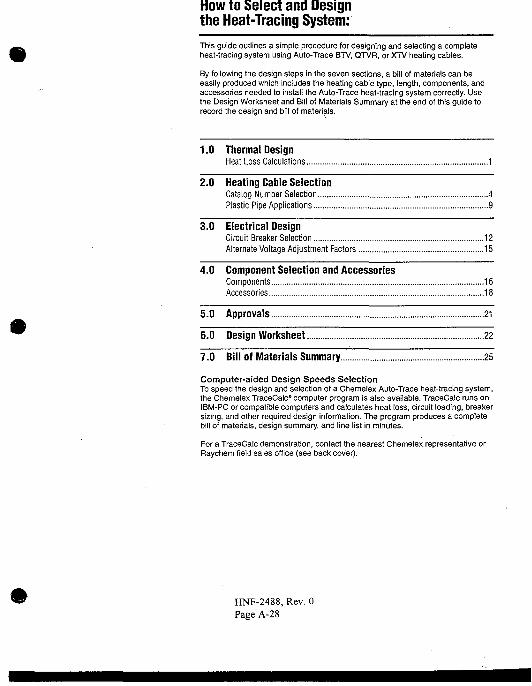
How to Select and Designthe Heat-Tracing System:This guide outlines a simple procedure for designing and selecting a completeheat-tracing system using Auto-Trace BTV, QTVR, or XTV heating cables.
By following the design steps in the seven sections, a bill of materials can beeasily produced which includes the heating cable type, length, components, andaccessories needed to install the Auto-Trace heat-tracing system correctly. Usethe Design Worksheet and Bill of Materials Summary at the end of this guide torecord the design and bill of materials.
1.0 Thermal DesignHeat Loss Calculations 1
2.0 Heating Cable SelectionCatalog Number Selection...., 4Plastic Pipe Applications 9
3.0 Electrical DesignCircuit Breaker Selection 12Alternate Voltage Adjustment Factors 15
4.0 Component Selection and AccessoriesComponents 16Accessories 18
5.0 Approvals 21
6.0 Design Worksheet 22
7.0 Bill of Materials Summary 25
Computer-aided Design Speeds SelectionTo speed the design and selection of a Chemelex Auto-Trace heat-tracing system,the Chemelex TraceCalc* computer program is also available. TraceCalc runs onIBM-PC or compatible computers and calculates heat loss, circuit loading, breakersizing, and other required design information. The program produces a completebill of materials, design summary, and line list in minutes.
For a TraceCalc demonstration, contact the nearest Chemelex representative orRaychem field sales office (see back cover).
HNF-2488, Rev. 0Page A-28
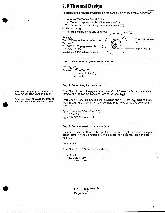
1.0 Thermal DesignTo calculate the heat loss that must be replaced by the heating cable, determine:
• Tj^: Maintenance temperature (*F)• T^: Minimum expected ambient temperature (°F)• T^: Maximum intermittent exposure temperature (°F)• Pipe or tubing size• Thermal insulation type and thickness . -r.
Example: XTM :40°F (water freeze protection)
TE : 366°F (150 psig steam cleaning)Pipe size: 6" steelInsulation: 21/2" calcium silicate
Thermal .nsulanon
Pipe or tubing
Step 1. Calculate temperature differential.
AT = TM -TACalculate AT = T M - T/s,
= 40°F -(-40°F)AT =80°F
Note: Heal loss calculations are based onIEEE Std. 515-1989, Equation 1, page 19.
Note: Heat tosses for valves and pipe sup-ports are addressed in Section 3.0, Step 1.
Step 2. Determine pipe heat loss.
From Chart 1, match the pipe size and insulation thickness with the temperaturedifferential AT to find the base heat loss of the pipe (Qg).
From Chart 1, for 6" pipe, with 2 1/2" insulation and AT = 80°F, Qg must be calcu-lated through interpolation. For this example 80 is 30/50 of the way between 50°and 100°:
Q B = 3.6 W/ft + 30/50 x (7.4 - 3.6)= 3.6 + 2.3
Q B = 5.9 W/ft @ T M = 40°F
Step 3. Compensate for insulation type.
Multiply the base heat loss of the pipe (QB) from Step 2 by the insulation compen-sation factor (f) from the bottom of Chart 1 to get the actual heat loss per foot ofpipe (Or).
Or = QB x f
From Chart1,f=1.50for calcium silicate:
Q-r = QB x f= 5.9 W/ft X1.50
QT = 8.9 W/ft @ 40°F
HNF-2488, Rev. 0
Page A-29
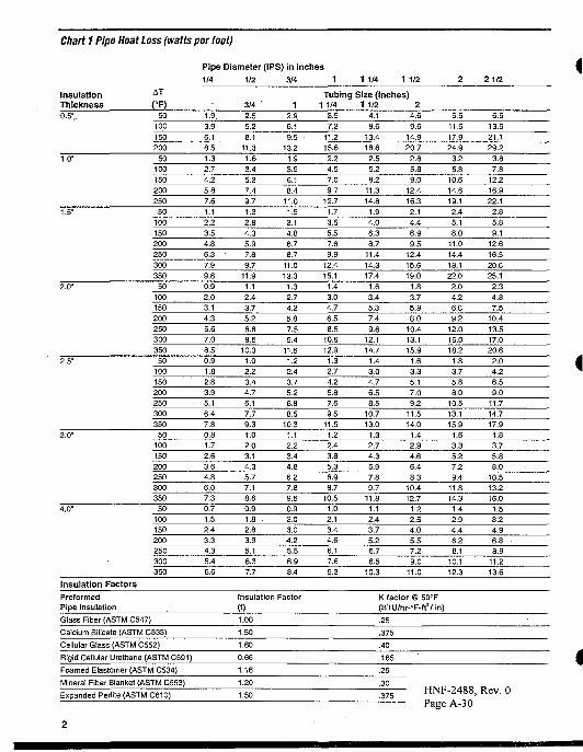
Chart 1 Pipe Heat Loss (watts per foot)
Pipe Diameter (IPS) in inches
1/4 1/2 3/4 1 1/4 1 1/2 21/2
InsulationThickness0.5-. 50
100
150
200
1-9.
3.96.1
8.5
3/4
2.5
5.2
8.111.3
1
2.9
6.1
9.513.2
Tubing Size (inches)1 1/4 1 1/2 2
3.57.2
11.215.6
4.1
8.613.4
18.6
4.6
9.614.9
20.7
5.5
11.517.9
24.9
6.513.5
21.1
29.2
350 6.6
Insulation Factors
PreformedPipe Insulation
Glass Fiber (ASTM C547)
Calcium Silicate (ASTM C533)
Cellular Glass (ASTM C552)
Rigid Cellular Urethane (ASTM C591)
7.7 8.4
Insulation Factor
(f)
1.00
1.50
1.60
0.66
9.3 10.3 11.0
K factor @ 50(BTU/hr-°F-ft!
.25
.375
.40
.165
12.3
/ in)
13.6
Foamed Elastomer (ASTM C534)
Mineral Fiber Blanket (ASTM C553)
Expanded Perlile (ASTM C610)
1.16
1.20
1.50
.29
.30
.375HNF-2488, Rev. 0Page A-30
#
3
7.7
16.025.0
34.64.4
9.114.219.7
25.8
3.26.7
10.514.5
19.023.8
28.9
2.65.58.5
11.815.519.4
23.6
2.34.7
7.410.2
13.316.720.3
2.04.2
6.69.1
11.914.918.11.7
3.55.57.6
10.012.5
15.2
3 1/2
8.6
18.0
28.1
39.0
4.910.2
15.922.028.7
3.67.4
11.616.121.0
26.332.0
2.96.09.4
13.0
17.021.3
25.92.55.2
8.111.214.6
18.322.2
2.24.67.1
9.912.9
16.219.7
1.83.86.08.3
10.813.516.5
4
9.6
20.031.2
43.35.4
11.2
17.524.2
31.73.9
8.1
12.717.6
23.028.8
35.03.1
6.610.214.2
18.523.228.3
2.7
5.68.7
12.1
15.819.824.1
2.4
4.97.7
10.7
14.017.521.3
2.04.16.4
8.911.614.6
17.7
6
13.628.4
44.3
61.5
7.5
15.624.333.7
44.0
5.3
11.117.324.031.4
39.3
47.84.2
8.813.8
19.124.931.2
38.03.67.4
11.6
16.121.026.332.0
3.16.5
10.114.0
18.323.028.02.5
5.38.3
11.415.018.8
22.8
8
17.4
36.3
56.678.69.4
19.7
30.7
42.555.6
6.7
13.9
21.630.039.2
49.2
59.85.2
10.917.0
23.630.938.747.1
4.49.1
14.2
19.725.8
32.339.3
3.8
7.912.417.1
22.4
28.134.1
3.16.4
10.013.818.122.6
27.5
10
21.4
44.669.6
96.6
11.5
24.037.4
51.967.9
8.1
16.8
26.236.3
47.559.672.4
6.3
13.1
20.528.437.2
46.6
56.65.2
10.9
17.023.630.938.747.1
4.59.4
14.720.4
26.633.440.6
3.67.5
11.8
16.321.326.7
32.4
12
25.2.
52.581.9
113.6
13.528.1
43.860.7
79.49.4
19.6
30.542.3
55.369.384.3
7.315.2
23.832.9
43.154.065.6
6.112.619.727.2
35.644.6
54.35.2
10.816.923.4
30.638.446.74.1
8.613.418.624.3
30.537.1
14
27.5
57.4
89.5124.2
14.7
30.6
47.866.2
86.610.2
21.333.246.0
60.275.4
91.7
7.916.5
25.835.7
46.7
58.671.2
6.613.7
21.329.5
38.648.4
58.85.6
11.7
18.325.333.1
41.550.54.4
9.3
14.520.026.232.839.9
16
31.3
65.2101.7
141.1
16.634.7
54.1
75.098.1
11.524.0
37.552.0
68.085.1
103.58.9
18.6
29.040.2
52.665.9
80.27.4
15.323.9
33.143.354.3
66.06.3
13.1
20.528.337.146.556.5
5.010.316.122.329.236.6
44.5
18
35.0
73.0
113.8
158.018.638.7
60.4
83.8109.6
12.926.8
41.857.975.7
94.9115.4
9.920.7
32.344.7
58.573.3
89.18.2
17.0
26.536.7
48.060.273.2
7.0
14.522.631.4
41.051.462.55.5
11.4
17.824.632.240.3
49.0
20
38.8
80.8126.0
174.8
20.542.866.7
92.5121.014.2
29:5
46.163.8
83.5104.6
127.2
10.922.835.549.2
64.380.6
98.19.0
18.729.1
40.352.866.180.4
7.615.924.8
34345.056.3
68.5
6.012.4
13.426.9
35.244.153.6
24
46.2
96.3150.2
208.524.4
50.979.4
110.0143.9
16.835.0
54.675.7
99.0
124.0150.8
12.926.9
42.058.276.1
95.3115.9
10.622.034.3
47.562.2
77.994.7
9.018.7
29.240.4
52.866.2
80.57.0
14.522.731.441.151.5
62.6
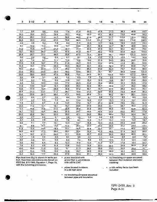
Pipe heat loss (QB) is shown in watts perfoot. Heat loss calculations are based onIEEE Std. 515-1989, Equation 1, Page 19,with the following provisions:
pipes insulated withglass fiber in accordancewith ASTM C547
pipes located outdoorsin a 20 mph wind
no insulating air-space assumedbetween pipe and insulation
no insul;betweencladding
iting air-space assumedthe insulation and outer
a 10% safety factor has beenincluded
HNF-2488, Rev. 0PageA-31
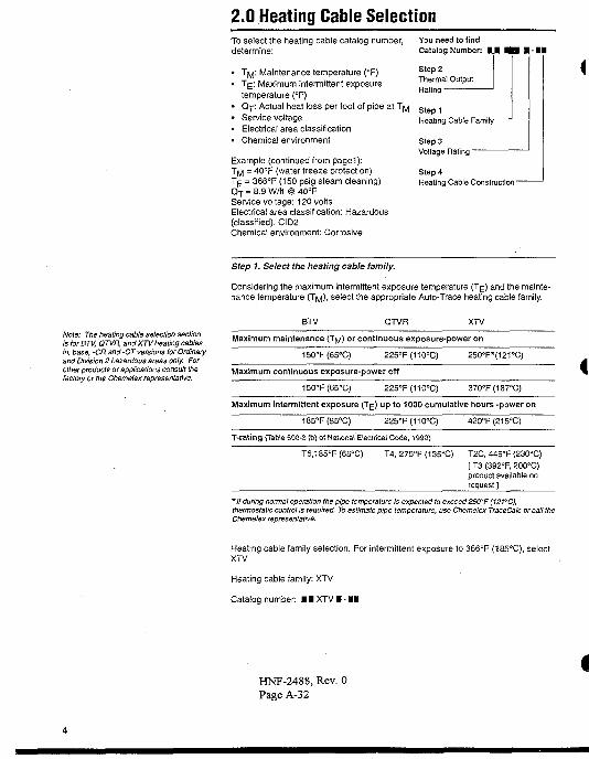
2.0 Heating Cable SelectionTo select the heating cable catalog number,determine:
• T^ : Maintenance temperature (°F)• T|=; Maximum intermittent exposure
temperature (°F)• Q-p: Actual heat loss per foot of pipe at T^• Service voltage• Electrical area classification• Chemical environment
Example (continued from pagei):T M = 40°F (water freeze protection)T[£ = 366°F (150 psig steam cleaning)Q T = 8.9 W/ft @ 40°FService voltage: 120 voltsElectrical area classification: Hazardous(classified), CID2Chemical environment: Corrosive
You need to findCatalog Number: U M I - 1 1
Step 2Thermal OutputRating -
StepiHeating Cable Family '
Step 3Voltage Rating -
Step 4Heating Cable Construction-
Note: The heating cable selection sectionisforBTV, QTVR, and XTV heating cablesin, base, -CR and -CT versions for Ordinaryand Division 2 hazardous areas only. Forother products or applications consult thefactory or the Chemelex representative.
Step 1. Select the heating cable family.
Considering the maximum intermittent exposure temperature (T^) and the mainte-nance temperature (T^), select the appropriate Auto-Trace heating cable family.
BTV QTVR XTV
Maximum maintenance (T^) or continuous exposure-power on
150°F(65°C) 225°F(110°C) 250°F*(121°C)
Maximum continuous exposure-power off
150°F(65°C) 225°F(110°C) 370°F(187°C)
Maximum intermittent exposure (Trf) up to 1000 cumulative hours -power on
185°F(85°C) 225°F(110°C) 420°F(215°C)
T-rating (Table 500-3 (b) ol National Electrical Code, 1990)
T6,185°F(65°C) T4, 275°F (135°C) T2C, 446°F (230°C)[ T3 (392°F, 200°C)product available onrequest ]
* / / during normal operation the pipe temperature is expected to exceed 250*F (121°C),thermostatic control is required. To estimate pipe temperature, use Chemelex TraceCalc or call theChemelex representative.
Heating cable family selection: For intermittent exposure to 366°F (185°C), selectXTV.
Heating cable family: XTV
Catalog number: • • XTV I - BO
HNF-2488, Rev. 0Page A-32
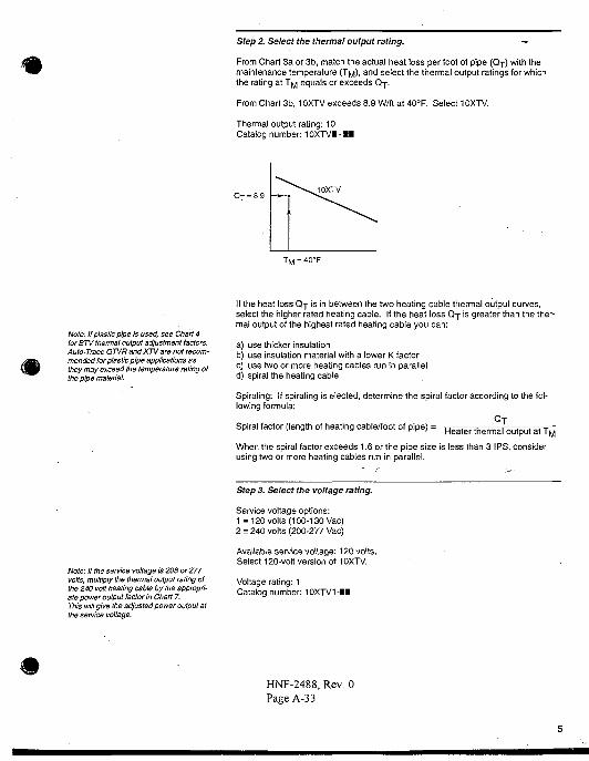
Step 2. Select the thermal output rating. —
From Chart 3a or 3b, match the actual heat loss per foot of pipe (Qj) with themaintenance temperature (Tf^), and select the thermal output ratings for whichthe rating at T ^ equals or exceeds Q-p.
From Chart 3b, 10XTV exceeds 8.9 W/ft at 40°R Select 10XTV.
Thermal output rating: 10Catalog number: 10XTV1-M
Q T = 8.9
Note: If plastic pipe is used, see Chart 4for BTV thermal output adjustment factors.Auto-Trace QTVR andXTVare not recom-mended for plastic pipe applications asthey may exceed the temperature rating ofthe pipe material.
If the heat loss Q j is in between the two heating cable thermal output curves,select the higher rated heating cable. If the heat loss Q-p is greater than the ther-mal output of the highest rated heating cable you can:
a) use thicker insulationb) use insulation material with a lower K factorc) use two or more heating cables run in paralleld) spiral the heating cable
Spiraling: If spiraling is elected, determine the spiral factor according to the fol-lowing formula:
Spiral factor (length of heating cable/foot of pipe) = Heater therm'aloutput at T M
When the spiral factor exceeds 1.6 or the pipe size is less than 3 IPS, considerusing two or more heating cables run in parallel.
Note: If the service voltage is 208 or 277volts, multiply the thermal output rating ofthe 240 volt heating cable by the appropri-ate power output factor in Chart 7.This will give the adjusted power output atthe service voltage.
Step 3. Select the voltage rating.
Service voltage options:1 =120 volts (100-130 Vac)2 = 240 volts (200-277 Vac)
Available service voltage: 120 volts.Select 120-volt version of 10XTV.
Voltage rating: 1Catalog number: 10XTV1-H
HNF-2488, Rev. 0Page A-33
Note: This example is continued on page12for metal pipes. For plastic pipes, usethe example on page 10.
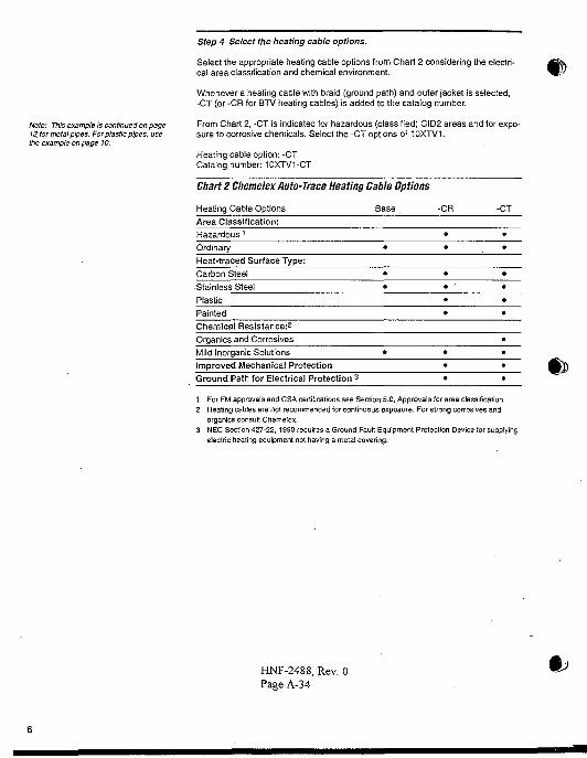
Step 4 Select the heating cable options.
Select the appropriate heating cable options from Chart 2 considering the electri-cal area classification and chemical environment.
Whenever a heating cable with braid (ground path) and outer jacket is selected,-CT (or -CR for BTV heating cables) is added to the catalog number.
From Chart 2, -CT is indicated for hazardous (classified) CID2 areas and for expo-sure to corrosive chemicals. Select the -CT options of 10XTV1.
Heating cable option: -CTCatalog number: 10XTV1-CT
Chart 2 Chemelex Auto-Trace Heating Cable Options
Heating Cable Options Base . -CR -CT
Area Classification:Hazardous 1
Ordinary
Heat-traced Surface Type:Carbon Steel
Stainless Steel
Plastic
PaintedChemical Resistance:2
Organics and Corrosives
Mild Inorganic Solutions
Improved Mechanical ProtectionGround Path for Electrical Protection 3
1 For FM approvals and CSA certifications see Section 5.0, Approvals for area classification.2 Heating cables are not recommended for continuous exposure. For strong corrosives and
organics consult Chemelex.3 NEC Section 427-22, 1990 requires a Ground Fault Equipment Protection Device for supplying
electric heating equipment not having a metal covering.
HNF-2488, Rev. 0Page A-34
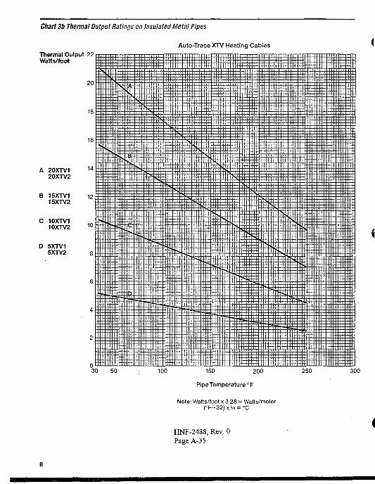
Chart 3b Thermal Output Ratings on Insulated Metal Pipes
Auto-Trace XTV Heating CablesThermal Output 22Watts/foot
D 5XTV15XTV2
20
18
16
A 20XTV1 14
20XTV2
B 15XTV1 1215XTV2
C 10XTV110XTV2 10
o30 50
ss
I
Si
I
100 150 200
Pipe Temperature °F
Note: Watts/foot x 3.28 = Watts/meter(°F-32)x5/9 = °C
250 300
HNF-2488, Rev. 0Page A-35
#
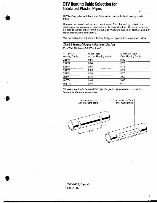
BTV Heating Cable Selection forInsulated Plastic Pipes
BTV heating cable with braid and outer jacket is ideal for heat-tracing plasticpipes.
However, increased resistance to heat transfer from the heating cable to theplastic pipe necessitates compensation of its thermal output. Aluminum tape maybe used to increase the thermal output of BTV heating cables on plastic pipes. Fortape specifications, see Chart 9.
The thermal output adjustment factors for typical applications are shown below.
Chart 4 Thermal Output Adjustment FactorsPipe Wall Thickness 0.250" or Less*
-CT or -CRHeating Cable3BTV13BTV25BTV15BTV28BTV18BTV210BTV110BTV2
Glass TapeAcross Heating Cable0.550.600.55
0.500.50
0.450.40
0.45
Aluminum TapeOver Heating Cable0.800.750.750.750.700.65.0.600.70
'Equivalent to a 3 1/2' schedule 40 PVC pipe. For greater pipe wall thickness consult thefactory or the Chemelex representative.
GT-66 Glass Tapeacross heating cable
HNF-2488, Rev. 0Page A-36
BTV Heating Cable Selection forInsulated Plastic Pipes
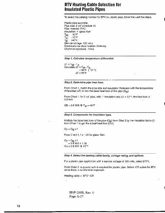
To select the catalog number for BTV on plastic pipe, follow the next five steps.
Plastic pipe example:Pipe size: 2 1/2" schedule 40Pipe material: PVCInsulation: 1" glass fiberTM : 40°FTA : -1O°FTE : 140°FService voltage: 120 voltsElectrical area classification: OrdinaryChemical exposure: None
Step 1. Calculate temperature differential.
M A
Calculate AT = T M - TA
= 40cF-(-10°F)AT = 50°F
Step 2. Determine pipe heat loss.
From Chart 1, match the pipe size and insulation thickness with the temperaturedifferential (AT) to find the base heat loss of the pipe (Qg).
From Chart 1, for 2 1/2" pipe, with 1" insulation and AT = 50°F, the heat loss is3.8 W/ft
QB = 3.8 W/ft @ T M = 40°F
Step 3. Compensate for insulation type.
Multiply the base heat loss of the pipe (Qg) from Step 2 by the insulation factor (f)from Chart 1 to get the actual heat loss (Qy).
Q T = QB x f
From Chart 1, f = 1.00 for glass fiber:
Q T = QB x f= 3.8 W/ft x 1.00
Q T = 3.8 W/ft @ 40cF
Step 4. Select the heating cable family, voltage rating, and options.
For a plastic pipe application with a service voltage of 120 volts, select BTV1.
From Chart 2, a ground path is required for plastic pipe. Select -CR option for BTVsince there is no chemical exposure.
Heating cable = BTV1-CR
HNF-2488, Rev. 0Page A-37
10
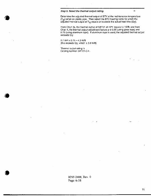
Step S. Select the thermal output rating. —
Determine the adjusted thermal output of BTV at the maintenance temperature(TM) when on plastic pipe. Then select the BTV heating cable for which theadjusted thermal output at T ^ equals or exceeds the actual heat loss (Qj).
From Chart 3a, the thermal output of 5BTV1 at 40°F equals 5.7 W/ft; and fromChart 4, the thermal output adjustment factors are 0.55 (using glass tape) and0.75 (using aluminum tape). If aluminum tape is used, the adjusted thermal outputexceeds Qy.
5.7 W/ft X 0.75 = 4.3 W/ft(this exceeds QT, which is 3.8 W/ft)
Thermal output rating: 5Catalog number: 5BTV1-CR.
HNF-2488, Rev. 0PageA-38
11
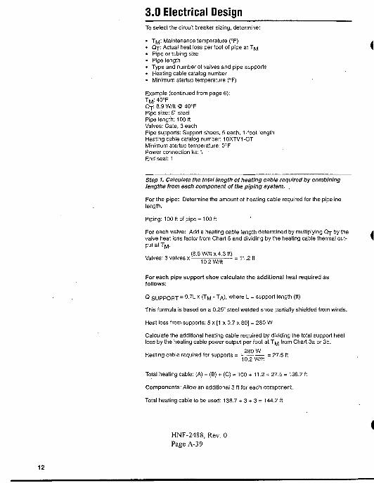
3.0 Electrical DesignTo select the circuit breaker sizing, determine:
• Ttf. Maintenance temperature (°F)• Q j : Actual heat loss per foot of pipe at 7pj\• Pipe or tubing size• Pipe length• Type and number of valves and pipe supports• Heating cable catalog number• Minimum startup temperature (°F)
Example (continued from page 6):TM :40°FQT: 8.9 W/ft @ 40rFPipe size: 6" steelPipe length: 100 ftValves: Gate, 3 eachPipe supports: Support shoes, 5 each, 1-foot lengthHeating cable catalog number: 10XTV1-CTMinimum startup temperature: 0°FPower connection kit: 1 •End seal: 1
Step 1. Calculate the total length of heating cable required by combininglengths from each component of the piping system.
For the pipe: Determine the amount of heating cable required for the pipelinelength.
Piping: 100 ft of pipe = 100 ft
For each valve: Add a heating cable length determined by multiplying Q T by thevalve heat loss factor from Chart 5 and dividing by the heating cable thermal out-put at T M .
(8.9 W/ft x 4.3 ft)Valves: 3 valves x 1 0 2 w / f ( = 11.2 ft
For each pipe support shoe calculate the additional heat required asfollows:
Q SUPPORT = ° - 7 L x (TM - TA>. where L = support length (ft)
This formula is based on a 0.25" steel welded shoe partially shielded from winds.
Heat loss from supports: 5 x [1 x 0.7 x 80] = 280 W
Calculate the additional heating cable required by dividing the total support heatloss by the heating cable power output per foot at T^ from Chart 3a or 3b.
280 WHeating cable required for supports = • = 27.5 ft
Total heating cable: (A) + (B) + (C) = 100 + 11.2 + 27.5 = 138.7 ft
Components: Allow an additional 3 ft for each component.
Total heating cable to be used: 138.7 + 3 + 3 = 144.7 ft
HNF-2488, Rev. 0Page A-39
12

HNF-2488, Rev. 0Page A-40 Chart 5 Valve Heat Loss Factors
Valve TypeGateButterfly
BallGlobe
Heat Loss Factor4.32.32.6
3.9
Example: Heat loss for a 2" gate valve is 4.3 times the heat loss for one foot ofpipe of the same size and insulation.
Note: All thermal and electrical designinformation provided here is based upon a"standard"installation, i.e., with heatingcable fastened with glass tape to an insu-lated metal pipe.
For any other method of installation, con-sult the Chemelex representative fordesign assistance.
Step 2. Determine the circuit breaker trip rating.
Using Chart 6, match the heating cable catalog number at the expected minimumstartup temperature with the total heating cable length and select a circuit breakertrip rating. Circuit breaker trip rating should not exceed the maximum trip ratingshown for heating cables of that product family. For example, the trip rating of acircuit breaker protecting several XTV circuits should not exceed 50 amps. Tomaximize fault current protection use the lowest allowable circuit breaker sizing.
From Step 1, the total heating cable circuit length is 144.7 feet. From Chart 6, themaximum heating cable length allowed for 10XTV powered at 120 volts with a 0°Fstartup temperature on a 20 amp circuit breaker is 130 feet, and on a 30 ampbreaker is 195 feet. Select the 30 amp circuit breaker.
Circuit breaker trip rating: 30 amps
WARNING: Fire and shock hazard. To mini-mize the danger of fire if the heating cableis damaged or improperly installed, use aGround Fault Equipment Protection Device{GFEPD). Electrical fault currents may beInsufficient to trip a conventional circuitbreaker.
Line 1 + Line 2 + Line 3 < Maximum Circuit length
Note: Because magnetic circuit breakerscould nuisance trip at low temperatures,thermal circuit breakers are recommended.
Step 3. Select the circuit breaker
Ground Fault ProtectionThe IEEE standard (515-1989) for heating cables recommends the use ofGFEPDs with a nominal 30 milliampere trip level "for piping systems in classifiedareas requiring a high degree of maintenance, or which may be exposed to physi-cal abuse or corrosive atmospheres."
Article 427-22 of the 1990 National Electrical Code requires the use of GFEPDwith non braided (base) electric heating cables.
Device selectionUsing the information below, select the appropriate device for the system.
Ground Fault EquipmentProtection Devices• Square D
Type QOB-EPD• Westinghouse
Types GFEP, GFEPD
Conventional Devices• General Electric
Type TEB• Square D
Types EH, QO• Westinghouse
Types BA, GH
13
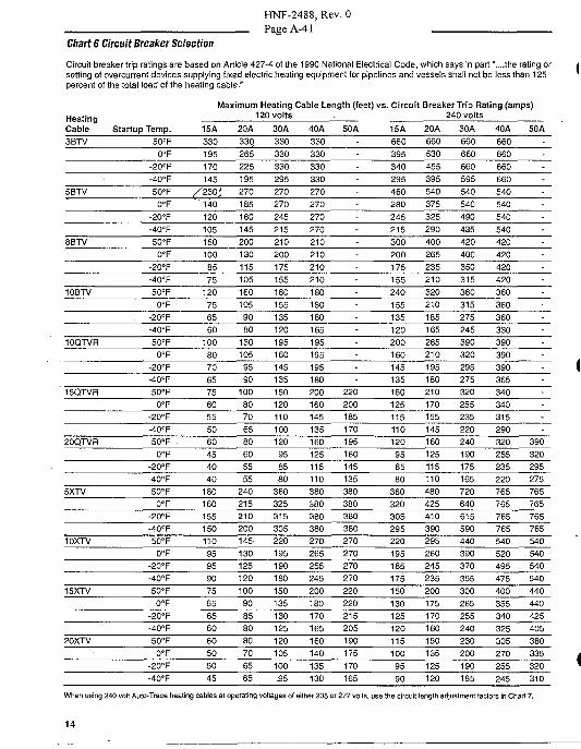
Chart 6 Circuit Breaker Selection
HNF-2488, Rev. 0
Page A-41
Circuit breaker trip ratings are based on Article 427-4 of the 1990 National Electrical Code, which says in part "....the rating orsetting of overcurrent devices supplying fixed electric heating equipment for pipelines and vessels shall not be less than 125percent of the total load of the heating cable."
Max
HeatingCable
Imum Heating Cable Length (feet) vs.120 volts
Circuit Breaker Trip Rating (ai240 volts
imps)
Startup Temp. 15A 20A 30A 40A 15A 40A 50A3BTV .
5BTV
8BTV
10BTV
10QTVR
15QTVR
20QTVR
5XTV
10XTV
15XTV
20XTV
50°F
0°F-20°F
-40°F
50°F
0°F-20°F
-40°F
50°F
0°F-20°F
-40°F
50°F
0°F. -20°F
-40°F
50°F
0°F-20°F
-40°F
50°F
0°F-20°F
-40°F
50°F
0°F-20°F
-40°F
50°F
0°F-20°F
-40°F
50°F
0°F-20°F
-40°F
50°F
0°F-20°F
-40°F
50°F
0°F-20°F
-40°F
330195170145
/^230j
140120105150100857512075656010080706575605550604540401801601551501109595907565656060505045
330265225195270185160145200130115105160105908013010595901008070658060555524021521020014513012512010090858080706565
3303303302.95270270245215210200175155180155135120195160145135150120110100120958580360325315305220195190180150135130125120105100S5
330330330330270270270270210210210210180180180165195195195180200160145135160125115110380380380380270265255245200180170165160140135130
-
-
-
-220200185170195160145135380380380380270270270270220220215205190175170165
6603953402954602802452153002001751552401551351202001601451351601251151101209585803603203052952201951851751501301251201151009590
660530455395540375325290400265235210320210185165265210195180210170155145160125115110480425410390295260245235200175170160150135125120
660660660595540540490435420400350315360315275245390320295275320255235220240190175165720640615590440390370355300265255240230200190185
660660660660540540540540420420420420360360360330390390390365340340315290320255235220765765765765540520495475400355340325305270255245
-
-
--------
--
390320295275765765765765540540 '540540440440425405380335320310
When using 240 volt Auto-Trace heating cables at operating voltages of either 208 or 277 volts, use the circuit length adjustment factors in Chart 7.
14
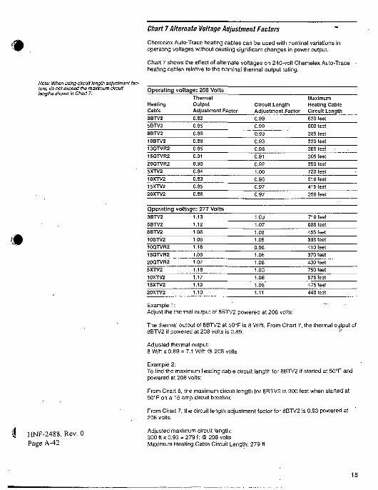
Chart 7 Alternate Voltage Adjustment Factors
Chemeiex Auto-Trace heating cables can be used with nominal variations inoperating voltages without causing significant changes in power output.
Chart 7 shows the effect of alternate voltages on 240-volt Chemeiex Auto-Traceheating cables relative to the nominal thermal output rating.
Note: When using circuit length adjustment fac-tors, do not exceed the maximum circuitlengths shown in Chart 7.
m
Operating voltac
HeatingCable
3BTV2
5BTV2
8BTV2
10BTV2
10QTVR2
15QTVR2
20QTVR2
5XTV2
10XTV2
15XTV2
20XTV2
Operating voltac3BTV2
5BTV2
8BTV2
10BTV2
10QTVR2
15QTVR2
20QTVR2
5XTV2
10XTV2
15XTV2
20XTV2
je: 208 VoltsThermalOutputAdjustment Factor
0.82
0.85
0.89
0.89
0.85
0.91
0.90
0.84
0.83
0.85
0.88
je: 277 Volts1.13
1.12
1.08
1.08
1.18
1.09
1.07
1.18
1.17
1.13
1.10
Circuit LengthAdjustment Factor
0.99
0.99
0.93
0.93
0.98
0.91
0.92
1.00
0.98
0.97
0.97
1.03
1.07
1.08
1.05
0.96
1.06
1.06
1.03
1.06
1.08
1.11
MaximumHeating CableCircuit Length
630 feet
500 feet
385 feet
330 feet
365 feel •
305 feet
350 feet
720 feet
510 feet
415 feet
350 feet
710 feet
585 feet
465 feet
395 feet
410 feet
370 feet
430 feet
750 feet
575 feet
475 feet
440 feet
HNF-2488, Rev. 0Page A-42
Example 1: -Adjust the thermal output of 8BTV2 powered at 208 volts:
The thermal output of 8BTV2 at 50°F is 8 W/ft. From Chart 7, the thermal output of8BTV2 if powered at 208 volts is 0.89. ^
Adjusted thermal output:8 W/ft x 0.89 = 7.1 W/ft @ 208 volts
Example 2:To find the maximum heating cable circuit length for 8BTV2 if started at 50°F andpowered at 208 volts:
From Chart 6, the maximum circuit length for 8BTV2 is 300 feet when started at50°F on a 15 amp circuit breaker.
From Chart 7, the circuit length adjustment factor for 8BTV2 is 0.93 powered at208 volts.
Adjusted maximum circuit length:300 ft x 0.93 = 279 ft @ 208 voltsMaximum Heating Cable Circuit Length: 279 ft
15
e5 PAGES
HNF-2488, Rev. 0Page A-43
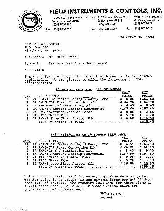
FIELD INSTRUMENTS & CONTROLS, INC.12606 N.E. 9Sth Street, Suite C-l 30 5302 North Millview Drive 2928 • 162nd Street S.E.Vancouver, WA 98682 Spokane, WA 99212 Mill Creek, WA 98012|2O6|896-99IO (509) 926-3284 (206) 402-0427
Fax: |Z06) 896-9905 Fax; (509)926-3529 Fax: (206)402-0623
December 30, 1994
ICF KAISER HANFORDP.O. Box 888Richland, WA 99352
At ten t ion : Mr. Dick Graber
Subject : Raychen Heat Trace Reguirem&nt
Dear Dick:
Thank you for the opportunity to work with you on the referencedapplication. We are pleased to offer the following for yourconsideration:
FOAMED ELASTOMER - 1/2" THICKNESS:
OTY DESCRIPTION32 FT 5BTV1-CT Heater cable; 5 Watt, 120V1 EA PMKG-JLP Power Connection Kit1 EA PMKG-LE End Termination Kit1 EA AMC-1A Ambient sensing Thermostat;3 EA ETL "Electric Traced" Label1 SA GT66 Glass Tape1 EA PMK-B Pipe Strap Adaptor Kit
BILL OF MATERIALS TOTAL:
UNIT
5.05$ 64.95$ 8.43$157.60$ 0.85$ 3.70$ 16.60
EXT.
1/2" FIBERGLASS OR 1" FOAHliD ELASTOMSR:
• QTY DESCRIPTION .32 FT 3BTV1-CT Heater Cable; 3 Watt, 120V1 EA PMKOJLP Power Connection Kit1 EA PKKG-LE End Termination Kit1 EA AMC-1A Ambient sensing thermostat3 EA ETL "Electric Traced" Label1 EA GT66 Glass Tape1 EA PMK-B Pipe Strap Adaptor Kit
BILL OF MATERIALS TOTAL
UNIT
$ 4.55$ 64.95$ 8.45$157.60$ 0.B5$ 3.70$ 16.60
EXT.PRIC$145.60$ 64.95$ 8.45$157.60$ 2.55$ 3.70S 16.609399.45
Prices quoted remain valid for thirty days from date of quote.The FOB point is Vancouver, WA and payment terms are net 30 daysfrom date of invoice. The standard lead time for these items is1 week after receipt o£ order, or sooner (item3 shown arenormally stocked in Vancouver).
HNF-2488, Rev. 0Page A-44
Mr. Dick GraberICF Kaiser Hanford - 2 - December 30, 1994
Please give us a call if you need any more detail regarding thisapplication. Thanks again for the chance to quote.
Sincerely,
FIELD INSTRUMENTS & COKTROLS
rls
Enclosures
oc: Jamie Sullivan/Spokane
Russ Suttffirinside Sales/Vancouver
HNF-2488, Rev. 0Page A-45
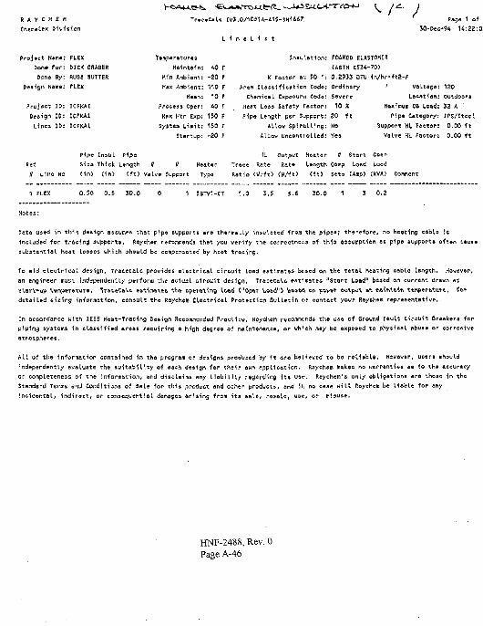
I A V C H E K
Chemettx D i v i s
.^A 1 ai •
H:2Z:0;
Project N*m*
bone for
6one By
Design Name
Project IS
De&ign 1&
Lines IB
FLEX
DICK GRABER
RUSS SUTTEft
FLEX
ICTKAI
KFKA1
ICFKAI
T»mp»ritur#s
Hin Ambient
Max Ambient
Mean
Proteas oper
Hax Htr Exp
Syiteu Litiiit
AO r
-20 F
no r10 f
40 r
150 f
150 r
Startup; -20 F
Jnsu'.ation
K Factor at 50 r
Area Classification Code
Chemical Exposure Cods
Heat Lass Safety rector
Pipe Length per Support
ALlow Spiralling
Allow uncontrolled
FOAMED ELASTOMER
(ASTH C53W0)
0.2933 OTu in/hr-ft2-F
Ordinar/
Severe
10 X
20 ft
NO
Yes
VoLtsge
Le-eatien
Haxifflum CB Load
fipe Category
Support HL Foct6^
Valve HL Factor
120outdoor*
32 A
IPS/Stccl
0.00 •ft
0.00 ft
Pipit InsuL Pipe
Kef Siza Thick Length II U Heater
fl L ine No ( in> ( i n ) ( f t ) Valve Support Type
HL Cutput Heater tt Start Opcr
Trace Rate. Rate Length Comp Load Load
Ratio (W/ft> (H/-ft) <ft> 5«s (Amp) <kVA) Comment
1 FLEX
Notes:
0.50 0.5 30.0 1.0 3.5 5-6 30.0 0.2
Pats used in this de&ign assumes that pipe supports are thsrmaLLy insulated from the pipe*; therefore, no heating cable 1*
included for troctog supports. Raychetn peeoswenda that you verify the corrcctnei-a of th<» attwrnptifin as pipe Bupport* ofttn
subatsntiaL heat losses which should be compcr.sated by heat tracing.
To aid electrical design, TraceCalc provides electrical, circuit Load estimates bi.sed en the total heating cable Length. However,
an engineer musi independent.ly perfonu v!i« evtudl circuit design. TraceCaLc estimates "Start Loftd" based on current drawn at
storV-up ivinperaXure. TratcCalt e&fiinatfc& the operating load ("Opcr Load") bftsfttt en povtr output at iwlntft ft tttfijieraturt, f©^
detailed sizing in-formation, consult the Raychem ClettMcal Protection Bulletin tip contact your Raythem representative.
In accordance with IEEE Heat-Tracing Design Recommended Practice* Rayclteffl r&corrifri£.nds the ute of Ground fault Circuit Breakers for
piping systems in classified areas requiring a high degree of maintenance, or wh'ch iray be exposed to physical abuse or corrosive
atmosphere*.
All of the information contained in the program or design* produced by it are believed to be reliable. However, usere should
independently evaluate the suitability of each design for their own appliction Raychem makes no warranti«s as to th» Accuracy
R h ' l b l i i th i hs only are thoac in the
All of the information contained in the program or design* produced by it are believed to b
independently evaluate the suitability of each design for their own application. Raychem m
or completeness of the information, and disclaims any liability regarding Its ust;. Raychem y s
Standard Terms driJ Conditions of Sale for this product and other products, and iii no ca«e will Raychefn be liable for any
Incidental, indirect, or consequential damages arising from ita eale, resale, use, or
HNF-2488, Rev. 0Page A-46
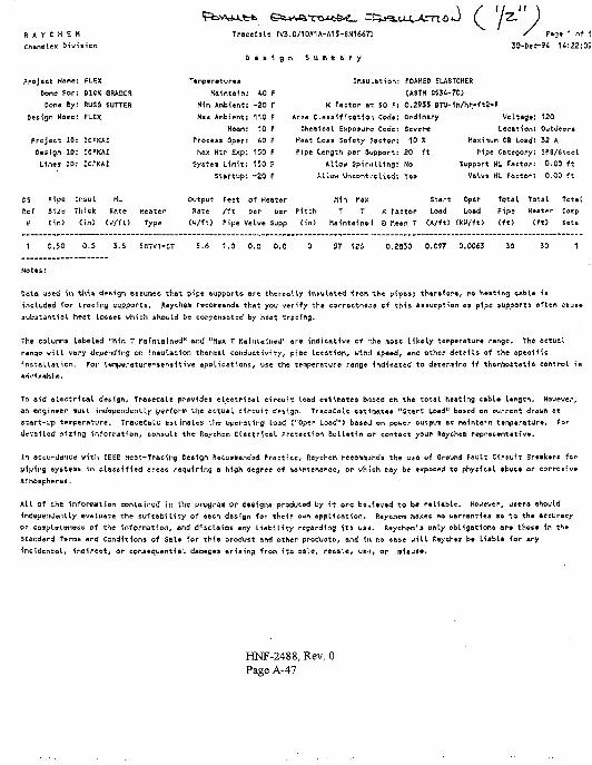
R A Y C H
Cha*eLex
Project N
Done
Don*
ESiv
sme
or
ByDesign Name
Project
Design
Lines
10
IDID
i»ion
FLEX
DICK GRAOCR
RUSS SUITER
FLEX
1CFKAI
ICPKAI
JCfKAI
TroceCalc tV3.0/10»1A-A15-SN1667;
D . s i g n S u m m a r y
C V)/ P«3» 1 of 1
1*:22;0S
Pipe Insul HL
^e Thick
n> (in)
Rate
(H/fU
Heater
Type
T«rnp«r.turcs
K«'.nt«in: 10 F
H(n ABbient: -20 r
Hsx Ambient: 110 F
Mean: 10 F
Pree«as Oper: W F
(1«x Htr Exp; 150 F
C-ystM Limit: 150 F
startup: -20 F
Output Feet
Rate /ft
<u/ft) Pipe
Intu'.ation: FOAMED ELASTOMER
(ASTM C536-70)
K factor ax 50 F: 0.2935 BTV-Whr-ft2-f
Area Classification Code: Ordinary
Chemical Exposure Code: Sever*
Heat Loss Safety Factor: 10 X
Pipe Length per Support: 20 ft
Allow Spiralling: No
Allow Uncontrolled: Yes
Voltage
Location
Maximum CB Load
Pipe Category
Support HL Factor
Valve HL Factor
Outdoor*
52 A
IPS/Stsel
0.00 ft
0.00 ft
of Heater
par par
alve Supp
Pitch
fin)
Hln M«X
T T
Maintained
K
S
Tactor
Mean T
Start
Load
<A/ft>
oper
Load
(KW/ft>
Total Total. Totil
Pipe Heater Comp
(ft) <*t) Sets
3.5 SBTV1-CT 5.6 1.0 0.0 0.0 0.2S30 0.097 0.0063
Daia u*ed 1n this design assumes that pipa &upports are thermally Insulated from the pips*; therefore, no heating cable i«
includod for trovlny supports. Raychem recommends that you verify the correctness cf th<i asaunption as p\pe supports often cauae
substantial heat losses which should bo compensated by heat freeing.
The columns labeled "Min T Maintained" and "Max T MalnUfiieU" are Indicative of -she- most likely temperature range. The actual
range will vary Unending on insulation thermal conductivity, pipe location, wind speed, and other deteUs of the aptcific
installation. For lemperature-sensUive applications, use the temperature rang* Indicated to determine if thermoitatU control ie
To aid fllcctrical design, TraceCaLe erovidea electrical circuit load estimates bnted en the total heating CfcbU Ungth. However,
an engineer must indttpeiKJetHly perfotli) I he actual circuit design. TracaCslc estimates "Start Load" based on current drown at
siart-up temperature. TraceCoU' estimates 'Jic uperating load C'Oper Load") based on pvvtr output at maintain temperature, for
detailed sizing information, consult the Roychsm Electrical Pre-ectSon Bulletin or contact your ftaychem representative.
In ecturdsMce with IEEE Heat-Tracing Design Recommended Practice, Raychetn reeomfnisnds the use of Ground Fault Circuit Br«»k*r« for
piping systems in classified areas requiring o high degree of maintenance, or which trAy be expeced to phyeictl *but» or corrosive
atmospheres.
All of the information coniained In Ihc jjrvacetrt Oi" designs produced by it ore be.ieved. to be reliable. However, ueere ehould
indcpviiOwntly evaluate the suitability of each design for the^r own application. Raychem makes no warranties as to the accuracy
or complttltfntfss of the Information, and disclaims any liability regarding its us-j. ftaychem's only obligations are those In the
Standard Terms and Conditions of Sale for this product and other products, ond in no tate will ftaychem be li*M» for any
incidental, Indirect, or consequential damages arising from its sale, retale, UB-I, or m1«ue#.
HNF-2488, Rev. 0Page A-47
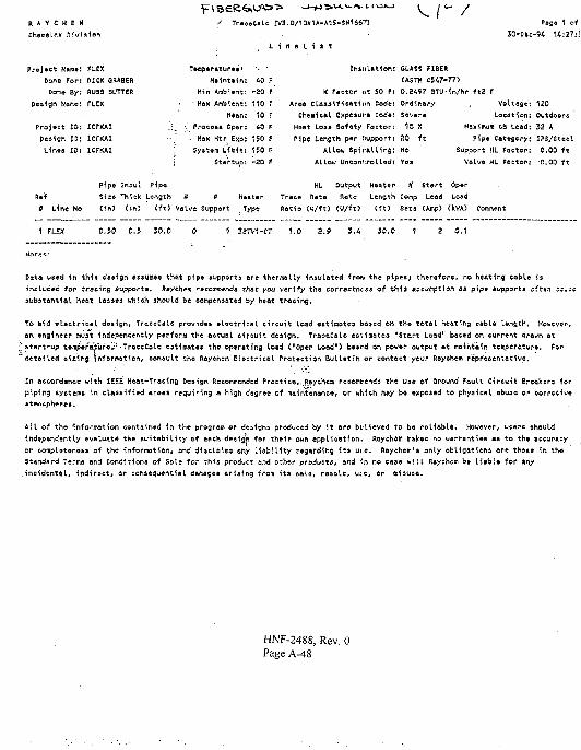
Project Name FLEX
&ono For! HICK GRABER
none By: RUSS sUTTEft
Design Name: fLCX
Project lt>: ICFKAI
Design IP: ICFKAILines 15; ICFKAI
Fipc Inoul Pipe
Ref Size Thick Lonjth * » Heator
0 Line No (in) <in) (ft) Valve Support Type
T.mjs«ratur.»'
Haintain
Min Ambient
- Hax Ambient
Mean
PTOCOM Opor
Hax Htr Exp
System Limit
StartuD
CO
-20
110
10
40
150
150
-20
F
F
rrF
F
rF
.0/10K1A-A1S-SN16S?]
Insulat ion:
K Factor nt 50 F:
Area c las»i<iMt i i>n Code:
chemical Cxsasur-e cede.
Hoat Loss Sa-rety Factor:
Pipe Length per support:
Allow Sp i ra l l ing :
ALLOW Uncontrolled:
GUSS FIBER
(ASTM C5A7-77)
0.2A97 STU-^n/hr ft2 r
Ordinary
Page 1 of
3O-D»c-94 14:27:!
Voltage
20 ftHaximum C& Load
Pip* Category
Support HL Factor
VaLve HL Factor
0,00 ft
0.00 ft
HL Output Heater H Start 0p«r
Trat« Rato flatc
ftatio (W/ft> (W/ft)
Length Comp Load Laad
(•ft) Seta (Amp) (kVA)
0.50 0.5 30.0 1 3B7V1-CT 1.0 2.9
Dot« u»ed ity this dt*ign sssumes that" pipe »>jppdrt9 Are therwaUy iniulated frarv the pipes; thoroforc, no heating wble is
included for tracing Jupporta. Raychent recommend* rhat you verify th» corroctnc*5 of zhis assyfliptien aa pipe supports cfto.n c;-;
subitarnial htet Loisej which should be eottpen»ated by heat tracing.
To aid «Uctricat. dssign, TraceCaLc provid** »l«ctrica(. circuit Load e*tlmate* l>a*ed en the total heating cable length. However,
an engineer muat independently perform the actual tircuit design, TraceCalc estimates "Start Load" based en current 4r&un at
;'start-up temperatures" • TraccColc esti'matea the epsrating load £"0per Load") baaed On pewtr output at maintain teftperature. For
"detailed aixing informatien, consult tS* Rayehem Electrical Protection Bulletin or contact your Rayehen repr'ecentative.
In accordance with IEEE Heat-Tracing Design Recommended Practice,..Roychem reeofflMendi the use of Ground fault Circuit Breaker* for
piping systems in classified areas requiring a high dogroo of maintenance, or which may be exposed to physical abuoe or corrcswe
Atmotphertt.
All of the information contained in the program or designs produced by It are believed to be reliable. However, users should
independently evaluate th* suitability of eaeh design for their own application. Rayehew makes no warranties ae to th* »eeur*ey
or complBtcne&s of the information, and disclaims any liability regarding its ut-e. Raychem'a only obligations are those in the
Standard Terms and Conditions of Sole for this product and other product*, and <n no ease will flayehem be Uoblc for an/
incidental, indirect/ or consequential damages arising from its sata, resole, u:c, or misuse.
HNF-2488, Rev. 0Page A-48
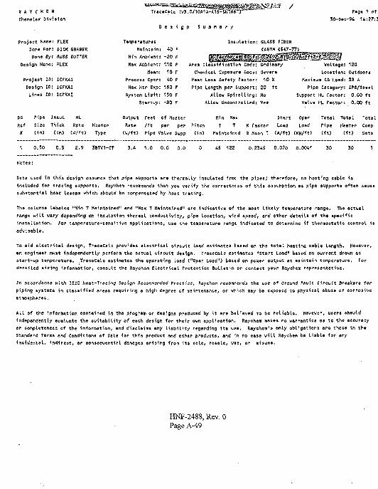
H V C I E Hrhemelex Dwi*
Project Nsne: FLEX
Dene For: DICK SRABER
Cone By: R'JSS CUTTER
Design Name; FLEX
Pi»ejeet ID: ICFKAI
Design ID: ICFKAI
Lines 10: ICFKAI
^ - /
Maintain: 40 F
Min Ambi«ntt -20 F
Max Ambient: 110 f
Mean: 10 r
Process Open 40 P
Max Htr Exp: 150 F
System Limit: 150 F
Startup; -20 F
S u m m a r y
Insulation: GLASS FIBER
(ASTH I
Area classification code: Ordinary
CSemicel exposure Code: Severe
Host Loss Safety Factor: 10 X
Pipe Length per s-upport: 20 ft
Allow Spiralling: No
Allou Uncontrolled: Yes
P*g« 1 of
30-t>ec-9£ 14:27:3
Voltage: 120
Location: Outdoors
Kaximum CB Load: 32 A
Pipe Category: IPS/Steel
Support HI. rector: 0.00 ft
Valve HL Factori O.OO ft
Pipe
Size
(in)
Output r«ftt of Heater rUn Start cper Total Total TotalThick
(in)
Rate
<W/ft)
Hcoter
Type
Rate
(U/ft>
/ft per per Pitch
Pipe Vaivt Supp <in>
TMainto
TIntd
K
afactor
Mean T
Load
<A/ft>
Load
<KU/ft>
Pipe
(ft)
Heater
(ft)
Comp
Sets
0.50 0.S 2.9 3BTV1-CT 3.i 1.0 0.0 0.0 0.2345 O.O?O 0.0041
Data used in this dciign assume* that pipe supports are thermally insulated fron the pipes; therefore, no hooting cable is
included for tracing supports, Ptaychem recommends that ycu verify the correctness of tM» «»9umpt1#n. ai pip« support* often cauat
substantial heat losses which should be compensated by heat tracing.
The columns labeled "Hin T Maintained" and "Hax T Maintained" are indicative of the moit likely temperature range. Th« actual
range will vary depending oti Insulation thermal conductivity, pips location, vird speed, and ether detail* oi the apeeific
installation. For temperature-sensitive eppLi cat ions, use the temperature rangt indicated to determine if thcrnrtotatic control ift
advisable.
In accordance with IEEE Hcot-Tr»ci«g Dea-lgn Recommended Pracflce, Roychem reconnends the use of Ground Fault Circuit Breakers for
piping systems in classified areas requiring a high degree of maintenance, or which may be exposed to physical abuse or corrosive
atmd*ph*r**.
All of the information contained in the prosram or designs produced by it are beLieved to be reliable. However, ucera should
independently evaluate the suitability of coch design for their own application. Rayeftem makes, no warranties as- to the ateuraey
or completeness of the information, and disclaim* any liability regarding it» usa. Raychem'a only obligations are tho&« "in th»
Standard Terms and Conditions of sale for this product and other products, and in no case will Rftychem be Liable for any
incidental. Indirect, or consequential damages arising from its sale, re6aLer u*e, or misuse,
HNF-2488, Rev. 0Page A-49
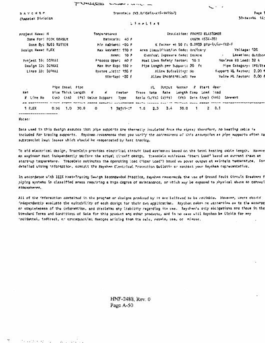
PivisionU tV3.0/10*U-A1S-SN166?)
I f l l l l l l
Fage 1
>roject Namtj: N
Done For: DICK GRMStK
Done By: RUSS SUITER
Design Name: FLEX
Project ID: ICFKAI
Design ID: 1CFKU
Lines JD: 1CFKA1
Tenpecfiturcs
Maintain
Nfn Anbient
Kax Ambisnx
Mean
Proeejs oper
Hax Htr Exp
System limit
-SO
11010
£0
150
150
F
F
FF
F
FStarrup;
I n f l a t i o n ; FOAHEO EUStOHER(ASTH C534-7O)
K Factor i t 50 r: 0.2933 BTU-ir./hr-ft2-FArea tlas»1f1 call in Code: Ordinary
Chemical Exposure Cade: Severe
Heat Loss Safety Factor: 10 X
Pipe Length per Support: £0 ft
Allow Spiralling: No
Allow vneontrelled; rts
VelUg*: 120
.i location: Outdoor
Maximum C3 Load: 32 A
Pipa Category: IPS/St»
Support ML Factor: 0,00 i
Valvff HL Ttctor: 0.00 i
H Line No
Pipe Insul Pipe
size Thick Length tf #
(in) (in) (to valve Support Type
KL Output
Trace Rate Rat*
Ratio (W/ft) CU/+t>
Heater # Start Cper
L»ngth Comp LO*H load
Cft) Gets CArcp) <WA)
O.iU 1.0 50.0 1.0 2,3 3.4 50.0 1 0.1
Notes:
Data uc*d in this design assumes that p^pt suppens ere thermally in ulate-d frcm the- pipes; thcr*f©j*e^ no h»»tipj e*bLe is
included for tracing supports, ftsychem recommends that you verify the correctness or this assumption aa pips supports often fi*t
substantial liedt to5£ss which sh#«ld b« cempensdted b/ heat tracing.
To a<d *Lfectrical design, TraceCaU prcviaes electrical, c^rcuii load estimates b«»*d on the total heating cable lenQth. H*u«v«i
an englnssr must indepehdftnTly per-form the actual circuit design. Tracecslc ttuifnate* "start Load11 based on eurr*[\t drtwn *t
start-up tsmpersture. TracecaU estimates th* operating load coper Load") based vn power output «t maintain terf ftritur*. Far
dstailed sizing inforrriation, consult the Raychem CLeuirivdl Frotecticn oulletin or c»nt«ftt your R*yeh»m r^pres^ntAtWe.
In accordance with, IEEE H*at-Tracing Design Rscommended Practice, Raychem recunmendi the use oi Greund Fault Circuit Br»»k»ri ft
piping systsffis in classified areas requiring a high degree of maintenance, or vhich ma/ be exposed t« physical abuse tp corrotii
A U of the information contained in the program or designs produced by it arc tcH«ve4 to be r<U«bU. H*w*v*r, users
independently evaluate the suitability of each design for their own application, ftaychem wakes no warrantiea as to the acsurac)
or completeness of the information, and disclaims any liability regarding its use. ftaychem't only ebtigationa are those in the
Standard Terms and Conditions of Sale for thij product and other products, and in no case will Haychcw be U a b U for any
incidental. Indirect, or consequential damages arising from ita sale, resale, tte«, or tniause.
HNF-2488, Rev. 0Page A-50
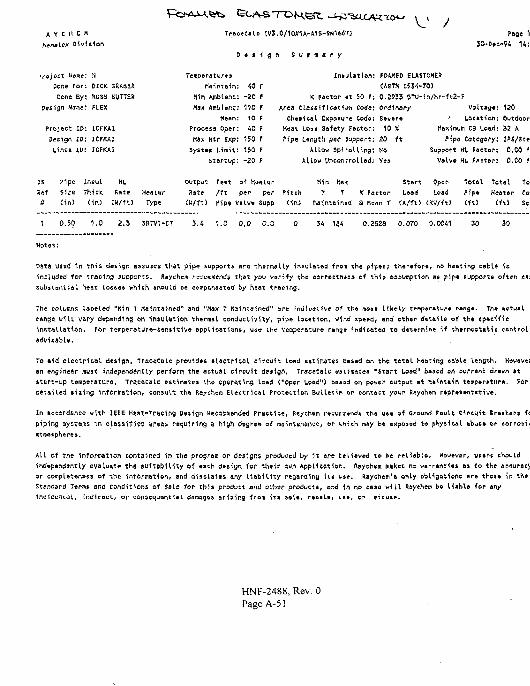
TOjec t Name: H
Done For: GICK SRABER
Done. By: RUS3
Design Name: FLEX
Pro;ect ID : 1CFKAI
Oestgn ID'. ICFKAl
Lines i t): ICFKAl
pipe Xnsul HLThick Rate Hcalar
Type
0.50 1.0 2.3 3 B T V W T
TemperaturesMaintain:
Mn AmbientMax Arabian!
MeanProcess operHaX ritr EXp
System Li mi V
40 T
-20 F
110 F
10 F
W F
150 F
150 F
startup: -20 F
S u m m a r y
K Factor .st 50 F
Ares Clasiii 1cott*fi Cods
Chemical Exposure Code
Hoat Losa Safety Factor
fipa L«nyt(i per Jupport
AUow Spi'ailing
Allow Uncontrolled;
output Feet of KwUr
V.1Page 1
3O-D#e-94 14:
fOiHED EUSTOHE*
0.2M5 5TU-in/hr-ft2-FOrdinarySevere ' I10 X Maximum
20 f t Pipe C0 Support HI
Yes Volve HU
nilien:cs uond:ategocyj
Factor;ffletDf:
Rate
CV/fs)
/ft per per
Cipe Vatve Supp
K factor
a Ccan T
0.00 f
Start Oper Total Total To'
Load Lead P4 p* Heat «r Co'
<A/ftJ (KH/ft) (ftj <fti $ci
3.4 1.0 0.0 0.0 0.2625 0.070 0.0041 30
Notes:
Data used in this design assuiuvs that pipe support6 arc thermaUy 1n*uLat«d freti the pipet) th«r4-fsr», no heating cabl* it
included *er tracing supports. Raythcm rewmweods that you veri-fy the e*rrectn»aj of this fttsumption us pip* tupports often «*i
subatantiaL heat tosses whHch 4h«uU be componaated b/ heat tracing.
The columns lab*led "Kin I KJunT4 4ftKT a^d "Max T Maintained" am IntJIvaUve cf th* m©st likely t*«peratur* ^»^3•. Th» *ctu«l
^&nge wiU vary depending on insulation thermaL conduuvWUy, pip* location, wi-id speed, and othe^ rf«aiU of th» «p«ci/^e
installation, for temperatur*-ssn*1Xive applications, use the Vemperatur* rangs indicated to determine "if thtrmot.ntie ceritrol
adi/i*#bU.
To aid electrical design, TraceCaU provides electrical circuit load estimates cased on the total heating cable length, Hovaver
an engineer must independently perform The actual circuit design. TraceCaU- wUmates "Start u>«d" baaed en current drawn »?
start-up temperature, Tracecalc estimates Uie operating load ("Oper Load") baa»d on power output at ir,*<fttain temp»r«turA. Far
detailed sizing Infortnation, consult the Raychom Electrical Protection Bulletin or contact your fiaychsm r»pr»»entativ6.
In accordance with UEE Htat-Tracing Design Kecommended Practice, Raychom rcwwn-ideiidA the u»? fi Ground Poult ciwuit Br«ik»rs it
piping systejns in classified 9rea5 requiring Q high degree of mBinienance, or vn .th may be exposod to physical abus* or eorrosi*
•tmespheres.
All of the information contained in the program or design? produced by 1t are telieved te be reliable. However, us#r* should
independently evaluate the suitability of each desiyn for their oury appHcatior.. ftaychem makes no wirr*rtt<#i ai "to the accuracy
or complater.eas of the intOrmation, and disclaims any Liability regardinu lls cse. ftaychem'a only obligations ar« thoi* in the
Sxandard Tsrms and conditions of Sale for this product and oilier product*, and in t\e> caao will ftaychem b» L.UbL» for any
incidsnxai., indireut, «r vonsequentiaL ciamagfts arisins from •its sole, resale, t8», or misuse.
HNF-2488, Rev. 0Page A-51
HNF-2488, Rev. 0
W320-31-015
Cable Ampacity, Lighting, ConduitFill, & Voltage Drop
B-i
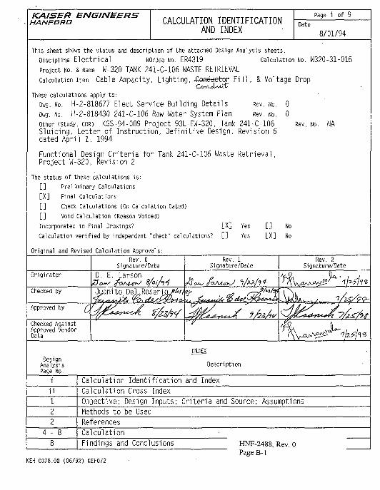
KAISER ENGINEERSHANFORD
CALCULATION IDENTIFICATIONAND INDEX
Page i of 9Date
8/01/94
This sheet shows the status and description of the attached Design Analysis sheets.
Discipline E l e c t r i c a l WO/Job No. ER4319 Calculation No. W320-31-015
Project No. & Name W-320 TANK 241-C-106 WASTE RETRIEVAL
Calculation item Cable Ampacity, L i gh t i ng , -GeftAjetor F i l l , & Voltage DropC l t "
These calculations apply to:Dwg. No. H-2-818677 Elect Service Building Details Rev. No.
Dwg. No. H-2-818430 241-C-106 Raw Water System Plan Rev. No.other (Study. CDR) KGS-94-009 Project 93L-EW-320, Tank 241-C-106Sluicing, Letter of Instruct ion, Def ini t ive Design, Revision 6dated Apri l 1. 1994
Functional Design Cr i ter ia for Tank 241-C-106 Waste Retr ieval,Project W-320, Revision 2
The status of these calculations is:[ ] Preliminary Calculations[X] Final Calculations
[ ] Check Calculations (On Calculation Dated)[ ] Void Calculation (Reason Voided)
Incorporated in Final Drawings? [X]
Calculation verified by independent "check" calculations? [ ]
Original and Revised Calculation Approvals:
Rev. No. NA
Yes
Yes
[][X]
No
No
Rev. 0Signature/Date
Rev. 1Signature/Date
Rev. 2Signature/Date
Originator D. E. Larson
Checked by Jganito
Approved by
Checked AgainstApproved VendorData
INDEXDesign
AnalysisPage No.
Description
1 Calculation Identification and Index
Calculation Cross Index
Objective; Design Inputs; Criteria and Source; Assumptions
Methods to be Used
References
4 - 8 Calculation
Findings and Conclusions
KEH 0378.00 (06/92) KEF072
HNF-2488, Rev. OPageB-1
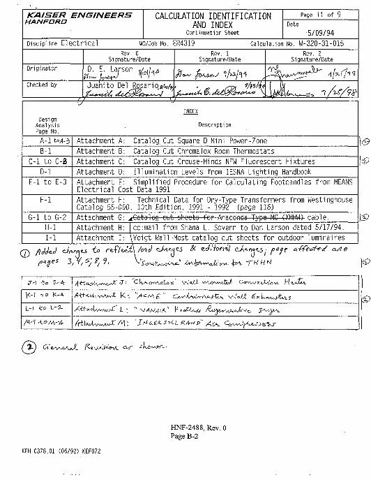
KAISER ENGINEERSHANFORO
CALCULATION IDENTIFICATIONAND INDEX
Continuation Sheet
Page i 1 of 9Date
5/09/94Discipline E lec t r i ca l WO/Job No. ER4319 Calculation No. W-320-31-015
Rev. 0Signature/Date
Rev. 1Signature/Date
Rev. 2Signature/Date
Originator D. E. Larson
Checked by Juanito Del
INDEXDesign
AnalysisPage No.
Description
A-l t*A-5 Attachment A: Catalog. Cut Square D Mini Power-Zone
B-l Attachment B: Catalog Cut Chromalox Room Thermostats
C-l to C-B Attachment C: Catalog Cut Crouse-Hinds NFW Fluorescent Fixtures
D-l Attachment D: Illumination Levels from IESNA Lighting HandbookE-l to E-3 Attachment
ElectricalE: Simplified Procedure for Calculating Footcandles from MEANSCost Data 1991
F-l AttachmentCatalog 55
F: Technical Data for Dry-Type Transformers from Westinghouse000, 10th Edition, 1991 - 1992 (page 116)
G-l to G-2 Attachment G: ^c€ata4eg cut sheets for Anaconda Typo MC 4XHHW- cable. \S>H-l Attachment H: cc:mail from Shana L. Sovern to Dan Larson dated 5/17/94.
1-1 Attachment I: \Voigt Wall-Most catalog cut sheets for outdoor luminaires
to
V-\ -to 3-4-
)<-| t o |<-A-
y.\ t o L-2-
A««cU^X3-- civ.
HNF-2488, Rev. 0Page B-2
KEH 0378.01 (06/92) KEF072
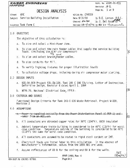
KAISER ENGINEERS . Calc. No. W320-31-015HANPtma Rev i s i on > z
DESIGN ANALYSIS Pa9e No- 1 of 9
Client WHC . WO/Job No. ER4319Subject Service Bu i ld ing I n s t a l l a t i o n Date 8/01/94 By O.E. Larson D-S.L.
Checked gfah* By J . Del T ^Location Tank Farm C Revi sed -NA- - i / 2 - * / ' 8 By-WA k
1.0 OBJECTIVE
The objective of this calculation is:
a. To size and select a Mini-Power Zone.
b. To size and" select the main feeder cables that supply the service buildingloads, (including the/BJHP air compressor)
c. To size and select branch/feeder cables.
d. To size conduits for fill.
e. To verify lighting fixtures for proper illumination levels
f. To calculate voltage drops, including during air compressor motor starting.
2.0 DESIGN INPUTS
a. KGS-94-009 Project 93L-EW-320. Tank 241-C-106 Sluicing, Letter of Instruction,Definitive Design, Revision 6 dated April 1, 1994
b. NFPA-70, National Electrical Code, IT? 3.
3.0 CRITERIA AND SOURCE
Functional Design Criteria for Tank 241-C-106 Waste Retrieval, Project W-320,Revision 2
4.0 ASSUMPTIONS
-eh—Power is supplied initially from the Power Distribution Panel (C-PDP-1) andlater from an M C C N ) .
b. All conductors are stranded copper rated for 90°C (194°F), 600V insulated
c. Ambient temperature inside building is considered to be 46°C (115°F) for worstcase condition. Temperature outside of the building is considered to be 46°C(115°F) the same for worst case condition.
d. All conductors are assumed to be routed in rigid steel conduit or EMT.
e. Electrical loads are listed later in this calculation. In the absence ofmanufacturer's information, values from the 1993 NEC are used.
f. Assume reflectances of 80 % for the ceiling and 50 % for the walls.
HNF-2488, Rev. OKEH 0037.00 (06/92) KEF055 Page B-3
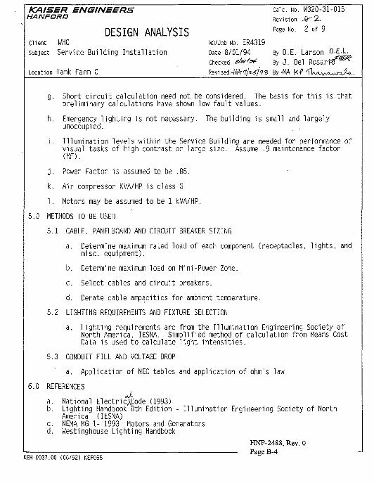
KAISER ENGINEERS Calc. No. W320-31-015HANPORO R e v i s i o n jy 2.
DESIGN ANALYSIS Page No 2 of 9
Client WHC WO/Job No. ER4319Subject Service Bui ld ing I n s t a l l a t i o n Date 8/01/94 By O.E. Larson
Checked d«'# ByJ . Del
Location Tank Farm C Revised-NA-'f/fe-^s By-NA k f
g. Short circuit calculation need not be considered. The basis for this is thatpreliminary calculations have shown low fault values.
h. Emergency lighting is not necessary. The building is small and largelyunoccupied.
i. Illumination levels within the Service Building are needed for performance ofvisual tasks of high contrast or large size. Assume .9 maintenance factor(MF).
j. Power Factor is assumed to be .85.
k. Air compressor KVA/HP is class G
1. Motors may be assumed to be 1 kVA/HP.
5.0 METHODS TO BE USED
5.1 CABLE, PANELBOARD AND CIRCUIT BREAKER SIZING
a. Determine maximum rated load of each component (receptacles, lights, andmisc. equipment).
b. Determine maximum load on Mini-Power Zone.
c. Select cables and circuit breakers.
d. Derate cable ampacities for ambient temperature.
5.2 LIGHTING REQUIREMENTS AND FIXTURE SELECTION
a. Lighting requirements are from the Illumination Engineering Society ofNorth America, IESNA. Simplified method of calculation from Means CostData is used to calculate light intensities.
5.3 CONDUIT FILL AND VOLTAGE DROP
a. Application of NEC tables and application of ohm's law
6.0 REFERENCESJ.
a. National Electriencode (1993)b. Lighting Handbook 8th Edition - Illumination Engineering Society of North
America (IESNA)c. NEMA MG 1- 1993 Motors and Generatorsd. Westinghouse Lighting Handbook
HNF-2488, Rev. 0Page B-4
KEH 0037.00 (06/92) KEF055
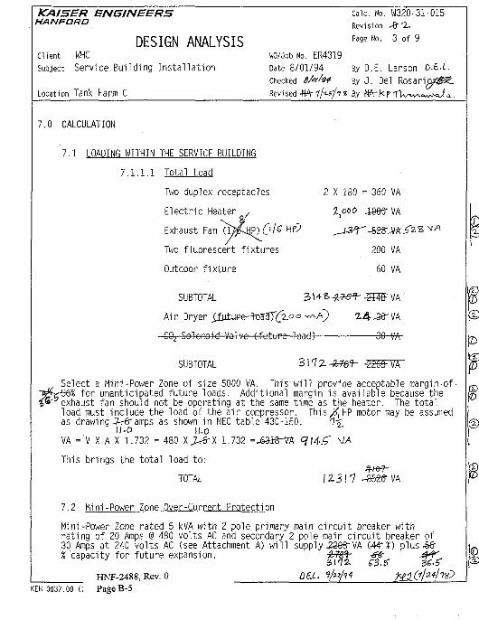
KAISER ENGINEERSHAN FORD
DESIGN ANALYSISClient WHCSubject Service Building Instal lat ion
Location Tank Farm C
Calc. No. W320-31-015Revision •#'2-
Page No. 3 of 9
WO/Job No. ER4319
Date 8/01/94
Checked S/e'fe*
Revised -MA- ? / « / / n By
By O.E. Larson D.E-L.By J . Del Rosar i (p/^ .
7.0 CALCULATION
7.1 LOADING WITHIN
7.1.1.1
THE SERVICE BUILDING
Total Load
Two duplex receptacles
Electric Heater ,
Exhaust Fan "(MjJP) Ol£ HF?
Two fluorescent fixtures
Outdoor fixture
2 X
,-—
180 = 360
-"-628-
200
60
VA
VA
VA
VA
SUBTOTAL
Ai r Dryer Xfutupe-h3a^T(^zo° w Q 2.4 -36" VA
• CO} Solenoid Valve (future load) 30 VA-
SUBTOTAL
Select a Mini-Power Zone of size 5000 VA. This w i l l provide acceptable margin ofr-56£ for unanticipated future loads. Additional margin is available because theexhaust fan should not be operating at the same time as the heater. The to ta lload must include the load of the a i r compressor. Th is^HP motor may be assumedas drawing -Wramps as shown in NEC table 430-150. 1-£
I/.D |/.oVA = V X A X 1.732 = 480 X ^ X 1.732 =_63i8-VA' 9 145" VA
This brings the total load to:
TOTAL
7.2 Mini-Power Zone Over-Current Protection
Mini-Power Zone rated 5 kVA with 2 pole primary main c i r cu i t breaker withrat ing of 20 Amps @ 480 volts AC and secondary 2 pole main c i r cu i t breaker of30 Amps at 240 volts AC (see Attachment A) w i l l supply ^68-VA W?%) plus-S€rX capacity for future expansion.
?»P
HNF-2488, Rev. 0KEH 0037.00 (( PageB-5
Dai..
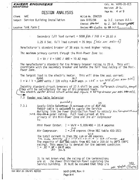
KAISER ENGINEERS Calc. No. W320-31-015HANFORO R e v i s i o n ^ . ^
DESIGN ANALYSIS Page No- 4 of 9
Client WHC WO/Job No. ER4319Subject Service Building Instal lat ion Date 8/01/94 By D.E. Larson D.l-L
Checked sU/to* By J . Del R o s a r i o / ^Location Tank Farm C Revised -MA f / z^ fs By -Nfr | i
Secondary full load current = 5000/VA / 240 V = 20.83 A
1.25 X Sec. full load current = 26 Amps £"£= --" ^ ^ = ' £ /
Manufacturer's standard breaker of 30 amps is next higher rating.
The maximum primary current through the Mini-Power Zone is:
I = VA / V = 5000 / 480 = 10.42 amps
The manufacturer's standard for the Primary breaker rating is 20 A. This willcoordinate with the secondary breaker and handle the full load rating of the Mini -Power Zone.
The largest load is the electric heater. This will draw the most current:
I = W / V =Smrwatts / 120 volts =^3-amps. s I-2S" = t o - i t ^ A ^ ^ ^ f - s G O Jqll
Industry standard.circuit breakers of 20 A shall be used forAbranch c i r cu i t s , <J*ty>i-{They w i l l be satisfactory for any of the proposed loads.
th<!. e/ec£/v'c Elites AriniJ, ojhaw'i u/AizJ, sfc// svyuirs 9 ZS'!'*/) 4/*ttAzr pv A/£C 38f-/i(<.).
7.3 Feeder and Cable Selection
7.3.1 Supply Cable Se;Veet+efl: A fiwwnuffl- size of ifeeder cable is -sel^etea-to supply the ServiceBuilding from the Power Distribution Panel to sat isfy'the 20 A- panel rat ing. Full load current at theprimary of the Mini-Power Zone and the a i r compressori s :
Mini Power Center: I = VA/V = 5,000/480 = 10.4' amperes
Air Compressor: I =,7-r€ amperes (from NEC table 430-150)•2.1-4-
The total current is then the sum or AA amperes.
The ampacity of H T AWG cable from NEC table 310-16 is-3TA (90°Crating). This ampacity is derated for the ambient conditionI = .82 * M = 2A^ amps
A-o 32..S
It is not known what the rating of the terminationsare at the Power Distribution Panel supplying theService building. It must be assumed that they are
KEH 0037.00 (06/92) KEF055 HNF-2488, Rev. 0Page B-6
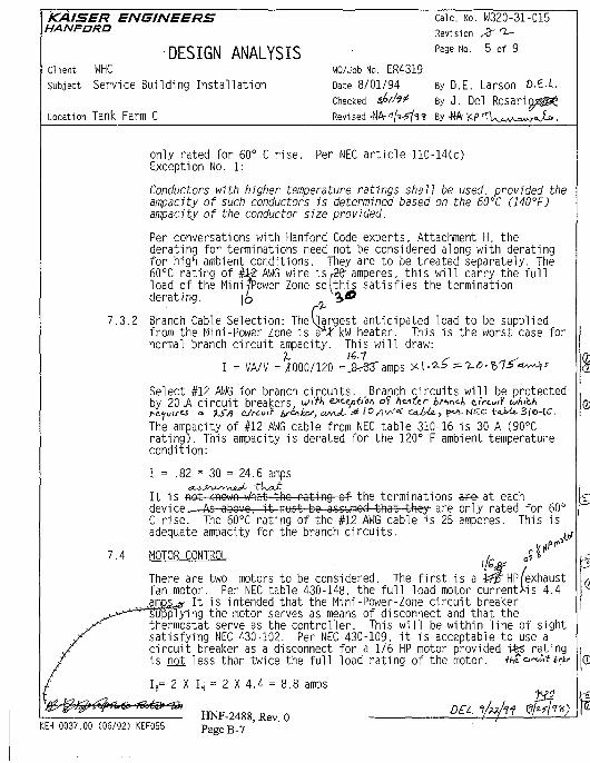
KAISER ENGINEERSHAN FORD
DESIGN ANALYSISClient WHCSubject Service Building Installation
Location Tank Farm C
wo/Job No. ER4319Date 8/01/94Checked
Revi sed -NA-
Calc. No. W320-31-015
Revision ^T r^—
Page No. 5 of 9
By D.E. Larson D.E.l
By J . Del
By-NA
7.3.2
only rated for 60° C rise. Per NEC article 110-14(c)Exception No. 1:
Conductors with higher temperature ratings shall be used, provided theampacity of such conductors is determined based on the 60°C (140°F)ampacity of the conductor size provided.
Per conversations with Hanford Code experts. Attachment H, thederating for terminations need not be considered along with deratingfor high ambient conditions. They are to be treated separately. The60°C rating of #1? AWG wire is (28 amperes, this will carry the fullload of the Minitower Zone so I this satisfies the terminationderating. \t> „ 3»*
Branch Cable Selection: The I]argest anticipated load to be suppliedfrom the Mini-Power Zone is a JT kW heater. This is the worst case fornormal branch circuit ampacity. This will draw:
7- 16.7I = VA/V =1000/120
7.4
Select #12 AWG for branch circuits. Branch circuits will be protectedby 20 A circuit breakers. <^>W '&<•«•?•&'<>'> °*< h^ttr trinej, circuiY Ai'cA
The ampacity of #12 AWG cable from NEC table 310-16 is 30 A (90°Crating). This ampacity is derated for the 120° F ambient temperaturecondition:
I = .82 * 30 = 24.6 amps
(D
It is not known what tho- rating of- the terminations ape- at eachdevice As-above, it must be assumed-that'they- are only rated for 60°C rise. The 60°C rating of the #12 AWG cable is 25 amperes. This isadequate ampacity for the branch circuits. .j
HOTOR CONTROL , o ? *p
There are two motors to be considered. The first is a ifp HP/exhaustfan motor. Per NEC table 430-148, the full load motor currentss 4.4
It is intended that the Mini-Power-Zone circuit breakerying the motor serves as means of disconnect and that the
thermostat serve as the controller. This will be within line of sightsatisfying NEC 430-102. Per NEC 430-109, it is acceptable to use acircuit breaker as a disconnect for a 1/6 HP motor provided i£5 ratingis not less than twice the full load rating of the motor. fl»o«;n*
IB= 2 X IH = 2 X 4.4 = 8.8 amps
KEH 0037.00 (06/92) KEF055HNF-2488, Rev. 0Page B-7
DEL
b
*z.
©
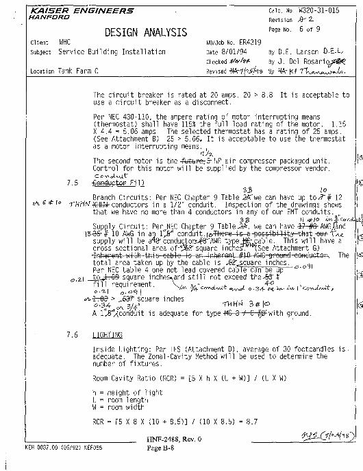
KAISER ENGINEERS Calc. No. W320-31-015HANFORD R e v i s i o n ^ z
DESIGN ANALYSIS Pa9eNo- 6 of 9
Client WHC WO/Job No. ER4319Subject Service Building Installation Date 8/01/94 By D.E. Larson 0-E-L,
Checked ifvht- ByJ. Del Rosaricyz^Location Tank Farm C . Revised Mki(%$f-vi, B y N A - K f ' ^
The circuit breaker is rated at 20 amps. 20 > 8.8 It is acceptable touse a circuit breaker as a disconnect.
Per NEC 430-110, the ampere rating of motor interrupting means(thermostat) shall have 115% the full load rating of the motor. 1.15X 4.4 = 5.06 amps The selected thermostat has a rating of 25 amps.(See Attachment B) 25 > 5.06. It is acceptable to use the thermostatas a motor interrupting means. ,
The second motor is the -fofettpe-5- HP air compressor packaged unit.Control for this motor will be supplied by the compressor vendor.
7.5 -GeftdtictoP Fill33 \o
Branch Circuits: Per NEC Chapter 9 Table SA'we can have up to^7"# 12'^HHW-conductors in a 1/2" conduit. Inspection of the drawings showsthat we have no more than 4 conductors in any of our EMT conduits.
Supply Circui t : Per NEC Chapter 9 Table-3A, we can have -i7-#6-AWGjandlS-36-# 10 AWG in an l"jf conduit.i^rFhero is a possib i l i ty- that ow- T W
supply w i l l be a43-conductors.^"AWG typeite-cable. This w i l l have across-sectional area o f - ! ^ square inches. tSee Attachment G)-frihorent with this cable 'is an inhereaM^lO-AWG ground conductor.. Thetota l area taken up by the cable is -fe^square inches. „ ,Per NEC table 4 one not lead covered cable can be up a'°
5 2.1 __tojrr0& square inches, and s t i l l not exceed the-ft? %f i l l requirement. \c*v. y ' ^ t ^ ^ u . " °
<A-irrQ& > JaS? square inches
A l '^ f /conduit is adequate for type -MC 3 / C Iff1 with ground.
Inside Lighting: Per IES (Attachment D), average of 30 footcandles is.adequate. The Zonal-Cavity Method will be used to determine thenumber of fixtures.
Room Cavity Ratio (RCR) = [5 X h X (L + W)] / (L X W)
h = height of lightL = room lengthW = room width
RCR = [5 X 8 X (10 + 8.5)] / (10 X 8.5) = 8.7
HNF-2488,Rev.OKEH 0037.00 (06/92) XEF055 Page B-8
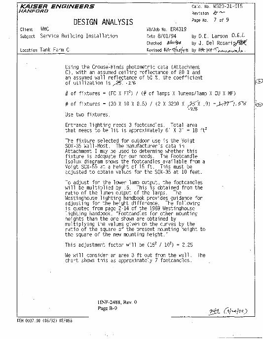
KAISER ENGINEERS Calc. No. W320-31-015HANFORO R e v i s i o n ^ ^
DESIGN ANALYSIS Page No 7 of 9
Client WHC WO/Job No. ER4319Subject Service Building Ins ta l l a t i on Date 8/01/94 By O.E. Larson O.E.L
Checked 8U/'$<t By J . Del R o s a r i p / ^ fLocation Tank Farm C Revised Wr'ifiSJ'jS By •N J
Using the Crouse-Hinds photometric data (AttachmentC). with an assumed ceiling reflectance of 80 % andan assumed wall reflectance of 50 %, the coefficientof utilization is ,35. -rs
# of fixtures = (FC X FT2) / (# of lamps X lumens/lamp X CU X MF)
# of fixtures = (30 X 10 X 8.5) / (2 X 3200 X .7^1 .9) =
Use two fixtures.
Entrance lighting needs 3 footcandles. Total areathat needs to be lit is approximately 6' X 3' = 18 ft2
The fixture selected for outdoor use is the VoigtSOX-35 Wall-Most. The manufacturer's data inAttachment I may be used to determine whether thisfixture is adequate for our needs. The FootcandleIsolux diagram shows the footcandles available from aVoigt SOX-55 at a height of 15 ft. This must beadjusted to obtain values for the SOX-35 at 10 feet.
To adjust for the lower lamp output, the footcandleswill be multiplied by .6. This is obtained from theratio of the lumen output of the lamps. TheWestinghouse lighting handbook provides guidance foradjusting for the height difference. The followingis quoted from page 2-14 of the 1969 Westinghouselighting handbook, "Footcandles for other mountingheights than the one shown are obtained bymultiplying the values given on the curves by theratio of the square of the present mounting height tothe square of the new mounting height."
This adjustment factor will be (152 / 102) = 2.25
We will consider an area 3 ft out from the wall. Thechart shows this as approximately 7 footcandles.
HNF-2488, Rev. O
KEH 0037.00 (06/92) KEF055
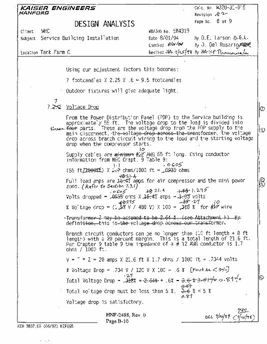
KAISER ENGINEERS Calc. No. W320-31-015HANFORD Revision £ ^
DESIGN ANALYSIS Pa9eNo- 8 of 9
Client WHC WO/Job No. ER4319
Subject S e r v i c e B u i l d i n g I n s t a l l a t i o n Date 8 / 0 1 / 9 4 By D.E. La rson O-E-L-
checked tf^"^ By J . Del R o s a r i p / ^
Location Tank Farm C R e v i s e d -NA- ijiSJtS By • N W /
Using our adjustment factors th is becomes:
7 footcandles X 2.25 X .6 = 9.5 footcandles
Outdoor f ixtures w i l l give adequate l igh t .
77.2^2 Voltage Drop
From the Power Distribution Panel (PDP) to the Service building isapproximately 55 ft. The voltage drop to the load is divided into£ e w parts. These are the voltage drop from the PDP supply to themain disconnect,-the voltage drop across the transformer, the voltagedrop across branch circuit wiring to the load and the starting voltagedrop when the compressor starts.
\oSupply cables are .mwtfflttffl-#>T AWG 55 f t long. Using conductorinformation from NEC Chapt. 9 Table 9:
|
(55 ft£t&e§?£) X ir? ohms/1000 ft = J393& ohms/ 8 4
Full load amps are A&rzFT amps for a i r compressor and the mini powerZone. (A«fe<- to S^eiibn 7.3./)
Volts dropped = ,0935- ohms X.16r4T amps =_tr5Sr volts
% Voltage drop = U.J3 V / 480 V) X 100 = & & % for #lfwire
•Transformer Z may bo assumed to be 2.64 %. (see Attachment F)—By-definition, this is the voltago drop across our transformer.
Branch circuit conductors can be no longer than (10 ft length + 8 ftlength) with a 20 percent margin. This is a total length of 21.6 ft.Per Chapter 9 table 9 the impedance of a # 12 AWG conductor is 1.7ohms / 1000 ft.
V = I * Z = 20 amps X 21.6 ft X 1.7 ohms / 1000 ft = .7344 volts
% V o l t a g e Drop = .734 V / 120 V X 100 = . 6.2/7 I H I
Total Voltage Drop = Jim, -t-2^64«-+ .6% = -3r6-%-3^rrr o ."8" 1"(<=•
KEH 0037.00 (06/92) KEF055
Total voltage drop must be less than 5 %. 3-6 % < 5 %
Voltage drop is satisfactory.
HNF-2488, Rev. 0 biLPageB-10
KAISER ENGINEERS Calc. No. W320-31-015HANFORO R e v i s i o n ^ a .
DESIGN ANALYSIS Page Uo- 9 of 9
Client WHC WO/Job No. ER4319Subject Service Bui ld ing I n s t a l l a t i o n Date 8/01/94 By D.E. Larson D-S.L-
Checked ?/*//& By J . Del
Location Tank Farm C R e v i s e d ^k^S^z By -N
Upon starting our compressor will draw about 45-rfr LRA amps per NEC pTable 430-151. In order to start our compressor motor our supplyvoltage should not dip below 80 % of the motor's voltage rating. Thiscurrent is in conjunction with the current to our mini-power zone.The total worst case current will then be:C«*/--k<- 7-3-O
$' 110.4 p
loVoltage drop to compressor is the drop across our 55 foot # "supplyand an additional 20 ft.to the compressor motor.,B935 X && =-6^336-volts to the disconnect.
45r6-amps X 20 ft/H»e-=R X 1.7 ohms/1000 f t =4r55-volts
% drop is (-Sr236- + 4-r55-)V / 480 V * 100 = ir4 % voltage drop\-3S
The total £T4" % voltage drop is within the allowable limits given forNEMA motors. (NEMA MG-1 12.44.2)
8.0 FINDINGS AND CONCLUSIONS
8.1 Supply cable to the Service Building is adequately sized.
8.2 Branch circuit conductors are adequately sized.
8.3 Conductep fill is satisfactory.8.4 Lighting system designed meets or exceeds the minimum required illumination
for the W-320 Service Building.
8.5 Total voltage drop on air compressor feeder and branch circuit is withintolerance for NEMA motors.
HNF-2488, Rev. 0PageB-l 1
KEH 0037.00 (06/92) KEF055
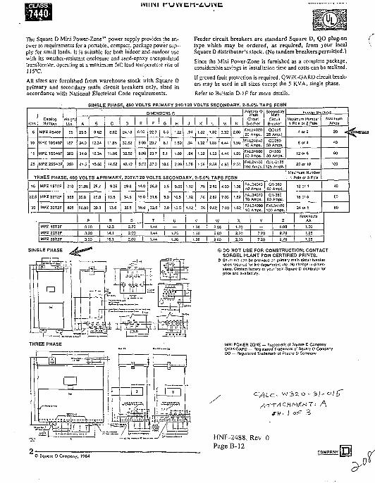
The Square D Mini Power-Zone"1 power supply provides the an-swer lo requiremems for a portable, compact, package power sup-ply for small loads. It is suitable for both indoor and outdoor usewith its weather-resistant enclosure and sand-epoxy encapsulatedtransformer, operating at a maximum full load temperature rise ofJI5°C.
All sizes are furnished from warehouse stock with Square Dprimary and secondary main circuit breakers only, sized inaccordance with National Electrical Code requirements.
Feeder circuit breakers are standard Square D, QO plug-ontype which may be ordered, as required, from your localSquare D distributor's stock. (No tandem breakers permitted.)
Since the Mini Power-Zone is furnished as a complete package,considerable savines in installation time and costs can be realized.
If ground fault protection is required, QWIK-GARD circuit break-ers may be used in all sizes except the 5 KVA, single phase.
Refer to Bulletin D-1F for more details.
KVA
5
10
15
25
CatalogNumber
MPZ 5S40F
MPZ 10S40F
MPZ 15S40F
MPZ 25S4DF
WeightLbs.
95
167
202
358
SINGLE PHASE, 480 VOLTS PRIMARY 240/120 VOLTS SECONDARY,
DIMENSIONS ffi
A
25.5
34.0
34.0
41.5
B
9-62
12.34
12.34
15.60
C
8.82
11.85
11.86
14.62
D
24.18
32.62
32.52
40.12
E
6.00
8.00
8.00
9.00
F
22.3
29.7
29.7
37.3
G
5.6
8.1
8.1
10.6
K
1.22
1.50
• 1.50
2.33
J
.94
.94
M
J.?6
K
1.32
1.32
1.32
1.56
L
1.82
1.6S
1.88
2.38
M
3.32
4.44
4.44
4.62
N
2.00
1.50
1.50
J-5.0% TAPS FCBN
CircuitBreaker
FAL2402020 Amps.
FAL2£M040 Amps.
FAL2406060 Amps.
, M JFAU241002 0 0 flOO Amps.
SecondaryWain
CircuitBreaker
OO22525 Amps.
QO25050 Amps-
Q128060 Amps-
Q2L-2125125 Amps.
THREE PHASE, 480 VOLTS APRIMARY, 20SY/120 VOLTS SECONDARY, 2-5.0% TAPS FCBN
15
22.5
30
MPZ1ST2F 310
MPZ 22T2F
MPZ 30T2F
555
625
MPZ 22T2F
MPZ 30T2F
31.08
35.8
36.80
25.7
29.8
29.8
P
3.00
3.00
9.38
13.6
13.6
R
14.1
16.1
29.8
34.5
35.5
14.0
16.0
16.0
s
26.8
31.6
32.6
2.5
3.0
3.0
T
2.00 | 1.44
2.00 1.44
9.00
10.5
10.5
U
1.26
1.26
v i a
i .u
1.18
.76
.76
.76
v
| 1.38
1.38
2.62
2.62
2.62
4.00
7.00
7.00
W
2.38
2.602.60
1.39
1.62
1.62
FAL34040£Q Amps.
FAL3407070 Amps.
FAL3409090 Amps.
X
2.20
2.20
Q1-36060 AmpS.
Q1-38080 Amps.
FAL34100100 Amps.
FppriPt Rfpavers
Maximum Number1 Pole or 2 Pole-
4 or 2
8 Of 4
12 or 6
20 Of 10
Maximum Number1 Pole or 3 Pole
12 or 4
18 or 6
24 or 8
v 1 z7.20 9.70
7.20 | 9-70
KnockoutsAA
1.25
1.25
MaximumAmps
20 <
40
60
100
40
60
80
SINGLE PHASE <D DO NOT USE FOR CONSTRUCTION; CONTACTSORGEL PLANT FOR CERTIFIED PRINTS.
® Shunt trip can be provided on primary main circuit breakerwhen required (or lire department use. No change in dimen-sions. Contact factory or your local Square D distributor (orprice and avail anility.
MINI POWER-ZONE — Trademark ol Square D CompanyOWIK-GARD — Registered Trademark of Square D CompanyQO — Regisle.'ed Trademark t>f Square D Company
: /\- I
HNF-2488, Rev. 0Page B-12
© Squore D Company, 1984
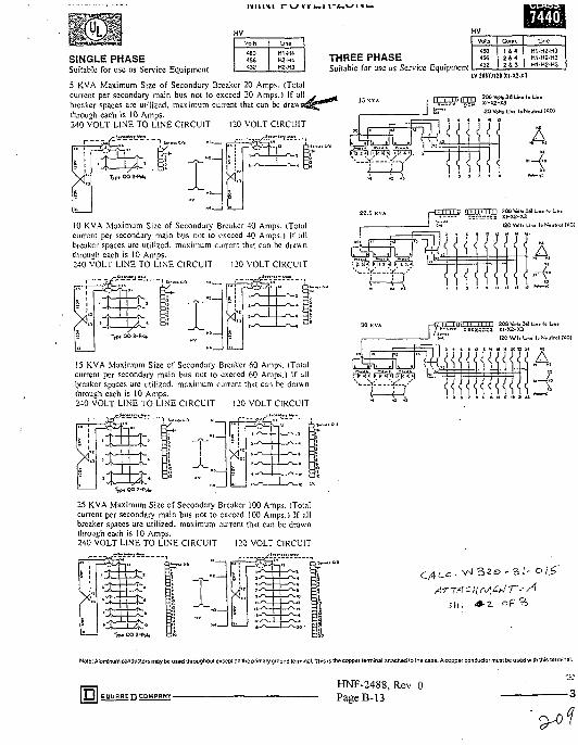
HV
Vote
4804 56432
Line
H1-H4H2-HAH2-H3
SINGLE PHASESuitable for use as Service Equipment
5 KVA Maximum Size of Secondary Breaker 20 Amps. (Totalcurrent per secondary main bus not to exceed 20 Amps.) If ai!breaker spaces are utilized, maximum current that can be drawjthrough each is 10 Amps.240 VOLT LINE TO LINE CIRCUIT 120 VOLT CIRCUIT
10 KVA Maximum Size of Secondary Breaker 40 Amps. (Totalcurrent per secondary main bus not to exceed 40 Amps.) If allbreaker spaces arc utilized, maximum current that can be drawnthrough each is 10 Amps.240 VOLT LINE TO LINE CIRCUIT 120 VOLT CIRCUIT
15 KVA Maximum Size of Secondary Breaker 60 Amps. (Totalcurrent per secondary main bus not to exceed 60 Amps.) If altbreaker spaces arc utilized, maximum current that can be drawnthrough each is 10 Amps.240 VOLT LINE TO LINE CIRCUIT !20 VOLT CIRCUIT
THREE PHASESuitable for use as Service Equipment
Votts | Conn.
4 SO456432
1 &4
2 4 3
Line
H1-H2-H3H1-H2-H3H1-H2-H3
IV 20BY/120 XI-X2-X3
25 KVA Maximum Size of Secondary Breaker 100 Amps. (Totalcurrent per secondary main bus not to exceed I00 Amps.) If allbreaker spaces arc utilized, maximum current that can be drawnthrough each is I0 Amps.240 VOLT LINE TO LINE CIRCUIT I20 VOLT CIRCUIT
A
120 Volt. Unt to Nmiral (XO)
i 1Nole: Aluminum conductors may be used throughout except on the primary ground terminal. This is the copper lerminal attached to the case. Acoppef conductor must be used with this terminal.
HNF-2488, Rev. 0PageB-13
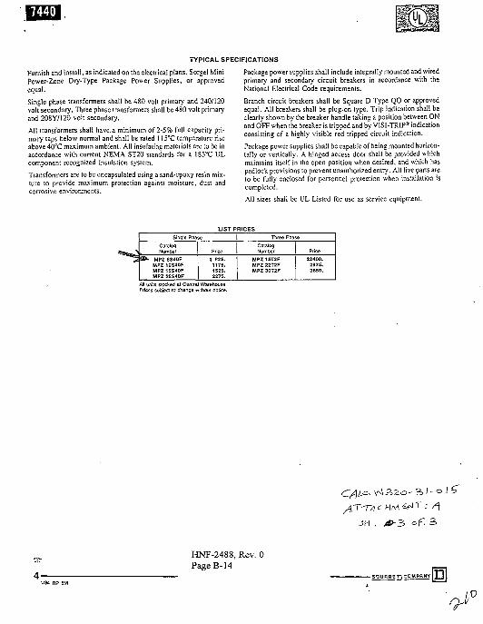
TYPICAL SPECIFICATIONS
Furnish and install, as indicated on the electrical plans, Sorgel MiniPower-Zone Dry-Type Package Power Supplies, or approvedequal.
Single phase transformers shall be 480 volt primary and 240/120volt secondary. Three phase transformers shall be 480 volt primaryand 208Y/120 volt secondary.
AM transformers shall have.a minimum of 2-5% full capacity pri-mary taps below normal and shall be rated 115CC temperature riseabove 40°C maximum ambient. All insulating materials are to be inaccordance with current NEMA ST20 standards for a 185°C ULcomponent recognized insulation system.
Transformers are to be encapsulated using a sand-epoxy resin mix-ture to provide maximum protection against moisture, dust andcorrosive environments.
Package power supplies shall include integrally mounted and wiredprimary and secondary circuit breakers in accordance with theNational Electrical Code requirements.
Branch circuit breakers shall be Square D Type QO or approvedequal. All breakers shall be plug-on type. Trip indication shall beclearly shown by the breaker handle taking a position between ONand OFF when the breaker is tripped and by VISI-TRIP* indicationconsisting of a highly visible red tripped circuit indication.Package power supplies shall be capable of being mounted horizon-tally or vertically. A hinged access door shall be provided whichmaintains itself in the open position when desired, and which haspadlock provisions to prevent unauthorized entry. All live parts areto be fully enclosed for personnel protection when installation iscompleted.
All sizes shall be UL Listed for use as service equipment.
LIST PRICESSingle Phase
CatalogNumber
MPZ 10S40FMPZ1SS40FMPZ 25S40F
Price
1175.1525.2275.
Three Phase
CatalogNumber
MPZ 22T2FMPZ 30T2F
Price
2975.3650.
AH units stocked at Central WarehousePrices subject to change without nadce.
• A
JH
HNF-2488, Rev. 0PageB-14
SqURHETl CDMPBNYl
I.O
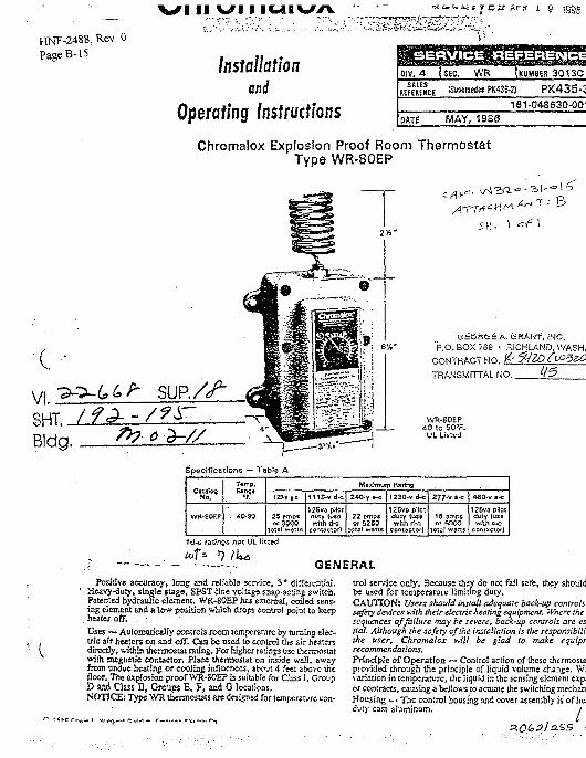
HNF-2488, Rev. 0PageB-15
vsi ii yi IIUIVA
Installationand
Operating Instructions
i 5
OIV. 4 {SEG. W R JKUMBER 3 0 1 3 C
REFEMKE [Supersede* PK4S6-2) PK435-C161-04S630-001
DATE MAY, 1986
Chromalox Explosion Proof Room ThermostatType WR-80EP
VI.SHT.Bldg
t f i A. (SRAN'f, INS.'P.O. EOX 789 • RICHLAND. WASH.
CONTRACT NO. H-9 ^TRA.MSMITTAL NO.
WR-SOEP40 to 90»F.UL Listed
Specitications — Table A
C»1flfosNo.
WK-80EP
Rang«1Z0-T M
25 emps
lots) ws:is
l11E-vd-c
12Sva pilotduty (u*cwith d-c
CoritocTOrJ
24O.y »-c
22 empsOr 52SO
toifil wans
125vo pilotduty fu$«wfih ri-c
contactor]
2 7 7 ^ t-c
18 emps*>r VKX>
to:al wans
480-v s-c
125va pilotduty {use
COfUSClOf)
td-c ratings not UL lisied
GENERALPositive accuracy, long and reliable service, 3 * differential.
Heavy-duty, single stage, SPST line voltage snap-acting switch.Patented hydraulic element. WR-80EP has enernal, coiled sens-ing element and a low position which drops control point to keepheater off. . •Uses — Automatically controls room temperature by turning elec-tric air healers on and off. Can be used to control the air healersdirectly, within thermostat rating. For higher ratings use thermostatwith magnetic contactor. Place thermostat on inside wall, awayfrom undue heating or cooling influences, about 4 feel above thefloor. The explosion proof WR-50EP is suitable for Class I, GroupD and Class D, Groups E, F, and G locations.NOTICE; Type WR thermostats are designed for temperature con-
trol service only. Because they do not fail sale, they shouldbe used for temperature limiting duty.CAUTION* Users should install adequate back-lip controlssafety devices Kith their electric keeling equipment. Where the <sequences of failure may be severe, back-up controls arc es.tial. Although ihe safety of the installation is Ate responsibilitihc user, Chromalox Kill be glad lo make equipnrecommendations.Principle of Operation — Control action of these ihcrmosiaprovided through the principle of liquid volume change. Wivariation in temperature, the liquid in the sensing element enpior contracts, causing a bellows to actuate the switching mechaniHousing — The control housing and cover assembly is of hciduty cast aluminum. / ,
\
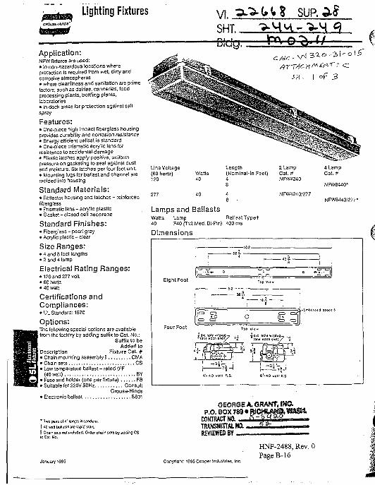
Lighting Fixtures
Application:NFW fixtures are used:• in non-hazardous locations whereprotection is required from wet, dirty andcorrosive atmospheres• where cleanliness and sanitation are primefactors, sucfi zs dairies, canneries, foodprocessing plants, bottling plants,laboratories• in dock areas for protection against saltspray
Features:• One-piece high impact fiberglass housingprovides durability and corrosion resistance• Energy efficient ballast is standard• One-piece prismatic acrylic lens forresistance to accidental damage• PJastic larches apply positive, uniformpressure on gasketing to sea! against dustand moisture. Six latches per four foot unit.• Mounting lugs (or ballast and channel aremolded into housing
Standard Materials:• Reflector housing and latches - reinforcedfiberglass• prismatic lens - acrylic plastic• Gasket - dosed cell neoprene
Standard Finishes:• Fiberglass - pearl gray• Acrylic plastic-clear
Size Ranges:• 4 and 8 fool lengths• 2 and 4 lamp
Electrical Rating Ranges:• 120 and 277 volt• 60 hertz• 40 watt
Certifications andCompliances:.• UL Standard: 1570
Options:The following special options are availablefrom the factory by adding suffix to Cat. No.:
Suffix to beAdded to
Description Fixture Cat. #• Chain mounting assembly § CMA• Chain sets CS• Low temperature ballast - rated O'F
(40 watt) BY• Fuse and holder (one per fixture) FB• Suitable for 220V 50Hz Consult
Crouse-Hinds• Electronic ballast SS01
* Two pairs ol <' lamps in tandem.
t <D wan bsllasis ate rapid start
§ Chain sets not included. Order chain sets by adding CSto Car No.
January 1995
Line Voltage(60 hertz)120
NFW8440*
277 40 NFW4240/277
Lamps and BallastsWatts Lamp BallastTypet40 F40(T12Med. Bi-Pin) 430 ma
Dimensions
Eight Foot
Four Foot
\<=> o
<- 40 wOl
EG
R.S.
:02
1
. — - " • ^ ^
T..V...
, , 3
4 3
0
/ I3
" e
—
t l R S
;
1
GEORGE A. QRANT,P.O. BOX 789 «
CONTRACT NO.
REVIEWED BY
Copyright' 1995 Cooper Industries, Inc.
HNF-2488, Rev. 0PageB-16
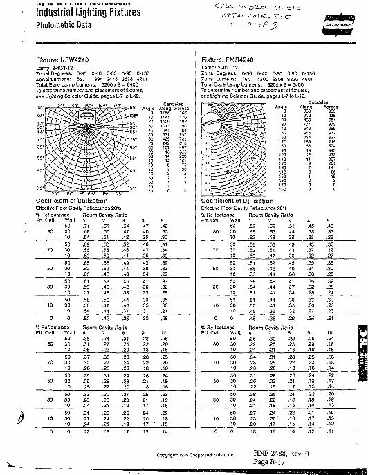
Industrial Lighting FixturesPhotometric Data
ATT/fsh • z OKXJSE-HINDS'
Fixture: NFW4240Lamp:2-40/T-12Zonal Degrees: O-3O 0-40 0-60 0-90 0-180Zonal Lumens: 857 1394 2478 3678 4211Total Bare Lamp Lumens: 3200x2 = 6400To determine number and placement of fixtures,see Lighting Selector Guide, pages L-7 to L-12.
125* '45* 180* 145* 125* CandelasAlong Across
35' ,25- 15* 5* 0* 5* 15* 25*
Coefficient of UtilizationEffective Floor Cavity Reflectance 20%% Reflectance Room Cavity RatioEH. Ceil.
80
Wall503010
1.71.68.64
2.61.56.51
3.54.47.42
4.47.40.35
5.42.35.30
70
50
30
10
503010
503010
503010
503010
.69
.66
.63
.65
.62
.60
.61
.59
.57
.53
.56
.54
.60
.55
.50
.55
.52
.48
.53
.40 .
.46
.50
.47
.44
.52
.46
.41
.49
.44
.40
.46
.42
.38
.44
.40
.37
.46
.40
.35
.43
.38
.34
.41
.36
.33
.39
.35
.31
.41
.34
.30
.39
.33
.29
.37
.32
.28
.35
.30
.27.35
% Reflect*EH. Ceil.
80
jnceWall503010
Room Cavity Ratio6.38.31.26
7.34.27.23
8.31.25.20
9.28.22.18
10.26.20.16
70
50
30
10
503010
503010
503010
503010
.37
.30
.26
.35
.29
.25
.33
.28
.24
.31
.27
.24
.33
.27
.23
.31
.26
.22
.30
.25
.21
.28
.24
.21
.30
.24
.20
.29
.23
.20
.27
.23
.19
.26
.22
.19
.28
.22
.18
.26
.21
.18
.25
.21
.17
.24
.20
.17
.25
.20
.16
.24
.19
.16
.23
.19
.16
.22
.18
.15
Fixture: FMR4240Lamp: 2-40^-12Zonal Degrees: 0-30 0-40 0-60 0-90 0-180Zonal Lumens: 761 1300 2503 3826 4601Total Bare Lamp Lumens: 3200 x 2 = 6400To determine number and placement of fixtures,see Lighting Selector Guide, pages L-7 to L-12.
Cande/asAlong
93391286077464948631416968
Coefficient of UtilizationEffective Floor Cavity Reflectance 20%% Reflectance Room Cavity Ratio
1 2 3Erf. Ceil. Wall 150 .69
60 30 .6510 .62
2.59.53.48
3.51.44.39
4.45.38.33
Across93393695497S96991282771957444343236726114455153
5.40.33.28
70
50
30
10
503010
503010
503010
503010
.66
.63
.59
.61
.58
.55
.56
.54
.51
.51
.50
.48
.56
.51
.47
.52
.48
.44
.48
.44
.41
.44
.41
.38
.49
.43
.38
.45
.40
.36
.41
.37
.34
.38
.35
.32
.43
.37
.32
.39
.34
.30
.36
.32
.28
.33
.30
.27
.38
.32
.27
.35
.30
.25
.32
.28
.24
.30
.26
.23
% ReflectanceEff. Ceil.
80
Wall503010
Room Cavity Ratio6.35.29.24
7.32.25.21
3.29.23.18
9.26.20.16
10.24.18.15
70
50
30
10
503010
503010
503010
503010
.34
.28
.23
.31
.26
.22
.29
.24
.21
.27
.23
.20
.31
.25
.20
.28
.23
.19
.26
.22
.18
.24
.20
.17
.28
.22
.18
.26
.21
.17
.24
.19
.16
.22
.18
.15
.25
.20
.16
.24
.19
.15
.22
.18
.14
.21
.17
.14
.23
.18
.14
.22
.17
.14
.20
.16
.13
.19
.15
.12
Copyright* 1995 Cooper Industries. Inc. HNF-2488, Rev. 0PageB-17
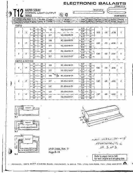
T12ELECTRONIC BALLASTS
. U-Shapea Lamps
RAPID STARTNORMAL LIGHT OUTPUTSERIES
Straight L
SOUND RATED A
Xia-Ai Mln Start r.Diagram":
F30T12
1
2
3
31
3'
3'
25 | 60
30 | 50
25 | 60
30 | 50
25 | 60
30 | 50
25 1 60
30 | 50
, 25 ! 60
30 [ 50
25 ! 60
30 i 50
F40T12 S F40T12/U
1'
2
3
4'
«'
4-
34 | 60
40 i 50
34 j 60
40 | 50
34 ! 60
40 • 50
34 : 60
40 | 50
34 i 60
40 ; 50
34 i 60
40 i 50
34 ; 60
40 | 50
120
277
,20
277
120
277
REL-1S40-HH-T?
VEL-1S40-RH-TP
REL-2S40-RH-TP
VEL-2S40-RH-TP •
REL-3S40-RH-T?
VEL-3S40-RK-TP
0.24
0.27
[_ 0.10
0.12
0.41 •
0.51
0.18
0.22
0.69
0.78
0.30
0.34
27
31
27
31
48
60
48
60
80
90
80
90
0.95
0.95
0.95
<20
rfO
<20
>0.96
>0.9S
>0.97
1
2
3
120
277
120
277
347
120
277
REL-1S40-RK-TP
VEL-1S40-RH-7?
" ~ ^ REL-2S40-RH-TP
VEL-2SJ0-RH-7P
GcL-2S40-a.H-T?
RSL-3S40-RH-T?
VEL-3S4C-RH-7?
0.27
0.33
0.12
0.14
0.51
0.61
0.22
0.27
0.18
0.21
0.77
0.91
0.33
0.39
31
38
31
38
60
72 j
60
72
60
72
91
107
SI
107
0.90
0.87
0.87
<20
<20
<20
>0.98
>0.S8
>0.9S
1
2
3
HNF-2488, Rev. 0PageB-18
z csn. 3
Refer to pages 144 to 145for lead lengths and shipping data
A D V A N C E , 1 0 2 7 5 W E S T H I G G I N S R O A D . R O S E M O N T , 1L 6 0 0 1 8 . T E L : ( 7 0 8 ) 3 9 0 - 5 0 0 0 . F A X : ( 7 0 8 ) 3 9 0 - 5 1 0 9
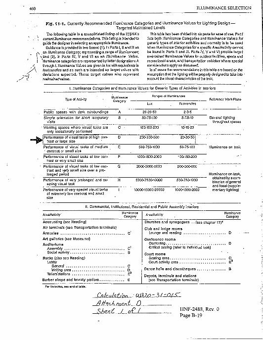
460 ILLUMINANCE SELECTION
Fig. 11 -1 , Currently Recommended Illuminance Categories and Illuminance Values for Ughting Design —Targeted Maintained Levels
; The following table is a consolidated listing of the lESMA's•r'Z current illuminance recommendations. This listing is intended to
guide the designer In selecting an appropriate fllumlnance.Guidance is provided in two forms: (1), in Parts I, II and 111 as
, \ an Illuminanca Category, representing a range of illuminances;l, \ f i n d (2), in Parts IV, V and VI as an llIuminancB Value.{ illuminance categories are represented by letter designations A
(, through I. Illuminance Values are given in lux with equwalents in' \ footcandles and as such are intended as target values with
deviations expected.. These target values also representmaintained vahies.
This table has been divided into six parts for ease of use. Part Ilists both Illuminance Categories and Illuminance Values forgeneric types of interior activities and normally is to be usedwhen Illuminance Categories for a specific Area/Activity cannotbe found in Parts II and 111. Parts IV, V and VI provide targetmaintained Illuminance Values for outdoor facilities, sports andrecreational areas, and transportation vehicles where specialconsiderations apply as discussed.
In all cases the recommendations in this table are based on theassumption that the lighting will be properly designed to take Into •account the visual characteristics of the task.
I. Illuminance Caiegories and Illuminance Values for Generic Types of Activities in Interiors
Type.of Activity IlluminanceCategory
Ranges of IlluminancesReference Work-Plane
Public spaces with dark surroundings
Simple orientation for short temporaryvisits
• Working spaces where visual tasks areonly occasionally performed
General lightingthroughout spaces
Performance of visual tasks of high con-trast or large size
Performance of visual tasks of mediumcontrast or small size
Performance of visual tasks of low con-trast or very small size
1000-1500-2000
Illuminance on task
Performance of visual tasks of low con-trast and \^ ry small size over a pro-longed period
2000-3000-5000
Performance of very prolonged and ex-acting visual task
5000-7500-10000
Performance of very special visual tasksof extremely low contrast and smallsize
10000-15000-20000 1000-1500-2000
illuminance on task,obtained by a com-bination of generaland local (supple-mentary lighting)
. Commercial, Institutional, Residential and Public Assembly Interiors
Areji/Acltvity • IlluminanceCategory Area/Activity Illuminance
Category
Accounting (see Reading)
Air terminals (see Transportation terminals)
Armories C1
Art galleries (see Museums)
AuditoriumsAssembly C1
Social activity B
Banks (also see Reading)Lobby
General CWriting area D
Tellers'stations E3
Barber shops and beauty pariors E
Churches and synagogues . . (see chapter 17)4
Club and lodge roomsLounge and reading D
Conference roomsConferring DCritical seeing (refer to individual task)
Court roomsSealing area CCourt activity area E3
Dance halls and discotheques B
Depots, terminals and stations(see Transportation terminals)
For iootnoies, se« end of lable.
HNF-2488, Rev. 0Page B-19
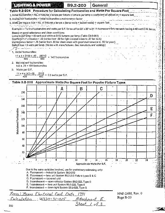
UGHTING&POWER B9.2-200 Genera!Table 9.2-204 Procedure for Calculating Footcandies and Watts Per Square Foot "_:_1. Initial footcandies = No. of fixtures x lamps per fixture x lumens per lamp x coefficient of utilization H- square feet
2. Maintained footcandies ~ initial footcandies x maintenance factor . . _ _ _ ..
3. Watts "per square foot = No. of fixtures x lamps x (lamp watts + ballast watts) -H square feet _
"1 ^
Example — To find footcandies and watts per S.F. for an office 20' x 20' with 11 fluorescent fixtures each having 4-40 watt C.W. lamps.' V
Based, on good reflectance and clean conditions: • • " ' '"" ' , " ' ;§Lumens p_ef.!a'mp = 40 watt cool white at 3150 lumens per lamp (Table C9.2-251) •• • - - - ••- - • •;;Coefficient of utilization = .42 (varies from .62 for light colored areas to .27 for dark) " . . . ' *Maintenance factor = .75 (varies from .80 for clean areas with good maintenance to .50 for poor) . .. 5JBallasf loss = 8 watts per lamp. (Varies with manufacturer. See manufacturers' catalog.) • •_ . ' • >;••
1. Initial footcandies:
11 x4x31S0x.42_ 58212400 . ~ 400
2. Maintained footcandies:145x75 = 109 footcandies
3. Watts per S.F.
11 x 4 x (40 + 8)_ 2112 _400 400
- 145 footcandies
5.3 watts per S.F.
Table 9.2-205 Approximate Watts Per Square Foot for Popular Fixture Types.
200
180
160
•g 140
§ 120
£ IW
1 SO
40/
u
/// /
//
f/
/
/
A
/
/
/
/A
B
/ /
/
<
C' - D
E
F
2 4 6 8 10 12 14 .. 16
• - - • Approximate Watts Per S.F.
Due to the many variables involved, use for preliminary estimating only:A. Fluorescent — industrial System B9.2-212B. Fluorescent — lens unit System B9.2-212 Fixture types B S. CC. Fluorescent — louvered unitD. Incandescent — open reflector System B9.2-222, Type DE Incandescent — lens unit System B9.2-222, Type AF. Incandescent — down light System B9.2-222, Type B
2 0 . . 2 2
from '• /Veq/is F.le.cfncql Cast fivf?—Calculation : W32O'^/-Q/r F:
HNF-2488, Rev. 0Page B-20
250
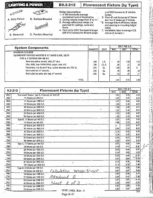
UGHTING& POWER
A. Strip Fixture B. Surface Mounted
C. Recessed D. Pendent Mounted
B9.2-212 Ffuorescent Fixture {by Type)
Design Assumptions:1." A100 footcandle average
maintained level of illumination. . •2. Ceiling heights range from 9' to 11'.3. Average reflectance values are
assumed for ceilings, walls andfloors.
4. Cool white (CW) fluorescent lampswith 3150 lumens for 40 watt lamps
and S3C0 lumens for 8' slimlinelamps.
5. Four 40 watt lamps per 4' fixtureand two 8' lamps per 8' fixture.
* 6. Average fixture efficiency valuesand spacing to mounting heightratios.
7. Installation labor is average U.S.rate as of January 1.
System ComponentsSYSTEM 09.2-212-OS20
FLUORESCENT FIXTURES MOUNTED S' -11 ' ABOVE FLOOR, 100 FC
TYPE A, 8 FIXTURES PER 400 S.F.
Steel intermediate conduit, (IMC) ! 4 ' t£am
Wire. 600V, type THWN-TKKN. copper, solid, *12
Fluorescent strip fixture 8' long, surface mounted, two 75\V SL
Steel oudet box 4 ' concrete.
Steel outlet box plate with stud. A' concrete
TOTAL
0UANTITY
.404
.003
.020
.020
.020
UNIT
L.F.
O.L.F.
Ea.
Ea.
Ea.
COST PER S.F.
MAT.
.39
.05
1.03
.10
.04
1.61
INST.
1.20
.21
.97
.30
.07
2.75
TOTAL
1.59
.26
2
.40
'.11
4.35
9.2-212C520
C5S0
0600
0340
0580
0720
0500
0540
0550
0320
O360
1000
1040
1080
1160
1200
1240
1280
1320
1350
1400
J4401520
1550
1600
J640_
1680
1720
1760
J800
leso
Fluorescent Fixtures (by Type)Fluorescent fixtures, type A, 8 fixtures per 400 S.F.
11 fixtures per 600 S.F.
17 fixtures per 1000 S.F.
23 fixtures per 1600 S.F.
28 fixtures psr 2000 S.F.
41 fixtures per 3000 S.F.
53 fixtures per 4000 S.F.
'64 lixtures per 5000 S.F.
Type B. 11 tares per 400 S.F.
15 fixtures per 603 S.F. .
24 fixtures per 1030 S.F.
35 fixtures per 1600 S.F.
42 fixtures per 2000 S.F.
61 fixtures per 3000 S.F.
80 fixtures per 40O0 S.F.
98 fixtures per 5003 S.F.
Type C, 11 fixtures per 400 S.F.
14 fixtures per 600 S.F.
23 fixtures per 1000 S.F.
34 fixtures per 1600 S.F.
43 fixtures per 2000 S.F.
63 fixtures per 3000 S.F.
81 lixtures per 4000 S.F. /
101 fixtures per 5000 S.F.
Type D, 8 fixtures per 400 S.F. . ' .
12 fixtures per 603 S.F. CA IcuMlhh M/13O' ?/-<O/ <T19 fixtures per 1000 S.F.
27 fixtures per 1600 S.F. /y/?9cArhpnC £•
34 fixtures per 2000 S.F.
48 fixtures per 3000 S.F. S / > P C . j f 2. OT 3 • •
64 fixtures per 4000 S.F.
79 fixtures per 5000 S.F. y ^ ^ nA 0 s D ^ , n
COST PER S.F.
HAT.
1.61
1.51
1.47
1.30
1.30
1.27
1.25
1.25
3.37
3.09
3
2.80
173
'2 .76
2.63
2.62
175
140
139
129
132
126
2.18
118
168
167
156
2.38
2.37
2.26
2.25
2.2S
-1NST.
2.75
167
162
149
2.43
2.42
142
3.93
3.78
3.77
3.59
3.62
3.47
3.57
3.54
4.23
4.01
3.93
3.93
3.89
3.84
3.78
3.78
.3.28
.3.27
3.19
3.10
3.07
2.93
199
• 2.93
TOTAL
4.SS
4.18
4.03
3.79
3.79
3.75
3.67
3.67
7.30
6.87
6.77
6.39
6.35
6.23
6.20
6.16
7.04
6.41
6.37,
6.22
.• v6-2,1
" " • S j o
5.96
5.96
5.95
5.54
. • . 5.75
• . 5.48
- -r.5.44
5.25
5.25
5.25
251PageB-21
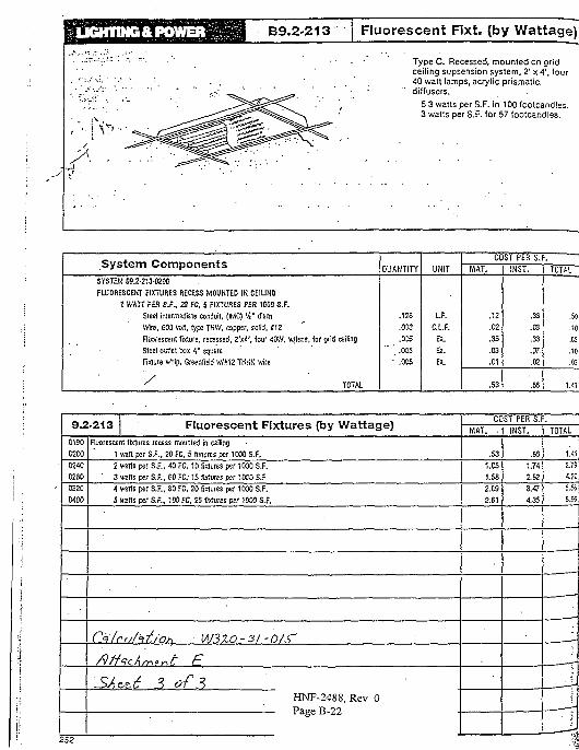
B9.2-213 Fluorescent Fixt. (by Wattage)
Type C. Recessed, mounted on gridceiling supsension system. 2' x 41, four40 watt lamps, acrylic prismatic.diffusers.
5.3 watts per S.F. in 100 footcandles.3 watts per S.F. for 57 footcandles.
System ComponentsSYSTEM 09.2-213-D200
FLUORESCENT FIXTURES RECESS MOUNTED IN CEIUNQ
1 WATT PER S.F., 20 FC, 5 FIXTURES PES 1000 S.F.
Steef intermediate conduit, (IMC) 14' diam
Wire, 603 volt, type TKW, copper, solid. #12
Fliwrescent fixture, recessed, 2'x4\ four 4OW, w/lens, for grid ceiling
Slee! outlet box 4 ' square
Fixture whip, Greenfield w/S'12 TKKN wire
/ TOTAL
OUANTITY
.128
.003
.055
.005
' .005
UNIT
L.F.
C.L.F.
a.Ea.
Ea.
COST PER S.
HAT.
.12
.02
.35
.03
.01
.53
INST.
.33
.03
.33
.07-
.02
.88
TOTAL
.50
MS
.68
.10
.03
1.<1
9.2-2130130
0203
0240
0280
0320
0400
Fluorescent Fixtures (by Wattage)Fluorescent fixtures recess mounted in ceiling
1 van per S.F., 20 FC. 5 fixtures per 1000 S.F.
2 watts per S.F., 40 FC. 10 fixtures per 1000 S.F.
' 3 wans per S.F., 60 FC.-15 fixtures psr 1000 S.F
4 watts per S.F., 80 FC. 20 fixtures per 1000 S.F.
5 ireits per S.F., 100 FC. 25 fixtures per 1000 S.F.
CJilraht/'oht W3XO-3/-0/6"
SAn6 ? of 3HNF-2488, Rev. 0
COST PER S.F.
MAT. .
.53
1.05
1.58
2.09
2.61
IHST. | TOTAL
.65
1.74
2.62
3.47
4.35
1.41
2.75
4.2!
5.K
6.55
I,
ri
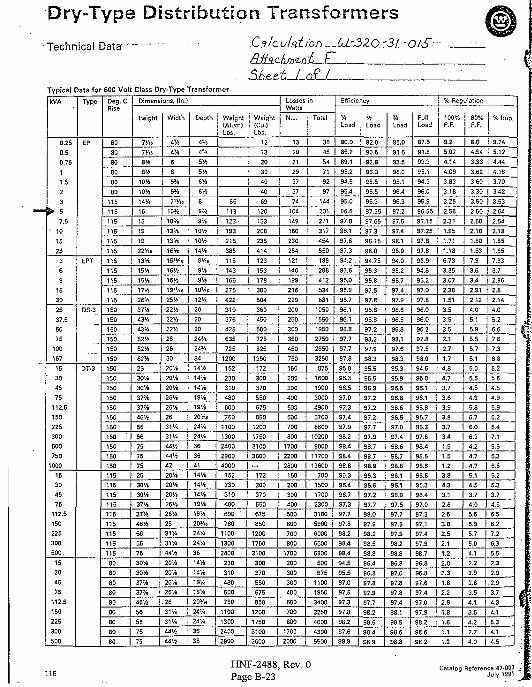
Dry-Type Distribution Transformers
Technical Data
Typical Data for 600 Volt Class Dry-Type Transformer
CsdcuUtLDJi—Uz3.ZO.:3l. ••
Shu.tJ-.aL/kVA
0.250.50.7511.523
> 57.5
• 101525
369
1530
2537.55075
100167
15301575
112.5150225300500750
15304575
112.5150225300500.
15304575
112.5150225300500
Type
EP
EPT
DS-3
DT-3
Deg. CRise
80
80
80
80
80
80
115
115
115
115
115
115
115
115
115
115
115
150
150
150
150
150
150
150
150
150
150
150
150
150
150
150
150
.115115115
115115
115115
115
115
8080
80
8080
80
80
8080
Dimensions, (In.)
Height
7«5
TAt
8tt
ev>10%
10ft14'/.
16
16
19
19
22V,i
13%
15%
15%17*1
26%i37%
43%
43%52%
52V4
62%25
30%30%
37'/i37%
46%
5666
7575
2530%
30K37%37%
46%
5656
75
30%
30%37%
37%
4 6 %
56
5675
75
Width
4V4
4%
6
66%
6%
7"/i«
ioy.
10V.
13%
13%16%
15'W.
16%
16VS
19"/.«
25%
22ft
22ft22%26
26
30
20%20"/.
20V4
26%26%
2631%
31%44%
44%
20%20%20%26%
26%2631%
31%44%
20%
20%
26%
Depth
tv,
« t
5%5%
6%
Weight(Alum)Lbs.
6'4 |
89%
9%
10ft10ft
14%
S H i
9Vi
9%10>/lS
12W
20
20
20
24V*
24%
34
14%
14%
14%
19'/.19'/.
2oy..
24%24%
36
36
14%14%
14%
19%
19%
20Y.<24'/.24'/.
3614%
14%
19%
26% | 1S%
26
31%31 ' / .44%
44 ft
2oy>.24%
24'/,
36
36
65
113
Weight(Cu.)Lbs.
12
13
20
30
40
40
69
120
123.- | 133
133
216
385
116
143
166275
422310
375425
635
725
1200152
230310
480
600760
110013002400
2900
152
230
310
480
600 '
7601100
1300
2400
230310
480600
750
1100
208
235
414
123
153
178
300
504
360
450
500
725
825
1350172300
370
550
675850
12001750
31003600
172
300370
Losses inWatts
N.L.
1320
2129
3737
74
104
149
160
230284
121140
1S9
216
229200
250300
350
450
750150
200300
400
500600
700800
17002200
150
200300
550 | 400
675850
12001750
3100
300
370
550675
850
12001300 | 1750
2400 31002900 j 3600
500600
700
8001700
200
300300
400
600700
8001700
2000
Total
36
45
64
71
S2
97
144
201
271
317
454
550
189
288
412534
681
1050
15501950
27502850
Efficiency
%Load
80.0
85.2
89.1
ftLoad
82.0
90.5
92.895.2 | S6.0
94.595.4
95.095.6
97.095.1
97.6
97.3
S4.2 .
93.6
96,0
96.996.7
96.1
96.195.897.7
97.7
3250 | 97.8
875
1600
1900
30004900
67008600
102009000
11700
700
1500
170023003100
5900
60006600
6800
500
975
11001950
3400
3250
40004300
5500
95.0
96.396.5
97.097.397.4
97.998.298.4
98.4
95.396.4
96.797.397.7
97.8
98.298.4
98.4
94.5
95.597.0
97.5
97.3
97.8
98.297.698.9
S5.5
96.5
96.3
97.35
97.65
97.398.15
98.0
94.75
95.3
96.8
97.5
97.8S6.8
96.897.2
98.2
97.9
98.395.5
96.596.9
97.2
y.Load
85.0
91.6
93.5
96.0
95.196.4
96.397.2
97.597.4
98.1
98.0
94.0
95.2
96.797.4
97.9
96.6
96.596.8
98.197.6
98.3
95.395.9
96.5
96.8
97.2 i 96.697.297.7
97.998.7
98.7
96.3
96.697.297.7
98.097.9
98.2
98.5
98.896.4
96.8
97.897.9
97.7
98.2
98.698.4
98.9
96.597.097.4
98.698.7
96.1
96.196.997.597.7
97.597.9
98.2
98.896.8
97.0
97.897.897.4
98.1
98.5
98.698.8
FullLoad
87.5
91.8
93.3
95.1
94.3
96.0
95.9
96.85
97.15
97.25
97.8
97.8
92.9
94.896.2
97.0
97.896.0
96.0
96.297.8
% Reoulalion
100%P.F.
9.2
5.074.14
4.09
3.83
3.18
3.25
2.58
2.31
1.95
1.71
1.18
6.733.35
3.07
2.38
1.513.5
3.5
3.5
2.1
97.5 | 2.7
98.094.5
95.0
96.196.1
95.895.7
96.397.6
98.498.5
95.696.396.4
97.0
97.397.197.4
97.998.7
96.8
96.8
97.697.4
97.0
97.9
98.2
98.698.2
1.7
4.8
4.7
3.73.6
3.9
3.83.7
3.4
1.5
1.5
3.8
4.3
3.1
2.62.5
3.82.5
2.1
1.2
2.0
2.31.8
2.2
2.6
1.8
1.61.1
1.2
80%P.F.
8.0
4.54
3.33
3.62
3.60
3.30
3.50
2.50
2.50
2.10
1.80
1.63
7.93.6
3.4
2.91
2.124.0
5.1
% Imp.
9.24
5.124.44
4.18
3.70
3.42
3.532.64
2.54
2.18
1.85
1.657.93
3.7
2.96
2.82.14
4.0
5.2
5.9 | 6.65.5
5.7
5.15.0
5.6
4.54.9
5.85.7
6.0
6.3
4.2
4.7
5.1
4.5
3.7
4.0
5.5
5.95.7
5.04.1
2.2
2.9
2.8
3.54.1
3.6
4.2
2.7
4.0
7.6
7.3
6.85.2
5.64.54.9
5.96.26.4
7.1
5.56.3
5.25.33.74.6
6.56.2
7.2
6.3
5.52.3
2.9
.2.93.7
4.34.1
5.34.1
4.5
HNF-2488, Rev. 0Page B-23
Catalog Reference 47-000 '.July 1991
AITA-c H A-L iSLrJT -
600 Volt. Ooppar Conductor! Th«rmoplattlg Insuhrtlon/KyionShaath. H*at, Moisture, OH & O«»olln» Re»Utairt\ All Steso
Rated THWH-2. All Strandad Sizes Ratod MTW. AWQ S(sa« 4«Throunh 6 AWQ Rated AWM (105°C). AWO. S!z«a 14 Thpoiigh
O2.6 O O ci iprt O Q 1 R a t o d V W '1 a n d Lars"" S I l s»^a t«<» '«<• CT Utta.VI.SHT._Bldg.
APPLICATIONSSouthwlre Type THHN or THWN-2 conductors are primarily ussd In conduit andcable trays (or services, feeders, and branch circuits In commercial or Industrialapplications as specified In the National Electrical Coda2. When used at TypeTHHN, conductor Is suitable for use In dry locations at temperatures not toexceed 90'C. When used as Type THWN-2, conductor Is suitable for uss In wstor dry locations at temperatures not to exceed 9O'C or not to exceed 75°C whanexposed to oil or coolant. When used as Type MTW, conductor la sultabls foruse In wet locations or when exposed to oil or coolant at temperatures not toexceed 60°C or dry locations at temperatures not to exceed 90°C (with ampacity 'limited to that for 75°C conductor temperature per NFPA 79). Conductortemperatures not to exceed 1OS°C In dry locations when rated AWM and used asappliance wiring material. Voltage for all applications Is 600 volts.
SPECIFICATIONSSouthwlrs Type THHN or THWN-2 or MTW (also AWM) meets or exceeds allapplicable ASTM specifications, UL standard 83, UL standard 1063 (MTW),Federal Specification J-C-30B, and requirements of the National Elactrlcal Code;
CONSTRUCTIONSouthwlre Type THHN or THWN-2 or MTW copper conductors are annealed(soft) copper, Insulated with a tough, heat and moisture resistant potyvlnvlchloride (PVC), over which a nylon (polyamlde) or UL-IIsted equal Jacket Is •applied. Available In blacx, white, red, blue, green, yellow, brown, orange, orgrey. Some colors standard, some subject to economic order quantity. Sizes1-19 through 1,000 kcmll available In black only. • .:
1 Oil and guollne r««j»uncf n is detintd By UndtrwTitftrt Laboratories.•ISMEdlUsn.
SouthwlreHNF-2488, Rev. 0Page B-24
P.O. BOX 789 •CONTRACT NO.TRANSMfTTALNO.
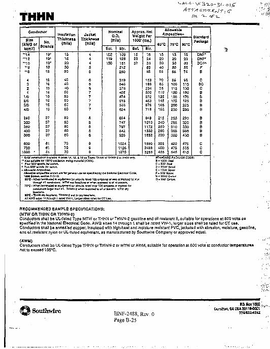
THHNConductor
(AWO orkcmll)
"14" 1 2" 1 0" 8" 8
43Z1
1/02/0
a/o•vo2 SO300350400BOO
600750
1000 •
No.Strand!
19"19*19'1919
1919191919191919
3737373737
616161
InsubttionTrilclnuit
<mll.)
15152030SO
40to4 0
SO505050£0
60606060
eo707070
1 SettonatrwGJai tvtlaA* h o i * * 14.12," Abo Kflutta tor 103*0 acclnnc-j truing m«
A Two S » tcoob o»r oana*.• Ago-MbU Arrp»3&4c:
AlbMbla «7np&dtie« iro*n 4/afor p«r*ra.i
»*C • Wiao Wrrrinaad ra »«!uJpfw« lor dJ
Jick*tTMckneu
(mile)
44455
6C677777
S3S88
999
Nomlnil0.0,
Sol.
102119150
Str,
10312S181212220
319
378433474513558£24
694747797642S25
102411261275
Approx, NetWeight Per1009' (IDS,)
8 si.
152337
110 at Tjrpat THMN of TKWN-2 of AWM only.erU] (AWM).
i f f aa ap*cJfi>4 by ma Nations! Eladnelt Coftfl,
XJir* ro« 100 »r«Iriroggri 11 ccnduaor*. MTW »»|boalJoAa or wmtci «xp
»i%t or IOM or rmrXMoa*d to ot\ of taMiam.
1Oftl4
? i*C • Wr*n l«yrf***)« u »qwl©m«rt for oftuta rttad n * 100 amperei or mirkM foroMvjooort It/gor 0%47i f l . THWN.2looataa.
IG*C-THHN dry teailortt, TMWty-2 «.»t rxA! AW0 I U I 14 mnuon 1 rtiMVW-l. U .
• r « i i i » 3 t * d » g (
Cry tooallcil.
orooUnt. MTW Cry
-j*f alZM r»lK for CT U M .
Elr.
its24386395
1531S9234300372443576719
6481010117213321052
1S90246332S3
Allowlbl.Ampadtlts*
eo-c
1520304055
7065S5
HO125145165195
2152402S0230320
3S54004JS
75X
1520305065
ES100115130150175
. 200230
2552653103353S0
420475545
90'C
152030557£
9S1101301501701S522S250
2903203503S0430
475535615
SUrxUrd
DNF*DNF'DOF"
FB
CBOCBBBB
. B
BBBBB
CCC
STAN0AAO PACKAGE COOE:
" - K0' P
E- looc Scootf.SWSpool
3» 2*r Cwon"
flSCOMMBNOeO 8AMPS.E SPCCIflCATIONSl(HTW OR THHN OR THWN-2)Conductors shall be UL-IIstsd Typa MTW or THHN or THWN-2 gasoline and oil resistant II, $ultaWe lor operations at 600 volts asspecified In the National Electrical Code. AWQ slzss 14 through 1 shall be rated VW-1, larger sizes shall be rated (or CT use.Conductors shall be annealed copper. Insulated with high-heat and moisture resistant PVC, jacketed with ubrasion, moisture, gasoline,and oil resistant nylon or UL-I[3fed equivalent, as manufactured by Southwlre Company or approved equal.
(AWM)Conductors shall be UL-llsted Type THMN or THWN-2 or MTW or AWM, suitable lor operation at 600 volts at conductor temperature*not to exceed 105*C.
iSoulhwire HNF-2488, Rev. 0Page B-25
pdtrelKM, M UW WI1W001''
770VZ4I4Z
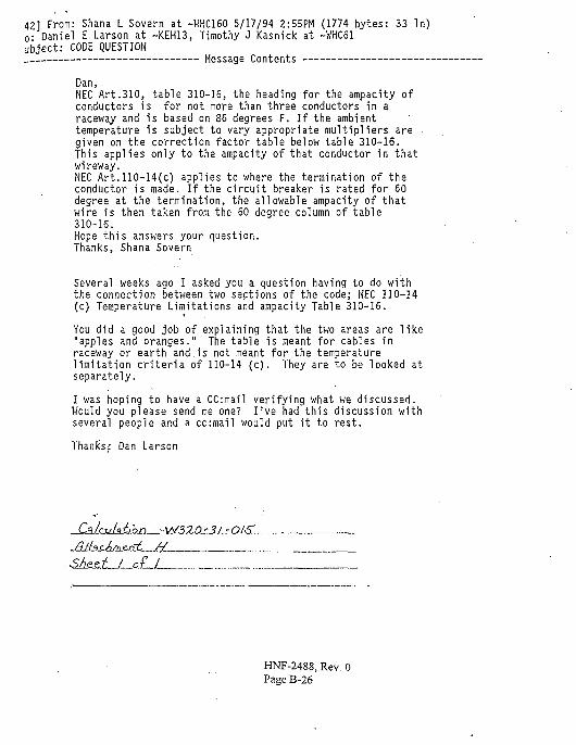
42] From: Shana L Sovern at -WHC16O 5/17/94 2:55PM (1774 bytes: 33 In)o- Daniel E Larson at -KEH13, Timothy J Kasnick at -WHC61ubjeet: CODE QUESTION
Message Contents
Dan,NEC Art.310, table 310-16, the heading for the ampacity ofconductors is for not more than three conductors in araceway and is based on 86 degrees F. If the ambienttemperature is subject to vary appropriate multipliers are •given on the correction factor table below table 310-16.This applies only to the ampacity of that conductor in thatwireway.NEC Art.llO-14(c) applies to where the termination of theconductor is made. If the circuit breaker is rated for 60degree at the termination, the allowable ampacity of thatwire is then taken from the 60 degree column of table310-16.Hope this answers your question.Thanks, Shana Sovern
Several weeks ago I asked you a question having to do withthe connection between two sections of the code; NEC 110—14(c) Temperature Limitations and ampacity Table 310-16.
You did a good job of explaining that the two areas are like"apples and oranges." The table is meant for cables inraceway or earth and.is not meant for the temperaturelimitation criteria of 110-14 (c). They are to be looked atseparately.
I was hoping to have a CC:mail verifying what we discussed.Would you please send me one? I've had this discussion withseveral people and a cc:mail would put it to rest.
Thanks; Dan Larson
_ik/ctAtj.o_f)_-VV3ZQ-'J/_7 OAST..
HNF-2488, Rev. 0Page B-26
' BEST AVAILABLE
OUTDOOR LUMINAIRES "
Outdoor Energy-Dollar SaverCheck-Chart
- ; V _ . If You Now U K
! \ orPlanioUie
1-300 Wilt incandescentFish Bow) Unii
3-150 Wan Inc. ReflectorLamp Cluster
1-500 Wait Inc.Quartz Floodlight
1-1000 Watt Inc.Quartz Light
1-175 Wat: MercuryVapor Wall-Unit
]-400 Wilt MercuryVapor Wall-Unit
1-400 Watt Metal KaiideWall-Unit
1-250 Watt H.P.S.Wall-Unit |
UM VoiglWall-Moil
for EquivalentLighting
Re>ulu-ln.tead
No. 0-36(35 u.art)
No. 0-36(55v.au]
No. 0-36(55 wii)
No. 0-39OSOiran)
. No. 0-36(55 wart)
No. 0-3S035 wart)
No. 0-391180wanl
No. 0-38(135u.an)
WarnSaved
for EachUnitUsed
240
370
420
780
125
275
245
132
AnnualDollarSaving
forNightly
U x(6«/Kwhr;
53
89
101
1S7
30-
. 66
59
32
Whether you seek to.Protect visitors in a parking lotSecure a fence against intrudersHighlight a building entrance
•. Provide visiDiliry for your watchmanPour light into a loading 18-wheeler
OrAssure proper T.V. surveillance lighting
The Wall-Most family does it exceptionally welland attractively using fewer wafts and often for a1
much smaller dollar outlay.
-Relamping is accomplished through fully-gas-keted door in end—keeping optical chambersealed against bug and dirt entry.
Z of ^ HNF-2488, Rev. 0Page B-28
Installation, even under adverse outdoor condi-tions, is remarkably easy; with all mounting boltsand wire splices fully accessible as lens & reflec-tor slide out of the way.
Internally mounted uplight shield can be field in-stalled or removed at any time (SD-1 shownwith 0-36).
Polycarbonate lens resists breakage.- Absence ofultraviolet in L.P.S. source eliminates lensembriftJement and yellowing over time.
Wide beam spread of Wall-Most achieves cover-age of large areas adjacent to buildings andmounting walls.
Footcandle-IsohrxTop View of Footcandles on Ground FromSingle Unit.
^ Mounting Height - 15 '-0*'^/Prom: Voigt Wall-Most™ No. 0-36-120 with 55
watt Low Pressure Sodium Lamp. •*(Data: Electrical Testing Laboratories TestNo. 440926).
HNF-2488, Rev. 0Page B-29
Larger (90 through 180 watts} Wail-Most have amore sharply denned distribution of light—Jocover even larger areas. For 135 watts proratedata by multiplying factor of I\67. For 180 wattsmultiply by 2.44.
Aesthetic elegance of Wall-Most can be enhanced byversions in black — orother architecturalcolor finishes as de-sired. Simply specifycolor.
Additional Wall-Most notes.Long luminous arc size, forall lamps, spreads the light over the entire Wall-Most lens face—reducing the viewing bright-ness—so that unit is comfortable to iook at— .-even when viewed directly.
vThe yellow monochromatic light of Wall-Mostdoes not attract bugs to your building. The light,however, does penetrate smoke, haze, foj& 'smog more forcefully than other sources ofillumination.
Unique prismatic lens structure precisely de-signed for twin Arc L.P.S. source, significantlyaids in control of light into efficient beam pat-tern; and optically disperses source for greatercomfort.
. Back View Mounting Details .- - :
'•:f&-£±
m
Information ;• •^-.•=i-.1 * * — - -
• CATALOG:.: NUMBER
sox-i8- ••:-.SOX-35 ..
.SOX-55-.v
SOX-90 • •:•
SOX-13S . '
SOX-180 ' •
;.?SSr..-"Ci".
^ LOW PRESSURE SODIUM LAMPS ONLY
• Waits
•"•..18
:-.-:3S
" 5 5
••".90
.135-
; ISO
..10,000
. 18,000-
• 18,000 •- 18,000-
;. 18,000
v 13,000'
Initial & Maintain**!•• Lumen Ourpvt
• •-':' 1,800 " " •
• i i . i " 4 ,800 ••• -
• . ' - • • . • : 8,000 • • ' • :
f - . - - - . 1 3 , 5 0 0 - • • -
•..••: '.- 2 2 , 5 0 0 ' ••..;••'•
- . ; • " 3 3 , 0 0 0 •>•;•
- ; • ! ; : • ' • • * " • •
•S;;i^f-^'.;: 'Max. O A Length
.-. . la lnchet
:. • : " . 8-1/2
!\'{- 12-3/16
Kr-16-3H.••A2O-3/4' "'
-••-t-: 30-1/2. -.-.
'S •: 44-1/8
:•• -'• i » » « ™ ' : - :
ttUt M »
... "a « »
=>' =. a =3
T^ZT 1 :"
,.
-1-
IX
=»'
U
i n
ct c.c^
in -ii -M
o * o o
:n m in
V,
-.r a'i-'ar* 121 ili -^
3 a » »
12S '.3 13 13O—K%
« WATTS
B a a a
**
a
Bw.m "
•"77
•3- w in
3 3 3-
O-»*8*
3
-m [
Basic Wall-MostSpecification and Ordering Information
-.
2'
NUMBEH
0-34^000"
0-36-000'
O-37-OO0'
0-38-000'• ^ • . - • • • • • ' • ' . ; '
L.P.S.
18
55. OR
35
90 •
135 ;.
• iso'i
FreolVlrwSUlxwrat
ia •;-a •
A
10
20
24
34
47
" I C
8
8
8
8
8
-
13v4
13H
1 3 ,
0
-
-
1754
17*
m
17V5
8
8
8 ,. ' - " • • • " "
15
21
3 1 .
39':
44.;
Wail-Most with exposed portionswholly made of extruded and castaluminum and transparant polycar-bonate lens is the standard forstrength and durability in outdoorwall mounted'luminaires.
Optioned Accessories
• 1
q
- O - [O] " C -
0-36
1 11 1
—0-iOJ—0-
yap-
0-34
-• *Sp«=fy vohag* required:'120. 208. 240. 277-cr «S0 L«.. No. 0-36-120. ." Lined by Underwriter* La bora [odd, Inc. •-.•-.. . .• ' ..'• • - . . , " - ' : •• . . - .^ '•• Unfa any 1BEW labd. • - ; ;-.-V.. -, ••. ..:: : ."*• ' • :. / - -V •;
:'_.«>Tl.''-.--
:: For »dditiof»l technical cf uppDcstion d«« or aou&I dtmoncration c< tS«i". Vo^t Wall-Most » n i » a Voigi LJ3htL->g Industries, Inc. Htftdqwinen, or: "'.
HNF-2488, Rev. 0Page B-30
CATALOGNUMBERSUFFK •
. PR
. P I '•••
MULTI
NB i~
. ._ES -;.
'•' •:>., F ' . . '> : -
-;. FF..'-':
BLACK
COLOR
. • •• T P ' •" • • •
S D - 1 •'1 SD-i :
' SD-3 .
SD-4
D«*crfpdon
Tu«t-Lock Photocell Receptacle
Internally Mounted Photocell (120 volts only)
Multi-Tip Bal te (120. 208.244 & 277 volts)
' Unit without ballast to allow remote mounting
Emergency Lighting Socket for 15 wart ;. - ."Bayonc Base, T-7 Inc. Lamp
": Single Fus« •
• D o u b l e F u s e ' • • . - . . ,
'- B l a c k P a i n t e d o u t s i d e finish • - • " • ' / •
P a i n t e d F i n i s h — s p e c i f y co lo r •"" " »" : •
VandalResisiant. Tamper-Pioof Screws "• \ ;
Fntema] Shield for 0-36 . " '
Internal Shield for 0-37 ' " "•'•"...'- " .
Internal Shield for 0-38
Internal Shield for 0-39Fcr xfditioivJ bcccssoncs Infonnation conud Voigi Er^ieew^ Depvt-
. ITICAL COS* for option*! »cc*35ori« av&ilabU on request.
NJoigf LJgfting Industries, Inc.Hcsdqu&ncn Locarion13S Fort U . Rd.UonU. N J . 07605201-«l-2<93
s ation1636 No. CailisJ. Si.Phi^e.lphj. Pu . r j . 15121
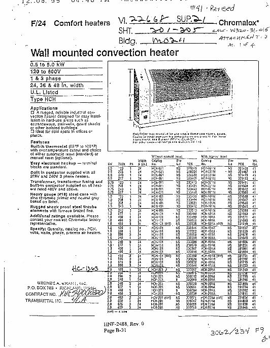
. -u s.
F/24 Comfort heaters VI. '^-L (* $^ SUP/3-V— chromalox*SHT._Bldg. _
Wall mounted convection heaterjj-t. I tf
0.51201 &24,U.L
to 5.0 kWto 600V3 phase3S & 48 In. width. Listed
Type HCH
ApplicationsD A ruoged, reliable industrial con-vection heeler designed for easy insial-lation in hard-use areas such asenlranceways, stairwells, guard shacksor oiher isolated buildings.• IdeaJ for cold spots In offices orplanis.
FeaturesBuilt-in thermostat (55*F to 105°F)with overtemperature cutout and choiceo( either automatic reset (standard) ormanual reset (optional).Easy electrical hookup — terminalblocks are standard.Ballt In contactor supplied with all20BV and 240V 3 phase heaters.Transformer, transformer fusing andbullion contactor supplied on all heat-ers rated 460V end above.Heavy gaug« (#18} steel csso withzinc chromate primer and neutral graybafced on (inish.Rugged shock proof steel flntubeelements with furnace brazed fins.Additional ratings available. Pleasecontact your nearesi Chro.r.alox factoryrepresentative.Specify: Quantity, catalog no., PCtN.volis, watts, phase, process air healers.
kW0.5
Volls120
Ph1
WiiihA tin.)24
WC:
Hi:H-OSI
Mte!Sll-
n'5
FCH330275
Vs'uri - 5 rw i l r t re l
Ho.HCM51M
Silu
la-it fCN
3314590.5 203C.5 2-S00.5 277
C=EGH3£ A. feii-lA.H i , irVC.P.O.BOX7S9 • n!Cn
CONTRACT NO.TRANSM.TTAL HC
151.5-1.51.1l .b1.51.51.52.0
2.02.02.1)2.02.0•i.ti
2.02.02.02.0
240277« 0<80<E0550575600123
208240240277<;o« 0<&3550S756M
311333331
313113i333
24}i; <24
2424242424
242424?t242424?42424
HCH-151HCH-1SIHCH-1S1HCH-151HCH-151 (4W1HCK-1SIHCH-151HCH-151
( HCH-201 )
HCH-201HCH-201HCH-201HCH-201KCH-201KCK-201hCH-201 (4W)HCH-201HCK-201HCH-201
KSMSNSNSNSN1?KSKSNS
NSSNSNSSKSNSNSNSNS
33060333057933056732K15330559330624330632330540335667jjjb<533071223D5E3
330720330591330704330739330771230747330755330763
HCH-151MMCH-151MHCK-151HHCH-151MHCH-lSlM (4W1HCH-1511.1KCH-151MHCH-151M
HCK-201MHvri-iuiMHCH-201MHCH-201U
HCH-201MHCH-201HHCH-201MHCH-2C1H.HCH-201H \anKCH-201HHCH701MHCH-201M
NSNSNSNSNSKSKSNSNS
"TiT1
NSNSNSNSKSKSKSNSNSNS
33166633IS5!3316613316S4331731331707331715331723331740.jJl/'SS331790331765331803331774331782351811331354331620331833331846
4141414141414141
41
zr4141
41414141414141<1
HNF-2488, Rev. 0PageB-31
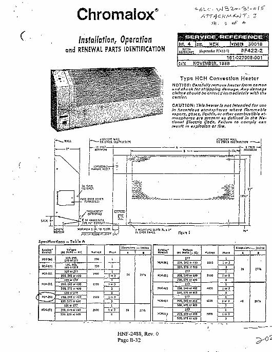
C
Chromalox'Installation, Operation
and RENEWAL PARTS IDENTIFICATION
sh. i. of
: SERVJCE/ftCFCRENCEOIY.
urn
M l !
4 ISfC, HCH [K
^ (Suptrjrfn PF42Z-1)
161NOVEMBER, 1S88
JMint 3001B
PF422-2•027003-001
Type HCH Convection HeaterNOTICE: Ctrt fully rumorsheater from cartonand check for sh/ppp/ng deme$«. Any damageclxtms should be entered ictfrntdlaialy with thacarrier.
CAUTION: Tbfc faster U not Intended for usein hazardous ttmospfieres rrhtrG ftammBbferapvrs, gazes, Ikjuhfs, or other combvstibls *t»mosphervs art present as defined in th« <V#«tionvt Blvcttfc Code. Failure to comply cxrtnsuft in expfoHon ct flrw.
••i— t IKK — (>J<,«J' HI Hi WJM
cntftms -• Toble A
Xsmttr
HOMSl
HCK471
HtK-lCl
KK-iSl
*~ — - ^ .
- * • • i — ^
Tiitetf(M > t r j —*C)
210 vrZT?
tfS. HO W*tQ
120 or 277
530, 575 or ECS
170 »t 277
iM,2*o©rin;so. 5r5«rtco
2C8. 2«0 or i*0
SEO, 575 « WO
SM
7S0
:wo
U00
KC5
K M
n u t
1
1i
I ft 3
1
1 »O
3
1
I r r 3
J
1
1 et 3
3
• 1 S
HCH-4CI
(M t h r u — « J
277
3S6. 575 n 600
r?7
2OC, JH9 ot &g?
277
I M . ) « ef *toSiC, 573 M KS
SW, S75 « ' 6C9.
j n
j t a , u o t r < t 9
!
J t
1 0
1 G
I
l i _
r l
T 3
r 3
f 3
jt ! i
-
HNF-2488, Rev. 0Page B-32
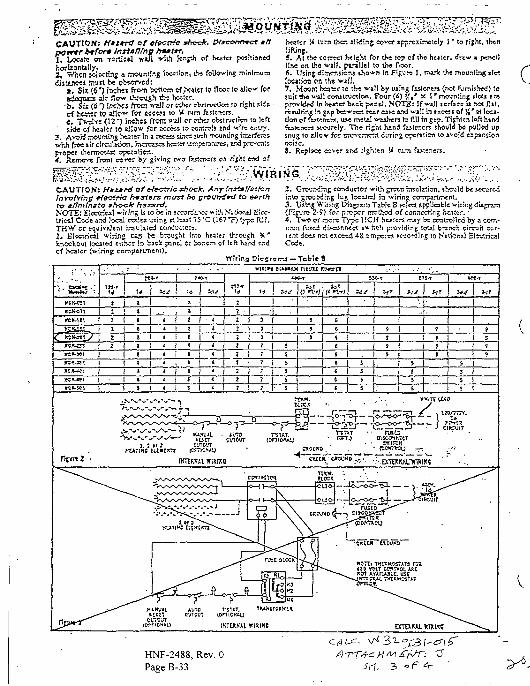
n Oven ilWing cover spproximccly I " iiCAUTION; Ktztrct Qfcfvcrrfc J / H A > . P/^rowwpcf *ff
I* Locate on TCrtical YTJJI ^ilh kr.ph °f hcafcr positionedhorlzonUHy. , . . . .i , When Klccvinj a ipounslr.fi locsiisn, lhs fcdowinj minimum<UjluK<i murt be observed:
«, Si=c (6*) inches from bcttcm cf ,!>M'ter to floor ;o aJlow foreiagujEB aJr flt?w through tiw beater,
cf h « « f W allow for acteji to W ™m ftstencrs.c» TVdvc (U" ) Inches frcniwaJI or cThcroVsirvctwnw lefts«Je cf heater to sdlow for 2CCCJ$ to torrtrols and •"-•ire entry.
3. A v ^y r OU ii g heater in 3 recss? sLnct such rrcunung interferesvhh^ft i rclrcJtr icn,hicr«scshcsief lernperatures,:
?pcrat:W._jv<r by giving t^o
preper i-<. Remove fnTirt :rS Of) ri$M tfld Of
heater W lurn Oven ilWing eovcf spproxirv>*,cly I * lo fijht. thenlifting,5. Al ibe secret htl^M fcr iSe top of ihc hea'.cr, drew «line on the walj, parallel to tf>« Poor.6. Usinf dimensions *Jio^n in Fi£'Jrt I, nu.-^ ih« mour.tin-st«Iccaifon on ihc ^iff.7. Mount heater w lbs "wall by wing fultnen (not FjmixJw^) lojuit tf>« wa]l cc^ilr^Jctlo«. Four (4) * e* x I ' rnounline *loC« Breprovided In Sciltr back piDeJ. NOTE: If ^aJ] icrfece u ft« flil.rryuJting In gip between rear ca« «.-d wail in txcet« of %'si loca-tion of iMi^ners. uw meiJ v^shen b fill :n gcp. Tithi«n Itft Kindfestcners 5<-cijrc!y. The ri^M hand fiitencra shdulo be pulled upsnug to iJIov for urc^crrrcTrt durtpg openiion lo ivoid expansionrjoiic.3. Replace covtr afx3 tigSKn U rum fwwners.
c
CAUTION: H*z*rd of cfactrk: shock. AnrlnstMflattonfnvtrfvfng eJ&ctHc hosiers mvyt be ground+d to &ertfrtry effmtnsto shock hazard.
TH or c ^ i3, Electrical wiriig c*a beknockout located either in baci; pcY heater (wiring compartment).
Inro healer through .-r bo~c-m cf left hind end
Wiring Dicgn
2. Grounding conductor wiLh grctn rnsuTition, «ir.to grounding lug located ia wiring companirwni.3. Using Wiring Diagran] Table B FC!«3 applicable wiring diagram(Figure 2-9) for proper method of connecting hen'cr.'•4, ~C>*o or it^orc Type KCH healers n-^y be controlled by a com-rrron f\i«d di^ccr.rxct s«.TiC?i presiding towl brsnch circ*jft cur-rent dots not exceed 4S arnperrs eccordlpg to Nfiticr.a] EttCricalCode.
T.3 — Tab!* 8
• U ! w U [t w\n) UJ
J 1L
I •' Ii I
IHTiRKtl W1XIICE
HNF-2488, Rev. 0Page B-33
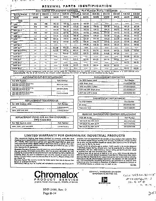
> RENEWAL PAKT3 IDSNTIMCATIONp " — " HCH KIATIR RSPU.CSMINT lUMtJJIJ^- Tori Numbir rrrflx 1IS-OT495S .
CltllrtCRO"
Witt
ftlsI K Y • . •
• }W» • : . .
ECU tat
KWrf
» ien
r»i u ; 1 . 1 —
« * * , • • • - . I M >
m a r
—
•xn
—K 7
—
— 1 —
—
—
—
—
t*rYJ*K«««t 1 — 1 — .
J J W » t — 1 —•JKY.m —
5»V5»T . . | —
. s r s r v ^ • ••
iwi" ' / ••
———
—
—
—
—
—
KCX1G1
tWCTf
MIC1
raq
5*1 (3)
K3 0J
clop;
w:::
KJ17J
Ktm
e«(5>
CO7OJ
KJ(S)
P08 1!)
«7{I)
— . . 1tuts
—
OCX (3)
sisroeuroMl(3>
• c:i w
MiO)
« l> l | MS P)
KIP)
C12U) 01! PI
E13I3) j &1S13J
1
KJID
c;<«]
t!l(3)
—
«l(3)
KtO)
O<7(3)
— 1 '— 1 —
—
tad)B»(3)
ownC3113)
cam—
m r?)C33 (3?
CE13)
T —
HCH 151
Wtfff
t i l ID
135(3)
MI B)
t!7BJ
B!I(3)
tn(3J
«»(!)
—
e:si3l
W5(1
—
—
—
WJ13)
KJB)
t>"(!)
«snt
—
M.O!
esiB)OU(3) I K tW
KS1J) ] MJ1!)
?<MJ} 1 SIJ(J)c« (Jl 1 K3P7
1wa | «!roM B
—
nrffl
XCHfti
H7BI
K7:3)
«l7j
BI(I)
KSI3)
t«I7)
C»<!)
e:i (7)
—. | KSO)
BIB |
] CM PI
KI (3>
—
W3O)
?. i:i-C2WSS ? r r i in i 1TCY KH 111 i
AUTOMATIC CU7-0F? Rt?LAC£MEKT
^H3Sl#nJ>*CS3i :«
REPLACEMENT T3WKSPORMER
Ftrt Ksift
REPlACEMENT FUSES FOR ALL TRANSFORMERS -TWO REQUIRED
for RCH Kesltn n W
REPLACIMIKT CONTACTOR
ifcr airft F^»«
«CVSn E5OT J ^ i i
&TI W ilW SiV F*««
fKi Itmfcn .
C7:-CE;5KI-CM
CT2-CSJSS9-5C3
THERMOSTAT REPU.CEMEKT
* V 1 K.-O
f»rt JTsmVtf
MANUAL TEMrERATURE CONTRO1. REPLACEMENT
HCK M Htlttr
MCH K I M thfu KM m h t
KC« ?51« n i l KC« 3SiM
f*;)i <O1K ftrv HCH 5C1K
f>rt Kimltr
5PP117W7-W*
LIMITED WARRANTY FOR CHROMALOX INDUSTRIAL PRODUCTS
yBTtnrrTf In ftV tT
P V K $ ? A7TT ff h tw'orf i t (*" i ^ *l*w *niti*.x w M n n i i j t|li»
p-M» m
p i . ^ f ? j , is rt term tfrrrfrrt Sfn^p. Al j « k itrss >"«rt bt »t»Tp*f^ t j » Kt;ir'nl REIKII
WKi^rt Jtrm W! kc iep»L-rt « tt^K»4 rl hr epiciv. SUCH HFUX CR RtPUC£«VtKI C -rn tXaVSNt R£MEcr AVAWELI ROM DWSi L WI£WX5 CMS)^. 1**^.SCW meTK1C CCKltGiWD ^ KDT UIB'J WH UJ01 CCSTS «CV*K» IK MKCVAU
n P.>T « t tnpfr n p c w : t 6 U
ChromaloxP R O D U C T S E R V I C E2*50 W. PULONWwtre H.VD.. OGDEN. UT JA^IM
EDWIN t_ WIEOANO DIVISIONtVEBSON ELECTRIC CO.
C^t-c. -3/' =
HNF-2488, Rev. 0Page B-34
[ACME ACME ENGINEERING &MANUFACTURING CORP.
P O B 978P.O. Box 978
' * * INTERNAL ^ SApirrf PLUG
DIRECT DRIVE w™= POST ^ 0 , ™ ™ ^ ^
\
FEATURES
Aluminum housing and wheel with gaugesfrom .050 to .125; steel wall plale and recessedorifice, finished with epoxy.
Backward curved non-overloading airfoil Im-peller, statically and dynamically balanced.
Hollow airloil blades for quieter performance.
, SPECIFICATIONS
flefarenca lOuan I . Model.
WALL EXHAUSTERSModel PW & PWB
DIRECTS BELT DRIVEN
Project 11
Location
Architect
Engineer
Conlracto
Submitted by i ft 1 1 ^ / ^
Date T) -LI- ^ ^Dimensions given on this sheet are correct within limitssuitable (or normal installation requirements.
PW100PWtIO^wt 1 s j=W126=WI35=W145PW163=W171PW200PWB200='W8223PWB215
20'X.20'X.23'X.23'X.2 6 %2 6 %30tf30i{SO-104g
46
fTJ- |
11111414
W'A
15/i15S18I8?i201i20J(
••*3
33K3X3X3V
44
44
3X4 '^
aV4B121214
14
16161919222225/f28K
n;a131316161818212124242830
LU11
11
14
14
1616191922222628
101012121414161618202224
•BBSS
mmyeI K
us-12S"13!j"14!4"16^'\7y,'20 '20"22y,"
24X-
• ADD 4- for EXPLOSION PROOF ON PW FANS
WARNING! DO NOT us« In HAZARDOUS ENVIRONMENTS where l»n»6!eciMc»l sysusm could proWcle lanliion to combusslDl* or fl*mm»bifl
CAUTION! Gu*rc3* mini b« Installed when f*n Is within r»or wlthtn seven (7) reel of working level or when deemed a
External drip ring prevents grease and othercontaminants from running down wall.
Directs exhause air away from wall.
All motors have lubricated ball bearings andare available in single or two speed. ModelsPWlOO and PW 110 have three speed motors.
LEQEHD
O- Open (Dripproof)
(JxJ Explosion Proof
2S- Two Speed
AW- Square Damper
RD- Round Damper
GR- Wall Grille
PWG- Inlet Guard
RPM iTSIpm I
- cU
±€,[
n.
13.0
>f
Z-X
HNF-2488, Rev. 0PageB-35
•k C*nHi»i tound ratine* In a»clt>«lt lor «acn or tht S ocitv* bands. In Lw(A) declbela ana In Sones are shown In Acm«
LICENSED MANUFACTURER IN CANADA: LISI AERO GUIDE INC., MONTREAL. PROV. QUE.Submiltal Sheet No. 13J-2
P/O SECTION I 582

ACME ENGINEERINGSMANUFCTURING CORP.
P.O. Box 973Muskoges. OWahoma 7M02
Telephone: 918/682-7791FAX: 918-682-0134
HNF-2488, Rev. 0Page B-36
FORM 610002REV. C
SECTION 12
INSTALLATION & MAINTENANCE INSTRUCTIONSCENTRI MASTER® MODELS PW & PWB
RECEIVING AND INSPECTION1. Immediately upon receipt of a shipment, carefully inspect
for damage and shortage. Turn impeller by hand to seethat it turns freely and does not bind. If any damageand/or shortage is detected or suspected the carrier mustbe asked to conduct an inspection. The consignee'srepresentative should not accept shipment without anotation on the delivery receipt indicating items notdelivered or apparent extent of damage.
2. When a shipment is opened and damage is found whichwas not evident externally (concealed damage), it ismandatory that the consignee request an immediateinspection by the carrier. Report damage to the carrierwithin 15 days. Failure to report damage within the abovetime limit will cause rejection of a claim.
HANDLING AND STORAGEf. Units should be lifted using a sling or platform. Whenever
possible, fans should be stored indoors in clean, drylocations. If storage outdoors is necessary, fans shouldbe protected against the elements and accumulation ofdirt and moisture. Special care must be taken to keepmotors and bearing assemblies dry and clean. SeeAcme Form 333, Proper Storage of Acme Fans.
INSTALLATION1. This unit has rotating parts and safety precautions should
be exercised during installation, operation andmaintenance.
2. WARNING! DO NOT USE IN HAZARDOUSENVIRONMENTS WHERE THE FAN'S ELECTRICALSYSTEM COULD PROVIDE IGNITION TOCOMBUSTIBLE OR FLAMMABLE MATERIALS.UNLESS UNIT IS BUILT SPECIFICALLY FOR THEENVIRONMENT.
3. Provide a square opening in the wall equal to the outsidedimensions of fan wallplate.
4. Slide the fan into the framed opening in the wall.Securely fasten with lag bolts or screws provided by theinstaller.
5. CAUTION: GUARDS MUST BE INSTALLED WHENFAN IS WITHIN REACH OF PERSONNEL OR WITHINSEVEN (7) FEET (2.134 m) OF WORKING LEVEL ORWHEN DEEMED ADVISABLE FOR SAFETY.
6. Turn centrifugal impeller by hand to make sure it rotatesfreely. If impeller hits orifice, adjust as follows:Direct Driven Exhausters • Loosen set screws in impellerhub and move impeller back on motor shaft. The impellerof the PW200 unit is attached to a sleeve which isattached to the motor shaft. Remove the two socket headcap screws completely. This will allow (he impeller to beremoved from the shaft.Belt Driven Exhausters - The bearing support is slottedfor up and down adjustment. Loosen bearing supportbolts on both support channels and move bearing supportup or down. If impeller continues to strike, move impellerand shaft back. (See Maintenance, Section 7 for bearingreplacement).
7. CAUTION Before proceeding, make sure electricalservice to fan is locked in "OFF" position. Run wiresthrough the internal wiring post to the motor, to safetydisconnect switch if used. On.Belt Driven Exhaustersleave enough slack in wiring to allow for motor movementwhen adjusting belt tension. Some fractional motors will
have to be removed to make connection at terminal boxon end of motor; remove bolts securing motor base toadjusting rails - do not take out motor bolts. He-adjust belttension.
8. All wiring should be in accordance with local ordinancesand the National Electric Code.
9. WARNING! Check voltage at the fan to see if itcorresponds with the motor nameplate: high or lowvoltace can seriously damage the motor Extra careshould be taken when wiring two or three speed motorssince imprcper connections will damage motor and vcidmeter warranty.
10. Operate under power and compare rotation withdirectional arrow. WARNING! Do not operate at speedshigher than shown in catalog for this equipment.Operation in the wrong direction will deliver air but willoverload [he motor to [he extent of blowing fuses oroverload protection and could seriously damage themotor. In the case of three phase motors, the directioncan be changed by interchanging any two of the threemotor leads. In the case of single phase motors, thereversing instructions will appear on the wiring diagram inthe motor wiring compartment or on the motor.
MAINTENANCE1. No spare parts are recommended for one year normal
service.2. CAUTION: Before proceeding, make sure electrical
service to fan is locked in "OFF" position.3. Impeller shaft bearings on Bell Driven Exhausters are
prelubricated and sealed: no service required.4. Motor bearings are prelubricated. Consult information
printed on motor for lubrication instructions.5. On Beit Driven Exhausters check belt tension after first
48 hours of operation and thereafter annually. Beltshould depress its width when pressed firmly inward atmidway point between the pulleys. Too much tension willdamage bearings: belt should be tight enough to preventslippage. When replacing worn belt, replace motor pulleyif "shoulder" is worn in groove. WARNING! Do notreplace motor pulley with a larger diameter pulley. Do notreplace the fan pulley with one smaller in diameter. Thepulley ratios are set so that the motor will not beoverloaded.
6. If impeller shaft bearings need replacement, replace withbearings comparable to original equipment. Install newbearings into neoprene rings, check correct position ofimpeller with orifice, position bearings in die formedrecess and tighten set screws. Replace die formedbearing cap and tighten four bolts. NOTE: If locking collar
. type bearing is used, collar must first be positionedagainst inner race on bearing nearest impeller and turnedin direction of impeller rotation with drift pin and hammeruntil it locks. Locking collars must be on inboard (facing)sides of the bearings. Secure bearing to shaft with setscrew. Lock and secure other bearing to shaft in samemanner. If pillow block type bearings are used, slidebearings on to shaft to desired location and bolt bearingblock securely to support base.Slide shaft back and forth in secured bearing (do not
. drive with hammer) and rotate to make certain it turnsfreely. Check correct position of impeller with inlet orifice.Then secure bearings to shaft by tightening set screws.
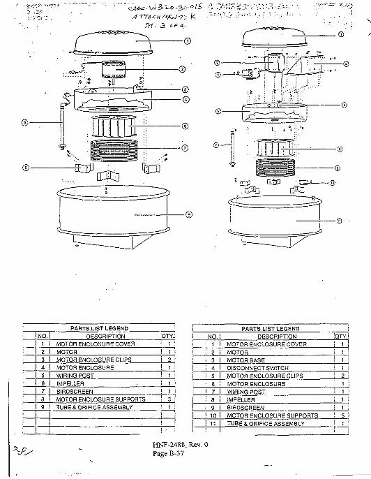
•®
PARTS LIST LEGENDNO.
! 123
DESCRIPTIONMOTOR ENCLOSURE COVERMOTORMOTOR ENCLOSURE CLIPS
:OTY.j 1i 1
! 24 j MOTOR ENCLOSURES I WIRING POST
IMPELLERI 7 I BIRDSCREEN
MOTOR ENCLOSURE SUPPORTSI 9 TUBE & ORIFICE ASSEMBLY i 1
1
j
PARTS LIST LEGENDNO. 1 DESCRIPTION ;QTY.
1 I MOTOR ENCLOSURE COVER2 i MOTOR3 i MOTOR BASE4 ! DISCONNECT SWITCH5 I MOTOR ENCLOSURE CLIPS
S ; MOTOR ENCLOSURE7 I WIRING POST8 i IMPELLER
i 9 j BIRDSCREENI 10 1 MOTOR ENCLOSURE SUPPORTS .! 11 I TUBE & ORIFICE ASSEMBLY
I
11
5t
HNF-2488, Rev. 0Page B-37
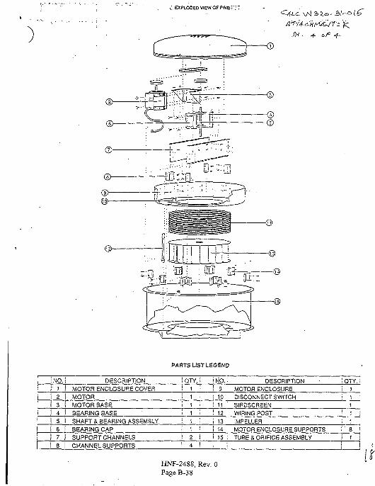
.; EXPLO0EDVIEWOFPW8':T
@
, ^-irnnr IF
SH . -f- oF -f-
PARTS LIST LEGEND
!N0.! 1i 2I 31 4! 51 s
78
DESCRIPTIONMOTOR ENCLOSURE COVEFlMOTORMOTOR BASEBEARING 8ASESHAFT & BEARING ASSEMBLYBEARING CAPSUPPORT CHANNELSCHANNEL SUPPORTS
IQTY.!i 1 •• 1 •
i 1 •
i • 1 i
i ! :i 1 '•
\ 2 iI 4 !
i NO. •! 9 'i 10! 11i 12r 13
I 141 15 :1 ;
DESCRIPTIONMOTOR ENCLOSUREDISCONNECT SWITCHBIRDSCREENWIRING POST
IMPELLERMOTOR ENCLOSURE SUPPORTSTUBE a ORIFICE ASSEMBLY
iQTY.; 1
i 11
'• 1
i 1V 8! 1
i
HNF-2488, Rev. 0PageB-38
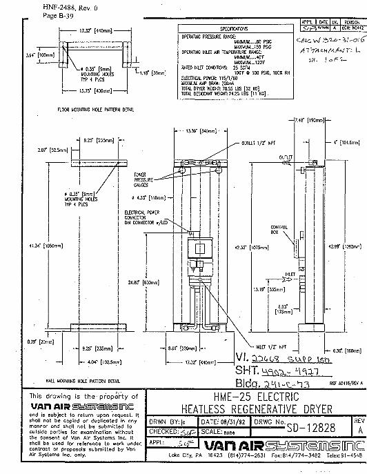
HNF-2488, Rev. 0Page B-39
I7J2" [440mm]-
3.94" [100mm]
-» 0.35" [9mm]MOUNTING HOLESTYP 4 PLCS
• 15.75" [ 4 0 0 m m ] -
FLOOR MOUNTING HOLE PATTERN DETAIL
_L— j -
t-1.13" [30mm]
SPECIFICATIONS
OPERATING PRESSURE RANGE:MINIMUU._..6O PSIGWAXIUUU._150 PSG
OPERATING INLET AR TEMPERATURE RANCE:UIN1MUU.._..4O'FUASUUM....12CTF
RATED INLET CONDITIONS: 25 SCFU100T 0 100 PSIG. 1003 RH
ELECTRICAL POWER: 115 /1 /60UAXIUUU A1IP DRAW: 200mA
TOTAL DRYER WEIGHT: 70.55 LBS [32 KG)TOTAL OESCCANT WOGHT: 24.25 LBS [11 KG] .
APP1 DATEwvn
LVtA
REVISION
tC* N0«2
Cr)^L \ A / 3'2-<^~3>f ~Ol^>
A ~T~TA CH At / ^ / T- L.
SH- lafi-i-
2.07" [52.5mm]
4134" [1050mm]
0.79" [20mm]
WALL MOUNTING HOLE'PMTERH DETAIL
This drawing is the property of
UAH AIR SMSKSDSOnEond Is subject to return upon request. Itshot! not be copied or duplicated in anymonner ond shall not be submitted tooutside porties for exominotion withoutthe consent of Von Air Systems Inc. Itshall be used for reference to work undercontroct or proposals submitted by VonAir Systems Inc. only.
HME-25 ELECTRICHEATLESS REGENERATIVE DRYER
DRWN BY:jc
CHECKED:
APPL:
DATE: 08/31/92
SCALE: nor>»
DRWG No.SD-12828
REV
A
UAH AIRLoke City. PA 16423 (814)774-2631 Fox:814/774-3482 Telex:91-4548
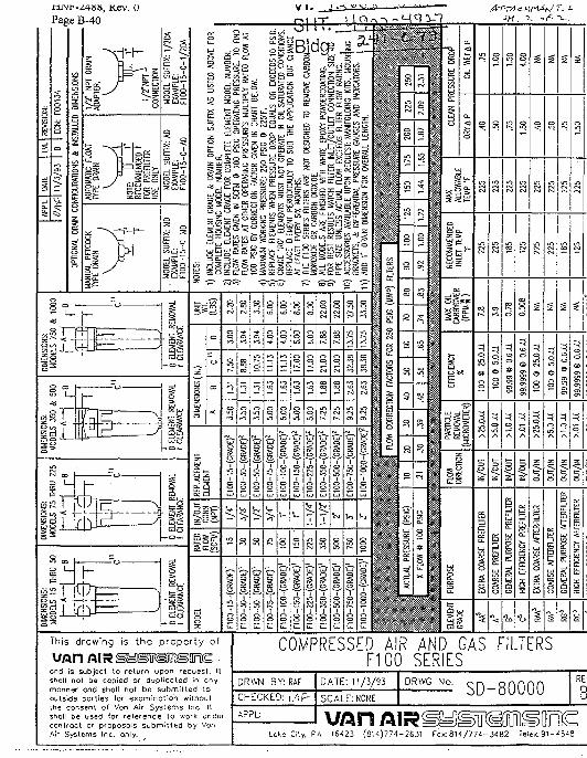
niNr-Z4»s, Kev. U
Page B-40
This drawing is the property of
ond is subject to return upon request. IIsnoii not be copied or dupiicoled in cnymanner ond sholl not be submitted tooutside porlies (or exominction withoutthe consent of Von Air Systems inc. !tshell be used (or reference lo wofk underconlroct or proposols submitted by VonAir Systems Inc. only.
COMPRESSED AIR AND GAS FILTERSF100 SERIES
DRWN 3Y: RAF
CHECKED:
APPL:
DATE: 11/3/93
SCALE: NONE
DRWG No. SD-80000RE1
B
Lake Cily. PA 16423 {814)774-2631 rox:814/774-3482 Ielex:91-454S
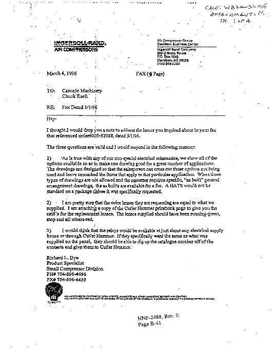
- lria»r»©iMUnd CompanyStrwt '
OD«vW»n, NC 25035<70« 8SS-U00
March 4,1996 FAX (4 Page)
TCh Ciicade MacJuziery. Chuck Krott'
RE: Fax Dated 3/1/9$
I thought I would drop you a note to sddrett the uiugs you inquired about in your faxOut referenced order#005-S2088, dsltd 3/1/96.
The three questions era valid sod I would respond in the fbljawing manflen
1) "As is true with any of our non-rpocisj ebcta'eal sehetn«^o», we show sll cf theoptions available s o » { o na le one drawng good for a great number of applications,' i le drawings are designed so th# lbe Htopcrjen can cross out diose options not beingused and leave unmarked the items thai appJy to &st partieulto ejiplicalion. Whiwi thosetypes of drawings are not allowed snd the custonw requires specific "as built" generalBnaogeinerrt drawings, th« « builts «»tvajlabb for a fee. A HATS would nnttestajidfirf on a package unless h was speclficdly renussted
2) I am pretty luretba! the color lenses they ax requeuing ire equal to what wesupplied. I am attaching a copy of the Cutler Hunrae: pricefcook page to give you feecatf's for tjre rcplsccrneat Jense*. The leases supplied should have been running-green,stop snd all olhers-red.
3) I would think that the rd&ys vrould be RYsil^lo st just obaut «ny electrical supplybouse or through Cutler Hammer. If&ny specifically want the tans as what vrassupplied on the panel, they should be able to dig up the cdajogue number off of thecontacts and give them to Cutler Hammer.'
Kiehsrd L. DyeProduct SpecialistSmall Compressor DivisionPH# 704-896-4496
Ait MMEWKTT COKTOtt-KT «»CW SflttttX AW©8 « 0 JOU K V « CSNWWfS K T > » OU( O C T .
Rev. 0-41
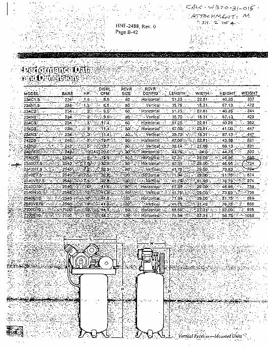
HNF-2488, Rev. 0
Page B-42
-'Hr^CritT- -M-' "2-" op4--..
234C1.5V::
'234N1',5- •-
;:ZHC2:<: •..•
!'234N2Vv:.-;:-;
: 234C3?.'.-..;1.'
;234D3S: ; : ;
• ; -234«3. ; i ii - : :
F 242D5f<v--:
-.•-.•; 2 5 4 0 0 5 ; %•
^ 254O07i5ft'
•i-&otif.s-S
..:;254CVE7.5-
..V2546at.tt7.-:3
K2S46aeft'r
:--ir'Tioo&i o- ' '•
. ••••• . B A R E : " H
v- ••';• . 1 1 2 3 4 i - . . - • .1
:-.'---:.'.--:-.'-23«;-ll!v'-.1
' -. .-. .-•• 2 3 4 ' . . - .•:•;
' • " ! : . , : ; ' 23*. :?::>"J-
. : ' . . : • . • . • • - ; : . 2 3 * . ; ; ^ i - / - v .
$-V:-<i - i t ivl-: -.2
^•':.:/:'^V;;23«ii;'N>
a3fflgi;2>glt:ST"K-5S.;."2545S;;,rt;;s
;;s&ti.25*WiKif:?
^•*-.*254cOSap!i
•:.-sfe'i-fe7io6;;gssfe'
IP."f;:.'- CFW-'ii
.5I-.-;-.;.:-.6.5-.-1...
.si---^"--^^-.'.1-Si;;-\V;:. 9.o:,-'v
:3¥'-'.-V:'-'ii'>->.-',
ii'l-^-Vt'fii.-'?
••SsStXsTS^sS^
^•^--S- iKES-r. ' i i '
RCVRv SIZE ;
•.-•; so ,-.
.v:-' 80:i.i
' . • V 6 0 . ' ;
-".;: 80. -:
,"•,. 60.: •
'••'•--'BtS^i:
i ^ ••««•!
?i'-?i80ft.
^A'SKi1
.^t2&'ji
>£v;i'2a?s;i5i5,^-8Oi^
:?"1'2^*s
: • l l CONFIG;-v. ::
. ; . , Horizontal1 ••:.-
: - . •" ';. ..Vertical: V-
: ; Horizontal ; .
-".••'•y.Vertical';-^
• . ' Horizontal • r-
\'J'. HorizonJal'v-' ;
'••.:• • •Hbr izbhlaT. . ' :
Wf.HorizQMaf.-'fs
:? :> HqrizontafeV
teHorizpntaJ^:-:
?yv Horizontal;.-;
l-SviHtjriioiital?.^:
*?;•• HOTZor i ta l / ^
' LENGTH-.'.-
-.- 51.25 .:•:•;•.
• ••-• 35.75.-, .
"• . 51.25. r . •1 35.75-:-.-.'
:51.25 V
::.\ 67.6i;:;-:.;
;v'35;.7Si'i>;
;v-:67:oos::«
:rt'67.3f"'.v;r
K ;67;3t':^-;-.
•,;.--.4W5K^
¥-%73g?S
vi:4ii7S;oiffi
!•;-;' 6S:59^ii
:.' WIDTH.'.
.. .: 22.81- . .1 --18.31....-. •
- : • « 2 2 . 8 1 - ••;••
-SV. 18.31V;
.- : 22.81V:>.
v?.-22.8V-v.':
;:f ::22.8i;:-,
&:.V-24;o-:r
• :'> 2s:-oo\!-.:.
" ^ ^ . G O . ••.'•
R?2?XXH-V;
f-;«-29.oa;;v-:
;\^27.;3T:;iV\
HEIGHT
• 4 0 . 2 5 .
. 67.13. .
• 4 0 . 2 5 ' ••
••'• 6 7 ; 13 .1 40.25 V
"-." .4v.oo-;v
-.;-1'67.13'--J1
"... ".43.38 -• •
rV?"4e.9&--\
:»:\46.9S:J::
•.•- 7 3 . 6 3 . ; ;
:-;:•• 4 6 . 9 6 ^
. ^ • . " • g i -T^V
•.••;.-',76.7S'-:--."
'••• i 52 .00 ; ; .
' ; '56.75-:":
WEIGHT
337
•:..-. 422 .
- • • • - . 3 4 4 -
• . .' 429 . :
•'• . 362.
•'.':, 4 4 7 '
'.V.-.447 .
• .-. 5 2 1 •
:.: .'.500 v.
• ';. figOCj .
-.':/?-724 • ~)
•*•/?•:' 8 7 4 :
*v." ^35 -
' . - - . • • 8 8 6 - •
•f- • 8 8 6
..'••'-S'. ' 9 3 5 , •
• • • - •1085. .
" v . V . 1 »•.:;:•••.•;:
• • > . • - . - . . " :
: - i . - . 1 • * • • • . . - . • ' ! • ' * . . ? : • • • • • " • • • • • V ' • ' • : - . • • ' - - • : . - ' . " • : ; . - . . • . - - '
:-^\b.iij-.'.:; VerticalReceivers-Mounted Units"v-\ :
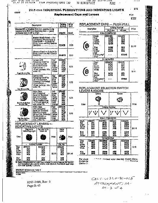
rrirt nv. cuy iP002
22.3 mm INDUSTRIAL PUSHBUTTONS AND IKWCAT1HO LIGHTS 2 7 5
R*plac*m*nt Ctpa end Ltnses - FILE
' • . . E22
Ctscrtpsiai
A«»j ur B l — J M H B n .5 njm Mtftta Is t*raomltd in 1335 ram mxinlinj rail — firiijMclmsi tremVi.r W7/3T.. ESURK
?4 ftanSica
^
i »IK» lent—Far
Sumwfob i a t S u m wLncr mi Kw
t k m n i I K I I — SrfiiV IcrKnot. Uv«f «xl K S ^ i
mm DtaxtW
Unit's wUhOttsjunal Smlfef25 n Dmoier
I O M I PKA)B», rrwvOCOK 10.
ZSWnDUmtUrflan Pi»iit«j!lsn»
Pusiiblftienj —
firf
5'lfl
Ertw
tlrMR
1S
ova
AMASIASSA M
ETZ4CSACS
ACEACH
REPLACEMENT LENSES —INDICATING LIGHTS .
8.20
5.70
Cdol
Otu
VM>
Lter
•. Cililogh
enxn>HIJgAE1US
forUHWItiltrairto
mvnrta;
£22(60AG2 '
ASS'
G6«
"sa
Pria
$11.40
n, o«« avis. Pt'
REPUCEMENT CAPS — PUSH-PULLWal^ nunisr
Whltl
w
AKKAxnAXS*
laUMINAitD
VU
AH1
AK2RS
Prira
S3.10
REPLACEMENT SELECTOR SWITCHLEVERS & KNOBS
Cxr
Grwl
VrW
CnvAnbir
Iseran
• S38?tin
V
i^
S5AH
VEOAXC1
S8AMAM
»K2t
tfl£5
Poa
3.10
FordevfcCvUtf-Kt
i your nearest Eaton Coip.
HNF-2488, Rev. 0
PageB-43SH • 3, « P Ar
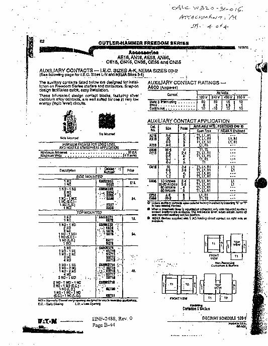
(4-
62 CUTLER'HAMMER FREEDOM SERtES
AfrBftMOftM -AE18,AN18,AE58,AN5e,
CB1S.-ON15, CN35, CE55 <u*j CN6S
AUXIUARY CONTACTS — I.E.C. SIZES A-K, NEMA SIZES 00-2(S*e following page tor l.B.C. Sizw L-N ana HEMA Stee» W )
Ths aujlSary conlscft ljjtsd beisw sra dtelgned tor inet&J-btten on F»e<(»m Seritc el»rt»n» and eafilseton.-Snap-ondsasn taitKsles QU'<*, easy trnftiJiaBoa -Thesa b!Iurcal*d clatjyi coniast bloda, fatlurins trvtc 'cadmium sHoy co'ntncts. i n n ! JiAed lor u « In vary lew
foo'5 ttv»D clreuib.
AUXIUARY CONTACT RATINGS -ASOO (Amp»rM)
-
Corttoiwi
AiVolls /1SCV
60
.4
2^0V (Mil15
euv12,0
AUXIUARY CONTACT APPLICATION
MMMUM RATIKSAMD HOSTILE iTOO!
ffiSSvS?"*5(WREAPPuSlKIH
S1DSMOUNTJO
1681K0-1W!
2H0
TOP MOUNTED
1N0-1KC
aatsn
JSi
" KT7 •
wn
am
t i t
to0-2l . i
S»«nT»l. P.L1.R1
T1.U.Mn, LI . R1
.1.R1
.1.R1•jj-i.flfyhTt.U.MTi.u.m
fi.u.ftiri.L1.R1TllLI R1T1.L1 M
L1.R1T1.T2
11, W
uL1
1 i i L1
FADKTv.ew
VBV
T1
ft
t. .n In-
nsKTvraw
Rf. T>!
IP
HNF-2488, Rev. 0PageB-44
OISCOUKT SCHEDULE 1»-1;

HNF-2488, Rev. 0
W320-31-022
Control Circuit Sizing & VoltageDrop Analysis for SeismicShutdown System (Class IE)
C-i
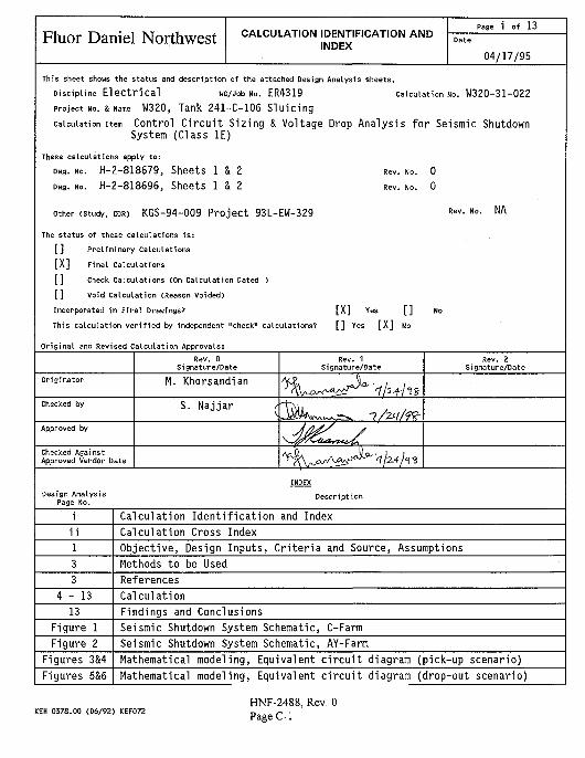
Fluor Daniel Northwest CALCULATION IDENTIFICATION ANDINDEX
Page 1 of 13
04/17/95
This sheet shows the status and description of the attached Design Analysis sheets.
Discipline E l e c t r i c a l WO/Job No. ER4319 Calculation No. W320-31-022project NO. s Name W320, Tank 241-C-106 S lu i c ing
calculation item Control C i r c u i t S iz ing & Voltage Drop Analys is f o r Seismic ShutdownSystem (Class IE)
These calculations apply to:
Dug. NO. H-2-818679, Sheets 1 & 2Dwg. NO. H-2-818696, Sheets 1 & 2
other (study, CDR) KGS-94-009 Pro jec t 93L-EW-329
The status of these calculations is:
[] Preliminary Calculations
[X] Final Calculations
[] Check Calculations (On Calculation Dated >
[] Void Calculation (Reason Voided)
Incorporated in Final Drawings?
Rev. No. 0
Rev. No. 0
Rev. No. NA
[X]This calculation verified by independent "check" calculations? [] Yes [X] No
Original and Revised Calculation Approvals:
Rev. 0Signature/Date
Rev. 1Signature/Date
Rev. 2Signature/Date
Originator M. Khorsandian
Checked by S. Najjar
Approved by
Checked AgainstApproved Vendor Data
INDEX
Design AnalysisPage No.
Description
Calculation Identification and IndexCalculation Cross IndexObjective, Design Inputs, Criteria and Source, AssumptionsMethods to be UsedReferences
4 - 1 3 Calculation13 Findings and Conclusions
Figure 1 Seismic Shutdown System Schematic, C-FarmFigure 2 Seismic Shutdown System Schematic, AY-Farm
Figures 3&4 Mathematical modeling, Equivalent c i rcu i t diagram (pick-up scenario)Figures 5&6 Mathematical modeling, Equivalent c i rcu i t diagram (drop-out scenario)
KEH 0378.00 (06/92) KEF072HNF-2488, Rev. 0PageC-1
Fluor Daniel NorthwestCALCULATION IDENTIFICATION AND
INDEXContinuation Sheet
Page i l of 13
04/17/95Discipline E l e c t r i c a l UO/Job No. ER4319 Calculation No. W320-31-022
Rev. 0Signature/Date
Rev. 1Signature/Date
Rev. 2Signature/Date
Originator M. Khorsandian
Checked by S. Najjar
INDEX
Design AnalysisPage No.
Description
A-1 to A-2 Attachment A: Westinghouse, Size 6, Type A201k6CX Catalog cutB-l to B-2 Attachment B: Westinghouse Type AR600 and GE CR12OB Relay Information
C-l Attachment C: 750 VA, Control Power Transformer (CPT) Impedance DataD-1 to D-3 Attachment D: Bussman FNQ Type Fuse DataE-1 to E-5 Attachment E: Cutler-Hammer 1025T and GE CR104P Indicating Light DataF-1 to F-6 Attachment F: Rockbestos Firewall SIS Switchboard Wire data including
ICEA S-68-516 Resistance and Okonite Temp. Correc. factors
G-l Attachment G: Telephone conversation record with Kinemetrics, Inc.H-l Attachment H: Electronic I/O board digital output information
KEK 0378.01 (06/92) KEF072
HNF-2488, Rev. 0Page C-2
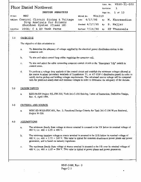
calc. No. W320-31-022Fluor Daniel Northwest Revision 1
DESIGN ANALYSIS Page No. 1 of 1 3
client WHC uo/Job No. E R 4 3 1 9
subject Control Ci rcu i t Sizing & Voltage Date 4/'17/'95 By M. KhorsandianDrop Analysis for Seismic ,
Shutdown System (Class IE) checked 4/17/95 By S. NajjarLocation 2 0 0 E ; C & AY T a n k F a r m s Revised 7 / 2 4 / 9 8 By KP T h a n a w a l a
1.0 OBJECTIVE
The objective of this calculation is:
a. To determine the adequacy of voltage supplied by the electrical power distribution system to thecontactor coil.
b. To size and select control loop cables supplying the contactor coil.
c. To size and select the cable connecting contactor control circuit to the "Emergency Trip" switch incontrol room.
d. To perform a voltage drop analysis of the control circuit and establish the minimum voltages allowed atthe source terminal (secondary terminals of Transformer Tl, or AY-PDP-1 distribution panel) in order tosatisfy device pickup and holding voltages requirements. The calculated source voltage will be comparedwith the predicted steady-state and transient voltages in order to determine the adequacy of the circuits.
2.0 DESIGN INPUTS
a. KGS-94-009 Project 93L-EW-320, Tank 241-C-106 Sluicing, Letter of Instruction, Definitive Design,Rev. 6, April 1994.
3.0 CRITERIA AND SOURCE
a. WHC-SD-W320-FDC-001, Rev. 2; Functional Design Criteria for Tank 241-C-106 Waste Retrieval,Project W-320.
4.0 ASSUMPTIONS
a. The minimum Steady State voltage at source terminal is assumed to be 5% below its nominal voltage of480 V; i.e. 480 x 0.95 = 456 V.
b. The minimum transient voltage at source terminal is assumed to be 25 % below its nominal voltage of480 V; i.e. 480 x 0.75 = 360 V. This value is typical for transient situations at power plants and powergenerators, and is based on industry experience.
c. The maximum Steady State voltage at source terminal is assumed to be 5 % over its nominal voltage of480 V; i.e. 480 x 1.05 = 504 V. This value is typical at power plants and power generators.
HNF-2488, Rev. 0Page C-3
calc. No. W320-31-022
Fluor Daniel Nor thwest Revision 1DESIGN ANALYSIS Page No. 2 of 13
Client WHC wo/Job No. E R 4 3 1 9
subject Control C i rcu i t Sizing & Voltage Date 4/17/95 By M. KhorsandianDrop Analysis for Seismic
Shutdown System (Class IE) c h e c k e d 4 / l 7 / 9 5 By S. Najjar
Location 200E; C & AY Tank Farms Revised 7/24/98 By KP Thanawala
d. Loop conductors are considered to be #14 AWG unless otherwise noted in this calculation or on thedrawing.
e. Resistance for loop conductors is based on 55°C. This value is the maximum anticipated ambienttemperature, and is based on the consideration that these conductors are low current carrying conductors.
f. Cable reactance is assumed equal to zero since the resistive component of impedance is much larger thanthe reactive component of impedance for cable sizes utilized in this control loop.
g. Resistance of the cable connecting upstream transformer (transformer Tl) , or distribution panel (AY-PDP-1) to the contactor assembly is negligible due to insignificant length.
h. Percent impedance of a 750 VA Control Power Transformer is not published by the manufacturer. The%Z = 4.44 of a similar dry-type distribution transformer is used in this calculation. This value is typicalfor 750 VA transformers.
i. Indicating lights are transformer type, and have very high input impedance. Indicating lights impedancesare assumed to be purely resistive.
j . The impedance of fuses larger than 3 amps is neglected.
k. Minimum pick up and hold in voltages of Westinghouse AR industrial relay is not published by themanufacturer. Therefore, it is conservatively assumed that relay minimum pick up and hold in voltages tobe %85 of its nominal coil voltage, i.e.:
Vnipie^p = V^ i, = 120 X 85%
= 102 V
1. The most restrictive circuit device is the device being analyzed for pick-up and hold-in capabilities,
m. The impedance of panel wiring is assumed to be zero due to insignificant conductor lengths,
n. The impedance of circuit loads/devices is based on rated voltage and current.
o. The design data for Lamp No. 755 for Cutler-Hammer 10250T indicating lights is not provided by thevendor. Therefore, the data provided for the same lamp for GE CR104P indicating lights is used.
p. The Hold-in Wattage data for Westinghouse AR600 relay coils is not provided by the vendor. Therefore,the data provided for GE CR120B relay coil, which is similar, is used.
HNF-2488, Rev. 0Page C-4
Calc NO. W320-31-022Fluor Daniel Nor thwest Revision 1
DESIGN ANALYSIS Page No. 3 of 13Client WHC WO/Job No. E R 4 3 1 9
subject Control C i rcu i t Sizing & Voltage Date 4/17/95 By M. KhorsandianDrop Analysis for Seismic
Shutdown System (Class IE) checked 4/17/95 By S. NajjarLocation 200E; C & AY Tank Farms Revised 7/24/98 By KP Thanawala
5.0 METHODS TO BE USED
1. For each utilization device, the minimum required terminal voltage for adequate operation of the deviceis obtained. For contactor coil and relays this will typically include a minimum pick-up voltage and aminimum hold-in voltage.
2. For each utilization device, the maximum power required by the device is obtained. For contactor coiland relays, this will normally include a momentary in-rush (pick-up) current and a steady state (hold-in)current.
3. Using transformer %R and %X, Control Power Transformer (CPT) impedance is calculated.
4. Using cable sizes and lengths, conductor impedances are calculated.
5. Impedance of each utilization device according to whether the device is drawing in-rush current or hold-in current is calculated.
6. From the control circuit diagram, the device alignment that yields the heaviest load on the CPT isdetermined. Based on this alignment the most restrictive device in the control circuit is determined. Dueto large inrush and hold-in current, typically, contactor coil is among the most restrictive devices in thecircuit.
7. A mathematical model using the values determined in previous steps is constructed, showing the worstcase loop loading, the most restrictive device and minimum pick-up and drop-out voltages across thismost restrictive device.
8. Using electrical circuit theory, the minimum pick-up and drop-out voltages required across the sourceterminal is calculated.
9. The required minimum pick-up and drop-out voltage values across source terminal will be compared withthe minimum steady state and minimum transient voltage values to determine the adequacy of the controlcircuit.
6.0 REFERENCES
1. Westinghouse Catalog 25-000, 1993
2. Cutler-Hammer Quick Selector Catalog 25-000, 1995
3. Okonite Company Catalog,"Power, Control and instrumentation Cables", 1990.
HNF-2488, Rev. 0Page C-5
Fluor Daniel NorthwestDESIGN ANALYSIS
Client WHC
subject Control Circui t Sizing & VoltageDrop Analysis for Seismic
Shutdown System (Class IE)Location 200E; C & AY Tank Farms
Calc. No.
Revision
W320-31-022
1
4 of 13Page No.
UO/Job No. E R 4 3 1 9
Date 4 / 1 7 / 9 5 By M. K h o r s a n d i a n
Checked 4 / 1 7 / 9 5 By S . N a j j a r
Revised 7 / 2 4 / 9 8 By KP T h a n a w a l a
4. Bussmann Fuse Catalog, Section 3
5. NFPA-70, National Electrical Code, 1993
6. Westinghouse Consulting Application Guide, 1991; Dry-Type Distribution Transformers technical Data
7. GE Electrical Distribution & Control Catalog, 1993
8. Ref. Standard ICEA S-68-516, WC 8-1988
7.0 CALCULATION
Seismic Shutdown System (SSS) is consisted of 2 sets of redundant contactor assemblies (Figures 1 and 2). Sinceall 4 contactors are identical, only one unit, seismic shutdown system #1, Figure #1 is analyzed.
7.1 CIRCUIT DATA
7.1.1 Westinghouse, size 6, 3 phase, 480 V contactor, Catalog # A201K6CA (Coil Ml)Coil data (Attachment A):
In-Rush VAHold-In VAHold-In WattsIn-Rush P_r
Hold-In P|Voltage RatingMin. Pick-Up VoltageMin. Hold-In Voltage
= 2900 VA= 220 VA= 42 W= 0.0145= 0.19= 120 VAC= 84 V= 72 to 84 V
7.1.2 Westinghouse AR 600 Relay (Relay coils JXY1361, JXY1362, JXY0621, JXY0622, YY13650, YY13651,YY13652, YY13653, YY06210, YY06211, YY06212 and YY06213) coil data (Attachment B):
In-Rush VAHold-In VAHold-In WattsIn-Rush P,Hold-In PjVoltage RatingMin. Pick-Up VoltageMin. Hold-In Voltage
= 96 VA= 14 VA= 7 W= 0.0729= 0.5= 120 VAC= 102 V= 102 V
HNF-2488,Page C-6
(Section 4.0-k)(Section 4.0-k)
Rev. 0
calc. No. W320-31-022
Fluor Daniel Nor thwest Revision 1DESIGN ANALYSIS Page No. 5 of 13
Client WHC no/Job No. E R 4 3 1 9
subject Control Circuit Sizing & Voltage. Bate 4/17/95 By M. Khorsandian
Drop Analysis for Seismic
Shutdown System (Class IE) c h e c k e d 4/17/95 By S. Naj ja r
Location 200E; C & AY Tank Farms Revised 7/24/98 By KP Thanawala
7.1.3 Control Power Transformer (CPT)
A 750 VA CPT is selected480/120 V, Single phase
= 4.44 (Attachment C)
7.1.4 Fuse Data
"NUTHBRM" has provided a 10 Amp control fuse for secondary side of transformer, and a 5 Amp fusefor isolation.Since both these kinds of fuses are over 3 Amp the resistance is neglected.RFNQ-IO = 0 a
RBKM = o n
7.1.5 Indicating Lights
Indicating lights provided are Cutler-Hammer 10250T transformer type (Attachment E).
Cutler-Hammer 10250T transformer secondary voltage = 6 VLamp No. 755
7.1.6 Seismic Switch Power Supply
Power supply unit rating is 120 VAC, 150 mA (Attachment G). For conservatism, it is assumed powersupply has an input rating of 300 mA.
7.1.7 Cable Data
#14 AWG size is provided for loop conductors
R«I4AWG®25-C = 2.79 S) Per 1000 ft (Attachment F)
^#14 AWG ® S5°C ~ *S*U AWG@2S*C * 1 .115
= 2.79 X 1.115
K*MAWO»S-C = 3 . 1 1 0 Per 1000 ft
HNF-2488, Rev. 0Page C-7
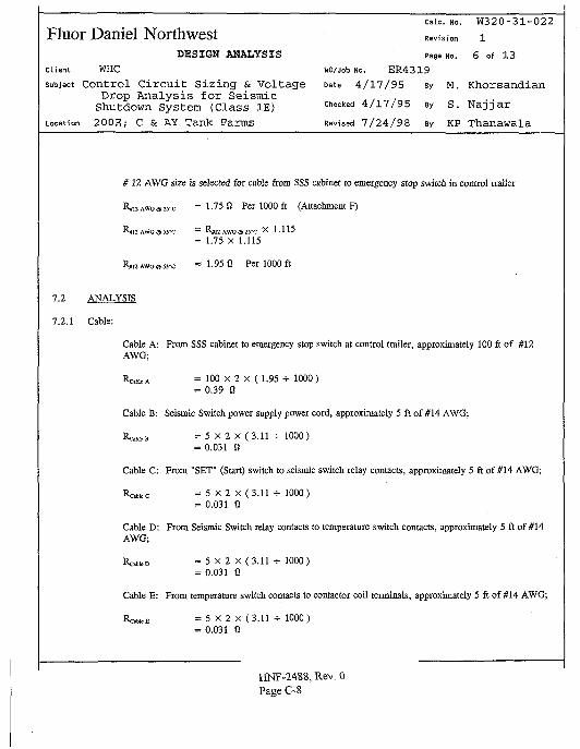
calc. NO. W320-31-022
Fluor Daniel Northwest Revis,-on iDESIGN ANALYSIS Page No. 6 of 1 3
Client WHC WO/Job No. ER4319
subject Control Ci rcu i t Sizing & Voltage Date 4/17/95 By M. KhorsandianDrop Analysis for Seismic
Shutdown System (Class IE) c h e c k e d 4/17/95 By S. NajjarLocation 200E; C & AY Tank Farms Revised 7/24/98 By KP Thanawala
# 1 2 AWG size is selected for cable from SSS cabinet to emergency stop switch in control trailer
R»I2AWG®2S-C = 1 . 7 5 0 Per 1000 ft (Attachment F)
R#12AWG@55'C = R#12 AWG ffl 25'C X 1 .115= 1.75 X 1.115
R».2AWG®55-C " 1 . 9 5 0 Per 1000 ft
Cable A: From SSS cabinet to emergency stop switch at control trailer, approximately 100 ft of #12AWG;
RobicA = 100 x 2 x (1.95 •*• 1000)
= 0.39 S)
Cable B: Seismic Switch power supply power cord, approximately 5 ft of #14 AWG;
UB = 5 X 2 X (3.11 •*• 1000)
= 0.031 0
Cable C: From "SET" (Start) switch to seismic switch relay contacts, approximately 5 ft of #14 AWG;
R c ^ c = 5 X 2 X (3.11 * 1000)= 0.031 Q
Cable D: From Seismic Switch relay contacts to temperature switch contacts, approximately 5 ft of #14AWG;Rou.D = 5 X 2 X (3.11 *• 1000)
= 0.031 0
Cable E: From temperature switch contacts to contactor coil tenninals, approximately 5 ft of #14 AWG;
Rc< W c E = 5 X2 X (3.11 -i- 1000)
= 0.031 0
HNF-2488, Rev. 0
Page C-8
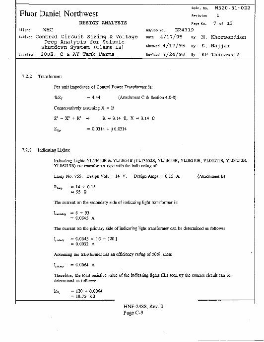
Calc NO. W320-31-022
Fluor Daniel Northwest Revision 1DESIGN ANALYSIS Page No. 7 of 1 3
Client WHC WO/Job No. ER4319
subject Contro l C i r c u i t S i z i n g & Voltage Date 4 /17 /95 By M. KhorsandianDrop A n a l y s i s f o r Seismic
Shutdown System (Class IE) c h e c k e d 4 /17 /95 By S. N a j j a r
Location 200E; C & AY Tank Farms Revised 7/24/98 By KP Thanawala
7.2.2 Transformer:
Per unit impedance of Control Power Transformer is:
%Zp = 4.44 (Attachment C & Section 4.0-8)
Conservatively assuming X = R
Z? = X ! + R 2 = > R = 3.14 0, X « 3.14 Q
Zr,,, = 0.0314 + j 0.0314
7.2.3 Indicating Lights:
Indicating Lights YL13650B & YL13651B (YL13652B, YL13653B, YL06210B, YL06211B, YL06212B,YL06213B) are transformer type with the bulb rating of:
Lamp No. 755; Design Volt = 14 V, Design Amps = 0.15 A (Attachment E)
Ru»p = 14 -*• 0.15= 93 fi
The current on the secondary side of indicating light transformer is:
IsewDdso- ~ 6 -=- 9 3
= 0.0645 A
The current on the primary side of indicating light transformer can be determined as follows:
W = 0.0645 X [ 6 •*• 120 ]= 0.0032 A
Assuming the transformer has an efficiency rating of 50%, then:
W ? = 0.0064 A
Therefore, the total resistive value of the indicating lights (IL) seen by the control circuit can bedetermined as follows:
R t = 120 + 0.0064= 18.75 K0
HNF-2488, Rev. 0Page C-9
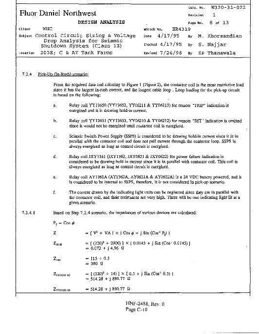
catc. No. W320-31-022
Fluor Daniel Northwest ReViSion 1DESIGN ANALYSIS Page No. 8 of 13
client WHC uo/Job No. E R 4 3 1 9
subject Control Ci rcu i t Sizing & Voltage Date 4/17/95 By M. KhorsandianDrop Analysis for Seismic
Shutdown System (Class IE) checked 4/17/95 By S. NajjarLocation 200E; C & AY Tank Farms Revised 7/24/98 By KP Thanawala
7.2.4 Pick-Up (In-Rush) scenario:
From the acquired data and referring to Figure 1 (Figure 2), the contactor coil is the most restrictive loadsince it has the largest in-rush current, and the longest cable loop . Loop loading for the pick-up circuitis based on the following:
a. Relay coil YY13650 (YY13652, YY06211 & YY06213) for remote "TRIP" indication isenergized and it is drawing hold-in current.
b. Relay coil YY13651 (YY13653, YY06210 & YY06212) for remote "SET" indication is omittedsince it would not be energized until contactor coil is energized.
c. Seismic Switch Power Supply (SSPS) is considered to be drawing hold-in current since it is inparallel with the contactor coil and does not pull current through the contactor loop. SSPS isalways energized as long as control circuit is energized.
d. Relay coil JXY1361 (JXY1362, JXY0621 & JXY0622) for power failure indication isconsidered to be drawing hold in current since it is in parallel with contactor coil. This coil isalways energized as long as control circuit is energized.
e. Relay coil AY1361A (AY1362A, AY0621A & AY0622A) is a 24 VDC battery powered, and itis considered to be internal to SSPS, therefore, it is not considered in pick-up scenario.
f. The current drawn by the indicating light units can be neglected since they are in parallel withthe contactor coil, and their resistances are very high. There will be one indicating light lit at agiven scenario.
7.2.4.1 Based on Step 7.2.4 scenario, the impedances of various devices are calculated:
Pr = Cos <t>
Z = [ V2 - VA ] X [ Cos 0 + j Sin (Cos ' P,) ]
ZM I K = [ (120)2 + 2900) ] X [ 0.0145 + j Sin (Cos"1 0.0145) ]= 0.072 + j 4.96 a
Z ^ = 115 •*• 0.3« 380 a
ZKY1361 HI = [ (120)2 •*• 14) ] X [ 0.5 + j Sin (Cos'1 0.5) ]= 514.28 + j 890.77 Q
Z Y ™ * HI = 514.28 + j 890.77 !)
HNF-2488, Rev. 0Page C-10
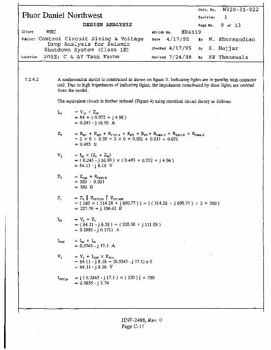
calc. No. W320-31-022
Fluor Daniel Northwest Revision 1DESIGN ANALYSIS Page No. 9 of 13
client WHC wo/Job No. E R 4 3 1 9
subject Control Circui t Sizing & Voltage Date 4/17/95 By M. KhorsandianDrop Analysis for Seismic
Shutdown System (Class IE) c h e c k e d 4/17/95 By S. NajjarLocation 200E; C & AY Tank Farms Revised 7/24/98 By KP Thanawala
7.2.4.2 A mathematical model is constructed as shown on figure 3. Indicating lights are in parallel with contactorcoil. Due to high impedances of indicating lights, the impedances contributed by these lights are omittedfrom the model.
The equivalent circuit is further reduced (Figure 4) using electrical circuit theory as follows:
IM = V M - Z M= 84 + (0.072 + j 4.96)= 0.245-j 16.93 A
^ 3 = Rffl + &1F2 + Rcable A + ^IF3 + RlR + ^Cablc C "*" Cable D + ^Cable E
= 2 X 0 + 0.39 + 2 X 0 + 0.031 + 0.031 + 0.031» 0.483 0
V2 = IM X (Z, + ZM)
= ( 0.245 - j 16.93 ) X ( 0.483 + 0.072 + j 4.96)= 84.11 - j 8.18 V
^2 — ^ssps "•" 1V:able B
= 380 + 0.031= 380 a
Z<1 = Z 2 ][ Z j X Y i 3 S i II ZyY13S50
= [ 380 X ( 514.28 + j 890.77 ) ] -=- [ ( 514.28 + j 890.77 ) + 2 x 380 ]« 227.76 + j 106.42 fi
Izi = V2 + Z,= (84.11 - J8 .18 ) - (228.58 + j 111.03)= 0.2893 - j 0.1711 A
ITOT = Izi "t" IM
= 0.5343 - j 17.1 A
V, = V2 + IT0T x RTO
= 84.11 - j 8.18 + (0.5343-j 17.1) xO= 84.11 - j 8.18 V
ITOTPU = [ (0 .5343- j 17.1) X ( 1 2 0 ) ] +750= 0.0855-j 2.74
HNF-2488, Rev. 0PageC-II
Fluor Daniel NorthwestDESIGN ANALYSIS
Client WHC
subject Control C i r c u i t S iz ing & VoltageDrop Analysis for Seismic
Shutdown System (Class IE)Location 200E; C & AY Tank Farms
Calc. No. W320 -31 -022
Revision 1
Page No. 1 0 of 1 3
WO/Job No. E R 4 3 1 9
Date 4 / 1 7 / 9 5 By M. K h o r s a n d i a n
Checked 4 / 1 7 / 9 5 By S . N a j j a r
Revised 7 / 2 4 / 9 8 By KP T h a n a w a l a
Vlpu = ( 84.11-j 8.18) •*• 120= 0 .7- j 0.068
VMIN = [ ITOTPU X Z ^ + Vlpa ] X 480= [(• 0.0855-j 2.74) X (0.0314 + j 0.068 ) + 0 .7 - j 0.34] x 480= [ 0.7887-j 0.1514] X 480= 378.6-j 72.6= 385.5 / -11° V
I VMINplcl.p | = 385.5 V
This value represents the minimum source voltage required to ensure that all devices can pick up.
Since V M I N I M M P < Vmnrpfctop ( Vi_TMrrpicbu]> assumed to be 456 V in Section 4.0-1), the control loop isadequate. The most restrictive device, contactor coil, can pick up when the minimum source voltage, 456V, is present at the secondary side of transformer Tl.
7.2.5 Drop-Out (Hold-INI Scenario:
From the acquired data and referring to Figure 1 (Figure 2), the contactor coil is again the mostrestrictive load since it has the largest hold-in current, and the longest cable loop. Loop loading for thedrop-out circuit is based on the following:
a. Relay coil YY13651 (YY13653, YY06210 & YY06212) for remote "SET" indication isenergized and it is drawing hold-in current.
b. Relay coil YY13650 (YY13652, YY06211 & YY06213) for remote "TRIP" indication is omittedsince it would not be energized until contactor coil is de-energized.
c. Seismic Switch Power Supply (SSPS) is considered to be drawing hold-in current since it is inparallel with the contactor coil and does not pull current through the contactor loop. SSPS isalways energized as long as control circuit is energized.
d. Relay coil JXY1361 (JXY1362, JXY0621 & JXY0622) for power failure indication isconsidered to be drawing hold in current since it is in parallel with contactor coil. This coil isalways energized as long as control circuit is energized.
e. Relay coil AY1361A (AY1362A, AY0621A & AY0622A) is a 24 VDC battery powered, and itis considered to be internal to SSPS, therefore, it is not considered in drop-out scenario.
HNF-2488, Rev. 0PageC-12
CaU. No. W320-31 -022
Fluor Daniel Nor thwest Revision 1DESIGN ANALYSIS Page No. 1 1 of 13
Client WHC UO/Job No. E R 4 3 1 9
subject Control C i rcu i t Sizing & Voltage Date 4/17/95 By M. KhorsandianDrop Analysis for Seismic
Shutdown System (Class IE) checked 4/17/95 By S. N a ^ a r
Location 200E; C & AY Tank Farms Revised 7/24/98 By KP Thanawala
f. The current drawn by the indicating light units can be neglected since they are in parallel withthe contactor coil, and their resistances are very high. There will be one indicating light lit at agiven scenario.
7.2.5.1 Based on Step 7.2.5 scenario, impedances of various devices are calculated:
ZMHI = I (120)2 •*• 220) ] X [ 0.19 + j Sin (Cos"1 0.19) ]» 12.44 + j 64.26 Q
ZSJp! = 1 1 5 + 0.3= 380 a
ZJXVI*. HI = [ (120)2 •*• 14) ] X [ 0.5 + j Sin (Cos'1 0.5) ]= 514.28 + j 890.77 fi
ZYY.365.HI = 514.28 + j 890.77 0
7.2.5.2 A mathematical model is again constructed as shown on figure 5. Indicating lights are in parallel withcontactor coil. Due to high impedances of indicating lights, the impedances contributed by these lightsare omitted from the model.
The equivalent circuit is further reduced (Figure 6) using electrical circuit theory as follows:
IM = VM * Z«= 84 * ( 12.44 + j 64.26 )= 0 . 2 4 - j 1.26 A
Z3 = 0.483 O
V2 = IM X (Z, + ZM)= ( 0.24 - j 1.26 ) X ( 0.483 + 12.44 + j 64.26 )= 8 4 . 0 7 - j 0.86 V
Zj = 380 0
Zt = Z2 ]| Zjxyus! |] ZyY13651<= 227.76 + j 106.42 0
Izi = V 2 •*• Z ,= ( 84.07 - j 0.86 ) + ( 227.76 + j 106.42 )<* 0.3015-j 0.1447 A
HNF-2488, Rev. 0Page C-13
Fluor Daniel NorthwestDESIGN ANALYSIS
Client WHC
subject Control C i r c u i t S iz ing & VoltageDrop Analysis for Seismic
Shutdown System (Class IE)Location 200E; C & AY Tank Farms
Calc. No.
Revision
W320-31-022
1
12 of 13Page No.
UO/Job No. ER4319
Date 4 / 1 7 / 9 5 By M. K h o r s a n d i a n
Checked 4 / 1 7 / 9 5 By S. N a j j a r
Revised 7 / 2 4 / 9 8 By KP Thanawala
7.3
'TOT = Izi + IM= 0.5415-j 1.4047 A
V, = V2 + IT0T X RH,,= 84.07 - j 0.86 + ( 0.5415 - j 1.4047 ) x 0= 84.07-j 0.86 V
W = K ° - 5 4 1 5 " J i - 4 0 4 7 ) x ( 120 )] * 750= 0.0866 - j 0.225
V l p l = ( 84.07-j 0.86) •*• 120= 0.7 - j 0.007
VM,N = [ ITOTP. X ZTP. + V l p l ] X 480= [ ( 0.086-j 0.225) X (0.0314 + j 0.0314) + 0 .7 - j 0.007] X 480= [ 0.71-j 0.011] X 480= 340.7-j 5.5= 340.7 L -0.9° V
vM„ , I = 340.7 V
This value represents the minimum source voltage transient dip to ensure that all devices will not drop-out underbus voltage transient situation.
Since VMN „„,«„, < VLatnl;vM ( VLMIT*<,«». assumed to be 360 V in Section 4.0-2), the control loop isadequate. The most restrictive device, contactor coil, will not drop-out when the source voltage dips intominimum 360 V transient, at the secondary side of transformer Tl.
OVERVOLTAGE CONSIDERATION
When maximum steady state voltage of 504 is present at the primary side of CPT, the voltage at the secondaryside is conservatively calculated as follows:
V ^ , ^ , , = 120 X [504 + 480]= 126 V
Assuming no voltage losses in contactor coil loop, the contactor coil is subjected to 126 V which is less than themaximum allowable voltage of 132 V (Attachment A), i.e.:
V ™ , ^ . ^ = 120 X 110%= 132 V
HNF-2488, Rev. 0Page C-14
calc. No. W320-31-022Fluor Daniel Northwest Revision 1
DESIGN ANALYSIS Page No. 1 3 of 1 3
Client WHC UO/Job No. ER4319
subject Control Circui t Sizing & Voltage Date 4/17/95 By M. KhorsandianDrop Analysis for Seismic
Shutdown System (Class IE)Location 200E; C & AY Tank Farms
checked 4 / 1 7 / 9 5 By S. N a j j a r
Revised 7 / 2 4 / 9 8 By KP Thanawala
7.4
126 V < l = 132 V
Therefore, contactor coil can safely operate under CPT primary voltage value of 504 V without injury to theoperating coil.
FINDINGS AND CONCLUSIONS
1. The voltage supplied by the electrical power distribution system to the contactor coil is adequate.
2. #14 AWG cable is adequate for internal wiring of contactor assembly, and cables supplying seismicswitch power supply.
3. #12 AWG cable to emergency stop switch in control room is adequate in size.
4. The voltage drop analysis of the control circuit shows that the minimum voltages allowed at the sourcefor steady-state and transient conditions are adequate to satisfy the device pickup and holding voltagerequirements.
This calculation shows that the control circuit of the size 6 contactor used in the Seismic Shutdown System isadequately sized. The contactor will pick up when worst case minimum bus voltage condition is present, and itwill hold in during worst case minimum transient voltage situation. Nuisance tripping will not occur due to busvoltage normal fluctuations. Long lead cables and panel internal wiring sizes are adequately selected such thatvoltage drop will not adversely affect system operation.
HNF-2488, Rev. 0Page C-15
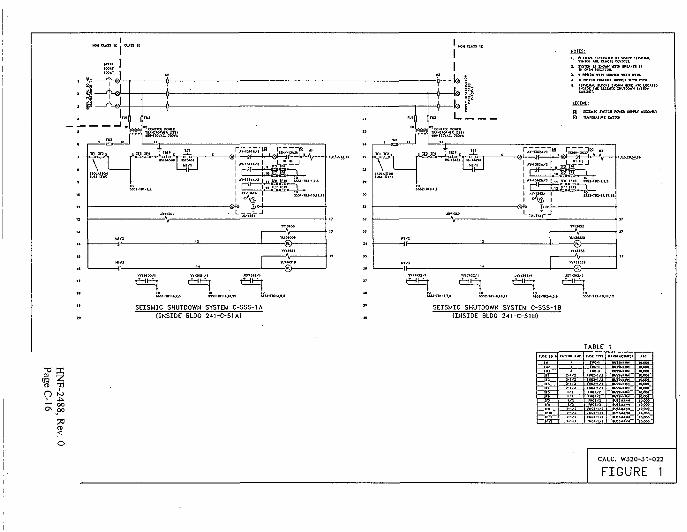
SEISMIC SHUTDOWN SYSTEM C-S5S-1A[INSIDE BLDG 241-C-51A)
SEISMIC SHUTDOWN SYSTEM C-SSS-18(INSIDE BLDG 241-C-518)
Oi
fust to •
m—
MTIW ftUT
TABLEruic TWC
- IS —- • i s
1tte
CALC. W320-31-022
FIGURE 1
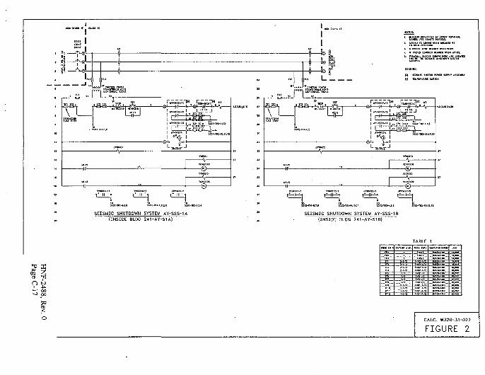
S&™....,..,, ;;„.„,-„..SEISMIC SHUTDOWN SYSTEM AY-SSS-1A
(INSIDE BLDG 241-AY-51A)SEISMIC SHUTDOWN SYSTEM AY-SSS-1B
(INSIDE BLDG 241-AY-51B)
*"0 P-l- r " r -
! " o
1F11
tmwa *HP.
— i ——rfe-
1 / 1
,-,„— K K T -
TABLE
fm-l
-iwr-
- S T U T S S -
jaasa_
IO.WO
CALC. W320-31-022
FIGURE 2
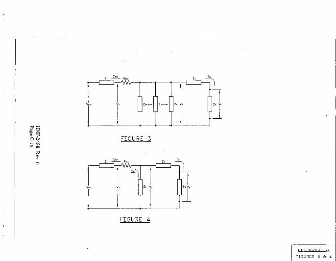
O to FIGURE 3
FIGURE 4
CAIC W320-31-022
FIGURES 3 & 4
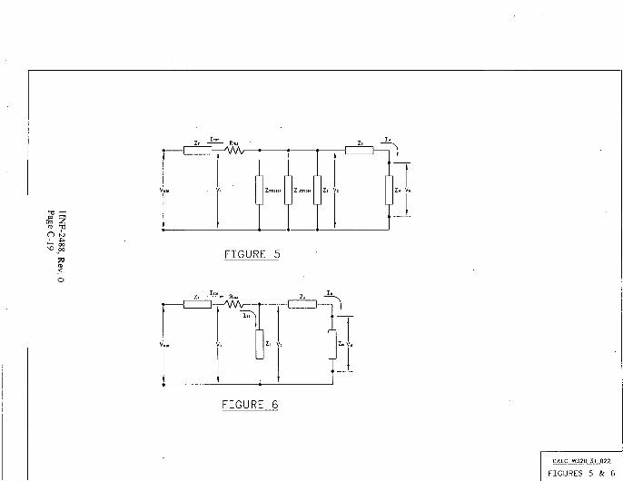
FIGURE 5
FIGURE 6
CALC W32O-31-O22
FIGURES 5 & 6
, run vuiutyc MONon-Reversing, Sizes 00-9Class A201
A - \
' &
1Max.Hp.
I'AV/i22
3355
7V4V/2
1010
10152525
25305050
4050
100100
100200200
200400400
300600
900
" • _ : .
W
feil?iMotorVoiis
200230460575
200230460575
200230460575
200230460S7S
200230460575
200230460575
230460575
230460575
230460
460
®
NEMASize
00
0
1
2
3
4
6
9
Com.AmpsEnd.
9
18
27
45
90
135
540
2250
CoilVoiis
120208240480600
120208240480600
120208240480600
120208240480600
120203240480600
120208240480600
240480600
120240480600
240480
480
120
2 Poles
Open
A201
KABAKAB8KABWKABXKABE
K0BAK088K0BWKOBXKOBE
K1BAK1B8K1SWK18XK18E
K28AK288K2BWK28XK2BE
K3BAK3BBK3BWK3BXK3BE
K4BAK4B8K48WK48XK4BE
K58WK5BXK58E
K6BAK6BWK6BXK6BE
K7BKK78U
K8BU
K9BJ
S 120
156
186
348
552
1332
7344
23040
Type 1 En
A20t
SABASABBSABWSABXSAeE
S08ASOBBSOBWSOBXSOBE
S18AS18BSlBWS1BXS18E
S2BAS2BBS2BWS2BXS2BE
S3BAS3BBS38WS38XS38E
S4BAS4B3S4BWS4BXS4BE
S5BAS5BWS5BXS5BE
S68AS68WS68XS6BE
S7BKS7BU
S8BJ
S88U
S38J ^
cl.
5 132
If58
198
408
672
15S4
9378
20529
2S20O
3 Poles
Open
A201
KACAKACBKACWKACXKACE
KOCAKOCBKOCWKOCXKOCE
KlCAK1C8K1CWK1CXK1CE
K2CAK2CBK2CWK2CXK2CE
K3CAK3C8K3CWK3CXK3CE
K4CAK4C8K4CWK4CXK4CE
K5CAK5CWK5CXK5CE
K6CAK6CWK6CXK6CE
K7CKK7CU
K8CU
KOCJ
Ililllilii
$ 13S
174
204
372
600
1440
6S68
25410
Type 1 End,
A2QI
SACASACSSACWSACXSACE
SOCAS0C8SOCWSOCXSbCE
StCASlCBS1CWS1CXSICE
S2CAS2CBS2CWS2CXS2CE
S3CAS3C6S3CWS3CXS3CE
S4CASaCBS4CWS4CXS4CE
S5CWS5CXSSCE
S6CAS6CWS6CXS6CE
S7CKS7CU
S8CU
S3CJ
$ 150
186
216
432
720
1632
10602
28410
4 Poles
— — '
KADAKAD8KAOWKAOXKAOE
KODAKODBK0DWKOOXKODE
K1DAK1D8K1DWK1DXK10E
K2DAK2D8K2OWK2OXK20E
K3DBK3DWK3DXK30E
K4DAK4DBK4DWK4DXK4DE
HNF-2488 Rev 0Page C-20
S 18S
222
252
480
2004
• .
A201
SADASAOBSADWSAOXSADE
SODASOOBSOOWSOOXSOOE
S1DAS1D8S1DWS10XSIDE
S2DAS2DBS20WS2OXS2oe
S30BS30WS3DXS3DE
S40AS4DBS4DWS4DXS40E
'i . -
S 198
234
264
540
2256
S Poles
A201
KAEAKAE8<AEWKAEXKAEE
KOEAK0E8K0EWKOEXKOEE
K1EAK1EBK1EWK1EXKlEE
K2EAK2E8K2EWK2EXK2EE
K3EBK3EWK3EXK3EE
K4EAK4EBK4EWK4EXK4EE
•rVtfV
Price
S 252
288
318
720
2772
- v -' - -
Number
A201
SAEASAE8SAEWSAEXSAEE
SOEASOEBS0EWSOEXSOEE
S1EAS1EBS1EWS1EXS1EE
S2EAS2E3S2EWS2EXS2EE
S3EBS3EWS3EXS3EE
S4EA
S4EWS4EXS4EE
. . . ;,.
:{•••'.•••
ncl.
Price
S 264
300
330
780
3024
UKRear Connected Contactors
120 Volt Rectified Coil/Open OnlySize
789
Cai. No,
A201K7CJZ9A2Q1K8CJZ9A201K9CJZ9
List Price
$129281977626610
Electrical Components DivisionFebruary 1993
Selling Policy 25-000Modification Kits, Accessories,
pages 410-414Factory Modifications, page 415Other Enclosures, page 414
Other Available Coil Voltages, page 419Technical Data, pages 417-419Instruction Leaflets:Nonreversing, Reversing
Size 00-0-1 16960Size 2 16961Size 3-4 13238Size 4 (Model Kl 17001Size 5 17049
MSize 6 17053Size 7-8 17048Size 9 16978
Replacement Parts, page 606Discount C10-S1
Order by catalog number. Complete cat-alog number consists of A201 in boldtype in catalog number column, plussuffix letters KABA, etc. in catalog num-ber column. Example: A201 + KABA =A201KABA
tlO I uiniiiL.nu rtiw uuKinwiunu
Full Voltage AC, NEMA Sizes 00-9Technical Data
mOperating Coil Characteristics at Rated Coil Volts, Sizes 00-9The following represent typical production test va ues and should
AC CoilBurden (Open VA)
(Cosed Watts . . .Pick-up VoitsODrop-out VoitsOPick-up Time H*O0Drop-out Time HzO
DC CoilBurden (Open VA)
(Closed VA)(Closed Wans). . .
Drop-out VolisOPick-up Time©Drop-oui TmeQ
160 VA
7.8 W85%40 - 60%
1 - 1 WV*- 1
17 VA17 VA18 W
5 - 10%
160 VA
7.8 W85%40 - 60%
i V i - 2Vt - 1
7 VA7 VA8 W
5 - 10%5 - 75 MS6 - 2 5 MS
625 VA
18 W85%40 - 60%
2 - 2V?V* - 1
35 VA35 VA35 W
5 - 10%25 - 75 MS16- 25 MS
700 VA
21 W85%40 - 60%
1 — 1 '^i
35 W
5 - 10%25 - 75 MS16 - 25 MS
NEMA Std.lCS 2-110
WBiEMnot be interpreted as
1700 VA
32 W78%
65 to 75%1.5
600 VA22 VA20 W64%18%2.7 HzO9.3 mo
2900 VA
42 W70%
60 10 70%4.00.75
2120 VA21 VA20 W
13%3 HzO
17.5 HiC
mma guarantee of actual performance.
(DC OperatedOnly)
400 VA400 VA,400 W
30% - 45%O21 - 4 1 H:OO7 - 1 2 HzOO
[DC Operated
7
400 VA40Q VA400 W45% - 6S%©30%-45%Q17 - 29 H;©O7 - 1 2 H2SO
(DC OperatedOnly)
2100 VA350 VA.350 W50% - 65%Q40% - 50%©1 6 - 18 HiQO18- 20 Hz©O
Direct-current operated contactors shall withstand 110 percent of their rated voltage continuously without injury to the operating coilsand shall close successfully at 80 percent of their rated voltage.
Alternating-current opera ed contactors shall withstand 110 percent of their rated voltage continuously without injury to the operatingcoils and shall close successfully at 85 percent of their rated voltage.
Mechanical Characteristics, Si2es 00-9
Dimensions - Inches
Depth
Panel Area - Square Inches. . . .
Cable Connection
Maximum Cable Size/PhaseCopper (AWG/MCM)
Auxiliary Electrical CircuitsAvailable
Latched Vers on Available
Mechanical Interlock Com-binations Available
9
4.61
21.35
#6
8
Yes
4.96
23.7
#3
6
Yes
6.75
46.0
1/0
6
Yes
6.75
46.0
4/0
6
Yes
Data From Tables 430- 147 Through 150 of 1987 N.E.C.Motor Amperes at Full Loado , Three Phase ACHp
'AVi
1
lV i2
5V/i
101520253040506075
100125150200
Single Phase AC
115Volts
7.29.8
2024
80100
230
3.64.9
12
SO
7.750
84.0
front
1-500 MCM
4
Yes
Squirrel Cage AC
200
6.07.8
253248627892
120150177221230360414552
230
1
2.83.65.26.8
15.22228
546380
104130154192248312360480
460
2.63.4
11142127344052657796
124156ISO240
575
11i ;222'i32415?6277Sf
125
192
17
8.750
94.5
ftont*"
2-500 MCM
4
Yes
11.00©
437.5
FionVRear
3-500 MCM
3
No
Vertical
n.000
452.4
Front/Rear
4-500 MCM
3
No
Vertical
13.000
800
Front/Rear
8-500 MCM
4 ,
No
Vertical
DC
120
4.1
13.217
5876
240
2.0
6.68.5
2938557289
106140173206255341425506675
coil is hot.
load and contact wear.OAt 60 hertz base.0 To contact touch.
tefct \o Westinahouse.O Data pertains to Model K; Tor Model J. refer to
O These current values are for motors runn ng a( usual
Motors (or spec at low speed or high torque may'require higher current. In all cases, healers should beselected on ba s ot information on motor nameplateor motor card data.
HNF-2488, Rev. 0
Electrical Components DivisionFebruary 1993
PageC-21
i ypes Mri ouu voit AC, anu ouu volt uc,Convertible Contacts
Application . • .AWARD relays.are designed for use onmachine tools, process lines, conveyors,and similar automatic and semi-automaticequipment. . 'AfVARD relays are electro-mechanicalconvertible contact relays. AR relays areAc devices, and the ARD is for Dcapplications.
DescriptionAvailable in either 4 or 5-pole configura-tions, AR relays are easily converted to 8or 10 poles simply by adding a 4-poledeck, in addition, mechanical latch andpneumatic or solid state timer attach-
ments are available for use with 4 and6-pole relays. .Contacts are convertible from either NO.to NC to provide any combination:desired; up1 to a maximum of 10, exceptthat for the ARD, the number of NC polescannot exceed four in any pole configura-tion. Wide spacing of contacts simplifiesinstallation, contact testing, and mainte-nance. Contacts are electrically andmechanically isolated from each other.Overlap contacts are also available in oneor two sets. These contacts should bemounted in the center pole positions. Acand Dc contact cartridges should not beused in the same relay.
L
AR/ARD ReNumber
Spaces
4
6
SO
10©
laysContacts
NO
02
- 4
046
68
10
NC
000
00 .0
00
0
Contact CartridgesTypfl Terminal
600 VoFt Ac Cartridges
With Clamp Terminals .With Screw Terminals
WOVottOtt 'Cirtr idsM ••• ••••••
With Ctohip Terminals'With Screw Terminals
BlankCcv'mes
420
62Q
20
0
AR 600 Voll Ac Relay!
120/60,110/50 Ac Coil
CatalogNumber
AR4JCAR«OA"-
AR44OA
AR6A*AR640A?AR660A'1
AR860*AR880A1
ARWOOAi
UstPrkt
Standard Contact Cartridges
CatalogNumber
UstPriceO
ARC . 1 • >ARCS J _ . .
• • . . ' • . " - •
.ARDC.•ARDCR .
ARD GOO Volt Dc Relays
120 VoltDc Coil
CatalogNumber
ARMS •„ARW20SARD44o£
ARMSAR0640SARD660S
AR0860SARD88OS
ARD10100S
UstPrice
Overlap Contact Cartridges
CatalogNumberQ
UstPrtceQ
AROC " .AROCR
ARDOCARDOCR
O Standard cartridges are sold in cartons of 4 cartridges. Catalog number and list price are for jingle cartridge.* ^© Overlap contact cartridges are sold in sets of 2 cartridges. Catalog number and list price are for sets of Z.© Wiii RQ\ accept lop moyntcrf latch of tirnere, • ':
HNF-2488, Rev. 0Page C-22
Discount C10-S12UL File No. E19223CSA File No. LR39402-6, LR54517, and
LR54520
Volts
120240480600
Com.
Current
1010. , :10 .i o • •• •
Max. C
Make
603015
. 12
rrent
Break
631.51.2
Dc Cartridges NEMA P600Volts
1252S0600
ConL\Current..
' 5 '-.6
- 5 '• • :••
Max. Current
* Makeo
1.1.5520
r Break •
Max. V A
M3ke
72007200720072O0 •.
Break
720720720720
Max. VA
Make or Break
138138138
Resistive Load - ' ' . '..125VDc? 3.0 amps \ " . • , •250V:pc:-r,5arnps ; : ; ' : . v ;
Coil Powe> Requirements • "Ac: 96 VA open, 14 VA closeDc: 14 watts open, 250 vplts max.
Contact Ratings600 Volt Ac Cartridges NEMA A60Q
lays• Order by catalog number. AR rellisted have 120/HOvoit, 60/50 H;coils, and ARD relays have 120 voltDc coils.
• If a different coil voltage is required,select the catalog letter from the CoilVoltage Tablejjelow and substitute itfor the SHAD'Edi letter in the catalognumber, .
• AR and ARD relays listed are suppliedwith NO contacts which are easilyconverted to NC. if both NO and NCpoles are required, order by catalognumber. Example: 4 pole relay with 1NO and 3 NC contacts, order AR413A.Add $12 list per relay.
VJs'CREW Terminals - For ring-type 'connectors, add Suffix R to the cata-.log number. Example: AR420AR. Noadditional charge,
• OVERLAP Contacts - Overlap con-tacts for AR and ARD relays are
• designed so that a normally opencontact closes before the correspond-ing normajly closed contact opens.Overlap cbntacts.come in NO/NC setsof two cartridges. Add catalog letterSuffix S to the catalog number. Exam-ple: AR420AS. Speciiy the number of
• sets required:- S tor one set and S2 .': for two sets. Add.*12 list per set;
Coil Voltage Table •":
' 24..48 ' •no208240/220277440/380
550
'60. • 6 0 •
• 6060/50 •
HNF-2488, Rev. 0Page C-23
&-2-GE Control Relays
CRI20B Machine-Tool and Industrial Relays]
CR120BL latched relay
CR120BL Latched RelaysForms listed below have captive terminal clamps and
convertible contact modules. DC forms are available. Contact
nearest GE Electrical Distribution & Control sales office for
information.
600 Volis
10 Amperes Continuous
50/60 Hem. I
CR122B pneumatic
time-delay relay
** AC Coil Suffix Table{insert where " appears in Catalog Number, ac relays only)
AC coil suffixes are the same for ac relays, including standard,
pneumatic lime delay, and latch.
No of Poles©
Tola!
2
3
• 4
6
8
NO NCCatalog NumberAC Open Forms
CR12O6L020"CR12OSL0H"CR120BL002"
CR120BL030'CR12OSL021-CR1208L012*CR120BL003*
CRi20BL0^0'CR1308L03TCR120BLO22*CR120BL013'CR120SLCW
CR120BL060"CR12O3L051"CRI208L0J2"CR120SI.033"CR1206I024--CRI208L015"CR120BL006"
CR120BL0S0"CR120BL071"CR130BL062"CR120CLOS3"CR120SL044"CR130BLO35"CR120BLO26"CR120BL017"CR130BL008"
Ust Price,GO-10Q4
• : • •
56.00 •G8.0063.00 ' ' •
68.0060.00 .,.--,.80.0080.00
8 0 . 0 0 .-•-•••9 2 . 0 0 • ' - ' •9 2 . 0 0 ' • -••• '9 2 . 0 0 -' -9 2 . 0 0 • :"
MM.OO • •.'16.0016 .00 - ' • '
1 6 . 0 0 ' ••1 6 . 0 0 , '•-16 .00 : " . .
16 .00 '' •-••
Z 2 8 . o o > •:.•'•••
240.OO ^ : - V2<o.oo >;•",.-."240 .00 •••.•-.:.z « . o o " : • : •>•240 ,00 • • , ' . '240 .00 •.'•- •.;! 4 o . o o • : ••••:2 « , 0 0 • - •
RcQuency
CO Hz
5OH;
24 V
25
115V
02
?6
120V
22®
110V
07
200V
23
208V
24
220V
08
230V
03
380V
04
460V
04
440V
675V
05
09
•600V
06
550V
10
© Coi! 22 is dual raied for 120-Volts. 60-Hertz/110-Volls, 50-Hertzoperation.
t t DC Coil Suffix Table(Insert where t t appears in Catalog Number, dc relays only)
1?V
44
2 4 V
4 8
4 8 V
4 9
6 4 V
45
125V
41
Coil Data
AC Relay coilACUnlaicticoilDC Relay coil
Ir^Sh VA
12031
235
Sealed VA
151528
Sealed v,'a;:s
79.22.8
Contact Ratings — Ail RelaysType
Coniacis
Ins i©
Delay
Wax. ACVoiiage
600
600
Max.Contin-uous
Fating
10
5
WaxVolla
Ra
Make
7200
3600
ACnperen9
Break
720
360
Max. ACRatingAmps
Make
60
30
Steak
6
3
Max. DCRatingAmps
135V
1.1
0.5
250V
0.55
-
Max. DCVollampere
Baling
300V or less
133
© Use for CR120B and CR122BT contact rating.
CR122B Pneumatic Time-deiay RelaysAil Forms have 1NO-1NC time delay contacts®. Listed (orms are field convertible from TDE to TDD and vice versa. DC forms are
available. Contact nearest GE Electrical Distribution & Control sales office for information.
NumA
Total
None
2
3
ber ol Instantaneousuxiliary Contacts
NO NC
Caiaiog Number AC Foims
Time Delay on Encgizaiion
Time Range0 2-60 Seconds
Cni22BO0O"A
CH122B020-CR132BO1TCR122B002*
CR1220030 *CR122B02TCR132B013*CR132B003 *
CR122B040*CR1236031*CR122B022*CR 1228013 •CR 1228004'
Time Range5.200 Seconds
CR122O00O-B
CR122B020*CR122B0H-CR132B002'
CR122B03O*CR122B031CR122B012CR122B003
Cfli22B0J0CR122B031CR122B022CR122B013Cfli223004
' 8•o•8
"0' 8•o•B
•B•1)•B*B•B
Tifi c Delay o^ Oo cnergizotio^
Time Range0 2-60 Seconds
CR122BO0O"E
CR132BO2O*CR122B011*CR122BO03*
CR122B030 *C i H 2 2 U O 2 i 'CR132B013*CR122B003*
CR122B040'CR122B031CR122B022'CRI22B013CRI22B004*
E•E
E
EE
•E•E
•E•E•E•E•E
-5-200 Seconds
CR12280OO"F
CR 1228020 •CR12280H-CR 1228002'
CR122B0301
CR122B021'CR122B0131
CR122B003*
CR122B040'CR122B03TCR122B022'CR122B013'CR 1220004-
. Ut t'• Price,
GO-10G4
' S216.00
' "2*0.00... 252.00
- ••• 252.00
,,1252.00. 264.00' 264.00
'-"264.00
.•"••' 264.00 ••' "276.00
.. -276.00••: 276.00
•:• 276.00 :
\ " Inser t coil number Irom AC Coil Suffix Table lo complele Calalog Number. ©Form Z contacts, Polarity must be observed.
? References: References:
Instructions: Instructions: (Time-delay Relays)
GEH-4115 (AC Relays) GEH-4119 (CR122BT Relays)
GEH-4120 (Latch Relays) GEH-4147 (CR122B Relays)
GEH-4143 (DC Relays)
Prices and data subject to change without notice 1993 Issue 9-3
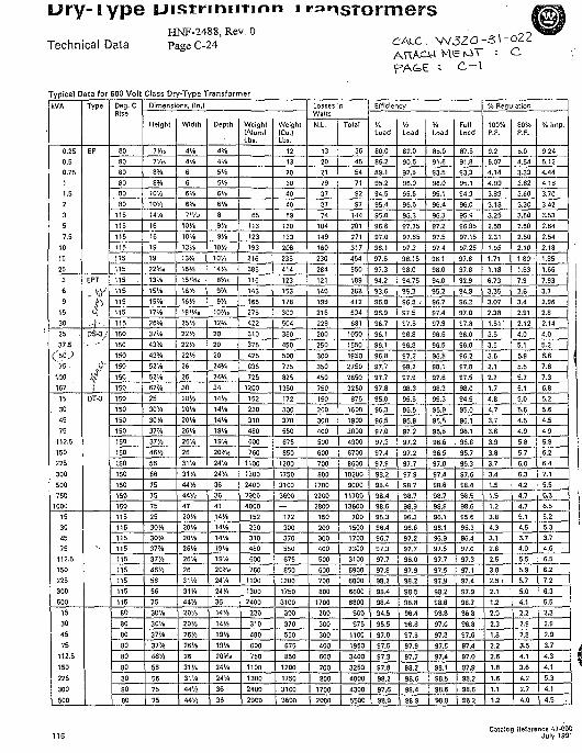
Ury-iype UistriniiTinn iHNF-2488, Rev. 0
Technical Data PageC-24
Typical Data for 600 Vol t Class Dry-Type Transformer
CALC. \N3ZOj-Z\-022Me M \ : c
kVA
0.250.50.7511.52357.5
101525
369
15
30
25
37;5C'5o.;
75100167
15. 30
4575
112.5. 150
225300500750
1000
15304575
112.5150225300500
15
30
45
75
112.5
150
225
300
500
Type
EP
EPT
D£-3;
/
DT-3
Deg. CRise
80SO80
8080
80
115
115115
115
115
115
115 .
115115
115
115150
150
150
150
150
150150
150
150150
150
150
150
150
150150
150115115115115115
115
115115
115
80
80
80
80
80
80
80
80
80
Dimensions, (In.)
Height
7'/,.
7 « .8Y«
8"/.10%
10V;14%
16
16
19
19
22y.s
13"/.
15'/.15'/.
17'/.
26V.37'/.
43%43V<
52'/.
52'/.62'/.
25
3O'/i
30'/.37'/.
37'/.
46%
56
56
757575
2530'/.30'A37'/.37'/.
46%
5656
75
30V.
30'/.
37'/,
37'/.
46'/;
56
56
75
75
Width
4'/.4'/.
6
66'/.
6>/.7 "/is
10>/>
10"/.
13'/.
13"/.
16"/.
15'V.t
IS'A16'/!
19"/i«
25'/.
22'/!22'/!
22'/i26
2630
20'/.
JO'/.
20'/.
26'/.
26'/.
26
31%
31'/<
44 V4
44%47
20%20'/.
20'/.
26'/.
26'/.
2631%
31M
44'/ !
20V.
20' / .
26'/.
26'/.
26
31%
3 1 ' / .
44'/j44 Vi
Depth
4y.
4Ve5'/i5'/!6'/.
67.8
9'/.
97.
10'/i
10'/!14'/.
8V,s
9'/»9'/.
I O ' / I .
12"/<20
20
2024Y.
24'A34
14 V.14'/.
14'/.
19'/.19'/.
2O'/n
24'/<24'/.
36
364114%14%14%
19%19%
20"/i.24'/<
24%
3614V.
14%
19%
19%
2oy><
24%
24%
36
36
Weight(Alum)Lbs.
65
113123
193
216
385
116
143166
275
422
310
375425
635
725
1200
152230
310
480600
760
1100
1300
240023004000
152
230310480600
7601100
1300
2400
230
310
480
600
750
1100
1300
2400
2900
Weight(Cu.lLbs.
121320
3040
40
69
120
133208
235414
123
153
178300
504
360
450
500725
825
1350
172300
370550
675
850
1200
175031003600—
172
300370550
675850
1200
17503100
300
370
550
675
850
1200
1750
3100
3600
Losses nWattsN.L.
1320
212937
3774
104
149
160
230
284
121140
199216
229
200250
300 .
350
450
750
150200
300400
500
600
700
8001700
22002800150200300400
500
600700
800
1700
200
300
300
400
600
700
800
1700
2000
Total
3645
5471
9297
144
201
271
317454
550
189
288412
534
681
10501550
1950
2750
2850
3250
8751600
1900
30004900
6700
8600
102009000
1170013600
7001500
17002300
3100
59006000
6600
6800
500
975
1100
1950
3400
3250
4000
4300
5500
Efficiency
%Load
80.085.2
89.195.2
94.5
95.495.0
96.697.0
96.197.6
97.394.2
93.6
96.0
96.996.7
96.1
96.196.897.7
97.797.8
95.0
96.396.5
97.0
97.397.4
97.9
98.298.4
38.498.695.3
96.496.797.397.7
97.8
98.2
98.498.4
94.5
95.597.0
97.5
97.3
97.8
98.2
97.6
98.9
'/!Load
82.0
90.592.8
96.095.5
96.5
96.3
97.35
97.6597.3
98.1598.0
94.7595.3
96.8 r
97.597.8
96.8
96.8
97.2
98.2
97.9
98.3
95.596.5
96.997.2
97.2
97.2
97.7
97.998.7
93.798. 996.3
96.697.297.7
98.0
97.998.2
98.598.8
96.4
96.8
97.8
97.9
97.7
98.2
98.698.4
98.9
y.Load
85.0
91.693.5
96.0
95.196.4
96.3
97.2
97.597.4
98.1
98.0
94.035.2
96.797.4
97.996.6
96.5
96.8
98.197.6
98.3
95.3
95.9
96.596.8
96.6
96.597.0
97.498.6
98.798.8
96.196.1
96.997.597.7
97.697.9
98.298.8
96.8
97.0
97.8
97.897.4
98.1
98.5
98.6
38.8
FullLoad
87.591.8
93.3
95.194.3
96.0
95.996.85
97.15
97.25
97.8
97.8
92.994.8
96.2
97.0
97.8
96.0
96.096.2
97.8
97.5
98.0
94.595.0
96.1
96.195.8
95.7
96.3
97.698.4
98.5
98.695.695.396.497.0
97.397.1
97.4
97.998.7
35.8
96.8
97.697.4
97.0
97.9
98.2
98.6
93.2
% Regulation
100%P.F.
9.26.074.14
4.09
3.83
3.183.25
2.58
2.31
1.95
1.71
1.18
6.73
3.353.07
2.38
1.51'3.53.5
3.5
2.1
2.71.7
4.8
4.73.7
3.6
3.9
3.83.7
3.4
1.51.51.23.8
4.33.12.62.5
3.8
2.5 I
2.11.2
2.0
2.3
1.8
2.2
2.6
1.8
1.6
1.1
1.2
80%P.F.
8.04.54
3.33
3.623.60
3.30
3.50
2.50
2,50
2.10
1.80"
1.63
7.9
3.63.4
2.91
2.124.0
5.1
5.9
5.55.7
5.1
5.0
5.6
4.54.9
5.85.7
6.0
6.34.2
4.74.75.14.53.74.0
5.5
5.95.7
5.04.1
2.2
2.9
2.8
3.54.1
3.6
4.2
2.7
4.0
% Imp.
9.24
5.124.44
4.183.70
3.42
3.532.642.54
2.18
1.85
1.65
7.933.7
2.962.82.14
4.0
5.26.6
7.6
7.3
6.85.2
5.6
4.54.9
5.9
6.26.4
7.15.5
6.36.55.2
5.33.74.6 •
6.5
6.27.2
6.35.5
2.3
2.9
2.93.7
4.34.1
5.3
4.1
4.5 .
Catalog Reference 47-000July 1991
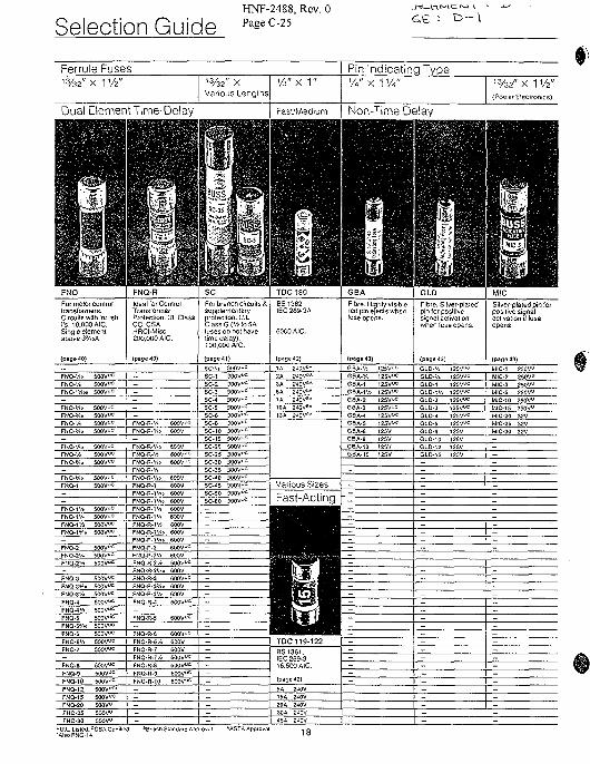
HNF-2488, Rev. 0
Select ion G u i d e PageC-25
Ferrule Fuses Pin Indicating Type13/32" X 1 W
FNQ
For motor conlrolIransformers.Circuils with inrushl"s. 10.000 AIC.Single elementabove 3J/«>A.
(pageW)
FNO-'/m 500VJC
FNQ-"/ i» 5O0Vuc
FNQ-Vio 50OVuc
FNQ-'A 500Vuc
FNQ-'/io 500Vuc
FNQ-'Ao 600VOC
FNQ-'A 500Vuc
FNQ-*/io SOOV^c
FNQ-1 SOOV1^
F N Q - I V I SO0VUCFNQ-1'/• 5OOVUC
FNQ.fA SOOVUC
FNQ-1 */.o 50OVUC-
FNQ-2 500Vuc
FNO-21/* S00V«CFNQ-2VJ SOOVuC
_
FNQ-3 5O0VJCFNQ-3V.0 500VJC
FNO-3'/i 5OOVUC
FNQ-4 5OOVUC
FNQ-4'A 500Vuc
FNQ-S 500VUC
FNO-5V10 SOOVue
FNQ-S 500Vuc
FNQ-6'/« 500VJCFNQ-7 500Vuc
_
FNQ-8 500Vuc
FNQ-9 SOOV^FNQ-10 500 V ^
FNQ-12 SOOV00
FNQ-1 S SOOV00
FNQ-20 500V"FNQ-25 500VU
FNQ-3O 500V0
FNQ-R
Ideal forConlrolTransformerProteci'On. UL ClassC C . C S AHRCI-Misc.200.000 AIC.
(page 40)
-
-
_ _
-
-
FNQ-R-V* 60OVuc
FNQ-R-V10 600V
FNQ-R-V.0 600V
FNQ-R-'A 6O3VUC
FNQ-R-Vx 60OVuc
FNQ-R-VJ
FMQ-R-1 6OOVFNO-R-IV10 600VFNQ-R-IVio 600VFNQ-R-i'/t 600VFNQ-R-1V. 600VFNQ-R-1'A 600VFNQ-R-1V» 600V
FNO-R-IVie 600VFNQ-R-2 60OVuc
FNQ-R-2'/< 600VFNQ-R-2% 600Vuc
FNQ-R-2V,o 600V
FNQ-R-3 600VUC
FNQ-R-3*/.o 600V
FNQ-R-3V* 600VFNQ-R-J 60OVuc
_
FNQ-R-5 600VuC
FNQ-R-6 600VuC
FNQ-R-6'/. 600V
FHQ-R-7 600VFNQ-R-7'/i 600VJCFNQ.R-8 600VUC
FNQ-R-9 eOO^cFNQ-R. 10 600VUC
---_
-
scFor branch circuits &supplemeniaryprotection. U.L.Class G ( V J lo 5Afuses do not havelime delay).100.000 AIC.
(page 41)
SC-'/i 300V°cSC-1 300VUC
SC-3 300VuC
SC-4 300VUC
SC-S 30OVuC
SC-8 300Vuc
SC-10 300VuC
SC-15 30OVuC
SC-20 30OVuc
SC-2S 300Vuc
SC-30 300VUC
SC-35 300Vuc
SC-45 300Vuc
SC-SO 300Vuc
SC-60 300VUC
-
_
----
-_
- J-
-—-
_
-----
-
TDC180BS1362IEC 269-3A
6000 AIC.
(page 42)
1A 24CVU*2A 2^0Vf>*
5A 240V"*7A 2JOVSA
10A 240V6*
Various Sizes
Fast-Acting
TDC 119-122BS1361.1EC 269-316.500 AIC.
(page 42)
5A 2-JQV
ISA 240V20A 240V30A 240V4SA 240V
GBA
Fibre. Highly visiblered pin ejects whenfuse opens.
(page 43)
GBA-VJ
G6A-V*
GBA- IVJ
GBA-2GSA-3
GSA-5
GBA-6GBA-8
25VuC
25V"=
l i v^25V u C
2SVUC
livw25V2SV
—
—-----_—--------
_
-
-—--
-----
-
GLD
? bre. Silver-platedpin for positivesgnal activationwhen fuse opens.
(page 43)
GLD-'/J 12SVU^
GLD-V. 125VUC
GLO-1V) 125V«=GLO-2 125V^C
GLD-3 125V^
GLD-5 l2SVuc
GLO-6 12SVGLD-10 125V
-
—__
_--
_______
__
-
-
___
---
-
-
MIC
Silver-plated pin forpostve signalactivation if fuseopens.
(page 43)
MIC-1 250Vu
MIC-2 250Vu
MIC-5 250V"MIC-10 250Vu
MtC-15 250Vu
MIC-2S 32VMIC-30 32V
-
-
-
_
___-
__-
___
-
___
----
-
18
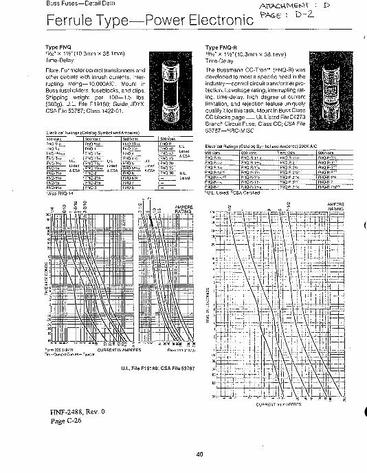
Buss Fuses—Detail Data
Ferrule Type-—Power Electronic D-Z.
Type FNQ'%2" x 1V4"( 10.3mm x 38.1mm)Time-Delay
Fibre. For motor control transformers andother circuits with inrush currents. Inter-rupting rating—10,OOOAIC. Mounl inBuss fuseholders, luseblocks, and clips.Shipping weight per 100—1.5 lbs.(680g). U.L. File E19180; Guide JDYX.CSA File 53787; Class 1422-01.
Eleclfical Ratings (Catalog Symbol and Amperes)
Listed4 CSA
Listed&CSA
NQ-10
NO12'
Type FNQ-R'%2" x 1 '/2"(10.3mm x 38.1mm)Time-Delay
The Bussmann CC-Tron" (FNQ-R) wasdeveloped to meet a specific need in theindustry—control circuit transformer pro-tection. Its voltage rating, interrupting rat-ing, time-delay, high degree of currentlimitation, and rejection feature uniquelyqualify it for this task. Mount in Buss ClassCC blocks page UL Listed File E4273Branch Circuit Fuse; Class CC; CSA File53787—HRC-MISC
Electrical Ratings (Caialog Symbol and Amperes) 20OK AIC600 VollS:NO-R. ','J:NQ-fi.'/.o:NO-R-J/.o
:NQ-R.-/,uul-
:NQ-R.-..U
FNO-R-I
600 VOlISFNQ.R-1 iioFNQ-R-H'-oFNQ-R-lVo
FNQ.fl-1'A
FNQ.R-11/:
FNO-B-1*'FNO-R-ivi*
600 VotisFNO-R-i".':o
FNO-R-2L-C
FNO-R-21/-FNQ-R^v^c
FNQ-R-2V.0FNQ-R-3^FNQ-R-3vio
600 VolisFNQ-R-3'.iFWQ.R.41^
FNQ-R-51^FNQ-R.o1^FNO-R-6 ' /J
FNO-R-?FNQ-R-7 V i 0 0
'U.L. Listed; CCSA Cerlilied
CURRENT IN AMPERES
HNF-2488, Rev. 0Page C-26
40
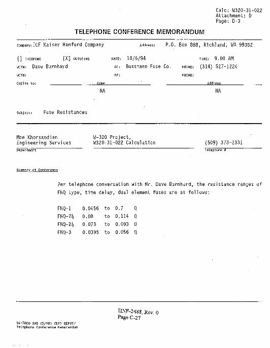
Calc: W320-31-022Attachment: DPage: D-3
TELEPHONE CONFERENCE MEMORANDUM
comPany:ICF Kaiser Hanford Company Address: P.O. Box 888, Rich"!and, WA 99352
[ ] INCOMING [ X ] OUTGOING DATE: 1 0 / 6 / 9 4 TIME: 9 . 0 0 AM
WITH: Dave Burnhard OF: Bussmann Fuse Co. PHONE: (314) 527-1224
WITH: OF: PHONE:
Copies to: Name ^ _ _ Address
NA NA
subject: Fuse Resistances
Moe Khorsandian W-320 Project,Engineering Services W320-31-022 Calculation (509) 373-2331Department
Summary of Conference
Per telephone conversation with Mr. Dave Burnhard, the resistance ranges of
FNQ type, time delay, dual element fuses are as follows:
FNQ-1 0.0456 to 0.7 QFNQ-2% 0.08 to 0.114 0FNQ-2% 0.073 to 0.093 fiFNQ-3 0.0395 to 0.056 Si
HNF-2488, Rev. 0Page C-27
54-7600-098 (5/90) <EF> GEF017Telephone Conference Memorandum
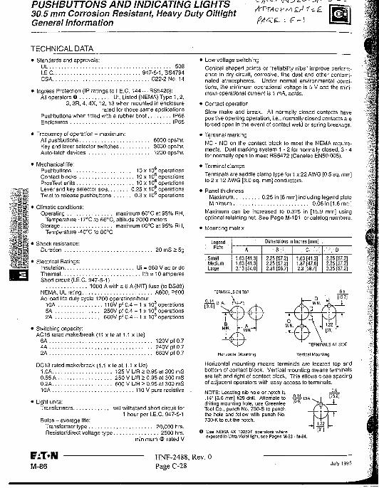
PUSHBUTTONS AND INDICATING LIGHTS30.5 mm Corrosion Resistant, Heavy Duty OiltightGeneral Information
<-/?'•
TECHNICAL DATA• Standards and approvals:
UL 508I.E.C 947-5-1, BS4794CSA C22-2 No. 14
• Ingress Protection (IP ratings to I.E.C. 144 — BS5420):All operators O UL Listed (NEMA) Type 1, 2,
3, 3R, 4, 4X, 12, 13 when mounted in enclosurerated for those same applications
Pushbuttons when fitted with a rubber boot IP66Enclosures IP65
• Frequency of operation - maximum:All pushbuttons 6000 ops/hr.Key and lever selector switches 3000 ops/hr.Auto-latch devices 1200 ops/hr.
* Mechanical life:PushbuttonsContact blocksPresTest unitsLever and key selector sws...Twist to release pushbuttons .
* Climatic conditions:Operating
Temperature -17°C.to 66CC,Storage
Temperature -40°C to 80°C
* Shock resistance:Duration
10x10 operations10 x 106 operations10 x 106 operations
. . . . 0.25 x 10 operations0.3 x 106 operations
maximum 60°C at 95% RH,altitude 2000 metersmaximum 60°C at 95% RH,
20 mS > 5g
' Electrical Ratings:Insulation Ui = 660 V ac or dcThermal Ith = 10 amperesShort circuit (I.E.C. 947-5-1)
1000 A with a 6 A (NIT) fuse (to BS88)NEMA, UL rating A600, P600Ac load life duty cycle 1200 operations/hour
10A 110V pf 0 . 4 -1 x10⁶ operations5A . 250V pf 0.4 - 1 x 10° operations2A 660V pf 0.4 - 1 x 10⁶ operations
• Switching capacity:AC15 rated make/break (11 x le at 1.1 x Ue)6A 120V pf 0.74A 240V pf 0.72A 660V pf 0.7
DC13 rated make/break (1.1 x le at 1.1 x Ue)1.0A 125 V L/R > 0.95 at 300 mS0.55 A 250 V L/R > 0.95 at 300 mS0.2A 600 V L/R > 0.95 at 300 mS10A 110 V pure resistive
' Light units:Transformers will withstand short circuit for
1 hour per I.E.C. 947-5-1Bulbs - average life:
Transformer type 20,000 hrs.Resistor/direct voltage type 2500 hrs.
minimum @ rated V
• Low voltage switching
Conical shaped points or "reliability nibs" improve perform-ance in dry circuit, corrosive, fine dust and other contami-nated atmospheres. Under normal environmental condi-tions, the minimum operational voltage is 5 V and the mini-mum operational current is 1 mA, ac/dc.
• Contact operationSlow make and break. All normally closed contacts havepositive opening operation, i.e., normally closed contacts areforced open in the event of contact weld or spring breakage.
• Terminal marking
NC - NO on the contact block to meet the NEMA require-ments. Dual marking system 1 - 2 for normally closed, 3 - 4for normally open to meet BS5472 (Cenelec EN50 005).
• Terminal clampsTerminals are saddle clamp type for 1 x 22 AWG [0.5 sq. mm]to 2 x 12 AWG [3.0 sq. mm] conductors.
• Panel thicknessMaximum 0.25 in [8 mm] including legend plateMinimum 0.06 in [1.6 mrv
Maximum can be increased to 0.375 in [15.9 mm] usingoptional retaining nut. See Page M-101 or catalog numbers.
• Mounting matrix
Legend. Plate '
SmallMediumLarge •
Dimensions in Inches [mm] -
A .
1.631.632.13
41.341.354.0
• B ; - .
2.252.252.31
57.257.2587
" ' . c .' ,•-:
1.63 141.3]1.87 [47.6]2.3 [58.7]
•'.~.-0
2.252.252.25
57.257.257.2
TERMINALS ON TOP
TERMINALS AT SIDE
Horizontal Mounting Vertical Mounting
Horizontal mounting means terminals are located top andbottom of contact block. Vertical mounting means terminalsare left and right of contact block. This allows close spacingof adjacent operators with easy access to terminals.
NOTE: Locating nib hole or notch is.14" [3.6 mm] #29 drill. Alternate todrilling mourning hole, use GreenleeTool Co., punch No. 730-S to punchthe hole and follow with punch No.730-K to cut the notch.
© Use NEMA 4X 10250T operators whereexposed to Ultra Violet light, see Pages M-53 - M-84.
M-86HNF-2488, Rev. 0Page C-28 July 1995
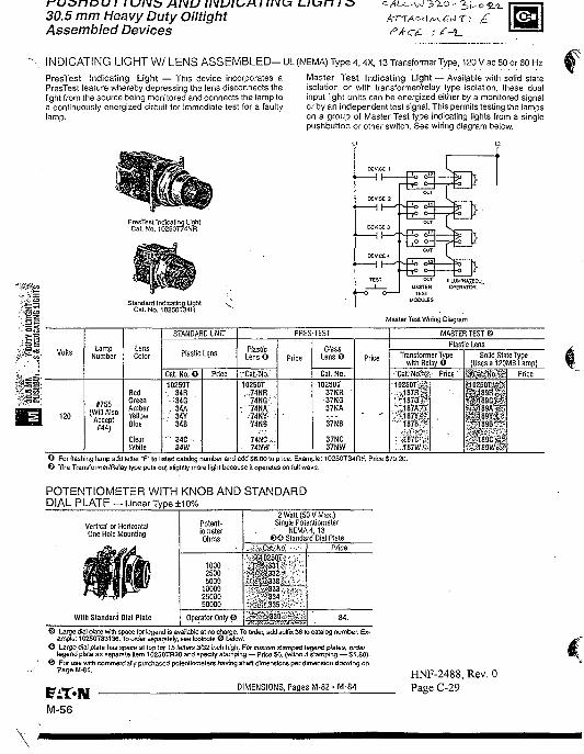
fUi>tieu I I UNt> AND INUIUAI ;/VU L/Lin / cs30.5 mm Heavy Duty OiltightAssembled Devices
INDICATING LIGHT W/ LENS A S S E M B L E D - UL (NEMA) Type 4,4X, 13 Transformer Type, 120 V ac 50 or 60 Hz
PresTest Indicating Light — This device incorporates aPresTest feature whereby depressing the lens disconnects thelight from the source being monitored and connects the lamp toa continuously energized circuit for immediate test for a faultylamp.
Master Test Indicating Light — Available with solid staleisolation or with transformer/relay type isolation, these dualinput light units can be energized either by a monitored signalor by an independent test signal. This permits testing the lampson a group of Master Test type indicating lights from a singlepushbutton or other switch. See wiring diagram below.
PresTest Indicating LightCal. No. 10250T74NR
Standard Indicating LightCat. No. 10250T34R
MASTERTEST
MODULES
Master Test Wiring Diagram
Volls
120
LampNumber
#755(Will Also
Accept#44)
LensColor
RedGreenAmberYellowBlue
ClearWhile
STANDARD UNIT
Plastic Lens
Cat. No. O
10250T-. 34R.
•34G '. 34A
: 34Y" 348
. 34C34W
Price
PRES-TEST
PlasticLensO
rCaLTfo.
10250T....74NR.
74NG'-"74NA .••74HY-: :74HB
74NC,:..74NW;
PriceGlass
Lens O
Cat. No.10250T
37NR37NG37NA
37N8
37NC37NW
Price
- • -
MASTER TEST©
Plastic Lens
TransformerTypewith Relay 0
CaL"No?s
10250TSS,.-H187RS-::~187ffS!
.";:i87A7¥a ; ^ 8 7 Y i *T-187B;3|
:.-ii87CV,ii. -187Wft
Pnce
Solid State Type(Usesai20M8Lamp)
•*Cat,Mo
"*189A^ a 8 9 Y »
1898"~"
^189C vi389W
Price
O For flashing lamp add letter T to listed catalog number and add $6.00 to price. Example: 10250T34RF, Price $70.20.© The Transformer/Relay type puts ouj slightly more light because it operates on full wave.
POTENTIOMETER WITH KNOB AND STANDARDDIAL PLATE — Linear Type ±10%
Vertical or HorizontalOne Hole Mounting
iPWith Standard Dial Plate
100025005000
100002500050000
Operator Only 0
2 Watt (50 V Max.)Single Potentiometer
NEMA 4,13© 0 Standard Dial Plate
Cat No»-*|0250T
334CSV 335
• * • " , 330
Price
84.
© Large dial plate with space for legend is available at no charge. To order, add suffix 36 to catalog number. Ex-ample: 10250T33136. To order separately, see footnote © below.
© Large dial plate has space at top for 15 letters 3/32 inch high. For custom stamped legend plates, ordertegend plate as separate item 10250TR30 and specify stamping — Price S6. (without stamping — S1.80).
© For use with commercially purchased potentiometers having shaft dimensions per dimension drawing onPageM-81.
DIMENSIONS, Pages M-82 - M-84
HNP-2488, Rev. 0Page C-29
M-56
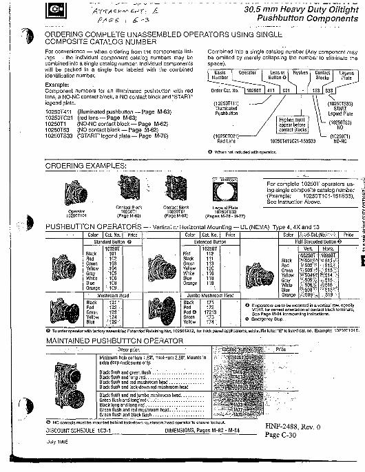
30.5 mm Heavy Duty OiltightPushbutton Components
ORDERING COMPLETE UNASSEMBLED OPERATORS USING SINGLECOMPOSITE CATALOG NUMBERFor convenience — when ordering from the components list-ings — the individual component catalog numbers may becombined into a single catalog number. Individual componentswill be packed in a single box labeled with the combinedidentification number.
Example:Component numbers for an illuminated pushbutton with redlens, a NO-NC contact block, a NO contact block and "STARrlegend plate.
10250T411 (illuminated pushbutton — Page M-63)10250TC21 (red lens — Page M-63)10250T1 (NO-NC contact block —Page M-62)10250T53 (NO contact block —Page M-62)10250TS33 ("START legend plate — Page M-76)
Combined into a single catalog number (Any component maybe omitted by merely collapsing the number to eliminate thespace).
10250T411C21-153S33
(10250TS3)NO
(10250T1)NO-NC
O When not included wilM operator.
ORDERING EXAMPLES:
For complete 10250T operators us-ing single composite catalog number(Example: 10250T101-151S33),See Instruction Above.
Operator10250T101
Legend Plate10250TS33
(Pages M-76 - M-77)
PUSHBUTTON OPERATORS — Vertical or Horizontal Mounting — UL. (NEMA) Type 4, 4X and 13Color | Cat No. | Price Color [Cat. No. | Price Color |fe;-SCat.-JI6.v:.;.| Price
Standard Button 6 Extended Button Half Shrouded Button 6
BlackRedGreenYellowGrayWhiteBlueOrange
BlackRedGreenYellowBlue
10250T101102103104105
• 106108
••109..
Mushroom H ad
121 '1221231241
•'129-
RedBlackGreenYellowWhiteBlueOrange
BlackRedRedOGreenYellow
10250T112111113120
. 116118119
Jumbo Mushroom Head
171172
17213173174
BlackRedGreenYellowGrayWhiteBlueOrange
•1C250T
K506-S-508'
10250T
•.-v.51 s-:'<;516 :." ' 5 1 8 T
519 •
© Itoperatore are to be mounted in a vertical row. specifyVERT, for correct orientation of contact block terminals,See Page M-84 for mounting instructions.
O Emergency Slop.
© Toorderoperalorwith factor assembled Extended Retaining Nut. 10250TA12, for thick panel applications, add suffix letter PE'to listed cat. no. Example: 10250T101E.
MAINTAINED PUSHBUTTON OPERATORDescription
Minimum hole centers 1.62*. maximum 2.50", Mounts inextra deep enclosures only.
Black flush and green flush . . . . . . " ,Black flush and long red , ,Black flush and red mushroom head'.Black flush and lock-down red mushroom head
Black'flush and red jumbo mushroom hGreen flush and long r e d - , \ . : : . ' . . ; . .Black long and long red..-Green (lush and red mushroom head..Green flush and black flush
© NC contacts must be mounted behind, lock-down mushroom head operator to ensure lockout.
DISCOUNT SCHEDULE 1CD-1 DIMENSIONS, Pages M-82 - M-84
July 1995
HNF-2488, Rev. 0PageC-30
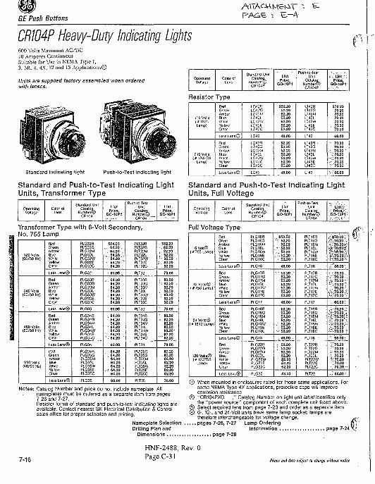
GE Push Buttons
CR104P Heevy-Duty Indicating Lightsf>00 Volts Maximum AC/DC
10 Amperes Continuous
Suitable for Use in NKMA Type 1,
3, 3R. - I , AX, 12 and 13 Applications©
Units are supplied factory assembled when orderedwith lenses.
Standard indicating light Push-to-Test Indicating light
Standard and Push-to-Test Indicating LightUnits, Transformer Type
Opetaiingvoiiage
Color ofStandard Unii
CaialooNumber®
CRUK
UstPrice,
GO-10P1
Push-lo-TesiUnit
Caia'onNumsei©
CR104 ~
Ust .Prlc«,
GO-10P1
Transformer Type with 6-Volt Secondary,No. 755 Lamp
120 Volls(60/50 Hj)
2A0 Volis(60/50 Hz)
480 Voils(60/50 Hz}
600 VollS(60/50 Hz)
RedGreenAmberBlueWhileYellowCleai
Less Lens®
RedGre-enAmberBlueWhileYeiiowClear
Less Lens®
RedGreenAmber8lueWhileYellowClear
Less Lens®
RedGreenAmberBlueWhileYellowClear
Less Lens®
PLG32RPLG32GPLG32MPLG32LPLG32WPLG32GPLG32C
PLG32
PLG33RPLG33GPLG33WPLG33LPLG33WPLG33EPLG33C
PLG33
PLG34RPLG34GPLG34MPLG34LPLG34WPLG34EPLG34C
PLG34
PLG35RPLG30GPLG3CMPLG35LPLG35WPLG35EPLG35C
PLG35
S64.20 .. , 64.20 ..'.. 64.20 ., 64.20 '.
64.20' 64.20-* '' 64.20 '
• 60.00 ;
,... 64.20 .64.20 .64.20
' 6 4 . 2 0 ', 64.20
64.20 •. 64.20
60.00
• 64.2064.2064.20
' 64.2064.20
" 64.2064.20
60.00
64.20' 64.20
64.2064.2064,20
.:' 64.20 "64.20
eo.oo
PLT32RR.T32GPLT32MPLT32LPLT32WPLT32EPLT32C
PLT33
PLT33RPLT33GPLT33MPLT33LPLT33WPLT33EPLI33C
PLT33
PLT34RPLT34GPLT34MPLI34LPLT34WPLT34EPLT34C
PLT34
PLT35RPLT35GPLT35UPLT35LPLT35WPLT35EPU35C
PLT35
• S82J0- . 82.20. 82.20.'. 62.20 "'- 82.20 -; . 62.20"
. 82.20
78.00 .
: 82.20• - 82.20! 82.20
82.20• 82.20
82.20• 82.20
' 78.00
' 82^0- 82.20
82.20-82.20"
: 82^0 '' 82.20' '82.20
78.00
82.20. 82.20
62.2082.20
. 62.20 .'82.2062.20
78.00
Notes: Catalog Number and price do not include nameplate, Allnameplates must be ordered as a separate item from pages7-26 and 7-27.Resistor forms of standard and push-to-lesl indicating lights areavailable. Contact nearest GE Electrical Distribution & Controlsales office for proper selection and pricing.
Nameplate Selection
Drilling Plan and
Dimensions
UstPrice,
GO-10P1Caialoq
Number©CR104P
.-.. Ust-'-'i- Price."GO-10P1
Resistor Type
CO Volis<# !S3i>Lamp)
240 Volis(# lPOi'SU
fledGreenAmberBije
YellowClear
less Lens®
flodGreen
BlueWhile
Less Lens®
LG-irnLCOGLG-CM
LG-Jf'.VLCL-ELG42C
LG42
LG-13RL G O GLG-J3MLGi2LLGO'.V
LG-3C
LG^3
S52.2052.2052.20
52.2052.2052.20
48.00
52.2052.2052.2052.2052.20
52.20
48.00
Q-I2RLT42GLT-I2H
LT42WLT42ELT42C
LT42
LT43R •LT43GLT43MLT43LLT4 3WLT43ELT43C
LT43
570.2070.2070.20
70.20. 70.20
70.20
68.00
• 70.2070.20
• • 70.20:- ' 70.20
•••;; 70.20•:• 70.20'-V."70.20 "
-.V 66.00
Standard and Push-to-Test Indicating LightUnits, Full Voltage
CaialooNumber®
CRHM
Full Voltage Type
6 VOH©(#755 Lamp)
12 Volls©(#750 Lamp)
24 Volis©{#1819 Lamp)
120 Volls©(#120PSB
Lamp)
RedGreenAmberBlueWhileYellowClear
Less Lens®
RedGreenAmberBlueWhileYellowClear
Less Lens®
RedGreenAmberBlueWhileYellowClear
Less Lens®
RedGreenAmberBlueWhileYellowClear
Less Lens®
PLG16RPLG16G
• PLG16MPLG16LPLG16WPLGI6EPLG16C
PLG 16
PLG17RPLG17GPLG17MPLG17LPLG17WPIG17EPLG17C
PLG17
PLG18RPLG18GPLG18MPLG18LPLG 18WPLG 18EPLG18C
PLGIS
PLG22RPLG22GPLG22MPLG32LPLG22WPLG22EPLG22C
PLG22
. $52.20 .. 52.20 ;' 52.20= •52.20, r 52.20. - 52.20 -
. 52.20
48.00
- 52.2052.20
; 52.20 v52.20
. 52.20..52.2052.20 .
48.00
52.2052.2055L2052.20
-,' 52.20 •'.52.20
•-- 52.20
. 48.00 -
; 52.20; 52.20.. 52.20 -
52.20' 52.20• 52.20
52.20
48.00
PLT16RPLT16GPLT16MPLT16LPLT16WPLT16EPLT16C
PLTI6
PLT17RPLT17GPLT17MPLT17LPLT17WPLT17EPLT17C
PLT17
PLT18RPLT18GPLT18MPLT18LPLT18WPLT18EPLT18C
PLT18 •
PLT22RPLT22GPLT22MPLT22LPLT22WPLI22EPLT22C
PLT22
^570. '20 •;'
r-f>o.2Ov
;;-::r66.oo'.
V V 7 Q J Q
'./'•-• 7 0 . 2 0 •--.-.',V 70.20 >•;- '• 70.20 "'-:.j 70^0 ;•
.'•/', 7020"'
': 66.00 f
.'.'.'- 70JO •',if" 70.20 J
s" 70.20^"'^•70^0; ' . ' - ',- , ;70.20'-•-'5 70.20.'^
.••T'eeiooV
•.•"70 J O-••70.2ai : 70.20::.;': 70.20 :-?70.20"-
. " .70.20:-;.- 70.20 ,-•-
.•...; 66.00';
© When mounted in enclosures rated for those same applications. Forsome NEMA Type 4X applications, protective caps will improvecorrosion resistance.
© "CR104PXG . . . " Catalog Number on light unit label identifies onlythe "power source" component oE each complete unit listed above.
S Select required lens from page 7-23 and order as a separate item.6-, 12-, and 24-Volt units have same lamp socket; lamps aretherefore interchangeable for voltage change.
pages 7-26, 7-27 Lamp Ordering t
Information page 7-24 >
page 7-28
7-16
HNF-2488, Rev. 0Page C-3I
Prices and dsta subject to change without rt.
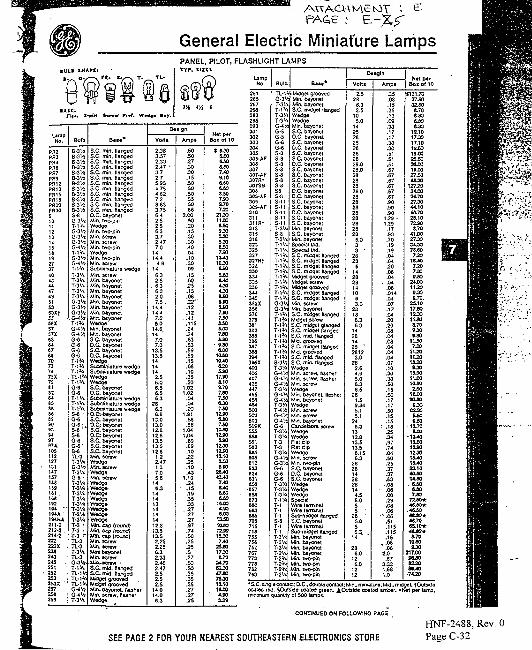
FACB
General Electric Miniature LampsPANEL, PILOT, FLASHLIGHT LAMPSTYF. SIZEl
LampNo.
PR2PR3PR4PR6PR7PR9PR12PR13PR15PR13PRWPR3O
1011121314ISI t
27374043444743SIS353Xf55MX57S7X636467637073747SX'9
1284)S
W!9
93M97S7A10S112127131147157isa1591S1 .
194 "•I M A1MMA211-2212-2 .214-2222222X238243245 .2S1252253253X '2S7258259
Bulb
B-3W
B-3W8-3 '^B-31,?8-3'/z8-3 '/?8-3 V48-3 ^B-3'/!8-314S-8G-3V1
G-3'rtG-3V1G-3W
T-lV*
T-iV<T-3'AT-3'AT-3'AT-3'AT-3'A
G-31/!C3V?G-4V4T-1V*
G-6
G-6G-6
T-lV*T-iV*
T-lV*G-6G-6T-1'AT-lV*T-lV*S-8 'G-6G-6 . ,S-fl •S-flG-6G-61
B-8TL-3T-3'AG-3'AT-3V*G-6-T-31/*T-3'AT-3V*T-3'AT-3'AT-3'AT-3V*T-3V*T-3 •T-3 i.T-3 r-TL-3TL-3T-3lATL-3G-3'4T-1V«TL-1MTL-iV.TL-1V.
G-4'/4T-3'A
B . M *
S.C. min. HangedS.C. min. HangedS.C. min. HangedS.C. min. HangedS.C. min. HangedS.C. min. HangedS.C. min. HangedS.C. mm. HangedS.C. min. HangedS.C. min. flangedS.C. min. HangedS.C. mm. HangedO.C. bayonetMin. two-pinWedgeMm. two-pinMin. screwMin. screwMin. two-pinWedgeMin. two-pinMin. screwSutxniniature wedgeMin. screwMin. bayonetMin. bayonelMin. bayonetMm. bayonetMin. bayonetMin. bayonetMin. bayonetMin. bayonetW«dg«Min. bayonetMin. bayonetS.C. bayonetD.C. bayonetS.C. bayonetD.C. bayonet
Scbminiarure wedgeSubmiriiature wedgeWedgeWedgeS.C. bayonetO.C. bayonetSubminiatura wedgeSubminiature wedgeSocmniatura weogeO.CvtwycortS.C bayonelO.C,- bayonetS.C. baycnetO.C: bayonetS.C bayonetS.C. bayonetS.C. bayonetMin. screwWodgeMin. screwWedgeMin. screw
Wwto*
Min. cap (round)Min. cap (round)Mtt. cap (round)Min. screwWin. *crewMini bayonetMriacrevr
S.C. mid. HangedS.C. mid HangedMidget groovedMidget groovedMm. bayonet, flastwMm. screw, HasherWedga
D«*!on
Vrt t t
2.383.572.332.47 •3.72.75.954.75
7.28.633.756.42.52.56.33.72.477.0
1414.4
4.9146.32.5
. 6.36.32.07.5 -
14.414.47.05.0
14.014 '7.07.0
13.513.51414142.56.06.S6.56.3
286.36.33.03.02.82.83.53.52.81.2 '2.471.37.05.846.34434442.83.53.52.252.2S6.32.332.462.472.52.52.S
14.014.06.3
Ampi
.50
.50
.27
.30
.30
.15
.50
.50
.50
.55
.60
.863.00
.60
.20
.15
.30
.30.•*0
.04
.10
.30
.09
.15
.60
.25
.15
.06 _
.12-12
. 4 1.115.2424.63.63.59.59.15.08.10.35.20
1.02 •1.02
.04
.04
.201.91
.58
.581.041.04
.69
.69
.10222S.10 ..43
1.10.24.15.19.35.33
..2727.27.97.74.50.25.25.527.50.30.35.35.35.27.2725
Net perSox of 10
3 6J06-60
teo7M9.106*06.608J07508.707.20 .
21 JO11.Wtso9.30S30SJ0
114010J3
MO
4J0
S-60sso5-807.907.50&S05X07.83(30
too1OG010-40&205-SO
17JO8.109.797J07.506JQ7.50
6J07.50
1OS312JM&90
12J012JC12.10150tso
2L4O4X40740
6JS0
14XO
* * )(XO
13J0• 10-60
12J015J07.40
21 JO17J08.70
34.70B2J047JO75-3012.101«£O
3^9
U m pHo.
2S12GS2672582S0
293301302303304305305-AF3C6307307-AF307Ht307S3308308-AF309309-AF310311311Rt31331S316323325327
32S33033433533S34434535 2X3M37037?3413523353363S734S394365X40040640742S4474554534*450050250350vK5555ia551592SOS6056 i :6236246316£fl6576S4673tiO68368570S715718755756757767773778782753
Suib
TL-lG-3'AT-3VT-lVT-3'/T-3'/
G-5G-5G-6G-6S-8S-8S-8S-8S-8
• S-8S-8S8S-8S-11S-11S-11S-11S-nT-3V*S-8-3'A-IV*-1V»•1V*
i!^
• IV .
G-3WT-lV*T - I V J
T-1V<
T-lV*
T-3'AG-4V.
T-3"*G-4V:
-3'A-4'/S
•3'A•3'A3
-3•3'A
i-6
•3'A-3'A-3'A- l 'A
-1
-1• 1-3'A-3'A-3V*-2'A
•2 V.
B a « *
:Micget groovedMin. bayonetMin. bayonetS.C. midget HangedWedgeWedgeMin. bayonetS.C. bayonetO.C, bayonetS.C. bayonetO.C. bayonetS.C. bayonetS.C. bayonetO.C. bayonetS.C. bayonetS.C. bayonetS.C. bayonetS.C. bayonelD.C. bayonetD.C. bayonetS.C. bayonetS.C, bayonetD.C. bayonetS.C. bayon«tS.C. bayonetMm. bayonetS.C. bayonetMm. bayonetSpecial tM.Special tM,S.C. micgei HangedS.C. midget HangedS.C. midget flangedS.C. rnKSgei flangedMidget groovedMidget screwMidget groovedS.C. nudget HangedS.C. midget HangedMin. screwMin. bayonetS.C. midget HangedMdgel screwS.C. midget giangedS.C. midget flangedS.C. mid. HangedMid. groovedS.C. midget HangedMd. groovedS.C. mid flangedS.C. min. HangedWedgeMm. screw, flasherMin. screw. HasherMm. screwWedgeMin. bayonet. HasherMin. bayonetWedgeMm. screwMin. screwMm. bayonetCandelabra screwWedge
Flat dipFlat clipWedgeMm. screwMm. rwo-oinS.C. bayonetD.C. bayonetS.C. bayonetWedgeWedgeWedgeSpecial
Wire terminalSub-midget flangedS.C bayonetWire termfnalSub-midget BangedMin. bayonetMin. bayonet^in. bayonet^in. bayonetUin. two-pinUin. two-pinJin. two-pin,Min. two-pin
Detgln
Vottt
2.5286.32.5
105.0
1423282328232828.028.028282828.02828232828232323
6.033 •
23236
142323141063.0
28186.36.3
14231423 "2812
3.028
2.64.95.06.36.5
281.59.845.15.1
246.3
1312.813.513.56.156.3
2828142828144.55.055 •
28 '5.056.3. .
14
236.0
126.0
1212
Amps
.35
.08
.15
.35
.13
.09
.33
.17
.17
.30
.30
.51
.51
.51
.67
.67
.67
.67
.67
.67
.90
.SO
.so1.29 -1,29.17.90.70.19.19.04.04.20.08.04
. .04.08.014.04.07.1?.04.20.20.08.04.03.04.04.04.07.10.30.30.50.15.50.17.17.50.15.15
• • . 1 8
25.34.97.74.04. M.25.37.37.63.08.06.08.29
• . 0 6
.06- . 0 6
.SI
.115
.115
.15, .08
.08• 2.0
.673.331.66 '1.0
H*t perBox of 10
H21.7037.903££08.706-306J06-80
18.1017 JO17.10ia-6019,0025-6036JX19X027.504&20
127.2024X024.7027JO44,1044.7023.107Z908.70
41XC27 JO34J075^07.20
1L407.207.806 JO
11.209.30a. 70.
25.1017.3012J011.808.70
• S JO933
11.507J0
11.2011.201L20S.30
16J011XO10-90150
16XO*X£0
9J062335^0SJSD
• 13.705-00
-13^010£012JO12J01!L401&JQ23.104CL5014J0. 6-80
tM7JKS
72J0+4SJ0*4<J0ttXrk*J.7O65.10+AtXHr
8.701O90S-30
217X0
s&aoS220SOA0
,74J»
•S.C.iinglecontaci:D.C..dOubla contact: Mm., miniature; Mid-midgeL"coated red. §Oi/ts>de coated green. ^Outside coated amber. *rMt per tamp.
-n quanirty 0! SOO lamps.
COMTIKUED ON FOLLOWING PACE
SEE PAGE 2 FOR YOUR NEAREST SOUTHEASTERN ELECTRONICS STORE
HNF-2488, Rev. 0Page C-32
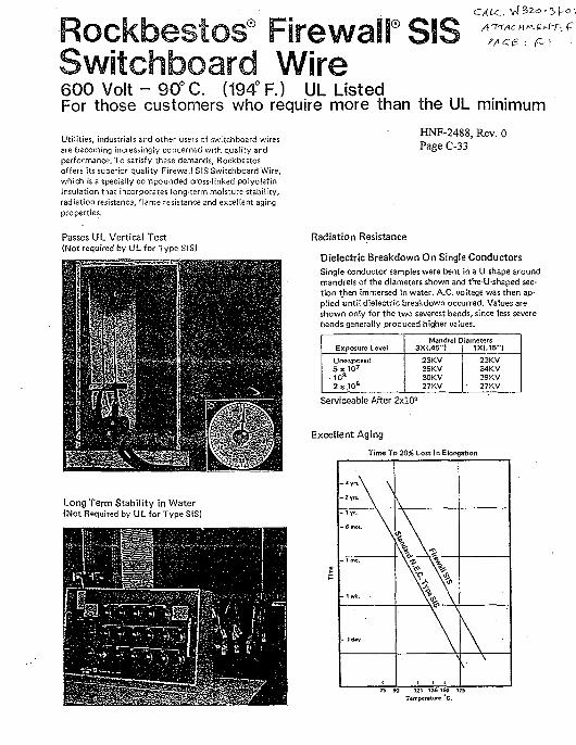
F-\
600 Volt - 90° C. (194° F.) UL ListedFor those customers who require more than the UL minimum
Utilities, industrials and other users of switchboard wiresare becoming increasingly concerned with quality andperformance. To satisfy these demands, Rockbestosoffers its superior quality Firewall SIS Switchboard Wire,which is a specially compounded cross-linked polyolefininsulation that incorporates long-term moisture stability,radiation resistance, flame resistance and excellent agingproperties.
Passes UL Vertical Test{Not required by UL for Type SIS)
Long Term Stability in Water(Not Required by UL for Type SIS)
HNF-2488, Rev. 0Page C-33
Radiation Resistance
Dielectric Breakdown On Single ConductorsSingle conductor samples were bent in a U shape aroundmandrels of the diameters shown and theU-shaped sec-tion then immersed in water. A.C. voltage was then ap-plied until dielectric breakdown occurred. Values areshown only for the two severest bends, since less severebends generally produced higher values.
Exposure Level
Unexposed5 x 1 0 7
• 1 0 s
2)5,108
Mandrel Diameters3X{.45")
23KV35KV30KV27 KV
1XI.15")
23KV34KV29 KV27 KV
Serviceable After 2xlO8
Excellent Aging
Time To 20% Loss In Elongation
- ' m \ \
" ' " " • \
. . . . \
- 1 mo.
- Iwt .
\
A. V V
V\75 90 121 136 160 175
Temperature "C.
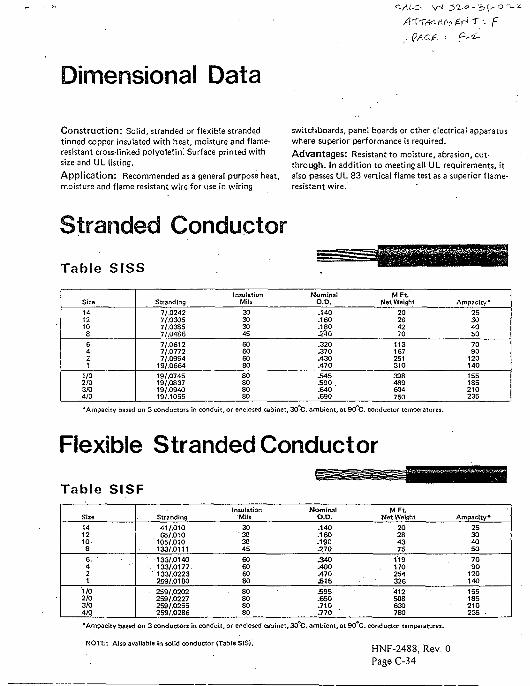
Dimensional Data
'- F
Construction: Solid, stranded or flexible strandedtinned copper insulated with heat, moisture and flame-resistant cross-linked polyolefin! Surface printed withsize and UL listing.
Application: Recommended as a general purpose heat,moisture and flame resistant wire for use in wiring
switchboards, panel boards or other electrical apparatuswhere superior performance is required.Advantages: Resistant to moisture, abrasion, cut-through. In addition to meeting all UL requirements, italso passes UL 83 vertical flame test as a superior flame-resistant wire.
Stranded Conductor
Table SISS
Size1412108
6421
1/02/03/04/0
Stranding7/.02427/.03057/.03857/.04867/.06127/.07727/.0994
19/.066419/.074519/.083719/.094019/.1055
InsulationMils30303045
60606080
80808080
NominalO.D..140.160.180J2/I0.320.370.430.470.5455 9 0.640.690
MFt.Net Weight
20284270
113167251310
398489604750
Ampacity*25304050
7090
120140
155185210235
•Ampacity based on 3 conductors in conduit, or enclosed cabinet, 30 C. ambient, at 90 C. conductor temperatures.
Flexible Stranded Conductor
Table SISF
Size
1412108
6. '421
1/02/03/04/0
Stranding41/.01065/.010
105/.010133/.0111133/.0140133/.0177133/.0223259/.0180259/.O202259/.0227259/.0255259/.0286
InsulationMils30
"303045
60606080
. 80808080
NominalO.D..140.160.190.270.340.400.470£ 1 5
£ 9 5.650.710.770
MFt.Net Weight
20284375
119170
.254326
412508630780
Ampacity*25304050
7090
120140
155185210235
•Ampacity based on 3 conductors in conduit, or enclosed cabinet,50 C. ambient, at 90 C. conductor temperatures.
NOTE: Also available in solid conductor (Table SIS).HNF-2488, Rev. 0Page C-34
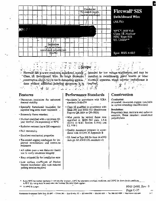
i
-
IB1-
c
-
ross]
1Insolation
nkea poTyeth
{Conductor 1Tirl-coaied copptr.
i —-
XFirewallSISSwitchboard Wire
(Xl.PK)
90"C*, 600 VoliClass IE NuclearNEC Type SISUI, Listed**
Spec. KSS-4-002
.!• Firewall," SJS;j^"Glass, IE Switchboard
;is'.a,oneconductor,!amacfeeted.'nucleit j V . inten.ded for low voltage''applications, and may bevitchlpoarii Wire, ."fe1/tough '.tjiemcA V installed;, in switchboard^, ,p#nel boards .or 'other
1 jranstruction.ailov5iforAi5aseindpiiandiiigapplicar •" electrical apparatus. wh$ES superior performance istions without artiiao^iaI>'jaofc^tingrr^ptectioD.; It is, !freqi&ei , • ' ;b\, '•/'•••'' , ,;, .
Features• Thermoses-insulation for enhanced
thermal stability ~
•^Specially formulated insulation forsuperior long term waier resistance -
• Extremely flame retardant
• Nuclear qualified with a minimum 40-year thermal life expectancy-at 90°C -
• Radiation resistant (up to 200 megarads)
° Full craccability
- Excellent mechanical properties
•Tin-coared coppet conductors for im-proved terminations and corrosionresistance
• All cables pass a wet dielectric (tank)lesi to verify insulation integrity _
• Easy strippability for installation ease
• Low surface coefficient of frictioninsures installation ease with reducedpulling tension required
Performance Standards•-Insulation "in accordance with ICEA
standards S-66-524
• Class IE qualified in accordance withIEEE-383 and IEEE-323 (RockbesiosReports QR-5804 or QR-5805)
•Wire passes the vertical flame testsspecified in IEEE-383 para. 2.5.6(ICEA S-19-81 Section 6.19.6) andUL vw-1
• Quality Assurance program in accor-dance with 10 CFR SO Appendix B
• UL listed as Type SIS for sizes 14 AWGthrough 4/0 AWG (UL standard 44)
ConstructionConductor:Annealed, tin-coated copper, (availablein various stranding classifications)
Insulation:Proprietary heat, moisture and radiationresistant, flame retardant crosslinkedpolyethylene
* Rated 90"C tor normal operation in wet and diy locations. J 30cC for emergency overload conditions, and 250°C for ahon circuUA 90flC dry ruliilg must he used when the Nutionnl Electrical Code applies.
HNF-2488, Rev. 0
le Corp. © 1097 • Clinton, MA - Ea3[ Granby. CT • BO0-U4-3732 • 503.3S5-5331
PageC-35• Fat: S0S-3ES-40S4 • hllp:/'wivw.f-scc.com .•>•!
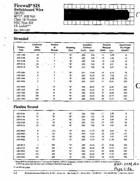
Firewall® SISSwitchboard Wire(XLPE)90°C*, 600 VoltClass IE NuclearNEC Type SISUL Listed**Spec. RSS-4-OO2
Stranded
ProductCode
AS2-I1S6
A82-OI66
A82-0I46
A82-0I26
AS2-0116
AS2-1O86A82-I066
A82-1046
AS2-I026
A82-I0I6
A82-IW0
A82-1200
AS2-13OO
A82-I400
ConductorSize
(AWG)
18
16
14
_ 1 2
10
S
642
1
1/0
'210
3/0
-4/0
Numberof
Strands
7
- 7
7
- - 7
_- 7
7 .
77
7
- 19
1919
19
19
StrandingClass
"B"
"B"
"B"
"B""B"
"B"
"B"-B"
"B"
"B"
-B""B"
"B""B"
InsulationThickness
(Inch)
.030
.030
.030
.030
.030
.045
.060
.060
.060
-OS0
.080
.080
,080
.030
(mm)
7.62 .
7.62 ~
7.62
7.62
7.62
11.4315.24
15.2*15.24
20.32
20.32
20.32
20.32
20.32
NominalDiameter
(Inch)
.11
.12
.13
.15
.18
.24
.30
.35
.41
.49
.53
.57
.62
.68
(mm)
2,79
3.05
3.30
3.814.57
6.107.62
8.89
10.41
12.45
13.46
14.4315.75
17.27
ApproximateNet Weighitt-bs/M")
10
13
19
28
40
70
no170250
325
400
490
610 -
755
Flexible Strand
A83-O186
A83-0I66AS3-0146
AS3-0I26A83-OH6
AS3-0086A83.-0O66 ._
A83-0046
A83-0026
A83-0016
A83-0100" AS3-0200
A83-030O
AS3-O400
18
1614
12
10 *-
8642
1
1/0
1/03/04/0
16
-2641
65
105
133-
133— 133
133
259
259 -
259
259
259
"K""K-"K""K1"UK"
"H"
"H""H""H"
-i-r~H"
"H"
• • H "
• • H "
.030
.030
.030
.030
.030
.045
.060
.060
.060
.080
.080
.050
.OSO
.080
7.62
7.62
7.627.62
7.62
11.43
15.2415.2415.24
20.32
20.32
20.32
20.32
20.32"
.11
.12
.14
.15
.19
.26
.33
.38
.46
.55
.53
.63
.69
.76
2.793.05
3.563.814.83
6,608.3S
9.6511.68
13.46
14.73
16.00
17.53
19.30
10
1419
2843
72
115175260
340420
520
640
795
* Ruled 90*C for normal operation in wet and dry locations, 130°C for emergency overload conditions, and 2S0°C lor shun circuit conditions.A 9 0 ^ dry ruling muse be used when the National Electrical Code applies. - U/P
S-2 RockHlsuJB-SurprerunrCahli! Corp. ©1997 • Clinmn. MA • Easi Gianby, CT • «0rj."4-3792 • 5oa-3SS-633l • Fat: S0B-365.«S» - Mlp://«™rw,r.scc,com
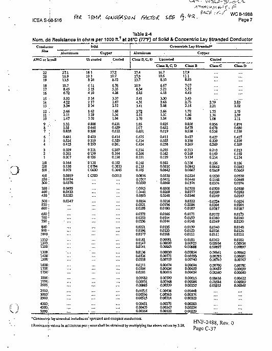
ICEAS-68-516 ft* CoiOOtAUoti FficTog.fAC* ^ ' ^ WC 8-1988
Page 7
Table 2-4Nom. de Resistance in ohn is per 1000 ft.1 at 2PC (7TT) of Solid & Concentric Lay Stranded Conductor
Q
\J
Conductor
Size '
AWG or kcmll
I
22 '2019
18 117 .16 .
15 •
13 '
12 .11 •10
9 :.8 'i :6 :5 I4 i
3 •2 !
1
vo i2/03/o j4/o ;250 •300 i
350 i400 •450 ;
5 0 0 :550 •6oo;650 j700 •ISO.
800-9 0 0 '
1000;
1100!1200:1250!
1300 i1400:1500;
1600;17001750!
1800 i1900;2000,2500.3000:3500.
4000'4500:5000'
Aluminum
27.116.9133
10.78.456.72
5324.223342.662.111.67
1321.050.833
0.66103240.415
0.3290.2610.207
0.1640.1300.103
0.08190.06940.0578
0.04950.04330.0385
0.0347
Solid
Copper
Ul coaled
16 510 3820
6 SI5154103242 57204
162129102
080806400508
0 4030 3190 253
0 20101590126
0 100C0794C0630
C0500
Coaled
17.210.7832
6.765354263.372.67112
1.681341.060.8310.6590322
0.41403290261
0.2070.1640.130
0.1020.08130.0645
0.0511
Aluminum
Class B , C D
27.417313.7
10.98346.85
5.414313.41
1722.151.701351.0705510.67503340.424
0.3350.2660.211
0.1680.1330.105
0.08360.07070.0590
0.05050.04420.0393
0.03540.0321O.0295
0.02720.02530.0236
0.02210.01960.0177
0.01610.01470.0141
0.01360.01260.0118
0.01110.01040.0101
0.009820.009310.008SS
0.007150.005960.00515
0.004510.004050.00364
'Concentric lay stranded includes CO: nprcssed and compact conductors.
Concer
U&coaUd
Class B, C D
16.7103833
6.675.214.18
3302.632.08
1.661311.04
0.8250.6520319
0.41103250.258
02050.1620.129
0.1020.08100.0642
0.0510O.O43I0.0360
0.03030.02690.0240
0.02160.01960.0180
0.01660.01540.0144
0.01330.01200.0108
0.009810.008990.00863
0.0083O0.007710.00719
0.006740.0O6340.00616
0.00599O.O0568O.O0539
' 0.004360.003630.00314
0.002750.002470.00222
I r k L»y Stranded*
Copper
Class B
17.911.1
8 .S3
7.075324.433.431732.16
1.721361.08
0.8560.6780338
0.4270.3380.269
0.2130.1690.134
0.1060.08420.0667
0.05240.04480.0374
0.03200.0277O.0246
0.02220.02040.0187
0.01710.01590.0148
0.01390.01230.01110.01010.009250.00888
0.008540.007930.00740
0.006940.006530.00634
0.006160.005840.0055S
0.004430.003740.00323
0.002830.002540.00229
Tjrxnc
Coated
Class C
179"121
1.751361.080.8560.6780338
0.42703390269
0.2130.1690.134
0.1060.08420.0669
0.05300.04480.0374
0.03200.02800.0249
0.02240.02040.0187
0.01720.01600.0149
0.01400.01260.01110.01020.009340.008970.008610.007930.00740
0.007000.006590.00640
0.006160.005840.OO555
1AOa n .
tResistance values in miliiohms per I tetcr shall be obtained by multiplying the above values by 3.28. D '
Class D
183"122
1.751391.11
05740.6800333
0.42703390269
0.2130.1690.134
0.1060.08420.0669
0.05300.04480.03740.03200.02800.0249
0.02240.02040.0187
0.01730.01600.0150
0.01400.01260.0112
0.01020.009340.00897
0.008620.008010.00747
0.007000.006590.00640
0.006220.005890.00560
0
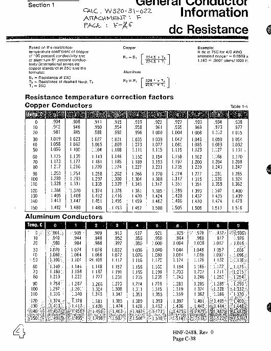
Section 1 vaenerai
F-
Informationdc Resistance
Based on the resistance-temperature coefficient of copperof 100 percent conductivity andof aluminum 61 percent conduc-tivity (international annealedcopper standard) at 25C and theformulas:Ri = Resistance at 25CR2 = Resistance at desired temp. T2Ti = 25C
Copper Example:R dc at 75C for 4/0 AWGuncoated copper = 0.0509 x1.193 = .0607 ohms/1000 ft.
Resistance temperature correction factorsCopper Conductors
Aluminum Conductors
HNF-2488, Rev. 0Page C-38
Table 1-4
01020
304050
607080
90100110
120130140
150
.904
.942
.981
1.0191.0581.096
1.1351.1731.212
1.2501.2891.328
1.3661.4051.443
1.482
mm.908.946.985
1.0231.0621.100
1.1391.1771.216
1.2541.2931.331
'1.3701.4081.447
1.480
nm.911.950.988
1.0271.0661.104
1.1431.1811.220
1.2581.2971.335
1.3741.4121.451
1.489
f||§i.915.954.992
1.0311.0691.108
1.1461.1851.224
1.2621.3001.339
1.3781.4161.455
.1.493
w.919.958.996
.035
.073
.111
.150
.189
.227
.266
.304
.343
.381
.420
.459
1.497
.923
.9611.000
1.0391.0771.115
1.1541.1931.231
1.2701.3081.347
1.385 '1.4241.462
1.500
.927
.9651.004
1.0421.0811.119
1.1581.197.1.235
1.2741.3121.351
•1.3891.4281.466
1.505
.931.969
1.008
.046
.085
.123
.162
.200
.239
.277
.316
.354
.393
.432
.470
1.509
.934
.9731.012
1.0501.0891.127
1.1661.2041.243
1.2811.3201.358
1.3971.4351.474
1.513
nn.938.977
1.015
1.0541.0921.131 ,
1.1701.2081.247
1.2851.3241.362
1.4001.4391.478
1.516
Temp. C 1
CD C
D C
D
30 '40
- • 5 0 • :
607080
90100110
120130140
150
o
" .940. :980
1.0201.060..;
1.1401.180V1.219
1:258 "1.2971.336
1 37414131 452
: t • • !
• . 905
.944
.984
1.0241.0641.104
. 1.1441.1841.223
1.262.1.301
••• 1.340
l"3781 417
U95
2
.909
.948
.988
1.0281.068
1.1481.1871.227
1.2661.304'1.343
1 38114201 4 5 9 t
1498
: : v ; : . 3 . ^
.913
.952.992
1.0321.0721.112
1.1521.1911.231
1.2701.3081.347
13851 4241463
1 502
• • 4 ' . - I
.917.956.996
1.036' 1.076
1.116
1.1561.1951.235
1.2741.3111.351
1 38914281467
1 506
5
.921
.9601.000
1.0401.0801.120
1.1601.1991.239
1.2781.3151.355
1 39314321471 >
1510 '
.925
.9641.004
1.0441.0841.124
1.1641.2031.243
1.2811.3191.359
13971436
J 475
1 5*14*
?928968
1 008
1 0481 0881 128
1 1681 2071 246
1 2851 3241 362
14011 440
v l l 5T8
932972
1 012
10521 0921 132
1 1721 2111 250
1 2891 3281 366
1405
,,1444%. 483g
§ 522~
9 1936976
1016
10561 0961 136
1 1761 2151 254
1 29313321 370
4091 4481487;
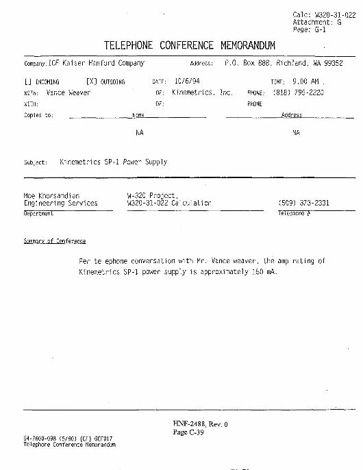
Calc: W320-31-022Attachment: GPage: G-l
TELEPHONE CONFERENCE MEMORANDUMCompany:ICF Kaiser Hanford Company Address: P.O. Box 888, Richland, WA 99352
[ ] INCOMING [X] OUTGOING DATE: 10/6/94 TIME: 9.00 AM .
WITH: Vance Weaver OF.- Kinemetr ics, Inc. PHONE.- (818) 795-2220
WITH: OF: PHONE:
Copies to: Name Address
NA NA
Subject: Kinemetrics SP-1 Power Supply
Moe Khorsandian W-320 Project.Engineering Services W320-31-022 Calculation (509) 373-2331Department Telephone #
Summary of Conference
Per telephone conversation with Mr. Vance weaver, the amp rating ofKinemetrics SP-1 power supply is approximately 150 mA.
HNF-2488, Rev. 0Page C-39
54-7600-098 (5/90) {EF} GEF017Telephone Conference Memorandum
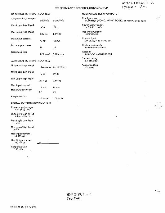
PERFORMANCE SPECIFICATIONS (Cont'd)
ATTACH M £ M i - HV A - l
DC DIGITAL OUTPUTS (ISOLATED)
Output voltage ranges
Max Logic Low Input
Min Logic High Input
Max Input current
Max Output current
Response time
5-60V dc 5-200V dc
iVtic iV cfc
2.5V dc 2.5V dc
12 mA 12 mA
3A 1A
0.75 msec 0.75 msec
12-l40Vac
IV dc
2.5V dc
12 mA
3A
24-230V ac
1Vdc
2.5V dc
12 mA
3A
AC DIGITAL OUTPUTS (ISOLATED)
Output voltage range
Max Logic Low Input
Min Logic High Input
Max Input current
Max Output current
Response time
1/2 cycle 1/2 cycle
DIGITAL OUTPUTS (NONISOLATED)
Power supply range+ 5VdC ±10%
Output voltage range+ 5 (0 + 24V dc
Max Logic Low Input1.35V
Min Logic High Input4.2V
Max Input current1.5rnAdc
Max Output currentTOOmACc ^
Response time100 usec
MECHANICAL RELAY OUTPUTS
ConfigurationDual relays (WO/NO, NC/NC, NO.-NC) or Form C single relay
Power supply range+ 5Vdc ±10%
Max Input Current-10.0 rnAdc
Contact load3A at 250V ec or 30V dc
Contact resistance0.10 ohms maximum
Isolation250V rms (contacts to coil)
Current rating3A per relay
Response time10 /nsec
HNF-2488, Rev. 0Page C-40
SS-23-05-06, iss. 4, 3/93
DISTRIBUTION SHEETTo
Distribution
Project Title/Work Order
Project W-320 Tank 106-C,V o l . 2
Name
From
JW
HNF-2488,
Bailey
Electrical
MSIN
Calculations,
TextWith AllAttach.
Text
Page 1 of 1
Date 25 July 1998
EDT No. 622246
ECN No. n/a
Only Attach./Appendix
Only
EDT/ECNOnly
JW BaileyW-320 Project Files
S2-48Rl-29
A-6000-135 (01/93) WEF067


