Embed Size (px)
Citation preview
Damage Thresholds for New Collimator
Materials, Experiment Detectors and SC
Magnet Components
F. Carra (EN-MME), C. Bertella (EP), A. Sbrizzi (EP), D. Wollmann (TE-MPE)
With contributions from colleagues of EN-MME, BE-ABP, EN-STI, TE-MPE, EP
MPP Workshop 2019
Chateau de Bossey
May 7th, 2019
Outline
2F. Carra (CERN), 7 May 2019
Introduction
Particle beam – matter interactions
Damage mechanisms
Collimator materials
HiRadMat experiments
Damage thresholds
SC magnet components
ATLAS detectors
Conclusions
Introduction to beam damage
3F. Carra (CERN), 7 May 2019
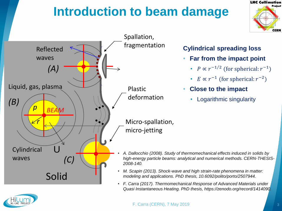
Cylindricalwaves
Reflectedwaves
Liquid, gas, plasma
p
r
BEAM
Solid
(B)
Micro-spallation, micro-jetting
(A)
(C)U
Plastic deformation
Cylindrical spreading loss
• Far from the impact point
• 𝑃 ∝ 𝑟 Τ−1 2 (for spherical: 𝑟−1)
• 𝐸 ∝ 𝑟−1 (for spherical: 𝑟−2)
• Close to the impact
• Logarithmic singularity
• A. Dallocchio (2008). Study of thermomechanical effects induced in solids by
high-energy particle beams: analytical and numerical methods. CERN-THESIS-
2008-140.
• M. Scapin (2013). Shock-wave and high strain-rate phenomena in matter:
modeling and applications. PhD thesis, 10.6092/polito/porto/2507944.
• F. Carra (2017). Thermomechanical Response of Advanced Materials under
Quasi Instantaneous Heating. PhD thesis, https://zenodo.org/record/1414090.
Spallation, fragmentation
Introduction to beam damage
4F. Carra (CERN), 7 May 2019
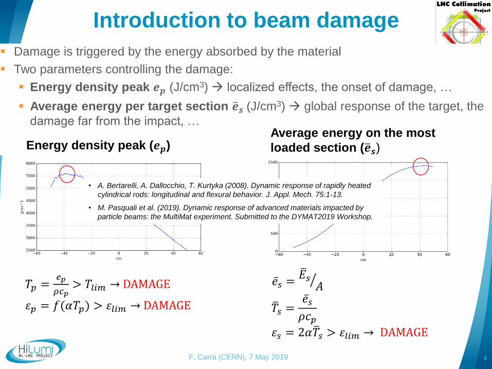
Damage is triggered by the energy absorbed by the material
Two parameters controlling the damage:
Energy density peak 𝒆𝒑 (J/cm3) localized effects, the onset of damage, …
Average energy per target section ത𝒆𝒔 (J/cm3) global response of the target, the
damage far from the impact, …
Energy density peak (𝒆𝒑)Average energy on the most
loaded section (ത𝒆𝒔)
𝑇𝑝 =𝑒𝑝
𝜌𝑐𝑝> 𝑇𝑙𝑖𝑚 → DAMAGE
𝜀𝑝 = 𝑓(𝛼𝑇𝑝) > 𝜀𝑙𝑖𝑚 → DAMAGE ത𝑇𝑠 =ҧ𝑒𝑠
𝜌𝑐𝑝𝜀𝑠 = 2𝛼ത𝑇𝑠 > 𝜀𝑙𝑖𝑚 → DAMAGE
• A. Bertarelli, A. Dallocchio, T. Kurtyka (2008). Dynamic response of rapidly heated
cylindrical rods: longitudinal and flexural behavior. J. Appl. Mech. 75:1-13.
• M. Pasquali et al. (2019). Dynamic response of advanced materials impacted by
particle beams: the MultiMat experiment. Submitted to the DYMAT2019 Workshop.
ҧ𝑒𝑠 = ൗത𝐸𝑠
𝐴
Collimator damage thresholds
5F. Carra (CERN), 7 May 2019
Three damage thresholds defined for collimator materials.
Introduced for metallic (ductile) materials see MPP Workshop 2013, Annecy. Extended here to graphitic ones.
Defined as a function of the effect on the collimator behaviour.
Threshold 1: onset of damage, with no need to activate the 5th axis.
Ductile materials: onset of plasticity.
Graphitic materials: crack initiation, local material ablation.
Threshold 2: damage to the surface requiring correction with the 5th axis.
Ductile materials: it usually involves heavy plastic deformation and/or ejecta generation.
Graphitic materials: pseudo-plastic deformation, internal delamination, important material ablation, …
Threshold 3: damage cannot be corrected with 5th axis anymore.
Ductile materials: significant material erosion and plastic deformation in the jaw, no more flat surface close to the impact.
Graphitic materials: fracture of the blocks jeopardizing the structural integrity, complete block face delamination with loss of the flatness.
Collimator materials
6F. Carra (CERN), 7 May 2019
The evaluation of material response to beam impact is done in two ways:
Numerical simulations (FLUKA + ANSYS, Autodyn, LS-Dyna)
Experimental tests (HiRadMat: on full-scale devices or on simple geometry
targets)
The damage thresholds are estimated with a combination of the two techniques
HiRadMat experiments on collimator materials and devices:
HRMT-09 (2012): TCT collimator (Inermet180)
HRMT-14 (2012): collimator material samples (cylinders and half-moons)
HRMT-23 (2015): LHC and HL-LHC collimator jaws (CFC, MoGr, CuCD)
HRMT-21 (2017): Rotatable collimator (Glidcop) see backup slides
HRMT-36 (2017): collimator material samples (rods, uncoated and coated)
HRMT-09 (2012)
7F. Carra (CERN), 7 May 2019
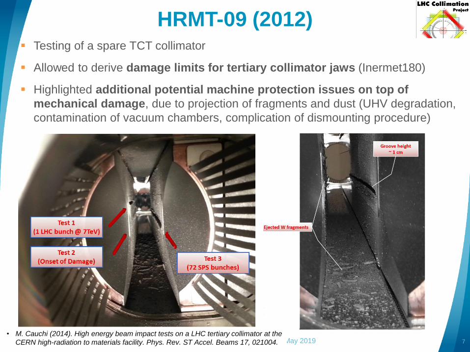
Testing of a spare TCT collimator
Allowed to derive damage limits for tertiary collimator jaws (Inermet180)
Highlighted additional potential machine protection issues on top of
mechanical damage, due to projection of fragments and dust (UHV degradation,
contamination of vacuum chambers, complication of dismounting procedure)
• M. Cauchi (2014). High energy beam impact tests on a LHC tertiary collimator at the
CERN high-radiation to materials facility. Phys. Rev. ST Accel. Beams 17, 021004.
HRMT-14 (2012)
8F. Carra (CERN), 7 May 2019
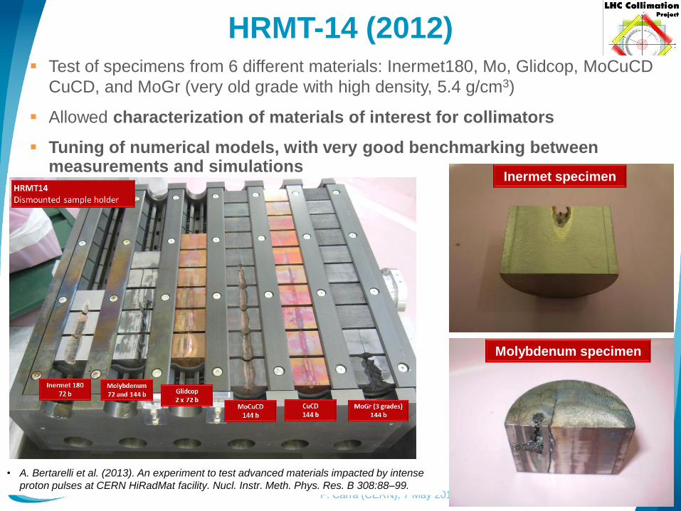
Test of specimens from 6 different materials: Inermet180, Mo, Glidcop, MoCuCD
CuCD, and MoGr (very old grade with high density, 5.4 g/cm3)
Allowed characterization of materials of interest for collimators
Tuning of numerical models, with very good benchmarking between measurements and simulations
• A. Bertarelli et al. (2013). An experiment to test advanced materials impacted by intense
proton pulses at CERN HiRadMat facility. Nucl. Instr. Meth. Phys. Res. B 308:88–99.
Inermet specimen
Molybdenum specimen
HRMT-23 (2015)
9F. Carra (CERN), 7 May 2019
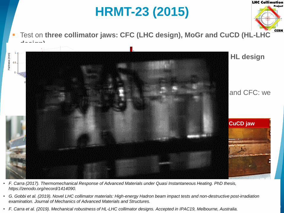
Test on three collimator jaws: CFC (LHC design), MoGr and CuCD (HL-LHC
design)
Allowed validation of absorber jaw materials, as well as integral HL design
(taperings, BPM, housing, cooling circuit, brazing)
Achieved 𝒆𝒑 of HL-LHC accidental cases, by squeezing the beam
For CuCD, exceeded ത𝒆𝒔 of the HL-LHC accidental case; for MoGr and CFC: we
were below (LIU beam needed!)
CuCD jaw
48b, η=0.18mm
σ=0.35mm
144b, η=3.05mm
σ=0.61mm
60b, η=0.18mm
σ=0.61mm
48 bunches on CuCD
𝝈 = 𝟎. 𝟑𝟓𝐦𝐦, η𝒙 = 𝟎. 𝟏𝟖𝐦𝐦
• F. Carra (2017). Thermomechanical Response of Advanced Materials under Quasi Instantaneous Heating. PhD thesis,
https://zenodo.org/record/1414090.
• G. Gobbi et al. (2019). Novel LHC collimator materials: High-energy Hadron beam impact tests and non-destructive post-irradiation
examination. Journal of Mechanics of Advanced Materials and Structures.
• F. Carra et al. (2019). Mechanical robustness of HL-LHC collimator designs. Accepted in IPAC19, Melbourne, Australia.
HRMT-23 (2015)
10F. Carra (CERN), 7 May 2019
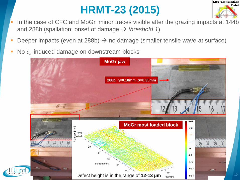
In the case of CFC and MoGr, minor traces visible after the grazing impacts at 144b
and 288b (spallation: onset of damage threshold 1)
Deeper impacts (even at 288b) no damage (smaller tensile wave at surface)
No ҧ𝑒𝑠-induced damage on downstream blocks
CFC jaw
144b, η=0.18mm ,σ=0.35mm
288b, η=0.18mm ,σ=0.35mm
MoGr jaw
288b, η=0.18mm ,σ=0.35mm
MoGr most loaded block
Defect height is in the range of 12-13 µm
HRMT-36 (2017)
11F. Carra (CERN), 7 May 2019
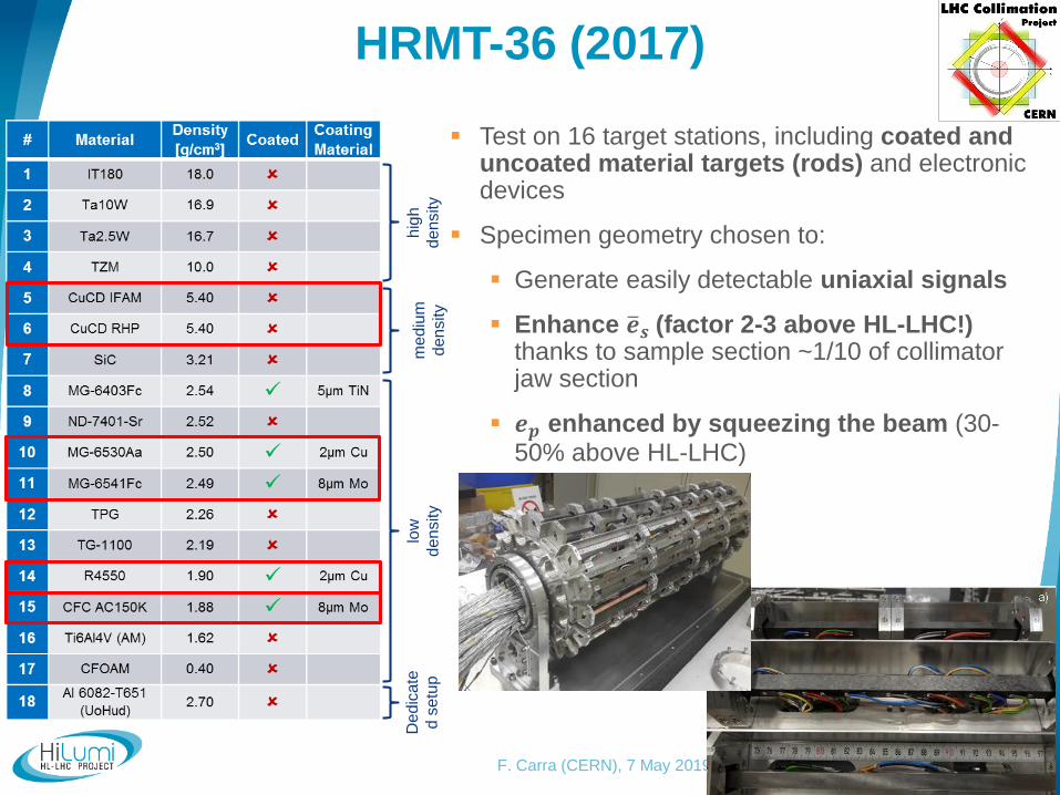
Test on 16 target stations, including coated and uncoated material targets (rods) and electronic devices
Specimen geometry chosen to:
Generate easily detectable uniaxial signals
Enhance ത𝒆𝒔 (factor 2-3 above HL-LHC!) thanks to sample section ~1/10 of collimator jaw section
𝒆𝒑 enhanced by squeezing the beam (30-50% above HL-LHC)
De
dic
ate
d s
etu
ph
igh
den
sity
low
den
sity
me
diu
m
den
sity
HRMT-36 (2017)
12F. Carra (CERN), 7 May 2019
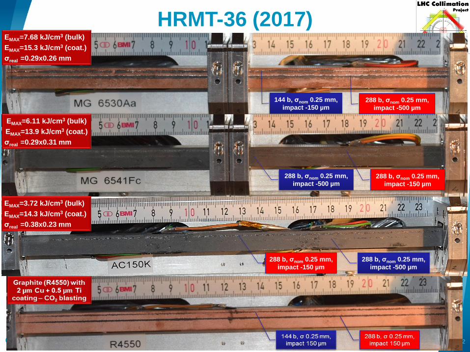
EMAX=7.68 kJ/cm3 (bulk)
EMAX=15.3 kJ/cm3 (coat.)
σreal =0.29x0.26 mm
144 b, σnom 0.25 mm,
impact -150 µm 288 b, σnom 0.25 mm,
impact -500 µm
288 b, σnom 0.25 mm,
impact -500 µm 288 b, σnom 0.25 mm,
impact -150 µm
EMAX=6.11 kJ/cm3 (bulk)
EMAX=13.9 kJ/cm3 (coat.)
σreal =0.29x0.31 mm
288 b, σnom 0.25 mm,
impact -150 µm
288 b, σnom 0.25 mm,
impact -500 µm
EMAX=3.72 kJ/cm3 (bulk)
EMAX=14.3 kJ/cm3 (coat.)
σreal =0.38x0.23 mm
HRMT-36 (2017)
13F. Carra (CERN), 7 May 2019
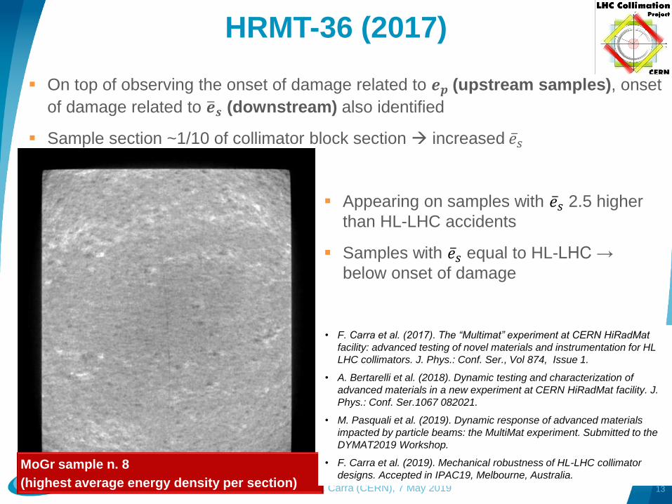
On top of observing the onset of damage related to 𝒆𝒑 (upstream samples), onset
of damage related to ത𝒆𝒔 (downstream) also identified
Sample section ~1/10 of collimator block section increased ҧ𝑒𝑠
MoGr sample n. 8
(highest average energy density per section)
Appearing on samples with ҧ𝑒𝑠 2.5 higher
than HL-LHC accidents
Samples with ҧ𝑒𝑠 equal to HL-LHC →
below onset of damage
• F. Carra et al. (2017). The “Multimat” experiment at CERN HiRadMat
facility: advanced testing of novel materials and instrumentation for HL
LHC collimators. J. Phys.: Conf. Ser., Vol 874, Issue 1.
• A. Bertarelli et al. (2018). Dynamic testing and characterization of
advanced materials in a new experiment at CERN HiRadMat facility. J.
Phys.: Conf. Ser.1067 082021.
• M. Pasquali et al. (2019). Dynamic response of advanced materials
impacted by particle beams: the MultiMat experiment. Submitted to the
DYMAT2019 Workshop.
• F. Carra et al. (2019). Mechanical robustness of HL-LHC collimator
designs. Accepted in IPAC19, Melbourne, Australia.
Collimator damage thresholds and
accidental scenarios
14F. Carra (CERN), 7 May 2019
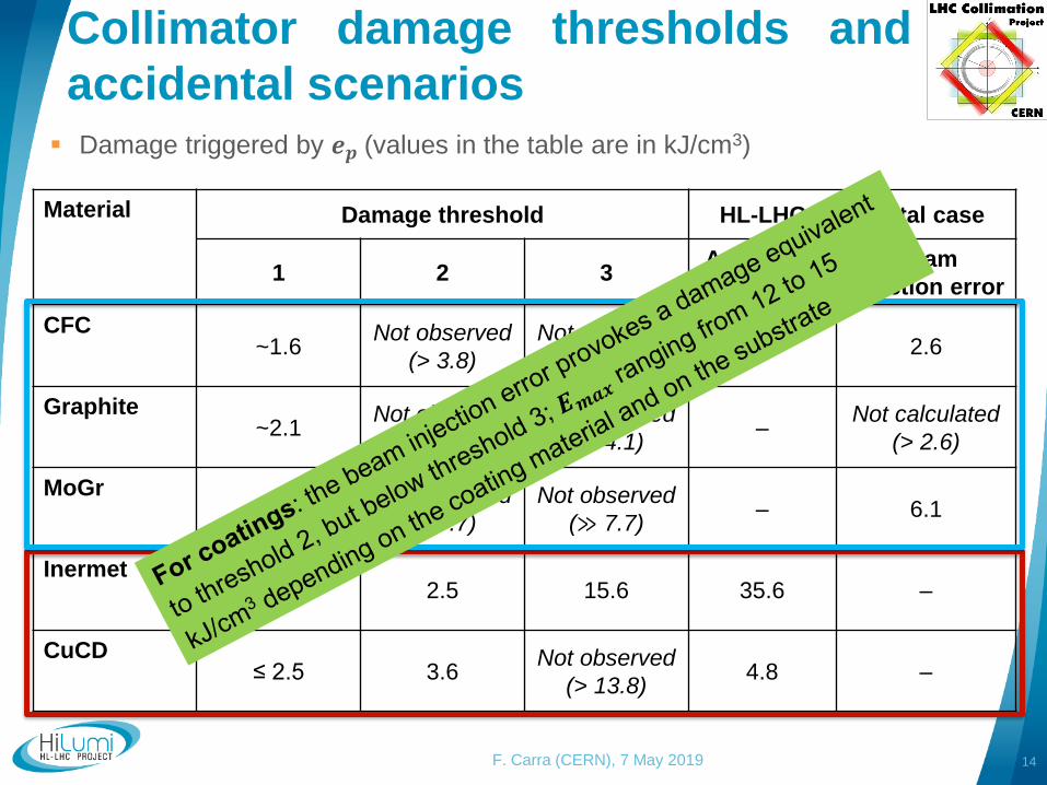
Material Damage threshold HL-LHC accidental case
1 2 3Asy. beam
dump
Beam
injection error
CFC~1.6
Not observed
(> 3.8)
Not observed
(≫ 3.8)– 2.6
Graphite~2.1
Not observed
(> 4.1)
Not observed
(≫ 4.1) –
Not calculated
(> 2.6)
MoGr≤ 5.7
Not observed
(> 7.7)
Not observed
(≫ 7.7) – 6.1
Inermet0.6 2.5 15.6 35.6 –
CuCD≤ 2.5 3.6
Not observed
(> 13.8)4.8 –
Damage triggered by 𝒆𝒑 (values in the table are in kJ/cm3)
Collimator damage thresholds and
accidental scenarios
15F. Carra (CERN), 7 May 2019
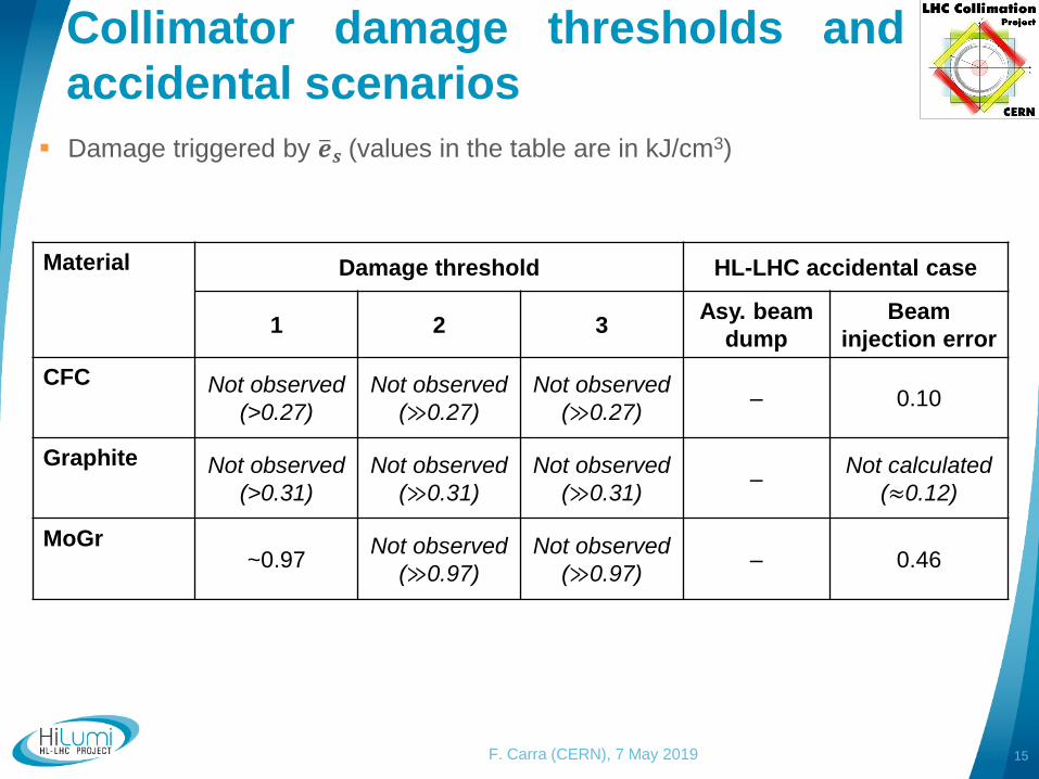
Material Damage threshold HL-LHC accidental case
1 2 3Asy. beam
dump
Beam
injection error
CFC Not observed
(>0.27)
Not observed
(≫0.27)
Not observed
(≫0.27)– 0.10
Graphite Not observed
(>0.31)
Not observed
(≫0.31)
Not observed
(≫0.31)–
Not calculated
(≈0.12)
MoGr~0.97
Not observed
(≫0.97)
Not observed
(≫0.97)– 0.46
Damage triggered by ത𝒆𝒔 (values in the table are in kJ/cm3)
16F. Carra (CERN), 7 May 2019
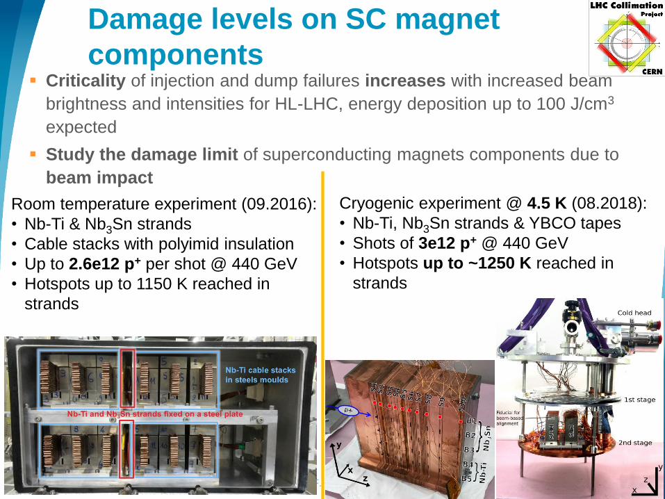
Criticality of injection and dump failures increases with increased beam
brightness and intensities for HL-LHC, energy deposition up to 100 J/cm3
expected
Study the damage limit of superconducting magnets components due to
beam impact
Room temperature experiment (09.2016):
• Nb-Ti & Nb3Sn strands
• Cable stacks with polyimid insulation
• Up to 2.6e12 p+ per shot @ 440 GeV
• Hotspots up to 1150 K reached in
strands
Cryogenic experiment @ 4.5 K (08.2018):
• Nb-Ti, Nb3Sn strands & YBCO tapes
• Shots of 3e12 p+ @ 440 GeV
• Hotspots up to ~1250 K reached in
strands
Damage levels on SC magnet
components
Main results of RT experiment
17F. Carra (CERN), 7 May 2019
Polyimid insulation:
No degradation measured after beam impact – temperature up to
~1050 K (2.5 kJ/cm3)
Weakening of the insulation at the point of the beam impact was
observed for T > 850 K (1.9 kJ/cm3)
Nb-Ti strands:
Jc degradation for hotspot temperatures > 878 K (2.2 kJ/cm3)
Nb3Sn strands:
Jc degradation observed in all samples T ≥ 699 K (1.4 kJ/cm3)
V. Raginel, et al., First Experimental Results on Damage Limits of Superconducting Accelerator Magnet
Components Due to Instantaneous Beam Impact, IEEE Trans. Appl. SC, Vol 28(4), June 2018
V. Raginel, Study of the Damage Mechanisms and Limits of Superconducting Magnet Components due to Beam
Impact, CERN-THESIS-2018-090
Observations after cryogenic
experiment
18F. Carra (CERN), 7 May 2019
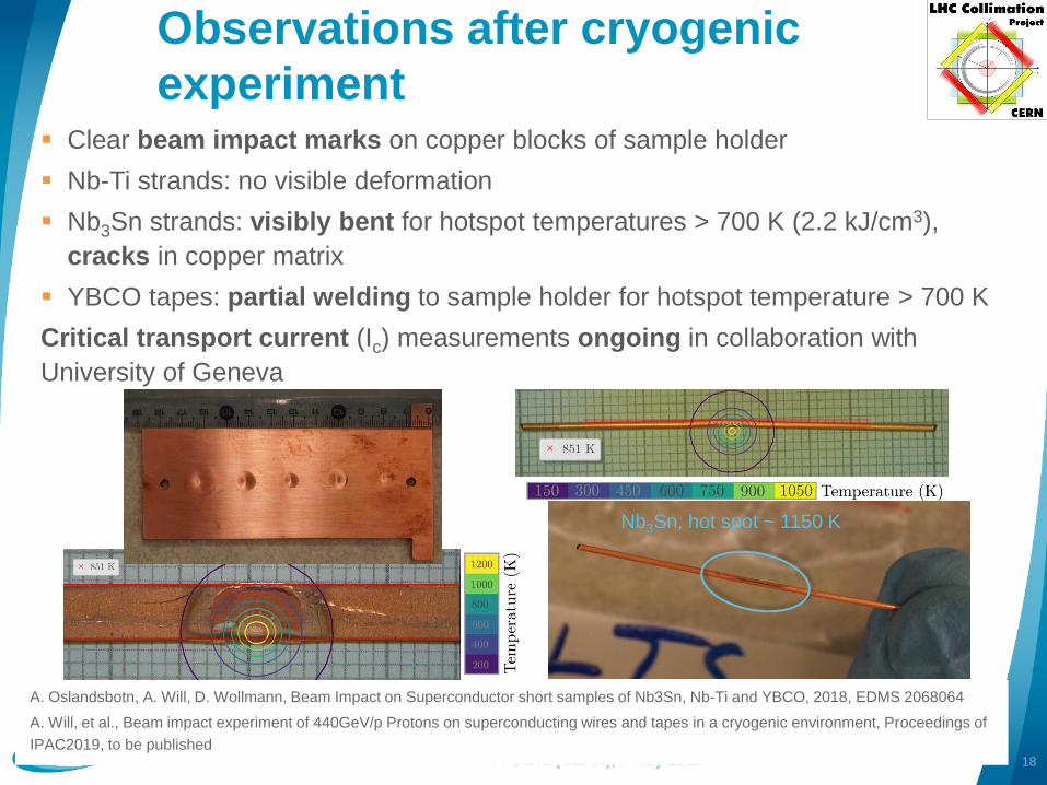
Clear beam impact marks on copper blocks of sample holder
Nb-Ti strands: no visible deformation
Nb3Sn strands: visibly bent for hotspot temperatures > 700 K (2.2 kJ/cm3),
cracks in copper matrix
YBCO tapes: partial welding to sample holder for hotspot temperature > 700 K
Critical transport current (Ic) measurements ongoing in collaboration with
University of Geneva
Nb3Sn, hot spot ~ 1150 K
A. Oslandsbotn, A. Will, D. Wollmann, Beam Impact on Superconductor short samples of Nb3Sn, Nb-Ti and YBCO, 2018, EDMS 2068064
A. Will, et al., Beam impact experiment of 440GeV/p Protons on superconducting wires and tapes in a cryogenic environment, Proceedings of
IPAC2019, to be published
ATLAS detectors
19F. Carra (CERN), 7 May 2019
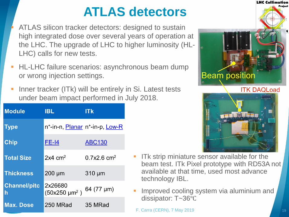
ATLAS silicon tracker detectors: designed to sustain
high integrated dose over several years of operation at
the LHC. The upgrade of LHC to higher luminosity (HL-
LHC) calls for new tests.
HL-LHC failure scenarios: asynchronous beam dump
or wrong injection settings.
Inner tracker (ITk) will be entirely in Si. Latest tests
under beam impact performed in July 2018.
ITk strip miniature sensor available for the beam test. ITk Pixel prototype with RD53A not available at that time, used most advance technology IBL.
Improved cooling system via aluminium and dissipator: T~36℃
ATLAS detectors: IBL results
20F. Carra (CERN), 7 May 2019
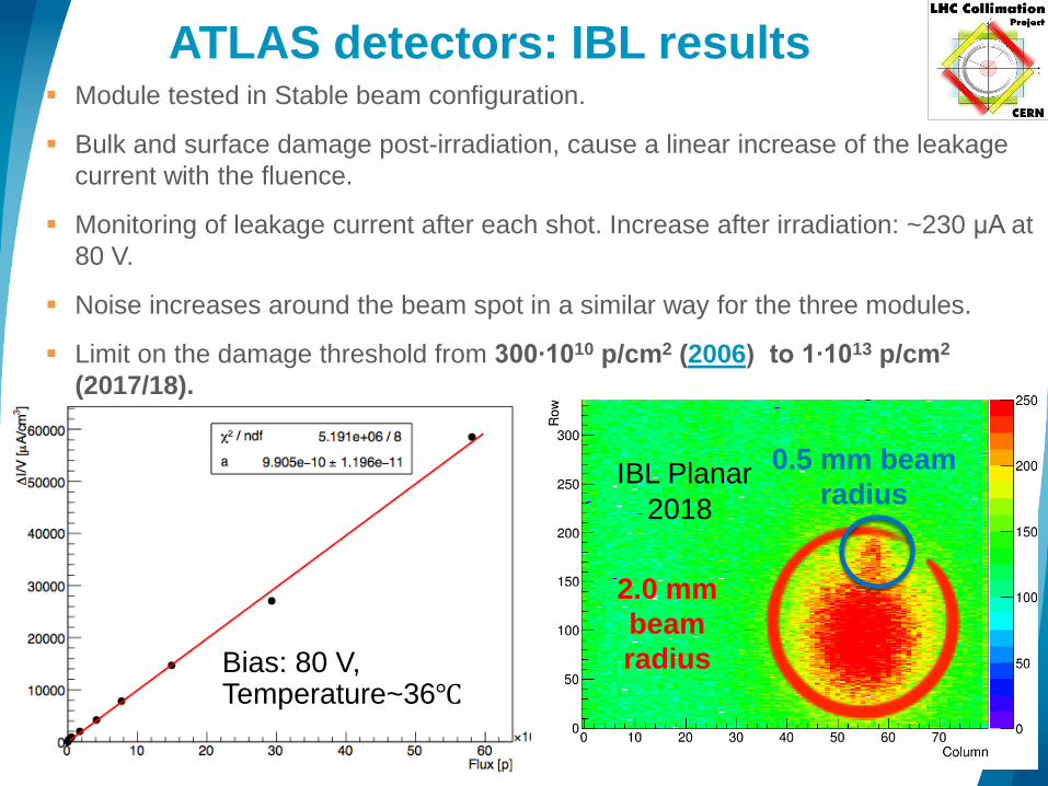
Bias: 80 V, Temperature~36℃
IBL Planar
2018
0.5 mm beam
radius
2.0 mm
beam
radius
Module tested in Stable beam configuration.
Bulk and surface damage post-irradiation, cause a linear increase of the leakage
current with the fluence.
Monitoring of leakage current after each shot. Increase after irradiation: ~230 μA at
80 V.
Noise increases around the beam spot in a similar way for the three modules.
Limit on the damage threshold from 300∙1010 p/cm2 (2006) to 1∙1013 p/cm2
(2017/18).
ITK STRIP: Influence on Read-out
Electronics
21F. Carra (CERN), 7 May 2019
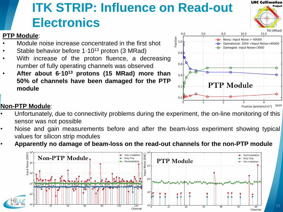
PTP Module:
• Module noise increase concentrated in the first shot
• Stable behavior before 1·1013 proton (3 MRad)
• With increase of the proton fluence, a decreasing
number of fully operating channels was observed
• After about 6·1013 protons (15 MRad) more than
50% of channels have been damaged for the PTP
module
Non-PTP Module:
• Unfortunately, due to connectivity problems during the experiment, the on-line monitoring of this
sensor was not possible
• Noise and gain measurements before and after the beam-loss experiment showing typical
values for silicon strip modules
• Apparently no damage of beam-loss on the read-out channels for the non-PTP module
ITK STRIP: Influence on Read-out
Electronics
22F. Carra (CERN), 7 May 2019
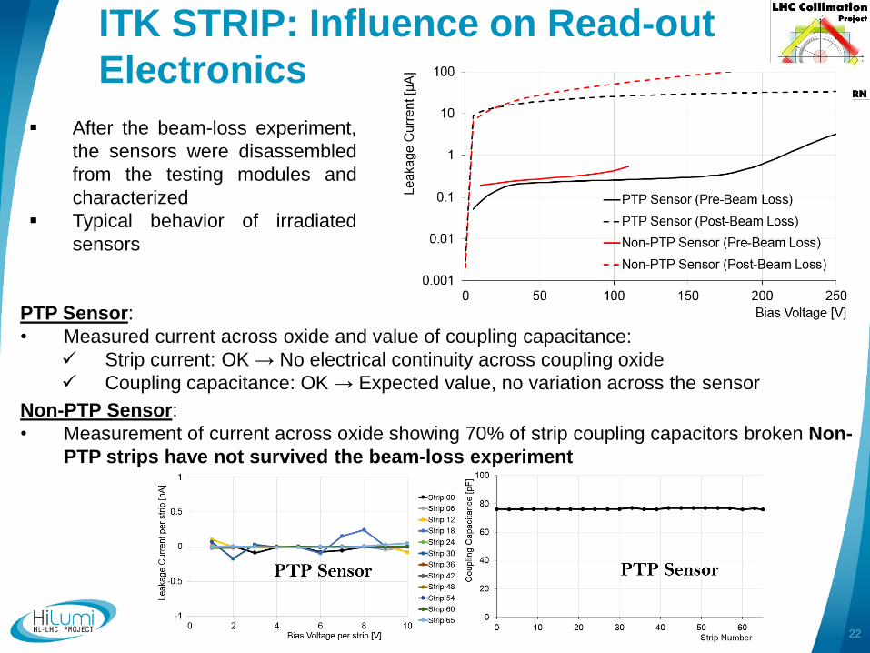
After the beam-loss experiment,
the sensors were disassembled
from the testing modules and
characterized
Typical behavior of irradiated
sensors
PTP Sensor:
• Measured current across oxide and value of coupling capacitance:
Strip current: OK → No electrical continuity across coupling oxide
Coupling capacitance: OK → Expected value, no variation across the sensor
Non-PTP Sensor:
• Measurement of current across oxide showing 70% of strip coupling capacitors broken Non-
PTP strips have not survived the beam-loss experiment
Conclusions
23F. Carra (CERN), 7 May 2019
The damage mechanism in case of particle beam impact on a material is
controlled by two parameters: peak energy density (ത𝒆𝒔) and maximum energy
over a longitudinal cross-section (𝒆𝒑)
However, damage definition changes depending on the application: it may be
related to the thermostructural behaviour (collimators), to the degradation of the
relevant electromagnetic properties (SC magnets), or to a loss of electronic
functionality (ATLAS detectors)
Need of performing experimental tests (HiRadMat) and, where possible,
numerical simulations, combining the two methods
For collimators, dedicated tests aimed at simulating similar or higher expected in
the accidental scenario.
For primary and secondary collimator materials, thresholds 2 and 3 have
never been reached so far
For tertiary collimator materials, threshold 3 is expected in the case of
tungsten under energies lower than the accidental scenario. In the case of
CuCD, threshold 3 is not reached neither in the accidental scenario, nor
experimentally
Conclusions
24F. Carra (CERN), 7 May 2019
The tests done in 2016 and 2018 to SC magnet components allowed:
Assessing the damage thresholds for the insulation
Evaluate the behaviour and damage limits of different SC solutions: Nb-Ti,
Nb3Sn and YBCO
Effects on the superconducting properties (Ic) under checking
Technical solutions for the ATLAS detectors also recently tested.
Allowed to choose between different technologies. For example, highlighted
the need of a PTP system.
Updated damage thresholds, first defined in 2006.
In the experimental tests, in spite of the lower beam stored energy, the expected
damage mechanisms was mimicked through squeezing the HRMT beam,
changing the sample geometry.
However, to completely validate full scale devices and derive upper damage
thresholds, it is of paramount importance to perform tests with the nominal
LIU/HL-LHC beam stored energy.
25
Thanks for your
attention!
F. Carra (CERN), 7 May 2019
26
Backup
slides
F. Carra (CERN), 7 May 2019
HRMT-14 (2012)
27F. Carra (CERN), 7 May 2019
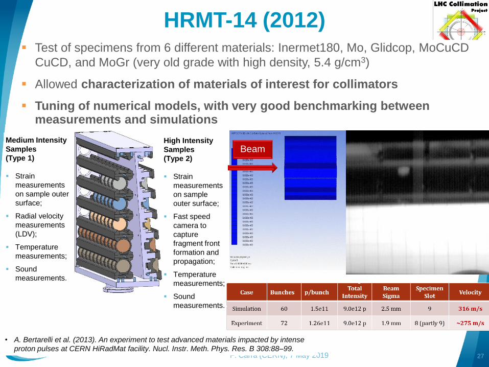
Test of specimens from 6 different materials: Inermet180, Mo, Glidcop, MoCuCD
CuCD, and MoGr (very old grade with high density, 5.4 g/cm3)
Allowed characterization of materials of interest for collimators
Tuning of numerical models, with very good benchmarking between measurements and simulations
BeamHigh Intensity
Samples
(Type 2)
Strain
measurements
on sample
outer surface;
Fast speed
camera to
capture
fragment front
formation and
propagation;
Temperature
measurements;
Sound
measurements.
Medium Intensity
Samples
(Type 1)
Strain
measurements
on sample outer
surface;
Radial velocity
measurements
(LDV);
Temperature
measurements;
Sound
measurements.
• A. Bertarelli et al. (2013). An experiment to test advanced materials impacted by intense
proton pulses at CERN HiRadMat facility. Nucl. Instr. Meth. Phys. Res. B 308:88–99.
HRMT-14 (2012)
28F. Carra (CERN), 7 May 2019
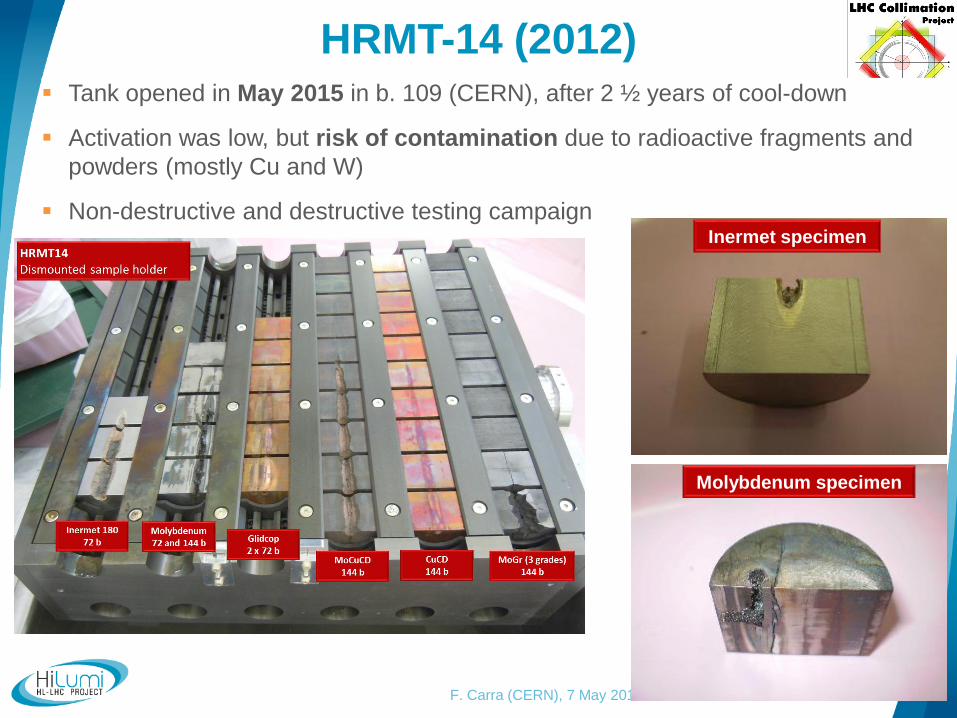
Tank opened in May 2015 in b. 109 (CERN), after 2 ½ years of cool-down
Activation was low, but risk of contamination due to radioactive fragments and
powders (mostly Cu and W)
Non-destructive and destructive testing campaignInermet specimen
Molybdenum specimen

HRMT-21 (2017)
29F. Carra (CERN), 7 May 2019
Test on SLAC rotatable collimator (Glidcop)
Low-impedance secondary collimator capable of withstanding 7 TeV failures
Goals:
Demonstrate that the rotation functionality works for the design failure at top energy
(Asynchronous beam dump: 8 bunches @ 7 TeV)
Understand onset of damage for even more demanding scenarios, e.g. LHC injection
error: 288 bunches @ 450 GeV
Integrity control of the cooling pipes under both impact and jaw rotation
Check the eventual sticking of the jaws in case of ejecta with LHC-type aperture
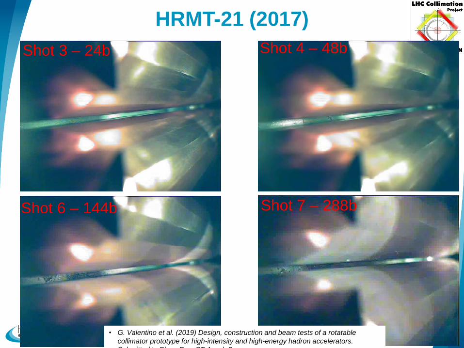
HRMT-21 (2017)
30F. Carra (CERN), 7 May 2019
Shot 3 – 24b Shot 4 – 48b
Shot 6 – 144b Shot 7 – 288b
• G. Valentino et al. (2019) Design, construction and beam tests of a rotatable
collimator prototype for high-intensity and high-energy hadron accelerators.
Submitted to Phys. Rev. ST Accel. Beams
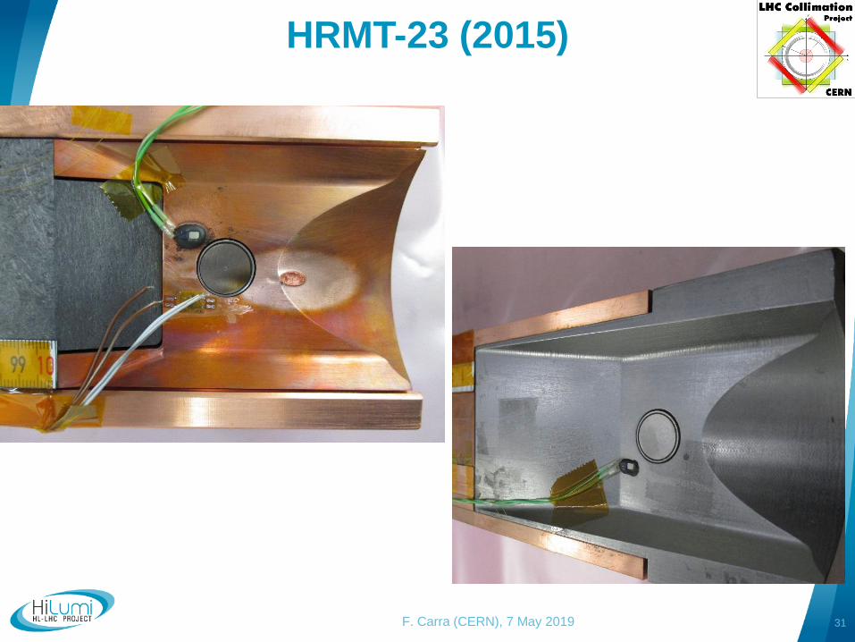
HRMT-23 (2015)
31F. Carra (CERN), 7 May 2019
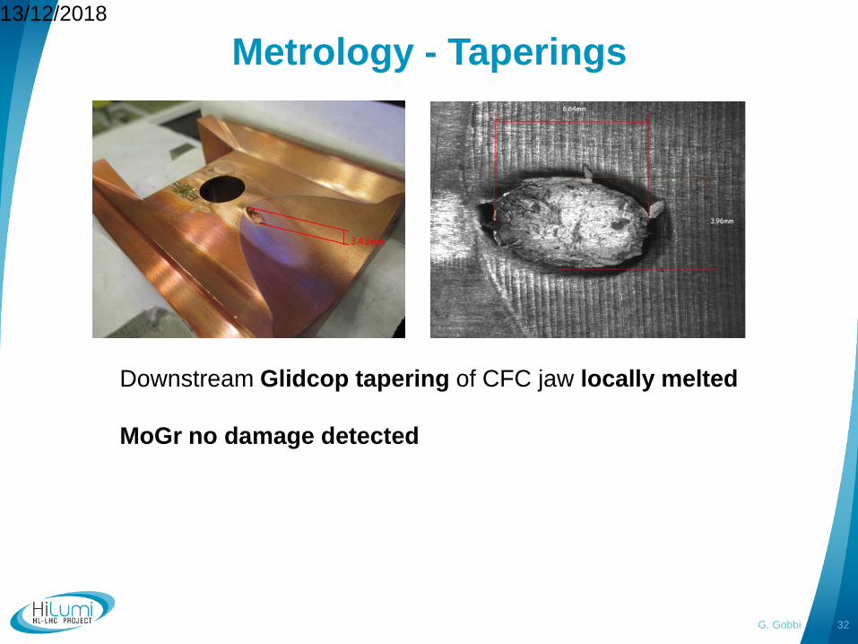
Metrology - Taperings13/12/2018
G. Gobbi 32
Downstream Glidcop tapering of CFC jaw locally melted
MoGr no damage detected
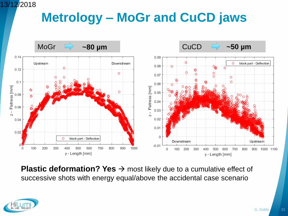
Metrology – MoGr and CuCD jaws13/12/2018
G. Gobbi 33
MoGr CuCD~80 µm ~50 µm
Plastic deformation? Yes most likely due to a cumulative effect of
successive shots with energy equal/above the accidental case scenario
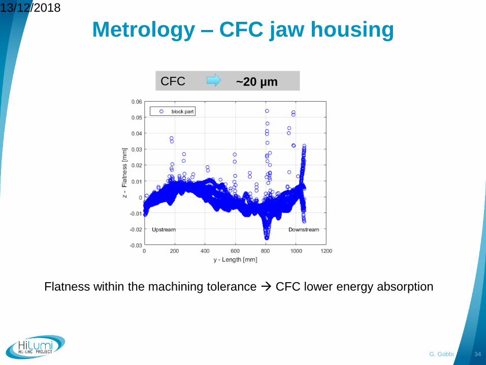
Metrology – CFC jaw housing13/12/2018
G. Gobbi 34
Flatness within the machining tolerance CFC lower energy absorption
CFC ~20 µm
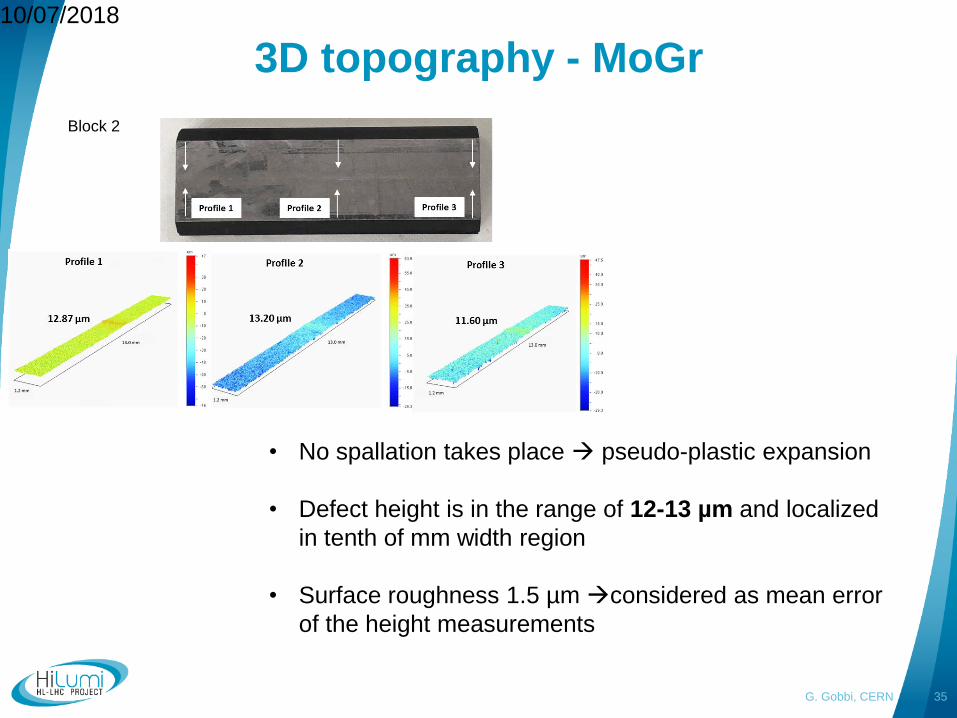
3D topography - MoGr10/07/2018
G. Gobbi, CERN 35
Block 2
• No spallation takes place pseudo-plastic expansion
• Defect height is in the range of 12-13 µm and localized
in tenth of mm width region
• Surface roughness 1.5 µm considered as mean error
of the height measurements
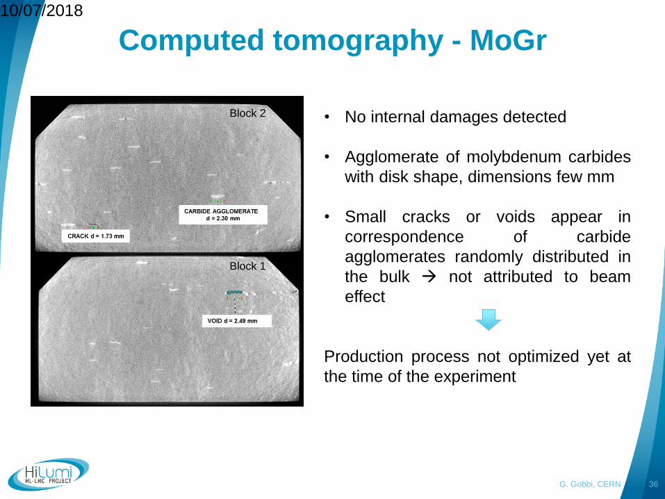
Computed tomography - MoGr10/07/2018
G. Gobbi, CERN 36
• No internal damages detected
• Agglomerate of molybdenum carbides
with disk shape, dimensions few mm
• Small cracks or voids appear in
correspondence of carbide
agglomerates randomly distributed in
the bulk not attributed to beam
effect
Production process not optimized yet at
the time of the experiment
Block 2
Block 1
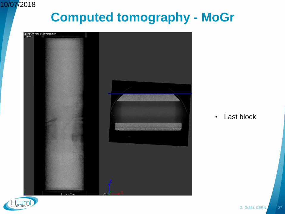
Computed tomography - MoGr10/07/2018
G. Gobbi, CERN 37
• Last block
Useful links and literature
38F. Carra (CERN), 7 May 2019
MoGr production management:
EDMS CERN-0000186962
Procedures for UHV compatibility of MoGr
Vacuum firing on uncoated MoGr, EDMS n. 2050564
Surface preparation and vacuum firing on MoGr to be coated, EDMS n. 2067775
Thermal treatment on MoGr post-coating, EDMS n. 2083915
Irradiation studies on materials:
Summary of irradiations at BNL and Kurchatov Institute for MoGr and CuCD: Eucard-2
deliverable D11.3: “Irradiation tests results”, 2018
MoGr irradiation with ions at GSI:
“Heavy ion induced radiation effects in novel molybdenum-carbide graphite”, GSI
Scientific report , 2015
“Present results on material damage from irradiation”, Eucard-2 milestone MS70, 2015
“Radiation induced effects in MoGr composites”, Eucard2 WP11 meeting, Malta, 2016
CFC irradiation at Kurchatov Institute: “The effects of high-energy proton beams on LHC
collimator materials”, Kurchatov final technical report, 2008
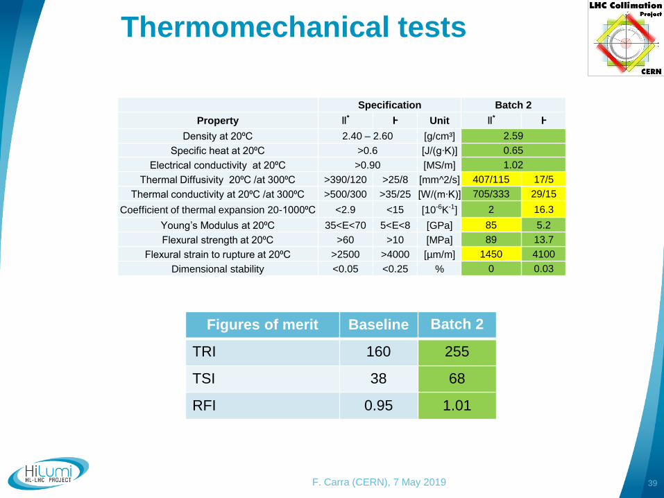
Thermomechanical tests
39F. Carra (CERN), 7 May 2019
Specification
Property ǁ* Ⱶ Unit
Density at 20⁰C 2.40 – 2.60 [g/cm³]
Specific heat at 20⁰C >0.6 [J/(g∙K)]
Electrical conductivity at 20⁰C >0.90 [MS/m]
Thermal Diffusivity 20⁰C /at 300⁰C >390/120 >25/8 [mm^2/s]
Thermal conductivity at 20⁰C /at 300⁰C >500/300 >35/25 [W/(m∙K)]
Coefficient of thermal expansion 20-1000⁰C <2.9 <15 [10-6K-1]
Young’s Modulus at 20⁰C 35<E<70 5<E<8 [GPa]
Flexural strength at 20⁰C >60 >10 [MPa]
Flexural strain to rupture at 20⁰C >2500 >4000 [µm/m]
Dimensional stability <0.05 <0.25 %
Batch 2
ǁ* Ⱶ
2.59
0.65
1.02
407/115 17/5
705/333 29/15
2 16.3
85 5.2
89 13.7
1450 4100
0 0.03
Figures of merit Baseline Batch 2
TRI 160 255
TSI 38 68
RFI 0.95 1.01
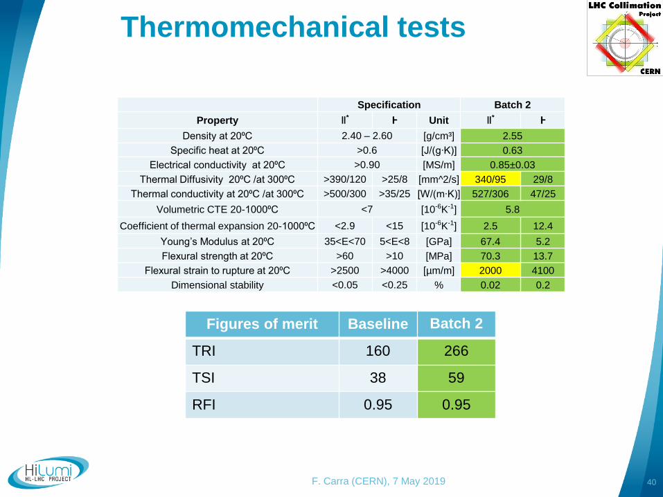
Thermomechanical tests
40F. Carra (CERN), 7 May 2019
Specification
Property ǁ* Ⱶ Unit
Density at 20⁰C 2.40 – 2.60 [g/cm³]
Specific heat at 20⁰C >0.6 [J/(g∙K)]
Electrical conductivity at 20⁰C >0.90 [MS/m]
Thermal Diffusivity 20⁰C /at 300⁰C >390/120 >25/8 [mm^2/s]
Thermal conductivity at 20⁰C /at 300⁰C >500/300 >35/25 [W/(m∙K)]
Volumetric CTE 20-1000⁰C <7 [10-6K-1]
Coefficient of thermal expansion 20-1000⁰C <2.9 <15 [10-6K-1]
Young’s Modulus at 20⁰C 35<E<70 5<E<8 [GPa]
Flexural strength at 20⁰C >60 >10 [MPa]
Flexural strain to rupture at 20⁰C >2500 >4000 [µm/m]
Dimensional stability <0.05 <0.25 %
Batch 2
ǁ* Ⱶ
2.55
0.63
0.85±0.03
340/95 29/8
527/306 47/25
5.8
2.5 12.4
67.4 5.2
70.3 13.7
2000 4100
0.02 0.2
Figures of merit Baseline Batch 2
TRI 160 266
TSI 38 59
RFI 0.95 0.95


