Embed Size (px)
Citation preview
Palestine Polytechnic University
College of Engineering
Design and Implementation of Soap Forming Machine
Prototype
By
Ibraheem Zaitoun Obadah Al- Qawasme
Supervisor: Prof. Dr. Sameer Hana Khader
Submitted to the College of Engineering
in partial fulfillment of the requirements for the
Bachelor degree in Electrical Engineering
Hebron, Jan 2018
Palestine Polytechnic University
College of Engineering
Department of Electrical Engineering
Hebron - Palestine
Design and Implementation of Soap Forming Machine Prototype
By
Ibraheem Zaitoun Obadah AL- Qawasme
Submitted to the College of Engineering
in partial fulfillment of the requirements for the
Bachelor degree in Electrical Engineering
Supervisor Signature
……………………………
Chair of the Department Signature
……………….
January - 2018

I
إهداء
قائدنا وحبیبنا وشفیعنا و قدوتنا محمد صلى هللا علیه وسلم. إلى معلمنا و
إلى من رسموا بدمائهم خارطة الوطن وطر�ق المستقبل وهندسوا �أجسادهم معاقل العزة والكرامة و�لى من هم أكرم منا جمیعا
شهداء الوطن الحبیب.
الیاسمین وتواروا خلف القضبان لیفسحوا لنا النور أسرانا البواسل.إلى الذین عشقوا الحر�ة التي تفوح منها رائحة
التي زودتني �الحنان والمحبة أقول لهم: وأمي ،إلى أبي الذي لم یبخل علي یومًا �شيء
أنتم وهبتموني الحیاة واألمل والنشأة على شغف اإلطالع والمعرفة.
جمیعا. أسرتي إلى إخوتي و
.أصبح سنا برقه �ضيء الطر�ق أماميإلى �ل من علمني حرفًا
إلى من ضاقت السطور لذ�رهم فوسعتهم قلو�نا أصدقاءنا األعزاء.
و�رحابته سماحة ، فأظهر �سماحته تواضع العلماء، أو هدى �الجواب الصحیح حیرة سائلیه، �ل من أضاء �علمه عقل غیره ىلإ
. العارفین

II
شكر وتقدیر
ستاذ الد�تور سمیر حنا خضر لما منحه لنا من وقت لى المشرف األإمتنان العظیم والتقدیر واإلنتقدم �جز�ل الشكر
ساتتذتنا الكرام .ألى إرشاد وتشجیع. �ما و نتقدم �جز�ل الشكر �وجهد وتوجیه و
هلنا الكرام.ألیه الیوم إا وصلنا متنان لمن سهر اللیالي لنصل لم�ضا جز�ل الشكر واإلأو
.ن نشكر جامعتنا الموقره لما وفرته لنا طوال الفتره الدراسیةأكما وال ننسى
صدقاءنا وزمالءنا الذین �انوا خیر عون خالل سنین الدراسة, شكرا لكم جمیعا.أونشكر

III
الملخص
"صابون التشكیل لماكینةنموذج تصمیم وتنفیذ "
_____________________________________________________________________________
�ضا أو , ل الصابون المحلي المصنع یدو�اتشكی ةتعمل على تقلیل الجهد الالزم لعملی ماكینةهذا المشروع للخروج �یهدف
ةسواق العالمیفي السوق المحلي وفي األ ةعلى المنافس الصابون المحلية قدر ةز�اد �ذلكالصابون في فلسطین و ةنتاجیإ ةلز�اد
�شكل �امل. ةتمؤتم ةنیماكو�ناء تصمیم من خاللوذلك
عملت ةنیالعمل على تصمیم ماك من ثملتصنیع الصابون و عالمیاً ةنات المستخدمیعمل الماك ةلیآ ةسیتم دراسبدا�ة
المشروع لبناء هذاة الالزم المعدات واألجهزةلیتم �عدها تحدید لوانواأل ة الروائح العطر� ةضاف�التشكیل للصابون و ةعلى عملی
.PLCــ ال على تحكماللبرنامج شامالً
یةوعمل ةلوان والروائح العطر�الخلط للصابون الخام مع األ ةملی�ع حیث تقوم للماكینةنتاج نموذج إهذا المشروع تم في
لوان والروائح واأل شكال صابون متعدد األ مما سیوفر إنتاجوتقطیعه حسب الحجم المطلوب هالضغط للصابون الناتج وتشكیل
جاهز للتغلیف والتسو�ق. ةالعطر�
IV
Abstract
_____________________________________________________________________________________
This project aims to produce a machine that minimizes the efforts required for the process of
forming handmade local soap. As well as, increasing the quality of local soap to compete in the local
and global markets. The project is designing and constructing a fully automated machine.
At the beginning, the researchers studied the mechanism of operating of the machines, used
worldwide, that produce soap. Then, they worked on the designing of a machine that works on the
formation of soap, adding aromatic smells and colors the equipment and devices necessary for the
construction of this project have been determined, including PLC control program.
The project produced a model of machine for mixing raw soap with aromatic smells and colors;
in addition, it extrudes the produced soap, forming and cutting it according to the required size. This
process provided a production of various shapes of soap with a wide variety of colors and aromatic
fragrances. This soap is ready for packaging and marketing.
V
Table of Contents
Contents Page I اإلھداء II شكر وتقدیر III الملخصAbstract IV Table of Contents V List of Figures VII List of Tables VIII List of Equations XI Chapter One: Introduction 1 1.1 Introduction 2 1.2 Background 2
1.3 Problem Statement 3 1.4 Objectives 3 1.5 Project Scope 4 1.6 Time Table 4 Chapter Two: Main Designs Concepts 5 2.1 Introduction 6 2.2 Soap Forming Machine Stages 6 2.3 Process Flow Chart 8 2.4 Required Components 9 Chapter Three: Mechanical Design 11 3.1 Introduction 12 3.2 Overall Machine Assembly 12 3.3 Mixing Stage 13 3.4 Extrusion Stage 14 3.5 Shaping Stage 16 3.6 Cutting Stage 17 3.7 Control Panel 17 3.8 Mechanical Calculations 18 3.9 Soap Flow Calculation 20 Chapter Four: Electrical Design 22 4.1 Introduction 23 4.2 Motors Sizing 23 4.3 Protection Circuit Sizing 23 4.4 PLC Input-Output Table 25 4.5 Motors Power Circuit 26 4.6 Pneumatic Power Circuit 27
VI
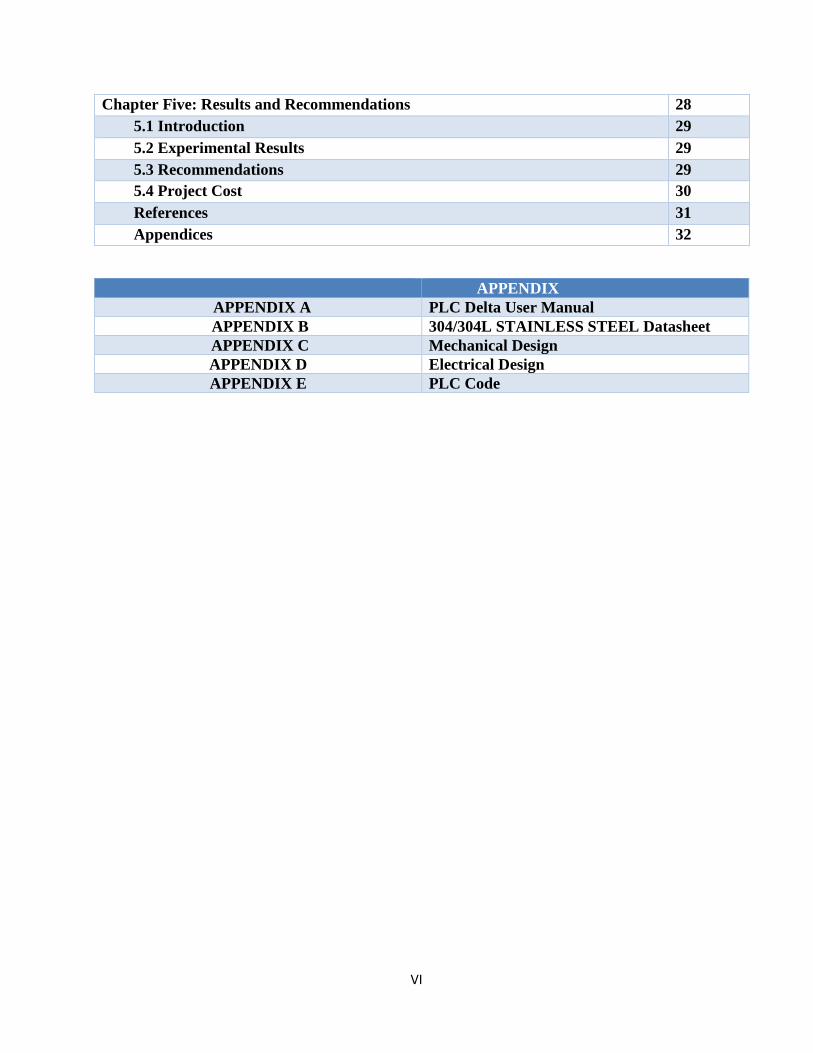
Chapter Five: Results and Recommendations 28 5.1 Introduction 29 5.2 Experimental Results 29 5.3 Recommendations 29 5.4 Project Cost 30 References 31 Appendices 32
APPENDIX APPENDIX A PLC Delta User Manual APPENDIX B 304/304L STAINLESS STEEL Datasheet APPENDIX C Mechanical Design APPENDIX D Electrical Design APPENDIX E PLC Code
VII
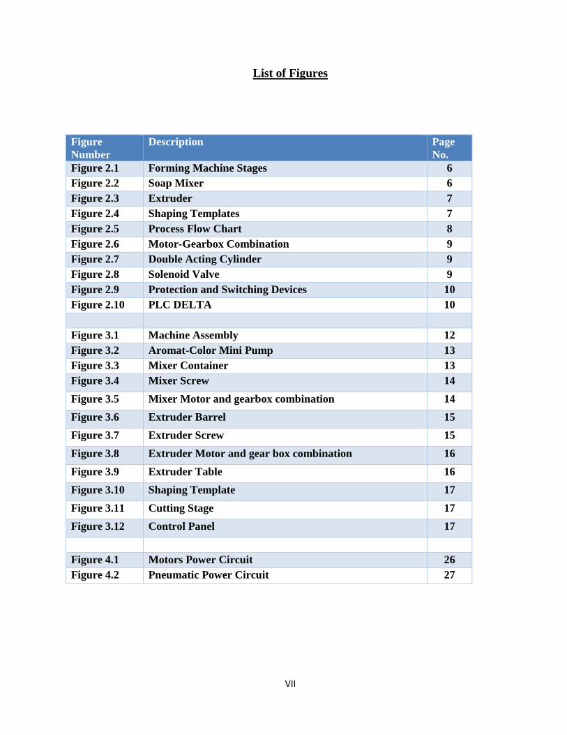
List of Figures
Figure Number
Description Page No.
Figure 2.1 Forming Machine Stages 6 Figure 2.2 Soap Mixer 6 Figure 2.3 Extruder 7 Figure 2.4 Shaping Templates 7 Figure 2.5 Process Flow Chart 8 Figure 2.6 Motor-Gearbox Combination 9 Figure 2.7 Double Acting Cylinder 9 Figure 2.8 Solenoid Valve 9 Figure 2.9 Protection and Switching Devices 10 Figure 2.10 PLC DELTA 10 Figure 3.1 Machine Assembly 12 Figure 3.2 Aromat-Color Mini Pump 13 Figure 3.3 Mixer Container 13 Figure 3.4 Mixer Screw 14 Figure 3.5 Mixer Motor and gearbox combination 14 Figure 3.6 Extruder Barrel 15 Figure 3.7 Extruder Screw 15 Figure 3.8 Extruder Motor and gear box combination 16 Figure 3.9 Extruder Table 16 Figure 3.10 Shaping Template 17 Figure 3.11 Cutting Stage 17 Figure 3.12 Control Panel 17 Figure 4.1 Motors Power Circuit 26 Figure 4.2 Pneumatic Power Circuit 27
VIII
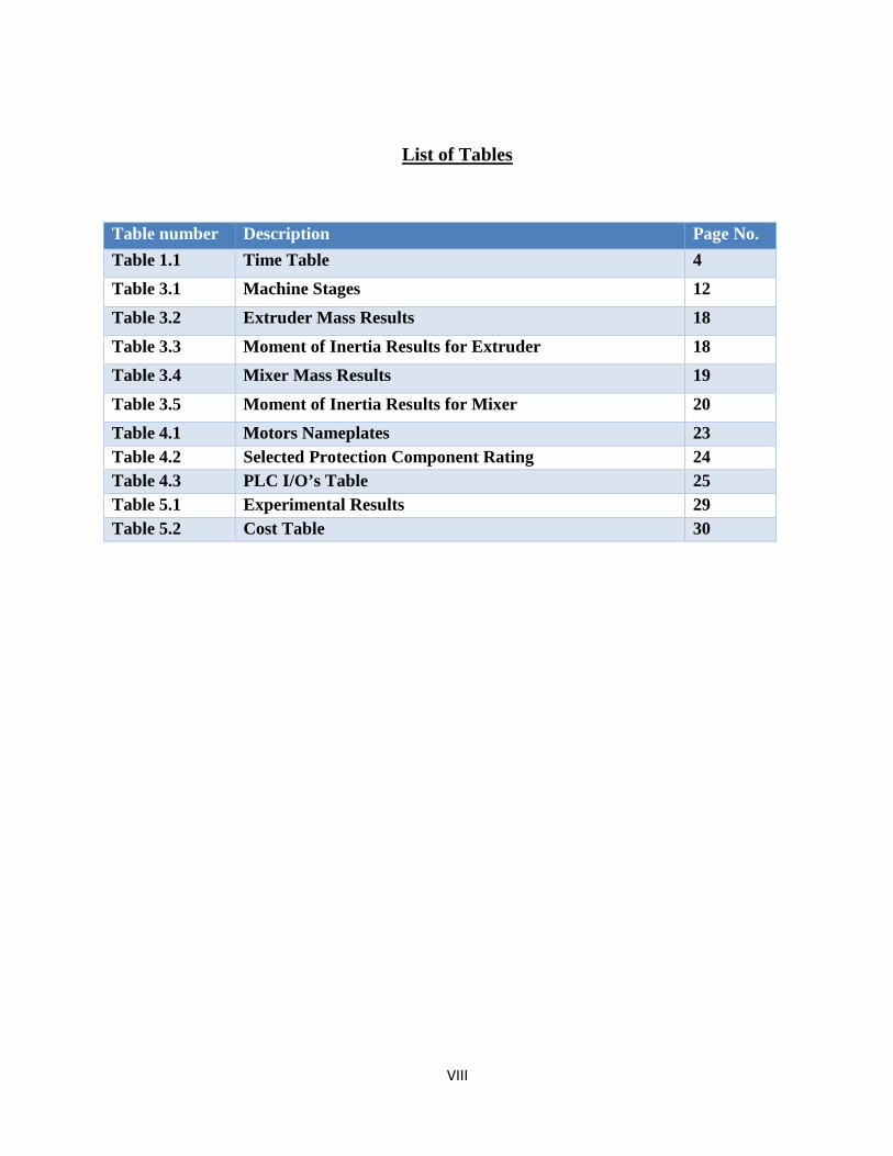
List of Tables
Table number Description Page No. Table 1.1 Time Table 4 Table 3.1 Machine Stages 12 Table 3.2 Extruder Mass Results 18 Table 3.3 Moment of Inertia Results for Extruder 18 Table 3.4 Mixer Mass Results 19 Table 3.5 Moment of Inertia Results for Mixer 20 Table 4.1 Motors Nameplates 23 Table 4.2 Selected Protection Component Rating 24 Table 4.3 PLC I/O’s Table 25 Table 5.1 Experimental Results 29 Table 5.2 Cost Table 30
IX
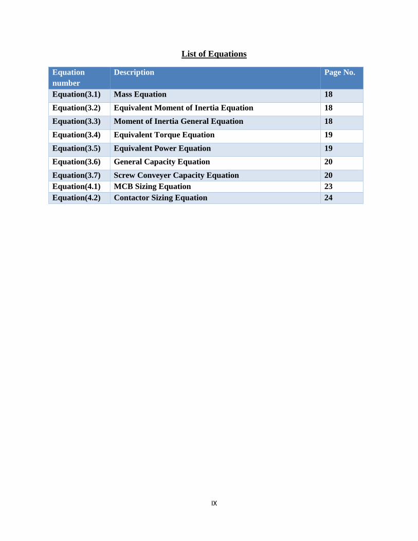
List of Equations
Equation number
Description Page No.
Equation(3.1) Mass Equation 18 Equation(3.2) Equivalent Moment of Inertia Equation 18 Equation(3.3) Moment of Inertia General Equation 18 Equation(3.4) Equivalent Torque Equation 19 Equation(3.5) Equivalent Power Equation 19 Equation(3.6) General Capacity Equation 20 Equation(3.7) Screw Conveyer Capacity Equation 20 Equation(4.1) MCB Sizing Equation 23 Equation(4.2) Contactor Sizing Equation 24
1 Chapter One
Introduction
1.1 Introduction
1.2 Background
1.3 Problem Statement
1.4 Objectives
1.5 Project Scope
1.6 Cost Table
1.7 Time Table
2
1.1 Introduction
This project aims at design full-automatic forming machine to be used for soap shaping, and
prototype implementation.
The machine will be able to convert the raw soap material into aromatic, colorful and multi-
shaped soap bars. The proposed prototype will produce soap bars with suitable size for kids use
and even for hotel use.
1.2 Background
Handmade soap can be made from scratch, by either hot or cold process, handmade soap made
from scratch require three ingredients to become soap: oil (animal or vegetable oil), water and
lye. These ingredients are mixed together in proper proportions, combine and chemically
change into soap. They may include other ingredients to provide additional benefits or to color
or scent the soap, but these are not part of the chemical process that results in basic soap [2].
• Methods of soap making:
1. The term "cold process" refers to the fact that no heat is applied during soap production
process.
The lye solution is normally cooled to room temperature before it is added to the oils. The oils
are then heated as necessary to melt any solid fats or butter and generally cooled to between
80° - 110° F, depending on the recipe formulation [2].
2. The term "Hot process" soap refers to the fact that an outside source of heat is applied to
make the soap.
With hot process soap, the lye solution and oils are mixed together and then an outside
source of heat is used to keep the temperature high. The added heat reduces the time needed
to ensure the chemical process is completed [2].
After the chemical stage, it comes the process were the resulting mixture is dried that usually
takes very long time up to 7 days or more in some cases.
3
In Nabulsi soap and after drying comes the cutting stage where the soap is cut manually into
cubic form soap and then is left to dry completely.
In the traditional process, it is hard to add colors and aromat to the chemical soap mixture and to
shape the soap in other forms as long as the way of production is the same.
It is a good idea to design a machine that enhances the soap appearance and smell for
marketing reasons and kid’s attractiveness and comfortably. After This machine implementation,
it will be the first machine in Palestine to form the soap and add color and aromat to it.
1.3 Problem Statement
The project idea came up from the status of Nabulsi Soap handmade craft that has some
drawbacks:
- It requires great efforts to produce the soap bars.
- Nabulsi soap is losing the competitiveness in the local and international market because
of its general appearance and final finishing even with its good quality.
- Soap bars come in single shape, color, and inability to add various aromat.
- The soap waste rate is high during the cutting process.
1.4 Objectives
The main project objectives are to overcome the up mentioned problems as following:
- Design a forming machine that reduces the effort needed for forming process for better
use and management in existing workforces.
- Increase the Nabulsi soap competitiveness in the local and international market.
- Reducing the wasted material in the forming process
- To be able to produce a multi-shape, colorful, and aromatic soap bars.
4
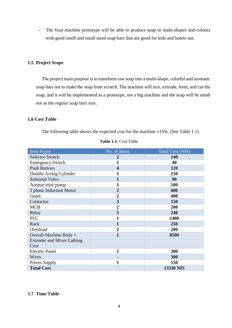
- The final machine prototype will be able to produce soap in multi-shapes and colours
with good smell and small sized soap bars that are good for kids and hotels use.
1.5 Project Scope
The project main purpose is to transform raw soap into a multi-shape, colorful and aromatic
soap bars not to make the soap from scratch. The machine will mix, extrude, form, and cut the
soap, and it will be implemented as a prototype, not a big machine and the soap will be small
not as the regular soap bars size.
1.6 Cost Table
The following table shows the expected cost for the machine ±15%. (See Table 1.1)
Table 1.1: Cost Table
Item Name No. of Items Total Cost (NIS) Selector Switch 2 140 Emergency Switch 1 40 Push Buttons 4 120 Double Acting Cylinder 1 150 Solenoid Valve 1 90 Aromat mini pump 1 100 3 phase Induction Motor 2 600 Gears 2 400 Contactor 3 150 MCB 2 200 Relay 5 240 PLC 1 1400 Rack 1 250 Overload 2 200 Overall Machine Body + Extruder and Mixer Lathing Cost
1 8500
Electric Panel 1 200 Wires - 300 Power Supply 1 150 Total Cost 13330 NIS
1.7 Time Table
5
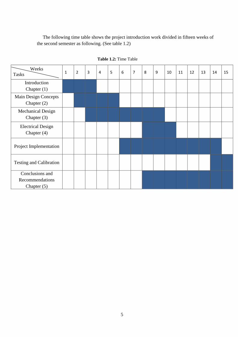
The following time table shows the project introduction work divided in fifteen weeks of
the second semester as following. (See table 1.2)
Weeks Tasks 1 2 3 4 5 6 7 8 9 10 11 12 13 14 15
Introduction Chapter (1)
Main Design Concepts Chapter (2)
Mechanical Design Chapter (3)
Electrical Design Chapter (4)
Project Implementation
Testing and Calibration
Conclusions and Recommendations
Chapter (5)
Table 1.2: Time Table
2 Chapter Two
Main Design Concepts
2.1 Introduction
2.2 Soap Forming Machine Stages
2.3 Process Flow Chart
2.4 Required Components
6
2.1 Introduction
The forming process is an essential process in many industries, in soap, it is required to
give it shape in order to make it easier to use and attractive to the customer. Also, giving the
soap aromatic smell and colorful appearance is important as forming for marketing reasons.
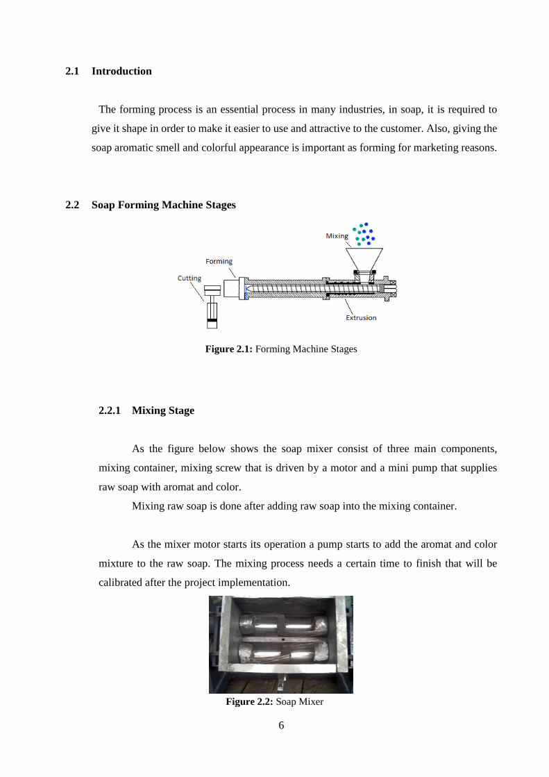
2.2 Soap Forming Machine Stages
Figure 2.1: Forming Machine Stages
2.2.1 Mixing Stage
As the figure below shows the soap mixer consist of three main components,
mixing container, mixing screw that is driven by a motor and a mini pump that supplies
raw soap with aromat and color.
Mixing raw soap is done after adding raw soap into the mixing container.
As the mixer motor starts its operation a pump starts to add the aromat and color
mixture to the raw soap. The mixing process needs a certain time to finish that will be
calibrated after the project implementation.
Figure 2.2: Soap Mixer
7
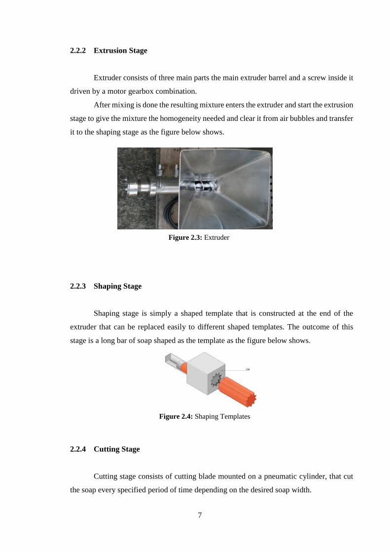
2.2.2 Extrusion Stage
Extruder consists of three main parts the main extruder barrel and a screw inside it
driven by a motor gearbox combination.
After mixing is done the resulting mixture enters the extruder and start the extrusion
stage to give the mixture the homogeneity needed and clear it from air bubbles and transfer
it to the shaping stage as the figure below shows.
2.2.3 Shaping Stage
Shaping stage is simply a shaped template that is constructed at the end of the
extruder that can be replaced easily to different shaped templates. The outcome of this
stage is a long bar of soap shaped as the template as the figure below shows.
2.2.4 Cutting Stage
Cutting stage consists of cutting blade mounted on a pneumatic cylinder, that cut
the soap every specified period of time depending on the desired soap width.
Figure 2.3: Extruder
Figure 2.4: Shaping Templates
8
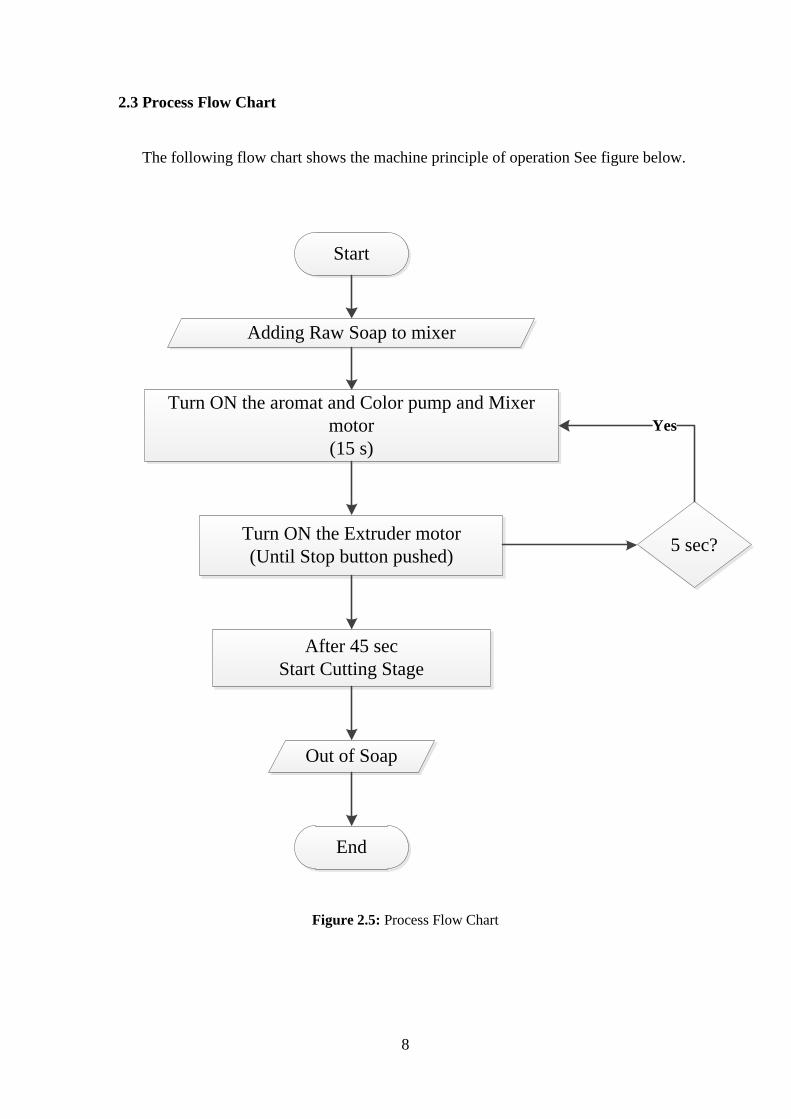
2.3 Process Flow Chart
The following flow chart shows the machine principle of operation See figure below.
Start
Adding Raw Soap to mixer
Turn ON the aromat and Color pump and Mixer motor(15 s)
Turn ON the Extruder motor(Until Stop button pushed)
After 45 secStart Cutting Stage
5 sec?
Out of Soap
End
Yes
Figure 2.5: Process Flow Chart
9
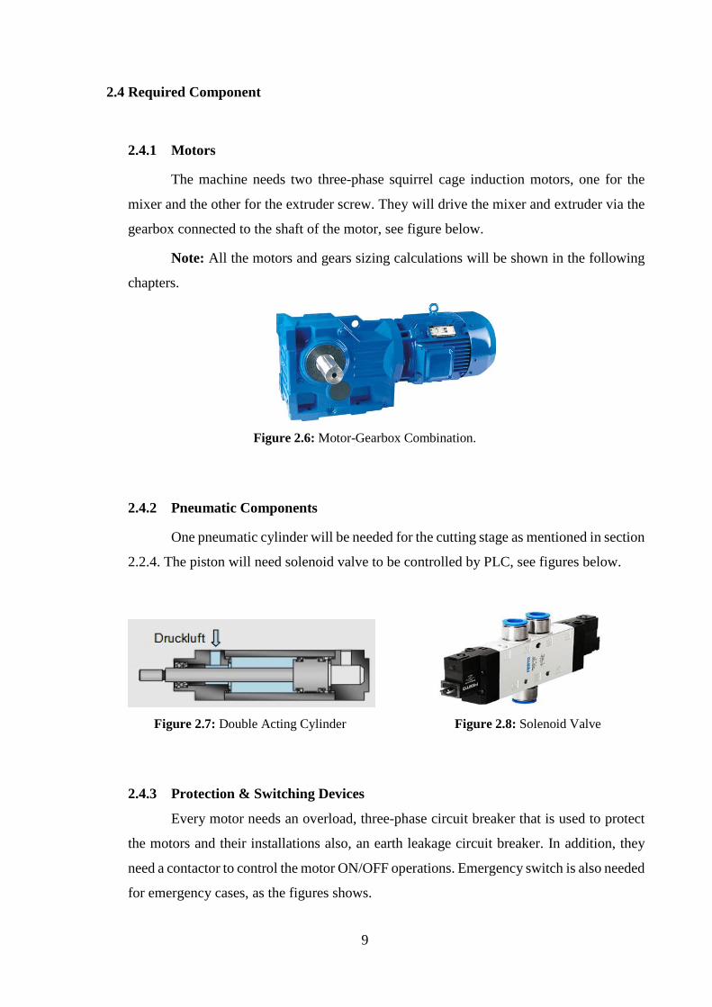
2.4 Required Component
2.4.1 Motors
The machine needs two three-phase squirrel cage induction motors, one for the
mixer and the other for the extruder screw. They will drive the mixer and extruder via the
gearbox connected to the shaft of the motor, see figure below.
Note: All the motors and gears sizing calculations will be shown in the following
chapters.
Figure 2.6: Motor-Gearbox Combination.
2.4.2 Pneumatic Components
One pneumatic cylinder will be needed for the cutting stage as mentioned in section
2.2.4. The piston will need solenoid valve to be controlled by PLC, see figures below.
Figure 2.7: Double Acting Cylinder Figure 2.8: Solenoid Valve
2.4.3 Protection & Switching Devices
Every motor needs an overload, three-phase circuit breaker that is used to protect
the motors and their installations also, an earth leakage circuit breaker. In addition, they
need a contactor to control the motor ON/OFF operations. Emergency switch is also needed
for emergency cases, as the figures shows.

10
Figure 2.9: Protection and Switching Devices
2.4.5 PLC (Programmable Logic Controller)
A programmable logic controller (PLC) is
a microprocessor-based piece of hardware that is
specifically designed to operate in the industrial
environment.
Generally, PLCs (as the name suggests)
implement logic, determining outputs based on
some logical combination of inputs. PLCs are
programmable devices that are capable of taking
inputs from sensors and activating actuators in order to control industrial equipment.
The PLC type that will be used is DELTA-DVP32ES2 that has 16 inputs and 16
outputs. We chose delta PLC because of its good quality, it is easy to be programmed, has
accepted price and meet the required purpose. (See figure 2.10)
The PLC DELTA-DVP32ES2 Datasheet is attached in the Appendix A.
Figure 2.10: PLC DELTA-DVP32ES2
3 Chapter Three
Mechanical Design
3.1 Introduction
3.2 Overall Machine Assembly
3.3 Mixing Stage
3.4 Extrusion Stage
3.5 Shaping Stage
3.6 Cutting Stage
3.7 Control Panel
3.8 Mechanical Calculations
3.9 Soap Flow Calculation
12
3.1 Introduction
This chapter will include the 3D Design for all the machine stages using SOLIDWORKS
software. The sequence shown in this chapter is the machine sequence of operation that means it
starts with the raw soap input stage until the soap is completely ready. This chapter will include
also the mechanical calculations needed for the motor sizing in the next chapter.
Note: The detailed design and dimensions of all the machine parts is attached in Appendix C.
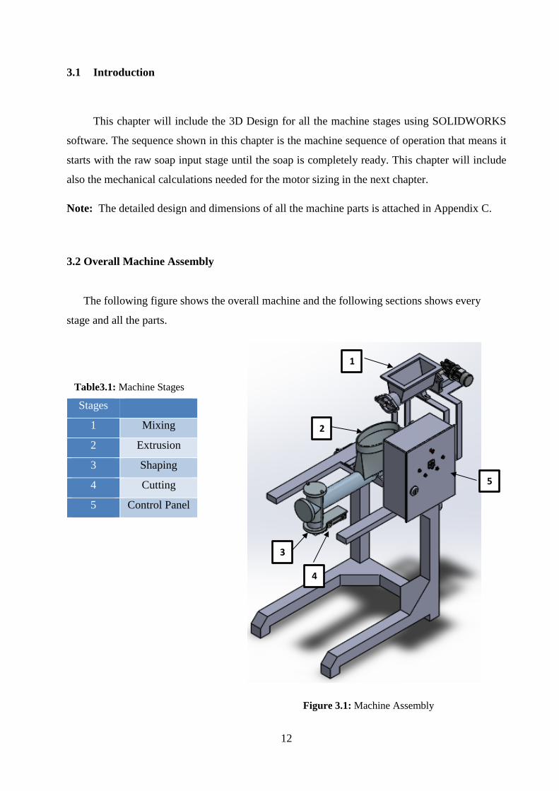
3.2 Overall Machine Assembly
The following figure shows the overall machine and the following sections shows every
stage and all the parts.
Figure 3.1: Machine Assembly
Stages
1 Mixing
2 Extrusion
3 Shaping
4 Cutting
5 Control Panel
1
2
3
5
4
Table3.1: Machine Stages
13
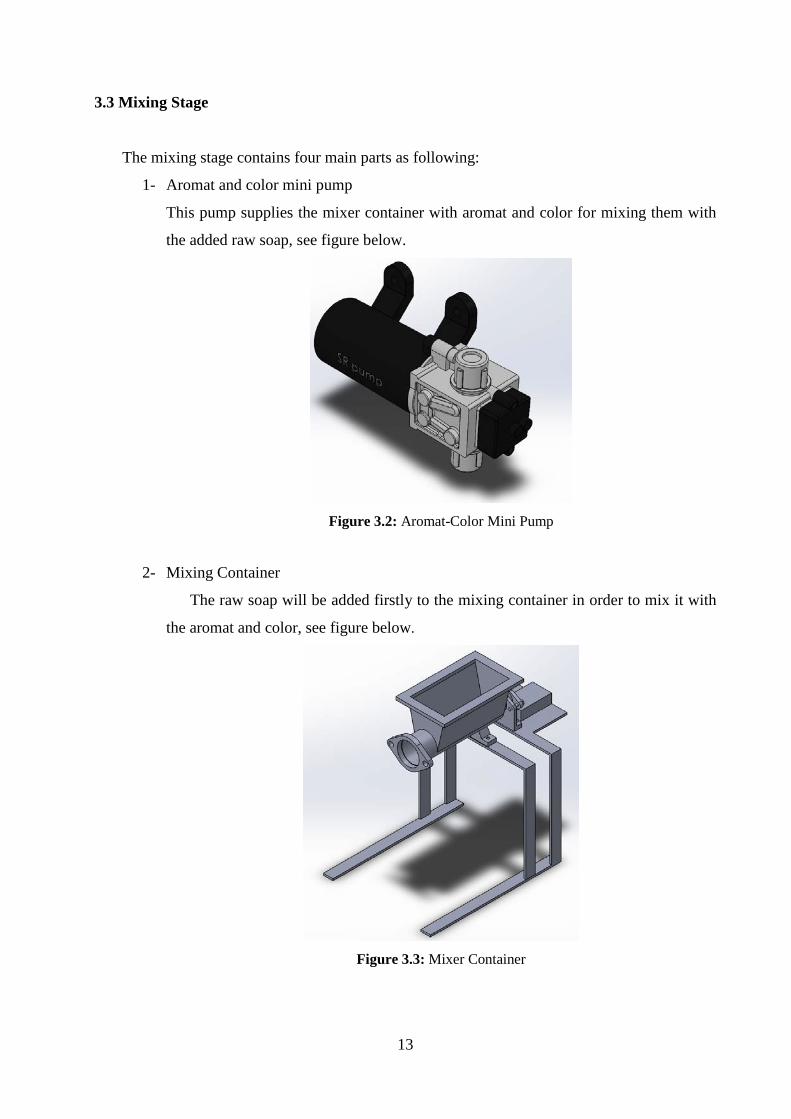
3.3 Mixing Stage
The mixing stage contains four main parts as following:
1- Aromat and color mini pump
This pump supplies the mixer container with aromat and color for mixing them with
the added raw soap, see figure below.
Figure 3.2: Aromat-Color Mini Pump
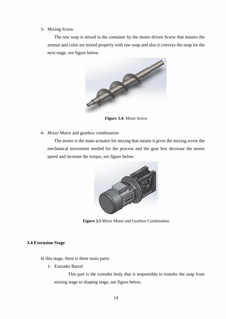
2- Mixing Container
The raw soap will be added firstly to the mixing container in order to mix it with
the aromat and color, see figure below.
Figure 3.3: Mixer Container
14
3- Mixing Screw
The raw soap is mixed in the container by the motor driven Screw that insures the
aromat and color are mixed properly with raw soap and also it conveys the soap for the
next stage, see figure below.
Figure 3.4: Mixer Screw
4- Mixer Motor and gearbox combination
The motor is the main actuator for mixing that means it gives the mixing screw the
mechanical movement needed for the process and the gear box decrease the motor
speed and increase the torque, see figure below.
Figure 3.5 Mixer Motor and Gearbox Combination
3.4 Extrusion Stage
In this stage, there is three main parts:
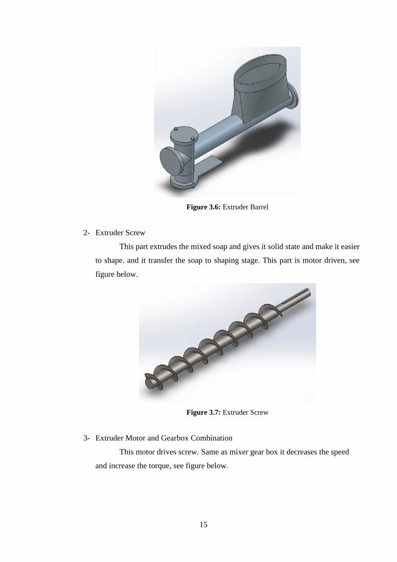
1- Extruder Barrel
This part is the extruder body that is responsible to transfer the soap from
mixing stage to shaping stage, see figure below.
15
Figure 3.6: Extruder Barrel
2- Extruder Screw
This part extrudes the mixed soap and gives it solid state and make it easier
to shape. and it transfer the soap to shaping stage. This part is motor driven, see
figure below.
Figure 3.7: Extruder Screw
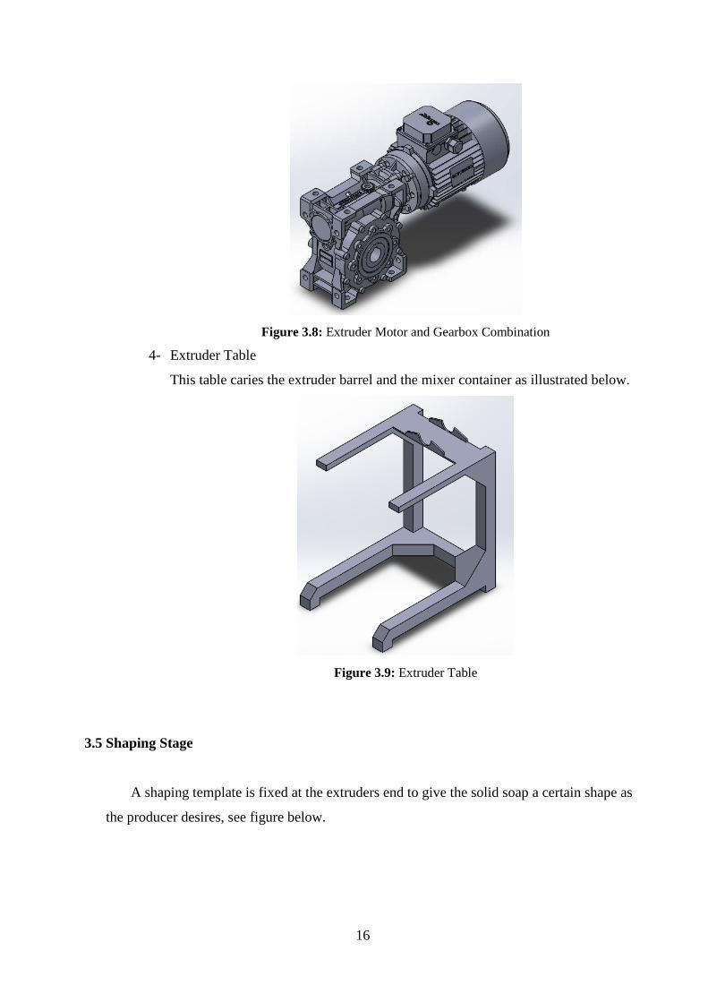
3- Extruder Motor and Gearbox Combination
This motor drives screw. Same as mixer gear box it decreases the speed
and increase the torque, see figure below.
16
Figure 3.8: Extruder Motor and Gearbox Combination
4- Extruder Table
This table caries the extruder barrel and the mixer container as illustrated below.
Figure 3.9: Extruder Table
3.5 Shaping Stage
A shaping template is fixed at the extruders end to give the solid soap a certain shape as
the producer desires, see figure below.
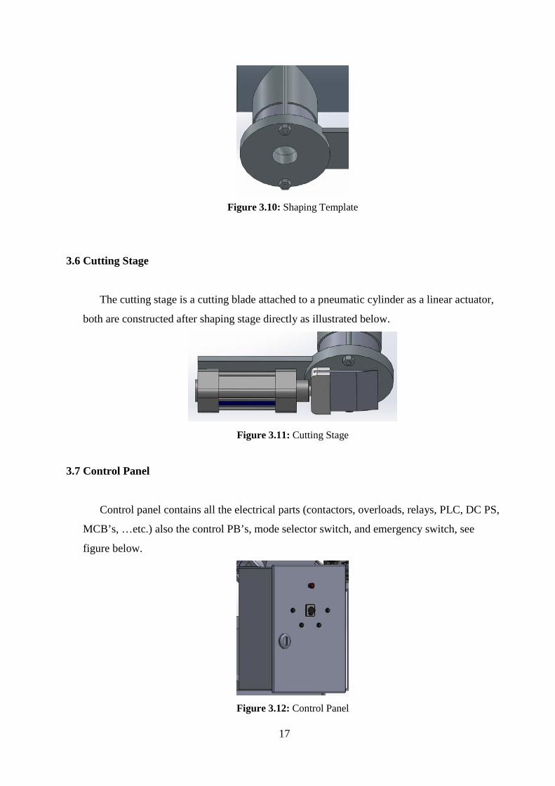
17
Figure 3.10: Shaping Template
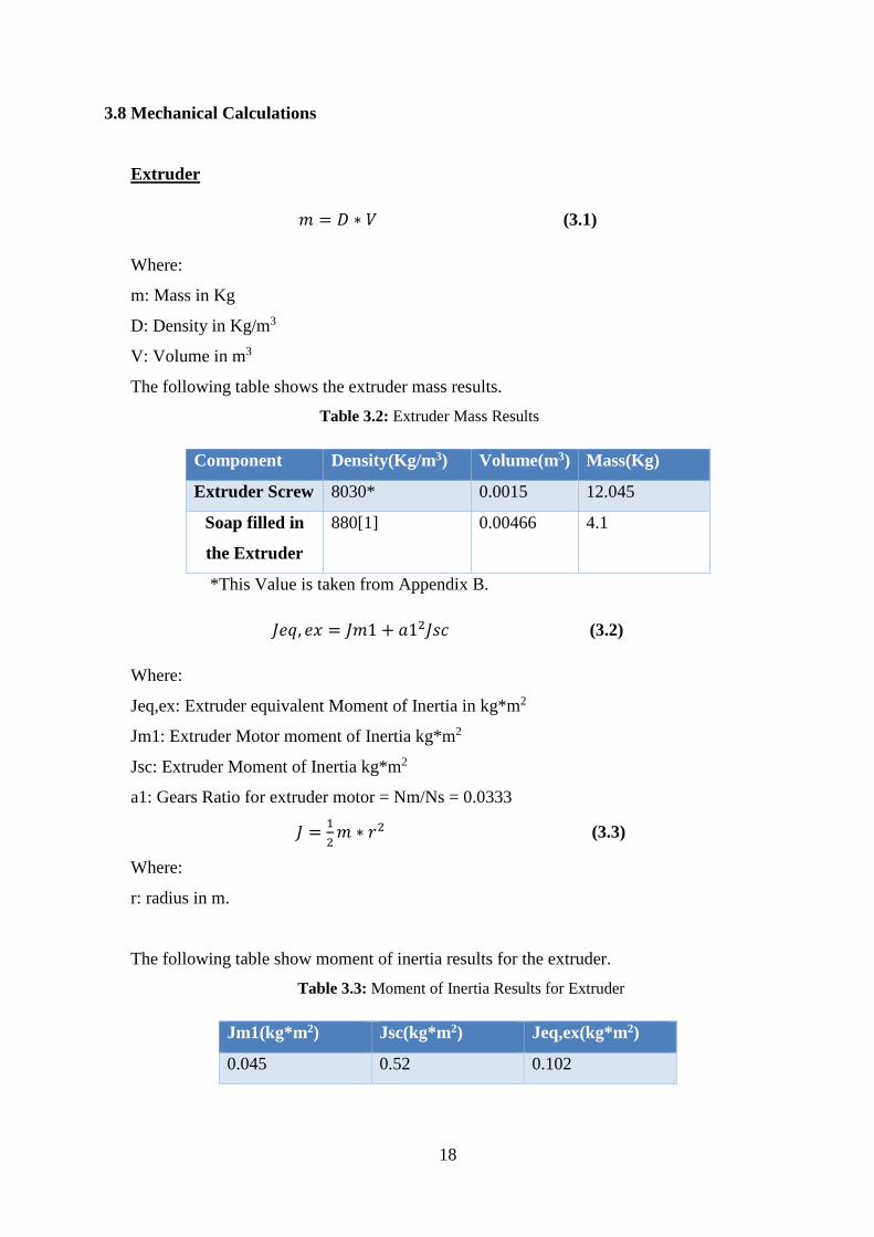
3.6 Cutting Stage
The cutting stage is a cutting blade attached to a pneumatic cylinder as a linear actuator,
both are constructed after shaping stage directly as illustrated below.
Figure 3.11: Cutting Stage
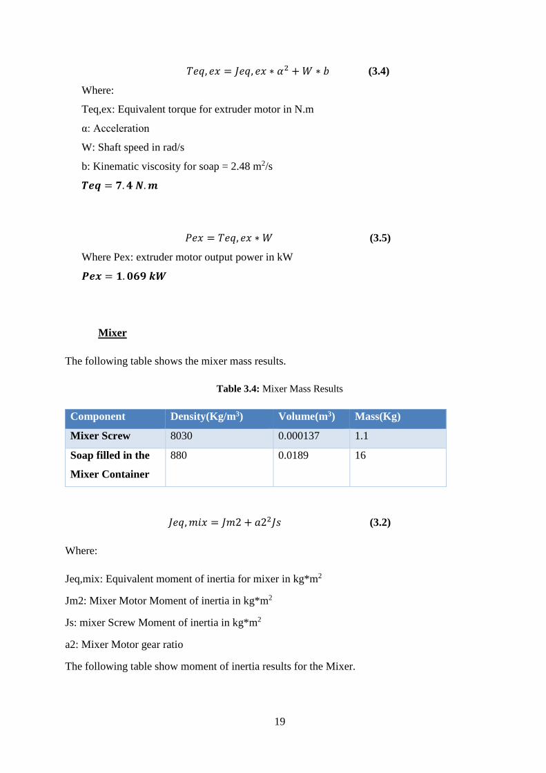
3.7 Control Panel
Control panel contains all the electrical parts (contactors, overloads, relays, PLC, DC PS,
MCB’s, …etc.) also the control PB’s, mode selector switch, and emergency switch, see
figure below.
Figure 3.12: Control Panel
18
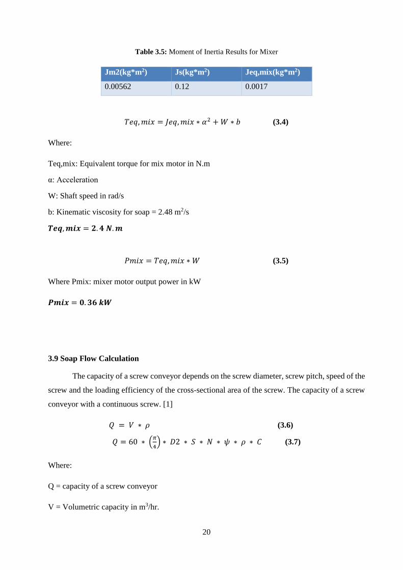
3.8 Mechanical Calculations
Extruder
𝑚𝑚 = 𝐷𝐷 ∗ 𝑉𝑉 (3.1)
Where:
m: Mass in Kg
D: Density in Kg/m3
V: Volume in m3
The following table shows the extruder mass results. Table 3.2: Extruder Mass Results
Component Density(Kg/m3) Volume(m3) Mass(Kg)
Extruder Screw 8030* 0.0015 12.045
Soap filled in
the Extruder
880[1] 0.00466 4.1
*This Value is taken from Appendix B.
𝐽𝐽𝐽𝐽𝐽𝐽, 𝐽𝐽𝑒𝑒 = 𝐽𝐽𝑚𝑚1 + 𝑎𝑎12𝐽𝐽𝐽𝐽𝐽𝐽 (3.2)
Where:
Jeq,ex: Extruder equivalent Moment of Inertia in kg*m2
Jm1: Extruder Motor moment of Inertia kg*m2
Jsc: Extruder Moment of Inertia kg*m2
a1: Gears Ratio for extruder motor = Nm/Ns = 0.0333
𝐽𝐽 = 12𝑚𝑚 ∗ 𝑟𝑟2 (3.3)
Where:
r: radius in m.
The following table show moment of inertia results for the extruder. Table 3.3: Moment of Inertia Results for Extruder
Jm1(kg*m2) Jsc(kg*m2) Jeq,ex(kg*m2)
0.045 0.52 0.102
19
𝑇𝑇𝐽𝐽𝐽𝐽, 𝐽𝐽𝑒𝑒 = 𝐽𝐽𝐽𝐽𝐽𝐽, 𝐽𝐽𝑒𝑒 ∗ 𝛼𝛼2 + 𝑊𝑊 ∗ 𝑏𝑏 (3.4)
Where:
Teq,ex: Equivalent torque for extruder motor in N.m
α: Acceleration
W: Shaft speed in rad/s
b: Kinematic viscosity for soap = 2.48 m2/s
𝑻𝑻𝑻𝑻𝑻𝑻 = 𝟕𝟕.𝟒𝟒 𝑵𝑵.𝒎𝒎
𝑃𝑃𝐽𝐽𝑒𝑒 = 𝑇𝑇𝐽𝐽𝐽𝐽, 𝐽𝐽𝑒𝑒 ∗ 𝑊𝑊 (3.5)
Where Pex: extruder motor output power in kW
𝑷𝑷𝑻𝑻𝑷𝑷 = 𝟏𝟏.𝟎𝟎𝟎𝟎𝟎𝟎 𝒌𝒌𝒌𝒌
Mixer
The following table shows the mixer mass results.
Table 3.4: Mixer Mass Results
Component Density(Kg/m3) Volume(m3) Mass(Kg)
Mixer Screw 8030 0.000137 1.1
Soap filled in the
Mixer Container
880 0.0189 16
𝐽𝐽𝐽𝐽𝐽𝐽,𝑚𝑚𝑚𝑚𝑒𝑒 = 𝐽𝐽𝑚𝑚2 + 𝑎𝑎22𝐽𝐽𝐽𝐽 (3.2)
Where:
Jeq,mix: Equivalent moment of inertia for mixer in kg*m2
Jm2: Mixer Motor Moment of inertia in kg*m2
Js: mixer Screw Moment of inertia in kg*m2
a2: Mixer Motor gear ratio
The following table show moment of inertia results for the Mixer.
20
Table 3.5: Moment of Inertia Results for Mixer
Jm2(kg*m2) Js(kg*m2) Jeq,mix(kg*m2)
0.00562 0.12 0.0017
𝑇𝑇𝐽𝐽𝐽𝐽,𝑚𝑚𝑚𝑚𝑒𝑒 = 𝐽𝐽𝐽𝐽𝐽𝐽,𝑚𝑚𝑚𝑚𝑒𝑒 ∗ 𝛼𝛼2 + 𝑊𝑊 ∗ 𝑏𝑏 (3.4)
Where:
Teq,mix: Equivalent torque for mix motor in N.m
α: Acceleration
W: Shaft speed in rad/s
b: Kinematic viscosity for soap = 2.48 m2/s
𝑻𝑻𝑻𝑻𝑻𝑻,𝒎𝒎𝒎𝒎𝑷𝑷 = 𝟐𝟐.𝟒𝟒 𝑵𝑵.𝒎𝒎
𝑃𝑃𝑚𝑚𝑚𝑚𝑒𝑒 = 𝑇𝑇𝐽𝐽𝐽𝐽,𝑚𝑚𝑚𝑚𝑒𝑒 ∗ 𝑊𝑊 (3.5)
Where Pmix: mixer motor output power in kW
𝑷𝑷𝒎𝒎𝒎𝒎𝑷𝑷 = 𝟎𝟎.𝟑𝟑𝟎𝟎 𝒌𝒌𝒌𝒌
3.9 Soap Flow Calculation
The capacity of a screw conveyor depends on the screw diameter, screw pitch, speed of the
screw and the loading efficiency of the cross-sectional area of the screw. The capacity of a screw
conveyor with a continuous screw. [1]
𝑄𝑄 = 𝑉𝑉 ∗ 𝜌𝜌 (3.6)
𝑄𝑄 = 60 ∗ �𝜋𝜋4� ∗ 𝐷𝐷2 ∗ 𝑆𝑆 ∗ 𝑁𝑁 ∗ 𝜓𝜓 ∗ 𝜌𝜌 ∗ 𝐶𝐶 (3.7)
Where:
Q = capacity of a screw conveyor
V = Volumetric capacity in m3/hr.
21
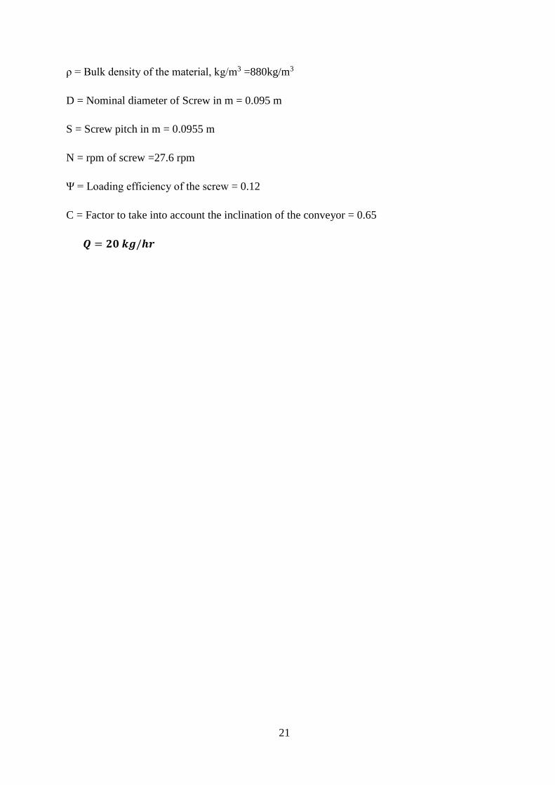
ρ = Bulk density of the material, kg/m3 =880kg/m3
D = Nominal diameter of Screw in m = 0.095 m
S = Screw pitch in m = 0.0955 m
N = rpm of screw =27.6 rpm
Ψ = Loading efficiency of the screw = 0.12
C = Factor to take into account the inclination of the conveyor = 0.65
𝑸𝑸 = 𝟐𝟐𝟎𝟎 𝒌𝒌𝒌𝒌/𝒉𝒉𝒉𝒉
4 Chapter Four
Electrical Design
4.1 Introduction
4.2 Motors Sizing
4.3 Protection Circuit Sizing
4.4 PLC Input-Output Table
4.5 Motors Power Circuit
4.6 Pneumatic Power Circuit
23
4.1 Introduction
In this chapter, we will size both extruder and mixer motors and gearboxes depending
on the results from the previous chapter. also, Protection circuits will be sized. Power circuit
and control circuit will be explained in this chapter.
4.2 Motors Sizing
Extruder Motor Sizing
Selected Extruder Motor = 1.1 kW = 1.5 hp
Mixer Motor Sizing
Selected Extruder Motor = 0.37 kW = 0.5 hp
The following table describes selected motors specifications.
Table 4.1: Selected Motors Nameplates
4.3 Protection Circuit Sizing
Extruder Motor Protection Circuit
- Overload
OL = In
- MCB (Miniature Circuit Breaker)
MCB = Next Slandered(1.25In) Equation (4.1)
Name phase P / kw V A rpm f/Hz
Extruder Motor 3Փ 1.1 380 2.8 1380 50
Mixer Motor 3Փ 0.37 380 1.1 1400 50
24
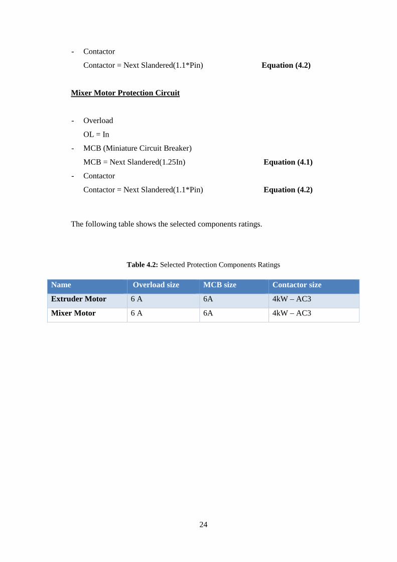
- Contactor
Contactor = Next Slandered(1.1*Pin) Equation (4.2)
Mixer Motor Protection Circuit
- Overload
OL = In
- MCB (Miniature Circuit Breaker)
MCB = Next Slandered(1.25In) Equation (4.1)
- Contactor
Contactor = Next Slandered(1.1*Pin) Equation (4.2)
The following table shows the selected components ratings.
Table 4.2: Selected Protection Components Ratings
Name Overload size MCB size Contactor size
Extruder Motor 6 A 6A 4kW – AC3
Mixer Motor 6 A 6A 4kW – AC3
25
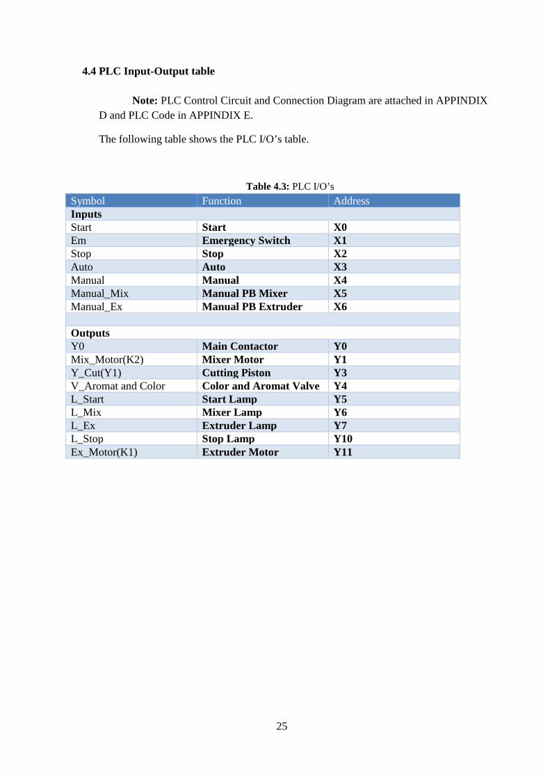
4.4 PLC Input-Output table
Note: PLC Control Circuit and Connection Diagram are attached in APPINDIX D and PLC Code in APPINDIX E.
The following table shows the PLC I/O’s table.
Table 4.3: PLC I/O’s Symbol Function Address Inputs Start Start X0 Em Emergency Switch X1 Stop Stop X2 Auto Auto X3 Manual Manual X4 Manual_Mix Manual PB Mixer X5 Manual_Ex Manual PB Extruder X6 Outputs Y0 Main Contactor Y0 Mix_Motor(K2) Mixer Motor Y1 Y_Cut(Y1) Cutting Piston Y3 V_Aromat and Color Color and Aromat Valve Y4 L_Start Start Lamp Y5 L_Mix Mixer Lamp Y6 L_Ex Extruder Lamp Y7 L_Stop Stop Lamp Y10 Ex_Motor(K1) Extruder Motor Y11
26
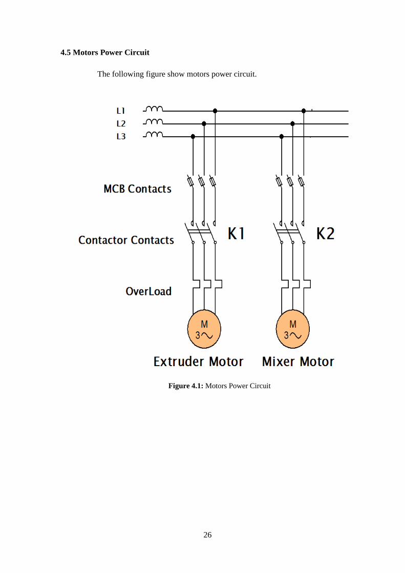
4.5 Motors Power Circuit
The following figure show motors power circuit.
Figure 4.1: Motors Power Circuit
27
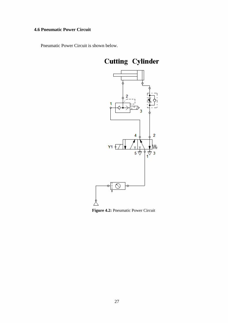
4.6 Pneumatic Power Circuit
Pneumatic Power Circuit is shown below.
Figure 4.2: Pneumatic Power Circuit
5 Chapter Five
Results and Recommendations
5.1 Introduction
5.2 Experimental Results
5.3 Recommendations
5.4 Project Cost
29
5.1 Introduction
This chapter provides experimental results and some recommendations for future work for this project. In this chapter we are listing some goals hope to be accomplished or to be considered for future project. Note: All machine pictures are attached in appendix F. 5.2 Experimental Result
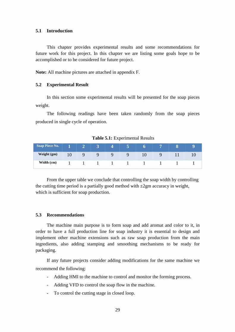
In this section some experimental results will be presented for the soap pieces
weight.
The following readings have been taken randomly from the soap pieces
produced in single cycle of operation.
Table 5.1: Experimental Results Soap Piece No. 1 2 3 4 5 6 7 8 9 Weight (gm) 10 9 9 9 9 10 9 11 10 Width (cm) 1 1 1 1 1 1 1 1 1
From the upper table we conclude that controlling the soap width by controlling the cutting time period is a partially good method with ±2gm accuracy in weight, which is sufficient for soap production.
5.3 Recommendations
The machine main purpose is to form soap and add aromat and color to it, in order to have a full production line for soap industry it is essential to design and implement other machine extensions such as raw soap production from the main ingredients, also adding stamping and smoothing mechanisms to be ready for packaging.
If any future projects consider adding modifications for the same machine we
recommend the following:
- Adding HMI to the machine to control and monitor the forming process.
- Adding VFD to control the soap flow in the machine.
- To control the cutting stage in closed loop.
30
- Adding two conveyers, the first one to feed the mixer with raw soap and the
second to transfer the ready soap pieces to the next stage.
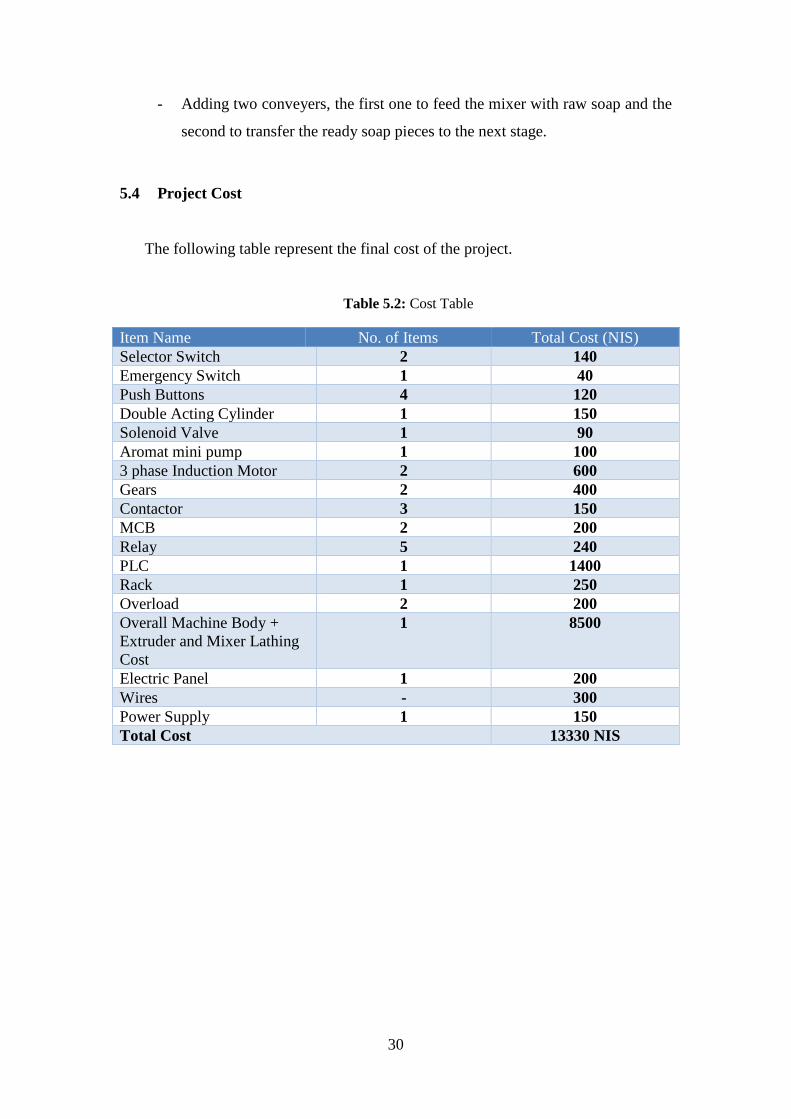
5.4 Project Cost
The following table represent the final cost of the project.
Table 5.2: Cost Table
Item Name No. of Items Total Cost (NIS) Selector Switch 2 140 Emergency Switch 1 40 Push Buttons 4 120 Double Acting Cylinder 1 150 Solenoid Valve 1 90 Aromat mini pump 1 100 3 phase Induction Motor 2 600 Gears 2 400 Contactor 3 150 MCB 2 200 Relay 5 240 PLC 1 1400 Rack 1 250 Overload 2 200 Overall Machine Body + Extruder and Mixer Lathing Cost
1 8500
Electric Panel 1 200 Wires - 300 Power Supply 1 150 Total Cost 13330 NIS
31
References
[1] J. Kililku, Design of bar soap making machine for local soap industry, B. of Science in mechanics, university of Nairobi, 2016.
[2] M.Gaboya, Soap making, a quick guide, Horto, Australia ,2012.
[3] R.K.Basal, Theory of Machines, Laxmi , New Delhi.
[4] Solidworks Corporation, Introducing Solidworks, 2016.
[5] Y.Sweity , machines design 2 lectures notes, PPU, Hebron-Palestine, 2017.
2013, القاھره ,المرجع في التركیبات والتصمیمات الكھربیةم. الجیالني, [6]

Appendix A “PLC Delta User
Manual”

Appendix B
“304/304L STAINLESS STEEL
Datasheet”

Appendix C “Mechanical Design”

Appendix D “Electrical Design”

Appendix E “PLC Code”

Appendix F “Machine Pictures”
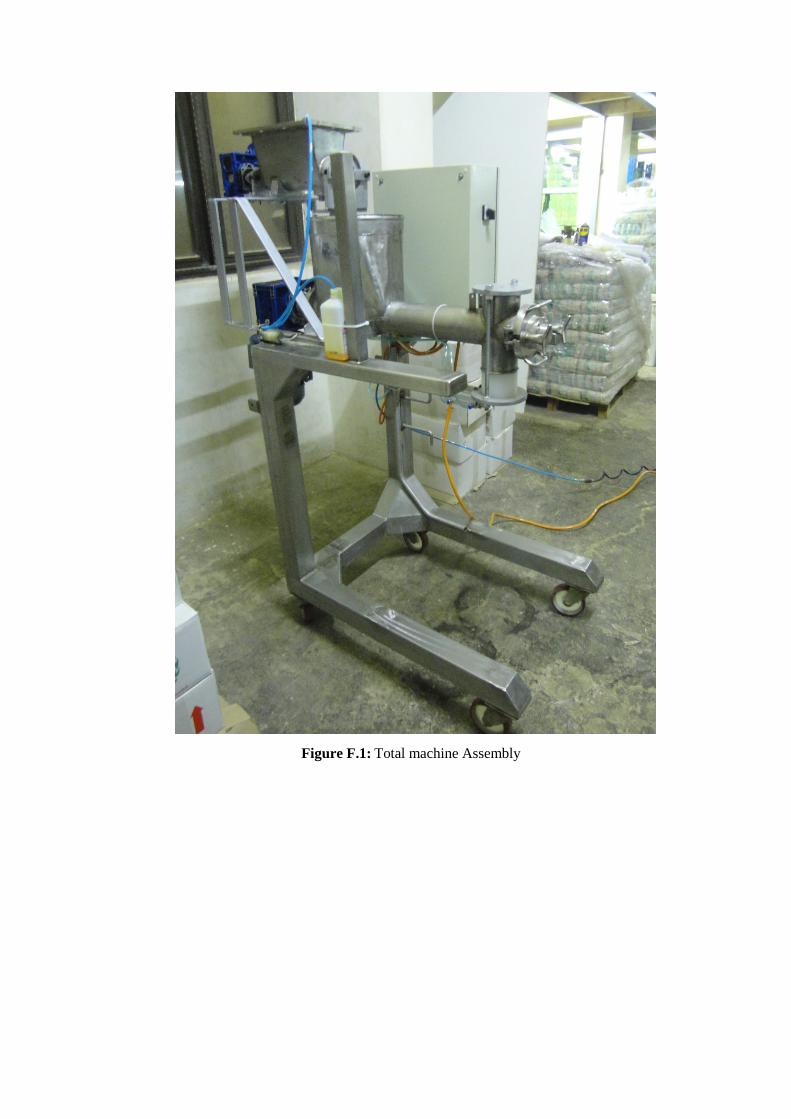
Figure F.1: Total machine Assembly
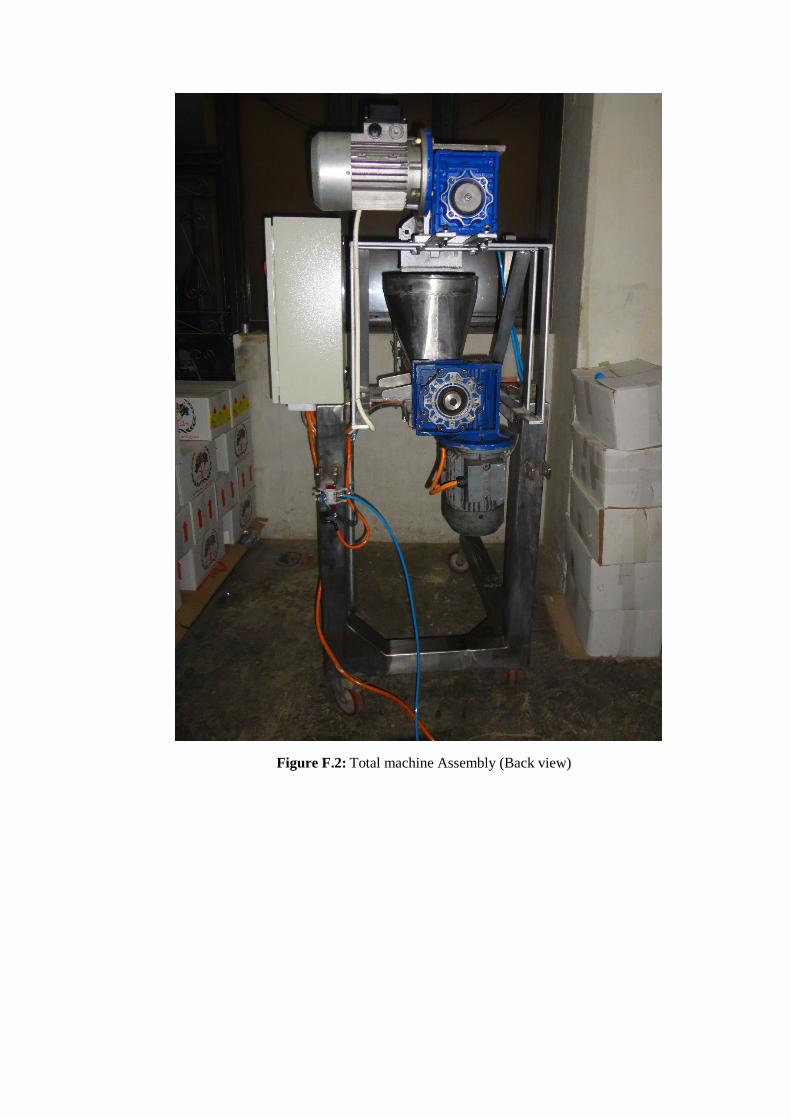
Figure F.2: Total machine Assembly (Back view)
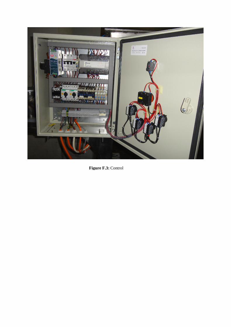
Figure F.3: Control
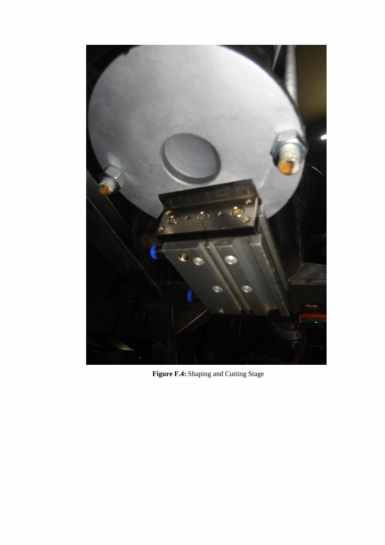
Figure F.4: Shaping and Cutting Stage
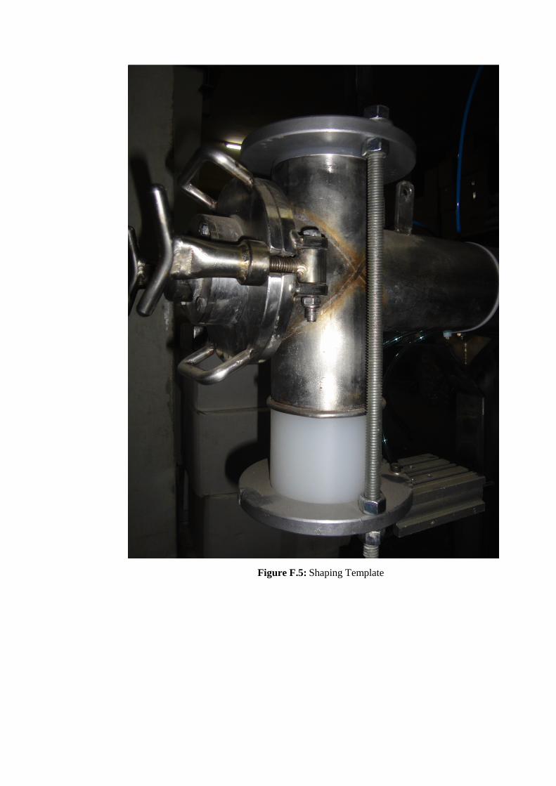
Figure F.5: Shaping Template
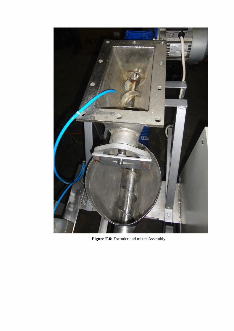
Figure F.6: Extruder and mixer Assembly


