Embed Size (px)
Citation preview

DEPARTMENT OF VETERANS AFFAIRS
VHA MASTER SPECIFICATIONS
TABLE OF CONTENTS
Section 00 01 10
DIVISION 01 - GENERAL REQUIREMENTS PAGE
01 00 00 General Requirements 05-13 1
01 33 23 Shop Drawings, Product Data, and Samples 03-12 19
01 42 19 Reference Standards 09-11 23
01 57 19 Temporary Environmental Controls 01-11 27
01 58 16 Temporary Interior Signage 08-11 31
01 74 19 Construction Waste Management 09-13 33
DIVISION 07 - THERMAL AND MOISTURE PROTECTION
07 84 00 Firestopping 10-11 39
07 92 00 Joint Sealants 12-11 43
DIVISION 09 – FINISHES
09 91 00 Painting 07-13 55
DIVISION 14- CONVEYING EQUIPMENT
21 24 00 Elevators 05-11 73
DIVISION 26 – ELECTRICAL
26 05 11 Requirements for Electrical Installations 12-12 83
26 05 19 Low-Voltage Electrical Power Conductors and
Cables
07-13 93
26 05 26 Grounding and Bonding for Electrical Systems 12-12 99
26 05 33 Raceway and Boxes for Electrical Systems 09-10 105
DIVISION 27 – COMMUNICATIONS
27 10 00 Structured Cabling 12-05 115
27 52 13 Patient Wandering Systems 03-14 119
27 52 23 Nurse Call Systems 06-13 175
DIVISION 28 – ELECTRONIC SAFETY AND SECURITY
28 31 00 Fire Detection and Alarm 10-11 247

(THIS PAGE INTENTIONALLY LEFT BLANK)

1
SECTION 01 00 00
GENERAL REQUIREMENTS
1.1 GENERAL INTENTION
A. Contractor shall completely prepare site for building operations,
including demolition and removal of existing structures, and furnish
labor and materials and perform work for Replace Nurse Call System,
Salem VA Medical Center, Salem, VA as required by drawings and
specifications.
B. Visits to the site by bidders may only be made during the organized
site visit. Please refer to the solicitation for the
date/time/location of the organized site visit.
C. All employees of general contractor and subcontractors shall comply
with VA security management program and obtain permission of the VA
police, be identified by project and employer, and restricted from
unauthorized access. The contractor shall submit a list of anticipated
employees (both general contractor employees and subcontractor
employees) to the RE and the Contracting Officer within ten calendar
days of receipt of the notice to proceed. This list will aid in the
credentialing and badging process for all contract employees.
D. Prior to commencing work, general contractor shall provide proof that a
OSHA certified “competent person” (CP) (29 CFR 1926.20(b)(2) will
maintain a presence at the work site whenever the general or
subcontractors are present.
E. Training:
1. All employees of general contractor or subcontractors shall have the
10-hour OSHA certified Construction Safety course and /or other
relevant competency training, as determined by VA CP with input from
the ICRA team. The Prime Contractor Superintendent and the OSHA
certified “competent person” noted above shall have the 30-hour OSHA
certified Construction Safety course and/or other relevant
competency training, as determined by the VA CO with input from the
ICRA team.
2. Submit training records of all such employees for approval before
the start of work.

2
1.2 STATEMENT OF BID ITEM(S)
A. BASE BID ITEM I, Work includes all materials, labor, tools, and
equipment to complete Project 658-13-101, Replace Nurse Call System, at
the VAMC, Salem, VA. The project shall be completed in accordance with
all construction specifications and drawings. Performance period is 270
days.
B. DEDUCTIVE ALTERNATES: The alternates below are all deducts to the Base
Bid listed in priority order. Deducts listed below are to be broken
out separately on the bid form.
1. Deduct 1: Contractor shall perform all work as described in Bid
Item I (Base Bid) except deduct all work associated with Deduct
1. Deduct 1 includes: ALL WORK ASSOCIATED WITH WIRELESS PHONES
FOR ALL COUNTS IN THE SPECIFICATIONS WHILE REPLACING THE WIRELESS
PHONES WITH PAGERS. MAINTAIN ONE (1) WIRELESS PHONE FOR EACH OF
THE SEVEN (7) UNIT’S CHARGE NURSES AND ONE (1) WIRELESS PHONE FOR
THE NOD.
2. Deduct 2: Contractor shall perform all work as described in Bid
Item 1 (Base Bid) except deduct all work associated with Deduct 1
and all work associated with Deduct 2. Deduct 2 includes: ALL
WORK ASSOCIATED WITH THE EIGHT (8) WIRELESS PHONES REMAINING FROM
DEUCT 1 WHILE REPLACING THE WIRELESS PHONES WITH PAGERS.
ELIMINATE ALL THIRD PARTY INTEGRATION ASSOCIATED WITH THE
WIRELESS PHONES WHILE MAINTINAING THE PAGERS.
3. Deduct 3: Contractor shall perform all work as described in Bid
Item 1 (Base Bid) except deduct all work associated with Deduct
1, Deduct 2, and all work associated with Deduct 3. Deduct 3
includes: ALL WORK ASSOCIATED WITH THE REPORTING FOR THE NURSE
CALL SYSTEM AND ASSOCIATED SERVERS, SOFTWARE, ETC.
4. Deduct 4: Contractor shall perform all work as described in Bid
Item 1 (Base Bid) except deduct all work associated with Deduct
1, Deduct 2, Deduct 3, and all work associated with Deduct 4.
Deduct 4 includes: ALL WORK ASSOCIATED WITH THE AUTOMATED CODE
CALLS TO WIRELESS PHONES AND PAGERS, MANUAL CODE CALLS TO
WIRELESS PHONES AND PAGERS FROM THE SWITCHBOARD AND AOD, AND
ASSOCIATED THIRD PARTY INTEGRATION.

3
5. Deduct 5: Contractor shall perform all work as described in Bid
Item 1 (Base Bid) except deduct all work associated with Deduct
1, Deduct 2, Deduct 3, Deduct 4 and all work associated with
Deduct 5. Deduct 5 includes: ALL WORK ASSOCIATED WITH THE ENTIRE
PATIENT WANDERING SYSTEM IN BULDING/FLOORS #143-4H AND #143-4J.
6. Deduct 6: Contractor shall perform all work as described in Bid
Item 1 (Base Bid) except deduct all work associated with Deduct
1, Deduct 2, Deduct 3, Deduct 4, Deduct 5 and all work associated
with Deduct 6. Deduct 6 includes: ALL WORK ASSOCIATED WITH THE
ENTIRE PATIENT WANDERING SYSTEM IN BULDING/FLOORS #2-2 AND #2-3.
1.3 SPECIFICATIONS AND DRAWINGS FOR CONTRACTOR
A. AFTER AWARD OF CONTRACT, 5 sets of specifications and drawings will be
furnished. These drawings and specifications will consist of those
returned by prospective bidders.
B. Additional sets of drawings may be made by the Contractor, at
Contractor's expense.
1.4 CONSTRUCTION SECURITY REQUIREMENTS
A. Security Plan:
1. The security plan defines both physical and administrative security
procedures that will remain effective for the entire duration of the
project.
2. The General Contractor is responsible for assuring that all sub-
contractors working on the project and their employees also comply
with these regulations.
B. Security Procedures:
1. General Contractor’s employees shall not enter the project site
without appropriate badge. Badges shall be obtained from the VA
credentialing service located in the Human Resource wing, first
floor of Building 74. To be issued badges, employees will be
required to provide two valid forms of identification including at
least one photo ID AND their names will need to be included on the
employee list submitted by the General Contractor as described in
paragraph 1.1D of this Section. In addition, employees are required
to submit a copy of their OSHA Training Certificate. They may also
be subject to inspection of their personal effects when entering or
leaving the project site.
4
2. For working outside the “regular hours” as defined in the contract,
The General Contractor shall give 3 days’ notice to the Contracting
Officer or Resident Engineer so that security arrangements can be
provided for the employees. This notice is separate from any
notices required for utility shutdown described later in this
section.
3. No photography of VA premises is allowed without written permission
of the CO or RE.
4. VA reserves the right to close down or shut down the project site
and order General Contractor’s employees off the premises in the
event of a national emergency. The General Contractor may return to
the site only with the written approval of the CO or RE.
C. Key Control:
1. The General Contractor shall provide duplicate keys and lock
combinations to the CO or RE for the purpose of security inspections
of every area of project including tool boxes and parked machines
and take any emergency action.
D. Document Control:
1. Before starting any work, the General Contractor/Sub Contractors
shall submit an electronic security memorandum describing the
approach to following goals and maintaining confidentiality of
“sensitive information”.
2. The General Contractor is responsible for safekeeping of all
drawings, project manual and other project information. This
information shall be shared only with those with a specific need to
accomplish the project.
4. Certain documents, sketches, videos or photographs and drawings may
be marked “Law Enforcement Sensitive” or “Sensitive Unclassified”.
Secure such information in separate containers and limit the access
to only those who will need it for the project. Return the
information to the CO or RE upon request.
5. These security documents shall not be removed or transmitted from
the project site without the written approval of CO or RE.
6. All paper waste or electronic media such as CD’s and diskettes shall
be shredded and destroyed in a manner acceptable to the VA.
7. Notify CO or RE and Site Security Officer immediately when there is
a loss or compromise of “sensitive information”.

5
8. All electronic information shall be stored in specified location
following VA standards and procedures using an Engineering Document
Management Software (EDMS).
a. Security, access and maintenance of all project drawings, both
scanned and electronic shall be performed and tracked through the
EDMS system.
b. “Sensitive information” including drawings and other documents
may be attached to e-mail provided all VA encryption procedures
are followed.
F. Motor Vehicle Restrictions
1. Vehicle authorization request shall be required for any vehicle
entering the site and such request shall be submitted 24 hours
before the date and time of access. Access shall be restricted to
picking up and dropping off materials and supplies.
2. Separate permits shall be issued for General Contractor and its
employees for parking in designated areas only.
1.5 FIRE SAFETY
A. Applicable Publications: Publications listed below form part of this
Article to extent referenced. Publications are referenced in text by
basic designations only.
1. American Society for Testing and Materials (ASTM):
E84-2009.............Surface Burning Characteristics of Building
Materials
2. National Fire Protection Association (NFPA):
10-2010..............Standard for Portable Fire Extinguishers
30-2008..............Flammable and Combustible Liquids Code
51B-2009.............Standard for Fire Prevention During Welding,
Cutting and Other Hot Work
70-2011..............National Electrical Code
241-2009.............Standard for Safeguarding Construction,
Alteration, and Demolition Operations
3. Occupational Safety and Health Administration (OSHA):
29 CFR 1926..........Safety and Health Regulations for Construction
B. Fire Safety Plan: Establish and maintain a fire protection program in
accordance with 29 CFR 1926. Prior to start of work, prepare a plan
detailing project-specific fire safety measures, including periodic
status reports, and submit to RE. Prior to any worker for the

6
contractor or subcontractors beginning work, they shall undergo a
safety briefing provided by the general contractor’s competent person
per OSHA requirements. This briefing shall include information on the
construction limits, VAMC safety guidelines, means of egress, break
areas, work hours, locations of restrooms, use of VAMC equipment, etc.
Documentation shall be provided to the RE that individuals have
undergone contractor’s safety briefing.
C. Site and Building Access: Maintain free and unobstructed access to
facility emergency services and for fire, police and other emergency
response forces in accordance with NFPA 241.
D. Separate temporary facilities, such as trailers, storage sheds, and
dumpsters, from existing buildings and new construction by distances in
accordance with NFPA 241. For small facilities with less than 6 m (20
feet) exposing overall length, separate by 3m (10 feet).
E. Temporary Construction Partitions:
1. Close openings in smoke barriers and fire-rated construction to
maintain fire ratings. Seal penetrations with listed through-
penetration firestop materials in accordance with Section 07 84 00,
FIRESTOPPING.
F. Means of Egress: Do not block exiting for occupied buildings, including
paths from exits to roads. Minimize disruptions and coordinate with RE.
G. Egress Routes for Construction Workers: Maintain free and unobstructed
egress. Inspect daily. Report findings and corrective actions to RE on
a weekly basis.
I. Fire Extinguishers: Provide and maintain extinguishers in construction
areas and temporary storage areas in accordance with 29 CFR 1926, NFPA
241 and NFPA 10.
J. Flammable and Combustible Liquids: Store, dispense and use liquids in
accordance with 29 CFR 1926, NFPA 241 and NFPA 30.
K. Existing Fire Protection: Do not impair automatic sprinklers, smoke and
heat detection, and fire alarm systems, except for portions immediately
under construction, and temporarily for connections. Provide fire watch
for impairments more than 4 hours in a 24-hour period. Request
interruptions in accordance with Article, OPERATIONS AND STORAGE AREAS,
and coordinate with RE. All existing or temporary fire protection
systems (fire alarms, sprinklers) located in construction areas shall
be tested as coordinated with the medical center. Parameters for the

7
testing and results of any tests performed shall be recorded by the
medical center and copies provided to the RE.
L. Smoke Detectors: Prevent accidental operation. Remove temporary covers
at end of work operations each day. Coordinate with RE.
M. Hot Work: Perform and safeguard hot work operations (if required) in
accordance with NFPA 241 and NFPA 51B. Coordinate with RE at least 4
hours in advance. Designate contractor's responsible project-site fire
prevention program manager to permit hot work.
N. Fire Hazard Prevention and Safety Inspections: Inspect entire
construction areas weekly. Coordinate with, and report findings and
corrective actions weekly to RE.
O. Smoking: Smoking is prohibited in and adjacent to construction areas
inside existing buildings and additions under construction. In separate
and detached buildings under construction, smoking is prohibited except
in designated smoking rest areas.
P. Dispose of waste and debris in accordance with NFPA 241. Remove from
buildings daily.
Q. Perform other construction, alteration and demolition operations in
accordance with 29 CFR 1926.
R. If required, submit documentation to the RE that personnel have been
trained in the fire safety aspects of working in areas with impaired
structural or compartmentalization features.
1.6 OPERATIONS AND STORAGE AREAS
A. The Contractor shall confine all operations (including storage of
materials) on Government premises to areas authorized or approved by
the Contracting Officer or Resident Engineer. The Contractor shall hold
and save the Government, its officers and agents, free and harmless
from liability of any nature occasioned by the Contractor's
performance.
B. Temporary buildings (e.g., storage sheds, shops, offices) and utilities
may be erected by the Contractor only with the approval of the CO or RE
and shall be built with labor and materials furnished by the Contractor
without expense to the Government. The temporary buildings and
utilities shall remain the property of the Contractor and shall be
removed by the Contractor at its expense upon completion of the work.
With the written consent of the CO or RE, the buildings and utilities
may be abandoned and need not be removed.

8
C. The Contractor shall, under regulations prescribed by the CO or RE, use
only established roadways, or use temporary roadways constructed by the
Contractor when and as authorized by the CO or RE. When materials are
transported in prosecuting the work, vehicles shall not be loaded
beyond the loading capacity recommended by the manufacturer of the
vehicle or prescribed by any Federal, State, or local law or
regulation. When it is necessary to cross curbs or sidewalks, the
Contractor shall protect them from damage. The Contractor shall repair
or pay for the repair of any damaged curbs, sidewalks, or roads.
D. Working space and space available for storing materials shall be as
determined by the RE.
E. Workmen are subject to rules of the Medical Center applicable to their
conduct.
F' Execute work in such a manner as to interfere as little as possible with
work being done by others. Keep roads clear of construction materials,
debris, standing construction equipment and vehicles at all times.
G. Execute work so as to interfere as little as possible with normal
functioning of Medical Center as a whole, including operations of
utility services, fire protection systems and any existing equipment,
and with work being done by others. Use of equipment and tools that
transmit vibrations and noises through the building structure, are not
permitted in buildings that are occupied, during construction, jointly
by patients or medical personnel, and Contractor's personnel, except as
permitted by RE where required by limited working space.
1. Do not store materials and equipment in other than assigned areas.
2. Schedule delivery of materials and equipment to immediate
construction working areas within buildings in use by Department of
Veterans Affairs in quantities sufficient for not more than two work
days. Provide unobstructed access to Medical Center areas required
to remain in operation.
3. Where access by Medical Center personnel to vacated portions of
buildings is not required, storage of Contractor's materials and
equipment will be permitted subject to fire and safety requirements.
H. Utilities Services: Where necessary to cut existing pipes, electrical
wires, conduits, cables, etc., of utility services, or of fire
protection systems or communications systems (except telephone), they
shall be cut and capped at suitable places where shown; or, in absence
9
of such indication, where directed by RE. All such actions shall be
coordinated with the Utility Company involved.
I. Phasing: To insure such executions, Contractor shall furnish the RE
with a schedule of approximate dates on which the Contractor intends to
accomplish work in each specific area of site, building or portion
thereof. In addition, Contractor shall notify the RE two weeks in
advance of the proposed date of starting work in each specific area of
site, building or portion thereof. Arrange such dates to insure
accomplishment of this work in successive phases mutually agreeable to
by the RE and Contractor
J. Utilities Services: Maintain existing utility services for Medical
Center at all times. Provide temporary facilities, labor, materials,
equipment, connections, and utilities to assure uninterrupted services.
Where necessary to cut existing water, steam, gases, sewer or air
pipes, or conduits, wires, cables, etc. of utility services or of fire
protection systems and communications systems (including telephone),
they shall be cut and capped at suitable places where shown; or, in
absence of such indication, where directed by RE.
1. No utility service such as water, gas, steam, sewers or electricity,
or fire protection systems and communications systems may be
interrupted without prior approval of RE. Electrical work shall be
accomplished with all affected circuits or equipment de-energized.
When an electrical outage cannot be accomplished, work on any
energized circuits or equipment shall not commence without the
Medical Center Director’s prior knowledge and written approval.
2. Contractor shall submit a request to interrupt any such services to
RE, in writing, 48 hours in advance of proposed interruption.
Request shall state reason, date, exact time of, and approximate
duration of such interruption.
3. Contractor will be advised (in writing) of approval of request, or
of which other date and/or time such interruption will cause least
inconvenience to operations of Medical Center. Interruption time
approved by Medical Center may occur at other than Contractor's
normal working hours.
4. Major interruptions of any system must be requested, in writing, at
least 15 calendar days prior to the desired time and shall be
performed as directed by the RE.

10
5. In case of a contract construction emergency, service will be
interrupted on approval of RE. Such approval will be confirmed in
writing as soon as practical.
K. Abandoned Lines: All service lines such as wires, cables, conduits,
ducts, pipes and the like, and their hangers or supports, which are to
be abandoned but are not required to be entirely removed, shall be
sealed, capped or plugged. The lines shall not be capped in finished
areas, but shall be removed and sealed, capped or plugged in ceilings,
within furred spaces, in unfinished areas, or within walls or
partitions; so that they are completely behind the finished surfaces.
M. To minimize interference of construction activities with flow of
Medical Center traffic, comply with the following:
1. Keep roads, walks and entrances to grounds, to parking and to
occupied areas of buildings clear of construction materials, debris
and standing construction equipment and vehicles.
1.7 ALTERATIONS
A. Survey: Before any work is started, the Contractor shall make a
thorough survey with the RE of all areas of buildings in which
alterations occur and areas which are anticipated routes of access, and
furnish a report, signed by both, to the CO or RE. This report shall
list by rooms and spaces:
1. Shall note any discrepancies between drawings and existing
conditions at site.
2. Shall designate areas for working space, materials storage and
routes of access to areas within buildings where alterations occur
and which have been agreed upon by Contractor and RE.
B. Any items required by drawings to be either reused or relocated or
both, found during this survey to be nonexistent, or in opinion of RE
to be in such condition that their use is impossible or impractical,
shall be furnished and/or replaced by Contractor with new items in
accordance with specifications which will be furnished by Government.
Provided the contract work is changed by reason of this subparagraph B,
the contract will be modified accordingly, under provisions of clause
entitled "DIFFERING SITE CONDITIONS" (FAR 52.236-2) and "CHANGES" (FAR
52.243-4 and VAAR 852.236-88).

11
C. Re-Survey: Thirty days before expected partial or final inspection
date, the Contractor and RE together shall make a thorough re-survey of
the areas of buildings involved. They shall furnish a report on
conditions then existing, of resilient flooring, doors, windows, walls
and other surfaces as compared with conditions of same as noted in
first condition survey report:
1. Re-survey report shall also list any damage caused by Contractor to
such flooring and other surfaces, despite protection measures; and,
will form basis for determining extent of repair work required of
Contractor to restore damage caused by Contractor's workmen in
executing work of this contract.
D. Protection: Provide the following protective measures:
1. Temporary protection against damage for portions of existing
structures and grounds where work is to be done, materials handled
and equipment moved and/or relocated.
2. Protection of interior of existing structures at all times, from
damage, dust and weather inclemency. Wherever work is performed,
floor surfaces that are to remain in place shall be adequately
protected prior to starting work, and this protection shall be
maintained intact until all work in the area is completed.
1.8 INFECTION PREVENTION MEASURES
A. Implement the requirements of VAMC’s Infection Control Risk Assessment
(ICRA) team. ICRA Group may monitor dust in the vicinity of the
construction work and require the Contractor to take corrective action
immediately if the safe levels are exceeded.
B. Establish and maintain a dust control program as part of the
contractor’s infection preventive measures in accordance with the
guidelines provided by ICRA Group//as specified here//. Prior to start
of work, prepare a plan detailing project-specific dust protection
measures, including periodic status reports, and submit to RE for
review for compliance with contract requirements in accordance with
Section 01 33 23, SHOP DRAWINGS, PRODUCT DATA AND SAMPLES.
1. All personnel involved in the construction or renovation activity
shall be educated and trained in infection prevention measures
established by the medical center.
C. Medical center Infection Control personnel shall monitor for airborne
disease (e.g. aspergillosis) as appropriate during construction. A

12
baseline of conditions may be established by the medical center prior
to the start of work and periodically during the construction stage to
determine impact of construction activities on indoor air quality. In
addition:
1. The RE and VAMC Infection Control personnel shall review pressure
differential monitoring documentation to verify that pressure
differentials in the construction zone and in the patient-care rooms
are appropriate for their settings. The requirement for negative air
pressure in the construction zone shall depend on the location and
type of activity. Upon notification, the contractor shall implement
corrective measures to restore proper pressure differentials as
needed.
2. In case of any problem, the medical center, along with assistance
from the contractor, shall conduct an environmental assessment to
find and eliminate the source.
D. In general, following preventive measures shall be adopted during
construction to keep down dust and prevent mold.
1. Dampen debris to keep down dust and provide temporary construction
partitions in existing structures where directed by RE. Blank off
ducts and diffusers to prevent circulation of dust into occupied
areas during construction.
2. Do not perform dust producing tasks within occupied areas without
the approval of the RE. For construction in any areas that will
remain jointly occupied by the medical Center and Contractor’s
workers, the Contractor shall:
a. Provide dust proof temporary drywall construction barriers to
completely separate construction from the operational areas of
the hospital in order to contain dirt debris and dust. Barriers
shall be sealed and made presentable on hospital occupied side.
Install a self-closing rated door in a metal frame, commensurate
with the partition, to allow worker access. Maintain negative air
at all times. A fire retardant polystyrene, 6-mil thick or
greater plastic barrier meeting local fire codes may be used
where dust control is the only hazard, and an agreement is
reached with the RE and Medical Center.
b. HEPA filtration is required where the exhaust dust may reenter
the breathing zone. Contractor shall verify that construction
exhaust to exterior is not reintroduced to the medical center

13
through intake vents, or building openings. Install HEPA (High
Efficiency Particulate Accumulator) filter vacuum system rated at
95% capture of 0.3 microns including pollen, mold spores and dust
particles. Insure continuous negative air pressures occurring
within the work area. HEPA filters should have ASHRAE 85 or other
prefilter to extend the useful life of the HEPA. Provide both
primary and secondary filtrations units. Exhaust hoses shall be
heavy duty, flexible steel reinforced and exhausted so that dust
is not reintroduced to the medical center.
c. Adhesive Walk-off/Carpet Walk-off Mats, minimum 600mm x 900mm
(24” x 36”), shall be used at all interior transitions from the
construction area to occupied medical center area. These mats
shall be changed as often as required to maintain clean work
areas directly outside construction area at all times.
d. Vacuum and wet mop all transition areas from construction to the
occupied medical center at the end of each workday. Vacuum shall
utilize HEPA filtration. Maintain surrounding area frequently.
Remove debris as they are created. Transport these outside the
construction area in containers with tightly fitting lids.
e. The contractor shall not haul debris through patient-care areas
without prior approval of the RE and the Medical Center. When,
approved, debris shall be hauled in enclosed dust proof
containers or wrapped in plastic and sealed with duct tape. No
sharp objects should be allowed to cut through the plastic. Wipe
down the exterior of the containers with a damp rag to remove
dust. All equipment, tools, material, etc. transported through
occupied areas shall be made free from dust and moisture by
vacuuming and wipe down.
f. Using a HEPA vacuum, clean inside the barrier and vacuum ceiling
tile prior to replacement. Any ceiling access panels opened for
investigation beyond sealed areas shall be sealed immediately
when unattended.
g. There shall be no standing water during construction. This
includes water in equipment drip pans and open containers within
the construction areas. All accidental spills must be cleaned up
and dried within 12 hours. Remove and dispose of porous materials
that remain damp for more than 72 hours.

14
h. At completion, remove construction barriers and ceiling
protection carefully, outside of normal work hours. Vacuum and
clean all surfaces free of dust after the removal.
E. Final Cleanup:
1. Upon completion of project, or as work progresses, remove all
construction debris from above ceiling, vertical shafts and utility
chases that have been part of the construction.
2. Perform HEPA vacuum cleaning of all surfaces in the construction
area. This includes walls, ceilings, cabinets, furniture (built-in
or free standing), partitions, flooring, etc.
3. All new air ducts shall be cleaned prior to final inspection.
1.9 DISPOSAL AND RETENTION
A. Materials and equipment accruing from work removed and from demolition
of buildings or structures, or parts thereof, shall be disposed of as
follows:
1. Reserved items which are to remain property of the Government are
noted on drawings as items to be stored. Items that remain property
of the Government shall be removed or dislodged from present
locations in such a manner as to prevent damage which would be
detrimental to re-installation and reuse. Store such items where
directed by RE.
2. Items not reserved shall become property of the Contractor and be
removed by Contractor from Medical Center.
3. Items of portable equipment and furnishings located in rooms and
spaces in which work is to be done under this contract shall remain
the property of the Government. When rooms and spaces are vacated by
the Department of Veterans Affairs during the alteration period,
such items which are NOT required by drawings and specifications to
be either relocated or reused will be removed by the Government in
advance of work to avoid interfering with Contractor's operation.
1.10 RESTORATION
A. Remove, cut, alter, replace, patch and repair existing work as
necessary to install new work. Except as otherwise shown or specified,
do not cut, alter or remove any structural work, and do not disturb any
ducts, plumbing, steam, gas, or electric work without approval of the
RE. Existing work to be altered or extended and that is found to be
15
defective in any way, shall be reported to the RE before it is
disturbed. Materials and workmanship used in restoring work, shall
conform in type and quality to that of original existing construction,
except as otherwise shown or specified.
B. Upon completion of contract, deliver work complete and undamaged.
Existing work (walls, ceilings, partitions, floors, mechanical and
electrical work, lawns, paving, roads, walks, etc.) disturbed or
removed as a result of performing required new work, shall be patched,
repaired, reinstalled, or replaced with new work, and refinished and
left in as good condition as existed before commencing work.
C. At Contractor's own expense, Contractor shall immediately restore to
service and repair any damage caused by Contractor's workmen to
existing piping and conduits, wires, cables, etc., of utility services
or of fire protection systems and communications systems (including
telephone) which are indicated on drawings and which are not scheduled
for discontinuance or abandonment.
D. Expense of repairs to such utilities and systems not shown on drawings
or locations of which are unknown will be covered by adjustment to
contract time and price in accordance with clause entitled "CHANGES"
(FAR 52.243-4 and VAAR 852.236-88) and "DIFFERING SITE CONDITIONS" (FAR
52.236-2).
1.11 AS-BUILT DRAWINGS
A. The contractor shall maintain two full size sets of as-built drawings
which will be kept current during construction of the project, to
include all contract changes, modifications and clarifications.
B. All variations shall be shown in the same general detail as used in the
contract drawings. To insure compliance, as-built drawings shall be
made available for the RE's review, as often as requested.
C. Contractor shall deliver two approved completed sets of as-built
drawings to the RE within 15 calendar days after each completed phase
and after the acceptance of the project by the RE.
D. Paragraphs A, B, & C shall also apply to all shop drawings.
1.12 USE OF ROADWAYS
A. For hauling, use only established public roads and roads on Medical
Center property and, when authorized by the RE, such temporary roads
which are necessary in the performance of contract work.

16
1.13 TEMPORARY USE OF EXISTING ELEVATORS
A. Use of existing elevators for handling building materials and
Contractor's personnel will be permitted subject to following
provisions:
1. Contractor makes all arrangements with the RE for use of elevators.
The RE will ascertain that elevators are in proper condition.
Personnel for operating elevators will not be provided by the
Department of Veterans Affairs.
2. Contractor covers and provides maximum protection of following
elevator components:
a. Entrance jambs, heads soffits and threshold plates.
b. Entrance columns, canopy, return panels and inside surfaces of
car enclosure walls.
c. Finish flooring.
1.14 TOILETS
A. Contractor may have for use of Contractor's workmen, such toilet
accommodations as may be assigned to Contractor by Medical Center.
Contractor shall keep such places clean and be responsible for any
damage done thereto by Contractor's workmen. Failure to maintain
satisfactory condition in toilets will deprive Contractor of the
privilege to use such toilets.
1.15 AVAILABILITY AND USE OF UTILITY SERVICES
A. The Government shall make all reasonably required amounts of utilities
available to the Contractor from existing outlets and supplies, as
specified in the contract. The amount to be paid by the Contractor for
chargeable electrical services shall be the prevailing rates charged to
the Government. The Contractor shall carefully conserve any utilities
furnished without charge.
1.16 TESTS
A. Pre-test electrical equipment and systems and make corrections required
for proper operation of such systems before requesting final tests.
Final test will not be conducted unless pre-tested.
B. Conduct final tests required in various sections of specifications in
presence of an authorized representative of the Contracting Officer.
Contractor shall furnish all labor, materials, equipment, instruments,
and forms, to conduct and record such tests.
17
C. All related components as defined above shall be functioning when any
system component is tested. Tests shall be completed within a
reasonably short period of time during which operating and
environmental conditions remain reasonably constant.
D. Individual test result of any component, where required, will only be
accepted when submitted with the test results of related components and
of the entire system.
1.17 INSTRUCTIONS
A. Contractor shall furnish Maintenance and Operating manuals and verbal
instructions when required by the various sections of the
specifications and as hereinafter specified.
B. Manuals: Maintenance and operating manuals (four copies each) for each
separate piece of equipment shall be delivered to the RE coincidental
with the delivery of the equipment to the job site. Manuals shall be
complete, detailed guides for the maintenance and operation of
equipment. They shall include complete information necessary for
starting, adjusting, maintaining in continuous operation for long
periods of time and dismantling and reassembling of the complete units
and sub-assembly components. Manuals shall include an index covering
all component parts clearly cross-referenced to diagrams and
illustrations. Illustrations shall include "exploded" views showing and
identifying each separate item. Emphasis shall be placed on the use of
special tools and instruments. The function of each piece of equipment,
component, accessory and control shall be clearly and thoroughly
explained. All necessary precautions for the operation of the equipment
and the reason for each precaution shall be clearly set forth. Manuals
must reference the exact model, style and size of the piece of
equipment and system being furnished. Manuals referencing equipment
similar to but of a different model, style, and size than that
furnished will not be accepted.
C. Instructions: Contractor shall provide qualified, factory-trained
manufacturers' representatives to give detailed instructions to
assigned Department of Veterans Affairs personnel in the operation and
complete maintenance for each piece of equipment. All such training
will be at the job site. These requirements are more specifically
detailed in the various technical sections. Instructions for different
items of equipment that are component parts of a complete system, shall
be given in an integrated, progressive manner. All instructors for
18
every piece of component equipment in a system shall be available until
instructions for all items included in the system have been completed.
This is to assure proper instruction in the operation of inter-related
systems. All instruction periods shall be at such times as scheduled by
the RE and shall be considered concluded only when the RE is satisfied
in regard to complete and thorough coverage. The Department of Veterans
Affairs reserves the right to request the removal of, and substitution
for, any instructor who, in the opinion of the RE, does not demonstrate
sufficient qualifications in accordance with requirements for
instructors above.
1.18 HOURS WORKED
A. The majority of the work can be performed between the hours of 7:45
a.m. and 4:30 p.m., Monday through Friday, excluding Federal Holidays.
However, a portion of the project (approximately 10% to 20%) will
require work outside of normal business hours for outages and for work
affecting critical buildings and other similar circumstances. The ten
(10) holidays observed by the Federal Government shall be considered
non-workdays. They are:
- New Year's Day
- Martin Luther King Jr.'s Birthday
- Presidents Day
- Memorial Day
- Independence Day
- Labor Day
- Columbus Day
- Veterans Day
- Thanksgiving Day
- Christmas Day
- or any other day declared by the President of the United States of
America to be a Federal Holiday. If a holiday falls on a Saturday,
the holiday shall be observed on the preceding Friday. If a holiday
falls on a Sunday, the holiday shall be observed on the following
Monday.
- - - E N D - - -

19
SECTION 01 33 23
SHOP DRAWINGS, PRODUCT DATA, AND SAMPLES
1.1 Refer to Articles titled SPECIFICATIONS AND DRAWINGS FOR CONSTRUCTION
(FAR 52.236-21) and, SPECIAL NOTES (VAAR 852.236-91), in GENERAL
CONDITIONS.
1.2 For the purposes of this contract, samples, test reports, certificates,
and manufacturers' literature and data shall also be subject to the
previously referenced requirements. The following text refers to all
items collectively as SUBMITTALS.
1.3 Submit for approval, all of the items specifically mentioned under the
separate sections of the specification, with information sufficient to
evidence full compliance with contract requirements. Materials,
fabricated articles and the like to be installed in permanent work
shall equal those of approved submittals. After an item has been
approved, no change in brand or make will be permitted unless:
A. Satisfactory written evidence is presented to, and approved by the CO
or RE, that manufacturer cannot make scheduled delivery of approved
item or;
B. Item delivered has been rejected and substitution of a suitable item is
an urgent necessity or;
C. Other conditions become apparent which indicates approval of such
substitute item to be in best interest of the Government.
1.4 Forward submittals in sufficient time to permit proper consideration
and approval action by Government. Time submission to assure adequate
lead time for procurement of contract - required items. Delays
attributable to untimely and rejected submittals will not serve as a
basis for extending contract time for completion.
1.5 Submittals will be reviewed for compliance with contract requirements
by Architect-Engineer, and action thereon will be taken by RE on behalf
of the CO.
1.6 Upon receipt of submittals, Architect-Engineer will assign a file
number thereto. Contractor, in any subsequent correspondence, shall
refer to this file and identification number to expedite replies
relative to previously approved or disapproved submittals.
1.7 The Government reserves the right to require additional submittals,
whether or not particularly mentioned in this contract. If additional
submittals beyond those required by the contract are furnished pursuant
to request therefor by CO or RE, adjustment in contract price and time
20
will be made in accordance with Articles titled CHANGES (FAR 52.243-4)
and CHANGES - SUPPLEMENT (VAAR 852.236-88) of the GENERAL CONDITIONS.
1.8 Schedules called for in specifications and shown on shop drawings shall
be submitted for use and information of Department of Veterans Affairs
and Architect-Engineer. However, the Contractor shall assume
responsibility for coordinating and verifying schedules. The CO or RE
and Architect- Engineer assumes no responsibility for checking
schedules or layout drawings for exact sizes, exact numbers and
detailed positioning of items.
1.9 Submittals must be submitted by Contractor only and shipped prepaid.
Contracting Officer or Resident Engineer assumes no responsibility for
checking quantities or exact numbers included in such submittals.
A. Submittals will receive consideration only when covered by a
transmittal letter signed by Contractor. Letter shall be sent via first
class mail and shall contain the list of items, name of Medical Center,
name of Contractor, contract number, applicable specification paragraph
numbers, applicable drawing numbers (and other information required for
exact identification of location for each item), manufacturer and
brand, ASTM or Federal Specification Number (if any) and such
additional information as may be required by specifications for
particular item being furnished. In addition, catalogs shall be marked
to indicate specific items submitted for approval.
1. A copy of letter must be enclosed with items, and any items received
without identification letter will be considered "unclaimed goods"
and held for a limited time only.
2. Each sample, certificate, manufacturers' literature and data shall
be labeled to indicate the name and location of the Medical, name of
Contractor, manufacturer, brand, contract number and ASTM or Federal
Specification Number as applicable and location(s) on project.
3. Required certificates shall be signed by an authorized
representative of manufacturer or supplier of material, and by
Contractor.
B. If submittal samples have been disapproved, resubmit new samples as
soon as possible after notification of disapproval. Such new samples
shall be marked "Resubmitted Sample" in addition to containing other
previously specified information required on label and in transmittal
letter.
21
C. Approved samples will be kept on file by the RE at the site until
completion of contract, at which time such samples will be delivered to
Contractor as Contractor's property. Where noted in technical sections
of specifications, approved samples in good condition may be used in
their proper locations in contract work. At completion of contract,
samples that are not approved will be returned to Contractor only upon
request and at Contractor's expense. Such request should be made prior
to completion of the contract. Disapproved samples that are not
requested for return by Contractor will be discarded after completion
of contract.
D. Submittal drawings (shop, erection or setting drawings) and schedules,
required for work of various trades, shall be checked before submission
by technically qualified employees of Contractor for accuracy,
completeness and compliance with contract requirements. These drawings
and schedules shall be stamped and signed by Contractor certifying to
such check.
1. For each drawing required, submit one legible reproducible.
2. Reproducible shall be full size.
3. Each drawing shall have marked thereon, proper descriptive title,
including Medical Center location, project number, manufacturer's
number, reference to contract drawing number, detail Section Number,
and Specification Section Number.
4. A space 120 mm by 125 mm (4-3/4 by 5 inches) shall be reserved on
each drawing to accommodate approval or disapproval stamp.
5. Submit drawings, ROLLED WITHIN A MAILING TUBE, fully protected for
shipment.
6. One reproducible print of approved or disapproved shop drawings will
be forwarded to Contractor.
7. When work is directly related and involves more than one trade, shop
drawings shall be submitted to Architect-Engineer under one cover.
1.10 Samples, shop drawings, test reports, certificates and manufacturers'
literature and data, shall be submitted for approval to:
Atriax, PLLC
102 Third Ave. NE
Hickory, NC 28601
1.11 At the time of transmittal to the Architect-Engineer, the Contractor
shall also send a copy of the complete submittal directly to the RE.
- - - E N D - - -

22
(THIS PAGE INTENTIONALLY LEFT BLANK)

23
SECTION 01 42 19
REFERENCE STANDARDS
PART 1 - GENERAL
1.1 DESCRIPTION
This section specifies the availability and source of references and
standards specified in the project manual under paragraphs APPLICABLE
PUBLICATIONS and/or shown on the drawings.
1.2 AVAILABILITY OF SPECIFICATIONS LISTED IN THE GSA INDEX OF FEDERAL
SPECIFICATIONS, STANDARDS AND COMMERCIAL ITEM DESCRIPTIONS FPMR PART 101-29
(FAR 52.211-1) (AUG 1998)
A. The GSA Index of Federal Specifications, Standards and Commercial Item
Descriptions, FPMR Part 101-29 and copies of specifications, standards,
and commercial item descriptions cited in the solicitation may be
obtained for a fee by submitting a request to – GSA Federal Supply
Service, Specifications Section, Suite 8100, 470 East L’Enfant Plaza,
SW, Washington, DC 20407, Telephone (202) 619-8925, Facsimile (202)
619-8978.
B. If the General Services Administration, Department of Agriculture, or
Department of Veterans Affairs issued this solicitation, a single copy
of specifications, standards, and commercial item descriptions cited in
this solicitation may be obtained free of charge by submitting a
request to the addressee in paragraph (a) of this provision. Additional
copies will be issued for a fee.
1.3 AVAILABILITY FOR EXAMINATION OF SPECIFICATIONS NOT LISTED IN THE GSA
INDEX OF FEDERAL SPECIFICATIONS, STANDARDS AND COMMERCIAL ITEM DESCRIPTIONS
(FAR 52.211-4) (JUN 1988)
The specifications and standards cited in this solicitation can be
examined at the following location:
DEPARMENT OF VETERANS AFFAIRS
Office of Construction & Facilities Management
Facilities Quality Service (00CFM1A)
425 I Street N.W, (sixth floor)
Washington, DC 20001
Telephone Numbers: (202) 632-5249 or (202) 632-5178
Between 9:00 AM - 3:00 PM
1.4 AVAILABILITY OF SPECIFICATIONS NOT LISTED IN THE GSA INDEX OF FEDERAL
SPECIFICATIONS, STANDARDS AND COMMERCIAL ITEM DESCRIPTIONS (FAR 52.211-3)
(JUN 1988)
The specifications cited in this solicitation may be obtained from the
associations or organizations listed below.

24
AA Aluminum Association Inc.
http://www.aluminum.org
AAMA American Architectural Manufacturer's Association
http://www.aamanet.org
ACGIH American Conference of Governmental Industrial Hygienists
http://www.acgih.org
ACI American Concrete Institute
http://www.aci-int.net
ANSI American National Standards Institute, Inc.
http://www.ansi.org
ASHRAE American Society of Heating, Refrigerating, and
Air-Conditioning Engineers
http://www.ashrae.org
ASME American Society of Mechanical Engineers
http://www.asme.org
ASTM American Society for Testing and Materials
http://www.astm.org
CAGI Compressed Air and Gas Institute
http://www.cagi.org
CGA Compressed Gas Association, Inc.
http://www.cganet.com
EPA Environmental Protection Agency
http://www.epa.gov
FCC Federal Communications Commission
http://www.fcc.gov
FM Factory Mutual Insurance
http://www.fmglobal.com
GSA General Services Administration
http://www.gsa.gov
NBS National Bureau of Standards
See - NIST
NEC National Electric Code
See - NFPA National Fire Protection Association
NEMA National Electrical Manufacturers Association
http://www.nema.org
NFPA National Fire Protection Association
http://www.nfpa.org
25
NIH National Institute of Health
http://www.nih.gov
OSHA Occupational Safety and Health Administration
Department of Labor
http://www.osha.gov
PCA Portland Cement Association
http://www.portcement.org
SMACNA Sheet Metal and Air-Conditioning Contractors
National Association, Inc.
http://www.smacna.org
UBC The Uniform Building Code
See ICBO
UL Underwriters' Laboratories Incorporated
http://www.ul.com
- - - E N D - - -

26
(THIS PAGE INTENTIONALLY LEFT BLANK)

27
SECTION 01 57 19
TEMPORARY ENVIRONMENTAL CONTROLS
PART 1 - GENERAL
1.1 DESCRIPTION
A. This section specifies the control of environmental pollution and
damage that the Contractor must consider for air, water, and land
resources. It includes management of visual aesthetics, noise, solid
waste, radiant energy, and radioactive materials, as well as other
pollutants and resources encountered or generated by the Contractor.
The Contractor is obligated to consider specified control measures with
the costs included within the various contract items of work.
B. Environmental pollution and damage is defined as the presence of
chemical, physical, or biological elements or agents which:
1. Adversely affect human health or welfare,
2. Unfavorably alter ecological balances of importance to human life,
3. Effect other species of importance to humankind, or;
4. Degrade the utility of the environment for aesthetic, cultural, and
historical purposes.
C. Definitions of Pollutants:
1. Chemical Waste: Petroleum products, bituminous materials, salts,
acids, alkalis, herbicides, pesticides, organic chemicals, and
inorganic wastes.
2. Debris: Combustible and noncombustible wastes, such as leaves, tree
trimmings, ashes, and waste materials resulting from construction or
maintenance and repair work.
3. Sediment: Soil and other debris that has been eroded and transported
by runoff water.
4. Solid Waste: Rubbish, debris, garbage, and other discarded solid
materials resulting from industrial, commercial, and agricultural
operations and from community activities.
5. Surface Discharge: The term "Surface Discharge" implies that the
water is discharged with possible sheeting action and subsequent
soil erosion may occur. Waters that are surface discharged may
terminate in drainage ditches, storm sewers, creeks, and/or "water
of the United States" and would require a permit to discharge water
from the governing agency.

28
6. Rubbish: Combustible and noncombustible wastes such as paper, boxes,
glass and crockery, metal and lumber scrap, tin cans, and bones.
7. Sanitary Wastes:
a. Sewage: Domestic sanitary sewage and human and animal waste.
b. Garbage: Refuse and scraps resulting from preparation, cooking,
dispensing, and consumption of food.
1.2 QUALITY CONTROL
A. Establish and maintain quality control for the environmental protection
of all items set forth herein.
B. Record on daily reports any problems in complying with laws,
regulations, and ordinances. Note any corrective action taken.
1.3 REFERENCES
A. The publications listed below form a part of this specification to the
extent referenced. The publications are referred to in the text by
basic designation only.
B. U.S. National Archives and Records Administration (NARA):
33 CFR 328..............Definitions
1.4 SUBMITTALS
A. In accordance with Section, 01 33 23, SHOP DRAWINGS, PRODUCT DATA, AND
SAMPLES, furnish the following:
1. Environmental Protection Plan: After the contract is awarded and
prior to the commencement of the work, the Contractor shall meet
with the RE to discuss the proposed Environmental Protection Plan
and to develop mutual understanding relative to details of
environmental protection. Not more than 20 days after the meeting,
the Contractor shall prepare and submit to the RE for approval, a
written and/or graphic Environmental Protection Plan including, but
not limited to, the following:
a. Name(s) of person(s) within the Contractor's organization who is
(are) responsible for ensuring adherence to the Environmental
Protection Plan.
b. Name(s) and qualifications of person(s) responsible for
manifesting hazardous waste to be removed from the site.
c. Name(s) and qualifications of person(s) responsible for training
the Contractor's environmental protection personnel.
d. Description of the Contractor's environmental protection
personnel training program.

29
e. A list of Federal, State, and local laws, regulations, and
permits concerning environmental protection, pollution control,
noise control and abatement that are applicable to the
Contractor's proposed operations and the requirements imposed by
those laws, regulations, and permits.
f. Methods for protection of features to be preserved within
authorized work areas including trees, shrubs, vines, grasses,
ground cover, landscape features, air and water quality, fish and
wildlife, soil, historical, and archeological and cultural
resources.
g. Procedures to provide the environmental protection that comply
with the applicable laws and regulations. Describe the procedures
to correct pollution of the environment due to accident, natural
causes, or failure to follow the procedures as described in the
Environmental Protection Plan.
h. Permits, licenses, and the location of the solid waste disposal
area.
i. Drawings showing locations of any proposed temporary material
storage areas and/or structures.
j. Environmental Monitoring Plans for the job site including water,
air, and noise.
k. Work Area Plan showing the proposed activity in each portion of
the area and identifying the areas of limited use or nonuse.
1.5 PROTECTION OF ENVIRONMENTAL RESOURCES
A. Handle and dispose of solid wastes in such a manner that will prevent
contamination of the environment. Place solid wastes (excluding
clearing debris) in containers that are emptied on a regular schedule.
B. Store chemical waste away from the work areas in corrosion resistant
containers and dispose of waste in accordance with Federal, State, and
local regulations.
C. Handle discarded materials other than those included in the solid waste
category as directed by the RE.
D. Protection of Air Resources: Keep construction activities under
surveillance, management, and control to minimize pollution of air
resources. Burning is not permitted on the job site. Keep activities,
equipment, processes, and work operated or performed, in strict
accordance with the State of North Carolina and Federal emission and
performance laws and standards. Maintain ambient air quality standards

30
set by the Environmental Protection Agency, for all construction
operations and activities.
1. Particulates: Control dust particles, aerosols, and gaseous by-
products from all construction activities, processing, and
preparation of materials at all times, including weekends, holidays,
and hours when work is not in progress.
2. Hydrocarbons and Carbon Monoxide: Control monoxide emissions from
equipment to Federal and State allowable limits.
3. Odors: Control odors of construction activities and prevent
obnoxious odors from occurring.
F. Reduction of Noise: Minimize noise using every action possible. Perform
noise-producing work in less sensitive hours of the day or week as
directed by the RE. Maintain noise-produced work at or below the
decibel levels and within the time periods specified.
1. Perform construction activities involving repetitive, high-level
impact noise only between 8:00 a.m. and 6:00 p.m unless otherwise
permitted by local ordinance or the RE. Repetitive impact noise on
the property shall not exceed the following dB limitations:
Time Duration of Impact Noise Sound Level in dB
More than 12 minutes in any hour 70
Less than 30 seconds of any hour 85
Less than three minutes of any hour 80
Less than 12 minutes of any hour 75
2. Use shields or other physical barriers to restrict noise
transmission.
G. Final Clean-up: On completion of project and after removal of all
debris, rubbish, and temporary construction, Contractor shall leave the
construction area in a clean condition satisfactory to the RE. Cleaning
shall include off the station disposal of all items and materials not
required to be salvaged, as well as all debris and rubbish resulting
from demolition and new work operations.
- - - E N D - - -

31
SECTION 01 58 16
TEMPORARY INTERIOR SIGNAGE
PART 1 GENERAL
DESCRIPTION
This section specifies temporary interior signs.
PART 2 PRODUCTS
2.1 TEMPORARY SIGNS
A. Fabricate from 50 Kg (110 pound) mat finish white paper.
B. Cut to 100 mm (4-inch) wide by 300 mm (12 inch) long size tag.
C. Punch 3 mm (1/8-inch) diameter hole centered on 100 mm (4-inch)
dimension of tag. Edge of Hole spaced approximately 13 mm (1/2-inch)
from one end on tag.
D. Reinforce hole on both sides with gummed cloth washer or other suitable
material capable of preventing tie pulling through paper edge.
E. Ties: Steel wire 0.3 mm (0.0120-inch) thick, attach to tag with twist
tie, leaving 150 mm (6-inch) long free ends.
PART 3 EXECUTION
3.1 INSTALLATION
A. Install temporary signs attached to room door frame or room door knob,
lever, or pull for doors on corridor openings.
B. Mark on signs with felt tip marker having approximately 3 mm (1/8-inch)
wide stroke for clearly legible numbers or letters.
C. Identify room with numbers as designated on floor plans.
3.2 LOCATION
A. Install on doors that have room, corridor, and space numbers shown.
B. Doors that do not require signs are as follows:
1. Corridor barrier doors (cross-corridor) in corridor with same
number.
2. Folding doors or partitions.
3. Toilet or bathroom doors within and between rooms.
4. Communicating doors in partitions between rooms with corridor
entrance doors.
5. Closet doors within rooms.
C. Replace missing, damaged, or illegible signs.
- - - E N D - - -

32
(THIS PAGE INTENTIONALLY LEFT BLANK)

33
SECTION 01 74 19
CONSTRUCTION WASTE MANAGEMENT
PART 1 – GENERAL
1.1 DESCRIPTION
A. This section specifies the requirements for the management of non-
hazardous construction and demolition waste.
B. Waste disposal in landfills shall be minimized to the greatest extent
possible. Of the inevitable waste that is generated, as much of the
waste material as economically feasible shall be salvaged, recycled or
reused.
C. Contractor shall use all reasonable means to divert construction and
demolition waste from landfills and incinerators, and facilitate their
salvage and recycle not limited to the following:
1. Techniques to minimize waste generation.
2. Sorting and separating of waste materials.
3. Salvage of existing materials and items for reuse or resale.
4. Recycling of materials that cannot be reused or sold.
D. At a minimum the following waste categories shall be diverted from
landfills:
1. Metal products (eg, steel, wire, beverage containers, copper, etc).
2. Cardboard, paper and packaging.
3. Plastics (eg, ABS, PVC).
4. Gypsum board.
5. Insulation.
1.2 RELATED WORK
A. Section 01 00 00, GENERAL REQUIREMENTS.
1.3 QUALITY ASSURANCE
A. Contractor shall practice efficient waste management when sizing,
cutting and installing building products. Processes shall be employed
to ensure the generation of as little waste as possible. Construction
/Demolition waste includes products of the following:
1. Excess or unusable construction materials.
2. Packaging used for construction products.
3. Poor planning and/or layout.
4. Construction error.
5. Over ordering.
6. Weather damage.

34
7. Contamination.
8. Mishandling.
9. Breakage.
B. Establish and maintain the management of non-hazardous building
construction and demolition waste set forth herein. Conduct a site
assessment to estimate the types of materials that will be generated by
demolition and construction.
C. Contractor shall develop and implement procedures to reuse and recycle
new materials to a minimum of 50 percent.
D. Contractor shall be responsible for implementation of any special
programs involving rebates or similar incentives related to recycling.
Any revenues or savings obtained from salvage or recycling shall accrue
to the contractor.
E. Contractor shall provide all demolition, removal and legal disposal of
materials. Contractor shall ensure that facilities used for recycling,
reuse and disposal shall be permitted for the intended use to the
extent required by local, state, federal regulations. The Whole
Building Design Guide website http://www.wbdg.org provides a
Construction Waste Management Database that contains information on
companies that haul, collect, and process recyclable debris from
construction projects.
F. Contractor shall assign a specific area to facilitate separation of
materials for reuse, salvage, recycling, and return. Such areas are to
be kept neat and clean and clearly marked in order to avoid
contamination or mixing of materials.
G. Contractor shall provide on-site instructions and supervision of
separation, handling, salvaging, recycling, reuse and return methods to
be used by all parties during waste generating stages.
H. Record on daily reports any problems in complying with laws,
regulations and ordinances with corrective action taken.
1.4 TERMINOLOGY
A. Class III Landfill: A landfill that accepts non-hazardous resources
such as household, commercial and industrial waste resulting from
construction, remodeling, repair and demolition operations.
B. Clean: Untreated and unpainted; uncontaminated with adhesives, oils,
solvents, mastics and like products.

35
C. Construction and Demolition Waste: Includes all non-hazardous resources
resulting from construction, remodeling, alterations, repair and
demolition operations.
D. Disposal: Acceptance of solid wastes at a legally operating facility
for the purpose of land filling (includes Class III landfills and inert
fills).
E. Mixed Debris: Loads that include commingled recyclable and non-
recyclable materials generated at the construction site.
F. Mixed Debris Recycling Facility: A solid resource processing facility
that accepts loads of mixed construction and demolition debris for the
purpose of recovering re-usable and recyclable materials and disposing
non-recyclable materials.
G. Recycling: The process of sorting, cleansing, treating, and
reconstituting materials for the purpose of using the altered form in
the manufacture of a new product. Recycling does not include burning,
incinerating or thermally destroying solid waste.
1. On-site Recycling – Materials that are sorted and processed on site
for use in an altered state in the work.
2. Off-site Recycling – Materials hauled to a location and used in an
altered form in the manufacture of new products.
H. Recycling Facility: An operation that can legally accept materials for
the purpose of processing the materials into an altered form for the
manufacture of new products. Depending on the types of materials
accepted and operating procedures, a recycling facility may or may not
be required to have a solid waste facilities permit or be regulated by
the local enforcement agency.
I. Reuse: Materials that are recovered for use in the same form, on-site
or off-site.
J. Return: To give back reusable items or unused products to vendors for
credit.
K. Salvage: To remove waste materials from the site for resale or re-use
by a third party.
L. Source-Separated Materials: Materials that are sorted by type at the
site for the purpose of reuse and recycling.
M. Solid Waste: Materials that have been designated as non-recyclable and
are discarded for the purposes of disposal.
N. Transfer Station: A facility that can legally accept solid waste for
the purpose of temporarily storing the materials for re-loading onto

36
other trucks and transporting them to a landfill for disposal, or
recovering some materials for re-use or recycling.
1.5 SUBMITTALS
A. In accordance with Section 01 33 23, SHOP DRAWINGS, PRODUCT DATA, and
SAMPLES, furnish the following:
B. Prepare and submit to the RE a written demolition debris management
plan. The plan shall include, but not be limited to, the following
information:
1. Procedures to be used for debris management.
2. Techniques to be used to minimize waste generation.
3. Analysis of the estimated job site waste to be generated:
a. List of each material and quantity to be salvaged, reused,
recycled.
b. List of each material and quantity proposed to be taken to a
landfill.
C. Designated Manager responsible for instructing personnel, supervising,
documenting and administer over meetings relevant to the Waste
Management Plan.
D. Monthly summary of construction and demolition debris diversion and
disposal, quantifying all materials generated at the work site and
disposed of or diverted from disposal through recycling.
PART 2 - PRODUCTS
2.1 MATERIALS
A. List of each material and quantity to be salvaged, recycled, reused.
B. List of each material and quantity proposed to be taken to a landfill.
PART 3 - EXECUTION
3.1 COLLECTION
A. Provide all necessary containers, bins and storage areas to facilitate
effective waste management.
B. Clearly identify containers, bins and storage areas so that recyclable
materials are separated from trash and can be transported to respective
recycling facility for processing.
C. Hazardous wastes shall be separated, stored, disposed of according to
local, state, federal regulations.
3.2 DISPOSAL
A. Contractor shall be responsible for transporting and disposing of
materials that cannot be delivered to a source-separated or mixed
materials recycling facility to a transfer station or disposal facility

37
that can accept the materials in accordance with state and federal
regulations.
B. Construction or demolition materials with no practical reuse or that
cannot be salvaged or recycled shall be disposed of at a landfill or
incinerator.
- - - E N D - - -

38
(THIS PAGE INTENTIONALLY LEFT BLANK)
39
SECTION 07 84 00
FIRESTOPPING
PART 1 GENERAL
1.1 DESCRIPTION
A. Closures of openings in walls, floors, and roof decks against
penetration of flame, heat, and smoke or gases in fire resistant rated
construction.
B. Closure of openings in walls against penetration of gases or smoke in
smoke partitions.
1.2 SUBMITTALS
A. Submit in accordance with Section 01 33 23, SHOP DRAWINGS, PRODUCT
DATA, AND SAMPLES.
B. Manufacturers literature, data, and installation instructions for types
of firestopping and smoke stopping used.
C. List of FM, UL, or WH classification number of systems installed.
D. Certified laboratory test reports for ASTM E814 tests for systems not
listed by FM, UL, or WH proposed for use.
1.3 DELIVERY AND STORAGE
A. Deliver materials in their original unopened containers with
manufacturer’s name and product identification.
B. Store in a location providing protection from damage and exposure to
the elements.
1.4 WARRANTY
Firestopping work subject to the terms of the Article “Warranty of
Construction”, FAR clause 52.246-21.
1.5 QUALITY ASSURANCE
FM, UL, or WH or other approved laboratory tested products will be
acceptable.
1.6 APPLICABLE PUBLICATIONS
A. Publications listed below form a part of this specification to the
extent referenced. Publications are referenced in the text by the basic
designation only.
B. American Society for Testing and Materials (ASTM):
E84-10..................Surface Burning Characteristics of Building
Materials
E814-11.................Fire Tests of Through-Penetration Fire Stops

40
C. Factory Mutual Engineering and Research Corporation (FM):
Annual Issue Approval Guide Building Materials
D. Underwriters Laboratories, Inc. (UL):
Annual Issue Building Materials Directory
Annual Issue Fire Resistance Directory
1479-10.................Fire Tests of Through-Penetration Firestops
E. Warnock Hersey (WH):
Annual Issue Certification Listings
PART 2 - PRODUCTS
2.1 FIRESTOP SYSTEMS
A. Use either factory built (Firestop Devices) or field erected (through-
Penetration Firestop Systems) to form a specific building system
maintaining required integrity of the fire barrier and stop the passage
of gases or smoke.
B. Through-penetration firestop systems and firestop devices tested in
accordance with ASTM E814 or UL 1479 using the "F" or "T" rating to
maintain the same rating and integrity as the fire barrier being
sealed. "T" ratings are not required for penetrations smaller than or
equal to 100 mm (4 in) nominal pipe or 0.01 m2 (16 sq. in.) in overall
cross sectional area.
C. Products requiring heat activation to seal an opening by its
intumescence shall exhibit a demonstrated ability to function as
designed to maintain the fire barrier.
D. Firestop sealants used for firestopping or smoke sealing shall have
following properties:
1. Contain no flammable or toxic solvents.
2. Have no dangerous or flammable out gassing during the drying or
curing of products.
3. Water-resistant after drying or curing and unaffected by high
humidity, condensation or transient water exposure.
4. When used in exposed areas, shall be capable of being sanded and
finished with similar surface treatments as used on the surrounding
wall or floor surface.
E. Firestopping system or devices used for penetrations by glass pipe,
plastic pipe or conduits, unenclosed cables, or other non-metallic
materials shall have following properties:
1. Classified for use with the particular type of penetrating material
used.

41
2. Penetrations containing loose electrical cables, computer data
cables, and communications cables protected using firestopping
systems that allow unrestricted cable changes without damage to the
seal.
3. Intumescent products which would expand to seal the opening and act
as fire, smoke, toxic fumes, and, water sealant.
F. Maximum flame spread of 25 and smoke development of 50 when tested in
accordance with ASTM E84.
G. FM, UL, or WH rated or tested by an approved laboratory in accordance
with ASTM E814.
H. Materials to be asbestos free.
2.2 SMOKE STOPPING IN SMOKE PARTITIONS
A. Use silicone sealant in smoke partitions as specified in Section 07 92
00, JOINT SEALANTS.
B. Use mineral fiber filler and bond breaker behind sealant.
C. Sealants shall have a maximum flame spread of 25 and smoke developed of
50 when tested in accordance with E84.
D. When used in exposed areas capable of being sanded and finished with
similar surface treatments as used on the surrounding wall or floor
surface.
PART 3 - EXECUTION
3.1 EXAMINATION
Submit product data and installation instructions, as required by
article, submittals, after an on site examination of areas to receive
firestopping.
3.2 PREPARATION
A. Remove dirt, grease, oil, loose materials, or other substances that
prevent adherence and bonding or application of the firestopping or
smoke stopping materials.
B. Remove insulation on insulated pipe for a distance of 150 mm (six
inches) on either side of the fire rated assembly prior to applying the
firestopping materials unless the firestopping materials are tested and
approved for use on insulated pipes.
3.3 INSTALLATION
A. Do not begin work until the specified material data and installation
instructions of the proposed firestopping systems have been submitted
and approved.

42
B. Install firestopping systems with smoke stopping in accordance with FM,
UL, WH, or other approved system details and installation instructions.
C. Install smoke stopping seals in smoke partitions.
3.4 CLEAN-UP AND ACCEPTANCE OF WORK
A. As work on each floor is completed, remove materials, litter, and
debris.
B. Do not move materials and equipment to the next-scheduled work area
until completed work is inspected and accepted by the RE.
C. Clean up spills of liquid type materials.
- - - E N D - - -

43
SECTION 07 92 00
JOINT SEALANTS
PART 1 - GENERAL
1.1 DESCRIPTION:
Section covers all sealant and caulking materials and their
application, wherever required for complete installation of building
materials or systems.
1.2 RELATED WORK:
A. Firestopping penetrations: Section 07 84 00, FIRESTOPPING.
B. Sound rated gypsum partitions/sound sealants: Section 09 29 00, GYPSUM
BOARD.
C. Mechanical Work:
A. Section 21 05 11, COMMON WORK RESULTS FOR FIRE SUPPRESSION
B. Section 22 05 11, COMMON WORK RESULTS FOR PLUMBING
C. Section 23 05 11, COMMON WORK RESULTS FOR HVAC AND STEAM
GENERATION.
1.3 QUALITY CONTROL:
A. Installer Qualifications: An experienced installer who has specialized
in installing joint sealants similar in material, design, and extent to
those indicated for this Project and whose work has resulted in joint-
sealant installations with a record of successful in-service
performance.
B. Source Limitations: Obtain each type of joint sealant through one
source from a single manufacturer.
C. VOC: Acrylic latex and Silicon sealants shall have less than 50g/l VOC
content.
1.4 SUBMITTALS:
A. Submit in accordance with Section 01 33 23, SHOP DRAWINGS, PRODUCT
DATA, AND SAMPLES.
B. Manufacturer's installation instructions for each product used.
C. Manufacturer's Literature and Data:
1. Caulking compound
2. Primers
3. Sealing compound, each type, including compatibility when different
sealants are in contact with each other.
1.5 PROJECT CONDITIONS:
A. Environmental Limitations:

44
1. Do not proceed with installation of joint sealants under following
conditions:
a. When ambient and substrate temperature conditions are outside
limits permitted by joint sealant manufacturer or are below 4.4 C
(40 F).
b. When joint substrates are wet.
B. Joint-Width Conditions:
1. Do not proceed with installation of joint sealants where joint
widths are less than those allowed by joint sealant manufacturer for
applications indicated.
C. Joint-Substrate Conditions:
1. Do not proceed with installation of joint sealants until
contaminants capable of interfering with adhesion are removed from
joint substrates.
1.6 DELIVERY, HANDLING, AND STORAGE:
A. Deliver materials in manufacturers' original unopened containers, with
brand names, date of manufacture, shelf life, and material designation
clearly marked thereon.
B. Carefully handle and store to prevent inclusion of foreign materials.
C. Do not subject to sustained temperatures less than 5 C (40 F) or
exceeding 32 C (90 F).
1.7 DEFINITIONS:
A. Definitions of terms in accordance with ASTM C717 and as specified.
B. Back-up Rod: A type of sealant backing.
C. Bond Breakers: A type of sealant backing.
D. Filler: A sealant backing used behind a back-up rod.
1.8 WARRANTY:
A. Warranty exterior sealing against leaks, adhesion, and cohesive
failure, and subject to terms of "Warranty of Construction", FAR clause
52.246-21.
B. General Warranty: Special warranty specified in this Article shall not
deprive Government of other rights Government may have under other
provisions of Contract Documents and shall be in addition to, and run
concurrent with, other warranties made by Contractor under requirements
of Contract Documents.
45
1.9 APPLICABLE PUBLICATIONS:
A. Publications listed below (including amendments, addenda, revisions,
supplements and errata) form a part of this specification to extent
referenced. Publications are referenced in text by basic designation
only.
B. American Society for Testing and Materials (ASTM):
C509-06.................Elastomeric Cellular Preformed Gasket and
Sealing Material.
C612-04.................Mineral Fiber Block and Board Thermal
Insulation.
C717-07.................Standard Terminology of Building Seals and
Sealants.
C834-05.................Latex Sealants.
C919-02.................Use of Sealants in Acoustical Applications.
C920-05.................Elastomeric Joint Sealants.
C1021-08................Laboratories Engaged in Testing of Building
Sealants.
C1193-05................Standard Guide for Use of Joint Sealants.
C1330-02 (R2007)........Cylindrical Sealant Backing for Use with Cold
Liquid Applied Sealants.
D1056-07................Specification for Flexible Cellular Materials—
Sponge or Expanded Rubber.
E84-08..................Surface Burning Characteristics of Building
Materials.
C. Sealant, Waterproofing and Restoration Institute (SWRI).
The Professionals’ Guide
PART 2 - PRODUCTS
2.1 SEALANTS:
A. S-1:
1. ASTM C920, polyurethane or polysulfide.
2. Type M.
3. Class 25.
4. Grade NS.
5. Shore A hardness of 20-40
B. S-2:
1. ASTM C920, polyurethane or polysulfide.
2. Type M.
3. Class 25.
46
4. Grade P.
5. Shore A hardness of 25-40.
C. S-3:
1. ASTM C920, polyurethane or polysulfide.
2. Type S.
3. Class 25, joint movement range of plus or minus 50 percent.
4. Grade NS.
5. Shore A hardness of 15-25.
6. Minimum elongation of 700 percent.
D. S-4:
1. ASTM C920 polyurethane or polysulfide.
2. Type S.
3. Class 25.
4. Grade NS.
5. Shore A hardness of 25-40.
E. S-5:
1. ASTM C920, polyurethane or polysulfide.
2. Type S.
3. Class 25.
4. Grade P.
5. Shore hardness of 15-45.
F. S-6:
1. ASTM C920, silicone, neutral cure.
2. Type S.
3. Class: Joint movement range of plus 100 percent to minus 50 percent.
4. Grade NS.
5. Shore A hardness of 15-20.
6. Minimum elongation of 1200 percent.
G. S-7:
1. ASTM C920, silicone, neutral cure.
2. Type S.
3. Class 25.
4. Grade NS.
5. Shore A hardness of 25-30.
6. Structural glazing application.
H. S-8:
1. ASTM C920, silicone, acetoxy cure.
2. Type S.

47
3. Class 25.
4. Grade NS.
5. Shore A hardness of 25-30.
6. Structural glazing application.
I. S-9:
1. ASTM C920 silicone.
2. Type S.
3. Class 25.
4. Grade NS.
5. Shore A hardness of 25-30.
6. Non-yellowing, mildew resistant.
2.2 CAULKING COMPOUND:
A. C-1: ASTM C834, acrylic latex.
B. C-2: One component acoustical caulking, non-drying, non-hardening,
synthetic rubber.
2.3 COLOR:
A. Sealants used with exposed masonry shall match color of mortar joints.
B. Sealants used with unpainted concrete shall match color of adjacent
concrete.
C. Color of sealants for other locations shall be light gray or aluminum,
unless specified otherwise.
D. Caulking shall be light gray or white, unless specified otherwise.
2.4 JOINT SEALANT BACKING:
A. General: Provide sealant backings of material and type that are
nonstaining; are compatible with joint substrates, sealants, primers,
and other joint fillers; and are approved for applications indicated by
sealant manufacturer based on field experience and laboratory testing.
B. Cylindrical Sealant Backings: ASTM C1330, of type indicated below and
of size and density to control sealant depth and otherwise contribute
to producing optimum sealant performance:
1. Type C: Closed-cell material with a surface skin.
C. Elastomeric Tubing Sealant Backings: Neoprene, butyl, EPDM, or silicone
tubing complying with ASTM D1056, nonabsorbent to water and gas, and
capable of remaining resilient at temperatures down to minus 32 C
(minus 26 F). Provide products with low compression set and of size and
shape to provide a secondary seal, to control sealant depth, and
otherwise contribute to optimum sealant performance.

48
D. Bond-Breaker Tape: Polyethylene tape or other plastic tape recommended
by sealant manufacturer for preventing sealant from adhering to rigid,
inflexible joint-filler materials or joint surfaces at back of joint
where such adhesion would result in sealant failure. Provide self-
adhesive tape where applicable.
2.5 FILLER:
A. Mineral fiber board: ASTM C612, Class 1.
B. Thickness same as joint width.
C. Depth to fill void completely behind back-up rod.
2.6 PRIMER:
A. As recommended by manufacturer of caulking or sealant material.
B. Stain free type.
2.7 CLEANERS-NON POUROUS SURFACES:
Use chemical cleaners which are acceptable to manufacturer of sealants
and sealant backing materials. Chemical cleaners shall be free of oily
residues and other substances capable of staining or harming joint
substrates and adjacent non-porous surfaces and formulated to promote
adhesion of sealant and substrates.
PART 3 - EXECUTION
3.1 INSPECTION:
A. Inspect substrate surface for bond breaker contamination and unsound
materials at adherent faces of sealant.
B. Coordinate for repair and resolution of unsound substrate materials.
C. Inspect for uniform joint widths and that dimensions are within
tolerance established by sealant manufacturer.
3.2 PREPARATIONS:
A. Prepare joints in accordance with manufacturer's instructions and SWRI.
B. Clean surfaces of joint to receive caulking or sealants leaving joint
dry to the touch, free from frost, moisture, grease, oil, wax, lacquer
paint, or other foreign matter that would tend to destroy or impair
adhesion.
1. Clean porous joint substrate surfaces by brushing, grinding, blast
cleaning, mechanical abrading, or a combination of these methods to
produce a clean, sound substrate capable of developing optimum bond
with joint sealants.
2. Remove loose particles remaining from above cleaning operations by
vacuuming or blowing out joints with oil-free compressed air. Porous
joint surfaces include the following:

49
a. Concrete.
b. Masonry.
c. Unglazed surfaces of ceramic tile.
3. Remove laitance and form-release agents from concrete.
4. Clean nonporous surfaces with chemical cleaners or other means that
do not stain, harm substrates, or leave residues capable of
interfering with adhesion of joint sealants.
a. Metal.
b. Glass.
c. Porcelain enamel.
d. Glazed surfaces of ceramic tile.
C. Do not cut or damage joint edges.
D. Apply masking tape to face of surfaces adjacent to joints before
applying primers, caulking, or sealing compounds.
1. Do not leave gaps between ends of sealant backings.
2. Do not stretch, twist, puncture, or tear sealant backings.
3. Remove absorbent sealant backings that have become wet before
sealant application and replace them with dry materials.
E. Apply primer to sides of joints wherever required by compound
manufacturer's printed instructions.
1. Apply primer prior to installation of back-up rod or bond breaker
tape.
2. Use brush or other approved means that will reach all parts of
joints.
F. Take all necessary steps to prevent three sided adhesion of sealants.
3.3 BACKING INSTALLATION:
A. Install back-up material, to form joints enclosed on three sides as
required for specified depth of sealant.
B. Where deep joints occur, install filler to fill space behind the back-
up rod and position the rod at proper depth.
C. Cut fillers installed by others to proper depth for installation of
back-up rod and sealants.
D. Install back-up rod, without puncturing the material, to a uniform
depth, within plus or minus 3 mm (1/8 inch) for sealant depths
specified.
E. Where space for back-up rod does not exist, install bond breaker tape
strip at bottom (or back) of joint so sealant bonds only to two
opposing surfaces.

50
F. Take all necessary steps to prevent three sided adhesion of sealants.
3.4 SEALANT DEPTHS AND GEOMETRY:
A. At widths up to 6 mm (1/4 inch), sealant depth equal to width.
B. At widths over 6 mm (1/4 inch), sealant depth 1/2 of width up to 13 mm
(1/2 inch) maximum depth at center of joint with sealant thickness at
center of joint approximately 1/2 of depth at adhesion surface.
3.5 INSTALLATION:
A. General:
1. Apply sealants and caulking only when ambient temperature is between
5 C and 38 C (40 and 100 F).
2. Do not use polysulfide base sealants where sealant may be exposed to
fumes from bituminous materials, or where water vapor in continuous
contact with cementitious materials may be present.
3. Do not use sealant type listed by manufacture as not suitable for
use in locations specified.
4. Apply caulking and sealing compound in accordance with
manufacturer's printed instructions.
5. Avoid dropping or smearing compound on adjacent surfaces.
6. Fill joints solidly with compound and finish compound smooth.
7. Tool joints to concave surface unless shown or specified otherwise.
8. Finish paving or floor joints flush unless joint is otherwise
detailed.
9. Apply compounds with nozzle size to fit joint width.
10. Test sealants for compatibility with each other and substrate. Use
only compatible sealant.
B. For application of sealants, follow requirements of ASTM C1193 unless
specified otherwise.
C. Where gypsum board partitions are of sound rated, fire rated, or smoke
barrier construction, follow requirements of ASTM C919 only to seal all
cut-outs and intersections with the adjoining construction unless
specified otherwise.
1. Apply a 6 mm (1/4 inch) minimum bead of sealant each side of runners
(tracks), including those used at partition intersections with
dissimilar wall construction.
2. Coordinate with application of gypsum board to install sealant
immediately prior to application of gypsum board.
51
3. Partition intersections: Seal edges of face layer of gypsum board
abutting intersecting partitions, before taping and finishing or
application of veneer plaster-joint reinforcing.
4. Openings: Apply a 6 mm (1/4 inch) bead of sealant around all cut-
outs to seal openings of electrical boxes, ducts, pipes and similar
penetrations. To seal electrical boxes, seal sides and backs.
5. Control Joints: Before control joints are installed, apply sealant
in back of control joint to reduce flanking path for sound through
control joint.
3.6 FIELD QUALITY CONTROL:
A. Field-Adhesion Testing: Field-test joint-sealant adhesion to joint
substrates as recommended by sealant manufacturer:
1. Extent of Testing: Test completed elastomeric sealant joints as
follows:
a. Perform 10 tests for first 300 m (1000 feet) of joint length for
each type of elastomeric sealant and joint substrate.
b. Perform one test for each 300 m (1000 feet) of joint length
thereafter or one test per each floor per elevation.
B. Inspect joints for complete fill, for absence of voids, and for joint
configuration complying with specified requirements. Record results in
a field adhesion test log.
C. Inspect tested joints and report on following:
1. Whether sealants in joints connected to pulled-out portion failed to
adhere to joint substrates or tore cohesively. Include data on pull
distance used to test each type of product and joint substrate.
2. Compare these results to determine if adhesion passes sealant
manufacturer’s field-adhesion hand-pull test criteria.
3. Whether sealants filled joint cavities and are free from voids.
4. Whether sealant dimensions and configurations comply with specified
requirements.
D. Record test results in a field adhesion test log. Include dates when
sealants were installed, names of persons who installed sealants, test
dates, test locations, whether joints were primed, adhesion results and
percent elongations, sealant fill, sealant configuration, and sealant
dimensions.
E. Repair sealants pulled from test area by applying new sealants
following same procedures used to originally seal joints. Ensure that

52
original sealant surfaces are clean and new sealant contacts original
sealant.
F. Evaluation of Field-Test Results: Sealants not evidencing adhesive
failure from testing or noncompliance with other indicated requirements
will be considered satisfactory. Remove sealants that fail to adhere to
joint substrates during testing or to comply with other requirements.
Retest failed applications until test results prove sealants comply
with indicated requirements.
3.7 CLEANING:
A. Fresh compound accidentally smeared on adjoining surfaces: Scrape off
immediately and rub clean with a solvent as recommended by the caulking
or sealant manufacturer.
B. After filling and finishing joints, remove masking tape.
C. Leave adjacent surfaces in a clean and unstained condition.
3.8 LOCATIONS:
A. Exterior Building Joints, Horizontal and Vertical:
1. Metal to Metal: Type S-1, S-2
2. Metal to Masonry or Stone: Type S-1
3. Masonry to Masonry or Stone: Type S-1
4. Stone to Stone: Type S-1
5. Cast Stone to Cast Stone: Type S-1
6. Threshold Setting Bed: Type S-1, S-3, S-4
7. Masonry Expansion and Control Joints: Type S-6
8. Wood to Masonry: Type S-1
B. Metal Reglets and Flashings:
1. Flashings to Wall: Type S-6
2. Metal to Metal: Type S-6
C. Sanitary Joints:
1. Walls to Plumbing Fixtures: Type S-9
2. Counter Tops to Walls: Type S-9
3. Pipe Penetrations: Type S-9
D. Interior Caulking:
1. Typical Narrow Joint 6 mm, (1/4 inch) or less at Walls and Adjacent
Components: Types C-1, C-2 and C-3.
2. Perimeter of Doors, Windows, Access Panels which Adjoin Concrete or
Masonry Surfaces: Types C-1, C-2 and C-3.
3. Joints at Masonry Walls and Columns, Piers, Concrete Walls or
Exterior Walls: Types C-1, C-2 and C-3.

53
4. Perimeter of Lead Faced Control Windows and Plaster or Gypsum
Wallboard Walls: Types C-1, C-2 and C-3.
5. Exposed Isolation Joints at Top of Full Height Walls: Types C-1, C-2
and C-3.
6. Exposed Acoustical Joint at Sound Rated Partitions Type C-2.
7. Concealed Acoustic Sealant Type S-4, C-1, C-2 and C-3.
- - - E N D - - -

54
(THIS PAGE INTENTIONALLY LEFT BLANK)
55
SECTION 09 91 00
PAINTING
PART 1-GENERAL
1.1 DESCRIPTION
A. Section specifies field painting.
B. Section specifies prime coats which may be applied in shop under other
sections.
C. Painting includes shellacs, stains, varnishes, coatings specified, and
striping or markers and identity markings.
1.2 RELATED WORK
A. Shop prime painting of steel and ferrous metals: Division 05 - METALS,
Division 08 - OPENINGS, Division 21 – FIRE SUPPRESSION.
1.3 SUBMITTALS
A. Submit in accordance with Section 01 33 23, SHOP DRAWINGS, PRODUCT
DATA, AND SAMPLES.
B. Manufacturer's Literature and Data:
Before starting work or preparing sample panels, submit manufacturer's
literature, the current Master Painters Institute (MPI) "Approved
Product List" indicating brand label, product name and product code as
of the date of contract award, will be used to determine compliance
with the submittal requirements of this specification. The Contractor
may choose to use subsequent MPI "Approved Product List", however, only
one list may be used for the entire contract and each coating system is
to be from a single manufacturer. All coats on a particular substrate
must be from a single manufacturer. No variation from the MPI "Approved
Product List" where applicable is acceptable.
C. Manufacturers' Certificates indicating compliance with specified
requirements:
1. Manufacturer's paint substituted for Federal Specification paints
meets or exceeds performance of paint specified.
1.4 DELIVERY AND STORAGE
A. Deliver materials to site in manufacturer's sealed container marked to
show following:
1. Name of manufacturer.
2. Product type.
3. Batch number.
4. Instructions for use.
5. Safety precautions.
56
B. In addition to manufacturer's label, provide a label legibly printed as
following:
1. Federal Specification Number, where applicable, and name of
material.
2. Surface upon which material is to be applied.
3. If paint or other coating, state coat types; prime, body, or finish.
C. Maintain space for storage and handling of painting materials and
equipment in a neat and orderly condition to prevent spontaneous
combustion from occurring or igniting adjacent items.
D. Store materials at site at least 24 hours before using, at a
temperature between 18 and 30 degrees C (65 and 85 degrees F).
1.5 MOCK-UP PANEL
A. Before starting application of water paint mixtures, apply paint as
specified to an area, not to exceed 9 m2 (100 ft2), selected by RE.
B. Finish and texture approved by RE will be used as a standard of quality
for remainder of work.
1.6 APPLICABLE PUBLICATIONS
A. Publications listed below (including amendments, addenda, revisions,
supplements, and errata) form a part of this specification to the
extent referenced. Publications are referenced in the text by basic
designation only.
B. American Conference of Governmental Industrial Hygienists (ACGIH):
ACGIH TLV-BKLT-2008.....Threshold Limit Values (TLV) for Chemical
Substances and Physical Agents and Biological
Exposure Indices (BEIs)
ACGIH TLV-DOC-2008......Documentation of Threshold Limit Values and
Biological Exposure Indices, (Seventh Edition)
C. American National Standards Institute (ANSI):
A13.1-07................Scheme for the Identification of Piping Systems
D. American Society for Testing and Materials (ASTM):
D260-86..........Boiled Linseed Oil
E. Commercial Item Description (CID):
A-A-1555................Water Paint, Powder (Cementitious, White and
Colors) (WPC) (cancelled)
F. Reserved.
G. Master Painters Institute (MPI):
No. 4-07................Interior/ Exterior Latex Block Filler
No. 43-07...............Interior Satin Latex, MPI Gloss Level 4

57
No. 44-07...............Interior Low Sheen Latex, MPI Gloss Level 2
No. 45-07...............Interior Primer Sealer
No. 46-07...............Interior Enamel Undercoat
No. 47-07...............Interior Alkyd, Semi-Gloss, MPI Gloss Level 5
(AK)
No. 48-07...............Interior Alkyd, Gloss, MPI Gloss Level 6 (AK)
No. 49-07...............Interior Alkyd, Flat, MPI Gloss Level 1 (AK)
No. 50-07...............Interior Latex Primer Sealer
No. 51-07...............Interior Alkyd, Eggshell, MPI Gloss Level 3
No. 52-07...............Interior Latex, MPI Gloss Level 3 (LE)
No. 53-07...............Interior Latex, Flat, MPI Gloss Level 1 (LE)
No. 54-07...............Interior Latex, Semi-Gloss, MPI Gloss Level 5
(LE)
H. Steel Structures Painting Council (SSPC):
SSPC SP 1...............Solvent Cleaning
SSPC SP 2...............Hand Tool Cleaning
SSPC SP 3...............Power Tool Cleaning
SSPC SP 6...............Commercial Blast Cleaning
PART 2 - PRODUCTS
2.1 MATERIALS
A. Interior Satin Latex: MPI 43.
B. Interior Low Sheen Latex: MPI 44.
C. Interior Primer Sealer: MPI 45.
D. Interior Enamel Undercoat: MPI 47.
E. Interior Alkyd, Semi-Gloss (AK): MPI 47.
F. Interior Alkyd, Gloss (AK): MPI 49.
G. Interior Latex Primer Sealer: MPI 50.
H. Interior Alkyd, Eggshell: MPI 51
I. Interior Latex, MPI Gloss Level 3 (LE): MPI 52.
J. Interior Latex, Flat, MPI Gloss Level 1 (LE): MPI 53.
K. Interior Latex, Semi-Gloss, MPI Gloss Level 5 (LE): MPI 54.
2.2 PAINT PROPERTIES
A. Use ready-mixed (including colors), except two component epoxies,
polyurethanes, polyesters, paints having metallic powders packaged
separately and paints requiring specified additives.
B. Where no requirements are given in the referenced specifications for
primers, use primers with pigment and vehicle, compatible with
substrate and finish coats specified.

58
2.3 REGULATORY REQUIREMENTS/QUALITY ASSURANCE
A. Paint materials shall conform to the restrictions of the local
Environmental and Toxic Control jurisdiction.
1. Volatile Organic Compounds (VOC): VOC content of paint materials
shall not exceed 10g/l for interior latex paints/primers and 50g/l
for exterior latex paints and primers.
2. Lead-Base Paint:
a. Comply with Section 410 of the Lead-Based Paint Poisoning
Prevention Act, as amended, and with implementing regulations
promulgated by Secretary of Housing and Urban Development.
b. Regulations concerning prohibition against use of lead-based
paint in federal and federally assisted construction, or
rehabilitation of residential structures are set forth in Subpart
F, Title 24, Code of Federal Regulations, Department of Housing
and Urban Development.
3. Asbestos: Materials shall not contain asbestos.
4. Chromate, Cadmium, Mercury, and Silica: Materials shall not contain
zinc-chromate, strontium-chromate, Cadmium, mercury or mercury
compounds or free crystalline silica.
5. Human Carcinogens: Materials shall not contain any of the ACGIH-BKLT
and ACGHI-DOC confirmed or suspected human carcinogens.
6. Use high performance acrylic paints in place of alkyd paints, where
possible.
7. VOC content for solvent-based paints shall not exceed 250g/l and
shall not be formulated with more than one percent aromatic hydro
carbons by weight.
PART 3 - EXECUTION
3.1 JOB CONDITIONS
A. Safety: Observe required safety regulations and manufacturer's warning
and instructions for storage, handling and application of painting
materials.
1. Take necessary precautions to protect personnel and property from
hazards due to falls, injuries, toxic fumes, fire, explosion, or
other harm.
2. Deposit soiled cleaning rags and waste materials in metal containers
approved for that purpose. Dispose of such items off the site at end
of each day’s work.
B. Atmospheric and Surface Conditions:
59
1. Do not apply coating when air or substrate conditions are:
a. Less than 3 degrees C (5 degrees F) above dew point.
b. Below 10 degrees C (50 degrees F) or over 35 degrees C (95
degrees F), unless specifically pre-approved by the RE and the
product manufacturer. Under no circumstances shall application
conditions exceed manufacturer recommendations.
2. Maintain interior temperatures until paint dries hard.
3. Do no exterior painting when it is windy and/or dusty.
4. Do not paint in direct sunlight or on surfaces that the sun will
soon warm.
5. Apply only on clean, dry, and frost free surfaces except as follows:
a. Apply water thinned acrylic and cementitious paints to damp (not
wet) surfaces where allowed by manufacturer's printed
instructions.
b. Concrete and masonry surfaces, to which water thinned acrylic and
cementitious paints are applied, dampened with a fine mist of
water on hot, dry days to prevent excessive suction and cool the
surface.
3.2 SURFACE PREPARATION
A. Method of surface preparation is optional, provided results of finish
painting produce solid even color and texture specified with no
overlays.
1. Prepare new surfaces as specified in the appropriate section and
here.
2. Prepare existing wall surfaces to the equivalent of a Level 5
finish.
B. General:
1. Remove prefinished items not to be painted such as lighting
fixtures, escutcheon plates, hardware, trim, and similar items for
reinstallation after paint is dried.
2. Remove items for reinstallation and complete painting of such items
and adjacent areas when item or adjacent surface is not accessible
or finish is different.
3. See other sections of specifications for specified surface
conditions and prime coat.
4. Clean surfaces for painting with materials and methods compatible
with substrate and specified finish. Remove any residue remaining
60
from cleaning agents used. Do not use solvents, acid, or steam on
concrete and masonry.
C. Wood:
1. Sand to a smooth even surface and then dust off.
2. Sand surfaces showing raised grain smooth between each coat.
3. Wipe surface with a tack rag prior to applying finish.
4. Surface painted with an opaque finish:
a. Coat knots, sap and pitch streaks with MPI 36 (Knot Sealer)
before applying paint.
b. Apply two coats of MPI 36 (Knot Sealer) over large knots.
5. After application of prime or first coat of stain, fill cracks, nail
and screw holes, depressions and similar defects with wood filler
paste. Sand the surface to make smooth and finish flush with
adjacent surface.
6. Before applying finish coat, reapply wood filler paste if required,
and sand surface to remove surface blemishes. Finish flush with
adjacent surfaces.
7. Fill open grained wood such as oak, walnut, ash and mahogany with
MPI 91 (Wood Filler Paste), colored to match wood color.
a. Thin filler in accordance with manufacturer's instructions for
application.
b. Remove excess filler, wipe as clean as possible, dry, and sand as
specified.
D. Ferrous Metals:
1. Remove oil, grease, soil, drawing and cutting compounds, flux, and
other detrimental foreign matter in accordance with SSPC-SP 1
(Solvent Cleaning).
2. Remove loose mill scale, rust, and paint, by hand or power tool
cleaning, as defined in SSPC-SP 6 (Commercial Blast Cleaning).
3. Fill dents, holes and similar voids and depressions in flat exposed
surfaces of hollow steel frames, access panels, and similar items
specified to have satin or semi-gloss or gloss finish with TT-F-322D
(Filler, Two-Component Type, For Dents, Small Holes and Blow-Holes).
Finish flush with adjacent surfaces.
a. This includes flat head countersunk screws used for permanent
anchors.
b. Do not fill screws of item intended for removal such as glazing
beads.
61
4. Spot prime abraded and damaged areas in shop prime coat which expose
bare metal with same type of paint used for prime coat. Feather edge
of spot prime to produce smooth finish coat.
5. Spot prime abraded and damaged areas which expose bare metal of
factory finished items with paint as recommended by manufacturer of
item.
E. Zinc-Coated (Galvanized) Metal, Copper and Copper Alloys Surfaces
Specified Painted:
1. Clean surfaces to remove grease, oil and other deterrents to paint
adhesion in accordance with SSPC-SP 1 (Solvent Cleaning).
2. Spot coat abraded and damaged areas of zinc-coating which expose
base metal on hot-dip zinc-coated items with MPI 18 (Organic Zinc
Rich Coating). Prime or spot prime with MPI 134 (Waterborne
Galvanized Primer) or MPI 135 (Non- Cementitious Galvanized Primer)
depending on finish coat compatibility.
F. Masonry, Concrete, Cement Board, Cement Plaster and Stucco:
1. Clean and remove dust, dirt, oil, grease efflorescence, form release
agents, laitance, and other deterrents to paint adhesion.
2. Use emulsion type cleaning agents to remove oil, grease, paint, and
similar products. Use of solvents, acid, or steam is not permitted.
3. Remove loose mortar in masonry work.
4. Replace mortar and fill open joints, holes, cracks and depressions
with new mortar specified in Section 04 05 16, MASONRY GROUTING. Do
not fill weep holes. Finish patched area to match adjacent surfaces.
5. Neutralize Concrete floors to be painted by washing with a solution
of 1.4 Kg (3 pounds) of zinc sulfate crystals to 3.8 L (1 gallon) of
water, allow to dry three days and brush thoroughly free of
crystals.
6. Repair broken and spalled concrete edges with concrete patching
compound to match adjacent surfaces as specified in CONCRETE
Sections. Remove projections to level of adjacent surface by
grinding or similar methods.
G. Gypsum Plaster and Gypsum Board:
1. Remove efflorescence, loose and chalking plaster or finishing
materials.
2. Remove dust, dirt, and other deterrents to paint adhesion.
3. Fill holes, cracks, and other depressions with CID-A-A-1272A
[Plaster, Gypsum (Spackling Compound) finished flush with adjacent

62
surface, with texture to match texture of adjacent surface. Patch
holes over 25 mm (1-inch) in diameter as specified in Section for
plaster or gypsum board.
3.3 PAINT PREPARATION
A. Thoroughly mix painting materials to ensure uniformity of color,
complete dispersion of pigment and uniform composition.
B. Do not thin unless necessary for application and when finish paint is
used for body and prime coats. Use materials and quantities for
thinning as specified in manufacturer's printed instructions.
C. Remove paint skins, then strain paint through commercial paint strainer
to remove lumps and other particles.
D. Mix two component and two part paint and those requiring additives in
such a manner as to uniformly blend as specified in manufacturer's
printed instructions unless specified otherwise.
E. For tinting required to produce exact shades specified, use color
pigment recommended by the paint manufacturer.
3.4 APPLICATION
A. Start of surface preparation or painting will be construed as
acceptance of the surface as satisfactory for the application of
materials.
B. Unless otherwise specified, apply paint in three coats; prime, body,
and finish. When two coats applied to prime coat are the same, first
coat applied over primer is body coat and second coat is finish coat.
C. Apply each coat evenly and cover substrate completely.
D. Allow not less than 48 hours between applications of succeeding coats,
except as allowed by manufacturer's printed instructions, and approved
by RE.
E. Finish surfaces to show solid even color, free from runs, lumps,
brushmarks, laps, holidays, or other defects.
F. Apply by brush, roller or spray, except as otherwise specified.
G. Do not spray paint in existing occupied spaces unless approved by RE,
except in spaces sealed from existing occupied spaces.
1. Apply painting materials specifically required by manufacturer to be
applied by spraying.
2. In areas, where paint is applied by spray, mask or enclose with
polyethylene, or similar air tight material with edges and seams
continuously sealed including items specified in WORK NOT PAINTED,
motors, controls, telephone, and electrical equipment, fronts of
63
sterilizes and other recessed equipment and similar prefinished
items.
I. Do not paint in closed position operable items such as access doors and
panels, window sashes, overhead doors, and similar items except
overhead roll-up doors and shutters.
3.5 PRIME PAINTING
A. After surface preparation prime surfaces before application of body and
finish coats, except as otherwise specified.
B. Spot prime and apply body coat to damaged and abraded painted surfaces
before applying succeeding coats.
C. Additional field applied prime coats over shop or factory applied prime
coats are not required except for exterior exposed steel apply an
additional prime coat.
D. Prime rebates for stop and face glazing of wood, and for face glazing
of steel.
E. Wood and Wood Particleboard:
1. Use same kind of primer specified for exposed face surface.
a. Exterior wood: MPI 7 (Exterior Oil Wood Primer) for new
construction and MPI 5(Exterior Alkyd Wood Primer) for repainting
bare wood primer except where MPI 90 (Interior Wood Stain, Semi-
Transparent (WS)) is scheduled.
b. Interior wood except for transparent finish: MPI 45 (Interior
Primer Sealer) or MPI 46 (Interior Enamel Undercoat), thinned if
recommended by manufacturer.
c. Transparent finishes as specified under Transparent Finishes on
Wood except Floors.
2. Apply two coats of primer MPI 7 (Exterior Oil Wood Primer) or MPI 5
(Exterior Alkyd Wood Primer) or sealer MPI 45 (Interior Primer
Sealer) or MPI 46 (Interior Enamel Undercoat) to surfaces of wood
doors, including top and bottom edges, which are cut for fitting or
for other reason.
3. Apply one coat of primer MPI 7 (Exterior Oil Wood Primer) or MPI 5
(Exterior Alkyd Wood Primer) or sealer MPI 45 (Interior Primer
Sealer) or MPI 46 (Interior Enamel Undercoat) as soon as delivered
to site to surfaces of unfinished woodwork, except concealed
surfaces of shop fabricated or assembled millwork and surfaces
specified to have varnish, stain or natural finish.

64
4. Back prime and seal ends of exterior woodwork, and edges of exterior
plywood specified to be finished.
5. Apply MPI 67 (Interior Latex Fire Retardant, Top-Coat (ULC Approved)
(FR) to wood for fire retardant finish.
F. Metals except boilers, incinerator stacks, and engine exhaust pipes:
1. Steel and iron: MPI 95 (Fast Drying Metal Primer).
2. Zinc-coated steel and iron: MPI 134 (Waterborne Galvanized Primer).
3. Aluminum scheduled to be painted: MPI 95 (Fast Drying Metal Primer).
4. Copper and copper alloys scheduled to be painted: MPI 95 (Fast
Drying Metal Primer).
5. Machinery not factory finished: MPI 9 (Exterior Alkyd Enamel (EO)).
6. Asphalt coated metal: MPI 1 (Aluminum Paint (AP)).
G. Gypsum Board:
1. Surfaces scheduled to have MPI 140 (High Performance Interior Latex,
MPI Gloss Level 4) finish: Use MPI 140 (High Performance Interior
Latex, MPI Gloss Level 4).
2. Primer: MPI 50(Interior Latex Primer Sealer) except use MPI 45
(Interior Primer Sealer) in shower and bathrooms.
H. Gypsum Plaster and Veneer Plaster:
1. MPI 45 (Interior Primer Sealer), except use MPI 50 (Interior Latex
Primer Sealer) when an alkyd flat finish is specified.
2. Surfaces scheduled to have MPI 140 (High Performance Interior Latex,
MPI Gloss Level 4) finish: Use MPI 140 (High Performance Interior
Latex, MPI Gloss Level 4).
I. Concrete Masonry Units except glazed or integrally colored and
decorative units:
1. MPI 4 (Block Filler) on interior surfaces.
2. Prime exterior surface as specified for exterior finishes.
J. Concrete Floors: MPI 68 (Interior/ Exterior Latex Porch & Floor Paint,
Gloss) or MPI 60 (Interior/ Exterior Latex Porch & Floor Paint, Low
Gloss).
3.6 EXTERIOR FINISHES
A. Wood:
1. Do not apply finish coats on surfaces concealed after installation,
top and bottom edges of wood doors and sash, or on edges of wood
framed insect screens.
65
2. Portion of sash runs of double hung wood windows, concealed by sash
when in a closed position: Apply two coats of ASTM D260 mixed with
not more than 0.12L (1/4 pint) of dryer per 3.89L (gallon).
3. Two coats of MPI 11 (Exterior Latex, Semi-Gloss (AE) on exposed
surfaces, except where transparent finish is specified.
4. Two coats of MPI 31 (Polyurethane, Moisture Cured, Clear Gloss (PV))
for transparent finish.
B. Steel and Ferrous Metal:
1. Two coats of MPI 94 (Exterior Alkyd, Semi-Gloss (EO)) on exposed
surfaces, except on surfaces over 94 degrees C (200 degrees F).
C. Concrete Masonry Units, Brick, and Concrete:
1. General:
a. Mix as specified in manufacturer's printed directions.
b. Do not mix more paint at one time than can be used within four
hours after mixing. Discard paint that has started to set.
c. Dampen warm surfaces above 24 degrees C (75 degrees F) with fine
mist of water before application of paint. Do not leave free
water on surface.
d. Cure paint with a fine mist of water as specified in
manufacturer's printed instructions.
2. Use two coats of TT-P-1411 (Paint, Co-polymer-Resin, Cementitious
(CEP)), unless specified otherwise.
3.7 INTERIOR FINISHES
A. Apply following finish coats over prime coats in spaces or on surfaces
specified in Section 09 06 00, SCHEDULE FOR FINISHES.
B. Metal Work:
1. Apply to exposed surfaces.
2. Omit body and finish coats on surfaces concealed after installation
except electrical conduit containing conductors over 600 volts.
3. Ferrous Metal, Galvanized Metal, and Other Metals Scheduled:
a. Apply two coats of MPI 47 (Interior Alkyd, Semi-Gloss (AK))
unless specified otherwise.
b. Two coats of MPI 51 (Interior Alkyd, Eggshell (AK)).
c. One coat of MPI 46 (Interior Enamel Undercoat) plus one coat of
MPI 47 (Interior Alkyd, Semi-Gloss (AK)) on exposed interior
surfaces of alkyd-amine enamel prime finished windows.

66
d. Ferrous Metal over 94 degrees K (200 degrees F): Boilers,
Incinerator Stacks, and Engine Exhaust Pipes: One coat MPI 22
(High Heat Resistant Coating (HR).
C. Gypsum Board:
1. One coat of MPI 45 (Interior Primer Sealer) plus one coat of MPI 140
(Interior High Performance Latex, MPI Gloss level 4).
D. Plaster:
1. One coat of MPI 50 (Interior Latex Primer Sealer) plus one coat of
MPI 140 (Interior High Performance Latex, MPI Gloss level 4).
E. Masonry and Concrete Walls:
1. Over MPI 4 (Interior/Exterior Latex Block Filler) on CMU surfaces.
2. Two coats of MPI 140 (Interior High Performance Latex MPI Gloss
level 4).
3.8 REFINISHING EXISTING PAINTED SURFACES
A. Clean, patch and repair existing surfaces as specified under surface
preparation.
B. Remove and reinstall items as specified under surface preparation.
C. Remove existing finishes or apply separation coats to prevent non-
compatible coatings from having contact.
D. Patched or Replaced Areas in Surfaces and Components: Apply spot prime
and body coats as specified for new work to repaired areas or replaced
components.
E. Except where scheduled for complete painting apply finish coat over
plane surface to nearest break in plane, such as corner, reveal, or
frame.
F. In existing rooms and areas where alterations occur, clean existing
stained and natural finished wood, retouch abraded surfaces and then
give entire surface one coat of MPI 31 (Polyurethane, Moisture Cured,
Clear Gloss).
G. Refinish areas as specified for new work to match adjoining work unless
specified or scheduled otherwise.
H. Coat knots and pitch streaks showing through old finish with MPI 36
(Knot Sealer) before refinishing.
I. Sand or dull glossy surfaces prior to painting.
J. Sand existing coatings to a feather edge so that transition between new
and existing finish will not show in finished work.

67
3.9 PAINT COLOR
A. Color and gloss of finish coats is specified on drawings under Finish
Schedule.
B. For additional requirements regarding color see Articles, REFINISHING
EXISTING PAINTED SURFACE and MECHANICAL AND ELECTRICAL FIELD PAINTING
SCHEDULE.
C. Coat Colors:
1. Color of priming coat: Lighter than body coat.
2. Color of body coat: Lighter than finish coat.
3. Color prime and body coats to not show through the finish coat and
to mask surface imperfections or contrasts.
3.10 MECHANICAL AND ELECTRICAL WORK FIELD PAINTING SCHEDULE
A. Field painting of mechanical and electrical consists of cleaning,
touching-up abraded shop prime coats, and applying prime, body and
finish coats to materials and equipment if not factory finished in
space scheduled to be finished.
B. In spaces not scheduled to be finish painted in Finish Schedule as
specified under paragraph H, colors.
C. Paint various systems specified in Division 02 – EXISTING CONDITIONS,
Division 21 – FIRE SUPPRESSION, Division 22 - PLUMBING, Division 23 –
HEATING, VENTILATION AND AIR-CONDITIONING, Division 26 - ELECTRICAL,
Division 27 - COMMUNICATIONS, and Division 28 – ELECTRONIC SAFETY AND
SECURITY.
D. Paint after tests have been completed.
E. Omit prime coat from factory prime-coated items.
F. Finish painting of mechanical and electrical equipment is not required
when located in interstitial spaces, above suspended ceilings, in
concealed areas such as pipe and electric closets, pipe basements, pipe
tunnels, trenches, attics, roof spaces, shafts and furred spaces except
on electrical conduit containing feeders 600 volts or more.
G. Omit field painting of items specified in paragraph, Building and
Structural WORK NOT PAINTED.
H. Color:
1. Paint items having no color specified in Finish Schedule to match
surrounding surfaces.
I. Apply paint systems on properly prepared and primed surface as follows:
1. Exterior Locations:

68
a. Apply two coats of MPI 94 (Exterior Alkyd, Semi-gloss (EO)) to
the following ferrous metal items:
Vent and exhaust pipes with temperatures under 94 degrees C
(200 degrees F), roof drains, fire hydrants, post indicators,
yard hydrants, exposed piping and similar items.
b. Apply two coats of MPI 11 (Exterior Latex, Semi Gloss (AE)) to
the following metal items:
Galvanized and zinc-copper alloy metal.
2. Interior Locations:
a. Apply two coats of MPI 47 (Interior Alkyd, Semi-Gloss (AK)) to
following items:
1) Metal less than 94 degrees C (200 degrees F) of items such as
bare piping, fittings, hangers and supports.
2) Equipment and systems such as hinged covers and frames for
control cabinets and boxes, cast-iron radiators, electric
conduits and panel boards.
3) Heating, ventilating, air conditioning, plumbing equipment,
and machinery having shop prime coat and not factory finished.
c. Paint electrical conduits containing cables rated 600 volts or
more using two coats of MPI 94 (Exterior Alkyd, Semi-gloss (EO))
in the Federal Safety Orange color in exposed and concealed
spaces full length of conduit.
3. Other exposed locations:
a. Cloth jackets of insulation of ducts and pipes in connection with
plumbing, air conditioning, ventilating refrigeration and heating
systems: One coat of MPI 50 (Interior Latex Primer Sealer) and
one coat of MPI 11 (Exterior Latex Semi-Gloss (AE).
3.11 BUILDING AND STRUCTURAL WORK FIELD PAINTING
A. This section not used.
3.12 IDENTITY PAINTING SCHEDULE
A. Identify designated service in accordance with ANSI A13.1, unless
specified otherwise, on exposed piping, piping above removable
ceilings, piping in accessible pipe spaces, interstitial spaces, and
piping behind access panels.
1. Legend may be identified using 2.1 G options or by stencil
applications.
2. Apply legends adjacent to changes in direction, on branches, where
pipes pass through walls or floors, adjacent to operating

69
accessories such as valves, regulators, strainers and cleanouts a
minimum of 12 000 mm (40 feet) apart on straight runs of piping.
Identification next to plumbing fixtures is not required.
3. Locate Legends clearly visible from operating position.
4. Use arrow to indicate direction of flow.
5. Identify pipe contents with sufficient additional details such as
temperature, pressure, and contents to identify possible hazard.
Insert working pressure shown on drawings where asterisk appears for
High, Medium, and Low Pressure designations as follows:
a. High Pressure - 414 kPa (60 psig) and above.
b. Medium Pressure - 104 to 413 kPa (15 to 59 psig).
c. Low Pressure - 103 kPa (14 psig) and below.
d. Add Fuel oil grade numbers.
6. Legend name in full or in abbreviated form as follows:
COLOR OF COLOR OF COLOR OF LEGEND
PIPING EXPOSED PIPING BACKGROUND LETTERS BBREVIATIONS
Blow-off Yellow Black Blow-off
Boiler Feedwater Yellow Black Blr Feed
A/C Condenser Water Supply Green White A/C Cond Wtr Sup
A/C Condenser Water Return Green White A/C Cond Wtr Ret
Chilled Water Supply Green White Ch. Wtr Sup
Chilled Water Return Green White Ch. Wtr Ret
Shop Compressed Air Yellow Black Shop Air
Air-Instrument Controls Green White Air-Inst Cont
Drain Line Green White Drain
Emergency Shower Green White Emg Shower
High Pressure Steam Yellow Black H.P. ______*
High Pressure Condensate Return Yellow Black H.P. Ret ____*
Medium Pressure Steam Yellow Black M. P. Stm ____*
Medium Pressure Condensate Return Yellow Black M.P. Ret _____*
Low Pressure Steam Yellow Black L.P. Stm _____*
Low Pressure Condensate Return Yellow Black L.P. Ret _____*
High Temperature Water Supply Yellow Black H. Temp Wtr Sup
High Temperature Water Return Yellow Black H. Temp Wtr Ret
Hot Water Heating Supply Yellow Black H. W. Htg Sup
Hot Water Heating Return Yellow Black H. W. Htg Ret
Gravity Condensate Return Yellow Black Gravity Cond Ret
Pumped Condensate Return Yellow Black Pumped Cond Ret
Vacuum Condensate Return Yellow Black Vac Cond Ret
Fuel Oil - Grade Green White Fuel Oil-Grade __*
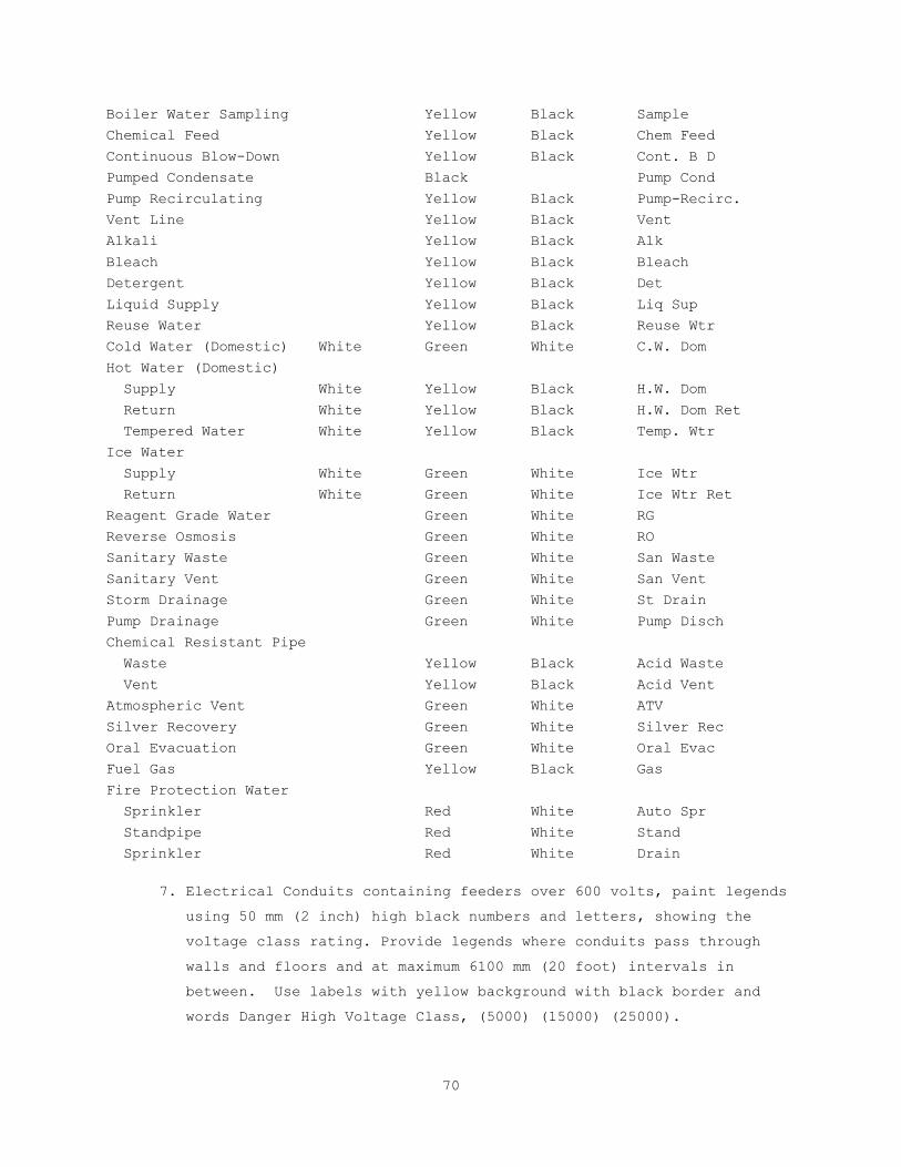
70
Boiler Water Sampling Yellow Black Sample
Chemical Feed Yellow Black Chem Feed
Continuous Blow-Down Yellow Black Cont. B D
Pumped Condensate Black Pump Cond
Pump Recirculating Yellow Black Pump-Recirc.
Vent Line Yellow Black Vent
Alkali Yellow Black Alk
Bleach Yellow Black Bleach
Detergent Yellow Black Det
Liquid Supply Yellow Black Liq Sup
Reuse Water Yellow Black Reuse Wtr
Cold Water (Domestic) White Green White C.W. Dom
Hot Water (Domestic)
Supply White Yellow Black H.W. Dom
Return White Yellow Black H.W. Dom Ret
Tempered Water White Yellow Black Temp. Wtr
Ice Water
Supply White Green White Ice Wtr
Return White Green White Ice Wtr Ret
Reagent Grade Water Green White RG
Reverse Osmosis Green White RO
Sanitary Waste Green White San Waste
Sanitary Vent Green White San Vent
Storm Drainage Green White St Drain
Pump Drainage Green White Pump Disch
Chemical Resistant Pipe
Waste Yellow Black Acid Waste
Vent Yellow Black Acid Vent
Atmospheric Vent Green White ATV
Silver Recovery Green White Silver Rec
Oral Evacuation Green White Oral Evac
Fuel Gas Yellow Black Gas
Fire Protection Water
Sprinkler Red White Auto Spr
Standpipe Red White Stand
Sprinkler Red White Drain
7. Electrical Conduits containing feeders over 600 volts, paint legends
using 50 mm (2 inch) high black numbers and letters, showing the
voltage class rating. Provide legends where conduits pass through
walls and floors and at maximum 6100 mm (20 foot) intervals in
between. Use labels with yellow background with black border and
words Danger High Voltage Class, (5000) (15000) (25000).

71
3.14 PROTECTION CLEAN UP, AND TOUCH-UP
A. Protect work from paint droppings and spattering by use of masking,
drop cloths, removal of items or by other approved methods.
B. Upon completion, clean paint from hardware, glass and other surfaces
and items not required to be painted of paint drops or smears.
C. Before final inspection, touch-up or refinished in a manner to produce
solid even color and finish texture, free from defects in work which
was damaged or discolored.
- - - E N D - - -

72
(THIS PAGE INTENTIONALLY LEFT BLANK)
73
SECTION 14 24 00
ELEVATORS
PART 1 – GENERAL
1.1 DESCRIPTION
A. This section specifies the interconnection of the existing elevator
systems in Buildings 2, 2A and 143 with the new Patient Wandering
System as described herein and as indicated on the contract drawings.
B. Refer to the description of Bid Deducts for further information that
applies to this Section.
C. Items listed in the singular apply to each and every elevator in this
specification except where noted.
D. Building 2 – Two (2) existing Millar Hydraulic Elevators to be wired
and configured to integrate seamlessly with the new Patient Wandering
System on floors 2-2 and 2-3.
E. Building 2A – Two (2) existing Dover Traction Elevators to be wired and
configured to integrate seamlessly with the new Patient Wandering
System on floors 2-2 and 2-3.
F. Building 143 - Six (6) existing Dover Traction Elevators to be wired
and configured to integrate seamlessly with the new Patient Wandering
System on floors 4-H and 4-J.
1.2 RELATED WORK
A. Section 26 05 11, REQUIREMENTS FOR ELECTRICAL INSTALLATIONS: General
electrical requirements that are common to more than one section.
B. Section 26 05 19, LOW-VOLTAGE ELECTRICAL POWER CONDUCTORS AND CABLES
(600 VOLTS AND BELOW): Low Voltage power and lighting wiring.
C. Section 26 05 26, GROUNDING AND BONDING FOR ELECTRICAL SYSTEMS:
Requirements for personnel safety and to provide a low impedance path
for possible ground fault currents.
D. Section 26 05 33, RACEWAY AND BOXES FOR ELECTRICAL SYSTEMS: Conduits
for cables and wiring.
E. Section 27 52 13, PATIENT WANDERING SYSTEMS: Interconnection
requirements, operational requirements and devices furnished by PWS
contractor to be installed by this Elevator Contractor.
1.3 QUALIFICATIONS
A. Approval by the Contracting Officer is required for products or
services of proposed manufacturers, suppliers and installers and shall
be contingent upon submission by Contractor of a certificate stating
the following:

74
1. Elevator contractor is currently and regularly engaged in the
installation and maintenance of elevator equipment as one of his
principal products.
2. Elevator contractor shall have five years of successful experience,
trained supervisory personnel, and facilities installing and
maintaining elevator equipment on this VA campus.
3. The installers shall be Certified Elevator Mechanics with technical
qualifications of at least five years of successful experience and
Apprentices actively pursuing certified mechanic status.
Certificates are required for all workers employed in this capacity.
4. Elevator contractor shall submit a list of two or more prior
VAMC Salem hospital installations where all the elevator equipment
they propose to furnish for this project functioned satisfactorily
to serve varying hospital traffic and material handling demands.
Provide a list of hospitals that have the equipment in operation for
two years preceding the date of this specification. Provide the
names and addresses of the Medical Centers and the names and
telephone numbers of the Medical Center Administrators.
B. Approval will not be given to elevator contractors who have established
on prior projects, either government, municipal, or commercial, a
record for unsatisfactory elevator installations, have failed to
complete awarded contracts within the contract period, and does not
have the requisite record of satisfactorily performing elevator
installations of similar type and magnitude.
C. The Contractor shall provide and install only those types of safety
devices that have been subjected to tests witnessed and certified by an
independent professional testing laboratory that is not a subsidiary of
the firm that manufactures supplies or installs the equipment.
1.4 APPLICABLE PUBLICATIONS
A. The publications listed below form a part of this specification.
Elevator installation shall meet the requirements of the latest
editions published and adopted by the United States Department of
Veterans Affairs on the date contract is signed.
B. Federal Specifications (Fed. Spec.):
J-C-30B.................Cable and Wire, Electrical (Power, Fixed
Installation)
W-C-596F................Connector, Plug, Electrical; Connector,
Receptacle, Electrical

75
W-F-406E................Fittings for Cable, Power, Electrical and
Conduit, Metal, Flexible
W-F-408E................Fittings for Conduit, Metal, Rigid (Thick- Wall
and Thin-wall (EMT) Type)
RR-W-410................Wire Rope and Strand
TT-E-489J...............Enamel, Alkyd, Gloss, Low VOC Content
QQ-S-766 ...............Steel, Stainless and Heat Resisting, Alloys,
Plate, Sheet and Strip
C. International Building Code (IBC)
D. American Society of Mechanical Engineers (ASME):
A17.1...................Safety Code for Elevators and Escalators
A17.2...................Inspectors Manual for Electric Elevators and
Escalators
E. National Fire Protection Association:
NFPA 13..........Standard for the Installation of Sprinkler Systems
NFPA 70..........National Electrical Code (NEC)
NFPA 72..........National Fire Alarm and Signaling Code
NFPA 101.........Life Safety Code
F. American Society for Testing and Materials (ASTM):
A1008/A1008M-09.........Steel, Sheet, Cold Rolled, Carbon, Structural,
High-Strength Low-Alloy and High Strength Low-
Alloy with Improved Farability
E1042-02................Acoustically Absorptive Materials Applied by
Trowel or Spray
G. Manufacturer's Standardization Society of the Valve and Fittings
Industry (MSS):
SP-58...................Pipe Hangers and Supports
H. Society of Automotive Engineers, Inc. (SAE)
J517-91..................Hydraulic Hose, Standard
I. Gages:
For Sheet and Plate: U.S. Standard (USS)
For Wires: American Wire Gauge (AWG)
J. Underwriter's Laboratories (UL):
486A....................Safety Wire Connectors for Copper Conductors
797.....................Safety Electrical Metallic Tubing
K. Institute of Electrical and Electronic Engineers (IEEE)
L. Regulatory Standards:
Uniform Federal Accessibility Standards

76
Americans with Disabilities Act
1.5 SUBMITTALS
A. Before execution of work, furnish information to evidence full
compliance with contract requirements for proposed items. Such
information shall include, as required: Manufacturer's Name, Trade
Names, Model or Catalog Number, Nameplate Data (size, capacity, and
rating) and corresponding specification reference (Federal or project
specification number and paragraph). All submitted drawings and related
elevator material shall be forwarded to the Contracting Officer.
C. Shop Drawings:
1. Drawings showing the arrangement of new equipment, wiring and all
affected details of each and every elevator unit associated with
this project.
2. Interconnection diagrams between elevator controllers, contacts and
wiring supplied by PWS Contractor installed by Elevator Contractor.
D. Furnish certificates as required under: Paragraph "QUALIFICATIONS".
1.6 WIRING DIAGRAMS
A. Provide three complete sets of field wiring and straight line wiring
diagrams showing all NEW electrical circuits in the hoistway, machine
room and fixtures.
B. In the event field modifications are necessary during installation,
diagrams shall be revised to include all corrections made prior to and
during the final inspection. Corrected diagrams shall be delivered to
the Resident Engineer within 30 days of final acceptance.
1.7 ADDITIONAL EQUIPMENT
A. Additional equipment required to operate the specified equipment
manufactured and supplied for this installation shall be furnished and
installed by the contractor. The cost of the equipment shall be
included in the base bid.
B. Special equipment not required by specification, which would improve
the operation, may be installed in conjunction with the specified
equipment by the contractor at his option at no additional cost to the
Government, provided prior approval is obtained from the Contracting
Officer’s Technical Representative.
1.9 PERFORMANCE STANDARDS
A. Upon receiving an alarm signal from the PWS that a tagged patient is in
field of the elevator cab, the elevator’s doors will stop being closed
and the car will cease to travel until the tagged patient is out of the

77
field of detection and the PWS signal is restored back to normal
condition.
1.10 WARRANTY
A. Submit all labor and materials furnished in connection with elevator
system and installation for a one year Warranty which shall commence
after final inspection, completion of performance test, and upon full
acceptance of the installation.
B. During warranty period if a device associated with this project is not
functioning properly or in accordance with specification requirements,
or if in the opinion of the Resident Engineer, excessive maintenance
and attention must be employed to keep device operational, device shall
be removed and a new device meeting all requirements shall be installed
as part of work until satisfactory operation of installation is
obtained. Period of warranty shall start anew for such parts from date
of completion of each new installation performed, in accordance with
foregoing requirements.
PART 2 - PRODUCTS
2.1 MANUFACTURED PRODUCTS
A. Refer to the Electrical Drawings and Section 27 52 13 for a list of the
Materials, devices and equipment that is to be furnished by the PWS
Contractor but installed inside the elevator cabs and hoistways by the
Elevator Contractor. Items in or on top of the cabs include but are not
limited to: PWS elevator controller, PWS antennae, PWS override keypad,
PWS wiring/pigtails, and aesthetically pleasing surface mounted
raceways inside the cab to conceal all wiring.
2.2 POWER SUPPLY
A. Unless otherwise noted, power for new equipment shall be provided from
the existing elevator power available on top of the cabs.
2.3 RACEWAYS
A. Unless otherwise specified or approved, install electrical conductors,
except traveling cable connections to the car, in surface raceway
(inside the cabs) or rigid zinc-coated steel or aluminum conduit,
electrical metallic tubing or metal wireways (inside the elevator
machine rooms). Rigid conduit smaller than 3/4 inch or electrical
metallic tubing smaller than 1/2 inch electrical trade size shall not
be used. Fully protect self-supporting connections, where approved,
from abrasion or other mechanical injury. Flexible metal conduit not

78
less than 3/8 inch electrical trade size may be used, not exceeding 18
inches in length unsupported, for short connections between risers and
limit switches, interlocks, and for other applications permitted by
NEC.
B. All conduit terminating in steel cabinets, junction boxes, wireways,
switch boxes, outlet boxes and similar locations shall have approved
insulation bushings. Install a steel lock nut under the bushings if
they are constructed completely of insulating materials. Protect the
conductors at ends of conduits not terminating in steel cabinets or
boxes by terminal fittings having an insulated opening for the
conductors.
C. Rigid conduit and EMT fittings using set screws or indentations as a
means of attachment shall not be used. All fittings shall be steel or
malleable iron.
D. Connect other items subject to movement, vibration or removal to the
conduit or EMT systems with flexible, steel conduits.
2.4 CONDUCTORS
A. Unless otherwise specified, conductors, excluding the traveling cables,
shall be stranded or solid coated annealed copper in accordance with
Federal Specification J-C-30B for Type RHW or THW. Where 16 and 18 AWG
are permitted by NEC, single conductors or multiple conductor cables in
accordance with Federal Specification J-C-580 for Type TF may be used
provided the insulation of single conductor cable and outer jacket of
multiple conductor cable is flame retardant and moisture resistant.
Multiple conductor cable shall have color or number coding for each
conductor. Conductors for control boards shall be in accordance with
NEC. Joints or splices are not permitted in wiring except at outlets.
Tap connectors may be used in wireways provided they meet all UL
requirements.
B. It is understood that the existing travel cable does not have enough
spare conductors to support the PWS integration. Therefore, the
Elevator Contractor shall provide all necessary conduit and wiring
between machine room and hoistway to support this PWS integration.
C. All wiring must test free from short circuits or ground faults.
Insulation resistance between individual external conductors and
between conductors and ground shall be a minimum of one megohm.
D. Where size of conductors is not given, voltage and amperes shall not
exceed limits prescribed by NEC.

79
E. Provide equipment grounding. Ground the conduits, supports, controller
enclosure, and all other non-current conducting metal enclosures for
electrical equipment in accordance with NEC. The ground wires shall be
copper, green insulated and sized as required by NEC. Bond the
grounding wires to all junction boxes, cabinets, and wire raceways.
F. Terminal connections for all conductors used for external wiring
between various items of elevator equipment shall be solderless
pressure wire connectors in accordance with Federal Specification W-S-
610. The Elevator Contractor may, at his option, make these terminal
connections on 10 gauge or smaller conductors with approved terminal
eyelets set on the conductor with a special setting tool, or with an
approved pressure type terminal block. Terminal blocks using pierce-
through serrated washers are not acceptable.
2.5 TRAVELING CABLES
A. As the existing travel cables need to be added onto, all conductors to
the car shall consist of flexible traveling cables conforming to the
requirements of NEC. Traveling cables shall run from the junction box
on the car directly to the controller. Junction boxes on the car shall
be equipped with terminal blocks. Terminal blocks having pressure wire
connectors of the clamp type that meet UL 486A requirements for
stranded wire may be used in lieu of terminal eyelet connections.
Terminal blocks shall have permanent indelible identifying numbers for
each connection. Cables shall be securely anchored to avoid strain on
individual terminal connections. Flame and moisture resistant outer
covering must remain intact between junction boxes. Abrupt bending,
twisting and distortion of the cables shall not be permitted.
B. Provide spare conductors equal to 10 percent of the total number of
conductors furnished, but not less than 2 spare conductors in each
traveling cable.
C. If traveling cables come into contact with the hoistway or elevator due
to sway or change in position, provide shields or pads to the elevator
and hoistway to prevent damage to the traveling cables.
D. Hardware cloth wide may be installed from the hoistway suspension point
downward to the elevator pit to prevent traveling cables from rubbing
or chafing. Hardware cloth shall be securely fastened and tensioned to
prevent buckling. Hardware cloth is not required when traveling cable
is hung against a flat wall.

80
2.6 INTEGRATION
A. Provide contacts, interconnect wiring and all necessary programming to
perform the specified sequence of operation with respect to the PWS.
Coordinate the work with the PWS Contractor regarding voltages, AC/DC,
power, wiring types and counts, equipment locations, etc.
PART 3 – EXECUTION
3.1 PREPARATION
A. Examine work of other trades on which the work of this Section depends.
Report defects to the Resident Engineer in writing which may affect the
work of this trade or equipment operation dimensions from site for
preparation of shop drawings.
B. Before fabrication, take necessary job site measurements, and verify
where work is governed by other trades. Check measurement of space for
equipment, and means of access for installation and operation. Obtain
dimensions from site for preparation of shop drawings.
C. Supply for installation including all necessary inserts, anchors,
plates, brackets, supports and bracing including all setting templates
and diagrams for placement.
3.2 SPACE CONDITIONS
A. Attention is called to overhead clearance, pit clearances, overall
space in machine room, and construction conditions at building site in
connection with elevator work. Addition or revision of space
requirements, or construction changes that may be required for the
complete installation of the elevators must be arranged for and
obtained by the Contractor, subject to approval by Resident Engineer.
Include cost of changes in bid that become a part of the contract.
Provide proper, code legal installation of equipment, including all
construction, accessories and devices in connecting with elevator,
mechanical and electrical work specified.
3.3 INSTALLATION
A. Perform work with competent Certified Elevator Mechanics and
Apprentices skilled in this work, familiar with the elevators on this
VA Salem campus and under the direct supervision of the Elevator
Contractor’s experienced foreman.
D. Install cabling and all equipment and accessories in accordance with
manufacturer's instructions, applicable codes and standards.
3.4 ARRANGEMENT OF EQUIPMENT
A. Clearance around elevator, mechanical and electrical equipment shall
comply with applicable provisions of NEC. Arrange equipment in machine
81
room so that major equipment components can be removed for repair or
replacement without dismantling or removing other equipment in the same
machine room. Locate contacts near controller and visible to its
respective controller.
3.5 WORKMANSHIP AND PROTECTION
A. Installations shall be performed by Certified Elevator Mechanics and
Apprentices to best possible industry standards. Details of the
installation shall be mechanically and electrically correct. Materials
and equipment shall be new and without imperfections.
B. Recesses, cutouts, slots, holes, patching, grouting, refinishing to
accommodate installation of equipment shall be included in the
Contractor's work. All new holes in concrete shall be core drilled.
C. Structural members shall not be cut or altered. Work in place that is
damaged or defaced shall be restored equal to original condition.
D. Finished work shall be straight, plumb, level, and square with smooth
surfaces and lines. All machinery and equipment shall be protected
against dirt, water, or mechanical injury. At final completion, all
work shall be thoroughly cleaned and delivered in perfect unblemished
condition.
E. Sleeves for conduit and other small holes shall project 50 mm (2 in.)
above concrete slabs.
F. Exposed gears, sprockets, and sheaves shall be guarded from accidental
contact in accordance with ASME A17.1 Section 2.10.
3.6 CLEANING
A. Clean up any new debris created within the cabs, hoistways, or machine
rooms.
3.7 PRE-TESTS AND TESTS
A. Pre-test the elevators and related equipment in the presence of the PWS
Contractor and Resident Engineer for proper operation before requesting
final inspection. Conduct final inspection at other than normal working
hours, if required by Resident Engineer.
B. Provide Technician for the inspection of workmanship, equipment
furnished, and installation for compliance with specification.
C. Evidence of malfunction in any tested system or parts of equipment that
occurs during the testing shall be corrected, repaired, or replaced at
no additional cost to the Government, and the test repeated.
D. If equipment fails test requirements and a re-inspection is required,
the Contractor shall be responsible for the cost of re-inspection.
82
3.8 INSTRUCTION OF VA PERSONNEL
A. Provide competent instruction to VA personnel regarding the operation
of equipment and accessories installed under this contract, for a
period equal to two hours. Instruction shall commence after completion
of all work and at the time and place directed by the Resident
Engineer.
B. Written instructions in triplicate relative to care, adjustments and
operation of all equipment and accessories shall be furnished and
delivered to the Resident Engineer in independently bound folders. DVD
recordings will also be acceptable. Written instructions shall include
correct and legible wiring diagrams, nomenclature sheet of all
electrical apparatus including location of each device, complete and
comprehensive sequence of operation, complete replacement parts list
with descriptive literature, and identification and diagrammatic cuts
of equipment and parts.
C. Provide supplementary instruction for any new equipment that may become
necessary because of changes, modifications or replacement of equipment
or operation under requirements of paragraph entitled "Warranty of
Construction".
- - - E N D - - -

83
SECTION 26 05 11
REQUIREMENTS FOR ELECTRICAL INSTALLATIONS
PART 1 - GENERAL
1.1 DESCRIPTION
A. This section applies to all sections of Division 01, 14, 26, 27 and 28.
B. Furnish and install electrical systems, materials, equipment, and
accessories in accordance with the specifications and drawings.
Capacities and ratings of equipment, circuit breakers, conductors and
cable and other items and arrangements for the specified items are
shown on the drawings.
C. Conductor ampacities specified or shown on the drawings are based on
copper conductors, with the conduit and raceways sized per NEC.
Aluminum conductors are prohibited.
D. It is to be understood that this is an active hospital with patients
and staff in the area of renovation. Contractor to verify where they
can work and how many rooms that can work on at a time with each Unit’s
Nurse Manager prior to working each day. Contractor to be aware of and
abide by any and all ICRA requirements while performing work.
E. In general, the following is a list of the maximum amount of rooms that
the Contractor can work on in each specific Unit. The Contractor shall
coordinate the times and days that they can occupy the patient rooms
with the approval of the Unit’s Nurse Manager:
1. SICU – 2 rooms per day and only 1 at a time
2. MICU – 2 rooms per day and only 1 at a time
3. SDU – 2 rooms per day and only 1 at a time
4. 2-2 – 2 rooms at a time max
5. 2-3 – 2 rooms at a time max
6. 4-H – 4 rooms per day
7. 4-J - 4 rooms per day
1.2 MINIMUM REQUIREMENTS
A. The International Building Code (IBC), National Electrical Code (NEC),
Underwriters Laboratories, Inc. (UL), and National Fire Protection
Association (NFPA) codes and standards are the minimum requirements for
materials and installation.
B. The drawings and specifications shall govern in those instances where
requirements are greater than those stated in the above codes and
standards.
84
1.3 TEST STANDARDS
A. All materials and equipment shall be listed, labeled, or certified by a
Nationally Recognized Testing Laboratory (NRTL) to meet Underwriters
Laboratories, Inc. (UL), standards where test standards have been
established. Materials and equipment which are not covered by UL
standards will be accepted, providing that materials and equipment are
listed, labeled, certified or otherwise determined to meet the safety
requirements of a NRTL. Materials and equipment which no NRTL accepts,
certifies, lists, labels, or determines to be safe, will be considered
if inspected or tested in accordance with national industrial
standards, such as ANSI, NEMA, and NETA. Evidence of compliance shall
include certified test reports and definitive shop drawings.
B. Definitions:
1. Listed: Materials and equipment included in a list published by an
organization that is acceptable to the Authority Having Jurisdiction
and concerned with evaluation of products or services, that
maintains periodic inspection of production or listed materials and
equipment or periodic evaluation of services, and whose listing
states that the materials and equipment either meets appropriate
designated standards or has been tested and found suitable for a
specified purpose.
2. Labeled: Materials and equipment to which has been attached a label,
symbol, or other identifying mark of an organization that is
acceptable to the Authority Having Jurisdiction and concerned with
product evaluation, that maintains periodic inspection of production
of labeled materials and equipment, and by whose labeling the
manufacturer indicates compliance with appropriate standards or
performance in a specified manner.
3. Certified: Materials and equipment which:
a. Have been tested and found by a NRTL to meet nationally
recognized standards or to be safe for use in a specified manner.
b. Are periodically inspected by a NRTL.
c. Bear a label, tag, or other record of certification.
4. Nationally Recognized Testing Laboratory: Testing laboratory which
is recognized and approved by the Secretary of Labor in accordance
with OSHA regulations.
5. All products and systems shall bear the MADE IN THE USA
certification.

85
1.4 QUALIFICATIONS (PRODUCTS AND SERVICES)
A. Manufacturer’s Qualifications: The manufacturer shall regularly and
currently produce, as one of the manufacturer's principal products, the
materials and equipment specified for this project, and shall have
manufactured the materials and equipment for at least five years.
B. Product Qualification:
1. Manufacturer's materials and equipment shall have been in
satisfactory operation, on three installations of similar size and
type as this project, for at least three years.
2. The Government reserves the right to require the Contractor to
submit a list of installations where the materials and equipment
have been in operation before approval.
C. Service Qualifications: There shall be a permanent service organization
maintained or trained by the manufacturer which will render
satisfactory service to this installation within eight hours of receipt
of notification that normal service is needed and within four hours of
receipt of notification that an emergency service is needed. Submit
name and address of service organizations.
1.5 APPLICABLE PUBLICATIONS
A. Applicable publications listed in all Sections of Division 26 and 27
are the latest issue, unless otherwise noted.
B. Products specified in all sections of Division 26 shall comply with the
applicable publications listed in each section.
1.6 MANUFACTURED PRODUCTS
A. Materials and equipment furnished shall be of current production by
manufacturers regularly engaged in the manufacture of such items, and
for which replacement parts shall be available.
B. When more than one unit of the same class or type of materials and
equipment is required, such units shall be the product of a single
manufacturer.
C. Equipment Assemblies and Components:
1. Components of an assembled unit need not be products of the same
manufacturer.
2. Manufacturers of equipment assemblies, which include components made
by others, shall assume complete responsibility for the final
assembled unit.
3. Components shall be compatible with each other and with the total
assembly for the intended service.
86
4. Constituent parts which are similar shall be the product of a single
manufacturer.
D. Factory wiring and terminals shall be identified on the equipment being
furnished and on all wiring diagrams.
E. When Factory Testing Is Specified:
1. The Government shall have the option of witnessing factory tests.
The Contractor shall notify the Government through the Resident
Engineer a minimum of 30 working days prior to the manufacturer’s
performing the factory tests.
2. Four copies of certified test reports shall be furnished to the
Resident Engineer two weeks prior to final inspection and not more
than 90 days after completion of the tests.
3. When materials and equipment fail factory tests, and re-testing and
re-inspection is required, the Contractor shall be liable for all
additional expenses for the Government to witness re-testing.
1.7 VARIATIONS FROM CONTRACT REQUIREMENTS
A. Where the Government or the Contractor requests variations from the
contract requirements, the connecting work and related components shall
include, but not be limited to additions or changes to branch circuits,
low voltage circuits, equipment cabinets, circuit protective devices,
conduits, wire, feeders, controls, panels and installation methods.
1.8 MATERIALS AND EQUIPMENT PROTECTION
A. Materials and equipment shall be protected during shipment and storage
against physical damage, vermin, dirt, corrosive substances, fumes,
moisture, cold and rain.
1. Store materials and equipment indoors in clean dry space with
uniform temperature to prevent condensation.
2. During installation, equipment shall be protected against entry of
foreign matter, and be vacuum-cleaned both inside and outside before
testing and operating. Compressed air shall not be used to clean
equipment. Remove loose packing and flammable materials from inside
equipment.
3. Damaged equipment shall be repaired or replaced, as determined by
the Resident Engineer.
4. Painted surfaces shall be protected with factory installed removable
heavy kraft paper, sheet vinyl or equal.
87
5. Damaged paint on equipment shall be refinished with the same quality
of paint and workmanship as used by the manufacturer so repaired
areas are not obvious.
1.9 WORK PERFORMANCE
A. All electrical work shall comply with the requirements of NFPA 70
(NEC), NFPA 70B, NFPA 70E, OSHA Part 1910 subpart J – General
Environmental Controls, OSHA Part 1910 subpart K – Medical and First
Aid, and OSHA Part 1910 subpart S – Electrical, in addition to other
references required by contract.
B. Job site safety and worker safety is the responsibility of the
Contractor.
C. Electrical work shall be accomplished with all affected circuits or
equipment de-energized. When an electrical outage cannot be
accomplished in this manner for the required work, the following
requirements are mandatory:
1. Electricians must use full protective equipment (i.e., certified and
tested insulating material to cover exposed energized electrical
components, certified and tested insulated tools, etc.) while
working on energized systems in accordance with NFPA 70E.
2. Before initiating any work, a job specific work plan must be
developed by the Contractor with a peer review conducted and
documented by the Resident Engineer and Medical Center staff. The
work plan must include procedures to be used on and near the live
electrical equipment, barriers to be installed, safety equipment to
be used, and exit pathways.
3. Work on energized circuits or equipment cannot begin until prior
written approval is obtained from the Resident Engineer.
D. For work that affects existing electrical or low voltage systems,
arrange, phase and perform work to assure minimal interference with
normal functioning of the facility. Refer to Article OPERATIONS AND
STORAGE AREAS under Section 01 00 00, GENERAL REQUIREMENTS.
E. New work shall be installed and connected to existing work neatly,
safely and professionally. Disturbed or damaged work shall be replaced
or repaired to its prior conditions, as required by Section 01 00 00,
GENERAL REQUIREMENTS.
F. Coordinate location of equipment and conduit with existing conditions
to minimize interference.

88
1.10 EQUIPMENT INSTALLATION AND REQUIREMENTS
A. Equipment location shall be as close as practical to locations shown on
the drawings.
B. Working clearances shall not be less than specified in the NEC.
C. Inaccessible Equipment:
1. Where the Government determines that the Contractor has installed
equipment not readily accessible for operation and maintenance, the
equipment shall be removed and reinstalled as directed at no
additional cost to the Government.
2. "Readily accessible” is defined as being capable of being reached
quickly for operation, maintenance, or inspections without the use
of ladders, or without climbing or crawling under or over obstacles
such as, but not limited to, motors, pumps, belt guards,
transformers, piping, ductwork, conduit and raceways.
1.11 EQUIPMENT IDENTIFICATION
A. Identification signs for Normal Power System equipment shall be
laminated black phenolic resin with a white core with engraved
lettering. Identification signs for Essential Electrical System (EES)
equipment, as defined in the NEC, shall be laminated red phenolic resin
with a white core with engraved lettering. Lettering shall be a minimum
of 3/8 inch high. Identification signs shall indicate equipment
designation, rated bus amperage, voltage, number of phases, number of
wires, and type of EES power branch as applicable. Secure nameplates
with screws.
1.12 SUBMITTALS
A. Submit to the Resident Engineer in accordance with Section 01 33 23,
SHOP DRAWINGS, PRODUCT DATA, AND SAMPLES.
B. The Government's approval shall be obtained for all materials and
equipment before delivery to the job site. Delivery, storage or
installation of materials and equipment which has not had prior
approval will not be permitted.
C. All submittals shall include six copies of adequate descriptive
literature, catalog cuts, shop drawings, test reports, certifications,
samples, and other data necessary for the Government to ascertain that
the proposed materials and equipment comply with drawing and
specification requirements. Catalog cuts submitted for approval shall
be legible and clearly identify specific materials and equipment being
submitted.

89
D. Submittals for individual systems and equipment assemblies which
consist of more than one item or component shall be made for the system
or assembly as a whole. Partial submittals will not be considered for
approval.
1. Mark the submittals, "SUBMITTED UNDER SECTION__________________".
2. Submittals shall be marked to show specification reference including
the section and paragraph numbers.
3. Submit each section separately.
E. The submittals shall include the following:
1. Information that confirms compliance with contract requirements.
Include the manufacturer's name, model or catalog numbers, catalog
information, technical data sheets, shop drawings, manuals,
pictures, nameplate data, and test reports as required.
2. Submittals are required for all equipment anchors and supports.
Submittals shall include weights, dimensions, center of gravity,
standard connections, manufacturer's recommendations and behavior
problems (e.g., vibration, thermal expansion, etc.) associated with
equipment or piping so that the proposed installation can be
properly reviewed. Include sufficient fabrication information so
that appropriate mounting and securing provisions may be designed
and attached to the equipment.
3. Elementary and interconnection wiring diagrams for communication and
signal systems, control systems, and equipment assemblies. All
terminal points and wiring shall be identified on wiring diagrams.
4. Parts list which shall include information for replacement parts and
ordering instructions, as recommended by the equipment manufacturer.
F. Maintenance and Operation Manuals:
1. Submit as required for systems and equipment specified in the
technical sections. Furnish in hardcover binders or an approved
equivalent.
2. Inscribe the following identification on the cover: the words
"MAINTENANCE AND OPERATION MANUAL," the name and location of the
system, material, equipment, building, name of Contractor, and
contract name and number. Include in the manual the names,
addresses, and telephone numbers of each subcontractor installing
the system or equipment and the local representatives for the
material or equipment.

90
3. Provide a table of contents and assemble the manual to conform to
the table of contents, with tab sheets placed before instructions
covering the subject. The instructions shall be legible and easily
read, with large sheets of drawings folded in.
4. The manuals shall include:
a. Internal and interconnecting wiring and control diagrams with
data to explain detailed operation and control of the equipment.
b. A control sequence describing start-up, operation, and shutdown.
c. Description of the function of each principal item of equipment.
d. Installation instructions.
e. Safety precautions for operation and maintenance.
f. Diagrams and illustrations.
g. Periodic maintenance and testing procedures and frequencies,
including replacement parts numbers.
h. Performance data.
i. Pictorial "exploded" parts list with part numbers. Emphasis shall
be placed on the use of special tools and instruments. The list
shall indicate sources of supply, recommended spare and
replacement parts, and name of servicing organization.
j. List of factory approved or qualified permanent servicing
organizations for equipment repair and periodic testing and
maintenance, including addresses and factory certification
qualifications.
G. Approvals will be based on complete submission of shop drawings,
manuals, test reports, certifications, and samples as applicable.
H. After approval and prior to installation, furnish the Resident Engineer
with one sample of each of the following:
1. A minimum 300 mm (12 inches) length of each type and size of wire
and cable along with the tag from the coils or reels from which the
sample was taken. The length of the sample shall be sufficient to
show all markings provided by the manufacturer.
2. Each type of conduit coupling, bushing, and termination fitting.
3. Conduit hangers, clamps, and supports.
4. Duct sealing compound.
5. Firestopping compound.
5. Each type of outlet box, nurse call and patient station device,
engraved nameplate, and wire and cable splicing and terminating
material.
91
1.13 SINGULAR NUMBER
A. Where any device or part of equipment is referred to in these
specifications in the singular number (e.g., "the switch"), this
reference shall be deemed to apply to as many such devices as are
required to complete the installation as shown on the drawings.
1.14 ACCEPTANCE CHECKS AND TESTS
A. The Contractor shall furnish the instruments, materials, and labor for
tests.
B. Where systems are comprised of components specified in more than one
section of Division 26 and 27, the Contractor shall coordinate the
installation, testing, and adjustment of all components between various
manufacturer’s representatives and technicians so that a complete,
functional, and operational system is delivered to the Government.
C. When test results indicate any defects, the Contractor shall repair or
replace the defective materials or equipment, and repeat the tests.
Repair, replacement, and retesting shall be accomplished at no
additional cost to the Government.
1.15 WARRANTY
A. All work performed and all equipment and material furnished under this
Division shall be free from defects and shall remain so for a period of
one year from the date of acceptance of the entire installation by the
Contracting Officer for the Government.
1.16 INSTRUCTION
A. Instruction to designated Government personnel shall be provided for
the particular equipment or system as required in each associated
technical specification section.
B. Furnish the services of competent instructors to give full instruction
in the adjustment, operation, and maintenance of the specified
equipment and system, including pertinent safety requirements.
Instructors shall be thoroughly familiar with all aspects of the
installation, and shall be trained in operating theory as well as
practical operation and maintenance procedures.
C. A training schedule shall be developed and submitted by the Contractor
and approved by the Resident Engineer at least 30 days prior to the
planned training.
PART 2 - PRODUCTS (NOT USED)
PART 3 - EXECUTION (NOT USED)
---END---

92
(THIS PAGE INTENTIONALLY LEFT BLANK)
93
SECTION 26 05 19
LOW-VOLTAGE ELECTRICAL POWER CONDUCTORS AND CABLES
PART 1 - GENERAL
1.1 DESCRIPTION
A. This section specifies the furnishing, installation, connection, and
testing of the electrical conductors and cables for use in electrical
systems rated 600 V and below, indicated as cable(s), conductor(s),
wire, or wiring in this section.
1.2 RELATED WORK
A. Section 07 84 00, FIRESTOPPING: Sealing around penetrations to maintain
the integrity of fire-resistant rated construction.
B. Section 26 05 11, REQUIREMENTS FOR ELECTRICAL INSTALLATIONS:
Requirements that apply to all sections of Division 26 and 27.
C. Section 26 05 26, GROUNDING AND BONDING FOR ELECTRICAL SYSTEMS:
Requirements for personnel safety and to provide a low impedance path
for possible ground fault currents.
D. Section 26 05 33, RACEWAY AND BOXES FOR ELECTRICAL SYSTEMS: Conduits
for conductors and cables.
1.3 QUALITY ASSURANCE
A. Refer to Paragraph, QUALIFICATIONS (PRODUCTS AND SERVICES), in Section
26 05 11, REQUIREMENTS FOR ELECTRICAL INSTALLATIONS.
1.4 FACTORY TESTS
A. Conductors and cables shall be thoroughly tested at the factory per
NEMA to ensure that there are no electrical defects. Factory tests
shall be certified.
1.5 SUBMITTALS
A. Submit six copies of the following in accordance with Section 26 05 11,
REQUIREMENTS FOR ELECTRICAL INSTALLATIONS.
1. Shop Drawings:
a. Submit sufficient information to demonstrate compliance with
drawings and specifications.
b. Submit the following data for approval:
1) Electrical ratings and insulation type for each conductor and
cable.
2) Splicing materials and pulling lubricant.
2. Certifications: Two weeks prior to final inspection, submit the
following.
94
a. Certification by the manufacturer that the conductors and cables
conform to the requirements of the drawings and specifications.
b. Certification by the Contractor that the conductors and cables
have been properly installed, adjusted, and tested.
1.6 APPLICABLE PUBLICATIONS
A. Publications listed below (including amendments, addenda, revisions,
supplements and errata) form a part of this specification to the extent
referenced. Publications are reference in the text by designation only.
B. American Society of Testing Material (ASTM):
D2301-10................Standard Specification for Vinyl Chloride
Plastic Pressure-Sensitive Electrical
Insulating Tape
D2304-10................Test Method for Thermal Endurance of Rigid
Electrical Insulating Materials
D3005-10................Low-Temperature Resistant Vinyl Chloride
Plastic Pressure-Sensitive Electrical
Insulating Tape
C. National Electrical Manufacturers Association (NEMA):
WC 70-09................Power Cables Rated 2000 Volts or Less for the
Distribution of Electrical Energy
D. National Fire Protection Association (NFPA):
70-11...................National Electrical Code (NEC)
E. Underwriters Laboratories, Inc. (UL):
44-10...................Thermoset-Insulated Wires and Cables
83-08...................Thermoplastic-Insulated Wires and Cables
467-07..................Grounding and Bonding Equipment
486A-486B-03............Wire Connectors
486C-04.................Splicing Wire Connectors
486D-05.................Sealed Wire Connector Systems
486E-09.................Equipment Wiring Terminals for Use with
Aluminum and/or Copper Conductors
493-07..................Thermoplastic-Insulated Underground Feeder and
Branch Circuit Cables
514B-04.................Conduit, Tubing, and Cable Fittings
PART 2 - PRODUCTS
2.1 CONDUCTORS AND CABLES
A. Conductors and cables shall be in accordance with NEMA, UL, as
specified herein, and as shown on the drawings.

95
B. All conductors shall be copper.
C. Single Power Conductor and Cable:
1. No. 12 AWG: Minimum size, except where smaller sizes are specified
herein or shown on the drawings.
2. No. 8 AWG and larger: Stranded.
3. No. 10 AWG and smaller: Solid; except shall be stranded for final
connection to motors, transformers, and vibrating equipment.
4. Insulation: THHN-THWN and XHHW-2. XHHW-2 shall be used for isolated
power systems.
D. Nurse Call/Patient Wandering Systems Conductor and Cable:
1. No. 24 AWG: Minimum size and as recommended by the equipment
manufacturers.
2. Solid: As recommended by the equipment manufacturers.
3. Riser rated, non-plenum.
E. Color Code for Power Conductors:
1. No. 10 AWG and smaller: Solid color insulation or solid color
coating.
2. No. 8 AWG and larger: Color-coded using one of the following
methods:
a. Solid color insulation or solid color coating.
b. Stripes, bands, or hash marks of color specified.
c. Color using 19 mm (0.75 inches) wide tape.
4. For modifications and additions to existing wiring systems, color
coding shall conform to the existing wiring system.
5. Conductors shall be color-coded as follows:
208/120 V Phase 480/277 V
Black A Brown
Red B Orange
Blue C Yellow
White Neutral Gray *
* or white with colored (other than green) tracer.
F. Color Code for Nurse Call/Patient Wandering Conductors:
1. Solid color insulation or solid color coating.
2. Insulation Colors:
a. Nurse Call - Pink.
b. Patient Wandering – Yellow.

96
2.2 SPLICES
A. Splices shall be in accordance with NEC and UL and splices shall only
occur if absolutely necessary for power wiring and not allowed for low
voltage wiring.
B. Above Ground Splices for No. 10 AWG and Smaller:
1. Solderless, screw-on, reusable pressure cable type, with integral
insulation, approved for copper and aluminum conductors.
2. The integral insulator shall have a skirt to completely cover the
stripped conductors.
3. The number, size, and combination of conductors used with the
connector, as listed on the manufacturer's packaging, shall be
strictly followed.
C. Plastic electrical insulating tape: Per ASTM D2304, flame-retardant,
cold and weather resistant.
2.3 CONNECTORS AND TERMINATIONS
A. Mechanical type of high conductivity and corrosion-resistant material,
listed for use with copper and aluminum conductors.
B. Long barrel compression type of high conductivity and
corrosion-resistant material, with minimum of two compression indents
per wire, listed for use with copper and aluminum power conductors.
C. All bolts, nuts, and washers used to connect connections and
terminations to bus bars or other termination points shall be zinc-
plated steel.
2.4 CONTROL OR LOW VOLTAGE WIRING
A. Unless otherwise specified elsewhere in these specifications and as
recommended by the low voltage equipment manufacturer, control wiring
shall be as specified herein.
B. Control or low voltage wiring shall be sized such that the voltage drop
under in-rush conditions does not adversely affect operation of the
controls.
2.5 WIRE LUBRICATING COMPOUND
A. Lubricating compound shall be suitable for the wire insulation and
conduit, and shall not harden or become adhesive.
B. Shall not be used on conductors for low voltage systems.
PART 3 - EXECUTION
3.1 GENERAL
A. Install conductors in accordance with the NEC, as specified, and as
shown on the drawings.

97
B. Install all power conductors in raceway systems. Low voltage conductors
may be installed on j-hook type supports on a maximum of two foot (2’)
centers.
C. Splice conductors only in outlet boxes, junction boxes, pullboxes,
manholes, or handholes.
D. Conductors of different systems (e.g., 120 V and 277 V) shall not be
installed in the same raceway.
E. In panelboards, cabinets, wireways, switches, enclosures, and equipment
assemblies, neatly form, train, and tie the conductors with non-
metallic ties.
F. Power Conductor and Cable Pulling:
1. Provide installation equipment that will prevent the cutting or
abrasion of insulation during pulling. Use lubricants approved for
the cable.
2. Use nonmetallic pull ropes.
3. Attach pull ropes by means of either woven basket grips or pulling
eyes attached directly to the conductors.
4. All conductors in a single conduit shall be pulled simultaneously.
5. Do not exceed manufacturer’s recommended maximum pulling tensions
and sidewall pressure values.
G. No more than three branch circuits shall be installed in any one
conduit.
H. When stripping stranded conductors, use a tool that does not damage the
conductor or remove conductor strands.
3.2 SPLICE AND TERMINATION INSTALLATION
A. Splices and terminations shall be mechanically and electrically secure,
and tightened to manufacturer’s published torque values using a torque
screwdriver or wrench.
B. Where the Government determines that unsatisfactory splices or
terminations have been installed, replace the splices or terminations
at no additional cost to the Government.
3.3 POWER CONDUCTOR IDENTIFICATION
A. When using colored tape to identify phase, neutral, and ground
conductors larger than No. 8 AWG, apply tape in half-overlapping turns
for a minimum of 75 mm (3 inches) from terminal points, and in junction
boxes, pullboxes, and manholes. Apply the last two laps of tape with no
tension to prevent possible unwinding. Where cable markings are covered
by tape, apply tags to cable, stating size and insulation type.

98
3.4 CONDUCTOR IDENTIFICATION
A. In each interior, splice or junction box, install self-adhesive wrap
around tags on all conductors to clearly designate their circuit or
cable identification.
3.5 EXISTING CONDUCTORS
A. Unless specifically indicated on the plans, existing conductors shall
not be reused.
3.6 CONTROL OR LOW VOLTAGE WIRING INSTALLATION
A. Unless otherwise specified in other sections, install control wiring
and connect to equipment to perform the required functions as specified
or as shown on the drawings.
B. Install a separate power supply circuit for each system, except where
otherwise shown on the drawings.
3.7 CONTROL OR LOW VOLTAGE WIRING IDENTIFICATION
A. Install a self-adhesive wrap around label on each cable at each
termination.
B. Identifying numbers and letters on the wire markers shall correspond to
those on the wiring diagrams used for installing the systems.
C. Wire markers shall retain their markings after cleaning.
3.8 ACCEPTANCE CHECKS AND TESTS
A. Perform in accordance with the manufacturer's recommendations. In
addition, include the following:
1. Visual Inspection and Tests: Inspect physical condition.
2. Electrical tests:
a. Continuity tests.
b. Grounding tests.
c. ANSI/TIA/EIA minimum tests on UTP copper and fiber optic cables.
---END---

99
SECTION 26 05 26
GROUNDING AND BONDING FOR ELECTRICAL SYSTEMS
PART 1 - GENERAL
1.1 DESCRIPTION
A. This section specifies the furnishing, installation, connection, and
testing of grounding and bonding equipment, indicated as grounding
equipment in this section.
B. “Grounding electrode system” refers to grounding electrode conductors
and all electrodes required or allowed by NEC, as well as made,
supplementary, and lightning protection system grounding electrodes.
C. The terms “connect” and “bond” are used interchangeably in this section
and have the same meaning.
1.2 RELATED WORK
A. Section 26 05 11, REQUIREMENTS FOR ELECTRICAL INSTALLATIONS:
Requirements that apply to all sections of Division 26.
B. Section 26 05 19, LOW-VOLTAGE ELECTRICAL POWER CONDUCTORS AND CABLES:
Low-voltage conductors.
C. Section 26 05 33, RACEWAY AND BOXES FOR ELECTRICAL SYSTEMS: Conduit and
boxes.
1.3 QUALITY ASSURANCE
A. Refer to Paragraph, QUALIFICATIONS (PRODUCTS AND SERVICES), in Section
26 05 11, REQUIREMENTS FOR ELECTRICAL INSTALLATIONS.
1.4 SUBMITTALS
A. Submit six copies of the following in accordance with Section 26 05 11,
REQUIREMENTS FOR ELECTRICAL INSTALLATIONS.
1. Shop Drawings:
a. Submit sufficient information to demonstrate compliance with
drawings and specifications.
2. Test Reports:
a. Two weeks prior to the final inspection, submit field test
reports to the Resident Engineer.
3. Certifications:
a. Certification by the Contractor that the grounding equipment has
been properly installed and tested.
1.5 APPLICABLE PUBLICATIONS
A. Publications listed below (including amendments, addenda, revisions,
supplements, and errata) form a part of this specification to the
100
extent referenced. Publications are referenced in the text by
designation only.
B. American Society for Testing and Materials (ASTM):
B1-07...................Standard Specification for Hard-Drawn Copper
Wire
B3-07...................Standard Specification for Soft or Annealed
Copper Wire
B8-11...................Standard Specification for Concentric-Lay-
Stranded Copper Conductors, Hard, Medium-Hard,
or Soft
C. Institute of Electrical and Electronics Engineers, Inc. (IEEE):
81-83...................IEEE Guide for Measuring Earth Resistivity,
Ground Impedance, and Earth Surface Potentials
of a Ground System Part 1: Normal Measurements
D. National Fire Protection Association (NFPA):
70-11...................National Electrical Code (NEC)
70E-12..................National Electrical Safety Code
99-12...................Health Care Facilities
E. Underwriters Laboratories, Inc. (UL):
44-10 ..................Thermoset-Insulated Wires and Cables
83-08 ..................Thermoplastic-Insulated Wires and Cables
467-07 .................Grounding and Bonding Equipment
PART 2 - PRODUCTS
2.1 GROUNDING AND BONDING CONDUCTORS
A. Equipment grounding conductors shall be insulated stranded copper,
except that sizes No. 10 AWG and smaller shall be solid copper.
Insulation color shall be continuous green for all equipment grounding
conductors, except that wire sizes No. 4 AWG and larger shall be
identified per NEC.
B. Bonding conductors shall be bare stranded copper, except that sizes No.
10 AWG and smaller shall be bare solid copper. Bonding conductors
shall be stranded for final connection to motors, transformers, and
vibrating equipment.
C. Conductor sizes shall not be less than shown on the drawings, or not
less than required by the NEC, whichever is greater.
D. Insulation: THHN-THWN and XHHW-2.

101
2.2 GROUND CONNECTIONS
A. Above Grade:
1. Bonding Jumpers: Listed for use with aluminum and copper conductors.
For wire sizes No. 8 AWG and larger, use compression-type
connectors. For wire sizes smaller than No. 8 AWG, use mechanical
type lugs. Connectors or lugs shall use zinc-plated steel bolts,
nuts, and washers. Bolts shall be torqued to the values recommended
by the manufacturer.
2. Connection to Grounding Bus Bars: Listed for use with aluminum and
copper conductors. Use mechanical type lugs, with zinc-plated steel
bolts, nuts, and washers. Bolts shall be torqued to the values
recommended by the manufacturer.
3. Connection to Equipment Rack and Cabinet Ground Bars: Listed for use
with aluminum and copper conductors. Use mechanical type lugs, with
zinc-plated steel bolts, nuts, and washers. Bolts shall be torqued
to the values recommended by the manufacturer.
2.3 GROUND TERMINAL BLOCKS
A. At any equipment mounting location where rack-type ground bars cannot
be mounted, provide mechanical type lugs, with zinc-plated steel bolts,
nuts, and washers. Bolts shall be torqued to the values recommended by
the manufacturer.
PART 3 - EXECUTION
3.1 GENERAL
A. Install grounding equipment in accordance with the NEC, as shown on the
drawings, and as specified herein.
B. Equipment Grounding: Metallic piping, building structural steel,
electrical enclosures, raceways, junction boxes, outlet boxes,
cabinets, machine frames, and other conductive items in close proximity
with electrical circuits, shall be bonded and grounded.
3.2 SECONDARY VOLTAGE EQUIPMENT AND CIRCUITS
A. Panelboards, equipment cabinets and other electrical equipment:
1. Connect the equipment grounding conductors to the ground bus.
2. Connect metallic conduits by grounding bushings and equipment
grounding conductor to the equipment ground bus.
3.3 RACEWAY
A. Conduit Systems:
1. Ground all metallic conduit systems. All metallic conduit systems
shall contain an equipment grounding conductor.

102
2. Non-metallic conduit systems, except non-metallic feeder conduits
that carry a grounded conductor from exterior transformers to
interior or building-mounted service entrance equipment, shall
contain an equipment grounding conductor.
3. Metallic conduit that only contains a grounding conductor, and is
provided for its mechanical protection, shall be bonded to that
conductor at the entrance and exit from the conduit.
4. Metallic conduits which terminate without mechanical connection to
an electrical equipment housing by means of locknut and bushings or
adapters, shall be provided with grounding bushings. Connect
bushings with a equipment grounding conductor to the equipment
ground bus.
B. Feeders and Branch Circuits: Install equipment grounding conductors
with all feeders, and power and lighting branch circuits.
C. Boxes, Cabinets, Enclosures, and Panelboards:
1. Bond the equipment grounding conductor to each pullbox, junction
box, outlet box, device box, cabinets, and other enclosures through
which the conductor passes (except for special grounding systems for
intensive care units and other critical units shown).
2. Provide lugs in each box and enclosure for equipment grounding
conductor termination.
D. Wireway Systems:
1. Bond the metallic structures of wireway to provide electrical
continuity throughout the wireway system, by connecting a No. 6 AWG
bonding jumper at all intermediate metallic enclosures and across
all section junctions.
2. Install insulated No. 6 AWG bonding jumpers between the wireway
system, bonded as required above, and the closest building ground at
each end and approximately every 16 M (50 feet).
3. Use insulated No. 6 AWG bonding jumpers to ground or bond metallic
wireway at each end for all intermediate metallic enclosures and
across all section junctions.
4. Use insulated No. 6 AWG bonding jumpers to ground cable tray to
column-mounted building ground plates (pads) at each end and
approximately every 15 M (49 feet).
E. Fixed electrical appliances and equipment shall be provided with a
ground lug for termination of the equipment grounding conductor.

103
3.4 CORROSION INHIBITORS
A. When making grounding and bonding connections, apply a corrosion
inhibitor to all contact surfaces. Use corrosion inhibitor appropriate
for protecting a connection between the metals used.
3.5 CONDUCTIVE PIPING
A. Bond all conductive piping systems, interior and exterior, to the
grounding electrode system. Bonding connections shall be made as close
as practical to the equipment ground bus.
3.6 GROUND RESISTANCE
A. Grounding system resistance to ground shall not exceed 5 ohms. Make any
modifications or additions to the grounding electrode system necessary
for compliance without additional cost to the Government. Final tests
shall ensure that this requirement is met.
B. Grounding system resistance shall comply with the electric utility
company ground resistance requirements.
3.7 ACCEPTANCE CHECKS AND TESTS
A. Provide test reports to the Resident Engineer.
---END---

104
(THIS PAGE INTENTIONALLY LEFT BLANK)

105
SECTION 26 05 33
RACEWAY AND BOXES FOR ELECTRICAL SYSTEMS
PART 1 - GENERAL
1.1 DESCRIPTION
A. This section specifies the furnishing, installation, and connection of
conduit, fittings, and boxes, to form complete, coordinated, grounded
raceway systems. Raceways are required for all wiring unless shown or
specified otherwise.
B. Definitions: The term conduit, as used in this specification, shall
mean any or all of the raceway types specified.
1.2 RELATED WORK
A. Section 07 84 00, FIRESTOPPING: Sealing around penetrations to maintain
the integrity of fire rated construction.
B. Section 07 92 00, JOINT SEALANTS: Sealing around conduit penetrations
through the building envelope to prevent moisture migration into the
building.
C. Section 09 91 00, PAINTING: Identification and painting of conduit and
other devices.
D. Section 26 05 11, REQUIREMENTS FOR ELECTRICAL INSTALLATIONS: General
electrical requirements and items that are common to more than one
section of Division 26.
E. Section 26 05 26, GROUNDING AND BONDING FOR ELECTRICAL SYSTEMS:
Requirements for personnel safety and to provide a low impedance path
for possible ground fault currents.
F. Section 27 52 23, NURSE CALL SYSTEMS: Requirements for raceways.
G. Section 27 52 13, PATIENT WANDERING SYSTEMS: Requirements for raceways.
1.3 QUALITY ASSURANCE
Refer to Paragraph, QUALIFICATIONS, in Section 26 05 11, REQUIREMENTS
FOR ELECTRICAL INSTALLATIONS.
1.4 SUBMITTALS
In accordance with Section 26 05 11, REQUIREMENTS FOR ELECTRICAL
INSTALLATIONS, submit the following:
A. Manufacturer's Literature and Data: Showing each cable type and rating.
The specific item proposed and its area of application shall be
identified on the catalog cuts.
B. Shop Drawings:
1. Layout of required conduits, sleeves, j-hooks, boxes, and
penetrations through structural elements.

106
C. Certifications:
1. Two weeks prior to the final inspection, submit four copies of the
following certifications to the Resident Engineer:
a. Certification by the manufacturer that the material conforms to
the requirements of the drawings and specifications.
b. Certification by the contractor that the material has been
properly installed.
1.5 APPLICABLE PUBLICATIONS
A. Publications listed below (including amendments, addenda, revisions,
supplements, and errata) form a part of this specification to the
extent referenced. Publications are referenced in the text by
designation only.
B. American National Standards Institute (ANSI):
C80.1-05................Electrical Rigid Steel Conduit
C80.3-05................Steel Electrical Metal Tubing
C80.6-05................Electrical Intermediate Metal Conduit
C. National Fire Protection Association (NFPA):
70-08...................National Electrical Code (NEC)
D. Underwriters Laboratories, Inc. (UL):
1-05....................Flexible Metal Conduit
5-04....................Surface Metal Raceway and Fittings
6-07....................Electrical Rigid Metal Conduit - Steel
50-95...................Enclosures for Electrical Equipment
360-093.................Liquid-Tight Flexible Steel Conduit
467-07..................Grounding and Bonding Equipment
514A-04.................Metallic Outlet Boxes
514B-04.................Conduit, Tubing, and Cable Fittings
514C-96.................Nonmetallic Outlet Boxes, Flush-Device Boxes
and Covers
797-07..................Electrical Metallic Tubing
1242-06.................Electrical Intermediate Metal Conduit - Steel
E. National Electrical Manufacturers Association (NEMA):
FB1-07..................Fittings, Cast Metal Boxes and Conduit Bodies
for Conduit, Electrical Metallic Tubing and
Cable

107
PART 2 - PRODUCTS
2.1 MATERIAL
A. Conduit Size: In accordance with the NEC, but not less than 0.75 in [19
mm] unless otherwise shown. Where permitted by the NEC, 0.5 in [13 mm]
flexible conduit may be used for tap connections to recessed devices in
ceilings.
B. Conduit:
1. Rigid steel: Shall conform to UL 6 and ANSI C80.1.
2. Rigid intermediate steel conduit (IMC): Shall conform to UL 1242 and
ANSI C80.6.
3. Electrical metallic tubing (EMT): Shall conform to UL 797 and ANSI
C80.3. Maximum size not to exceed 4 in [105 mm] and shall be
permitted only with cable rated 600 V or less.
4. Flexible galvanized steel conduit: Shall conform to UL 1.
5. Liquid-tight flexible metal conduit: Shall conform to UL 360.
6. Surface metal raceway: Shall conform to UL 5.
C. Conduit Fittings:
1. Rigid steel and IMC conduit fittings:
a. Fittings shall meet the requirements of UL 514B and NEMA FB1.
b. Standard threaded couplings, locknuts, bushings, conduit bodies,
and elbows: Only steel or malleable iron materials are
acceptable. Integral retractable type IMC couplings are also
acceptable.
c. Locknuts: Bonding type with sharp edges for digging into the
metal wall of an enclosure.
d. Bushings: Metallic insulating type, consisting of an insulating
insert, molded or locked into the metallic body of the fitting.
Bushings made entirely of metal or nonmetallic material are not
permitted.
e. Sealing fittings: Threaded cast iron type. Use continuous drain-
type sealing fittings to prevent passage of water vapor. In
concealed work, install fittings in flush steel boxes with blank
cover plates having the same finishes as that of other electrical
plates in the room.
2. Electrical metallic tubing fittings:
a. Fittings and conduit bodies shall meet the requirements of UL
514B, ANSI C80.3, and NEMA FB1.
b. Only steel or malleable iron materials are acceptable.

108
c. Setscrew couplings and connectors: Use setscrews of case-hardened
steel with hex head and cup point, to firmly seat in wall of
conduit for positive grounding.
d. Indent-type connectors or couplings are prohibited.
e. Die-cast or pressure-cast zinc-alloy fittings or fittings made of
"pot metal" are prohibited.
4. Flexible steel conduit fittings:
a. Conform to UL 514B. Only steel or malleable iron materials are
acceptable.
b. Clamp-type, with insulated throat.
5. Liquid-tight flexible metal conduit fittings:
a. Fittings shall meet the requirements of UL 514B and NEMA FB1.
b. Only steel or malleable iron materials are acceptable.
c. Fittings must incorporate a threaded grounding cone, a steel or
plastic compression ring, and a gland for tightening. Connectors
shall have insulated throats.
6. Surface metal raceway fittings: As recommended by the raceway
manufacturer. Include couplings, offsets, elbows, expansion joints,
adapters, hold-down straps, end caps, conduit entry fittings,
accessories, and other fittings as required for complete system.
7. Expansion and deflection couplings:
a. Conform to UL 467 and UL 514B.
b. Accommodate a 0.75 in [19 mm] deflection, expansion, or
contraction in any direction, and allow 30 degree angular
deflections.
c. Include internal flexible metal braid, sized to guarantee conduit
ground continuity and a low-impedance path for fault currents, in
accordance with UL 467 and the NEC tables for equipment grounding
conductors.
d. Jacket: Flexible, corrosion-resistant, watertight, moisture and
heat-resistant molded rubber material with stainless steel jacket
clamps.
D. Conduit Supports:
1. Parts and hardware: Zinc-coat or provide equivalent corrosion
protection.
2. Individual Conduit Hangers: Designed for the purpose, having a
pre-assembled closure bolt and nut, and provisions for receiving a
hanger rod.
109
3. Multiple conduit (trapeze) hangers: Not less than 1.5 x 1.5 in [38
mm x 38 mm], 12-gauge steel, cold-formed, lipped channels; with not
less than 0.375 in [9 mm] diameter steel hanger rods.
4. Solid Masonry and Concrete Anchors: Self-drilling expansion shields,
or machine bolt expansion.
E. Outlet, Junction, and Pull Boxes:
1. UL-50 and UL-514A.
2. Cast metal where required by the NEC or shown, and equipped with
rustproof boxes.
3. Sheet metal boxes: Galvanized steel, except where otherwise shown.
4. Flush-mounted wall or ceiling boxes shall be installed with raised
covers so that the front face of raised cover is flush with the
wall. Surface-mounted wall or ceiling boxes shall be installed with
surface-style flat or raised covers.
F. Wireways: Equip with hinged covers, except where removable covers are
shown. Include couplings, offsets, elbows, expansion joints, adapters,
hold-down straps, end caps, and other fittings to match and mate with
wireways as required for a complete system.
PART 3 - EXECUTION
3.1 PENETRATIONS
A. Cutting or Holes:
1. Cut holes in advance where they should be placed in the structural
elements, such as ribs or beams. Obtain the approval of the Resident
Engineer prior to drilling through structural elements.
2. Cut holes through concrete and masonry in new and existing
structures with a diamond core drill or concrete saw. Pneumatic
hammers, impact electric, hand, or manual hammer-type drills are not
allowed, except where permitted by the Resident Engineer as required
by limited working space.
B. Firestop: Where conduits, wireways, and other electrical raceways pass
through fire partitions, fire walls, smoke partitions, or floors,
install a fire stop that provides an effective barrier against the
spread of fire, smoke and gases as specified in Section 07 84 00,
FIRESTOPPING.
C. Waterproofing: At floor, exterior wall, and roof conduit penetrations,
completely seal clearances around the conduit and make watertight, as
specified in Section 07 92 00, JOINT SEALANTS.

110
3.2 INSTALLATION, GENERAL
A. In accordance with UL, NEC, as shown, and as specified herein.
B. Essential (Emergency) raceway systems shall be entirely independent of
other raceway systems, except where shown on drawings.
C. Install conduit as follows:
1. In complete mechanically and electrically continuous runs before
pulling in cables or wires.
2. Unless otherwise indicated on the drawings or specified herein,
installation of all conduits shall be concealed within finished
walls, floors, and ceilings.
3. Flattened, dented, or deformed conduit is not permitted. Remove and
replace the damaged conduits with new undamaged material.
4. Assure conduit installation does not encroach into the ceiling
height head room, walkways, or doorways.
5. Cut square, ream, remove burrs, and draw up tight.
6. Independently support conduit at 8 ft [2.4 M] on centers. Do not use
other supports, i.e., suspended ceilings, suspended ceiling
supporting members, lighting fixtures, conduits, mechanical piping,
or mechanical ducts.
7. Support within 12 in [300 mm] of changes of direction, and within 12
in [300 mm] of each enclosure to which connected.
8. Close ends of empty conduit with plugs or caps at the rough-in stage
until wires are pulled in, to prevent entry of debris.
9. Conduit installations under fume and vent hoods are prohibited.
10. Secure conduits to cabinets, junction boxes, pull-boxes, and outlet
boxes with bonding type locknuts. For rigid and IMC conduit
installations, provide a locknut on the inside of the enclosure,
made up wrench tight. Do not make conduit connections to junction
box covers.
11. Conduit bodies shall only be used for changes in direction, and
shall not contain splices.
D. Conduit Bends:
1. Make bends with standard conduit bending machines.
2. Conduit hickey may be used for slight offsets and for straightening
stubbed out conduits.
3. Bending of conduits with a pipe tee or vise is prohibited.
E. Layout and Homeruns:

111
1. Install conduit with wiring, including homeruns, as shown on
drawings.
2. Deviations: Make only where necessary to avoid interferences and
only after drawings showing the proposed deviations have been
submitted approved by the Resident Engineer.
3.3 CONCEALED WORK INSTALLATION
A. In Concrete:
1. Conduit: Rigid steel, IMC, or EMT. Do not install EMT in concrete
slabs that are in contact with soil, gravel, or vapor barriers.
2. Align and run conduit in direct lines.
3. Install conduit through concrete beams only:
a. Where shown on the structural drawings.
b. As approved by the Resident Engineer prior to construction, and
after submittal of drawing showing location, size, and position
of each penetration.
4. Installation of conduit in concrete that is less than 3 in [75 mm]
thick is prohibited.
a. Conduit outside diameter larger than one-third of the slab
thickness is prohibited.
b. Space between conduits in slabs: Approximately six conduit
diameters apart, and one conduit diameter at conduit crossings.
c. Install conduits approximately in the center of the slab so that
there will be a minimum of 0.75 in [19 mm] of concrete around the
conduits.
5. Make couplings and connections watertight. Use thread compounds that
are UL approved conductive type to ensure low resistance ground
continuity through the conduits. Tightening setscrews with pliers is
prohibited.
B. Above Furred or Suspended Ceilings and in Walls:
1. Conduit for conductors 600 V and below: Rigid steel, IMC, or EMT.
Mixing different types of conduits indiscriminately in the same
system is prohibited.
2. Align and run conduit parallel or perpendicular to the building
lines.
3. Connect recessed devices in ceilings to conduit runs with maximum 6
ft [1.8 M] of flexible metal conduit extending from a junction box
to the fixture.
4. Tightening setscrews with pliers is prohibited.
112
3.4 EXPOSED WORK INSTALLATION
A. Unless otherwise indicated on the drawings, exposed conduit is only
permitted in mechanical and electrical rooms.
B. Conduit for Conductors 600 V and Below: Rigid steel, IMC, or EMT.
Mixing different types of conduits indiscriminately in the system is
prohibited.
C. Align and run conduit parallel or perpendicular to the building lines.
D. Install horizontal runs close to the ceiling or beams and secure with
conduit straps.
E. Support horizontal or vertical runs at not over 8 ft [2.4 M] intervals.
F. Surface metal raceways: Use only where shown.
G. Painting:
1. Paint exposed conduit as specified in Section 09 91 00, PAINTING.
3.5 WET OR DAMP LOCATIONS
A. Unless otherwise shown, use conduits of rigid steel or IMC.
B. Provide sealing fittings to prevent passage of water vapor where
conduits pass from warm to cold locations, i.e., refrigerated spaces,
constant-temperature rooms, air-conditioned spaces, building exterior
walls, roofs, or similar spaces.
C. Unless otherwise shown, use rigid steel or IMC conduit within 5 ft [1.5
M] of the exterior and below concrete building slabs in contact with
soil, gravel, or vapor barriers. Conduit shall be half-lapped with 10
mil PVC tape before installation. After installation, completely recoat
or retape any damaged areas of coating.
3.6 EXPANSION JOINTS
A. Conduits 3 in [75 mm] and larger that are secured to the building
structure on opposite sides of a building expansion joint require
expansion and deflection couplings. Install the couplings in accordance
with the manufacturer's recommendations.
B. Provide conduits smaller than 3 in [75 mm] with junction boxes on both
sides of the expansion joint. Connect conduits to junction boxes with
sufficient slack of flexible conduit to produce 5 in [125 mm] vertical
drop midway between the ends. Flexible conduit shall have a bonding
jumper installed. In lieu of this flexible conduit, expansion and
deflection couplings as specified above for conduits 15 in [375 mm] and
larger are acceptable.
C. Install expansion and deflection couplings where shown.

113
D. Seismic Areas: In seismic areas, provide conduits rigidly secured to
the building structure on opposite sides of a building expansion joint
with junction boxes on both sides of the joint. Connect conduits to
junction boxes with 15 in [375 mm] of slack flexible conduit. Flexible
conduit shall have a copper green ground bonding jumper installed.
3.10 CONDUIT SUPPORTS, INSTALLATION
A. Safe working load shall not exceed one-quarter of proof test load of
fastening devices.
B. Use pipe straps or individual conduit hangers for supporting individual
conduits.
C. Support multiple conduit runs with trapeze hangers. Use trapeze hangers
that are designed to support a load equal to or greater than the sum of
the weights of the conduits, wires, hanger itself, and 200 lbs [90 kg].
Attach each conduit with U-bolts or other approved fasteners.
D. Support conduit independently of junction boxes, pull-boxes, fixtures,
suspended ceiling T-bars, angle supports, and similar items.
E. Fasteners and Supports in Solid Masonry and Concrete:
1. New Construction: Use steel or malleable iron concrete inserts set
in place prior to placing the concrete.
2. Existing Construction:
a. Steel expansion anchors not less than 0.25 in [6 mm] bolt size
and not less than 1.125 in [28 mm] embedment.
b. Power set fasteners not less than 0.25 in [6 mm] diameter with
depth of penetration not less than 3 in [75 mm].
c. Use vibration and shock-resistant anchors and fasteners for
attaching to concrete ceilings.
E. Hollow Masonry: Toggle bolts.
F. Bolts supported only by plaster or gypsum wallboard are not acceptable.
G. Metal Structures: Use machine screw fasteners or other devices
specifically designed and approved for the application.
H. Attachment by wood plugs, rawl plug, plastic, lead or soft metal
anchors, or wood blocking and bolts supported only by plaster is
prohibited.
I. Chain, wire, or perforated strap shall not be used to support or fasten
conduit.
J. Spring steel type supports or fasteners are prohibited for all uses
except horizontal and vertical supports/fasteners within walls.

114
K. Vertical Supports: Vertical conduit runs shall have riser clamps and
supports in accordance with the NEC and as shown. Provide supports for
cable and wire with fittings that include internal wedges and retaining
collars.
3.11 BOX INSTALLATION
A. Boxes for Concealed Conduits:
1. Flush-mounted.
2. Provide raised covers for boxes to suit the wall or ceiling,
construction, and finish.
B. In addition to boxes shown, install additional boxes where needed to
prevent damage to cables and wires during pulling-in operations.
C. Remove only knockouts as required and plug unused openings. Use
threaded plugs for cast metal boxes and snap-in metal covers for sheet
metal boxes.
D. Outlet boxes mounted back-to-back in the same wall are prohibited. A
minimum 24 in [600 mm] center-to-center lateral spacing shall be
maintained between boxes.
E. Minimum size of outlet boxes for ground fault interrupter (GFI)
receptacles is 4 in [100 mm] square x 2.125 in [55 mm] deep, with
device covers for the wall material and thickness involved.
F. Stencil or install phenolic nameplates on covers of the boxes
identified on riser diagrams; for example "SIG-FA JB No. 1."
G. On all branch circuit and cabling junction box covers, identify the
circuits/cables with permanent black marker.
- - - E N D - - -

115
SECTION 27 10 00
STRUCTURED CABLING
PART 1 - GENERAL
1.1 DESCRIPTION
A. This section specifies the furnishing, installation, and connection of
new structured cabling system to integrate with the existing security
system’s fiber infrastructure.
1.2 RELATED WORK
A. Section 27 52 13, PATIENT WANDERING SYSTEM (PWS).
B. Section 27 52 23, NURSE CALL SYSTEM (NCS).
1.3 SUBMITTALS
A. In accordance with Section 01 33 23, SHOP DRAWINGS, PRODUCT DATA, AND
SAMPLES, furnish the following:
1. Manufacturer's Literature and Data: Showing each cable type and
rating.
2. Certificates: Two weeks prior to final inspection, deliver to the
Resident Engineer four copies of the certification that the material
is in accordance with the drawings and specifications and has been
properly installed.
1.4 APPLICABLE PUBLICATIONS
A. Publications listed below (including amendments, addenda, revisions,
supplements and errata) form a part of this specification to the extent
referenced. Publications are reference in the text by the basic
designation only.
B. American Society of Testing Material (ASTM):
D2301-04................Standard Specification for Vinyl Chloride
Plastic Pressure Sensitive Electrical
Insulating Tape
C. Federal Specifications (Fed. Spec.):
A-A-59544-00............Cable and Wire, Electrical (Power, Fixed
Installation)
D. National Fire Protection Association (NFPA):
70-05...................National Electrical Code (NEC)
E. Underwriters Laboratories, Inc. (UL):
44-02...................Thermoset-Insulated Wires and Cables
83-03...................Thermoplastic-Insulated Wires and Cables
467-01..................Electrical Grounding and Bonding Equipment

116
486A-01.................Wire Connectors and Soldering Lugs for Use with
Copper Conductors
486C-02.................Splicing Wire Connectors
486D-02.................Insulated Wire Connector Systems for
Underground Use or in Damp or Wet Locations
486E-00.................Equipment Wiring Terminals for Use with
Aluminum and/or Copper Conductors
493-01..................Thermoplastic-Insulated Underground Feeder and
Branch Circuit Cable
514B-02.................Fittings for Cable and Conduit
1479-03.................Fire Tests of Through-Penetration Fire Stops
PART 2 - PRODUCTS
2.1 COMMUNICATION COPPER WIRING
A. Shall conform to the recommendations of the manufacturers of the
communication and signal systems; however, not less than what is shown.
B. Provide minimum code compliant CAT6 UTP riser rated cable as indicated.
2.2 COMMUNICATION FIBER OPTIC WIRING
A. Shall conform to the recommendations of the manufacturers of the
communication and signal systems; however, not less than what is shown.
B. Provide 2-strand 50/125uM multi-mode OM2 fiber in armored jacket as
indicated.
2.3 TERMINATIONS
A. Provide fiber termination to match existing on fiber WIC boxes (it is
believed to be ST) along with new switches and/or media converters.
B. Provide standard RJ45 jacks on the CAT6 UTP cabling.
2.4 WORK AREA OUTLETS
A. At each piece of new network equipment for the NCS and PWS, provide a
standard outlet box with a single RJ45 port/faceplate and CAT6 patch
cord for interconnection.
2.5 SWITCHES AND MEDIA CONVERTERS
A. Contractor to provide wall mounted switches and/or media converters on
plywood backboards as necessary for interconnecting the various types
of fiber optic, UTP copper cabling and RS485 control cabling per the
drawings and requirements of the equipment manufacturers.
B. Confirm wavelengths with existing fiber to ensure compatibility.
C. Provide minimum of 12 fiber ports and 24 copper ports on the switches
or as needed to tie in the new network equipment for the NCS and PWS.
117
PART 3 - EXECUTION
3.1 INSTALLATION, GENERAL
A. Install all wiring in conduit systems where exposed or supported by j-
hooks every 4’ where above accessible ceilings.
B. Provide sleeves as necessary where penetrating walls.
C. Provide UL fire stopping assembly as required for each fire rated wall
penetration.
D. Wire Pulling:
1. Provide installation equipment that will prevent the cutting or
abrasion of insulation during pulling of cables.
2. Use ropes made of nonmetallic material for pulling.
3. Attach pulling lines for cables of either woven basket grips or
pulling eyes attached directly to the conductors, as approved by the
Resident Engineer.
3.3 COMMUNICATION WIRING INSTALLATION
A. Unless otherwise specified in other sections, install wiring and
connect to equipment/devices to perform the required functions as shown
and specified.
3.4 COMMUNICATION IDENTIFICATION
A. Install a permanent wire marker on each wire at each termination.
B. Identifying numbers and letters on the wire markers shall correspond to
those on the wiring diagrams used for installing the systems.
C. Wire markers shall retain their markings after cleaning.
3.5 EXISTING WIRING
A. Confirm existing fiber and copper standards with Salem OIT to ensure
new installation is per current standards.
- - - E N D - - -

118
(THIS PAGE INTENTIONALLY LEFT BLANK)

119
SECTION 27 52 13
PATIENT WANDERING SYSTEMS
PART 1 - GENERAL
1.1 SECTION SUMMARY
A. Work covered by this document includes design, engineering, labor,
material and products, equipment warranty and system warranty, training
and services for, and incidental to, the complete installation of new
and fully operating Patient Wandering System and associated equipment
(here-in-after referred to as the System) provided in approved
locations indicated on the contract drawings. These items shall be
tested and certified capable of receiving, distributing,
interconnecting and supporting Patient Wandering communications signals
generated local and remotely as detailed herein.
B. Work shall be complete, Occupational Safety and Health Administration
(OSHA), National Recognized Testing Laboratory (NRTL – i.e.
Underwriters Laboratory [UL]) Listed and Labeled; tested, certified and
ready for operation.
C. The System shall be delivered free of engineering, manufacturing,
installation, and functional defects. It shall be designed, engineered
and installed for ease of operation, maintenance, and testing.
D. The term “provide”, as used herein, shall be defined as: designed,
engineered, furnished, installed, certified, tested, and warranty by
the Contractor.
E. Specification Order of Precedence: In the event of a conflict between
the text of this document and the Project’s Contract Drawings outlined
and/or cited herein; THE TEXT OF THIS DOCUMENT TAKES PRECEDENCE.
HOWEVER, NOTHING IN THIS DOCUMENT WILL SUPERSEDE APPLICABLE EMERGENCY
LAWS AND REGULATIONS, SPECIFICALLY NATIONAL AND/OR LOCAL LIFE AND
PUBLIC SAFETY CODES. The Local Fire Marshall and/or VA Public Safety
Officer are the only authorities that may modify this document’s
EMERGENCY CODE COMPLIANCE REQUIREMENTS, on a case by case basis, in
writing and confirmed by VA’s Resident Engineer (RE). The VA RE is the
only approving authority for other amendments to this document that may
be granted, on a case by case basis, in writhing with technical
concurrencies by VA’s RE and identified Facility Project Personnel.
F. The Original Equipment Manufacturer (OEM) and Contractor shall ensure
that all management, sales, engineering and installation personnel have

120
read and understand the requirements of this specification before the
system is designed, engineered, delivered and provided. The Contractor
shall furnish a written statement stating this requirement as a part of
the technical submittal that includes each name and certification,
including the OEMs. The Contractor is cautioned to obtain in writing,
all approvals for system changes relating to the published contract
specifications and drawings, from the RE before proceeding with the
change.
G. The quantities of components shall be determined and installed by the
contractor based on the requirement to provide a fully operational
wander prevention system as per the intent of the specific application
as shown on the shop drawings and as recommended by the manufacturer.
1.2 RELATED SECTIONS
A. 01 33 23 – Shop Drawings, Product Data and Samples.
B. 07 84 00 – Firestopping.
C. 14 24 00 - Elevators
D. 26 05 11 – Requirements for Electrical Installations.
E. 26 05 19 – Low – Voltage Electrical Power Conductors and Cables (600
Volts and Below).
F. 26 05 26 – Grounding and Bonding for Electrical Systems
G. 26 05 33 – Raceways and Boxes for Electrical Systems
H. 27 10 00 – Structured Cabling
I. 28 31 00 – Fire Detection and Alarm
1.3 DEFINITION
A. Provide: Design, engineer, furnish, install, connect complete, test,
certify and warranty.
B. Work: Materials furnished and completely installed.
C. Review of contract drawings: A service by the engineer to reduce the
possibility of materials being ordered which do not comply with
contract documents. The engineer's review shall not relieve the
Contractor of responsibility for dimensions or compliance with the
contract documents. The reviewer's failure to detect an error does not
constitute permission for the Contractor to proceed in error.
D. Architect: The Atriax Group, Hickory NC
E. Engineer: Quality Consulting Engineers, Indian Land SC
F. Owner: VAMC Salem, Salem VA
G. Contractor: Systems Contractor; you; successful bidder (potentially
through a General Contractor and/or Electrical Contractor).
121
1.4 REFERENCES
A. The installation shall comply fully with all governing authorities,
laws and ordinances, regulations, codes and standards, including, but
not limited to:
1. American National Standards Institute (ANSI):
a. A17.1 – Safety Code for Elevators and Escalators.
b. A17.3 – Safety Code for Existing Elevators and Escalators.
2. Department of Justice American Disability Act (ADA):
a. 28 CFR Part 36 – ADA Standards for Accessible Design 2010
3. American National Standards Institute/Electronic Industries
Association/Telecommunications Industry Association (ANSI/EIA/TIA):
a. 568-B - Commercial Building Telecommunications Wiring Standards:
1) B-1 – General Requirements.
2) B-2 – Balanced twisted-pair cable systems.
3) B-3 - Fiber optic cable systems.
b. 569 - Commercial Building Standard for Telecommunications
Pathways and Spaces.
c. 606 – Administration Standard for the Telecommunications
Infrastructure of Communications Buildings.
d. 607 – Commercial Building Grounding and Bonding Requirements for
Telecommunications.
e. REC 127-49 – Power Supplies.
f. RS 270 – Tools, Crimping, Solderless Wiring Devices, Recommended
Procedures for User Certification.
4. American Society of Mechanical Engineers (ASME):
a. Standard 17.4 – Guide for Emergency Personnel.
b. Standard 17.5 – Elevator & Escalator Equipment (prohibition of
installing non-elevator equipment in Elevator Equipment Room /
Mechanical Penthouse).
5. American Society of Testing Material (ASTM):
a. D2301-04 - Standard Specification for Vinyl Chloride Plastic
Pressure Sensitive Electrical Insulating Tape.
6. Building Industries Communications Services Installation (BICSI):
a. All standards for smart building wiring, connections and devices
for commercial and medical facilities.
b. Structured Building Cable Topologies.
c. In consort with ANSI/EIA/TIA.
7. Institute of Electrical and Electronics Engineers (IEEE):

122
a. SO/TR 21730:2007 - Use of mobile wireless communication and
computing technology in healthcare facilities - Recommendations
for electromagnetic compatibility (management of unintentional
electromagnetic interference) with medical devices.
b. 0739-5175/08/©2008 IEEE – Medical Grade – Mission Critical –
Wireless Networks.
c. C62.41 – Surge Voltages in Low-Voltage AC Power Circuits.
8. National Fire Protection Association (NFPA):
a. 70 - National Electrical Code (current date of issue) – Articles
517, 645 & 800.
b. 75 - Standard for Protection of Electronic Computer Data-
Processing Equipment.
c. 77 – Recommended Practice on Static Electricity.
d. 99 - Healthcare Facilities.
e. 101 - Life Safety Code.
9. Underwriters Laboratories (UL):
a. 60950 – Safety of Information Technology Equipment.
b. 294 – Access Control System Units.
10.State Hospital Code(s).
12.Local Town, City and/or County Codes.
13.Accreditation Organization(s):
a. Joint Commission on Accreditation of Hospitals Organization
(JCAHO) – Section VI, Part 3a – Operating Features.
1.5 QUALIFICATIONS
A. The OEM shall have had experience with five (5) or more installations
on VA facilities of Patient Wandering systems of comparable size and
interfacing complexity with regards to type and design as specified
herein. Each of these installations shall have performed
satisfactorily for at least one (1) year after final acceptance by the
user. Include the names, locations and point of contact for these
installations as a part of the submittal.
B. The Contractor shall submit certified documentation that they have been
an authorized distributor and service organization for the OEM for a
minimum of five (5) years. The Contractor shall be authorized by the
OEM to pass thru the OEM’s warranty of the installed equipment to VA.
In addition, the OEM and Contractor shall accept complete
responsibility for the design, installation, certification, operation,
and physical support for the System. This documentation, along with

123
the System Contractor and OEM certifications must be provided in
writing as part of the Contractor’s Technical submittal.
C. The Contractor’s Communications Technicians assigned to the System
shall be fully trained, qualified, and certified by the OEM on the
engineering, installation, operation, and testing of the System. The
Contractor shall provide formal written evidence of current OEM
certification(s) for the installer(s) as a part of the submittal or to
the RE before being allowed to commence work on the System.
D. The Contractor shall display all applicable national, state and local
licenses.
E. The Contractor shall submit copy (s) of Certificate of successful
completion of OEM’s installation/training school for installing
technicians of the System’s Patient Wandering equipment being proposed.
G. All system service must be performed by an authorized factory servicing
company.
H. Employees of the company selling the defined system must perform all
installation.
I. Vendor must have at least one current factory certified installer for
the installation.
J. Patient wandering installer must have a 24/7/365 service phone line.
K. Contractor must have all applicable state licenses.
1.6 CODES AND PERMITS
A. Provide all necessary permits and schedule all inspections as
identified in the contract’s milestone chart, so that the system is
proof of performance tested, certified and approved by VA and ready for
operation on a date directed by the Owner.
B. The contractor is responsible to adhere to all codes described herein
and associated contractual, state and local codes.
1.7 SCHEDULING
A. After the award of contract, the Contractor shall prepare a detailed
schedule (aka milestone chart) using “Microsoft Project” software or
equivalent. The Contractor Project Schedule (CPS) shall indicate
detailed activities for the projected life of the project. The CPS
shall consist of detailed activities and their restraining
relationships. It will also detail manpower usage throughout the
project.
B. It is the responsibility of the Contractor to coordinate all work with
the other trades for scheduling, rough-in, and finishing all work

124
specified. The owner will not be liable for any additional costs due
to missed dates or poor coordination of the supplying contractor with
other trades.
1.8 REVIEW OF CONTRACT DRAWINGS AND EQUIPMENT DATA SUBMITTALS (AKA
TECHNICAL SUBMITTAL[S])
A. Submit at one time within 30 days of contract awarding, drawings and
product data on all proposed equipment and system. Check for
compliance with contract documents and certify compliance with
Contractor's "APPROVED" stamp and signature.
B. Support all submittals with descriptive materials, i.e., catalog
sheets, product data sheets, diagrams, and charts published by the
manufacturer. These materials shall show conformance to specification
and drawing requirements.
C. Where multiple products are listed on a single cut-sheet, circle or
highlight the one that you propose to use. Provide a complete and
through equipment list of equipment expected to be installed in the
system, with spares, as a part of the submittal.
D. Provide multiple copies to the RE for technical review as required. The
RE will provide copies to appropriate VA departments for compliance
review as described herein where each responsible individual(s) shall
respond to the RE within 10 days of receipt of their acceptance or
rejection of the submittal(s).
E. Provide interconnection methods, conduit/boxes (where not already
installed), junction boxes (J-Boxes), cable, interfaces, and equipment
lists for the: Master Server, Master Consoles, Head End Cabinet (HEC),
and approved device locations on an interface distribution layout
drawing, as they are to be installed and interconnected to teach other.
F. Equipment technical literature detailing the electrical and technical
characteristics of each item of equipment to be furnished.
G. Engineering drawings of the System, showing calculated of expected
signal levels at the headend input and output, each input and output
distribution point, and signal level at each telecommunications outlet.
H. Door Schedule – Produce a door schedule for each door equipped with
electronic security components. At a minimum, the door schedule shall
be coordinated with the existing conditions and include the following
information:
1. Door Number/Location
2. Antenna Locations

125
3. Maglock
4. Door Contact
5. Keypad with integral piezo horn
6. Motorized Door Controller Integration, as required
7. Wiring and Rough-In Requirements
I. Elevator Schedule – Produce an elevator schedule for each elevator
equipped with electronic security components. At a minimum, the
elevator schedule shall be coordinated with the existing conditions and
include the following information:
1. Elevator Number/Location
2. Antenna Locations
3. Keypad with integral piezo horn
4. Elevator Controller Components from Elevator Manufacturer
5. Wiring and Rough-In Requirements
J. Surveys Required as a Part of The Technical Submittal:
1. The Contractor shall provide the following System surveys that
depict various system features and capacities required in addition
to the on-site survey requirements described. Each survey shall be
in writing and contain the following information (the formats are
suggestions and may be used for the initial Technical Submittal
Survey requirements), as a minimum:
a. Patient Wandering System Design Plan:
1) An OEM and contractor designed functioning Patient Wandering
System cable plan to populate the empty conduit/pathway
distribution systems and shall be provided as a part of the
technical proposal. A specific functioning Patient Wandering:
cable, interfaces, J-boxes and back boxes shall coincide with
the total growth items as described herein. It is the
Contractor’s responsibility to provide the Systems’ entire
Patient Wandering cable and accessory requirements and
engineer a functioning Patient Wandering distribution system
and equipment requirement plan of the following paragraph(s),
at a minimum:
2) The required Patient Wandering Device and Equipment Locations,
network interconnection locations, power circuit locations,
etc.
3) The required Patient Wandering Cable Plant/Connections:

126
The Contractor shall clearly and fully indicate this category
for each item identified herein as a part of the technical
submittal.
1.9 PROJECT RECORD DOCUMENTS (AS BUILTS)
A. Throughout progress of the Work, maintain an accurate record of changes
in Contract Documents. Upon completion of Work, transfer recorded
changes to a set of Project Record Documents.
B. The floor plans shall be marked in pen to include the following:
1. Each device specific locations with UL labels affixed.
2. Conduit/sleeve locations.
3. Each interface and equipment specific location.
4. Head-end equipment and specific location.
5. Wiring diagram.
6. Labeling and administration documentation.
7. Warranty certificate.
8. System test results.
1.10 WARRANTIES
A. The Contractor shall warrant the installation to be free from defect in
material and workmanship for a period of one (1) year from the date of
acceptance of the project by the owner. The Contractor shall agree to
remedy covered defects within four (4) hours of notification of major
failures or within eight (8) hours of notification for individual
station related problems. The above time constraints are with regards
to response time for labor involved including standard stock items. It
is understood that non-stock items must be overnighted at the next
business day.
B. The Contractor shall agree to grantee the system according to the
guidelines outlined in Article 4 herein.
1.11 USE OF THE SITE
A. Use of the site shall be at the VA’s direction on a daily basis that
shall be coordinated with the RE and Unit Nurse Managers.
B. Coordinate with the VA for lay-down areas for product storage and
affected work areas daily as this hospital shall be operating normally
during this renovation.
C. Coordinate work with the VA RE and affected Unit’s Nurse Managers.
D. Access to buildings/rooms wherein the work is performed shall be
directed by the RE.

127
E. As the new system is replacing the existing, the existing shall remain
up and running until the new system can be completely turned over.
1.12 DELIVERY, STORAGE, AND HANDLING
A. Deliver, store, and handle products using means and methods that will
prevent damage, deterioration, and loss, including theft.
B. Store products in original containers.
C. Coordinate with the VA for product storage. There may be little or no
storage space available on site. Plan to potentially store materials
off site.
D. Do not install damaged products. Remove damaged products from the site
and replaced with new product at no cost to the Owner.
1.13 PROJECT CLOSE-OUT
A. Prior to final inspection and acceptance of the work, remove all
debris, rubbish, waste material, tools, construction equipment,
machinery and surplus materials from the project site and thoroughly
clean your work area.
B. Before the project closeout date, the Contractor shall submit:
1. OEM Equipment Warranty Certificates.
2. Evidence of compliance with requirements of governing authorities
such as the Low Voltage Certificate of Inspection.
3. Project record documents.
4. Instruction manuals and software that is a part of the system.
5. System Warranty Certificate.
6. Training video DVD’s.
C. Contractor shall submit written notice that:
1. Contract Documents have been reviewed.
2. Project has been inspected for compliance with contract.
3. Work has been completed in accordance with the contract.
PART 2 – PRODUCTS / FUNCTIONAL REQUIREMENTS
2.0 GENERAL REQUIREMENTS FOR EQUIPMENT AND MATERIALS
A. Furnish and install a complete and fully functional and operable
standalone Patient Wandering System (that is also networked together)
for each location shown on the contract drawings and necessary for a
complete and fully functional system.
B. Coordinate features and select interface components to form an
integrated Patient Wandering system. Match components and
interconnections between the systems for optimum performance of
specified functions.

128
C. Expansion Capability: The Patient Wandering head end equipment
including the master server, local unit master workstation consoles and
associated network cabling in between shall be able to increase number
of annunciation points in the future by a minimum of 50 percent (%)
above those indicated without adding any internal or external
components or main trunk cable conductors.
D. Equipment: Active electronic type shall use solid-state components,
fully rated for continuous duty unless otherwise indicated. Select
equipment for normal operation on input power usually supplied between
110 to 130 VAC, 60 Hz supplied from the Facility’s Emergency Electrical
Power System.
F. Meet all FCC requirements regarding equipment listing, low radiation
and/or interference of RF signal(s). The system shall be designed to
prevent direct pickup of signals from within and outside the building
structure.
G. Weather/Water Proof Equipment: Listed and labeled by an OSHA certified
NRTL (i.e. UL) for duty outdoors or in damp locations.
2.1 SYSTEM DESCRIPTION
A. Furnish and install a complete and fully functional and operable
Patient Wandering System.
B. The Contractor shall continually employ interfacing methods that are
approved by the OEM and VA. At a minimum, an acceptable interfacing
method requires not only a physical and mechanical connection, but also
a matching of signal, voltage, and processing levels with regard to
signal quality and impedance. The interface point must adhere to all
standards described herein for the full separation of Critical Care and
Life Safety systems.
C. The System Contractor shall connect the System ensuring that all NFPA
and UL Critical Care and Life Safety Circuit and System separation
guidelines are satisfied. The System Contractor is not allowed to make
any connections to the OIT System.
E. In general, the System hardware shall consist of a standalone
(separate) Patient Wandering communications systems comprised of:
patient wandering master server, patient wandering master consoles,
door controller kits, elevator controller kits, receivers, patient
tags, tag racks, key pads, wiring, programming, testing, and training.
All necessary equipment required to meet the intent of these
specifications, whether or not enumerated within these specifications,

129
shall be supplied and installed to provide a complete and operating
Patient Wandering communications network. It is not acceptable to
utilize the telephone cable system for the control and distribution of
patient wandering signals and equipment.
F. System firmware shall be the product of a reputable firmware OEM of
record with a proven history of product reliability and sole control
over all source code. Manufacturer shall provide, free of charge,
product firmware/software upgrades for a period of two (2) years from
date of acceptance by VA for any product feature enhancements. System
configuration programming changes shall not require any exchange of
parts and shall be capable of being executed remotely via a modem
connection where approved by the VA.
G. The System shall utilize microprocessor components for all signaling
and programming circuits and functions. Self contained or on board
system program memory shall be non-volatile and protected from erasure
from power outages for a minimum of 12 hours.
H. Provide a backup battery or a UPS for the System (including each master
console workstation and master server) to allow normal operation and
function (as if there was no AC power failure) in the event of an AC
power failure or during input power fluctuations for a minimum of 30
minutes.
I. All passive distribution equipment shall meet or exceed -80 dB
radiation shielding (aka RFI) shielding specifications and be provided
with connectors specified by the OEM.
J. All equipment face plates utilized in the system shall be stainless
steel, anodized aluminum or UL approved cycolac plastic for the areas
where provided.
K. Noise filters and surge protectors shall be provided for each equipment
interface cabinet, headend cabinet, control console and local and
remote amplifier locations to insure protection from input primary AC
power surges and to insure noise glitches are not induced into low
voltage data circuits.
L. Plug-in connectors shall be provided to connect all equipment, except
coaxial cables. Coaxial cable distribution points shall use coaxial
cable connections recommended by the cable OEM and approved by the
system OEM. Base band cable systems shall utilize barrier terminal
screw type connectors, at a minimum. As an alternate, crimp type
connectors installed with a ratchet type installation tool are
130
acceptable provided the cable dress, pairs, shielding, grounding,
connections and labeling are the same as the barrier terminal strip
connectors. Tape of any type, wire nuts or solder type connections are
unacceptable and will not be approved.
M. Contractor is responsible for pricing all accessories and miscellaneous
equipment required to form a complete and operating system. Unless
otherwise noted in this Part, equipment quantities shall be as
indicated on the drawings.
N. System Performance:
1. At a minimum, each distribution, interconnection, interface,
terminating point and device shall be capable of supporting the
Facility’s Patient Wandering data service as follows:
a. The System shall provide the following minimum operational
functions:
1) Wander prevention detection shall be cancelable at the local
key pad only. The Patient Wandering master station (s) that
are managing Patient Wandering functions shall not have the
ability to cancel Patient Wandering calls.
2) Wander prevention detection placed from any antenna shall
generate audible signals at the respective key pad and
audible/visual signals at the master console workstation.
O. General Performance:
1. At a minimum, the system must have:
a. Field expandability of up to 500 devices per system server.
b. Devices that are supervised and can provide system
failure alarms.
c. Capability to immediately report the failure of any
field device’s microprocessor to a computer display.
d. Password protection, allowing access to authorized
personnel only.
e. Access to a VPN connection for shop/factory
troubleshooting, maintenance, reprogramming, and
downloading future software upgrades. 2.3 MANUFACTURERS
A. The products specified shall be new, FCC and UL Listed, labeled and
produced by OEM manufacturer of record. An OEM of record shall be
defined as a company whose main occupation is the manufacture for sale
of the items of equipment supplied and which:
131
1. Maintains a stock of replacement parts for the item submitted,
2. Maintains engineering drawings, specifications, and operating
manuals for the items submitted, and
3. Has published and distributed descriptive literature and equipment
specifications on the items of equipment submitted at least 30 days
prior to the Invitation for Bid.
B. Specifications contained herein as set forth in this document detail
the salient operating and performance characteristics of equipment in
order for VA to distinguish acceptable items of equipment from
unacceptable items of equipment. When an item of equipment is offered
or furnished for which there is a specification contained herein, the
item of equipment offered or furnished shall meet or exceed the
specification for that item of equipment.
C. Equipment Standards and Testing:
1. The System has been defined herein as connected to systems
identified as Critical Service performing various Emergency and Life
Support Functions. Therefore, at a minimum, the system shall conform
to all aforementioned National and/or Local Life Safety Codes (which
ever are the more stringent), NFPA, NEC, this specification, JCAHCO
Life Safety Accreditation requirements, and the OEM recommendations,
instructions, and guidelines.
2. All supplies and materials shall be listed, labeled or certified by
UL or a NRTL where such standards have been established for the
supplies, materials or equipment.
3. The provided equipment required by the System design and approved
technical submittal must conform with each UL standard in effect for
the equipment, as of the date of the technical submittal (or the
date when the RE approved system equipment necessary to be replaced)
was technically reviewed and approved by VA. Where a UL standard is
in existence for equipment to be used in completion of this
contract, the equipment must bear the approved UL seal.
4. Each item of electronic equipment to be provided under this contract
must bear the approved UL seal or the seal of the testing laboratory
that warrants the equipment has been tested in accordance with, and
conforms to the specified standards. The placement of the UL Seal
shall be a permanent part of the electronic equipment that is not
capable of being transportable from one equipment item to another.
132
2.4 PRODUCTS
A. General.
1. Contractor is responsible for pricing all accessories and
miscellaneous equipment required to form a complete and operating
system. The equipment quantities provided herein shall be as
indicated on the drawings with the exception of the indicated spare
equipment.
2. Contractor Furnished Equipment List (CFEs):
a. The Contractor is required to provide a list of the CFE equipment
to be furnished. The quantity, make and model number of each
item is required. Select the required equipment items quantities
that will satisfy the needs of the system as described herein and
with the OEM’s concurrence applied to the list(s), in writing.
B. Patient Wandering System Room(s):
Refer to CFM Physical Security Manual (07-2007) for VA Facilities,
Chapters 9.3 & 1) and PG 18-10, EDM, Chapters 7- Table 7-1, 8 &
Appendix B, Telecommunications One Line Topology for specific Room and
Device Connection Requirements.
C. Patient Wandering Equipment:
Refer to CFM Physical Security Manual (07-2007) for VA Facilities,
Chapters 9.3 & 1) and PG 18-10, EDM, Chapters 7- Table 7-1, 8 &
Appendix B, Telecommunications One Line Topology for specific Room and
Device Connection Requirements.
D. Cable Systems:
Connect the system as listed as a part of Speciation Section 26 05 19.
Provide additional equipment, interfaces and connections as required by
System design. Provide secured pathway(s) and lockable cabinet/rack(s)
as required.
E. Reports:
1. The system’s generated reports logging all alarms, response time,
etc. may be allowed to transmit these reports to a central archiving
entity.
2. Reports function shall be limited by passwords and security tier
level access, so that only supervisors may access it when desired.
3. Provide instructions to the owner on how to enable/disable the
reporting functions.
4. The Facility’s OIT LAN/WAN IS NOT ALLOWED for Patient Wandering
wiring that must be a “stand alone primary cable infrastructure.”

133
F. System/Management Software:
1. Provide and install system/management software on all Patient
Wandering Master Workstation Consoles and Server. Computers shall
be fully furnished by the Contractor including: PC, flat screen LCD
monitor, keyboard, mouse, Windows Operating System, Patient
wandering Software, and all necessary software licenses.
a. The management software shall at a minimum provide all historical
reporting features of the system as well as real-time monitoring
of events.
b. The system software shall at a minimum provide the system’s
operating and functioning parameters and script. The OEM shall
provide VA with access to the software’s script writing and
functions.
2. Rights in Data: VA shall have the right to all script and
programming language of system management software. If commercial
off the shelf (COTS) or a memorandum of understanding (MOU) is
required for follow-on maintenance, the Contractor is required to
accomplish the COTS Survey document and the RE is required to
accomplish the COTS Acquisition document supplied in Part 5
Attachments herein.
G. System Functional Stations:
1. Master Server Station:
a. Provide PC with 23” minimum monitor size (noninterlaced 1024 x
768, XGA, SVGA, VGA), keyboard and mouse.
b. The one (1) master server shall communicate to all Unit Master
Workstation Consoles via network cabling, manager software and
network software.
c. Server shall have minimum Windows XP operating system, all
required network and integration software and 120 Volt operating
voltage.
d. CPU shall be a minimum of Intel® Celeron®, 3.0 GHz.
e. RAM shall be a minimum of 2 GB.
f. Hard Disk shall be a minimum of 100GB.
g. CDR/W shall be 52x24x52.
h. Ethernet card shall be 100BaseTX.
i. Patient Wandering network license.
j. Patient Wandering workstation license.
k. Warranty period is administered by the computer manufacturer.

134
l. One year software maintenance agreement.
m. Application software and central database shall reside on the
server Computer. The server receives status information from the
door controllers, elevator controllers, and receivers via an RS-
485 network. The server also provides an ethernet network
connection to which master workstations are connected. All of the
functions of the master workstations are available at the server,
which may be used on a day-to-day basis by the user. Specific
Software features and functions are described below.
2. Master Console Workstation:
a. Provide PC with 23” minimum monitor size (noninterlaced 1024 x
768, XGA, SVGA, VGA), keyboard and mouse.
b. CPU shall be a minimum of Intel® Celeron®, 2.2 GHz.
c. RAM shall be a minimum of 256 MB.
d. Hard Disk shall be a minimum of 40GB.
e. CDR/W shall be 52x24x52.
f. Ethernet card shall be 100BaseTX.
g. Warranty period is administered by the computer manufacturer.
h. Patient Wandering application software.
i. Patient Wandering workstation license.
j. The master station shall have a full control capability over tag
assignment to patients.
k. On-screen command buttons are sized and spaced (adjustable) for
easy use.
l. Display 10 active alarms and provide on-screen message if more
than 10 alarms are active in the system. Alarm types must be
indicated by individual tone and color. Hospital must designate
tones, colors and flash rates.
m. Display simultaneous and constant patient alarms location in both
a list and graphical (map) format.
n. Provide map mode customization to allow an entire unit to be
graphically viewed by staff. Admitted patients must be visually
displayed on the map.
o. Display alarms by tag number and patient name. Call type must be
differentiated by audible tone and screen color. Patient name must
be configured to display on screen with each alarm.
p. Display at all times the hospital name, floor/unit name, time of
day, and system status indicators.
135
q. Differentiate between male and female patients using color for the
patient information screen icons on the map.
r. Allow on-site configuration of room numbers, patient name
assignments, etc. Any combination of alphanumeric room
configuration must be allowable to a maximum of nine characters.
s. All master stations run minimum Windows XP embedded operating
systems as required to integrate with patient wandering system
features.
t. Graphical user interface.
u. Highly customizable features to meet nursing unit’s needs.
v. Master stations must have the ability to support: keyboard and
mouse, one button switching between alarm list mode and a
graphical floor map mode, and location mapping (graphical).
w. Remote application software and a secondary database shall reside
on each of the master workstation computers. The workstation
computers shall allow the user to access the remote software
capabilities of the Patient Wandering system. Administrative
account access is restricted to the server PC only.
x. The software features are identical to the User and Supervisor
mode features on the Server. For security purposes,
Administration mode shall not be available on Patient Wandering
master workstations consoles to prevent unauthorized changes to
system parameters.
3. Headend Equipment Distribution Cabinet:
a. Have the ability to be networked.
b. Use a RS-485 based network.
c. Be able to run networked or independently from the network.
d. Support field-programming.
e. 120 Volt operating voltage.
f. Can report system failures.
g. Can report to up to eight master stations.
4. Door Controller Kit:
a. Door controller to be powered from remote 24VDC power supply
b. Exciter antenna
c. Exciter antenna cable
d. Receiver antenna
e. Door contact
f. Door contact cable
136
g. Access keypad
h. Keypad cable
i. Maglock and door plate with delayed egress where required.
Mechanical linkage is not allowed.
j. Integration with existing motorized doors where indicated
k. System shall create a perimeter around the protected area using
door controller packs at each of the egress points. The door
controller packs detect tags worn by patients and upon detection
will perform alarm and control functions listed below.
l. The Door Controller shall be mounted at each egress point to
detect Tags attempting to exit the protected perimeter. The
Controller shall also detect Tag initiated communication messages
such as Duress alarms and low battery signals. The Controller
shall communicate all Tag messages and Controller status to the
Patient Wandering Server. The Controller shall also provide
audible and visual indicators via local alarm annunciation
devices, which shall include an Access Keypad mounted near the
egress point. The Door Controller circuit board shall consist of
a 433.9 MHz receiver to receive signals from the Tags, and a 307
kHz transmitter to send information to the Tags.
m. Standalone Operation - This Door Controller shall be fully
capable of operating in stand-alone mode in the event of loss of
communication with the Patient Wandering Server.
n. Front Panel Connections - The front panel shall provide easy
access to a number of different output formats as well as
allowing inputs to alter some of its automatic functions as
necessary.
1) Input Voltage - The Controller shall operate on 24 VDC rated
at 1.5 A, including current required to operate the maglock.
2) RS-485 - The Controller shall have an RS-485 connection to
communicate information to the Patient Wandering Server.
3) Wiegand Output - The Tag IDs and status as well as Controller
serial number and status information shall be output in
Wiegand format on 2 of the output pins.
4) Door Switch Input - The Controller shall use the Door Switch
input to disable alarm reporting when the door is closed. This
is known as the Nurse Saver Feature. Although Tags are still
detected and reported to the Patient Wandering Server, no
137
alarms shall be annunciated until the door opens. At that
time, all the Tags are re-read by the Controller so that only
the Tags that are still in the field will cause an alarm. The
door switch is also useful during bypass as the controller
will detect the door opening and then terminate the bypass as
soon as the door closes. In the event that a Tag is detected
at the door with the door being closed, and the Tag remains at
the door for a period exceeding 55 seconds, a Loiter alarm is
created.
5) Override In - Override In shall disable the Door Controller
exciter field in order that no Tags are read and no Exit or
Loiter are reported to the Patient Wandering console. Shorting
the Override In line to system ground will activate this
function. The Override In shall ignore Duress alarms or Low
Battery alarms.
6) Unlock In - Unlock In provides a temporary release of the
door, by dropping the Mag Out voltage to zero, for a maglock
override such as that from a fire alarm control. New alarms
and messaging are still allowed.
7) Alarm In - Alarm in will cause an immediate lockup of the door
with the local and remote alarm annunciators on.
8) Maglock Output - The MagOut line shall supply a minimum of 1A
at 24 VDC to a magnetic door lock when Tags are detected in
the field.
9) Auxiliary Relay Outputs - The Controller shall provide 2 Form-
C dry relay contacts. Relay 1 will activate on TIF and door
open, or Loiter, if selected. Relay # 2 is configurable for
activation on TIF, TIC, or bypass.
o. Front Panel Indicator - This indicator shall be solid red in
stand-alone mode. In a networked system, the indicator shall be
solid green to indicate normal communications, and alternate
red/green to report communications failure.
p. Internal Mode Switch - An internal mode switch shall provide the
Controller the following function Responses:
1) Test Mode used for Exciter Field set-up
2) Latched or unlatched alarm options
3) Relay #2 configuration for activation on TIF, TIC, or Bypass.

138
q. Exciter Antenna Status Alarm - The Controller shall have the
ability to detect the status of the Exciter Antenna and report a
problem to the Patient Wandering Server in the event it senses
either of the following:
1) SRA Exciter Antenna is disconnected from the Controller
2) The Exciter Field is significantly turned down (< 4.5V) to the
point where an exciter field hardly exists.
r. Physical Installation - The Door Controller shall be designed for
surface wall or shelf mounting. All wiring to and from the Door
Controller shall be terminated on a plug-in, polarized terminal
strip so that wiring remains intact should Door Controller
replacement become necessary. The Door Controller housing shall
be constructed of zinc dichromate plated steel with a flip top
lid for easy access. The Door Controller shall require a 24 VDC
power source and shall be connected to a surge-protected
emergency generator circuit if available.
s. The Receiver Circuit shall have the following functions:
1) Threshold / RX Sensitivity Switch (R3 Receiver only) - The
Threshold switch may be adjusted to increase or reduce the
sensitivity of the Receiver and therefore the range of
detection of Tags. It is also used to remove some of the
background RF noise on the radio channel if the Controller is
having trouble detecting Tags. The adjustment raises the RF
field strength required for Tags to trigger the Controller
into alarm, and reduces the detection field range. Maximum
sensitivity is “9,” and minimum sensitivity is “1.” Setting to
“0” turns the Receiver input OFF.
2) Threshold / RX Sensitivity (R4 Receiver only) - R4 Receivers
are autosensing for maximum range.
3) Receiver Activity Indicator - The Receiver Activity Indicator
shall blink briefly when valid data is received by the
Controller. Continuous activation indicates the presence of RF
noise. No indication signifies that the receiver section is
not operational.
t. Exciter Antenna - The Exciter Antenna shall be designed for
surface wall, ceiling, or floor mounting, or concealed within the
ceiling or wall structure of the area to be protected. The
antenna wiring shall consist of a factory prepared 7.5 meter (25
139
foot) RG59U coaxial cable with BNC connectors from the antenna to
the Door Controller. A single Exciter Antenna shall have a field
range of approximately 10 feet. Two antennae connected to the
Door Controller shall have a range of 16 feet.
u. Delayed Egress (DE)
1) General:
a. The delay egress locking hardware shall provide a method to
secure emergency exits and provide an approved delayed
emergency exit method. The package shall be Underwriters
Laboratories listed as a delay egress-locking device. The
delay egress device shall be available to support
configurations with both rated and non-rated fire doors.
The delay egress device shall comply with Life Safety Codes
(NFPA-101, BOCA) as it applies to special locking
arrangements for delay egress locks. Unless specifically
identified as a non-fire rated opening, all doors shall be
equipped with fire rated door hardware. The Contractor
shall be responsible for providing all equipment and
installation to provide a fully functioning system. Need to
amend to use crashbars type mechanical release switches.
2) The delay-locking device shall include all of the following
features:
a. Delay Egress Mode
1) The delayed egress device shall be a SDC 101V Series
Exit Check with wall mounted control module. Upon
activation of an approved panic bar the delay locking
device shall begin a delay sequence of 30 seconds; a
flush mounted wall LED panel adjacent to the door will
indicate initiation of the countdown time. During the
30 second delay period, a local sounding device shall
annunciate a tone activation of the delay cycle and
verbal exit instructions. At the end of the delay cycle
the locking device shall unlock and allow free egress.
The reset of the local sounding device shall be user
definable and include options to select either local
sound until silenced by reset or local sounder silenced
upon opening of the door. Unless otherwise indicated
the local delay sounder shall be silenced upon opening

140
of the door. The SDC’s device trigger output shall be
connected to the SMS DGP alarm panel for pre-activation
warning. The contractor shall specify the bond sensor
option when ordering the delayed egress hardware; this
output shall be wired to the SMS DGP to activate an
alarm if the door does not lock. Use of reset panel not
top mounted device.
2) Delayed egress doors will have bond sensors.
b. Fire Alarm Mode
1) Upon activation of the facility’s fire evacuation and
water flow alarm signal the delay locking devices shall
immediately unlock and provide free egress. The Fire
Alarm Contractor shall provide any required fire alarm
relays, interface devices, wiring and programming for
this sequence to integrate with the Patient Wandering
System.
c. Reset Mode
1) The delay egress device shall be manually reset by the
Delayed Egress controller located at the door via key
switch.
2) The delay egress device shall automatically reset upon
fire alarm system reset.
3) The delayed egress shall be resettable through the SMS.
d. The Contractor shall provide a Master Open Switch for all
the facility’s delayed egress hardware, with protective
cover and permanent labeling in the Unit Control Room. The
switch shall be wired into the fire alarm system to
activate the evacuation alarms. When the switch is pressed
all delayed egress or evacuation doors shall unlock and
generate an alarm at the security console monitor showing
and recording time and date of when the switch was pressed.
The contractor is responsible for coordinating the wiring
and connection with the fire alarm contactor. The Master
Open Switch shall be linked to the fire alarm panel for the
release of doors locks.
e. Each individual delayed egress door shall have the ability
to unlock through a manual action on the keypad.

141
f. Unless otherwise indicated the Contractor shall provide all
of the above reset methods for each door. All signs will
meet the latest ADA requirements.
g. Signs
1) The delay egress package shall be provided with a
warning sign complying with local code requirements.
The warning sign shall be attached to the interior side
of the controlled door. The sign shall be located on
the interior side of the door above and within 304 mm
(12 in) of the panic bar. The sign shall read:
EMERGENCY EXIT.
PUSH UNTIL
ALARM SOUNDS
DOOR CAN BE OPENED,
IN 30 SECONDS.
2) Signs shall be coordinated and comply with the
building’s existing sign specifications. Signs shall
include grade 2 Braille.
3) Signs shall meet the current ADA requirements.
4) In instances of code and specification conflicts, the
life safety code requirement shall prevail.
5. Elevator Controller Kit:
a. Elevator controller
b. Surface mounted exciter antennas (2) with cables
c. Power supply consisting of 120 Volt cord and plug connection into
standard NEMA 5-20R outlet located on top of the elevator cabs.
d. Access keypad and cable
e. Interface relay and cable
f. Any necessary elevator equipment/programming/wiring/installation
of wiring and equipment within the cabs or shafts up to the
elevator controllers shall be performed by the Elevator
Contractor. The Patient Wandering Contractor will provide the
antennas and keypads for installation within the cabs by the
Elevator Contractors.
g. Elevator controller packs are used when egress is possible via an
elevator. Elevator controller packs are mounted on the elevator
car, with the antennas mounted inside the car to detect tags

142
within the car. When a tag enters the elevator car, the elevator
controller will perform alarm and control functions listed below.
h. The Elevator Controllers shall prevent an elevator car from
moving should a Tag enter the elevator car. The Exciter Antennas
transmit a 307 kHz radio signals that create a detection zone
inside the elevator. When a Tag enters the detection zone, it
transmits its identity at 433 MHz to the Elevator Controller’s
Receiver Antenna, and a pre-alarm shall sound in the elevator
car. Should the Tag exit the elevator car within the 11-second
pre-alarm time period, the system will reset, the pre-alarm will
clear, and the elevator will resume its normal operation. Should
a Tag remain on board the elevator, an Exit Alarm will occur and
the elevator doors will remain open preventing the elevator from
moving. In Exit alarm mode, the elevator system will attempt to
automatically reset every 10 seconds. When the Tag is removed
from the elevator car, reset will automatically occur at the end
of the last 10 second time period, the audible alarm will cease,
and the elevator will resume its normal operation.
i. Elevator Bypass - A keypad “Bypass” operation shall enable the
transportation of one or more Tags by entering a valid bypass
code on the keypad during the alarm period. The alarm will clear
and the elevator will resume its normal operation. The Bypass
light on the keypad will activate and remain on until all the
bypassed Tags have left the elevator. The Bypass will only apply
to Tags that are currently in the field. Any new Tags detected
after the Bypass request will initiate a pre-alarm. In the event
of fire or other emergency the elevator control system shall
override the Patient Wandering Elevator System. In addition, a
set of terminals shall be provided that, when shorted by a dry
set of contacts from the Fire Alarm system, will inhibit and
override the operation of the Patient Wandering elevator system.
j. Pre-Alarm - The Elevator Interface shall enter a Pre-Alarm state
as soon as it detects a Tag in its field. The Access Keypad shall
indicate the pre-alarm, which will provide 10 seconds for a
bypass code to be entered.
k. Exit Alarm - An Exit alarm shall be indicated locally by a steady
Alarm light on the Access Keypad. This alarm shall continue until

143
all the Tags leave the detection field or the user requests a
Bypass.
6. Receiver Kit:
a. Receiver
b. Receiver antenna
c. Receivers shall be placed at specified intervals within the
protected perimeter to receive signals generated by the tags.
d. The Receiver shall receive the Duress alarm, Low Battery or Tag
Pulse Message from the Tag at 433 MHz and report the status to
the Patient Wandering Server. The Receiver shall be powered by 24
VDC. Status indicators shall indicate RF activity, power and
network status.
7. I/O-8 Module:
a. Shall provide transistor connections that allow external relays
to be used to enable the integration of other manufacturers’
equipment into the Patient Wandering System.
b. The I/O-8 Module shall be connected to the rest of the system via
the RS-485 network. The user shall be able to configure each of
the 8 ports as an input or output from the Patient Wandering
Server, as follows.
c. Input Zone - Two types of inputs shall be configurable at the
Patient Wandering Server:
1) Latching Input: The Patient Wandering Server shall report an
alarm when the zone is in alarm, and will remain in alarm
condition until the zone input returns to the normal/default
state and the user accepts the alarm.
2) Non-Latching Input: The Patient Wandering Server shall report
the alarm as long as the zone is in alarm and will
automatically clear the alarm when the input condition returns
to normal/default state.
3) Every Input Zone shall be configured to have a certain default
input state. An input zone is said to be in alarm when the
input condition is other than this default state. The two
basic states shall be:
4) Normally Closed (NC): The normal state is when the zone
contact is closed and an alarm is generated when the zone
contact opens

144
5) Normally Open (NO): The normal state is when the zone contact
is open and an alarm is generated when the zone contact closes
6) The Input Zone shall be configurable as a Supervised or Non-
Supervised zone depending on whether an end-of-line
termination resistor is installed at the input zone.
Configuring the zone as a Supervised zone will help to detect
whether the input switch is being tampered with, i.e. if the
switch is hard-wired or open circuited.
7) Output Zone - The Output Zone shall be controlled by the Links
feature at the Patient Wandering Server. Links allows the user
to link the occurrence of one or more predefined conditions
such as time, input zone conditions, Exit alarm or
Communication Failure alarm to act as a trigger (Link Trigger)
which causes the system to carry out certain operations (Link
Action) on one of the output zones specified during Link
setup. A link can be triggered in one of three ways:
a) Time and Day triggered: Link actions are carried out
during the Link ON period.
b) Alarm trigger: Link actions are carried out anytime the
Link trigger condition is met.
c) Combination of 1 and 2 above: Link actions are carried
out when the Link trigger condition is met during the
Link ON period.
When a Link is active (all the trigger conditions are met), the
link action causes the output state on the selected output zone
to change from the normal state to the opposite state.
8. Central power supply:
a. Shall provide eight (8) eight independent, fuse protected, 24 VDC
trigger controlled outputs.
b. The Central Power Supply shall have 8 independent, fuse protected
24 VDC 1.25A outputs with a total current capacity of 10 A,
supplied with a line voltage of 115 VAC. A fire alarm input shall
be provided which will switch off power to four, or eight,
outputs to deactivate maglocks. A Form-C relay output enables
alarm monitoring, or trigger to other auxiliary devices. A
battery backup shall provide continuous power to all devices in
the case of a power failure.
9. RS-485 communication network:

145
a. Shall be used to communicate door controller and receiver status
to the server computer.
b. An isolated RS-485 Network shall be constructed utilizing proper
RS-485 communications cable, the rating of which adheres to Code.
door controllers, elevator controllers, receivers. I/O 8 Modules
and all other potential family RS-485 devices shall be connected
in this network adhering to RS-485 protocols. This network shall
be interfaced to the Patient Wandering server.
10.Ethernet Network:
a. Shall be used to communicate data between the Server and the
Workstations. The computers shall communicate via TCP/IP.
b. An isolated 100Mb Ethernet Local Area Network shall be
constructed in order for the server and master workstation
console computers to communicate utilizing Dynamic TCP/IP
protocol.
11.Pocket tag reader:
a. Shall test all types of tags and display the electronic serial
number and battery status. The pocket tag reader shall have
capabilities to test field strength and function as a diagnostic
tool for technicians and installers of the Patient Wandering
system.
b. The Pocket Tag Reader shall be battery operated with a backlit
LCD screen for reading, testing and configuring Patient Wandering
tags. It shall display Tag electronic serial number and provide
quick Pass/Fail indication for evaluating Tag performance and
enabling/disabling Tag Pulse signals. It shall also enable and
disable TIF on Pendant Tags. Furthermore, the configuration tool
shall provide technical functionalities for reading, testing and
configuring Patient Wandering tags, as well as analyzing system
and field parameters. The device also shall have its own internal
low battery indication.
c. Provide a quantity of four (4), which equates to one (1) unit.
12.Tags:
a. Wrist tags without tag pulse
b. Wrist tags worn by patients shall be detected by the door
controllers placed at each egress point, generating a Wander
alarm. The tag shall also indicate a low battery condition when
brought into the field of a protected egress point 30 days prior

146
to the tag becoming inoperative due to a low battery. The wrist
tag shall be constructed of a high impact plastic that is easily
cleaned. The wrist tag shall carry a one-year warranty.
c. The Tag Database shall record all Tags in the facility inventory.
Each Tag shall be listed with the Tag ID, Tag status, assigned
by, date time assigned and warranty expiry date. The Tag database
shall have the following buttons:
1) Add New Tag shall initiate the Add New Tag wizard, which will
guide the supervisor through the process of adding a Tag
manually or using a Tag Link to automatically read the tag
serial number.
2) Delete Tag shall delete the Tag from the Tag Database, however
not the records pertaining to the Tag in the activity log.
3) Tag Properties shall include information containing Tag serial
number, status, Tag expiry date, Tag assignment, assigning
user, Tag pulse supervision, location history and Category.
4) Print, which shall print the Tag database list.
d. Tags shall be of the “semi-active” type, operating at a frequency
of 433.9 MHz. Tags shall be water-resistant. Each Tag shall have
a unique ID number, with the serial number visible on the
surface. Tag weight shall be 1/3 ounce (9 grams) or less. All
Tags shall carry a one-year warranty.
1) Wrist Tag without Tag Pulse - The Wrist Tag without Tag Pulse
shall be an active Tag that sends the following information
wirelessly to the Patient Wandering system:
a) Exit Alarm (Tag in Field (TIF)): generated when the Tag
enters a Door Controller's exciter field.
b) Low Battery message: sent when Tag has 30 days of life
remaining.
e. Provide a quantity of 25 tags for each of the four (4) Units
requiring PWS (2-2, 2-3, 4-H, 4-J).
13.Tag Rack:
a. Wrist tags without tag pulse.
b. Shall store up to 42 Tags. Tags shall have their pulse disabled
while in the tag rack so as to conserve battery life.
c. The Tag Rack shall provide a central storage cabinet that helps
to extend the battery life of Wrist Tags. The metal Tag Rack
cabinet shall be wall-mountable and easily cleaned. The Tag Rack

147
door shall be left-hand opening and can be fitted with an
optional lock for additional security. Labels shall be provided
to record Tag serial numbers with specific Tag Rack locations.
Each Tag rack shall accommodate up to 42 Tags.
d. Provide a quantity of 1 tag rack for each of the four (4) Units
requiring PWS (2-2, 2-3, 4-H, 4-J).
14.Alarm Output Module:
a. The Alarm Output Module shall connect to either the Server or
Workstation RS-232 serial port. The Alarm Output Module shall
incorporate 2 Form-C relay outputs, one to notify on TIF and the
other to notify on TIC.
H. Distribution System: Refer to Specification Sections 26 05 19, Low-
Voltage Electrical Power Conductors and Cables.
1. In addition to the cabling provided under the aforementioned
Specification Sections, the contractor shall provide the following
additional cabling installation and testing requirements, provide
the following minimum additional System cabling requirements, cables
& interconnections:
a. Each wire and cable used in the System shall be specifically OEM
certified by tags on each reel and recommended and approved for
installation in the Facility.
b. The Contractor shall provide the RE a 610 mm (2 foot) sample of
each wire and/or cable actually employed in the System and each
certification tag for approval before continuing with the
installation as described herein.
c. Fiber optic Cables: Provide for minimum technical standards and
requirements per the manufacturer while matching existing
security system fiber optic infrastructure.
d. Copper Cables: Provide for minimum compliant CAT6 cabling per
the manufacturer.
e. All cabling shall be riser (UL-1666) rated, unless Contractor
comes across a plenum rated space.
g. All PWS cable jacket insulation color to be Yellow.
2. Raceways, Back Boxes and conduit:
a. Each raceway that is open top, shall be: UL certified for
telecommunications systems, partitioned with metal partitions in
order to comply with NEC Parts 517 & 800 to “mechanically
separate telecommunications systems of different service, protect

148
the installed cables from falling out when vertically mounted and
allow junction boxes to be attached to the side to interface
“drop” type conduit cable feeds.
b. Cable infrastructure: EMT or in J-hooks above accessible
ceilings, 24 inches on center.
c. Junction boxes shall be not less than 2-1/2 inches deep and 6
inches wide by 6 inches long.
d. Flexible metal conduit, other than for connections to ceiling
mounted devices, is prohibited unless specifically approved by
the VA.
e. System Conduit:
1) The use of centralized mechanically partitioned wireways may
be used to augment main distribution conduit on a case by case
basis when specifically approved by the VA RE.
2) Conduit Sleeves:
a) The AE has made a good effort to identify where conduit
sleeves through full-height and fire rated walls on the
drawings, and has instructed the electrician to provide the
sleeves as shown on the drawings.
b) While the sleeves shown on the drawings will be provided by
others, the contractor is responsible for installing
conduit sleeves and fire-proofing where necessary. It is
often the case, that due to field conditions, the nurse-
call cable may have to be installed through an alternate
route. Any conduit sleeves required due to field
conditions or those omitted by the engineer shall be
provided by the cabling contractor.
f. Device Back Boxes:
1) Furnish to the electrical contractor all back boxes required
for the system devices.
2) The electrical contractor shall install the back boxes as well
as the system conduit. Coordinate the delivery of the back
boxes with the construction schedule.
3. UPS:
a. Provide a backup battery or a UPS for the System to allow normal
operation and function (as if there was no AC power failure) in
the event of an AC power failure or during input power
fluctuations for a minimum of 30 minutes.

149
b. The Patient wandering Contractor shall not make any attachments
or connection to the telephone system until specifically directed
to do so, in writing, by the RE.
c. Provide UPS for all active system components including but not
limited to:
1) Headend Equipment Cabinets
2) Servers
3) Master Consoles
I. Installation Kit:
1. General: The kit shall be provided that, at a minimum, includes all
connectors and terminals, labeling systems, audio spade lugs,
barrier strips, punch blocks or wire wrap terminals, heat shrink
tubing, cable ties, solder, hangers, clamps, bolts, conduit, cable
duct, and/or cable tray, etc., required to accomplish a neat and
secure installation. All wires shall terminate in a spade lug and
barrier strip, wire wrap terminal or punch block. Unfinished or
unlabeled wire connections shall not be allowed. Turn over to the RE
all unused and partially opened installation kit boxes, coaxial,
fiber optic, and twisted pair cable reels, conduit, cable tray,
and/or cable duct bundles, wire rolls, physical installation
hardware. The following are the minimum required installation sub-
kits:
2. System Grounding:
a. The grounding kit shall include all cable and installation
hardware required. All radio equipment shall be connected to
earth ground via internal building wiring, according to the NEC.
b. This includes, but is not limited to:
1) Fiber optic Optic Cable Armor/External Braid
2) Coaxial Cable Shields.
3) Control Cable Shields.
4) Data Cable Shields.
5) Equipment Racks.
6) Equipment Cabinets.
7) Conduits.
8) Cable Duct.
9) Cable Trays.
10)Innerduct
11)Power Panels.

150
12)Connector Panels.
15)Grounding Blocks.
3. Fiber optic Cable: The fiberoptic cable kit shall include all fiber
optic connectors, cable tying straps, interduct, heat shrink tubing,
hangers, clamps, etc. required to accomplish a neat and secure
installation.
4. Coaxial Cable: The coaxial cable kit shall include all coaxial
connectors, cable tying straps, heat shrink tubing, hangers, clamps,
etc., required to accomplish a neat and secure installation.
5. Wire and Cable: The wire and cable kit shall include all connectors
and terminals, audio spade lugs, barrier straps, punch blocks, wire
wrap strips, heat shrink tubing, tie wraps, solder, hangers, clamps,
labels etc., required to accomplish a neat and orderly installation.
6. Conduit, Cable Duct, and Cable Tray: The kit shall include all
conduit, duct, trays, junction boxes, back boxes, cover plates, feed
through nipples, hangers, clamps, other hardware required to
accomplish a neat and secure conduit, cable duct, and/or cable tray
installation in accordance with the NEC and this document.
7. Equipment Interface: The equipment kit shall include any item or
quantity of equipment, cable, mounting hardware and materials needed
to interface the systems with the identified sub-system(s) according
to the OEM requirements and this document.
8. Labels: The labeling kit shall include any item or quantity of
labels, tools, stencils, and materials needed to completely and
correctly label each subsystem according to the OEM requirements,
as-installed drawings, and this document.
9. Documentation: The documentation kit shall include any item or
quantity of items, computer discs, as installed drawings, equipment,
maintenance, and operation manuals, and OEM materials needed to
completely and correctly provide the system documentation as
required by this document and explained herein.
J. Software/Hardware:
1. Software shall be a combination of server programs and user interface
The server software shall have three levels of security: User,
Supervisor and Administrator, each protected by user names and
passwords. The capacity shall be 1000 users. In addition to the
functions listed under the pertinent section below, the User screen
shall provide the following features:

151
a. Graphical Floor Plan, displayed prominently on the screen. The
floor plan shall be stored on the Server hard disk, in a bitmap
format.
b. Mode Indication, indicating the current mode the software is
operating in: User, Supervisor or Administrator.
c. Assigned Tag Count
d. Unassigned Tag Count
e. Day/Date/Time
f. Number of active alarms
g. Device Icons shall indicate the location of all Door Controllers,
Elevator Controllers, Receivers, and I/O-8 Modules when in an
alarm state. The Server and Workstation icons are displayed at
all times.
h. Active Alarm Indication shall be displayed on the Graphical Floor
Plan, using separate icons to differentiate between Wrist Tags,
Pendant Tags and Asset Tags. An alarm identifier shall appear as
a text description of the alarm, indicating the location of the
device (Door Controller, Elevator Controller, I/O-8 Module or
Receiver), the name of the resident/patient, and the date and
time of the alarm event. The alarm event shall also be indicated
by a user defined sound, stored on the Hard Disk as a .wav file.
Separate sounds may be configured for Wrist Tags and Asset Tags.
K. User Mode Functionality:
1. The User Mode shall require a User Level password and user name in
order to access the following functions:
a. The Admit feature shall be accessible via a single-click button
on the User Screen. When the Admit button is selected an Admit
Wizard shall guide the user through the process of associating
Wrist Tags and Asset Tags to their respective resident/patient or
asset. Tags which are currently associated to residents/patients
or assets will not be selectable in this screen to prevent Tags
being associated with more than one resident/patient or asset.
b. The Discharge feature shall be accessible by a single-click
button on the User Screen. When the Discharge Button is selected
a Discharge Wizard shall guide the user through the process of
disassociating the Tag from the resident/patient or asset. Tags
which are not associated to a resident/patient or asset will not
be available in this wizard.

152
c. The Accept Alarm feature shall be accessible by a single-click
button on the user screen. As an alternative, the alarm may be
selected by double-clicking the text description of the alarm. In
either case, the Accept Alarm wizard shall guide the user through
the process. When an alarm is accepted a note must be entered
into the wizard to describe the details of the alarm. This note
may be selected from a drop down menu box with pre-defined
annotations that are customizable by each facility. The drop down
annotations are defined by a supervisor in the Supervisor Mode,
see Sec. Error! Reference source not found..
d. The Edit button shall allow the user to edit the resident/patient
or asset information without discharging and readmitting the
resident/patient.
e. The Mute button shall allow the user to mute the alarm sound
without a user name and password being entered. It is possible to
disable the Mute button within the Administrator Mode if this
functionality is not desired.
f. The Locate feature shall allow the user to locate any Tag with
Tag Pulse within the protected perimeter. Upon entering the
Locate function, a tree-structured list of assigned Tags
organized by floor, Tag type and category will appear. A user can
locate one or more Tags in the system by floor, by Tag type and
by category (for Pendant and Asset Tags). The physical locations
of Tag shall be indicated on the floor plan by the appropriate
Tag icon.
g. The Transport button shall allow the user to designate a Tag for
transport out of the protected perimeter. When the Transport
button is selected a Transport wizard text box shall appear
guiding the user through the Transport process. The transport
feature shall allow the user to select a Tag for transport,
assigning the Tag a specified duration of leave from the
protected perimeter in fifteen minute intervals to a maximum of
72 hours. The Tag which has been selected for transport will be
automatically bypassed through any of the perimeter doors during
the following 15 minutes, and will then be in Transport mode for
the duration selected in the Transport wizard. If the Tag is not
transported through any of the doors within 15 minutes, the
transport feature will be automatically cancelled. When a Tag in
153
transport mode is returned to the protected perimeter, it must be
reactivated manually.
K. Supervisor Mode Functionality:
1. The Supervisor Mode shall require a Supervisor Level password and
user name in order to access the following functions as selectable
tabs:
a. The Activity Log shall record all events, including general
information, alarms, warnings, acceptance of alarms, Tag status
changes, software status, communication errors, node failures,
attempted security breaches, software configuration changes,
console errors and system errors. The Activity Log shall have the
following buttons to provide ease of use. The Activity Log shall
be stored for a minimum of 30 days, configurable by the user,
with the ability to backup the Activity Log to a folder on the
computer network.
b. Date Navigator buttons to jump to the First Day, Previous Day,
Next Day, and Last Day of the Activity Log.
c. Annotation button to annotate the Activity Log entry.
d. Auto Refresh button to suspend writing to the activity log while
it is being used.
e. Activity Display Filter Setup to set up criteria for viewing
events in the Activity log.
f. Print button to print the currently displayed Activity Log data.
L. Administration Mode Functionality:
1. Administration Mode shall require an Administrator Level user name
and password in order to access the following functions:
a. Patient Wandering Settings
The Settings tab shall contain the following user configurable
checkbox options:
1) Filter Door Events shall cause each door open and close event
to be written the activity log.
2) Show Noise Status shall cause RF noise status events to be
displayed.
3) Nurse Saver Mode shall suppress Exit alarms when the door is
closed and there is no danger of a Tag exiting the protected
perimeter.
4) Use Screen Saver shall display a screen saver after five
minutes of user inactivity.
154
5) Show Floor Plan Icons shall cause floor plan icons to be
hidden until an alarm associated with the associated device
takes place.
6) Use Small Icon Size shall cause floor plan icons to be
displayed at a smaller size to aid viewing of floor plans with
many icons.
7) Alarm On Unassigned TIF shall display TIF alarms from Tags
that are stored improperly.
8) Enable Mute Button shall enable users to access the Mute
button.
9) Warn on Tag Not in Inventory shall select the option of
displaying a warning when a Tag is seen that is not in the Tag
database.
10)Multi Floor TIC Discriminator, shall select the option of
displaying alarms only to the floor the Tag is referenced
with.
11)Activity Log Keep Last x Days shall select how many days of
the activity log to keep on file.
12)Backup Folder shall select the location for backup storage.
13)Missed Tag Pulse Actions shall select how the system responds
to configured missing Tag Pulse signals.
14)Message Port settings shall select the serial port to connect
to the system and the messaging baud rate to communicate with
the Tags.
15)System Background Color shall provide a background color
palette to select the desired color of the display properties.
b. Activity Log:
1) The Activity log tab shall have the same properties as the
Activity Log tab in Supervisor mode.
c. Tags:
1) The Tags tab shall have the same properties as the Tags tab in
Supervisor mode.
d. Users:
1) The Users tab shall have the same properties as the User tab
in Supervisor mode.
e. Floors:
1) The Floors tab shall allow the Administrator to import floor
plans from a bitmap file into the application. This tab shall

155
also allow the user to drag and drop Door Controller, Elevator
Controller, Receiver and I/O-8 Module icons onto the imported
floor plans in the application.
f. Consoles:
1) The Consoles tab shall allow the Administrator to add
workstation consoles to the Ethernet network. Each console
shall be configurable with the following filters: 3 Tag ID
range filters, 2 Tag Type filters, and alarm suppression
filters. This feature is used to partition each console to
respond to the selected type of alarms, and the selected alarm
zones.
g. Nodes:
1) The Nodes tab shall allow the Administrator to add or delete
Door Controller, Elevator Controller, Receiver, and I/O-8
Module devices to/from the system’s database.
h. Links:
1) The Links Tag shall allow the Administrator to add or delete
and configure links. Links shall enable a logical condition to
be related to an I/O 8 Module channel, configurable by the
Administrator.
i. RS485 Network:
1) The RS485 Network tab shall add or delete and configure the
baud rate of any attached RS-485 network drivers.
j. Sounds:
1) The sound notification tab shall allow the Administrator to
customize alarm sounds by importing a .wav file into the
application.
k. Messaging:
1) The Messaging Interface shall allow for notification of alarms
to be sent directly to a messaging device such as a pager.
l. Annotations:
1) The Annotation tab shall allow the Administrator to add/delete
preconfigured annotations to be selected by the user when
accepting an alarm.
m. Categories:
1) The Categories tab shall allow the Administrator to classify
Tags into groups to enable the Tags to bypass specified Door
Controllers without generating an alarm.

156
M. Users:
1. The Users Database shall record all users authorized to access the
software. The User Database shall list Login Name, Full Name, Access
group, Status, Assigning user, Date/Time assigned. The User Database
shall have the following buttons:
a. Add New User shall initiate the Add New User wizard, which will
guide the Supervisor through the process of adding a new user.
b. Delete User shall allow the Supervisor to delete a current User
with an equal or lower access level.
c. Properties shall display the properties of the user including:
Login name, Full name, Password (hidden), PIN code, Access
rights, and a checkbox to disable login for that user.
d. Print, which will print the user list.
N. Annotations:
1. The Annotations database shall provide the user with automatic alarm
annotation entries. The Annotations database shall have the
following buttons:
a. Add New Annotation shall enable the Supervisor to add new
annotations, which will be made available in a drop down list to
the user when an alarm is acknowledged.
b. Delete Annotation shall allow the Supervisor to delete the
Annotation.
c. Properties shall allow the Supervisor to view or edit the
Annotation.
O. Tag Categories:
1. The Patient Wandering system is capable of providing customized
levels of access for residents/patients of different cognitive
ability. The Tag Categories shall allow for organizing Tags into
groups to enable Tag groups to bypass specified Door Controllers
without generating an alarm.
a. Add New Tag Category shall allow for defining and configuring a
Tag class for Tags.
b. Delete Tag Category shall allow the Supervisor to delete a Tag
Category.
c. Properties shall allow the Supervisor to view and edit the Tag
Category.
P. Notification to Messaging Devices:

157
1. The Patient Wandering system shall be capable of automatically
forwarding alarm notifications to messaging devices such as pagers.
This feature has the following sub-components:
a. Pager View shall list all configured messaging devices and
include: device ID, notification events, console and optional
notes.
b. Add New Messaging Device shall invoke the Messaging Device
Wizard, which will guide the user through the addition of a new
messaging device. Notification events that can be sent to
messaging devices includes: Notify on Exit Alarm, Notify on
Duress Alarm, Notify on Alarm Acceptance, and Notify on a
Communication Alarm. The workstation/console from where the
notification events are generated is also selected.
c. Delete Messaging Device shall invoke the Delete Messaging Device
Wizard, which will guide the user through the deletion of a
messaging device.
d. Properties shall allow the properties of the messaging devices to
be edited including the notification events to be sent to a
specific messaging device and the workstation/consoles from which
the notifications will be generated.
e. Print shall allow a hardcopy print out of the Pager View.
PART 3 – EXECUTION
3.1 PROJECT MANAGEMENT
A. Assign a single project manager to this project who will serve as the
point of contact for the VA and the A/E.
B. The Contractor shall be proactive in scheduling work at the hospital,
specifically the Contractor will initiate and maintain discussion with
the general contractor regarding the schedule for ceiling cover up and
install cables to meet that schedule.
3.2 COORDINATION WITH OTHER TRADES/EXISTING CONDITIONS
A. Coordinate with the existing hospital doors/controllers for integration
with the patient wandering patient station.
B. Before beginning work, verify the location, quantity, size and access
for the following:
1. Door, frames, rough-in requirements for new devices/wiring.
2. Emergency power circuits.

158
3. Junction boxes, wall boxes, wire troughs, conduit stubs and other
related infrastructure for the systems.
4. System integration components, existing.
5. Above ceiling condition for new raceways/wiring/support/sleeve
locations.
C. Immediately notify the VA in writing of any discrepancies.
3.3 NEEDS ASSESSMENT
Provide a one-on-one meeting with the particular nursing manager of
each unit affected by the installation of the new patient wandering
system. Review the floor plan drawing, educate the nursing manager
with the functions of the equipment that is being provided and gather
details specific to the individual units; coverage and priorities of
alarms; entering patient’s tags/names; and other pertinent details that
will affect system programming and training.
3.4 INSTALLATION
A. General:
1. Execute work in accordance with National, State and local codes,
regulations and ordinances.
2. Install work neatly, plumb and square and in a manner consistent
with standard industry practice. Carefully protect work from dust,
paint and moisture as dictated by site conditions. The Contractor
will be fully responsible for protection of his work during the
construction phase up until final acceptance by the Owner.
3. Install equipment according to OEM’s recommendations. Provide any
hardware, adaptors, brackets, rack mount kits or other accessories
recommended by OEM for correct assembly and installation.
4. Secure equipment firmly in place, including receptacles, speakers,
equipment racks, system cables, etc.
a. All supports, mounts, fasteners, attachments and attachment
points shall support their loads with a safety factor of at least
5:1.
b. Do not impose the weight of equipment or fixtures on supports
provided for other trades or systems.
c. Any suspended equipment or associated hardware must be certified
by the OEM for overhead suspension.
d. The Contractor is responsible for means and methods in the
design, fabrication, installation and certification of any
supports, mounts, fasteners and attachments.
159
5. Finishes for any exposed work such as plates, racks, panels,
speakers, etc. shall be approved by the Architect and VA RE.
6. Coordinate cover plates with field conditions. Size and install
cover plates as necessary to hide joints between back boxes and
surrounding wall. Where cover plates are not fitted with
connectors, provide grommeted holes in size and quantity required.
Do not allow cable to leave or enter boxes without cover plates
installed.
7. Active electronic component equipment shall consist of solid state
components, be rated for continuous duty service, comply with the
requirements of FCC standards for equipment, systems, and service.
8. Color code all distribution wiring to conform to the Patient
wandering Industry Standard, EIA/TIA, and this document, whichever
is the more stringent. At a minimum, all equipment, cable duct
and/or conduit, enclosures, wiring, terminals, and cables shall be
clearly and permanently labeled according to and using the provided
record drawings, to facilitate installation and maintenance.
9. Connect the System’s primary input AC power to the Facility’
Critical Branch of the Emergency AC power distribution system as
shown on the plans or if not shown on the plans consult with RE
regarding a suitable circuit location prior to bidding.
10.Product Delivery, Storage and Handling:
a. Delivery: Deliver materials to the job site in OEM's original
unopened containers, clearly labeled with the OEM's name and
equipment catalog numbers, model and serial identification
numbers. The RE may inventory the cable, patch panels, and
related equipment.
b. Storage and Handling: Store and protect equipment in a manner,
which will preclude damage as directed by the RE.
11.Equipment installed outdoors or in wet locations shall be
weatherproof or installed in weatherproof enclosures.
B. Equipment Racks/Cabinets:
1. Fill unused equipment mounting spaces with blank panels or vent
panels. Match color to equipment racks/cabinets.
2. Provide security covers for all devices not requiring routine
operator control.
3. Provide vent panels and cooling fans as required for the operation
of equipment within the OEM' specified temperature limits. Provide

160
adequate ventilation space between equipment for cooling. Follow
manufacturer’s recommendations regarding ventilation space between
amplifiers.
4. Provide insulated connections of the electrical raceway to equipment
racks.
5. Provide continuous raceway/conduit with no more than 40% fill
between wire troughs and equipment racks/cabinets for all non-
plenum-rated cable. Ensure each system is mechanically separated
from each other in the wireway.
6. Ensure a minimum of 36 inches around each cabinet and/or rack to
comply with OSHA Safety Standards. Cabinets and/or Racks installed
side by side – the 36” rule applies to around the entire assembly
C. Distribution Frames.
1. A new stand-alone (i.e., self supporting, free standing) PA
rack/frame may be provided in each TR to interconnect the Patient
wandering network equipment. Rack/frames shall be wired in
accordance with industry standards and shall employ "latest state-
of-the-art" modular cross-connect devices. The PA riser cable shall
be sized to satisfy all voice/digital requirements plus not less
than 50% spare (growth) capacity in each TR which includes a fiber
optic backbone.
2. The frames/racks shall be connected to the system ground.
D. Wiring Practice - in addition to the MANDATORY infrastructure
requirements outlined in VA Construction Specifications, the following
additional practices shall be adhered too:
1. Comply with requirements for raceways and boxes specified in
Division 26 Section "Raceway and Boxes for Electrical Systems."
2. Execute all wiring in strict adherence to the National Electrical
Code, applicable local building codes and standard industry
practices.
3. Wiring shall be classified according to the following low voltage
signal types:
a. Low voltage DC control or power (less than 48VDC)
4. Where raceway is to be EMT (conduit), wiring of differing
classifications shall be run in separate conduit. Where raceway is
to be an enclosure (rack, tray, wire trough, utility box) wiring of
differing classifications which share the same enclosure shall be
mechanically partitioned and separated by at least four (4) inches.

161
Where Wiring of differing classifications must cross, they shall
cross perpendicular to one another.
5. Do not splice wiring anywhere along the entire length of the run.
Make sure cables are fully insulated and shielded from each other
and from the raceway for the entire length of the run.
6. Do not pull wire through any enclosure where a change of raceway
alignment or direction occurs. Do not bend wires to less than radius
recommended by manufacturer.
7. Replace the entire length of the run of any wire or cable that is
damaged or abraided during installation. There are no acceptable
methods of repairing damaged or abraided wiring.
8. Use wire pulling lubricants and pulling tensions as recommended by
the OEM.
9. Use grommets around cut-outs and knock-outs where conduit or chase
nipples are not installed.
10.Do not use tape-based or glue-based cable anchors.
11.Ground shields and drain wires to the Facility’s signal ground
system as indicated by the drawings.
12.Field wiring entering equipment racks shall be terminated as
follows:
a. Provide OEM directed service loops at harness break-outs and at
plates, panels and equipment. Loops should be sufficient to allow
plates, panels and equipment to be removed for service and
inspection.
b. Employ permanent strain relief for any cable with an outside
diameter of 1” or greater.
13.Make all connections as follows:
a. Make all connections using rosin-core solder or mechanical
connectors appropriate to the application.
b. For crimp-type connections, use only tools that are specified by
the manufacturer for the application.
c. Use only insulated spade lugs on screw terminals. Spade lugs
shall be sized to fit the wire gauge. Do not exceed two lugs per
terminal.
d. Wire nuts, electrical tape or “Scotch Lock” connections are not
acceptable for any application.
14.Noise filters and surge protectors shall be provided for each
equipment interface cabinet, switch equipment cabinet, control

162
console, local, and remote active equipment locations to ensure
protection from input primary AC power surges and noise glitches are
not induced into low Voltage data circuits.
15.Wires or cables previously approved to be installed outside of
conduit, cable trays, wireways, cable duct, etc:
a. Only when specifically authorized as described herein, will wires
or cables be identified and approved to be installed outside of
conduit. The wire or cable runs shall be UL rated plenum and OEM
certified for use in air plenums.
b. Wires and cables shall be hidden, protected, fastened and tied at
600 mm (24 in.) intervals, maximum, as described herein to
building structure.
c. Closer wire or cable fastening intervals may be required to
prevents sagging, maintain clearance above suspended ceilings,
remove unsightly wiring and cabling from view and discourage
tampering and vandalism. Wire or cable runs, not provided in
conduit, that penetrate outside building walls, supporting walls,
and two hour fire barriers shall be sleeved and sealed with an
approved fire retardant sealant.
d. Wire or cable runs to system components installed in walls (i.e.:
volume attenuators, circuit controllers, signal, or data outlets,
etc.) may, when specifically authorized by the RE, be fished
through hollow spaces in walls and shall be certified for use in
air plenum areas.
e. Completely test all of the cables after installation and replace
any defective cables.
f. Wires or cables that are installed outside of buildings shall be
in conduit, secured to solid building structures. If specifically
approved, on a case by case basis, to be run outside of conduit,
the wires or cables shall be installed, as described herein. The
bundled wires or cables must: Be tied at not less than 460 mm (18
in.) intervals to a solid building structure; have ultra violet
protection and be totally waterproof (including all connections).
The laying of wires or cables directly on roof tops, ladders,
drooping down walls, walkways, floors, etc. is not allowed and
will not be approved.

163
E. Cable Installation - Cable Installation - In addition to the MANDATORY
infrastructure requirements outlined in VA Construction Specifications
26 05 19, the following additional practices shall be adhered too:
1. Support cable on maximum 2’-0” centers. Acceptable means of cable
support are cable tray, j-hooks, and bridal rings. Velcro wrap cable
bundles loosely to the means of support with plenum rated Velcro
straps. Plastic tie wraps are not acceptable as a means to bundle
cables.
2. Run cables parallel to walls.
3. Install maximum of 10 cables in a single row of J-hooks. Provide
necessary rows of J-hooks as required by the number of cables.
4. Do not lay cables on top of light fixtures, ceiling tiles,
mechanical equipment, or ductwork. Maintain at least 2’-0” clearance
from all shielded electrical apparatus.
5. All cables shall be tested after the total installation is fully
complete. All test results are to be documented. All cables shall
pass acceptable test requirements and levels. Contractor shall
remedy any cabling problems or defects in order to pass or comply
with testing. This includes the re-pull of new cable as required at
no additional cost to the Owner.
6. Ends of cables shall be properly terminated on both ends per
industry and OEM’s recommendations.
7. Provide proper temporary protection of cable after pulling is
complete before final dressing and terminations are complete. Do not
leave cable lying on floor. Bundle and tie wrap up off of the floor
until you are ready to terminate.
8. Terminate all conductors; no cable shall contain unterminated
elements. Make terminations only at outlets and terminals.
9. Splices, Taps, and Terminations: Arrange on numbered terminal strips
in junction, pull, and outlet boxes; terminal cabinets; and
equipment enclosures. Cables may not be spliced.
10.Bundle, lace, and train conductors to terminal points without
exceeding OEM's limitations on bending radii. Install lacing bars
and distribution spools.
11.Cold-Weather Installation: Bring cable to room temperature before
dereeling. Heat lamps shall not be used.
12.Cable shall not be run through structural members or be in contact
with pipes, ducts, or other potentially damaging items.

164
13.Separation of Wires: (REFER TO RACEWAY INSTALLATION) Separate power
wiring runs. Install in separate raceways or, where exposed or in
same enclosure, separate conductors at least 12 inches apart for
speaker microphones and adjacent parallel power and telephone
wiring. Separate other intercommunication equipment conductors as
recommended by equipment manufacturer.
14.Serve all cables as follows:
a. Cover the end of the overall jacket with a 1” (minimum) length of
transparent heat-shrink tubing. Cut unused insulated conductors
2” (minimum) past the heat-shrink, fold back over jacket and
secure with cable-tie. Cut unused shield/drain wires 2” (minimum)
past the Heatshrink and serve as indicated below.
b. Cover shield/drain wires with heat-shrink tubing extending back
to the overall jacket. Extend tubing ¼” past the end of unused
wires, fold back over jacket and secure with cable tie.
c. For each solder-type connection, cover the bare wire and solder
connection with heat-shrink tubing.
F. Labeling: Provide labeling in accordance with ANSI/EIA/TIA-606-A. All
lettering for Patient wandering and/or Code Blue circuits shall be
stenciled.
1. Cable and Wires (Hereinafter referred to as “Cable”): Cables shall
be labeled at both ends in accordance with ANSI/EIA/TIA-606-A.
Labels shall be permanent in contrasting colors. Cables shall be
identified according to the System “Record Wiring Diagrams.”
2. Equipment: System equipment shall be permanently labeled with
contrasting plastic laminate or Bakelite material. System equipment
shall be labeled on the face of the unit corresponding to its
source.
a. Clearly, consistently, logically and permanently mark switches,
connectors, jacks, relays, receptacles and electronic and other
equipment.
b. Engrave and paint fill all receptacle panels using 1/8” (minimum)
high lettering and contrasting paint.
c. For rack-mounted equipment, use engraved Lamacoid labels with
white 1/8” (minimum) high lettering on black background. Label
the front and back of all rack-mounted equipment.
3. Conduit, Cable Duct, and/or Cable Tray: The Contractor shall label
all conduit, duct and tray, including utilized GFE, with permanent
165
marking devices or spray painted stenciling a minimum of 3 meters
(10 ft.) identifying it as the System. In addition, each enclosure
shall be labeled according to this standard.
4. Termination Hardware: The Contractor shall label devices and patch
panel connections using color coded labels with identifiers in
accordance with ANSI/EIA/TIA-606-A and the “Record Wiring Diagrams.”
5. Where multiple pieces of equipment reside in the same rack group,
clearly and logically label each indicating to which room, channel,
receptacle location, etc. they correspond.
6. Permanently label cables at each end, including intra-rack
connections. Labels shall be covered by the same, transparent heat-
shrink tubing covering the end of the overall jacket. Alternatively,
computer generated labels of the type which include a clear
protective wrap may be used.
7. Contractor’s name shall appear no more than once on each continuous
set of racks. The Contractor’s name shall not appear on wall plates
or portable equipment.
8. Ensure each OEM supplied item of equipment has appropriate UL Labels
/ Marks for the service the equipment is performed permanently
attached / marked to a non-removal board in the unit. EQUIPMENT
INSTALLED NOT BEARING THESE UL MARKS WILL NOT BE ALLOWED TO BE A
PART OF THE SYSTEM. THE CONTRACTOR SHALL BEAR ALL COSTS REQUIRED TO
PROVIDE REPLACEMENT EQUIPMENT WITH APPROVED UL MARKS.
G. Conduit and Signal Ducts: When the Contractor and/or OEM determines
additional system conduits and/or signal ducts are required in order to
meet the system minimum performance standards outlined herein, the
contractor shall provide these items as follows:
1. Conduit:
a. The Contractor shall employ the latest installation practices and
materials. The Contractor shall provide conduit, junction boxes,
connectors, sleeves, weather heads, pitch pockets, and associated
sealing materials not specifically identified in this document as
GFE. Conduit penetrations of walls, ceilings, floors,
interstitial space, fire barriers, etc., shall be sleeved and
sealed.
b. All cables shall be installed in separate conduit and/or signal
ducts (exception from the separate conduit requirement to allow
Patient wandering and/or Code Blue cables to be installed in

166
partitioned cable tray with voice cables may be granted in
writing by the RE if requested). Conduits shall be provided in
accordance with Section 26 05 33, RACEWAYS AND BOXES FOR
ELECTRICAL SYSTEMS, and NEC Articles 517 for Critical Care and
800 for Communications systems, at a minimum.
c. When metal, plastic covered, etc., flexible cable protective
armor or systems are specifically authorized to be provided for
use in the System, their installation guidelines and standards
shall be as specified herein, Section 26 05 33, RACEWAYS AND
BOXES FOR ELECTRICAL SYSTEMS, and the NEC.
d. When ”innerduct” flexible cable protective systems is
specifically authorized to be provided for use in the System,
it’s installation guidelines and standards shall be as the
specified herein, Section 26 05 33, RACEWAYS AND BOXES FOR
ELECTRICAL SYSTEMS, and the NEC.
e. Conduit fill (including GFE approved to be used in the system)
shall not exceed 40%. Each conduit end shall be equipped with a
protective insulator or sleeve to cover the conduit end,
connection nut or clamp, to protect the wire or cable during
installation and remaining in the conduit. Electrical power
conduit shall be installed in accordance with the NEC. AC power
conduit shall be run separate from signal conduit.
f. Ensure that Critical Care Patient wandering and Code Blue Systems
(as identified by NEC Section 517) are completely separated and
protected from all other systems.
2. Signal Duct, Cable Duct, or Cable Tray:
a. The Contractor shall use GFE signal duct, cable duct, and/or
cable tray, when identified and approved by the RE.
b. Approved signal and/or cable duct shall be a minimum size of 100
mm x 100 mm (4 in. X 4 in.) inside diameter with removable tops
or sides, as appropriate. Protective sleeves, guides or barriers
are required on all sharp corners, openings, anchors, bolts or
screw ends, junction, interface and connection points.
c. Approved cable tray shall be fully covered, mechanically and
physically partitioned for multiple electronic circuit use, and
be UL certified and labeled for use with telecommunication
circuits and/or systems. The RE shall approve width and height
dimensions.

167
d. All cable junctions and taps shall be accessible. Provide an 8” X
8” X 4” (minimum) junction box attached to the cable duct or
raceway for installation of distribution system passive
equipment. Ensure all equipment and tap junctions are accessible
H. Elevator Equipment Installation: Turn over PWS equipment and wiring
that is to be located within the elevator cabs, hoistways and machine
rooms to the Elevator Contractor for their installation. Coordinate
voltage and signal types to share information from the PWS system to
the elevator system for their use in programming the elevators.
I. Fire Alarm Integration: Interconnect the signals from the fire alarm
control relays installed by the Fire Alarm Contractor into the local
locked doors for free egress upon a general fire alarm.
3.5 PROTECTION OF NETWORK DEVICES
A. Contractor shall protect network devices during unpacking and
installation by wearing manufacturer approved electrostatic discharge
(ESD) wrist straps tied to chassis ground. The wrist strap shall meet
OSHA requirements for prevention of electrical shock, should technician
come in contact with high voltage.
3.6 CUTTING, CLEANING AND PATCHING
A. It shall be the responsibility of the contractor to keep their work
area clear of debris and clean area daily at completion of work.
B. It shall be the responsibility of the contractor to patch and paint any
wall or surface that has been disturbed by the execution of this work.
C. The Contractor shall be responsible for providing any additional
cutting, drilling, fitting or patching required that is not indicated
as provided by others to complete the Work or to make its parts fit
together properly.
D. The Contractor shall not damage or endanger a portion of the Work or
fully or partially completed construction of the Owner or separate
contractors by cutting, patching or otherwise altering such
construction, or by excavation. The Contractor shall not cut or
otherwise alter such construction by the Owner or a separate contractor
except with written consent of the Owner and of such separate
contractor; such consent shall not be unreasonably withheld. The
Contractor shall not unreasonably withhold from the Owner or a separate
Contractor the Contractor’s consent to cutting or otherwise altering
the Work.

168
E. Where coring of existing (previously installed) concrete is specified
or required, including coring indicated under unit prices, the location
of such coring shall be clearly identified in the field and the
location shall be approved by the Project Manager prior to commencement
of coring work.
3.7 FIREPROOFING
A. Where Patient wandering and Code Blue wires, cables and conduit
penetrate fire rated walls, floors and ceilings, fireproof the opening.
B. Provide conduit sleeves (if not already provided by electrical
contractor) for cables that penetrate fire rated walls and
Telecommunications Rooms floors and ceilings. After the cabling
installation is complete, install fire proofing material in and around
all conduit sleeves and openings. Install fire proofing material
thoroughly and neatly. Seal all floor and ceiling penetrations.
C. Use only materials and methods that preserve the integrity of the fire
stopping system and its rating.
D. Use approved fireproofing tape of the same type as used for the high
voltage cables, and apply the tape in a single layer, one-half lapped
or as recommended by the manufacturer. Install the tape with the coated
side towards the cable and extend it not less than 25 mm (one inch)
into each duct.
E. Secure the tape in place by a random wrap of glass cloth tape.
3.8 GROUNDING
A. Ground Patient wandering and Code Blue cable shields and equipment to
eliminate shock hazard and to minimize ground loops, commonmode
returns, noise pickup, cross talk, and other impairments as specified
in CFM Division 26, Section 26 05 26 – Grounding and Bonding for
Electrical Systems.
B. Facility Signal Ground Terminal: Locate at main room or area signal
ground within the room (i.e. head end and telecommunications rooms) or
area(s) and indicate each signal ground location on the drawings.
C. Extend the signal ground to inside each equipment cabinet and/or rack.
Ensure each cabinet and/or rack installed item of equipment is
connected to the extended signal ground. Isolate the signal ground
from power and major equipment grounding systems.
D. When required, install grounding electrodes as specified in CFM
Division 26, Section 26 05 26 –Grounding and Bonding for Electrical
Systems.
169
E. Do not use “3rd or 4th” wire internal electrical system conductors for
communications signal ground.
F. Do not connect the signal ground to the building’s external lightning
protection system.
G. Do Not “mix grounds” of different systems.
H. Insure grounds of different systems are installed as to not violate
OSHA Safety and NEC installation requirements for protection of
personnel.
3.09 PROOF OF PERFORMANCE TESTING
A. Pretesting:
1. Upon completing installation of the Patient Wandering System, the
Contractor shall align, balance, and completely pretest the entire
system under full operating conditions.
2. Pretesting Procedure:
a. During the System Pretest the Contractor shall verify (utilizing
approved test equipment) that the System is fully operational and
meets all the System performance requirements of this standard.
b. The Contractor shall pretest and verify that all Patient
Wandering System functions and specification requirements are met
and operational, no unwanted aural effects, such as signal
distortion, noise pulses, glitches, audio hum, poling noise, etc.
are present. At a minimum, each of the following locations shall
be fully pretested:
1) Central Patient Wandering Server.
2) Master Patient Wandering Workstation Consoles.
3) Door Controllers.
a) Antennas
b) Door Contacts
c) Maglocks
d) Keypads
4) System interface locations (i.e. door controllers, elevators,
etc.).
5) System trouble reporting.
6) System electrical supervision.
7) UPS operation.
8) Primary / Emergency AC Power Requirements
3. The Contractor shall provide four (4) copies of the recorded system
pretest measurements and the written certification that the System

170
is ready for the formal acceptance test shall be submitted to the
RE.
C. Acceptance Test:
1. After the Patient Wandering System has been pretested and the
Contractor has submitted the pretest results and certification to
the RE, then the Contractor shall schedule an acceptance test date
and give the RE 15 working days written notice prior to the date the
acceptance test is expected to begin. The System shall be tested in
the presence of a VA RE and OEM certified representatives. The
System shall be tested utilizing the approved test equipment to
certify proof of performance and Life Safety / Critical Service
compliance, especially delayed egress. The tests shall verify that
the total System meets all the requirements of this specification.
The notification of the acceptance test shall include the expected
length (in time) of the test.
2. The acceptance test shall be performed on a "go-no-go" basis. Only
those operator adjustments required to show proof of performance
shall be allowed. The test shall demonstrate and verify that the
installed System does comply with all requirements of this
specification under operating conditions. The System shall be rated
as either acceptable or unacceptable at the conclusion of the test.
Failure of any part of the System that precludes completion of
system testing, and which cannot be repaired in four (4) hours,
shall be cause for terminating the acceptance test of the System.
Repeated failures that result in a cumulative time of eight (8)
hours to affect repairs shall cause the entire System to be declared
unacceptable.
3. Retesting of the entire System shall be rescheduled at the
convenience of the Government and costs borne by the Contractor at
the direction of the SRE.
D. Acceptance Test Procedure:
1. Physical and Mechanical Inspection:
a. Each Unit’s Nurse Manager and the RE will tour all major areas
where the Patient Wandering System is completely and properly
installed to insure they are operationally ready for proof of
performance testing. A system inventory including available spare
parts will be taken at this time. Each item of installed
171
equipment shall be checked to ensure appropriate UL certification
labels are affixed.
b. The System diagrams, record drawings, equipment manuals, TIP Auto
CAD Disks, intermediate, and pretest results shall be formally
inventoried and reviewed.
c. Failure of the System to meet the installation requirements of
this specification shall be grounds for terminating all testing.
2. Operational Test:
a. After the Physical and Mechanical Inspection, the central
terminating and patient wandering master control equipment shall
be checked to verify that it meets all performance requirements
outlined herein. A spectrum analyzer and sound level meter may be
utilized to accomplish this requirement.
b. The distribution system shall be checked at each interface,
junction, and distribution point to verify that the patient
wandering distribution system meets all system performance
standards.
c. Each installed antenna and keypad location shall be checked
insuring they meet the requirements of this specification.
d. Each door locking system and elevator control system shall be
check and verified.
e. Individual Item Test: Each Unit’s Nurse Manager and the RE will
witness testing 100% of the System’s devices including
programming and sequence of operation and found to meet the
contents of this specification. Each item shall meet or exceed
the minimum requirements of this document.
3. Test Conclusion:
a. At the conclusion of the Acceptance Test, using the generated
punch list (or discrepancy list) the VA and the Contractor shall
jointly agree to the results of the test, and reschedule testing
on deficiencies and shortages with the RE. Any retesting to
comply with these specifications will be done at the Contractor's
expense.
b. If the System is declared unacceptable without conditions, all
rescheduled testing expenses will be borne by the Contractor.
E. Acceptable Test Equipment: The test equipment shall furnished by the
Contractor shall have a calibration tag of an acceptable calibration
service dated not more than 12 months prior to the test. As part of the

172
submittal, a test equipment list shall be furnished that includes the
make and model number of each type of equipment.
3.10 WARRANTY
A. Contractor’s Responsibility:
1. The Contractor shall warranty that all provided material and
equipment will be free from defects, workmanship and will remain so
for a period of one year from date of final acceptance of the System
by the VA. These documents must be turned over to the RE (or
Facility Contracting Officer if the Facility has taken procession of
the building), and be certified that each item of equipment
installed conforms to OEM published specifications.
2. The Contractor's maintenance personnel shall have the ability to
contact the Contractor and OEM for emergency maintenance and
logistic assistance, remote diagnostic testing, and assistance in
resolving technical problems at any time. This contact capability
shall be provided by the Contractor and OEM at no additional cost to
the VA.
3. All Contractor maintenance and supervisor personnel shall be fully
qualified by the OEM and must provide two (2) copies of current and
qualified OEM training certificates and OEM certification upon
request.
4. The Contractor shall respond and correct on-site trouble calls,
during the standard work week to:
a. A routine trouble call within eight (8) hours of its report as
stated above. A routine trouble call shall not include where no
antennas where will work at a given location, where doors will
not lock or where elevators will not stop.
b. Emergency trouble calls within four (4) hours of its report as
stated above. This includes any doors that will not lock
properly, any elevators that will not stop properly or any door
where none of the antennas function. The RE (or Facility
Contracting Officer) shall notify the Contractor of this type of
trouble call.
c. Required On-Site Visits during the One Year Warranty Period
1) The Contractor shall visit, on-site, for a minimum of eight
(8) hours, once during the warranty period, to perform system
preventive maintenance, equipment cleaning, and operational
173
adjustments to maintain the System according the descriptions
identified in this document.
2) The Contractor shall arrange all Facility visits with the RE
(or Facility Contracting Officer) prior to performing the
required maintenance visits.
3) Preventive maintenance shall be performed by the Contractor in
accordance with the OEM's recommended practice and service
intervals during non-busy time agreed to by the RE (or
Facility Contracting Officer) and Contractor.
4) The preventive maintenance schedule, functions and reports
shall be provided to and approved by the RE (or Facility
Contracting Officer).
5) The Contractor shall provide the RE (or Facility Contracting
Officer) a type written report itemizing each deficiency found
and the corrective action performed during each required visit
or official reported trouble call. The Contractor shall
provide the RE with sample copies of these reports for review
and approval at the beginning of the Acceptance Test. The
following reports are the minimum required:
a) The Contractor shall provide a monthly summary of all
equipment and sub-systems serviced during this warranty
period to RE (or Facility Contracting Officer) by the fifth
(5th) working day after the end of each month. The report
shall clearly and concisely describe the services rendered,
parts replaced and repairs performed. The report shall
prescribe anticipated future needs of the equipment and
systems for preventive and predictive maintenance.
b) The Contractor shall maintain a separate log entry for each
item of equipment and each sub-system of the System. The
log shall list dates and times of all scheduled, routine,
and emergency calls. Each emergency call shall be
described with details of the nature and causes of
emergency steps taken to rectify the situation and specific
recommendations to avoid such conditions in the future.
6) The RE (or Facility Contracting Officer) shall convey to the
Facility Engineering Officer, two (2) copies of actual reports
for evaluation.

174
a) The RE (or Facility Contracting Officer) shall ensure a
copy of these reports is entered into the System’s official
acquisition documents.
b) The Facility Chief Engineer shall ensure a copy of these
reports is entered into the System’s official technical
record documents.
B. Work Not Included: Maintenance and repair service shall not include the
performance of any work due to improper use; accidents; other vendor,
contractor, or owner tampering or negligence, for which the Contractor
is not directly responsible and does not control. The Contractor shall
immediately notify the RE or Facility Contracting Officer in writing
upon the discovery of these incidents. The RE or Facility Contracting
Officer will investigate all reported incidents and render
3.11 TRAINING
A. Provide thorough training of all nursing staff assigned to those
nursing units receiving a new system. This training shall be developed
and implemented to address two different types of staff. Floor
nurses/staff shall receive training from their perspective, and
likewise, unit secretaries shall receive operational training from
their perspective. A separate training room will be set up that allows
this type of individualized training utilizing in-service training
unit, prior to cut over of the new system.
B. Go over the O&M manuals, inputting of patients and tags, floor plan
icons, etc.
C. Training must be videotaped on site per unit and DVD’s shall be turned
over as part of Closeout Documents.
D. Submit Owner’s Training sign-in sheets and turn over as well.
E. Provide for one full day of training at manufacturer’s facilities in
addition to those on site. Travel and per diem is the responsibility of
the VA.
F. Provide the following minimum training times and durations:
1. 4 hours per Unit scheduled 48 hours prior to opening for nursing
staff. Coordinate schedule with VA RE and Unit Nurse Manager.
2. 4 hours for supervisors and system administrators.
- - - E N D - - -

175
SECTION 27 52 23
NURSE CALL SYSTEMS
PART 1 - GENERAL
1.1 SECTION SUMMARY
A. Work covered by this document includes design, engineering, labor,
material and products, equipment warranty and system warranty, training
and services for, and incidental to, the complete installation of new
and fully operating National Fire Protection Association (NFPA) – Life
Safety Code 101.3-2 (a) Labeled and (b) Listed, Emergency Service
Nurse-Call and Life Safety listed Code Blue Communication System and
associated equipment (here-in-after referred to as the System) provided
in approved locations indicated on the contract drawings. These items
shall be tested and certified capable of receiving, distributing,
interconnecting and supporting Nurse-Call and Code Blue communications
signals generated local and remotely as detailed herein.
B. Work shall be complete, Occupational Safety and Health Administration
(OSHA), National Recognized Testing Laboratory (NRTL – i.e.
Underwriters Laboratory [UL]) Listed and Labeled; tested, certified and
ready for operation.
C. The System shall be delivered free of engineering, manufacturing,
installation, and functional defects. It shall be designed, engineered
and installed for ease of operation, maintenance, and testing.
D. The term “provide”, as used herein, shall be defined as: designed,
engineered, furnished, installed, certified, tested, and warranty by
the Contractor.
E. Specification Order of Precedence: In the event of a conflict between
the text of this document and the Project’s Contract Drawings outlined
and/or cited herein; THE TEXT OF THIS DOCUMENT TAKES PRECEDENCE.
HOWEVER, NOTHING IN THIS DOCUMENT WILL SUPERSEDE APPLICABLE EMERGENCY
LAWS AND REGULATIONS, SPECIFICALLY NATIONAL AND/OR LOCAL LIFE AND
PUBLIC SAFETY CODES. The Local Fire Marshall and/or VA Public Safety
Officer are the only authorities that may modify this document’s
EMERGENCY CODE COMPLIANCE REQUIREMENTS, on a case by case basis, in
writing and confirmed by VA’s Resident Engineer (RE). The VA RE is the
only approving authority for other amendments to this document that may
be granted, on a case by case basis, in writhing with technical
concurrencies by VA’s RE and identified Facility Project Personnel.
176
F. The Original Equipment Manufacturer (OEM) and Contractor shall ensure
that all management, sales, engineering and installation personnel have
read and understand the requirements of this specification before the
system is designed, engineered, delivered and provided. The Contractor
shall furnish a written statement stating this requirement as a part of
the technical submittal that includes each name and certification,
including the OEMs. The Contractor is cautioned to obtain in writing,
all approvals for system changes relating to the published contract
specifications and drawings, from the RE before proceeding with the
change.
1.2 RELATED SECTIONS
A. 01 33 23 – Shop Drawings, Product Data and Samples.
B. 07 84 00 – Firestopping.
C. 26 05 11 – Requirements for Electrical Installations.
D. 26 05 19 – Low – Voltage Electrical Power Conductors and Cables (600
Volts and Below).
E. 26 05 26 – Grounding and Bonding for Electrical Systems
F. 26 05 33 – Raceways and Boxes for Electrical Systems
G. 27 10 00 – Structured Cabling
1.3 DEFINITION
A. Provide: Design, engineer, furnish, install, connect complete, test,
certify and warranty.
B. Work: Materials furnished and completely installed.
C. Review of contract drawings: A service by the engineer to reduce the
possibility of materials being ordered which do not comply with
contract documents. The engineer's review shall not relieve the
Contractor of responsibility for dimensions or compliance with the
contract documents. The reviewer's failure to detect an error does not
constitute permission for the Contractor to proceed in error.
D. Architect: The Atriax Group, Hickory NC
E. Engineer: Quality Consulting Engineers, Indian Land SC
F. Owner: VAMC Salem, Salem VA
G. Contractor: Systems Contractor; you; successful bidder (potentially
through a General Contractor and/or Electrical Contractor).
H. ADT: Admit-Discharge-Transfer
I. ASD: Auxiliary Signaling Device
J. HL7: Health Level Seven International
K. OAI: Open Applications Interface
177
L. VESA: Video Electronics Standards Association
1.4 REFERENCES
A. The installation shall comply fully with all governing authorities,
laws and ordinances, regulations, codes and standards, including, but
not limited to:
1. United States Federal Law:
a. Departments of:
1) Commerce, Consolidated Federal Regulations (CFR), Title 15 –
Under the Information Technology Management Reform Act (Public
Law 104-106), the Secretary of Commerce approves standards and
guidelines that are developed by the:
a) Chapter II, National Institute of Standards Technology
(NIST – formerly the National Bureau of Standards). Under
Section 5131 of the Information Technology Management
Reform Act of 1996 and the Federal Information Security
Management Act of 2002 (Public Law 107-347), NIST develops
– Federal Information Processing Standards Publication
(FIPS) 140-2—Security Requirements for Cryptographic
Modules.
b) Chapter XXIII, National Telecommunications and Information
Administration (NTIA – aka ‘Red Book’) Chapter 7.8 / 9;
CFR, Title 47 Federal communications Commission (FCC) Part
15, Radio Frequency Restriction of Use and Compliance in
“Safety of Life” Functions & Locations.
2) FCC - Communications Act of 1934, as amended, CFR, Title 47 –
Telecommunications, in addition to Part 15 – Restrictions of
use for Part 15 listed Radio Equipment in Safety of Life /
Emergency Functions / Equipment/ Locations (also see CFR,
Title 15 – Department of Commerce, Chapter XXIII – NTIA):
a) Part 15 – Restrictions of use for Part 15 listed Radio
Equipment in Safety of Life / Emergency Functions /
Equipment/Locations.
b) Part 58 – Television Broadcast Service.
c) Part 90 – Rules and Regulations, Appendix C.
3) Health, (Public Law 96-88), CFR, Title 42, Chapter IV Health &
Human Services, CFR, Title 46, Subpart 1395(a)(b) JCAHO “a
hospital that meets JCAHO accreditation is deemed to meet the
178
Medicare conditions of Participation by meeting Federal
Directives:”
a) All guidelines for Life, Personal and Public Safety; and,
Essential and Emergency Communications.
4) Labor, CFR, Title 29, Part 1910, Chapter XVII - Occupational
Safety and Health Administration (OSHA), Occupational Safety
and Health Standard:
a) Subpart 7 - Definition and requirements (for a NRTL – 15
Laboratory’s, for complete list, contact
(http://www.osha.gov/dts/otpca/nrtl/faq_nrtl.html):
1) UL:
a) 44-02 – Standard for Thermoset-Insulated Wires and
Cables.
b) 65 – Standard for Wired Cabinets.
c) 83-03 – Standard for Thermoplastic-Insulated Wires
and Cables.
d) 467-01 – Standard for Electrical Grounding and
Bonding Equipment
e) 468 – Standard for Grounding and Bonding Equipment.
f) 486A-01 – Standard for Wire Connectors and Soldering
Lugs for Use with Copper Conductors
g) 486C-02 – Standard for Splicing Wire Connectors.
h) 486D-02 – Standard for Insulated Wire Connector
Systems for Underground Use or in Damp or Wet
Locations.
i) 486E-00 – Standard for Equipment Wiring Terminals for
Use with Aluminum and/or Copper Conductors.
j) 493-01 – Standard for Thermoplastic-Insulated
Underground Feeder and Branch Circuit Cable.
k) 514B-02 – Standard for Fittings for Cable and
Conduit.
l) 1069 – Hospital Signaling and Nurse Call Equipment.
m) 1449 – Standard for Transient Voltage Surge
Suppressors.
n) 1479-03 – Standard for Fire Tests of Through-
Penetration Fire Stops.
o) 1666 – Standard for Wire/Cable Vertical (Riser) Tray
Flame Tests.

179
p) 1863 – Standard for Safety, Communications Circuits
Accessories.
q) 2024 – Standard for Optical Fiber Raceways.
r) 60950-1/2 – Information Technology Equipment –
Safety.
2) Canadian Standards Association (CSA): same tests as for
UL.
3) Communications Certifications Labatory (CCL): same tests
as for UL.
4) Intertek Testing Services NA, Inc. (ITSNA formerly
Edison Testing Laboratory [ETL]): same tests as for UL.
b) Subpart 35 – Compliance with NFPA 101 – Life Safety Code.
c) Subpart 36 - Design and construction requirements for exit
routes.
d) Subpart 268 - Telecommunications.
e) Subpart 305 - Wiring methods, components, and equipment for
general use.
5) Veterans Affairs (Public Law No. 100-527), CFR, Title 38,
Volumes I & II:
a) Office of Telecommunications:
1) Handbook 6100 – Telecommunications.
a) Spectrum Management FCC & NTIA Radio Frequency
Compliance and Licensing Program.
b) Special Communications Proof of Performance Testing,
VACO Compliance and Life Safety Certification(s).
b) Office of Cyber and Information Security (OCIS):
1) Handbook 6500 - Information Security Program.
2) Wireless and Handheld Device Security Guideline Version
3.2, August 15, 2005.
c) VA’s National Center for Patient Safety – Veterans Health
Administration Warning System, Failure of Medical Alarm
Systems using Paging Technology to Notify Clinical Staff,
July 2004.
d) VA’s Center for Engineering Occupational Safety and Health,
concurrence with warning identified in VA Directive 7700.
e) Office of Construction and Facilities Management (CFM):
1) Master Construction Specifications (PG-18-1).
2) Standard Detail and CAD Standards (PG-18-4).

180
3) Equipment Guide List (PG-18-5).
4) Electrical Design Manual for VA Facilities (PG 18-10),
Articles 7 & 8.
5) Minimum Requirements of A/E Submissions (PG 18-15):
a) Volume B, Major New Facilities, Major Additions; and
Major Renovations, Article VI, Paragraph B.
b) Volume C - Minor and NRM Projects, Article III,
Paragraph S.
c) Volume E - Request for Proposals Design/Build
Projects, Article II, Paragraph F.
6) Mission Critical Facilities Design Manual (Final Draft –
2007).
7) Life Safety Protected Design Manual (Final Draft –
2007).
8) Solicitation for Offerors (SFO) for Lease Based Clinics
– (05-2009).
b. Federal Specifications (Fed. Specs.):
1) A-A-59544-00 - Cable and Wire, Electrical (Power, Fixed
Installation).
2. National Codes:
a. American Institute of Architects (AIA): Guidelines for Healthcare
Facilities.
b. American National Standards Institute/Electronic Industries
Association/Telecommunications Industry Association
(ANSI/EIA/TIA):
1) 568-B - Commercial Building Telecommunications Wiring
Standards:
a) B-1 – General Requirements.
b) B-2 – Balanced twisted-pair cable systems.
c) B-3 - Fiber optic cable systems.
2) 569 - Commercial Building Standard for Telecommunications
Pathways and Spaces.
3) 606 – Administration Standard for the Telecommunications
Infrastructure of Communications Buildings.
4) 607 – Commercial Building Grounding and Bonding Requirements
for Telecommunications.
5) REC 127-49 – Power Supplies.

181
6) RS 270 – Tools, Crimping, Solderless Wiring Devices,
Recommended Procedures for User Certification.
c. American Society of Mechanical Engineers (ASME):
1) Standard 17.4 – Guide for Emergency Personnel.
2) Standard 17.5 – Elevator & Escalator Equipment (prohibition of
installing non-elevator equipment in Elevator Equipment Room /
Mechanical Penthouse).
d. American Society of Testing Material (ASTM):
1) D2301-04 - Standard Specification for Vinyl Chloride Plastic
Pressure Sensitive Electrical Insulating Tape.
e. Building Industries Communications Services Installation (BICSI):
1) All standards for smart building wiring, connections and
devices for commercial and medical facilities.
2) Structured Building Cable Topologies.
3) In consort with ANSI/EIA/TIA.
f. Institute of Electrical and Electronics Engineers (IEEE):
1) SO/TR 21730:2007 - Use of mobile wireless communication and
computing technology in healthcare facilities -
Recommendations for electromagnetic compatibility (management
of unintentional electromagnetic interference) with medical
devices.
2) 0739-5175/08/©2008 IEEE – Medical Grade – Mission Critical –
Wireless Networks.
3) C62.41 – Surge Voltages in Low-Voltage AC Power Circuits.
g. NFPA:
1) 70 - National Electrical Code (current date of issue) –
Articles 517, 645 & 800.
2) 75 - Standard for Protection of Electronic Computer Data-
Processing Equipment.
3) 77 – Recommended Practice on Static Electricity.
4) 99 - Healthcare Facilities.
5) 101 - Life Safety Code.
3. State Hospital Code(s).
4. Local Town, City and/or County Codes.
5. Accreditation Organization(s):
a. Joint Commission on Accreditation of Hospitals Organization
(JCAHO) – Section VI, Part 3a – Operating Features.
182
1.5 QUALIFICATIONS
A. The OEM shall have had experience with five (5) or more installations
on VA facilities of Nurse Call systems of comparable size and
interfacing complexity with regards to type and design as specified
herein. Each of these installations shall have performed
satisfactorily for at least one (1) year after final acceptance by the
user. Include the names, locations and point of contact for these
installations as a part of the submittal.
B. The Contractor shall submit certified documentation that they have been
an authorized distributor and service organization for the OEM for a
minimum of five (5) years. The Contractor shall be authorized by the
OEM to pass thru the OEM’s warranty of the installed equipment to VA.
In addition, the OEM and Contractor shall accept complete
responsibility for the design, installation, certification, operation,
and physical support for the System. This documentation, along with
the System Contractor and OEM certifications must be provided in
writing as part of the Contractor’s Technical submittal.
C. The Contractor’s Communications Technicians assigned to the System
shall be fully trained, qualified, and certified by the OEM on the
engineering, installation, operation, and testing of the System. The
Contractor shall provide formal written evidence of current OEM
certification(s) for the installer(s) as a part of the submittal or to
the RE before being allowed to commence work on the System.
D. The Contractor shall display all applicable national, state and local
licenses.
E. The Contractor shall submit copy (s) of Certificate of successful
completion of OEM’s installation/training school for installing
technicians of the System’s Nurse Call and/or Code Blue equipment being
proposed.
G. All system service must be performed by an authorized factory servicing
company.
H. Employees of the company selling the defined system must perform all
installation.
I. Vendor must have at least one current factory certified installer for
the installation.
J. Nurse Call installer must have a 24/7/365 service phone line.
K. Contractor must have all applicable state licenses.
183
1.6 CODES AND PERMITS
A. Provide all necessary permits and schedule all inspections as
identified in the contract’s milestone chart, so that the system is
proof of performance tested, certified and approved by VA and ready for
operation on a date directed by the Owner.
B. The contractor is responsible to adhere to all codes described herein
and associated contractual, state and local codes.
1.7 SCHEDULING
A. After the award of contract, the Contractor shall prepare a detailed
schedule (aka milestone chart) using “Microsoft Project” software or
equivalent. The Contractor Project Schedule (CPS) shall indicate
detailed activities for the projected life of the project. The CPS
shall consist of detailed activities and their restraining
relationships. It will also detail manpower usage throughout the
project.
B. It is the responsibility of the Contractor to coordinate all work with
the other trades for scheduling, rough-in, and finishing all work
specified. The owner will not be liable for any additional costs due
to missed dates or poor coordination of the supplying contractor with
other trades.
1.8 REVIEW OF CONTRACT DRAWINGS AND EQUIPMENT DATA SUBMITTALS (AKA
TECHNICAL SUBMITTAL[S])
A. Submit at one time within 30 days of contract awarding, drawings and
product data on all proposed equipment and system. Check for
compliance with contract documents and certify compliance with
Contractor's "APPROVED" stamp and signature.
B. Support all submittals with descriptive materials, i.e., catalog
sheets, product data sheets, diagrams, and charts published by the
manufacturer. These materials shall show conformance to specification
and drawing requirements.
C. Where multiple products are listed on a single cut-sheet, circle or
highlight the one that you propose to use. Provide a complete and
through equipment list of equipment expected to be installed in the
system, with spares, as a part of the submittal. The VA’s Special
Communications staff will not review any submittal that does not have
this list.
D. Provide multiple copies to the RE for technical review as required. The
RE will provide copies to appropriate VA departments for compliance
184
review as described herein where each responsible individual(s) shall
respond to the RE within 10 days of receipt of their acceptance or
rejection of the submittal(s).
E. Provide interconnection methods, conduit/boxes (where not already
installed), junction boxes (J-Boxes), cable, interfaces, and equipment
lists for the: Master Server, Master Consoles, Head End Cabinet (HEC),
Head End Interface Cabinet (HEIC) and approved device locations on an
interface distribution layout drawing, as they are to be installed and
interconnected to teach other.
F. Equipment technical literature detailing the electrical and technical
characteristics of each item of equipment to be furnished.
G. Engineering drawings of the System, showing calculated of expected
signal levels at the headend input and output, each input and output
distribution point, and signal level at each telecommunications outlet.
H. Surveys Required as a Part of The Technical Submittal:
1. The Contractor shall provide the following System surveys that
depict various system features and capacities required in addition
to the on-site survey requirements described herein. Each survey
shall be in writing and contain the following information (the
formats are suggestions and may be used for the initial Technical
Submittal Survey requirements), as a minimum:
a. Nurse Call Cable System Design Plan:
1) An OEM and contractor designed functioning Nurse Call System
cable plan to populate the empty conduit/pathway distribution
systems and shall be provided as a part of the technical
proposal. A specific functioning Nurse Call: cable,
interfaces, J-boxes and back boxes shall coincide with the
total growth items as described herein. It is the
Contractor’s responsibility to provide the Systems’ entire
Nurse Call cable and accessory requirements and engineer a
functioning Nurse Call distribution system and equipment
requirement plan of the following paragraph(s), at a minimum:
2) The required Nurse Call and Code Blue Device and Equipment
Locations, network interconnection locations, power circuit
locations, etc.
3) The required Nurse Call and/or Code Blue Cable
Plant/Connections:
185
The Contractor shall clearly and fully indicate this category
for each item identified herein as a part of the technical
submittal.
1.9 PROJECT RECORD DOCUMENTS (AS BUILTS)
A. Throughout progress of the Work, maintain an accurate record of changes
in Contract Documents. Upon completion of Work, transfer recorded
changes to a set of Project Record Documents.
B. The floor plans shall be marked in pen to include the following:
1. Each device specific locations with UL labels affixed.
2. Conduit/sleeve locations.
3. Each interface and equipment specific location.
4. Head-end equipment and specific location.
5. Wiring diagram.
6. Labeling and administration documentation.
7. Warranty certificate.
8. System test results.
1.10 WARRANTIES
A. The Contractor shall warrant the installation to be free from defect in
material and workmanship for a period of one (1) year from the date of
acceptance of the project by the owner. The Contractor shall agree to
remedy covered defects within four (4) hours of notification of major
failures or within eight (8) hours of notification for individual
station related problems. The above time constraints are with regards
to response time for labor involved including standard stock items. It
is understood that non-stock items must be overnighted at the next
business day.
B. The Contractor shall agree to grantee the system according to the
guidelines outlined in Article 4 herein.
1.11 USE OF THE SITE
A. Use of the site shall be at the VA’s direction on a daily basis that
shall be coordinated with the RE and Unit Nurse Managers.
B. Coordinate with the VA for lay-down areas for product storage and
affected work areas daily as this hospital shall be operating normally
during this renovation.
C. Coordinate work with the VA RE and affected Unit’s Nurse Managers.
D. Access to buildings/rooms wherein the work is performed shall be
directed by the RE.
186
E. As the new system is replacing the existing, the existing shall remain
up and running until the new system can be completely turned over.
1.12 DELIVERY, STORAGE, AND HANDLING
A. Deliver, store, and handle products using means and methods that will
prevent damage, deterioration, and loss, including theft.
B. Store products in original containers.
C. Coordinate with the VA for product storage. There may be little or no
storage space available on site. Plan to potentially store materials
off site.
D. Do not install damaged products. Remove damaged products from the site
and replaced with new product at no cost to the Owner.
1.13 PROJECT CLOSE-OUT
A. Prior to final inspection and acceptance of the work, remove all
debris, rubbish, waste material, tools, construction equipment,
machinery and surplus materials from the project site and thoroughly
clean your work area.
B. Before the project closeout date, the Contractor shall submit:
1. OEM Equipment Warranty Certificates.
2. Evidence of compliance with requirements of governing authorities
such as the Low Voltage Certificate of Inspection.
3. Project record documents.
4. Instruction manuals and software that is a part of the system.
5. System Warranty Certificate.
6. Training video DVD’s.
C. Contractor shall submit written notice that:
1. Contract Documents have been reviewed.
2. Project has been inspected for compliance with contract.
3. Work has been completed in accordance with the contract.
PART 2 – PRODUCTS / FUNCTIONAL REQUIREMENTS
2.0 GENERAL REQUIREMENTS FOR EQUIPMENT AND MATERIALS
A. Furnish and install a complete and fully functional and operable
standalone Nurse Call System (that is also networked together) for each
location shown on the contract drawings and necessary for a complete
and fully functional system.
B. Coordinate features and select interface components to form an
integrated Nurse Call system. Match components and interconnections
between the systems for optimum performance of specified functions.
187
C. Expansion Capability: The Nurse Call head end equipment including the
master server, local unit master consoles, local unit equipment cabinet
and associated network cabling in between shall be able to increase
number of annunciation points in the future by a minimum of 50 percent
(%) above those indicated without adding any internal or external
components or main trunk cable conductors.
D. Equipment: Active electronic type shall use solid-state components,
fully rated for continuous duty unless otherwise indicated. Select
equipment for normal operation on input power usually supplied between
110 to 130 VAC, 60 Hz supplied from the Facility’s Emergency Electrical
Power System.
F. Meet all FCC requirements regarding equipment listing, low radiation
and/or interference of RF signal(s). The system shall be designed to
prevent direct pickup of signals from within and outside the building
structure.
G. Weather/Water Proof Equipment: Listed and labeled by an OSHA certified
NRTL (i.e. UL) for duty outdoors or in damp locations.
2.1 SYSTEM DESCRIPTION
A. Furnish and install a complete and fully functional and operable Nurse
Call and Code Blue System.
B. The Contractor is responsible for interfacing with the separate
wireless infrastructure system, existing wireless equipment, existing
Patient Bed Service Walls, existing raceways/boxes, existing
Switchboard for code calls, existing Dispatch for public restroom calls
with the System.
C. The Contractor shall continually employ interfacing methods that are
approved by the OEM and VA. At a minimum, an acceptable interfacing
method requires not only a physical and mechanical connection, but also
a matching of signal, voltage, and processing levels with regard to
signal quality and impedance. The interface point must adhere to all
standards described herein for the full separation of Critical Care and
Life Safety systems.
D. The System Contractor shall connect the System ensuring that all NFPA
and UL Critical Care and Life Safety Circuit and System separation
guidelines are satisfied. The System Contractor is not allowed to make
any connections to the OIT System. VA shall arrange for the
interconnection between the separate wireless infrastructure system
with the appropriate responsible parties.
188
E. In general, the System hardware shall consist of a standalone
(separate) nurse call and code blue patient communications system that
is also networked together and comprised of: nurse master server,
master consoles, patient stations, staff and duty stations, staff
assist stations, room and corridor dome lights, pillow speakers/call
cords, bathroom and shower stations, code button station, wiring,
programming, testing, training, etc. Provide options including
network interfaces, wireless phone/pager network interfaces, and
automatic code annunciation via third party integration as required.
All necessary equipment required to meet the intent of these
specifications, whether or not enumerated within these specifications,
shall be supplied and installed to provide a complete and operating
nurse call and code blue patient communications network. It is not
acceptable to utilize the telephone cable system for the control and
distribution of nurse call (code Blue) signals and equipment. Other
options that are not being implemented at this time but the system must
be capable of supporting in the future include:
1. Staff Locating including CenTrak interface.
2. CPRS Information sharing throughout the masters and phones/pagers.
3. Bed Management interface.
F. System firmware shall be the product of a reputable firmware OEM of
record with a proven history of product reliability and sole control
over all source code. Manufacturer shall provide, free of charge,
product firmware/software upgrades for a period of two (2) years from
date of acceptance by VA for any product feature enhancements. System
configuration programming changes shall not require any exchange of
parts and shall be capable of being executed remotely via a modem
connection where approved by the VA.
G. The System shall utilize microprocessor components for all signaling
and programming circuits and functions. Self contained or on board
system program memory shall be non-volatile and protected from erasure
from power outages for a minimum of 12 hours.
H. Provide a backup battery or a UPS for the System (including each
distribution cabinet/point, workstation, server and Monitor) to allow
normal operation and function (as if there was no AC power failure) in
the event of an AC power failure or during input power fluctuations for
a minimum of 30 minutes.

189
I. The System is defined as Critical Service and the Code Blue functions
is defined as Life Safety/Support by NFPA (re Part 1.1.A) and so
evaluated by JCAHCO.
1. In addition to the local dome and zone lights, the two (2)
additionally required remote locations shall be fully manned:
a. 24/7/365 for certified Hospital.
b. As long as other identified VA Medical / Servicing Facilities are
open for servicing patients.
c. The remote annunciation locations shall be:
1) The local Nurse Call Master Stations, Staff Stations and Duty
Stations in each Unit
2) Switchboard Operator Room.
2. The MAXIMUM annunciation time period from placement of the Code Blue
Call to annunciation at each remote locations is 10 seconds; and, 15
seconds to the subsequent annunciating media stations (i.e. PA,
Radio Paging, Emergency Telephone or Radio Backup, etc.).
J. Each Code Blue System shall be designed to provide continuous
electrical supervision of the complete and entire system (i.e. dome
light bulbs [each light will be considered supervised if they use any
one or a combination of (UL) approved electrical supervision
alternates, as identified in UL-1069, 1992 revision], wires, contact
switch connections, circuit boards, data, audio, and communication
busses, main and UPS power, etc.). All alarm initiating and signaling
circuits shall be supervised for open circuits, short circuits, and
system grounds. Main and UPS power circuits shall be supervised for a
change in state (i.e. primary to backup, low battery, UPS on line,
etc.). When an open, short or ground occurs in any system circuit, an
audible and visual fault alarm signal shall be initiated at the nurse
control station and all remote locations.
K. When the System is approved to connect to a separate communications
system (i.e. Security System WAN, Telephone, Public Address, radio
raging, wireless systems, etc) the connection point shall meet the
following minimum requirements for each hard wired / wireless
connection (note each wireless system connection MUST BE APPROVED PRIOR
TO CONTRACT BID BY VA:
1. UL 60950-1/2.
2. FIPS 142.
3. FCC Part 15 Listed Radio Equipment restriction compliance.

190
L. All passive distribution equipment shall meet or exceed -80 dB
radiation shielding (aka RFI) shielding specifications and be provided
with connectors specified by the OEM.
M. All equipment face plates utilized in the system shall be stainless
steel, anodized aluminum or UL approved cycolac plastic for the areas
where provided.
N. Noise filters and surge protectors shall be provided for each equipment
interface cabinet, headend cabinet, control console and local and
remote amplifier locations to insure protection from input primary AC
power surges and to insure noise glitches are not induced into low
voltage data circuits.
O. Plug-in connectors shall be provided to connect all equipment, except
coaxial cables. Coaxial cable distribution points shall use coaxial
cable connections recommended by the cable OEM and approved by the
system OEM. Base band cable systems shall utilize barrier terminal
screw type connectors, at a minimum. As an alternate, crimp type
connectors installed with a ratchet type installation tool are
acceptable provided the cable dress, pairs, shielding, grounding,
connections and labeling are the same as the barrier terminal strip
connectors. Tape of any type, wire nuts or solder type connections are
unacceptable and will not be approved.
P. Audio Level Processing: The control equipment shall consist of audio
mixer(s), volume limiter(s) and/or compressor(s), and power
amplifier(s) to process, adjust, equalize, isolate, filter, and amplify
each audio channel for each sub-zone in the system and distribute them
into the System’s RF interfacing distribution trunks and amplification
circuits. Additionally, each control location shall be provided with
the equipment required to insure the system can produce its designed
audio channel capacity at each speaker identified on the contract
drawings. The Contractor shall provide: a spare set of telephone paging
modules as recommended by the OEM (as a minimum provide one spare
module for each installed module) and minimum RF equipment recommended
by the OEM.
Q. Contractor is responsible for pricing all accessories and miscellaneous
equipment required to form a complete and operating system. Unless
otherwise noted in this Part, equipment quantities shall be as
indicated on the drawings.
R. System Performance:

191
1. At a minimum, each distribution, interconnection, interface,
terminating point and device shall be capable of supporting the
Facility’s Nurse Call and Code Blue System voice and data service as
follows:
a. Shall be compliant with and not degrade the operating parameters
of the Public Switched Telephone Network (PSTN) and the Federal
Telecommunications System (FTS) at each PSTN and FTS interface
(if attachment is permitted by VA OIT), interconnection and
device terminating locations detailed on the contract drawings.
b. The System shall provide the following minimum operational
functions:
1) Code Blue calls shall be cancelable at the calling station
only. The nurse call master station (s) that a managing Code
Blue functions shall not have the ability to cancel Code Blue
calls.
2) Each Code Blue system shall be able to receive audio calls
from all bedside stations simultaneously.
3) Calls placed from any Code Blue station shall generate Code
Blue emergency type audible and visual signals at each
associated nurse control and duty station, respective dome
lights and all local and remote annunciator panels. Calls
placed from a bedside station shall generate emergency type
visual signals at the bedside station and associated dome
light(s) in addition to the previous stated stations and
panels.
4) Activating the silencing device at any location, while a Code
Blue call or system fault is occurring shall mute the audible
signals at the alarm location.
a) The audible alarm shall regenerate at the end of the
selected time-out period until the call or fault is
corrected.
b) The visual signals shall continue until the call is
canceled and/or a fault is corrected. When the fault is
corrected, all signals generated by the fault shall
automatically cease, returning the System to a standby
status.
c) Audible signals shall be regenerated in any local or remote
annunciator panel that is in the silence mode, in the event

192
an additional Code Blue call is placed in any Code Blue
system.
d) The additional Code Blue call shall also generate visual
signals at all annunciators to identify the location of the
call.
2. Each System Nurse Call location shall generate a minimum of
distinct calls:
a. Routine: Single and solid white dome and zone light & master
station color and audio tone,
b. Staff Assist: Single and solid white dome and zone lights &
master station color and audio tone,
c. Emergency (Bathroom Toilet/Shower Station): Red flashing dome
and zone lights & master station color and audio tone,
d. Code Blue: Blue flashing dome and zone lights and master station
color and audio tone,
e. Code White: White flashing dome and zone lights and master
station color and audio tone,
f. MET Code: Pink/Turquoise flashing dome and zone lights and
master station color and audio tone,
g. Each generated call shall be cancelable at ONLY the originating
location.
S. General Performance:
1. At a minimum, the system must have:
a. Field expandability.
b. User-programmable priority levels for patient calls such as
Routine, Priority and Emergency.
c. Programmable priority levels for staff calls such as
staff emergency and code blue.
d. Devices that are supervised and can provide system
failure alarms.
e. Capability to immediately report the failure of any
field device’s microprocessor to a computer display.
f. Equipment that meets current UL 1069 for hospital usage
NBRZ category.
g. Full-duplex, high quality, non-interrupted audio without
having a push-to-talk button or voice-activated switching
circuitry.
h. Capability to program the system to remotely cancel calls.
193
See local code.
i. Capability to configure all call types with assignable
priorities, lights, and flash rates.
j. The means to escalate a call to proper staff levels with
specific request, with single touch at master station.
k. Functionality to answer a call and send specific request to
appropriate level of staff from master station.
l. Capability to swing (move) patient calls between master stations.
m. Password protection for critical and noncritical levels
of system setup, allowing access to authorized personnel
only.
n. Call tone volume control (with administrative password)
with automatic volume decrease at designated time of day
(Quiet Mode). Quiet Mode can also affect radio pager
beeping sequence.
o. Access to a VPN connection for shop/factory troubleshooting,
maintenance, reprogramming, and downloading future software
upgrades.
p. Capability for patient calls to report to any master
configured on the nurse call system.
q. Allow all masters configured on the same network to operate
independently of each other.
T. Functionality Performance:
1. At a minimum, the system must have:
a. Field expandability.
b. User-programmable priority levels for patient calls such as
Routine, Priority and Emergency.
c. Programmable priority levels for staff calls such as
staff emergency and code blue.
d. Devices that are supervised and can provide system
failure alarms.
e. Capability to immediately report the failure of any
field device’s microprocessor to a computer display.
f. Equipment that meets current UL 1069 for hospital usage
NBRZ category.
g. Full-duplex, high quality, noninterrupted audio.
h. Capability to configure all call types with assignable
priorities, lights, and flash rates.
i. The means to escalate a call to proper staff levels with
specific request, with single touch at master station.

194
j. Functionality to answer a call and send specific request to
appropriate level of staff from master station.
k. Capability to swing (move) patient calls between master stations.
l. Password protection for critical and noncritical levels
of system setup, allowing access to authorized personnel
only.
m. Call tone volume control (with administrative password)
with automatic volume decrease at designated time of day
(Quiet Mode). Quiet Mode can also affect radio pager
beeping sequence.
n. Access to a VPN connection for shop/factory troubleshooting,
maintenance, reprogramming, and downloading future software
upgrades.
o. Capability for patient calls to report to any master
configured on the nurse call system.
p. Allow all masters configured on the same network to operate
independently of each other.
q. Programmable station functions which can be controlled
through circuitry on the device.
r. Interface with the wireless system.
s. Support patient stations for controlling the patient room
t. TV and lights.
u. Interface with wireless devices (pagers, cell phones,
etc.)
v. Interface with computerized system(s) to receive
external equipment alarms.
w. Create productivity reports.
x. Support two-way signaling and messaging between master stations.
y. Support two-way signaling and audio communication
between master stations and audio-enabled devices.
z. Program any call type to transmit an automatic text message
to any pager, mobile phone, or other wireless device.
aa. Signal auxiliary signaling device (ASD) zones, activating any
number of zone/dome lights, duty or staff stations connected
to the system.
bb. Interface with hospital ADT system via HL7 to
automatically populate patient information.
cc. Interface with existing hospital equipment systems, IV
195
pumps/medical devices, telemetry systems, etc., that are
able to accept a ¼” jack connection to receive calls and
send emergency pages/texts to appropriate levels of
staff.
2.3 MANUFACTURERS
A. The products specified shall be new, FCC and UL Listed, labeled and
produced by OEM manufacturer of record. An OEM of record shall be
defined as a company whose main occupation is the manufacture for sale
of the items of equipment supplied and which:
1. Maintains a stock of replacement parts for the item submitted,
2. Maintains engineering drawings, specifications, and operating
manuals for the items submitted, and
3. Has published and distributed descriptive literature and equipment
specifications on the items of equipment submitted at least 30 days
prior to the Invitation for Bid.
B. Specifications contained herein as set forth in this document detail
the salient operating and performance characteristics of equipment in
order for VA to distinguish acceptable items of equipment from
unacceptable items of equipment. When an item of equipment is offered
or furnished for which there is a specification contained herein, the
item of equipment offered or furnished shall meet or exceed the
specification for that item of equipment.
C. Equipment Standards and Testing:
1. The System has been defined herein as connected to systems
identified as Critical Service performing various Emergency and Life
Support Functions. Therefore, at a minimum, the system shall conform
to all aforementioned National and/or Local Life Safety Codes (which
ever are the more stringent), NFPA, NEC, this specification, JCAHCO
Life Safety Accreditation requirements, and the OEM recommendations,
instructions, and guidelines.
2. All supplies and materials shall be listed, labeled or certified by
UL or a NRTL where such standards have been established for the
supplies, materials or equipment.
3. The provided equipment required by the System design and approved
technical submittal must conform with each UL standard in effect for
the equipment, as of the date of the technical submittal (or the
date when the RE approved system equipment necessary to be replaced)
was technically reviewed and approved by VA. Where a UL standard is
196
in existence for equipment to be used in completion of this
contract, the equipment must bear the approved UL seal.
4. Each item of electronic equipment to be provided under this contract
must bear the approved UL seal or the seal of the testing laboratory
that warrants the equipment has been tested in accordance with, and
conforms to the specified standards. The placement of the UL Seal
shall be a permanent part of the electronic equipment that is not
capable of being transportable from one equipment item to another.
2.4 PRODUCTS
A. General.
1. Contractor is responsible for pricing all accessories and
miscellaneous equipment required to form a complete and operating
system. The equipment quantities provided herein shall be as
indicated on the drawings with the exception of the indicated spare
equipment.
2. Contractor Furnished Equipment List (CFEs):
a. The Contractor is required to provide a list of the CFE equipment
to be furnished. The quantity, make and model number of each
item is required. Select the required equipment items quantities
that will satisfy the needs of the system as described herein and
with the OEM’s concurrence applied to the list(s), in writing.
B. Nurse Call System Room(s):
Refer to CFM Physical Security Manual (07-2007) for VA Facilities,
Chapters 9.3 & 1) and PG 18-10, EDM, Chapters 7- Table 7-1, 8 &
Appendix B, Telecommunications One Line Topology for specific Room and
TIP Connection Requirements.
C. TER, SCC, PCR, STR, HER Rooms and Equipment:
Refer to CFM Physical Security Manual (07-2007) for VA Facilities,
Chapters 9.3 & 1) and PG 18-10, EDM, Chapters 7- Table 7-1, 8 &
Appendix B, Telecommunications One Line Topology for specific Room and
TIP Connection Requirements.
D. Telecommunications Room(s) (TR):
1. Locate the Nurse Call and Code Blue floor distribution equipment as
required by system design and OEM direction. Provide secured and
lockable cabinet/rack(s) as required.
2. Head-End Equipment:
a. Provide all required power supplies, communications hubs, network
switches, intelligent controllers and other devices necessary to
197
form a complete system. Head-end components may be rack mounted
or wall mounted in an enclosed metal enclosure.
b. Provide the head end equipment in the closest identified on the
drawings and agreed to by the VA.
c. Provide the System UPS inside the cabinet or in a separate
cabinet adjacent to the head end cabinet that shall maintain a
minimum of 30 minute battery back-up to all system components.
d. Equipment Cabinet: Comply with TIA/EIA-310-D. Lockable,
ventilated metal cabinet houses terminal strips, power supplies,
amplifiers, system volume control, and other switching and
control devices required for conversation channels and control
functions. See below for cabinet’s minimum internal items that
are in addition to the installed System equipment.
3. HL7 Interface:
a. The system must be capable of supporting downloading and updating
of patient data from the hospital admission system (or other
database) via the HL7 standard, but is not being implemented at
this time. The data only has to travel one way, i.e. from the
admission system to the nurse-call system.
b. Coordinate with the Owner the exact fields that will be populated
from the admissions system in the nurse-call system.
c. The Facility’s LAN/WAN is not allowed for Nurses Call/Code Blue
main wiring / function that must be a “stand alone primary cable
infrastructure” as described herein.
d. Connections to the VA LAN/WAN for functional or operable
conditions will be allowed ONLY when the LAN/WAN system has been
demonstrated and NFPA Certified meeting Life Safety Standards.
e. Provide one (1) spare HL Interface unit.
4. Wireless:
a. Wireless Equipment / Systems
1) The nurse call/code blue system shall have the ability to
interface ONLY with VA Certified and Licensed wireless phone
system (FCC Part 15 listed pagers and transmitters are not
allowed for “Safety of Life” functions or installed in those
specific areas; the RE and OIT are the ONLY approving
authorities for this function) and must have the following
minimum system features:

198
a) Ability to pass-through location information (such as a
room number) and call-type as well as other text messages
simultaneously to shift supervisor identified staff members
b) System shall allow the operator to select staff members by
name and wireless number and to select a message consisting
of a room number and a condition code (aka priority level).
Operator may also choose to type in a unique alpha-numeric
text message (the text message shall meet or exceed all
HIPA and VA OCIS Communications Security Guidelines for the
transmission of Patient or Staff Specific information; the
RE and OIT are the approving authority for this function)
into the system to be read by the holder of the pager unit.
c) While a patient station is connected to the nurse’s master
station, the system shall allow the operator to
automatically page the staff member assigned to that room.
An alternate staff member may be selected for paging
purposes in place of the primary staff member. The System
must allow an alternate staff member to be paged when the
primary staff member is unable to respond to patient’s
needs within a specified period of time. The System must
have the ability to assign any bed to any wireless phone,
pager or phone/pager group, and to assign an unlimited
amount of pagers to any patient bed.
d) System shall have the ability to send all code blue calls
to staff members by predetermined group (as required)
automatically by simply pressing one “Code Blue” button.
Pager shall indicate room number of code call, and state
“Code Blue” in plain English format on pagers (FCC Part 15
listed phones/pagers are not allowed to be use as “Safety
of Life” functions or those specific locations.
5. Personal Wireless Communicator
a. The System will only be allowed to connect to the personal
wireless communications system, pass text data and provide a 2-
way communication between the wireless phone interface and the
personal wireless communicator as long as it is not a FCC Part 15
listed device(s), meets or exceeds UL 60950-1/2, meets OCIS Guide
Lines for FIPS 140-2 certification and the using staff shows an
extensive training program along with recertification(s)

199
according to the Facility Emergency Plan concerning HIPA
requirements.
b. VA OIT is the approving authority for this requirement.
E. Cable Systems:
Connect the system as listed as a part of Speciation Section 26 05 19.
Provide additional equipment, interfaces and connections as required by
System design. Provide secured pathway(s) and lockable cabinet/rack(s)
as required.
F. Interface Equipment:
1. TCR:
a. Code Annunciation Station:
1) The Annunciation Station shall be connected to the System via
hard wire connection(s) that shall contain all the electrical
supervisory tone signals, visual bulbs, read out panel to
indicate the location of the Code and system troubles.
2) The System shall not be connected to the Telephone system
unless specifically APPROVED BY VA OIT PRIOR TO CONTRACT BID.
3) The Annunciation Station shall be installed in a location
directly viewable and the readout is completely readable from
the Public Address Microphone Control Console.
b. Electrical Supervision Trouble Annunciator Panel:
1) The Electrical Supervision Trouble Annunciation Panel shall be
located in the Switchboard Operators Room, Police Dispatch,
and associate Nurse Call Master Station(s).
2) The panel(s) shall be compatible with the generated electrical
and/or electronic supervising signals to continuously monitor
the operating condition for the System head-end processing
equipment, master stations, staff stations, patient stations,
duty stations, audio power amplifier(s), UPS, power supplies,
dome lights and interconnecting trunks. The panels shall
generate an audible and visual signal when the System’s
supervising system detects a system and equipment trouble or
trunk-line is malfunctioning.
2. Hospital Bed Interface(s):
a. Provide a 37-pin receptacle for bed connection.
b. Connect cable from the multi-pin receptacle to the nurse-call
system, so that alarms, such as bed exit, shall be monitored by
the nurse-call system.

200
c. Connect cable from the multi-pin receptacle to the nurse-call
system, so that the bedside control buttons, such as nurse call,
and television controls are functional and monitored.
d. Confirm the manufacturers for the various hospital beds per Unit.
e. Cabling from 37-pin connector to the bed shall be by the VA.
3. Nurse (aka Staff) Locator Interface (future capability only):
a. The System must be capable of performing nurse-locator functions.
b. The System must be capable of performing staff-locator functions
c. These functions may be combined into one operation.
4. Bed/Pillow Speaker Interfaces:
a. See functional requirements herein.
b. Provide one (1) pillow speaker for each patient station.
c. Provide one (1) spare pillow speaker for each twenty (20)
speakers installed.
5. TV Remote Control Interface:
a. The pillow speaker shall have the following TV control
capability:
1) Play the TV audio through the pillow speaker.
2) Change channels up and down.
3) Increase and decrease the volume.
4) TV audio mute.
5) UL Certified for direct patient contact.
6) The TV interface wiring exists at each of the patient stations
that are being replaced one for one. Contractor to maintain
cabling from demolition phase and reconnect to the new patient
stations so that the new bed/pillow speakers are able to
adjust volume, channel and power to the TV’s.
6. TV Control Jack and Wiring:
a. Cabling from the pillow speaker connection to the TV location is
existing to be maintained and re-terminated into the new patient
stations.
b. Coordinate with VA Biomedical Engineer, Joe Wilder.
G. Call Initiation, Annunciation and Response:
1. Light and Tones:
a. Calls may be initiated through:
1) Patient station.
2) Staff station.
3) Code Blue station.

201
4) Toilet Emergency Station pull cord / push button.
5) Shower Emergency Station pull cord.
6) Bed Pillow speaker.
7) Bed Push-button cordset.
8) Hospital Bed Integrated controls.
9) Code White station.
10)MET Code station.
b. Once a call is initiated, it must be annunciated at the following
locations:
1) The Corridor, Intersectional and Room dome light associated
with the initiating device.
2) A local master control station indicating the call location
and priority.
3) Each duty station.
4) Each staff station.
5) Each remote location.
c) All calls must be displayed until they are cleared by the
nursing staff ONLY from the initiating device location.
2. Voice:
a Calls may be initiated through:
1) Patient station.
2) Staff station.
3) Code Blue station.
4) Toilet Emergency pull cord / push button station.
5) Shower Emergency pull cord station.
6) Pillow speaker.
7) Push-button cordset.
8) Integrated bed controls.
9) Master Station.
3. Provide two-way voice communication between a master station and
patient, toilet, staff, duty stations along with wireless phones.
4. Failure of voice intercom portion of system shall not interfere with
visual and audible signal systems.
5. All calls must be displayed on the master station until they are
cleared by the nursing staff at ONLY the originating station. If
multiple calls are received at the master station within a short
period of time, they shall be stacked based on priority and wait
time. If there are more calls than the master station screen can
202
display at one time (four [4] minimum), the system must provide a
simple scrolling feature. The nurse must be able to answer any call
in any order at the master station. The nurse must also be able to
forward calls to staff members. If a call is not answered within a
programmable time period, then the system must forward the call to
appropriate back-up staff identified by each shift supervisor in a
manner technically approved by VA.
6. Wireless phone personal communicator (within the restrictions
identified herein)
H. Auxiliary Alarm Monitoring:
1. Each single gang outlet designated as having (3) ¼” jacks must have
the ability to connect a separate and isolated auxiliary ¼” jack
alarm/interconnect to it such as an infusion pump, data
tracking/recording device, etc.. The System must support naming the
device that is being monitored/controlled as well as display its
alarms/controls at the master station and via the room/corridor dome
light(s).
2. The jack shall be configured as normally open (N.O.) so that only
when an alarm output is sent, then does the system react
accordingly.
3. Provide ¼” alarm jacks as noted on the drawings.
I. Patient and Staff Assignment:
1. System may provide for transfer of one or more individual or groups
of stations from one master station to another without mechanical
switches or additional wiring of the stations. The transfer may be
initiated manually be the nurse or automatically at certain times of
the day.
2. The Facility’s LAN/WAN IS NOT ALLOWED for Nurses Call/Code Blue main
wiring which must be a “stand alone primary cable infrastructure.”
J. Reports:
1. The system’s generated reports logging all calls, alarms, response
time, bed, and staff assignments may be allowed to transmit these
reports to a central archiving entity.
2. Reports function shall be limited by passwords and security tier
level access, so that only supervisors may access it when desired.
3. Provide instructions to the owner on how to enable/disable the
reporting functions.

203
4. The Facility’s OIT LAN/WAN IS NOT ALLOWED for Nurses Call/Code Blue
main wiring that must be a “stand alone primary cable
infrastructure.” It must be connected to the Security System’s
Fiber LAN/WAN network.
K. System/Management Software:
1. Provide and install system/management software on all Nurse Call
Master Station Consoles and Servers. Computers shall be fully
furnished by the Contractor including: PC, flat screen LCD monitor,
keyboard, mouse, Windows Operating System, Nurse Call Software, and
all necessary software licenses.
a. The management software shall at a minimum provide all historical
reporting features of the system as well as real-time monitoring
of events.
b. The system software shall at a minimum provide the system’s
operating and functioning parameters and script. The OEM shall
provide VA with access to the software’s script writing and
functions.
2. Rights in Data: VA shall have the right to all script and
programming language of system management software. If commercial
off the shelf (COTS) or a memorandum of understanding (MOU) is
required for follow-on maintenance, the Contractor is required to
accomplish the COTS Survey document and the RE is required to
accomplish the COTS Acquisition document supplied in Part 5
Attachments herein.
L. System Functional Stations:
1. Master Server Station:
a. Provide PC with 23” minimum monitor size (noninterlaced 1024 x
768, XGA, SVGA, VGA), keyboard and mouse.
b. The one (1) master server shall communicate to all Unit Master
Station Consoles via network cabling and software.
c. Server shall have minimum Windows XP operating system, all
required network and integration software and 120 Volt operating
voltage.
2. Master Console Station:
a. Touch Screen:
1) Provide a touch screen master console station with 15” minimum
monitor size (noninterlaced 1024 x 768, XGA, SVGA, VGA),
keyboard and mouse.

204
2) The master station shall have a full control capability over
staff assignment to patients and beds as well as wireless
personal communication devices.
3) Speakerphone and handset communication.
4) On-screen command buttons are sized and spaced (adjustable) for
easy use.
5) Include an on-screen keyboard in the software platform for
sites with limited space requirements and/or when a desktop
keyboard is absent.
6) Display 10 active calls and provide on-screen message if more
than 10 calls are active in the system. Call types must be
indicated by individual tone and color. Hospital must designate
tones, colors and flash rates.
7) Display simultaneous and constant patient requests and
staff location in both a list and graphical (map) format.
Multiple staff level location displays must be separate
and designated by unique colors.
8) Provide map mode customization to allow an entire unit to
be graphically viewed by staff. Calls must be displayed in
each room with no limit on the number of simultaneously
displayed calls. Patient requests, staff presence and
admitted patients must be visually displayed on the map.
9) Display incoming calls by room number, bed number and call
type. Call type must be differentiated by audible tone and
screen color. Patient name must be configured to display
on screen with each call.
10)Display recalled patient calls and service request not
answered within an allotted amount of time. An elapse
timer must indicate the length of time the call is in the
system. The hospital must have the ability to set recall
time limits for all individual call types and tasks for
all levels of staff.
11)The display shows original request upon recall with the
ability to use the same or add additional requests as
required.
12)Display at all times the hospital name, floor/unit name,
time of day, and system status indicators.
13)Differentiate between male and female patients using color

205
for the patient information screen and bed icons on the
map.
14)Allow on-site configuration of room numbers, zone paging,
patient priority, zone lights, and duty station
assignments. Any combination of alphanumeric room
configuration must be allowable to a maximum of nine
characters.
15)Provide auto-page feature (where applicable), to allow
assigned staff to be paged automatically when any patient
call is placed. The message on the pager must indicate
location (room and bed) of where the call originated, and
the call type (Routine, Bath, etc.).
16)Place a call on hold while answering a higher priority
call. Any number of calls can be placed on hold with an
on-screen indicator of ON HOLD status while the elapsed
timer continues to run.
17) Support map locating on a low cost, base master.
18)Register and locate staff by constant display in both a
list and graphical (map) format.
19)View active staff requests on a monitor in both a list and
graphical (map) format.
20)Set patient status at the master station to be Routine,
Priority, or Emergency. Call must display on-screen based on
status and have unique tones and colors for each station.
21)Have the ability to mute calls for a predetermined amount of
time to allow staff to assist patients without toning the call
at the master station.
b. Master stations are available in two configurations: high end
master and basic sub-master.
c. Each master station is capable of displaying active calls,
service requests, and staff locations.
d. Two-way voice communications enable staff and patient to exchange
information from the master station to patient stations, staff
stations, duty stations, and other sub-master stations on the
same distribution panel.
e. All master stations run minimum Windows XP embedded operating
systems as required to integrate with nurse call system features.
f. Touch screen with optional integrated handset.

206
g. Graphical user interface.
h. Full duplex, high quality voice communication with adjustable
volume.
i. Full messaging, staff assignment, and patient information.
j. Call list and active call list display, service request, and
staff location capability via software.
k. Highly customizable features to meet nursing unit’s needs.
l. Full messaging capability for pagers, text paging, and wireless
devices.
m. Routine, priority and emergency call annunciation throughout the
Nurse Call System.
n. Unlimited call tones with adjustable volume level and repeat
interval for each call type.
o. An interface with the hospital’s ADT information systems.
p. Master stations must have the ability to support: keyboard and
mouse, active call LED to match dome light colors, one button
switching between a call list mode and a graphical floor map
mode, and location mapping (graphical).
q. Sub-master basic station shall have touch screen display panel
with integrated minimum Windows XP embedded operating systems,
monitor and handset, 120 Volt operating voltage, minimum 10.4”
screen size, minimum 800 x 600 resolution.
3. Headend Equipment Distribution Cabinet:
a. Have the ability to be networked.
b. All canceling of all routine calls placed in the nurse call system
from the device where the call originated, from any nurse master
station assigned to receive call, or at a designated remote
locator station. All emergency and code calls can only be
cancelled at the calling device.
c. Use a RS-485 based network.
d. Be able to run networked or independently from the network.
e. Support 1 to 8 call controllers, power supplies, and audio
controller.
f. Support unlimited number of call controller boards to be networked
together.
g. Support field-programming of call controller boards.
h. 120 Volt operating voltage.

207
i. One call controller board supports up to 16 NV-Dome addresses, up
to 64 subaddresses each per call controller.
j. Can connect unlimited numbers of call controller boards together
via RS-485 network.
k. Can connect up to 16 call controller boards to an audio controller
with audio controller expansion.
l. Call controller boards are field programmable with hardware
configuration software.
m. Can report system failures.
n. Can report to up to eight master stations with audio expansion
board.
o. Supports eight external audio inputs.
4. Home Run Module:
a. 120 Volt operating voltage.
b. The remote home run controller is responsible for the
communication between the dome light network and the master
stations.
c. Provides voltage test points.
d. Requires minimal mounting area.
e. Has solid-state circuitry.
f. Provides LED status indicators.
g. Includes electronics in a 12″x12″ Hoffman box.
h. Support up to 16 dome lights.
i. Support up to 63 devices per circuit.
j. Unlimited networking capability.
5. Power Supply Module:
a. 120 Volt operating voltage.
b. Provide independent replaceable power supplies and a 120VAC power
outlet for plug-in type power connections.
c. Include high frequency switching, solid-state circuitry,
electronic circuit breaker overload protection and a power LED.
d. Support an Uninterruptible Power Source (UPS) to protect against
power fluctuations and power outages.
e. Connect to the hospital’s critical branch of emergency power.
6. Dome/Zone Light:
a. Provides clear visual notification to staff members of a room's
status.
b. Incorporates an updated processor, lamp controller, and LED.
208
c. New color, position, and flash programming matrix.
d. Quick Programming Matrix allows programmer to reference the output
for each call type without using the drop-down list.
e. Customizable tables can be created.
f. Ability to correct LED color variation using the Adjust RGB
function.
g. New lamp test color sequence (red-to-orange-to-white) during
power-up.
h. Long-life RGB LED lamps displaying up to 16 call type color
assignments
i. Solid, Slow and Fast Flashing, and Scrolling indications.
j. Mounts on the wall or ceiling, offering increased visibility from
most angles.
k. Translucent lens sections which allow maximum visibility in all
directions, great distances and under high ambient lighting
conditions.
l. Easy connection to both low voltage and power cabling.
m. Built-in buzzer for code calls.
n. Optical contact closure input, configurable to any type of alarm.
o. Normal and emergency calls distinguished by different visual
signals for positive identification of call priority.
p. Can be used as zone light.
7. Patient Station:
a. Patient stations shall be available in both a single or dual
patient configuration.
b. When a patient presses the routine call button on the patient
station, pillow speaker, or bed rail, a call assurance tone sounds
and a call assurance LED illuminates. The call is displayed at the
nurse master station and assigned staff wireless phones. When a
call is answered, two-way communication is established between the
patient room and nurse master station or staff wireless phone.
Audio is disconnected when a call is canceled, put on hold, muted,
and when the nurse call station or staff wireless phone hangs up.
c. 3-gang sized maximum.
d. Internal Mylar cone speaker.
e. Variety of button configurations per the drawings and
specifications herein.

209
f. Have an internal two-way audio system, ensuring communication if a
pillow speaker or bed disconnects.
g. Connectivity to the dome light.
h. Scrolling dome LED.
i. Cord-out override.
j. External speaker connection.
k. Full duplex, high quality audio.
l. Supports full duplex, high quality audio with pillow speakers
and/or remote speakers.
m. Supports television controls.
n. Enables call assurance tones with On/Off features.
o. Configures alert types.
p. Accepts requests from the master.
q. Supports a cleaning mode to prevent call activation during
cleaning.
r. Enables custom configuration for dome LEDs.
s. Is compatible with side rail bed communications and bed exit
emergency alarms.
8. Emergency Shower Station:
a. Large color-coded labels for placement of calls.
b. Highly visible call LED to assure that a call has been placed.
c. Large color-coded CANCEL or CANCEL AT SHOWER label for
cancellation of calls.
d. Fire-retardant, high-impact hospital grade molded thermoplastic
with inlaid membrane.
e. Lexan membrane PMS 427; Light Grey Opaque.
f. Solid-state circuitry.
g. Easy plug-in connection into system wiring.
h. Eight-foot pull cord with a plastic tassel on the end for easy
gripping.
i. Water resistant gasket
j. Alerts staff members of the location where prompt emergency help
is required.
k. A pull cord that extends to the floor places an emergency call
when pulled.
l. Device connects directly to a dome light.
m. Device connects directly to an associated patient station.
9. Emergency Toilet Station:

210
a. Large color-coded labels for placement of calls.
b. Highly visible call LED to assure that a call has been placed.
c. Large color-coded CANCEL or CANCEL AT TOILER label for
cancellation of calls.
d. Fire-retardant, high-impact hospital grade molded thermoplastic
with inlaid membrane.
e. Lexan membrane PMS 427; Light Grey Opaque.
f. Solid-state circuitry.
g. Easy plug-in connection into system wiring.
h. Eight-foot pull cord with a plastic tassel on the end for easy
gripping.
i. Alerts staff members of the location where prompt emergency help
is required.
j. A pull cord that extends to the floor places an emergency call
when pulled.
k. Device connects directly to a dome light.
l. Device connects directly to an associated patient station.
n. Consists of a yellow push button area.
o. Full duplex audio communication.
10.Staff Assist:
a. Large color-coded call type labels for placement of calls.
b. Color coded push button area.
c. Large CANCEL label for cancellation of calls.
d. Highly visible call assurance LED.
e. Dry contact closure activated when button is pressed and
deactivated when the Cancel button is pressed.
f. Fire-retardant, high-impact hospital grade molded thermoplastic
with inlaid membrane.
g. Solid-state circuitry.
h. Easy plug-in connection into the system wiring.
i. Connects directly to a dome light or patient station.
j. Standard labels and colors: Staff Assist.
k. Calls can be cleared by pressing the buttons a second time.
l. All calls annunciate locally at assigned nurse’s stations, nurse’s
wireless phones, zone light and dome light.
m. Annunciates similar to standard patient call.
11.Code Station:
a. Large color-coded call type labels for placement of calls.
211
b. Color coded push button area.
c. Large CANCEL label for cancellation of calls.
d. Highly visible call assurance LED.
e. Dry contact closure activated when button is pressed and
deactivated when the Cancel button is pressed.
f. Fire-retardant, high-impact hospital grade molded thermoplastic
with inlaid membrane.
g. Solid-state circuitry.
h. Easy plug-in connection into the system wiring.
i. Connects directly to a dome light or patient station.
j. Standard labels and colors: Blue for Code Blue, White for code
White and Pink for MET code.
k. Calls can be cleared by pressing the buttons a second time.
l. All calls annunciate locally at assigned nurse’s stations,
assigned nurse’s wireless phones, assigned code team
pagers/wireless phones, Switchboard, dome light and zone light.
m. Annunciates with flashing lights and special tones.
12.Staff Station:
a. For voice communication between the nurse station and other non-
patient occupied areas such as nurses’ lounge, waiting rooms,
locker rooms, and break rooms.
b. Large 2-3/4" Mylar cone speaker with a separate electret condenser
microphone for natural full duplex, high quality communication.
c. Buzzer to annunciate assigned call types.
d. Standard multi-gang hospital grade ABS plastic faceplate.
e. Red nurse monitor/privacy LED.
f. Solid-state circuitry for long life and reliability.
g. Inlaid membrane switch with call and monitor indicator LED and
call buttons.
h. Full duplex, high quality speech for uninterrupted communication
between staff station and nurses’ station.
i. Manual call origination by the call button.
j. Staff stations also available with a duty alert option.
h. Quick connect/disconnect connectors for simplified installation
and service.
13.Duty Station:

212
a. For voice communication between the nurse station and other non-
patient occupied areas such as nurses’ lounge, waiting rooms,
locker rooms, and break rooms.
b. Buzzer for annunciating assigned call types.
c. Standard multi-gang hospital grade ABS plastic faceplate.
d. Multi-color LED.
e. Solid-state circuitry for long life and reliability.
f. Quick connect/disconnect connectors for simplified installation
and service.
14.Bed/Pillow Speakers:
a. Nurse call button.
b. TV (on/off/channel change) button.
c. Volume control for incoming television audio.
d. Mylar coned speaker.
e. High fidelity Mylar speaker for private listening.
f. Eight-foot cord with a standard pin modular plug.
g. Pillow speakers made of Huntsman #799 Polystyrene (UL94V-0)
thermoplastic.
h. Compact unit easily cleaned and sterilized.
i. Wide variety of controls governing patient
entertainment systems (radio, television).
j. Patient convenience for contacting hospital
personnel.
k. UL-1069 listed pillow speakers used.
l. Numerical keypad for television control.
m. Typical standard-pin break-away connection.
n. Headset feature for private listening of entertainment systems.
15.Specialty Call Cords:
a. Provide 8’ cords with a ¼” pins.
b. With each device listed below provide a breakout box. Breakout
box to plug into nurse call patient station call cord connector
and shall have a call cord connector and a ¼” jack connector on
the box. Secure breakbox to the patient station via double sided
Velcro or other secure mechanism for intermittent use.
b. Furnish a quantity of five (5) of each as listed
below:
1) Breath Call
2) EZ Call
213
3) Mechanical Pad
4) Pad Call
5) Press Call
16.37-Pin Bed Connectors:
a. 1-gang stainless steel faceplates each featuring a 37-pin
receptacle.
b. Dual color LED indicator display for current device status:
standby mode, bed connected, bed disconnected.
c. Cord-out override feature; no dummy plugs needed.
d. Cords themselves by the Government.
17.Optical Isolated Jack:
a. 1-gang stainless steel faceplates each featuring three (3) ¼”
phono sockets.
b. The optical isolated jack is used to connect auxiliary hospital
equipment such as IV pumps and ventilator alarms to the nurse call
system. The device protects the nurse call system from high or
rapidly changing voltage that may be caused by equipment connected
to the alarm jack.
c. Multicolored port status LEDs for each jack.
d. Unique graphic for each jack.
e. Configurable jacks for latching, or momentary operation, disabled
or enabled status, alert types, call cancel when port is
configured for latching, delay settings.
f. Able to place two alert types per port, cord-out and alert.
g. Supervised jacks for cord-out alarm.
h. Cord-out cancel/override button eliminates need for dummy plugs.
i. Cords and adapters themselves by the Government, unless otherwise
noted.
M. Distribution System: Refer to Specification Sections 26 05 19, Low-
Voltage Electrical Power Conductors and Cables.
1. In addition to the cabling provided under the aforementioned
Specification Sections, the contractor shall provide the following
additional cabling installation and testing requirements, provide
the following minimum additional System cabling requirements, cables
& interconnections:
a. Each wire and cable used in the System shall be specifically OEM
certified by tags on each reel and recommended and approved for
installation in the Facility.

214
b. The Contractor shall provide the RE a 610 mm (2 foot) sample of
each wire and/or cable actually employed in the System and each
certification tag for approval before continuing with the
installation as described herein.
c. Fiber Optic Cables: Provide for minimum technical standards and
requirements per the manufacturer while matching existing
security system fiber optic infrastructure.
d. Copper Network Cables: Provide for minimum CAT6 compliant per
the manufacturer.
e. Line Level Audio and Microphone Cable (as necessary):
1) Line level audio and microphone cable for inside racks and
conduit.
2) Shielded, twisted pair Minimum 22AWG, stranded conductors and
24AWG drain wire with overall jacket.
f. Speaker Level Audio (70.7Volt RMS, as necessary):
1) For use with 70.7V speaker circuits.
2) 18AWG stranded pair, minimum.
g. All cabling shall be riser (UL-1666) rated, unless Contractor
comes across plenum rated spaces.
h. All nurse call cabling jacket insulation to be PINK.
2. Raceways, Back Boxes and conduit:
a. Each raceway that is open top, shall be: UL certified for
telecommunications systems, partitioned with metal partitions in
order to comply with NEC Parts 517 & 800 to “mechanically
separate telecommunications systems of different service, protect
the installed cables from falling out when vertically mounted and
allow junction boxes to be attached to the side to interface
“drop” type conduit cable feeds.
b. Cable infrastructure: EMT or in J-hooks above accessible
ceilings, 24 inches on center.
c. Junction boxes shall be not less than 2-1/2 inches deep and 6
inches wide by 6 inches long.
d. Flexible metal conduit, other than for connections to ceiling
mounted devices, is prohibited unless specifically approved by
the VA.
e. System Conduit:

215
1) The use of centralized mechanically partitioned wireways may
be used to augment main distribution conduit on a case by case
basis when specifically approved by the VA RE.
2) Conduit Sleeves:
a) The AE has made a good effort to identify where conduit
sleeves through full-height and fire rated walls on the
drawings, and has instructed the electrician to provide the
sleeves as shown on the drawings.
b) While the sleeves shown on the drawings will be provided by
others, the contractor is responsible for installing
conduit sleeves and fire-proofing where necessary. It is
often the case, that due to field conditions, the nurse-
call cable may have to be installed through an alternate
route. Any conduit sleeves required due to field
conditions or those omitted by the engineer shall be
provided by the cabling contractor.
f. Device Back Boxes:
1) Furnish to the electrical contractor all back boxes required
for the system devices.
2) The electrical contractor shall install the back boxes as well
as the system conduit. Coordinate the delivery of the back
boxes with the construction schedule.
3. UPS:
a. Provide a backup battery or a UPS for the System to allow normal
operation and function (as if there was no AC power failure) in
the event of an AC power failure or during input power
fluctuations for a minimum of 30 minutes.
b. The Nurse Call Contractor shall not make any attachments or
connection to the telephone system until specifically directed to
do so, in writing, by the RE.
c. Provide UPS for all active system components including but not
limited to:
1) Headend Equipment Cabinets
2) Servers
3) Master Consoles
N. Patient Bedside Prefabricated Units (PBPU):
1. Where PBPU’s exist in the Facility; the Contractor shall identify
the “gang box” location on the PBPU designated for installation of

216
the devices. The Contractor shall be responsible for obtaining
written approval and specific instructions from the PBPU OEM
regarding the necessary disassembly and reassembly of each PBPU to
the extent necessary to pull wire from above the ceiling junction
box to the PBPU’s reserved gang box for the unit’s devices. A
Contractor provided stainless steel cover plate approved for use by
the PBPU OEM and Facility OIT Chief shall finish out the jack
installation.
2. Under no circumstances shall the Contractor proceed with the PBPU
installations without the written approval of the PBPU OEM and the
specific instructions regarding the attachment to or modifying of
the PBPU. The RE shall be available to assist the Contractor in
obtaining approvals and instructions in a timely manner as related
to the project’s time constraints.
3. It is the responsibility of the Contractor to maintain the UL
integrity of each PBPU. If the Contractor violates that integrity,
it shall be the responsibility of the Contractor to obtain on site
UL re-certification of the violated PBPU at the direction of the RE
and at the Contractor’s expense.
O. Installation Kit:
1. General: The kit shall be provided that, at a minimum, includes all
connectors and terminals, labeling systems, audio spade lugs,
barrier strips, punch blocks or wire wrap terminals, heat shrink
tubing, cable ties, solder, hangers, clamps, bolts, conduit, cable
duct, and/or cable tray, etc., required to accomplish a neat and
secure installation. All wires shall terminate in a spade lug and
barrier strip, wire wrap terminal or punch block. Unfinished or
unlabeled wire connections shall not be allowed. Turn over to the RE
all unused and partially opened installation kit boxes, coaxial,
fiber optic, and twisted pair cable reels, conduit, cable tray,
and/or cable duct bundles, wire rolls, physical installation
hardware. The following are the minimum required installation sub-
kits:
2. System Grounding:
a. The grounding kit shall include all cable and installation
hardware required. All radio equipment shall be connected to
earth ground via internal building wiring, according to the NEC.
b. This includes, but is not limited to:

217
1) Fiber optic Optic Cable Armor/External Braid
2) Coaxial Cable Shields.
3) Control Cable Shields.
4) Data Cable Shields.
5) Equipment Racks.
6) Equipment Cabinets.
7) Conduits.
8) Cable Duct.
9) Cable Trays.
10)Innerduct
11)Power Panels.
12)Connector Panels.
15)Grounding Blocks.
3. Fiber optic Cable: The fiberoptic cable kit shall include all fiber
optic connectors, cable tying straps, interduct, heat shrink tubing,
hangers, clamps, etc. required to accomplish a neat and secure
installation.
4. Coaxial Cable: The coaxial cable kit shall include all coaxial
connectors, cable tying straps, heat shrink tubing, hangers, clamps,
etc., required to accomplish a neat and secure installation.
5. Wire and Cable: The wire and cable kit shall include all connectors
and terminals, audio spade lugs, barrier straps, punch blocks, wire
wrap strips, heat shrink tubing, tie wraps, solder, hangers, clamps,
labels etc., required to accomplish a neat and orderly installation.
6. Conduit, Cable Duct, and Cable Tray: The kit shall include all
conduit, duct, trays, junction boxes, back boxes, cover plates, feed
through nipples, hangers, clamps, other hardware required to
accomplish a neat and secure conduit, cable duct, and/or cable tray
installation in accordance with the NEC and this document.
7. Equipment Interface: The equipment kit shall include any item or
quantity of equipment, cable, mounting hardware and materials needed
to interface the systems with the identified sub-system(s) according
to the OEM requirements and this document.
8. Labels: The labeling kit shall include any item or quantity of
labels, tools, stencils, and materials needed to completely and
correctly label each subsystem according to the OEM requirements,
as-installed drawings, and this document.
218
9. Documentation: The documentation kit shall include any item or
quantity of items, computer discs, as installed drawings, equipment,
maintenance, and operation manuals, and OEM materials needed to
completely and correctly provide the system documentation as
required by this document and explained herein.
P. Wireless Messaging Interface:
1. The nurse call system can interface with wireless messaging systems
that include pagers and wireless phones.
2. Interface with wireless phone systems and standard paging systems
using ESPA 4.4.4 Protocol, standard TAP (v1.8) protocol, or
proprietary wireless phone system protocols.
3. Accept inputs from third-party vendors, such as telemetry systems, to
route messages to wireless devices.
4. Assign any bed to any wireless device or device group.
5. Assign an unlimited number of wireless devices to any patient bed.
6. Send unlimited number of hospital-selected messages to any wireless
device in system from any nurse master station in system.
7. Send detailed, 32-character special messages to any wireless device
in system from any nurse call master in system.
8. Automatically send staff emergency calls by pressing one button in
patient room to all assigned staff members and/or by patient care
group. Staff emergency calls must be indicated by an emergency tone,
the wireless device must indicate the room number of the call and
display Staff Emergency in plain English format on wireless device.
9. Automatically send all code calls by pressing one button in patient
room to assigned staff members and/or by patient care group. Wireless
device must give a separate and distinct code tones, must indicate
room number of code call, and display Code Blue/White/MET in plain
English format on wireless device.
10.Route patient calls directly to the staff member(s) assigned to the
patient.
11. Nurse call system must continue to indicate the call until assigned
staff member cancels the call in the room or the patient call is
answered at the master station. The wireless device must give
specific call type indication, indicate room and bed number of the
call, and display call type-specific patient need in plain English
format on wireless device.

219
12.Send a second message to the wireless device assigned to a specific
bed when a patient service request is initiated at the Master by
staff. The wireless device must give a general call tone, display
specific service request, and indicate room and bed number.
13.Easily make or display wireless device assignments from any nurse
call master in the system. Hospital has the ability to assign levels
of call to individual wireless devices.
14.Direct bathroom toilet/shower emergency calls directly to staff
assigned to that room by pulling bathroom emergency call cord. The
wireless device must sound an emergency call, indicate room number,
and display Bathroom Toilet/Shower Emergency in plain English format
on device.
15.Place unlimited, scheduled messages, programmed as needed at the
master station. System must have the capability to send messages
automatically on specific days and times.
16.Send message to supervisor wireless device if a patient or staff call
is recalled more than two times (number of recalls is configurable)
without call being cleared by assigned staff. An emergency tone on
device must alert the Supervisor and the device must display the call
type, room number, and bed number of the patient needing assistance.
17.Receive inputs from wireless phone system to enable a connection
between a wireless phone and in- room patient station.
18.Integrate the new wireless phones and pagers with the existing
hospital phone system such that a staff member may be able to place
a call or page to those with wireless phones/pagers.
Q. Paging Systems and Pagers:
1. Transmit messages to assigned staff pager. Assignments are made on
master staff screen.
2. Have configurable tones so that different levels of priority can be
programmed to distinct tones.
3. Interface with software and receive either ESPA 4.4.4 protocol or TAP
V1.8 protocol using TCP/IP or RS-232 protocol.
4. Send timed, automatic pages to select staff member(s), team(s) or
staff level(s) at a specified time and day(s) of the week.
5. Provide one (1) swivel clip for each pager listed below:
6. Quantity and Description of Pagers:
a. Respiratory Therapist – 3 (Receives Code Blues and MET Codes)
b. Floor Team Resident Doctor – 1 (Receives MET Codes)

220
c. Attendant – 1 (Receives MET Codes)
d. Pharmacist – 1 (Receives Code Blues)
e. Hospitalist – 1 (Receives Code Blues)
f. NOD – 1 (Receives Code Blues, Code Whites and MET Codes)
g. In-Patient Psych Nurse – 1 (Receives Code Whites)
h. Psych Resident Doctor – 1 (Receives Code Whites)
R. Wireless Phone Systems and Wireless Phones:
1. Must interface with existing hospital wireless infrastructure and
wireless phone system.
2. Provide any and all required licenses and wireless equipment
upgrades/programing.
3. Receive detailed 32-character special messages from any nurse call
master in system.
4. Place audio calls from the phone into a patient room with full
duplex, high quality audio for uninterrupted communication through
the in-room patient/staff station.
5. Annunciate configurable tones so that different levels of priority
can be programmed to distinct tones.
6. Interface to Nurse Call System software using TCP/IP or RS-232
protocol.
7. Must be SIP compliant.
8. Phones shall have the ability to make calls outside of the wireless
system but not texting. The phones are to be programmed using a
route pattern. The route pattern is assigned to a partition and the
partition is assigned to a calling search space. Program the phones
by assigning the USER or DN to a calling search space to create
restrictions on certain phones per the Government’s direction.
9. Provide one (1) swivel clip for each phone listed below:
10.Quantity of Wireless Phones:
a. SICU – 7
b. MICU – 6
c. SDU – 6
d. 2-2 – 14
e. 2-3 – 14
f. 4-H – 14
g. 4-J – 14
11.Wireless Phones to receives all standard patient calls and code
calls from within their unit and/or designated patients within their

221
Units. The exception is the SICU charge nurse that is to receive all
standard calls and code calls from within their unit AND all Code
Blues and MET Codes.
S. Wireless Phone Battery Charging Stations:
1. Provide a minimum of one (1) rack charger for each of the seven (7)
Units listed above under Quantity of Wireless Phones. Provide rack
charger ports to equal the amount of wireless phones per unit listed
above (i.e. if the rack charger is capable of handling the charger
of only 5 phone batteries, then 2 rack chargers must be provided for
SICU, MICU, SDU and 3 rack chargers must be provided for 2-2, 2-3,
4-H, and 4-J). Rack charger to plug into standard NEMA 5-20R outlet.
Rack charger to be suited for and compatible with wireless phone
batteries.
T. Wireless Phone Batteries:
1. Provide a minimum of two (2) batteries per quantity of phones listed
above unit Quantity of Wireless Phones, such that one set of
batteries are always energized for the phones being used on that
shift while the second set of batteries are being charged for the
next shift. Provide batteries that can be charged separate from the
phones.
U. ADT Systems:
1. The hospital’s Admission, Discharge, and Transfer Software must have
the ability to interface with the Nurse Call System and must have
the ability to transmit information in real time using HL7 version
2.x through a serial or TCP/IP connection, although this is not
being implemented at this time.
V. Software/Hardware:
1. Software shall be a combination of server programs and user interface
software that together delivers a complete nurse call management
system. It is used by staff workers responsible for communicating
with and managing both staff and patients, managing equipment, and
monitoring housekeeping status. The available features are determined
by the type of integrated systems used with the specific nurse call
system.
2. Store unlimited preset alphanumeric messages sent to any combination
of specific staff member(s), team(s) or individual pager numbers.
3. Use an auto-page mode to direct all call levels to the pager assigned
to the bed placing the call. Hospital must have the ability to
222
determine which level(s) of calls go to any or all of the pagers
assigned to the bed.
4. Enable assigned staff member(s) to be paged automatically, using an
auto- page feature, when any patient call is placed. Page message
shows source of call (room, bed) and call type placed (Routine, Bath,
Staff Emergency, etc.).
5. Support a Page feature allowing a secondary staff member to be paged
if a primary staff member does not respond to call/request in a
specified time period.
6. Support a Supervisor Page feature allowing supervisory staff members
to be automatically paged when a patient request is not completed the
primary staff or support staff in a specified time period.
7. Store the last eight transmitted messages and recipients for easy
repaging.
8. Assign any bed to any phone or phone group.
9. Assign an unlimited amount of phones to any patient bed.
10.Send an unlimited number of stored messages to any phone in the
system from any nurse master station in the system.
11.Automatically send staff emergency calls to staff members by patient
care group, by pressing one button. Staff emergency calls must be
indicated by an emergency tone, and the phone must indicate the room
number of the call and display Staff Emergency in plain English
language.
12.Automatically send code calls to staff members by pressing one
button. Phone must give a separate and distinct code blue tone, and
must indicate room number of code call, and display Code
Blue/White/MET in plain English language.
13.Have patient calls routed directly to the staff member(s) assigned to
the patient. The nurse call system must continue to indicate the call
until the assigned staff member cancels the call in the room or the
patient call is answered at the master station. The phone must
display: call type, room and bed number of the call, and patient need
in plain English format on wireless pagers.
14.Directly route all call levels direct to the phone(s) assigned to the
bed placing the call when Auto-Page feature is activated. Hospital
must have the ability to determine which level(s) of calls go to any
or all of the phones assigned to the bed.

223
15.Web-based server software that provides access to many functions of
the nurse call master stations including the ability to:
a. Send text-based messages to pagers or compatible wireless phones
b. View and edit the patient room housekeeping status
c. View staff members and edit profiles and room assignments
d. View and edit patient profiles
e. Future capability of viewing the location of staff and medical
equipment in conjunction with a separate real-time locating
system.
f. Apply security features to manage roles and accessibility.
16.Data Manager server software provides common functionality and data
sharing across the facility network and nurse call network. Internal
and external networks can be physical or virtual, or can be the same
network. Data Manager stores data and configurations for quick and
easy updating or replacement of masters or other server applications.
17.Manager server software controls scheduled events, such as clearing
assignments for staff, pagers, badges, and support staff at a
predetermined time after a shift ends. Manager also is used for
setting dome light attributes which include bed status, fall risk,
isolation and NPO settings.
18.Server software provides a general purpose, flexible interface
between external products, services, data, and the Nurse Call System
software. Server software has the ability to interface to a paging
system and/or a two-way FIPS compliant wireless device system such as
Cisco and accepts inputs from third-party systems to distribute to
wireless devices.
19.Local Positioning System (capabilities only). The LPS is an automatic
locating system server software that uses ultrasonic signals to
provide extraordinarily accurate, real-time location of staff members
and hospital equipment. The Local Positioning System software has the
ability to:
a. Light a patient room dome light to indicate staff presence by
illuminating the assigned color lamp when a staff member wearing a
badge enters a patient room.
b. Allow Routine, Bed Pan, or Pain Med patient calls to be
automatically canceled when staff of assigned level enters a
patient room.
224
c. Support the nurse call master station to have automatic location
features such staff location display on the onscreen map, as low
battery indication and badge log file.
d. Support instant voice communication to staff members using a
location badge.
e. Store staff location information in the reporting database for
generating productivity reports on all patient calls.
20.Server software that provides an interface between a hospital’s
admission/discharge/transfer system and the Nurse Call System.
Shall have the ability to:
a. Receive information from the hospital’s Admit-Discharge-
Transfer
system in real-time.
b. Receive information using HL7, Version 2.x.
c. Receive information through a serial or TCP/IP connection.
d. Support all filtering.
e. Automatically populate predefined information in the
appropriate patient information profile in the NCS.
21.Server database tool that interfaces with an SQL database and the
Nurse Call System software. The data is accessed by Nurse Call System
Reporting Software to generate management, patient, area, and call
distribution reports. Logger has the ability to:
a. Receive data from all connected master stations on the NCS.
b. Process the data into individual files and store them on the MS-
SQL
database.
c. Provide a direct data link from the Nurse Call System LPS which
feeds all locating data directly to the database.
22.Reporting Software is a server application and Web-based reporting
system featuring data gathering and reporting tools for users of the
nurse call system. Historian interfaces with an SQL Server database
and the Logger application. Reporting software has the ability to:
a. Define, schedule, and runs management, staff, patient, area, and
call distribution reports based on nurse call events.
b. Define reports based on call distribution by alert types, number
of calls by alert type, and call response times.
c. Apply security features to manage roles and accessibility.
d. Define reports based on time or date ranges.

225
22.Patient Flow Software is a Web-based software that provides access to
functions for managing the intake process, patient flow,
appointments, patient location, and staff assignments within a clinic
facility. Patient Flow software has the ability to:
a. View daily appointments.
b. View a care provider’s patients.
c. View providers and edit their profiles.
d. Change a patient exam room.
e. Sort the day’s appointments by patient, provider, time, or by
room/lab.
f. See the location of a provider (an automatic locating system is
required).
g. Apply security features to manage roles and accessibility.
23.Hardware Configuration Utility is used to set the primary and
secondary addresses of each device, set the devices’ physical
attributes, and upload new firmware and configuration tables. It has
the ability to:
a. Set polling options for each controller (speed, missed polls
before fault, number of reads before call, extra dome polling).
b. Survey devices to find which ones need the latest firmware.
c. Perform a bulk firmware update.
d. One-step dome light programming option using configuration tables.
e. Autoscan for all assigned devices.
f. Correct color variation in the LEDs.
g. Choose from custom programs for dome light illumination patterns.
h. Set call type outputs for in-room devices.
24.Configuration Utility is a system configuration tool for the software
running the Nurse Call Systems. It has the ability to:
a. Manage the structure of a nurse call system and name logical
addresses.
b. Access the local Data Manager program to update, in real-time, the
configuration data stored in the central database.
c. Edit configuration tables (password protected).
d. Import maps used on master stations.
e. Import staff from TAB file.
f. Remove unassociated references in the database.
g. Generate a report of all controllers and associated devices.
h. Define patient attribute properties.
226
W. Third Party Integration:
1. Provide third party middleware, servers, programming, and
integration via web based software on Government PC’s along with
training of staff.
2. Integration Component:
a. Wireless phones with Nurse Call system allowing for patient to
staff voice conversations, staff to nurse master voice
conversations, staff to staff voice conversations.
b. Wireless phones staff to staff texting.
c. Nurse Call code calls (blue, white and MET) from Switchboard
Operator and AOD PC’s web based screens to designated wireless
staff phones and pagers.
d. Non-Nurse Call code calls (red, black, green, stray cat, orange,
yellow, 10, silver, adam) from Switchboard Operator and AOD PC’s
to designated wireless staff phones and pagers.
e. Hospital phone calls and pagers to from existing phone system to
the new wireless phones and pagers.
f. Reporting server and software from Nurse Call system data.
3. Interface Requirements:
a. Serial connection: configured to use a TAP 1.8 Interface. Third
party integrator will provide the DIGI to interface with the TAP
1.8/ serial interface.
b. Rauland Specific Requirements: Responder Sync to integrate other
systems and staff assignment; also the Brekeke SIP Server is
required if callback to the patient room is desired.
c. Web Services configured via a TCP/IP connection
PART 3 - EXECUTION
3.1 PROJECT MANAGEMENT
A. Assign a single project manager to this project who will serve as the
point of contact for the VA and the A/E.
B. The Contractor shall be proactive in scheduling work at the hospital,
specifically the Contractor will initiate and maintain discussion with
the general contractor regarding the schedule for ceiling cover up and
install cables to meet that schedule.
C. Prior to commencing work, contact the VA’s Office of Internet
Telecommunications (OIT), Sharon Collins at (540) 982-2463 X2604, to
have a VA Certified Telecommunications COTR assigned to the project for

227
telecommunications review, equipment and system approval and co-
ordination.
3.2 COORDINATION WITH OTHER TRADES/EXISTING CONDITIONS
A. Coordinate with the existing hospital TV’s cabling/outlets for
integration with the nurse call patient station and bed/pillow speaker
controls.
B. Before beginning work, verify the location, quantity, size and access
for the following:
1. Headwall size, locations, rough-in requirements for new
devices/wiring.
2. Emergency power circuits.
3. Junction boxes, wall boxes, wire troughs, conduit stubs and other
related infrastructure for the systems.
4. System integration components, existing.
5. Above ceiling condition for new raceways/wiring/support/sleeve
locations.
C. Immediately notify the VA in writing of any discrepancies.
3.3 NEEDS ASSESSMENT
Provide a one-on-one meeting with the particular nursing manager of
each unit affected by the installation of the new nurse call/code blue
system. Review the floor plan drawing, educate the nursing manager
with the functions of the equipment that is being provided and gather
details specific to the individual units; coverage and priorities of
calls; staffing patterns; and other pertinent details that will affect
system programming and training.
3.4 INSTALLATION
A. General:
1. Execute work in accordance with National, State and local codes,
regulations and ordinances.
2. Install work neatly, plumb and square and in a manner consistent
with standard industry practice. Carefully protect work from dust,
paint and moisture as dictated by site conditions. The Contractor
will be fully responsible for protection of his work during the
construction phase up until final acceptance by the Owner.
3. Install equipment according to OEM’s recommendations. Provide any
hardware, adaptors, brackets, rack mount kits or other accessories
recommended by OEM for correct assembly and installation.

228
4. Secure equipment firmly in place, including receptacles, speakers,
equipment racks, system cables, etc.
a. All supports, mounts, fasteners, attachments and attachment
points shall support their loads with a safety factor of at least
5:1.
b. Do not impose the weight of equipment or fixtures on supports
provided for other trades or systems.
c. Any suspended equipment or associated hardware must be certified
by the OEM for overhead suspension.
d. The Contractor is responsible for means and methods in the
design, fabrication, installation and certification of any
supports, mounts, fasteners and attachments.
5. Finishes for any exposed work such as plates, racks, panels,
speakers, etc. shall be approved by the Architect and VA RE.
6. Coordinate cover plates with field conditions. Size and install
cover plates as necessary to hide joints between back boxes and
surrounding wall. Where cover plates are not fitted with
connectors, provide grommeted holes in size and quantity required.
Do not allow cable to leave or enter boxes without cover plates
installed.
7. Active electronic component equipment shall consist of solid state
components, be rated for continuous duty service, comply with the
requirements of FCC standards for equipment, systems, and service.
8. Color code all distribution wiring to conform to the Nurse Call
Industry Standard, EIA/TIA, and this document, whichever is the more
stringent. At a minimum, all equipment, cable duct and/or conduit,
enclosures, wiring, terminals, and cables shall be clearly and
permanently labeled according to and using the provided record
drawings, to facilitate installation and maintenance.
9. Connect the System’s primary input AC power to the Facility’
Critical Branch of the Emergency AC power distribution system as
shown on the plans or if not shown on the plans consult with RE
regarding a suitable circuit location prior to bidding.
10.Product Delivery, Storage and Handling:
a. Delivery: Deliver materials to the job site in OEM's original
unopened containers, clearly labeled with the OEM's name and
equipment catalog numbers, model and serial identification

229
numbers. The RE may inventory the cable, patch panels, and
related equipment.
b. Storage and Handling: Store and protect equipment in a manner,
which will preclude damage as directed by the RE.
11.Equipment installed outdoors or in wet locations shall be
weatherproof or installed in weatherproof enclosures.
B. Equipment Racks/Cabinets:
1. Fill unused equipment mounting spaces with blank panels or vent
panels. Match color to equipment racks/cabinets.
2. Provide security covers for all devices not requiring routine
operator control.
3. Provide vent panels and cooling fans as required for the operation
of equipment within the OEM' specified temperature limits. Provide
adequate ventilation space between equipment for cooling. Follow
manufacturer’s recommendations regarding ventilation space between
amplifiers.
4. Provide insulated connections of the electrical raceway to equipment
racks.
5. Provide continuous raceway/conduit with no more than 40% fill
between wire troughs and equipment racks/cabinets for all non-
plenum-rated cable. Ensure each system is mechanically separated
from each other in the wireway.
6. Ensure a minimum of 36 inches around each cabinet and/or rack to
comply with OSHA Safety Standards. Cabinets and/or Racks installed
side by side – the 36” rule applies to around the entire assembly
C. Distribution Frames.
1. A new stand-alone (i.e., self supporting, free standing) PA
rack/frame may be provided in each TR to interconnect the Nurse Call
network equipment. Rack/frames shall be wired in accordance with
industry standards and shall employ "latest state-of-the-art"
modular cross-connect devices. The PA riser cable shall be sized to
satisfy all voice/digital requirements plus not less than 50% spare
(growth) capacity in each TR which includes a fiber optic backbone.
2. The frames/racks shall be connected to the system ground.
D. Wiring Practice - in addition to the MANDATORY infrastructure
requirements outlined in VA Construction Specifications, the following
additional practices shall be adhered too:

230
1. Comply with requirements for raceways and boxes specified in
Division 26 Section "Raceway and Boxes for Electrical Systems."
2. Execute all wiring in strict adherence to the National Electrical
Code, applicable local building codes and standard industry
practices.
3. Wiring shall be classified according to the following low voltage
signal types:
a. Low voltage DC control or power (less than 48VDC)
4. Where raceway is to be EMT (conduit), wiring of differing
classifications shall be run in separate conduit. Where raceway is
to be an enclosure (rack, tray, wire trough, utility box) wiring of
differing classifications which share the same enclosure shall be
mechanically partitioned and separated by at least four (4) inches.
Where Wiring of differing classifications must cross, they shall
cross perpendicular to one another.
5. Do not splice wiring anywhere along the entire length of the run.
Make sure cables are fully insulated and shielded from each other
and from the raceway for the entire length of the run.
6. Do not pull wire through any enclosure where a change of raceway
alignment or direction occurs. Do not bend wires to less than radius
recommended by manufacturer.
7. Replace the entire length of the run of any wire or cable that is
damaged or abraided during installation. There are no acceptable
methods of repairing damaged or abraided wiring.
8. Use wire pulling lubricants and pulling tensions as recommended by
the OEM.
9. Use grommets around cut-outs and knock-outs where conduit or chase
nipples are not installed.
10.Do not use tape-based or glue-based cable anchors.
11.Ground shields and drain wires to the Facility’s signal ground
system as indicated by the drawings.
12.Field wiring entering equipment racks shall be terminated as
follows:
a. Provide OEM directed service loops at harness break-outs and at
plates, panels and equipment. Loops should be sufficient to allow
plates, panels and equipment to be removed for service and
inspection.

231
b. Employ permanent strain relief for any cable with an outside
diameter of 1” or greater.
13.Make all connections as follows:
a. Make all connections using rosin-core solder or mechanical
connectors appropriate to the application.
b. For crimp-type connections, use only tools that are specified by
the manufacturer for the application.
c. Use only insulated spade lugs on screw terminals. Spade lugs
shall be sized to fit the wire gauge. Do not exceed two lugs per
terminal.
d. Wire nuts, electrical tape or “Scotch Lock” connections are not
acceptable for any application.
14.Noise filters and surge protectors shall be provided for each
equipment interface cabinet, switch equipment cabinet, control
console, local, and remote active equipment locations to ensure
protection from input primary AC power surges and noise glitches are
not induced into low Voltage data circuits.
15.Wires or cables previously approved to be installed outside of
conduit, cable trays, wireways, cable duct, etc:
a. Only when specifically authorized as described herein, will wires
or cables be identified and approved to be installed outside of
conduit. The wire or cable runs shall be UL rated plenum and OEM
certified for use in air plenums.
b. Wires and cables shall be hidden, protected, fastened and tied at
600 mm (24 in.) intervals, maximum, as described herein to
building structure.
c. Closer wire or cable fastening intervals may be required to
prevents sagging, maintain clearance above suspended ceilings,
remove unsightly wiring and cabling from view and discourage
tampering and vandalism. Wire or cable runs, not provided in
conduit, that penetrate outside building walls, supporting walls,
and two hour fire barriers shall be sleeved and sealed with an
approved fire retardant sealant.
d. Wire or cable runs to system components installed in walls (i.e.:
volume attenuators, circuit controllers, signal, or data outlets,
etc.) may, when specifically authorized by the RE, be fished
through hollow spaces in walls and shall be certified for use in
air plenum areas.

232
e. Completely test all of the cables after installation and replace
any defective cables.
f. Wires or cables that are installed outside of buildings shall be
in conduit, secured to solid building structures. If specifically
approved, on a case by case basis, to be run outside of conduit,
the wires or cables shall be installed, as described herein. The
bundled wires or cables must: Be tied at not less than 460 mm (18
in.) intervals to a solid building structure; have ultra violet
protection and be totally waterproof (including all connections).
The laying of wires or cables directly on roof tops, ladders,
drooping down walls, walkways, floors, etc. is not allowed and
will not be approved.
E. Cable Installation - Cable Installation - In addition to the MANDATORY
infrastructure requirements outlined in VA Construction Specifications
26 05 19, the following additional practices shall be adhered too:
1. Support cable on maximum 2’-0” centers. Acceptable means of cable
support are cable tray, j-hooks, and bridal rings. Velcro wrap cable
bundles loosely to the means of support with plenum rated Velcro
straps. Plastic tie wraps are not acceptable as a means to bundle
cables.
2. Run cables parallel to walls.
3. Install maximum of 10 cables in a single row of J-hooks. Provide
necessary rows of J-hooks as required by the number of cables.
4. Do not lay cables on top of light fixtures, ceiling tiles,
mechanical equipment, or ductwork. Maintain at least 2’-0” clearance
from all shielded electrical apparatus.
5. All cables shall be tested after the total installation is fully
complete. All test results are to be documented. All cables shall
pass acceptable test requirements and levels. Contractor shall
remedy any cabling problems or defects in order to pass or comply
with testing. This includes the re-pull of new cable as required at
no additional cost to the Owner.
6. Ends of cables shall be properly terminated on both ends per
industry and OEM’s recommendations.
7. Provide proper temporary protection of cable after pulling is
complete before final dressing and terminations are complete. Do not
leave cable lying on floor. Bundle and tie wrap up off of the floor
until you are ready to terminate.

233
8. Terminate all conductors; no cable shall contain unterminated
elements. Make terminations only at outlets and terminals.
9. Splices, Taps, and Terminations: Arrange on numbered terminal strips
in junction, pull, and outlet boxes; terminal cabinets; and
equipment enclosures. Cables may not be spliced.
10.Bundle, lace, and train conductors to terminal points without
exceeding OEM's limitations on bending radii. Install lacing bars
and distribution spools.
11.Cold-Weather Installation: Bring cable to room temperature before
dereeling. Heat lamps shall not be used.
12.Cable shall not be run through structural members or be in contact
with pipes, ducts, or other potentially damaging items.
13.Separation of Wires: (REFER TO RACEWAY INSTALLATION) Separate power
wiring runs. Install in separate raceways or, where exposed or in
same enclosure, separate conductors at least 12 inches apart for
speaker microphones and adjacent parallel power and telephone
wiring. Separate other intercommunication equipment conductors as
recommended by equipment manufacturer.
14.Serve all cables as follows:
a. Cover the end of the overall jacket with a 1” (minimum) length of
transparent heat-shrink tubing. Cut unused insulated conductors
2” (minimum) past the heat-shrink, fold back over jacket and
secure with cable-tie. Cut unused shield/drain wires 2” (minimum)
past the Heatshrink and serve as indicated below.
b. Cover shield/drain wires with heat-shrink tubing extending back
to the overall jacket. Extend tubing ¼” past the end of unused
wires, fold back over jacket and secure with cable tie.
c. For each solder-type connection, cover the bare wire and solder
connection with heat-shrink tubing.
F. Labeling: Provide labeling in accordance with ANSI/EIA/TIA-606-A. All
lettering for Nurse Call and/or Code Blue circuits shall be stenciled.
1. Cable and Wires (Hereinafter referred to as “Cable”): Cables shall
be labeled at both ends in accordance with ANSI/EIA/TIA-606-A.
Labels shall be permanent in contrasting colors. Cables shall be
identified according to the System “Record Wiring Diagrams.”
2. Equipment: System equipment shall be permanently labeled with
contrasting plastic laminate or Bakelite material. System equipment
234
shall be labeled on the face of the unit corresponding to its
source.
a. Clearly, consistently, logically and permanently mark switches,
connectors, jacks, relays, receptacles and electronic and other
equipment.
b. Engrave and paint fill all receptacle panels using 1/8” (minimum)
high lettering and contrasting paint.
c. For rack-mounted equipment, use engraved Lamacoid labels with
white 1/8” (minimum) high lettering on black background. Label
the front and back of all rack-mounted equipment.
3. Conduit, Cable Duct, and/or Cable Tray: The Contractor shall label
all conduit, duct and tray, including utilized GFE, with permanent
marking devices or spray painted stenciling a minimum of 3 meters
(10 ft.) identifying it as the System. In addition, each enclosure
shall be labeled according to this standard.
4. Termination Hardware: The Contractor shall label devices and patch
panel connections using color coded labels with identifiers in
accordance with ANSI/EIA/TIA-606-A and the “Record Wiring Diagrams.”
5. Where multiple pieces of equipment reside in the same rack group,
clearly and logically label each indicating to which room, channel,
receptacle location, etc. they correspond.
6. Permanently label cables at each end, including intra-rack
connections. Labels shall be covered by the same, transparent heat-
shrink tubing covering the end of the overall jacket. Alternatively,
computer generated labels of the type which include a clear
protective wrap may be used.
7. Contractor’s name shall appear no more than once on each continuous
set of racks. The Contractor’s name shall not appear on wall plates
or portable equipment.
8. Ensure each OEM supplied item of equipment has appropriate UL Labels
/ Marks for the service the equipment is performed permanently
attached / marked to a non-removal board in the unit. EQUIPMENT
INSTALLED NOT BEARING THESE UL MARKS WILL NOT BE ALLOWED TO BE A
PART OF THE SYSTEM. THE CONTRACTOR SHALL BEAR ALL COSTS REQUIRED TO
PROVIDE REPLACEMENT EQUIPMENT WITH APPROVED UL MARKS.
G. Conduit and Signal Ducts: When the Contractor and/or OEM determines
additional system conduits and/or signal ducts are required in order to

235
meet the system minimum performance standards outlined herein, the
contractor shall provide these items as follows:
1. Conduit:
a. The Contractor shall employ the latest installation practices and
materials. The Contractor shall provide conduit, junction boxes,
connectors, sleeves, weather heads, pitch pockets, and associated
sealing materials not specifically identified in this document as
GFE. Conduit penetrations of walls, ceilings, floors,
interstitial space, fire barriers, etc., shall be sleeved and
sealed.
b. All cables shall be installed in separate conduit and/or signal
ducts (exception from the separate conduit requirement to allow
Nurse Call and/or Code Blue cables to be installed in partitioned
cable tray with voice cables may be granted in writing by the RE
if requested). Conduits shall be provided in accordance with
Section 26 05 33, RACEWAYS AND BOXES FOR ELECTRICAL SYSTEMS, and
NEC Articles 517 for Critical Care and 800 for Communications
systems, at a minimum.
c. When metal, plastic covered, etc., flexible cable protective
armor or systems are specifically authorized to be provided for
use in the System, their installation guidelines and standards
shall be as specified herein, Section 26 05 33, RACEWAYS AND
BOXES FOR ELECTRICAL SYSTEMS, and the NEC.
d. When ”innerduct” flexible cable protective systems is
specifically authorized to be provided for use in the System,
it’s installation guidelines and standards shall be as the
specified herein, Section 26 05 33, RACEWAYS AND BOXES FOR
ELECTRICAL SYSTEMS, and the NEC.
e. Conduit fill (including GFE approved to be used in the system)
shall not exceed 40%. Each conduit end shall be equipped with a
protective insulator or sleeve to cover the conduit end,
connection nut or clamp, to protect the wire or cable during
installation and remaining in the conduit. Electrical power
conduit shall be installed in accordance with the NEC. AC power
conduit shall be run separate from signal conduit.
f. Ensure that Critical Care Nurse Call and Code Blue Systems (as
identified by NEC Section 517) are completely separated and
protected from all other systems.

236
2. Signal Duct, Cable Duct, or Cable Tray:
a. The Contractor shall use GFE signal duct, cable duct, and/or
cable tray, when identified and approved by the RE.
b. Approved signal and/or cable duct shall be a minimum size of 100
mm x 100 mm (4 in. X 4 in.) inside diameter with removable tops
or sides, as appropriate. Protective sleeves, guides or barriers
are required on all sharp corners, openings, anchors, bolts or
screw ends, junction, interface and connection points.
c. Approved cable tray shall be fully covered, mechanically and
physically partitioned for multiple electronic circuit use, and
be UL certified and labeled for use with telecommunication
circuits and/or systems. The RE shall approve width and height
dimensions.
d. All cable junctions and taps shall be accessible. Provide an 8” X
8” X 4” (minimum) junction box attached to the cable duct or
raceway for installation of distribution system passive
equipment. Ensure all equipment and tap junctions are accessible
3.5 PROTECTION OF NETWORK DEVICES
A. Contractor shall protect network devices during unpacking and
installation by wearing manufacturer approved electrostatic discharge
(ESD) wrist straps tied to chassis ground. The wrist strap shall meet
OSHA requirements for prevention of electrical shock, should technician
come in contact with high voltage.
3.6 CUTTING, CLEANING AND PATCHING
A. It shall be the responsibility of the contractor to keep their work
area clear of debris and clean area daily at completion of work.
B. It shall be the responsibility of the contractor to patch and paint any
wall or surface that has been disturbed by the execution of this work.
C. The Contractor shall be responsible for providing any additional
cutting, drilling, fitting or patching required that is not indicated
as provided by others to complete the Work or to make its parts fit
together properly.
D. The Contractor shall not damage or endanger a portion of the Work or
fully or partially completed construction of the Owner or separate
contractors by cutting, patching or otherwise altering such
construction, or by excavation. The Contractor shall not cut or
otherwise alter such construction by the Owner or a separate contractor
except with written consent of the Owner and of such separate

237
contractor; such consent shall not be unreasonably withheld. The
Contractor shall not unreasonably withhold from the Owner or a separate
Contractor the Contractor’s consent to cutting or otherwise altering
the Work.
E. Where coring of existing (previously installed) concrete is specified
or required, including coring indicated under unit prices, the location
of such coring shall be clearly identified in the field and the
location shall be approved by the Project Manager prior to commencement
of coring work.
3.7 FIREPROOFING
A. Where Nurse Call and Code Blue wires, cables and conduit penetrate fire
rated walls, floors and ceilings, fireproof the opening.
B. Provide conduit sleeves (if not already provided by electrical
contractor) for cables that penetrate fire rated walls and
Telecommunications Rooms floors and ceilings. After the cabling
installation is complete, install fire proofing material in and around
all conduit sleeves and openings. Install fire proofing material
thoroughly and neatly. Seal all floor and ceiling penetrations.
C. Use only materials and methods that preserve the integrity of the fire
stopping system and its rating.
D. Use approved fireproofing tape of the same type as used for the high
voltage cables, and apply the tape in a single layer, one-half lapped
or as recommended by the manufacturer. Install the tape with the coated
side towards the cable and extend it not less than 25 mm (one inch)
into each duct.
E. Secure the tape in place by a random wrap of glass cloth tape.
3.8 GROUNDING
A. Ground Nurse Call and Code Blue cable shields and equipment to
eliminate shock hazard and to minimize ground loops, commonmode
returns, noise pickup, cross talk, and other impairments as specified
in CFM Division 26, Section 26 05 26 – Grounding and Bonding for
Electrical Systems.
B. Facility Signal Ground Terminal: Locate at main room or area signal
ground within the room (i.e. head end and telecommunications rooms) or
area(s) and indicate each signal ground location on the drawings.
C. Extend the signal ground to inside each equipment cabinet and/or rack.
Ensure each cabinet and/or rack installed item of equipment is

238
connected to the extended signal ground. Isolate the signal ground
from power and major equipment grounding systems.
D. When required, install grounding electrodes as specified in CFM
Division 26, Section 26 05 26 –Grounding and Bonding for Electrical
Systems.
E. Do not use “3rd or 4th” wire internal electrical system conductors for
communications signal ground.
F. Do not connect the signal ground to the building’s external lightning
protection system.
G. Do Not “mix grounds” of different systems.
H. Insure grounds of different systems are installed as to not violate
OSHA Safety and NEC installation requirements for protection of
personnel.
3.9 SYSTEM LISTING
The Nurses Call System is NFPA listed as an “Emergency” Communication
system. Where Code Blue signals are transmitted, that listing is
elevated to “Life Support/Safety.” Therefore, the following testing
and warranty provisions are the minimum to be performed and provided by
the contractor and Warranted by the OEM.
3.10 PROOF OF PERFORMANCE TESTING
A. Intermediate Testing:
1. After completion of 30 – 40% of the installation of a head end
cabinet(s) and interconnection to the corresponding System Patient
Head Wall Units and equipment, one master stations, local and remote
stations, treatment rooms, and prior to any further work, this
portion of the system must be pretested, inspected, and 1certified.
Each item of installed equipment shall be checked to ensure
appropriate UL Listing and Certification Labels are affixed as
required by NFPA -Life Safety Code 101-3.2 (a) & (b), UL Nurse Call
Standard 1069 and JCHCO evaluation guidelines, and proper
installation practices are followed. The intermediate test shall
include a full operational test.
2. All inspections and tests shall be conducted by an OEM-certified
contractor representative and witnessed by the appropriate
centralized VA department staff if there is no local Government
Representative that processes OEM and VA approved Credentials to
inspect and certify the system. The results of the inspection will
be officially recorded by the Government Representative and

239
maintained on file by the RE, until completion of the entire
project. The results will be compared to the Acceptance Test
results. An identical inspection may be conducted between the 65 -
75% of the system construction phase, at the direction of the RE.
B. Pretesting:
1. Upon completing installation of the Nurse Call and Code Blue System,
the Contractor shall align, balance, and completely pretest the
entire system under full operating conditions.
2. Pretesting Procedure:
a. During the System Pretest the Contractor shall verify (utilizing
approved test equipment) that the System is fully operational and
meets all the System performance requirements of this standard.
b. The Contractor shall pretest and verify that all PSM System
functions and specification requirements are met and operational,
no unwanted aural effects, such as signal distortion, noise
pulses, glitches, audio hum, poling noise, etc. are present. At a
minimum, each of the following locations shall be fully
pretested:
1) Central Nurse Call Server.
2) Nurse Control Stations.
a) Master Console Stations
b) Patient Stations
c) Staff Stations
d) Duty Stations
d) Staff Assist Stations
e) Toilet Stations
f) Shower Stations
e) Code Stations
3) Dome/Zone Lights.
a) Patient Rooms
b) Corridors
c) Intersectional
4) Local and Remote Annunciation Panels (code blue).
5) Electrical Supervision Panels/Functions/locations.
6) All Networked locations.
7) System interface locations (i.e. wireless, CATV, etc.).
8) System trouble reporting.
9) System electrical supervision.

240
10)UPS operation.
11)Primary / Emergency AC Power Requirements
3. The Contractor shall provide four (4) copies of the recorded system
pretest measurements and the written certification that the System
is ready for the formal acceptance test shall be submitted to the
RE.
C. Acceptance Test:
1. After the Nurse Call and Code Blue System has been pretested and the
Contractor has submitted the pretest results and certification to
the RE, then the Contractor shall schedule an acceptance test date
and give the RE 15 working days written notice prior to the date the
acceptance test is expected to begin. The System shall be tested in
the presence of a VA RE and OEM certified representatives. The
System shall be tested utilizing the approved test equipment to
certify proof of performance and Life Safety / Critical Service
compliance. The tests shall verify that the total System meets all
the requirements of this specification. The notification of the
acceptance test shall include the expected length (in time) of the
test.
2. The acceptance test shall be performed on a "go-no-go" basis. Only
those operator adjustments required to show proof of performance
shall be allowed. The test shall demonstrate and verify that the
installed System does comply with all requirements of this
specification under operating conditions. The System shall be rated
as either acceptable or unacceptable at the conclusion of the test.
Failure of any part of the System that precludes completion of
system testing, and which cannot be repaired in four (4) hours,
shall be cause for terminating the acceptance test of the System.
Repeated failures that result in a cumulative time of eight (8)
hours to affect repairs shall cause the entire System to be declared
unacceptable.
3. Retesting of the entire System shall be rescheduled at the
convenience of the Government and costs borne by the Contractor at
the direction of the SRE.
D. Acceptance Test Procedure:
1. Physical and Mechanical Inspection:
a. Each Unit’s Nurse Manager and the RE will tour all major areas
where the Nurse Call and/or Code Blue System and all sub-systems

241
are completely and properly installed to insure they are
operationally ready for proof of performance testing. A system
inventory including available spare parts will be taken at this
time. Each item of installed equipment shall be checked to ensure
appropriate UL certification labels are affixed.
b. The System diagrams, record drawings, equipment manuals, TIP Auto
CAD Disks, intermediate, and pretest results shall be formally
inventoried and reviewed.
c. Failure of the System to meet the installation requirements of
this specification shall be grounds for terminating all testing.
2. Operational Test:
a. After the Physical and Mechanical Inspection, the central
terminating and nurse call master control equipment shall be
checked to verify that it meets all performance requirements
outlined herein. A spectrum analyzer and sound level meter may be
utilized to accomplish this requirement.
b. Following the central equipment test, a pillow speaker (or on
board speaker) shall be connected to the central terminating and
nurse call master control equipment’s output tap to ensure there
are no signal distortions such as intermodulation, data noise,
popping sounds, erratic system functions, on any function.
c. The distribution system shall be checked at each interface,
junction, and distribution point, first, middle, and last
intersectional, room, and bed dome light in each leg to verify
that the nurse call distribution system meets all system
performance standards.
d. Each CATV outlet that is controlled by a nurse call pillow
speaker shall be functionally tested at the same time utilizing
the Contractor’s approved hospital grade HDTV receiver and TV
remote control cable.
e. The RED system and volume stepper switches shall be checked to
insure proper operation of the pillow speaker, the volume stepper
and the RED system (if installed).
f. Additionally, each installed emergency toilet/shower, patient,
staff, duty, intersectional, room, and bed dome light, power
supply, codes, and remote annunciator panels shall be checked
insuring they meet the requirements of this specification.
242
g. Once these tests have been completed, each installed sub-system
function shall be tested as a unified, functioning and fully
operating system. The typical functions are: nurse follower,
three levels of emergency signaling (i.e. solid white patient
call, flashing red emergency toilet/shower, flashing white code
white, flashing pink/turquoise MET code, flashing blue code
blue), minimum of 10 minutes of UPS operation, memory saving,
minimum of ten station audio paging, canceling emergency calls at
each originating station only, and storage and prioritizing of
calls.
h. Individual Item Test: Each Unit’s Nurse Manager and the RE will
witness testing 100% of the System’s devices including wireless
phones, programming and sequence of operation and found to meet
the contents of this specification. Each item shall meet or
exceed the minimum requirements of this document.
3. Test Conclusion:
a. At the conclusion of the Acceptance Test, using the generated
punch list (or discrepancy list) the VA and the Contractor shall
jointly agree to the results of the test, and reschedule testing
on deficiencies and shortages with the RE. Any retesting to
comply with these specifications will be done at the Contractor's
expense.
b. If the System is declared unacceptable without conditions, all
rescheduled testing expenses will be borne by the Contractor.
E. Acceptable Test Equipment: The test equipment shall furnished by the
Contractor shall have a calibration tag of an acceptable calibration
service dated not more than 12 months prior to the test. As part of the
submittal, a test equipment list shall be furnished that includes the
make and model number of the following type of equipment as a minimum:
1. Spectrum Analyzer.
2. Signal Level Meter.
3. Volt-Ohm Meter.
4. Sound Pressure Level (SPL) Meter.
5. Oscilloscope.
6. Pillow Speaker Test Set (Pillow Speaker with appropriate load and
cross connections in lieu of the set is acceptable).
7. Patient Push Button Cord Test Set.
8. Patient Bed with connecting multiple conductor cord.
243
3.11 WARRANTY
A. Comply with FAR 52.246-21, except that warranty shall be as follows:
B. Contractor’s Responsibility:
1. The Contractor shall warranty that all provided material and
equipment will be free from defects, workmanship and will remain so
for a period of one year from date of final acceptance of the System
by the VA. The Contractor shall provide OEM’s equipment one year
warranty for materials. These documents must be turned over to the
RE (or Facility Contracting Officer if the Facility has taken
procession of the building), and be certified that each item of
equipment installed conforms to OEM published specifications.
2. The Contractor's maintenance personnel shall have the ability to
contact the Contractor and OEM for emergency maintenance and
logistic assistance, remote diagnostic testing, and assistance in
resolving technical problems at any time. This contact capability
shall be provided by the Contractor and OEM at no additional cost to
the VA.
3. All Contractor maintenance and supervisor personnel shall be fully
qualified by the OEM and must provide two (2) copies of current and
qualified OEM training certificates and OEM certification upon
request.
4. Additionally, the Contractor shall accomplish the following minimum
requirements during the one year warranty period:
a. Response Time during the One Year Warranty Period:
1) The RE (or Facility Contracting Officer if the system has been
turned over to the Facility) is the Contractor’s ONLY OFFICIAL
reporting and contact official for nurse call system trouble
calls, during the warranty period.
2) A standard work week is considered 8:00 A.M. to 5:00 P.M. or
as designated by the RE (or Facility Contracting Officer),
Monday through Friday exclusive of Federal Holidays.
3) The Contractor shall respond and correct on-site trouble calls,
during the standard work week to:
a) A routine trouble call within one (1) working day of its
report. A routine trouble is considered a trouble which
causes a pillow speaker or cordset, one (1) master nurse
control station, patient station, emergency station, or
dome light to be inoperable.

244
b) Routine trouble calls in critical emergency health care
facilities (i.e., cardiac arrest, intensive care units,
etc.) shall also be deemed as an emergency trouble call.
The RE (or Facility Contracting Officer) shall notify the
Contractor of this type of trouble call.
c) An emergency trouble call within four hours of its report.
An emergency trouble is considered a trouble which causes a
sub-system (ward), distribution point, terminal cabinet, or
code one system to be inoperable at anytime.
4) If a Nurse Call and Code Blue/ component failure cannot be
corrected within four (4) hours (exclusive of the standard
work time limits), the Contractor shall be responsible for
providing alternate nurse call equipment. The alternate
equipment/system shall be operational within a maximum of 20
hours after the four (4) hour trouble shooting time and
restore the effected location operation to meet the System
performance standards. If any sub-system or major system
trouble cannot be corrected within one working day, the
Contractor shall furnish and install compatible substitute
equipment returning the System or sub-system to full
operational capability, as described herein, until repairs are
complete.
b. Required On-Site Visits during the One Year Warranty Period
1) The Contractor shall visit, on-site, for a minimum of eight
(8) hours, once during the warranty period, to perform system
preventive maintenance, equipment cleaning, and operational
adjustments to maintain the System according the descriptions
identified in this document.
2) The Contractor shall arrange all Facility visits with the RE
(or Facility Contracting Officer) prior to performing the
required maintenance visits.
3) Preventive maintenance shall be performed by the Contractor in
accordance with the OEM's recommended practice and service
intervals during non-busy time agreed to by the RE (or
Facility Contracting Officer) and Contractor.
4) The preventive maintenance schedule, functions and reports
shall be provided to and approved by the RE (or Facility
Contracting Officer).

245
5) The Contractor shall provide the RE (or Facility Contracting
Officer) a type written report itemizing each deficiency found
and the corrective action performed during each required visit
or official reported trouble call. The Contractor shall
provide the RE with sample copies of these reports for review
and approval at the beginning of the Acceptance Test. The
following reports are the minimum required:
a) The Contractor shall provide a monthly summary all
equipment and sub-systems serviced during this warranty
period to RE (or Facility Contracting Officer) by the fifth
(5th) working day after the end of each month. The report
shall clearly and concisely describe the services rendered,
parts replaced and repairs performed. The report shall
prescribe anticipated future needs of the equipment and
systems for preventive and predictive maintenance.
b) The Contractor shall maintain a separate log entry for each
item of equipment and each sub-system of the System. The
log shall list dates and times of all scheduled, routine,
and emergency calls. Each emergency call shall be
described with details of the nature and causes of
emergency steps taken to rectify the situation and specific
recommendations to avoid such conditions in the future.
6) The RE (or Facility Contracting Officer) shall convey to the
Facility Engineering Officer, two (2) copies of actual reports
for evaluation.
a) The RE (or Facility Contracting Officer) shall ensure a
copy of these reports is entered into the System’s official
acquisition documents.
b) The Facility Chief Engineer shall ensure a copy of these
reports is entered into the System’s official technical
record documents.
C. Work Not Included: Maintenance and repair service shall not include the
performance of any work due to improper use; accidents; other vendor,
contractor, or owner tampering or negligence, for which the Contractor
is not directly responsible and does not control. The Contractor shall
immediately notify the RE or Facility Contracting Officer in writing
upon the discovery of these incidents. The RE or Facility Contracting
Officer will investigate all reported incidents and render
246
3.12 TRAINING
A. Provide thorough training of all nursing staff assigned to those
nursing units receiving new networked nurse/patient communications
equipment. This training shall be developed and implemented to address
two different types of staff. Floor nurses/staff shall receive training
from their perspective, and likewise, unit secretaries (or any person
whose specific responsibilities include answering patient calls and
dispatching staff) shall receive operational training from their
perspective. A separate training room will be set up that allows this
type of individualized training utilizing in-service training unit,
prior to cut over of the new system.
B. Go over the O&M manuals, inputting of staff and patients, assigning of
phones/pagers to staff, patients to staff, codes to staff
phones/pagers, floor plan icons, etc.
C. Training must be videotaped on site per unit and DVD’s shall be turned
over as part of Closeout Documents.
D. Submit Owner’s Training sign-in sheets and turn over as well.
E. Provide for one full day of training at manufacturer’s facilities in
addition to those on site. Travel and per diem is the responsibility of
the VA.
F. Provide the following minimum training times and durations:
1. 8 hours per Unit scheduled 48 hours prior to opening for nursing
staff. Coordinate schedule with VA RE and Unit Nurse Manager.
2. 8 hours for supervisors and system administrators.
- - - E N D - - -

247
SECTION 28 31 00
FIRE DETECTION AND ALARM
PART 1 - GENERAL
1.1 DESCRIPTION
A. This section of the specifications includes the furnishing,
installation, and connection of new fire alarm control relays into the
existing fire alarm system and ensure a complete coordinated system for
the locked doors with the Patient Wandering System (PWS) and be ready
for operation. It shall include, but not be limited to: control relays,
power supplies, conduit and wiring as shown on the drawings and
specified within as necessary.
B. Fire alarm systems shall comply with requirements of the most recent VA
FIRE PROTECTION DESIGN MANUAL and NFPA 72 unless variations to NFPA 72
are specifically identified within these contract documents by the
following notation: "variation". The design, system layout, document
submittal preparation, and supervision of installation and testing
shall be provided by a technician that is certified NICET level III or
a registered fire protection engineer. The NICET certified technician
shall be on site for the supervision and testing of the system. Factory
engineers from the equipment manufacturer, thoroughly familiar and
knowledgeable with all equipment utilized, shall provide additional
technical support at the site as required by the Resident Engineer or
their authorized representative. Installers shall have a minimum of 2
years experience installing fire alarm systems.
1.2 SCOPE
A. Basic Performance:
1. The signaling line circuits (SLC) between building fire alarm
control units shall be wired Style 7 in accordance with NFPA 72.
Isolation shall be provided so that no more than one building can be
lost due to a short circuit fault.
2. Initiating device circuits (IDC) shall be wired Style C in
accordance with NFPA 72.
3. Signaling line circuits (SLC) within buildings shall be wired Style
4 in accordance with NFPA 72. Individual signaling line circuits
shall be limited to covering 22,500 square feet (2,090 square
meters) of floor space or 3 floors whichever is less.
248
4. Notification appliance circuits (NAC) shall be wired Style Y in
accordance with NFPA 72.
5. Provide fail safe operation so that either when a general alarm is
present or loss of power, then the doors that are being locked by
the PWS system are released and then restored thereafter.
1.3 RELATED WORK
A. Section 27 52 13, PATIENT WANDERING SYSTEM (PWS).
1.4 SUBMITTALS
A. General: Submit 5 copies in accordance with Section 26 05 11,
REQUIREMENTS FOR ELECTRICAL INSTALLATIONS.
B. Drawings:
1. Prepare drawings to indicate new work and interconnections and
programming requirements.
2. Floor plans: Provide locations of all new devices (with device
number at each addressable device corresponding to control unit
programming), junction/terminal cabinets/boxes, electrical power
connections, individual circuits and routing; number, size, and type
of raceways and conductors. Only those devices connected and
incorporated into the final system shall be on these floor plans. Do
not show any removed devices on the floor plans. Show all interfaces
for all fire safety functions.
4. Detailed wiring diagrams.
5. Two weeks prior to final inspection, the Contractor shall deliver to
the COTR 3 sets of as-built drawings and one set of the as-built
drawing computer files (using AutoCAD 2007 or later). As-built
drawings (floor plans) shall show all new equipment used for the
fire alarm system.
C. Manuals:
1. Submit simultaneously with the shop drawings, companion copies of
complete maintenance and operating manuals including technical data
sheets for all items used in the system, power requirements, device
wiring diagrams, dimensions, and information for ordering
replacement parts.
a. Wiring diagrams shall have their terminals identified to
facilitate installation, operation, expansion and maintenance.
b. Wiring diagrams shall indicate internal wiring for each item of
equipment and the interconnections between the items of
equipment.

249
c. Provide a clear and concise description of operation that gives,
in detail, the information required to properly operate, inspect,
test and maintain the equipment and system. Provide all
manufacturer's installation limitations including but not limited
to circuit length limitations.
d. Furnish manuals in manufacturer's standard binder.
e. A print out for all devices proposed on each signaling line
circuit with spare capacity indicated.
2. Two weeks prior to final inspection, deliver 4 copies of the final
updated maintenance and operating manual to the COTR.
a. The manual shall be updated to include any information
necessitated by the maintenance and operating manual approval.
b. Complete "As installed" wiring and schematic diagrams shall be
included that shows all items of equipment and their
interconnecting wiring. Show all final terminal identifications.
c. Complete listing of all programming information, including all
control events per device including an updated input/output
matrix.
d. Certificate of Installation as required by NFPA 72 for each
building. The certificate shall identify any variations from the
National Fire Alarm Code.
e. Certificate from equipment manufacturer assuring compliance with
all manufacturers installation requirements and satisfactory
system operation.
D. Certifications:
1. Together with the shop drawing submittal, submit the technician's
NICET level III fire alarm certification as well as certification
from the control unit manufacturer that the proposed performer of
contract maintenance is an authorized representative of the major
equipment manufacturer. Include in the certification the names and
addresses of the proposed supervisor of installation and the
proposed performer of contract maintenance. Also include the name
and title of the manufacturer’s representative who makes the
certification.
2. Together with the shop drawing submittal, submit a certification
from either the control unit manufacturer or the manufacturer of
each component (e.g., smoke detector) that the components being
furnished are compatible with the control unit.
250
3. Together with the shop drawing submittal, submit a certification
from the major equipment manufacturer that the wiring and connection
diagrams meet this specification, UL and NFPA 72 requirements.
1.5 WARRANTY
All work performed and all material and equipment furnished under this
contract shall be free from defects and shall remain so for a period of
one year from the date of acceptance of the entire installation by the
Contracting Officer.
1.7 APPLICABLE PUBLICATIONS
A. The publications listed below (including amendments, addenda,
revisions, supplements and errata) form a part of this specification to
the extent referenced. The publications are referenced in text by the
basic designation only and the latest editions of these publications
shall be applicable.
B. National Fire Protection Association (NFPA):
NFPA 13 ................Standard for the Installation of Sprinkler
Systems, 2010 edition
NFPA 14 ................ Standard for the Installation of Standpipes and
Hose Systems, 2010 edition
NFPA 20 ................ Standard for the Installation of Stationary
Pumps for Fire Protection, 2010 edition
NFPA 70.................National Electrical Code (NEC), 2010 edition
NFPA 72.................National Fire Alarm Code, 2010 edition
NFPA 90A................Standard for the Installation of Air
Conditioning and Ventilating Systems, 2009
edition
NFPA 101................Life Safety Code, 2009 edition
C. Underwriters Laboratories, Inc. (UL): Fire Protection Equipment
Directory
D. Factory Mutual Research Corp (FM): Approval Guide, 2007-2011
E. American National Standards Institute (ANSI):
S3.41...................Audible Emergency Evacuation Signal, 1990
edition, reaffirmed 2008
F. International Code Council, International Building Code (IBC), 2009
edition

251
PART 2 - PRODUCTS
2.1 EQUIPMENT AND MATERIALS, GENERAL
A. All equipment and components shall be new and the manufacturer's
current model. All equipment shall be tested and listed by Underwriters
Laboratories, Inc. or Factory Mutual Research Corporation for use as
part of a fire alarm system. The authorized representative of the
manufacturer of the major equipment shall certify that the installation
complies with all manufacturers’ requirements and that satisfactory
total system operation has been achieved.
2.2 CONDUIT, BOXES, AND WIRE
A. Conduit shall be in accordance with Section 28 05 28.33 CONDUIT AND
BACKBOXES FOR ELECTRONIC SAFETY AND SECURITY and as follows:
1. All new conduits shall be installed in accordance with NFPA 70.
2. Conduit fill shall not exceed 40 percent of interior cross sectional
area.
3. All new conduits shall be 3/4 inch (19 mm) EMT or fire alarm rated
MC cable colored red.
B. Wire:
1. Wiring shall be in accordance with manufacturer’s recommendations.
All wires shall be color coded. Number and size of conductors shall
be as recommended by the fire alarm system manufacturer, but not
less than 18 AWG for initiating device circuits.
2. Addressable circuits and wiring used for the multiplex communication
loop shall be twisted and shielded unless specifically excepted by
the fire alarm equipment manufacturer in writing.
C. Terminal Boxes, Junction Boxes, and Cabinets:
1. Shall be galvanized steel in accordance with UL requirements.
2. All boxes shall be sized and installed in accordance with NFPA 70.
3. covers shall be repainted red in accordance with Section 09 91 00,
PAINTING and shall be identified with white markings as "FA" for
junction boxes and as "FIRE ALARM SYSTEM" for cabinets and terminal
boxes. Lettering shall be a minimum of 3/4 inch (19 mm) high.
4. Terminal boxes and cabinets shall have a volume 50 percent greater
than required by the NFPA 70. Minimum sized wire shall be considered
as 14 AWG for calculation purposes.
5. Terminal boxes and cabinets shall have identified pressure type
terminal strips and shall be located at the base of each riser.

252
Terminal strips shall be labeled as specified or as approved by the
COTR.
2.3 ADDRESSABLE CONTROL RELAY
A. Shall have unique addresses that reports directly to the building fire
alarm panel.
B. Shall be configurable to monitor normally open or normally closed
devices for both alarm and trouble conditions.
C. Shall have terminal designations clearly differentiating between the
circuit to which they are reporting from and the device that they are
monitoring.
D. Shall be UL listed for fire alarm use and compatibility with the panel
to which they are connected.
E. Shall be fail safe.
F. Shall maintain power to locked doors until a general alarm condition,
when it then breaks the power circuit to release power to the doors.
PART 3 - EXECUTION
3.1 INSTALLATION:
A. Installation shall be in accordance with NFPA 70, 72, 90A, and 101 as
shown on the drawings, and as recommended by the major equipment
manufacturer. Fire alarm wiring shall be installed in conduit.
B. All conduits, junction boxes, conduit supports and hangers shall be
concealed in finished areas and may be exposed in unfinished areas.
C. All new and reused exposed conduits shall be painted with red stripes.
E. All fire detection and alarm system devices, control units and remote
annunciators shall be flush mounted when located in finished areas and
may be surface mounted when located in unfinished areas. Exact
locations are to be approved by the COTR.
3.2 TESTS
A. Provide the service of a NICET level III, competent, factory-trained
engineer or technician authorized by the manufacturer of the fire alarm
equipment to technically supervise and participate during all of the
adjustments and tests for the system. Make all adjustments and tests in
the presence of the Resident Engineer and PWS Foreman.
B. When the systems have been completed and prior to the scheduling of the
final inspection, furnish testing equipment and perform the following
tests in the presence of the Resident Engineer and PWS Foreman. When
any defects are detected, make repairs or install replacement
components, and repeat the tests until such time that the complete fire

253
alarm systems meets all contract requirements. After the system has
passed the initial test and been approved by the Resident Engineer and
PWS foreman, the contractor may request a final inspection.
3.3 FINAL INSPECTION AND ACCEPTANCE
A. Prior to final acceptance a minimum 30 day "burn-in" period shall be
provided. The purpose shall be to allow equipment to stabilize and
potential installation and software problems and equipment malfunctions
to be identified and corrected. During this diagnostic period, all
system operations and malfunctions shall be recorded. Final acceptance
will be made upon successful completion of the "burn-in" period and
where the last 14 days is without a system or equipment malfunction.
B. At the final inspection a factory trained representative of the
manufacturer of the major equipment shall repeat the tests in Article
3.2 TESTS and those required by NFPA 72. In addition the representative
shall demonstrate that the systems function properly in every respect.
The demonstration shall be made in the presence of a VA representative.
3.5 INSTRUCTION
A. The manufacturer's authorized representative shall provide instruction
and training to the VA for a period of 1 hour.
B. The Contractor and/or the Systems Manufacturer's representative shall
provide a typewritten "Sequence of Operation" including a trouble
shooting guide of the entire system for submittal to the VA. The
sequence of operation will be shown for each input in the system in a
matrix format and provided in a loose leaf binder. When reading the
sequence of operation, the reader will be able to quickly and easily
determine what output will occur upon activation of any input in the
system. The INPUT/OUTPUT matrix format shall be as shown in Appendix A
to NFPA 72.
- - END - -