Embed Size (px)
Citation preview
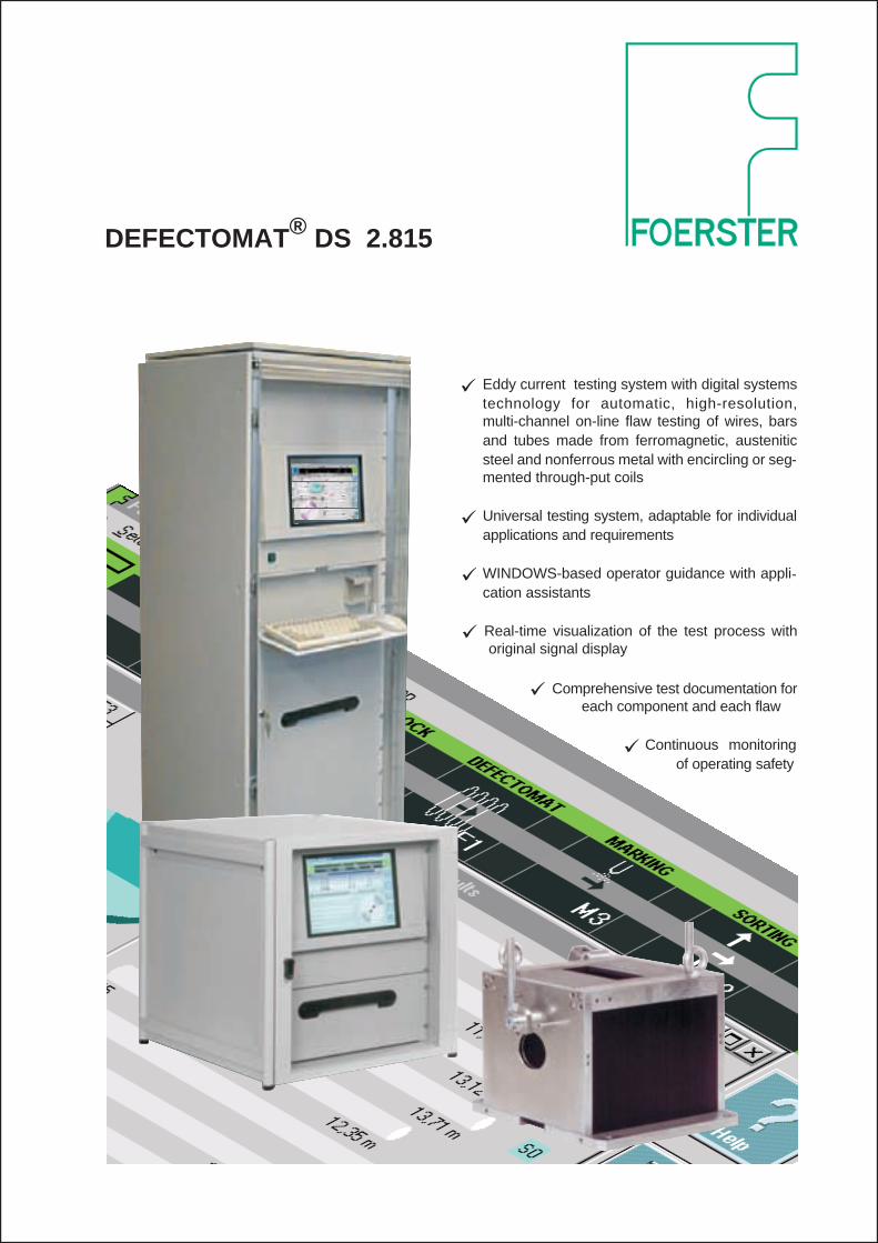
DEFECTOMAT® DS 2.815
� Eddy current testing system with digital systemstechnology for automatic, high-resolution,multi-channel on-line flaw testing of wires, barsand tubes made from ferromagnetic, austeniticsteel and nonferrous metal with encircling or seg-mented through-put coils
� Universal testing system, adaptable for individualapplications and requirements
� WINDOWS-based operator guidance with appli-cation assistants
� Real-time visualization of the test process withoriginal signal display
� Comprehensive test documentation foreach component and each flaw
� Continuous monitoringof operating safety

Features
� The new FOERSTERnet enables free access to theDEFECTOMAT DS by any number of computers
� An Ethernet interface and TCP/IP protocol enableunrestricted network integration in existing produc-tion and quality systems
� The operating software is based on WINDOWS NTand provides TCP/IP interfaces to other WIN-DOWS programs
� Simplified device adjustment based on materialand test line data
� Tested adjustment sets can be stored on the harddisk or centrally in the network
� Work instructions for the operator can be definedwith the adjustment set
� Comprehensive adjustment and function tests withmulti-channel synchronous signal display
� Continuous process control with display and moni-toring of the noise level response
� The specified test report in accordance withEN12084 can be adapted to meet cus-tomer-specific requirements
� The test results are saved in a database. Additionalevaluations can be implemented easily using stan-dard software, e.g. MS ACCESS
� Sensitivity adjustment can be automated with testflaw or noise level as reference parameters
� Operator interface protected against unauthorizedaccess by an access code
� Dialogue language of the operator interface can beextended by loadable translation files
� Context-sensitive online help with additionallyloadable languages
Application
� Eddy-current testing of ferrous, austenite andnonferrous round stock (wires, bars and tubes)for surface flaws (longitudinal flaws) with encir-cling coils in accordance with DIN 54140
� Testing of profile material (e.g. hexagon bars)
� Replaces leak test for pipes
� Typically with a fixed coil which the test piece ismoved through or passed by with a synchronoussignal display
� Used typically to evaluate the differential coil sig-nal for highly sensitive flaw testing but can also beused as a test channel for absolute coil testing todetect phase-characteristic material properties ata freely selectable frequency, e.g. to detectcoarse material mix
� Locat ion of s lowly changing mater ia linhomogeneities or inhomogeneities that havebeen present for a long time, typically of slit tubeswith an absolute channel
� Single-channel or multi-channel design
� Multi-channel design for testing with several sen-sors in series in a test line
� Single or dual frequency operation
� Connectable sensor systems: all usual coil types(through-put, segment and scanning coils)
� Material diameter according to sensor system:� M40/90/170 1 to 40/90/170 mm� H40/90/ 1 to 44/100 mm� P12/40 0.3 to 15/44 mm� S(LSP/LSM) 10 to 500 mm
� Test result logging� Event-related with details of each individual
flaw or optionally� statistics logging of flaw densities, e.g. in the
case of wire testing� all result information is referenced to the test
piece and the test request
2 2.815 - 99/12
Typical applications
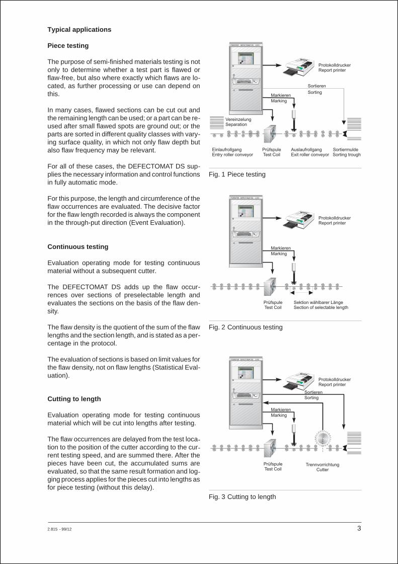
Piece testing
The purpose of semi-finished materials testing is notonly to determine whether a test part is flawed orflaw-free, but also where exactly which flaws are lo-cated, as further processing or use can depend onthis.
In many cases, flawed sections can be cut out andthe remaining length can be used; or a part can be re-used after small flawed spots are ground out; or theparts are sorted in different quality classes with vary-ing surface quality, in which not only flaw depth butalso flaw frequency may be relevant.
For all of these cases, the DEFECTOMAT DS sup-plies the necessary information and control functionsin fully automatic mode.
For this purpose, the length and circumference of theflaw occurrences are evaluated. The decisive factorfor the flaw length recorded is always the componentin the through-put direction (Event Evaluation).
Continuous testing
Evaluation operating mode for testing continuousmaterial without a subsequent cutter.
The DEFECTOMAT DS adds up the flaw occur-rences over sections of preselectable length andevaluates the sections on the basis of the flaw den-sity.
The flaw density is the quotient of the sum of the flawlengths and the section length, and is stated as a per-centage in the protocol.
The evaluation of sections is based on limit values forthe flaw density, not on flaw lengths (Statistical Eval-uation).
Cutting to length
Evaluation operating mode for testing continuousmaterial which will be cut into lengths after testing.
The flaw occurrences are delayed from the test loca-tion to the position of the cutter according to the cur-rent testing speed, and are summed there. After thepieces have been cut, the accumulated sums areevaluated, so that the same result formation and log-ging process applies for the pieces cut into lengths asfor piece testing (without this delay).
2.815 - 99/12 3
Markieren
Marking
ProtokolldruckerReport printer
FOERSTER DEFECTOMAT DS 2.815
PrüfspuleTest Coil
Sortieren
Sorting
EinlaufrollgangEntry roller conveyor
Auslaufrollgang SortiermuldeExit roller conveyor Sorting trough
VereinzelungSeparation
Fig. 1 Piece testing
Markieren
Marking
ProtokolldruckerReport printer
FOERSTER DEFECTOMAT DS 2.815
PrüfspuleTest Coil
Sektion wählbarer LängeSection of selectable length
Fig. 2 Continuous testing
Markieren
Marking
ProtokolldruckerReport printer
FOERSTER DEFECTOMAT DS 2.815
PrüfspuleTest Coil
Sortieren
Sorting
TrennvorrichtungCutter
Fig. 3 Cutting to length
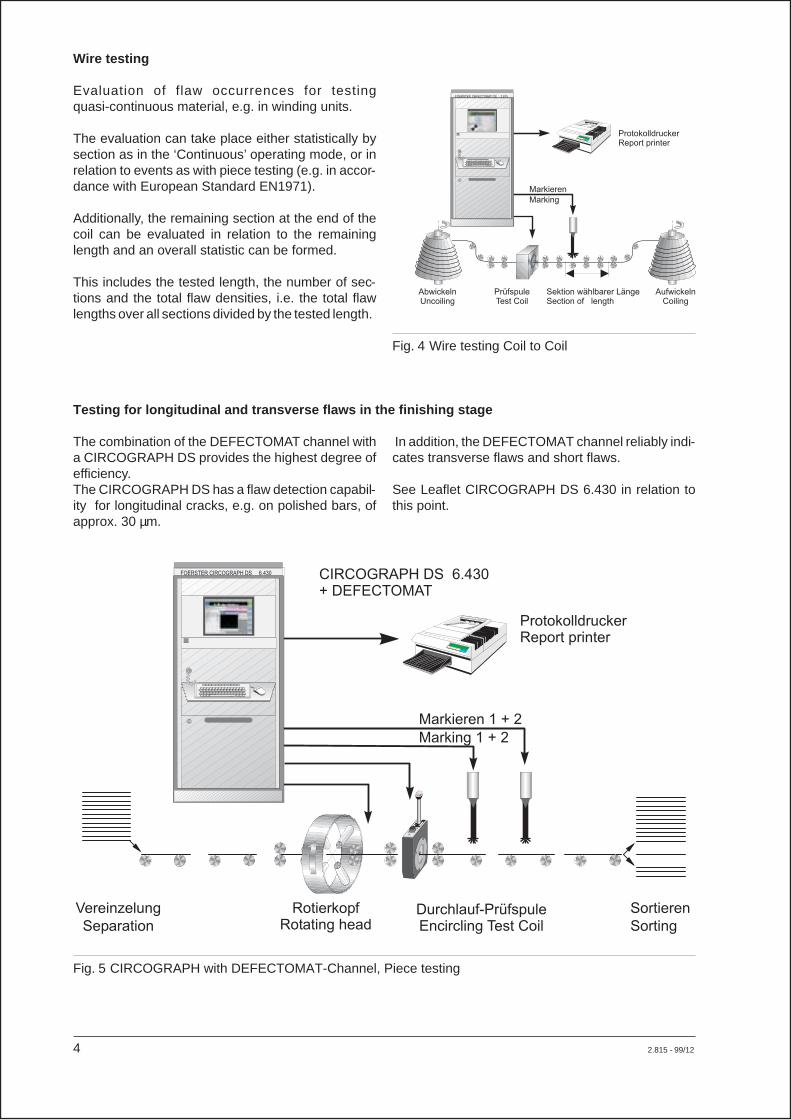
Wire testing
Evaluation of flaw occurrences for testingquasi-continuous material, e.g. in winding units.
The evaluation can take place either statistically bysection as in the ‘Continuous’ operating mode, or inrelation to events as with piece testing (e.g. in accor-dance with European Standard EN1971).
Additionally, the remaining section at the end of thecoil can be evaluated in relation to the remaininglength and an overall statistic can be formed.
This includes the tested length, the number of sec-tions and the total flaw densities, i.e. the total flawlengths over all sections divided by the tested length.
Testing for longitudinal and transverse flaws in the finishing stage
The combination of the DEFECTOMAT channel witha CIRCOGRAPH DS provides the highest degree ofefficiency.The CIRCOGRAPH DS has a flaw detection capabil-ity for longitudinal cracks, e.g. on polished bars, ofapprox. 30 µm.
In addition, the DEFECTOMAT channel reliably indi-cates transverse flaws and short flaws.
See Leaflet CIRCOGRAPH DS 6.430 in relation tothis point.
4 2.815 - 99/12
Markieren
Marking
ProtokolldruckerReport printer
FOERSTER DEFECTOMAT DS 2.815
PrüfspuleTest Coil
Sektion wählbarer LängeSection of length
AbwickelnUncoiling
AufwickelnCoiling
Fig. 4 Wire testing Coil to Coil
ProtokolldruckerReport printer
FOERSTER CIRCOGRAPH DS 6.430 CIRCOGRAPH DS 6.430+ DEFECTOMAT
Markieren 1 + 2
Marking 1 + 2
RotierkopfRotating head
Sortieren
Sorting
Vereinzelung
SeparationDurchlauf-PrüfspuleEncircling Test Coil
Fig. 5 CIRCOGRAPH with DEFECTOMAT-Channel, Piece testing
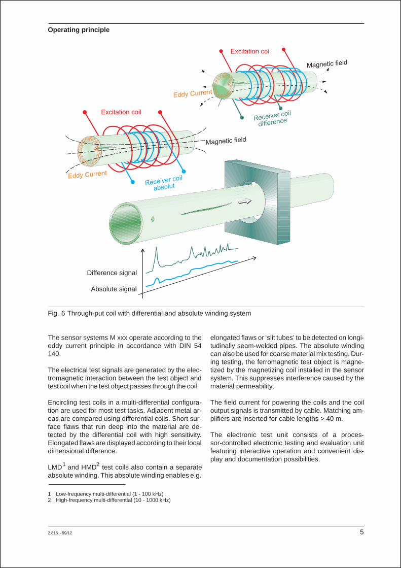
Operating principle
The sensor systems M xxx operate according to theeddy current principle in accordance with DIN 54140.
The electrical test signals are generated by the elec-tromagnetic interaction between the test object andtest coil when the test object passes through the coil.
Encircling test coils in a multi-differential configura-tion are used for most test tasks. Adjacent metal ar-eas are compared using differential coils. Short sur-face flaws that run deep into the material are de-tected by the differential coil with high sensitivity.Elongated flaws are displayed according to their localdimensional difference.
LMD1 and HMD2 test coils also contain a separateabsolute winding. This absolute winding enables e.g.
elongated flaws or ‘slit tubes’ to be detected on longi-tudinally seam-welded pipes. The absolute windingcan also be used for coarse material mix testing. Dur-ing testing, the ferromagnetic test object is magne-tized by the magnetizing coil installed in the sensorsystem. This suppresses interference caused by thematerial permeability.
The field current for powering the coils and the coiloutput signals is transmitted by cable. Matching am-plifiers are inserted for cable lengths > 40 m.
The electronic test unit consists of a proces-sor-controlled electronic testing and evaluation unitfeaturing interactive operation and convenient dis-play and documentation possibilities.
2.815 - 99/12 5
Excitation coil
Excitation coi
Magnetic field
Magnetic field
Eddy Current
Eddy Current
Receiver coil
absolut
Receiver coil
difference
Fig. 6 Through-put coil with differential and absolute winding system
Difference signal
Absolute signal
1 Low-frequency multi-differential (1 - 100 kHz)2 High-frequency multi-differential (10 - 1000 kHz)
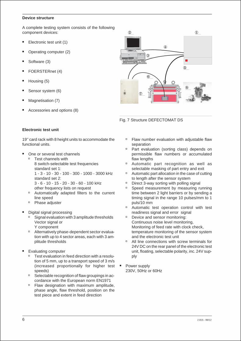
Device structure
A complete testing system consists of the followingcomponent devices:
� Electronic test unit (1)
� Operating computer (2)
� Software (3)
� FOERSTERnet (4)
� Housing (5)
� Sensor system (6)
� Magnetisation (7)
� Accessories and options (8)
Electronic test unit
19’’ card rack with 8 height units to accommodate thefunctional units.
� One or several test channels� Test channels with
8 switch-selectable test frequenciesstandard set 1:1 - 3 - 10 - 30 - 100 - 300 - 1000 - 3000 kHzstandard set 2:3 - 6 - 10 - 15 - 20 - 30 - 60 - 100 kHzother frequency lists on request
� Automatically adapted filters to the currentline speed
� Phase adjuster
� Digital signal processing� Signal evaluation with 3 amplitude thresholds
Vector signal orY component
� Alternatively phase-dependent sector evalua-tion with up to 4 sector areas, each with 3 am-plitude thresholds
� Evaluating computer� Test evaluation in feed direction with a resolu-
tion of 5 mm, up to a transport speed of 3 m/s(increased proportionally for higher testspeeds)
� Selectable recognition of flaw groupings in ac-cordance with the European norm EN1971
� Flaw designation with maximum amplitude,phase angle, flaw threshold, position on thetest piece and extent in feed direction
� Flaw number evaluation with adjustable flawseparation
� Part evaluation (sorting class) depends onpermissible flaw numbers or accumulatedflaw lengths
� Automatic part recognition as well asselectable masking of part entry and exit
� Automatic part allocation in the case of cuttingto length after the sensor system
� Direct 3-way sorting with polling signal� Speed measurement by measuring running
time between 2 light barriers or by sending atiming signal in the range 10 pulses/mm to 1puls/10 mm
� Automatic test operation control with testreadiness signal and error signal
� Device and sensor monitoring:Continuous noise level monitoring,Monitoring of feed rate with clock check,temperature monitoring of the sensor systemand the electronic test unit
� All line connections with screw terminals for24V DC on the rear panel of the electronic testunit, floating, selectable polarity, inc. 24V sup-ply
� Power supply230V, 50Hz or 60Hz
6 2.815 - 99/12
C
Fig. 7 Structure DEFECTOMAT DS
�
�
�
�
�
�
�
�

Operating computer
PC with WINDOWS NT operating system, Ethernetplug-in card, operating software installed and opera-tional.
� Integrated PCDisplay and operation in cabinet/housing� Powerful Pentium computer, all operating ele-
ments located in cabinet/housing� TFT tilting colour display� Hinged keyboard� Touch screen operation:
All mouse functions are triggered by touchingthe screen directly with fingertips or a pen
� Standard mouse parallel to the touch screen
� Built-in PCMonitor and keyboard separate� Powerful Pentium computer installed in cabi-
net/housing� 17" monitor� Industrial keyboard and mouse separate for
operation on a desk
� Stand alone PCInstallation on a desk next to the electronic testingunit or as an additional computer for additionaloperating stations� Powerful Pentium computer in the desktop
housing� 17" monitor� Industrial keyboard and mouse
Software
� Base software
� Operating software on WINDOWS NT for oneoperator terminal
� Guided device adjustment
� Adjustments can be saved
� Automatic adjustment procedures
� Original signal display
� Test result display and logging in a database
� Automatic administration of the database sizeto prevent hard disk overflow (holds the last100,000 pieces)
� Positionally accurate flaw marking
� Direct 3-way sorting
2.815 - 99/12 7
Fig. 8 Dialogue screen Fig. 9 Prompted operation
Channel 2New adjustmentDEFECTOMAT
Channel 1New adjustmentDEFECTOMAT
Channel nNew adjustmentDEFECTOMAT
Start adjustment
Allocation Rights
Assistant Installation
Start Setup
Assistant Setup
Adapt Setup
Load Setup
Start New Report
� Result investigation (optional)
� All test results are stored in an open database
� Grafical research mode using the stored re-sults with every part and every flaw displayed
� Printout of the stored results in every level ofdetail
� Copies of test request result into a MS Accessdatabase for saving purpose or for additionalevaluation
� With FOERSTERnet option possible fromevery PC in the network
� Tail marking (optional)
� Control of a maximum of 3 marking guns tomark the tails of the test pieces according tothe sorting result, independent of and in addi-tion to the standard positionally accurate flawmarking
� Selectable marking length and position mea-sured from the end of the test piece
� Compensation of the response delay
� Possible via the same marking guns in combi-nation with flaw marking
� Report design (optional)
� The design of test reports can be chosenfreely
� All test results, adjustment data and constanttexts can be used
� Type, size and format can be selected freely
� Log templates can be saved and used tomake a log printout at any time
FOERSTERnet
� Operation of one electronic test unit at several PCor access to several electronic test units at onePC using Ethernet connection (optional)
� Each operator terminal has fully functional ac-cess, can be configured and operated independ-ent of the other operator terminals
� Setting mode can be delegated to every PC in thenetwork
� Connection to any TCP/IP-capable network (e.g.Internet) via gateway
8 2.815 - 99/12
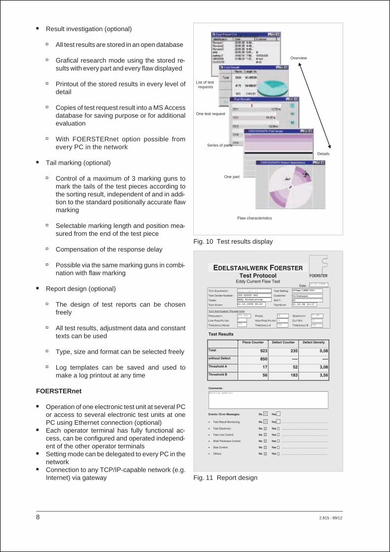
Fig. 10 Test results display
Hierarchical structure
List of testrequests
One test request
Series of parts
One part
Flaw characteristics
Overview
Details
DEFECTOMAT DS
Fig. 11 Report design
� Software interface (optional)� Call-up of operating functions from other WIN-
DOWS applications via TCP commands� All setting parameters can be read individually
or in groups and can be written individually
� Control of the internal setting archive throughremote call-ups
� Notification of new test results in the result da-tabase for synchronization of the result transfer
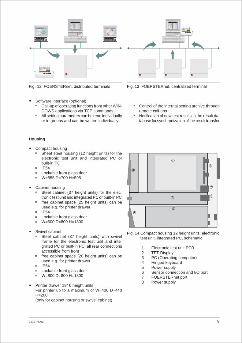
Housing
� Compact housing� Sheet steel housing (12 height units) for the
electronic test unit and integrated PC orbuilt-in PC
� IP54� Lockable front glass door� W=555 D=700 H=595
� Cabinet housing� Steel cabinet (37 height units) for the elec-
tronic test unit and integrated PC or built-in PC� free cabinet space (25 height units) can be
used e.g. for printer drawer� IP54� Lockable front glass door� W=600 D=800 H=1800
� Swivel cabinet� Steel cabinet (37 height units) with swivel
frame for the electronic test unit and inte-grated PC or built-in PC, all rear connectionsaccessible from front
� free cabinet space (20 height units) can beused e.g. for printer drawer
� IP54� Lockable front glass door� W=800 D=800 H=1800
� Printer drawer 19“ 6 height unitsFor printer up to a maximum of W=400 D=440H=260(only for cabinet housing or swivel cabinet)
2.815 - 99/12 9
Fig. 12 FOERSTERnet, distributed terminals Fig. 13 FOERSTERnet, centralized terminal
Fig. 14 Compact housing 12 height units, electronictest unit, integrated PC, schematic
1 Electronic test unit PCB2 TFT-Display3 PC (Operating computer)4 Hinged keyboard5 Power supply6 Sensor connection and I/O port7 FOERSTERnet port8 Power supply
�
��
�
�
�
�
�
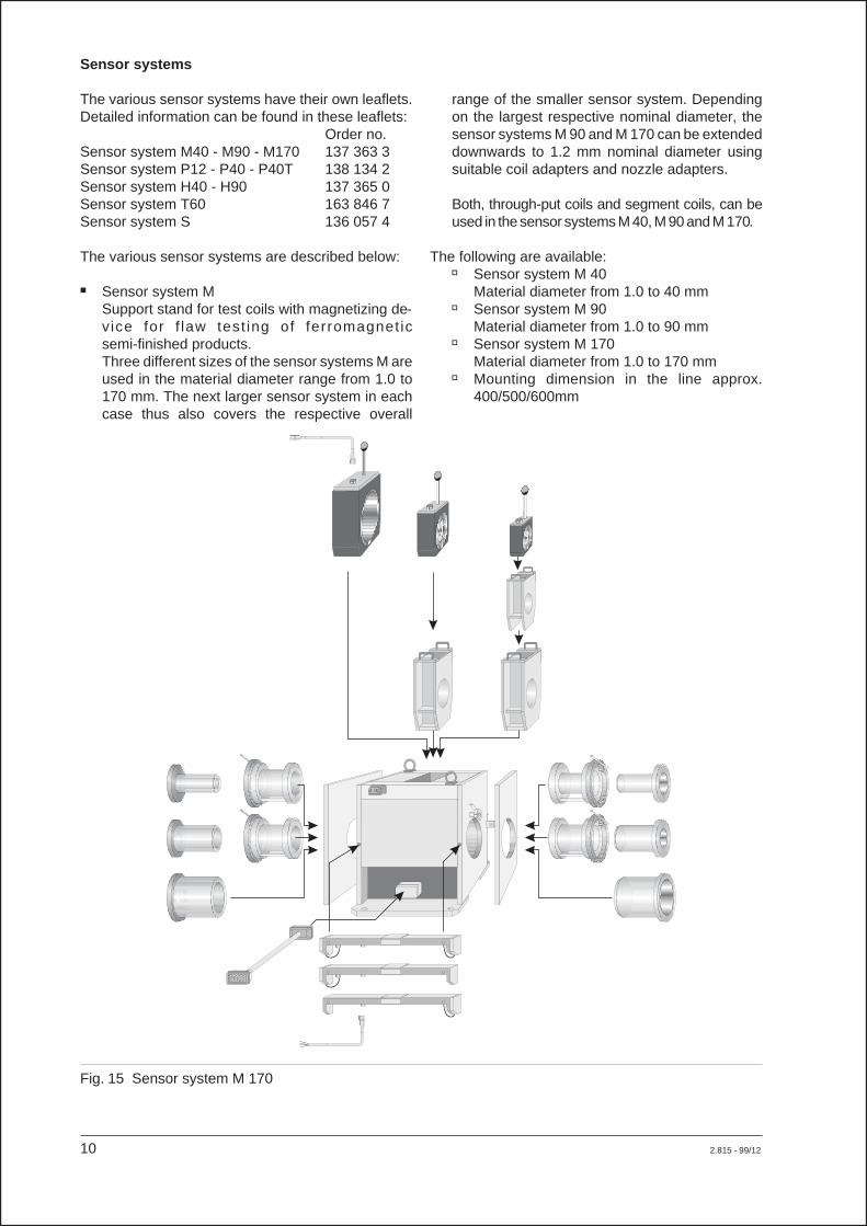
Sensor systems
The various sensor systems have their own leaflets.Detailed information can be found in these leaflets:
Order no.Sensor system M40 - M90 - M170 137 363 3Sensor system P12 - P40 - P40T 138 134 2Sensor system H40 - H90 137 365 0Sensor system T60 163 846 7Sensor system S 136 057 4
The various sensor systems are described below:
� Sensor system MSupport stand for test coils with magnetizing de-vice for f law test ing of ferromagnet icsemi-finished products.Three different sizes of the sensor systems M areused in the material diameter range from 1.0 to170 mm. The next larger sensor system in eachcase thus also covers the respective overall
range of the smaller sensor system. Dependingon the largest respective nominal diameter, thesensor systems M 90 and M 170 can be extendeddownwards to 1.2 mm nominal diameter usingsuitable coil adapters and nozzle adapters.
Both, through-put coils and segment coils, can beused in the sensor systems M 40, M 90 and M 170.
The following are available:� Sensor system M 40
Material diameter from 1.0 to 40 mm� Sensor system M 90
Material diameter from 1.0 to 90 mm� Sensor system M 170
Material diameter from 1.0 to 170 mm� Mounting dimension in the line approx.
400/500/600mm
10 2.815 - 99/12
Fig. 15 Sensor system M 170
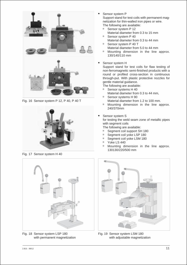
� Sensor system PSupport stand for test coils with permanent mag-netization for thin-walled iron pipes or wire.The following are available:� Sensor system P 12
Material diameter from 0.3 to 15 mm� Sensor system P 40
Material diameter from 0.3 to 44 mm� Sensor system P 40 T
Material diameter from 5.0 to 44 mm� Mounting dimension in the line approx.
130/140/110 mm
� Sensor system HSupport stand for test coils for flaw testing ofnon-ferromagnetic semi-finished products with around or profiled cross-section in continuousthrough-put. With plastic protective nozzles forgentle material guidance.The following are available:� Sensor systems H 40
Material diameter from 0.3 to 44 mm,� Sensor systems H 90
Material diameter from 1.2 to 100 mm.� Mounting dimension in the line approx.
240/370mm
� Sensor system Sfor testing the weld seam zone of metallic pipeswith segment coilsThe following are available:� Segment coil support SH 180� Segment coil yoke LSP 180� Segment coil yoke LSM 180� Yoke LS 440� Mounting dimension in the line approx.
130130/220/500 mm
2.815 - 99/12 11
Fig. 16 Sensor system P 12, P 40, P 40 T
Fig. 17 Sensor system H 40
Fig. 18 Sensor system LSP 180with permanent magnetization
Fig. 19 Sensor system LSM 180with adjustable magnetization

Magnetization power supply
Selectable current strength, remote controlled by theelectronic test unit.Installed in housing for wall mounting
Accessories and options
� Light barrierfor measuring the transport speed for each testparttransport speed range from 0.005m/s to 200m/s
� Motion transducerIncremental sensor for determining the transportspeed using a running wheel placed on the testpiece surfaceRunning wheel diameter 160mm1 pulse per mmRecommended for varying transport speed (ac-celerated parts)Up to a maximum of 3m/s
� Holder for motion transducerSupport for motion transducer with steplessheight adjustment over 200mm
� Lifter for motion transducer with standPneumatic-electric positioning and lifting of themotion transducer onto the test pieceControl signal 24V DC from the feeding conveyorcontrol (from the customer)
� Colour marking unit 1.176.11To mark the flaw spots on the material, see Leaf-let (149 593 3)� Connection to electronic test unit� Single-channel, no distinction between differ-
ent types of flaws� Two-channel, for distinction between different
flaws according to colour
� Demagnetization EMAG M 2.980see Leaflet (159 783 3)
� Laser printer with single sheet feeder
� Voltage adaptationto local power supply� All electronic components are designed for
230V, all power components for 3 x 400V50/60Hz with ground conductor
� Adaptation by means of an isolating trans-former for deviating supply voltages,e.g. 3 x 200V, 3 x 440V, 3 x 500V
� Suppression of mains interferencefor 3 x 400V
� Maximum power consumption 7.5kW� Fitted in motor control housing (for MOC E
separate installation)
� Cooling device for cabinet housing or swivelcabinet� With ambient temperature of > 40 to 50EC� With high level of air pollution from dust and
scale� Mounting on the rear door of the cabinet hous-
ing or swivel cabinet� W=320 D=110 H=600
![Kku ds fy, izos'k] fodkl ds fy, izLFkku - MGIMT](https://img.dokumen.tips/doc/110x75/634c9c98ae9997954c039497/kku-ds-fy-izosk-fodkl-ds-fy-izlfkku-mgimt.jpg)


