Embed Size (px)
Citation preview
DCCUMENT RESUME
ED 274 318 IR 012 295
AUTHOR Easter, Amanda Williams; And OthersTITLE Instructor Support Feature Guidelines. Final
Report.INSTITUTION LOGICON, Inc., San Diego, Calif.SPONS AGENCY Air Force Human Resources Lab., Brooks AFB, Texas.REPORT NO AFHRL-TR-85-57(II)PUB DATE May 86CONTRACT F33615-84-C-0054NOTE 197p.; For the first volume of this report, see IR
012 294.PUB TYPE Reports - Descriptive (141) -- Gvides - Non-Classroom
Use (055)
EDRS PRICE MF01/PC08 Plus Postage.DESCRIPTORS *Computer Assisted Instruction; *Computer Managed
Instruction; Computer Simulation; Design; *FlightTraining; Guidelines; *Instructional Systems; ManMachine Systems; Research and Development; SystemsDevelopment; Teacher Role
IDENTIFIERS *Aircrew Training Devices; *Flight Simulation
ABSTRACTThis report is the second of two volumes which
document the research and analysis project that resulted in thedevelopment of Instructor Support Feature (ISF) Guidelines. Theseguidelines are intended to aid operational users from the Air Forcemajor commands, Simulator Systems Program Office procurementpersonnel, and contractors in the development and procurement ofinstructor support systems for future aircrew training devices(ATDs). The first of four sections in this volume introduces thecontents and purpose of these guidelines and provides an overview oftheir background and development. The second section explains theconcept of the Instructor Support System (ISS) and the functions itserves, while the third presents a systematic approach for theselection of instructor support features. Intended for use duringsystem development, the fourth section presents and discusses aformat for providing the operational information needed to implementthe instructor support system features selected. Also included are: alist of six Primary references; a glossary of terms; a list ofabbreviations and acronyms; a subject index to the report; and sevenappendices. Appended materials include a list of documents pertainin4to specific aircrew training devices; a four-page bibliography; asample specification illustrating the use of these guidelines; a listof training sites visited with dates; a task commonality analysis;and samples of two basic task module types--flight and procedural.(DJR)
***********************************************************************Reproductions supplied by EDRS are the best that can be made
from the original document.******************************************************-*****************
AFHRL-TR-85-57(II)
U.S. DEPARTMENT Of EDUCATIONOffice of Educational Research and ImprovementEDUCATIONAL RESOURCES INFORMATION
CENTER (ERIC)This document has been reproduced asreceived trOm the person Of OfganilaflOnOfigMliting
0 Minor changes have been made to improvereproduction quality.
Points of view Or opinions statedin MIS docu-me nt do not necessarily represent officialOEM positiOn or poky.
AIR FORCE tA INSTRUCTOR SUPPORT FEATURE GUIDELINES
Amanda Williams EasterJohn T. KrywayWayne R. OlsonSusan M. PetersGail K. Slemon
Logicon, Inc.
4010 Sorrento Valloy Boulevard
San Diego, California 92138-5158
Richard W. Obermayer
Vreuls Research Corporation
68 Long Court, Suite E
Thousand Oaks, California 91360-6084
OPERATIONS TRAINING DIVISIONWilliams Air Force Base, Arizona 85240-6457
May 1986Final Report for Period October 1984 - September 1985
Approved for public release; distribution is unlimited.
S LABORATORY
AIR FORCE SYSTEMS COMMANDBROOKS AIR FORcE BASE, TEXAS 78235-5601
BEST COPY AVAILABLE2
NOTICE
When Government drawings, specifications, or other data are used for any
purpose other than in connection with a definitely Government-related
procurement, the United States Government incurs no responsibility or any
obligation whatsoever. The fact that the Government may have formulated or
in any way supplied the said drawings, specifications, or other data, is
not to be regarded bY implication, or otherwise in any manner construed, as
licensing the holder, or any other person or corporation; or as conveying
any rights or permission to manufacture, use, or sell any patented
invention that may in any way be related thereto.
The Public Affairs Office has reviewed this report, and it is releasable to
the National Technical Information Service, where it will be available to
the general public, including foreign nationals.
This report has been reviewed and is approved for publication.
WAYNE WAAG
Contract Monitor
MILTON E. WOOD, Technical Director
Operations Training Division
DENNIS W. JARVI, Colonel, USAF
Commander
UnclassifiedSECURITY CLASSIFICATION OF THIS PAGE
REPORT DOCUMENTATION PAGEIa. REPORT SECURITY CLASSIFICATION
Unclassifiedlb. RESTRICTIVE MARKINGS
2a. SECURITY CLASSIFICATION AUTHORITY 3 . DISTRIBUTION / AVAILABILITY OF REPORT
Approved for public release; distribution is
unlimited.2b1 DECLASSIFICATION /DOWNGRADING SCHEDULE
4. PERFORMING ORGANIZATION REPORT NUMBER(S) S. MONITORING ORGANIZATION REPORT NUMBER(S)AFHRL-TR-85-57(II)
6a. NAME OF PERFORMING ORGANIZATION
Logicon, Inc.
. . .
6b. OFFICE SYMBOL(If applicable)
7a. NAME OF MONITORING ORGANIZATIONOperations Training Division
6c. ADDRESS (City, State, and ZIP Code)
4010 Sorrento Valley BoulevardP.O. Box 85158
San Diego, California 92138-5158
7b. ADDRESS (City, State, and ZIP Code)Air Force Human Resources Laboratory
Williams Air Force Base, Arizona 85240-6457
8a. NAME OF FUNDING/SPONSORINGORGANIZATIONAir Force Human Resources Laboratory
8b. OFFICE SYMBOL(If applicable)
HQ AFHRL
9 PROCUREMENT INSTRUNIENT IDENTIFICATION NUMBER
F33615-84-C-0054
8c. ADDRESS (City, State,and ZIPCode)
Brooks Air Force Base, Texas 78235-5601
10 SOURCE OF FUNDING NUMBER
PROGRAMELEMENT NO.
63751F
PROJECTNO.
2359
TASKNO.
01
WORK UNITACCESSION NO.
06
11. TITLE (Include Security Classification)Instructor Support Feature Guidelines
12. PERSONAL AUTHOR(S)
Easter, Amanda W.; KrywAy, John T.; Olson, WAyne R.; Peters, Susan M.; Slemon, Gail K.; Obermayer, Richard W.13a. TYPE OF REPORT
Final13b. TIME COVERED
FROM Oct 84 TO Se. 8514. DATE OF REPORT (Year, Month, Day)
MAy 19861S. PAGE COUNT
I192
16. SUPPLEMENTARY NOTATION
17. COSATI CODES 18. SUBJECT TERMS (Continue on reverse if necessary and identify by block number)acquisition flight simulator
advanced instructional features flight training simulator designaircrew training devices (Continued)
FIELD GROUP SUB-GROUP05 08
05 09
19. ABSTRACT (Continue on reverse if necessary and identify by block number)
This report documents the development of specification ju:delines for aircrew training device (ATD)Instructor Support Feature (ISF) requirements. Thirteen advanced instructional systems and ATDs provided datafor identification and definition of ISFs. These operational definitions and a recommended specificationprocedure were written to aid operational users from the major commands, SimSPO procurement personnel, andccntractors. One conclusion reached as a result of the specification procedure development is that bothstudent training and instructor requirements be analyzed comprehensively. Other stucky results point to theneed for instructor training in the use of ISFs. The data, methods, and anablis used to reach theseconclusions.and others are reported. Volume I documents the research and development effort and presentsmethodology, results, conclusions, and recommendations. Volume II contains the ISF Guidelines. The ISFGuidelines is a "living" document. The current version of the Guidelines can be obtained from the SimulatorSystems Program Office, ASD/YWEE, Wright-Patterson AFB, OH.
20. DISTRIBUTION /AVAILABILITY OF ABSTRACTMUNCLASSIFIED/UNLIMITED SAME AS RPT. DTIC USERS
21. ABSTRACT SECURITY CLASSIFICATION
Va. NAME OF.RESPONSIBLE INDIVIDUAL-Nancy A. Perrido, Chief, STINFO Office
..........,
22b. TELEPHONE (Include Area Code)(512) 536-3877
r...............
22c. OFFICE SYMBOLAFHRL/TSR
DD FORM 1473, 84 MAR 83 APR edition may be used until exhausted.All other editions are obsolete. SECURITY CLASSIFICATION OF THIS PAGE
Unclassified

18. (Concluded)
instructional support features
instructor/operator station
instructor support features
Instructor Support System
performance measurement
simulator training
task module
5
SUMMARY
This report documents the research and analysis project that resulted inthe development of Instructor Support Feature (ISF) Guidelines. Theguidelines are intended to aid operational users from the Air Force majorcommands, Simulator Systems Program Office procurement personnel, andcontractors in the development and procurement of instructor support systemsfor future aircrew training devices (ATDs). During the 12-month technicaleffort, the Guidelines content and format were defined, data were collectedand analyzed for inclusion within the Guidelines, and the Guidelines documentwas written. Thirteen advanced instructional systems and ATDs provided datafor identification and definition of ISF requirements. Volume I documents theresearch and development effort and presents methodology, results, conclu-sions, and recommendations. Volume II contains the ISF Guidelines. The ISFGuidelines is a "living" document. The current version of the Guidelines canbe obtained from the Simulator Systems Program Office, ASD/YWEE,Wright-Patterson APB, OH.
6
PREFACE
This document is the final report of the Performance Measurement System(PMS) Guidelines for Aircrew Training Devices (ATDs) project conducted underContract Number F33615-84-C-0054, sponsored by the Air Force Human ResourcesLaboratory (AFHRL). The project focused on the development of the InstructorSupport Feature Guidelines to aid in the specification of requirements for ATDacquisitions.
Drs. Wayne Waag and Gary Thomas of AFHRL/OT provided technical directionduring the course of the study. Mr. Craig McLean and his staff at the SimulatorSystems Program Office made valuabe contributions to the contents of theInstructor Support Feature Guidelines.
The authors wish to expresri cb,Iir gratitude to the many operationalpersonnel at the training sites visited for their time and assistance. Theirinput greatly added to the operational validity of this report.
ii
TABLE OF CONTENTS
Section litla EIS1
OVERVIEW 1
II INSTRUCTOR SUPPORT FEATURES 7Tutorial 13Briefing Utilities 15Scenario Control 19Initial Conditions 25Real-Time Simulation Variables Contrca 27Malfunction Control 29Reposition 33IOS Display Control and Formatting 37Procedures Monitoring 41Freeze 45Simulator Record/Replay 49Automated Simulator Demonstration 53Automated Performance Measurement 57Hardcopy/Printout 61Remote Graphics Replay 65Data Storage and Analysis 67
III SELECTING INSTRUCTOR SUPPORT FEATURES 71
IV PROVIDING OPERATIONAL INFORMATION 85
PRIMARY REFERENCES 97
GLOSSARY OF TERMS 99
ABBREVIATIONS AND ACRONYMS 101
ISF INDEX103
APPENDLX A Aircrew Training Documentation A-1
APPENDLX B Bibliography 8-1
APPENDIX C Sample Specification C-1
APPENDIX D Training Sites Visited D-1
APPENDIX E Task Commonality Analysis E-1
APPENDIX F ISS Implementation Considerations F-1
APPENDIX G Sample Task Modules G-1
iii

LIST OF TABLES
Number Title Page
II-1 Scenario Table 23
IV-1 Flight Task Module Format 93
IV-2 Normal Procedures Task Module Format 95
iv

SECTION I
OVERVIEW
1
1 0
..11011%111.
II
. 1.1011....
SS 7111111. 4.i....01111141111S,,s,.."
s Ill Os Will.. lis . .....
2 11
SECTION IOVERVIEW
Introduction Aircrew training devices may be conceptualized as consisting oftwo main components: the simulation system and the instructionalsystem. Within the simulation component, the major issue isfidelity. In other words, to what extent should the trainingsituation be a faithful reproduction of the aircraft and theflight environment? To date, the majority of R & D effortshave focused on this component.
Purpose
The other component, the instructional system, is what makesthe simulator a training device. It consists of thosecapabilities specifically designed to enhance the trainingprocess by providing instructor support features (ISFs). Thepurpose of these features is to increase the instructor'sefficiency and effectiveness by reducing the workload involvedin conducting the training exercise. Thus through theimplementation of a set of such features, the instructor isfreed to devote more of his attention to the training function.
However, attempts to develop and provide a comprehensiveinstructional system have sometimes created more problems forthe instructor than solutions. Attempts to build ATDs withfeatures to support every possible aspect of instruction haveoften resulted in instructional systems, includinginstructor/operator stations (IOSs), which are difficult ifnot impossible to understand and use. Such systems often havenot been developed according to user specified needs. Theseattempts have been overenthusiastic and premature.
The instructional system has more recently been the focus ofseveral development efforts. In particular, advanced systemshave been developed in which traditional instructor supportfeatures (ISFs) have been enhanced and new features have beenadded. These efforts are based on user defined needs, lessonslearned from existing instructional systems, and state-of-the-arttraining technology. The resulting systems, with expanded andenhanced ISFs, are referred to as Instructor Support Systems(ISSs).
The purpose of the "ISF Guidelines" is to effectively transitionlessons learned from the advanced systems into the operationaltraining environment. It is anticipated that through theseguidelines effective communication among operational users,procurement personnel, and system developers can be established.By promoting a better understanding of what instructor supportfeatures can provide, and by providing a means to communicateoperational needs, it is hoped that these guidelines willhelp to avoid the. pitfalls of the past.
3
12
SECTION IOVERVIEW
A second major purpose of these guidelines is to emphasize theimportance of specifying instructional systems on the basis offunctionality rather than technology. The definitions andrecommendations made throughout these guidelines are based onthe functional needs of the instructor and are not made interms of the current, "state-of-the-art" technology. Hardwareand software technology is changing at an accelerating rate.Over-specification on the basis of today's technology canunnecessarily restrict tomorrow's design. Specification offunctionality and performance from a user's perspective isimperative to allow contractor latitude in providing SimSPOwith a spectrum of alternatives which will maximize theapplication of current technological advances and currentstandards.
How to use This document is organized into four sections:thisdocument I. Overview,
Instructor Support Features,
III. Selecting Instructor Support Features, and
IV. Providing Operational Information.
The document is not designed to be read from cover to cover.Rather, the sections are intended for different users atdifferent times in the ATD procurement process.
Section I The remainder of Section I introduces the contents and purpose,the background and the development of these guidelines.
Section II Section II, "Instructor Support Features:1 explains the conceptof the ISS and the functions it serves. A set of definitionsof instructor support features is provided. The informationin this section is important to those tasked with laying outinitial ISS requirements, to those tasked with developing theSystem Specification, and finally, to those involved in systemdevelopment. Intended users of Section II include Operationalpersonnel at the using comma:nd, MAJCOH personnel, SimSPOpersonnel, and finally,contracting personnel involved in systemdevelopment.
4
13
SECTION IOVERVIEW
Section III
Section IV
Section III is entitled "Selecting Instructor Support Features."It guides the reader through a procedure to analyze instructorsupport requirements. This procedure should form the basis forthe selection of instructor support features in the developmentof the specification for the ISS. Intended users of SectionIII are.those tasked with developing a Statement of Need, theSystem Specification, and ultimately the ISS.
Section IV, "Providing Operational Informatiany is intendedto be used during system development. If instructor supportfeatures are to be programmed into an ATD system, then certainspecific operational information must be provided to implementthese features. This information must be providedby prospectiveOperational Users of the ATD to ensure that ehe resulting ISSis tailored to their unique requirements. A format for providingthis information is discussed and provided.
Background In 1981 the SUulator Systems Program Office (SimSPO) of theAeronautical Systems Division (ASD) stated a need for enhancingthe instructor's capability to assess student performance inATDs. The need for improved instructional capabilities withinATDs was also clearly identified by the Defense Science Board1982 Summer Panel Study Report on Training and TrainingTechnology.
Prototype training systems have demonstrated the utility offeatures which provide the instructor with greater ability tocontrol and monitor student activity and therefore makesimulators more effective training systems. These systems havemuch to offer insofar as lessons learned during theirdevelopment, test and evaluation, and operation. A means forcapitalizing upon these lessons learned and introducing proventechnology into the operational environment was sought.Development of a set of guidelines addressing the design,development, and incorporation of instructional capabilitieswithin ATDs was the proposed solution.
Development The development of ehe guidelines took place in several steps.of the The first was the collection and review of a large number ofGuidelines documents. Documentation collected and reviewed included
training documents and syllabi from nine aircrew trainingprograms, relevant sections from recent ATD specifications, andresearch and informational literature on the use (and failureof use) of instructor support features incorporated intooperational and research based ATDs. Over 100 documentswere reviewed for the final version of the guidelines (AppendicesA and B).
5
1 4
SECTION IOVERVIEW
A series of meetings were held with SimSPO and MAJCOM personnel,including instructors and training requirements personnel,to determine ATD specification requirements. Meetings werealso held with an Operational Using Command during thedevelopment of a sample specification (Appendix C).
.
Data were also gathered during a series of data collectiontrips to operational ATD sites and prototype ISS sites (AppendixD). At least one representative site was selected for eachMAJCOM. During each site visit ATD training requirements,including aircrew training objectives , simulator characteristics ,and instructor control and informational requirements werecollected and assessed. Visits to prototype systems suppliedinformation on lessons learned in the use of instructionalfeatures. Survey results cited throughout these guidelinesrefer to the collection of this data and also to surveysreviewed during the first phase of the guidelines development.
Finally, a commonality analysis was performed to determine thetypes of tasks trained across the surveyed ATD sites and theprototype ISS systems. The results of this analysis arepresented in Appendix E.
6 15

SECTION II
INSTRUCTOR SITPORT FEATURES
7
16
8 17
SECTION IIINSTRUCTOR SUPPORT FEATURES
Introduction The purpose of the Instructor Support System (ISS) is to
transform the simulator into a more effective training device.The ISS consists of the set of instructor support features (ISFs)present in the simulator. Through the implementation of acarefully selected set of ISFs , the ISS increases theinstructor's efficiency and effectiveness by reducing theworkload and providing support in the total instructionalprocess of simulator training. This includes exercisepreparation, simulator control, performance measurement andrecording, and student performance feedback both during trainingand during debriefing. Through the presence of an ISS, theinstructor may devote more attention to providing personal,high quality, one-on-one instruction, rather than dividing histime among the student and countless other required activities.
Design to A properly designed ISS is responsive to user needs. In theUser Needs past, some attempts to design a comprehensive instructional
system have created more problems for the instructor thansolutions. Instructor Support System designs based onspecifications of a set of features to support every possibleaspect of instruction are not based on functionality. They arenot based on an analysis of the instructor's needs. Suchdesigns can result in an instructional system which is difficultto use and understand, improperly tailored to the trainingapplication, and difficult to keep concurrent with trainingrequirements,
Purpose
The goal of this document is to guide the reader through aprocess of selecting instructor support features based onfunction and required training needs. Therefore, the definitionsof features provided here emphasize function and are notintended to reference hardware, software or human factorsengineering considerations.
The first step in the proper design of an ISS is to ensure thatall personnel involved in the specification process have aclear understanding of what each feature is, and what it isnot. The purpose of this section is to present a set of clearlydefined ISFs. The definitions included here are stated inoperational terms to facilitate the decision as to when aparticular feature will properly support the required trainingfunction. In 'addition to the operational definition, the purpose,additional considerations, related features, examples, lessonslearned, and a specification oriented definition are alsoprovided in the description of each feature. This informationis provided to promote clear communication among operational
9
18
SECTION IIINSTRUCTOR SUPPORT FEATURES
personnel stating training requirements, procurement personnelinvolved in final specification definition, and contractingpersonnel involved in system development.
Organization The ISF definitions are organized according to instructorof Section II function and presented in the order they would most likely
be used by an instructor proceeding through a training exercise.This order is also used to facilitate the use of this sectionby those readers stepping through the procedure to select ISFspresented in Section III. The features are presented as follows:
Pre-Tgaining Requirements
o Instructor TrainingISF: Tutorial
o BriefingISF: Briefing Utilities
Training Reauirement§
o Control FunctionISFs: Scenario Control
Initial ConditionsReal-Time Simulation Variables ControlMalfunction ControlReposition
o Monitor FunctionISFs: IOS Display control and Formatting
Procedures Monitoring
o Instruct FunctionISFs: Freeze
Simulator Record/ReplayAutomated Simulator Demonstration
o Evaluate FunctionISFs: Automated Performance Measurement
Post-Trair&g'Requirements.
o Debrief FunctionISFs: Hardcopy/Printout
Remote Graphics Replay
o r :01'1 FunctionISF: Data Storage and Analysis
1019
SECTION IIINSTRUCTOR SUPPORT FEATURES
Formatof ISFDescriptions
The section describing each ISF contains the following:
o Definition.L Stated in functional terms.
o PurPPse and _Intended Use: Stated in operational terms.Further describes each feature. This section can also beused when justification and rationale for inclusion of afeature are desired.
Addltionl Constderat.ionsL Important additional points toconsider when including this feature. These points alsowill help to "fine tune" the feature to the current trainingapplication.
gelatedISrs; ISFs that can affect or be affected by theinclusion of the present featute.
o E)iamples_: Examples of the operational use of this feature.
o Ltssops_learned: Experiences gained (positive and negative)from the use of this feature in operational settings.Please note that readers with further lessons learnedare encouraged to forward them to SimSPO to be added tothis document. In this way the Guidelines will continueto be kept up to date on experience with ISFs in operationalapplications.
Spgciftgatjan; A definition of this feature stated inlanguage that can incorporated into a specification. Itshould be noted that this is a suggested wording. If"fine tuning" of the feature is required (e.g., as a resultof additional considerations), the ATD specification shouldbe restated to reflect ehese needs.
11
20
INSTRUCTOR SUPPORT FEATURESTutorial
Feature Tutorial
Definition This feature provides the instructor/student with self-pacedand self-administered programmed instruction on the capabilitiesand use of the flight simulator and its instructional supportfeatures.
Purpose and A problem noted in several ATD surveys is that most simulatorIntended Use instructors are not aware of all of the functions including the
instructional support features available to operate the ATD.In many cases, the full capability of a device is not beingutilized due to lack of knbwledge and understanding. This isunfortunate because system operating functions and instructionalsupport features, properly designed and implemented, cansignificantly relieve instructors of routine and non-productivetasks.
A built-in tutorial for system operation aids in the overallunderstanding and acceptance of the system for new instructorswhile providing valuable hands-on training. It also helps theintermittent user by providing on-line guidance for "refresh-er training".
If self-practice is an objective of the ATD, then this featuremay also be used by the student.
Additional Tutorial designs should take into consideration the following:Consider-ations o Hell) Eunction. A "help" function which can be readily
accessed during an exercise can provide valuable systeminformation about indtvidual capabilities of the system andtraining objective descriptions. The HELP feature isintended for the user who already has a basic knowledge ofthe system and wishes to review a specific area of the ISSduring runtime.
0 Tutori41. A complete tutorial which gives a step-by-stepintroduction to all the capabilities of the simulator can beconducted at the instructor console to provide hands-onexperience. However, it is highly desirable that thisfeature be conducted on similar equipment such as a remotebriefing/debriefing console. Using a remote console for thetutorial frees the simulator for continuing training anddoes not detract from the self-paced advantages of a tutorial.
13
21
INSTRUCTOR SUPPORT FEATURES
TutPX.Ial
o Modification and Update of Tutorial. Due to the fact thatATDs are often changed and updated, tutorial procedures shouldbe modifiable. The use of a data base common to the actualsystem (e.g., common use of the display of a procedure or agraphic depiction of a SID) would provide simulator andtutorial concurrency.
Related ISFs All instructional features should be covered by the tutorial.
Example An instructor completed his training on how to use the ATDseveral weeks ago and hasn't yet used it with a student. Sincehe is scheduled with his first student in a few days, heutilizes a remote console to obtain some refresher training.He employs the tutorial feature in a refresher mode to ensurethat he is prepared to efficiently operate ehe ATD in supportof the scheduled training period.
Lessons Help functions have been incorporated into a recently installedLearned operational system. Although not enough operational data has
been collected to provide lessons learned, the initial instructorresponse at implementation was very positive.
When instructors have been surveyed as to the potential trainingvalue of a tutorial, they have rated it very highly. Themaximum potential of ATDs Will only be attained when instruc-tors are provided with the proper training in the usage of thesimulator and its instructional features are part of the totaltraining system. A built-in system tutorial is a step in thisdirection.
ATD Specifi- The tutorial feature shall provide the instructor/student withcation a user-friendly, interacttve, self-paced and self-administered
program of instruction on the capabilities and use of theflight simulator and its instructional support features. Thetutorial feature shall include a "help" function in the form ofan easily accessible prompt. The tutorial design shall resultin step-by-step instruction and shall be provided off-line at aremote console or at the IOS. On-line instructional systemoperation shall also be provided (for the novice or infrequentuser) and be accessible to the user as required.
14 22
INSTRUCTOR SUPPORT FEATURESBriefingLUtilities
Feature
Definition
Briefing Utilities
Briefing utilities are any aids provided by an ATD which aredesigned to assist the instructor in briefing a student for anupcoming simulator session.
Purpose and The main purpose of the briefing is to prepare both the studentIntended Use and instructor for a particular exercise. This is normally
accomplished by reviewing the student's past performance, hisreadiness for the upcoming event, and a review of the trainingobjectives to be accomplished. Typical materials used arelesson guides, training program outlines, instructor guides,and student (ATD) training records. Briefings can be improvedby the inclusion of a briefing utility which will provide thosematerials mentioned. This is normally accomplished on a CRTwith both alphanumeric and graphics capabilities.
Additional If the Briefing Utility is selected, then the following addi-Consider- tional considerations should be specified.ations
o The Briefing Utility should be accessed via a separateconsole away from the IOS so aS not to interfere with anexercise which may be in progress. Providing a separateconsole will eliminate any scheduling conflicts, thus nottaking away any valuable "hands on" time. On some existingsystems, this console serves the dual purpose of briefing anddebriefing when a remote graphics capability exists.
o It is important that the method of interaction with thebriefing utility be as similar as possible to the main IOS.This will ensure inrtructor familiarity with the device. Itmust be user-friendly. For example, the briefing materialirequired to cover the training objectives for a particularATD may be very extensive. These materials must be easilyaccessed and functionally grouped in user terms or thisfeature may become cumbersome to use. The data and displaysshould be identical to realtime data wherever possible. Forexample, approaches and departures shown at a briefing stationshould look identical to corresponding IOS displays duringthe exercise.
o It is most important that briefing data be easily modifiable.Procedures and flight profiles change routinely. Briefingmaterials which cover these objectives must be up-to-date,or they are of little value. An automated means of updatingthe material should be provided.
15
23
INSTRUCTOR SUPPORT FEATURESByte tins_ utilities
o Briefing for Instructorless Training: With more sophisticatedsoftware and hardware, briefings may be presented without aninstructor. Computer-assisted interactive britfings would beespecially appropriate for simulators which allow unsuper-vised practice or when there is a need to otherwise reduceinstructor workload.
Related ISFs Scenario Co tro . Scenario Control should be related to thebriefing utility for effi.cient accessibility. By selecting aparticular scenario for review during the briefing process, theinstructor would have available the training objectives for thatparticular exercise and any other pertinent information(e.g., threat characteristics during the ingress leg of aninterdiction mission).
Examples
Automated Performance Measurement. If the ATD has an automatedperformance measurement feature, then the algorithms,measurementcriteria, and any other information relevant to this featureshould be made available via the briefing utility. This willprovide an insight as to the method of measurement and willhelp in the general understanding and user acceptance ofautomated performance measurement.
Data Storage and Analysis. If the ATD has a data storage andanalysis feature which records performance and retains thisinformation by student, the instructor should be able to
access this information by student name or number via theBriefing Utility. In this way, both the student and instructorwill be informed of the student's progress and previousperformance.
An instructor and student scheduled for a formal syllabus trainerevent would arrive at the facility in time for the briefing.They would proceed to a Briefing/Debriefing console and log onto the system. The instructor would then select the syllabusevent. The Briefing Utility would display an outline of theexercise. From here the instructor would have access to thetraining objectives, performance criteria, and any otherpertinent information. If the system had a data storageand analysis feature, he would have the option of reviewing thestudent's previous performance.
If the upcoming event were not part of a formal syllabus, theinstructor may still access the briefing utility and reviewbriefing materials by training objective and or other subjectheadings, e.g., "aircraft system descriptions.
16
24
INSTRUCTOR SUPPORT FEATURESDr_iefing Utilities
Lessons The use of prerecorded briefings has been attempted in isolatedLearned circumstances; however, surveys have revealed that instructors
believe this feature is unnecessary and prefer to brief studentsthemselves.
Briefing materials should be modified and updated reliably andefficiently as needed. This will encourage use of the briefingutility. A positive result would be to provide standardizationat the briefing level. Unfortunately, some existing deviceswith a Briefing Utility have not been updated, and therefore thepositive aspects of this feature have been lost.
ATD Specifi- Briefing utility aids shall be designed to assist the instructorcation in briefing a student for an upcoming simulator session. The
aids shall prepare both the student and instructor prior to aparticular exercise and consist of the following materials:lesson guides, training program outlines, instructor guides, andstudent training records. The aid shall serve as a briefingand debriefing utility accessed on an off-line remote graphicsconsole. The method of interaction shall be similar to themain IOS and shall be easily accessible by the instructor.Presentation materials shall be functionally grouped in userterms to ensure optimal usability and easy modifiability forfuture update.
17
INSTRUCTOR SUPPORT FEATURESSenart9 C0=21
Feature
Definition
Scenario Control
The Scenario Control feature supports the instructor bycontrolling the ATD to meet established training criteria.This feature configures and controls the ATD to accomplishspecific training objectives. The objectives are activated in apredefined order and under prespecified conditions.
Purpose and During the conduct of an exercise, instructor workload is dividedIntended Use among providing instruction in the form of explanations and
feedback to the student, monitoring and evaluating studentperformance, and controlling the simulator. The purpose ofscenario control is to relieve some of this workload by theautomation of certain ATD control inputs and by automaticallypresenting information which is appropriate to the currenttraining objective.
When training is conducted with scenario control, a properlyconstructed ISS can determine where the student is in thetraining exercise. This allows the ISS to present appropriatedisplays and graphics to the instructor at appropriate times.It also allows the ISS to automate the control of simulationvariables. For example, at the beginning of certain trainingobjectives, environmental conditions may require change.Rather than requiring instructor input at these times, the ISSmay automatically reinitialize those variables. In sum, underscenario control it is possible to automate wherever possiblethose tasks which do not directly relate ta personal instruction.
Additional _Scenaxo There are varyingConsider- levels of automation of scenario control. The level thatations should be selected will depend on the nature of the training to
be conducted on the ATD. The levels are described below:
o Fully Automated Scenario Control. Fully automated scenariocontrol is equtvalent to a totally preprogrammed missionscenario. This level of scenario control automaticallycontrols an entire exercise (e.g., cross-county navigationflight, strike mission with high and low altitude segments,etc.). To use fully automated scenario control, theinstructor must simply select a specific scenario at thebeginning of the training exercise. The ATD will beautomatically programmed for the entire exercise. All inputsusually required from the instructor during the exercise(e.g., environmental conditions, malfunctions, checklists,threat, departure and arrival facilities) enroute way points,
19
2 6
/NSTRUCTOR SUPPORT FEATURESScenario Control
display content, display options, etc.) are automaticallyprogrammed to occur when specific conditions have been met.
This type of control is supportive of a formalized trainingsyllabus, instructorless training, and trainer eventsrequiring rigid standardization requirements.
o Semi-Automated Scenario Control. Semi-automated scenariocontrol is designed to provide the instructor with someflexibility during the exercise. A specific scenario is
selected in preparation for the tratning exercise identicallyto the fully automated mode. However, inputs during theexercise may be selectable (e.g., activating a malfunctionfrom a pre-selected list), they may be modified or overridden(e.g., removing a SAM threat from a battle scenario), or
messages may-be presented informing the instructor that inputsare about to be made and confirmation is requested prior toactivation (e.g., reducing visibility to field minimums).
This type of control is supportive of continuation trainingwhere the exercise requires "real-tims" tailoring to conformto student needs.
o Scenario Control by Objective. Scenario control by objectiverequires the instructor to pre-select specific trainingobjecttves prior to an exercise. These objecttves will bemade readily available to the instructor during the exercisefor manual selection. When selectec displays appropriateto the tratning objective will be automaticary displayed, andvariables such as environmental conditions relative to thetraining objective will be automatically set.
This type of control is supportive of specialized part-tasktraining or training e-.1ations which require instructorflexibility.
Related ISPs Inttial Conditions. The initial conditions at the beginning ofa scenario should be ma part of this feature such that when aspecific scenario is selected, the initial conditions will beautomatically set when the exercise is started.
Igaradj,_sse2rmantalura= In a well-designed ISS, theperformance m, isurement computer programs are directly linkedto and run corwurrently with the scenario control feature.
Begl- tint Six tion Variables Control. These variibles maybe preprograiumed to be inserted automatically if desired.Simulation variables mlay also be grouped according to the
active objective and made readily available for instructoractivation or adjustment.
20 27
INSTRUCTOR SUPPORT FEATURESScenario Control
Examples Fully Automated Scenario Control. The following is anoperational description of an instrument training exercise atthe undergraduate level. The student will:
o Take off from a training base via a standard instrumentdeparture (SID)
o Fly an instrument "round robin" in the jet route structure,to arrive back at his departure field
o Fly a jet penetration with an ILS final to minimums
o Execute a missed approach at minimums
o Terminate the exercise by flying a GCA precision final
o Demonstrate his knowledge of the normal checklist procedures
o Demonstrate his knowledge of the procedures covering theelectrical system malfunctions
This exercise can be conducted under fully automated scenariocontrol. Table II-1 presents a list of the task objectiveswhich would be automatically tracked by the ISS. The appropriatedisplays and required simulation variables control are alsopresented. As the student flies the scenario,these displaysare automatically p:isented and the variables are automaticallyinitialized as the student enters the phase of the scenariorelated to each task Objective.
Semi-Automated Scenario Control. Under semi-automated scenariocontrol, the same displays and variables control would occurfor each phase of the exercise. The instructor would be givenoptions at each phase, however, to select, modify, or cancelthe automated inputs. This would give the instructor morecontrol over the simulator exercise than in the fully automatedcase described above.
Scenario Control bv Objective. Scenario control by objectivewould be used in a part-task training situation. For examplethe training objective could be a GCA Precision Final to WilliamsAFB (See training objective listed in Table II-1). Using thistype of scenario control, the instructor could repeatedly askthe student to perform the task objective. Each time thestudent repeats the task, the instructor would reselect theappropriate objecttve and the ISS would present the appropriatedisplays (Glideslope/centerline and hi5toric trail of A/C) andreinitialize the simulator variables (Set Wx to above minimums).
21
2 8
INSTRUCTOR SUPPORTScenario Control
Lessons Canned exercises which provide fully automated scenario control
Learned have been incorporated in ATDs and have been useful in certainspecific training applications. These are usually limited tostandardization/evaluation exercises, instructorless training,and a certain undergraduate level of training where there is a
formalized sYllabus.
A great part of the training conducted on ATDs requires a moreflexible control, however. Tailoring an exercise to anindividual's need is often a basic operational requirement. Asemi-automated level f control or control by objective wouldallow for modificat",,-4c to the scenario (e.g., reset back orforward in a mission profile, delay or delete a malfunction,)and to allow for modIfications to the simulation variables(e.g., change weather at a destination field) during an exercisewithout having to re-initialize the system to some otheroperational mode.
For every level of scenario control a means should be specifiedfor the instructor to review scenarios before selection to seeexactly what objectives are to be performed and to determinehow the scenario will develop. The instructor should also beable to review the scenarios via the remote briefing/debriefingconsole if one exists.
Finally, for any type of scenario control, the scenarios shouldbe relattvely easy to create and to modify. The basic systemdesign should acknowledge that training requirements change,and provide for modifications of preprogrammed scenariosaccordingly.
ATD Specifi- The Scenario Control feature shall support the instructor bycation controlling the ATD to meet established training criteria.
This feature shall configure and control the ATD to accomplishspecific training objectives. The objectives shall be activatedduring training in a predefined order and under prespecifiedconditions.
22 29
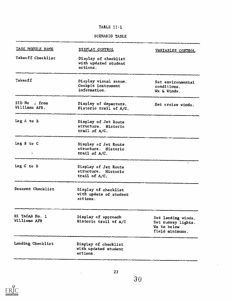
TABLE II-1
SCENARIO TABLE
TASK MODULE NAME
Takeoff Checklist
DISPLAY CONTROL VARIABLES_CONTROL
Display of checklistwith updated studentactions.
Takeoff Display visual scene. Set environmentalCockpit instrument conditions.information. Wx & Winds.
SID No - from Display of departure. Set cruise winds.Williams AFB. Historic trail of A/C.
Leg A to B Display of Jet Routestructure. Historictrail of A/C.
Leg B to C Display of Jet Routestructure. Historictrail of A/C.
Leg C to D Display of Jet Routestructure. Historictrail of A/C.
Descent Checklist Display of checklistwith update of studentactions.
Hi TACAN No. 1 Display of approachWilliams AFB Historic trail of A/C
Set landing winds.Set runway lights.Wx to belowfield minimums.
Landing Checklist Display of checklistwith updated studentactions.
23
30
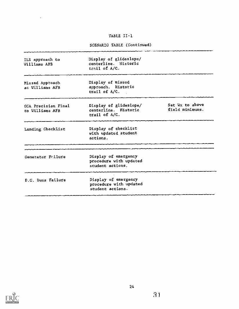
TABLE II-1
SCENARIO TABLE (Continued)
ILS approach toWilliams AFB
Display of glideslope/centerline. Historictr,rd.1 of A/C.
Hissed Approachat Williams AFB
Display of missedapproach. Historictrail of A/C.
GCA Precision Finalto Williams AFB
Display of glideslope/centerline. Historictrail of A/C.
Set Wx to abovefield minimums.
Landing Checklist Display of checklistwith updated studentactions.
Generator Frilure Display of emergencyprocedure with updatedstudent actions.
D.C. Buss Failure Display of emergencyprocedure with updatedstudent actions.
24
21
INSTRUCTOR SUPPORT FEATURESInjjial Conditions
Feature Initial Condit:ions
Definition This feature enables the instructor to set initial values formany parameters within the simulation. Initial values forenvironmental factors such as wind, turbulence, visibility,etc. and vehicle dynamics such as altitude, airspeed, position,weapons load and fuel can be established before the trainingsession (during lesson initialization procedures) or during thetraining session (by calling up by the reset facility).
Purpose and The primary value of the initialization/reset capability isIntended Use that it enables the instructor to devote his time to instruction
rather than inserting variables which have been predefined.
Additional o For any moderately complex simulator, it is necessary that aConsider- library of initial conditions be stored for use in actualations training sessions. The number of initial conditions varies
according to the training requirements specific to thatdevice.
o The instructor should be able to review the initial conditionsbefore executing them, to see exactly what conditions are .specified and to determine how the training activity willdevelop. To add flexibility, he should also be able to modifythe prestored data before execution (and save it for later useif desired), so that a particular lesson could be tailoredto the training situation.
Related ISFs §szmaja.S.Rag.9.1,. If a scenario control feature is specified fora specific ATD, then the initial condition sets may be incor-porated as part of this feature.
Example
Sotal Systgm Xreeze. The state of the simulator should be intotal system freeze while the initialization process is beingconducted. This will allow the student to reorient himselfwith respect to this new configuration. The freeze conditionmay then be removed by instructor control.
After reviewing the student's records, the instructor decidesthat several of the predefined values for scenario conditionsneed revising to make the scenarios more challenging. He thenmakes the appropriate changes so that he is not burdened withthis task during the training session.
25
32
INSTRUCTOR SUPPORT FEATURESInitial Conditions
Lessons Because the I.C. reset is often-used method to reposition the ATD
Learned to a specific point within the training scenario, it should bedesigned so as not to be restrictive, time consuming anddifficult to access.
ATD Specifi- Initial conditions feature shall enable the instructor to set
cation initial values for a set of parameters which shall define astarting point for a mission scenario.
Parameters whose values are set shall include the followingtypes:
a. Air vehicle configurationb. Air field and runway characteristicsc. Radio/navigation aidsd. Environmental conditionse. Air vehicle flight characteristics
The initial conditions sets shall include preprogrammed sets andprogrammable sets capable of temporary storage, modification
and recall of pre-selected parameters.
Initial conditions sets shall be created off-line and storedfor call-up by the instructor at the beginning of a missionscenario. An on-line capability shall also exist for temporarymodification, review and. recall of pre-selected values during thetraining session.
26 33
INSTRUCTOR SUPPORT FEATURESRea Laime _Simulation Variables Control
Feature
Definition
Real-Time Simulation Variables Control
This feature provides control for the insertion, removal, andalteration of simulation variables while the simulator is inoperation. The simulation variables include such variables asenvironmental conditions; aircraft configuration, maneuvering,and positioning (ownship, wtngmen, and adversary); target data;airfield data; and threat data. The methods of control rangefrom complete automation where no instructor action is necessary,to manual selection from a set of variables which have beengrouped according to the needs of a particular exercise. Thedegree of automation depends on the training application andrequirements. Control by continuous interaction via an inputdevice is also included.
Purpose and Control of the simulation variables can be provided throughIntended Use several different instructor support features in addition to
this feature. For example, Reposition offers control of aircraftposition parameters; Malfunction Control offers the instructorcontrol over insertion of malfunctions; Initial Conditionsprovides for the setting of initial conditions; and ScenarioControl offers several levels of automation in the control ofthese variables. Therefore, simulation variables controlshould be specified when control of certain variables is notadequately covered by means of any of the features identifiedabove.
-
Additional o Controlling the simulation variables in a completelyConsider- automated mode, in a semi-automated mode, and by objectiveations are covered under the discussion of scenario control.
See Che definition of Scenario Control in this section.
o Another potential means of control is continuously throughan tnteractive device at the instructor console. This isthe means that would be employed to control the movementor position of other aircraft or surface vehicles. Forexample, control of the target could be by movement of acursor over a graphics display.
o Finally manual control may be required in specificinstances. If so, access to these controls should bemade convenient by functional grouping according to theactive training objecttves.
27
34
INSTRUCTOR SUPPORT FEATURES
Real:Tjme_541AlatOnj.a.riablesControl,
Related ISFs gulmatzusxfatungsjitauramat. The simulationvariables to
be controlled may impact task difficulty. This would directly
.affect the performance measurement output and should be made
explicitly clear to instructors as the results of the performance
measurement are presented to him,
Example
I f Of o d ti n a I.acengtrio Cqntrol. These features are also means of offering the
instructor control of the simulation variables in real-time.
See discussion under "Purpose and Intended Use."
An instructor may activate and position an airborne adversary
by positioning the cursor over a graphic depiction of a hostile
environment.
Lessons It was observed that the manual selection of the simulation
Learned variables is best suited for informal training, e.g., contin-
uation training. This feature was available on all of the
systems visited. The amount of usage depended on the
accessibility of the variable and whether it had any training
value with respect to the objectives being taught.
Using the preprogrammed sets of initial conditions to control
simulation variables has been observed. However, the selection
of variables by "re-initializing" the simulator seemed to break
the flow of training and detracted from the realism offlight. The initialization feature is designed primarily to set
up the simulator at the start of an exercise. The use of
this feature to change simulation variables during training was
observed to be more of a "work aroundif!
ATD Specifi- This feature shall provide control for the insertion, removal,
cation and alteration of simulation variables while the simulator is
in operation. The simulation variables shall include such
variables as environmental conditions; aircraft configuration,
maneuvering, and positioning (ownship, wingmen, and adversary);
target data; airfield data; and threat data.
28 3 5
INSTRUCTOR SUPPORT FEATURESMalfunction Control
Feature
Definition
Malfunction Control
Malfunction Control enables the instructor to fail, partially ortotally, simulated aircraft equipment or to introduce anabnormal equipment condition during the simulation in orderto train the student in recognizing and responding to suchmalfunctions.
Purpose and ATDs provide the student with a safe, controlled learningIntended Use environment for training responses to equipment malfunctions and
resultant emergencies. Control of malfunctions can be partiallyor completely taken over by the simulation computer,thus freeingthe instructor for other important instructional activities.In addition, if malfunction control is even partially automatedthen students can practice malfunction and emergency procedureswithout the aid of an instructor. Thus students can benefit fromadditional practice whenever ATD time is available.
Malfunction control can either be manual, partially automated orfully automated. Under manual control, the instructor isrequired to select and activate malfunctions as the simulatormission proceeds. While this method offers the instructormaximum flexibility in controlling malfunctions, it also imposesthe greatest workload. Automated malfunction control includesseveral different possible variations. The following listsuggests various ways malfunction control can be automated andthe purpose of each.
o Malfunction control can be partially automated by allowingthe instructor to select the set of malfunctions to be usedin advance of the simulator mission. This preselected listis then made readily available during the exercise. Thenumber of alternatives for selection during the mission isreduced while still allowing instructor control.
o In another possible variation of partially automated control,the instructor may pre-select both the malfunctions to beused and when they should be activated. During the missionthe instructor takes no action except to cancel or postponean upcoming malfunction he has decided not to impose on thestudent. This method of selection further reduces theinstructor's workload.
29
3 6
INSTRUCTOR SUPPORT FEATURESMalfunction_Consrol
o Under a completely automated version, malfunction control
would be preprogrammed according to each specific simulator
exercise in the training program. The instructor is onlyrequired to select the exercise. All selection and activation
of malfunctions is predetermined and preprogrammed. Ideally,
automated malfunction control significantly reduces theinstructor's workload both in setting up the mission and in
conducting it. This method also promotes standardizationwithin the training program by ensuring that such lessons are
'always presented in the same way.
Additional If Malfunction Control is selected, then the following additional
Consider- considerations should be specified.
ationso It is assumed in these guidelines that through the ISD
process, training objectives, task listings, and mediascaection have been completed for your training programbefore the specifications for the training devices have beendeveloped. Malfunctions should be included in the simulatorbased on these task listings. The decision to manually orautomatically control the selection and activation ofmalfunctions should at least partially be based on the typesof malfunctions that are presented in these analyses.
o If malfunctions are to be selected by the instructor eitherbefore or during the simulator mission, then they should bepresented in groups organized according to the previouslyidentified tasks or training objectives. They should alsccorrelate to the TO-1 sections for emergency procedures.
o If malfunctions are to be automatically activated, then allconditions to start, stop, identify correct and incorrect
procedures, and any other factors (e.g., environments]conditions) should be identified in advance by the usinlcommand,
o Instructors may require the capability to cancel or postpon(malfunctions which have been pre-selected for automate<insertion. To make it possible to override previousl:programmed malfunctions, the system must provide a warninlto the instructor that a malfunction is about to occur.
o Whether ot not the type of malfunction control is manua:or automated, the instructor should be provided with a lisi
that shows which malfunctions are presently active. II
addition to the above, if in the automated mode, a mean:
should be provided which will preview the remaining malfunctions and conditions under which they will be activated.
30
3 7
INSTRUCTOR SUPPORT FEATURESMalfunction Control
Related ISFs Scenario Control. Automated malfunction insertion and removalrequires a real-time scenario control capability. This controlis required for malfunction insertion/removal because theconditions for initiating the malfunction must be sensed andcompared against insertion/removal criteria.
Procedures Monitoring. Similarly, if the malfunction is to beautomatically removed after the student has successfully copedwith it, a procedures monitor is necessary for assessing whenthe correct procedures have been completed. If the malfunctionis co remain in effect (e.g., engine out), then a proceduresmonitoring system designed to monitor student performance mustknow this so that appropriate standards of flight performancecan be used.
Examples The following are examples of malfunction control:
o Manual Control. During a training session the student haddifficulty with an engine failure so the instructor decidesto introduce the malfunction again later in the session forremediation. At an appropriate time the instructor manuallyselects and activates the engine failure.
o §emj,-Automated Control. Based on his review of studentrecords the instructor decides that extra practice of thehydraulic system failure procedure is needed. He thereforepre-selects the malfunction but does not specify when it isto be inserted. This places it in a "ready" status. Laterin the training session at a time when it does not interferewith other training, the instructor introduces the hydraulicfailure with a simple command.
o Fully Automated control. A trainer event on airwaysnavigation includes training objectives concerned with TACANfailure and lost communications procedures. At a predefinedpoint in the route, the TACAN failure is automaticallyintroduced. After the student has demonstrated the properprocedures or at a predefined point in the route, the TACANis restored. At a later point in the route the simulatedradio failure is introduced automatically.
Lessons Automated malfunction control is valuable only if it is wellLearned designed. Problems have been experienced with time-based
automated malfunction insertion/removal since time does notalways correlate with mission events in a meaningful way. Forelample, in a tactical situation, particularly one with modelingof enemy forces and tactics, the student will be expected to
31
38
INSTRUCTOR SUPPORT FEATURESMalfunction Control
take actions which are based upon the situation rather than the
clock. Therefore logic-controlled automated malfunctioninsertion/removal is preferred, as long as the al.o.w.,-; decision
logic is flexible enough to specify appropriate conditionscompletely. With logic-controlled procedures, it may bepossible to specify probabilistic malfunction insertion. Forexample, under certain conditions one of a small list ofmalfunctions will occur, or under certain conditions a
malfunction may or may not occur.
Manual malfunction insertion tends to produce a high instructor
workload. Therefore when manual control is specified, the
method of selecting and activating malfunctions becomes veryimportant. Grouping by objective or training task would helpto reduce the workload.
Automated malfunction control is seldom used by some groupsof instructors who prefer manual control. Their commentsindicate that automated malfunctions are sometimes unreliableand can be difficult to implement. In general, instructorsprefer the flexibility to tailor training to student response andneeds.
As stated in the above paragraphs, there are basic problemswith both extremes, from manual insertion, where instructorworkload may hamper his instructional tasks, to fully automatedwhich restricts his flexibility in tailoring the exercise inresponse to student needs.
Instructional personnel should determine what malfunctions shouldbe trained on the ATD to meet the training requirements. Too
often, malfunctions are inserted to "incre4se the student'sworkload" without any specific training objective in mind.Malfunctions can then be organized in logical groups either forlater presentation to instructors using the simulator or forsimulator designers' and programmers' use when programmingthe simulator for automated insertion by task or trainingobjecttve.
ATD Specifi- Malfunction control shall provide the instructor the capability
cation to preprogram a sequence of abnormal aircraft equipmentconditions and/or emergency conditions before or during thetraining session. The time and number of actions requiredon the part of the instructor to select, alter, and entermalfunctions shall be minimized to the greatest extent possible.
32
39
INSTRUCTOR SUPPORT FEATURESPAPolitton
Feature
Definition
Reposition
This feature provides the ability to position the ATD to aspecific point in space that has some significance to thetraining scenario. All flight parameters will be capable ofadjustment to meet the new condition, and the ATD configurationwill be automatically checked to ensure a crash condition willnot occur as a result of repositioning.
Purpose and This feature promotes efficient use of available training timeIntended Use and other assets by not requiring the student to "fly" the ATD
to the desired location. Having the ability to reposition theATD to meaningful positions in the exercise will allow theinstructor to modify the exercise to meet the student's needs.This can be done in an effective manner by providing repositionoptions associated with the training objectives, e.g., initialapproach fix, final approach fix, or end of the runway after anaborted takeoff.
Additional o Method of SelectIM. Older ATDs required lengthy manualConsider- procedures such as slewing to reposition the ATD. Some neweratIons devices incorporate dedicated controls (usually pushbuttons)
that instructors use to select one of several sets ofinitial conditions. Others provide lists of combinations ofinitialization options displayed on CRT display whichallow a single selection from a readily available menu.Regardless of the method used, it is important that themethod chosen does not add to the instructor workload, andthat the selections made available are clearly labelled andare appropriate co the objectives being trained.
o Copftglaratial_Ximalsh. If after a repositioning a crashcondition exists, a message warning the instructor should begiven and the device will not be moved until the configurationis corrected. For example, if the simulator is to be placedat the end of runway from a flight condition, and the landinggear is not down, a message will inform the instructor of thecondition and the ATD will not be repositioned until thelanding gear is placed down.
Related ISFs ErlIge. It is important that when the ATD is being repositioned,that the cockpit be placed in the freeze condition uponcompletion. This will allow the student time for re-orientationand the time of fly-ouc can be controlled by the instructor.
33
4 0
INSTRUCTOR SUPPORT FEATURESReposition
Example
Scenario Control. If a scenario control feature exists, itmust be made aware that the ATD is being repositioned.
Anuomsltd_Nsslamasa_Etaammatat. The automated performancemeasurement feature must be aware of any repositioning andsimudator reconfiguration during resets. By repositioning thesimulator to the beginning of a training objective with aknown set of conditions, an APM can easily account for anymodifications to a scenario and adjust accordingly.
During a strike training mission involving a low-level navigationingress to a target, the student flies most of the routecorrectly. However, he has difficulty in flying the properairspeed and altitude profile in the final portion of the routeleading up to the target. This adversely affects his performancein the attack phase and degrades the training value of themission. The instructor then uses the reposition feature toposition the aircraft at a point in the route where the studentcan re-fly the final portion of the mission.
Lessons Repositioning the simulator to a specific location is used onLearned all devices and is mostly used for repetitive training
(e.g., approaches). The most common way to reposition wasaccomplished via an T.C. reset. It is among the most frequentlyused and highly valued features at ATD sites. It is typicallyused in conjunction with flight system freeze and permitsinstructors to rapidly re-initialize the ATD to a particularconfiguration so that a student can repeat a particular maneuveror mission segment. However, if the I.C. reset is used, itmust be designed so as not to be restrictive, time consuming,and difficult to access.
The most versatile design of the reposition feature was observedon a device where the simulator can be positioned anywhere withinthe active geographic graphics display by identifying theposition with a light pen. Repositioning this device may also beaccomplished by bearing and distance from a fix, latitude/longitude, or by identifying a previous position by a "snapshotI.C." However, this may be over-designed for the trainingrequirement.
ATD Specifi- The reposition feature shall have the capability to positioncation the ATD at any point in the mission training scenario. All
flight parameters shall be capable of automatic adjustmentto meet the new condition imposed by repositioning. Afterreposition, ATD configuration shall be automatically checked topreclude any crash condition or other adverse condition and
34 41
INSTRUCTOR SUPPORT FEATURESReposition
shall remain ir, freeze state until all incompatible conditionsare correct:Jt
The reposition feature shall he designed to enhance instructorefficiency. The time and the number of act:ions 1:equired on thepart of the instructor to select, alter and enter data shall beminimized.
35
42
INSTRUCTOR SUPPORT FEATURESXOS Dtaplay_ Control and Formatting
Feature
Definition
IOS Display Control and Formatting
The IOS display control and formatting provides the instructorwith a meaningful depiction of student performance duringactive mission training. The presentation of information isdesigned to be an easy-to-read, uncluttered, standardizedformat of the current status of graphical and instructionalinformation, The information layout should be consistent withthe limitations of human perception and memory in order tominimize user interpretational effort, alleviate confusionthereby ensuring quick recognition and maximizing readability.
Purpose and There is a basic requirement that the instructor "knows" whatIntended Use the crew is doing throughout the training exercise. He needs
information regarding the current status of various facets ofthe simulation exercise. An IOS display which is formattedbased on instructor needs and training objectives provides amore meaningful depiction of student performance.
Additional Misl_ion _Status Disnlays. Computer-generated mission statusConsider- displays can be tailored to the segment or task activity inations progress. Some systems have switchable fields of view in the
cockpit. Radar, for example, may use one screen for navigationand targeting modes, The capability to select and view modesindependently of the student's choice allows the instructor tomore clearly determine whether the student is using theappropriate mode. Such requirements should be stated clearly,since they may place additional demands on the computationalsystem and require significantly different software designs.
Manual, vossug. automatic Displayjelectjon. A default display forthe active training objective should be displayed automatically.However, alternate displays should be made available forselection from a group of displays appropriate to the activetask being conducted.
Automptivilly activated. In most cases where the aircraft isgeographically referenced on a display, an automated featurecan provide the correct reference. For example, in the casewhere the simulator is repositioned to the beginning of anapproach, an approach display will automatically come up. Incases when a geographic plot is being displayed and when theaircraft flight path approaches the edge, the display wouldchange to the next appropriate display.
37
43
'INSTRUCTOR SUPPORT FEATURESIDS Display Control alyi Formatting
Display Formats. CRT displays can present many categories ofinformation very concisely. In an attempt to provide thegreatest amount of information at one time, display formats aresometimes so compact and complex that the results can beunreadable. In preparing display formats, one should considerthe amount and appropriateness of the data. It must also beformatted for quick and accurate legfhility. A "declutter"option also provides a method of separating "need to know" and"nice to know" information.
Related ISFs: Scenario Control. Although display options do not relatedirectly to simulator control, they do provide valuableevaluation information. The "smart" system would know whichtraining objectives were currently being performed. Thedisplay options appropriate to the running task could be madereadily available (SID plates, approach plates, optimum diveangle, single engine landing procedures, etc.).
Examples During an instrument flight training mission, the studentflies an IFR navigation route to an instrument approach at adestination airfield. During the navigation phase, actualaircraft track relative to the planned route is displayed tothe instructor. The student's selections of NAVAIDs and radiofrequencies are monitored and incorrect selections are alsodisplayed to the instructor. When the student starts hisfinal approach, the display formats change to provide graphicdepictions of glideslope, lineup and airspeed parameters, andindications of aircraft landing configuration status. When anaircraft system malfunction occurs in the scenario, systemindicators and student control activations are displayed tothe instructor. All of the display format changes occurredautomatically, based on the active training tasks and instructorinformation requirements for the tasks. This graphic informationcan be recorded and later replayed during debrief.
Lessons In the past, repeater instruments were the mechanism to satisfyLearned the requirement for aircraft cockpit/control information.
More recently, this type of information has been replaced withgraphic displays. However, in many cases where graphics havebeen the primary method of displaying simulator configurationand cockpit activity, the design has been toward displayinganything and everything that "may" be of value. This hasresulted in displays which are very difficult to interpret.The appropriate data is most likely contained on these displays;however, at times it is difficult to follow to evaluate studentperformance. This is especially true with the casual user.The most immediate user response to this design problem is togo back to the basic aircraft instrumentation and to lay out theinstruments and repeaters as in the actual aircraft. This may
38 4 4
INSTRUCTOR SUPPORT FEATURESIOS Display Control and Formatting
be a valid alternative, however, care should be taken so as totake advantage of this feature and the state-of-art technology.For example, in an exercise where the training objective is tofly instrument navigation, the instructor may be provided withthe navigation instruments to evaluate the student'sperformance. He must then interpret those instruments in orderto know exact aircraft location. A properly designed displayfor this type of objective may provide both instrument readoutand aircraft position with respect to a route or flight pathbeing flown.
ATD Specifi- The IOS display format shall provide the instructor with acation meaningful depiction of student performance during active
mission training. The presentation of information shall bean easy-to-read, uncluttered, standardized format of thecurrent status of graphical and instructional information.The information layout shall be consistent with the limitationsof human perception and mc.ory in order to minimize userinterpretational effort, alleviate confusion thereby ensuringquick recognition and maximizing readability.
39
4 5
INSTRUCTOR SUPPORT FEATURESProcedures Monitoring
Feature
Definition
Procedures Monitoring
Procedures Monitoring provides a method of monitoring studentactivity with respect to procedural performance, such asthe accomplishment of checklist items. This feature may alsoprovide performance measurement of these items.
Purpose and A major focus of flight training is to teach the student aboutIntended Use normal and emergency procedures specific to the aircraft
equipment to be operated. Typically, there are numerouschecklist procedures the student must know thoroughly. Thesimulator provides the ideal tool to master these procedures,especially in the area of emergencies and system malfunctions.Procedures monitoring provides the instructor with the capabilityto observe and evaluate several facets of student performancesimultaneously. It may also provide objective, standardizedperformance measurement of the student's accomplishment ofprocedural steps. A graphics display which summarizes theprocedures attempted and procedural errors should be made anoption to the instructor for monitoring student activity. Thisfeature is especially useful when the instructor monitors theexercise from an off-board station where cockpit activitycannot be directly observed.
Additional Many ATDs present (on real-time displays or hardcopy printouts)Consider- the actual sequences in which procedures are performed byations students. It is the instructor's responsibility to determine
whether or not the procedural sequences and timing areacceptable. State-of-the-art devices have been able to provideautomated measurement of performance of procedural sequences.This has been accomplished by the development of "intelligent"start/stop logics which know when and what the crew is doing,thereby providing a more dynamic and accurate description ofstudent performance.
The meaningful measure of procedures requires relativelycomplicated computer measurement logics. A considerableand detailed task analysis must be accomplished prior tocontractor development. Correct sequences must be determinedin detail, and likely alternative sequences (both acceptableand unacceptable) must be defined so that computer measurementand scoring logics act fairly and do not penalize students forusing occasional (but acceptable) departures from normal,textbook procedural sequences.
41
4 6
INSTRUCTOR SUPPORT FEATURESPtqcedures Monitoring
Related ISFs 2Q Display Control., and Formatting. It is important thatassessment of student performance of procedures be presented inan easy-to-read-and-understand format. Among the problemsidentified about displays were 1) that the volume ofinformational data displayed is too overwhelming, and 2) theywere difficult to integrate and interpret by instructors. Forexample, on some devices, the last twenty actions in thecockpit were displayed at the 10$. At times, actions, whichwere both appropriate and totally irrelevant, rapidly scrolledpast the instructor and were unusable.
Example
AUSSAated PestornIttic_e_doaavrement. If training objectivesrequire performance evaluation of student procedural activity,then these two features should be directly correlated.
An instructor wishes to test a student on his ability toaccomplish a pre-flight (before takeoff) checklist. He activatesthe performance monitoring feature to observe student actions.During the student's performance of checklist actions, adiagnostic message appears on the IOS CRT which indicates thatehe sequence of the steps the student performed are incorrect.The instructor might then call up the appropriate display whichindicates exactly what the student error wav so he can repeat thetask. By using this feature, the instructor has obtainedadditional infotmation to what he was abl(0 to see.
Lessons Many ATDs have the procedures monitoring feature. However,Learned this feature is often not used because many of the procedures
programmed in the simulator are quickly outdated and are notupdated as they should be. It is mandatory, therefore, thatdata relating to aircraft procedures be easily modifiable.
Many of the actions related to procedural activity are notcomputer detectable. For example, many of the checklistsinvolve scanning cockpit gauges and checking for proper aircraftconfiguration. In those cases, any automated performancealgorithms must not try to assign a value which may be totallydistorted. It is important that the Procedures Monitoringfeature be used as an aid in these cases and to provide onlyuseful information to the instructor for his overall evaluation.
ATD Specifi- The procedures monitoring feature shall provide the instructorcation with a method of monitoring the sequential mission training
activities of a student. The design shall be easily modifiableand include valid measures of monitoring procedural activity.The design may include an automated feature of measuringperformance of sequential procedures. The assessment of
42
47

INSTRUCTOR SUPPORT FEATURESProcgdures Monitoring
student performance shall be displayed to the instructor in aneasy-to-read and understandable format.
43
4 8

INSTRUCTOR SUPPORT FEATURESFreeze
Feature
Definition
Freeze
The freeze feature allows simulator parameters to be fixed atvalues existing when freeze is activated. Some or all deviceparameters can be fixed. The freeze feature can be operatedeither manually by the instructor, or it can be operatedautomatically. Automatic freeze occurs either when specifiedparameter values are exceeded, as in the case of a "crash/kill,"or when the state of the simulator changes as in repositioningor going from replay to the normal operating mode.
Common variations of the freeze feature are defined below:
Zatal Systep Freeze. All systemparameters are frozen, includingflight control, propulsion, navigation and weapons. The entiresimulation ceases to function from a training standpoint. Forsystems equipped with platform motion, the motion system isdriven to a neutral position, at a safe rate.
Partkal_or Parameter Freeze. This type of freeze enables theinstructor to fix the value of individual parameters. Thevalues of one or more parameters can be frozen at any giventime. Common variations of the parameter freeze featureinclude the following.
o Flight System Freeze. This feature permits the instructorto simultaneously freeze flight control and propulsionsystems, position, altitude and heading. The net effect isthat the ATD ceases to "fl.y'." However, all other simulatedsystems remain operational and can be used for instructionalpurposes without the burden of having to fly the ATD. Thisfreeze variation functionally converts an OFT to a CPT.
o Attitude Freeze. This feature permits thesimultaneously freeze pitch, bank and heading.
o Position Freeze. This feature permits thesimultaneously freeze latitude and longitude.continues to "fly" but it "goes nowhere:fl
instructor to
instructor toThus, the ATD
45
4 9
INSTRUCTOR SUPPORT FEATURESEtIRAD.
Purpose and Toal- System Freeze The total system freeze is used in threeIntended Use ways:
o to temporarily suspend the training session so that theinstructor can provide feedback to the student,
o to suspend training to re-configure the simulator, or
o automatically as in the case of crash or kill.
Parti4 or_ Zarameter Freeze The partial freeze featureselectively freezes parts of the ATD system for the purpose ofreducing the student's task load.
Additional The following additional considerations should be specified:Consider-ations
o Specify the type of freeze required. See descriptionsunder Purpose and Intended Use above.
o In order to avoid confusion, the freeze status of thesimulator must be made obvious to all participants in thesimulator exercise.
Related ISFs 3imulator Record/Replay. The use of total system freeze iscommon in devices during replay. It has proved useful to stopthe replay to allow for instruction and also when changing thestate of the simulator from replay to the normal operatingmode.
Examples
Automate4 Simulatoz Demonsttatiol. As in simulator record/replay, the total system freeze has proved useful to stop thedemonstration to allow for student questions or instruction,and to allow changing the state of the simulator from automateddemonstration to the normal operating mode.
wstalige mil. Total system freeze is used in most ATDs tostop an ongoing exercise as the first step in reinitializingthe ATD.
Partial Ireeze. During a UPT navigation trainer period, theinstructor suspects that the student is disoriented relative tohis route of flight. He then activates "position freeze" sothat he can discuss the problem with the student. Once theproblem is resolved,the instructor "unfreezes" the ATD and themission is resumed. Another example involves a student problem
66
INSTRUCTOR SUPPORT FEATURESFreeze
LessonsLearned
with an emergency procedure. The instructor activates "flightsystem freeze" so that he can point out system indicatorsrelated to the procedure. The student can pay attention to theinstructor without the burden of flying the aircraft.
Totsajysterl Freeze. During an ACM trainer mission the studentis having difficulty recognizing when he is in a missile firingenvelope. As the student reaches the edge of the envelope, theinstructor activates "total system freeze" so that he cenprovide instruction on envelope recognition cues and relevantaircraft parameters.
o Manual. All ATDs observed in preparation of these guidelineshad this feature. It was used in varying degrees depending ontype of training. Freeze was used more frequently when tasksbeing trained were relatively or totally new to the stuC-nt.Thus, at the undergraduate training level, freeze was .1.se4extensively by the instructor while providing direct feedband corrective action. It is rarely used in total miss...,training at the continuation level.
o Automatic. All ATDs observed in preparation of thisguidelines had an automatic freeze feature designed to beactivated when a "crash" or "kill" occurred. However, theautomatic freeze feature was not observed to be used.Instead, a crash/kill override was always set so that thasimulator would not activate freeze when a crash or killoccurred.
Eus.1.4112.esmgesFsw.zg... Evidence from several surveyssuggests that, unless there is specific known application forparameter freeze in the training context, it will probably notbe used. Partial/Parameter Freeze was found on many devicesbut was observed in use only at the undergraduate traininglevel. Instructors expressed that there is little trainingvalue for this feature at the MAC/SAC/TAC sites.
A design consideration is to identify the uses to which freezewill be put to.support training needs, and then to incorporateinto ATDs the freeze variations that meet those needs. Thisapproach simplifies instructor/operator tasks while ensuringmeaningful control over the training environment. The followingtable presents uses of freeze together with the freeze variationsthat best match each use.
47
51
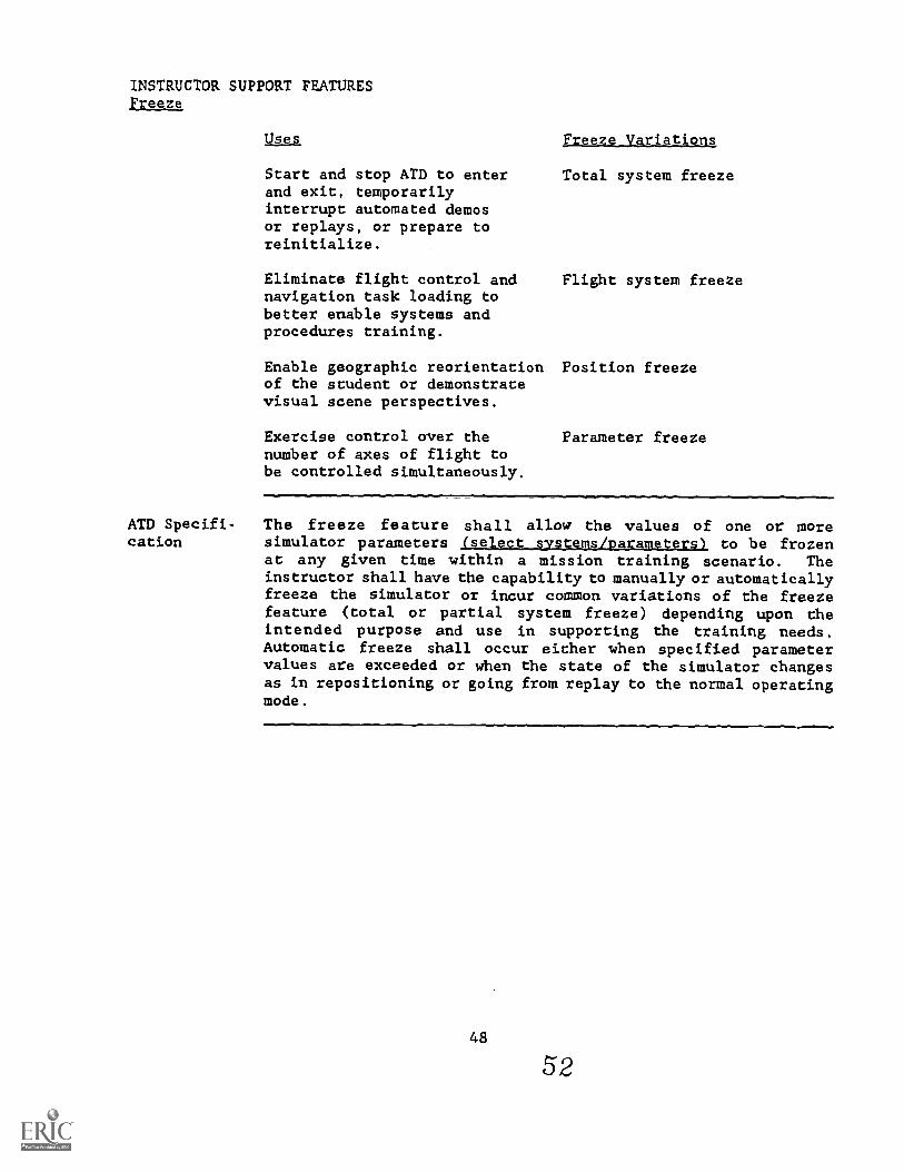
INSTRUCTOR SUPPORT FEATURESFreeze
Use% Freeze Variations
Start and stop ATD to enterand exit, temporarilyinterrupt automated demosor replays, or prepare toreinitialize.
Eliminate flight control andnavigation task loading tobetter enable systems andprocedures training.
Total system freeze
Flight system freeze
Enable geographic reorientation Position freezeof the student or demonstratevisual scene perspectives.
Exercise control over thenumber of axes of flight tobe controlled simultaneously.
Parameter freeze
ATD Specifi- The freeze feature shall allow the values of one or morecation simulator parameters (select orstems/Darameters) to be frozen
at any given time within a mission training scenario. Theinstructor shall have the capability to manually or automaticallyfreeze the simulator or incur common variations of the freezefeature (total or partial system freeze) depending upon theintended purpose and use in supporting the training needs.Automatic freeze shall occur either when specified parametervalues are exceeded or when the state of the simulator changesas in repositioning or going from replay to ehe normal operatingmode.
48
52
INSTRUCTOR SUPPORT FEATURESSimulator RecordAleplay
Feature Simulator Record/Replay
Definition This feature enables the instructor to record a student'sactionn/inputs during a simulated mission. During a replay,all events which occurred as a consequence of student input tothe simulator's controls will be reproduced. The replay willrepeat the control movements, instrument values, displays,motion cues, visual scenes, sounds and voice communications whichoccurred during the period of recorded time selected for replay.
Purpose and Simulator Record/Replay allows the student to review his ownIntended Use behavior. The reduced student task load during replay provides
a better environment for instructor feedback. For example, theinstructor can review the student's performance, identifyproblems and resulting errors, analyze causes of the problemsand give guidance.
This feature is most useful when students have difficultymastering a specific skill, when new maneuvers or tasks arebeing trained and when instructor critiques are necessary.Frequency of use will decrease as students become more proficientat performing the required tasks.
Additional If Simulator Record/Replay is selected, then the followingConsider- additional considerations should be specified.ations
The capability to freeze the ATD during replay is a requiredfeature for most training applications. Total systnm freezeis typically used to stop the simulation prior to enteringthe replay mode and, on many occasions, to temporarilyinterrupt replay or to terminate replay for instructionalinteraction.
o The means of exiting the replay is important. In additionto "freeze" and allowing the simulator replay to continue tothe end of the recorded segment, the capability of allowingthe student to resume control of the simulator at any pointduring the replay is also desirable. This feature isreferred to as the capability to "fly out" of the replay.
o The period of time replay has typically been available hasranged from the last three to five minutes of simulatedactivity. In addition to computation requirements andmemory limitations, the amount of time to allow for replay
4.9
53
INSTRUCTOR SUPPORT FEATURES
5il]MlAtPr gecord/841121PY
should be determined after careful analysis of howrecord/replay will be used and the training applicationspecific to the device.
o Row to index the starting point for a replay is veryimportant. Its selection will often dictate whether or notthe feature will be used. Replays have been traditionallystarted by time and usually at one minute increments.In many cases, this has proved to be cumbersome and considereda waste of simulator time. If a small replay capability isall that is required for an ATD, e.g., two to three minutes,the instructor may easily orient himself by time. However,if the recording requirement is relatively long, as in amission scenario, orientation within the replay by time onlymay not be appropriate. In this case, orientation bytraining objective or some other specific identifiable event,is more appropriate. Identifiable events might include suchevents as the beginning of an approach, surface-to-air missilelaunch or engine malfunction.
Another method of indexing is by the instructor inserting anindex flag.
o In simulators with a motion base, it should be specifiedwhether or not motion is desired in the replay. Pastexperience suggests that motion is desired only at theundergraduate training level.
Related ISFs Freeze (Total System). See Additional Consider.;t:ons above.
Example
Automated Simulator Demonstration. Simulator Record/Replay icused in some ATDs by instructors to create demonstraticAutomated demonstrations differ from demonstrations create'.using simulator record/replay in several important ways. (SeeAutomated Demonstrations - Related ISFs.)
During a Basic Fighter Maneuvering training exercise theinstructor may ask the student to perform a particular maneuver.After completion of the maneuver, the simulator record/replayfeature would allow the instructor to replay the maneuverexactly as the student performed it with the student sitting inthe cockpit. This would allow the student to review his ownperformance while the instructor provides feedback to him.
so
5 4
INSTRUCTOR SUPPORT FEATURESSimulator Record/Replay
LessonsLearned
It has been found in several surveys that student proficiencyappears to be the primary factor in deciding whether toincorporate simulator record/replay into an ATD. It has thegreatest training value when the cues, responses and task arenew to the student. This feature tends to be used most at theundergraduate training level. During transition and continuationtraining, it is used for training of new and also relativelycomplex advanced flying skills such as those required forair-to-air combat maneuvering. Simulator record/replay was notused during transition training or continuation training whereltudents have already developed the required basic skills. Inthese cases, students were generally able to identify theirown performance deficiencies, diagnose the causeg. and takecorrecttve steps without the need for such a highly detailedmemory and diagnostic aid such as record/replay.
It should be noted that although this feature is found on manyof the devices, it is not a regularly and consistently usedfeature. Many instructors express tha,.t this feature may havesome value, but that they would rather use the simulator for"hands-on" training. This is especially true at the MAC/TAC/SACsites.
Slow motion replay capability has been incorporated in some ATDs,but has not been used because it is considered "unrealistic".
ATD Specifi- The simulator record/replay feature shall enable the instructorcation to record a student's actions/inputs during a missioa training
session. The record/replay feature shall have the capability torecord and reproduce all events which occurred as a consequenceof student input to the simulator's controls. Recorded studentevents shall include control movements, instrument values,displays, motion cues, visual scenes, sounds and voicecommunications. The recorded time selected for replay shall be10 seconds; and, the recording time shall be increased to amaximum of minutes in 10-second intervals. A capabllitymust exist to freeze the recording at any time d...m-ing replayand to exit the replay at any point during or at the end of therecorded segment at the instructor's discretion. Such an exitshall be a smooth transition to dhe original simulator stateprior to replay.
51
INSTRUCTOR SUPPORT FEATURESAutomated Simulator Demonstration
Feature
Definition
Automated Simulator Demonstration
The Automated Simulator Demonstration feature provides aprerecorded or preprogrammed aircraft maneuver, or i;ariesof maneuvers, that model desired student performance. Thedemonstration, as viewed from the cockpit stati'r reproduces allsimulated flight conditions that occurred when ttle mane ver wasoriginally recorded or programmed. This includes the actuationof cockpit instruments, indicators, flight controls, motionsystem movement, visual display scenes, and crew communications.
Purpose and The purpose of this feature is to provide a model that theIntended Use student can observe, analyze, pattern his own behavior after,
and use as a reference for seli-evaluation in subsequenttraining or during operational flying. Demonstrations identifythe significant cues and discriminations the student must learnand provide instructional commentary that may facilitate taskmastery. Demonstrations are nIrmally used by the instructor tointroduce a new maneuver to the student. Demonstrations are ofgreatest value when the student is unfamiliar with the task tobe learned.
AdditionalConsider-ations
If Automated Simulator Demonstration is selected, then thefollowing additional considerations Should be specified.
o It is important to be able to modify the stored demonstrationas aircraft and aircraft operating procedures change.Modifications should not require timely, expensive softwarere-development.
o The capabilitias to freeze or stopre-initiate it from the beginning,demonstration at a desired point should
o If the ATD has a motion base, then a"Hands and feet clear" should be clearlydemonstration is to be played.
a demonstration, toand to enter the
also be specified.
safety warning forissued whenever the
53
5 6
INSTRUCTOR SUPPORT FEATURESAvtamastd_glivl&tu Demonstration
Related ISFs Simmja.por Record/Replay. Simulator record/replay is usedprimarily to record the last few minutes of a student'sperformance for replay and review by the student and instructor.Occasionally, the instructor will take the controls, fly thesimulator from the cockpit or the IOS, and immediately replayhis performance to demonstrate something to the student.This type of demonstration is different from an automateddemonstration in several ways. Because only the last fewminutes of simulator time are stored, this feature does notprovide a permanently stored and available demonstration. Eachtime an instructor wishes to demonstrate something to the
student, he must re-record it. Such demonstrations vary frominstructor to instructor and from one recording to the next.Thus they each provide a slightly different model of behav:Lorto the student, rather than a standard. Additionally, suchdemonstrations, recorded in the midst of an on-going trainingsession, provide an approximation of the desired behaviorrather than an optimal model.
Example
Freeze. See Additional Considerations, above.
An automated demonstration can be constructed for any segment offlight. For example, an ATD can be programmed to takeoff, flystraight and level, refuel inflight, perform aerobatic or aircombat maneuvers, deliver weapons, fly a standard approach, orland without the student or instructor operating any primarycontrols.
en
Lessons Although automated demonstrations would appear to have greatLearned practical application, experience has shown that this is not
true in certain cases. In two recent surveys of ATD use,automated demonstrations were found on many of the devicessurveyed but their usage was minimal and inconsistent. Onereasor may be found in sentiments expressed by trainingpersonnel at the simulator sites. Many instructors felt thatthis feature might have some value. However, simulator timereserved for "hands on" training was too valuable to give upfor such demonstrations.
Automated demonstrations are of greatest value when the studentis unfamiliar with the basic task or characteristics of-theaircraft he is learning'to operate. Survey results indicatethat demos are used mostly for undergraduate training. However,even this use was sporadic and not by all instructors.
54
57
INSTRUCTOR SUPPORT FEATURESAutomated Simulator Demonstration
ATD Specifi- The automated simulator demonstration feature shall provide acation prerecorded or preprogrammed aircraft maneuver, or seriesof maneuvers, that model desired student performance. Thedemonstration shall reproduce all simulated flight conditionsincluding activation of cockpit instruments, indicators, flightcontrols, moti3n system movement, visual display scenes, andcrow communications, as viewed from the cockpit station.Demonstrations shall also include the significant cues anddiscriminations the student must learn and shall provide theinstructional commentary that may facilitate task mastery. Thedesign shall provide ease of software modification and shallprovide the capability to freeze, stop, re-initiate at thebeginning, or to enter the demonstration at a desired point.
55
INSTRUCTOR SUPPORT FEATURESAutomated Perfogmance Measurement
Feature Automated Performance Measurement
Definition This feature provides quantitative measures of studentperformance in the ATD. It is intended to be used as an aid bythe instructor in his rwerall evaluation of the student.
Purpose and Automated Performance Measurement supports the instructorIntended Use during training by providing the following: precision,
objectivity, standardization, and the capability to measure manyfacets of performance simultaneously. It can provide sensitive,reliable and valid measurements of student performance duringtimes when the instructor may be preoccupied with otherinstructional tasks. Except for obvious objective measures'(e.g., bomb score); the final evaluation rests with theinstructor. This feature may also be used by the studentduring self-practice as a measure of his progress.
Additional o Measurement by Uer-Defiried Ob ectives. Most automatedConsider- performance measurement capabilities on existing trainers,ations aside from being quite simplistic, require manual control by
the instructor. There are no "intelligent" start/stoplogics which "know" what the crew is doing and therebyknow what parameters to measure. Practically all automatedmeasurement capabilities in existing ATDs are best describedas performance monitoring and data collection systems.These capabilities allow instructors to select tolerancebands (e.g., +/- 100 feet) around various performanceparameters (e.g., altitude). The performance monitoringcapability then monitors for cases that exceed the tolermcsbands values, and records out-of-tolerance conditions fnrsubsequent display at the instructor's console or for hardcopyprintouts. Such rudimentary performance monitoringcapabilities have been used to effectively drive automAtedperformance alerting systems and automated cueing and coachingsystems. However, they have found little acceptance as anaid for performance evaluation and learning diagnosis during.training.
57
59
INSTRUCTOR SUPPORT FEATURESAutomated Performance Measurement
Performance measurement systems for aircrew training must be
designed to support specific training objectives. They should
be designed around user needs and requirements. Thus, the
specific design of an &PM will depend on its trainingapplication. In this context, the user can define performance
criteria. When various measures are properly weighted andcombined, the resulting measure set collectively can be
quite useful to the instructor. The specification for anAPM should include the requirement for a formal developmentand validation program where inputs by the end user aretried and refined using the fully developed system. The
system must also be designed such that "fine tuning"performance algorithms may be accomplished on-site.
o Timely Feedback. An APM system designed for use in trainingmust perform all statistical and other processing ofperformance data in real or near-real time so that studentsand instructors are provided with useful, concise and timelyperformance feedback information.
Measures may be displayed on-line for use during dae training
session. This type of information must be computed in atimely manner such that the results may be used by the
instructor for immediate feedback.
The measures are also output as a summary to be used fordebriefing purposes. On some of the devices, the outputis also used for student recordkeeping. If this is a
requirement, there must be a mechanism whereby the instructorcan override or modify the measure as his overall evaluation.
Related ISFs: Remote Graphics RePlay. A complete summary of the performancemeasurement output including what was measured, how it was
measured, and an instructor input (override and/or modification)is required as part of the debriefin.g. The student andinstructor will know precisely the means by which the resultswere attained. In this way the "black box" stigma of computergrading can best be eliminated.
Data Storage and Analysis. The data storage and analysisfeature will derive much of its data from automated performance
measurement.
Procedures Monitoring. If training objectives requireperformance evaluation of student procedural activity, then
daese two features should be directly correlated.
58
60
INSTRUCTOR SUPPORT FEATURESAutomated Performance Measurement
Example An example of the use of Automar,,; 'ormance Measurement byobjecttve would be the evaluat,ion of a basic air-to-surfaceweapons delivery (pop-up) using the example measurements listedbelow.
o Attack run-in performance at closest point of apprnachto a pre-planned position along the run-in corridor, measure
altitude to be within tolerance bandairspeed to be within tolerance bandground track to be within tolerance band
o Pop-up performance, measure
distance from the target to be within tolerance bandwhen vertical velocity exceeds defined parametershighest altitude obtained to be within tolerance band(low enough to minimize exposure, high enough for safeand accurate delivery)position at which highest altitude achieved to bewithin appropriate distance from target
o Weapons delivery performance, measure
dive angle to be within tolerance bandrelease altitude to be within tolerance band (lowenough for delivery acyuracy, high enough for saferecovery)airspeed at release point to be within tolerance bandyaw at release point to be within tolerance bandordnance impact to be within lethal range of target
o Exit performance at minimum altitude on pull-out, measure
altitude to be within tolerance band to avoidfragmentation patternground track to be within tolerance band (with respectto pre-planned exit route)altitude to be within tolerance band (with respect topre-planned exit route)
This information should be used in_addition to the instructor'sjudgement about the student's performance, ast_JaL_Oge of11. Measures would be available to the instructor for each ofthe steps listed for ads objective. As the student concludedeach step,the instructor would be able to determine immediatelyif the step had been completed within the predeterminedtolerances. If an overall score was desired, themeasures for each step could be weighted end combinta to yteia
59
61
INSTRUCTOR SUPPORT FEATURESAutomated Performance Measurement
an overall score for performance on this objective. As in the
case of the individual step measures, this score would be used
in addition to the instructor's assessment of the student'sperformance. This objective summary and the individual measure-ments would then be made available for instructor review for
his final evaluation.
The performance measurement information, when used with remotegraphics replay, becomes a powerful debriefing and evaluation
tool. While graphically viewing the route flown during theexercise and the visual HUD cues during the run and at release,
the measures provide the basis for instructor feedback anddiscussion with the student. The instructor may then formulate
his final evaluation.
Lessons Automated Performance Measurement is an instructional feature
Learned which has probably taken on the greatest variety ofconfigurations. There are misconceptions as to what it can doand what it cannot do, and therefore it is a feature which is
least accepted and used. If this feature becomes a requirementon a specific device, then there must be an educational processand complete understanding as to its purpose and intended use.
Some ATDs have a feature called performance measurement where
bomb drops and missile shots are scored. However, this featureis not used because instructors feel that the basic simulationdoes not provide the cues necessary to properly launch theweapon. In order for automated performance measurement to havemeaning, the APM has to take into account the fidelity andcompleteness of the simulation. For example, a visual systemwith only 48 degrees field of view may not be adequate to
provide the visual cues for a conventional bombing pattern.
ATD The automated performance measurement shall aid the instructor
Specification in obtaining a valid and reliable measurement of student
performance. The feature shall be designed to support specifictraining applications and to provide the instructor with aprecise, objective standardized measure of student performanceand a capability to simultaneously measure many facets of a
mission event. The instructor shall be provided timely feedback
of performance data in real or near-real time; and it shall be
displayed on-line for use during a training session or off-line
for debriefing purposes.
INSTRUCTOR SUPPORT FEATURESBardcopy/Printout
Feature Hardcopy/Printout
Definition Hardcopy/Printout provides for the retrieval of data from anyspecified source within the simulation - i.e., parameters,variables, real-time display content. It retrieves and createsa hardcopy print of the data upon demand and in such a way thatno interruptions occur within the simulation and its displays.
Purpose and Hardcopy/Printout provides the instructor with a printed copyIntended Use of selected information obtained during the training exercise.
It can provide the instructor with information about the trainingexercise and the student's performance. Both graphic flightprofile data and performance summaries can be provided. Thecopied data is especially useful during debrief for reviewingthe exercise as a whole, for comparing the student's performanceover the course of the exercise, and for looking for improvementsin performance over several simulator exercises.
Hardcopy/Printout supports permanent recordkeeping. Used in thisway, it provides a means of comparing and reviewing all students'performance in the training program. Training managers can moreeasily determine whether or not students are meeting trainingobjectives on schedule. In addition, through the ISD process,a comparison of this sort facilitates on-going evaluation of thetraining program itself.
Additional Several problems have occurred in current implementationsConsider- which have resulted in less use of this feature than would beations anticipated. The printed information should be provided in a
convenient format and under time and location constraints suchthat it is useful in the conduct of training, debriefing andrecordkeeping. If this feature is selected, the followingconsiderations should be specified.
o If a printout of a graphics display is requested, neitherreal-time data being displayed nor the simulation should beinterrupted or delayed.
o The printer should be readily accessible to the instructoras he conducts the mission. In addition, the noise causedby the printout of information should not interfere withtraining acttvities.
61
63
INSTRUCTOR SUPPORT FEATURESHardcopv/Printout
o The printed information should be well formatted and organizedaround ehe instructor's needs. Organization according totraining objectives is desirable.
o It would be highly desirable to allow some flexibility inthe content and format of the printed information. For
example, some applications or instructors might require moredetailed information than others. Perhaps an option similarto a "declutter" option for displayed output would bedesirable in such a situation. In addition, as flight
procedures and subsequent training objectives change, it
would be convenient to allow some modification of theinformation to be printed out.
Related 1SFs: automated Performance Measuxement. If an ATD has the automatedperformance measurement feature, hardcopy performance summariescan be produced.
Example During a training session the instructor flags various graphicplots and sets of performance measurement data for use in
conducting ehe debrief. During the debrief he uses the printoutsof the plots and data to guide his feedback to the student whendynamic replay and feedback are not required. The printoutsare also helpful in guiding use of the remote graphics replayfeature.
Lessons This feature is found on most ATDs. While a potentially useful
Learned feature, printout is seldom used at most sites. Problems inreliability and ease of implementation were noted. For some ofthe simulators observed, use of the printout feature requiresthat the system be taken down from the runtime programs priorto providing the hardcopy output. This was observed to berestrictive to actual training because by the time the copy ismade, the instructor has already debriefed the student. In
other cases, use of hardcopy required that the display beingcopied be frozen while output was produced. This was disruptivewith respect to real-time feedback.
In some cases the reason instructors didn't use the printoutfeature was because they didn't know it existed or how to useit.
The ability to obtain a printout of graphic flight profileinformation for subsequent debriefing was viewed favorably andused by instructors. Graphic situational displays are generallymore preferable than numeric summaries. Some ATDs produceperformance alert symbols overlaying flight profile data.This too was vlewed favorably as a debriefing aid.
62
INSTRUCTOR SUPPORT FEATURESHardcopy/Printout
Reports that do little more than list parameter data at aspecified sampling rate are rarely used. For ATDs which includean automated performance measurement system, information shouldbe summarized into a format meaningful to the instructor/consoleoperator.
ATD Specifi- The Hardcopy/Printout feature shall retrieve data from anycation specified source within the simulation - i.e., parameters,variables, CRT display content. It shall retrieve and create ahardcopy print of the data upon demand and in such a way thatno interruptions occur within the simulation and its displays.
63
6 5
INSTRUCTOR SUPPORT FEATURESRemote Graphics Riolay
Feature
Definition
Remote Graphics Replay
This feature provides a post-mission graphic and dynamicre-creation of a training exercise which has beenpreviously recorded. This replay is conducted at a r2motecomputer graphics console and may be accessed concurrentlywhile training is being conducted on the ATD.
Purpose and Debrief at the conclusion of a simulator session providesIntended Use the student the greatest part of his performance feedback.
Typically during the debrief, the instructor reviews studentperformance, reinforces instructional points, answers questionsand points the student co the next instructional activity.This information is normally provided by instructor recall andhis ability to take notes during the exercise. This type ofdebriefing varies accordingly. With the aid of a graphicsreplay, dhe instructor's ability to debrief is greatly enhanced.This feature will also relieve the instructor of note-takingduring the actual conduct : an exercise. This type ofdebriefing feature dlso : instructor and the studentto determine when and why the Ar ation occurred.
...........31.Additional o Replay Indexing. It is important that a convenient methodConsider- of indexing into a replay be designed into this feature.ations Positioning within a prerecorded exercise must be oriented
toward the end-user. Indexing methods specifically tailoredto training would include indexing by training objectivesand/or instructor-inserted flags. For example, the instructorshould be able to easily select an approach which had beenpreviously executed. Upon selection, the graphics wouldreplay from the starting point of the objective. In thiscase, the starting point would be at the initial approachfix. Instructor-inserted flags are also used to facilitatelocating points of interest in the mission.
o Replay Control. The control of the graphics replay shouldinclude the selection "f optional graphics as provided duringthe exercise. In addition, the exercise should be able to bereplayed at either normal or fast speeds and frozen at anypoint for review and feedback.
65
66
INSTRUCTOR SUPPORT FEATURESRelpte Graphics Replay
Related ISFs: Apsorated Performance Measurement. The remote graphics replayis used in conjunction with automated performance measurementreview. These two features should be interconnected such that,in addition to replaying a ,raining objective, any performancemeasurement associated with that objective can also be reviewedaccordingly.
Example After leaving the trainer, the instructor and student proceedto a remote station for post-mission debriefing of a navigationtraining event. The instructor calls up selected portions ofthe navigation route for replay in a dynamic graphics format.lie also calls up the performance measures which were takenduring the recording of the training objective. The studentand instructor observe the replay, and the instructor critiquesthe student and provides performance feedback.
Lessons Instructors in general believe that time on a simulator is bestLearned spent doing "hands on" training. It is therefore most important
that a replay feature include a remote console which can runconcurrently with normal training.
Although not enough data has been collected to provide lessonslearned wi. respect to this type of feature which includes aremote cc, '.1e, the operational feedback thus far has beenpositive.
ATD Specifi- The remote graphics replay feature shall provide the capabilitycation to recreate a graphic and dynamic replay of a training exercise
either conducted at a remote briefing/debriefing console orconducted concurrently on the ATD. Automatic indexing bytraining objectives, in addition to instructor-inserted flagsshall facilitate locating points of interest in the mission.The feature shall also provide normal or fast speeds for replayand a capability to freeze any point within the trainingoxercise for review and feedback.
66
6
INSTRUCTOR SUPPORT FEATUREData Storage and Analysts
Feature
Definition
Data Storage and Analysis
This feature records information pertinent to student and crewperformance during the training session as well as to certainaspects regarding the operation of the system. The data isgrouped by student, student type, student class, etc., andincludes the objectives attained, time/attempts to attain theobjectives, and conditions under which the objectives were metor not met.
Purpose and This data serves up to three purposes depending on whether theIntended Use device has the related features described below:
o This information is used to "fine tune" the performancemeasurement algorithms.
o The data storage and analysis feature will combine all ofthe data and categorize this information with respect to tostudent type, experience level, etc. This summary will beprimarily for curriculum managers. The information providesdynamic feedback which can be used in gaining maximum trainingeffectiveness from the ATD.
o This information will be retLined on the system as partof a student's record as long as desired. This informationis available for instructor and student review via theBriefing Utility.
Additional If the Data Storage and Analysis feature is selected, theConsider- following additional consideraticns should be specified.ations
o The data summarized for analysis will have to be accessedvia an output device that does not interfere with normalsimulator operation. This is normally accomplished off-linevia a computJr system console and printer for hardcopyoutputs.
o The information for the Purpose and Intended Use cited aboveshould be individually tailored to the end user. For example,a student's personal record should contain data specific tothat student and should not contain the type of voluminousdata summaries that are contained in the summary of simulatorutilization/effecttveness.
676 8
INSTRUCTOR SUPPORT FEATUREData Storage and Analysis
o A utility in the form .of a data editor is required to enteradministrative data and interact with this feature off-line.Examples of this are entering new studevts, deleting oldstudents and their records when they are no longer needed,and deleting other stored data when it is no longer required.
Related ISFs Briefine Utility. The Briefing Utility is desirable to accessthe student performance data from this feature. If a debriefingutility/remote console is not available, this information maybe accessed via a computfr system console with hardcopy output.The hardcopy output may then be used by ehe instructor duringbriefing.
Example
Automated egrformance Measurement. The data storage andanalysis feature would provide dynamic feedback to "fine tune"performance algorithms. -Prior to a briefing,.the instructor reviews student performancetecords to determine his training progress and to diagnose anyaspect4 of performance which may affect this trainer event.For instance, prior to a scheduled event for advanced instrumentapproach training, he notes that the student has had problemswith altitude and heading control. As a result, he decides togive the student some basic approach scenarios before proceedingto the more complex scenarios scheduled for the event. This"tailoring" of the event provides some remedial warm-up for thestudent and allows the instructor to confirm the student'sreadiness for advanced scenarios.
Lessons This is a fairly new feature which has been implemented on aLearned only a few ATDs. On one new system, a &at:, :.orage and analysis
feature with a structured student trackicomparative systemis provided. Since this system was just resntly installed, nodata has been collected uith respect to operational usage.However, user response was very positive during its introduction.
ATD Specifi- The data storage and analysis feature shall record pertinentcation student and crew performance information during the training
session and may also store information regarding certainaspects of system operation. The data may include informationgrouped by student, student type and class, the objectivesattained, time/attempts to attain the objectives, and conditionsunder which the objectives were met or not met. Such informationshall be retained on the system, for as long as required by the
68
69
INSTRUCTOR SUPPORT FEATUREData_Storage apd Analysis
training program, as part of a student's record and accessedvia an off-line.output device as well as provide an overalldynamic feedback evaluation for curriculum managers. Thedesign shall be indJAdually tailored to the end user and shallprovide an interactive data entry capability for administrativeinformation update.
69
70
SECTION III
SELECTING INSTRUCTOR SUPPORT FrATURES
71
71

C4
I,-
c\1t-
SECTION IIISELECTING INSTRUCTOR 'FEATURES
Purpose
Overview
This section presents a systematic approach for the selectionof instructor support features. Section II provides definitionsof ISFs, their intended use, and lessons learned from surveysof current ATDs. ISFs are intended to support the instructor andimprove the overall training effectiveness. To this end, ISFsmust be identified which support instructor functions and areoriented to the specified training to be performed on the ATD.
In the past, ISFs hrIve been specified without a thoroughanalysis of their need or how and when they should be used.They were included because it was felt they might be helpful,or because they were included on other similar ATDs. Thisapproach does not allow for effective selection or design ofthe features, and generally results in a system that iscumbersome for the instructor to use. It also can lead to adevice which includes many features which are seldom, if ever,used.
This section discusses the approach used to determine ISFrequirements for the sample specification in Appendix C. Itspecifies the rationale for each ISF selection, and identifieshow it is to be used. This is not the only way to approachthis issue; rather, it provides a guide to be used in otherspecification efforts. More importantly, this procedureclarifies to the ISS designer how each feature should be usedand hopefully produces a system to match user needs.
Simulator specifications have been developed under highlystructured methodologies such as Instructional SystemsDevelopment (ISD). These methods primarily address the studentinterface with the training device. They relate device trainingcharacteristics to specific operational tasks, but do notconsider training effectiveness requirements of the instructor.Specifying the instructional system for any ATD requires afirm understanding of ISFs, training requirements, and the roleof the instructor in the training cycle.
To define the instruntional system, an approach should beused which integrates the training requirements with theinstructor's functional requirements to identify ISFs whichwould aid the instructor and enhance overall trainingeffectiveness. This approach is similar in many respects to thetask and mission analysis used to define aircrew trainingrequirements. The following areas, to be addressed in thissection, should be considered:
73
73
SECTION IIISELECTING INSTRUCTOR SUPPORT FEATURES
o Front-End Training Analysis
o Instructor Functions
o Pre-training Requirements
o Training Requirements
o Post-training Requirements
o Benefit Analysis
o Technology and Cost Considerations
Instructor support features are designed to facilitate theinstructional process. They are intended to improve the"efficiency" of the training. Only those features whichsupport the instructional objectives or instructor task shouldbe included in the specification.
Front-End Before any ATD is specified, a front-end training analysis mustTraining be accomplished to determine ATD capabilities to supportAnalysis training. This analysis provides valuable information which is
necessary in determining ISF requirements to support thetraining program. The following information from the front-endanalysis will be used as inputs to the training requirementsphase:
o 5.1.),ck knowledge level - This identifies theATD user groups provides information on how trainingwill be conducted and the use of various trainingmethodologies. The general training objectives of thevarious user groups may be similar, but the content andconduct of the training events may be different.
o Training tuk obiectives - This specifies what is tobe trained under what conditions and to what standards.This information is used to specify the instructor'scontrol and information requirements in order to conductthe specified training.
74
74
SECTION IIISELECTING INSTRUCTOR SUPPORT FEATURES
o Izeinting_gyllAl2= - This information specifies how thetraining objectives will be tied togiLcher to form trainingevents. It must be analyzed to determine what instructorcontrols and information will be required to perform eachtraining event efficiently.
As can be seen, a thorough analysis of the training needs ofthe aircrew plays an important role in the ISF analysis.Without the front-end training analysis, it is difficult todetermine the exact needs of the instructor and define designrequirements to meet training efficiency.
Instructor The total 1..rainirtg situation includes not (Aly the trainingFunctions device and tite trainee but also the training syllabus and mostAnalysis importantly, the instructor. He is the key to ATD training.
The instructional effeo.;iveness of the simulator is dependent,to a large degree, on the manner in which the instructionalsystem is designed and implemented. Maximizing the instructor'sability to fully utilize the capabilities of the ATD is crucialto improving the effectiveness of the ATD.
Since most training features are designed for use by theinstructor, it is necessary to have a good understanding of hisrole and job function. Instructor functions are implicitlyknown, but by explicitly defining the instructor functionsaccording to specific training needs, one can identify designrequirements which will enhance the total training system.Instructor functions should be analyzed in three distinctareas. These are:
RuLarainin& Bequirements - instructor activities whichare required prior to the actual training session on theATD. This would include functions such as trainingsession preparation and briefing.
Trifitang_Reouirementa - this includes instructor activitiesrequired during the active training session on the ATD.It would include instructor functions such as controlling,instructing, monitoring and evaluating trairling activities.
Reuirementa - instructor activities requiredafter the actual training session on the ATD. It includessuch functions as debriefing and record keeping.
Each of these areas is, discussed in detail in the followingsections.
75
75
SECTION IIISELECTING INSTRUCTOR SUPPORT FEATURES
Fre-Trai-ig Prior to conducting training on an ATD, an instructor has manyRequirements requirements which must be accomplished to enhance the training
session. These include:
o Istructor Trainin_g_Function - The instructor must becapable of utilizing the instructional subsystem to provideeffective training. This means that the instructor must betrained on console capabilities, operation, and theuse of the capabilities to provide effective training. Inaddition, instructors will require refresher training atperiodic intervals to maintain their proficiency. Thisrequirement can be met through many ways: formal training,computer-assisted instruction, instructor handbooks, orthe instructor support feature which is capable of providingself-paced instruction at the instructor console and/or aremote console:
_orial
o Preparg Fuuction - The instructor must be familiar withall aspects of the planned training event prior tobriefing the trainee. This includes a review of the eventdescription, specific training objectives, performancecriteria, procedures to be followed, and current status ofthe ATD. The instructor should review the trainee'sperformance records to determine his training progress andto diagnose any aspects of performance which may affectthe current training event. This process is necessary sothe instructor can plan how the tzaining event will beconducted, identify control requirements, training methods,and possible event tailoring to meet the needs of thetrainee.
All required information should be available at a singlelocation via hardcopy or a remote console/terminal.
o TrgIntnL let-gp Function - This activity is normallyperformed at the instructor's console prior to the startof ehe training event. However, a capability could existwhich allows the instructor to tailor the training eventoff-line (remote console) and recall the information atthe instructor console for initialization of the ATD. Atraining system which utilizes the task module concept(see Section IV) could allow the instructor to tailor thetraining event by objectives, specify variables such ascontrol of the environment and targets prior to the activetraining session. This capability would reduce theinstrvctor's workload at the console and provide efficientuse of the ATD training time.
76
SECTION IIISELECTING INSTRUCTOR SUPPORT FEATURES
Another consideration is instructorless training. Ifinstructorless training is required, the instructionalsystem must be designed to accommodate this need. Itshould allow the student to select and activate trainingscenarios to meet the required training needs. Theobjective based Scenario Control ISF could provide such amechanism.
o Devglon Training Function -This involves the identificationof changes to the training syllabus, implementation andvalidation of these changes. This function requires designconsiderations which allow it to be performed easily in atimely fashion. This function should be capable of beingperformed from a remote location which will not interferewith the active training capability. A training systemwhich utilizes a task objective data base provides amechanism by which the instructor can easily modify and/ordevelop new training scenarios based on the existingtraining objectives.
0 Axleg Function - This involves reviewing with the studentthe training event, specific training objectives andperformance criteria and known ATD discrepancies. Dependingon the level of training, the instructor may be required todiscuss common difficulties, specific procedures,techniques, displays and cues which would enhance thehands-on training in the ATD. As noted previously,training event information can be stored and retrievedfrom the ATD computer storage. Likewise, informationaldisplays and graphics, which are useful to the briefingfunction can be retrieved for the instructor's use at aremote console. The instructor support feature whichrelates to the brief function is:
o Briefing Utilities
The pre-training requirements deserve careful consideration indetermining instructor support feature requirements. A trainingsystem which is designed around instructor needs and providesinformation in a meaningful easy-to-interpret format canbenefit the instructor during his pre-training requirements.In particular, the preparation and briefing functions candramatically affect the training process.
Training The support requirements of the instructor for conductingRequirements simulator training vary from ATD to ATD. In one instance the
instructor is onboard the simulator with the trainee; inanother the instructor is located offboard at a remote console.
77
77
SECTION IIISELECTING INSTRUCTOR SUPPORT FEATURES
Even though there are configuration differences among ATDs,the role of the instructor remains the same. The instructormust control the training, monitor trainee activities, provideinstruction and evaluate performance. These are the functionalrequirements of the instructor which must be performed toaccomplish the active training task. The instructor's supportneeds will depend on his location relative to the trainee andthe training requirements. These support needs will be expressedin terms of control and informational requirements of theinstructor to provide effective training. These factors play akey role in the design requirements of the instructor's stationand must be identified up fl:ont during ATD specification.
To determine instructor support needs, a thorough analysisof the activities performed by the instructor during trainingis necessary to ensure an optimum design. The front-endtraining analysis should be used to identify what has to becontrolled and displayed to the instructor so he may performthe functions of controlling, monitoring, instructing andevaluating performance.
The following sections discuss considerations for each of theinstructor functional requirements.
csjurs_Lianatign - includes all activities pertainingto the control of the training exercise. It includescontrol of the content and conduct of the simulationexercise as well as basic simulation. An analysis ofthe training task and syllabus events will identify controlrequirements. It was observed on data collection tripsfor this document that instructors spent much of theirtime inputting and controlling simulation variables. Thisdetracted from the primary responsibility of instructing.It should also be noted that in all cases instructorsupport features existed in these ATDs which would haveeased the instructor's workload, but they were not designedeffectively to meet his needs; thus the features were notused. Five instructor support features are defined inthis manual vhich directly relate to the control function.They are:
o Scenario Controlo Initial Conditionso Real-Time Simulation Variables Controlo Malfunction Controlo Reposition
The definition and supporting information for each of thesefeatures should be read thoroughly then compared with the
78
78
SECTION IIISELECTING INSTRUCTOR SUPPORT FEATURES
control requirements identified for the task and syllabito be trained to determine their applicability.
o BoniZor Function - involves the presentation of informationwhich is required by the instructor to perform the trainingfunctions. This information must be available when theinstructor needs it and presented in a format which iseasy to interpret. Two instructor support featureswhich address the monitoring function are:
o IOS Display Control and Formattingo Procedures Monitoring
Information formatting is required of all ATDs. CurrentlyCRT flexible format displays are the preferred mechanismfor providing the instructor with cockpit and situationalinformation. By defining the specific trainingrequirements, display of relevant training activities canbe specir:Led to provide the instructor the necessaryinformation. Without defining the instructor's specificneeds, it is possible that the instructor could have thewrong information displayed at a critical point, ordisplayed in a format which is difficult to interrupt.For manual selection of displays, options should be keptto a reasonable number and grouped by training objective;otherwise the instructor will simply be unable to utilizethe choices effectively.
o s_trtaq.tis.n - involves those activities that directthe growth of skills and knowledge of the student whileproviding knowledge, information, and feedback in asystematic way. The training analysis identifies thetraining task and the skill and knowledge level of thestudents. This information must be considered whendefining features to support the instructional capabilityof the ATD. Three instructor support features arc: definedwhich support the instruct function. They are:
o Freezeo Simulator Record/Replayo Automated Simulator Demonstration
It should be noted that these features are for on-lineinstruction. Off-line instruction, e.g., debrief, isconsidered under the Post-Training Requirements.
o Evaluate function - involves monitoring relevant trainingparameters which reflect the performance of the traineeduring the training session and assessing whether the
79
4 9
SECTION IIISELECTING INSTRUCTOR SUPPORT FEATURES
observed performance meets specified training criteria. Theevaluation function is closely tied to the monitor functionin that the instructor requires the relevant traininginformation presented at the appropriate time in ameaningful easy-to-interpret format. The IOS DisplayControl and Formatting ISF can aid the instructor byminimizing his workload, allowing more time for hisprimary tasks of instructing and evaluating.
Another method of evaluation is to let the ATD automaticallyprovide performance evaluation data in terms of thestandards defined in the training task analysis. Such asysteu can provide sensitive, reliable and validmeasurements of the trainee's performance. The featurewhich supports the evaluate function is :
o Automated Performance Measurement
An Automated Performance Measurement feature shouldinclude a capability which allows the instructor tooverride or modify each performance evaluation. Not alltraining can be evaluated through APM. But on those taskswhere APM can be applied, it reduces the instructor'sworkload and provides a greater degree of evaluationstandardization.
Post-Training At the completion of active training on an ATD, the instructorRequirements must perform certain functions to complete the training cycle.
Two functions which must be performed are debriefing thestucent and recording pertinent data from the training session.
o Debrief FunctlqA - involves the review of the trainingsession with emphasis on student performance evaluationand instruction. Debriefing is the most widely usedform of feedback in military training. The debriefingfunction is an extremely valuable instruction method.The instructor can analyze student performance, identifypro.olem areas and recommend corrective action for subsequenttraining, The instructor must have the relevant traininginformation available during debrief to perform th4.9functlon effectively. In many cases the only informaticiaavailable tu the instructor for debrief are hand-writtennotes and Q)ecific items that the instructor can remember.This method can be cumbersome, detract from the activetrainir:tt session, and possibly cause the instructor tomiss or omit key training points. Two inztructor supportfeattires which can aid the debriefing function are:
80
so
SECTION IIISELECTING INSTRUCTOR SUPPORT FEATURES
o Hardcopy/Printouto Remote Graphics Replay
Hardcopy can provide data and graphic printouts .whichare pertinent to student performance during the trainingevent. For all printouts, information concerning contentand format will be required during ATD development.Hardcopies provide "snapshots" of the training event atthe time of selection. Where dynamic recreation ofspecific events is required, a remote graphics replayfeature could provide this information. This replay wouldbe conducted at a remote console so as not to interferewith active training on the ATD.
o Record Function - includes activities associated withobtaining and recording pertinent data associated with thetraining session in terms of student performance anddevice operation. The data storage and analysis featurecan aid the instructor in the performance of this function.It can also provide student progress information necessaryfor the Fre-Training Requirement, and data pertinent tothe management of the training system.
Benefit The Instructor Functions Analysis, presented above, identifiesAnalysis where instructor support features can be used to aid the
instructional efficiency of the ATD. Some of these featuresare required to perform the necessary training functionl,e.g., IOS Display Control and Formatting, while other featureswould be considered "nice to have." At some point in thespecification process, due to cost and other factors, the ISFsto be included must be prioritized. This requires that abenefit analysis be performed to identify which features shouldbe included in the specification. The results of ehis analysiswill produce a prioritization of features based on theiroverall contribution to training efficiency.
It should be noted that this prioritization does not take costinto consideration. Although cost will ultimately be a decidingfactor with respect to the final ISS configuration, theseguidelines are intended to emphasize selection based purely onfunctiona1 requirements. In other words, the set of instructorsupport features selected and prioritized should be consideredthe "ideal set": those features which would be included ifcost was not a factor. 'Subsequent "trimming" of the features,based on budgetary considerations, should be made from thisbaseline.
81
Si_
SECTION IIISEUCTING INSTRUCTOR SUPPORT FEATURES
The benefit analysis shn.q.t., include the following trainingconsiderations.
FrenueneY qt I4exiti,fie4_,VeQ4. The projected frequency ofuse should be considered in the prioritization of theselected instructor support features. Features whichwould bc needed more often, in general, will have higherpriority among those selected. However, if a feature isthe only effective method of training a specific criticaltask or if it is by far the most efficient method, thenit should be considered a higher priority feature.
o Ilittructor Loading. The impact on the instructor'sworkload is another important consideration in prioritizingfeatures. Features which substantially reduce theinstructor's workload should be giver, a higher priority.
o Useatality af the Sylteni. This is related to instructorloading. It is important to consider what tasks theinstructor will be required to do if the feature is notpresent. For example, if features supporting the controlfunction are not included, the instructor would be requiredto spend more time and attention controlling the simulatorand less time instructing the student.
Training, EffialeirY. Some features directly affect thetraining efficiency of the ATD. For example, a remf)te
briefing utility console or a remote graphics replayconsole would allow pre-training or post-training functionsto be carried during the "hands-on" training. This type ofconfiguration maximizes the total amount of trainingcarried out on the ATD.
O lay in.t2r412enOenqy Reouirementa. As pointed out in thesection describing ISFs, the selection and design of onefeature may impact the selection and design of other,related features. This should be a consideration in theprioritization of the selected features.
Technology Personnel in the Simulator Systems Program Ofl.'ce will need toand Cost consider technology and cost issues at the poi,At of finalizingConsiderations the selection oZ ISFs. It is suggested that SimSPO personnel
review the steps immediately above before proceeding.
The consideration of technology and cost has been reserved forthe end of the selection procedure because ISF implementationcosts should not drive the unfrant analysis. Ultimately costhas a significant impact. Maximization of training effectiveness
82
82
via ISS utilization results in cost savings over the life ofthe ATD. These cost savings and other ISF benefits are to beweighed against the ISF implementation costs. As features forInstructor Support are selected, justifications can be found inthe "Purpose and Intended Use" section of ehe instructorsupport feature definitions. SimSPO personnel should work withOperational personnel after all upfront analysis has beencompleted and a complete assessment of justifications has beenaccomplished for ehe ultimate cost/benefit tradeoff.
Appendix F offers background information for SimSPO personnelwho have technical backgrounds but have limited experience withISS implementations. Major components of the ISS and theirassociated cost factors, implementation tradeoffs, and optionsare included. Sizing and performance information for softwareand hardware components are also gtven as examples from selectedprototype system implementations.

SECTION IV
PROVIDING OPERATIONAL INFORMATION
85
8 4
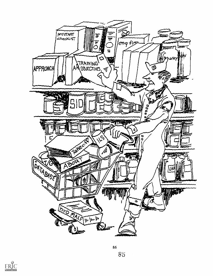
86
85
SECTION IVPROVIDING OPERATIONAL INFORMATION
Introduction After the selection of instructor support features, it isnecessary for operational personnel to provide more detailedinformation about the tasks to be trained and practiced. Thissection of the ISF Guidelines has three purposes: 1) to explainwhy cask specific information is required, 2) to describe whattype of information is required, and 3) to provide a formatthat is both convenient to use and that ensures that theinformation to be provided will be complete.
Background
ModularDesign:
Task Modules
Instructor support features (ISFs) are incorporated intoa simulator by means of an tnstructional Support System (ISS).The ISS is a subsystem within the ATD designed to reduce theinstructor's workload during the training exercise. The ISScan support instruction in a number of ways. It can simplifycontrol of the simulation and simulation variables, selectdisplays appropriate to the phase of flight, monitor flightparameters and procedures, compute performance measures,and store data for debriefing and other purposes. In short, itcan carry out any of the functions described in the definitionsof ISFs in Section II of these guidelines. By taking over someof these functions, the ISS allows the instructor to use histime more effectively during the training exercise. He isfreed to spend more time providing quality, one-en-oneinstruction, rather than dividing his time between the studentand countless other required functions.
In the past, instructional features having a direct correlatior.to procedures and curriculum requirements have been incorpor!l.tAinto ATDs; however the design of these features did not allow foreasy modifications. Changes in checklists, modificationfl toapproaches/departures, etc, continually change and instrucr-ionalfeatures which supported these events were quickly outdatod andtherefore justifiably not used.
To correct this major deficiency, a modular design was developedto allow straightforward modifications to the system without anysoflware rewrite. The operational training requirements areseparated into units called task modulas. They have a directcorrelation to a group of files which make up the data base fora modular data base driven system. This provides the capabilityto handle operational changes in a timely and economic manner.
Task modules have an additional advantage. Because they alsohave a direct correlation to training objectives, theirtncorporation into the system design will help to ensure thatthe ISS is designed to user needs.
87
8
SECTION IVPROVIDING OPERATIONAL INFORMATION
The folLwing paragraph should be added to the software sectionof the specification if the task module design is chosen:
"A database shall be deveLiped to parallel the syllabustraining objectives. The ISS ...hall be driven from this
data base. An editor for convm-S,ent update and moclificationof this database shall also be developnd."
Required If instructor support features are to be incorporated into
Information an ATD using the task module concept, then the ISS needscertain information to be able to implement them. In designing
an ISS, the user states what the ISS should do by specifyingwhich ISFs to incorporate. However, in order to recognizehow and when to activate/de-activate ISFs, the ISS also needsto have more specific information about the tasks to be trained
and practiced.
Example The following is a brief description of a TAKEOFF procedure andan example of the types of information which might be required:
Two typesof taskmodules:
§SgrI conditions for the task:(e.g., Value for airspeed is greater than zero andaccelerating)
Arag....tuditligna for the task:
(es.g., Airborne with &e id flips up)
o The digsaays to be presented to the instructor:(e.g., Plan view of runway and appropriat r. cockpit
instruments)
(e.g., Specify Maximum Centerline Deviation allowed)
O tsar mtssagesL(e.g., Rotated below specified rotation speed)
This type of operational information must be supplied by theusing command. Through the use of task modules, personnel inthe using command can specifically state the conditions underwhich training support functions will be provided by the ISS.
There are two basic types of task modules: flight and procedural.Modules related to the control of flight parameters and modulesrelated to procedural actions are basically different from the
viewpoints of both instruction and implementation.
88
87
SECTION IVPROVIDING OPERATIONAL INFORMATION
Flight Flight task modules involve monitoring continuously changingflight variables and measuring the amount of deviation from adesired value.
Procedural Procedural task modules involve monitoring events (eitherdiscrete switch actions or instantaneous values of variables)and measuring whether all the right actions were taken in acorrect order.
While the basic distinction between task module types is flightand procedural, it may be convenient to further subdivide thesetypes into categories for normal, emergency, and tacticalflight.
1.1t The resulting six categories (with examples included) areCategories listed below.
Normal Formal_Fltght Task Modules are the type of task modules whichFlight pertain to the flight segments of a training scenario. These
are pilot actions which directly relate to the control offlight parameters. The following is a sample list of this typeof module:
o Taxio Takeoffo Climb (non-controlled)o Climb (standard instrument departure)o Cruise (non-controlled)o Enroute (point ta point controlled)o Descent (non-controlled)o Descent (controlled)o Holdingo High Altitude Pert .-:4tiono Law Altitude Pen,. .:tiono GCA (precision final approach)o GCA (non-precision final approach)o /LS final approacho Non-controlled visual approacho Landingo Landing roll outo In-flight basic instrument maneuvering (S patterns)o Aerobatic maneuveringo Inflight refueling
Normal Normal grocedures Task Modules are the type of task module5whichProcedures pertain to the normal procedural e-yts the student must
accomplish. These are flight crew actions in the cockpit- otherthan direct flight control. The following is a sample List ofthis type of task module:
89 88
SECTION IVPROVIDING OPERATIONAL INFORMATION
o Pre-start checklistso Start checklistso Post start checklistso Pre-taxi checklistso Pre-takeoff checklists
Takeoff checklistso Post take off checklists
Climb checklistso Pre-descent checklistso Penetration checklistso Pre-landing checklistso Landing checklistso Post landing checklistso Pre-shutdown checklistso Shutdown checklists
Emergency gmezzency_r_tos iures_Task Nodulel are the type of task modules
Procedures which pertain ) the procedural events in handling aircraftsystem malfunctions. This type of task module is aircraftsystems specific; therefore the following is a list of commonaircraft systems which this type of task module would mostlikely fall under.
o Hydraulic malfunctionso Electrical malfunctionso Flight control malfunctions
Fuel malfunctionsEngine malfunctions
o Environmental control malfunctions
Emergency Emergency Flight Task Nodules are the type of task modulesFlight which pertain to aircraft flight control while handling an
emergency. The following is a sample list of this type oftask module:
o Single engine landing (or less than all engines)o Landing gear malfunction landingso Land PSAP (e.g., low fuel - re-routing quick descent)o Blown tire on landingo Less than optimum configuration landing (e.g., no
flaps)a n-flight fire
gngine failure on takeoff (abort)o Engine failure on takeoff (no abort)o Blown tire on takeoff
Engine restart procedures (in flight)
90
ssJ
SECTION IV
PROVIDING OPERATIONAL INFORMATION
Weapons Weapons Procedures Task odules are the type of task modulesProcedures which pertain to the procedural actions in operating weaponsrelated equipment in the cockpit. This type of task module isweapons specific; therefore the following sample list is verybroad !.n scope.
o AAI radar search procedureso Weapons control panel procedureso ECM systems procedureso AEW systems procedures
Flight Flight Tactics Task Modules are the type of task modules whichTactics pertain to aircraft tactical maneuvering. This type of task
module is weapons Task Modules specific; therefore the followingsample list is ver broad in scope.
o Low-altftude bomb runo 2 v 1 1.4.D
o SAM defensive maneuver
A. task commontlity analysis, found in Appendix E, may be used asan initial step in identifying task modules for specific ATDs.
Other As a detailed checklIst of items to be included, the taskOperational module is an aid to the user and training analyst in specifyingConsiderations system requirements. The following are examples of some of the
operational considerations which should be addressed whendescribing these tasks:
Display Requirement Any graphic display requirements specificto the task module should be specified (e.g., HI TACAN NO.1approach plate with a non-erasing history trail of the aircraftflight path)
eata___Luggsats.. TIle measurements expected co be taken shouldbe defined. The following are examples:
o Airspeed (TAS, CAS, MACH)o Heading (degrees, true, magnetic)o Altitude (feet AGL, MSL)o Vert1 (feet per second)o Rate (degre7is net second, standard rate)o Acceleratfun (Gs)o Position (lat,qc.,11,s, radial/distance)o Angle of Attack (ur.!_tf... specific to A/C)o Switch positions (for procedural tasks)o AircriOt configur&tion
91
5 0
SECTION IVPROVIDING OPERATIONAL INFORMATION
Measurement Twes_. How the measurements are to be taken shouldbe addressed. The following are examples:
o Continuous over a period of time with start stopconditions.
o transform selection- sampling rate
o Single measurement (snap shot)- logic when to take the measurement
o Reaction time and time to complete a procedure (forprocedural tasks).
Performance Algorithm If automated performance measurementis to be applied, the following are some issues to address:
o Scoring Procedure- weight factors within the objective- weight factor within the exercise
o Task difficulty dependent on the environmentalconditions
o Task difficulty dependent on other parallel runningtasks
Task Module Start Sto Conditions The following are someexamples of how to define machine detectable start stopconditions:
o Machine detec-:flole events
- reaching a flight parameter or combination offlight parameters
- arriving at a specified position (lat, long, fix)or the closest point of approach to a position
- flying into a cone in space defined by radials ofa nav facility and within an altitude band
any of the combination of the above
o Operator inputs
- resets- changes to I.C.s- manual insertion , checklist or malfunction
92
91
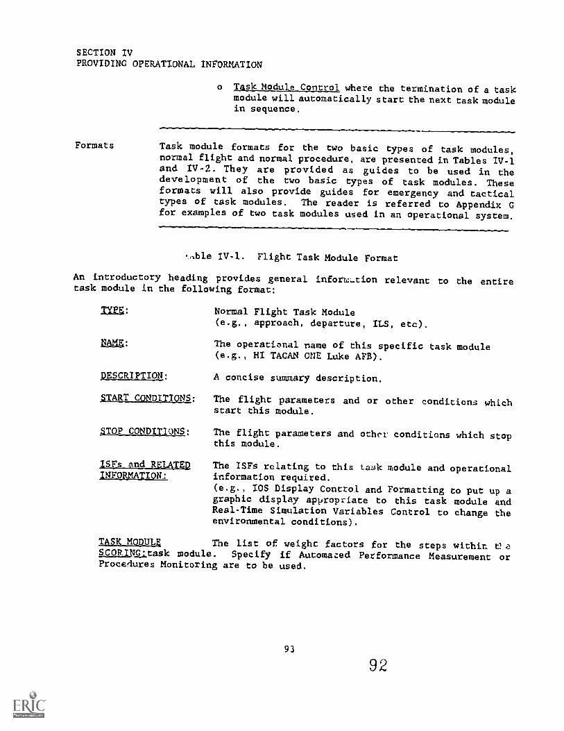
SECTION IVPROVIDING OPERATIONAL INFORMATION
Formats
o Task Module Control where the termination of a taskmodule will automatically start the next task modulein sequence.
Task module formats for the two basic types of task modules,normal flight and normal procedure, are presented in Tables I1-1and IV-2. They are provided as guides to be used in thedevelopment of the two basic types of task modules. Theseformats will also provide guides for emergency and tacticaltypes of task modules. The reader is referred to Appendix Gfor examples of two task modules used in an operational system.
4ble IV-1. Flight Task Module Format
An introductory heading provides general inforw,..cion relevant to the entiretask module in the following format:
TYPE: Normal Flight Task Module(e.g., approach, departure, ILS, etc).
NAMg: The operational name of this specific task module(e.g., HI TACAN ONE Luke AFB).
DESCRIPTION: A concise summary description.
START CONDITIONS: The flight parameters and or other conditions whichstart this module.
STOP CONDITIONS: The flight parameters and other conditions which stopthis module.
ISfs and RELATED The ISFs relating to this task module and operationalINFORMATION_L information required.
(e.g., IOS Display Control and Formatting to put up agraphic display appropriate to this task module andReal-Time Simulation Variables Control to change theenvironmental conditions).
TASK MODULZ The list of weight factors for the steps within. tteSCORINatask module. Specify if Automazed Performance Measurement orProcedures Monitoring are to be used.
93
92
SECTION IVPROVIDING OPERATIONAL INFORMATION
Table IV-1. Flight Task Module Format - Continued
Each task module is further broken down into measurable events called steps.
This further breakdown provides more precise points whereby additional support
features may become active. They are listed in logical order in the following
format:
STEP NUMBER: The unique sequential number identifying this
step: 1,2,3, ...N.
DESCAIPTION: A statement of the student action to be performed in
terms of specific aircraft flight/configurationparameters(e.g., climb to FL 180 upon reaching "BIC"intersection).
TT CONDITIONg: The flight parameters and or other conditions which
start this step.(e.g., in the case above, a start condition would be
the closest point of approach to "BIC" intersection.)
Vgr COYDITIONS: The flight parameters and or other conditions which
stop this step.(In the case above, when the simulator reaches 18,000ft MSL.)
1SFs and RELATED The ISFs related to this step.
INFORUATION: (e.g., Malfunction Control to insert "cabin pressure
failure").Also specify operational information required forthese ISFs.(e.g., Scoring procedures for Automated PerformanceMeasurement, diagnostic messages if desired.)
94
9 3
SECTION IVPROVIDING OPERATIONAL INFORMATION
Table IV-2. Normal Procedures Task Module Format
The heading provides introductory, general information regarding the entiretask module in the follou_ng order:
LYIE:
DESCRIPTION:
gARy CONDITIONS:
STOP CONDITIONS:
and MATZOPFOBMATION:
Normal Procedures Task Module(e.g., engine start, taxi checklist, takeoff checklist,etc.)
The specific name of the task module(e.g., takeoff checklist).
A concise summary of the content.
A description of the situation which defines thestart of this task module; may consist of variousswitches being set, parameters being met, or byoperator selection.
A description of the situation which defines thecompletion of this task module; may consist of variousswitches being set, parameters being met, or byoperator selection.
/SFs relating to this task module and requiredoperational information.(e.g., IOS Display Control and Formatting to put upthe appropriate display for this checklist)
Each task module is further broken down into steps. This further breakdownprovides more preciss points whereby additional support features may becomeactive. They are listed in logical order in the following format:
TELP _NUMAER:
DESCRIPTION:
CONTINGENCI4S:
EVENTS:
JSFs and REIAMJNFORMATI9N:
The unique sequential number identifying this step:1, 2, 3, ...N.
A statement of the checklist activity to beaccomplished in this step, generally consisting ofone chocklist item which oay or may not includeseveral associated activities.
If appropriate, a description of the events whichmust have caken place prior to the initiation of thisstep, i.e., prerequisite events.
To be supplied.
ISFs relating to this step and required operationalinformation.
(e.g., Procedures Monitoring to determine if correctprocedure was followed and possibly to put up a7r,
error message if something was done incorrectly).
95
PRIMARY REFERENCES
Caro, P.W., Pohlmann, L.D. & Islay, R.N. (11:479). Development of stmulatorins_t_rzationgLie_a_tegign_gaiskta (AFOSR-TR-80-0346). Bolling AFB, DC: AirForce Office of Scientific Research.
Horn, R.E. (1983). Developing instructional matesiall_ga_pdaspedures:_ antmnkgAlcot_ireinorinationrr (rev. ed.). Lexington, MA: Information Mapping,
Inc.
Locaf, W.A., Fitzpatrick, J.A. & Gunzburger, S.P. (1983). lisIrNing...AxAf.t.i.Prime item devekoRment specification for flight simulators-___InA/suctionalaspgcts (F33615-78-C-0019/P00012). Lowry Air Force Base, CO: Air Force HumanResources Laboratory.
(1983). Atrcrew training devices.; utility and utilizationof ad-rance,. instructisnal fr-tures (Phase I - Tactiski),_Atr CCITIMLInd) (AFHRL-TR-83-12). Williams AFB, AZ: Air Force Human Resources Laboratory. (Kii-A135 052)
Semple C.A., Cotton, J.C., & Sullivan, D.J. (1981). Aircrew trainingdevIce!,..; Instructfonal suppqrt features (AFHRL-TR-80-58). Wright-PattersonAFB, OH: Air Force Human Resources Laboratory. (AD-A096 234)
Waag, W. (In work). IpUructional_support featurel_km.wismSraLning.4.1tylata.For The Technical Cooperation Program, Sub-Committee on Non-Atomic MilitaryResearch and Development. Williams AFB, AZ: Air Force Human ResourcesLaboratory.
97
9 5
GLOSSARY OF TERMS
AIRCREW TRAIN/NG DEVICE (ATD): A term that refers to synthetic trainingdevices (simulators) used in support of aircrew training programs. Thesedevices range from simple procedures trainers to more complex training systems.
ALGORITHM: A precise characterization of a method for solving a problem orachieving a goal, e.g., a sequence of actions terminating in a solution.
BRIEF: Review of events, objectives and procedures with aircrew andinstructional staff prior to simulator session.
CHECKLIST: series of distinct actions to be performed at discrete times.
CONTINUATI' ' '.74,.INING: Training conducted routinely in operational squadrons,or profici--)c,7 training conducted periodically.
CONVEkS1 TRAINING: Initial qualifying training for a particular typeof weapotl system.
DATA-DRIVEN: A system that relies on general software which acts upon adatahise, such that a change to the database would not Ofect a change tothe noftware.
DEBRIEF: Review of event results with aircrew and instructors subsequentto simulator session.
FIDELITY: Row closely the simulation reflects the actual performance of theaircraft.
INITIALIZATION: Initialization involves specifying, usually from diainstructor/operator console, the parameters of interest and their values forpositioning and configuring an ATD within a gaming area.
INSTRUCTOR SUPPORT FEATURE (ISF): Feature provided by the ISS to aid the ATDinstructor in conducting the training exercise. See Section /I for a completelist of ISF definitions.
INSTRUCTIONAL SYSTEMS DEVELOPMENT (ISD): Procedural approach to the analysisof training requirements and the development of training programs and systems.
INSTRUCTOR/OPERATOR STATION (IOS): The aircrew training device man-machineinterface where active control and monitoring of training events occurs.
INSTRUCTOR SUPPORT SYSTEM (ISS): Automated system within the ATD designed toaid the instructor in performing the training function.
OFF-BOARD STATION: Instructor/operator station which is outside cockpit.
99
96
OFF-LINE: Any action not associated with active training on the simulator.(Operations on the remote graphics brief/debrief station is off-line)
ON-BOARD STATION: Instructor/operator station which is inside cockpit.
ON-LINE: Controlled directly by a computer.
OPERNTIONAL FLIGHT TRAINER (OFT): A device which dynamically simulates theflight characteristics of the designated aircraft to train flight crewsin cockpit procedures, instrument flight procedures, emergency procedures,communications and navigation procedures, and includes limited missionexecution.
SAMPLING RATE: The temporal frequency at which a stated variable (parameter)may be recorded or examined by an automated performance measurement system.
SCENARIO: A predefined sequence of training events used to exercise thecapabilities of an ATD in a specific area of intended training usage.
SIMULATION SYSTEM: That part of the ATD that provides aircraft dynamics andthe environmental conditions.
STATEMENT OF OPERATIONAL NEED: A general statement of requirements preparedby one of the Air Force Major Commands.
TRAINING OBJECTIVES: Explicit statements of the goals of training includingtasks to be performed, the performance standards for each task, and theconditions under which those tasks are to be performed.
TRAINING REQUIREMENTS: General statements of task performance skills requiredfor operational proficiency. Also, general statements of performance skillsthat require periodic practice in order to maintain proficiency.
TRANSITION TRAINING: Training for aircrew members transitioning to differentoperational aircraft.
UNDERGRADUATE PILOT TRAINING: Initial pilot flight training.
100
97
ABBREVIATIONS AND ACRONYMS
A/C aircraftACM air combat maneuveringAFB Air Force BaseAFTS Adaptive Flight Training SystemAGL above ground levelAPM automated performance measurementARPTT aerial refueling part-task trainerASD Aeronautical Systems DivisionASR advanced surveillance ridarATC Air Training CommandATD aircrew training device
BFM basic fighter maneuvers
CAS calibrated air speed'CDR critical design reviewCPA closest point of approachCPT cockpit procedures trainerCRT cathode ray tube
D.C. direct current
ECM electronic countermeasures
GCA ground controlled approachGCI ground controlled intercept
HUD head-up display
LAS indicated air speedI.C. initial conditionIFF identification friend and foeIFR Instrument Flight RulesILS Instrument Landing SystemINS Inertial Navigation SystemIOS instructor/operator stationISD instructional system developmentISF instructor support featureISS Instructional Support System
MAC Military Airlift CommandMAJCOM major commandMRM medium range missileMSL mean sea level
NAVAIDS navigational aidsNDB non-directional beacon
101 9 8

OAP offset air pointOFT operational flight trainer
PAR precision approach radarPIDS prime item development specification
R&D research and developmentREO radar electro optical
SAC Strategic Air CommandSAM surface-to-air missilesSID standard instrument departureSimSPO Simulator Systems Program OfficeSMS/FNCP storage management system and fuel navigation control panelSRM short range missile
TAC Tactical Air CommandTACAN tactical air navigation
UPT Undergraduate Pilot Training
WST weapon system trainerWx weather
102
/SF INDEX
automated demonstration(see automated simulator demonstration)
automated performanoe measurement,10, 16, 20, 28, 34,.421 57-60, 62, 63, 66, 68, 80, 92, 93, 94
automated stmniator demonstration,10, 46, 50, 53-55, 79
briefing utilities,10, 15-17, 67, 68, 771 82
crash/kill override(see freeze)
current status displays(see IDS display control and formatting)
data recording(see data storage and analysis)
data atoms amd analysis,10, 161 58, 67-69, 81
demonstration(see automated simulator demonstration)
freeze,10, 25, 31, 32, 34, 35, 37, 45-46, 49, 501 51, 531 541 551 661 79
graphic displays(see IDS display control and formatting and remote graphics replay)
graphic replay(see remote graphics replay)
bardoopy/printout,10, 6143, 78, 94
Initial ()auditions,10, 20, 25-26, 27, 28, 332 78
IOS display control and fOrmattiAS,10, 37..39, 42, 79, 811 931 95
malfunction oontrol,10, 27, 28, 29-32
off-line replay(see remote graphics replay)
parameters monitoring(see automated performance measurement)
IS/1k
performance measurement(see automated performance measurement)
preprogrammed mission scenarios(see scenario control)
printout(see bardoopy/printout)
procedures monitoring,10, 31, 41-43, 58, 79, 93, 95
Programmed mission scenarios(see scenario control)
real-tims etiolation variables oontrol,10, 20, 27-28, 78, 93
recordkeeping.(see data ttorage and analysis)
record/playback(see simulator record/replay)
recorded briefings(see briefing utilities)
reposition,10, 26, 28, 33.35, 78
remcte briefing/debriefing consoleisee remote graphics replay and briefing utilities)
remote grapbics replay,101 58, 82, 85-66, 81, 82
soemario control,10, 19-24, 25, 27, 28, 31, 941 77, 78
simulation variables(see real-time simulation variables control and initial conditions)
simulator reoordireplaY,10, 46, 49-52, 54, 79
slew(see reposition)
tutorial,10, 13-14, 76
vehiole control(see real-time simulation variables control)
104
1

A-10
3-52
C-130
APPENDIX A
AIRCREW TRAINING DOCUMENTATION
Flight Objectives Pamphlet (8/84)GradesheetIOS Manual, Upgrade Training Course (not dated)TAC Syllabus (8/84)
Console Familiarization Course (1984)Test Option 5 Scenario Description (not dated)Training Program WST Coursebook (not dated)WST OIS Console Operations Guide Vol. I and II (8/84)WST DOS Console Operations Guide (8/84)
Flight Simulator Operating Instructions (10/82)Instructor Guide Part II, Pilot Requalification/Upgrade Course (1/83)Instructor Guide, Navigator Mission Qualification (12/82)Mission Profiles I - V (not dated)Nullmeyor, R.T., and Rockway, M.R. Effectieness of Weapon System
Trainers for Tactical Aircrew Training. In Proceedings of Inter-service/Industry Training Equipment Conference and Exhibition,October 1984.
Partial Preliminary Simulator Instructor Guide for Tactical MissionQualification Training (12/82)
Pilot Study Guide Part I, Pilot Initial Qualification Course (10/82)Student Study Guide Part II, Tactical Mission Qualification Training
(12/82)
C-141
Flight Instructor Guide, Navigator Airdrop Mission Qualification Course(3/83)
Flight Instructor Guide, Pilot Initial Qualification Course (1/81)Instructor Guide, Pilot Airdrop Qualification Course (11/83)Instructor Malfunction Guide, Flight Engineer Initial Qualification
Course (3/84)SIM/CPT Instructor Guide, Pilot Initial Qualification Course (11/82)Task and Objectives Document, Loadmaster Airdrop Qualification Course
(10/81)
A-1
102
F-15
F-16
Instructor Operator Guide, F-15 Simulator (7/83)Operational Training Course (10/81)Simulator Instructor Pilot Upgrade Procedures (7/83)
Basic Operational Training Course (1/84)GradesheetsInstructor Handbook (3/82)Wordstar Lesson Eqins (1984)
KC-135
T-37
T-38
Navigator WST Coursebnok (1/84)Pilot WST Coursebcoh (1/84)
Instrument Program (3/83 and 9/84)Syllabus of Instruction for Undergraduate Pilot Training (T-37/T-38) (8/83)T-50 IFS Mission Guide (3/83)
Syllabus of Instruction for Undergraduate Pilot Training (T-37/T-38) (8/83)
Admanced Instmc_tional_SYBte_m_Documentation:
AFTS (F426000-77-C-2581)AFT Program Description (5/72)Automated Weapon System Trainer (6/70)Grunzke, P. Evaluation of the Automated Adaptive Flight Training System's
Air-to-Air Intercept Performance Measurement. AFHRL-TR-78-23. AirForce Human Resources Laboratory, Williams Air Force Base, AZ. July1978.
Performance Specification for AFTS for A-7D (6/78)Performance Specification for AFTS for F-4E (6/78)Program Source ListingsSoftware Users Guide for AFTS for F-4E (4/79)Training Specification for AFTS for A-7D (6/77)Training SL:ecification for AFTS for F-4E (7/78)
B-52 ARPTT ISS (F04604-81-C-0030)ARPTT Training Program (5/84)Functional Design Document - ARPTT ISS (11/84)Instructor Guide, B-52 Training Program Pilot BPAT (not dated)Program Source ListingsStudy on the Refurbishment of Aerial Refueling Part Task Trainer (ARPTT)
to Extend its Life Expectancy - Technical Report (10/81)
A-2
103
C-5A PMS (F33615-78-C-0027)C-5 Course Summary Document, Pilot Initial Qualification Course (1/82)C-5 Pilot Master Task Listing (3/83)CPT/SIM/FLT Student Guide, Pilot Initial Qualification Course (2/81)CPT/SIM/FLT Instructor Guide, Pilot Initial Qualification Course (1/83)Operations Manual - PMS for the C-5A Simulator (9/83)Program Source ListingsSwink, T.R., Butler, E.A., Lankford, H.E., Miller, R.M., Watkins, H., and
Waag, W.L. Definition of Requirements for a Performance MeasurementSystem for C-5 Aircrew Members. AFHRL-TR-78-54. Air Force HumanResources Laboratory, Williams Air Force Base, AZ. October 1978.
System Specification (Parts I, II and III) (12/82)Waag, Wayne L. and Hubbard, Davitt C. Tho Measurement of C-5A Perfor-
mance. In Proceeding& of P4).,:bology DOD Symposium, U.S. Air ForceAcademy, April 1984.
F-14 ISS (N61339-78-C-0108)Bosworth, L.K., Kryway, J.T., and Seidensticker, S.S. F-14 Instructional
Support System (ISS) Weapons System Training (WST). NAVTRAEQUIPCEN80-C-0056-1. Naval Training Equipment Center, Orlando, FL. March1981.
F-14 Instructional Support System (ISS) Final Technical Report.NAVTRAEQUIPCEN 78-C-0108-1. Naval Training Equipment Center, Orlando,FL. June 1982.
F-14 ISS Operational Design (not dated)F-14 ISS System Development Notebook Vol. I (not dated)Osborne, S.R., Semple, C.A., and Obermayer, R.W. Three Reviews of the
Instructional Support System (ISS) Concept. NAVTRAEQUIPCEN 81-C--0081-1. Naval Training Equipment Center, Orlando, FL. March 1983.
Program Source ListingsSemple, C.A., Vreuls, D., Cotton, J.C., Durfee, D.R., Hooks, J.T., and
Butler, E.A. The Functional Design of an Automated InstructionalSupport System for Operational Flight Trainers. NAVTRAEQUIPCEN76-C-0096-1. Naval Training Equipment Center, Orlando, FL. January1979.
A-3
1.04
APPENDIX B
BIBLIOGRAPHY
Allbee, K.E. & Semple, C.A. (1981) Aircrew training devices: Life cyclecost ancl wotth ot ownership (AFHRL-TR-80-34). WrightPatterson AFB, OH:Logistics and Technical Training Division. (AD-A094 704)
Ballard, H.M., Bosworth, L.K., Connors, J.J., Goad, D.E., Hecker, M-E., King,M.R., & Seidensticker, S.S. (1984) Modulat simulator copcept definition--Ipsetim seport (USAF ASD 83-C-2201-1). Wright-Patterson AFB, OH: Air ForceSystems Command, Aeronautical Systems Division.
Bosworth, L.K., Connors, J.J., Goad, D.E., Hecker, M-E., Johnston, D.L., King,M.R. & Seidensticker, S.S. (1984). Modular simulator concept definition--fioal toport volumej._ final technical seport (USAF ASD 83-C-2201-2). Wright-Patterson AFB, OH: Air Force Systems Command, Aeronautical Systems Division.
Bosorth, L.K., Connors, J.J., Goad, D.E., Hecker, M-E., Johnston, D.L., King,M.R. & Seidensticker, S.S. (1984). Modular simulator concept definition--float report volume IL netvorlc dftaition (USAF ASD-83-C-2201-3). Wright-Patterson AFB, OH: Air Force Systems Command, Aeronautical Systems Division.
Bosworth, L.K., Connors, J.J., Goad, D.E., Hecker, M-E., Johnston, D.L., King,M.R. & Seidensticker, S.S. (1984). Modular simulator concept definttion--
I 11 s ecii to adstateme o o (USAFAir Force Systems Command,ASD-83C-2201-4). Wright-Patterson AFB, OH:
Aeronautical Systems Division.
Caro, P.W., Pohlmann, L.D. & Isley, R.N. (1979) Develo ment of simulatorinattuctiomal feature design guides (AFOSR-TR-80-0346). Bolling AFB, DC: AirForce Office of Scientific Research.
Caro, P., Shelnutt, J. & Spears, W. (1981). Aircrew training devices_: Utili-zation (AFHRL-TR-80-35). Wright-Patterson AFB, OH: Air Force Human ResourcesLaboratory. (AD-A095 071)
Cream, B.W., Eggemeier, F.T., & Klein, G.A. (1978). A strategy for thedevelopment sxt training devices (AFHRL-TR-78-37). Wright-Patterson AFB, OH:Air Force Human Resources Laboratory. (AD-A061 584)
Department of the Air Force. (1982). Acauisttion program management (AirForce Regulation 800-2). Washington, DC: Author.
Department of the Air Force. (1984). Executive summary. T-46A operationalflight trainer (Request for Proposal, F33657-84-0003). Wright-Patterson AFB,OH: Air Force Systems Command.
B-1
105
Department of the Air Force. Human Factors Engineering. (1977). AFSC designbandbook, (DH1-3). Wright-Patterson AFB, OH: Headquarters AeronauticalSystems Division.
Department of the Air Force. (1977). Manaeement and utilization of trainingdevices (Air Force Regulation 50-11). Washington, DC: Author.
Department of the Air Force. (1984). Management of training systems (AirForce Regulation 50-11). Washington, DC: Author.
Departmont of the Air Force. (1983). Modification pcKogram approval andmanagemen (Air Force Regulation 57-4). Washington, DC: Author.
Department of the Air Force. (1979). Statement of operational need ISON)(Air Force Resulation 57-1). Washington, DC: Author.
Department of the Air Force. (1978) Training. Handbook for designers ofinstrmptional systems (AF Pamphlet 50-58). Washington, DC: Author.
Department of Defense. (1968). Military standard. Specification practices(MIL-STD 490). Washington, DC: Author.
Dickman, J.L. (1982, November). Automated performance measurement: Anoverview and assessment. In ATILIntssuConference Zroceedings. National Security Industrial Association.
Hagin, W.V., Osborne, S.R., Hockenberger, R.L., Smith, J.P., & Gray, T.H.(1982). Onerational test pnd evaluation handbook for aircrew training devices:Operational effectiveness evaluation (AFHRL-TR-81-44(II). Williams AFB, AZ:Air Force Human Resources Laboratory. (AD-A112 570)
Hagin, W.V., Osborne, S.R., Hockenberger, R.L., Smith, J.P., & Gray, T.H.(1982). Operational test and evaluitton havlbook for aircrew training devices:Operational_ suttability evalmatIon (AFHRL-TR-81-44(III)). Williams AFB, AZ:Air Force Human Resources Laboratory. (AD-A112 569)
Hagin, W.V., Osborne, S.R., Hockenberger, R.L., Smith, J.P., & Gray, T.H.(1982). Operational test and evaluation handbook for aircrew trainine devices:pj,Annjng_AncL_mandz,§msnt (AFHRL-TR-81-44(I)). Williams AFB, AZ: Air ForceHuman Resources Laboratory. (AD -A112 498)
Hammell, T.J. (1982, October). The instructional subsystem, a major componentof the training device. In G.L. Richard, T.N. Crosby, & E.Y. Lambert (Eds.),Workshou ori_Inqtructiompl Featmres ausl Instructor/Operator Station Design forTraining Sysgros (NAVTRAEQUIPCEN I11-341). Orlando, FL: Naval TrainingEquipment Center.
Harris, W.T., Hinton, W.M. & Komanski, W.M. (1962, November). The instructoroperator station: Design for the user. In 4th Interserviqq/Industry TrainingEquivrent Confetence Proleedings. Volume I. National Security IndustrialAssociation.
B-2
106
Hinton, W.M. & Komanski, W.M. (1982, October). Instructor/operator stationdesign concepts. In G.L. Richard, T.N. Crosby, & E.Y. Lambert (Eds.), Workshopon Instructional Features and Instructor/Operator Station Design for TrainingSystems (NAVTRAEQUIPCEN IH-341). Orlando, FL: Naval Training Equipment Center.
Hritz, R.J. & Purifoy, G.R. (1980). Maintenance traintng simulator delignand acquisition (AFHRL-TR-80-23). Lowry AFB, CO: Air Force Human ResourcesLaboratory. (AD-A089 149)
Horn, R.E. (1983). Developing_ instructional materials and procedures: an311.g_i§itiLn_)!_pnairpLg_s_5:Lt_irsert (rev. ed.). Lexington, MA: Information Mapping,
Inc.
Hritz, R.J. & Purifoy, G.R., Jr. (1982). daintenance Training Simulatorpesign aqd Acquisition: MD-Derived Training Equipment Design (AFHRL-TR-81-52).Lowry AFB, CO: Air Force Human Resources Laboratory. (AD-A110 871)
Hussar, J.S. (1984). A comparison of simulator procurement/program practices:Military vs. commercial. Training_Technologvi Journal, 1(3), 4-18.
Leaf, W.A., Fitzpatrick, J.A. & Gunzburger, S.P. (1983). Working draft.Prime item development specification for flight simulators_ InstructionalAspects (F33615-78-C-0019/P00012). Lowry Air Force Base, CO: Air Force HumanResources Laboratory.
Meyn, Catherine. (1984, October). IOS hardware usage and training effective-ness: The best approach. In 6th Interservice/Industry Iraining EauipaentConference Proceedings- Volume I. National Security Industrial Association.
Miller, G.G. (1974). Some considerations in the design and utilizatlon of(AFHRL-1.11-74-65). Lowry AFB, CO: Air Force
Human Resources Laboratory. (AD-A001 630)
Pohlmann, L.D., Isley, R.N., & Caro, P.W. (1979, November). A mechanism forcommunicating simulator instructional feature requirements. In 1st Intgrser-vice Technical Eauipment Confetence Proceedings (NAVTRAEQUIPCEN IH-316).Orlando, FL: Naval Training Equipment Center.
Polzella, D.J. (1983). Aircrew traiqing devices: utility and utilizatlon ofAdvanced instructional features (Phase I - Tactical Air Command) (AFHRL-TR83--22). Williams AFB, AZ: Air Force Human Resources Laboratory. (AD-A135 052)
Polzella, D.J. (1984). Aircrew training devices: Utility and utilization ofadvanced instructional features (Phase II - Air Training Command. MilitaryAirlift Command. Strategic Air Command) (UDR-TR-84-32). Dayton, OH: Universityof Dayton Research Institute.
Purifoy, G.R., Jr. & Benson, E.W. (1979). daintenance training simukatprsdesign and acquisition; summary of current procedures (AFHRL-TR-79-23). LowryAFB, CO: Air Force Human Resources Laboratory. (AD-A079 636)
B-3
107
Seidensticker, S. & Kryway, T. (1982, October). Procedures monitoring andscoring in a simulator. In G.L. Richard, T.N. Crosby, & E.Y. Lambert (Eds.),workshop on Instructional Features and Instructor/Operator Station Desian forTraining Systems (NAVTRAEQUIPCEN IH-341). Orlando, FL: Naval TrainingEquipment Center.
Seidensticker, S. & Meyn, C. (1982, October). Modular control of simulators.In G.L. Richard, T.N. Crosby, & E.Y. Lambert (Eds.), Workshop on InstructtonalFeatures and InstructorLDperator Statton Design for Training Systems(NAVTRAEQUIPCEN IH-341). Orlando, FL: Naval Training Equipment Center.
Semple, C.A., Cotton, J.C., & Sulltvan, D.J. (1981). Atrcrew trainingdevices: Instructional support features (AFHRL-TR-80-58). Wright-PattersonAFB, OH: Air Force Human Resources Laboratory. (AD-A096 234)
Semple, C.A. & Cross, B.K., II. (1982, October). The real world and instruc-tional support features in flying training simulators. In G.L. Richard,T.N. Crosby, & E.Y. Lambert (Eds.), Workshop on Instructional Features apdInstructor/Operator Station Desian for Training Systems (NAVTRAEQUIPCENIH-341). Orlando, FL: Naval Training Equipment Center.
Tucker, R.N. & Speer, R.G. C-5 aircrew training system. (1984, October). In6th Interservice/Industry Training Equipment Conference Proceedinas. Volume1. National Security Industrial Association.
U.S. Department of Transportation. (1982, January 31). Advisory Circular120-40. Federal Aviation Administration.
Waag, Wayne. (1984) ATD acquisition in the U.S. Air Force. Williams AFB,AZ: Air Force Human Resources Laborary.
Waag, W. (In work). Instructtonal support features for majorsrainina devices.For The Technical Cooperation Program, SubCommittee on Non-Atomic MilitaryResearch and Development. Williams AFB, AZ: Air Force Human ResourcesLaboratory.
Waag, Wayne. (1984) Performance measurement requirements in the design ofinstructional support systems for operational training simulators. WilliamsAFB, AZ: Air Force Human Resources Laboratory.
B-4
108
APPENDIX C
SAMPLE SPECIFICATION
The purpose of the sample specification provided, beginning on page C-12, isto illustrate the use of these guidelines in defining instructor supportfeatures for an ATD specification. It was developed using the proceduresdescribed in Section III of this document. The resulting specification is afunctional baseline: Once budgetary constraints are known, SimSPO personnelcan then perform cost, technology, and benefit tradeoffs.
Meetings were held with the TAC ISD Squadron's F-16 training program represen-tatives at Luke AFB in order to identify their specific training and instructorsupport system requirements. This sample specification was developed using ageneral description of the device and training to be accomplished. Theassumptions made include:
o A complete front end analysis has been performed.o The instructor will operate and control the device.o The anticipated use rate is between 8-12 hours per day.
FRONT END ANALYSIS
General Description - The sample specification is for an F-16 OFT-type devicewith a remote instructor/operator station. It will have a limited field-of-view visual system and a generic digital radar landmass presentation. Thedevice will be used for basic weapon system training in addition to the basicsafety of flight objectives. Continuation and conversion training will beconducted on this device. The following is a general description of thetraining capabilities required of this ATD.
Provide Basic Safety of Flight Training
o Emergency Procedureso Degraded Flight Conditionso Checklist and Procedural Trainingo Normal Flight Trainingo Instrument and Navigation Trainingo Standardization Training/Evaluation
Provide Basic Tactical Training
o Air-to-Air Training Phase- Air-to-Air Intercepts (1 to 4 bogies)- Air-to-Air Sensors Use- Air-to-Air Weapon Employment- Intercept Tactics to Merge Plot (Visual on bogie)- Clear Air Environment (Non-ECM)
C-1
109
o Air-to-Ground Training Phase- Low Altitude Tactical Navigation (DR/INS/sensors)- Air-to-Ground Sensors Utilization- Air-to-Ground Weapon Delivery
Itaamt Sill and Kuowledge Leve1 - Continuation and conversion training willbe cavcht on this device. Training will range from familiarization to fullmission scenarios. The conversion student is most likely unfamiliar with themission of the aircraft, weapon system use, and/or the cockpit controls anddisplays.
Training Task Objectives - The following training task objectives will betaught using this device. They are grouped according to task module type (seeSection IV, "Providing Operational Information").
NOrmal Procequreq Normal Flight
o Cockpit Checks o Takeoffo Before Engine Start o Standard Instrument Departureo Engine Start o Instrument Navigationo Before Taxi Checks o Point to Point Navigationo Before Takeoff Checks o Unusual Attitude Recoveryo Penetration Checklist o Steep Turnso Landing Checklist o Holdingo Before Engine Shutdown Checks o Instrument Penetrationo Engine Shutdown Checklist o Instrumeut Final Approacho Radio Communications (TACAN/ILS/PAR/ASR)o INS Update o
o
Missed ApproachLanding/Roll-out
Emergency Procedures emergency Flight
o Abnormal Start o Aborted Takeoffo Engine Malfunctions o Precautionary Landingo Electrical Malfunctions o Degraded Flight Conditionso Hydraulic Malfunctions o Arrested Landingo Flight Control Malfunctions o Minimum Fuel Profileo
o
oo
AirstartFireJettison ProceduresLanding Gear Malfunctions
o Asymmetrical Load Approach
Weapons Procedures Flight Tactics
o SMS/FNCP Programming o Radar Target Acquisitiono REO Set Up o Collision Course Intercepto Fence Check 0 Stern Conversion Intercepto Radar Set Up/Checks o Vertical Attacko Ordnance Arming o Weapon Selection/Employmento Radar Search Pattern o Intercept Controlo GCl/AWACS Procedures o Low Altitude Tactical Navigation
C-2
110
o Radar Position Updateo HUD Updateo Altitude Calibrationo Communication Procedures
o Air-to-Ground Ordnance Delivery(Level/Dives/Loft/Toss/OAP)
o System/Manual Ordnance Deliveryo Escape/Evasive Manewvers
Training - For the purpose of this sample specification, threetraining scenarios have been developed based on the training objectives andperceived user training requirements.
o Scenario 1 - End-to-end training from cockpit entry to engineshutdown. It includes normal procedures and flight objectives,emergency conditions and basic air-to-air intercepts and weaponemployment. Training objectives include:
o Cockpit Checkso Before Engine Start Checkso Abnormal Starto Normal Starto Before Taxi Checkso Before Takeoff Checklist
o Takeoffo Standard Instrument Departureo Engine Emergencyo Airstart
o Radar Checkso Fence Checko Air-to-Air Intercept (single target)o Air-to-Air Weapon Employment
o Holdingo High Altitude Penetrationo GCAo Missed Approacho ILS
o Landing/Roll-outo After Landing Checkso Engine Shutdown
o Scenario 2 - The simulator is initialized at the end of the runwaywith the engine running. Emphasis is on normal flight task (T/0,SID, approach), low altitude tactical navigation and air-to-groundweapon delivery. The training objectives include:
o SMS/FCNP Programmingo Before Takeoff Checklisto Takeoffo Standard Instrument Departure
C-3
1 _1
o INS Updateo Low Level Navigation Routeo Altitude Calibrationo Ordnance Armingo Laydown Weapon Deliverieso Escape Maneuvero Selective Jettisono Holdingo High Altitude Penetrationo TACAN Final Approach (Asymmetrical Load)o Landing
o Scenario 3 - Emphasis is on air-to-ground tactical training. Theaircraft is initialized airborne at the bombing range entry point.Air-to-ground ordnance delivery training, multiple runs. Thetraining objectives include:
o Ordnance Armingo Manual Deliverieso System Deliverieso LADD Deliveries
o LOFT Deliverieso Manual Strafeo System Strafeo FT;Irgency Jettison Procedures
After the oprational ..zaining requirements were identified, the instructortraining requirements were analyzed according to the procedure described inSction III, "Selecting Instructor Support Features". Each training objectivewas specified in terms of instructor control and monitoring requirements, andinstruction and evaluation aids. An example of this process is shown in TableC-1. The identified ISFs for each training objective are listed in TableC-2. The following sections discuss the selection of ISFs according toinstructor function.
PRE-TRAINING REQUIREMENTS
IrqAxuctos Tsaining Function - A tutorial aid is necessary to maintaininstructor proficiency. New instructors will require training at the consoleto become familiar with the system and its operation. Trained instructorswill require refresher training after prolonged periods of not using thedevice, as this ATD will be used for continuation training where instructorstend to be "casual" users. Instructors require a tutorial capability thatprovides a variety of training levels. A tutorial feature which could beused at a remote console could satisfy this need. Additionally, the instructorwill require an on-line "Help" function at the IOS to access system operationreference material during training.
C-4
112
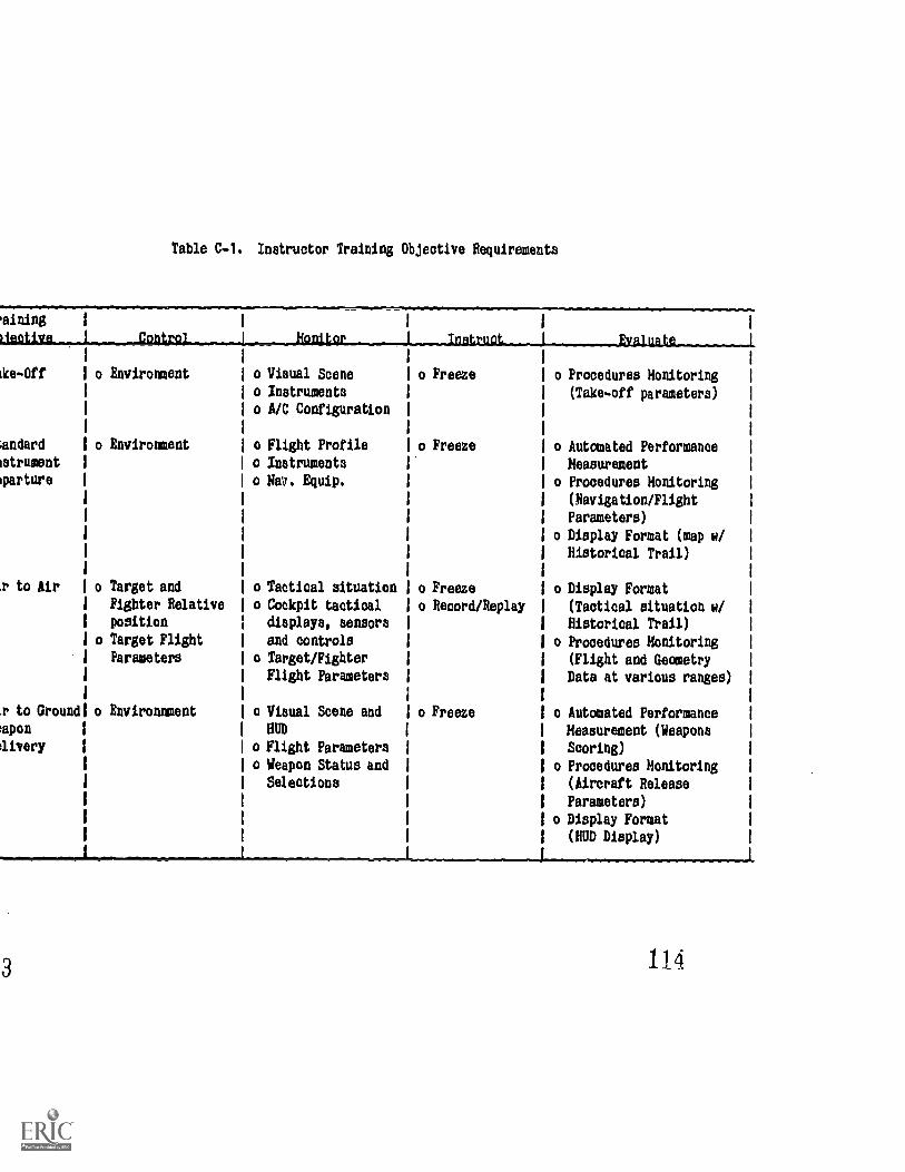
Table C-1. Inatructor Training Objective Requirements
aining
Ufletin J __coritro L Jinn**
ike-Off o Environment
mndard
istrument
orture
.r to Air
1. to Ground
mpon
aivery
o Environment
o Target and
Fighter Relative
position
o Target Flight
Parameters
o Environnment
o Viaual Scene
o Instruments
o A/C Configuration
o Flight Profile
o Inatruments
o Nav. Equip.
o Tactical situation
o Cockpit tactical
diaplays, aensors
and controls
o Target/Fighter
Flight Parameters
o Viaual Scene and
HUD
o Flight Parameters
o Weapon Status and
Selections
Instruct_
o Freeze
.o Freeze
o Freeze
o Record/Replay
o Freeze
Evaluate
o Procedures Monitoring
(Take-off parameters)
o Automated Performance
Measurement
o Procedures Monitoring
(Navigation/Flight
Parameters)
o Display Format (map w/
Historical Trail)
o Display Format
(Tactical situation w/
Historical Trail)
o Procedures Monitoring
(Flight and Geometry
Data at various ranges)
o Automated Performance
Measurement (Weapons
scoring)
o Procedures Monitoring
(Aircraft Release
Parameters)
o Display Format
(RUD Display)
114
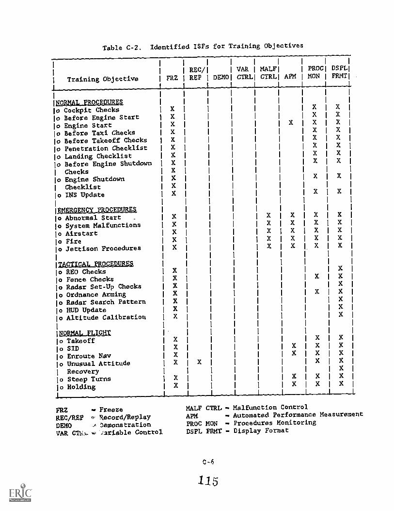
Table C-2. Identified ISFs for Training Objectives
Training Objective FRZ
REC/REP DEMO
VARCTRL
MALFCTRL
FORMALLPRQCEDUREZo Cockpit Checkso Before Engine Starto Engine Starto Before Taxi Checkso Before Takeoff Checks
o Penetration Checklisto Landing Checklisto Before Engine Shutdown
Checkso Engtne ShutdownChecklist
o INS Update
EMERGENCY PROCEDURESo Abnormal Start -
o System Malfunctionso Airstarto Fireo Jettison Procedures
TApTICAT,RALWEINgsso REO Checkso Fence Checkso Radar Set-Up Checkso Ordnance Armingo Radar Search Patterno HUD Updateo Altitude Calibration
NORMAL, FLIGHTo Takeoffo SIDo Enroute Nayo Unusual AttitudeRecovtry
o Steep Turnso Holding
I PROCI DSPLAPM 1 MON 1 FRMT
FRZ Freeze
REC/REP Record/ReplayDEMO emonstrationVAR CTkA,.. '.1ariable Control
MALF CTRL - Malfunction ControlAPM - Automated Performance Measurement
PROC MON - Procedures MonitoringDSPL FRMT - Display Format
P.4
115
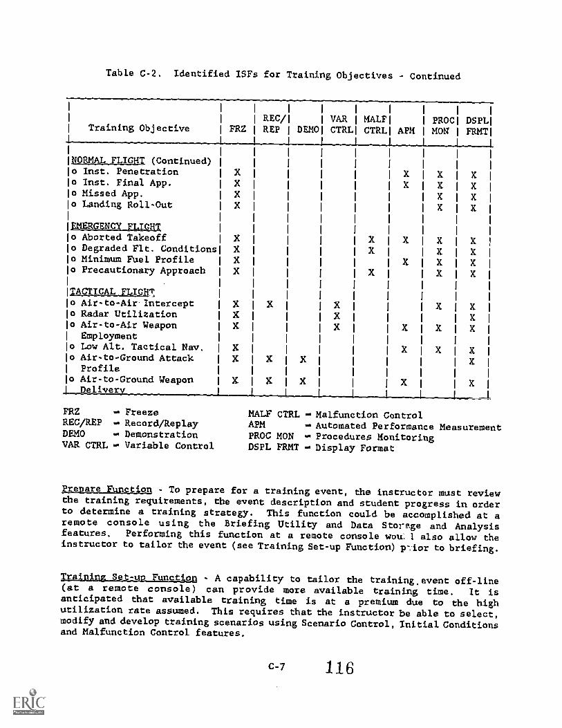
Table C-2. Identified ISFs for Training Objectives - Continued
Training Objective
1 I 1
1REC/1 1 VAR
FRZIREP
fDEMO1 CTRL
NORMAL FLIGHT (Continued)o Inst. Penetrationo Inst. Final App.o Missed App.o Landing Roll-Out
EMERGENCY FLIGHTo Aborted Takeoffo Degraded Flt. Conditionso Minimum Fuel Profileo Precautionary Approach
TACTICAL FLIGHTo Air-to-Air.Intercepto Radar Utilizationo Air-to-Air Weapon
Employmento Low Alt. Tactical Nav,o Air-to-Ground AttackProfile
o Air-to-Ground WeaponDeliver
1 1 1
MALF1 PROC1 DSPL1
CTRL APM 1 MON 1 FM4T1t
FRZ -- FreezeREC/REP Record/ReplayDEMO DemonstrationVAR CTRL Variable Control
MALF CTRL -- Malfunction ControlAPM Automated Performance MeasurementPROC MON Procedures MonitoringDSPL FRMT Display Format
rreaare Function - To prepare for a training event, the instructor must reviewthe training requirements, the event description and student progress in orderto determine a training strategy. This function could be accomplished at aremote console using the Briefing Utility and Data Stors..ge and Analysisfeatures. Performing this function at a remote console woul 1 also allow theinstructor to tailor the event (see Training Set-up Function) vior to briefing.
Irabaing_g_e_tzucto - A capability to tailor the training,event off-line(at a remote console) can provide more available training time. It isanticipated that available training time is at a premium due to the highutilization rate assumed. This requires that ehe instructor be able to select,modify and develop training scenarios using Scenario Control, Initial Conditionsand Malfunction Control features.
C-7 116
PeNplpp Tratning Furtction - As mentioned above in the Training Set-up Function,
the instructor must have the capability to tailor training to meet the students
need. In addition, there must be a utility which allows the training curriculum
managers to develop totally new training objectives to meet changes in aircraft
equipment, tactical tapes slid defined mission requirements. These modifications
to the set of training objecttves must be able to be made easily and in a
timely manner.
Brief. FunctIon - The training effecttveness of any system is directly related
to the quality of the briefing and debriefing functions. For conversion
training in particular, the brief function sets the tone for the entire training
event. The Briefing Utility feature provides the student with a complete
overview of the training event, plus graphic displays of task relevant infor-
mation. A capability to present dynamic demonstration of tactical displays
used during intercept and air-to-ground training is considered to be beneficial
to conversion students. These students are unfamiliar with the weapon system
and associated displays and will require coaching on how to interpret and use
the information presented. This capability will allow the instructor to
demonstrate how to use the information and develop a "scan pattern" essential
to mission training.
TRAINING REQUIREMENTS
Control Function - All ftve identified control features (Scenario Control,
Initial Conditions, Real-Time Simulation Variables Control, Malfunction
Control and Reposition) are required for this ATD. Scenario Control by
training objective provides the greatest benefit to the instructor by minimizing
his workload while allowing the flexibility to make real-time changes. A
fully automated Scenario Control capability is required for standardization
and evaluation training and can be used during instructorless training.
Scenario Control provides a wide variety of initial conditions identified by
training objectives (e.g., Hi-ILS Rwy 03R at Luke AFB). Malfunction Control is
required for training and should include the capability to preprogram sets of
malfunctions at the remote console for manual insertion by the instructor
during the training event. Real-Time Simulation Variables Control and
Reposition provide the instructor added flexibility during training to control
the training event and efficiently use available training time. The Free
feature may be required to perform some of these control functions.
Monitor Function - Due to the instructor offboard location, the IDS Display
Control and Formatting and Procedures Monitoring features are required. Task
specific and training-related information should be presented to the instructor
in a meaningful format.
Instruct FunctIon - The Freeze feature will be used the most to provide
instruction during training. Due to the student skill level, only total
system freeze and crash/kill freeze are appropriate for this ATD. The Simulator
Record/Replay and Automatic Simulator Demonstration features can be used
for conversion training of tactical intercepts, air-to-air weapon employment,
low altitude tactical navigation, and air-to-ground weapon delivery. These
new training tasks require the use of many cockpit controls, displays and cues
which are new to the student.
Evaluate Function - The instructor must analyze training relevant informationto determine if student performance has met specified criteria. This requiresthat the instructor be provided the information in a content and format whichmeet his needs. IOS Display Control and Formatting and Procedures Monitoringare required to aid the instructor perform the evaluation function. ProceduresMonitoring, as defined in Section II, includes the monitoring of flightdiagnostics which would provide the instructor with a parameter monitor-ing and performance alerting capability. For tactical training, weaponsscoring is necessary for performance results feedback. An Automated PerformanceMeasurement feature is required for this capability. Automated PerformanceMeasurement should be designed to support specific training objectives aswould be provided by the Scenario Control by objective feature. This wouldprovide an objective, standardized performance measuring capability which theinstructor can modify if required. It will reduce the instructor's workloadas well as prgvide a training effectiveness measure for training curriculummanagers.
POST-TRAINING REQUIREMENTS
Debrief Function - This function requires the instructor to provide t:te
student with a detailed analysis of the training event, identifying strengths,problem areas and corrective actions. Performance information is extremelyuseful during debrief and can be provided by the Hardcopy/Printout feature.The Remote Graphics Replay feature provides a debriefing tool which allowsdynamic replay of specified events. This can be very training effective,especially for conversion students.
Record Function - The instructor is required to record the student's progressand any device deficiencies at the completion of the training event. The DataStorage and Analysis feature can provide the mechanism for recording studentperformance and progress and storing pertinent training data (e.g., studentrecords and automated performance measurements, recording and storage oftraining device information). This feature supports the requirements ofpre-training, curriculum managers, and the ATD managers.
BENEFIT ANALYSIS
The benefit analysis will determine the final selection of ISFs for ATDspecification. ISF selection must be based on specific training requirementsand the functional needs of the instructor and training system managers toenhance training efficiency. Specific items to consider are outlined inSection III under the "Benefit Analysis" heading. These items lead to furtherjustifications, prioritization, and subsequent selection and rejection ofISFs. The results of the benefit analysis for ehe sample specification areshown in Table C-3.
C-9 118
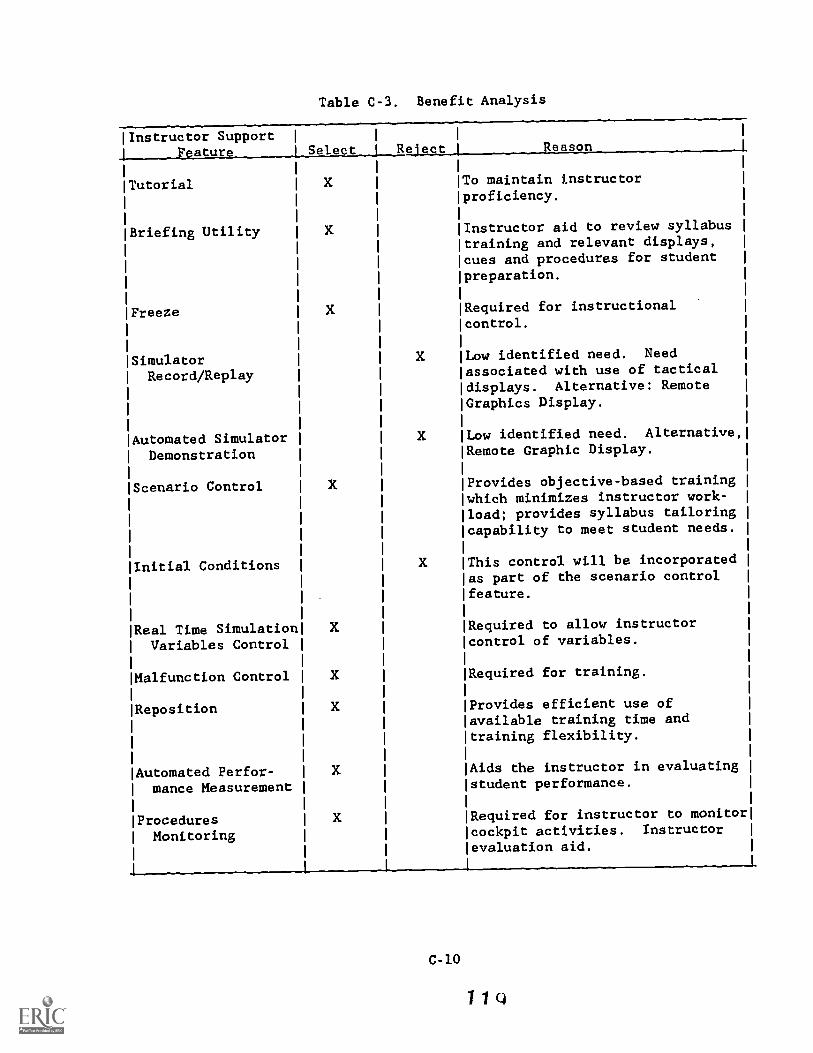
Table C-3. Benefit Analysis
Ilnstructor Support
1 Feature Select j Reject
Tutorial
Briefing Utility
Freeze X
Simulator XRecord/Replay
Automated Simulator X
Demonstration
Scenario Control X
Initial Conditions X
Real Time SimulationVariables Control
Malfunction Control
Reposition
Automated Perfor-mance Measurement
ProceduresMonitoring
1
Reason
To maintain instructorproficiency.
Instructor aid to review syllabustraining and relevant displays,cues and procedures for studentpreparation.
Required for instructionalcontrol.
Low identified need. Needassociated with use of tacticaldisplays. Alternative: RemoteGraphics Display.
Low identified need. Alternative,
Remote Graphic Display.
Provides objective-based trainingwhich minimizes instructor work-load; provides syllabus tailoringcapability to meet student needs.
This control will be incorporatedas part of the scenario control
feature.
Required to allow instructorcontrol of variables.
Required for training.
Provides efficient use ofavailable training time andtraining flexibility.
Aids the instructor in evaluatingstudent performance.
Required for instructor to monitorcockpit activities. Instructorevaluation aid.
C-10
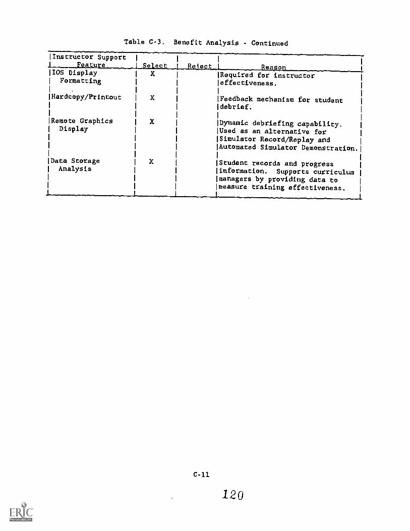
Table C-3. Benefit Analysis . Continued
lInstructor Support I
_Feature I StlectIOS Display XFormatting
Hardcopy/Printout
Remote GraphicsDisplay
Data StorageAnalysis
X
Reject 1 ReasonRequired for instructoreffectiveness.
Feedback mechanism for studentdebrief.
Dynamic debriefing capability.Used as an alternative forSimulator Record/Replay andAutomated Simulator Demonstration.
Student records and progressinformation. Supports curriculummanagers by providing data tomeasure training effectiveness.
SAMPLE SPECIFICATION
3.7.2 Instructional Subsystem The F-16 OFT shall be provided the followinstructor support features to enhance the efficiency of training.
3.7.2.1 Briefing Utilities - Briefing utility aids shall be designedassist the instructor in briefing a student for an upcoming simulator sessi
The aids shall prepare both the student and instructor prior to a particu
exercise and consist of F-16 training material to be used for preparat(e.g., lesson guides, training program outlines, and instructor guides).
Briefing Utilities shall provide the capability to review training evgraphics (e.g., SID and approach plates and emergency procedures), and al
demonstrations of specific dynamic events (e.g., intercept tactical displ
and air-to-ground weapon delivery displays). The instructor shall also be a
to access student training records recorded by the Data Storage and Analyfeature described in paragraph 3.7.2.13. This feature shall be accessed on
off-line remote graphics console and shall not degrade normal training perfor
on the main IOS. The method of interaction shall be similar to the mainand shall be easily accessible by the instructor. Briefing materials shall
functionally grouped in user terms to ensure optimal usability; datadisplays shall be easily modifiable for future updates. A detailed descrtion of the briefing data shall be made available at CDR.
3.7.2.2 Freeze - A total system freeze feature shall allow all simulaparameters to be frozen at a given time within a F-16 mission train
scenario. The instructor shall have the capability to manually or automatica
freeze the simulator. Manual total system freeze shall be capable witsingle action on the part of the instructor. Automatic total system freshall occur either when specified parameter values are exceeded or wthe state of the simulator changes, as in reposition or when changing operat
modes. An automatic freeze override feature shall be incorporatedallows the training event to continue uninterrupted, while displayin,message to the instructor that the automatic freeze criteria were met.override feature will be the normal setting for automatic freeze.
3.7.2.3 Scenario Control - Scenario Control shall support the instructorproviding efficient control of the simulation during training and by provicstudent activity by automatically displaying information relevant totraining being accomplished. It shall provide the capability to configurecontrol the ATD in accordance with predefined scenarios covering the 1
simulator curriculum. Scenarios shall include the initial conditions forexercise and the training objectives to be activated in a predefined ol
and/or under prespecified conditions. The scenarios shall be made avaiLfor review of content and for selection at both the remote graphics con !
and the IOS. The full range of scenario control automation shall be
available. This range covers total automation with no instructor inputs
minimal automation where flexible instructor interaction is provided, inclui
the options of repeating, deleting, and adding certain objectives.interaction shall not require re-initializing the simulator and should
detract from the overall simulation. ATD configuration changes caused by
feature shall be automatically checked to preclude any crash conditior
C-12
121
other adverse condition and shall freeze the state of the simulator until allincompatible conditions are corrected. A list of scenarios and the dataspecified within each scenario will be made available at CDR.
3.7.2.4 Real-Time Simulation Variables Control - The instructor shall beprovided the capability to insert, delete or alter simulation variables inreal time. This shall include variables aSsociated with environmentalconditions, airfield data, target data (controllable adversary and friendlyradar targets) and aircraft flight and positional data (ownship, wingman oradversary). In addition to preprogrammed profiles, friendly and adversarydata shall be capable of changes in altitude, artitude, speed, acceleration,and heading, and positioned in relative range and bearing from the fighteraircraft via an interactive input device (joystick, trackball, light pen,etc.).
3.7.2.5 Malfunction Control - Malfunction control shall provide the instructorthe capability to select a sequence of abnormal aircraft equipment conditionsand/or emergency conditions before or during the training session. The methodof insertion during runtime shall depend on the level of scenario com.rolautomation. In the case of total automation, insertion shall be automatictriggered by preprogrammed events. In the case where scenario control provi lsinstructor flexibility for insertion and removal of certain training objectivthe preselected malfunctions shall be made readily available for ruraccessibility. The time and number of actions required on the part ofinstructor to select, alter, and enter malfunctions shall be minimized to negreatest extent possible. This feature shall provide an optional graphicswhich allows the instructor to monitor student procedures related directly tothe active malfunction.
3.7.2.6 Reposition - The Reposition feature shall provide the capability toposition the ATD to any point in the mission training scenario. All flightparameters ihall be capable of automatic adjustment to meet the new conditionimposed by repositioning. After reposition, ATD configuration shall beautomatically checked to preclude any crash condition or other adverse conditionand shall remain in a freeze state until all incompatible conditions arecorrected. The reposition feature shall be designed to enhance instructorefficiency. The time and the number of actions required on the part of theinstructor to select, alter and enter data shall be minimized.
3.7.2.7 Automated Performance Measurement - The automated performancemeasurement feature shall aid the instructor in obtaining a valid and reliablemeasurement of student performance. The feature shall be designed to supportspecific training applications and to provide the instructor with a precise,objective and standardized measure of student performance and a capability tosimultaneously measure many facets of a mission event. The instructor shallbe provided timely feedback of performance data in real or near-real time; andas an instructor option, shall be displayed on-line for use during a trainingsession or off-line for debriefing purposes. The instructor shall have theoption to override or modify performance measurements provided by this feature.F-16 curriculum managers shall have the capability to modify ("fine tune")performance algorithms on-site. Final determination of automated performancemeasurement algorithms including the parameters to be measured, the methods ofmeasurement, and evaluation criteria shall be made at PDR.
C-13
122
3.7.2.8 Procedures Monitoring - The Procedures Monitoring feature shall
provide the instructor with a method of monitoring the procedural training
activities of the student. This includes the procedures involved with both
normal and emergency procedures as specified in the F-16 Flight Manual. The
data to be monitored shall be easily modifiable to reflect current procedures
and valid measures of these procedural activities. Final determination of
procedures monitoring activities including a list of the procedures and
associated data shall be made at PDR.
3.7.2.9 IDS Display Control and Formatting - This feature shall automatically
provide the instructor with a graphic representation of student action appro-
priate to the active training objective. This feature shall also provide
optional graphics associated with the scenario currently being trained.
The presentation of information shall be an easy-to-read, uncluttered,
standardized format of the current status of graphical and instructional
information. To the greatest extent possible, informational display formats
shall replicate that which the aircrew normally uses (e.g., a graphic depiction
of the F-16 HUD should replicate the actual aircraft). The information layout
shall be consistent with the limitations of human perception and memory in
order to minimize user interpretational effort and alleviate confusion, thereby
ensuring quick recognition and maximizing readability. The default and
optional displays, display content and display formatting will be determined
at PDR.
3.7.2.10 Hardcopy/Printout - The instructor shall be capable of retrieving
data from any specified source within the simulation - i.e., parameters,
variables, display content. It shall retrieve the data in such a way that no
interruptions occur within the simulation and its displays and shall create a
hardcopy printout of the collected data upon demand without simulation
disruption. The time and number of aP.tions required on the part of the
instructor to activate hardcopy/printout .hall be minimized.
3.7.2.11 Remote Graphics Replay - The remote graphics replay feature shall
provide the capability to recreate a graphic replay as viewed from the IOS
during an active exercise. This feature shall also include the optional
graphics which were Jade avail.Able regardless as to whether they were accessed.
This feature shall be accessd via a remote briefing/debriefing console. It
shall be capable of operating concurrently with active training without any
degradation to the performance of the simulator and the 10S. Indexing into
the playback data by treining objectives, in addition to instructor inserted
flags during realtime, shall facilitate locating points of interest in the
mission. The feature shall also provide viewing in normal or fast speeds. An
option to freeze any point within the playback shall also be provided.
3.7.2.12 Tutorial - The tutorial feature shall provide the instructor/student
with a user-fz.endly interactive, self-paced and self-administered program of
instruction on the capabilities and use of the flight simulator and its
instructor suprort featur s. The tutorial feature shall include a "help"
function in t form of an easily accessible prompt. The tutorial shall
be provided off-line at a .1mote console or at the IOS. On-line instructional
system operation in the form of a HELP function shall also be provided (for
the novice or infrequent user) and be accessible to the user as an option.
C-14
The data provided by this feature shall be easily modifiable to reflect thecurrent F-16 training objectives, performance criteria, F-16 aircraft/ATDconfiguration, etc.
3.7.2.13 Data Storage and Analysis - The data storage and analysis featureshall record pertinent student performance information during the trainingsession. Access to this information shall be available in a variety of ways:grouped by student, student type and class, phase of training, the objectivesattained, time/attempts to attain the objectives, and conditions under whichthe objectives were met or not met. Such information shall be retained on thesystem as part of a student's record and accessible via the Briefing Utility.This feature shall also store information regarding certain aspects of systemoperation (e.g., use of instructor support feature options) to be used bycurriculum managers to assess overall ATD training effectiveness and use.This feature shall provide an tnteractive data editor capability for admini-strative information update at an off-line device which does not interferewith normal simulator operation. The actual data to be stored and analyzedwill be determined at CDR.
NOTE: The following paragraph is added to support task module-based design:
"A database shall be developed to parallel the syllabus trainingobjectives. The ISS shall be driven from this data base. An editorfor convenient update and modification of this database shall alsobe developed."
C-15
124
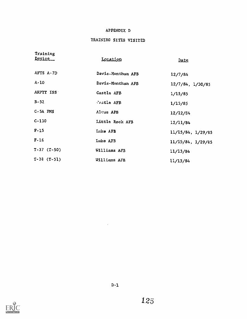
TrainingDevice
AFTS A-7D
A-10
ARPTT ISS
B-52
C-5A PMS
C-130
F-15
F-16
T-37 (T-50)
T-38 (T-51)
APPENDIX D
TRAINING SITES VISITED
Location
Davis-Monthan AFB
Davis-Monthan AFB
Castle AFB
,7ost1e AFB
Alf:us AFB
Little Rock AFB
Luke AFB
Luke AFB
Williams APB
Williams APB
D-1
125
bate
12/7/84
12/7/84, 1/30/85
1/15/85
1/15/85
12/12/34
12/11/84
11/15/84, 1/29/85
11/15/84, 1/29/85
11/13/84
11/13/84
APPENDIX E
TASK COMMONALITY ANALYSIS
Tables E-1 through E.-6 present a listing of tasks which are trained in ATDswithin the four major Air Force Commands and Chose incorporated into fourISSs. The purpose of this task listing is to compare tasks which are commonlytrained utilizing ATDs with tasks incorporated into recently developed ISSs.This task listing can be used to determine what types of tasks have beenmonitored using an ISS and what types have not. In order to determinecommonality of tasks, only pilot flight station tasks were included in thisanalysis. This is due to the fact that five of the nine aircraft trainingsystems investigated perform pilot only training.
scou OF THE ANALYSIS
The identification of training tasks involved a detailed review of trainingdocumentation, including the simulator training syllabi and instructor guides.This documentation describes the general training scenario and the specifictraining objectives for each event. In many cases this documentation did notdescribe the training event on a task-by-task basis. Therefore, to furtheramplify training task requirements, extensive instructor interviews wereconducted to determine which tasks were monitored during the training sessions.
The task listing is organized according to task type: Normal Flight, NormalProcedures, Emergency Flight, Emergency Procedures, Tactical Flight andTactical Procedures. The tasks which are monitored in the ISSs were identifiedfrom existing documentation and compared with the previously defined tasklisting.
ANALYSIS RESULTS
A strong commonality of simulator training tasks exists throughout normalflight, normal procedures, emergency flight and emergency procedures. Thiscommonality of tasks is consistent across the Air Force major commands. Thisis as would be expected, since these types of tasks reflect a basic flighttraining philosophy. This philosophy includes ensuring that the aircrew has afirm understanding of procedures and limitations of ehe aircraft, and candemonstrate this knowledge plus the motor skill ability to safely operate theaircraft under normal and abnormal conditions prior to the first flight.
The task listing matrix indicates that conversion training encompasses all UPTtraining task requirements. The aircrew is becoming familiar with the newsystems at their disposal, and is utilizing them to perform the same taskrequired UPT. Primary emphasis is on safety of flight, and the aircrew'sability to safely operate the system within the procedures and guidelines setforth. This includes starts, take-offs, landings, instrument and basicairwork skills, navigation, use of checklists and abnormal situations. Oncethis performance has been demonstrated, the aircrew is introduced to basictactical skills.
E-1 126
Most tasks identified for tact:lc-al flight and tactical procedures are unique
for each tactical mission. Mese tasks, as taught in conversion training,
provide the basic foundation for contimmcion training in the operational
squadrons. The tactical phase of training does contain some common tasks
which would be applicable acrosli ;11 major operational commands. Such
mission-related tasks are encompasse:i in Air-to-Ground Attack and Electronic
Warfare.
Nearly all conversion training tasks in the first four task categories (normalflight, normal procedures, emergency flight and emergency procedures) are
incorporated into the ISS systems under study. Tasks which are not identified
as monitored by an ISS, were not done so by design. The ISS systems for ehe
F-14, B-52 ARPTT and C-5A could be easily modified to monitor these conversion
training task requirements.
The AFTS for the A-7D and F-4E are the only ISSs designed to monitor tactical
training. These systems provide air-to-air and air-to-ground training, and
meet the needs of conversion training in these areas.
A commonality of tasks exists for all ATDs in the Normal Procedures, NormalFlight, Emergency Procedures and Emergency Flight task module categories. The
ISS devices under study currently monitor the major portion of these identified
task requirements. The task module approach utilized by these ISS devicesprovide a user-oriented system which can be easily modified to encompass all
tasks in these categories.
Tasks that address motor skills, e.g., Normal and Emergency Flight, and tasks
that deal with performance of procedures, e.g., Normal and Emergency Procedures,
can be addressed by the current ISS technology. Some tactical tasks can
also be addressed utilizing the same technology.
Tactical traintng is composed of unique training skills for each aircraft and
tactical missian. Tactical training at the conversion level consistsof defined
parameters and established guidelines which must be demonstrated in the ATD.
Certain tactical training tasks, i.e. low-level navigation and EW training, are
applicable to all major operational commands.
Task taught and parameters monitored in conversion training are directly
applicable to continuation training. Standardized evaluation of operational
aircrew is required to ensure that they can perform the mission in a saf3 and
effective manner. Much of ehis evaluation can also utilize the current ISS
technology.
E-2
1 2
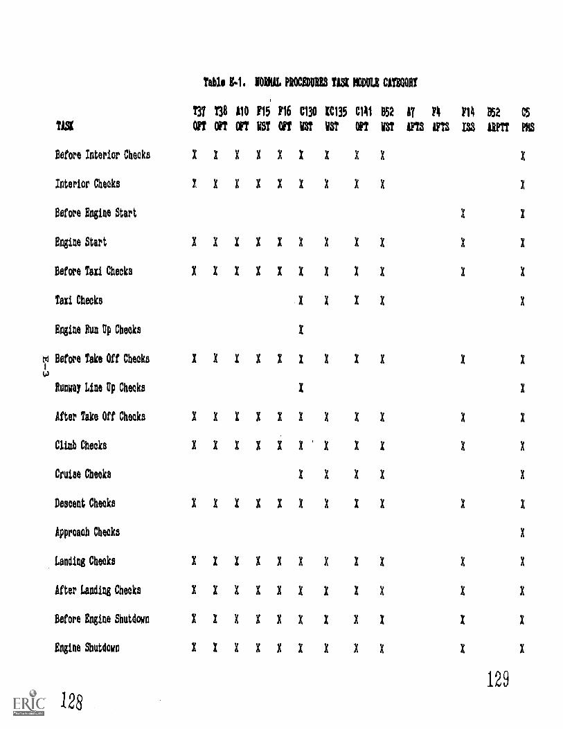
TISK
Before Interior Cheeks
Interior Cheeks
Before Engine Start
Engine Start
Before Taxi Checks
Taxi Checks
Engine Pun Up Checks
Before Take Off Checks
Runway Line Up Checks
After Take Off Cheeks
Clig Checks
Cruise Checks
Descent Checks
Approach Checks
Landing Cheeks
After Landing Cheeks
Before Engine Shutdown
Engine Shutdown
126
Table If.1. NORVAL PROCEDURES TISI NODULE CATEGORY
T37 T38 110 F15 F16 C130 CC135 C1A1 852 AT FA FA 852 CS
OFT OPT orr VST OFT V3T V3T OPT V3T IFTS AFTS 133 11PTT PDS
X X X X X X X X X
X X X X X X X X
X
X
X
X
X
X
X
X
X
X
X
X
XXXXXXX XX X X
XXXXXXX XX X X
XXXXXXX I X X X
XXXIII I XX I I
129

Table Ep.1. IMRE PROCIOVIES TiSt NODULE CATEGORY (continued)
T37 T38 A10 P15 P16 C130 IC135 C141 B52 17 F4 FI4 152C5
TASIOFT OFT OFT MST OPT MST MST OF! VS! AFTS AFTS 133 ARPTTEIS
Before Leaving Cockpit
Inflight Refueling Cheeks1 X X
Crew CoordinationX X XX I X
Crew BriefingXXIX X
Pilot Not Plying Rest,.XXIX
.131
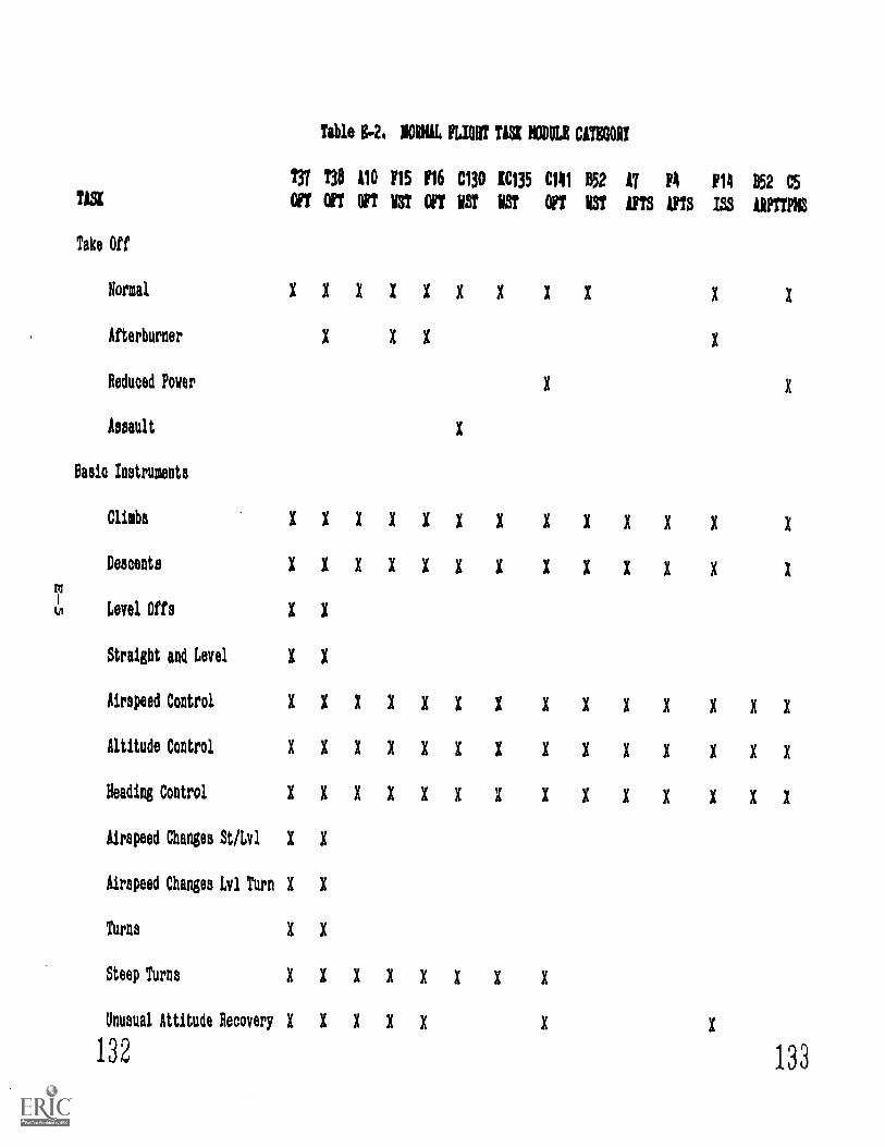
Table B-2, MORK MORT TISK MODER CATEGOIT
TN T38 110 F15 116 C130 IC135 C141 B52 17 P4 P14 B52 C5
TASI OFT OPT 111 113T OFT NT ET OFT UT MS IPTS 135 WTTPIS
Take Oft
Normal XXXXXXX XX X X
Afterburner X X X X
Reduced Power X X
Assault X
Basle Instruments
Climbs XXXXXXX XXXXXDocents XXXXXXX XXXII X
Level Offs X X
Straight and Level X X
Airspeed Control XXXXXXX XXIX XXXAltitude Control XXXXXXX XXXI XXXHeading Control XXXXXXX XXXX XXXAirspeed Changes St/Lvl X X
Airspeed Changes Lvl Turn X X
Turns X X
Steep Turns XXXXXXXXUnusual Attitude RecoveryXXXXX X X
132 133
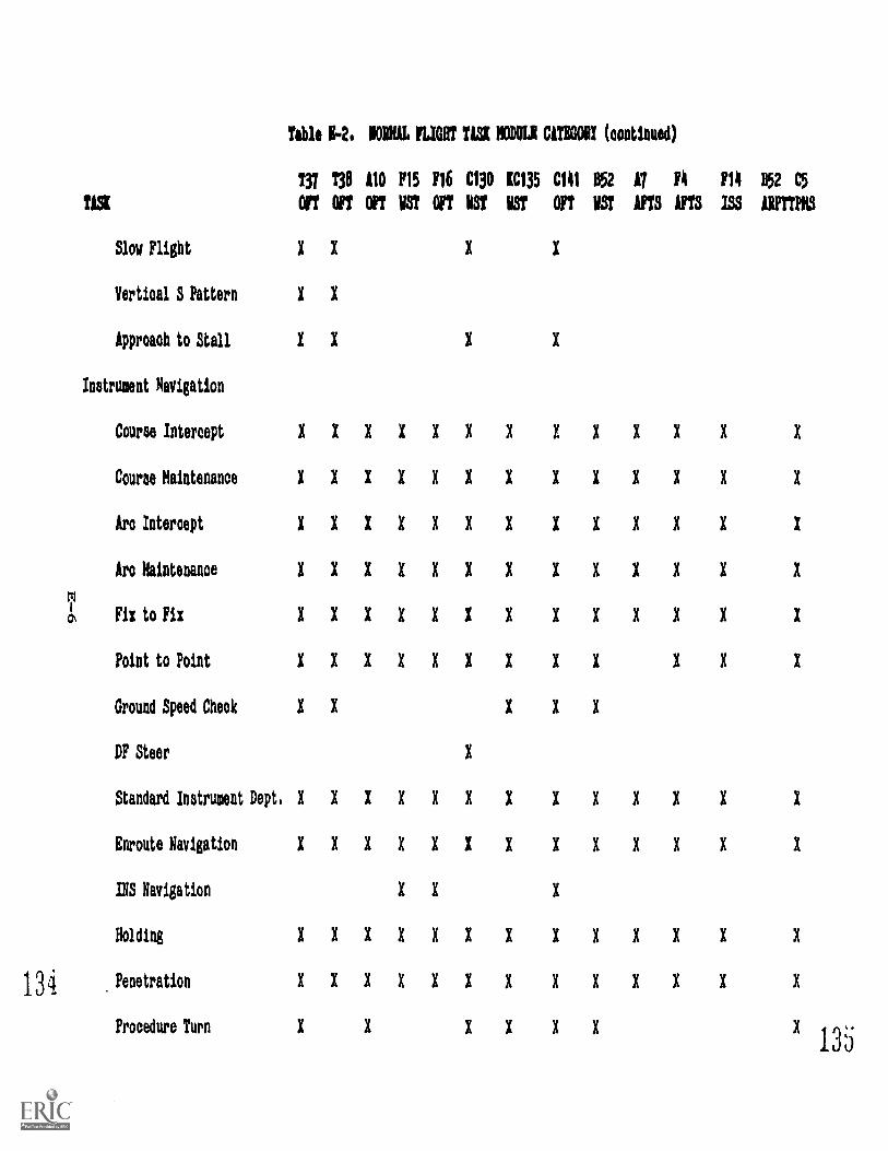
Table 1-2. 101116 FLIOOT TASK MODER CAUGHT (continued)
T37 T30 £10 F15 116 C130 £C135 C141 052 A7 14 F14 852 C5
TASK OFT OFT OF? VS? OFT BST VST OFT UST YTS AFTS ISS 1111?1,10
Slow Flight X X X X
Vertical S Pattern X X
Approaoh to Stall X X X X
Instrument Navigation
Course Intercept XXXXXXX XXXXX X
Course Maintenance XXXXXXX XXXXX X
Arc Intercept XXXXXXX XXXXX X
Arc Maintenance XXXXXXX XXXII X
m1
0 Fix to Fix XXXXXXX XXXXX X
Point to Point XXXXXXX XX X X X
Ground Speed Check X X X X X
DP Steer X
Standard Instrument Dept.XXXXXXX XXXII X
Enroute Navigation XXXXXXX XXXXX X
INS Navigation X X X
Holding XXXXXXX XXXXX X
134 Penetration XXXXXXX XXXII X
Procedure Turn X X XXXI1 135
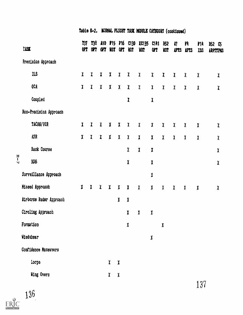
Table W. 10111L FLIGHT TASK NODULE CATEGORY (=tined)
731 738 110 F15 F16 C130 KC135 C141 B52 I? F4 F14 B52 C5
1/3K OFT OF? orr 113T OFT 113T UT OFT VST iFT3 /33 WITF13
Precision Approach
ILS XXXXXXX XXXXX X
GCA XXXXXXX XXXXX X
Coupled X X
Non.Preciaion Approach
TICAW/VOR XXXXXXX XXXXX X
ASI XXXXXXX XXXXX X
Back Course X X X X
ROB X X X
Surveillance Approach X
Missed Approach XXXXXXX XXXII X
Airborne Radar Approach X X
Circling Approach X X X
Formation I X
Windshear X
Confidence Maneuvers
Loops X X
Wing Overa X X
137
13 6
Table 1.2. 101MiL MGR! TASI NODULE CATEGORY (oontioued)
737 130 110 F15 F16 C130 1C135 C141 652 17 F4 F14 652 C5
TISK OFT OFT OFT 1ST OFT NT WST OFT 1ST 1FTS LFTS 1SS tRPTTPNS
Aileron Rolls X X
Afterburner Climbs X X
Air Refueling Rendezvous X X X
Air Refueling Traok X
Radar Trail Departure X X
Auto Pilot Utilization X X X
Lost Wingman IFR
Inflight Refueling
Maintain Position X X X
Change Position X X X X
Breakaway X X X X
Landings
Full Stop XXXXXXX XXXXX X
Touch and Go X X X XXXXXXXX X
Stop and Go X
Assault X
119Landing Roll Out 4 XXXXXXXXXXX X
TISK
Comunioations
Tali, 14. BORMAL FLIGHT TISI MODULI CAT1001! (continued)
737 130 110 F15 F16 C130 1C135 C141 B52 AT 14 F14 B52 C5
OPT OFT OFT WS? OFT WST WST OFT WST IFTS AFTS 133
Clearance XXXXXXX XXXII X
Oround XXXXXXX XXXII X
Tower XXXXXXX XXXII X
Traffic Controller XXXXXXX XXXII X
OCI X X I X X
X X XVP Squawk
Navigation ID/Tuning XXXXXXX XXXXX X
T1/41) INS Setup 1 X X X X X
INS Update X X X X X
TACAN Update X
141
140
Tible Eq. TACTICAL PROCEDURES TASI MODULE CATBOORI
138 110 115 116 C130 IC135 C1111 052 IT 8 r14 052
TUE OFT OFT OFT EST OFT EST VST OFT EST MS WM ISS UPTTPIIS
Weapons System Checks X X X X X
Pence Check X X
Ordnance Arming/Dearming I X X X X
Electronic Warfare
Preflight Procedures
knight Procedures X X X X
Threat Identification X X X X
Threat Evaluation X X X
Air.to-Ground
Radar Position Update
HUD Update
Ground Speed Cheek X
Radar Calibration
Altitude Calibration
Weapon System Configuation I X X
Computer Data Entry I X
1 11 2 Special Weapons Proud. I 2143
Table KR.3. TICTICIL PROCKOUBMS TASK NODDLR CITIOORT (continued)
Y37 T38 110 F15 116 C130 KC135 C141 B52 17 A 1111 B52 C5TASK OFT OFT On VST OFT BST VST OFT BST iFTS 1FTS ISS MIMS
Air-to-Air
Scramble X X
Radar Calibration X
Radar Searob X X X
Radar Look-on X X X
Radar Interpretation X X
Target Sorting X
Weapon System Configuration X X X
144 145
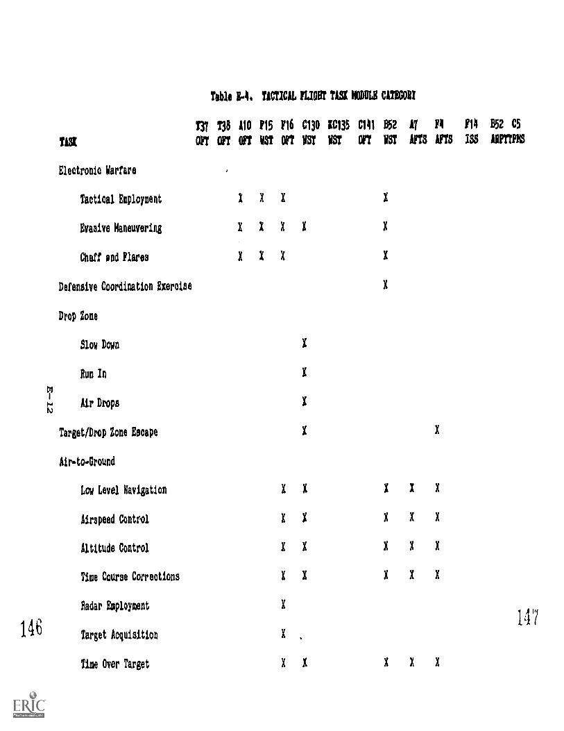
TASI
Electronic Warfare
Tactical Employment
Evasive Haneuvering
Chaff pod Flares
Defensive Coordination Exercise
Drop Zone
slow Down
Run In
Air Drops
Target/Drop Zone Escape
Air-to.Oround
Low Level Navigation
Airspeed Control
Altitude Control
Time Course Cotreotions
Radar Employment
Target Acquisition
Time Over Target
Table E..k TACTICAL FMB T121 NODULE CATEGORY
TR T38 A10 £15 £16 C130 IIC135 C141 052 11 Y £14 052 CS
OFT OFT OFT Vat OFT EST VST OFT EST YTS AIM ISS liPTTPES
X
X X X
147
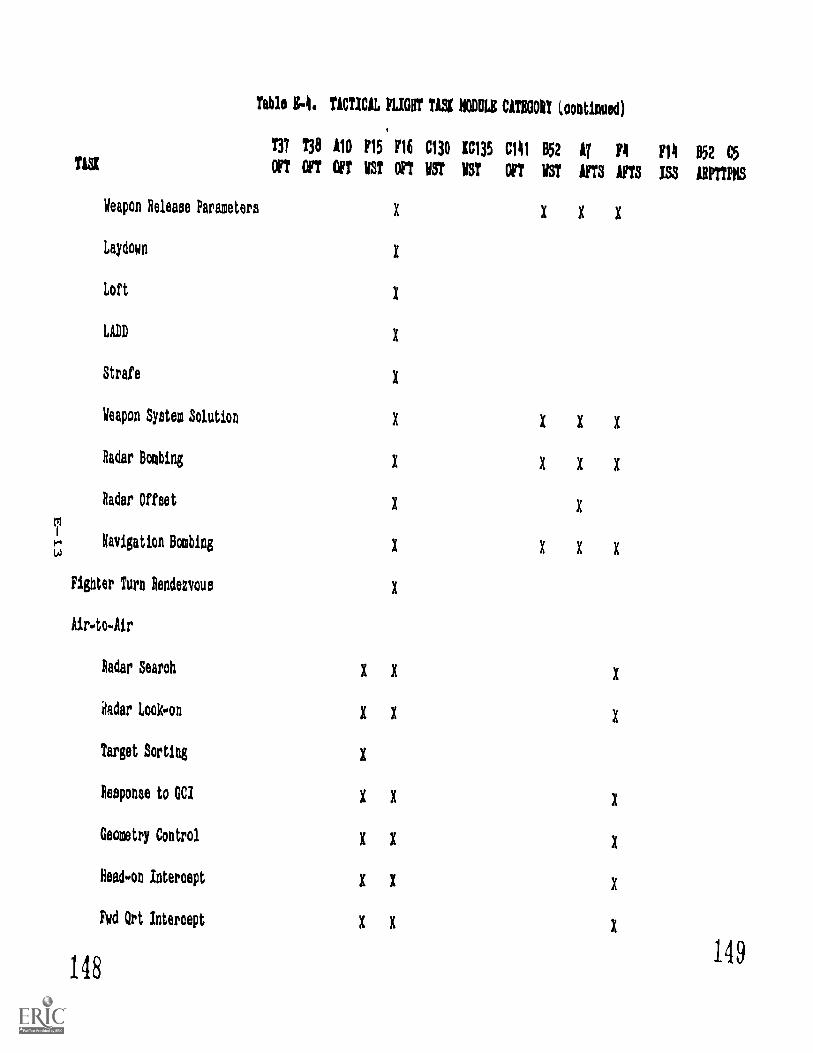
Tag
Table 14. TACTICAL ',LIMIT TISK NODULE CATEGORI (maimed)
T3T T38 A10 £15 1/16 C130 1C135 C141 052 AT 11 F14 052 C5
OFT OFT OFT VST OFT UST UST OFT VST *YTS AFTS ISS ARPTTIIS
Weapon Release Parameters X X X X
Laydown X
Loft X
LADD 1
Strafe X
Weapon System Solution X X X K
Radar BombingX X X
Radar Offset K X
Navigation Bombing K X X X
Fighter Turn Rendezvous X
Air.to.Air
Radar Search X X X
Mar Look-on X X X
Target Sorting X
Response to Gel X X X
Geometry Control X X X
Read-on Intercept X X X
Fwd Qrt Intercept X X X
148149
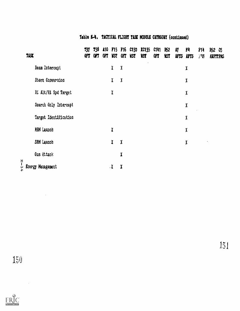
Table 1-4. TACTICAL FLIGHT TISK NODULE C1T1GORI (continued)
Tyr 138 110 F15 116 C130 1C135 C141 B52 17 FA 2114 B52 C5
OFT OFT OFT HST OFT HST HST OFT VST !ITS 1113 ARIMPHS
Beam Intercept X X X
Stern Conversion X X X
Hi Alt/Hi Spd Target X X
Search Only Intercept X
Target Identification X
HBM Launch X X
SRM Launch X X X
Gun Attack X
Energy Management .X X
151
150
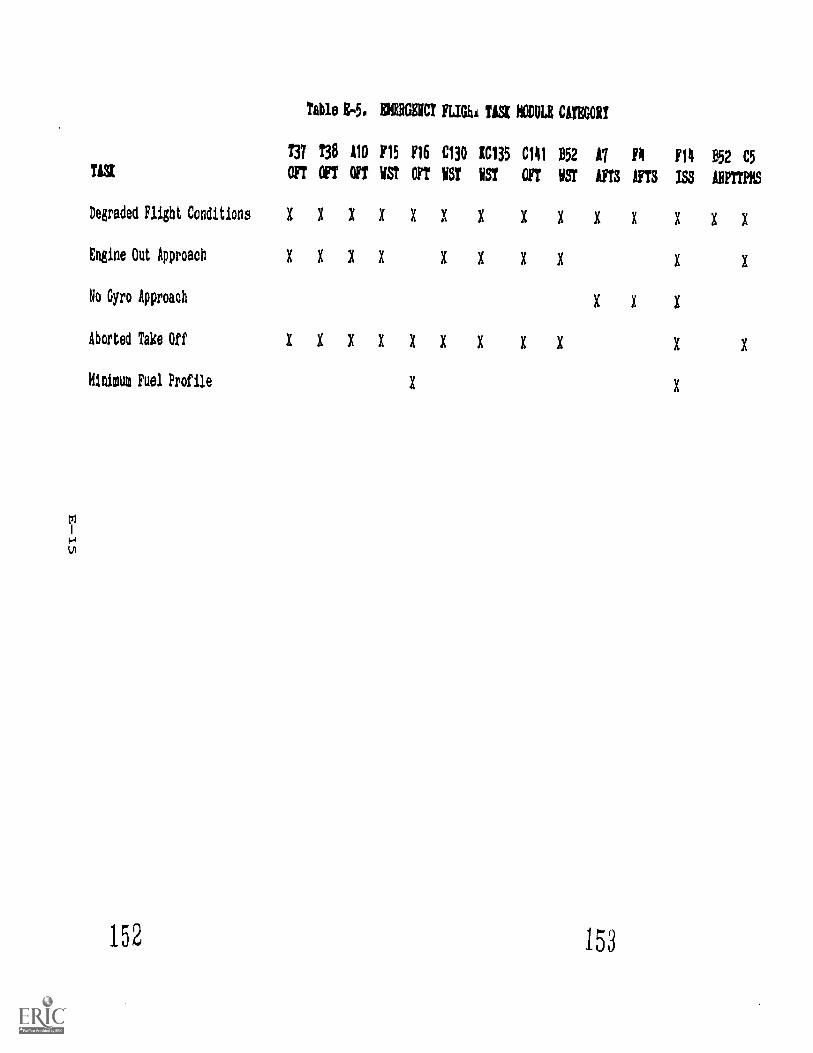
Table g.5. ENRRGIVCT FLIVIA USX DOLE CATEGORT
T37 T38 A10 £15 116 C130 IC135 C141 B52
TIS1 OFT OFT OFT VS7 OFT VS! VST OFT VST
Degraded Flight ConditionsXXXXXXX
Engine Out Approach XXXI XXIXNo Gyro Approach
Aborted Take Off XXXXXXX XXMinima Fuel Profile X
17 FA F14 B52 C5
YTS NTS ISS MIMS
XXIX XXXX X
X X X
X X
X
152 153
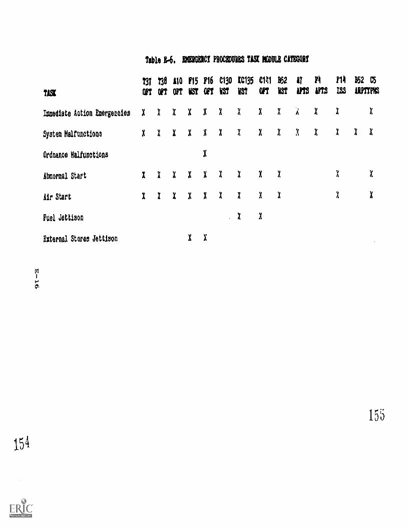
t31
1.54
Table 14. MOM PROCEDUVIS T1S1 MODULE MEOW
TM T38 110 F15 F16 C130 1C135 C141 B52 17 14 F14 852 C5
TISK OFT OPT OPT VSY OFT VS? VS? OFT VST APIS 1FTS 155 AIMS
Immediate Action EmargeteiesXXXXXXX XX X X X
System Malfunctions
Ordnance Malfunctions
Abnormal Start
lir Start
Fuel Jettison
External Stores Jettison
XXXXXXX XXXI XXX
XXXXXXX XX X X
X X X X X X X X X X X
X
155
APPENDIX F
ISS IMPLEMENTATION CONSIDERATIONS
ISS IMPLEMENTATION CONSIDERATIONS
Introduction The purpose of this appendix is to provide technical readerswith a general understanding of ISS cost and implementationconsiderations. Since technology is advancing rapidly, manycost factors are being reduced, and there can be littleconfidence in quantitative predictions of the future. Asa consequence, the state of the art must be periodicallyinvestigated to assess issues about the feasibility anddesirability of specific ISS implementations. With thisin mind, the appendix attempts to provide a framework fordocumenting those cost and implementation considerations whichshould not be forgotten.
Organization The organization used in this appendix is derived from highand Scope level architectural components identified from previous ISS
implementations. Each section of this appendix represents amajor ISS component. What is truly important to an effectiveISS implementation is the development of a task modules databaseand the software which supports it. These components are thuspresented first. The computer system and station which supportthe database and software, and allow the user to work with theISS:are included next. Additional components which are necessaryand unique to ISS implementation are included last; they arethe simulation ipterfa,..e.and the life cycle cost component.
Other traditional system development components such as projectmanagement, data requirements, integration and test, sysrnmtest and evaluation, and site activation are not specific...) yaddressed here because ISS-unique considerations were minimal.However, the components should be included in any final costanalysis.
Format For each component, the discussion includes:
o Componenc. Name given to the component.
o Definition. A definition of the component.
o Purpose and Intended Use. What role the component playswithin the implementation and costing of an ISS.
o Cost Factors. General cost factors which should not beoverlooked are included. In order to produt.2 more precisecost estimates, it is recommended thzt future procurementsutilize strictly standardized ww:k htf-:a1:4olna :Itructires
F-1
5 3
APPENDIX FISS IMPLEMENTATION CONSIDERATIONS
with costs reported to levels which address the instructorsupport features so that accurate historical records maybe preserved.
o Options and Tradeoffs. Implementation options and tradeoffswhich may affect the cost and performance of the ISS.
o Example. Past implementation example based on the F-14ISS. It is used throughout this appendix as an exampleof ISS technology because it was designed to providestate-of-the-art instructor support functions in theareas of monitoring, analysis, debriefing, graphics replayand record keeping, in addition to instructor-orientedsimulation control. ISFs supported by the ISS includethe briefing utility, total and partial freeze, scenariocontrol, initial conditions, automated and manualmalfunction control, reposition, automated performancemeasurement, procedures monitoring, IOS display controland formatting, hardcopy/printout, remote graphics replay,data storage and analysis, and a tutorial. Although theF-14 ISS was added on to an existing F-14 OFT, the conceptspresented in the examples can also be applied to an ISSthat is procured as part of a new ATD.
o Lessons Learned. Lessons learned during/from theimplementation of the four prototype systems. Readers areencouraged to submit their own lessons learned to be addedhere.
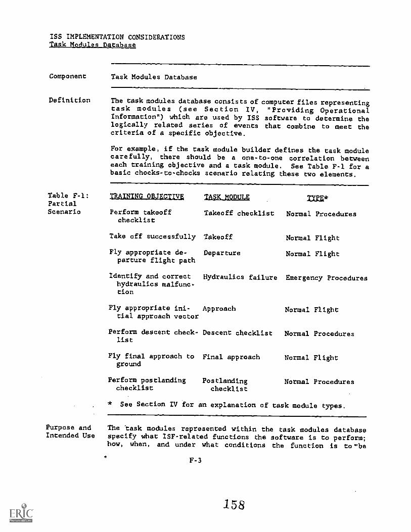
ISS IMPLEMENTATION CONSIDERATIONSTask Modules Database
Component
Definition
Task Modules Database
The task modules database consists of computer files representingtask modules (see Section IV, "Providing OperationalInformation") which are used by ISS software to determine thelogically related series of events that combine to meet thecriteria of a specific objective.
For example, if the task module builder defines the task modulecarefully, there should be a one-to-one correlation betweeneach training objective and a task module. See Table F-1 for abasic chocks-to-chocks scenario relating these two elements.
Table F-1: TRAINING OBJECTIVE TAO( MODVLE TYPE*PartialScenario Perform takeoff Takeoff checklist Normal Procedures
checklist
Take off successfully Takeoff Normal Flight
Fly appropriate de- Departureparture flight path
Normal Flight
Identify and correct Hydraulics failure Emergency Procedureshydraulics malfunc-tion
Fly appropriate ini- Approach Normal Flighttial approach vector
Perform descent check- Descent checklist Normal Procedureslist
Fly final approach to Final approach Normal Flightground
Perform postlanding Postlanding Normal Procedureschecklist checklist
* See Section IV for an explanation of task module types.
Purpose and The task modules represented within the task modules databaseIntended Use specify what ISF-related functions the software is to perform;
how, when, and under what conditions the function is twebe
F-3
ISS IMPLEMENTATION CONSIDERATIONS
laaltadultailetakAlaperformed. For example, a takeoff task module might begin whenan aircraft exceeds 0 knots and terminates when the aircraftachieves a positive rate of climb. Within this task modulewould be appropriate triggers for displays, scenario control,and other ISFs.
From a system resources point of view, the task modules reducethe amount of data that requires monitoring to encompass onlythose events that are critical at a spL,cific point in time.For example, during an engine failure at 30,000 feet theposition of the landing gear is not important; but during anapproach, the position of the landing gear may be associatedwith a primary training objecttve. By reducing the monitoredevents, there is more processing time available for ISFs.
Task modules may be consecutive or concurrent. For example,the departure task module may start upon completion of thetakeoff task module. An emergency procedures (malfunction)task module, however, may take place at any appropriate timeand may overlap both the takeoff and departure task modules.
In addition to the basic training objectives related task modulesthere can be one other task module running at all times. In
past implementations this has been referred to as an umbrella
task module. The umbrella can monitor hypercritical eventsthat must be associated with the entire scenario. For example,
a crash would trigger a diagnostic message and possibly a resetif desired from the umbrella task module.
Pseudo-task modules unrelated to training objectives maybe used to reposition the aircraft or reset initial flightparameters for the instructor's convenience. See Table F-2 fora partial task module event chart of a typical scenario.
F-4
159
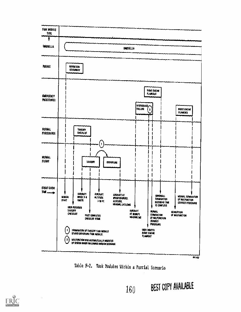
TA1K MODULE
TYPE
NOIMENNOIMMINWIIIIMIN
LAMELLAUMBRELLA
PSEUDO
_ .WOTANTO NOWAY
EMERGENCY
PROCEDUREI
-
L4........:1110111501NE
!MOUT
NORMAL
PROCEDURES
?AXIOM'
pacmat
NORMAL
FLIGHT
-1
EVENT OVER
TIME -.0MINION
ITART
1
i1
0
Ifr
man SKINSfimioul
AIRCRAFT
PITO > IIKNOTS
MIR ANNUSTAICIOFf
CANCKUIT
I
1
I
1
1
1
1
1
1
1
1
1
I
AIRCRAFT AIRCRAFT ATALMON INCUR') PIM
) 10 Pt *LITTON,
11401110,LA1/LON
P110 MUMCWICIALIII ITIN
0 TILIONATION Of TAIWO0 TUX NNWUNIX OVUM TUX MODULI,
0 MALFUNCTION WAX MITONATICALLV MUMIlf NUN IMO ON CAN1O NINON moo
UMW NORMAL 115011101001TIRMINATION I OF oturumiem,tkCIMINI TIN I COPUCT IICIUMNIITO WAITS
NORVAL IIIINIVITIONURINATION OF MALFUNCTION
OF NALINCTION
CORRICT
MOON!
INR WWI111010 INOINI
FLAMM
Table F-2, Task Modules Within a Partial Scenario
160 BEST GO MAME
ISS IMPLEMENTATION CONSIDERATIONSTask Modules Database
Cost Factors The cost of development of the task modules database willdepend on the number of unique task modules and the number
of different training event scenarios in the training syllabus.
Options and The cost of developing and maintaining a task modules database
Tradeoffs can be reduced by providing a highly functional database
editor. This may increase the initial procurement cost of
software but may result in savings over the life of the system.
Example From a software point of view, the task modules database can be
implemented as several files which contain different types of
information. Files used for the F-14 ISS are listed below:
o dltdauLlmaLc_1111. This file contains data needed to
define an entire exercise (mission). It consists of a
series of records which define the task modules in the
exercise and tbe events or conditions which will trigger
tile execution of the task modules. When an exercise is
Lnitiated, t".n file is transferred to memory and is used
to contr0 Activity of the ISS.
RepsaltioL_VILA. This file is for task modules that
require a certain location. For example, the takeoff taskmodule requires the aixcraft to be on a runway to start.
o Initial Conditions File. One file for each task module
defined in the system. Describes the events and otherstarting conditions that allow the system to determine
when a task module is to start execution.
o Events File One file for each task module defined in
the system. Describes the events to be detected when that
task module is running.
o Sequence File. One file for each task module defined in
the Liystem. Describes the relationships of the events to
each other under a varying number of circumstances andprovides the information on action to take when the event
occurs.
o Performaags_Measuremant File. This file containsperformance parameter data including limits and tolerances
for each task module.
F-6
161
ISS IMPLEMENTATION CONSIDERATIONSTask Modules Database
LessonsLearned
o Scoring _File. One file for each task module defined inthe system. Describes the grading criteria that will beused when scoring a task module.
o Dt.spl,ay File. One file for each task module defined inthe system. Contains a list of pictures to be displayedwhen the task module is initiated.
o Text File. One file for each task module defined in thesystem. Contains descriptive and error text messages tobe displayed when events occur during the execution of atask module.
Other files associated with the F-l4 ISS task modules databaseinclude:
o Display Template tiles. One file for each basic displayframe defined in the system. Serves as a template tolocate both the picture on the screen and in the displaylist.
o Ptcture Touch Files. One file for each picture defined.Contains information needed to properly react to theoperator touching the "select" areas of the screen.
?ictuKe Display List Files. One file for each picture"fined. Contains information which describes the picturebe displayed, including the binary data used to generate
the graphic displays.
The manual formulation of task modules proved to be costlyand an editor to aid in generating data files was recommended.
ISS IMPLEMENTATION CONSIDERATIONSSoftware
Component
Definition
Software
Software refers to the sequence of instructions and data usedto direct the computer to perform a desired operation orsequence of operations.
Purpose and Software is required to develop and run the task modulesIntended Use database on the ISS. To develop and build task modules, it is
essential that an editor be implemented to obtain event andprocedural data, generate text files, build graphic displays,and define parameters for all related ISFs. To run taskmodules two or three primary software modules are required forsystem event detection and monitoring.
Software modularity is encouraged in that each independentISF can have its own associated software module. For example,IOS display control and formatting would be independent ofautomated performance measurement. Such a modvlar approachprovides flexibility and ease of execution. Other supportmodules such as a graphics software module may be required toprovide for actual display device dependent output capabilities.
Cost Factors The cost associated with this element includes the time requiredto design, write, integrate, and test software. ISS softwarecomplexity is largely determined by tIle number and types oftasks that are to be taught and the instructional featureswhich are incorporated in the ISS. The magnitude of softwaredevelopment will depend on whether the ATD is intended for parttask training, operational flight training, single seat weaponsystem training, or full crew mission training. It willalso depend on which of the ISFs has been selected and theadditional considerations which must be taken into account fortheir customized implementation.
Options and Software modularity allows for functionality in phases.Tradeoffs During system development, as soon as an ISF is programmed, it
can be used. For example, automated performance measurement,procedures monitoring, remote graphics replay, and data storageand analysis capabilities can be added after an initial deliveryof IOS display formatting, initial conditions, scenario control,malfunction control, freeze, and reposition. A tutorial can bea final addition.
F-8
163
ISS IMPLEMENTATION CONSIDERATIONSSoftware
Example
Commercially availle operating systems and utilities can beintegrated into the ISS to reduce software development costs.The commercial ptoducts, however, may require additionaltailoring to be effective in the ISS environment.
The basic architecture of the F-14 ISS utilizes event triggersfor initiating processing activity. Messages are passed toactivate responses to the events as defined within the taskmodule files (see the Task Modules Database example). Simulationsystem variables are evaluated ftve times a second to detectevents.
o Op-line MIssion Conduct. Mission conduct is the executionof a predefined exercise in one of three modes of operation(CANNED, Ilostructor Select (ISEL), Specialized Part TaskTraining (S77)).
iaassilasar_jlimmli Receives messages from thegraphics display module (see below). Controlsoperation of the simulator interface. Controlsthe execution of the task modules. Controlsrepositioning. Updates and maintains environmentaloptions. Maintains, updates and formats a listof task modules comprising an exercise. Creates andterminates applications processes.
Conerter-Detector. Converts cockpit device valuesfrom the simulator to formats usable by applicationsprograms. Detects discrete events associated withpilot actions or changes in aircraft parameters.
Ex_sass_tiusajgsmisss Determines the correctness ofvarious cockpit procedures based on a predeterminedtemplate. Events will checked for legalitywithin the current procedur context and for correctorder of occurrence. The rocedures Monitor willsupport a separate monitor task for each acttve taskmodule.
arleralpse_tatto Samples, processes, andrecords aircraft parameters. The measurements aredivided into two groups: primary--those used inscoring the flight, and secondary--those measured andrecorded for research purposes.
Egsns.L. Handles hardware interrupts and transfersdata from the simulation system.
F-9
164
ISS IMPLEMENTATION CONSIDERATIONSSoftware
Aircraft Monitor Maintains displays concerningaircraftposition, key parameters, important instrumentvalues, and configuration.
Controller Model, Generates voice output to emulatethe following human controllers during execution ofan exercise: tower, departure, approach, final.
Scoring, Scores the student's flight and p)..ceduresperformance for each task module executed.
Event/Replay Recorder, Records display data generatedduring run-time by task module executions as wellmiscellaneous system events.
o On-line Exercise Setup _and Debriefing. Includes logging
onto the ISS, reviewing student performance prior tomission setup, constructing an executable mission (ISEL andSTT modes), and debriefing the mission after completion.Debriefing entails review of ISS assigned grades andreplay of all or selected task modules from the exercise.
Exercise Definition, Builds a mission definition fileto describe an exercise for the ISEL and STT modes,or select from a list of predefined CANNED missions,and conducts mission briefing functions for all threemodes,
Log.on - Student Performance Review, Controls accessto the ISS and conducts an interactive review sessionof previous student performance.
Debriefing. Permits the instructor to review aparticular training session, approve/medify gradesgiven by the ISS, and replay portions of the exercise.
o On; line Graphics Di_play Controls the graphics choresduring all on,line ISS operations.
o Off-line Support. Programs that are intended to be run in
the off-line m(-:.et. Includes introduction of predefinedtask modules into t",a ISS by the generation of the requiredcontrol and data structutes, analysis of data recorded inthe daily audit file, maintenance of student record filesand system software, and functional integrity verificationof the ISS prior to on-line operations.
F-10
165
ISS IMPLEMENTATION CONSIDERATIONSSoftware
Procedure Definition, Translates proceduraldescriptions into the control structures required toexecute a given task module (see the previouscomponent discussion on the Task Modules Database).The tables so generated will drive logics forprocedures monitoring, event detection, and performancemeasurement.
Lyszt_4.teat_s__yinalsis Data recorded by the EventRecorder task in the Applications Processor will beused to provide ISS usage data, program debuggingaids, and operating environment data for researchpurposes.
Housekeeping. Disk file maintenanceuser access lists.
and changes in
CcInfidence test, Checks functional integrity of theISS prior to initialization of on-line operations.
Lessons The manual formulation of task modules proved to be costly andLearned an editor to aid in generating data files was recommended.Languages and simpie editors dre often difficult and tedious touse. A menu-driven, nonprogrammer oriented program to allowoperational users to define their requirements could be easierto use. Although it may be more costly to implement initially,the cost savings may be realized through use during the life ofthe ISS.
Synchronous execution of software can cause problems in detectingevents for an ISS. For example, a 200 millisecond cycle wasfound to be insufficient for monitoring momentary switches anda 50 millisecond cycle was recommended to account for themomentary switch. An ISS can be tplemented on an asynchronousbasis, as accomplished by the F-14 ISS and ARPTT-ISS, toaccount for critical events as they occur.
Imi
F-11
166
ISS IMPLEMENTATION CONSIDERATIONSComputer Syst_em
Component
Definition
Computer System
The computer system performs all logical and numerical process:Ing
for the ISS. It usually consists of a processor or processors,
storage, and input/output channels.
Purpose and The computer system provides the means for adding instructional
Intended Use support to a siollator capability by executing software which
permit monitori T, simulator variables, instructor controls,student actions, and making the instructional responses desired
of tile ISS. The types of ISFs which may be implemented in this
way ate listed earlier in this document. If the ISS computer
system did not exist, these features either would be impossiblewith the basic simulation facility or, in some cases, would be
only by manual instructor action.
Cost Factors Programs which execute within the computational system require
adequate processing capacity, main memory and mass storage. A
thorough analysis of system functional requirements, with
provisions for growth, is required for estimation of these
parameters.
Rsocas4na_capacAty, The processing capacity of a computer
takes into account the number of instructions which can be
executed per second and the rate at which input/output
information can be transferred. The latter is also afunction of the devices added to the system, such as mass
storage devices.
Napa gomqry. Main memory size is usually expressed interms of the total number of bytes which may be stored.
Fast processing is normally accomplished with information
in main memory.
o Mass storage, Primary mess storage is used for storage of
programs and data that are necessary for daily use of the
ISS and for short term storage of data collected for a
training event. Secondary mass storage is used to form anarchive of programs and data that are not required for
daily use of the ISS. Primary mass storage might emphasize
fast access to a disk system whereas secondary storagecould be relegated to slow devices such as tape drives.
F-12
1167
ISS IMPLEMENIA;ION CONSIDERATIONS.g...91.1211=
Contributions to the storage requirement by each ISFshould be estimated using the stated functional requirementand the expected utilization. For example, the storagerequirements for Simulator Record/Replay are large andneed to accommodate the total number of minutes which areto be recorded (see the Simulator Record/Replay ISF).
Function complexity, that is degree of interaction among ISFsand task module concurrency requirements, may affect the costof implementation of the basic ISS software architecture anddictate the computer system capacity and storage requirements.
Expected system performance also determines the computer systemcost. For example, display update rates of 1 to 2 times asecond are sufficient for ISS implementations. Displays neednot be updated if the display content need not be altered.Given these performance requirements the ISS could be implementedusing less costly computer systems. If performance requirementsrequiring higher update rates were unnecessarily imposed, thecost would increase.
Options and Processing may be distributed among 1.2ss costly, less capableTradeoffs computer systems rather than one costly centralized system.
Tradeoffs would be experienced in the computer-to-computerinterface cost.
Example
Oftentimes a tradeoff exists between the hardware and softwarecosts. For example, lots of programmer time can be wastedtrying to scale down program sizes to fit into limited mainmemory. As memory costs have decreased and programmer laborcosts increased, purchase of additional memory can realize costsavings.
The F-14 ISS utilized two computer systems. One was dedicatedto On-line Graphics Display (see example for the Softwarecomponent) end the other performed all other processing tasks.
o Applications Computer System
Data General Eclipse 5-250(1.23 million instructions per second)1024 KB main memory96 MB disk storage1/2 inch magnetic tape drive
F-13
168
ISS IMPLEMENTATION CONSIDERATIONSComputer System
o Display Computer System
Data General Eclipse S-130(1.23 million instructions per second)384 KB main memory10 MB disk storage
Lessons Large program sizes may cause system response to be too slow.
Learned This can be alleviated by tuning the operating system, addingmore memory, and reorganizing files on mass storage to optimize
data file access.
The processing speed of the selected computer may affect theSimulator-ISS interface. For example, data may have to bebuffered from the interface in order to allow time forprocessing.
F-14
169
ISS IMPLEMENTATION CONSIDERATIONSStations
Component Stations
Definition Stations provide a person-machine interface between all usersof the ISS and the ISS. Components of the station includeinput devices, such as keyboards and touch panels, and outputdevices, such as hardcopy printers, speech genaration equipment,and graphic and tabular displays.
Purpose and Stations can be used for:Intended Use
o ISS and simulation system .:vric.rolo Monitoring of student activtcy while trainingo Display of student activity after trainingo Retrieval of performance information
Prev?Arion of a preprogrammed mission scenarioo Update of the task modules databaseo Maintenance of the ISS
Ccst Factors Devices located at the station, the number of stations, and thelocation of the stations are factors which affect their cost.
o Statism_ devices, The intended station functionswill determine the devices located at the station.Identification of functions requires an analysis of usertasks.
o Number of stations, Candidate stations include on-board(in cockpit), off-board (outside cockpit), dedicatedbriefing/debriefing (see the Briefing Utilities and RemoteGraphics Replay ISFs), mission-generation, trainingobjective database generation, and programmer/maintenancestations.
kosAlliza_s_t_s_tAtissu_ Cost may be influenced by thelocation of a station and on any constraints on thesize of the components. Replacement of an existingoperator console may also b a cost factor..l.,.
Options and The number of stations, locations, functions to be performed,Tradeoffs concurrent operation, information displayed, control actions,
specific control/displays, and hvaan engineering design,present a multitude of options to be considered for ISSstations. An analysis of training functions, training load,personnel characteristics, and specific training constraints
F- 15
-1P-Yn
ISS IMPLEMENTATION CONSIDERATIONSStations
Example
will be required to identify specific options to be consideredfor tradeoff study.
The functionality, maintainability, reliability, and cost ofcurrently available devices should be surveyed to arrive atcost estimates. State of current commercial offerings shouldbe considered to keep costs at reasonable levels. For example,1985 technology offers color, raster graphics d Ilays withantialiauing features (to minimize stairstepping).
An important input device consideration is that a single inputmethod be adopted at each station so as not to confuse theuser.
Two similar instructor stations were used on the F-14 ISS. ThePrimar ISS Station was placed next to the existing InstructorOpera- : Station (IOS); the Remote Station was used for setup,brief jebrief and grading. Each consisted of upper and lowergraphic displays with a touch pad on the lower for operatorcontrol inputs. A separate printer/plotter was used forhardcopy needs. Additionally, the systum included voicegeneration capabilities for controller models, and twomaintenance terminals.
Note that future ISS implementations should incorporate ISSstation requirements into main and remote IOS requirements,strtving towards an ISS that is fully integrated into the ATD.
Lessons The touch panel design Firs received good user acceptance,Learned requires no special input skills, nd allows only legal inputs
to be made. Touch panel technology has been found to bereliable for ISS use.
Display resolutions of 512 x 512 picture elements and 16 colorshave been found to be sufficient for symbolic information.
F-16
171
ISS IMPLEMENTATION CONSIDERATIONSSimulation System Interface
Component
Definition
Simulation System Interface
The simulation system interface is that portion of the systemwhich allows the ISS to transmit to, and receive data from, therest of the ATD.
Purpose and The simulation system interface allows the ISS co communicateIntended Use with the remainder of the ATD to:
o initiate control of the simulation scenarioo monitor flight variables, such as altitude and airspeedo monitor discrete actions, such as switch actions
Cost Factors The simulator interface can be a major hardware cost when theISS is to be added to an existing simulator capability. Thereis a major engineering challenge to find a least costly way toobtain needed data and exercise required control. The solutionvaries on a case-by-case basis since it depends on how the ATDis built. Lower cost can be expected if the ISS can be designedas an integral part of a new ATD acquisition.
Options and The following are alternative methods for the simulatorTradeoffs interface. Only the first two methods have been used in the
four prototype systems as additions to existing ATDs.
o Data Avauisition System/Switch Unit. This type of interfaceinterrupts the data path(s) between the central processingunit (CPU) of the ATD and the hardware devicol whichdistributes CPU outputs to the flight station, visualsystem, motion system, and operator/instructor station,and funnels inputs from these systems to the CPU. Theinterface therefore allows communication with the ISS CPUand acquires data traveling in either direction at cheATD, totally transparent to the simulation system.
o Zumi_mgmatu, A portion of the ATD CPU memory can beshared with the ISS CPU. The sharEd memory would containall data originated by the operator/instructor and allpertinent ATD flight information.
o Culvqntippal data link. A possible alternative is the useof a high speed data link which connects the simulationsystem computer(s) and the ISS computer(s). Both systemsmust have software which handles the required communicationsprotocols.
F-17
172
ISS IMPLEMENTATION CONSIDERATIONSSimu ation Syztem_Interface
Example To assist the Instructor in training, the F-l4 ISS had tomonitor all information transmitted betw.sen the Sigma 5 simulatorsystem computer and the Instructor Console-Cockpit. All of thisinformation passes over a channel between the Sigma 5 mainmemory and an Input/Output Processor. A Data AcquisitionSystem/Switch Unit was constructed for placement in thischannel. In addition to monitoring the information on thischannel, it was also necessary to alter some of the informationcoming from the Instructor Console to allow the ISS to generatesequences of 1VDUts which would otherwise require the Instructorto press buttons and turn knobs. This required detecting databefore data is transferred, and making changes at the time oftransfer. Finally, the Data Acquisition System/Switch Unit hadto be able to read information from the Sigma 5 memory toprovide the ISS computer with information on the configurationof the trainer and the flight situation.
Lessons If an ISS is added to an existing ATD, the simulation systemLearned interface involves risks and possible interference with the
operation of the ATD. The risks can be minimized if the ISS isdesigned into the initial procurement of an ATD.
F-18
173
ISS IMPLEMENTATION CONSIDERATIONSLife Cycle Cost
Component Life Cycle Cost
Definition Life cycle costs are incurred over the operational life of theISS. Of primary importance to an Instructor Support System arethose personnel considerations which affect operator/instructorperformance in the use of the ISS. Included are considerationsof the number and type of personnel required to use the ISS,operatimal_cluto for effective instructional use, and trainingfor the new or infrequent operator/instructor.
Purpose and The ISS must be usable by the specified personnel and allowIntended Use maximum instructional effectiveness. This, in turn, requires
that the ISS be designed for the number and characteristicsof nperating personnel; the system must be designed for easyuse and support the instructional process without burdeningthe instructor; and, training must be provided so that theoperator/instructors can effectively use the tnstructionalfeatures of the ISS.
Options and Personnel, design, and personnel training aids are among theTradeoffs options and tradeoffs to consider:
o Personnel. The number of people required for instructionwill depend on the ATD configuration and the design ofthe ISS. The number of people will depend on whetherinstructors are required inside the cockpit as well asoutside and whether an operator will be assigned for theduties of simulator operation and communications. Ifdesired,the ISS can include features to simplify simulatoroperation and automate functions whick can eliminate theneed for a separate Operator, and zliaimize the burden onthe Instructor, Lncluding the burden of coordinating witha separate Operator. People are also needed for maintenanceand update/revision of the ISS, especially those needed forcourseware update/revision (e.g., task module creation andnavigational display definition). The number of peopleassociated with the ISS are major factors in determiningtotal life-cycle costs.
For example, in the ARPTT ISS procurement it was shownthat the ISS eliminates a console operator. Cost savingsare expected over the 15 year life of the ISS.
F-19
1 74
ISS Pfr.LEMENTATION CONSIDERATIONS
Example
o ISS Design. The design process consists of the followingsteps:
Functional Analysis: Definition of the specificfunctions to be performed by the ISS, that is, yhatthe ISS is to do.
Operational Design: Definition of the controls,displays, and procedures to perform each of therequired functions, that is, bsE the ISS is to be used
System Design: Definition of the hardware andsoftware to be used in constructing the ISS.
Of particular interest at this point is the second step,that of operational design. Many options and tradeoffsare identified at this stage which will ultimately determinehow well the ISS can be used for instruction by those whomust use it. It is recommended that representatives of theusers become actively involved in the operational designprocess. Note that human engineering of the ISS can reduceuser workload and special knowledge/skill requirements,and in turn increase training effecttveness while reducinglife-cycle costs.
o Trainillg. Helps. and Documentaon. An ATD may be used insome curricula by instructors who infrequently use the
simulator as an adjunct to inflight training and they mayneed some training and help in using the ISS/ATD eachsession. An instructor new to tho ISS/ATD will requiretraining in use of the system and the expertise of theformer instructor may depart with him. One way of copingwith these situations is to incorporate training featuresin the I$S. See the discussion on the Tutorial ISF forsuggested training features.
System documentation can also be provided as a databasewhich can be selectively retrieved when detailed referencematerial is needed.
While the optimum operational design used for one system maynot be best for another, the Instructor-ISS interface used inthl F-14 1St; (and the ARPTT) may be broadly applicable. The
batic interface is a CRT with a touch panel and control is
F-20
1 76
ISS IMPLEMENTATION CONSIDERATIONSLife CyciR Cost
exercised through a sequence of menu selections. AL!,:. 1.?1;
several inherent advantages:
o the available control options at any given time aredisplayed on the display screen; the instructor does nothave to remember specific commands.
o only legal options can be selected; there is no need forerror checking or the display of cryptic error messages.
o because of the touch panel, no special input devices orskills are required; one only needs to point at theselected menu item on the display screen.
o built-in "helps" are easily implemented.
Such systems in the field have met with good user acceptance.
Lessons Difficulties were encountered with the C-SA PMS when thoseLearned trained in its use were rotated to new duties; understandably,
the PMS option was not used by those who did not know how touse it. It is common experience that systems are not effectivewhen users are not adequately trained in its use, or if systemdesign has not been accomplished with the requirements of the.using personnel in mind.
APPENDIX G
,:ASK MODULES
Samples of the two basic task module i.:ypes (flight and procedural) are givenin this appendix. The tacan approach ;:ask module is a normal flight taskmodule. The engine start task module is a normal procedures task module. ArLview of Section IV, "Providimg Operational Information", is recommendedbefore readiog these samples.
The samples are taken from the F-14 /SS. An ISS requires certain informationto be able to provide Instructor Support Features (ISFs). These task modulesproviAe nhc, operational information required for the F-14 ISS to supportthe foliowtng features:
o IOS Display Control and Formattingo Procedures Monitoringo Automated Performance Measurement
Although beyond the scope of these guidelines, information for an automatedvoice controller is also included.
G-1
177
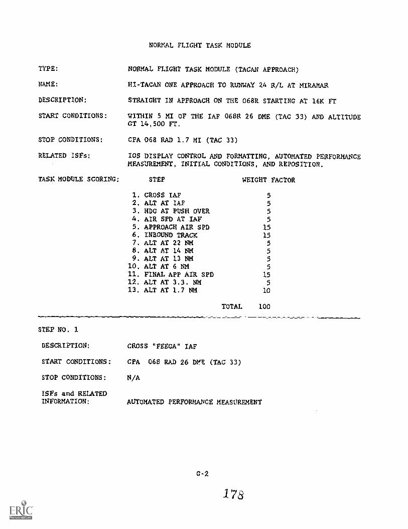
NORMAL FLIGHT TASK MODULE
TYPE: NORMAL FLIGHT TASK MODULE (TACAN APPROACH)
NNME: HI-TACAN ONE APPROACH TO RUNWAY 24 R/L AT MIRAMAR
DESCRIPTION: STRAIGHT IN APPROACH ON THE 068R STARTING AT 16K FT
StART CONDITIONS: WITHIN 5 MI OF THE IAF 068R 26 DME (TAC 33) AND ALTITUDEGT 14,500 FT.
STOP CONDITIONS: CPA 068 RAD 1.7 MI (TAC 33)
RELATED ISFs: IOS DISPLAY CONTROL AND FORMATTING, AUTOMATED PERFORMANCEMEASUREMENT, INITIAL CONDITIONS, AND REPOSITION.
TASK MODULE SCORING: STEP WEIGHT FACTOR
1. CROSS IAF 52. ALT AT IAF 53. HDG AT PUSH OVER 54. AIR SPD AT IAF 55, APPROACH AIR SPD 156, INBOUND TRACK 157. ALT AT 22 NM 58. ALT AT 14 NM 59. ALT AT 13 NM 5
10, ALT AT 6 NM 511. FINAL APP AIR SPD 1512. ALT AT 3.3. NM 513. ALT AT 1.7 NM 10
=11.TOTAL 100
STEP NO. 1
DESCRIPTION: CROSS "FEEGA" IAF
START CONDITIONS: CPA 068 RAD 26 DME (TAC 33)
STOP CONDITIONS: N/A
1SFs and RELATEDINFORMATION: AUTOMATED PERFORMANCE MEASUREMENT
G-2
178
DIAGNOSTICS:DISCREPANCY: NM FROM "FEEGA" GREATER THAN 2 MIERROR: POOR NAV CONTROLRULE: CROSS "FEEGA" 068/26 FROM TAC 33DISCREPANCY: FREQ NOT EQUAL 261.8ERROR: WRONG UHF FREQUENCY
RULE: SD APP 81.8
AUTO VOICE:CONTROLLER: ':EGO APPROACH / FREQ - 281.8TEXT: Y ZERO ONE CLEARED FOR TACAN APPROACH TO RUNWAY
TWO FOUR aIGHT CALL WHEN LEAVING ONE SIX THOUSANDFEET"
MEASUREMENT PACKET:CPA 068R 26 NM / TYPE - SNAPSHOT / OPTIMUM . 0
SCORING:SCORE 4.0 3.5 3.0 2.5 2.8
MEASURE <.5 <.75 <1.0 <2.0 ->2.0
STEP NO. 2
DESCRIPTION: CROSS "FEEGA" NO LESS THAN 16,000 FT.
START CONDITIONS: CPA 068 RAD 26 MI (TAC 33)
STOP CONDITIONS: N/A
ISFs and RELATEDINFORMATION: AUTOMATED PERFORMANCE MEASUREMENT.
DIAGNOSTICS:
DISCREPANCY:ERROR:RULE:
ALTITUDE LESS THAN 15,500 FT.POOR ALT CONTROL
CROSS"FEEGA" 068/26 AT 16,000 FT. OR GREATER
AUTO VOICE: N/A
MEASUREMENT PACKET:ALTITUDE / TYPE SNAPSHOT / OPTIMUM - 15,000 FT.
SCORING:SCORE 4.0 3.5 3.0
MEASURE <16,500 <16,750>15,950 >15,900
2.5
<16,850>15,850
2.0
<17,000>15,250 -<15,250
G-3
1 79
STEP NO. 3
DESCRIPTION: START DESCENT WITHIN 45 DEG OF APPROACH HEADING
START CONDITIONS: VSI GT 3000 FPM, ALT. LT 15,000 FT AND DME DECREASING
STOP CONDITIONS: N/A
ISFs and RELATEDINFORMATION: AUTOMATED PERFORMANCE MEASUREMENT
DIAGNOSTICS:DISCREPANCY: HDG LT203 OR GT 293ERROR: POOR NAV CONTROL
START APP WITHIN 45 DEG OF INiOUND HDG.
AUTO VOICE: N/A
MEASUREMENT PACKET:HEADING / TYPE SNAPSHOT / OPTIMUM 248
SCORING:SCORE 4.0 3.5 3.0 2.5 2.0
MEASURE >203 >198 >193 >193 -41934293 <298 <303 <308 ->308
STEP O. 4
DESCRIPTION: CROSS "FEF1A" IAP AT 250 KIAS
START CONDITIONS: CPA 068 RAD 26 MI (TAC 33)
STOP CONDITIONS: N/A
ISFs and RELATEDINFORMATION: AUTOMATED PERFORMANCE MEASUREMENT
DIAGNOSTICS:DISCREPANCY: KIAS GT 265 OR LT 235ERROR: POOR AIR SPD CONTROLRULE: CROSS "FEEGA" 068/26 AT 250 KIAS
AUTO VOICE: N/A
MEASUREMENT PACKET:AIRSPEED TYPE SNAPSHOT / OPTIMUM - 250 KIAS
0-4
1 C5 u
SCORING:SCORE
MEASURE
4.0
<255>245
3.5
<260>240
3.0
<265>235
2.5
<270>230
2.0
STEP NO. 5
DESCRIPMN: MAINTAIN APPROACH AIRSPEED 250 PRIOR TO LANDING CHK. LIST
START CONDITIONS: "FEEGA" 068R 26 MI (TAC 33)
STOP CONDITIONS: LANDING GEAR HANDLE DOWN
ISFs and RELATEDINFORMATION: AUTOMATED PERFORMANCE MrASUREMENT
DIAGNOSTICS:DISCREPANCY: KIAS GT 265 OR LT 235ERROR: POOR AIR SPD CONTROLRULE: MAINTAIN 250 KIAS DURING APPROACH
AUTO VOICE: N/A
MEASUREMENT PACKET:AIRSPEED TYPE - RMS / OPTIMUM 250 KIAS
SCORING:SCORE 4.0 3.5 3.0 2.5 2.0
MEASURE <255 <260 <265 <270>245 >240 >235 >200
STEP NO. 6
DESCRIPTION: TRACK INBOUND ON 068R
START CONDITIONS: CPA "FEEGA" 068R 26 MI (TAC 33)
STOP CONDITIONS: CPA 068R 1.7 DME (TAC 33)
ISFs and RELATEDINFORMATION: AUTOMATED PERFORMANCE MEASUREMENT
DIAGNOSTICS:DISCREPANCY: RAD GT 073 OR LT 063ERROR: POOR NAV CONTROLRULE: TRACX INBOUND 068R
AUTO VOICE: N/A
0-5
181
MEASUREMENT PACKET:RADIAL / TYPE RMS
SCORING:
/ OPTIMUM - 068
SCORE 4.0 3.5 3.0 2.5 2.0
MEASURE <70 <73 -73 <83 ->83>66 >63 !:i3 >53 -<53
STEP O. 7
DESCRIPTION: 5,200 ALTITUDE RESTRICTION AT 22 DME
START CONDITIOW: CPA 068 RAD 22 NM (TAC 33)
STOP CONDITIONS: N/A
ISFs and RELATEDINFORMATION: AUTOMATED PERFORMANCE MEASUREMENT
DIAGNOSTICS:DISCREPANCY: ALTITUDE LESS THAN 5,000 FTERROR: POOR ALT CONTROLRULE: CROSS 22 DME AT OR ABOVE 5,200 FT
AUTO VOICE: N/A
MEASUREMENT PACKET:ALTITUDE / TYPE
SCORING:SCORE 4.0
MEASURE <5,700>5,200
SNAPSHOT / OPTIMUM 5,200 FT
3.5 3.0 2.5
<6,000 <6,300>5,150 >5,000
2.0
<6,600>5,000
STEP O. 8
DESCRIPTION: 4,700 FT ALTITUDE RESTRICTION AT 14 DME
START CONDITIONS: CPA 068 RAD 14 NM (TAC 33)
STOP CONDITIONS: N/A
ISFs and RELATEDINFORMATION: AUTOMATED PERFORMANCE MEASUREMENT
G-6
182
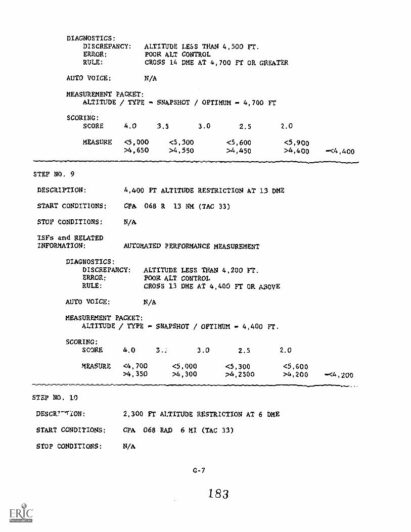
DIAGNOSTICS:DISCREPANCY: ALTITUDE LESS THAN 4,500 FT.ERROR: POOR ALT CONTROLRULE: CROSS 14 DME AT 4,700 Fr OR GREATER
AUTO VOICE: N/A
MEASUREMENT PACKET:ALTITUDE / TYPE
SCORING:
SNAPSHOT / OPTIMUM 4,700 FT
SCORE 4.0 3.5 3.0 2.5 2.0
MEASURE <5,000 <5,300 <5,600 <5,900>4,650 >4,550 >4,450 >4,400 -<4,400
STEP NO. 9
DESCRIPTION: 4,400 FT ALTITUDE RESTRICTION AT 13 DME
START CONDITIONS: CFA 068 R 13 NM (TAC 33)
STOP CONDITIONS: N/A
ISFs and RELATEDINFORMATION: AUTOMATED PERFORMANCE MEASUREMENT
DIAGNOSTICS:DISCREPANCY: ALTITUDE LESS THAN 4,200 FT.ERROR: POOR ALT CONTROLRULE: CROSS 13 DME AT 4,400 FT OR ABOVE
AUTO VOICE: N/A
MEASUREMENT PACKET:ALTITUDE / TYPE
SCORING:
SNAPSHOT / OPTIMUM - 4,400 Fr.
SCORE 4.0 3.0 2.5 2.0
MEASURE <4,700 <5,000 <5,300 <5,600>4,350 >4,300 >4,2500 >4,200 -<4,200
STEP NO. 10
DESCRT'TiON: 2,300 FT ALTITUDE RESTRICTION AT 6 ME
START CONDITIONS: CPA 068 RAD 6 MI (TAC 33)
STOP CONDITIONS: N/A
G-7
183
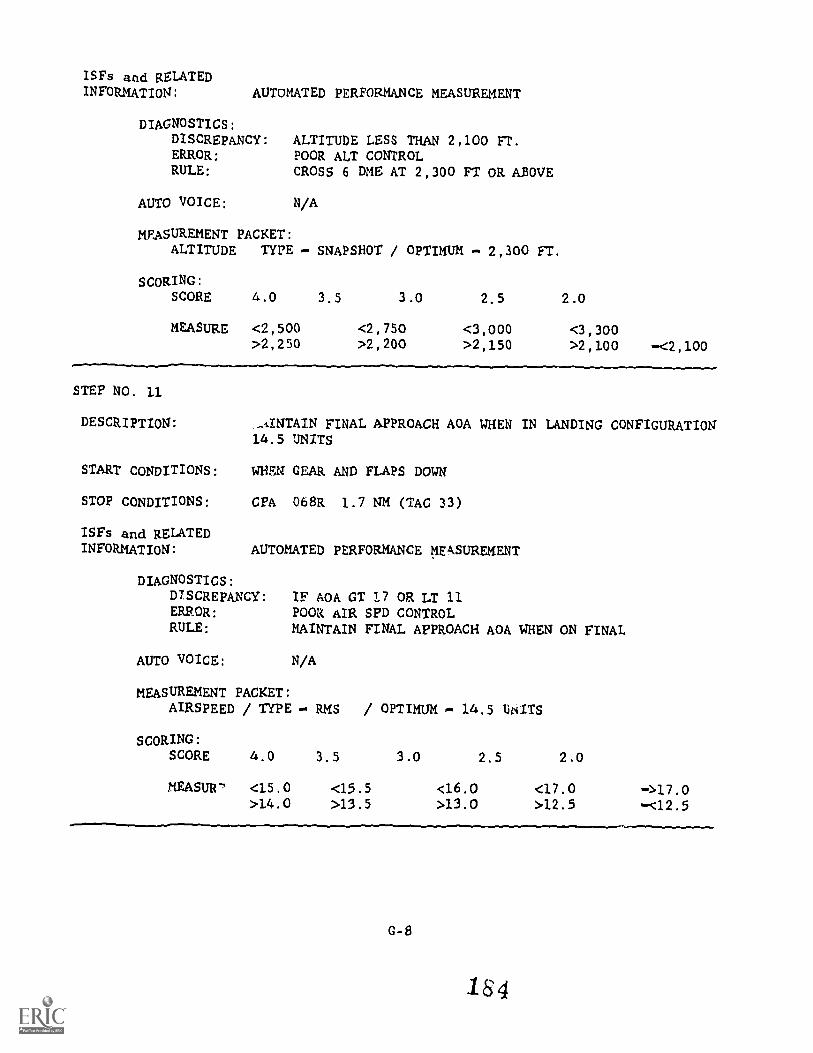
ISFs and RELATEDINFORMATION: AUTOMATED PERFORMANCE MEASUREMENT
DIAGNOSTICS:DISCREPANCY:ERROR:RULE:
ALTITUDE LESS THAN 2,100 FT.POOR ALT CONTROLCROSS 6 DME AT 2,300 FT OR ABOVE
AUTO VOICE: N/A
MEASUREMENT PACKET:ALTITUDE TYPE - SNAPSHOT / OPTIMUM - 2,300 FT.
SCORING:SCORE 4.0
MEASURE 42,500>2,250
3.5 3.0
42,750>2,200
2.5
<3,000>2,150
2.0
<3,300>2,100 -<2,100
STEP NO. 11
DESCRIPTI0N:
START CONDITIONS:
STOP CONDITIONS:
ISFs and RELATEDINFORMATION:
-IINTAIN FINAL APPROACH AOA WHEN IN LANDING CONFIGURATION14.5 UNITS
WHEN GEAR AND FLAPS DOWN
CPA 068R 1.7 NM (TAC 33)
AUTOMATED PERFORMANCE MEASUREMENT
DIAGNOSTICS:DISCREPANCY:ERROR:RULE:
IF AGA GT L7 OR LT 11POOR AIR SPD CONTROLMAINTAIN FINAL APPROACH AOA WHEN ON FINAL
AUTO VOICE: N/A
MEASUREMENT PACKET:AIRSPEED / TYPE RMs / OPTIMUM 14.5 LNITS
SCORING:SCORE 4.0 3.5
MEASUR-, <15.0 <15.5>14.0 >13.5
3.0 2.5 2.0
<16.0 <17.0>13.0 >12.5
->17.0-<12.5
G-8
164
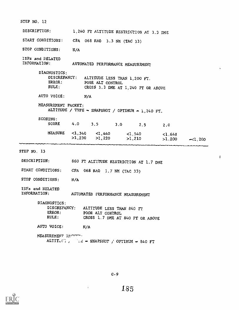
STEP NO. 12
DESCRIPTION: 1,240 FT ALTITUDE RESTRICTION AT 3.3 DME
START CONDITIONS: CPA 068 RAD 3.3 NM (TAC 33)
STOP CONDITIONS: N/A
ISFs and RELATEDINFORMATION: AUTOMATED PERFORMANCE MEASUREMENT
DIAGNOSTICS:DISCREPANCY: ALTITUDE LESS THAN 1,200 FT.ERROR: POOR ALT CONTROLRULE: CROSS 3.3 DME AT 1,240 FT OR ABOVE
AUTO VOICE: N/A
MEASUREMENT PACKET:ALTITUDE / TYPE SNAPSHOT / OPTIMUM 1,240 FT.
SCORING:SCORE
MEASURE
4.0
<1,340>1,230
3.5
<1,440>1,220
3.0 2.5
<1,540>1,210
2.0
<1,648>1,200 <1,200
STEP NO. 13
DESCRIPTION: 860 FT ALTITUDE RESTRICTION AT 1.7 DME
START CONDITIONS: CPA 068 RAJD 1.7 NM (TAC 33)
STOP CONDITIONS: N/A
ISFs and RELATEDINFORMATION: AUTOMATED FERFORMANCE MEASUREMENT
DIAGNOSTICS:DISCREPANCY: ALTITUDE LESS THAN 840 FTERROR: POOR ALT CONTROLRULE: CROSS 1.7 DME AT 840 FT OR ABOVE
AUTO VOICE: N/A
MEASUREMENTALTILC SNAPSHOT / OPTIMUM 840 FT
G-9
185
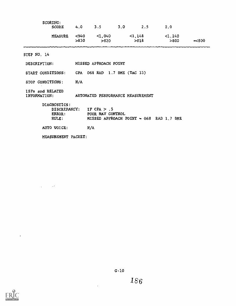
SCORING:SCORE
MEASURE
4.0
<940>830
3.5
<1,040>820
3.0 2.5
<1,148>818
2.0
<1,240>800 -<800
STEP NO. 14
DESCRIPTION: MISSED APPROACH POINT
START CONDITIONS: CPA 068 RAD 1.7 DME (TAC 33)
STOP CONDITIONS: N/A
ISFs and RELATEDINFORMATION: AUTOMATED PERFORMANCE MEASUREMENT
DIAGNOSTICS:DISCREPANCY: IF CPA > .5ERROR: POOR NAV CONTROLRULE: MISSED APPROACH POINT - 068 RAD 1.7 DME
AUTO VOICE: N/A
MEASUREMENT PACKET:
G-10
186
NORMAL PROCEDURES TASK MODULE
TYPE: NORMAL PROCEDURES TASK MODULE
NAME: ENGINES START
DESCRIPTION: NORMAL GROUND START or BOTH ENGINES
START CONDITIONS: COMPLETION OF THE PRE-START TASK MODULE, OR EXTERNAL AIRON.
STOP CONDITIONS: EXTERNAL AIR DISCONNECTED +30 SEC.
IsFs and RELATEDINFORMATION: PROCEDURES MONITORING
TASK MODULE SCORING: 4.0 3.5 3.0 2.5 2.0 WT
CRITICAL :RRORSSEQUENCE ERRORS 0 2 4 6 8 30%MANDATORY COMPLETE 95 40 80 70 60 40%OPTIONAL COMPLETE 100 97 95 90 80 10TIME TO FIRST EVENT (sac) 6 10 15 25 30 10
TOTAL TIME (sec) 60 90 120 240 360 10
STEP NO. 1
DESCRIPTION: CRANK LEFT ENGINE TO BUILD UP AUXILIARY BRAKE PRESSURE
CONTINGENCIES: EXTERNAL AIR AND EXTERNAL POWER ON
EVENTS: 1. ENGINE CRANK SWITCH LEFT
ISFs and RELATED INFORMATION:
IOS DISPLAY CONTROL & FORMATTING
DISPLAY UPDATE: "(TIME) ENGINE CRANK LEFT"
PROCEDURES MONITORING
DIAGNOSTICS :
DISCREPANCY: IF CRANK SW RIGHTERROR: CRANK SV SWITCH POSITION ERRORRULE: CRANK L ENG. TO BUILD AUX. BK. PRESS.
G-11
18 7
MEASUREMENT:EVENT 1 - MANDATORYSEQUENCE - N/ATIME: START FOR TOTAL PROCEDURE
STEP O. 2
DESCRIPTION: POSITION CRANK SWITCH TO OFF AFTER BRAKE PRESSURE HAS BUILTUP TO SAFE
CONTINGENCIES: ENG CRANK - LEFT
EVENTS: 2. AUX BRAKE PRESSURE SAFE3. ENGINE CRANK SWITCH OFF
ISFs and RELATED INFORMATION:
IOS DISPLAY CONTROL & FORMATTING
DISPLAY UPDATE: "(TIME) ENGINE CRANK OFF"
PROCEDURES MONITORING
DIAGNOSTICS:DISCREPANCY: IF 3 < 2ERROR: AUX BRAKE PRESS UNSAFERULE: CRANK PORT ENG. TO BUILD AUX. BRAKE PRESSURE TO
SAFE
MEASUREMENT:EVENT 3 - MANDATORYSEQUENCE - 2,3TIME: N/A
STEP O. 3
DESCRIPTION: EMERGENCY HYDRAULIC CHECK AND VERIFY CONTROL OF FLIGHTCONTROL SURFACES
CONTINGENCIES: EXT. AIR & POWER/EMERG FLT HYD SW AUTO (LOW)
EVENTS: 4. EMERG FLIGHT HYD. SWITCH - LOW5. STICK DEFLECTION - FORE/AFT LEFT/RIGHT6. RUDDER LEFT, RIGHT7. EMERG FLIGHT HYD. SWITCH - HI8. STICK DEFLECTION - FORE/AFT LEFT/RIGHT9. RUDDER LEFT, RIGHT
10. EMERG FLIGHT HYD - SWITCH AUTO (LN)
G-12
188
ISFs and RELATED INFORMATION:
IOS DISPLAY CONTROL & FORMATTING
DISPLAY UPDATE: "(TIME) EMERG. FLT. HYD. SW LOW/HI/AUTO
PROCEDURES MONITORING
DIAGNOSTICS:IF 9<7<4
ERROR: IMPROPER CHECK OF EMER. FLT HYD,RULE: SWITCH ERROR (SW. - LOW/HI/AUTO)
DIAGNOSTICS:IF 5, 6, 8 OR 9 DO NOT OCCURERROR: NO CONTROL MOVEMENTRULE: MUST CHK Fla CONTROLS
MEASUREMENTEVENTS 4, 5, 6, 7, 8, 9, 10 MANDATORYSEQUENCE - 4, 5, 6, 7, 8, 9, 10TIME: N/A
STEP NO. 4
DESCRIPTION: ENGINE CRANK TO RIGHT ENGINE FOR START
CONTINGENCIES: STEP 1 & 2 CO4PLETE
EVENTS: 10. ENGINE CRANK RIGHT
ISFs and RELATED INFORMATION:
IOS DISPLAY CONTROL & FORMATTING
DISPLAY UPDATE: "(TIME) ENGINE CRANK RIGHT"
PROCEDURES MONITORING
DIAGNOSTICS:DISCREPANCY: IF ENG. CRANK - LEFTERROR: ENG. CRANK (POSITION)RULE: START RIGHT ENG. FIRST
MEASUREMENT:EVENT 9 MANDATORYSEQUENCE - 9,10TIME N/A
STEP NO. 5
DESCRIPTION: RIGHT THROTTLE IDLE AT 20% FOR IGNITION
CONTIE5ENCIES: STEP 4 COMPLETE
EVENTS:U. R RPM - >20%12. RIGHT THROTTLE - IDLi13. ENG. CRANK OFF14. R RPM - 50%15. R OVSP/VALVE LT - OUT16. RT GEN LT - t-JUT
17. R FUEL PRLSS LT - OUT18. R TIT < 750
ISFs and RELATED INFORMATION:
IOS DISPLAY CONTROL & FORMATTING
DISPLAY UPDATE: EVENTS 12, 13, 15, 16, 17
G-14
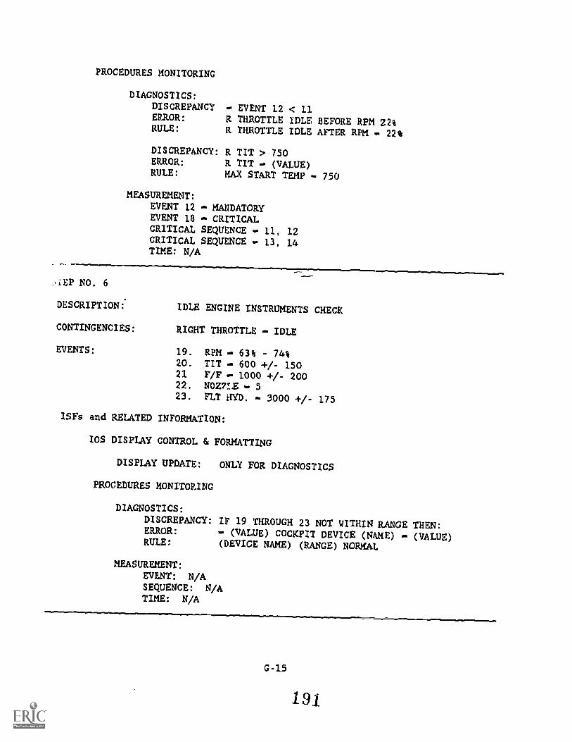
PROCEDURES MONITORING
DIAGNOSTICS:DISCREPANCY EVENT 12 < 11ERROR: R THROTTLE IDLE BEFORE RPM 22%RULE: R THROTTLE IDLE AFTER RPM - 22%
DISCREPANCY: R TIT > 750ERROR: R TIT - (VALUE)RULE: MAX START TEMP 750
MEASUREMENT:EVENT 12 - MANDATORYEVENT 18 - CRITICALCRITICAL SEQUENCE - 11, 12CRITICAL SEQUENCE - 13, 14TIME: N/A
.,LEP NO. 6
DESCRIPTION:' IDLE ENGINE INSTRUMENTS CHECK
CONTINGENCIES: RIGHT THROTTLE - IDLE
EVENTS: 19. RPM 63% - 74%20. TIT 600 +/- 15021 F/F 1000 +/- 20022. NOVIE - 523. FLT HYD. 3000 +/- 175
ISFs and RELATED INFORMATION:
IOS DISPLAY CONTROL & FORMATTING
DISPLAY UPDATE: ONLY FOR DIAGNOSTICS
PROCEDURES MONITORING
DIAGNOSTICS:DISCREPANCY: IF 19 THROUGH 23 NOT WITHIN RANGE THEN:ERROR: . (VALUE) COCKPIT DEVICE (NAME) (VALUE)RULE: (DEVICE NAME) (RANGE) NORMAL
MEASUREMENT:EVENT: N/ASEQUENCE: N/ATIME: N/A
G-15
191
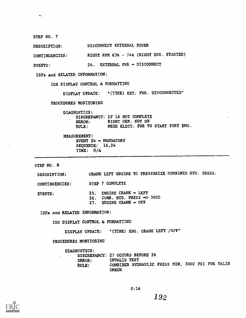
STEP NO. 7
DESCRIPTION: DISCONNECT EXTERNAL POWER
CONTINGENCIES: RIGHT RPM 63% - 74% (RIGHT ENG. STARTED)
EVENTS: 24. EXTERNAL PWR - DISCONNECT
ISFs and RELATED INFORMATION:
IOS DISPLAY CONTROL & FORMATTING
DISPLAY UPDATE: "(TIME) EXT. PWR. DISCONNECTED"
PROCEDURES MONITORING
DIAGNOSTICS:D/SCREPANCY: IF 16 NOT COMPLETEERROR: RIGHT GEN. NOT ON
RULE: NEED ELECT. PWR TO START PORT ENG.
MEASUREMENT:EVENT 24 MANDATORYSEQUENCE: 16,24TIME: N/A
STEP NO. 8
DESCR/PTION: CRANK LEFT ENGINE TO PRESSURIZE COMBINED HYD. PRESS.
CONTINGENCIES: STEP 7 COMPLETE
EVENTS: 25. ENGINE CRANK LEFT26. COMB. HYD. PRESS -> 300027. ENGINE CRANK OFF
ISFs and RELATED INFORMATION:
IOS DISPLAY CONTROL & FORMATTING
DISPLAY UPDATE: "(TIME) ENG. CRANK LEFT /OFF"
PROCEDURES MONITORING
DIAGNOSTICS:DISCREPANCY: 27 OCCURS BEFORE 26ERROR: INVALID TEST
RULE: COMBINED HYDRAULIC PRESS MIN, 3000 PSI FOR VALID
CHECK
G-16
192
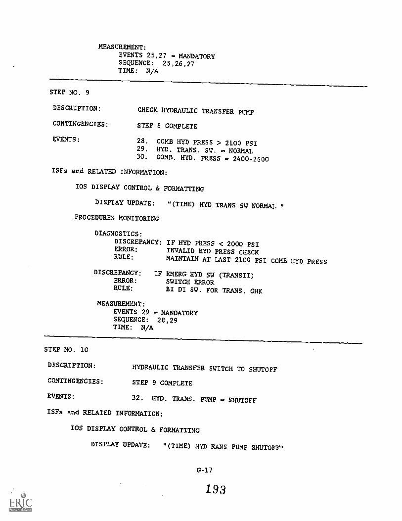
MEASUREMENT:EVENTS 25,27 - MANDATORYSEQUENCE: 25,26,27TIME: N/A
STEP NO. 9
DESCRIPTION: CHECK HYDRAULIC TRANSFER PUMP
CONTINGENCIES: STEP 8 COMPLETE
EVENTS: 28. COMB HYD PRESS > 2100 PSI29. HYD. TRANS. SW. NORMAL30. COMB. HID. PRESS - 2400-2600
ISFs and RELATED INFORMATION:
IOS DISPLAY CONTROL & FORMATTING
DISPLAY UPDATE: "(TIME) HYD TRANS SW NORMAL "
PROCEDURES MONITORING
DIAGNOSTICS:
DISCREPANCY: IF HYD PRESS < 2000 PSIERROR: INVALID HYD PRESS CHECKRULE: MAINTAIN AT LAST 2100 PSI COMB HYD PRESS
DISCREPANCY: IF EMERG HYD SW (TRANSIT)ERROR: SWITCH ERRORRULE: BI DI SW. FOR TRANS. CHK
MEASUREMENT:EVENTS 29 MANDATORYSEQUENCE: 28,29TIME: N/A
STEP NO. 10
DESCRIPTION: HYDRAULIC TRANSFER SWITCH TO SHUTOFF
CONTINGENCIES: STEP 9 COMPLETE
EVENTS: 32. HYD. TRANS. PUMP - SHUTOFF
ISFs and RELATED INFORMATION:
IOS DISPLAY CONTROL & FORMATTING
DISPLAY UPDATE: "(TIME) OD RANS PUMP SHUTOFF"
G-17
1 93
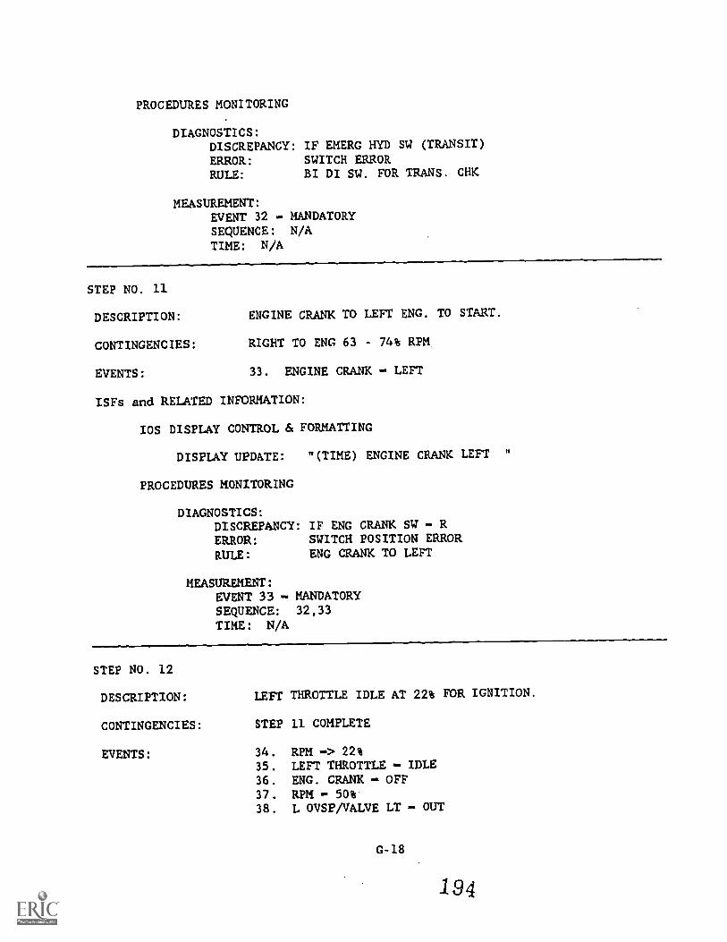
PROCEDURES MONITORING
DIAGNOSTICS:DISCREPANCY: IF EMERG HYD SW (TRANSIT)
ERROR: SWITCH ERRORRULE: BI DI SW. FOR TRANS. CHK
MEASUREMENT:EVENT 32 MANDATORYSEQUENCE: N/ATIME: N/A
STEP NO. 11
DESCRIPTION: ENGINE CRANK TO LEFT ENG. TO START.
CONTINGENCIES: RIGHT TO ENG 63 - 74% RPM
EVENTS: 33. ENGINE CRANK LEFT
ISFs and RELATED INFORMATION:
IOS DISPLAY CONTROL & FORMATTING
DISPLAY UPDATE: "(TIME) ENGINE CRANK LEFT "
PROCEDURES MONITORING
DIAGNOSTICS:DISCREPANCY: IF ENG CRANK SW R
ERROR: SWITCH POSITION ERROR
RULE: ENG CRANK TO LEFT
MEASUREMENT:EVENT 33 - MANDATORYSEQUENCE: 32,33
TIME: N/A
STEP NO. 12
DESCRIPTION: LEFT THROTTLE IDLE AT 22% FOR IGNITION.
CONTINGENCIES: STEP 11 COMPLETE
EVENTS: 34. REM 22%
35. LEFT THROTTLE - IDLE36. ENG. CRANK OFF37. REM - 50%38. L OVSP/VALVE LT OUT
G-18
194
39. L GEN LT - OUT40. L FUEL PRESS LT OUT41. LEFT TIT < 750
ISFs and RELATED INFORMATION:
IOS DISPLAY CONTROL & FORMATTING
DISPLAY UPDATE: EVENTS 35 THRU 41 UPDATE
PROCEDURES MONITORING
DIAGNOSTICS:DISCREPANCY: IF 35 < 34 THEN
:
ERROR: THROTTLE IDLE BEFORE RPM 22%RULE: THROTTLE IDLE AFTER RPM 22%
DISCREPANCY: IF L TIT > 750 THEN:ERROR: L TIT - (VALUE)RULE: MAX START TEMP - 750
MEASUREMENT:EVENT 35 MANDATORYEVENT 41 - CRITICALCRITICAL SEQUENCE: 34,35CRITICAL SEQUENCE: 36,37TIME: N/A
STEP NO. 13
DESCRIPTION: IDLE ENGINE INSTRUMENTS CHECK
CONTINGENCIES: LEFT THROTTLE IDLE
EVENTS: 42. L RPM 63% - 74%43. L TIT 600 -1-/- 15044. L F/F 1000 +/- 20045. L ACZZLE - 546. L FLT HYD. 3000 +/- 175
ISFs and RELATED INFORMATION:
IOS DISPLAY CONTROL & FORMATTING
DISPLAY UPDATE: ONLY FOR DIAGNOSTICS
PROCEDURES MONITORING
DIAGNOSTICS:DISCREPANCY: IF 42 45 NOT EQUAL RANGE THEN :
ERROR: DEVICE (NAME) (VALUE)
RULE: DEVICE (NAME) (RANGE) NORMAL
MEASUREMENT:EVENT: N/ASEQUENCE: N/ATIME: N/A
STEP NO. 14
DESCRIPTION: DISCONNECT EXTERNAL AIR.
CONTINGENCIES: L&R RPM 63 - 74% RPM
EVENTS: 47. EXTERNAL AIR DISCONNECTED
ISFs and RELATED INFORMATION:
IOS DISPLAY CONTROL & FORMATTING
DISPLAY UPDATE: "(TIME) EXT. AIR DISCONNECTED"
PROCEDURES MONITORING
DIAGNOSTICS: N/A
MEASUREMENT:EVENT 47 MANDATORYSEQUENCE: N/ATIME: N/A
STEP NO. 15
DESCRIPTION: HYDRAULIC TRANSFER PUMP TO NORMAL
CONTINGENCIES: L&R HYD PSI 3000 PSI
EVENTS: 48. HYDRAULIC TRANSFER PUMP NORMAL
ISFs and RELATED INFORMATION:
IOS DISPLAY CONTROL & FORMATTING
DISPLAY UPDATE: "(TIME) HYD TRANS PUMP NORMAL"
G-20
196

PROCEDURES MONITORING
DIAGNOSTICS:
ERROR:RULE:
IF EMERG FLT HND SW (TRANSIT)WITHIN 30 SEC OF AIR DISCONNECTSWITCH ERRORBI DI PUMP TO NORMAL
MEASUREMENT:EVENT 48 - MANDATORYTIME: TIME FOR TOTAL TIME TO COMPLETE THE TASK MODULE.
197