Embed Size (px)
Citation preview

Check Processing Control System IBM
Customization GuideRelease 11
SC31-2853-09


Check Processing Control System IBM
Customization GuideRelease 11
SC31-2853-09

Note!
Before using this information and the product it supports, be sure to read the general information under “Notices” on page xi.
| Tenth Edition (May 2001)
| This edition is a revision of SC31-2853-08. This edition applies to Version 1 Release 11 of the Check Processing Control System| licensed program (Program No. 5734-F11). This publication is current as of PTF numbers UQ47917 and UQ47918. Each change is
indicated by a vertical line (revision bar) in the left margin.
For automatic distribution of updates to the documentation for this product, the user must be enrolled in the System LibrarySubscription Service (SLSS). See your marketing representative for enrollment procedures.
Information in this manual is subject to change from time to time. Before using this publication in connection with the operation ofIBM systems, consult your IBM representative to be sure you have the latest edition and any Technical Newsletters.
IBM does not stock publications at the address given below; requests for IBM publications should be made to your IBMrepresentative or to the IBM branch office serving your locality.
A form for reader’s comments is provided at the back of this publication. If the form has been removed, comments may beaddressed to IBM Corporation, Payment Solutions, Department 58G, MG96/204, 8501 IBM Drive, Charlotte, NC 28262, U.S.A. IBMmay use or distribute any of the information you supply in any way it believes appropriate without incurring any obligation to you.
Copyright International Business Machines Corporation 1973, 2001. All rights reserved.Note to U.S. Government Users — Documentation related to restricted rights — Use, duplication or disclosure is subject torestrictions set forth in GSA ADP Schedule Contract with IBM Corp.

Contents
Notices . . . . . . . . . . . . . . . . . . . . . . . . . . . . . . . . . . . . . . . . . . xiProgramming Interface Information . . . . . . . . . . . . . . . . . . . . . . . . . . xiYear 2000 Compliance . . . . . . . . . . . . . . . . . . . . . . . . . . . . . . . . . xiTrademarks . . . . . . . . . . . . . . . . . . . . . . . . . . . . . . . . . . . . . . . xii
About This Book . . . . . . . . . . . . . . . . . . . . . . . . . . . . . . . . . . . xiiiWho Should Read This Book? . . . . . . . . . . . . . . . . . . . . . . . . . . . . xiiiHow Is This Book Organized? . . . . . . . . . . . . . . . . . . . . . . . . . . . . xiiiRelated Publications . . . . . . . . . . . . . . . . . . . . . . . . . . . . . . . . . . xivCPCS Web Site . . . . . . . . . . . . . . . . . . . . . . . . . . . . . . . . . . . . xv
| Summary of Changes for SC31-2853-09 . . . . . . . . . . . . . . . . . . . . . . xvSummary of Changes for SC31-2853-08 . . . . . . . . . . . . . . . . . . . . . . xviSummary of Changes for SC31-2853-07 . . . . . . . . . . . . . . . . . . . . . . xviSummary of Changes for SC31-2853-06 . . . . . . . . . . . . . . . . . . . . . . xviiSummary of Changes for SC31-2853-05 . . . . . . . . . . . . . . . . . . . . . . xviiSummary of Changes for SC31-2853-04 . . . . . . . . . . . . . . . . . . . . . xviiiSummary of Changes for SC31-2853-03 . . . . . . . . . . . . . . . . . . . . . . xixSummary of Changes for SC31-2853-02 . . . . . . . . . . . . . . . . . . . . . . xixSummary of Changes for SC31-2853-01 . . . . . . . . . . . . . . . . . . . . . . xxSummary of Changes for CPCS Release 11 . . . . . . . . . . . . . . . . . . . . xx
Chapter 1. System Programming and Operations . . . . . . . . . . . . . . . 1-1Overview . . . . . . . . . . . . . . . . . . . . . . . . . . . . . . . . . . . . . . . . . 1-3System Programming Requirements . . . . . . . . . . . . . . . . . . . . . . . . . 1-3CPCS Startup and Shutdown . . . . . . . . . . . . . . . . . . . . . . . . . . . . . 1-5Operational Considerations . . . . . . . . . . . . . . . . . . . . . . . . . . . . . 1-13External Storage Requirements . . . . . . . . . . . . . . . . . . . . . . . . . . 1-19Data-Set Recovery Procedures . . . . . . . . . . . . . . . . . . . . . . . . . . . 1-33CPCS-Supplied Command Procedures . . . . . . . . . . . . . . . . . . . . . . 1-43Changing CPCS Control Blocks . . . . . . . . . . . . . . . . . . . . . . . . . . 1-47Remote Site Support . . . . . . . . . . . . . . . . . . . . . . . . . . . . . . . . . 1-48
Chapter 2. Installation and Generation Procedures . . . . . . . . . . . . . . 2-1Overview . . . . . . . . . . . . . . . . . . . . . . . . . . . . . . . . . . . . . . . . . 2-3Macro Descriptions . . . . . . . . . . . . . . . . . . . . . . . . . . . . . . . . . . . 2-4COBOL Copy Definitions . . . . . . . . . . . . . . . . . . . . . . . . . . . . . . . 2-5Using Data-Set Duplexing . . . . . . . . . . . . . . . . . . . . . . . . . . . . . . . 2-6Logging CPCS Data . . . . . . . . . . . . . . . . . . . . . . . . . . . . . . . . . . 2-7Customizing Item Sequence Numbers . . . . . . . . . . . . . . . . . . . . . . . 2-14Describing an Application Task’s Environment . . . . . . . . . . . . . . . . . . 2-15Dynamically Allocating Data Sets . . . . . . . . . . . . . . . . . . . . . . . . . 2-23Nonswap SVC Generation Task . . . . . . . . . . . . . . . . . . . . . . . . . . 2-31Concurrent Sort Generation . . . . . . . . . . . . . . . . . . . . . . . . . . . . . 2-32MICR Task Generation . . . . . . . . . . . . . . . . . . . . . . . . . . . . . . . 2-33Expanding the Mass Data Set . . . . . . . . . . . . . . . . . . . . . . . . . . . 2-48VTAM Installation Requirements for CPCS . . . . . . . . . . . . . . . . . . . . 2-53Accessing the VSAM Table . . . . . . . . . . . . . . . . . . . . . . . . . . . . . 2-63CPCS Third-Party Vendor Definition . . . . . . . . . . . . . . . . . . . . . . . . 2-66CPCS Mass Data Set Exit Points . . . . . . . . . . . . . . . . . . . . . . . . . 2-66
Copyright IBM Corp. 1973, 2001 iii

Chapter 3. System and Application Profiles . . . . . . . . . . . . . . . . . . 3-1Profile Keywords . . . . . . . . . . . . . . . . . . . . . . . . . . . . . . . . . . . . 3-3System Profile Data Set . . . . . . . . . . . . . . . . . . . . . . . . . . . . . . . . 3-4Application Profile List . . . . . . . . . . . . . . . . . . . . . . . . . . . . . . . . 3-29DKNMRGE Codeline Data Matching . . . . . . . . . . . . . . . . . . . . . . . . 3-55
Chapter 4. User Programming Requirements and Exits . . . . . . . . . . . 4-1Overview . . . . . . . . . . . . . . . . . . . . . . . . . . . . . . . . . . . . . . . . . 4-5User Data Preparation for Sort Programs . . . . . . . . . . . . . . . . . . . . . . 4-5CPCS Stacker-Select Routine Operation . . . . . . . . . . . . . . . . . . . . . 4-36CPCS SCI Macros and User SCI Coding . . . . . . . . . . . . . . . . . . . . . 4-41Host Codeline Edit Routines . . . . . . . . . . . . . . . . . . . . . . . . . . . . 4-49User Stacker-Select Routine Operation for OLRR . . . . . . . . . . . . . . . . 4-55Changing the SETDEV and Diagnostic Operation Time-Out Interval . . . . . 4-56CPCS System Exit Points . . . . . . . . . . . . . . . . . . . . . . . . . . . . . . 4-58Customizing ETDM User Exits . . . . . . . . . . . . . . . . . . . . . . . . . . . 4-82Customizing ETIO User Exits . . . . . . . . . . . . . . . . . . . . . . . . . . . . 4-86Customizing ETCSH and X937 User Exits . . . . . . . . . . . . . . . . . . . 4-121DKNLDMY and DKNLJMP Exit — Logging Job MVS Posture . . . . . . . . 4-127DKNLOGU: Logging User Exit . . . . . . . . . . . . . . . . . . . . . . . . . . 4-129DKNMBEGN User Processing Exit . . . . . . . . . . . . . . . . . . . . . . . . 4-130DKNMDIS–ESM Task Profile User Data Area . . . . . . . . . . . . . . . . . 4-132
| DKNMDIS User Exit — Modify M-String Distribution . . . . . . . . . . . . . 4-132DKNMIPI User Processing Exit . . . . . . . . . . . . . . . . . . . . . . . . . . 4-136DKNMREAD Document-Processing User Exit . . . . . . . . . . . . . . . . . 4-138DKNCSBU—Sort Program Build Task . . . . . . . . . . . . . . . . . . . . . . 4-141DKNEMRG User Exits . . . . . . . . . . . . . . . . . . . . . . . . . . . . . . . 4-142DKNMRGE Programmable Switches . . . . . . . . . . . . . . . . . . . . . . 4-150DKNMRGK–Document-Processing User Exit . . . . . . . . . . . . . . . . . . 4-151DKNMRG2X–Positional Matching User Exit . . . . . . . . . . . . . . . . . . 4-151DKNMRGK–Selectable Functions for DKNMRGK . . . . . . . . . . . . . . . 4-152DKNPLST, DKNSLST, and DKNXLST: Controlling Entry Master-List
Reports . . . . . . . . . . . . . . . . . . . . . . . . . . . . . . . . . . . . . . . 4-153DKNKILL and DKNPLST: Modifying Report Layouts . . . . . . . . . . . . . 4-155DKNSCATX - String Concatenation User Exit . . . . . . . . . . . . . . . . . 4-155Extract Programming . . . . . . . . . . . . . . . . . . . . . . . . . . . . . . . . 4-167Installing the Refreshed Enhanced Jam Option . . . . . . . . . . . . . . . . 4-169
| Installing the CPCS 48-Pocket Support . . . . . . . . . . . . . . . . . . . . . 4-170Installing the Feature Disable/Disengage Option . . . . . . . . . . . . . . . . 4-170DKNMREAD Assembly Option . . . . . . . . . . . . . . . . . . . . . . . . . . 4-171Balancing and Power-Encoding Considerations . . . . . . . . . . . . . . . . 4-171Security Options . . . . . . . . . . . . . . . . . . . . . . . . . . . . . . . . . . 4-177DKNCYCLX - Validate Cycle and Endorse Dates Exit . . . . . . . . . . . . 4-184
Glossary . . . . . . . . . . . . . . . . . . . . . . . . . . . . . . . . . . . . . . . X-1
Bibliography . . . . . . . . . . . . . . . . . . . . . . . . . . . . . . . . . . . . . X-9ACF/VTAM Publications . . . . . . . . . . . . . . . . . . . . . . . . . . . . . . . X-9Document Processor Support Publications . . . . . . . . . . . . . . . . . . . . X-9OS/390 Publications (Version 2, Release 8) . . . . . . . . . . . . . . . . . . . X-9MVS Publications . . . . . . . . . . . . . . . . . . . . . . . . . . . . . . . . . . . X-9RACF Publications . . . . . . . . . . . . . . . . . . . . . . . . . . . . . . . . . . X-9VTAM Publications . . . . . . . . . . . . . . . . . . . . . . . . . . . . . . . . . . X-10Other IBM Publications . . . . . . . . . . . . . . . . . . . . . . . . . . . . . . . X-10
iv CPCS V1R11 Customization Guide

Index . . . . . . . . . . . . . . . . . . . . . . . . . . . . . . . . . . . . . . . . . . X-11
Contents v

vi CPCS V1R11 Customization Guide

Figures
1-1. Effect of CPCS Start Parameters on Critical Data Sets . . . . . . . . 1-61-2. MDS directory index relationships . . . . . . . . . . . . . . . . . . . . 1-231-3. MDS Index Block Allocation . . . . . . . . . . . . . . . . . . . . . . . 1-241-4. Example of Endpoint Data-Set Member Contents . . . . . . . . . . . 1-311-5. Suggested Recovery Procedures . . . . . . . . . . . . . . . . . . . . 1-352-1. RCVUNTBL Copybook Example . . . . . . . . . . . . . . . . . . . . . . 2-92-2. The code showing the default setting (send to MVS console) . . . . . 2-92-3. The code changing from default to send to programmer only . . . . . 2-92-4. CPCS Startup JCL Changes for Logging Data Sets . . . . . . . . . 2-112-5. Example of Macros for DKNMICR Generation . . . . . . . . . . . . . 2-342-6. CPCSRDR Parameter Values . . . . . . . . . . . . . . . . . . . . . . 2-36
| 2-7. MICR Document Field Defaults . . . . . . . . . . . . . . . . . . . . . 2-422-8. Control-Document Field Identifiers . . . . . . . . . . . . . . . . . . . . 2-442-9. Control-Document Field Definitions . . . . . . . . . . . . . . . . . . . 2-44
2-10. DKNVTASK Variables . . . . . . . . . . . . . . . . . . . . . . . . . . . 2-542-11. DKNMDSVC_FREE_STRING Exit Point Parameter List . . . . . . . 2-672-12. DKNMDSVC_OPEN_STRING Exit Point Parameter List . . . . . . . 2-68
| 2-13. DKNMDSVC_CLOSE_STRING Exit Point Parameter List . . . . . . 2-692-14. DKNMDSVC_READ_DIRECTORY Exit Point Parameter List . . . . 2-702-15. DKNMDSVC_SRCH_DIRECTORY Exit Point Parameter List . . . . 2-722-16. DKNMDSV4_COMPRESSION Exit Point Parameter List . . . . . . . 2-742-17. MDS View Exit Communication Control Blocks . . . . . . . . . . . . 2-753-1. DKNPSG03 character overlay for valid values . . . . . . . . . . . . . 3-283-2. Record Type 3 . . . . . . . . . . . . . . . . . . . . . . . . . . . . . . . 3-52
| 4-1. M-Record for Pockets 1 to 35 . . . . . . . . . . . . . . . . . . . . . . 4-24| 4-2. M-Record for Pockets 36 to 70 . . . . . . . . . . . . . . . . . . . . . 4-24| 4-3. M-Record for Pockets 71 to 98 . . . . . . . . . . . . . . . . . . . . . 4-24
4-4. Distribution Options . . . . . . . . . . . . . . . . . . . . . . . . . . . . 4-264-5. R-Record for Pockets 1 to 35 . . . . . . . . . . . . . . . . . . . . . . 4-31
| 4-6. R-Record for Pockets 36 to 70 . . . . . . . . . . . . . . . . . . . . . . 4-31| 4-7. R-Record for Pockets 71 to 98 . . . . . . . . . . . . . . . . . . . . . . 4-31
4-8. CPCS Sorter-Program Storage Map—Standard Sort . . . . . . . . . 4-374-9. Sample Format for SCI Routines . . . . . . . . . . . . . . . . . . . . 4-38
4-10. CPCS Sorter-Program Storage Map—Expanded Sort . . . . . . . . 4-384-11. CPCS Document Processor Header Byte and Status Byte . . . . . 4-404-12. Example of DKNEPTBL Table . . . . . . . . . . . . . . . . . . . . . . 4-464-13. Sample Expanded-Format SCI Routine and Table . . . . . . . . . . 4-484-14. Main SCI Program . . . . . . . . . . . . . . . . . . . . . . . . . . . . . 4-494-15. SCI Table Program . . . . . . . . . . . . . . . . . . . . . . . . . . . . 4-494-16. Document Buffer Area Codeline Data Record . . . . . . . . . . . . . 4-504-17. Converted Pocket Number for the Document Processor . . . . . . . 4-524-18. DKNALLO_EXIT1000_REQ_VALIDATION Point Parameter List . . 4-584-19. DKNALLO_EXIT2000_MESSAGE Point Parameter List . . . . . . . 4-59
| 4-20. DKNASGF_EXIT_01 Point Parameter List . . . . . . . . . . . . . . . 4-614-21. DKNATASK_APPLTSK_START_EXIT01 Point Parameter List . . . 4-624-22. DKNATASK_DEQ_EXIT01 Point Parameter List . . . . . . . . . . . 4-634-23. DKNATASK_ENQ EXIT01 Point Parameter List . . . . . . . . . . . . 4-644-24. DKNATASK_EXECTSK_START_EXIT01 Point Parameter List . . . 4-654-25. DKNATASK_SUPV_TERM_EXIT01 Point Parameter List . . . . . . 4-664-26. DKNATSK2_INITIALIZE_EXIT_01 Point Parameter List . . . . . . . 4-68
Copyright IBM Corp. 1973, 2001 vii
4-27. DKNATSK2_TERMINATE_EXIT_01 Point Parameter List . . . . . . 4-694-28. DKNATSK2_WRITE_APTR_EXIT_01 Point Parameter List . . . . . 4-704-29. DKNATSK3_0100_TASKABEND_EXIT Point Parameter List . . . . 4-714-30. DKNCYCDT_DATE_VALIDATE_EXIT Point Parameter List . . . . . 4-724-31. DKNINIT_POST_DKNITASK_EXIT Point Parameter List . . . . . . . 4-734-32. DKNLOADR_EXIT_01 Point Parameter List . . . . . . . . . . . . . . 4-754-33. DKNMBEGN_APPLTSK_START_EXIT01 Point Parameter List . . . 4-764-34. DKNMBST_APPLTSK_START_EXIT01 Point Parameter List . . . . 4-774-35. DKNMTASK_INITIALIZE_EXIT_01 Point Parameter List . . . . . . . 4-784-36. DKNMTASK_MICR_ABEND_EXIT0100 Point Parameter List . . . . 4-794-37. DKNMTASK_TERMINATION_EXIT_01 Point Parameter List . . . . 4-804-38. ETDM User Exit Point One Communication Control Blocks . . . . . 4-824-39. ETDM User Exit Point One Return Codes . . . . . . . . . . . . . . . 4-824-40. ETDM User Exit One - Example 1 . . . . . . . . . . . . . . . . . . . . 4-834-41. ETDM User Exit Point Two Communication Control Blocks . . . . . 4-844-42. ETDM User Exit Two Return Codes . . . . . . . . . . . . . . . . . . . 4-844-43. ETDM User Exit Two - Example 1 . . . . . . . . . . . . . . . . . . . . 4-854-44. ETOT User Exit Point One Communication Control Blocks . . . . . 4-874-45. ETOT User Exit Point One Return Codes . . . . . . . . . . . . . . . 4-884-46. ETOT User Exit One - Example 1 . . . . . . . . . . . . . . . . . . . . 4-884-47. ETOT User Exit Point Two Communication Control Blocks . . . . . 4-904-48. ETOT User Exit Point Two Return Codes . . . . . . . . . . . . . . . 4-914-49. ETOT User Exit Two - Example 1 . . . . . . . . . . . . . . . . . . . . 4-924-50. ETIN User Exit Point One Communication Control Blocks . . . . . . 4-954-51. ETIN Exit Point One Routine Return Codes . . . . . . . . . . . . . . 4-964-52. ETIN User Exit One - Example 1 . . . . . . . . . . . . . . . . . . . . 4-964-53. ETIN User Exit Point Two Communication Control Blocks . . . . . . 4-994-54. ETIN Exit Point Two Routine Return Codes . . . . . . . . . . . . . . 4-994-55. ETIN User Exit Two - Example 1 . . . . . . . . . . . . . . . . . . . 4-1004-56. ETIN User Exit Point Three Communication Control Blocks . . . . 4-1024-57. ETIN Exit Point Three Routine Return Codes . . . . . . . . . . . . 4-1024-58. ETIN User Exit Three - Example . . . . . . . . . . . . . . . . . . . 4-1034-59. ETIN User Exit Point Four Communication Control Blocks . . . . . 4-1054-60. ETIN Exit Point Four Routine Return Codes . . . . . . . . . . . . . 4-1054-61. ETIN User Exit Four - Example . . . . . . . . . . . . . . . . . . . . 4-1064-62. ETIP User Exit Point One Communication Control Blocks . . . . . 4-1084-63. ETIP Exit Point One Routine Return Codes . . . . . . . . . . . . . 4-1094-64. ETIP User Exit Point One - Example 1 . . . . . . . . . . . . . . . . 4-1094-65. ETIP User Exit Point Two Communication Control Blocks . . . . . 4-1124-66. ETIP Exit Point Two Routine Return Codes . . . . . . . . . . . . . 4-1124-67. ETIP User Exit Two - Example 1 . . . . . . . . . . . . . . . . . . . 4-1134-68. ETIP User Exit Point Three Communication Control Blocks . . . . 4-1144-69. ETIP Exit Point Two Routine Return Codes . . . . . . . . . . . . . 4-1144-70. ETIP User Exit Three - Example 1 . . . . . . . . . . . . . . . . . . 4-1154-71. ETCFU User Exit One Communication Control Block . . . . . . . . 4-1184-72. DKNETCFU User Exit Return Codes . . . . . . . . . . . . . . . . . 4-1184-73. ETIP User Exit Three - Example 1 . . . . . . . . . . . . . . . . . . 4-1194-74. DKNETCSH_FORMATS Point Parameter List . . . . . . . . . . . . 4-1214-75. DKNETCSH_0100_NEW_RECORD Point Parameter List . . . . . 4-1234-76. DKNETCSH_0200_FILE-CREATED Point Parameter List . . . . . 4-1244-77. DKNX937_0100_NEW_RECORD Point Parameter List . . . . . . 4-1254-78. LJMP Exit Communication Control Blocks . . . . . . . . . . . . . . 4-1284-79. DKNRCVY_EXIT1000_BEFORE_WRITE Point Parameter List . . 4-129
| 4-80. MDIS Exit Parameter List . . . . . . . . . . . . . . . . . . . . . . . . 4-133
viii CPCS V1R11 Customization Guide
| 4-81. Return codes on exit from MDIS . . . . . . . . . . . . . . . . . . . . 4-1344-82. Format of Record Insertion Area . . . . . . . . . . . . . . . . . . . . 4-1404-83. Format of User-Supplied Message Area . . . . . . . . . . . . . . . 4-1404-84. User Exit Register Contents . . . . . . . . . . . . . . . . . . . . . . 4-1404-85. DKNEMRG user exits . . . . . . . . . . . . . . . . . . . . . . . . . . 4-1424-86. EMRG user exits, function, and purpose . . . . . . . . . . . . . . . 4-1434-87. Codeline and Match Tables . . . . . . . . . . . . . . . . . . . . . . 4-1654-88. Codeline Entry Organization . . . . . . . . . . . . . . . . . . . . . . 4-1664-89. Mapping of fields in the CPCS mass data set . . . . . . . . . . . . 4-1714-90. Sample RACF Class/Group to User ID Structure . . . . . . . . . . 4-1814-91. Sample RACF Class/Group to User ID Structure . . . . . . . . . . 4-182
Figures ix

x CPCS V1R11 Customization Guide

Notices
References in this publication to IBM products, programs, or services do not implythat IBM intends to make these available in all countries in which IBM operates.Any reference to an IBM product, program, or service is not intended to state orimply that only IBM’s product, program, or service may be used. Any functionallyequivalent product, program, or service that does not infringe any of IBM’sintellectual property rights or other legally protectable rights may be used instead ofthe IBM product, program, or service. Evaluation and verification of operation inconjunction with other products, programs, or services, except those expresslydesignated by IBM, are the user’s responsibility.
Licensees of this program who wish to have information about it for the purpose ofenabling: (i) the exchange of information between independently created programsand other programs (including this one) and (ii) the mutual use of the informationwhich has been exchanged, should contact: IBM Corporation, DepartmentMG39/201, 8501 IBM Drive, Charlotte, NC 28262-8563, U.S.A. Such informationmay be available, subject to appropriate terms and conditions, including in somecases, payment of a fee.
IBM may have patents or pending patent applications covering subject matter inthis document. The furnishing of this document does not give you any license tothese patents. You can send license inquiries, in writing, to the IBM Director ofCommercial Licensing, IBM Corporation, North Castle Drive, Armonk, NY10504-1785 U.S.A.
Programming Interface InformationThis guide is intended to help the customer install, customize and maintain theIBM Check Processing Control System (CPCS).
This guide also documents General-Use Programming Interface and AssociatedGuidance Information.
General-Use programming interfaces allow the customer to write programs thatobtain the services of the Check Processing Control System.
General-Use Programming Interface and Associated Guidance Information isidentified where it occurs, by an introductory statement to the chapter or section.
Year 2000 ComplianceIBM announces that the Check Processing Control System, Version 1 Release 11,at PTF numbers UN99696 and UN99801, supports Year 2000. This IBM product,when used in accordance with its associated documentation, is designed to becapable of correctly processing, providing, and receiving date data within andbetween the twentieth and twenty-first centuries. This has been done by allowingthe user to set the date format as a default throughout the system.
In the complex global computing environment that we have today, this IBMproduct’s support for Year 2000 is, of course, dependent on the capabilities of all
Copyright IBM Corp. 1973, 2001 xi

the other products that are working together (for example, hardware, software, andfirmware) to properly exchange accurate date data.
TrademarksThe following are trademarks of International Business Machines Corporation in theUnited States and/or other countries:
IBM, ACF/VTAM, COBOL/370, ES/9000, MVS/DFP, MVS/ESA,MVS/SP, RACF, System/370, VTAM, 3090.
Other company, product, and service names may be trademarks or service marksof others.
xii CPCS V1R11 Customization Guide
About This Book
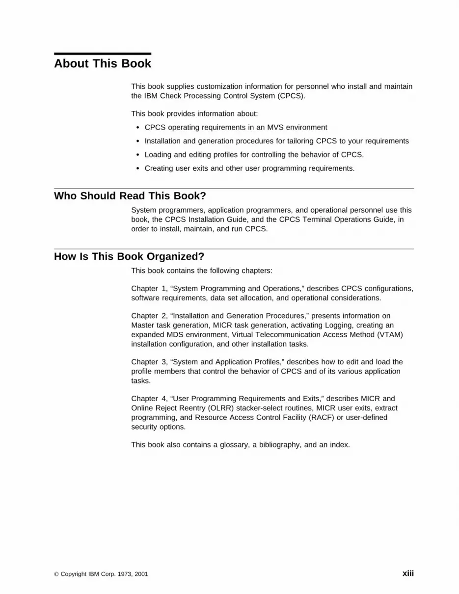
This book supplies customization information for personnel who install and maintainthe IBM Check Processing Control System (CPCS).
This book provides information about:
� CPCS operating requirements in an MVS environment
� Installation and generation procedures for tailoring CPCS to your requirements
� Loading and editing profiles for controlling the behavior of CPCS.
� Creating user exits and other user programming requirements.
Who Should Read This Book?System programmers, application programmers, and operational personnel use thisbook, the CPCS Installation Guide, and the CPCS Terminal Operations Guide, inorder to install, maintain, and run CPCS.
How Is This Book Organized?This book contains the following chapters:
Chapter 1, “System Programming and Operations,” describes CPCS configurations,software requirements, data set allocation, and operational considerations.
Chapter 2, “Installation and Generation Procedures,” presents information onMaster task generation, MICR task generation, activating Logging, creating anexpanded MDS environment, Virtual Telecommunication Access Method (VTAM)installation configuration, and other installation tasks.
Chapter 3, “System and Application Profiles,” describes how to edit and load theprofile members that control the behavior of CPCS and of its various applicationtasks.
Chapter 4, “User Programming Requirements and Exits,” describes MICR andOnline Reject Reentry (OLRR) stacker-select routines, MICR user exits, extractprogramming, and Resource Access Control Facility (RACF) or user-definedsecurity options.
This book also contains a glossary, a bibliography, and an index.
Copyright IBM Corp. 1973, 2001 xiii
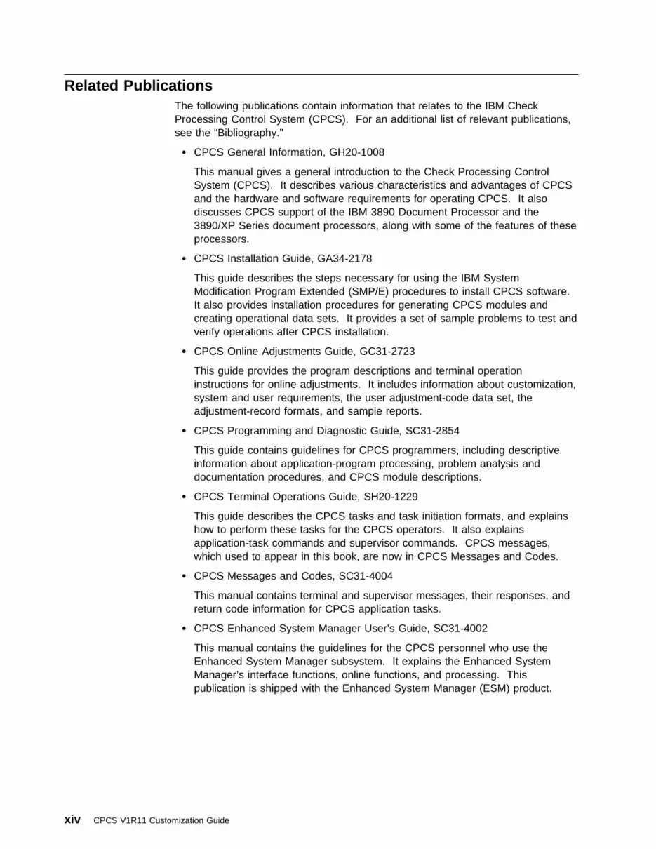
Related PublicationsThe following publications contain information that relates to the IBM CheckProcessing Control System (CPCS). For an additional list of relevant publications,see the “Bibliography.”
� CPCS General Information, GH20-1008
This manual gives a general introduction to the Check Processing ControlSystem (CPCS). It describes various characteristics and advantages of CPCSand the hardware and software requirements for operating CPCS. It alsodiscusses CPCS support of the IBM 3890 Document Processor and the3890/XP Series document processors, along with some of the features of theseprocessors.
� CPCS Installation Guide, GA34-2178
This guide describes the steps necessary for using the IBM SystemModification Program Extended (SMP/E) procedures to install CPCS software.It also provides installation procedures for generating CPCS modules andcreating operational data sets. It provides a set of sample problems to test andverify operations after CPCS installation.
� CPCS Online Adjustments Guide, GC31-2723
This guide provides the program descriptions and terminal operationinstructions for online adjustments. It includes information about customization,system and user requirements, the user adjustment-code data set, theadjustment-record formats, and sample reports.
� CPCS Programming and Diagnostic Guide, SC31-2854
This guide contains guidelines for CPCS programmers, including descriptiveinformation about application-program processing, problem analysis anddocumentation procedures, and CPCS module descriptions.
� CPCS Terminal Operations Guide, SH20-1229
This guide describes the CPCS tasks and task initiation formats, and explainshow to perform these tasks for the CPCS operators. It also explainsapplication-task commands and supervisor commands. CPCS messages,which used to appear in this book, are now in CPCS Messages and Codes.
� CPCS Messages and Codes, SC31-4004
This manual contains terminal and supervisor messages, their responses, andreturn code information for CPCS application tasks.
� CPCS Enhanced System Manager User’s Guide, SC31-4002
This manual contains the guidelines for the CPCS personnel who use theEnhanced System Manager subsystem. It explains the Enhanced SystemManager’s interface functions, online functions, and processing. Thispublication is shipped with the Enhanced System Manager (ESM) product.
xiv CPCS V1R11 Customization Guide

CPCS Web SiteVisit us at our web site:www.ibm.com/products/cpcs
| Summary of Changes for SC31-2853-09| � PTF Number: This publication is current as of PTF numbers UQ47917 and| UQ47918.
| � 48-Pocket Sorter: Sorters may now be generated with up to eight pocket| modules—that is, up to 48 pockets, including the system reject pocket. The J,| M, and R sort pattern definition records have been extended to support the new| pockets, as has the endpoint table downloaded into expanded sort prologs. In| the CPCS Customization Guide, please see “Installing the CPCS 48-Pocket| Support” section of Chapter 4, “User Programming Requirements and Exits”.
| � DKNPATSK LOWLIM Parameter: You can now require that anywhere up to| 7000K (7 megabytes) of below-the-line storage be free before an application| task is allowed to start.
| � MICR Generation: Now it is not always necessary to run a cold start after a| MICR generation. In the CPCS Customization Guide, please see the| “Important!” box in the MICR Task Generation section of Chapter 2, “Installation| and Generation Procedures” for specifics.
| � MDS_CLOSE_EXIT: This new user exit point allows one or more user exits to| be executed whenever a string closes. For output strings, these user exits can| order CPCS not to close the string.
| � DKNPMCRE GLOBAL_USER_AREAS_EXTRACT: This new DKNPMCRE| parameter allows the user to extract the Global User Areas of extended string| records into the Master Create data set.
| � BYP_BANKNUM: This new DKNPRCVY parameter instructs DKNRCVY to| ignore bank numbers when recovering strings. This might be useful if, for| example, a sort pattern edit routine changed the bank number between the| time a string was opened and the time it was closed, back when the string was| originally captured.
| � DKNSBAL BLDL Entry: It is no longer necessary to change the PRINT| parameter on DKNSBAL’s DKNBLDL entry when you expand the mass data| set.
| � RSCB: The RSCB has been moved from the tracer group data set to its own| data set, DKNMRSCB.
| � APTCB and PARMLST Copybooks: The copybooks representing the APTCB| and PARMLST have been expanded to provide for future growth: DKNAPTCB,| DKNPARM, DKNCPARM, and DKNCATCB.
| � SDE Copybooks: The copybooks representing the SDE have been expanded:| DKNCRZB, DKNCRZB2, ZEDSCT, ZBDSCT, DKNCCZE, DKNCCZE2,| ZE2DSCT, and ZB2DSCT.
About This Book xv

Summary of Changes for SC31-2853-08� PTF Number: This publication is current as of PTF numbers UQ44297 and
UQ44298.
� Tracer Data Set: Removed the sorter restart information from the tracer dataset and placed it in its own VSAM file (CPCS.V1R11.DKNMRSCB) to make allRSCB and user restart information easily available.
� Electronic Transaction Support:
– Enabled the ETOT profile to determine the name and size of thetransmission file that will be created.
– Electronic Transaction support user exits now use the User Exit Facility.– Enabled the ETIN read and write user exits to insert items.– HSRR strings are now supported for ETUT.
� DKNICRE Support: Added extended string support to DKNICRE.
� MICR Support: MICR support for an SPDEF HH record for HSRR hardwaredefinitions has been added.
� Auto-startable Tasks: DKNCLSM can now be automatically started throughESM.
� User Exits:
– DKNATASK user exit that allows supervisor terminal messages to bemodified.
– DKNATASK user exit that provides an ENQ/DEQ facility for vendor/userrequirements.
� M-string Support: Added subsequent pass M-string support to DKNSLST.
Summary of Changes for SC31-2853-07� PTF Number: This publication is current as of PTF numbers UQ39721 and
UQ39722.
� User Exits: User exits have been added to DKNMICR, DKNATASK, andDKNETCFU.
� Extended String Support: Extended string support has been added to theEMRG, SCAT, and MDIS tasks.
� Auto-startable Tasks: Tasks ECYC, ICRE, and MCRE have been madeauto-startable.
� OCO Modules: Various MICR task modules have been made OCO.
� New Supervisor Command: Supervisor command SYSLEVEL has beenadded. This command returns the latest PTF maintenance level applied toCPCS.
xvi CPCS V1R11 Customization Guide

Summary of Changes for SC31-2853-06� PTF Number: This publication is current as of PTF numbers UQ34786 and
UQ34787.
� CPCS Password Protection: CPCS provides password protection to ensure itcan be executed only for customers who are registered with IBM. IBM doesprovide a preset grace period for CPCS customers; during this grace period,CPCS can be started without a password. However, once this grace periodexpires, CPCS cannot be started without a valid password. Customers mustuse this grace period to contact IBM and to obtain a valid CPCS password.
� System Manager: Only Enhanced System Manager (not System Manager) issupported by CPCS Version 1 Release 11.
� Subset Processing: All subset processing has been disabled from CPCS;however, all subset processing features have not been removed from CPCS,for example, in screens, settings, etc. All these features will be removed in thenear future.
� CPCS Transaction Charging: The CPCS License Agreement requires that anytransaction that a customer introduces into CPCS must now use the transactioncharging output modes when writing the transactions to the CPCS mass dataset. The output modes and the transaction charging guidelines are detailed inthe CPCS Programming and Diagnostic Guide, Chapter 2, “Accessing the MassData Set and Its Index.”
� Sample Problems: All the sample problems in the CPCS Installation Guidehave been rewritten so the sort patterns fit on a six-pocket sorter.
� Exit Point for MTASK: An exit point has been added for MTASK(DKNMTASK_MICR_ABEND_EXIT0100).
� Electronic Cash Letter Support: A new module (DKNETCSH) createselectronic cash letters. Three new user exits support this function.
� Electronic Transaction Data Matching: This feature allows an institution tomatch the codelines of items from strings within a CPCS environment. Thetask matches strings created through a CPCS MICR task against strings thatwere either created as part of the initial MICR capture or strings that wereimported to CPCS using the electronic transaction import process.
� System Profile DKNPRCVY: This profile is the Logging system configurationthat contains all the logging parameters.
� Changes to System Profile DKNPEXIT: More user exits were added.
Summary of Changes for SC31-2853-05Extended String Support: CPCS supports strings with records having one ormore associated user areas.
Electronic Transaction Input/Output: The term ETIO refers to the importing andexporting of electronic transactions. It includes the following new CPCS features:electronic transaction output (ETOT), electronic transaction input (ETIN), andelectronic transaction input/output display (ETIO).
Electronic Transaction Output: The ETOT task allows a financial institution toexport strings from CPCS to a sequential data set (known as transmission data
About This Book xvii
sets). Strings can be extracted either individually, by endpoint, or can be groupedby using Enhanced System Manager.
Electronic Transaction Input: The ETIN task allows a financial institution tocreate strings within CPCS from a transmission data set. The electronic recordscan be in any format; consequently, the import process can load transmission datasets from various sources.
Electronic Transaction Input/Output Display: The electronic transactioninput/out (ETIO) task allows a financial institution to display online the status ofeither electronic control file records or electronic string file records. The institutionmay then display and update or delete records on either of these files.
Electronic Transaction Utility: The electronic transaction utility (ETUT) taskallows the loading and unloading of both standard strings and extended strings fortesting and maintenance purposes.
Summary of Changes for SC31-2853-04The main changes for this revision are:
Merge Before Main Support: Dividers can optionally precede kill bundle items ina capture. With a Sort Pattern Definition option, a merge feed document can besprayed to each kill pocket before any main hopper item is processed. Also, whenthis feature is active, CPCS post-capture tasks associate kill bundles to theirpreceding dividers. Merge-Before-Main is only supported for expanded-sort typesusing stacker-select routines that include PROLOGX.
User Exit Facility: The CPCS user exit facility (UEF) is designed to isolate CPCSprograms from user exit processing. To use this facility, a CPCS program simplycalls the user exit manager (UEM) at a defined exit point, and UEM does the rest.
User Area Manager: The CPCS User Area Manager (UAM) isolates user datafrom CPCS control blocks and other data. User data may be added to applicablecontrol blocks and processed through UAM.
System Manager Module Name Changes: All system manager module nameschanged from “DKNSM*” to “DKNZM*”.
New MDS Exit Point: The mass data set FREE exit point (MDS_FREE_EXIT)allows multiple exits to be invoked during MDS string FREE processing. You mayuse these exits to deny a FREE SPACE request.
DKNPEXIT Profile Member: The DKNPEXIT profile member is a system profiledata set that contains records that are used to specify user exits to be run at thespecific exit point with which they are associated. More than one exit may bespecified for a single exit point, and the exits are called in the order specified in thisprofile member.
Feature Disable/Disengage Option: If selected features have been initialized inthe IREC and are subsequently disabled, you can have the sorter issue adisengage.
xviii CPCS V1R11 Customization Guide

Summary of Changes for SC31-2853-03The main changes for this revision are:
Application Profiles: The Application Profile (DKNAPPL) data set’s members areprofiles that each control the behavior of a different CPCS application task.
Summary of Changes for SC31-2853-02The main changes for this revision are:
Year 2000 Changes:
� Date Customization: CPCS now provides the ability to specify a date formatat the system level (as a default). This format is propagated throughout CPCSin reports, screens, and in data sets.
For more information regarding CPCS code compliance with the Year 2000,see “Year 2000 Compliance” on page xi. For a summary of Year 2000changes, refer to the special appendix on this subject in the Programming andDiagnostic Guide.
Enhanced Prime: CPCS supports the capture of multiple entries on a single primepass without the use of subsets.
Task Groups: This enhancement allows multiple BLDL tasks to be grouped forperformance tuning.
System and Application Profile Data Sets: These data sets are used to passinformation to programs now and in the future. These profiles contain configurationand run-time option information for the CPCS system and application programs.
MICR JAM Enhancement: You can configure the MICR task to have a refreshedenhanced jam screen displayed at the end of a runout on the 3890/XP.
Sequence Number Assignment: When the P record in the sort pattern specifiesan XF sort, the item sequence number is returned to CPCS from the 3890/XP foreach item processed.
PTF Numbers: This publication is current as of PTF Numbers UN99696 andUN99801.
New Web Site: Visit us at our new web site:www.ibm.com/products/cpcs
Enhanced System Manager Support: CPCS supports the IBM Enhanced SystemManager feature, which provides workflow management functions including taskstarting (based on workflow, time of day, after CPCS End Cycle, after Cold Start,after Warm Start, etc.), task tracking (auto-started and manual, Task Suppression(deadline management), Unit of Work (UOW) functions, and automatic generationof workflows.
About This Book xix
Summary of Changes for SC31-2853-01The main change for this revision is:
Enhanced System Manager Support: CPCS supports the IBM Enhanced SystemManager feature, which provides work scheduler functions including task starting(based on workflow, time of day, after CPCS End Cycle, after Cold Start, afterWarm Start, etc.), task tracking (auto-started and manual), Unit of Work (UOW)functions, and automatic generation of workflows.
Summary of Changes for CPCS Release 11The new and enhanced functions in this release are in the following areas:
Automatic Restart: When a host or link failure occurs, CPCS restarts interrupteditem-capture operations without the physical intervention of operators. The3890/XP control program maintains a restart buffer where it stores a copy of therecords that it sends to the host. When it is recovering from a host or link failure,CPCS retrieves the records contained in the restart buffer and replaces theintermediate buffer records that were lost when the failure occurred.
Blocked BDAM: To use disk storage space more efficiently, you can change thebasic direct access method (BDAM) files that are used in CPCS to a blockedformat. This capability can improve processing time, especially during startup,when initialization and compression of files occur.
Data-Set Duplexing: CPCS maintains the integrity of all data sets through thedata-set duplexing (DUPLEX) function. CPCS duplexes all data sets that arecritical to its operation. If a disk failure occurs, you can re-initialize or re-createduplexed data sets through predefined procedures.
Enhanced Logging: CPCS logging has some significantly enhanced features forthe automatic recovery of mass-data-set strings. These features include:
� Tracer data-set recovery.
� Automated tracking (history) of mass-data-set strings and logging data sets.
� Elimination of dedicated tape drives.
� Automated full mass-data-set recovery. (Recovery automatically determineswhich strings should be recovered.)
� Recovery of strings with different mass-data-set definitions. (Recoveryperforms data conversions to match the existing mass-data-set definition.)
� Recovery of multiple strings with one pass of the logging data set.
� Selective recovery of strings by a generic search capability.
Enhanced Reject Processing: CPCS provides for two types of reject pockets:system reject pockets and user-defined reject pockets.
Expanded Document Processor Read Record: The 3890/XP Series documentprocessors give your sort program access to a larger read record. You can nowexpand the read record to contain as many as 12 header bytes and 244 data bytes.CPCS supports 15 logical fields, 14 of which are available to you. The documentprocessors write data from the code line into the first seven fields. CPCS uses
xx CPCS V1R11 Customization Guide

field 8 during code-line data-match processing. Your sort program can set theremaining seven fields. For example, you can use the additional fields for:
� The depositor’s account number� An alternate account-numbering system� A pass-pocket history of the pocket used on each pass� Optical character recognition (OCR) data capture.
Full Document Image Capture: When you add the IBM 3897 Image CaptureSystem to your 3890/XP Document Processor, CPCS can perform full documentimage capture. This system, when supported by the IBM ImagePlus HighPerformance Transaction System (HPTS) Application Library Services licensedprogram, lets you capture an image (both front and back) of each item in an entry.These images can assist in reject repair. You can also use them for amountcapture, eliminating the need to encode amounts before entry. You can store theimages for later use in back-end systems, such as exception-item processing, cyclesorting, and statement assembly.
Merged String Distribution: The merged string (M-string) distribution module(DKNMDIS) enables CPCS to distribute M-strings.
Online Adjustments: The Online Adjustments function lets you correctmass-data-set errors found during the CPCS reconciliation process. This functionprocesses updated M-string information to provide a balanced and accurate file foranalysis and account posting.
The Online Adjustments function includes the following modules:
� Adjustment entry � Adjustment listing � Trial balancing.
Power Encoding: CPCS supports the IBM 3892/XP Power Encoder feature. Withthe Power Encoder feature, the 3892/XP can encode up to 500 documents aminute. It encodes the amount data on your checks and the entire MICR code linefor MICR rejects. To ensure accuracy, the Power Encoder feature compares thecode-line data from the prime pass with the data on the check that it is encoding.The Power Encoder verifies the data and stops processing when it reaches a setnumber of consecutive discrepancies. You determine this number duringinstallation.
Enhanced Prime Capture: CPCS supports the capture of multiple entries on asingle prime pass.
About This Book xxi

xxii CPCS V1R11 Customization Guide
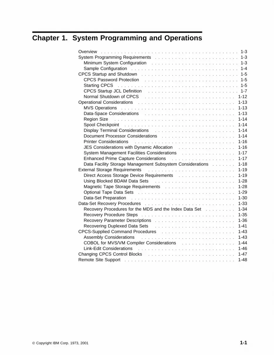
Chapter 1. System Programming and Operations
Overview . . . . . . . . . . . . . . . . . . . . . . . . . . . . . . . . . . . . . . . . . 1-3System Programming Requirements . . . . . . . . . . . . . . . . . . . . . . . . . 1-3
Minimum System Configuration . . . . . . . . . . . . . . . . . . . . . . . . . . 1-3Sample Configuration . . . . . . . . . . . . . . . . . . . . . . . . . . . . . . . . 1-4
CPCS Startup and Shutdown . . . . . . . . . . . . . . . . . . . . . . . . . . . . . 1-5CPCS Password Protection . . . . . . . . . . . . . . . . . . . . . . . . . . . . 1-5Starting CPCS . . . . . . . . . . . . . . . . . . . . . . . . . . . . . . . . . . . . 1-5CPCS Startup JCL Definition . . . . . . . . . . . . . . . . . . . . . . . . . . . 1-7Normal Shutdown of CPCS . . . . . . . . . . . . . . . . . . . . . . . . . . . 1-12
Operational Considerations . . . . . . . . . . . . . . . . . . . . . . . . . . . . . 1-13MVS Operations . . . . . . . . . . . . . . . . . . . . . . . . . . . . . . . . . . 1-13Data-Space Considerations . . . . . . . . . . . . . . . . . . . . . . . . . . . 1-13Region Size . . . . . . . . . . . . . . . . . . . . . . . . . . . . . . . . . . . . 1-14Spool Checkpoint . . . . . . . . . . . . . . . . . . . . . . . . . . . . . . . . . 1-14Display Terminal Considerations . . . . . . . . . . . . . . . . . . . . . . . . 1-14Document Processor Considerations . . . . . . . . . . . . . . . . . . . . . . 1-14Printer Considerations . . . . . . . . . . . . . . . . . . . . . . . . . . . . . . 1-16JES Considerations with Dynamic Allocation . . . . . . . . . . . . . . . . . 1-16System Management Facilities Considerations . . . . . . . . . . . . . . . . 1-17Enhanced Prime Capture Considerations . . . . . . . . . . . . . . . . . . . 1-17Data Facility Storage Management Subsystem Considerations . . . . . . . 1-18
External Storage Requirements . . . . . . . . . . . . . . . . . . . . . . . . . . 1-19Direct Access Storage Device Requirements . . . . . . . . . . . . . . . . . 1-19Using Blocked BDAM Data Sets . . . . . . . . . . . . . . . . . . . . . . . . 1-28Magnetic Tape Storage Requirements . . . . . . . . . . . . . . . . . . . . . 1-28Optional Tape Data Sets . . . . . . . . . . . . . . . . . . . . . . . . . . . . . 1-29Data-Set Preparation . . . . . . . . . . . . . . . . . . . . . . . . . . . . . . . 1-30
Data-Set Recovery Procedures . . . . . . . . . . . . . . . . . . . . . . . . . . . 1-33Recovery Procedures for the MDS and the Index Data Set . . . . . . . . . 1-34Recovery Procedure Steps . . . . . . . . . . . . . . . . . . . . . . . . . . . . 1-35Recovery Parameter Descriptions . . . . . . . . . . . . . . . . . . . . . . . . 1-36Recovering Duplexed Data Sets . . . . . . . . . . . . . . . . . . . . . . . . 1-41
CPCS-Supplied Command Procedures . . . . . . . . . . . . . . . . . . . . . . 1-43Assembly Considerations . . . . . . . . . . . . . . . . . . . . . . . . . . . . 1-43COBOL for MVS/VM Compiler Considerations . . . . . . . . . . . . . . . . 1-44Link-Edit Considerations . . . . . . . . . . . . . . . . . . . . . . . . . . . . . 1-46
Changing CPCS Control Blocks . . . . . . . . . . . . . . . . . . . . . . . . . . 1-47Remote Site Support . . . . . . . . . . . . . . . . . . . . . . . . . . . . . . . . . 1-48
Copyright IBM Corp. 1973, 2001 1-1

1-2 CPCS V1R11 Customization Guide

System Configuration
OverviewThis chapter contains information about establishing and using the IBM CheckProcessing Control System (CPCS) operating environment and includes informationabout:
� System programming requirements, including system configuration� CPCS startup and shutdown
� Operational considerations� External storage requirements� Data-set recovery procedures� CPCS-supplied command procedures.
Important!
The job control language (JCL) referenced in this chapter represents systemsand procedures that are tested at the time this book was published. You mustcustomize most, if not all, JCL that is supplied with CPCS to meet user andinstallation requirements. For the most current information, refer to the files onthe installation tape.
System Programming RequirementsCPCS supports document processors in the following modes:
3890s Channel-attached
3890/XPs Channel-attached or attached on a token-ring network, using thelogical unit (LU) 6.2 protocol
3891/XPs and 3892/XPsAttached, using the LU 6.2 protocol, through a synchronous data linkcontrol (SDLC) or a token-ring network.
CPCS operates only on Multiple Virtual Storage (MVS) systems with extendedarchitecture.
For extensive coverage on both the hardware and software requirements for CPCS,refer to the CPCS Program Directory.
Minimum System ConfigurationCPCS requires, as a minimum hardware configuration, a System/370 processoroperating in extended architecture mode with at least 4 megabytes (8MBrecommended) of main storage. In addition to the extended architecturerequirement, the following features and input/output (I/O) devices are necessary:
� Two direct access storage devices, with sufficient space for the CPCS datasets.
� One 3270 series display terminal or an equivalent device.
� One 3890, or one document processor from the 3890/XP Series, with the itemnumbering and endorsing feature. The document processor should alsoinclude the microfilming feature.
Note: The standard CPCS mass data set configuration stores therouting-transit (R/T) number as 8 digits. If a 9 digit, all numeric R/T number is
Chapter 1. System Programming and Operations 1-3

System Configuration
used, only the first 8 digits are stored. RPQ S00391 converts 9-digit R/Tnumbers to 8 digits and a dash for use by CPCS. This RPQ is for the 3890Document Processor, it is not required for 3890/XP Series documentprocessors. You can also code an SCI program to accomplish this change orexpand the R/T field in the mass data set to accommodate 9 digits.
Sample ConfigurationCorrect system configuration depends upon each user’s volume of work, processingtechniques, and performance requirements. The following configuration informationshould serve only as a guide. Your IBM marketing representative can help you findfurther assistance with detailed configuration planning.
Quantity Hardware
One 4381 Processor, Model Group 2 (8 megabytes)
One 3811 Printer Control Unit
Two 3203 Printer Model 5s
Two Document processors with item numbering, endorsing, and microfilmingfeatures
Two 3274 Display Control Unit Model 31Ds
One 3287 Printer Model 2
Ten 3278 Display Terminal Model 2s
Three Direct Access Storage Devices
One 3880 Storage Controller Model 1
One 3803 Tape Controller Model 2
Four 3420 Magnetic Tape Unit Model 3s
1-4 CPCS V1R11 Customization Guide
CPCS Startup and Shutdown
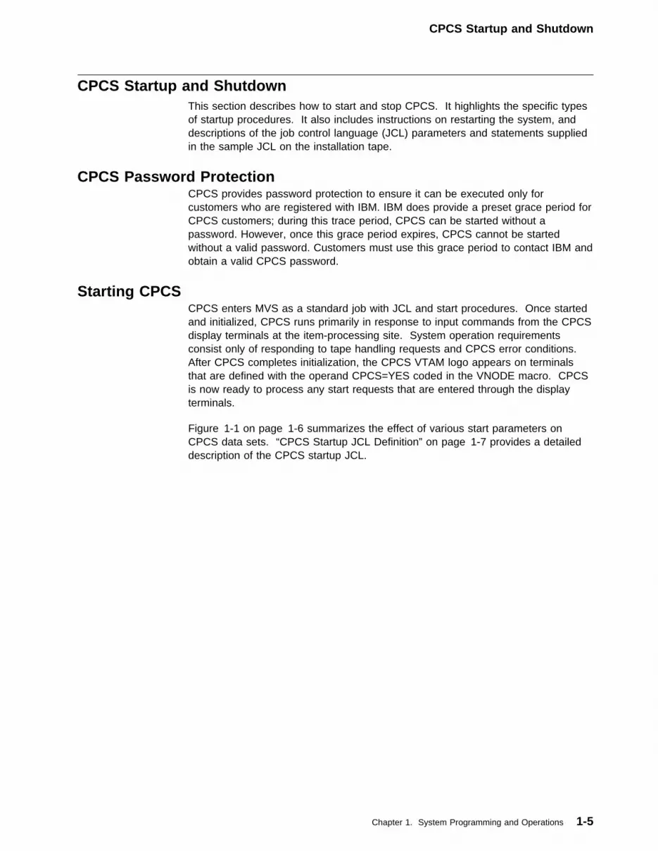
CPCS Startup and ShutdownThis section describes how to start and stop CPCS. It highlights the specific typesof startup procedures. It also includes instructions on restarting the system, anddescriptions of the job control language (JCL) parameters and statements suppliedin the sample JCL on the installation tape.
CPCS Password ProtectionCPCS provides password protection to ensure it can be executed only forcustomers who are registered with IBM. IBM does provide a preset grace period forCPCS customers; during this trace period, CPCS can be started without apassword. However, once this grace period expires, CPCS cannot be startedwithout a valid password. Customers must use this grace period to contact IBM andobtain a valid CPCS password.
Starting CPCSCPCS enters MVS as a standard job with JCL and start procedures. Once startedand initialized, CPCS runs primarily in response to input commands from the CPCSdisplay terminals at the item-processing site. System operation requirementsconsist only of responding to tape handling requests and CPCS error conditions.After CPCS completes initialization, the CPCS VTAM logo appears on terminalsthat are defined with the operand CPCS=YES coded in the VNODE macro. CPCSis now ready to process any start requests that are entered through the displayterminals.
Figure 1-1 on page 1-6 summarizes the effect of various start parameters onCPCS data sets. “CPCS Startup JCL Definition” on page 1-7 provides a detaileddescription of the CPCS startup JCL.
Chapter 1. System Programming and Operations 1-5

CPCS Startup and Shutdown
Figure 1-1. Effect of CPCS Start Parameters on Critical Data SetsStart Parameters Critical Data Sets
STYPE FTYPE CTYPE Mass DataSet
IndexData Set
TracerData Set
Kill BundleData Set
MicrofilmData Set
ScrollData Set
SpoolCheckpoint
Record
CycleData Set
Omitted(defaultstoWARM)
Omitted(defaultstoNOFMT)
Omitted Sets openI-strings andR-strings torestart mode
Does notclear thedata set
Does notclear thedata set
Compressesthe data set
Compressesthe data set
Does notclear thedata set
Does notclear thecheckpointrecord
Does notclear thedata set
COLD FMT1 Omitted(assumesCKPT)
Formats thedata set anddeletes allSDE data
Clearsthe dataset
Clearsthe dataset
Clears andreformatsthe data set
Clears andreformatsthe data set
Clearsthe dataset
Clears thecheckpointrecord
Clearsthe dataset
COLD NOFMT Omitted(assumesCKPT)
Does notformat thedata set
Clearsthe dataset
Clearsthe dataset
Clears andreformatsthe data set
Clears andreformatsthe data set
Does notclear thedata set
Clears thecheckpointrecord
Clearsthe dataset
COLD SCFMT Omitted(assumesCKPT)
Does notformat thedata set
Clearsthe dataset
Clearsthe dataset
Clears andreformatsthe data set
Clears andreformatsthe data set
Clearsthe dataset
Clears thecheckpointrecord
Clearsthe dataset
WARM FMT Omitted Sets openI-strings andR-strings torestart mode
Does notclear thedata set
Does notclear thedata set
Compressesthe data set
Compressesthe data set
Does notclear thedata set
Does notclear thecheckpointrecord
Clearsthe dataset
WARM FMT CKPT Sets openI-strings andR-strings torestart mode
Does notclear thedata set
Does notclear thedata set
Compressesthe data set
Compressesthe data set
Does notclear thedata set
Clears thecheckpointrecord
Clearsthe dataset
WARM NOFMT1 Omitted Sets openI-strings andR-strings torestart mode
Does notclear thedata set
Does notclear thedata set
Compressesthe data set
Compressesthe data set
Does notclear thedata set
Does notclear thecheckpointrecord
Clearsthe dataset
WARM NOFMT1 CKPT Sets openI-strings andR-strings torestart mode
Does notclear thedata set
Does notclear thedata set
Compressesthe data set
Compressesthe data set
Does notclear thedata set
Clears thecheckpointrecord
Clearsthe dataset
WARM SCFMT Omitted Sets openI-strings andR-strings torestart mode
Does notclear thedata set
Does notclear thedata set
Compressesthe data set
Compressesthe data set
Clearsthe dataset
Does notclear thecheckpointrecord
Clearsthe dataset
WARM SCFMT CKPT Sets openI-strings andR-strings torestart mode
Does notclear thedata set
Does notclear thedata set
Compressesthe data set
Compressesthe data set
Clearsthe dataset
Clears thecheckpointrecord
Clearsthe dataset
REST FMT Omitted Sets openI-strings andR-strings torestart mode
Does notclear thedata set
Does notclear thedata set
Does notcompressthe data set
Does notcompressthe data set
Does notclear thedata set
Does notclear thecheckpointrecord
Clearsthe dataset
REST FMT CKPT Sets openI-strings andR-strings torestart mode
Does notclear thedata set
Does notclear thedata set
Does notcompressthe data set
Does notcompressthe data set
Does notclear thedata set
Clears thecheckpointrecord
Does notclear thedata set
REST NOFMT1 Omitted Sets openI-strings andR-strings torestart mode
Does notclear thedata set
Does notclear thedata set
Does notcompressthe data set
Does notcompressthe data set
Does notclear thedata set
Does notclear thecheckpointrecord
Does notclear thedata set
REST NOFMT1 CKPT Sets openI-strings andR-strings torestart mode
Does notclear thedata set
Does notclear thedata set
Does notcompressthe data set
Does notcompressthe data set
Does notclear thedata set
Clears thecheckpointrecord
Does notclear thedata set
REST SCFMT Omitted Sets openI-strings andR-strings torestart mode
Does notclear thedata set
Does notclear thedata set
Does notcompressthe data set
Does notcompressthe data set
Clearsthe dataset
Does notclear thecheckpointrecord
Does notclear thedata set
REST SCFMT CKPT Sets openI-strings andR-strings torestart mode
Does notclear thedata set
Does notclear thedata set
Does notcompressthe data set
Does notcompressthe data set
Clearsthe dataset
Clears thecheckpointrecord
Does notclear thedata set
1 If you omit the FTYPE parameter, the system defaults to this setting for this STYPE parameter. If you specify the FTYPEparameter, you must specify the STYPE parameter.
1-6 CPCS V1R11 Customization Guide
Startup JCL Definition
CPCS Startup JCL DefinitionThe JCL for starting CPCS (member DKNJRUN in CPCS.V1R11.CTRL) is a thebasis for the descriptions of the CPCS start parameters, device specification, fileallocation and initialization, and recovery procedures in this section.
You must preallocate data sets that are assigned a disposition (DISP) of share(SHR) or old (OLD). The space allocations are enough for test purposes only.Each CPCS installation must perform the detailed calculations for file allocationbased on the expected volume of work and retention periods.
Execute Statement
//CPCS EXEC PGM=DKNMTASK,PARM='STYPE,FTYPE,CTYPE,ESM',// TIME=1439
The CPCS EXEC statement must contain the following positional parameters:
STYPE Start type defines how CPCS is started.
FTYPE Format type defines how the mass data set (MDS) is formatted andwhether the scroll data set is cleared.
CTYPE Checkpoint type defines whether the checkpoint record is cleared.
ESM Start type for Enhanced System Manager
Figure 1-1 on page 1-6 contains a description of the effect of the differentparameter combinations on some of the critical data sets.
These parameters determine the type of CPCS process, as shown on the followingpages. Be sure you understand the implications of each option and establish yourinstallation procedures accordingly. Since CPCS is often a continuously runningtask, select a value for the TIME operand that prevents premature ending of thejob.
Note: If you omit the PARM operand on the EXEC statement, the default optionsare WARM, NOFMT. If you specify an FTYPE parameter, you must also specify anSTYPE parameter.
STYPE Parameter
COLD
� Rebuilds the CPCS system parameter log file (MCMPL).
� Deletes, by rewriting the string directory index, all string informationthat exists in the MDS.
� Clears all information from the pass-to-pass control tracer data setand the cycle data set.
� Calls DKNCOMP to clear and reformat the kill bundle data set andthe microfilm data set.
� The FTYPE setting determines whether to clear the MDS and thescroll data set. (See Figure 1-1 on page 1-6.)
� Assumes that CTYPE=CKPT.
A cold start can be time consuming, but it is a requirement if:
� MDS parameters change
Chapter 1. System Programming and Operations 1-7

Startup JCL Definition
� MAXTG parameters change� MAXRP parameters change� Certain kinds of errors occur.
Note: If you want to initialize the IGEN data set, run JCL first to deleteand then to re-create the IGEN data set (DKNISEQ).
WARM
� Scans the CPCS system parameter log file (MCMPL) for changesfrom the last run of CPCS. The CPCS system editor determines ifany parameters have changed and if those parameters require aCOLD start. If the CPCS system editor determines that a COLDstart is required, the system shuts down and the system log file isnot updated. If a COLD start is not required, the CPCS systemparameter log file (MCMPL) is rebuilt.
� Scans the MDS for I-strings or R-strings that were open when CPCSwas last stopped and sets them to restart mode.
� Does not change the pass-to-pass control data set or the cycle dataset.
� Compresses fully processed records from the kill bundle data setand the microfilm data set.
� Clears all information from the scroll data set unless NOFMT is theoption in the FTYPE parameter.
� Clears all information from the writer checkpoint record when CKPTis the option in the CTYPE parameter.
REST
� Scans the CPCS system parameter log file (MCMPL) for changesfrom the last run of CPCS. The CPCS system editor determines ifany parameters have changed and if those parameters require aCOLD start. If the CPCS system editor determines that a COLDstart is required, the system shuts down and the system log file isnot updated. If a COLD start is not required, the CPCS systemparameter log file (MCMPL) is rebuilt.
� Scans the MDS for I-strings that were open when CPCS was laststopped and sets them to restart mode.
� Does not change the pass-to-pass control data set or the cycle dataset.
� Does not compress the kill bundle data set or the microfilm data set.If REST is used consistently, the COMP task should be scheduledafter end-cycle processing.
� Does not change in the scroll data set.
� Gives the quickest restart of CPCS without loss or change of data.
RECV
� Recovery of the MDS and index should be complete before CPCScan operate. See the description of the FTYPE parameter forrecovery options.
� Scans the MDS for I-strings or R-strings that were open when CPCSwas last brought down and sets them to restart mode.
1-8 CPCS V1R11 Customization Guide
Startup JCL Definition
� Calls DKNCOMP to scan the kill bundle data set and the microfilmdata set to determine the next available key. These files are notcompressed.
� Permits use of previous information in the scroll data set.
For a description of the effect of this option with the various FTYPEparameters for data set recovery, see “Data-Set Recovery Procedures”on page 1-33.
FTYPE Parameter
FMT
� FMT is the default if COLD is the option for the STYPE parameter.
� If you change the size of the MDS record or any of the MDSparameters in the CPCS system profile member DKNPCPCS, youmust also use FMT.
� Formats the MDS when STYPE is COLD.
� Clears the scroll data set when STYPE is COLD.
NOFMT
� NOFMT is the default when WARM or REST is the option for theSTYPE parameter.
� Does not format the MDS.
SCFMT Clears the information from the scroll data set on a restart.
Note: You can use the following FTYPE parameters only if STYPE is specified asRECV. For more information about selecting these parameters, see “RecoveryProcedures for the MDS and the Index Data Set” on page 1-34.
MDS CPCS recovers the MDS from user-specified log tapes.
INDEX CPCS recovers the MDS index from the MDS.
BOTH CPCS recovers the MDS and the MDS index. CPCS recovers the MDSfrom user-specified log tapes, then assembles the index from the MDS.This parameter is valid for logging.
SEL You specify this option (selective recovery) if an MDS or BOTH recoveryresulted in incomplete strings and the tapes necessary for completenessoriginated before the tapes used in the preceding recovery. SELspecifies that only the incomplete strings are recovered from theseearlier tapes. This parameter is valid for logging.
RMDS You specify this option (restart MDS recovery) if the recovery tapeswere in the sequence 1, 2, 3, 5, 4 in the restart JCL (DKNRT) and only4 and 5 are necessary for RMDS.
RBTH You specify this option if you want to restart BOTH recovery under thesame conditions as for RMDS.
NBTH You specify this option when you want to recover the mass data set andindex but do not want to alter the tracer data set. The recover processis the same as if you specify PARM='RECV,BOTH', except the tracerdata set is not initialized.
Chapter 1. System Programming and Operations 1-9
Startup JCL Definition
CTYPE Parameter
CKPT Indicates that CPCS must clear the writer-checkpoint record whenevereither the printer or spool configurations change.
Note: All spooled output is lost.
The checkpoint record contains information about the spool data setsand the printers assigned to CPCS. It must be the third positionalparameter, if specified. When the STYPE parameter is specified asCOLD, CKPT is the default value for the CTYPE parameter. In thiscase, you can omit CTYPE and substitute a positional null.
ESM Parameter
XXXX Specifies the type of startup that the Enhanced System Manager shouldperform. See the Enhanced System Manager User’s Guide for thepossible values for this parameter.
Library Statements
STEPLIB Data Set Statements: This set of concatenated data definition (DD)statements should reference the CPCS load library and any user-load librariesrequired by the installation. COBOL/370 programs might require the correct systemlibrary if the COBOL/370 and sort libraries are not in the MVS link list.
SORTLIB Data Set Statements: CPCS requires this library when runningDKNFILM, DKNCREF, and any user-written COBOL programs that use the SORTverb.
Document Processor Statements: These DDs are a requirement if you usechannel-attached document processors. They refer to the DDRDRIN parameters ofthe CPCSRDR macros. With dynamic allocation, you must specify these DDs onlyif allocation is necessary at startup. These DDs, and the 3890s contained in theDKNDSAT table for MVS dynamic allocation, associate the DDNAME parameters ofthe CPCSRDR macros with their physical document processors. DDs for 3890simulated document processors are also included.
Printer Device Statements: DKNITASK uses these DDs and the printers in theDKNDSAT table for dynamic allocation to complete the printer table at initializationof CPCS. If you use a unit reference in the form of a channel and unit address, thedevice must be a physical printer. If the ddname is TAPEOUT, DKNITASKincludes a tape-output printer in the printer table.
Temporary and Permanent CPCS Data Sets: Permanent CPCS data setsshould be cataloged in the system and allocated in accordance with the volumerequirements of the installation. For information on sizing calculations, see“External Storage Requirements” on page 1-19.
CPCS temporary data sets should be sized to meet the needs of the installationand, for performance reasons, should be specified as single buffered (BUFNO=1)data sets.
Spool Data Set Statements: You can enter up to the maximum number of spooldata sets supported by CPCS, based on the number specified by the SPOOLparameter in the CPCS system profile member DKNPCPCS. The first 5 characters
1-10 CPCS V1R11 Customization Guide
Startup JCL Definition
of the ddname must be SPOOL. One to three digits follow the ddname SPOOL (forexample, SPOOLxxx, where xxx can be 1 to 3 characters).
You preallocate spool data sets because they are used by application programs asintermediate data sets. The CPCS output writer then reads from these data setsand directs them to a printer. As a guide, the working minimum should equal thenumber of application tasks that require a printer and that you expect to haverunning concurrently.
Note: Generating only a small number of spool data sets increases the chancesthat none will be available when there is a request to start an application task thatneeds one. In this case, the task waits in a queue for a spool data set to becomefree. An excessive number of spool data sets wastes direct access space. Youcan allocate a minimum of two and a maximum of 255 spool data sets.
High-Volume Spool Data Set Statements: CPCS supports tasks that generate alarge amount of spooled output (for example, DKNKILL). This option minimizes theamount of space necessary for all spool data sets by sending spooled output tospecific data sets. The user must conform to the specifications as explained in theCPCS Programming and Diagnostic Guide and must code the letter L as the eighthcharacter of the ddname in the DD statement (for example, SPOOL�1L).
DKNATASK allocates these spool data sets to selected application tasks, providedthat this requirement is specified in the DKNBLDL list by the HIVOL=1 operand.You must determine, and specify in the DD statement, the amount of disk space toallocate to the larger spool data sets.
Application tasks can write directly to job entry subsystem (JES) spool files. Themaximum number of output spools is 255. DKNBLDL saves additional informationfor assigning JES spools. This information includes:
� The class to which reports are sent for this task� Routing information, if applicable.
See “JES Considerations with Dynamic Allocation” on page 1-16 for moreinformation.
Tape Data Set Statements: If you elect to make them tape data sets, the inputcreate file (DKNIN), the master create file (DKNMD), and the end cycle file(DKNSK) can be allocated to a single tape unit. These tapes are dynamicallyallocated using the definitions in DKNDSAT.
The recovery tape (DKNRT) is used for both selective and full MDS recoveries. Ifyou install logging, and elect to log directly to tape, then the MDS log tape (DKNLT)and its option duplex (DKNLTD) should each have its own drive. If possible,secondary units should be available to minimize delays that result from end-of-reelconditions.
Logging Data Set Statements: These DDs are a requirement if the master taskgeneration defines LOG=YES. With dynamic allocation, the DKNLD, DKNLDD, andDKNDTD statements can be dynamically allocated if the DD definitions are inDKNDSAT. DKNRINIT should preallocate and initialize all other DDs.
Chapter 1. System Programming and Operations 1-11

Startup JCL Definition
System Print Data Set Statements: Various system tasks and user tasks (forexample, the SORT program called by COBOL tasks) generate printed outputmessages during the running of CPCS. For this reason, you should include aSYSOUT DD in the JCL.
In the event of program abends and possible system errors, you should code aSYSUDUMP or a SYSABEND DD to obtain the documentation necessary forproblem determination. DKNATASK deallocates and reallocates SYSUDUMP eachtime a CPCS application program returns with a nonzero system or user returncode.
Normal Shutdown of CPCSThe MVS system operator can remove CPCS from the system through the normaloperating system facilities by canceling the job. However, the operator should notcancel the CPCS job unless directed to do so by a CPCS supervisor. Thesupervisor can shut down CPCS at any time with the STOP command. This typeof shutdown is a scheduled shutdown. When it occurs, a console messageinforms the system operator that CPCS has been shut down because of asupervisor request. For more information on the STOP command, see theexecutive task commands section of the CPCS Terminal Operations Guide.
1-12 CPCS V1R11 Customization Guide

Operational Considerations
Operational ConsiderationsThis section describes system operation recommendations for CPCS. Theserecommendations are intended to help you run CPCS more efficiently on your hostsystem. However, depending on the host system configuration, some of theserecommendations might not be appropriate or necessary. The topics include jobpriority, terminal and sorter attachment, automatic restart, printing, job entrysubsystem (JES), and system management facilities (SMF).
MVS OperationsYou should run CPCS with the highest available job priority on your system. Youmust run CPCS as non-swappable. Include an entry for the CPCS master task(DKNMTASK) in member SCHED00 of SYS1.PARMLIB. Place the entry in thefollowing columns:
----+----1----+----2----+----3----+----
PPT PGMNAME(DKNMTASK)
NOSWAP
This marks the CPCS region as non-swappable, but does not prevent it from beingpaged. For details on running a non-swappable task, see MVS/ESA Initializationand Tuning.
A secondary method for making CPCS non-swappable is to have the CPCS mastertask invoke a non-swappable SVC. For further information, see “Nonswap SVCGeneration Task” on page 2-31.
Data-Space ConsiderationsThe merged string (M-string) distribution (DKNMDIS) module uses IBM licensedprogram Multiple Virtual Storage/Enterprise Systems Architecture (MVS/ESA*) dataspaces to temporarily store D-strings that DKNMDIS builds. The following formuladetermines the size of the data space: data-space size = ((maximum number of
D-strings x length of string directory entry) + (number of codelines x
(length of one codeline + 8)) + 4�95) ÷ 4�96.
For example, given a 50,000 item entry, the size of the data space would be2�46 = ((99 x 736) + (5�,��� x (158 + 8)) + 4�95 ÷ 4�96.
The result is 2046 pages of memory, which is approximately 9MB (MB equals1,048,576 bytes) of memory. The sample BLDL allows three copies of MDIS to beactive at the same time, which is 3 x 9MB or 27MB.
DKNMDIS maintains a forward and backward pointer to the codelines, and itrequires approximately 8 bytes per codeline. MDIS also uses approximately onepage of the data space for control variables. When DKNMDIS attaches, it cannotdetermine the exact size of the data space. Therefore, DKNMDIS checks the sizeof the data space each time it adds an item to the data space. If the size of thedata space is too small, MDIS increases the size up to the maximum data-spacesize or up to the system installation limit. Each time a copy of DKNMDIS attaches,a new data space is created. The data space is deleted when DKNMDIS ends.
Chapter 1. System Programming and Operations 1-13

Operational Considerations
Note: If DKNMDIS cannot extend the data space to fulfill the requirements of theentry, DKNMDIS ends and no permanent data sets are updated. The maximumnumber of codelines in a string that DKNMDIS can distribute is approximately10,000,000 lines. The standard mass data set provides a data space of 2gigabytes. For more information about data spaces, see MVS/ESA ApplicationDevelopment Guide: Extended Addressability.
Region SizeThe CPCS configuration needs a region of at least 4M bytes. However, for efficientoperation, the region size may need to be much larger; at least 8M bytes isrecommended.
Spool CheckpointThe writer interface module DKNWTRIF performs the checkpointing of the spooland printer allocation table. The checkpoint record is rewritten each time the statusof an entry in the table changes. In the event of a system failure, restarting CPCSprompts DKNWTRIF to recover the existing checkpoint record. This record is usedto restore the existing spool and printer allocation table entries to the status thatexisted at the time of the last checkpoint. DKNWTRIF scans the printer table,flagging all printers available except those designated offline; the output classremains the same.
The spool table is scanned to determine whether any status change is required.The status of a spool changes under the following conditions:
� A spool that was printing at the time of the failure is flagged as queued.
� A spool in-use (assigned to an application task for data creation) is flagged asavailable, because any data on the spool is considered unreliable and theapplication task is normally rerun.
� Spools waiting to print are flagged as queued.
After checking and changing each table entry, DKNWTRIF performs its normalinterface functions by checkpointing the newly modified table and scheduling thecorrect spools for print processing.
Display Terminal ConsiderationsMAXTERM=nn (where nn=1 to 99) must be specified in the CPCS system profilemember DKNPCPCS. Specifying a number greater than the actual number ofphysical terminals creates extra terminal entries in the terminal table. CPCS usesVTAM functions for allocation of the terminals.
Document Processor ConsiderationsCPCS supports the following three host attachments for document processors:
� Channel attachment� LU 6.2 attachment� Host-simulated (no physical attachment).
You define how the document processor attaches to the host as part of the MICRtask generation. For more information about the MICR task generation, see “MICRTask Generation” on page 2-33.
1-14 CPCS V1R11 Customization Guide

Operational Considerations
Channel AttachmentChannel-attached document processors use QSAM for I/O operations. If youspecify the 3890/XP Document Processor during the MICR task generation, CPCSrequires the 3890/XP MVS Support product, which provides enhanced QSAMsupport. You must use the MODEL=XP option and the TYPE=3890-nn option onthe CPCSRDR macro to define the 3890/XP Document Processor.
You can define the physical document processor channel-unit addresses throughdata definition (DD) statements in your JCL. If you use dynamic allocation, anoperator defines the physical document processor channel-unit address using theDKNALLO program, and the DKNDSAT data set must contain a correspondingDSAT macro entry. For more information about using the DSAT macro, see“Dynamically Allocating Data Sets” on page 2-23.
LU 6.2 AttachmentAn LU 6.2-attached document processor requires 3890/XP MVS Support Version 1Release 2 or higher and ACF/VTAM Version 3 Release 2 or higher. You mustdefine LU 6.2-attached document processors to the VTAM products. For moreinformation about defining an LU 6.2-attached document processor, see the3890/XP MVS Support and 3890/XP VSE Support Program Reference.
You must supply an LU 6.2 node table module to define the physical LU6.2-attached document processors. The LNTNAME parameter in the CPCS systemprofile member DKNPCPCS specifies the name of the LU 6.2 node table module.For information about creating an LU 6.2 node table module, see the 3890/XP MVSSupport and 3890/XP VSE Support Program Reference.
The DKNALLO program begins and ends communication with an LU 6.2-attacheddocument processor and associates a CPCS logical document processor to aphysical LU 6.2-attached document processor. During MICR processing, LU6.2-attached document processors operate the same way as do channel-attacheddocument processors. LU 6.2-attached document processors and channel-attacheddocument processors can replace one another as part of MICR OPEN processing.
Host-Simulated AttachmentThe host-simulated document processor requires the 3890/XP MVS Supportprogram. You must define each simulated document processor in your JCL withadditional DD statements. For an example of the DD statements, see the sampledefinition statements in DKNJRUN in the CPCS.V1R11.CTRL data set. For moreinformation about defining DD statements for document processors, see the3890/XP MVS Support and 3890/XP VSE Support Program Reference.
Automatic Restart ConsiderationsDifferent CPCS jobs that access the same group of document processors musthave different ARST parameter values. Automatic restart is performed only for3890/XP Series document processors.
The restart method is always manual for simulated document processors.MICR-user changes must not exclude any paper and automatic restart exceptioncontrol records from being written to the MDS. Otherwise, automatic restart mightfail and manual restart would be forced.
Note: Automatic exception control records are written to the MDS wheneverCPCS processes exception or SCI error headers. These control records, which are
Chapter 1. System Programming and Operations 1-15
Operational Considerations
identified by X'80' in field DIFLAG2 and X'E3' in field DITYPEI, are necessary forthe automatic-restart matching process.
If the Run Profile Drives/Paths do not specify the standard directory (INIT), theRestart Run Profile (RESTART.RPR) must be copied into the nonstandarddirectories. Otherwise, automatic restart will fail with an AUTOMATIC RESTART NOT
IMPLEMENTED status message, and manual restart would be forced.
Printer ConsiderationsIf you do not use dynamic printer allocation, you should define a dedicated devicefor print output. In most cases, this would be a printer. However, an option existsto substitute a tape drive or SYSOUT=A, using the CPCS TAPEOUT DDstatement.
To substitute a tape drive, change the JCL according to the following specifications:
� The DD statement for the tape unit must contain the ddname TAPEOUT.� The disposition parameter must be DISP=(MOD,PASS).� The DCB parameter must specify BLKSIZE, BUFL, and BUFNO.� Do not code the volume serial number (VOL=SER=nnnnnn).
If you use dynamic printer allocation, you do not need to specify printers in the JCL.You must include these printers in the DKNDSAT table. With this approach, theprinters can be allocated to other jobs when CPCS is started. They can beallocated to CPCS, when needed, by using the DKNALLO task.
CPCS can also use JES output facilities, see “JES Considerations with DynamicAllocation.”
If you specify a printer with the universal character set (UCS) feature, the characterimage should be a default layout. Specify both the forms control buffer (FCB) andUCS parameters for use with a forms control buffer.
For efficiency in printing, the number of copies (MAX) for the DKNWTR taskspecified in DKNBLDL should be equal to the number of printers specified in theCPCS system profile member DKNPCPCS. For more information on the DKNWTRtask, see the CPCS Programming and Diagnostic Guide.
Do not direct output to a particular printer because, for example, if a printer isexperiencing hardware errors, all output to that device is lost. In this case, changethe printer to an offline status or change its class to one that is not used. You canuse DKNFORM to change the class. For more information about DKNFORM, seethe CPCS Terminal Operations Guide.
JES Considerations with Dynamic AllocationWhen using dynamically allocated SYSOUT data sets and JES writers, perform thefollowing steps to generate CPCS printed output:
� Include JESPRTnc entries in DKNDSAT, using the DSAT macro to provide apool of SYSOUT data sets for use by the CPCS writer task. For moreinformation on SYSOUT data sets, see the CPCS Programming and DiagnosticGuide.
If you need to print large reports without tying up spool data sets, use DKNADCB3.This subroutine changes the calling program’s data control block (DCB).
1-16 CPCS V1R11 Customization Guide

Operational Considerations
DKNADCB3 dynamically allocates a JES SYSOUT spool and sets the callingprogram’s DCB to the JES ddname.
For dynamic allocation of data sets, see “Dynamically Allocating Data Sets” onpage 2-23 for a description of using the DSAT macro. For a description ofDKNADCB3, see the CPCS Programming and Diagnostic Guide.
System Management Facilities ConsiderationsCPCS customers who use System Management Facilities (SMF) must specify ajob-wait-time parameter for SMF generation. This parameter governs the length oftime a job can be in a WAIT state before automatic system termination. Becausecheck processing operations can be lengthy, CPCS might have to remain in a waitstate for a long period of time. If it is not feasible to increase the time parametervalue (for example, TIME=1439) to accommodate a long wait, unscheduled CPCSshutdowns can occur.
Enhanced Prime Capture ConsiderationsEnhanced Prime captures have the following characteristics:
� The MICR capture begin information is entered only once, before starting therun, with the PRIME field containing the tracer group number corresponding tothe first entry to be captured. All stacked entries run under the same sort type,on the same cycle and under the same MICR user parameters and exitroutines.
� The MICR capture end commands are entered only once, after having capturedthe last stacked entry. The capture end screens show counts and totalscorresponding to the last entry captured.
� The number of tracer groups that identify an entry is determined by the valuethat is specified in the Sort Pattern Definition O, card columns 41-43. Thedefault value is 001.
� Output I-strings follow the same naming conventions as all other normalI-strings.
� MICR status message 118 may optionally be displayed, before each new entryis captured, to allow the MICR operator to pull the pocketed items before thenext entry is captured. The capture may also be suspended or ended at thispoint, instead of continuing capturing more entries.
� If the pocketed items are not pulled after capturing each entry, kill itemsbelonging to different entries may be separated by activating the “tracers in killpockets” option.
� All normal prime pass features and options are available.
� Kill bundles do not span through entries. A “Sorter Initialization at EntryBreaks” option is available to avoid small bundles at the beginning of theentries.
� The function and its options are activated by using the sort pattern definitionoptions (O) record.
Chapter 1. System Programming and Operations 1-17

Operational Considerations
Data Facility Storage Management Subsystem ConsiderationsCPCS data sets can reside on Data Facility Storage Management Subsystem(SMS) controlled volumes, except the mass data set. You must adequately definethe CPCS data set requirements. You should use the following guidelines:
1. SMS cannot control the CPCS mass data set. The mass data set is allocatedas follows:
DD DSN=CPCS.V1R11.MASSDS,
DCB=(RECFM=F,LRECL=1�12,BLKSIZE=1�12,DSORG=DAU),VOL=SER=XXXXXX
You should allocate the mass data set as contiguous and unmovable,especially with multi-pack allocation.
2. The data sets cannot have space released.3. The duplex data sets cannot be on the same volume serial as primary data
sets. The data sets can be on the same volume serial only when you use splitstorage groups or guaranteed space storage classes.
4. Data sets should not be migrated.5. Blocking factors cannot be automatically generated by SMS.6. No DCB or VSAM allocation parameter can be altered by SMS.7. You should write the SMS access control system (ACS) routine to use all
dynamic allocation parameters. You must decide if SMS uses specific volumeserial requests.
8. CPCS BDAM data sets are not allocated with extents.9. Fast I/O response time for certain data sets is required. Caching volumes may
be required for high I/O data sets, (such as the Divider data set).10. CPCS logging data sets are not allocated with free space. When a D37
system completion code occurs the data set should not be increased. A dataclass should not be selected that assigns a volume count or secondary spaceto the data set.
11. Data sets required for user written, third party vendor, and business partnerprograms that run in the CPCS environment must be analyzed and consideredfor any unique restrictions that may apply to those programs.
12. Sorter allocation is not controlled by SMS.
1-18 CPCS V1R11 Customization Guide
External Storage Requirements
External Storage RequirementsThis section describes the external storage requirements for CPCS. It includesinformation about direct access storage, magnetic tape storage, and data setpreparation.
Direct Access Storage Device RequirementsWithin each of the following categories, the data sets are listed alphabetically byddname. (Depending on the degree to which you have customized your ownCPCS run JCL, your ddnames may not be the order in which they occur thesupplied sample CPCS run JCL.)
Important!
Before you run CPCS, you must allocate and pre-format the VSAM data sets.
Permanently Allocated Data SetsThe following ddnames must be coded in your run JCL when you start CPCS.
APTR (ATASK Printer)The applications task, DKNATASK, writes a log of events as they occur.Whenever a task is attached, detached, or queued, DKNATASK writes amessage to the log. It also writes these messages to the scroll data set. Youshould allocate APTR to a SYSOUT data set. If you do not want this function,allocate the DD statement to DD DUMMY.
CKPTDS (Writer Checkpoint Record)This data set contains status information about the spools and printersassigned to CPCS. DKNWTRIF rewrites this single record each time a statuschange occurs. It is a sequential data set that consists of one record thatcontains both the spool and the printer tables. This data set must bepre-allocated. It requires no special formatting; DKNWTRIF formats it, basedon the PARM operand values in the JCL EXEC statement.
CKPTDS size = (4 + (48 x SPOOL)) + (4 + (2� x NUMPTR)) bytes
CYCLDS1 (Cycle Table Data Set)This data set contains records for status, date, endorse date, name, and cyclequantity. You must pre-allocate this data set with LRECL=664 andBLKSIZE=664.
CYCLDS2 (Cycle Table Duplex Data Set)This data set is a duplicate of CYCLDS1 when DUPLEX=1. The storagerequirements are the same. Allocate it on a different DASD volume than theone used for CYCLDS1.
DKNAB (Endpoint Name and Address Data Set)The CPCS installation creates the endpoint name and address data set forreference by DKNKILL and DKNCLSM. One record exists for each routingnumber entered in the file. DKNLOAD creates this file each time it runs (see“Data-Set Preparation” on page 1-30). The data set is unblocked and the
Chapter 1. System Programming and Operations 1-19

External Storage Requirements
logical record length is 600. You should allow 20% additional space forexpansion.
DKNADJCDThis data set defines the adjustment codes used by the DKNADJ onlineadjustments program. Each record is 30 bytes in length, and contains theuser’s two-digit adjustment code, the equivalent internal DKNADJ flag, and acomment.
DKNAPPLDKNAPPL is a partitioned data set with a logical record length of 80. Itsmembers are profiles that control the behavior of individual CPCS tasks. Theprofile for a specific task is reloaded each time that task is run.
DKNBCF (Bank Control File Data Set)The CPCS installation creates a set of 80-byte records that describe eachprocessing bank. DKNLOAD uses this input data set, created outside ofCPCS, to create the records in the DKNBCF data set. DKNMICR and variousreport modules use this data set as input.
DKNCMPRS (Work Data Set for DKNCOMP)This is a work data set used by DKNCOMP. The space allocation for this dataset should be large enough to hold a complete copy of the kill bundle data setor the microfilm data set, whichever is larger. It must be permanently allocated,because it contains the only complete copy of the kill bundle or microfilm dataset during compress operations.
DKNDIV (Divider Slip Data Set)This optional data set is a VSAM-keyed, sequential data set (KSDS) thatprovides the location of a divider slip in the MDS. DKNDIST, DKNMDIS, andDKNTDUP (a subroutine of DKNSCAT) all update this data set. Its purpose isto resynchronize sorter codeline data match buffers during a subsequent-passcapture.
DKNEP (Endpoint Tables Data Set)This is a partitioned data set whose members are endpoint tables (see“Data-Set Preparation” on page 1-30). The user creates and maintains thisdata set. The number of endpoints that you have defined determines its totalsize.
DKNFREE (Work Data Set for DKNIMGS)This data set area is required for shops that run image and HSRR captures,and use DKNIMGS to provide the image system with a cross-referencebetween the prime pass and HSRR pass sequence numbers. It is a sequentialdata set, fixed blocked, with a logical record length of 29 and a BLKSIZE of290. A record is written to DKNFREE for each HSRR I-string codeline thatcould not be matched back to its prime-pass system reject D-string.
DKNHELP (System Help Data Set)This is a VSAM-keyed, sequential data set (KSDS) used to hold help screens.It is allocated and loaded during CPCS installation. Thereafter, any task candisplay any help screen by passing the appropriate task name and screennumber keys to the Help Function Manager module, DKNHELP.
DKNISEQ (Item Sequence Number Data Set)This data set is a VSAM relative-record data set that DKNIGEN uses tomaintain unique sequence numbers for up to 96 document processors.
1-20 CPCS V1R11 Customization Guide
External Storage Requirements
Provision is made for other electronic data. DKNMICR and DKNOLRR updatethis data set. The CPCS installation process includes a stand-alone job thatinitializes this data set.
DKNKB (Kill Bundle Data Set)DKNKILL writes a record to the kill bundle data set for each printed kill bundle.These records are deleted by cycle when DKNECYC runs. DKNCOMPpre-formats the kill bundle data set with a specific number of records, based onthe expected maximum number of kill bundles.
Apply the following formula when sizing the kill bundle data set:
K = (N ÷ A) x 1.1
where:
K = Number of kill bundle records requiredN = Number of items killedA = Average number of items for each killed bundle
Base the calculation on peak-day volume.
Notes:
1. The value 1.1 is an allowance for kill bundles for high-speed reject reentry(HSRR) runs and for the partial bundles at the end of each prime andsubsequent pass for kill pockets.
2. You can use a blocked BDAM format for this data set. For informationabout formatting this data set using blocked BDAM, see “Using BlockedBDAM Data Sets” on page 1-28.
DKNKD (Duplex Kill Bundle Data Set)This data set is a duplicate of DKNKB, and its storage requirements are thesame. Allocate it on a different DASD volume from the volume used forDKNKB.
If you specify DUPLEX=1 in your master task generation, you must include aDD statement for this data set in your JCL. You cannot have a DD DUMMYstatement for this data set.
DKNMC (Master Create Work Data Set)DKNMCRE uses this temporary work data set. It contains one record for eachkill bundle (DKNKB records) transferred to the master tape and one record foreach R-string, on-us D-string, user-to-process D-string, or subsequent-passreject D-string.
This data set must be large enough to contain both the records for themaximum number of kill bundles that one run of master creation can processand records for the maximum number of R-strings, on-us D-strings,user-to-process D-strings, or subsequent-pass reject D-strings in the run.
DKNMF (Microfilm Data Set)DKNFILM produces microfilm reports from this data set. It is a required dataset even if microfilming is not present or used. DKNDIST and DKNMDIS writea record for every batch and block slip they process. DKNFILM reads recordsfor its reports, and marks them for removal; DKNCOMP deletes the markedrecords. DKNCOMP pre-formats the microfilm data set with a specific numberof records, based on the expected maximum number of batch and block slips.
Chapter 1. System Programming and Operations 1-21
External Storage Requirements
Consider how often you run DKNFILM and how often you compress the dataset by running using DKNCOMP (including CPCS startup) when calculating thesize of the data-set. An allocation of one track is enough if microfilming is notpresent or not used because only three records are written to this file by CPCS.You can allocate the microfilm data set as a blocked BDAM data set. Forinformation about formatting this data set using blocked BDAM, see “UsingBlocked BDAM Data Sets” on page 1-28.
DKNMFD (Duplex Microfilm Data Set)This data set is a duplicate of DKNMF. Its storage requirements are the same.Allocate it on a DASD volume that is different from the volume used forDKNMF.
If you specify DUPLEX=1 in your master task generation, you must include aDD statement for this data set in your JCL. You cannot have a DD DUMMYstatement for this data set.
DKNMISS (Work Data Set for DKNIMGS)This data set area is required for shops that run image and HSRR captures,and use DKNIMGS to provide the image system with a cross-referencebetween the prime pass and HSRR pass sequence numbers. It is a bothsequential data set, fixed blocked, with a logical record length of 29 and aBLKSIZE of 290. A record is written to DKNMISS for each prime-pass systemreject D-string codeline that could not be matched to its HSRR I-string.
DKNSMSGD (System Message Data Set)This is a VSAM keyed sequential data set (KSDS) used to hold errormessages. It is allocated and loaded during CPCS installation. Thereafter, anytask can fetch any message by passing the appropriate subsystem, task name,and message number keys to the System Message Handler module,DKNSMSG.
DKNSPDEF (Sort Pattern Definition Library)The user creates and maintains this data set. This is a partitioned data set.You must define it as unblocked.
DKNSUBMT (Default JCL Submit Data Set for DKNSUB)This is an optional partitioned data set with a logical record length of 80. If it ispresent in the CPCS run JCL, DKNSUB searches it for the JCL members that itis to submit. If DKNSUBMT is not present in the CPCS run JCL, DKNSUBassumes its start parameter names a data set as well as a member, and itattempts to allocate and submit from that data set.
DKNTG (Pass-to-Pass Control Data Set)This is the tracer data set used in pass-to-pass control. DKNPCTL formats thisdata set on a cold start. The calculations for space requirements are asfollows:
SPACE = N blocks where:
N = Q x (R + 1)
Q = MAXTG (defined under “CPCSOPTN Macro Parameters” onpage 2-43)
R = MAXRP + 9 (defined under “CPCSOPTN Macro Parameters” onpage 2-43)
1-22 CPCS V1R11 Customization Guide

External Storage Requirements
DKNTG is a “keyed” file and must be allocated with the DCB parameter,DCB=(KEYLEN=12,RECFM=F,DSORG=DA,BLKSIZE=2212).
DKNTGD (Pass-to-Pass Control Duplex Data Set)This data set is a duplicate of DKNTG, and the storage requirements are thesame. Allocate it on a different DASD volume than the one used for DKNTG.
If you specify DUPLEX=1 in your master task generation, you must include aDD statement for this data set in your JCL. You cannot have a DD DUMMYstatement for this data set.
IMGSSEQ (Work Data Set for DKNIMGS)This data set is required for shops that run image and HSRR captures and useDKNIMGS to provide the image system with a cross-reference between theprime-pass and HSRR-pass sequence numbers. It is a sequential data set,fixed blocked, with a logical record length of 47 and a BLKSIZE of 470. Onerecord is written for each codeline that matches, or fails to match, between theHSRR I-string and its corresponding prime-pass system reject D-string.
INDEX (MDS directory index)The MDS directory index is a random access data set. To maximizeprocessing efficiency, we recommend that the data set physically reside on adevice separate from the MDS. The MDS directory index consists of stringdirectory index (SDI) records for all active strings.
Specify the number of physical records allocated to the MDS directory index(NDIRBLK), based on the number of anticipated active strings. To aid insearching the index for a named string, SDI records are grouped by string typewithin the MDS directory index. You specify the number of physical recordsallocated to each string type by specifying the last relative record allocated to aspecific string type (EDIREND, MDIREND, IDIREND, RDIREND, andDDIREND).
A randomizing routine distributes active SDI records across the recordsallocated for a specific string type. If a record is completely filled, one overflowrecord is chained to the primary record. If both the primary and overflowrecords contain no free SDI records, a request to open an output string to thatrecord results in an error and a return to the calling program.
Figure 1-2 shows the relationship between the types of strings and the numberof physical records:
Figure 1-2. MDS directory index relationships
String Type Number of Physical Records
NDIRBLK 42EDIREND 1MDIREND 2IDIREND 5RDIREND 6DDIREND 21
Chapter 1. System Programming and Operations 1-23
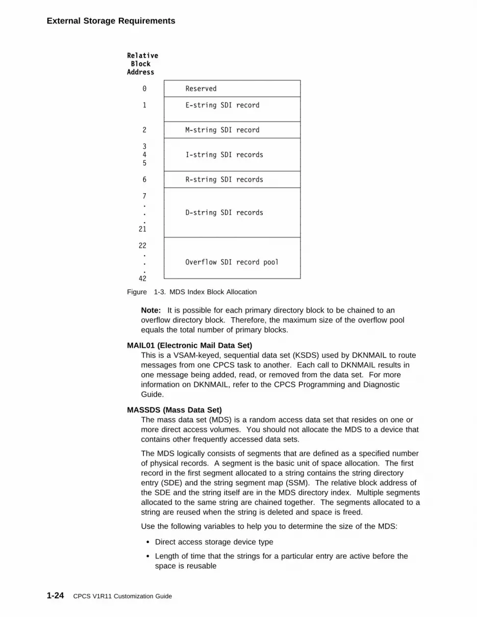
External Storage Requirements
Relative BlockAddress ┌──────────────────────────────────┐
� │ Reserved │
├──────────────────────────────────┤
1 │ E-string SDI record │
│ │
├──────────────────────────────────┤
2 │ M-string SDI record │
├──────────────────────────────────┤
3 │ │
4 │ I-string SDI records │
5 │ │
├──────────────────────────────────┤
6 │ R-string SDI records │
├──────────────────────────────────┤
7 │ │
. │ │
. │ D-string SDI records │
. │ │
21 │ │
├──────────────────────────────────┤
22 │ │
. │ │
. │ Overflow SDI record pool │
. │ │
42 └──────────────────────────────────┘
Figure 1-3. MDS Index Block Allocation
Note: It is possible for each primary directory block to be chained to anoverflow directory block. Therefore, the maximum size of the overflow poolequals the total number of primary blocks.
MAIL01 (Electronic Mail Data Set)This is a VSAM-keyed, sequential data set (KSDS) used by DKNMAIL to routemessages from one CPCS task to another. Each call to DKNMAIL results inone message being added, read, or removed from the data set. For moreinformation on DKNMAIL, refer to the CPCS Programming and DiagnosticGuide.
MASSDS (Mass Data Set)The mass data set (MDS) is a random access data set that resides on one ormore direct access volumes. You should not allocate the MDS to a device thatcontains other frequently accessed data sets.
The MDS logically consists of segments that are defined as a specified numberof physical records. A segment is the basic unit of space allocation. The firstrecord in the first segment allocated to a string contains the string directoryentry (SDE) and the string segment map (SSM). The relative block address ofthe SDE and the string itself are in the MDS directory index. Multiple segmentsallocated to the same string are chained together. The segments allocated to astring are reused when the string is deleted and space is freed.
Use the following variables to help you to determine the size of the MDS:
� Direct access storage device type
� Length of time that the strings for a particular entry are active before thespace is reusable
1-24 CPCS V1R11 Customization Guide

External Storage Requirements
� Maximum number and size of concurrently active strings
� Block size as specified in the CPCS system profile member DKNPCPCS.
MDS services (DKNMDSVC) directs a message to the system operator and thesupervisor terminal when the MDS is 80% filled and for each 5% incrementthereafter until the data set is completely filled. When the MDS becomescompletely filled, all tasks enter a wait state until space becomes available.You can run DKNICRE, DKNMCRE, DKNDELE DKNSTGD, DKNFREE, orDKNLDIR with the delete option, to free MDS data set space. For informationabout using these, see the CPCS Programming and Diagnostic Guide and theCPCS Terminal Operations Guide.
MCMPL (System Log File)The application task, MTASK, writes a system log file with the latest systemparameters. This log is used to identify what parameters have been modifiedfrom the previous run and what type of start CPCS requires. You mustpre-allocate this data set with LRECL=200 and BLKSIZE=200.
MPTR (CPCS System Parameter Edit Report)This is a report DD that displays the CPCS system parameters generated andany errors associated with the edits. This DD is defined to the CPCS run JCL(DKNJRUN) and the Batch System batch editor JCL (DKNJEDTP). This JCL islocated in the CPCS.V1R11.CTRL data set.
SCROLL (Online Activity Log)The communication task (DKNVTASK) writes supervisor terminal messagesand ATASK log messages to this data set. The operator can use theDKNSCRL application task to browse this data set.
Warning: The data set must be previously allocated as a single contiguousextent.
The communication task formats this data set during a cold start of CPCS. Itcan optionally format the data set during a warm start of CPCS.
The average number of supervisor terminal messages and ATASK logmessages that a particular installation receives determines the number of tracksallocated to the data set. This is not a history data set. Writes to this data setwrap around when it is full. Allocate this data set in cylinders.
SORTWK01, SORTWK02, SORTWK03 (Sort Work Data Sets)These work data sets are required for the sort-merge programs. If you useconcurrent sorting, do not code them in the startup JCL because CPCSmodules acquire the work data sets dynamically.
SYSTPROF (System Profile Data Set)This is a partitioned data set with a logical record length of 80. Its membersare profiles that control the behavior of CPCS. They are loaded once CPCS isstarted and are used thereafter for the remainder of CPCS job execution.
Temporary Data SetsThe following data sets are all temporary work files. You should code entries inyour DKNDSAT table, using a DYNDSN of 35 characters or less, a DYNSTAT ofNEW, a DYNNORM of DELETE, and a DYNCOND of DELETE. For moreinformation, see “Dynamically Allocating Data Sets” on page 2-23. The standardDKNDSAT shipped with CPCS already contains entries for all these data sets.
Chapter 1. System Programming and Operations 1-25

External Storage Requirements
Important!
If you expand your mass data set, the DCB parameters, and possibly the spaceallocation, for the DKNMRGE data sets (MRGEIN, MRGEOUT, RSTGFIL,MATCHFIL, and HSRRFIL) may have to change. The updates would takeplace either in DKNDSAT, if you are configured for dynamic allocation, or in theCPCS run JCL, if you are not. For more information, see “Expanding the MassData Set” on page 2-48.
ALSTSORTThis is a work data set used by the DKNALST report program of the OnlineAdjustments system. Each record is 18 bytes in length. As many recordsshould be allocated as there are adjustment M-strings you might conceivablyhave to list. (A separate adjustment M-string is created for each individualtracer group within an adjusted entry.) You should size ALSTSORTaccordingly.
CLDSI (Temporary Work Data Set for DKNCLSM)DKNCLSM uses this data set to store kill bundle records. When you requestcash letter summaries, DKNCLSM writes the kill bundle records that meet therequest criteria of this data set.
CLDSO (Temporary Work Data Set for DKNCLSM)DKNCLSM sorts the data on the CLDSI data set, using the following keys:
� Endpoint� Sending financial institution
� Cycle code.
It writes the output of the sort to this data set.
CREFIN, CREFOUT (Temporary Work Data Sets for DKNCREF)These data sets contain one active record for each kill bundle that meets thecriteria for the current run of DKNCREF.
DKNIW (Input Creation Work Data Set)This data set serves as an intermediate data set during the input creation task.It saves information about M-strings being transferred during this run of thetask. Therefore, the data set should contain one record for each M-stringprocessed during an input creation run.
KLDSO (Temporary Work Data Set for DKNKILL)This data set contains one record for each string that is kill-listed during this runof DKNKILL. This data set is input and output to an internal sort of the stringnames that DKNKILL uses to generate the kill lists.
MFSORTED (Microfilm Work File)This data set contains the sorted output from the two-sort run in DKNFILM.Each record contains an entire microfilm record of 50 bytes and a 4-byte sortkey, for a total of 54 bytes for each record. Enough space should be allocatedso that the work file can contain a complete data set of microfilm records.
MRGEIN, MRGEOUT, RSTGFIL, MATCHFIL, HSRRFIL (Temporary Work DataSets for DKNMRGE)These work files are used for various purposes by DKNMRGE. At most, tworecords are written to each file for every codeline that DKNMRGE processes.
1-26 CPCS V1R11 Customization Guide

External Storage Requirements
Therefore, each file should have enough primary space allocation to hold twicethe size of your largest M-string.
Logging and Recovery Data SetsIf you plan to install the CPCS Logging Subsystem, the following data sets must beadded to your CPCS run JCL. See “Logging CPCS Data” on page 2-7 for moreinformation.
Required
DKNLD1 DKNLD2 DKNRCVCK DKNRCVSR DKNRCVTD DKNRCVUT DKNRCVY
Required If Duplexing “Flip-flop” Files
DKNLD1D DKNLD2D
Required If Duplexing the Control Files
DKNRCVCD DKNRCVSD DKNRCVT2 DKNRCVYD
Enhanced System Manager Data SetsIf you plan to install the Enhanced System Manager feature, the following data setsmust be added to your CPCS run JCL. For more information, refer to the CPCSEnhanced System Manager User’s Guide.
ESMCNTL ESMLOG EVEDATA HSADATA MEMDATA MWFLDD SMSPDEF TLRDATA TPDD TPDDO UOWDATA UOWNRDD WFLDD WFLDDO WRBDATA
Chapter 1. System Programming and Operations 1-27

External Storage Requirements
Using Blocked BDAM Data SetsYou can use a blocked BDAM format for the DKNKB and DKNMF data sets.Follow these steps if you plan to use blocked BDAM for these data sets.
1. Determine the blocking factor you need for the DKNKB and DKNMF data sets.The maximum blocking factor is 255.
For DKNKB, this value must be a multiple of the logical record length of 400.The maximum value is 32400.
For DKNMF, this value must be a multiple of the logical record length of 50.The maximum value is 12750.
Note: You might need to increase the amount of working storage requestedfor the distribution (DIST) task in DKNBLDL. For more information aboutDKNBLDL, see “Describing an Application Task’s Environment” on page 2-15.
The BLKSIZE and LRECL parameters must be equal for each file that usesblocked BDAM.
2. Allocate the DKNKB and DKNMF data sets with the new logical record lengthand block size.
3. Change the KBBLKSZ and MFBLKSZ parameters in the CPCS system profilemember DKNPCPCS to the new block size values.
Important!
� If you are using duplexed data sets, repeat steps 1 and 2 for the DKNKDand DKNMFD data sets.
� Be sure that the DUPLEX parameter in the CPCS system profile memberDKNPCPCS is set to 1. When you use duplexed data sets, you mustallocate the duplex versions for all four of the data sets that are duplexed.For more information about duplexed data-sets, see “Using Data-SetDuplexing” on page 2-6.
� Only the DKNKB and DKNMF data sets (and their duplexed versions) canbe allocated as blocked BDAM data sets. You can choose to allocate onlyone of the data sets (and its duplex version) using blocked BDAM.
Magnetic Tape Storage RequirementsThe input creation (DKNICRE), master creation (DKNMCRE), and end cycle(DKNECY2) tasks have data sets that optionally can be written to tape.
If more than one data set is allocated to a drive, all data sets except the first musthave UNIT=AFF=FILE1 in the JCL of the data description (DD) for this data set. Toensure that two data sets do not use the same tape, the second parameter of theDISP operand must be KEEP. This parameter causes all tapes for this data set tounload when the data set is closed, which means that the operator must mount anadditional tape the next time the task is run.
If you do not have enough tape drives, you should dynamically allocate tape datasets wherever possible. Dynamic allocation lets you free up tape drives when anapplication module does not require them. If you use dynamic allocation, you donot need to allocate multiple data sets to a single tape drive. For information aboutsetting up tape DD statements for dynamically allocated tape data sets, see theMVS/ESA JCL User’s Guide. For information about CPCS dynamic allocation
1-28 CPCS V1R11 Customization Guide
External Storage Requirements
requirements, see “Dynamically Allocating Data Sets” on page 2-23 and the CPCSProgramming and Diagnostic Guide.
If the LOG=YES and LOGDEV=TAPE functions are active, the logging taskrequires that you mount one tape throughout CPCS operation. You should mounttwo tapes for this task to save time mounting and dismounting the tapes. When alog tape is not mounted, any CPCS task that issues a write to the MDS goes into await state and this has a serious effect on all CPCS operations. For instructions onassigning two tape drives to one data set, see the MVS/ESA JCL User’s Guide.
When CPCS opens a tape data set, it sends a message to the system operatorindicating that it is creating a data set. CPCS identifies the external label for thetape. When CPCS closes the tape data set, it sends another message to thesystem operator stating that it created the data set and repeats the labelinformation.
The following instructions required to implement tape handling for DKNICRE andDKNCIRET also apply to the data sets for the master create and end cycle tasks.Program changes are the same except for the naming convention.
DKNICRECalls the subroutine DKNICRET to open, write, or close the DKNIN data set.DKNICRET passes back to DKNICRE the unit-serial number that is used whileopening the file. This file is used for each run of DKNICRE. This informationgoes to the supervisor terminal and the scroll data set, if they are used.
DKNICRETReads the JFCB to establish addressability to the Task Input/Output Table(TIOT). The TIOT contains the address of the unit control block (UCB). TheUCB contains the volume serial number. The JFCB contains the 44-bytedata-set name. This information is extracted at open and EOV time. If thedata-set name is a generation data group (GDG), it is used as it exists the firsttime DKNIN is opened. The data-set name is incremented by 1 in thegeneration level, and the serial number field is cleared to its original status. Atclose time, the serial numbers that are used are cataloged if index levels exist.Suitable index levels must be created by running IEHPROGM or IDCAMS.
If the data set is on tape and is not a GDG, DKNICRET appends .Tdddhhmmto the end of the DSN, where ddd is the Julian day of the year and hhmm isthe hour and minute the data set was opened. DISP=(NEW,KEEP) is requiredin the JCL before these changes to the data-set name occur. If DISP=OLD orDISP=MOD, no data-set name changes occur.
DKNICRE creates one data set each time it runs. The JCL for DKNIN shouldspecify VOL=PRIVATE and LABEL=EXPDT or RETPD to prevent the operatorfrom accidentally overwriting the output tapes.
Optional Tape Data SetsThe following tape data sets are listed by ddname and must appear with that sameddname in the JCL that starts CPCS.
Note: Dynamic allocation applies to the DKNRT, DKNSK, DKNIN, and DKNMDdata sets.
Chapter 1. System Programming and Operations 1-29
External Storage Requirements
DKNIN (Input Data Set)This data set contains the data from the M-strings for a cycle and bank. It cancontain multiple volumes. The record length is the MDS record length + 1byte, and you can specify whether it is blocked. This data set may be eithertape or DASD.
DKNLT, DKNLTD (Log Data Set)Thess data sets are required for logging if LOGDEV=TAPE is selected in theoptions module. DKNLT and DKNLTD replace the DKNLD and DKNLDDstatements.
DKNMD (Master Data Set)This data set contains the data for a cycle and bank from the killed D-strings,subsequent-pass reject D-strings, R-strings, and on-us D-strings. It can containmultiple volumes. The record length is the MDS record length + 9, and you canspecify whether it is blocked. This data set may be either tape or DASD.
DKNRT (Recovery Tape Data Set)CPCS uses this data set to restore the MDS. CPCS creates these tapes as areal-time log of MDS activity. When RECV is specified, the data set is opened,read, and closed as part of CPCS initialization. The DCB parameters areobtained from the header label of the tape. You supply the volume serialnumbers for the data set.
DKNSK (Summary Kill Bundle Data Set)This data set contains kill bundle records for a cycle. The record length is31 bytes, and you can specify whether it is blocked. This data set may beeither tape or DASD.
TAPEOUT (Printer Tape Output)When specified as a tape in the DD statement, this tape substitutes for adedicated printer. It contains CPCS output writer information from data writtento spool data sets. For more information on tape-drive substitution, see “PrinterConsiderations” on page 1-16.
Data-Set PreparationThese data sets are listed by ddname and you must format them with data beforerunning CPCS. You determine the space, volume-serial-number, and number ofrecords for each data set.
DKNAB (Endpoint Name and Address Data Set)DKNLOAD creates the endpoint name and address data set, a basic directaccess method (BDAM) data set, each time it runs. The data set contains:
� The routing number
� The receiving financial institution’s name and address
� Flags that identify the type and format of the kill bundles
� Any other instructions to or from the financial institution
� Twelve bytes in each record to store codes that might be meaningful to thelocal operation.
There is one record for each endpoint number entered into the data set.DKNKILL and DKNCLSM use the information as a reference during theprocessing cycle.
1-30 CPCS V1R11 Customization Guide
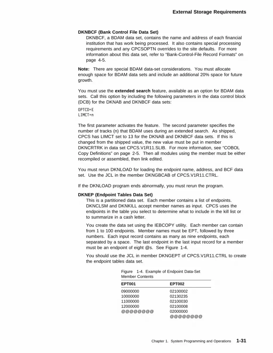
External Storage Requirements
DKNBCF (Bank Control File Data Set)DKNBCF, a BDAM data set, contains the name and address of each financialinstitution that has work being processed. It also contains special processingrequirements and any CPCSOPTN overrides to the site defaults. For moreinformation about this data set, refer to “Bank-Control-File Record Formats” onpage 4-5.
Note: There are special BDAM data-set considerations. You must allocateenough space for BDAM data sets and include an additional 20% space for futuregrowth.
You must use the extended search feature, available as an option for BDAM datasets. Call this option by including the following parameters in the data control block(DCB) for the DKNAB and DKNBCF data sets:
OPTCD=E
LIMCT=n
The first parameter activates the feature. The second parameter specifies thenumber of tracks (n) that BDAM uses during an extended search. As shipped,CPCS has LIMCT set to 13 for the DKNAB and DKNBCF data sets. If this ischanged from the shipped value, the new value must be put in memberDKNCRTRK in data set CPCS.V1R11.SLIB. For more information, see “COBOLCopy Definitions” on page 2-5. Then all modules using the member must be eitherrecompiled or assembled, then link edited.
You must rerun DKNLOAD for loading the endpoint name, address, and BCF dataset. Use the JCL in the member DKNGBCAB of CPCS.V1R11.CTRL.
If the DKNLOAD program ends abnormally, you must rerun the program.
DKNEP (Endpoint Tables Data Set)This is a partitioned data set. Each member contains a list of endpoints.DKNCLSM and DKNKILL accept member names as input. CPCS uses theendpoints in the table you select to determine what to include in the kill list orto summarize in a cash letter.
You create the data set using the IEBCOPY utility. Each member can containfrom 1 to 100 endpoints. Member names must be EPT, followed by threenumbers. Each input record contains as many as nine endpoints, eachseparated by a space. The last endpoint in the last input record for a membermust be an endpoint of eight @s. See Figure 1-4.
You should use the JCL in member DKNGEPT of CPCS.V1R11.CTRL to createthe endpoint tables data set.
Figure 1-4. Example of Endpoint Data-SetMember Contents
EPT001 EPT002
09000000 0210000210000000 0213023511000000 0210003012000000 02100008@@@@@@@@ 02000000 @@@@@@@@
Chapter 1. System Programming and Operations 1-31
External Storage Requirements
You can run the IEBGENER utility to update the endpoint table. Forinformation about using IEBGENER, see MVS/ESA Data Administration:Utilities, Version 3.1.
DKNISEQ (Item Sequence Number Data Set)You must initialize this VSAM relative-record data set after you define it. Usethe JCL in member DKNGISN of CPCS.V1R11.CTRL for this initialization.
DKNSPDEF (Sort Pattern Definition Library)Sort patterns are defined to CPCS through a partitioned data-set member in theDKNSPDEF data set. The MICR task retrieves the information pertaining to aparticular sort pattern when a document processor entry is made. The memberof the sort pattern definition data set is accessed by the type-of-workparameter. All member names must be of the format SPTYPxxx, where xxx isthe type of work. The xxx is numeric, and can have a value from 1–255.
Use the JCL in member DKNGSPDF of CPCS.V1R11.CTRL to set up the sortpattern definitions used during CPCS operation.
1-32 CPCS V1R11 Customization Guide

Data-Set Recovery Procedures
Standard 3890 SPDEF Example
P1������S��1S1 �21 � 2�1�� 2�
RP RP��1
R �1�1
M �1
K�1125����2�2125���57�3125���1��4125���11�5125���13�6�����125�988888888
K1�888888881188888888
P2�7����S��1S2 ��122222� 1�1�� �
RP RP��1
K�1125���28�2125��182�3125��188�4125��713�5125��755�6125��756�7125��78�
K�8125��785�9325�71171�1251���7
P2�8����S��1S3 ��122222� 1�1�� �
RP RP��1
K�1�������1�2�������2�3�������3�4�������4�5�������5�6�������6�7�������7
K�8�������8�9�������91�������1�11������11
Expanded Format 3890/XP Series SPDEF Example
P1������S��2S1 �11 � 1�1��XF 1�
RP RP��2 XP
R �1
M �1
K�188888888�288888888�388888888�4��999999�5125����2�6125���57�7125���1�
K�8125���11�9125���131������125
P211����S��2S2 ��122222� 1�1�� �
RP RP��2
K�1�������1�2�������2�3�������3�4�������4�5�������5�6�������6�7�������7
K�8�������8�9�������91�������1�11������11
For a detailed description of the SPDEF format, see “Sort-Pattern-Definition RecordFormats” on page 4-17.
Sample ProfilesYour CPCS.V1R11.SAMPLIB distribution library contains a number of sampleprofile members. CPCS.V1R11.CTRL jobs DKNGSYST and DKNAPPL load thesemembers into, respectively, the SYSTPROF System Profile and DKNAPPLApplication Profile data sets. The recommended procedure for customizing profilesis to copy them from SAMPLIB, edit them, then use jobs DKNGSYST andDKNAPPL to transfer the edited copies into your CPCS.
Changes made to the DKNAPPL application profile data set take effectimmediately, while CPCS is still up.
For changes made to the SYSTPROF System Profile data set, you must stop andrestart CPCS before they have any effect.
Data-Set Recovery ProceduresThis section describes the types of data-set recovery procedures provided byCPCS.
Chapter 1. System Programming and Operations 1-33
Data-Set Recovery Procedures
Recovery Procedures for the MDS and the Index Data SetRecovery for the MDS and the index data set is separate from recovery for theduplexed data sets. The type of recovery necessary depends on which files youwant to recover. When you have determined the recovery type, you must specifythe proper parameters for the PARM operand of the CPCS JCL. For the suggestedrecovery parameters, see Figure 1-5 on page 1-35.
DKNMDSV1 performs MDS and MDS index recoveries. When the recovery iscomplete, DKNMTASK initializes CPCS in a restart mode. Logging does not takeplace during recovery. Logging starts with the completion of CPCS initialization.
Whenever you cannot access data on the MDS or the index, run an MDS or indexrecovery to restore the data. CPCS sends messages that indicate I/O errors to thesystem operator and supervisor. I/O errors on the index result in the consolemessages DKNMDSVC02 or DKNMDSV104, which state the requirements for anindex recovery. CPCS handles write errors on the MDS. Read errors on the MDSare more serious, and the task requesting the read handles them individually. Youmust determine how important the inaccessible data is and must decide whethersome form of recovery is necessary.
Note: I/O errors can indicate that data cannot be processed. Recovery does notsolve hardware failure problems unless you allocate a new data set to a differentdevice.
Figure 1-5 on page 1-35 contains the suggested recovery procedures for theCPCS mass data set recovery. Before you use this table, you must first know thestatus of the following files involved in the recovery:
� RCVY support files� Mass data set� Mass data set index� Tracer data set.
You must determine whether these files are available and contain valid data. InFigure 1-5 on page 1-35, YES means that the files are available and contain validdata. NO means that the files were lost or are not available and have beenreallocated empty.
Note: If any one of the following files has been lost, first check to see if its duplexcan be used in its place. If the duplex has also been lost, or if you do not haveyour recovery system configured for control file duplexing, then the answer for theRCVY Support Files is NO.
DKNRCVY DD name for the logging recovery index.DKNRCVSR DD name for the logging VOL-SER file.DKNRCVTD DD name for the logging status file.
Important!
Initialize the tracer data set only when necessary. Any time the tracer data setis reinitialized, all I-strings that were not closed through the MICR task cannotbe restarted. The restart information is lost when the tracer data set isreinitialized.
1-34 CPCS V1R11 Customization Guide
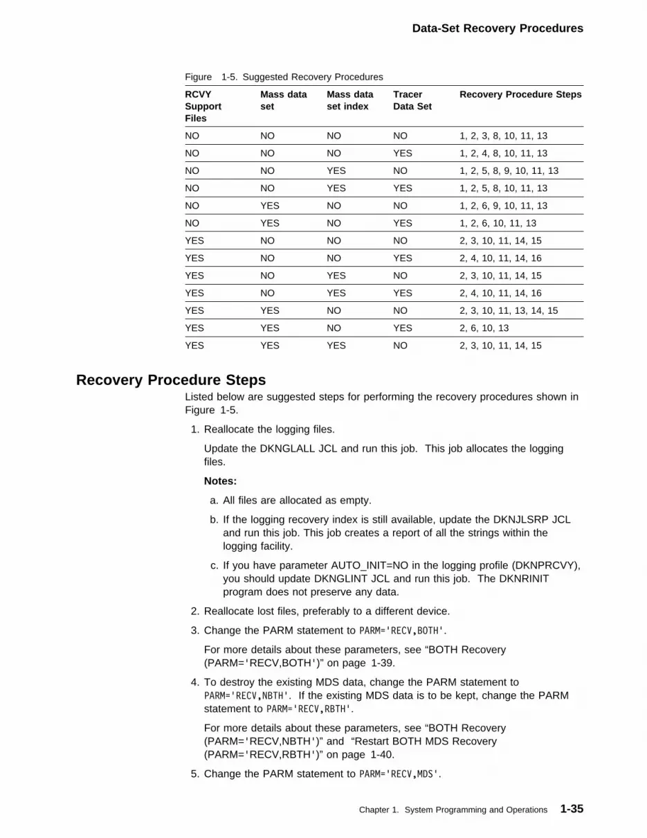
Data-Set Recovery Procedures
Figure 1-5. Suggested Recovery Procedures
RCVYSupportFiles
Mass dataset
Mass dataset index
TracerData Set
Recovery Procedure Steps
NO NO NO NO 1, 2, 3, 8, 10, 11, 13
NO NO NO YES 1, 2, 4, 8, 10, 11, 13
NO NO YES NO 1, 2, 5, 8, 9, 10, 11, 13
NO NO YES YES 1, 2, 5, 8, 10, 11, 13
NO YES NO NO 1, 2, 6, 9, 10, 11, 13
NO YES NO YES 1, 2, 6, 10, 11, 13
YES NO NO NO 2, 3, 10, 11, 14, 15
YES NO NO YES 2, 4, 10, 11, 14, 16
YES NO YES NO 2, 3, 10, 11, 14, 15
YES NO YES YES 2, 4, 10, 11, 14, 16
YES YES NO NO 2, 3, 10, 11, 13, 14, 15
YES YES NO YES 2, 6, 10, 13
YES YES YES NO 2, 3, 10, 11, 14, 15
Recovery Procedure StepsListed below are suggested steps for performing the recovery procedures shown inFigure 1-5.
1. Reallocate the logging files.
Update the DKNGLALL JCL and run this job. This job allocates the loggingfiles.
Notes:
a. All files are allocated as empty.
b. If the logging recovery index is still available, update the DKNJLSRP JCLand run this job. This job creates a report of all the strings within thelogging facility.
c. If you have parameter AUTO_INIT=NO in the logging profile (DKNPRCVY),you should update DKNGLINT JCL and run this job. The DKNRINITprogram does not preserve any data.
2. Reallocate lost files, preferably to a different device.
3. Change the PARM statement to PARM='RECV,BOTH'.
For more details about these parameters, see “BOTH Recovery(PARM='RECV,BOTH')” on page 1-39.
4. To destroy the existing MDS data, change the PARM statement toPARM='RECV,NBTH'. If the existing MDS data is to be kept, change the PARMstatement to PARM='RECV,RBTH'.
For more details about these parameters, see “BOTH Recovery(PARM='RECV,NBTH')” and “Restart BOTH MDS Recovery(PARM='RECV,RBTH')” on page 1-40.
5. Change the PARM statement to PARM='RECV,MDS'.
Chapter 1. System Programming and Operations 1-35

Data-Set Recovery Procedures
For more details about these parameters, see “Mass Data Set Recovery(PARM='RECV,MDS')” on page 1-37.
6. Change the PARM statement to PARM='RECV,INDEX'.
For more details about these parameters, see “Mass Data Set Index Recovery(PARM='RECV,INDEX')” on page 1-37.
7. Change the PARM statement to PARM='RECV,SEL'.
For more details about these parameters, see “Selective Recovery(PARM='RECV,SEL')” on page 1-40.
8. Change the CPCS startup JCL by specifying recovery tapes under the DKNRTDD statement.
The recovery tape serial numbers should be specified for the recovery data set(DKNRT). You should specify, in the order of their creation, all tapes thatcontain required strings.
9. Copy the duplex tracer group file over to the newly allocated tracer group file(DKNTG).
10. Start CPCS.
11. Sign on to CPCS as a supervisor.
If you specify a recovery start parameter, the RCVY task starts automatically onthe supervisor terminal.
12. Enter RCVY to see the Recovery Start option menu.
13. Select option 3.
This synchronizes the CPCS MDS recovery files with the mass data set.
14. Select the Full Mass Data Set Recovery (option 1) of RCVY.
RCVY automatically determines which strings and which tapes are necessary.For more details, see the description of DKNRCVY in the CPCS Programmingand Diagnostic Guide.
15. Enter YES in the RCVY Tracer Group File Update option.
Before beginning recovery, RCVY presents the Recovery Cycle Specificationscreen. Enter YES in the Tracer Group File Update option. This optionupdates the tracer file for the strings being recovered.
16. Enter NO in the RCVY Tracer Group File Update option.
Before beginning recovery, RCVY presents the Recovery Cycle Specificationscreen. Enter NO in the Tracer Group File Update option. This option doesnot update the tracer file for the strings being recovered.
Recovery Parameter DescriptionsListed below are the detailed descriptions of the CPCS recovery parameters.These parameters are valid only when LOG=YES is specified in the CPCS systemprofile member DKNPCPCS.
1-36 CPCS V1R11 Customization Guide

Data-Set Recovery Procedures
Mass Data Set Index Recovery (PARM='RECV,INDEX')Delete the old index data set and allocate a new data set, preferably on a differentdevice. Tape input is not necessary for index recovery. The index is rebuilt fromthe existing data on the mass data set.
Processing Description: The index data set is formatted and the MDS isunchanged. You can recover the index data set by processing all the active SDEson the MDS and constructing index records (SDIs) for those strings. If the stringsare closed, CPCS updates the master and existing segment maps. This recoveryoption does not update the tracer data set.
Note: OPEN and RESTART strings are added to the corresponding map duringthe automatic CPCS restart that follows recovery.
MDS read errors can result in a loss of data. If the error segment contained anactive SDE and data, then part or all of the string can be lost. Other READ errorsdo not affect the index recovery. Run the program DKNLDIR and check the outputto determine whether all strings are present. For MDS READ errors, the recoveryroutine writes console message DKNMDSV120 and continues processing.
SDI READ and WRITE errors on the index data set cause messagesDKNMDSV107 and DKNMDSV108 to be sent to the system operator. Recoveryends with a user ABEND (U0073). Reallocate the data set and run recovery again.
After recovery is complete, the RCVY screen is automatically presented to thesystem supervisor when the supervisor signs on. Normally, no additional recoveryis necessary. It might be necessary, in some cases, to use option 3 on this screento synchronize the MDS with the RCVY recovery index. You must determinewhether any additional recovery steps are necessary, depending on the specificcircumstances.
Mass Data Set Recovery (PARM='RECV,MDS')Note: Use this recovery option only when the recovery support files have beenlost. If the recovery support files are intact, the recovery process RCVYautomatically determines which strings and tapes are active and recoversaccordingly. For the recovery procedures relating to specific recovery situations,see Figure 1-5 on page 1-35.
The option does not update the tracer data set. Delete the old MDS and allocate anew MDS, preferably to a different device. Change the CPCS startup JCL byspecifying the recovery tape serial numbers for the recovery data set (DKNRT).
Each time CPCS is shut down, DKNLOGX closes the data set. Therefore, morethan one log data set can exist. Regardless of the end-of-volume (EOV) orend-of-file (EOF) condition, if you specify OPTCD=B in the DCB parameter of therecovery data set, DKNMDSV1 processes all tapes in the sequence indicated in theJCL. You must specify tape JCL serial numbers in the sequence in which theywere created.
Processing Description: The MDS is formatted and the index is left as-is.DKNMDSV1 reads the header record from the tapes and writes it to the MDS.Each tape record is sequence-checked as to date and time, which appear in theheader record. An out-of-sequence condition means that the tapes have beenspecified in the wrong sequence. DKNMDSV1 sends message DKNMDSV111 tothe system operator. The operator has the option of ignoring the error or canceling
Chapter 1. System Programming and Operations 1-37

Data-Set Recovery Procedures
the recovery. The data already restored is not lost if the recovery is cancelled.The recovery can be restarted (see “Restart MDS Recovery(PARM='RECV,RMDS')” on page 1-40). The data is checked for completenessafter all the tapes have been read and processed. DKNMDSV1 considers thestring incomplete if an index entry exists and one or more of the followingconditions exist:
� No SDE exists.� The SDE does not contain the correct IDs.� The first data record of the string does not contain the correct ID.
DKNMDSV1 sends message DKNMDSV110 to the system operator, specifying thenames of the incomplete strings; and the recovery process ends with a userABEND (U0074) after all strings have been checked. Incomplete strings mean thatyou have not supplied enough tapes to recover all active data. (CPCS does notprocess any incomplete strings.) Three possibilities exist:
� The missing tape or tapes should have been specified sequentially before allthe other tapes (see “Case 1”). You can recover the missing data byperforming a selective recovery. See “Selective Recovery(PARM='RECV,SEL')” on page 1-40.
� The missing tape or tapes should have been specified after all the other tapes(see “Case 2”). You can recover the missing data by performing a restart MDSrecovery, using only those tapes that were omitted. See “Restart MDSRecovery (PARM='RECV,RMDS')” on page 1-40.
� The missing tape or tapes should have been specified somewhere in themiddle (see “Case 3”). You can recover the missing data by performing arestart MDS recovery, starting with the missing tapes and including allsubsequent tapes. See “Restart MDS Recovery (PARM='RECV,RMDS')” onpage 1-40.
Examples:
Case 1: There are five tapes in the recovery data set. Tapes 3, 4, and 5 areused in an MDS recovery, resulting in incomplete strings. Therefore,use tapes 1 and 2 in a selective recovery to complete the strings.
Case 2: There are five tapes in the recovery data set. Tapes 1, 2, 3, and 4are used in an MDS recovery, resulting in incomplete strings.Therefore, use tape 5 in a restart MDS recovery to complete thestrings.
Case 3: There are five tapes in the recovery data set. Tapes 1, 2, 4, and 5are used in an MDS recovery, resulting in incomplete strings.Therefore, use tapes 3, 4, and 5 in a restart MDS recovery tocomplete the strings.
Recovery Tape Read Errors: Each time a read error occurs on the recoverytape, DKNMDSV1 sends message DKNMDSV114 to the system operator.DKNMDSV1 skips the tape data record and reads the next record. DKNMDSV1loses the MDS information in the skipped tape record. Should 25 unsuccessfulREADs occur in succession, DKNMDSV1 sends message DKNMDSV113 to thesystem operator and ends the recovery process with a user ABEND (U0073). Foradditional security, back up the recovery tapes using an MVS copy utility.
1-38 CPCS V1R11 Customization Guide
Data-Set Recovery Procedures
MDS Write Errors: These errors indicate that CPCS cannot process the newlyallocated MDS. DKNMDSV1 sends message DKNMDSV117 to the systemoperator and ends the recovery process with a user ABEND (U0073). You mustrerun MDS recovery, using a reallocated MDS.
MDS Read Errors: These errors indicate that CPCS cannot process the newlyallocated MDS. DKNMDSV1 sends message DKNMDSV106 to the systemoperator and ends the recovery process with a user ABEND (U0073). You mustrerun MDS recovery, using a reallocated MDS.
SDI Read Errors: These errors indicate that the index data set also needs to berecovered. DKNMDSV1 sends message DKNMDSV107 to the system operatorand ends the recovery process with a user ABEND (U0073). To recover both theMDS and the index, you must run a BOTH recovery.
BOTH Recovery (PARM='RECV,BOTH') Important!
If you use this option, the tracer data set is initialized. Once it is initialized, anyexisting I-strings in restart status cannot be restarted because the MICR tasksaves the Restart Control Block (RSCB) in the tracer data set. Without theRSCB information for an entry, MICR cannot restart the entry.
Although it may not be necessary to delete the mass data set and its index, it isrecommended that they be deleted and reallocated. At this point, you mustdetermine whether the recovery support files are available and contain validinformation. If these files have been lost, you must change the CPCS startup JCLby specifying the recovery tape serial numbers for the recovery data set (DKNRT).If the recovery support files have not been lost, you do not need to specify therecovery tape serial numbers in the CPCS startup JCL. The RCVY processdetermines which strings were active, which tapes are necessary, and in whichsequence to process the tapes.
Processing Description
� Recovery Support Files (or their duplexes) do exist
DKNRCVY DD name for the logging recovery indexDKNRCVSR DD name for the logging VOLSER file.DKNRCVTD DD name for the logging status file.
If the recovery support files exist, (see previous list), using the parameterPARM=(‘RECV,BOTH’) causes the initialization of the MDS, the MDS Index,and the tracer data set. This is followed by CPCS startup. Do not specify anyrecovery tape serial numbers for the recovery data set (DKNRT). They are notnecessary if the recovery support files exist. No recovery takes place until thesystem supervisor uses the RCVY process to start recovery.
RCVY is started automatically on the supervisor terminal when the supervisorsigns on. The CPCS Recovery Start Options Menu screen is displayed on thesystem supervisor terminal. The Full Mass Data Set Recovery option is on thisscreen. The supervisor should select that option to begin full MDS recovery.You can find additional information on the RCVY process in the CPCS TerminalOperations Guide and the CPCS Programming and Diagnostic Guide.
Chapter 1. System Programming and Operations 1-39
Data-Set Recovery Procedures
� Recovery Support Files do not exist
If the recovery support files do not exist, using the parameterPARM=(‘RECV,BOTH’) causes the initialization of the MDS, the MDS Index,and the tracer data set. The processing is the same as described for MDSrecovery (see “Mass Data Set Recovery (PARM='RECV,MDS')” on page 1-37and “Mass Data Set Index Recovery (PARM='RECV,INDEX')” on page 1-37.If you use this type of recovery, the tracer data set will only be initialized, butnot updated.
Restart MDS Recovery (PARM='RECV,RMDS')This option does not cause the initialization of the tracer data set. Run this type ofrecovery only when a previous recovery (‘RECV,MDS’) did not recover the MDS asexpected. The data recovered must be more recent than the data already residingon the MDS. MDS recovery and restart MDS recovery processes are the same,except that the MDS is not formatted in the restart MDS recovery process.
Restart BOTH MDS Recovery (PARM='RECV,RBTH')This option does not cause the initialization of the tracer data set. This type ofrecovery is only necessary when you are recovering by specifying tape volumeserial numbers under the DKNRT DD in the CPCS startup JCL.
Use this type of recovery when you need to recover more data to the MDS withoutdestroying the data that already exists. The index needs reassembling after theMDS recovery. The data recovered must be more recent than the data that alreadyresides on the MDS. The BOTH recovery process and the Restart BOTH recoveryprocess are the same, except that the MDS is not formatted in the Restart BOTHrecovery process.
BOTH Recovery (PARM='RECV,NBTH')This recovery is the same as with PARM=‘RECV,BOTH’, except that the tracer dataset is not initialized. Also, the tracer update option on the RCVY screen is set toNO. You should leave this option set to NO if the tracer data set is intact.
Selective Recovery (PARM='RECV,SEL')This option does not cause the initialization of the tracer data set. Selectiverecovery assumes that the MDS contains incomplete strings (for more information,see “Mass Data Set Recovery (PARM='RECV,MDS')” on page 1-37). You cannotspecify any additional string names for recovery. When selective recovery starts, itscans the MDS to locate any incomplete strings. If there are no incomplete strings,the selective recovery ends.
Therefore, you should run selective recovery only when a previous MDS recoveryor a BOTH recovery results in incomplete strings. If the recovery tapes were in themiddle or at the end of the sequence of tapes used in the previous recovery,consider a restart MDS recovery or a restart BOTH recovery. However, theDKNRT ddname must be specified in the JCL as DD_DUMMY, as the taskDKNMDSV1 attempts to open and close this file. For examples of recoveryoptions, see page 1-38.
Processing Description: The index contains an indication of every incompletestring. This information is used to assemble a list of incomplete strings. As itreads each recovery tape, the program compares the data records against the list.If it finds a match, the program writes the record and checks the next record
1-40 CPCS V1R11 Customization Guide

Data-Set Recovery Procedures
against the MDS. If there is not a match, the program checks the next record.After all the tapes are processed, the MDS is scanned for any incomplete strings.You can run CPCS with incomplete strings; however, the system does not processthese strings.
Note: As the list of incomplete strings is assembled, the complete stringindications are removed from the index. Therefore, if selective recovery abnormallyends, the index indicates that there are no incomplete strings.
Before you can rerun a selective recovery, you must run a restart MDS recovery,specifying DD DUMMY for the recovery data set (DKNRT). A restart MDS recoveryscans the MDS for incomplete strings. It updates the index to indicate thoseincomplete strings.
Suggestion
� After a recovery, you should run DKNLDIR and check the list to verify that allactive strings were recovered. DKNLDIR provides a list of all active strings onthe MDS.
Recovering Duplexed Data SetsA basic recovery procedure exists for all duplexed data sets in CPCS. All data setsthat are duplexed can be recovered by:
1. Ending CPCS as quickly as possible to start the recovery procedure
2. Determining the causes of failure (for example, a disk head crash)
3. Formatting (or allocating) the original data set and copying the duplexed dataset to the newly allocated data set
4. Starting CPCS.
The following CPCS data sets are duplexed:
CYCLDS1 the cycle-table data setDKNTG the pass-to-pass control data setDKNKB the kill-bundle data setDKNMF the microfilm data set.
If you have installed logging, the following data sets may also be duplexed:
DKNLD1 disk log 1 (used if you elect to log to disk)DKNLD2 disk log 2 (used if you elect to log to disk)DKNRCVCK the Recovery System checkpoint fileDKNRCVSR the Recovery System volume serial fileDKNRCVTD the Recovery System logging status fileDKNRCVY the Recovery System string name file
You can use IEBGENER to restore lost data for all data sets except thepass-to-pass control data set. The IBM Data Facilities/Data Set Services (DFDSS)program can be used to restore the pass-to-pass control data set because it is akeyed direct-access data set.
For a description of how to use IEBGENER, see MVS/ESA Data Administration:Utilities Version 3.1.
Chapter 1. System Programming and Operations 1-41

Data-Set Recovery Procedures
For more information about how to use DFDSS, see Data Facilities/Data SetServices User’s Guide and Reference.
1-42 CPCS V1R11 Customization Guide

CPCS-Supplied Command Procedures
CPCS-Supplied Command ProceduresThe following supplied command procedures are a series of job steps, eachcontaining EXEC statements for assembly, compile, and link-edit. The load libraryis named CPCS.V1R11.LLIB. The assembly and link-edit parameters for theassembler programs are coded in accordance with the table of link-edit parameters.The data sets CPCS.V1R11.SLIB and CPCS.V1R11.LLIB are assumed to becataloged. If the data sets are not cataloged, the volume identification must becoded.
Use the member DKNJCOB in CPCS.V1R11.CTRL to compile and link-edit allCOBOL source modules necessary for CPCS. You can change this member tomeet your installation standards.
These PROCs are used by the ASSEMBLY JCL that follows in this section.
Use the member DKNJASM1 in CPCS.V1R11.CTRL to assemble and link-editthose source modules that are called by other source modules.
Use the member DKNJASM2 in CPCS.V1R11.CTRL to assemble and link-edit allother assembler source necessary for CPCS, except the MICR modules. This JCLplaces load modules in CPCS.V1R11.LLIB. You can change this member to meetyour installation standards.
Use the member DKNJMICR in CPCS.V1R11.CTRL to assemble and link-edit allMICR assembler source modules necessary for CPCS. This JCL places loadmodules in CPCS.V1R11.LLIB. You can change this member to meet yourinstallation standards.
Note: Before using your JCL to assemble or compile any modules, be sure thatyou complete the changes described in the following sections. For additionalinformation on assembling and compiling your CPCS source modules, see theCPCS Installation Guide.
Assembly ConsiderationsCPCS assembler modules contain code that indicates the addressing mode(AMODE) and the residency mode (RMODE) of the CSECT. If a CPCS assemblermodule contains the following lines, you should not override either AMODE orRMODE at link-edit time:
DKNcccc CSECT
DKNcccc AMODE 31
DKNcccc RMODE ANY
or
DKNcccc CSECT
DKNcccc AMODE 31
DKNcccc RMODE 24
� Copy or link-edit DKNMPSR into SYS1.IMAGELIB. You can skip this step ifyou have installed 3890/XP MVS Support Version 1 Release 2 on your system.
Chapter 1. System Programming and Operations 1-43

CPCS-Supplied Command Procedures
COBOL for MVS/VM Compiler ConsiderationsYou must install COBOL for MVS/VM Release 1.0, or higher, to compile CPCSCOBOL modules that can run above the 16MB line. The COBOL for MVS/VMmodules that IBM ships with the CPCS system are all designed to run above the16MB line (AMODE 31, RMODE ANY).
If you write COBOL for MVS/VM modules that you want to run above the 16MBline, each module must contain a parameter override record as the first input recordin the source deck, as follows:
CBL RENT,RES,DYNAM,DATA(31),TRUNC(BIN)
� The LKED.SYSLIN should include the COBOL run-time options module,CPCS.V1R11.LLIB (CEEUOPT), appended after the object deck. See “COBOLfor MVS/VM Compile Options” on page 1-45 for instructions on assemblingCEEUOPT.
1-44 CPCS V1R11 Customization Guide
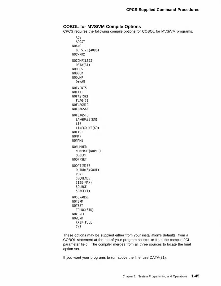
CPCS-Supplied Command Procedures
COBOL for MVS/VM Compile OptionsCPCS requires the following compile options for COBOL for MVS/VM programs.
ADV
APOST
NOAWO
BUFSIZE(4�96)
NOCMPR2
NOCOMPILE(S)
DATA(31)
NODBCS
NODECK
NODUMP
DYNAM
NOEVENTS
NOEXIT
NOFASTSRT
FLAG(I)
NOFLAGMIG
NOFLAGSAA
NOFLAGSTD
LANGUAGE(EN)
LIB
LINECOUNT(6�)
NOLIST
NOMAP
NONAME
NONUMBER
NUMPROC(NOPFD)
OBJECT
NOOFFSET
NOOPTIMIZE
OUTDD(SYSOUT)
RENT
SEQUENCE
SIZE(MAX)
SOURCE
SPACE(1)
NOSSRANGE
NOTERM
NOTEST
TRUNC(STD)
NOVBREF
NOWORD
XREF(FULL)
ZWB
These options may be supplied either from your installation’s defaults, from aCOBOL statement at the top of your program source, or from the compile JCLparameter field. The compiler merges from all three sources to locate the finaloption set.
If you want your programs to run above the line, use DATA(31).
Chapter 1. System Programming and Operations 1-45
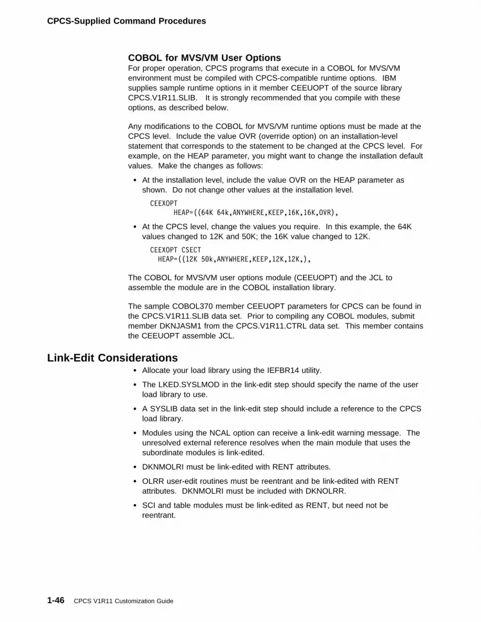
CPCS-Supplied Command Procedures
COBOL for MVS/VM User OptionsFor proper operation, CPCS programs that execute in a COBOL for MVS/VMenvironment must be compiled with CPCS-compatible runtime options. IBMsupplies sample runtime options in it member CEEUOPT of the source libraryCPCS.V1R11.SLIB. It is strongly recommended that you compile with theseoptions, as described below.
Any modifications to the COBOL for MVS/VM runtime options must be made at theCPCS level. Include the value OVR (override option) on an installation-levelstatement that corresponds to the statement to be changed at the CPCS level. Forexample, on the HEAP parameter, you might want to change the installation defaultvalues. Make the changes as follows:
� At the installation level, include the value OVR on the HEAP parameter asshown. Do not change other values at the installation level.
CEEXOPT
HEAP=((64K 64k,ANYWHERE,KEEP,16K,16K,OVR),
� At the CPCS level, change the values you require. In this example, the 64Kvalues changed to 12K and 50K; the 16K value changed to 12K.
CEEXOPT CSECT
HEAP=((12K 5�k,ANYWHERE,KEEP,12K,12K,),
The COBOL for MVS/VM user options module (CEEUOPT) and the JCL toassemble the module are in the COBOL installation library.
The sample COBOL370 member CEEUOPT parameters for CPCS can be found inthe CPCS.V1R11.SLIB data set. Prior to compiling any COBOL modules, submitmember DKNJASM1 from the CPCS.V1R11.CTRL data set. This member containsthe CEEUOPT assemble JCL.
Link-Edit Considerations� Allocate your load library using the IEFBR14 utility.
� The LKED.SYSLMOD in the link-edit step should specify the name of the userload library to use.
� A SYSLIB data set in the link-edit step should include a reference to the CPCSload library.
� Modules using the NCAL option can receive a link-edit warning message. Theunresolved external reference resolves when the main module that uses thesubordinate modules is link-edited.
� DKNMOLRI must be link-edited with RENT attributes.
� OLRR user-edit routines must be reentrant and be link-edited with RENTattributes. DKNMOLRI must be included with DKNOLRR.
� SCI and table modules must be link-edited as RENT, but need not bereentrant.
1-46 CPCS V1R11 Customization Guide
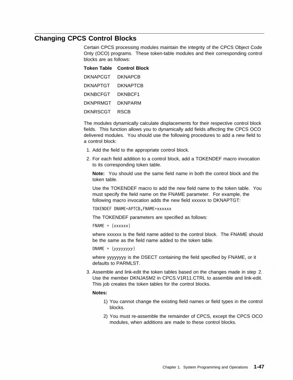
Changing CPCS Control BlocksCertain CPCS processing modules maintain the integrity of the CPCS Object CodeOnly (OCO) programs. These token-table modules and their corresponding controlblocks are as follows:
Token Table Control Block
DKNAPCGT DKNAPCB
DKNAPTGT DKNAPTCB
DKNBCFGT DKNBCF1
DKNPRMGT DKNPARM
DKNRSCGT RSCB
The modules dynamically calculate displacements for their respective control blockfields. This function allows you to dynamically add fields affecting the CPCS OCOdelivered modules. You should use the following procedures to add a new field toa control block:
1. Add the field to the appropriate control block.
2. For each field addition to a control block, add a TOKENDEF macro invocationto its corresponding token table.
Note: You should use the same field name in both the control block and thetoken table.
Use the TOKENDEF macro to add the new field name to the token table. Youmust specify the field name on the FNAME parameter. For example, thefollowing macro invocation adds the new field xxxxxx to DKNAPTGT:
TOKENDEF DNAME=APTCB,FNAME=xxxxxx
The TOKENDEF parameters are specified as follows:
FNAME = {xxxxxx}
where xxxxxx is the field name added to the control block. The FNAME shouldbe the same as the field name added to the token table.
DNAME = {yyyyyyyy}
where yyyyyyyy is the DSECT containing the field specified by FNAME, or itdefaults to PARMLST.
3. Assemble and link-edit the token tables based on the changes made in step 2.Use the member DKNJASM2 in CPCS.V1R11.CTRL to assemble and link-edit.This job creates the token tables for the control blocks.
Notes:
1) You cannot change the existing field names or field types in the controlblocks.
2) You must re-assemble the remainder of CPCS, except the CPCS OCOmodules, when additions are made to these control blocks.
Chapter 1. System Programming and Operations 1-47

Remote Site SupportUsing the VNODE macro, you may assign sites, both “owning” and “processing” toa particular terminal. When VNODE is run, and a string is captured through MICR,the site information associated with the MICR terminal is then propagated intoMICR’s APTCB for that MICR session, and ultimately the unit of workcorresponding to the mass data set string. From this point, DKNATASKcontinuously propagates this site identification from the work request block of theEnhanced System Manager task that was automatically started, to the APTCB ofthose tasks, and on to the communication buffers.
For more information on the VNODE macro, see “VNODE Macro Description” onpage 2-57.
1-48 CPCS V1R11 Customization Guide

Chapter 2. Installation and Generation Procedures
Overview . . . . . . . . . . . . . . . . . . . . . . . . . . . . . . . . . . . . . . . . . 2-3Macro Descriptions . . . . . . . . . . . . . . . . . . . . . . . . . . . . . . . . . . . 2-4COBOL Copy Definitions . . . . . . . . . . . . . . . . . . . . . . . . . . . . . . . 2-5Using Data-Set Duplexing . . . . . . . . . . . . . . . . . . . . . . . . . . . . . . . 2-6
Capture of Duplexed Data Sets . . . . . . . . . . . . . . . . . . . . . . . . . . 2-6Recovering Duplexed Data Sets . . . . . . . . . . . . . . . . . . . . . . . . . 2-6
Logging CPCS Data . . . . . . . . . . . . . . . . . . . . . . . . . . . . . . . . . . 2-7Installing the Logging Subsystem . . . . . . . . . . . . . . . . . . . . . . . . . 2-7Capture of Logged Data Sets . . . . . . . . . . . . . . . . . . . . . . . . . . 2-12Recovering Logged Data Sets . . . . . . . . . . . . . . . . . . . . . . . . . . 2-12Overriding the Log Data-Set Definition . . . . . . . . . . . . . . . . . . . . . 2-13Data-Set Utilities . . . . . . . . . . . . . . . . . . . . . . . . . . . . . . . . . . 2-14
Customizing Item Sequence Numbers . . . . . . . . . . . . . . . . . . . . . . . 2-14Describing an Application Task’s Environment . . . . . . . . . . . . . . . . . . 2-15Dynamically Allocating Data Sets . . . . . . . . . . . . . . . . . . . . . . . . . 2-23Nonswap SVC Generation Task . . . . . . . . . . . . . . . . . . . . . . . . . . 2-31Concurrent Sort Generation . . . . . . . . . . . . . . . . . . . . . . . . . . . . . 2-32MICR Task Generation . . . . . . . . . . . . . . . . . . . . . . . . . . . . . . . 2-33
CPCSRDR Macro Parameters . . . . . . . . . . . . . . . . . . . . . . . . . . 2-36CPCSOPTN Macro Parameters . . . . . . . . . . . . . . . . . . . . . . . . . 2-43
Expanding the Mass Data Set . . . . . . . . . . . . . . . . . . . . . . . . . . . 2-48MDX Macro Parameters . . . . . . . . . . . . . . . . . . . . . . . . . . . . . 2-48Expanded MDS Installation Procedure . . . . . . . . . . . . . . . . . . . . . 2-51
VTAM Installation Requirements for CPCS . . . . . . . . . . . . . . . . . . . . 2-53DKNVTASK Installation . . . . . . . . . . . . . . . . . . . . . . . . . . . . . . 2-53VNODE Macro Error Messages . . . . . . . . . . . . . . . . . . . . . . . . . 2-59Terminal Definition . . . . . . . . . . . . . . . . . . . . . . . . . . . . . . . . 2-59Assigning VTAM Terminals to CPCS . . . . . . . . . . . . . . . . . . . . . . 2-60Releasing a CPCS Terminal . . . . . . . . . . . . . . . . . . . . . . . . . . . 2-61Terminal Screens and Key Usage . . . . . . . . . . . . . . . . . . . . . . . 2-61Screen Sizes . . . . . . . . . . . . . . . . . . . . . . . . . . . . . . . . . . . . 2-62
Accessing the VSAM Table . . . . . . . . . . . . . . . . . . . . . . . . . . . . . 2-63CPCS VSAM Table . . . . . . . . . . . . . . . . . . . . . . . . . . . . . . . . 2-63Processing Description . . . . . . . . . . . . . . . . . . . . . . . . . . . . . . 2-65
CPCS Third-Party Vendor Definition . . . . . . . . . . . . . . . . . . . . . . . . 2-66CPCS Mass Data Set Exit Points . . . . . . . . . . . . . . . . . . . . . . . . . 2-66
| DKNMDSVC_FREE_STRING Exit . . . . . . . . . . . . . . . . . . . . . . . 2-66| DKNMDSVC_OPEN_STRING Exit . . . . . . . . . . . . . . . . . . . . . . . 2-68| DKNMDSVC_CLOSE_STRING Exit . . . . . . . . . . . . . . . . . . . . . . 2-69| DKNMDSVC_READ_DIRECTORY Exit . . . . . . . . . . . . . . . . . . . . 2-70| DKNMDSVC_SRCH_DIRECTORY Exit . . . . . . . . . . . . . . . . . . . . 2-71| DKNMDSV4_COMPRESSION Exit . . . . . . . . . . . . . . . . . . . . . . . 2-73
Copyright IBM Corp. 1973, 2001 2-1

2-2 CPCS V1R11 Customization Guide
Overview
OverviewTo simplify installation and maintenance, CPCS is packaged using the IBM SystemModification Program Extended (SMP/E) product. For complete installationinstructions, see the CPCS Installation Guide and the CPCS Program Directorywhich accompanies the installation tape for this release. The files on the CPCStape are:
� SMP/E control file� CPCS source, copybooks, and macros
� Sample data� Installation documentation and sample JCL
� SMP/E JCL� Sample report listings.
To make the best use of SMP/E packaging, complete the following steps duringCPCS installation:
1. Use SMP/E to unload the distribution tape to your system, and run theinstallation job streams as described in the CPCS Installation Guide.
2. Run the sample problems to verify that CPCS has been correctly installed. Seethe CPCS Installation Guide for instructions on how to run the sampleproblems.
3. Customize the CPCS generation to the requirements of your system byperforming a DKNMICR generation, which describes the document processorsand control documents that you are using. (For information on generatingDKNMICR, see “MICR Task Generation” on page 2-33.) Link the MICRmodules together in a workable DKNMICR module.
4. Allocate and initialize all CPCS data sets in accordance with the requirementsof your system.
5. Edit and load your system and application profiles. Chapter 3, “System andApplication Profiles” contains instructions for customizing profiles.
6. Design, code, and test user document-processing routines. Chapter 4, “UserProgramming Requirements and Exits,” describes the requirements for creatinguser document-processing routines.
7. Generate data security tables and routines as required for your system. Forcontrolling CPCS resource access, “Security Options” on page 4-177 describesthe various methods.
8. Code user-exit routines as required for your system.
9. Customize CPCS reports by changing the endpoint name-and-address data set(DKNAB) and the bank-control-file data set (DKNBCF).
Note: CPCS runs in an MVS extended architecture environment. If you want tocapture images, you must run CPCS in an MVS/ESA environment.
Chapter 2. Installation and Generation Procedures 2-3
Macro Descriptions
Macro DescriptionsThe CPCS macro parameters described in this chapter are presented in thefollowing format:
The following list describes the symbols for coding macros:
Capital letters Capital letters represent values that you code directly, withoutchange.
Lowercase letters Lowercase letters represent parameters for which you mustsupply a value or name.
Brackets [ ] Brackets enclose parameters or symbols that are eitheroptional or conditional. Conversely, the lack of bracketsindicates that you must code an item or group of items.
Vertical “or” bar ( | )A vertical bar between operands indicates that you mustcode one parameter from among the values separated by the“or” bar.
Parentheses, equal signs, and commasParentheses, equal signs, and commas must be coded asshown.
Underlined values An underlined value represents the default value that CPCSuses if you omit the parameter.
Braces { } Braces indicate mutually exclusive parameters.
Never code brackets, the “or” bar, underlines, braces, or subscripts.
Name Operation Parameters
Symbolicname
Macroname
Required and optional parameters
2-4 CPCS V1R11 Customization Guide

COBOL Copy Definitions
COBOL Copy DefinitionsThe COPY definitions DKNCRPKT, DKNCRTRK, DKNCRTG, and DKNCRTGU aresupplied to you with default values. If the default values do not meet yourrequirements, you can change these values and incorporate the changes by usingthe IEBUPDTE utility.
You can obtain listings of the definitions in CPCS.V1R11.SLIB by using theIEBPTPCH utility to list them.
Each of the following is a one-statement member of the above library. You mustset the values in these statements to reflect the configuration.
DKNCRPKT This value should be 1 less than the number of pockets on thelargest sorter: 5, 11, 17, 23, 29, or 35.
DKNCRTRK The DKNLOAD program uses this parameter when loading theendpoint name and address file (DKNAB) and the bank controlfile (DKNBCF). DKNKILL and DKNCLSM also use thisparameter when reading these files. DKNCRTRK issues as alevel 77 statement and should be set equal to the nearestprime number that is less than the number of tracks allocatedto the file. Then all modules using the member must be eitherrecompiled or assembled, then link edited.
DKNCRTG You must change this data description to contain the number ofpockets of the largest sorter (including simulated sorters),minus 1. Change the OCCURS statement for the number ofpockets.
DKNCRTGU You must change this data description to contain the number ofpockets of the largest sorter (including simulated sorters),minus 1. Change the OCCURS statement for the number ofpockets.
Chapter 2. Installation and Generation Procedures 2-5
Data-Set Duplexing
Using Data-Set DuplexingBecause a check processing system is a continuous cycle of throughput, loss ofaccess to certain data sets can result in a serious loss of work-in-progress. CPCSrelies on the data-set duplexing functions to re-establish the database and tocontinue processing existing work under dollar control. You can select the duplexoption by specifying DUPLEX=1 in the master task generation options.
Data sets that represent dollar control are duplexed for recovery. Duplexingcreates copies of these files that should reside on different disk volumes.
The files that are duplexed in CPCS are:
DKNTG Pass-to-pass control data set. The duplex data set name isDKNTGD.
DKNKB Kill bundle data set. The duplex data set name is DKNKD.DKNMF Microfilm data set. The duplex data set name is DKNMFD.CYCLDS1 Cycle table data set. The duplex data set name is CYCLDS2.
The DKNKB and DKNMF data sets can be allocated as blocked BDAM data sets.(For information about allocating these data sets using blocked BDAM, see “UsingBlocked BDAM Data Sets” on page 1-28.) You can recover the duplexed data setsby using an MVS utility to copy from the backup file to the newly created file.
Capture of Duplexed Data SetsEach time CPCS writes to one of the duplexed data sets, it performs a secondwrite to the corresponding data-set copy. You should allocate the data-set copieson a DASD unit other than the primary data set.
Recovering Duplexed Data SetsTo recover a CPCS data set that is duplexed, you must stop CPCS. Use standardMVS utilities to copy from the duplicate data set to a newly allocated, primary dataset. For more information about recovering duplex data sets, see page 1-41.
2-6 CPCS V1R11 Customization Guide
Installing the Logging Subsystem
Logging CPCS DataThe CPCS Logging subsystem maintains the integrity of the CPCS mass data set(MDS) and associated index. This subsystem records or logs to tape or disk allMDS activity. This lets you reinitialize or re-create these data sets and restorelogged data if a disk failure occurs during CPCS processing.
The CPCS system is shipped with the Logging function inactive (LOG=NO in theCPCS system profile member DKNPCPCS). You can use the sample problemsdescribed in the CPCS Installation Guide without activating Logging.
CPCS Logging supports a number of options that enhance the CPCS data-recoveryprocess. These options include logging to disk, duplexed log tapes, tracking of logtapes, tracer data set recovery, and streamlined recovery functions.
The Logging subsystem maintains an index of unexpired log tapes with anotherindex of all string names that are on each tape.
During both selective and full mass-data-set (MDS) recovery, Logging automaticallyselects the tapes that are required to recover the requested strings.
When you use disk logging, Logging uses two disk log files (with optional duplexfiles) and alternates between them. As each one fills up, a backup job starts toback up the disk log file to tape. Optionally, you can duplex this tape backup.
When you use tape logging, duplexing is available as an option.
Installing the Logging SubsystemInstallation of the Logging subsystem requires the following steps:
1. Change the CPCS system profile member DKNPCPCS parameters to activateLogging.
2. Change the Logging profile member DKNPRCVY.3. Verify the RCVUNTBL entries.4. Verify the DKNLOGM routing destination.5. Change the DKNDSAT parameters.6. Assemble the Logging program modules.7. Assemble the DKNLOGU user exit.8. Allocate the Logging data sets.9. Initialize the Logging data sets.
10. Create the generation data group (GDG) for the log data-set backups.11. Update the CPCS startup JCL.12. Restart CPCS with PARM='COLD' in the EXEC statement of the JCL.13. Back up the logging files.14. Change the DKNJLCRH JCL.
These procedures assume that you have already completed the installationprocedures described in the CPCS Installation Guide.
Chapter 2. Installation and Generation Procedures 2-7
Installing the Logging Subsystem
Step 1: Change the DKNPCPCS parameters to activate loggingTo activate the logging functions of CPCS, you must change the CPCS systemprofile member DKNPCPCS parameters. Change the following CPCS systemprofile DKNPCPCS parameters:
� Set the buffer ratio (BFRAT) to a non-zero value.
� Set the number of tape buffers (TPBFNM) to a nonzero value.
� Set the LOG parameter to YES.
� As a part of the CPCS system edit routine (see page 1-25) the block size forthe DKNLD data set has been calculated using the formula below. The blocksize is written to the CPCS system edit report. The report ddname is MPTR.
(BFRATx(BLKSIZE + 12)) + ((BFRAT x 4) + 16)
For details about the CPCS system parameters, see “DKNPCPCS Profile Member”on page 3-6.
To deactivate logging, set the LOG parameter in the CPCS system profile memberDKNPCPCS to NO.
Step 2: Change DKNPRCVY to Specify the Logging OptionsThe Logging options module controls the environment for Logging. A sampleDKNPRCVY profile member is in CPCS.V1R11.SAMPLIB. See “DKNPRCVY ProfileMember” on page 3-23, for more details.
Step 3: Verify the RCVUNTBL Copybook EntriesRCVUNTBL is a table that contains the dynamic allocation device names and typesthat are available to the DKNLOGX and DKNBKUP programs. However, thenames contained in this copybook might not be valid for your system.
You can change RCVUNTBL to show the correct device names and types for yoursystem. Type over the names (IBM unit numbers) in the unit-name column of thetable with the names assigned to your devices. For example, instead of 3480 yoursystem might use TAPE as a device name. You would replace 348� with TAPE tospecify this as your unit type (see Figure 2-1 on page 2-9). If you modify this tableafter installing CPCS, activate the changes by generating a new version of theDKNRUTBL module.
2-8 CPCS V1R11 Customization Guide

Installing the Logging Subsystem
DC CL6'2311 ',XL2'2��1'
DC CL6'23�1 ',XL2'2��2'
DC CL6'23�3 ',XL2'2��3'
DC CL6'23�2 ',XL2'2��4'
DC CL6'2321 ',XL2'2��5'
DC CL6'23�5 ',XL2'2��6'
DC CL6'23�5 ',XL2'2��7'
DC CL6'2314 ',XL2'2��8'
DC CL6'333� ',XL2'2��9'
DC CL6'334� ',XL2'2��A'
DC CL6'335� ',XL2'2��B'
DC CL6'3375 ',XL2'2��C'
DC CL6'333� ',XL2'2��D'
DC CL6'338� ',XL2'2��E'
DC CL6'339� ',XL2'2��F'
DC CL6'24�� ',XL2'8��1'
DC CL6'34�� ',XL2'8��3'
DC CL6'348� ',XL2'8�8�' DC CL6'349� ',XL2'8�81'
DC CL6' ' END OF TABLE MARKER
Figure 2-1. RCVUNTBL Copybook Example
Step 4: Verify the DKNLOGM Routing DestinationThis step outlines the preparations required to change the routing destination of theWTO messages sent out by DKNLOGX. Because DKNLOGX calls DKNLOGM tosend WTO messages, modify DKNLOGM to send the messages to either theprogrammer or to the MVS console and the programmer.
This example changes the message LOGLOGX 0006 from the default setting of“send to the MVS console” to “send to the programmer only.”
T_NL1�6I DS �CL2�
DC CL8'DKNL1�6I' .T T_MSG_NO..MESSAGE NUMBER
DC AL4 (C_PROGRAMMER_OPERATOR) .T T_MSG_DT..WTO TO USE
DC AL4(C_1�6I) .T T_MSG_TX..MESSAGE TEXT
DC �XL4 .T T_MSG_SM..ZEROS = NOT USED
DC AL1(T-MSG_WTO) .T T_MSG_SM1..SEND VIA WTO
DC XL1'��' .T T_MSG_SM2..SEND VIA GB2
DC XL1'��' .T T_MSG_SM3..SCROLL OR SUPER
DC XL1'��' .T T_MSG_SM4..RESERVED
Figure 2-2. The code showing the default setting (send to MVS console)
T_NL1�6I DS �CL2�
DC CL8'DKNL1�6I' .T T_MSG_NO..MESSAGE NUMBER
@MOD��1 DC AL4 (C_PROGRAMMER_ONLY) .T T_MSG_DT..WTO TO USE
DC AL4(C_1�6I) .T T_MSG_TX..MESSAGE TEXT
DC �XL4 .T T_MSG_SM..ZEROS = NOT USED
DC AL1(T-MSG_WTO) .T T_MSG_SM1..SEND VIA WTO
DC XL1'��' .T T_MSG_SM2..SEND VIA GB2
DC XL1'��' .T T_MSG_SM3..SCROLL OR SUPER
DC XL1'��' .T T_MSG_SM4..RESERVED
Figure 2-3. The code changing from default to send to programmer only
Chapter 2. Installation and Generation Procedures 2-9
Installing the Logging Subsystem
Step 5: Modify DKNDSATThe DKNDSAT data set describes dynamically allocated data sets. Verify the filenames on the logging entries for DKNLD and DKNLDD.
For information about using the DSAT macro to create DKNDSAT entries, see“Dynamically Allocating Data Sets” on page 2-23.
Step 6: Assemble the Logging Program ModulesAssemble and link-edit the Logging assembler source modules, using memberDKNJASML in CPCS.V1R11.CTRL.
Step 7: Assemble the DKNLOGU User ExitAssemble and link-edit the DKNLOGU sample user exit, using DKNJSAMP inCPCS.V1R11.CTRL.
Step 8: Allocate the Logging Data SetsAllocate the logging data sets by running the DKNGLALL job fromCPCS.V1R11.CTRL.
The following data sets (with high-level qualifier CPCS.V1R11) are allocated:
DKNRCVY DKNRCVSR DKNRCVCK DKNRCVTD.
You need the following data sets only if DPXCNTL=YES:
DKNRCVYD DKNRCVSD DKNRCVCD DKNRCVT2.
You need the following data sets only if LOGDEV=DISK:
DKNLD1 DKNLD2.
You need the following data sets only if LOGDEV=DISK and DPXDISK=YES:
DKNLD1D DKNLD2D.
Step 9: Initialize the Logging Data SetsIf the AUTO_INIT=YES is specified in the Logging profile member DKNPRCVY, theLogging system automatically performs the initialization of the Logging data sets.Each time the initialization routine runs, the logging system creates a strings namesreport of the strings within the logging system. If the AUTO_INIT=NO is specifiedin the Logging profile member DKNPRCVY, you must run the batch editor(DKNJEDTP) and update member DKNGLINT and run the job. This job initializesthe Logging data sets that were previously allocated in step “Step 8: Allocate theLogging Data Sets.” For more details on the AUTO_INIT parameter, see“DKNPRCVY Profile Member” on page 3-23.
2-10 CPCS V1R11 Customization Guide
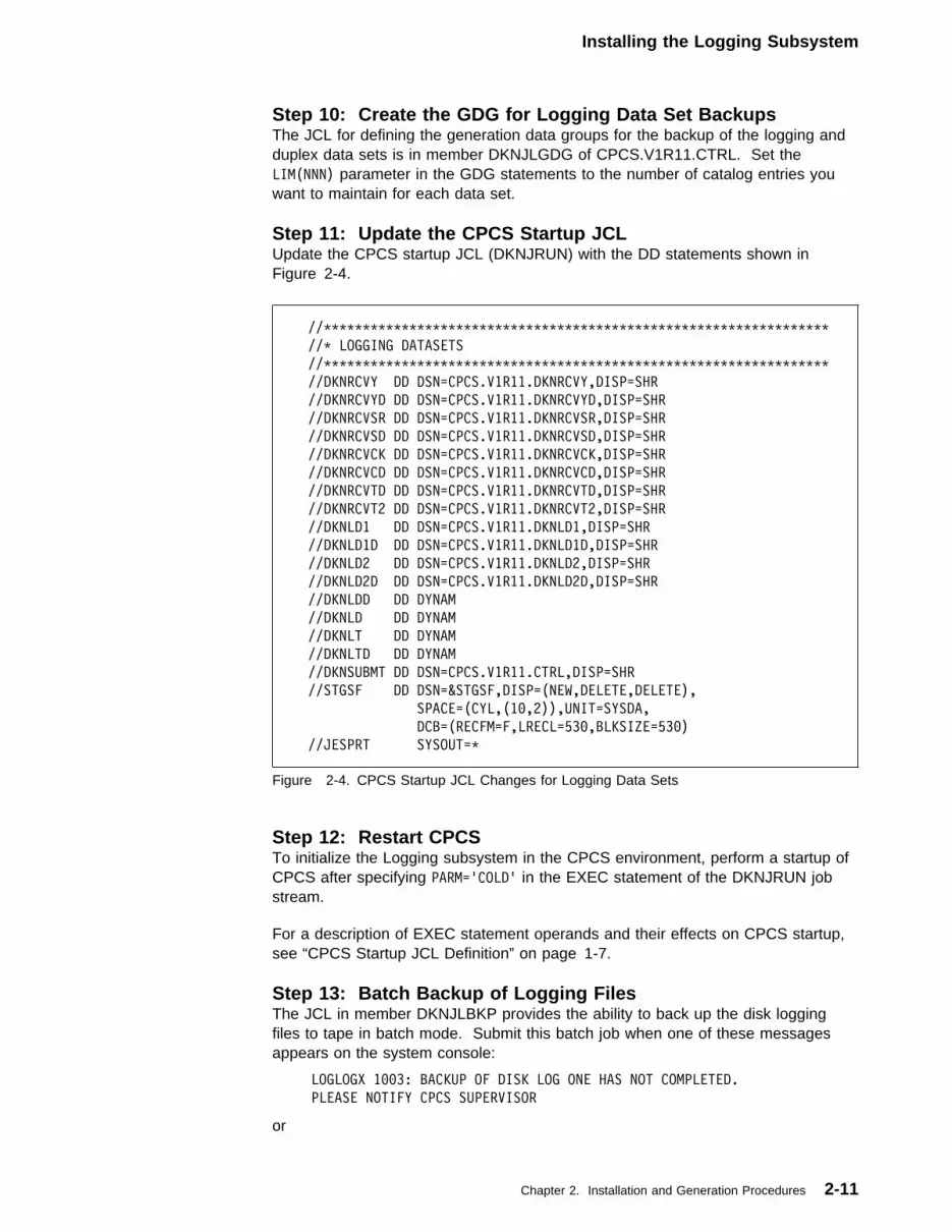
Installing the Logging Subsystem
Step 10: Create the GDG for Logging Data Set BackupsThe JCL for defining the generation data groups for the backup of the logging andduplex data sets is in member DKNJLGDG of CPCS.V1R11.CTRL. Set theLIM(NNN) parameter in the GDG statements to the number of catalog entries youwant to maintain for each data set.
Step 11: Update the CPCS Startup JCLUpdate the CPCS startup JCL (DKNJRUN) with the DD statements shown inFigure 2-4.
//TTTTTTTTTTTTTTTTTTTTTTTTTTTTTTTTTTTTTTTTTTTTTTTTTTTTTTTTTTTTTTTTT
//T LOGGING DATASETS
//TTTTTTTTTTTTTTTTTTTTTTTTTTTTTTTTTTTTTTTTTTTTTTTTTTTTTTTTTTTTTTTTT
//DKNRCVY DD DSN=CPCS.V1R11.DKNRCVY,DISP=SHR
//DKNRCVYD DD DSN=CPCS.V1R11.DKNRCVYD,DISP=SHR
//DKNRCVSR DD DSN=CPCS.V1R11.DKNRCVSR,DISP=SHR
//DKNRCVSD DD DSN=CPCS.V1R11.DKNRCVSD,DISP=SHR
//DKNRCVCK DD DSN=CPCS.V1R11.DKNRCVCK,DISP=SHR
//DKNRCVCD DD DSN=CPCS.V1R11.DKNRCVCD,DISP=SHR
//DKNRCVTD DD DSN=CPCS.V1R11.DKNRCVTD,DISP=SHR
//DKNRCVT2 DD DSN=CPCS.V1R11.DKNRCVT2,DISP=SHR
//DKNLD1 DD DSN=CPCS.V1R11.DKNLD1,DISP=SHR
//DKNLD1D DD DSN=CPCS.V1R11.DKNLD1D,DISP=SHR
//DKNLD2 DD DSN=CPCS.V1R11.DKNLD2,DISP=SHR
//DKNLD2D DD DSN=CPCS.V1R11.DKNLD2D,DISP=SHR
//DKNLDD DD DYNAM
//DKNLD DD DYNAM
//DKNLT DD DYNAM
//DKNLTD DD DYNAM
//DKNSUBMT DD DSN=CPCS.V1R11.CTRL,DISP=SHR
//STGSF DD DSN=&STGSF,DISP=(NEW,DELETE,DELETE),
SPACE=(CYL,(1�,2)),UNIT=SYSDA,
DCB=(RECFM=F,LRECL=53�,BLKSIZE=53�)
//JESPRT SYSOUT=T
Figure 2-4. CPCS Startup JCL Changes for Logging Data Sets
Step 12: Restart CPCSTo initialize the Logging subsystem in the CPCS environment, perform a startup ofCPCS after specifying PARM='COLD' in the EXEC statement of the DKNJRUN jobstream.
For a description of EXEC statement operands and their effects on CPCS startup,see “CPCS Startup JCL Definition” on page 1-7.
Step 13: Batch Backup of Logging FilesThe JCL in member DKNJLBKP provides the ability to back up the disk loggingfiles to tape in batch mode. Submit this batch job when one of these messagesappears on the system console:
LOGLOGX 1��3: BACKUP OF DISK LOG ONE HAS NOT COMPLETED.
PLEASE NOTIFY CPCS SUPERVISOR
or
Chapter 2. Installation and Generation Procedures 2-11

Installing the Logging Subsystem
LOGLOGX 1��4: BACKUP OF DISK LOG TWO HAS NOT COMPLETED.
PLEASE NOTIFY CPCS SUPERVISOR
Step 14: Change the DKNJLCRH JCLYou must modify the JCL member DKNJLCRH to match your operatingenvironment. To ensure that no logging data is lost, you must change the JCLafter any abend of the MVS system. For more information about the DKNJLCRHfunctions, see the CPCS Programming and Diagnostic Guide.
Capture of Logged Data SetsLogging maintains a real-time log of all write operations to the MDS. DKNMDCTLcalls the program DKNLOGX after every write operation to the MDS. DKNLOGXbuffers the disk record according to the value that you specified for the CPCSsystem profile member DKNPCPCS parameter BFRAT. You also specify thenumber of available buffers for DKNLOGX (CPCS system profile parameterTPBFNM). While a buffer remains free, there is no waiting on I/O operations.
Recovering Logged Data SetsYou can use the following methods to recover logged data sets:
Mass Data Set Recovery: Recover the mass data set (MDS) by starting CPCSwith the correct start parameters. The program DKNMDSV1 performs the recoveryby reading the log tapes and writing the data to a newly allocated MDS. CPCSchecks the data to ensure the completeness of the recovered data. At the end ofMDS recovery, a normal restart occurs.
MDS Directory Index Recovery: The program DKNMDSV1 performs the indexrecovery by reading the MDS and rebuilding the index that points to the stringsfound on the MDS. At the end of index recovery, a normal restart occurs.
BOTH Recovery: The CPCS start parameters support concurrent recovery of theMDS and index. An index recovery follows an MDS recovery. At the end of theindex recovery, a normal restart occurs.
Selective and Restart Recovery: Tapes can be mistakenly left out of an MDSrecovery or a BOTH recovery, resulting in strings that are not complete. Underthese conditions, it is not necessary to rerun the complete recovery process. Useeither a selective or a restart recovery to reload the data on the omitted tapes.
For additional information about recovering data sets, see the recovery proceduresdescribed in “Data-Set Recovery Procedures” on page 1-33.
Log-Tape Synchronization: Whenever CPCS or MVS ends abnormally, it ispossible that the MDS contains more data than the log tape. This can happenbecause the tape-record block size is a multiple of the disk record size and theremight be data in a buffer at the time of the error. During the restart, CPCS logsdata from the MDS to ensure that the tape-log data set reflects all active MDS data.
2-12 CPCS V1R11 Customization Guide
Installing the Logging Subsystem
Overriding the Log Data-Set DefinitionThe Logging subsystem writes the current log data-set definition in the first orsecond record of each log data set. RCVY normally uses this system-generateddefinition record to define the log data set being recovered.
The DKNRDX50 module defines the fields used when overriding the log data-setdefinition. DKNRDX50 is shipped with field values that match the sample CPCSsystem profile parameters and MDX record defaults. If a change is required, youcan alter the field definitions, and assemble and link-edit a new load module. Thelog data-set definition can be overridden by changing the default setting of &RDX inthe DKNROPTS macro to the new module name and assembling DKNRCVY, or bykeying in the new module name on the Recovery Cycle Specification screen ofRCVY.
Important!
Creating a new load module is not normally required. Use this option onlywhen the log data-set definition does not exist as the first record in the data set.
Using an incorrect definition can cause errors during RCVY operation. Ensurethat the definition used to recover a log data set is the correct definition for thatdata set.
If you choose to override the log data-set definition, you must create a newdefinition override module any time there are changes to the CPCS systemprofile member DKNPCPCS parameters (BFRAT, TPBFNM, or BLKSZ) orchanges to the MDX record.
Tracer group update is supported when recovering strings from CPCS Release10, or higher, which contains MICR group edit disengage records.
Use the following steps to create a new definition to override the module from theDKNRDX50 log data-set definition:
1. Change the RBFRAT field to match the CPCS system profile memberDKNPCPCS parameter BFRAT value that was in effect when the data set wascreated.
2. Change the RTPBFN field to match the value of the CPCS system profilemember DKNPCPCS parameter TPBFNM that was in effect when the data setwas created.
3. Change the RBLKSZ field to match the value of the CPCS system profilemember DKNPCPCS parameter BLKSZ that was in effect when the data setwas created.
4. If the log data set was created under CPCS Release 10 or greater, change theRDXLGSDE field to Y; otherwise set the value to N.
5. Change the RDESC field to a 40-character description that describes this logdata-set definition. This description appears on the RCVY Recover Statusscreen.
6. The remaining fields in the record correspond to the same fields that were inthe MDX record when the log data set was created.
Note: Ensure that all fields are updated to match exactly.
Chapter 2. Installation and Generation Procedures 2-13
Installing the Logging Subsystem
7. Assemble and link-edit the new module for your load library.
Provide a unique name for each definition override module that you create. Forexample, if you have a log data set with a mass data set expanded by 3 bytes,you could name the new module DKNRDX53. However, any meaningful namecan be used. This name can then be entered on the Recovery CycleSpecification screen.
Data-Set UtilitiesThere is one data-set duplexing utility. DKNCOPY copies the log tape to a secondtape.
DKNCOPY: If MVS ends abnormally, and you are using LOG=YES andLOGDEV=TAPE, the CPCS log tape might not have an end-of-file marker. Youcan use the improperly closed log tape as input to the program DKNCOPY.DKNCOPY is a batch job that runs under the control of MVS, not CPCS.DKNCOPY copies the log tape to a second tape and closes the second tape. Thistape takes the place of the copied log tape.
Customizing Item Sequence NumbersAt the generation time for the Item Sequence Number data set, you can select oneof three different formats for the last 8 digits of the item sequence numbers. Theformats are ssssssss, rsssssss, and rrssssss, where ssssssss/sssssss/ssssss is asequence number and r/rr is a region number. The CPCS item sequence numberformat and the item sequence number ranges are selected with the Item SequenceNumber Data Set Generation Profile (see “DKNPISNG Profile Member” onpage 3-19). CPCS must be cold-started after regenerating the Item SequenceNumber Data Set (see “Step 18: Initialize the Item-Sequence-Number Data Set” inthe CPCS Installation Guide. See also the “Sequence Number” section of theCPCS Programming and Diagnostic Guide for detailed documentation of the entire12-digit item sequence number field. If region numbers are used:
� The user decides what they identify.
� Items captured under a non-XF sort type do not have the region numberstamped as part of their sequence numbers.
2-14 CPCS V1R11 Customization Guide

Describing an Application Task’s Environment
Describing an Application Task’s EnvironmentYou can change the APCB macro keywords for performance, security, or controlreasons. The APCB macros must be in alphabetical sequence by program moduleand can be found in DKNBLDL. Descriptions of the APCB keywords (operands)follow this table:
NAME=application task nameSpecifies the name of the application task. The first 3 characters of the nameare user-variable; the last 4 characters are the transaction ID and must beunique. The names in the BLDL table must be in alphabetic sequence on thefull length.
Note: You no longer need to use DKN as the first 3 characters of the name.
AUTH={1 | 2 | 3 | 4 | 5}Specifies the authority class (0, 1, 2, 3, 4, or 5) of the task. This operand hasmeaning only if you selected the data security (DASC) option in the master task
Name Operation Operands
SYMBOL APCB [NAME=task name] [AUTH={1 | 2 | 3 | 4 | 5}] [AUTO={0 | 1}] [CIMS={0 | 1}] [CLASS=output class] [COMP={0 | 1}] [DPCOD={0 | dispatching priority modifier}] [ECYEND={0 | 1}] [ECYRTN={0 | 1}] [EXSEQ={1 - 255}] [EXTSK={Y | N}] [HIVOL={0 | 1}] [HLOG={0 | 1}] [ICLSS={I | application class value}] [INSTRG={0 | number of MDS input strings open
concurrently}] [ISPOOL={000 | number of document print files}] [ISUPV={0 | 1}] [MAIL={N | Y}] [MAX={1 | number of concurrent runs permitted}] [MAXM={1 | pages of above-the-line storage}] [MSUPV={0 | 1}] [OUTSTRG={0 | number of MDS output strings open
concurrently}] [PRINT={0 | number of spool data sets required}] [SMMULT={0 | 1}] [SMSTART={0 | 1}] [SMTRACK={0 | 1}] [SORT={0 | 1}] [SPEC={0 | 1}] [SSUPV={0 | 1}] [TASKGRP={0 | 1-digit group number 0-9 }] [TIMECK={0 | 1}] [USREXIT=optional user exit name] [USRPARM={X}] [WORK=amount of work storage required] [WRKPOOL={0 | 1 | 2}]
Chapter 2. Installation and Generation Procedures 2-15

Describing an Application Task’s Environment
generation. See the CPCS Programming and Diagnostic Guide for moreinformation on the security option. If you do not specify AUTH, the task defaultsto AUTH=1.
Note: For executive tasks, the value for AUTH always defaults to AUTH=1.
AUTO={0 | 1}Specifies whether another task or an operator at a CPCS terminal can start thistask.
AUTO=0 Either an operator (manually) or another task (automatically) canstart this task (default value).
AUTO=1 Another task must start this task (automatically).
CIMS={0 | 1}Specifies whether the task that is associated with this entry uses the servicesof an image system program that stores, retrieves, and manages documentimages.
CIMS=0 This task does not use the services of an image system (defaultvalue).
CIMS=1 This task uses the services of an image system. Specify CIMS=1only if an image system is being used and the task accesses theimage system’s database.
CLASS=output classSpecifies the CPCS output class (A through Z or 0 through 9) of any printedoutput produced by the task. The CLASS parameter of the CPCS systemprofile member DKNPCPCS parameter determines the default value. For moreinformation about the DKNPCPCS profile member, see “DKNPCPCS ProfileMember” on page 3-6. Using this operand and the printer control capabilitiesof the DKNFORM task lets you direct output to specific printers. For example,you can direct the kill and cash-letter summary lists to one printer and thebalancing lists to another printer. With job-entry subsystem (JES) print support,the last character of the JESPRT DD name is assigned as the CPCS printerclass.
Note: If you make this last digit the same as the SYSOUT class of the CPCSJES printer, you can locate the print buffer data set more easily. See“Dynamically Allocating Data Sets” on page 2-23 for details.
COMP={0 | 1}Specifies whether the task can run while the DKNCOMP task is running.
COMP=0 This task does not use DKNKB and DKNMF, so it can run whilethe DKNCOMP task is running (default value).
COMP=1 This task uses DKNKB or DKNMF, so it cannot run while theDKNCOMP task is running. Specify COMP=1 for any task thatrequires the use of the kill bundle or microfilm data sets (exceptDKNCOMP).
DPCOD={0 | dispatching priority modifier}Specifies the task-dispatching priority modifier, which DKNATASK passes toMVS when it attaches the task.
DPCOD=0 This task has the highest dispatching priority (default value).
2-16 CPCS V1R11 Customization Guide

Describing an Application Task’s Environment
DPCOD=dispatching priority modifierThis value should be a negative number (-1, -2,...), with -1 havinga higher dispatching priority than -2, followed by -3, -4, and soforth.
You can use this operand to optimize the performance of CPCS tasks. Forexample, when you specify DPCOD=� for DKNOLRR and DPCOD=-1 forDKNMRG2, DKNPLST, and DKNDIST, you give a higher dispatching priority toDKNOLRR than to higher processing-unit usage programs. This priority isimportant for programs such as DKNOLRR that have a low processing-unitusage and a critical response requirement.
ECYEND={0 | 1}Specifies whether this task is the last task in the end cycle series of tasks.
ECYEND=0 This is not the last task in end cycle processing (default value).ECYEND=1 This is the last task in end cycle processing.
ECYRTN={0 | 1}Specifies whether this task is part of the end cycle series of tasks.
ECYRTN=0 This is not an end cycle processing task (default value).ECYRTN=1 This is an end cycle processing task.
EXSEQ={1–255}Specifies the sequence in which DKNATASK will activate user executive tasks(EXTSK=Y). This parameter is valid only for auto-started tasks (AUTO=1).The default value is EXSEQ=50.
EXTSK={Y | N}Specifies whether the associated task is a user executive task. User executivetasks can be manually or automatically started.
EXTSK=Y This is a user executive task.EXTSK=N This is not a user executive task (default value).
HLOG={0 | 1}Specifies whether DKNLOADR posts the host logon process.
HLOG=0 DKNLOADR does not post the host logon process. This isstandard CPCS treatment (default value).
HLOG=1 DKNLOADR posts the host logon process when a task issuccessfully attached.
HIVOL={0 | 1}Specifies whether the task requires a large spool data set for printed output.
HIVOL=0 This task does not require a large spool data set. The smallprinter spool data sets should be large enough to contain thelargest printed output of this task (default value).
HIVOL=1 This task requires a large spool data set.
Chapter 2. Installation and Generation Procedures 2-17

Describing an Application Task’s Environment
Notes:
1. If the task requires more than one spool data set, only one can be a largespool data set. When an application program calls DKNADCB to obtainspool data sets, the large spool data set should appear first in theparameter list.
2. This parameter has no effect on task output that prints through CPCSspools with the DKNADCB and DKNADCB2 macros. Use the CLASSparameter instead.
ICLSS={I | application class value}Specifies the application class for printing directly to the JES spool. Applicationclass values are 0 through 9 or A through Z. The default value is ICLSS=I.
INSTRG={0 | number of MDS input strings open concurrently}Specifies the maximum number of MDS input strings that can be openconcurrently for the task. If the number of concurrently open input strings isgreater than this specification, the task will abend. This specification must notbe too large, or the task might exceed the 64K maximum work area. Thedefault value is INSTRG=0.
ISPOOL={000 | number of document print files}Specifies the maximum number of print files, which can be a 3-digit numberbetween 000 and 255. DKNATASK must assign as many ddnames for printfiles as this field indicates. The default value is ISPOOL=000.
Note: This parameter has no effect on task output that prints through CPCSspools via the DKNADCB and DKNADCB2 macros. Use the CLASS parameterinstead.
ISUPV={0 | 1}Specifies whether the INSC supervisor terminal must start the task.
ISUPV=0 This task can start on any terminal (default value).ISUPV=1 This task can be started only on the INSC supervisor terminal.
MAIL={N | Y}Specifies whether a module can receive electronic mail.
MAIL=N This module cannot receive electronic mail (default value).MAIL=Y This module can receive electronic mail.
MAX={1 | number of concurrent runs permitted}Specifies the maximum number of concurrent runs of this task that CPCSpermits. The default value is MAX=1. You can use this operand to increase ordecrease the maximum number for more flexibility and performance tuning.
Note: DKNCLSM is an example of a CPCS task that requires MAX=1 in itsAPCB macro in DKNBLDL, because DKNCLSM uses a single work data set.
MAXM={1 | pages of above-the-line storage}Specifies the maximum number of pages of above-the-line storage that anapplication can request from DKNMEMI. The input value is between 1 and 500000. Each page represents 4096 bytes of storage. The default value isMAXM=1. For more information about the storage manager, see the CPCSProgramming and Diagnostic Guide.
2-18 CPCS V1R11 Customization Guide
Describing an Application Task’s Environment
MSUPV={0 | 1}Specifies whether the MICR supervisor terminal must start this task.
MSUPV=0 This task can start on any terminal (default value).MSUPV=1 This task can be started only on the MICR supervisor terminal.
OUTSTRG={0 | number of MDS output strings open concurrently}Specifies the number of MDS output strings concurrently open for normalperformance of the program that is associated with this APCB macro. UnlikeINSTRG, if more output strings are concurrently open than are specified here,the task does not abend; but some storage fragmentation might occur. If fewerthan the specified output strings are concurrently open, the extra storage thatDKNATASK obtains is unused. This specification must not be too large, sincethe task can exceed the 64K maximum. The default value is OUTSTRG=0.
PRINT={0 | number of spool data sets required}Specifies the number of spool data sets required to run this task. Themaximum number that you can specify is 255. The default value is PRINT=0.
Note: This parameter has no effect on task output that prints directly to JESinstead of with the DKNADCB3 macro. Use the ISPOOL parameter instead.
SMMULT={0 | 1}Specifies whether one execution of this task may complete Enhanced SystemManager work request blocks.
SMMULT=0 When one copy of this task is executed, only one EnhancedSystem Manager WRB is marked “active” and subsequentlycompleted (shown with a ‘C’). The majority of CPCS tasks fallinto this category.
SMMULT=1 When one copy of this task is executed, several EnhancedSystem Manager WRBs may be marked “active” andsubsequently completed (shown with a ‘C’).
Specifying SMMULT=1 enables Enhanced System Manager toanticipate this scenario and process this type of work correctly.
Note: See the CPCS Enhanced System Manager User’sGuide for more information.
SMSTART={0 | 1}Specifies whether the task may be automatically started by the EnhancedSystem Manager.
SMSTART=0 This task cannot be automatically started by Enhanced SystemManager.
SMSTART=1 This task can be automatically started by Enhanced SystemManager.
Note: See the CPCS Enhanced System Manager User’sGuide for more information.
SMTRACK={0 | 1}Specifies whether the task may be tracked but may not be started by theEnhanced System Manager.
SMTRACK=0 This task cannot be automatically started or tracked byEnhanced System Manager.
Chapter 2. Installation and Generation Procedures 2-19

Describing an Application Task’s Environment
SMTRACK=1 This task can be tracked but cannot be started by EnhancedSystem Manager.
Note: See the CPCS Enhanced System Manager User’sGuide for more information.
SORT={0 | 1}Specifies whether the task uses an internal sort.
SORT=0 This task does not use an internal sort (default value).SORT=1 This task uses an internal sort.
SPEC={0 | 1}Specifies whether the task requires special testing before DKNATASK canattach the task.
SPEC=0 This task requires no special testing (default value).
SPEC=1 This task requires special testing (for example, DKNCOMP andDKNECYC require special testing).
SSUPV={0 | 1}Specifies whether the SYST system supervisor terminal must start the task.
SSUPV=0 This task can start on any terminal (default value).
SSUPV=1 This task can be started only on the SYST system supervisorterminal.
TASKGRP={0 | 1-digit group number 0–9}Specifies the task group number for the task. Similar tasks may be groupedwith the same task group number to restrict how many task of that group maybe active at one time.
This is related to the System Profile data set member DKNPATSK, which isdescribed in Chapter 3, “System and Application Profiles.” Group 0 will causethe task to be started immediately if MAXTASK is not exceeded. Group 0 isthe default if this parameter is omitted.
TIMECK={0 | 1}Specifies whether DKNASGF automatically logs off the task.
TIMECK=0 This task is available for automatic logoff if it is inactive for aperiod of time that exceeds the period specified in the CPCSsystem profile member DKNPCPCS.
TIMECK=1 DKNASGF must not automatically log off this task even if thetask is inactive for a period of time that exceeds the periodspecified in the CPCS system profile member DKNPCPCS.
USREXIT=optional user exit nameSpecifies the name of a user-written exit routine. This is not a requiredparameter. When you use this parameter, the name of the exit must be nomore than 8 characters in length; the first character must be alphabetic and therest must be alphanumeric. Generally, user exits named in DKNBLDL are usedfor default bank 001 only. The bank control file and/or the sort patterndefinition may name other user exits that override the user exit named here.
USRPARM={X}Used by DKNICRE and DKNMRGE.
2-20 CPCS V1R11 Customization Guide
Describing an Application Task’s Environment
DKNICRE Specifies whether DKNICRE should extract an uncompresseddata set. When you code X for this parameter, DKNICREextracts data sets using the copybook DKNCRINA, anuncompressed format based on the extract field lengths in theMDX macro. If you do not code this parameter, DKNICRE usesthe default copybook DKNCRIN, which has a compressedformat.
Change the record length of the ICRE file in the DKNGALLO JCLand in the DSAT to match the MDX (GENCLIB JCL) output,matching the ICRA note. Do not change the ddname.
DKNMRGE Specifies the threshold of uncorrected errors allowed whenMRGE is run. If this threshold is met, MRGE 24 is issued andMRGE terminates. This may or may not indicate an error.MRGE inspects all flag bits including the flag bits for fields 9–15.If it can be determined that the suspect OLRR user editprocessing the items correctly but flagging items incorrectly, thenthe error message can be eliminated by coding USPARM=9999.This does not fix the error, but eliminates the message, as athreshold of 9999 will probably not be exceeded.
WORK=amount of work storage requiredSpecifies the amount of user work storage that the task requires (applies toassembler programs only, usually reentrant).
Note:
WORK acquires 24-bit, below-the-line storage.
For expanded MDS records you must increase the work area for DKNOLRR by50 bytes for every byte of MDS expansion.
Note: Before DKNATASK attaches a task, it must acquire a work area equalto the sum of the WORK parameter and the size of the APTCB and MDScontrol blocks and buffers required for INSTRG and OUTSTRG. The maximumsize of this work area is 64K. You should specify the correct number of stringsfor INSTRG and OUTSTRG. If you are using blocked BDAM, you might needto increase the WORK= value for DKNDIST. Failing to do this results in anSOC4 abend in DKNDIST. The default value for this is 25,000. For maximumblocking factors, a value of 40,000 is sufficient.
WRKPOOL={0 | 1 | 2}Specifies whether the task uses an internal work area (for example, sort workareas).
WRKPOOL=0 This task does not use an internal work area (default value).WRKPOOL=1 This task uses an internal work area assigned outside
subpool 0.WRKPOOL=2 This task uses an internal work area assigned to subpool 0.
Examples of Adding a DKNBLDL Entry for a New Task: This following exampleshows you how to add a system supervisor task that the transaction identificationWXYZ can start. The task reads one MDS input string and writes a report. Onlyone of these tasks can be run at a time.
APCB NAME=DKNWXYZ,PRINT=1,INSTRG=1,SSUPV=1
Chapter 2. Installation and Generation Procedures 2-21

Describing an Application Task’s Environment
The following example shows an application task that another task startsautomatically:
APCB NAME=DKNDEMO,AUTO=1,PRINT=1,ECYRTN=1,COMP=1,OKONDUMP=1, X
MAIL=Y,ICLSS=I,ISPOOL=��1,MAXM=2
The task, DEMO, is part of the end cycle process. It is authorized to receivemessages in the electronic mailbox from other applications. In addition to a regularreport, the DEMO task includes routines that use class I to process and sendreports to a JES printer. The task uses memory above the line to store therecords. This task cannot be called if DKNCOMP is running, and DKNCOMPcannot start if this task is running.
2-22 CPCS V1R11 Customization Guide
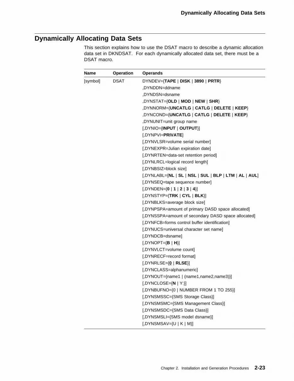
Dynamically Allocating Data Sets
Dynamically Allocating Data SetsThis section explains how to use the DSAT macro to describe a dynamic allocationdata set in DKNDSAT. For each dynamically allocated data set, there must be aDSAT macro.
Name Operation Operands
[symbol] DSAT DYNDEV={TAPE | DISK | 3890 | PRTR}
,DYNDDN=ddname
,DYNDSN=dsname
,DYNSTAT={OLD | MOD | NEW | SHR}
,DYNNORM={UNCATLG | CATLG | DELETE | KEEP}
,DYNCOND={UNCATLG | CATLG | DELETE | KEEP}
,DYNUNIT=unit group name
[,DYNIO={INPUT | OUTPUT}]
[,DYNPVI=PRIVATE]
[,DYNVLSR=volume serial number]
[,DYNEXPR=Julian expiration date]
[,DYNRTEN=data-set retention period]
[,DYNLRCL=logical record length]
[,DYNBSIZ=block size]
[,DYNLABL={NL | SL | NSL | SUL | BLP | LTM | AL | AUL]
[,DYNSEQ=tape sequence number]
[,DYNDEN={0 | 1 | 2 | 3 | 4}]
[,DYNSTYP={TRK | CYL | BLK}]
[,DYNBLKS=average block size]
[,DYNPSPA=amount of primary DASD space allocated]
[,DYNSSPA=amount of secondary DASD space allocated]
[,DYNFCB=forms control buffer identification]
[,DYNUCS=universal character set name]
[,DYNDCB=dsname]
[,DYNOPT={B | H}]
[,DYNVLCT=volume count]
[,DYNRECF=record format]
[,DYNRLSE={0 | RLSE}]
[,DYNCLASS=alphanumeric]
[,DYNOUT={name1 | (name1,name2,name3)}]
[,DYNCLOSE={N | Y:}]
[,DYNBUFNO={0 | NUMBER FROM 1 TO 255}]
[,DYNSMSSC={SMS Storage Class}]
[,DYNSMSMC={SMS Management Class}]
[,DYNSMSDC={SMS Data Class}]
[,DYNSMSLI={SMS model dsname}]
[,DYNSMSAV={U | K | M}]
Chapter 2. Installation and Generation Procedures 2-23

Dynamically Allocating Data Sets
The following list describes the DSAT parameters.
DYNDEV={TAPE | DISK | 3890 | PRTR}Specifies the type of data set to allocate (tape, disk, 3890 channel-attacheddocument processor, or printer).
DYNDDN=ddnameSpecifies the data-definition name (ddname) that the calling program uses toreference the dynamically allocated file. Specify 1 to 8 characters, according tothe JCL conventions for data definition names.
DYNDSN=dsnameSpecifies the data-set name that CPCS uses for the dynamically allocated file.Use 1 to 44 characters, following the JCL conventions for data-set names.
DYNSTAT={OLD | MOD | NEW | SHR}Specifies the data-set status of old, modified, new, or shared. IfDYNDEV=DISK, and the status is not NEW, CPCS ignores the DYNBLKS,DYNPSPA, and DYNSSPA parameters.
DYNNORM={UNCATLG | CATLG | DELETE | KEEP}Specifies the normal disposition of the allocated data set. The options are:
UNCATLG Uncatalog the data set when the program ends.CATLG Catalog the data set when the program ends.DELETE Delete the data set when the program ends.KEEP Keep the data set when the program ends.
DYNCOND={UNCATLG | CATLG | DELETE | KEEP}Specifies the conditional disposition of the data set. The options are:
UNCATLG Uncatalog the data set when the program ends abnormally.CATLG Catalog the data set when the program ends abnormally.DELETE Delete the data set when the program ends abnormally.KEEP Keep the data set when the program ends abnormally.
DYNUNIT=unit group nameSpecifies a unit group name as defined by the installation (for example,SYSDA, TAPE9). If you specify DYNDEV=3890, the character length is 6;otherwise, the character length is 8.
DYNIO={INPUT | OUTPUT}Specifies whether CPCS allocates the data set as input-only or output-only.This is an optional parameter.
DYNPVI=PRIVATESpecifies a data set as PRIVATE. This is an optional parameter.
DYNVLSR=volume serial numberSpecifies the volume serial number. Use 6 characters following the JCLconventions for volume serial numbers.
DYNEXPR=Julian expiration dateSpecifies the Julian expiration date for the file. The parameter may be 5 digits(yyddd) or 7 digits (yyyyddd) depending on the settings in copybook EXPDTV.This is an optional parameter. It is mutually exclusive with DYNRTEN.
2-24 CPCS V1R11 Customization Guide

Dynamically Allocating Data Sets
DYNRTEN=data-set retention periodSpecifies the data-set retention period. Use 1 to 4 numeric characters. This isan optional parameter. It is mutually exclusive with DYNEXPR.
DYNLRCL=logical record lengthSpecifies the actual or maximum length (in bytes) of a logical record. This isan optional parameter.
DYNBSIZ=block sizeSpecifies the length (in bytes) of a block. The maximum size depends on thedevice type. This is an optional parameter.
DYNLABL={NL | SL | NSL | SUL | BLP | LTM | AL | AUL}Specifies the tape label processing that CPCS performs on the allocated dataset. The options are:
NL No label on the tapeSL IBM standard label on the tapeNSL Nonstandard label on the tapeSUL IBM standard label and user label on the tapeBLP Bypass label processingLTM Bypass leading tape mark on an unlabeled tapeAL ANSI standard label on the tapeAUL ANSI standard label and ANSI user label on the tape.
DYNSEQ=tape sequence numberSpecifies the tape sequence number. This is an optional parameter.
DYNDEN={0 | 1 | 2 | 3 | 4}Specifies the tape density setting. Options are 0 through 4, where:
This is only a required parameter if you specified the TAPE option in DYNDEV;otherwise, this is an optional parameter.
DYNSTYP={TRK | CYL | BLK}Defines the type of space allocation for new disk data sets. Valid options aretracks (TRK), cylinders (CYL), or blocks (BLK).
DYNBLKS=average block sizeSpecifies the average block size of the data set if DYNSTYP=BLK.
DYNPSPA=amount of primary DASD space to allocateSpecifies the amount of primary DASD space to allocate to the new disk dataset.
DYNSSPA=amount of secondary DASD space to allocateSpecifies the amount of secondary DASD space to allocate to the new diskdata set.
DYNFCB=forms control buffer identificationSpecifies the forms control buffer record identification. Use 1 to 4 characters.
0 200 bpi (7-track tape only)1 556 bpi (7-track tape only)2 800 bpi 3 1600 bpi (9-track tape only)4 6250 bpi (9-track tape only).
Chapter 2. Installation and Generation Procedures 2-25

Dynamically Allocating Data Sets
DYNUCS=universal character set nameSpecifies the universal character set, such as PCAN or PCHAN. Use1 to 4 characters.
DYNDCB=dsnameSpecifies the referenced data-set name. This is an optional parameter.
DYNOPT={B | H}Specifies the optional service code; only B and H are permitted. This is anoptional parameter. This optional service code applies only to dynamicallyallocated tape data sets for the basic sequential access method (BSAM) or tothe queued sequential access method (QSAM). For more information aboutthis option, see the MVS/ESA Data Administration: Macro InstructionReference.
DYNVLCT=volume countSpecifies the volume count.
DYNRECF=record formatSpecifies the record format. The options are:
A Records contain ANSI control charactersB Records are blockedD Data set contains variable length ISCII/ASCII tape recordsF Record size is fixedM Records contain machine-code control charactersS Data set contains spanned recordsT Data set accommodates track overflowU Record format is undefinedV Record size is variable.
For valid combinations of these options, see the MVS/ESA Data Administration:Macro Instruction Reference.
DYNRLSE={0 | RLSE}Specifies the release (RLSE) of unused DASD space. This is an optionalparameter.
DYNCLASS=alphanumericSpecifies the SYSOUT class for JES printers.
DYNOUT={name1 | (name1,name2,name3)}Specifies one to three names that refer to an output record defined in theCPCS run JCL. Each name can be 1 through 8 characters in length.
DYNCLOSE={N | Y}Specifies if the ddname is to be unallocated when the data set is closed.
DYNBUFNO={0 | NUMBER FROM 1 TO 255}Specifies the number of QSAM buffers to be used for this data set. A value of0 indicates this option is not to be used.
DYNSMSSC={SMS Storage Class}Specifies the SMS Storage Class to be assigned to this data set. Use a 1- to8-character, SMS-defined storage class name. DYNUNIT is optional whenDYNSMSSC is specified.
2-26 CPCS V1R11 Customization Guide
Dynamically Allocating Data Sets
DYNSMSMC={SMS Management Class}Specifies the SMS Management Class to be assigned to this data set. Use a1- to 8-character, SMS-defined management class name.
DYNSMSDC={SMS Data Class}Specifies the SMS Data Class to be assigned to this data set. Use a 1- to8-character, SMS-defined data class name.
DYNSMSLI={SMS Model Data Set Name}Specifies the SMS Model Data Set Name to be used for this data set. Use a1- to 44-character, SMS-defined model data set name.
DYNSMSAV={U | K | M}Specifies the SMS average record scale modifier to be used for this data set.
Example of Coding the DSAT Parameter DYNOUT: The following examplesshow you how to code OUTPUT records for the CPCS run JCL and correspondingDSAT macro entries for DKNDSAT. For more information about using theOUTPUT operands, see the MVS/ESA JCL User’s Guide.
Example 1: To route the same print job to multiple destinations with the sameoutput class, add the following statements to the CPCS run JCL:
//CPCSP1 OUTPUT COPIES=1,DEST=PRT1 CPCS PRINT TO LOCATION 1
//CPCSP1 OUTPUT COPIES=1,DEST=PRT2 CPCS PRINT TO LOCATION 2
Add the following entry to the DKNDSAT data set:
JES DSAT DYNDEV=PRTR, always PRTR for printer X
DYNDDN=JESPRT1C, DDNAME X
DYNCLASS=C, SYSOUT class X
DYNOUT=(CPCSP1,CPCSP2) OUTPUT record names
All printing is routed to class C, with destinations of PTR1 and PTR2.
Example 2: The following example shows how to code the JCL and the DSATmacro for different output classes and destinations. This example assumes thatyou have an online microfiche printer and are printing on a standard printer and themicrofiche printer.
Add the following OUTPUT records to the CPCS run JCL:
//CPCSP OUTPUT COPIES=1,CLASS=E,DEST=PRT1 REGULAR CPCS PRINT
//FICHE OUTPUT COPIES=1,CLASS=F,DEST=FICHE CPCS PRINT TO MICROFICHE
Add the following entry to the DKNDSAT data set:
JES DSAT DYNDEV=PRTR, always PRTR for printer X
DYNDDN=JESPRT1A, DDNAME X
DYNOUT=(CPCSP,FICHE) OUTPUT record names
Note: The DYNCLASS parameter is not necessary because the OUTPUT recordin the JCL specifies the output class.
Example of Adding a DKNDSAT Entry for a New Tape Data Set: Todynamically allocate a tape data set, you should assemble the following DSATmacro in DKNDSAT. Set up the parameters according to your standards.
Chapter 2. Installation and Generation Procedures 2-27

Dynamically Allocating Data Sets
EXTR DSAT DYNDEV=TAPE, tape data set X
DYNDDN=USEREXTR, user's DCB DDNAME X
DYNDSN=EXTRACT, user's data set name X
DYNSTAT=NEW, new allocation X
DYNNORM=KEEP, KEEP normal disposition X
DYNCOND=DELETE, DELETE error disposition X
DYNVLSR=123456, VOLSER for allocation X
DYNEXPR=99365, expiration date X
DYNUNIT=TAPE9, allocate from 9 track pool X
DYNLABL=SL, standard label processing X
DYNSEQ=1, data set sequence number X
DYNDEN=3 16�� bpi 9 track
Example of Adding a DKNDSAT Entry for a Disk Data Set: Use the followingDSAT macro to add a dynamically-allocated data set for an extract system:
EXTR DSAT DYNDEV=DISK, disk data set X
DYNDDN=USREXT1, user's DCB DDNAME X
DYNDSN=EXTR1.DSK, user's data set name X
DYNSTAT=NEW, status is NEW X
DYNNORM=KEEP, KEEP normal disposition X
DYNCOND=DELETE, DELETE error disposition X
DYNVLSR=CPCS�1, volume serial number X
DYNUNIT=SYSDA, on-line disk X
DYNLRCL=63, logical record length X
DYNBSIZ=63�, maximum block size X
DYNSTYP=CYL, cylinder space allocation X
DYNPSPA=1, primary space X
DYNSSPA=1 secondary space
Example of Adding a DKNDSAT Entry for a Document Processor: Use thefollowing DSAT macro to dynamically allocate a channel-attached documentprocessor, using DKNALLO, through terminal commands:
RS389�1 DSAT DYNDEV=389�, 389� is device X
DYNDDN=RS389�I1, DDNAME X
DYNUNIT=�1B-�1, device address/logical # X
DYNLRCL=44, logical record length X
DYNBSIZ=7�4 maximum block size
Note: The DYNUNIT parameter is in the format of CUU-nn, where CUU is thedevice address and nn is the logical device number. The logical device number isthe same number that the MICR OPEN command uses.
2-28 CPCS V1R11 Customization Guide

Dynamically Allocating Data Sets
If, along with the above 3890 DSAT entry, there is also a requirement for a logicalsorter 2 that uses the same unit address, then you could specify another 3890DSAT macro entry as follows:
RS389�2 DSAT DYNDEV=389�, X
DYNDDN=RS389�I2, X
DYNUNIT=�1B-�2, X
DYNLRCL=44, X
DYNBSIZ=7�4
At any one time, DKNALLO can allocate only one logical device for each physicalunit.
Example of Coding a DKNDSAT Entry for a Printer: Use a DSAT macro todynamically allocate a printer, using DKNALLO, through terminal commands.
PRNTER DSAT DYNDEV=PRTR, always PRTR for a printer X
DYNDDN=PRINT1, DDNAME X
DYNUNIT=�1E, device address X
DYNLRCL=133, logical record length X
DYNBSIZ=133, maximum block size X
DYNFCB=xxxx, forms control buffer X
DYNUCS=yyyy universal character set
Substitute your system standard values for the values xxxx and yyyy.
To dynamically allocate this device, use the same procedure shown in “Example ofAdding a DKNDSAT Entry for a Document Processor” on page 2-28. Use 01E asthe device address in the DKNALLO commands. Increase the NUMPTR parameterin the CPCS system profile member DKNPCPCS, if required.
Example of Coding a DKNDSAT Entry for a JES Printer: Use the DSAT macrothat follows to dynamically allocate a SYSOUT data set through DKNWTR forprinting:
JES DSAT DYNDEV=PRTR, always PRTR for printer X
DYNDDN=JESPRT1A DDNAME X
DYNCLASS=A, SYSOUT CLASS (optional) X
DYNOUT=OUT1 OUTPUT CARD NAME (optional)
The DYNDDN statement has the following requirements:
� The first 6 characters of the ddname must be JESPRT.
� The seventh character can be any user-selected digit that makes the ddnameunique.
� The eighth character is the CPCS internal class specification. This option letsapplication tasks that use spools have an assigned CPCS class (in DKNBLDL)that is the same as a JESPRT SYSOUT class. This removes the need to useFORM operands to direct output to the desired JES printer class. Forinformation on DKNBLDL and the CLASS parameter, see “Describing anApplication Task’s Environment” on page 2-15.
The eighth digit can also be the same as the SYSOUT class.
Increase the NUMPTR parameter in the MDEF macro, if required.
Chapter 2. Installation and Generation Procedures 2-29

Dynamically Allocating Data Sets
Example of Adding a DKNDSAT Entry for a Unique Temporary Disk Data Set:Use the following DSAT macro to add a temporary-work data set for an extractsystem:
EXTR DSAT DYNDEV=DISK, disk data set X
DYNDDN=USREXT1, user's DCB DDNAME X
DYNDSN=EXTR1.DSK, user's data set name X
DYNSTAT=NEW, status is NEW X
DYNNORM=DELETE, DELETE normal disposition X
DYNCOND=DELETE, DELETE error disposition X
DYNVLSR=CPCS�1, volume serial X
DYNUNIT=SYSDA, on-line disk X
DYNLRCL=63, logical record length X
DYNBSIZ=63�, maximum block size X
DYNSTYP=CYL, cylinder space allocation X
DYNPSPA=1, primary space X
DYNSSPA=1 secondary space
Note: The data-set name must be fewer than 35 characters in length. Thisaccommodates the 9-character time stamp suffix that DKNTDYNA appends.
2-30 CPCS V1R11 Customization Guide
Nonswap SVC Generation Task
Nonswap SVC Generation TaskSample input to the nonswap macro is shown as it is supplied in the SAMPSVCmember of CPCS. The nonswap macro uses this input to create an SVC thatmarks the task and steplibs as “non-swappable” when the SVC is invoked from theCPCS master task. The keyword operands contained in this sample input shouldbe changed to suit your installation’s needs. The input is in macro assemblerformat. The nonswap macro checks the operands for valid values. The keywordsare:
SVC The desired SVC number. Must be numeric, between 200 and 255.If omitted, the number defaults to 203. Multiple operands are ignored.
PROG The authorized program name must be DKNMTASK.
LIBS The names of the data sets marked non-swappable. They must be44 characters or less and must conform to MVS data set name rules.Multiple operands are allowed.
NONSWAP SVC=2�3,
PROG=DKNMTASK,
CPCS.V1R11.LLIB,
CPCS.V1R11.TEST.LLIB
END
The nonswap macro creates the proper type 4 SVC CSECT name based on theSVC number specified. However, due to assembler and linkage editor limitations, adefault member name for the SVC load module must be used. On successfulcompletion, an MNOTE is issued during assembly, giving the proper SVC membername. You should rename the load module “TEMPSWAP” to the name issued inthe MNOTE.
Chapter 2. Installation and Generation Procedures 2-31

Concurrent Sort Generation
Concurrent Sort GenerationWhen you specify concurrent sorting (with MAXSORT) in the CPCS system profilemember DKNPCPCS, you must create a SORT load module by assembling theCCSDEF macro.
Important!
If you code any SORTWK data sets in the CPCS run JCL, CPCS startupdisables concurrent sorting.
This macro defines the sort-work data sets and the sort-message data set used byeach application task that requires sorting functions. CCSDEF has no defaults.The format of the CCSDEF macro is as follows:
The following list describes each CCSDEF parameter:
NUMWORK=nSpecifies the number of sort-work data sets to dynamically allocate for eachtask. A valid value is any number from 1 through 9.
TRACKS=nnnSpecifies the number of tracks allocated to each work data set. All sort-workdata sets are the same size. This parameter and the CYLS parameter aremutually exclusive. Any numeric value is acceptable.
CYLS=nnnSpecifies the number of cylinders allocated to each sort-work data set. Allsort-work data sets are the same size. This parameter and the TRACKSparameter are mutually exclusive. Any numeric value is acceptable.
UNIT=xxxxxxxxSpecifies the generic unit type to which the sort-work data sets are allocated.All sort-work data sets are allocated on this unit type. Specify any valid unittype up to 8 characters in length.
VOLSER=xxxxxxSpecifies a volume serial number to which the sort-work data sets areallocated. All sort-work data sets are allocated on this volume. This parameteris optional. A valid length is 1 to 6 characters.
Name Operation Parameters
[symbol] CCSDEF NUMWORK=n ,{TRACKS=nnn} ,{CYLS=nnn} ,UNIT=xxxxxxxx ,VOLSER=xxxxxx ,SYSOUT=x ,SORTNAM=xxxxxxxx ,SORTMSG={Y, N}
2-32 CPCS V1R11 Customization Guide

MICR Task Generation
SYSOUT=xSpecifies the SYSOUT class for the sort message data sets. Specify any validSYSOUT class.
Note: If you do not want the SORT control statements and statistics outputgenerated, specify your system’s discard class value.
SORTNAM=xxxxxxxxSpecifies an alias name for your system’s sort program. Ask your systemprogrammer what names you can use for your program (other than SORT).
Note: Concurrent sort cannot be used if your installation does not use an aliasfor SORT.
SORTMSG={Y, N}Specifies whether the sort module created from CCSDEF should allocate a sortoutput data set. To eliminate sort messages, you must pass appropriateparameters to your actual sort program. For example, using DFSORT,eliminate the sort output messages by having the DFSPARM data set specify:
'OPTION NOLIST, NOLISTX, MSGPRT=NONE'
MICR Task GenerationYou perform the CPCS MICR task generation by assembling and link-editing a setof user-prepared, MICR task-generation macros.
The purpose of this assembly is to:
� Enable the user to designate specific installation options� Construct the permanently resident MICR task control blocks and tables.
You can perform the assembly, using the procedures described in the CPCSInstallation Guide. There are two MICR task-generation macros for which youselect keyword parameters. These macros are CPCSRDR and CPCSOPTN.
You must specify at least one CPCSRDR macro for each 3890 or 3890/XP SeriesDocument Processor that CPCS operates. The keyword parameters for theCPCSRDR macro are defined in “CPCSRDR Macro Parameters” on page 2-36.
Important!
� All CPCSRDR macros must precede the CPCSOPTN macro.
| � It is not necessary to follow the MICR task generation with a cold start,| provided no captures are pending to be restarted for any sorter. If captures| have been left pending, a cold start is required. Sorter additions,| redefinitions, or deletions only require a CPCS restart.
Use the JCL in member DKNGMICR of CPCS.V1R11.CTRL to generate DKNMICRfor CPCS. Figure 2-5 on page 2-34 is an example of the member DKNMGEN,which is used as the SYSIN data set in the MGEN step of the DKNGMICR job.
Note: The CSBU task uses RDR99. If you are not using DKNCSBU, the RDR99entry is not required.
Chapter 2. Installation and Generation Procedures 2-33

MICR Task Generation
TITLE 'CPCS - MICR TASK GENERATION'
TTTTTTTTTTTTTTTTTTTTTTTTTTTTTTTTTTTTTTTTTTTTTTTTTTTTTTTTTTTT
T READER SORTER 1
T
RDR1 CPCSRDR TYPE=389�-1,ATTACH=SIM,DDRDRIN=SORTER�1, -
MODEL=A,MFILM=YES,ENDORSE=YES,INF=YES
T
TTTTTTTTTTTTTTTTTTTTTTTTTTTTTTTTTTTTTTTTTTTTTTTTTTTTTTTTTTTT
T READER SORTER 2
T
RDR2 CPCSRDR TYPE=389�-1,ATTACH=SIM,DDRDRIN=SORTER�2, -
MODEL=B,MFILM=YES
T
TTTTTTTTTTTTTTTTTTTTTTTTTTTTTTTTTTTTTTTTTTTTTTTTTTTTTTTTTTTT
T READER SORTER 3
T
RDR3 CPCSRDR TYPE=389�-2,ATTACH=SIM,DDRDRIN=SORTER�3, -
MODEL=XP,MFILM=YES,PEND=YES,IMAGE=YES
T
TTTTTTTTTTTTTTTTTTTTTTTTTTTTTTTTTTTTTTTTTTTTTTTTTTTTTTTTTTTT
T READER SORTER 4
T
RDR4 CPCSRDR TYPE=3892-2,ATTACH=SIM,DDRDRIN=SORTER�4, -
MODEL=XP,MFILM=YES,PEND=YES,POWER=YES
T
TTTTTTTTTTTTTTTTTTTTTTTTTTTTTTTTTTTTTTTTTTTTTTTTTTTTTTTTTTTT
T READER SORTER 5
T
RDR5 CPCSRDR TYPE=389�-2,ATTACH=CHANNEL, -
DDRDRIN=SORTER�5, -
MODEL=XP,MFILM=YES,PEND=YES
T
TTTTTTTTTTTTTTTTTTTTTTTTTTTTTTTTTTTTTTTTTTTTTTTTTTTTTTTTTTTT
T READER SORTER 6
T
RDR6 CPCSRDR TYPE=389�-2,ATTACH=SIM,DDRDRIN=SORTER�6, -
MODEL=XP,MFILM=YES,PEND=YES
T
TTTTTTTTTTTTTTTTTTTTTTTTTTTTTTTTTTTTTTTTTTTTTTTTTTTTTTTTTTTT
T READER SORTER 8
T
RDR8 CPCSRDR TYPE=389�-1,ATTACH=SIM,DDRDRIN=SORTER�8, -
LDPN=�8, -
MODEL=A,MFILM=YES,ENDORSE=YES,INF=YES
T
TTTTTTTTTTTTTTTTTTTTTTTTTTTTTTTTTTTTTTTTTTTTTTTTTTTTTTTTTTTT
Figure 2-5 (Part 1 of 2). Example of Macros for DKNMICR Generation
2-34 CPCS V1R11 Customization Guide

MICR Task Generation
T READER SORTER 9
T
RDR9 CPCSRDR TYPE=389�-1,ATTACH=SIM,DDRDRIN=SORTER�9, -
MODEL=A,MFILM=YES,ENDORSE=YES,INF=YES
T
TTTTTTTTTTTTTTTTTTTTTTTTTTTTTTTTTTTTTTTTTTTTTTTTTTTTTTTTTTTT
T READER SORTER 1�
T
RDR1� CPCSRDR TYPE=389�-6,ATTACH=EMICR,DDRDRIN=SORTER1�, -
LDPN=1�, -
MODEL=A,MFILM=NO
T
TTTTTTTTTTTTTTTTTTTTTTTTTTTTTTTTTTTTTTTTTTTTTTTTTTTTTTTTTTTT
T
T----------------------------------------------------------T
T ADD ALL NEW READER SORTERS HERE T
T----------------------------------------------------------T
T
TTTTTTTTTTTTTTTTTTTTTTTTTTTTTTTTTTTTTTTTTTTTTTTTTTTTTTTTTTTT
T READER SORTER 99
T
RDR99 CPCSRDR TYPE=389�-6,ATTACH=SIM,DDRDRIN=SORTER99, -
MODEL=XP,MFILM=YES,IMAGE=YES,LDPN=99
T
TTTTTTTTTTTTTTTTTTTTTTTTTTTTTTTTTTTTTTTTTTTTTTTTTTTTTTTTTTTT
EJECT
TTTTTTTTTTTTTTTTTTTTTTTTTTTTTTTTTTTTTTTTTTTTTTTTTTTTTTTTTTTT
T CPCS OPTIONS
T
OPTIONS CPCSOPTN TRACER=(5555-5555,5), -
BLOCK=(5533-3333,5), -
BATCH=(5566-6666,5), -
SBATCH=(5599-9999,5), -
DIVIDER=(4666-6666,5), -
CTLSEQ=PP, -
BEXIT=BEGNEXIT, -
MAXTG=5�, -
MAXRP=15, -
MAXSCI=256K, -
SSWORK=2�4�
TTTTTTTTTTTTTTTTTTTTTTTTTTTTTTTTTTTTTTTTTTTTTTTTTTTTTTTTTTTT
END
Figure 2-5 (Part 2 of 2). Example of Macros for DKNMICR Generation
Chapter 2. Installation and Generation Procedures 2-35
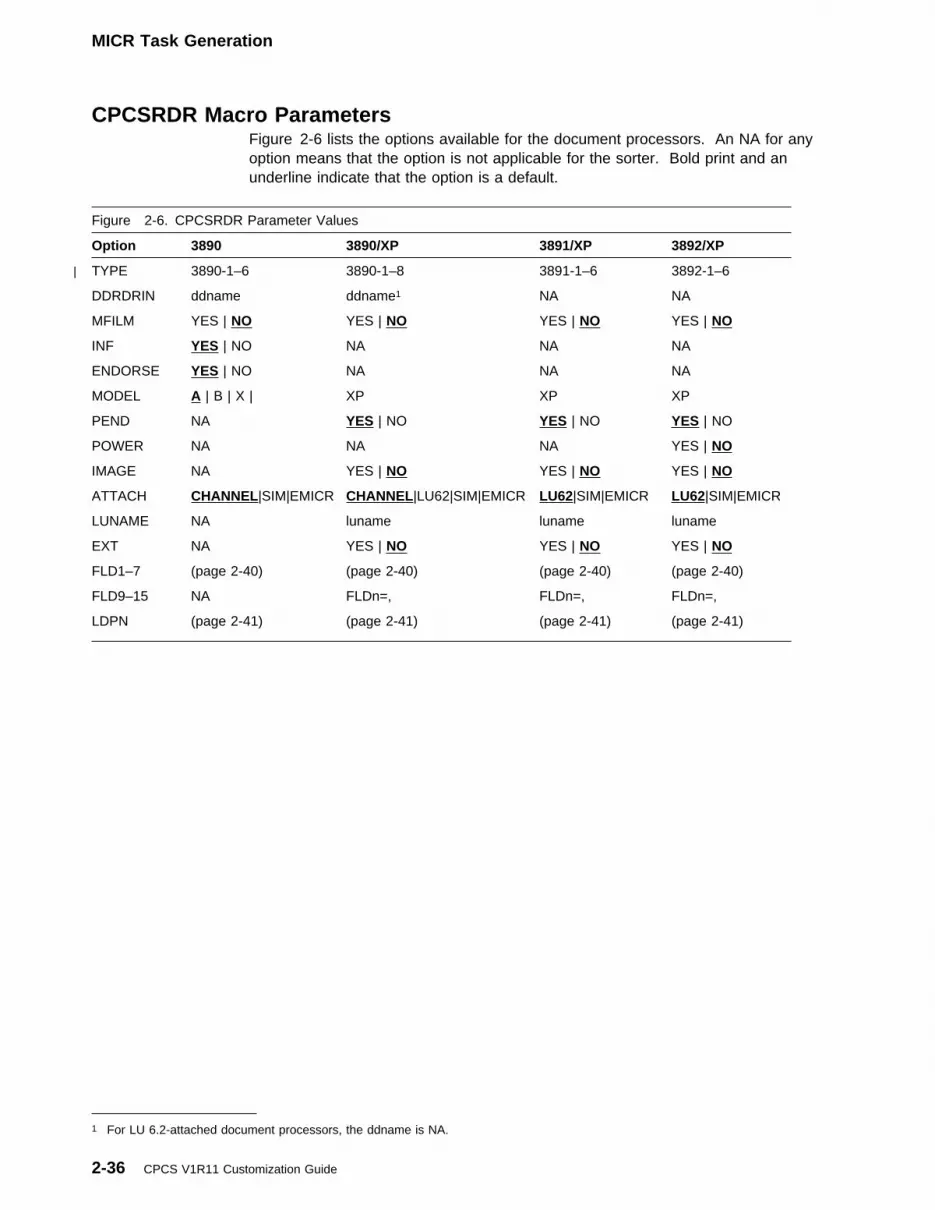
MICR Task Generation
CPCSRDR Macro ParametersFigure 2-6 lists the options available for the document processors. An NA for anyoption means that the option is not applicable for the sorter. Bold print and anunderline indicate that the option is a default.
Figure 2-6. CPCSRDR Parameter Values
Option 3890 3890/XP 3891/XP 3892/XP
TYPE 3890-1–6| 3890-1–8 3891-1–6 3892-1–6
DDRDRIN ddname ddname1 NA NA
MFILM YES | NO YES | NO YES | NO YES | NO
INF YES | NO NA NA NA
ENDORSE YES | NO NA NA NA
MODEL A | B | X | XP XP XP
PEND NA YES | NO YES | NO YES | NO
POWER NA NA NA YES | NO
IMAGE NA YES | NO YES | NO YES | NO
ATTACH CHANNEL|SIM|EMICR CHANNEL|LU62|SIM|EMICR LU62|SIM|EMICR LU62|SIM|EMICR
LUNAME NA luname luname luname
EXT NA YES | NO YES | NO YES | NO
FLD1–7 (page 2-40) (page 2-40) (page 2-40) (page 2-40)
FLD9–15 NA FLDn=, FLDn=, FLDn=,
LDPN (page 2-41) (page 2-41) (page 2-41) (page 2-41)
1 For LU 6.2-attached document processors, the ddname is NA.
2-36 CPCS V1R11 Customization Guide

MICR Task Generation
The following is a description of all the possible parameters for the documentprocessors.
TYPE={3890-n | 3891-n | 3892-n}Specifies the type of IBM document processor for this macro. You must selectone of the model numbers and include the number of stacker modules. The
| number of stacker modules is n. For a listing of the valid values, see| Figure 2-6 on page 2-36.
ATTACH={CHANNEL | LU62 | SIM | EMICR}This optional operand defines how the document processor attaches to thehost.
CHANNEL Specifies channel-attached document processors.
LU62 Specifies LU 6.2-attached document processors. This is thedefault for the 3891/XP and 3892/XP Document Processors.
SIM Specifies host-simulated document processors. The default valueis CHANNEL, except for 3891/XP and 3892/XP processors, forwhich the default is LU62. If you specify either CHANNEL or SIM,the DDRDRIN= parameter is required and the LUNAMEparameter is ignored. If you specify LU 6.2, the MODELparameter defaults to XP, and you should not specify DDRDRIN.
ATTACH=SIM defines a host-simulated document processor,which lets you run MICR without a physical document processor.ATTACH=SIM requires the 3890/XP MVS Support licensedprogram. You can create a set of simulated items, includingcontrol documents, in a data set and have these captured into theMDS. The simulator feature supports codeline data matching insubsequent passes. The codeline data match record, whichCPCS supplies to the simulated document processor, returns toCPCS as document read records. For more information on the
Name Operation Parameters
[symbol] CPCSRDR TYPE={3890-n | 3891-n | 3892-n}
[,ATTACH={CHANNEL | LU62 | SIM | EMICR}]
[,DDRDRIN=ddname]
[,LUNAME=nnnnnnnn]
[,MFILM={YES | NO}]
[,INF={YES | NO}]
[,ENDORSE={YES | NO}]
[,MODEL={A | B | X | XP}]
[,PEND={YES | NO}]
[,POWER={YES | NO}]
[,IMAGE={YES | NO}]
[,FLDn=(d,b,o,i)]
[,EXT={YES | NO}]
[,LDPN={nn}]
Chapter 2. Installation and Generation Procedures 2-37

MICR Task Generation
simulator, see the 3890/XP MVS Support and 3890/XP VSESupport Program Reference.
EMICR Specifies a host-simulated EMICR document processor forelectronic string processing. As with SIM, this option allows you torun MICR without a physical document processor.
DDRDRIN=ddnameSpecifies the name of the DD statement that identifies the document processorunit address. For a simulated document processor, the DD statement mustreference the sequential data set containing codeline data. For moreinformation about the unit address DD statement, see the CPCS Programmingand Diagnostic Guide. For information on dynamically allocating documentprocessors, see “Dynamically Allocating Data Sets” on page 2-23. You mustadd entries to the DKNDSAT table and then assemble and link DKNALLO.This parameter is not valid for ATTACH=LU62.
LUNAME=nnnnnnnnSpecifies the LU name for an LU 6.2 connection. This parameter is not validfor ATTACH=CHANNEL or ATTACH=SIM.
MFILM={YES | NO}Specifies whether the microfilm feature is present on the document processor.
INF={YES | NO}Specifies whether the item-numbering feature is present on the 3890 DocumentProcessor. You must activate this feature on the prime pass. However, thisoption permits the use of a document processor without this feature on asubsequent pass. The 3890/XP Series document processors do not requirethis parameter. You must supply information for item-numbering in the sortpattern definition record for these document processors.
The item sequence number consists of three parts:
� Location of item on microfilm. This is true whether or not the documentprocessor includes a microfilm unit.
� The document processor that you used to enter the work.
� The physical sequence of the items in the entry.
The physical sequence number is 6 digits for the 3890 and 8 digits for the3890/XP Series document processors. The 3890 Document Processors printthe last part of the item sequence number on each item.
CPCS stores the item sequence number in the old format (DISEQ) and the newformat (DISEQ12). This provides compatibility with your own application tasksand with third-party vendor software. DISEQ contains the same digits asDISEQ12, except for the leftmost 4 digits of the sequential number. Youshould not consider DISEQ as the unique sequence number for CPCS. If youdo not use DISEQ12 for your references, we cannot guarantee uniquesequence numbers.
ENDORSE={YES | NO}Specifies whether the endorsement feature is present on the 3890 DocumentProcessor. The sort-pattern definition activates this feature for prime passduring the initialization record SETDEV process.
Note: This parameter applies only to non-XP document processors.Application of this parameter to a 3890/XP Series document processor results
2-38 CPCS V1R11 Customization Guide

MICR Task Generation
in an MNOTE 4 and in ENDORSE=NO being set automatically. To specifywhether the endorse feature is present on a 3890/XP Series documentprocessor, set the PEND parameter.
MODEL={A | B | X | XP}This optional parameter specifies the model of the document processor. Themodel code identifies the amount of storage available for your stacker controlinstruction (SCI) programs.
Model Available StorageA 10KB 26KX 42KXP Between 64K and 6M
Note: In all models, you have 3K additional storage available for prime-passand high-speed entries. If you do not code this parameter for the 3890, theCPCSRDR macro uses A as the default. For the 3890/XP Series documentprocessors, the macro uses XP as the default. If you use ATTACH=LU62, thedefault value is XP; using other MODEL options causes an error.
PEND={YES | NO}Specifies whether the programmable endorse feature is present.
The sort-pattern definition controls the various endorse options (positioning,front, back, stamp) for the different sorts.
Note: This parameter applies only to the 3890/XP Series documentprocessors.
POWER={YES | NO}Specifies whether the power encode feature is present.
The sort pattern definition controls for the power encode options (path and font)for the different sorts.
Note: This parameter applies only to the 3892/XP Document Processors.
IMAGE={YES | NO}Specifies whether the image feature is present.
Note: This parameter applies to the 3890/XP Series document processors.
FLDn=(d,b,o,i)This optional parameter defines the settings for the 15 fields that can appear ona record (FLD1...FLD15). You can repeat this parameter for each field. Thevalue of n can be 1 through 7 or 9 through 15. You cannot define field 8. Thesettings are positional so, if you omit one, you must insert a comma torepresent it.
d Defines the total number of digits for this field. For variable-length fields,this is the maximum number of digits in the field. Do not use this value forfields 9 through 15. For extended fields, use the b parameter to specifythe length.
b Defines the number of bytes necessary to store this field in the bufferrecord of the document processor. Each digit in the field requires ahalfbyte (4 bits) of storage. This means that the value for this settingshould be one-half the value for the first setting (d), rounded up if the firstsetting is an odd number.
Chapter 2. Installation and Generation Procedures 2-39

MICR Task Generation
o Defines the options associated with the field. If you use these options,they must be in the order shown below and you must not separate them bycommas. The options are:
F Defines the field as a fixed-length field. If you omit this option, thefield will be variable in length. If you define a field as fixed, the fieldmust be on all documents.
Note: The shipped default for FLD1 and FLD5 is fixed.
D Specifies whether you want to transmit the dash from an encoded fieldto the record buffer of the document processor. If you omit this option,dash transmission does not occur and the dash does not occupy ahalfbyte in the record.
Usage Notes:
1. You must specify this option for field 5. The position of the dashdistinguishes Canadian checks from American checks.
2. You should be careful about using this option for other fields. Forexample, if you specify this option in field 3 (account number), and youinscribe a dash in field 3 of the tracer documents, unpredictable resultsoccur when the tracers are read.
S Specifies whether you want symbol error correction for the field
I Specifies whether to use the field during codeline data matching onsubsequent passes
i Specifies the digit error threshold of codeline data matching. See the3890/XP Programming Guide for a complete description of the codelinedata matching function.
If you do not include a parameter for fields 1 through 3 or 5 through 7, thefollowing default values are applied automatically:
[,FLD1=(10, | 5, | FSI, | 10)] [,FLD2=(6, | 3,| SI, | 6)] [,FLD3=(14, | 7, | SI, | 14)] [,FLD5=(9, | 5 , | FDSI, | 9)] [,FLD6=(2, | 1 , | SI, | 2)] [,FLD7=(10, | 5, | SI, | 10)]
If you omit the parameter for field 4 and fields 9 through 15, the macro doesnot generate any data for the omitted parameter. There are no default valuesfor these parameters.
Field 8 (not specified by the user) does have a default length of 6 bytes; thislength should be used in process buffer-length calculations.
2-40 CPCS V1R11 Customization Guide

MICR Task Generation
Important!
If you want to expand the MDS, you should use FLDn= parameters on theCPCSRDR macro. This enables your sorters to physically define the fieldsread by the sorters independently from the size of the MDS. Expansion ofthe MDS also automatically expands the size of the transmitted fields fromthe sorter if these FLDn= parameters are not specified.
A non-XP sorter is limited to 36 bytes of read data. A 3890/XP Seriesdocument processor is limited to 244 bytes of read data.
Violation of these limits generates a level-12 MNOTE (resulting in a badassembly of DKNMICR) and the message:
EFA366 SUM OF BYTE LENGTH FOR FIELDS 1-15 IS nnn,
CANNOT BE GREATER THAN xxx
where nnn is the sum of the read data lengths of all the defined fields, andxxx is either 36 for a 3890 Document Processor or 244 for a 3890/XPSeries document processor.
EXT={YES | NO}Specifies whether you are requesting the extended features of the 3890/XPSeries document processors for this initialization record (IREC). Thisparameter allows for an expanded initialization record.
Note: You must specify EXT=YES if you defined fields 9 through 15.
LDPN={nn}The logical document processor number is a unique 2-digit identifier fordocument processors. CPCS uses this number to find records in the itemsequence-number data set and to determine whether the item sequencenumber is in use, needs to be updated, or is available.
� If you do not specify a value in the CPCSRDR macros for your documentprocessors, the number defaults to 01 for the first document processor andincrements by 1 for each subsequent macro without a value for LDPN.
Note: Records 00 and 99 are reserved for CPCS use.
� If you specify a value, it must be greater than the LDPN value for theprevious document processor.
The following table is an example of the effect of the LDPN parameter:
RDRn
Unit Number
LDPN CodedValue
LDPNAssignedValue
RDR1 01 Omitted 01 DefaultRDR2 02 Omitted 02 DefaultRDR3 03 LDPN=11 11 AssignedRDR4 04 Omitted 12 DefaultRDR5 05 Omitted 13 Default
Chapter 2. Installation and Generation Procedures 2-41
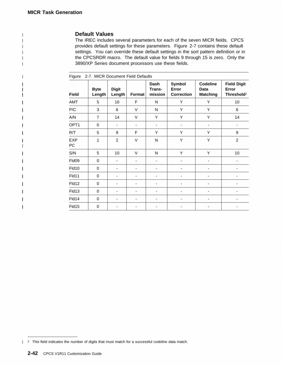
MICR Task Generation
| Default Values| The IREC includes several parameters for each of the seven MICR fields. CPCS| provides default settings for these parameters. Figure 2-7 contains these default| settings. You can override these default settings in the sort pattern definition or in| the CPCSRDR macro. The default value for fields 9 through 15 is zero. Only the| 3890/XP Series document processors use these fields.
| Figure 2-7. MICR Document Field Defaults
| Field| Byte| Length| Digit| Length| Format
| Dash| Trans-| mission
| Symbol| Error| Correction
| Codeline| Data| Matching
| Field Digit| Error| Threshold2
| AMT| 5| 10| F| N| Y| Y| 10
| P/C| 3| 6| V| N| Y| Y| 6
| A/N| 7| 14| V| Y| Y| Y| 14
| OPT1| 0| -| -| -| -| -| -
| R/T| 5| 9| F| Y| Y| Y| 9
| EXP| PC| 1| 2| V| N| Y| Y| 2
| S/N| 5| 10| V| N| Y| Y| 10
| Fld09| 0| -| -| -| -| -| -
| Fld10| 0| -| -| -| -| -| -
| Fld11| 0| -| -| -| -| -| -
| Fld12| 0| -| -| -| -| -| -
| Fld13| 0| -| -| -| -| -| -
| Fld14| 0| -| -| -| -| -| -
| Fld15| 0| -| -| -| -| -| -
| 2 This field indicates the number of digits that must match for a successful codeline data match.
2-42 CPCS V1R11 Customization Guide
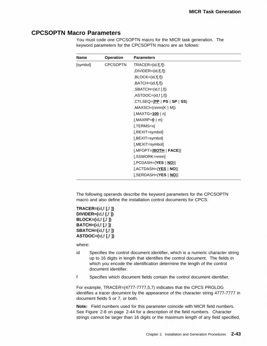
MICR Task Generation
CPCSOPTN Macro ParametersYou must code one CPCSOPTN macro for the MICR task generation. Thekeyword parameters for the CPCSOPTN macro are as follows:
The following operands describe the keyword parameters for the CPCSOPTNmacro and also define the installation control documents for CPCS:
TRACER=(id,f [,f ]) DIVIDER=(id,f [,f ]) BLOCK=(id,f [,f ]) BATCH=(id,f [,f ]) SBATCH=(id,f [,f ]) ASTDOC=(id,f [,f ])
where:
id Specifies the control document identifier, which is a numeric character stringup to 16 digits in length that identifies the control document. The fields inwhich you encode the identification determine the length of the controldocument identifier.
f Specifies which document fields contain the control document identifier.
For example, TRACER=(4777-7777,5,7) indicates that the CPCS PROLOGidentifies a tracer document by the appearance of the character string 4777-7777 indocument fields 5 or 7, or both.
Note: Field numbers used for this parameter coincide with MICR field numbers.See Figure 2-8 on page 2-44 for a description of the field numbers. Characterstrings cannot be larger than 16 digits or the maximum length of any field specified,
Name Operation Parameters
[symbol] CPCSOPTN TRACER=(id,f[,f])
,DIVIDER=(id,f[,f])
,BLOCK=(id,f[,f])
,BATCH=(id,f[,f])
,SBATCH=(id,f [,f])
,ASTDOC=(id,f [,f])
,CTLSEQ={PP | PS | SP | SS}
,MAXSCI=(nnnn{K | M})
[,MAXTG=100 | n]
[,MAXRP=0 | m]
[,TERMS=x]
[,REXIT=symbol]
[,BEXIT=symbol]
[,MEXIT=symbol]
[,MFOPT={BOTH | FACE}]
[,SSWORK=nnnn]
[,PCDASH={YES | NO}]
[,ACTDASH={YES | NO}]
[,SERDASH={YES | NO}]
Chapter 2. Installation and Generation Procedures 2-43

MICR Task Generation
whichever is smaller. If you encode the field on the control document with a dash,you must include the dash in this parameter. You must encode the dash in bothfields. While you can specify multiple control-document identifier fields, therecommended method is to use the routing number field solely for this purpose.See Figure 2-8 for field length limitations.
The MICR task identifies a control document by comparing the contents of specifieddocument fields with the character strings indicated. If you specify more than onefield, then the task makes multiple comparisons to identify the document. A matchon any field causes the MICR task to recognize the document as a controldocument. Specific fields of control documents are arbitrarily defined and cannotbe used for control-document identifiers. See Figure 2-9 for control-document fielddefinitions.
CTLSEQ={PP | PS | SP | SS}Specifies the location of batch, sub-batch, and block control documents relativeto the document stream, where:
P Specifies that the control document precedes the items it controls.S Specifies that the control document follows the items it controls.
Figure 2-8. Control-Document Field Identifiers
Document Field
CPCSIdentifier
MaximumLength
Amount 1 16 digitsProcess control 2 16 digitsOn-us (account number) 3 16 digitsRouting number 5 16 digitsAuxiliary on-us (serial number) 7 16 digits
Figure 2-9. Control-Document Field Definitions
DocumentType
Field ID
7 5 3 2 1
Tracer TGIDZ
Divider[ KillbundleID
Block Control amount
Batch Control amount
Sub-batch Control amount
Notes:
1. Tracer-group identification (TGID). You must pre-encode the TGID in field 3. It consistsof a 7-digit number, XXXX-YYY, where XXXX is constant for all tracer slips within agroup and YYY is greater than or equal to 1 and less than or equal to (MAXRP+9). YYYmust be unique.
If you code the parameter ACTDASH=YES, the TGID field on the tracer documentscannot contain a dash between the tracer group number and the slip number.
2. CPCS does not record data in the MDS record for fields 5, 2, and 1. CPCS controlinformation occupies these fields. However, you can use these fields as documentidentifiers.
2-44 CPCS V1R11 Customization Guide

MICR Task Generation
The first character refers to the position of block control documents and thesecond refers to the position of batch and sub-batch control documents. Forexample, CTLSEQ=PS indicates that block control documents precede thework and batch control documents follow the work.
MAXSCI=(nnnn[K | M])This operand limits the size of the temporary buffer used to load SCI programs.You can define space in 1024-byte (K) increments or in 1048576-byte (M)increments. If MAXSCI=0, no limit is set.
MAXTG=100 | nSpecifies the maximum number of tracer groups permitted in the systemconcurrently. When the number reaches this threshold, no more tracer groupscan enter the system until there is an end-cycle operation. The default valuefor MAXTG is 100. Changing this parameter requires a CPCS cold start toinitialize the pass-to-pass control file. For more information on CPCS cold start,see “STYPE Parameter” on page 1-7.
MAXRP=0 | mSpecifies the number of tracer slips required for the sort pattern with the mostrehandle pockets. You can determine this number by totaling the number ofslips specified in the R-records of each sort pattern and selecting the maximum.For example, if a specific sort pattern has five rehandle pockets, defined as tworehandle pockets on the prime pass and three rehandle pockets on pass 2, andeach rehandle pocket receives two tracer slips, MAXRP is 10. If you specifythe tracers in the Kill-Pockets Sort-Pattern Definition option, you should alsoinclude additional tracer slips to allow one tracer slip for each prime-pass killpocket. The default value for MAXRP is zero.
For more information on sort patterns and sort pattern R records, see“Sort-Pattern-Definition Record Formats” on page 4-17.
Usage Notes:
1. For any given sort pattern, MAXRP plus 9 is the minimum number of tracerslips required in each tracer group for CPCS to effectively maintainpass-to-pass controls.
2. Changing this parameter requires a CPCS cold start to initialize thepass-to-pass control file. You should make this number larger than yourcurrent requirements to avoid cold starts.
3. MAXRP serves as a factor for calculating the physical record size for thetracer pass-to-pass data set. Records are established in the tracer data setto store the RSCB for each sorter. There is a direct size relationshipbetween the tracer record calculated using the MAXRP and the tracerrecord required for MAXRP+9 sorters. The CPCSOPTN macro ensuresthat the number of sorters is no more than MAXRP+9 by issuing MNOTE12 for violations of this rule.
TERMS=xSpecifies the number of CPCS terminals that can communicate concurrentlywith the MICR task. If you code this parameter, it must be large enough toinclude at least one terminal for every CPCSRDR macro specified. If you omitthis parameter, it defaults to the number of CPCSRDR macros used.
Chapter 2. Installation and Generation Procedures 2-45

MICR Task Generation
REXIT=symbolSpecifies a user-written DKNMREAD exit routine that receives control eachtime a codeline data record is retrieved from the document processor. The exitroutine permits user processing of items beyond those that the userstacker-selection routine has already processed. If specified, the routine loadsduring MICR task initialization and remains resident throughout CPCS runs.For correct operation, you must ensure that this routine is reusable or reentrant.The same copy of the program is used for all active document processors. Formore information about the user exit for DKNMREAD, see “DKNMREADDocument-Processing User Exit” on page 4-138.
BEXIT=symbolSpecifies a user-written DKNMBEGN exit routine that receives control after thefinal verification by the operator of the DKNMBEGN display and before startingthe entry. The exit routine lets the user check all data that the operator enteredand decide whether to permit the entry to start or to return a message to theoperator to correct the data. If you specify this routine, it loads during MICRtask initialization and remains resident throughout CPCS runs. The user mustensure the re-usability or reentrance of this routine for correct operation. Allactive document processors use the same copy of the program. For moreinformation about the user exit for DKNMBEGN, see “DKNMBEGN UserProcessing Exit” on page 4-130.
MEXIT=symbolSpecifies a user-written DKNMIPI exit routine that receives control each timeDKNMIPI has prepared another record to be sent to the sorter for codeline datamatching. The exit routine permits the user to suppress, edit, or insert recordsinto the data-matching process. This DKNMIPI exit is a default only; otherDKNMIPI exits, specified in bank control or sort pattern definition entries, canoverride it. Regardless of its source, you must ensure that the DKNMIPIroutine is re-usable and reentrant. For more information about the DKNMIPIuser exit, see “DKNMIPI User Processing Exit” on page 4-136.
MFOPT={BOTH | FACE}Specifies how document processors with the microfilm feature initialize, where
BOTH Specifies duplex mode, which records both sides of the document
FACE Specifies duo mode operation, which records only the front of thedocument.
SSWORK=nnnnSpecifies the amount of additional 24-bit storage (in bytes) that you want foruse as a work area during the running of:
� OLRR edit routine� MICR user document processing exit (DKNMREAD).
The maximum size for SSWORK is 2040. For a description of the extendedstorage, see “MICR User-Parameter Area (MUPA)” on page 4-54.
2-46 CPCS V1R11 Customization Guide

MICR Task Generation
PCDASH={YES | NO}ACTDASH={YES | NO}SERDASH={YES | NO}
Controls dash transmission from the document processor for the processcontrol, account number, and serial number fields, respectively. (The defaultvalues shown above correspond to the original release of 3890 support inwhich these parameters were not available.)
If you use ACTDASH=YES, the TGID field on the tracer documents cannotcontain a dash between the tracer group number and the slip number.
Chapter 2. Installation and Generation Procedures 2-47

Expanding the Mass Data Set
Expanding the Mass Data SetThe purpose of the MDS expansion is to enable you to define, within specifiedlimits, all field sizes for records stored in the MDS. This lets you customize theMDS records according to your own needs. You can vary the size of fields 1through 7, but not the sequence number field (field 8). Field 8 has internalrequirements and dependencies.
MDX Macro ParametersThe MDX macro controls the MDS record expansion. IBM distributes CPCS withthe MDX macro defined for the standard 50-byte record. You can customize theMDX parameter list to define a record according to your needs.
For example, if you want to include a field in your MDS record that containsremittance data, you can define one of the optional fields (fields 9 through 15) forthis purpose. You might also want to define the amount field (field 1) on the MICRdocument with a length of 12 to take advantage of the larger field processingcapabilities of the 3890/XP Series document processors.
Important!
1. If yours is a multi-bank installation, all of your financial institutions must usethe same MDS record, even though they might not all need the expandeddata. Each field must be as large as the largest required field size.
2. If you decide to expand the MDS, use FLDn= parameters on the CPCSRDRmacro. This enables your sorters to physically define the fields read by thesorters independently from the size of the MDS. Expansion of the MDSautomatically expands the size of the transmitted fields from the sorter ifthese FLDn= parameters are not specified.
3. A non-XP sorter is limited to 36 bytes of read data. A 3890/XP Seriesdocument processor is limited to 244 bytes of read data.
Violation of these limits causes a level 12 MNOTE (resulting in a badassembly of DKNMICR) and the message:
EFA366 SUM OF BYTE LENGTH FOR FIELDS 1-15 IS nnn,
CANNOT BE GREATER THAN xxx
where nnn is the sum of the read data lengths of all the defined fields, andxxx is either 36 for a 3890 Document Processor or 244 for a 3890/XPSeries document processor.
2-48 CPCS V1R11 Customization Guide

Expanding the Mass Data Set
For more information about the CPCSRDR macro and the FLDn= parameter, see“CPCSRDR Macro Parameters” on page 2-36.
The following shows the syntax for the MDX macro:
MDXFyySpecifies the field that you are defining. yy can be field numbers 01 through15, except 08. (You must include the 0.)
An additional field may be defined to reserve space in the mass data set bycoding RP in the yy location. If RP is used, only the internal field length isspecified. Any other parameters are ignored. The reserved space is placedfollowing field flag 3.
m Specifies the internal field length that you need. The field size must be lessthan or equal to the maximum size permitted. Field length refers to the numberof bytes required to store the data in the MDS record. Data for fields 1 through7 is stored at the rate of 2 digits per byte. Data for fields 9 through 15 is storedon a one-for-one ratio. Do not change field 8.
A size of zero indicates that the field is to be skipped and it will be commentedout in the DSECT or copybooks. Zero is valid only for field 4 and fields9 through 15. No other field can be set to zero.
'descriptor'Specifies the unique field descriptor that you want printed on reports. It can beup to 12 characters, including spaces and special characters. The descriptormust be in single quotation marks.
For example, you can define field 9 to be used for remittances. If you specifythis parameter as 'REMITTANCE', your reports will have a REMITTANCE labelon any information retrieved from field 9. For examples, see “MDX MacroExamples (Input Parameters)” on page 2-50.
displenSpecifies the number of displayable digits that are stored in the field. Thismust be more than zero, if you want the field to print on a report, and less thanor equal to twice the defined field size (m, as described above). If you set thisvalue for a field to zero, the field will not print on a report. If you do not codethis parameter (in other words, if you leave it as a default by placing a commain the corresponding position), the value defaults to twice the defined field size(m).
Note: This parameter is only valid for fields 1 through 7. For all other fields,omit the parameter but include the comma to delimit the positional parameter.The MDX macro sets this parameter to the defined size of the field.
Name Operation Parameters
[symbol] MDX MDXFyy ,[m] ,['descriptor'] ,[displen] ,[justification] ,[truncation] ,[fill character] ,[extrlen]
Chapter 2. Installation and Generation Procedures 2-49
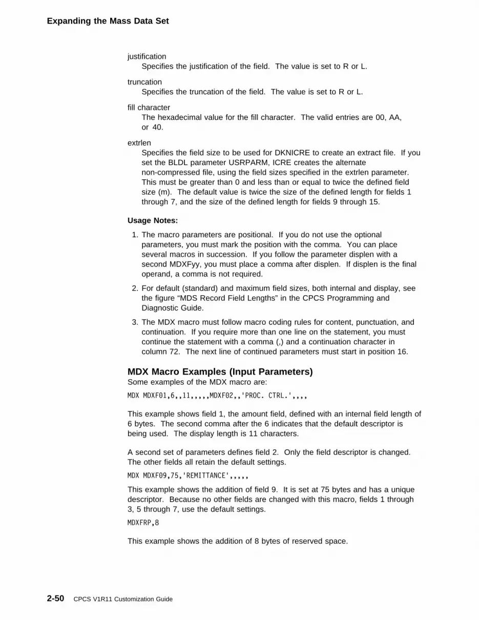
Expanding the Mass Data Set
justificationSpecifies the justification of the field. The value is set to R or L.
truncationSpecifies the truncation of the field. The value is set to R or L.
fill characterThe hexadecimal value for the fill character. The valid entries are 00, AA,or 40.
extrlenSpecifies the field size to be used for DKNICRE to create an extract file. If youset the BLDL parameter USRPARM, ICRE creates the alternatenon-compressed file, using the field sizes specified in the extrlen parameter.This must be greater than 0 and less than or equal to twice the defined fieldsize (m). The default value is twice the size of the defined length for fields 1through 7, and the size of the defined length for fields 9 through 15.
Usage Notes:
1. The macro parameters are positional. If you do not use the optionalparameters, you must mark the position with the comma. You can placeseveral macros in succession. If you follow the parameter displen with asecond MDXFyy, you must place a comma after displen. If displen is the finaloperand, a comma is not required.
2. For default (standard) and maximum field sizes, both internal and display, seethe figure “MDS Record Field Lengths” in the CPCS Programming andDiagnostic Guide.
3. The MDX macro must follow macro coding rules for content, punctuation, andcontinuation. If you require more than one line on the statement, you mustcontinue the statement with a comma (,) and a continuation character incolumn 72. The next line of continued parameters must start in position 16.
MDX Macro Examples (Input Parameters)Some examples of the MDX macro are:
MDX MDXF�1,6,,11,,,,,MDXF�2,,'PROC. CTRL.',,,,
This example shows field 1, the amount field, defined with an internal field length of6 bytes. The second comma after the 6 indicates that the default descriptor isbeing used. The display length is 11 characters.
A second set of parameters defines field 2. Only the field descriptor is changed.The other fields all retain the default settings.
MDX MDXF�9,75,'REMITTANCE',,,,,
This example shows the addition of field 9. It is set at 75 bytes and has a uniquedescriptor. Because no other fields are changed with this macro, fields 1 through3, 5 through 7, use the default settings.
MDXFRP,8
This example shows the addition of 8 bytes of reserved space.
2-50 CPCS V1R11 Customization Guide
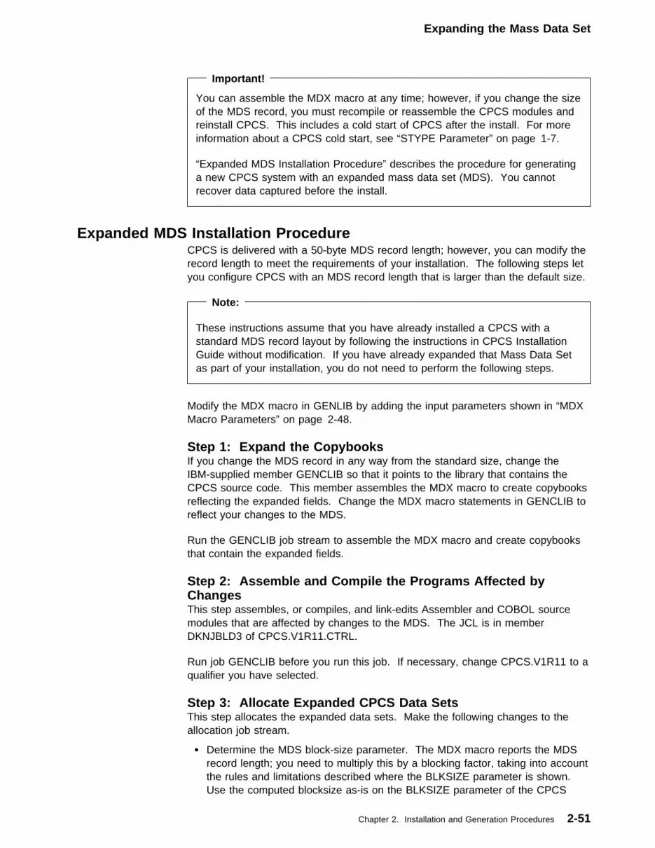
Expanding the Mass Data Set
Important!
You can assemble the MDX macro at any time; however, if you change the sizeof the MDS record, you must recompile or reassemble the CPCS modules andreinstall CPCS. This includes a cold start of CPCS after the install. For moreinformation about a CPCS cold start, see “STYPE Parameter” on page 1-7.
“Expanded MDS Installation Procedure” describes the procedure for generatinga new CPCS system with an expanded mass data set (MDS). You cannotrecover data captured before the install.
Expanded MDS Installation ProcedureCPCS is delivered with a 50-byte MDS record length; however, you can modify therecord length to meet the requirements of your installation. The following steps letyou configure CPCS with an MDS record length that is larger than the default size.
Note:
These instructions assume that you have already installed a CPCS with astandard MDS record layout by following the instructions in CPCS InstallationGuide without modification. If you have already expanded that Mass Data Setas part of your installation, you do not need to perform the following steps.
Modify the MDX macro in GENLIB by adding the input parameters shown in “MDXMacro Parameters” on page 2-48.
Step 1: Expand the CopybooksIf you change the MDS record in any way from the standard size, change theIBM-supplied member GENCLIB so that it points to the library that contains theCPCS source code. This member assembles the MDX macro to create copybooksreflecting the expanded fields. Change the MDX macro statements in GENCLIB toreflect your changes to the MDS.
Run the GENCLIB job stream to assemble the MDX macro and create copybooksthat contain the expanded fields.
Step 2: Assemble and Compile the Programs Affected byChangesThis step assembles, or compiles, and link-edits Assembler and COBOL sourcemodules that are affected by changes to the MDS. The JCL is in memberDKNJBLD3 of CPCS.V1R11.CTRL.
Run job GENCLIB before you run this job. If necessary, change CPCS.V1R11 to aqualifier you have selected.
Step 3: Allocate Expanded CPCS Data SetsThis step allocates the expanded data sets. Make the following changes to theallocation job stream.
� Determine the MDS block-size parameter. The MDX macro reports the MDSrecord length; you need to multiply this by a blocking factor, taking into accountthe rules and limitations described where the BLKSIZE parameter is shown.Use the computed blocksize as-is on the BLKSIZE parameter of the CPCS
Chapter 2. Installation and Generation Procedures 2-51
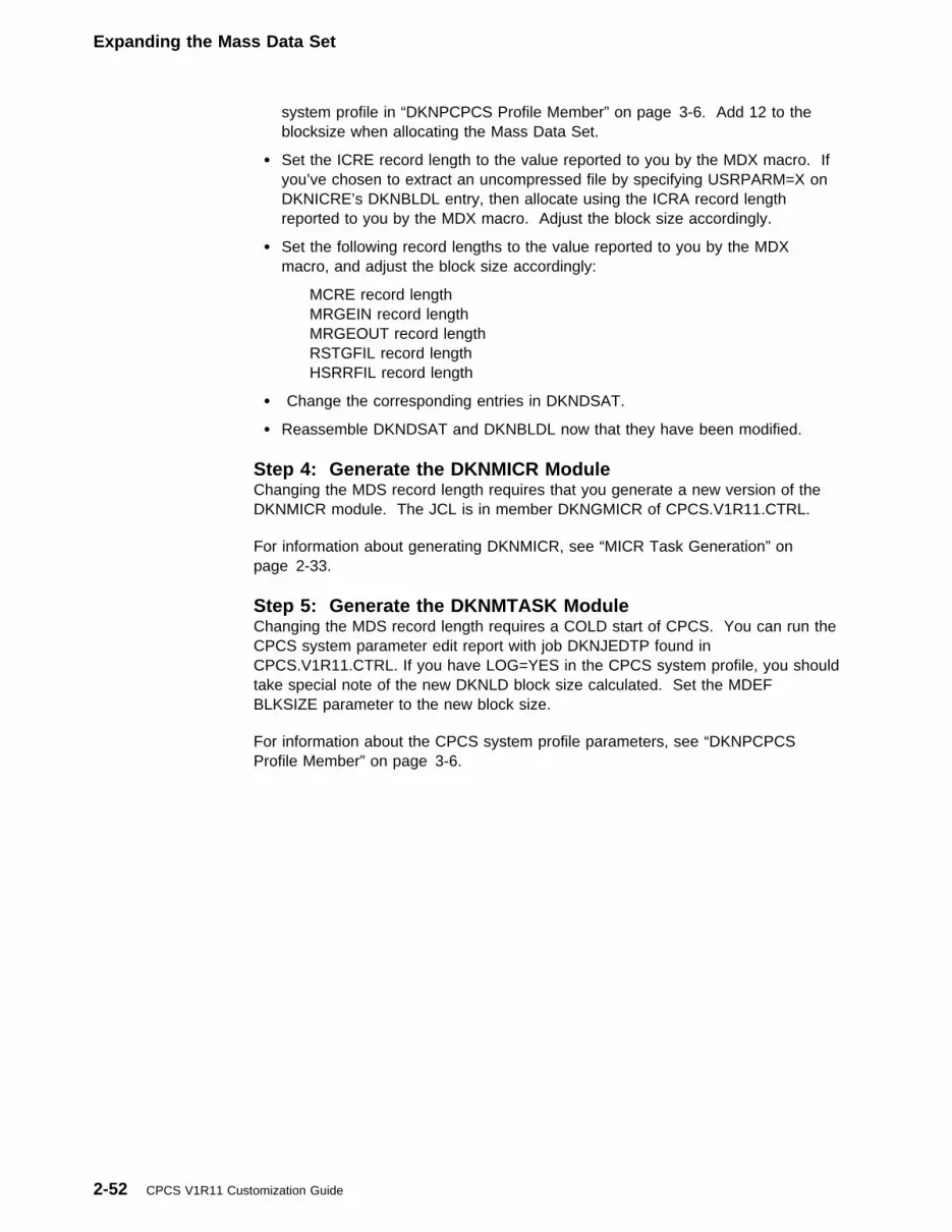
Expanding the Mass Data Set
system profile in “DKNPCPCS Profile Member” on page 3-6. Add 12 to theblocksize when allocating the Mass Data Set.
� Set the ICRE record length to the value reported to you by the MDX macro. Ifyou’ve chosen to extract an uncompressed file by specifying USRPARM=X onDKNICRE’s DKNBLDL entry, then allocate using the ICRA record lengthreported to you by the MDX macro. Adjust the block size accordingly.
� Set the following record lengths to the value reported to you by the MDXmacro, and adjust the block size accordingly:
MCRE record lengthMRGEIN record lengthMRGEOUT record lengthRSTGFIL record lengthHSRRFIL record length
� Change the corresponding entries in DKNDSAT.
� Reassemble DKNDSAT and DKNBLDL now that they have been modified.
Step 4: Generate the DKNMICR ModuleChanging the MDS record length requires that you generate a new version of theDKNMICR module. The JCL is in member DKNGMICR of CPCS.V1R11.CTRL.
For information about generating DKNMICR, see “MICR Task Generation” onpage 2-33.
Step 5: Generate the DKNMTASK ModuleChanging the MDS record length requires a COLD start of CPCS. You can run theCPCS system parameter edit report with job DKNJEDTP found inCPCS.V1R11.CTRL. If you have LOG=YES in the CPCS system profile, you shouldtake special note of the new DKNLD block size calculated. Set the MDEFBLKSIZE parameter to the new block size.
For information about the CPCS system profile parameters, see “DKNPCPCSProfile Member” on page 3-6.
2-52 CPCS V1R11 Customization Guide
DKNVTASK Installation
VTAM Installation Requirements for CPCSTo run CPCS, you must perform the following Virtual Telecommunications AccessMethod (VTAM) tasks:
1. Assemble and link an installation node-name table (even if you do not specifyany entries) into the CPCS load library and name it DKNVNODE.
2. Define the CPCS application and all CPCS terminals in the installation’s VTAMconfiguration tables for System Network Architecture (SNA) local and non-SNAlocal terminals. You must define all SNA remote terminals within your networkcontrol program (NCP) generation.
To define CPCS as a VTAM application program, use the APPL statement inSYS1.VTAMLST. For user flexibility, the distributed DKNVTASK program takes theCPCS application program name from the job-step name of the EXEC statement inthe CPCS job stream. Therefore, the CPCS application name on the APPLstatement in SYS1.VTAMLST must correspond to the name you specify as thejob-step name in the EXEC statement.
If you do not want to use this method to name the CPCS application, you canchange two SETC variables within the DKNVTASK program (immediately followingthe DKNVTASK statement) to cause the EXEC statement to be ignored. You canchange the &ACBLAB variable from &ACBLAB SETC � to &ACBLAB SETC VCVTASK,which is the name field within the DKNVTASK module for the CPCS applicationname. This change causes the VTAM products to use the name specified in theDKNVTASK module as the application name.
The distributed name within the DKNVTASK module is CPCS (label VCVTASK).You can change this name by changing the 1- to 8-character alphanumeric value inthe &ACBNAME variable. This variable specifies the CPCS application name and itmust be the same as the name specified in the APPL statement withinSYS1.VTAMLST.
DKNVTASK InstallationThe DKNVTASK program includes a number of global variables that let you:
� Omit the abend processor (CSECT VPSTA000)
� Omit the issuing of some or all WTOs
� Omit the expansion of the CPCS, VTAM, or DKNVTASK control block DSECTs
� Omit the issuing of snap dumps for various error conditions
� Set the number of various threshold counters
� Assign an application name (APPLID) to the CPCS task or use the job-stepname from the CPCS job stream
� Set session protocol definitions for the session BIND
� Assign program function keys to either CPCS commands or tasks or both.
Figure 2-10 on page 2-54 lists the DKNVTASK variables, their initial settings, andthe functions they perform.
Chapter 2. Installation and Generation Procedures 2-53

DKNVTASK Installation
Figure 2-10 (Page 1 of 3). DKNVTASK Variables
Variable Setting Function
Control block expansions (0=do not expand, 1=expand):
&PVTAMB SETB 0 Expand VTAM control blocks.
&PVTASKB SETB 0 Expand DKNVTASK control blocks (VDSECT).
&PVMSGS SETB 0 Expand DKNVTASK message table.
&PCPCSB SETB 0 Expand CPCS control blocks.
Include or omit processing routines (0=include, 1=omit):
&SNAPS SETB 0 0= Issue snap dumps.
1= Do not issue a snap dump for control blockswhen session error conditions occur (forexample, I/O errors or data-stream errors).
&STOP SETB 1 0= Stop DKNVTASK during initialization. Requiresa reply on the console to continue (any replyOK).
1= Do not stop DKNVTASK.
&STA SETB 1 0= Include the DKNVTASK STAE routine.
1= Do not include the DKNVTASK STAE routine.The DKNVTASK STAE routine interceptsDKNVTASK abends, takes a snap dump, issuesabend messages, and attempts to recover theabending session.
&WTOALL SETB 0 0= Include all WTOs.
1= Omit all WTOs (routine VIWTO000 returns tothe caller).
&WTOSES SETB 0 0= Include logon/logoff WTOs.
1= Omit logon/logoff WTOs.
&WTOIOR SETB 0 0= Include I/O error WTOs.
1= Omit I/O error WTOs.
&WTOABD SETB 0 0= Include abend processor WTOs.
1= Omit abend processor WTOs (except for theSTA abend WTO).
Note: The DKNVTASK program is distributed with the above SETB settings.
Threshold counters:
&STACRSH SETA 25 STAE routine-number of session stops that canoccur before CPCS stops with an abend 119 (see&STAABRT).
&STAABRT SETA 4 STAE routine-number of times that an abendedsession can recover before it stops. Each time asession stops, the crash counter increments by 1(see &STACRSH).
2-54 CPCS V1R11 Customization Guide
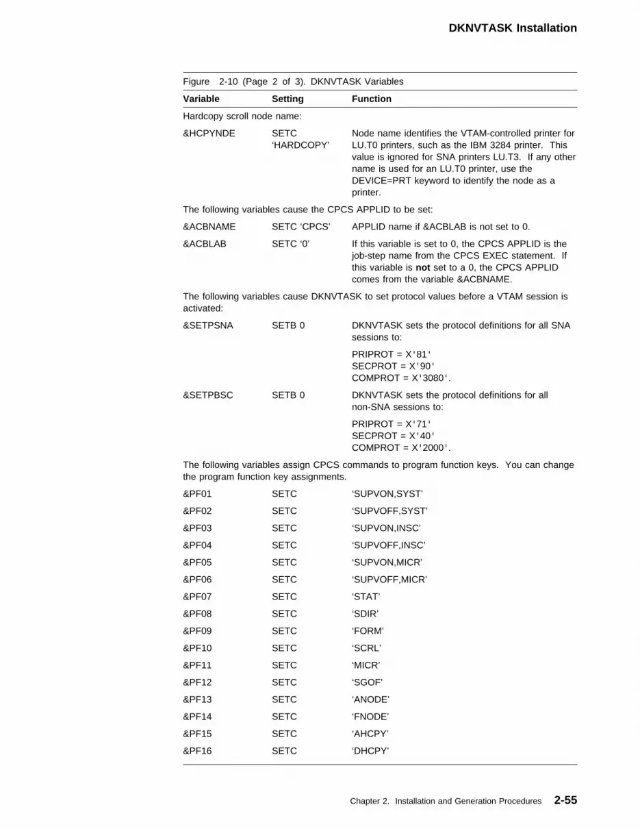
DKNVTASK Installation
Figure 2-10 (Page 2 of 3). DKNVTASK Variables
Variable Setting Function
Hardcopy scroll node name:
&HCPYNDE SETC‘HARDCOPY’
Node name identifies the VTAM-controlled printer forLU.T0 printers, such as the IBM 3284 printer. Thisvalue is ignored for SNA printers LU.T3. If any othername is used for an LU.T0 printer, use theDEVICE=PRT keyword to identify the node as aprinter.
The following variables cause the CPCS APPLID to be set:
&ACBNAME SETC ‘CPCS’ APPLID name if &ACBLAB is not set to 0.
&ACBLAB SETC ‘0’ If this variable is set to 0, the CPCS APPLID is thejob-step name from the CPCS EXEC statement. Ifthis variable is not set to a 0, the CPCS APPLIDcomes from the variable &ACBNAME.
The following variables cause DKNVTASK to set protocol values before a VTAM session isactivated:
&SETPSNA SETB 0 DKNVTASK sets the protocol definitions for all SNAsessions to:
PRIPROT = X'81'SECPROT = X'90'COMPROT = X'3080'.
&SETPBSC SETB 0 DKNVTASK sets the protocol definitions for allnon-SNA sessions to:
PRIPROT = X'71'SECPROT = X'40'COMPROT = X'2000'.
The following variables assign CPCS commands to program function keys. You can changethe program function key assignments.
&PF01 SETC ‘SUPVON,SYST’
&PF02 SETC ‘SUPVOFF,SYST’
&PF03 SETC ‘SUPVON,INSC’
&PF04 SETC ‘SUPVOFF,INSC’
&PF05 SETC ‘SUPVON,MICR’
&PF06 SETC ‘SUPVOFF,MICR’
&PF07 SETC ‘STAT’
&PF08 SETC ‘SDIR’
&PF09 SETC ‘FORM’
&PF10 SETC ‘SCRL’
&PF11 SETC ‘MICR’
&PF12 SETC ‘SGOF’
&PF13 SETC ‘ANODE’
&PF14 SETC ‘FNODE’
&PF15 SETC ‘AHCPY’
&PF16 SETC ‘DHCPY’
Chapter 2. Installation and Generation Procedures 2-55

DKNVTASK Installation
Figure 2-10 (Page 3 of 3). DKNVTASK Variables
Variable Setting Function
&PF17 SETC ‘PDUMP’
&PF18 SETC ‘PBUFF’
&PF19 SETC ‘VWHO’
&PF20 SETC Not defined
&PF21 SETC Not defined
&PF22 SETC ‘CANCEL’
&PF23 SETC ‘STOP’
&PF24 SETC ‘ALLO’
DKNVTASK Node-Name Table DescriptionThe node-name table (DKNVNODE) is a non-executable CSECT that theDKNVTASK program loads at run time. It contains node names and passwords forthe VTAM terminal devices. This table has two sections that are used to specifythose terminals in the VTAM network that are primary and those terminals that logon CPCS as auxiliary terminals. If you specify a terminal as a primary CPCSterminal, it automatically logs on CPCS during initialization, and CPCS writes itslogo to the screen. If you specify a terminal as an auxiliary CPCS terminal, itrequires the standard VTAM command LOGON to log on CPCS. The LOGONcommand causes CPCS to write its logo to the screen and to identify the terminalas a standard CPCS terminal.
If you do not specify any primary CPCS terminals in the node-name table, allterminals that CPCS uses must log on the VTAM products as auxiliary terminals.In this case, terminals are not automatically assigned to CPCS during CPCSinitialization. CPCS does not write logos to any terminal, and any terminal in theVTAM network can log on CPCS. If you do not specify any terminals as auxiliaryCPCS terminals in the node-name table, any node in the VTAM network can log onCPCS and function as a CPCS terminal.
Along with node names, the node-name table can also contain logon passwords foreach primary and auxiliary node specified. If the password is present, you mustspecify the password as data in the logon message. The password entered in thelogon message is checked against the password in the node-name table for theterminal that is logged on. For auxiliary node names, the password is checkedeach time that the terminal is logged on. For primary node names, the password isonly checked if the LOGOFF command logs the terminal off CPCS and a laterattempt is made to log it back on CPCS with a VTAM LOGON request.
You create DKNVNODE by coding, assembling, and link-editing VNODE macrostatements into your load library (see “VNODE Macro Description” on page 2-57).For each VNODE statement that you code, an entry is created as either a primarynode-name entry or an auxiliary node-name entry in the node-name table.
On each VNODE macro statement, you must code a NODE=node-nameparameter, but the PASSWD=password parameter is optional. Coding the CPCSparameter is optional for primary node names because the default is CPCS=YES.However, it is required for auxiliary CPCS terminals (CPCS=NO). You can codethe DEVICE parameter to indicate whether the device is a display (CRT) or a scroll
2-56 CPCS V1R11 Customization Guide

DKNVTASK Installation
printer (SCR). DEVICE=CRT is the default. The NEND=YES parameter isrequired for the last VNODE macro statement to end the assembly process. If thelast VNODE macro statement does not contain the NEND=YES parameter, theVNODE macro does not generate the node-name table.
You must link-edit the output generated by the assembly of the VNODE macrosinto your load library as DKNVNODE.
VNODE Macro DescriptionThe VNODE macro generates the node-name table CSECT as previouslydescribed in “DKNVTASK Node-Name Table Description” on page 2-56. Eachvalid issuance of the macro results in a node-name entry being placed in either theprimary node name section or the auxiliary node-name section of the node-nametable (DKNVNODE). The table generation process continues until it reaches amacro with the NEND=YES parameter or until there are no more macro requests inthe input stream. If the last processed macro does not include a NEND=YESparameter, it does not create a CSECT END statement and does not generateassembly errors.
NODE=xxxxxxxxAn alphanumeric, 1- to 8-character node name of the node to be placed ineither the primary or auxiliary node-name table.
CPCS={YES | NO}Specifies whether the node-name entry is in the primary or auxiliary node-nametable, where
YES Specifies that the node-name entry is in the primary node-name table.The terminal is considered a primary CPCS terminal and is put intosession with CPCS when CPCS starts.
NO Specifies that the node-name entry is in the auxiliary node-name tableand must be put into session with CPCS by a VTAM LOGON request.
NEND={NO | YES}Specifies either that this is the last node name in the node-name table andshould cause a CSECT END statement, or that more macros follow.NEND=YES causes the macro processing to end.
PASSWD=pswdAn alphanumeric, 1- to 8-character password that you must enter with a VTAMLOGON request for a terminal to activate. If you include this parameter for aprimary CPCS terminal, it is effective only if you take the terminal out ofsession by a VTAM LOGOFF request and put it back into session by a VTAMLOGON request.
Name Operation Parameters
[SYMBOL] VNODE NODE=xxxxxxxx [,CPCS={YES | NO}] [,NEND={NO | YES}] [,PASSWD=pswd] [,DEVICE={CRT | SCR | PRT}] [,OSITE={CPCSR11 | xxxxxxxx}] [,PSITE={OSITE-value | xxxxxxxx}]
Chapter 2. Installation and Generation Procedures 2-57

DKNVTASK Installation
DEVICE={CRT | SCR | PRT}Specifies the type of device in use, where:
CRT Specifies that the device is a display terminalSCR Specifies that the device is a scroll printerPRT Specifies that the device is a scroll printer.
OSITE={CPCSR11 | xxxxxxxx}The alphanumeric, 1- to 8-character, site identifier of this terminal’s “owning”site; for example, this site owns this terminal or this terminal belongs to thissite.
PSITE={OSITE-value | xxxxxxxx}The alphanumeric, 1- to 8-character, name for the current processing site forthis terminal; for example, the site from where this terminal’s activities are nowbeing processed.
Terminal InterfaceThe node-name table determines which terminals are CPCS terminals and whichare not. You generate the node-name table by coding VNODE macro statementsas described in “VNODE Macro Description” on page 2-57. To associate terminalswith CPCS, you must specify (in CPCS VNODE macro statements) whether thenode names on the LU and LOCAL statements are primary or auxiliary CPCSterminals, as follows:
Primary Terminals Primary terminals log on CPCS automatically during CPCSinitialization. If a primary terminal is powered off, initialization continues. However,if that terminal becomes available, then it automatically logs on CPCS. When aprimary terminal logs on CPCS, the CPCS logo appears, which indicates thatentering the SGON command will start CPCS processing. For information aboutspecifying a primary terminal, see “DKNVTASK Node-Name Table Description” onpage 2-56.
Auxiliary Terminals: Unlike CPCS primary terminals, CPCS auxiliary terminals donot automatically log on CPCS. An auxiliary CPCS terminal requires the VTAMLOGON request to log on CPCS.
You must specify auxiliary terminals only if you want to limit which terminals withinthe VTAM network can or cannot log on the CPCS application.
Note: If you do not specify an auxiliary terminal, any terminal within the VTAMnetwork can use the CPCS application. If you specify at least one terminal as aCPCS auxiliary terminal, only those terminals included in the node-name table asprimary or auxiliary terminals, or both, can use the CPCS application.
Once an auxiliary CPCS terminal or a primary CPCS terminal (one that has beenlogged off CPCS) logs on CPCS, the CPCS logo appears and you can use theCPCS SGON command to log on CPCS. For information on specifying an auxiliaryterminal, see “DKNVTASK Node-Name Table Description” on page 2-56.
Remote Site Support: When assigning site information to a terminal, use theVNODE macro. You may assign sites, both “owning” and “processing” to aparticular terminal.
This information is propagated throughout the CPCS control blocks (communicationbuffer, APTCB, UOW, and others) and therefore throughout the system as well.
2-58 CPCS V1R11 Customization Guide

Local Non-SNA Devices
Application InterfaceApplication tasks communicate with a terminal through DKNVTASK. For additionalinformation about using DKNVTASK and for an explanation of the operation codes,see the CPCS Programming and Diagnostic Guide.
VNODE Macro Error MessagesSee the CPCS Messages and Codes manual for error messages that can occurduring processing of VNODE macros to build the DKNVNODE table.
Terminal DefinitionDKNVTASK supports the following devices unless otherwise noted:
� All 327x series devices, except the 3277 Display Station Model 1
� Any 3270 Control Unit in binary synchronous communication (BSC) mode(3271 Control Unit Models 1 and 2 or the 3274-1C Control Unit in BSC mode)
� Configuration Support A devices and all devices connected to a 3274-1DControl Unit as non-SNA Local (LU.T0) devices
� Configuration Support B devices as either SNA Local or SNA Remote (LU.T2 orLU.T3) devices
� 3290 and 3278 Model 5s as 80-column devices that use from 24 to 43 rows inboth SNA and non-SNA modes.
This section briefly describes and gives some examples of the NCP macrostatements and the configuration statements necessary to define CPCS as a VTAMproduct and to define CPCS terminals to VTAM. VTAM configuration statementsmust define all local terminals (non-SNA and SNA) and the CPCS application;SYS1.VTAMLST retains these definitions. The user’s NCP generation must includethe definitions (using the correct NCP generation macro) for all SNA remotedevices.
Local Non-SNA DevicesFor local non-SNA environments (LU.T0 devices), you must define the terminalsavailable to CPCS as part of a major node. You do this by using the LBUILDstatement to define the major node and a LOCAL statement to define eachnon-SNA terminal. In the following example, FINS3270 is a member ofSYS1.VTAMLST and defines the major node, FINS3270, with the two minor nodes,EIGHT01 and HARDCOPY.
FINS327� LBUILD
EIGHT�1 LOCAL CUADDR=BE�,TERM=3277, X
FEATUR2=(MODEL2,ANKEY,PFK), X
DLOGMOD=D4B32782
HARDCOPY LOCAL CUADDR=BE7,TERM=3284, X
FEATUR2=MODEL2,DLOGMOD=S327�
Local SNAFor local SNA terminals (LU.T2 devices), you must use a VBUILD statement todefine a major node along with a physical unit (PU) statement to define eachphysical unit (such as an SNA controller) and LU statements to define each logicalunit. In the following example, LOCALSNA is a member of SYS1.VTAMLST, whichdefines a major node with one local cluster, LOC3274, and two local terminalnodes, LOC3278 and LOC3279.
Chapter 2. Installation and Generation Procedures 2-59

Assigning VTAM Terminals to CPCS
LOCALSNA VBUILD TYPE=LOCAL
LOC3274 PU CUADDR=BE�,ISTATUS=ACTIVE,MAXBFRU=4
LOC3278 LU LOCADDR=2,DLOGMOD=D4A32781
LOC3279 LU LOCADDR=3,DLOGMOD=D4A32782
Remote SNAFor SNA remote terminals, you must define each CPCS terminal and its associatedcontrol unit within the user’s NCP generation. You must define each 3274 with aPU statement and each terminal with an LU statement. The following exampleshows that portion of an NCP generation that describes one cluster for a 3274-1C(CLUSTI0) and two LUs for two display terminals (F327802 and F327804).
CLUSTI� PU ADDR=C�,
MAXDATE=265,
ISTATUS=ACTIVE,
SPAN=(SPANTR�3)
F3278�2 LU LOCADDR=2,
DLOGMOD=D4C32782
F3278�4 LU LOCADDR=3,
DLOGMOD=D4C32784
Assigning VTAM Terminals to CPCSTerminal or printer device node names that you specify as primary CPCS terminalsin the node-name table automatically log on CPCS when CPCS is started. Duringinitialization, there are no password checks and all terminals that you specified asprimary CPCS terminals are reserved for the CPCS application.
If a terminal is powered off at the time of initialization, it is assigned to CPCS andbecomes active when the device is powered on. If a primary CPCS terminal is notonline to the VTAM products when CPCS is started, it requires a VTAM LOGONafter the device has been activated to the VTAM products by a VARY ACTIVEcommand.
If a VTAM LOGOFF command releases a primary CPCS terminal, the terminalrequires a VTAM LOGON command to log on CPCS again. If a CPCS DHCPYcommand releases a printer device to the VTAM products, the printer requires aCPCS AHCPY command to log on CPCS again.
Terminal or printer devices that you specify as auxiliary CPCS terminals in thenode-name table require a manual operation to log on CPCS. For terminaldisplays, you can log on CPCS with a VTAM LOGON request from the displaydevice. For terminal printers, you can log on CPCS with a CPCS AHCPYcommand.
If you specify any devices in the node-name table as CPCS auxiliary terminals, onlythose devices whose node names you specify in the node-name table as eitherprimary or auxiliary CPCS terminals can log on CPCS. If you do not specify anydevices as auxiliary CPCS terminals, any terminal in the complete VTAM networkcan log on CPCS.
The optional user-specified password parameter in the node-name table is arequirement only for a VTAM LOGON request. For primary CPCS terminals, it is arequirement only if the primary terminal logs off and then logs back on CPCS with aVTAM LOGON request. When a printer logs on CPCS with a CPCS AHCPYcommand, no password is necessary. Also, the optional password, if in the
2-60 CPCS V1R11 Customization Guide
Terminal Screens and Key Usage
node-name table, is a required entry each time an auxiliary CPCS terminal logs onCPCS.
Note: If a major node or a terminal node is activated with the logon option, thefollowing conditions are enforced:
� If you specify any auxiliary node names, only those nodes in either the primaryor auxiliary table, or both, can log on.
� CPCS rejects any node containing the optional password.
Releasing a CPCS TerminalTerminals that CPCS uses are available to other VTAM products at any time. Youmust first use the CPCS SGOF command to log off CPCS. When the CPCS logoappears, use the LOGOFF command to release the terminal. After you enter theLOGOFF command, the logo disappears and the display terminal is available toother VTAM products.
You can enter the DHCPY command, from the supervisor terminal, to release aprinter to the VTAM products. You can also use the FNODE command to releaseany terminal to the other VTAM products. For a detailed description of the CPCScommands, see the CPCS Terminal Operations Guide. Also, terminals can bereleased to a VTAM product if external error conditions exist. For example, theabend processor or an unrecoverable I/O error can release the terminal.
Terminal Screens and Key UsageThe CPCS system (non-application mode) uses a full-screen format for commandsand messages. A terminal uses the number of rows defined in its logon modetable (DLOGMOD). CPCS writes commands and messages on a screen from thetop to the bottom. The screen wraps to the first line and CPCS starts to write overthe existing lines.
When in application mode, an application can also use the full screen. Again, thedimensions specified in the logon mode table (DLOGMOD) parameter limit the sizeof the screen.
DKNVTASK controls the screen format when it is not in application mode. TheREADY message determines where you can enter commands. All lines above theREADY message are protected (you cannot use them for entering commands); alllines below the READY message are unprotected (you can use them for enteringcommands).
On color terminals, the protected area is blue, the unprotected area is green, theREADY message appears in white, and the entry area appears in red.
On non-color terminals, the protected and unprotected areas appear in normalintensity. The READY message and entry areas appear in high intensity.
As with a non-supervisor terminal, CPCS writes all supervisor terminal messages inwhite for color terminals and in high-intensity for non-color terminals.
Program Function (PF) Keys: You can optionally assign PF keys to retrieveCPCS commands and CPCS tasks for performance (see the DKNVTASK variableson page 2-55). If you select this option and press a PF key assigned to a CPCScommand or task, the assigned command or task appears to the right of the
Chapter 2. Installation and Generation Procedures 2-61

Screen Sizes
READY message, with the cursor located to the right of the retrieved command ortask name. The READY message is down one line, and the retrieved command ortask returns to the input buffer as if you had previously entered it. If you press aprogram function key that is not assigned to a CPCS command or task, the lastcommand or task that you entered appears.
Program Attention Keys (PA1, PA2, PA3): If you press a program attention key,the last command entered appears to the right of the READY message. The cursorappears to the right of the retrieved command and the READY message is on thenext line (it can only retrieve the command that you entered earlier).
CLEAR Key: If you press CLEAR, the terminal screen clears and the READYmessage displays on the next line.
Screen SizesUnder VTAM control, CPCS supports screen sizes based on the logical unit type.The logon-mode table (DLOGMOD) entry establishes the base default screen sizeand the alternate (large) screen size. For detailed information on defining screensizes, see the following publications:
� 3270 Information Display System Customizing Guide Supplement for 3274Control Unit
� ACF/VTAM Version 3 Programming
� ACF/VTAM Planning and Installation Reference.
In general, the definitions in the VTAM logon-mode tables establish screen sizes.When specified in the DLOGMOD parameter, those tables bind the terminalsession. Therefore, they determine the dimensions of a terminal screen.
You must specify at least 80 columns for CPCS. Only the characteristics of thedevice restrict the number of rows that you can specify.
� If you specify fewer than 80 columns, DKNVTASK resets this value to 80.
� If you specify fewer than 24 rows, DKNVTASK resets this value to 24.
� If you specify more than 43 rows, DKNVTASK resets the number of rows to 43.
Although you can code logon-mode tables, we recommend that you use thoselogon-mode tables distributed for the specific device type.
2-62 CPCS V1R11 Customization Guide

Accessing the VSAM Table
Accessing the VSAM TableThe CPCS VSAM manager modules access the VSAM table (DKNVSTBL) todetermine whether an application is requesting access to a file in the table. Thetable specifies information on how the file is to be processed. Listing a file in thetable, which lets the file be treated as a CPCS resource, provides minimum systemoverhead in file processing.
Note: There is no requirement that files used during CPCS processing be listed inDKNVSTBL.
The CPCS VSAM table has the following characteristics:
� The table entry has an 8-character file identification that is cross-referenced tothe DDNAME of the file.
This method of logical reference permits multiple table entries for a singleVSAM file. This provides flexibility because each entry can specify differentattributes for opening and accessing the file.
� The table entry specifies the level of data integrity protection for the file.
When the table entry is created, you can specify either VSAM subtask-sharingprotection or VSAM manager cross-region sharing protection.
� You can define file access for read, write, and update; or you can limit fileaccess to read-only, based on values used to create the table entry.
� The table entry can specify that the file is to be emptied when a CPCS coldstart occurs.
� For each VSAM table-file identification, the table entry can specify exit routinesthat run during CPCS startup, CPCS shutdown, or both.
DKNVSTBL contains control information used by DKNVSMGR and a series ofentries generated by the DKNVSENT macro. To add a new VSAM file definition tothe table, add a DKNVSENT macro to the existing DKNVSTBL source code,compile, and link. The definition of the CPCS message file, DKNSMSGD, shouldremain the first table entry.
The DKNVSTAB macro describes the VSAM table layout. The following codinggenerates a DSECT:
(label) DKNVSTAB .Generate a DSECT of the CPCS VSAM
T . table, DKNVSTBL
The DKNVSENT macro describes each entry in the table. The following codinggenerates a DSECT:
(label) DKNVSENT DSECT=Y .Generate a DSECT of the DKNVSTBL
T . entries
CPCS VSAM Table
The following is a sample of CPCS VSAM table entries:
Chapter 2. Installation and Generation Procedures 2-63

Accessing the VSAM Table
DIV DKNVSENT DDN=DKNDIV, - CPCS DIVIDER DATA SET DDNAME
FILEID=DKNDIV, - FILE ID OF DIVIDER DATA SET
READONL=N, - FILE IS READ/ WRITE
CROSSRG=N, - USES VSAM SUBTASK SHARING
COLDCLR=Y - CLEAR FILE AT CPCS COLD STARTS
The following is a sample of DKNVSENT macro coding:
SAMPLE DKNVSENT DDN=DKNSAMP, - A SAMPLE DATA SET DDNAME
FILEID=SAMPLE, - FILE ID DIFFERENT FROM DDNAME
READONL=Y, - FILE IS READ ONLY
CROSSRG=Y, - SERIALIZE FILE ACCESS
COLDCLR=N, - DON'T EMPTY FILE AT COLD STARTS
BEGEXIT=SAMPINIT, - CALL SAMPINIT AT CPCS START-UP
ENDEXIT=SAMPTERM - CALL SAMPTERM AT CPCS SHUTDOWN
DKNVSENT Keywords and ValuesThe following is a description of the DKNVSENT keywords and their values:
DDN=ddnameThe DDNAME given to the file in the JCL that starts CPCS.
FILEID=filenameThe file identification is up to 8 characters long. More than one FILEID canreference a single VSAM file.
READONL={Y | N}
Y The ACB that accesses the VSAM file, which this table entry defines, canbe used only for reads. This is the default value.
N The ACB that accesses the VSAM file can be used for reads, writes, andupdates.
CROSSRG={Y | N}
Y Provide cross-region data integrity. The file use is serialized by asystems-wide enqueue of the 44-character data-set name of the VSAM file.This is the default value.
N Only programs in a single address space can access the file. VSAMsubtask sharing ensures data integrity.
COLDCLR={Y | N}
Y Empty the file when CPCS is cold started.N Never empty the file. This is the default value.
BEGEXIT=exit nameThe 8-character name for an optional initialization-exit module. This module iscalled during CPCS startup.
ENDEXIT=exit nameThis 8-character name for an optional termination-exit module. This module iscalled during CPCS termination.
2-64 CPCS V1R11 Customization Guide

Accessing the VSAM Table
Processing DescriptionThis section describes the CPCS VSAM Manager DKNVSMGR operations.
During CPCS InitializationDKNMTASK loads the VSAM table and attaches DKNVSMGR. During this start-up,DKNVSMGR processes each VSAM table entry to determine the following:
� Whether to empty the file because of a cold start of CPCS (a flag on the entryindicates empty on CPCS cold starts)
� Whether to call an exit module to perform initialization for the VSAM filedescribed by the entry.
When processing is complete for all the table entries, DKNVSMGR waits foradditional requests to open, close, or end CPCS VSAM operations. Event controlblocks that are incorporated in the VSAM table make requests and signal thecompletion of the requests.
During CPCS OperationsThe VSAM manager can be activated to allocate and open or close ACBs forVSAM files. If an application program caller specifies a file identification (VSMFID)in the VSMVOFL control block, DKNVSMIO scans the VSAM table for a matchingidentifier. If no match is found, an error code returns. If a corresponding identifieris found and the table entry contains a zero ACB address, DKNVSMIO activatesthe VSAM manager to open the file.
The manager verifies that no ACB was previously allocated for the FILEID and thenuses DKNVSOPN, the open file routine, to allocate an ACB and open the VSAMfile. The file can remain open after the application program ends because theVSAM manager, instead of the application task, owns the ACB that accesses thefile.
After a successful open, the VSAM manager copies the ACB address to the tableentry for use by other CPCS applications and sets a flag in the requestor’s VOFLcontrol block to indicate that the VSAM manager opened the file. When anapplication closes a VSAM file listed in the CPCS VSAM table, DKNVSMIO usesthis flag to determine whether to activate the VSAM manager to free temporarybuffers that were allocated during open processing. The application does not closeVSAM files that are CPCS system resources. When an application caller requestsa close operation, the close does, however, free the temporary buffers that wereallocated during file open processing.
During CPCS End ProcessingDKNVSMGR scans the VSAM table for files that were opened during CPCSprocessing. If an entry defines a file that is open, the exit module that is listed inthe entry is called to perform end processing. If an exit module is not specified, thefile is closed.
Chapter 2. Installation and Generation Procedures 2-65
CPCS MDS Exit Points
CPCS Third-Party Vendor DefinitionUse the DKNVENDR macro to define a third-party program vendor to CPCS. Thedefinitions of the DKNVENDR keywords (operands) follow:
FUNCT=requested macro expansionSpecifies the code to be expanded for this macro invocation. Thepossible values are:
BEGIN Marks the beginning of the CPCS Third-Party VendorTable
ELEMENT Generates a table element that defines a CPCS third-partyvendor
END Generates the label that marks the end of the CPCSThird-Party Vendor Table
TYPE=requested macro expansion typeSpecifies the type of macro expansion. The possible values are:
DATA Generates a Data Section
DSECT Generates a Data Section Map
PF=macro label prefixSpecifies a 1- to 3-character prefix on all labels
NAME=vendor company nameSpecifies a 1- to 32-character vendor company name
ABBR=vendor company abbreviationSpecifies a 1- to 8-character vendor company abbreviation
PREFIX=vendor company prefixSpecifies a 3-character vendor company prefix that is used in user exitname comparisons to associate user exits to vendors. This enablesCPCS to pass each user exit, the specific user area that belongs to thevendor who owns the exit.
MDSL=Mass Data Set Vendor Area LengthSpecifies the length of the vendor’s section of the overall mass data setuser area. The first four bytes of this area are used to store the prefixand length of the area, so those four bytes should be included in thevalue for this parameter. For example, if 10 bytes of data are needed, avalue of 14 bytes should be specified.
CPCS Mass Data Set Exit PointsCPCS provides several exit points for mass data set-related processing. These exitpoints are detailed in this section, as well as the user exit information relative to theexit points.
| DKNMDSVC_FREE_STRING ExitThe Mass Data Set FREE exit point allows multiple exits to be invoked during MDSstring FREE processing. You may use these exits to deny a FREE SPACE request.
2-66 CPCS V1R11 Customization Guide

CPCS MDS Exit Points
EnvironmentThis exit is given control within mass data set services TCB and can be detrimentalto system performance.
Point of ProcessingThese exits are called prior to deleting the requested MDS string.
ActivationAll exits for this exit point are specified in the CPCS system profile (DKNPEXIT),which is located in the CPCS.V1R11.SYSTPROF partitioned data set. TheDKNMDSVC_FREE_STRING=keyword is used to specify an exit for this exit point.Up to ten (10) exits may be specified for this exit point. Each exit is called, in theorder they were specified in the DKNPEXIT profile, until there are no more exits oruntil one of the exits denies the request with a return code.
Register Contents When Control Is Passed to the Exit Routine
R0 Not applicable
R1 Parameter list address
R2-R12 Not applicable
R13 Caller’s save area address
R14 Return address
R15 User exit entry point address
Register Contents When Control Is Passed Back to CPCS
R0 Not applicable
R1 Not applicable
R2-R13 Restored to same values as on user exit entry
R14 Not applicable
R15 Return codes as described below:
00 Continue normally
04 Deny the caller’s request
Figure 2-11. DKNMDSVC_FREE_STRING Exit Point Parameter List
Offset Description
+00 Caller’s APTCB address
+04 Vendor-specific user area address, may be null if no MDS user area wasspecified for a vendor with a prefix that matches the first three charactersof the exit name.
+08 MDS User Exit Control Block mapped by DKNMDS11
Chapter 2. Installation and Generation Procedures 2-67

CPCS MDS Exit Points
Other Programming ConsiderationsNotes:
1. You may alter your MDS user area data, if desired; however, your changes arenot saved.
2. This exit point is located in a performance-critical area and, as a result,inefficient code affects overall CPCS performance.
3. IBM does not require this exit be re-entrant and recommends that extraSTORAGE, GETMAIN, or FREEMAIN invocations be avoided to improveperformance.
ExampleNo examples have been provided.
| DKNMDSVC_OPEN_STRING ExitThe Mass Data Set OPEN exit point allows multiple exits to be invoked during MDSstring OPEN processing. You may use these exits to initialize or modify the MDSuser area specific to your exit. You may also request that CPCS not allow thestring open request.
EnvironmentThis exit is given control within mass data set services TCB and can be detrimentalto system performance.
Point of ProcessingThese exits are called prior to opening the requested MDS string.
ActivationAll exits for this exit point are specified in the CPCS system profile (DKNPCPCS),which is located in the CPCS.V1R11.SYSTPROF partitioned data set. TheDKNMDSVC_OPEN_STRING=keyword is used to specify an exit for this exit point.Up to ten (10) exits may be specified for this exit point. Each exit is called, in theorder in which it was specified in the DKNPEXIT profile until no more exits exist oruntil one of the exits denies the request with a return code.
Register Contents When Control Is Passed to the Exit Routine
R0 Not applicable
R1 Parameter list address
R2-R12 Not applicable
R13 Caller’s save area address
Figure 2-12. DKNMDSVC_OPEN_STRING Exit Point Parameter List
Offset Description
+00 Caller’s APTCB address
+04 Vendor-specific user area address, may be null if no MDS user area wasspecified for a vendor with a prefix that matches the first three charactersof the exit name.
+08 MDS user Exit Control Block mapped by DKNMDS11
2-68 CPCS V1R11 Customization Guide

CPCS MDS Exit Points
R14 Return address
R15 User exit entry point address
Register Contents When Control Is Passed Back to CPCS
R0 Not applicable
R1 Not applicable
R2-R13 Restored to same values as on user exit entry
R14 Not applicable
R15 Return codes as described below:
00 Continue normally.
04 Deny the caller’s request.
Other Programming ConsiderationsNotes:
1. You may alter your MDS user area data, if desired.
2. This exit point is located in a performance-critical area and, as a result,inefficient code affects overall CPCS performance.
3. IBM does not require this exit be re-entrant and recommends that extraSTORAGE, GETMAIN, or FREEMAIN invocations be avoided to improveperformance.
ExampleMember DKNMDSX1, in the CPCS.V1R11.SAMPLIB partitioned data set, may beused as an example when coding assembler exit routines for this exit point.
| DKNMDSVC_CLOSE_STRING Exit| The mass data set services CLOSE exit point allows multiple exits to be invoked| during string close processing. You may use this exit to initialize or update your| specific private user area. You may also request that CPCS not allow the string| close request for output strings.
| Point of Processing| These exits are called prior to performing the requested close function.
| Activation| All exits for this exit point are specified in the CPCS system profile member| (DKNPEXIT), which is located in the CPCS.V1R11.SYSTPROF partitioned data set.| The DKNMDSVC_CLOSE_STRING=keyword is used to specify an exit for this exit| point. Each exit is called in the order specified in the profile until no more exits exist| or until a user exit routine denies the request with a return code.
| Figure 2-13. DKNMDSVC_CLOSE_STRING Exit Point Parameter List
| Offset| Description
| +00| Caller’s APTCB address
| +04| String Directory Entry’s Global User Area address
| +08| User exit routine’s interface control block, mapped by DKNMDS11
Chapter 2. Installation and Generation Procedures 2-69
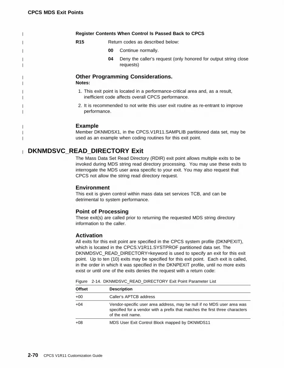
CPCS MDS Exit Points
| Register Contents When Control Is Passed Back to CPCS
| R15 Return codes as described below:
| 00 Continue normally.
| 04 Deny the caller’s request (only honored for output string close| requests)
| Other Programming Considerations.| Notes:
| 1. This exit point is located in a performance-critical area and, as a result,| inefficient code affects overall CPCS performance.
| 2. It is recommended to not write this user exit routine as re-entrant to improve| performance.
| Example| Member DKNMDSX1, in the CPCS.V1R11.SAMPLIB partitioned data set, may be| used as an example when coding routines for this exit point.
| DKNMDSVC_READ_DIRECTORY ExitThe Mass Data Set Read Directory (RDIR) exit point allows multiple exits to beinvoked during MDS string read directory processing. You may use these exits tointerrogate the MDS user area specific to your exit. You may also request thatCPCS not allow the string read directory request.
EnvironmentThis exit is given control within mass data set services TCB, and can bedetrimental to system performance.
Point of ProcessingThese exit(s) are called prior to returning the requested MDS string directoryinformation to the caller.
ActivationAll exits for this exit point are specified in the CPCS system profile (DKNPEXIT),which is located in the CPCS.V1R11.SYSTPROF partitioned data set. TheDKNMDSVC_READ_DIRECTORY=keyword is used to specify an exit for this exitpoint. Up to ten (10) exits may be specified for this exit point. Each exit is called,in the order in which it was specified in the DKNPEXIT profile, until no more exitsexist or until one of the exits denies the request with a return code:
Figure 2-14. DKNMDSVC_READ_DIRECTORY Exit Point Parameter List
Offset Description
+00 Caller’s APTCB address
+04 Vendor-specific user area address, may be null if no MDS user area wasspecified for a vendor with a prefix that matches the first three charactersof the exit name.
+08 MDS User Exit Control Block mapped by DKNMDS11
2-70 CPCS V1R11 Customization Guide

CPCS MDS Exit Points
Register Contents When Control Is Passed to the Exit RoutineR0 Not applicable
R1 Parameter list address
R2-R12 Not applicable
R13 Caller’s save area address
R14 Return address
R15 User exit entry point address
Register Contents When Control Is Passed Back to CPCSR0 Not applicable
R1 Not applicable
R2-R13 Restored to same values as on user exit entry
R14 Not applicable
R15 Return code as described below:
00 Continue normally.
04 Deny the caller’s request.
Other Programming ConsiderationsNotes:
1. This exit point is located in a performance critical area and, as a result,inefficient code affects overall CPCS performance.
2. IBM does not require this exit be re-entrant and recommends that extraSTORAGE, GETMAIN, or FREEMAIN invocations be avoided to improveperformance.
ExampleMember DKNMDSX1, in the CPCS.V1R11.SAMPLIB partitioned data set, may beused as an example when coding assembler exit routines for this exit point.
| DKNMDSVC_SRCH_DIRECTORY ExitThe Mass Data Set Search Directory (SRCH) exit point allows multiple exits to beinvoked during MDS Search Directory processing. You may use these exits tointerrogate the MDS user area specific to your exit. You may also request thatCPCS not allow the string search directory request.
EnvironmentThis exit is given control within mass data set services TCB and can be detrimentalto system performance.
Point of ProcessingThese exit(s) are called prior to returning the requested MDS string directoryinformation to the caller.
Chapter 2. Installation and Generation Procedures 2-71

CPCS MDS Exit Points
ActivationAll exits for this exit point are specified in the CPCS system profile (DKNPEXIT),which is located in the CPCS.V1R11.SYSTPROF partitioned data set. TheDKNMDSVC_SRCH_DIRECTORY=keyword is used to specify an exit for this exitpoint. Up to ten (10) exits may be specified for this exit point. Each exit is called,in the order in which they were specified in the DKNPEXIT profile, until no moreexits exist or until one of the exits denies the request with a return code:
Figure 2-15. DKNMDSVC_SRCH_DIRECTORY Exit Point Parameter List
Offset Description
+00 Caller’s APTCB address
+04 Vendor-specific user area address, may be null if no MDS user area wasspecified for a vendor with a prefix that matches the first three charactersof the exit name.
+08 MDS User Exit Control Block mapped by DKNMDS11
Register Contents When Control Is Passed to the Exit RoutineR0 Not applicable
R1 Parameter list address
R2-R12 Not applicable
R13 Caller’s save area address
R14 Return address
R15 User exit entry point address
Register Contents When Control Is Passed Back to CPCSR0 Not applicable
R1 Not applicable
R2-R13 Restored to same values as on user exit entry
R14 Not applicable
R15 Return code as described below:
00 Continue normally.
04 Exclude current directory information from the search results.
Other Programming ConsiderationsNotes:
1. This exit point is located in a performance critical area and, as a result,inefficient code affects overall CPCS performance.
2. IBM does not require this exit be re-entrant and recommends that extraSTORAGE, GETMAIN, or FREEMAIN invocations be avoided to improveperformance.
2-72 CPCS V1R11 Customization Guide

CPCS MDS Exit Points
ExampleMember DKNMDSX1, in the CPCS.V1R11.SAMPLIB partitioned data set may beused as an example when coding assembler exit routines for this exit point.
| DKNMDSV4_COMPRESSION ExitThis exit allows the user to control the way codelines are compressed,decompressed, expanded, and unexpanded prior to being stored or after beingretrieved from the CPCS mass data set. See the “Definition of Terms” in the CPCSProgramming and Diagnostic Guide. The format of the codeline returned to theprogram requesting CPCS mass data set services does not necessarily reflect theway the actual data is stored in the CPCS mass data set.
This exit allows the user to control this conversion process. The exit is optional inthat it is not required for CPCS to operate. If the exit is installed, it is called foreach codeline that is sent to Mass Data Set Services for compression,decompression, expansion, or non-expansion. Not all codelines are expanded oruncompressed. Mass Data Set services can be and is often called to retrieve thecompressed version of the codeline. The user exit is not called for these codelines.Any manipulation of these codelines must be done in the user’s applicationprogram.
EnvironmentThis exit is given control within mass data set services TCB, and can bedetrimental to system performance.
Point of ProcessingThe user exit is called at CPCS initialization and each time thereafter that acodeline needs to be compressed, decompressed, expanded, or non-expanded.When called at initialization, the user exit obtains a re-entrant work area for use bythe user exit. The address of this re-entrant work area is maintained by the callingprogram until CPCS ends. This re-entrant work area is not returned to the user exitwhen called to perform mass data set services, such as compressing ordecompressing a codeline. Since there is no final call (in other words, the CPCSsupervisor enters STOP,STOP at the ready prompt), users should not obtain thisre-entrant work area from common storage.
When called by Mass Data Set services, the user must determine whether there-entrant work area has already been obtained by testing a switch in the user exitcontrol block passed by the calling program. If the re-entrant work area has notbeen obtained, the user exit must obtain working storage. Each time Mass Data SetServices is called and initialized, the user exit is called. Mass Data Set Servicescannot determine if the requesting module needs the services of the Mass Data SetView modules. Therefore, it is possible the user exit may be called only twice,once to initialize and once to end Mass Data Set Services.
The user exit is controlled by function codes located in the user exit control block.Below is the list of function codes and a brief explanation of each code:
� Calls Made at CPCS Initialization
INIT Initial call used to initialize variables
� Calls Made by CPCS Mass Data Set Services
Chapter 2. Installation and Generation Procedures 2-73

CPCS MDS Exit Points
ZAIT An application module is requesting Mass Data Set Services; theuser exit must obtain storage to save registers and programvariables that are needed.
ZAEN An application module is requesting Mass Data Set Services to freestorage obtained for accessing the mass data set. The user exitshould free any storage obtained during the ZAIT call.
DIZD Convert the DIDSCT to the ZDDSCT view (decompress).
DIDX Convert the DIDSCT to the DXDSCT view (expand).
DIZX Convert the DIDSCT to the ZXDSCT view (decompress, expand)
ZDDI Convert the ZDDSCT to the DIDSCT view (compress).
DXDI Convert the DXDSCT to the DIDSCT view (unexpand).
ZXDI Convert the ZXDSCT to the DIDSCT view (unexpand, decompress).
ActivationAll exits for this exit point are specified in the CPCS system profile (DKNPEXIT),which is located in the CPCS.V1R11.SYSTPROF partitioned data set. TheDKNMDSV4_COMPRESSION=keyword is used to specify an exit for this exit point.Up to one (1) exit may be specified for this exit point. Each exit is called, in theorder in which they were specified in the DKNPEXIT profile until no more exits existor until one of the exits denies the request with a return code:
Note: A fullword containing binary zeroes indicates the calling program did notprovide this parameter.
Information is passed in the following interface control blocks:
Figure 2-16. DKNMDSV4_COMPRESSION Exit Point Parameter List
Offset Description
+00 DKNMDSX2 Control Block Address
+04 Caller’s APTCB (DKNAPTCB) Address
+08 CPCS Parameter List (DKNPARM) Address
+12 ZA Control Block (ZADSCT) Address
+16 ZB Control Block (ZBDSCT) Address
+20 ZE Control Block (ZEDSCT) Address
+24 DI Control Block (DIDSCT) Address
+28 ZD Control Block (ZDDSCT) Address
+32 DX Control Block (DXDSCT) Address
+36 ZX Control Block (ZXDSCT) Address
2-74 CPCS V1R11 Customization Guide

CPCS MDS Exit Points
Figure 2-17. MDS View Exit Communication Control Blocks
Control Block COBOLCopybook
AssemblerMacro/Copybook
Call Parameters
Processing modification requests are made with thereason-code field in this control block. The two requestsare:
0000 Use default results
0004 The user exit has completed the requestedfunction.
None DKNMDS2P
CPCS APTCB DKNCATCB DKNAPTCB
CPCS Parameter List DKNCPARM DKNPARM
CPCS MDS Control Block DKNCRZA ZADSCT
MDS Compressed SDE DKNCRZB ZEDSCT
MDS Uncompressed SDE DKNCRZE ZBDSCT
MDS Compressed View of the Codeline DKNCRZC DIDSCT
MDS Uncompressed View of the Codeline DKNCRDI ZDDSCT
MDS Expanded Compressed View DKNCRZX DXDSCT
MDS Expanded Uncompressed View DKNCRDX ZXDSCT
Register Contents When Control Is Passed to the Exit RoutineR0 Not applicable
R1 Parameter List Address
R2-R12 Not applicable
R13 Caller’s Save Area Address
R14 Return Address
R15 User Exit Entry Point Address
Register Contents When Control Is Passed Back to CPCSR0 Not applicable
R1 Not applicable
R2-R13 Restored to same values as on user exit entry
R14 Not applicable
R15 Return Codes:
00 The user exit has been called successfully and Mass DataSet Services continues normally, in other words, thefunction code is DIZD, the user exit reason code is 00, andthe user exit has chosen to let Mass Data Set Servicesuncompress this codeline.
04 The user exit has been called successfully and Mass DataSet Services continues normally, in other words, thefunction code is DIZD, the user exit reason code is 04, and
Chapter 2. Installation and Generation Procedures 2-75
the user exit has chosen to uncompress the codeline. MassData Set Services does not uncompress the codeline again.
Other Programming ConsiderationsNotes:
1. This exit point is located in a performance critical area and, as a result,inefficient code affects overall CPCS performance.
2. IBM requires this exit be re-entrant.
ExampleMember DKNMDSX2, in the CPCS.V1R11.SAMPLIB partitioned data set, may beused as an example when coding assembler exit routines for this exit point. It alsohas code to change the default decompression for a batch statistic record. This isdone for the first three batch statistic records found in the string. The batch statisticrecord is converted to a user control document that has no meaning in CPCS.
After DKNMRGE runs for sample problem 1, the M-string can be hex-listed usingDKNHEXL. The three new user control records should show up in the hex listing.This proves that the user exit has been called successfully.
2-76 CPCS V1R11 Customization Guide
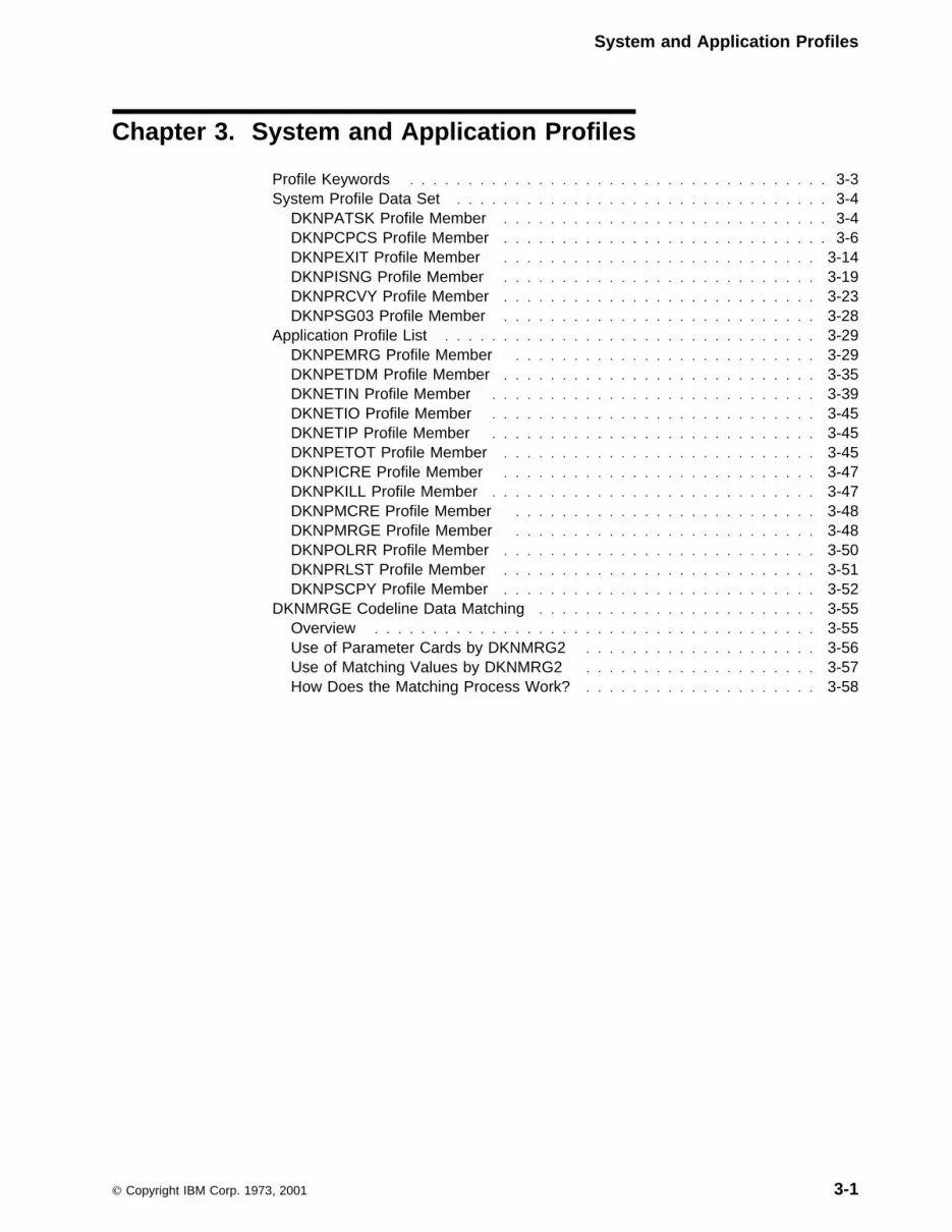
System and Application Profiles
Chapter 3. System and Application Profiles
Profile Keywords . . . . . . . . . . . . . . . . . . . . . . . . . . . . . . . . . . . . 3-3System Profile Data Set . . . . . . . . . . . . . . . . . . . . . . . . . . . . . . . . 3-4
DKNPATSK Profile Member . . . . . . . . . . . . . . . . . . . . . . . . . . . . 3-4DKNPCPCS Profile Member . . . . . . . . . . . . . . . . . . . . . . . . . . . . 3-6DKNPEXIT Profile Member . . . . . . . . . . . . . . . . . . . . . . . . . . . 3-14DKNPISNG Profile Member . . . . . . . . . . . . . . . . . . . . . . . . . . . 3-19DKNPRCVY Profile Member . . . . . . . . . . . . . . . . . . . . . . . . . . . 3-23DKNPSG03 Profile Member . . . . . . . . . . . . . . . . . . . . . . . . . . . 3-28
Application Profile List . . . . . . . . . . . . . . . . . . . . . . . . . . . . . . . . 3-29DKNPEMRG Profile Member . . . . . . . . . . . . . . . . . . . . . . . . . . 3-29DKNPETDM Profile Member . . . . . . . . . . . . . . . . . . . . . . . . . . . 3-35DKNETIN Profile Member . . . . . . . . . . . . . . . . . . . . . . . . . . . . 3-39DKNETIO Profile Member . . . . . . . . . . . . . . . . . . . . . . . . . . . . 3-45DKNETIP Profile Member . . . . . . . . . . . . . . . . . . . . . . . . . . . . 3-45DKNPETOT Profile Member . . . . . . . . . . . . . . . . . . . . . . . . . . . 3-45DKNPICRE Profile Member . . . . . . . . . . . . . . . . . . . . . . . . . . . 3-47DKNPKILL Profile Member . . . . . . . . . . . . . . . . . . . . . . . . . . . . 3-47DKNPMCRE Profile Member . . . . . . . . . . . . . . . . . . . . . . . . . . 3-48DKNPMRGE Profile Member . . . . . . . . . . . . . . . . . . . . . . . . . . 3-48DKNPOLRR Profile Member . . . . . . . . . . . . . . . . . . . . . . . . . . . 3-50DKNPRLST Profile Member . . . . . . . . . . . . . . . . . . . . . . . . . . . 3-51DKNPSCPY Profile Member . . . . . . . . . . . . . . . . . . . . . . . . . . . 3-52
DKNMRGE Codeline Data Matching . . . . . . . . . . . . . . . . . . . . . . . . 3-55Overview . . . . . . . . . . . . . . . . . . . . . . . . . . . . . . . . . . . . . . 3-55Use of Parameter Cards by DKNMRG2 . . . . . . . . . . . . . . . . . . . . 3-56Use of Matching Values by DKNMRG2 . . . . . . . . . . . . . . . . . . . . 3-57How Does the Matching Process Work? . . . . . . . . . . . . . . . . . . . . 3-58
Copyright IBM Corp. 1973, 2001 3-1

System and Application Profiles
3-2 CPCS V1R11 Customization Guide

Profile Keywords
Profiles provide a simple and efficient means for customizing CPCS. They consistof members in a PDS (partitioned data set), each of which contains one or morekeywords. The values assigned to these keywords control how CPCS behaves.
| Profiles allow you to change the run-time characteristics of various modules without| having to recompile or reassemble these modules or without having to bounce| CPCS.
System profiles, stored in the SYSTPROF data set, affect the CPCS system as awhole. They are loaded once whenever CPCS is started and are used thereafterfor the remainder of the CPCS run.
| Application profiles, stored in the DKNAPPL data set, affect individual CPCS tasks.| Although these profiles set values for some of the settings that dictate how CPCS| runs as system profiles do, application profiles are reloaded from the DKNAPPL| data set every time a fresh copy of the task they affect starts.
SYSTPROF and DKNAPPL are ddnames in your CPCS execution JCL. For moreinformation, see “External Storage Requirements” on page 1-19.
The naming convention for the application profile members is DKNPxxxx, where| xxxx is the name of the module. For example, inside the DKNAPPL application| profile data set is a member named DKNPEMRG. This is the profile for CPCS| application program DKNEMRG. DKNPEMRG, in turn, contains keywords that| control how much space DKNEMRG allocates for its various internal tables.
| The names of the various system and application profile members, and the| definitions of the keywords and values they contain, are listed in the following| sections. Keyword and value definitions are also documented within each individual| member.
Profile KeywordsProfile members consist of a number of keywords. All keywords share the samecommon characteristics:
� Only one keyword for each profile member line.
� Each keyword must start in column 1.
� A keyword can be of any length.
� A keyword must consist of either upper-case alphabetic characters, numericdigits, or underscores.
� A keyword may not contain imbedded spaces (use underscores instead).
� An equals sign (=) must immediately follow the last character of the keyword.
� The value to be assigned to the keyword must immediately follow the equalssign.
� A space character (" ") must immediately follow the last character of the value.Any comments to the right of this space are ignored.
| For example, the following is a portion of the DKNPEMRG application profile:
Chapter 3. System and Application Profiles 3-3
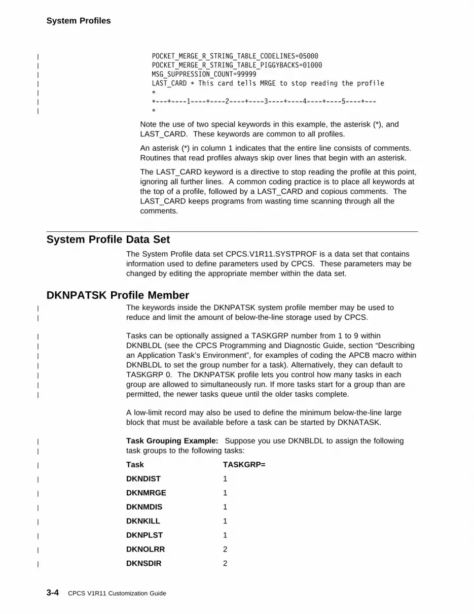
System Profiles
| POCKET_MERGE_R_STRING_TABLE_CODELINES=�5���
| POCKET_MERGE_R_STRING_TABLE_PIGGYBACKS=�1���
| MSG_SUPPRESSION_COUNT=99999
| LAST_CARD T This card tells MRGE to stop reading the profile
| T
| T---+----1----+----2----+----3----+----4----+----5----+---
| T
Note the use of two special keywords in this example, the asterisk (*), andLAST_CARD. These keywords are common to all profiles.
An asterisk (*) in column 1 indicates that the entire line consists of comments.Routines that read profiles always skip over lines that begin with an asterisk.
The LAST_CARD keyword is a directive to stop reading the profile at this point,ignoring all further lines. A common coding practice is to place all keywords atthe top of a profile, followed by a LAST_CARD and copious comments. TheLAST_CARD keeps programs from wasting time scanning through all thecomments.
System Profile Data SetThe System Profile data set CPCS.V1R11.SYSTPROF is a data set that containsinformation used to define parameters used by CPCS. These parameters may bechanged by editing the appropriate member within the data set.
DKNPATSK Profile Member| The keywords inside the DKNPATSK system profile member may be used to| reduce and limit the amount of below-the-line storage used by CPCS.
| Tasks can be optionally assigned a TASKGRP number from 1 to 9 within| DKNBLDL (see the CPCS Programming and Diagnostic Guide, section “Describing| an Application Task’s Environment”, for examples of coding the APCB macro within| DKNBLDL to set the group number for a task). Alternatively, they can default to| TASKGRP 0. The DKNPATSK profile lets you control how many tasks in each| group are allowed to simultaneously run. If more tasks start for a group than are| permitted, the newer tasks queue until the older tasks complete.
A low-limit record may also be used to define the minimum below-the-line largeblock that must be available before a task can be started by DKNATASK.
| Task Grouping Example: Suppose you use DKNBLDL to assign the following| task groups to the following tasks:
| Task TASKGRP=
| DKNDIST 1
| DKNMRGE 1
| DKNMDIS 1
| DKNKILL 1
| DKNPLST 1
| DKNOLRR 2
| DKNSDIR 2
3-4 CPCS V1R11 Customization Guide
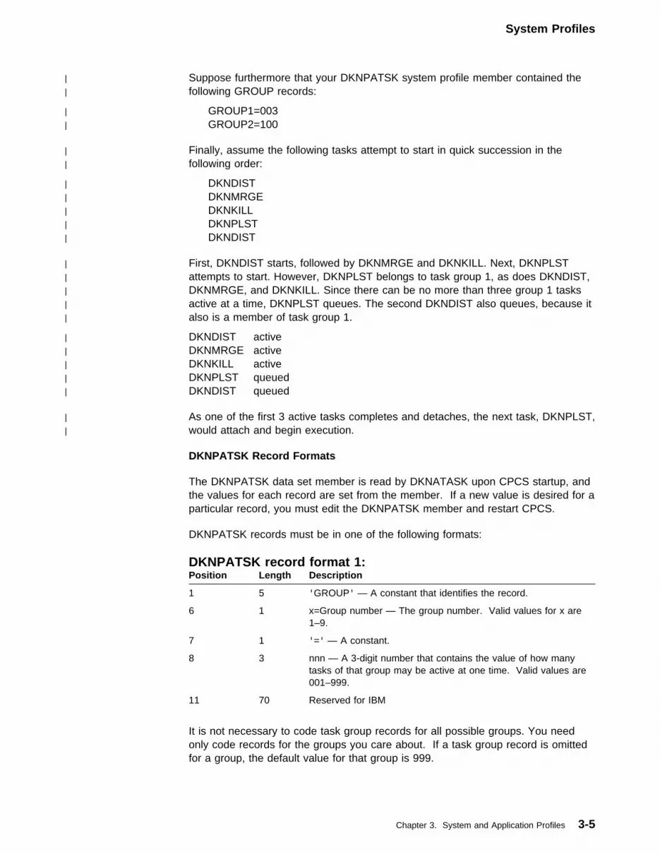
System Profiles
| Suppose furthermore that your DKNPATSK system profile member contained the| following GROUP records:
| GROUP1=003| GROUP2=100
| Finally, assume the following tasks attempt to start in quick succession in the| following order:
| DKNDIST| DKNMRGE| DKNKILL| DKNPLST| DKNDIST
| First, DKNDIST starts, followed by DKNMRGE and DKNKILL. Next, DKNPLST| attempts to start. However, DKNPLST belongs to task group 1, as does DKNDIST,| DKNMRGE, and DKNKILL. Since there can be no more than three group 1 tasks| active at a time, DKNPLST queues. The second DKNDIST also queues, because it| also is a member of task group 1.
| DKNDIST active| DKNMRGE active| DKNKILL active| DKNPLST queued| DKNDIST queued
| As one of the first 3 active tasks completes and detaches, the next task, DKNPLST,| would attach and begin execution.
DKNPATSK Record Formats
The DKNPATSK data set member is read by DKNATASK upon CPCS startup, andthe values for each record are set from the member. If a new value is desired for aparticular record, you must edit the DKNPATSK member and restart CPCS.
DKNPATSK records must be in one of the following formats:
DKNPATSK record format 1:
It is not necessary to code task group records for all possible groups. You needonly code records for the groups you care about. If a task group record is omittedfor a group, the default value for that group is 999.
Position Length Description
1 5 'GROUP' — A constant that identifies the record.
6 1 x=Group number — The group number. Valid values for x are1–9.
7 1 '=' — A constant.
8 3 nnn — A 3-digit number that contains the value of how manytasks of that group may be active at one time. Valid values are001–999.
11 70 Reserved for IBM
Chapter 3. System and Application Profiles 3-5
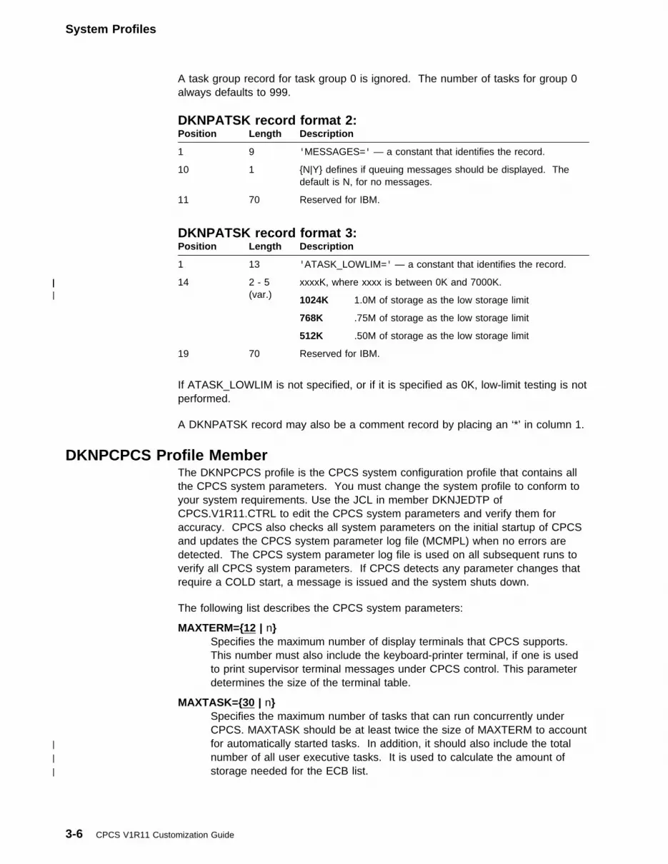
System Profiles
A task group record for task group 0 is ignored. The number of tasks for group 0always defaults to 999.
DKNPATSK record format 2:Position Length Description
1 9 'MESSAGES=' — a constant that identifies the record.
10 1 {N|Y} defines if queuing messages should be displayed. Thedefault is N, for no messages.
11 70 Reserved for IBM.
DKNPATSK record format 3:
If ATASK_LOWLIM is not specified, or if it is specified as 0K, low-limit testing is notperformed.
A DKNPATSK record may also be a comment record by placing an ‘*’ in column 1.
Position Length Description
1 13 'ATASK_LOWLIM=' — a constant that identifies the record.
| 14| 2 - 5| (var.)| xxxxK, where xxxx is between 0K and 7000K.
1024K 1.0M of storage as the low storage limit
768K .75M of storage as the low storage limit
512K .50M of storage as the low storage limit
19 70 Reserved for IBM.
DKNPCPCS Profile MemberThe DKNPCPCS profile is the CPCS system configuration profile that contains allthe CPCS system parameters. You must change the system profile to conform toyour system requirements. Use the JCL in member DKNJEDTP ofCPCS.V1R11.CTRL to edit the CPCS system parameters and verify them foraccuracy. CPCS also checks all system parameters on the initial startup of CPCSand updates the CPCS system parameter log file (MCMPL) when no errors aredetected. The CPCS system parameter log file is used on all subsequent runs toverify all CPCS system parameters. If CPCS detects any parameter changes thatrequire a COLD start, a message is issued and the system shuts down.
The following list describes the CPCS system parameters:
MAXTERM={12 | n}Specifies the maximum number of display terminals that CPCS supports.This number must also include the keyboard-printer terminal, if one is usedto print supervisor terminal messages under CPCS control. This parameterdetermines the size of the terminal table.
MAXTASK={30 | n}Specifies the maximum number of tasks that can run concurrently underCPCS. MAXTASK should be at least twice the size of MAXTERM to account
| for automatically started tasks. In addition, it should also include the total| number of all user executive tasks. It is used to calculate the amount of| storage needed for the ECB list.
3-6 CPCS V1R11 Customization Guide
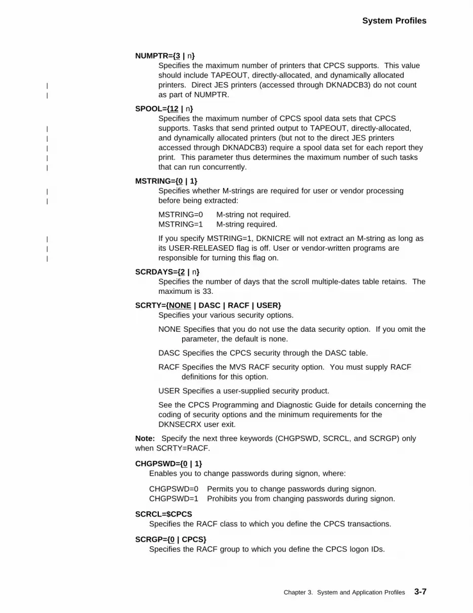
System Profiles
NUMPTR={3 | n}Specifies the maximum number of printers that CPCS supports. This valueshould include TAPEOUT, directly-allocated, and dynamically allocated
| printers. Direct JES printers (accessed through DKNADCB3) do not count| as part of NUMPTR.
SPOOL={12 | n}Specifies the maximum number of CPCS spool data sets that CPCS
| supports. Tasks that send printed output to TAPEOUT, directly-allocated,| and dynamically allocated printers (but not to the direct JES printers| accessed through DKNADCB3) require a spool data set for each report they| print. This parameter thus determines the maximum number of such tasks| that can run concurrently.
MSTRING={0 | 1}| Specifies whether M-strings are required for user or vendor processing| before being extracted:
MSTRING=0 M-string not required.MSTRING=1 M-string required.
| If you specify MSTRING=1, DKNICRE will not extract an M-string as long as| its USER-RELEASED flag is off. User or vendor-written programs are| responsible for turning this flag on.
SCRDAYS={2 | n}Specifies the number of days that the scroll multiple-dates table retains. Themaximum is 33.
SCRTY={NONE | DASC | RACF | USER}Specifies your various security options.
NONE Specifies that you do not use the data security option. If you omit theparameter, the default is none.
DASC Specifies the CPCS security through the DASC table.
RACF Specifies the MVS RACF security option. You must supply RACFdefinitions for this option.
USER Specifies a user-supplied security product.
See the CPCS Programming and Diagnostic Guide for details concerning thecoding of security options and the minimum requirements for theDKNSECRX user exit.
Note: Specify the next three keywords (CHGPSWD, SCRCL, and SCRGP) onlywhen SCRTY=RACF.
CHGPSWD={0 | 1}Enables you to change passwords during signon, where:
CHGPSWD=0 Permits you to change passwords during signon.CHGPSWD=1 Prohibits you from changing passwords during signon.
SCRCL=$CPCSSpecifies the RACF class to which you define the CPCS transactions.
SCRGP={0 | CPCS}Specifies the RACF group to which you define the CPCS logon IDs.
Chapter 3. System and Application Profiles 3-7

System Profiles
SCRGP=0 TSO users (regardless of the RACF group) can log on CPCS.The RACF group or groups to which the user is defineddetermine the access to protected CPCS transactions.
SCRGP=CPCS (or any valid RACF group name)Only TSO users who are defined to or connected to the RACFgroup can log on CPCS.
Note: The value CPCS is an example; this value can be anyvalid group name defined to RACF.
TIMECK={0 | nn}Specifies the status of the auto sign-off function for inactive terminals, where:
TIMECK=0 Disables this function
TIMECK=nn Enables this function (where nn is the number of minutes, from1 to 60, that a terminal can remain inactive before it isautomatically logged off).
KILLAUT={0 | 1}Specifies whether DKNDIST automatically starts DKNKILL.
KILLAUT=0 DKNKILL requires a manual start.
KILLAUT=1 An I-string name starts DKNKILL automatically.
Note: The next 10 parameters relate to the MDS. Before defining theseparameters, you should perform MDS data-set space calculations to determinepreliminary specifications for the MDS. If you change any of the MDS parameters,you must perform a CPCS cold start. For more information on CPCS cold start,see “STYPE Parameter” on page 1-7.
BLKSIZE={1000 | nnnn}Specifies block size for the MDS.
| � BLKSIZE=R x blocking_factor, where R is the MDS record length (50,| unless you have expanded the MDS record), and blocking_factor is a value| you select. You should choose a blocking factor that makes effective use of| the space allocated for the MDS.
| � BLKSIZE must be less than or equal to either the track size of the device| allocated for the MDS, or 32750, whichever is smaller.
| � BLKSIZE must be greater than:
| | |
| | SEGDEV + 7 |
| | ─────────── x MAXDA | + 1168
| | 8 |
| | |
| � BLKSIZE, plus 12, is the actual block size of the MDS, as allocated in the| DKNALLO JCL. The MDS does not have keys. The 12 bytes are part of the| block.
| For a description of the MDS record format, see the figure “MDS Record| Field Lengths” in the CPCS Programming and Diagnostic Guide. For a| description of expanding the MDS record, see “Expanding the Mass Data| Set” on page 2-48.
3-8 CPCS V1R11 Customization Guide

System Profiles
MAXDA={1 | n}Specifies the number of direct access devices that the MDS uses.MAXDA x SEGDEV must be less than or equal to 65535.
Note: All DASD the MDS uses must be the same type.
BLKSEG={10 | nnnnn}| BLKSEG specifies how many MDS blocks are grouped into each segment. A| segment is what CPCS allocates when it assigns MDS space. For example,| when CPCS opens a new I-string, it allocates one segment, which consists of| BLKSEG blocks. Each of these blocks consists of a number of MDS records| (see the BLKSIZE parameter above). You should specify BLKSEG so that a| high percentage of any active string can be in one segment. BLKSEG must be| greater than or equal to 4 and less than or equal to 32767.
SEGDEV={250 | nnnnn}| Specifies the number of logical segments for each device. A segment is what| CPCS allocates when it assigns MDS space. For example, when CPCS opens| a new I-string, it allocates one segment, which consists of BLKSEG blocks.| Each of these blocks consists of a number of MDS records (see the BLKSIZE| and BLKSEG parameters above). SEGDEV must be less than 32767, and| MAXDA x SEGDEV must be less than or equal to 65535.
NDIRBLK={42 | nnnn}Specifies the number of physical record blocks in the MDS directory index.
| Each block can index up to 49 strings. NDIRBLK should be twice the value of| DDIREND (to allow room for overflow blocks), and must be less than or equal| to 1338.
EDIREND={1 | n }| The first set of strings in the MDS directory index are E-strings. EDIREND
specifies the relative block address of the last physical record block of theindex data set that contains E-strings.
MDIREND={2 | n}| The next set of strings in the MDS directory index are M-strings. MDIREND
specifies the relative block address of the last physical record block of theindex data set that contains M-strings.
IDIREND={5 | n}| The next set of strings in the MDS directory index are I-strings. IDIREND
specifies the relative block address of the last physical record block of theindex data set that contains I-strings.
RDIREND={6 | n}| The next set of strings in the MDS directory index are R-strings. RDIREND
specifies the relative block address of the last physical record block of theindex data set that contains R-strings.
DDIREND={21 | n}| The last set of strings in the MDS directory index are D-strings. DDIREND
specifies the relative block address of the last physical record block of theindex data set that contains D-strings.
MAXOPEN={60 | nnn}Specifies the maximum number of different strings that can be openconcurrently for input, output, or both. This number should be larger thanMAXTASK because many tasks can have multiple open strings.
Chapter 3. System and Application Profiles 3-9

System Profiles
Note: The next three parameters (DUPLEX, BFRAT, and TPBFNM) control theduplexing of data sets and MDS logging options. If any of the parameters change,you must perform a CPCS cold start. For more information on CPCS cold start,see “STYPE Parameter” on page 1-7.
DUPLEX={0 | 1}Specifies whether the duplex function is active.
DUPLEX=1 Duplex function is activeDUPLEX=0 Duplex function is not active.
For more information about the duplex function, see “Using Data-SetDuplexing” on page 2-6.
BFRAT={0 | n}Specifies the ratio of MDS blocks to logging records. The greater the ratio, the
| less often logging I/O is performed, but also the less accurately the log will| reflect the MDS at any moment.
| Set BFRAT to 0 only if you set LOG=NO. If you set BFRAT to a non-zero| value, you must also provide a value for TPBFNM, set LOG=YES, and activate| logging by following the instructions in “Installing the Logging Subsystem” on| page 2-7.
TPBFNM={0–5}| Specifies the number of logging buffers that DKNLOGX uses. The maximum
number of logging buffers is five. The buffers are written as they are filled. Ifanother buffer is free, I/O operations occur without delay. The greater thenumber of buffers, the less likely that an I/O event is delayed.
SUBBAL={SLST | SBAL | BOTH | NONE}Specifies the subsequent-pass balancing list that DKNDIST automatically starts.
SLST Specifies that DKNDIST automatically starts DKNSLST.
SBAL Specifies that DKNDIST automatically starts DKNSBAL.
BOTH Specifies that DKNDIST automatically starts both DKNSLST andDKNSBAL.
NONE Specifies that DKNDIST does not automatically start DKNSLST orDKNSBAL.
MAXSORT={NO | nn}Specifies whether concurrent sorting is active. If it is active, the value codedbecomes the maximum number of concurrent tasks that can run a sort. Youmust generate a new sort module to complete activation of concurrent sortingfor your CPCS system. For more information about concurrent sorting, see“Concurrent Sort Generation” on page 2-32.
CLASS={A | n}Specifies the default CPCS output class (A through Z, 0 through 9). This classspecification is assigned to application tasks that did not specify a class inDKNBLDL through the APCB macro. See “Describing an Application Task’sEnvironment” on page 2-15 for more information about the BLDL table.
DUMPCLAS={F | n}Specifies the default CPCS Dump class (A through Z, 0 through 9). This classspecification is assigned to any dumps produced in the system.
3-10 CPCS V1R11 Customization Guide
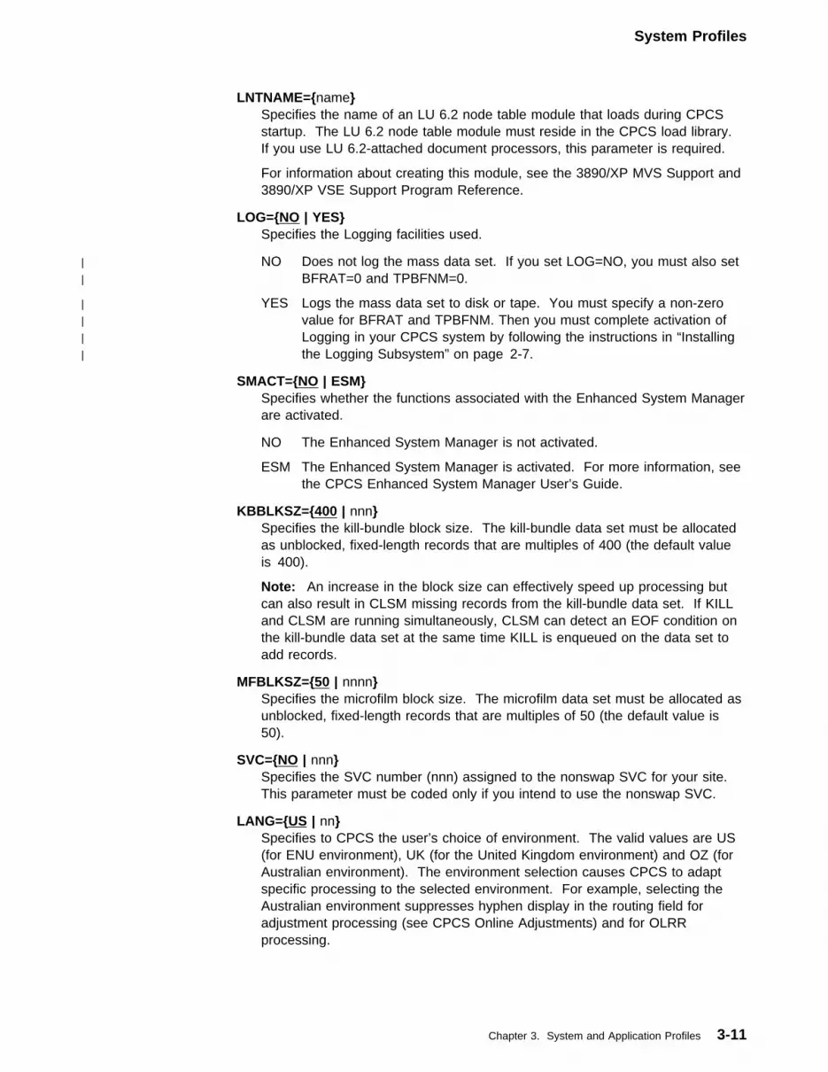
System Profiles
LNTNAME={name}Specifies the name of an LU 6.2 node table module that loads during CPCSstartup. The LU 6.2 node table module must reside in the CPCS load library.If you use LU 6.2-attached document processors, this parameter is required.
For information about creating this module, see the 3890/XP MVS Support and3890/XP VSE Support Program Reference.
LOG={NO | YES}Specifies the Logging facilities used.
| NO Does not log the mass data set. If you set LOG=NO, you must also set| BFRAT=0 and TPBFNM=0.
| YES Logs the mass data set to disk or tape. You must specify a non-zero| value for BFRAT and TPBFNM. Then you must complete activation of| Logging in your CPCS system by following the instructions in “Installing| the Logging Subsystem” on page 2-7.
SMACT={NO | ESM}Specifies whether the functions associated with the Enhanced System Managerare activated.
NO The Enhanced System Manager is not activated.
ESM The Enhanced System Manager is activated. For more information, seethe CPCS Enhanced System Manager User’s Guide.
KBBLKSZ={400 | nnn}Specifies the kill-bundle block size. The kill-bundle data set must be allocatedas unblocked, fixed-length records that are multiples of 400 (the default valueis 400).
Note: An increase in the block size can effectively speed up processing butcan also result in CLSM missing records from the kill-bundle data set. If KILLand CLSM are running simultaneously, CLSM can detect an EOF condition onthe kill-bundle data set at the same time KILL is enqueued on the data set toadd records.
MFBLKSZ={50 | nnnn}Specifies the microfilm block size. The microfilm data set must be allocated asunblocked, fixed-length records that are multiples of 50 (the default value is50).
SVC={NO | nnn}Specifies the SVC number (nnn) assigned to the nonswap SVC for your site.This parameter must be coded only if you intend to use the nonswap SVC.
LANG={US | nn}Specifies to CPCS the user’s choice of environment. The valid values are US(for ENU environment), UK (for the United Kingdom environment) and OZ (forAustralian environment). The environment selection causes CPCS to adaptspecific processing to the selected environment. For example, selecting theAustralian environment suppresses hyphen display in the routing field foradjustment processing (see CPCS Online Adjustments) and for OLRRprocessing.
Chapter 3. System and Application Profiles 3-11

System Profiles
Important!
| If you code LANG=OZ on this parameter, then to fully disable the hyphen| display in the routing field, first set the variable &DASHDSP to 0 in the MDX| macro. Follow the procedures listed in “Expanding the Mass Data Set” on| page 2-48.
DATE={mm/dd/yy | nnnnnnnnnn}Specifies the CPCS default date format. Dates on all reports and screens aredisplayed in this format. Valid date formats are:
mm/dd/yy mm/dd/yyyydd/mm/yy dd/mm/yyyyyy/mm/dd yyyy/mm/ddyy.ddd yyyy.ddd
IOMODE={31 | 24}| Specifies the I/O addressing mode. Customers who use MVS/DFP must set| IOMODE=24. All other customers should set IOMODE=31.
Note: If this value is not set correctly, you may receive an assembly error forthe APTR DCB because it specifies an invalid parameter of DCBE. If youreceive this error, you must specify IOMODE=24.
SYSID={CPCS | nnnn}| Specifies a unique job identifier that can be used to verify the existing| installation level, or to identify a test system. The default value is CPCS.
CIMSID={nnnn}Specifies the four-character identifier of the unique image system thatprocesses CPCS document images. For information about defining the CMID,
| see your image system’s documentation.
AUTORST={Z | n}| This character is used during automatic restart processing. It identifies the| particular CPCS job that had captured the last items that had passed through| each document processor.
Notes:
1. Different CPCS jobs that access the same document processors must havedifferent values specified for the AUTORST parameter.
2. If this parameter is not specified, automatic restart processing isdeactivated.
3. If more than one character is specified, only the first one is used. Theremaining characters are ignored.
4. The # character deactivates automatic restart
OVERRIDE={NO | YES}| Normally, when the system notices that one or more DKNPCPCS parameters| have changed in such a way that a COLD start is required, it does not allow a| warm start or a restart. This parameter forces a warm start or a restart to occur| anyway.
3-12 CPCS V1R11 Customization Guide

System Profiles
Important!
If you set the OVERRIDE parameter to YES during this condition,unpredictable results may occur!
LE370={YES | NO}Specifies whether LE370 COBOL modules will be executed in CPCS. If yourMVS system does NOT support the LE370 environment, this parameter shouldbe set to NO
START_DKNCOMP={YES | NO}Specifies whether DKNCOMP should be automatically started during CPCSstartup regardless of the CPCS start parameters.
BUFEXT={0 | nnnnn}Specifies the Communication Buffer Extended Area Length. This user area iscarried along with each communication buffer generated in CPCS. This areacan ONLY be modified by using the User Area Manager. For more details onthe User Area Manager, see the UAM documentation in the CPCSProgramming and Diagnostics Guide, Chapter 2, “User Area Manager”. Themaximum value is 32767.
PARMEXT={0 | nnnnn}Specifies the PARMLST Extended Area Length. This user area is carried alongwith the PARMLST (DKNPARM) area. This area can ONLY be modified byusing the User Area Manager. For more details on the User Area Manager,see the UAM documentation in the CPCS Programming and Diagnostics Guide,Chapter 2, “User Area Manager”. The maximum value is 32767.
APTCBEXT={0 | nnnnn}Specifies the APTCB Extended Area Length. This user area is carried alongwith each APTCB generated in CPCS. This area can ONLY be modified byusing the User Area Manager. For more details on the User Area Manager,see the UAM documentation in the CPCS Programming and Diagnostics Guide,Chapter 2, “User Area Manager”. The maximum value is 32767.
MAXEXIT_PTS={10 | nnnnn}This keyword specifies the maximum number of user exit points supported bythe User Exit Manager Facility. See UEM documentation in the CPCSProgramming and Diagnostic Guide, Chapter 2, “User Exit Manager”. Themaximum value is 32767.
MAX_EP_EXIT={8 | nnnnn}This keyword, Maximum Exits Per Exit Point, specifies the maximum number ofexit programs that can exist per exit point.
Example
If you code MAX_EP_EXIT=2, you can specify the following in theSYSTPROF member DKNPEXIT:
| DKNMDSVC_FREE_STRING=DKNMDXS1
| DKNMDSVC_FREE_STRING=DKNMDXS2
GLOBAL_MDSUAL={100 | nnn}This keyword specifies the global user area length, in bytes, of extended strings
| that are not created by the RCVY or ETUT tasks. (Strings created by RCVY or
Chapter 3. System and Application Profiles 3-13

System Profiles
| ETUT have the same global user area length they had when they were last| logged or unloaded.) A global user area of this length is attached to each| record in the string. These areas can ONLY be modified by using the User| Area Manager. For more details on the User Area Manager, see the UEM| documentation in the CPCS Programming and Diagnostic Guide, Chapter 2,| “User Exit Manager”.
The keyword’s default value is 100. Its maximum value is 2048.
CPCS must be restarted when this value is changed. It is not recommended todecrease the global user area length, because that could result in truncatedglobal user areas by tasks that transfer global user areas from input extendedinput strings to extended output strings. See the section “Extended Strings -External Storage Considerations” in Chapter 1 of the CPCS Programming andDiagnostic Guide for potential implications of large global user area sizes.
CPCS_PASSWORD={xxxxxxxxxxxx}This keyword is used to set the CPCS password for the CPU on which you arerunning CPCS. You must obtain a password from IBM support for each CPUon which CPCS is run.
DKNPEXIT Profile Member| The DKNPEXIT system profile member names user exit points and identifies the| user exits to be run at each specific point. More than one exit may be specified for| a single exit point (see parameters MAXEXIT_PTS and MAX_EP_EXIT in| “DKNPCPCS Profile Member” on page 3-6). If more than one exit is specified,| these exits are called in the order specified in this profile member.
DKNPEXIT records must be in the following format:
exit-point=user-exit,option1,option2,....
Where:
exit-point The exit point name
user-exit The user exit name to be called at this exit point
options One of the following options:
DEACTIVATE=YES|NO| Specifying NO for this option prevents the online user exit facility,| DKNEXIT, from deactivating this user exit and exit point. This
option should be specified for exits that are critical to the correctimplementation of your CPCS system. The default value for thisoption is YES, meaning the exit may be deactivated withDKNEXIT.
ID=xxx| This option creates a 255-byte user exit work area and assigns it| a unique three-byte User Area Manager name. The application| program can pass this area to the user exit each time it is called,| thereby allowing the exit to share data with itself from call to call.| Alternatively, different user exits for the same user exit point can| be given the same UAM ID, and they will be able to share data| with each other. The User Exit Manager and the User Area
3-14 CPCS V1R11 Customization Guide

System Profiles
| Manager work together to make sure each exit gets the correct| work area.
| This ID is not required and need not be specified if there is no| need for a user exit to share its data.
| There are restrictions on the UAM IDs that are allowed. See| “Processing User Areas with the User Area Manager” in the| CPCS Programming and Diagnostic Guide for more information.
| For more information on using the User Exit Manager to call user exits, refer to| “Invoking User Exits with the User Exit Manager” in the CPCS Programming and| Diagnostic Guide.
Keyword Description
DKNALLO_EXIT1000_REQ_VALIDATION=This exit allows the further validation of the operator-entered
| request, immediately after DKNALLO has performed its own| validations, and before the actual document processor| allocation/deallocation operation takes place. For more| detail, see “CPCS System Exit Points” on page 4-58.
DKNALLO_EXIT2000_MESSAGE=| This exit is entered each time a message is generated by| DKNALLO. It can choose to display it, to replace it with a| more descriptive message, or perhaps to display a help| screen. For more detail, see “CPCS System Exit Points” on| page 4-58.
| DKNASGF_EXIT_01=| This exit puts you in control of DKNASGF, which| automatically signs off terminals that have not been in use for| a while. (For more information, see the TIMECK parameter| in “DKNPCPCS Profile Member” on page 3-6.) You can| choose to block the signoff, or allow it to proceed. For more| detail, see “CPCS System Exit Points” on page 4-58.
DKNATASK_APPLTSK_START_EXIT01=This exit lets you update any user extended area prior tostarting an application task. For more detail, see “CPCSSystem Exit Points” on page 4-58.
| DKNATASK_DEQ_EXIT01=| This exit allows you to request control of a serially reusable| resource after DKNATASK dequeues on its ECBLIST. For| more detail, see “CPCS System Exit Points” on page 4-58.
| DKNATASK_ENQ_EXIT01=| This exit allows you to request control of a serially reusable| resource after DKNATASK enqueues on its ECBLIST. For| more detail, see “CPCS System Exit Points” on page 4-58.
DKNATASK_EXECTSK_START_EXIT01=This exit lets you update any user extended area prior tostarting an executive task. For more detail, see “CPCSSystem Exit Points” on page 4-58.
Chapter 3. System and Application Profiles 3-15

System Profiles
| DKNATASK_SUPV_TERM_EXIT01=| This exit lets you modify the setting of the TERM flag| whenever DKNATASK determines that a task must be| started from a supervisor terminal. For more detail, see| “CPCS System Exit Points” on page 4-58.
DKNATSK2_INITIALIZE_EXIT_01=This exit lets you update any user extended area after theAPTR DCB has been opened. For more detail, see “CPCSSystem Exit Points” on page 4-58.
DKNATSK2_TERMINATE_EXIT_01=This exit lets you update any user extended area after theAPTR DCB has been closed. For more detail, see “CPCSSystem Exit Points” on page 4-58.
DKNATSK2_WRITE_APTR_EXIT_01=This exit lets you update any user extended area after eachWRITE to the APTR DCB. For more detail, see “CPCSSystem Exit Points” on page 4-58.
DKNATSK3_0100_TASKABEND=EXIT=| This exit is invoked whenever a CPCS application task| abends. For more detail, see “CPCS System Exit Points” on| page 4-58.
DKNCYCDT_DATE_VALIDATE_EXIT=This exit allows the further validation of the cycle and/orendorse date before a cycle table modification takes place.DKNCYCDT does edit checking and calls DKNDATE; thenthe user is allowed to do further validation through this exitpoint. For more detail, see “CPCS System Exit Points” onpage 4-58.
| DKNEMRG_MAIN_EXIT=| This exit provides overall control over DKNEMRG’s behavior.| For more detail, see “DKNEMRG User Exits” on page 4-142.
| DKNEMRG_USER_INPUT_EXIT=| This exit controls how DKNEMRG’s input is edited. For more| detail, see “DKNEMRG User Exits” on page 4-142.
| DKNEMRG_POCKET_MERGE_EXIT=| This exit controls DKNEMRG’s pocket merge behavior. For| more detail, see “DKNEMRG User Exits” on page 4-142.
| DKNEMRG_CONSOL_REJ_MERGE_EXIT=| This exit controls DKNEMRG’s consolidated reject merge| behavior. For more detail, see “DKNEMRG User Exits” on| page 4-142.
| DKNEMRG_HSRR_MERGE_EXIT=| This exit controls DKNEMRG&cs.s HSRR merge behavior.| For more detail, see “DKNEMRG User Exits” on page 4-142.
| DKNEMRG_KEY_ENTRY_MERGE_EXIT=| This exit controls DKNEMRG’s entry merge behavior. For| more detail, see “DKNEMRG User Exits” on page 4-142.
3-16 CPCS V1R11 Customization Guide
System Profiles
DKNETCSH_FORMATS=This exit lets you specify a special format for the record,allowing you to put the X9.37 record inside a larger record.For more detail, see “Customizing ETCSH and X937 UserExits” on page 4-121.
DKNETCSH_0100_NEW_RECORD=This exit lets you perform special processing on the X9.37record before writing it out to the electronic cash letter file.For more detail, see “Customizing ETCSH and X937 UserExits” on page 4-121.
DKNETCSH_0200_FILE_CREATED=This exit lets you perform special processing after theelectronic cash letter file has been created. For more detail,see “Customizing ETCSH and X937 User Exits” onpage 4-121.
DKNETDM_ADJUST_MATCH_CRITERIA=Called by DKNETDM to allow customers to adjust the matchcriteria following a match attempt. For more detail, see“Customizing ETDM User Exits” on page 4-82.
DKNETDM_RECON_RECORD_WRITECalled by DKNETDM before each item is written to thereconciliation string. For more detail, see “CustomizingETDM User Exits” on page 4-82.
DKNETIN_CREATE_RESYNCH_RECORD=xxxxxxxx(,ID=yyy)| This user exit is called by DKNETIN for each resynch record| identified, prior to it being written to the resynch file. For| more detail, see “Customizing ETIO User Exits” on| page 4-86.
DKNETIN_FILE_IMPORTED=xxxxxxxx(,ID=yyy)Called by DKNETIN after a transmission file has beensuccessfully imported. For more detail, see “CustomizingETIO User Exits” on page 4-86.
Note: It is not called for operator-initiated imports.
DKNETIN_MDS_RECORD_WRITE=xxxxxxxx(,ID=yyy)Called by DKNETIN before an item is written to the CPCSmass data set. For more detail, see “Customizing ETIO UserExits” on page 4-86.
DKNETIN_MVS_RECORD_READ=xxxxxxxx(,ID=yyy)| Called by DKNETIN for each item read from a transmission| file, prior to the item being processed by DKNETIN. For| more detail, see “Customizing ETIO User Exits” on| page 4-86.
DKNETIP_ALTER_CF_IMPORT_DATA=Called by DKNETIP each time an incomplete control filerecord is read from the electronic control file. For moredetail, see “Customizing ETIO User Exits” on page 4-86.
Chapter 3. System and Application Profiles 3-17
System Profiles
DKNETIP_ANALYSE_RECS_PROCESSED=Called once for each run of DKNETIP after all electroniccontrol file records have been processed. For more detail,see “Customizing ETIO User Exits” on page 4-86.
DKNETIP_IDENTIFY_RECS_TO_PROCESS=Called by DKNETIP after an eligible control file record hasbeen identified for processing. For more detail, see“Customizing ETIO User Exits” on page 4-86.
DKNETOT_CONTROL_FILE_UPDATE=xxxxxxxx(,ID=yyy)Called by DKNETOT to allow a control file update after eachsuccessful creation of a transmission file. For more detail,see “Customizing ETIO User Exits” on page 4-86.
DKNETOT_MVS_RECORD_WRITE=xxxxxxxx(,ID=yyy)Called by DKNETOT as each item is about to be written tothe transmission file. For more detail, see “CustomizingETIO User Exits” on page 4-86.
DKNINIT_POST_DKNITASK_EXIT=This exit lets you initialize any user control block. For moredetail, see “CPCS System Exit Points” on page 4-58.
DKNLOADR_EXIT_01=This exit lets you request that a different program be loadedand executed. For more detail, see “CPCS System ExitPoints” on page 4-58.
DKNMBEGN_APPLSK_START_EXIT01=This exit lets you update any user extended area after theAPTCB is built. For more detail, see “CPCS System ExitPoints” on page 4-58.
| DKNMBRST_0100_APPLTASK_START=| This exit lets you update any user-extended area after the| APTCB has been built by the MICR restart module| DKNMBRST. For more detail, see “CPCS System Exit| Points” on page 4-58.
| DKNMDSVC_CLOSE_STRING=| This exit is invoked during MDS string CLOSE processing.| For output strings, you can use this exit to prevent the string| from being closed. For more detail, see “CPCS Mass Data| Set Exit Points” on page 2-66.
DKNMDSVC_FREE_STRING=| This exit is invoked during MDS string FREE processing. You| may use these exits to deny a FREE SPACE request. For| more detail, see “CPCS Mass Data Set Exit Points” on| page 2-66.
| DKNMDSVC_OPEN_STRING=| This exit is invoked during MDS string OPEN processing.| You may specify up to ten (10) user exits for this exit point.| For more detail, see “CPCS Mass Data Set Exit Points” on| page 2-66.
3-18 CPCS V1R11 Customization Guide

System Profiles
DKNMDSVC_READ_DIRECTORY=This exit is invoked during MDS Read Directory processing.You may specify up to ten (10) user exits for this exit point.For more detail, see “CPCS Mass Data Set Exit Points” onpage 2-66.
DKNMDSVC_SEARCH_DIRECTORY=This exit is invoked during MDS Search Directory processing.You may specify up to ten (10) user exits for this exit point.For more detail, see “CPCS Mass Data Set Exit Points” onpage 2-66.
DKNMDSV4_COMPRESSION=This exit is invoked during item compression anddecompression processing. You may specify up to one (1)user exit for this exit point. For more detail, see “CPCSMass Data Set Exit Points” on page 2-66.
| DKNMRG2_001_POSITIONAL_EXIT=| This exit lets you examine the output of DKNMRG2 to see if| you can associate any remaining missing and free items.| For more detail, see “DKNMRG2X–Positional Matching User| Exit” on page 4-151.
DKNMTASK_INITIALIZE_EXIT_01=This exit lets you initialize any user control block after alltasks have been successfully initialized and attached. Formore detail, see “CPCS System Exit Points” on page 4-58.
DKNMTASK_MICR_ABEND_EXIT0100=This exit is invoked after DKNMTASK has finishedprocessing a MICR abend. For more detail, see “CPCSSystem Exit Points” on page 4-58.
DKNMTASK_TERMINATION_EXIT_01This exit lets you perform user clean-up before all the majorsubtasks are terminated prior to shutdown. For more detail,see “CPCS System Exit Points” on page 4-58.
DKNRCVY_EXIT1000_BEFORE_WRITE=This exit lets you examine each item recovered before it iswritten to the mass data set. This user exit routine is enteredonce for each item processed by DKNRCVY. For moredetail, see “DKNLOGU: Logging User Exit” on page 4-129.
DKNX937_0100_NEW_RECORD=This exit lets you perform special processing on the X9.37record after it has been created. For more detail, see“Customizing ETCSH and X937 User Exits” on page 4-121.
DKNPISNG Profile MemberThe DKNPISNG system profile member is used to customize the format of itemsequence numbers and to set item sequence number ranges. This profile isaccessed by the Item Sequence Data Set Generation job (DKNGISN).
REGION_NUMBER_LENGTH=l
� This parameter indicates the number of digits (l) used to
Chapter 3. System and Application Profiles 3-19

System Profiles
hold the region number. These digits are left-justifiedwithin the eight (8) lowest-order digits of the CPCS itemsequence number.
� This parameter may only be present once.
� If present, this must be the first parameter.
� If present, it must be 0, 1 or 2.
� This parameter defaults to 0 (no region number).
SORTER_nn_REGION_NUMBER=r/rr
� This parameter specifies the region number (r/rr) to beincluded in the sequence numbers of items captured ondocument processor (nn).
� This parameter may not be present if no region numbersare used.
� If this parameter is present, nn must be a valid documentprocessor number (01 - 99).
� If this parameter is present and 1-digit region numbersare used, r/rr must be a 1-digit region number (0 - 9).
� If the parameter is present and 2-digit region numbersare used, r/rr must be a 2-digit region number (00 - 99).
� This parameter may be present up to 99 times, for eachof the 99 valid CPCS logical document processornumbers.
� This parameter may only be present once for eachdocument processor.
DEFAULT_SORTER_REGION_NUMBER=r/rr
� This parameter specifies the region number (r/rr) to beincluded in the sequence numbers of items captured ondocument processors not mentioned in anySORTER_nn_REGION_NUMBER parameter.
� This parameter may only be present once.
� This parameter may not be present if no region numbersare used.
� If the parameter is present and 1-digit region numbersare used, r/rr must be a 1-digit region number (0 - 9).
� If the parameter is present and 2-digit region numbersare used, r/rr must be a 2-digit region number (00 - 99).
� This parameter defaults to region number 0 when 1-digitregion numbers are used.
� This parameter defaults to region number 00 when 2-digitregion numbers are used.
3-20 CPCS V1R11 Customization Guide

System Profiles
SORTER_nn_ROLLOVER_SEQUENCE_NUMBER=ssssssss
� This parameter specifies the prime-pass start itemsequence number rollover value (ssssssss) for a sorter(nn).
� This parameter affects captures; it also affectsenhanced-prime subsequent entries for XF sort types thatuse the 'setdev at entry breaks' O-record option.
� When an affected entry starts, and document processornn’s item sequence number exceeds ssssssss, it resetsback to one. Specifically, it resets to 00000001 (fordocument processors with no region numbers), tor0000001 (for document processors with 1-digit regionnumbers), and to rr000001 (for document processors with2-digit region numbers).
� Item sequence numbers do not roll over when ssssssssis reached while items are being captured.
� If this parameter is present, nn must be a valid documentprocessor number (01 - 99).
� If this parameter is present, ssssssss must be an 8-digitsequence number that does not include a region number.
� The sequence number must be smaller than 10000000 if1-digit region numbers are used.
� The sequence number must be smaller than 01000000 if2-digit region numbers are used.
� The sequence number must be greater than 00000000.
� This parameter may be present up to 99 times, for eachof the 99 valid CPCS logical document processors.
� This parameter may only be present once for eachdocument processor.
DEFAULT_ROLLOVER_SEQUENCE_NUMBER=sssssssss
� This parameter specifies the sequence number rollovervalue to be used for document processors not mentionedin anySORTER_nn_ROLLOVER_SEQUENCE_NUMBERparameter.
� This parameter may only be present once.
� If this parameter is present, ssssssss must be an 8-digitsequence number that does not include a region number.
� The sequence number must be smaller than 10000000 if1-digit region numbers are used.
� The sequence number must be smaller than 01000000 if2-digit region numbers are used.
� The sequence number must be greater than 00000000.
Chapter 3. System and Application Profiles 3-21

System Profiles
� This parameter defaults to 09000000 when no regionnumber are used.
� This parameter defaults to 09000000 when 1-digit regionnumbers are used.
� This parameter defaults to 00900000 when 2-digit regionnumbers are used.
REGION_r/rr_SEQUENCE_NUMBER_RANGE=(llllllll,hhhhhhhh)
� This parameter specifies the range of sequence numbers(llllllll,hhhhhhhh) to be used as non-MICR task sequencenumbers for a region number (r/rr).
� The first sequence number in the parenthesis is thelow-range sequence number. The second sequencenumber in the parenthesis is the high-range sequencenumber.
� Sequence number wrap: The low-range number is thefirst non-MICR sequence number to be used for a region.Non-MICR sequence numbers then increase until thehigh-range number is used, after which these numbersstart over again with the low-range number.
� This parameter may only be present when regionnumbers are used.
� If this parameter is present, llllllll and hhhhhhhh must be8-digit sequence numbers that do not contain regionnumbers.
� If this parameter is present and 1-digit region numbersare used, r/rr must be a 1-digit (0 - 9) region number andllllllll and hhhhhhhh must be smaller than 10000000.
� If this parameter is present and 2-digit region numbersare used, r/rr must be a 2-digit region number (00 -99)and llllllll and hhhhhhhh must be smaller than 01000000.
� The high-range sequence number (hhhhhhhh) must behigher than the low-range (llllllll) sequence number.
� Both sequence numbers must be greater than 00000000.
� This parameter may be present up to 10 times if 1-digitregion numbers are used, or up to 100 times if 2-digitregion numbers are used, for each of the valid regionnumbers.
� This parameter may only be present once for eachregion.
DEFAULT_REGION_SEQUENCE_NUMBER_RANGE=(llllllll,hhhhhhhh)
� This parameter specifies the range of sequence numbers(llllllll,hhhhhhhh) to be used as non-MICR task sequencenumbers for regions not mentioned in any
3-22 CPCS V1R11 Customization Guide

System Profiles
REGION_r/rr_SEQUENCE_NUMBER_RANGEparameter.
� This parameter also specifies the range of sequencenumbers (llllllll,hhhhhhhh) to be used as non-MICR tasksequence numbers when no regions are used.
� This parameter may only be present once.
� If this parameter is present, llllllll and hhhhhhhh must be8-digit sequence numbers that do not contain regionnumbers.
� If the parameter is present and 1-digit region numbersare used, llllllll and hhhhhhhh must be smaller than10000000.
� If the parameter is present and 2-digit region numbersare used, llllllll and hhhhhhhh must be smaller than01000000.
� The high-range sequence number (hhhhhhhh) must behigher than the low-range (llllllll) sequence number.
� Both sequence numbers must be greater than 00000000.
� This parameter defaults to (00000001,09000000) whenno region numbers are used.
� This parameter defaults to (00000001,09000000) when1-digit numbers are used.
� This parameter defaults to (00000001,00900000) when2-digit numbers are used.
� A missing, non-existing profile, or a profile that containsno parameters, results in no region numbers being used,and an item sequence number range of 00000001through 09000000.
CAUTION:On non-XF sort type document processors, the leftmost 2 digits of the 8lowest-order digits of the item sequence number are truncated. Only the 6lowest-order digits are used in these types of captures. Therefore, if regionnumbers are used, they are not stamped on checks as part of their sequencenumber.
Microfilm numbers are the last 6 digits of the corresponding item sequencenumber.
DKNPRCVY Profile MemberThe DKNPRCVY profile is the Logging system configuration profile. It contains allthe Logging system parameters. You must change the logging profile to conform toyour system requirements. Use the JCL in member DKNJEDTP ofCPCS.V1R11.CTRL to edit the logging parameters and verify them for accuracy.
CPCS also checks all the logging parameters on the initial startup of CPCS andupdates the CPCS system parameter log file (MCMPL) when no errors aredetected. The CPCS system parameter log file is used on all subsequent runs to
Chapter 3. System and Application Profiles 3-23

System Profiles
verify all logging system parameters. If CPCS detects any parameter changes thatrequire a Logging initialization, a message is issued and the system shuts down.
The following list describes the Logging system parameters:
LOGDEV={DISK | TAPE}| Specifies whether the MDS is logged to disk or tape. If LOGDEV=DISK,| Logging occurs initially to a disk log file (DKNDL1 or DKNLD2). Later, when| the disk log file fills up, Logging switches to the other disk log file while the| previous one is backed up to tape. If LOGDEV=TAPE, the MDS is logged| directly to tape. See the description of the DKNLT tape data set on
“Optional Tape Data Sets” on page 1-29.
DPXDISK={YES | NO}Specifies whether the disk log files (DKNLD1, DKNLD2) are duplexed whenthey are created. This parameter has no effect if LOGDEV=TAPE has been
| specified. If this parameter is changed from NO to YES, and| AUTO_INIT=YES, the Logging files are automatically initialized the next time| CPCS is started. If this parameter is changed from NO to YES, and| AUTO_INIT=NO, you must manually submit DKNGLINT.
DPXTAPE={ YES | NO }| Specifies whether the tape log files are duplexed. If LOGDEV=TAPE,| Logging writes each MDS record to both DKNLT and DKNLTD. If| LOGDEV=DISK, it is the backup programs (DKNBKUP or DNBBKUP) that| perform the duplexing. Each log disk record backed up to tape (DKNLD) is| also copied to the duplex (DKNLDD).
DPXCNTL={ YES |NO}| Specifies whether the logging control files are duplexed. If this parameter is| changed from NO to YES, and AUTO_INIT=YES, the Logging files are| automatically initialized the next time CPCS is started. If this parameter is| changed from NO to YES, and AUTO_INIT=NO, you must manually submit| DKNGLINT.
BACKUP={BKUP | SUB member | SUB dsn(member) }Specifies how Logging is to start a backup:
BKUP Logging autostarts the DKNBKUP task.
SUB member| Logging calls on DKNSUB to submit the job contained in| member. member is a member of the DKNSUBMT PDS| defined in your DKNJRUN JCL.
SUB dsn(member)| Logging calls on DKNSUB to submit the job contained in the| indicated PDS and member. This version of the BACKUP SUB| command may be used only if there is no DKNSUBMT DD| statement in your DKNJRUN JCL.
| The BACKUP SUB command is not checked for validity to allow for various| user-specified methods for starting batch jobs. Be sure to check this| parameter for accuracy. Failure to specify a valid command prevents the| backup jobs from starting automatically.
A sample backup job, DKNJLBKP, exists in the CPCS.V1R11.CTRL library.You can use DKNJLBKP as the target for your BACKUP SUB commandonce you have customized the job for your installation’s environment.
3-24 CPCS V1R11 Customization Guide

System Profiles
The BACKUP parameter has no effect if LOGDEV=TAPE has beenspecified.
RCVSIZE={30011 | nnnn}| Specifies the number of records on the string names file (DKNRCVY). If this| parameter changes, and AUTO_INIT=YES, the Logging files are| automatically initialized the next time CPCS is started. If this parameter| changes, and AUTO_INIT=NO, you must manually submit DKNGLINT.
This value is calculated as:
(number of strings created each day x log tape retention period) x 2
To estimate the number of strings created each day, you should perform thefollowing calculations:
1. Estimate the average number of prime entries each day by dividing thedaily prime volume by the average entry size.
2. Estimate the average number of strings generated from each primeentry, based on the following:
� One prime-pass I-string| � If you captured electronically, then one E-string| � If running high-speed reject re-entry, then one additional I-string| � One D-string for each pocket on your sorters for each I-string (prime| and HSRR)| � One additional D-string if you use consolidated rejects| � One or more R-strings, depending on how you make corrections| � One I-string for each rehandle pocket| � One D-string for each pocket on your sorter for each rehandle| I-string| � If running MRGE and high-speed reject reentry, one work M-string| � If running EMRG and high-speed reject reentry, two work M-strings| � One original M-string (before balancing)| � One adjustment M-string for each tracer group (on average) in your| entry| � One adjusted M-string| � Additional specialized M-strings, as needed, for your institution’s| balancing and power-encode procedures
Note: Take extreme caution when calculating this value.Underestimating this value can cause the string names file to reach fullcapacity. When this happens, you will still be able to recover loggedstrings, but DKNRCVY can no longer automatically track which string isfound on which log.
RCVYBLKZ={13500 | nnnnn}Specifies the block size of the string names file. This file contains across-reference of all strings and of all log files to which they were logged.
| The block size must be a multiple of 250. If this parameter changes, and| AUTO_INIT=YES, the Logging files are automatically initialized the next time| CPCS is started. If this parameter changes, and AUTO_INIT=NO, you must| manually submit DKNGLINT.
Note: Although making the number larger causes a faster initiation ofCPCS when reading the whole string names file, a larger number alsocauses larger blocks to be written whenever CPCS processing updates a
Chapter 3. System and Application Profiles 3-25
System Profiles
logical record. If this number is too large, CPCS operation can be adverselyaffected during peak processing periods.
VLSRSIZ={50 | nnnn}| Specifies the maximum number of log files tracked by the logging function. If| this parameter changes, and AUTO_INIT=YES, the Logging files are| automatically initialized the next time CPCS is started. If this parameter| changes, and AUTO_INIT=NO, you must manually submit DKNGLINT.
This value should be calculated as:
(number of tapes created each day x log tape retention period) x 1.5
MAXATMP={60 | nnnnn}Specifies the number of consecutive attempts to find an available record onthe string name file (DKNRCVY) before the information on the file is lost tothe logging index file.
This value should never be less than 50 or more than 65535.
Set this value to the size of the string names file (RCVSIZE), or greater, notexceeding 32767. For more information, see the definition for RCVSIZEearlier in this profile description for System Profile DKNPRCVY.
MAXSTGS={99 | nnnn}Specifies the maximum number of strings to be recovered in a single pass ofDKNRCVY. This value should be large enough to accommodate a fullrecovery of the mass data set, regardless of how many strings are involved.If this number is exceeded, it causes the RCVY 047 message to appear.
TPRETPD={3 | nnnn}Specifies the number of days that the string name entries are maintained on
| the string name file (DKNRCVY). TPRETPD has no bearing on the recovery| of the string, or on the retention period of the log tapes. It controls only how| long DKNRCVY can automatically track which strings are found on which| logs.
| A small value for TPRETPD ensures there is always room on the string| names file for new strings; it does this by making sure DKNRCVY| remembers old strings only as long as necessary.
BLDTBL={ YES | NO}| If BLDTBL=YES, the entire string names file (DKNRCVY) is loaded above| the 16MB line during CPCS initialization. Loading the file into memory
causes initialization to take longer, but reduces the processing overhead ofthe Logging function during ongoing runs and also enhanced performanceduring the selective recovery process.
| Multiply the RCVSIZE value by 250 to calculate the required amount of| memory.
TG_UPDATE={YES | NO}Update the tracer group data set during recovery.
RDX={xxxxxxxx | blanks}Override the log data set definition generated by the logging system.
Note: This option is needed only when trying to recover tape data from asystem, such as CPCS V1M9, that does not write the log data set definitionon the tape. All CPCS Release 11 Logging systems write the definition. IBMrecommends this parameter be set to the default (blanks).
3-26 CPCS V1R11 Customization Guide

System Profiles
NUM_STRG_VOLS={200 | nnnn}Maximum number of volumes that can be displayed during a recoveryprocess.
| BYP_BANKNUM={Y | N}| Bypass checking the bank number when recovering a string. This would be| used, for example, when recovering a string whose bank number was| changed by an edit routine in mid-capture. The default is N.
BYP_SORTTYPE={Y | N}| Bypass the requirement of Sort Type for the external string selection| (external string selection occurs when you are trying to recover a string not| known to DKNRCVY). Typically, you have to supply DKNRCVY with| additional information, such as cycle, bank number, sort type. You also have| to tell DKNRCVY on which data set and volume it needs to search for the| string.
AUTO_INIT={YES | No}| If, on a start of CPCS, certain key parameters have changed, then| automatically initialize the logging files and generate the string names report.
Note: It is advisable to run a backup before bringing up the system withAUTO_INIT=YES. All data in the disk log files is lost when the initializationtakes place.
The logging files are initialized when one or more of the following recoveryparameters are changed in the system profile member DKNPRCVY:
RCVSIZE Number of records contained on DKNRCVY / DKNRCVYD
RCVYBLKZ Block size of DKNRCVY / DKNRCVYD
VLSRSIZ Number of records contained on DKNRCVSR / DKNRCVSD
DPXCNTL When DPXCNTL=NO changed to DPXCNTL=YES
DPXDISK When DPXDISK=NO changed to DPXDISK=YES.
The logging files are also initialized when the following CPCS systemparameter is changed in the system profile member DKNPCPCS:
MAXOPEN Number of records contained on DKNRCVCK / DKNRCVCD;the block size of this file is calculated as 3 times MAXOPEN.
Note: AUTO_INIT cannot detect reallocation of the logging data sets. If thelogging data sets are reallocated, but DKNGLINT is not run and noDKNPRCVY parameters are changed, then AUTO_INIT will not run. CPCSdetects that the logging files are not initialized, displays error messages, andabends with a U004.
DFP_DFSMS={DFP | DFSMS}The DFP_DFSMS parameter tells Logging what I/O facilities are available toit. If the user does not have DFSMS installed, the parameter must be set toDFP. If DFSMS is installed, the parameter may be set to either DFP orDFSMS. The default is DFP_DFSMS=DFP.
STRING_OCCUR={F | L}String Occurrence Flag. This parameter sets a default for DKNRCVY to usewhen there is more than one copy of a string in its database:
F Find and recover the “FIRST” (or earliest) occurrence of a string knownto DKNRCVY.
Chapter 3. System and Application Profiles 3-27

System Profiles
L Find and recover the “LAST” (or most recent) occurrence of a stringknown to DKNRCVY.
| The operator can override this default on DKNRCVY’s string specification| screen.
DKNPSG03 Profile MemberDKNPSGO3 is a system profile member that controls how the user and operatorIDs are handled when using RACF or any other security package. (For more onspecifying security packages, see the SCRTY parameter in “DKNPCPCS ProfileMember” on page 3-6.)
The following parameters may be specified in the DKNPSG03 profile:
USER_ID_OFFSET={0 | n}This value tells DKNSG03 which three characters (if any) of theeight-character user ID field it should use to overlay the three-characteroperator ID field in the CPCS terminal table (TTABLE).
This may be done for audit purposes to ensure that the three-characteroperator ID is always associated with the eight-character user ID that iscontrolled with RACF or another security package.
Figure 3-1 shows the character overlay that occurs for each valid value (0 - 6):
Figure 3-1. DKNPSG03 character overlay for valid values
USER_ID_OFFSET Characters Moved
0 None1 1 - 32 2 - 43 3 - 54 4 - 65 5 - 76 6 - 8
3-28 CPCS V1R11 Customization Guide

Application Profiles
Application Profile ListThe Application Profile data set CPCS.V1R11.APPLPROF is a data set thatcontains information used to define parameters used by CPCS application tasks.These parameters may be changed by editing the appropriate member within thedata set.
DKNPEMRG Profile MemberThe DKNPEMRG profile controls the behavior of DKNEMRG. The keywords are:
POCKET_MERGE_R_STRING_TABLE_CODELINES=#####This keyword controls how much space is reserved in the pocket mergetable for R-string codelines (other than piggybacks). Replace “#####” witha five-digit number; use leading zeros, if necessary. The larger this number,the larger the R-string EMRG can handle, but also the greater the amountof memory that EMRG consumes.
Note: If EMRG is not asked to perform a Pocket Merge, it does notallocate a pocket merge R-string table.
The actual size of the pocket merge R-string table, in bytes, is given by theformula:
44 + ( (28 + length of DKNCRDI2) T (C + P + 1�) )
Where C is the number ofPOCKET_MERGE_R_STRING_TABLE_CODELINES, and P is the numberof POCKET_MERGE_R_STRING_TABLE_PIGGYBACKS. The value of(28 + length of DKNCRDI2) should be rounded up to the nearest multiple of4.
Note: Additional memory is allocated when merging extended strings. Thesize of this memory, in bytes, is given by the formula:
(G + 12) T (number of R-string codelines + 2�)
Where G is the length of the Global User Area attached to each extendedstring record. This length is either that specified by the GLOBAL_MDSUALparameter of the DKNPCPCS system profile or, in the case of stringsimported by RCVY or ETUT, whatever Global User Area length they hadwhen they were first exported. You should round the results of this formulaup to the nearest multiple of 4K.
The default value for this keyword is 05000. EMRG uses the default if itcannot find this keyword in the DKNPEMRG application profile, or if theDKNAPPL data set does not contain a DKNPEMRG application profile.
POCKET_MERGE_R_STRING_TABLE_PIGGYBACKS=#####This keyword controls how much space is reserved in the pocket mergetable for R-string piggyback codelines. Replace “#####” with a five-digitnumber; use leading zeros, if necessary. The larger this number, the morepiggybacks EMRG can handle, but also the greater the amount of memorythat EMRG consumes.
Note: If EMRG is not asked to perform a Pocket Merge, it does notallocate a pocket merge R-string table.
Chapter 3. System and Application Profiles 3-29
Application Profiles
The actual size of the pocket merge R-string table, in bytes, is given by theformula:
44 + ( (28 + length of DKNCRDI2) T (C + P + 1�) )
Where C is the number ofPOCKET_MERGE_R_STRING_TABLE_CODELINES, and P is the numberof POCKET_MERGE_R_STRING_TABLE_PIGGYBACKS. The value of(28 + length of DKNCRDI2) should be rounded up to the nearest multiple of4.
Note: Additional memory is allocated when merging extended strings. Thesize of this memory, in bytes, is given by the formula:
(G + 12) T (number of R-string codelines + 2�)
Where G is the length of the Global User Area attached to each extendedstring record. This length is either that specified by the GLOBAL_MDSUALparameter of the DKNPCPCS system profile or, in the case of stringsimported by RCVY or ETUT, whatever Global User Area length they hadwhen they were first exported. You should round the results of this formulaup to the nearest multiple of 4K.
The default value for this keyword is 01000. EMRG uses the default if itcannot find this keyword in the DKNPEMRG application profile, or if theDKNAPPL data set does not contain a DKNPEMRG application profile.
CONSOLIDATED_MERGE_R_STRING_TABLE_CODELINES=#####This keyword controls how much space is reserved in the consolidatedmerge table for R-string codelines (other than piggybacks). Replace“#####” with a five-digit number; use leading zeros, if necessary. The largerthis number, the larger the R-string EMRG can handle, but also the greaterthe amount of memory that EMRG consumes.
Note: If EMRG is not asked to perform a consolidated merge, it does notallocate a consolidated merge R-string table.
The actual size of the consolidated merge R-string table, in bytes, is givenby the formula:
44 + ( (28 + length of DKNCRDI2) T (C + P + 1�) )
where C is the number ofCONSOLIDATED_MERGE_R_STRING_TABLE_CODELINES, and P is thenumber of CONSOLIDATED_MERGE_R_STRING_TABLE PIGGYBACKS.The value of (28 + length of DKNCRDI2) should be rounded up to thenearest multiple of 4.
Note: Additional memory is allocated when merging extended strings. Thesize of this memory, in bytes, is given by the formula:
(G + 12) T (number of R-string codelines + 2�)
Where G is the length of the Global User Area attached to each extendedstring record. This length is either that specified by the GLOBAL_MDSUALparameter of the DKNPCPCS system profile or, in the case of strings
3-30 CPCS V1R11 Customization Guide

Application Profiles
imported by RCVY or ETUT, whatever Global User Area length they hadwhen they were first exported. You should round the results of this formulaup to the nearest multiple of 4K.
The default value for this keyword is 05000. EMRG uses the default if itcannot find this keyword in the DKNPEMRG application profile, or if theDKNAPPL data set does not contain a DKNPEMRG application profile.
CONSOLIDATED_MERGE_R_STRING_TABLE_PIGGYBACKS=#####This keyword controls how much space is reserved in the consolidatedmerge table for R-string piggyback codelines. Replace “#####” with afive-digit number; use leading zeros, if necessary. The larger this number,the more piggybacks EMRG can handle, but also the greater the amount ofmemory that EMRG consumes.
Note: If EMRG is not asked to perform a consolidated merge, it does notallocate a consolidated merge R-string table.
The actual size of the consolidated merge R-string table, in bytes, is givenby the formula:
44 + ( (28 + length of DKNCRDI2) T (C + P + 1�) )
where C is the number ofCONSOLIDATED_MERGE_R_STRING_TABLE_CODELINES, and P is thenumber of CONSOLIDATED_MERGE_R_STRING_TABLE PIGGYBACKS.The value of (28 + length of DKNCRDI2) should be rounded up to thenearest multiple of 4.
Note: Additional memory is allocated when merging extended strings. Thesize of this memory, in bytes, is given by the formula:
(G + 12) T (number of R-string codelines + 2�)
Where G is the length of the Global User Area attached to each extendedstring record. This length is either that specified by the GLOBAL_MDSUALparameter of the DKNPCPCS system profile or, in the case of stringsimported by RCVY or ETUT, whatever Global User Area length they hadwhen they were first exported. You should round the results of this formulaup to the nearest multiple of 4K.
The default value for this keyword is 01000. EMRG uses the default if itcannot find this keyword in the DKNPEMRG application profile, or if theDKNAPPL data set does not contain a DKNPEMRG application profile.
HSRR_MERGE_I52M_STRING_TABLE_CODELINES=#####To complete a HSRR merge, DKNEMRG loads the 52-M string (atemporary string representing the results of codeline data matching betweenthe HSRR I-sting and its prime-pass reject D-string) into the HSRR mergeI52M-string table. This keyword controls how large the table can be.Replace “#####” with a five-digit number; use leading zeros, if necessary.The larger this number, the larger the 52-M string that EMRG can handle,but also the greater the amount of memory that EMRG consumes.
Note: If EMRG is not asked to perform a HSRR Merge, it does notallocate a HSRR merge I52M-string table.
Chapter 3. System and Application Profiles 3-31

Application Profiles
The actual size of the HSRR merge I52M-string table, in bytes, is given bythe formula.
2� + ( (14 + length of DKNCR52M) T (C + 1) )
Where C is the number ofHSRR_MERGE_I52M_STRING_TABLE_CODELINES. The value of (14 +length of DKNCR52M) should be rounded up to the nearest multiple of 4.
Note: Additional memory is allocated when merging extended strings. Thesize of this memory, in bytes, is given by the formula:
(G + 12) T (number of 5�-M string codelines + 13�)
Where G is the length of the Global User Area attached to each extendedstring record. This length is either that specified by the GLOBAL_MDSUALparameter of the DKNPCPCS system profile or, in the case of stringsimported by RCVY or ETUT, whatever Global User Area length they hadwhen they were first exported. You should round the results of this formulaup to the nearest multiple of 4K.
The default value for this keyword is 05000. EMRG uses the default if itcannot find this keyword in the DKNPEMRG application profile, or if theDKNAPPL data set does not contain a DKNPEMRG application profile.
HSRR_MERGE_I50M_STRING_TABLE_CODELINES=#####To complete a HSRR merge, DKNEMRG loads the 50-M string (atemporary string representing the results of codeline data matching betweenthe HSRR I-sting and R-strings) into the HSRR merge I50M-string table.This keyword controls how large the table can be. Replace “#####” with afive-digit number; use leading zeros, if necessary. The larger this number,the larger the 50-M string that EMRG can handle, but also the greater theamount of memory that EMRG consumes.
Note: If EMRG is not asked to perform a HSRR Merge, it does notallocate a HSRR merge I50M-string table.
The actual size of the HSRR merge I50M-string table, in bytes, is given bythe formula.
28 + ( (36 + length of DKNCRDI2) T (C + 1�) )
Where C is the number ofHSRR_MERGE_I50M_STRING_TABLE_CODELINES. The value of (36 +length of DKNCRDI2) should be rounded up to the nearest multiple of 4.
Note: Additional memory is allocated when merging extended strings. Thesize of this memory, in bytes, is given by the formula:
(G + 12) T (number of 5�-M string codelines + 13�)
Where G is the length of the Global User Area attached to each extendedstring record. This length is either that specified by the GLOBAL_MDSUALparameter of the DKNPCPCS system profile or, in the case of stringsimported by RCVY or ETUT, whatever Global User Area length they had
3-32 CPCS V1R11 Customization Guide

Application Profiles
when they were first exported. You should round the results of this formulaup to the nearest multiple of 4K.
The default value for this keyword is 05000. EMRG uses the default if itcannot find this keyword in the DKNPEMRG application profile, or if theDKNAPPL data set does not contain a DKNPEMRG application profile.
IMAGE_MERGE_ONLY_WITH=(01M | I)This keyword controls with which string EMRG attempts to perform anOption 2 Image-Merge. Specify either the interim M-string (01M) or theI-string (I), whichever you normally send to Key Entry. EMRG attempts tofind the indicated string and, if it fails, displays error message EMRG010E.
This keyword is used only by Image-Merge. If you merge with any otherEMRG option, this keyword has no effect.
If the keyword is not present in the DKNPEMRG application profile, or if theDKNAPPL data set does not contain a DKNPEMRG application profile,EMRG resorts to its default Image-Merge behavior. In its default mode,EMRG searches first for an Interim M-string, then for an I-string; whicheverstring it finds first is the string with which EMRG performs an Image-Merge.
BALANCE_HSRR_MERGE_INITIAL_ALLOC_SIZE=#####This keyword controls how much space, in codelines, is initially reserved forbuilding codeline-linked lists by the Balanced HSRR 99-50 M-string mergemodule. This module loads into this area an entire HSRR 50M-string, plusselected codelines from the corresponding Balanced 99M-string (the exactnumber depends on how many adjustments had been made). If thesecodelines won’t fit, the module allocates additional space as directed by theBALANCE_HSRR_MERGE_SUBSEQUENT_ALLOC_SIZE keyword.
Replace “#####” with a five-digit number; use leading zeros, if necessary.The larger this number, the longer the lists can grow, but also the greaterthe amount of memory they consume.
Note: If EMRG is not asked to perform a Balanced HSRR 99-50 M-stringmerge, it does not allocate codeline-linked list space.
The actual size of the allocation, in bytes, is given by the formula:
8 + (8 + length of DKNCRDI2 + length of DKNCRZC2) T C
Where C is the number of codelines specified byBALANCE_HSRR_MERGE_INITIAL_ALLOC_SIZE.
Note: Additional memory is allocated when merging extended strings. Thesize of this memory, in bytes, is given by the formula:
(G + 4) T (number of 5�-M string codelines T 1.1�)
Where G is the length of the Global User Area attached to each extendedstring record. This length is either that specified by the GLOBAL_MDSUALparameter of the DKNPCPCS system profile or, in the case of stringsimported by RCVY or ETUT, whatever Global User Area length they hadwhen they were first exported. You should round the results of this formulaup to the nearest multiple of 4K.
Chapter 3. System and Application Profiles 3-33

Application Profiles
The default value for this keyword is 05000. EMRG uses the default if itcannot find this keyword in the DKNPEMRG application profile, or if theDKNAPPL data set does not contain a DKNPEMRG application profile.
BALANCE_HSRR_MERGE_SUBSEQUENT_ALLOC_SIZE=#####This keyword controls how much additional space, in codelines, is allocatedby the Balanced HSRR 99-50 M-string merge module whenever it runs outof room for its codeline-linked lists. Should the additional space get used upas well, the module makes another subsequent allocation, then another,and another, until the module finally exceeds itsBALANCE_HSRR_MERGE_MAXIMUM_ALLOCS setting.
Replace “#####” with a five-digit number; use leading zeroes, if necessary.The larger this number, the longer the codeline-linked lists can grow, butalso the greater the amount of memory they consume.
Note: If EMRG is not asked to perform a Balanced HSRR 99-50 M-stringmerge, it does not allocate codeline-linked list space.
The actual size of the allocation, in bytes, is given by the formula:
8 + (8 + length of DKNCRDI2 + length of DKNCRZC2) T C
Where C is the number of codelines specified byBALANCE_HSRR_MERGE_SUBSEQUENT_ALLOC_SIZE.
Note: Additional memory is allocated when merging extended strings. Thesize of this memory, in bytes, is given by the formula:
(G + 4) T (number of 5�-M string codelines T 1.1�)
Where G is the length of the Global User Area attached to each extendedstring record. This length is either that specified by the GLOBAL_MDSUALparameter of the DKNPCPCS system profile or, in the case of stringsimported by RCVY or ETUT, whatever Global User Area length they hadwhen they were first exported. You should round the results of this formulaup to the nearest multiple of 4K.
The default value for this keyword is 01000. EMRG uses the default if itcannot find this keyword in the DKNPEMRG application profile, or if theDKNAPPL data set does not contain a DKNPEMRG application profile.
BALANCE_HSRR_MERGE_MAXIMUM_ALLOCS=##This keyword controls how many times the Balanced HSRR 99-50 M-stringmerge module can allocate space for its codeline-linked lists. The countincludes both the initial allocation, which takes place when the modulestarts running, and any subsequent allocations that occur whenever themodule runs out of space. Should the merge module exceed this limit, itaborts the Balanced HSRR merge, displays an error message, and quits.
Replace “##” with a two-digit number; use leading zeroes, if necessary.
Note: If EMRG is not asked to perform a Balanced HSRR 99-50 M-stringmerge, it does not allocate codeline-linked list space and can never exceedthis limit.
The default value for this keyword is 16. EMRG uses the default if it cannotfind this keyword in the DKNPEMRG application profile, or if the DKNAPPLdata set does not contain a DKNPEMRG application profile.
3-34 CPCS V1R11 Customization Guide

Application Profiles
MSG_SUPPRESSION_COUNT=xxxxxThis keyword controls the number of EMRG “missing correction” messagesthat are issued before EMRG suppresses them. If the current count is set to99999, EMRG suppresses all “missing correction” messages. If the count isset to 00000, EMRG suppresses no messages. At the end of processing,EMRG details how many “missing correction” messages were suppressed.If no suppression parameter is specified, EMRG defaults to displaying all“missing correction” messages.
DKNPETDM Profile MemberNo restrictions exist on the number of ETDM profiles that an institution can create.Each ETDM profile should be used to describe a unique type of match processing.The ETDM profile name can be anything, as long as it conforms to standard MVSmember naming conventions.
Control Record
Position Description
1–1 C
Control Record Identifier
2–2 Electronic Match Flag
Y Perform electronic matching, using master strings from ETIN
N Electronic matching is not performed
3–3 Reconciliation-string indicator
Y Create reconciliation string
N No reconciliation string is created. Thereconciliation-file-indicator and the report indicator cannot bothbe N.
4–20 Reconciliation string name
EEEEPAABBCCDDTSSSName of the reconciliation string
* The corresponding character of the first process stringname that is to be used to build the reconciliation stringname.
Note: The reconciliation string name must be differentfrom the process string name. Consequently, thereconciliation string name cannot be all '*' (asterisks).
21–21 Report indicator
Y Create report
N No report.
The reconciliation-file-indicator and the report indicator cannotboth be 0 or blank.
22–22 Electronic Resynch Document. Informs ETDM what control documentshould be used to resynch on during electronic matching. This controldocument also acts as a boundary, restricting matching to within the
Chapter 3. System and Application Profiles 3-35

Application Profiles
control document boundaries. It is required for electronic matching butis not required for non-electronic matching.
6 Resynch files when a divider document is read from the processstring
4 Resynch files when a batch ticket is read from the process string
23–23 Control document match flag
Y Match control documents, only control document types 6, 4, 3,and 2 are considered for matching. For electronic matching, theresynch document is always considered for matching.
N Do not match control documents.
24–24 Item-sequence-number (ISN) match indicator
Y Match on item-sequence number
N Do not match on item-sequence-number
25–25 Codeline data match indicator
Y Match on all fields, digit error threshold is zero; overrides the Frecord
N For field record match criteria, see “Field Record” on page 3-37.
Note: It is more efficient to set the codeline data matchindicator to N and use the F record to specify a match on onlythose fields defined to the MDS.
26–26 Missing in place flag.
Y Missing items should be kept in place within the matchingboundary.
N Missing items are placed at the end of the matching boundary.
27–27 Electronic Resynch Grouping. This option describes to ETDM whichmaster items to load into its matching buffer for electronic matches.Each time a resynch document is read on the process string, it ischecked against the electronic resynch file. If it is found, the matchingbuffer is built using the criteria defined by this option.
1 Resynch Document to Resynch Document
This option loads all master items that are between the currentresynch document and the next resynch document on themaster string. This should be the default option for electronicmatches.
2 Resynch Document to End of String
This option loads all master items that are between the currentresynch document and the end of the master string.
3 Parent Resynch Document to Resynch Document
This option loads all master items that are between the parentresynch document and the current resynch document on themaster string.
3-36 CPCS V1R11 Customization Guide
Application Profiles
4 Parent Resynch Document to End-of-String
This option loads all master items that are between the parentresynch document and the end of the master string.
Note: ETDM writes out missing items from the previously processedgroup of master items each time a new resynch document is readfrom the process string. Consequently, for any resynch groupingoption other than grouping option 1 (resynch doc to resynch doc),missing items will probably have no significance until all work hasbeen processed. Under these circumstances, IBM recommends thatthe customer sets the ETDM “process missing items” flag to ‘N’.
28–28 Mark Master Items
This option instructs ETDM to update the matched or unmatchedstatus of each master item following an electronic match. If severalresynch documents on the process string reference the same set ofmaster items, this option should be set to “Y”. A simple guide is that,if the electronic resynch grouping option is not set to “1”, this optionshould probably be set to “Y”.
N Do not update master items used in the matching process.
Y Master items used in the matching process should be marked aseither matched or unmatched following an electronic match.
Note: The mark master items option is only valid for electronicmatches. For non-electronic matches, the field should be set to “N”.
29–29 Process Missing Items
This option allows the customer to suppress the processing of missingitems. The advantage of this is that internal processing times arereduced due to the time saved in attempting to insert missing items. Ifyou have several resynch documents on a process string thatreference the same master items, missing items will have nosignificance for each match attempt. Under these circumstances, IBMrecommends setting this option to “N”.
Y All missing items are processed by ETDM.
N Missing item processing is suppressed.
30–65 Reserved
66–80 Description name for the matching profile. This is printed on thematching report.
Field Record
Position Description
1–1 F
Field Record Identifier
2–2 Digit substitutions allowed
Y If the threshold count can include unmatched digits.
N Do allow digit substitution.
Chapter 3. System and Application Profiles 3-37
Application Profiles
3–5 Field 01 match indicator
Fields are matched byte for byte. Two fields are a match if thenumber of match failures does not exceed the digit-error thresholdlimit. The digit error threshold is incremented when comparingmisread or missing digits during a field match. However, if the digitsubstitution flat is on, good digits may also be considered in thethreshold totals.
BLANKDo not match on field 01.
000–256Digit-error threshold; match on this field.
Valid digit-error threshold values for fields 1–7 are 000–028. Valuesfor fields 9–15 are 000–256.
Note: If you specify a digit-error threshold other than 000 for field 01(amount), you might cause the difference between the current andprevious totals and the difference between the missing and free totalsto be unequal.
6–8 Field 02 match indicator
9–11 Field 03 match indicator
12–14 Field 04 match indicator
15–17 Field 05 match indicator
18–20 Field 06 match indicator
21–23 Field 07 match indicator
24–26 Field 09 match indicator
27–29 Field 10 match indicator
30–32 Field 11 match indicator
33–35 Field 12 match indicator
36–38 Field 13 match indicator
39–41 Field 14 match indicator
42–44 Field 15 match indicator
45–80 Reserved
User Record
Position Description
1–1 U
User Options Record Identifier
2–75 User area for user exits
76–80 Reserved
3-38 CPCS V1R11 Customization Guide

Application Profiles
DKNETIN Profile MemberETIN profiles are user-created, partitioned data-set members that are used tocontrol selected internal functions of the ETIN task. No restrictions exist on thenumber of ETIN profiles that a financial institution can create. Each profile membermust contain 12 records.
Record 01: ETIN uses this record to control specific functions and assign valuesin the creation of strings.
Position Description
1–4 Constant PF01. Identifies the record.
5–5 Electronic string creation flag
Y ETIN creates an electronic string. The string is created asextended and has an ETIN user area inserted.
N ETIN does not create an extended string and does not insertan ETIN user area.
6–6 Extended string creation flag
Y ETIN creates an extended string.
N ETIN does not create an extended string. However, anextended string may still be created if the electronic stringcreation flag is set (see above).
7–38 Description of the type or source of the data being processed. Thisrecord has a maximum of 32 characters. This description is printedon the completion report.
39–42 Reserved
43 Item Charge Flag
Y CPCS charges for transactions introduced to the mass data setusing the ETIN task. .
N CPCS does not charge for transactions introduced to the massdata set using the ETIN task.
Note: It is the customer’s responsibility to ensure that transactionsintroduced to the CPCS mass data set using the ETIN feature arecorrectly charged for in the CPCS Licensing Agreement. Guidelinesfor transaction charging are included in the “Accessing the Mass DataSet and Its Index” section of the CPCS Programming and DiagnosticGuide.
44–46 Bank number for the processing bank.
47 User Edit Flag. This flag should be set if you wish to perform codelinevalidation on the items being processed.
Y ETIN passes items to the host codeline edit routine for editing.
N Records are not passed to the host codeline edit routine.
48 ETIN completion report flag
Y A report detailing the processing ETIN performed is produced.
N No report is produced.
Chapter 3. System and Application Profiles 3-39

Application Profiles
49 ETIN error report flag
Y A report detailing any reject items is produced.
N No report is produced.
50–51 Reserved
52 Update CPCS pass-to-pass control file
Y When importing the electronic data, the CPCS pass-to-pass dataset is updated with the string’s entry number.
N Do NOT update the CPCS pass-to-pass data set when loadingthis work.
53 Generate an ESM unit of work
Y A UOW is generated in ESM for the string being loaded.
N No UOW is generated with ESM.
54 Create electronic resynch records. This is needed if work beingimported is destined to be used by the ETDM product.
N No electronic resynch record is created.
4 An electronic resynch record is generated for each batch ticket.
5 An electronic resynch record is generated for each block ticket.
6 An electronic resynch record is generated for each dividerdocument.
8 An electronic resynch record is generated for each kill bundlerecord.
55 Generate kill bundle record. This should be used if, during the importprocessing, new pocket numbers are to be assigned to items. Withthis option, existing kill bundle records within the file are not written tothe mass-data-set string.
Y Generate new kill bundle records.
N Do NOT generate new kill bundle records.
56–59 Reserved
60–62 Sort pattern number. This value is used by ETIN when creating thestring, and it is used to retrieve the user-edit routine name if items areto be edited during import.
63–67 Reserved
68–68 Replace String Flag. This flag is used to tell ETIN if it can replace anexisting string the FIRST time a transmission data set is loaded.
Y ETIN replaces an existing string.
N ETIN does not replace an existing string.
69–70 Sorter number. This value is used to allocate item sequence numbersduring the import processing. Valid values are 97 to 99 only. Default is97.
71 Item-sequence-number option flag; default=Y.
3-40 CPCS V1R11 Customization Guide

Application Profiles
Y ETIN assigns new item-sequence numbers to items beingimported.
N ETIN writes the items to the mass data set with the itemsequence number as received.
72 String type. This value is used to set the string type for strings beingcreated. This is only used if the task cannot determine a string namefrom any other data source. *
73–80 Reserved
Record 03: If the PF01 profile record specifies that records are to be validated bya user edit routine. Then the PF03 profile record can be used to instruct ETIN tobypass validation for specific control documents.
Position Description
1–4 Constant PF03. Identifies the record.
5–53 Reserved
Positions 54 through 59 are bypass flags for incoming control documents, where:
Y Yes, bypass indicated control document.N No, capture indicated control document.
Note: The default for flags 54 - 59 is N.
54 Bypass AST image
55 Bypass sub-batch slip
56 Bypass batch slip
57 Bypass block slip
58 Bypass divider
59 Bypass tracer
60–80 Reserved
Record 05: This record is used to assign a specific string name to the string beingcreated.
Position Description
1–4 Constant PF05. Identifies the record.
5–21 A specific string name assigned to the input as written to the MDS.This supersedes any string name that ETIN may have built andshould only be used where a definite string name is always created bythis profile.
22–80 Reserved
Record 07: Records 07 and 08 are used to control creation of a tracer record andto provide the data for fields 1 through 7 of the record, if created.
Position Description
01–04 Constant PF07. Identifies the record.
05 Generate the tracer flag.
Chapter 3. System and Application Profiles 3-41

Application Profiles
Y ETIN generates a tracer document, including any data specifiedfor fields 1 through 7.
N A tracer document is not generated.
06–20 Data for tracer-record field 1
21–35 Data for tracer-record field 2
36–50 Data for tracer-record field 3
Note: Field 3 data can not be present if the update tracer data setoption is active on the PF01 profile card and the generate traceroption is active on card PF07.
51–53 Number of tracers to insert. Used only if the generate tracer flag is“Y”. Valid values are 001 to 999.
54–80 Reserved
Record 08
Position Description
1–4 Constant PF08. Identifies the record.
5–19 Data for tracer-record field 4
20–34 Data for tracer-record field 5
35–49 Data for tracer-record field 6
50–64 Data for tracer-record field 7
65–80 Reserved
Record 09: Records 09 and 10 are used to control creation of a block record andto provide the data for fields 1 through 7 of the record, if created.
Position Description
1–4 Constant PF09. Identifies the record.
5 Generate block flag.
Y ETIN generates a block document, including any data specifiedfor fields 1 through 7.
N A block document is not generated (default).
6–20 Data for block-record field 1
21–35 Data for block-record field 2
36–50 Data for block-record field 3
51–80 Reserved
Record 10
Position Description
1–4 Constant PF10. Identifies the record.
5–19 Data for block-record field 4
20–34 Data for block-record field 5
35–49 Data for block-record field 6
3-42 CPCS V1R11 Customization Guide
Application Profiles
50–64 Data for block-record field 7
65–80 Reserved
Record 11: Records 11 and 12 are used to control creation of a batch record andto provide the data for fields 1 through 7 of the record, if created.
Position Description
1–4 Constant PF11. Identifies the record.
5 Generate batch flag.
Y ETIN generates a batch document, including any data specifiedfor fields 1 through 7.
N A batch document is not generated (default).
6–20 Data for batch-record field 1
21–35 Data for batch-record field 2
36–50 Data for batch-record field 3
51–80 Reserved
Record 12
Position Description
1–4 Constant PF12. Identifies the record.
5–19 Data for batch-record field 4
20–34 Data for batch-record field 5
35–49 Data for batch-record field 6
50–64 Data for batch-record field 7
65–80 Reserved
Record 20: ETIN does not use this record, but you can use it to pass data to theuser-exit programs.
Position Description
1–4 Constant PF20. Identifies the record.
5–80 User data area
Record 32: Records 32 and 34 give the user the capability of setting flags asvariables in the string directory entry of the string that is created. If the recordposition is blank, that field is not used. Except as noted, data from the profilerecord is placed in the string directory entry as received.
Positions 5–11, and 14–33 of record 32 can be turned by setting the flags to avalue of one.
Position Description1–4 Constant PF32. Identifies the record.5 ZB-BALANCED6 ZB-DISTRIBUTED7 ZB-MERGED8 ZB-KILL-STATUS9 ZB-KILL-LISTED
Chapter 3. System and Application Profiles 3-43
Application Profiles
10 ZB-USER-RELSD11 ZB-TRANSF-INPUT12-13 Reserved14 ZB-ADDL-FLAGS15 ZB-MASS-FLAGS16 ZB-IMAGE-ENTRY17 ZB-KEY-ENTRY-DONE18 ZB-POWER-ENCODE-DONE19 ZB-IA-REPAIR-DONE20 ZB-MERGE-FOR-BALANCE21 ZB-IA-BALANCE-DONE22 ZB-TYPE-INPUT-FLAG23 ZB-SIG-VERIFY-FLAG24 ZB-PRIORITY-CODE25 ZB-STRING-TYPE-CODE26 ZB-OLRR-FLAG27 ZB-REJECT-DIST-FLAG28 ZB-KILL-PROGRESS-STATUS29 ZB-CIMS-HSRR-FLAG30 ZB-SOURCE-LOOKUP31 ZB-MICR-PROCESSED32 ZB-REGION-DISPLAY33 ZB-KILL-SUBSET34 ZB-CONAINS-ECHECKS35–80 Reserved
Record 34
Position Description1–4 Constant PF34. Identifies the record.5 Order of Work
0 Debits precede credits
1 Credits precede debits
2 Debits only
3 Credits only
4 Mixed non-POD
6–13 ZB-DIST-STATUS – bit representation. Each byte represents 1 bit;0 and 1 are the only valid characters.
14–16 ZB-BANK-NUMBER17–24 ZB-ENDPOINT-ID25–27 Reserved28–30 ZB-NEXT-SUBSTRING31 ZB-KILL-OPTION32 ZB-DIST33–36 ZB-COMPL-KB-NUM37 ZB-DISTR38–80 Reserved
A sample profile can be found on CPCS.V1R11.SAMPLIB.
3-44 CPCS V1R11 Customization Guide
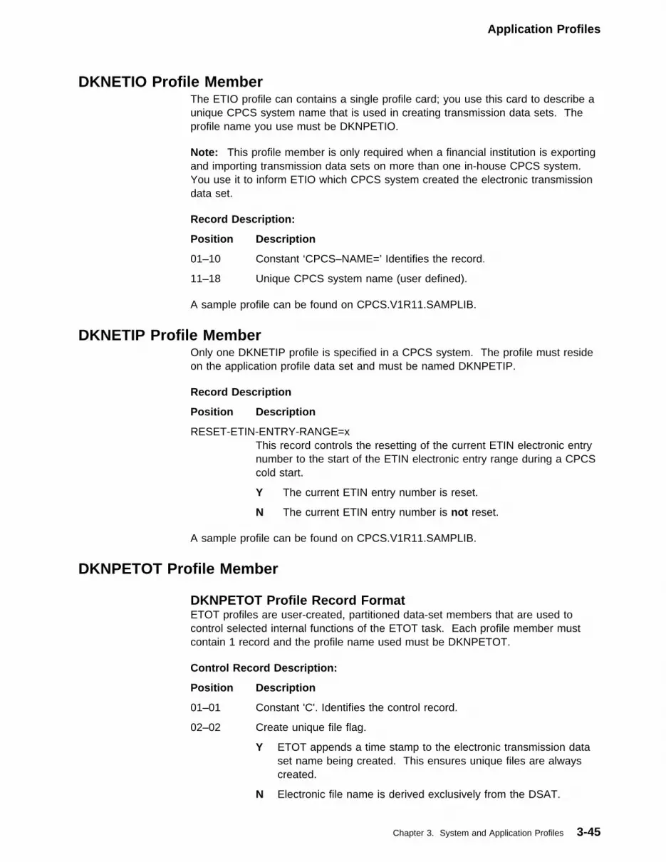
Application Profiles
DKNETIO Profile MemberThe ETIO profile can contains a single profile card; you use this card to describe aunique CPCS system name that is used in creating transmission data sets. Theprofile name you use must be DKNPETIO.
Note: This profile member is only required when a financial institution is exportingand importing transmission data sets on more than one in-house CPCS system.You use it to inform ETIO which CPCS system created the electronic transmissiondata set.
Record Description:
Position Description
01–10 Constant ‘CPCS–NAME=’ Identifies the record.
11–18 Unique CPCS system name (user defined).
A sample profile can be found on CPCS.V1R11.SAMPLIB.
DKNETIP Profile MemberOnly one DKNETIP profile is specified in a CPCS system. The profile must resideon the application profile data set and must be named DKNPETIP.
Record Description
Position Description
RESET-ETIN-ENTRY-RANGE=xThis record controls the resetting of the current ETIN electronic entrynumber to the start of the ETIN electronic entry range during a CPCScold start.
Y The current ETIN entry number is reset.
N The current ETIN entry number is not reset.
A sample profile can be found on CPCS.V1R11.SAMPLIB.
DKNPETOT Profile Member
DKNPETOT Profile Record FormatETOT profiles are user-created, partitioned data-set members that are used tocontrol selected internal functions of the ETOT task. Each profile member mustcontain 1 record and the profile name used must be DKNPETOT.
Control Record Description:
Position Description
01–01 Constant 'C'. Identifies the control record.
02–02 Create unique file flag.
Y ETOT appends a time stamp to the electronic transmission dataset name being created. This ensures unique files are alwayscreated.
N Electronic file name is derived exclusively from the DSAT.
Chapter 3. System and Application Profiles 3-45

Application Profiles
03–03 Separate electronic images by sort pattern number.
Y ETOT separates strings exported to the transmission data set bysort pattern. As work is written to the transmission data set, asort type delimiter record is written to when the sort typechanges. This enables the sort pattern number to be maintainedwhen importing work for multiple sort patterns into CPCS.
N All work within a single transmission data set is allocated to thesame sort pattern number when imported into CPCS.
04–04 Create ETOT report.
Y A report detailing the transmission data set created is produced.
N No report is produced.
05–05 Export SDE details. This flag is used to indicate whether the stringdirectory information should be included on the transmission data setas part of the export process.
Y Export SDE details.
N Do not export SDE details.
06–06 Export GUA data. This flag is used to indicate whether an item’sglobal user area should be included on the transmission data setwhen exporting extended strings.
Y Export GUA details.
N Do not export GUA details.
07–07 Write work from different banks to unique transmission files.
N If several strings selected for export were captured underdifferent bank numbers, the work is written to the sametransmission file.
Y If several strings selected for export were captured underdifferent bank numbers, the work is written to differenttransmission files. If you use this option, you must ensure thatthe DSAT entry used to allocate the transmission files doescreate unique files; otherwise, previously written data may beoverwritten.
08–15 Transmission File DSAT Name. This is the DSAT name that ETOTuses to allocate the ETOT output transmission file.
16–80 Reserved
A sample profile can be found on CPCS.V1R11.SAMPLIB.
Name Record Description: It is possible to add up to five optional name andaddress lines in the ETOT profile. These name and address lines are written to theETOT report as the destination name and address. If no name and address linesare included in the ETOT profile, and ETOT is run by endpoint, the name andaddress lines are taken from the endpoint name and address file.
Position Description
01–01 Constant ‘N’. Identifies a name record.
02–02 Name and address line number. Values can be between 1 and 5.
3-46 CPCS V1R11 Customization Guide

Application Profiles
03–28 Name and address details
29–80 Reserved
A sample profile can be found on CPCS.V1R11.SAMPLIB.
DKNPICRE Profile MemberThe DKNPICRE profile controls the behavior of the ICRE task. The keywords are:
GLOBAL_USER_AREAS_EXTRACT={YES | NO}When YES is specified, ICRE extracts the global user areas (GUAs)corresponding to extended string records. When NO is specified or bydefault (no keywords or missing DKNPICRE member), ICRE does notextract extended string GUAs.
When extracted, GUAs are placed following their associated conventionalfields. Therefore, the ICRE output data set record length must be increasedin this case to accommodate each GUA. Specifically, the record lengthshould be increased by the highest possible GUA length + 4. (If dynamicdata set allocation is used, this change must be made to the ICRE entry ofthe DKNDSAT table, and then the table must be reassembled.) Output datasets with a record length shorter than required result in the output recorddata being truncated.
Conventional and extended strings can be extracted into a same outputdata set by a single execution of the ICRE task. GUAs are always extractedin the same format, preceded by four bytes that contain the GUA length inbinary, regardless of what format has been selected for the conventionalfields. The output data set’s string header records (ID=X'08') indicate theassociated string’s type (conventional or extended).
DKNPKILL Profile MemberThe DKNPKILL profile controls the behavior of DKNKILL. The keywords are:
ALLOW_KILL_AND_MCRE_TO_RUN_CONCURRENTLY={YES | NO}If one or more KILLs run at the same time as MCRE for a given cycle, it ispossible for MCRE to fail to extract some of the KILLed bundles. Toprevent this from happening, set this keyword to a value of NO. Eachstarted KILL checks to see if an MCRE is running for the same cycle; if it is,KILL waits for the MCRE to finish.
This keyword has no effect if the KILL and the MCRE are being run fordifferent cycles. It does not prevent multiple simultaneous KILLs fromrunning on the same cycle.
Many sites normally schedule their MCREs at a time when no KILLs takeplace. If your site is one of them, you can set this keyword to YES for aslight improvement in performance.
This keyword should be set to the same value as the“ALLOW_KILL_AND_MCRE_TO_RUN_CONCURRENTLY’ keyword in theDKNPMCRE profile. If this keyword is not present in DKNPKILL, it defaultsto a value of YES.
Chapter 3. System and Application Profiles 3-47

Application Profiles
DKNPMCRE Profile MemberThe DKNPMCRE profile controls the behavior of DKNMCRE. The keywords are:
ALLOW_KILL_AND_MCRE_TO_RUN_CONCURRENTLY={YES | NO}If one or more KILLs run at the same time as MCRE for a given cycle, it ispossible for MCRE to fail to extract some of the KILLed bundles. Toprevent this from happening, set this keyword to a value of NO. WhenMCRE starts, it checks if any KILLs are being run for the same cycle. Sucha KILL causes MCRE to consult with the terminal operator for furtherinstructions. The operator can choose to either cancel MCRE, or make itwait until all the KILLs are finished.
This keyword has no effect if the KILLs and the MCRE are being run fordifferent cycles.
Many sites normally schedule their MCRE runs at a time when no KILLstake place. If your site is one of them, you can set this keyword to YES fora slight improvement in performance.
This keyword should be set to the same value as the“ALLOW_KILL_AND_MCRE_TO_RUN_CONCURRENTLY” keyword in theDKNPKILL profile. If this keyword is not present in DKNPMCRE, it defaultsto a value of YES.
| GLOBAL_USER_AREAS_EXTRACT={YES | NO}| When YES is specified, MCRE extracts the global user areas (GUAs)| corresponding to extended string records. When NO is specified or the| default is used (no keywords or missing DKNPMCRE member), MCRE| does not extract extended-string GUAs.
| When extracted, GUAs are placed following their associated conventional| fields. Therefore, the MCRE output data set record length must be| increased in this case to accommodate each GUA. Specifically, the record| length should be increased by the highest possible GUA length + 4. (If| dynamic data set allocation is used, this change must be made to the| MCRE entry of the DKNDSAT table and the table must be reassembled.)| Output data sets with a record length shorter than required results in the| output record data being truncated.
| Conventional and extended strings can be extracted into the same output| data set by a single execution of the MCRE task. GUAs are always| extracted in the same format, preceded by four bytes that contain the GUA| length in binary, regardless of what format has been selected for the| conventional fields. The output data set’s string header records (ID=X'82')| indicate the associated string’s type (conventional or extended).
DKNPMRGE Profile MemberThe DKNPMRGE profile controls the behavior of DKNMRGE. The keywords are:
USE_SCATTED_SYSTEM_REJECT_R_STRING={YES | NO}For those merges involving the System Reject pocket, this keyword controlswhat sort of R-string MRGE looks for. It has no effect on Pocket,Consolidated, Final, or HSRR merges.
A value of YES means that MRGE uses a concatenated System Reject R-string.Before running MRGE, you must run SCAT to combine the various PartialSystem Reject R-strings into a single concatenated System Reject R-string.
3-48 CPCS V1R11 Customization Guide
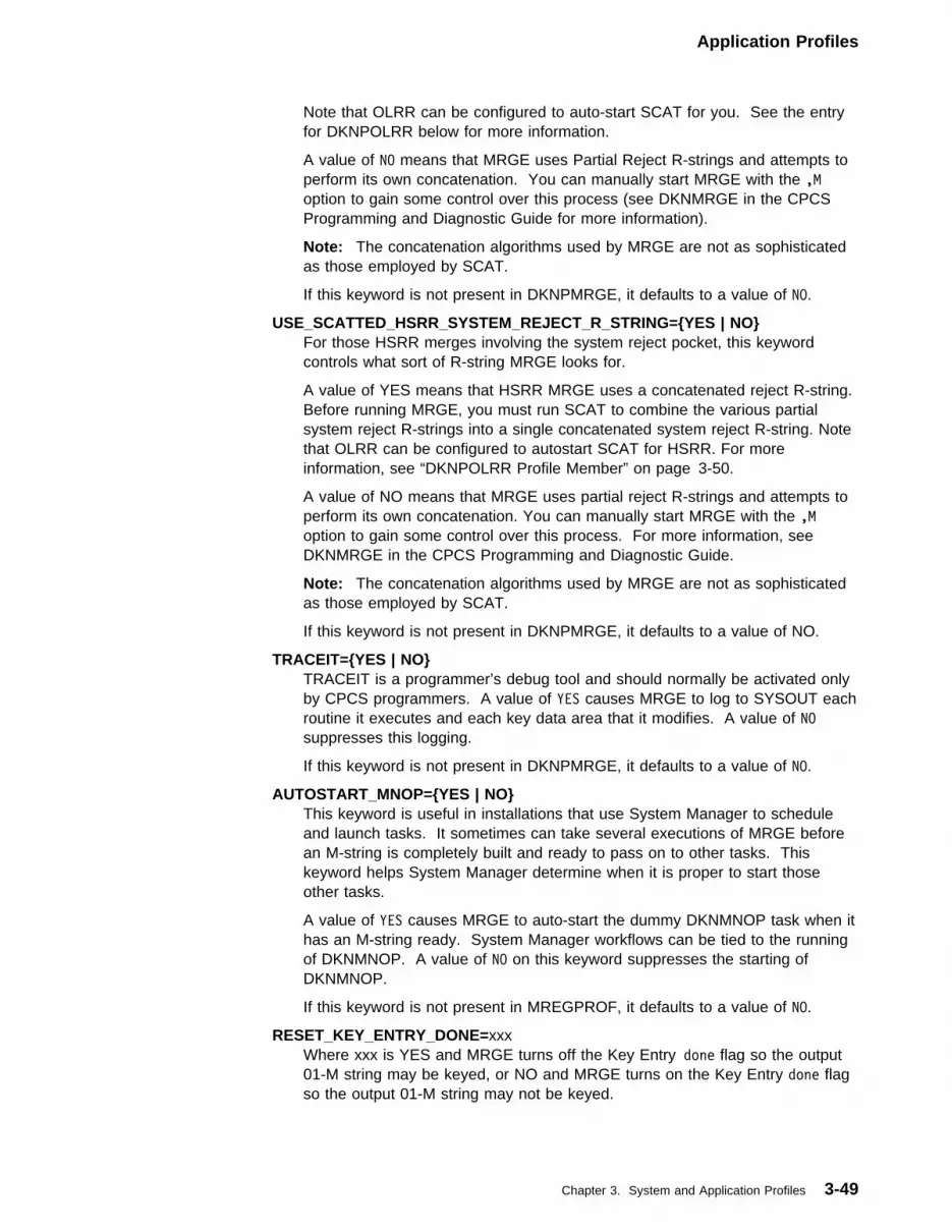
Application Profiles
Note that OLRR can be configured to auto-start SCAT for you. See the entryfor DKNPOLRR below for more information.
A value of NO means that MRGE uses Partial Reject R-strings and attempts toperform its own concatenation. You can manually start MRGE with the ,Moption to gain some control over this process (see DKNMRGE in the CPCSProgramming and Diagnostic Guide for more information).
Note: The concatenation algorithms used by MRGE are not as sophisticatedas those employed by SCAT.
If this keyword is not present in DKNPMRGE, it defaults to a value of NO.
USE_SCATTED_HSRR_SYSTEM_REJECT_R_STRING={YES | NO}For those HSRR merges involving the system reject pocket, this keywordcontrols what sort of R-string MRGE looks for.
A value of YES means that HSRR MRGE uses a concatenated reject R-string.Before running MRGE, you must run SCAT to combine the various partialsystem reject R-strings into a single concatenated system reject R-string. Notethat OLRR can be configured to autostart SCAT for HSRR. For moreinformation, see “DKNPOLRR Profile Member” on page 3-50.
A value of NO means that MRGE uses partial reject R-strings and attempts toperform its own concatenation. You can manually start MRGE with the ,Moption to gain some control over this process. For more information, seeDKNMRGE in the CPCS Programming and Diagnostic Guide.
Note: The concatenation algorithms used by MRGE are not as sophisticatedas those employed by SCAT.
If this keyword is not present in DKNPMRGE, it defaults to a value of NO.
TRACEIT={YES | NO}TRACEIT is a programmer’s debug tool and should normally be activated onlyby CPCS programmers. A value of YES causes MRGE to log to SYSOUT eachroutine it executes and each key data area that it modifies. A value of NOsuppresses this logging.
If this keyword is not present in DKNPMRGE, it defaults to a value of NO.
AUTOSTART_MNOP={YES | NO}This keyword is useful in installations that use System Manager to scheduleand launch tasks. It sometimes can take several executions of MRGE beforean M-string is completely built and ready to pass on to other tasks. Thiskeyword helps System Manager determine when it is proper to start thoseother tasks.
A value of YES causes MRGE to auto-start the dummy DKNMNOP task when ithas an M-string ready. System Manager workflows can be tied to the runningof DKNMNOP. A value of NO on this keyword suppresses the starting ofDKNMNOP.
If this keyword is not present in MREGPROF, it defaults to a value of NO.
RESET_KEY_ENTRY_DONE=xxxWhere xxx is YES and MRGE turns off the Key Entry done flag so the output01-M string may be keyed, or NO and MRGE turns on the Key Entry done flagso the output 01-M string may not be keyed.
Chapter 3. System and Application Profiles 3-49

Application Profiles
DKNPOLRR Profile MemberThe DKNPOLRR profile controls the behavior of DKNOLRR. The keywords are:
AUTOSTART_SCAT_WHEN_OLRRING_SYSTEM_REJECT_D-STRING={YES |NO}
This keyword controls how OLRR handles any Partial System Reject R-string itis asked to create. It has no effect on Alternate, Consolidated, or UnencodedPartial R-strings.
A value of YES will cause OLRR to auto-start SCAT and pass it the name of thePartial System Reject R-string. SCAT will accumulate each such Partial itreceives until it has enough on hand to concatenate them. MRGE can beconfigured to read these concatenated R-strings (see the DKNPMRGE profileabove for more information).
A value of NO means that OLRR does not auto-start SCAT. You will eitherhave to run SCAT yourself, or configure MRGE to directly process PartialSystem Reject R-strings. See the DKNPMRGE profile above for moreinformation.
Note: The concatenation algorithms used by MRGE are not as sophisticatedas those employed by SCAT.
This keyword is ignored if your installation has installed Enhanced SystemManager. In an ESM environment, the only way to auto-start SCAT is toincorporate it into your workflows.
If this keyword is not present in DKNPOLRR, it defaults to a value of NO.
AUTOSTART_SCAT_WHEN_OLRRING_SYSTEM_REJECT_D-STRING_FOR_HSRR={YES| NO}
This keyword controls how OLRR handles any partial system reject R-string itis asked to create for HSRR rejects that are repaired through OLRR.
A value of YES causes OLRR to autostart SCAT and to pass it the name of thepartial system reject R-string. SCAT accumulates each such partial it receivesuntil it has enough on hand to concatenate them. MRGE can be configured toread these concatenated R-strings (see “DKNPMRGE Profile Member” onpage 3-48 for more information).
A value of NO means that OLRR does not autostart SCAT. You must either runSCAT yourself or configure MRGE to directly process partial system rejectR-strings. (See “DKNPMRGE Profile Member” on page 3-48 for moreinformation.)
Note: The concatenation algorithms used by MRGE are not as sophisticatedas those employed by SCAT.
If this keyword is not present in DKNPOLRR, it defaults to a value of NO.
REQUIRE_PLUS_TO_VALIDATE_INPUT={YES | NO}If this keyword is set to YES, the operator:
� Enters all corrections on an OLRR screen
� Tabs to the PIGGYBACKS field at the bottom of the screen
� Enters a single plus character (+) to cause the corrections to be accepted.
If the operator does not enter a plus, for example if he or she simply pressesENTER instead, then all corrections are “forgotten” and the screen resets to
3-50 CPCS V1R11 Customization Guide

Application Profiles
what had originally been displayed. The operator must then re-enter all thecorrections again.
If this parameter is set to NO, it is not necessary for the operator to validateeach OLRR screen with a plus. Simply pressing ENTER causes thecorrections to be accepted. However, the operator also no longer has a way tomake OLRR “forget” corrections and reset its display.
The default value for this keyword is YES.
GENERATE_STATISTICS_ON_OLRR_BYPASS={YES | NO}If this keyword is set to YES, and OLRR is run in BYPASS mode, an OLRRstatistics record is added to the end of the R-string it creates, the same way anormal, non-BYPASS OLRR would.
If this keyword is set to NO, and OLRR is run in BYPASS mode, an OLRRstatistics record is not added.
The default value for this keyword is NO.
RTNOTVER_OFF_WHEN_NO_CHECK_DIGIT_ON_PB={NO | YES}Where: --
NO Means always turn on the RTNOTVER bit.YES Means do not turn on the RTNOTVER bit.
Note: This card only applies to piggybacks.
This card instructs OLRR not to turn the Routing Transit Not Verified(RTNOTVER) bit on if the codeline is a piggyback. The default (NO) is toalways turn on the RTNOTVER bit before editing the codeline. By changingthe setting to YES, the RTNOTVER bit is not turned on unless instructed to doso by the Check Digit Routines. The RTNOTVER bit is in DI3BYTE3.
RT_MODCHK_BYPASS=[YES | NO]This keyword controls how OLRR handles any 9-digit routing and transit. TheYES option directs to bypass mod checking, and the NO option directs to notbypass mod checking.
DKNPRLST Profile MemberThe DKNPRLST profile controls the behavior of DKNRLST. The keywords are:
DISPOSITION_OF_SCATTED_SYSTEM_REJECT_R-STRING={KEEP | DELETE}This keyword controls what RLST does with any concatenated System RejectR-string it is asked to list. It has no effect on RLST’s handling of PartialSystem Reject R-strings.
A value of DELETE deletes the R-string when RLST is finished; a value of KEEPkeeps it. It is not necessarily an error to delete concatenated System RejectR-strings, as the data contained in them are still available in the various PartialSystem Reject R-strings from which the concatenated was built.
If you choose to KEEP concatenated System Reject R-strings, be aware thatthey will be automatically deleted anyway by MCRE.
This keyword is ignored if you have installed Enhanced System Manager. Inan ESM environment, the only way to delete concatenated System RejectR-strings is to incorporate an STGD step into your workflows.
If this keyword is not present in DKNPRLST, it defaults to a value of KEEP.
Chapter 3. System and Application Profiles 3-51

Application Profiles
FIELD from DIDSCT - RELATIVE Location
NAME BYTE:BIT in 5�-byte MDS
-------- ----:---
DI3BYTE3 45:�
RTCKDIGT 45:� 1�1� <-- No check digit
RTNOTVER 45:4 � <-- RT not verified
SCIPAON 45:5 �
DI33_RES1 45:6 �
DI33_RES2 45:7 �
Figure 3-2. Record Type 3
DKNPSCPY Profile MemberDKNPSCPY provides a utility for copying strings under the control of an applicationprofile. The profile selects properties of the copying process (for example, whetherthis is a string-to-string copy or a copy-in-place, whether the string is modified inany way during the copy, and so on). There exists a different SCPY profile foreach different way a string can be copied.
All SCPY profiles share the same common characteristics:
� Their names all begin with SCPY (for example, DKNPSCPS).
� They all contain the COPY_FROM, COPY_TO, COPY_WORK, andCOPY_PROG keywords, which furthermore must appear in that order (that is,COPY_FROM before COPY_TO, COPY_TO before COPY_WORK, etcetera).
� They may contain other keywords unique to that particular SCPY profile.
� They may contain the optional DEBUG keyword.
SCPY Profile Common Keywords
The following is a complete list of all the keywords common to all SCPY profiles:
COPY_FROM=eeee-p-aa-bb-cc-dd-t-sssNames the string that SCPY is to copy from. Each component (entry number,pass, pocket 1, pocket 2, etcetera), besides containing a legal value for thatcomponent, may also contain asterisks (*). In such a case SCPY will plug thecomponent from the Unit of Work (if started by ESM), or from the operator’sCOPY FROM input, if started manually.
Note: If COPY_FROM is other than ****-*-**-**-**-**-*-***, then the string thatis copied won’t necessarily be the string passed in the UOW, or entered by theoperator.
COPY_FROM is a required keyword. It is an error not to have one present inan SCPY profile. It must appear before the profile’s COPY_TO,COPY_WORK, and COPY_PROG keywords.
COPY_TO=eeee-p-aa-bb-cc-dd-t-sssNames the string that SCPY is to copy to. Each component (entry number,pass, pocket 1, pocket 2, etcetera), besides containing a legal value for thatcomponent, may also contain asterisks (*). In such a case SCPY will plug thecomponent from the COPY_FROM string. If SCPY is manually-started, andthe operator enters a COPY TO string, then SCPY will plug from the operator’sinput instead.
3-52 CPCS V1R11 Customization Guide

Application Profiles
A COPY_TO of ****-*-**-**-**-**-*-***, if not overridden by the operator, causesSCPY to perform a copy-in-place.
COPY_TO is a required keyword. It is an error not to have one present in anSCPY profile. It must appear after the profile’s COPY_FROM keyword, butbefore the COPY_WORK and the COPY_PROG.
COPY_WORK=eeee-p-aa-bb-cc-dd-t-sssNames the work string that SCPY creates as a scratchpad. Each component(entry number, pass, pocket 1, pocket 2, etcetera), besides containing a legalvalue for that component, may also contain asterisks (*). In such a case SCPYwill plug the component from the COPY_FROM string.
COPY_WORK is a required keyword. It is an error not to have one present inan SCPY profile. It must appear after the profile’s COPY_FROM andCOPY_TO keywords, but before COPY_PROG.
COPY_PROG=xxxxxxxxNames the program that SCPY is to pass control to after it has validated thecommon keywords. This sub-module validates all remaining keywords in theprofile and may even perform additional validation on COPY_FROM,COPY_TO, and COPY_WORK. Finally, it performs the actual copying ofstrings.
COPY_PROG is a required keyword. It is an error not to have one present inan SCPY profile. It must appear after the profile’s COPY_FROM, COPY_TO,and COPY_WORK keywords.
DEBUGDEBUG is a programmer’s debug tool and should normally be activated onlyby CPCS programmers. If present, it causes each profile record read from thatpoint forward to be listed on the SCRL log (if SCPY was manually started, theprofile records will be listed on the terminal as well). Comment records will notbe listed.
If this keyword is not present, SCPY’s default action is to list no records.
SCPY Profiles List
DKNPSCPSThe DKNPSCPS profile controls the behavior of the SCPY sub-moduleDKNSCPSB. DKNSCPSB’s first action is to ensure that:
� COPY_FROM names a subpass I-string.
� The COPY_TO string is identical to the COPY_FROM string (that is,COPY_TO specifies copy-in-place).
� The COPY_WORK string is identical to the COPY_FROM string, except forpocket 4, which must be different.
DKNSCPSB also verifies that DKNPSCPS contains at least one PAPER_DOCkeyword, or at least one CONTROL_DOC keyword.
The keywords specific to the DKNPSCPS profile are:
PAPER_DOC={nn | nn-nn},{nn | nn-nn},...Names DITYPEI document type codes and/or ranges of DITYPEI documenttype codes for non-control documents. Every time DKNSCPSB encounters anon-control document of this type, it checks to see if its sequence number is9999999999 (that is, whether or not sorter codeline data matching had
Chapter 3. System and Application Profiles 3-53
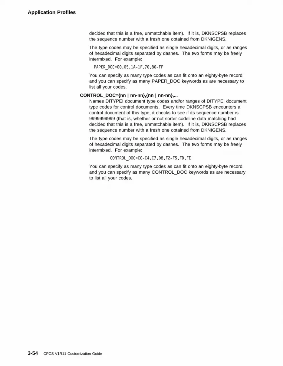
Application Profiles
decided that this is a free, unmatchable item). If it is, DKNSCPSB replacesthe sequence number with a fresh one obtained from DKNIGENS.
The type codes may be specified as single hexadecimal digits, or as rangesof hexadecimal digits separated by dashes. The two forms may be freelyintermixed. For example:
PAPER_DOC=��,�5,1A-1F,7�,8�-FF
You can specify as many type codes as can fit onto an eighty-byte record,and you can specify as many PAPER_DOC keywords as are necessary tolist all your codes.
CONTROL_DOC={nn | nn-nn},{nn | nn-nn},...Names DITYPEI document type codes and/or ranges of DITYPEI documenttype codes for control documents. Every time DKNSCPSB encounters acontrol document of this type, it checks to see if its sequence number is9999999999 (that is, whether or not sorter codeline data matching haddecided that this is a free, unmatchable item). If it is, DKNSCPSB replacesthe sequence number with a fresh one obtained from DKNIGENS.
The type codes may be specified as single hexadecimal digits, or as rangesof hexadecimal digits separated by dashes. The two forms may be freelyintermixed. For example:
CONTROL_DOC=C�-C4,C7,D8,F2-F5,FD,FE
You can specify as many type codes as can fit onto an eighty-byte record,and you can specify as many CONTROL_DOC keywords as are necessaryto list all your codes.
3-54 CPCS V1R11 Customization Guide

DKNMRGE Codeline Data Matching
DKNMRGE Codeline Data MatchingThis section outlines the preparations required to build the codeline data matchingtables used to merge HSRR strings.
OverviewDKNMRGE calls DKNMRG2 to build a match file that contains the prime-passsequence number and the corresponding HSRR sequence number. The match fileis built by comparing the MICR fields in the prime-pass reject D-string to the MICRfields in the HSRR I-string. The resulting file is then merged with the HSRR I-stringand the HSRR R-string to create the HSRR file. The HSRR file is sorted intoprime-pass sequence number order and merged with the prime-pass I-string toproduce the output M-string. For each sort pattern in DKNSPDEF that is used forcapturing HSRR strings, build a matching table member, or you may elect to buildone for each bank. However, in most cases the default member MRG2S256provides sufficient results.
The following naming convention is used by DKNMRGEP to locate the HSRRmerge profile member in the file specified by the ddname DKNAPPL in the CPCSrun JCL.
MRG2xyyy The convention:
MRG2Constant tells DKNMRGEP to use this member
x Where:
S Sort pattern
B Bank
yyy Sort pattern number or bank number
For example, MRG2S001 has the matching table parameters DKNMRG2 useswhen matching the HSRR I-string to the prime reject D-string for work capturedunder sort pattern 001.
The search order is:
1. Look for a member corresponding to the sort pattern using the prime I-stringSDE information.
2. If a sort pattern member is not found, look for a member corresponding to thebank number.
3. If neither a corresponding sort pattern or bank member is found, default to thevalues in MRG2S256.
4. If neither a corresponding sort pattern or bank member and MRG2S256 cannotbe found, use the values contained in the COBOL copybook DKNMRGEZ.
For example, you capture a prime I-string using sort pattern 070. You use a deviceto fix rejects that returns a HSRR I-string to CPCS. Because this device doesn’trequire a sort pattern, the string directory entry (SDE) is zero filled. In this case,the member name should be MRG2S070.
In the same example but you want to use the sort pattern from the HSRR I-string,you must modify DKNMRGEZ and change the default value
Chapter 3. System and Application Profiles 3-55
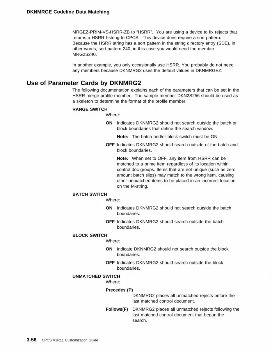
DKNMRGE Codeline Data Matching
MRGEZ-PRIM-VS-HSRR-ZB to “HSRR”. You are using a device to fix rejects thatreturns a HSRR I-string to CPCS. This device does require a sort pattern.Because the HSRR string has a sort pattern in the string directory entry (SDE), inother words, sort pattern 240, in this case you would need the memberMRG2S240.
In another example, you only occasionally use HSRR. You probably do not needany members because DKNMRG2 uses the default values in DKNMRGEZ.
Use of Parameter Cards by DKNMRG2The following documentation explains each of the parameters that can be set in theHSRR merge profile member. The sample member DKN2S256 should be used asa skeleton to determine the format of the profile member.
RANGE SWITCHWhere:
ON Indicates DKNMRG2 should not search outside the batch orblock boundaries that define the search window.
Note: The batch and/or block switch must be ON.
OFF Indicates DKNMRG2 should search outside of the batch andblock boundaries.
Note: When set to OFF, any item from HSRR can bematched to a prime item regardless of its location withincontrol doc groups. Items that are not unique (such as zeroamount batch slips) may match to the wrong item, causingother unmatched items to be placed in an incorrect locationon the M-string.
BATCH SWITCHWhere:
ON Indicates DKNMRG2 should not search outside the batchboundaries.
OFF Indicates DKNMRG2 should search outside the batchboundaries.
BLOCK SWITCHWhere:
ON Indicate DKNMRG2 should not search outside the blockboundaries.
OFF Indicates DKNMRG2 should search outside the blockboundaries.
UNMATCHED SWITCHWhere:
Precedes (P)DKNMRG2 places all unmatched rejects before thelast matched control document.
Follows(F) DKNMRG2 places all unmatched rejects following thelast matched control document that began thesearch.
3-56 CPCS V1R11 Customization Guide

DKNMRGE Codeline Data Matching
Sequence(M)DKNMRG2 places all unmatched rejects after the lastmatched item (default).
Block(B) DKNMRG2 places all unmatched rejects after the lastmatched block.
Batch(C) DKNMRG2 places all unmatched rejects after the lastmatched batch within the current block. If there is nomatched batch header yet within the current block,DKNMRG2 places unmatched rejects after the lastmatched block header.
BAD BAD SWITCHWhere:
ON DKNMRG2 masks out digit errors in both the prime andHSRR codelines when both contain errors.
OFF DKNMRG2 does not mask out digit errors.
OVERRIDE SWITCHWhere:
ON If an error occurs while editing, the PDS member overridesthe error and allows DKNMRGE to continue with the defaultsettings in DKNMRGEZ.
OFF If an error occurs while editing, the PDS member stopsDKNMRGE; no M-string is created.
Control Document SwitchWhere:
K Keep unmatched control documents from the HSRR string.
D Discard unmatched control documents from the HSRR string.
Unmatched Reject Report SwitchWhere:
1 Print unmatched reject report number DKNMRGE-001
3 Print unmatched reject report number DKNMRGE-003
A Print ALL unmatched reject reports
N Do not print any unmatched reject reports
Use of Matching Values by DKNMRG2Five tables are used by MRG2 during its matching process. Two tables are used todetermine if a codeline can be considered eligible for matching (TFLD and DFLDtables), three tables (GFLD, UFLD and BFLD tables) are used to determine if twocodelines can be considered matched.
Each table contains four unique rows. There are two rows for documents (one foronus documents and one for transit documents), one row for batch tickets, and arow for block tickets. Each of these rows describes a unique set of values that areused during the matching process for each of the document types.
The following list describes each of the tables used by DKNMRG2 when assigningvalues during the matching process:
Chapter 3. System and Application Profiles 3-57
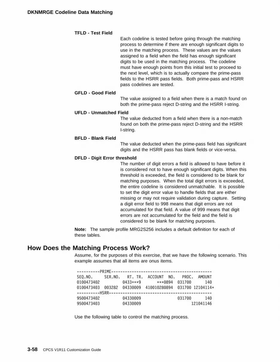
DKNMRGE Codeline Data Matching
TFLD - Test FieldEach codeline is tested before going through the matchingprocess to determine if there are enough significant digits touse in the matching process. These values are the valuesassigned to a field when the field has enough significantdigits to be used in the matching process. The codelinemust have enough points from this initial test to proceed tothe next level, which is to actually compare the prime-passfields to the HSRR pass fields. Both prime-pass and HSRRpass codelines are tested.
GFLD - Good FieldThe value assigned to a field when there is a match found onboth the prime-pass reject D-string and the HSRR I-string.
UFLD - Unmatched FieldThe value deducted from a field when there is a non-matchfound on both the prime-pass reject D-string and the HSRRI-string.
BFLD - Blank FieldThe value deducted when the prime-pass field has significantdigits and the HSRR pass has blank fields or vice-versa.
DFLD - Digit Error thresholdThe number of digit errors a field is allowed to have before itis considered not to have enough significant digits. When thisthreshold is exceeded, the field is considered to be blank formatching purposes. When the total digit errors is exceeded,the entire codeline is considered unmatchable. It is possibleto set the digit error value to handle fields that are eithermissing or may not require validation during capture. Settinga digit error field to 998 means that digit errors are notaccumulated for that field. A value of 999 means that digiterrors are not accumulated for the field and the field isconsidered to be blank for matching purposes.
Note: The sample profile MRG2S256 includes a default definition for each ofthese tables.
How Does the Matching Process Work?Assume, for the purposes of this exercise, that we have the following scenario. Thisexample assumes that all items are onus items.
----------PRIME--------------------------------------------
SEQ.NO. SER.NO. RT. TR. ACCOUNT NO. PROC. AMOUNT
�1��4734�2 �433TTT9 TTT�894 �317�� 14�
�1��4734�3 ��3282 �433���9 41��1�28�894 �317�� 121�4114T
----------HSRR---------------------------------------------
95��4734�2 �433���9 �317�� 14�
95��4734�3 �433���9 121�41146
Use the following table to control the matching process.
3-58 CPCS V1R11 Customization Guide

DKNMRGE Codeline Data Matching
AMT P/C ACC OPT R/T OPT SER TOT
RECID F1 F2 F3 F4 F5 F6 F7 TOT
----- --- --- --- --- --- --- --- ---
��2�1 ��2 ��1 ��2 ��� ��3 ��� ��2 ��4 T ONUS Test
��3�1 ��2 ��1 ��3 ��� ��3 ��� ��2 ��4 T ONUS Good
��4�1 ��2 ��� ��� ��� ��2 ��� ��� T ONUS Unmatched
��5�1 ��� ��� ��� ��� ��� ��� ��� T ONUS Blank
��6�1 ��2 ��1 ��2 ��� ��2 ��� ��2 ��6 T ONUS Digit Errors
First, look at the first prime item.
SEQ.NO. SER.NO. RT. TR. ACCOUNT NO. PROC. AMOUNT
�1��4734�2 �433TTT9 TTT�894 �317�� 14�
Step 001 - Test for enough significant digits to use for matching seq. no.000100473402.
Field 1 has no digit errors: recid{��2�1(f1)} is 002. We add two points to ourtest weight total.
Field 2 has no digit errors: recid{��2�1(f2)} is 001. We add one point to ourtest weight total.
Field 3 has three digit errors: recid{��6�1(f3) is 002; since 3 > 2, the field isblanked out for testing purposes. We add no points to our test weight total; we addthree points to our digit error total.
Field 5 has three digit errors: recid{��6�1(f5) is 002; since 3 > 2, the field isblanked out for testing purposes. We add no points to our test weight total; we addthree points to our digit error total.
Field 7 is blank. No points are added to our test weights.
Results:
Test Weight points = ��3
Digit Error points = ��6
Because three is less than four (the total test weight points needed for matching anonus item), this codeline is unmatchable and is missing its correction seq029500473402, which is a free item. Also, had the test total points been greaterthan or equal to four, an additional test would have been made to ensure therewere no more than six total digit errors in the entire codeline. As there were sixdigit errors, this codeline would still have been considered unmatchable.
Now, let’s consider the next prime item:
SEQ.NO. SER.NO. RT. TR. ACCOUNT NO. PROC. AMOUNT
�1��4734�3 ��3282 �433���9 41��1�28�894 �317�� 121�4114T
STEP 001 - Test for enough significant digits to use for matching seq no.000100473403.
Test weight points equal:
Chapter 3. System and Application Profiles 3-59
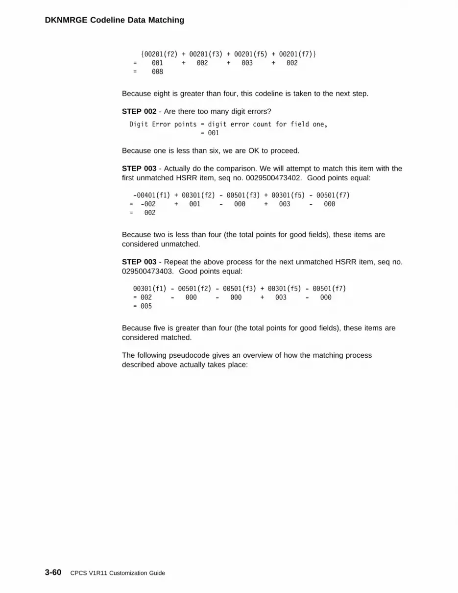
DKNMRGE Codeline Data Matching
{��2�1(f2) + ��2�1(f3) + ��2�1(f5) + ��2�1(f7)}
= ��1 + ��2 + ��3 + ��2
= ��8
Because eight is greater than four, this codeline is taken to the next step.
STEP 002 - Are there too many digit errors?
Digit Error points = digit error count for field one,
= ��1
Because one is less than six, we are OK to proceed.
STEP 003 - Actually do the comparison. We will attempt to match this item with thefirst unmatched HSRR item, seq no. 0029500473402. Good points equal:
-��4�1(f1) + ��3�1(f2) - ��5�1(f3) + ��3�1(f5) - ��5�1(f7)
= -��2 + ��1 - ��� + ��3 - ���
= ��2
Because two is less than four (the total points for good fields), these items areconsidered unmatched.
STEP 003 - Repeat the above process for the next unmatched HSRR item, seq no.029500473403. Good points equal:
��3�1(f1) - ��5�1(f2) - ��5�1(f3) + ��3�1(f5) - ��5�1(f7)
= ��2 - ��� - ��� + ��3 - ���
= ��5
Because five is greater than four (the total points for good fields), these items areconsidered matched.
The following pseudocode gives an overview of how the matching processdescribed above actually takes place:
3-60 CPCS V1R11 Customization Guide

DKNMRGE Codeline Data Matching
tfld-accum = �
derr-accum = �
do TEST each FIELD in the CODELINE for SIGNIFICANT DIGITS
do COUNT the number of DIGIT ERRORS
if tfld-accum >= TOTAL for TFLD
and derr-accum <= TOTAL for DERR
then
accum = �
evaluate true
when A PRIME FIELD MATCHES A HSRR FIELD
accum = accum + GFLD
when A PRIME FIELD IS BLANK AND A HSRR FIELD HAS
SIGNIFICANT DIGITS
accum = accum - BFLD
when A HSRR FIELD IS BLANK AND A PRIME FIELD HAS
SIGNIFICANT DIGITS
accum = accum - BFLD
when BOTH HSRR AND PRIME FIELDS HAVE DIGITS AND
THEY DON'T MATCH
accum = accum - UFLD
end-evaluate
if accum >= TOTAL for GFLD
then
THIS IS CONSIDERED A MATCH
else
THIS IS NOT A MATCH
end-if
else
THE CODELINE CANNOT BE MATCHED
end-if
Chapter 3. System and Application Profiles 3-61

DKNMRGE Codeline Data Matching
3-62 CPCS V1R11 Customization Guide
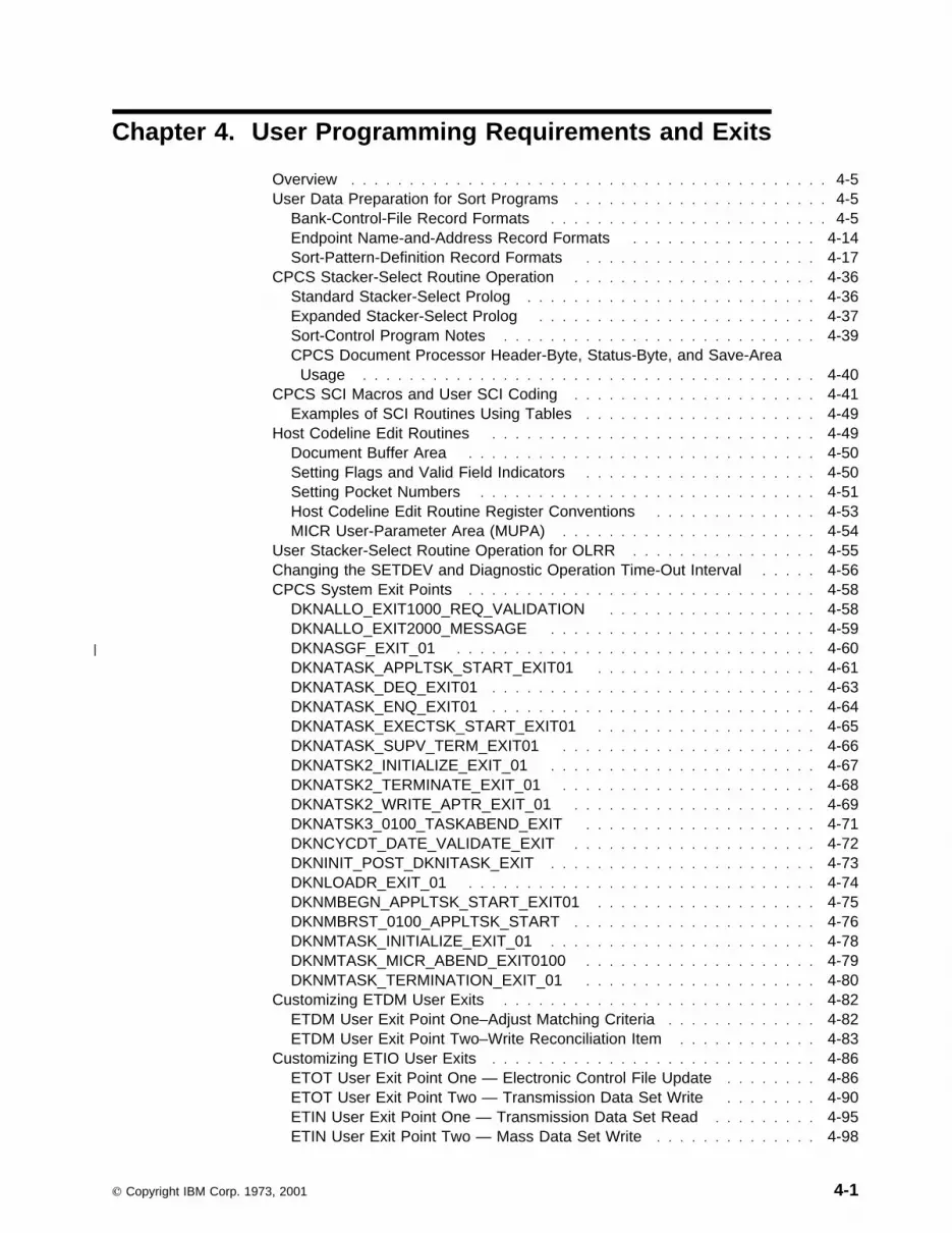
Chapter 4. User Programming Requirements and Exits
Overview . . . . . . . . . . . . . . . . . . . . . . . . . . . . . . . . . . . . . . . . . 4-5User Data Preparation for Sort Programs . . . . . . . . . . . . . . . . . . . . . . 4-5
Bank-Control-File Record Formats . . . . . . . . . . . . . . . . . . . . . . . . 4-5Endpoint Name-and-Address Record Formats . . . . . . . . . . . . . . . . 4-14Sort-Pattern-Definition Record Formats . . . . . . . . . . . . . . . . . . . . 4-17
CPCS Stacker-Select Routine Operation . . . . . . . . . . . . . . . . . . . . . 4-36Standard Stacker-Select Prolog . . . . . . . . . . . . . . . . . . . . . . . . . 4-36Expanded Stacker-Select Prolog . . . . . . . . . . . . . . . . . . . . . . . . 4-37Sort-Control Program Notes . . . . . . . . . . . . . . . . . . . . . . . . . . . 4-39CPCS Document Processor Header-Byte, Status-Byte, and Save-Area
Usage . . . . . . . . . . . . . . . . . . . . . . . . . . . . . . . . . . . . . . . 4-40CPCS SCI Macros and User SCI Coding . . . . . . . . . . . . . . . . . . . . . 4-41
Examples of SCI Routines Using Tables . . . . . . . . . . . . . . . . . . . . 4-49Host Codeline Edit Routines . . . . . . . . . . . . . . . . . . . . . . . . . . . . 4-49
Document Buffer Area . . . . . . . . . . . . . . . . . . . . . . . . . . . . . . 4-50Setting Flags and Valid Field Indicators . . . . . . . . . . . . . . . . . . . . 4-50Setting Pocket Numbers . . . . . . . . . . . . . . . . . . . . . . . . . . . . . 4-51Host Codeline Edit Routine Register Conventions . . . . . . . . . . . . . . 4-53MICR User-Parameter Area (MUPA) . . . . . . . . . . . . . . . . . . . . . . 4-54
User Stacker-Select Routine Operation for OLRR . . . . . . . . . . . . . . . . 4-55Changing the SETDEV and Diagnostic Operation Time-Out Interval . . . . . 4-56CPCS System Exit Points . . . . . . . . . . . . . . . . . . . . . . . . . . . . . . 4-58
DKNALLO_EXIT1000_REQ_VALIDATION . . . . . . . . . . . . . . . . . . 4-58DKNALLO_EXIT2000_MESSAGE . . . . . . . . . . . . . . . . . . . . . . . 4-59
| DKNASGF_EXIT_01 . . . . . . . . . . . . . . . . . . . . . . . . . . . . . . . 4-60DKNATASK_APPLTSK_START_EXIT01 . . . . . . . . . . . . . . . . . . . 4-61DKNATASK_DEQ_EXIT01 . . . . . . . . . . . . . . . . . . . . . . . . . . . . 4-63DKNATASK_ENQ_EXIT01 . . . . . . . . . . . . . . . . . . . . . . . . . . . . 4-64DKNATASK_EXECTSK_START_EXIT01 . . . . . . . . . . . . . . . . . . . 4-65DKNATASK_SUPV_TERM_EXIT01 . . . . . . . . . . . . . . . . . . . . . . 4-66DKNATSK2_INITIALIZE_EXIT_01 . . . . . . . . . . . . . . . . . . . . . . . 4-67DKNATSK2_TERMINATE_EXIT_01 . . . . . . . . . . . . . . . . . . . . . . 4-68DKNATSK2_WRITE_APTR_EXIT_01 . . . . . . . . . . . . . . . . . . . . . 4-69DKNATSK3_0100_TASKABEND_EXIT . . . . . . . . . . . . . . . . . . . . 4-71DKNCYCDT_DATE_VALIDATE_EXIT . . . . . . . . . . . . . . . . . . . . . 4-72DKNINIT_POST_DKNITASK_EXIT . . . . . . . . . . . . . . . . . . . . . . . 4-73DKNLOADR_EXIT_01 . . . . . . . . . . . . . . . . . . . . . . . . . . . . . . 4-74DKNMBEGN_APPLTSK_START_EXIT01 . . . . . . . . . . . . . . . . . . . 4-75DKNMBRST_0100_APPLTSK_START . . . . . . . . . . . . . . . . . . . . . 4-76DKNMTASK_INITIALIZE_EXIT_01 . . . . . . . . . . . . . . . . . . . . . . . 4-78DKNMTASK_MICR_ABEND_EXIT0100 . . . . . . . . . . . . . . . . . . . . 4-79DKNMTASK_TERMINATION_EXIT_01 . . . . . . . . . . . . . . . . . . . . 4-80
Customizing ETDM User Exits . . . . . . . . . . . . . . . . . . . . . . . . . . . 4-82ETDM User Exit Point One–Adjust Matching Criteria . . . . . . . . . . . . . 4-82ETDM User Exit Point Two–Write Reconciliation Item . . . . . . . . . . . . 4-83
Customizing ETIO User Exits . . . . . . . . . . . . . . . . . . . . . . . . . . . . 4-86ETOT User Exit Point One — Electronic Control File Update . . . . . . . . 4-86ETOT User Exit Point Two — Transmission Data Set Write . . . . . . . . 4-90ETIN User Exit Point One — Transmission Data Set Read . . . . . . . . . 4-95ETIN User Exit Point Two — Mass Data Set Write . . . . . . . . . . . . . . 4-98
Copyright IBM Corp. 1973, 2001 4-1

ETIN User Exit Point Three — Transmission Data Set Imported . . . . . 4-102ETIN User Exit Point Four — Write Electronic Resynch Record . . . . . 4-105ETIP User Exit Point One — Input Processor Messaging . . . . . . . . . 4-107ETIP User Exit Point Two — Input Processor Selection . . . . . . . . . . 4-111ETIP User Exit Point Three — Alter Import Data Exit . . . . . . . . . . . 4-113DKNETCFU User Exit One — Control File Record Create . . . . . . . . 4-118
Customizing ETCSH and X937 User Exits . . . . . . . . . . . . . . . . . . . 4-121DKNETCSH_FORMATS . . . . . . . . . . . . . . . . . . . . . . . . . . . . 4-121DKNETCSH_0100_NEW_RECORD . . . . . . . . . . . . . . . . . . . . . 4-122DKNETCSH_0200_FILE-CREATED . . . . . . . . . . . . . . . . . . . . . 4-123DKNX937_0100_NEW_RECORD . . . . . . . . . . . . . . . . . . . . . . . 4-125
DKNLDMY and DKNLJMP Exit — Logging Job MVS Posture . . . . . . . . 4-127DKNLDMY (Dummy executive task) . . . . . . . . . . . . . . . . . . . . . 4-127DKNLJMP . . . . . . . . . . . . . . . . . . . . . . . . . . . . . . . . . . . . 4-127Activation . . . . . . . . . . . . . . . . . . . . . . . . . . . . . . . . . . . . . 4-128Linkage . . . . . . . . . . . . . . . . . . . . . . . . . . . . . . . . . . . . . . 4-128Restrictions . . . . . . . . . . . . . . . . . . . . . . . . . . . . . . . . . . . . 4-128Writing Your Own User Exit for DKNLJMP . . . . . . . . . . . . . . . . . 4-128
DKNLOGU: Logging User Exit . . . . . . . . . . . . . . . . . . . . . . . . . . 4-129DKNRCVY_EXIT1000_BEFORE_WRITE . . . . . . . . . . . . . . . . . . 4-129
DKNMBEGN User Processing Exit . . . . . . . . . . . . . . . . . . . . . . . . 4-130Register Contents on Entry to DKNMBEGN Processing Exit Routine . . 4-131Sample DKNMBEGN User Processing Exit Routine . . . . . . . . . . . . 4-132
DKNMDIS–ESM Task Profile User Data Area . . . . . . . . . . . . . . . . . 4-132| DKNMDIS User Exit — Modify M-String Distribution . . . . . . . . . . . . . 4-132| Environment . . . . . . . . . . . . . . . . . . . . . . . . . . . . . . . . . . . 4-133| Point of Processing . . . . . . . . . . . . . . . . . . . . . . . . . . . . . . . 4-133| Activation . . . . . . . . . . . . . . . . . . . . . . . . . . . . . . . . . . . . . 4-133| Linkage . . . . . . . . . . . . . . . . . . . . . . . . . . . . . . . . . . . . . . 4-133
DKNMIPI User Processing Exit . . . . . . . . . . . . . . . . . . . . . . . . . . 4-136User-Exit Parameters and Conventions . . . . . . . . . . . . . . . . . . . 4-137
DKNMREAD Document-Processing User Exit . . . . . . . . . . . . . . . . . 4-138MDS Record Insertion . . . . . . . . . . . . . . . . . . . . . . . . . . . . . 4-139User-Exit Register Conventions . . . . . . . . . . . . . . . . . . . . . . . . 4-140Sample Document-Processing User-Exit Routine . . . . . . . . . . . . . . 4-141
DKNCSBU—Sort Program Build Task . . . . . . . . . . . . . . . . . . . . . . 4-141Task Initiation . . . . . . . . . . . . . . . . . . . . . . . . . . . . . . . . . . 4-142
DKNEMRG User Exits . . . . . . . . . . . . . . . . . . . . . . . . . . . . . . . 4-142DKNEMRG User Exit Calling Parameters . . . . . . . . . . . . . . . . . . 4-143Using the Sample User Exits . . . . . . . . . . . . . . . . . . . . . . . . . 4-146DKNEMRG_MAIN_EXIT—DKNEMRG1 . . . . . . . . . . . . . . . . . . . 4-147DKNEMRG_USER_INPUT_EXIT—DKNEMRG2 . . . . . . . . . . . . . . 4-148DKNEMRG_POCKET_MERGE_EXIT—DKNEMRG3 . . . . . . . . . . . 4-148DKNEMRG_CONSOL_REJ_MERGE_EXIT—DKNEMRG4 . . . . . . . . 4-149DKNEMRG_HSRR_MERGE_EXIT—DKNEMRG6 . . . . . . . . . . . . . 4-150DKNEMRG_KEY_ENTRY_MERGE_EXIT—DKNEMRG7 . . . . . . . . . 4-150
DKNMRGE Programmable Switches . . . . . . . . . . . . . . . . . . . . . . 4-150DKNMRGK–Document-Processing User Exit . . . . . . . . . . . . . . . . . . 4-151DKNMRG2X–Positional Matching User Exit . . . . . . . . . . . . . . . . . . 4-151DKNMRGK–Selectable Functions for DKNMRGK . . . . . . . . . . . . . . . 4-152DKNPLST, DKNSLST, and DKNXLST: Controlling Entry Master-List
Reports . . . . . . . . . . . . . . . . . . . . . . . . . . . . . . . . . . . . . . . 4-153DKNKILL and DKNPLST: Modifying Report Layouts . . . . . . . . . . . . . 4-155DKNSCATX - String Concatenation User Exit . . . . . . . . . . . . . . . . . 4-155
4-2 CPCS V1R11 Customization Guide
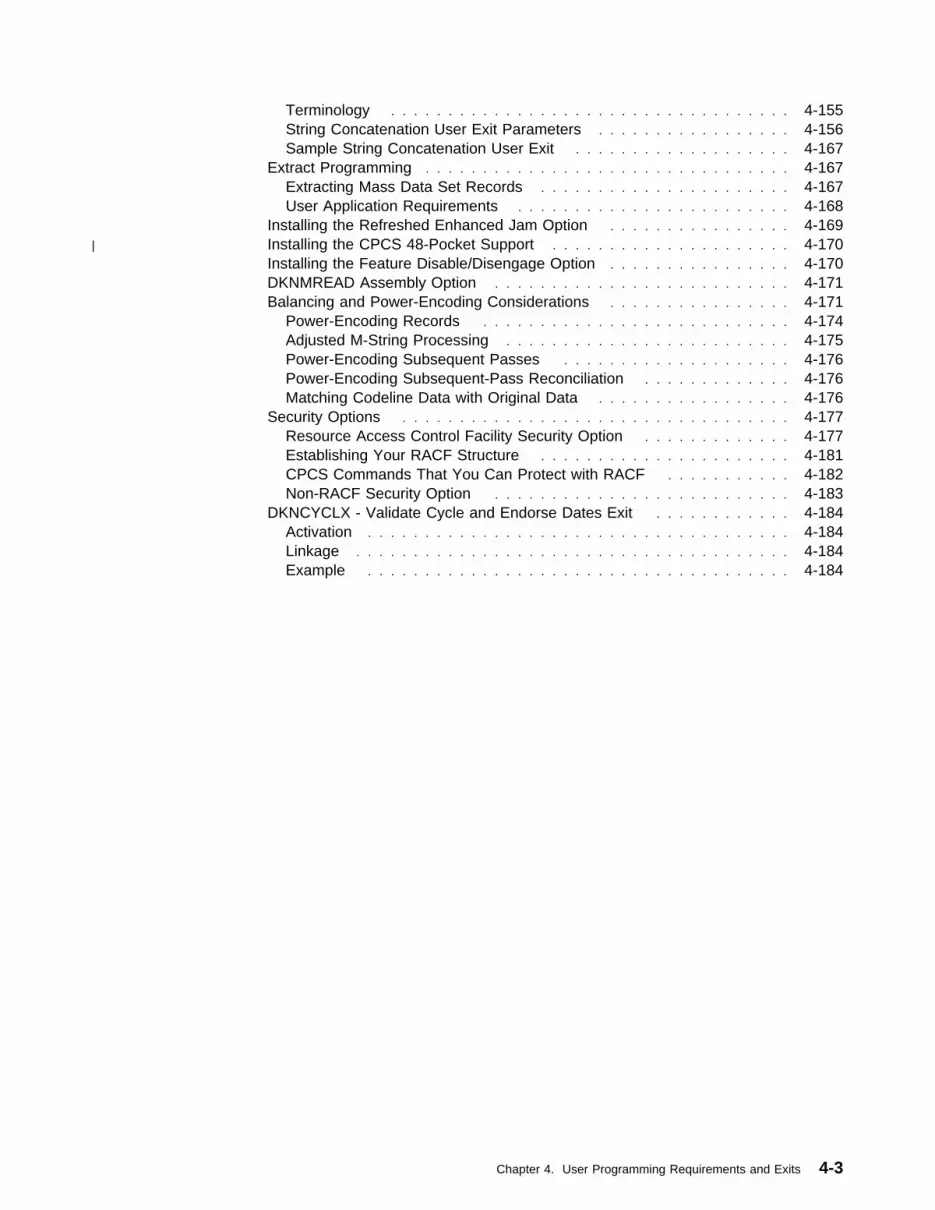
Terminology . . . . . . . . . . . . . . . . . . . . . . . . . . . . . . . . . . . 4-155String Concatenation User Exit Parameters . . . . . . . . . . . . . . . . . 4-156Sample String Concatenation User Exit . . . . . . . . . . . . . . . . . . . 4-167
Extract Programming . . . . . . . . . . . . . . . . . . . . . . . . . . . . . . . . 4-167Extracting Mass Data Set Records . . . . . . . . . . . . . . . . . . . . . . 4-167User Application Requirements . . . . . . . . . . . . . . . . . . . . . . . . 4-168
Installing the Refreshed Enhanced Jam Option . . . . . . . . . . . . . . . . 4-169| Installing the CPCS 48-Pocket Support . . . . . . . . . . . . . . . . . . . . . 4-170
Installing the Feature Disable/Disengage Option . . . . . . . . . . . . . . . . 4-170DKNMREAD Assembly Option . . . . . . . . . . . . . . . . . . . . . . . . . . 4-171Balancing and Power-Encoding Considerations . . . . . . . . . . . . . . . . 4-171
Power-Encoding Records . . . . . . . . . . . . . . . . . . . . . . . . . . . 4-174Adjusted M-String Processing . . . . . . . . . . . . . . . . . . . . . . . . . 4-175Power-Encoding Subsequent Passes . . . . . . . . . . . . . . . . . . . . 4-176Power-Encoding Subsequent-Pass Reconciliation . . . . . . . . . . . . . 4-176Matching Codeline Data with Original Data . . . . . . . . . . . . . . . . . 4-176
Security Options . . . . . . . . . . . . . . . . . . . . . . . . . . . . . . . . . . 4-177Resource Access Control Facility Security Option . . . . . . . . . . . . . 4-177Establishing Your RACF Structure . . . . . . . . . . . . . . . . . . . . . . 4-181CPCS Commands That You Can Protect with RACF . . . . . . . . . . . 4-182Non-RACF Security Option . . . . . . . . . . . . . . . . . . . . . . . . . . 4-183
DKNCYCLX - Validate Cycle and Endorse Dates Exit . . . . . . . . . . . . 4-184Activation . . . . . . . . . . . . . . . . . . . . . . . . . . . . . . . . . . . . . 4-184Linkage . . . . . . . . . . . . . . . . . . . . . . . . . . . . . . . . . . . . . . 4-184Example . . . . . . . . . . . . . . . . . . . . . . . . . . . . . . . . . . . . . 4-184
Chapter 4. User Programming Requirements and Exits 4-3

4-4 CPCS V1R11 Customization Guide

Bank-Control-File Record Formats
OverviewThis chapter provides general use programming interface and associated guidanceinformation.
This chapter describes the programming you must complete to run CPCSsuccessfully.
User Data Preparation for Sort ProgramsThis section outlines the preparations required for the sort programs:
� Bank-Control-File Record Formats
� Endpoint Name-and-Address Record Formats
� Sort-Pattern-Definition Record Formats
Bank-Control-File Record FormatsEach bank control file record contains the following information:
� Processing bank number (an internal number between 001 and 999 that theCPCS installation assigns).
� Name and address information that the report tasks use.
� Special kill-list instructions printed on each kill list.
� Customized CPCS option data. This data, if present, overrides the data thatthe CPCSOPTN macro generates for the CPCS installation. Overriding occursonly for entries that are processed for the financial institution specified by theserecords.
The DKNMICR task reads the record for the financial institution before startingthe sort. It checks to see whether any of this data is present; if so, it replacesdata existing in memory with this data before downloading the documentprocessor instructions.
� Data required for producing electronic cash letters
When you start a new entry, DKNMICR reloads the CPCS option parameters intomemory before it reads the financial institution record, ensuring that the defaultvalues are always present when needed.
Detailed Bank Control File Input for DKNLOADThe input data set to the DKNLOAD program (CARD) is device-independent, and itmust consist of 80-character logical records. Each processing financial institutionrequires 10 input records, each of which contains a record code 0 and sequencenumbers 001 through 010. An optional 11th input card, with sequence number011, may also appear. This card is used to specify Electronic Cash Letter data.
The following fields are common to each record.
Position Description1 Record code – 02 Constant – 03–5 Bank number – 001 through 9996 Constant – 0
Chapter 4. User Programming Requirements and Exits 4-5
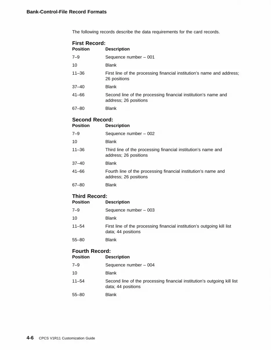
Bank-Control-File Record Formats
The following records describe the data requirements for the card records.
First Record:Position Description
7–9 Sequence number – 001
10 Blank
11–36 First line of the processing financial institution’s name and address;26 positions
37–40 Blank
41–66 Second line of the processing financial institution’s name andaddress; 26 positions
67–80 Blank
Second Record:Position Description
7–9 Sequence number – 002
10 Blank
11–36 Third line of the processing financial institution’s name andaddress; 26 positions
37–40 Blank
41–66 Fourth line of the processing financial institution’s name andaddress; 26 positions
67–80 Blank
Third Record:Position Description
7–9 Sequence number – 003
10 Blank
11–54 First line of the processing financial institution’s outgoing kill listdata; 44 positions
55–80 Blank
Fourth Record:Position Description
7–9 Sequence number – 004
10 Blank
11–54 Second line of the processing financial institution’s outgoing kill listdata; 44 positions
55–80 Blank
4-6 CPCS V1R11 Customization Guide

Bank-Control-File Record Formats
Fifth Record:Position Description
7–9 Sequence number – 005
10 Blank
11–54 Third line of the processing financial institution’s outgoing kill listdata; 44 positions
55–80 Blank
Sixth Record:Position Description
7–9 Sequence number – 006
10 Blank
11–54 Fourth line of the processing financial institution’s outgoing kill listdata; 44 positions
55–80 Blank
Seventh Record:Position Description
7–9 Sequence number – 007
10 Blank
11–54 Fifth line of the processing financial institution’s outgoing kill listdata; 44 positions
55 Blank
56–63 DKNMDIS user-exit program name. The MDIS user exit specifiesthe name of a user-written routine that is unique for your financialinstitution. It is left-justified and padded with blanks.
64–80 Blank
Eighth Record:Notes for Record 8:
1. If dashes occur on the physical document, they should appear in the documentidentifier.
2. The CPCSOPTN description defines the bank control file for bank 001 only.Record 8 must contain only the record type, the bank number, and the recordnumber; columns 11-46 should be blank.
3. Character strings must be left-justified in their document fields and cannot belarger than 16 digits or the maximum length of any field specified, whichever issmaller.
Position Description
7–9 Sequence number — 008
10 Blank
11–26 The tracer document identifier. It is left-justified and padded withblanks.
Chapter 4. User Programming Requirements and Exits 4-7

Bank-Control-File Record Formats
27 The primary field for the tracer ID. The number corresponds to theMICR field.
1 = Amount field2 = Process control field4 = Optional field 15 = Routing number field6 = Optional field 27 = Serial number field
28 The secondary field for the tracer ID. The number corresponds tothe MICR field. The field can be blank, but must not be the sameas the primary field.
1 = Amount field2 = Process control field4 = Optional field 15 = Routing number field6 = Optional field 27 = Serial number field
29–44 The divider document identifier. It is left-justified and padded withblanks. See Notes for Record 8, which also apply to this identifier.
45 The primary field for the divider ID. The number corresponds tothe MICR field.
1 = Amount field2 = Process control field3 = Account number field4 = Optional field 15 = Routing number field6 = Optional field 2
46 The secondary field for the divider ID. The number corresponds tothe MICR field. It can be blank, but it must not be the same as theprimary field.
1 = Amount field2 = Process control field3 = Account number field4 = Optional field 15 = Routing number field6 = Optional field 2
47–54 The name for the optional OLRR user exit. This is a user-writtenexit routine used to resolve non-numeric keys. The first charactermust be alphabetic; all others can be alphanumeric. If you do notuse the exit, you must leave these fields blank.
55–62 The name of the optional Online Adjustments user exit. This is auser-written exit routine used to resolve non-numeric keys. Thefirst character must be alphabetic; all others can be alphanumeric.If you do not use the exit, you must leave these fields blank.
63–80 Blank
4-8 CPCS V1R11 Customization Guide

Bank-Control-File Record Formats
Ninth Record:Notes for Record 9:
1. If dashes occur on the physical document, they should appear in the documentidentifier.
2. The CPCSOPTN description defines the bank control file for bank 001 only.Record 9 must contain only the record type, the bank number, and the recordnumber; columns 11-50 should be blank.
3. Character strings must be left-justified in their document fields and cannot belarger than 16 digits or the maximum length of any field specified, whichever issmaller.
Position Description
7–9 Sequence number – 009
10 Blank
11–26 The block slip document identifier. It is left-justified and paddedwith blanks. See Notes for Record 8 on page 4-7, which alsoapply to this identifier.
27 The primary field for the block ID. The number corresponds to theMICR field.
2 = Process control field3 = Account number field4 = Optional field 15 = Routing number field6 = Optional field 27 = Serial number field
28 The secondary field for the block slip ID. The number correspondsto the MICR field. The field can be blank, but it must not be thesame as the primary field.
2 = Process control field3 = Account number field4 = Optional field 15 = Routing number field6 = Optional field 27 = Serial number field
29–44 The batch slip document identifier. It is left-justified and paddedwith blanks. See Notes for Record 8 on page 4-7, which alsoapply to this identifier.
45 The primary field for the batch slip ID. The number corresponds tothe MICR field.
2 = Process control field3 = Account number field4 = Optional field 15 = Routing number field6 = Optional field 27 = Serial number field
46 The secondary field for the batch slip ID. The numbercorresponds to the MICR field. The field can be blank, but it mustnot be the same as the primary field.
Chapter 4. User Programming Requirements and Exits 4-9

Bank-Control-File Record Formats
2 = Process control field3 = Account number field4 = Optional field 15 = Routing number field6 = Optional field 27 = Serial number field
47–50 Blank
Tenth Record:Notes for Record 10:
1. If dashes occur on the physical document, they should appear in the documentidentifier.
2. The CPCSOPTN description defines the bank control file for bank 001 only.Record 10 must contain only the record type, the bank number, and the recordnumber; columns 11-48 should be blank.
3. Character strings must be left-justified in their document fields and cannot belarger than 16 digits or the maximum length of any field specified, whichever issmaller.
Position Description
7–9 Sequence number – 010
10 Blank
11–26 The sub-batch slip document identifier. It is left-justified andpadded with blanks. See Notes for Record 8 on page 4-7, whichalso apply to this identifier.
27 The primary field for the sub-batch ID. The number correspondsto the MICR field.
2 = Process control field3 = Account number field4 = Optional field 15 = Routing number field6 = Optional field 27 = Serial number field
28 The secondary field for the sub-batch slip ID. The numbercorresponds to the MICR field. The field can be blank, but it mustnot be the same as the primary field.
2 = Process control field3 = Account number field4 = Optional field 15 = Routing number field6 = Optional field 27 = Serial number field
29–44 The AST pointer document identifier. Used mainly for imageprocessing, it is left-justified and padded with blanks. See Notesfor Record 8 on page 4-7, which also apply to this identifier.
45 The primary field for the AST pointer ID. The number correspondsto the MICR field.
1 = Amount field
4-10 CPCS V1R11 Customization Guide

Bank-Control-File Record Formats
2 = Process control field3 = Account number field5 = Routing number field7 = Serial number field
46 The secondary field for the AST pointer ID. The numbercorresponds to the MICR field. The field can be blank, but it mustnot be the same as the primary field.
1 = Amount field2 = Process control field3 = Account number field5 = Routing number field7 = Serial number field
47–49 Blank
50 The block sequence. It specifies whether block slips are placedbefore or after the documents they control.
P = Before (prior)S = After (subsequent)
51 The batch sequence. It specifies whether batch slips (andsub-batch slips, if used) are placed before or after the documentsthey control.
P = Before (prior)S = After (subsequent)
52 Blank
53 Blank
54–61 The user-written MREAD EXIT routine. It specifies the name of auser-written exit routine that is unique for this financial institution.It is left-justified and padded with blanks.
62–69 The MICR codeline data match user exit. It specifies the name ofa user-written routine for codeline data matching. If you use thisroutine, MICR calls it before making final codeline data matchdecisions.
70 Blank
71 The microfilm option. This option permits a financial institution tohave a different microfilm option. If present, the value must beeither F (front) or B (both front and back).
72 Blank
73 The process control dash option. Y indicates that dashtransmission is a requirement in this field for the financialinstitution. N means that dash transmission is not a requirement inthis field.
74 The account number dash option. Y indicates that dashtransmission is a requirement in this field for the financialinstitution. N means that dash transmission is not a requirement inthis field.
Chapter 4. User Programming Requirements and Exits 4-11
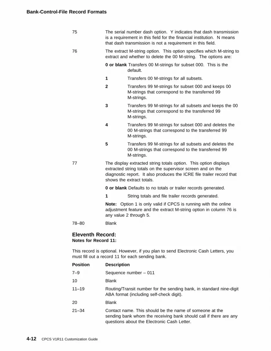
Bank-Control-File Record Formats
75 The serial number dash option. Y indicates that dash transmissionis a requirement in this field for the financial institution. N meansthat dash transmission is not a requirement in this field.
76 The extract M-string option. This option specifies which M-string toextract and whether to delete the 00 M-string. The options are:
0 or blank Transfers 00 M-strings for subset 000. This is thedefault.
1 Transfers 00 M-strings for all subsets.
2 Transfers 99 M-strings for subset 000 and keeps 00M-strings that correspond to the transferred 99M-strings.
3 Transfers 99 M-strings for all subsets and keeps the 00M-strings that correspond to the transferred 99M-strings.
4 Transfers 99 M-strings for subset 000 and deletes the00 M-strings that correspond to the transferred 99M-strings.
5 Transfers 99 M-strings for all subsets and deletes the00 M-strings that correspond to the transferred 99M-strings.
77 The display extracted string totals option. This option displaysextracted string totals on the supervisor screen and on thediagnostic report. It also produces the ICRE file trailer record thatshows the extract totals.
0 or blank Defaults to no totals or trailer records generated.
1 String totals and file trailer records generated.
Note: Option 1 is only valid if CPCS is running with the onlineadjustment feature and the extract M-string option in column 76 isany value 2 through 5.
78–80 Blank
Eleventh Record:Notes for Record 11:
This record is optional. However, if you plan to send Electronic Cash Letters, youmust fill out a record 11 for each sending bank.
Position Description
7–9 Sequence number – 011
10 Blank
11–19 Routing/Transit number for the sending bank, in standard nine-digitABA format (including self-check digit).
20 Blank
21–34 Contact name. This should be the name of someone at thesending bank whom the receiving bank should call if there are anyquestions about the Electronic Cash Letter.
4-12 CPCS V1R11 Customization Guide

Bank-Control-File Record Formats
35 Blank
36–45 Contact phone. This should be the telephone number the receivingbank should use when trying to reach the contact at the sendingbank.
46 Blank
47–55 Returns Routing/Transit (R/T) number, in standard nine-digit ABAformat (including self-check digit). Any items returned from thesending bank’s Electronic Cash Letters go to this R/T. The R/Tdoes not necessarily have to be the same as that specified incolumns 11–19.
56–80 Blank
Chapter 4. User Programming Requirements and Exits 4-13
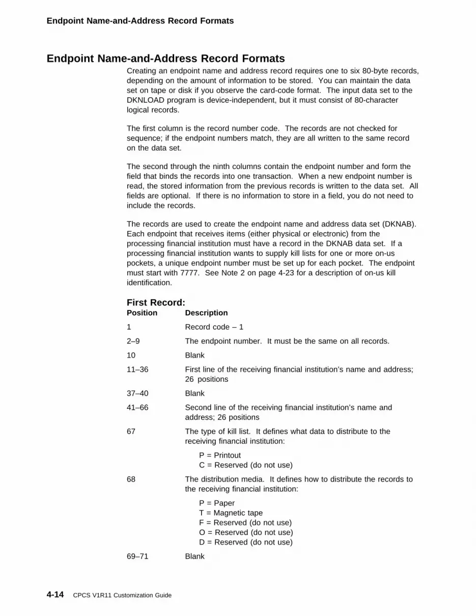
Endpoint Name-and-Address Record Formats
Endpoint Name-and-Address Record FormatsCreating an endpoint name and address record requires one to six 80-byte records,depending on the amount of information to be stored. You can maintain the dataset on tape or disk if you observe the card-code format. The input data set to theDKNLOAD program is device-independent, but it must consist of 80-characterlogical records.
The first column is the record number code. The records are not checked forsequence; if the endpoint numbers match, they are all written to the same recordon the data set.
The second through the ninth columns contain the endpoint number and form thefield that binds the records into one transaction. When a new endpoint number isread, the stored information from the previous records is written to the data set. Allfields are optional. If there is no information to store in a field, you do not need toinclude the records.
The records are used to create the endpoint name and address data set (DKNAB).Each endpoint that receives items (either physical or electronic) from theprocessing financial institution must have a record in the DKNAB data set. If aprocessing financial institution wants to supply kill lists for one or more on-uspockets, a unique endpoint number must be set up for each pocket. The endpointmust start with 7777. See Note 2 on page 4-23 for a description of on-us killidentification.
First Record:Position Description
1 Record code – 1
2–9 The endpoint number. It must be the same on all records.
10 Blank
11–36 First line of the receiving financial institution’s name and address;26 positions
37–40 Blank
41–66 Second line of the receiving financial institution’s name andaddress; 26 positions
67 The type of kill list. It defines what data to distribute to thereceiving financial institution:
P = PrintoutC = Reserved (do not use)
68 The distribution media. It defines how to distribute the records tothe receiving financial institution:
P = PaperT = Magnetic tapeF = Reserved (do not use)O = Reserved (do not use)D = Reserved (do not use)
69–71 Blank
4-14 CPCS V1R11 Customization Guide

Endpoint Name-and-Address Record Formats
72–80 Routing/Transit (R/T) number for the endpoint, in standardnine-digit ABA format (including self-check digit). This field isrequired if you are going to be sending Electronic Cash Letters tothe endpoint. Note that the R/T need not necessarily be the sameas the endpoint number in columns 2-9.
Second Record:Position Description
1 Record code – 2
2–9 The endpoint number. It must be the same on all records.
10 Blank
11–36 Third line of the receiving financial institution’s name and address;26 positions
37–40 Blank
41–66 Fourth line of the receiving financial institution’s name andaddress; 26 positions
67–80 Blank
Third Record:Position Description
1 Record code – 3
2–9 The endpoint number. It must be the same on all records.
10 Blank
11–60 First line of special instruction to or from the user site;50 positions
61–80 Blank
Fourth Record:Position Description
1 Record code – 4
2–9 The endpoint number. It must be the same on all records.
10 Blank
11–60 Second line of special instruction to or from the user site;50 positions
61–80 Blank
Fifth Record:Position Description
1 Record code – 5
2–9 The endpoint number. It must be the same on all records.
10 Blank
11–60 Third line of special instruction to or from the user site;50 positions
Chapter 4. User Programming Requirements and Exits 4-15

Endpoint Name-and-Address Record Formats
61 Blank
62–73 User data—available to the user for any purpose
74–80 Blank
Sixth Record:Notes for Record 6:
1. Unlike other name-and-address records, you may specify record 6 multipletimes–as many times as is necessary to define all cash letter formats desiredand all actions to be taken for each format.
2. If you specify more than one action for a cash letter format, all such actionstake place simultaneously, meaning you get multiple copies of the same cashletter but with each copy prepared in a different way.
3. It is legal to specify an action with the CLIF Flag and the same action withoutthe CLIF Flag; the cash letter is prepared in both formats simultaneously.
4. If you must specify more actions for a cash letter format than can fit on a singlerecord 6, create another record 6 with the same cash letter format and continuewith your action list.
5. Record 6 is optional. If you specify no record 6’s for an endpoint, CPCSassumes a single cash letter format of “PAPER” and a single action for thatformat, “PRINT”.
Position Description
1 Record code – 6
2–9 The endpoint number. It must be the same on all records.
10 Blank
11–18 Cash letter format name, left justified in the field. At present, theonly names recognized are “PAPER” and “ECASH”. Additionalnames will be defined in the future.
19 Blank
20–24 Action to take place when processing cash letters that are in thisformat. At present, the only actions recognized are “PRINT” and“X937”. “PRINT” causes the cash letter to be physically printed;“X937” causes the cash letter to be written in ANSI X9.37 format tothe data set specified by the DKNETC entry in your DKNDSATtable. Additional actions will be defined in the future.
25 Blank
26 CLIF flag. When preparing an electronic cash letter and this flag isa “Y”, the CLIF file prefix information is added to each record sothe cash letter can be subsequently recognized and processed bythe E-Check server. For any other value, the electronic cash letteris prepared unaltered. Do not specify a “Y” if your action is“PRINT”.
27–28 Blank
29–35 Same as with columns 20–26. This allows you to specify a secondaction for the same cash letter format.
36–37 Blank
4-16 CPCS V1R11 Customization Guide
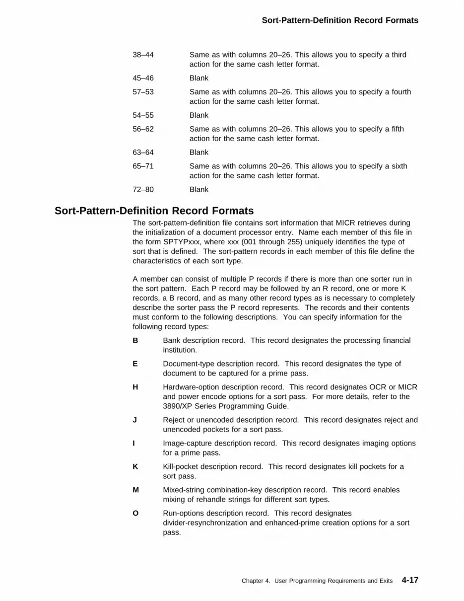
Sort-Pattern-Definition Record Formats
38–44 Same as with columns 20–26. This allows you to specify a thirdaction for the same cash letter format.
45–46 Blank
57–53 Same as with columns 20–26. This allows you to specify a fourthaction for the same cash letter format.
54–55 Blank
56–62 Same as with columns 20–26. This allows you to specify a fifthaction for the same cash letter format.
63–64 Blank
65–71 Same as with columns 20–26. This allows you to specify a sixthaction for the same cash letter format.
72–80 Blank
Sort-Pattern-Definition Record FormatsThe sort-pattern-definition file contains sort information that MICR retrieves duringthe initialization of a document processor entry. Name each member of this file inthe form SPTYPxxx, where xxx (001 through 255) uniquely identifies the type ofsort that is defined. The sort-pattern records in each member of this file define thecharacteristics of each sort type.
A member can consist of multiple P records if there is more than one sorter run inthe sort pattern. Each P record may be followed by an R record, one or more Krecords, a B record, and as many other record types as is necessary to completelydescribe the sorter pass the P record represents. The records and their contentsmust conform to the following descriptions. You can specify information for thefollowing record types:
B Bank description record. This record designates the processing financialinstitution.
E Document-type description record. This record designates the type ofdocument to be captured for a prime pass.
H Hardware-option description record. This record designates OCR or MICRand power encode options for a sort pass. For more details, refer to the3890/XP Series Programming Guide.
J Reject or unencoded description record. This record designates reject andunencoded pockets for a sort pass.
I Image-capture description record. This record designates imaging optionsfor a prime pass.
K Kill-pocket description record. This record designates kill pockets for asort pass.
M Mixed-string combination-key description record. This record enablesmixing of rehandle strings for different sort types.
O Run-options description record. This record designatesdivider-resynchronization and enhanced-prime creation options for a sortpass.
Chapter 4. User Programming Requirements and Exits 4-17
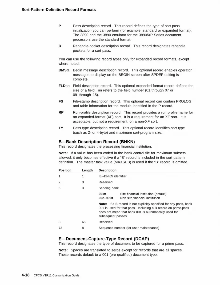
Sort-Pattern-Definition Record Formats
P Pass description record. This record defines the type of sort passinitialization you can perform (for example, standard or expanded format).The 3890 and the 3890 emulator for the 3890/XP Series documentprocessors use the standard format.
R Rehandle-pocket description record. This record designates rehandlepockets for a sort pass.
You can use the following record types only for expanded record formats, exceptwhere noted:
BMSG Begin message description record. This optional record enables operatormessages to display on the BEGIN screen after SPDEF editing iscomplete.
FLDnn Field description record. This optional expanded format record defines thesize of a field. nn refers to the field number (01 through 07 or09 through 15).
FS File-stamp description record. This optional record can contain PROLOGand table information for the module identified in the P record.
RP Run-profile description record. This record provides a run profile name foran expanded-format (XF) sort. It is a requirement for an XF sort. It isacceptable, but not a requirement, on a non-XF sort.
TY Pass-type description record. This optional record identifies sort type(such as 2- or 4-byte) and maximum sort-program size.
B—Bank Description Record (BNKN)This record designates the processing financial institution.
Note: If a value has been coded in the bank control file for maximum subsetsallowed, it only becomes effective if a “B” record is included in the sort patterndefinition. The master task value (MAXSUB) is used if the “B” record is omitted.
Position Length Description
1 1 ‘B’=BNKN identifier
2 3 Reserved
5 3 Sending bank
001= Site financial institution (default)002–999= Non-site financial institution
Note: If a B record is not explicitly specified for any pass, bank001 is used for that pass. Including a B record on prime-passdoes not mean that bank 001 is automatically used forsubsequent passes.
8 65 Reserved
73 8 Sequence number (for user maintenance)
E—Document-Capture-Type Record (DCAP)This record designates the type of document to be captured for a prime pass.
Note: Spaces are translated to zeros except for records that are all spaces.These records default to a 001 (pre-qualified) document type.
4-18 CPCS V1R11 Customization Guide

Sort-Pattern-Definition Record Formats
Position Length Description
1 1 ‘E’=DCAP identifier
2 3 Reserved
5 3 Type of document being captured
000= Unqualified001= Pre-qualified (default)002= Signature card data003= Returns004= Cycle/exception005= Statement sort006= OCR remittance007= OCR non-remittance008= Wholesale remittance009= Drafts (credit card voucher)010–127= Reserved for IBM use128–255= Reserved for user applications
8 65 Reserved
73 8 Sequence number
H—Document Processor Hardware Options Record (OCR)This record designates OCR or MICR options for a sort pass, including powerencoder options. You cannot turn a PATH off in the sort pattern H record; turnthem off or on through the sort operator panel.
Position Length Description
1 1 ‘H’=OCR identifier
2 1 HSRR H record. This code allows you to specify differenthardware options to be used for HSRR captures. You do nothave to use this card if the hardware options are to be the sameas in prime pass. HH cards are ignored during prime andsubsequent passes. If both an H and an HH record are present,the H record must come first.
blank Prime/subsequent pass H recordH HSRR H record
3 2 Reserved
5 1 OCR read system 1
blank= Off (default)N= OffY= On
6 1 OCR read system 2
blank= Off (default)N= OffY= On
7 1 OCR read system 3. Must be off if either read system 1 or readsystem 2 is on.
blank= Off (default)N= OffY= On
8 2 Reserved
Chapter 4. User Programming Requirements and Exits 4-19

Sort-Pattern-Definition Record Formats
Position Length Description
10 1 MICR read system 1
blank= Off (default)N= OffY= On
11 1 MICR read system 2
blank= Off (default)N= OffY= On
12 2 Reserved
14 1 Power encode option
blank= Off (default)P= OnY= OnN= Off
15 1 Reserved
16 1 Reserved
17 1 Reserved
18 1 Reserved
19 4 Power encode font
blank= E13B (MICR default)E13B= MICRCMC7= OCR
23 1 Reserved
24 7 Fields to encode
Digits 1 through 7 are valid.
1= Amount field2= Process control field3= Account number field4= Extended process control field5= Routing number field6= Optional field7= Serial number field
31 1 Reserved
32 2 Microfilm space
blank= 0 (default)0= No microfilm space option1= Option 12= Option 23= Option 3
34 38 Reserved
72 1 Bypass flag. If this flag is ON, and you are loading a 3890 sorter,ignore this record; otherwise, process it. Note that H records arealways handled by sorters other than 3890’s (for example,3892’s), no matter whether the bypass flag is present or not.
blank Always process this record.B Ignore this record if you are loading a 3890 sorter.
4-20 CPCS V1R11 Customization Guide

Sort-Pattern-Definition Record Formats
I—Sorter Image-Capture Options Record (IMAGE)This record identifies the image capture specifications for each document.
Position Length Description
1 1 ‘I’=IMAGE identifier
2 3 Reserved
5 1 Pass
blank= Prime only (default)P= Prime onlyH= HSRR onlyB= Both prime and HSRR
6 2 Reserved
8 2 Front black and white
blank= Not on (default)BW Capture front black-and-white image
10 1 Reserved
11 2 Front gray scale
blank= Not on (default)GS= Capture front gray-scale image
13 4 Reserved
17 2 Back black and white
blank= Not on (default)BW= Capture back black-and-white image
19 1 Reserved
20 2 Back gray scale
blank= Not on (default)GS= Capture back gray-scale image
22 1 Reserved
23 1 Compensation error override
blank= Not on (default)Y= Ignore compensation errors
24 1 Reserved
25 1 Analysis error override
blank= Not on (default)Y= Ignore analysis errors
26 3 Reserved
29 7 Online/offline to host processor
blank= Online (default)
ONLINE= Imaging processor online to host processor
OFFLINE= Imaging processor offline from host processor
36 2 Reserved
Chapter 4. User Programming Requirements and Exits 4-21

Sort-Pattern-Definition Record Formats
Position Length Description
38 10 Overlay/no overlay
blank= No overlay (default)
NO OVERLAY= Do not overlay images within the sorterimage buffers. The sorter will pause themain feed when the image buffers are full.
OVERLAY= Overlay images within the sorter imagebuffers when the buffers become full.
Note: This option is not valid if the imageprocessor is online to the host.
48 2 Reserved
50 3 Location in process buffer for DIDM and document type
blank= None
000= None
001–244= Specified location for DIDM and document-typeinformation with the document’s process buffer.The location is relative to 1 and right to left. Forexample, if the P/C field is to contain DIDMinformation and the amount field is 5 bytes plus 12header bytes, the value would be 018 (6 + 12).This value, the rightmost byte of the P/C field, is inpacked-decimal format so that the 4-charactervalue is loaded into 2 bytes.
53 20 Reserved
73 8 Sequence number
J—Reject-Pocket-Number Record (RUPKT)This record designates reject pockets or unencoded pockets for a sort pass.
Position Length Description
1 1 ‘J’=RUPKT identifier
2 3 Reserved
5 1 Reject pocket indicator—pocket 1
blank= Not a reject or unencoded pocketR= Reject pocketU= Unencoded pocketE= Enhanced reject pocket
6 1 Reject pocket indicator—pocket 2
7 1 Reject pocket indicator—pocket 3...
| 51| 1| Reject pocket indicator—pocket 47
| 52| 21| Reserved
4-22 CPCS V1R11 Customization Guide
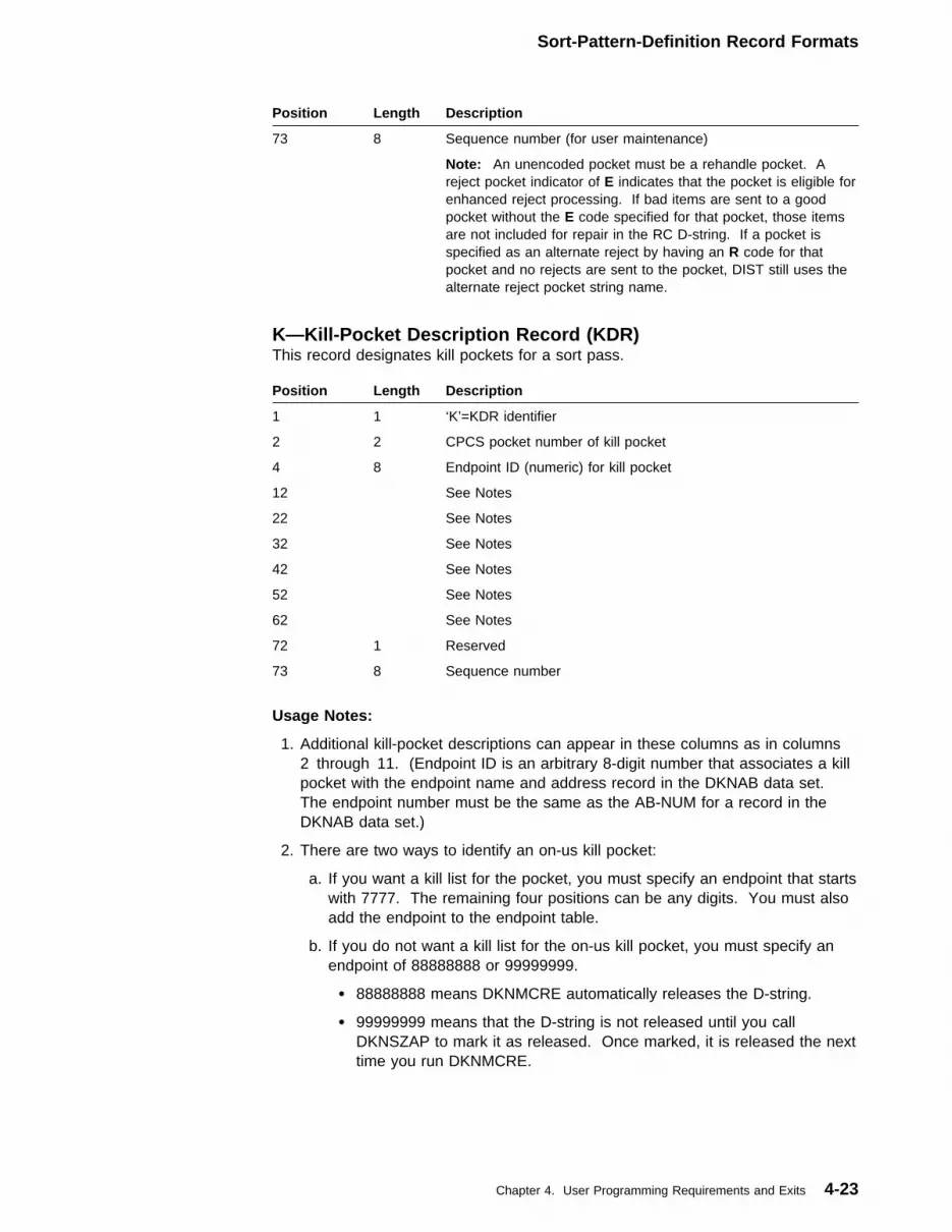
Sort-Pattern-Definition Record Formats
Position Length Description
73 8 Sequence number (for user maintenance)
Note: An unencoded pocket must be a rehandle pocket. Areject pocket indicator of E indicates that the pocket is eligible forenhanced reject processing. If bad items are sent to a goodpocket without the E code specified for that pocket, those itemsare not included for repair in the RC D-string. If a pocket isspecified as an alternate reject by having an R code for thatpocket and no rejects are sent to the pocket, DIST still uses thealternate reject pocket string name.
K—Kill-Pocket Description Record (KDR)This record designates kill pockets for a sort pass.
Usage Notes:
1. Additional kill-pocket descriptions can appear in these columns as in columns2 through 11. (Endpoint ID is an arbitrary 8-digit number that associates a killpocket with the endpoint name and address record in the DKNAB data set.The endpoint number must be the same as the AB-NUM for a record in theDKNAB data set.)
2. There are two ways to identify an on-us kill pocket:
a. If you want a kill list for the pocket, you must specify an endpoint that startswith 7777. The remaining four positions can be any digits. You must alsoadd the endpoint to the endpoint table.
b. If you do not want a kill list for the on-us kill pocket, you must specify anendpoint of 88888888 or 99999999.
� 88888888 means DKNMCRE automatically releases the D-string.
� 99999999 means that the D-string is not released until you callDKNSZAP to mark it as released. Once marked, it is released the nexttime you run DKNMCRE.
Position Length Description
1 1 ‘K’=KDR identifier
2 2 CPCS pocket number of kill pocket
4 8 Endpoint ID (numeric) for kill pocket
12 See Notes
22 See Notes
32 See Notes
42 See Notes
52 See Notes
62 See Notes
72 1 Reserved
73 8 Sequence number
Chapter 4. User Programming Requirements and Exits 4-23
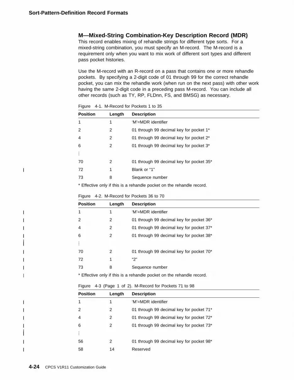
Sort-Pattern-Definition Record Formats
M—Mixed-String Combination-Key Description Record (MDR)This record enables mixing of rehandle strings for different type sorts. For amixed-string combination, you must specify an M-record. The M-record is arequirement only when you want to mix work of different sort types and differentpass pocket histories.
Use the M-record with an R-record on a pass that contains one or more rehandlepockets. By specifying a 2-digit code of 01 through 99 for the correct rehandlepocket, you can mix the rehandle work (when run on the next pass) with other workhaving the same 2-digit code in a preceding pass M-record. You can include allother records (such as TY, RP, FLDnn, FS, and BMSG) as necessary.
Figure 4-1. M-Record for Pockets 1 to 35
Position Length Description
1 1 ‘M’=MDR identifier
2 2 01 through 99 decimal key for pocket 1*
4 2 01 through 99 decimal key for pocket 2*
6 2 01 through 99 decimal key for pocket 3*...
70 2 01 through 99 decimal key for pocket 35*
| 72| 1| Blank or “1”
73 8 Sequence number
* Effective only if this is a rehandle pocket on the rehandle record.
Figure 4-2. M-Record for Pockets 36 to 70
Position Length Description
| 1| 1| ‘M’=MDR identifier
| 2| 2| 01 through 99 decimal key for pocket 36*
| 4| 2| 01 through 99 decimal key for pocket 37*
| 6| 2| 01 through 99 decimal key for pocket 38*| .| .| .| |
| 70| 2| 01 through 99 decimal key for pocket 70*
| 72| 1| “2”
| 73| 8| Sequence number
| * Effective only if this is a rehandle pocket on the rehandle record.
Figure 4-3 (Page 1 of 2). M-Record for Pockets 71 to 98
Position Length Description
| 1| 1| ‘M’=MDR identifier
| 2| 2| 01 through 99 decimal key for pocket 71*
| 4| 2| 01 through 99 decimal key for pocket 72*
| 6| 2| 01 through 99 decimal key for pocket 73*| .| .| .| |
| 56| 2| 01 through 99 decimal key for pocket 98*
| 58| 14| Reserved
4-24 CPCS V1R11 Customization Guide
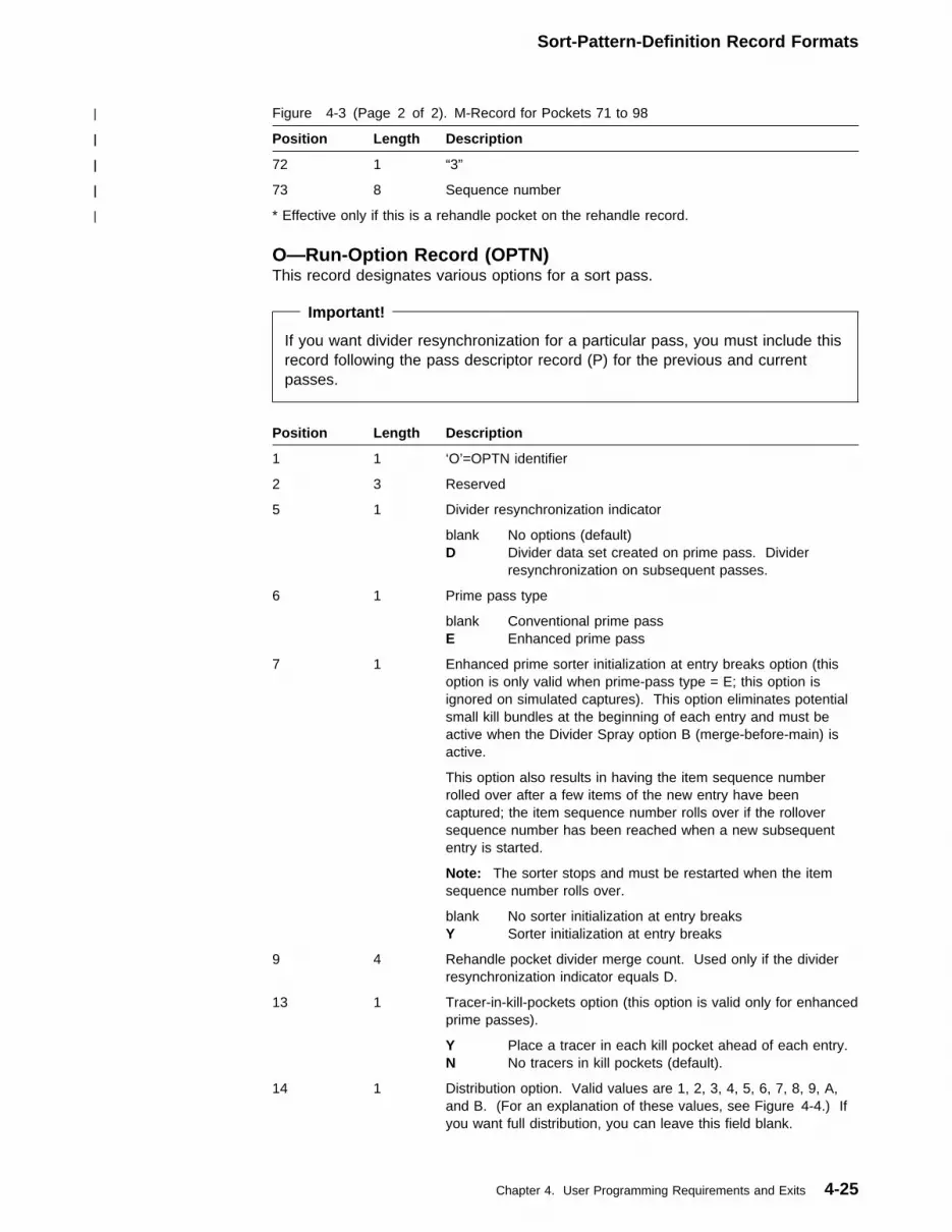
Sort-Pattern-Definition Record Formats
| Figure 4-3 (Page 2 of 2). M-Record for Pockets 71 to 98
| Position| Length| Description
| 72| 1| “3”
| 73| 8| Sequence number
| * Effective only if this is a rehandle pocket on the rehandle record.
O—Run-Option Record (OPTN)This record designates various options for a sort pass.
Important!
If you want divider resynchronization for a particular pass, you must include thisrecord following the pass descriptor record (P) for the previous and currentpasses.
Position Length Description
1 1 ‘O’=OPTN identifier
2 3 Reserved
5 1 Divider resynchronization indicator
blank No options (default)D Divider data set created on prime pass. Divider
resynchronization on subsequent passes.
6 1 Prime pass type
blank Conventional prime passE Enhanced prime pass
7 1 Enhanced prime sorter initialization at entry breaks option (thisoption is only valid when prime-pass type = E; this option isignored on simulated captures). This option eliminates potentialsmall kill bundles at the beginning of each entry and must beactive when the Divider Spray option B (merge-before-main) isactive.
This option also results in having the item sequence numberrolled over after a few items of the new entry have beencaptured; the item sequence number rolls over if the rolloversequence number has been reached when a new subsequententry is started.
Note: The sorter stops and must be restarted when the itemsequence number rolls over.
blank No sorter initialization at entry breaksY Sorter initialization at entry breaks
9 4 Rehandle pocket divider merge count. Used only if the dividerresynchronization indicator equals D.
13 1 Tracer-in-kill-pockets option (this option is valid only for enhancedprime passes).
Y Place a tracer in each kill pocket ahead of each entry.N No tracers in kill pockets (default).
14 1 Distribution option. Valid values are 1, 2, 3, 4, 5, 6, 7, 8, 9, A,and B. (For an explanation of these values, see Figure 4-4.) Ifyou want full distribution, you can leave this field blank.
Chapter 4. User Programming Requirements and Exits 4-25

Sort-Pattern-Definition Record Formats
Distribution Options: Figure 4-4 describes the distribution options for nonsubsetprocessing or for subset processing. For more information on distribution options,and on how DKNDIST behaves under various conditions when confronted withdifferent types of strings and distribution options, see “CPCS Pocket Distribution byDKNDIST” in the CPCS Programming and Diagnostic Guide.
Position Length Description
15 1 Enhanced Prime pause option
blank No pause between entriesN No pause between entriesY Pause between entries
16 8 DKNMIPI user-processing exit name. If this is blank, CPCS usesthe name in either the BCF or the CPCSOPTN macro. For moreinformation on this exit routine, see “DKNMIPI User ProcessingExit” on page 4-136.
29 1 Enhanced reject processing. The values are:
blank Enhanced reject processing is not active.N Enhanced reject processing is not active.Y Enhanced reject processing is active.
30 1 Divider spray type. The values are:
blank Place dividers after kill bundles.A Place dividers after kill bundles.B Place dividers before kill bundles (merge-before-main)
31 8 DKNMDIS user-exit name. If this is blank, CPCS uses the namein the bank control file or in the BLDL table.
39 1 Prime-pass main hopper divider identification option. The valuesare:
blank Do not identify dividers.N Do not identify dividers.Y Identify dividers.
40 1 Blank
41 3 Number of tracer groups that comprise an Enhanced Prime entry.Default is 001. This field is only used when column 6 is “E”.
44 29 Reserved
73 8 Sequence number
Figure 4-4 (Page 1 of 2). Distribution Options
OptionNumber
Description
1 Full string distribution. All pockets are distributed. This is a normaldistribution, and option 1 indicates that the I-string is distributed.
2 Full kill distribution. All kill pockets are distributed. DKNDIST selects onlythe pockets that are marked as good pockets and kill pockets. It does notcheck for rejects in the good pockets. This is a selective pocket distribution.DKNDIST does not mark the I-string as distributed.
3 Good kill-only distribution. DKNDIST selects only those pockets that aremarked as good pockets and eligible kill pockets that contain rejects, ifenhanced reject processing is off. This is a selective pocket distribution.DKNDIST does not mark the I-string as distributed.
4-26 CPCS V1R11 Customization Guide

Sort-Pattern-Definition Record Formats
Figure 4-4 (Page 2 of 2). Distribution Options
OptionNumber
Description
4 Full reject-pocket distribution. DKNDIST distributes the system reject pocket(pocket 1-1) and the alternate reject pockets. It produces the consolidatedreject (RC) string. This is a selective pocket distribution. DKNDIST doesnot mark the I-string as distributed. It does, however, turn on the flag in theI-string that indicates that the consolidated reject string is distributed.
5 Full enhanced-reject-processing pocket distribution. DKNDIST distributes allreject pockets, including the system reject pocket. This is a selective pocketdistribution. DKNDIST does not mark the I-string as distributed.
6 Consolidated reject distribution. DKNDIST distributes reject items that are ingood pockets. This is a consolidated reject-pocket distribution. DKNDISTdoes not mark the I-string as distributed. It does, however, turn on the flagin the I-string that indicates that the consolidated reject string is distributed.
7 Reject and full kill distribution. DKNDIST distributes all pockets exceptrehandle pockets. This is a selective pocket distribution. DKNDIST doesnot mark the I-string as distributed.
8 Reject and partial kill distribution. DKNDIST distributes all reject pockets,including the system reject pocket. It also distributes kill and eligible killpockets that have no rejects. This is a selective pocket distribution.DKNDIST does not mark the I-string as distributed.
9 Suppress automatic distribution.
A Full rehandle distribution. DKNDIST distributes only rehandle pockets. Thisis a selective pocket distribution. DKNDIST does not mark the I-string asdistributed.
B Reject and full rehandle distribution. DKNDIST distributes only rehandlepockets and reject pockets. This is a selective pocket distribution.DKNDIST does not mark the I-string as distributed.
P—Pass-Description Record (PDR)—Standard FormThis record defines the type of sort-pass initialization you can perform. Thestandard format is used for the 3890 Document Processor and a 3890/XP Seriesdocument processor emulating a 3890 Document Processor.
Position Length Description
1 1 ‘P’=PDR identifier
2 7 Source pass/pocket history ‘PAABBCC’. For example,PAABBCC=2110000 equals pass 2 from pocket 11 on pass 1.
9 8 Primary stacker-select module name (required). Used on primeor subsequent pass.
17 8 Sort pattern table name (optional)
25 2 Number of rehandle pockets resulting from this pass. Used onprime or subsequent pass; defaults to zero.
27 1 Debit/credit order
0 or blank Debits precede credits1 Credits precede debits2 All debit work (no credits)3 All credit work (no debits)
Prime pass only; defaults to zero
Chapter 4. User Programming Requirements and Exits 4-27

Sort-Pattern-Definition Record Formats
Position Length Description
28 11 Reserved
39 1 Item-numbering option
blank No item number, invalid on prime pass
1 Position 1 on prime pass, no item number on highspeed
2 Position 2 on prime pass, no item number on highspeed
3 Position 3 on prime pass, no item number on highspeed
4 Position 1 on prime pass, position 2 on high speed
5 Position 2 on prime pass, position 3 on high speed
6 Position 3 on prime pass, position 1 on high speed
7 Position 3 on prime pass, position 2 on high speed
40 4 Kill bundle minimum count
44 4 Unused
48 7 Next run PPH (PAABBCC) (optional)
55 1 Microfilming option
blank No microfilmingM MicrofilmingJ Microfilming with microfilm jam processing option
This option ensures that the MICR operator canreroute to the reject pocket those items that readcorrectly, but are involved in a jam at or before themicrofilm module and are not microfilmed.
56 1 Endorsing option
blank No endorsing1 Endorsing position 12 Endorsing position 23 Endorsing position 3
57 16 Available
73 8 Sequence number (for user maintenance)
P—Pass-Description Record (PDR)—Expanded Format (XF)This record defines the type of sort pass initialization you can perform.
Position Length Description
1 1 ‘P’=PDR identifier
2 7 Source pass/pocket history ‘PAABBCC’. For example,PAABBCC=2110000 equals pass 2 from pocket 11 on pass 1.
9 8 Primary stacker-select module name (required). Used on primeor subsequent pass.
17 8 Sort pattern table name (optional)
25 2 Number of rehandle pockets resulting from this pass. Used onprime or subsequent pass; defaults to zero.
4-28 CPCS V1R11 Customization Guide

Sort-Pattern-Definition Record Formats
Position Length Description
27 1 Debits/credit order
0 or blank Debits precede credits1 Credits precede debits2 All debit work (no credits)3 All credit work (no debits)4 Mixed debit/credit non-POD
Prime pass only; defaults to zero
28 11 Reserved
39 1 INF position (prime pass only) and endorse position (prime andsubsequent passes)
blank No item numbering or endorsing; invalid on prime pass1 Position 12 Position 23 Position 34 Position 4 (3890/XP only)5 Position 5 (3890/XP only)6 Position 6 (3890/XP only)
40 4 Kill bundle minimum count
44 4 Expanded format indicator = 'XF '
48 7 Next run PPH (PAABBCC) (optional)
55 1 Microfilming option
blank No microfilmingM MicrofilmingJ Microfilming with microfilm jam processing option
This option ensures that the MICR operator can rerouteto the reject pocket those items that read correctly, butare involved in a jam at or before the microfilm moduleand are not microfilmed.
56 1 Endorsing option
blank Endorsing off (default)N Endorsing off1 Endorsing on
57 1 INF option
blank INF off (default)N INF off1 INF on
58 1 Reserved
59 1 INF position and endorse position (HSRR pass only)
blank Not valid on HSRR pass1 Position 12 Position 23 Position 34 Position 4 (3890/XP only)5 Position 5 (3890/XP only)6 Position 6 (3890/XP only)
60 1 Reserved
Chapter 4. User Programming Requirements and Exits 4-29

Sort-Pattern-Definition Record Formats
Position Length Description
61 1 3892/XP front endorse option
blank Front endorsing off (default)N Front endorsing off1 Front endorsing onY Front endorsing onC Front endorse with converge DLL
62 1 Reserved
63 1 3892/XP stamp endorse option
blank Stamp endorsing off (default)N Stamp endorsing off1 Stamp endorsing onY Stamp endorsing on
64 1 3892/XP stamp endorse position
blank No stamp endorse1 Position 12 Position 23 Position 3
65 1 Reserved
66 1 3892/XP back endorse font
blank Small font (default)0 Small font1 Large font
67 1 3892/XP front endorse font
blank Small font (default)0 Small font1 Large font
68 5 Reserved
73 8 Sequence number (for user maintenance)
4-30 CPCS V1R11 Customization Guide
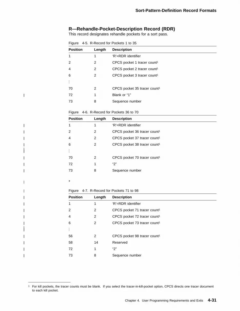
Sort-Pattern-Definition Record Formats
R—Rehandle-Pocket-Description Record (RDR)This record designates rehandle pockets for a sort pass.
| *
Figure 4-5. R-Record for Pockets 1 to 35
Position Length Description
1 1 ‘R’=RDR identifier
2 2 CPCS pocket 1 tracer count1
4 2 CPCS pocket 2 tracer count1
6 2 CPCS pocket 3 tracer count1
...
70 2 CPCS pocket 35 tracer count1
| 72| 1| Blank or “1”
73 8 Sequence number
Figure 4-6. R-Record for Pockets 36 to 70
Position Length Description
| 1| 1| ‘R’=RDR identifier
| 2| 2| CPCS pocket 36 tracer count1
| 4| 2| CPCS pocket 37 tracer count1
| 6| 2| CPCS pocket 38 tracer count1
| .| .| .| |
| 70| 2| CPCS pocket 70 tracer count1
| 72| 1| “2”
| 73| 8| Sequence number
| Figure 4-7. R-Record for Pockets 71 to 98
| Position| Length| Description
| 1| 1| ‘R’=RDR identifier
| 2| 2| CPCS pocket 71 tracer count1
| 4| 2| CPCS pocket 72 tracer count1
| 6| 2| CPCS pocket 73 tracer count1
| .| .| .| |
| 56| 2| CPCS pocket 98 tracer count1
| 58| 14| Reserved
| 72| 1| “2”
| 73| 8| Sequence number
1 For kill pockets, the tracer counts must be blank. If you select the tracer-in-kill-pocket option, CPCS directs one tracer documentto each kill pocket.
Chapter 4. User Programming Requirements and Exits 4-31
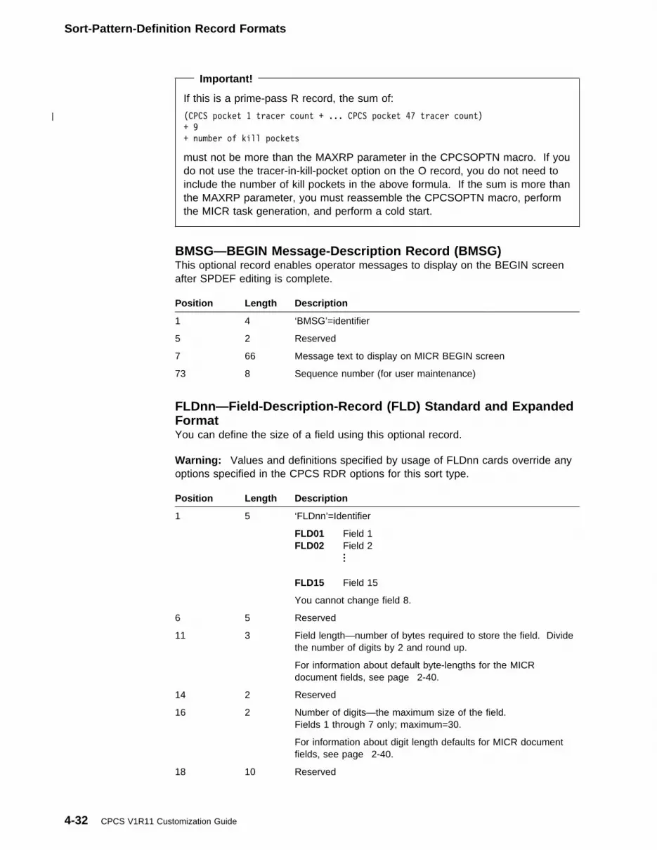
Sort-Pattern-Definition Record Formats
Important!
If this is a prime-pass R record, the sum of:
| (CPCS pocket 1 tracer count + ... CPCS pocket 47 tracer count)
+ 9
+ number of kill pockets
must not be more than the MAXRP parameter in the CPCSOPTN macro. If youdo not use the tracer-in-kill-pocket option on the O record, you do not need toinclude the number of kill pockets in the above formula. If the sum is more thanthe MAXRP parameter, you must reassemble the CPCSOPTN macro, performthe MICR task generation, and perform a cold start.
BMSG—BEGIN Message-Description Record (BMSG)This optional record enables operator messages to display on the BEGIN screenafter SPDEF editing is complete.
Position Length Description
1 4 ‘BMSG’=identifier
5 2 Reserved
7 66 Message text to display on MICR BEGIN screen
73 8 Sequence number (for user maintenance)
FLDnn—Field-Description-Record (FLD) Standard and ExpandedFormatYou can define the size of a field using this optional record.
Warning: Values and definitions specified by usage of FLDnn cards override anyoptions specified in the CPCS RDR options for this sort type.
Position Length Description
1 5 ‘FLDnn’=Identifier
FLD01 Field 1FLD02 Field 2
... FLD15 Field 15
You cannot change field 8.
6 5 Reserved
11 3 Field length—number of bytes required to store the field. Dividethe number of digits by 2 and round up.
For information about default byte-lengths for the MICRdocument fields, see page 2-40.
14 2 Reserved
16 2 Number of digits—the maximum size of the field.Fields 1 through 7 only; maximum=30.
For information about digit length defaults for MICR documentfields, see page 2-40.
18 10 Reserved
4-32 CPCS V1R11 Customization Guide
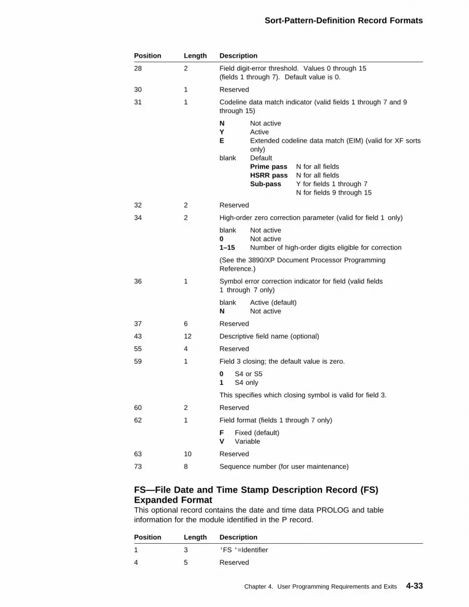
Sort-Pattern-Definition Record Formats
Position Length Description
28 2 Field digit-error threshold. Values 0 through 15(fields 1 through 7). Default value is 0.
30 1 Reserved
31 1 Codeline data match indicator (valid fields 1 through 7 and 9through 15)
N Not activeY ActiveE Extended codeline data match (EIM) (valid for XF sorts
only)blank Default
Prime pass N for all fieldsHSRR pass N for all fieldsSub-pass Y for fields 1 through 7
N for fields 9 through 15
32 2 Reserved
34 2 High-order zero correction parameter (valid for field 1 only)
blank Not active0 Not active1–15 Number of high-order digits eligible for correction
(See the 3890/XP Document Processor ProgrammingReference.)
36 1 Symbol error correction indicator for field (valid fields1 through 7 only)
blank Active (default)N Not active
37 6 Reserved
43 12 Descriptive field name (optional)
55 4 Reserved
59 1 Field 3 closing; the default value is zero.
0 S4 or S51 S4 only
This specifies which closing symbol is valid for field 3.
60 2 Reserved
62 1 Field format (fields 1 through 7 only)
F Fixed (default)V Variable
63 10 Reserved
73 8 Sequence number (for user maintenance)
FS—File Date and Time Stamp Description Record (FS)Expanded FormatThis optional record contains the date and time data PROLOG and tableinformation for the module identified in the P record.
Position Length Description
1 3 'FS '=Identifier
4 5 Reserved
Chapter 4. User Programming Requirements and Exits 4-33

Sort-Pattern-Definition Record Formats
Position Length Description
9 8 File name (required)
17 4 Reserved
21 8 Optional date stamp (MM/DD/YY)
29 2 Reserved
31 8 Optional time stamp (HH.MM)
39 34 Reserved
73 8 Sequence number (for user maintenance)
RP—Run-Profile-Description Record (RP) Expanded FormatThis record provides a run profile name for an expanded-format (XF) sort. It isrequired for an XF sort.
Position Length Description
1 3 'RP '=Identifier
4 5 Unused
9 8 Run profile name (optional)
17 4 Unused
21 8 Date stamp—YY/MM/DD (optional)
29 2 Unused
31 8 Time stamp—HH/MM/SS (optional)
39 2 Unused
41 5 Document processor model
blank Any document processor'XP ' Any XP processor'3892 ' Any 3892/XP'PE ' Any power encoder'3890 ' Any 38903890A 3890 Model A3890B 3890 Model B3890X 3890 Model XIMAGE Any document processor with image capacity
46 27 Unused
73 8 Sequence number (for user maintenance)
TY—Pass-Type Description Record (TY) Expanded FormatThis optional record identifies sort type (such as 2- or 4-byte) and maximum-sortprogram size.
Position Length Description
1 3 'TY '=Identifier
4 27 Unused
4-34 CPCS V1R11 Customization Guide

Sort-Pattern-Definition Record Formats
Position Length Description
31 4 Sort-type indicator (optional)
SCI4 4-byte SCISCI2 2-byte SCI
If set, the sort program can be only SCI2 or SCI4. The defaultvalue (blank) is a 2-byte SCI routine.
35 6 Unused
41 6 Maximum sort-size indicator (option) nnnnnK indicates themaximum storage size required to load all SCI modules for thispass.
47 26 Unused
73 8 Sequence number (for user maintenance)
Chapter 4. User Programming Requirements and Exits 4-35

CPCS Stacker-Select Routine Operation
CPCS Stacker-Select Routine OperationThe stacker-select prolog (SSP) performs specific MICR processing operations oneach document that the document processor reads during stacker-select time.SSP code consists of 3890 stacker control instructions (SCIs) and resides in thefirst 1504 (X'5E0') bytes of program storage of the document processor. CPCSmacros generate this SSP along with the user’s SCIs. The SSP performs thefollowing functions:
� Initializing and setting CPCS-reserved switches and areas within the documentprocessor
� Processing I-strings
� Controlling the updating of item number and microfilm number
� Identifying document types
� Selecting and processing CPCS control documents
� Allocating to pockets (tracer spraying)
� Issuing SCI pause instructions for tracer-verification errors andresynchronization of codeline data matching
� Routing all batch, sub-batch, block, and user documents to the user’sSCI routine at the label DKNUSER
� Receiving control after user processing at label DKNRTN
� Processing SCI errors.
SSPs are included with SCIs that reside in sorter-program storage. They consist ofDKNMPSR and a PROLOG macro, a PROLOG2 macro, or a PROLOGX macro,depending on the format that you selected (standard or expanded). An explanationof the different SSPs follows. For a description of sorter-program storage use, seeFigure 4-8 on page 4-37 and Figure 4-10 on page 4-38.
Standard Stacker-Select PrologA standard-sort SSP consists of two parts: the ENTR macro (80 bytes long) andPROLOG. The ENTR macro includes a routine for processing SCI errors. When aSCI error occurs, the SCI error routine sets an operator message light on andloops, causing a SCI error header to go to the host processor. For the exactsetting of the operator message lights, see the 3890/XP Document ProcessorProgramming Reference.
The second part of the SSP is the PROLOG macro, which is used in the assemblyof user stacker-select routines. It is assembled with user SCIs and is link-edited asreentrant into the CPCS load library. The SSP/user stacker-select routine is loadedinto the host computer entry for the specific sort type. DKNMSTRT changes theSSP portion before SETDEV sends it to sorter program storage. A user-providedtable can also be loaded with the SSP/user stacker-select routine.
4-36 CPCS V1R11 Customization Guide

CPCS Stacker-Select Routine Operation
┌───────────────────────────────┐
│ │
│ TBLEND │
│ │
│ User Table (optional) │
│ │
│-TBLSTART----------------------│
│ PROEND │
│ │
│ │
│ User Stacker-Select Routine │
│ DKNUSER │
1588 │-------------------------------│X'634'
│ │
│ PROLOG │
│ │
24� │-PROLOG------------------------│X'F�'
│ │
│ ENTRMACR │
128 │-------------------------------│X'8�'
│ │
│ IREC │
� └───────────────────────────────┘X'��'
Figure 4-8. CPCS Sorter-Program Storage Map—Standard Sort
When the CPCS standard-sort SSP completes processing both non-controldocuments and CPCS block and batch control documents, it branches to theuser-edit routine at label DKNUSER. Assembling the PROLOG macro in the userSCI assembly supplies user linkage. User-written, stacker-select routines mustperform the following functions:
� Pocket selection and field validation for non-control documents� Field validation for control documents (except tracer slips).
Expanded Stacker-Select PrologThe PROLOG2 or PROLOGX macro is the first statement coded in expanded-sortprimary stacker-selection routines. PROLOG2 uses 2-byte SCIs, program sizespecification, and a 32-byte prefix. PROLOGX uses 2- or 4-byte SCIs based on atype indicator, a program size specification, a 32-byte prefix, and a table addresslist.
DKNMLPRn (n=1, 2, or 4) changes the SSP portion before SETDEV sends it tosorter program storage. A user-provided table can also be loaded with theSSP/user stacker-select routine.
Chapter 4. User Programming Requirements and Exits 4-37
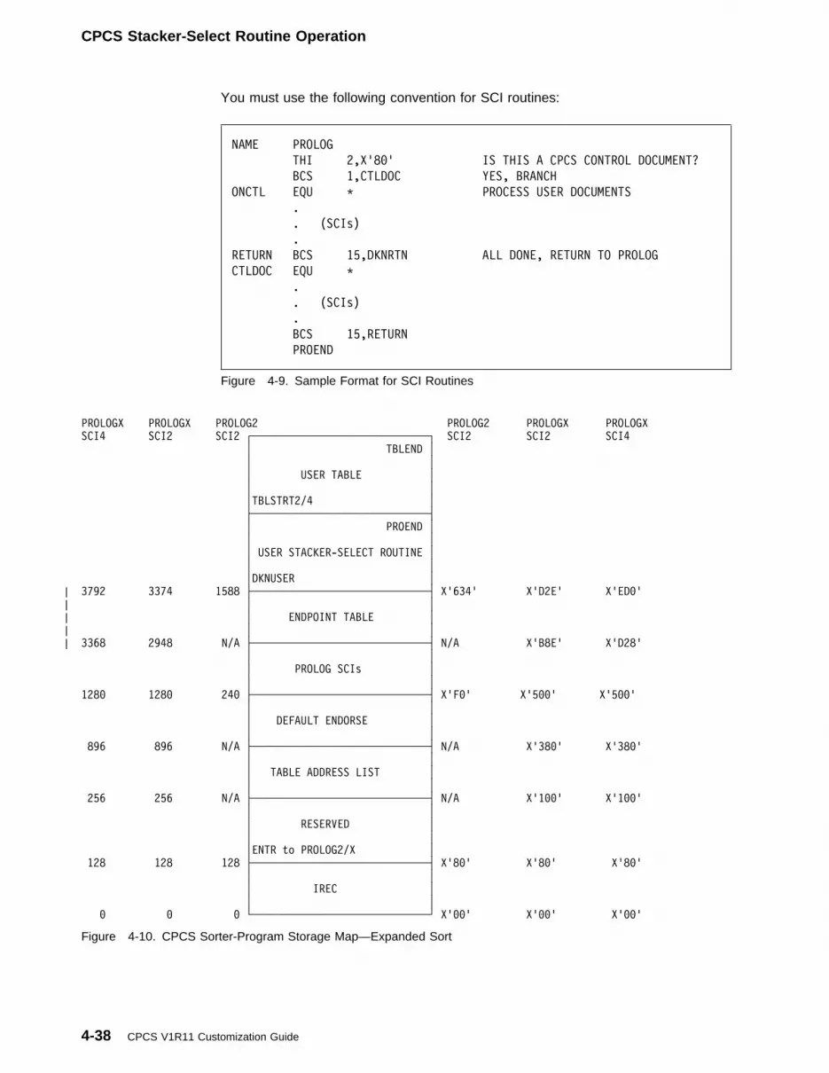
CPCS Stacker-Select Routine Operation
You must use the following convention for SCI routines:
NAME PROLOG
THI 2,X'8�' IS THIS A CPCS CONTROL DOCUMENT?
BCS 1,CTLDOC YES, BRANCH
ONCTL EQU T PROCESS USER DOCUMENTS
.
. (SCIs)
.
RETURN BCS 15,DKNRTN ALL DONE, RETURN TO PROLOG
CTLDOC EQU T
.
. (SCIs)
.
BCS 15,RETURN
PROEND
Figure 4-9. Sample Format for SCI Routines
PROLOGX PROLOGX PROLOG2 PROLOG2 PROLOGX PROLOGX
SCI4 SCI2 SCI2 ┌─────────────────────────────┐ SCI2 SCI2 SCI4
│ TBLEND │
│ │
│ USER TABLE │
│ │
│TBLSTRT2/4 │
├─────────────────────────────┤
│ PROEND │
│ │
│ USER STACKER-SELECT ROUTINE │
│ │
│DKNUSER │
| 3792 3374 1588 ├─────────────────────────────┤ X'634' X'D2E' X'ED�'
| │ │
| │ ENDPOINT TABLE │
| │ │
| 3368 2948 N/A ├─────────────────────────────┤ N/A X'B8E' X'D28'
│ │
│ PROLOG SCIs │
│ │
128� 128� 24� ├─────────────────────────────┤ X'F�' X'5��' X'5��'
│ │
│ DEFAULT ENDORSE │
│ │
896 896 N/A ├─────────────────────────────┤ N/A X'38�' X'38�'
│ │
│ TABLE ADDRESS LIST │
│ │
256 256 N/A ├─────────────────────────────┤ N/A X'1��' X'1��'
│ │
│ RESERVED │
│ │
│ENTR to PROLOG2/X │
128 128 128 ├─────────────────────────────┤ X'8�' X'8�' X'8�'
│ │
│ IREC │
│ │
� � � └─────────────────────────────┘ X'��' X'��' X'��'
Figure 4-10. CPCS Sorter-Program Storage Map—Expanded Sort
4-38 CPCS V1R11 Customization Guide

CPCS Stacker-Select Routine Operation
Sort-Control Program Notes� Your sort-control program routines must ensure that all auto-selected
documents go to the reject pocket. Header byte 8 bit 0 indicates to thesort-control program routine that the document is an auto-select.
� You can also specify a sort pattern table in the SPDEF. The table isassembled separately from your stacker-select routine, but SETDEV loads itwith your stacker-select routine. The document processor does not provide forrelocation of sort-control programs and has no means of resolving sort-controlprogram addresses while sort control programs are running. All sort-controlprogram module linkage must be complete before SETDEV initiation.
� User-written SCIs have access to the codeline data record and header duringsort-control program processing; however, specific header bytes and save arealocations are reserved for CPCS use. (For a description of header and statusbytes and save-area locations, see “CPCS Document Processor Header-Byte,Status-Byte, and Save-Area Usage” on page 4-40.) If your sort controlprograms set or reset any of these, unpredictable results can occur.
� Your sort control program routines must ensure that all fields are valid andcontain correct data.
� You might want to modify fields 1 through 7 in the process buffer. Because agiven field’s location in the process buffer is not fixed, subroutines enableaccurate modification of the process buffer (in program storage, for the 3890Document Processor and XPs emulating 3890s, and in auxiliary storage for XPprocessors).
Load the work register with the modified value for the field. Perform a branchand link (BLS), using link register 1 as the return register and DKNUPFn as thetarget label, where n is the number of the field to update. If it is not a definedfield, it makes a simple return to the caller. You can determine whether it is afield defined to the document processor by testing the byte at label DKNUPFn.If the value of the byte at that label is X'BE'(BUR operation code), the field isnot defined to the document processor.
� If you define field 4, field 6, sub-batch documents, or AST pointer documents,PROLOG moves the routing-number check digit to the leftmost digit of theprocess buffer (undefined digit of sequence number). You can access thecheck digit in the right digit of program storage at label DKNIIRTD+3. You canupdate the check digit that went to the host by changing the rightmost digit ofthe byte at label DKNIIRTD+3 and performing a branch and link (BLS), usinglink register 1 as the return register and DKNUPRTD as the target label.
If you do not define field 4, field 6, sub-batch documents, or AST pointerdocuments, you can access and update the check digit in header byte 9, bits0 through 3.
� The PROLOG marks field errors, indicated by header byte 9, bits 0 and 1 (on isvalid), if either of the fields is defined to the document processor. Undefinedfields are marked as valid.
In testing for field 6 validity in header bytes 0 and 1, you should only test byte 1(length/special symbol error) when the document contains a valid non-blankfield 7 (serial number). This is because of the need for a closing symbol todenote the end of a MICR field and because the closing symbol for field 6 isalso the opening symbol for field 7. If no field 7 is present, header byte 1
Chapter 4. User Programming Requirements and Exits 4-39
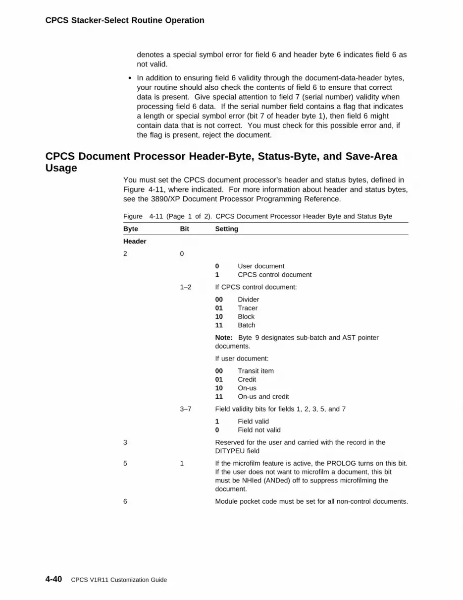
CPCS Stacker-Select Routine Operation
denotes a special symbol error for field 6 and header byte 6 indicates field 6 asnot valid.
� In addition to ensuring field 6 validity through the document-data-header bytes,your routine should also check the contents of field 6 to ensure that correctdata is present. Give special attention to field 7 (serial number) validity whenprocessing field 6 data. If the serial number field contains a flag that indicatesa length or special symbol error (bit 7 of header byte 1), then field 6 mightcontain data that is not correct. You must check for this possible error and, ifthe flag is present, reject the document.
CPCS Document Processor Header-Byte, Status-Byte, and Save-AreaUsage
You must set the CPCS document processor’s header and status bytes, defined inFigure 4-11, where indicated. For more information about header and status bytes,see the 3890/XP Document Processor Programming Reference.
Figure 4-11 (Page 1 of 2). CPCS Document Processor Header Byte and Status Byte
Byte Bit Setting
Header
2 0
0 User document1 CPCS control document
1–2 If CPCS control document:
00 Divider01 Tracer10 Block11 Batch
Note: Byte 9 designates sub-batch and AST pointerdocuments.
If user document:
00 Transit item01 Credit10 On-us11 On-us and credit
3–7 Field validity bits for fields 1, 2, 3, 5, and 7
1 Field valid0 Field not valid
3 Reserved for the user and carried with the record in theDITYPEU field
5 1 If the microfilm feature is active, the PROLOG turns on this bit.If the user does not want to microfilm a document, this bitmust be NHIed (ANDed) off to suppress microfilming thedocument.
6 Module pocket code must be set for all non-control documents.
4-40 CPCS V1R11 Customization Guide

CPCS SCI Macros and User SCI Coding
The CPCS PROLOG uses the following save areas in the document processor:
0–489 Available to the user490–493 Divider count for divider spraying494–497 Pocket index for divider spraying498 Merge-before-main in progress flag499 Reserved
Figure 4-11 (Page 2 of 2). CPCS Document Processor Header Byte and Status Byte
Byte Bit Setting
9
0 1=Field 4 valid
1 1=Field 6 valid
2 1=Sub-batch document (byte 2, bits 0 through 2=111)
3 1=AST pointer document(byte 2, bits 0 through 2=100)
Note: These bits have meaning only when field 4, field 6,sub-batch, or AST documents are defined. Otherwise, bits 0through 3 contain the routing number check digit. See“Sort-Control Program Notes” on page 4-39.
Status
0–2 Reserved for CPCS
3–7 Available to the user
CPCS SCI Macros and User SCI CodingThere are a number of macros within CPCS that you can use to code userSCI routines and tables. PROLOG and PROEND delimit the SCI stacker-selectroutine, and TBLSTART and TBLEND delimit the optional SCI table.
The expanded format PROLOG macros, PROLOG2, PROLOGX, TBLSTRT2, andTBLSTRT4, work with the 3890/XP Series document processors only. Theexpanded format SPDEF records are required to initialize these sorts (see“Sort-Pattern-Definition Record Formats” on page 4-17). These macros provideSCI routines that process documents at the document processor. CPCS uses the32-byte prefix area that these macros generate to check for correctness andcompatibility of SCI programs during sort initialization. To initialize sorts that usethese PROLOGs, you use the in-core SETDEV, which does not require loading ofDKNMPSR during initialization. The DKNMPSR function is an imbed in theexpanded format macros.
Users can code RMODE=ANY and AMODE=31 in the SCI routines, usingexpanded-format SCI macros to take advantage of MVS storage above 16MBduring CPCS loading of the SCI routines. For additional information on SCIroutines, see Figure 4-13 on page 4-48.
Loading a table for expanded format sorts requires the TBLSTRT2 and TBLSTRT4macros. You do not have to code the ENTR macro after these macros; TBLSTRT2and TBLSTRT4 macros generate the ENTR macro.
Chapter 4. User Programming Requirements and Exits 4-41

CPCS SCI Macros and User SCI Coding
PROLOG MacroDescription: The PROLOG macro must be the first statement of the user’sSCI program. It generates the CPCS PROLOG SCIs (part 2 of the standard SSPdescribed before). You should code a label; no operands are necessary. The laststatement generated by the PROLOG macro is the statement DKNUSER EQU T; theuser stacker-select routine instructions start immediately after this statement.
Label Operation Parameters
LABEL PROLOG
PROEND MacroDescription: The PROEND macro must be the last statement of the user’sSCI program. It delimits the SCI program so that CPCS can calculate the length ofthe generated SCI program, including the bytes of PROLOG. The label is optional.
Label Operation Parameters
LABEL PROEND
TBLSTART MacroDescription: You should code TBLSTART as the first statement of the user’sSCI table. The table is a completely different module from the stacker-selectroutine.
The purpose of TBLSTART is to establish the load point of the table in SCI storage.The coded table usually contains SCI tables, but it can also include SCI routinesand executable SCI instructions.
The required operand TBLLOAD specifies the hexadecimal address in the sorterprogram storage at which the user wants to load the table. Code it as 3 or 4hexadecimal characters without quotes. The address must be higher than theaddress of the end of the user stacker-select routine. It might be necessary to dotrial assemblies of both the stacker-select routine and the table modules todetermine the sizes and required load addresses. The user’s SCIs should followthe TBLSTART macro.
Label Operation Parameters
LABEL TBLSTART TBLLOAD=XXXX
TBLEND MacroDescription: The TBLEND macro must be the last statement of the user’s SCItable. It delimits the SCI table so that CPCS can calculate the length of thegenerated SCI table. The label is optional.
Label Operation Parameters
LABEL TBLEND
4-42 CPCS V1R11 Customization Guide
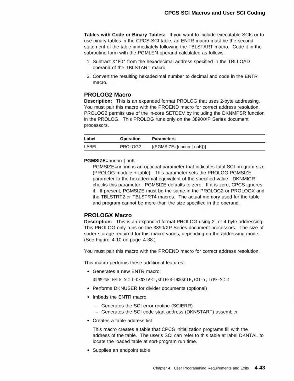
CPCS SCI Macros and User SCI Coding
Tables with Code or Binary Tables: If you want to include executable SCIs or touse binary tables in the CPCS SCI table, an ENTR macro must be the secondstatement of the table immediately following the TBLSTART macro. Code it in thesubroutine form with the PGMLEN operand calculated as follows:
1. Subtract X'80' from the hexadecimal address specified in the TBLLOADoperand of the TBLSTART macro.
2. Convert the resulting hexadecimal number to decimal and code in the ENTRmacro.
PROLOG2 MacroDescription: This is an expanded format PROLOG that uses 2-byte addressing.You must pair this macro with the PROEND macro for correct address resolution.PROLOG2 permits use of the in-core SETDEV by including the DKNMPSR functionin the PROLOG. This PROLOG runs only on the 3890/XP Series documentprocessors.
PGMSIZE=nnnnn | nnKPGMSIZE=nnnnn is an optional parameter that indicates total SCI program size(PROLOG module + table). This parameter sets the PROLOG PGMSIZEparameter to the hexadecimal equivalent of the specified value. DKNMICRchecks this parameter. PGMSIZE defaults to zero. If it is zero, CPCS ignoresit. If present, PGMSIZE must be the same in the PROLOG2 or PROLOGX andthe TBLSTRT2 or TBLSTRT4 macros. The actual memory used for the tableand program cannot be more than the size specified in the operand.
Label Operation Parameters
LABEL PROLOG2 [(PGMSIZE={nnnnn | nnK})]
PROLOGX MacroDescription: This is an expanded format PROLOG using 2- or 4-byte addressing.This PROLOG only runs on the 3890/XP Series document processors. The size ofsorter storage required for this macro varies, depending on the addressing mode.(See Figure 4-10 on page 4-38.)
You must pair this macro with the PROEND macro for correct address resolution.
This macro performs these additional features:
� Generates a new ENTR macro:
DKNMPSR ENTR SCI1=DKNSTART,SCIERR=DKNSCIE,EXT=Y,TYPE=SCI4
� Performs DKNUSER for divider documents (optional)
� Imbeds the ENTR macro
– Generates the SCI error routine (SCIERR)– Generates the SCI code start address (DKNSTART) assembler
� Creates a table address list
This macro creates a table that CPCS initialization programs fill with theaddress of the table. The user’s SCI can refer to this table at label DKNTAL tolocate the loaded table at sort-program run time.
� Supplies an endpoint table
Chapter 4. User Programming Requirements and Exits 4-43

CPCS SCI Macros and User SCI Coding
� Supplies an SBTBL-format table that contains the endpoint ID for each pocket.
TYPE={SCI2 | SCI4}This is an optional parameter that indicates SCI type. The default is SCI4.
PGMSIZE={0 | nnnnK | nnM}This is an optional parameter that indicates total SCI program size (PROLOGmodule + table). The system uses this parameter to set the PGMSIZEparameter to the hexadecimal equivalent of the value specified. You specifythe PGMSIZE parameter in decimal values of kilo (K) bytes or mega (M) bytes.DKNMICR checks this operand for consistency for all modules. PGMSIZEdefaults to zero. If it is zero, CPCS ignores this parameter. If present,PGMSIZE must be the same in the PROLOG2 or PROLOGX and TBLSTRT2or TBLSTRT4 macros. The actual memory used for the table and programcannot be more than the size specified in the operand.
DIVDOC={YES | NO}This is an optional parameter that may be set to have dividers processed bythe SCI routine user code. The default is NO.
PROLOGX does the following for DIVDOC=NO:
1. Flags the item as a merge document (header byte 8 = X'08').
2. Assigns the pocket corresponding to the pocket counter that has reachedthe limit.
3. Does not pass control to the user control area.
PROLOGX does the following for DIVDOC=YES:
1. Flags the item as a merge document (header byte 8 = X'08').
2. Assigns the system reject pocket (this is a temporary pocket code to beoverlaid by the user code).
3. Flags non-merge-before-main dividers (as such, header byte 2 = X'80').The user code must set this flag for successfully validatedmerge-before-main dividers.
The following code could be used to identify merge-before-maindocuments:
Label Operation Parameters
LABEL PROLOGX [TYPE={SCI2 | SCI4}] [PGMSIZE={0 | nnnnK | nnM}] [DIVDOC={YES | NO}]
4-44 CPCS V1R11 Customization Guide

CPCS SCI Macros and User SCI Coding
THI 8,X'�8' MERGE FEED DOC ?
BCS 8,SCISTART NO - DO NORMAL TEST
IA (�,2),498 GET MBM FLAG
CI (�,2),X'�1' MBM PROCESSING
BCS 8,DOMBM YES - DO MBM
|
| <========= REGULAR DIVIDER EDITING
|
BADDIV EQU T <======== BRANCH TO IF EDITING FAILS
FM
BCS 15,DKNRTN RETURN
GOODDIV EQU T <======== BRANCH TO IF EDITING PASSES
SPC
BCS 15,DKNRTN
DOMBM EQU T
|
| <========= MBM DIVIDER EDITING
|
MBMBAD EQU T SELECT REJECT POCKET IF BAD
SPI 11
MBMGOOD EQU T LEAVE PKT CODE AS-IS IF GOOD
BCS 15,DKNRTN RETURN
SCISTART DS �H
4. Passes control to the user area.
Endpoint ID ProcessingThe PROLOGX macro supplies endpoint ID information to the user-sort routine inthe form of an SBTBL-format table. The table, which is located at the labelDKNEPTBL, contains the endpoint ID for each kill pocket.
Example of Endpoint ID Table: The kill-pocket endpoint ID table (DKNEPTBL) inthe PROLOGX portion of the SCI program is in SBTBL format. You can use thistable to get the endpoint ID that is associated with a kill pocket. To obtain theendpoint ID, do the following:
1. Load the pocket number into the work register. The SPC instruction selectedthe pocket number; it is in header-byte 6.
2. Send an SBT instruction for the DKNEPTBL.
The SBT instruction returns a 2-digit pocket number and an 8-digit endpoint ID tothe work register.
The DKNEPTBL table is indexed by pocket number in a module/pocket (M/P)| format. The 48 table entries range from M/P 11 through M/P 86. For each kill
pocket, the endpoint ID section of the table contains the 8-digit (4-byte) endpointIDs. For each non-kill pocket, the endpoint ID section of the table contains X'AA'.Figure 4-12 is an example of a DKNEPTBL table.
Chapter 4. User Programming Requirements and Exits 4-45

CPCS SCI Macros and User SCI Coding
Figure 4-12. Example of DKNEPTBL Table
DKNEPTBL SBTBL 2,11AAAAAAAA, M/P=1/1
12AAAAAAAA, M/P=1/2
13AAAAAAAA, M/P=1/3
1405300019, M/P=1/4 (Kill pocket)
15AAAAAAAA, M/P=1/5
1688888888, M/P=1/6 (On-us pocket)
21AAAAAAAA, M/P=2/1
...
| | | 8105311004,| M/P=8/1| (Kill pocket)
| | | 86AAAAAAAA,| M/P=8/6| (Last table entry)
TBLSTRT2Description: This macro is the first statement in the 2-byte SCI program’ssort-pattern table routine. It creates a 32-byte prefix area based on user-codedoperands. The CPCS initialization programs reference the prefix area to verify thatthe format and size of the user-generated program are correct.
You must pair this macro with a TBLEND macro. You do not have to code theENTR macro after this macro; the TBLSTRT2 macro generates the ENTR macro.
TBLLOAD=nnnnn | nnKThe load address for the table, expressed in decimal (nnnnn) or in decimalincrements of kilo (K) bytes. nnnnn must be a multiple of 8 (double-wordboundary). This operand is required.
PGMSIZE={0 | nnK}The size parameter, indicates total SCI program size (PROLOG module +table) in decimal increments of kilo (K) bytes. This parameter is optional. Youmust code the same value for each program and table in a sort.
Example: LABEL TBLSTRT2 TBLLOAD=32768,PGMSIZE=48K
TBLLOAD=nnnnn is the decimal load address for the table and PGMSIZE=nnK isthe decimal size for the PROLOG module and the table.
Label Operation Parameters
LABEL TBLSTRT2 TBLLOAD=nnnnn | nnK [,PGMSIZE={0 | nnK}]
TBLSTRT4Description: This macro is the first statement in the 4-byte SCI programsort-pattern table routine. It creates a 32-byte prefix area based on user-codedoperands. The CPCS initialization programs reference the prefix area to verify thatthe format and size of the user-generated program are correct.
You must pair this macro with a TBLEND macro. You do not have to code theENTR macro after this macro; the TBLSTRT4 macro generates the ENTR macro.
4-46 CPCS V1R11 Customization Guide
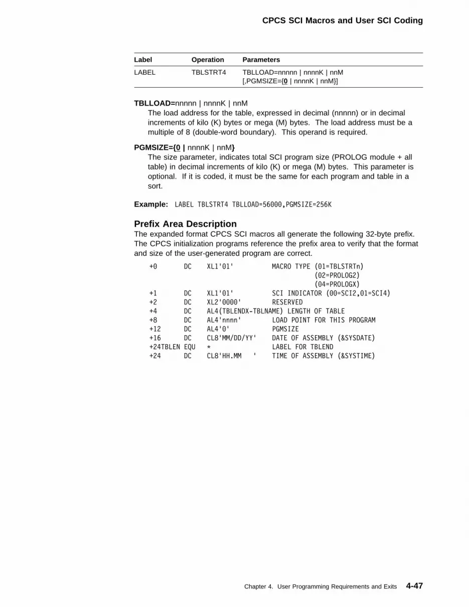
CPCS SCI Macros and User SCI Coding
TBLLOAD=nnnnn | nnnnK | nnMThe load address for the table, expressed in decimal (nnnnn) or in decimalincrements of kilo (K) bytes or mega (M) bytes. The load address must be amultiple of 8 (double-word boundary). This operand is required.
PGMSIZE={0 | nnnnK | nnM}The size parameter, indicates total SCI program size (PROLOG module + alltable) in decimal increments of kilo (K) or mega (M) bytes. This parameter isoptional. If it is coded, it must be the same for each program and table in asort.
Example: LABEL TBLSTRT4 TBLLOAD=56���,PGMSIZE=256K
Label Operation Parameters
LABEL TBLSTRT4 TBLLOAD=nnnnn | nnnnK | nnM [,PGMSIZE={0 | nnnnK | nnM}]
Prefix Area DescriptionThe expanded format CPCS SCI macros all generate the following 32-byte prefix.The CPCS initialization programs reference the prefix area to verify that the formatand size of the user-generated program are correct.
+� DC XL1'�1' MACRO TYPE (�1=TBLSTRTn)
(�2=PROLOG2)
(�4=PROLOGX)
+1 DC XL1'�1' SCI INDICATOR (��=SCI2,�1=SCI4)
+2 DC XL2'����' RESERVED
+4 DC AL4(TBLENDX-TBLNAME) LENGTH OF TABLE
+8 DC AL4'nnnn' LOAD POINT FOR THIS PROGRAM
+12 DC AL4'�' PGMSIZE
+16 DC CL8'MM/DD/YY' DATE OF ASSEMBLY (&SYSDATE)
+24TBLEN EQU T LABEL FOR TBLEND
+24 DC CL8'HH.MM ' TIME OF ASSEMBLY (&SYSTIME)
Chapter 4. User Programming Requirements and Exits 4-47

CPCS SCI Macros and User SCI Coding
Sample Expanded-Format SCI Routine Using a TableThe following figure shows two different examples: PROLOGX4 and TBLSTRT4.They are separated by a ****** line.
TITLE 'PROLOGX4 SAMPLE'
AMODE 31
RMODE ANY
PRINT NOGEN
MX4SAMP1 PROLOGX TYPE=SCI4,PGMSIZE=256K,DIVDOC=YES
PRINT GEN
T
T
CST (�,1),KILLTB
T
KILLTB EQU MX4SAMP1+MEM128K–IRECSI2 ADDRESS OF TABLE
MEM128K DC X'131�72' VALUE OF 128K OF MEMORY
IRECS12 DC X'128' VALUE OF SIZE OF IREC
LASTLABL DC CL3�'128K PROLOGX4 PASS 1- MX4SAMP1'
PROEND
TTTTTTTTTTTTTTTTTTTTTTTTTTTTTTTTTTTTTTTTTTTTTTTTTTTTTTTTTTTTTTTTT
TITLE 'TBLSTRT4 SAMPLE '
AMODE 31
RMODE ANY
MT4SAMP1 TBLSTRT4 TBLLOAD=128K,PGMSIZE=256K
KILLTB CSTBL 12,� CPCS POCKET 1
CSTBL 13,1 CPCS POCKET 2
CSTBL 14,2 CPCS POCKET 3
CSTBL 15,3,4,5 CPCS POCKET 4
CSTBL 16,6,7,8,9 CPCS POCKET 5
CSTBL 11,T CPCS POCKET REJECT
LASTLABL DC CL3�'128K TBLSTRT4 PASS 1- MT4SAMP1'
TBLEND
Figure 4-13. Sample Expanded-Format SCI Routine and Table
4-48 CPCS V1R11 Customization Guide
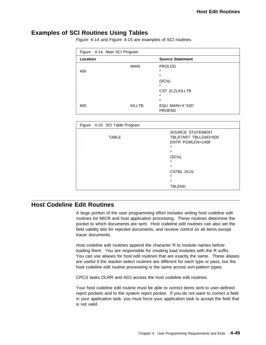
Host Edit Routines
Examples of SCI Routines Using TablesFigure 4-14 and Figure 4-15 are examples of SCI routines.
Figure 4-14. Main SCI Program
Location Source Statement
MAIN PROLOG400 * * (SCIs) * CST (0,2),KILLTB * *600 KILLTB EQU MAIN+X'530' PROEND
Figure 4-15. SCI Table Program
SOURCE STATEMENT TABLE TBLSTART TBLLOAD=600 ENTR PGMLEN=1408 * * (SCIs) * * CSTBL 16,01 * * TBLEND
Host Codeline Edit RoutinesA large portion of the user programming effort includes writing host codeline editroutines for MICR and host application processing. These routines determine thepocket to which documents are sent. Host codeline edit routines can also set thefield validity bits for rejected documents, and receive control on all items excepttracer documents.
Host codeline edit routines append the character R to module names beforeloading them. You are responsible for creating load modules with the R suffix.You can use aliases for host edit routines that are exactly the same. These aliasesare useful if the stacker-select routines are different for each type or pass, but thehost codeline edit routine processing is the same across sort-pattern types.
CPCS tasks OLRR and ADJ access the host codeline edit routines.
Your host codeline edit routine must be able to correct items sent to user-definedreject pockets and to the system reject pocket. If you do not want to correct a fieldin your application task, you must force your application task to accept the field thatis not valid.
Chapter 4. User Programming Requirements and Exits 4-49
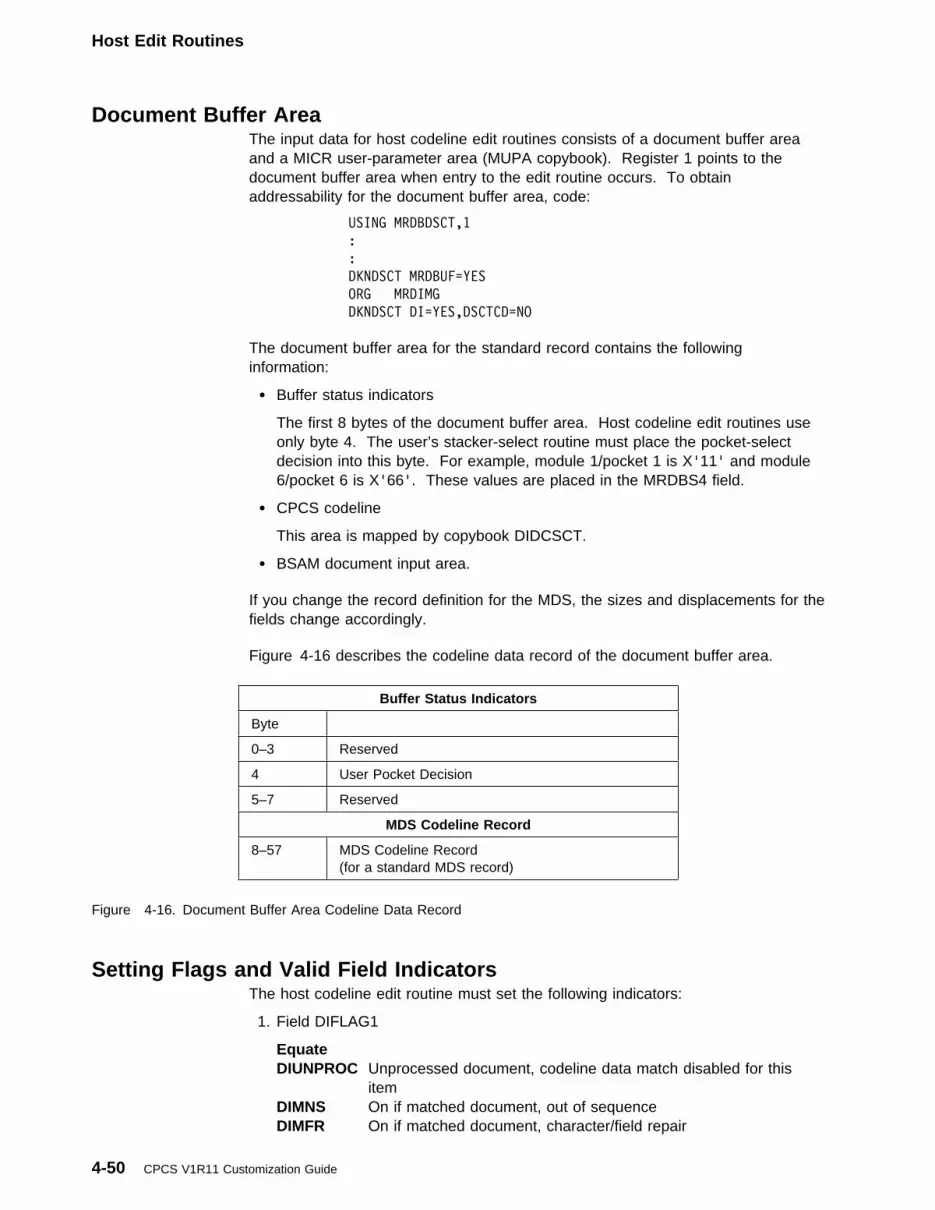
Host Edit Routines
Document Buffer AreaThe input data for host codeline edit routines consists of a document buffer areaand a MICR user-parameter area (MUPA copybook). Register 1 points to thedocument buffer area when entry to the edit routine occurs. To obtainaddressability for the document buffer area, code:
USING MRDBDSCT,1
:
:
DKNDSCT MRDBUF=YES
ORG MRDIMG
DKNDSCT DI=YES,DSCTCD=NO
The document buffer area for the standard record contains the followinginformation:
� Buffer status indicators
The first 8 bytes of the document buffer area. Host codeline edit routines useonly byte 4. The user’s stacker-select routine must place the pocket-selectdecision into this byte. For example, module 1/pocket 1 is X'11' and module6/pocket 6 is X'66'. These values are placed in the MRDBS4 field.
� CPCS codeline
This area is mapped by copybook DIDCSCT.
� BSAM document input area.
If you change the record definition for the MDS, the sizes and displacements for thefields change accordingly.
Figure 4-16 describes the codeline data record of the document buffer area.
Figure 4-16. Document Buffer Area Codeline Data Record
Buffer Status Indicators
Byte
0–3 Reserved
4 User Pocket Decision
5–7 Reserved
MDS Codeline Record
8–57 MDS Codeline Record(for a standard MDS record)
Setting Flags and Valid Field IndicatorsThe host codeline edit routine must set the following indicators:
1. Field DIFLAG1
Equate DIUNPROC Unprocessed document, codeline data match disabled for this
itemDIMNS On if matched document, out of sequenceDIMFR On if matched document, character/field repair
4-50 CPCS V1R11 Customization Guide

Host Edit Routines
DIVAMT On if amount field valid (user can reset)DIVPCTL On if process control field valid (user can reset)DIVONUS On if account field valid (user can reset)DIVABA On if routing number field valid (user can reset)DIVAUX On if serial number field valid (user can reset)
2. Field DIFLAG2
Equate DIMTCR On if this is a control documentDIJAM On if a jam occurred (user does not set)DICAN On if document is a Canadian checkDIOURS On if document is on-usDICRD On if document is a credit (for example, a deposit slip)DILOW On if this document has been entered through online reject
reentry (user does not set).DIHIGH On if this document has been entered through high-speed reject
reentry (user does not set).
3. Field DITYPEI
If flag DIMTCR is ON, you cannot set any flags in this field because this fieldrepresents the control document type. If flag DIMTCR is OFF, you can set anyflags in this field.
4. Field DITYPEU
This byte is available to the user.
5. Field DI3FLG3, byte DI3BYTE4
Equate DI3FL04V On if field 4 is valid (user can reset)DI3FL06V On if field 6 is valid (user can reset)
6. Field DI3FLG3, byte DI3BYTE5
Equate DI3FL09V On if field 9 is valid (user can reset)DI3FL10V On if field 10 is valid (user can reset)DI3FL11V On if field 11 is valid (user can reset)DI3FL12V On if field 12 is valid (user can reset)DI3FL13V On if field 13 is valid (user can reset)DI3FL14V On if field 14 is valid (user can reset)DI3FL15V On if field 15 is valid (user can reset)
Note: CPCS establishes field validity for fields 1, 2, 3, 5, and 7 from DIFLAG1only. CPCS ignores attempts to change field validity for these fields usingDI3BYTE4. However, it does maintain the settings for fields 1, 2, 3, 5, and 7 inDI3BYTE4 by copying them from DIFLAG1. For example, if you mark field 1 as notvalid by turning DIVAMT off, CPCS turns DI3FL01V off as well.
Setting Pocket NumbersYour host codeline edit routine should not use the CPCS pocket number. CPCSautomatically takes the pocket code placed in buffer status byte 4 (MRDBS4),converts it, and places the result in the CPCS pocket number byte (DIPKT field).
If you identify a pocket as a reject pocket in your SPDEF, CPCS modifies thepocket code by adding X'80' to it. This identifies the pocket as a user-defined
Chapter 4. User Programming Requirements and Exits 4-51

Host Edit Routines
reject pocket. For display purposes, the first digit of the pocket code is convertedto an alphabetic character.
Figure 4-17 shows examples of this converted pocket number for the documentprocessor.
Figure 4-17 (Page 1 of 2). Converted Pocket Number for the Document Processor
Buffer StatusByte (4)
DocumentProcessorPocket(Module/Pocket =MP)
Pocket # in CPCS forGood Pockets
Pocket # in CPCS forReject Pockets
SDE Report SDE Report
X'11' Reject NotApplicable
NotApplicable
X'FF' ' '
X'12' MP 1-2 X'01' C'01' X'81' C'Z1'X'13' MP 1-3 X'02' C'02' X'82' C'Z2'X'14' MP 1-4 X'03' C'03' X'83' C'Z3'X'15' MP 1-5 X'04' C'04' X'84' C'Z4'X'16' MP 1-6 X'05' C'05' X'85' C'Z5'X'21' MP 2-1 X'06' C'06' X'86' C'Z6'X'22' MP 2-2 X'07' C'07' X'87' C'Z7'X'23' MP 2-3 X'08' C'08' X'88' C'Z8'X'24' MP 2-4 X'09' C'09' X'89' C'Z9'X'25' MP 2-5 X'0A' C'10' X'8A' C'A0'X'26' MP 2-6 X'0B' C'11' X'8B' C'A1'X'31' MP 3-1 X'0C' C'12' X'8C' C'A2'X'32' MP 3-2 X'0D' C'13' X'8D' C'A3'X'33' MP 3-3 X'0E' C'14' X'8E' C'A4'X'34' MP 3-4 X'0F' C'15' X'8F' C'A5'X'35' MP 3-5 X'10' C'16' X'90' C'A6'X'36' MP 3-6 X'11' C'17' X'91' C'A7'X'41' MP 4-1 X'12' C'18' X'92' C'A8'X'42' MP 4-2 X'13' C'19' X'93' C'A9'X'43' MP 4-3 X'14' C'20' X'94' C'B0'X'44' MP 4-4 X'15' C'21' X'95' C'B1'X'45' MP 4-5 X'16' C'22' X'96' C'B2'X'46' MP 4-6 X'17' C'23' X'97' C'B3'X'51' MP 5-1 X'18' C'24' X'98' C'B4'X'52' MP 5-2 X'19' C'25' X'99' C'B5'X'53' MP 5-3 X'1A' C'26' X'9A' C'B6'X'54' MP 5-4 X'1B' C'27' X'9B' C'B7'X'55' MP 5-5 X'1C' C'28' X'9C' C'B8'X'56' MP 5-6 X'1D' C'29' X'9D' C'B9'X'61' MP 6-1 X'1E' C'30' X'9E' C'C0'X'62' MP 6-2 X'1F' C'31' X'9F' C'C1'X'63' MP 6-3 X'20' C'32' X'A0' C'C2'X'64' MP 6-4 X'21' C'33' X'A1' C'C3'X'65' MP 6-5 X'22' C'34' X'A2' C'C4'X'66' MP 6-6 X'23' C'35' X'A3' C'C5'X'71' MP 7-1 X'24' C'36' X'A4' C'C6'X'72' MP 7-2 X'25' C'37' X'A5' C'C7'X'73' MP 7-3 X'26' C'38' X'A6' C'C8'X'74' MP 7-4 X'27' C'39' X'A7' C'C9'X'75' MP 7-5 X'28' C'40' X'A8' C'D0'X'76' MP 7-6 X'29' C'41' X'A9' C'D1'X'81' MP 8-1 X'2A' C'42' X'AA' C'D2'X'82' MP 8-2 X'2B' C'43' X'AB' C'D3'X'83' MP 8-3 X'2C' C'44' X'AC' C'D4'
4-52 CPCS V1R11 Customization Guide

Host Edit Routines
Figure 4-17 (Page 2 of 2). Converted Pocket Number for the Document Processor
Buffer StatusByte (4)
DocumentProcessorPocket(Module/Pocket =MP)
Pocket # in CPCS forGood Pockets
Pocket # in CPCS forReject Pockets
SDE Report SDE Report
X'84' MP 8-4 X'2D' C'45' X'AD' C'D5'X'85' MP 8-5 X'2E' C'46' X'AE' C'D6'X'86' MP 8-6 X'2F' C'47' X'AF' C'D7' Note: The remaining entries in the table are applicable only for electronic or simulatedentries. Because there can be no document processor associated with these pockets, thiscolumn is blank. However, the OLRR edit routines may use the buffer status byte to setpocket numbers as high as 98 for electronic or simulated entries.X'91' X'30' C'48' X'B0' C'D8'X'92' X'31' C'49' X'B1' C'D9'X'93' X'32' C'50' X'B2' C'E0'X'94' X'33' C'51' X'B3' C'E1'X'95' X'34' C'52' X'B4' C'E2'X'96' X'35' C'53' X'B5' C'E3'X'A1' X'36' C'54' X'B6' C'E4'...
......
...
......
......
X'F5' X'58' C'88' X'D8' C'H8'X'F6' X'59' C'89' X'D9' C'H9'X'F7' X'5A' C'90' X'DA' C'I0'X'F8' X'5B' C'91' X'DB' C'I1'X'F9' X'5C' C'92' X'DC' C'I2'X'FA' X'5D' C'93' X'DD' C'I3'X'FB' X'5E' C'94' X'DE' C'I4'X'FC' X'5F' C'95' X'DF' C'I5'X'FD' X'60' C'96' X'E0' C'I6'X'FE' X'61' C'97' X'E1' C'I7'X'FF' X'62' C'98' X'E2' C'I8'N/A X'63' C'99' X'E3' C'I9'
Host Codeline Edit Routine Register ConventionsRegisters on entry to the host codeline edit routine are as follows:
0 Unpredictable1 Address of the document buffer area2 Address of the MICR user parameter area3–12 Unpredictable13 Address of the standard save area containing the contents of the registers
to recover before return from the host codeline edit routine.Host codeline edit routines must not save their registers in the save areapointed to by register 13. Because CPCS’s registers have already beensaved in this area, alteration of this save area can cause unexpectedresults.You are responsible for recovering registers before return, and you mustuse register 13 to do so.
14 Return register15 Host codeline edit routine entry point. You must set this register to zero
before return.
Chapter 4. User Programming Requirements and Exits 4-53

MICR User Parameter Area (MUPA)
All host codeline edit routines must be re-entrant. In addition, the linkage editormust assign the re-entrant attribute for the host codeline edit routines.
MICR User-Parameter Area (MUPA)This parameter area contains information for your host codeline edit routine.Addressability is obtained by coding:
USING MUPADSCT,2
:
:
DKNMSCT MUPA=YES
The MUPA area is also used to communicate with the DKNMREADdocument-processing user exit. Areas of the MUPA specific only to theDKNMREAD user exit are noted in the table below.
Field Name FieldSize
ContentValue
Modifiedby
Field Content Description
MUPAENT XL02 User CPCS entry tracer-group number (binary)
MUPACYC CL02 1 through 9A through L
User CPCS entry cycle number (Left justified,alphanumeric)
MUPATYPE XL01 User CPCS entry type of work (sort type, binary value 0through 255, X'00' through X'FF')
MUPAPPH XL04 User Pass and pocket history (X'PP112233'),PP=X'00' through X'04'. X'00' if there arehigh-speed reject re-entry documents in this run.
Pocket history: The prior-pass pocket distributionrecord of the documents in this run. Each bytecontains a value of X'01' to X'99' that indicatesthe pocket that received the document in previouspasses. X'11' represents the prime-pass pocket,X'22' represents the second-pass pocket, andX'33' represents the third-pass pocket.
MUPASTEP Fullword DKNMOLRI Contains the address of the optional host codelineedit table specified in MUPASTN. If no table isspecified, contains binary zeroes.
MUPAUSER XL16 User Area reserved for user (initialized to binary zeros)
The contents of this area remain constant fromdocument to document and are available, forexample, for program switches and addresses.This area is helpful for all re-entrant user interfaceroutines. If more than 16 bytes of storage areneeded, the expanded user work area can beused (see description for MUPAXWA on page4-55).
MUPAFLGS XL01 MUPA flag byte
MUPARST Equate B'100000000' DKNMREAD Restart of an entry in progress (MICR MREAD exitprocessing)
Bit 0 = 1, restart in progress. This means that, ona restart, the MICR document processing routineis still reading from the I-string.
4-54 CPCS V1R11 Customization Guide

MICR User Parameter Area (MUPA)
Field Name FieldSize
ContentValue
Modifiedby
Field Content Description
MUPAREX Equate B'010000000' DKNMREAD Expanded sorter record flag (MICR MREAD exitprocessing)
Bit 1 = 1. The record from the documentprocessor is larger than 44 bytes.
MUPADSPK Equate B'001000000' DKNOLRR(or otheruserinterfaces)
Do not let the host codeline edit routine set thepocket. This indicator is set to signal that thepocket decision must not be changed from theoriginal one made during MICR capture.
MUPAXWA XL03 CPCS The address of an expanded user work area. Ithas the same attributes as the 16-byte areadescribed at label MUPAUSER. This area isavailable if you coded the SSWORK operand inthe CPCSOPTN macro during MICR generation.Loading this address into a register gives youaccess to this area. You can request up to 2040bytes. The amount that you specify is allocatedduring each MICR entry or host codeline editoperation. When allocated, this area initializes toX'00'.
MUPASSN CL08 DKNMOLRI Host codeline edit routine name. DKNMOLRIdetermines this name by appending an R to thename passed passed in a CPCS-defined stringheader record.
MUPASTN CL08 DKNMOLRI Optional host codeline edit table name.DKNMOLRI determines this name by appendingan R to the name passed passed in aCPCS-defined string header record.
MUPASSEP Fullword DKNMOLRI Contains the entry-point address of the hostcodeline edit routine specified in MUPASSN.
MUPASPTR Fullword DKNMREAD Contains the address of the sorterdocument-buffer area that MREAD uses tocommunicate with the MREAD user-exit routine.
User Stacker-Select Routine Operation for OLRRA user stacker-select routine performs the editing of corrected documents duringOLRR in a way similar to that of the sorter pass. You should write theuser-supplied routines for OLRR document editing as described earlier in thischapter. (For more details, see “Host Codeline Edit Routines” on page 4-49.)
To ensure accurate editing of corrected reject documents, each reject D-string fromprime pass, HSRR, or a subsequent pass contains a CPCS string-header record.DKNOLRR uses this information to obtain the following data:
1. The user’s stacker-select routine name for this pass (from the pass descriptionrecord in the SPDEF library). This name must not contain more than7 characters.
2. The user’s sort pattern-table name (if any).
Chapter 4. User Programming Requirements and Exits 4-55

Changing the SETDEV and Diagnostic Operation Time-Out Interval
DKNOLRR appends the character R to module names before loading them. Youare responsible for creating load modules with the R suffix. You can use aliasesfor OLRR user-edit routines that are exactly the same. These aliases are useful ifthe stacker-select routines are different for each type or pass, but the OLRRprocessing is the same across sort pattern types.
Keep in mind that your stacker-select routine must be able to control processing forboth your user-defined reject pockets and your system reject pocket.
After being loaded, items 1 and 2 explained above remain the same for theduration of processing. After the OLRR operator corrects a codeline, DKNOLRRbranches to the module in item 1. In addition to the document data, the entry pointof item 2 passes to the user. For example, you can edit the document as desiredand set the validity flags.
Notes:
1. Since DKNOLRR re-displays codeline data records that the user-exit routinedoes not accept, the operator should have some way of forcing validity on agiven field (for example, by filling the account number field with 9s). Theuser-edit routine must check for these indications. This permits you to controllogical rejects that are indicated as reject pocket items.
2. The setting of the field validity bit in each codeline data record determines thecorrective action required during online reject reentry. The setting refers torecord flag 1 of the CPCS codeline data record, bits 3 through 7, and flag 3byte 4, bits 4 and 6. Do not flag a field as not valid unless you need to havevalid information in that field.
3. If a document amount field contains non-numeric data and it is selected to anon-reject pocket with the field flagged as valid, an abnormal end occurs for thecurrent task. This is true for both the MICR and OLRR user-edit selectroutines.
4. CPCS reserves the sequence number and the processing unit bytes in theCPCS codeline data record; the user-edit program, either MICR or OLRR, mustnot change these.
Changing the SETDEV and Diagnostic Operation Time-Out IntervalThe MICR program, DKNMPUTC, allows a SETDEV or diagnostic operation to thedocument processor to end abnormally if it does not complete in a specified time.You can change the time-out interval by modifying DKNMPUTC. The standardtime-out interval for the SETDEV is:
Time-Out Interval Document Processor
1 minute SETDEV for 3890 Models A, B, and X
3 minutes SETDEV for channel-attached 3890/XP Series document processors
5 minutes SETDEV for all LU 6.2-attached 3890/XP Series document processors
5 seconds Diagnostic operations.
Shown below are the DKNMPUTC constants with current settings. There areseparate constants to permit different time-out intervals for different operations that
4-56 CPCS V1R11 Customization Guide

Changing the SETDEV and Diagnostic Operation Time-Out Interval
MICR issues. You can set these constants as you want, but you should considerthe following factors:
� A SETDEV interval that is too short does not permit normal completion ofSETDEV processing.
� A SETDEV interval that is too long delays subsequent SETDEVs to otherdocument processors when a SETDEV problem occurs.
Standard SETDEV Time-Out Interval: Modify the following constant inDKNMPUTC to set the time-out interval for all standard 3890 SETDEVs. All 3890unexpanded (old format) sort programs use this SETDEV time-out interval.
TIME389� DS �D TIME FOR STANDARD SETDEV
DC C'��' HOUR HOUR
DC C'�1' MIN MIN
DC C'��' SEC SEC
DC C'�' TENTH
DC Z'�' HUNDREDS
After modification, reassemble DKNMPUTC and link it to the correct CPCS programlibrary.
Expanded SETDEV Time-Out Interval: Modify the following constant inDKNMPUTC for expanded SETDEVs. This SETDEV time-out interval is only forsort programs that are in expanded format (XF) and that process on3890/XP Series document processors.
TIMEXF DS �D TIME FOR EXPANDED (XF) SETDEV
DC C'��' HOUR HOUR
DC C'�1' MIN MIN
DC C'��' SEC SEC
DC C'�' TENTH
DC Z'�' HUNDREDS
After you complete the modification, reassemble DKNMPUTC and link it to thecorresponding CPCS program library.
Diagnostic Operation Time-Out Interval: Modify the following constant inDKNMPUTC to set a different time-out interval.
TIMEDIAG DS �D TIME FOR DIAGNOSTIC OPERATION
DC C'��' HOUR HOUR
DC C'��' MIN MIN
DC C'�5' SEC SEC
DC C'�' TENTH
DC Z'�' HUNDREDS
After you complete the modification, reassemble DKNMPUTC and link it to thecorresponding CPCS program library.
Chapter 4. User Programming Requirements and Exits 4-57
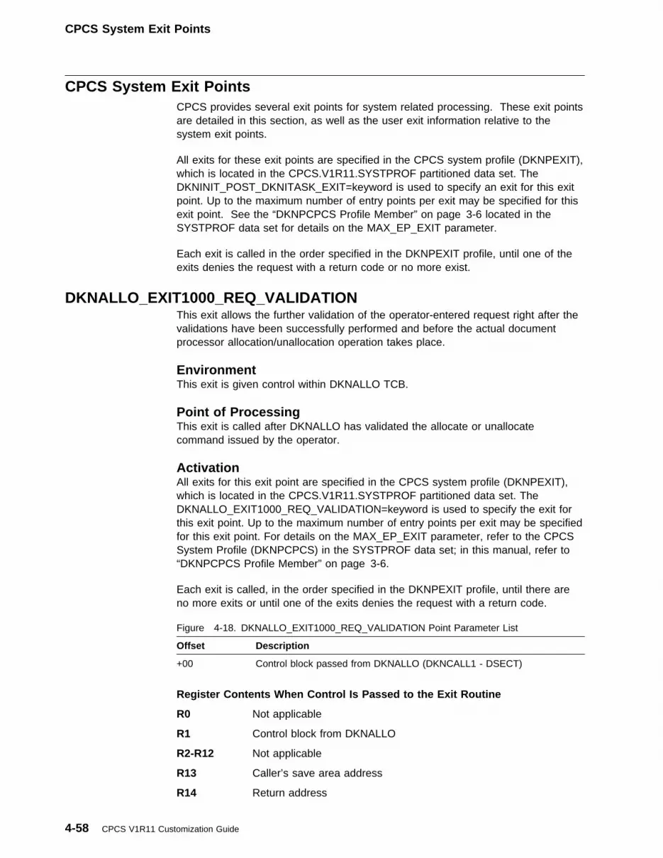
CPCS System Exit Points
CPCS System Exit PointsCPCS provides several exit points for system related processing. These exit pointsare detailed in this section, as well as the user exit information relative to thesystem exit points.
All exits for these exit points are specified in the CPCS system profile (DKNPEXIT),which is located in the CPCS.V1R11.SYSTPROF partitioned data set. TheDKNINIT_POST_DKNITASK_EXIT=keyword is used to specify an exit for this exitpoint. Up to the maximum number of entry points per exit may be specified for thisexit point. See the “DKNPCPCS Profile Member” on page 3-6 located in theSYSTPROF data set for details on the MAX_EP_EXIT parameter.
Each exit is called in the order specified in the DKNPEXIT profile, until one of theexits denies the request with a return code or no more exist.
DKNALLO_EXIT1000_REQ_VALIDATIONThis exit allows the further validation of the operator-entered request right after thevalidations have been successfully performed and before the actual documentprocessor allocation/unallocation operation takes place.
EnvironmentThis exit is given control within DKNALLO TCB.
Point of ProcessingThis exit is called after DKNALLO has validated the allocate or unallocatecommand issued by the operator.
ActivationAll exits for this exit point are specified in the CPCS system profile (DKNPEXIT),which is located in the CPCS.V1R11.SYSTPROF partitioned data set. TheDKNALLO_EXIT1000_REQ_VALIDATION=keyword is used to specify the exit forthis exit point. Up to the maximum number of entry points per exit may be specifiedfor this exit point. For details on the MAX_EP_EXIT parameter, refer to the CPCSSystem Profile (DKNPCPCS) in the SYSTPROF data set; in this manual, refer to“DKNPCPCS Profile Member” on page 3-6.
Each exit is called, in the order specified in the DKNPEXIT profile, until there areno more exits or until one of the exits denies the request with a return code.
Register Contents When Control Is Passed to the Exit Routine
R0 Not applicable
R1 Control block from DKNALLO
R2-R12 Not applicable
R13 Caller’s save area address
R14 Return address
Figure 4-18. DKNALLO_EXIT1000_REQ_VALIDATION Point Parameter List
Offset Description
+00 Control block passed from DKNALLO (DKNCALL1 - DSECT)
4-58 CPCS V1R11 Customization Guide

CPCS System Exit Points
R15 User exit entry point address
Register Contents When Control Is Passed Back to CPCS
R0 Not applicable
R1 Not applicable
R2-R13 Restored to same values as on user exit entry
R14 Not applicable
R15 Not applicable
Other Programming ConsiderationsNote: IBM requires this exit be re-entrant.
Example:
Member DKNXAL10, in the CPCS.V1R11.SAMPLIB partitioned data set, may beused as an example when coding assembler exit routines for this exit point.
DKNALLO_EXIT2000_MESSAGEThis exit allows the opportunity to interpret the message generated by DKNALLOand to send a more descriptive message explaining the problem or the ability towrite a help screen created by the user. This exit is entered each time a messageis generated by DKNALLO.
EnvironmentThis exit is given control within DKNALLO TCB.
Point of ProcessingThis exit is called each time DKNALLO generates a message to be displayed.
ActivationAll exits for this exit point are specified in the CPCS system profile (DKNPEXIT),which is located in the CPCS.V1R11.SYSTPROF partitioned data set. TheDKNALLO_EXIT2000_MESSAGE=keyword is used to specify the exit for this exitpoint. Up to the maximum number of entry points per exit may be specified for thisexit. For details on the MAX_EP_EXIT parameter for the CPCS system profile(DKNPCPCS) located in the SYSTPROF data set, see “DKNPCPCS ProfileMember” on page 3-6.
Each exit is called in the order they were specified in the DKNPEXIT profile, untilthere are no more exits or until one of the exits denies the request with a returncode.
Register Contents When Control Is Passed to the Exit Routine
R0 Not applicable
R1 Control block from DKNALLO
Figure 4-19. DKNALLO_EXIT2000_MESSAGE Point Parameter List
Offset Description
+00 Control block passed from DKNALLO (DKNCALL2 - DSECT)
Chapter 4. User Programming Requirements and Exits 4-59

CPCS System Exit Points
R2-R12 Not applicable
R13 Caller’s save area address
R14 Return address
R15 User exit entry point address
Register Contents When Control Is Passed Back to CPCS
R0 Not applicable
R1 Not applicable
R2-R13 Restored to same values as on user exit entry
R14 Not applicable
R15 Not applicable
Other Programming ConsiderationsNote: IBM requires this exit be re-entrant.
Example:
Member DKNXAL20, in the CPCS.V1R11.SAMPLIB partitioned data set, may beused as an example when coding assembler exit routines for this exit point.
| DKNASGF_EXIT_01| This exit puts you in control of DKNASGF and its automatic signoff routine.| DKNASGF calls this exit each time it decides to sign off a terminal. You can| choose to disallow the signoff, or permit it to proceed.
| Environment| This exit is given control within DKNASGF TCB.
| Point of Processing| This exit is called whenever DKNASGF finds a terminal that:
| � Has been signed on but has been inactive for longer than the TIMECK| parameter of the DKNPCPCS system profile member| � Is not a MICR terminal| � Is not a supervisor terminal| � Is not queued, waiting to start a task| � Is not running a task that has the TIMECK=1 parameter in its BLDL entry
| Activation| All exits for this exit point are specified in the CPCS system profile (DKNPEXIT),| which is located in the CPCS.V1R11.SYSTPROF partitioned data set. The| DKNASGF_EXIT_01=keyword is used to specify an exit for this exit point. You can| specify up to the maximum number of entry points for each exit for this exit point.| For more details on the MAX_EP_EXIT parameter, see “DKNPCPCS Profile| Member” on page 3-6.
| Each exit is called in the order specified in the DKNPEXIT profile, until one of the| exits disallows the signoff or until no more exits exist.
4-60 CPCS V1R11 Customization Guide

CPCS System Exit Points
| Register Contents When Control Is Passed to the Exit Routine
| R0 Not applicable
| R1 Parameter list address
| R2-R12 Not applicable
| R13 Caller’s save area address
| R14 Return address
| R15 User exit entry point address
| Register Contents When Control Is Passed Back to CPCS
| R0 Not applicable
| R1 Not applicable
| R2-R13 Restored to same values as on user exit entry
| R14 Not applicable
| R15 Return codes as described below:
| 0 Allow automatic signoff to proceed.
| 4 Disallow automatic signoff.
| Figure 4-20. DKNASGF_EXIT_01 Point Parameter List
| Offset| Description
| +00| Dummy APTCB, contains PARMLST address ONLY (DKNAPTCB)
| +04| Terminal Table (DKNTENT)
| Other Programming Considerations| Note: IBM requires this exit be re-entrant.
| Example| Member DKNASGF1, in the CPCS.V1R11.SAMPLIB partitioned data set, may be| used as an example when coding assembler exit routines for this exit point. This| example shows how to disallow automatic signoff if the terminal is running one of| the tasks in an internal table.
DKNATASK_APPLTSK_START_EXIT01This exit allows you the opportunity to update any user extended area prior tostarting an application task.
EnvironmentThis exit is given control within DKNATASK TCB.
Point of ProcessingThis exit is called prior to the application task, ATTACH.
Chapter 4. User Programming Requirements and Exits 4-61
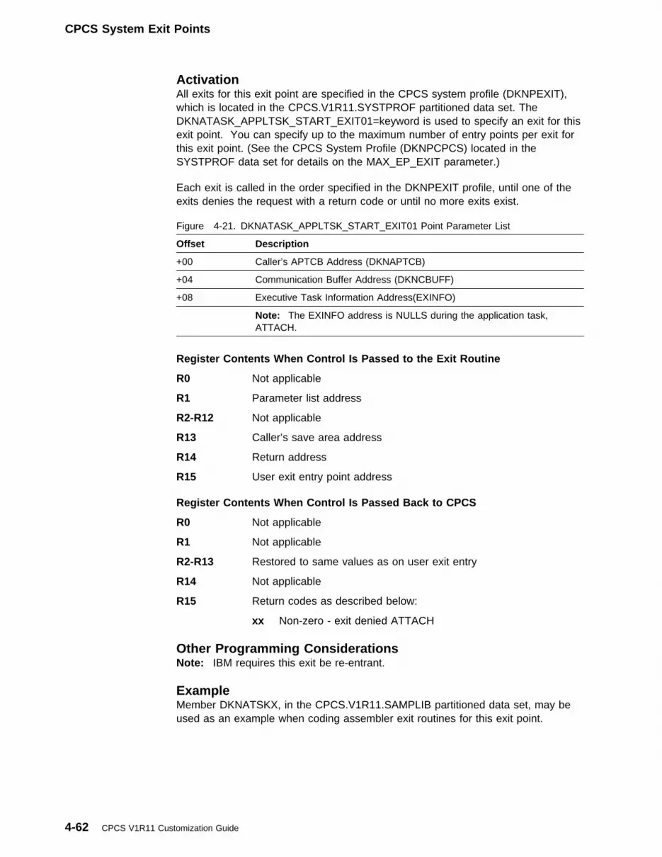
CPCS System Exit Points
ActivationAll exits for this exit point are specified in the CPCS system profile (DKNPEXIT),which is located in the CPCS.V1R11.SYSTPROF partitioned data set. TheDKNATASK_APPLTSK_START_EXIT01=keyword is used to specify an exit for thisexit point. You can specify up to the maximum number of entry points per exit forthis exit point. (See the CPCS System Profile (DKNPCPCS) located in theSYSTPROF data set for details on the MAX_EP_EXIT parameter.)
Each exit is called in the order specified in the DKNPEXIT profile, until one of theexits denies the request with a return code or until no more exits exist.
Register Contents When Control Is Passed to the Exit Routine
R0 Not applicable
R1 Parameter list address
R2-R12 Not applicable
R13 Caller’s save area address
R14 Return address
R15 User exit entry point address
Register Contents When Control Is Passed Back to CPCS
R0 Not applicable
R1 Not applicable
R2-R13 Restored to same values as on user exit entry
R14 Not applicable
R15 Return codes as described below:
xx Non-zero - exit denied ATTACH
Figure 4-21. DKNATASK_APPLTSK_START_EXIT01 Point Parameter List
Offset Description
+00 Caller’s APTCB Address (DKNAPTCB)
+04 Communication Buffer Address (DKNCBUFF)
+08 Executive Task Information Address(EXINFO)
Note: The EXINFO address is NULLS during the application task,ATTACH.
Other Programming ConsiderationsNote: IBM requires this exit be re-entrant.
ExampleMember DKNATSKX, in the CPCS.V1R11.SAMPLIB partitioned data set, may beused as an example when coding assembler exit routines for this exit point.
4-62 CPCS V1R11 Customization Guide

CPCS System Exit Points
DKNATASK_DEQ_EXIT01This exit allows you the opportunity to request control of a serially reusableresource of your choosing after DKNATASK dequeues on its ECBLIST.
EnvironmentThis exit is given control within the DKNATASK TCB.
Point of ProcessingThis exit is called before DKNATASK has dequeued the ECBLIST.
ActivationAll exits for this exit point are specified in the CPCS system profile (DKNPEXIT),which is located in the CPCS.V1R11.SYSTPROF partitioned data set. TheDKNATASK_DEQ_EXIT01=keyword is used to specify an exit for this exit point.You can specify up to the maximum number of entry points per exit for this exitpoint. See the CPCS System Profile (DKNPCPCS) located in the SYSTPROF dataset for details on the MAX_EP_EXIT parameter.
Each exit is called in the order specified in the DKNPEXIT profile, until one of theexits denies the request with a return code or until no more exits exist.
Register Contents When Control is Passed to the Exit Routine
R0 Not applicable
R1 Parameter list address
R2-R12 Not applicable
R13 Caller’s save area address
R14 Return address
R15 User exit entry point address
Register Contents When Control Is Passed Back to CPCS
R0 Not applicable
R1 Not applicable
R2-R13 Restored to same values as on user exit entry
R14 Not applicable
R15 Not applicable
Figure 4-22. DKNATASK_DEQ_EXIT01 Point Parameter List
Offset Description
+00 'DEQ '
+04 PARMLST address
Chapter 4. User Programming Requirements and Exits 4-63

CPCS System Exit Points
Other Programming ConsiderationsNote: IBM requires this exit be re-entrant.
ExampleMember DKNATSKE, in the CPCS.V1R11.SAMPLIB partitioned data set, may beused as an example when coding assembler exit routines for this exit point.
DKNATASK_ENQ_EXIT01This exit allows you the opportunity to request control of a serially reusableresource of your choosing after DKNATASK enqueues on its ECBLIST.
EnvironmentThis exit is given control within the DKNATASK TCB.
Point of ProcessingThis exit is called after DKNATASK has enqueued on the ECBLIST.
ActivationAll exits for this exit point are specified in the CPCS system profile (DKNPEXIT),which is located in the CPCS.V1R11.SYSTPROF partitioned data set. TheDKNATASK_ENQ_EXIT01=keyword is used to specify an exit for this exit point.You can specify up to the maximum number of entry points per exit for this exitpoint. See the CPCS System Profile (DKNPCPCS) located in the SYSTPROF dataset for details on the MAX_EP_EXIT parameter.
Each exit is called in the order specified in the DKNPEXIT profile, until one of theexits denies the request with a return code or until no more exits exist.
Register Contents When Control is Passed to the Exit Routine
R0 Not applicable
R1 Parameter list address
R2-R12 Not applicable
R13 Caller’s save area address
R14 Return address
R15 User exit entry point address
Register Contents When Control Is Passed Back to CPCS
R0 Not applicable
R1 Not applicable
R2-R13 Restored to same values as on user exit entry
R14 Not applicable
R15 Not applicable
Figure 4-23. DKNATASK_ENQ EXIT01 Point Parameter List
Offset Description
+00 'ENQ '
+04 PARMLST address
4-64 CPCS V1R11 Customization Guide

CPCS System Exit Points
Other Programming ConsiderationsNote: IBM requires this exit be re-entrant.
ExampleMember DKNATSKE, in the CPCS.V1R11.SAMPLIB partitioned data set, may beused as an example when coding assembler exit routines for this exit point.
DKNATASK_EXECTSK_START_EXIT01This exit allows you the opportunity to update any user extended area prior tostarting an executive task.
EnvironmentThis exit is given control within DKNATASK TCB.
Point of ProcessingThis exit is called prior to the executive task, ATTACH.
ActivationAll exits for this exit point are specified in the CPCS system profile (DKNPEXIT),which is located in the CPCS.V1R11.SYSTPROF partitioned data set. TheDKNATASK_EXECTSK_START_EXIT01=keyword is used to specify an exit for thisexit point. You can specify up to the maximum number of entry points per exit forthis exit point. (See the CPCS System Profile (DKNPCPCS), located in theSYSTPROF data set for details on the MAX_EP_EXIT parameter.)
Each exit is called in the order specified in the DKNPEXIT profile, until one of theexits denies the request with a return code or until no more exits exist.
Register Contents When Control Is Passed to the Exit Routine
R0 Not applicable
R1 Parameter list address
R2-R12 Not applicable
R13 Caller’s save area address
R14 Return address
R15 User exit entry point address
Register Contents When Control Is Passed Back to CPCS
R0 Not applicable
R1 Not applicable
R2-R13 Restored to same values as on user exit entry
Figure 4-24. DKNATASK_EXECTSK_START_EXIT01 Point Parameter List
Offset Description
+00 Caller’s APTCB Address (DKNAPTCB)
+04 Communication Buffer Address (DKNCBUFF)
+08 Executive Task Information Address(EXINFO)
Chapter 4. User Programming Requirements and Exits 4-65

CPCS System Exit Points
R14 Not applicable
R15 Return codes as described below:
xx Non-zero - Exit Denied ATTACH
Other Programming ConsiderationsNote: IBM requires this exit be re-entrant.
ExampleMember DKNATSKX, in the CPCS.V1R11.SAMPLIB partitioned data set, may beused as an example when coding assembler exit routines for this exit point.
DKNATASK_SUPV_TERM_EXIT01This exit allows you the opportunity to modify the settings of the TERM flag afterATASK has determined that the task being attached must be started from asupervisor terminal.
EnvironmentThis exit is given control within DKNATASK TCB.
Point of ProcessingThis exit is called after DKNATASK has determined that a supervisor terminal isneeded to attach the current task.
ActivationAll exits for this exit point are specified in the CPCS system profile (DKNPEXIT),which is located in the CPCS.V1R11.SYSTPROF partitioned data set. TheDKNATASK_SUPV_TERM_EXIT01=keyword is used to specify an exit for this exitpoint. You can specify up to the maximum number of entry points per exit for thisexit point. See the CPCS System Profile (DKNPCPCS), located in the SYSTPROFdata set, for details on the MAX_EP_EXIT parameter.
Each exit is called in the order specified in the DKNPEXIT profile, until one of theexits denies the request with a return code or until no more exits exist.
Figure 4-25. DKNATASK_SUPV_TERM_EXIT01 Point Parameter List
Offset Description
+00 Pointer to TTABLE
+04 Pointer to PARMLIST
+08 Pointer to TERMFLAG
4-66 CPCS V1R11 Customization Guide

CPCS System Exit Points
Register Contents When Control Is Passed to the Exit Routine
R0 Not applicable
R1 Parameter list address
R2-R12 Not applicable
R13 Caller’s save area address
R14 Return address
R15 User exit entry point address
Register Contents When Control Is Passed Back to CPCS
R0 Not applicable
R1 Not applicable
R2-R13 Restored to same values as on user exit entry
R14 Not applicable
R15 Not applicable
Other Programming ConsiderationsNote: IBM requires this exit be re-entrant.
ExampleMember DKNATSKS, in the CPCS.V1R11.SAMPLIB partitioned data set, may beused as an example when coding assembler exit routines for this exit point.
DKNATSK2_INITIALIZE_EXIT_01This exit allows you the opportunity to update any user extended area after theAPTR DCB has been opened.
EnvironmentThis exit is given control within DKNATASK TCB.
Point of ProcessingThis exit is called after a successful open of the ATASK Print Log (APTR) DCB.
ActivationAll exits for this exit point are specified in the CPCS system profile (DKNPEXIT),which is located in the CPCS.V1R11.SYSTPROF partitioned data set. TheDKNATSK2_INITIALIZE_EXIT_01=keyword is used to specify an exit for this exitpoint. You can specify up to the maximum number of entry points per exit for thisexit point. (See the CPCS System Profile (DKNPCPCS) located in the SYSTPROFdata set for details on the MAX_EP_EXIT parameter.)
Each exit is called in the order specified in the DKNPEXIT profile, until one of theexits denies the request with a return code or until no more exits exist.
Chapter 4. User Programming Requirements and Exits 4-67

CPCS System Exit Points
Register Contents When Control Is Passed to the Exit Routine
R0 Not applicable
R1 Parameter list address
R2-R12 Not applicable
R13 Caller’s save area address
R14 Return address
R15 User exit entry point address
Register Contents When Control Is Passed Back to CPCS
R0 Not applicable
R1 Not applicable
R2-R13 Restored to same values as on user exit entry
R14 Not applicable
R15 Not applicable
Figure 4-26. DKNATSK2_INITIALIZE_EXIT_01 Point Parameter List
Offset Description
+00 APTCB with PARMLST address ONLY
+04 Address of User Exit Work Area. This space is passed to theDKNATSK2_INITIALIZE_EXIT_01, DKNATSK2_TERMINATAE_EXIT_01,and the DKNATSK2_WRITE_APTR_EXIT_01 exits.
Other Programming ConsiderationsNote: IBM requires this exit be re-entrant.
ExampleMember DKNATSKI, in the CPCS.V1R11.SAMPLIB partitioned data set, may beused as an example when coding assembler exit routines for this exit point.
DKNATSK2_TERMINATE_EXIT_01This exit allows you the opportunity to update any user extended area after theAPTR DCB has been closed.
EnvironmentThis exit is given control within DKNATASK TCB.
Point of ProcessingThis exit is called after a successful CLOSE of the ATASK print log (APTR) DCB.
ActivationAll exits for this exit point are specified in the CPCS system profile (DKNPEXIT),which is located in the CPCS.V1R11.SYSTPROF partitioned data set. TheDKNATSK2_TERMINATE_EXIT_01=keyword is used to specify an exit for this exitpoint. You can specify up to the maximum number of entry points per exit for thisexit point. (See the CPCS System Profile (DKNPCPCS) located in the SYSTPROFdata set for details on the MAX_EP_EXIT parameter.)
4-68 CPCS V1R11 Customization Guide

CPCS System Exit Points
Each exit is called in the order specified in the DKNPEXIT profile, until one of theexits denies the request with a return code or until there are no more exits.
Register Contents When Control Is Passed to the Exit Routine
R0 Not applicable
R1 Parameter list address
R2-R12 Not applicable
R13 Caller’s save area address
R14 Return address
R15 User exit entry point address
Register Contents When Control Is Passed Back to CPCS
R0 Not applicable
R1 Not applicable
R2-R13 Restored to same values as on user exit entry
R14 Not applicable
R15 Not applicable
Figure 4-27. DKNATSK2_TERMINATE_EXIT_01 Point Parameter List
Offset Description
+00 APTCB with PARMLST address ONLY
+04 Address of User Exit Work Area. This space is passed to theDKNATSK2_INITIALIZE_EXIT_01, DKNATSK2_TERMINATE_EXIT_01,and the DKNATSK2_WRITE_APTR_EXIT_01 exits.
Other Programming ConsiderationsNote: IBM requires this exit be re-entrant.
ExampleMember DKNATSKT, in the CPCS.V1R11.SAMPLIB partitioned data set, may beused as an example when coding assembler exit routines for this exit point.
DKNATSK2_WRITE_APTR_EXIT_01This exit allows you the opportunity to update any user extended area after eachWRITE to the APTR DCB.
EnvironmentThis exit is given control within DKNATASK TCB.
Point of ProcessingThis exit is called after each successful WRITE of the ATASK Print Log (APTR)DCB.
Chapter 4. User Programming Requirements and Exits 4-69

CPCS System Exit Points
ActivationAll exits for this exit point are specified in the CPCS system profile (DKNPEXIT),which is located in the CPCS.V1R11.SYSTPROF partitioned data set. TheDKNATSK2_WRITE_APTR_EXIT_01=keyword is used to specify an exit for thisexit point. You may specify up to the maximum number of entry points per exit forthis exit point. (See the CPCS System Profile (DKNPCPCS) located in theSYSTPROF data set for details on the MAX_EP_EXIT parameter.)
Each exit is called in the order specified in the DKNPEXIT profile, until one of theexits denies the request with a return code or until no more exits exist.
Register Contents When Control Is Passed to the Exit Routine
R0 Not applicable
R1 Parameter list address
R2-R12 Not applicable
R13 Caller’s save area address
R14 Return address
R15 User exit entry point address
Register Contents When Control Is Passed Back to CPCS
R0 Not applicable
R1 Not applicable
R2-R13 Restored to same values as on user exit entry
R14 Not applicable
R15 Not applicable
Figure 4-28. DKNATSK2_WRITE_APTR_EXIT_01 Point Parameter List
Offset Description
+00 APTCB with PARMLST address ONLY
+04 APTR Output Area Address
+08 Address of User Exit Work Area. This space is passed to theDKNATSK2_INITIALIZE_EXIT_01, DKNATSK2_TERMINATE_EXIT_01,and the DKNATSK2_WRITE_APTR_EXIT_01 exits.
Other Programming ConsiderationsNote: IBM requires this exit be re-entrant.
ExampleMember DKNATSKW, in the CPCS.V1R11.SAMPLIB partitioned data set, may beused as an example when coding assembler exit routines for this exit point.
4-70 CPCS V1R11 Customization Guide

CPCS System Exit Points
DKNATSK3_0100_TASKABEND_EXITThis exit allows you the opportunity to perform any user processing after the BLDLtask abends.
EnvironmentThis exit is given control within the DKNATASK TCB.
Point of ProcessingThis exit is called after all DKNATASK BLDL task abend processing has beencompleted, but called before the dump data set is unallocated and reallocated.
ActivationAll exits for this exit point are specified in the CPCS system profile (DKNPEXIT),which is located in the CPCS.V1R11.SYSTPROF partitioned data set. TheDKNATSK3_0100_TASKABEND_EXIT=keyword is used to specify an exit for thisexit point. You can specify up to the maximum number of entry points for each exitfor this exit point. See the CPCS System Profile (DKNPCPCS) located in theSYSTPROF data set for details on the MAX_EP_EXIT parameter; this material islocated in “DKNPCPCS Profile Member” on page 3-6.
Each exit is called in the order specified in the DKNPEXIT profile, until one of theexits denies the request with a return code or until no more exits exist.
Register Contents When Control is Passed to the Exit Routine
R0 Not applicable
R1 Parameter list address
R2-R12 Not applicable
R13 Caller’s save area address
R14 Return address
R15 User exit entry point address
Register Contents When Control Is Passed Back to CPCS
R0 Not applicable
R1 Not applicable
R2-R13 Restored to same values as on user exit entry
R14 Not applicable
R15 Not applicable
Figure 4-29. DKNATSK3_0100_TASKABEND_EXIT Point Parameter List
Offset Description
+00 BLDL task APTCB address
Chapter 4. User Programming Requirements and Exits 4-71
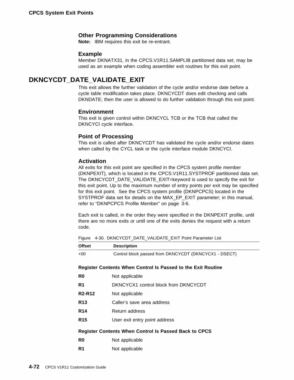
CPCS System Exit Points
Other Programming ConsiderationsNote: IBM requires this exit be re-entrant.
ExampleMember DKNATX31, in the CPCS.V1R11.SAMPLIB partitioned data set, may beused as an example when coding assembler exit routines for this exit point.
DKNCYCDT_DATE_VALIDATE_EXITThis exit allows the further validation of the cycle and/or endorse date before acycle table modification takes place. DKNCYCDT does edit checking and callsDKNDATE; then the user is allowed to do further validation through this exit point.
EnvironmentThis exit is given control within DKNCYCL TCB or the TCB that called theDKNCYCI cycle interface.
Point of ProcessingThis exit is called after DKNCYCDT has validated the cycle and/or endorse dateswhen called by the CYCL task or the cycle interface module DKNCYCI.
ActivationAll exits for this exit point are specified in the CPCS system profile member(DKNPEXIT), which is located in the CPCS.V1R11.SYSTPROF partitioned data set.The DKNCYCDT_DATE_VALIDATE_EXIT=keyword is used to specify the exit forthis exit point. Up to the maximum number of entry points per exit may be specifiedfor this exit point. See the CPCS system profile (DKNPCPCS) located in theSYSTPROF data set for details on the MAX_EP_EXIT parameter; in this manual,refer to “DKNPCPCS Profile Member” on page 3-6.
Each exit is called, in the order they were specified in the DKNPEXIT profile, untilthere are no more exits or until one of the exits denies the request with a returncode.
Register Contents When Control Is Passed to the Exit Routine
R0 Not applicable
R1 DKNCYCX1 control block from DKNCYCDT
R2-R12 Not applicable
R13 Caller’s save area address
R14 Return address
R15 User exit entry point address
Register Contents When Control Is Passed Back to CPCS
R0 Not applicable
R1 Not applicable
Figure 4-30. DKNCYCDT_DATE_VALIDATE_EXIT Point Parameter List
Offset Description
+00 Control block passed from DKNCYCDT (DKNCYCX1 - DSECT)
4-72 CPCS V1R11 Customization Guide

CPCS System Exit Points
R2-R13 Restored to same values as on user exit entry
R14 Not applicable
R15 Return code
Other Programming ConsiderationsNotes:
1. A 20-byte user area is provided for the caller of DKNCYCDT and,subsequently, to the user exit through the DKNCYCX1 control block. Data maybe passed by the caller, which the user exit may process. When DKNCYCL isthe caller, the 20 bytes of user data are obtained from the last input parameter(must be last) with the keyword of ',USER=.....'. For more information aboutthe CYCL task start parameters, see the DKNCYCL section in the CPCSTerminal Operations Guide.
2. The CPCS sample user exit DKNCYCLX uses a user data parameter ofOVERRIDE to bypass all date validation processing in the user exit.
3. A return code in R15 of X'14' or decimal '20' shall indicate that the user exitrejected the specified date(s). A 32-character message may be extracted fromthe DKNCYCX1 control block placed there by the user exit.
Example:
Member DKNCYCLX, in the CPCS.V1R11.SAMPLIB partitioned data set, may beused as an example when coding assembler exit routines for this exit point.
DKNINIT_POST_DKNITASK_EXITThis exit allows the user the opportunity to initialize any user control block. Notethat, at the time these exits are called, all programs or service associated withCPCS are NOT available.
EnvironmentThis exit is given control within DKNINIT TCB.
Point of ProcessingThese exits are called after DKNITASK has successfully completed.
ActivationAll exits for this exit point are specified in the CPCS system profile (DKNPEXIT),which is located in the CPCS.V1R11.SYSTPROF partitioned data set. TheDKNINIT_POST_DKNITASK_EXIT=keyword is used to specify an exit for this exitpoint. You may specify up to the maximum number of entry points per exit for thisexit point. (See the CPCS system profile DKNPCPCS, located in the SYSTPROFdata set for details on the MAX_EP_EXIT parameter.)
Each exit is called, in the order specified in the DKNPEXIT profile, until one of theexits denies the request with a return code or until no more exits exist.
Figure 4-31. DKNINIT_POST_DKNITASK_EXIT Point Parameter List
Offset Description
+00 APTCB with PARMLST address ONLY
Chapter 4. User Programming Requirements and Exits 4-73

CPCS System Exit Points
Register Contents When Control Is Passed to the Exit Routine
R0 Not applicable
R1 Parameter list address
R2-R12 Not applicable
R13 Caller’s save area address
R14 Return address
R15 User exit entry point address
Register Contents When Control Is Passed Back to CPCS
R0 Not applicable
R1 Not applicable
R2-R13 Restored to same values as on user exit entry
R14 Not applicable
R15 Return codes as described below:
xx Non-zero - system shutdown
Other Programming ConsiderationsNote: IBM requires this exit be re-entrant.
ExampleMember DKNINIT1, in the CPCS.V1R11.SAMPLIB partitioned data set, may beused as an example when coding assembler exit routines for this exit point.
DKNLOADR_EXIT_01This exit allows you the opportunity to request that a different program be loadedand executed.
EnvironmentThis exit is given control within DKNLOADR TCB.
Point of ProcessingThis exit is called prior to the actual load of the BLDL task.
ActivationAll exits for this exit point are specified in the CPCS system profile (DKNPEXIT),which is located in the CPCS.V1R11.SYSTPROF partitioned data set. TheDKNLOADR_EXIT_01=keyword is used to specify an exit for this exit point. Youcan specify up to the maximum number of entry points per exit for this exit point.(See the CPCS System Profile (DKNPCPCS) located in the SYSTPROF data setfor details on the MAX_EP_EXIT parameter.)
Each exit is called in the order specified in the DKNPEXIT profile, until one of theexits denies the request with a return code or until no more exits exist.
4-74 CPCS V1R11 Customization Guide

CPCS System Exit Points
Register Contents When Control Is Passed to the Exit Routine
R0 Not applicable
R1 Parameter list address
R2-R12 Not applicable
R13 Caller’s save area address
R14 Return address
R15 User exit entry point address
Register Contents When Control Is Passed Back to CPCS
R0 Not applicable
R1 Not applicable
R2-R13 Restored to same values as on user exit entry
R14 Not applicable
R15 Return codes as described below:
xx Non-zero - Exit denied load
Figure 4-32. DKNLOADR_EXIT_01 Point Parameter List
Offset Description
+00 Caller’s APTCB Address (DKNAPTCB)
+04 Task Start Parm Address (TCBZB)
+08 Caller’s APCB Address (DKNAPCB)
+12 Address of the Alternative Program Name to be Executed
Other Programming ConsiderationsNote: IBM requires this exit be re-entrant.
ExampleMember DKNLDRX1, in the CPCS.V1R11.SAMPLIB partitioned data set, may beused as an example when coding assembler exit routines for this exit point.
DKNMBEGN_APPLTSK_START_EXIT01This exit allows you the opportunity to update any user extended area after theAPTCB is built.
EnvironmentThis exit is given control within DKNMICR TCB.
Point of ProcessingThis exit is called after the APTCB is built in MICR at MBEGN time.
Chapter 4. User Programming Requirements and Exits 4-75

CPCS System Exit Points
ActivationAll exits for this exit point are specified in the CPCS system profile (DKNPEXIT),which is located in the CPCS.V1R11.SYSTPROF partitioned data set. TheDKNMBEGN_APPLTSK_START_EXIT01=keyword is used to specify an exit forthis exit point. You can specify up to the maximum number of entry points per exitfor this exit point. (See the CPCS System Profile (DKNPCPCS) located in theSYSTPROF data set for details on the MAX_EP_EXIT parameter.)
Each exit is called in the order specified in the DKNPEXIT profile, until one of theexits denies the request with a return code or until no more exits exist.
Register Contents When Control Is Passed to the Exit Routine
R0 Not applicable
R1 Parameter list address
R2-R12 Not applicable
R13 Caller’s save area address
R14 Return address
R15 User exit entry point address
Register Contents When Control Is Passed Back to CPCS
R0 Not applicable
R1 Not applicable
R2-R13 Restored to same values as on user exit entry
R14 Not applicable
R15 Return codes as described below:
xx Non-zero - Exit Denied ATTACH
Figure 4-33. DKNMBEGN_APPLTSK_START_EXIT01 Point Parameter List
Offset Description
+00 Caller’s APTCB Address (DKNAPTCB)
Other Programming ConsiderationsNote: IBM requires this exit be re-entrant.
ExampleMember DKNATSKX, in the CPCS.V1R11.SAMPLIB partitioned data set, may beused as an example when coding assembler exit routines for this exit point.
DKNMBRST_0100_APPLTSK_STARTThis exit allows the user to update any user-extended area after the APTCB is builtwithin the MICR Restart module DKNMBRST.
4-76 CPCS V1R11 Customization Guide
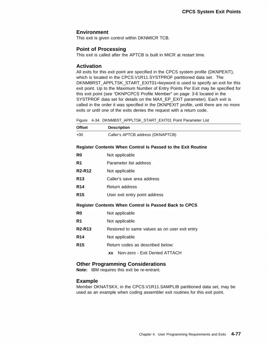
CPCS System Exit Points
EnvironmentThis exit is given control within DKNMICR TCB.
Point of ProcessingThis exit is called after the APTCB is built in MICR at restart time.
ActivationAll exits for this exit point are specified in the CPCS system profile (DKNPEXIT),which is located in the CPCS.V1R11.SYSTPROF partitioned data set. TheDKNMBRST_APPLTSK_START_EXIT01=keyword is used to specify an exit for thisexit point. Up to the Maximum Number of Entry Points Per Exit may be specified forthis exit point (see “DKNPCPCS Profile Member” on page 3-6 located in theSYSTPROF data set for details on the MAX_EP_EXIT parameter). Each exit iscalled in the order it was specified in the DKNPEXIT profile, until there are no moreexits or until one of the exits denies the request with a return code.
Register Contents When Control Is Passed to the Exit Routine
R0 Not applicable
R1 Parameter list address
R2-R12 Not applicable
R13 Caller’s save area address
R14 Return address
R15 User exit entry point address
Register Contents When Control Is Passed Back to CPCS
R0 Not applicable
R1 Not applicable
R2-R13 Restored to same values as on user exit entry
R14 Not applicable
R15 Return codes as described below:
xx Non-zero - Exit Denied ATTACH
Figure 4-34. DKNMBST_APPLTSK_START_EXIT01 Point Parameter List
Offset Description
+00 Caller’s APTCB address (DKNAPTCB)
Other Programming ConsiderationsNote: IBM requires this exit be re-entrant.
ExampleMember DKNATSKX, in the CPCS.V1R11.SAMPLIB partitioned data set, may beused as an example when coding assembler exit routines for this exit point.
Chapter 4. User Programming Requirements and Exits 4-77
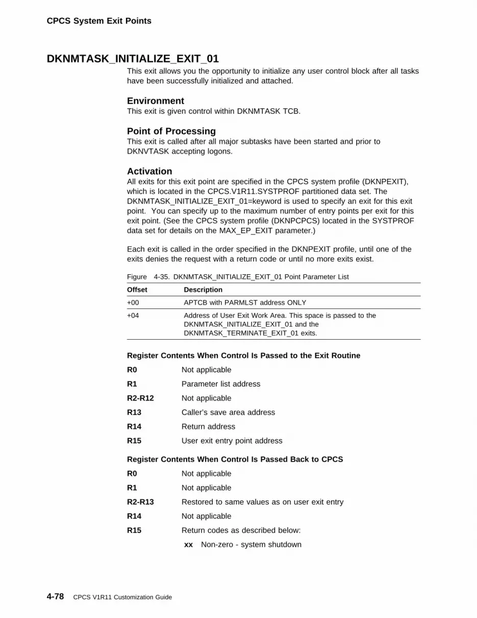
CPCS System Exit Points
DKNMTASK_INITIALIZE_EXIT_01This exit allows you the opportunity to initialize any user control block after all taskshave been successfully initialized and attached.
EnvironmentThis exit is given control within DKNMTASK TCB.
Point of ProcessingThis exit is called after all major subtasks have been started and prior toDKNVTASK accepting logons.
ActivationAll exits for this exit point are specified in the CPCS system profile (DKNPEXIT),which is located in the CPCS.V1R11.SYSTPROF partitioned data set. TheDKNMTASK_INITIALIZE_EXIT_01=keyword is used to specify an exit for this exitpoint. You can specify up to the maximum number of entry points per exit for thisexit point. (See the CPCS system profile (DKNPCPCS) located in the SYSTPROFdata set for details on the MAX_EP_EXIT parameter.)
Each exit is called in the order specified in the DKNPEXIT profile, until one of theexits denies the request with a return code or until no more exits exist.
Register Contents When Control Is Passed to the Exit Routine
R0 Not applicable
R1 Parameter list address
R2-R12 Not applicable
R13 Caller’s save area address
R14 Return address
R15 User exit entry point address
Register Contents When Control Is Passed Back to CPCS
R0 Not applicable
R1 Not applicable
R2-R13 Restored to same values as on user exit entry
R14 Not applicable
R15 Return codes as described below:
xx Non-zero - system shutdown
Figure 4-35. DKNMTASK_INITIALIZE_EXIT_01 Point Parameter List
Offset Description
+00 APTCB with PARMLST address ONLY
+04 Address of User Exit Work Area. This space is passed to theDKNMTASK_INITIALIZE_EXIT_01 and theDKNMTASK_TERMINATE_EXIT_01 exits.
4-78 CPCS V1R11 Customization Guide

CPCS System Exit Points
Other Programming ConsiderationsNote: IBM requires this exit be re-entrant.
ExampleMember DKNMTSKI, in the CPCS.V1R11.SAMPLIB partitioned data set, may beused as an example when coding assembler exit routines for this exit point.
DKNMTASK_MICR_ABEND_EXIT0100This exit allows you the opportunity to perform any user processing after a MICRabend.
EnvironmentThis exit is given control within DKNMTASK TCB.
Point of ProcessingThis exit is called after all DKNMTASK MICR abend processing has beencompleted.
ActivationAll exits for this exit point are specified in the CPCS system profile (DKNPEXIT),which is located in the CPCS.V1R11.SYSTPROF partitioned data set. TheDKNMTASK_MICR_ABEND_EXIT0100=keyword is used to specify an exit for thisexit point. You can specify up to the maximum number of entry points per exit forthis exit point. (See the CPCS System Profile (DKNPCPCS) located in theSYSTPROF data set for details on the MAX_EP_EXIT parameter.)
Each exit is called in the order specified in the DKNPEXIT profile, until one of theexits denies the request with a return code or until no more exits exist.
Register Contents When Control Is Passed to the Exit Routine
R0 Not applicable
R1 Parameter list address
R2-R12 Not applicable
R13 Caller’s save area address
R14 Return address
R15 User exit entry point address
Register Contents When Control Is Passed Back to CPCS
R0 Not applicable
R1 Not applicable
R2-R13 Restored to same values as on user exit entry
R14 Not applicable
R15 Not applicable.
Figure 4-36. DKNMTASK_MICR_ABEND_EXIT0100 Point Parameter List
Offset Description
+00 APTCB with PARMLST address ONLY
Chapter 4. User Programming Requirements and Exits 4-79
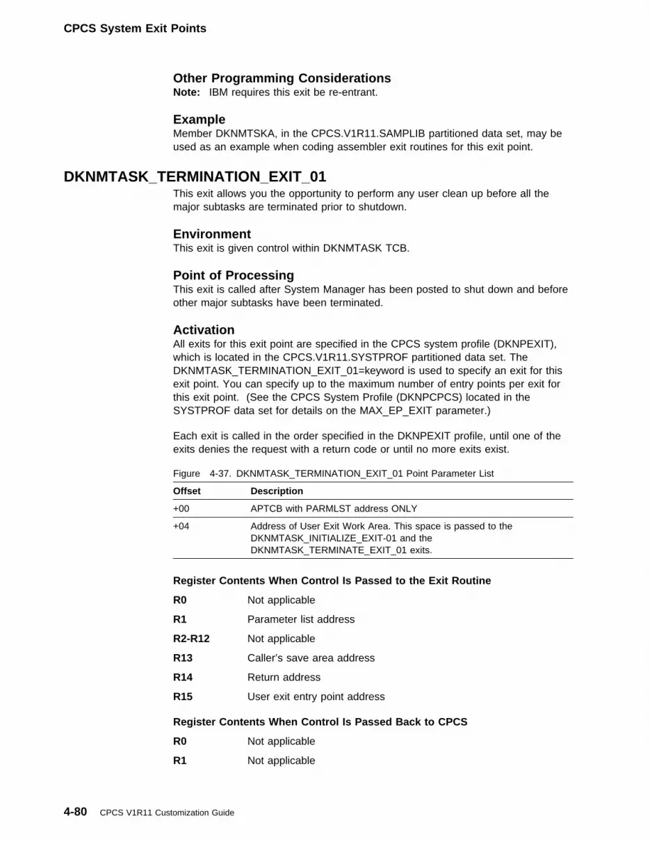
CPCS System Exit Points
Other Programming ConsiderationsNote: IBM requires this exit be re-entrant.
ExampleMember DKNMTSKA, in the CPCS.V1R11.SAMPLIB partitioned data set, may beused as an example when coding assembler exit routines for this exit point.
DKNMTASK_TERMINATION_EXIT_01This exit allows you the opportunity to perform any user clean up before all themajor subtasks are terminated prior to shutdown.
EnvironmentThis exit is given control within DKNMTASK TCB.
Point of ProcessingThis exit is called after System Manager has been posted to shut down and beforeother major subtasks have been terminated.
ActivationAll exits for this exit point are specified in the CPCS system profile (DKNPEXIT),which is located in the CPCS.V1R11.SYSTPROF partitioned data set. TheDKNMTASK_TERMINATION_EXIT_01=keyword is used to specify an exit for thisexit point. You can specify up to the maximum number of entry points per exit forthis exit point. (See the CPCS System Profile (DKNPCPCS) located in theSYSTPROF data set for details on the MAX_EP_EXIT parameter.)
Each exit is called in the order specified in the DKNPEXIT profile, until one of theexits denies the request with a return code or until no more exits exist.
Register Contents When Control Is Passed to the Exit Routine
R0 Not applicable
R1 Parameter list address
R2-R12 Not applicable
R13 Caller’s save area address
R14 Return address
R15 User exit entry point address
Register Contents When Control Is Passed Back to CPCS
R0 Not applicable
R1 Not applicable
Figure 4-37. DKNMTASK_TERMINATION_EXIT_01 Point Parameter List
Offset Description
+00 APTCB with PARMLST address ONLY
+04 Address of User Exit Work Area. This space is passed to theDKNMTASK_INITIALIZE_EXIT-01 and theDKNMTASK_TERMINATE_EXIT_01 exits.
4-80 CPCS V1R11 Customization Guide

CPCS System Exit Points
R2-R13 Restored to same values as on user exit entry
R14 Not applicable
R15 Not applicable.
Other Programming ConsiderationsNote: IBM requires this exit be re-entrant.
ExampleMember DKNMTSKT, in the CPCS.V1R11.SAMPLIB partitioned data set, may beused as an example when coding assembler exit routines for this exit point.
Chapter 4. User Programming Requirements and Exits 4-81

CPCS System Exit Points
Customizing ETDM User ExitsTwo user exit points are available for use as part of the electronic data matchingfunction:
1. ETDM User Exit Point One–Adjust Matching Criteria2. ETDM User Exit Point Two–Write Reconciliation Item
ETDM User Exit Point One–Adjust Matching CriteriaETDM user exit point one is called after an attempt has been made to match ablock of process items with a block of master items. The user exit can adjust thematching criteria and can attempt another match of the remaining unmatched itemsor, if the user exit does not adjust the matching criteria, the matching is consideredcomplete.
It is only possible to attempt up to five match attempts on the items. Consequently,the user exit is called a maximum of four times (one match uses the profile criteriaand four further matches may be attempted with adjusted matching criteria).
The user exit point is called by the ETDM task after each match attempt if there areunmatched items remaining.
To initiate this user exit point, set the following card in the DKNPEXIT member onthe system profile data set:
DKNETDM_ADJUST_MATCH_CRITERIA=xxxxxxxx
If a new user exit is installed, the user exit must be refreshed using the CPCS EXITtask.
The standard OS/390 linkage conventions are followed.
Linkage: Information is passed in the following interface control blocks:
The exit routine may return the following condition codes in the RETURN-CODEspecial register (COBOL programs) or register 15 (assembler programs):
Restrictions: ETDM user exit one routines must be reentrant and reusable.
Figure 4-38. ETDM User Exit Point One Communication Control Blocks
Control BlockCOBOLCopybook
AssemblerMacro/Copybook
Application Task Control Block DKNCATCB DKNAPTCB
ETDM Profile DKNETMP2 DKNETMP1
User Exit Point One Parameter List DKNETM12 DKNETM11
Figure 4-39. ETDM User Exit Point One Return Codes
Return Code Description
0 Continue processing.
4-82 CPCS V1R11 Customization Guide
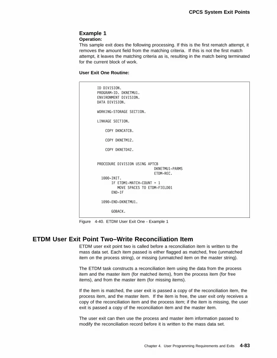
CPCS System Exit Points
Example 1Operation:This sample exit does the following processing. If this is the first rematch attempt, itremoves the amount field from the matching criteria. If this is not the first matchattempt, it leaves the matching criteria as is, resulting in the match being terminatedfor the current block of work.
User Exit One Routine:
ID DIVISION.
PROGRAM-ID. DKNETMU1.
ENVIRONMENT DIVISION.
DATA DIVISION.
WORKING-STORAGE SECTION.
LINKAGE SECTION.
COPY DKNCATCB.
COPY DKNETM12.
COPY DKNETD42.
PROCEDURE DIVISION USING APTCB
DKNETMU1-PARMS
ETDM-REC.
1���-INIT.
IF ETDM1-MATCH-COUNT = 1
MOVE SPACES TO ETDM-FIELD�1
END-IF
1�9�-END-DKNETMU1.
GOBACK.
Figure 4-40. ETDM User Exit One - Example 1
ETDM User Exit Point Two–Write Reconciliation ItemETDM user exit point two is called before a reconciliation item is written to themass data set. Each item passed is either flagged as matched, free (unmatcheditem on the process string), or missing (unmatched item on the master string).
The ETDM task constructs a reconciliation item using the data from the processitem and the master item (for matched items), from the process item (for freeitems), and from the master item (for missing items).
If the item is matched, the user exit is passed a copy of the reconciliation item, theprocess item, and the master item. If the item is free, the user exit only receives acopy of the reconciliation item and the process item; if the item is missing, the userexit is passed a copy of the reconciliation item and the master item.
The user exit can then use the process and master item information passed tomodify the reconciliation record before it is written to the mass data set.
Chapter 4. User Programming Requirements and Exits 4-83

CPCS System Exit Points
Note: If the item is marked as free, the user exit should not attempt to use themaster record. If the record is marked as missing, the user exit should not attemptto use the process item.
The user exit point is called by the ETDM task before each item is written to themass data set.
To initiate this user exit point, set the following card in the DKNPEXIT member onthe system profile data set:
DKNETDM_RECON_RECORD_WRITE=xxxxxxxx
If a new user exit is installed, the user exit must be refreshed using the CPCS EXITtask.
The standard MVS/ESA linkage conventions are followed.
Information is passed in the following interface control blocks:
The exit routine may return the following condition codes in the RETURN-CODEspecial register (COBOL programs) or register 15 (assembler programs):
Restrictions: ETDM user exit point two routines must be reentrant and reusable.
Example 1: Operation:
This sample exit demonstrates how to address the various records passed to theuser exit, for each of the match conditions.
User Exit Two Routine:
Figure 4-41. ETDM User Exit Point Two Communication Control Blocks
Control BlockCOBOLCopybook
AssemblerMacro/Copybook
Application Task Control Block DKNCATCB DKNAPTCB
ETDM Profile DKNETMP2 DKNETMP1
User Exit Point Two Parameter List DKNETM22 DKNETM21
Figure 4-42. ETDM User Exit Two Return Codes
Return Code Description
0 Write the reconciliation record.
4 Do not write the reconciliation record.
8 Insert the modified/unmodified reconciliation record and pass the originalreconciliation record again.
12 Do not call the user exit again for this run of ETDM.
16 Abnormally terminate this run.
4-84 CPCS V1R11 Customization Guide

CPCS System Exit Points
ID DIVISION.
PROGRAM-ID. DKNETMU2.
ENVIRONMENT DIVISION.
DATA DIVISION.
WORKING-STORAGE SECTION.
LINKAGE SECTION.
COPY DKNCATCB.
COPY DKNETMP2.
COPY DKNETM22.
PROCEDURE DIVISION USING APTCB
DKNETMU2-PARMS
ETDM-REC.
����-MAINLINE.
IF ETMU2-MISSING-ITEM
PERFORM 2���-MISSING-ITEM-LOGIC
ELSE
IF ETMU2-FREE-ITEM
PERFORM 3���-FREE-ITEM-LOGIC
ELSE
PERFORM 4���-MATCHED-ITEM-LOGIC
END-IF
END-IF
MOVE WS-RETURN-CODE TO RETURN-CODE
GOBACK.
2���-MISSING-ITEM-LOGIC.
SET ADDRESS OF DIMAST TO ETMU2-MASTER-MDS
SET ADDRESS OF DIRECON TO ETMU2-RECON-MDS
MOVE � TO WS-RETURN-CODE.
3���-FREE-ITEM-LOGIC.
SET ADDRESS OF DIPROC TO ETMU2-PROCESS-MDS
SET ADDRESS OF DIRECON TO ETMU2-RECON-MDS
MOVE � TO WS-RETURN-CODE.
Figure 4-43 (Part 1 of 2). ETDM User Exit Two - Example 1
Chapter 4. User Programming Requirements and Exits 4-85

ETOT User Exit Point One
4���-MATCHED-ITEM-LOGIC.
SET ADDRESS OF DIPROC TO ETMU2-PROCESS-MDS
SET ADDRESS OF DIMAST TO ETMU2-MASTER-MDS
SET ADDRESS OF DIRECON TO ETMU2-RECON-MDS
MOVE � TO WS-RETURN-CODE.
Figure 4-43 (Part 2 of 2). ETDM User Exit Two - Example 1
Customizing ETIO User ExitsTen user exit points are available for use as part of the electronic transactioninput/output function:
1. ETOT User Exit Point One–Electronic Control File Update2. ETOT User Exit Point Two–Transmission Data Set Write3. ETIN User Exit Point One–Transmission Data Set Read4. ETIN User Exit Point Two–Mass Data Set Write5. ETIN User Exit Point Three–Transmission Data Set Import Complete6. ETIN User Exit Point Four–Write Electronic Resynch Record7. ETIP User Exit Point One–Input Processor Messaging8. ETIP User Exit Point Two–Input Processor Selection9. ETIP User Exit Point Three–Alter Control File Import Data
10. ETCFU User Exit One–Control File Record Create
ETOT User Exit Point One — Electronic Control File UpdateThe ETOT control file user exit point one is called after each transmission data setis created. The user exit point can then decide whether or not the transmission dataset should be written to the electronic control file.
The user exit point may elect to insert a record into the electronic control file bysetting the import information and the “write control record” flag in the user exitpoint control block. This process is described within the sample user exitDKNETOU1.
Important!
Inserting a record into the electronic control file causes the ETIN task to importthe associated electronic transmission data set. Therefore, the customer shouldonly insert records onto the electronic control file for transmission data sets thatare to be imported back into an in-house CPCS system.
ActivationTo activate ETOT user exit point one, specify the following card in the CPCSsystem profile member DKNPEXIT:
DKNETOT_CONTROL_FILE_UPDATE=xxxxxxxx,ID=yyy
Where xxxxxxxx is the user exit name and yyy is a user area ID name that enablesthe contents of the user exit work area to be preserved between calls to the userexit.
4-86 CPCS V1R11 Customization Guide

ETOT User Exit Point One
If the user exit is changed, the user exit can be refreshed by using the CPCS UserExit Facility.
LinkageThe standard OS/390 linkage conventions are followed.
Information is passed in the following interface control blocks:
Figure 4-44. ETOT User Exit Point One Communication Control Blocks
Control BlockCOBOLCopybook
AssemblerMacro/Copybook
Application Task Control Block DKNCATCB DKNAPTCB
Call Parameters List DKNETO12 DKNETO11
ETOT Profile Record DKNETOP2 DKNETOP1
Chapter 4. User Programming Requirements and Exits 4-87

ETOT User Exit Point One
The exit routine must decide on the action that DKNETOT should perform bysetting the ETO1-USER-RESPONSE flag within the call parameters control block.
As shown in Figure 4-45, the exit routine may return the following condition codesin the RETURN-CODE special register (COBOL programs) or register 15(assembler programs):
The user exit point control block contains details of how the transmission file wascreated. The customer may set the import information based on criteria used tocreate the transmission data set or on other customer-specific criteria.
Figure 4-45. ETOT User Exit Point One Return Codes
Return Code Description
0 Continue processing. The processing request is set in the ETOT userexit one control block.
RestrictionsETOT user exit point one routines must be reentrant and reusable.
Example 1Operation:
This sample exit uses the capture information supplied within the call parameter listto build the import information. The ETOT task uses this information to constructthe electronic control file record that is used to import the transmission data set.
Processing Description
� Set the import profile name as a constant.
� Set the import information using the supplied capture information.
� Instruct ETOT to write a record to the electronic control file.
User Exit One Routine:
ID DIVISION.
PROGRAM-ID. DKNETOU1.
ENVIRONMENT DIVISION.
DATA DIVISION.
WORKING-STORAGE SECTION.
Figure 4-46 (Part 1 of 2). ETOT User Exit One - Example 1
4-88 CPCS V1R11 Customization Guide

ETOT User Exit Point One
�1 WS-WORK-DATA.
�3 WS-PROFILE-MEM PIC X(�8) VALUE
'ETINSAMP'.
LINKAGE SECTION.
COPY DKNCATCB.
COPY DKNETO12.
COPY DKNETOP2.
PROCEDURE DIVISION USING APTCB,
ETO1-USER-EXIT-PARMS,
ETOT-PROFILE-RECORD.
����-MAIN SECTION.
PERFORM 1���-SET-IMPORT-DATA
SET ETO1-WRITE-CONTROL-RECORD TO TRUE
GOBACK.
1���-SET-IMPORT-DATA SECTION.
MOVE WS-PROFILE-MEM TO ETO1-IMP-PROFILE-MEM
MOVE ETO1-CAP-SYSTEM TO ETO1-IMP-SYSTEM
MOVE ETO1-CAP-CYCLE-NUM TO ETO1-IMP-CYCLE-NUM
MOVE ETO1-CAP-BANK-NUMBER TO ETO1-IMP-BANK-NUMBER
MOVE ETO1-CAP-SORT-TYPE TO ETO1-IMP-SORT-TYPE
MOVE SPACES TO ETO1-IMP-STRING-NAME.
Figure 4-46 (Part 2 of 2). ETOT User Exit One - Example 1
Chapter 4. User Programming Requirements and Exits 4-89

ETOT User Exit Point Two
ETOT User Exit Point Two — Transmission Data Set WriteThe ETOT user exit point two is called before each item is written to thetransmission data set. The user exit point has the opportunity to instruct ETOT todelete the item, to write the item, to write the item and resend it (insert an item), orto terminate the processing.
The user exit is passed two pointers, one to the record read from the CPCS massdata set, and one to a data area that contains the record that is to be written to thetransmission file. The user exit should only amend the record that is to be written tothe transmission file. Any changes to to the mass data set record are ignored.
The size of the record to be written to the transmission file is determined by thelogical record length of the transmission file allocated by ETOT.
Any modifications the user exits may make to an item is permanent and is reflectedon the transmission data set.
All processing options are controlled by setting the relevant request within the userexit point control block. This process is described within the sample user exitDKNETOU2.
Note
It is only possible to ‘write and resend’ item records; any attempt to ‘write andresend’ header or trailer records results in a bad response message, and thetask terminates.
ActivationTo activate ETOT user exit point two, specify the following card in the systemprofile member DKNPEXIT:
DKNETOT_MDS_RECORD_WRITE=xxxxxxxx,ID=yyy
Where xxxxxxxx is the user exit name, and yyy is a user area ID name thatenables the contents of the user exit work area to be preserved between calls tothe user exit.
If the user exit is changed, the user exit can be refreshed by using the CPCS UserExit Facility.
LinkageThe standard OS/390 linkage conventions are followed.
Information is passed in the following interface control blocks:
Figure 4-47. ETOT User Exit Point Two Communication Control Blocks
Control BlockCOBOLCopybook
AssemblerMacro/Copybook
Application Task Control Block DKNCATCB DKNAPTCB
Call Parameters List DKNETO22 DKNETO21
4-90 CPCS V1R11 Customization Guide

ETOT User Exit Point Two
As shown in Figure 4-48, the exit routine may return the following condition codesin the RETURN-CODE special register (COBOL programs) or register 15(assembler programs):
The exit routine must decide on the action that DKNETOT should perform bysetting the ETO2-USER-RESPONSE flag within the call parameters control block.
Figure 4-48. ETOT User Exit Point Two Return Codes
Return Code Description
0 Continue processing. The processing request is set in the ETOT userexit two control block.
RestrictionsETOT user exit point two routines must be reentrant and reusable.
Example 1Operation:
This sample exit demonstrates how to interpret the various record types the userexit can receive. The sample user exit writes the default header and trailer records,but only writes select item records.
The sample also shows how the user exit work area can be used. However, thedata written to the user exit work area is only preserved if the user exit has an IDcoded in the DKNPEXIT profile. This concept is explained in the CPCSProgramming and Diagnostic Guide in the section, “Passing Work Areas to UserExits”.
Processing Description
� Ensure we have a valid file record address.
� Evaluate the type of record we have.
� If the record is a header record, write it. Also set the cycle date in the workarea.
� If the record is a trailer record, write it. Also display the cycle date from thework area.
� If the record is an item, only write MICR, tracer, divider, block, and batch items.
User Exit Two Routine:
Chapter 4. User Programming Requirements and Exits 4-91

ETOT User Exit Point Two
IDENTIFICATION DIVISION.
PROGRAM-ID. DKNETOU2.
ENVIRONMENT DIVISION.
INPUT-OUTPUT SECTION.
DATA DIVISION.
WORKING-STORAGE SECTION.
LINKAGE SECTION.
TTTTTTTTTTTTTTTTTTTTTTTTTTTTTTTTTTTTTTTTTTTT
T APPLICATION PROGRAM CONTROL BLOCK T
TTTTTTTTTTTTTTTTTTTTTTTTTTTTTTTTTTTTTTTTTTTT
COPY DKNCATCB.
TTTTTTTTTTTTTTTTTTTTTTTTTTTTTTTTTTTTTTTTTTTTTTTTTTTTTTTTT
TT CONTROL BLOCK FOR PARAMETERS PASSED TO DKNETOU2
TTTTTTTTTTTTTTTTTTTTTTTTTTTTTTTTTTTTTTTTTTTTTTTTTTTTTTTTT
COPY DKNETO22.
TTTTTTTTTTTTTTTTTTTTTTTTTTTTTTTTTTTTTTTTTTTTTTTTTTTTTTTTT
TT MAP OF COMPRESSED MDS RECORD
TTTTTTTTTTTTTTTTTTTTTTTTTTTTTTTTTTTTTTTTTTTTTTTTTTTTTTTTT
COPY DKNCRZC.
TTTTTTTTTTTTTTTTTTTTTTTTTTTTTTTTTTTTTTTTTTTTTTTTTTTTTTTTT
TT MAP OF DEFAULT TRANSMISSION FILE HEADER & TRAILER
TTTTTTTTTTTTTTTTTTTTTTTTTTTTTTTTTTTTTTTTTTTTTTTTTTTTTTTTT
COPY DKNETFL2 REPLACING ==: TAG : == BY ==ETIO==.
TTTTTTTTTTTTTTTTTTTTTTTTTTTTTTTTTTTTTTTTTTTTTTTTTT
TT USER EXIT WORK AREA
TTTTTTTTTTTTTTTTTTTTTTTTTTTTTTTTTTTTTTTTTTTTTTTTTT
�1 USER-EXIT-WORK-AREA PIC X(255).
TTTTTTTTTTTTTTTTTTTTTTTTTTTTTTTTTTTTTTTTTTTTTTTTTT
TT TRANSMISSION FILE RECORD
TTTTTTTTTTTTTTTTTTTTTTTTTTTTTTTTTTTTTTTTTTTTTTTTTT
�1 FILE-RECORD PIC X(2��).
PROCEDURE DIVISION USING APTCB,
ETO2-USER-EXIT-PARMS.
����-MAIN SECTION.
Figure 4-49 (Part 1 of 3). ETOT User Exit Two - Example 1
4-92 CPCS V1R11 Customization Guide

ETOT User Exit Point Two
IF ETO2-FILE-RECORD-ADDR = NULL THEN
DISPLAY 'DKNETOU2 - NO FILE REC ADDRESS PASSED'
SET ETO2-TERMINATE-PROCESSING TO TRUE
ELSE
EVALUATE TRUE
WHEN ETO2-ITEM-RECORD
PERFORM 1���-PROCESS-ITEM-RECORD
WHEN ETO2-HEADER-RECORD
PERFORM 2���-PROCESS-HEADER-RECORD
WHEN ETO2-TRAILER-RECORD
PERFORM 3���-PROCESS-TRAILER-RECORD
END-EVALUATE
END-IF
GOBACK.
TTTTTTTTTTTTTTTTTTTTTTTTTTTTTTTTTTTTTTTTTTTTTTTTTTTTTTTT
TT FUNCTION = PROCESS A MDS ITEM RECORD
TTTTTTTTTTTTTTTTTTTTTTTTTTTTTTTTTTTTTTTTTTTTTTTTTTTTTTTT
1���-PROCESS-ITEM-RECORD.
IF ETO2-ITEM-RECORD-ADDR = NULL THEN
DISPLAY 'DKNETOU2 - NO ITEM RECORD ADDRESS'
SET ETO2-TERMINATE-PROCESSING TO TRUE
ELSE
SET ADDRESS OF ZC TO ETO2-ITEM-RECORD-ADDR
SET ADDRESS OF FILE-RECORD TO
ETO2-FILE-RECORD-ADDR
IF ZC-DOCU-TYPE = (X'��' OR X'F6' OR X'F7' OR
X'F5' OR X'F4')
SET ETO2-WRITE-RECORD TO TRUE
ELSE
SET ETO2-DELETE-RECORD TO TRUE
END-IF
END-IF.
TTTTTTTTTTTTTTTTTTTTTTTTTTTTTTTTTTTTTTTTTTTTTTTTTTTTT
TT FUNCTION = PROCESS THE ELECTRONIC TRANSACTION FILE
TTTTTTTTTTTTTTTTTTTTTTTTTTTTTTTTTTTTTTTTTTTTTTTTTTTTT
2���-PROCESS-HEADER-RECORD.
SET ADDRESS OF USER-EXIT-WORK-AREA TO
ETO2-WORK-AREA-ADDR
SET ADDRESS OF ETIO-ELECFILE-HEADER TO
ETO2-FILE-RECORD-ADDR
MOVE ETIO-HEADER-CYCLE-DATE TO
USER-EXIT-WORK-AREA(1:1�)
SET ETO2-WRITE-RECORD TO TRUE.
Figure 4-49 (Part 2 of 3). ETOT User Exit Two - Example 1
Chapter 4. User Programming Requirements and Exits 4-93

ETOT User Exit Point Two
TTTTTTTTTTTTTTTTTTTTTTTTTTTTTTTTTTTTTTTTTTTTTTTTTTTTTTTTT
TT FUNCTION = PROCESS THE ELECTRONIC TRANSACTION FILE
TRAILER
TTTTTTTTTTTTTTTTTTTTTTTTTTTTTTTTTTTTTTTTTTTTTTTTTTTTTTTTT
3���-PROCESS-TRAILER-RECORD.
SET ADDRESS OF USER-EXIT-WORK-AREA TO
ETO2-WORK-AREA-ADDR
DISPLAY 'DKNETOU2 FILE DATE WAS '
USER-EXIT-WORK-AREA (1:1�)
SET ADDRESS OF ETIO-ELECFILE-TRAILER TO
ETO2-FILE-RECORD-ADDR
SET ETO2-WRITE-RECORD TO TRUE.
Figure 4-49 (Part 3 of 3). ETOT User Exit Two - Example 1
4-94 CPCS V1R11 Customization Guide
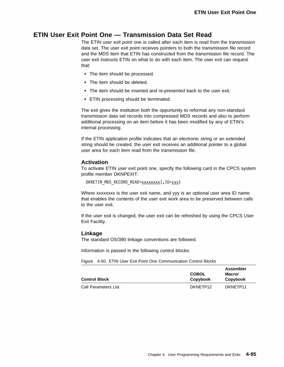
ETIN User Exit Point One
ETIN User Exit Point One — Transmission Data Set ReadThe ETIN user exit point one is called after each item is read from the transmissiondata set. The user exit point receives pointers to both the transmission file recordand the MDS item that ETIN has constructed from the transmission file record. Theuser exit instructs ETIN on what to do with each item. The user exit can requestthat:
� The item should be processed.
� The item should be deleted.
� The item should be inserted and re-presented back to the user exit.
� ETIN processing should be terminated.
The exit gives the institution both the opportunity to reformat any non-standardtransmission data set records into compressed MDS records and also to performadditional processing on an item before it has been modified by any of ETIN’sinternal processing.
If the ETIN application profile indicates that an electronic string or an extendedstring should be created, the user exit receives an additional pointer to a globaluser area for each item read from the transmission file.
ActivationTo activate ETIN user exit point one, specify the following card in the CPCS systemprofile member DKNPEXIT:
DKNETIN_MDS_RECORD_READ=xxxxxxxx(,ID=yyy)
Where xxxxxxxx is the user exit name, and yyy is an optional user area ID namethat enables the contents of the user exit work area to be preserved between callsto the user exit.
If the user exit is changed, the user exit can be refreshed by using the CPCS UserExit Facility.
LinkageThe standard OS/390 linkage conventions are followed.
Information is passed in the following control blocks:
Figure 4-50. ETIN User Exit Point One Communication Control Blocks
Control BlockCOBOLCopybook
AssemblerMacro/Copybook
Call Parameters List DKNETP12 DKNETP11
Chapter 4. User Programming Requirements and Exits 4-95

ETIN User Exit Point One
The exit routine may return the following condition codes in the RETURN-CODEspecial register (COBOL programs) or register 15 (assembler programs).
Figure 4-51. ETIN Exit Point One Routine Return Codes
Code (dec) Request
+00 Process this record
+04 Do not process this record
+06 Insert the current record and re-present the same record back to theuser exit.
+08 Terminate ETIN processing
RestrictionsETIN user exit point one routines must be reentrant and reusable.
Example 1Operation:
This sample exit instructs ETIN to not process any batch tickets.
Processing Description
� Get the ETIN user exit control block.
� Set up addressability for other control blocks that you need.
� Check if the item is a block ticket. If it is, instruct ETIN to not process it;otherwise, instruct ETIN to process it.
User Exit One Routine:
DKNETIU1 CSECT
DKNETIU1 AMODE 31
DKNETIU1 RMODE ANY
PRINT GEN
SAVE (14,12),,DKNETIU1TV�1R11T�4/26/��TPQ37612
LR R12,R15
USING DKNETIU1,R12
TTTTTTTTTTTTTTTTTTTTTTTTTTTTTTTTTTTTTTTTTTTTTTTTTTTT
T PICK UP INPUT PARMS T
TTTTTTTTTTTTTTTTTTTTTTTTTTTTTTTTTTTTTTTTTTTTTTTTTTTT
L R7,�(R1) ;Get Exit Control Block Address
USING DKNETI11,R7 ;Map Exit Control Block
L R8,EI1APTCB ;Get APTCB Address
Figure 4-52 (Part 1 of 3). ETIN User Exit One - Example 1
4-96 CPCS V1R11 Customization Guide

ETIN User Exit Point One
L R9,EI1TFR@ ;Get Tran File Record Address
L R1�,EI1DI@ ;Get MDS Record Address
L R11,EI1WKA@ ;Get Work Area Address
USING APTCB,R8 ;Map APTCB
USING MYTRANFL,R9 ;Map Transmission File Record
USING DIDSCT,R1� ;Map MDS Item
USING USERWORK,R11 ;Map User Exit Work Area
TTTTTTTTTTTTTTTTTTTTTTTTTTTTTTTTTTTTTTTTTTTTTTTTTTTTTTTTT
T Complete Save Area Chaining T
TTTTTTTTTTTTTTTTTTTTTTTTTTTTTTTTTTTTTTTTTTTTTTTTTTTTTTTTT
LA R1,WKSVAREA ;Load Addr of my Save Area
ST R1,8(R13) ;Save in Caller's FWD Chain
ST R13,4(R1) ;BCK Chain in my Save Area
LR R13,R1 ;Addressability to Workarea
TTTTTTTTTTTTTTTTTTTTTTTTTTTTTTTTTTTTTTTTTTTTTTTTTTTTTTTTT
T Sample Code T
TTTTTTTTTTTTTTTTTTTTTTTTTTTTTTTTTTTTTTTTTTTTTTTTTTTTTTTTT
CLI DITYPEI,DIBK ;Block Ticket ?
BE B99��4 ;Yes, Do not process it
T ;Else, process the item
TTTTTTTTTTTTTTTTTTTTTTTTTTTTTTTTTTTTTTTTTTTTTTTTTTTTTTTTT
T Exit With Return Code Zero - Process This Item T
TTTTTTTTTTTTTTTTTTTTTTTTTTTTTTTTTTTTTTTTTTTTTTTTTTTTTTTTT
B99��� DS �H
SLR R15,R15 ;Set return code �
B B99999 ;Go to return
TTTTTTTTTTTTTTTTTTTTTTTTTTTTTTTTTTTTTTTTTTTTTTTTTTTTTTTTT
T Exit With Return Code Four - Do NOT Process the ItemT
TTTTTTTTTTTTTTTTTTTTTTTTTTTTTTTTTTTTTTTTTTTTTTTTTTTTTTTTT
B99��4 DS �H
LA R15,4 ;Set return code 4
B B99999 ;Go to return
TTTTTTTTTTTTTTTTTTTTTTTTTTTTTTTTTTTTTTTTTTTTTTTTTTTTTTTTT
T Exit With Return Code Six - Insert this Item and T
T the re-present it T
TTTTTTTTTTTTTTTTTTTTTTTTTTTTTTTTTTTTTTTTTTTTTTTTTTTTTTTTT
B99��6 DS �H
LA R15,6 ;Set return code 6
B B99999 ;Go to return
TTTTTTTTTTTTTTTTTTTTTTTTTTTTTTTTTTTTTTTTTTTTTTTTTTTTTTTTT
T Exit With Return Code Eight - Terminate the Process T
TTTTTTTTTTTTTTTTTTTTTTTTTTTTTTTTTTTTTTTTTTTTTTTTTTTTTTTTT
B99��8 DS �H
LA R15,8 ;Set return code 8
TTTTTTTTTTTTTTTTTTTTTTTTTTTTTTTTTTTTTTTTTTTTTTTTTTTTTTTTT
T RETURN TO DKNETIN T
TTTTTTTTTTTTTTTTTTTTTTTTTTTTTTTTTTTTTTTTTTTTTTTTTTTTTTTTT
B99999 DS �H
L R13,WKSVAREA+4
Figure 4-52 (Part 2 of 3). ETIN User Exit One - Example 1
Chapter 4. User Programming Requirements and Exits 4-97
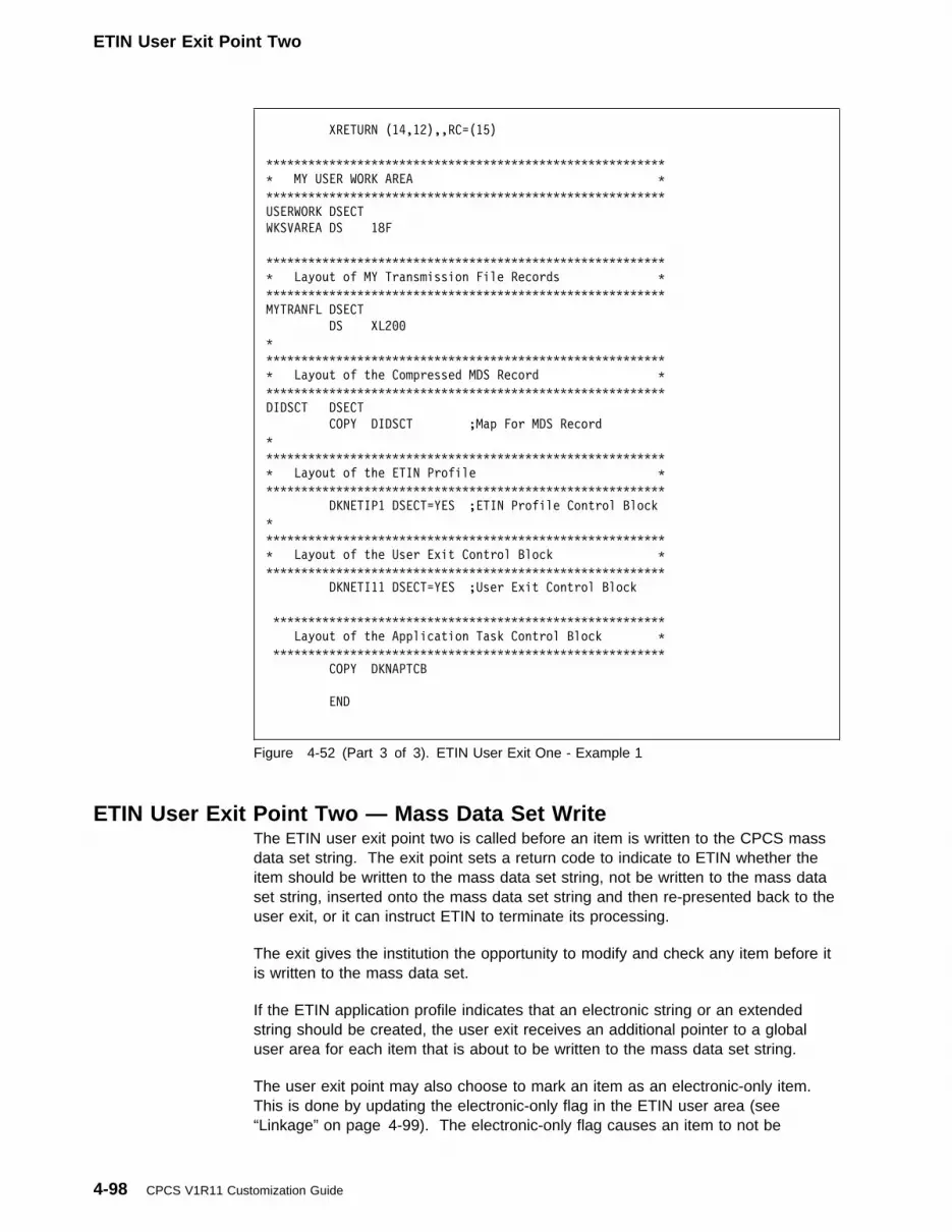
ETIN User Exit Point Two
XRETURN (14,12),,RC=(15)
TTTTTTTTTTTTTTTTTTTTTTTTTTTTTTTTTTTTTTTTTTTTTTTTTTTTTTTTT
T MY USER WORK AREA T
TTTTTTTTTTTTTTTTTTTTTTTTTTTTTTTTTTTTTTTTTTTTTTTTTTTTTTTTT
USERWORK DSECT
WKSVAREA DS 18F
TTTTTTTTTTTTTTTTTTTTTTTTTTTTTTTTTTTTTTTTTTTTTTTTTTTTTTTTT
T Layout of MY Transmission File Records T
TTTTTTTTTTTTTTTTTTTTTTTTTTTTTTTTTTTTTTTTTTTTTTTTTTTTTTTTT
MYTRANFL DSECT
DS XL2��
T
TTTTTTTTTTTTTTTTTTTTTTTTTTTTTTTTTTTTTTTTTTTTTTTTTTTTTTTTT
T Layout of the Compressed MDS Record T
TTTTTTTTTTTTTTTTTTTTTTTTTTTTTTTTTTTTTTTTTTTTTTTTTTTTTTTTT
DIDSCT DSECT
COPY DIDSCT ;Map For MDS Record
T
TTTTTTTTTTTTTTTTTTTTTTTTTTTTTTTTTTTTTTTTTTTTTTTTTTTTTTTTT
T Layout of the ETIN Profile T
TTTTTTTTTTTTTTTTTTTTTTTTTTTTTTTTTTTTTTTTTTTTTTTTTTTTTTTTT
DKNETIP1 DSECT=YES ;ETIN Profile Control Block
T
TTTTTTTTTTTTTTTTTTTTTTTTTTTTTTTTTTTTTTTTTTTTTTTTTTTTTTTTT
T Layout of the User Exit Control Block T
TTTTTTTTTTTTTTTTTTTTTTTTTTTTTTTTTTTTTTTTTTTTTTTTTTTTTTTTT
DKNETI11 DSECT=YES ;User Exit Control Block
TTTTTTTTTTTTTTTTTTTTTTTTTTTTTTTTTTTTTTTTTTTTTTTTTTTTTTTT
Layout of the Application Task Control Block T
TTTTTTTTTTTTTTTTTTTTTTTTTTTTTTTTTTTTTTTTTTTTTTTTTTTTTTTT
COPY DKNAPTCB
END
Figure 4-52 (Part 3 of 3). ETIN User Exit One - Example 1
ETIN User Exit Point Two — Mass Data Set WriteThe ETIN user exit point two is called before an item is written to the CPCS massdata set string. The exit point sets a return code to indicate to ETIN whether theitem should be written to the mass data set string, not be written to the mass dataset string, inserted onto the mass data set string and then re-presented back to theuser exit, or it can instruct ETIN to terminate its processing.
The exit gives the institution the opportunity to modify and check any item before itis written to the mass data set.
If the ETIN application profile indicates that an electronic string or an extendedstring should be created, the user exit receives an additional pointer to a globaluser area for each item that is about to be written to the mass data set string.
The user exit point may also choose to mark an item as an electronic-only item.This is done by updating the electronic-only flag in the ETIN user area (see“Linkage” on page 4-99). The electronic-only flag causes an item to not be
4-98 CPCS V1R11 Customization Guide

ETIN User Exit Point Two
considered for matching during ETDM processing, but the item is still presented asa missing item to the ETDM user exits.
ActivationTo activate ETIN user exit point two, specify the following card in the CPCS systemprofile member DKNPEXIT:
DKNETIN_MDS_RECORD_WRITE=xxxxxxxx(,ID=yyy)
Where xxxxxxxx is the user exit name, and yyy is an optional user area ID namethat enables the contents of the user exit work area to be preserved between callsto the user exit.
If the user exit is changed, the user exit can be refreshed by using the CPCS UserExit Facility.
LinkageThe standard OS/390 linkage conventions are followed.
Information is passed in the following control blocks:
The exit routine may return the following condition codes in the RETURN-CODEspecial register (COBOL programs) or register 15 (assembler programs):
Note: It is not possible to insert records when the item presented is anETIN-generated item. These items may include string header records, tracers,block, batch, or kill bundle records, and their creation is controlled by the ETINapplication profile being used.
Figure 4-53. ETIN User Exit Point Two Communication Control Blocks
Control BlockCOBOLCopybook
AssemblerMacro/Copybook
Call Parameters List DKNETI22 DKNETI21
Figure 4-54. ETIN Exit Point Two Routine Return Codes
Code (dec) Request
+00 Write this record to the mass data set.
+04 Do not write this record to the mass data set.
+06 Insert the current record onto the mass data set and re-present thesame item back to the user exit.
+08 Terminate ETIN processing.
RestrictionsETIN user exit point two routines must be reentrant and reusable.
Chapter 4. User Programming Requirements and Exits 4-99

ETIN User Exit Point Two
Example 1Operation:
This sample exit instructs ETIN to not write any kill bundle records to the mass dataset string being created.
Processing Description
� Get the ETIN user exit control block.
� Set up addressability for other control blocks that you need.
� Check if the item is a kill bundle record. If it is, instruct ETIN to not write theitem to the string; otherwise, instruct ETIN to write the item.
User Exit Two Routine:
DKNETIU2 CSECT
DKNETIU2 AMODE 31
DKNETIU2 RMODE ANY
PRINT GEN
SAVE (14,12),,DKNETIU2TV�1R11T�4/26/��TPQ37612
LR R12,R15
USING DKNETIU2,R12
T
TTTTTTTTTTTTTTTTTTTTTTTTTTTTTTTTTTTTTTTTTTTTTTTTTTTTTTTTT
T PICK UP INPUT PARMS T
TTTTTTTTTTTTTTTTTTTTTTTTTTTTTTTTTTTTTTTTTTTTTTTTTTTTTTTTT
L R7,�(R1) ;Get Exit Control Block Address
USING DKNETI21,R7 ;Map Exit Control Block
L R8,EI2APTCB ;Get APTCB Address
L R9,EI2DI@ ;Get MDS Record Address
L R1�,EI2WKA@ ;Get Work Area Address
USING APTCB,R8 ;Map APTCB
USING DIDSCT,R9 ;Map MDS Item
USING USERWORK,R1� ;Map User Exit Work Area
TTTTTTTTTTTTTTTTTTTTTTTTTTTTTTTTTTTTTTTTTTTTTTTTTTTTTTTTT
T Complete Save Area Chaining T
TTTTTTTTTTTTTTTTTTTTTTTTTTTTTTTTTTTTTTTTTTTTTTTTTTTTTTTTT
LA R1,WKSVAREA ;Load Addr of my Save Area
ST R1,8(R13) ;Save in Caller's FWD Chain
ST R13,4(R1) ;BCK Chain in my Save Area
LR R13,R1 ;Addressability to Workarea
TTTTTTTTTTTTTTTTTTTTTTTTTTTTTTTTTTTTTTTTTTTTTTTTTTTTTTTTT
T Sample Code T
TTTTTTTTTTTTTTTTTTTTTTTTTTTTTTTTTTTTTTTTTTTTTTTTTTTTTTTTT
CLI DITYPEI,DIKB ;Kill Bundle Rec ?
BE B99��4 ;Yes, Do not process it
T ;Else, process the item
Figure 4-55 (Part 1 of 3). ETIN User Exit Two - Example 1
4-100 CPCS V1R11 Customization Guide

ETIN User Exit Point Two
TTTTTTTTTTTTTTTTTTTTTTTTTTTTTTTTTTTTTTTTTTTTTTTTTTTTTTTTT
T Exit With Return Code Zero - Write this Item T
TTTTTTTTTTTTTTTTTTTTTTTTTTTTTTTTTTTTTTTTTTTTTTTTTTTTTTTTT
B99��� DS �H
SLR R15,R15 ;Set return code �
B B99999 ;Go to return
TTTTTTTTTTTTTTTTTTTTTTTTTTTTTTTTTTTTTTTTTTTTTTTTTTTTTTTTT
T Exit With Return Code Four - Do NOT Write this Item T
TTTTTTTTTTTTTTTTTTTTTTTTTTTTTTTTTTTTTTTTTTTTTTTTTTTTTTTTT
B99��4 DS �H
LA R15,4 ;Set return code 4
B B99999 ;Go to return
TTTTTTTTTTTTTTTTTTTTTTTTTTTTTTTTTTTTTTTTTTTTTTTTTTTTTTTTT
T Exit With Return Code Six - Insert this Item and T
T then re-present it T
TTTTTTTTTTTTTTTTTTTTTTTTTTTTTTTTTTTTTTTTTTTTTTTTTTTTTTTTT
B99��6 DS �H
LA R15,6 ;Set return code 6
B B99999 ;Go to return
TTTTTTTTTTTTTTTTTTTTTTTTTTTTTTTTTTTTTTTTTTTTTTTTTTTTTTTTT
T Exit With Return Code Eight - Terminate the Process T
TTTTTTTTTTTTTTTTTTTTTTTTTTTTTTTTTTTTTTTTTTTTTTTTTTTTTTTTT
B99��8 DS �H
LA R15,8 ;Set return code 8
TTTTTTTTTTTTTTTTTTTTTTTTTTTTTTTTTTTTTTTTTTTTTTTTTTTTTTTTT
T RETURN TO DKNETIN T
TTTTTTTTTTTTTTTTTTTTTTTTTTTTTTTTTTTTTTTTTTTTTTTTTTTTTTTTT
B99999 DS �H
L R13,WKSVAREA+4
XRETURN (14,12),,RC=(15)
TTTTTTTTTTTTTTTTTTTTTTTTTTTTTTTTTTTTTTTTTTTTTTTTTTTTTTTTT
T MY USER WORK AREA T
TTTTTTTTTTTTTTTTTTTTTTTTTTTTTTTTTTTTTTTTTTTTTTTTTTTTTTTTT
USERWORK DSECT
WKSVAREA DS 18F
TTTTTTTTTTTTTTTTTTTTTTTTTTTTTTTTTTTTTTTTTTTTTTTTTTTTTTTTT
T Layout of the Compressed MDS Record T
TTTTTTTTTTTTTTTTTTTTTTTTTTTTTTTTTTTTTTTTTTTTTTTTTTTTTTTTT
DIDSCT DSECT
COPY DIDSCT ;Map For MDS Record
T
TTTTTTTTTTTTTTTTTTTTTTTTTTTTTTTTTTTTTTTTTTTTTTTTTTTTTTTTT
T Layout of the ETIN Profile T
TTTTTTTTTTTTTTTTTTTTTTTTTTTTTTTTTTTTTTTTTTTTTTTTTTTTTTTTT
DKNETIP1 DSECT=YES ;ETIN Profile Control Block
T
TTTTTTTTTTTTTTTTTTTTTTTTTTTTTTTTTTTTTTTTTTTTTTTTTTTTTTTTT
T Layout of the User Exit Control Block T
TTTTTTTTTTTTTTTTTTTTTTTTTTTTTTTTTTTTTTTTTTTTTTTTTTTTTTTTT
DKNETI21 DSECT=YES ;User Exit Control Block
T
TTTTTTTTTTTTTTTTTTTTTTTTTTTTTTTTTTTTTTTTTTTTTTTTTTTTTTTTT
T Layout of the Application Task Control Block T
TTTTTTTTTTTTTTTTTTTTTTTTTTTTTTTTTTTTTTTTTTTTTTTTTTTTTTTTT
Figure 4-55 (Part 2 of 3). ETIN User Exit Two - Example 1
Chapter 4. User Programming Requirements and Exits 4-101

ETIN User Exit Point Three
COPY DKNAPTCB
T
END
Figure 4-55 (Part 3 of 3). ETIN User Exit Two - Example 1
ETIN User Exit Point Three — Transmission Data Set ImportedThis ETIN user exit point is called each time an auto-started ETIN task successfullyloads an electronic file.
Note: The user exit point is not called for operator-started ETIN processes.
The exit gives the customer the opportunity to perform any clean-up processing orimport notification each time an autostarted ETIN completes successfully.
ActivationTo initiate this user exit point, set the following card in the DKNPEXIT profilemember:
DKNETIN_FILE_IMPORTED=xxxxxxxx(,ID=yyy)
Where xxxxxxxx is the user exit name, and yyy is an optional user area ID namethat enables the contents of the user exit work area to be preserved between callsto the user exit.
If a new user exit is installed, the user exit must be refreshed using the CPCS EXITtask.
LinkageThe standard OS/390 linkage conventions are followed.
Information is passed in the following control blocks:
The exit routine may return the following condition codes in the RETURN-CODEspecial register (COBOL programs) or register 15 (assembler programs):
Figure 4-56. ETIN User Exit Point Three Communication Control Blocks
Control BlockCOBOLCopybook
AssemblerMacro/Copybook
Call Parameters List DKNETI32 DKNETI31
Figure 4-57. ETIN Exit Point Three Routine Return Codes
Code (dec) Request
+00 Continue processing.
4-102 CPCS V1R11 Customization Guide

ETIN User Exit Point Three
RestrictionsETIN user exit point three routines must be reentrant and reusable.
ExampleOperation:
This sample exit issues a WTO for imported electronic transmission files.
Processing Description
� Get the ETIN user exit control block.
� Set up addressability for other control blocks that you need.
� Issue a ‘write to operator’ message.
User Exit Three Routine:
DKNETIU3 CSECT
DKNETIU3 AMODE 31
DKNETIU3 RMODE ANY
PRINT GEN
SAVE (14,12),,DKNETIU3TV�1R11T�4/26/��TPQ37612
LR R12,R15
USING DKNETIU3,R12
T
TTTTTTTTTTTTTTTTTTTTTTTTTTTTTTTTTTTTTTTTTTTTTTTTTTTTTTTTT
T PICK UP INPUT PARMS T
TTTTTTTTTTTTTTTTTTTTTTTTTTTTTTTTTTTTTTTTTTTTTTTTTTTTTTTTT
L R7,�(R1) ;Get Exit Control Block Address
USING DKNETI31,R7 ;Map Exit Control Block
L R11,EI3WKA@ ;Get Work Area Address
USING USERWORK,R11 ;Map User Exit Work Area
TTTTTTTTTTTTTTTTTTTTTTTTTTTTTTTTTTTTTTTTTTTTTTTTTTTTTTTTT
T Complete Save Area Chaining T
TTTTTTTTTTTTTTTTTTTTTTTTTTTTTTTTTTTTTTTTTTTTTTTTTTTTTTTTT
LA R1,WKSVAREA ;Load Addr of my Save Area
ST R1,8(R13) ;Save in Caller's FWD Chain
ST R13,4(R1) ;BCK Chain in my Save Area
LR R13,R1 ;Addressability to Workarea
TTTTTTTTTTTTTTTTTTTTTTTTTTTTTTTTTTTTTTTTTTTTTTTTTTTTTTTTT
T Sample Code T
TTTTTTTTTTTTTTTTTTTTTTTTTTTTTTTTTTTTTTTTTTTTTTTTTTTTTTTTT
MVC MSGTEXT(L'SMSG1),SMSG1
MVC WTOLIST(WTOLEN),WTOLISTF
MVC MSGAREA(2),SMSGMS1L
LA R2,MSGAREA
WTO TEXT=(R2),
ROUTCDE=(11),
MF=(E,WTOLIST)
Figure 4-58 (Part 1 of 2). ETIN User Exit Three - Example
Chapter 4. User Programming Requirements and Exits 4-103

ETIN User Exit Point Three
MVC MSGTEXT(L'SMSG2),SMSG2
MVC MSGTEXT+9(44),EI3MVSDS
MVC WTOLIST(WTOLEN),WTOLISTF
MVC MSGAREA(2),SMSGMS2L
LA R2,MSGAREA
WTO TEXT=(R2),
ROUTCDE=(11),
MF=(E,WTOLIST)
TTTTTTTTTTTTTTTTTTTTTTTTTTTTTTTTTTTTTTTTTTTTTTTTTTTTTTTTT
T Exit With Return Code Zero T
TTTTTTTTTTTTTTTTTTTTTTTTTTTTTTTTTTTTTTTTTTTTTTTTTTTTTTTTT
B99��� DS �H
SLR R15,R15 ;Set return code �
T
L R13,WKSVAREA+4
XRETURN (14,12),,RC=(15)
TTTTTTTTTTTTTTTTTTTTTTTTTTTTTTTTTTTTTTTTTTTTTTTTTTTTTTTTT
T C O N S T A N T S T
TTTTTTTTTTTTTTTTTTTTTTTTTTTTTTTTTTTTTTTTTTTTTTTTTTTTTTTTT
SMSG1 DC C'DKNETIU3 THE FOLLOWING FILE WAS IMPORTED'
SMSGMS1L DC AL2(L'SMSG1)
T
SMSG2 DS �CL53
DC C'DKNETIU3 '
DS CL44
SMSGMS2L DC AL2(L'SMSG2)
T
WTOLISTF WTO TEXT=(R2),ROUTCDE=(11),MF=L
WTOLEN EQU T-WTOLISTF ;WTO
TTTTTTTTTTTTTTTTTTTTTTTTTTTTTTTTTTTTTTTTTTTTTTTTTTTTTTTTT
T MY USER WORK AREA T
TTTTTTTTTTTTTTTTTTTTTTTTTTTTTTTTTTTTTTTTTTTTTTTTTTTTTTTTT
USERWORK DSECT
WKSVAREA DS 18F
T
TTTTTTTTTTTTTTTTTTTTTTTTTTTTTTTTTTTTTTTTTTTTTTTTTTTTTTTTT
T Message Work Area T
TTTTTTTTTTTTTTTTTTTTTTTTTTTTTTTTTTTTTTTTTTTTTTTTTTTTTTTTT
DS �F
MSGAREA DC AL2(�)
MSGTEXT DC CL6�' '
WTOLIST WTO TEXT=(R2),ROUTCDE=(11),MF=L
T
USERLEN EQU T-WKSVAREA ;LEN
T
TTTTTTTTTTTTTTTTTTTTTTTTTTTTTTTTTTTTTTTTTTTTTTTTTTTTTTTTT
T Layout of the User Exit Control Block T
TTTTTTTTTTTTTTTTTTTTTTTTTTTTTTTTTTTTTTTTTTTTTTTTTTTTTTTTT
DKNETI31 DSECT=YES ;User Exit Control Block
T
END
Figure 4-58 (Part 2 of 2). ETIN User Exit Three - Example
4-104 CPCS V1R11 Customization Guide

ETIN User Exit Point Four
ETIN User Exit Point Four — Write Electronic Resynch RecordThis ETIN user exit point is called each time a resynch record is to be written to theelectronic resynch file. The user exit point control block contains details of theinformation that are used to build the resynch record.
The user exit can only modify the resynch document’s parent item note information(a parent item is a previously read resynch document). The associating of aresynch document with a previously-read resynch document enables theDKNETDM task to read items that precede the resynch document’s position on thestring.
ActivationTo initiate this user exit point, set the following card in the DKNPEXIT profilemember:
DKNETIN_CREATE_RESYNCH_RECORD=xxxxxxxx(,ID=yyy)
Where xxxxxxxx is the user exit name, and yyy is an optional user area ID namethat enables the contents of the user exit work area to be preserved between callsto the user exit.
If a new user exit is installed, the user exit must be refreshed using the CPCS EXITtask.
LinkageThe standard OS/390 linkage conventions are followed.
Information is passed in the following control blocks:
The exit routine may return the following condition codes in the RETURN-CODEspecial register (COBOL programs) or register 15 (assembler programs):
Figure 4-59. ETIN User Exit Point Four Communication Control Blocks
Control BlockCOBOLCopybook
AssemblerMacro/Copybook
Call Parameters List DKNETI42 DKNETI41
Figure 4-60. ETIN Exit Point Four Routine Return Codes
Code (dec) Request
+00 Write resynch record and continue.
+04 Do not write resynch record but continue processing.
+08 Terminate processing.
RestrictionsETIN user exit point four routines must be reentrant and reusable.
Chapter 4. User Programming Requirements and Exits 4-105

ETIN User Exit Point Four
ExampleOperation:
This sample exit instructs ETIN to write the electronic resynch record that itpresents to the user exit.
Processing Description
� Get the ETIN user exit control block.
� Set up addressability for other control blocks that you need.
� Set the return code to write the resynch record.
User Exit Four Routine:
DKNETIU4 CSECT
DKNETIU4 AMODE 31
DKNETIU4 RMODE ANY
PRINT GEN
SAVE (14,12),,DKNETIU4TV�1R11T�4/26/��TPQ37612
LR R12,R15
USING DKNETIU4,R12
T
TTTTTTTTTTTTTTTTTTTTTTTTTTTTTTTTTTTTTTTTTTTTTTTTTTTTTTTTT
T PICK UP INPUT PARMS T
TTTTTTTTTTTTTTTTTTTTTTTTTTTTTTTTTTTTTTTTTTTTTTTTTTTTTTTTT
L R7,�(R1) ;Get Exit Control Block Address
USING DKNETI41,R7 ;Map Exit Control Block
L R8,EI4ITEM ;Get MDS Record Address
L R9,EI4WKA@ ;Get User Exit Work Area Address
USING DIDSCT,R8 ;Map MDS Record
USING USERWORK,R9 ;Map User Exit Work Area
TTTTTTTTTTTTTTTTTTTTTTTTTTTTTTTTTTTTTTTTTTTTTTTTTTTTTTTTT
T Complete Save Area Chaining T
TTTTTTTTTTTTTTTTTTTTTTTTTTTTTTTTTTTTTTTTTTTTTTTTTTTTTTTTT
LA R1,WKSVAREA ;Load Addr of my Save Area
ST R1,8(R13) ;Save in Caller's FWD Chain
ST R13,4(R1) ;BCK Chain in my Save Area
LR R13,R1 ;Addressability to Workarea
TTTTTTTTTTTTTTTTTTTTTTTTTTTTTTTTTTTTTTTTTTTTTTTTTTTTTTTTT
T Sample Code - Default is to Write the Resynch Record T
TTTTTTTTTTTTTTTTTTTTTTTTTTTTTTTTTTTTTTTTTTTTTTTTTTTTTTTTT
T
TTTTTTTTTTTTTTTTTTTTTTTTTTTTTTTTTTTTTTTTTTTTTTTTTTTTTTTTT
T Exit With Return Code Zero - Write this Record T
TTTTTTTTTTTTTTTTTTTTTTTTTTTTTTTTTTTTTTTTTTTTTTTTTTTTTTTTT
B99��� DS �H
SLR R15,R15 ;Set return code �
B B99999 ;Go to return
Figure 4-61 (Part 1 of 2). ETIN User Exit Four - Example
4-106 CPCS V1R11 Customization Guide

ETIP User Exit Point One
TTTTTTTTTTTTTTTTTTTTTTTTTTTTTTTTTTTTTTTTTTTTTTTTTTTTTTTTT
T Exit With Return Code Four - Do NOT Write this Record
TTTTTTTTTTTTTTTTTTTTTTTTTTTTTTTTTTTTTTTTTTTTTTTTTTTTTTTTT
B99��4 DS �H
LA R15,4 ;Set return code 4
B B99999 ;Go to return
TTTTTTTTTTTTTTTTTTTTTTTTTTTTTTTTTTTTTTTTTTTTTTTTTTTTTTTTT
T Exit With Return Code Eight - Terminate the Process T
TTTTTTTTTTTTTTTTTTTTTTTTTTTTTTTTTTTTTTTTTTTTTTTTTTTTTTTTT
B99��8 DS �H
LA R15,8 ;Set return code 8
TTTTTTTTTTTTTTTTTTTTTTTTTTTTTTTTTTTTTTTTTTTTTTTTTTTTTTTTT
T RETURN TO DKNETIN T
TTTTTTTTTTTTTTTTTTTTTTTTTTTTTTTTTTTTTTTTTTTTTTTTTTTTTTTTT
B99999 DS �H
L R13,WKSVAREA+4
XRETURN (14,12),,RC=(15)
TTTTTTTTTTTTTTTTTTTTTTTTTTTTTTTTTTTTTTTTTTTTTTTTTTTTTTTTT
T MY USER WORK AREA T
TTTTTTTTTTTTTTTTTTTTTTTTTTTTTTTTTTTTTTTTTTTTTTTTTTTTTTTTT
USERWORK DSECT
WKSVAREA DS 18F
TTTTTTTTTTTTTTTTTTTTTTTTTTTTTTTTTTTTTTTTTTTTTTTTTTTTTTTTT
T Layout of the Compressed MDS Record T
TTTTTTTTTTTTTTTTTTTTTTTTTTTTTTTTTTTTTTTTTTTTTTTTTTTTTTTTT
DIDSCT DSECT
COPY DIDSCT
T
TTTTTTTTTTTTTTTTTTTTTTTTTTTTTTTTTTTTTTTTTTTTTTTTTTTTTTTTT
T Layout of the User Exit Control Block T
TTTTTTTTTTTTTTTTTTTTTTTTTTTTTTTTTTTTTTTTTTTTTTTTTTTTTTTTT
DKNETI41 DSECT=YES ;User Exit Control Block
T
END
Figure 4-61 (Part 2 of 2). ETIN User Exit Four - Example
ETIP User Exit Point One — Input Processor MessagingThe ETIP user exit point one is called at the end of ETIP processing; it is called togive the customer the opportunity to issue an end-of-task message detailing anyerror condition that may have been identified. The user exit is supplied a set ofcounts detailing the number of eligible, complete, and queued records processedduring this run of ETIP. The task is also passed a start switch detailing the type ofETIP run that has occurred.
ActivationTo initiate this user exit point, set the following card in the DKNPEXIT member onthe system profile data set:
DKNETIP_ANALYSE_RECS_PROCESSED=xxxxxxxx
If a new user exit is installed, the user exit must be refreshed using the CPCS EXITtask.
Chapter 4. User Programming Requirements and Exits 4-107
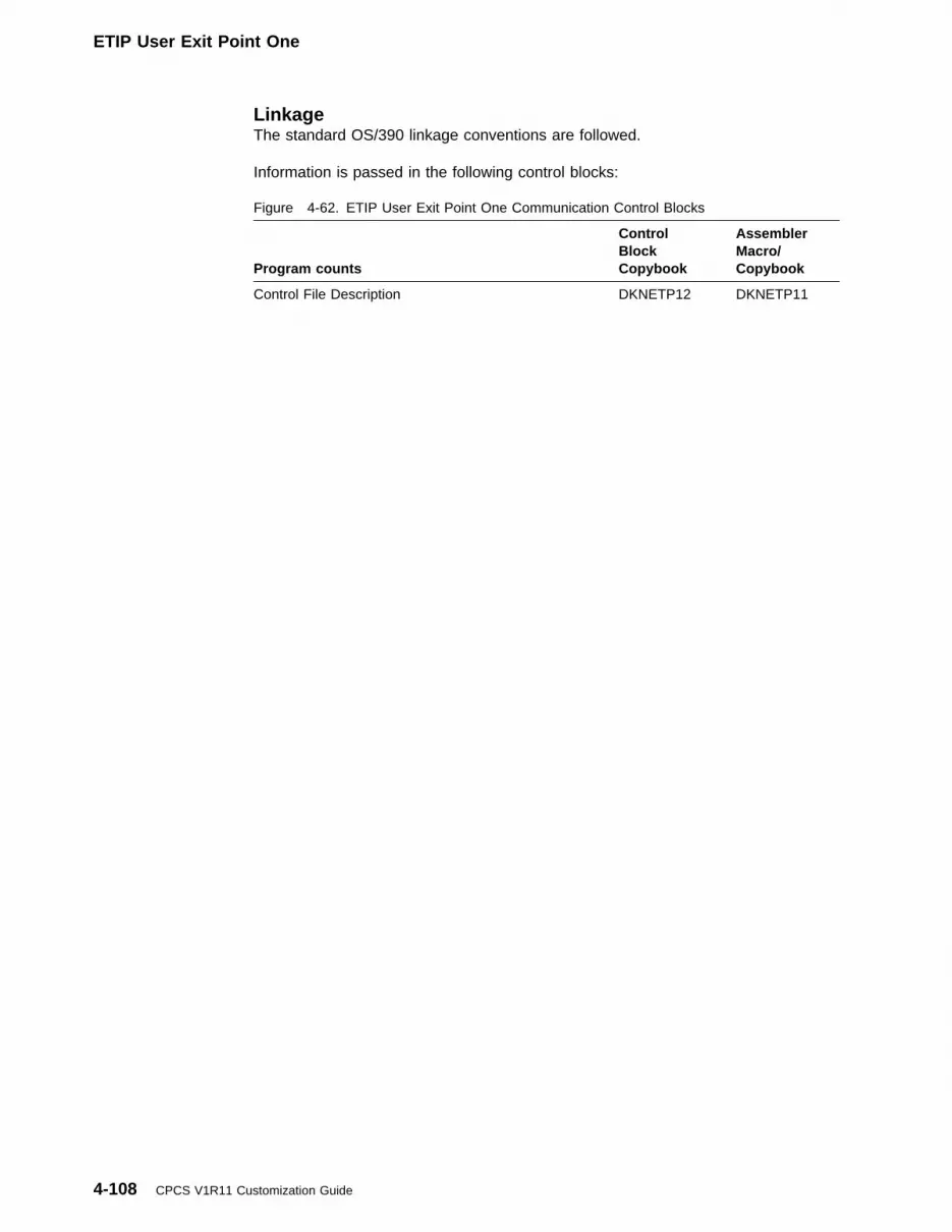
ETIP User Exit Point One
LinkageThe standard OS/390 linkage conventions are followed.
Information is passed in the following control blocks:
Figure 4-62. ETIP User Exit Point One Communication Control Blocks
Program counts
ControlBlockCopybook
AssemblerMacro/Copybook
Control File Description DKNETP12 DKNETP11
4-108 CPCS V1R11 Customization Guide
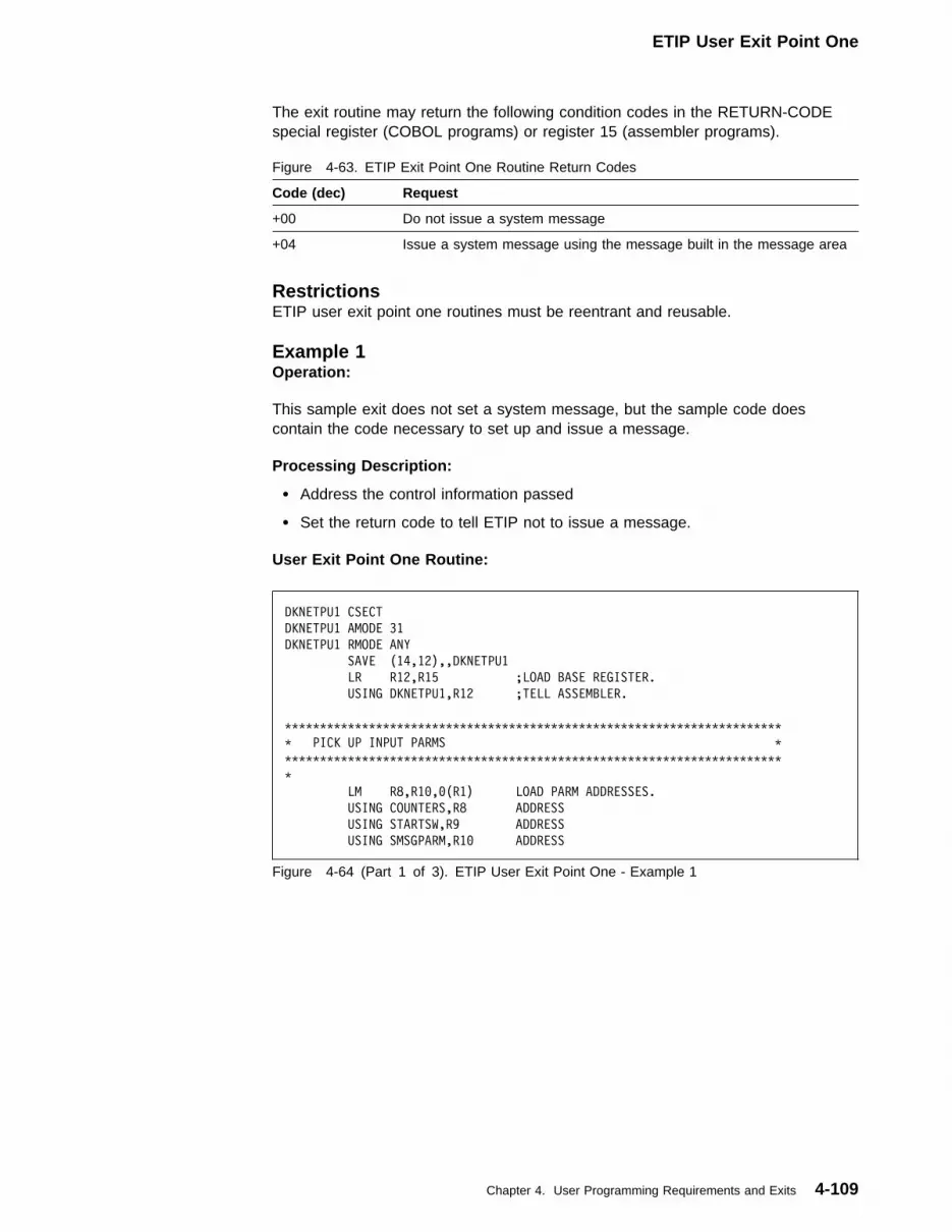
ETIP User Exit Point One
The exit routine may return the following condition codes in the RETURN-CODEspecial register (COBOL programs) or register 15 (assembler programs).
Figure 4-63. ETIP Exit Point One Routine Return Codes
Code (dec) Request
+00 Do not issue a system message
+04 Issue a system message using the message built in the message area
RestrictionsETIP user exit point one routines must be reentrant and reusable.
Example 1Operation:
This sample exit does not set a system message, but the sample code doescontain the code necessary to set up and issue a message.
Processing Description:
� Address the control information passed
� Set the return code to tell ETIP not to issue a message.
User Exit Point One Routine:
DKNETPU1 CSECT
DKNETPU1 AMODE 31
DKNETPU1 RMODE ANY
SAVE (14,12),,DKNETPU1
LR R12,R15 ;LOAD BASE REGISTER.
USING DKNETPU1,R12 ;TELL ASSEMBLER.
TTTTTTTTTTTTTTTTTTTTTTTTTTTTTTTTTTTTTTTTTTTTTTTTTTTTTTTTTTTTTTTTTTTTTTT
T PICK UP INPUT PARMS T
TTTTTTTTTTTTTTTTTTTTTTTTTTTTTTTTTTTTTTTTTTTTTTTTTTTTTTTTTTTTTTTTTTTTTTT
T
LM R8,R1�,�(R1) LOAD PARM ADDRESSES.
USING COUNTERS,R8 ADDRESS
USING STARTSW,R9 ADDRESS
USING SMSGPARM,R1� ADDRESS
Figure 4-64 (Part 1 of 3). ETIP User Exit Point One - Example 1
Chapter 4. User Programming Requirements and Exits 4-109

ETIP User Exit Point One
TTTTTTTTTTTTTTTTTTTTTTTTTTTTTTTTTTTTTTTTTTTTTTTTTTTTTTTTTTTTTTTTTTTTTTT
T USER CODE GOES HERE T
TTTTTTTTTTTTTTTTTTTTTTTTTTTTTTTTTTTTTTTTTTTTTTTTTTTTTTTTTTTTTTTTTTTTTTT
T
B B99��� EXIT WITHOUT DISPLAYING A MESSAGE.
T
T ROUTE MESSAGE TO BOTH TERMINAL AND TO THE SUPV TUBE.
T
MVC DESTCODE,=AL2(SMPDRTN+SMPDSUPV)
T
T THIS IS AN ETPU1 MESSAGE, NOT AN ETIP MESSAGE.
T
MVC PROGNAME,=CL8'DKNETPU1'
T
T SET MESSAGE NUMBER USING STANDARD SNNNN FORMAT.
T
MVC MSGNUMBR,=CL5'3���1' SEVERITY 3, MESSAGE ���1
T
LA R3,INSERTBF LOCATE THE INSERT BUFFER.
T
T CREATE AND TERMINATE THE FIRST SUBSTITUTION FIELD.
T
MVC �(L'INSERT1,R3),INSERT1 ADD THE FIRST INSERT AND
LA R3,L'INSERT1(�,R3) STEP AROUND IT.
MVI �(R3),X'��' ADD THE TERMINATOR.
LA R3,1(�,R3) STEP AROUND IT.
T
T CREATE AND TERMINATE THE SECOND SUBSTITUTION FIELD.
T
MVC �(L'INSERT2,R3),INSERT2 ADD THE SECOND INSERT AND
LA R3,L'INSERT2(�,R3) STEP AROUND IT.
MVI �(R3),X'��' ADD THE TERMINATOR.
LA R3,1(�,R3) STEP AROUND IT.
T
T CREATE AND TERMINATE THE SECOND SUBSTITUTION FIELD.
T
MVC �(L'INSERT2,R3),INSERT2 ADD THE SECOND INSERT AND
LA R3,L'INSERT2(�,R3) STEP AROUND IT.
MVI �(R3),X'��' ADD THE TERMINATOR.
LA R3,1(�,R3) STEP AROUND IT.
T
T MARK LAST FIELD IN BUFFER.
T
MVI �(R3),X'��' NO MORE INSERT FIELDS.
T
B B99��4 COMMAND ETIP TO DISPLAY THE MESSAGE.
TTTTTTTTTTTTTTTTTTTTTTTTTTTTTTTTTTTTTTTTTTTTTTTTTTTTTTTTTTTTTTTTTTTTTTT
T EXIT WITH RETURN CODE ZERO - CONTINUE WITH NORMAL ETIP PROCESSING T
TTTTTTTTTTTTTTTTTTTTTTTTTTTTTTTTTTTTTTTTTTTTTTTTTTTTTTTTTTTTTTTTTTTTTTT
B99��� DS �H
SLR R15,R15 ZERO RETURN CODE
B B99999 GO TO RETURN
Figure 4-64 (Part 2 of 3). ETIP User Exit Point One - Example 1
4-110 CPCS V1R11 Customization Guide

ETIP User Exit Point Two
TTTTTTTTTTTTTTTTTTTTTTTTTTTTTTTTTTTTTTTTTTTTTTTTTTTTTTTTTTTTTTTTTTTTTTT
T EXIT WITH RETURN CODE FOUR - DISPLAY MESSAGE FROM SMSG AREA T
TTTTTTTTTTTTTTTTTTTTTTTTTTTTTTTTTTTTTTTTTTTTTTTTTTTTTTTTTTTTTTTTTTTTTTT
B99��4 DS �H
LA R15,4 SET RETURN CODE
TTTTTTTTTTTTTTTTTTTTTTTTTTTTTTTTTTTTTTTTTTTTTTTTTTTTTTTTTTTTTTTTTTTTTTT
T RETURN TO DKNETIP T
TTTTTTTTTTTTTTTTTTTTTTTTTTTTTTTTTTTTTTTTTTTTTTTTTTTTTTTTTTTTTTTTTTTTTTT
B99999 DS �H
XRETURN (14,12),,RC=(15) END OF ETPU1 PROCESSING
TTTTTTTTTTTTTTTTTTTTTTTTTTTTTTTTTTTTTTTTTTTTTTTTTTTTTTTTTTTTTTTTTTTTTTT
T LITERALS AND CONSTANTS T
TTTTTTTTTTTTTTTTTTTTTTTTTTTTTTTTTTTTTTTTTTTTTTTTTTTTTTTTTTTTTTTTTTTTTTT
INSERT1 DC CL39'THIS TEXT WILL OVERLAY THE MESSAGE''S %1'
INSERT2 DC CL21'TEXT FOR REPLACING %2'
TTTTTTTTTTTTTTTTTTTTTTTTTTTTTTTTTTTTTTTTTTTTTTTTTTTTTTTTTTTTTTTTTTTTTTT
T DSECTS AND VARIABLE STORAGE T
TTTTTTTTTTTTTTTTTTTTTTTTTTTTTTTTTTTTTTTTTTTTTTTTTTTTTTTTTTTTTTTTTTTTTTT
COUNTERS DSECT COUNT OF RECORD TYPES PROCESSED:
ELIGIBLE DS H ... ELIGIBLE RECORDS
COMPLETE DS H ... COMPLETE RECORDS
QUEUED DS H ... QUEUED RECORDS
STARTSW DSECT ETIP START SWITCH --
ETIPSTRT DS X HOW DKNETIP WAS STARTED:
OPERATOR EQU B'�������1' ... MANUAL START BY CPCS OPERATOR
ESMECYC EQU B'������1�' ... BY ESM DURING END CYCLE
ESMTIMER EQU B'�����1��' ... BY ESM START TIMER
INITIAL EQU B'����1���' ... THIS IS 1ST RUN SINCE CPCS IPL
ESMCOLD EQU B'���1����' ... BY ESM DURING COLD START
ESMANUAL EQU B'��1�����' ... MANUAL START VIA ESM
SMSGPARM DSECT OPTIONAL MESSAGE FOR DISPLAY BY ETIP
DESTCODE DS AL2 ... DESTINATION CODE(S) (NOTE:
T THESE MAY BE OR'ED TOGETHER):
SMPDRTN EQU X'���1' ... RETURN MESSAGE TO DKNETIP
SMPDSUPV EQU X'���2' ... SEND MESSAGE TO SUPV TUBE
SMPDSCRL EQU X'���4' ... SEND MESSAGE TO SCROLL
SMPDWTO EQU X'���8' ... DISPLAY MESSAGE VIA WTO
SMPDMICR EQU X'��1�' ... SEND MESSAGE TO MICR TUBE
SMPDINSC EQU X'��2�' ... SEND MESSAGE TO INSC TUBE
T
PROGNAME DS CL8 ... SUBSYSTEM / PROGRAM NAME
MSGNUMBR DS CL5 ... MESSAGE NUMBER
INSERTBF DS CL12� ... INSERT BUFFER
END
Figure 4-64 (Part 3 of 3). ETIP User Exit Point One - Example 1
ETIP User Exit Point Two — Input Processor SelectionThe ETIP user exit point two is called each time an eligible record is selected fromthe electronic control file. The user exit can then determine whether the eligiblerecord should be passed to ETIN for processing.
Chapter 4. User Programming Requirements and Exits 4-111
ETIP User Exit Point Two
ActivationTo initiate this user exit point, set the following card in the DKNPEXIT member onthe system profile data set:
DKNETIP_IDENTIFY_RECS_TO_PROCESS=xxxxxxxx
Where xxxxxxxx is the user exit name.
If a new user exit is installed, the user exit must be refreshed using the CPCS EXITtask.
LinkageThe standard OS/390 linkage conventions are followed.
Information is passed in the following control blocks:
The exit routine may return the following condition codes in the RETURN-CODEspecial register (COBOL programs) or register 15 (assembler programs).
Figure 4-65. ETIP User Exit Point Two Communication Control Blocks
Control BlockCOBOLCopybook
AssemblerMacro/Copybook
Control File Description DKNETP22 DKNETP21
Figure 4-66. ETIP Exit Point Two Routine Return Codes
Code (dec) Request
+00 Pass the control file record to ETIN for processing
+04 Do NOT pass the control file record to ETIN
RestrictionsETIP user exit point one routines must be reentrant and reusable.
Example 1Operation:
This sample exit instructs ETIP to always import the transmission file beingchecked.
Processing Description
� Address the control information passed
� Set the return code to tell ETIP to initiate the import for the transmission dataset.
User Exit Two Routine:
4-112 CPCS V1R11 Customization Guide
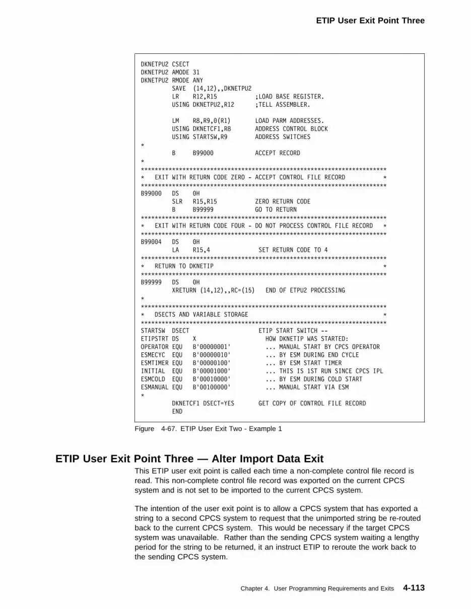
ETIP User Exit Point Three
DKNETPU2 CSECT
DKNETPU2 AMODE 31
DKNETPU2 RMODE ANY
SAVE (14,12),,DKNETPU2
LR R12,R15 ;LOAD BASE REGISTER.
USING DKNETPU2,R12 ;TELL ASSEMBLER.
LM R8,R9,�(R1) LOAD PARM ADDRESSES.
USING DKNETCF1,R8 ADDRESS CONTROL BLOCK
USING STARTSW,R9 ADDRESS SWITCHES
T
B B99��� ACCEPT RECORD
T
TTTTTTTTTTTTTTTTTTTTTTTTTTTTTTTTTTTTTTTTTTTTTTTTTTTTTTTTTTTTTTTTTTTTTTT
T EXIT WITH RETURN CODE ZERO - ACCEPT CONTROL FILE RECORD T
TTTTTTTTTTTTTTTTTTTTTTTTTTTTTTTTTTTTTTTTTTTTTTTTTTTTTTTTTTTTTTTTTTTTTTT
B99��� DS �H
SLR R15,R15 ZERO RETURN CODE
B B99999 GO TO RETURN
TTTTTTTTTTTTTTTTTTTTTTTTTTTTTTTTTTTTTTTTTTTTTTTTTTTTTTTTTTTTTTTTTTTTTTT
T EXIT WITH RETURN CODE FOUR - DO NOT PROCESS CONTROL FILE RECORD T
TTTTTTTTTTTTTTTTTTTTTTTTTTTTTTTTTTTTTTTTTTTTTTTTTTTTTTTTTTTTTTTTTTTTTTT
B99��4 DS �H
LA R15,4 SET RETURN CODE TO 4
TTTTTTTTTTTTTTTTTTTTTTTTTTTTTTTTTTTTTTTTTTTTTTTTTTTTTTTTTTTTTTTTTTTTTTT
T RETURN TO DKNETIP T
TTTTTTTTTTTTTTTTTTTTTTTTTTTTTTTTTTTTTTTTTTTTTTTTTTTTTTTTTTTTTTTTTTTTTTT
B99999 DS �H
XRETURN (14,12),,RC=(15) END OF ETPU2 PROCESSING
T
TTTTTTTTTTTTTTTTTTTTTTTTTTTTTTTTTTTTTTTTTTTTTTTTTTTTTTTTTTTTTTTTTTTTTTT
T DSECTS AND VARIABLE STORAGE T
TTTTTTTTTTTTTTTTTTTTTTTTTTTTTTTTTTTTTTTTTTTTTTTTTTTTTTTTTTTTTTTTTTTTTTT
STARTSW DSECT ETIP START SWITCH --
ETIPSTRT DS X HOW DKNETIP WAS STARTED:
OPERATOR EQU B'�������1' ... MANUAL START BY CPCS OPERATOR
ESMECYC EQU B'������1�' ... BY ESM DURING END CYCLE
ESMTIMER EQU B'�����1��' ... BY ESM START TIMER
INITIAL EQU B'����1���' ... THIS IS 1ST RUN SINCE CPCS IPL
ESMCOLD EQU B'���1����' ... BY ESM DURING COLD START
ESMANUAL EQU B'��1�����' ... MANUAL START VIA ESM
T
DKNETCF1 DSECT=YES GET COPY OF CONTROL FILE RECORD
END
Figure 4-67. ETIP User Exit Two - Example 1
ETIP User Exit Point Three — Alter Import Data ExitThis ETIP user exit point is called each time a non-complete control file record isread. This non-complete control file record was exported on the current CPCSsystem and is not set to be imported to the current CPCS system.
The intention of the user exit point is to allow a CPCS system that has exported astring to a second CPCS system to request that the unimported string be re-routedback to the current CPCS system. This would be necessary if the target CPCSsystem was unavailable. Rather than the sending CPCS system waiting a lengthyperiod for the string to be returned, it an instruct ETIP to reroute the work back tothe sending CPCS system.
Chapter 4. User Programming Requirements and Exits 4-113

ETIP User Exit Point Three
ActivationTo initiate this user exit point, set the following card in the DKNPEXIT profilemember.
DKNETIP_ALTER_CF_IMPORT_DATA=xxxxxxxx
Where xxxxxxxx is the user exit name.
If a new user exit is installed, the user exit must be refreshed using the CPCS EXITtask.
LinkageThe standard OS/390 linkage conventions are followed.
Information is passed in the following control blocks:
The exit routine may return the following condition codes in the RETURN-CODEspecial register (COBOL programs) or register 15 (assembler programs):
Figure 4-68. ETIP User Exit Point Three Communication Control Blocks
Control BlockCOBOLCopybook
AssemblerMacro/Copybook
Control File Description DKNETP32 DKNETP31
Figure 4-69. ETIP Exit Point Two Routine Return Codes
Code (dec) Request
+00 Do not amend the control file record passed.
+04 Amend the control file record passed with the new data supplied in thecontrol block.
+12 Terminate ETIP processing.
RestrictionsETIP user exit point three routines must be reentrant and reusable.
ExampleThis sample exit instructs ETIP to reroute eligible control file records back to thecurrent CPCS system that have been waiting to be processed for more than 20minutes. For other work that is still not complete after 20 minutes, a message isissued to inform the operator to investigate any potential problem with the work.
User Exit Three Routine:
4-114 CPCS V1R11 Customization Guide
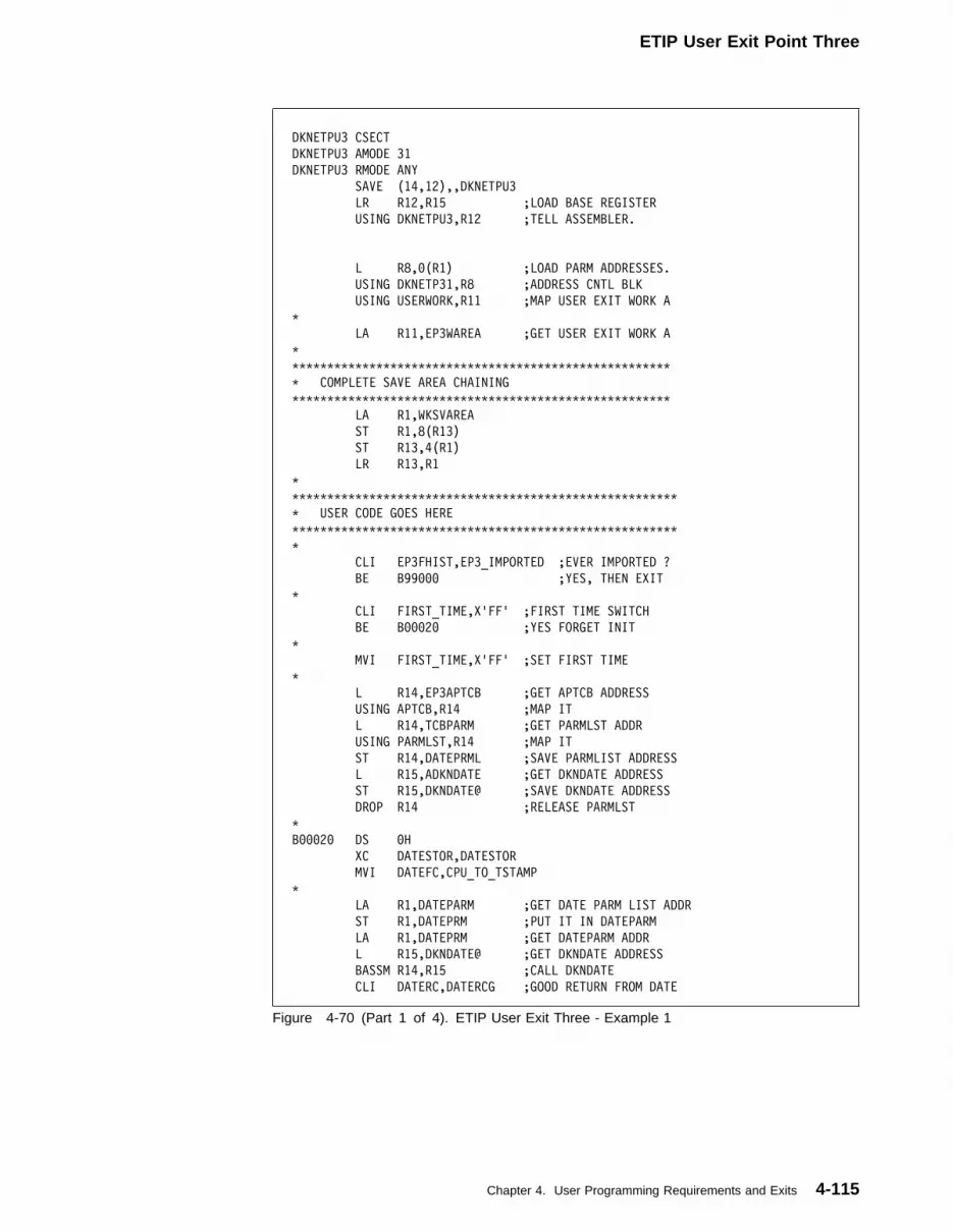
ETIP User Exit Point Three
DKNETPU3 CSECT
DKNETPU3 AMODE 31
DKNETPU3 RMODE ANY
SAVE (14,12),,DKNETPU3
LR R12,R15 ;LOAD BASE REGISTER
USING DKNETPU3,R12 ;TELL ASSEMBLER.
L R8,�(R1) ;LOAD PARM ADDRESSES.
USING DKNETP31,R8 ;ADDRESS CNTL BLK
USING USERWORK,R11 ;MAP USER EXIT WORK A
T
LA R11,EP3WAREA ;GET USER EXIT WORK A
T
TTTTTTTTTTTTTTTTTTTTTTTTTTTTTTTTTTTTTTTTTTTTTTTTTTTTTT
T COMPLETE SAVE AREA CHAINING
TTTTTTTTTTTTTTTTTTTTTTTTTTTTTTTTTTTTTTTTTTTTTTTTTTTTTT
LA R1,WKSVAREA
ST R1,8(R13)
ST R13,4(R1)
LR R13,R1
T
TTTTTTTTTTTTTTTTTTTTTTTTTTTTTTTTTTTTTTTTTTTTTTTTTTTTTTT
T USER CODE GOES HERE
TTTTTTTTTTTTTTTTTTTTTTTTTTTTTTTTTTTTTTTTTTTTTTTTTTTTTTT
T
CLI EP3FHIST,EP3_IMPORTED ;EVER IMPORTED ?
BE B99��� ;YES, THEN EXIT
T
CLI FIRST_TIME,X'FF' ;FIRST TIME SWITCH
BE B���2� ;YES FORGET INIT
T
MVI FIRST_TIME,X'FF' ;SET FIRST TIME
T
L R14,EP3APTCB ;GET APTCB ADDRESS
USING APTCB,R14 ;MAP IT
L R14,TCBPARM ;GET PARMLST ADDR
USING PARMLST,R14 ;MAP IT
ST R14,DATEPRML ;SAVE PARMLIST ADDRESS
L R15,ADKNDATE ;GET DKNDATE ADDRESS
ST R15,DKNDATE@ ;SAVE DKNDATE ADDRESS
DROP R14 ;RELEASE PARMLST
T
B���2� DS �H
XC DATESTOR,DATESTOR
MVI DATEFC,CPU_TO_TSTAMP
T
LA R1,DATEPARM ;GET DATE PARM LIST ADDR
ST R1,DATEPRM ;PUT IT IN DATEPARM
LA R1,DATEPRM ;GET DATEPARM ADDR
L R15,DKNDATE@ ;GET DKNDATE ADDRESS
BASSM R14,R15 ;CALL DKNDATE
CLI DATERC,DATERCG ;GOOD RETURN FROM DATE
Figure 4-70 (Part 1 of 4). ETIP User Exit Three - Example 1
Chapter 4. User Programming Requirements and Exits 4-115

ETIP User Exit Point Three
BNE B99�12 ;NO - TERM PROCESSING
T
MVC WORKXL1�+6(2),EP3TIME ;GET THE FILE
MVC WORKXL1�+8(2),EP3TIME+3 ;TIME IN MINS
PACK WORKXL1�(4),WORKXL1�+6(2) ;
PACK WORKXL1�+4(2),WORKXL1�+8(2)
MP WORKXL1�(4),=P'6�' ;
AP WORKXL1�(4),WORKXL1�+4(2) ;
AP WORKXL1�(4),=P'2�' ;ADD WAIT TIME
T
MVC WORKXL�5+1(1),DATETST ;GET THE
MVI WORKXL�5+2,X'�F' ;TIME IN MINS
MP WORKXL�5(3),=P'6' ;
MVO WORKXL�5+3(2),DATETST(2) ;
NI WORKXL�5+3,X'�F' ;
OI WORKXL�5+4,X'�F' ;
AP WORKXL�5(3),WORKXL�5+3(2) ;
T
CP WORKXL�5(3),WORKXL1�(4) ;WAIT PERIOD OVER
BNH B99��� ;NO, EXIT
T CLC EP3FSTAT,=AL2(EP3SELIG) ;ELIGIBLE WORK
BE B���15 ;YES, ALTER DATA
T
MVC MSGTEXT(L'SMSG1),SMSG1 ;ISSUE OPER WTO
MVC WTOLIST(WTOLEN),WTOLISTF
MVC MSGAREA(2),SMSGMS1L ;
LA R2,MSGAREA ;
WTO TEXT=(R2),
ROUTCDE=(11),
MF=(E,WTOLIST)
MVC MSGTEXT(L'SMSG2),SMSG2
MVC MSGTEXT+9(44),EP3MVSDS
MVC WTOLIST(WTOLEN),WTOLISTF
MVC MSGAREA(2),SMSGMS2L ;
LA R2,MSGAREA ;
WTO TEXT=(R2),
ROUTCDE=(11),
MF=(E,WTOLIST)
T
B B99��� ;EXIT
T
B���15 DS �H
MVC EP3IMP_SYS,EP3SRC_SYS ;ADJUST TARGET SYSTEM
MVC EP3PROFM,=C'DKNPETI1' ;ADJUST PROFILE
B B99��4 ;SET RC = 4
T
TTTTTTTTTTTTTTTTTTTTTTTTTTTTTTTTTTTTTTTTTTTTTTTTTTTTTTT
T EXIT WITH RETURN CODE ZERO - DO NOT AMEND REC
TTTTTTTTTTTTTTTTTTTTTTTTTTTTTTTTTTTTTTTTTTTTTTTTTTTTTTT
B99��� DS �H
SLR R15,R15 ;ZERO RETURN CODE
Figure 4-70 (Part 2 of 4). ETIP User Exit Three - Example 1
4-116 CPCS V1R11 Customization Guide

ETIP User Exit Point Three
B B99999 ;GO TO RETURN
TTTTTTTTTTTTTTTTTTTTTTTTTTTTTTTTTTTTTTTTTTTTTTTTTTTTTTT
T EXIT WITH RETURN CODE FOUR - AMEND RECORD
TTTTTTTTTTTTTTTTTTTTTTTTTTTTTTTTTTTTTTTTTTTTTTTTTTTTTTT
B99��4 DS �H
LA R15,4 ;SET RETURN CODE TO 4
B B99999 ;GO TO RETURN
TTTTTTTTTTTTTTTTTTTTTTTTTTTTTTTTTTTTTTTTTTTTTTTTTTTTTTT
T EXIT WITH RETURN CODE TWELVE - TERMINATE ETIP
TTTTTTTTTTTTTTTTTTTTTTTTTTTTTTTTTTTTTTTTTTTTTTTTTTTTTTT
B99��4 DS �H
LA R15,12 ;SET RETURN CODE TO 12
TTTTTTTTTTTTTTTTTTTTTTTTTTTTTTTTTTTTTTTTTTTTTTTTTTTT
T RETURN TO DKNETIP
TTTTTTTTTTTTTTTTTTTTTTTTTTTTTTTTTTTTTTTTTTTTTTTTTTTT
B99999 DS �H
XRETURN (14,12),,RC=(15)
T
TTTTTTTTTTTTTTTTTTTTTTTTTTTTTTTTTTTTTTTTTTTTTTTTTTTT
T C O N S T A N T S
TTTTTTTTTTTTTTTTTTTTTTTTTTTTTTTTTTTTTTTTTTTTTTTTTTTT
T
SMSG1 DC C'DKNETPU3 INVESTIGATE FILE '
SMSGMS1L DC AL2(L'SMSG1)
T
SMSG2 DS �CL53
DC C'DKNETIU3 '
DS CL44
SMSGMS2L DC AL2(L'SMSG2)
T
WTOLISTF WTO TEXT=(R2),ROUTCDE=(11),MF=L
WTOLEN EQU T-WTOLISTF
T
USERWORK DSECT ;USER EXIT WORK AREA
WKSVAREA DS 18F
DKNDATE@ DS F
FIRST_TIME DS XL�1
WORKXL�5 DS XL�5
WORKXL1� DS XL1�
COPY DATEPARM
TTTTTTTTTTTTTTTTTTTTTTTTTTTTTTTTTTTTTTTTTTTTT
T WTO WORK AREAS
TTTTTTTTTTTTTTTTTTTTTTTTTTTTTTTTTTTTTTTTTTTTT
DS �F
MSGAREA DC AL2(�)
MSGTEXT DC CL79' '
WTOLIST WTO TEXT=(R2),ROUTCDE=(11),MF=L
T
TTTTTTTTTTTTTTTTTTTTTTTTTTTTTTTTTTTTTTTTTTTTTTTTTTTT
T DSECTS AND VARIABLE STORAGE
TTTTTTTTTTTTTTTTTTTTTTTTTTTTTTTTTTTTTTTTTTTTTTTTTTTT
T
COPY DKNAPTCB ;LAYOUT - CPCS APTCB
COPY DKNPARM ;LAYOUT - CPCS COMM PARM
Figure 4-70 (Part 3 of 4). ETIP User Exit Three - Example 1
Chapter 4. User Programming Requirements and Exits 4-117

DKNETCFU User Exit One
T
TTTTTTTTTTTTTTTTTTTTTTTTTTTTTTTTTTTTTTTTTTTTTTTTTTTT
T LAYOUT OF USER EXIT CONTROL BLOCK
TTTTTTTTTTTTTTTTTTTTTTTTTTTTTTTTTTTTTTTTTTTTTTTTTTTT
DKNETP31 DSECT=YES ;USER EXIT CONTROL BLOCK
END
Figure 4-70 (Part 4 of 4). ETIP User Exit Three - Example 1
DKNETCFU User Exit One — Control File Record CreateDKNETCFU user exit one is only called for create runs and is used to allow thecustomer to set any of the import data fields for each Transmission data set writtento the Electronic Transaction Control File by the batch utility job DKNJECFU.
ActivationThe user exit is optional. To activate the user exit, DKNETCU1 should beassembled and linked onto a load library that is concatenated into the steplib of thebatch job DKNJECFU.
LinkageThe standard OS/390 linkage conventions are followed.
Information is passed in the following interface control blocks:
The exit routine may return the following condition codes in the RETURN-CODEspecial register (COBOL programs) or register 15 (assembler programs).
Figure 4-71. ETCFU User Exit One Communication Control Block
Control BlockCOBOLCopybook
AssemblerMacro/Copybook
Call Parameters List DKNETC12 DKNETC11
Figure 4-72. DKNETCFU User Exit Return Codes
Code (dec) Request
+00 Continue processing
ExampleThis sample exit instructs DKNETCFU to write each electronic control file record tothe electronic control file.
Processing Description� Get the control blocks passed by DKNETCFU.
� Set up addressability for all the relevant records.
� If this is the first time, set the first-time flag.
� Instuct DKNETCFU to write the record.
ETCFU User Exit Routine:
4-118 CPCS V1R11 Customization Guide

DKNETCFU User Exit One
DKNETCU1 CSECT
DKNETCU1 AMODE 31
DKNETCU1 RMODE ANY
SAVE (14,12),,DKNETCU1
LR R12,R15 ;LOAD BASE REGISTER
USING DKNETCU1,R12 ;TELL ASSEMBLE
TTTTTTTTTTTTTTTTTTTTTTTTTTTTTTTTTTTTTTTTTTTTTTTTTTTT
T PICK UP INPUT PARMS T
TTTTTTTTTTTTTTTTTTTTTTTTTTTTTTTTTTTTTTTTTTTTTTTTTTTT
L R7,�(R1) ;LOAD PARM ADDRESS
USING DKNETC11,R7 ;MAP PARAMETER AREA
T
LA R8,ECU1WKA ;GET USER EXIT WORK A
USING USERWORK,R8 ;MAP USER EXIT WORK A
T
TTTTTTTTTTTTTTTTTTTTTTTTTTTTTTTTTTTTTTTTTTTTTTTTTTTTTT
T COMPLETE SAVE AREA CHAINING
TTTTTTTTTTTTTTTTTTTTTTTTTTTTTTTTTTTTTTTTTTTTTTTTTTTTTT
LA R1,WKSVAREA
ST R1,8(R13)
ST R13,4(R1)
LR R13,R1
T
CLI FIRST_TIME,X'��' ;FIRST TIME ?
BNE B1���� ;NO, SO CONTINUE
T
MVI FIRST_TIME,X'FF' ;SET FIRST TIME
T
TTTTTTTTTTTTTTTTTTTTTTTTTTTTTTTTTTTTTTTTTTTTTTTTTTTTTT
T USER CODE GOES HERE
TTTTTTTTTTTTTTTTTTTTTTTTTTTTTTTTTTTTTTTTTTTTTTTTTTTTTT
B1���� EQU T
MVI ECU1RSP,ECU1RSP_WRITE ;WRITE THE CF REC
TTTTTTTTTTTTTTTTTTTTTTTTTTTTTTTTTTTTTTTTTTTTTTTTTTTT
T RETURN TO DKNETIN
TTTTTTTTTTTTTTTTTTTTTTTTTTTTTTTTTTTTTTTTTTTTTTTTTTTT
B99999 DS �H
T
SLR R15,R15 ;ZERO RETURN
L R13,WKSVAREA+4
XRETURN (14,12),,RC=(15)
TTTTTTTTTTTTTTTTTTTTTTTTTTTTTTTTTTTTTTTTTTTTTTTTTTTT
T C O N S T A N T S
TTTTTTTTTTTTTTTTTTTTTTTTTTTTTTTTTTTTTTTTTTTTTTTTTTTT
T
USERWORK DSECT
WKSVAREA DS 18F
T
FIRST_TIME DS CL��1
T
TTTTTTTTTTTTTTTTTTTTTTTTTTTTTTTTTTTTTTTTTTTTTTTTTTTTTT
T LAYOUT OF THE USER EXIT CONTROL BLOCK T
TTTTTTTTTTTTTTTTTTTTTTTTTTTTTTTTTTTTTTTTTTTTTTTTTTTTTT
Figure 4-73 (Part 1 of 2). ETIP User Exit Three - Example 1
Chapter 4. User Programming Requirements and Exits 4-119

DKNETC11 DSECT=YES ;DKNETCFU CB
T
END
Figure 4-73 (Part 2 of 2). ETIP User Exit Three - Example 1
4-120 CPCS V1R11 Customization Guide

Customizing ETCSH and X937 User Exits
Customizing ETCSH and X937 User ExitsFour user exits are available for use as part of the Electronic Transaction CashLetter function:
� DKNETCSH_FORMATS=DKNETX01 � DKNETCSH_0100_NEW_RECORD=DKNETX02 � DKNETCSH_0200_FILE_CREATED=DKNETX03 � DKNX937_0100_NEW_RECORD=DKNETX04
DKNETCSH_FORMATSDKNETCSH calls this program during initialization time to determine if a formatother than X9.37 is required and, if so, to pass back the file length. It is also calledfor every detail item to determine if a file format other than X9.37 is required.
Initialize Work AreasIn the work areas you can check if a special type of record is to be created. Theserecords may be specified in the kill-bundle record that can be accessed through theETPM dsect. If the special records are to be processed, and the record length isgreater than 80 (size of X9.37 record), the new length must be placed in theDSCRECLN field. The DSCSWCH1 flag can be set to identify special records andcan be used in future calls of this exit.
Detail Record ProcessingIf we are processing a format other than X9.37, and if it is applicable, produce thenecessary data, such as file headers. Also adjust record pointers, if necessary, sothat records are written out correctly.
EnvironmentThis exit is given control within DKNCLSM TCB.
Point of ProcessingThis exit is called during the initialization process of DKNETCSH to determine ifspecial records are to be created. If special records are to be processed, this exit iscalled prior to creating X9.37 records for each record processed.
ActivationAll exits for this exit point are specified in the CPCS system profile (DKNPEXIT),which is located in the CPCS.V1R11.SYSTPROF partitioned data set. TheDKNETCSH_FORMATS=keyword is used to specify an exit for this exit point.
LinkageThe standard OS/390 linkage conventions are followed.
Information is passed in the following interface control blocks:
Figure 4-74. DKNETCSH_FORMATS Point Parameter List
Offset Description
+00 CPCS Parameter List (DKNPARM)
+04 DKNETCSH Parameter Block (DKNETPM1)
+08 DKNETCSH Data Set Control Area (DKNETDSC)
Chapter 4. User Programming Requirements and Exits 4-121
Customizing ETCSH and X937 User Exits
Register Contents When Control is Passed to the Exit Routine:
R0 Not applicable
R1 Parameter list address
R2-R12 Not applicable
R13 Caller’s save area address
R14 Return Address
R15 User exit entry point address
Register Contents When Control is Passed Back to CPCS:
R0 Not applicable
R1 Not applicable
R2-R13 Restored to same values as on user exit entry
R14 Not applicable
R15 Return codes as described below
0 Good return code
4 Warning level error
8 Error
12 Severe Error
Other Programming ConsiderationsNote: IBM requires this exit to be re-entrant.
Example:Member DKNETX01, in the CPCS.V1R11.SAMPLIB partitioned data set, may beused as an example when coding assembler exit routines for this exit point.
DKNETCSH_0100_NEW_RECORDThis program is called by DKNETCSH after an X9.37 record has been created.This exit allows the operator to modify the X9.37 record.
EnvironmentThis exit is given control within DKNCLSM TCB.
Point of ProcessingEach X9.37 record is passed to this exit and the operator can modify the record asnecessary.
ActivationAll exits for this exit point are specified in the CPCS system profile (DKNPEXIT),which is located in the CPCS.V1R11.SYSTPROF partitioned data set. TheDKNETCSH_0100_NEW_RECORD=keyword is used to specify an exit for this exitpoint.
4-122 CPCS V1R11 Customization Guide
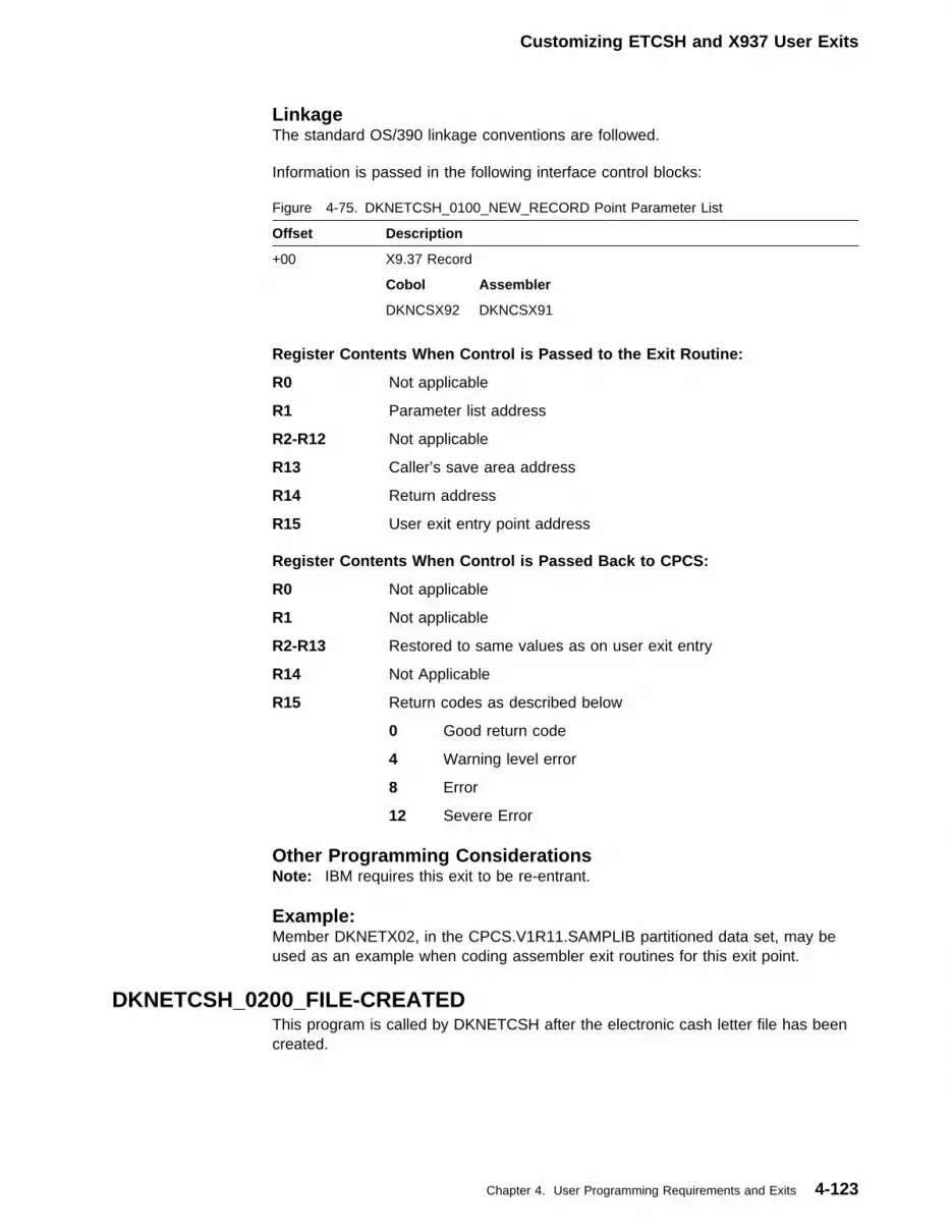
Customizing ETCSH and X937 User Exits
LinkageThe standard OS/390 linkage conventions are followed.
Information is passed in the following interface control blocks:
Register Contents When Control is Passed to the Exit Routine:
R0 Not applicable
R1 Parameter list address
R2-R12 Not applicable
R13 Caller’s save area address
R14 Return address
R15 User exit entry point address
Register Contents When Control is Passed Back to CPCS:
R0 Not applicable
R1 Not applicable
R2-R13 Restored to same values as on user exit entry
R14 Not Applicable
R15 Return codes as described below
0 Good return code
4 Warning level error
8 Error
12 Severe Error
Figure 4-75. DKNETCSH_0100_NEW_RECORD Point Parameter List
Offset Description
+00 X9.37 Record
Cobol Assembler
DKNCSX92 DKNCSX91
Other Programming ConsiderationsNote: IBM requires this exit to be re-entrant.
Example:Member DKNETX02, in the CPCS.V1R11.SAMPLIB partitioned data set, may beused as an example when coding assembler exit routines for this exit point.
DKNETCSH_0200_FILE-CREATEDThis program is called by DKNETCSH after the electronic cash letter file has beencreated.
Chapter 4. User Programming Requirements and Exits 4-123

Customizing ETCSH and X937 User Exits
EnvironmentThis exit is given control within DKNCLSM TCB.
Point of ProcessingThis exit, named DKNETX03, is called after the electronic cash letter file has beencreated. The exit receives the data set name of the cash letter file.
ActivationAll exits for this exit point are specified in the CPCS system profile (DKNPEXIT),which is located in the CPCS.V1R11.SYSTPROF partitioned data set. TheDKNETCSH_0200_FILE_CREATED=keyword is used to specify an exit for this exitpoint.
LinkageThe standard OS/390 linkage conventions are followed.
Information is passed in the following interface control blocks:
Register Contents When Control is Passed to the Exit Routine:
R0 Not applicable
R1 Parameter list address
R2-R12 Not applicable
R13 Caller’s save area address
R14 Return address
R15 User exit entry point address
Register Contents When Control is Passed Back to CPCS:
R0 Not applicable
R1 Not applicable
R2-R13 Restored to same values as on user exit entry
R14 Not applicable
R15 Return codes as described below
0 Good return code
4 Warning level error
Figure 4-76. DKNETCSH_0200_FILE-CREATED Point Parameter List
Offset Description
+00 DKNETCSH Parameter Block
Cobol Assembler
DKNETPM2 DKNETPM1
04 Cash Letter Data Set Name
08 Application Task Control Block
Cobol Assembler
DKNCATCB DKNAPTCB
4-124 CPCS V1R11 Customization Guide

Customizing ETCSH and X937 User Exits
8 Error
12 Severe Error
Other Programming ConsiderationsNote: IBM requires this exit to be re-entrant.
ExampleMember DKNETX03, in the CPCS.V1R11.SAMPLIB partitioned data set, may beused as an example when coding assembler exit routines for this exit point.
DKNX937_0100_NEW_RECORDThis program is called by DKNX937 after an X9.37 record has been created. Thisexit allows the operator to modify the X9.37 record.
EnvironmentThis exit is given control within DKNCLSM TCB.
Point of ProcessingEach X9.37 record is passed to this exit and the operator can modify the record asnecessary.
ActivationAll exits for this exit point are specified in the CPCS system profile (DKNPEXIT),which is located in the CPCS.V1R11.SYSTPROF partitioned data set. TheDKNX937_0100_NEW_RECORD=keyword is used to specify an exit for this exitpoint.
LinkageThe standard OS/390 linkage conventions are followed.
Information is passed in the following interface control blocks:
Register Contents When Control is Passed to the Exit Routine:
R0 Not applicable
R1 Parameter list address
R2-R12 Not applicable
R13 Caller’s save area address
R14 Return address
R15 User exit entry point address
Register Contents When Control is Passed Back to CPCS:
Figure 4-77. DKNX937_0100_NEW_RECORD Point Parameter List
Offset Description
+00 X9.37 Record
Cobol Assembler
DKNCSX92 DKNCSX91
Chapter 4. User Programming Requirements and Exits 4-125

R0 Not applicable
R1 Not applicable
R2-R13 Restored to same values as on user exit entry
R14 Not applicable
R15 Return codes as described below
0 Good return code
4 Warning level error
8 Error
12 Severe Error
Other Programming ConsiderationsNote: IBM requires this exit to be re-entrant.
ExampleMember DKNETX04, in the CPCS.V1R11.SAMPLIB partitioned data set, may beused as an example when coding assembler exit routines for this exit point.
4-126 CPCS V1R11 Customization Guide
DKLNDMY and DKNLJMP Exit
DKNLDMY and DKNLJMP Exit — Logging Job MVS Posture
DKNLDMY (Dummy executive task)DKNLDMY is an executive task that can be automatically started each time CPCSis started. DKNLDMY’s only function is to autostart DKNLJMP at CPCS start-up.
DKNLJMPDKNLJMP reports the status of the logging files and gives control to a user exit thatcan then tell DKNLJMP to automatically start a backup. It has three distinct levels.
1. DKNBKUP and DKNBBKUP turn on a backup in progress flag (BIP), and theysend a message to indicate a backup has started. When the backupcompletes successfully an additional message is sent to indicate the backuptask (either DKNBKUP or DKNBBKUP) ran successfully.
2. DKNLJMP can be run manually by the CPCS supervisor or startedautomatically by the executive task DKNLDMY, to check the status of the BIPflag. If no user exit is specified DKNLJMP will send messages to the CPCSsupervisor and the CPCS SCROLL data set indicating the status of the DASDlogging files. If a user exit is specified then the user exit can instruct DKNLJMPto autostart either DKNBBKUP or DKNBKUP. Using this technique andLOGCRASH, you can now have a backup run each time CPCS is started andstopped.
3. LOGCRASH is a batch job that when placed in the CPCS run JCL before orafter the CPCS JOBSTEP will run and backup the logging files. DKNLJMP’sprimary purpose is to provide the CPCS supervisor a way within CPCS todetermine if either DKNBKUP or DKNBBKUP completed successfully.
DASD logging will log to either of two files whose DDNAMES are DKNLD1 andDKNLD2. Logging will log to one of these two files and when the file gets fulllogging will flip-flop the files and continue logging to the other file. Logging thenautostarts either DKNBKUP or submits an MVS job to start DKNBBKUP, wheneither DKNBKUP or DKNBBKUP complete the recovery status file is updated toreflect the status of the DASD logging files.
DKNLJMP reads the recovery status file (DDNAME DKNRCVTD) to determine ifDKNBKUP or DKNBBKUP has successfully completed.
If DKNBKUP or DKNBBKUP do not complete successfully then DKNLJMP willattempt a restart of either DKNBKUP or DKNBBKUP, if told to do so by theDKNLJMP user exit. The user should however verify that DKNBKUP orDKNBBKUP are not currently running (they may be waiting for a tape mount orother system resources). This capability has not been included in the user exit; thedefault in the user exit is that a backup is started using the parameters in thesystem profile member DKNPRCVY.
The LJMP user exit receives control at three times during the execution ofDKNLJMP.
� During Initialization
� After the logging status file has been read. The user exit may be able todetermine the status of the logging files by testing to see if at least one of the
Chapter 4. User Programming Requirements and Exits 4-127
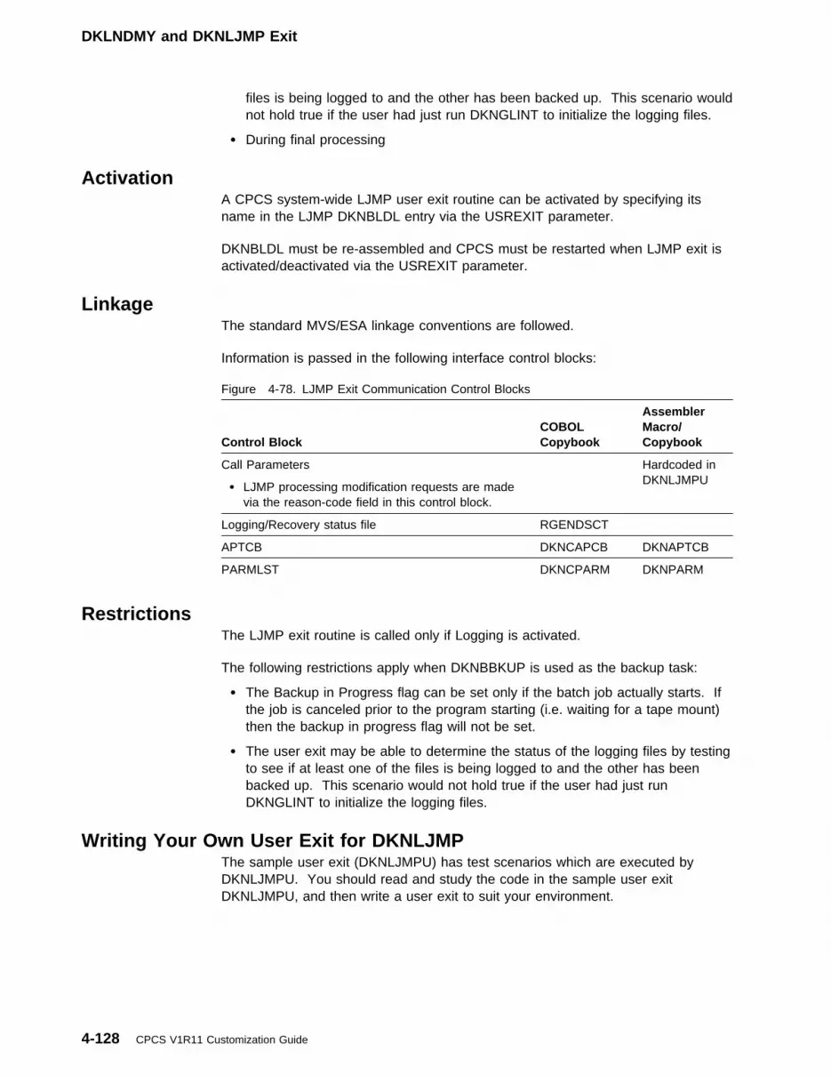
DKLNDMY and DKNLJMP Exit
files is being logged to and the other has been backed up. This scenario wouldnot hold true if the user had just run DKNGLINT to initialize the logging files.
� During final processing
ActivationA CPCS system-wide LJMP user exit routine can be activated by specifying itsname in the LJMP DKNBLDL entry via the USREXIT parameter.
DKNBLDL must be re-assembled and CPCS must be restarted when LJMP exit isactivated/deactivated via the USREXIT parameter.
LinkageThe standard MVS/ESA linkage conventions are followed.
Information is passed in the following interface control blocks:
Figure 4-78. LJMP Exit Communication Control Blocks
Control BlockCOBOLCopybook
AssemblerMacro/Copybook
Call Parameters
� LJMP processing modification requests are madevia the reason-code field in this control block.
Hardcoded inDKNLJMPU
Logging/Recovery status file RGENDSCT
APTCB DKNCAPCB DKNAPTCB
PARMLST DKNCPARM DKNPARM
RestrictionsThe LJMP exit routine is called only if Logging is activated.
The following restrictions apply when DKNBBKUP is used as the backup task:
� The Backup in Progress flag can be set only if the batch job actually starts. Ifthe job is canceled prior to the program starting (i.e. waiting for a tape mount)then the backup in progress flag will not be set.
� The user exit may be able to determine the status of the logging files by testingto see if at least one of the files is being logged to and the other has beenbacked up. This scenario would not hold true if the user had just runDKNGLINT to initialize the logging files.
Writing Your Own User Exit for DKNLJMPThe sample user exit (DKNLJMPU) has test scenarios which are executed byDKNLJMPU. You should read and study the code in the sample user exitDKNLJMPU, and then write a user exit to suit your environment.
4-128 CPCS V1R11 Customization Guide

DKNLOGU: Logging User Exit
DKNLOGU: Logging User ExitDKNLOGU is the default name for the logging user exit.
DKNRCVY_EXIT1000_BEFORE_WRITEThe primary purpose of this exit is to provide your CPCS system a point at which toexamine each item and to adjust the item record for your individual requirements.This user exit routine is entered once for each item processed by DKNRCVY.
EnvironmentThis exit is given control within DKNRCVY.
Point of ProcessingThis exit is called before the write to the mass data set. Each item is passed to theexit after DKNRCVY has performed its conversion process.
ActivationAll exits for this exit point are specified in the CPCS system profile (DKNPEXIT),which is located in the CPCS.V1R11.SYSTPROF partitioned data set. TheDKNRCVY_EXIT1000_BEFORE_WRITE=keyword is used to specify an exit for thisexit point. Up to the maximum number of entry points per exit may be specified forthis exit point. See “DKNPCPCS Profile Member” on page 3-6 for this profile,located in the SYSTPROF data set, for details on the MAX_EP_EXIT parameter.
Each exit is called, in the order they were specified in the DKNPEXIT profile, untilthere are no more exits or until one of the exits denies the request with a returncode.
Register Contents When Control Is Passed to the Exit Routine
R0 Not applicable
R1 Parameter list address
R2-R12 Not applicable
R13 Caller’s save area address
R14 Return address
R15 User exit entry point address
Figure 4-79. DKNRCVY_EXIT1000_BEFORE_WRITE Point Parameter List
Offset Description
+00 Caller’s APTCB Address (DKNAPTCB)
+04 Tape Record Address
+08 MDS Record Address
+12 RDX Address (RDXREC)
+16 XREC Address (MDXREC)
Chapter 4. User Programming Requirements and Exits 4-129

DKNMBEGN User Processing Exit
Register Contents When Control Is Passed Back to CPCS
R0 Not applicable
R1 Not applicable
R2-R13 Restored to same values as on user exit entry
R14 Not applicable
R15 Return codes as described below:
xx Non-zero - do not write item to MDS
Other Programming ConsiderationsNotes:
1. IBM requires this exit be re-entrant.
2. MDSREC is the updated record written to the mass data set.
ExampleMember DKNLOGU, in the CPCS.V1R11.SAMPLIB partitioned data set, may beused as an example when coding assembler exit routines for this exit point.
DKNMBEGN User Processing ExitThe CPCSOPTN macro specifies the DKNMBEGN user processing exit. It permitsexit-routine inspection of the information that the operator enters on the MICRBEGIN screen and determines whether to return a diagnostic message to theoperator or to permit the entry to start. If specified, this user-supplied routine isentered after the operator presses ENTER to verify the BEGIN screen, but beforethe start of the entry.
When accepting an entry, the exit might cause 4 bytes of user data, for use byapplication programs, to go into the string-header record of the entry I-string. Thisoption also permits the operator to enter up to 12 bytes of additional information, inaddition to the normal BEGIN screen input, so that the DKNMBEGN user exit caninspect it and process accordingly, based on user criteria. An example of this exitappears on the following pages.
To use the option, the CPCSOPTN macro operand BEXIT=symbol must bespecified. Symbol is the name of the user-written exit routine that loads duringMICR task initialization. After the routine loads, it is resident throughout CPCSrunning. You must ensure that the exit routine is reentrant. The same copy of theprogram is used for all active document processors.
The user-exit routine receives control from the MICR BEGIN command processorafter the operator verifies the screen by pressing ENTER, but before the start of theentry. On entry to the user-exit routine, register 1 contains the address of a16-byte field. The first 12 bytes contain information that the operator entered onthe option line of the screen. The first 2 of these bytes must be U=. The rest ofthe field is user-dependent. You must key in U=X...X so that the exit routine willprocess this information. If the data entered is less than 12 bytes, it is padded withblanks. The user-exit routine can use the last 4 bytes of the 16-digit field. WhenDKNMBEGN regains control from the user-exit routine, it puts the 4 bytes intoRSCBUSPA and this field is later inserted into the string header (DIDSCT) for
4-130 CPCS V1R11 Customization Guide
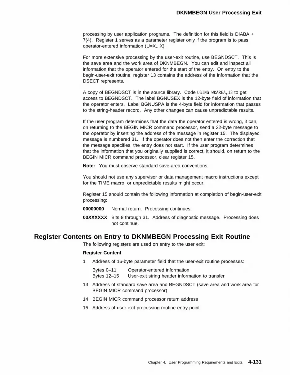
DKNMBEGN User Processing Exit
processing by user application programs. The definition for this field is DIABA +7(4). Register 1 serves as a parameter register only if the program is to passoperator-entered information (U=X...X).
For more extensive processing by the user-exit routine, use BEGNDSCT. This isthe save area and the work area of DKNMBEGN. You can edit and inspect allinformation that the operator entered for the start of the entry. On entry to thebegin-user-exit routine, register 13 contains the address of the information that theDSECT represents.
A copy of BEGNDSCT is in the source library. Code USING WKAREA,13 to getaccess to BEGNDSCT. The label BGNUSEX is the 12-byte field of information thatthe operator enters. Label BGNUSPA is the 4-byte field for information that passesto the string-header record. Any other changes can cause unpredictable results.
If the user program determines that the data the operator entered is wrong, it can,on returning to the BEGIN MICR command processor, send a 32-byte message tothe operator by inserting the address of the message in register 15. The displayedmessage is numbered 31. If the operator does not then enter the correction thatthe message specifies, the entry does not start. If the user program determinesthat the information that you originally supplied is correct, it should, on return to theBEGIN MICR command processor, clear register 15.
Note: You must observe standard save-area conventions.
You should not use any supervisor or data management macro instructions exceptfor the TIME macro, or unpredictable results might occur.
Register 15 should contain the following information at completion of begin-user-exitprocessing:
00000000 Normal return. Processing continues.
00XXXXXX Bits 8 through 31. Address of diagnostic message. Processing doesnot continue.
Register Contents on Entry to DKNMBEGN Processing Exit RoutineThe following registers are used on entry to the user exit:
Register Content
1 Address of 16-byte parameter field that the user-exit routine processes:
Bytes 0–11 Operator-entered informationBytes 12–15 User-exit string header information to transfer
13 Address of standard save area and BEGNDSCT (save area and work area forBEGIN MICR command processor)
14 BEGIN MICR command processor return address
15 Address of user-exit processing routine entry point
Chapter 4. User Programming Requirements and Exits 4-131

DKNMDIS User Exit
Sample DKNMBEGN User Processing Exit RoutineA sample routine is in CPCS.V1R11.SAMPLIB under the name BEGNEXIT. Thissample routine serves as a guide for the user. It performs the following functions:
1. Checks to see whether the operator entered U=run1 on the option line of theBEGIN command processor.
If yes, the exit-processing routine continues. If the operator entered blanks, theexit processing is bypassed. Otherwise, the routine inserts the address of themessage WRONG EXIT INFORMATION ENTERED in register 15 and returns to theBEGIN command processor.
2. Checks to see whether the cycle that the operator entered is 8.
If it is, exit processing continues. If not, the routine inserts the address of themessage THE CYCLE ENTERED IS WRONG in register 15 and returns to the BEGINcommand processor.
3. Checks to see whether the sort type that the operator entered is 1, 4, or 60.
If it is one of these, the routine moves RUN1 into BGNUSPA, clears register15, and returns to the BEGIN command processor.
If the sort type is not one of the above numbers, the routine inserts the addressof the message THE SORT TYPE ENTERED IS WRONG and returns to the BEGINcommand processor.
DKNMDIS–ESM Task Profile User Data AreaIf DKNMDIS is automatically started with the Enhanced System Manager feature ofCPCS, one of the following options should be entered in the user data area of thetask profile:
ESM User Option Corresponding Manual Start Optionnull 1 (No option specified defaults to option 01)01 1 (Normal distribution - the default)02 2 (Force distribute enhanced reject pockets)03 3 (Force distribute kill pockets)04 4 (Force redistribute enhanced reject pockets)
| DKNMDIS User Exit — Modify M-String Distribution| The MDIS user exit lets you examine and modify the distribution decisions made by| DKNMDIS. You can:
| � Distribute codeline records to D-strings other than the ones selected by MDIS.
| � Exclude codeline records from being distributed.
| � Distribute non-distributable records.
| � Instruct MDIS to stop calling the exit.
| � Terminate MDIS processing.
4-132 CPCS V1R11 Customization Guide

DKNMDIS User Exit
| Environment| This exit is given control within the DKNMDIS TCB.
| Point of Processing| DKNMDIS makes a “DIST” call to the user exit each time it builds a collection of| related codelines. “Related” codelines consist of the main codeline, plus any| original rejects and balancing records that are associated with it. DKNMDIS passes| the entire collection to the exit in a codeline buffer.
| DKNMDIS also makes an “INIT” call to the exit when it has successfully opened an| M-string and read its first record, and a “TERM” call when all processing is| complete.
| Activation| An MDIS user exit may be specified on the O-record of a sort pattern definition. It| takes effect for each entry captured on that particular pass of that sort pattern. See| “Sort-Pattern-Definition Record Formats” on page 4-17 for more information.
| An MDIS user exit may be specified on record 007 of a bank control file group. It| takes effect for each entry captured for that bank. See “Bank-Control-File Record| Formats” on page 4-5 for more information.
| An MDIS user exit may be specified on the USREXIT parameter of DKNMDIS’s| BLDL entry. Once DKNBLDL is reassembled and CPCS restarted, the exit takes| effect every time DKNMDIS runs.
| If an MDIS user exit exists in more than one place, the sort pattern definition| version takes precedence, followed by the Bank Control file version, and then the| DKNBLDL USREXIT version.
| If no MDIS user exit exists in any of the three locations, DKNMDIS makes no| attempt to call one.
| Linkage| Information is passed in the following interface control blocks:
| Register Contents When Control Is Passed to the Exit Routine
| R0 Not applicable
| R1 Parameter list address
| Figure 4-80. MDIS Exit Parameter List
| Offset| Control Block| COBOL Copybook| Assembler Macro/| Copybook
| +00| Call Parameters| DKNMDIXC| DKNMDIXP
| +04| MDS Codeline Buffer| DKNCRDI,| DKNCRZC| ZDSCT, DEDSCT
| +08| MDIS Destination Stack| DKNMDISQ| DKNMDIXP
| +12| String Directory Information| DKNCRZE| ZEDSCT
| +16| MDIS Candidate List| DKNMDISS| DKNMDIXP
Chapter 4. User Programming Requirements and Exits 4-133

DKNMDIS User Exit
| R2-R12 Not applicable
| R13 Caller’s save area address
| R14 Return address
| R15 User exit entry point address
| Register Contents When Control Is Passed Back to CPCS
| R0 Not applicable
| R1 Not applicable
| R2-R13 Restored to same values as on user exit entry
| R14 Not applicable
| R15 Zero. Return codes are replied back through the Call Parameters| control block.
| Other Programming Considerations| Call Parameters:
| On Entry:
| The function code contains one of three values:
| INIT This is the initial call to the exit.
| DIST The MDS Codeline Buffer/MDIS Stack has a group of related| codelines for you to examine. The M-STRING field tells you what| M-string is being distributed, and the RUN-OPTION field tells you| what distribution option was selected.
| FINL This is the final call to the exit.
| On Exit:
| Three different return codes are returned simultaneously:
| Figure 4-81 (Page 1 of 2). Return codes on exit from MDIS
| Return Code Type| Return| Code| Description
| REASON CODE| 0000| No change
| | 0004| A pocket has been changed for a| codeline’s MDIS stack entry. When| MDIS creates a D-string for that| pocket, it turns on the string’s UD| “Altered D-string” flag.
| | 0020| Terminate DKNMDIS. DKNMDIS| displays message MDIS 30013 and| quits without distributing D-strings.
| | 0099| Stop calling the exit. DKNMDIS| continues to run but makes no more| DIST calls to the user exit. It also does| not make a FINL call.
| MESSAGE CONTROL| Blank| Do no messaging.
| | M| If a terminal is attached, display the| message in the Message Buffer.
4-134 CPCS V1R11 Customization Guide
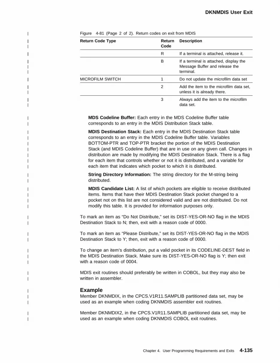
DKNMDIS User Exit
| MDS Codeline Buffer: Each entry in the MDS Codeline Buffer table| corresponds to an entry in the MDIS Distribution Stack table.
| MDIS Destination Stack: Each entry in the MDIS Destination Stack table| corresponds to an entry in the MDIS Codeline Buffer table. Variables| BOTTOM-PTR and TOP-PTR bracket the portion of the MDIS Destination| Stack (and MDIS Codeline Buffer) that are in use on any given call. Changes in| distribution are made by modifying the MDIS Destination Stack. There is a flag| for each item that controls whether or not it is distributed, and a variable for| each item that indicates which pocket to which it is distributed.
| String Directory Information: The string directory for the M-string being| distributed.
| MDIS Candidate List: A list of which pockets are eligible to receive distributed| items. Items that have their MDIS Destination Stack pocket changed to a| pocket not on this list are not considered valid and are not distributed. Do not| modify this table. It is provided for information purposes only.
| To mark an item as “Do Not Distribute,” set its DIST-YES-OR-NO flag in the MDIS| Destination Stack to N; then, exit with a reason code of 0000.
| To mark an item as “Please Distribute,” set its DIST-YES-OR-NO flag in the MDIS| Destination Stack to Y; then, exit with a reason code of 0000.
| To change an item’s distribution, put a valid pocket in its CODELINE-DEST field in| the MDIS Destination Stack. Make sure its DIST-YES-OR-NO flag is Y; then exit| with a reason code of 0004.
| MDIS exit routines should preferably be written in COBOL, but they may also be| written in assembler.
| Figure 4-81 (Page 2 of 2). Return codes on exit from MDIS
| Return Code Type| Return| Code| Description
| | R| If a terminal is attached, release it.
| | B| If a terminal is attached, display the| Message Buffer and release the| terminal.
| MICROFILM SWITCH| 1| Do not update the microfilm data set
| | 2| Add the item to the microfilm data set,| unless it is already there.
| | 3| Always add the item to the microfilm| data set.
| Example| Member DKNMDIX, in the CPCS.V1R11.SAMPLIB partitioned data set, may be| used as an example when coding DKNMDIS assembler exit routines.
| Member DKNMDIX2, in the CPCS.V1R11.SAMPLIB partitioned data set, may be| used as an example when coding DKNMDIS COBOL exit routines.
Chapter 4. User Programming Requirements and Exits 4-135
DKNMIPI User Processing Exit
DKNMIPI User Processing ExitThis exit is an option in CPCSOPTN, in the bank control file, or in the SPDEF. Itgives you control over the records sent to the document processor for codeline datamatching. If specified, the user-supplied routine is presented for each documentthat the document-processing work element of MICR (DKNMIPI) processes.
To select this option, you must specify the CPCSOPTN macro operandMEXIT=nnnnnnnn, where nnnnnnnn is the name of a user-written exit routine thatloads during MICR task initialization. In addition, you can specify a differentDKNMIPI exit in the BCF for each financial institution or for each run type in theSPDEF.
DKNMIPI user exit routines must be re-entrant. Results will be unpredictable if thisrequirement is not met.
DKNMIPI uses the user-exit routine for each codeline data record or group ofrecords whose item sequence numbers are the same. DKNMIPI passes the recordor records along with the entire MDS codeline data record to the exit routine in abuffer that contains a flag byte for each record. The default buffer contains slots for16 codeline data records.
The user-exit routine must indicate, through the flag byte, which records to send tothe document processor for codeline data matching. The flag byte is preset withX'00', indicating that normal document records should be sent to the documentprocessor. Unused buffer slots are filled with X'00'.
Reject codeline records (DITYPEI=X'95'), change control records (DITYPEI=X'85'and DI3CHG on), and power-encoding records (DITYPEI=X'86') are preset withX'FF', indicating that they should not be sent to the document processor. Theuser-exit routine can prevent a record from being sent to the document processorby placing any value other than X'00' in the associated flag byte. For moreinformation about these records, see “Balancing and Power-EncodingConsiderations” on page 4-171.
DKNMIPI provides the prior pass D-string records in groups of 16 to the documentprocessor. These groups of 16 documents are sequential in the order that they areon the prior pass D-string. Resynchronization may be required for conditions suchas a Divider Slip, a sorter pause, or an out-of-synch condition. This will causeDKNMIPI to back up in the prior pass D-string, and process some records again.Records that are processed again will be sent to the MIPIEXIT if one is specified,and then sent to the document processor.
Notes:
1. A resynchronization is done after the first two buffers are sent following newtracers due to a possible sorter pause. This results in most of the first buffer,and all of the second buffer being repeated.
2. When divider resynchronization is active, the divider slips must be encoded withunique serial numbers and with the field that identifies the control document.When codeline data matching is active, the input of D-string data records mustbe synchronized on a restart. The D-string records must also beresynchronized for each new tracer group, divider slip, or string combination.
4-136 CPCS V1R11 Customization Guide
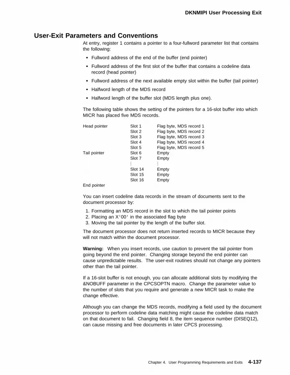
DKNMIPI User Processing Exit
User-Exit Parameters and ConventionsAt entry, register 1 contains a pointer to a four-fullword parameter list that containsthe following:
� Fullword address of the end of the buffer (end pointer)
� Fullword address of the first slot of the buffer that contains a codeline datarecord (head pointer)
� Fullword address of the next available empty slot within the buffer (tail pointer)
� Halfword length of the MDS record
� Halfword length of the buffer slot (MDS length plus one).
The following table shows the setting of the pointers for a 16-slot buffer into whichMICR has placed five MDS records.
You can insert codeline data records in the stream of documents sent to thedocument processor by:
1. Formatting an MDS record in the slot to which the tail pointer points2. Placing an X'00' in the associated flag byte3. Moving the tail pointer by the length of the buffer slot.
The document processor does not return inserted records to MICR because theywill not match within the document processor.
Warning: When you insert records, use caution to prevent the tail pointer fromgoing beyond the end pointer. Changing storage beyond the end pointer cancause unpredictable results. The user-exit routines should not change any pointersother than the tail pointer.
If a 16-slot buffer is not enough, you can allocate additional slots by modifying the&NOBUFF parameter in the CPCSOPTN macro. Change the parameter value tothe number of slots that you require and generate a new MICR task to make thechange effective.
Although you can change the MDS records, modifying a field used by the documentprocessor to perform codeline data matching might cause the codeline data matchon that document to fail. Changing field 8, the item sequence number (DISEQ12),can cause missing and free documents in later CPCS processing.
Head pointer Slot 1 Flag byte, MDS record 1 Slot 2 Flag byte, MDS record 2 Slot 3 Flag byte, MDS record 3 Slot 4 Flag byte, MDS record 4 Slot 5 Flag byte, MDS record 5Tail pointer Slot 6 Empty Slot 7 Empty
......
Slot 14 Empty Slot 15 Empty Slot 16 EmptyEnd pointer
Chapter 4. User Programming Requirements and Exits 4-137
DKNMREAD Document-Processing User Exit
DKNMREAD Document-Processing User ExitYou can specify this exit in either the CPCSOPTN macro or as an option in thebank control file. It permits additional user processing over and above that whichthe user stacker-select routine has already performed in the document processor.If specified, the user-supplied routine is used for each document processed by thedocument-processing work element of MICR (DKNMREAD). Such additionalprocessing might include:
� Additional item validation that was not necessary to determine pocket selection.
� Analysis of rejected items and setting of communication flags to affectprocessing of the item when received by the user-edit (stacker-select) routineduring online reject reentry.
� Determination of document sequence errors that should cause entry ending orrestart or other operator intervention. For example, it could check for too manyrejects in a row or for control documents that are not valid for the type of run.
� Preparation of user-defined control records for insertion into the I-string.
� Checking for incorrect programmable endorse when MODEL=XP was coded inCPCSRDR generation.
� User data inserted into expanded MDS fields.
To select this option, you must specify the CPCSOPTN macro operand,REXIT=nnnnnnnn, where nnnnnnnn is the name of the user-written exit routine thatloads during MICR task initialization. You can also specify in the bank control filean MREAD exit name for banks other than bank 001.
DKNMREAD user exit routines must be re-entrant. Results will be unpredictable ifthis requirement is not met.
The user-exit routine receives control from the MICR task document processingroutine after a codeline data record is retrieved from the document processor, butbefore its capture on the I-string. All documents pass to the routine, with theexception of divider documents. In addition, the routine is entered before the firstdocument and again after the last document completes processing.
You can inspect the codeline data record and control information; however, youshould change only the following information:
� User flag byte� Flag 3 bytes 4 and 5� Expanded MICR fields (9 through 15).
Unpredictable results might occur if you change other portions of the record. Theroutine has the ability to suspend document processor operations and communicatewith the MICR operator. If this is done, no more document processing isattempted, and the operator must either end or cancel the entry. Operatorcommunication in this case consists of displaying a message on the MICR Statusdisplay. Messages supplied by the exit routine for this purpose can be up to40 characters long and can contain any EBCDIC characters except % (X'6C') and? (X'6F').
The user-exit routine should not send any supervisor or data-management macroinstructions, except the TIME macro. If it does, unpredictable results might occur.
4-138 CPCS V1R11 Customization Guide
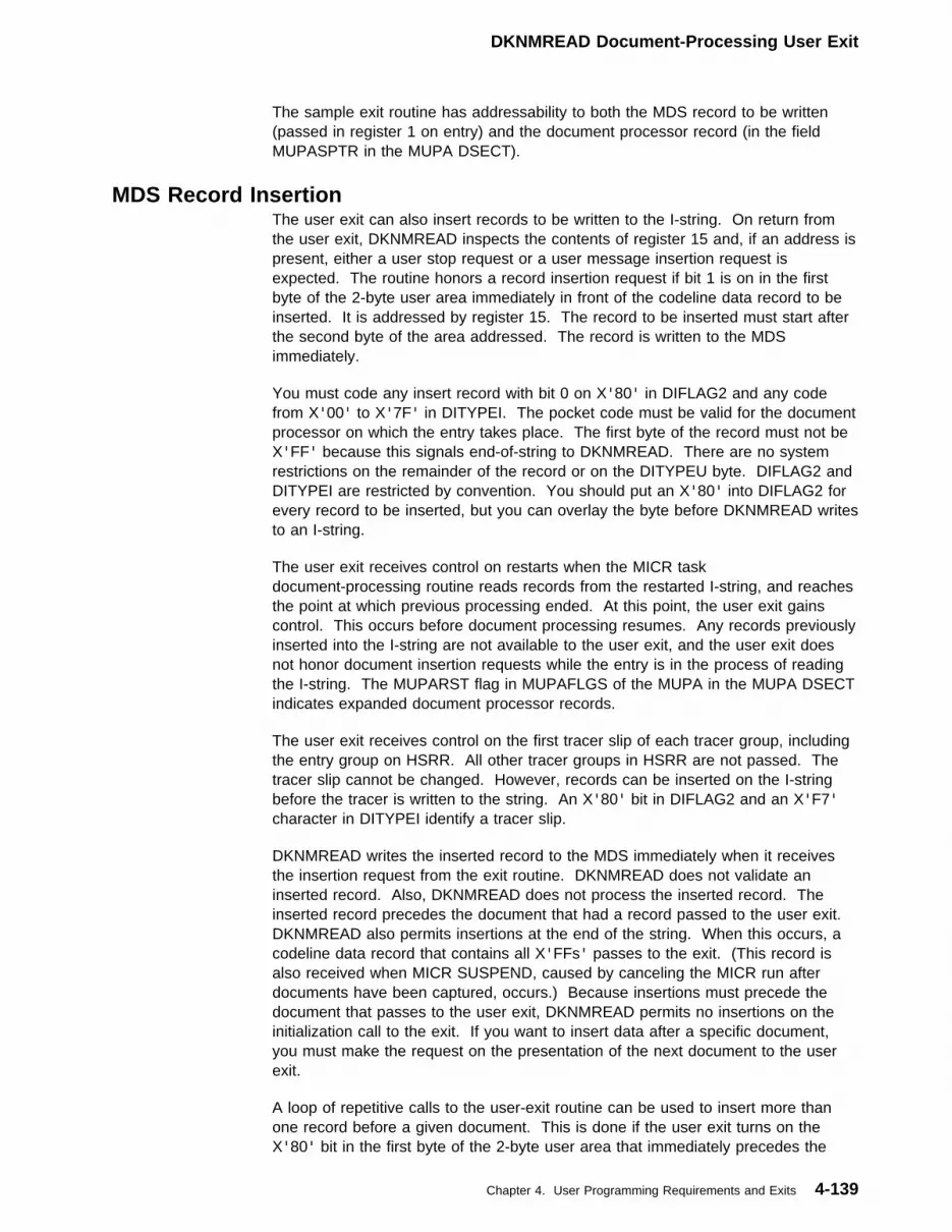
DKNMREAD Document-Processing User Exit
The sample exit routine has addressability to both the MDS record to be written(passed in register 1 on entry) and the document processor record (in the fieldMUPASPTR in the MUPA DSECT).
MDS Record InsertionThe user exit can also insert records to be written to the I-string. On return fromthe user exit, DKNMREAD inspects the contents of register 15 and, if an address ispresent, either a user stop request or a user message insertion request isexpected. The routine honors a record insertion request if bit 1 is on in the firstbyte of the 2-byte user area immediately in front of the codeline data record to beinserted. It is addressed by register 15. The record to be inserted must start afterthe second byte of the area addressed. The record is written to the MDSimmediately.
You must code any insert record with bit 0 on X'80' in DIFLAG2 and any codefrom X'00' to X'7F' in DITYPEI. The pocket code must be valid for the documentprocessor on which the entry takes place. The first byte of the record must not beX'FF' because this signals end-of-string to DKNMREAD. There are no systemrestrictions on the remainder of the record or on the DITYPEU byte. DIFLAG2 andDITYPEI are restricted by convention. You should put an X'80' into DIFLAG2 forevery record to be inserted, but you can overlay the byte before DKNMREAD writesto an I-string.
The user exit receives control on restarts when the MICR taskdocument-processing routine reads records from the restarted I-string, and reachesthe point at which previous processing ended. At this point, the user exit gainscontrol. This occurs before document processing resumes. Any records previouslyinserted into the I-string are not available to the user exit, and the user exit doesnot honor document insertion requests while the entry is in the process of readingthe I-string. The MUPARST flag in MUPAFLGS of the MUPA in the MUPA DSECTindicates expanded document processor records.
The user exit receives control on the first tracer slip of each tracer group, includingthe entry group on HSRR. All other tracer groups in HSRR are not passed. Thetracer slip cannot be changed. However, records can be inserted on the I-stringbefore the tracer is written to the string. An X'80' bit in DIFLAG2 and an X'F7'character in DITYPEI identify a tracer slip.
DKNMREAD writes the inserted record to the MDS immediately when it receivesthe insertion request from the exit routine. DKNMREAD does not validate aninserted record. Also, DKNMREAD does not process the inserted record. Theinserted record precedes the document that had a record passed to the user exit.DKNMREAD also permits insertions at the end of the string. When this occurs, acodeline data record that contains all X'FFs' passes to the exit. (This record isalso received when MICR SUSPEND, caused by canceling the MICR run afterdocuments have been captured, occurs.) Because insertions must precede thedocument that passes to the user exit, DKNMREAD permits no insertions on theinitialization call to the exit. If you want to insert data after a specific document,you must make the request on the presentation of the next document to the userexit.
A loop of repetitive calls to the user-exit routine can be used to insert more thanone record before a given document. This is done if the user exit turns on theX'80' bit in the first byte of the 2-byte user area that immediately precedes the
Chapter 4. User Programming Requirements and Exits 4-139

DKNMREAD Document-Processing User Exit
codeline data record to be inserted. It is addressed by register 15. You can alsouse this technique to make a user stop-processing request following a recordinsertion.
User-Exit Register ConventionsThe user-exit routine must set a return code in register 15 before returning toDKNMREAD.
Register 15 Return Codes0 Normal return, continue processing
Address Address of a user area
If bit 1 of the byte pointed to by register 15 is on, the user exit isrequesting that MREAD insert a user control record into the I-string.
If bit 1 of the byte pointed to by register 15 is off, the user exit isrequesting that MREAD suspend (disengage) the document processorand display the message supplied.
Figure 4-82 shows the format for the record insertion area. Figure 4-83 shows theformat for the user-supplied message area. Figure 4-84 shows the registercontents on entry to the user-exit routine.
Figure 4-82. Format of Record Insertion Area
Bytes Bits Contents
0 0 If on, perform insertion that bit 1 indicates and return to user exit foradditional inserts
1 If on, perform record insertion
2–7 Reserved
1 0–7 Reserved
2–xx MDS formatted record for insertion into the I-string. The definedlength of the MDS determines xx.
Figure 4-83. Format of User-Supplied Message Area
Bytes Bits Contents
0 0–7 Reserved; must be 0
1 0–1 Reserved; must be 0
2–7 Binary length of user-supplied message. Must be less than or equalto the binary equivalent of decimal 40.
2–41 User-supplied message
Figure 4-84 (Page 1 of 2). User Exit Register Contents
Register Bits Contents
0 0–23 Zero
24–31 Document processor
(X'01'=document processor 1)(X'02'=document processor 2)...(X'63'=document processor 99)
1 8–31 Address of codeline data record
4-140 CPCS V1R11 Customization Guide

DKNCSBU-Sort Program Build Task
Figure 4-84 (Page 2 of 2). User Exit Register Contents
Register Bits Contents
2 8–31 Address of MICR user-parameter area (MUPA)
13 8–31 Address of a standard save area that lets the user saveDKNMREAD’s registers. Any registers that the exit routine usesmust be saved in this area and restored before returning toDKNMREAD.
14 8–31 MICR task return address
15 8–31 Address of user-exit routine entry point
Sample Document-Processing User-Exit RoutineSample routines are in CPCS.V1R11.SAMPLIB under the names SAMPEXIT andSEXIT770.
This sample routine serves as a guide for the user. It performs the followingfunctions:
1. After initialization, clears a work area for the indicated document processor
2. Checks to see whether the first document is a block slip (not done onsubsequent pass). If YES, does a normal exit. If NO, suspends the entry anddisplays message 1
3. Checks to see whether the batch slip always follows the block slip (not done onsubsequent pass). If YES, does a normal exit. If NO, suspends the entry anddisplay message 2.
4. Checks to see whether more than 20 successive rejects occur. If NO, does thenext step. If YES, suspends the entry and displays message 3.
5. Checks whether more than 20 successive programmable endorse errors occur(SEXIT770 routine only–used with the 3890/XP Series document processors).If NO, does a normal exit. If YES, suspends the entry and displays message 4.
6. Clears the work area after ending the entry.
Number Message1 BLOCK SEQUENCE ERROR : CANCEL/RESTART
2 BATCH SEQUENCE ERROR : CANCEL/RESTART
3 EXCESSIVE REJECTS : CANCEL/RESTART
4 EXCESSIVE ENDR ERRORS : CANCEL/RESTART
DKNCSBU—Sort Program Build TaskThe DKNCSBU task provides the capability for a workstation-based application toload the sorter version of the sort program from CPCS and run it on a workstation.This includes the initialization data (IREC), user stacker-select routine, and the usertable.
Chapter 4. User Programming Requirements and Exits 4-141

Task InitiationDKNCSBU should have the following APCB entry added to DKNBLDL:
APCB NAME=DKNCSBU,AUTO=1
To initiate DKNCSBU, the calling program posts DKNATASK with the followinginformation in the start parameter:
First fullword Address of the ECB that DKNCSBU posts after it isattached by DKNATASK
Second fullword Address of the ECB that DKNCSBU waits on for the postfrom the calling program
Third fullword Address of the DKNCSBUB control block.
DKNEMRG User ExitsDKNEMRG makes a number of calls to various user exits. These exits are allcontrolled by the CPCS user exit manager (UEM); they are listed in the DKNPEXITSystem Profile Control Card and can be activated, deactivated, or refreshed usingthe CPCS EXIT task.
For each user exit, IBM has provided a sample in the SAMPLIB distribution library.These samples are not type 1 supported code; rather, they are provided asexamples of how the end user should go about coding his or her user exit logic.
Figure 4-85 shows a complete list of all DKNEMRG user exits, along with thesample program that IBM ships for each one:
Figure 4-85. DKNEMRG user exits
EMRG User Exit Name SampleUser ExitProgram
DKNEMRG_MAIN_EXIT
Provides overall control over EMRG’s behavior.
DKNEMRG1
DKNEMRG_USER_INPUT_EXIT
Controls how EMRG’s input (whether from a screen, from an autostartbuffer, or from ESM) is edited.
DKNEMRG2
DKNEMRG_POCKET_MERGE_EXIT
Provides control over EMRG’s Pocket Merge behavior.
DKNEMRG3
DKNEMRG_CONSOL_REJ_MERGE_EXIT
Provides control over EMRG’s Consolidated Reject Merge behavior. TheConsolidated Reject Merge module is, in fact, quite dependent on its userexit; it cannot function without it. For this reason,DKNEMRG_CONSOL_REJ_MERGE_EXIT has been set asDEACTIVATE=NO.
DKNEMRG4
DKNEMRG_HSRR_MERGE_EXIT
Provides control over EMRG’s HSRR merge behavior.
DKNEMRG6
DKNEMRG_KEY_ENTRY_MERGE_EXIT
Provides control over EMRG’s key entry merge behavior.
DKNEMRG7
DKNEMRG_70001_FINAL_MERGE_EXIT None
4-142 CPCS V1R11 Customization Guide

DKNEMRG User Exit Calling ParametersAlthough each different DKNEMRG user exit is called in a different way, they allshare some common properties. Each receives a common control block,EMRGX-CB, which is mapped by the copybook DKNEMRGL. Among the fieldscontained in the control block is EMRGX-CB-FUNC. This is a four-byte characterfunction code indicating what operation the exit is expected to perform. Typical ofsuch functions include:
INT The calling program is starting up and initializing; it is asking the userexit to do the same.
PRC This is a process call; most often the calling program issues such acall for each CPCS codeline it handles.
TRM The calling program is ending and is asking the exit to performwhatever wrap-up is necessary.
Depending on the exit, other more specialized functions may have to be handled.
Figure 4-86 is a complete list of all function codes each user exit is expected tosupport:
Figure 4-86 (Page 1 of 4). EMRG user exits, function, and purpose
User Exit Name
DKNEMRG_MAIN_EXIT
Function: INT
Purpose: Initialize. This function is invoked when DKNEMRG starts running.
Function: TRM
Purpose: Terminate. This function is invoked when EMRG has finished its work and isshutting down. DKNEMRG_USER_INPUT_EXIT
Function: AINT
Purpose: Initialize. This function is invoked when EMRG first calls on its internalDKNEMRGA module to edit ESM or autostart input or, in the case of a manual start, todisplay an input screen.
Function: APRC
Purpose: Process. This function asks the exit to decide which process option EMRG shoulduse–the one implied by the string name, the one entered by the user (assuming the userkeyed a valid option, of course), or one selected by the exit itself. DKNEMRG_POCKET_MERGE_EXIT
Function: BINT
Purpose: Initialize. This function is invoked when EMRG first calls on its internalDKNEMRGB module to start a Pocket Merge.
Chapter 4. User Programming Requirements and Exits 4-143
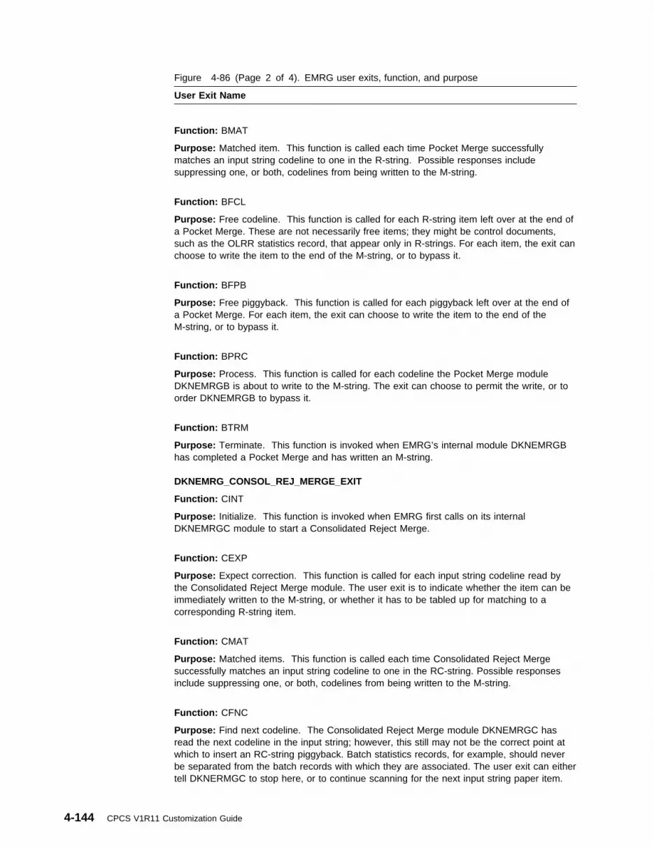
Figure 4-86 (Page 2 of 4). EMRG user exits, function, and purpose
User Exit Name
Function: BMAT
Purpose: Matched item. This function is called each time Pocket Merge successfullymatches an input string codeline to one in the R-string. Possible responses includesuppressing one, or both, codelines from being written to the M-string.
Function: BFCL
Purpose: Free codeline. This function is called for each R-string item left over at the end ofa Pocket Merge. These are not necessarily free items; they might be control documents,such as the OLRR statistics record, that appear only in R-strings. For each item, the exit canchoose to write the item to the end of the M-string, or to bypass it.
Function: BFPB
Purpose: Free piggyback. This function is called for each piggyback left over at the end ofa Pocket Merge. For each item, the exit can choose to write the item to the end of theM-string, or to bypass it.
Function: BPRC
Purpose: Process. This function is called for each codeline the Pocket Merge moduleDKNEMRGB is about to write to the M-string. The exit can choose to permit the write, or toorder DKNEMRGB to bypass it.
Function: BTRM
Purpose: Terminate. This function is invoked when EMRG’s internal module DKNEMRGBhas completed a Pocket Merge and has written an M-string. DKNEMRG_CONSOL_REJ_MERGE_EXIT
Function: CINT
Purpose: Initialize. This function is invoked when EMRG first calls on its internalDKNEMRGC module to start a Consolidated Reject Merge.
Function: CEXP
Purpose: Expect correction. This function is called for each input string codeline read bythe Consolidated Reject Merge module. The user exit is to indicate whether the item can beimmediately written to the M-string, or whether it has to be tabled up for matching to acorresponding R-string item.
Function: CMAT
Purpose: Matched items. This function is called each time Consolidated Reject Mergesuccessfully matches an input string codeline to one in the RC-string. Possible responsesinclude suppressing one, or both, codelines from being written to the M-string.
Function: CFNC
Purpose: Find next codeline. The Consolidated Reject Merge module DKNEMRGC hasread the next codeline in the input string; however, this still may not be the correct point atwhich to insert an RC-string piggyback. Batch statistics records, for example, should neverbe separated from the batch records with which they are associated. The user exit can eithertell DKNERMGC to stop here, or to continue scanning for the next input string paper item.
4-144 CPCS V1R11 Customization Guide

Figure 4-86 (Page 3 of 4). EMRG user exits, function, and purpose
User Exit Name
Function: CFCL
Purpose: Free codeline. This function is called for each R-string item left over at the end ofa Consolidated Reject Merge. These are not necessarily free items; they might be controldocuments, such as the OLRR statistics record, that appear only in R-strings. For eachitem, the exit can choose to write it to the end of the M-string, or to bypass it.
Function: CFPB
Purpose: Free piggyback. This function is called for each piggyback left over at the end ofa Consolidated Reject Merge. For each item, the exit can choose to write it to the end of theM-string, or to bypass it.
Function: COUT
Purpose: Out. This function is called for each codeline the Consolidated Reject Mergemodule DKNEMRGC is about to write to the M-string. The exit can choose to permit thewrite, or to order DKNEMRGC to bypass it.
Function: CSDE
Purpose: SDE change. This function is called if, at the end of Consolidated Reject Merge,there are still input string codelines that have not been repaired and/or repaired pockets thatstill contain rejects. The Consolidated Reject Merge module DKNEMRGC normally displayserror message(s); however, the user exit can choose to suppress the error instead bychanging the appropriate pocket flags in the M-string SDE.
Function: CTRM
Purpose: Terminate. This function is invoked when EMRG’s internal module DKNEMRGChas completed a Consolidated Reject Merge and has written an M-string. DKNEMRG_HSRR_MERGE_EXIT
Function: EINT
Purpose: Initialize. This function is invoked when EMRG first calls on its internalDKNEMRGE module to complete a HSRR merge.
Function: EPRC
Purpose: Process. This function is called for each codeline the HSRR Merge moduleDKNEMRGE is about to write to the M-string. The exit can choose to permit the write, or toorder DKNEMRGE to bypass it.
Function: EFCL
Purpose: Free codeline. This function is called for each 50M-string item left over at the endof a HSRR merge. These are not necessarily free items; they might be control documents,such as the OLRR statistics record, that transferred in from the R-string. For each item, theexit can choose to write it to the end of the M-string, or to bypass it.
Chapter 4. User Programming Requirements and Exits 4-145
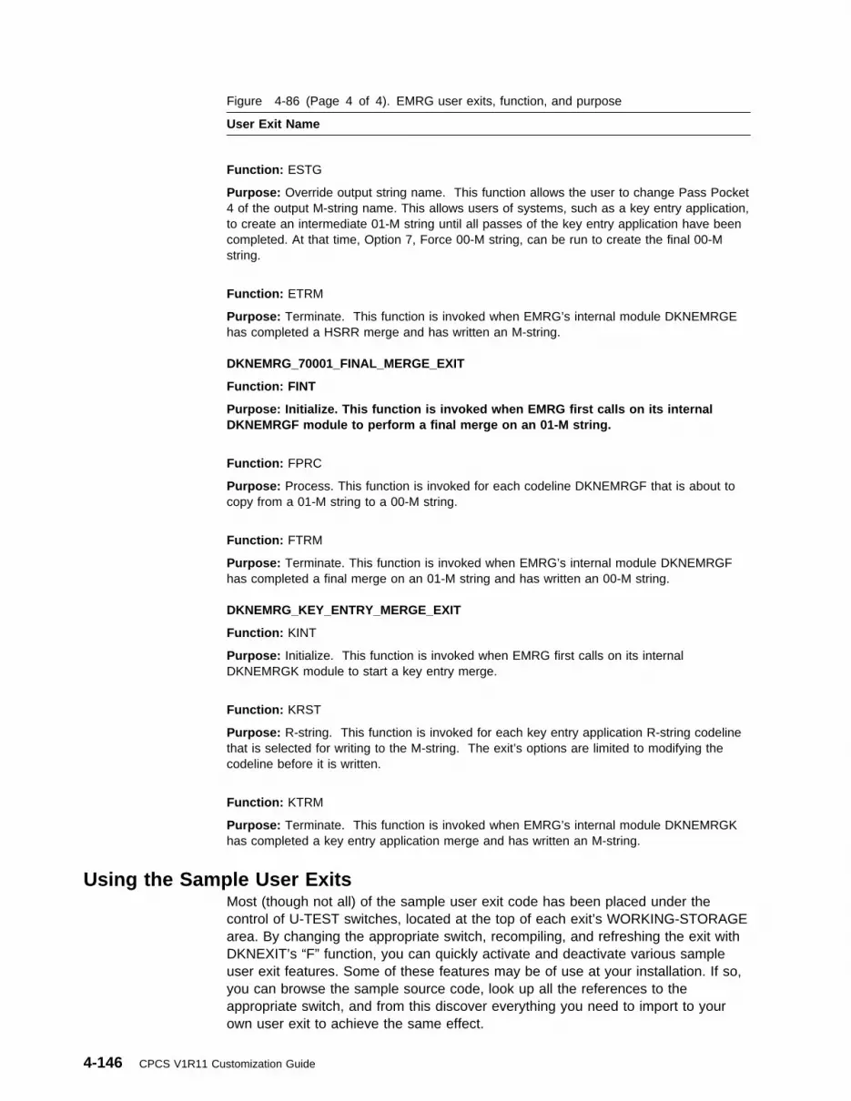
Figure 4-86 (Page 4 of 4). EMRG user exits, function, and purpose
User Exit Name
Function: ESTG
Purpose: Override output string name. This function allows the user to change Pass Pocket4 of the output M-string name. This allows users of systems, such as a key entry application,to create an intermediate 01-M string until all passes of the key entry application have beencompleted. At that time, Option 7, Force 00-M string, can be run to create the final 00-Mstring.
Function: ETRM
Purpose: Terminate. This function is invoked when EMRG’s internal module DKNEMRGEhas completed a HSRR merge and has written an M-string. DKNEMRG_70001_FINAL_MERGE_EXIT
Function: FINT
Purpose: Initialize. This function is invoked when EMRG first calls on its internalDKNEMRGF module to perform a final merge on an 01-M string.
Function: FPRC
Purpose: Process. This function is invoked for each codeline DKNEMRGF that is about tocopy from a 01-M string to a 00-M string.
Function: FTRM
Purpose: Terminate. This function is invoked when EMRG’s internal module DKNEMRGFhas completed a final merge on an 01-M string and has written an 00-M string. DKNEMRG_KEY_ENTRY_MERGE_EXIT
Function: KINT
Purpose: Initialize. This function is invoked when EMRG first calls on its internalDKNEMRGK module to start a key entry merge.
Function: KRST
Purpose: R-string. This function is invoked for each key entry application R-string codelinethat is selected for writing to the M-string. The exit’s options are limited to modifying thecodeline before it is written.
Function: KTRM
Purpose: Terminate. This function is invoked when EMRG’s internal module DKNEMRGKhas completed a key entry application merge and has written an M-string.
Using the Sample User ExitsMost (though not all) of the sample user exit code has been placed under thecontrol of U-TEST switches, located at the top of each exit’s WORKING-STORAGEarea. By changing the appropriate switch, recompiling, and refreshing the exit withDKNEXIT’s “F” function, you can quickly activate and deactivate various sampleuser exit features. Some of these features may be of use at your installation. If so,you can browse the sample source code, look up all the references to theappropriate switch, and from this discover everything you need to import to yourown user exit to achieve the same effect.
4-146 CPCS V1R11 Customization Guide

The listings of DKNEMRG user exits below show all the U-TEST switches locatedin each sample user exit, and discusses the effects they have when turned on.Unless otherwise specified, these switches are shipped turned off:
DKNEMRG_MAIN_EXIT—DKNEMRG1U-TEST-SWITCH-1-01
If set to “2”, this switch causes EMRG’s HSRR codeline data matchmodule DKNEMRGD to allocate a CPCS spool for its unmatchedreject report. If set to “3”, DKNERMGD allocates a JES spool instead.The shipped setting is “D” (default), which causes DKNEMRGD totake its default action of allocating a CPCS spool.
U-TEST-SWITCH-1-02If on, this switch causes EMRG’s Pocket Merge module DKNEMRGBto use the DI-CPU-FLAG1 tracking byte, as well as the item sequencenumber, when comparing input string codelines against R-stringcodelines to see if they match. Note that this feature can reduce thechance of EMRG mistaking an autoselect for a neighboring good item.
U-TEST-SWITCH-1-03If on, this switch causes EMRG to autostart RLST at the end of apocket or Consolidated Reject Merge. It also autostarts PLST if theresult of the merge is a prime-pass 00M-string. Note that no programautostarts if you are running ESM. In such an environment, use ESMworkflows to start the desired programs.
U-TEST-SWITCH-1-04If this switch and U-TEST-SWITCH-1-03 are both on, EMRG alwaysautostarts an RLST at the end of its run, even if it had not beenconducting a pocket or Consolidated Reject Merge. Note that noprogram autostarts if you are running ESM. In such an environment,use ESM workflows to start the desired programs.
U-TEST-SWITCH-1-05If this switch and U-TEST-SWITCH-1-03 are both on, EMRG alwaysautostarts a PLST after writing a prime-pass 00M-string, even if it hadnot been conducting a pocket or Consolidated Reject Merge. Notethat no program autostarts if you are running ESM. In such anenvironment, use ESM workflows to start the desired programs.
U-TEST-SWITCH-1-06If this switch and U-TEST-SWITCH-1-03 are both on, EMRG alwaysautostarts an MDIS after writing a prime-pass 00M-string. Note that noprogram autostarts if you are running ESM. In such an environment,use ESM workflows to start the desired programs.
U-TEST-SWITCH-1-07If on, this switch causes informational messages (message numbers00000 through 09999) to be sent only to the SCROLL data set, ratherthan to both the SUPV terminal and to SCROLL. Note that this switchis shipped turned on.
U-TEST-SWITCH-1-08If on, this switch causes EMRG’s Pocket Merge module DKNEMRGBto always create an 01M-string, even when all rejects have beenmerged.
Chapter 4. User Programming Requirements and Exits 4-147

DKNEMRG1 also contains the following hard-coded behavior:
� On an INT call, selects certain DITYPEs recorded in the DKNEMRGT table andalters their properties (is this a DKNCRZC uncompressed or a DKNCRDIcompressed codeline; was there an actual paper document read for it; is itcorrectable; does it contain an item sequence number). Please do not usethese alterations as-is; they are provided only as examples of how you canmake similar changes for custom documents in your own institution.
� On an INT call, sends messages to the SCROLL data set describing how theU-TEST switches have been set up.
DKNEMRG_USER_INPUT_EXIT—DKNEMRG2U-TEST-SWITCH-2-01
If set to “U”, this switch causes EMRG to accept the merge option theuser had keyed on the input screen (that is, after editing it to makesure it is a 1, 2, or 3). If set to “X”, this switch causes EMRG toalways perform option 3, Consolidated Reject Merge, no matter whatstring or option the operator had entered. The shipped setting is “D”(default), which causes EMRG to decide what option to apply basedon the name of the string the operator had entered.
DKNEMRG2 also contains the following hard-coded behavior:
� On an AINT call, this switch tests to see if EMRG had been manually started byan operator named JED, or if it had been manually started by an operatornamed KEY. For JED, it sets U-TEST-SWITCH-2-01 to “U” (that is, it causesEMRG to accept JED”s keyed option rather than compute one from the stringname); for KEY, it not only sets U-TEST-SWITCH-2-01 to “X” (EMRG alwaysperforms option 3), but it also causes EMRG to release the terminal the instantit begins the actual merge, rather than wait until the merge is complete.
DKNEMRG_POCKET_MERGE_EXIT—DKNEMRG3U-TEST-SWITCH-3-02
If on, this switch causes EMRG to keep each free paper-documentcodeline passed to DKNEMRG3 as part of a BFCL call. The defaultaction is to bypass the free codelines.
U-TEST-SWITCH-3-03If on, this switch causes EMRG to keep each free piggyback passedto DKNEMRG3 as part of a BFPB call. The default action is to bypassthe free piggybacks.
U-TEST-SWITCH-3-04If on, this switch causes the EMRG Pocket Merge moduleDKNEMRGB to issue ENQ and DEQ calls to prevent other programsfrom trying to create the same M-string (or work M-string) that it is inthe process of writing. Note that this switch is shipped turned on.
DKNEMRG3 also contains the following hard-coded behavior:
� On a BINT call, displays a message indicating that it had started.
� On a BMAT call, marks R-string items that have been keyed or reconciled, butare not in the system reject pocket, as low-speed (corrected) items.
4-148 CPCS V1R11 Customization Guide
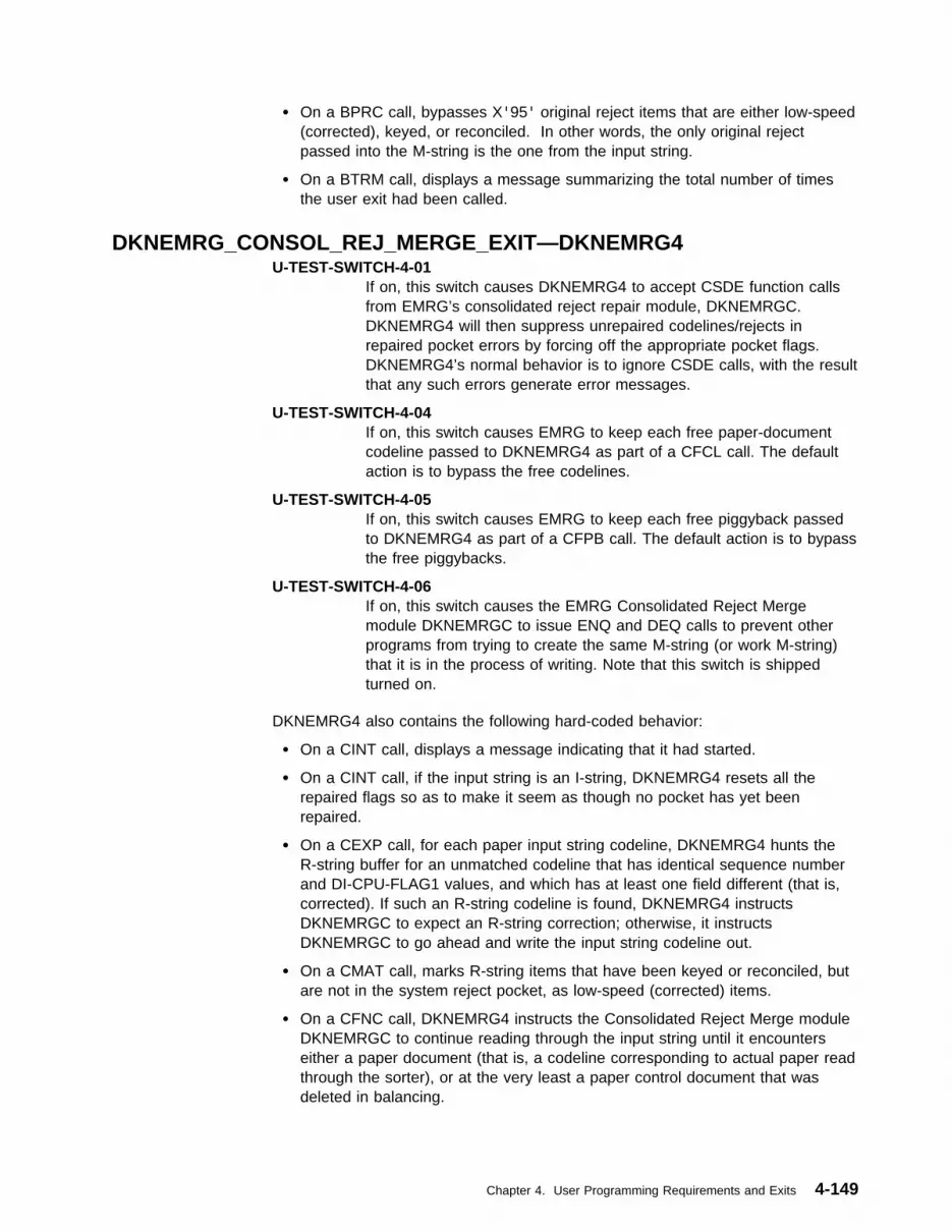
� On a BPRC call, bypasses X'95' original reject items that are either low-speed(corrected), keyed, or reconciled. In other words, the only original rejectpassed into the M-string is the one from the input string.
� On a BTRM call, displays a message summarizing the total number of timesthe user exit had been called.
DKNEMRG_CONSOL_REJ_MERGE_EXIT—DKNEMRG4U-TEST-SWITCH-4-01
If on, this switch causes DKNEMRG4 to accept CSDE function callsfrom EMRG’s consolidated reject repair module, DKNEMRGC.DKNEMRG4 will then suppress unrepaired codelines/rejects inrepaired pocket errors by forcing off the appropriate pocket flags.DKNEMRG4’s normal behavior is to ignore CSDE calls, with the resultthat any such errors generate error messages.
U-TEST-SWITCH-4-04If on, this switch causes EMRG to keep each free paper-documentcodeline passed to DKNEMRG4 as part of a CFCL call. The defaultaction is to bypass the free codelines.
U-TEST-SWITCH-4-05If on, this switch causes EMRG to keep each free piggyback passedto DKNEMRG4 as part of a CFPB call. The default action is to bypassthe free piggybacks.
U-TEST-SWITCH-4-06If on, this switch causes the EMRG Consolidated Reject Mergemodule DKNEMRGC to issue ENQ and DEQ calls to prevent otherprograms from trying to create the same M-string (or work M-string)that it is in the process of writing. Note that this switch is shippedturned on.
DKNEMRG4 also contains the following hard-coded behavior:
� On a CINT call, displays a message indicating that it had started.
� On a CINT call, if the input string is an I-string, DKNEMRG4 resets all therepaired flags so as to make it seem as though no pocket has yet beenrepaired.
� On a CEXP call, for each paper input string codeline, DKNEMRG4 hunts theR-string buffer for an unmatched codeline that has identical sequence numberand DI-CPU-FLAG1 values, and which has at least one field different (that is,corrected). If such an R-string codeline is found, DKNEMRG4 instructsDKNEMRGC to expect an R-string correction; otherwise, it instructsDKNEMRGC to go ahead and write the input string codeline out.
� On a CMAT call, marks R-string items that have been keyed or reconciled, butare not in the system reject pocket, as low-speed (corrected) items.
� On a CFNC call, DKNEMRG4 instructs the Consolidated Reject Merge moduleDKNEMRGC to continue reading through the input string until it encounterseither a paper document (that is, a codeline corresponding to actual paper readthrough the sorter), or at the very least a paper control document that wasdeleted in balancing.
Chapter 4. User Programming Requirements and Exits 4-149

� On a COUT call, bypasses X'95' original reject items that are either low-speed(that is, corrected), keyed, or reconciled. In other words, the only original rejectpassed into the M-string is the one from the input string.
� On a CTRM call, displays a message summarizing the total number of timesthe user exit had been called.
DKNEMRG_HSRR_MERGE_EXIT—DKNEMRG6U-TEST-SWITCH-6-01
If on, this switch causes the EMRG HSRR merge moduleDKNEMRGE to issue ENQ and DEQ calls to prevent other programsfrom trying to create the same M-string (or work M-string) that it is inthe process of writing. Note that this switch is shipped turned on.
DKNEMRG6 also contains the following hard-coded behavior:
� On a EINT call, displays a message indicating that it had started.
� On a BPRC call, bypasses high-speed (captured on HSRR) uncompressedX'95' original reject items. The only original reject passed into the M-string isthe one from the prime-pass capture string.
� On an ETRM call, displays a message summarizing the total number of timesthe user exit had been called.
� On an ESTG call, the code as delivered is commented out. It is up to the userto update or change the code to follow the institution’s requirements. Thischanges Pass Pocket 4 of the output 00-M string to 01.
DKNEMRG_KEY_ENTRY_MERGE_EXIT—DKNEMRG7DKNEMRG7 also contains the following hard-coded behavior:
� On a KINT call, displays a message indicating that it had started.
� On a KINT call, selects certain DITYPEs recorded in the DKNEMRGT table andalters their properties (is this a DKNCRZC uncompressed or a DKNCRDIcompressed codeline; was there an actual paper document read for it; is itcorrectable; does it contain an item sequence number). Please do not usethese alterations as-is; they are provided only as examples of how you canmake similar changes for custom documents in your own institution.
� On a KRST call, marks R-string items that have been keyed or reconciled, butare not in the system reject pocket, as low-speed (corrected) items.
� On a KTRM call, displays a message summarizing the total number of timesthe user exit had been called.
DKNMRGE Programmable SwitchesThis programmable switch controls whether a batch or block slip containing fielderrors on prime pass will be marked automatically as an original reject document(X'95') if it is not matched on a HSRR pass. The default is that the batch or blockslip will not be marked as an original reject document. If you want this option,change the switch value to 0.
77 BAD-PRIME-CTL-DOC-ALLOWED-SW PIC X VALUE ‘1’
88 BAD-PRIME CTL-DOC-ALLOWED VALUE ‘1’
88 BAD-PRIME-CTL-DOC-NOT-ALLOWED VALUE ‘�’
4-150 CPCS V1R11 Customization Guide

DKNMRGK–Document-Processing User ExitYou can specify this exit in the USREXIT parameter of the DKNBLDL macro. Itpermits you to control the setting of the DILOW and DI34KEY bits in the mass dataset codeline. Unpredictable results might occur if you change other portions of therecord.
DKNMRGK performs the codeline matching on image-repaired strings. DKNMRGKpasses each codeline from the 00-R-string to the DKNMRGK user exit forprocessing.
A sample document-processing user-exit routine, DKNMRGKX, is provided for thisuse and may be found in CPCS.V1R11.SAMPLIB. The prologue of DKNMRGKXcontains a README file that contains the most up-to-date information about theuser exit.
DKNMRG2X–Positional Matching User ExitDKNMRGE and DKNEMRG call DKNMRG2X to do codeline data matching forHSRR strings. DKNMRG2X produces a file, MATCHFIL, which is used by the twomerges to decide which items match and where to place the missing/free items onthe merged string. This exit is called after the MATCHFIL is created and beforecontrol is returned to the merge process.
The user exit allows the user to write code to change the match decisions made byDKNMRG2X. By changing the records in the MATCHFIL, the user can convert amissing/free record pair into a single matched record. Care should be taken toreplace the missing record with the matched record and to delete the free record.
The logic to do this is completely in the user’s hands. The exit is provided withboth the Prime and HSRR string names, and all the missing (Prime) and free(HSSR) records have the ZB-Note information. By using point-read logic and othermethods, the user can match the missing/free records.
Example: A MATCHFIL created by DKNMRG2 consists of:
After the user’s logic is complete, you will find 0005 matches 2014:
Prime Seq HSSR Seq Match Flag
0004 2010 Matched
0005 Missing
0006 2011 Matched
0007 Missing
0008 2013 Matched
2014 Free
0010 2015 Matched
Chapter 4. User Programming Requirements and Exits 4-151
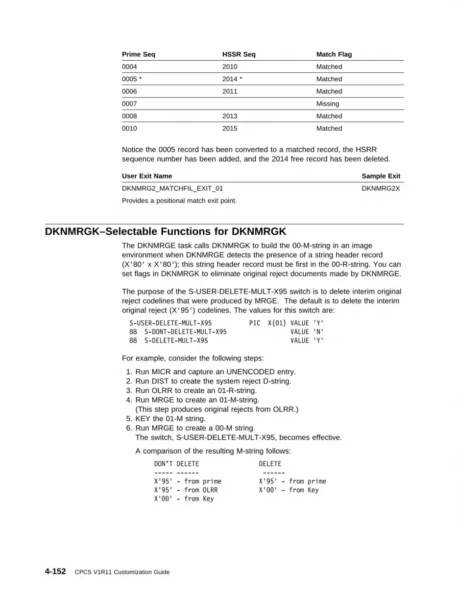
Notice the 0005 record has been converted to a matched record, the HSRRsequence number has been added, and the 2014 free record has been deleted.
Prime Seq HSSR Seq Match Flag
0004 2010 Matched
0005 * 2014 * Matched
0006 2011 Matched
0007 Missing
0008 2013 Matched
0010 2015 Matched
User Exit Name Sample Exit
DKNMRG2_MATCHFIL_EXIT_01
Provides a positional match exit point.
DKNMRG2X
DKNMRGK–Selectable Functions for DKNMRGKThe DKNMRGE task calls DKNMRGK to build the 00-M-string in an imageenvironment when DKNMRGE detects the presence of a string header record(X'80' x X'80'); this string header record must be first in the 00-R-string. You canset flags in DKNMRGK to eliminate original reject documents made by DKNMRGE.
The purpose of the S-USER-DELETE-MULT-X95 switch is to delete interim originalreject codelines that were produced by MRGE. The default is to delete the interimoriginal reject (X'95') codelines. The values for this switch are:
S-USER-DELETE-MULT-X95 PIC X(�1) VALUE 'Y'
88 S-DONT-DELETE-MULT-X95 VALUE 'N'
88 S-DELETE-MULT-X95 VALUE 'Y'
For example, consider the following steps:
1. Run MICR and capture an UNENCODED entry.2. Run DIST to create the system reject D-string.3. Run OLRR to create an 01-R-string.4. Run MRGE to create an 01-M-string.
(This step produces original rejects from OLRR.)5. KEY the 01-M string.6. Run MRGE to create a 00-M string.
The switch, S-USER-DELETE-MULT-X95, becomes effective.
A comparison of the resulting M-string follows:
DON’T DELETE DELETE
----- ------ ------
X'95' - from prime X'95' - from prime
X'95' - from OLRR X'��' - from Key
X'��' - from Key
4-152 CPCS V1R11 Customization Guide

DKNPLST, DKNSLST, and DKNXLST
DKNPLST, DKNSLST, and DKNXLST: Controlling Entry Master-ListReports
The entry master-list task (DKNPLST) controls the format of the entry master-listreports. These formats are selected by flags that you can specify in the DKNPLSTprogram and by the format of the mass data set (standard or expanded recordlength). You can set the flags by changing the affected fields in the program,compiling the new program, and using CHAP PLST to load a new version in theBLDL table.
For a standard MDS record size (50 bytes), DKNPLST provides two types of reportlayouts:
Type A This layout provides for a 3-column report in which each columnconsists of the following fields:
� Sequence number� Routing number (field 5) or, for on-us items, account number
(field 3)� Amount (field 1)
� Pocket number.
You can select this report type by setting the300-TYPE-OF-REPORT field to a value of A and the300-PLST-NO-OF-COLMS field to a value of 3 for a 3-columnreport.
Type B This layout provides a 2-column report in which each columnconsists of the following fields:
� Sequence number� Serial number (field 7)� Routing number (field 5)� Account number (field 3)� Process control (field 2)� Amount (field 1)
� Pocket number.
You can select this report type by setting the300-TYPE-OF-REPORT field to a value of B and the300-PLST-NO-OF-COLMS field to a value of 2 for a 3-columnreport.
For a nonstandard MDS record length, DKNPLST provides the following reportlayouts:
Type A or B Each of these report layouts uses DKNMDXR to print a 1-columnreport that contains the following fields:
� Sequence number� Routing number (field 5)� Account number (field 3)� Amount (field 1)
� Flag 2 � Pocket number.
You can select one of these layout types by setting the300-TYPE-OF-REPORT field to a value of A or B. DKNMDXR
Chapter 4. User Programming Requirements and Exits 4-153

DKNPLST, DKNSLST, and DKNXLST
formats the report in one column, so it is not necessary to set thevalue for the 300-PLST-NO-OF-COLMS field.
DKNXLST, as supplied with CPCS, automatically causes the printing of bothprime-pass and subsequent-pass exception listings for all entries throughout theday. For prime-pass entries, DKNXLST produces a detailed item listing only forout-of-balance batches. For subsequent-pass entries, DKNXLST produces adetailed item listing only for out-of-balance tracer groups.
CPCS provides a skeleton format, which you can change or expand according toyour financial institution’s requirements. The skeleton format can determine thetype of master list to print, based on the following:
� Time of day � Cycle� Sort pattern type.
You can add other parameters. DKNXLST is accessed on either automatic ormanual starts.
Before assembling DKNXLST, you can insert the values of the sort patterns. Thecode supplied is essentially a skeleton in which you can insert the sort-patternnumbers with the proper cycles and set the return to indicate the type of reportproduced by DKNPLST or DKNSLST. You can also cause the program to defaultand print the exception lists at all times.
Sort patterns should be set by EQU statements to an equivalent 1-byte binaryvalue. They should be checked for under the correct cycle, and the type of reportyou want should be branched to on an equal condition. The branches are:
PLSTSFLL Produces full listing only for DKNPLSTPLSTSBTH Produces full and summary listings for DKNPLSTPLSTSXCP Produces exception print by batch for DKNPLST (default)PLSTSEXT Causes DKNPLST to endSLSTSDET Produces full listing only for DKNSLSTSLSTSSUM Produces summary listing only for DKNSLSTSLSTSXCP Produces exception print by batch for DKNSLST (default).
Processing DescriptionDKNXLST contains two separate entry points, DKNXLST and DKNYLST. Acommon processing section, DKNZLST, is accessed through each entry point.DKNPLST calls entry point DKNXLST and DKNSLST calls entry point DKNYLST.Each entry point sets a switch (LISTSW) that DKNZLST uses to determine thecalling program.
DKNPLST or DKNSLST passes two parameters, the cycle and the sort type, toDKNXLST. (You can add additional parameters.) DKNZLST accesses thetime-of-day and bases the processing decision on these three parameters.DKNXLST passes the decision back to DKNPLST or DKNSLST.
The first check is based on the time of the run. If, because of time restraints, acertain type of printout (for example, exception) is the only type wanted after acertain hour, make the hour comparison value the value of PLSTLATE orSLSTLATE.
4-154 CPCS V1R11 Customization Guide
DKNSCATX
If the branch on the time is not taken, DKNXLST checks the value of the cycleparameter and a branch on a valid cycle of 0 to L is taken.
On valid cycles, DKNXLST branches to the proper cycle routine. Under each cycle,DKNXLST makes the comparison on the sort-pattern type. DKNXLST sets the sortpatterns as EQUs of a 1-byte binary value converted to the hexadecimal values ofthe sort-pattern numbers.
DKNKILL and DKNPLST: Modifying Report LayoutsYou can modify the report layouts for the DKNKILL and DKNPLST programs tomeet your installation’s requirements. To modify the layout, change the valuesdocumented after the 300-USER-SUPPLIED-INPUT field in the working storagesection of the DKNKILL and DKNPLST programs. Research the modified layout toensure that the printer and paper used are still appropriate for the data.
For the DKNKILL report, you can also select an expanded format that showsportions of MICR fields (1, 2, 3, 5, and 7) as delivered. This layout provides for a2-column report. To select the report, set the value of the310-NEW-REPORT-TYPE-SW field (immediately precedes the 340-FIELD-STORfield) to YES. If the value of the 310-NEW-REPORT-TYPE-SW field is set to YES,also set the value of the 300-KILL-NO-OF-COLMS field to 2. The expanded reportlayout can also be modified. Research the modifications to ensure that the printerand paper used are appropriate for the data.
DKNSCATX - String Concatenation User ExitYou can specify a user exit in the USREXIT parameter of DKNSCAT’s APCB entryin DKNBLDL. This exit allows you to customize and control the behavior of SCATin many different ways. For example, you could:
� Control which codelines are selected from the Reject D-string and the partialR-string(s) for sequence-matching against each other
� Prepare a report listing uncorrected rejects, duplicate corrections, missing andfree codelines, and any other anomalies that may be uncovered duringconcatenation
� Control how duplicate corrections are handled: Which duplicates (if any) pullinto the final R-string, and which are suppressed
� Decide final disposition of any interim R-strings created during concatenation.You can decide to delete them, or retain them for archival purposes.
The user exit is called out of the DKNSCAT subroutine DKNSCA3. This means itis invoked only during concatenation of the System Reject Pocket.
TerminologyDuplicate Corrections
A codeline that has been corrected two or more times. This could happen, forexample, if two or more OLRR operators inadvertently processed the sameportion of a reject D-string.
Chapter 4. User Programming Requirements and Exits 4-155
DKNSCATX
Final R-stringThe target R-string that SCAT tries to create. Contains one correction forevery codeline in the original reject D-string. Typically identified by a �� in thefourth pocket of its string name.
Free CodelinesRecords found in partial R-strings that could not be sequence-matched back toReject D-string codelines.
Interim R-stringIf SCAT determines that it cannot construct a final R-string, it builds an interimR-string instead. This represents various partial R-strings that are still missing.Typically identified by a 99 in the fourth pocket of its string name.
Missing CodelinesReject D-string records that were never successfully sequence-matched to anypartial R-string codeline.
Operator ID RecordOne or more control documents at the top of final and interim R-strings thatname the partial R-strings they are composed of. These records have aDITYPEI of X'99', and each byte after the DISEQ field contains an operatorID in binary format. The last operator ID byte is followed by a X'FF'.
Partial R-stringThe individual R-strings prepared out of OLRR (or other reject repair tool usedin your installation). It is SCAT’s job to construct a final R-string by assemblingall the partial R-strings in the correct order. Typically, the fourth pocket of thestring name for an partial R-string contains the operator ID (01 through 98) ofwhomever it was that created the string.
Uncorrected RejectsCodelines in partial R-strings that still contain invalid fields (that is, fields whosevalidity bits are turned off).
String Concatenation User Exit ParametersThe following parameters are passed to the String Concatenation user exit on everyinvocation. Note that not all parameters are useable on all calls. For example,during user exit INIT, only the Document Use Table is available for manipulation.The Codeline Table has just been cleared, and the Operator, Match, andCorrections Tables have not yet been loaded.
CONTROL BLOCKMapped by: DKNSCATU
This is the main control block for communicating between SCAT and its userexit. It contains the following fields:
FUNCTION-CODEThe specific call SCAT is making to its user exit. This is a PIC X(04) fieldset to one of the following values:
INIT SCAT is starting for the first time. The Codeline Table has beencleared and the Document Use Table loaded. No other tables areavailable for manipulation at this time.
MAIN SCAT has added a partial R-string record to the Codeline Table.The record could be in the DOC, NDOC, DUP, or PIGY regions of thetable (CDLN-CURRENT SUB tells you exactly where it is). If this is
4-156 CPCS V1R11 Customization Guide
DKNSCATX
a DOC record, MATCH-TABLE-SUB points to the Match Table entryto which it matched. RESULT-CODELINE-MATCH andRESULT-CODELINE-CORR are set; if the reject is uncorrected, theCorrection Table tells you exactly what is wrong. (If the recordcame from an OLRR bypass run, RESULT-CODELINE-CORRalways indicates the item is 100% correct; however, its errors arestill available for inspection in the Corrections Table.) At this time,the DOC, NDOC, and DUP regions of the Codeline Table are threadedtogether, but piggybacks have been stored in the PIGY region asshort independent chains of items. Refer to the description of theCodeline Table below for more information.
PIGY With all R-string codelines now in the Codeline Table, SCAT beginslinking in the piggyback chains. A PIGY call is made every timeSCAT successfully inserts a chain. SCATC-CDLN-CURRENT-SUBand SCATC-CDLN-DOC-SUB-2 point to, respectively, the first andlast items in the piggyback chain; SCATC-CDLN-PREV-SUB andSCATC-CDLN-NEXT-SUB point to, respectively, the items beforeand after the inserted chain. A user exit PIGY call is made for eachchain successfully relinked.
BYPS BYPS calls are made only when SCAT is run in bypass mode. Allavailable partial R-string codelines have been added to theCodeline Table; all piggyback chains have been linked in. SCATnow begins filling in missing codelines by copying Reject D-stringcodelines from the Match Table. A BYPS call is made for eachreject D-string record added. SCATC-CDLN-CURRENT-SUB pointsto the Codeline Table slot where the record was inserted.
LAST SCAT has made its last MAIN, PIGY, and/or BYPS call. TheCodeline Table is now complete and ready to be read out into thefinal (or interim) R-string. The read-out begins as soon as this userexit call returns to SCAT.
DELE SCAT makes this call only under the following circumstances:
1. It is ready to create a final R-string;
2. Some earlier run of SCAT created an interim R-string.
Most users will want at this time to delete the interim R-string.Some users might want to retain it for archival purposes, or evencopy it to another string or file. Note that SCAT does NOT call thisexit if it is creating an interim R-string and some earlier SCATcreated a previous interim R-string. In such circumstances SCATon its own deletes the old interim R-string and replaces it with thenew.
FINL SCAT has completed all processing and is preparing to quit. TheFINL call is made so that the user exit, too, can completeprocessing and prepare to quit.
RETURN-CODEBefore returning, the user exit should set this PIC S9(04) COMP field toeither 0, 4, or some value 8 or greater.
0 Normal return.
4 Requests SCAT not to make any further calls to the user exit.
Chapter 4. User Programming Requirements and Exits 4-157
DKNSCATX
8 or greaterRequests SCAT to abend. It ends with an error message containingthe returned RETURN-CODE.
D-STRING-NAMEThe Reject D-string name, in condensed 17-byte format. That is, alldashes are stripped out, and the System Reject Pocket, if present, isrepresented as two bytes of HIGH-VALUES.
OP-R-STRING-NAMEThe partial R-string name, in condensed 17-byte format. That is, alldashes are stripped out, and the System Reject Pocket, if present, isrepresented as two bytes of HIGH-VALUES.
R-STRING-NAMEThe final (or interim) R-string name, in condensed 17-byte format. That is,all dashes are stripped out, and the System Reject Pocket, if present, isrepresented as two bytes of HIGH-VALUES.
D-STRING-SSBPointer to the SSB for an open Reject D-string.
OP-R-STRING-SSBPointer to the SSB for an open partial R-string.
R-STRING-SSBPointer to the SSB for an open interim or final R-string.
RESULT-CODELINE-MATCHDuring MAIN calls, this PIC X(01) field indicates what happened whenSCAT tried to sequence match the partial R-string codeline to the RejectD-string sequence numbers in the Match Table:
M This codeline was successfully matched. SCAT has filed it in theDOC area of the Codeline Table.
Space This is a free codeline; it failed to match any Match Tablesequence. SCAT has filed it in the NDOC area of the CodelineTable.
D This is a duplicate correction; it matched to a sequence numberthat was already matched. SCAT has filed the item in the DUParea of the Codeline Table.
The user exit is free to change this field if there are grounds tocountermand SCAT’s decision. If it does so, the exit should also considermoving the item to a different area of the Codeline Table.
RESULT-CODELINE-CORRDuring MAIN calls, this PIC X(01) field summarizes SCAT’s analysis of thepartial R-string record’s validity:
Y This is either a 100% valid codeline, or this codeline came from apartial R-string created out of OLRR bypass mode.
N This is an uncorrected reject; some fields are invalid. The CorrectionsTable will describe the error in greater detail. Please see thedescription of the Corrections Table below for more information.
The user exit is free to change this field if there are grounds to alterSCAT’s analysis. If it does so, the Exit should also consider editing the
4-158 CPCS V1R11 Customization Guide
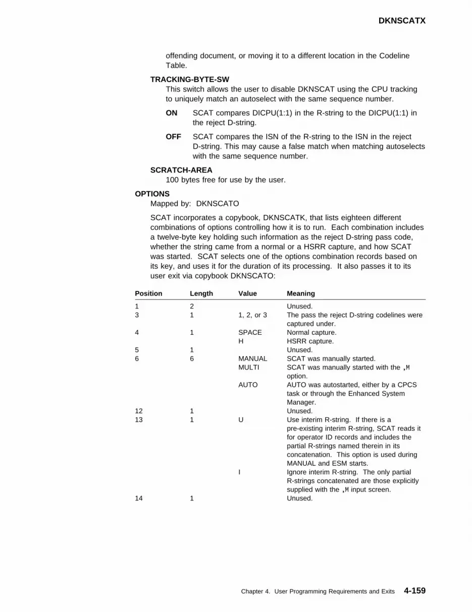
DKNSCATX
offending document, or moving it to a different location in the CodelineTable.
TRACKING-BYTE-SWThis switch allows the user to disable DKNSCAT using the CPU trackingto uniquely match an autoselect with the same sequence number.
ON SCAT compares DICPU(1:1) in the R-string to the DICPU(1:1) inthe reject D-string.
OFF SCAT compares the ISN of the R-string to the ISN in the rejectD-string. This may cause a false match when matching autoselectswith the same sequence number.
SCRATCH-AREA100 bytes free for use by the user.
OPTIONSMapped by: DKNSCATO
SCAT incorporates a copybook, DKNSCATK, that lists eighteen differentcombinations of options controlling how it is to run. Each combination includesa twelve-byte key holding such information as the reject D-string pass code,whether the string came from a normal or a HSRR capture, and how SCATwas started. SCAT selects one of the options combination records based onits key, and uses it for the duration of its processing. It also passes it to itsuser exit via copybook DKNSCATO:
Position Length Value Meaning
1 2 Unused.3 1 1, 2, or 3 The pass the reject D-string codelines were
captured under.4 1 SPACE Normal capture. H HSRR capture.5 1 Unused.6 6 MANUAL SCAT was manually started. MULTI SCAT was manually started with the ,M
option. AUTO AUTO was autostarted, either by a CPCS
task or through the Enhanced SystemManager.
12 1 Unused.13 1 U Use interim R-string. If there is a
pre-existing interim R-string, SCAT reads itfor operator ID records and includes thepartial R-strings named therein in itsconcatenation. This option is used duringMANUAL and ESM starts.
I Ignore interim R-string. The only partialR-strings concatenated are those explicitlysupplied with the ,M input screen.
14 1 Unused.
Chapter 4. User Programming Requirements and Exits 4-159

DKNSCATX
Position Length Value Meaning
15 1 Y Required existence. It is an error if SCATfails to find an partial R-string it is lookingfor. This option is used during ,M and ESMstarts, when the exact partial R-strings toconcatenate are known in advance.
N SCAT concatenates all possible partialR-strings in succession until it fails to findone. It then creates its final (or interim)R-string and quits. This option is usedduring MANUAL starts, when it is not knownin advance how many partial R-strings existto concatenate.
16 1 Unused.17 1 Y SCAT uses exact sequence matching. If an
partial R-string codeline matches to a rejectD-string sequence already matched to, thenthe codeline is considered a duplicatecorrection. This option is used only when itis known with certainty that all rejectD-string sequence numbers are unique.
N SCAT uses probable sequence matching. Ifan partial R-string codeline matches to areject D-string sequence already matchedto, then SCAT continues scanning theMatch Table looking for a better match.This option is used when it is possible oneor more reject D-string codelines could havethe same sequence number.
18 1 Unused.19 1 D Reject D-string ordering. The partial
R-string codelines are assembled in theorder of the reject D-string codelines towhich they match. This option is legal onlywith exact sequence matching, and is usedonly if SCAT has not been given a differentassembly order with the ,M screen.
O Operator ID ordering. The partial R-stringcodelines are assembled in the order theyare encountered in the various partialR-strings.
20 1 Unused.21 2 00 The code used in the pass pocket of
System Reject partial R-strings. This is thepocket that, in reject D-strings and in final orinterim R-strings, is represented by an R(24-byte string name format) or byHIGH-VALUES (17-byte string nameformat).
23 1 Unused.24 2 99 The code used in the fourth pocket of
interim R-strings.26 1 Unused.27 2 00 The code used in the fourth pocket of final
R-strings.29 1 Unused.
4-160 CPCS V1R11 Customization Guide

DKNSCATX
OPERATOR TABLEMapped by: DKNSCATI
This table names all of the partial R-strings that SCAT is to access, and, in thecase of partial R-string ordering, also lists the order in which they are to beassembled. There are 99 entries. Each entry consists of the following:
The table is constructed in two phases, both of which occur between the userexit INIT call and the first User Exit MAIN call.
In the first phase, if the Use Interim R-string option has been selected, SCATlooks for one and, if it finds it, scans it for operator ID records. The operatorIDs extracted from those records are entered into the table with an error codeof Y (since these operator IDs participated in some earlier SCAT, theyobviously must exist).
In the second phase, SCAT merges in operator IDs supplied with its startparameter and/or ,M screen. These IDs are given either an error code of Y, ifthe required existence option is selected; or N, if it is not.
In the case of MANUAL starts, the Operator Table consists of every possibleoperator ID, from 1 to 98. SCAT attempts to concatenate each partial R-stringin succession until it fails to find one; then, it creates its final (or interim)R-string and quits.
The end of the table is always indicated by HIGH-VALUES in an operator IDslot.
Position Length Value Meaning
30 1 Y If a piggyback is encountered that has itsDI30DOCH flag turned on (bit X'80' inDIFLAG3 Byte 0), abort the concatenationwith an error message.
N If a piggyback is encountered that has itsDI30DOCH flag turned on (bit X'80' inDIFLAG3 Byte 0), ignore it and carry onwith the concatenation.
31 1 Unused.32 1 Y If a piggyback is encountered that has its
DI30DOCH flag turned on (bit X'80' inDIFLAG3 Byte 0), reset the flag.
N If a piggyback is encountered that has itsDI30DOCH flag turned on (bit X'80' inDIFLAG3 Byte 0), do nothing to the flag.
33 48 Unused.
Position Length Value Meaning
1 2 01–98 An operator ID. SCAT tries to concatenatein a partial R-string with this ID in its name.
HIGH-VALUES Indicates the end of the table.3 1 Y It is an error if this partial R-string does not
exist. N If this partial R-string cannot be found, the
end of the concatenation has been reached.Create a final (or interim) R-string and quit,just as if the HIGH_VALUES end-tablemarker had been encountered.
Chapter 4. User Programming Requirements and Exits 4-161

DKNSCATX
DOCUMENT USE TABLEMapped by: DKNSCATD
The Document Use Table contains 256 entries, one for each DITYPEI valuethat can possibly exist. Each entry, in turn, consists of two pairs of flags – onepair for control documents, and one pair for non-control documents.
The compressed/uncompressed flag indicates how a codeline of this type isstored within the Codeline Table – either in ZC format, or in DI format. Thesequence-matching flag, meanwhile, controls how SCAT treats the variousitems it reads initially from the reject D-string, and, later on, from the partialR-string(s).
An item should have a Y sequence-match flag only if:
1. It has a sequence number
2. It can appear inside an partial R-string.
A DOC item is one that has a Y Document Use Table sequence-matching flag,and which successfully sequence-matched against a Match Table codeline.Where in the DOC table a partial-R codeline goes depends on the orderingoption in effect. If we are using Operator ID ordering, then DOC slots areallocated, one after the other, linearly from the top of the table. If we are usingReject D-string ordering, however, then the slot a DOC item is placed incorresponds to the Match Table entry that it matched against. Either way,once all partial R-strings have been read, constructing a final (or interim)
Position Length Value Meaning
1 1 C This control document is stored compressed(ZC format).
U This control document is storeduncompressed (DI format).
2 1 Y This control document is to be used insequence-matching.
N This control document is not to be used insequence-matching.
3 1 C This non-control document is storedcompressed (ZC format).
U This non-control document is storeduncompressed (DI format).
4 1 Y This non-control document is to be used insequence-matching.
N This non-control document is not to be usedin sequence-matching.
String Flag Behavior
Reject D-string Y This codeline is added to the Match Table. N This codeline is ignored.Partial R-string Y SCAT attempts to sequence-match this codeline
against codelines from the Match Table. If the matchis successful, SCAT stores the partial R-stringcodeline in the DOC region of the Codeline Table.Otherwise, the item goes into the NDOC or DUP region,as appropriate.
N SCAT attempts no sequence-matching. The codelineis instead stored directly into the NDOC region of theCodeline Table.
4-162 CPCS V1R11 Customization Guide
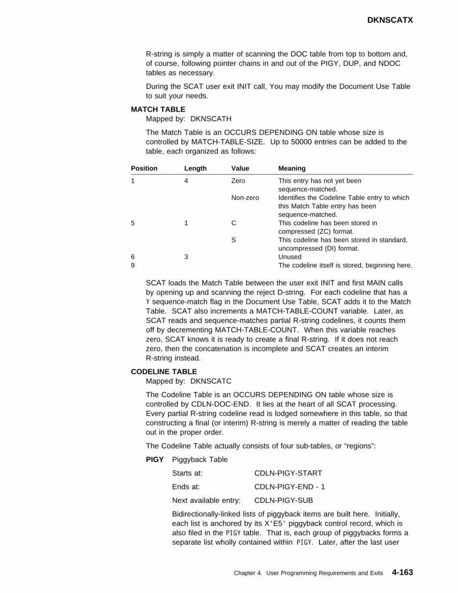
DKNSCATX
R-string is simply a matter of scanning the DOC table from top to bottom and,of course, following pointer chains in and out of the PIGY, DUP, and NDOCtables as necessary.
During the SCAT user exit INIT call, You may modify the Document Use Tableto suit your needs.
MATCH TABLEMapped by: DKNSCATH
The Match Table is an OCCURS DEPENDING ON table whose size iscontrolled by MATCH-TABLE-SIZE. Up to 50000 entries can be added to thetable, each organized as follows:
SCAT loads the Match Table between the user exit INIT and first MAIN callsby opening up and scanning the reject D-string. For each codeline that has aY sequence-match flag in the Document Use Table, SCAT adds it to the MatchTable. SCAT also increments a MATCH-TABLE-COUNT variable. Later, asSCAT reads and sequence-matches partial R-string codelines, it counts themoff by decrementing MATCH-TABLE-COUNT. When this variable reacheszero, SCAT knows it is ready to create a final R-string. If it does not reachzero, then the concatenation is incomplete and SCAT creates an interimR-string instead.
CODELINE TABLEMapped by: DKNSCATC
The Codeline Table is an OCCURS DEPENDING ON table whose size iscontrolled by CDLN-DOC-END. It lies at the heart of all SCAT processing.Every partial R-string codeline read is lodged somewhere in this table, so thatconstructing a final (or interim) R-string is merely a matter of reading the tableout in the proper order.
The Codeline Table actually consists of four sub-tables, or “regions”:
PIGY Piggyback Table
Starts at: CDLN-PIGY-START
Ends at: CDLN-PIGY-END - 1
Next available entry: CDLN-PIGY-SUB
Bidirectionally-linked lists of piggyback items are built here. Initially,each list is anchored by its X'E5' piggyback control record, which isalso filed in the PIGY table. That is, each group of piggybacks forms aseparate list wholly contained within PIGY. Later, after the last user
Position Length Value Meaning
1 4 Zero This entry has not yet beensequence-matched.
Non-zero Identifies the Codeline Table entry to whichthis Match Table entry has beensequence-matched.
5 1 C This codeline has been stored incompressed (ZC) format.
S This codeline has been stored in standard,uncompressed (DI) format.
6 3 Unused9 The codeline itself is stored, beginning here.
Chapter 4. User Programming Requirements and Exits 4-163
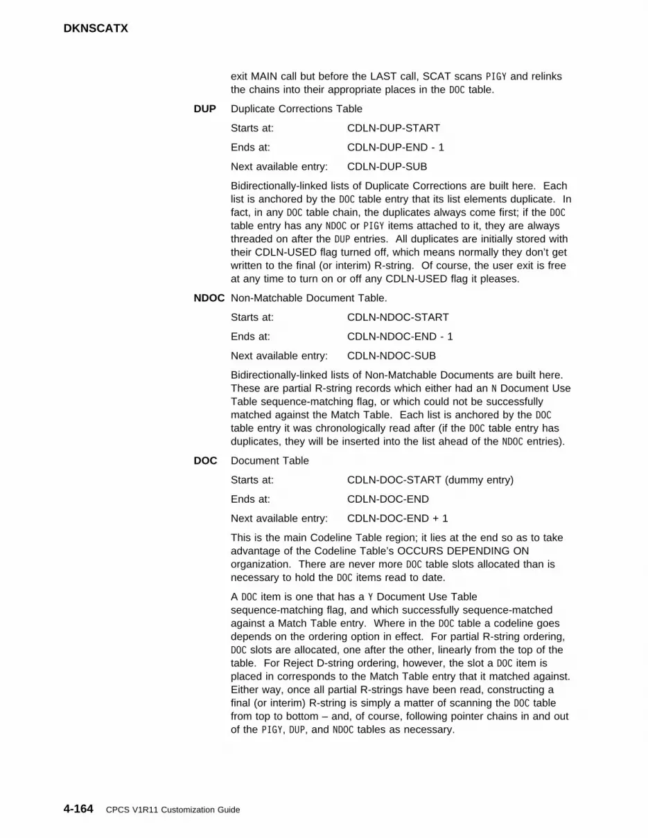
DKNSCATX
exit MAIN call but before the LAST call, SCAT scans PIGY and relinksthe chains into their appropriate places in the DOC table.
DUP Duplicate Corrections Table
Starts at: CDLN-DUP-START
Ends at: CDLN-DUP-END - 1
Next available entry: CDLN-DUP-SUB
Bidirectionally-linked lists of Duplicate Corrections are built here. Eachlist is anchored by the DOC table entry that its list elements duplicate. Infact, in any DOC table chain, the duplicates always come first; if the DOCtable entry has any NDOC or PIGY items attached to it, they are alwaysthreaded on after the DUP entries. All duplicates are initially stored withtheir CDLN-USED flag turned off, which means normally they don’t getwritten to the final (or interim) R-string. Of course, the user exit is freeat any time to turn on or off any CDLN-USED flag it pleases.
NDOC Non-Matchable Document Table.
Starts at: CDLN-NDOC-START
Ends at: CDLN-NDOC-END - 1
Next available entry: CDLN-NDOC-SUB
Bidirectionally-linked lists of Non-Matchable Documents are built here.These are partial R-string records which either had an N Document UseTable sequence-matching flag, or which could not be successfullymatched against the Match Table. Each list is anchored by the DOCtable entry it was chronologically read after (if the DOC table entry hasduplicates, they will be inserted into the list ahead of the NDOC entries).
DOC Document Table
Starts at: CDLN-DOC-START (dummy entry)
Ends at: CDLN-DOC-END
Next available entry: CDLN-DOC-END + 1
This is the main Codeline Table region; it lies at the end so as to takeadvantage of the Codeline Table’s OCCURS DEPENDING ONorganization. There are never more DOC table slots allocated than isnecessary to hold the DOC items read to date.
A DOC item is one that has a Y Document Use Tablesequence-matching flag, and which successfully sequence-matchedagainst a Match Table entry. Where in the DOC table a codeline goesdepends on the ordering option in effect. For partial R-string ordering,DOC slots are allocated, one after the other, linearly from the top of thetable. For Reject D-string ordering, however, the slot a DOC item isplaced in corresponds to the Match Table entry that it matched against.Either way, once all partial R-strings have been read, constructing afinal (or interim) R-string is simply a matter of scanning the DOC tablefrom top to bottom – and, of course, following pointer chains in and outof the PIGY, DUP, and NDOC tables as necessary.
4-164 CPCS V1R11 Customization Guide

DKNSCATX
See Figure 4-87 for an illustration of the relationship between theCodeline Table and its companion, the Match Table.
┌─────────────────┐
┌────┼─CODELINE │f───────┐ PIGY
│ ├─────────────────┤ │
└─────gCODELINE │ │
└─────────────────┘ │
┌─────────────────┐ │
┌────┼─CODELINE UNUSEDf┼────┐ │ DUP
│ ├─────────────────┤ │ │
│ │ UNUSED │ │ │
│ └─────────────────┘ │ │
│ ┌─────────────────┐ │ │
└────┼gCODELINE ─┼────┼───┘ NDOC
├─────────────────┤ │
│ UNUSED │ │
MATCH TABLE └─────────────────┘ │
┌─────────┐ ┌─────────────────┐ │
│MATCHED ─┼─────────────g│ CODELINE │ │ DOC
├─────────┤ ├─────────────────┤ │
│MATCHED ─┼─────────────g│ CODELINE ─┼────┘
├─────────┤ ├─────────────────┤
│UNMATCHED│ │ UNUSED │
├─────────┤ ├─────────────────┤
│MATCHED ─┼─────────────g│ CODELINE │
└─────────┘ └─────────────────┘
Figure 4-87. Codeline and Match Tables
This illustrates the Codeline Table as it looks after the PIGY chainshave been linked in. Note that most DOC entries do not actually anchorlink chains; also, that there are many entries with their CDLN-USEDflags turned off. Unused entries never get written out to final (orinterim) R-strings. Finally, note that at least one Match Table entryremains unmatched. Because of this, SCAT creates an interim ratherthan a final R-string.
The organization of each Codeline Table entry is as follows:
Chapter 4. User Programming Requirements and Exits 4-165

DKNSCATX
CORRECTION TABLEMapped by: DKNSCATF
For each partial R-string codeline read, SCAT builds a Correction Tableshowing the status of each of its fields (valid, invalid, or unused). Normally, ifan R-string codeline contains invalid fields, it is an uncorrected reject, andSCAT sets the RESULT-CODELINE-CORR flag to N to alert the user exit tothis fact. However, if the codeline came out of OLRR Bypass processing, thepresence of rejects is probably intentional. In such a case SCAT leavesRESULT-CODELINE-CORR set to Y. The validity flags in this table are neverchanged, however, so the user exit can always interrogate them to learn thetrue status of any codeline.
This table is fifteen bytes long, with each byte corresponding to MICR fields 1through 15, in that order. Each byte can have one of three values (refer toFigure 4-88 on page 4-165).
Value Meaning
U This field is not used, as per your MDX generation.
SPACE This field is valid.
I This field is invalid.
Altering these fifteen bytes has no affect on SCAT’s behavior. To indicate thatan uncorrected reject is really corrected (or vise-versa), the user exit mustchange the setting of RESULT-CODELINE-CORR, and, optionally, edit theoffending codeline and/or change its location in the Codeline Table.
Figure 4-88. Codeline Entry Organization
Position Length Contents
1 4 Fore Pointer — locates the next Codeline Table entry in thischain. If this is a DOC table entry that anchors no chain, thenthe Fore Pointer points to the DOC table entry itself.
5 4 Back Pointer — locates the previous Codeline Table entry inthis chain. If this is a DOC table entry that anchors no chain,then the Back Pointer points to the DOC table entry itself.
9 4 Likely piggyback location. Used only by PIGY tablePiggyback Control records, this points to the DOC table entrythe record was chronologically found after. In all likelihoodthis is the probable place where the piggyback chain is tolink in. However, if this location does not pan out, thenSCAT is prepared to scan the entirety of the Codeline Tableto find the true piggyback insert point.
13 1 CDLN-USED flag. If U, this Codeline Table entry is in useand should be written to the final (or interim) R-string. IfSPACE, this Codeline Table entry is not in use and shouldnot be written.
14 1 Compressed/Uncompressed flag. Copied from theDocument Use table, this flag indicates how the codeline isstored: A C means in compressed (ZC) format, a U means inuncompressed (DI) format.
15 2 Operator ID. Names the partial R-string from which thiscodeline was read.
17 The codeline itself is stored beginning here.
4-166 CPCS V1R11 Customization Guide

Extract Programming
APTCBMapped by: DKNAPTCB
Application Program Task Control Block, for use in interfacing with variousCPCS subtasks and service routines.
Sample String Concatenation User ExitA sample String Concatenation user exit may be found in CPCS.V1R11.SAMPLIBunder the name DKNSCATX. It performs the following functions:
� During initialization, calls on DKNMDXR to set up and open a SCATUncorrected Rejects Report.
� For every uncorrected reject, duplicate correction, and free codelineencountered, writes the offending record to the Uncorrected Rejects Report,along with a message documenting the error.
� After SCAT reads the last partial R-string codeline, scans the Match Table formissing codelines and adds them to the Uncorrected Rejects Report.
� Deletes the interim R-string, when SCAT decides it’s ready to create a finalR-string but discovers that an interim R-string already exists.
� Calls on DKNMDXR to close and write the Uncorrected Rejects Report duringSCAT shutdown.
Note: DKNSCATX prepares a report. If you use it as-is on the USREXITparameter of DKNSCAT’s BLDL entry, then you will also need to equip the entrywith a PRINT=1 and a CLASS parameter.
Extract ProgrammingAfter CPCS captures and processes input documents, the next step is to extractthe codeline data records, usually by M-string, from CPCS. You can use theserecords as input to your posting systems. The coding to do this is referred to asextract programming, which you must supply.
Important!
Power-encoding records must be bypassed by the extract application to preventdouble posting. For a description of these records, see “Balancing andPower-Encoding Considerations” on page 4-171.
Extracting Mass Data Set RecordsDKNICRE extracts all completely processed M-strings for a specific cycle, and foreither a specific bank or all banks, and transfers them to an output tape (or disk)data set. You can use the output data set as input to an archive retrieval system.If the output data set is unreadable when you use it as input, you must perform aselective string recovery from one or more CPCS log tapes to retrieve theM-strings. (See “Data-Set Recovery Procedures” on page 1-33.) Otherwise, usethe DKNICRE program as a base or guideline to create your extract programs.You can change the output format to meet the requirements of your postingsystem.
Chapter 4. User Programming Requirements and Exits 4-167

Extract Programming
If the user specifies the MSTRING=1 option in the CPCS system profile memberDKNPCPCS parameters (see “DKNPCPCS Profile Member” on page 3-6), theextract program can flag extracted M-strings as being user-processed.
User Application RequirementsCPCS lets you refer to the MDS records in several different ways:
� You can change application tasks to refer to the maximum allowable field sizes.The advantage of this method is that you only need to change the programonce to use these enlarged fields. The disadvantage of doing this is that eachfield has to be parsed to allow for the internal pad characters used forformatting the expanded fields. For additional information on fields and theirsizes, see the CPCS Programming and Diagnostic Guide.
� You can change application tasks to refer to the redefinable copybooks andDSECTs that describe the MDS record layout. You must recompile orreassemble these programs whenever you redefine the MDS record with theMDX macro. This is the best option for COBOL programs.
� You can change your application tasks to use the MDXREC DSECT;specifically, use the field lengths in the DSECT as parameters to changeinstructions. For example, an application task can move the length (−1) of afield into a valid move-character instruction.
USING TSTDSECT,R1�
T
XR R5,R5
IC R5,MDXFLD�3 GET FIELD LENGTH
BCTR R5,� DECREMENT FOR EXECUTE
EX R5,EXECUTE MOVE FIELD
B WOW
T
EXECUTE MVC SAVEACCT(T-T),VARFIELD
T
WOW DS OH
T
TSTDSECT DSECT
SAVEACCT DS XL256
VARFIELD DS XL256
R5 EQU 5
R1� EQU 1�
R11 EQU 11
R12 EQU 12
COPY MDXREC
If the MDXREC is defined in DKNMTASK during system generation and isaddressed through a pointer in the PARMLST (AMDXREC), you do not have toreassemble programs that refer only to the MDXREC. However, this method is notrecommended because it is difficult to maintain and debug.
4-168 CPCS V1R11 Customization Guide

Installing the Refreshed Enhanced Jam Option
Installing the Refreshed Enhanced Jam OptionYou can choose to have CPCS display a refreshed enhanced jam screen at theend of a runout condition on the 3890/XP. In addition, you can choose to have allitems displayed on the refreshed jam screens selected to the reject pocket whenthe operator enters DONE, as well as have all items selected to the reject pocket setas user control documents. You can also flag suspect items as having beenimaged.
To invoke these options, follow these steps:
1. Make a user change to copy member EJAMCTRL, changing:&REFRESH SETC 'N' to&REFRESH SETC 'Y'
2. Make a user change to copy member EJAMCTRL, changing:&ALLDONE SETC 'N' to&ALLDONE SETC 'Y'
3. Make a user change to copy member EJAMCTRL, changing:&USERSET SETC 'N' to&USERSET SETC 'Y'
4. Make a user change to copy member EJAMCTRL, changing:&HSIBACT SETC 'N' to&HSIBACT SETC 'Y'
5. Assemble and LKED modules DKNMGET, DKNMJAM, DKNMCDRJ,DKNMCMDS, DKNMREAD, DKNMCQC, DKNMCRST, and DKNMSTAT.
6. Changing these modules requires you to generate a new version of theDKNMICR module. The JCL is in member DKNGMICR of CPCS.V1R11.CTRL.
For information about generating DKNMICR, see “MICR Task Generation” onpage 2-33.
7. Copy DKNJAMPR.DLL to \OS2\DLL on the sorter PC.
8. Update the run profiles to include the following:
USERDLL DKNJAMPR
SPSINIT JAMPROC_INIT_EVNT
SPSMS JAMPROC_MS_EVNT
SPSDOC JAMPROC_DOC_EVNT Note: Must be LAST DOC event.
SPSPAUSE JAMPROC_PAUSE_EVNT
Notes:
1. Control program code R15F10, or higher, must be running on the 3890/XP.
2. The &ALLDONE option is valid only if the &REFRESH option is also active.
3. The DKNJAMPR DLL should not be used unless the &REFRESH value is setto Y. The function of the DKNJAMPR DLL is to direct the “inflight” itemsbetween the hopper and the read head to the reject pocket and to disengagethe sorter at the end of the runout.
4. The DKNJAMPR DLL uses the first 10 bytes of the New Save Area in AUXstorage on the 3890/XP. If you have any user DLL’s that use these 10 bytes,you must modify these user DLL’s.
Chapter 4. User Programming Requirements and Exits 4-169

Disable/Disengage Option
| Installing the CPCS 48-Pocket Support| Effective with APAR PQ42860, CPCS supports a 3890/XP sorter definition of up to| 8 stacker modules (48 pockets) with the CPCSRDR macro. To be able to use this| feature, the following functions must also be available:
| � ICSM (5655B2301) APAR PQ41583 must be installed.
| � The CPCS 48-Pocket Feature Key must be installed.
| � The sorter control program for the sorter(s) that exceed 36 pockets must| emulate a 3890/XP sorter, and use the IREC Extension as defined in the| 3890/XP Enhanced Document Processor Guide, (SC31-4069).
| Note: If you define a 3890/XP sorter to CPCS that has 7 or 8 stackers and you| do not have the CPCS 48-Pocket Feature Key installed, CPCS reduces the number| of stackers to 6 at execution time.
Installing the Feature Disable/Disengage OptionIf selected features have been initialized in the IREC and are subsequentlydisabled, you can have the sorter issue a disengage:
1. Download DKNFEATD in binary format from the SDKNDAT1 data set to adiskette.
2. Copy DKNFEATD.DLL to the \OS2\DLL directory on your sorters.
3. Add the following statements to your run profiles for which you want thisfeature:
USERDLL DKNFEATD
SPSINIT DKNFEATD_INIT_EVNT
T Use the following SPSPOST event for all features.
T (INF, END, and IMG)
SPSPOST DKNFEATD_POST_EVNT
T Use the following SPSPOST event for IMG feature only.
SPSPOST DKNFEATD_POST_IMGONLY_EVNT
Notes:
1. If you are installing this DLL on a 3890/XP, you must be at control program fixlevel R15F34 or greater. (There is no specific fix level requirement for the3890/XPE.) You must also be at fix level R271F04 or greater on the 3897, ifapplicable.
2. This DLL disengages the sorter when any of the following features have beeninitialized in the IREC and are subsequently uninitialized:
� INF (Item Numbering Feature) � END (Endorse)� IMG (Image Scanner)
After the disengage, the operator must cancel/restart the entry run. If the entryis not canceled/restarted, the sorter sorts 6 (plus or minus) more checks anddisengages again.
3. This DLL uses bytes 6 - 9 (relative to 0) of the NewArea of auxiliary storage. Ifyou have any other DLLs that use this area, they must be modified.
4-170 CPCS V1R11 Customization Guide
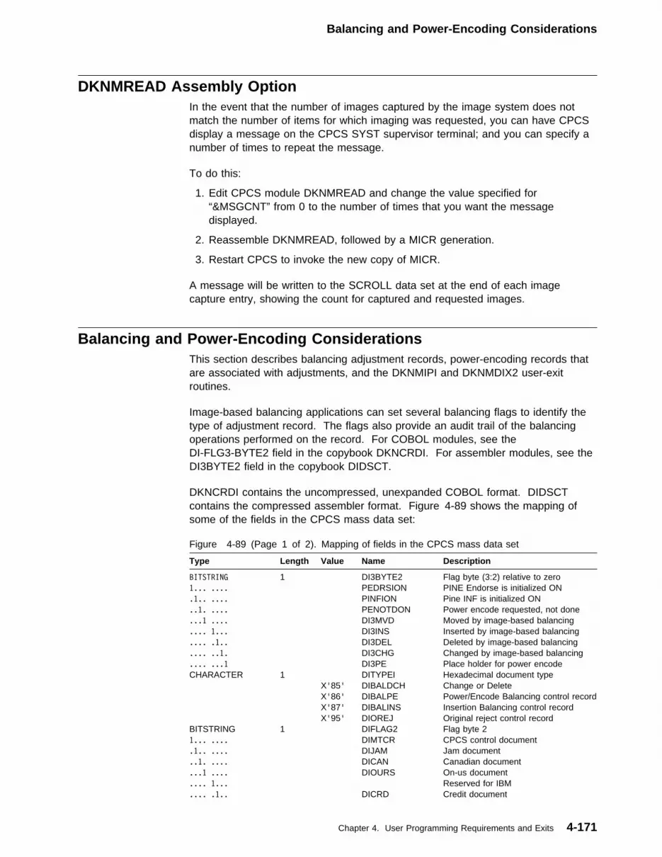
Balancing and Power-Encoding Considerations
DKNMREAD Assembly OptionIn the event that the number of images captured by the image system does notmatch the number of items for which imaging was requested, you can have CPCSdisplay a message on the CPCS SYST supervisor terminal; and you can specify anumber of times to repeat the message.
To do this:
1. Edit CPCS module DKNMREAD and change the value specified for“&MSGCNT” from 0 to the number of times that you want the messagedisplayed.
2. Reassemble DKNMREAD, followed by a MICR generation.
3. Restart CPCS to invoke the new copy of MICR.
A message will be written to the SCROLL data set at the end of each imagecapture entry, showing the count for captured and requested images.
Balancing and Power-Encoding ConsiderationsThis section describes balancing adjustment records, power-encoding records thatare associated with adjustments, and the DKNMIPI and DKNMDIX2 user-exitroutines.
Image-based balancing applications can set several balancing flags to identify thetype of adjustment record. The flags also provide an audit trail of the balancingoperations performed on the record. For COBOL modules, see theDI-FLG3-BYTE2 field in the copybook DKNCRDI. For assembler modules, see theDI3BYTE2 field in the copybook DIDSCT.
DKNCRDI contains the uncompressed, unexpanded COBOL format. DIDSCTcontains the compressed assembler format. Figure 4-89 shows the mapping ofsome of the fields in the CPCS mass data set:
Figure 4-89 (Page 1 of 2). Mapping of fields in the CPCS mass data set
Type Length Value Name Description
BITSTRING 1 DI3BYTE2 Flag byte (3:2) relative to zero1... .... PEDRSION PINE Endorse is initialized ON.1.. .... PINFION Pine INF is initialized ON..1. .... PENOTDON Power encode requested, not done...1 .... DI3MVD Moved by image-based balancing.... 1... DI3INS Inserted by image-based balancing.... .1.. DI3DEL Deleted by image-based balancing.... ..1. DI3CHG Changed by image-based balancing.... ...1 DI3PE Place holder for power encodeCHARACTER 1 DITYPEI Hexadecimal document type X'85' DIBALDCH Change or Delete X'86' DIBALPE Power/Encode Balancing control record X'87' DIBALINS Insertion Balancing control record X'95' DIOREJ Original reject control recordBITSTRING 1 DIFLAG2 Flag byte 21... .... DIMTCR CPCS control document.1.. .... DIJAM Jam document..1. .... DICAN Canadian document...1 .... DIOURS On-us document.... 1... Reserved for IBM.... .1.. DICRD Credit document
Chapter 4. User Programming Requirements and Exits 4-171

Balancing and Power-Encoding Considerations
Adjusted M-strings can contain the following types of image-based balancingadjustments:
INSERT The example below shows Balancing has inserted one item into the99-M string. The offsets are based on a standard 50-byte mass dataset.
Tag nm DISEQ12 DIAMT DIMTCR DITYPEI DI3INS DI3PE
Size 6/HEX 5/HEX �:1/BIT 1/HEX �:1/BIT �:1/BIT
Loc (5-1�) (31-35) (39-38) (4�-4�) (45-44) (45-44)
Fld num 2----------- 8--------- 22------ 3�------ 56------ 59------
1�������1278 �������2�� 1 87 1 �
1�������1278 �������2�� � �� 1 �
1. Insertion control record.
2. Insertion detail record. This record contains the inserted dataused for posting. It has the same DISEQ12 field sequencenumber as the associated insertion control record, with theexception of the first digit, which is always 1.
DELETE An example of a delete is shown below:
DISEQ12 DIAMT DIMTCR DITYPEI DI3DEL DI3CHG
6/HEX 5/HEX �:1/BIT 1/HEX �:1/BIT �:1/BIT
(5-1�) (31-35) (39-38) (4�-4�) (45-44) (45-44)
2----------- 8--------- 22------ 3�------ 57------ 58------
���7����3357 ���������� 1 95 � �
���7����3357 ����1�2297 1 85 1 �
���7����3358 ���������� 1 95 � �
���7����3358 �����17457 � �� � �
The first 3357 is the original rejected item from the prime-pass I-string.The next 3357 indicates this record was deleted by Balancing.
This adjustment is indicated by a deletion control record that containsthe following flags:
Figure 4-89 (Page 2 of 2). Mapping of fields in the CPCS mass data set
Type Length Value Name Description
.... ..1. DILOW Document entered with on-line entry
.... ...1 DIHIGH Document entered on high-speed pass
Field Flag Flag Description
DIFLAG2 DIMCTR Control recordDITYPEI DIBALINS InsertionDI3BYTE2 DI3INS Insert
Field Flag Flag Description
DI3BYTE2 DI3INS Insert
4-172 CPCS V1R11 Customization Guide
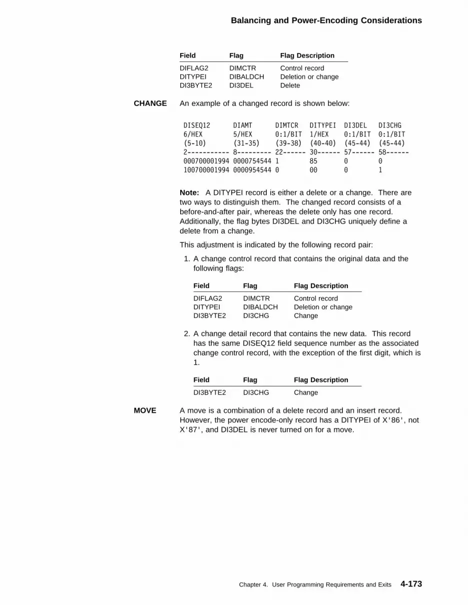
Balancing and Power-Encoding Considerations
CHANGE An example of a changed record is shown below:
DISEQ12 DIAMT DIMTCR DITYPEI DI3DEL DI3CHG
6/HEX 5/HEX �:1/BIT 1/HEX �:1/BIT �:1/BIT
(5-1�) (31-35) (39-38) (4�-4�) (45-44) (45-44)
2----------- 8--------- 22------ 3�------ 57------ 58------
���7����1994 ����754544 1 85 � �
1��7����1994 ����954544 � �� � 1
Note: A DITYPEI record is either a delete or a change. There aretwo ways to distinguish them. The changed record consists of abefore-and-after pair, whereas the delete only has one record.Additionally, the flag bytes DI3DEL and DI3CHG uniquely define adelete from a change.
This adjustment is indicated by the following record pair:
1. A change control record that contains the original data and thefollowing flags:
2. A change detail record that contains the new data. This recordhas the same DISEQ12 field sequence number as the associatedchange control record, with the exception of the first digit, which is1.
MOVE A move is a combination of a delete record and an insert record.However, the power encode-only record has a DITYPEI of X'86', notX'87', and DI3DEL is never turned on for a move.
Field Flag Flag Description
DIFLAG2 DIMCTR Control recordDITYPEI DIBALDCH Deletion or changeDI3BYTE2 DI3DEL Delete
Field Flag Flag Description
DIFLAG2 DIMCTR Control recordDITYPEI DIBALDCH Deletion or changeDI3BYTE2 DI3CHG Change
Field Flag Flag Description
DI3BYTE2 DI3CHG Change
Chapter 4. User Programming Requirements and Exits 4-173

Balancing and Power-Encoding Considerations
DISEQ12 DIAMT DIMTCR DITYPEI DI3MVD DI3INS DI3PE
6/HEX 5/HEX �:1/BIT 1/HEX �:1/BIT �:1/BIT �:1/BIT
(5-1�) (31-35) (39-38) (4�-4�) (45-44) (45-44) (45-44)
2----------- 8--------- 22------ 3�------ 55------ 56------ 59------
���8��279538 ���������� 1 95 � � �
���8��279538 ��������12 1 85 1 � �
���8��279538 ��������12 1 86 1 � 1
1��8��279538 ��������12 � �� 1 � 1
������117828 �����21683 1 87 � 1 �
1�����117828 �����21683 � �� � 1 �
���8��279538 ��������12 1 87 1 � �
1��8��279538 ��������12 � �� 1 � �
���8��279539 ���������� 1 95 � � �
���8��279539 ��������12 1 85 � � �
1��8��279539 �������112 � �� � � �
The records are identified by the flags shown for the delete and insertadjustments, except the DI3BYTE2 field contains the following flagand flag description:
Field Flag Flag Description
DI3BYTE2 DI3MVD Move
Power-Encoding RecordsAn example of the power encode control record is shown below.
Note: These records are paired and a X'86' should always be followed by aX'00' in the 99-M-string. By default, DKNMDIS does not distribute the X'86'record. DKNMDIS distributes only the X'00' record that follows the X'86' record,and ICRE does not extract either the X'86' or X'00' when DI3PE is on.
DISEQ12 DIAMT DIMTCR DITYPEI DI3MVD DI3INS DI3PE
6/HEX 5/HEX �:1/BIT 1/HEX �:1/BIT �:1/BIT �:1/BIT
(5-1�) (31-35) (39-38) (4�-4�) (45-44) (45-44) (45-44)
2----------- 8--------- 22------ 3�------ 55------ 56------ 59------
���8��279538 ��������12 1 86 1 � 1
For insert and move adjustments, a power-encoding record pair can also beincluded as follows:
� A record is inserted and the corresponding physical item is also inserted in thecorrect location in the entry.
� A record is moved and the corresponding physical item is either left in itsoriginal location or moved to the correct location in the entry.
Power-encoding records have the same relative location as the physical items theyrepresent. If they are associated with an insert, they follow the insert record pair.If they are associated with a move and the item is left in its original location, theyfollow the delete record. If they are associated with a move and the item is alsomoved, they follow the insert record pair.
4-174 CPCS V1R11 Customization Guide

Balancing and Power-Encoding Considerations
Power-encoding record pairs have the following format:
1. Power-encoding control record. This record has the inserted item’s data or themoved item’s original data (if it has also been changed). The DISEQ12 fieldsequence number is the same as the associated insert control record or movecontrol record.
2. Power-encoding detail record. An example of a power encode-only codeline isshown below:
DISEQ12 DIAMT DIMTCR DITYPEI DI3MVD DI3INS DI3PE
6/HEX 5/HEX �:1/BIT 1/HEX �:1/BIT �:1/BIT �:1/BIT
(5-1�) (31-35) (39-38) (4�-4�) (45-44) (45-44) (45-44)
2----------- 8--------- 22------ 3�------ 55------ 56------ 59------
1��8��279538 ��������12 � �� 1 � 1
This record contains the inserted data or final moved data (if the moved itemdata is changed before or after the move). The DISEQ12 field sequencenumber is the same as the associated power-encoding control record, exceptthat the first digit is 1.
Field Flag Flag Description
DIFLAG2 DIMCTR Control recordDITYPEI DIBAPE Power encodingDI3BYTE2 DI3PE Power encode
Field Flag Flag Description
DI3BYTE2 DI3PE Power encode
Adjusted M-String ProcessingPower-encoding records are used only for power-encoding purposes and are neverused for posting purposes. Because they do not have any posting value andcontain duplicate detail data, power-encoding records must be bypassed by extracttasks for the same reason they are bypassed by the DKNICRE and DKNPLSTtasks.
Important!
When using extract applications, a double posting can occur if you do notbypass power-encoding records (setting flag DI3PE on in field DI3BYTE2).
The M-string distribution task (DKNMDIS) distributes only one adjustment record foreach adjusted item (with the final adjusted data) in the same relative location it wascaptured.
� Adjustment control records and insert detail adjustment records are notdistributed.
� Change detail records, power-encoding detail records, and individual deleterecords (not part of a move) are distributed.
Chapter 4. User Programming Requirements and Exits 4-175

Balancing and Power-Encoding Considerations
Power-Encoding Subsequent PassesWhen the DKNMIPI user-exit routine (MIPIEXIT) is not active, the D-stringadjustment records are treated as follows:
� Detail records are passed to the sorter for codeline data matching.
� Delete control records are passed to the sorter for codeline data matching, withpower encoding disabled.
Power-Encoding Subsequent-Pass ReconciliationThe subsequent pass balancing list task (DKNSBAL) treats delete control records inthe same way as detail records and includes them in the matching process. As aresult, the deleted items are listed as missing items.
To eliminate missing item conditions, you can activate a DKNMDIS user-exit routineto stop distribution of the delete control records. The user-exit routine can also beused to avoid other problems, such as codeline data matching failures caused bygroups of contiguous deletes. The IBM-supplied sample DKNMDIS user-exitroutines (DKNMDIX and DKNMDIX2) include part of the code needed to do this.
Matching Codeline Data with Original DataThe following steps provide a method to match codeline data with original data andto power encode from adjusted data. Using this method can help you avoidcodeline data matching failures that result from changed data.
1. Write and activate a DKNMDIS user-exit routine to force the distribution ofchange and power-encoding adjustment control records.
2. For the power-encoding pass sort-pattern definition, define a DKNMIPI exitwork field in the O-record. The byte length must be greater than or equal tothe total sorter-record byte length of fields 0 through 8. The field must not existin the MDS record.
3. Write and activate a MICR DKNMIPI user-exit routine that merges each changeor power-encoding record pair into one record. This single record contains theold and new data (in fields 1 through 8) for codeline data matching. Use thedata in the work field (flagged for use in codeline data matching) for powerencoding.
When the DKNMIPI user-exit routine is active, CPCS processes the D-stringadjustment records as follows:
� Records that are normally passed to the sorter for codeline data matchingare marked for codeline data matching and passed to the user-exit routine.
� Change and power-encoding control records are marked as “not availablefor codeline data matching” and are passed to the user-exit routine.
4. Add logic to the sorter edit routine used in the power-encoding pass to movethe power-encoding data from the work field to the power-encoding buffer.When codeline data matching is successful, set the appropriate field selectionin the power-encoding mask byte before calling the power-encoding SPXservices.
4-176 CPCS V1R11 Customization Guide

Security Options
Security OptionsCPCS lets you control, through IDs and passwords, which operators can log onCPCS. You can also define the tasks that the operator is allowed to start.
Resource Access Control Facility Security OptionThe CPCS system profile parameter, SCRTY=RACF, indicates that the MVSresource access control facility (RACF) security subsystem is the security option forCPCS. If enabled, the master task loads and initializes a task named DKNSECRfrom the load library specified in the step library and places its address inPARMLST.
When RACF security is specified, DKNSGO3 and DKNSGOF control access toCPCS through IDs, passwords, and other parameters defined in RACF for therespective CPCS system. Each time DKNATASK is requested to run an applicationtask, it accesses RACF data to determine whether the terminal operator can accessthe task. RACF definitions for each CPCS operator can include:
� The time of day and days of the week when an operator can log on
� The number of invalid logon attempts that can occur before ID access to CPCSis revoked
� ID password retention period
� The format of the IDs and passwords.
DKNMAYI is the transaction-level interface that enables applications to performmore detailed verification. For example, an operator might have access to CYCL,but not have access to CYCLU. The operator can start the CYCL task and displayinformation defined for each cycle but cannot change it. DKNATASK verifies theCYCL command before starting the DKNCYCL task for the operator; but, if theoperator tries to change any of the definitions, DKNCYCL checks the CYCLUtransaction, finds it not valid, and permits no changes. For more information on theMVS RACF security interface, see the CPCS Programming and Diagnostic Guide.
Data Security OptionThe CPCS system profile parameter, SCRTY=DASC, indicates that the data-accesssecurity control option of CPCS is called. It causes DKNMTASK to load a tablecalled DKNDASC and places its address in PARMLST. If you omit the parameter,or specify SCRTY=NONE, the data security option is ignored. If you specify thedata security option incorrectly, the CPCS system editor generates the appropriatemessage in the CPCS system parameter edit report (MPTR).
When you specify SCRTY=DASC in the system profile member DKNPCPCS, youmust generate an operator logon table (DKNDASC) by coding a DKNBSCY macrofor each operator entry in the table. An operator password that is not in the tablecannot log on CPCS.
DKNMTASK controls whether data security is called. If it is called, data securitycompares the information in DKNBLDL and DKNDASC for each application tasklogon request. SGO3, SGOF, and tasks that automatically start are exempt andare not subject to data security testing; if they can be initiated under existingcriteria, they will be.
Chapter 4. User Programming Requirements and Exits 4-177

Security Options
You must arbitrarily assign authority classes to the application programs by theAUTH parameter of the DKNBLDL generation. For more information on the BLDLtable, see “Describing an Application Task’s Environment” on page 2-15. Theseassignments should be consistent with the CPCS philosophy. For example, theSUPV task given any authority class still controls tasks requiring a supervisoryterminal, no matter what authority classes are given to those tasks. An applicationtask can be of only one authority class.
In creating the operator logon table, the user supplies an operator password, anoperator logon ID, and one or more authority classes that the operator is restrictedfrom running. For example, if all authority classes are specified, the operator canrun only SGO3 and SGOF; there is no way to start any other application task orMICR. For more information on the coding requirements for this table, see “DASCTable.”
The macro DKNBSCY creates the operator logon table (DKNDASC); it must havean entry for each operator who can operate CPCS. Unknown operator passwordsentered into SGO3 are not accepted and the terminal is not logged on. All logonattempts through SGO3 are logged to the ATASK log, showing the results of thelogon attempt. Once a display terminal logs on with SGO3, the terminal takes onthe security characteristics of the operator signing on.
These characteristics remain in effect until the terminal logs off through SGOF,even if the operator identification in the terminal changes by other means (forexample, MSGON).
BLDL Table: The parameter AUTH=x in the APCB macro, where x is 1, 2, 3, 4, or5, assigns an application task to an authorization class of tasks. The defaultauthorization class is 1 if no authorization class is specified (unless the applicationtask can only be started automatically). Automatically started tasks have theauthorization class set to zero, regardless of what is coded in the AUTH parameter.An application task can only belong to one authorization class.
DASC Table: You can create the data-security table (DKNDASC) by coding themacro DKNBSCY with correct parameters: one macro for each CPCS operator.The assembled table consists of 8-byte entries, each containing an operatorpassword, operator ID, and, if applicable, application authorization classes andMICR that this operator is not permitted to start.
Important!
You specify the restrictions. Omitting authorization classes for an entry in thedata-security table means that operator can run all tasks in the unspecifiedauthorization classes.
After you code the table, assemble it and link-edit it with the name DKNDASC intothe CPCS load library. The first occurrence of DKNBSCY generates a CSECTrecord labeled DKNDASC. Coding DKNBSCY without any parameters generatesthe end of the table.
4-178 CPCS V1R11 Customization Guide

Security Options
DKNBSCY Macro FormatThe macro format is:
passwordSpecifies a 3-character password with no embedded blanks. The operatormust enter the password to log on. SGO3 reads it.
operator IDSpecifies a 3-character operator identification with no embedded blanks. It isused for display purposes only.
authorization classSpecifies the authorization class that the operator is not permitted to run. It iseither a single-digit number (1, 2, 3, 4, or 5), the letter M, or a combination ofboth. If two or more classes are coded, the operator must enclose them inparentheses and separate them with commas. The codes are expressed inany order to a maximum of six authorization classes. If you omit thisparameter, the operator can start all authorization classes.
Label Operation Parameters
label DKNBSCY ,password ,operator ID [authorization class]
DKNBSCY Examples
Note: Along with the CPCS SGON security option, VTAM users can specify thepassword parameter (PASSWD) in the VNODE macro. This requires the operatorto enter a password when logging on CPCS by a standard VTAM LOGON request.For more information, see “DKNVTASK Node-Name Table Description” onpage 2-56.
Macro Examples ExplanationDKNBSCY PW1,AAA Operator password PW1 signs on as operator AAA and
can run any authorization class.
DKNBSCY PW2,BBB,1 Operator password PW2 signs on as operator BBB andcan run any authorization class tasks except class 1.
DKNBSCY PW3,CCC, (M,3) Operator password PW3 signs on as operator CCC andcan run any authorization tasks except MICR and class 3.
DKNBSCY Denotes the end of the DKNDASC table.
RACF Security Installation ProcedureYou must complete the following tasks when using RACF facilities for security withCPCS.
1. Define a RACF class and class group to protect your CPCS resources.
2. Connect your CPCS resources to the RACF class and/or class group structure.
3. Define a RACF group for your CPCS user IDs.
4. Change the CPCS system profile parameter SCRTY= to activate your RACFsecurity procedure (see “DKNPCPCS Profile Member” on page 3-6).
Chapter 4. User Programming Requirements and Exits 4-179

Security Options
The following procedures illustrate, in greater detail, how to implement RACFsecurity within CPCS.
1. In order to define a RACF class and class group, you must do the following:
� Define a RACF class with the RACLIST=YES option. The namingconvention for RACF classes is defined in the System ProgrammingLibrary: Resource Access Control Facility manual. The DKNGRACF JCL inCPCS.V1R11.CTRL shows an example of how to define a resource classand resource class group.
� The default RACF class is $CPCS. To change it, substitute your choice inthe JCL.
� To use a group of resources, code a group in the JCL. CPCS uses$GCPCS as the default class group name.
� You must have system-level authority to run this JCL because you areupdating SYS1.LINKLIB.
� Issue the RACF command SETROPTS RACLIST (class) for the CPCSclass. Every time you modify the RACF CPCS class tables, you must issuethis command.
2. In order to protect your resources, you must connect them to a class.
� Use the ISPF display panels for RACF or you may do this by submitting theDKNGRCFD JCL in CPCS.V1R11.CTRL. You must have RACF specialauthority to use either method to connect your resources to the class.
You can connect each of the resources to the class $CPCS and connectgroups of resources to the CLASS GROUP ($GCPCS). For an example,see “Establishing Your RACF Structure” on page 4-181.
3. In order to provide access to CPCS and its resources, you should define aRACF group for the user IDs.
A RACF group may be defined through ISPF RACF panels. CPCS does notinclude JCL to complete this task. You must have RACF special authority todefine a group of user IDs.
Note: This step may be optional if you use an existing RACF group, such asone for TSO users. Please read Step 4 carefully concerning the CPCS systemprofile member DKNPCPCS parameter SCRGP=, if you choose to eliminate thisstep.
4. The following CPCS system profile member DKNPCPCS parameters may becoded in order to activate your RACF security procedure for CPCS.
� Change the CPCS system profile member DKNPCPCS parameter toSCRTY=RACF.
� Specify the RACF class in the DKNPCPCS parameter SCRCL= for theresources that you protected. The default class name for CPCS is $CPCS.If you used a different class name in the DKNGRACF and DKNGRCFDJCL, change the parameter to reflect the proper class name.
� Specify the RACF group name for the CPCS user IDs in the DKNPCPCSparameter as SCRGP=. The default RACF group name is CPCS. If youdefined a different RACF group or are using an existing RACF group,change the parameter to reflect the proper RACF group name for user IDs
4-180 CPCS V1R11 Customization Guide

Security Options
that may log on (SGON) to CPCS. Only one RACF group of user IDs maybe defined to CPCS, unless you specify SCRGP=0.
Note: If the value of SCRGP is 0, TSO users defined to any RACF groupcan log on to CPCS. The users may then access any resources that arenot protected or not defined in your resource class group structure.However, they may not access any resources or groups of resources theyhave not been permitted to access. For more information about theSCRGP keyword, see “DKNPCPCS Profile Member” on page 3-6.
� The system profile member DKNPCPCS has a default parameter,CHGPSWD=0, that allows you to maintain a password within the rulesestablished in the definition to RACF for CPCS. If you do not want anoperator to be able to change the password, code CHGPSWD=1 in thesystem profile member DKNPCPCS.
Note: The default RACF security lets an ID log on only one terminal at a time. Topermit multiple logons, change the program DKNSG03.
Establishing Your RACF StructureBefore you establish your RACF structure, plan your class/group structure toprotect your resources. If you use a class/group structure, you will be able toauthorize new users more easily. See Figure 4-90 for a sample group structure.
$CPCS (class)
│
│
$GCPCS (group)
│
│
┌──────────────┬─────────┴────────┬───────────────┐
│ │ │ │
│ │ │ │
GROUP1 GROUP2 GROUP3 GROUP4
ALL MICR LIST ALL other
protected HEXL protected
resources other CYCL resources
Figure 4-90. Sample RACF Class/Group to User ID Structure
The groups would be joined to resource class group $GCPCS.
If you do not want the resource class group structure, define each resourceseparately to the resource class.
Permitting Access to ResourcesWhen you use the resource class group structure, you can let user IDs accessresources by giving the IDs access to the group itself. Without the resource classgroup structure, you must give each ID access to each resource. Here is anexample of the resource class group structure:
Chapter 4. User Programming Requirements and Exits 4-181

Security Options
┌──────────────┬──────────────────┬────────────────┐
│ │ │ │
│ │ │ │
GROUP1 GROUP2 GROUP3 GROUP4
USERID1 USERID2 USERID3 USERID4
Figure 4-91. Sample RACF Class/Group to User ID Structure
This example lets USERID1 access all resources. USERID2 can access onlyresources in GROUP2. Any resource not defined to the class $CPCS or classgroup $GCPCS is not protected. Any USERID defined to the RACF group CPCScan access undefined resources.
You must understand this resource class structure. It is important to the security ofthe CPCS system. Consider your plan carefully.
Here are some other RACF system parameters that you can use:
� Time of day restrictions� Days of the week restrictions� Password length and limitations.
For more information on defining an application system to RACF, see the followingRACF manuals:
� Resource Access Control Facility Security Administrator’s Guide� Resource Access Control Facility Command Language Reference� System Programming Library: Resource Access Control Facility.
CPCS Commands That You Can Protect with RACFAfter you create the RACF class CPCS($CPCS), determine which CPCScommands you want to protect. Use the following guidelines to make yourdecision:
� RACF can protect all tasks that are started manually and are listed inDKNBLDL.
� RACF can also protect the following commands that are not in DKNBLDL:
AHCPY ANODE DHCPY FNODE MICR PBUFF PDUMP STOP
� RACF cannot protect the following commands:
SGON SGO3 SGOF ASGF CANCEL STRTMICR HALTMICR.
4-182 CPCS V1R11 Customization Guide
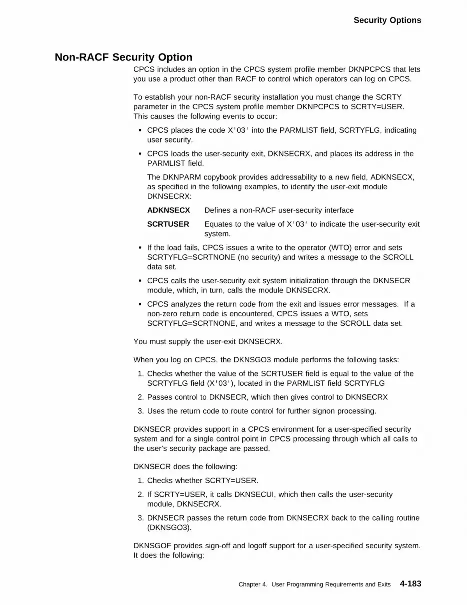
Security Options
Non-RACF Security OptionCPCS includes an option in the CPCS system profile member DKNPCPCS that letsyou use a product other than RACF to control which operators can log on CPCS.
To establish your non-RACF security installation you must change the SCRTYparameter in the CPCS system profile member DKNPCPCS to SCRTY=USER.This causes the following events to occur:
� CPCS places the code X'03' into the PARMLIST field, SCRTYFLG, indicatinguser security.
� CPCS loads the user-security exit, DKNSECRX, and places its address in thePARMLIST field.
The DKNPARM copybook provides addressability to a new field, ADKNSECX,as specified in the following examples, to identify the user-exit moduleDKNSECRX:
ADKNSECX Defines a non-RACF user-security interface
SCRTUSER Equates to the value of X'03' to indicate the user-security exitsystem.
� If the load fails, CPCS issues a write to the operator (WTO) error and setsSCRTYFLG=SCRTNONE (no security) and writes a message to the SCROLLdata set.
� CPCS calls the user-security exit system initialization through the DKNSECRmodule, which, in turn, calls the module DKNSECRX.
� CPCS analyzes the return code from the exit and issues error messages. If anon-zero return code is encountered, CPCS issues a WTO, setsSCRTYFLG=SCRTNONE, and writes a message to the SCROLL data set.
You must supply the user-exit DKNSECRX.
When you log on CPCS, the DKNSGO3 module performs the following tasks:
1. Checks whether the value of the SCRTUSER field is equal to the value of theSCRTYFLG field (X'03'), located in the PARMLIST field SCRTYFLG
2. Passes control to DKNSECR, which then gives control to DKNSECRX
3. Uses the return code to route control for further signon processing.
DKNSECR provides support in a CPCS environment for a user-specified securitysystem and for a single control point in CPCS processing through which all calls tothe user’s security package are passed.
DKNSECR does the following:
1. Checks whether SCRTY=USER.
2. If SCRTY=USER, it calls DKNSECUI, which then calls the user-securitymodule, DKNSECRX.
3. DKNSECR passes the return code from DKNSECRX back to the calling routine(DKNSGO3).
DKNSGOF provides sign-off and logoff support for a user-specified security system.It does the following:
Chapter 4. User Programming Requirements and Exits 4-183
DKNCYCLX
1. Checks whether SCRTYFLG=SCRTUSER2. Calls DKNSECR with the sign-off transaction.
DKNCYCLX - Validate Cycle and Endorse Dates ExitThe CYCL user exit DKNCYCLX may be used to perform additional cycle andendorse date validations; for example, to prevent user holidays from being specifiedas cycle date or endorse date. Before control is passed to DKNCYCLX, the datesare validated by DKNCYCDT for valid month, day and year.
ActivationDKNCYCLX is invoked if it exists in the load library concatenation. No re-gens,CPCS restarts, or CHAPs are required when a new CYCL exit routine version isinstalled.
LinkageDKNCYCLX is called by DKNCYCDT whenever a cycle is activated by the CYCLtask or the DKNCYCI interface. For the parameter list passed, see the assemblercopybook CYCXDSCT or the COBOL version DKNCCYCX. The calling programmust specify a cycle date and a one-byte indicator of the format, and an endorsedate with a one-byte indicator of the format. The values of the format indicators arethe same as the values for PARMDATE in DKNPARM, the CPCS parameter list.DKNCYCLX returns a zero return code if the dates are valid, or a nonzero returncode with a message if either date is invalid.
ExampleThe SAMPLIB PDS contains an assembler example of DKNCYCLX to preventJanuary 1 from being specified for either cycle date or endorse date.
4-184 CPCS V1R11 Customization Guide

CPCS Glossary � cash-letter summary
Glossary
This glossary defines important terms and abbreviationsused in this manual. If you do not find the term you arelooking for, refer to the Index or to the IBM Dictionary ofComputing, SC20-1699.
AABA. See American Bankers Association.
ABA number. (1) A numbering system devised by theABA to provide exact identification of financialinstitutions. The code structure also identifies theFederal Reserve Bank and branch. (2) TheMICR-inscribed field on a document, containing thefinancial institution identification number.
account number field. A MICR-encoded field, on acheck or a deposit slip, that represents the accountnumber of the item. The account number field is MICRfield 3.
active task status. This indicates that this task iscurrently processing the string associated with thisUOW. See also task status.
active UOW status. This indicates that a task in thetask list is currently processing the string associatedwith this UOW. See also UOW status.
adjustment. A change or a description of a changethat has been made to reflect a detected error in workthat has been processed.
advice. A letter that is sent to a financial institution orcustomer from whom checks have been received,advising that errors have been detected in the checksor in the listing that accompanied the checks.
American Bankers Association (ABA). Among thefunctions of this group is the specification of bankingindustry standards for check-handling documents andprocedures.
amount field. A MICR-encoded field on an item thatrepresents the amount of that item. The amount field isMICR field 1.
application program task control block (APTCB). A CPCS area created by the applications task(DKNATASK) for every active subtask in the system.This area contains operating system control blocks thatare related to the subtask; it also contains addressesand constants used by the CPCS executive programs.
APTCB. See application program task control block.
AST. Assist document.
automatic restart. The process of restarting(continuing) an interrupted entry without having to findand rebatch any item.
auxiliary on-us field. See serial number field.
Bbalancing. The act of bringing two sets of relatedfigures into agreement (for example, reconcilingaccumulated-detail totals and input-control totals).
batch. The lowest required level that has dollar controlestablished by a control document.
batch number. The number that uniquely identifies aspecific batch of documents.
batch slip. A level of control for balancing items. Seealso batch.
block. (1) A prime-pass control level consisting of oneor more batches. In CPCS, this control level is used tototal multiple batches. A block can also represent workfrom a specific source. (2) A data-processing termused to refer to a series of logical records storedcontiguously on external storage devices. (3) To insertcontrol documents in preparation for a prime-pass sorterrun. See data preparation.
block slip. A level of control for balancing batches.See also block.
buffer. A main storage area used as a data-transferarea for physical records being read or written.
bypass task status. This indicates that this taskshould not process for the string associated with thisUOW. See also task status.
Ccash letter. The group of items to be delivered to anendpoint. Grouping of the items is usually by killbundle.
cash-letter detail. A listing of all kill bundles. Seealso kill list.
cash-letter summary. A listing that summarizes all ofthe kill bundles in a cash letter by giving monetary anditem controls for each kill list.
Copyright IBM Corp. 1973, 2001 X-1

check � document processor
check. A draft drawn on a financial institution andpayable on demand any time on or after the dateindicated.
clearing house. An organization, established byfinancial institutions in the same locality, through whichchecks and other instruments are exchanged and netbalances settled.
code-line data matching. A method by which acomputer system controls items on a detail level bycomparing the internal data records from a previouspass with data that it reads on the current pass.Code-line data matching occurs on subsequentoperations.
code-line data record. See data record.
cold start. An initiation of the CPCS region thatcauses the deletion of the previous contents of themass data set and the control data sets.
complete task status. This indicates that this taskprocessed successfully for this UOW. See also taskstatus.
complete UOW status. This indicates that all tasks inthe task list processed successfully or had a bypassstatus. See also UOW status.
control slip. A MICR-encoded document that containscontrol information, including the amount of the itemsthat the document controls, the source of the items, anda code that describes the level of the control.
control total. The total dollar value or item count for agroup of documents.
copy library. A library that contains statements to bemodified by the user, accessed by the assemblerinstruction copy, and inserted into some of the CPCSprograms.
correspondent financial institution. A financialinstitution that carries a deposit balance for, or engagesin an exchange of services with, another financialinstitution.
credit. The opposite of a debit. In normal checkcollection terminology, deposit slips are credits.
cursor. A small horizontal line on a computer screenthat indicates the position to which the next character istransmitted from either the keyboard or the CPU.
cutoff. The financial institution’s designated point forbalancing or releasing work before processingcontinues. Also, the designated time after which thefinancial institution cannot accept work for processing.
cut slip. A control document used to separate andidentify one kill bundle from another.
cycle. (1) A group of work or an identification of agroup of work processed completely as a single entity.(2) A convenient grouping of work. A cycle normallycontains a variable number of entries.
Ddata preparation. Preparation of documents forprocessing by a high-speed check-processing system.
data record. The electronic representation of theMICR code line captured from a check, deposit, debit,credit, or control document. The electronicrepresentation can include additional data to helpidentify the record.
data set. A single collection of data that can be storedon cards, a tape, or one or more disks (for example, akill-bundle data set).
debit. A transaction that increases an asset ordecreases a liability. In normal check-collectionterminology, a check is considered a debit.
deferred printing. The method by which data isprocessed, transferred to a storage device, and laterprinted (as opposed to printing during the processing ofdata).
deleted UOW status. This indicates that the stringassociated with this UOW is deleted. No moreprocessing can be done for this UOW. See also UOWstatus.
deposit slip. A document that details a deposit. Thetotal of the deposit is MICR encoded on the deposit slip.A deposit is considered a credit.
distributed string (D-string). The distribution taskreads I-strings that the MICR task created and producesD-strings. Each D-string contains the records thatcorrespond to all of the documents in a single pocket ofthe document processor.
divider slip. A control document that is used toseparate kill bundles during machine sorting of checks.It can also be used to support the resynchronization ofcode-line data matching during subsequent-passprocessing.
document processor. A device that can readMICR-encoded digits and control characters fromdocuments and sort the documents into multiplepockets.
X-2 CPCS V1R11 Customization Guide

document processor station � high-speed reject re-entry
document processor station. A workstationconsisting of a document processor and a terminal foroperator communication.
D-string. See distributed string.
Eeligible task status. This indicates that this task iswaiting for processing. Other tasks must processbefore this task. See also task status.
enclosed and not listed. A condition that exists whenan item is in a batch of checks but is not listed on theincoming kill list or inscriber tape.
encode. To imprint a MICR field on a check.
encoder. A machine that encodes.
endorsement. The signature of the endorser; thestamp of a financial institution or company.
endorser. (1) A person or financial institution, otherthan the maker, who presents a check for payment.(2) A device that stamps an endorsement.
endpoint. The destination of a check.
entry. A variable whole number of blocks that areprocessed as a single group of work.
entry number. The number of the first tracer groupwithin an entry.
EPC. See extended process control field.
error description. The detailed description of an errorcreated, detected, and corrected by the processingfinancial institution.
exception printing. Printing of only the data thatrequires action external to a computer.
exchange charge. A charge made by the draweefinancial institution for its services in paying checks andother instruments presented to it. The Federal ReserveAct forbids drawee financial institutions to make suchcharges against Federal Reserve Banks on checks inprocess of collection. The purpose is to assure thatcheckbook money will be payable throughout thecountry at its face value.
extended process control (EPC) field. An optionalMICR-encoded item field that indicates special handling(such as return or truncation).
Ffine-sort. (1) The sorting of items into account numberorder for filing. (2) The sorting of items for a singleaccount into serial-number order as a customer service.
flip-flop. An event that occurs when the volume towhich you are writing a file becomes full. The writingcontinues on a new volume and the full volume isbacked up.
float. The portion of a financial institution’s totaldeposits, or of a depositor’s account, that representsitems (for example, checks and coupons) in the processof collection.
flow code. A 3-digit number (mnemonic) thatrepresents an ordered list of tasks.
flow control. The pairing of a CPCS string with a tasklist through the specification of sort type, pass pockethistory, string type, and flow code.
full-page printing. A method of page formatting inwhich items are listed in as many columns as can becontained on the page (for example, the first 50 items incolumn 1, the second 50 in column 2, and so on).
functional unit of work. This unit of work correspondsto a CPCS string.
funds availability. The portion of the financialinstitution’s total deposits or of a depositor’s accountthat represents items (for example, checks andcoupons) that have been collected and are nowavailable. This includes cash deposited and checksdrawn on the depositor’s financial institution.
Ggenerated total. The total dollar value or item count ofchecks that are processed by the computer.
Hheld task status. This indicates that this task shouldbe the next task to process, but a condition external toCPCS must complete first. See also task status.
held UOW status. This indicates that the task toprocess next for this UOW has a held status. See alsoUOW status.
high-speed reject re-entry. The re-entering into thedocument processor of reconditioned documents thathave previously been sorted to the system reject pocket(1-1).
Glossary X-3

holdover � MICR field 2
holdover. Items that were not processed in time tomeet their deadline.
inclearings. Checks drawn on your financial institutionthat are sent in for collection by another financialinstitution, the Federal Reserve Bank, or a clearinghouse.
incoming sequence number. A number that definesthe incoming sequence of an item within the inputstream. This unique number is associated with the itemthroughout the whole cycle of computer processing.
informational unit of work. This usually represents aphysical group of checks that CPCS has not yetprocessed. It represents work to be done. One ormore informational units of work are ultimatelyassociated with a functional unit of work when CPCScaptures the physical check documents.
input string (I-string). This is a string of documentscreated by the MICR task. On each documentprocessor run, an I-string is created. The stringincludes every document read by the documentprocessor, including control documents and rejecteddocuments. Related information, such as the pocketselected, is also stored in each record. The string alsoincludes internally generated control records.
inscriber. A machine that encodes.
I-string. See input string.
item. A check, deposit slip, or other machine-readabledocument.
item number. A number that is associated uniquelywith a document throughout the processing cycle.
Jjam. A condition that exists when items form ablockage anywhere in the transport mechanism of adocument processor.
joggler. A device that straightens and aligns itemsbefore high-speed sorting, principally to line up thelower edge and right side of a group of documents.This device is an integral component of some documentprocessors.
Kkill. To process items to a point where no furtherdistribution is required.
kill bundle. A group of killed items, indicated bydivider slips. With concurrent kill, this group can spanstrings.
kill list. A document that accompanies a kill bundle,listing detail and controls for the items.
kill pass. A pass on which items are distributed totheir endpoint pockets.
kill pocket. A document-processor pocket assigned tokilled items.
Llegal tender. Any money that must, by law, beaccepted in payment of debts. Checkbook money isnot legal tender.
listed and not enclosed. A condition that exists whenan item is listed on an incoming kill list or inscriber tapebut is not enclosed in the kill bundle.
low-speed transit. The manual sorting and processingof checks.
Mmagnetic ink character recognition (MICR). Thereading of magnetically encoded data on the 5/8" clearband that runs along the bottom of a check. The MICRsystem uses 10 specially coded digits and four specialsymbols.
maker. The person on whose account a check isbeing drawn.
manual restart. The process of physically finding andrebatching, before resuming an interrupted entry, theitems to be recaptured.
mass data set (MDS). A file that contains records ofall active document strings. This file consists of twodirect access data sets: a directory index and a datarecord set.
master list. A list of all items that are read during acomputer pass.
MDS. See mass data set.
merged string (M-string). The M-string, produced byDKNMRGE, represents the merging of images from theprime-pass I-string with corrected reject data. Reportsthat result from the M-string let you reconcile andbalance input to ensure that all items were captured.
MICR. See magnetic ink character recognition.
MICR field 1. See amount field.
MICR field 2. See process control field.
X-4 CPCS V1R11 Customization Guide

MICR field 3 � rehandle pocket
MICR field 3. See account number field.
MICR field 4. See optional field 1.
MICR field 5. See ABA number.
MICR field 6. See extended process control field.
MICR field 7. See serial number field.
microfilm number. The assigned item number that isalso captured on microfilm.
misread. A condition that occurs when a documentprocessor interprets a MICR character as a goodcharacter other than that which was actually encodedon the document.
missort. An item that is found in a pocket other thanthe pocket to which it was sorted.
M-string. See merged string.
Oonline fine sort. A computer-controlled sorting ofon-us checks by either or both the account number andthe serial number sequence for filing. This process canuse image-processing techniques.
online reject re-entry. Manual entry or correction ofMICR data through a display terminal.
on-us checks. Checks that are drawn on the financialinstitution that is processing them.
optional field 1. An optional, MICR-encoded fieldused by some financial institutions for check truncation.It can also be used for other internal purposes.
optional field 2. See extended process control field.
outgoing sequence number. A sequence number orunique identification assigned to each item, identifyingthe kill bundle in which the item left the financialinstitution.
Ppass. A single reading and sorting of a group ofchecks and control documents on a documentprocessor.
pass-to-pass control. A process that maintains dollarand item control of a group of MICR documents onsubsequent passes, when control has been establishedon the previous pass.
path. The path of a functional unit of work is theordered list of tasks processed for the associated CPCSstring. See also flow code and flow control.
pending request queue. A first-in-first-out EnhancedSystem Manager (ESM) queue through which CPCSapplications interface to the ESM, in sequence, toperform UOW creations, deletions, inquiries, andupdates.
piggyback item. An item that was missing from itsassigned pocket in a sorter and sorted “free” to anunidentified pocket, as when one document attachesitself to or overlaps another during processing.
pocket 1-1. See system reject pocket.
prime pass. The first pass of an entry on a documentprocessor.
printing after the fact. See deferred printing.
process control field. (1) A MICR-encoded field on adocument, usually representing the type of document.The process control field is MICR field 2.(2) Transaction code.
proof. Receives checks that come from tellers, mailand night depository, and internal departments of thefinancial institution. Proof proves and inscribes thedollar amount in MICR.
proof of deposit. The act of totaling items at thedeposit level and ensuring that the total of the creditsequals the total of the debits.
Qqueued task status. This indicates that this task isready and waiting to process. See also task status.
queued UOW status. This indicates that no task iscurrently active for this UOW; however, one task has aqueued status. See also UOW status.
RRACF. See Resource Access Control Facility.
RBA. See relative block address.
reconcile. To find and correct the cause of adifference between two sets of totals.
reconciliation. See balancing.
rehandle pocket. A document processor pocket thatreceives items for multiple endpoints. Items directed torehandle pockets are processed again on a later pass.
Glossary X-5

reject � supervisor
reject. A MICR-encoded document that cannot beread in its entirety by a document processor or that failscertain editing checks. This document is directed to aspecial pocket called a reject pocket.
reject string (R-string). Strings are created by theonline reject re-entry task. Each R-string representschecks that have been re-entered online. R-strings areinput to the DKNMRGE task.
relationship. Shows the parent/child hierarchy of unitsof work.
relative block address (RBA). In CPCS, thecalculated location of a specific record.
repass. See rehandle pocket.
rerun. A group of items that are sorted into a pocketon one pass and later brought into a documentprocessor for further sorting.
Resource Access Control Facility (RACF). An MVSsecurity subsystem that determines the validity of eachoperator’s ID password and that controls operatoraccess to application tasks and transactions.
restart. An initiation of the CPCS system after asystem failure. A restart is generally used to start thesystem (after an abnormal end of a task) to cause theexecutive routines to re-establish the system to thestatus that existed before the failures.
restart buffer. An XP reader/sorter area whererecords are stored during online operations until theyare sent to the host. The buffer is accessed duringautomatic restart.
return item. A check that is not honored by themaker’s financial institution and that is returned to thedepositor’s financial institution.
routing number. A MICR-encoded check field thatrepresents the financial institution on which the check isdrawn. The routing transit field is field 5.
routing transit field. See ABA number.
R-string. See reject string.
Sscroll. The ability to use the DKNSCRL application topage through or look at the scroll data set. This dataset includes supervisor terminal messages andDKNATASK log messages.
separator. See divider slip.
sequence number. A number, assigned to adocument, that uniquely identifies its position in a groupof incoming or outgoing work.
serial number field. A MICR-encoded check field thatrepresents the serial number of that check.Synonymous with auxiliary on-us field. The serialnumber is MICR field 7.
settlement. The act of bringing sets of related figuresfrom two financial institutions into agreement.Adjustments are made to offset the differences.
SMOF. Enhanced System Manager Online Functions.
sort pattern. A table used by the sort routine todetermine the pocket to which a check is to be directed.
sort program. A routine that performs all processingrequired to select a document to a pocket.
spool data set. A data set used to store printed outputlines. Each spool (Simultaneous Peripheral OperationsOn-Line) data set is written by a CPCS application taskand is read by the CPCS output writer as it is beingprinted.
SSB. See string status block.
statistics. The processing of Unit of Work datathrough a statistical program such as the ImagePlusApplication Library Services MIS system. This term canalso refer to the processing of Unit of Work datathrough a user-written statistical program.
SSM. See string segment map.
string. The data records representing a group of itemsentered through a physical or simulated documentprocessor or through OLRR. Can be an I-string, aD-string, or an M-string. See related definitions fordetails.
string segment map (SSM). One of three types ofsegment maps in CPCS. Each string in the system isassociated with a string segment map. Each bit in amap represents a segment of direct access storage.The bit settings for the string segment map are(1) 0=segment available or (2) 1=segment allocated.
string status block (SSB). This CPCS control block ismaintained by the MDS programs for every open string.
subsequent pass. A pass on which previously sorteditems are resorted for further distribution.
supervisor. (1) An MVS term used to refer to thesystem nucleus in internal storage. (2) A personresponsible for operation of a financial institution area.
X-6 CPCS V1R11 Customization Guide

supervisory terminal � zero-balancing
supervisory terminal. A special terminal or operatingmode used in CPCS.
suspended task status. This indicates that this taskprocessed, but it did not complete successfully. Seealso task status.
suspended UOW status. This indicates that the lasttask that processed for this UOW did not completesuccessfully. See also UOW status.
System Manager (Enhanced). A subsystem of CPCSthat directs and controls the operations of the IBM3890/XP Series document processors.
System Manager Online Functions (SMOF). A set ofapplication-level tasks that monitor and modify thequeues and databases of Enhanced System Manager.
system reject pocket. The first physical pocket on thedocument processor. It is used by CPCS to holdmachine and user-selected rejects.
Ttab key. A keyboard function key. The tab key causesthe cursor to position to the next colon on the screen orto the top of the screen.
task. A CPCS application or function. A task namemust be DKNMICR or it must be in the CPCS BLDL list.
task list. The ordered list of tasks to be performed fora unit of work. It is determined by selecting the flowcode for a given flow control record.
task status. A representation of what will happen,what is happening, or what happened during processingof this unit of work. Can be (1) active, (2) bypass,(3) complete, (4) eligible, (5) held, (6) queued, or(7) suspended. See related definitions for details.
total system. A system in which the computer is usedfor all phases of an operation.
tracer. A check-processing document used to providepass-to-pass control.
tracer group. An arbitrary grouping of items for controlpurposes.
transit. The sorting of checks to external destinations.
Uunit of work (UOW). A logical entity that the SystemManager uses to track a piece of work through CPCS.It can be informational or functional. See alsoinformational unit of work and functional unit of work.
UOW. See unit of work.
UOW status. This status represents the state of a unitof work and its associated string. Can be (1) active,(2) queued, (3) suspended, (4) complete, (5) deleted,or (6) held. See definitions for details.
Wwarm start. An initiation of the CPCS system, causingthe contents of the MDS and the control data sets to beretained. A warm start is generally used for restartingCPCS after a normal ending.
work. Any document or group of documents thatCPCS processes.
work flow. An ordered list of tasks for a specificCPCS string. Each CPCS string must have a workflow.
Zzero-balancing. The procedure that ensures thatgenerated totals for a group of items plus anydocumented errors minus the control total equals zero.
Glossary X-7

X-8 CPCS V1R11 Customization Guide

Bibliography
The publications in this bibliography contain informationrelated to CPCS.
ACF/VTAM Publications
The following publications are related to the ACF/VTAMproduct:
IBM ACF/VTAM Version 3 Programming, SC23-0115
IBM ACF/VTAM Planning and Installation Reference,SC27-0584
IBM ACF/VTAM, 5735-RC2, 5746-RC3, ProgramOperator’s Guide, SC38-0257.
Document Processor SupportPublications
The following publications are related to documentprocessor support:
IBM 3890/XP Series Document Processor GeneralInformation, GA34-2012
IBM 3890/XP Series Programming Guide, GC31-2662
IBM 3890/XP Series SPXServ Reference, GC31-2704
IBM 3890/XP MVS Support and IBM 3890/XP VSESupport Program Reference, SC31-2654(TNL SN31-8160)
IBM 3890/XP Series Stacker Control InstructionsReference, SC31-2703.
OS/390 Publications (Version 2,Release 8)
The following publications are related to OS/390:
IBM OS/390 MVS Initialization and Tuning Reference,GC28-1752
IBM OS/390 MVS JCL User’s Guide, GC28-1758
IBM OS/390 MVS System Codes, GC28-1780
IBM OS/390 MVS Installation Exits, SC28-1753
IBM OS/390 MVS System Messages Volume 1,GC28-1784
IBM OS/390 MVS System Messages Volume 2,GC28-1785
IBM OS/390 MVS System Messages Volume 3,GC28-1786
IBM OS/390 MVS System Messages Volume 4,GC28-1787
IBM OS/390 MVS System Messages Volume 5,GC28-1788
IBM OS/390 MVS Programming: Assembler ServicesGuide, GC28-1762
IBM OS/390 MVS Programming: Assembler ServicesReference, GC28-1910
MVS Publications
The following publications are related to MVS:
IBM OS/VS2 MVS System Programming Library JobManagement, GC28-1303
IBM MVS/ESA Initialization and Tuning Reference,GC28-1635
MVS/ESA JCL User’s Guide, GC28-1653
IBM MVS/ESA System Messages Volume 1,GC28-1812
IBM MVS/ESA System Messages Volume 2,GC28-1813
IBM MVS/ESA System Codes, GC28-1815
IBM MVS/ESA Data Administration: Utilities,Version 3.1, SC26-4516.
RACF Publications
The following publications are related to RACF:
IBM Resource Access Control Facility CommandLanguage Reference, SC28-0733
IBM Resource Access Control Facility Master Index,GC28-1035
IBM Resource Access Control Facility SecurityAdministrator’s Guide, SC28-1340
Copyright IBM Corp. 1973, 2001 X-9

IBM System Programming Library: Resource AccessControl Facility, SC28-1343
IBM Resource Access Control Facility Macros andInterfaces, SN28-1539.
VTAM Publications
The following publications are related to Version 3Release 2 of the VTAM product:
IBM SNA Transaction Programmer’s Reference Manualfor Logical Unit Type 6.2, GC30-3084
IBM VTAM Programming for LU 6.2, SC30-3400.Trademark of IBM
Note: Several of these manuals also containinformation about VTAM Version 3 Release 1.2 for VM
and VSE, Version 3 Release 1.1 for MVS and VM, andVersion 3 Release 1 for VSE.
Other IBM Publications
The following publications provide information abouttopics related to CPCS:
IBM 3270 Information Display System 3274 Control UnitDescription and Programmer’s Guide, GA23-0061
IBM 3270 Information Display System CustomizingGuide Supplement for 3274 Control Unit, GC11-6045
IBM System/370, 30xx, 4300, and 9370 Processors:Bibliography of Industry Systems and ApplicationPrograms, GC20-0370
IBM Data Facilities/Data Set Services User’s Guide andReference, SC26-4125.
X-10 CPCS V1R11 Customization Guide
Index
Numerics3890 document processor
channel attachment 1-15host-simulated attachment 1-15
3890/XPchannel attachment 1-15host-simulated attachment 1-15LU 6.2 attachment 1-15stacker-select routine 4-36
3890/XP sorter definition (for 48 pockets) 4-17048-pocket support
3890/XP sorter definition 4-170installing 4-170special feature 4-170
Aaccessing VSAM table 2-63account number dash transmission (ACTDASH)
parameter 2-47ACTDASH (CPCSOPTN parameter) 2-47adjustments
CHANGE 4-173DELETE 4-172INSERT 4-172M-string processing 4-175MOVE 4-173
allocationBDAM data set 1-31dynamic 1-16, 2-23load library 1-46printer 1-16
ALSTSORT data set 1-26APCB
See application program control block (APCB)application interface 2-59application profiles
DKNPEMRG 3-29DKNPETDM 3-35DKNPETIN 3-39DKNPETIO 3-45DKNPETIP 3-45DKNPETOT 3-45DKNPICRE 3-47DKNPKILL 3-47DKNPMCRE 3-48DKNPMRGE 3-48DKNPOLRR 3-50DKNPRLST 3-51DKNPSCPY 3-52
application program control block (APCB)macro
CLASS keyword 2-16describing an application task’s
environment 2-15image system keyword 2-16
application requirements, MDS expansion 4-168application task manager (DKNATASK) 1-19APTCBEXT (option under DKNPCPCS) 3-13assembly procedures
for MDS changes 2-51assembly requirements 1-43ASTDOC (CPCSOPTN parameter) 2-43ATASK (applications task) 1-19ATTACH (CPCSRDR parameter) 2-37attach parameter (ATTACH) 2-37attachments, document processor 1-14AUTH (APCB macro keyword) 2-15AUTO (APCB macro keyword) 2-16AUTO_INIT (option under DKNPRCVY) 3-27automatic restart considerations 1-15AUTORST (option under DKNPCPCS) 3-12auxiliary terminals
CPCS 2-58VTAM 2-56
BB record 4-18BACKUP (option under DKNPRCVY) 3-24balancing adjustment records
CHANGE 4-173DELETE 4-172INSERT 4-172MOVE 4-173
balancing considerations 4-171bank control file (DKNBCF)
data set 1-20data set preparation 1-31detailed input for DKNLOAD 4-5loading 1-31record format 4-5
bank description record (BNKN) 4-18bank name-and-address data set (DKNAB)
creating 1-19loading 1-31preparation 1-30record format 4-14
basic direct access method (BDAM)data set allocation 1-30using blocked format 1-28
Copyright IBM Corp. 1973, 2001 X-11

BATCH (CPCSOPTN parameter) 2-43BCF
See bank control file (DKNBCF)BDAM
See basic direct access method (BDAM)BEGIN message description record (BMSG) 4-32BEGNDSCT (DKNMBEGN work/save area) 4-131BEXIT (CPCSOPTN parameter) 2-46BFRAT (option under DKNPCPCS) 3-10binary tables 4-43BLDL table 4-178BLDL table (DKNBLDL)
APCB macro 2-15MDIS exit 4-133parameters (APCB macro keywords)
AUTH (authorization) 2-15AUTO (automatic task start) 2-16CLASS (output class) 2-16COMP (DKNCOMP use) 2-16DPCOD (priority modifier) 2-16ECYEND (end cycle) 2-17ECYRTN (end cycle routine) 2-17EXSEQ (executive task sequence) 2-17EXTSK (executive task) 2-17HIVOL (high-volume print) 2-17HLOG (host logon) 2-17ICLSS (application class print) 2-18image system (services) 2-16INSTRG (input string) 2-18ISPOOL (image print authorization) 2-18ISUPV (INSC supervisor terminal) 2-18MAIL (electronic mail) 2-18MAX (maximum copies) 2-18MAXM (maximum pages) 2-18MSUPV (MICR supervisor terminal) 2-19NAME (application name) 2-15OUTSTRG (output string) 2-19PRINT (print) 2-19SMMULT (multiple) 2-19SMSTART (automatic start) 2-19SMTRACK (tracked) 2-19SORT (internal sort) 2-20SPEC (special testing) 2-20SSUPV (system supervisor terminal) 2-20TASKGRP (task group number) 2-20TIMECK (logoff time check) 2-20USREXIT (optional user exit name) 2-20USRPARM (DKNICRE extracts) 2-20WORK (work size) 2-21WRKPOOL (internal work area) 2-21
task addition example 2-21USREXIT parameter 4-133
BLDTBL (option under DKNPRCVY) 3-26BLKSEG (option under DKNPCPCS) 3-9BLKSIZE (option under DKNPCPCS) 3-8
BLOCK (CPCSOPTN parameter) 2-43block size
DKNPCPCS parameter 2-52microfilm 3-11parameter (BLKSIZE) 3-8
blocked BDAM 1-28blocks-per-segment parameter (BLKSEG) 3-9blocks-to-tape ratio parameter (BFRAT) 3-10BMSG record description 4-32BNKN (bank description record) 4-18BOTH (FTYPE option) 1-9BOTH recovery (MDS and index) 1-39, 2-12BUFEXT (option under DKNPCPCS) 3-13buffer area, document 4-50buffers
numbers (QSAM) 2-26tape 2-8, 3-10temporary (VSAM) 2-65
BYP_BANKNUM (option under DKNPRCVY) 3-27BYP_SORTTYPE (option under DKNPRCVY) 3-27
Ccapture
document image 4-21duplex data set 2-6logged data set 2-12type, document 4-18
CCSDEF (concurrent sort generation) macrodescription 2-32parameters
CYLS 2-32NUMWORK 2-32SORTNAM 2-33SYSOUT 2-33TRACKS 2-32UNIT 2-32VOLSER 2-32
change password parameter (CHGPSWD) 3-7channel-attached document processor 1-15checkpoint, spool 1-14CHGPSWD (change password) 3-7CIMSID (option under DKNPCPCS) 3-12CKPT (CTYPE option) 1-10CKPTDS (writer checkpoint record data set) 1-19CLASS (APCB macro keyword) 2-16CLASS (option under DKNPCPCS) 3-10class parameter (CLASS) 3-10class, SYSOUT 2-33CLDSI (temporary work data set for DKNCLSM) 1-26CLDSO ( temporary work data set for
DKNCLSM) 1-26CLEAR key, using 2-62COBOL
COBOL for MVS/VM compiler considerations 1-44COBOL for MVS/VM user options 1-46
X-12 CPCS V1R11 Customization Guide
COBOL (continued)compile procedure 2-51copy definitions 2-5MDS expansion requirements 4-168modules, installing 1-44
codeline data matching (DKNMRGE) 3-55codeline data matching interface (DKNMIPI)
power-encoding from adjusted data 4-176processing exit 4-136specifying on CPCSOPTN 4-136
codeline data record 4-50coding conventions, SCI 4-41COLD (STYPE option) 1-7cold start 1-7command procedures 1-43commands, RACF protected 4-182COMP (APCB macro keyword) 2-16compiler, COBOL considerations 1-44concurrent processing 3-8concurrent sort generation (CCSDEF) macro 2-32concurrent sort with SORTWK 2-32configuration
minimum system 1-3sample system 1-4
control documentdefining 2-43field definitions 2-44field identifiers 2-44installation 2-43
control sequence parameter (CTLSEQ) 2-44conventions, user-exit 4-137converted pocket number 4-52COPY definitions 2-5CPCS
restart 1-8shutdown 1-12
CPCS (VNODE parameter) 2-57CPCS start parameters 1-6CPCS terminals 2-58CPCS-supplied command procedures 1-43CPCS_PASSWORD (option under DKNPCPCS) 3-14CPCSOPTN macro
MICR task generation 2-33parameters
ACTDASH 2-47ASTDOC 2-43BATCH 2-43BEXIT 2-46BLOCK 2-43CTLSEQ 2-44DIVIDER 2-43MAXRP 2-45MAXSCI 2-45MAXTG 2-45MEXIT 2-46MFOPT 2-46PCDASH 2-47
CPCSOPTN macro (continued)parameters (continued)
REXIT 2-46SBATCH 2-43SERDASH 2-47SSWORK 2-46TERMS 2-45TRACER 2-43
specifyingDKNMBEGN 4-130DKNMIPI 4-136DKNMREAD 4-138
CPCSRDR macroadding macros 2-33MICR task generation 2-33options 2-36parameters
ATTACH 2-37DDRDRIN 2-38ENDORSE 2-38EXT 2-41FLD 2-39IMAGE 2-39INF 2-38LDPN 2-41LUNAME 2-38MFILM 2-38MODEL 2-39PEND 2-39POWER 2-39TYPE 2-37
CREF data setsCREFIN (input) 1-26CREFOUT (output) 1-26
CTLSEQ (CPCSOPTN parameter) 2-44CTYPE (CPCS start parameter) 1-10cycle table data set
CYCLDS1 1-19CYCLDS2 (duplex data set) 1-19
cylinders parameter (CYLS) 2-32
DD-string (distribution string) 1-30D-string directory end parameter (DDIREND) 3-9DASC
See data set authority security credential (DASC)DASC (data security) option 2-15DASD
See direct access storage device (DASD)dash transmission 2-47data preparation
bank control file record format 4-5endpoint name and address record 4-14sort program 4-5
Index X-13

data record, codeline 4-50data security (DASC) option 2-15data set
See also data-set statementbank control file 1-20BDAM 1-30cycle table 1-19description 2-6divider-slip 1-20duplex
capture 2-6cycle table 1-19kill bundle 1-21microfilm 1-22pass-to-pass control 1-23recovering 2-6tracer group 1-23
duplexed 1-41dynamically allocating 2-23endpoint name and address 1-19endpoint tables 1-20, 1-31INDEX 1-23kill bundle 1-21logged 2-12mass
See mass data set (MDS)microfilm 1-21pass-to-pass control 1-22permanent 1-10preparation 1-30recovering 1-33, 2-6tape 1-11, 1-29temporary 1-10unique sequence number 1-20utilities 2-14VSAM
allocating 1-19, 1-32DKNDIV 1-20DKNISEQ 1-20
data set authority security credential (DASC)DKNBSCY
examples 4-179macro format 4-179
RACF security installation procedure 4-179security option 4-177specifying 4-177table 4-178
data sets, VSAMallocating 1-19, 1-32DKNDIV 1-20DKNISEQ 1-20
data-set statementhigh-volume spool 1-11logging 1-11SORTLIB 1-10spool 1-10
data-set statement (continued)STEPLIB 1-10system print 1-12tape 1-11
data-space considerations 1-13DATE (option under DKNPCPCS) 3-12date/time stamp 4-33DCAP (document capture type record) 4-18DD statement parameter (DDRDRIN) 2-38DDIREND (option under DKNPCPCS) 3-9DDRDRIN (CPCSRDR parameter) 2-38definition file, sort pattern
See sort pattern definitionDEVICE (VNODE parameter) 2-58device support, DKNVTASK 2-59device, logical segments 3-9DFP_DFSMS (option under DKNPRCVY) 3-27diagnostic operation time-out interval 4-57direct access storage device (DASD)
requirements 1-19directory index
MDS 1-23directory record blocks parameter (NDIRBLK) 3-9disable/disengage option, installing 4-170distribution (DKNDIST)
nonsubset processing 4-26subset processing 4-26
distribution string (D-string) 1-30DIVIDER (CPCSOPTN parameter) 2-43divider-slip
data set (DKNDIV) 1-20resynchronization 4-25
DKNABSee bank name-and-address data set (DKNAB)
DKNADJCD (online adjustment codes data set) 1-20DKNAPCGT DSECT 1-47DKNAPPL data set
See profiles, applicationDKNAPTCB DSECT 1-47DKNATASK (applications task) 1-19DKNBCF
See bank control file (DKNBCF)DKNBCFGT DSECT 1-47DKNBLDL
See BLDL table (DKNBLDL)DKNBSCY macro format 4-179DKNCLSM temporary work data set 1-26DKNCMPRS (work data set for DKNCOMP) 1-20DKNCOMP temporary work data set 1-20DKNCOPY (recovery-tape copy) 2-14DKNCRPKT (COPY definition) 2-5DKNCRTG (tracer group data set) 2-5DKNCRTRK (COPY definition) 2-5DKNCSBU (sort program build task) 4-141DKNDASC
See data set authority security credential (DASC)
X-14 CPCS V1R11 Customization Guide

DKNDIV (divider-slip data set) 1-20DKNEMRG
calling parameters 4-143list of exits 4-142list of sample programs 4-142use of EXIT task 4-142using sample user exits 4-146
DKNEPSee endpoint tables data set (DKNEP)
DKNEPTBL (kill pocket endpoint ID table) 4-45DKNETX01 (ETCSH) 4-121DKNETX02 (ETCSH) 4-121DKNETX03 (ETCSH) 4-121DKNETX04 (ETCSH) 4-121DKNICRE (input creation) 1-29DKNICRET (input create tape handler) 1-29DKNIN (input data set) 1-30DKNISEQ (item sequence number data set) 1-20DKNIW (input creation work data set) 1-26DKNKB (kill bundle data set) 1-21DKNKILL (kill list)
modifying report layouts 4-155DKNLOAD, bank control file input 4-5DKNLOGU user exit
assembling 2-10DKNLT (log tape data set) 1-30DKNMBEGB user-exit parameter (BEXIT) 2-46DKNMBEGN
See also entry initialization (MBEGN)work/save area (BEGNDSCT) 4-131
DKNMBEGN work/save area (BEGNDSCT) 4-131DKNMC (master create work data set) 1-21DKNMD (MDS tape data set) 1-30DKNMDIS (for ESM) 4-132DKNMDIS user exit 4-132DKNMDIX 4-132DKNMDIX2 4-132DKNMDSVC (MDS services) 1-25DKNMF (microfilm data set) 1-21DKNMFD (duplex microfilm data set) 1-22DKNMICR
See also MICR task (DKNMICR)expanded MDS, using 2-52
DKNMIPISee codeline data matching interface (DKNMIPI)
DKNMPUTC (SETDEV processing) 4-56DKNMREAD
See also read processor (DKNMREAD)document processing exit 4-138
DKNMREAD assembly option 4-171DKNMREAD document processing exit 4-138DKNMRG2
use of matching values 3-57use of parameter cards 3-56
DKNMRG2X (positional matching user exit) 4-151
DKNMRGEcodeline data matching 3-55
DKNMRGE (programmable switches) 4-150DKNMRGK
selectable functions 4-152DKNMRGK (document-processing user exit) 4-151DKNOLRR
See online reject reentry (DKNOLRR)DKNPARM DSECT 1-47DKNPATSK profile member
record formats 3-5task grouping example 3-4
DKNPCPCS profile memberoptions
APTCBEXT 3-13AUTORST 3-12BFRAT 3-10BLKSEG 3-9BLKSIZE 3-8BUFEXT 3-13CIMSID 3-12CLASS 3-10DATE 3-12DDIREND 3-9DUMPCLAS 3-10DUPLEX 3-10EDIREND 3-9GLOBAL_MDSUAL 3-13IDIREND 3-9IOMODE 3-12KBBLKSZ 3-11KILLAUT 3-8LANG 3-11LE370 3-13LNTNAME 3-10LOG 3-11MAX_EP_EXIT 3-13MAXDA 3-9MAXEXIT_PTS 3-13MAXOPEN 3-9MAXSORT 3-10MAXTASK 3-6MAXTERM 3-6MDIREND 3-9MFBLKSZ 3-11MSTRING 3-7NDIRBLK 3-9NUMPTR 3-6OVERRIDE 3-12PARMEXT 3-13RDIREND 3-9SCRCL 3-7SCRDAYS 3-7SCRGP 3-7SCRTY 3-7SEGDEV 3-9SMACT 3-11
Index X-15
DKNPCPCS profile member (continued)options (continued)
SPOOL 3-7START_DKNCOMP 3-13SUBBAL 3-10SVC 3-11SYSID 3-12TIMECK 3-8TPBFNM 3-10
DKNPCTL (pass-to-pass control) 1-22DKNPEMRG profile member
keywords 3-29user exits 4-142
DKNPEXIT profile memberoptions
DEACTIVATE 3-14various exit names 3-15
DKNPICRE profile member 3-47DKNPISNG profile member
options and parameters 3-19DKNPKILL profile member 3-47DKNPLST (entry master-list) 4-153, 4-155DKNPMCRE profile 3-48DKNPMRGE profile 3-48DKNPOLRR
description 3-50keywords 3-50profile 3-50
DKNPRCVY profile memberoptions
AUTO_INIT 3-27BACKUP 3-24BLDTBL 3-26BYP_BANKNUM 3-27BYP_SORTTYPE 3-27DFP_DFSMS 3-27DPXCNTL 3-24DPXDISK 3-24DPXTAPE 3-24LOGDEV 3-24MAXATMP 3-26MAXSTGS 3-26NUM_STRG_VOLS 3-26RCVSIZE 3-25RCVYBLKZ 3-25RDX 3-26STRING_OCCUR 3-27TG_UPDATE 3-26TPRETPD 3-26VLSRSIZ 3-26
DKNPRLST profile 3-51DKNPSCPY profile 3-52DKNPSG03 profile member 3-28DKNRSCGT DSECT 1-47DKNRT (recovery tape data set) 1-30
DKNSK (summary kill bundle data set) 1-30DKNSLST (subsequent-pass master list) 4-154DKNSPDEF (sort pattern definition library) 1-22, 1-32DKNTG (tracer data set) 1-22DKNTGD (tracer duplex data set) 1-23DKNVNODE (node-name table) 2-56DKNVTASK
See VTAM terminal control task (DKNVTASK)DKNXLST (PLST and SLST printout selector) 4-154document
See also control documentbuffer area 4-50capture type 4-18field characteristics 2-44image capture 4-21processing exit routine, sample 4-141processing exit, DKNMREAD 4-138
document capture type record (DCAP) 4-18document processor
channel-attached 1-15considerations 1-14converted pocket number 4-52hardware options 4-19header and status byte 4-40host-simulated attachment 1-15LU 6.2 attached 1-15modes 1-3parameters 2-37statements 1-10type parameter (TYPE) 2-37
document-processing user exit (DKNMRGK) 4-151DPCOD (APCB macro keyword) 2-16DPXCNTL (option under DKNPRCVY) 3-24DPXDISK (option under DKNPRCVY) 3-24DPXTAPE (option under DKNPRCVY) 3-24DSAT macro
See also dynamic allocationexample of adding entries for
disk data set 2-28document processor 2-28JES printer 2-29printer 2-29tape data set 2-27unique temporary disk data set 2-30
optional parametersDYNBLKS 2-25DYNBSIZ 2-25DYNCLASS 2-26DYNDCB 2-26DYNDEN 2-25DYNEXPR 2-24DYNFCB 2-25DYNIO 2-24DYNLABL 2-25DYNLRCL 2-25DYNOPT 2-26DYNOUT 2-26
X-16 CPCS V1R11 Customization Guide

DSAT macro (continued)optional parameters (continued)
DYNPSPA 2-25DYNPVI 2-24DYNRECF 2-26DYNRLSE 2-26DYNRTEN 2-25DYNSEQ 2-25DYNSSPA 2-25DYNSTYP 2-25DYNUCS 2-26DYNVLCT 2-26DYNVLSR 2-24
required parametersDYNCOND 2-24DYNDDN 2-24DYNDEV 2-24DYNDSN 2-24DYNNORM 2-24DYNSTAT 2-24DYNUNIT 2-24
DUMPCLAS (option under DKNPCPCS) 3-10DUPLEX (option under DKNPCPCS) 3-10duplex data set
capture 2-6cycle table 1-19function, activatingkill bundle 1-21recovering 2-6recovery procedure 1-41tracer group 1-23
duplex microfilm data set (DKNMFD) 1-22duplexed data sets, recovery 1-41, 2-6duplexing, data-set 2-6dynamic allocation
JES considerations 1-16printer 1-16tape 1-28tape data set 1-11, 1-29work data sets per task 2-32
EE record 4-18ECB list 3-6, 4-142ECYEND (APCB macro keyword) 2-17ECYRTN (APCB macro keyword) 2-17EDIREND (option under DKNPCPCS) 3-9endorse parameter (ENDORSE) 2-38endpoint
ID processing 4-45name and address record format 4-14on-us kill pocket 4-23
endpoint name-and-address data set (DKNAB)See bank name-and-address data set (DKNAB)
endpoint tables data set (DKNEP)description 1-20preparation 1-31
Enhanced System Managerdata for task profile 4-132DKNMDIS use with auto-start 4-132ESM parameter 1-10task profile user data area 4-132
entry initialization (MBEGN)exit description 4-130sample exit routine 4-132specifying on CPCSOPTN 4-130
errorsread 1-39recovery 1-38write 1-39
ESM (ESM startup parameter) 1-10ETCFU user exit one
control file record create 4-118ETCSH and X937 user exits
DKNETX01 4-121DKNETX02 4-121DKNETX03 4-121DKNETX04 4-121
ETDM user exitsUser exit point one 4-82User exit point two 4-83
ETIO user exitsETCFU user exit one 4-118ETIN user exit point four 4-105ETIN user exit point one 4-95ETIN user exit point three 4-102ETIN user exit point two 4-98ETIP user exit point one 4-107ETIP user exit point three 4-113ETIP user exit point two 4-111ETOT user exit point one 4-86ETOT user exit point two 4-90
ETIP User Exit Point Oneactivation 4-107control blocks 4-108electronic input processor messaging 4-107example 4-109linkage 4-108restrictions 4-109return codes 4-109
ETIP user exit point threealter import data exit 4-113
ETIP user exit point twoactivation 4-112control blocks 4-112electronic input processor selection 4-111example 4-112linkage 4-112restrictions 4-112
Index X-17
execute statement 1-7executive tasks 2-15, 3-6exit points (CPCS) 4-58exit points (mass data set) 2-66exit routine, sample 4-141expanded format
field description 4-32file date/time stamp 4-33SSP 4-37
expanded format (XF)FLDnn record 4-32FS record 4-33P record (PDR) 4-28PROLOG2 4-43PROLOGX 4-43RP record 4-34SCI routine, sample 4-48SPDEF example 1-33TY record 4-34
expanded format SPDEF example 1-33expanded mass data set, creating 2-51expanded SETDEV time-out interval 4-57EXSEQ (APCB macro keyword) 2-17EXT (CPCSRDR parameter) 2-41extended architecture 1-3extended features parameter (EXT) 2-41extended search feature, BDAM 1-31external storage requirements 1-19extract programming 4-167, 4-175EXTSK (APCB macro keyword) 2-17
FFCB (forms control buffer) 1-16field
characteristics 2-44definitions 2-44description, expanded 4-32identifiers 2-44settings 2-39validity bit 4-51
field description record (FLDnn) 4-32field parameter (FLD) 2-39field values (CPCSRDR)
default 2-42file date and time stamp 4-33file stamp record (FS) expanded 4-33flag settings, stacker-select routine 4-50FLD (CPCSRDR parameter) 2-39FLDnn (field description record) 4-32FMT (FTYPE option) 1-9format MDS (FMT), FTYPE option 1-9format option 1-9format type (FTYPE)
BOTH 1-9FMT (format MDS) 1-9
format type (FTYPE) (continued)INDEX 1-9MDS 1-9NOFMT 1-9RBTH 1-9RMDS 1-9SCMFT 1-9SEL 1-9
format, record insertion area 4-140forms control buffer (FCB) 1-16FS (file stamp) record expanded 4-33FTYPE (CPCS start parameter)
See format type (FTYPE)function, duplex 2-6
Ggeneration
concurrent sort 2-32logging 2-7MICR task 2-33
GLOBAL_MDSUAL (option under DKNPCPCS) 3-13
HH record 4-19hardware options, document processor 4-19header byte, document processor 4-40high-volume spool data-set statements 1-11HIVOL (APCB macro keyword) 2-17HLOG (APCB macro keyword) 2-17host-simulated attachment 1-15
II record 4-21I-string directory end parameter (IDIREND) 3-9ICLSS (APCB macro keyword) 2-18ICRE work data set (DKNIW) 1-26IDIREND (option under DKNPCPCS) 3-9IMAGE (CPCSRDR parameter) 2-39image capture options record (IMAGE) 4-21Important! notices
adjusted M-string processing 4-175assembling the MDX macro 2-51blocked BDAM data sets 1-28CPCSRDR and CPCSOPTN macros 2-33divider-slip resynchronization 4-25DKNSBAL change in DKNBLDLexpanded MDS restrictions 2-48expanding the MDS 2-41initializing the tracer data set 1-34, 1-39JCL changes 1-3log data-set definition 2-13operator authorization 4-178prime-pass R record 4-32
X-18 CPCS V1R11 Customization Guide
Important! notices (continued)scroll data-set allocation 1-25SORTWK with concurrent sort 2-32startup requirement 1-19suppressing distribution 4-27
indexdata set, recovery procedures 1-33MDS directory 1-23record overflow 1-23recovery 1-37, 2-12recovery procedures 1-34
INDEX (FTYPE parameter) 1-9INDEX data set 1-23INF (CPCSRDR parameter) 2-38initializing (logging data sets) 2-10input create tape handler (DKNICRET) 1-29input creation (DKNICRE) 1-26, 1-28input data set (DKNIN) 1-30input for DKNLOAD 4-5input, CREF 1-26installation
control documents 2-43DKNVTASK 2-53files 2-3macro format 2-4procedure
expanded MDS 2-51logging 2-7non-RACF 4-183overview 2-3RACF 4-179VTAM 2-53
requirements, MDS 2-48steps 2-3VS COBOL II modules 1-44
installingwith expanded MDS 2-51with logging 2-7
INSTRG (APCB macro keyword) 2-18IOMODE (option under DKNPCPCS) 3-12IREC (initialization record)
field default 2-42ISPOOL (APCB macro keyword) 2-18ISUPV (APCB macro keyword) 2-18item number feature parameter (INF) 2-38item sequence numbers
customizing 2-14
JJ record 4-22Jam options
installing 4-169refreshed enhanced 4-169
JCLSee job control language (JCL)
JESSee job entry subsystem (JES)
job control language (JCL)assemble and link-edit 1-43compile and link-edit 1-43data-set statements
high-volume spool 1-11logging 1-11SORTLIB 1-10spool 1-10STEPLIB 1-10system print 1-12tape 1-11
document processor statements 1-10execute statement 1-7JES printing 1-11library statements 1-10MICR task generation 2-33printer device statement 1-10sample
DKNAB and DKNBCF 1-31DKNEP 1-31DKNISEQ 1-32DKNSPDEF 1-32SPDEF 1-33startup 1-7
TAPEOUT printing 1-10job entry subsystem (JES)
dynamic allocation 1-16printing 1-10
KK record 4-23KBBLKSZ (option under DKNPCPCS) 3-11KDR (kill pocket description record) 4-23keys
CLEAR 2-62program attention (PA) 2-62program function (PF) 2-55, 2-61
KILL auto-start parameter (KILLAUT) 3-8kill bundle
block size parameter (KBBLKSZ) 3-11data set (DKNKB) 1-21duplex data set 1-21
kill pocketdescription record (KDR) 4-23endpoint ID table (DKNEPTBL) 4-45
KILLAUT (option under DKNPCPCS) 3-8KLDSO work data sets 1-26
LLANG (option under DKNPCPCS) 3-11LE370 (option under DKNPCPCS) 3-13
Index X-19

library statements 1-10link-edit
COBOL 2-51considerations 1-46
LNTNAME (option under DKNPCPCS) 3-10load library allocation 1-46local non-SNA device 2-59local SNA device 2-59LOG (option under DKNPCPCS) 3-11log tape
copying 2-14data set (DKNLT) 1-30synchronization 2-12
LOGDEV (option under DKNPRCVY) 3-24logged data set
capture 2-12recovery 2-12
loggingdata-set statements 1-11installation steps
activating and deactivating logging 2-8allocate and initialize logging data sets 2-10assemble and link-edit DKNMTASK 2-9assemble the logging program modules 2-10batch backup of logging files 2-11CPCS COLD start 2-11generate GDG for logging data set backups 2-11modify DKNDSAT 2-10update CPCS startup JCL 2-11verification of RCVUNTBL 2-8
parameter (LOG) 3-11user exit (DKNLOGU) 4-129
logging data sets, initializing 2-10logical document processor number (LDPN)
parameter 2-41logical segments per device 1-15, 3-9logical unit (LU) 6.2
attachment 1-15node table 1-15
logon procedures, VTAM 2-56logon, VTAM 2-60LU 6.2
See logical unit (LU) 6.2LU name parameter (LUNAME) 2-38LU table name parameter (LNTNAME) 3-10LU.T0 printers 2-55LUNAME (CPCSRDR parameter) 2-38
MM record 4-24M-string directory end parameter (MDIREND) 3-9M-string distribution 4-132M-string parameter (MSTRING) 3-7macro
CCSDEF 2-32
macro (continued)CPCSOPTN 2-43CPCSRDR 2-36DKNBSCY 4-179DSAT 2-23MDX 2-48VNODE 2-57
macro format, DKNBSCY 4-179macro instructions
adding 2-33CPCSOPTN 2-43format 2-4PROEND 4-42PROLOG 4-42PROLOG2 4-43PROLOGX 4-43SCI 4-41TBLEND 4-42TBLSTART 4-42
magnetic tape storage requirements 1-28mass data set (MDS)
changing record size 2-51directory index 1-23directory index recovery 2-12expanding 2-41expansion
application requirements 4-168description 2-48MDX macro 2-48
format option 1-9installation procedure 2-51installation requirements 2-48read errors 1-39record insertion 4-139records, extracting 4-167recovering 2-12recovery 1-37recovery procedures 1-34restart recovery 1-40
mass data set exit pointsDKNALLO_EXIT1000_REQ_VALIDATION 4-58DKNALLO_EXIT2000_MESSAGE 4-59DKNASGF_EXIT_01 4-60DKNATASK_APPLTSK_START_EXIT01 4-61DKNATASK_EXECTSK_START_EXIT01 4-65DKNATASK_SUPV_TERM_EXIT01 4-66DKNATASK3_DEQ_EXIT01 4-63DKNATASK3_ENQ_EXIT01 4-64DKNATSK2_INITIALIZE_EXIT_01 4-67DKNATSK2_TERMINATE_EXIT_01 4-68DKNATSK2_WRITE_APTR_EXIT_01 4-69DKNATSK3_0100_TASKABEND EXIT 4-71DKNCYCDT_DATE_VALIDATE_EXIT 4-72DKNINIT_POST_DKNITASK_EXIT 4-73DKNLOADR_EXIT_01 4-74DKNMBEGN_APPLTSK_START_EXIT01 4-75
X-20 CPCS V1R11 Customization Guide
mass data set exit points (continued)DKNMBRST_0100_APPLTSK_START 4-76DKNMDSV4_COMPRESSION Exit 2-73DKNMDSVC_CLOSE_STRING exit 2-69DKNMDSVC_FREE_STRING exit 2-66DKNMDSVC_OPEN_STRING exit 2-68DKNMDSVC_READ_DIRECTORY exit 2-70DKNMDSVC_SRCH_DIRECTORY exit 2-71DKNMTASK_INITIALIZE_EXIT_01 4-78DKNMTASK_MICR_ABEND_EXIT0100 4-79DKNMTASK_TERMINATION_EXIT_01 4-80
MASSDS (MDS structure) 1-24master creation (DKNMCRE) 1-21matching user-exit parameter 2-46MAX (APCB macro keyword) 2-18MAX_EP_EXIT (option under DKNPCPCS) 3-13MAXATMP (option under DKNPRCVY) 3-26MAXDA (option under DKNPCPCS) 3-9MAXEXIT_PTS (option under DKNPCPCS) 3-13maximum
DASD parameter (MAXDA) 3-9open string parameter (MAXOPEN) 3-9SCI buffer parameter (MAXSCI) 2-45sorts parameter (MAXSORT) 3-10tasks parameter (MAXTASK) 3-6terminals parameter (MAXTERM) 3-6tracer group parameter (MAXTG) 2-45tracer slips parameter (MAXRP) 2-45
MAXM (APCB macro keyword) 2-18MAXOPEN (option under DKNPCPCS) 3-9MAXRP (CPCSOPTN parameter) 2-45MAXSCI (CPCSOPTN parameter) 2-45MAXSORT (option under DKNPCPCS) 3-10MAXSTGS (option under DKNPRCVY) 3-26MAXTASK (option under DKNPCPCS) 3-6MAXTERM (option under DKNPCPCS) 3-6MAXTG (CPCSOPTN parameter) 2-45MBEGN
See entry initialization (MBEGN)MCRE work data set (DKNMC) 1-21MDIREND (option under DKNPCPCS) 3-9MDIS user exit 4-132MDR (mixed-string combination-key description
record) 4-24MDS
See mass data set (MDS)MDS (FTYPE option) 1-9MDS services (DKNMDSVC) 1-25MDS structure (MASSDS) 1-24MDS tape data set (DKNMD) 1-30MDX macro
assembling 2-51changing MDS record 2-51description 2-48example 2-50parameter list 2-48
MEXIT (CPCSOPTN parameter) 2-46MFBLKSZ (option under DKNPCPCS) 3-11MFILM (CPCSRDR parameter) 2-38MFOPT (CPCSOPTN parameter) 2-46MFSORTED (microfilm work file) 1-26MICR
See MICR task (DKNMICR)MICR and OLRR stacker and pocket select
routines 4-49MICR task (DKNMICR)
document processing exit 4-138flag setting 4-50generation 2-33
MICR task generationfield default (CPCSRDR) 2-42field size default 2-42
MICR user parameter area (MUPA) 4-54microfilm
block size 3-11data set 1-21data set, duplex 1-22feature initialization 2-46sorted output 1-26
microfilm block-size parameter (MFBLKSZ) 3-11microfilm data set (DKNMF) 1-21microfilm option parameter (MFOPT) 2-46microfilm parameter (MFILM) 2-38microfilm work file (MFSORTED) 1-26missing item conditions, eliminating 4-176mixed-string combination-key description record
(MDR) 4-24model parameter (MODEL) 2-39modes, document processor 1-3MREAD
See read processor (DKNMREAD)MSTRING (option under DKNPCPCS) 3-7MSUPV (APCB macro keyword) 2-19Multiple Virtual Storage (MVS) operating
requirements 1-13MUPA (MICR user parameter area) 4-54MVS operating requirements 1-13
NNAME (APCB macro keyword) 2-15NDIRBLK (option under DKNPCPCS) 3-9NEND (VNODE parameter) 2-57NODE (VNODE parameter) 2-57node table, LU 6.2 3-10node-name table (DKNVNODE)
description 2-56macro (VNODE) 2-57, 2-58
NOFMT (FTYPE option) 1-9non-RACF security option
installation procedures 4-183
Index X-21
non-SNA devices 2-59nonswap (SVC generation task)
keywords 2-31sample input 2-31
NUM_STRG_VOLS (option under DKNPRCVY) 3-26number of printers parameter (NUMPTR) 3-6NUMPTR (option under DKNPCPCS) 3-6NUMWORK (CCSDEF parameter) 2-32
OO record 4-25OLRR
See online reject reentry (DKNOLRR)on-us kill pocket 4-23online activity log (SCROLL) 1-25online adjustment codes data set (DKNADJCD) 1-20online reject reentry (DKNOLRR)
flag settings 4-50stacker-select routine
description 4-49flag settings 4-50operation 4-55register convention, user-edit 4-53user-edit routine 4-55
open strings, multiple 3-9operational considerations
BDAM data sets 1-31display terminals 1-14document processor
automatic restart 1-15channel attachment 1-15host-simulated attachment 1-15LU 6.2 attachment 1-15
JES 1-16MVS 1-13printer 1-16programming requirements 1-3PROLOG 4-39region size 1-14spool checkpoint 1-14System Management Facility 1-17, 1-18
OPTN (run option record) 4-25OSITE (VNODE parameter) 2-58output class, default 2-16output, CREF 1-26OUTSTRG (APCB macro keyword) 2-19OVERRIDE (option under DKNPCPCS) 3-12
PP record 4-27P record, expanded format 4-28parameter cards (DKNMRG2) 3-56parameters
CCSDEFCYLS 2-32
parameters (continued)CCSDEF (continued)
NUMWORK 2-32SORTNAM 2-33SYSOUT 2-33TRACKS 2-32UNIT 2-32VOLSER 2-32
CPCSOPTNACTDASH 2-47ASTDOC 2-43BATCH 2-43BEXIT 2-46BLOCK 2-43CTLSEQ 2-44DIVIDER 2-43MAXRP 2-45MAXSCI 2-45MAXTG 2-45MEXIT 2-46MFOPT 2-46PCDASH 2-47REXIT 2-46SBATCH 2-43SERDASH 2-47SSWORK 2-46TERMS 2-45TRACER 2-43
CPCSRDRATTACH 2-37DDRDRIN 2-38ENDORSE 2-38EXT 2-41FLD 2-39IMAGE 2-39INF 2-38LDPN 2-41LUNAME 2-38MFILM 2-38MODEL 2-39PEND 2-39POWER 2-39TYPE 2-37
DKNBSCYauthorization class 4-179operator id 4-179password 4-179
DKNPCPCS 3-10APTCBEXT 3-13AUTORST 3-12BFRAT 3-10BLKSEG 3-9BLKSIZE 3-8BUFEXT 3-13CHGPSWD 3-7CIMSID 3-12CLASS 3-10
X-22 CPCS V1R11 Customization Guide

parameters (continued)DKNPCPCS (continued)
DATE 3-12DDIREND 3-9DUMPCLAS 3-10DUPLEX 3-10GLOBAL_MDSUAL 3-13IDIREND 3-9IOMODE 3-12KBBLKSZ 3-11KILLAUT 3-8LANG 3-11LE370 3-13LNTNAME 3-10LOG 3-11MAX_EP_EXIT 3-13MAXDA 3-9MAXEDIT_PTS 3-13MAXOPEN 3-9MAXSORT 3-10MAXTASK 3-6MAXTERM 3-6MDIREND 3-9MFBLKSZ 3-11MSTRING 3-7NDIRBLK 3-9NUMPTR 3-6OVERRIDE 3-12PARMEXT 3-13RDIREND 3-9SCRCL 3-7SCRDAYS 3-7SCRGP 3-7SCRTY 3-7SEGDEV 3-9SMACT 3-11SPOOL 3-7START_DKNCOMP 3-13SUBBAL 3-10SVC 3-11SYSID 3-12TIMECK 3-8TPBFNM 3-10
document processor 2-37DSAT
DYNBLKS 2-25DYNBSIZ 2-25DYNCLASS 2-26DYNCOND 2-24DYNDCB 2-26DYNDDN 2-24DYNDEN 2-25DYNDEV 2-24DYNDSN 2-24DYNEXPR 2-24DYNFCB 2-25DYNIO 2-24
parameters (continued)DSAT (continued)
DYNLABL 2-25DYNLRCL 2-25DYNNORM 2-24DYNOPT 2-26DYNOUT 2-26DYNPSPA 2-25DYNPVI 2-24DYNRECF 2-26DYNRLSE 2-26DYNRTEN 2-25DYNSEQ 2-25DYNSSPA 2-25DYNSTAT 2-24DYNSTYP 2-25DYNUCS 2-26DYNUNIT 2-24DYNVLCT 2-26DYNVLSR 2-24
MDXdisplay length 2-49extract file, field size 2-50field descriptor 2-49field length 2-49fill character 2-50justification 2-50MDXFyy 2-49truncation 2-50
SORTMSG 2-33start
CTYPE 1-10FTYPE 1-9STYPE 1-7
user-exit 4-137VNODE
CPCS 2-57DEVICE 2-58NEND 2-57NODE 2-57PASSWD 2-57
PARMEXT (option under DKNPCPCS) 3-13pass description record (PDR) 4-27pass type description record (TY) 4-34pass-to-pass control (PCTL) 1-22PASSWD (VNODE parameter) 2-57passwords
changing 2-56VTAM logon 2-57
PCDASH (CPCSOPTN parameter) 2-47PCTL (pass-to-pass control) 1-22PDR (pass description record) 4-27PDR, expanded format 4-28PEND (CPCSRDR parameter) 2-39permanent CPCS data sets 1-10
Index X-23
physical sequence number 2-38PLST and SLST printout selector (DKNXLST) 4-154pocket number 4-52points, exit (CPCS) 4-58points, exit (mass data set) 2-66positional matching user exit (DKNMRG2X) 4-151POWER (CPCSRDR parameter) 2-39power-encode feature parameter (POWER) 2-39power-encoding considerations 4-171power-encoding records, INSERT and MOVE
adjustments 4-174power-encoding subsequent pass 4-176prefix area, SCI macro 4-47primary CPCS terminals 2-58primary VTAM terminals 2-56prime pass
exception listing printout 4-154R record 4-32
prime pass exception listing printout 4-154prime pass R record 4-32PRINT (APCB macro keyword) 2-19printer
allocation 1-16ATASK 1-19device statements 1-10dynamic allocation 1-16LU.T0 2-55tape output (TAPEOUT) 1-30with FCB 1-16
printout selector 4-154procedures, command 1-43process control number dash transmission
(PCDASH) 2-47PROCS (command procedures) 1-43PROEND macro 4-42profile record format (DKNPETDM) 3-35profile record format (DKNPETIN) 3-39profile record formats (DKNETIO) 3-45profile record formats (DKNETIP) 3-45profile record formats (ETOT) 3-45profiles
applicationdescribed 3-3DKNPEMRG member 3-29DKNPETDM member 3-35DKNPETIN member 3-39DKNPETIO member 3-45DKNPETIP member 3-45DKNPETOT member 3-45DKNPICRE member 3-47DKNPKILL member 3-47DKNPMCRE member 3-48DKNPMRGE member 3-48DKNPOLRR member 3-50DKNPRLST member 3-51DKNPSCPY member 3-52
profiles (continued)keywords 3-3system
contents 3-4described 3-3DKNPATSK member 3-4DKNPCPCS member 3-6DKNPEXIT member 3-14DKNPISNG member 3-19DKNPRCVY member 3-23DKNPSG03 member 3-28
profiles in CPCS (system and application) 3-3program attention key 2-62program function keys 2-55, 2-61program requirements 1-43programmable endorse feature parameter
(PEND) 2-39programming
document processor modes 1-3extract 4-167requirements and exits 4-1system requirements 1-3
programsDKNATASK 1-19DKNLOGU 4-129DKNMICR 2-52DKNMPUTC 4-56DKNMTASK
generate for expanded MDS 2-52DKNRDX50 2-13DKNVTASK 2-53DKNXLST 4-153SORT 2-33
PROLOG macrosexpanded format 4-43overview 4-42PROLOG2 4-43PROLOGX 4-43
PSITE (VNODE parameter) 2-58
RR record 4-31R-string directory end parameter (RDIREND) 3-9RACF
See Resource Access Control Facility (RACF)RBTH (FTYPE option) 1-9RCVSIZE (option under DKNPRCVY) 3-25RCVYBLKZ (option under DKNPRCVY) 3-25RDIREND (option under DKNPCPCS) 3-9RDR (rehandle pocket description record) 4-31RDX (option under DKNPRCVY) 3-26read errors 1-39read processor (DKNMREAD)
exit 4-138gaining control on restarts 4-139
X-24 CPCS V1R11 Customization Guide
read processor (DKNMREAD) (continued)inserting a record 4-139specifying on CPCSOPTN 4-138
record format, profile 3-35, 3-39record formats, profile 3-45record length 2-51records
B 4-18blocks, directory index 1-23BMSG 4-32E 4-18extracting MDS 4-167FLDnn 4-32format
bank control file 4-5endpoint name and address 4-14
FS 4-33H 4-19I 4-21insertion area format 4-140insertion, MDS 4-139J 4-22K 4-23M 4-24O 4-25overflow, index 1-23P 4-27, 4-28R 4-31RP 4-34size, MDS 2-51TY 4-34
recoveryBOTH (MDS and index) 1-39, 2-12data-set duplexing 2-6directory index 2-12duplexed data sets 1-41, 2-6errors 1-38FTYPE parameters
BOTH 1-9FMT 1-9INDEX 1-9MDS 1-9NOFMT 1-9RBTH 1-9RMDS 1-9SCFMT 1-9SEL 1-9
index 1-37logged data set 2-12MDS 1-37, 2-12MDS directory index 2-12procedures 1-34restart BOTH 1-40, 2-12restart MDS 1-40, 2-12selective 1-40, 2-12support files 1-37, 1-39
recovery (continued)tape data set (DKNRT) 1-30tape read errors 1-38
RECV (STYPE option) 1-8refreshed enhanced jam option 4-169region size 1-14register content for DKNMBEGN 4-131register convention
user edit 4-53user exit 4-140
rehandle pocket description record (RDR) 4-31rehandle strings, mixing 4-24reject pocket 4-52reject pocket number record (RUPKT) 4-22remote site support
using VNODE parameters 1-48remote SNA device 2-60Resource Access Control Facility (RACF)
access to resources 4-181protected commands 4-182resource class group 4-181security installation procedure 4-179security options 4-177structure, sample 4-181
resource class group, sample 4-181resources, defining for RACF 4-181REST (STYPE option) 1-8restart
control in DKNMREAD 4-139MDS recovery 1-40parameter 1-8
restart MDS recovery (RMDS) 1-9resynchronization, divider-slip 4-25REXIT (CPCSOPTN parameter) 2-46RMDS (FTYPE option) 1-9routines, stacker/pocket select 4-49RP (run profile description record) 4-34run option record (OPTN) 4-25run profile description record (RP) 4-34RUPKT (reject pocket number record) 4-22
Ssample
configuration 1-4DKNBSCY 4-179DKNMBEGN 4-132exit routine 4-141expanded SCI routine 4-48JCL
MICR task generation 2-33SPDEF 1-33startup 1-7
MDX macro 2-50OLRR user-edit routine 4-55RACF structure 4-181
Index X-25

sample (continued)resource class group, RACF 4-181
SAMPSVC member 2-31SBATCH (CPCSOPTN parameter) 2-43SCFMT (FTYPE option) 1-9SCI
See stacker control instruction (SCI)SCPY utility 3-52SCRCL (option under DKNPCPCS) 3-7SCRDAYS (option under DKNPCPCS) 3-7screen format 2-61screen size, VTAM 2-62SCRGP (option under DKNPCPCS) 3-7SCROLL (online activity log) 1-25scroll data-set allocation 1-25scroll days parameter (SCRDAYS) 3-7SCRTY (option under DKNPCPCS) 3-7SDE (string directory entry) 1-24SDI (string directory index)
description 1-23read errors 1-39
security class parameter (SCRCL) 3-7, 4-180security group parameter (SCRGP) 3-7, 4-180security option
DASC 4-177non-RACF 4-183RACF 4-177specifying
security parameter (SCRTY) 3-7SEGDEV (option under DKNPCPCS) 3-9segments per device parameter (SEGDEV) 3-9SEL (FTYPE option) 1-9selective recovery 1-40, 2-12sequence number, physical 2-38SERDASH (CPCSOPTN parameter) 2-47serial number dash transmission (SERDASH) 2-47SETDEV
changing interval 4-56processing (DKNMPUTC) 4-56
shutdown procedure 1-12SMACT (option under DKNPCPCS) 3-11SMF (System Management Facilities) 1-17, 1-18SMMULT (APCB macro keyword) 2-19SMSTART (APCB macro keyword) 2-19SMTRACK (APCB macro keyword) 2-19SNA (System Network Architecture) devices 2-59SORT (APCB macro keyword) 2-20sort name parameter (SORTNAM) 2-33sort pattern definition
DKNSPDEF 1-32library data set 1-22preparation 1-32record format 4-17sample, expanded format 1-33sample, standard 1-33
sort program build task (DKNCSBU) 4-141sort program, data preparation 4-5sort work data sets 1-25sorter image capture options record (IMAGE) 4-21sorter program
expanded-sort storage map 4-37standard-sort storage map 4-38
SORTLIB data-set statement 1-10SORTNAM (CCSDEF parameter) 2-33sorts, maximum 4-34SORTWK with concurrent sort 2-32SORTWK01 1-25SORTWK02 1-25SORTWK03 1-25SPDEF
See sort pattern definitionSPEC (APCB macro keyword) 2-20spool
checkpoint 1-14data-set statements 1-10high-volume data-set statement 1-11
SPOOL (option under DKNPCPCS) 3-7spool parameter (SPOOL) 3-7SPTYP001 (standard 3890 SPDEF example) 1-33SPTYP002 (expanded format SPDEF example) 1-33SSM (string segment map) 1-24SSP
See stacker-select PROLOGSSUPV (APCB macro keyword) 2-20SSWORK (CPCSOPTN parameter) 2-46stacker control instruction (SCI)
adding a table 4-43coding conventions and macros 4-41convention 4-38expanded format prefix area 4-47expanded format sample routine 4-48PROLOG considerations 4-39storage 2-39with stacker-select PROLOG 4-36
stacker-select PROLOGexpanded 4-37functions 4-36SCI considerations 4-39standard sort 4-36
stacker-select routinesdescription 4-49flag settings 4-50operation for OLRR 4-55user-edit register convention 4-53user-edit routine example 4-55
standard 3890 SPDEF (SPTYP001) example 1-33standard SETDEV time-out interval 4-57standard sort SSP 4-36start type (STYPE)
COLD 1-7RECV 1-8
X-26 CPCS V1R11 Customization Guide

start type (STYPE) (continued)REST 1-8WARM 1-8
START_DKNCOMP (option under DNPCPCS) 3-13startup procedure 1-5statements, document processor 1-10status byte, document processor 4-40STEPLIB data-set statement 1-10STOP command 1-12storage
additional 2-46DASD 1-19external 1-19magnetic tape 1-28SCI 2-39
storage mapexpanded sorter program 4-38standard sorter program 4-37
storage work area parameter (SSWORK) 2-46string directory entry (SDE) 1-24string directory index (SDI) 1-23string segment map (SSM) 1-24STRING_OCCUR (option under DKNPRCVY) 3-27STYPE parameter 1-7SUBBAL (option under DKNPCPCS) 3-10subsequent pass balancing parameter (SUBBAL) 3-10subset I-string, distribution 4-26subsystem identifier, CIMS 3-12summary kill bundle data set (DKNSK) 1-30SVC (option under DKNPCPCS) 3-11synchronization, log tape 2-12SYSID (option under DKNPCPCS) 3-12SYSOUT (CCSDEF parameter) 2-33system configuration 1-3System Management Facility (SMF) 1-17, 1-18System Network Architecture (SNA) devices 2-59system print data-set statement 1-12system profiles
See profilessystem programming 1-1, 1-3SYSTPROF data set
See also profiles, systemlogical record length 1-25
Ttables
binary 4-43BLDL 4-178DASC 4-178LU 6.2 node 1-15, 3-10node-name 2-56, 2-58SCI 4-43
tapebuffers, specifying 3-10data sets 1-29
tape (continued)data-set statement 1-11installation 2-3log capture 2-12read errors, recovery 1-38storage requirements 1-28
tape buffer parameter (TPBFNM) 3-10tape copy program (DKNCOPY) 2-14TAPEOUT (printer tape output) 1-30TASKGRP (APCB macro keyword) 2-20tasks, maximum 3-6TBLEND macro 4-42TBLSTART macro 4-42TBLSTRT2 macro 4-46TBLSTRT4 macro 4-46temporary CPCS data sets 1-10temporary work data set, DKNCLSM
input (CLDSI) 1-26output (CLDSO) 1-26
terminalconsiderations 1-14CPCS auxiliary 2-58CPCS primary 2-58defining to VTAM 2-59definition 2-59interface 2-58maximum number 3-6parameter (TERMS) 2-45releasing CPCS terminal under VTAM control 2-61screen format under VTAM 2-61specifying number of 2-45VTAM logon 2-60VTAM primary and auxiliary 2-56
TERMS (CPCSOPTN parameter) 2-45TG_UPDATE (option under DKNPRCVY) 3-26third-party vendor definition 2-66time check (TIMECK) parameter 3-8TIMECK (APCB macro keyword) 2-20TIMECK (option under DKNPCPCS) 3-8TPBFNM (option under DKNPCPCS) 3-10TPRETPD (option under DKNPRCVY) 3-26TRACER (CPCSOPTN parameter) 2-43tracer data set (DKNTG) 1-22tracer duplex data set (DKNTGD) 1-23tracer group
file update option 1-36maximum number parameter (MAXTG) 2-45record (DKNCRTG) 2-5
tracer slips, maximum 2-45tracks parameter (TRACKS) 2-32trademarks used in this guide xiiTY (pass type description record) 4-34TYPE (CPCSRDR parameter) 2-37
Index X-27
Uunique sequence number data set (DKNISEQ) 1-20unit type parameter (UNIT) 2-32user executive tasks 2-17, 3-6user exits
conventions 4-137DKNMBEGN
BEGNDSCT, work area 4-131description 4-130register content 4-131sample routine 4-132specifying on CPCSOPTN 2-46, 4-130
DKNMIPIdescription 4-136specifying on CPCSOPTN 4-136
DKNMREADdescription 4-138gaining control on restarts 4-139inserting a record 4-139register convention 4-140sample routine 4-141specifying on CPCSOPTN 4-138
ETCFU one (control file record create) 4-118ETDM point one (adjust matching criteria) 4-82ETDM Point Two (write reconciliation item) 4-83ETIN One (data set read) 4-95ETIN Three (data set imported) 4-102ETIN Three (write electronic resynch record) 4-105ETIN Two (mass data set write) 4-98ETIP One (input processor messaging) 4-107ETIP Three (alter import data exit) 4-113ETIP Two (input processor selection) 4-111ETOT One (control file update) 4-86ETOT Two (data set write) 4-90MEXIT 2-46parameters 4-137register convention 4-140REXIT parameter 2-46sample routines 4-132, 4-141
user exits (DKNEMRG) 4-142user parameter area 4-54user programming requirements 4-1user-edit register convention 4-53user-sort routine, sample 4-45USREXIT (APCB macro keyword) 2-20USRPARM (APCB macro keyword) 2-20utilities, data-set duplexing 2-14
Vvalidity bit, field 4-51vendor (third party) definition 2-66Virtual Telecommunications Access Method (VTAM)
auxiliary terminals 2-56defining CPCS applications to 2-59
Virtual Telecommunications Access Method (VTAM)(continued)
defining terminals to 2-59installation procedures 2-53local non-SNA devices 2-59local SNA device 2-59logon 2-60logon password 2-57logon procedures 2-56primary terminals 2-56releasing a CPCS terminal 2-61remote SNA 2-60screen size 2-62screens and key usage 2-61terminals 2-56
VLSRSIZ (option under DKNPRCVY) 3-26VNODE macro
description 2-57parameters
CPCS 2-57DEVICE 2-58NEND 2-57NODE 2-57OSITE 2-58PASSWD 2-57PSITE 2-58
VOLSER (CCSDEF parameter) 2-32volume serial parameter (VOLSER) 2-32VS COBOL II
See COBOLVSAM data sets
allocating 1-19, 1-32DKNDIV 1-20DKNISEQ 1-20
VTAMSee Virtual Telecommunications Access Method
(VTAM)VTAM terminal control task (DKNVTASK)
controlling screen format 2-61device support 2-59installation 2-53node-name table 2-56VNODE macro 2-57
VTASKSee VTAM terminal control task (DKNVTASK)
WWARM (STYPE option) 1-8warm start 1-8WORK (APCB macro keyword) 2-21work data set
DKNCOMP (DKNCMPRS) 1-20dynamic allocation 2-32input creation 1-26KLDSO 1-26
X-28 CPCS V1R11 Customization Guide

work data set (continued)master create 1-21parameter (NUMWORK) 2-32sort 1-25temporary
for DKNCLSM (CLDSI) 1-26for DKNCLSM (CLDSO) 1-26for DKNCOMP (DKNCMPRS) 1-20
work file, microfilm 1-26writer checkpoint record data set (CKPTDS) 1-19WRKPOOL (APCB macro keyword) 2-21
XX937 4-121XF
See expanded format (XF)
Index X-29

Communicating Your Comments to IBM
Check Processing Control SystemCustomization GuideRelease 11
Publication No. SC31-2853-09
If you especially like or dislike anything about this book, please use one of the methodslisted below to send your comments to IBM. Whichever method you choose, make sure yousend your name, address, and telephone number if you would like a reply.
Feel free to comment on specific errors or omissions, accuracy, organization, subject matter,or completeness of this book. However, the comments you send should pertain to only theinformation in this manual and the way in which the information is presented. To requestadditional publications, or to ask questions or make comments about the functions of IBMproducts or systems, you should talk to your IBM representative or to your IBM authorizedremarketer.
When you send comments to IBM, you grant IBM a nonexclusive right to use or distributeyour comments in any way it believes appropriate without incurring any obligation to you.
If you are mailing a readers' comment form (RCF) from a country other than the UnitedStates, you can give the RCF to the local IBM branch office or IBM representative forpostage-paid mailing.
� If you prefer to send comments by mail, use the RCF at the back of this book.
� If you prefer to send comments electronically, use this network ID:
Internet: www.ibm.com/Products/CPCS
Make sure to include the following in your note:
� Title and publication number of this book� Page number or topic to which your comment applies.

Readers' Comments — We'd Like to Hear from You
Check Processing Control SystemCustomization GuideRelease 11
Publication No. SC31-2853-09
Overall, how satisfied are you with the information in this book?
How satisfied are you that the information in this book is:
Please tell us how we can improve this book:
Thank you for your responses. May we contact you? � Yes � No
When you send comments to IBM, you grant IBM a nonexclusive right to use or distribute your commentsin any way it believes appropriate without incurring any obligation to you.
Name Address
Company or Organization
Phone No.
Very
Satisfied Satisfied Neutral DissatisfiedVery
Dissatisfied
Overall satisfaction � � � � �
Very
Satisfied Satisfied Neutral DissatisfiedVery
Dissatisfied
Accurate � � � � �Complete � � � � �Easy to find � � � � �Easy to understand � � � � �Well organized � � � � �Applicable to your tasks � � � � �

Cut or FoldAlong Line
Cut or FoldAlong Line
Readers' Comments — We'd Like to Hear from YouSC31-2853-09 IBM
Fold and Tape Please do not staple Fold and Tape
NO POSTAGENECESSARYIF MAILED IN THEUNITED STATES
BUSINESS REPLY MAILFIRST-CLASS MAIL PERMIT NO. 40 ARMONK, NEW YORK
POSTAGE WILL BE PAID BY ADDRESSEE
International Business Machines CorporationPayment SolutionsDepartment 58G, MG96/2048501 IBM DriveCharlotte NC 28262-8563
Fold and Tape Please do not staple Fold and Tape
SC31-2853-09


IBM
Program Number: 5734-F11
Printed in the United States of Americaon recycled paper containing 10%recovered post-consumer fiber.
SC31-2853-�9


