Embed Size (px)
Citation preview

Copeland ScrollTM Air Conditioning Product Catalogue

2 3
Emerson Climate Technologies, With Our Partners,Will Provide Global Solutions To Improve Human Comfort,
Safeguard Food And Protect Our Environment.
Our Vision:
ModulationApplications
Residential Air Conditioning
Heat PumpWater Heating
CommercialAir Conditioning
Emerson Climate Technologies is the world’s leading provider of heating, ventilation, air conditioning and refrigeration solutions for residential, commercial and industrial applications, supporting the industry with advanced technology, technical support and training services.
For more than 80 years, we have been introducing innovative technology to the market, from the irst semi-hermetic and hermetic compressors in the 1940s and 1950s, the high eficiency Discus semi-hermetic, air conditioning and heating scroll compressors in the 1980s and 1990s, to the new Stream semi-hermetic and the digital scroll compressor technology of today.
Based on this, we have developed an unequalled range of solutions for the refrigeration and air conditioning markets. In recent years, we have become a major solution provider to the air conditioning and refrigeration industry. Our range of CopelandTM brand products addresses the diverse needs of all of these markets. With scrolls and semi-hermetic compressors available for all main refrigerants, equipped with smart electronics and capable of modulation, Emerson Climate Technologies has taken compression technology to new heights.
Pioneering Technologies For Best-In-Class Products

4 5
Copeland ScrollTM Compressors for R22, R407C and R134a refrigerant page 06
Copeland ScrollTM Compressors for R410A refrigerant page 20
Copeland ScrollTM Digital Compressors for R22, R407C and R410A refrigerant page 26
Copeland ScrollTM Compressors with Vapor Injection Technology page 34
Copeland ScrollTM Compressors for Heat Pump Water Heating page 38
Mechanical Dimensions page 42
Bill of Material page 52
Table of Contents
Z R D U 1 2 K C E - T F D 5 2 2
Compressor Family Series Z - Scroll
Nomenclature
Application RangeCode Description R For Air Conditioning: R22, R134a, R407C P For Air Conditioning: R410A W For Heat Pump Water Heating
Application RangeCode Description F Internal Inherent Protection - One protector, use with contactor W External Electronic Protection E External Module with CoreSense™ Diagnostics/Protection
Application RangeCode 50 HZ 60 HZ
V 200-1 208/230-1
5 200/220-3 200/230-3
7 - 380-3
D 380/420-3 460-3
C 200-3 208/230-3
J 220/240-1 265-1
Z 220/240-1 -
M 380/420-3 -
P 380-3 -
S 220-1 -
Compressor Motor Type
Optional
Bill of MaterialProduct Variation
Model Series Variations A number or letter assigned to indicate different model types within any family series.
35ACEMS
CapacityCompressor nominal 60 Hertz capacity at AHRI rating condition to two or three signiicant digits.
ConfigurationCode Description D Digital DU Digital Uneven Tandem DT Digital Even Tandem I Fixed Speed EVI J Digital EVI T Even Tandem U Uneven Tandem Y Trio
Capacity Multiplier K 1,000 M 10,000
Code Phase P 1 T 3 F 3 with Part Winding Start
Code Description E POE Oil - AK/DA or 3MA
Copeland Scroll™ compressors for R22, R407C and R134a refrigerants are widely used in air conditioning, process cooling and precision cooling applications.
Applied in the air conditioning industry in diverse applications including split systems, rooftops, packaged units and chillers, scroll compressors are now the most used compression technology replacing reciprocating and screw compressors due to its undeniable superiority. Several, fully Copeland™ qualiied, multiple compressor assemblies (tandem and trio) are available to be used in large capacity systems to deliver optimal comfort, low operating cost with higher seasonal eficiency.
The range of products goes from ZR18 (1.5HP) to ZR380 (30HP) in single compressor applications and to 60/90 HP in Tandem/trio applications in single module.
Copeland ScrollTM Compressors for R22, R407C and R134a refrigerant
Compressor Line-up
Maximum Allowable Pressure (PS)
• ZR18 to ZR81:
Low Side PS 20 bar(g) / High Side PS 29.5 bar(g)
• ZR84 to ZR380:
Low Side PS 20 bar(g) / High Side PS 32 bar(g)
Features and Beneits
• Copeland Scroll™ axial and radial compliance for superior reliability and eficiency
• Wide scroll line-up
• Low oil circulation rate
• Superior liquid handling capability
• Low sound and vibration level
• Low Total Equivalent Warming Impact
• Copeland™ qualiied tandem and trio conigurations for superior seasonal eficiency
R22, R407C and R134a
Eficiency
Operating Envelopes
Note:Dashed Blue Line Indicates The Reduced Envelope For The ZR144 When Operating With R407C
Low Life Cycle Cost
Reliability
Evaporating Temperature °C
Co
nd
en
sin
g T
em
pe
ratu
re °
C
-30-35 -25 -20 -15 -10
5
10
15
20
25
30
35
40
45
50
55
60
65
70
75
0 5-5 10 15 20
ZR18 to ZR81KC/KCE
ZR84 to ZR190KC/KCE
ZR250 to ZR380KC/KCE
-400
**SEE NOTE
O
R22/R407C50 Hz
60 Hz
0 40 80 120 160 200 280 360240 320 400220 300 380260 340 42020 60 100 140 180
Single Phase
Single Phase
Three Phase
Three Phase
kW Cooling
kW Cooling
Trio
Trio
Tandem
Tandem
0 40 80 120 160 200 280 360240 320 400220 300 380260 340 42020 60 100 140 180
R134a50 Hz
60 Hz
Single Phase
Single Phase
Three Phase
Three Phase
Tandem
Tandem
kW Cooling
kW Cooling
0 40 80 120 160 200 280 360240 320 400220 300 380260 340 42020 60 100 140 180
0 40 80 120 160 200 280 360240 320 400220 300 380260 340 42020 60 100 140 180
6 7
8 9
ModelNominal
HP
Capacity Input Power
(W)
Current(A)
COP(W/W)
EER(Btu/Wh)
Displacement (cc/ Rev.)
Oil Quantity
(I)
NetWeight
(kg)
LRA (A)
Sound Pressure @ 1 m (dBA)(W) (Btu/h)
ZR18K5 PFV 1.5 5,300 18,000 1,705 7.8 3.09 10.6 25.2 0.74 22.2 55.0 57.0
ZR22K3 PFV 1.8 6,550 22,400 2,090 9.0 3.14 10.7 30.7 1.12 25.9 56.0 57.0
ZR24K3 PFV 2.0 7,200 24,500 2,230 10.3 3.22 11.0 34.0 1.12 26.3 61.0 57.0
ZR26K3 PFV 2.2 7,800 26,600 2,440 11.1 3.19 10.9 36.1 1.12 26.8 67.0 57.0
ZR28KM PFV 2.3 8,250 28,100 2,450 10.9 3.34 11.4 37.2 0.77 19.4 61.5 55.0
ZR28KC PFV 2.3 8,500 29,000 2,620 12.0 3.22 11.0 39.3 1.12 26.7 73.0 57.0
ZR30K3 PFV 2.5 9,100 31,100 2,800 12.6 3.25 11.1 42.0 1.24 28.1 73.0 57.0
ZR32K3 PFV 2.7 9,550 32,600 2,960 13.6 3.22 11.0 43.4 1.24 28.7 83.0 60.0
ZR34K3 PFV 2.8 10,100 34,400 3,060 14.1 3.28 11.2 46.2 1.24 28.5 88.0 60.0
ZR36K3 PFV 3.0 10,800 36,900 3,290 14.9 3.28 11.2 49.5 1.24 29.0 95.0 60.0
ZR40K3 PFV 3.3 11,900 40,600 3,630 16.8 3.28 11.2 54.2 1.24 29.7 104.0 60.0
ZR42K3 PFV 3.5 12,550 42,800 3,790 17.2 3.31 11.3 57.2 1.24 30.4 109.0 60.0
ZR47K3 PFV 3.9 14,150 48,200 4,190 18.2 3.37 11.5 63.3 1.24 31.3 137.0 60.0
ZR48K3 PFV 4.0 14,600 49,800 4,330 19.5 3.37 11.5 65.6 1.24 32.2 137.0 60.0
ZR54K3 PFV 4.5 16,100 55,000 4,830 21.4 3.34 11.4 73.2 1.66 43.1 148.0 63.0
ZR57K3 PFV 4.8 17,000 58,000 5,040 23.6 3.37 11.5 77.2 1.66 40.8 148.0 63.0
ZR61K3 PFV 5.1 18,200 62,000 5,450 24.8 3.34 11.4 82.6 1.66 40.8 148.0 63.0
ZR68KC PFV 5.7 20,400 69,500 6,200 28.0 3.28 11.2 93.0 1.77 40.4 176.0 63.0
ModelNominal
HP
Capacity Input
Power
(W)
Current
(A)
COP
(W/W)
EER
(Btu/Wh)
Displacement
(cc/ Rev.)
Oil
Quantity
(I)
Net
Weight
(kg)
LRA
(A)
Sound Pressure @ 1 m (dBA)(W) (Btu/h)
ZR22K3 PFJ 1.8 5,350 18,200 1,730 8.0 3.08 10.5 30.7 1.12 25.9 47.0 54.0
ZR24K3 PFJ 2.0 5,900 20,200 1,920 9.2 3.08 10.5 34.0 1.12 25.0 58.0 54.0
ZR26K3 PFJ 2.2 6,350 21,700 2,010 9.5 3.17 10.8 36.1 1.12 27.2 60.0 54.0
ZR28KM PFZ 2.3 6,750 23,000 2,020 9.2 3.34 11.4 37.2 0.77 19.4 52.9 52.0
ZR30KM PFZ 2.5 7,350 25,000 2,190 10.1 3.34 11.4 40.5 0.77 19.3 52.9 52.0
ZR30KS PFZ 2.5 7,350 25,000 2,230 10.2 3.28 11.2 41.0 0.74 22.1 60.0 57.0
ZR32KS PFZ 2.7 7,900 27,000 2,410 10.9 3.28 11.2 44.3 0.74 22.1 66.0 57.0
ZR34K3 PFJ 2.8 8,250 28,100 2,550 12.1 3.22 11.0 46.2 1.24 28.6 76.0 57.0
ZR36K3 PFJ 3.0 8,850 30,200 2,720 13.1 3.25 11.1 49.5 1.24 29.5 82.0 57.0
ZR40K3 PFJ 3.3 9,750 33,300 3,000 14.7 3.25 11.1 54.2 1.24 27.9 100.0 57.0
ZR42K3 PFJ 3.5 10,250 35,000 3,150 15.2 3.25 11.1 57.2 1.24 30.4 97.0 57.0
ZR45K3 PFJ 3.8 11,200 38,200 3,380 16.4 3.31 11.3 61.1 1.24 32.2 114.0 57.0
ZR47K3 PFJ 3.9 11,550 39,400 3,460 16.8 3.34 11.4 63.3 1.24 31.3 114.0 57.0
ZR48K3 PFJ 4.0 11,850 40,500 3,630 17.6 3.28 11.2 65.5 1.24 31.3 114.0 57.0
ZR61KC PFZ 5.1 14,950 51,000 4,550 21.7 3.28 11.2 82.6 1.66 42.6 150.0 60.0
ZR68KC PFJ 5.7 16,700 57,000 5,130 24.5 3.25 11.1 93.0 1.83 40.4 150.0 61.0
Technical Overview
220-240V ; 50Hz , 1 PhaseR22 R22Technical Overview
208-230V ; 60Hz , 1 Phase
380-420V ; 50Hz , 3 Phase
Note: All Values As Per AHRI Standards : Evaporating Temp. : 7.2oC , Condensing Temp. : 54.4oC , Subcooling : 8.3K , Superheat : 11.1K , Ambient Temp. : 35oC
ModelNominal
HP
Capacity Input
Power
(W)
Current
(A)
COP
(W/W)
EER
(Btu/Wh)
Displacement
(cc/ Rev.)
Oil
Quantity
(I)
Net
Weight
(kg)
LRA
(A)
Sound Pressure @ 1 m (dBA)(W) (Btu/h)
ZR22K3 TFD 1.8 5,350 18,200 1,770 3.2 3.02 10.3 30.7 1.12 24.5 24.0 54.0
ZR24K3 TFD 2.0 5,900 20,200 1,920 3.5 3.08 10.5 34.0 1.12 25.0 26.0 54.0
ZR26K3 TFD 2.2 6,350 21,700 2,010 3.8 3.17 10.8 36.1 1.12 26.8 26.0 54.0
ZR28K3 TFD 2.3 6,900 23,600 2,150 4.0 3.22 11.0 39.3 1.12 25.4 32.0 54.0
ZR30K3 TFD 2.5 7,400 25,200 2,290 4.2 3.22 11.0 42.0 1.24 25.9 32.0 54.0
ZR32K3 TFD 2.7 7,750 26,500 2,430 4.4 3.19 10.9 43.4 1.24 26.3 35.0 57.0
ZR34K3 TFD 2.8 8,250 28,100 2,500 4.6 3.28 11.2 46.2 1.24 26.9 40.0 57.0
ZR36K3 TFD 3.0 8,850 30,200 2,700 4.8 3.28 11.2 49.5 1.24 27.2 40.0 57.0
ZR40K3 TFD 3.3 9,750 33,300 2,970 5.3 3.28 11.2 54.2 1.24 28.1 46.0 57.0
ZR42K3 TFD 3.5 10,250 35,000 3,110 5.5 3.31 11.3 57.2 1.24 28.2 46.0 57.0
ZR44K5 TFD 3.7 10,600 36,100 3,280 5.4 3.22 11.0 58.4 1.24 28.9 41.0 59.0
ZR45KC TFD 3.8 11,100 37,900 3,320 6.1 3.34 11.4 61.1 1.36 28.1 48.0 57.0
ZR47KC TFD 3.9 11,550 39,400 3,430 6.3 3.37 11.5 64.2 1.36 28.1 48.0 57.0
ZR48KC TFD 4.0 11,850 40,500 3,600 6.1 3.28 11.2 65.5 1.36 28.1 50.0 57.0
ZR54KE TFD 4.5 13,200 45,000 3,920 7.4 3.37 11.5 73.1 1.36 29.9 71.3 58.0
ZR54KS TFD 4.5 13,200 45,000 3,920 7.1 3.37 11.5 73.1 1.24 29.9 56.0 58.0
ZR57KE TFD 4.8 13,900 47,500 4,130 7.8 3.37 11.5 77.2 1.36 28.6 71.3 58.0
ZR57KS TFD 4.8 14,050 48,000 4,170 7.5 3.37 11.5 77.2 1.24 30.0 56.0 58.0
ZR61KE TFP 5.1 15,000 51,000 4,470 8.3 3.40 11.4 82.6 1.36 30.0 58.0 58.0
ZR61KS TFD 5.1 14,950 51,000 4,430 7.9 3.37 11.5 82.6 1.24 29.9 59.0 58.0
ZR68KC TFD 5.7 16,900 57,500 4,960 8.6 3.40 11.6 93.0 1.77 39.0 74.0 61.0
ZR72KC TFD 6.0 17,700 60,500 5,200 8.9 3.43 11.7 98.1 1.77 38.6 74.0 61.0
ZR81KC TFD 6.8 19,900 68,000 5,810 10.5 3.43 11.7 107.8 1.77 39.0 101.0 61.0
ZR84KC TFD 7.0 20,800 71,000 6,000 11.4 3.46 11.8 113.6 2.51 57.2 100.0 62.0
ZR94KC TFD 7.8 23,300 79,500 6,750 12.5 3.46 11.8 127.2 2.51 57.2 95.0 62.0
ZR108KC TFD 9.0 26,400 90,000 7,550 13.7 3.52 12.0 142.9 3.25 59.9 111.0 63.0
ZR125KC TFD 10.4 31,000 106,000 9,000 15.8 3.46 11.8 167.2 3.25 61.2 118.0 64.0
ZR144KC TFD 12.0 35,000 120,000 10,100 17.6 3.49 11.9 190.9 3.25 61.2 118.0 65.0
ZR160KCTFD
TWD13.3 38,000 130,000 11,300 20.3 3.37 11.5 209.1 3.25 64.9 140.0 68.0
ZR190KCTFD
TWD15.8 45,500 155,000 13,600 25.6 3.34 11.4 249.2 3.25 66.2
174.0
173.071.0
ZR250KC TWD 20.8 60,000 204,000 17,700 29.6 3.37 11.5 325.2 4.67 139.3 225.0 72.0
ZR310KC TWD 25.8 74,000 253,000 22,000 37.9 3.37 11.5 410.6 6.80 160.1 272.0 74.0
ZR380KC TWD 31.7 92,500 315,000 26,500 45.1 3.49 11.9 502.7 6.30 176.9 310.0 77.0
Note:All Values As Per AHRI Standards : Evaporating Temp. : 7.2oC , Condensing Temp. : 54.4oC , Subcooling : 8.3K , Superheat : 11.1K , Ambient Temp. : 35oC

10 11
ModelNominal
HP
Capacity Input
Power
(W)
Current
(A)
COP
(W/W)
EER
(Btu/Wh)
Displacement
(cc/ Rev.)
Oil
Quantity
(I)
Net
Weight
(kg)
LRA
(A)
Sound Pressure @ 1 m (dBA)(W) (Btu/h)
ZR190KC TFD 15.8 55,500 190,000 16,800 26.5 3.34 11.4 249.2 3.25 66.2 179.0 72.0
ZR190KC
TWD
TW5
TW7
15.8 55,500 190,000 16,800
26.5
53.2
32.0
3.34 11.4 249.2 3.25 66.2
173.0
340.0
196.0
72.0
ZR250KC
TWD
TWC
TW7
20.8 73,500 250,000 21,700
30.5
66.6
36.9
3.37 11.5
325.2
325.2
318.1
4.67
139.3
138.8
139.3
225.0
505.0
280.0
77.0
ZR310KC
TWD
TWC
TW7
25.8 89,500 306,000 27,100
38.8
81.6
47.0
3.31 11.3 410.6 6.80 160.1
272.0
605.0
353.0
79.0
ZR380KC
TWD
TWC
TW7
31.7 111,000 379,000 32,700
47.1
94.2
57.0
3.40 11.6 502.7 6.30 176.9
310.0
599.0
358.0
81.0
R22 R22Technical Overview Technical Overview
460V / 200-230V / 380V ; 60 Hz , 3 Phase Continuation460V / 200-230V / 380V ; 60 Hz , 3 Phase
ModelNominal
HP
Capacity Input
Power
(W)
Current
(A)
COP
(W/W)
EER
(Btu/Wh)
Displacement
(cc/ Rev.)
Oil
Quantity
(I)
Net
Weight
(kg)
LRA
(A)
Sound Pressure @ 1 m (dBA)(W) (Btu/h)
ZR22K3TFD
TF51.8 6,500 22,100
2,090
2,080
3.2
6.0
3.11
3.14
10.6
10.730.7 1.12 24.5
22.4
45.057.0
ZR24K3TFD
TF52.0 7,250 24,800 2,310
3.5
7.03.14 10.7 34.0 1.12 25.0
27.0
55.057.0
ZR26K3TFD
TF52.2
7,700
7,750
26,200
26,500
2,430
2,450
3.8
7.03.17 10.8 36.1 1.12 26.8
27.0
55.057.0
ZR28K3TFD
TF52.3 8,450 28,900 2,630
4.0
7.93.22 11.0 39.3 1.12 25.4
31.0
63.057.0
ZR30K3TFD
TF52.5 9,100 31,100 2,830
4.2
8.33.22 11.0 42.0 1.24 25.9
31.0
63.057.0
ZR32K3TFD
TF52.7 9,550 32,600 2,910
4.4
8.73.28 11.2 43.4 1.24 26.3
35.0
77.060.0
ZR34K3
TFD
TF5
TF7
2.8 9,950 34,000
2,970
2,970
3,200
4.6
9.1
5.4
3.34
3.34
3.11
11.4
11.4
10.6
46.2 1.24
26.9
26.9
31.3
39.0
77.0
39.0
60.0
ZR36K3TFD
TF53.0 10,800 36,900 3,250
4.9
9.73.31 11.3 49.5 1.24
27.2
27.3
39.0
77.060.0
ZR40K3TFD
TF53.3 11,900 40,600 3,560
5.4
10.73.34 11.4 54.2 1.24
28.1
27.9
44.0
88.060.0
ZR42K5TFD
TF53.5 12,350 42,200 3,750
5.7
11.33.30 11.3 56.5 1.24
27.6
27.7
48.0
93.062.0
ZR45KCTFD
TF53.8 13,500 46,000 4,000
6.1
12.13.37 11.5 61.1 1.36 28.1
46.0
91.060.0
ZR47KC
TFD
TF5
TF7
3.9 13,900 47,500 4,130
6.1
12.2
7.4
3.37 11.5
64.2
64.2
63.4
1.36 28.1
46.0
91.0
54.0
60.0
ZR48KC
TFD
TF5
TF7
4.0 14,400 49,100 4,270
6.3
12.6
7.6
3.37 11.5 65.5 1.36 28.1
50.0
91.0
54.0
60.0
ZR54KE TFD 4.5 16,200 55,000 4,780 7.6 3.37 11.5 73.1 1.36 29.9 74.8 61.0
ZR54KS
TFD
TF5
TF7
4.5 16,000 54,500
4,670
4,670
4,700
7.2
14.3
8.3
3.40 11.6 73.1 1.24 29.9
59.0
125.0
65.0
61.0
ZR54K5
TFD
TF5
TF7
4.5 15,700 53,500
4,740
4,740
4,730
6.8
13.6
7.9
3.31 11.3 72.0 1.24 31.0
52.0
114.0
65.0
62.0
ZR57KE TFD 4.8 17,100 58,400 5,040 8.0 3.40 11.6 77.2 1.36 28.6 74.8 61.0
ZR57KS
TFD
TF5
TF7
4.8 17,100 58,500
5,050
5,050
5,100
7.5
15.0
8.9
3.40
3.40
3.37
11.6
11.6
11.5
77.2 1.24 29.9
59.0
125.0
65.0
61.0
ZR61KS
TFD
TF5
TF7
5.1 18,200 62,000 5,350
7.9
15.8
9.2
3.40 11.6 82.6 1.24 29.9
56.0
125.0
65.0
61.0
ZR68KC
TFD
TF5
TF7
5.7 20,500 70,000 5,950
8.8
17.5
10.1
3.46 11.8 93.0 1.77 39.0
75.0
156.0
70.0
64.0
ZR72KC
TFD
TF5
TF7
6.0 21,500 73,500 6,250
9.1
18.2
10.5
3.43 11.7 98.1 1.77 38.6
75.0
156.0
70.0
64.0
ZR81KC
TFD
TF5
TF7
6.8 24,000 82,000 6,950
11.0
20.8
11.8
3.46 11.8 107.8 1.77 39.0
100.0
164.0
100.0
64.0
ZR84KC
TFD
TF5
TF7
7.0 25,100 85,500 7,300
11.4
22.8
13.8
3.46 11.8 113.6 2.51 57.2
100.0
196.0
135.0
67.0
ZR94KC
TFD
TF5
TF7
7.8 28,300 96,500 8,200
12.8
24.9
15.1
3.46 11.8 127.2 2.51
57.2
56.7
57.2
95.0
195.0
123.0
67.0
ZR108KC
TFD
TF5
TF7
9.0 32,000 109,000 9,200
14.1
28.2
17.1
3.49 11.9 142.9 3.25
59.9
59.9
60.3
114.0
225.0
140.0
69.0
ZR125KC
TFD
TF5
TF7
10.4 37,500 128,000 10,900
16.3
32.6
19.7
3.43 11.7 167.2 3.25 61.2
125.0
239.0
145.0
69.0
ZR144KC
TFD
TF5
TF7
12.0 43,000 146,000 12,300
18.2
38.3
22.5
3.46 11.8 190.9 3.25 61.2
125.0
245.0
145.0
69.0
ZR160KCTFD
TF713.3
47,000
45,500
160,000
155,00013,900
20.8
24.2
3.37
3.28
11.5
11.2209.1 3.25 64.9
150.0
138.072.0
ZR160KC
TWD
TW5
TW7
13.3 47,000 160,000 13,900
20.8
43.2
24.2
3.37 11.5 209.1 3.25
64.9
66.2
64.9
150.0
300.0
139.0
72.0
Note:All Values As Per AHRI Standards : Evaporating Temp. : 7.2oC , Condensing Temp. : 54.4oC , Subcooling : 8.3K , Superheat : 11.1K , Ambient Temp. : 35oC
12 13
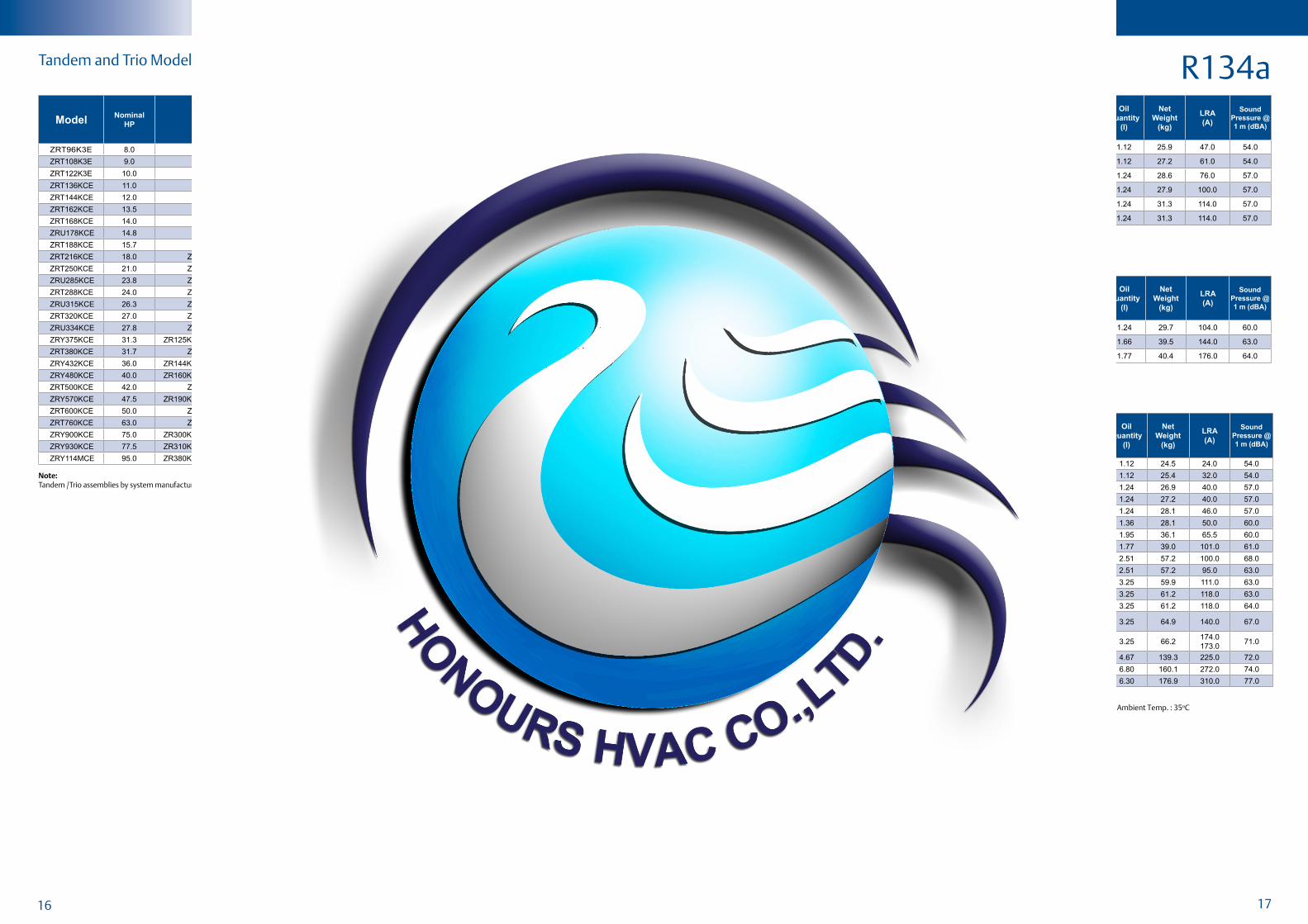
R22Tandem and Trio Model Availability
Note:Tandem / Trio assemblies by system manufacturers. Contact Application Engineering for more information.
Technical Overview
220-240V ; 50Hz , 1 PhaseR407C
208-230V ; 60Hz , 1 Phase
ModelNominal
HP
Capacity Input
Power
(W)
Current
(A)
COP
(W/W)
EER
(Btu/Wh)
Displacement
(cc/ Rev.)
Oil
Quantity
(I)
Net
Weight
(kg)
LRA
(A)
Sound Pressure @ 1 m (dBA)(W) (Btu/h)
ZR18K5E PFJ 1.5 4,200 14,400 1,455 6.8 2.9 9.9 25.2 0.74 22.4 45.0 54.0
ZR22K3E PFJ 1.8 5,100 17,400 1,740 8.1 2.93 10.0 30.7 1.12 25.9 47.0 54.0
ZR24K3E PFJ 2.0 5,700 19,400 1,940 9.2 2.93 10.0 34.0 1.12 25.0 58.0 54.0
ZR26K3E PFJ 2.2 6,050 20,600 2,010 9.6 2.99 10.2 36.1 1.12 27.2 60.0 54.0
ZR28K3E PFJ 2.3 6,650 22,700 2,190 10.4 3.02 10.3 39.3 1.12 27.2 61.0 54.0
ZR30K3E PFJ 2.5 7,100 24,300 2,330 11.2 3.05 10.4 42.0 1.24 28.1 74.0 54.0
ZR34K3E PFJ 2.8 7,900 27,000 2,580 12.3 3.05 10.4 46.2 1.24 28.6 76.0 57.0
ZR36K3E PFJ 3.0 8,450 28,800 2,740 13.1 3.08 10.5 49.5 1.24 29.5 82.0 57.0
ZR40K3E PFJ 3.3 9,300 31,800 3,040 14.3 3.08 10.5 54.2 1.24 28.0 100.0 57.0
ZR42K3E PFJ 3.5 9,750 33,200 3,150 15.2 3.11 10.6 57.2 1.24 30.4 97.0 57.0
ZR45K3E PFJ 3.8 10,400 35,500 3,360 16.6 3.11 10.6 61.1 1.24 32.2 114.0 57.0
ZR47K3E PFJ 3.9 10,950 37,400 3,480 16.9 3.14 10.7 63.3 1.24 31.3 114.0 57.0
ZR48K3E PFJ 4.0 11,400 38,900 3,610 17.3 3.17 10.8 65.5 1.24 31.3 114.0 57.0
ZR68KCE PFJ 5.7 15,700 53,500 5,200 25.1 3.02 10.3 93.0 1.83 40.4 150.0 61.0
ModelNominal
HP
Capacity Input Power
(W)
Current(A)
COP(W/W)
EER(Btu/Wh)
Displacement (cc/ Rev.)
Oil Quantity
(I)
NetWeight
(kg)
LRA (A)
Sound Pressure @ 1 m (dBA)(W) (Btu/h)
ZR18K5E PFV 1.5 5,050 17,300 1,750 7.6 2.89 9.9 25.2 0.74 22.2 55.0 57.0
ZR21K5E PFV 1.8 5,900 20,200 2,040 8.7 2.90 9.9 29.0 0.74 21.3 56.0 57.0
ZR24K3E PFV 2.0 6,850 23,400 2,260 10.2 3.02 10.3 34.0 1.12 26.3 61.0 57.0
ZR28K3E PFV 2.3 7,950 27,200 2,600 11.7 3.08 10.5 39.3 1.12 26.7 72.5 57.0
ZR30K3E PFV 2.5 8,550 29,200 2,760 12.4 3.11 10.6 42.0 1.24 28.1 73.0 57.0
ZR34K3E PFV 2.8 9,550 32,600 3,060 13.8 3.11 10.6 46.2 1.24 28.5 88.0 60.0
ZR36K3E PFV 3.0 10,250 34,900 3,260 14.9 3.14 10.7 49.5 1.24 29.0 95.0 60.0
ZR40K3E PFV 3.3 11,300 38,500 3,580 16.6 3.17 10.8 54.2 1.24 29.7 104.0 60.0
ZR48K3E PFV 4.0 13,850 47,200 4,410 20.3 3.14 10.7 65.6 1.24 32.2 137.0 60.0
ZR61KCE PFV 5.1 17,700 60,050 5,300 24.8 3.34 11.4 82.6 1.66 39.5 144.0 63.0
ZR68KCE PFV 5.7 19,000 65,000 6,050 27.5 3.14 10.7 93.0 1.77 40.4 176.0 64.0
Note:All Values As Per AHRI Standards : Evaporating Temp. : 7.2oC , Condensing Temp. : 54.4oC , Subcooling : 8.3K , Superheat : 11.1K , Ambient Temp. : 35oC
ModelNominal
HPConiguration
Capacity (W)
Even
Tandem
Uneven
TandemTrio50 Hz / 3 Ph 60 Hz / 3 Ph
380 / 420V 460V 200 / 230V 380V
ZRT90KC 7.5 ZR45KC + ZR45KC 21,863 26,600 26,600 - ●ZRT96K3 8.0 ZR48K3 + ZR48K3 23,400 28,200 28,400 - ●ZRT108K3 9.0 ZR54K3 + ZR54K3 26,200 31,500 31,000 - ●ZRT114K3 9.5 ZR57K3 + ZR57K3 28,000 33,500 33,500 - ●ZRT122K3 10.2 ZR61K3 + ZR61K3 29,600 35,500 35,500 - ●ZRT136KC 11.3 ZR68KC + ZR68KC 33,500 40,000 40,000 40,000 ●ZRU140KC 11.7 ZR68KC + ZR72KC 34,500 41,500 41,500 41,500 ●ZRT144KC 12.0 ZR72KC + ZR72KC 34,500 42,000 42,000 42,000 ●ZRT162KC 13.5 ZR81KC + ZR81KC 39,500 48,000 48,000 48,000 ●ZRT168KC 14.0 ZR84KC + ZR84KC 41,500 50,000 50,000 50,000 ●ZRU178KC 15.0 ZR84KC + ZR94KC 44,000 53,000 53,000 53,000 ●ZRT188KC 16.0 ZR94KC + ZR94KC 46,000 56,100 56,100 56,100 ●ZRT216KC 18.0 ZR108KC + ZR108KC 52,000 63,000 63,000 63,000 ●ZRT250KC 21.0 ZR125KC + ZR125KC 61,500 74,000 74,000 74,000 ●ZRU285KC 24.0 ZR125KC + ZR160KC 68,000 82,500 82,500 82,500 ●ZRT288KC 24.0 ZR144KC + ZR144KC 70,000 84,500 84,500 84,500 ●ZRU315KC 26.0 ZR125KC + ZR190KC 75,000 91,000 91,000 91,000 ●ZRT320KC 27.0 ZR160KC + ZR160KC 76,000 93,500 93,500 93,500 ●ZRU334KC 28.0 ZR144KC + ZR190KC 79,000 96,500 96,500 96,500 ●ZRY375KC 31.0 ZR125KC + ZR125KC + ZR125KC 93,000 112,000 112,000 112,000 ●ZRT380KC 32.0 ZR190KC + ZR190KC 90,500 110,000 110,000 110,000 ●ZRY432KC 36.0 ZR144KC + ZR144KC +ZR144KC 105,000 127,500 127,500 127,500 ●ZRY480KC 40.0 ZR160KC + ZR160KC + ZR160KC 114,000 140,000 140,000 140,000 ●ZRT500KC 42.0 ZR250KC + ZR250KC 116,000 141,500 141,500 141,500 ●ZRY570KC 47.5 ZR190KC + ZR190KC +ZR190KC 135,500 167,000 167,000 167,000 ●ZRT600KC 50.0 ZR300KC + ZR300KC 140,000 171,500 171,500 171,500 ●ZRT760KC 63.0 ZR380KC + ZR380KC 181,000 219,000 219,000 219,000 ●ZRY900KC 75.0 ZR300KC + ZR300KC +ZR300KC 210,000 258,000 258,000 258,000 ●ZRY930KC 77.5 ZR310KC + ZR310KC + ZR310KC 221,000 267,000 267,000 - ●ZRY114MC 99.0 ZR380KC + ZR380KC + ZR380KC 275,500 332,500 332,500 332,500 ●
14 15
Technical Overview
380-420V ; 50Hz , 3 PhaseR407C
ModelNominal
HP
Capacity Input
Power
(W)
Current
(A)
COP
(W/W)
EER
(Btu/Wh)
Displacement
(cc/ Rev.)
Oil
Quantity
(I)
Net
Weight
(kg)
LRA
(A)
Sound Pressure @ 1 m (dBA)(W) (Btu/h)
ZR22K3E TFD 1.8 5,150 17,500 1,670 3.1 3.08 10.5 30.7 1.12 24.6 24.0 54.0
ZR24K3E TFD 2.0 5,700 19,400 1,920 3.7 2.96 10.1 34.0 1.12 25.0 26.0 54.0
ZR26K3E TFD 2.2 6,400 21,800 2,190 4.1 2.93 10.0 36.1 1.12 26.8 26.0 54.0
ZR28K3E TFD 2.3 6,650 22,700 2,140 3.9 3.11 10.6 39.3 1.12 25.4 32.0 54.0
ZR30K3E TFD 2.5 7,400 25,200 2,270 4.4 3.25 11.1 42.0 1.24 25.9 32.0 54.0
ZR32K3E TFD 2.7 7,400 25,200 2,410 7.6 3.05 10.4 43.4 1.24 26.3 35.0 57.0
ZR34K3E TFD 2.8 7,900 27,000 2,530 4.7 3.14 10.7 46.2 1.24 26.9 40.0 57.0
ZR36K3E TFD 3.0 8,450 28,800 2,700 4.8 3.14 10.7 49.5 1.24 27.2 40.0 57.0
ZR38K5E TFD 3.2 8,800 30,000 2,900 5.4 3.03 10.4 50.9 1.24 27.5 47.0 59.0
ZR40K3E TFD 3.3 9,300 31,700 2,960 5.4 3.14 10.7 54.2 1.24 28.1 46.0 57.0
ZR42K3E TFD 3.5 9,750 33,300 3,110 5.3 3.14 10.7 57.2 1.24 28.2 46.0 57.0
ZR45KCE TFD 3.8 10,500 35,800 3,340 6.1 3.14 10.7 61.1 1.36 28.1 48.0 57.0
ZR47KCE TFD 3.9 10,950 37,400 3,440 6.5 3.19 10.9 64.2 1.36 28.1 48.0 60.0
ZR48KCE TFD 4.0 11,300 38,600 3,590 6.3 3.14 10.7 65.5 1.36 28.1 50.0 60.0
ZR48K5E TFD 4.0 11,200 38,300 3,450 6.2 3.25 11.1 63.4 1.24 29.1 60.0 59.0
ZR49K3E TFD 4.1 11,350 38,800 3,670 6.4 3.11 10.6 67.1 1.95 37.2 51.5 58.0
ZR54KSE TFD 4.5 13,350 45,600 4,190 7.4 3.19 10.9 73.1 1.24 29.9 56.0 58.0
ZR54K5E TFD 4.5 12,500 42,700 3,880 6.6 3.22 11.0 72.0 1.24 31.0 52.0 59.0
ZR57KSE TFD 4.8 14,250 48,700 4,450 7.8 3.19 10.9 77.2 1.24 30.0 56.0 61.0
ZR61KSE TFD 5.1 15,200 52,000 4,760 8.2 3.22 11.0 82.6 1.24 29.9 59.0 61.0
ZR61KHE TFM 5.1 14,350 48,900 4,470 8.0 3.19 10.9 82.6 1.77 39.5 67.0 61.0
ZR68KCE TFD 5.7 15,800 54,000 5,100 8.9 3.11 10.6 93.0 1.77 39.0 74.0 61.0
ZR72KCE TFD 6.0 16,600 56,500 5,150 9.1 3.22 11.0 98.1 1.77 38.6 74.0 61.0
ZR81KCE TFD 6.8 18,600 63,500 5,900 10.9 3.17 10.8 107.8 1.77 39.0 101.0 61.0
ZR84KCE TFD 7.0 19,600 67,000 6,150 11.4 3.19 10.9 113.6 2.51 57.2 100.0 68.0
ZR94KCE TFD 7.8 23,000 78,600 6,950 12.9 3.34 11.4 127.2 2.51 57.2 95.0 63.0
ZR108KCE TFD 9.0 25,800 88,100 7,580 13.8 3.40 11.6 142.9 3.25 59.9 111.0 63.0
ZR125KCE TFD 10.4 30,000 103,000 8,950 16.0 3.40 11.6 167.2 3.25 61.2 118.0 63.0
ZR144KCE TFD 12.0 34,500 118,000 10,150 17.7 3.40 11.6 190.9 3.25 61.2 118.0 64.0
ZR160KCETFD
TWD13.3 37,500 128,000 11,450 20.5 3.28 11.2 209.1 3.25 64.9 140.0 67.0
ZR190KCETFD
TWD15.8 44,000 150,000 13,650 26.5 3.22 11.0 249.2 3.25 66.2
174.0
173.071.0
ZR250KCE TWD 20.8 58,500 200,000 18,000 30.1 3.25 11.1 325.2 4.67 139.3 225.0 72.0
ZR310KCE TWD 25.8 72,500 248,000 22,300 37.9 3.25 11.1 410.6 6.80 160.1 272.0 74.0
ZR380KCE TWD 31.7 91,500 313,000 26,700 45.5 3.43 11.7 502.7 6.30 176.9 310.0 77.0
Technical Overview
460V / 200-230V / 380V / 208-230V ; 60Hz , 3 Phase
R407C
ModelNominal
HP
Capacity Input Power
(W)
Current
(A)
COP
(W/W)
EER
(Btu/Wh)
Displacement
(cc/ Rev.)
Oil
Quantity(I)
NetWeight
(kg)
LRA (A)
Sound Pressure @
1 m (dBA)(W) (Btu/h)
ZR22K3ETFD
TF51.8
6,100
6,200
20,800
21,100
2,110
2,090
3.3
8.9
2.87
2.96
9.8
10.130.7 1.12 24.5
22.4
45.057.0
ZR24K3ETFD
TF52.0
7,200
6,900
24,600
23,500
2,240
2,190
1.7
7.2
3.22
3.14
11.0
10.734.0 1.12 25.0
27.0
55.057.0
ZR26K3ETFD
TF52.2
7,750
7,700
26,400
26,200
2,470
2,490
3.7
7.0
3.14
3.08
10.7
10.536.1 1.12 26.8
27.0
55.057.0
ZR28K3ETFD
TF52.3 8,000 27,300 2,530
3.9
7.83.17 10.8 39.3 1.12 25.4
31.0
63.057.0
ZR30K3ETFD
TF52.5 8,500 29,000 2,750
4.3
8.53.08 10.5 42.0 1.24 25.9
31.0
63.057.0
ZR32K3ETFD
TF52.7 9,000 30,700 2,850
4.4
8.73.17 10.8 43.4 1.24 26.3
35.0
77.060.0
ZR34K3E
TFD
TF5
TF7
2.8 9,650 33,000
3,010
3,010
3,320
4.6
9.2
5.4
3.22
3.22
2.90
11.0
11.0
9.9
46.2 1.24
26.9
26.9
31.3
39.0
77.0
39.0
60.0
Note:All Values As Per AHRI Standards : Evaporating Temp. : 7.2oC , Condensing Temp. : 54.4oC , Subcooling : 8.3K , Superheat : 11.1K , Ambient Temp. : 35oC
ModelNominal
HP
Capacity Input
Power
(W)
Current
(A)
COP
(W/W)
EER
(Btu/Wh)
Displacement
(cc/ Rev.)
Oil
Quantity
(I)
Net
Weight
(kg)
LRA
(A)
Sound Pressure @ 1 m (dBA)(W) (Btu/h)
ZR36K3ETFD
TF53.0 10,250 34,900 3,180
4.9
9.73.22 11.0 49.5 1.24
27.2
27.3
39.0
77.060.0
ZR40K3ETFD
TF53.3 11,200 38,300 3,490
5.4
10.73.22 11.0 54.2 1.24
28.1
27.9
44.0
88.060.0
ZR42K3ETFD
TF53.5 11,800 40,200 3,730
5.5
11.03.17 10.8 57.2 1.24
28.2
28.1
44.0
88.0 60.0
ZR47KCETFD
TF53.9 13,050 44,600 4,150
6.2
12.43.14 10.7 64.2 1.36 28.1
46.0
91.060.0
ZR48KCE
TFD
TF5
TF7
4.0 13,750 47,000 4,330
6.3
12.6
7.6
3.19 10.9 65.5 1.36 28.1
50.0
91.0
54.0
60.0
64.0
60.0
ZR54KCE TF7 4.5 15,800 54,000 4,880 9.0 3.25 11.1 73.2 1.95 37.2 65.8 63.0
ZR54KSETFD
TF54.5 16,100 55,000
5,050
4,970
7.6
14.7
3.19
3.25
10.9
11.173.1 1.24 29.9
59.0
125.061.0
ZR57KSETFD
TF54.8 17,100 58,500 5,350
8.0
15.73.19 10.9 77.2 1.24 29.9
59.0
125.0
64.0
61.0
ZR61KCE TF7 5.1 17,100 58,500 5,300 9.2 3.25 11.1 82.6 1.95 36.3 64.0 63.0
ZR61KSETFD
TF55.1
17,400
18,300
59,500
62,500
5,450
5,750
8.0
16.5
3.22
3.19
11.0
10.982.6 1.24 29.9
56.0
125.0
64.0
61.0
ZR68KCETFD
TF55.7 19,200 65,500 6,000
9.2
18.43.19 10.9 93.0 1.77 39.0
75.0
156.064.0
ZR72KCE
TFD
TF5
TF7
6.0 20,400 69,500 6,200
8.8
18.1
10.7
3.28 11.2 98.1 1.77
38.6
38.6
38.6
75.0
156.0
70.0
64.0
ZR81KCE
TFD
TF5
TF7
6.8 22,600 77,000 7,150
11.0
21.9
13.3
3.17 10.8 107.8 1.77 39.0
100.0
164.0
100.0
64.0
ZR84KCE
TFD
TF5
TF7
7.0 23,900 81,500 7,300
11.6
23.2
14.0
3.28 11.2 113.6 2.51 57.2
100.0
196.0
135.0
71.0
ZR94KCE
TFD
TF5
TF7
7.8 27,500 94,000 8,310
12.8
25.6
15.5
3.34 11.4 127.2 2.51
57.2
56.7
57.2
95.0
195.0
123.0
68.0
ZR108KCE
TFD
TF5
TF7
9.0 31,000 106,000 9,220
14.0
28.0
17.0
3.37 11.5 142.9 3.25
59.9
59.9
60.3
114.0
225.0
140.0
69.0
ZR125KCE
TFD
TF5
TF7
10.4 36,500 125,000 10,850
16.3
32.6
19.8
3.40 11.6 167.2 3.25 61.2
125.0
239.0
145.0
69.0
ZR144KCE
TFD
TF5
TF7
12.0 41,500 142,000 12,350
18.2
36.3
22.0
3.40 11.6 190.9 3.25 61.2
125.0
245.0
145.0
69.0
ZR160KCETFD
TF713.3 45,000 154,000 13,850
20.8
25.13.28 11.2 209.1 3.25 64.9
150.0
138.071.0
ZR160KCE
TWD
TW5
TW7
13.3 45,000 154,000 13,850
20.8
41.5
25.1
3.28 11.2 209.1 3.25
64.9
66.2
64.9
150.0
300.0
139.0
71.0
ZR190KCE TFD 15.8 53,000 181,000 16,650 26.2 3.19 10.9 249.2 3.25 66.2 179.0 72.0
ZR190KCE
TWD
TW5
TW7
15.8 53,000 181,000 16,650
26.2
52.4
31.7
3.19 10.9 249.2 3.25 66.2
173.0
340.0
196.0
72.0
ZR250KCE
TWD
TWC
TW7
20.8 70,500 240,000 21,700
31.1
67.8
37.6
3.25 11.1
325.2
325.2
318.1
4.67
139.3
138.8
139.3
225.0
505.0
280.0
77.0
ZR310KCE
TWD
TWC
TW7
25.8 87,000 297,000 27,500
39.0
82.0
47.2
3.17 10.8 410.6 6.80 160.1
272.0
605.0
353.0
79.0
ZR380KCE
TWD
TWC
TW7
31.7 109,500 374,000 32,800
47.3
94.6
57.3
3.34 11.4 502.7 6.30 176.9
310.0
599.0
358.0
81.0
Continuation460V / 200-230V / 380V / 208-230V ; 60Hz , 3 Phase
16 17
ModelNominal
HPConiguration
Capacity (W)
Even
Tandem
Uneven
TandemTrio50 Hz / 3 Ph 60 Hz / 3 Ph
380 / 420V 460V 200 / 230V 380V
ZRT96K3E 8.0 ZR48K3E + ZR48K3E 22,500 27,500 27,100 - ●ZRT108K3E 9.0 ZR54K3E + ZR54K3E 24,600 29,600 - - ●ZRT122K3E 10.0 ZR61K3E + ZR61K3E 28,000 34,000 34,000 - ●ZRT136KCE 11.0 ZR68KCE + ZR68KCE 31,500 38,500 38,500 - ●ZRT144KCE 12.0 ZR72KCE + ZR72KCE 32,500 40,000 40,000 40,000 ●ZRT162KCE 13.5 ZR81KCE + ZR81KCE 36,500 45,000 45,000 45,000 ●ZRT168KCE 14.0 ZR84KCE + ZR84KCE 39,000 47,500 47,500 47,500 ●ZRU178KCE 14.8 ZR84KCE + ZR94KCE 44,000 53,000 53,000 53,000 ●ZRT188KCE 15.7 ZR94KCE + ZR94KCE 45,500 54,500 54,500 54,500 ●ZRT216KCE 18.0 ZR108KCE + ZR108KCE 51,500 61,500 61,500 61,500 ●ZRT250KCE 21.0 ZR125KCE + ZR125KCE 57,500 69,500 69,500 69,500 ●ZRU285KCE 23.8 ZR125KCE + ZR160KCE 68,000 82,500 82,500 82,500 ●ZRT288KCE 24.0 ZR144KCE + ZR144KCE 66,000 79,500 79,500 79,500 ●ZRU315KCE 26.3 ZR125KCE + ZR190KCE 73,000 88,000 88,000 88,000 ●ZRT320KCE 27.0 ZR160KCE + ZR160KCE 74,500 90,000 90,000 90,000 ●ZRU334KCE 27.8 ZR144KCE + ZR190KCE 79,000 96,500 96,500 96,500 ●ZRY375KCE 31.3 ZR125KCE + ZR125KCE + ZR125KCE 90,500 109,500 109,500 109,500 ●ZRT380KCE 31.7 ZR190KCE + ZR190KCE 87,600 106,000 106,000 106,000 ●ZRY432KCE 36.0 ZR144KCE + ZR144KCE + ZR144KCE 103,000 124,500 124,500 124,500 ●ZRY480KCE 40.0 ZR160KCE + ZR160KCE + ZR160KCE 112,000 135,000 135,000 135,000 ●ZRT500KCE 42.0 ZR250KCE + ZR250KCE 115,000 138,000 138,000 138,000 ●ZRY570KCE 47.5 ZR190KCE + ZR190KCE + ZR190KCE 131,500 158,500 158,500 158,500 ●ZRT600KCE 50.0 ZR300KCE + ZR300KCE 138,500 170,000 170,000 170,000 ●ZRT760KCE 63.0 ZR380KCE + ZR380KCE 180,000 217,000 217,000 217,000 ●ZRY900KCE 75.0 ZR300KCE + ZR300KCE + ZR300KCE 208,500 255,500 255,500 255,500 ●ZRY930KCE 77.5 ZR310KCE + ZR310KCE + ZR310KCE 216,500 259,000 259,000 - ●ZRY114MCE 95.0 ZR380KCE + ZR380KCE + ZR380KCE 273,500 328,000 328,000 328,000 ●
R407CTandem and Trio Model Availability
Note:Tandem /Trio assemblies by system manufacturers. Emerson Climate Technologies can provide full technical support.
Technical Overview
220-240V ; 50Hz , 1 Phase
380-420V ; 50Hz , 3 Phase
R134aModel
Nominal
HP
Capacity Input
Power
(W)
Current
(A)
COP
(W/W)
EER
(Btu/Wh)
Displacement
(cc/ Rev.)
Oil
Quantity
(I)
Net
Weight
(kg)
LRA
(A)
Sound Pressure @ 1 m (dBA)(W) (Btu/h)
ZR22K3E PFJ 1.8 3,500 12,000 1,190 5.5 2.96 10.1 30.7 1.12 25.9 47.0 54.0
ZR28K3E PFJ 2.3 4,700 16,000 1,510 7.4 3.11 10.6 39.3 1.12 27.2 61.0 54.0
ZR34K3E PFJ 2.8 5,600 19,100 1,780 8.8 3.14 10.7 46.2 1.24 28.6 76.0 57.0
ZR40K3E PFJ 3.3 6,450 22,000 2,170 11.5 2.96 10.1 54.2 1.24 27.9 100.0 57.0
ZR47K3E PFJ 3.9 7,950 27,200 2,620 16.2 3.05 10.4 63.3 1.24 31.3 114.0 57.0
ZR48K3E PFJ 4.0 8,150 27,800 2,670 16.5 3.05 10.4 65.5 1.24 31.3 114.0 57.0
ModelNominal
HP
Capacity Input Power
(W)
Current(A)
COP(W/W)
EER(Btu/Wh)
Displacement (cc/ Rev.)
Oil Quantity
(I)
NetWeight
(kg)
LRA (A)
Sound Pressure @ 1 m (dBA)(W) (Btu/h)
ZR22K3E TFD 1.8 3,600 12,300 1,230 2.4 2.93 10.0 30.7 1.12 24.5 24.0 54.0
ZR28K3E TFD 2.3 4,750 16,200 1,570 3.2 3.02 10.3 39.3 1.12 25.4 32.0 54.0
ZR34K3E TFD 2.8 5,550 18,900 1,830 3.7 3.02 10.3 46.2 1.24 26.9 40.0 57.0
ZR36K3E TFD 3.0 5,400 18,500 1,992 3.8 2.72 9.3 49.5 1.24 27.2 40.0 57.0
ZR40K3E TFD 3.3 6,500 22,100 2,090 4.1 3.11 10.6 54.2 1.24 28.1 46.0 57.0
ZR48KCE TFD 4.0 7,900 26,900 2,420 4.8 3.25 11.1 65.5 1.36 28.1 50.0 60.0
ZR61KCE TFD 5.1 10,050 34,300 2,990 6.3 3.37 11.5 82.6 1.95 36.1 65.5 60.0
ZR81KCE TFD 6.8 13,300 45,400 4,010 8.6 3.31 11.3 107.8 1.77 39.0 101.0 61.0
ZR84KCE TFD 7.0 13,350 45,600 4,200 10.0 3.18 10.9 113.6 2.51 57.2 100.0 68.0
ZR94KCE TFD 7.8 15,700 53,500 4,710 10.4 3.33 11.4 127.2 2.51 57.2 95.0 63.0
ZR108KCE TFD 9.0 17,600 59,900 5,260 11.6 3.34 11.4 142.9 3.25 59.9 111.0 63.0
ZR125KCE TFD 10.4 20,500 70,000 6,150 12.2 3.34 11.4 167.2 3.25 61.2 118.0 63.0
ZR144KCE TFD 12.0 23,300 79,500 6,950 13.6 3.37 11.5 190.9 3.25 61.2 118.0 64.0
ZR160KCETFD
TWD13.3 25,500 87,000 7,600 15.7 3.37 11.5 209.1 3.25 64.9 140.0 67.0
ZR190KCETFD
TWD15.8 30,500 104,000 9,200 20.6 3.31 11.3 249.2 3.25 66.2
174.0
173.071.0
ZR250KCE TWD 20.8 40,000 137,000 12,200 22.6 3.28 11.2 325.2 4.67 139.3 225.0 72.0
ZR310KCE TWD 25.8 50,000 170,000 15,300 28.3 3.25 11.1 410.6 6.80 160.1 272.0 74.0
ZR380KCE TWD 31.7 63,000 215,000 18,800 35.6 3.34 11.4 502.7 6.30 176.9 310.0 77.0
ModelNominal
HP
Capacity Input
Power
(W)
Current
(A)
COP
(W/W)
EER
(Btu/Wh)
Displacement
(cc/ Rev.)
Oil
Quantity
(I)
Net
Weight
(kg)
LRA
(A)
Sound Pressure @ 1 m (dBA)(W) (Btu/h)
ZR40K3E PFV 3.3 7,950 27,100 2,550 12.2 3.11 10.6 54.2 1.24 29.7 104.0 60.0
ZR61KCE PFV 5.1 12,200 41,700 3,590 20.4 3.40 11.6 82.6 1.66 39.5 144.0 63.0
ZR68KCE PFV 5.7 13,750 46,900 4,420 22.2 3.11 10.6 93.0 1.77 40.4 176.0 64.0
208-230V ; 60Hz , 1 Phase
Note:All Values As Per AHRI Standards : Evaporating Temp. : 7.2oC , Condensing Temp. : 54.4oC , Subcooling : 8.3K , Superheat : 11.1K , Ambient Temp. : 35oC

18 19
ModelNominal
HP
Capacity Input
Power
(W)
Current
(A)
COP
(W/W)
EER
(Btu/Wh)
Displacement
(cc/ Rev.)
Oil
Quantity
(I)
Net
Weight
(kg)
LRA
(A)
Sound Pressure @ 1 m (dBA)(W) (Btu/h)
ZR22K3E TFD 1.8 4,350 14,800 1,480 2.9 2.93 10.0 30.7 1.12 24.5 22.4 57.0
ZR28K3ETFD
TF52.3 5,800 19,800 1,910
3.3
6.63.02 10.3 39.3 1.12 25.4
31.0
63.057.0
ZR34K3E TFD 2.8 6,850 23,300 2,250 3.9 3.05 10.4 46.2 1.24 26.9 39.0 60.0
ZR36K3E TFD 3.0 7,150 24,400 2,390 3.8 2.99 10.2 49.5 1.24 27.2 39.0 60.0
ZR40K3E TFD 3.3 7,900 26,900 2,580 4.1 3.05 10.4 54.2 1.24 28.1 44.0 60.0
ZR48KCE TFD 4.0 9,600 32,800 2,970 5.0 3.22 11.0 65.5 1.36 28.2 50.0 60.0
ZR48K3ETFD
TF54.0
9,500
9,650
32,500
32,900
3,090
2,990
5.0
9.8
3.08
3.22
10.5
11.065.5 1.36
28.1
32.7
50.0
91.060.0
ZR61KCETFD
TF55.1
12,350
12,150
42,200
41,500
3,550
3,710
6.4
13.1
3.49
3.28
11.9
11.282.6 1.95
36.1
35.4
63.0
128.063.0
ZR68KCE TFD 5.7 13,850 47,200 4,030 6.5 3.43 11.7 93.0 1.77 39.0 75.0 64.0
ZR81KCETFD
TF56.8
16,100
16,000
55,000
54,500
4,950
4,760
8.9
16.0
3.25
3.37
11.1
11.5107.8 1.77 39.0
100.0
164.064.0
ZR84KCE
TFD
TF5
TF7
7.0 16,200 55,400 5,150
9.8
19.5
11.8
3.15 10.8 113.6 2.51 57.2
100.0
196.0
135.0
71.0
ZR94KCE
TFD
TF5
TF7
7.8 18,800 64,000 5,700
11.4
22.8
13.8
3.28 11.2 127.2 2.51
57.2
56.7
57.2
95.0
195.0
123.0
68.0
ZR108KCE
TFD
TF5
TF7
9.0 21,100 72,100 6,440
11.5
22.9
13.9
3.28 11.2 142.9 3.25
59.9
59.9
60.3
114.0
225.0
140.0
69.0
ZR125KCE
TFD
TF5
TF7
10.4 24,900 85,000 7,570
12.4
24.8
15.0
3.30 11.3 167.2 3.25 61.2
125.0
239.0
145.0
69.0
ZR144KCE
TFD
TF5
TF7
12.0
28,300
28,400
28,300
96,400
96,900
96,400
8,500
8,480
8,500
13.7
30.0
16.5
3.33
3.34
3.33
11.4 190.9 3.25 61.2
125.0
245.0
145.0
69.0
ZR160KCE TFD 13.3 31,000 105,000 9,500 16.3 3.25 11.1 209.1 3.25 64.9 150.0 71.0
ZR160KCE
TWD
TW5
TW7
13.3 31,000 105,000 9,500
16.3
32.6
19.8
3.25 11.1 209.1 3.25
64.9
66.2
64.9
150.0
300.0
139.0
71.0
ZR190KCE TFD 15.8 37,000 127,000 11,300 21.4 3.28 11.2 249.2 3.25 66.2 179.0 72.0
ZR190KCE
TWD
TW5
TW7
15.8 37,000 127,000 11,300
21.4
42.8
25.9
3.28 11.2 249.2 3.25 66.2
173.0
340.0
196.0
72.0
ZR250KCE
TWD
TW5
TW7
20.8 48,500 166,000 15,100
22.7
49.6
27.5
3.22 11.0
325.2
325.2
318.1
4.67
139.3
138.8
139.3
225.0
505.0
280.0
77.0
ZR310KCETWD
TW725.8 60,000 205,000 18,800
28.3
34.33.19 10.9 410.6 6.80 160.1
272.0
353.079.0
ZR380KCE
TWD
TW5
TW7
31.7 74,000 253,000 22,400
34.7
69.4
42.0
3.31 11.3 502.7 6.30 176.9
310.0
599.0
358.0
81.0
460V / 200-230V / 380V ; 60Hz , 3 Phase
Technical Overview R134aModel
Nominal
HPConiguration
Capacity (W)
Even
Tandem
Uneven
TandemTrio50 Hz / 3 Ph 60 Hz / 3 Ph
380 / 420V 460V 200 / 230V 380V
ZRT96K3E 8.0 ZR48K3E + ZR48K3E 15,400 18,500 - - ●
ZRT136KCE 11.0 ZR68KCE + ZR68KCE 22,600 27,400 - - ●
ZRT144KCE 12.0 ZR72KCE + ZR72KCE 23,400 28,400 28,400 - ●
ZRT162KCE 13.5 ZR81KCE + ZR81KCE 26,300 32,000 31,500 - ●
ZRT168KCE 14.0 ZR84KCE + ZR84KCE 26,450 32,165 - - ●
ZRT188KCE 16.0 ZR94KCE + ZR94KCE 31,066 37,147 - - ●
ZRT216KCE 18.0 ZR108KCE + ZR108KCE - - 41,616 - ●
ZRT250KCE 21.0 ZR125KCE + ZR125KCE - 49,000 47,200 49,000 ●
ZRT288KCE 24.0 ZR144KCE + ZR144KCE 46,500 54,000 54,500 54,000 ●
ZRT500KCE 42.0 ZR250KCE + ZR250KCE 79,500 96,500 96,500 96,500 ●
ZRT600KCE 50.0 ZR300KCE + ZR300KCE 93,000 113,000 113,000 113,000 ●
ZRT760KCE 63.0 ZR380KCE + ZR380KCE - 149,500 149,500 149,500 ●
Notes:All Values As Per AHRI Standards : Evaporating Temp. : 7.2oC , Condensing Temp. : 54.4oC , Subcooling : 8.3K, Superheat : 11.1K , Ambient Temp. : 35oCTandem /Trio assemblies by system manufacturers. Contact Application Engineering for more information.
R134aTandem and Trio Model Availability
Maximum Allowable Pressure (PS)
• ZP14 to ZP91: Low Side PS 28 bar(g) / High Side PS 43 bar(g)• ZP90 to ZP485: Low Side PS 29.5 bar(g) / High Side PS 45 bar(g)
Features and Beneits
• CopelandTM qualiied tandem and trio conigurations for superior seasonal eficiency
• Copeland Scroll axial and radial compliance for superior reliability and eficiency
• Low Total Equivalent Warming Impact• Wide scroll line-up in R410A• Low sound and vibration level• Low oil circulation rate• Extended 5K suction superheat operating envelope
suitable for heat pump applications - Contact Application Engineering for more information
Copeland ScrollTM Compressors for R410A refrigerantThe Copeland ScrollTM compressors are perfectly suitable for split systems, rooftops, packaged units and chiller applications.
Copeland Scroll compressors offer an advantage of fewer moving parts with scroll sets wearing in. Meanwhile, both axial and radial compliance allows the scroll compressor to be more tolerant of liquid refrigerant and debris thus enhancing reliability. Furthermore, Emerson’s well established expertise in paralleling multiple compressors to one eficient solution provides a unique advantage and an assured beneit even for the manufacturing of large capacity systems (air cooled and water cooled chillers).
The broad range of products goes from ZP14 (1.2HP) to ZP725 (60HP) in single compressor applications and to 120/180 HP in Tandem/trio applications in single module.
Compressor Line-up
Operating Envelopes Technical Overview
220-240V ; 50Hz , 1 Phase
208-230V ; 60Hz , 1 Phase
ModelNominal
HP
Capacity Input Power
(W)
Current (A)
COP(W/W)
EER(Btu/Wh)
Displacement (cc/ Rev.)
Oil Quantity
(I)
NetWeight
(kg)
LRA(A)
Sound Pressure @ 1 m (dBA)(W) (Btu/h)
ZP16KSE PFZ 1.3 3,600 12,300 1,400 6.6 2.58 8.8 15.1 0.74 21.7 44.0 55.0
ZP20KSE PFZ 1.7 4,800 16,300 1,750 8.1 2.73 9.3 19.3 0.74 21.7 52.0 55.0
ZP23K3E PFZ 1.9 5,700 19,400 2,050 9.5 2.78 9.5 23.2 1.12 28.6 61.0 54.0
ZP24KSE PFZ 2.0 5,750 19,600 2,000 9.3 2.87 9.8 22.8 0.74 21.9 60.0 55.0
ZP25KSE PFZ 2.1 5,950 20,300 2,110 9.8 2.81 9.6 23.9 0.74 22.0 60.0 55.0
ZP26K3E PFZ 2.2 6,050 20,700 2,300 11.0 2.64 9.0 25.2 1.12 28.9 74.0 54.0
ZP29KSE PFZ 2.4 6,900 23,500 2,400 11.0 2.87 9.8 27.5 0.74 22.8 67.0 55.0
ZP31KSE PFZ 2.6 7,350 25,100 2,550 11.8 2.89 9.9 29.5 0.74 22.8 67.0 55.0
ZP32K3E PFJ 2.7 7,550 25,700 2,860 13.2 2.64 9.0 30.7 1.24 31.3 82.0 56.0
ZP36KSE PFZ 3.0 8,800 30,000 2,940 14.1 2.99 10.2 34.4 1.24 29.4 98.0 57.0
ZP39KSE PFZ 3.3 9,200 31,400 3,140 14.5 2.93 10.0 36.9 1.24 33.1 98.0 57.0
ZP41K3EPFZ
PFJ3.4 9,850 33,600
3,510
3,570
17.2
16.9
2.8
2.75
9.6
9.439.3 1.24
29.5
31.8
114.0
97.056.0
ZP42KSE PFZ 3.5 10,200 34,800 3,480 16.7 2.93 10.0 39.8 1.24 33.1 128.0 57.0
ZP50K3EPFZ
PFJ4.2 12,500 42,600 4,100 19.5 3.05 10.4 48.2 1.66 44.0 136.0 61.0
ZP51KSE PFZ 4.3 12,150 41,500 4,050 19.8 3.00 10.3 48.2 1.24 34.4 126.0 57.0
ZP54KSE PFZ 4.5 13,050 44,500 4,320 20.9 3.02 10.3 51.1 1.24 34.4 115.5 59.0
ZP57K3E PFJ 4.8 13,950 47,600 4,700 24.0 2.96 10.1 54.3 1.66 41.7 153.0 61.0
ZP61KCE PFZ 5.1 14,800 50,500 4,950 23.3 2.99 10.2 58.1 1.77 40.3 147.0 61.0
ZP67KCE PFZ 5.6 16,100 55,000 5,450 25.7 2.96 10.1 63.0 1.77 39.9 155.0 61.0
Evaporating Temperature °C
Co
nd
en
sin
g T
em
pe
ratu
re °
C
-30-35 -25 -20 -15 -10
5
10
15
20
25
30
35
40
45
50
55
60
65
70
75
0 5-5 10 15 20-400
ZP50K3E, ZP57K3E and ZP61 to ZP91KCE
ZP90 to ZP182KCE
ZP235 to ZP485KCE
ZP23 to ZP41K3E and ZP14 to ZP61K5E
1
2
ModelNominal
HP
Capacity Input Power
(W)
Current
(A)
COP
(W/W)
EER
(Btu/Wh)
Displacement
(cc/ Rev.)
Oil
Quantity(I)
Net
Weight(kg)
LRA
(A)
Sound Pressure @ 1 m (dBA)(W) (Btu/h)
ZP14K5E PFV 1.2 4,300 14,650 1,580 7.0 2.73 9.3 14.3 0.74 22.5 46.0 55.0
ZP16K5E PFV 1.3 4,550 15,500 1,660 7.3 2.73 9.3 15.1 0.74 21.5 48.0 55.0
ZP20K5E PFV 1.7 5,850 20,000 2,040 9.1 2.87 9.8 19.3 0.74 21.5 58.3 55.0
ZP25K5E PFV 2.1 7,400 25,200 2,520 11.1 2.93 10.0 23.9 0.74 22.0 73.0 55.0
ZP29K5E PFV 2.4 8,500 29,000 2,870 12.7 2.96 10.1 27.5 0.74 22.5 77.0 57.0
ZP31K5E PFV 2.6 9,100 31,100 3,070 13.5 2.96 10.1 29.5 0.74 22.5 79.0 57.0
ZP34K5E PFV 2.8 10,100 34,500 3,380 15.6 2.99 10.2 32.8 1.24 32.3 112.0 57.0
ZP36K5E PFV 3.0 10,550 36,000 3,540 16.4 2.99 10.2 34.4 1.24 32.3 112.0 57.0
ZP39K5E PFV 3.3 11,450 39,000 3,790 17.5 3.02 10.3 36.9 1.24 32.8 109.0 57.0
Notes:
All Values As Per AHRI Standards : Evaporating Temp. : 7.2oC , Condensing Temp. : 54.4oC , Subcooling : 8.3K, Superheat : 11.1K , Ambient Temp. : 35oC
Note:Dashed Red Line 1 Indicates 63oC Condensing Limit For ZP51 To ZP61K5E - PFVDashed Red Line 2 Indicates The Limit Of Operation With Constant Return Gas Temperature of 35oC
50 Hz
60 Hz
0 40 80 120 160 200 280 360240 320 400220 300 380260 340 42020 60 100 140 180
Single Phase
Single Phase
Three Phase
Three Phase
kW Cooling
kW Cooling
Trio
Trio
Tandem
Tandem
0 40 80 120 160 200 280 360240 320 400220 300 380260 340 42020 60 100 140 180
20 21

22 23
R410ATechnical Overview
Continuation208-230V ; 60Hz , 1 Phase
380-420V ; 50Hz , 3 Phase
ModelNominal
HP
Capacity Input
Power
(W)
Current
(A)
COP
(W/W)
EER
(Btu/Wh)
Displacement
(cc/ Rev.)
Oil
Quantity
(I)
Net
Weight
(kg)
LRA
(A)
Sound Pressure @ 1 m (dBA)(W) (Btu/h)
ZP24K5E TFD 2.0 5,700 19,400 2,020 3.6 2.81 9.6 22.8 0.74 21.3 28.0 55.0
ZP26K3E TFD 2.2 6,200 21,100 2,270 4.1 2.73 9.3 25.2 1.12 27.2 32.0 54.0
ZP29K5E TFD 2.4 6,800 23,200 2,420 4.4 2.81 9.6 27.5 0.74 21.8 38.0 55.0
ZP29KSE TFM 2.4 7,000 23,900 2,380 4.3 2.93 10.0 27.5 0.74 22.3 38.0 55.0
ZP31KSE TFM 2.6 7,350 25,000 2,580 4.6 2.84 9.7 29.5 0.74 22.3 38.0 55.0
ZP32K3E TFD 2.7 7,400 25,200 2,680 4.7 2.75 9.4 30.7 1.24 28.1 35.0 56.0
ZP34K5E TFD 2.8 8,200 28,000 2,830 5.2 2.90 9.9 32.8 1.24 28.9 46.0 57.0
ZP36K5E TFD 3.0 8,600 29,300 2,940 5.4 2.93 10.0 34.4 1.24 29.2 46.0 57.0
ZP36KSE TFM 3.0 8,900 30,400 2,920 5.4 3.05 10.4 34.4 1.24 29.4 46.0 57.0
ZP38K3E TFD 3.2 9,050 30,800 3,120 5.5 2.90 9.9 36.1 1.24 29.9 48.0 59.0
ZP39KSE TFM 3.3 9,250 31,600 3,150 5.3 2.93 10.0 36.9 1.24 30.9 43.0 57.0
ZP41K3E TFD 3.4 9,800 33,500 3,380 6.0 2.90 9.9 39.3 1.24 29.5 48.0 56.0
ZP42KSE TFM 3.5 10,050 34,300 3,310 5.6 3.03 10.4 39.8 1.24 30.9 43.0 57.0
ZP44K5E TFD 3.7 10,700 36,500 3,540 6.1 3.02 10.3 42.0 1.24 30.9 52.0 57.0
ZP49K5E TFD 4.1 11,950 40,700 3,870 6.5 3.09 10.6 46.4 1.24 33.0 51.5 57.0
ZP49KSE TFM 4.1 11,950 40,700 3,870 6.5 3.09 10.6 46.4 1.24 33.0 51.5 57.0
ZP50K3E TFD 4.2 12,400 42,300 4,100 7.3 3.02 10.3 48.2 1.95 39.5 64.0 58.0
ZP51K5E TFD 4.3 12,050 41,200 4,000 6.9 3.02 10.3 48.2 1.24 32.4 51.5 57.0
ZP51KSE TFM 4.3 12,150 41,500 4,040 7.0 3.02 10.3 48.2 1.24 33.0 51.5 57.0
ZP54K5E TFD 4.5 12,900 44,000 4,280 7.0 3.02 10.3 51.1 1.24 32.4 51.5 57.0
ZP54KSE TFM 4.5 12,900 44,100 4,210 7.1 3.08 10.5 51.1 1.24 33.0 51.5 59.0
ZP57K3E TFD 4.8 13,900 47,500 4,610 8.1 3.02 10.3 54.3 1.66 41.7 74.0 60.0
ZP61KCE TFD 5.1 14,650 50,000 4,750 8.3 3.11 10.6 58.1 1.66 40.3 64.0 60.0
ZP67KCE TFD 5.6 16,100 55,000 5,200 9.1 3.11 10.6 63.0 1.77 39.9 74.0 61.0
ZP72KCE TFD 6.0 17,100 58,500 5,700 9.8 3.02 10.3 67.1 1.77 39.9 75.0 61.0
ZP76KCE TFD 6.3 18,400 62,700 5,850 11.0 3.14 10.7 70.8 1.77 39.5 100.0 61.0
ZP83KCE TFD 6.9 19,900 68,000 6,400 11.7 3.11 10.6 77.2 1.77 39.5 101.0 61.0
ZP90KCE TFD 7.5 21,800 74,500 6,950 12.3 3.14 10.7 84.2 2.51 57.6 95.0 61.0
*ZP91KCE TFD 7.6 21,700 74,000 6,790 12.4 3.19 10.9 84.6 1.77 40.8 101.0 61.0
ZP103KCE TFD 8.6 25,200 86,000 7,800 14.4 3.22 11.0 96.4 3.25 61.2 111.0 63.0
*ZP104KCE TFD 8.7 25,400 86,800 7,790 14.3 3.27 11.2 96.4 2.51 48.0 128.0 63.0
ZP120KCE TFD 10.0 29,300 100,000 9,110 16.6 3.22 11.0 113.6 3.25 61.2 118.0 63.0
*ZP122KCE TFD 10.2 29,600 101,000 9,060 16.6 3.27 11.2 112.3 2.51 48.8 139.0 63.0
ZP137KCE TFD 11.4 32,500 111,000 10,200 18.3 3.19 10.9 127.2 3.25 62.1 118.0 66.0
ZP154KCETFD
TWD12.8 37,000 127,000 11,600 20.8 3.22 11.0 142.9 3.25 64.9 140.0
65.0
66.0
ZP182KCETFD
TWD15.2 44,000 150,000 13,500
26.3
25.73.25 11.1 167.2 3.25 66.2
174.0
173.0
66.0
68.0
ZP235KCE TWD 19.6 57,000 195,000 17,600 30.0 3.25 11.1 217.2 4.67 140.6 225.0 71.0
ZP295KCE TWD 24.6 71,500 244,000 22,000 37.2 3.25 11.1 268.5 6.80 160.1 272.0 74.0
ZP385KCE TWD 32.1 92,500 316,000 28,500 48.1 3.25 11.1 349.4 6.30 176.9 310.0 74.0
ZP485KCE TWD 40.4 117,000 400,000 36,100 60.3 3.25 11.1 444.5 6.30 200.0 408.0 78.0
∆ZP725KCE FED 60.0 180,000 615,000 54,800 93.5 3.29 11.2 550.0 6.30 250.0 567.0 79.0
ModelNominal
HP
Capacity Input
Power
(W)
Current
(A)
COP
(W/W)
EER
(Btu/Wh)
Displacement
(cc/ Rev.)
Oil
Quantity
(I)
Net
Weight
(kg)
LRA
(A)
Sound Pressure @ 1 m (dBA)(W) (Btu/h)
ZP42K5E PFV 3.5 12,300 42,000 4,070 18.4 3.02 10.3 39.8 1.24 33.1 117.0 57.0
ZP44K5E PFV 3.7 13,000 44,400 4,270 19.3 3.05 10.4 42.0 1.24 33.5 135.0 57.0
ZP49K5E PFV 4.1 14,500 49,400 4,690 21.2 3.09 10.6 46.4 1.24 34.4 134.0 57.0
ZP51K5E PFV 4.3 14,950 51,000 4,860 21.8 3.08 10.5 48.2 1.24 34.4 134.0 57.0
ZP57K5E PFV 4.8 16,700 57,000 5,460 25.5 3.05 10.4 53.5 1.24 34.3 178.0 57.0
ZP61K5E PFV 5.1 18,000 61,500 5,860 27.2 3.08 10.5 57.2 1.24 35.0 178.0 57.0
R410ATechnical Overview
Notes:
All Values As Per AHRI Standards : Evaporating Temp. : 7.2oC , Condensing Temp. : 54.4oC , Subcooling : 8.3K, Superheat : 11.1K , Ambient Temp. : 35oC
* New Improved Models
460V / 200-230V / 380V / 208-230V ; 60Hz , 3 Phase
ModelNominal
HP
Capacity Input
Power
(W)
Current
(A)
COP
(W/W)
EER
(Btu/Wh)
Displacement
(cc/ Rev.)
Oil
Quantity
(I)
Net
Weight
(kg)
LRA
(A)
Sound Pressure @ 1 m (dBA)(W) (Btu/h)
ZP20K3ETFD
TF51.7
6,000
5,900
20,400
20,200
2,210
2,220
3.2
6.6
2.71
2.67
9.3
9.118.9 1.12 25.9
22.4
55.057.0
ZP24K5ETFD
TF52.0 7,050 24,000 2,420
3.7
7.32.90 9.9 22.8 0.74
21.3
21.2
28.0
58.058.0
ZP26K3ETFD
TF52.2
7,550
7,450
25,700
25,500
2,650
2,630
4.0
8.02.84 9.7 25.2 1.12 27.2
31.0
63.057.0
ZP31K5ETFD
TF52.6 9,150 31,200 3,060
4.6
9.12.99 10.2 29.5 0.74
22.0
21.8
38.0
73.058.0
ZP32K3ETFD
TF52.7
8,950
9,300
30,500
31,800
3,110
3,250
4.7
9.42.87
9.8
9.830.7 1.24 28.1
35.0
77.059.0
ZP36K5ETFD
TF53.0
10,550
10,55036,000 3,490
5.5
10.83.02 10.3 34.4 1.24
29.2
28.9
44.0
88.060.0
ZP39K5E TF7 3.3 11,450 39,000 3,750 6.4 3.05 10.4 36.9 1.24 30.4 51.8 60.0
ZP41K3ETFD
TF53.4
11,950
12,050
40,700
41,200
3,950
4,000
6.0
12.03.02 10.3 39.3 1.24 29.5
46.0
91.059.0
ZP42K5ETFD
TF53.5
12,300
12,350
41,900
42,200
4,060
4,020
5.5
11.3
3.02
3.08
10.3
10.539.8 1.24 30.4
41.0
83.160.0
ZP44K5E
TFD
TF5
TF7
3.7
13,050
13,050
13,150
44,500
44,500
44,900
4,220
4,220
4,250
6.2
12.2
7.6
3.09
10.6
10.6
10.6
42.0 1.24
30.9
30.9
30.6
55.0
98.0
64.0
60.0
ZP49K5E
TFD
TF5
TF7
4.1
14,650
14,550
14,550
50,000
49,700
49,600
4,650
4,650
4,630
6.5
13.4
7.9
3.15
3.14
3.14
10.8
10.7
10.7
46.4 1.24
33.0
33.0
32.8
52.0
110.0
66.0
60.0
ZP51K5E
TFD
TF5
TF7
4.3 15,100
51,500
51,500
51,600
4,810
6.8
13.8
8.3
3.14
3.14
3.15
10.7
10.7
10.8
48.2 1.24
32.4
32.5
32.9
52.0
110.0
66.0
60.0
ZP54K5E
TFD
TF5
TF7
4.5
15,900
15,900
15,600
54,300
54,300
53,400
5,070
5,070
5,100
7.2
14.4
8.8
3.14
3.14
3.08
10.7
10.7
10.5
51.1 1.24
32.4
32.5
33.0
52.0
110.0
65.6
60.0
ZP57K5E TF7 4.8 16,900 57,500 5,320 9.2 3.17 10.8 53.5 1.24 34.3 83.0 60.0
ZP61K5E TF7 5.1 18,000 61,500 5,700 9.7 3.17 10.8 57.2 1.24 35.0 83.0 60.0
ZP61KCE
TFD
TF5
TF7
5.1 18,000 61,500 5,700
8.3
16.8
10.5
3.17 10.8 58.1 1.66 40.3
62.0
123.0
78.0
63.0
ZP67KCE TF7 5.6 19,800 67,500 6,260 11.0 3.17 10.8 63.0 1.66 44.0 88.0 64.0
ZP72KCE
TFD
TF5
TF7
6.0
21,100
21,100
20,800
72,000
72,000
71,000
6,750
6,750
6,850
9.7
20.1
11.5
3.14
3.14
3.05
10.7
10.7
10.4
67.1 1.77
39.9
39.9
40.9
75.0
164.0
73.0
64.0
64.0
63.0
ZP76KCE
TFD
TF5
TF7
6.3 22,600 77,000 7,060
11.1
20.8
12.4
3.19 10.9 70.8 1.77 39.5
100.0
164.0
94.3
64.0
ZP83KCE
TFD
TF5
TF7
7.0
24,300
24,300
24,200
83,000
83,000
82,500
7,650
7,650
7,600
11.8
22.0
13.0
3.17 10.8 77.2 1.77
39.5
39.5
39.9
100.0
164.0
94.3
64.0
ZP90KCE
TFD
TF5
TF7
7.5 26,500 90,500
8,370
8,350
8,350
13.0
26.3
15.4
3.17 10.8 84.2 2.51
57.6
57.6
58.1
95.0
195.0
123.0
66.0
*ZP91KCE
TFD
TF5
TF7
7.5 26,500 90,500 8,230
12.6
24.8
15.2
3.22 11.0 84.6 1.77 40.8
100.0
191.0
123.0
64.0
ZP103KCE
TFD
TF5
TF7
8.5
31,000
31,000
30,500
105,000
105,000
104,000
9,550
14.3
28.6
17.8
3.22
3.22
3.19
11.0
11.0
10.9
96.4 3.25
61.2
60.8
59.9
114.0
225.0
140.0
66.0
*ZP104KCETFD
TF78.5 31,000 106,000 9,380
14.4
16.03.31 11.3 96.4 2.51 48.0
130.0
135.066.0
ZP120KCE
TFD
TF5
TF7
10.0 36,000 123,000 11,100
16.4
32.8
20.4
3.25 11.1 113.6 3.25
61.2
61.2
59.9
125.0
239.0
145.0
68.0
*ZP122KCETFD
TF710.0 36,500 124,000 11,100
16.9
18.73.31 11.3 112.3 2.51 48.8
140.0
151.668.0
ZP137KCE
TFD
TF5
TF7
11.5
39,500
40,000
40,000
135,000
137,000
137,000
12,300
12,400
12,700
18.0
38.0
22.6
3.22
3.22
3.17
11.0
11.0
10.8
127.2 3.25
62.1
62.6
62.6
125.0
245.0
145.0
69.0
ZP154KCETFD
TF713.0 45,500 155,000 14,000
21.0
24.43.25 11.1 142.9 3.25 64.9
150.0
138.069.0
ZP154KCE
TWD
TW5
TW7
13.0 45,500 155,000 14,000
21.0
42.8
24.4
3.25 11.1 142.9 3.25
64.9
66.2
64.9
150.0
300.0
139.0
69.0
ZP182KCE TFD 15.0 53,500 183,000 16,300 26.3 3.28 11.2 167.2 3.25 66.2 179.0 69.0
Note:∆Preliminary Data
24 25
ModelNominal
HP
Capacity Input
Power
(W)
Current
(A)
COP
(W/W)
EER
(Btu/Wh)
Displacement
(cc/ Rev.)
Oil
Quantity
(I)
Net
Weight
(kg)
LRA
(A)
Sound Pressure @ 1 m (dBA)(W) (Btu/h)
ZP182KCE
TWD
TW5
TW7
15.0 53,500 183,000 16,300
26.3
52.0
31.7
3.28 11.2 167.2 3.25 66.2
173.0
340.0
196.0
71.0
ZP235KCE
TWD
TWC
TW5
TW7
20.0 69,000 235,000 21,100
30.6
64.3
64.3
37.0
3.25 11.1 217.2 4.67 140.6
225.0
505.0
505.0
290.0
76.0
ZP295KCE
TWD
TWC
TW7
24.5 86,000 294,000 26,600
38.4
80.7
46.4
3.25
3.22
3.25
11.1
11.0
11.1
268.5 6.80
160.1
159.2
159.7
272.0
605.0
353.0
79.0
ZP385KCE
TWD
TWC
TW5
TW7
32.0 113,000 385,000 34,700
49.9
99.8
99.8
60.4
3.25 11.1 349.4 6.30 176.9
310.0
599.0
599.0
358.0
78.0
ZP485KCE TWD 40.0 142,000 485,000 44,500 63.5 3.19 10.9 444.5 6.30 200.0 408.0 82.0
∆ZP725KCE FED 60.0 216,000 739,000 67,800 96.0 3.19 10.9 550.0 6.30 250.0 567.0 83.0
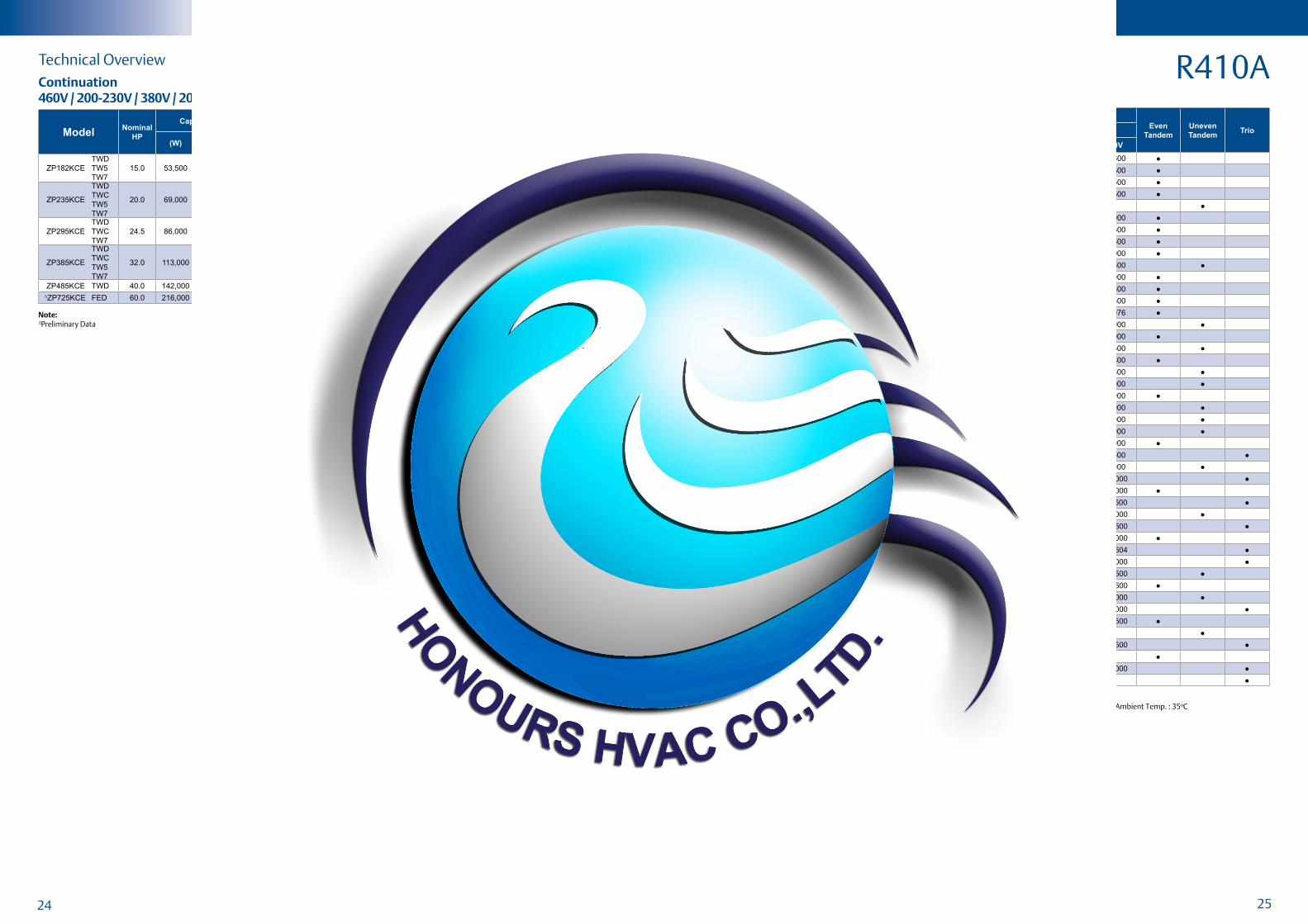
R410ATechnical OverviewContinuation460V / 200-230V / 380V / 208-230V ; 60Hz , 3 Phase
R410A
ModelNominal
HPConiguration
Capacity (W)
Even
Tandem
Uneven
TandemTrio50 Hz / 3 Ph 60 Hz / 3 Ph
380 / 420V 460V 200 / 230V 380V
ZPT100K3E 8.0 ZP50K3E + ZP50K3E 24,500 29,600 29,600 29,600 ●ZPT108K3E 9.0 ZP54K3E + ZP54K3E 25,900 31,500 31,500 31,500 ●ZPT114K3E 9.5 ZP57K3E + ZP57K3E 27,400 33,500 33,500 33,500 ●ZPT122KCE 10.0 ZP61KCE + ZP61KCE 29,000 35,500 35,500 35,500 ●ZPU122KCE 10.0 ZP50K3E + ZP72KCE 29,200 36,000 36,000 - ●ZPT134KCE 11.0 ZP67KCE + ZP67KCE 32,000 39,000 39,000 39,000 ●ZPT144KCE 12.0 ZP72KCE + ZP72KCE 33,500 41,500 41,500 41,500 ●ZPT152KCE 12.5 ZP76KCE + ZP76KCE 36,500 44,500 44,500 44,500 ●ZPT166KCE 14.0 ZP83KCE + ZP83KCE 39,500 48,000 48,000 48,000 ●ZPU174KCE 14.5 ZP83KCE + ZP91KCE 40,500 49,500 49,500 49,500 ●ZPT180KCE 15.0 ZP90KCE + ZP90KCE 43,000 53,000 53,000 53,000 ●ZPT182KCE 15.0 ZP91KCE + ZP91KCE 43,000 52,500 52,500 52,500 ●ZPT206KCE 17.0 ZP103KCE + ZP103KCE 50,000 61,500 61,500 61,500 ●ZPT208KCE 17.0 ZP104KCE + ZP104KCE 50,656 62,076 62,076 62,076 ●ZPU223KCE 18.6 ZP103KCE + ZP120KCE 54,000 66,000 66,000 66,000 ●ZPT240KCE 20.0 ZP120KCE + ZP120KCE 58,000 72,000 72,000 72,000 ●ZPU240KCE 20.0 ZP103KCE + ZP137KCE 57,000 69,500 69,500 69,500 ●ZPT244KCE 20.3 ZP122KCE + ZP122KCE 59,000 72,800 - 71,800 ●ZPU257KCE 21.5 ZP120KCE + ZP137KCE 61,500 74,500 74,500 74,500 ●ZPU272KCE 23.0 ZP90KCE + ZP182KCE 65,500 80,000 80,000 80,000 ●ZPT274KCE 23.0 ZP137KCE + ZP137KCE 64,000 79,000 79,000 79,000 ●ZPU274KCE 23.0 ZP120KCE + ZP154KCE 65,500 80,000 80,000 80,000 ●ZPU285KCE 23.8 ZP103KCE + ZP182KCE 68,500 84,000 84,000 84,000 ●ZPU302KCE 25.2 ZP120KCE + ZP182KCE 72,500 88,000 88,000 88,000 ●ZPT308KCE 25.7 ZP154KCE + ZP154KCE 74,000 90,000 90,000 90,000 ●ZPY309KCE 25.8 ZP103KCE + ZP103KCE + ZP103KCE 75,500 91,500 91,500 91,500 ●ZPU336KCE 28.0 ZP154KCE + ZP182KCE 80,500 98,000 98,000 98,000 ●ZPY360KCE 30.0 ZP120KCE + ZP20KCE + ZP120KCE 87,000 106,000 106,000 106,000 ●ZPT364KCE 30.0 ZP182KCE + ZP182KCE 86,500 106,000 106,000 106,000 ●ZPY411KCE 34.5 ZP137KCE + ZP137KCE + ZP137KCE 97,500 118,500 118,500 118,500 ●ZPU417KCE 35.0 ZP182KCE + ZP235KCE 100,500 122,000 122,000 122,000 ●ZPY462KCE 38.5 ZP154KCE + ZP154KCE + ZP154KCE 111,000 135,500 135,500 135,500 ●ZPT470KCE 40.0 ZP235KCE + ZP235KCE 112,500 136,000 136,000 136,000 ●ZPY532KCE 44.0 ZP236KCE + ZP296KCE 128,251 154,604 154,604 154,604 ●ZPY546KCE 45.5 ZP182KCE + ZP182KCE + ZP182KCE 130,500 159,000 159,000 159,000 ●ZPU567KCE 47.0 ZP182KCE + ZP385KCE 135,000 165,500 165,500 165,500 ●ZPT590KCE 50.0 ZP295KCE + ZP295KCE 142,500 171,500 171,500 171,500 ●ZPU680KCE 56.5 ZP295KCE + ZP385KCE 163,000 198,000 198,000 198,000 ●ZPY705KCE 59.0 ZP235KCE + ZP235KCE + ZP235KCE 170,000 205,000 205,000 205,000 ●ZPT770KCE 64.0 ZP385KCE + ZP385KCE 183,000 222,500 222,500 222,500 ●ZPU870KCE 72.5 ZP385KCE + ZP485KCE 210,000 251,000 - - ●ZPY885KCE 74.0 ZP295KCE + ZP295KCE + ZP295KCE 213,000 256,500 256,500 256,500 ●ZPT970KCE 81.0 ZP485KCE + ZP485KCE 233,500 278,500 - - ●ZPY115MCE 95.8 ZP385KCE + ZP385KCE + ZP385KCE 275,500 336,000 336,000 336,000 ●ZPY145MCE 120.8 ZP485KCE + ZP485KCE + ZP485KCE 347,000 417,500 - - ●
Tandem and Trio Model Availability
Notes:All Values As Per AHRI Standards : Evaporating Temp. : 7.2oC , Condensing Temp. : 54.4oC , Subcooling : 8.3K, Superheat : 11.1K , Ambient Temp. : 35oCTandem /Trio assemblies by system manufacturers. Contact Application Engineering for more information.
Note:∆Preliminary Data
Maximum Allowable Pressure (PS)
• Digital ZRD36 to ZRD81:
Low Side PS 20bar(g) / High Side PS 29.5 bar(g)
• Digital ZRD94 to ZRD125:
Low Side PS 20bar(g) / High Side PS 32 bar(g)
• Digital ZPD34 to ZPD91:
Low Side PS 28 bar(g) / High Side PS 43 bar(g)
Features and Beneits
• Wide modulation range from 10% to 100% for immediate load adjustment, precise temperature
control and optimal comfort
• Energy eficient operation at part load conditions• Copeland Scroll axial and radial compliance offers
high reliability • Fewer starts/stops• Constant speed operation means simpler system
oil return management• Easy to install, commission and maintain - simple
system architecture, no complicated electronics and no EMI/EMC problems
Copeland Scroll™ Digital Compressors for R22, R407C and R410A refrigerant
Copeland Scroll™ Digital Compressors offer stepless capacity modulation in air conditioning applications and a lexible solution for R22, R407C and R410A refrigerant.
In many cooling and heating systems, load and operating conditions vary over a wide range, thus, requiring the use of capacity modulation. The Digital Scroll™ is a simple compressor solution able to assure stepless modulation down to 10% of the nominal capacity allowing for precise temperature and humidity control, superior comfort and energy saving.
This compressor range is the preferred choice for VRF, rooftop, chilled water and process cooling applications.
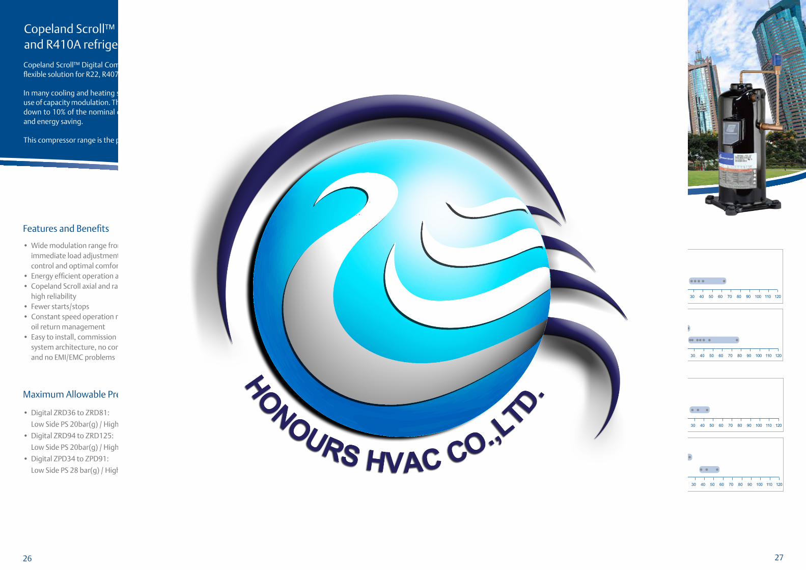
Compressor Line-up
0 20 40 60 80 100 12011010 30 50 70 90
R22/R407C50 Hz
60 Hz
0 20 40 60 80 100 12011010 30 50 70 90
Single Phase
Single Phase
Three Phase
Three Phase
kW Cooling
kW Cooling
Tandem
Tandem
R410A50 Hz
60 Hz
0 20 40 60 80 100 12011010 30 50 70 90
0 20 40 60 80 100 12011010 30 50 70 90
Single Phase
Single Phase
Three Phase
Three Phase
Tandem
Tandem
kW Cooling
kW Cooling
Operating Envelopes
R22, R407C and R410A
Evaporating Temperature °C
Co
nd
en
sin
g T
em
pe
ratu
re °
C
-30-35 -25 -20 -15 -10
5
10
15
20
25
30
35
40
45
50
55
60
65
70
75
0 5-5 10 15 20-400
ZRD36 to ZRD81KC/KCE ; ZPD34 to ZPD54K5E and ZPD61 to ZPD91KCE
The concept of cycle time
The modulation mechanism of a Copeland Digital Scroll compressor
Eficiency
Low Life Cycle Cost
ReliabilityCompressor in loaded state operates as a standard
scroll and delivers full capacity and mass low. During the unloaded state, however, the system delivers no capacity and no mass lows through.
Varying the ‘loaded state’ and the ‘unloaded state’ times, any capacity between 10% and 100% can be delivered by the compressor.
26 27
28 29
ModelNominal
HP
Capacity Input
Power
(W)
Current
(A)
COP
(W/W)
EER
(Btu/Wh)
Displacement
(cc/ Rev.)
Oil
Quantity
(I)
Net
Weight
(kg)
LRA
(A)
Sound Pressure @ 1 m (dBA)(W) (Btu/h)
ZRD36KC PFV 3.0 10,550 36,000 3,300 14.5 3.19 10.9 48.0 1.24 30.2 95.0 62.0
ZRD48KC PFV 4.0 14,550 49,700 4,320 19.5 3.37 11.5 65.6 1.48 33.5 137.0 62.0
ZRD49KC PFV 4.0 14,550 49,600 4,550 20.8 3.19 10.9 67.1 1.89 42.6 129.0 63.0
ZRD61KC PFV 5.0 18,200 62,000 5,650 26.1 3.19 10.9 82.6 1.89 38.1 148.0 66.0
R22 R22Technical Overview Tandem and Trio Model Availability
460V / 200-230V / 380V ; 60Hz , 3 Phase
ModelNominal
HP
Capacity Input
Power
(W)
Current
(A)
COP
(W/W)
EER
(Btu/Wh)
Displacement
(cc/ Rev.)
Oil
Quantity
(I)
Net
Weight
(kg)
LRA
(A)
Sound Pressure @ 1 m (dBA)(W) (Btu/h)
ZRD42KC PFJ 3.5 10,300 35,100 3,200 15.3 3.22 11.0 57.2 1.24 31.2 97.0 60.0
ZRD48KC PFZ 4.0 11,950 40,800 3,630 16.7 3.28 11.2 65.6 1.36 32.8 125.0 57.0
ZRD61KC PFZ 5.0 14,950 51,000 4,640 22.5 3.22 11.0 82.6 1.89 38.1 150.0 63.0
∆ZRD68KC PFZ 6.0 16,700 57,000 5,150 23.9 3.22 11.0 93.0 2.01 39.0 142.0 63.0
ModelNominal
HP
Capacity Input Power
(W)
Current (A)
COP(W/W)
EER(Btu/Wh)
Displacement (cc/ Rev.)
Oil Quantity
(I)
NetWeight
(kg)
LRA(A)
Sound Pressure @ 1 m (dBA)(W) (Btu/h)
ZRD42KC TFD 3.5 10,400 35,500 3,080 5.4 3.37 11.5 57.2 1.24 31.2 46.0 60.0
ZRD48KC TFD 4.0 11,950 40,800 3,510 6.1 3.40 11.6 65.6 1.36 32.7 48.0 64.0
ZRD49KC TFD 4.0 12,050 41,100 3,660 7.1 3.28 11.2 67.1 1.89 42.6 51.5 -
ZRD61KC TFD 5.0 14,950 51,000 4,550 8.1 3.28 11.2 82.6 1.89 38.1 64.0 67.0
ZRD68KC TFD 6.0 17,100 58,500 5,100 8.9 3.37 11.5 93.0 1.89 40.2 74.0 63.0
ZRD72KC TFD 6.0 17,600 60,200 5,330 9.6 3.31 11.3 98.1 1.89 39.9 74.0 60.0
ZRD81KC TFD 7.0 19,900 68,000 6,000 11.1 3.31 11.3 107.8 1.89 40.8 100.0 67.0
ModelNominal
HP
Capacity Input
Power(W)
Current (A)
COP(W/W)
EER(Btu/Wh)
Displacement (cc/ Rev.)
Oil Quantity
(I)
NetWeight
(kg)
LRA(A)
Sound Pressure @
1 m (dBA)(W) (Btu/h)
ZRD36KC TF5 3.0 10,600 36,200 3,120 9.3 3.40 11.6 48.0 1.24 30.2 77.0 62.0
ZRD42KC TFD 3.5 12,750 43,500 3,770 5.5 3.37 11.5 57.2 1.24 31.2 44.0 62.0
ZRD48KC
TFD
TF5
TF7
4.0
14,600
14,600
14,450
49,800
49,800
49,300
4,330
4,220
4,320
6.2
12.1
7.6
3.37
3.46
3.34
11.5
11.8
11.4
65.6 1.36 32.7
46.0
110.0
54.0
65.0
ZRD49KC
TFD
TF5
TF7
4.0 14,550 49,600 4,460
6.5
13.0
7.9
3.25 11.1 67.1 1.89 42.6
47.5
115.0
57.0
61.0
63.0
61.0
ZRD61KC
TFD
TF5
TF7
5.0 18,000 61,500
5,450
5,450
5,550
8.0
16.0
9.5
3.31
3.31
3.25
11.3
11.3
11.1
82.6 1.89 38.1
62.0
137.0
64.0
67.0
ZRD68KC TFD 6.0 20,800 71,000 6,150 8.9 3.37 11.5 93.0 1.89 40.2 75.0 67.0
ZRD72KC
TFD
TF5
TF7
6.0 21,400 72,900 6,460
9.3
18.6
11.3
3.31 11.3 98.1 1.89
39.9
39.9
39.5
70.0
156.0
70.0
63.0
ZRD81KCTFD
TF77.0 23,700 81,500
7,500
7,400
11.7
12.43.19 10.9 107.8 1.89 40.8
100.0
78.067.0
ModelNominal
HPConiguration
Capacity (W)
Even
Tandem
Uneven
TandemTrio50 Hz / 3 Ph 60 Hz / 3 Ph
380 / 420V 460V 200 / 230V 380V
ZRDT96KC 8.0 ZRD48KC + ZR48KC - 28,400 - 28,400 ●ZRDU11MC 9.2 ZRD61KC + ZR54KC 28,000 34,000 34,000 34,000 ●ZRDT12MC 10.0 ZRD61KC + ZR61KC 29,000 36,000 36,000 36,000 ●ZRDU13MC 11.0 ZRD72KC + ZR61KC 32,000 38,500 38,500 38,500 ●ZRDT14MC 11.5 ZRD72KC + ZR72KC 35,000 42,000 42,000 42,000 ●ZRDT16MC 13.5 ZRD81KC + ZR81KC 39,500 47,000 - 47,000 ●ZRDT25MC 21.0 ZRD125KC + ZR125KC 62,000 74,500 74,000 - ●
208-230V ; 60Hz , 1 Phase
220-240V ; 50Hz , 1 Phase
380-420V ; 50Hz , 3 Phase
Notes:All Values As Per AHRI Standards : Evaporating Temp. : 7.2oC , Condensing Temp. : 54.4oC , Subcooling : 8.3K , Superheat : 11.1K , Ambient Temp. : 35oCTandem/Trio assemblies by system manufacturers. Contact Application Engineering for more information.Tandem ready compressors provide lexibility to design different module size for VRF applications.
Note:∆Preliminary Data
30 31
Technical Overview Tandem and Trio Model Availability
ModelNominal
HP
Capacity Input Power
(W)
Current(A)
COP(W/W)
EER(Btu/Wh)
Displacement (cc/ Rev.)
Oil Quantity
(I)
NetWeight
(kg)
LRA(A)
Sound Pressure @ 1 m (dBA)(W) (Btu/h)
ZRD36KCE TFD 3.0 8,450 28,800 2,610 4.6 3.24 11.1 48.0 1.24 27.3 38.0 62.0
ZRD42KCE TFD 3.5 10,000 34,100 3,130 5.6 3.19 10.9 57.2 1.24 31.2 46.0 60.0
ZRD48KCE TFD 4.0 12,050 41,200 3,780 6.6 3.19 10.9 65.6 1.36 32.7 48.0 64.0
ZRD49KCE TFD 4.0 11,200 38,300 3,700 6.9 3.05 10.4 67.1 1.89 42.6 51.5 61.0
ZRD61KCE TFD 5.0 14,150 48,300 4,610 8.1 3.08 10.5 82.6 1.89 38.1 64.0 65.0
ZRD68KCE TFD 6.0 15,700 53,500 5,200 9.2 3.02 10.3 93.0 1.89 40.2 74.0 63.0
ZRD72KCE TFD 6.0 16,900 57,500 5,350 9.3 3.14 10.7 98.1 1.89 39.9 74.0 63.0
ZRD81KCE TFD 7.0 20,100 68,500 6,450 12.0 3.11 10.6 107.8 1.89 40.8 100.0 67.0
ModelNominal
HP
Capacity Input
Power
(W)
Current
(A)
COP
(W/W)
EER
(Btu/Wh)
Displacement
(cc/ Rev.)
Oil
Quantity
(I)
Net
Weight
(kg)
LRA
(A)
Sound Pressure @ 1 m (dBA)(W) (Btu/h)
ZRD42KCE PFJ 3.5 10,350 35,400 3,430 16.4 3.02 10.3 57.2 1.24 31.2 97.0 60.0
ZRD48KCE PFZ 4.0 11,250 38,400 3,690 17.1 3.05 10.4 65.6 1.36 32.8 125.0 57.0
ZRD61KCE PFZ 5.0 14,200 48,500 4,750 22.2 2.99 10.2 82.6 1.89 38.1 150.0 63.0
ModelNominal
HP
Capacity Input
Power
(W)
Current
(A)
COP
(W/W)
EER
(Btu/Wh)
Displacement
(cc/ Rev.)
Oil
Quantity
(I)
Net
Weight
(kg)
LRA
(A)
Sound Pressure @ 1 m (dBA)(W) (Btu/h)
ZRD36KCE PFV 3.0 10,650 36,400 3,550 15.6 3.02 10.3 48.0 1.24 30.2 95.0 62.0
ZRD48KCE PFV 4.0 14,650 50,000 4,640 21.0 3.17 10.8 65.6 1.48 33.5 137.0 62.0
ZRD61KCE PFV 5.0 16,900 57,500 5,700 25.9 2.96 10.1 82.6 1.89 38.1 148.0 66.0
ModelNominal
HP
Capacity Input Power
(W)
Current (A)
COP(W/W)
EER(Btu/Wh)
Displacement (cc/ Rev.)
Oil Quantity
(I)
NetWeight
(kg)
LRA(A)
Sound Pressure @ 1 m (dBA)(W) (Btu/h)
ZRD36KCE
TFD
TF5
TF7
3.0
-
10,750
10,150
-
36,700
34,700
-
3,350
3,150
-
10.0
5.5
-
3.19
3.22
-
10.9
11.0
48.0 1.24
27.3
30.2
27.2
37.5
77.0
38.0
-
62.0
62.0
ZRD42KCE TFD 3.5 12,200 41,700 3,960 7.0 3.08 10.5 57.2 1.24 31.2 44.0 62.0
ZRD48KCE
TFD
TF5
TF7
4.0
14,050
9,400
14,550
48,000
32,100
49,700
4,400
3,160
4,640
6.4
9.7
8.1
3.19
2.99
3.14
10.9
10.2
10.7
65.6 1.36 32.7
46.0
110.0
54.0
65.0
ZRD49KCE TFD 4.0 13,550 46,200 4,540 6.7 2.99 10.2 67.1 1.89 42.6 47.5 61.0
ZRD61KCE
TFD
TF5
TF7
5.0 17,400 59,500 5,740
8.5
16.9
10.3
3.05 10.4 82.6 1.89 38.1
62.0
137.0
64.0
63.0
ZRD68KCE TFD 6.0 19,500 66,500 6,250 9.1 3.11 10.6 93.0 1.89 40.2 75.0 67.0
ZRD72KCE
TFD
TF5
TF7
6.0 20,700 70,500 6,550
9.5
19.0
11.5
3.17 10.8 98.1 1.89
39.9
39.9
39.5
70.0
156.0
70.0
63.0
ZRD81KCETFD
TF77.0
22,900
24,200
78,000
82,500
7,700
7,950
12.2
10.9
2.99
3.05
10.2
10.4107.8 1.89 40.8
100.0
78.067.0
R407CR407C
ModelNominal
HPConiguration
Capacity (W)
Even
Tandem
Uneven
TandemTrio50 Hz / 3 Ph 60 Hz / 3 Ph
380 / 420V 460V 200 / 230V 380V
ZRDT96KCE 8.0 ZRD48KCE + ZR48KCE - 26,200 26,200 26,200 ●ZRDU11MCE 9.20 ZRD61KCE + ZR54KCE - 26,230 - 26,230 ●ZRDT12MCE 10.0 ZRD61KCE + ZR61KCE 28,000 - - - ●ZRDU13MCE 11.0 ZRD72KCE + ZR61KCE - 36,500 36,500 36,500 ●ZRDT14MCE 11.5 ZRD72KCE + ZR72KCE 33,000 40,000 40,000 40,000 ●ZRDT16MCE 13.5 ZRD81KCE + ZR81KCE 40,000 47,500 47,500 47,500 ●208-230V ; 60Hz , 1 Phase
460V / 200-230V / 380V ; 60Hz , 3 Phase
220-240V ; 50Hz , 1 Phase
380-420V ; 50Hz , 3 Phase
Notes:All Values As Per AHRI Standards : Evaporating Temp. : 7.2oC , Condensing Temp. : 54.4oC , Subcooling : 8.3K , Superheat : 11.1K , Ambient Temp. : 35oCTandem/Trio assemblies by system manufacturers. Contact Application Engineering for more information.Tandem ready compressors provide lexibility to design different module size for VRF applications.
32 33
R410A R410ATechnical Overview Technical Overview
Tandem and Trio Model Availability
220-240V ; 50Hz , 1 Phase
208-230V ; 60Hz , 1 Phase
380-420V ; 50Hz , 3 Phase
ModelNominal
HP
Capacity Input
Power
(W)
Current
(A)
COP
(W/W)
EER
(Btu/Wh)
Displacement
(cc/ Rev.)
Oil
Quantity
(I)
Net
Weight
(kg)
LRA
(A)
Sound Pressure @ 1 m (dBA)(W) (Btu/h)
ZPD34K5EPFZ
PFJ3.0 8,200 28,000 2,830 13.6 2.90 9.9 32.8 1.24 30.9 87.0 66.0
ZPD34KSE PFZ 3.0 8,200 28,000 2,830 13.6 2.90 9.9 32.8 1.24 30.9 87.0 66.0
ZPD42K5E PFZ 3.5 10,250 35,000 3,400 16.7 3.02 10.3 39.8 1.24 32.8 128.0 66.0
ZPD42KSE PFZ 3.5 10,250 35,000 3,400 16.7 3.02 10.3 39.8 1.24 32.8 128.0 66.0
ZPD51K5E PFZ 4.5 12,350 42,200 4,100 19.7 3.02 10.3 48.2 1.24 34.8 128.0 66.0
ZPD51KSE PFZ 4.5 12,350 42,200 4,100 19.7 3.02 10.3 48.2 1.24 34.8 128.0 66.0
ZPD54K5E PFZ 4.5 12,900 44,000 4,240 20.2 3.03 10.4 51.1 1.24 34.8 130.0 66.0
ZPD54KSE PFZ 4.5 13,050 44,500 4,320 20.4 3.02 10.3 51.1 1.24 34.8 130.0 59.0
ZPD61KCE PFZ 5.0 14,800 50,500 5,000 23.2 2.96 10.1 58.1 1.89 45.2 147.0 63.0
ZPD67KCE PFZ 5.5 16,000 54,500 5,400 25.7 2.96 10.1 63.0 1.89 45.3 155.0 63.0
ModelNominal
HP
Capacity Input
Power
(W)
Current
(A)
COP
(W/W)
EER
(Btu/Wh)
Displacement
(cc/ Rev.)
Oil
Quantity
(I)
Net
Weight
(kg)
LRA
(A)
Sound Pressure @ 1 m (dBA)(W) (Btu/h)
ZPD34K5E PFV 3.0 10,100 34,500 3,380 15.5 2.99 10.2 32.8 1.24 30.9 112.0 66.0
ZPD42K5E PFV 3.5 12,300 42,000 4,090 17.8 3.02 10.3 39.8 1.24 32.8 117.0 66.0
ZPD51K5E PFV 4.5 15,100 51,500 4,910 21.5 3.08 10.5 48.2 1.24 34.8 134.0 66.0
ZPD54K5E PFV 4.5 15,800 54,000 5,140 22.5 3.08 10.5 51.1 1.24 34.8 134.0 66.0
ModelNominal
HP
Capacity Input Power
(W)
Current (A)
COP(W/W)
EER(Btu/Wh)
Displacement (cc/ Rev.)
Oil Quantity
(I)
NetWeight
(kg)
LRA(A)
Sound Pressure @ 1 m (dBA)(W) (Btu/h)
ZPD34K5E TFD 3.0 8,200 28,000 2,830 5.1 2.90 9.9 32.8 1.24 30.9 46.0 66.0
ZPD42K5E TFD 3.5 10,300 35,200 3,350 5.7 3.08 10.5 39.8 1.24 32.8 52.0 66.0
ZPD51K5E TFD 4.5 12,350 42,100 4,040 6.8 3.05 10.4 48.2 1.24 33.0 52.0 66.0
ZPD54K5E TFD 4.5 13,200 45,100 4,280 7.5 3.08 10.5 51.1 1.24 34.8 62.0 67.0
ZPD61KCE TFD 5.0 14,800 50,500 4,930 8.5 3.02 10.3 58.1 1.89 40.3 64.0 64.0
ZPD67KCE TFD 5.5 16,200 55,200 5,260 9.3 3.08 10.5 63.0 1.89 45.3 74.0 67.0
ZPD72KCE TFD 6.0 17,100 58,500 5,750 9.8 2.99 10.2 67.1 1.89 40.9 75.0 67.0
ZPD83KCE TFD 7.0 20,000 68,100 6,630 12.0 3.02 10.3 77.2 1.77 40.8 101.0 66.0
ZPD91KCE TFD 7.5 21,600 73,800 6,900 12.5 3.14 10.7 84.6 1.77 41.5 101.0 69.0
∆ZPD104KCE TFD 9.0 25,600 87,500 8,100 14.6 3.15 10.8 96.4 2.51 48.8 128.0 77.0
∆ZPD122KCE TFD 10.0 29,900 102,000 9,450 17.2 3.15 10.8 112.3 2.51 48.8 139.0 77.0
460V / 200-230V / 380V ; 60Hz , 3 Phase
ModelNominal
HP
Capacity Input
Power
(W)
Current
(A)
COP
(W/W)
EER
(Btu/Wh)
Displacement
(cc/ Rev.)
Oil
Quantity
(I)
Net
Weight
(kg)
LRA
(A)
Sound Pressure @ 1 m (dBA)(W) (Btu/h)
ZPD34K5E
TFD
TF5
TF7
3.0 10,150 34,600 3,390
5.2
10.2
6.2
2.99 10.2 32.8 1.24 30.9
44.0
88.0
52.7
66.0
ZPD42K5E
TFD
TF5
TF7
3.5
12,500
12,600
12,500
42,600
43,000
42,700
3,980
4,020
4,040
5.7
12.1
7.4
3.14
3.14
3.11
10.7
10.7
10.6
39.8 1.24 32.8
52.0
110.0
65.6
66.0
66.0
67.0
ZPD51K5E
TFD
TF5
TF7
4.5
14,950
15,100
14,750
51,000
51,400
50,400
4,790
4,810
4,710
6.9
13.8
8.5
3.11
3.14
3.14
10.6
10.7
10.7
48.2 1.24
33.0
34.8
34.8
52.0
110.0
65.6
66.0
66.0
67.0
ZPD54K5E
TFD
TF5
TF7
4.5 16,000
54,500
54,600
54,500
5,080
5,060
5,140
7.6
14.5
9.0
3.14
3.17
3.11
10.7
10.8
10.6
51.1 1.24 34.8
62.0
110.0
65.6
67.0
67.0
66.0
ZPD61KCE
TFD
TF5
TF7
5.0
18,200
18,500
18,000
62,000
63,000
61,500
5,900
5,800
5,850
8.6
17.0
10.1
3.08
3.19
3.08
10.5
10.9
10.5
58.1 1.89 40.3
62.0
156.0
64.0
64.0
64.0
65.0
ZPD67KCE TFD 5.5 19,800 67,700 6,320 8.5 3.14 10.7 63.0 1.89 45.3 75.0 64.0
ZPD72KCE
TFD
TF5
TF7
6.0
21,000
21,100
20,800
71,500
72,000
71,000
6,800
6,850
6,900
9.8
20.4
11.6
3.08
3.08
2.99
10.5
10.5
10.2
67.1 1.89 40.9
75.0
164.0
73.0
67.0
ZPD83KCE
TFD
TF5
TF7
7.0
24,400
24,200
24,200
83,100
82,500
82,500
7,980
7,850
7,850
12.3
23.0
13.2
3.05
3.08
3.08
10.4
10.5
10.5
77.2 1.77 40.8
100.0
186.6
94.3
67.0
ZPD91KCE
TFD
TF5
TF7
7.5 26,400 90,100
8,300
8,270
8,270
12.8
25.3
15.2
3.18
3.19
3.19
10.9 84.6 1.77 41.5
100.0
191.0
123.0
70.0
∆ZPD104KCETFD
TF79.0 31,000 106,000
9,750
9,770
14.7
16.63.18 10.9 96.4 2.51 48.8
130.0
135.080.0
∆ZPD122KCETFD
TF710.0 36,500 124,000 11,400
17.3
19.43.18 10.9 112.3 2.51 48.8
140.0
152.080.0
Notes:∆Preliminary DataAll Values As Per AHRI Standards : Evaporating Temp. : 7.2oC , Condensing Temp. : 54.4oC , Subcooling : 8.3K , Superheat : 11.1K , Ambient Temp. : 35oCTandem/Trio assemblies by system manufacturers. Contact Application Engineering for more information.Tandem ready compressors provide lexibility to design different module size for VRF applications.
ModelNominal
HPConiguration
Capacity (W)
Even Tandem
Uneven Tandem
Trio50 Hz / 3 Ph 60 Hz / 3 Ph
380 / 420V 460V 200 / 230V 380V
ZPDT12MCE 10.0 ZPD61KCE + ZP61KCE 29,300 36,000 36,000 - ●ZPDT14MCE 11.5 ZPD72KCE + ZP72KCE 34,000 42,000 42,000 42,000 ●ZPDT18MCE 13.5 ZPD91KCE + ZP91KCE 43,000 52,500 52,500 52,500 ●
Note:∆Preliminary Data
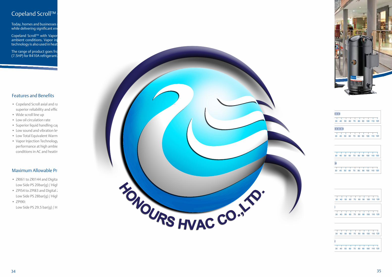
Evaporating Temperature °C
Co
nd
en
sin
g T
em
pe
ratu
re °
C
-30-35 -25 -20 -15 -10
5
10
15
20
25
30
35
40
45
50
55
60
65
70
75
0 5-5 10 15 20
ZRI61KC
ZRI94 to ZRI144KC
ZPI54 to ZPI83KCE
ZPI90KCE
-400
Copeland Scroll™ Compressors With Vapor Injection Technology
Today, homes and businesses need air conditioning system that can provide suficient cooling or heating capacity while delivering signiicant energy savings in whole operating range.
Copeland ScrollTM with Vapor injection allows air conditioning systems to deliver better performance at high ambient conditions. Vapor injection improves the cooling capacity of air conditioning systems up to 12%. This technology is also used in heating systems to improve the heating capacity up to 30% at lower ambient conditions.
The range of product goes from ZRI61 (5.1HP) to ZRI144 (12HP) for R22 refrigerant and ZPI54 (4.5HP) to ZPI90 (7.5HP) for R410A refrigerant.
Maximum Allowable Pressure (PS)
• ZRI61 to ZRI144 and Digital ZRJ61 to ZRJ72:
Low Side PS 20bar(g) / High Side PS 27.5 bar(g)
• ZPI54 to ZPI83 and Digital ZPJ61 to ZPJ83:
Low Side PS 28bar(g) / High Side PS 43 bar(g)
• ZPI90:
Low Side PS 29.5 bar(g) / High Side PS 45 bar(g)
Compressor Line-upThe Concept of Vapor Injection
R22 and R410A
Operating Envelopes
Vapor injection increases system capacity by delivering low temperature liquid refrigerant to the expansion device of the main evaporator. The main liquid line is cooled by taking part of liquid low and expanding it through the evaporator side of an economizer or subcooler. Vapor from the economizer is fed to the intermediate pockets of the scroll where it is added to the low that has been taken into the suction from the main evaporator. Compression of injected vapor is a more eficient process since the temperature lift from saturated injection to saturated discharge temperature is less than from saturated suction to saturated discharge. The COP of a vapor injected system can therefore be improved while maintaining capacity if the compressor displacement is reduced.
The vapor injection path
Vapor
Injection
Line
Vapor is injected via the vapor injection line into the compressor
110 120
110 120
R22
R22
50 Hz
50 Hz
60 Hz
60 Hz
0
0
20
20
40
40
60
60
80
80
100
100
110 120
110 120
10
10
30
30
50
50
70
70
90
90
0
0
20
20
40
40
60
60
80
80
100
100
10
10
30
30
50
50
70
70
90
90
Three Phase
Three Phase
Three Phase
Three Phase
kW Cooling
kW Cooling
kW Cooling
kW Cooling
R410A
R410A
50 Hz
50 Hz
60 Hz
60 Hz
0
0
20
20
40
40
60
60
80
80
100
100
10
10
30
30
50
50
70
70
90
90
0
0
20
20
40
40
60
60
80
80
100
100
10
10
30
30
50
50
70
70
90
90
Three Phase
Three Phase
Three Phase
Three Phase
kW Cooling
kW Cooling
kW Cooling
kW Cooling
110 120
110 120
110 120
110 120
Digital
Fixed Speed
Features and Beneits
• Copeland Scroll axial and radial compliance for superior reliability and eficiency
• Wide scroll line up• Low oil circulation rate• Superior liquid handling capability• Low sound and vibration level• Low Total Equivalent Warming Impact• Vapor Injection Technology allows better system
performance at high ambient/lower ambient conditions in AC and heating applications
Eficiency
Low Life Cycle Cost
Reliability
34 35

36 37
ModelNominal
HP
Capacity Input Power
(W)
Current (A)
COP(W/W)
EER(Btu/Wh)
Displacement (cc/ Rev.)
Oil Quantity
(I)
NetWeight
(kg)
LRA(A)
Sound Pressure @ 1 m (dBA)(W) (Btu/h)
ZPJ61KCE TFD 5.1 14,950 51,000 4,900 8.6 3.05 10.4 58.1 1.89 40.3 75.0 63.0
ZPJ72KCE TFD 6.0 17,100 58,500 5,700 10.8 3.02 10.3 67.1 1.89 40.9 101.0 67.0
ZPJ83KCE TFD 6.9 19,800 67,700 6,600 11.8 3.00 10.3 77.2 1.77 40.8 101.0 64.0
ModelNominal
HP
Capacity Input
Power(W)
Current
(A)
COP
(W/W)
EER
(Btu/Wh)
Displacement
(cc/ Rev.)
Oil Quantity
(I)
NetWeight
(kg)
LRA
(A)
Sound Pressure @ 1 m (dBA)(W) (Btu/h)
ZPJ61KCE
TFD
TF5
TF7
5.1
18,300
18,500
18,100
62,400
63,000
61,900
5,900
5,840
5,900
8.7
18.2
10.1
3.11
3.17
3.08
10.6
10.8
10.5
58.1 1.89 40.3
75.0
164.0
75.0
64.0
64.0
65.0
ZPJ72KCE
TFD
TF5
TF7
6.0
21,100
21,100
20,800
71,900
71,900
70,900
6,920
6,940
6,910
9.8
21.0
11.6
3.05
3.03
3.00
10.4
10.4
10.3
67.1 1.89 40.9
100.0
186.6
100.0
67.0
ZPJ83KCE
TFD
TF5
TF7
6.9
24,400
24,300
23,900
83,400
82,800
81,500
8,060
7,910
7,910
12.3
24.1
13.2
3.03
3.06
3.02
10.4
10.5
10.3
77.2 1.77 40.8
100.0
191.0
94.3
67.0
Note: All Values As Per AHRI Standards : Evaporating Temp. : 7.2oC , Condensing Temp. : 54.4oC , Subcooling : 8.3K , Superheat : 11.1K , Ambient Temp. : 35oC
380-420V ; 50Hz , 3 Phase
380-420V ; 50Hz , 3 Phase
460V / 200-230V / 380V ; 60Hz , 3 Phase
ModelNominal
HP
Capacity Input
Power
(W)
Current
(A)
COP
(W/W)
EER
(Btu/Wh)
Displacement
(cc/ Rev.)
Oil
Quantity
(I)
Net
Weight
(kg)
LRA
(A)
Sound Pressure @ 1 m (dBA)(W) (Btu/h)
ZRI61KC TFD 5.1 14,950 51,000 4,580 8.1 3.25 11.1 98.1 1.89 40.2 64.0 67.0
ZRI94KC TFD 7.8 23,300 79,500 6,850 12.7 3.40 11.6 127.2 2.54 57.2 95.0 62.0
ZRI108KC TFD 9.0 26,400 90,000 7,600 13.8 3.47 11.9 142.9 3.25 59.9 111.0 63.0
ZRI125KC TFD 10.4 31,000 105,500 8,900 15.8 3.47 11.9 167.2 3.25 61.2 118.0 64.0
ZRI144KC TFD 12.0 35,000 120,000 10,100 18.5 3.47 11.9 190.9 3.25 61.2 140.0 65.0
ModelNominal
HP
Capacity Input Power
(W)
Current(A)
COP(W/W)
EER(Btu/Wh)
Displacement (cc/ Rev.)
Oil Quantity
(I)
NetWeight
(kg)
LRA (A)
Sound Pressure @ 1 m (dBA)(W) (Btu/h)
∆ZPI54KCE TFD 4.5 13,350 45,600 4,330 7.9 3.08 10.5 58.1 1.89 40.3 75.0 67.0
ZPI61KCE TFD 5.1 14,950 51,000 4,900 8.6 3.05 10.4 58.1 1.89 40.3 75.0 63.0
ZPI72KCE TFD 6.0 17,100 58,500 5,700 10.8 3.02 10.3 67.1 1.89 40.9 101.0 67.0
ZPI83KCE TFD 6.9 19,800 67,700 6,600 11.8 3.00 10.3 77.2 1.77 39.5 101.0 64.0
∆ZPI90KCE TFD 7.5 21,700 74,000 6,960 12.2 3.11 10.6 84.2 2.51 57.6 95.0 61.0
∆ZPI104KCE TFD 9.0 25,600 87,500 7,950 14.3 3.22 11.0 96.4 2.51 48.8 128.0 74.0
∆ZPI122KCE TFD 10.0 29,900 102,000 9,300 16.9 3.22 11.0 112.3 2.51 48.8 139.0 74.0
ModelNominal
HP
Capacity Input
Power
(W)
Current
(A)
COP
(W/W)
EER
(Btu/Wh)
Displacement
(cc/ Rev.)
Oil
Quantity
(I)
Net
Weight
(kg)
LRA
(A)
Sound Pressure @ 1 m (dBA)(W) (Btu/h)
ZRI61KC TFD 5.1 18,200 62,000 5,500 8.5 3.28 11.2 98.1 1.89 40.2 62.0 67.0
ZRI94KC
TFD
TF5
TF7
7.8
28,000
28,300
28,300
95,400
96,500
96,500
8,220
8,250
8,200
13.1
25.3
15.1
3.40
3.43
3.46
11.6
11.7
11.8
127.2 2.51
57.2
56.7
57.2
95.0
195.0
123.0
67.0
ZRI108KC
TFD
TF5
TF7
9.0 32,000
108,500
109,000
108,500
9,160
9,200
9,170
14.3
28.6
17.1
3.47
3.47
3.46
11.9
11.9
11.8
142.9 3.25 59.9
114.0
239.0
140.0
69.0
ZRI125KCTFD
TF710.4 37,500 127,500 10,850
16.8
19.63.43 11.7 167.2 3.25 61.2
125.0
145.069.0
ZRI144KCTFD
TF712.0
43,000
42,500
146,000
145,000
12,300
12,250
18.0
22.43.47 11.9 190.9 3.25 61.2
150.0
145.069.0
Technical Overview Technical Overview
460V / 200-230V / 380V ; 60Hz , 3 Phase
ModelNominal
HP
Capacity Input Power
(W)
Current
(A)
COP
(W/W)
EER
(Btu/Wh)
Displacement
(cc/ Rev.)
Oil Quantity
(I)
Net
Weight
(kg)
LRA(A)
Sound Pressure @
1 m (dBA)(W) (Btu/h)
∆ZPI54KCE TFD 4.5 16,500 56,400 5,220 7.9 3.17 10.8 58.1 1.89 40.3 75.0 67.0
ZPI61KCE
TFD
TF5
TF7
5.1
18,300
18,300
18,100
62,400
62,600
61,900
5,900
5,830
5,900
8.7
18.3
10.1
3.11
3.15
3.08
10.6
10.8
10.5
58.1 1.89 40.3
75.0
164.0
75.0
64.0
64.0
65.0
ZPI72KCE
TFD
TF5
TF7
6.0
21,100
21,400
20,800
71,900
73,100
70,900
6,920
6,920
6,910
9.8
21.0
11.6
3.05
3.09
3.00
10.4
10.6
10.3
67.1 1.89 40.9
100.0
186.6
100.0
67.0
ZPI83KCE
TFD
TF5
TF7
6.9
24,400
24,300
23,900
62,400
82,800
81,500
8,060
7,910
7,910
12.3
24.1
13.2
3.03
3.06
3.02
10.4
10.5
10.3
77.2 1.77
39.5
39.5
39.9
100.0
191.0
94.3
67.0
∆ZPI90KCE TFD 7.5 26,500 90,300 8,430 12.7 3.14 10.7 84.2 2.51 57.6 95.0 66.0
∆ZPI104KCETFD
TF79.0 31,000 106,000 9,550
14.4
16.23.25 11.1 96.4 2.51 48.8
130.0
135.077.0
∆ZPI122KCETFD
TF710.0 36,500 124,000 11,200
16.9
19.13.25 11.1 112.3 2.51 48.8
140.0
152.077.0
R22
R410A
460V / 200-230V / 380V ; 60Hz , 3 Phase
Digital ScrollR22
ModelNominal
HP
Capacity Input
Power
(W)
Current
(A)
COP
(W/W)
EER
(Btu/Wh)
Displacement
(cc/ Rev.)
Oil
Quantity
(I)
Net
Weight
(kg)
LRA
(A)
Sound Pressure @ 1 m (dBA)(W) (Btu/h)
ZRJ61KC TFD 5.1 14,950 51,000 4,590 8.1 3.25 11.1 82.0 1.89 38.9 64.0 67.0
ZRJ72KC TFD 6.0 17,600 60,000 5,450 10.3 3.22 11.0 98.1 1.89 40.2 100.0 63.0
ModelNominal
HP
Capacity Input
Power
(W)
Current
(A)
COP
(W/W)
EER
(Btu/Wh)
Displacement
(cc/ Rev.)
Oil
Quantity
(I)
Net
Weight
(kg)
LRA
(A)
Sound Pressure @ 1 m (dBA)(W) (Btu/h)
ZRJ61KC TFD 5.1 18,000 61,500 5,500 8.5 3.28 11.2 82.0 1.89 38.9 62.0 67.0
ZRJ72KC TFD 6.0 21,400 73,000 6,650 10.5 3.22 11.0 98.1 1.89 40.2 100.0 63.0
380-420V ; 50Hz , 3 Phase
380-420V ; 50Hz , 3 Phase
Digital ScrollR410A
460V / 200-230V / 380V ; 60Hz , 3 Phase
Note:∆Preliminary Data Preliminary Data only for TF5 and TF7 Preliminary Data only for TF7
○
○
□
□
○□
Copeland Scroll™ Compressors for Heat Pump Water Heating
The Copeland Scroll™ ZW compressor provides energy eficient alternative for hot water heating and space heating to replace the use of electric heaters or fuel-ired boilers.
The combination of vapor injection technology and special scroll design enables the air source heat pump to operate at -20°C ambient condition. Compared to its predecessors, ZW provides 40% higher capacity and 22% higher COP at the same ambient condition.
The ZW compressor shows its commitment in promoting green technology by utilizing low GWP refrigerants, thereby directly and indirectly reducing CO
2 emissions.
Maximum Allowable Pressure (PS)
• ZW30KS to ZW108KS and ZW30KA to ZW61KA: Low Side PS 20 bar(g) / High Side PS 30 bar(g)• ZW30KSE to ZW108KSE and ZW34KAE to ZW61KAE: Low Side PS 20 bar(g) / High Side PS 32.5 bar(g) • ZW21KAE: Low Side PS 20 bar(g) / High Side PS 29.5 bar(g) • ZW108KA: Low Side PS 20 bar(g) / High Side PS 27.5 bar(g) • ZW108KAE: Low Side PS 20 bar(g) / High Side PS 32 bar(g)
Features and Beneits
• I nnovative Scroll Heating™ Technology• High eficiency water heating solution• 70% lower energy cost than traditional electric
heater and boiler• Whole season operation design: -20oC to about
43oC ambient temperature
• Water temperature up to 65oC
• 40% more heating capacity than traditional heat
pump technology
Compressor Line-up
0 20 40 60 80 100 12011010 30 50 70 90
R22/R407C50 Hz
60 Hz
0 20 40 60 80 100 12011010 30 50 70 90
Single Phase
Three Phase
Three Phase
kW Cooling
kW Cooling
R134a50 Hz
0 20 40 60 80 100 12011010 30 50 70 90
Single Phase
kW Cooling
R22, R407C and R134a
Operating Envelopes
Note: Wave Lines Correspond To Models In Transition Only
Evaporating Temperature °C
Co
nd
en
sin
g T
em
pe
ratu
re °
C
-30-35 -25 -20 -15 -10
5
10
15
20
25
30
35
40
45
50
55
60
65
70
75
0 5-5 10 15 20-400
ZW108KS/KSE
ZW30 to ZW61KS/KSE
ZW21KAE (R134a)
ZW30 to ZW61KA/KAE
Eficiency
Low Life Cycle Cost
Reliability
Copeland Scroll Compressors for Heat Pump Water Heating
The Copeland Scroll ZW is designed over Emerson Climate Technologies’ strong experience of 100 million scroll compressors and is recognized as a reliable and eficient product. On this strong base, ZW applies Scroll Heating™ technology and multiple new product design features. ZW scrolls hold additional new patent on its design.
Scroll Heating technology reliably expands the HPWH capability all the way to -20oC ambient. It also improves heating capacity by around 40% and COP by 22%.
Copeland Scroll’s eficiency is primarily derived from its axial compliance design. The axial compliance design is a pressure balanced mechanism to axially load the scroll elements–providing optimum scroll tip load and ensuring excellent tip sealing. ZW scrolls are required to operate on a much wider range of envelope compared to standard heat pump air-conditioners. This has been accomplished by a new axial compliance pressure balance combination designed speciically for ZW scrolls. It also applies highly eficient and high power motor which can cater to the extremes required by HPWH; to generate low internal losses at mild ambient cold tank heating and provide adequate power demanded at high ambient tank reheating. ZW is designed with options for R22 and HFC refrigerants R407C and R134a.
When it comes to eficiency and reliability in residential and commercial water heating applications, Copeland Scroll compressors continue to set the standard. HPWH
powered by Copeland Scroll ZW compressors is a new technology in residential and commercial water heating, thereby replacing traditional water heating systems.
The Copeland Scroll ZW compressor offers additional beneits, including more energy savings and higher water temperature, in comparison to standard scroll technology. Its unique scroll and axial compliance design is conigured for higher compression ratio and higher differential pressure. And because these compressors “wear in” over time instead of wearing out, industry experts can count on years of dependable performance, even under the most stringent water heating requirements. With all these beneits, the Copeland Scroll ZW compressor is deinitely the most reliable solution available on the HPWH market.
38 39
40 41
Technical Overview
220V ; 50Hz , 1 Phase
380V ; 50Hz , 3 Phase
380V ; 60Hz , 3 Phase
R22
ModelNominal
HP
Capacity Input
Power
(W)
Current
(A)
COP
(W/W)
EER
(Btu/Wh)
Displacement
(cc/ Rev.)
Oil
Quantity
(I)
Net
Weight
(kg)
LRA
(A)
Sound
Pressure @
1 m (dBA)(W) (Btu/h)
ZW30KS PFS 2.5 10,100 34,500 2,520 11.5 4.02 13.7 41.0 0.74 22.2 58.4 57.0
ModelNominal
HP
Capacity Input
Power
(W)
Current
(A)
COP
(W/W)
EER
(Btu/Wh)
Displacement
(cc/ Rev.)
Oil
Quantity
(I)
Net
Weight
(kg)
LRA
(A)
Sound Pressure @ 1 m (dBA)(W) (Btu/h)
ZW34KS TFP 2.8 11,150 38,100 2,820 5.0 3.97 13.6 46.2 0.74 22.2 31.6 57.0
ZW61KS TFP 5.1 20,300 69,100 4,950 8.5 4.09 14.0 82.6 1.36 29.9 59.0 65.0
ZW108KS TFP 9.0 36,000 123,500 8,300 16.1 4.35 14.9 142.9 3.25 59.9 133.0 63.0
ModelNominal
HP
Capacity Input
Power(W)
Current (A)
COP(W/W)
EER(Btu/Wh)
Displacement (cc/ Rev.)
Oil
Quantity(I)
Net
Weight(kg)
LRA(A)
Sound Pressure @ 1 m (dBA)(W) (Btu/h)
ZW34KS TF7 2.8 13,450 45,900 3,370 6.0 4.00 13.7 46.2 0.74 22.2 50.0 57.0
ZW108KS TF7 9.0 43,000 147,000 10,050 18.5 4.31 14.7 142.9 3.25 59.9 147.0 69.0
Technical Overview
220V ; 50Hz , 1 Phase
380V ; 50Hz , 3 Phase
380V ; 60Hz , 3 Phase
R407C Model
Nominal HP
Capacity Input Power
(W)
Current (A)
COP(W/W)
EER(Btu/Wh)
Displacement (cc/ Rev.)
Oil Quantity
(I)
NetWeight
(kg)
LRA(A)
Sound Pressure @ 1 m (dBA)(W) (Btu/h)
ZW30KAE PFS 2.5 9,300 31,800 2,330 10.8 3.99 13.6 41.0 0.74 22.2 58.4 57.0
ModelNominal
HP
Capacity Input Power
(W)
Current
(A)
COP
(W/W)
EER
(Btu/Wh)
Displacement
(cc/ Rev.)
Oil Quantity
(I)
NetWeight
(kg)
LRA(A)
Sound Pressure @ 1 m (dBA)(W) (Btu/h)
ZW34KAE TFP 2.8 10,400 35,500 2,600 4.5 4.02 13.7 46.2 0.74 22.2 31.6 57.0
ZW61KAE TFP 5.1 18,800 64,400 4,630 8.1 4.04 13.8 82.6 1.36 29.9 59.0 65.0
ZW108KAE TFP 9.0 31,000 105,500 7,600 13.8 4.06 13.9 142.9 3.25 59.9 100.0 63.0
ModelNominal
HP
Capacity Input
Power(W)
Current (A)
COP(W/W)
EER(Btu/Wh)
Displacement (cc/ Rev.)
Oil
Quantity(I)
Net
Weight(kg)
LRA
(A)
Sound Pressure @ 1 m (dBA)(W) (Btu/h)
ZW61KAE TF7 5.1 17,000 58,000 5,550 8.1 3.05 10.4 82.6 1.36 29.9 65.6 65.0
220V ; 50Hz , 1 Phase R134aModel
Nominal
HP
Capacity Input
Power
(W)
Current
(A)
COP
(W/W)
EER
(Btu/Wh)
Displacement
(cc/ Rev.)
Oil
Quantity
(I)
Net
Weight
(kg)
LRA
(A)
Sound Pressure @
1 m (dBA)(W) (Btu/h)
ZW21KAE PFZ 1.8 4,650 15,800 1,135 5.2 4.07 13.9 29.0 0.74 22.5 44.0 -
Note: All Values As Per AHRI Standards : Evaporating Temp. : 7.2oC , Condensing Temp. : 54.4oC , Subcooling : 8.3K , Superheat : 11.1K , Ambient Temp. : 35oC
220V ; 50Hz , 1 Phase
380V ; 50Hz , 3 Phase
380V ; 60Hz , 3 Phase
R407C Model
Nominal HP
Capacity Input Power
(W)
Current (A)
COP(W/W)
EER(Btu/Wh)
Displacement (cc/ Rev.)
Oil Quantity
(I)
NetWeight
(kg)
LRA(A)
Sound Pressure @ 1 m (dBA)(W) (Btu/h)
ZW30KSE PFS 2.5 9,800 33,400 2,510 11.5 3.90 13.3 41.0 0.74 22.2 58.4 57.0
ModelNominal
HP
Capacity Input Power
(W)
Current (A)
COP(W/W)
EER(Btu/Wh)
Displacement (cc/ Rev.)
Oil
Quantity
(I)
Net
Weight
(kg)
LRA(A)
Sound
Pressure @ 1 m (dBA)(W) (Btu/h)
ZW34KSE TFP 2.8 10,800 36,900 2,800 5.0 3.87 13.2 46.2 0.74 22.2 31.6 57.0
ZW61KSE TFP 5.1 19,500 66,700 4,850 8.4 4.03 13.8 82.6 1.36 29.9 59.0 65.0
ZW108KSE TFP 9.0 35,000 119,000 8,380 16.2 4.16 14.2 142.9 3.25 59.9 133.0 63.0
ModelNominal
HP
Capacity Input
Power(W)
Current
(A)
COP
(W/W)
EER
(Btu/Wh)
Displacement
(cc/ Rev.)
Oil Quantity
(I)
Net
Weight(kg)
LRA(A)
Sound Pressure @
1 m (dBA)(W) (Btu/h)
ZW34KSE TF7 2.8 13,050 44,500 3,320 6.0 3.93 13.4 46.2 0.74 22.2 50.0 57.0
ZW61KSE TF7 5.1 23,800 81,300 5,940 10.1 4.02 13.7 82.6 1.36 29.9 65.6 65.0
ZW108KSE TF7 9.0 41,500 141,500 10,150 18.8 4.07 13.9 142.9 3.25 59.9 147.0 69.0
220V ; 50Hz , 1 Phase
380V ; 50Hz , 3 Phase
380V ; 60Hz , 3 Phase
R22
ModelNominal
HP
Capacity Input
Power
(W)
Current
(A)
COP
(W/W)
EER
(Btu/Wh)
Displacement
(cc/ Rev.)
Oil
Quantity
(I)
Net
Weight
(kg)
LRA
(A)
Sound
Pressure @
1 m (dBA)(W) (Btu/h)
ZW30KA PFS 2.5 9,600 32,800 2,310 10.7 4.16 14.2 41.0 0.74 22.2 58.4 57.0
ModelNominal
HP
Capacity Input
Power
(W)
Current
(A)
COP
(W/W)
EER
(Btu/Wh)
Displacement
(cc/ Rev.)
Oil
Quantity
(I)
Net
Weight
(kg)
LRA
(A)
Sound Pressure @ 1 m (dBA)(W) (Btu/h)
ZW34KA TFP 2.8 10,750 36,700 2,580 4.5 4.16 14.2 46.2 0.74 22.2 31.6 57.0
ZW61KA TFP 5.1 19,300 66,000 4,580 8.0 4.22 14.4 82.6 1.36 29.9 59.0 65.0
ZW108KA TFP 9.0 34,000 116,000 7,530 13.7 4.51 15.4 142.9 3.25 59.9 100.0 -
ModelNominal
HP
Capacity Input
Power(W)
Current (A)
COP(W/W)
EER(Btu/Wh)
Displacement (cc/ Rev.)
Oil
Quantity(I)
Net
Weight(kg)
LRA(A)
Sound Pressure @ 1 m (dBA)(W) (Btu/h)
ZW61KA TF7 5.1 23,300 79,500 5,650 9.6 4.10 14.0 82.6 1.36 29.9 65.6 65.0

42 43
DC
B
A
Ø F I.D.
20.4 [0.803]MIN.,
COPPER PLATED
STEEL SUCTION
FITTING.
Ø 12.78 - 12.95 [0.503 - 0.510] I.D.
10.10 [0.398] MIN., COPPER
PLATED STEEL DISCHARGE
FITTING.
Ø 165.8
[6.526]
SEE FOOT DETAIL
H121.5
[4.783]190.5[7.500]
95.3[3.752]
4X Ø 19.00 - 19.50[Ø 0.748 - 0.768]
58.4[2.299]
236.1[9.295]
(49º) (31º)
190.5
[7.5
00]
226.1
[8.9
02] 83.1
[3.2
72]
95.3
[3.7
52]
97.2
[3.8
19]
115.5
[4.4
57]
121.5
[4.7
83]
Ø APIN CIRCLET1
C
T3R
ST2
X
13.1
[0.5
16]
USE THIS SURFACE FOR OVERALL,
FITTING, AND TERMINAL BOX
HEIGHTS.
FOOT DETAIL
TERMINAL BOX OPTION
T’BOX LAYOUTSTANDARD
Mechanical Dimensions
ZR22K3 to ZR48K3/CZR54KS to ZR61KS
Air Conditioning Models
Model Number Frame Size A B C D ØF I.D. H X
ZR22K3 to ZR28K3
165.8
[6.526]
363.8 [14.324]
338.3 [13.319] 244.5 [9.626] 202.9 [7.988]
19.12 - 19.30
[0.753 - 0.761]243 [9.567] 19.1 [0.752]ZR30K3 to ZR36K3 360.9 [14.209] 264.4 [10.409] 222.8 [8.772]
ZR40K3 to ZR42K3 400.2 [15.756] 374.6 [14.748] 277.1 [10.910] 235.5 [9.272]
ZR45K3 to ZR48K3/C 417.3 [16.429] 391.7 [15.421] 294.2 [11.583] 252 [9.921]22.30 - 22.48
[0.878 - 0.885]
240 - 246
[9.448 - 9.683]19.0 [0.748]
ZR54KS to ZR61KS414.2 -420.2
[16.31 - 16.54]
388.6 - 394.6
[15.30 - 15.53]
280.5 - 286.5
[11.05 - 11.27]
238.9 - 244.9
[9.5 -9.6]
22.30 - 22.48
[0.878 - 0.885]
239.7 -245.7
[9.44 - 9.67]19.1 [0.75]
Ø 185.5[7.30]
233.4
[9.1
89]
296.7
[11.6
8]
I
249.8
[9.8
3]
103.5
[4.0
7]
95.3
[3.7
5]
190.5
[7.5
0] 122.8
[4.8
3]
245.6
[9.6
7]
245.6 [9.69]
122.8 [4.83]
190.5 [7.50]
95.3 [7.75]
4X Ø 19.00 - 19.50[Ø 0.748 - 0.768]
62.2[2.45]
240 8 [9 48]
(31º)(41.5º)
19.0
[0:7
5]
12.7
[0 5
0]
Ø E I.D COPPER DISCHARGE
FITTING / STEEL CHECK VALVE.
Ø 22.30 - 22.48 [0.878 - 0.885] I.D.
19.9 [0.78] MIN. COPPER
PLATED STEEL SUCTION FITTING.
A
B
USE THIS SURFACE FOR
OVERALL, FITTING, AND
TERMINAL BOX HEIGHTS.
SEE FOOT DETAIL
FOOT DETAIL
TERMINAL BOX OPTION
T’BOX LAYOUTSTANDARD
ZR68KC to ZR81KCAir Conditioning Models
Model Number Frame Size A B ØE I.D. I
ZR68KC
185.5
[7.30]
437.9
[17.240]
409.9
[16.134]
12.84
[0.505]
124.7
[4.91]ZR72KC
ZR81KC443.4
[17.457]
413.9
[16.30]
19.18
[0.755]
128.7
[5.07]
Notes:(1) Nominal dimensions are shown. All tolerances are ± 1.50 [0.060] unless otherwise speciied.(2) Due to the accumulated assembly tolerances, the top of the compressor, terminal box, suction and discharge itting vary from the mounting feet by ± 3.0 [0.12](3) Terminal box option is shown.(4) Stub tube ittings are shown.(5) Linear measurements in [ ] are inch conversions. Third Angle Projection
ZR28M to ZR30MAir Conditioning Models
19
5.0
[7.7
]
15
2.4
[6.0
]
76
.2[3
.0]
10
5.5
[4.2
]
88.0[3.5]
132.0[5.2]
44.0[1.7]
187.0[7.4]
Ø 13.46 [0.53]
T2S
T 1C
T 3R
25
1.3
- 2
57
.3[9
.9 -
10
.1]
27
6.2
- 2
82
.2[1
0.9
- 1
1.1
]
39
5.5
- 4
01
.5[1
5.6
- 1
5.8
]
41
5.3
- 4
21
.3[1
6.4
- 1
6.5
]
14
.5[0
.6]
21
.1[0
.8]
FOOT DETAIL
41
5.0
- 4
21
.0[1
6.4
- 1
6.5
]
39
5.5
- 4
01
.5[1
5.6
- 1
5.8
]2
51
.3 -
25
7.3
[9.9
- 1
0.1
]
Ø 125.3[4.9]
27
6.2
- 2
82
.2[1
0.9
- 1
1.1
]
Ø 19.12 - 19.30 [0.753 - 0.760] I.D. 16.0 [0.630] MIN.0.038 [0.0015] MIN THICK EXTERIOR AND 0.038 [0.0015] MIN THICK INTERIOR COPPER PLATED STEEL SUCTION FITTING
Ø 12.78 - 12.90 [0.503 - 0.508] I.D. 10.00 [0.394] MIN, 0.038 [0.0015] MIN THICK EXTERIOR AND 0.038 [0.0015] MIN THICK INTERIOR COPPER PLATED STEEL DISCHARGE FITTING
SEE FOOT
DETAIL
Notes:(1) Nominal dimensions are shown. All tolerances are ± 1.50 [0.060] unless otherwise speciied.(2) Due to the accumulated assembly tolerances, the top of the compressor, terminal box, suction and discharge itting vary from the mounting feet by ± 3.0 [0.12](3) Terminal box option is shown.(4) Stub tube ittings are shown.(5) Linear measurements in [ ] are inch conversions. Third Angle Projection
417.3
[16.4
29]
391.7
[15.4
21]
294.2
[11.5
83]
265.9
[10.4
69]
FOOT DETAIL19.0
[0.7
48]
13.1
[0.5
16]
Ø 13.45[0.5295]PIN CIRCLE
T3 R
T2 S
T1 C
VIEW A - A
Ø 12.78 - 12.95 I.D. [0.504 - 0.509] 10.10 [0.394] MIN, 0.038 [0.0015] MIN THICK EXTERIOR AND 0.038 [0.0015] MIN THICK INTERIOR COPPER PLATED STEEL DISCHARGE FITTING
Ø 22.30 - 22.48 [0.8780 - 0.8850] I.D. 20.4 [0.803] MIN. 0.038 [0.0015] MIN THICK EXTERIOR AND 0.038 [0.0015] MIN THICK INTERIOR COPPER PLATED STEEL SUCTION FITTING
26
5.9
[10
.46
9]
165.8[6.528]
39
1.7
[15
.42
1]
41
7.3
[16
.42
9]
29
4.2
[11
.58
3]
SEE FOOT
DETAIL
58.3[2.295]
20
7.0
[8.1
50
]
19
0.5
[7.5
00
]
(49°)(31°)
58.3[2.295]
A
A
240.0 - 246.0[9.449 - 9.685]
121.5[4.783]
190.5[7.500]95.3
[3.752]
4X Ø 18.35-19.50 [0.723 - 0.767]
95
.3[3
.75
2]
83
.1[3
.27
2]
97
.2[3
.82
7]
11
5.5
[4.5
47
]1
21
.5[4
.78
3]
ZR54KE to ZR61KEAir Conditioning Models
Mechanical Dimensions

44 45
246.0 MAX[9.69]
190.5[7.50]
117.5[4.63]
95.3[3.75]
TERMINAL BOX OPTION
T1C
T3R
ST2
T’BOX LAYOUTSTANDARD
DC
B
A
Ø 12.78 - 12.95 [0.504 - 0.509] I.D. 10.10 [0.398] MIN. 0.038[0.0015] MIN THICK EXTERIOR AND 0.038[0.0015] MIN THICK INTERIOR COPPER PLATED STEEL DISCHARGE FITTING.
Ø 19.12 - 19.30 [0.753 - 0.761] I.D. 17.00 [0.669] MIN. 0.038 [0.0015] MIN THICK EXTERIOR AND 0.038 [0.0015] MIN THICK INTERIOR COPPER PLATED STEEL SUCTION FITTING.
SEE FOOT
DETAIL
Ø 167.5
[6.59]
4X Ø 18.35 - 19.50 [0.723 - 0.767]
(22
4.0
)[8
.82
]
11
5.4
[4.5
4]
98
.0[3
.86
]
95
.3[3
.75
]
11
7.5
[4.6
3]
19
0.5
[7.5
0]
24
6.0
MA
X[9
.69
]
58.9[2.32]
(49º) (31º)
(233.7)[9.20]
19
.0[0
.75
]1
2.1
[0.4
8]
FOOT DETAIL
Mechanical Dimensions
ZP20K3 to ZP44K3Air Conditioning Models
Model Number Frame Size A B C D
ZP20K3
167.5
[6.59]
383.8
[15.11]
358.0
[14.09]
264.2
[10.40]
222.0
[8.74]
ZP26K3 362.2
[14.26]
338.4
[13.32]
244.6
[9.63]
202.4
[7.97]
ZP32K3 383.8
[15.11]
358.0
[14.09]
264.2
[10.40]
222.0
[8.74]
ZP36K3 397.5
[15.65]
371.5
[14.62]
277.9
[10.94]
236.8
[9.32]ZP41K3
ZP44K3 Notes:(1) Nominal dimensions are shown. All tolerances are ± 1.50 [0.060] unless otherwise speciied.(2) Due to the accumulated assembly tolerances, the top of the compressor, terminal box, suction and discharge itting vary from the mounting feet by ± 3.0 [0.12](3) Terminal box option is shown.(4) Stub tube ittings are shown.(5) Linear measurements in [ ] are inch conversions. Third Angle Projection
Mechanical Dimensions
K
L
Ø 12.78 - 12.95 I.D. [0.503 - 0.510] 10.1 [0.398] MIN. 0.038[0.0015] MIN THICK EXTERIOR AND 0.038[0.0015] MIN THICK INTERIOR COPPER PLATED STEEL DISCHARGE FITTING.
Ø 22.30 - 22.48 I.D. [0.878 - 0.885] 19.9 [0.78] MIN. 0.06 [0.002] MIN THICK EXTERIOR AND 0.038 [0.0015] MIN THICK INTERIOR COPPER PLATED STEEL SUCTION FITTING.
440.2
- 4
46.2
[17.3
4 -
17.5
6]
410.8
[16.1
7]
231.4
- 2
37.4
[9.1
1-9
.34]
Ø 185.5
[7.30]
297.9
[11.7
3]
SEE FOOTDETAIL
H
S
M
Ø 19.00 - 19.50 [0.75 - 0.76]
125.8
[4.9
5]
95.3
[3.7
5]
122.8
[4.8
3]
190.5
[7.5
0]
103.5
[4.0
7]
190.5[7.50]
95.3[3.75]
62.2[2.45]
(41.5º) (31º)
Ø 13.46 PIN CIRCLE [0.530] MODELS: PFV, PFJ, TF5, PFZ
Ø 17.45PIN CIRCLE [0.687] MODELS: TF, TFM, TF7
FOOT DETAIL
XY
TERMINAL BOX OPTION
T’BOX LAYOUTSTANDARD
*ZP50K3 to ZP91KCAir Conditioning Models
Model Number Frame Size H K L M S X Y
ZP50-83185.5
[7.30]
245.6
[9.69]
249.8
[9.83]
249.8
[9.83]
245.6
[9.69]
122.8
[4.83]
19.0
[0.75]
12.7
[0.50]
ZP91246.0
[9.69]
248.1
[9.77]
239.0
[9.41]
246.0
[9.69]
123.0
[4.84]
19.1
[0.75]
11.8
[0.46]
* This range does not include ZP90KC
88.8 -
94.8
4X 246.0 MAX [9.69]
114.3 [4.50] 4X 190.5
[7.50]95.3[3.75]
4X Ø 18.35 - 19.75 [0.723 - 0.777]
94º ± 5º
45º ± 4º
14º ± 2º
[3.5
0 - 3.7
3]
96.7
- 102.7
[3.8
1 - 4
.04]
100.1
- 1
06.1
[3.9
5 -
4.1
7]
Y
Y
VIEW Y - Y
Ø 13.46 PIN CIRCLE [0.530]
T1C
T2S
T3R
FOOT DETAIL19
.1[0
.75
]1
2.0
[0.4
7]
Ø 12.78 - 12.95 I.D. [0.503 - 0.510] 10.10 [0.398] MIN. 0.038 [0.0015] MIN THICK EXTERIOR AND 0.038 [0.0015] MIN THICK INTERIOR COPPER PLATED STEEL DISCHARGE FITTING
38
5.0
- 3
91
.0[1
5.1
6 -
15
.39
]
Ø 19.12 - 19.30 I.D. [0.753 - 0.759] 16.50 [0.650] MIN. 0.038 [0.0015] MIN THICK EXTERIOR AND 0.038 [0.0015] MIN THICK INTERIOR COPPER PLATED STEEL SUCTION FITTING
Ø 139.6[5.50]
35
9.3
- 3
65
.3[1
4.1
5 -
14
.38
]
25
7.7
- 2
63
.7[1
0.1
5 -
10
.38
]T
O C
OF
FE
NC
E
26
0.4
- 2
66
.4[1
0.2
6 -
10
.48
]
L
SEE FOOT
DETAIL
ZP14K5/S to ZP31K5/SAir Conditioning Models
Notes:(1) Nominal dimensions are shown. All tolerances are ± 1.50 [0.060] unless otherwise speciied.(2) Due to the accumulated assembly tolerances, the top of the compressor, terminal box, suction and discharge itting vary from the mounting feet by ± 3.0 [0.12](3) Terminal box option is shown.(4) Stub tube ittings are shown.(5) Linear measurements in [ ] are inch conversions. Third Angle Projection
VIEW W - W
Ø 13.46 PIN CIRCLE [0.530]
T1C
T2S
T3R
FOOT DETAIL19.1
[0.7
5]
12.1
[0.4
8]
Ø 12.78 - 12.95 I.D. [0.504 - 0.509] 10.10 [0.398] MIN, 0.038 [0.0015] MIN THICK EXTERIOR AND 0.038 [0.0015] MIN THICK INTERIOR COPPER PLATED STEEL DISCHARGE FITTING
Ø 22.30 - 22.48 I.D. [0.878 - 0.885] 20.4 [0.803] MIN, 0.038 [0.0015] MIN THICK EXTERIOR AND 0.038 [0.0015] MIN THICK INTERIOR COPPER PLATED STEEL SUCTION FITTING
C
SEE FOOT
DETAIL
Ø 167.1[6.58]B
A
286.6
- 2
92.6
[11.2
9 -
11.5
2]
TO
C O
F F
EN
CE
L 102.0 -
108.0
4X 246.0 MAX[9.69]
94º ± 5º
[4.0
2 - 4.2
5]
W 112.4
- 1
18.4
[4.4
3 -
4.6
6]
W
10
8.6
- 11
4.6
[4.2
8 - 4
.51
]
14º ± 2º
45º ± 4º
4X 190.5[7.50]
4X Ø 18.35 - 19.50 [0.723 - 0.767]
ZP34K5/S to ZP61K5Air Conditioning Models
Model Number Frame Size A B C
ZP34K5/S to ZP51K5/S167.1
[6.58]
415.2 - 421.2
[16.35 -16.58]
389.6 - 395.6
[15.34 - 15.57]
286.6 - 292.6
[11.29 - 11.51]
ZP57K5, ZP61K5426.5 - 432.5
[16.80 - 17.02]
400.3 - 406.3
[15.76 - 15.99]
292.1 - 298.1
[11.50 - 11.73]

46 47
Mechanical Dimensions
Notes:(1) Nominal dimensions are shown. All tolerances are ± 1.50 [0.060] unless otherwise speciied.(2) Due to the accumulated assembly tolerances, the top of the compressor, terminal box, suction and discharge itting vary from the mounting feet by ± 3.0 [0.12](3) Terminal box option is shown.(4) Stub tube ittings are shown.(5) Linear measurements in [ ] are inch conversions. Third Angle Projection
Model Number Frame Size A B C D ØF I J X Y
ZR84 TF, ZR94 TF
232.2
[9.14]
476.3
[18.75]
444.3
[17.49]
93.6
[3.69]
201.5
[7.93]
28.49 - 28.67
[1.122 - 1.129]
132.8
[5.23]
76.6
[3.02]
19.1
[0.75]
12.6
[0.50]
ZR108 TF, ZR125 TF,
ZR144 TF
533.2
[20.99]
501.2
[19.73]
122.1
[4.81]
242.8
[9.56]
34.84 - 35.02 [1.372 - 1.379]
133.0 [5.24]
76.8
[3.02]
19.1
[0.75]
12.7
[0.50]
ZR160 TF, ZR190 TF551.6
[21.72]
519.6
[20.46]
140.5
[5.53]
181.0
[7.12]
34.84 - 35.02 [1.372 - 1.379]
133.0 [5.24]
76.8
[3.02]
33.3
[1.31]
12.6
[0.50]
ZP90 TF476.3
[18.75]
444.3
[17.49]
93.6
[3.69]
201.5
[7.93]
28.49 - 28.67
[1.122 - 1.129]
132.8
[5.23]
76.6
[3.02]
19.1
[0.75]
12.6
[0.50]
ZP103 TF to ZP144 TF533.2
[20.99]
501.2
[19.73]
122.1
[4.81]
242.8
[9.56]
34.84-35.02
[1.372-1.379]
133.0
[5.24]
76.8
[3.02]
19.1
[0.75]
12.7
[0.50]
ZP154 TF to ZP182 TF 551.6
[21.72]
519.6
[20.46]
140.5
[5.53]
181.0
[7.12]
34.84-35.02
[1.372-1.379]
133.0
[5.24]
76.8
[3.02]
33.3
[1.31]
12.6
[0.50]
4X Ø 19.00 - 19.50
[ Ø 0.748 - 0.768]
242.5
MA
X[9
.55]
TERMINAL BOX OPTION
X YD
B
A
C
Ø 22.30 - 22.42 [0.878 - 0.833] I.D. 20.0 [0.0015] MIN. THICK EXTERIOR 0.038[0.0015] MIN THICK EXTERIOR AND AND INTERIOR COPPER PLATED DISCHARGE FITTING/STEEL CHECK VALVE
Ø F I.D.
22.6 [0.890] MIN
0.038 [0.0015] MIN THICK EXTERIOR
AND INTERIOR COPPER PLATED
STEEL SUCTION FITTING
Ø 232.2
[9.14]
SEE FOOT
DETAIL
I
J
121.3[4.77]
242.5 MAX[9.55]
95.3[3.75]
190.5[7.50]
142.3[5.60]
A
A
190.5
[7.5
0]
121.3
[4.7
7]
95.3
[3.7
5]
157.8
[6.2
1]
163.8
[6.4
5]
(30º) (40º)
T’BOX LAYOUTSTANDARD
SECTION A -A
FOOT DETAIL
Ø 17.45 [0.687]
PIN CIRCLE
ZR84 to ZR190 TF*ZP90 to ZP182 TF
Air Conditioning Models
SEE FOOT
DETAIL
559.4
[22.0
2]
527.0
[20.7
5]
285.3
[11.2
3]
113.3
[4.4
6]
116.7
[4.5
9]
370.7
[14.5
9] (2
38.8
)[9
.40]
139.3
[5.4
9]
115.8
[4.5
6]
95.3
[3.7
5]
(123.0
)[4
.84]
114.6
[4.5
1] 1
90.5
[7.5
0]
246.0
MA
X[9
.69]
146.5[5.77]
(269.5)
[10.61]
68.9
[2.71]
(57º)
(31º)
(1º)
19.50 [0.767]
4X Ø 18.30 [0.721]
190.5[7.50]
(123.0)[4.84] 146.8
[5.78]95.3[3.75]
11.8
[0.4
6]
(559.4
)
[22.0
2]
19.1
[0.7
5]
TERMINAL BOX OPTION
Ø 22.30 - 22.42 [7/8] I.D.
20.0 [0.79] MIN.
COPPER PLATED STEEL
DISCHARGE FITTING
Ø 22.65 - 28.75 [1-1/8] I.D.
22.6 [0.89]
COPPER PLATED STEEL
SUCTION FITTING
Ø 185.5
[7.30]
T’BOX LAYOUTSTANDARD
46.0 MAX[9.69]
FOOT DETAIL
L1
L2
L3
ZP104, ZP122Air Conditioning Models
* This range does not include ZP104 and ZP122
Mechanical Dimensions
ZR160 TW, ZR190 TWZP154 TW, ZP182 TW
Air Conditioning Models
SEE FOOT
DETAIL
55
1.5
[21
.71
]
51
9.5
[20
.45
]1
40
.5[5
.53
]
Ø 232.2
[9.14]
18
1.0
[7.1
2]
24
2.5
MA
X[9
.55
]1
90
.5[7
.50
] 12
1.3
[4.7
7]
95
.3[3
.75
]
13
2.8
[5.2
3]
16
4.0
[6.4
6]
17
6.7
[6.9
6]
242.5 MAX[9.55]
121.3[4.77]
95.3[3.75]
190.5[7.50]
76.7[3.02]
207.4[8.16]
(30º) (40º)
SOLID STATE MODULE OPTION
33
.3[1
.31
]
12
.6[0
.50
]
Ø 22.30 - 22.42 [0.878 - 0.883] I.D.
20.0 [0.787] MIN.
0.038 [0.0015] MIN. THICK EXTERIOR
AND INTERIOR COPPER PLATED
DISCHARGE FITTING/
STEEL CHECK VALVE
Ø 34.84 - 35.02 [1.372 - 1.379] I.D.
22.6 [0.890] MIN.
0.06 [0.002] MIN. THICK EXTERIOR
AND INTERIOR COPPER PLATED
STEEL SUCTION FITTING
T’BOX LAYOUTSTANDARD
FOOT DETAIL
Notes:(1) Nominal dimensions are shown. All tolerances are ± 1.50 [0.060] unless otherwise speciied.(2) Due to the accumulated assembly tolerances, the top of the compressor, terminal box, suction and discharge itting vary from the mounting feet by ± 3.0 [0.12](3) Terminal box option is shown.(4) Stub tube ittings are shown.(5) Linear measurements in [ ] are inch conversions. Third Angle Projection
ZP235, ZR250Air Conditioning Models
SEE FOOT
DETAIL
717.1
[28.2
3]
667.1
[26.2
6]
333.5
[13.1
3]
208.2
[8.2
0]
97.2
[3.8
3]
104.4
[4.1
1]
Ø 289.0
[11.38]
SIGHT - GLASS
344.7
[13.5
7]
172.4
[6.7
9]
134.1
[5.2
8]
266.7
[10.5
0]
133.4
[5.2
5]
259.6
[10.2
2]
367.7[14.48]
183.9[7.24]
266.7[10.50]
133.4[5.25]
497 - 0998 - 00BRAZED OPTION
Ø 41.56 - 41.66 [
1.636 - 1.640] I.D. 25.0 [0.98]
SUCTION FITTING
Ø 35.20 - 35.30
[1.386 - 1.390] I.D. 28.80 [1.134]
DISCHARGE FITTING
134.1[5.28]
191.3[7.53]
FOOT DETAIL
10.0
[0.3
9]
19.0
[0.7
5]
TERMINAL BOX OPTION
4X Ø 22.6
[0.89]
GROUND
LOCATION
183.7[7.23]
181.1
[7.1
3]
T’BOX LAYOUT
STANDARD
48 49
K
TERMINAL BOX OPTION
D
Ø 9.65 - 9.77 [0.380 - 0.382] I.D. 10.20 [0.402] MIN.0.038 [0.0015] MIN THICK EXTERIOR AND0.038 [0.0015] MIN THICK INTERIORCOPPER PLATED STEEL SOLENOID FITTING
Ø 12.78 - 12.95 I.D. [0.504 - 0.509] 10.10 [0.398] MIN, 0.038 [0.0015] MIN THICK EXTERIOR AND 0.038 [0.0015] MIN THICK INTERIOR COPPER PLATED STEEL DISCHARGE FITTING
Ø 22.30 - 22.48 [0.878 - 0.885] I.D. 20.4 [0.803] MIN, 0.038 [0.0015] MIN THICK EXTERIOR AND 0.038 [0.0015] MIN THICK INTERIOR COPPER PLATED STEEL SUCTION FITTING
Ø 167.1
[6.6]
SEE FOOT
DETAIL
464.0
- 4
70.0
[18.2
7-1
8.5
0]
395.1
- 4
01.1
[15.5
6 -
15.7
9]
292.1
- 2
98.1
[11.5
0 -
11.7
3]
4X 246.0 MAX[9.69]
4X 190.5[7.50]
4X Ø 18.35 - 19.50 [0.723 - 0.767]
233.0[9.17]
94º ± 5º
14º ± 2º
45º ± 4º
108.7 - 114.7
[4.28 - 4.51]
113.9
- 1
19.9
[4.4
9 -
4.7
1]
Ø 17.45 PIN CIRCLE [0.687]MODELS: TFD/TF7
Ø 13.46 PIN CIRCLE [0.530]MODELS: TF5/PFV/PFZ/TFM/PFJ
CTI
RT3
ST2
T’BOX LAYOUTSTANDARD
(46
4.0
- 4
70
.0)
[8.2
7 -
18
.50
]
19
.1[0
.75
]1
2.1
[0.4
8]
FOOT DETAIL
Mechanical Dimensions
ZPD34 to ZPD54Air Conditioning Models
Model Number Frame Size D K
ZPD34
167.1
[6.6]
250.5 - 256.5
[9.87-10.09]
223.5
[8.80]ZPD42
ZPD51 221.4 - 227.4
[8.72 - 8.95]
231.8
[9.12]ZPD54
Notes:(1) Nominal dimensions are shown. All tolerances are ± 1.50 [0.060] unless otherwise speciied.(2) Due to the accumulated assembly tolerances, the top of the compressor, terminal box, suction and discharge itting vary from the mounting feet by ± 3.0 [0.12](3) Terminal box option is shown.(4) Stub tube ittings are shown.(5) Linear measurements in [ ] are inch conversions. Third Angle Projection
C
OM
H
Y X
TERMINAL BOX OPTION
Ø ECOPPER PLATED DISCHARGE FITTING
Ø 22.30 - 22.48 I.D. [0.878 - 0.885] 19.9 [0.78] MIN. 0.06 [0.02] MIN THICK EXTERIOR AND 0.038 [0.0015] MIN THICK INTERIOR COPPER PLATED STEEL SOLENOID FITTING.
SEE FOOT
DETAIL
460.0
- 4
66.0
[18.1
2 -
18.3
4]
412.1
[16.2
2]
230.4
- 2
36.4
[9.0
8 -
9.3
0]
Ø 185.5 [7.30]
129.7
[5.1
]
95.3
[3.7
5]
(122.8
)[4
.83]
190.5
[7.5
0]
103.5
[4.0
7]
4X Ø N
Ø 9.65 - 9.77 [0.380 - 0.385] 10.2 [0.40] MIN 0.030 [0.0015] MIN. 0.038 [0.0015] MIN THICK COPPER PLATED STEEL SOLENOID FITTING
190.5[7.50]
(122.8)[5.83]
95.3[3.75]
(240.8)[9.48]
62.2[2.45]
(41.5º) (31º)
CT1
RT3
ST2
T’BOX LAYOUTOPTIONAL
FOOT DETAIL
(481.1
)
[18.9
4]
B
C
D
O
TERMINAL BOX OPTION
Ø 9.65 - 9.77 [0.380 - 0.382] I.D. 10.20 [0.402] MIN. 0.038 [0.0015] MIN THICK EXTERIOR AND 0.038 [0.0015] MIN THICK INTERIOR COPPER PLATED STEEL SOLENOID FITTING.
Ø 12.78 - 12.95 [0.504 - 0.509] I.D. 1010 [0.398] MIN. 0.038 [0.0015] MIN THICK EXTERIOR AND 0.038 [0.0015] MIN THICK INTERIOR COPPER PLATED STEEL DISCHARGE FITTING.
Ø F I.D. R MIN.0.038 [0.0015] MIN THICK EXTERIOR AND 0.038 [0.0015] MIN THICK INTERIOR COPPERPLATED STEEL DISCHARGE FITTING.
Ø 165.9 [6.53]
SEE FOOT
DETAIL
4X Ø 19.00 - 19.50 [0.749 - 0.767]
243.0[9.57]
190.5[7.50]
121.5[4.78]
95.3[3.75]
(237.6)[9.35]
58.4[2.30]
22
7.7
[8.9
6]
11
6.9
[4.6
0]
95
.3[3
.75
]1
19
.6[4
.71
]
97
.2[3
.83
]
19
0.5
[7.5
0] 2
43
.0[9
.57
]
(49º) (31º)
T’BOX LAYOUTSTANDARD
CTI
RT3
ST2
Ø P PIN CIRCLE
13
.10
[0.5
2]
19
.0[0
.75
]
FOOT DETAIL
Mechanical Dimensions
ZRD49 to ZRD81ZPD61 to ZPD91Air Conditioning Models
ZRD36 to ZRD48Air Conditioning Models
Model Number Frame Size O B C D ØF ØP R
ZRD36
165.9
[6.53]
434.6
[17.11]
365.7
[14.40]
263.7
[10.38]
222.1
[8.74] 19.12 - 19.30
[0.753 - 0.761]
13.46 - 17.45
[0.530 - 0.687] 17.00
[0.669]ZRD42
449.0
[17.68]
380.1
[14.96]
277.1
[10.91]
235.1
[9.25]
13.36
[0.753 - 0.761]
ZRD48465.4
[18.32]
396.5
[15.61]
293.5
[11.56]
252.0
[9.92]
22.30 - 22.48
[0.878 - 0.885]
22.30 - 22.48
[0.878 - 0.885]
20.40
[0.803]
Model Number Frame Size C ØE I.D. H M ØN O X Y
ZRD49
185.5
[7.30]
296.7
[11.86]
12.78-12.95
[0.50-0.51] 246.0
[9.69]
249.8
[9.83]
19.00 - 19.50
[0.749-0.767] 481.1
[18.94]
19.1
[0.75] 12.7
[0.50]
ZRD61
ZRD68
ZRD72
ZRD8119.10 - 19.25
[0.75 - 0.76]
18.35 - 19.50
[0.723-0.767]
19.0
[0.75]
ZPD61
296.9
[11.96]
12.78-12.90
[0.503 - 0.508]245.6
[9.67]
252.5
[9.94]
19.00 - 19.50
[0.749-0.767]
478.1-484.1
[18.83-19.05]
19.05
[0.75]11.8
[0.46]
ZPD67
ZPD72
ZPD83
ZPD9119.10 - 19.25
[0.75 - 0.76]
19.1
[0.75]
Notes:(1) Nominal dimensions are shown. All tolerances are ± 1.50 [0.060] unless otherwise speciied.(2) Due to the accumulated assembly tolerances, the top of the compressor, terminal box, suction and discharge itting vary from the mounting feet by ± 3.0 [0.12](3) Terminal box option is shown.(4) Stub tube ittings are shown.(5) Linear measurements in [ ] are inch conversions. Third Angle Projection
ZR310 to ZR380ZP295 to ZP485 Air Conditioning Models
Model Number Frame Size A B C D G
ZR310, ZR380
331.00
[13.03]
715.1
[28.15]
659.7
[25.97]
375.3
[14.77]
273.3
[10.76]
108.8
[4.28]ZP295, ZP385
ZP485746.1
[29.37]
690.7
[27.19]
406.3
[16.00]
304.3
[11.98]
97.7
[3.85]
G
41.56 - 41.66 [1.636 - 1.640] I.D.
25.0 [0.98]
SUCTION FITTING
Ø 35.20 - 35.30 [1.386 - 1.390] I.D.
28.80 [1.134]
DISCHARGE FITTING
34
4.7
[13
.57
]1
72
.4[6
.79
]2
66
.7[1
0.5
0]
14
8.9
[5.8
6]
33
.4[5
.25
]
27
4.6
[10
.81
]
367.7[14.48]
183.9[7.24]
266.7[10.50]133.4
[5.25] 4X Ø 22.6
[0.89]
148.9[5.86]
206.8[8.14]
(45º) (25º)
(52º)
19
.0[0
.75
]1
0.0
[0.3
9]
D
B
A
C
TERMINAL BOX OPTION
Ø 331.00
[13.03]
SEE FOOT
DETAIL
10
4.9
[4.1
3]
BRAZED OPTION
183.7[7.23]
GROUND LOCATION
T’BOX LAYOUT STANDARD
18
1.1
[7.1
3]
FOOT DETAIL
50 51
Mechanical Dimensions
ZW21 to ZW34Heat Pump Water Heating Models
ZW61Heat Pump Water Heating Models
Notes:(1) Nominal dimensions are shown. All tolerances are ± 1.50 [0.060] unless otherwise speciied.(2) Due to the accumulated assembly tolerances, the top of the compressor, terminal box, suction and discharge itting vary from the mounting feet by ± 3.0 [0.12](3) Molded plug option is shown.(4) Stub tube ittings are shown.(5) Linear measurements in [ ] are inch conversions. Third Angle Projection
Model Number Frame Size A B C D S T U X Y
ZW21
139.0
[5.473]
384.7-390.7
[15.146-15.382]
362.0
[14.252]
253.4-259.4
[9.976-10.213]
228.5-234.5
[8.996-9.232]
96.7
[3.807]
199.1
[7.838]
49.89
[1.964]
19.1
[0.75]
13.3
[0.524]
ZW30386.5-392.5
[15.217-15.452]
364.4
[14.344]
255.7-261.7
[10.067-10.303]
230.9-236.9
[9.091-9.326]
96.9
[3.816]
197.5
[7.776]
49.9
[1.964]
19.0
[0.748]
13.5
[0.532]
ZW34386.5-392.5
[15.217-15.452]
364.4
[14.344]
255.7-261.7
[10.067-10.303]
230.9-236.9
[9.091-9.326]
96.9
[3.816]
197.5
[7.776]
49.9
[1.964]
19.0
[0.748]
13.5
[0.532]
417.3
[16.4
3]
391.7
[15.4
2]
265.9
[10.4
7]
190.5
[7.5
0]
69.6
[2.7
4]
95.3
[3.7
5]
80.1[3.15]
57.7[2.30]
240. 0 - 246.0[9.45 - 9.68]121.3
[4.78]
95.3[3.75]
190.5[7.50]
Ø 19.00 - 19.50[0.7481 - 0.7677]
83.1
[3.2
7]
96.0
[3.8
3] 1
15.5
[4.5
5]
121.3
[4.7
8]
T3 RT2 S
Ø 12.78 - 12.95 I.D. [0.5032 - 0.5098] 10.10 [0.394] MIN. 0.038 [0.0015] MIN THICK EXTERIOR AND 0.038 [0.0015] MIN THICK INTERIOR COPPER PLATED STEEL DISCHARGE FITTING.
Ø 22.30 - 22.48 [0.8780 - 0.8850] I.D. 20.4 [0.803] MIN. 0.038 [0.0015] MIN THICK EXTERIOR AND 0.038 [0.0015] MIN THICK INTERIOR COPPER PLATED STEEL SUCTION FITTING.
Ø 165.9 [6.53]
294.2
[11.5
8]
(49º)(31º)
T1 C
Ø 13.45[0.5295]
PIN CIRCLE
19.1
[0.7
5]
13.1
[0.5
2]
FOOT DETAIL
S
U
T
X Y
DC
B
A
Ø 12.78 - 12.95 I.D. [0.5032 - 0.5098] 10.10 [0.398] MIN, 0.038 [0.0015] MIN THICK EXTERIOR AND 10.10 [0.398] MIN, 0.038 MIN THICK INTERIOR COPPER PLATED STEEL DISCHARGE FITTING
Ø 19.12 - 19.30 I.D. [0.7528 - 0.7528] 16.00 [0.630] MIN, 0.038 [0.0015] MIN THICK EXTERIOR AND 0.038 [0.0015] MIN THICK INTERIOR COPPER PLATED STEEL SUCTION FITTING
SEE FOOT
DETAIL
139.0[5.472]
190.4 - 196.4[7.496 - 7.732]
152.4[6.001]
76.2[3.000]
50.0[1.968]
A
A 86.4[3.402]
132.0
[5.1
97]
44.0
[1.7
32]
108.6
[4.2
74]
90.5
[3.5
64]
90.5
[3.5
64]
(29º)
(60º)
20º
Ø 13.46
[0.5299]
PIN CIRCLE
CT1
ST2
T3R
SECTION A - A FOOT DETAIL
Mechanical Dimensions
ZW108Heat Pump Water Heating Models
Notes:(1) Nominal dimensions are shown. All tolerances are ± 1.50 [0.060] unless otherwise speciied.(2) Due to the accumulated assembly tolerances, the top of the compressor, terminal box, suction and discharge itting vary from the mounting feet by ± 3.0 [0.12](3) Terminal box option is shown.(4) Stub tube ittings are shown.(5) Linear measurements in [ ] are inch conversions. Third Angle Projection
12
2.1
[4.8
1]
24
2.8
[9.5
6]
SEE DETAIL FOOT
13
3.0
[5.2
4]
95
.3[3
.75
]
12
1.3
[4.7
7]
15
7.8
[6.2
1]
16
3.8
[6.4
5]
10
3.6
[4.0
8]
242.5 MAX[9.55]
121.3[4.77]
190.5[7.50]
95.3[3.75]
138.2[5.44]
4X Ø 19.00 - 19.50 [Ø0.748 - 0.768]
B
B
76.8[3.02]
142.3[5.60]
19
.1[0
.75
]
12
.6[0
.50
]
FOOT DETAIL
TERMINAL BOX OPTION
Ø 22.30 - 22.42 [0.878 - 0.883] ID 20.0 [0.787] MIN 0.038 [0.0015] MIN THICK EXTERIO AND INTERIOR COPPER PLATED STEEL DISCHARGE FITTING STEEL CHECK VALVE
Ø 34.84 - 35.02 [1.372 - 1.379] ID 22.6 [0.890] MIN 0.038 [0.0015] MIN THICK EXTERIO AND INTERIOR COPPER PLATED STEEL SUCTION FITTING
53
3.2
[20
.99
]
50
1.2
[19
.73
]
24
2.5
MA
X[9
.55
] 19
0.5
[7.5
0]
47.5[1.87]
T’BOX LAYOUT
STANDARD
SECTION B-B
Ø 17.45 [0.687]PIN CIRCLE
12
1.2
[4.7
7]
47
.9[1
.89
]
52 53
Bill of Material
Model BOM # Stub RotalockSight
Glass
Oil
Equalization
Schrader
Valve
MTG
Parts1 GroundingInternal
Protector
24V
Module
120/240V
module
Tandem-
Ready
ZR16 - ZR18600 x x x x
622 x x x x
ZR28 - ZR30 KM582 x x x x
583 x x x x
ZR22 - ZR47
230 x x x
511 x x x
512 x x x
522 x x x x
590 x x x
600 x x x x
622 x x x x
ZR48 - ZR81
230 x x x
250 x x x
422 x x x x x x
511 x x x
522/52E x x x x
592 x x x x
593 x x x x
599 x x x
ZP14 - ZP61
KSE/K5E
496 x x x x x x
499 x x x x x
522 x x x x
593 x x x x
622 x x x x
ZP23, ZP76
K3E/KCE
522/52E x x x x
593 x x x x
594 x x x
ZR84 - ZR144
ZP83 - ZP1372
422/42E x x x x x x
425/42H x x x x x x x x
522/52E x x x x
523/52F x x x x
550/55A x x x x x x
551 x x x x x x
ZP104, ZP122423 x x x x x x
522 x x x x
ZR160 - ZR190 TF
ZP154 - ZP182 TF
422 x x x x x x
425 x x x x x x x x
522 x x x x
523 x x x x
550 x x x x x x
551 x x x x x x
ZR160 - ZR190 TW
ZP154 - ZP182 TW
425 x x x x x x x
522 x x x
523 x x x
550 x x x x x
551 x x x x x
ZR250 - ZR380
ZP235 - ZP485
522 x x x
523 x x x
Notes:
1. BOM 4XX has hard mounting parts and BOM 5XX has soft mounting parts2. This range does not include ZP104 and ZP122
General Information
Technical data are correct at the time of printing. Updates may occur, and should you need conirmation of a speciic value, please contact Emerson Climate Technologies stating clearly the information required.
Emerson Climate Technologies cannot be held responsible for errors in capacities, dimensions, etc., stated herein. Products, speciications and data in this literature are subject to change without notice.
The information given herein is based on data and tests which Emerson Climate Technologies believes to be reliable and which are in accordance with today’s technical knowledge. It is intended for use by persons having the appropriate technical knowledge and skill, at their own discretion and risk. Our products are designed and adapted for ixed locations. For mobile applications, failures may occur. The suitability for this has to be assured from the plant manufacturer, which may include making appropriate tests.
Note:
The components listed in this catalogue are not released for use with caustic, poisonous or lammable substances. Emerson Climate Technologies cannot be held responsible for any damage caused by using these substances.

54 55
Notes


