Embed Size (px)
Citation preview

www.anilam.com
Conversational Programming
for 6000M, 5000M CNC

Conversational Programming P/N 70000486D - Warranty
All rights reserved. Subject to change without notice. iii 31-July-05
Warranty
ANILAM warrants its products to be free from defects in material and workmanship for one (1) year from date of installation. At our option, we will repair or replace any defective product upon prepaid return to our factory.
This warranty applies to all products when used in a normal industrial environment. Any unauthorized tampering, misuse or neglect will make this warranty null and void.
Under no circumstances will ANILAM, any affiliate, or related company assume any liability for loss of use or for any direct or consequential damages.
The foregoing warranties are in lieu of all other warranties expressed or implied, including, but not limited to, the implied warranties of merchantability and fitness for a particular purpose.
The information in this manual has been thoroughly reviewed and is believed to be accurate. ANILAM reserves the right to make changes to improve reliability, function, or design without notice. ANILAM assumes no liability arising out of the application or use of the product described herein. Copyright 2005 ACU-RITE Companies, Inc.
Conversational Programming P/N 70000486D - Contents
All rights reserved. Subject to change without notice. v 31-July-05
Section 1 - Introduction
Section 2 - Conversational Mode Programming Hot Keys Programming Hot Keys...........................................................................................................2-1 Editing Keys............................................................................................................................2-2
Section 3 - Writing Conversational Programs Program Basics ......................................................................................................................3-1 Developing Part Programs......................................................................................................3-1 Writing Program Blocks ..........................................................................................................3-3
Using Graphic Menus..........................................................................................................3-3 No Move Blocks......................................................................................................................3-4
Programming an Absolute/Incremental Mode Change........................................................3-4 Programming an Inch/MM Mode Change............................................................................3-4 Programming a Tool Change ..............................................................................................3-5 Activating a Tool ..................................................................................................................3-5 Activating Tool-Diameter Compensation .............................................................................3-6 Programming a Dwell ..........................................................................................................3-8 Programming a Return to Machine Zero .............................................................................3-9 Programming Fixture Offsets.............................................................................................3-10 Resetting Absolute Zero (Part Zero) .................................................................................3-12 Programming a Plane Change ..........................................................................................3-14 Programming a Feedrate Change.....................................................................................3-15 Programming a Spindle RPM............................................................................................3-15
Straight Moves......................................................................................................................3-16 Programming a Rapid Move..............................................................................................3-16 Programming a Line Move ................................................................................................3-17 Programming a Modal Move .............................................................................................3-17
Line or Rapid Moves.............................................................................................................3-18 Programming a Move Using XY Location, Radii, or Angles ..............................................3-19
Arcs ......................................................................................................................................3-20 Selecting the Plane for an Arc...........................................................................................3-20 Programming an Arc Using an Endpoint and Radius ........................................................3-20 Programming an Arc Using the Center and Endpoint .......................................................3-22 Programming an Arc Using the Center and the Included Angle........................................3-24
Programming M-Code Blocks...............................................................................................3-26 Dry Run M-Codes..............................................................................................................3-27
Section 4 - Programming Canned Cycles, Ellipses, and Spirals Drilling Cycles.........................................................................................................................4-1
Basic Drill Cycle ..................................................................................................................4-1 Peck Drilling Cycle ..............................................................................................................4-2 Boring Cycle ........................................................................................................................4-4 Chip Break Cycle.................................................................................................................4-5 Tapping Cycle .....................................................................................................................4-6 Drill Pattern..........................................................................................................................4-8
Conversational Programming P/N 70000486D - Contents
vi All rights reserved. Subject to change without notice. 31-July-05
Bolt Hole Pattern .................................................................................................................4-9 Thread Milling Cycle..........................................................................................................4-10
Pocket Cycles.......................................................................................................................4-12 Facing Cycle......................................................................................................................4-13 Rectangular Profile Cycle..................................................................................................4-15 Circular Profile Cycle.........................................................................................................4-17 Rectangular Pocket Cycle .................................................................................................4-19 Circular Pocket Cycle ........................................................................................................4-21 Frame Pocket Cycle ..........................................................................................................4-23 Hole - Mill Cycle ................................................................................................................4-25 Irregular Pocket Cycle .......................................................................................................4-27 Pockets with Islands..........................................................................................................4-32
Subprograms ........................................................................................................................4-37 Situation: 1 (Repetitive Drilling Cycle) ...............................................................................4-37 Situation: 2 (Rough and Finish Cycles) .............................................................................4-37 Subprogram Structure .......................................................................................................4-37 Subprogram Example........................................................................................................4-37 Organizing Programs Containing Subprograms................................................................4-38 Calling Subprograms from the Main Program ...................................................................4-39 Ending Main Programs......................................................................................................4-39 Starting Subprograms .......................................................................................................4-39 Ending Subprograms.........................................................................................................4-39 Looping Subprograms .......................................................................................................4-40 Rotating, Mirroring, and Scaling Subprograms (RMS) ......................................................4-40
Ellipses and Spirals ..............................................................................................................4-41 Plane Selection .................................................................................................................4-41 Programming an Ellipse ....................................................................................................4-42 Programming a Spiral........................................................................................................4-44
Mold Cycles ..........................................................................................................................4-45 Programming a Mold Rotation...........................................................................................4-45 Rotations Around X and Y Axes (Small Radius) ...............................................................4-46 Rotations Around X and Y Axes (Large Radius) ...............................................................4-50 Rotation Around the Z-Axis ...............................................................................................4-51 Programming an Elbow Milling Cycle ................................................................................4-53
Engraving, Repeat, and Mill Cycles......................................................................................4-58 Engraving Cycle ................................................................................................................4-58 Repeat Cycle.....................................................................................................................4-60 Mill Cycle ...........................................................................................................................4-62
Probing Cycles......................................................................................................................4-64 Tool Probe Cycles .............................................................................................................4-64 Spindle Probe Cycles ........................................................................................................4-81
Section 5 - Editing Programs Activating the Conversational Program Editor ........................................................................5-1 The Program Editor Screen ....................................................................................................5-2 Saving Edits............................................................................................................................5-3 Canceling Unsaved Edits........................................................................................................5-3 Deleting a Block......................................................................................................................5-3
Conversational Programming P/N 70000486D - Contents
All rights reserved. Subject to change without notice. vii 31-July-05
Inserting a Block .....................................................................................................................5-4 Editing Blocks .........................................................................................................................5-4
Searching Blocks for Words or Numbers ............................................................................5-4 Scrolling the Program Listing ..............................................................................................5-4 Paging through the Program Listing....................................................................................5-5 Jumping to First or Last Block in the Program ....................................................................5-5
Using Comments ....................................................................................................................5-5 Writing a Comment Block....................................................................................................5-5 Commenting Out Existing Blocks ........................................................................................5-5 Canceling a Comment .........................................................................................................5-6
Using Block Operations to Edit a Program .............................................................................5-6
Section 6 - Calculators CNC Calculator Package........................................................................................................6-1 Math Calculator.......................................................................................................................6-1
Math Calculator Basics........................................................................................................6-2 Operations Involving Two Numbers ....................................................................................6-3 Math with a Column of Numbers .........................................................................................6-3 Using Parentheses ..............................................................................................................6-3 Using Additional Functions..................................................................................................6-4 Storing Numbers from the Math Calculator .........................................................................6-5
Right Triangle Calculator ........................................................................................................6-5 Using the Triangle Calculator ..............................................................................................6-6 Storing Right Triangle Calculator Results ...........................................................................6-6 Hiding the Right Triangle Calculator Screen .......................................................................6-7
Geometry Calculator...............................................................................................................6-7 Activating the Geometry Calculator ........................................................................................6-7
Geometry Calculator Screen ...............................................................................................6-8 Using the Geometry Calculator ...........................................................................................6-8 Point Templates ................................................................................................................6-10 Line Templates..................................................................................................................6-11 Circle Templates ...............................................................................................................6-12 Deleting Selected Elements ..............................................................................................6-13 Deleting All Elements ........................................................................................................6-13 Listing All Geometry Elements ..........................................................................................6-13 Calculating the Distance between Two Elements .............................................................6-14 Last Position Recall ...........................................................................................................6-14
Recalling Values into a Program ..........................................................................................6-15 Recalling Values from the Math Calculator...........................................................................6-15 Recalling Values from the Right Triangle Calculator ............................................................6-16 Recalling Values from the Geometry Calculator...................................................................6-17 Recalling Values from One Calculator into Another .............................................................6-17
Index ....................................................................................................................................... Index-1
Conversational Programming P/N 70000486D - Introduction
All rights reserved. Subject to change without notice. 1-1 31-July-05
Section 1 - Introduction The 6000M and 5000M CNCs support a conversational programming feature. This feature is standard on 6000M, and an option on 5000M. The feature allows these CNCs to be programmed in conversational or G-code. The conversational programming language in these CNCs is compatible with the conversational programming in the 3000M 3-Axis Kit CNC. The program type (conversational or G-code) is determined when you create the program. Creating a program with extension of .M makes it a conversational program. Creating a program with extension of .G (or no extension) makes it a G-code program. If no extension is assigned, the default extension .G is assigned.
The Program Management screen normally displays programs with .G extension. To use conversational programs, the Program Management screen must display the .M programs also. To always display conversational programs, set the "Program directory pattern" parameter under Control Software in the Setup Utility to *.G+*.M. For more information on this, refer to 5000M CNC Setup Utility Manual, P/N 70000509, or 6000M CNC Setup Utility Manual, P/N 70000490. Alternatively, in the Program Management screen you can press Shift + F9 until the conversational programs are visible.
Conversational programs are used the same way as G-code programs. They can be edited, drawn, and executed in Auto or Single Step. The only feature that will operate differently is the editor. Conversational programs are edited with the conversational editor (similar to the editor in the 3000M 3-Axis Kit) while G-code programs are edited with the standard G-code editor. The program extension determines the editor that is used.
For more information on the Program Management, Draw, Auto/S.Step, etc. refer to 5000M CNC Programming and Operations Manual, P/N 70000508, or 6000M CNC Programming and Operations Manual, P/N 70000487.
Conversational Programming P/N 70000486D - Conversational Mode Programming Hot Keys
All rights reserved. Subject to change without notice. 2-1 31-July-05
Section 2 - Conversational Mode Programming Hot Keys
Programming Hot Keys
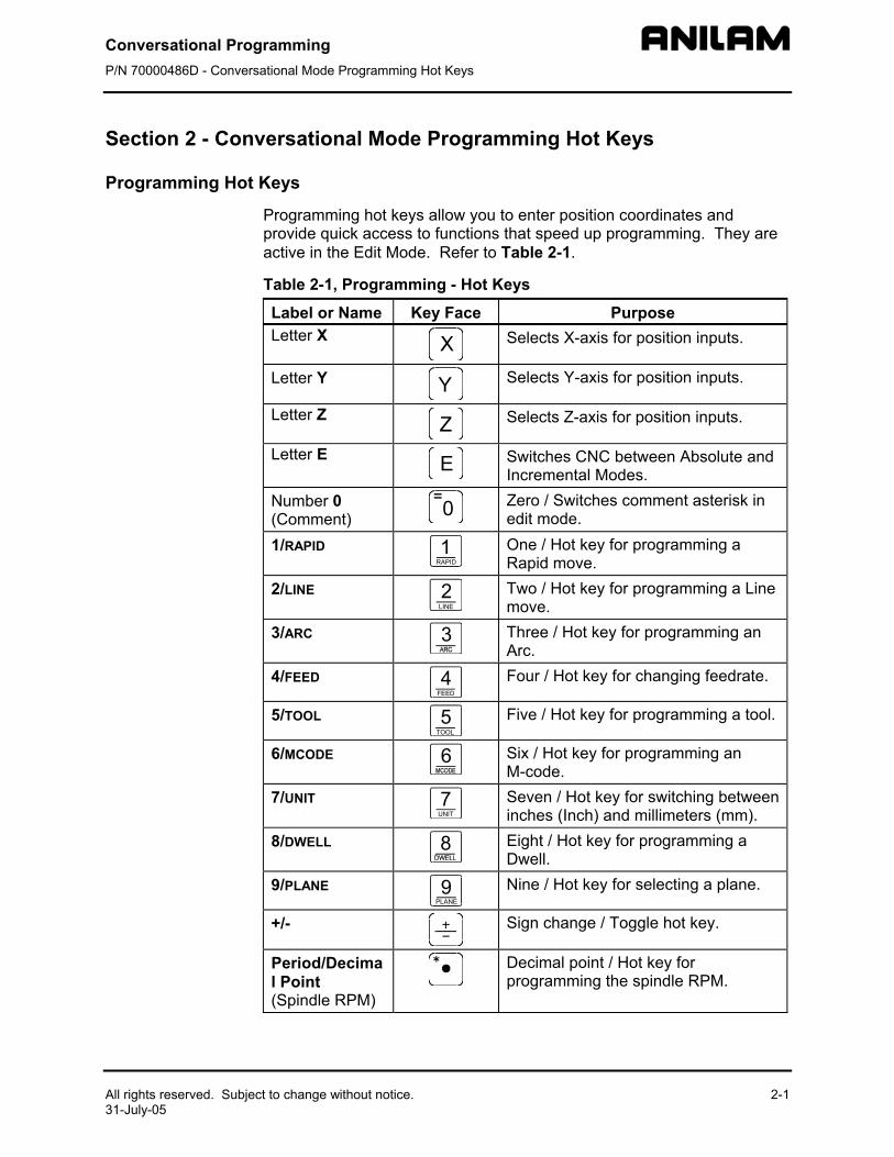
Programming hot keys allow you to enter position coordinates and provide quick access to functions that speed up programming. They are active in the Edit Mode. Refer to Table 2-1.
Table 2-1, Programming - Hot Keys
Label or Name Key Face Purpose Letter X
Selects X-axis for position inputs.
Letter Y
Selects Y-axis for position inputs.
Letter Z
Selects Z-axis for position inputs.
Letter E
Switches CNC between Absolute and Incremental Modes.
Number 0 (Comment)
Zero / Switches comment asterisk in edit mode.
1/RAPID RAPID1
One / Hot key for programming a Rapid move.
2/LINE 2LINE
Two / Hot key for programming a Line move.
3/ARC 3
Three / Hot key for programming an Arc.
4/FEED FEED4
Four / Hot key for changing feedrate.
5/TOOL 5TOOL
Five / Hot key for programming a tool.
6/MCODE 6
Six / Hot key for programming an M-code.
7/UNIT 7UNIT
Seven / Hot key for switching between inches (Inch) and millimeters (mm).
8/DWELL 8
Eight / Hot key for programming a Dwell.
9/PLANE 9PLANE
Nine / Hot key for selecting a plane.
+/-
Sign change / Toggle hot key.
Period/Decimal Point (Spindle RPM)
Decimal point / Hot key for programming the spindle RPM.
Conversational Programming P/N 70000486D - Conversational Mode Programming Hot Keys
2-2 All rights reserved. Subject to change without notice. 31-July-05
Editing Keys
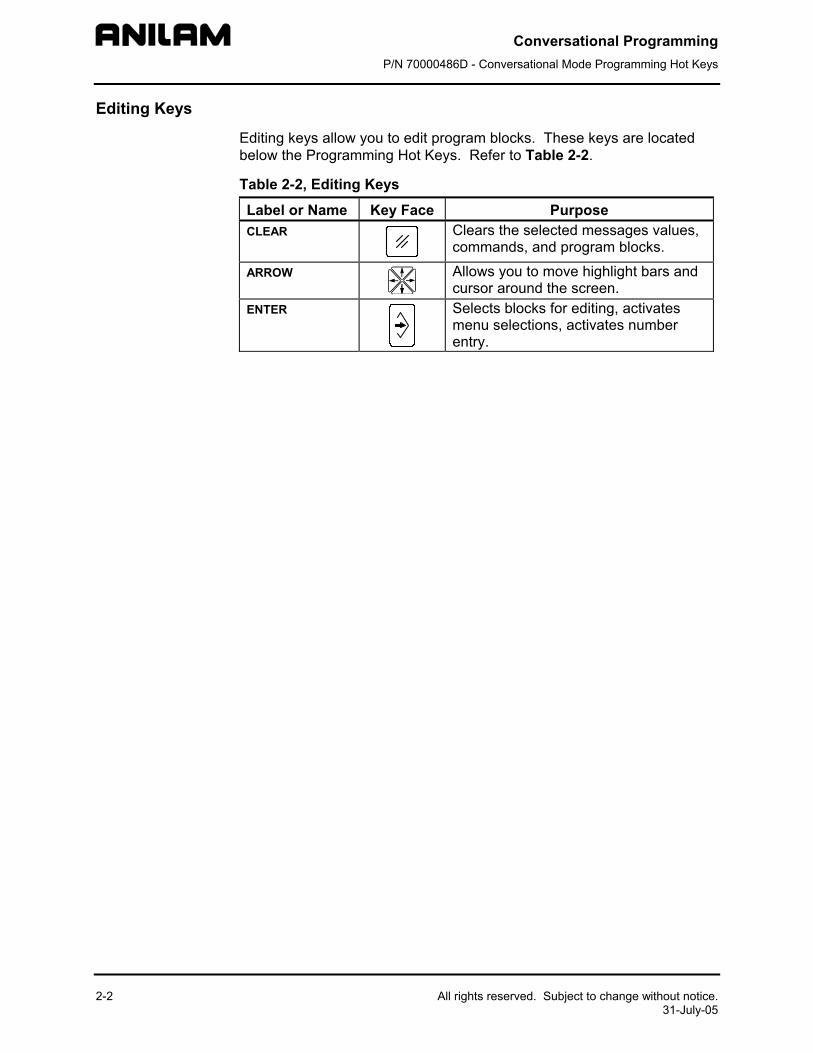
Editing keys allow you to edit program blocks. These keys are located below the Programming Hot Keys. Refer to Table 2-2.
Table 2-2, Editing Keys
Label or Name Key Face Purpose CLEAR
Clears the selected messages values, commands, and program blocks.
ARROW
Allows you to move highlight bars and cursor around the screen.
ENTER
Selects blocks for editing, activates menu selections, activates number entry.
Conversational Programming P/N 70000486D - Writing Conversational Programs
All rights reserved. Subject to change without notice. 3-1 31-July-05
Section 3 - Writing Conversational Programs
Program Basics
Each program consists of blocks of instructions that direct machine movements. Give each program a unique name.
Many settings remain active until changed or turned off. These are modal settings. For example, move type (Rapid/Feed), feedrate (IPM), units (Inch/MM), or ABS/INCR.
Write programs with combinations of moves, mode changes, and canned cycles. The CNC has a built-in library of canned cycles stored in its permanent memory.
Developing Part Programs
First, decide how to clamp the part and where to set Part Zero (Absolute Zero). Locate Part Zero at a point on the work positively positioned by the clamping fixture. This allows consistent machining of subsequent parts. Since Absolute positions are measured from Part Zero, locate Part Zero at a convenient location.
Determine the required tools and set the length offset for each tool.
Refer to the blueprint to select a Part Zero. Note the moves, positions, and tools needed to cut the part. The CNC has a calculator that finds coordinates for complex geometric shapes (refer to “Section 6 - Calculators”).
To develop a part program:
1. Enter the Program Directory (the PROGRAM screen) and create the program for the part. Use the extension .M.
2. Enter the Program Editor (the Edit screen) to open the new program and begin to write blocks (refer to “Section 5 - Editing Programs”).
3. The first block in a program is usually an Absolute Mode block. Put the CNC in the Absolute Mode at the start of a program to enable absolute positioning. (Use Incremental Mode only when specifically needed.)
4. Put the CNC in the appropriate Inch/MM Mode in the second block.
5. In the first move of the program, rapid to Tool #0, Z0 to retract the quill fully for the next move.
6. In the second move, rapid to a convenient part-change position.
7. Execute moves toward a part in two steps: A Rapid X, Y move at a clear height, followed by a Z move to 0.1 inch (2mm) above the surface of the cut (standard starting height). If necessary, activate the first tool mount at this time.
Conversational Programming P/N 70000486D - Writing Conversational Programs
3-2 All rights reserved. Subject to change without notice. 31-July-05
8. Subsequent blocks in the program are the moves, cycles, and tool changes required to machine the part.
9. Make the last three blocks of the program as follows: a) a Rapid move to Tool #0, Z0, b) a Rapid XY move to the same part change position used at the start of the program, and c) an EndMain block.
10. To verify and troubleshoot finished programs, run them in Draw Graphics Mode.
11. Secure the work on the table with the appropriate work-holding device.
12. Go to the Manual screen and set Part Zero at a convenient point on the part.
13. Go to the Tool Page and organize the tooling. Assign each tool a number (in the order of use). Assign length offset and tool diameter as appropriate.
14. If Fixture Offsets are used, define them in the Fixture Offsets Table. Refer to “Programming Fixture Offsets” in this section.
15. Before you cut a part, perform a dry run. There are several ways to get a close look at the programmed moves. Run the program in Motion Mode to hold between each move or in Single-Step Mode to hold between each block. Run the program with no tool installed.
16. After a successful dry run, the program is ready for production. Back up the program for safekeeping.
Conversational Programming P/N 70000486D - Writing Conversational Programs
All rights reserved. Subject to change without notice.31-July-05
Writing Program Blocks
You can program a block for a move type, mode, or cycle using one of the following: hot keys, soft keys, or pop-up menus.
To program a block, activate its graphic menu and fill in the appropriate values. To save a program block, press Save (F10) or press ENTER on the last entry field in the graphic menu. The CNC adds the new block to the Program Listing.
The last block of the Main Program must be EndMain. If this block is omitted, a warning displays stating “Missing M2 or M30!”
The <End Of Program> block is the last line of a program. The CNC automatically numbers new blocks and inserts them in front of the <End Of Program> block.
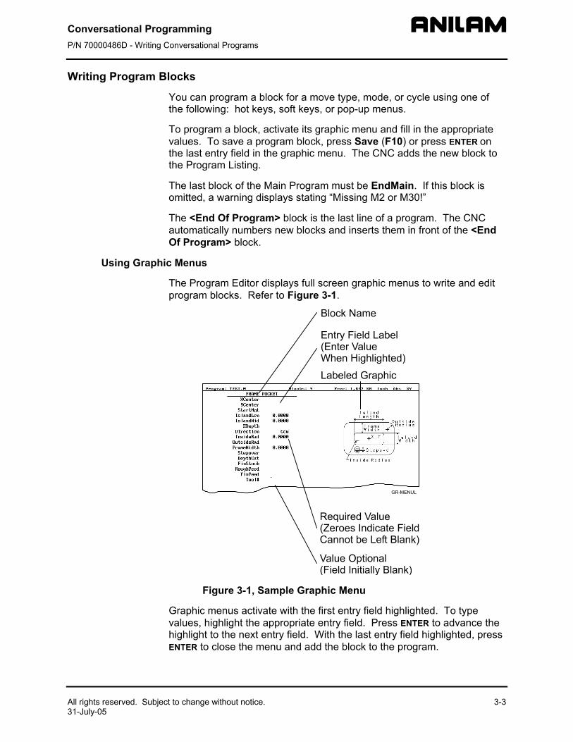
Using Graphic Menus
The Program Editor displays full screen graphic menus to write and edit program blocks. Refer to Figure 3-1.
Figure 3-1, S
Graphic menus activavalues, highlight the ahighlight to the next eENTER to close the m
3-3
ample Graphic Menu
te with the first entry field highlighted. To type ppropriate entry field. Press ENTER to advance the ntry field. With the last entry field highlighted, press enu and add the block to the program.
Conversational Programming P/N 70000486D - Writing Conversational Programs
3-4 All rights reserved. Subject to change without notice. 31-July-05
Press Save (F10) from any entry field to close the graphic menu and add the block to the program. Move the highlight from field to field using the ARROW keys. Fill out entry fields in any order.
Press CLEAR to remove values in the highlighted field.
There are two types of entry fields in a graphic menu:
Optional entry fields are blank when the graphic menu activates.
Required entry fields contain 0.000 when the graphic menu activates.
Required entry fields contain a 0.0000 default value. Change the value as required. Optional entry fields do not require a value. When left blank, the CNC usually assumes a default value or position. If the optional field is a position, the value defaults to the current position. If the optional field is a mode or tool change, the current mode and tool remain active. If the optional field is an angle, the value defaults to 0.0 degrees.
Type decimal points and negative signs where needed. Otherwise, the CNC assumes a positive whole number.
Press +/- to insert a negative sign or toggle selections in some entry fields (for example, Cw/Ccw fields).
No Move Blocks
No Move Blocks does not initiate machine moves. Use No Move Blocks to set modes (Incremental/Absolute, etc.), activate tools (Tool#), and set feedrates (Feed).
Programming an Absolute/Incremental Mode Change
A Dim (dimension) block sets the Absolute (Abs.) or Incremental (Incr.) Mode.
To program a Dim block:
1. In Edit Mode, press the Letter E. The SET ABS/INCR DIMENSION graphic menu prompts you to select Abs or Incr.
2. Press +/- to toggle the mode.
3. Press Save (F10) or ENTER to add the block to the Program Listing.
Programming an Inch/MM Mode Change
A Unit block sets the Inch (Inch) or Millimeter (MM) Mode.
To program a Unit block:
1. In Edit Mode, press 7/UNIT. The SET INCH/MM UNIT graphic menu prompts you to select Inch/MM.
2. Press +/- to toggle the selection.
3. Press Save (F10) or ENTER to add block to the Program Listing.
Conversational Programming P/N 70000486D - Writing Conversational Programs
All rights reserved. Subject to change without notice. 3-5 31-July-05
Programming a Tool Change
Identify tools with tool numbers. When you activate a tool, its tool length and diameter offsets activate. List these values on the corresponding row of the Tool Page.
Tool-length offset remains in effect until a different tool activates. Always turn off tool-diameter compensation and ramp off before activating a new tool.
NOTE: Each time a tool activates, the CNC holds the program to permit installation of the new tool. Programming unnecessary tool changes slows down production.
Activate Tool #0 to set the tool-length offset and diameter to 0.0.
To change a tool:
NOTE: An absolute move to Tool #0, Z0 fully retracts the quill. An incremental command to Z0 maintains the current position.
1. In Absolute Mode, program a Tool #0, Rapid Z0 to cancel length offsets and retract the quill to a safe position.
2. Program a Rapid move to the tool change XY position (usually Machine Zero).
3. Program a block to activate the required tool (example: Tool#1). When the CNC encounters the Tool# command, it holds program execution. The operator can now change the tool.
4. Press START to resume operation. The CNC activates applicable tool compensation.
Activating a Tool
To activate a tool:
1. In Edit Mode, press 5/TOOL. The TOOL MOUNT graphic menu prompts for Tool #.
2. Type tool number and press ENTER.
3. The cursor advances to the M-Code field. If you have Automatic Tool Changer, type the appropriate activation M-Code. (For example, type 6)
4. Press ENTER to add the Tool# block to the Program Listing.

Conversational Programming P/N 70000486D - Writing Conversational Programs
3-6 All rights reserved. Subject to change without notice. 31-July-05
Activating Tool-Diameter Compensation
Turn compensation on or off in (Rapid or Line) ramp moves. Ramp moves offset the tool on the programmed path by half the tool diameter. Tool compensation affects all subsequent moves until canceled.
The ToolComp command, available in Line or Rapid graphic menus, sets the required tool compensation. Settings include:
Left (of the path) Right (of the path) Off (cancel compensation)
When the field is left blank, the current compensation, if any, remains in effect.
Many canned cycles include automatic tool compensation. Activate the correct tool diameter to ensure accuracy in these cycles. The required tool activates within the cycle.
Refer to Table 3-1 for a list of move and cycle compensation requirements.
Table 3-1, Move and Cycle Compensation Requirements
Move or Cycle Program a Rapid or Line move to activate tool comp before you program the move or cycle. Tool diameter must be active.
Activate/deactivate compensation automatically when you program the move or cycle. Tool diameter must be active.
Rapid X --- Line X --- Modal X --- Arc X --- Ellipse (Has special requirements. Refer to “Section 4 - Programming Canned Cycles, Ellipses, and Spirals” for more information.)
X ---
Spiral (No compensation available.)
--- ---
(Continued…)
Conversational Programming P/N 70000486D - Writing Conversational Programs
All rights reserved. Subject to change without notice. 3-7 31-July-05
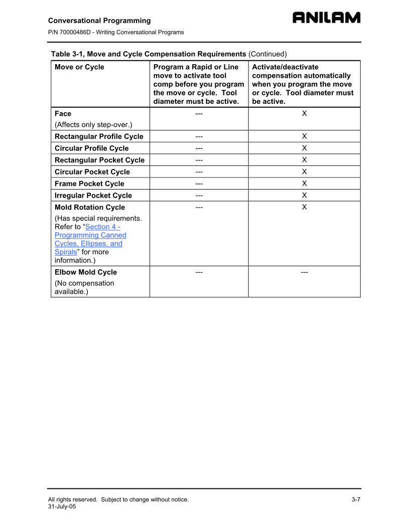
Table 3-1, Move and Cycle Compensation Requirements (Continued)
Move or Cycle Program a Rapid or Line move to activate tool comp before you program the move or cycle. Tool diameter must be active.
Activate/deactivate compensation automatically when you program the move or cycle. Tool diameter must be active.
Face (Affects only step-over.)
--- X
Rectangular Profile Cycle --- X Circular Profile Cycle --- X Rectangular Pocket Cycle --- X Circular Pocket Cycle --- X Frame Pocket Cycle --- X Irregular Pocket Cycle --- X Mold Rotation Cycle (Has special requirements. Refer to “Section 4 - Programming Canned Cycles, Ellipses, and Spirals” for more information.)
--- X
Elbow Mold Cycle (No compensation available.)
--- ---

Conversational Programming P/N 70000486D - Writing Conversational Programs
3-8 All rights reserved. Subject to change without notice. 31-July-05
Programming a Dwell
Dwell pauses a running program for a specified length of time, in seconds. Dwell resolution is 0.1 sec. When the operator types 0.0 seconds (infinite dwell), the CNC will hold indefinitely. Press START to restart the CNC after an infinite dwell.
To program a Dwell using hot keys:
1. In Edit Mode, press 8/DWELL. The DWELL graphic menu prompts for length of time in seconds.
2. Type the time and press ENTER to add Dwell block to the Program Listing.
To program a Dwell using soft keys:
1. In Edit Mode, press Sub (F8) to display the Secondary soft key functions.
2. Press Dwell (F7) to activate the DWELL graphic menu.
3. Type the time and press ENTER to add Dwell block to the Program Listing.
Conversational Programming P/N 70000486D - Writing Conversational Programs
All rights reserved. Subject to change without notice. 3-9 31-July-05
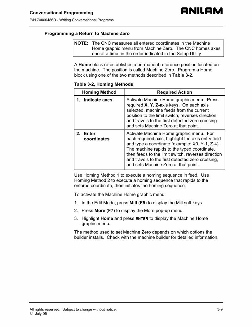
Programming a Return to Machine Zero
NOTE: The CNC measures all entered coordinates in the Machine Home graphic menu from Machine Zero. The CNC homes axes one at a time, in the order indicated in the Setup Utility.
A Home block re-establishes a permanent reference position located on the machine. The position is called Machine Zero. Program a Home block using one of the two methods described in Table 3-2.
Table 3-2, Homing Methods
Homing Method Required Action 1. Indicate axes Activate Machine Home graphic menu. Press
required X, Y, Z-axis keys. On each axis selected, machine feeds from the current position to the limit switch, reverses direction and travels to the first detected zero crossing and sets Machine Zero at that point.
2. Enter coordinates
Activate Machine Home graphic menu. For each required axis, highlight the axis entry field and type a coordinate (example: X0, Y-1, Z-4). The machine rapids to the typed coordinate, then feeds to the limit switch, reverses direction and travels to the first detected zero crossing, and sets Machine Zero at that point.
Use Homing Method 1 to execute a homing sequence in feed. Use Homing Method 2 to execute a homing sequence that rapids to the entered coordinate, then initiates the homing sequence.
To activate the Machine Home graphic menu:
1. In the Edit Mode, press Mill (F5) to display the Mill soft keys.
2. Press More (F7) to display the More pop-up menu.
3. Highlight Home and press ENTER to display the Machine Home graphic menu.
The method used to set Machine Zero depends on which options the builder installs. Check with the machine builder for detailed information.
Conversational Programming P/N 70000486D - Writing Conversational Programs
3-10 All rights reserved. Subject to change without notice. 31-July-05
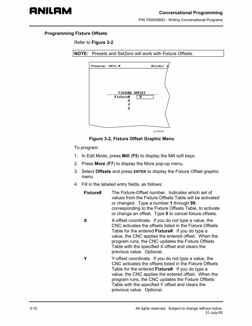
Programming Fixture Offsets
Refer to Figure 3-2.
NOTE: Presets and SetZero will work with Fixture Offsets.
Figure 3-2, Fixture Offset Graphic Menu
To program:
1. In Edit Mode, press Mill (F5) to display the Mill soft keys.
2. Press More (F7) to display the More pop-up menu.
3. Select Offsets and press ENTER to display the Fixture Offset graphic menu.
4. Fill in the labeled entry fields, as follows:
Fixture# The Fixture-Offset number. Indicates which set of values from the Fixture Offsets Table will be activated or changed. Type a number 1 through 99, corresponding to the Fixture Offsets Table, to activate or change an offset. Type 0 to cancel fixture offsets.
X X-offset coordinate. If you do not type a value, the CNC activates the offsets listed in the Fixture Offsets Table for the entered Fixture#. If you do type a value, the CNC applies the entered offset. When the program runs, the CNC updates the Fixture Offsets Table with the specified X offset and clears the previous value. Optional.
Y Y-offset coordinate. If you do not type a value, the CNC activates the offsets listed in the Fixture Offsets Table for the entered Fixture#. If you do type a value, the CNC applies the entered offset. When the program runs, the CNC updates the Fixture Offsets Table with the specified Y offset and clears the previous value. Optional.
Conversational Programming P/N 70000486D - Writing Conversational Programs
All rights reserved. Subject to change without notice. 3-11 31-July-05
Z Z-Offset coordinate. If you do not type a value, the
CNC activates the offsets listed in the Fixture Offsets Table for the entered Fixture#. If you do type a value, the CNC applies the entered offset. When the program runs, the CNC updates the Fixture Offsets Table with the specified Z offset and clears the previous value. Optional.
To cancel Fixture Offsets:
1. In Edit Mode, press Mill (F5) to display the Mill soft keys.
2. Press More (F7) to display the More pop-up menu.
3. Select Offsets and press ENTER to display the Fixture Offset graphic menu.
4. Select Fixture#. In the highlighted entry field, type 0 to cancel Fixture Offsets. (Do not fill in the other entry fields.)
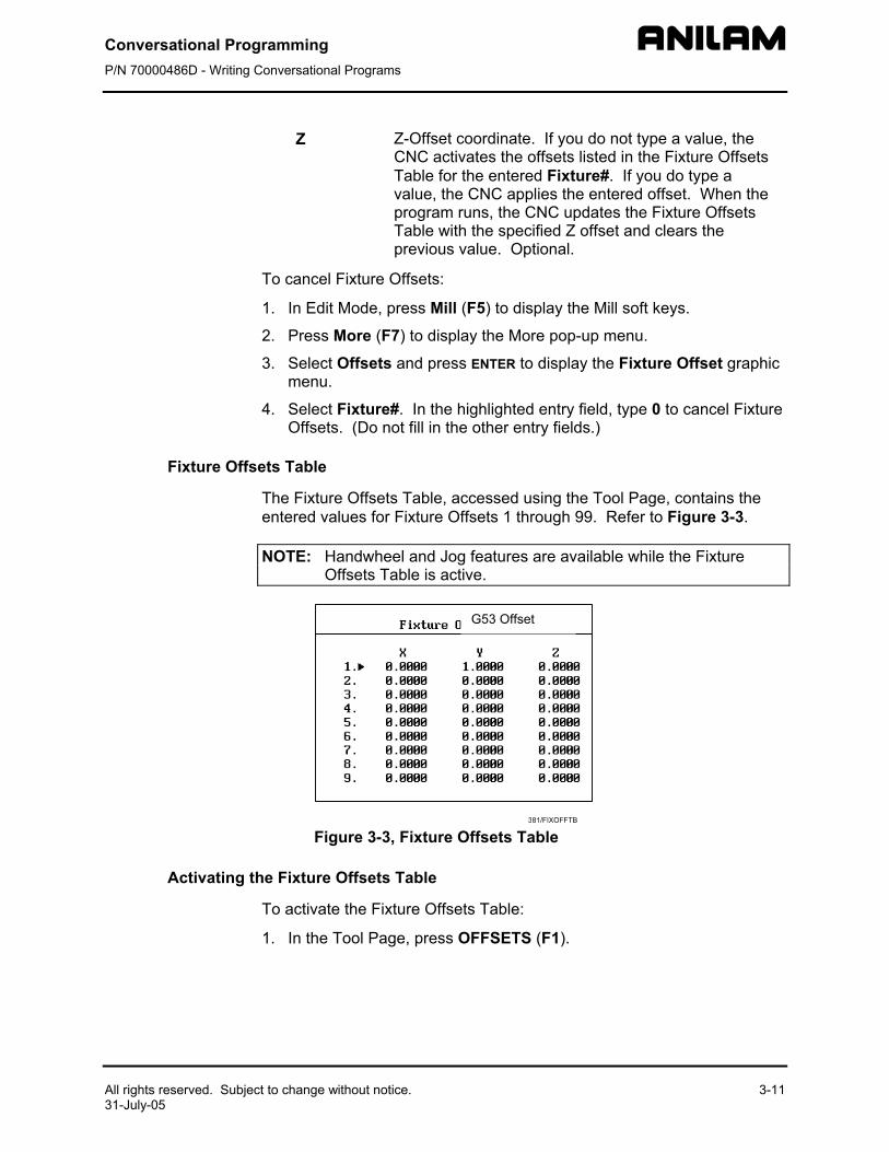
Fixture Offsets Table
The Fixture Offsets Table, accessed using the Tool Page, contains the entered values for Fixture Offsets 1 through 99. Refer to Figure 3-3.
NOTE: Handwheel and Jog features are available while the Fixture Offsets Table is active.
Figure 3-3, Fixture Offsets Table
Activating the Fixture Offsets Table
To activate the Fixture Offsets Table:
1. In the Tool Page, press OFFSETS (F1).
G53 Offset
Conversational Programming P/N 70000486D - Writing Conversational Programs
3-12 All rights reserved. Subject to change without notice. 31-July-05
Changing Fixture Offsets in the Table
There are two ways to change the values in the table, manually type a value or calibrate the fixture offset table entry to the machine’s current location (shown on the axis display).
To change a fixture offset to a manually typed coordinate:
1. Highlight a Fixture Offset (row 1 through 9).
2. Press an axis key (X, Y, or Z).
3. Type a value and press ENTER to store the value in the table.
To calibrate the fixture offset table entry to the machine’s current location:
1. Highlight a Fixture Offset (row 1 through 9).
2. Press CalibX (F5), CalibY (F6), or CalibZ (F7) to store the current machine position for the selected axis in the table.
Resetting Absolute Zero (Part Zero)
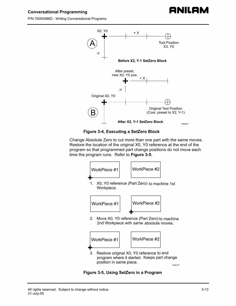
Absolute Zero is the X0, Y0 position for absolute dimensions. A SetZero block sets the Absolute Zero Reference of one or more axes to a new position. Use SetZero in one of two ways: to reset X0 Y0 or to preset the current location to entered coordinates.
In axis presetting, non-zero XY values set the current machine position to the entered coordinates. In axis resetting, X0 and Y0 values set the current machine position as the new Absolute Zero Reference.
When the CNC executes the block, the X and Y values (zero or non-zero) in the graphic menu redefine Absolute Zero.
In Figure 3-4, Executing a SetZero Block, diagram A shows Part Zero and tool position prior to a SetZero block. In this example, the operator programs a SetZero block with the following coordinates: X2, Y-1.
Diagram B shows Part Zero and tool position following the SetZero block. The coordinates at the tool position become X2, Y-1. This, in effect, moves Part Zero, as indicated.
Conversational Programming P/N 70000486D - Writing Conversational Programs
All rights reserved. Subject to change without notice. 3-13 31-July-05
Figure 3-4, Executing a SetZero Block
Change Absolute Zero to cut more than one part with the same moves. Restore the location of the original X0, Y0 reference at the end of the program so that programmed part change positions do not move each time the program runs. Refer to Figure 3-5.
Figure 3-5, Using SetZero in a Program
Conversational Programming P/N 70000486D - Writing Conversational Programs
3-14 All rights reserved. Subject to change without notice. 31-July-05
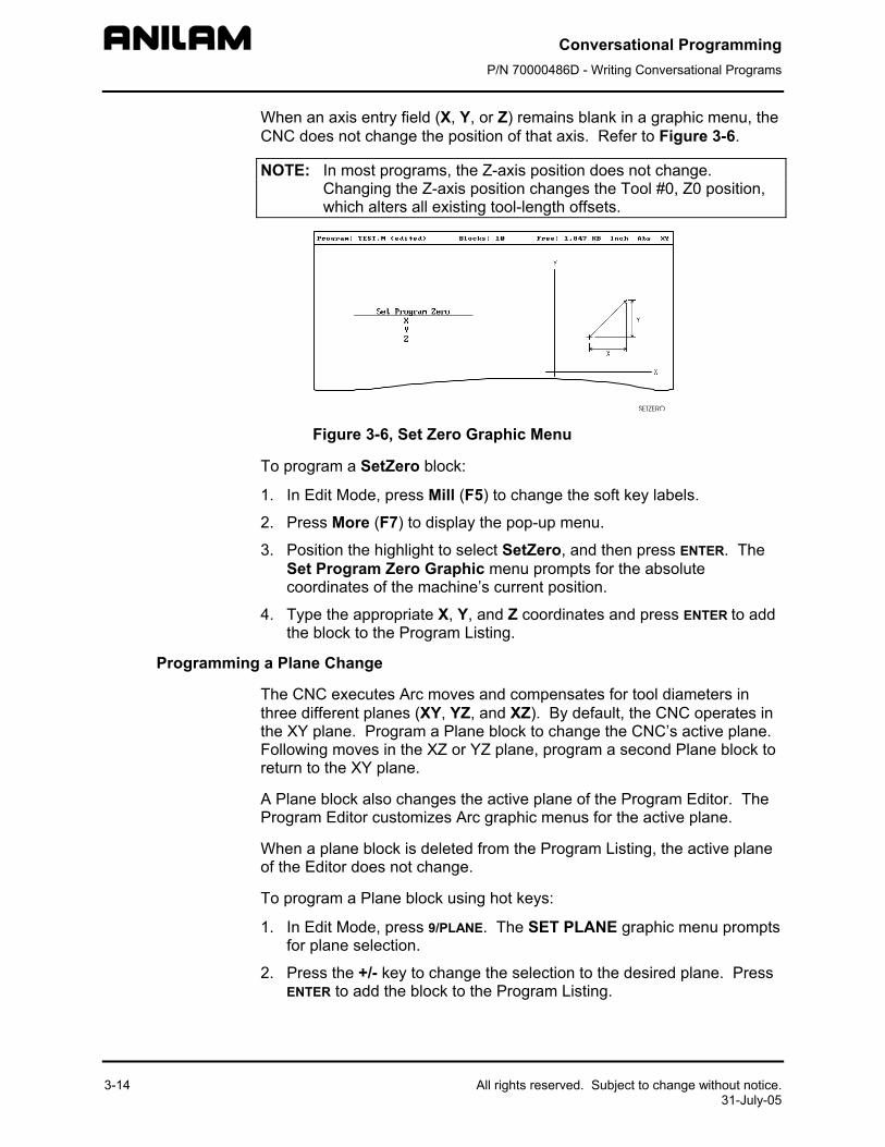
When an axis entry field (X, Y, or Z) remains blank in a graphic menu, the CNC does not change the position of that axis. Refer to Figure 3-6.
NOTE: In most programs, the Z-axis position does not change. Changing the Z-axis position changes the Tool #0, Z0 position, which alters all existing tool-length offsets.
Figure 3-6, Set Zero Graphic Menu
To program a SetZero block:
1. In Edit Mode, press Mill (F5) to change the soft key labels.
2. Press More (F7) to display the pop-up menu.
3. Position the highlight to select SetZero, and then press ENTER. The Set Program Zero Graphic menu prompts for the absolute coordinates of the machine’s current position.
4. Type the appropriate X, Y, and Z coordinates and press ENTER to add the block to the Program Listing.
Programming a Plane Change
The CNC executes Arc moves and compensates for tool diameters in three different planes (XY, YZ, and XZ). By default, the CNC operates in the XY plane. Program a Plane block to change the CNC’s active plane. Following moves in the XZ or YZ plane, program a second Plane block to return to the XY plane.
A Plane block also changes the active plane of the Program Editor. The Program Editor customizes Arc graphic menus for the active plane.
When a plane block is deleted from the Program Listing, the active plane of the Editor does not change.
To program a Plane block using hot keys:
1. In Edit Mode, press 9/PLANE. The SET PLANE graphic menu prompts for plane selection.
2. Press the +/- key to change the selection to the desired plane. Press ENTER to add the block to the Program Listing.
Conversational Programming P/N 70000486D - Writing Conversational Programs
All rights reserved. Subject to change without notice. 3-15 31-July-05
To program a Plane block using soft keys:
1. In Edit Mode press Mill (F5) to display the Mill soft keys.
2. Press More (F7) to display the More pop-up menu.
3. Highlight Plane and press ENTER. The SET PLANE graphic menu prompts for plane selection.
4. Press +/- to change to the desired plane. Press ENTER to add the block to the Program Listing.
Programming a Feedrate Change
A Feed block sets the feedrate for Line moves, arcs, and cycles that do not contain specifically programmed feedrates. Feed blocks also set the feedrate for modal moves. Add Feed blocks whenever necessary.
NOTE: A Feed block does not activate the Feed Mode.
To program a Feed block from the hot keys:
1. In Edit Mode, press 4/FEED to display the FEEDRATE graphic menu.
2. Type the required feedrate and press ENTER to add the block to the Program Listing.
To program a Feed block from the soft keys:
1. In Edit Mode, press Mill (F5) to display the Mill soft keys.
2. Press More (F7) to display the More pop-up menu.
3. Highlight Feed and press ENTER to activate the FEEDRATE graphic menu.
4. Press Save (F10) or ENTER to add Feed block to the Program Listing.
Programming a Spindle RPM
If your CNC has a programmable spindle RPM, you can set the RPM as follows:
To program an RPM block from the hot keys:
1. In Edit Mode, press the . (Decimal/RPM) key to display the Spindle RPM graphic menu.
2. Type the required spindle RPM and press ENTER to add the block to the Program Listing.
Conversational Programming P/N 70000486D - Writing Conversational Programs
3-16
To program an RPM block from the soft keys:
1. In Edit Mode, press Mill (F5) to display the Mill soft keys.
2. Press More (F7) to display the More pop-up menu.
3. Highlight RPM and press ENTER to activate the Spindle RPM graphic menu.
4. Type the required RPM.
5. Press Save (F10) or ENTER to add RPM block to the Program Listing.
Straight Moves
Programming a Rapid Move
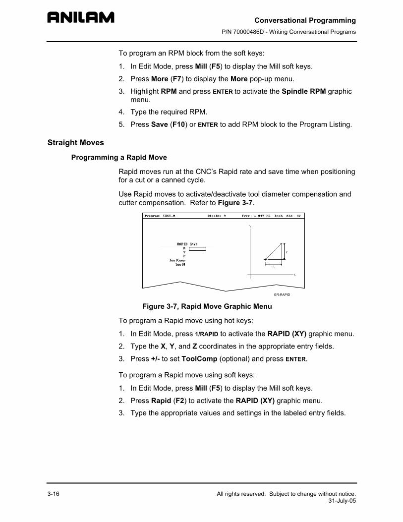
Rapid moves run at the CNC’s Rapid rate and save time when positioning for a cut or a canned cycle.
Use Rapid moves to activate/deactivate tool diameter compensation and cutter compensation. Refer to Figure 3-7.
Figure 3-7, R
To program a Rapid m
1. In Edit Mode, pre
2. Type the X, Y, an
3. Press +/- to set T
To program a Rapid m
1. In Edit Mode, pre
2. Press Rapid (F2)
3. Type the appropr
All rights reserved. Subject to change without notice. 31-July-05
apid Move Graphic Menu
ove using hot keys:
ss 1/RAPID to activate the RAPID (XY) graphic menu.
d Z coordinates in the appropriate entry fields.
oolComp (optional) and press ENTER.
ove using soft keys:
ss Mill (F5) to display the Mill soft keys.
to activate the RAPID (XY) graphic menu.
iate values and settings in the labeled entry fields.
Conversational Programming P/N 70000486D - Writing Conversational Programs
All rights reserved. Subject to change without notice.31-July-05
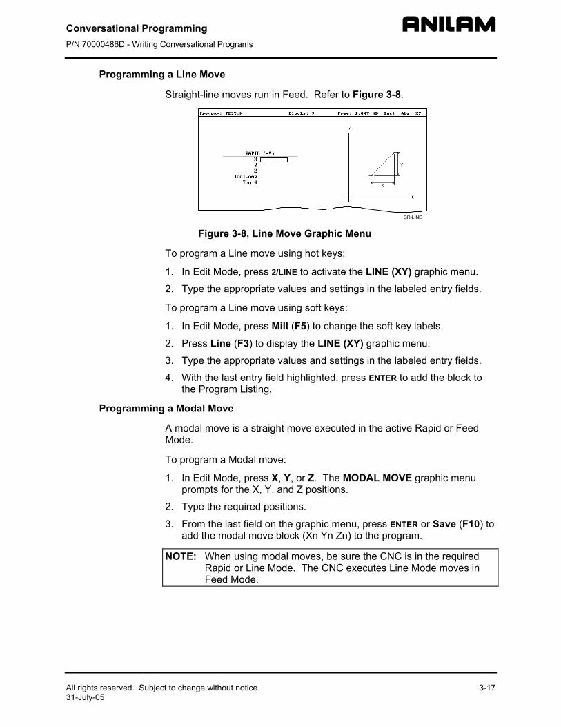
Programming a Line Move
Straight-line moves run in Feed. Refer to Figure 3-8.
Figure 3-8, L
To program a Line m
1. In Edit Mode, pre
2. Type the appropr
To program a Line m
1. In Edit Mode, pre
2. Press Line (F3) t
3. Type the appropr
4. With the last entrythe Program Listi
Programming a Modal Move
A modal move is a stMode.
To program a Modal
1. In Edit Mode, preprompts for the X
2. Type the required
3. From the last fieldadd the modal mo
NOTE: When usingRapid or LinFeed Mode.
3-17
ine Move Graphic Menu
ove using hot keys:
ss 2/LINE to activate the LINE (XY) graphic menu.
iate values and settings in the labeled entry fields.
ove using soft keys:
ss Mill (F5) to change the soft key labels.
o display the LINE (XY) graphic menu.
iate values and settings in the labeled entry fields.
field highlighted, press ENTER to add the block to ng.
raight move executed in the active Rapid or Feed
move:
ss X, Y, or Z. The MODAL MOVE graphic menu , Y, and Z positions.
positions.
on the graphic menu, press ENTER or Save (F10) to ve block (Xn Yn Zn) to the program.
modal moves, be sure the CNC is in the required e Mode. The CNC executes Line Mode moves in
Conversational Programming P/N 70000486D - Writing Conversational Programs
3-18 All rights reserved. Subject to change without notice. 31-July-05
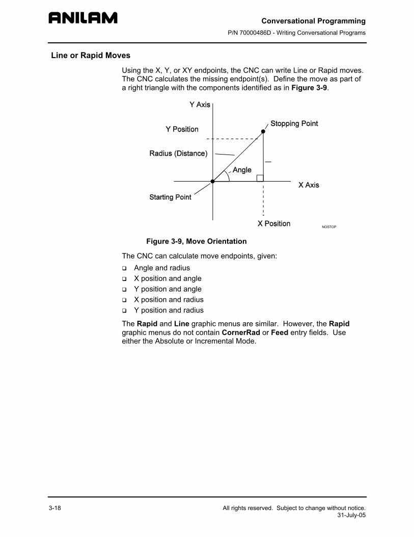
Line or Rapid Moves
Using the X, Y, or XY endpoints, the CNC can write Line or Rapid moves. The CNC calculates the missing endpoint(s). Define the move as part of a right triangle with the components identified as in Figure 3-9.
NOSTOP
Figure 3-9, Move Orientation
The CNC can calculate move endpoints, given: Angle and radius X position and angle Y position and angle X position and radius Y position and radius
The Rapid and Line graphic menus are similar. However, the Rapid graphic menus do not contain CornerRad or Feed entry fields. Use either the Absolute or Incremental Mode.
Conversational Programming P/N 70000486D - Writing Conversational Programs
All rights reserved. Subject to change without no31-July-05
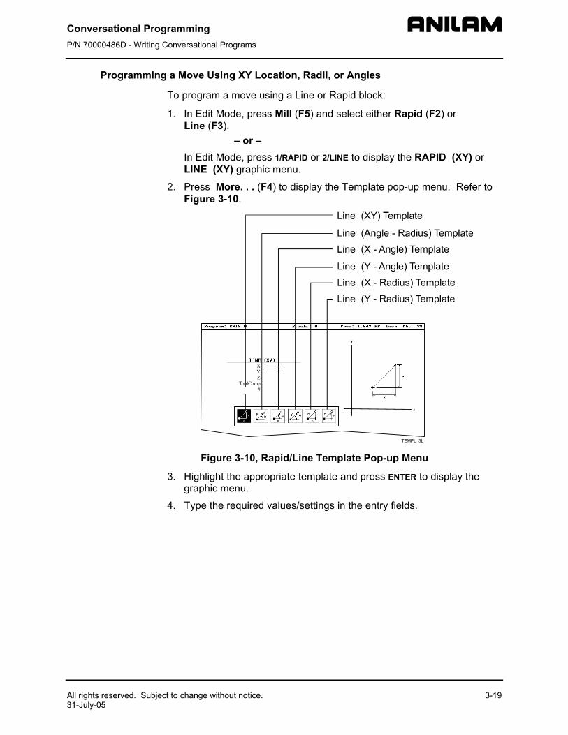
Programming a Move Using XY Location, Radii, or Angles
To program a move using a Line or Rapid block:
1. In Edit Mode, press Mill (F5) and select either Rapid (F2) or Line (F3).
– or – In Edit Mode, press 1/RAPID or 2/LINE to display the RAPID (XY) or
LINE (XY) graphic menu.
2. Press More. . . (F4) to display the Template pop-up menu. Refer to Figure 3-10.
Figure 3-1
3. Highlight the agraphic menu
4. Type the requ
tice. 3-19
0, Rapid/Line Template Pop-up Menu
ppropriate template and press ENTER to display the .
ired values/settings in the entry fields.
Conversational Programming P/N 70000486D - Writing Conversational Programs
3-20 All rights reserved. Subject to change without notice. 31-July-05
Arcs
Selecting the Plane for an Arc
The CNC executes Arcs in the XY plane by default. For an Arc in the XZ or YZ plane, program the plane change before the Arc move. The plane change customizes the Arc graphic menus for the required plane.
The graphic menus for moves in the XY, XZ, and YZ planes contain the same entry fields. Entry fields for selected plane positions require a value.
After a move in the XZ or YZ plane, return the CNC to the XY plane.
NOTE: To activate a new plane in the Program Editor, program a plane change block.
Program Arc moves: Using the endpoint and radius Using the center and endpoint Using the center and angle
Programming an Arc Using an Endpoint and Radius
To define the Endpoint - Radius Arc, type the direction of the Arc, the endpoint, and the radius. The CNC cuts an Arc of the specified radius from the current position to the endpoint. You must correctly define the modal endpoint coordinates in the Absolute or Incremental Mode.
In the XY plane, if the Z-axis starting and end points differ, the arc is a helix.
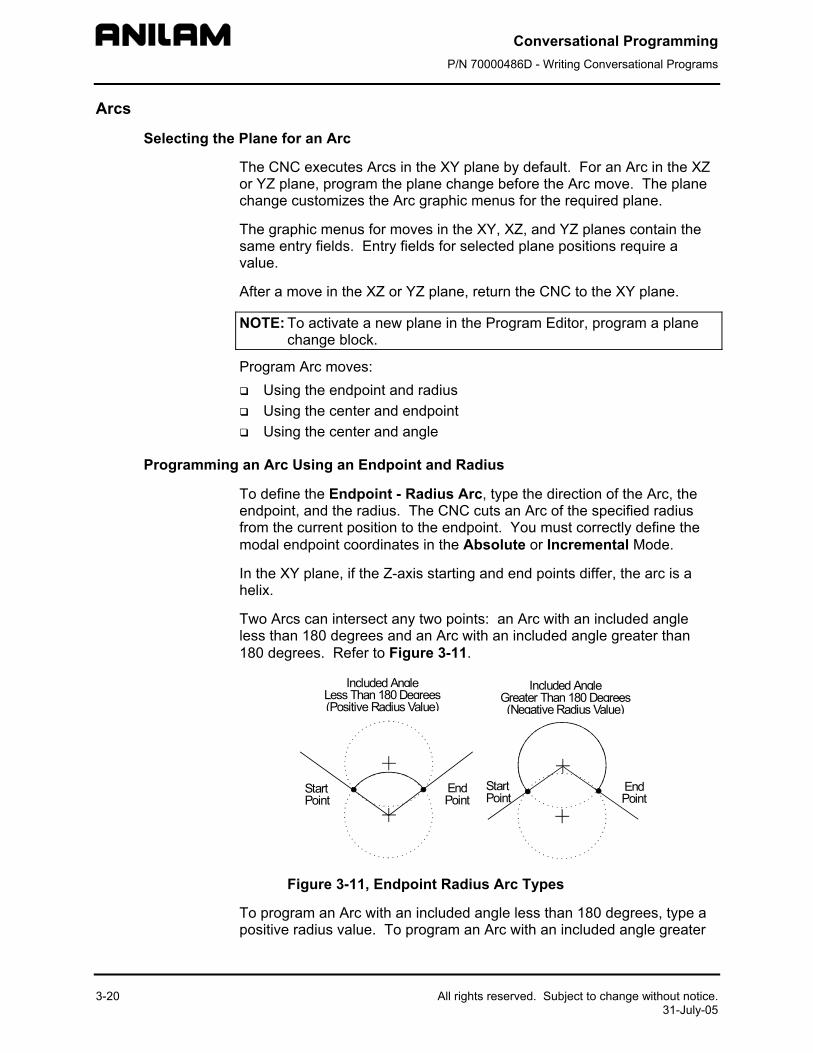
Two Arcs can intersect any two points: an Arc with an included angle less than 180 degrees and an Arc with an included angle greater than 180 degrees. Refer to Figure 3-11.
StartPoint
EndPoint
StartPoint
EndPoint
Included AngleGreater Than 180 Degrees(Negative Radius Value)
Included AngleLess Than 180 Degrees(Positive Radius Value)
Figure 3-11, Endpoint Radius Arc Types
To program an Arc with an included angle less than 180 degrees, type a positive radius value. To program an Arc with an included angle greater
Conversational Programming P/N 70000486D - Writing Conversational Programs
All rights reserved. Subject to change without notice. 31-July-05
than 180 degrees, type a negative radius value. The CNC selects which Arc center to use, based on the sign of the typed value.
To program an Arc using an endpoint and radius, using hot keys:
1. In Edit Mode, press 3/ARC. The ARC (END POINT - RADIUS) graphic menu prompts for labeled values.
2. Fill in the entry fields as labeled. To program an Arc using an endpoint and radius, using soft keys:
1. In Edit Mode, press Mill (F5) to display the Mill secondary soft keys.
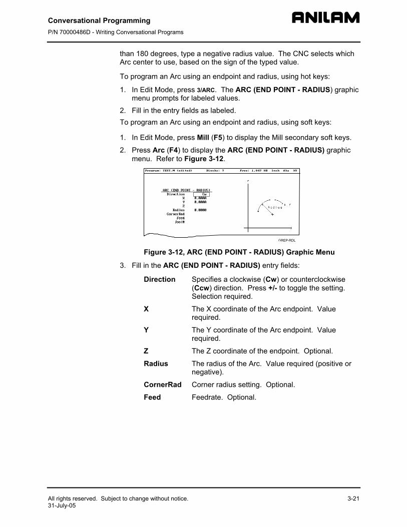
2. Press Arc (F4) to display the ARC (END POINT - RADIUS) graphic menu. Refer to Figure 3-12.
Figure 3-12, AR
3. Fill in the ARC (EN
Direction S(S
X Tr
Y Tr
Z T
Radius Tn
CornerRad C
Feed F
3-21
C (END POINT - RADIUS) Graphic Menu
D POINT - RADIUS) entry fields:
pecifies a clockwise (Cw) or counterclockwise Ccw) direction. Press +/- to toggle the setting. election required.
he X coordinate of the Arc endpoint. Value equired.
he Y coordinate of the Arc endpoint. Value equired.
he Z coordinate of the endpoint. Optional.
he radius of the Arc. Value required (positive or egative).
orner radius setting. Optional.
eedrate. Optional.
Conversational Programming P/N 70000486D - Writing Conversational Programs
3-22
Programming an Arc Using the Center and Endpoint
NOTE: Use Center and Endpoint Arcs to cut helical threads.
To define the Center - Endpoint Arc, type the endpoint, arc center, and direction. The CNC cuts an Arc from the current position to the end point.
In Absolute Mode, the CNC measures the Arc center and endpoint from Absolute Zero. In Incremental Mode, the CNC measures the Arc center and end point from the starting position of the arc.
NOTE: Ensure that the required Absolute or Incremental Mode is active.
When the Z-axis start and end points differ in the XY plane, the Arc is a helix. The Revs value determines the number of rotations used to machine the helix.
The CNC calculates the radius from the specified starting point and Arc center. Therefore, the endpoint must lie along the Arc’s path. If the endpoint does not lie along the Arc’s path, the CNC will adjust the center or end point. Configure whether the CNC will adjust the center or endpoint in the Setup Utility. Endpoint is preferred. The machine builder sets the maximum arc circle center adjustment in the Setup Utility. If the error exceeds the setup tolerance, the CNC generates an error message.
To program a Center - End Point Arc using hot keys:
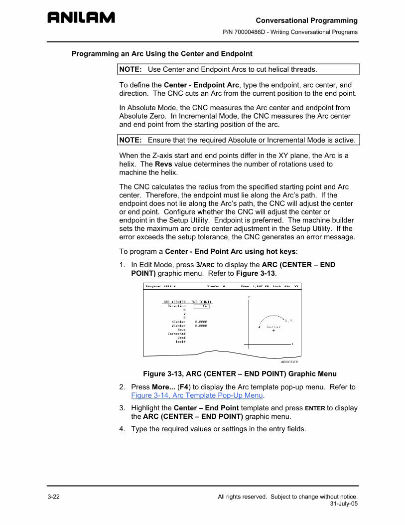
1. In Edit Mode, press 3/ARC to display the ARC (CENTER – END POINT) graphic menu. Refer to Figure 3-13.
Figure 3-13, AR
2. Press More... (F4) Figure 3-14, Arc Te
3. Highlight the Centethe ARC (CENTER
4. Type the required v
All rights reserved. Subject to change without notice. 31-July-05
C (CENTER – END POINT) Graphic Menu
to display the Arc template pop-up menu. Refer to mplate Pop-Up Menu.
r – End Point template and press ENTER to display – END POINT) graphic menu.
alues or settings in the entry fields.
Conversational Programming P/N 70000486D - Writing Conversational Programs
All rights reserved. Subject to change without notice. 3-23 31-July-05
To program a Center – End Point Arc using soft keys:
1. In Edit Mode, press Mill (F5) to display the Mill secondary soft keys.
2. Press Arc (F4) to display the ARC (END POINT - RADIUS) graphic menu.
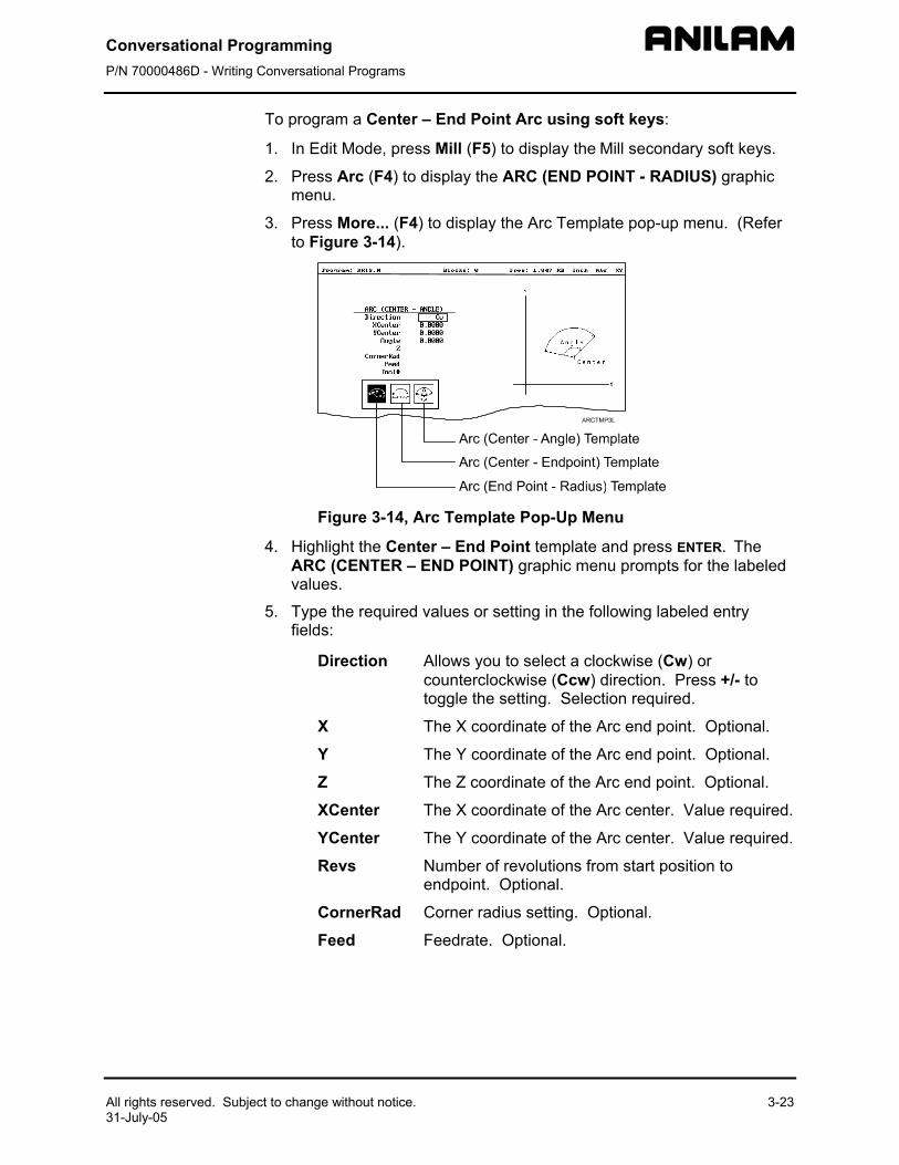
3. Press More... (F4) to display the Arc Template pop-up menu. (Refer to Figure 3-14).
Figure 3-14, Arc Template Pop-Up Menu
4. Highlight the Center – End Point template and press ENTER. The ARC (CENTER – END POINT) graphic menu prompts for the labeled values.
5. Type the required values or setting in the following labeled entry fields:
Direction Allows you to select a clockwise (Cw) or counterclockwise (Ccw) direction. Press +/- to toggle the setting. Selection required.
X The X coordinate of the Arc end point. Optional.
Y The Y coordinate of the Arc end point. Optional.
Z The Z coordinate of the Arc end point. Optional.
XCenter The X coordinate of the Arc center. Value required.
YCenter The Y coordinate of the Arc center. Value required.
Revs Number of revolutions from start position to endpoint. Optional.
CornerRad Corner radius setting. Optional.
Feed Feedrate. Optional.
Conversational Programming P/N 70000486D - Writing Conversational Programs
3-24 All rights reserved. Subject to change without notice. 31-July-05
Programming an Arc Using the Center and the Included Angle
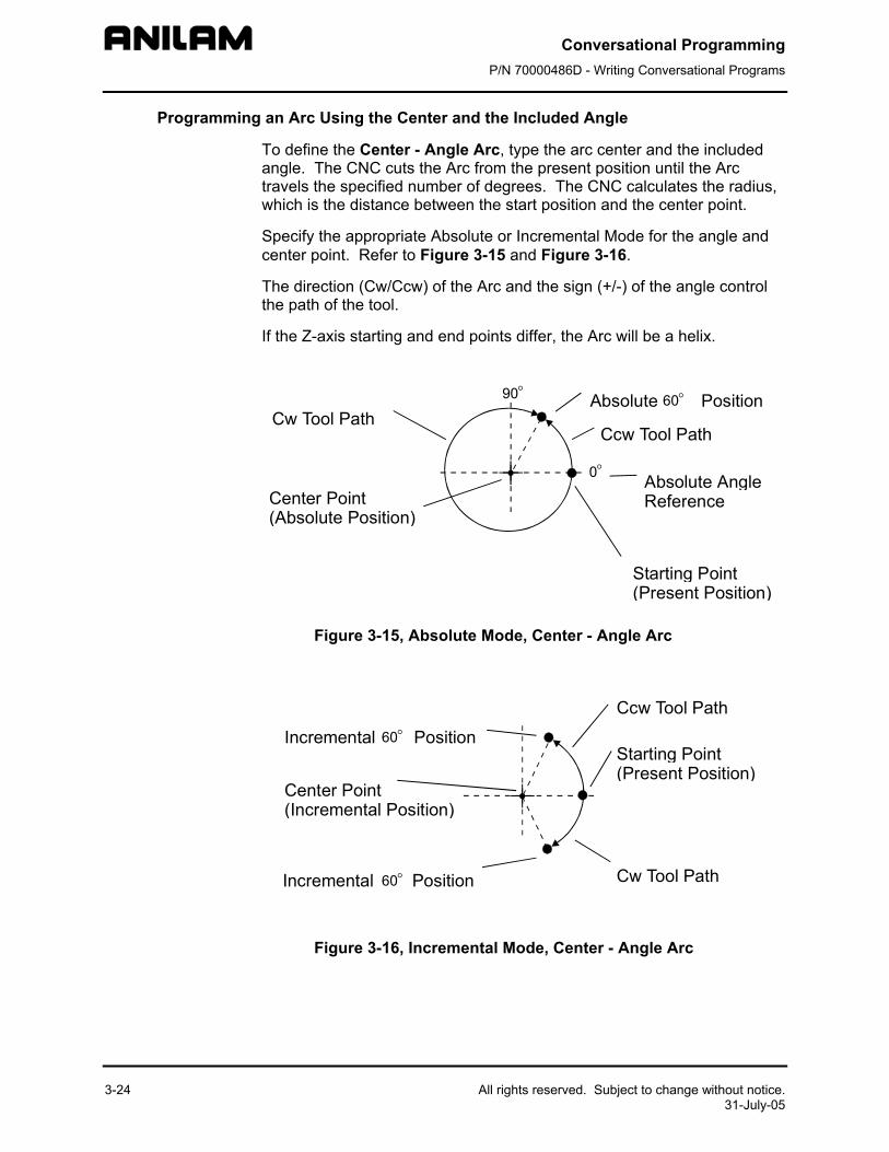
To define the Center - Angle Arc, type the arc center and the included angle. The CNC cuts the Arc from the present position until the Arc travels the specified number of degrees. The CNC calculates the radius, which is the distance between the start position and the center point.
Specify the appropriate Absolute or Incremental Mode for the angle and center point. Refer to Figure 3-15 and Figure 3-16.
The direction (Cw/Ccw) of the Arc and the sign (+/-) of the angle control the path of the tool.
If the Z-axis starting and end points differ, the Arc will be a helix.
Starting Point(Present Position)
Center Point(Absolute Position)
Absolute AngleReference
Absolute Position
Ccw Tool PathCw Tool Path
90°
0°
60°
Figure 3-15, Absolute Mode, Center - Angle Arc
Starting Point(Present Position)
Center Point(Incremental Position)
Incremental Position
Cw Tool Path
Ccw Tool Path
Incremental Position
60°
60°
Figure 3-16, Incremental Mode, Center - Angle Arc
Conversational Programming P/N 70000486D - Writing Conversational Programs
All rights reserved. Subject to change without notice. 31-July-05
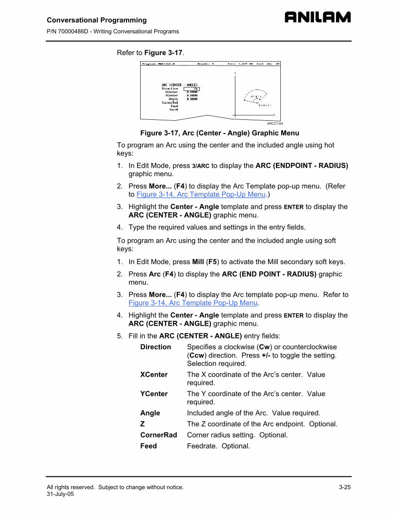
Refer to Figure 3-17.
Figure 3-17, ArcTo program an Arc usingkeys:
1. In Edit Mode, press graphic menu.
2. Press More... (F4) toto Figure 3-14, Arc T
3. Highlight the CenterARC (CENTER - AN
4. Type the required va
To program an Arc usingkeys:
1. In Edit Mode, press
2. Press Arc (F4) to dismenu.
3. Press More... (F4) toFigure 3-14, Arc Tem
4. Highlight the CenterARC (CENTER - AN
5. Fill in the ARC (CENDirection S
(CS
XCenter Thre
YCenter Thre
Angle InZ ThCornerRad CFeed Fe
3-25
(Center - Angle) Graphic Menu the center and the included angle using hot
3/ARC to display the ARC (ENDPOINT - RADIUS)
display the Arc Template pop-up menu. (Refer emplate Pop-Up Menu.)
- Angle template and press ENTER to display the GLE) graphic menu.
lues and settings in the entry fields.
the center and the included angle using soft
Mill (F5) to activate the Mill secondary soft keys.
play the ARC (END POINT - RADIUS) graphic
display the Arc template pop-up menu. Refer to plate Pop-Up Menu.
- Angle template and press ENTER to display the GLE) graphic menu.
TER - ANGLE) entry fields: pecifies a clockwise (Cw) or counterclockwise cw) direction. Press +/- to toggle the setting.
election required. e X coordinate of the Arc’s center. Value
quired. e Y coordinate of the Arc’s center. Value
quired. cluded angle of the Arc. Value required. e Z coordinate of the Arc endpoint. Optional.
orner radius setting. Optional. edrate. Optional.
Conversational Programming P/N 70000486D - Writing Conversational Programs
3-26 All rights reserved. Subject to change without notice. 31-July-05
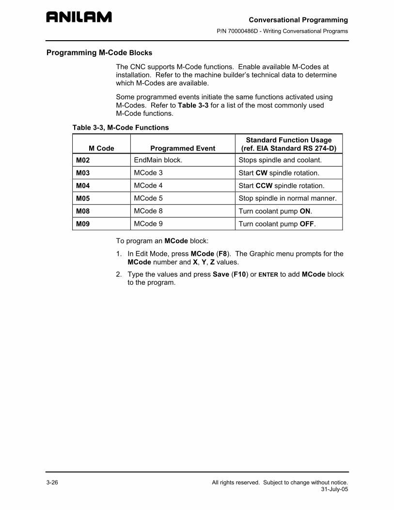
Programming M-Code Blocks
The CNC supports M-Code functions. Enable available M-Codes at installation. Refer to the machine builder’s technical data to determine which M-Codes are available.
Some programmed events initiate the same functions activated using M-Codes. Refer to Table 3-3 for a list of the most commonly used M-Code functions.
Table 3-3, M-Code Functions
M Code
Programmed Event Standard Function Usage
(ref. EIA Standard RS 274-D) M02 EndMain block. Stops spindle and coolant.
M03 MCode 3 Start CW spindle rotation.
M04 MCode 4 Start CCW spindle rotation.
M05 MCode 5 Stop spindle in normal manner.
M08 MCode 8 Turn coolant pump ON.
M09 MCode 9 Turn coolant pump OFF.
To program an MCode block:
1. In Edit Mode, press MCode (F8). The Graphic menu prompts for the MCode number and X, Y, Z values.
2. Type the values and press Save (F10) or ENTER to add MCode block to the program.
Conversational Programming P/N 70000486D - Writing Conversational Programs
All rights reserved. Subject to change without notice. 3-27 31-July-05
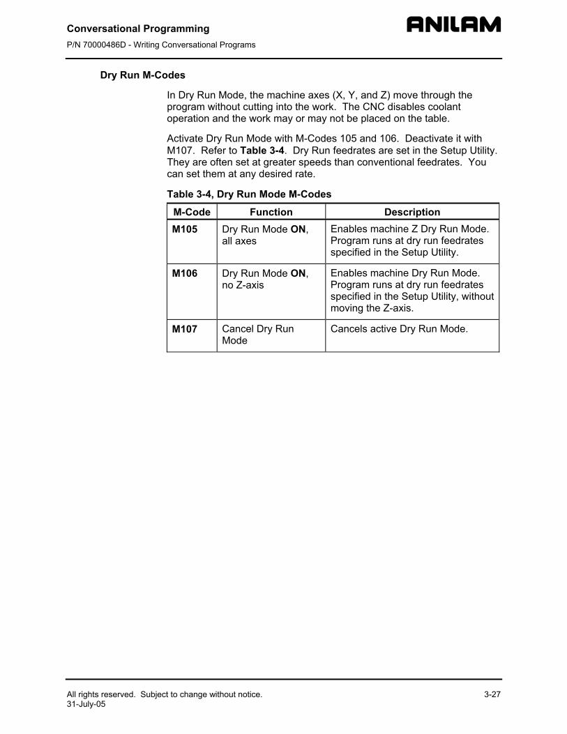
Dry Run M-Codes
In Dry Run Mode, the machine axes (X, Y, and Z) move through the program without cutting into the work. The CNC disables coolant operation and the work may or may not be placed on the table.
Activate Dry Run Mode with M-Codes 105 and 106. Deactivate it with M107. Refer to Table 3-4. Dry Run feedrates are set in the Setup Utility. They are often set at greater speeds than conventional feedrates. You can set them at any desired rate.
Table 3-4, Dry Run Mode M-Codes
M-Code Function Description M105 Dry Run Mode ON,
all axes Enables machine Z Dry Run Mode. Program runs at dry run feedrates specified in the Setup Utility.
M106 Dry Run Mode ON, no Z-axis
Enables machine Dry Run Mode. Program runs at dry run feedrates specified in the Setup Utility, without moving the Z-axis.
M107 Cancel Dry Run Mode
Cancels active Dry Run Mode.
Conversational Programming P/N 70000486D - Programming Canned Cycles, Ellipses, and Spirals
All rights reserved. Subject to change without notice. 4-1 31-July-05
Section 4 - Programming Canned Cycles, Ellipses, and Spirals
Drilling Cycles
NOTE: Program all blocks by filling in the entry fields of a Graphic Menu.
Drill cycles simplify the programming required for repetitive drilling, boring, and tapping operations. Select specific drill cycles from the Program Editor’s Drill (F3) pop-up menu:
Basic (drill cycle) Pecking Boring Chip Break Tapping Drilling Off Pattern Bolt Hole Thread Mill
Drill cycles are modal. When the CNC encounters a block for any type of Drill cycle, it executes that cycle at the endpoint of each subsequent move until it encounters a DrillOff block. To change drill cycle parameters between moves, program a new drill block.
Basic Drill Cycle
The Basic Drill Cycle is a modal operation. When the CNC receives a BasicDrill command, it performs the drilling operation at the endpoint of every subsequent block until it receives a Drilling Off block. To change Basic Drilling dimensions cancel the current cycle and program a new cycle.
During the cycle, the tool rapids to the StartHgt, then Z feeds to ZDepth. To provide clearance for the next move, at the end of the cycle, the tool rapids to ReturnHgt.
Program a DrillOff block to deactivate the cycle. You can program any number of patterns and moves before turning off the cycle.
To program a BasicDrill block:
1. In Edit mode, press Drill (F3) to display the Drill cycle pop-up menu.
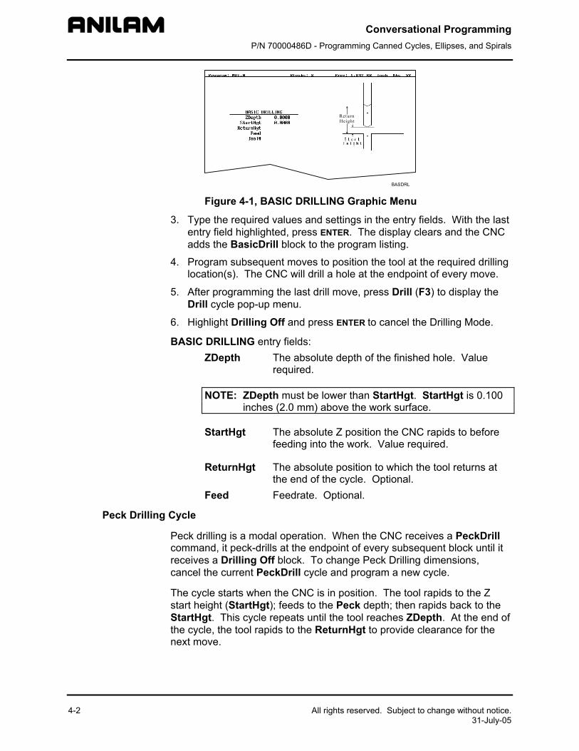
2. Highlight Basic and press ENTER to display the BASIC DRILLING Graphic Menu. Refer to Figure 4-1, BASIC DRILLING Graphic Menu.
Conversational Programming P/N 70000486D - Programming Canned Cycles, Ellipses, and Spirals
4-2
Figure 4-1, BAS
3. Type the required vaentry field highlighteadds the BasicDrill
4. Program subsequenlocation(s). The CN
5. After programming tDrill cycle pop-up m
6. Highlight Drilling Of
BASIC DRILLING entryZDepth Th
re
NOTE: ZDepth inches (
StartHgt Thfe
ReturnHgt Thth
Feed Fe
Peck Drilling Cycle
Peck drilling is a modal command, it peck-drills receives a Drilling Off bcancel the current Peck
The cycle starts when thstart height (StartHgt); fStartHgt. This cycle repthe cycle, the tool rapidsnext move.
All rights reserved. Subject to change without notice. 31-July-05
IC DRILLING Graphic Menu
lues and settings in the entry fields. With the last d, press ENTER. The display clears and the CNC block to the program listing.
t moves to position the tool at the required drilling C will drill a hole at the endpoint of every move.
he last drill move, press Drill (F3) to display the enu.
f and press ENTER to cancel the Drilling Mode.
fields: e absolute depth of the finished hole. Value
quired.
must be lower than StartHgt. StartHgt is 0.100 2.0 mm) above the work surface.
e absolute Z position the CNC rapids to before eding into the work. Value required.
e absolute position to which the tool returns at e end of the cycle. Optional. edrate. Optional.
operation. When the CNC receives a PeckDrill at the endpoint of every subsequent block until it lock. To change Peck Drilling dimensions, Drill cycle and program a new cycle.
e CNC is in position. The tool rapids to the Z eeds to the Peck depth; then rapids back to the eats until the tool reaches ZDepth. At the end of to the ReturnHgt to provide clearance for the
Conversational Programming P/N 70000486D - Programming Canned Cycles, Ellipses, and Spirals
All rights reserved. Subject to change without notice. 31-July-05
To program a Peck Drilling cycle:
1. In Edit mode, press Drill (F3) to display the Drill cycle pop-up menu.
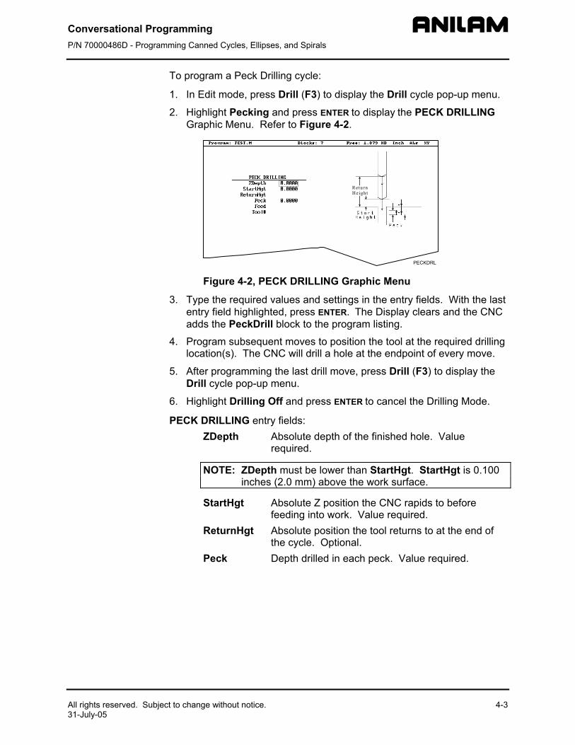
2. Highlight Pecking and press ENTER to display the PECK DRILLING Graphic Menu. Refer to Figure 4-2.
Figure 4-2, PE
3. Type the required ventry field highlightadds the PeckDrill
4. Program subsequelocation(s). The CN
5. After programmingDrill cycle pop-up m
6. Highlight Drilling O
PECK DRILLING entryZDepth
NOTE: ZDepthinches
StartHgt
ReturnHgt
Peck
4-3
CK DRILLING Graphic Menu
alues and settings in the entry fields. With the last ed, press ENTER. The Display clears and the CNC block to the program listing.
nt moves to position the tool at the required drilling C will drill a hole at the endpoint of every move.
the last drill move, press Drill (F3) to display the enu.
ff and press ENTER to cancel the Drilling Mode.
fields: Absolute depth of the finished hole. Value required.
must be lower than StartHgt. StartHgt is 0.100 (2.0 mm) above the work surface.
Absolute Z position the CNC rapids to before feeding into work. Value required. Absolute position the tool returns to at the end of the cycle. Optional. Depth drilled in each peck. Value required.
Conversational Programming P/N 70000486D - Programming Canned Cycles, Ellipses, and Spirals
4-4 All rights reserved. Subject to change without notice. 31-July-05
Boring Cycle
Boring is a modal operation. When the CNC encounters a Boring block it executes a Boring Cycle at the endpoint of every subsequent move until it sees a Drilling Off block. To change Boring Cycle dimensions between moves, deactivate the cycle and program a new boring block.
The cycle starts when the CNC is in position. The tool rapids to the StartHgt, feeds to ZDepth, then feeds back to StartHgt. At the end of the cycle, the tool moves to ReturnHgt to provide clearance for the next move.
When running a Dwell block, the CNC pauses at ZDepth for the indicated time period (in seconds). Dwell resolution is 0.1 sec. When you type 0.0 sec., the CNC dwells until manually restarted.
To program a Boring cycle:
1. In Edit mode, press Drill (F3) to display the Drill cycle pop-up menu.
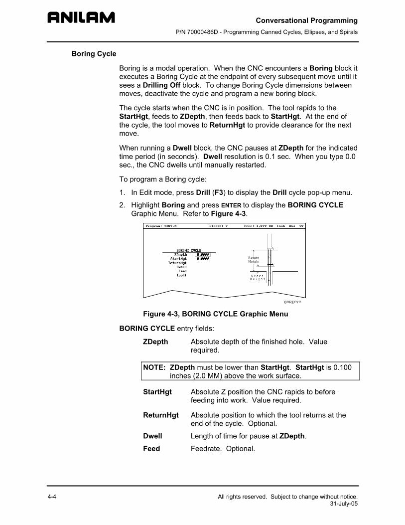
2. Highlight Boring and press ENTER to display the BORING CYCLE Graphic Menu. Refer to Figure 4-3.
Figure 4-3, BORING CYCLE Graphic Menu
BORING CYCLE entry fields:
ZDepth Absolute depth of the finished hole. Value required.
NOTE: ZDepth must be lower than StartHgt. StartHgt is 0.100 inches (2.0 MM) above the work surface.
StartHgt Absolute Z position the CNC rapids to before feeding into work. Value required.
ReturnHgt Absolute position to which the tool returns at the end of the cycle. Optional.
Dwell Length of time for pause at ZDepth.
Feed Feedrate. Optional.
Conversational Programming P/N 70000486D - Programming Canned Cycles, Ellipses, and Spirals
All rights reserved. Subject to change without notice. 31-July-05
3. Type the required values and settings in the entry fields. With the last entry field highlighted, press ENTER. The display clears and the CNC adds Boring block to the program listing.
4. Program subsequent moves to position the work at the required boring locations. The CNC executes the Boring Cycle at the endpoint of every move.
5. After programming the last boring position, press Drill (F3) to display the Drill cycle pop-up menu.
6. Highlight Drilling Off and press ENTER to cancel the cycle.
Chip Break Cycle
The Chip Break Cycle is modal. Once the CNC encounters a ChipBreak block, it executes the Chip Break Cycle at the endpoint of each block until it sees a Drilling Off block. To change Chip Break values between moves, deactivate the cycle and program a new one.
The cycle starts when the CNC is in position. The tool rapids to the StartHgt, feeds to the FirstPeck, retracts 0.02 inches [0.4 mm (default value)], then feeds to the next peck. Retract moves occur at the end of each peck in order to break the chip. This cycle repeats until the tool reaches ZDepth. At the end of the cycle, the tool moves to ReturnHgt to provide clearance for the next move.
Type a PeckDecr value to decrement the depth of each peck by the specified amount. The MinPeck sets the minimum peck the cycle can decrement. A ChipBrkInc is the size of the retract move that breaks the chip.
Peck to the RetractDep, retract to the StartHgt, then peck to the next RetractDep increment. The first full retract occurs one RetractDep increment after the first peck.
To program a Chip Break cycle:
1. In Edit Mode, press Drill (F3) to display the Drill cycle pop-up menu.
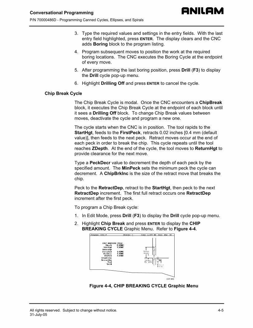
2. Highlight Chip Break and press ENTER to display the CHIP BREAKING CYCLE Graphic Menu. Refer to Figure 4-4.
Figure 4-4, CHIP
4-5
BREAKING CYCLE Graphic Menu
Conversational Programming P/N 70000486D - Programming Canned Cycles, Ellipses, and Spirals
4-6 All rights reserved. Subject to change without notice. 31-July-05
CHIP BREAKING CYCLE entry fields: ZDepth Absolute depth of the finished hole. Value
required.
NOTE: ZDepth must be lower than StartHgt. StartHgt is 0.100 inches (2.0 mm) above the work surface.
StartHgt Absolute Z position to which the CNC rapids before feeding into work. Value required.
ReturnHgt Absolute position to which the tool returns at the end of the cycle. Optional.
FirstPeck Absolute depth drilled in each peck. Value required.
PeckDecr Amount to subtract from previous peck (positive dimension). Value required.
MinPeck Smallest peck allowed. Value required. ChipBrkInc Size of chip break retract. Optional. RetractDep Z increment before full retract. Optional.
3. Type the required values and settings in the entry fields. With the last entry field highlighted, press ENTER. The display clears and the CNC adds the Chip Break block to the program listing.
4. Program the drilling location(s). The CNC will drill a hole at the endpoint of every move until it receives the Drilling Off command.
5. Program the Drilling Off command. After programming the last drill move, press Drill (F3) to display the Drill cycle pop-up menu.
6. Highlight Drilling Off and press ENTER to add the DrillOff block to the program Listing.
Tapping Cycle
The Tapping Cycle is available only on machines equipped with spindle RPM control and M-Codes (M3, M4, and M5).
In order for the cycle to operate, you must program a Spindle RPM block. During execution, the CNC uses the Spindle RPM programmed value and the programmed threads per inch (or pitch) value from the block to calculate the proper feedrate for tapping.
When the cycle, runs the CNC rapids to the StartHgt and feeds to the ZDepth. The spindle stops and reverses direction to retract the tool from the hole. At ReturnHgt, the spindle stops and changes back to the original direction in preparation for the next programmed move.
Use the Tapping Cycle with any available pattern. A Drilling Off block cancels the cycle.
NOTE: The system supports spindle FWD, REV, OFF (M3, M4, M5), and spindle RPM control. At machine setup the machine builder determines which M-Codes to install.
Conversational Programming P/N 70000486D - Programming Canned Cycles, Ellipses, and Spirals
All rights reserved. Subject to change without notice. 4-7 31-July-05
To program a Tapping block:
1. In Edit mode, press Drill (F3) to display the Drill cycle pop-up menu.
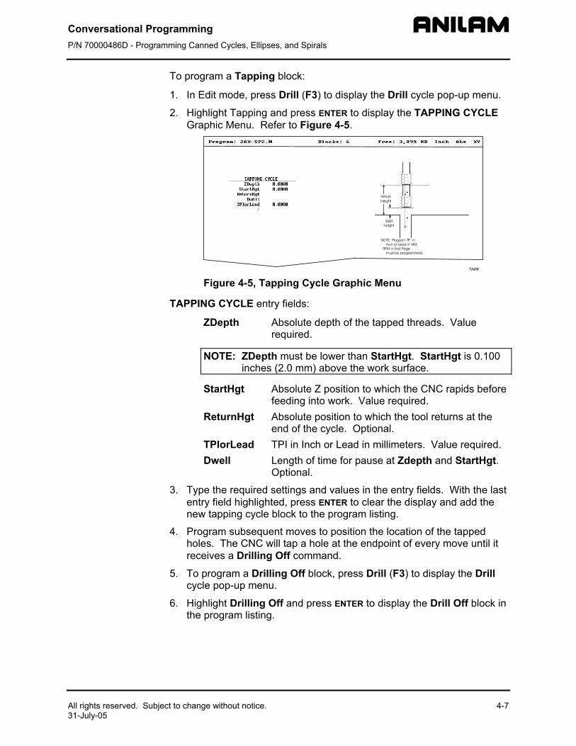
2. Highlight Tapping and press ENTER to display the TAPPING CYCLE Graphic Menu. Refer to Figure 4-5.
Figure 4-5, Tapping Cycle Graphic Menu
TAPPING CYCLE entry fields:
ZDepth Absolute depth of the tapped threads. Value required.
NOTE: ZDepth must be lower than StartHgt. StartHgt is 0.100 inches (2.0 mm) above the work surface.
StartHgt Absolute Z position to which the CNC rapids before feeding into work. Value required.
ReturnHgt Absolute position to which the tool returns at the end of the cycle. Optional.
TPIorLead TPI in Inch or Lead in millimeters. Value required. Dwell Length of time for pause at Zdepth and StartHgt.
Optional.
3. Type the required settings and values in the entry fields. With the last entry field highlighted, press ENTER to clear the display and add the new tapping cycle block to the program listing.
4. Program subsequent moves to position the location of the tapped holes. The CNC will tap a hole at the endpoint of every move until it receives a Drilling Off command.
5. To program a Drilling Off block, press Drill (F3) to display the Drill cycle pop-up menu.
6. Highlight Drilling Off and press ENTER to display the Drill Off block in the program listing.
Conversational Programming P/N 70000486D - Programming Canned Cycles, Ellipses, and Spirals
4-8
Drill Pattern
The Pattern Cycle instructs the CNC to execute a pattern of regularly spaced moves. Locate a Pattern Cycle between a Drill Cycle and a DrillOff block. The CNC executes the Drill Cycle at every endpoint in the pattern.
In a Pattern Cycle, type a size, location, spacing, Tool #, and rotation angle of the pattern.
To program a Drill Pattern cycle:
1. In Edit Mode, press Drill (F3) to display the Drill cycle pop-up menu.
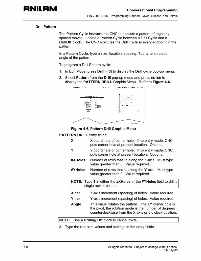
2. Select Pattern from the Drill pop-up menu and press ENTER to display the PATTERN DRILL Graphic Menu. Refer to Figure 4-6.
Figure 4-6, PatPATTERN DRILL entr
X X cput
Y Y cput
#XHoles Numvalu
#YHoles Numvalu
NOTE: Type 1single r
Xincr X-aYincr Y-aAngle Thi
thecou
NOTE: Use a Drilling
3. Type the required v
All rights reserved. Subject to change without notice. 31-July-05
tern Drill Graphic Menu y fields: oordinate of corner hole. If no entry made, CNC s corner hole at present location. Optional. oordinate of corner hole. If no entry made, CNC s corner hole at present location. Optional.
ber of rows that lie along the X-axis. Must type e greater than 0. Value required. ber of rows that lie along the Y-axis. Must type e greater than 0. Value required.
in either the #XHoles or the #YHoles field to drill a ow or column.
xis increment (spacing) of holes. Value required. xis increment (spacing) of holes. Value required. s value rotates the pattern. The XY corner hole is pivot, the rotation angle is the number of degrees nterclockwise from the X-axis or 3 o’clock position.
Off block to cancel cycle.
alues and settings in the entry fields.
Conversational Programming P/N 70000486D - Programming Canned Cycles, Ellipses, and Spirals
All rights reserved. Subject to change without notice. 31-July-05
Bolt Hole Pattern
The Bolt Hole Cycle instructs the CNC to run a series of moves with endpoints that form a circular pattern. At each of these endpoints, you can run a previously programmed Drill Cycle.
You should first program a Drill Cycle to describe the hole being drilled. Then follow the Drill Cycle by one or more moves, patterns, or Bolt Hole cycles to position the CNC for the Drill Cycle. A DrillOff block cancels the cycle.
To program a Bolt Hole Cycle:
1. In Edit Mode, press Drill (F3) to display a pop-up menu.
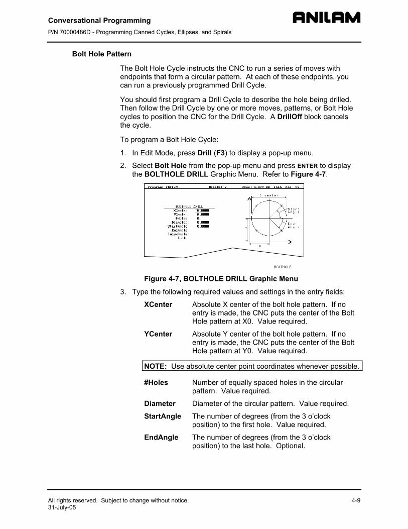
2. Select Bolt Hole from the pop-up menu and press ENTER to display the BOLTHOLE DRILL Graphic Menu. Refer to Figure 4-7.
Figure 4-7, BO
3. Type the following
XCenter AeH
YCenter AeH
NOTE: Use ab
#Holes Np
Diameter D
StartAngle Tp
EndAngle Tp
4-9
LTHOLE DRILL Graphic Menu
required values and settings in the entry fields:
bsolute X center of the bolt hole pattern. If no ntry is made, the CNC puts the center of the Bolt ole pattern at X0. Value required.
bsolute Y center of the bolt hole pattern. If no ntry is made, the CNC puts the center of the Bolt ole pattern at Y0. Value required.
solute center point coordinates whenever possible.
umber of equally spaced holes in the circular attern. Value required.
iameter of the circular pattern. Value required.
he number of degrees (from the 3 o’clock osition) to the first hole. Value required.
he number of degrees (from the 3 o’clock osition) to the last hole. Optional.
Conversational Programming P/N 70000486D - Programming Canned Cycles, Ellipses, and Spirals
4-10
IndexAngle The number of degrees that the 3 o’clock reference position rotates around the center (rotates entire pattern).
NOTE: Use a Drilling Off block to cancel the cycle.
Thread Milling Cycle Thread Milling Cycle simplifies the programming required to mill a thread. It will cut inside or outside, up or down, straight or tapered right or left hand, and inch or metric. Tool must be position at center of hole or boss. This can be done either by positioning before putting cycle in the program or in the cycle.
Cutter compensation is built into cycle, so cutter diameter must be entered into tool table correctly.
Xcenter, Ycenter, RoughFeed, FinFeed, and TaperAng are all optional Input; all other parameters must be programmed. If the feed rates are not programmed, the CNC will use last feed rate used.
Cycle will always take the final pass twice. Diameter is always the major diameter of thread. Inside diameter is at finished depth and outside diameter is the diameter of boss.
To program a Thread Milling Cycle:
1. In Edit Mode, press Drill (F3) to display a pop-up menu.
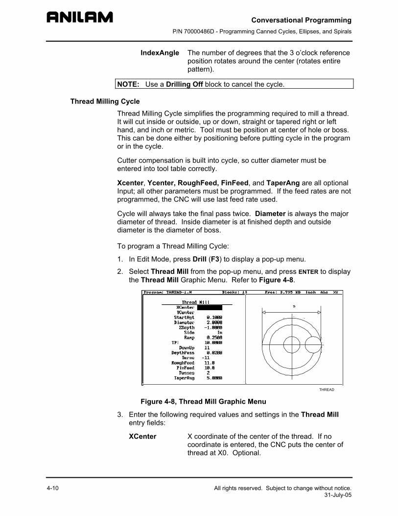
2. Select Thread Mill from the pop-up menu, and press ENTER to display the Thread Mill Graphic Menu. Refer to Figure 4-8.
3. Ee
X
All rights reserved. Subject to change without notice. 31-July-05
THREAD Figure 4-8, Thread Mill Graphic Menu
nter the following required values and settings in the Thread Mill ntry fields:
Center X coordinate of the center of the thread. If no coordinate is entered, the CNC puts the center of thread at X0. Optional.
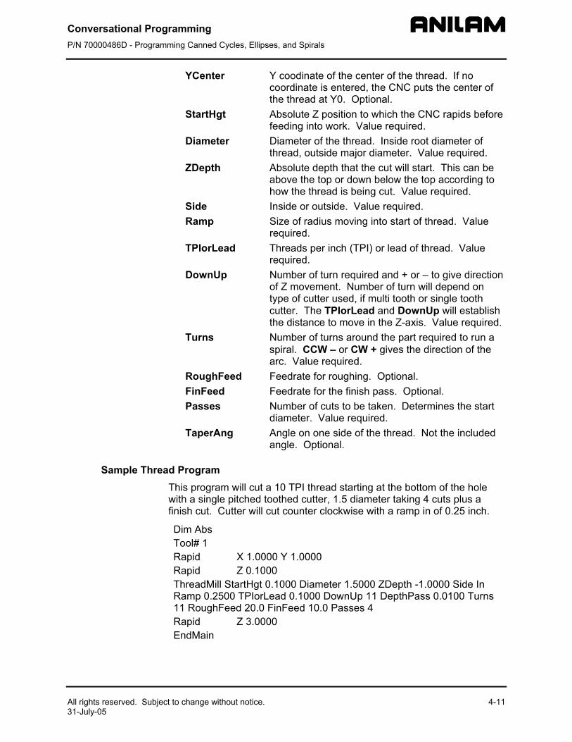
Conversational Programming P/N 70000486D - Programming Canned Cycles, Ellipses, and Spirals
All rights reserved. Subject to change without notice. 31-July-05
YCenter Y coodinate of the center of the thread. If no coordinate is entered, the CNC puts the center of the thread at Y0. Optional.
StartHgt Absolute Z position to which the CNC rapids before feeding into work. Value required.
Diameter Diameter of the thread. Inside root diameter of thread, outside major diameter. Value required.
ZDepth Absolute depth that the cut will start. This can be above the top or down below the top according to how the thread is being cut. Value required.
Side Inside or outside. Value required. Ramp Size of radius moving into start of thread. Value
required. TPIorLead Threads per inch (TPI) or lead of thread. Value
required. DownUp Number of turn required and + or – to give direction
of Z movement. Number of turn will depend on type of cutter used, if multi tooth or single tooth cutter. The TPIorLead and DownUp will establish the distance to move in the Z-axis. Value required.
Turns Number of turns around the part required to run a spiral. CCW – or CW + gives the direction of the arc. Value required.
RoughFeed Feedrate for roughing. Optional. FinFeed Feedrate for the finish pass. Optional. Passes Number of cuts to be taken. Determines the start
diameter. Value required. TaperAng Angle on one side of the thread. Not the included
angle. Optional.
Sample Thread Program This program will cut a 10 TPI thread starting at the bottom of the hole with a single pitched toothed cutter, 1.5 diameter taking 4 cuts plus a finish cut. Cutter will cut counter clockwise with a ramp in of 0.25 inch.
Dim Abs Tool# 1 Rapid X 1.0000 Y 1.0000 Rapid Z 0.1000 ThreadMill StartHgt 0.1000 Diameter 1.5000 ZDepth -1.0000 Side In Ramp 0.2500 TPIorLead 0.1000 DownUp 11 DepthPass 0.0100 Turns 11 RoughFeed 20.0 F Feed 10.0 Passes 4 Rapid Z 3.000 EndMain
in0
4-11
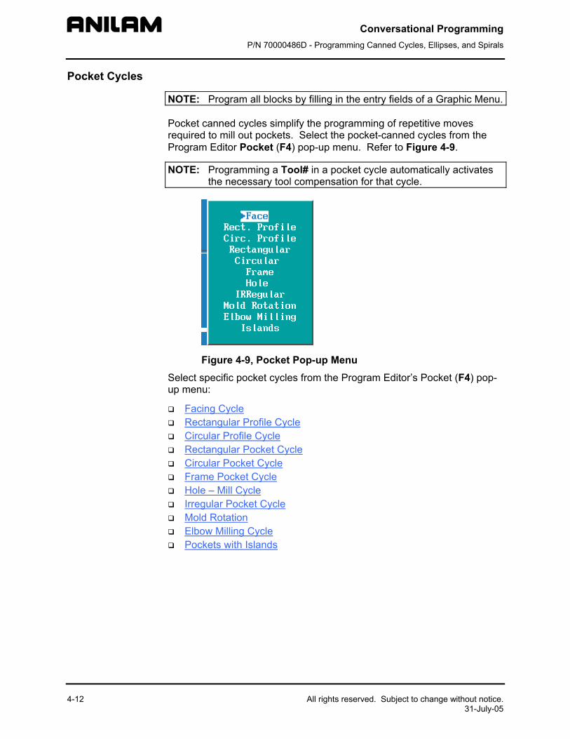
Conversational Programming P/N 70000486D - Programming Canned Cycles, Ellipses, and Spirals
4-12 All rights reserved. Subject to change without notice. 31-July-05
Pocket Cycles
NOTE: Program all blocks by filling in the entry fields of a Graphic Menu.
Pocket canned cycles simplify the programming of repetitive moves required to mill out pockets. Select the pocket-canned cycles from the Program Editor Pocket (F4) pop-up menu. Refer to Figure 4-9.
NOTE: Programming a Tool# in a pocket cycle automatically activates the necessary tool compensation for that cycle.
Figure 4-9, Pocket Pop-up Menu Select specific pocket cycles from the Program Editor’s Pocket (F4) pop-up menu:
Facing Cycle Rectangular Profile Cycle Circular Profile Cycle Rectangular Pocket Cycle Circular Pocket Cycle Frame Pocket Cycle Hole – Mill Cycle Irregular Pocket Cycle Mold Rotation Elbow Milling Cycle Pockets with Islands
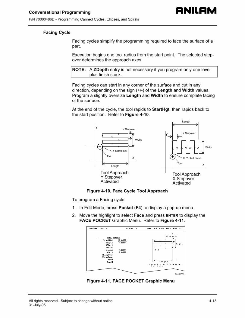
Conversational Programming P/N 70000486D - Programming Canned Cycles, Ellipses, and Spirals
All rights reserved. Subject to change without notice31-July-05
Facing Cycle
Facing cycles simplify the programming required to face the surface of a part.
Execution begins one tool radius from the start point. The selected step-over determines the approach axes.
NOTE: A ZDepth entry is not necessary if you program only one level plus finish stock.
Facing cycles can start in any corner of the surface and cut in any direction, depending on the sign (+/-) of the Length and Width values. Program a slightly oversize Length and Width to ensure complete facing of the surface.
At the end of the cycle, the tool rapids to StartHgt, then rapids back to the start position. Refer to Figure 4-10.
Figure 4-10,
To program a Facing
1. In Edit Mode, pre
2. Move the highligFACE POCKET
Figure 4-11,
. 4-13
Face Cycle Tool Approach
cycle:
ss Pocket (F4) to display a pop-up menu.
ht to select Face and press ENTER to display the Graphic Menu. Refer to Figure 4-11.
FACE POCKET Graphic Menu
Conversational Programming P/N 70000486D - Programming Canned Cycles, Ellipses, and Spirals
4-14 All rights reserved. Subject to change without notice. 31-July-05
NOTE: ZDepth must be lower than StartHgt. StartHgt is 0.100 inches (2.0 mm) above the work surface.
FACE POCKET entry fields:
ZDepth Absolute depth of the finished surface. Value required.
StartHgt Absolute Z position the CNC rapids to before feeding into work. Value required.
XStart X coordinate of the starting point. Optional.
YStart Y coordinate of the starting point. Optional.
NOTE: Type the required absolute XStart and YStart coordinates when possible.
Length X-axis length to be faced. Value required.
Width Y-axis length to be faced. Value required.
XStepover Width of cut in the X-axis direction. When no value is typed, the CNC defaults to 70% of the active tool radius. Maximum step-over permitted is 70% of the active tool radius.
NOTE: Type either an XStepover or YStepover. Do not type both.
YStepover Width of cut in the Y-axis direction. When no value is typed, the CNC defaults to 70% of the active tool radius. Maximum step-over permitted is 70% of the active tool radius.
NOTE: The Program Editor inadvertently will allow you to write a block containing a Stepover value greater than 70% of the active tool radius. To reveal this type of error, test the program in the Draw Graphics Mode.
3. Type the required values and settings in the entry fields.
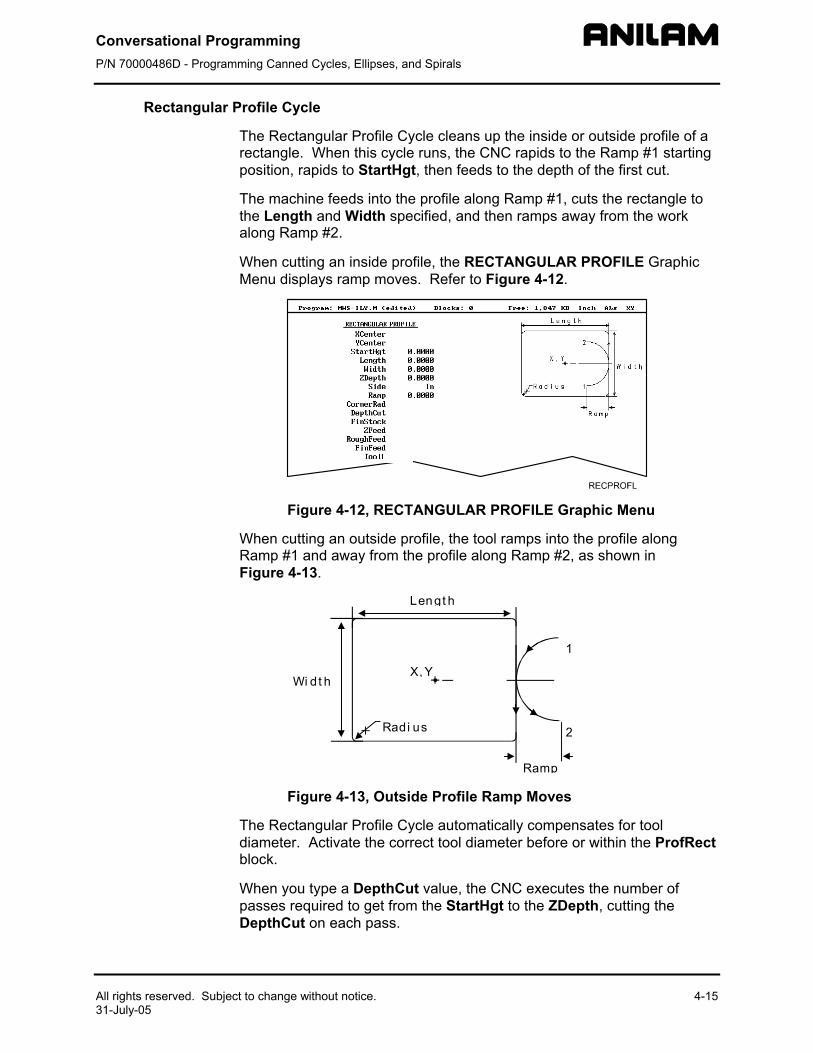
Conversational Programming P/N 70000486D - Programming Canned Cycles, Ellipses, and Spirals
All rights reserved. Subject to change without notice. 31-July-05
Rectangular Profile Cycle
The Rectangular Profile Cycle cleans up the inside or outside profile of a rectangle. When this cycle runs, the CNC rapids to the Ramp #1 starting position, rapids to StartHgt, then feeds to the depth of the first cut.
The machine feeds into the profile along Ramp #1, cuts the rectangle to the Length and Width specified, and then ramps away from the work along Ramp #2.
When cutting an inside profile, the RECTANGULAR PROFILE Graphic Menu displays ramp moves. Refer to Figure 4-12.
Figure 4-12, RE
When cutting an outsidRamp #1 and away froFigure 4-13.
Wi dt h
R
Figure 4-13, O
The Rectangular Profildiameter. Activate theblock.
When you type a Deptpasses required to get DepthCut on each pas
4-15
CTANGULAR PROFILE Graphic Menu
e profile, the tool ramps into the profile along m the profile along Ramp #2, as shown in
Lengt h
Ramp
X, Y
1
2adi us
utside Profile Ramp Moves
e Cycle automatically compensates for tool correct tool diameter before or within the ProfRect
hCut value, the CNC executes the number of from the StartHgt to the ZDepth, cutting the s.
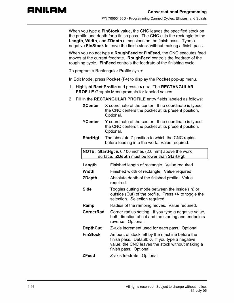
Conversational Programming P/N 70000486D - Programming Canned Cycles, Ellipses, and Spirals
4-16 All rights reserved. Subject to change without notice. 31-July-05
When you type a FinStock value, the CNC leaves the specified stock on the profile and depth for a finish pass. The CNC cuts the rectangle to the Length, Width, and ZDepth dimensions on the finish pass. Type a negative FinStock to leave the finish stock without making a finish pass.
When you do not type a RoughFeed or FinFeed, the CNC executes feed moves at the current feedrate. RoughFeed controls the feedrate of the roughing cycle. FinFeed controls the feedrate of the finishing cycle.
To program a Rectangular Profile cycle:
In Edit Mode, press Pocket (F4) to display the Pocket pop-up menu.
1. Highlight Rect.Profile and press ENTER. The RECTANGULAR PROFILE Graphic Menu prompts for labeled values.
2. Fill in the RECTANGULAR PROFILE entry fields labeled as follows: XCenter X coordinate of the center. If no coordinate is typed,
the CNC centers the pocket at its present position. Optional.
YCenter Y coordinate of the center. If no coordinate is typed, the CNC centers the pocket at its present position. Optional.
StartHgt The absolute Z position to which the CNC rapids before feeding into the work. Value required.
NOTE: StartHgt is 0.100 inches (2.0 mm) above the work surface. ZDepth must be lower than StartHgt.
Length Finished length of rectangle. Value required. Width Finished width of rectangle. Value required. ZDepth Absolute depth of the finished profile. Value
required. Side Toggles cutting mode between the inside (In) or
outside (Out) of the profile. Press +/- to toggle the selection. Selection required.
Ramp Radius of the ramping moves. Value required. CornerRad Corner radius setting. If you type a negative value,
both direction of cut and the starting and endpoints reverse. Optional.
DepthCut Z-axis increment used for each pass. Optional. FinStock Amount of stock left by the machine before the
finish pass. Default: 0. If you type a negative value, the CNC leaves the stock without making a finish pass. Optional.
ZFeed Z-axis feedrate. Optional.
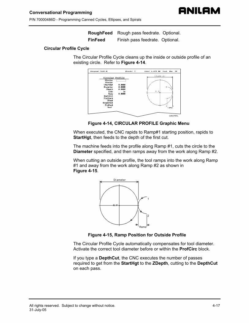
Conversational Programming P/N 70000486D - Programming Canned Cycles, Ellipses, and Spirals
All rights reserved. Subject to change without notice.31-July-05
RoughFeed Rough pass feedrate. Optional. FinFeed Finish pass feedrate. Optional.
Circular Profile Cycle
The Circular Profile Cycle cleans up the inside or outside profile of an existing circle. Refer to Figure 4-14.
Figure 4-14, CIRCULAR PROFILE Graphic Menu
When executed, the CNC rapids to Ramp#1 starting position, rapids to StartHgt, then feeds to the depth of the first cut.
The machine feeds into the profile along Ramp #1, cuts the circle to the Diameter specified, and then ramps away from the work along Ramp #2.
When cutting an outside profile, the tool ramps into the work along Ramp #1 and away from the work along Ramp #2 as shown in Figure 4-15.
X,Y
1
2
Ramp
Di ameter
Figure 4-15, R
The Circular Profile CActivate the correct to
If you type a DepthCrequired to get from ton each pass.
4-17
amp Position for Outside Profile
ycle automatically compensates for tool diameter. ol diameter before or within the ProfCirc block.
ut, the CNC executes the number of passes he StartHgt to the ZDepth, cutting to the DepthCut
Conversational Programming P/N 70000486D - Programming Canned Cycles, Ellipses, and Spirals
4-18 All rights reserved. Subject to change without notice. 31-July-05
When you type a FinStock value, the CNC leaves the specified stock on the profile and depth for a finish pass. The CNC finishes to the typed diameter on the finish pass. Type a negative FinStock to leave the finish stock without making a finish pass.
If you do not type a RoughFeed or FinFeed, the CNC executes feed moves at the current feedrate. RoughFeed controls feedrate of the roughing cycle. FinFeed controls the feedrate of the finishing cycle.
To program a Circular Profile cycle:
1. In Edit Mode, press Pocket (F4) to display the Pocket pop-up menu.
2. Highlight Circ.Profile and press ENTER to display the CIRCULAR PROFILE Graphic Menu. Refer to Figure 4-14, CIRCULAR PROFILE Graphic Menu.
3. Fill in the CIRCULAR PROFILE entry fields: XCenter X coordinate of the center. Default: present
position. Optional. YCenter Y coordinate of the center. Default: present
position. Optional. StartHgt Absolute Z position to which the CNC rapids before
feeding into work. Value required.
NOTE: StartHgt is 0.100 inches (2.0 mm) above the work surface. ZDepth must be lower than StartHgt.
Diameter Finished diameter of circle. If you type a negative value, both the direction of cut and the starting and endpoints reverse. Value required.
ZDepth Absolute depth of the finished profile. Value required.
Side Selection for cutting on the inside of the profile (In) or the outside (Out). Press +/- to toggle the selection. Selection required.
Ramp Radius of the ramp into and away from the cut. Value required (0 value allowed).
DepthCut Z-axis increment used for each pass. Optional. FinStock Amount of stock left by the machine before the
finish pass. Default: 0. Type a negative value to leave the stock without making a finish pass. Optional.
ZFeed Z-axis feedrate. Optional. RoughFeed Rough pass feedrate. Optional. FinFeed Finish pass feedrate. Optional.
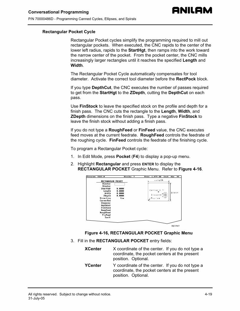
Conversational Programming P/N 70000486D - Programming Canned Cycles, Ellipses, and Spirals
All rights reserved. Subject to change without notice.31-July-05
Rectangular Pocket Cycle
Rectangular Pocket cycles simplify the programming required to mill out rectangular pockets. When executed, the CNC rapids to the center of the lower left radius, rapids to the StartHgt, then ramps into the work toward the narrow center of the pocket. From the pocket center, the CNC mills increasingly larger rectangles until it reaches the specified Length and Width.
The Rectangular Pocket Cycle automatically compensates for tool diameter. Activate the correct tool diameter before the RectPock block.
If you type DepthCut, the CNC executes the number of passes required to get from the StartHgt to the ZDepth, cutting the DepthCut on each pass.
Use FinStock to leave the specified stock on the profile and depth for a finish pass. The CNC cuts the rectangle to the Length, Width, and ZDepth dimensions o the finish pass. Type a negative FinStock to leave the finish stock
If you do not type a Rfeed moves at the cuthe roughing cycle. F
To program a Rectan
1. In Edit Mode, pres
2. Highlight RectangRECTANGULAR
Figure 4-16, R
3. Fill in the RECTA
XCenter
YCenter
n
4-19
without adding a finish pass.
oughFeed or FinFeed value, the CNC executes rrent feedrate. RoughFeed controls the feedrate of inFeed controls the feedrate of the finishing cycle.
gular Pocket cycle:
s Pocket (F4) to display a pop-up menu.
ular and press ENTER to display the POCKET Graphic Menu. Refer to Figure 4-16.
ECTANGULAR POCKET Graphic Menu
NGULAR POCKET entry fields:
X coordinate of the center. If you do not type a coordinate, the pocket centers at the present position. Optional. Y coordinate of the center. If you do not type a coordinate, the pocket centers at the present position. Optional.
Conversational Programming P/N 70000486D - Programming Canned Cycles, Ellipses, and Spirals
4-20 All rights reserved. Subject to change without notice. 31-July-05
StartHgt Absolute Z position to which the CNC rapids to before feeding into the work. Value required.
NOTE: StartHgt is 0.100 inches (2.0 mm) above the work surface. ZDepth must be lower than StartHgt.
Length Inside Y length of the finished pocket. Value required.
Width Inside X length of the finished pocket. Value required.
ZDepth Absolute depth of the finished pocket. Value required.
Direction Allows you to select a clockwise (Cw) or counterclockwise (Ccw) direction. Press +/- to toggle the selection. Selection required.
Stepover Width of cut. If you do not type a value, the CNC defaults to 70% of the active tool radius. The maximum step-over permitted is 70% of the active tool diameter. Optional.
DepthCut Depth the machine takes in a single pass. Defaults to a single ZDepth cut minus the finish stock. Optional.
FinStock Amount of stock left by the machine before the finish pass. Default: 0. Type a negative value to leave the stock without making a finish pass. Optional.
ZFeed Z-axis feedrate. Optional. RoughFeed Rough pass feedrate. Optional. FinFeed Finish pass feedrate. Optional.

Conversational Programming P/N 70000486D - Programming Canned Cycles, Ellipses, and Spirals
All rights reserved. Subject to change without notice. 4-21 31-July-05
Circular Pocket Cycle
Circular Pocket cycles simplify the programming of circular pockets. When executed, the CNC rapids to the center, rapids to the StartHgt, and then ramps into the work. The tool will circle outward from the center starting position, until it reaches the pocket Diameter. The tool circles back toward the center until the pass is complete.
The Circular Pocket Cycle automatically compensates for tool diameter. Activate the correct tool diameter before the CircPock block.
Use DepthCut to specify the number of passes required to get from the StartHgt to the ZDepth, cutting the DepthCut on each pass.
Use FinStock to leave the specified stock on the profile and depth for a finish pass. The cycle cuts the profile to the Diameter and ZDepth dimensions on the finish pass. Type a negative FinStock to leave the finish stock without making a finish pass.
Leave RoughFeed and FinFeed blank to execute feed moves at the current feedrate. RoughFeed controls the feedrate of the roughing cycle. FinFeed controls the feedrate of the finishing cycle.
To program a Circular Pocket cycle:
1. In Edit Mode, press Pocket (F4) to display a pop-up menu.
2. Move the highlight to select Circular and press ENTER to display the CIRCULAR POCKET Graphic Menu. Refer to Figure 4-17.
Figure 4-17, CIRCULAR POCKET Graphic Menu
3. Fill in the CIRCULAR POCKET entry fields: XCenter X coordinate of the center. Default: present position.
Optional. YCenter Y coordinate of the center. Default: present position.
Optional. StartHgt Absolute Z position to which the CNC rapids before
feeding into the work. Value required.
NOTE: StartHgt is 0.100 inches (2.0 mm) above the work surface. ZDepth must be lower than StartHgt.
Conversational Programming P/N 70000486D - Programming Canned Cycles, Ellipses, and Spirals
4-22
ZDepth Absolute depth of the finished hole. Value required.
Direction Allows you to select a clockwise (Cw) or counterclockwise (Ccw) direction. Press +/- to toggle the selection. Selection required.
Stepover Width of cut. If no value is typed, CNC defaults to 70% of the active tool radius. Maximum step-over permitted is 70% of the active tool diameter. Optional.
DepthCut Depth the machine takes in a single pass. Defaults to a single ZDepth cut minus the finish stock. Optional.
FinStock Amount of stock left by the machine before the finish pass. Default: 0. Type a negative value to leave the stock without making a finish pass. Optional.
RoughFeed Rough pass feedrate. Optional. FinFeed Finish pass feedrate. Optional.
All rights reserved. Subject to change without notice. 31-July-05
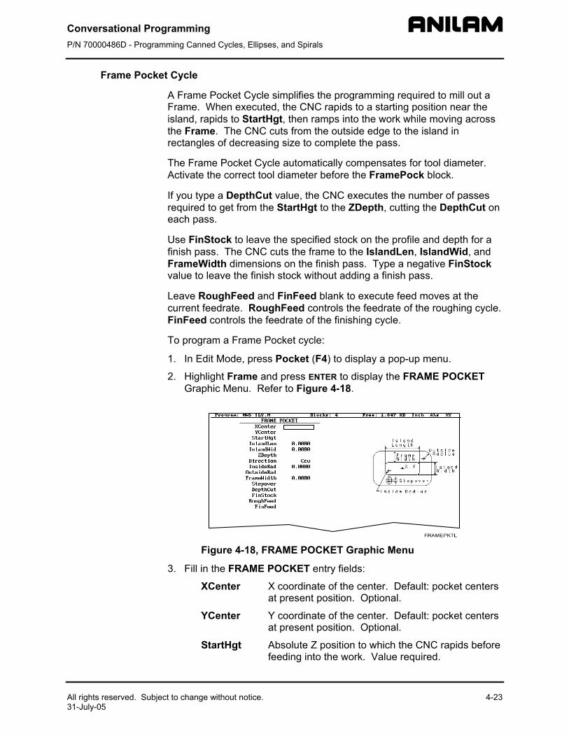
Conversational Programming P/N 70000486D - Programming Canned Cycles, Ellipses, and Spirals
All rights reserved. Subject to change without notice. 4-23 31-July-05
Frame Pocket Cycle
A Frame Pocket Cycle simplifies the programming required to mill out a Frame. When executed, the CNC rapids to a starting position near the island, rapids to StartHgt, then ramps into the work while moving across the Frame. The CNC cuts from the outside edge to the island in rectangles of decreasing size to complete the pass.
The Frame Pocket Cycle automatically compensates for tool diameter. Activate the correct tool diameter before the FramePock block.
If you type a DepthCut value, the CNC executes the number of passes required to get from the StartHgt to the ZDepth, cutting the DepthCut on each pass.
Use FinStock to leave the specified stock on the profile and depth for a finish pass. The CNC cuts the frame to the IslandLen, IslandWid, and FrameWidth dimensions on the finish pass. Type a negative FinStock value to leave the finish stock without adding a finish pass.
Leave RoughFeed and FinFeed blank to execute feed moves at the current feedrate. RoughFeed controls the feedrate of the roughing cycle. FinFeed controls the feedrate of the finishing cycle.
To program a Frame Pocket cycle:
1. In Edit Mode, press Pocket (F4) to display a pop-up menu.
2. Highlight Frame and press ENTER to display the FRAME POCKET Graphic Menu. Refer to Figure 4-18.
Figure 4-18, FRAME POCKET Graphic Menu
3. Fill in the FRAME POCKET entry fields:
XCenter X coordinate of the center. Default: pocket centers at present position. Optional.
YCenter Y coordinate of the center. Default: pocket centers at present position. Optional.
StartHgt Absolute Z position to which the CNC rapids before feeding into the work. Value required.
Conversational Programming P/N 70000486D - Programming Canned Cycles, Ellipses, and Spirals
4-24 All rights reserved. Subject to change without notice. 31-July-05
NOTE: StartHgt is 0.100 inches (2.0 mm) above the work surface. ZDepth must be lower than StartHgt.
IslandLen Outside length (X-axis) of finished island. Value required.
IslandWid Outside width (Y-axis) of finished island. Value required.
StartHgt Absolute Z position to which the CNC rapids before feeding into the work. Value required.
Direction Allows you to select conventional or climb milling for the pocket. The selections are clockwise (Cw) and counterclockwise (Ccw). Press +/- to toggle the selection. Selection required.
InsideRad Radius of the island corners. Value required. OutsideRad Outside radius of the frame corners. Value
required. FrameWidth Width of the finished frame. Value required. Stepover Width of cut. If no value is typed, the CNC defaults
to 70% of the active tool radius. Maximum step-over permitted is 70% of the active tool diameter. Optional.
DepthCut Z-axis increment used for each pass. Optional. FinStock Amount of stock left by the machine before the
finish pass. Default: 0. Type a negative value to leave the stock without making a finish pass. Optional.
RampFeed Z-axis feedrate. Optional. RoughFeed Rough pass feedrate. Optional. FinFeed Finish pass feedrate. Optional.
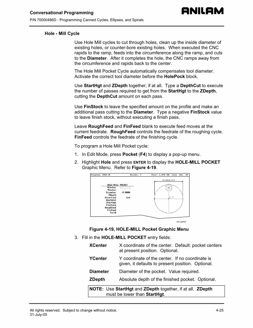
Conversational Programming P/N 70000486D - Programming Canned Cycles, Ellipses, and Spirals
All rights reserved. Subject to change without notice. 4-25 31-July-05
Hole - Mill Cycle
Use Hole Mill cycles to cut through holes, clean up the inside diameter of existing holes, or counter-bore existing holes. When executed the CNC rapids to the ramp, feeds into the circumference along the ramp, and cuts to the Diameter. After it completes the hole, the CNC ramps away from the circumference and rapids back to the center.
The Hole Mill Pocket Cycle automatically compensates tool diameter. Activate the correct tool diameter before the HolePock block.
Use StartHgt and ZDepth together, if at all. Type a DepthCut to execute the number of passes required to get from the StartHgt to the ZDepth, cutting the DepthCut amount on each pass.
Use FinStock to leave the specified amount on the profile and make an additional pass cutting to the Diameter. Type a negative FinStock value to leave finish stock, without executing a finish pass.
Leave RoughFeed and FinFeed blank to execute feed moves at the current feedrate. RoughFeed controls the feedrate of the roughing cycle. FinFeed controls the feedrate of the finishing cycle.
To program a Hole Mill Pocket cycle:
1. In Edit Mode, press Pocket (F4) to display a pop-up menu.
2. Highlight Hole and press ENTER to display the HOLE-MILL POCKET Graphic Menu. Refer to Figure 4-19.
Figure 4-19, HOLE-MILL Pocket Graphic Menu
3. Fill in the HOLE-MILL POCKET entry fields:
XCenter X coordinate of the center. Default: pocket centers at present position. Optional.
YCenter Y coordinate of the center. If no coordinate is given, it defaults to present position. Optional.
Diameter Diameter of the pocket. Value required.
ZDepth Absolute depth of the finished pocket. Optional.
NOTE: Use StartHgt and ZDepth together, if at all. ZDepth must be lower than StartHgt.
Conversational Programming P/N 70000486D - Programming Canned Cycles, Ellipses, and Spirals
4-26 All rights reserved. Subject to change without notice. 31-July-05
Direction Allows you to select a clockwise (Cw) or counterclockwise (Ccw) direction. Press +/- to toggle the selection. Selection required.
DepthCut Z-axis increment used for each pass. Optional.
StartHgt Absolute Z position to which the CNC rapids before feeding into the work. Optional.
FinStock Amount of stock left by the machine before the finish pass. Default: 0. Type negative value to leave a finish stock, without making a finish pass. Optional.
RoughFeed Rough pass feedrate. Optional.
FinFeed Finish pass feedrate. Optional.
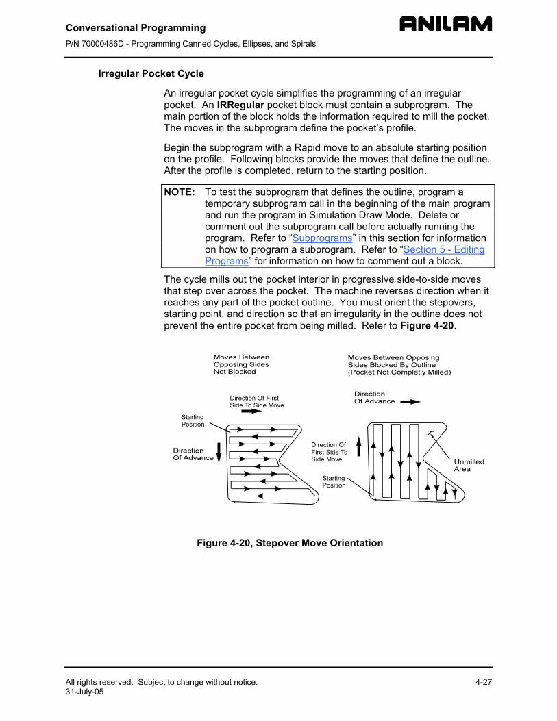
Conversational Programming P/N 70000486D - Programming Canned Cycles, Ellipses, and Spirals
All rights reserved. Subject to change without notice. 4-27 31-July-05
Irregular Pocket Cycle
An irregular pocket cycle simplifies the programming of an irregular pocket. An IRRegular pocket block must contain a subprogram. The main portion of the block holds the information required to mill the pocket. The moves in the subprogram define the pocket’s profile.
Begin the subprogram with a Rapid move to an absolute starting position on the profile. Following blocks provide the moves that define the outline. After the profile is completed, return to the starting position.
NOTE: To test the subprogram that defines the outline, program a temporary subprogram call in the beginning of the main program and run the program in Simulation Draw Mode. Delete or comment out the subprogram call before actually running the program. Refer to “Subprograms” in this section for information on how to program a subprogram. Refer to “Section 5 - Editing Programs” for information on how to comment out a block.
The cycle mills out the pocket interior in progressive side-to-side moves that step over across the pocket. The machine reverses direction when it reaches any part of the pocket outline. You must orient the stepovers, starting point, and direction so that an irregularity in the outline does not prevent the entire pocket from being milled. Refer to Figure 4-20.
StartingPosition
Direction OfFirst Side ToSide Move
StartingPosition
Direction Of FirstSide To Side Move
Figure 4-20, Stepover Move Orientation
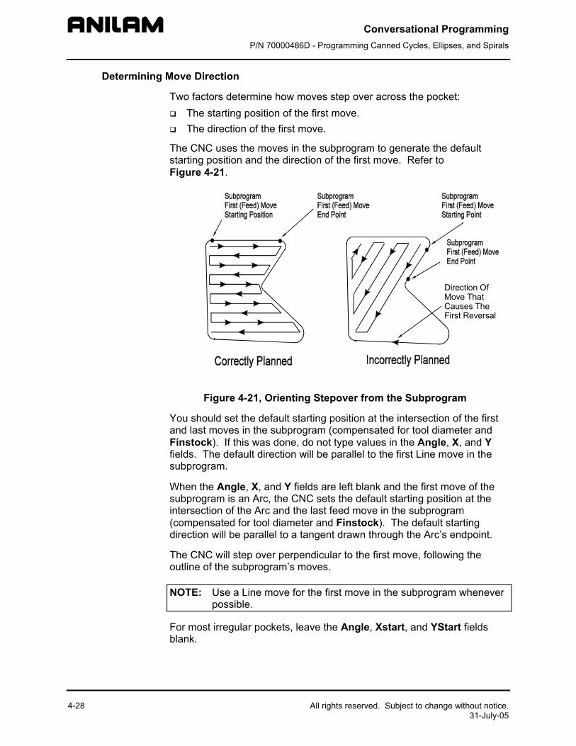
Conversational Programming P/N 70000486D - Programming Canned Cycles, Ellipses, and Spirals
4-28 All rights reserved. Subject to change without notice. 31-July-05
Determining Move Direction
Two factors determine how moves step over across the pocket: The starting position of the first move. The direction of the first move.
The CNC uses the moves in the subprogram to generate the default starting position and the direction of the first move. Refer to Figure 4-21.
Direction OfMove ThatCauses TheFirst Reversal
Figure 4-21, Orienting Stepover from the Subprogram
You should set the default starting position at the intersection of the first and last moves in the subprogram (compensated for tool diameter and Finstock). If this was done, do not type values in the Angle, X, and Y fields. The default direction will be parallel to the first Line move in the subprogram.
When the Angle, X, and Y fields are left blank and the first move of the subprogram is an Arc, the CNC sets the default starting position at the intersection of the Arc and the last feed move in the subprogram (compensated for tool diameter and Finstock). The default starting direction will be parallel to a tangent drawn through the Arc’s endpoint.
The CNC will step over perpendicular to the first move, following the outline of the subprogram’s moves.
NOTE: Use a Line move for the first move in the subprogram whenever possible.
For most irregular pockets, leave the Angle, Xstart, and YStart fields blank.
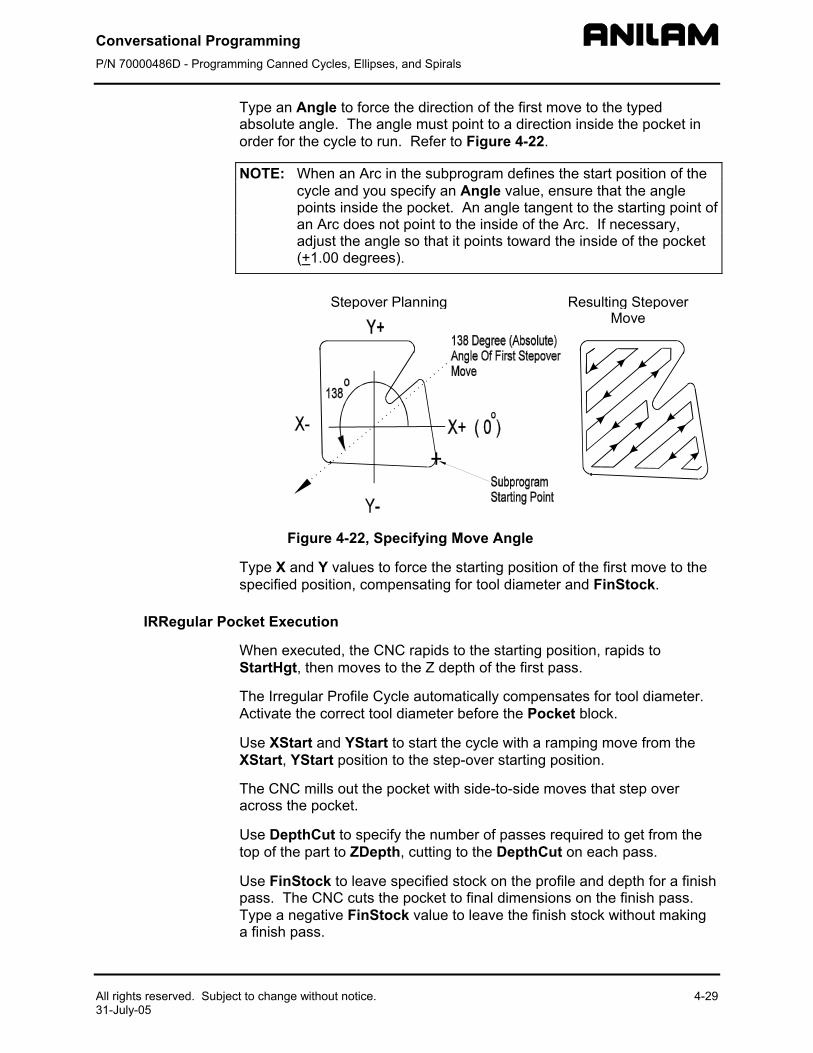
Conversational Programming P/N 70000486D - Programming Canned Cycles, Ellipses, and Spirals
All rights reserved. Subject to change without notice. 4-29 31-July-05
Type an Angle to force the direction of the first move to the typed absolute angle. The angle must point to a direction inside the pocket in order for the cycle to run. Refer to Figure 4-22.
NOTE: When an Arc in the subprogram defines the start position of the cycle and you specify an Angle value, ensure that the angle points inside the pocket. An angle tangent to the starting point of an Arc does not point to the inside of the Arc. If necessary, adjust the angle so that it points toward the inside of the pocket (+1.00 degrees).
Stepover Planning Resulting StepoverMove
Figure 4-22, Specifying Move Angle
Type X and Y values to force the starting position of the first move to the specified position, compensating for tool diameter and FinStock.
IRRegular Pocket Execution
When executed, the CNC rapids to the starting position, rapids to StartHgt, then moves to the Z depth of the first pass.
The Irregular Profile Cycle automatically compensates for tool diameter. Activate the correct tool diameter before the Pocket block.
Use XStart and YStart to start the cycle with a ramping move from the XStart, YStart position to the step-over starting position.
The CNC mills out the pocket with side-to-side moves that step over across the pocket.
Use DepthCut to specify the number of passes required to get from the top of the part to ZDepth, cutting to the DepthCut on each pass.
Use FinStock to leave specified stock on the profile and depth for a finish pass. The CNC cuts the pocket to final dimensions on the finish pass. Type a negative FinStock value to leave the finish stock without making a finish pass.
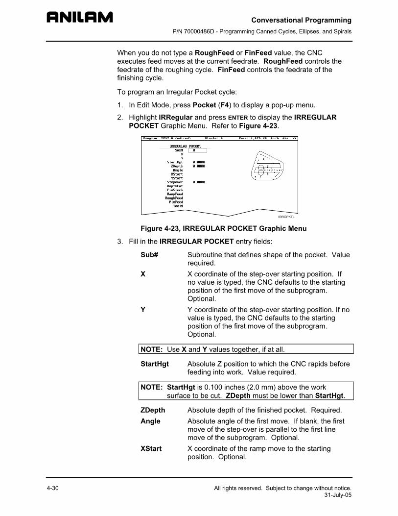
Conversational Programming P/N 70000486D - Programming Canned Cycles, Ellipses, and Spirals
4-30 All rights reserved. Subject to change without notice. 31-July-05
When you do not type a RoughFeed or FinFeed value, the CNC executes feed moves at the current feedrate. RoughFeed controls the feedrate of the roughing cycle. FinFeed controls the feedrate of the finishing cycle.
To program an Irregular Pocket cycle:
1. In Edit Mode, press Pocket (F4) to display a pop-up menu.
2. Highlight IRRegular and press ENTER to display the IRREGULAR POCKET Graphic Menu. Refer to Figure 4-23.
Figure 4-23, IRREGULAR POCKET Graphic Menu
3. Fill in the IRREGULAR POCKET entry fields:
Sub# Subroutine that defines shape of the pocket. Value required.
X X coordinate of the step-over starting position. If no value is typed, the CNC defaults to the starting position of the first move of the subprogram. Optional.
Y Y coordinate of the step-over starting position. If no value is typed, the CNC defaults to the starting position of the first move of the subprogram. Optional.
NOTE: Use X and Y values together, if at all.
StartHgt Absolute Z position to which the CNC rapids before feeding into work. Value required.
NOTE: StartHgt is 0.100 inches (2.0 mm) above the work surface to be cut. ZDepth must be lower than StartHgt.
ZDepth Absolute depth of the finished pocket. Required. Angle Absolute angle of the first move. If blank, the first
move of the step-over is parallel to the first line move of the subprogram. Optional.
XStart X coordinate of the ramp move to the starting position. Optional.
Conversational Programming P/N 70000486D - Programming Canned Cycles, Ellipses, and Spirals
All rights reserved. Subject to change without notice. 31-July-05
YStart Y coordinate of a ramp move to the starting position. Optional.
NOTE: Use XStart and YStart values together, if at all.
Stepover Width of cut. Value required. DepthCut Z-axis increment used for each pass. Optional. FinStock Amount of stock left by the machine before the
finish pass. Default: 0. Use a negative value to leave stock without making a finish pass. Optional.
RampFeed Z-axis feedrate. Optional. RoughFeed Rough pass feedrate. Optional. FinFeed Finish pass feedrate. Optional.
Using Irregular Pocket in Subprograms
The Irregular Pocket is ypically used with the main program. In cases where the Irregular Poc et is being used in a subprogram, an M-code must be used to specifused in the calculationsplaced immediately beused in the main progr
Format: MCode 9367
Tool# is the number ofthe calculations of the
Example:
MCode 9367 X 3.0000Pocket Sub# 1 S
This will use the diamePocket.
tk
4-31
y the tool number whose tool diameter must be of the Irregular Pocket. The M-code must be
fore the Irregular Pocket. If Irregular Pocket is am, it is not necessary to use this M-code.
X (tool#)
the tool diameter whose diameter must be used in Irregular Pocket.
tartHgt 0.1000 (etc.)
ter of Tool# 3 in the calculations of the Irregular
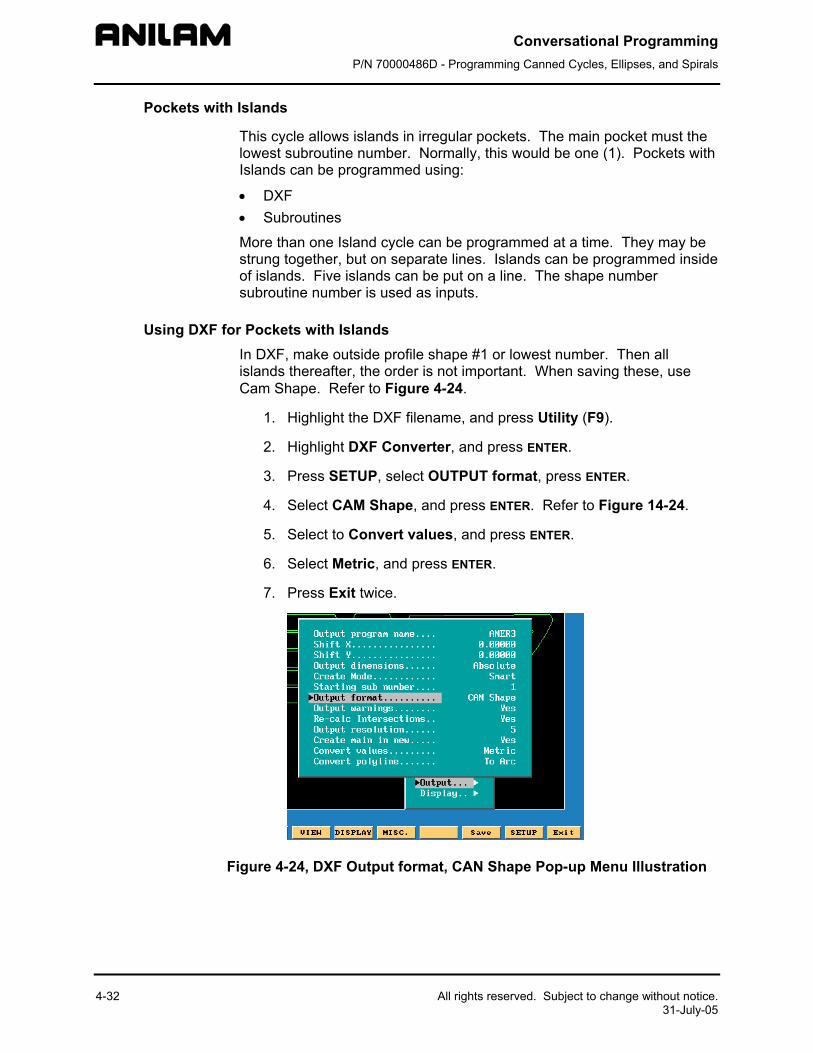
Conversational Programming P/N 70000486D - Programming Canned Cycles, Ellipses, and Spirals
4-32 All rights reserved. Subject to change without notice. 31-July-05
Pockets with Islands
This cycle allows islands in irregular pockets. The main pocket must the lowest subroutine number. Normally, this would be one (1). Pockets with Islands can be programmed using:
• DXF • Subroutines
More than one Island cycle can be programmed at a time. They may be strung together, but on separate lines. Islands can be programmed inside of islands. Five islands can be put on a line. The shape number subroutine number is used as inputs.
Using DXF for Pockets with Islands In DXF, make outside profile shape #1 or lowest number. Then all islands thereafter, the order is not important. When saving these, use Cam Shape. Refer to Figure 4-24.
1. Highlight the DXF filename, and press Utility (F9).
2. Highlight DXF Converter, and press ENTER.
3. Press SETUP, select OUTPUT format, press ENTER.
4. Select CAM Shape, and press ENTER. Refer to Figure 14-24.
5. Select to Convert values, and press ENTER.
6. Select Metric, and press ENTER.
7. Press Exit twice.
Figure 4-24, DXF Output format, CAN Shape Pop-up Menu Illustration
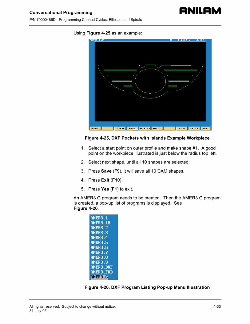
Conversational Programming P/N 70000486D - Programming Canned Cycles, Ellipses, and Spirals
All rights reserved. Subject to change without notic31-July-05
Using Figure 4-25 as an example:
Figure 4-25, D
1. Select a starpoint on the
2. Select next s
3. Press Save
4. Press Exit (F
5. Press Yes (F
An AMER3.G prograis created, a pop-upFigure 4-26.
Figure 4-26, D
e. 4-33
XF Pockets with Islands Example Workpiece
t point on outer profile and make shape #1. A good workpiece illustrated is just below the radius top left.
hape, until all 10 shapes are selected.
(F9), it will save all 10 CAM shapes.
10).
1) to exit.
m needs to be created. Then the AMER3.G program list of programs is displayed. See
XF Program Listing Pop-up Menu Illustration
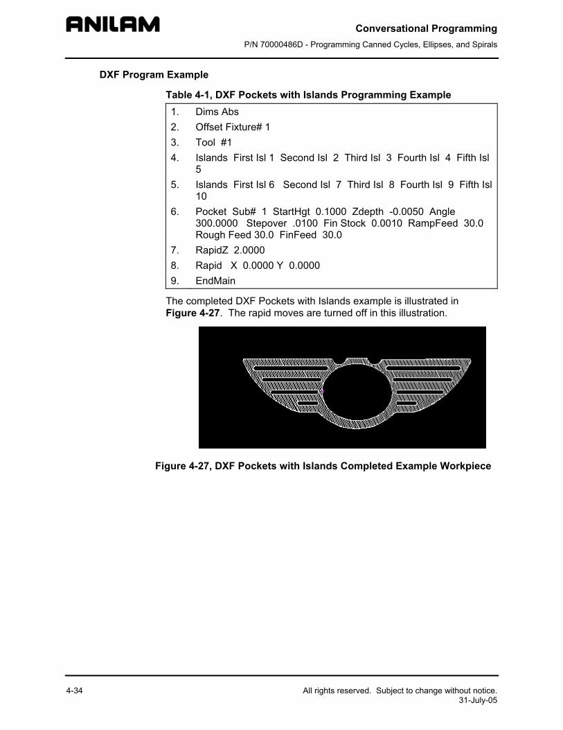
Conversational Programming P/N 70000486D - Programming Canned Cycles, Ellipses, and Spirals
4-34
DXF Program Example
Table 4-1, DXF Pockets with Islands Programming Example 1. Dims Abs 2. Offset Fixture# 1 3. Tool #1 4. Islands First Isl 1 Second Isl 2 Third Isl 3 Fourth Isl 4 Fifth Isl
5 5. Islands First Isl 6 Second Isl 7 Third Isl 8 Fourth Isl 9 Fifth Isl
10 6. Pocket Sub# 1 StartHgt 0.1000 Zdepth -0.0050 Angle
300.0000 Stepover .0100 Fin Stock 0.0010 RampFeed 30.0 Rough Feed 30.0 FinFeed 30.0
7. RapidZ 2.0000 8. Rapid X 0.0000 Y 0.0000 9. EndMain
The completed DXF Pockets with Islands example is illustrated in Figure 4-27. The rapid moves are turned off in this illustration.
Figure 4-27, DXF Pockets with Islands Completed Example Workpiece
All rights reserved. Subject to change without notice. 31-July-05
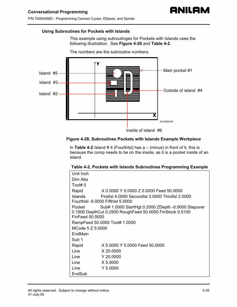
Conversational Programming P/N 70000486D - Programming Canned Cycles, Ellipses, and Spirals
All rights reserved. Subject to change without notice. 4-35 31-July-05
Using Subroutines for Pockets with Islands This example using subroutinges for Pockets with Islands uses the following illustration. See Figure 4-28 and Table 4-2.
The numbers are the subroutine numbers.
X
YMain pocket #1
Outside of island #4
Inside of island #6
Island #2
Island #3
Island #5
ISLANDSUB
Figure 4-28, Subroutines Pockets with Islands Example Workpiece
In Table 4-2 Island # 4 (FourthIsl) has a – (minus) in front of it, this is because the comp needs to be on the inside, as it is a pocket inside of an island.
Table 4-2, Pockets with Islands Subroutines Programming Example Unit Inch Dim Abs Tool# 0 Rapid X 0.0000 Y 0.0000 Z 0.0000 Feed 50.0000 Islands FirstIsl 4.0000 SecondIsl 3.0000 ThirdIsl 2.0000 FourthIsl -6.0000 FifthIsl 5.0000 Pocket Sub# 1.0000 StartHgt 0.2000 ZDepth -0.9000 Stepover 0.1900 DepthCut 0.2500 RoughFeed 50.0000 FinStock 0.0100 FinFeed 50.0000 RampFeed 50.0000 Tool# 1.0000 MCode 5 Z 5.0000 EndMain Sub 1 Rapid X 5.0000 Y 5.0000 Feed 50.0000 Line X 20.0000 Line Y 20.0000 Line X 5.0000 Line Y 5.0000 EndSub
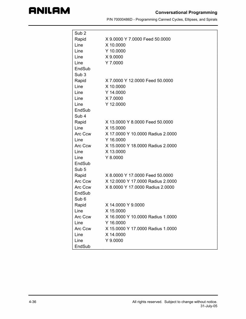
Conversational Programming P/N 70000486D - Programming Canned Cycles, Ellipses, and Spirals
4-36 All rights reserved. Subject to change without notice. 31-July-05
Sub 2 Rapid X 9.0000 Y 7.0000 Feed 50.0000 Line X 10.0000 Line Y 10.0000 Line X 9.0000 Line Y 7.0000 EndSub Sub 3 Rapid X 7.0000 Y 12.0000 Feed 50.0000 Line X 10.0000 Line Y 14.0000 Line X 7.0000 Line Y 12.0000 EndSub Sub 4 Rapid X 13.0000 Y 8.0000 Feed 50.0000 Line X 15.0000 Arc Ccw X 17.0000 Y 10.0000 Radius 2.0000 Line Y 16.0000 Arc Ccw X 15.0000 Y 18.0000 Radius 2.0000 Line X 13.0000 Line Y 8.0000 EndSub Sub 5 Rapid X 8.0000 Y 17.0000 Feed 50.0000 Arc Ccw X 12.0000 Y 17.0000 Radius 2.0000 Arc Ccw X 8.0000 Y 17.0000 Radius 2.0000 EndSub Sub 6 Rapid X 14.0000 Y 9.0000 Line X 15.0000 Arc Ccw X 16.0000 Y 10.0000 Radius 1.0000 Line Y 16.0000 Arc Ccw X 15.0000 Y 17.0000 Radius 1.0000 Line X 14.0000 Line Y 9.0000 EndSub
Conversational Programming P/N 70000486D - Programming Canned Cycles, Ellipses, and Spirals
All rights reserved. Subject to change without notice. 4-37 31-July-05
Subprograms
Program repetitive operations in a subprogram called from the main program.
Call (or nest) subprograms within other subprograms. The CNC supports up to ten levels of nesting.
Repeat or loop subprograms moving along any axis in increments each time the loop runs. ,
Rotate, scale, or mirror subprograms.
The following examples describe two situations where subprograms save time.
Situation: 1 (Repetitive Drilling Cycle)
When a workpiece must be center-drilled, drilled, then counterbored, each of the three tools must go to the same hole positions consecutively. Ten hole positions would require thirty programmed hole locations (ten for each tool). Program the ten hole locations in a subprogram called three times from the main program (once for each tool).
Situation: 2 (Rough and Finish Cycles)
Use subprograms for jobs that require both roughing and finishing cycles. Rough out the outside of a workpiece with a roughing mill, then finish it with a finishing mill. Program the profile in a subprogram. The main program calls the subprogram twice, once for each tool. You can set the tool diameter to 0.5300 inches for the .5-inch roughing mill and to 0.5000 inches for the .5-inch finishing mill. Tool #1 will leave 0.0150 inch excess stock per side. Tool #2 finishes the work to size.
Subprogram Structure
When using subprograms, define the end of the main program and the start and end of each subprogram
Subprogram Example 1 Dim Abs 2 Rapid X 5.0000 Y -5.0000 3 Call 1 4 Rapid X 6.0000 Y -6.0000 5 Call 1 6 Rapid X 7.0000 Y -5.0000 7 Call 1 8 EndMain End of Main Program 9 Sub 1 Start of Subprogram 1 10 Z -0.0625 11 Dim Incr 12 Line X 0.375 13 Line Y 0.375 14 Line X -0.375 15 Line Y -0.375
Conversational Programming P/N 70000486D - Programming Canned Cycles, Ellipses, and Spirals
4-38 All rights reserved. Subject to change without notice. 31-July-05
16 Dim Abs 17 Z 0.1000 18 EndSub End of Subprogram 1 19 <End Of Program> End of Program The main program begins at Block 1 and runs through Block 8. The subprogram begins at Block 9 and runs through Block 18.
When the main program reaches Block 3, the CNC jumps to Block 9, runs the subprogram through Block 18, then returns to the main program, Block 4.
Blocks 5 and 7 call the subprogram again.
Organizing Programs Containing Subprograms To write a program that includes a subprogram:
1. Write the main program and include the subprogram Call blocks.
2. Insert an EndMain block at the end of the main
3. Insert a Sub block, followed by a unique subprogram call number (1 to 9999), on the first block of the subprogram. Example: Sub1.
4. Write the subprogram blocks.
5. Finish the subprogram with an EndSub block.
6. End the program with an <End of Program> block.
Conversational Programming P/N 70000486D - Programming Canned Cycles, Ellipses, and Spirals
All rights reserved. Subject to change without notice. 4-39 31-July-05
Calling Subprograms from the Main Program
To call a subprogram from the main program:
1. In Edit Mode, press Sub (F8) to display the Subprogram soft key labels.
2. Press Call (F3). The Graphic Menu prompts for the subprogram number.
3. Type a subprogram number and press ENTER to add Call block to program.
Ending Main Programs
To program an EndMain block:
1. In Edit Mode, press Sub (F8) to display the Soft Key subprogram labels.
2. Press EndMain (F4) to display the EndMain block in the program listing.
Starting Subprograms
Start subprograms with a Sub block.
To program a Sub block:
1. In Edit Mode, press Sub (F8) to display the Sub soft keys.
2. Press Sub (F2). The CNC prompts for subprogram number.
3. Type Sub number and press ENTER to add a Sub block to the program. The Sub number must agree with the matching Call number.
Ending Subprograms
End subprograms with an EndSub block.
To program an EndSub block:
1. In Edit Mode, press Sub (F8) to display the Sub soft keys.
2. Press EndSub (F2) to add an EndSub block to the program.
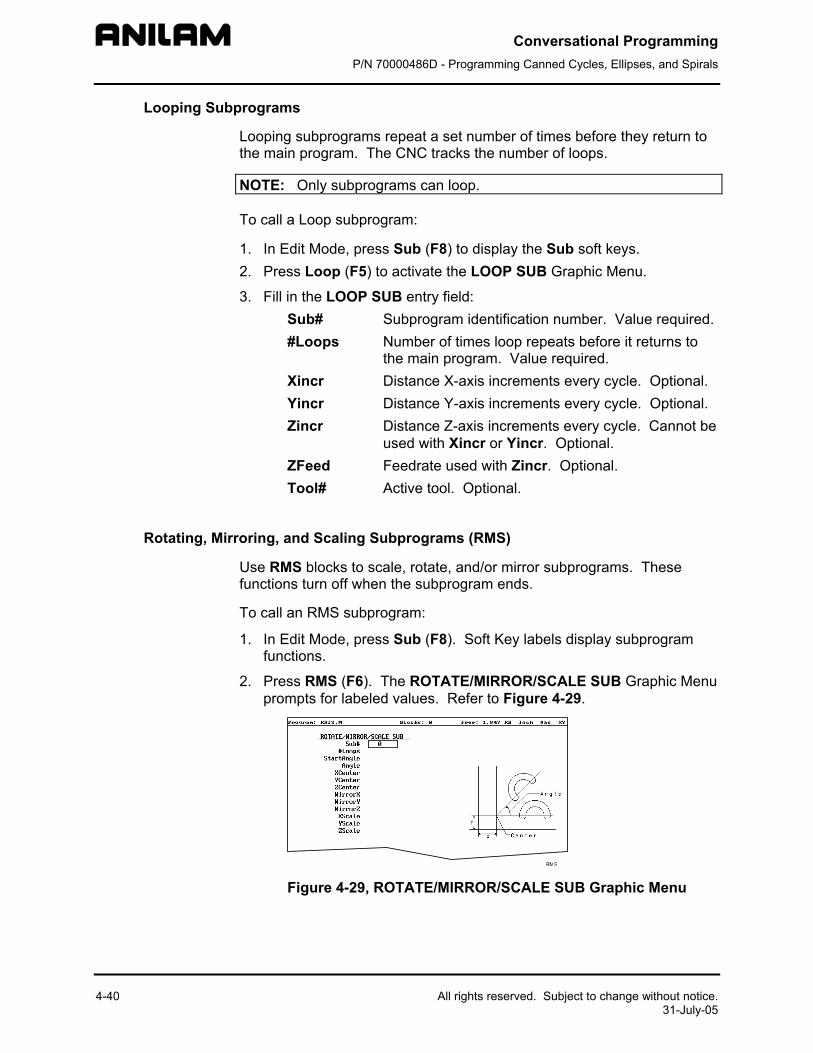
Conversational Programming P/N 70000486D - Programming Canned Cycles, Ellipses, and Spirals
4-40 All rights reserved. Subject to change without notice. 31-July-05
Looping Subprograms
Looping subprograms repeat a set number of times before they return to the main program. The CNC tracks the number of loops.
NOTE: Only subprograms can loop.
To call a Loop subprogram:
1. In Edit Mode, press Sub (F8) to display the Sub soft keys. 2. Press Loop (F5) to activate the LOOP SUB Graphic Menu.
3. Fill in the LOOP SUB entry field: Sub# Subprogram identification number. Value required. #Loops Number of times loop repeats before it returns to
the main program. Value required. Xincr Distance X-axis increments every cycle. Optional. Yincr Distance Y-axis increments every cycle. Optional. Zincr Distance Z-axis increments every cycle. Cannot be
used with Xincr or Yincr. Optional. ZFeed Feedrate used with Zincr. Optional. Tool# Active tool. Optional.
Rotating, Mirroring, and Scaling Subprograms (RMS)
Use RMS blocks to scale, rotate, and/or mirror subprograms. These functions turn off when the subprogram ends.
To call an RMS subprogram:
1. In Edit Mode, press Sub (F8). Soft Key labels display subprogram functions.
2. Press RMS (F6). The ROTATE/MIRROR/SCALE SUB Graphic Menu prompts for labeled values. Refer to Figure 4-29.
Figure 4-29, ROTATE/MIRROR/SCALE SUB Graphic Menu
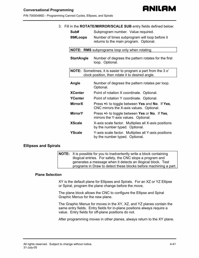
Conversational Programming P/N 70000486D - Programming Canned Cycles, Ellipses, and Spirals
All rights reserved. Subject to change without notice. 4-41 31-July-05
3. Fill in the ROTATE/MIRROR/SCALE SUB entry fields defined below: Sub# Subprogram number. Value required. 99#Loops Number of times subprogram will loop before it
returns to the main program. Optional.
NOTE: RMS subprograms loop only when rotating.
StartAngle Number of degrees the pattern rotates for the first loop. Optional.
NOTE: Sometimes, it is easier to program a part from the 3 o’ clock position, then rotate it to desired angle.
Angle Number of degrees the pattern rotates per loop. Optional.
XCenter Point of rotation X coordinate. Optional. YCenter Point of rotation Y coordinate. Optional. MirrorX Press +/- to toggle between Yes and No. If Yes,
CNC mirrors the X-axis values. Optional. MirrorY Press +/- to toggle between Yes or No. If Yes,
mirrors the Y-axis values. Optional. XScale X-axis scale factor. Multiplies all X-axis positions
by the number typed. Optional. YScale Y-axis scale factor. Multiplies all Y-axis positions
by the number typed. Optional.
Ellipses and Spirals
NOTE: It is possible for you to inadvertently write a block containing illogical entries. For safety, the CNC stops a program and generates a message when it detects an illogical block. Test programs in Draw to detect these blocks before machining a part.
Plane Selection
XY is the default plane for Ellipses and Spirals. For an XZ or YZ Ellipse or Spiral, program the plane change before the move.
The plane block allows the CNC to configure the Ellipse and Spiral Graphic Menus for the new plane.
The Graphic Menus for moves in the XY, XZ, and YZ planes contain the same entry fields. Entry fields for in-plane positions always require a value. Entry fields for off-plane positions do not.
After programming moves in other planes, always return to the XY plane.
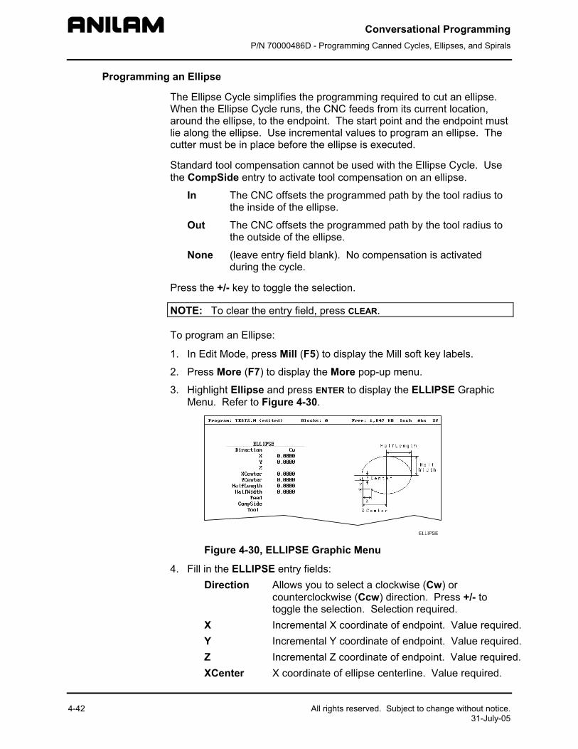
Conversational Programming P/N 70000486D - Programming Canned Cycles, Ellipses, and Spirals
4-42
Programming an Ellipse
The Ellipse Cycle simplifies the programming required to cut an ellipse. When the Ellipse Cycle runs, the CNC feeds from its current location, around the ellipse, to the endpoint. The start point and the endpoint must lie along the ellipse. Use incremental values to program an ellipse. The cutter must be in place before the ellipse is executed.
Standard tool compensation cannot be used with the Ellipse Cycle. Use the CompSide entry to activate tool compensation on an ellipse.
In The CNC offsets the programmed path by the tool radius to the inside of the ellipse.
Out The CNC offsets the programmed path by the tool radius to the outside of the ellipse.
None (leave entry field blank). No compensation is activated during the cycle.
Press the +/- key to toggle the selection.
NOTE: To clear the entry field, press CLEAR.
To program an Ellipse:
1. In Edit Mode, press Mill (F5) to display the Mill soft key labels.
2. Press More (F7) to display the More pop-up menu.
3. Highlight Ellipse and press ENTER to display the ELLIPSE Graphic Menu. Refer to Figure 4-30.
Figure 4-3
4. Fill in the ELLIDirection
X Y Z XCenter
All rights reserved. Subject to change without notice. 31-July-05
0, ELLIPSE Graphic Menu
PSE entry fields: Allows you to select a clockwise (Cw) or counterclockwise (Ccw) direction. Press +/- to toggle the selection. Selection required. Incremental X coordinate of endpoint. Value required. Incremental Y coordinate of endpoint. Value required. Incremental Z coordinate of endpoint. Value required. X coordinate of ellipse centerline. Value required.
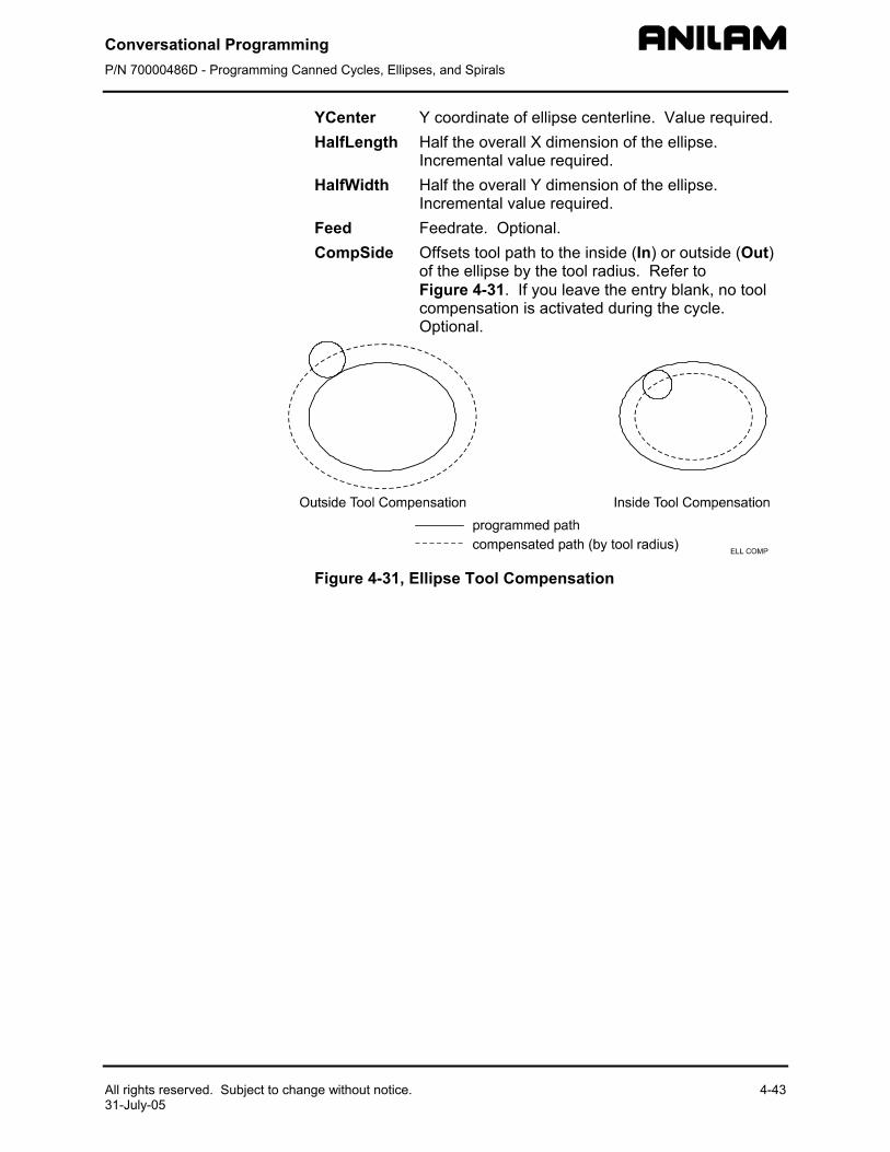
Conversational Programming P/N 70000486D - Programming Canned Cycles, Ellipses, and Spirals
All rights reserved. Subject to change without notice. 4-43 31-July-05
YCenter Y coordinate of ellipse centerline. Value required. HalfLength Half the overall X dimension of the ellipse.
Incremental value required. HalfWidth Half the overall Y dimension of the ellipse.
Incremental value required. Feed Feedrate. Optional. CompSide Offsets tool path to the inside (In) or outside (Out)
of the ellipse by the tool radius. Refer to Figure 4-31. If you leave the entry blank, no tool compensation is activated during the cycle. Optional.
Figure 4-31, Ellipse Tool Compensation
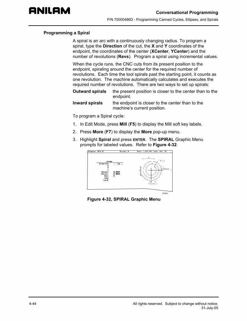
Conversational Programming P/N 70000486D - Programming Canned Cycles, Ellipses, and Spirals
4-44 All rights reserved. Subject to change without notice. 31-July-05
Programming a Spiral
A spiral is an arc with a continuously changing radius. To program a spiral, type the Direction of the cut, the X and Y coordinates of the endpoint, the coordinates of the center (XCenter, YCenter) and the number of revolutions (Revs). Program a spiral using incremental values.
When the cycle runs, the CNC cuts from its present position to the endpoint, spiraling around the center for the required number of revolutions. Each time the tool spirals past the starting point, it counts as one revolution. The machine automatically calculates and executes the required number of revolutions. There are two ways to set up spirals: Outward spirals the present position is closer to the center than to the
endpoint. Inward spirals the endpoint is closer to the center than to the
machine’s current position.
To program a Spiral cycle:
1. In Edit Mode, press Mill (F5) to display the Mill soft key labels.
2. Press More (F7) to display the More pop-up menu.
3. Highlight Spiral and press ENTER. The SPIRAL Graphic Menu prompts for labeled values. Refer to Figure 4-32.
Figure 4-32, SPIRAL Graphic Menu
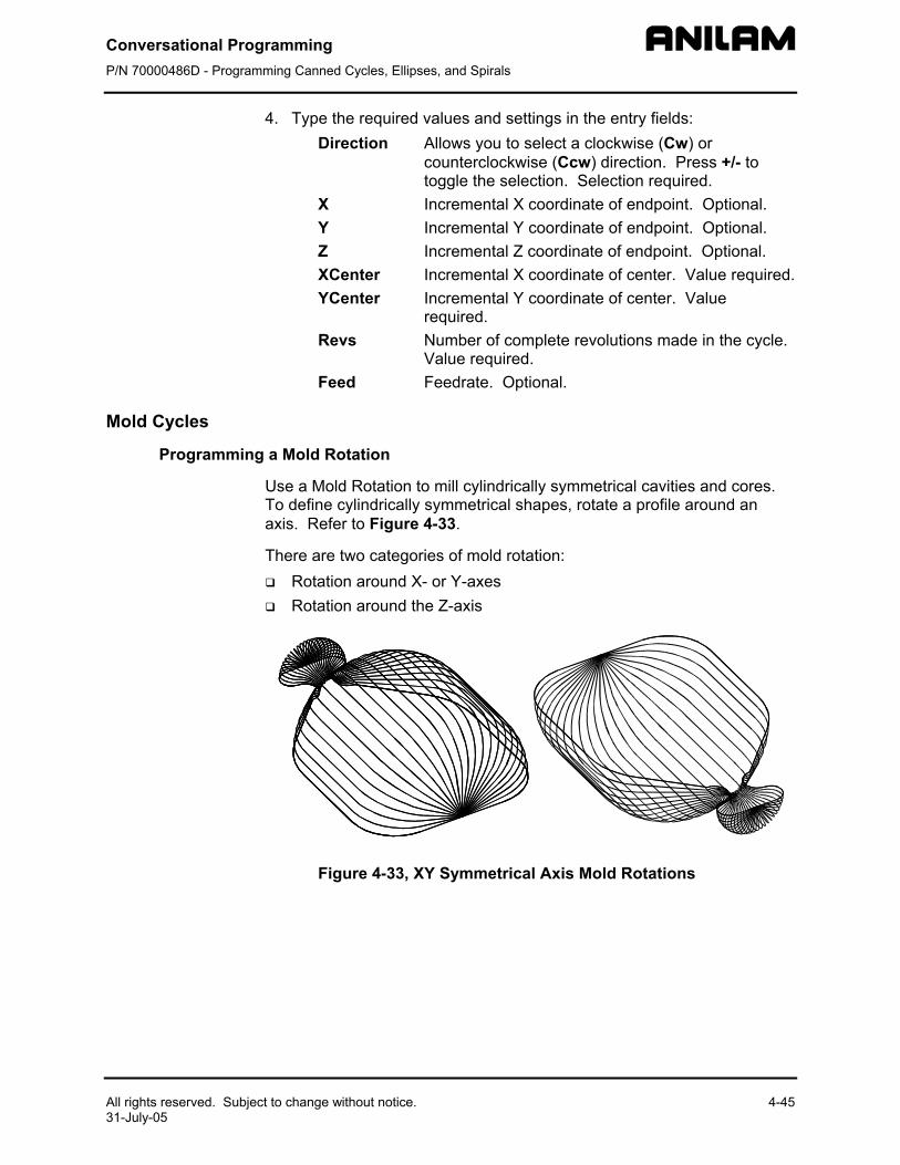
Conversational Programming P/N 70000486D - Programming Canned Cycles, Ellipses, and Spirals
All rights reserved. Subject to change without notice. 4-45 31-July-05
4. Type the required values and settings in the entry fields: Direction Allows you to select a clockwise (Cw) or
counterclockwise (Ccw) direction. Press +/- to toggle the selection. Selection required.
X Incremental X coordinate of endpoint. Optional. Y Incremental Y coordinate of endpoint. Optional. Z Incremental Z coordinate of endpoint. Optional. XCenter Incremental X coordinate of center. Value required. YCenter Incremental Y coordinate of center. Value
required. Revs Number of complete revolutions made in the cycle.
Value required. Feed Feedrate. Optional.
Mold Cycles
Programming a Mold Rotation
Use a Mold Rotation to mill cylindrically symmetrical cavities and cores. To define cylindrically symmetrical shapes, rotate a profile around an axis. Refer to Figure 4-33.
There are two categories of mold rotation: Rotation around X- or Y-axes Rotation around the Z-axis
Figure 4-33, XY Symmetrical Axis Mold Rotations
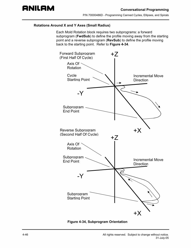
Conversational Programming P/N 70000486D - Programming Canned Cycles, Ellipses, and Spirals
4-46 All rights reserved. Subject to change without notice. 31-July-05
Rotations Around X and Y Axes (Small Radius)
Each Mold Rotation block requires two subprograms: a forward subprogram (FwdSub) to define the profile moving away from the starting point and a reverse subprogram (RevSub) to define the profile moving back to the starting point. Refer to Figure 4-34.
Forward Subprogram(First Half Of Cycle)
CycleStarting Point
SubprogramEnd Point
Incremental MoveDirection
+X
-Y
+Z
Reverse Subprogram(Second Half Of Cycle)
SubprogramStarting Point
SubprogramEnd Point
Axis OfRotation
Axis OfRotation
+X
-Y
+Z
Incremental MoveDirection
Figure 4-34, Subprogram Orientation
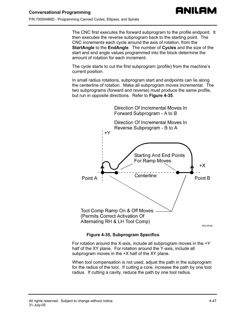
Conversational Programming P/N 70000486D - Programming Canned Cycles, Ellipses, and Spirals
All rights reserved. Subject to change without notice.31-July-05
The CNC first executes the forward subprogram to the profile endpoint. It then executes the reverse subprogram back to the starting point. The CNC increments each cycle around the axis of rotation, from the StartAngle to the EndAngle. The number of Cycles and the size of the start and end angle values programmed into the block determine the amount of rotation for each increment.
The cycle starts to cut the first subprogram (profile) from the machine’s current position.
In small radius rotations, subprogram start and endpoints can lie along the centerline of rotation. Make all subprogram moves incremental. The two subprograms (forward and reverse) must produce the same profile, but run in opposite di ctions. Refer to Figure 4-35.
Figure 4-35, S
For rotation around thhalf of the XY plane. subprogram moves in
When tool compensafor the radius of the toradius. If cutting a ca
re
4-47
ubprogram Specifics
e X-axis, include all subprogram moves in the +Y For rotation around the Y-axis, include all the +X half of the XY plane.
tion is not used, adjust the path in the subprogram ol. If cutting a core, increase the path by one tool vity, reduce the path by one tool radius.
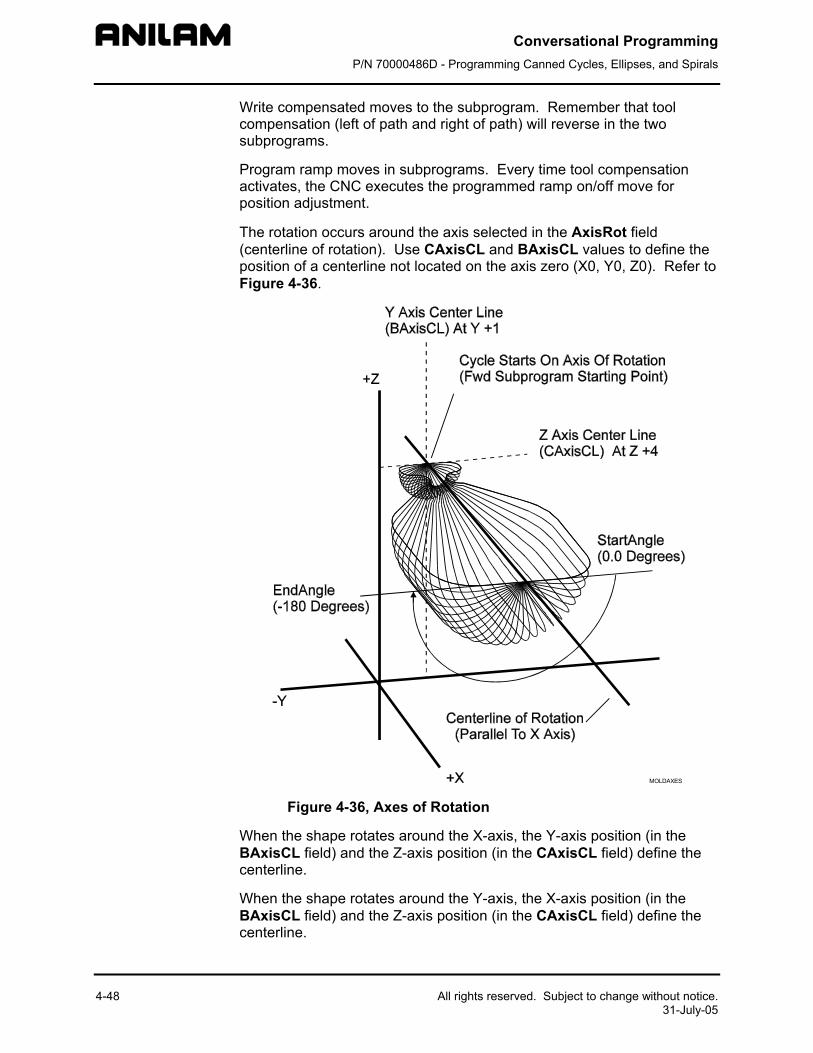
Conversational Programming P/N 70000486D - Programming Canned Cycles, Ellipses, and Spirals
4-48 All rights reserved. Subject to change without notice. 31-July-05
Write compensated moves to the subprogram. Remember that tool compensation (left of path and right of path) will reverse in the two subprograms.
Program ramp moves in subprograms. Every time tool compensation activates, the CNC executes the programmed ramp on/off move for position adjustment.
The rotation occurs around the axis selected in the AxisRot field (centerline of rotation). Use CAxisCL and BAxisCL values to define the position of a centerline not located on the axis zero (X0, Y0, Z0). Refer to Figure 4-36.
MOLDAXES
Figure 4-36, Axes of Rotation
When the shape rotates around the X-axis, the Y-axis position (in the BAxisCL field) and the Z-axis position (in the CAxisCL field) define the centerline.
When the shape rotates around the Y-axis, the X-axis position (in the BAxisCL field) and the Z-axis position (in the CAxisCL field) define the centerline.
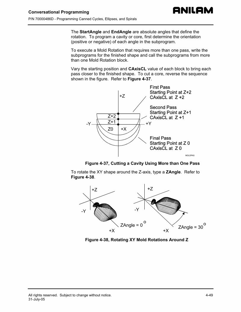
Conversational Programming P/N 70000486D - Programming Canned Cycles, Ellipses, and Spirals
All rights reserved. Subject to change without notice. 4-49 31-July-05
The StartAngle and EndAngle are absolute angles that define the rotation. To program a cavity or core, first determine the orientation (positive or negative) of each angle in the subprogram.
To execute a Mold Rotation that requires more than one pass, write the subprograms for the finished shape and call the subprograms from more than one Mold Rotation block.
Vary the starting position and CAxisCL value of each block to bring each pass closer to the finished shape. To cut a core, reverse the sequence shown in the figure. Refer to Figure 4-37.
+Z
-Y +Y+X
Z+2Z+1Z0
MOLDPAS
Figure 4-37, Cutting a Cavity Using More than One Pass
To rotate the XY shape around the Z-axis, type a ZAngle. Refer to Figure 4-38.
+X +X
+Z +Z
-Y -Y
ZAngle = 0o
ZAngle = 30o
Figure 4-38, Rotating XY Mold Rotations Around Z
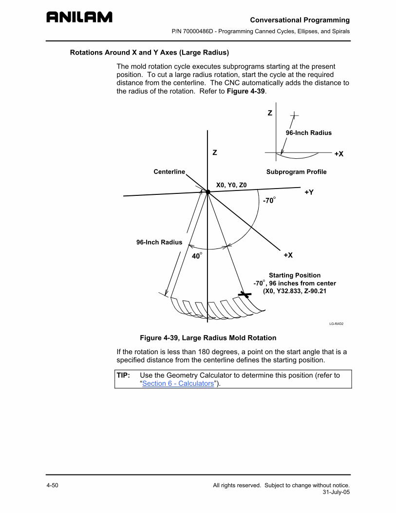
Conversational Programming P/N 70000486D - Programming Canned Cycles, Ellipses, and Spirals
4-50 All rights reserved. Subject to change without notice. 31-July-05
Rotations Around X and Y Axes (Large Radius)
The mold rotation cycle executes subprograms starting at the present position. To cut a large radius rotation, start the cycle at the required distance from the centerline. The CNC automatically adds the distance to the radius of the rotation. Refer to Figure 4-39.
LG-RAD2
Starting Position-70°, 96 inches from center
(X0, Y32.833, Z-90.21
Centerline
96-Inch Radius
X0, Y0, Z0
96-Inch Radius
Subprogram Profile
Z
Z
+X
+X
+Y-70°
40°
Figure 4-39, Large Radius Mold Rotation
If the rotation is less than 180 degrees, a point on the start angle that is a specified distance from the centerline defines the starting position.
TIP: Use the Geometry Calculator to determine this position (refer to “Section 6 - Calculators”).
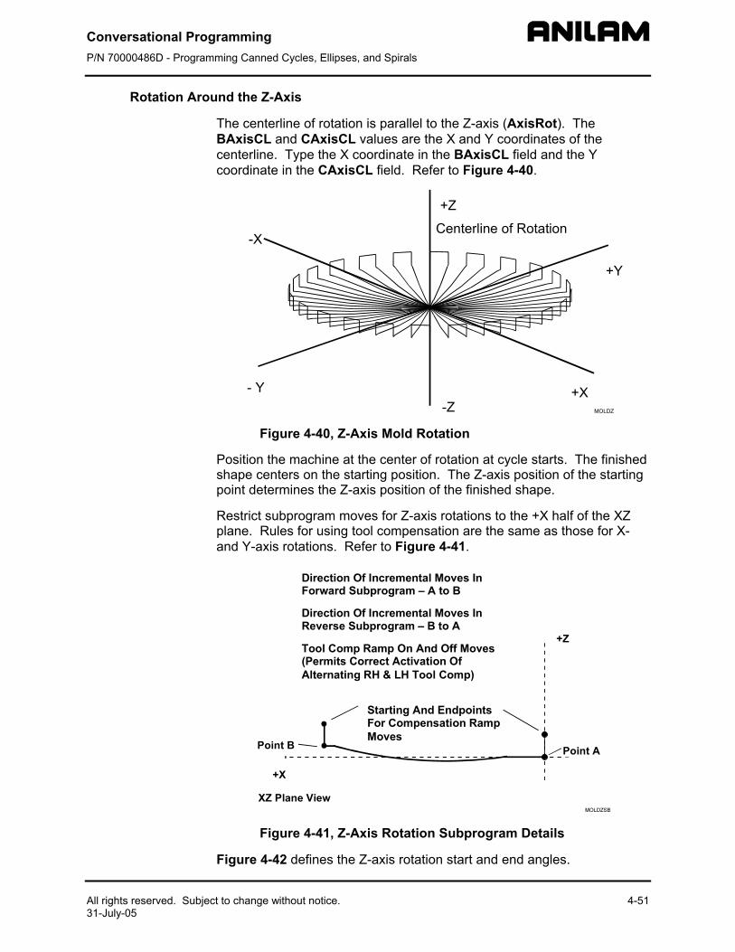
Conversational Programming P/N 70000486D - Programming Canned Cycles, Ellipses, and Spirals
All rights reserved. Subject to change without notice. 4-51 31-July-05
Rotation Around the Z-Axis
The centerline of rotation is parallel to the Z-axis (AxisRot). The BAxisCL and CAxisCL values are the X and Y coordinates of the centerline. Type the X coordinate in the BAxisCL field and the Y coordinate in the CAxisCL field. Refer to Figure 4-40.
+X
-X
- Y
+Y
+Z
-Z MOLDZ
Centerline of Rotation
Figure 4-40, Z-Axis Mold Rotation
Position the machine at the center of rotation at cycle starts. The finished shape centers on the starting position. The Z-axis position of the starting point determines the Z-axis position of the finished shape.
Restrict subprogram moves for Z-axis rotations to the +X half of the XZ plane. Rules for using tool compensation are the same as those for X- and Y-axis rotations. Refer to Figure 4-41.
Direction Of Incremental Moves InForward Subprogram – A to B
Direction Of Incremental Moves InReverse Subprogram – B to A
Tool Comp Ramp On And Off Moves(Permits Correct Activation OfAlternating RH & LH Tool Comp)
Starting And EndpointsFor Compensation RampMoves
Point A
XZ Plane View
Point B
+Z
+X
Figure 4-41, Z-Axis Rotation Subprogram Details
Figure 4-42 defines the Z-axis rotation start and end angles.
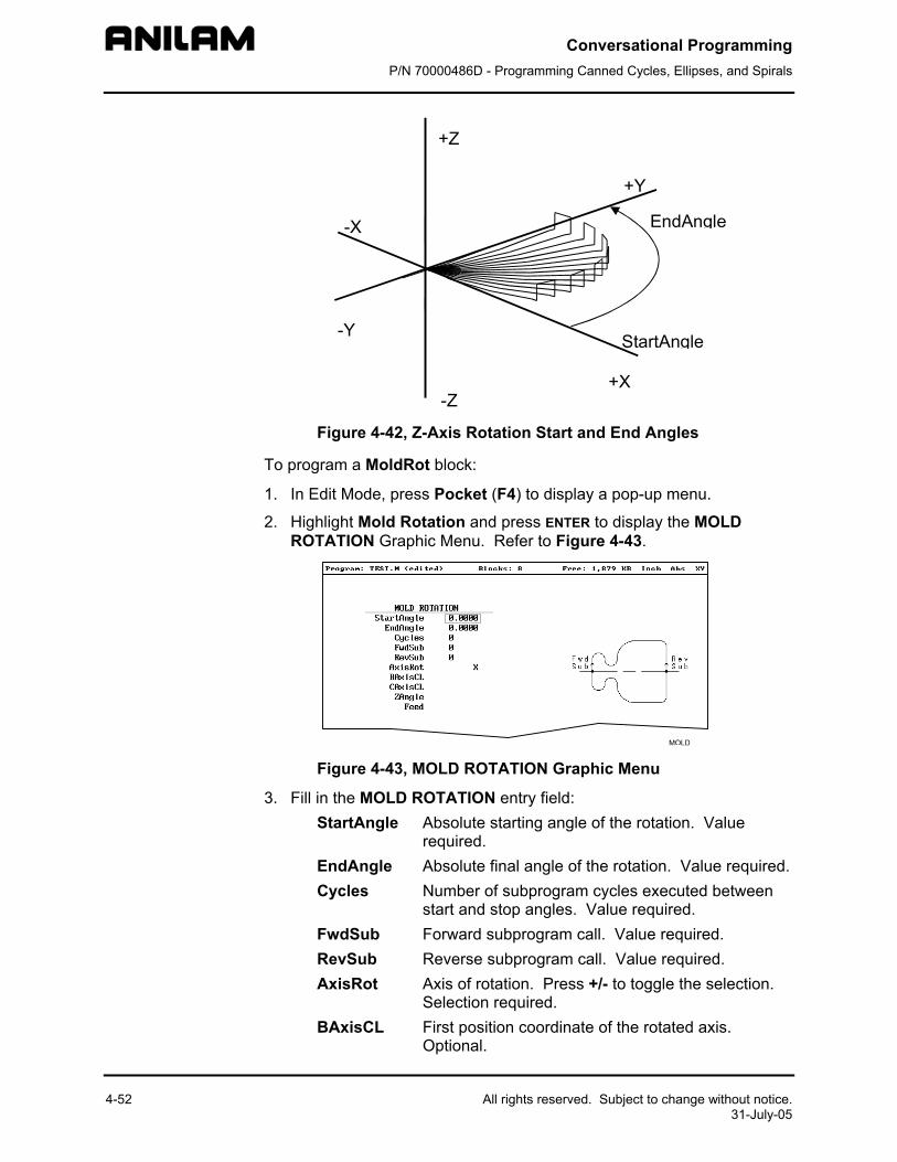
Conversational Programming P/N 70000486D - Programming Canned Cycles, Ellipses, and Spirals
4-52 All rights reserved. Subject to change without notice. 31-July-05
+X
-X
-Y
+Y
+Z
-Z
StartAngle
EndAngle
Figure 4-42, Z-Axis Rotation Start and End Angles
To program a MoldRot block:
1. In Edit Mode, press Pocket (F4) to display a pop-up menu.
2. Highlight Mold Rotation and press ENTER to display the MOLD ROTATION Graphic Menu. Refer to Figure 4-43.
Figure 4-43, MOLD ROTATION Graphic Menu
3. Fill in the MOLD ROTATION entry field: StartAngle Absolute starting angle of the rotation. Value
required. EndAngle Absolute final angle of the rotation. Value required. Cycles Number of subprogram cycles executed between
start and stop angles. Value required. FwdSub Forward subprogram call. Value required. RevSub Reverse subprogram call. Value required. AxisRot Axis of rotation. Press +/- to toggle the selection.
Selection required. BAxisCL First position coordinate of the rotated axis.
Optional.
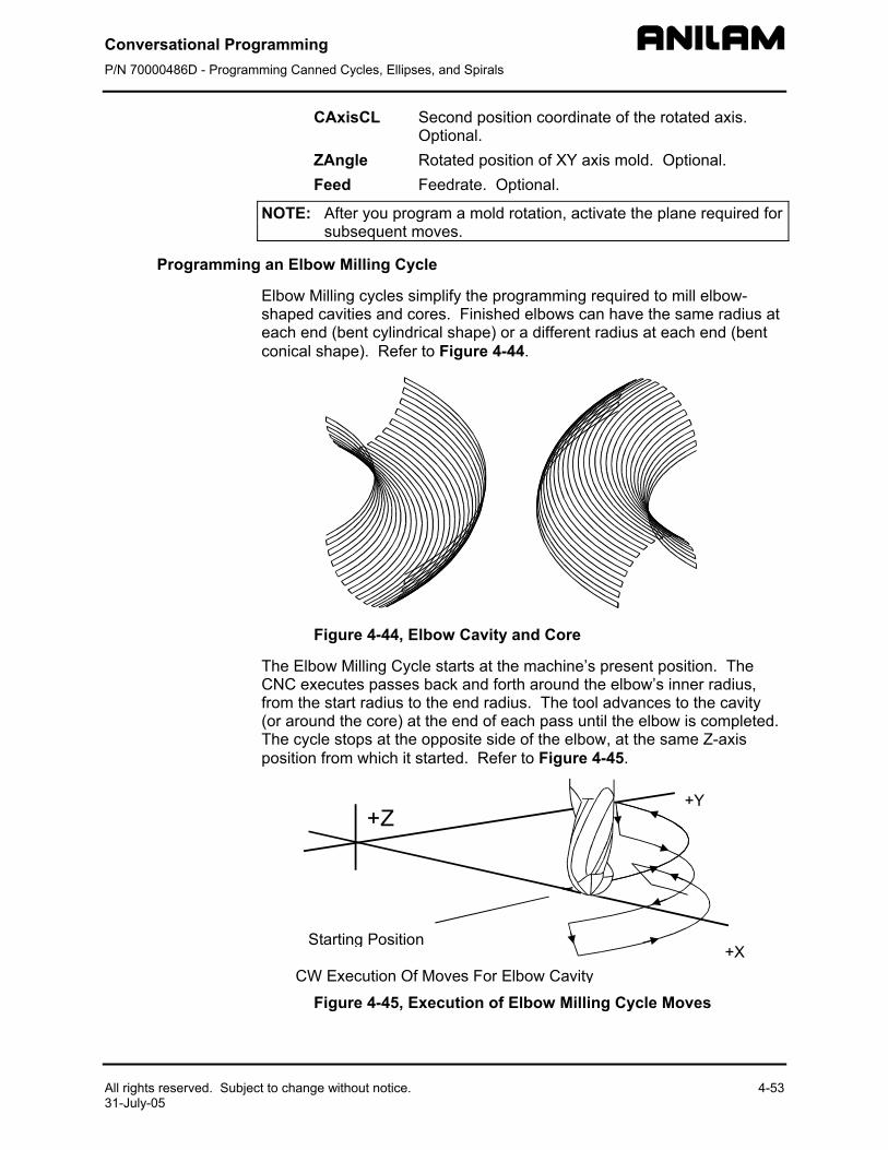
Conversational Programming P/N 70000486D - Programming Canned Cycles, Ellipses, and Spirals
All rights reserved. Subject to change without notice. 4-53 31-July-05
CAxisCL Second position coordinate of the rotated axis. Optional.
ZAngle Rotated position of XY axis mold. Optional. Feed Feedrate. Optional.
NOTE: After you program a mold rotation, activate the plane required for subsequent moves.
Programming an Elbow Milling Cycle
Elbow Milling cycles simplify the programming required to mill elbow-shaped cavities and cores. Finished elbows can have the same radius at each end (bent cylindrical shape) or a different radius at each end (bent conical shape). Refer to Figure 4-44.
Figure 4-44, Elbow Cavity and Core
The Elbow Milling Cycle starts at the machine’s present position. The CNC executes passes back and forth around the elbow’s inner radius, from the start radius to the end radius. The tool advances to the cavity (or around the core) at the end of each pass until the elbow is completed. The cycle stops at the opposite side of the elbow, at the same Z-axis position from which it started. Refer to Figure 4-45.
CW Execution Of Moves For Elbow Cavity
Starting Position
+Y
+X
+Z
Figure 4-45, Execution of Elbow Milling Cycle Moves
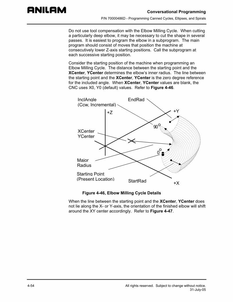
Conversational Programming P/N 70000486D - Programming Canned Cycles, Ellipses, and Spirals
4-54 All rights reserved. Subject to change without notice. 31-July-05
Do not use tool compensation with the Elbow Milling Cycle. When cutting a particularly deep elbow, it may be necessary to cut the shape in several passes. It is easiest to program the elbow in a subprogram. The main program should consist of moves that position the machine at consecutively lower Z-axis starting positions. Call the subprogram at each successive starting position.
Consider the starting position of the machine when programming an Elbow Milling Cycle. The distance between the starting point and the XCenter, YCenter determines the elbow’s inner radius. The line between the starting point and the XCenter, YCenter is the zero degree reference for the included angle. When XCenter, YCenter values are blank, the CNC uses X0, Y0 (default) values. Refer to Figure 4-46.
+X
+Y+Z
Starting Point(Present Location)
InclAngle(Ccw, Incremental)
StartRad
EndRad
XCenterYCenter
MajorRadius
90o
0o
Figure 4-46, Elbow Milling Cycle Details
When the line between the starting point and the XCenter, YCenter does not lie along the X- or Y-axis, the orientation of the finished elbow will shift around the XY center accordingly. Refer to Figure 4-47.
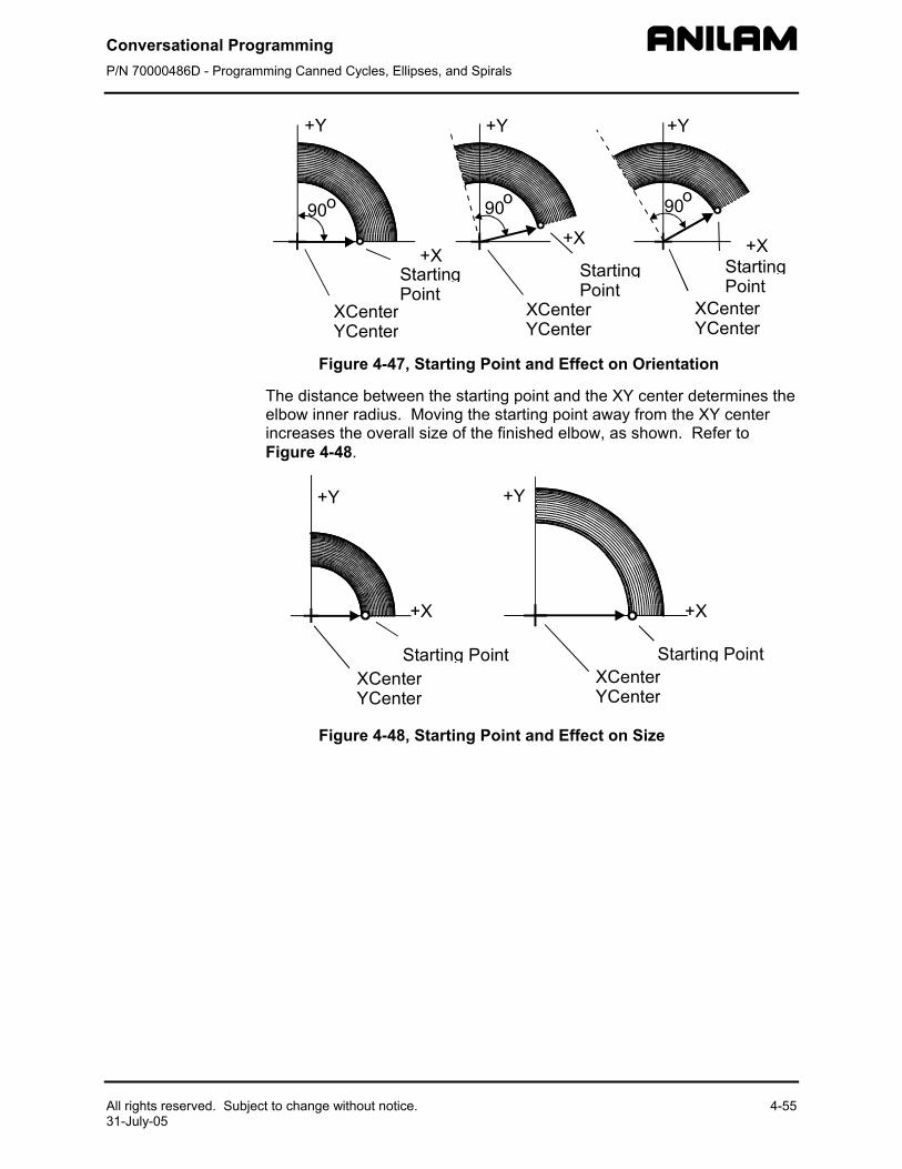
Conversational Programming P/N 70000486D - Programming Canned Cycles, Ellipses, and Spirals
All rights reserved. Subject to change without notice. 4-55 31-July-05
+X+X +X
+Y+Y+Y
StartingPoint
XCenterYCenter
90o90o
90o
StartingPoint
StartingPoint
XCenterYCenter
XCenterYCenter
Figure 4-47, Starting Point and Effect on Orientation
The distance between the starting point and the XY center determines the elbow inner radius. Moving the starting point away from the XY center increases the overall size of the finished elbow, as shown. Refer to Figure 4-48.
+Y
Starting PointXCenterYCenter
+Y
+X +X
Starting PointXCenterYCenter
Figure 4-48, Starting Point and Effect on Size
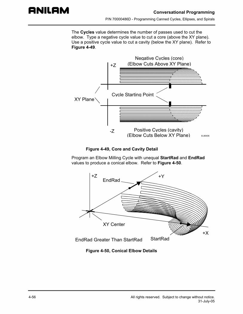
Conversational Programming P/N 70000486D - Programming Canned Cycles, Ellipses, and Spirals
4-56 All rights reserved. Subject to change without notice. 31-July-05
The Cycles value determines the number of passes used to cut the elbow. Type a negative cycle value to cut a core (above the XY plane). Use a positive cycle value to cut a cavity (below the XY plane). Refer to Figure 4-49.
Negative Cycles (core)(Elbow Cuts Above XY Plane)
Positive Cycles (cavity)(Elbow Cuts Below XY Plane)
Cycle Starting Point
+Z
-Z
XY Plane
ELBSIDE
Figure 4-49, Core and Cavity Detail
Program an Elbow Milling Cycle with unequal StartRad and EndRad values to produce a conical elbow. Refer to Figure 4-50.
+X
+Y+ZEndRad
StartRadEndRad Greater Than StartRad
XY Center
Figure 4-50, Conical Elbow Details
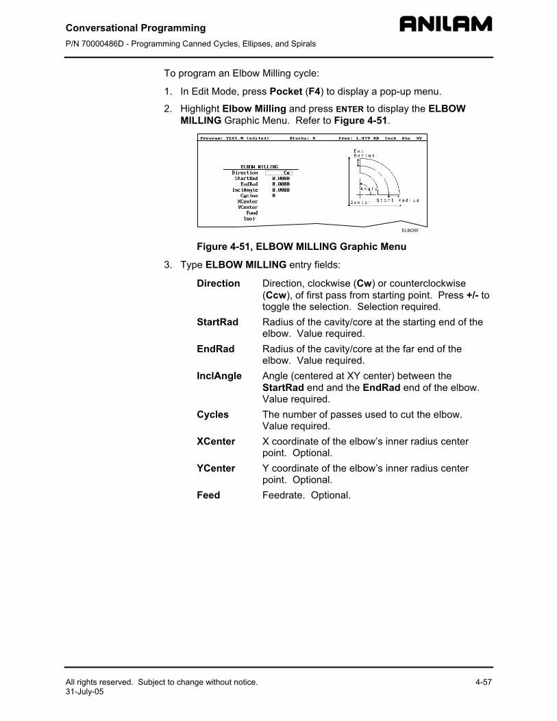
Conversational Programming P/N 70000486D - Programming Canned Cycles, Ellipses, and Spirals
All rights reserved. Subject to change without notice. 4-57 31-July-05
To program an Elbow Milling cycle:
1. In Edit Mode, press Pocket (F4) to display a pop-up menu.
2. Highlight Elbow Milling and press ENTER to display the ELBOW MILLING Graphic Menu. Refer to Figure 4-51.
Figure 4-51, ELBOW MILLING Graphic Menu
3. Type ELBOW MILLING entry fields:
Direction Direction, clockwise (Cw) or counterclockwise (Ccw), of first pass from starting point. Press +/- to toggle the selection. Selection required.
StartRad Radius of the cavity/core at the starting end of the elbow. Value required.
EndRad Radius of the cavity/core at the far end of the elbow. Value required.
InclAngle Angle (centered at XY center) between the StartRad end and the EndRad end of the elbow. Value required.
Cycles The number of passes used to cut the elbow. Value required.
XCenter X coordinate of the elbow’s inner radius center point. Optional.
YCenter Y coordinate of the elbow’s inner radius center point. Optional.
Feed Feedrate. Optional.
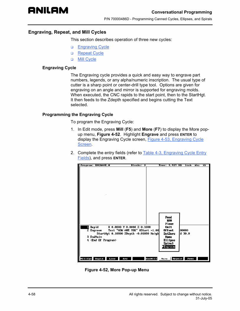
Conversational Programming P/N 70000486D - Programming Canned Cycles, Ellipses, and Spirals
4-58 All rights reserved. Subject to change without notice. 31-July-05
Engraving, Repeat, and Mill Cycles This section describes operation of three new cycles:
Engraving Cycle Repeat Cycle Mill Cycle
Engraving Cycle The Engraving cycle provides a quick and easy way to engrave part numbers, legends, or any alpha/numeric inscription. The usual type of cutter is a sharp point or center-drill type tool. Options are given for engraving on an angle and mirror is supported for engraving molds. When executed, the CNC rapids to the start point, then to the StartHgt. It then feeds to the Zdepth specified and begins cutting the Text selected.
Programming the Engraving Cycle To program the Engraving Cycle:
1. In Edit mode, press Mill (F5) and More (F7) to display the More pop-up menu, Figure 4-52. Highlight Engrave and press ENTER to display the Engraving Cycle screen, Figure 4-53, Engraving Cycle Screen.
2. Complete the entry fields (refer to Table 4-3, Engraving Cycle Entry Fields), and press ENTER.
Figure 4-52, More Pop-up Menu
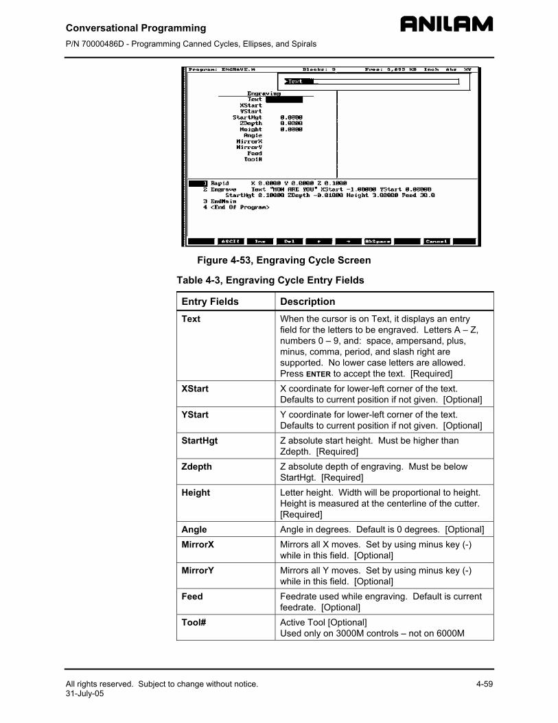
Conversational Programming P/N 70000486D - Programming Canned Cycles, Ellipses, and Spirals
All rights reserved. Subject to change without notice. 4-59 31-July-05
Figure 4-53, Engraving Cycle Screen
Table 4-3, Engraving Cycle Entry Fields
Entry Fields Description Text When the cursor is on Text, it displays an entry
field for the letters to be engraved. Letters A – Z, numbers 0 – 9, and: space, ampersand, plus, minus, comma, period, and slash right are supported. No lower case letters are allowed. Press ENTER to accept the text. [Required]
XStart X coordinate for lower-left corner of the text. Defaults to current position if not given. [Optional]
YStart Y coordinate for lower-left corner of the text. Defaults to current position if not given. [Optional]
StartHgt Z absolute start height. Must be higher than Zdepth. [Required]
Zdepth Z absolute depth of engraving. Must be below StartHgt. [Required]
Height Letter height. Width will be proportional to height. Height is measured at the centerline of the cutter. [Required]
Angle Angle in degrees. Default is 0 degrees. [Optional] MirrorX Mirrors all X moves. Set by using minus key (-)
while in this field. [Optional] MirrorY Mirrors all Y moves. Set by using minus key (-)
while in this field. [Optional] Feed Feedrate used while engraving. Default is current
feedrate. [Optional] Tool# Active Tool [Optional]
Used only on 3000M controls – not on 6000M
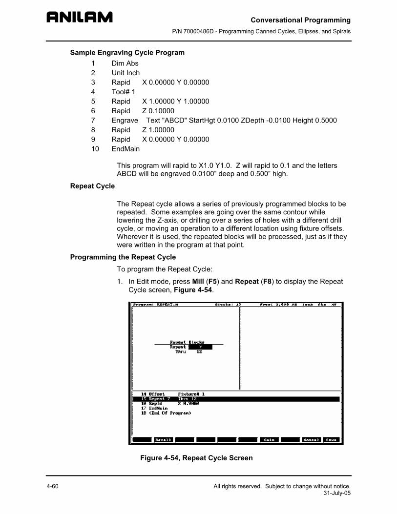
Conversational Programming P/N 70000486D - Programming Canned Cycles, Ellipses, and Spirals
4-60 All rights reserved. Subject to change without notice. 31-July-05
Sample Engraving Cycle Program 1 Dim Abs 2 Unit Inch 3 Rapid X 0.00000 Y 0.00000 4 Tool# 1 5 Rapid X 1.00000 Y 1.00000 6 Rapid Z 0.10000 7 Engrave Text "ABCD" StartHgt 0.0100 ZDepth -0.0100 Height 0.5000 8 Rapid Z 1.00000 9 Rapid X 0.00000 Y 0.00000 10 EndMain
This program will rapid to X1.0 Y1.0. Z will rapid to 0.1 and the letters ABCD will be engraved 0.0100” deep and 0.500” high.
Repeat Cycle
The Repeat cycle allows a series of previously programmed blocks to be repeated. Some examples are going over the same contour while lowering the Z-axis, or drilling over a series of holes with a different drill cycle, or moving an operation to a different location using fixture offsets. Wherever it is used, the repeated blocks will be processed, just as if they were written in the program at that point.
Programming the Repeat Cycle To program the Repeat Cycle:
1. In Edit mode, press Mill (F5) and Repeat (F8) to display the Repeat Cycle screen, Figure 4-54.
Figure 4-54, Repeat Cycle Screen
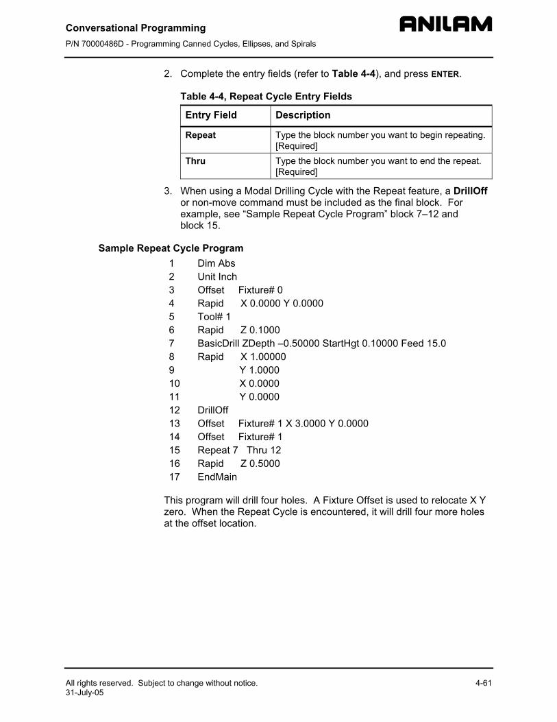
Conversational Programming P/N 70000486D - Programming Canned Cycles, Ellipses, and Spirals
All rights reserved. Subject to change without notice. 4-61 31-July-05
2. Complete the entry fields (refer to Table 4-4), and press ENTER.
Table 4-4, Repeat Cycle Entry Fields
Entry Field Description
Repeat Type the block number you want to begin repeating. [Required]
Thru Type the block number you want to end the repeat. [Required]
3. When using a Modal Drilling Cycle with the Repeat feature, a DrillOff or non-move command must be included as the final block. For example, see “Sample Repeat Cycle Program” block 7–12 and block 15.
Sample Repeat Cycle Program 1 Dim Abs 2 Unit Inch 3 Offset Fixture# 0 4 Rapid X 0.0000 Y 0.0000 5 Tool# 1 6 Rapid Z 0.1000 7 BasicDrill ZDepth –0.50000 StartHgt 0.10000 Feed 15.0 8 Rapid X 1.00000 9 Y 1.0000 10 X 0.0000 11 Y 0.0000 12 DrillOff 13 Offset Fixture# 1 X 3.0000 Y 0.0000 14 Offset Fixture# 1 15 Repeat 7 Thru 12 16 Rapid Z 0.5000 17 EndMain
This program will drill four holes. A Fixture Offset is used to relocate X Y zero. When the Repeat Cycle is encountered, it will drill four more holes at the offset location.
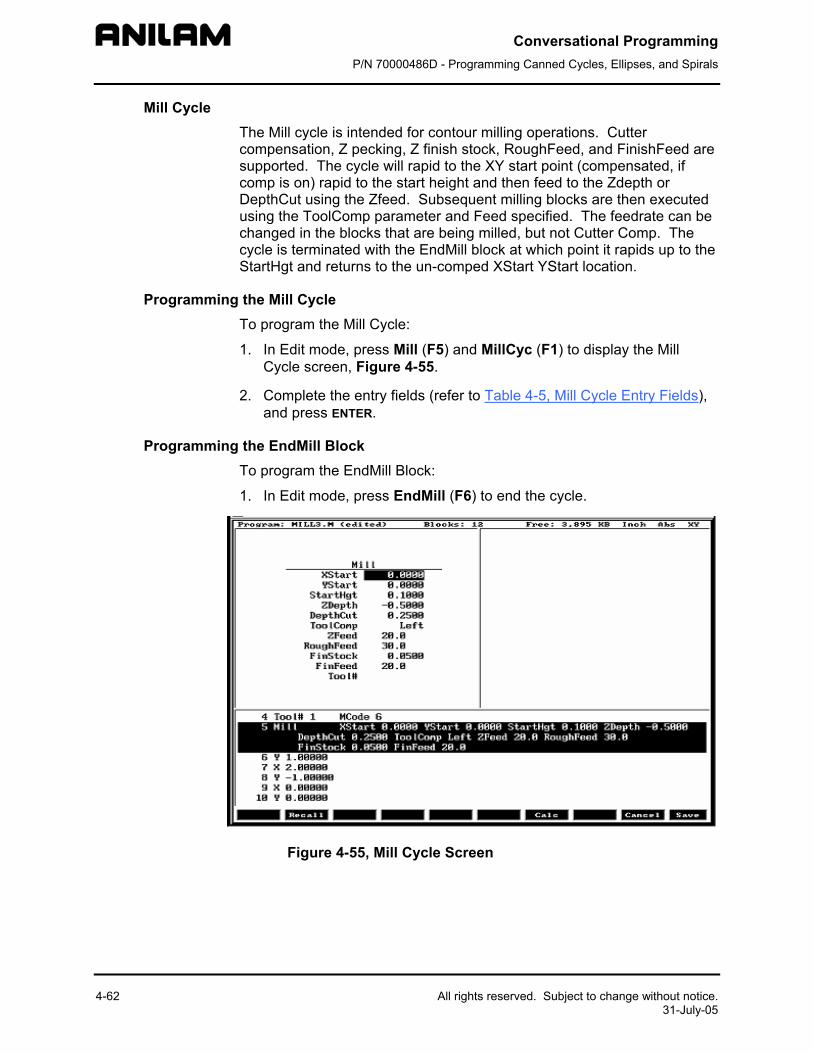
Conversational Programming P/N 70000486D - Programming Canned Cycles, Ellipses, and Spirals
4-62 All rights reserved. Subject to change without notice. 31-July-05
Mill Cycle The Mill cycle is intended for contour milling operations. Cutter compensation, Z pecking, Z finish stock, RoughFeed, and FinishFeed are supported. The cycle will rapid to the XY start point (compensated, if comp is on) rapid to the start height and then feed to the Zdepth or DepthCut using the Zfeed. Subsequent milling blocks are then executed using the ToolComp parameter and Feed specified. The feedrate can be changed in the blocks that are being milled, but not Cutter Comp. The cycle is terminated with the EndMill block at which point it rapids up to the StartHgt and returns to the un-comped XStart YStart location.
Programming the Mill Cycle To program the Mill Cycle:
1. In Edit mode, press Mill (F5) and MillCyc (F1) to display the Mill Cycle screen, Figure 4-55.
2. Complete the entry fields (refer to Table 4-5, Mill Cycle Entry Fields), and press ENTER.
Programming the EndMill Block To program the EndMill Block:
1. In Edit mode, press EndMill (F6) to end the cycle.
Figure 4-55, Mill Cycle Screen
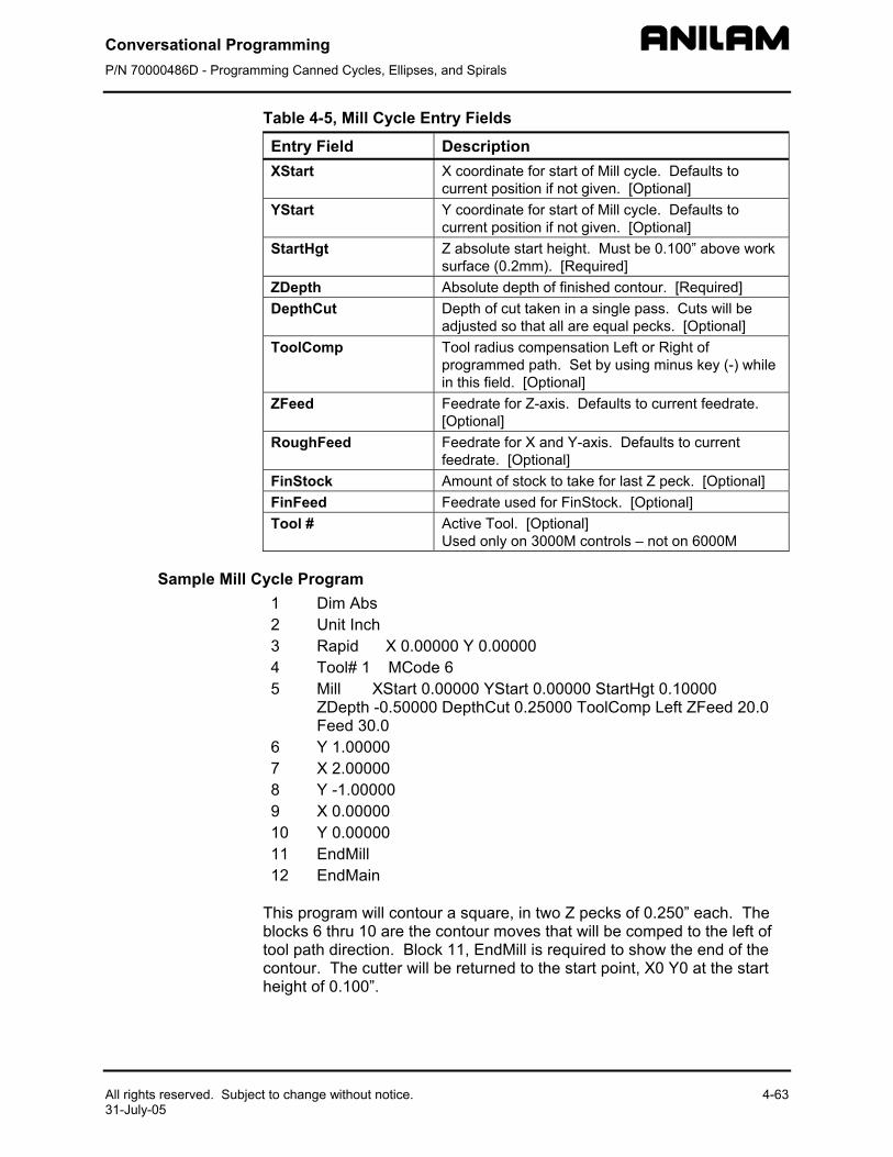
Conversational Programming P/N 70000486D - Programming Canned Cycles, Ellipses, and Spirals
All rights reserved. Subject to change without notice. 4-63 31-July-05
Table 4-5, Mill Cycle Entry Fields
Entry Field Description XStart X coordinate for start of Mill cycle. Defaults to
current position if not given. [Optional] YStart Y coordinate for start of Mill cycle. Defaults to
current position if not given. [Optional] StartHgt Z absolute start height. Must be 0.100” above work
surface (0.2mm). [Required] ZDepth Absolute depth of finished contour. [Required] DepthCut Depth of cut taken in a single pass. Cuts will be
adjusted so that all are equal pecks. [Optional] ToolComp Tool radius compensation Left or Right of
programmed path. Set by using minus key (-) while in this field. [Optional]
ZFeed Feedrate for Z-axis. Defaults to current feedrate. [Optional]
RoughFeed Feedrate for X and Y-axis. Defaults to current feedrate. [Optional]
FinStock Amount of stock to take for last Z peck. [Optional] FinFeed Feedrate used for FinStock. [Optional] Tool # Active Tool. [Optional]
Used only on 3000M controls – not on 6000M
Sample Mill Cycle Program 1 Dim Abs 2 Unit Inch 3 Rapid X 0.00000 Y 0.00000 4 Tool# 1 MCode 6 5 Mill XStart 0.00000 YStart 0.00000 StartHgt 0.10000
ZDepth -0.50000 DepthCut 0.25000 ToolComp Left ZFeed 20.0 Feed 30.0
6 Y 1.00000 7 X 2.00000 8 Y -1.00000 9 X 0.00000 10 Y 0.00000 11 EndMill 12 EndMain
This program will contour a square, in two Z pecks of 0.250” each. The blocks 6 thru 10 are the contour moves that will be comped to the left of tool path direction. Block 11, EndMill is required to show the end of the contour. The cutter will be returned to the start point, X0 Y0 at the start height of 0.100”.
Conversational Programming P/N 70000486D - Programming Canned Cycles, Ellipses, and Spirals
4-64 All rights reserved. Subject to change without notice. 31-July-05
Probing Cycles Probing cycles have the following features:
Tool probe cycles Spindle probe cycles
This section describes operation and an overview of the tool and spindle probe canned cycles in conversational format. Probing is an:
• Option in 5000M CNC system • Standard in 6000M CNC system
The cycles provided perform the most common tool and spindle probing functions. If Probing has been added post-sale, besides Setup Utility changes, there may be Integral Programmable Intelligence (IPI) program modifications required.
The tool probe cycles are only supported on machines with automatic spindle forward/reverse and spindle speed, and homing with a permanent X, Y, and Z machine position. The method described assumes the use of negative tool-length offsets. In this method, the Tool-Length Offset (TLO) in the length column for each tool represents the distance from the tool tip at machine home to top of work piece and is a negative number. This method does not require the use of any Z work coordinate offset to be active. This procedure will find the effective tool diameter by turning the spindle on in reverse and touching two sides of the probe stylus, then storing the tool’s diameter in the tool’s diameter offset table.
The spindle probing cycles are designed to assist in part setup. Using these cycles, one or more features (edges) of a part can be measured. Using the data obtained with these measurements, calculations are made that can be used to set a given fixture offset. It is also possible to find the orientation angle of a part so as to not always have to align the part exactly.
Tool and spindle probing do not allow rotation, scaling, and mirroring. Plane will be set to XY when these cycles are complete.
Tool Probe Cycles Before using your tool probe and tool probe cycles, you must setup the probe following the probe manufacturer’s specifications.
The tool probe will update the tool registers only. If you are going to use the tool being measured after the probing cycle, you must recall that tool for the new offsets to be active.
This section covers the following topics:
Tool Probe cycle designations Description of tool probe cycles
Conversational Programming P/N 70000486D - Programming Canned Cycles, Ellipses, and Spirals
All rights reserved. Subject to change without notice. 4-65 31-July-05
For probing system parameter setup information, refer to:
• 5000M CNC Setup Utility Manual, P/N 70000509, “Section 2 – Builder Setup,” “Probing”
• 6000M CNC Setup Utility Manual, P/N 70000490, “Section 2 - Machine Constants,” “MC_1150 to MC_1165”
Tool Probe Cycle Designations The following summarizes the cycles available:
Probe Calibration (CalibTlPrb)
Tool Probe Calibration Cycle
This is used to set the Z datum for length preset, the effective probe stylus diameter for setting tool diameter registers, and establishes the center of the probe stylus.
NOTE: Calibration must be done at least once before using the tool probe. Once the probe has been calibrated, calibration does not need to be done again unless the probe is moved or a new part is being setup. The cycle must always know the relationship between the top of the part and the top of the probe to set the TLO.
Length and Diameter (LenDiamMea)
Tool Length and Diameter Offset Preset
Updates length and diameter tool registers.
NOTE: If the tool has a hole on the bottom so that the probe would fall between the tool teeth, do not use this cycle. Damage to the probe could result. In this case, use Length Special for manual length preset or Diameter Special for manual diameter preset.
Length Special (LenSpecMea)
Manual Tool-Length Offset Preset
Updates tool-length register. To be used for large face mill style tools or shell mill tools that have a hole in the center of the bottom of the tool.
Diameter Special (DiaSpecMea)
Manual Tool Diameter Preset
Updates tool diameter register for irregular shaped tools or tools with a hole in the center of the bottom.
Break and Wear (BrkWearDet)
Tool Breakage, Length and Diameter Wear Detection Breakage
Checks the tool and gives an alarm if not within tolerance.
Length and Diameter Wear – Check the Length and/or Diameter and updates the Length and/or Diameter wear registers up to a user-defined limit. Once the user-defined limit has been reached, the cycle will give an alarm and stop the program.
Conversational Programming P/N 70000486D - Programming Canned Cycles, Ellipses, and Spirals
4-66 All rights reserved. Subject to change without notice. 31-July-05
Description of Tool Probe Cycles For tool probing or tool length presetting, Tool-Length Offset (TLO) is
the distance from machine home to top of work piece or wherever you set your part “Z” zero.
Before starting to set your tools, you must calibrate the probe. Once the probe has been calibrated, calibration does not have to be done again unless you remove the probe or replace the stylus.
Recalibration may also be required if the Z location of the top of the part changes, and is not compensated for by a Z work offset.
The probing cycles can be found in the conversational side of the 5000M and 6000M by pressing Mill (F5), then Probe (F10) and ToolPro (F1) or SpinPro (F3). You can also access the probe cycles on the 5000M and 6000M from the main edit screen by pressing the SHIFT key and then F1 or F3.
The following sections contain detailed descriptions of the tool probe cycles:
• Tool Probe Calibration Cycle (CalibTlPrb) • Tool Length and Diameter Offset Preset (LenDiamMea) • Manual Tool Length Measure for Special Tools (LenSpecMea) • Manual Tool Diameter Measure for Special Tools (DiaSpecMea) • Tool Breakage, Length, and Diameter Wear Detection (BrkWearDet)
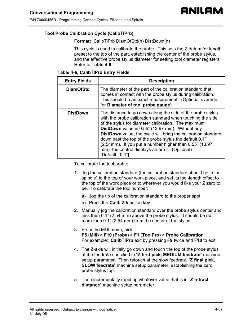
Conversational Programming P/N 70000486D - Programming Canned Cycles, Ellipses, and Spirals
All rights reserved. Subject to change without notice. 4-67 31-July-05
Tool Probe Calibration Cycle (CalibTlPrb) Format: CalibTlPrb DiamOfStd(n) DistDown(n)
This cycle is used to calibrate the probe. This sets the Z datum for length preset to the top of the part, establishing the center of the probe stylus, and the effective probe stylus diameter for setting tool diameter registers. Refer to Table 4-6.
Table 4-6, CalibTlPrb Entry Fields
Entry Fields Description
DiamOfStd The diameter of the part of the calibration standard that comes in contact with the probe stylus during calibration. This should be an exact measurement. (Optional override for Diameter of tool probe gauge)
DistDown The distance to go down along the side of the probe stylus with the probe calibration standard when touching the side of the stylus for diameter calibration. The maximum DistDown value is 0.55” (13.97 mm). Without any DistDown value, the cycle will bring the calibration standard down past the top of the probe stylus the default 0.1” (2.54mm). If you put a number higher than 0.55” (13.97 mm), the control displays an error. (Optional) [Default: 0.1”]
To calibrate the tool probe:
1. Jog the calibration standard (the calibration standard should be in the spindle) to the top of your work piece, and set its tool-length offset to the top of the work piece or to wherever you would like your Z zero to be. To calibrate the tool number:
a) Jog the tip of the calibration standard to the proper spot b) Press the Calib Z function key.
2. Manually jog the calibration standard over the probe stylus center and less then 0.1” (2.54 mm) above the probe stylus. It should be no more then 0.1” (2.54 mm) from the center of the stylus.
3. From the MDI mode, pick F5 (Mill) > F10 (Probe) > F1 (ToolPro) > Probe Calibration For example: CalibTlPrb exit by pressing F9 twice and F10 to exit.
4. The Z-axis will initially go down and touch the top of the probe stylus at the feedrate specified in “Z first pick, MEDIUM feedrate” machine setup parameter. Then retouch at the slow feedrate, “Z final pick, SLOW feedrate” machine setup parameter, establishing the zero probe stylus top.
5. Then incrementally rapid up whatever value that is in “Z retract distance” machine setup parameter.
Conversational Programming P/N 70000486D - Programming Canned Cycles, Ellipses, and Spirals
4-68 All rights reserved. Subject to change without notice. 31-July-05
6. The spindle will come on at the RPM specified at the “RPM for calibration and tool measurement” machine setup parameter and then the calibration standard will move over an incremental amount that is equal to (Half the value entered in the DiamOfStd cycle parameter (or machine setup parameter Diameter of probe gauge) + Half the value entered in “Nominal probe stylus diameter” machine setup parameter + The value in the “XY retract distance” machine setup parameter). The direction the probe will move over depends on what is placed in the “Probe orientation” machine setup parameter:
–1 Go first to the left
1 Go first to the right
–2 Go first to the front
2 Go first to the back
7. The Z-axis will then do a guarded Z move down 0.1” (2.54 mm) or whatever amount was placed in the DistDown cycle parameter and then move over toward the probe stylus 0.3” (7.62 mm) or until it touches the probe stylus. If contact is not made with the probe or if contact is made during a guarded move, then an alarm will be generated and the canned cycle will terminate.
8. After the probe stylus is touched on the first side, the machine will then rapid up and over the stylus then down on the opposite side then over to the other two sides until it has touched the probe stylus on all four quadrants. This will establish the center of the probe stylus.
9. The spindle will then turn off and the machine will touch off on two sides of the probe with the spindle off finding the effective probe stylus diameter. Then, will rapid up above the probe stylus and over to the center.
10. Remove the calibration standard. You are now ready to start running the Length and Diameter cycle (or one of the other cycles for setting or checking length and diameter of the tool) to set your tool-length offsets or tool diameter registers.
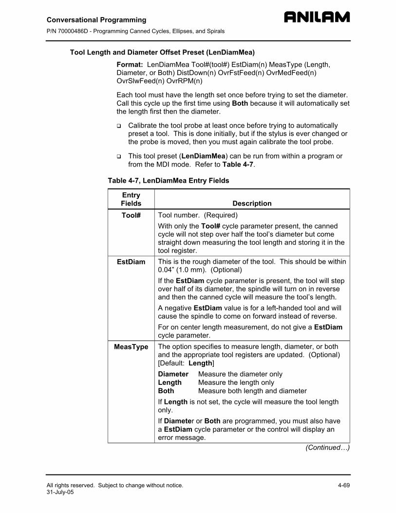
Conversational Programming P/N 70000486D - Programming Canned Cycles, Ellipses, and Spirals
All rights reserved. Subject to change without notice. 4-69 31-July-05
Tool Length and Diameter Offset Preset (LenDiamMea) Format: LenDiamMea Tool#(tool#) EstDiam(n) MeasType (Length, Diameter, or Both) DistDown(n) OvrFstFeed(n) OvrMedFeed(n) OvrSlwFeed(n) OvrRPM(n)
Each tool must have the length set once before trying to set the diameter. Call this cycle up the first time using Both because it will automatically set the length first then the diameter.
Calibrate the tool probe at least once before trying to automatically preset a tool. This is done initially, but if the stylus is ever changed or the probe is moved, then you must again calibrate the tool probe.
This tool preset (LenDiamMea) can be run from within a program or from the MDI mode. Refer to Table 4-7.
Table 4-7, LenDiamMea Entry Fields
Entry Fields
Description
Tool# Tool number. (Required) With only the Tool# cycle parameter present, the canned cycle will not step over half the tool’s diameter but come straight down measuring the tool length and storing it in the tool register.
EstDiam This is the rough diameter of the tool. This should be within 0.04” (1.0 mm). (Optional) If the EstDiam cycle parameter is present, the tool will step over half of its diameter, the spindle will turn on in reverse and then the canned cycle will measure the tool’s length. A negative EstDiam value is for a left-handed tool and will cause the spindle to come on forward instead of reverse. For on center length measurement, do not give a EstDiam cycle parameter.
MeasType The option specifies to measure length, diameter, or both and the appropriate tool registers are updated. (Optional) [Default: Length] Diameter Measure the diameter only Length Measure the length only Both Measure both length and diameter If Length is not set, the cycle will measure the tool length only. If Diameter or Both are programmed, you must also have a EstDiam cycle parameter or the control will display an error message.
(Continued…)
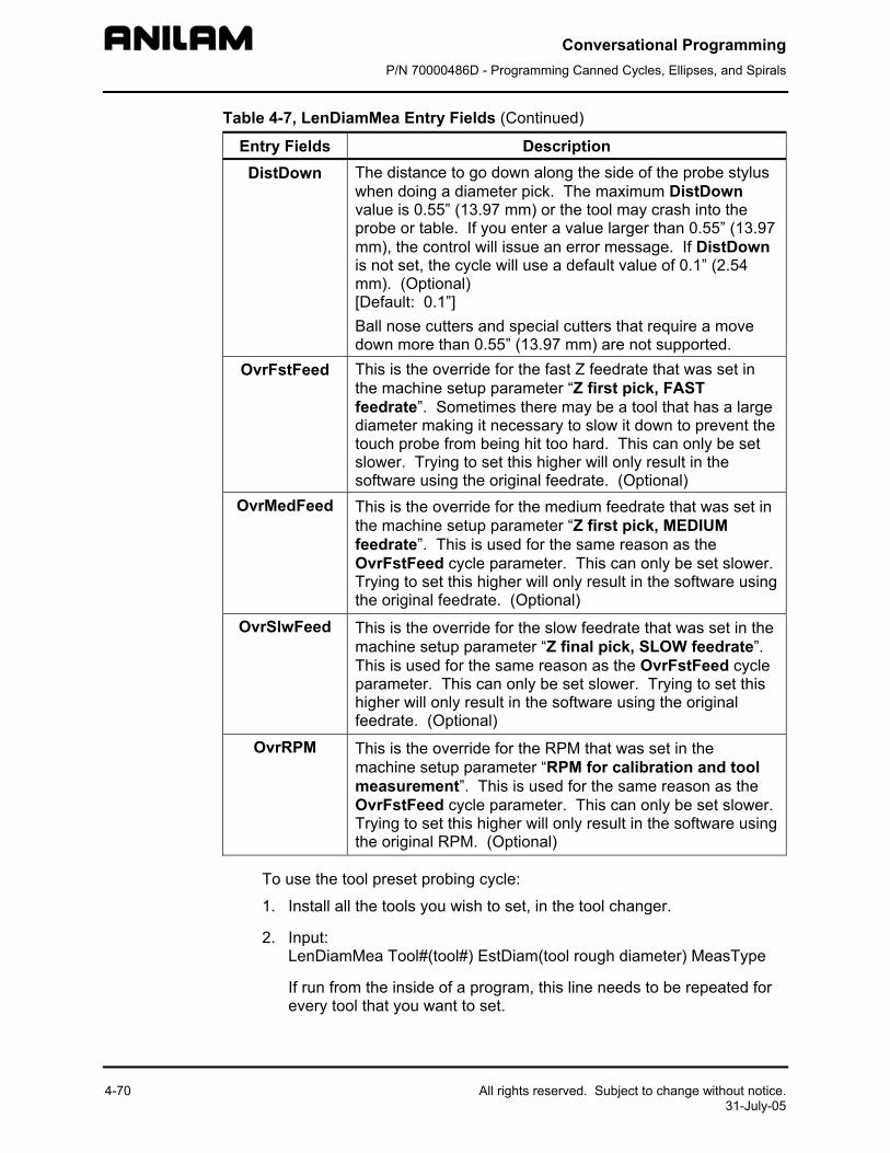
Conversational Programming P/N 70000486D - Programming Canned Cycles, Ellipses, and Spirals
4-70 All rights reserved. Subject to change without notice. 31-July-05
Table 4-7, LenDiamMea Entry Fields (Continued)
Entry Fields Description DistDown The distance to go down along the side of the probe stylus
when doing a diameter pick. The maximum DistDown value is 0.55” (13.97 mm) or the tool may crash into the probe or table. If you enter a value larger than 0.55” (13.97 mm), the control will issue an error message. If DistDown is not set, the cycle will use a default value of 0.1” (2.54 mm). (Optional) [Default: 0.1”] Ball nose cutters and special cutters that require a move down more than 0.55” (13.97 mm) are not supported.
OvrFstFeed This is the override for the fast Z feedrate that was set in the machine setup parameter “Z first pick, FAST feedrate”. Sometimes there may be a tool that has a large diameter making it necessary to slow it down to prevent the touch probe from being hit too hard. This can only be set slower. Trying to set this higher will only result in the software using the original feedrate. (Optional)
OvrMedFeed This is the override for the medium feedrate that was set in the machine setup parameter “Z first pick, MEDIUM feedrate”. This is used for the same reason as the OvrFstFeed cycle parameter. This can only be set slower. Trying to set this higher will only result in the software using the original feedrate. (Optional)
OvrSlwFeed This is the override for the slow feedrate that was set in the machine setup parameter “Z final pick, SLOW feedrate”. This is used for the same reason as the OvrFstFeed cycle parameter. This can only be set slower. Trying to set this higher will only result in the software using the original feedrate. (Optional)
OvrRPM This is the override for the RPM that was set in the machine setup parameter “RPM for calibration and tool measurement”. This is used for the same reason as the OvrFstFeed cycle parameter. This can only be set slower. Trying to set this higher will only result in the software using the original RPM. (Optional)
To use the tool preset probing cycle:
1. Install all the tools you wish to set, in the tool changer.
2. Input: LenDiamMea Tool#(tool#) EstDiam(tool rough diameter) MeasType
If run from the inside of a program, this line needs to be repeated for every tool that you want to set.
Conversational Programming P/N 70000486D - Programming Canned Cycles, Ellipses, and Spirals
All rights reserved. Subject to change without notice. 4-71 31-July-05
3. Execute that line if you are in MDI mode, or run the program if you have set all the tools up in a program.
4. If you have done a single tool in MDI mode, that tool is now measured and you are ready to measure the next tool. If you have placed multiple lines in a program, one for each tool, all your tools are measured and ready for use.
Shell mill style tools that have a hole in the center of the bottom will not work with this canned cycle; in this case, you must use the manual canned cycles LenSpecMea (Length Special Manual Tool Length Measure for Special Tools) for length and DiaSpecMea (Diameter Special Manual Tool Diameter Measure for Special Tools) for diameter. See Table 4-7, LenDiamMea Entry Fields. This cycle is only good for drills, taps, reamers, ball nosed endmills, and standard endmills with a flat bottom, the cycle updates length and diameter tool registers clearing anything in the wear registers.
Format: LenDiamMea Tool#(tool#)
With Tool# parameter only set:
1. The machine will rapid the Z-axis up and pick up the tool designated in the Tool# cycle parameter and rapid directly over the center of the probe stylus.
2. The Z-axis will rapid down the distance placed in the “Z rapid to start position from home” machine setup parameter, then start feeding down toward the probe for the initial touch at the feedrate that was placed in the “Z first pick, FAST feedrate” machine setup parameter, then will back up and retouch the probe at the feedrate that is in the “Z final pick, SLOW feedrate” machine setup parameter.
3. The tool-length register for that tool is now updated, and that tool’s length-wear register is set to zero.
4. Then the Z-axis will rapid up to home position.
5. If you have done a single tool in MDI mode, that tool is now measured and you are ready to measure the next tool. If you have placed multiple lines in a program, one for each tool, the machine will then grab the next tool and repeat steps 1 through 4 until all the tools have been measured.
Conversational Programming P/N 70000486D - Programming Canned Cycles, Ellipses, and Spirals
4-72 All rights reserved. Subject to change without notice. 31-July-05
Format: LenDiaMea Tool#(tool#) EstDiam(tool rough diameter)
With Tool# and EstDiam parameters only set:
1. The machine will rapid the Z-axis up and pick up the tool designated in the Tool# cycle parameter and rapid directly over the center of the probe stylus.
2. The Z-axis will rapid down the distance placed in the “Z rapid to start position from home” machine setup parameter then start feeding down toward the probe for the initial touch at the feedrate that was placed in the “Z first pick, FAST feedrate” machine setup parameter then will back up.
3. The machine will rapid over half the diameter of the cutter from the probe stylus center in the direction related to the “Probe orientation” machine setup parameter.
4. The spindle will then come on in reverse at the RPM specified in the “RPM for calibration and tool measurement” machine setup parameter and retouch the probe at the feedrate that is in the “Z final pick, SLOW feedrate” machine setup parameter.
5. The tool-length register for that tool is now updated, and that tool’s length-wear register is set to zero.
6. Then the Z-axis will rapid up to the home position.
7. If you have done a single tool in MDI mode, that tool is now measured and you are ready to measure the next tool. If you have placed multiple lines in a program, one for each tool, the machine will then grab the next tool and repeat steps 1 through 6 until all the tools have been measured.
Format: LenDiaMea Tool#(tool#) EstDiam(tool rough diameter) MeasType (Both)
With Tool#, EstDiam, and MeasType parameters set:
1. The machine will rapid the Z-axis up and pick up the tool designated in the Tool# cycle parameter and rapid directly over the center of the probe stylus.
2. The Z-axis will rapid down the distance placed in the “Z rapid to start position from home” machine setup parameter then start feeding down toward the probe for the initial touch at the feedrate that was placed in the “Z first pick, FAST feedrate” machine setup parameter then will back up.
3. The machine will rapid over half the diameter of the cutter from the probe stylus center in the direction related to the “Probe orientation” machine setup parameter.
Conversational Programming P/N 70000486D - Programming Canned Cycles, Ellipses, and Spirals
All rights reserved. Subject to change without notice. 4-73 31-July-05
4. The spindle will then come on counter clockwise at the RPM specified in the “RPM for calibration and tool measurement” machine setup parameter and retouch the probe at the feedrate that is in the “Z final pick, SLOW feedrate” machine setup parameter.
5. The tool-length register for that tool is now updated, and any value in the length wear register will be reset to zero.
6. Then the Z-axis will rapid up above the probe stylus the distance specified in the “Z retract distance” machine setup parameter and then rapid the X & Y axes over the center of the probe and turn the spindle on in reverse.
7. The machine will move the tool’s edge off to one side of the probe stylus in the direction indicated in the “Probe orientation” machine setup parameter before making a guarded move down 0.1” (2.54 mm) or whatever value has been placed in the DistDown cycle parameter.
8. The machine will then touch the tool to the probe stylus on two opposite sides at the feedrate specified in the “Z first pick, MEDIUM feedrate” machine setup parameter with the spindle running at the RPM specified in the “RPM for calibration and tool measurement” machine setup parameter, backing up 0.02” (0.508 mm) after each first touch then retouching and the feedrate specified in the “Z final pick, SLOW feedrate” machine setup parameter, calculating the diameter of the tool and placing the calculated diameter value in the diameter register for the tool being preset and any value in the diameter wear register will be reset to zero.
9. Then the Z-axis will rapid up to the home position.
10. If you have done a single tool in MDI mode, that tool is now measured and you are ready to measure the next tool. If you have placed multiple lines in a program, one for each tool, the machine will then grab the next tool and repeat steps 1 through 9 until all the tools have been measured.
Conversational Programming P/N 70000486D - Programming Canned Cycles, Ellipses, and Spirals
4-74 All rights reserved. Subject to change without notice. 31-July-05
Manual Tool Length Measure for Special Tools (LenSpecMea) Format: LenSpecMea Tool#(tool#) DiamOfStd(n) OvrMedFeed(n) OvrSlwFeed(n) OvrRPM(n)
This cycle is used to measure the length of large face mill style tools that have a hole in the center of the bottom of the tool. Refer to Table 4-8.
Table 4-8, LenSpecMea Entry Fields
Entry Fields Description
Tool# Tool number. (Required)
With only the Tool# cycle parameter present, the spindle will turn on in reverse and the canned cycle will come straight down measuring the tool length and storing it in the tool-length register. The Tool# cycle parameter must the same as the current tool in the spindle.
EstDiam This is the rough diameter of the tool and is only used in this cycle to determine if the spindle should be turned on in reverse or forward. If you have a left-handed tool you would give a negative value to the diameter. If this parameter is left off the control will always turn on in reverse by default. (Optional)
OvrMedFeed This is the override for the medium feedrate that was set in the machine setup parameter “Z first pick, MEDIUM feedrate”. Sometimes there may be a tool that has a large diameter making it necessary to slow it down to prevent the touch probe from being hit too hard. This can only be set slower. Trying to set this higher will only result in the software using the original feedrate. (Optional)
OvrSlwFeed This is the override for the slow feedrate that was set in the machine setup parameter “Z final pick, SLOW feedrate”. This is used for the same reason as the OvrMedFeed cycle parameter. This can only be set slower. Trying to set this higher will only result in the software using the original feedrate. (Optional)
OvrRPM This is the override for the RPM that was set in the machine setup parameter “RPM for calibration and tool measurement”. This is used for the same reason as the OvrMedFeed cycle parameter. This can only be set slower. Trying to set this higher will only result in the software using the original RPM. (Optional)

Conversational Programming P/N 70000486D - Programming Canned Cycles, Ellipses, and Spirals
All rights reserved. Subject to change without notice. 4-75 31-July-05
Warning: Large tools can result in probe damage if the touch feedrate is set too fast. For this reason, the parameters: OvrMedFeed, OvrSlwFeed, and OvrRPM have been added to enable the programmer/operator to override the values in the parameters for the specific tool being checked or set.
You must have the tool positioned over the probe stylus so that the tooth that sticks down the furthest is directly over the center of the probe stylus and above the stylus less then 0.200” (5.08 mm).
NOTE: If the spindle is locked, you may have to unlock it to manually orient the tool tooth over the probe stylus.
To measure the tool length:
1. Jog the tool to the top of the probe stylus so that the tooth that sticks down the furthest is directly over the center of the probe stylus.
2. From the MDI mode, input:
LenSpecMea Tool#(tool#) EstDiam(n), Exit and press the START button. Where Tool# is the tool number and EstDiam is roughly the diameter of the special tool. For example: LenSpecMea Tool# 3 EstDiam 3.5
3. The spindle will turn on in reverse and the Z-axis should go down and touch the top of the probe stylus keeping the X and Y position the same then rapid up 0.02” (0.508 mm) and then retouch using the slow feedrate programmed in the machine variables. The cycle will then update the tool-length offset register clearing any value in the length wear register, turn the spindle off and return the tool to the Z height where it started.
4. The Tool Length has been set and you can now change to another tool, and repeat steps 1 through 3.
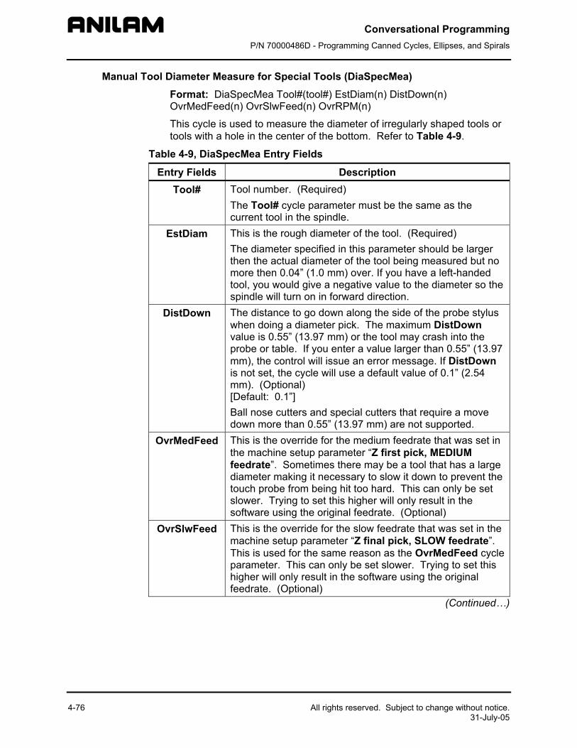
Conversational Programming P/N 70000486D - Programming Canned Cycles, Ellipses, and Spirals
4-76 All rights reserved. Subject to change without notice. 31-July-05
Manual Tool Diameter Measure for Special Tools (DiaSpecMea) Format: DiaSpecMea Tool#(tool#) EstDiam(n) DistDown(n) OvrMedFeed(n) OvrSlwFeed(n) OvrRPM(n)
This cycle is used to measure the diameter of irregularly shaped tools or tools with a hole in the center of the bottom. Refer to Table 4-9.
Table 4-9, DiaSpecMea Entry Fields
Entry Fields Description Tool# Tool number. (Required)
The Tool# cycle parameter must be the same as the current tool in the spindle.
EstDiam This is the rough diameter of the tool. (Required) The diameter specified in this parameter should be larger then the actual diameter of the tool being measured but no more then 0.04” (1.0 mm) over. If you have a left-handed tool, you would give a negative value to the diameter so the spindle will turn on in forward direction.
DistDown The distance to go down along the side of the probe stylus when doing a diameter pick. The maximum DistDown value is 0.55” (13.97 mm) or the tool may crash into the probe or table. If you enter a value larger than 0.55” (13.97 mm), the control will issue an error message. If DistDown is not set, the cycle will use a default value of 0.1” (2.54 mm). (Optional) [Default: 0.1”] Ball nose cutters and special cutters that require a move down more than 0.55” (13.97 mm) are not supported.
OvrMedFeed This is the override for the medium feedrate that was set in the machine setup parameter “Z first pick, MEDIUM feedrate”. Sometimes there may be a tool that has a large diameter making it necessary to slow it down to prevent the touch probe from being hit too hard. This can only be set slower. Trying to set this higher will only result in the software using the original feedrate. (Optional)
OvrSlwFeed This is the override for the slow feedrate that was set in the machine setup parameter “Z final pick, SLOW feedrate”. This is used for the same reason as the OvrMedFeed cycle parameter. This can only be set slower. Trying to set this higher will only result in the software using the original feedrate. (Optional)
(Continued…)
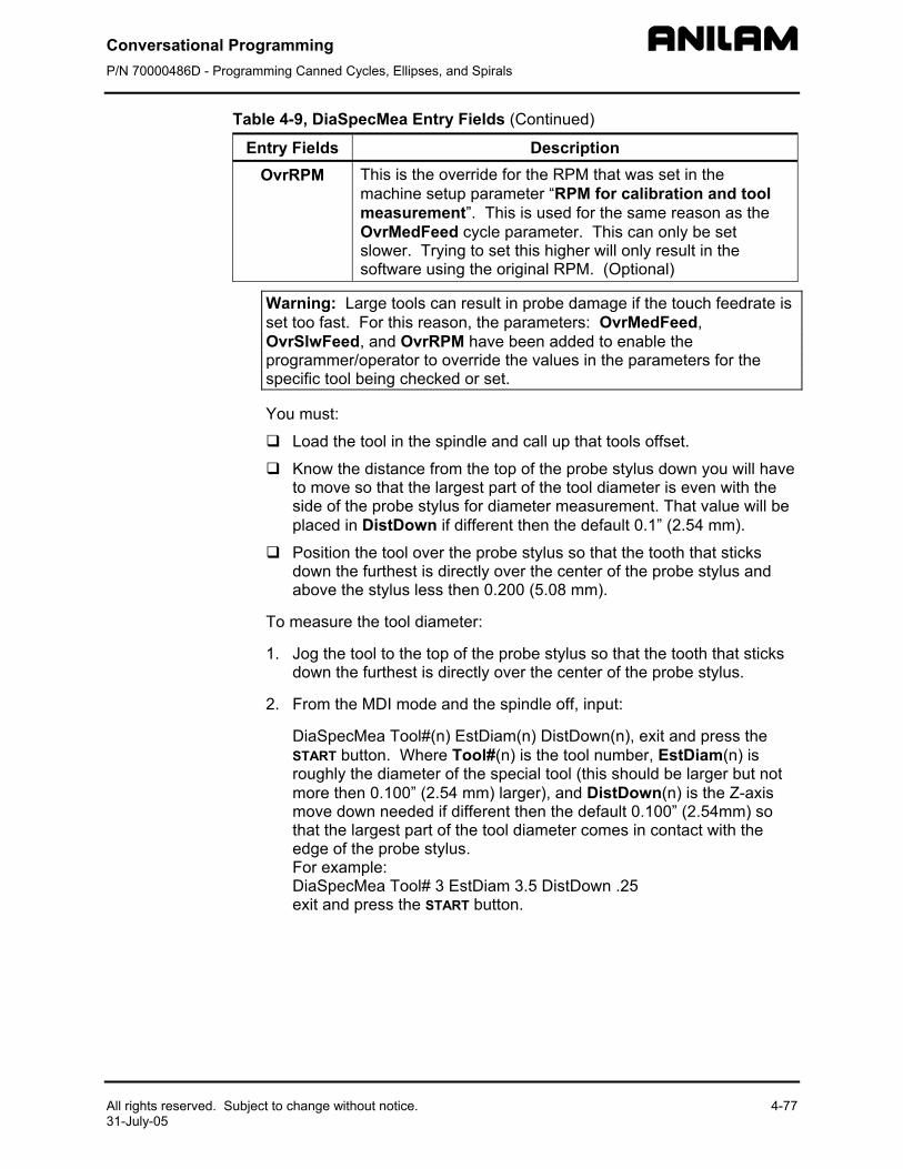
Conversational Programming P/N 70000486D - Programming Canned Cycles, Ellipses, and Spirals
All rights reserved. Subject to change without notice. 4-77 31-July-05
Table 4-9, DiaSpecMea Entry Fields (Continued)
Entry Fields Description OvrRPM This is the override for the RPM that was set in the
machine setup parameter “RPM for calibration and tool measurement”. This is used for the same reason as the OvrMedFeed cycle parameter. This can only be set slower. Trying to set this higher will only result in the software using the original RPM. (Optional)
Warning: Large tools can result in probe damage if the touch feedrate is set too fast. For this reason, the parameters: OvrMedFeed, OvrSlwFeed, and OvrRPM have been added to enable the programmer/operator to override the values in the parameters for the specific tool being checked or set.
You must:
Load the tool in the spindle and call up that tools offset.
Know the distance from the top of the probe stylus down you will have to move so that the largest part of the tool diameter is even with the side of the probe stylus for diameter measurement. That value will be placed in DistDown if different then the default 0.1” (2.54 mm).
Position the tool over the probe stylus so that the tooth that sticks down the furthest is directly over the center of the probe stylus and above the stylus less then 0.200 (5.08 mm).
To measure the tool diameter:
1. Jog the tool to the top of the probe stylus so that the tooth that sticks down the furthest is directly over the center of the probe stylus.
2. From the MDI mode and the spindle off, input:
DiaSpecMea Tool#(n) EstDiam(n) DistDown(n), exit and press the START button. Where Tool#(n) is the tool number, EstDiam(n) is roughly the diameter of the special tool (this should be larger but not more then 0.100” (2.54 mm) larger), and DistDown(n) is the Z-axis move down needed if different then the default 0.100” (2.54mm) so that the largest part of the tool diameter comes in contact with the edge of the probe stylus. For example: DiaSpecMea Tool# 3 EstDiam 3.5 DistDown .25 exit and press the START button.
Conversational Programming P/N 70000486D - Programming Canned Cycles, Ellipses, and Spirals
4-78 All rights reserved. Subject to change without notice. 31-July-05
3. The Z-axis will feed down with the spindle on, touching the top of the probe stylus. Once the top of the probe is found, the Z-axis will rapid back up above the probe and move over to one side of the probe stylus. The tool will then move down the distance in DistDown or 0.1” (2.54 mm) if DistDown is not programmed. Then, with the spindle turning in reverse, the canned cycle will touch the side of the tool to the probe stylus twice on opposite sides establishing the tool’s diameter. The new diameter will then be stored in that tool’s diameter register and clear any value in the diameter wear register. The Z-axis will rapid up to machine home.
4. The Tool Diameter has now been set and you can change to another tool and repeat steps 1 through 3.
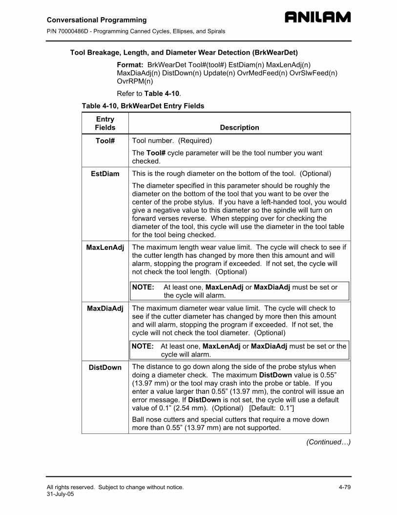
Conversational Programming P/N 70000486D - Programming Canned Cycles, Ellipses, and Spirals
All rights reserved. Subject to change without notice. 4-79 31-July-05
Tool Breakage, Length, and Diameter Wear Detection (BrkWearDet) Format: BrkWearDet Tool#(tool#) EstDiam(n) MaxLenAdj(n) MaxDiaAdj(n) DistDown(n) Update(n) OvrMedFeed(n) OvrSlwFeed(n) OvrRPM(n)
Refer to Table 4-10.
Table 4-10, BrkWearDet Entry Fields
Entry Fields
Description
Tool# Tool number. (Required)
The Tool# cycle parameter will be the tool number you want checked.
EstDiam This is the rough diameter on the bottom of the tool. (Optional)
The diameter specified in this parameter should be roughly the diameter on the bottom of the tool that you want to be over the center of the probe stylus. If you have a left-handed tool, you would give a negative value to this diameter so the spindle will turn on forward verses reverse. When stepping over for checking the diameter of the tool, this cycle will use the diameter in the tool table for the tool being checked.
MaxLenAdj The maximum length wear value limit. The cycle will check to see if the cutter length has changed by more then this amount and will alarm, stopping the program if exceeded. If not set, the cycle will not check the tool length. (Optional)
NOTE: At least one, MaxLenAdj or MaxDiaAdj must be set or the cycle will alarm.
MaxDiaAdj The maximum diameter wear value limit. The cycle will check to see if the cutter diameter has changed by more then this amount and will alarm, stopping the program if exceeded. If not set, the cycle will not check the tool diameter. (Optional)
NOTE: At least one, MaxLenAdj or MaxDiaAdj must be set or the cycle will alarm.
DistDown The distance to go down along the side of the probe stylus when doing a diameter check. The maximum DistDown value is 0.55” (13.97 mm) or the tool may crash into the probe or table. If you enter a value larger than 0.55” (13.97 mm), the control will issue an error message. If DistDown is not set, the cycle will use a default value of 0.1” (2.54 mm). (Optional) [Default: 0.1”] Ball nose cutters and special cutters that require a move down more than 0.55” (13.97 mm) are not supported.
(Continued…)
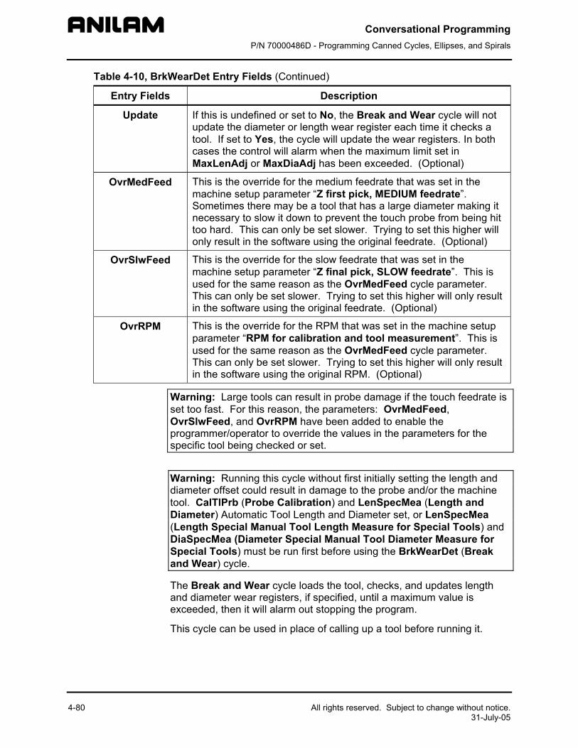
Conversational Programming P/N 70000486D - Programming Canned Cycles, Ellipses, and Spirals
4-80 All rights reserved. Subject to change without notice. 31-July-05
Table 4-10, BrkWearDet Entry Fields (Continued)
Entry Fields Description
Update If this is undefined or set to No, the Break and Wear cycle will not update the diameter or length wear register each time it checks a tool. If set to Yes, the cycle will update the wear registers. In both cases the control will alarm when the maximum limit set in MaxLenAdj or MaxDiaAdj has been exceeded. (Optional)
OvrMedFeed This is the override for the medium feedrate that was set in the machine setup parameter “Z first pick, MEDIUM feedrate”. Sometimes there may be a tool that has a large diameter making it necessary to slow it down to prevent the touch probe from being hit too hard. This can only be set slower. Trying to set this higher will only result in the software using the original feedrate. (Optional)
OvrSlwFeed This is the override for the slow feedrate that was set in the machine setup parameter “Z final pick, SLOW feedrate”. This is used for the same reason as the OvrMedFeed cycle parameter. This can only be set slower. Trying to set this higher will only result in the software using the original feedrate. (Optional)
OvrRPM This is the override for the RPM that was set in the machine setup parameter “RPM for calibration and tool measurement”. This is used for the same reason as the OvrMedFeed cycle parameter. This can only be set slower. Trying to set this higher will only result in the software using the original RPM. (Optional)
Warning: Large tools can result in probe damage if the touch feedrate is set too fast. For this reason, the parameters: OvrMedFeed, OvrSlwFeed, and OvrRPM have been added to enable the programmer/operator to override the values in the parameters for the specific tool being checked or set.
Warning: Running this cycle without first initially setting the length and diameter offset could result in damage to the probe and/or the machine tool. CalTlPrb (Probe Calibration) and LenSpecMea (Length and Diameter) Automatic Tool Length and Diameter set, or LenSpecMea (Length Special Manual Tool Length Measure for Special Tools) and DiaSpecMea (Diameter Special Manual Tool Diameter Measure for Special Tools) must be run first before using the BrkWearDet (Break and Wear) cycle.
The Break and Wear cycle loads the tool, checks, and updates length and diameter wear registers, if specified, until a maximum value is exceeded, then it will alarm out stopping the program.
This cycle can be used in place of calling up a tool before running it.
Conversational Programming P/N 70000486D - Programming Canned Cycles, Ellipses, and Spirals
All rights reserved. Subject to change without notice. 4-81 31-July-05
You must know the distance from the top of the probe stylus down that you will have to move so that the largest part of the tool diameter is even with the side of the probe stylus for diameter measurement. That value will be placed in DistDown if different then the default 0.1” (2.54 mm).
To check the tool length and/or tool diameter for wear or breakage:
In place of the usual “Tool#(tool#) MCode6” command, use:
BrkWearDet Tool#(tool#) EstDiam(n) MJaxLenAdy(n) MaxDiaAdj(n) DistDown(n) Update(n)
at a tool change according to the instructions above and the control will check the tool prior to using it. To activate the new offset wear values you must call that tool with “Tool#(Tool#) MCode6” after this cycle has been run.
Spindle Probe Cycles This section describes operation and an overview of the conversational programming spindle probing cycles available in 5000M Probe option and standard available in 6000M.
These cycles are designed to assist in part setup only.
Before using your spindle probe for part setup, you must set the probe up according to the probe manufacturer’s specification so it is set to turn on with a signal (if cordless) from the optical module sending unit and to automatically time out after approximately 120 seconds.
Rotation, Mirroring, and Scaling with (RMS) is not allowed while running these cycles. If any of these cycles are in a subprogram, you cannot call them using RMS. Plane will be set to XY when these cycles are complete.
This section contains the following topics:
Spindle probe cycle designations Canned cycle parameter settings Description of spindle probe cycles
Conversational Programming P/N 70000486D - Programming Canned Cycles, Ellipses, and Spirals
4-82 All rights reserved. Subject to change without notice. 31-July-05
Spindle Probe Cycle Designations The following summarizes the cycles available:
CalibPtPrb Spindle Probe Calibration Cycle This is used to set the effective probe stylus diameter and set the compensation factor for any run-out of the probe stylus.
You will also need to calibrate the probe using the CalibPtPrb cycle.
NOTE: On machines that do not have spindle orientation or if you are using a corded probe or cordless UD probe and cannot orient the spindle 180 degrees during calibration, the spindle probe stylus needs to be indicated true to the spindle centerline. In this case, the accuracy of the spindle probe is only as good as the stylus concentricity to the spindle. Calibration must be done at least once before using the spindle probe. Once calibrated, calibration does not have to be done again unless you replace the probe stylus.
EdgeFind Single Surface Measure/Edge Find This cycle will find a single surface and store that surface in a work or fixture offset register if programmed.
CornerOut Outside Part Corner Find This cycle will find the X & Y surface on an outside corner of a part and store that location in a work or fixture offset register if programmed.
CornerIn Inside Part Corner Find This cycle will find the X & Y surface in an inside corner of a part and store that location in a work or fixture offset register if programmed.
InOutBoss Inside or Outside Hole or Boss Center Find This cycle will find the X & Y center of an inside hole or outside standing boss on a part and store that location in a work or fixture offset register if programmed.
InOutWeb Inside or Outside Web or Slot Center Find This cycle will find the X or Y center of an inside or outside web or slot on a part and store that location in a work or fixture offset register if programmed. The slot or standing web must be parallel to either the X or Y axes.
Conversational Programming P/N 70000486D - Programming Canned Cycles, Ellipses, and Spirals
All rights reserved. Subject to change without notice. 4-83 31-July-05
ProbeMove Protected Positioning Move
This cycle allows for safe positioning of the probe around the part and will generate an alarm if an obstruction is encountered.
SkewComp Skew Error or Angle Find This cycle will make two touches on a surface in the X- or Y-axes and stores the angle relative to the 3 O’clock position. This cycle can also activate SkewComp at the same time as it is measured or in a subsequent call at another place in the program without measuring again.
Canned Cycle Parameter Settings Before you set the cycle parameters for the Spindle probe you must:
Know what the exact diameter of the Ring Gauge (calibration standard).
Know that the Ring Gauge is a standard that is specifically designed for calibrating the probe. The GaugeDiam cycle parameter is the diameter of hole that comes in contact with the probe stylus during calibration and should be an exact measurement.
Description of Spindle Probe Cycles This section contains detailed descriptions of the spindle probe cycles:
• Spindle Probe Calibration (CalibPtPrb) • Edge Finding (EdgeFind) • Outside Corner Finding (CornerOut) • Inside Corner Finding (CornerIn) • Out/Inside Boss/Hole Finding (InOutBoss) • Out/Inside Web Finding (InOutWeb) • Protected Probe Positioning (ProbeMove) • Skew Error Find (SkewComp)
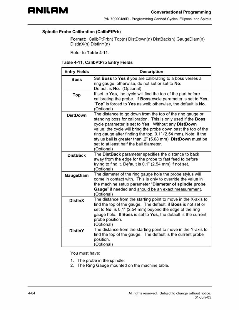
Conversational Programming P/N 70000486D - Programming Canned Cycles, Ellipses, and Spirals
4-84 All rights reserved. Subject to change without notice. 31-July-05
Spindle Probe Calibration (CalibPtPrb) Format: CalibPtPrbn) Top(n) DistDown(n) DistBack(n) GaugeDiam(n) DistInX(n) DistInY(n)
Refer to Table 4-11.
Table 4-11, CalibPtPrb Entry Fields
Entry Fields Description
Boss Set Boss to Yes if you are calibrating to a boss verses a ring gauge; otherwise, do not set or set to No. Default is No. (Optional)
Top If set to Yes, the cycle will find the top of the part before calibrating the probe. If Boss cycle parameter is set to Yes, “Top” is forced to Yes as well; otherwise, the default is No. (Optional)
DistDown The distance to go down from the top of the ring gauge or standing boss for calibration. This is only used if the Boss cycle parameter is set to Yes. Without any DistDown value, the cycle will bring the probe down past the top of the ring gauge after finding the top, 0.1” (2.54 mm). Note: If the stylus ball is greater than .2” (5.08 mm), DistDown must be set to at least half the ball diameter. (Optional)
DistBack The DistBack parameter specifies the distance to back away from the edge for the probe to fast feed to before trying to find it. Default is 0.1” (2.54 mm) if not set. (Optional)
GaugeDiam The diameter of the ring gauge hole the probe stylus will come in contact with. This is only to override the value in the machine setup parameter “Diameter of spindle probe Gauge” if needed and should be an exact measurement. (Optional)
DistInX The distance from the starting point to move in the X-axis to find the top of the gauge. The default, if Boss is not set or set to No, is 0.1” (2.54 mm) beyond the edge of the ring gauge hole. If Boss is set to Yes, the default is the current probe position. (Optional)
DistInY The distance from the starting point to move in the Y-axis to find the top of the gauge. The default is the current probe position. (Optional)
You must have:
1. The probe in the spindle. 2. The Ring Gauge mounted on the machine table.
Conversational Programming P/N 70000486D - Programming Canned Cycles, Ellipses, and Spirals
All rights reserved. Subject to change without notice. 4-85 31-July-05
To calibrate the probe:
1. Jog the probe to the approximate center of the ring gauge by eye and into the hole of the ring gauge at the depth that you wish the probe stylus to come in contact with the inside of the ring gauge hole.
2. From the MDI mode, go to the F5 (Mill), then F10 (Probe), then F3 (SpinPro), then select Probe Calibration. Type the appropriate information, press exit, and then press START.
3. The probe will touch four sides of the inside of the hole. The spindle will rotate (if the machine has spindle orientation) 180 degrees and touch the same four sides again establishing the center of the ring gauge. The spindle will then orient and touch four sides one more time calibrating the probe.
4. Remove the ring gauge from the machine and you are now ready to start spindle probing.
NOTE: On machines that allow the spindle probe to be installed in the spindle with more than one orientation, the probe stylus must be indicated true to the spindle centerline or the probe will not be accurate once removed and replaced into the spindle again.
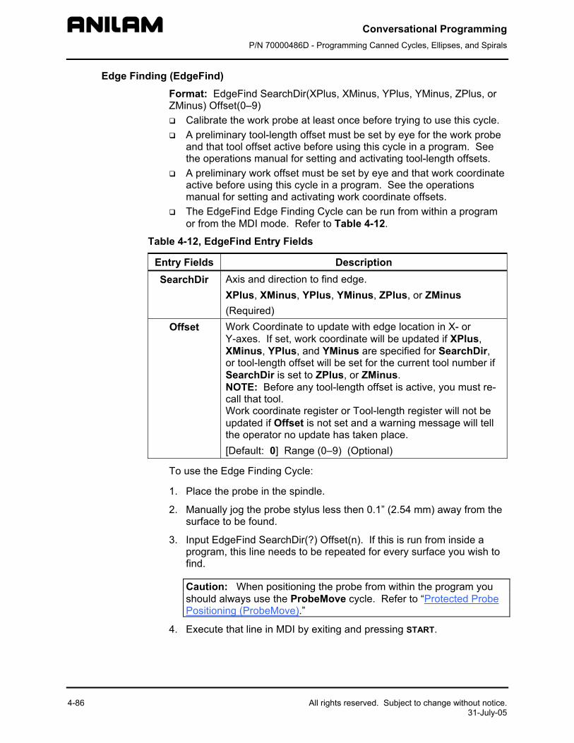
Conversational Programming P/N 70000486D - Programming Canned Cycles, Ellipses, and Spirals
4-86 All rights reserved. Subject to change without notice. 31-July-05
Edge Finding (EdgeFind) Format: EdgeFind SearchDir(XPlus, XMinus, YPlus, YMinus, ZPlus, or ZMinus) Offset(0–9)
Calibrate the work probe at least once before trying to use this cycle. A preliminary tool-length offset must be set by eye for the work probe
and that tool offset active before using this cycle in a program. See the operations manual for setting and activating tool-length offsets.
A preliminary work offset must be set by eye and that work coordinate active before using this cycle in a program. See the operations manual for setting and activating work coordinate offsets.
The EdgeFind Edge Finding Cycle can be run from within a program or from the MDI mode. Refer to Table 4-12.
Table 4-12, EdgeFind Entry Fields
Entry Fields Description SearchDir Axis and direction to find edge.
XPlus, XMinus, YPlus, YMinus, ZPlus, or ZMinus (Required)
Offset Work Coordinate to update with edge location in X- or Y-axes. If set, work coordinate will be updated if XPlus, XMinus, YPlus, and YMinus are specified for SearchDir, or tool-length offset will be set for the current tool number if SearchDir is set to ZPlus, or ZMinus. NOTE: Before any tool-length offset is active, you must re-call that tool. Work coordinate register or Tool-length register will not be updated if Offset is not set and a warning message will tell the operator no update has taken place. [Default: 0] Range (0–9) (Optional)
To use the Edge Finding Cycle:
1. Place the probe in the spindle.
2. Manually jog the probe stylus less then 0.1” (2.54 mm) away from the surface to be found.
3. Input EdgeFind SearchDir(?) Offset(n). If this is run from inside a program, this line needs to be repeated for every surface you wish to find.
Caution: When positioning the probe from within the program you should always use the ProbeMove cycle. Refer to “Protected Probe Positioning (ProbeMove).”
4. Execute that line in MDI by exiting and pressing START.
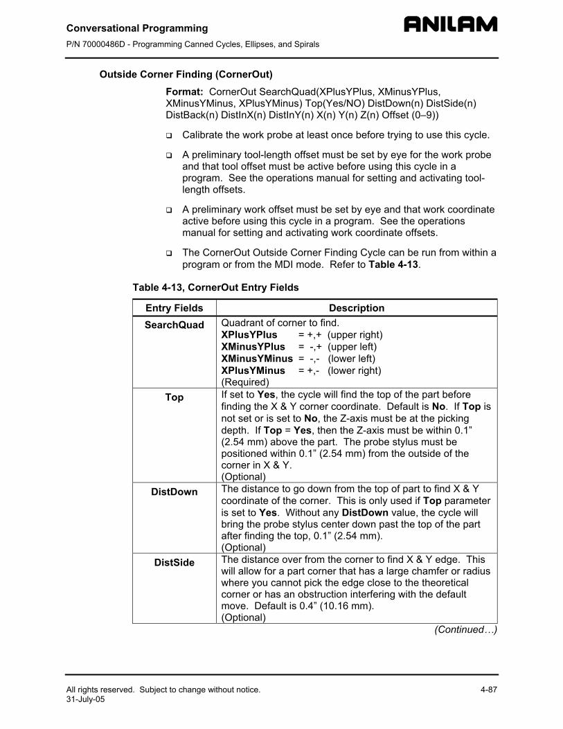
Conversational Programming P/N 70000486D - Programming Canned Cycles, Ellipses, and Spirals
All rights reserved. Subject to change without notice. 4-87 31-July-05
Outside Corner Finding (CornerOut) Format: CornerOut SearchQuad(XPlusYPlus, XMinusYPlus, XMinusYMinus, XPlusYMinus) Top(Yes/NO) DistDown(n) DistSide(n) DistBack(n) DistInX(n) DistInY(n) X(n) Y(n) Z(n) Offset (0–9))
Calibrate the work probe at least once before trying to use this cycle.
A preliminary tool-length offset must be set by eye for the work probe and that tool offset must be active before using this cycle in a program. See the operations manual for setting and activating tool-length offsets.
A preliminary work offset must be set by eye and that work coordinate active before using this cycle in a program. See the operations manual for setting and activating work coordinate offsets.
The CornerOut Outside Corner Finding Cycle can be run from within a program or from the MDI mode. Refer to Table 4-13.
Table 4-13, CornerOut Entry Fields
Entry Fields Description SearchQuad Quadrant of corner to find.
XPlusYPlus = +,+ (upper right) XMinusYPlus = -,+ (upper left) XMinusYMinus = -,- (lower left) XPlusYMinus = +,- (lower right) (Required)
Top If set to Yes, the cycle will find the top of the part before finding the X & Y corner coordinate. Default is No. If Top is not set or is set to No, the Z-axis must be at the picking depth. If Top = Yes, then the Z-axis must be within 0.1” (2.54 mm) above the part. The probe stylus must be positioned within 0.1” (2.54 mm) from the outside of the corner in X & Y. (Optional)
DistDown The distance to go down from the top of part to find X & Y coordinate of the corner. This is only used if Top parameter is set to Yes. Without any DistDown value, the cycle will bring the probe stylus center down past the top of the part after finding the top, 0.1” (2.54 mm). (Optional)
DistSide The distance over from the corner to find X & Y edge. This will allow for a part corner that has a large chamfer or radius where you cannot pick the edge close to the theoretical corner or has an obstruction interfering with the default move. Default is 0.4” (10.16 mm). (Optional)
(Continued…)
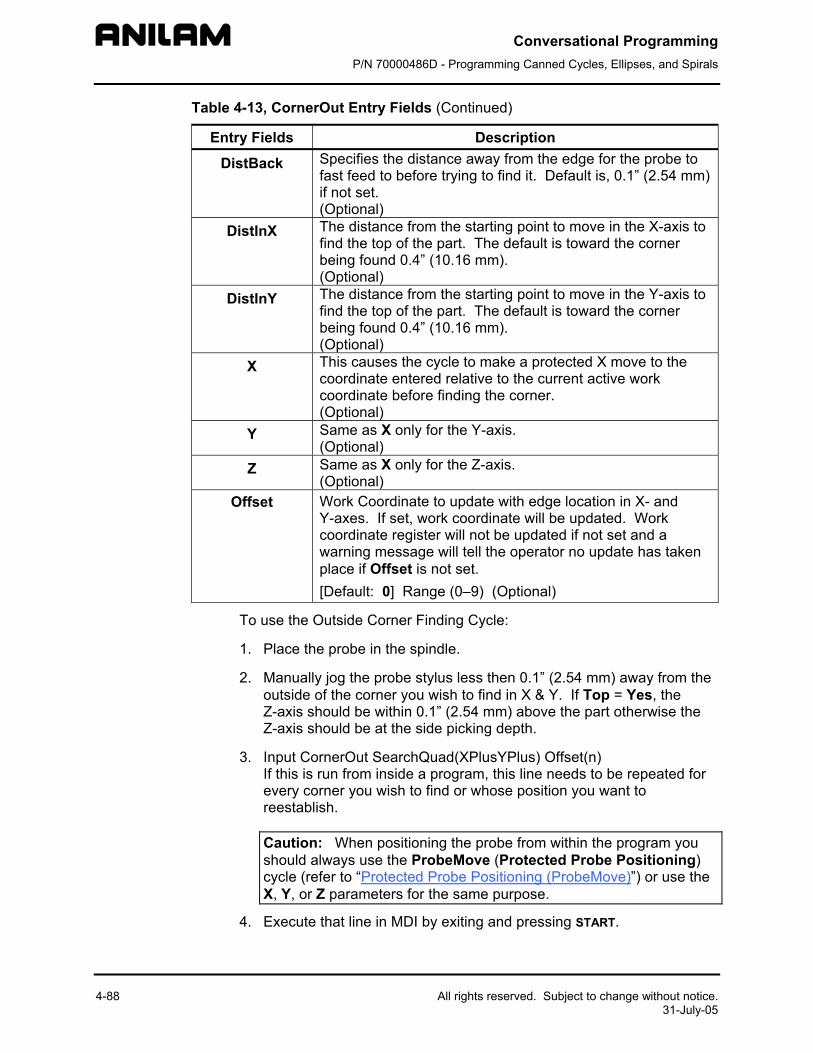
Conversational Programming P/N 70000486D - Programming Canned Cycles, Ellipses, and Spirals
4-88 All rights reserved. Subject to change without notice. 31-July-05
Table 4-13, CornerOut Entry Fields (Continued)
Entry Fields Description
DistBack Specifies the distance away from the edge for the probe to fast feed to before trying to find it. Default is, 0.1” (2.54 mm) if not set. (Optional)
DistInX The distance from the starting point to move in the X-axis to find the top of the part. The default is toward the corner being found 0.4” (10.16 mm). (Optional)
DistInY The distance from the starting point to move in the Y-axis to find the top of the part. The default is toward the corner being found 0.4” (10.16 mm). (Optional)
X This causes the cycle to make a protected X move to the coordinate entered relative to the current active work coordinate before finding the corner. (Optional)
Y Same as X only for the Y-axis. (Optional)
Z Same as X only for the Z-axis. (Optional)
Offset Work Coordinate to update with edge location in X- and Y-axes. If set, work coordinate will be updated. Work coordinate register will not be updated if not set and a warning message will tell the operator no update has taken place if Offset is not set. [Default: 0] Range (0–9) (Optional)
To use the Outside Corner Finding Cycle:
1. Place the probe in the spindle.
2. Manually jog the probe stylus less then 0.1” (2.54 mm) away from the outside of the corner you wish to find in X & Y. If Top = Yes, the Z-axis should be within 0.1” (2.54 mm) above the part otherwise the Z-axis should be at the side picking depth.
3. Input CornerOut SearchQuad(XPlusYPlus) Offset(n) If this is run from inside a program, this line needs to be repeated for every corner you wish to find or whose position you want to reestablish.
Caution: When positioning the probe from within the program you should always use the ProbeMove (Protected Probe Positioning) cycle (refer to “Protected Probe Positioning (ProbeMove)”) or use the X, Y, or Z parameters for the same purpose.
4. Execute that line in MDI by exiting and pressing START.
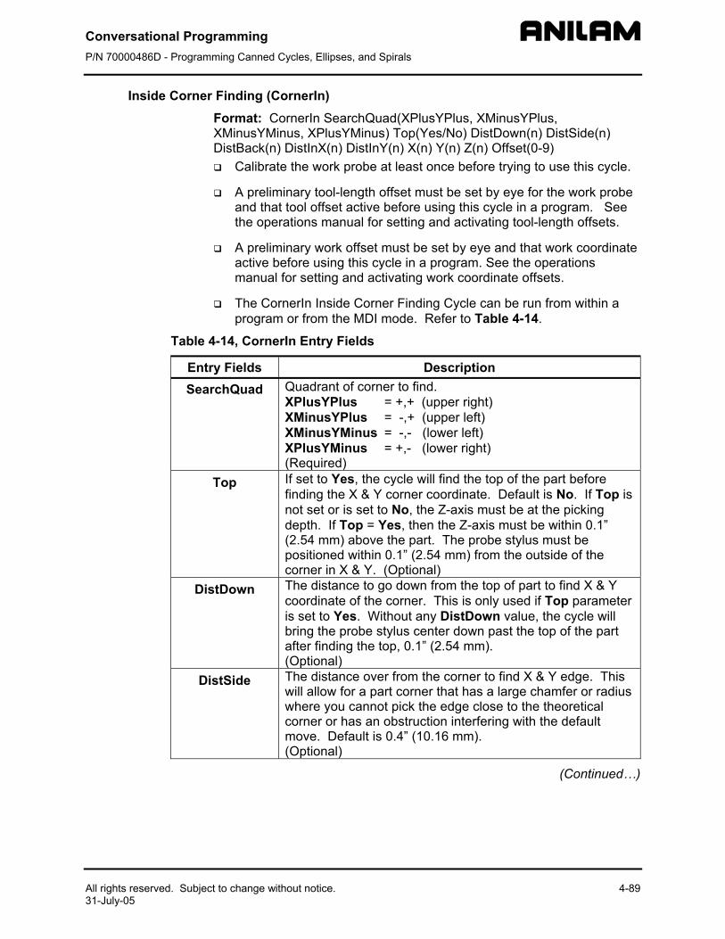
Conversational Programming P/N 70000486D - Programming Canned Cycles, Ellipses, and Spirals
All rights reserved. Subject to change without notice. 4-89 31-July-05
Inside Corner Finding (CornerIn) Format: CornerIn SearchQuad(XPlusYPlus, XMinusYPlus, XMinusYMinus, XPlusYMinus) Top(Yes/No) DistDown(n) DistSide(n) DistBack(n) DistInX(n) DistInY(n) X(n) Y(n) Z(n) Offset(0-9)
Calibrate the work probe at least once before trying to use this cycle.
A preliminary tool-length offset must be set by eye for the work probe and that tool offset active before using this cycle in a program. See the operations manual for setting and activating tool-length offsets.
A preliminary work offset must be set by eye and that work coordinate active before using this cycle in a program. See the operations manual for setting and activating work coordinate offsets.
The CornerIn Inside Corner Finding Cycle can be run from within a program or from the MDI mode. Refer to Table 4-14.
Table 4-14, CornerIn Entry Fields
Entry Fields Description SearchQuad Quadrant of corner to find.
XPlusYPlus = +,+ (upper right) XMinusYPlus = -,+ (upper left) XMinusYMinus = -,- (lower left) XPlusYMinus = +,- (lower right) (Required)
Top If set to Yes, the cycle will find the top of the part before finding the X & Y corner coordinate. Default is No. If Top is not set or is set to No, the Z-axis must be at the picking depth. If Top = Yes, then the Z-axis must be within 0.1” (2.54 mm) above the part. The probe stylus must be positioned within 0.1” (2.54 mm) from the outside of the corner in X & Y. (Optional)
DistDown The distance to go down from the top of part to find X & Y coordinate of the corner. This is only used if Top parameter is set to Yes. Without any DistDown value, the cycle will bring the probe stylus center down past the top of the part after finding the top, 0.1” (2.54 mm). (Optional)
DistSide The distance over from the corner to find X & Y edge. This will allow for a part corner that has a large chamfer or radius where you cannot pick the edge close to the theoretical corner or has an obstruction interfering with the default move. Default is 0.4” (10.16 mm). (Optional)
(Continued…)
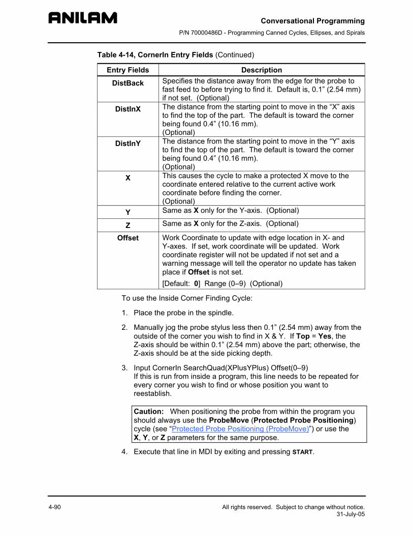
Conversational Programming P/N 70000486D - Programming Canned Cycles, Ellipses, and Spirals
4-90 All rights reserved. Subject to change without notice. 31-July-05
Table 4-14, CornerIn Entry Fields (Continued)
Entry Fields Description
DistBack Specifies the distance away from the edge for the probe to fast feed to before trying to find it. Default is, 0.1” (2.54 mm) if not set. (Optional)
DistInX The distance from the starting point to move in the “X” axis to find the top of the part. The default is toward the corner being found 0.4” (10.16 mm). (Optional)
DistInY The distance from the starting point to move in the “Y” axis to find the top of the part. The default is toward the corner being found 0.4” (10.16 mm). (Optional)
X This causes the cycle to make a protected X move to the coordinate entered relative to the current active work coordinate before finding the corner. (Optional)
Y Same as X only for the Y-axis. (Optional)
Z Same as X only for the Z-axis. (Optional)
Offset Work Coordinate to update with edge location in X- and Y-axes. If set, work coordinate will be updated. Work coordinate register will not be updated if not set and a warning message will tell the operator no update has taken place if Offset is not set. [Default: 0] Range (0–9) (Optional)
To use the Inside Corner Finding Cycle:
1. Place the probe in the spindle.
2. Manually jog the probe stylus less then 0.1” (2.54 mm) away from the outside of the corner you wish to find in X & Y. If Top = Yes, the Z-axis should be within 0.1” (2.54 mm) above the part; otherwise, the Z-axis should be at the side picking depth.
3. Input CornerIn SearchQuad(XPlusYPlus) Offset(0–9) If this is run from inside a program, this line needs to be repeated for every corner you wish to find or whose position you want to reestablish.
Caution: When positioning the probe from within the program you should always use the ProbeMove (Protected Probe Positioning) cycle (see “Protected Probe Positioning (ProbeMove)”) or use the X, Y, or Z parameters for the same purpose.
4. Execute that line in MDI by exiting and pressing START.
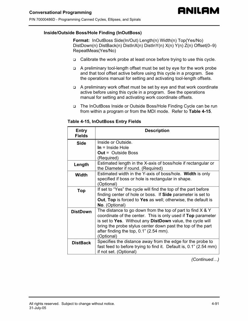
Conversational Programming P/N 70000486D - Programming Canned Cycles, Ellipses, and Spirals
All rights reserved. Subject to change without notice. 4-91 31-July-05
Inside/Outside Boss/Hole Finding (InOutBoss) Format: InOutBoss Side(In/Out) Length(n) Width(n) Top(Yes/No) DistDown(n) DistBack(n) DistInX(n) DistInY(n) X(n) Y(n) Z(n) Offset(0–9) RepeatMeas(Yes/No)
Calibrate the work probe at least once before trying to use this cycle.
A preliminary tool-length offset must be set by eye for the work probe and that tool offset active before using this cycle in a program. See the operations manual for setting and activating tool-length offsets.
A preliminary work offset must be set by eye and that work coordinate active before using this cycle in a program. See the operations manual for setting and activating work coordinate offsets.
The InOutBoss Inside or Outside Boss/Hole Finding Cycle can be run from within a program or from the MDI mode. Refer to Table 4-15.
Table 4-15, InOutBoss Entry Fields
Entry Fields
Description
Side Inside or Outside. In = Inside Hole Out = Outside Boss (Required)
Length Estimated length in the X-axis of boss/hole if rectangular or the Diameter if round. (Required)
Width Estimated width in the Y-axis of boss/hole. Width is only specified if boss or hole is rectangular in shape. (Optional)
Top If set to “Yes” the cycle will find the top of the part before finding center of hole or boss. If Side parameter is set to Out, Top is forced to Yes as well; otherwise, the default is No. (Optional)
DistDown The distance to go down from the top of part to find X & Y coordinate of the center. This is only used if Top parameter is set to Yes. Without any DistDown value, the cycle will bring the probe stylus center down past the top of the part after finding the top, 0.1” (2.54 mm). (Optional)
DistBack Specifies the distance away from the edge for the probe to fast feed to before trying to find it. Default is, 0.1” (2.54 mm) if not set. (Optional)
(Continued…)
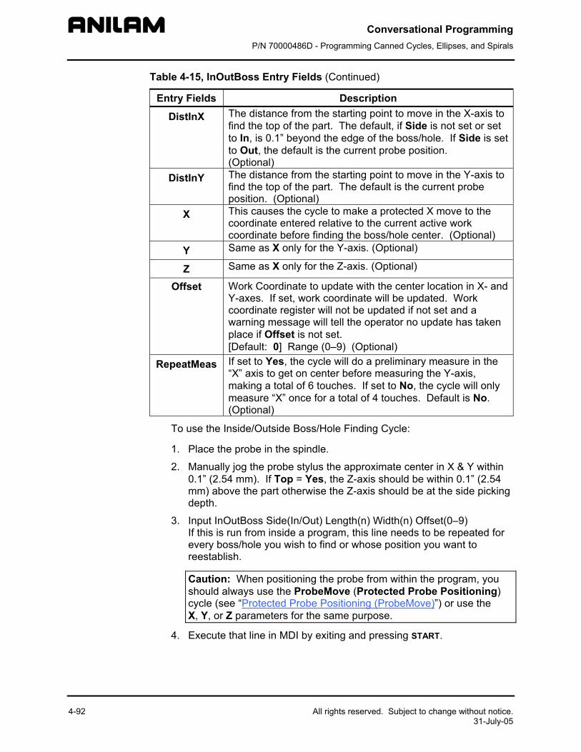
Conversational Programming P/N 70000486D - Programming Canned Cycles, Ellipses, and Spirals
4-92 All rights reserved. Subject to change without notice. 31-July-05
Table 4-15, InOutBoss Entry Fields (Continued)
Entry Fields Description
DistInX The distance from the starting point to move in the X-axis to find the top of the part. The default, if Side is not set or set to In, is 0.1” beyond the edge of the boss/hole. If Side is set to Out, the default is the current probe position. (Optional)
DistInY The distance from the starting point to move in the Y-axis to find the top of the part. The default is the current probe position. (Optional)
X This causes the cycle to make a protected X move to the coordinate entered relative to the current active work coordinate before finding the boss/hole center. (Optional)
Y Same as X only for the Y-axis. (Optional)
Z Same as X only for the Z-axis. (Optional)
Offset Work Coordinate to update with the center location in X- and Y-axes. If set, work coordinate will be updated. Work coordinate register will not be updated if not set and a warning message will tell the operator no update has taken place if Offset is not set. [Default: 0] Range (0–9) (Optional)
RepeatMeas If set to Yes, the cycle will do a preliminary measure in the “X” axis to get on center before measuring the Y-axis, making a total of 6 touches. If set to No, the cycle will only measure “X” once for a total of 4 touches. Default is No. (Optional)
To use the Inside/Outside Boss/Hole Finding Cycle:
1. Place the probe in the spindle.
2. Manually jog the probe stylus the approximate center in X & Y within 0.1” (2.54 mm). If Top = Yes, the Z-axis should be within 0.1” (2.54 mm) above the part otherwise the Z-axis should be at the side picking depth.
3. Input InOutBoss Side(In/Out) Length(n) Width(n) Offset(0–9) If this is run from inside a program, this line needs to be repeated for every boss/hole you wish to find or whose position you want to reestablish.
Caution: When positioning the probe from within the program, you should always use the ProbeMove (Protected Probe Positioning) cycle (see “Protected Probe Positioning (ProbeMove)”) or use the X, Y, or Z parameters for the same purpose.
4. Execute that line in MDI by exiting and pressing START.
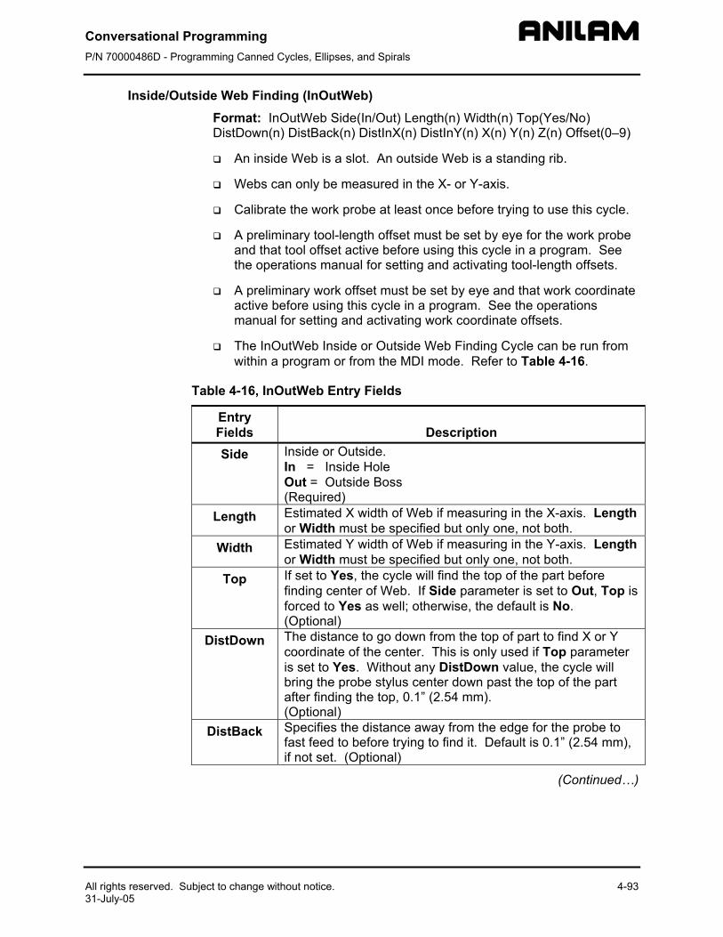
Conversational Programming P/N 70000486D - Programming Canned Cycles, Ellipses, and Spirals
All rights reserved. Subject to change without notice. 4-93 31-July-05
Inside/Outside Web Finding (InOutWeb) Format: InOutWeb Side(In/Out) Length(n) Width(n) Top(Yes/No) DistDown(n) DistBack(n) DistInX(n) DistInY(n) X(n) Y(n) Z(n) Offset(0–9)
An inside Web is a slot. An outside Web is a standing rib.
Webs can only be measured in the X- or Y-axis.
Calibrate the work probe at least once before trying to use this cycle.
A preliminary tool-length offset must be set by eye for the work probe and that tool offset active before using this cycle in a program. See the operations manual for setting and activating tool-length offsets.
A preliminary work offset must be set by eye and that work coordinate active before using this cycle in a program. See the operations manual for setting and activating work coordinate offsets.
The InOutWeb Inside or Outside Web Finding Cycle can be run from within a program or from the MDI mode. Refer to Table 4-16.
Table 4-16, InOutWeb Entry Fields
Entry Fields
Description
Side Inside or Outside. In = Inside Hole Out = Outside Boss (Required)
Length Estimated X width of Web if measuring in the X-axis. Length or Width must be specified but only one, not both.
Width Estimated Y width of Web if measuring in the Y-axis. Length or Width must be specified but only one, not both.
Top If set to Yes, the cycle will find the top of the part before finding center of Web. If Side parameter is set to Out, Top is forced to Yes as well; otherwise, the default is No. (Optional)
DistDown The distance to go down from the top of part to find X or Y coordinate of the center. This is only used if Top parameter is set to Yes. Without any DistDown value, the cycle will bring the probe stylus center down past the top of the part after finding the top, 0.1” (2.54 mm). (Optional)
DistBack Specifies the distance away from the edge for the probe to fast feed to before trying to find it. Default is 0.1” (2.54 mm), if not set. (Optional)
(Continued…)
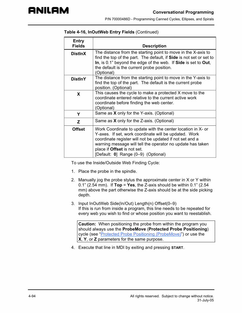
Conversational Programming P/N 70000486D - Programming Canned Cycles, Ellipses, and Spirals
4-94 All rights reserved. Subject to change without notice. 31-July-05
Table 4-16, InOutWeb Entry Fields (Continued)
Entry Fields
Description
DistInX The distance from the starting point to move in the X-axis to find the top of the part. The default, if Side is not set or set to In, is 0.1” beyond the edge of the web. If Side is set to Out, the default is the current probe position. (Optional)
DistInY The distance from the starting point to move in the Y-axis to find the top of the part. The default is the current probe position. (Optional)
X This causes the cycle to make a protected X move to the coordinate entered relative to the current active work coordinate before finding the web center. (Optional)
Y Same as X only for the Y-axis. (Optional)
Z Same as X only for the Z-axis. (Optional)
Offset Work Coordinate to update with the center location in X- or Y-axes. If set, work coordinate will be updated. Work coordinate register will not be updated if not set and a warning message will tell the operator no update has taken place if Offset is not set. [Default: 0] Range (0–9) (Optional)
To use the Inside/Outside Web Finding Cycle:
1. Place the probe in the spindle.
2. Manually jog the probe stylus the approximate center in X or Y within 0.1” (2.54 mm). If Top = Yes, the Z-axis should be within 0.1” (2.54 mm) above the part otherwise the Z-axis should be at the side picking depth.
3. Input InOutWeb Side(In/Out) Length(n) Offset(0–9) If this is run from inside a program, this line needs to be repeated for every web you wish to find or whose position you want to reestablish.
Caution: When positioning the probe from within the program you should always use the ProbeMove (Protected Probe Positioning) cycle (see “Protected Probe Positioning (ProbeMove)”) or use the X, Y, or Z parameters for the same purpose.
4. Execute that line in MDI by exiting and pressing START.
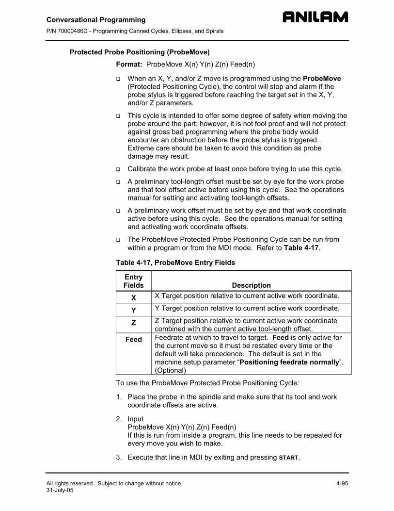
Conversational Programming P/N 70000486D - Programming Canned Cycles, Ellipses, and Spirals
All rights reserved. Subject to change without notice. 4-95 31-July-05
Protected Probe Positioning (ProbeMove) Format: ProbeMove X(n) Y(n) Z(n) Feed(n)
When an X, Y, and/or Z move is programmed using the ProbeMove (Protected Positioning Cycle), the control will stop and alarm if the probe stylus is triggered before reaching the target set in the X, Y, and/or Z parameters.
This cycle is intended to offer some degree of safety when moving the probe around the part; however, it is not fool proof and will not protect against gross bad programming where the probe body would encounter an obstruction before the probe stylus is triggered. Extreme care should be taken to avoid this condition as probe damage may result.
Calibrate the work probe at least once before trying to use this cycle.
A preliminary tool-length offset must be set by eye for the work probe and that tool offset active before using this cycle. See the operations manual for setting and activating tool-length offsets.
A preliminary work offset must be set by eye and that work coordinate active before using this cycle. See the operations manual for setting and activating work coordinate offsets.
The ProbeMove Protected Probe Positioning Cycle can be run from within a program or from the MDI mode. Refer to Table 4-17.
Table 4-17, ProbeMove Entry Fields
Entry Fields
Description
X X Target position relative to current active work coordinate.
Y Y Target position relative to current active work coordinate.
Z Z Target position relative to current active work coordinate combined with the current active tool-length offset.
Feed Feedrate at which to travel to target. Feed is only active for the current move so it must be restated every time or the default will take precedence. The default is set in the machine setup parameter “Positioning feedrate normally”. (Optional)
To use the ProbeMove Protected Probe Positioning Cycle:
1. Place the probe in the spindle and make sure that its tool and work coordinate offsets are active.
2. Input ProbeMove X(n) Y(n) Z(n) Feed(n) If this is run from inside a program, this line needs to be repeated for every move you wish to make.
3. Execute that line in MDI by exiting and pressing START.
Conversational Programming P/N 70000486D - Programming Canned Cycles, Ellipses, and Spirals
4-96 All rights reserved. Subject to change without notice. 31-July-05
Skew Error Find (SkewComp) Format: SkewComp Action(Find/FindActive/Activate) EstAngle(n) DistPicks(n) Top(Yes/No) DistDown(n) DistBack(n) DistInX(n) DistInY(n) X(n) Y(n) Z(n)
RMS cannot be used with SkewComp, skew error find.
Skew error is only supported for along the side edge of a part relative to the X,Y plane.
Calibrate the work probe at least once before trying to use this cycle.
A preliminary tool-length offset must be set by eye for the work probe and that tool offset active before using this cycle in a program. See the operations manual for setting and activating tool-length offsets.
A preliminary work offset must be set by eye and that work coordinate active before using this cycle in a program. See the operations manual for setting and activating work coordinate offsets.
The probe must be pre-positioned to the proper spot in relation to the part in accordance with the specified EstAngle cycle parameter as described below or an X, Y, and/or Z should be included for pre-positioning.
The SkewComp Skew Error Finding Cycle can be run from within a program or from the MDI mode. Refer to Table 4-18, SkewComp Entry Fields.
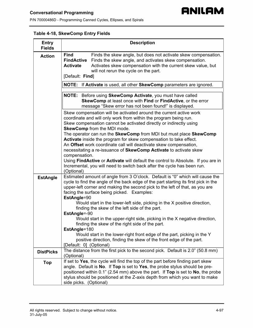
Conversational Programming P/N 70000486D - Programming Canned Cycles, Ellipses, and Spirals
All rights reserved. Subject to change without notice. 4-97 31-July-05
Table 4-18, SkewComp Entry Fields
Entry Fields
Description
Action Find Finds the skew angle, but does not activate skew compensation.FindActive Finds the skew angle, and activates skew compensation. Activate Activates skew compensation with the current skew value, but
will not rerun the cycle on the part. [Default: Find]
NOTE: If Activate is used, all other SkewComp parameters are ignored.
NOTE: Before using SkewComp Activate, you must have called SkewComp at least once with Find or FindActive, or the error message “Skew error has not been found!” is displayed.
Skew compensation will be activated around the current active work coordinate and will only work from within the program being run. Skew compensation cannot be activated directly or indirectly using SkewComp from the MDI mode. The operator can run the SkewComp from MDI but must place SkewComp Activate inside the program for skew compensation to take effect. An Offset work coordinate call will deactivate skew compensation, necessitating a re-issuance of SkewComp Activate to activate skew compensation. Using FindActive or Activate will default the control to Absolute. If you are in Incremental, you will need to switch back after the cycle has been run. (Optional)
EstAngle Estimated amount of angle from 3 O’clock. Default is “0” which will cause the cycle to find the angle of the back edge of the part starting its first pick in the upper-left corner and making the second pick to the left of that, as you are facing the surface being picked. Examples: EstAngle=90
Would start in the lower-left side, picking in the X positive direction, finding the skew of the left side of the part.
EstAngle=-90 Would start in the upper-right side, picking in the X negative direction, finding the skew of the right side of the part.
EstAngle=180 Would start in the lower-right front edge of the part, picking in the Y positive direction, finding the skew of the front edge of the part.
[Default: 0] (Optional) DistPicks The distance from the first pick to the second pick. Default is 2.0” (50.8 mm)
(Optional) Top If set to Yes, the cycle will find the top of the part before finding part skew
angle. Default is No. If Top is set to Yes, the probe stylus should be pre-positioned within 0.1” (2.54 mm) above the part. If Top is set to No, the probe stylus should be positioned at the Z-axis depth from which you want to make side picks. (Optional)
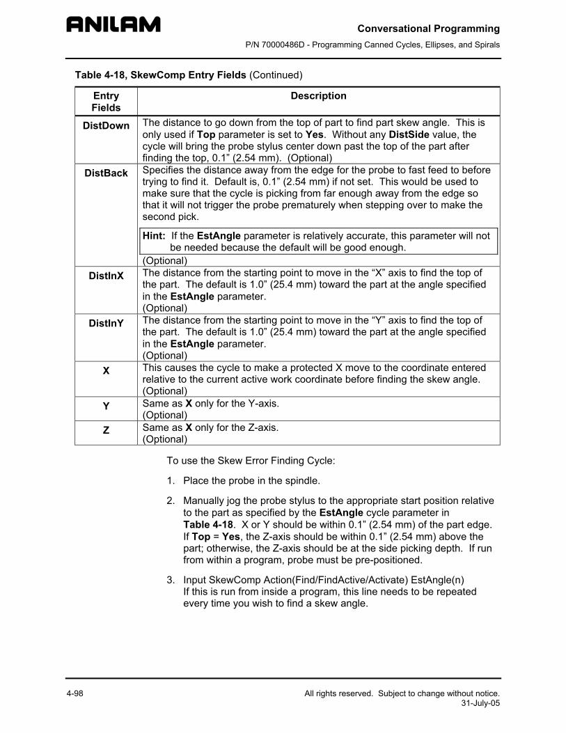
Conversational Programming P/N 70000486D - Programming Canned Cycles, Ellipses, and Spirals
4-98 All rights reserved. Subject to change without notice. 31-July-05
Table 4-18, SkewComp Entry Fields (Continued)
Entry Fields
Description
DistDown The distance to go down from the top of part to find part skew angle. This is only used if Top parameter is set to Yes. Without any DistSide value, the cycle will bring the probe stylus center down past the top of the part after finding the top, 0.1” (2.54 mm). (Optional)
DistBack Specifies the distance away from the edge for the probe to fast feed to before trying to find it. Default is, 0.1” (2.54 mm) if not set. This would be used to make sure that the cycle is picking from far enough away from the edge so that it will not trigger the probe prematurely when stepping over to make the second pick.
Hint: If the EstAngle parameter is relatively accurate, this parameter will not be needed because the default will be good enough.
(Optional) DistInX The distance from the starting point to move in the “X” axis to find the top of
the part. The default is 1.0” (25.4 mm) toward the part at the angle specified in the EstAngle parameter. (Optional)
DistInY The distance from the starting point to move in the “Y” axis to find the top of the part. The default is 1.0” (25.4 mm) toward the part at the angle specified in the EstAngle parameter. (Optional)
X This causes the cycle to make a protected X move to the coordinate entered relative to the current active work coordinate before finding the skew angle. (Optional)
Y Same as X only for the Y-axis. (Optional)
Z Same as X only for the Z-axis. (Optional)
To use the Skew Error Finding Cycle:
1. Place the probe in the spindle.
2. Manually jog the probe stylus to the appropriate start position relative to the part as specified by the EstAngle cycle parameter in Table 4-18. X or Y should be within 0.1” (2.54 mm) of the part edge. If Top = Yes, the Z-axis should be within 0.1” (2.54 mm) above the part; otherwise, the Z-axis should be at the side picking depth. If run from within a program, probe must be pre-positioned.
3. Input SkewComp Action(Find/FindActive/Activate) EstAngle(n) If this is run from inside a program, this line needs to be repeated every time you wish to find a skew angle.

Conversational Programming P/N 70000486D - Programming Canned Cycles, Ellipses, and Spirals
All rights reserved. Subject to change without notice. 4-99 31-July-05
Caution: When positioning the probe from within the program you should always use the ProbeMove (Protected Probe Positioning) cycle (see “Protected Probe Positioning (ProbeMove)”) or use the X, Y, or Z parameters for the same purpose.
4. Execute that line in MDI by exiting and pressing START.
Conversational Programming P/N 70000486D - Editing Programs
All rights reserved. Subject to change without notice. 5-1 31-July-05
Section 5 - Editing Programs Write and edit conversational program blocks using the CNC’s Conversational Program Editor (the Edit screen). Activate the Conversational Program Editor to put the CNC in the Edit Mode.
Activating the Conversational Program Editor
You can activate the Conversational Program Editor screen either from the Program Directory or from the Manual screen. When you activate the Program Editor from the Program Directory, the highlighted program opens for editing. When you activate the Program Editor from the Manual screen, the selected program opens for editing.
To activate the Program Editor from the Program Directory:
1. In the Program Directory, highlight a program.
2. Press Edit (F4). The Program Editor opens the selected program for editing.
To activate the Program Editor from the Manual screen:
1. In the Manual screen, press EDIT (F4). The Editor opens the loaded program. If no program is loaded, the CNC displays the message No Program Selected !.
2. Press PROGRAM (F2) to activate the Program Directory.
3. Highlight a program.
4. Press Edit (F4). The Program Editor opens the selected program for editing.
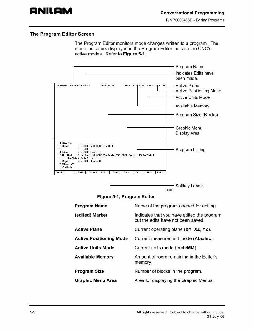
Conversational Programming P/N 70000486D - Editing Programs
5-2 All rights reserved. Subject to change without notice. 31-July-05
The Program Editor Screen
The Program Editor monitors mode changes written to a program. The mode indicators displayed in the Program Editor indicate the CNC’s active modes. Refer to Figure 5-1.
Figure 5-1, Program Editor
Program Name Name of the program opened for editing.
(edited) Marker Indicates that you have edited the program, but the edits have not been saved.
Active Plane Current operating plane (XY, XZ, YZ).
Active Positioning Mode Current measurement mode (Abs/Inc).
Active Units Mode Current units mode (Inch/MM).
Available Memory Amount of room remaining in the Editor’s memory.
Program Size Number of blocks in the program.
Graphic Menu Area Area for displaying the Graphic Menus.
EDITOR
(edited)
Program NameIndicates Edits havebeen made.Active PlaneActive Positioning ModeActive Units Mode
Available Memory
Program Size (Blocks)
Graphic MenuDisplay Area
Program Listing
Softkey Labels
Conversational Programming P/N 70000486D - Editing Programs
All rights reserved. Subject to change without notice. 5-3 31-July-05
Program Listing Current listing of the blocks in the open program.
Highlight Selects a block for editing and acts as an insertion marker for adding new blocks. The CNC tracks program mode changes up to this point in the Program Listing.
Softkey Labels These labels define the soft key functions. The following sets of soft keys are available.
Default set, normally visible. Misc soft keys, activated by pressing
Misc (F9). Sub soft keys, activated by pressing
Sub (F8).
Saving Edits
The Program Listing displays text entered by the programmer. The CNC does not save edits until you exit the Editor. If the (edited) marker is visible at the top of the Program Editor, the open program contains unsaved edits.
To save edits:
1. In Edit Mode, press Exit (F10). The CNC saves all edits and returns to the Program Directory.
Canceling Unsaved Edits
To cancel unsaved edits:
1. In Edit Mode, press Misc (F9). Misc soft key labels are displayed.
2. Press Quit (F8). The CNC displays the message WARNING: Program has been edited. Sure you want to QUIT? and changes the soft key labels.
3. Press Yes (F1). The CNC returns to the Program Directory without saving the edits. Press No (F2) to cancel.
Deleting a Block
To delete a program block:
1. In Edit Mode, highlight a block.
2. Press CLEAR.
Conversational Programming P/N 70000486D - Editing Programs
5-4 All rights reserved. Subject to change without notice. 31-July-05
Inserting a Block
To insert a program block:
1. In Edit Mode, highlight the block that will follow the inserted block.
2. Program the new block from the appropriate Graphic Menu. When you save the new block, it appears in front of the highlighted block. Blocks are automatically renumbered.
Editing Blocks
To edit a program block:
1. In Edit Mode, highlight a block.
2. Press ENTER if the existing block is a move or cycle. The appropriate Graphic Menu opens.
3. Highlight the entry fields that require changes. Press CLEAR to erase the existing values.
4. Make the appropriate changes. Press Save (F10) to close the block.
NOTE: When the program block’s Graphic Menu offers two modes (for example, Cw/Ccw), highlight the block and press +/- to change the selection.
Searching Blocks for Words or Numbers
Use Search to find a block number or word. Search looks only from the cursor position forward. To search an entire program, place the cursor at the beginning of the program, then activate Search.
To search for a block number or word:
1. In Edit Mode, Press Misc (F9). The soft key menu changes.
2. Press Search (F3). The CNC prompts for the block number or word.
3. Use the ASCII chart to type the block number or word. (You can also use the keypad to type numbers.)
4. Press ENTER. The CNC searches and highlights the next block that contains the specified word or block number.
Scrolling the Program Listing
In Edit Mode, use the up and down ARROWS to scroll through the Program Listing.
Conversational Programming P/N 70000486D - Editing Programs
All rights reserved. Subject to change without notice. 5-5 31-July-05
Paging through the Program Listing
To scroll through the Program Listing one page at a time:
1. In Edit Mode, Press Misc (F9). The CNC displays the Soft key secondary functions.
2. Press the PgUp (F4) or PgDn (F5) keys to page forward or backward.
3. Press Prev (F9). The CNC redisplays the Program Editor default soft keys.
Jumping to First or Last Block in the Program
To jump to the first or last block of the Program Listing:
1. In Edit Mode, press Misc. (F9). The CNC displays the Soft key secondary functions.
2. Press Begin (F6). The Program Listing displays the first block of the program.
– or –
Press End (F7). The Program Listing displays last block of the program.
Using Comments
The CNC will ignore comment blocks. You can add a new comment block to a program or convert an existing block into a comment. Comment blocks typically contain program setup or tool information, or are used to comment out existing blocks.
Writing a Comment Block
To write a comment block:
1. In Edit Mode, press Misc. (F9). The CNC displays the Soft key secondary functions.
2. Press Comment (F2). The CNC prompts for a comment.
3. Use your keyboard to type comments.
Commenting Out Existing Blocks
To comment out an existing block:
1. In Edit Mode, highlight the block being commented out.
2. Press 0 on the keypad. The CNC displays an asterisk after the block number.
NOTE: Offline keyboard users, use the 0 key (not the asterisk key) to produce a comment block.
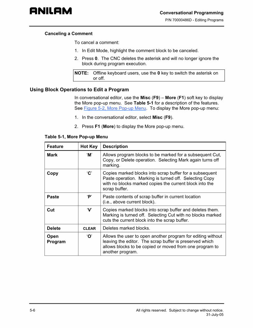
Conversational Programming P/N 70000486D - Editing Programs
5-6 All rights reserved. Subject to change without notice. 31-July-05
Canceling a Comment
To cancel a comment:
1. In Edit Mode, highlight the comment block to be canceled.
2. Press 0. The CNC deletes the asterisk and will no longer ignore the block during program execution.
NOTE: Offline keyboard users, use the 0 key to switch the asterisk on or off.
Using Block Operations to Edit a Program In conversational editor, use the Misc (F9) – More (F1) soft key to display the More pop-up menu. See Table 5-1 for a description of the features. See Figure 5-2, More Pop-up Menu. To display the More pop-up menu:
1. In the conversational editor, select Misc (F9).
2. Press F1 (More) to display the More pop-up menu.
Table 5-1, More Pop-up Menu
Feature Hot Key Description
Mark ‘M’ Allows program blocks to be marked for a subsequent Cut, Copy, or Delete operation. Selecting Mark again turns off marking.
Copy ‘C’ Copies marked blocks into scrap buffer for a subsequent Paste operation. Marking is turned off. Selecting Copy with no blocks marked copies the current block into the scrap buffer.
Paste ‘P’ Paste contents of scrap buffer in current location (i.e., above current block).
Cut ‘V’ Copies marked blocks into scrap buffer and deletes them. Marking is turned off. Selecting Cut with no blocks marked cuts the current block into the scrap buffer.
Delete CLEAR Deletes marked blocks.
Open Program
‘O’ Allows the user to open another program for editing without leaving the editor. The scrap buffer is preserved which allows blocks to be copied or moved from one program to another program.
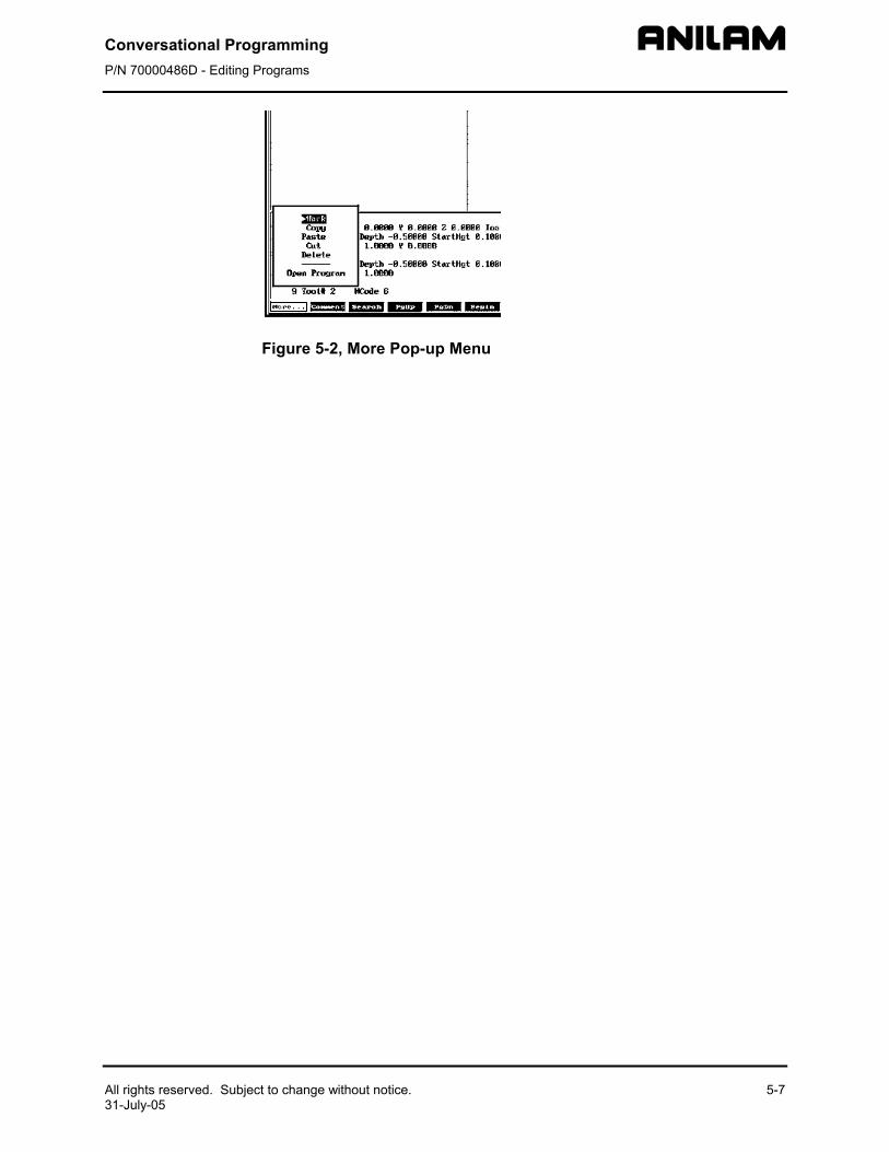
Conversational Programming P/N 70000486D - Editing Programs
All rights reserved. Subject to change without notice. 5-7 31-July-05
Figure 5-2, More Pop-up Menu
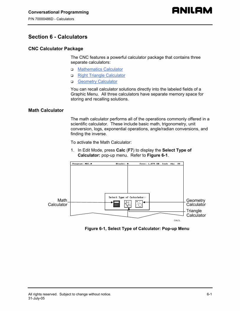
Conversational Programming P/N 70000486D - Calculators
All rights reserved. Subject to change without notice. 6-1 31-July-05
Section 6 - Calculators
CNC Calculator Package
The CNC features a powerful calculator package that contains three separate calculators:
Mathematics Calculator Right Triangle Calculator Geometry Calculator
You can recall calculator solutions directly into the labeled fields of a Graphic Menu. All three calculators have separate memory space for storing and recalling solutions.
Math Calculator
The math calculator performs all of the operations commonly offered in a scientific calculator. These include basic math, trigonometry, unit conversion, logs, exponential operations, angle/radian conversions, and finding the inverse.
To activate the Math Calculator:
1. In Edit Mode, press Calc (F7) to display the Select Type of Calculator: pop-up menu. Refer to Figure 6-1.
Figure 6-1, Select Type of Calculator: Pop-up Menu
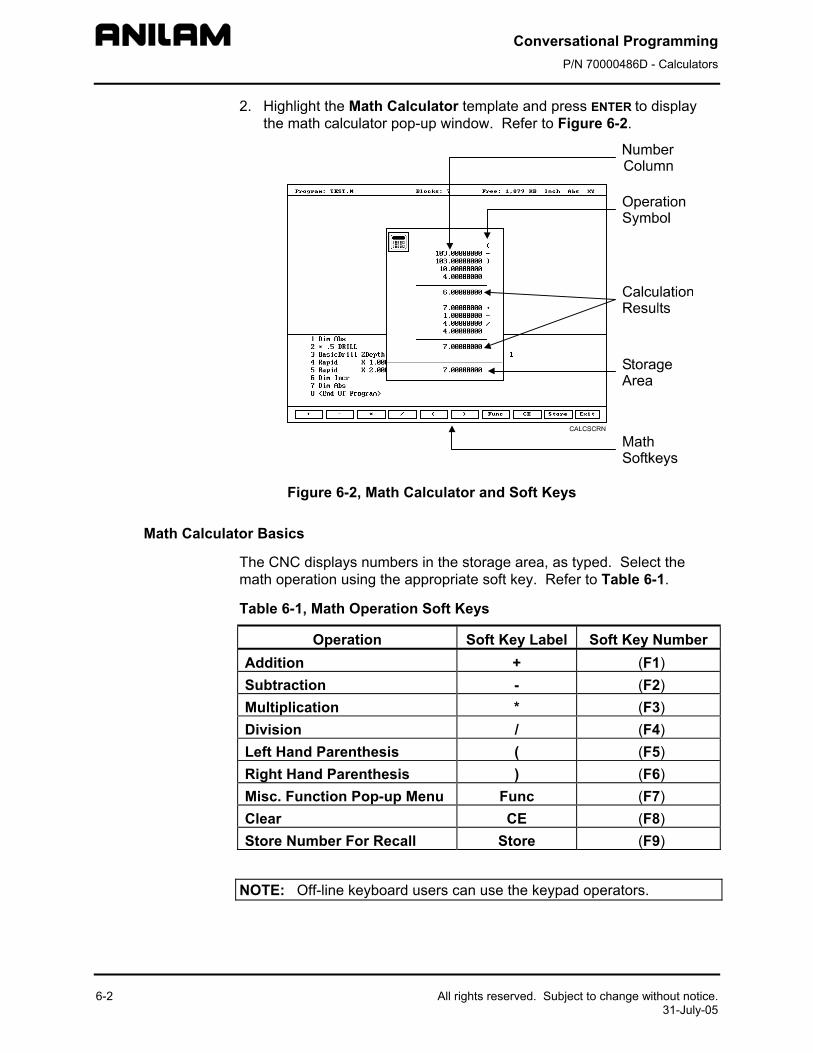
Conversational Programming P/N 70000486D - Calculators
6-2 All rights reserved. Subject to change without notice. 31-July-05
2. Highlight the Math Calculator template and press ENTER to display the math calculator pop-up window. Refer to Figure 6-2.
Figure 6-2, Math Calculator and Soft Keys
Math Calculator Basics
The CNC displays numbers in the storage area, as typed. Select the math operation using the appropriate soft key. Refer to Table 6-1.
Table 6-1, Math Operation Soft Keys
Operation Soft Key Label Soft Key Number Addition + (F1) Subtraction - (F2) Multiplication * (F3) Division / (F4) Left Hand Parenthesis ( (F5) Right Hand Parenthesis ) (F6) Misc. Function Pop-up Menu Func (F7) Clear CE (F8) Store Number For Recall Store (F9)
NOTE: Off-line keyboard users can use the keypad operators.
Conversational Programming P/N 70000486D - Calculators
All rights reserved. Subject to change without notice. 6-3 31-July-05
Type the first number of the calculation, and press an operation soft key. The CNC displays the number in the column. Next, select the desired operation to perform with the next number. Type the second number, and so forth.
After typing the last number of a calculation, press ENTER to place the final number in the column and calculate the answer. The CNC displays the result in the storage area. Press Store (F9) to copy the result into the calculator’s memory.
Press CE (F8) to clear previous calculations.
If you type illogical combinations of operations and numbers, the CNC displays an error message or a row of asterisks.
Operations Involving Two Numbers
To add, subtract, multiply, or divide two numbers:
1. With the math calculator active, type the first number, followed by the appropriate function hot key: + (F1), - (F2), * (F3), or / (F4). The CNC adds the number and operation symbol to the column.
2. Type the second number and press ENTER to add the second number to the column and display the sum in the storage area.
Math with a Column of Numbers
The CNC handles a column of numbers requiring multiple operations, such as a continuous equation, in standard mathematical order (multiplication, division, addition, and subtraction). Press ENTER to generate the result.
Using Parentheses
Use parentheses to indicate arithmetical operations in a non-standard order. (Example: finding a sum before using it as a multiplication factor.) The CNC performs operations within parentheses first.
When the CNC encounters parentheses, it solves the operation within the parentheses immediately, and substitutes that value for the parenthetical expression in the column.
Use parentheses in pairs. The parenthetical expression must contain a left parenthesis, (, at the beginning of the expression, and a right parenthesis, ), at the end of the expression. Otherwise, the CNC will not calculate the result.
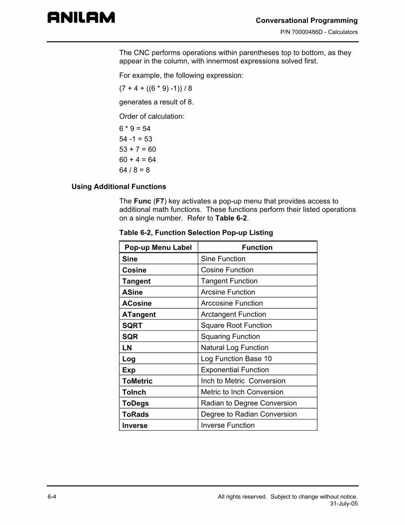
Conversational Programming P/N 70000486D - Calculators
6-4 All rights reserved. Subject to change without notice. 31-July-05
The CNC performs operations within parentheses top to bottom, as they appear in the column, with innermost expressions solved first.
For example, the following expression:
(7 + 4 + ((6 * 9) -1)) / 8
generates a result of 8.
Order of calculation:
6 * 9 = 54 54 -1 = 53 53 + 7 = 60 60 + 4 = 64 64 / 8 = 8
Using Additional Functions
The Func (F7) key activates a pop-up menu that provides access to additional math functions. These functions perform their listed operations on a single number. Refer to Table 6-2.
Table 6-2, Function Selection Pop-up Listing
Pop-up Menu Label Function Sine Sine Function Cosine Cosine Function Tangent Tangent Function ASine Arcsine Function ACosine Arccosine Function ATangent Arctangent Function SQRT Square Root Function SQR Squaring Function LN Natural Log Function Log Log Function Base 10 Exp Exponential Function ToMetric Inch to Metric Conversion ToInch Metric to Inch Conversion ToDegs Radian to Degree Conversion ToRads Degree to Radian Conversion Inverse Inverse Function
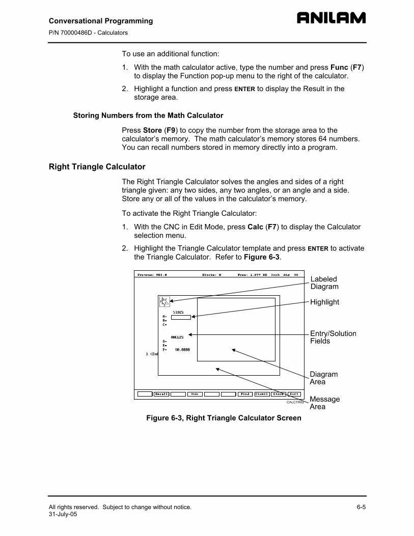
Conversational Programming P/N 70000486D - Calculators
All rights reserved. Subject to change without notice. 6-5 31-July-05
To use an additional function:
1. With the math calculator active, type the number and press Func (F7) to display the Function pop-up menu to the right of the calculator.
2. Highlight a function and press ENTER to display the Result in the storage area.
Storing Numbers from the Math Calculator
Press Store (F9) to copy the number from the storage area to the calculator’s memory. The math calculator’s memory stores 64 numbers. You can recall numbers stored in memory directly into a program.
Right Triangle Calculator
The Right Triangle Calculator solves the angles and sides of a right triangle given: any two sides, any two angles, or an angle and a side. Store any or all of the values in the calculator’s memory.
To activate the Right Triangle Calculator:
1. With the CNC in Edit Mode, press Calc (F7) to display the Calculator selection menu.
2. Highlight the Triangle Calculator template and press ENTER to activate the Triangle Calculator. Refer to Figure 6-3.
Figure 6-3, Right Triangle Calculator Screen
Conversational Programming P/N 70000486D - Calculators
6-6 All rights reserved. Subject to change without notice. 31-July-05
Using the Triangle Calculator
The Right Triangle Calculator solves only right triangle problems. The Right Triangle Calculator’s pop-up screen contains three main areas: the entry/solution area, the diagram area, and the message area.
The labeled entry fields in the entry/solution area correspond to the sides and angles shown in the diagram.
To use the Right Triangle Calculator, type known element values: any two angles, any two sides, or one angle and one side.
After you type two known elements, the CNC calculates and displays values for the remaining sides and/or angles. The CNC places an asterisk after solved element values and displays a scaled drawing of the solved triangle in the diagram area.
To clear a single incorrect value, highlight the value and press CLEAR. To clear all displayed values, press ClrAll (F8).
An illogical entry generates an error message.
Recall Right Triangle Calculator solutions directly into a program (for positive (+) incremental moves only). To adjust these solutions to produce absolute coordinates, recall the values into the Math Calculator and add an offset value.
To solve for the sides and angles of a right triangle:
1. With the Right Triangle Calculator active, highlight the field for the first side or angle and type the value.
2. Highlight a second side or angle and type the value.
3. Press Find (F7) to display a scaled drawing of the triangle appears in the solution box. The CNC displays calculated sides and angles in unused fields.
Storing Right Triangle Calculator Results
The CNC will store any side or angle value. Maximum: 64 values.
To store a value:
1. Solve the required triangle.
2. Highlight the value to be stored.
3. Press ENTER to store the selected value in memory.
Conversational Programming P/N 70000486D - Calculators
All rights reserved. Subject to change without notice. 6-7 31-July-05
Hiding the Right Triangle Calculator Screen
To temporarily hide the Right Triangle Calculator Screen:
1. Press Hide (F4). The CNC temporarily hides the Right Triangle Calculator Screen.
2. Press Find (F7) to display the screen again.
Geometry Calculator
The CNC uses Cartesian coordinates (X, Y, Z-axis values) to define most positions. However, you must sometimes determine position coordinates based on the known construction of other elements on the print, including lines, circles, and angles.
The Geometry Calculator provides an assortment of line, circle, angle, and point templates. Use these templates to sketch a geometry construction that identifies the unknown position. The Geometry Calculator inserts a point at the required position. The calculator automatically solves the coordinates of all points. Recall stored coordinates as necessary in a program.
Activating the Geometry Calculator
To activate the Geometry Calculator:
1. In Edit Mode, press Calc (F7) to display the Calculator selection menu.
2. Highlight Geometry Calculator template and press ENTER to display the Geometry Calculator.
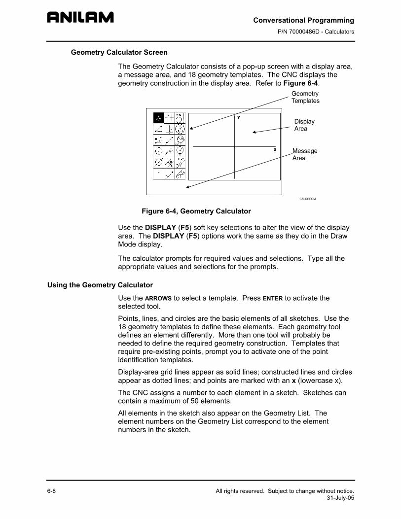
Conversational Programming P/N 70000486D - Calculators
6-8 All rights reserved. Subject to change without notice. 31-July-05
Geometry Calculator Screen
The Geometry Calculator consists of a pop-up screen with a display area, a message area, and 18 geometry templates. The CNC displays the geometry construction in the display area. Refer to Figure 6-4.
Figure 6-4, Geometry Calculator
Use the DISPLAY (F5) soft key selections to alter the view of the display area. The DISPLAY (F5) options work the same as they do in the Draw Mode display.
The calculator prompts for required values and selections. Type all the appropriate values and selections for the prompts.
Using the Geometry Calculator
Use the ARROWS to select a template. Press ENTER to activate the selected tool.
Points, lines, and circles are the basic elements of all sketches. Use the 18 geometry templates to define these elements. Each geometry tool defines an element differently. More than one tool will probably be needed to define the required geometry construction. Templates that require pre-existing points, prompt you to activate one of the point identification templates.
Display-area grid lines appear as solid lines; constructed lines and circles appear as dotted lines; and points are marked with an x (lowercase x).
The CNC assigns a number to each element in a sketch. Sketches can contain a maximum of 50 elements.
All elements in the sketch also appear on the Geometry List. The element numbers on the Geometry List correspond to the element numbers in the sketch.
Conversational Programming P/N 70000486D - Calculators
All rights reserved. Subject to change without notice. 6-9 31-July-05
The Geometry List contains the following details about each element: Circles Absolute position of center and radius Lines Orientation (angle) and absolute position at which it crosses X-
and/or Y-axis Points Absolute positions
The calculator automatically numbers each element and stores the following details in memory: Points Absolute position Circles Absolute position of center
NOTE: The Geometry Calculator does not automatically save the coordinates of an intersection between two elements. Insert a point at the intersection to save its coordinates.
When you delete an element from the sketch, the CNC deletes all stored information regarding that element.
There are three categories of Geometry templates.
Point templates Refer to Table 6-3, Point Templates Line templates Refer to Table 6-4, Line Templates Circle templates Refer to Table 6-5, Circle Templates
Review the tables to see the requirements for each template. Many templates require feature(s) of an existing element as a reference. Experiment to become familiar with how each template operates.
NOTE: After a series of deletions and additions, the display may appear incomplete. Press Display (F5) and select Redraw to refresh the screen.
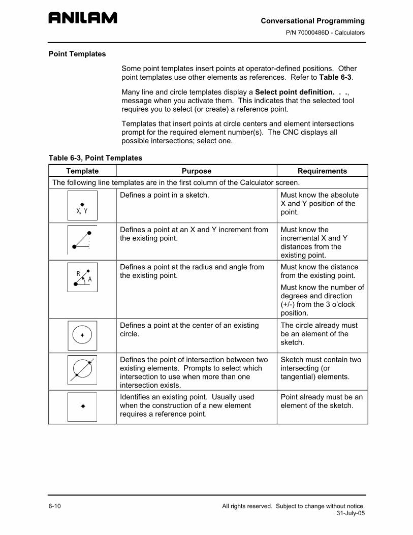
Conversational Programming P/N 70000486D - Calculators
6-10 All rights reserved. Subject to change without notice. 31-July-05
Point Templates
Some point templates insert points at operator-defined positions. Other point templates use other elements as references. Refer to Table 6-3.
Many line and circle templates display a Select point definition. . ., message when you activate them. This indicates that the selected tool requires you to select (or create) a reference point.
Templates that insert points at circle centers and element intersections prompt for the required element number(s). The CNC displays all possible intersections; select one.
Table 6-3, Point Templates
Template Purpose Requirements The following line templates are in the first column of the Calculator screen.
Defines a point in a sketch. Must know the absolute X and Y position of the point.
Defines a point at an X and Y increment from the existing point.
Must know the incremental X and Y distances from the existing point.
Defines a point at the radius and angle from the existing point.
Must know the distance from the existing point. Must know the number of degrees and direction (+/-) from the 3 o’clock position.
Defines a point at the center of an existing circle.
The circle already must be an element of the sketch.
Defines the point of intersection between two existing elements. Prompts to select which intersection to use when more than one intersection exists.
Sketch must contain two intersecting (or tangential) elements.
Identifies an existing point. Usually used when the construction of a new element requires a reference point.
Point already must be an element of the sketch.

Conversational Programming P/N 70000486D - Calculators
All rights reserved. Subject to change without notice. 6-11 31-July-05
Line Templates
Line templates use other elements or axis positions as references. Templates that draw lines tangent to circles, display all possible tangent lines and prompt you to select one. Refer to Table 6-4.
Table 6-4, Line Templates
Template Purpose Requirements The following line templates are in the second column of the Calculator screen.
Constructs a line parallel to the Y-axis. Must know the absolute X-axis position of the line.
Constructs a line parallel to the X-axis. Must know the absolute Y-axis position of the line.
Constructs a line between any two points. Prompts you to select a point tool to define each endpoint.
Use any point to locate the two endpoints.
Constructs a line through a point rotated a specified number of degrees from the 3 o’clock position. Prompts you to select any point tool to define the point of rotation.
Must know the number of degrees and direction (+/-) from the 3 o’clock position.Use any point to locate the point of rotation.
Constructs a line parallel to the existing line at the specified (positive or negative) distance.
Existing line already must be an element of the sketch.
Constructs a line through a selected point and tangent to an existing circle. Prompts you to select any point tool for point. Displays tangent lines on both sides of the circle. Select the required tangent.
Circle already must be an element of the sketch. Use any point to locate the point.
The following line templates are in the third column of the Calculator screen.
Constructs a line tangent to any two circles. Displays the four possible tangent lines. Select the required tangent.
Two circles already must be elements of the sketch.
Constructs a line rotated a specified number of degrees from the 3 o’clock position and tangent to the existing circle.
Circle already must be an element of the sketch. Must know the number of degrees of rotation from the 3 o’clock position.
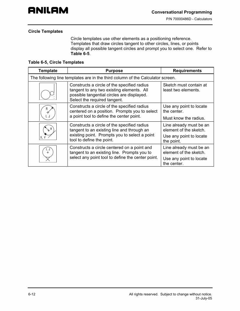
Conversational Programming P/N 70000486D - Calculators
6-12 All rights reserved. Subject to change without notice. 31-July-05
Circle Templates Circle templates use other elements as a positioning reference. Templates that draw circles tangent to other circles, lines, or points display all possible tangent circles and prompt you to select one. Refer to Table 6-5.
Table 6-5, Circle Templates
Template Purpose Requirements The following line templates are in the third column of the Calculator screen.
Constructs a circle of the specified radius tangent to any two existing elements. All possible tangential circles are displayed. Select the required tangent.
Sketch must contain at least two elements.
Constructs a circle of the specified radius centered on a position. Prompts you to select a point tool to define the center point.
Use any point to locate the center. Must know the radius.
Constructs a circle of the specified radius tangent to an existing line and through an existing point. Prompts you to select a point tool to define the point.
Line already must be an element of the sketch. Use any point to locate the point.
Constructs a circle centered on a point and tangent to an existing line. Prompts you to select any point tool to define the center point.
Line already must be an element of the sketch. Use any point to locate the center.
Conversational Programming P/N 70000486D - Calculators
All rights reserved. Subject to change without notice. 6-13 31-July-05
Deleting Selected Elements
To delete an element from the sketch:
1. With the Geometry Calculator active, press GEOMETR (F7) to display a pop-up menu.
2. Highlight Delete Item and press ENTER. The CNC prompts for the element number being deleted.
3. Type the element number and press ENTER to delete the element.
Deleting All Elements
To delete all elements from the display area:
1. With the Geometry Calculator active, press GEOMETR (F7) to display a pop-up menu.
2. Highlight Delete All and press ENTER. The CNC prompts to confirm the deletion.
3. Press Yes (F1) to delete all elements from the screen.
– or –
Press No (F2) to cancel the deletion.
Listing All Geometry Elements
The CNC stores information on all points, circles, and lines created in the Geometry Calculator in the Geometry List. For a point, the CNC lists the X,Y coordinates; for a circle, the circle center and radius; for a line, the endpoint coordinates and sometimes the angle in reference to the 3 o’clock, 0 degree position.
To display the Geometry List:
1. With the Geometry Calculator open, press GEOMETR (F7) to display a pop-up menu.
2. Highlight Geometry List and press ENTER to display the Geometry List.
Conversational Programming P/N 70000486D - Calculators
6-14 All rights reserved. Subject to change without notice. 31-July-05
Calculating the Distance between Two Elements
Use Calc. Distance to calculate the shortest distance between any two elements drawn with the Geometry Calculator.
NOTE: For circles, the CNC calculates the shortest distance from the circle center to the other element.
To calculate the distance between two elements in the Geometry Calculator:
1. With the Geometry Calculator open, press GEOMETR (F7) to display a pop-up menu.
2. Highlight Calc. Distance and press ENTER. The CNC prompts, Enter number of first element:
3. Type the first element number. The CNC prompts, Enter number of second element:
4. Type the second element number to calculate and display the shortest distance between the two elements.
Last Position Recall
Whenever the calculator prompts for an X position, Y position, or circle, you can recall the last X position, Y position, or circle used by the calculator.
To recall a position:
When the CNC prompts for an X position, Y position, or circle number, press the up and down ARROWS to recall the last position, Y position, or circle number used.
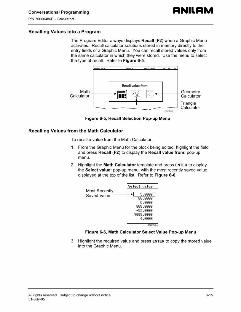
Conversational Programming P/N 70000486D - Calculators
All rights reserved. Subject to change without notice. 6-15 31-July-05
Recalling Values into a Program
The Program Editor always displays Recall (F2) when a Graphic Menu activates. Recall calculator solutions stored in memory directly to the entry fields of a Graphic Menu. You can recall stored values only from the same calculator in which they were stored. Use the menu to select the type of recall. Refer to Figure 6-5.
Figure 6-5, Recall Selection Pop-up Menu
Recalling Values from the Math Calculator
To recall a value from the Math Calculator:
1. From the Graphic Menu for the block being edited, highlight the field and press Recall (F2) to display the Recall value from: pop-up menu.
2. Highlight the Math Calculator template and press ENTER to display the Select value: pop-up menu, with the most recently saved value displayed at the top of the list. Refer to Figure 6-6.
Figure 6-6, Math Calculator Select Value Pop-up Menu
3. Highlight the required value and press ENTER to copy the stored value into the Graphic Menu.
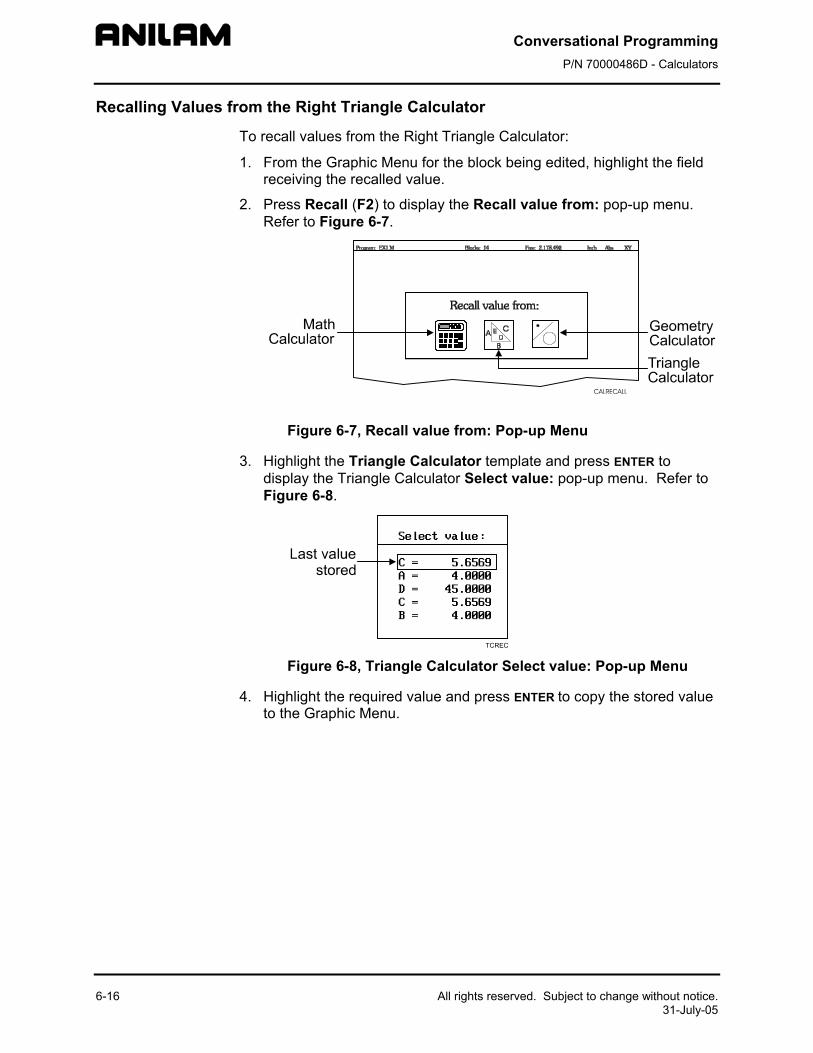
Conversational Programming P/N 70000486D - Calculators
6-16 All rights reserved. Subject to change without notice. 31-July-05
Recalling Values from the Right Triangle Calculator
To recall values from the Right Triangle Calculator:
1. From the Graphic Menu for the block being edited, highlight the field receiving the recalled value.
2. Press Recall (F2) to display the Recall value from: pop-up menu. Refer to Figure 6-7.
Figure 6-7, Recall value from: Pop-up Menu
3. Highlight the Triangle Calculator template and press ENTER to display the Triangle Calculator Select value: pop-up menu. Refer to Figure 6-8.
Figure 6-8, Triangle Calculator Select value: Pop-up Menu
4. Highlight the required value and press ENTER to copy the stored value to the Graphic Menu.
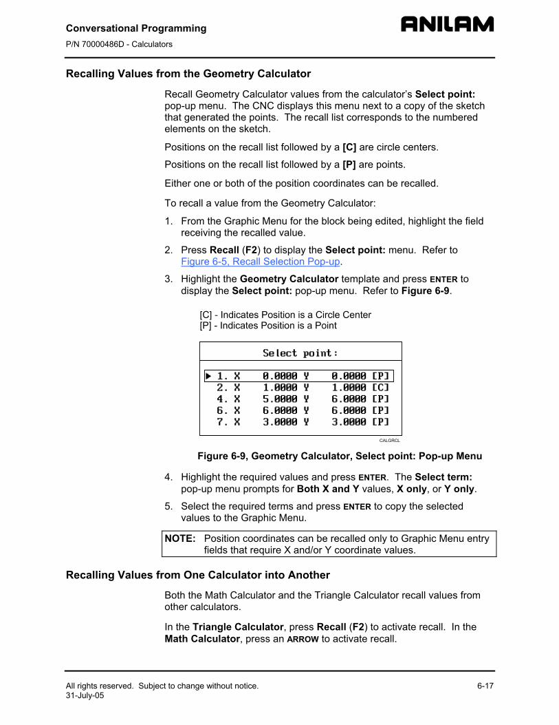
Conversational Programming P/N 70000486D - Calculators
All rights reserved. Subject to change without notice. 6-17 31-July-05
Recalling Values from the Geometry Calculator
Recall Geometry Calculator values from the calculator’s Select point: pop-up menu. The CNC displays this menu next to a copy of the sketch that generated the points. The recall list corresponds to the numbered elements on the sketch.
Positions on the recall list followed by a [C] are circle centers.
Positions on the recall list followed by a [P] are points.
Either one or both of the position coordinates can be recalled.
To recall a value from the Geometry Calculator:
1. From the Graphic Menu for the block being edited, highlight the field receiving the recalled value.
2. Press Recall (F2) to display the Select point: menu. Refer to Figure 6-5, Recall Selection Pop-up.
3. Highlight the Geometry Calculator template and press ENTER to display the Select point: pop-up menu. Refer to Figure 6-9.
Figure 6-9, Geometry Calculator, Select point: Pop-up Menu
4. Highlight the required values and press ENTER. The Select term: pop-up menu prompts for Both X and Y values, X only, or Y only.
5. Select the required terms and press ENTER to copy the selected values to the Graphic Menu.
NOTE: Position coordinates can be recalled only to Graphic Menu entry fields that require X and/or Y coordinate values.
Recalling Values from One Calculator into Another
Both the Math Calculator and the Triangle Calculator recall values from other calculators.
In the Triangle Calculator, press Recall (F2) to activate recall. In the Math Calculator, press an ARROW to activate recall.
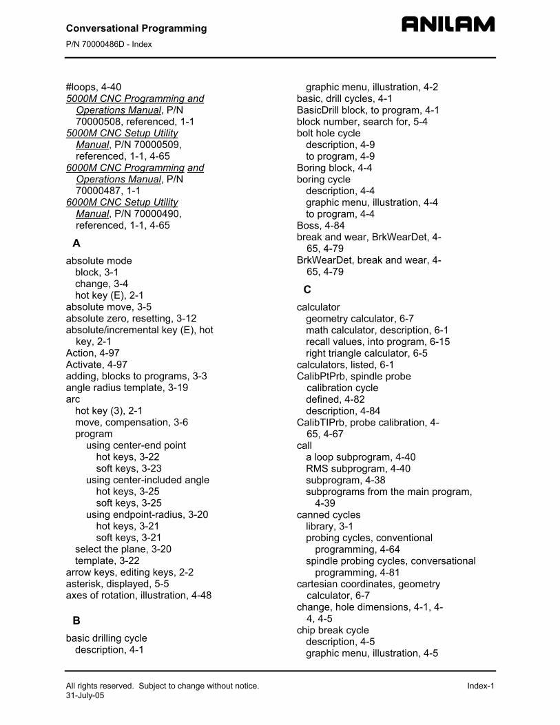
Conversational Programming P/N 70000486D - Index
All rights reserved. Subject to change without notice. Index-1 31-July-05
#loops, 4-40 5000M CNC Programming and
Operations Manual, P/N 70000508, referenced, 1-1
5000M CNC Setup Utility Manual, P/N 70000509, referenced, 1-1, 4-65
6000M CNC Programming and Operations Manual, P/N 70000487, 1-1
6000M CNC Setup Utility Manual, P/N 70000490, referenced, 1-1, 4-65
A absolute mode
block, 3-1 change, 3-4 hot key (E), 2-1
absolute move, 3-5 absolute zero, resetting, 3-12 absolute/incremental key (E), hot
key, 2-1 Action, 4-97 Activate, 4-97 adding, blocks to programs, 3-3 angle radius template, 3-19 arc
hot key (3), 2-1 move, compensation, 3-6 program
using center-end point hot keys, 3-22 soft keys, 3-23
using center-included angle hot keys, 3-25 soft keys, 3-25
using endpoint-radius, 3-20 hot keys, 3-21 soft keys, 3-21
select the plane, 3-20 template, 3-22
arrow keys, editing keys, 2-2 asterisk, displayed, 5-5 axes of rotation, illustration, 4-48
B
basic drilling cycle description, 4-1
graphic menu, illustration, 4-2 basic, drill cycles, 4-1 BasicDrill block, to program, 4-1 block number, search for, 5-4 bolt hole cycle
description, 4-9 to program, 4-9
Boring block, 4-4 boring cycle
description, 4-4 graphic menu, illustration, 4-4 to program, 4-4
Boss, 4-84 break and wear, BrkWearDet, 4-
65, 4-79 BrkWearDet, break and wear, 4-
65, 4-79
C calculator
geometry calculator, 6-7 math calculator, description, 6-1 recall values, into program, 6-15 right triangle calculator, 6-5
calculators, listed, 6-1 CalibPtPrb, spindle probe
calibration cycle defined, 4-82 description, 4-84
CalibTIPrb, probe calibration, 4-65, 4-67
call a loop subprogram, 4-40 RMS subprogram, 4-40 subprogram, 4-38 subprograms from the main program,
4-39 canned cycles
library, 3-1 probing cycles, conventional
programming, 4-64 spindle probing cycles, conversational
programming, 4-81 cartesian coordinates, geometry
calculator, 6-7 change, hole dimensions, 4-1, 4-
4, 4-5 chip break cycle
description, 4-5 graphic menu, illustration, 4-5
Conversational Programming P/N 70000486D - Index
Index-2 All rights reserved. Subject to change without notice. 31-July-05
to program, 4-5 circle templates, listed, 6-12 circular pocket cycle
compensation, 3-7 description, 4-21 graphic menu, illustration, 4-21 to program, 4-21
circular profile cycle compensation, 3-7 description, 4-17 graphic menu, illustration, 4-17 to program, 4-18
cleaning up, inside diameter, 4-25
CLEAR key, editing keys, 2-2 column of numbers, math, 6-3 comment
asterisk, hot key (0), 2-1 block
comment out, 5-5 description, 5-5 to cancel, 5-6 to write, 5-5
conversational editor, More (F1) soft key, 5-6 programs
M, extension, 3-1 writing, 3-1
conversational programming probe cycles, description, 4-64 spindle probe cycles, description, 4-64 spindle probing
description, 4-81, 4-83 designations, 4-82
tool probe cycle, description, 4-66 tool probe cycle, designations, listed, 4-65 tool probe cycle, listed, 4-66 tool probe cycles, description, 4-64
coordinates, finding, 3-1 CornerIn, inside part corner find
defined, 4-82 description, 4-89
CornerOut, outside part corner find defined, 4-82 description, 4-87
counter bore, existing holes, 4-25
curved moves, programming, 3-20
cut through holes, 4-25
cutting direction, 4-13 cycle compensation,
requirements, listed, 3-6
D decimal point, hot key, 2-1 diameter special, DiaSpecMea,
4-65, 4-76 DiamOfStd, 4-67 DiaSpecMea, diameter special,
4-65, 4-76 dim block, to program, 3-4 disclaimer, iii DisDown, 4-84 DistBack, 4-84, 4-88, 4-90, 4-91,
4-93, 4-98 DistDown, 4-67, 4-70, 4-76,
4-79, 4-87, 4-89, 4-91, 4-93, 4-98
DistInX, 4-84, 4-88, 4-90, 4-92, 4-94, 4-98
DistInY, 4-84, 4-88, 4-90, 4-92, 4-94, 4-98
DistPicks, 4-97 DistSide, 4-87, 4-89 drill
cycles basic, 4-1 description, 4-1 listed, 4-1
pattern description, 4-8 to program, 4-8
drilling cycles, listed, 4-1 Drilling Off block, 4-2, 4-5, 4-6 DrillOff block, 4-1 drilloff block, to program, 4-1 dry run
all axes (M105), 3-27 cancel (M107), 3-27 mode
description, 3-27 M-codes, listed, 3-27
no Z-axis (M106), 3-27 successful, 3-2
dwell block, to add, 3-8 graphic menu, 3-8 hot key (8), 2-1 programming
description, 3-8
Conversational Programming P/N 70000486D - Index
All rights reserved. Subject to change without notice. Index-3 31-July-05
using hot keys, 3-8 using soft keys, 3-8
resolution, 3-8, 4-4 DXF converter
output format, pop-up menu, 4-33 pockets with islands
description, 4-32 program example, 4-34
program listing, pop-menu, 4-33
E edge finding, EdgeFind, 4-86 EdgeFind, single surface
measure/edge find defined, 4-82 description, 4-86
edit mode, hot keys, listed, 2-1 editing
keys arrow keys, 2-2 CLEAR key, 2-2 ENTER key, 2-2 listed, 2-2
program blocks, More (F1), 5-6 programs, conversational, 5-1 to search, 5-4
editor, conversational, More (F1), 5-6
edits to exit, 5-3 to save, 5-3 unsaved, to cancel, 5-3
elbow cavity and core, illustration, 4-53
elbow milling cycle conical elbow details, illustration, 4-56 core & cavity detail, illustration, 4-56 details, illustration, 4-54 graphic menu, illustration, 4-57 moves, illustration, 4-54 programming, 4-53 starting point, orientation, illustration, 4-55 starting point, size, illustration, 4-55 to program, 4-57
elbow mold cycle, compensation, 3-7
ellipse description, 4-42 graphic menu, illustration, 4-42 move, compensation, 3-6 programming, 4-42
tool compensation, illustration, 4-44 end of main, block, 4-37 end of program, 3-3 ending
main programs, 4-39 subprograms, 4-39
EndMain, 4-39 EndMain, last program block, 3-3 EndMill block, to program, 4-62 endpoint template, 3-22 EndSub, 4-39 engraving cycle
description, 4-58 sample program, 4-60 to program, 4-58
ENTER key, editing keys, 2-2 entry fields
optional, graphic menu, 3-4 required, graphic menu, 3-4
EstAngle, 4-97 EstDiam, 4-69, 4-74, 4-76, 4-79 extension, M, 3-1
F F1, soft key, More,
conversational editor, 5-6 F1, ToolPro, 4-66 F10, Probe, 4-66 F3, SpinPro, 4-66 F5, Mill, 4-44, 4-66 F6, RMS, 4-40 F7, More, 4-44 F9, Misc soft key, 5-6 face pocket
graphic menu, illustration, 4-13 face, the surface of a part, 4-13 facing cycle
description, 4-13 to program, 4-13 tool approach, illustration, 4-13
feed block
description, 3-15 to program
hot keys, 3-15 soft keys, 3-15
hot key (4), 2-1 moves, programming, 3-17
Feed, 4-95 feedrate change, programming,
3-15
Conversational Programming P/N 70000486D - Index
Index-4 All rights reserved. Subject to change without notice. 31-July-05
Find, 4-97 FindActive, 4-97 fixture offsets
changing, 3-12 define, 3-2 entry fields, 3-10 table
entry, to calibrate, 3-12 illustrated, 3-11 to activate, 3-11 values, manually typed, 3-12
to cancel, 3-11 to program, 3-10
frame pocket cycle compensation, 3-7 description, 4-23 graphic menu, illustration, 4-23 to program, 4-23
G G, extension, 1-1 GaugeDiam, 4-84 geometry calculator
deleting, all elements, 6-13 deleting, elements, 6-13 description, 6-7 distance, calculate, 6-14 geometry list, 6-13 recall, last position, 6-14 recall, values, 6-17 screen, illustration, 6-8 templates
circle templates, 6-12 line templates, 6-11 listed, 6-9 point templates, 6-10
to activate, 6-7 to use, 6-8
geometry list element, details, 6-9 geometry calculator, 6-13 to display, 6-13
graphic menu basic drilling, illustration, 4-2 bolthole drill, illustration, 4-9 boring drilling, illustration, 4-4 chip breaking cycle, illustration, 4-5 circular pocket, illustration, 4-21 circular profile, illustration, 4-17 elbow milling, illustration, 4-57 ellipse, illustration, 4-42
entry fields, types, listed, 3-4 face pocket, illustration, 4-13 frame pocket, illustration, 4-23 hole-mill, illustration, 4-25 irregular pocket, illustration, 4-30 mold rotation, illustration, 4-52 pattern drill, illustration, 4-8 peck drilling, illustration, 4-3 rectangular pocket, illustration, 4-19 rectangular profile, illustration, 4-15 RMS SUB, illustration, 4-41 spiral, illustration, 4-44 tapping cycle, illustration, 4-7 thread mill, illustration, 4-10 using, 3-3
H height, standard starting, 3-1 helical threads, 3-22 hole mill pocket cycle
description, 4-25 graphic menu, illustration, 4-25 to program, 4-25
home, 3-9 homing method, 3-9 hot key
absolute mode (E), 2-1 absolute/incremental key (E), 2-1 arc key(3), 2-1 comment asterisk (0), 2-1 decimal point key, 2-1 dwell key (8), 2-1 feed key (4), 2-1 inch mode (7), 2-1 incremental mode (E), 2-1 line move (2), 2-1 M-code key (6), 2-1 millimeter mode (7), 2-1 plane key (9), 2-1 rapid move (1), 2-1 sign change key (+/-), 2-1 spindle speed, 2-1 tool key (5), 2-1 unit key (7), 2-1 X-axis, 2-1 Y-axis, 2-1 Z-axis, 2-1
hot keys editing, program blocks, More (F1), 5-6 feed block, to program, 3-15 line move, to program, 3-17
Conversational Programming P/N 70000486D - Index
All rights reserved. Subject to change without notice. Index-5 31-July-05
listed, 2-1 plane block, to program, 3-14 program
arc using center-end point, 3-22 using center-included angle, 3-25 using endpoint-radius, 3-21
rapid move, to program, 3-16 RPM, to program, 3-15
I inch mode, 3-4 inch mode, hot key (7), 2-1 incremental command, 3-5 incremental mode
change, 3-4 hot key (E), 2-1
InOutBoss, inside or outside hole or boss center find defined, 4-82 description, 4-91
InOutWeb, inside or outside web or slot center find defined, 4-82 description, 4-93
inside corner finding, CornerIn, 4-89
inside or outside hole or boss center find, InOutBoss, 4-82, 4-91
inside or outside web or slot center find, InOutWeb, 4-82, 4-93
inside part corner find, CornerIn, 4-82, 4-89
inside profile, 4-15 inside/outside hole/boss finding,
InOutBoss, 4-91 inside/outside web finding,
InOutWeb, 4-93 introduction, 1-1 irregular pocket
(M9367) correct tool diameter, from a subprogram, 4-31
cycle compensation, 3-7 description, 4-27 programming, 4-27 to program, 4-30
execution, 4-29 graphic menu, illustration, 4-30
island, in rectangles, 4-23
K keys, editing, listed, 2-2
L last, program block, EndMain,
3-3 LenDiamMea, length and
diameter, 4-65, 4-69 Length, 4-91, 4-93 length and diameter,
LenDiamMea, 4-65, 4-69 length offset, 3-2 length special, LenSpecMea, 4-
65, 4-74 LenSpecMea, length special, 4-
65, 4-74 line
(feed) moves, 3-17 block, move, programming, 3-19 move
compensation, 3-6 hot key (2), 2-1 programming, 3-17 to program
hot keys, 3-17 soft keys, 3-17
templates, listed, 6-11 tools, geometry calculator, 6-11
looping, subprograms, 4-37, 4-40
M M, extension, 1-1, 3-1 M105, dry run, all axes, 3-27 M106, dry run, cancel, 3-27 M106, dry run, no Z-axis, 3-27 M9367, correct tool diameter,
irregular pocket milling, 4-31 machine home
graphic menu, to activate, 3-9 return to, 3-9
machine zero, 3-9 manual tool diameter
measure for special tools, DiaSpecMea, 4-76
preset, DiaSpecMea, 4-65, 4-76 manual tool length
measure for special tools, LenSpecMea, 4-74
Conversational Programming P/N 70000486D - Index
Index-6 All rights reserved. Subject to change without notice. 31-July-05
offset preset, LenSpecMea, 4-65, 4-74 math
calculator basics, listed, 6-2 description, 6-1 functions, listed, 6-4 numbers, storage, 6-5 operation keys, listed, 6-2 operations, multiple, 6-3 operations, order of, 6-4 parentheses, using, 6-3 recall values, 6-15 recall, values from other calculators,
6-17 soft keys, listed, 6-2 to activate, 6-1 to add, 6-3 to divide, 6-3 to multiply, 6-3 to subtract, 6-3 two number, operations, 6-3
functions, listed, 6-4 operation, soft keys, listed, 6-2
MaxDiaAdj, 4-79 MaxLenAdj, 4-79 M-code
block, to program, 3-26 dry run mode, listed, 3-27 functions, listed, 3-26 hot key (6), 2-1
MeasTyoe, 4-69 measurement mode, 5-2 memory, storing numbers, 6-5 menus
bolthole drill, graphic menu, illustration, 4-9
ellipse, graphic illustration, 4-42 face pocket, graphic, illustration, 4-13 graphic
basic drilling, illustration, 4-2 boring drilling, illustration, 4-4 chip breaking cycle, illustration, 4-5 circular pocket, illustration, 4-21 circular profile, illustration, 4-17 elbow milling, illustration, 4-57 frame pocket, illustration, 4-23 hole-mill, illustration, 4-25 irregular pocket, illustration, 4-30 mold rotation, illustration, 4-52 pattern drill, illustration, 4-8 peck drilling, illustration, 4-3
rectangular pocket, illustration, 4-19 rectangular profile, illustration, 4-15 RMS SUB, illustration, 4-41 spiral, illustration, 4-44 tapping cycle, illustration, 4-7 thread mill, illustration, 4-10
pop-up, pocket, illustration, 4-12 Mill (F5), 4-44 mill cycle
description, 4-62 sample program, 4-63 to program, 4-62
Mill, F5, 4-66 millimeter mode, hot key (7), 2-1 milling, cavities, 4-45 milling, cores, 4-45 mirroring and scaling,
subprograms, 4-40 mirroring, subprograms, 4-37 mm mode, 3-4 modal
move block, 3-17 compensation, 3-6 programming, 3-17
setting, description, 3-1 mold cycles, 4-45 mold rotation
around X and Y axes small radius, 4-46
axes of rotation, illustration, 4-48 categories, listed, 4-45 cutting a cavity, illustration, 4-49 cycle, compensation, 3-7 graphic menu, illustration, 4-52 programming, 4-45 rotation around the Z-axis, 4-51 rotations around X and Y axes
large radius, 4-50 XY rotations about Z, illustration, 4-49 XY symmetrical axis, illustration, 4-45 Z-axis, illustration, 4-51
MoldRot block, to program, 4-52 More (F7), 4-44 More pop-up menu, to display,
5-6 move
angle, specifying, illustration, 4-29 compensation, requirements, listed, 3-6 direction, determining, 4-28
Conversational Programming P/N 70000486D - Index
All rights reserved. Subject to change without notice. Index-7 31-July-05
moves with unknown endpoints, programming, 3-18
N negative radius value, 3-21 nesting subprograms, 4-37 no move blocks, description, 3-4 Nominal probe stylus diameter,
4-68 numbers, storing in memory, 6-5
O Offset, 4-86, 4-88, 4-90, 4-92,
4-94 organizing programs, containing
subprograms, 4-38 output format pop-up menu,
illustration, 4-33 outside corner finding,
CornerOut, 4-87 outside part corner find,
CornerOut, 4-82, 4-87 outside profile, 4-17 outside profile ramp moves,
illustration, 4-15 OvrFstFeed, 4-70 OvrMedFeed, 4-70, 4-74, 4-76,
4-80 OvrRPM, 4-70, 4-74, 4-77, 4-80 OvrSlwFeed, 4-70, 4-74, 4-76,
4-80
P P/N 70000487, 6000M CNC
Programming and Operations Manual, referenced, 1-1
P/N 70000490, 6000M CNC Setup Utility Manual, referenced, 1-1, 4-65
P/N 70000508, 5000M CNC Programming and Operations Manual, referenced, 1-1
P/N 70000509, 5000M CNC Setup Utility Manual, referenced, 1-1, 4-65
parentheses, math calculator, 6-3
part programs, to develop, 3-1 part zero location, 3-1 part, moves toward, 3-1 Pattern Drill. See drill pattern
pattern drill cycle description, 4-8 graphic menu, illustration, 4-8
peck drilling cycle description, 4-2 graphic menu, illustration, 4-3 to program, 4-3
plane block, to program hot keys, 3-14 soft keys, 3-15
plane selection, ellipse and spiral, 4-41
plane, hot key (9), 2-1 pocket
cycle, description, 4-12 cycle, tool compensation, 4-12 cycles, listed, 4-12 pop-up menu, illustration, 4-12 with islands
description, 4-32 DXF, program example, 4-34 subroutines, example, 4-35 using DXF, 4-32
point definition, 6-10 point identification tools, 6-8 point of rotation, 4-41 point templates
description, 6-10 listed, 6-10
pop-up menus editing, program blocks, More (F1), 5-6 More (F1), illustration, 5-7 More (F7) engraving cycle, illustration,
4-58 output format, 4-33 program listing, 4-33
positive radius value, 3-21 probe
calibration, CalibTIPrb, 4-65, 4-67 cycles, conversational programming,
description, 4-64 orientation, description, 4-68 spindle cycles
conversational programming, description, 4-64
description, 4-81 listed, 4-82
tool cycles description, 4-64, 4-66 designations, 4-65 listed, 4-66
Conversational Programming P/N 70000486D - Index
Index-8 All rights reserved. Subject to change without notice. 31-July-05
tool-length offset, description, 4-64 Probe, F10, 4-66 ProbeMove, protected
positioning move defined, 4-83 description, 4-95
progamming feed block
hot keys, 3-15 soft keys, 3-15
line move hot keys, 3-17 soft keys, 3-17
rapid move hot keys, 3-16 soft keys, 3-16
RPM block hot keys, 3-15 soft keys, 3-16
SetZero block, 3-14 program
arc using center-end point
hot keys, 3-22 soft keys, 3-23
using center-included angle hot keys, 3-25 soft keys, 3-25
using endpoint-radius, 3-20 hot keys, 3-21 soft keys, 3-21
back up, 3-2 basics, description, 3-1 editing, conversational, 5-1 elbow milling cycle, 4-57 end of, 3-3 ending, main, 4-39 listing pop-up menu, illustration, 4-33
program block adding to program, 3-3 comment out, 5-5 comments, description, 5-5 editing, More (F1), 5-6 EndMain, last, 3-3 saving, 3-3 scroll, 5-4 to delete, 5-3 to edit, 5-4 to insert, 5-4 to jump, 5-5 to page, 5-5
writing, 3-3 program editor, 3-3
conversational from manual screen, activate, 5-1 from program directory, activate, 5-1
recall values, into program, 6-15 screen, illustration, 5-2
program type conversational, description, 1-1 G-code, description, 1-1
programming absolute mode, change, 3-4 an elbow milling cycle, 4-53 an ellipse, 4-42 arcs, 3-20 basic drill cycles, 4-1 circular pocket cycle, 4-21 circular profile cycles, 4-17 curved moves, 3-20 drill patterns, 4-8 dwell, 3-8
using hot keys, 3-8 using soft keys, 3-8
facing cycles, 4-13 feed moves, 3-17 feedrate change, 3-15 frame pocket cycles, 4-23 hole, 4-25 hole mill pocket cycle, 4-25 hot keys, listed, 2-1 inch/MM mode changes, 3-4 incremental mode, change, 3-4 irregular pocket cycle, 4-30 irregular pocket cycles, 4-27 line (feed) moves, 3-17 M-code block, 3-26 modal moves, 3-17 mold rotation, 4-45 MoldRot block, 4-52 move, using line block, 3-19 move, using rapid block, 3-19 moves with unknown endpoints, 3-18 part programs, 3-1 plane block
hot keys, 3-14 soft keys, 3-15
rapid move, 3-16 rectangular pocket cycles, 4-19 rectangular profile cycles, 4-15, 4-16 spindle RPM, 3-15 spiral, 4-44
Conversational Programming P/N 70000486D - Index
All rights reserved. Subject to change without notice. Index-9 31-July-05
straight moves, 3-16 tool change, 3-5
protected positioning move, ProbeMove, 4-83, 4-95
protected probe positioning, ProbeMove, 4-95
R ramp moves, 3-6 rapid block, move, programming,
3-19 rapid move
compensation, 3-6 hot key (1), 2-1 hot keys, 3-16 programming, 3-16 soft keys, 3-16 to program
hot keys, 3-16 soft keys, 3-16
recall value from one calculator, to another, 6-17 geometry calculator, from, 6-17 into program, 6-15 math calculator, from, 6-15 pop-up menu, from, 6-15 right triangle calculator, from, 6-16
rectangular pocket cycle compensation, 3-7 description, 4-19 graphic menu, illustration, 4-19 to program, 4-19
rectangular profile cycle compensation, 3-7 description, 4-15 graphic menu, illustration, 4-15 to program, 4-16
reference point, 6-10 repeat cycle
description, 4-60 sample program, 4-61 to program, 4-60
RepeatMeas, 4-92 repetitive
drilling cycle, subprograms, 4-37 operations, 4-12 operations, subprograms, 4-37
return to machine home, 3-9 ReturnHgt, 4-2 right triangle calculator. See
triangle calculator
RMS description, 4-40 SUB, graphic menu, illustration, 4-41 subprogram, entry fields, 4-41 subprogram, to call, 4-40 subprograms, 4-40
RMS (F6), 4-40 rotating, mirroring, and scaling.
See RMS rotating, subprograms, 4-37 rotation
around the Z-axis, 4-51 around X and Y axes
large radius, 4-50 small radius, 4-46
Z-axis rotation, start and end angles, 4-52 rough and finish cycles,
subprograms, 4-37 RPM block, to program
hot keys, 3-15 soft keys, 3-16
RPM for calibration and tool measurement, 4-68, 4-70, 4-74, 4-77, 4-80
S saving, program block, 3-3 scaling, subprograms, 4-37, 4-40 screens
engraving cycle, illustration, 4-59 mill cycle, illustration, 4-62 repeat cycle, illustration, 4-60
scroll, program, 5-4 search, blocks, 5-4 SearchDir, 4-86 SearchQuad, 4-87, 4-89 set plane graphic menu, 3-15 SetZero block, 3-12
to program, 3-14 to set, 3-13
Side, 4-91, 4-93 sign change, hot key (+/-), 2-1 single surface measure/edge
find, EdgeFind, 4-82, 4-86 sketch, elements, 6-8 skew error find, SkewComp,
4-96 skew error or angle find,
SkewComp, 4-83, 4-96
Conversational Programming P/N 70000486D - Index
Index-10 All rights reserved. Subject to change without notice. 31-July-05
SkewComp, skew error or angle find defined, 4-83 description, 4-96
soft keys feed block, to program, 3-15 labels, functions, listed, 5-3 line move, to program, 3-17 More (F1), editing, program blocks, 5-6 plane block, to program, 3-15 program
arc using center-end point, 3-23 using center-included angle, 3-25 using endpoint-radius, 3-21
rapid move, to program, 3-16 RPM, to program, 3-16
spindle probe calibration
CalibPtPrb, 4-84 cycle, CalibPtPrb, 4-82, 4-84
probe cycles conversational programming,
description, 4-64 description, 4-81 listed, 4-82
RPM, programmable, 3-15 speed, hot key, 2-1
SpinPro, F3, 4-66 spiral
geometry, 4-44 graphic menu, illustration, 4-44 inward, 4-44 move, compensation, 3-6 outward, 4-44 programming, 4-44
StartHgt, defined, 4-2 starting, subprograms, 4-39 stepover
face pocket, value, 4-14 facing cycle, 4-13 move direction, 4-28 move orientation, illustration, 4-27 orienting from subprogram, illustration,
4-28 Stepover values, 4-14 straight moves, programming,
3-16 Sub block, to program, 4-39 Sub#, 4-40
subprogram call, 4-38 call a loop, 4-40 calling, 4-39 description, 4-37 ending, 4-39 example, 4-37 looping, 4-40 M9367, correct tool diameter, irregular
pocket milling, 4-31 orientation, illustration, 4-46 program structure, 4-37 programs, containing, 4-38 repetitive drilling cycle, 4-37 RMS, to call, 4-40 rotating, mirroring, and scaling, 4-40 rough and finish cycles, 4-37 specific, illustration, 4-47 to program, 4-39 to write, 4-38 Z-axis rotation, illustration, 4-51
subroutines, pockets with islands, example, 4-35
T tapping cycle
description, 4-6 graphic menu, illustration, 4-7 to program, 4-7
templates circle, 6-12 line, 6-11 point, 6-10
thread milling cycle description, 4-10 graphic menu, illustration, 4-10 sample program, 4-11 to program, 4-10
TLO. See tool-length offset TLO, defined, 4-64 tool
approach, facing cycle, illustration, 4-13 change, progamming, 3-5 compensation, automatic, 3-6 compensation, ellipse, illustration, 4-44 diameter, 3-2 diameter compensation, activating, 3-6 diameter, correct for irregular pocket
milling, M9367, 4-31 hot key (5), 2-1 to activate, 3-5
Conversational Programming P/N 70000486D - Index
All rights reserved. Subject to change without notice. Index-11 31-July-05
to change, 3-5 tool breakage, length and
diameter wear detection, BrkWearDet, 4-65, 4-79
tool length and diameter offset preset, LenDiamMea, 4-65, 4-69
tool probe calibration cycle, CalibTIPrb, 4-65, 4-67
tool probe cycles description, 4-64, 4-66 designations, listed, 4-65 listed, 4-66
Tool#, 4-40 tool# block, 3-5 ToolComp command, 3-6 tooling, organize, 3-2 tool-length offset, probe,
description, 4-64 ToolPro, F1, 4-66 Top, 4-84, 4-87, 4-89, 4-91, 4-
93, 4-97 triangle calculator
description, 6-5 recall, values, 6-16 recall, values from other calculators, 6-17 screen, to hide, 6-7 to activate, 6-5 using, 6-6 value, to store, 6-6
troubleshoot, finished programs, 3-2
U unit block, to program, 3-4 unit, hot key (7), 2-1 units mode, 5-2 Update, 4-80
W warranty, iii
Width, 4-91, 4-93 word, search for, 5-4 writing, conversational programs,
3-1 writing, program blocks, 3-3
X X-axis, hot key, 2-1 Xincr, 4-40 XMinus, 4-86 XMinusYMinus, 4-87, 4-89 XMinusYPlus, 4-87, 4-89 X-offset coordinate, 3-10 XPlus, 4-86 XPlusYMinus, 4-87, 4-89 XPlusYPlus, 4-87, 4-89 XStepover, 4-14
Y Y-axis, hot key, 2-1 Yincr, 4-40 YMinus, 4-86 Y-offset coordinate, 3-10 YPlus, 4-86 YStepover, 4-14
Z Z final pick, SLOW feedrate,
4-70, 4-74, 4-76, 4-80 Z first pick
FAST feedrate, 4-70 MEDIUM feedrate, 4-67, 4-70, 4-74, 4-76,
4-80 Z-axis, hot key, 2-1 ZDepth, defined, 4-2 ZFeed, 4-40 Zincr, 4-40 ZMinus, 4-86 Z-offset coordinate, 3-11 ZPlus, 4-86
P/N 70000486D 31-July-05 www.anilam.com
U.S.A. ANILAM
One Precision Way Jamestown, NY 14701
(716) 661-1899 (716) 661-1884
ANILAM, CA 16312 Garfield Ave., Unit B
Paramount, CA 90723 (562) 408-3334 (562) 634-5459
Dial “011” before each number when calling from the U.S.A.
France
ANILAM S.A.R.L. 2 Ave de la Cristallerie
B.P. 68-92316 Serves Cedex, France
+33-1-46290061 +33-1-45072402
Germany ANILAM GmbH
Fraunhoferstrasse 1 D-83301 Traunreut
Germany +49 8669 856110 +49 8669 850930 [email protected]
Italy
ANILAM Elettronica s.r.l. 10043 Orbassano
Strada Borgaretto 38 Torino, Italy
+39 011 900 2606 +39 011 900 2466
Taiwan ANILAM, TW
No. 246 Chau-Fu Road Taichung City 407
Taiwan, ROC +886-4 225 87222 +886-4 225 87260
United Kingdom ACI (UK) Limited
16 Plover Close, Interchange Park Newport Pagnell
Buckinghamshire, MK16 9PS England
+44 (0) 1908 514 500 +44 (0) 1908 610 111 [email protected]
China
Acu-Rite Companies Inc.(Shanghai Representative Office) Room 1986, Tower B
City Center of Shanghai No. 100 Zunyi Lu Road
Chang Ning District 200051 Shanghai P.R.C.
+86 21 62370398 +86 21 62372320