Embed Size (px)
Citation preview
1
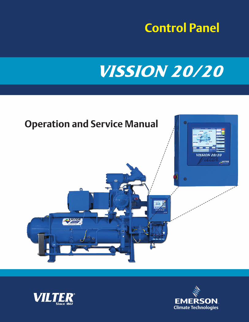
Control Panel
Operation and Service Manual

2
3
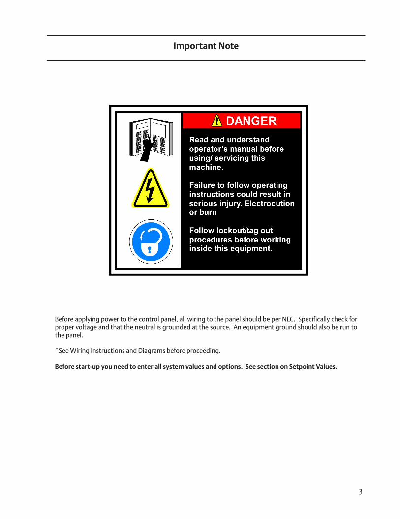
Important Note
Before applying power to the control panel, all wiring to the panel should be per NEC. Specifically check for proper voltage and that the neutral is grounded at the source. An equipment ground should also be run to the panel.
*See Wiring Instructions and Diagrams before proceeding.
Before start-up you need to enter all system values and options. See section on Setpoint Values.

4
5
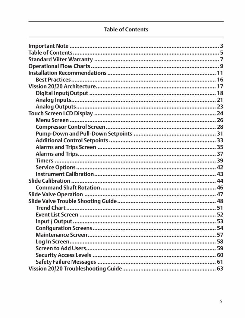
Table of Contents
Important Note ........................................................................................... 3Table of Contents ......................................................................................... 5Standard Vilter Warranty ............................................................................ 7Operational Flow Charts .............................................................................. 9Installation Recommendations .................................................................. 11 Best Practices ........................................................................................ 16Vission 20/20 Architecture ......................................................................... 17 Digital Input/Output ............................................................................. 18 Analog Inputs ........................................................................................ 21 Analog Outputs ..................................................................................... 23Touch Screen LCD Display .......................................................................... 24 Menu Screen ......................................................................................... 26 Compressor Control Screen ................................................................... 28 Pump-Down and Pull-Down Setpoints .................................................. 31 Additional Control Setpoints ................................................................. 33 Alarms and Trips Screen ........................................................................ 35 Alarms and Trips .................................................................................... 37 Timers .................................................................................................. 39 Service Options ..................................................................................... 42 Instrument Calibration .......................................................................... 43Slide Calibration ........................................................................................ 44 Command Shaft Rotation ...................................................................... 46Slide Valve Operation ................................................................................ 47Slide Valve Trouble Shooting Guide ............................................................ 48 Trend Chart ........................................................................................... 51 Event List Screen ................................................................................... 52 Input / Output ....................................................................................... 53 Configuration Screens ........................................................................... 54 Maintenance Screen .............................................................................. 57 Log In Screen ......................................................................................... 58 Screen to Add Users ............................................................................... 59 Security Access Levels ........................................................................... 60 Safety Failure Messages ........................................................................ 61Vission 20/20 Troubleshooting Guide ......................................................... 63
6
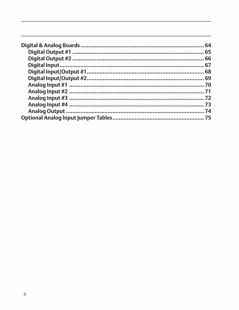
Digital & Analog Boards ............................................................................. 64 Digital Output #1 .................................................................................. 65 Digital Output #2 .................................................................................. 66 Digital Input .......................................................................................... 67 Digital Input/Output #1 ......................................................................... 68 Digital Input/Output #2 ......................................................................... 69 Analog Input #1 .................................................................................... 70 Analog Input #2 .................................................................................... 71 Analog Input #3 .................................................................................... 72 Analog Input #4 .................................................................................... 73 Analog Output ...................................................................................... 74Optional Analog Input Jumper Tables ......................................................... 75
7
Standard Vilter Warranty
Seller warrants the products it manufactures to be free from defects in material and workmanship for a period of eighteen (18) months from the date of shipment from Seller’s manufacturing plant or twelve (12) months from date of installation at the initial end users location, whichever occurs first. In addition, Seller provides the following extended warranties: (a) three (3) years from the date of shipment on single screw compressor internal rotating parts, (b) two (2) years from the date of shipment on reciprocating compres-sors and single screw and reciprocating compressor parts, and (c) two (2) years on all other parts on a single screw compressor unit. Such warranties do not apply to ordinary wear and tear. Seller does not warrant that the product complies with any particular law or regulation not explicitly set forth in the specifications, and Buyer is responsible for ensuring that the product contains all features necessary to safely perform in Buyer’s and its customer’s plants and operations. Buyer must notify Seller of any warranty claim within ten (10) days after such claim arises, otherwise Buyer waives all rights to such claim. Products supplied by Seller, which are manufactured by others, are not warranted by Seller, but rather Seller merely passes through the manufacturer’s warranty to Buyer.
SELLER EXPRESSLY DISCLAIMS ALL OTHER WARRANTIES, WHETHER EXPRESS OR IMPLIED, INCLUDING THE IMPLIED WARRANTIES OF MERCHANTABILITY AND FITNESS FOR A PARTICULAR PURPOSE.
Unless otherwise agreed in writing, Buyer’s sole remedy for breach of warranty is, at Seller’s option, the re-pair of the defect, the correction of the service, or the providing a replacement part FOB Seller’s office. Seller will not be responsible for costs of dismantling, lost refrigerant, reassembling, or transporting the product. Further, Seller will not be liable for any other direct, indirect, consequential, incidental, or special damages arising out of a breach of warranty. THESE WARRANTY REMEDIES ARE EXCLUSIVE AND ALL OTHER WAR-RANTY REMEDIES ARE EXCLUDED. Products or parts for which a warranty claim is made are to be returned transportation prepaid to Seller’s factory. Any improper use, corrosion, neglect, accident, operation beyond rated capacity, substitution of parts not approved by Seller, or any alteration or repair by others which, in Seller’s judgement, adversely affects the Product, shall void all warranties and warranty obligations. Further, Seller shall not be liable under the above warranties should Buyer be in default of its payment obligations to Seller under this Agreement or any credit agreement.

8
9
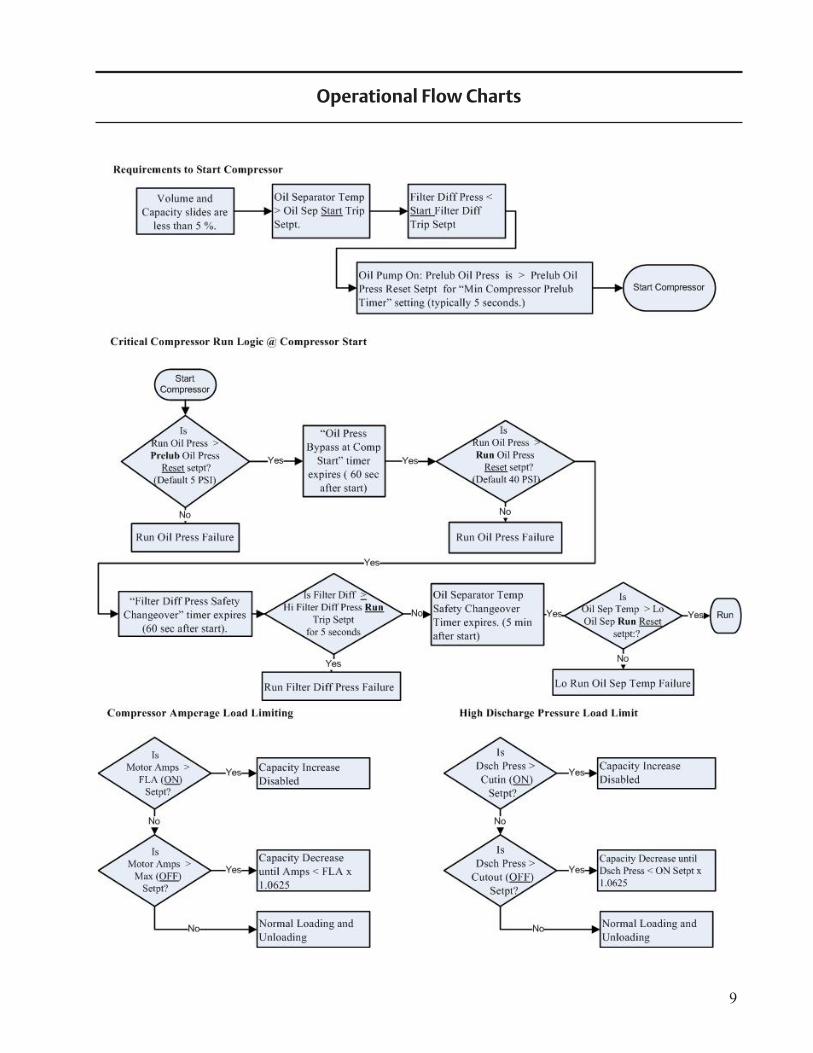
Operational Flow Charts
10
11
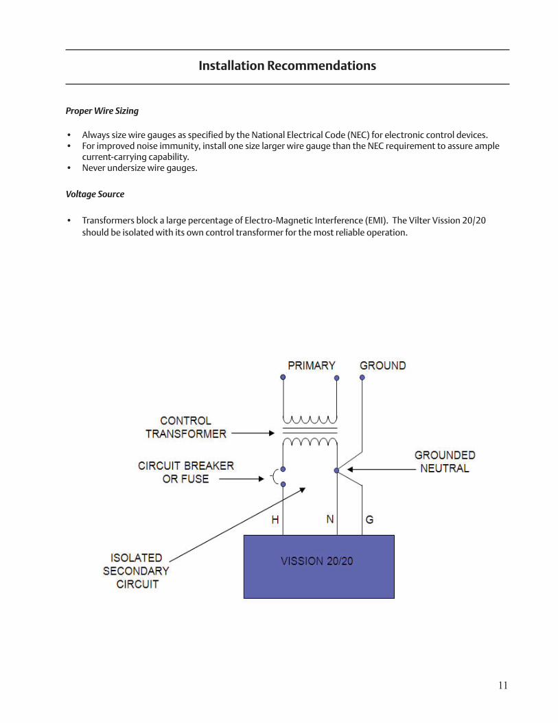
Installation Recommendations
Proper Wire Sizing
• Always size wire gauges as specified by the National Electrical Code (NEC) for electronic control devices.• For improved noise immunity, install one size larger wire gauge than the NEC requirement to assure ample
current-carrying capability.• Never undersize wire gauges.
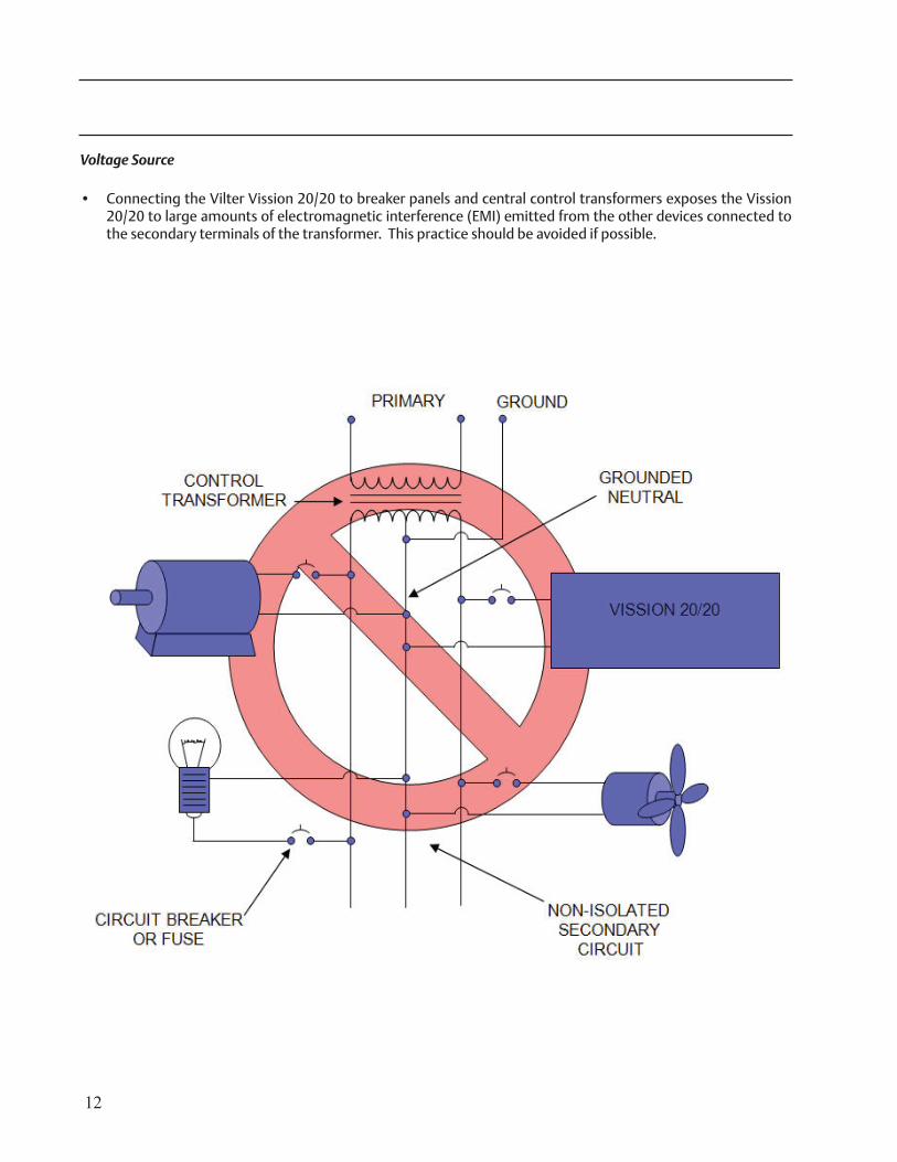
Voltage Source
• Transformers block a large percentage of Electro-Magnetic Interference (EMI). The Vilter Vission 20/20 should be isolated with its own control transformer for the most reliable operation.
12
Voltage Source
• Connecting the Vilter Vission 20/20 to breaker panels and central control transformers exposes the Vission 20/20 to large amounts of electromagnetic interference (EMI) emitted from the other devices connected to the secondary terminals of the transformer. This practice should be avoided if possible.
13
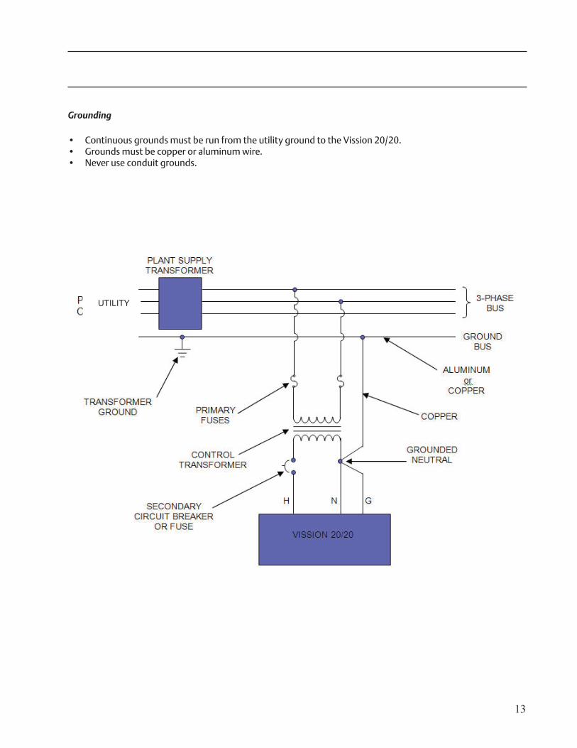
Grounding
• Continuous grounds must be run from the utility ground to the Vission 20/20.• Grounds must be copper or aluminum wire.• Never use conduit grounds.
UTILITY
14
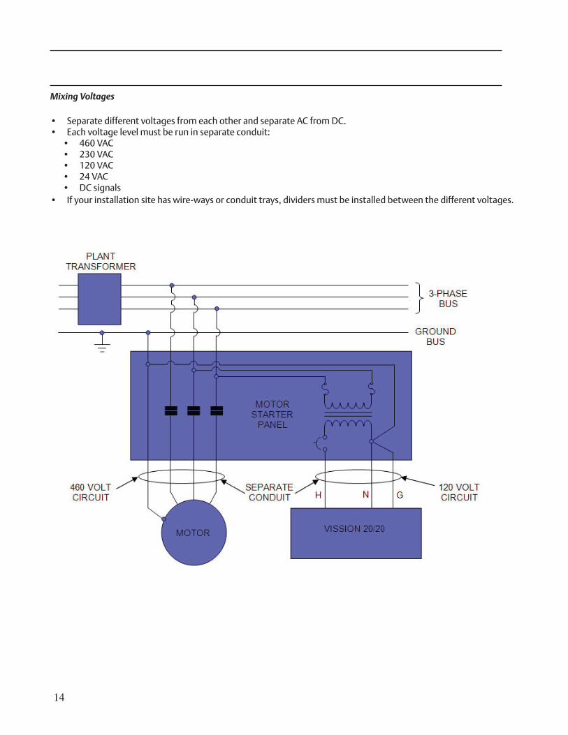
Mixing Voltages
• Separate different voltages from each other and separate AC from DC.• Each voltage level must be run in separate conduit:
• 460 VAC• 230 VAC• 120 VAC• 24 VAC• DC signals
• If your installation site has wire-ways or conduit trays, dividers must be installed between the different voltages.
15
Wiring Methods
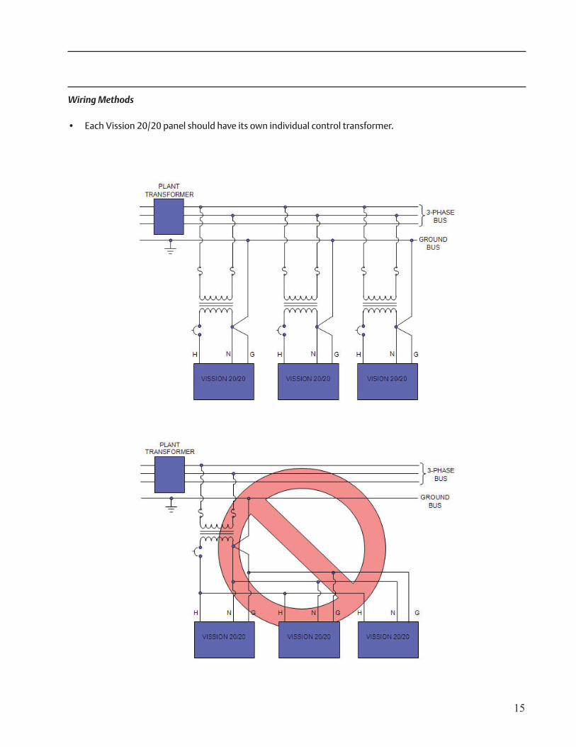
• Each Vission 20/20 panel should have its own individual control transformer.
16
DO:
• Keep AC wires away from circuit boards.
• Always run conduit into the bottom or sides of an enclosure.
• If the conduit must be placed in the top of an enclosure, use a water-tight conduit fit-ting to keep water from entering the enclosure.
• The Vission 20/20 is supplied with pre-punched conduit holes. Use them!
DON’T:
• Don’t run wires through the Vission 20/20 enclosure that are not related to the com-pressor control.
• Don’t add relays, timers, transformers, etc. in the Vission 20/20 enclosure without first checking with Vilter.
• Don’t run conduit into the top of an enclosure.
• Don’t run refrigerant tubing inside the enclosure.
• Don’t drill metal enclosures without taking proper precautions to protect circuit boards from damage.
Best Practices
17
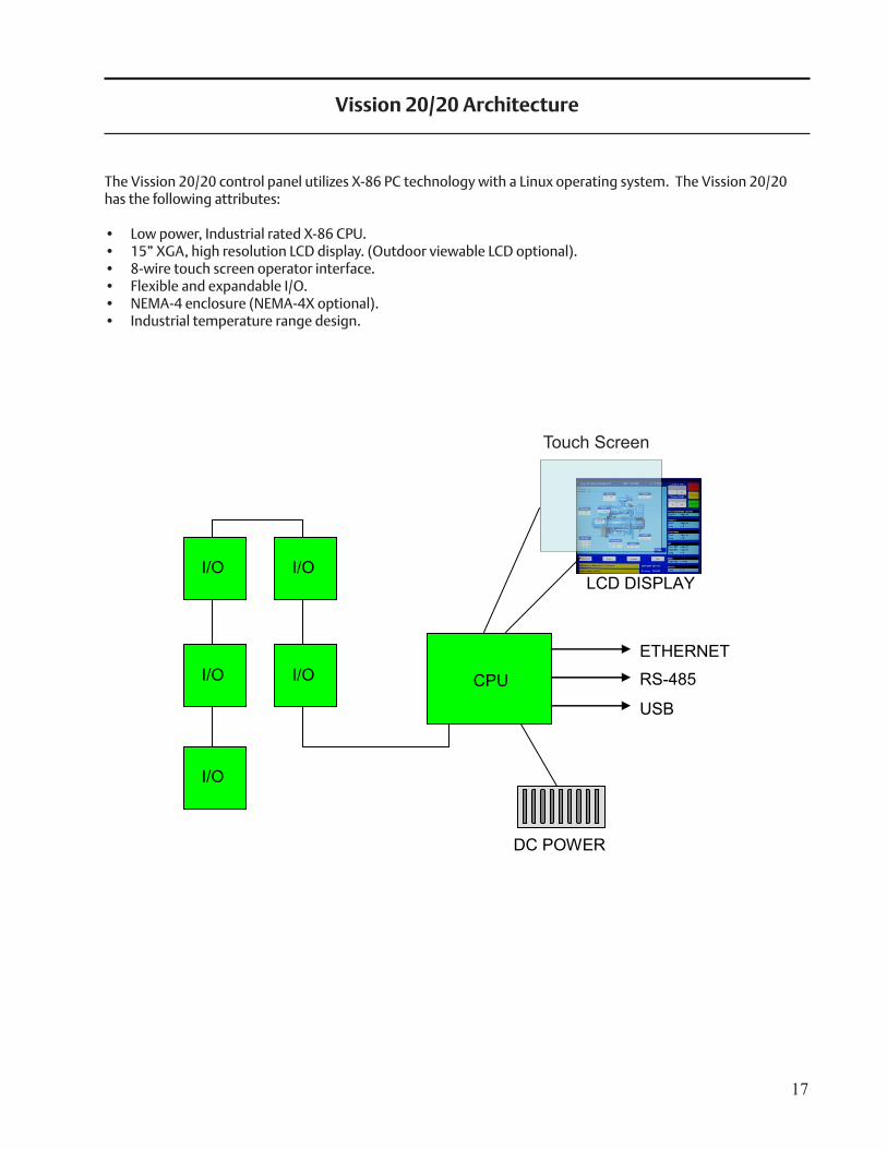
Vission 20/20 Architecture
The Vission 20/20 control panel utilizes X-86 PC technology with a Linux operating system. The Vission 20/20 has the following attributes:
• Low power, Industrial rated X-86 CPU.• 15” XGA, high resolution LCD display. (Outdoor viewable LCD optional).• 8-wire touch screen operator interface.• Flexible and expandable I/O.• NEMA-4 enclosure (NEMA-4X optional).• Industrial temperature range design.
DC POWER
RS-485
ETHERNET
USB
LCD DISPLAY I/O I/O
I/O I/O
I/O
CPU
Touch Screen
18
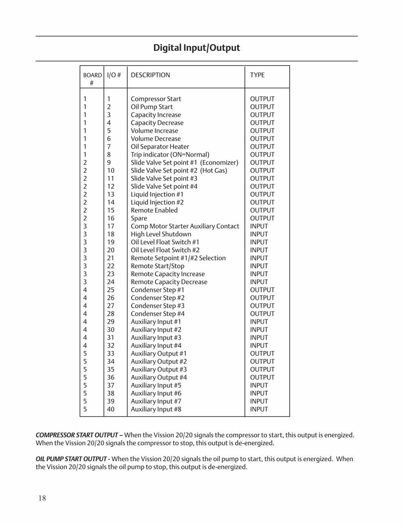
BOARD I/O # DESCRIPTION TYPE #
1 1 Compressor Start OUTPUT1 2 Oil Pump Start OUTPUT1 3 Capacity Increase OUTPUT1 4 Capacity Decrease OUTPUT1 5 Volume Increase OUTPUT1 6 Volume Decrease OUTPUT1 7 Oil Separator Heater OUTPUT1 8 Trip indicator (ON=Normal) OUTPUT2 9 Slide Valve Set point #1 (Economizer) OUTPUT2 10 Slide Valve Set point #2 (Hot Gas) OUTPUT2 11 Slide Valve Set point #3 OUTPUT2 12 Slide Valve Set point #4 OUTPUT2 13 Liquid Injection #1 OUTPUT2 14 Liquid Injection #2 OUTPUT2 15 Remote Enabled OUTPUT2 16 Spare OUTPUT3 17 Comp Motor Starter Auxiliary Contact INPUT3 18 High Level Shutdown INPUT3 19 Oil Level Float Switch #1 INPUT3 20 Oil Level Float Switch #2 INPUT3 21 Remote Setpoint #1/#2 Selection INPUT3 22 Remote Start/Stop INPUT3 23 Remote Capacity Increase INPUT3 24 Remote Capacity Decrease INPUT4 25 Condenser Step #1 OUTPUT4 26 Condenser Step #2 OUTPUT4 27 Condenser Step #3 OUTPUT4 28 Condenser Step #4 OUTPUT4 29 Auxiliary Input #1 INPUT4 30 Auxiliary Input #2 INPUT4 31 Auxiliary Input #3 INPUT4 32 Auxiliary Input #4 INPUT5 33 Auxiliary Output #1 OUTPUT5 34 Auxiliary Output #2 OUTPUT5 35 Auxiliary Output #3 OUTPUT5 36 Auxiliary Output #4 OUTPUT5 37 Auxiliary Input #5 INPUT5 38 Auxiliary Input #6 INPUT5 39 Auxiliary Input #7 INPUT5 40 Auxiliary Input #8 INPUT
COMPRESSOR START OUTPUT – When the Vission 20/20 signals the compressor to start, this output is energized. When the Vission 20/20 signals the compressor to stop, this output is de-energized.
OIL PUMP START OUTPUT - When the Vission 20/20 signals the oil pump to start, this output is energized. When the Vission 20/20 signals the oil pump to stop, this output is de-energized.
Digital Input/Output
19
CAPACITY INCREASE OUTPUT – This output is only active when the compressor is running. When the Vission 20/20 determines that the compressor should increase capacity by moving the slide valve to a higher percent-age, this output is energized. Once the slide valve reaches 100%, this output will not energize.
CAPACITY DECREASE OUTPUT – This output is only active when the compressor is running. When the Vission 20/20 determines that the compressor should decrease capacity by moving the slide valve to a lower percent-age, this output is energized. Once the slide valve reaches 0%, this output will not energize.
VOLUME INCREASE OUTPUT – This output is only active when the compressor is running. When the Vission 20/20 determines that the compressor should increase Volume Index (VI) by moving the volume slide to a higher per-centage, this output is energized. Once the volume slide reaches 100%, this output will not energize.
VOLUME DECREASE OUTPUT – This output is only active when the compressor is running. When the Vission 20/20 determines that the compressor should decrease Volume Index (VI) by moving the volume slide to a lower percentage, this output is energized. Once the volume slide reaches 0%, this output will not energize.
OIL SUMP HEATER OUTPUT – This output is active and energized when the oil separator temperature is lower than the oil separator temperature setpoint. It is de-energized when the oil separator temperature is higher than the oil separator temperature setpoint.
ALARM OUTPUT – This output is energized when the system has no alarms. If an alarm is issued, the output de-energizes and stays de-energized until the alarm condition is cleared.
SLIDE VALVE SETPOINT #1 OUTPUT (ECONOMIZER) – Normally used for an economizer solenoid, but could be used for other devices. When the compressor slide valve percentage is equal to or greater than “slide valve set-point #1”, the output is energized. When the compressor slide valve percentage is less than “slide valve set-point #1”, the output is de-energized.
SLIDE VALVE SETPOINT #2 OUTPUT (HOT GAS) – Normally used for a hot gas solenoid, but could be used for other devices. When the compressor slide valve percentage is equal to or greater than “slide valve set-point #2”, the output is energized. When the compressor slide valve percentage is less than “slide valve set-point #2”, the output is de-energized.
SLIDE VALVE SETPOINT #3 OUTPUT – When the compressor slide valve percentage is equal to or greater than “slide valve set-point #3”, the output is energized. When the compressor slide valve percentage is less than “slide valve set-point #3”, the output is de-energized.
SLIDE VALVE SETPOINT #4 OUTPUT – When the compressor slide valve percentage is equal to or greater than “slide valve set-point #4”, the output is energized. When the compressor slide valve percentage is less than “slide valve set-point #4”, the output is de-energized.
LIQUID INJECTION #1 OUTPUT – If the compressor has liquid injection oil cooling, this output is active. When the compressor is running and the discharge temperature is above the oil separator temperature override set-point and the oil separator temperature is above the override setpoint, then the output is energized. The output is de-energized when the discharge temperature falls below the “on” setpoint minus the solenoid differential.
LIQUID INJECTION #2 OUTPUT – Not Defined
REMOTE ENABLED OUTPUT – This output is energized when the Vission 20/20 panel is enabled for remote con-trol. The compressor can be running or stopped, but is available to the remote system. If the compressor has an alarm or is placed into the manual stop position, this output is de-energized.
20
SPARE OUTPUT – Not defined.
COMP MOTOR STARTER AUXILIARY CONTACT – This input looks for a feedback signal from the compressor starter, confirming that the compressor starter is energized.
HIGH LEVEL SHUTDOWN INPUT – This input must be energized in order for the compressor to operate. If de-ener-gized, the compressor will shut down and issue a high level trip.
OIL LEVEL FLOAT SWITCH #1 INPUT – Used for Cool Compression.
OIL LEVEL FLOAT SWITCH #2 INPUT – Used for Cool Compression.
LOCAL/REMOTE SELECT INPUT – This input enables or disables remote I/O control. Energizing this input enables the Remote Capacity Increase and Remote Capacity Decrease inputs.
REMOTE START/STOP INPUT – If the compressor is enabled for remote I/O control, this input is enabled. Energiz-ing this input will issue a start for the compressor as long as it is available to run. De-energizing this input stops the compressor.
REMOTE CAPACITY INCREASE INPUT – If the compressor is enabled for remote I/O control, this input is enabled. Operational only when the compressor is running. Energizing this input will increase the slide valve position. The slide valve will continuously increase as long as this input is energized. The slide valve will not increase when this input is de-energized.
NOTE: The scan interval on the remote increase and decrease inputs is approximately ONE SECOND. Please take that into account when developing a control scheme using the remote increase and remote decrease inputs for compressor control.
REMOTE CAPACITY DECREASE INPUT – Operational only when the compressor is running. This input is enabled if the compressor is enabled for remote I/O control. Energizing this input will decrease the slide valve position. The slide valve will continuously decrease as long as this input is energized. The slide valve will not decrease when this input is de-energized.
CONDENSER STEP #1 OUTPUT – This output is enabled when condenser control option is selected. A condenser fan or pump will be turned on or off by this output.
CONDENSER STEP #2 OUTPUT – This output is enabled when condenser control option is selected. A condenser fan or pump will be turned on or off by this output.
CONDENSER STEP #3 OUTPUT – This output is enabled when condenser control option is selected. A condenser fan or pump will be turned on or off by this output.
CONDENSER STEP #4 OUTPUT – This output is enabled when condenser control option is selected. A condenser fan or pump will be turned on or off by this output.
AUXILIARY #1 thru #8 INPUT – Optional inputs that can be configured as an alarm or trip. Typically connected to external switched devices.
21
Analog Inputs
MOTOR CURRENT – Default is a 0-5 Amp current transformer (CT). Current transformer ratio is set in the calibra-tion screen.
SUCTION PRESSURE – Default signal is 4-20Ma. Suction pressure transducer range and calibration is set in the calibration screen.
DISCHARGE PRESSURE - Default signal is 4-20Ma. Discharge pressure transducer range and calibration is set in the calibration screen.
OIL FILTER INLET PRESSURE - Default signal is 4-20Ma. Oil filter pressure transducer range and calibration is set in the calibration screen.
BOARD I/O DESCRIPTION TYPE #
6 1 Motor Current 4-20 mA, 0-5A6 2 Suction Pressure 0-5V, 1-5 V, 0-10V, 4-20 mA6 3 Discharge Pressure 0-5V, 1-5 V, 0-10V, 4-20 mA6 4 Oil Filter Inlet Pressure 0-5V, 1-5 V, 0-10V, 4-20 mA6 5 Oil Manifold Pressure 0-5V, 1-5 V, 0-10V, 4-20 mA6 6 Economizer Pressure 0-5V, 1-5 V, 0-10V, 4-20 mA6 7 % Slide Valve Position 0-5V, 4-20 mA, Potentiometer6 8 % Volume Position 0-5V, 4-20 mA, Potentiometer7 9 Suction Temperature 4-20 mA, RTD, ICTD7 10 Discharge Temperature 4-20 mA, RTD, ICTD7 11 Oil Separator Temperature 4-20 mA, RTD, ICTD7 12 Oil Manifold Temperature 4-20 mA, RTD, ICTD7 13 Process Temperature 4-20 mA, RTD, ICTD7 14 Chiller Inlet Temperature 4-20 mA, RTD, ICTD7 15 Condenser Pressure 0-5V, 1-5 V, 0-10V, 4-20 mA, RTD, ICTD7 16 Remote Caphold Setpoint 0-5V, 4-20 mA, RTD, ICTD8 17 Auxiliary #1 0-5V, 1-5 V, 0-10V, 4-20 mA, RTD, ICTD8 18 Auxiliary #2 0-5V, 1-5V, 0-10V, 4-20 mA, RTD, ICTD8 19 Auxiliary #3 0-5V, 1-5V, 0-10V, 4-20 mA, RTD, ICTD8 20 Auxiliary #4 0-5V, 1-5V, 0-10V, 4-20 mA, RTD, ICTD8 21 Auxiliary #5 0-5V, 1-5V, 0-10V, 4-20 mA, RTD, ICTD8 22 Auxiliary #6 0-5V, 1-5V, 0-10V, 4-20 mA, RTD, ICTD8 23 Auxiliary #7 0-5V, 1-5V, 0-10V, 4-20 mA, RTD, ICTD8 24 Auxiliary #8 0-5V, 1-5V, 0-10V, 4-20 mA, RTD, ICTD9 25 Auxiliary #9 0-5V, 1-5V, 0-10V, 4-20 mA, RTD, ICTD9 26 Auxiliary #10 0-5V, 1-5V, 0-10V, 4-20 mA, RTD, ICTD9 27 Auxiliary #11 0-5V, 1-5V, 0-10V, 4-20 mA, RTD, ICTD9 28 Auxiliary #12 0-5V, 1-5V, 0-10V, 4-20 mA, RTD, ICTD9 29 Auxiliary #13 0-5V, 1-5V, 0-10V, 4-20 mA, RTD, ICTD9 30 Auxiliary #14 0-5V, 1-5V, 0-10V, 4-20 mA, RTD, ICTD9 31 Auxiliary #15 0-5V, 1-5V, 0-10V, 4-20 mA, RTD, ICTD9 32 Auxiliary #16 0-5V, 1-5V, 0-10V, 4-20 mA, RTD, ICTD
22
OIL MANIFOLD PRESSURE - Default signal is 4-20Ma. Oil manifold pressure transducer range and calibration is set in the calibration screen.
ECONOMIZER PRESSURE – Default signal is 4-20Ma. Economizer pressure transducer range and calibration is set in the calibration screen.
% SLIDE VALVE POSITION – Reads the 0-5 volt signal back from the slide position motor actuator to indicate cur-rent slide valve position.
% VOLUME POSITION – Reads the 0-5 volt signal back from the slide volume motor actuator to indicate current volume position.
SUCTION TEMPERATURE – Default signal is RTD. Suction temperature calibration is set in the calibration screen.
DISCHARGE TEMPERATURE – Default signal is RTD. Discharge temperature calibration is set in the calibration screen.
OIL SEPARATOR TEMPERATURE – Default signal is RTD. Oil separator temperature calibration is set in the calibra-tion screen.
OIL MANIFOLD TEMPERATURE – Default signal is RTD. Oil manifold temperature calibration is set in the calibra-tion screen.
PROCESS TEMPERATURE – Default signal is 4-20mA. Process temperature calibration and range are set in the calibration screen.
CHILLER INLET TEMPERATURE – Default signal is 4-20mA. Measures separator level. Chiller Inlet Temperature calibration and range are set in the calibration screen.
CONDENSER PRESSURE – Default signal is 4-20Ma. Condenser pressure transducer range and calibration is set in the calibration screen.
REMOTE CAPHOLD – Default signal is 4-20Ma. Active in “Direct I/O” mode. Adjusts the capacity of the compres-sor from 0-100%, proportional to the 4-20mA signal.
AUXILIARY #1 thru #16 – Flexible analog inputs that can be configured to control, alarm or trip.
23
BOARD I/O # DESCRIPTION TYPE #10 1 Compressor VFD 4-20 mA10 2 Condenser VFD 4-20 mA10 3 % Slide Valve Position 4-20 mA10 4 Motorized Valve (Cool Compression or Liquid Injection), V+ 4-20 mA10 5 Spare / Unused 4-20 mA10 6 Spare / Unused 4-20 mA10 7 Spare / Unused 4-20 mA10 8 Spare / Unused 4-20 mA
COMPRESSOR VFD – 4-20mA output to control compressor motor speed with a Variable Frequency Drive (VFD).
CONDENSER VFD – 4-20mA output to control one condenser fan which is interleaved between the remaining condenser steps for smoother control.
% SLIDE VALVE POSITION – 4-20mA signal that transmits the slide valve position for remote monitoring.
MOTORIZED VALVE (V+) – for a cool compression compressor, this 4-20ma signal controls a motorized valve to regulate the liquid refrigerant level in the oil separator. For a liquid injection application on a standard single screw, this 4-20ma signal controls a motorized valve to regulate the liquid refrigerant injected into the compres-sor for oil cooling purposes.
Analog Outputs
24
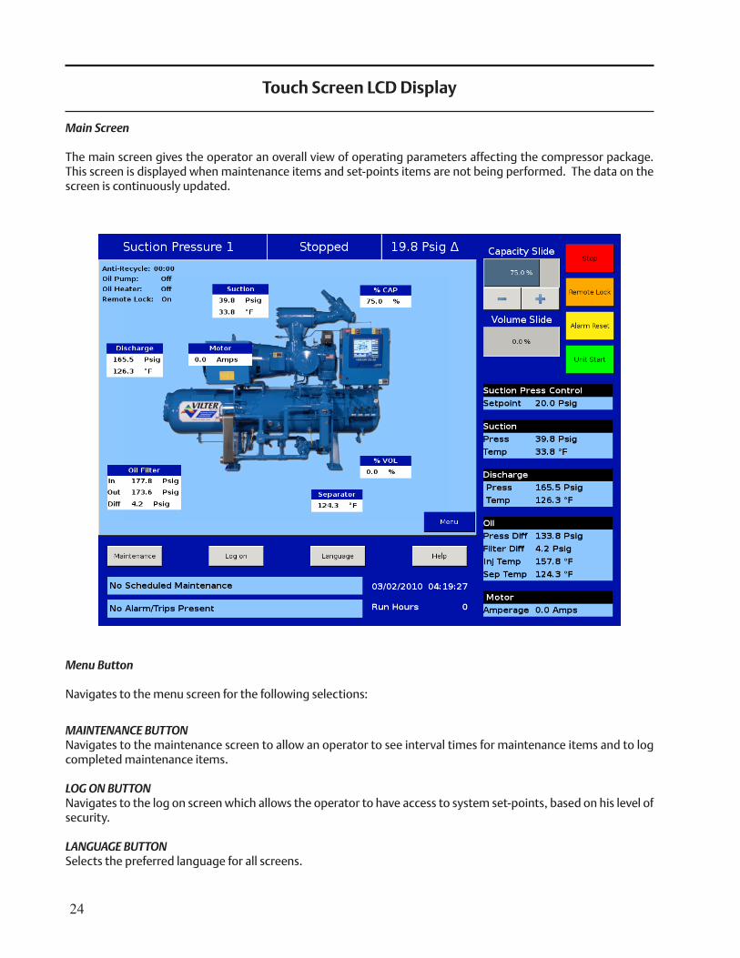
Menu Button
Navigates to the menu screen for the following selections:
MAINTENANCE BUTTONNavigates to the maintenance screen to allow an operator to see interval times for maintenance items and to log completed maintenance items.
LOG ON BUTTONNavigates to the log on screen which allows the operator to have access to system set-points, based on his level of security.
LANGUAGE BUTTONSelects the preferred language for all screens.
Touch Screen LCD Display
Main Screen
The main screen gives the operator an overall view of operating parameters affecting the compressor package. This screen is displayed when maintenance items and set-points items are not being performed. The data on the screen is continuously updated.
25
HELP BUTTONProvides help file notes for various screens and settings.
STOP BUTTONStops the compressor.
ALARM RESET BUTTONResets alarms and allows the compressor to be available to run. If there are issues that persist, the alarms will be re-issued and prevent the compressor from being available to run. After correcting the problem, press the alarm reset button again and the compressor will be available to run.
UNIT START BUTTONSelects mode of compressor start.
CAPACITY SLIDE BUTTONSAllows manual increase or decrease of the slide valve. VOLUME SLIDE BUTTONSAllows manual increase or decrease of the volume slide. Volume slide control will return to automatic operation after 5 minutes of manual inactivity.
REMOTE LOCK BUTTONPrevents a remote PLC or remote computer from taking control of the panel. This allows the operator to take local control of the panel if the need arises.
Indicators
• Hour meter in run hours• Time and Date• Suction pressure set-point • Suction pressure and temperature• Discharge pressure and temperature• Oil pressure difference• Oil filter pressure difference• Oil injection temperature• Oil separator temperature• Motor amperage• Process temperature• Oil heater status• Real time compressor and package operating conditions. • Maintenance messages. • Alarm and Trip Status.• Data Backup
26
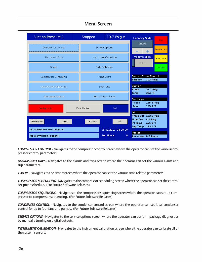
COMPRESSOR CONTROL - Navigates to the compressor control screen where the operator can set the variouscom-pressor control parameters.
ALARMS AND TRIPS - Navigates to the alarms and trips screen where the operator can set the various alarm and trip parameters.
TIMERS - Navigates to the timer screen where the operator can set the various time related parameters.
COMPRESSOR SCHEDULING - Navigates to the compressor scheduling screen where the operator can set the control set-point schedule. (For Future Software Releases)
COMPRESSOR SEQUENCING - Navigates to the compressor sequencing screen where the operator can set-up com-pressor to compressor sequencing. (For Future Software Releases)
CONDENSER CONTROL - Navigates to the condenser control screen where the operator can set local condenser control for up to four fans and pumps. (For Future Software Releases)
SERVICE OPTIONS - Navigates to the service options screen where the operator can perform package diagnostics by manually turning on digital outputs.
INSTRUMENT CALIBRATION - Navigates to the instrument calibration screen where the operator can calibrate all of the system sensors.
Menu Screen
27
SLIDE CALIBRATION - Navigates to the slide calibration screen where the operator can calibrate the slide and volume actuators.
TREND CHART - Navigates to the trend chart screen where the operator can select up to four parameters for histori-cal data trending. Trend charts are updated continuously.
EVENT LIST - Navigates to the event list screen where the operator can view the systems events in chronological order.
INPUT/OUTPUT STATES - Allows viewing of the live data of all analog and digital input and outputs. Also allows view-ing Frozen Data of all analog and digital input and outputs at the time of the last compressor stop event.
CONFIGURATION - Navigates to configuration screens where the system parameters are configured.
DATA BACKUP - Allows data backup of setpoints, configuration, and calibration settings to a USB memory device. (For Future Software Releases)
28
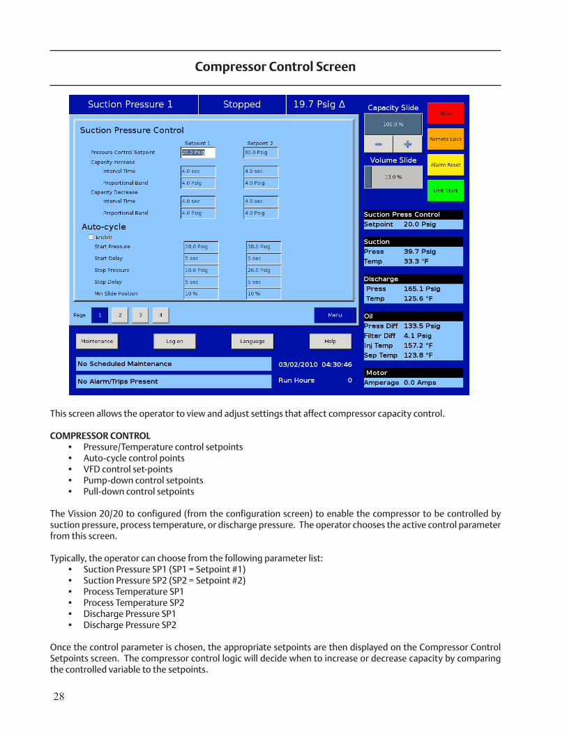
This screen allows the operator to view and adjust settings that affect compressor capacity control. COMPRESSOR CONTROL
• Pressure/Temperature control setpoints • Auto-cycle control points • VFD control set-points • Pump-down control setpoints • Pull-down control setpoints
The Vission 20/20 to configured (from the configuration screen) to enable the compressor to be controlled by suction pressure, process temperature, or discharge pressure. The operator chooses the active control parameter from this screen.
Typically, the operator can choose from the following parameter list:• Suction Pressure SP1 (SP1 = Setpoint #1) • Suction Pressure SP2 (SP2 = Setpoint #2) • Process Temperature SP1 • Process Temperature SP2 • Discharge Pressure SP1 • Discharge Pressure SP2
Once the control parameter is chosen, the appropriate setpoints are then displayed on the Compressor Control Setpoints screen. The compressor control logic will decide when to increase or decrease capacity by comparing the controlled variable to the setpoints.
Compressor Control Screen
29
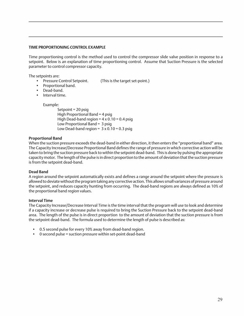
TIME PROPORTIONING CONTROL EXAMPLE Time proportioning control is the method used to control the compressor slide valve position in response to a setpoint. Below is an explanation of time proportioning control. Assume that Suction Pressure is the selected parameter to control compressor capacity.
The setpoints are:• Pressure Control Setpoint. (This is the target set-point.)• Proportional band.• Dead-band.• Interval time.
Example: Setpoint = 20 psig High Proportional Band = 4 psig High Dead-band region = 4 x 0.10 = 0.4 psig Low Proportional Band = 3 psig Low Dead-band region = 3 x 0.10 = 0.3 psig
Proportional Band When the suction pressure exceeds the dead-band in either direction, it then enters the “proportional band” area. The Capacity Increase/Decrease Proportional Band defines the range of pressure in which corrective action will be taken to bring the suction pressure back to within the setpoint dead-band. This is done by pulsing the appropriate capacity motor. The length of the pulse is in direct proportion to the amount of deviation that the suction pressure is from the setpoint dead-band. Dead BandA region around the setpoint automatically exists and defines a range around the setpoint where the pressure is allowed to deviate without the program taking any corrective action. This allows small variances of pressure around the setpoint, and reduces capacity hunting from occurring. The dead-band regions are always defined as 10% of the proportional band region values.
Interval Time The Capacity Increase/Decrease Interval Time is the time interval that the program will use to look and determine if a capacity increase or decrease pulse is required to bring the Suction Pressure back to the setpoint dead-band area. The length of the pulse is in direct proportion to the amount of deviation that the suction pressure is from the setpoint dead-band. The formula used to determine the length of pulse is described as:
• 0.5 second pulse for every 10% away from dead-band region. • 0 second pulse = suction pressure within set-point dead-band
30
Auto-Cycle Setpoints
The auto-cycle setpoints define the control points in which the compressor will automatically cycle on and off when the compressor has been placed into “Auto” mode. These setpoints can be “enabled” or “disabled” using the check box. A delay can be entered to momentarily delay the start or stop from immediately occurring when the pressure reaches setpoint. If a compressor shut down is desired on a suction pressure drop and a manual reset is required, set the OFF value below the Low Suction Pressure safety trip value. This will shut down the compressor and a Reset will be required to restart it.
• [x] Enable = enables the Auto-cycle control. Uncheck the box to disable the Auto-cycle set-points. • Start Pressure = When the suction pressure meets or exceeds this set-point, the compressor will start. • Start Delay = delays the compressor from starting when the suction pressure meets or exceeds this setpoint. • Stop Pressure = When the suction pressure meets or falls below this setpoint, the compressor will stop. • Stop Delay = delays the compressor from starting when the suction pressure meets or exceeds this setpoint. • Minimum Slide Position = The minimum capacity slide position that the compressor is allowed to run at.
NOTE: When the Pump-down Feature is enabled, the Auto-cycle setpoints are automatically disabled. Pump-down mode will cause the compressor to cycle off via the Pump-down Stop Pressure setpoint, and will not allow the compressor to start again.
VFD Settings (PID settings for Motor Speed Control)
When a VFD is used on the compressor motor, the speed of the VFD is controlled using a PID algorithm. The set-points are:
• P = Proportional (gain) setpoint. Used to adjust the motor speed action in direct proportion to the differ-ence between the control setpoint and the process variable (SP - PV error). This is a unit-less quantity and is used for coarse adjustment. Use an initial setting of 3.00. This setpoint should be set to the lowest value that gives adequate control system response. Increasing the proportional setting increases the control system’s sensitivity to small process fluctuations and the tendency to hunt.
• I = Integral (reset) setpoint. Used to adjust the capacity control action, integrating the error over time, to account for a small error that has persisted for a long time. This quantity is used for fine adjustment. Use an initial setting of 4.00. This setpoint is used to smooth out process variations. This setpoint should be set high enough to prevent hunting but low enough to prevent control system overshoot.
• D = Derivative (rate) setpoint. Used to adjust the capacity control action, accounting for how fast the error is changing, positively or negatively. A standard PID loop variable, it is not used for our applications. Use an initial setting of 0.00.
31
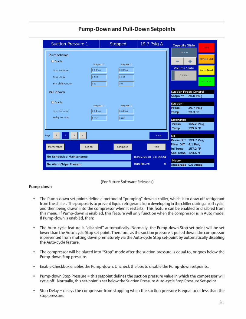
(For Future Software Releases)Pump-down
• The Pump-down set-points define a method of “pumping” down a chiller, which is to draw off refrigerant from the chiller. The purpose is to prevent liquid refrigerant from developing in the chiller during an off cycle, and then being drawn into the compressor when it restarts. This feature can be enabled or disabled from this menu. If Pump-down is enabled, this feature will only function when the compressor is in Auto mode. If Pump-down is enabled, then:
• The Auto-cycle feature is “disabled” automatically. Normally, the Pump-down Stop set-point will be set lower than the Auto-cycle Stop set-point. Therefore, as the suction pressure is pulled down, the compressor is prevented from shutting down prematurely via the Auto-cycle Stop set-point by automatically disabling the Auto-cycle feature.
• The compressor will be placed into “Stop” mode after the suction pressure is equal to, or goes below the Pump-down Stop pressure.
• Enable Checkbox enables the Pump-down. Uncheck the box to disable the Pump-down setpoints.
• Pump-down Stop Pressure = this setpoint defines the suction pressure value in which the compressor will cycle off. Normally, this set-point is set below the Suction Pressure Auto-cycle Stop Pressure Set-point.
• Stop Delay = delays the compressor from stopping when the suction pressure is equal to or less than the stop pressure.
Pump-Down and Pull-Down Setpoints
32
• Minimum Slide Position = The minimum capacity slide position that the compressor is allowed to run at. By forcing the compressor capacity to operate at a value above minimum, we insure that the suction pressure will be pulled down to the Stop pressure setpoint value.
Pull-down
• The Pull-down set-points define a method of slowly pulling the suction pressure down from a high value. This is sometimes required on systems that have liquid recirculation systems. On such systems, if the suc-tion pressure is pulled down too fast, the pumps can cavitate, causing vibration and damage to the pumps. Pull-down is also required for new plant startups. Pulling the temperature of new buildings down too quickly can cause structural damage, so limiting the suction pressure pull-down rate will prevent this, allowing time to de-humidify the rooms as the temperature in the rooms are pulled down.
• The pull-down feature provides a method to slowly pull the suction pressure down to operating conditions. The pull-down method used is to step the suction pressure down over a defined time interval. When the time interval expires, another step is taken.
Example:
Assume the suction pressure is at 80 psig and the desired set-point is 20 psig. This defines a change of 60 psig. We want to allow 48 hours of pull-down time. Pick a reasonable step pressure of 5 psig for every step. Numberofsteps=(∆60psig*1step/5psig)=12stepsDelay per step = (48 hours / 12 steps) = 4 hours/step
For the first 4 hours, the compressor runs at 75 psig. next 4 hours @ 70 psig next 4 hours @ 65 psigand so forth. After the 12th step (running at 25 psig), 48 hours will have elapsed, and the new setpoint be-comes 20 psig, achieving the 20 psig setpoint after 48 hours. After the pull-down setpoint equals or is less than the control setpoint, the pull-down feature disables itself.
• Enable = Enables Pulldown control. Uncheck the box to disable the Pull-down setpoints. • Step Pressure = This setpoint defines the step increments which the suction pressure will be controlled at. • Delay Per Step = Defines the time increment at which the compressor will be controlled for each step.
33
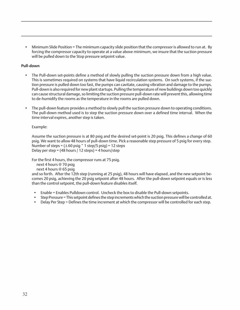
Misc. Control
• Control Mode = Drop-down box allows selection of current operating mode from the list of available modes. • High Motor Amps (Unloading) = This control feature will limit the compressor capacity when the compressor
motor amps reaches these load limiting setpoints. When the setpoints are set properly, this control feature will prevent the motor from operating at excessive high amp conditions, which will help to prevent the compressor starter from stopping the compressor on “motor overload” conditions.
• Stop Load = prevents the compressor from loading when the setpoint is reached. For a 1.15 SF motor, this value is the FLA value stamped onto the motor nameplate.
• Force Unload = forces an unload condition when this setpoint is reached. For a 1.15 SF motor, this value is FLA value (from motor nameplate) x 1.15. The unload pulse is released when the motor amps lands just above the FLA setting.
• High Discharge Pressure (Unloading) = This control feature is active in Suction Pressure or Process Tempera-ture Capacity Control mode. This control feature will limit the compressor from loading when the compressor discharge pressure reaches these load limiting conditions. When the set-points are set properly, this control feature will prevent the compressor from experiencing excessive high discharge pressure that could result in a high discharge pressure failure. The high discharge pressure unloading setpoints over-ride the Suction Pressure or Process Temperature Capacity Control setpoints.
Additional Control Setpoints
34
• Stop Load = prevents the compressor from loading when the setpoint is reached. Set this setpoint above normal discharge operating conditions. This setpoint should only become active if normal condenser control is not functioning properly, which will cause discharge pressure to become abnormally high.
• Force Unload = forces an unload condition when this setpoint is reached. This setpoint should be set above the “Stop Load” setpoint. This setpoint will cause the compressor to unload until the discharge pressure lands just above the “Stop Load” setpoint.
• Low Suction Pressure (Unloading) = This control feature is active in all control modes. This control feature will limit the compressor from loading when the compressor suction pressure reaches these load limiting condi-tions. When the set-points are set properly, this control feature will prevent the compressor from experiencing excessive low suction pressure that could result in a low suction pressure failure. The low suction pressure unloading setpoints override the Discharge Pressure, Process Temperature Capacity Control, and Suction Pressure Capacity Control setpoints.
• Stop Load = prevents the compressor from loading when the set-point is reached. Set this set-point below normal suction operating conditions.
• Force Unload = forces an unload condition when this set-point is reached. This set-point should be set below the “Stop Load” set-point. This set-point will cause the compressor to unload until the suction pressure lands just above the “Stop Load” set-point.
• Oil Separator Heater Temperature = These control limits determine when the oil separator heater is turned on and off. A decrease in oil separator temperature below the ON set point turns on the oil separator heater. An increase in oil separator temperature above the OFF set-point turns off the oil heater. There is a 5°F differential above and below the setpoint, which defines the on and off points.
• Liquid Injection Solenoid Control Temp = These set-points determine when the Liquid Injection Solenoid is turned on and off. The solenoid will always be off when the compressor is off. This solenoid can be controlled via the Oil Injection Temperature or the Oil Separator Temperature. This selection in made in the Configura-tion screen.
• Oil Pump Restart = The oil pump can be selected either as a full time oil pump (booster applications) or as a
part-time oil pump (high stage applications). The selection is accomplished from the Configuration Menu. When the oil pump is selected as a part-time oil pump, then these set-points determine when the oil pump is turned on and off based on the pressure ratio across the compressor. The pressure ratio is calculated using the absolute discharge pressure and the absolute suction pressure. The pump is cycled on when the pressure ratio is equal to or less than the ON set-point. The pump is cycled off when the pressure ratio is equal to or greater than the OFF setpoint. P.R = |Discharge Pressure| / |Suction Pressure|
• Volume Slide Adjustment Factor= This value is normally zero. It can be set to a non-zero value to permit a repositioning of the volume slide if it is found that the volume slide is not being positioned such to allow the compressor to run at the most efficient point.
• Economizer Solenoid = These setpoints determine when the economizer solenoid is turned on and off. When the percentage of compressor capacity is equal to or below the OFF set-point, then the solenoid is turned OFF. When the compressor capacity is equal to or above the ON set-point, then the solenoid is turned ON.
• Hot Gas Bypass Solenoid = These setpoints determine when the hot gas solenoid is turned on and off. When the compressor capacity is equal to or below the ON set-point, then the solenoid is turned ON. When the per-centage of compressor capacity is equal to or above the OFF set-point, then the solenoid is turned OFF.
35
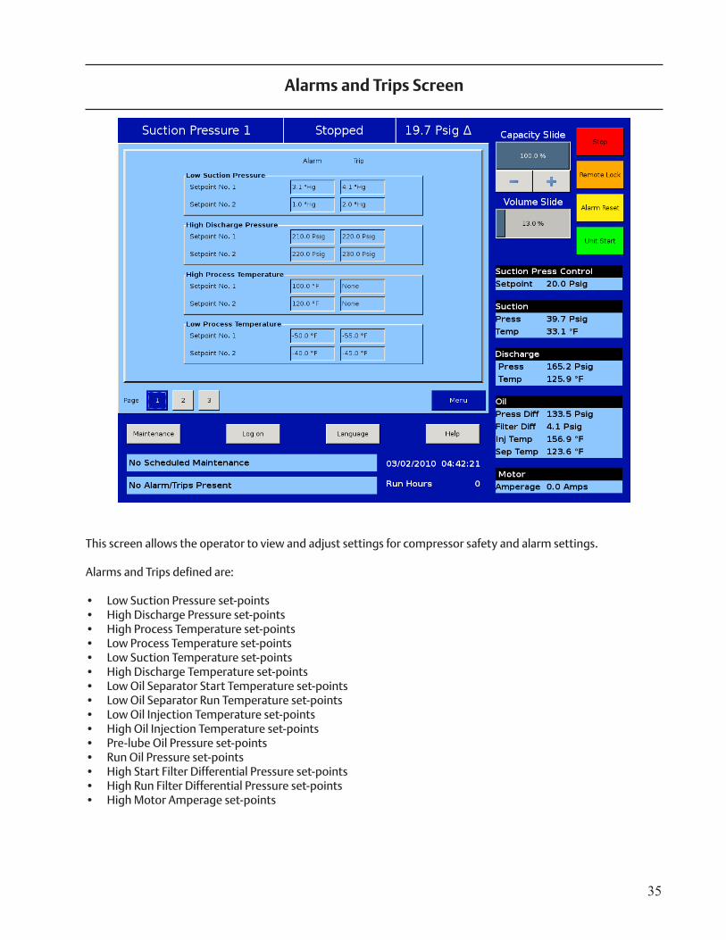
This screen allows the operator to view and adjust settings for compressor safety and alarm settings.
Alarms and Trips defined are:
• Low Suction Pressure set-points • High Discharge Pressure set-points • High Process Temperature set-points • Low Process Temperature set-points • Low Suction Temperature set-points • High Discharge Temperature set-points • Low Oil Separator Start Temperature set-points • Low Oil Separator Run Temperature set-points • Low Oil Injection Temperature set-points • High Oil Injection Temperature set-points • Pre-lube Oil Pressure set-points • Run Oil Pressure set-points • High Start Filter Differential Pressure set-points • High Run Filter Differential Pressure set-points • High Motor Amperage set-points
Alarms and Trips Screen
36
• Low Suction Pressure Alarm and Trip = This is the low suction pressure safety. This safety is active in both temperature and pressure control modes. An alarm or trip will be active on a drop in suction pressure at or below the set-point value.
• High Discharge Pressure Alarm and Trip = This is the high discharge pressure safety. The alarm or trip will be active on a rise in discharge pressure at or above the set-point value.
• High Process Temperature Alarm = This alarm is active when the process temperature is at or above the set-point value. There is no TRIP set-point.
• Low Process Temperature Alarm and Trip = This is the low control temperature safety. This safety is active when process temperature control has been selected in the Control Mode dropdown selection found in the Compres-sor Control Menu. An alarm or trip will be active on a drop in process temperature below the set-point value.
37
• Low Suction Temperature = This is the low suction temperature safety. The alarm or trip will be active if the suction temperature should drop to a value that is at or below the setpoint value.
• High Discharge Temperature : This is the high discharge temperature safety. The alarm or trip will be active if the discharge temperature should rise to a value that is at or above the setpoint value.
• Low Oil Separator Start Temperature = This is the starting low oil separator temperature safety. The compres-sor is prevented from starting or running if the oil in the separator is below the trip value. After a time delay (setting of the Oil Separator Temperature Safety Changeover timer), this safety is deactivated and the Low Oil Separator Run Temperature alarm and safety set-points become active.
• Low Oil Separator Run Temperature = This is the running low oil separator temperature safety. After a time delay, (setting of the Oil Separator Temperature Safety Changeover timer), the Low Oil Separator Start Tempera-ture is bypassed and Low Oil Separator Run Temperature alarm and safety setpoints become active. The alarm or trip will be active if the oil temperature in the separator drops to a value that is at or below the set-point value.
• Low Oil Injection Temperature = This is the low oil injection safety. The alarm and trip set-points are bypassed
at start for a time period (setting of the Oil Injection Temperature Safety Changeover timer). The alarm and trip will be active after the time delay has expired.
• High Oil Injection Temperature = This is the high oil injection temperature safety. The alarm or trip will be active on a rise in oil injection temperature at a value at or above the set-point value.
Alarms and Trips
38
Pre-lube Oil Pressure = This is the pre-lube oil pump failure safety. If the pre-lube oil pressure does not rise above the alarm setting for a time exceeding the Minimum Pre-lube Time and the pump run runs longer than the Pre-lube Pump Time Limit, an alarm or trip will occur. These time limits are set on the Timer menu screen. Pre-lube oil pressure is defined as manifold pressure minus discharge pressure. This safety insures adequate lubrica-tion of the the compressor at startup.
• Low (Run) Oil Pressure = This is the running oil pressure safety. The normal alarm and trip setpoints of this safety are “massaged” as soon as the compressor starts. The “Pre lube Oil Pressure” Alarm and Trip setpoints are substituted into this safety setpoints for a time of the “Oil Pressure Bypass” timer (typically 60 seconds). After this timer expires, then the setpoints return back to the normal settings. The action of adjusting the setpoints for about a minute allows the (Run) Oil Pressure to build up to normal running pressures after the compressor starts. After the Oil Pressure Bypass Timer has expired, the Oil Pressure must be above the normal setpoints, or else an Alarm or Trip will occur. An alarm or trip will be active if the oil pressure should drop below the normal setpoint values after the Oil Pressure Bypass timer has expired. This time limit is set on the Timer menu screen. Run oil pressure is defined as manifold pressure minus suction pressure.
• High Filter Differential Pressure Start = This safety allows a higher than normal filter differential pressure to exist during the first minute after a compressor starts. This allows time for cold oil that is present in the oil pip-ing and filters to be passed and replaced with warmer oil. After a time delay (setting of the Filter Diff Pressure Safety Changeover timer), this safety is deactivated and the High Filter Differential Pressure-Run alarm and safety set-points become active. An alarm or trip will be active if the filter differential (= Filter Inlet Pressure minus Filter Outlet Pressure) exceeds the setpoint value.
• High Filter Differential Pressure Run = This safety setpoint is active when the compressor has started and the Filter Diff Pressure Safety Changeover timer has timed out. An alarm or trip will be active if the filter differential (= Filter Inlet Pressure minus Filter Outlet Pressure) exceeds by the setpoint value.
• High Motor Amps : This safety set-point is active after the Volume Decrease At Start Timer expires (this timer is not settable by the operator). A trip will occur if the motor amperage exceeds the safety set-point value. For a motor with a 1.15 Service Factor, the trip set-point should be set at 125% of the motor full load amperage value. The alarm set-point should be set at 120% of the motor full load amperage value.
39
This screen allows the operator to view and adjust timer settings associated with compressor operation.
Timers defined are:
• Capacity Increase Start Delay • Minimum Compressor Pre lube Time • Low Oil Pressure Safety Changeover • High Filter Differential Pressure Safety Changeover • Low Oil Separator Level Safety Changeover • Low Oil Separator Temp Safety Changeover • Low Oil Injection Temp Safety Changeover • Max Restart after Power Failure • Hot Starts per Hour • True Anti-Recycle Timer • Accumulative Anti-Recycle Timer
• Capacity Increase Start Delay = At compressor startup, the capacity slide position is held at minimum position for this time period. This is to allow compressor and system conditions to stabilize. After the timer expires, the slide is free to move in accordance to the system demands.
• Minimum Compressor Pre-lube Time = This is the length of time the oil pump will run, after establishing Pre-lube Oil Pressure, to prime the oil circuit before starting the compressor.
Timers
40
• Low Oil Pressure Safety Changeover = This is the length of time in which the normal Low (Run) Oil Pressure set-points will be adjusted by the values of the Pre lube Oil Pressure set-points. After the timer has expired, the normal Low Oil Pressure setpoints become active.
• High Filter Differential Pressure Safety Changeover = This timer bypasses the High Filter Differential Run Pressure safety settings when the compressor starts. It defines how long the High Filter Differential Start Pressure set-points will be active after the compressor starts. After the timer has expired, then the High Filter Differential Run Pressure safety set-points are active.
• Low Oil Separator Level Safety Changeover Timer = This timer bypasses the low oil level switch for momen-
tary drops in the oil level. This timer activates when the low oil level switch opens, and deactivates when the switch closes. If the switch is still open after the timer has timed out, the compressor will be shut down and a trip message will be displayed. This timer is available if the unit is equipped with a low oil separator float switch (the oil level switch is standard on all liquid injection units and optional on all others).
• Low Oil Separator Temperature Safety Changeover = This timer allows Low Oil Separator Start Temperature safety set-point to protect the compressor against cold oil during starting. After the timer has expired, the Low Oil Separator Run Temperature is then active.
• Low Oil Injection Temperature Safety Changeover = This timer bypasses the Low Oil Injection Temperature Safety set-point during start-up, to allow any cold oil in the oil lines and filter to pass. After the timer expires, the Low Oil Injection Temperature safety is active.
• Restart After Power Failure = This timer forces the compressor to wait for the set time period after a power failure before it can be started automatically. By staggering the time settings of this timer between other com-pressor panels, the compressors can be allowed to start automatically, one at a time, after a power failure. This will prevent excessive load demand on the power system that could occur if all of the compressor equipment were to start at the same time. The Power-up Auto Re-Start [x]Enable option must be selected on the Timer screen for this option to be active.
• Hot Starts/Hr Counter = This counter counts compressor starts. After every start, a one-hour timer is reset and starts timing. If the timer times out, the hot starts counter is reset. When the counter reaches its preset value, it will not allow another compressor start until the one-hour timer times out and resets the counter. The hot starts counter, therefore, will be reset when the time between compressor starts total one hour. This counter allows repetitive compressor starts, but once the counter has reached its set point, it requires a one-hour window between compressor starts in order for the counter to be reset.
41
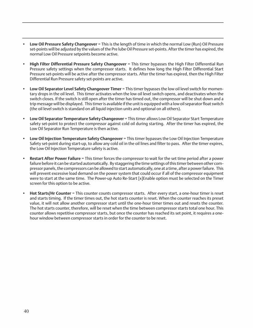
• True Anti-Recycle Timer = Once the compressor turns off, this timer will keep the compressor off for the setting of the True Anti-Recycle Timer. This timer is used to prevent short cycling of the compressor.
• Accumulative Anti-Recycle Timer = This timer also forces a specified time between compressor starts. When the compressor starts, the timer resets and starts timing and accumulates running time. Once the compressor shuts down, it will not be allowed to restart for the remainder of time left on the Accumulative Anti-Recycle Timer. Unlike the True Anti-Recycle Timer, if the compressor has run for a time period that exceeds the set-point of the Accumulative Anti-Recycle Timer, then when the compressor shuts down, it will be allowed to restart immediately.
As an example:• Accumulative Anti-Recycle Timer setting = 20 minutes. • Assume the compressor starts and runs for 15 minutes then shuts down. • The next start can occur in (20 minutes - 15 minutes of runtime = 5 minutes)
• The compressor restart options (Hot Starts or Anti-Recycle Timers) are selected from the “Configuration” menu. One additional Anti-Recycle Timer is selected from the Configuration menu, which is the “Modified Anti-Recycle” timer. Modified Anti-Recycle Timer = This timer has no direct set-point. It is defined as a combination of the True Anti-Recycle Timer and the Accumulative Anti-Recycle Timer. Normally when the “Modified Anti-Recycle Timer” function is selected from the Configuration menu, the timer functions as a True Anti-Recycle timer and uses the set-point of the True Anti-Recycle timer. However if the operator presses the stop button, or if a failure occurs, then the Modified Anti-Recycle Timer function switches to activate the “Accumulative Anti-Recycle Timer.” As the definition of the Accumulative Anti-Recycle Timer states, the compressor will be allowed to restart when the present accumulated runtime and the present accumulated off time meets or exceeds the setting of the “Accumulative Anti-Recycle Timer.”
Timers
42
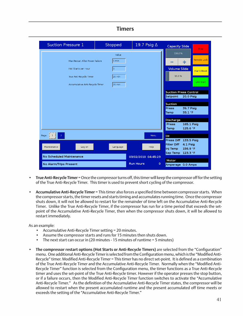
This screen allows the operator to force digital outputs ON for diagnostic purposes.
If you choose to exit this menu while an output is still forced on, the output will be “unforced” before the menu exits.
Note: The forcing of the compressor output will be limited to a “bump” for the purposes of determining motor rotation direction.
Service Options
43
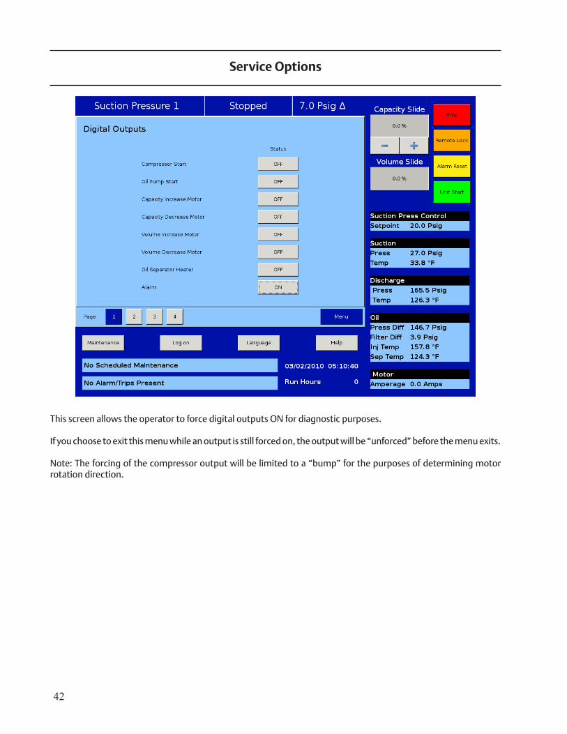
Instrument Calibration
44
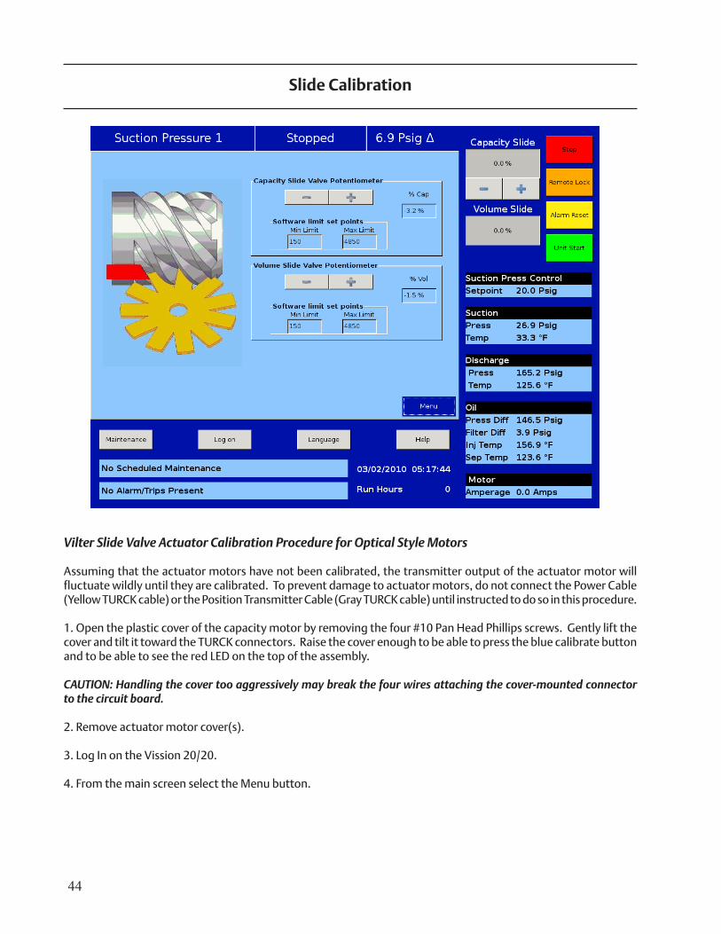
Vilter Slide Valve Actuator Calibration Procedure for Optical Style Motors
Assuming that the actuator motors have not been calibrated, the transmitter output of the actuator motor will fluctuate wildly until they are calibrated. To prevent damage to actuator motors, do not connect the Power Cable (Yellow TURCK cable) or the Position Transmitter Cable (Gray TURCK cable) until instructed to do so in this procedure.
1. Open the plastic cover of the capacity motor by removing the four #10 Pan Head Phillips screws. Gently lift the cover and tilt it toward the TURCK connectors. Raise the cover enough to be able to press the blue calibrate button and to be able to see the red LED on the top of the assembly.
CAUTION: Handling the cover too aggressively may break the four wires attaching the cover-mounted connector to the circuit board.
2. Remove actuator motor cover(s).
3. Log In on the Vission 20/20.
4. From the main screen select the Menu button.
Slide Calibration
45
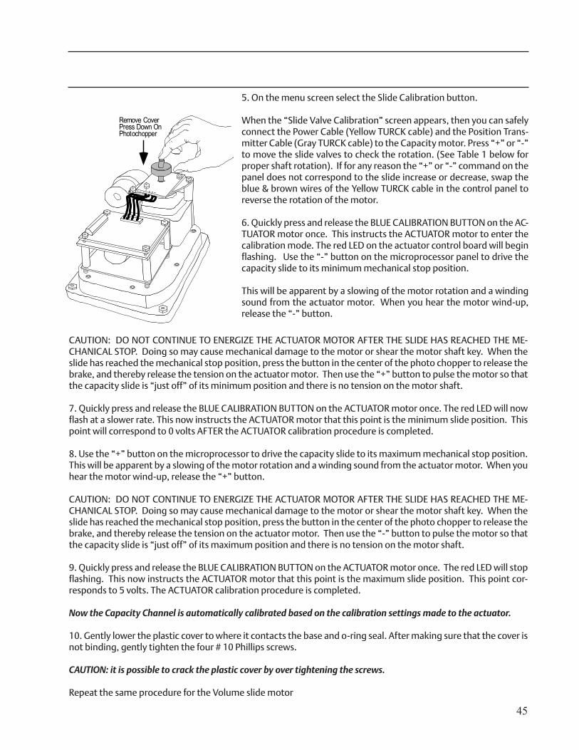
CAUTION: DO NOT CONTINUE TO ENERGIZE THE ACTUATOR MOTOR AFTER THE SLIDE HAS REACHED THE ME-CHANICAL STOP. Doing so may cause mechanical damage to the motor or shear the motor shaft key. When the slide has reached the mechanical stop position, press the button in the center of the photo chopper to release the brake, and thereby release the tension on the actuator motor. Then use the “+” button to pulse the motor so that the capacity slide is “just off” of its minimum position and there is no tension on the motor shaft. 7. Quickly press and release the BLUE CALIBRATION BUTTON on the ACTUATOR motor once. The red LED will now flash at a slower rate. This now instructs the ACTUATOR motor that this point is the minimum slide position. This point will correspond to 0 volts AFTER the ACTUATOR calibration procedure is completed. 8. Use the “+” button on the microprocessor to drive the capacity slide to its maximum mechanical stop position. This will be apparent by a slowing of the motor rotation and a winding sound from the actuator motor. When you hear the motor wind-up, release the “+” button.
CAUTION: DO NOT CONTINUE TO ENERGIZE THE ACTUATOR MOTOR AFTER THE SLIDE HAS REACHED THE ME-CHANICAL STOP. Doing so may cause mechanical damage to the motor or shear the motor shaft key. When the slide has reached the mechanical stop position, press the button in the center of the photo chopper to release the brake, and thereby release the tension on the actuator motor. Then use the “-” button to pulse the motor so that the capacity slide is “just off” of its maximum position and there is no tension on the motor shaft.
9. Quickly press and release the BLUE CALIBRATION BUTTON on the ACTUATOR motor once. The red LED will stop flashing. This now instructs the ACTUATOR motor that this point is the maximum slide position. This point cor-responds to 5 volts. The ACTUATOR calibration procedure is completed.
Now the Capacity Channel is automatically calibrated based on the calibration settings made to the actuator.
10. Gently lower the plastic cover to where it contacts the base and o-ring seal. After making sure that the cover is not binding, gently tighten the four # 10 Phillips screws.
CAUTION: it is possible to crack the plastic cover by over tightening the screws. Repeat the same procedure for the Volume slide motor
Remove CoverPress Down OnPhotochopper
5. On the menu screen select the Slide Calibration button.
When the “Slide Valve Calibration” screen appears, then you can safely connect the Power Cable (Yellow TURCK cable) and the Position Trans-mitter Cable (Gray TURCK cable) to the Capacity motor. Press “+” or “-” to move the slide valves to check the rotation. (See Table 1 below for proper shaft rotation). If for any reason the “+” or “-” command on the panel does not correspond to the slide increase or decrease, swap the blue & brown wires of the Yellow TURCK cable in the control panel to reverse the rotation of the motor.
6. Quickly press and release the BLUE CALIBRATION BUTTON on the AC-TUATOR motor once. This instructs the ACTUATOR motor to enter the calibration mode. The red LED on the actuator control board will begin flashing. Use the “-” button on the microprocessor panel to drive the capacity slide to its minimum mechanical stop position.
This will be apparent by a slowing of the motor rotation and a winding sound from the actuator motor. When you hear the motor wind-up, release the “-” button.
46
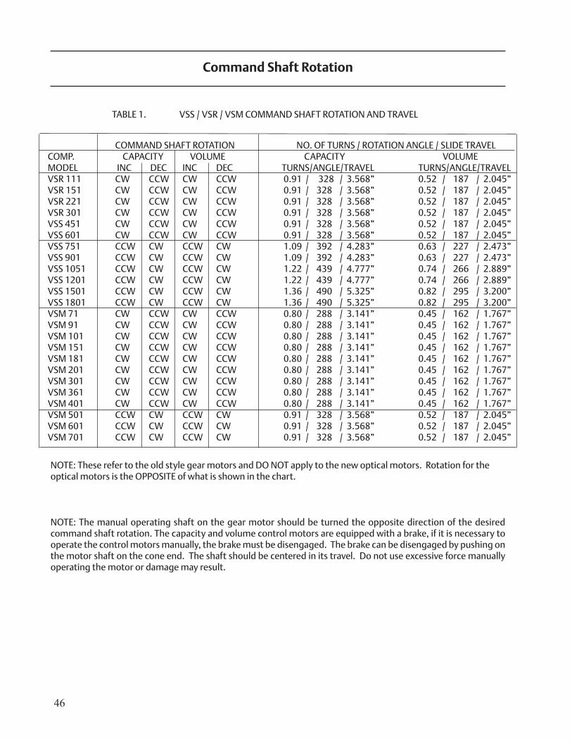
NOTE: The manual operating shaft on the gear motor should be turned the opposite direction of the desired command shaft rotation. The capacity and volume control motors are equipped with a brake, if it is necessary to operate the control motors manually, the brake must be disengaged. The brake can be disengaged by pushing on the motor shaft on the cone end. The shaft should be centered in its travel. Do not use excessive force manually operating the motor or damage may result.
Command Shaft Rotation
COMMAND SHAFT ROTATION NO. OF TURNS / ROTATION ANGLE / SLIDE TRAVEL COMP. CAPACITY VOLUME CAPACITY VOLUME MODEL INC DEC INC DEC TURNS/ANGLE/TRAVEL TURNS/ANGLE/TRAVELVSR 111 CW CCW CW CCW 0.91 / 328 / 3.568” 0.52 / 187 / 2.045”VSR 151 CW CCW CW CCW 0.91 / 328 / 3.568” 0.52 / 187 / 2.045”VSR 221 CW CCW CW CCW 0.91 / 328 / 3.568” 0.52 / 187 / 2.045”VSR 301 CW CCW CW CCW 0.91 / 328 / 3.568” 0.52 / 187 / 2.045”VSS 451 CW CCW CW CCW 0.91 / 328 / 3.568” 0.52 / 187 / 2.045”VSS 601 CW CCW CW CCW 0.91 / 328 / 3.568” 0.52 / 187 / 2.045”VSS 751 CCW CW CCW CW 1.09 / 392 / 4.283” 0.63 / 227 / 2.473”VSS 901 CCW CW CCW CW 1.09 / 392 / 4.283” 0.63 / 227 / 2.473”VSS 1051 CCW CW CCW CW 1.22 / 439 / 4.777” 0.74 / 266 / 2.889”VSS 1201 CCW CW CCW CW 1.22 / 439 / 4.777” 0.74 / 266 / 2.889”VSS 1501 CCW CW CCW CW 1.36 / 490 / 5.325” 0.82 / 295 / 3.200”VSS 1801 CCW CW CCW CW 1.36 / 490 / 5.325” 0.82 / 295 / 3.200”VSM 71 CW CCW CW CCW 0.80 / 288 / 3.141” 0.45 / 162 / 1.767”VSM 91 CW CCW CW CCW 0.80 / 288 / 3.141” 0.45 / 162 / 1.767”VSM 101 CW CCW CW CCW 0.80 / 288 / 3.141” 0.45 / 162 / 1.767”VSM 151 CW CCW CW CCW 0.80 / 288 / 3.141” 0.45 / 162 / 1.767”VSM 181 CW CCW CW CCW 0.80 / 288 / 3.141” 0.45 / 162 / 1.767”VSM 201 CW CCW CW CCW 0.80 / 288 / 3.141” 0.45 / 162 / 1.767”VSM 301 CW CCW CW CCW 0.80 / 288 / 3.141” 0.45 / 162 / 1.767”VSM 361 CW CCW CW CCW 0.80 / 288 / 3.141” 0.45 / 162 / 1.767”VSM 401 CW CCW CW CCW 0.80 / 288 / 3.141” 0.45 / 162 / 1.767”VSM 501 CCW CW CCW CW 0.91 / 328 / 3.568” 0.52 / 187 / 2.045”VSM 601 CCW CW CCW CW 0.91 / 328 / 3.568” 0.52 / 187 / 2.045”VSM 701 CCW CW CCW CW 0.91 / 328 / 3.568” 0.52 / 187 / 2.045”
TABLE 1. VSS / VSR / VSM COMMAND SHAFT ROTATION AND TRAVEL
NOTE: These refer to the old style gear motors and DO NOT apply to the new optical motors. Rotation for the optical motors is the OPPOSITE of what is shown in the chart.
47
Slide Valve Operation
The slide valve actuator is a gear-motor with a posi-tion sensor. The motor is powered in the forward and reverse directions from the main computer in the control panel. The position sensor tells the main computer the position of the slide valve. The main computer uses the position and process information to decide where to move the slide valve next.
During calibration, the position sensor records the high and low count of motor turns. The operator tells the position sensor when the actuator is at the high or low position with the push button. Refer to the calibration instructions for the detailed calibra-tion procedure.
The position sensor can get “lost” if the motor is moved while the position sensor is not powered. To prevent this, the motor can only be moved electri-cally while the position sensor is powered. When the position sensor loses power, power is cut to the motor. A capacitor stores enough energy to keep the position sensor circuitry alive long enough for the motor to come to a complete stop and then save the motor position to non-volatile EEPROM memory. When power is restored, the saved motor position is read from EEPROM memory and the actuators resumes normal function
This scheme is not foolproof. If the motor is moved manually while the power is off or the motor brake has failed, allowing the motor to free wheel for too long after the position sensor looses power, the actuator will become lost.
A brake failure can sometimes be detected by the position sensor. If the motor never stops turning after a power loss, the position sensor detects this, knows it will be lost, and goes immediately into calibrate mode when power is restored.
48
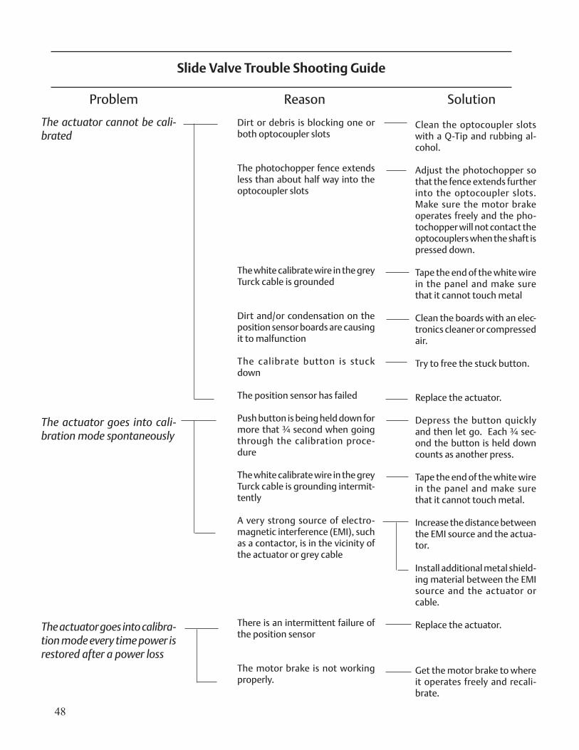
The actuator cannot be cali-brated
The actuator goes into cali-bration mode spontaneously
The actuator goes into calibra-tion mode every time power is restored after a power loss
Dirt or debris is blocking one or both optocoupler slots
The photochopper fence extends less than about half way into the optocoupler slots
The white calibrate wire in the grey Turck cable is grounded
Dirt and/or condensation on the position sensor boards are causing it to malfunction
The calibrate button is stuck down
The position sensor has failed
Push button is being held down for more that ¾ second when going through the calibration proce-dure
The white calibrate wire in the grey Turck cable is grounding intermit-tently
A very strong source of electro-magnetic interference (EMI), such as a contactor, is in the vicinity of the actuator or grey cable
There is an intermittent failure of the position sensor
The motor brake is not working properly.
Clean the optocoupler slots with a Q-Tip and rubbing al-cohol.
Adjust the photochopper so that the fence extends further into the optocoupler slots. Make sure the motor brake operates freely and the pho-tochopper will not contact the optocouplers when the shaft is pressed down.
Tape the end of the white wire in the panel and make sure that it cannot touch metal
Clean the boards with an elec-tronics cleaner or compressed air.
Try to free the stuck button.
Replace the actuator.
Depress the button quickly and then let go. Each ¾ sec-ond the button is held down counts as another press.
Tape the end of the white wire in the panel and make sure that it cannot touch metal.
Increase the distance between the EMI source and the actua-tor.
Install additional metal shield-ing material between the EMI source and the actuator or cable.
Replace the actuator.
Get the motor brake to where it operates freely and recali-brate.
Slide Valve Trouble Shooting Guide
Problem Reason Solution
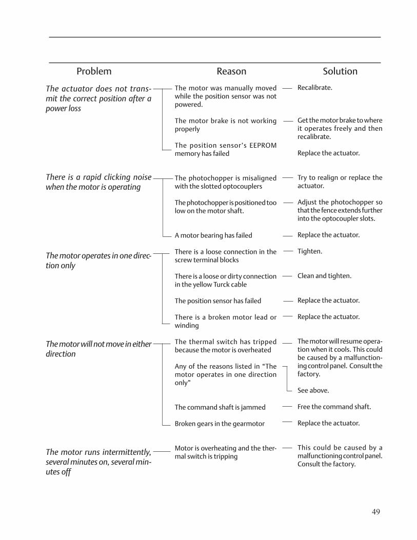
49
The motor was manually moved while the position sensor was not powered.
The motor brake is not working properly
The position sensor’s EEPROM memory has failed
The photochopper is misaligned with the slotted optocouplers
The photochopper is positioned too low on the motor shaft.
A motor bearing has failed
There is a loose connection in the screw terminal blocks
There is a loose or dirty connection in the yellow Turck cable
The position sensor has failed
There is a broken motor lead or winding
The thermal switch has tripped because the motor is overheated Any of the reasons listed in “The motor operates in one direction only”
The command shaft is jammed
Broken gears in the gearmotor
Motor is overheating and the ther-mal switch is tripping
Recalibrate.
Get the motor brake to where it operates freely and then recalibrate.
Replace the actuator.
Try to realign or replace the actuator.
Adjust the photochopper so that the fence extends further into the optocoupler slots.
Replace the actuator.
Tighten.
Clean and tighten.
Replace the actuator.
Replace the actuator.
The motor will resume opera-tion when it cools. This could be caused by a malfunction-ing control panel. Consult the factory.
See above.
Free the command shaft.
Replace the actuator.
This could be caused by a malfunctioning control panel. Consult the factory.
The actuator does not trans-mit the correct position after a power loss
There is a rapid clicking noise when the motor is operating
The motor operates in one direc-tion only
The motor will not move in either direction
The motor runs intermittently, several minutes on, several min-utes off
Problem Reason Solution
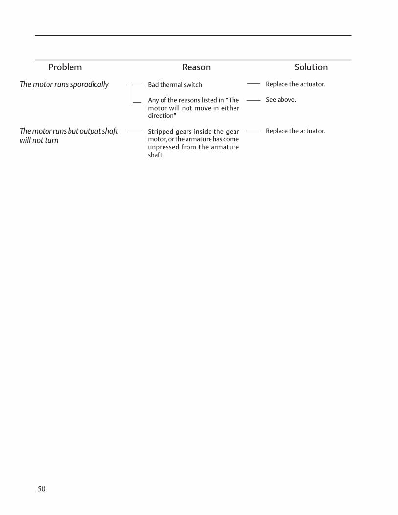
50
Bad thermal switch
Any of the reasons listed in “The motor will not move in either direction”
Stripped gears inside the gear motor, or the armature has come unpressed from the armature shaft
Replace the actuator.
See above.
Replace the actuator.
The motor runs sporadically
The motor runs but output shaft will not turn
Problem Reason Solution
51
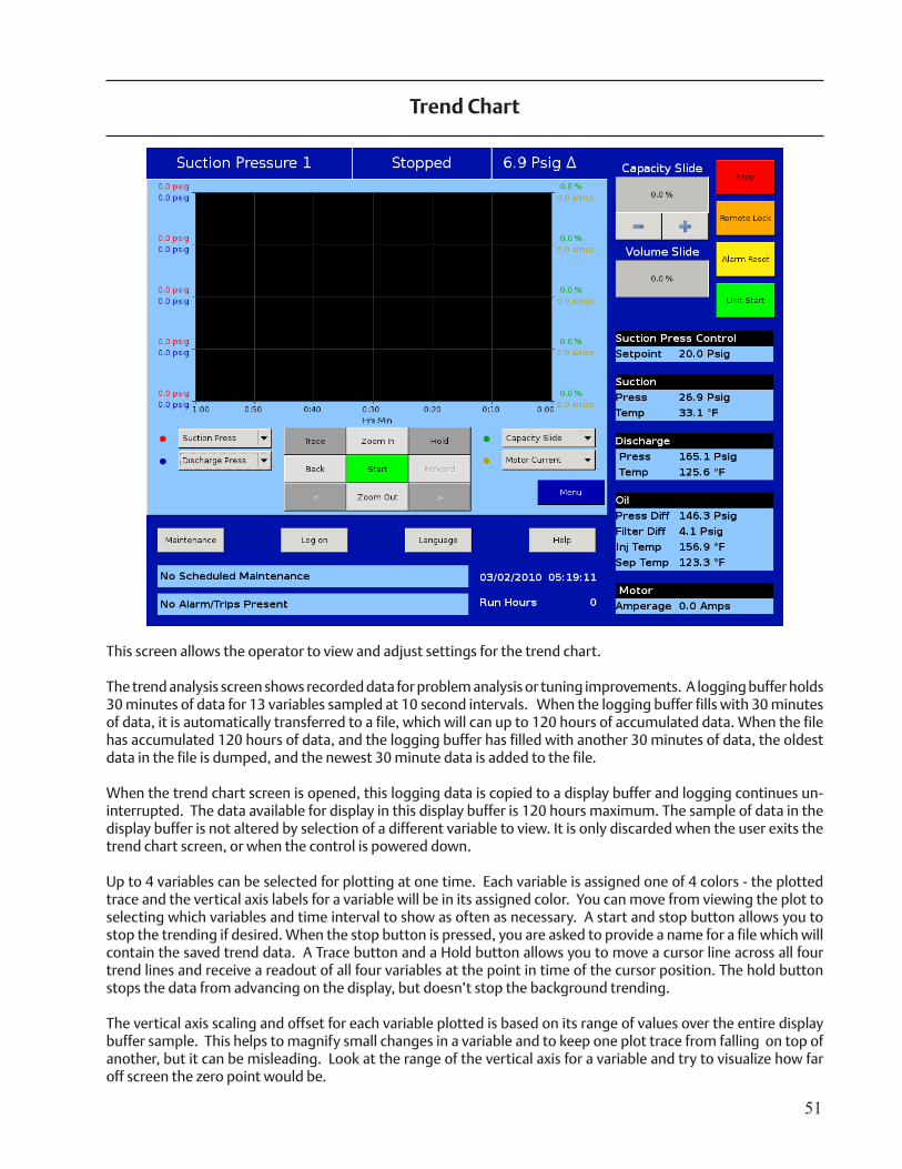
This screen allows the operator to view and adjust settings for the trend chart.
The trend analysis screen shows recorded data for problem analysis or tuning improvements. A logging buffer holds 30 minutes of data for 13 variables sampled at 10 second intervals. When the logging buffer fills with 30 minutes of data, it is automatically transferred to a file, which will can up to 120 hours of accumulated data. When the file has accumulated 120 hours of data, and the logging buffer has filled with another 30 minutes of data, the oldest data in the file is dumped, and the newest 30 minute data is added to the file.
When the trend chart screen is opened, this logging data is copied to a display buffer and logging continues un-interrupted. The data available for display in this display buffer is 120 hours maximum. The sample of data in the display buffer is not altered by selection of a different variable to view. It is only discarded when the user exits the trend chart screen, or when the control is powered down.
Up to 4 variables can be selected for plotting at one time. Each variable is assigned one of 4 colors - the plotted trace and the vertical axis labels for a variable will be in its assigned color. You can move from viewing the plot to selecting which variables and time interval to show as often as necessary. A start and stop button allows you to stop the trending if desired. When the stop button is pressed, you are asked to provide a name for a file which will contain the saved trend data. A Trace button and a Hold button allows you to move a cursor line across all four trend lines and receive a readout of all four variables at the point in time of the cursor position. The hold button stops the data from advancing on the display, but doesn’t stop the background trending.
The vertical axis scaling and offset for each variable plotted is based on its range of values over the entire display buffer sample. This helps to magnify small changes in a variable and to keep one plot trace from falling on top of another, but it can be misleading. Look at the range of the vertical axis for a variable and try to visualize how far off screen the zero point would be.
Trend Chart
52
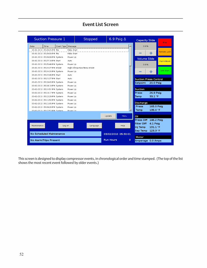
This screen is designed to display compressor events, in chronological order and time stamped. (The top of the list shows the most recent event followed by older events.)
Event List Screen
53
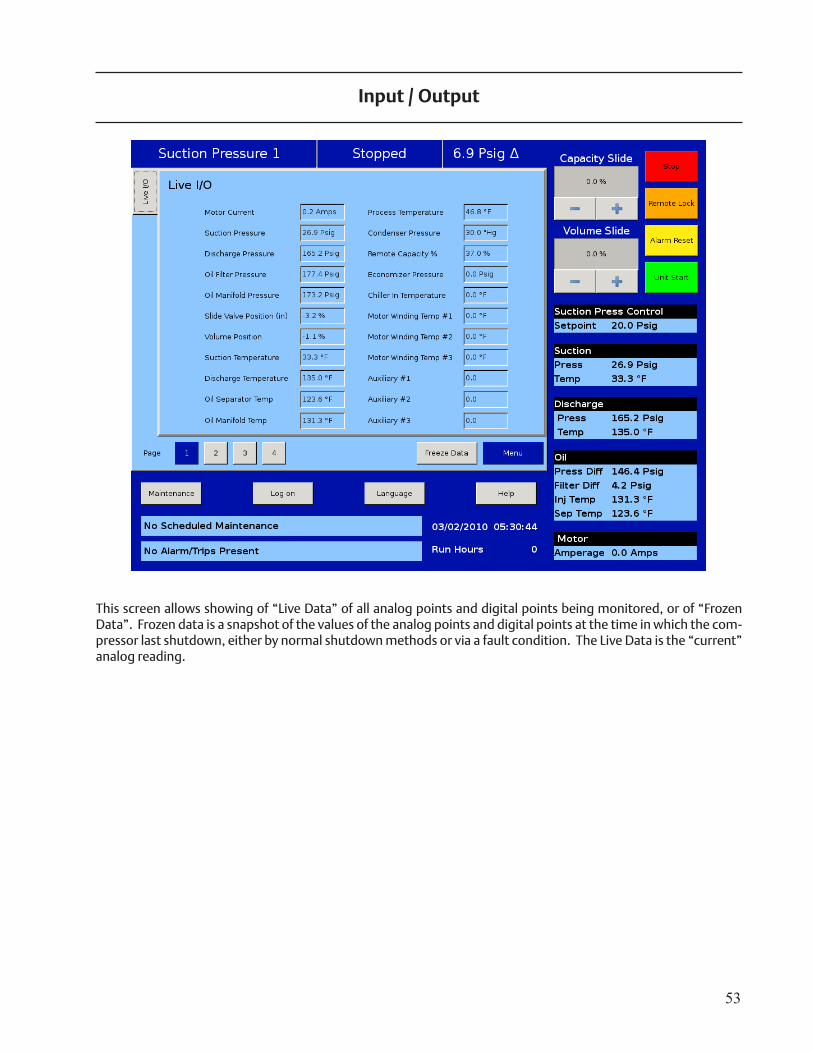
This screen allows showing of “Live Data” of all analog points and digital points being monitored, or of “Frozen Data”. Frozen data is a snapshot of the values of the analog points and digital points at the time in which the com-pressor last shutdown, either by normal shutdown methods or via a fault condition. The Live Data is the “current” analog reading.
Input / Output
54
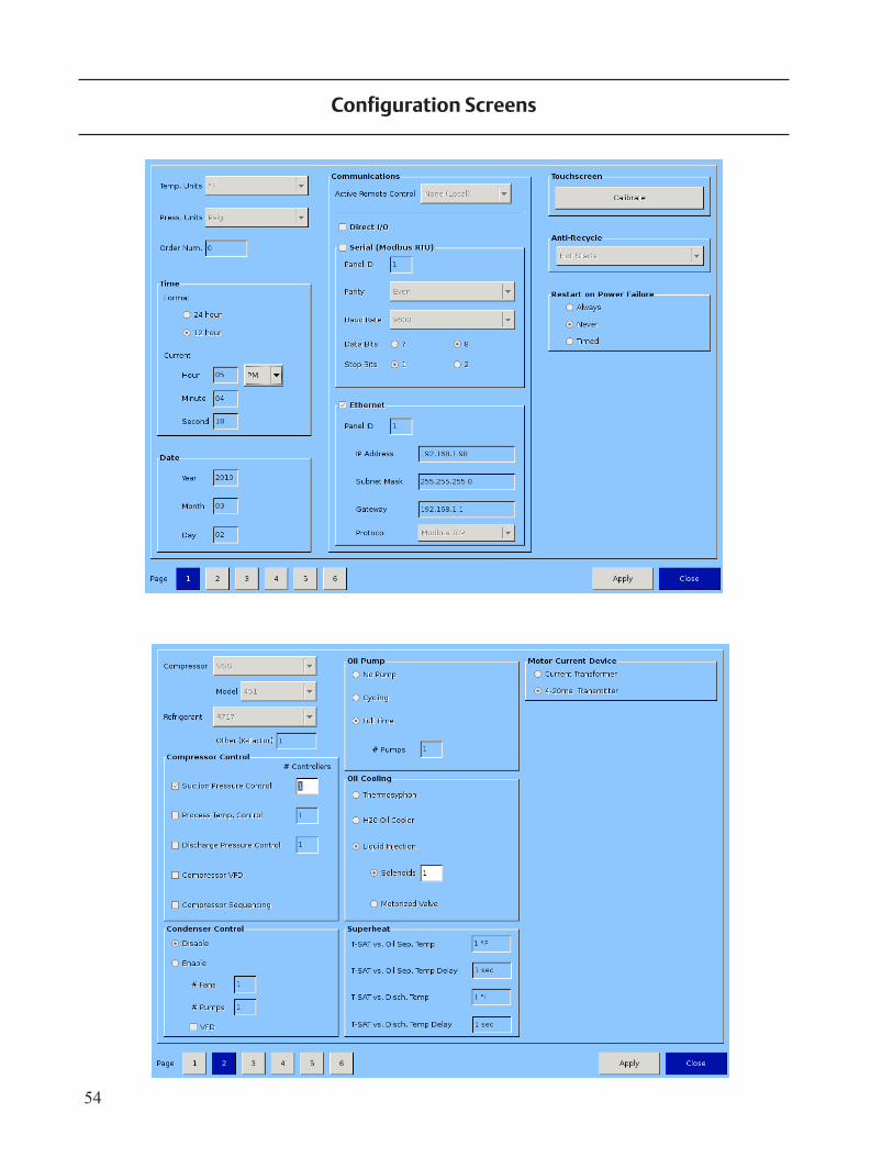
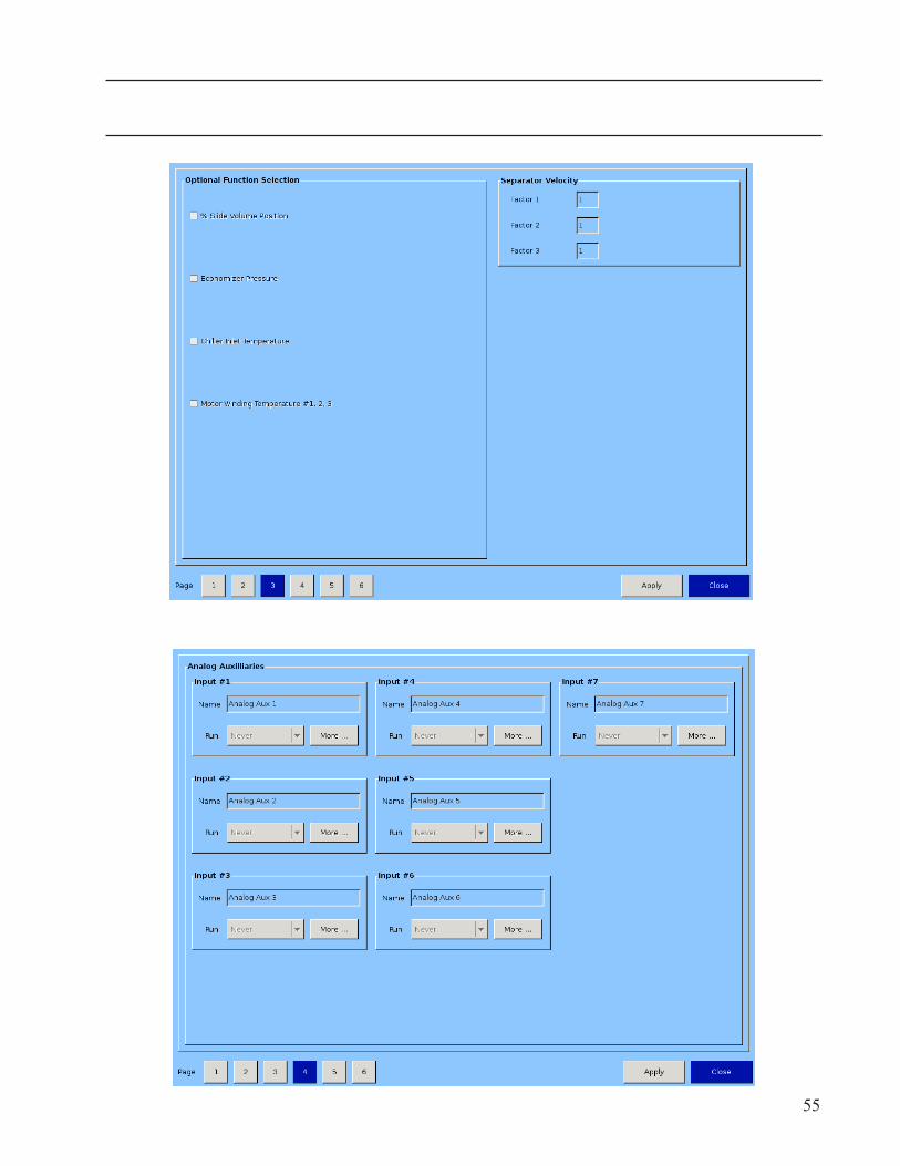
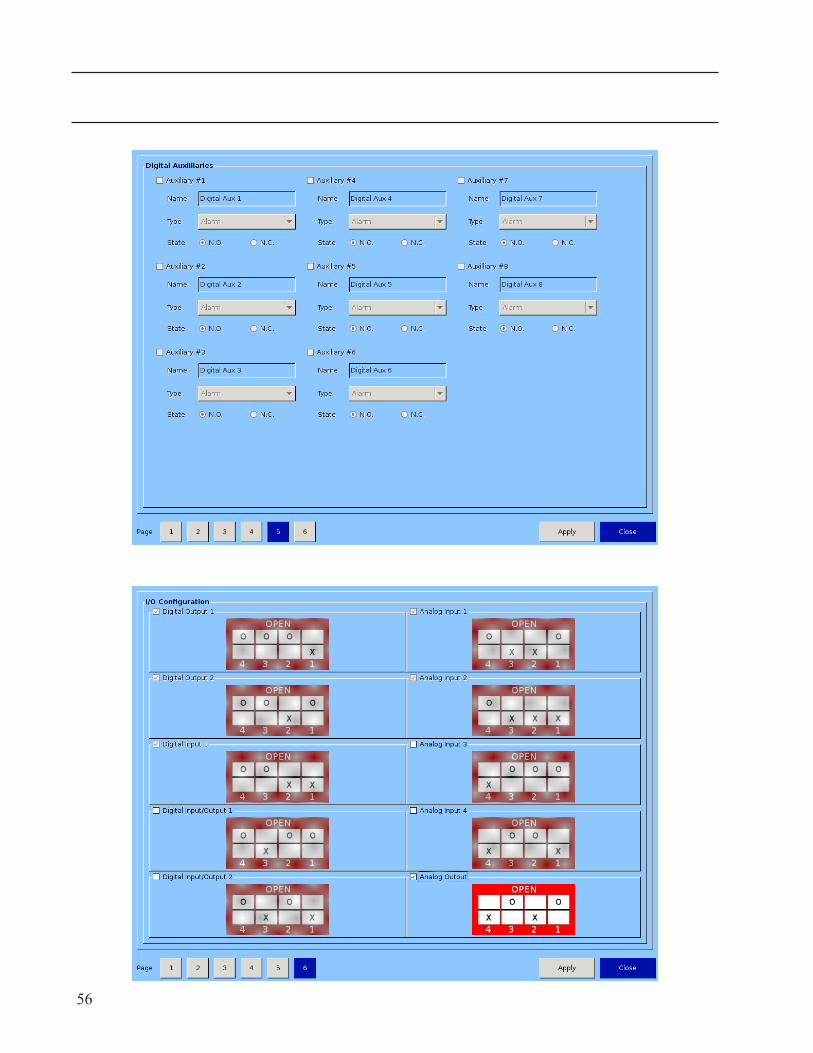
Configuration Screens
55
56
57
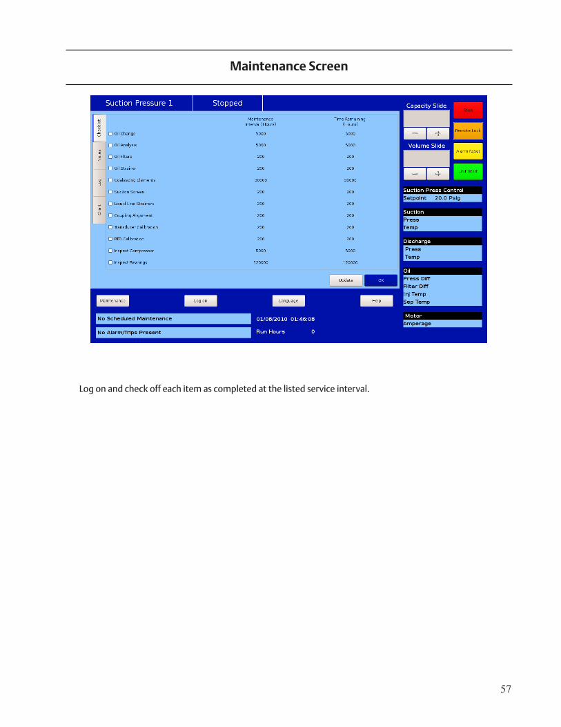
MALog on and check off each item as completed at the listed service interval.
Maintenance Screen
58
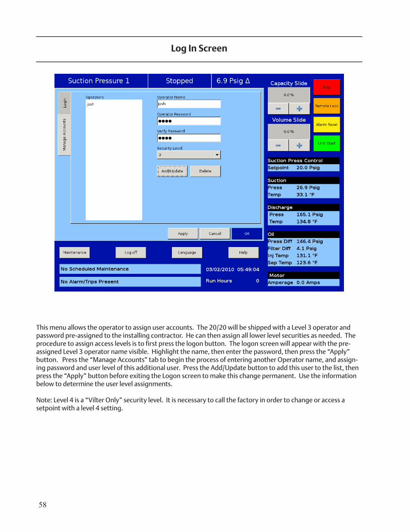
This menu allows the operator to assign user accounts. The 20/20 will be shipped with a Level 3 operator and password pre-assigned to the installing contractor. He can then assign all lower level securities as needed. The procedure to assign access levels is to first press the logon button. The logon screen will appear with the pre-assigned Level 3 operator name visible. Highlight the name, then enter the password, then press the “Apply” button. Press the “Manage Accounts” tab to begin the process of entering another Operator name, and assign-ing password and user level of this additional user. Press the Add/Update button to add this user to the list, then press the “Apply” button before exiting the Logon screen to make this change permanent. Use the information below to determine the user level assignments.
Note: Level 4 is a “Vilter Only” security level. It is necessary to call the factory in order to change or access a setpoint with a level 4 setting.
Log In Screen
59
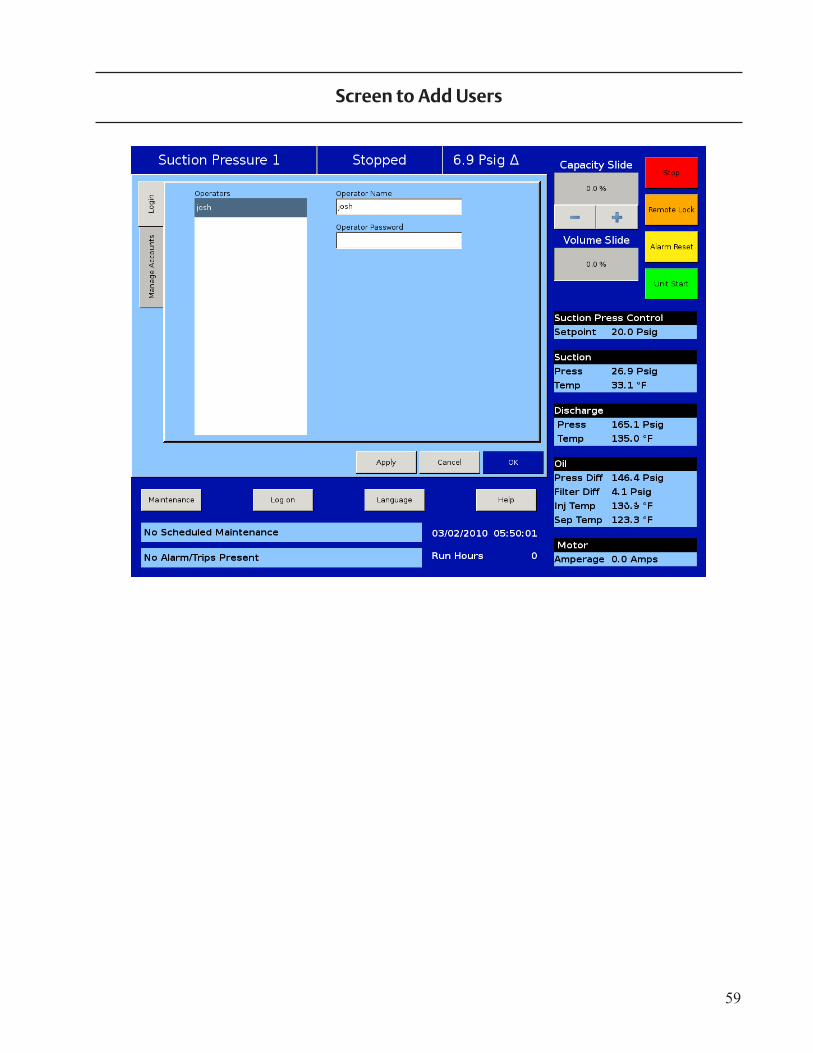
Screen to Add Users
60
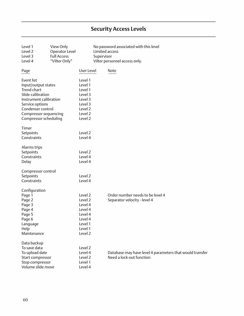
Level 1 View Only No password associated with this levelLevel 2 Operator Level Limited accessLevel 3 Full Access SupervisorLevel 4 “Vilter Only” Vilter personnel access only.
Page User Level Note
Event list Level 1Input/output states Level 1Trend chart Level 1Slide calibration Level 3Instrument calibration Level 3Service options Level 3Condenser control Level 2Compressor sequencing Level 2Compressor scheduling Level 2
TimerSetpoints Level 2Constraints Level 4
Alarms tripsSetpoints Level 2Constraints Level 4Delay Level 4
Compressor controlSetpoints Level 2Constraints Level 4 ConfigurationPage 1 Level 2 Order number needs to be level 4Page 2 Level 2 Separator velocity - level 4Page 3 Level 4Page 4 Level 4Page 5 Level 4Page 6 Level 4Language Level 1Help Level 1Maintenance Level 2
Data backupTo save data Level 2To upload date Level 4 Database may have level 4 parameters that would transferStart compressor Level 2 Need a lock-out functionStop compressor Level 1Volume slide move Level 4
Security Access Levels
61
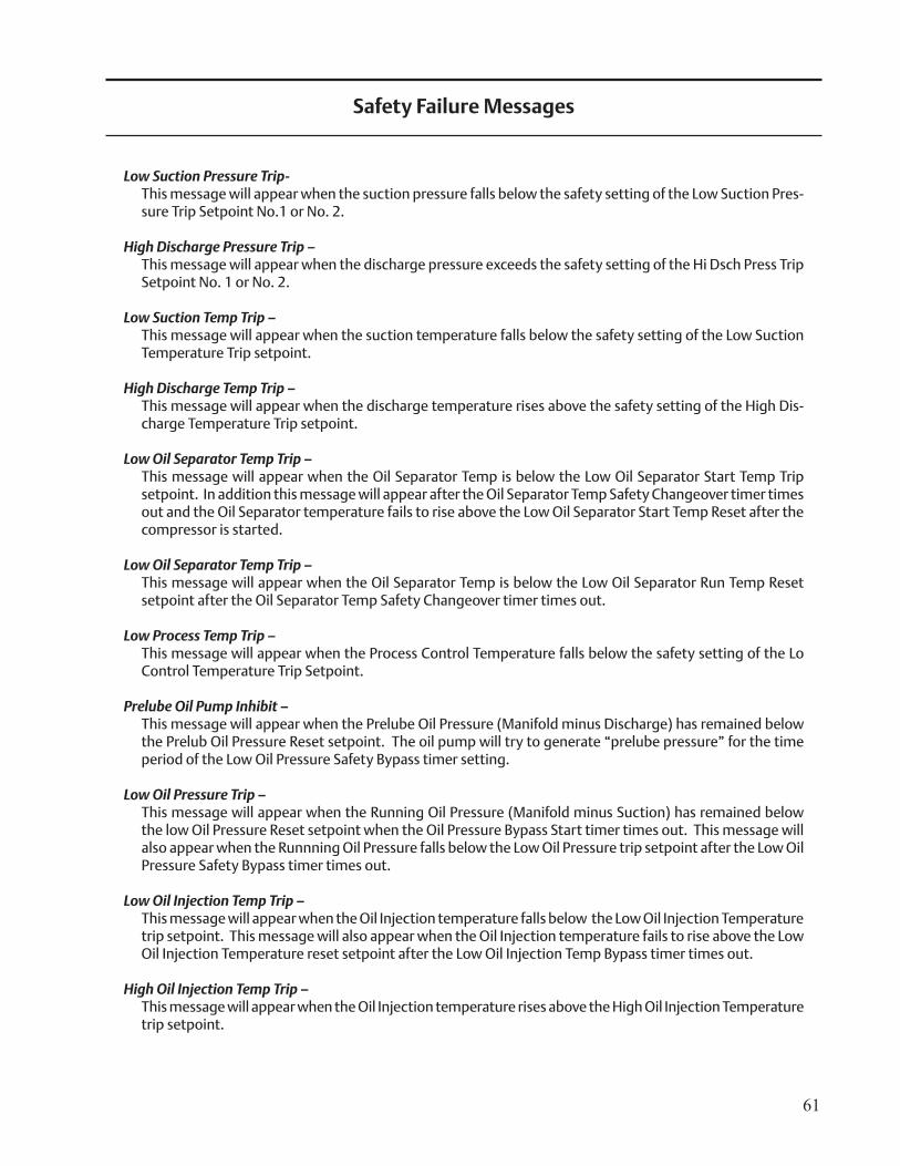
Low Suction Pressure Trip- This message will appear when the suction pressure falls below the safety setting of the Low Suction Pres-
sure Trip Setpoint No.1 or No. 2.
High Discharge Pressure Trip – This message will appear when the discharge pressure exceeds the safety setting of the Hi Dsch Press Trip
Setpoint No. 1 or No. 2.
Low Suction Temp Trip – This message will appear when the suction temperature falls below the safety setting of the Low Suction
Temperature Trip setpoint.
High Discharge Temp Trip – This message will appear when the discharge temperature rises above the safety setting of the High Dis-
charge Temperature Trip setpoint.
Low Oil Separator Temp Trip – This message will appear when the Oil Separator Temp is below the Low Oil Separator Start Temp Trip
setpoint. In addition this message will appear after the Oil Separator Temp Safety Changeover timer times out and the Oil Separator temperature fails to rise above the Low Oil Separator Start Temp Reset after the compressor is started.
Low Oil Separator Temp Trip – This message will appear when the Oil Separator Temp is below the Low Oil Separator Run Temp Reset
setpoint after the Oil Separator Temp Safety Changeover timer times out.
Low Process Temp Trip – This message will appear when the Process Control Temperature falls below the safety setting of the Lo
Control Temperature Trip Setpoint.
Prelube Oil Pump Inhibit – This message will appear when the Prelube Oil Pressure (Manifold minus Discharge) has remained below
the Prelub Oil Pressure Reset setpoint. The oil pump will try to generate “prelube pressure” for the time period of the Low Oil Pressure Safety Bypass timer setting.
Low Oil Pressure Trip – This message will appear when the Running Oil Pressure (Manifold minus Suction) has remained below
the low Oil Pressure Reset setpoint when the Oil Pressure Bypass Start timer times out. This message will also appear when the Runnning Oil Pressure falls below the Low Oil Pressure trip setpoint after the Low Oil Pressure Safety Bypass timer times out.
Low Oil Injection Temp Trip – This message will appear when the Oil Injection temperature falls below the Low Oil Injection Temperature
trip setpoint. This message will also appear when the Oil Injection temperature fails to rise above the Low Oil Injection Temperature reset setpoint after the Low Oil Injection Temp Bypass timer times out.
High Oil Injection Temp Trip – This message will appear when the Oil Injection temperature rises above the High Oil Injection Temperature
trip setpoint.
Safety Failure Messages
62
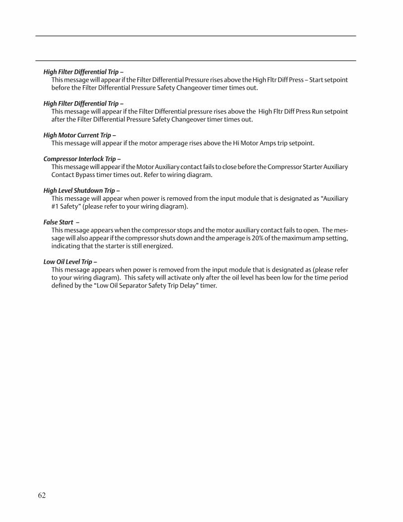
High Filter Differential Trip – This message will appear if the Filter Differential Pressure rises above the High Fltr Diff Press – Start setpoint
before the Filter Differential Pressure Safety Changeover timer times out.
High Filter Differential Trip – This message will appear if the Filter Differential pressure rises above the High Fltr Diff Press Run setpoint
after the Filter Differential Pressure Safety Changeover timer times out.
High Motor Current Trip – This message will appear if the motor amperage rises above the Hi Motor Amps trip setpoint.
Compressor Interlock Trip – This message will appear if the Motor Auxiliary contact fails to close before the Compressor Starter Auxiliary
Contact Bypass timer times out. Refer to wiring diagram.
High Level Shutdown Trip – This message will appear when power is removed from the input module that is designated as “Auxiliary
#1 Safety” (please refer to your wiring diagram).
False Start – This message appears when the compressor stops and the motor auxiliary contact fails to open. The mes-
sage will also appear if the compressor shuts down and the amperage is 20% of the maximum amp setting, indicating that the starter is still energized.
Low Oil Level Trip – This message appears when power is removed from the input module that is designated as (please refer
to your wiring diagram). This safety will activate only after the oil level has been low for the time period defined by the “Low Oil Separator Safety Trip Delay” timer.
63
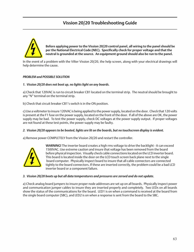
Vission 20/20 Troubleshooting Guide
Before applying power to the Vission 20/20 control panel, all wiring to the panel should be per the National Electrical Code (NEC). Specifically check for proper voltage and that the neutral is grounded at the source. An equipment ground should also be run to the panel.
In the event of a problem with the Vilter Vission 20/20, the help screen, along with your electrical drawings will help determine the cause.
PROBLEM and POSSIBLE SOLUTION
1. Vission 20/20 does not boot up, no lights light on any boards. a) Check that 120VAC is run to circuit breaker CB1 located on the terminal strip. The neutral should be brought to any “N” terminal on the terminal strip. b) Check that circuit breaker CB1’s switch is in the ON position.
c) Use a voltmeter to insure 120VAC is being applied to the power supply, located on the door. Check that 120 volts is present at the F1 fuse on the power supply, located on the front of the door. If all of the above are OK, the power supply may be bad. To test the power supply, check DC voltages at the power supply output. If proper voltages are not found at these test points, the power supply may be faulty.
2. Vission 20/20 appears to be booted, lights are lit on the boards, but no touchscreen display is evident.
a) Remove power COMPLETELY from the Vission 20/20 and restart the controller.
WARNING! The inverter board creates a high rms voltage to drive the backlight - it can exceed 1500VAC. Use extreme caution and insure that voltage has been removed from the board before physical inspection. Visually check cable connections located on the LCD inverter board. This board is located inside the door on the LCD touch screen back plane next to the single board computer. Physically inspect board to insure that all cable connectors are connected tightly to the board connectors. If these are inserted correctly, the problem could be a bad LCD inverter board or a component failure.
3. Vission 20/20 boots up but all data temperatures and pressures are zeroed and do not update.
a) Check analog board jumpers to insure proper node addresses are set up on all boards. Physically inspect power and communication jumper cables to insure they are inserted properly and completely. Two LEDs on all boards show the status of the communications for the board. LED1 is on when a command is received at the board from the single board computer (SBC), and LED2 is on when a response is sent from the board to the SBC.
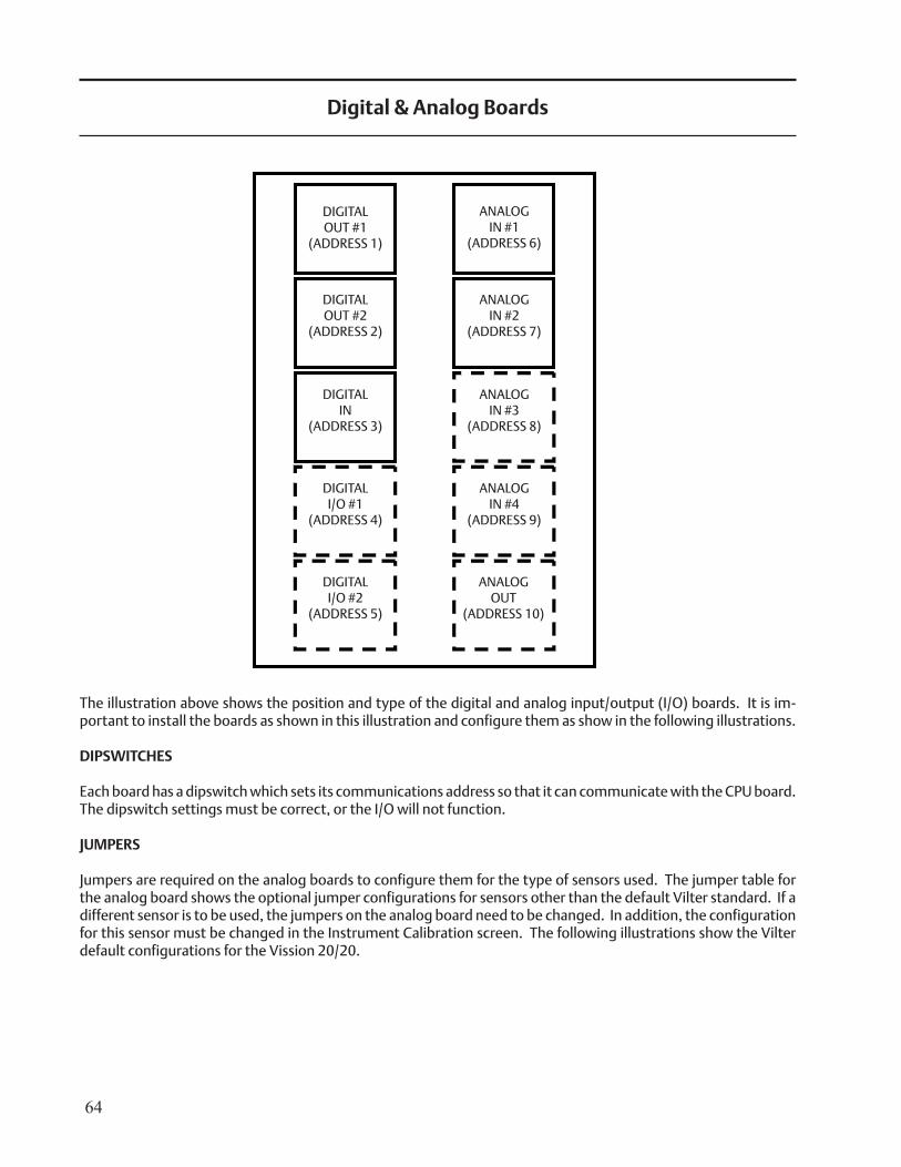
64
The illustration above shows the position and type of the digital and analog input/output (I/O) boards. It is im-portant to install the boards as shown in this illustration and configure them as show in the following illustrations.
DIPSWITCHES
Each board has a dipswitch which sets its communications address so that it can communicate with the CPU board. The dipswitch settings must be correct, or the I/O will not function.
JUMPERS
Jumpers are required on the analog boards to configure them for the type of sensors used. The jumper table for the analog board shows the optional jumper configurations for sensors other than the default Vilter standard. If a different sensor is to be used, the jumpers on the analog board need to be changed. In addition, the configuration for this sensor must be changed in the Instrument Calibration screen. The following illustrations show the Vilter default configurations for the Vission 20/20.
DIGITALOUT #1
(ADDRESS 1)
Digital & Analog Boards
DIGITALOUT #2
(ADDRESS 2)
DIGITALIN
(ADDRESS 3)
DIGITALI/O #1
(ADDRESS 4)
DIGITALI/O #2
(ADDRESS 5)
ANALOGIN #1
(ADDRESS 6)
ANALOGIN #2
(ADDRESS 7)
ANALOGIN #3
(ADDRESS 8)
ANALOGIN #4
(ADDRESS 9)
ANALOGOUT
(ADDRESS 10)
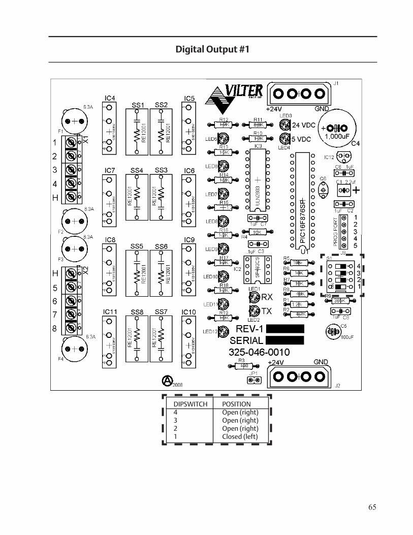
65
Digital Output #1
DIPSWITCH POSITION4 Open (right)3 Open (right)2 Open (right)1 Closed (left)
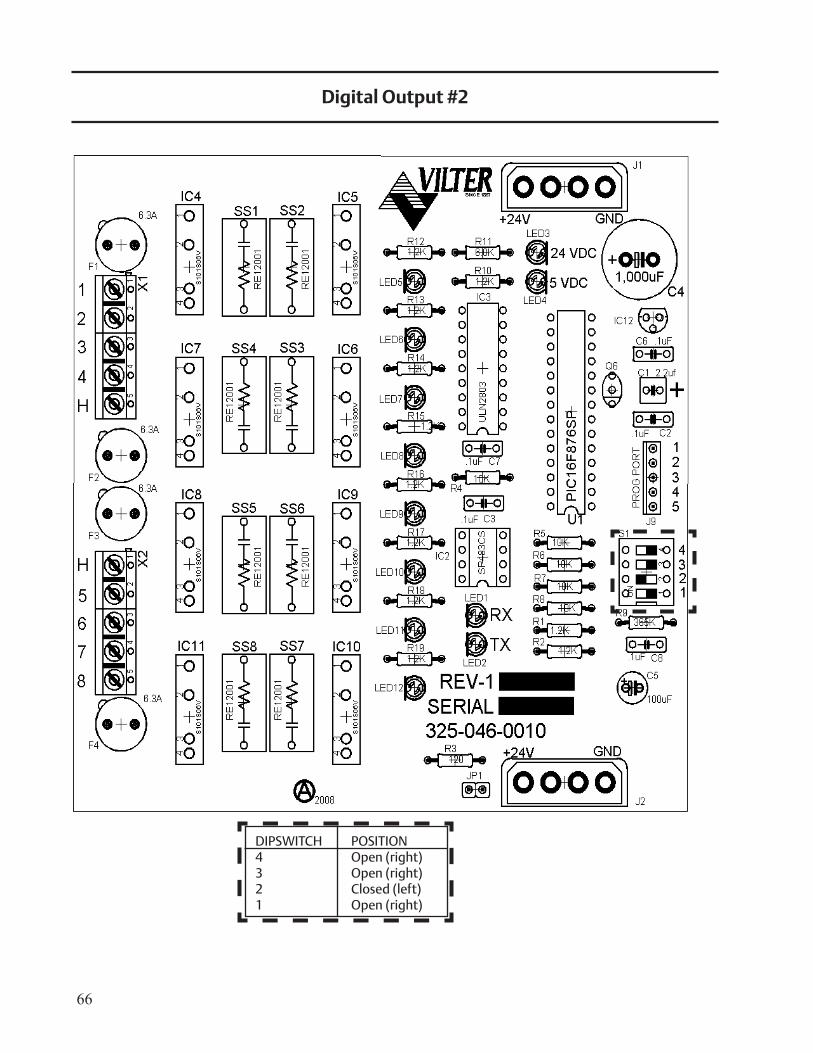
66
Digital Output #2
DIPSWITCH POSITION4 Open (right)3 Open (right)2 Closed (left)1 Open (right)
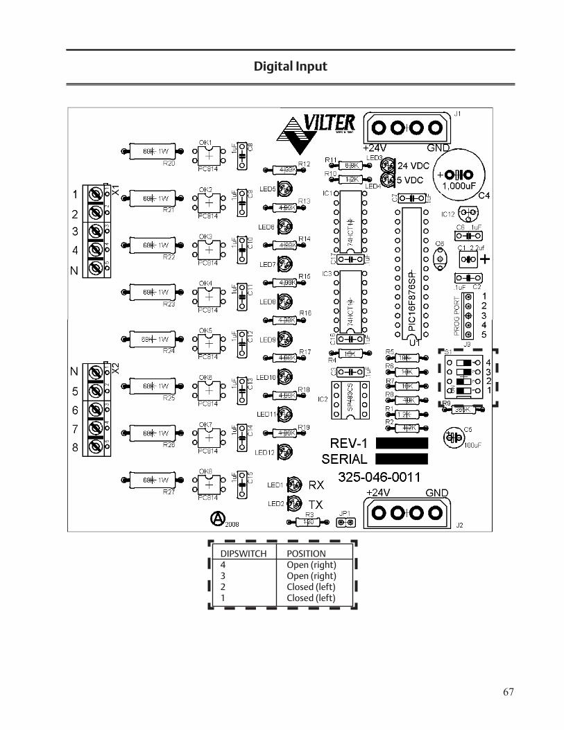
67
Digital Input
DIPSWITCH POSITION4 Open (right)3 Open (right)2 Closed (left)1 Closed (left)
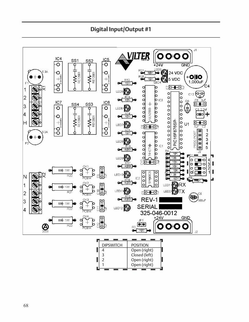
68
Digital Input/Output #1
DIPSWITCH POSITION4 Open (right)3 Closed (left)2 Open (right)1 Open (right)
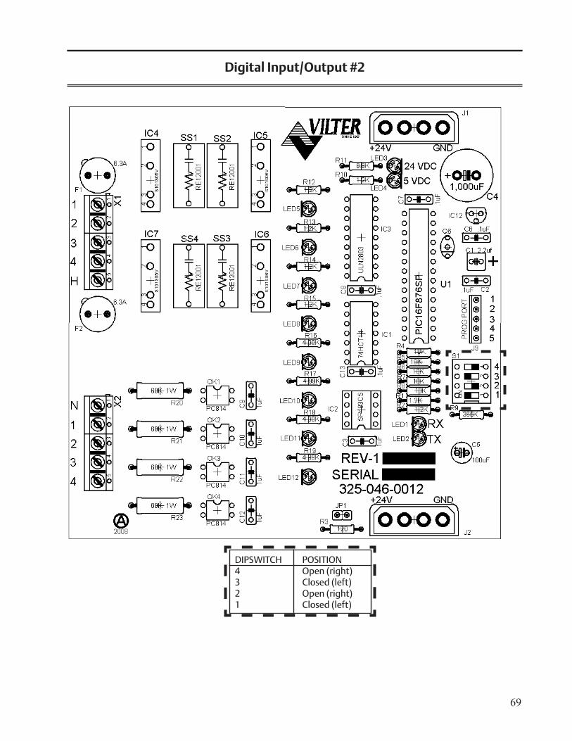
69
Digital Input/Output #2
DIPSWITCH POSITION4 Open (right)3 Closed (left)2 Open (right)1 Closed (left)
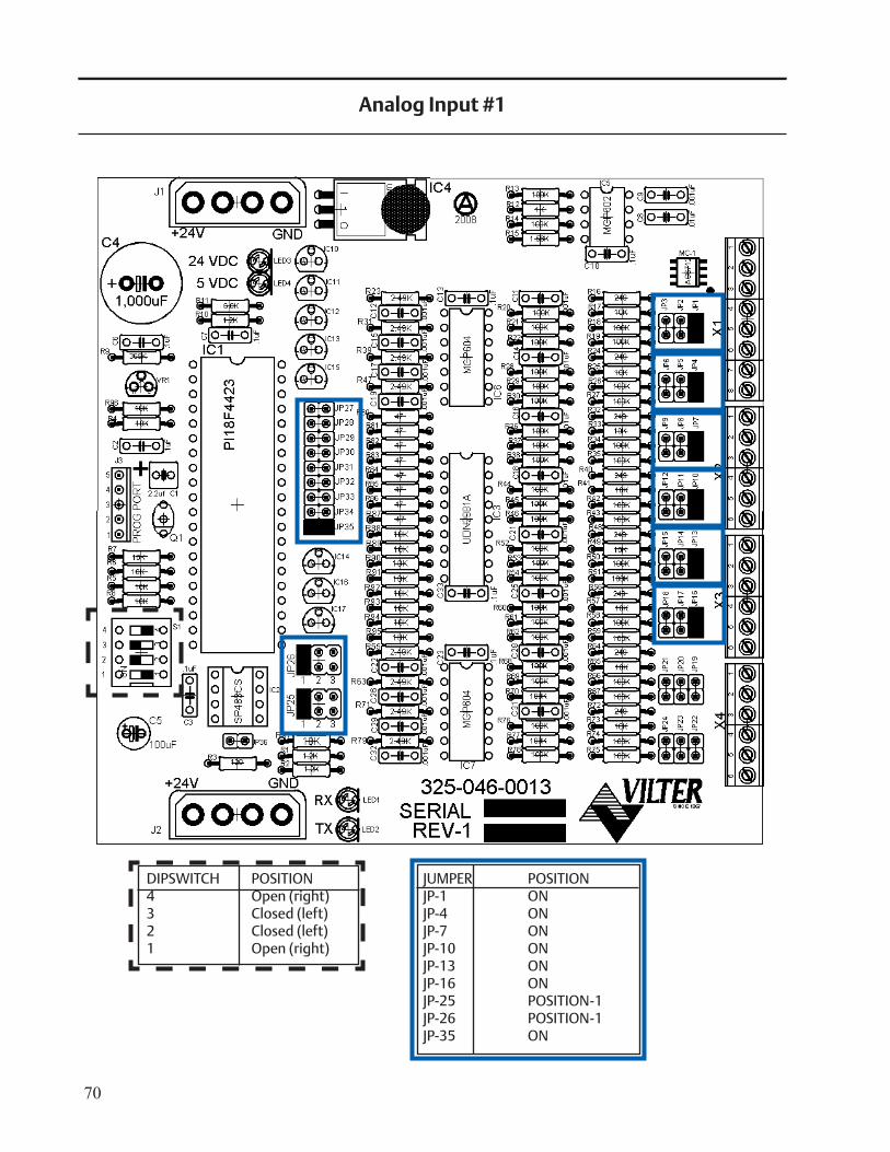
70
Analog Input #1
DIPSWITCH POSITION4 Open (right)3 Closed (left)2 Closed (left)1 Open (right)
JUMPER POSITIONJP-1 ONJP-4 ONJP-7 ONJP-10 ONJP-13 ONJP-16 ONJP-25 POSITION-1JP-26 POSITION-1JP-35 ON
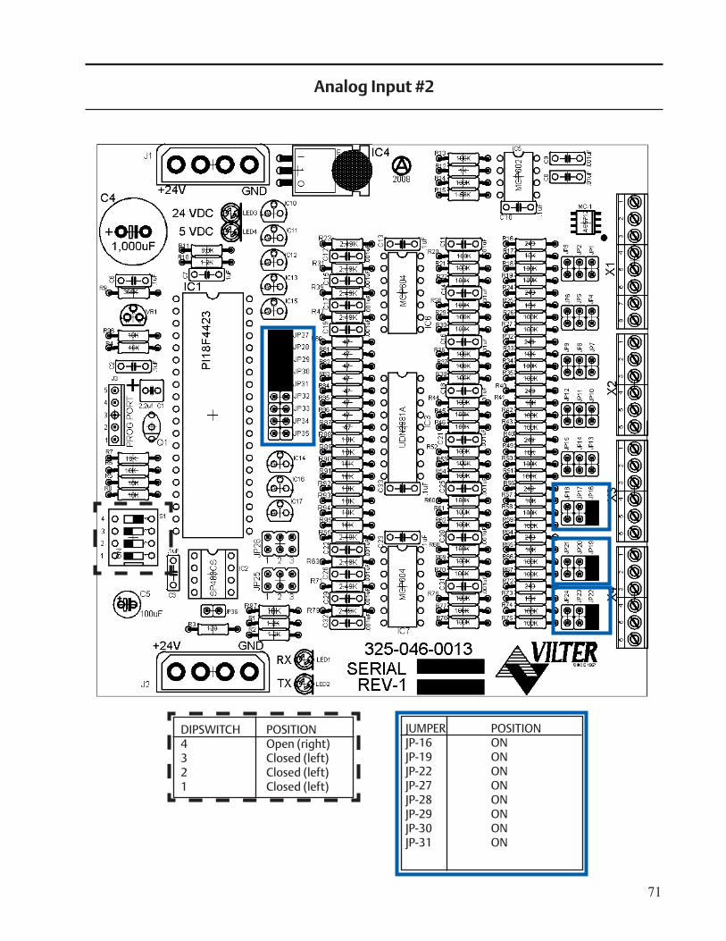
71
Analog Input #2
DIPSWITCH POSITION4 Open (right)3 Closed (left)2 Closed (left)1 Closed (left)
JUMPER POSITIONJP-16 ONJP-19 ONJP-22 ONJP-27 ONJP-28 ONJP-29 ONJP-30 ONJP-31 ON
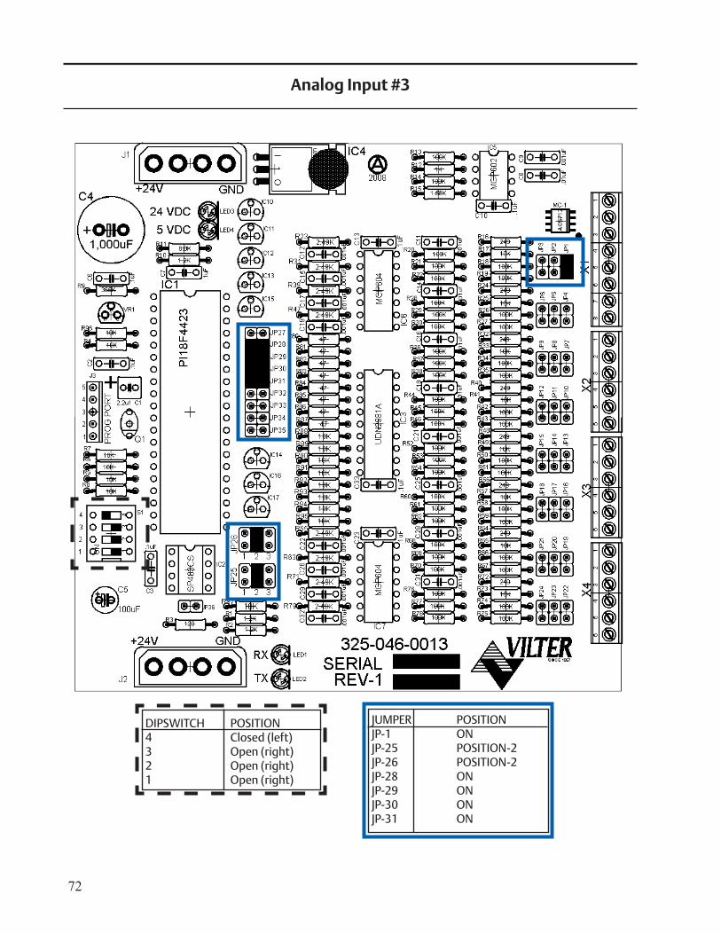
72
Analog Input #3
DIPSWITCH POSITION4 Closed (left)3 Open (right)2 Open (right)1 Open (right)
JUMPER POSITIONJP-1 ONJP-25 POSITION-2JP-26 POSITION-2JP-28 ONJP-29 ONJP-30 ONJP-31 ON
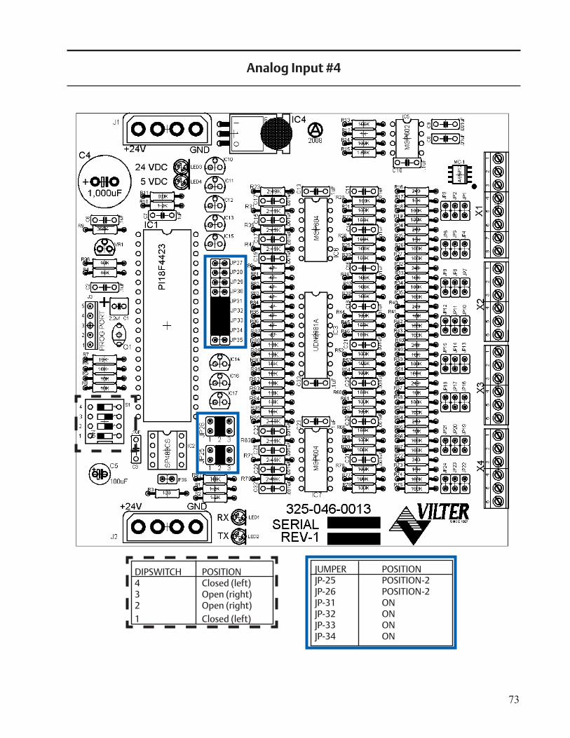
73
Analog Input #4
DIPSWITCH POSITION4 Closed (left)3 Open (right)2 Open (right)1 Closed (left)
JUMPER POSITIONJP-25 POSITION-2JP-26 POSITION-2JP-31 ONJP-32 ONJP-33 ONJP-34 ON
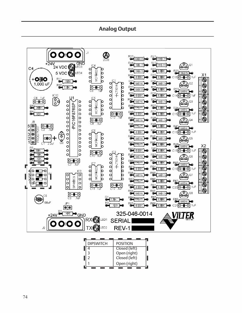
74
Analog Output
DIPSWITCH POSITION4 Closed (left)3 Open (right)2 Closed (left)1 Open (right)
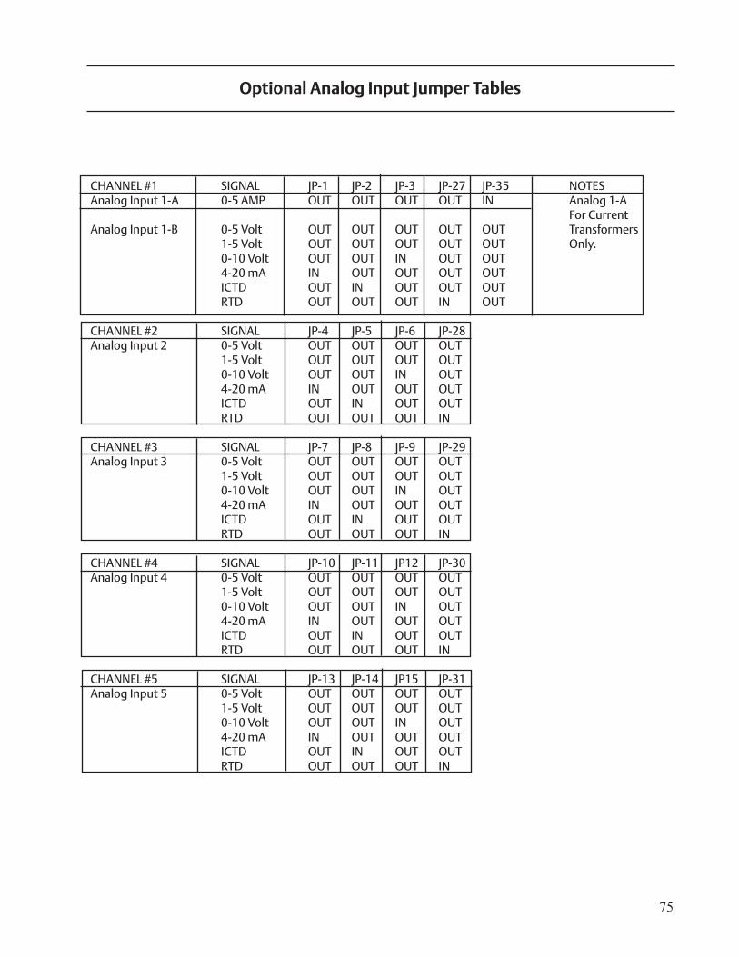
75
CHANNEL #1 SIGNAL JP-1 JP-2 JP-3 JP-27 JP-35 NOTESAnalog Input 1-A 0-5 AMP OUT OUT OUT OUT IN Analog 1-A For Current Analog Input 1-B 0-5 Volt OUT OUT OUT OUT OUT Transformers 1-5 Volt OUT OUT OUT OUT OUT Only. 0-10 Volt OUT OUT IN OUT OUT 4-20 mA IN OUT OUT OUT OUT ICTD OUT IN OUT OUT OUT RTD OUT OUT OUT IN OUT
CHANNEL #2 SIGNAL JP-4 JP-5 JP-6 JP-28Analog Input 2 0-5 Volt OUT OUT OUT OUT 1-5 Volt OUT OUT OUT OUT 0-10 Volt OUT OUT IN OUT 4-20 mA IN OUT OUT OUT ICTD OUT IN OUT OUT RTD OUT OUT OUT IN
CHANNEL #3 SIGNAL JP-7 JP-8 JP-9 JP-29Analog Input 3 0-5 Volt OUT OUT OUT OUT 1-5 Volt OUT OUT OUT OUT 0-10 Volt OUT OUT IN OUT 4-20 mA IN OUT OUT OUT ICTD OUT IN OUT OUT RTD OUT OUT OUT IN
CHANNEL #4 SIGNAL JP-10 JP-11 JP12 JP-30Analog Input 4 0-5 Volt OUT OUT OUT OUT 1-5 Volt OUT OUT OUT OUT 0-10 Volt OUT OUT IN OUT 4-20 mA IN OUT OUT OUT ICTD OUT IN OUT OUT RTD OUT OUT OUT IN
CHANNEL #5 SIGNAL JP-13 JP-14 JP15 JP-31Analog Input 5 0-5 Volt OUT OUT OUT OUT 1-5 Volt OUT OUT OUT OUT 0-10 Volt OUT OUT IN OUT 4-20 mA IN OUT OUT OUT ICTD OUT IN OUT OUT RTD OUT OUT OUT IN
Optional Analog Input Jumper Tables
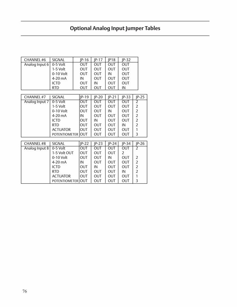
76
CHANNEL #6 SIGNAL JP-16 JP-17 JP18 JP-32Analog Input 6 0-5 Volt OUT OUT OUT OUT 1-5 Volt OUT OUT OUT OUT 0-10 Volt OUT OUT IN OUT 4-20 mA IN OUT OUT OUT ICTD OUT IN OUT OUT RTD OUT OUT OUT IN
CHANNEL #7 SIGNAL JP-19 JP-20 JP-21 JP-33 JP-25Analog Input 7 0-5 Volt OUT OUT OUT OUT 2 1-5 Volt OUT OUT OUT OUT 2 0-10 Volt OUT OUT IN OUT 2 4-20 mA IN OUT OUT OUT 2 ICTD OUT IN OUT OUT 2 RTD OUT OUT OUT IN 2 ACTUATOR OUT OUT OUT OUT 1 POTENTIOMETER OUT OUT OUT OUT 3
CHANNEL #8 SIGNAL JP-22 JP-23 JP-24 JP-34 JP-26Analog Input 8 0-5 Volt OUT OUT OUT OUT 2 1-5 Volt OUT OUT OUT OUT 2 0-10 Volt OUT OUT IN OUT 2 4-20 mA IN OUT OUT OUT 2 ICTD OUT IN OUT OUT 2 RTD OUT OUT OUT IN 2 ACTUATOR OUT OUT OUT OUT 1 POTENTIOMETER OUT OUT OUT OUT 3
Optional Analog Input Jumper Tables

77

78 Vilter Manufacturing LLC are trademarks of Emerson Electric Co. or one of its affi liated companies.©2010 Emerson Climate Technoligies, Inc. All rights reserved. Printed in the USA.
35391SC Rev 2.02
Vilter Manufacturing LLCP.O. Box 8904Cudahy, WI 53110-8904P 414 744 0111F 414 744 1769
www.vilter.com
EmersonClimate.com


