Embed Size (px)
Citation preview
CONTRACT DOCUMENTS FOR
INFLUENT PUMPING STATION BAR SCREEN INSTALLATION
CITY PROJECT NO. 15-19
CITY OF MOUNT VERNON, WASHINGTON
JILL BOUDREAU, MAYOR
CITY COUNCIL
BOB FIEDLER KEN QUAM MARK HULST DALE RAGAN JOE LINDQUIST MIKE URBAN GARY MOLENAAR
The Engineering material in this document was prepared under the supervision and direction of
Eric Bergstrom, P.E., whose seal as a Registered Professional Engineer is affixed above.
For information on this project, contact: Department of Public Works (360) 336-6204
TABLE OF CONTENTS
A. Contract Documents Page Advertisement for Bids ..................................................................................................... A2 Bidders Checklist .............................................................................................................. A4 Supplemental Instructions to Bidders .............................................................................. .A5 Bid Proposal ...................................................................................................................... A8 Bidder Identification ............................................................................................. A9 Proposal Forms ................................................................................................... A10 Proposal Measurement and Payment Schedule .................................................. A11 Proposal Signature and Addendum Acknowledgment ....................................... A13 Responsible Bidder Criteria ................................................................................ A14 Non-Collusion Declaration ................................................................................. A15 Bid Bond ............................................................................................................. A16 Contract ........................................................................................................................... A17 Retainage Investment Options Form ............................................................................. .A21 Performance Bond ......................................................................................................... .A22 B. Amendments to the Standard Specifications C. Special Provisions ................................................................................................... .SP-1 D. Contract Plans See Index on Cover Sheet E. Wage Rates
A-1

ADVERTISEMENT FOR BIDS INFLUENT PUMPING STATION BAR SCREEN INSTALLATION
CITY PROJECT NO. 15-19
Sealed bid proposals will be received by the City of Mount Vernon at the office of the City Finance Director, 910 Cleveland Avenue, Mount Vernon, Washington, 98273 until 10:00 a.m. Thursday, December 17, 2015, at which time the bids will be opened and publicly read. Bids shall be submitted on the forms attached with the bidding documents and shall be enclosed in an opaque envelope which is clearly marked “INFLUENT PUMPING STATION BAR SCREEN INSTALLATION.”
The work to be performed under this contract includes the procurement and installation of a new mechanical bar screen in the Influent Pump Station at the City of Mount Vernon Wastewater Treatment Plant (WWTP). The contract requirements may be found in the technical specifications and drawings of the special provisions for this project. All work shall be done in accordance with the Special Provisions of the Bid Documents and the 2014 Standard Specifications for Road, Bridge, and Municipal Construction, including the amendments thereto. The engineer’s estimate of the range of probable construction cost for the project is $400,000 to $700,000. Information, copies of maps, plans, specifications, and addenda for this project will be available on-line beginning Tuesday, December 1, 2015, at http://www.mountvernonwa.gov/bids.aspx. They will also be available for review or for purchase at the City of Mount Vernon Public Works Department, 1024 Cleveland Street, Mount Vernon, WA for a non-refundable fee of $50.00 (Fifty Dollars) for each set of bid documents. An additional $10.00 (Ten Dollar) fee will be charged for mailing. Checks should be made payable to the City of Mount Vernon and mailed to the Public Works Department, P.O. Box 809, Mount Vernon, WA 98273. Contractors who download plans and specifications are advised to e-mail [email protected] to be added to the plan holders list to receive any addenda that may be issued. Any questions may be directed to [email protected] or by phone to Gary Duranceau, Wastewater Division Manager at (360) 336-6219. All addenda will be posted on-line for this project. All bid proposals shall be accompanied by a bid proposal deposit in the form of a certified check, bank cashier’s check, or surety bond in an amount equal to five percent (5%) of the amount of such bid proposal. Should the successful bidder fail to enter into such contract and furnish satisfactory performance bond within the time stated in the specifications, the bid proposal deposit shall be forfeited to the City of Mount Vernon.
A pre bid conference will be held at the project site at 10:00 am on December 10, 2015, at 1401 Britt Road, Mount Vernon. Prospective bidders will have the opportunity to observe the project site during the conference. Any responses to questions arising during the conference will be responded to in an addendum if determined necessary.
The City of Mount Vernon reserves the right to accept a proposal of the bidder submitting the lowest responsible bid, to reject any or all bids, revise or cancel the work to be performed, or do the work otherwise, if the best interest of the City is served thereby. The City of Mount Vernon in accordance with Title VI of the Civil Rights Act of 1964, 78 Stat. 252, 42 U.S.C. 2000d to 2000d-4 and Title 49, Code of Federal Regulations, Department of Transportation,
A-2
Subtitle A, Office of the Secretary, Part 21, nondiscrimination in federally assisted programs of the Department of Transportation issued pursuant to such Act, hereby notifies all bidders that it will affirmatively insure that in any contract entered into pursuant to this advertisement, disadvantaged business enterprises will be afforded full opportunity to submit bids in response to this invitation and will not be discriminated against on the grounds of race, color or national origin in consideration for an award. The City of Mount Vernon is an Equal Opportunity and Affirmative Action Employer. Small, Minority and Women-Owned firms are encouraged to submit bids. All work performed on this project will be subject to the prevailing state wage rates. CITY OF MOUNT VERNON Alicia D. Huschka, Finance Director Published: Skagit Valley Herald & Daily Journal of Commerce – December 1, 2015, and December 8, 2015
A-3
BIDDER’S CHECKLIST 1. Has a bid bond or certified check been enclosed with your bid? 2. Is the amount of the bid guaranty at least five percent (5%) of the total amount of the bid? 3. Has the proposal been properly signed? 4. Have all items been bid on? 5. Has the Non-Collusion Declaration been reviewed? 6. Have you shown your State Contractor’s License Number on the proposal? 7. Have you acknowledged all addenda? 8. Have you included the Contractor's Responsibility Statement?
A-4
SUPPLEMENTAL INSTRUCTIONS TO BIDDERS
Preparation of Proposal Each bid proposal shall be submitted on the forms included in the “Bid Proposal” section following. All blank spaces on the forms shall be completed in ink or be typewritten. Any omission of prices for items included on the Bid form, or any addition in writing to the form of the bid proposal or any condition, limitation or provision not officially invited in these contract documents may render the proposal as being incomplete or modified and may become cause for rejection of the bid. The unit or lump sum price for each item, and the total bid price shall be shown in figures. The extended unit price for each bid item shall be shown in figures. All bid prices, shall be shown in the designated locations under the corresponding headings on the “Bid” form. The unit, extended unit, or lump sum price for each bid item shall include as shown on the “Bid” form complete under each heading all costs for labor, materials, tools, equipment, overhead and profit. No additional compensation for these items shall be allowed except through an approved change order as provided for in the contract documents. The sum shown for the “Bid Total” (total bid price) shall be the amount for which the Bidder offers to perform, and which the bidder agrees to accept for the work described in these documents. At the option and direction of the City of Mount Vernon, work may be added or deleted in accordance with the contract provisions hereunder. Bidders shall fill in and complete the information requested on the “Bidder Identification” form, including address and telephone number. Included in the form shall be the legal name under which the firm or bidder is registered. Bid proposals shall be signed in full by the person or persons legally authorized to bind the bidder to a contract. A bid by a corporation shall further give the state of incorporation and have the corporate seal affixed. A bid submitted by an agent shall have attached a current power of attorney certifying the agent’s authority to bind the Bidder. The name of each person signing shall by typed or printed below the signature.
Bid Proposal Deposit As a guarantee of good faith and as required by law, each bid shall be accompanied by a bid bond in the form of a certified check, bank cashier’s check, or surety bond, in accordance with the provisions of Section 1-02.7 of the Standard Specifications. All bid bonds shall be made payable to the City of Mount Vernon. A surety bond shall be submitted on the bid bond form in the Bid Proposal Forms section following. In the event of the withdrawal of this bid proposal after the receipt and opening of bid proposals, or the failure of the Bidder to enter into a contract and give the required insurance certification within 10 calendar days after the date of contract award, the Bidder shall be liable to the City of Mount Vernon for the amount of five (5) percent of the total amount of the bid, as liquidated damages due to the default of the Bidder.
A-5
The deposits of the three low bidders will be retained until a contract has been entered into between the successful bidder and the owner. The deposits of the other bidders will be returned as soon as it is determined that they are not one of the three low bidders.
Submittal of Proposal The completed Bid Proposal Forms, and any other documents required in accordance with the Special Provisions, shall be submitted to the office of the City Finance Director at Mount Vernon City Hall, 910 Cleveland Avenue, Post Office Box 809, Mount Vernon, Washington 98273 in an envelope marked: “INFLUENT PUMPING STATION BAR SCREEN INSTALLATION, CITY PROJECT NO. 15-19.”
Interpretations and Corrections If the Bidder finds any discrepancy in, or omission from the specifications or plans, or if there is any doubt as to their meaning, the Bidder shall promptly notify the City of Mount Vernon Public Works Department at (360) 336-6204. Any addenda issued during the time of bidding will be numbered consecutively and will be incorporated into these documents. The Bidder shall be responsible to ascertain prior to submittal of a bid proposal that all addenda issued have been received, and are acknowledged on the “Bid Proposal Signature and Addendum Acknowledgement” form. Addenda will only be issued to those contractors appearing on the Plan Holder’s List at the City of Mount Vernon Public Works Department. It will be the responsibility of the contractor to ensure their name appears on the Plan Holder’s List. The list is posted on the City’s Website at www.mountvernonwa.gov.
Consideration of Bids Bid proposals will be opened and read publicly at the time and place indicated in the “Advertisement for Bids” or in an addendum, unless the City of Mount Vernon has withdrawn the request for bids. In the event of any discrepancies, an item’s unit price shall have precedence over the item’s extended unit price, and the arithmetic sum of the extended unit and lump sum prices shall have precedence over the total amount of bid. Any interlineation, alteration or erasure shall be initialed by the Bidder for the proposal to be considered. It is the intent of the City of Mount Vernon to award a Contract to the responsible Bidder providing the lowest bid provided the bid proposal has been submitted in accordance with the requirements of these contract documents and does not exceed the funds available. Bidders are notified that all bids may be rejected if the lowest responsible bid received exceeds the Engineer’s Estimate by an unreasonable amount. In the event all bids are rejected for this reason, this project may be deferred for re-advertising for bids until a more competitive situation exists.
A-6
Award of Contract The award of the Contract, if awarded, shall be made within 30 calendar days of the date of opening of bids to the lowest Bidder deemed responsible by the City of Mount Vernon, as provided for herein. Except that upon mutual consent of the lowest responsible Bidder and the City of Mount Vernon, the 30 calendar days may be extended.
Execution of Contract The successful Bidder shall sign and return the contract to the City of Mount Vernon, within 10 calendar days after bid award.
State Sales Tax State Sales Tax is applicable to this project in accordance with Section 1-07.2(2).
Release of Bid Bonds If it is anticipated that the award of the contract will be delayed beyond 30 days from the bid opening, all bid bonds except for the lowest three bidders will be returned.
Examination of Plans, Specifications and Site of Work In accordance with Section 1-02.4 of the Standard Specifications, the information used for study and design of this project is available for review by the Contractor at the following address: City of Mount Vernon Public Works Department 1024 Cleveland Avenue Mount Vernon, WA 98273
Hours of Work Contractors desiring to perform contractual work on holidays, Saturdays, and Sundays, or before 7:00 a.m. or after 4:30 p.m. any day, shall apply in writing to the City of Mount Vernon Public Works Department, Post Office Box 809, Mount Vernon, Washington 98273. Additional working hours may be approved upon request to the Engineer. Any work performed outside of the dates and time specified herein as approved by the Engineer, or any overtime, double-shifting or longer than normal single shifts shall be the decision of the Contractor and will not be reason for extra compensation unless so approved in writing by the Engineer.
A-7
BID PROPOSAL FOR
INFLUENT PUMPING STATION BAR SCREEN INSTALLATION CITY PROJECT NO. 15-19
Date:___________________ TO: Mayor Boudreau and City Council Members P.O. Box 809 Mount Vernon, WA 98273 BIDDER: __________________________ The undersigned declares that they have examined the location of the project site and the conditions of work; and have carefully read and thoroughly understand the contract documents entitled: “INFLUENT PUMPING STATION BAR SCREEN INSTALLATION” including the “Specifications and Conditions” and “Contract Forms”, governing the work embraced in this project and the method by which payment will be made for said work. The Undersigned hereby propose to undertake and complete the work embraced in this project in accordance with said contract documents, and agree to accept as payment for said work, the schedule of lump sum and unit prices as set forth in the “Bid” below. The undersigned acknowledge that payment will be based on the actual work performed and material used as measured or provided for in accordance with the said contract documents. __________________________________ Signature
A-8
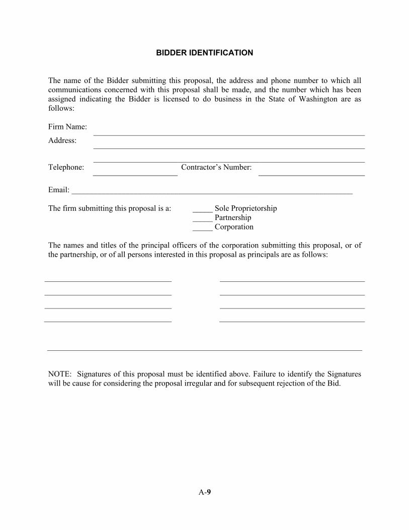
BIDDER IDENTIFICATION The name of the Bidder submitting this proposal, the address and phone number to which all communications concerned with this proposal shall be made, and the number which has been assigned indicating the Bidder is licensed to do business in the State of Washington are as follows: Firm Name:
Address:
Telephone: Contractor’s Number:
Email: ______________________________________________________________________ The firm submitting this proposal is a: _____ Sole Proprietorship _____ Partnership _____ Corporation The names and titles of the principal officers of the corporation submitting this proposal, or of the partnership, or of all persons interested in this proposal as principals are as follows:
NOTE: Signatures of this proposal must be identified above. Failure to identify the Signatures will be cause for considering the proposal irregular and for subsequent rejection of the Bid.
A-9
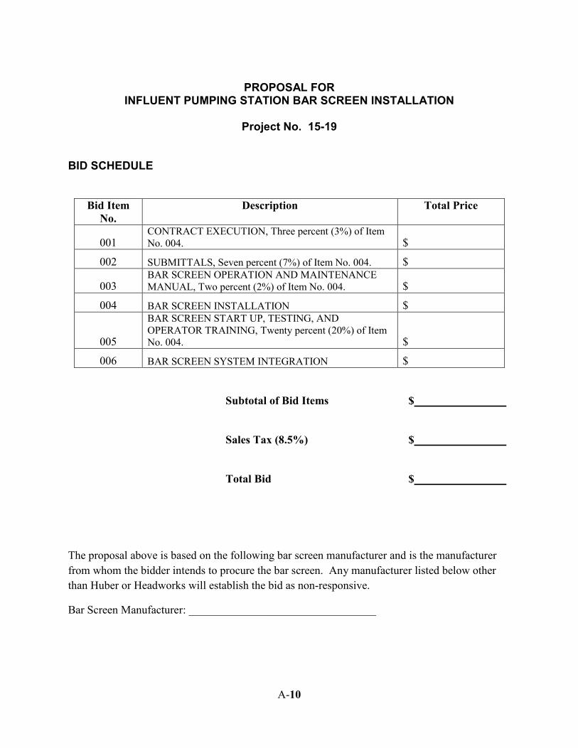
PROPOSAL FOR
INFLUENT PUMPING STATION BAR SCREEN INSTALLATION
Project No. 15-19 BID SCHEDULE
Bid Item No.
Description Total Price
001 CONTRACT EXECUTION, Three percent (3%) of Item No. 004. $
002 SUBMITTALS, Seven percent (7%) of Item No. 004. $
003 BAR SCREEN OPERATION AND MAINTENANCE MANUAL, Two percent (2%) of Item No. 004. $
004 BAR SCREEN INSTALLATION $
005
BAR SCREEN START UP, TESTING, AND OPERATOR TRAINING, Twenty percent (20%) of Item No. 004. $
006 BAR SCREEN SYSTEM INTEGRATION $ Subtotal of Bid Items $ Sales Tax (8.5%) $ Total Bid $
The proposal above is based on the following bar screen manufacturer and is the manufacturer from whom the bidder intends to procure the bar screen. Any manufacturer listed below other than Huber or Headworks will establish the bid as non-responsive.
Bar Screen Manufacturer: _________________________________
A-10
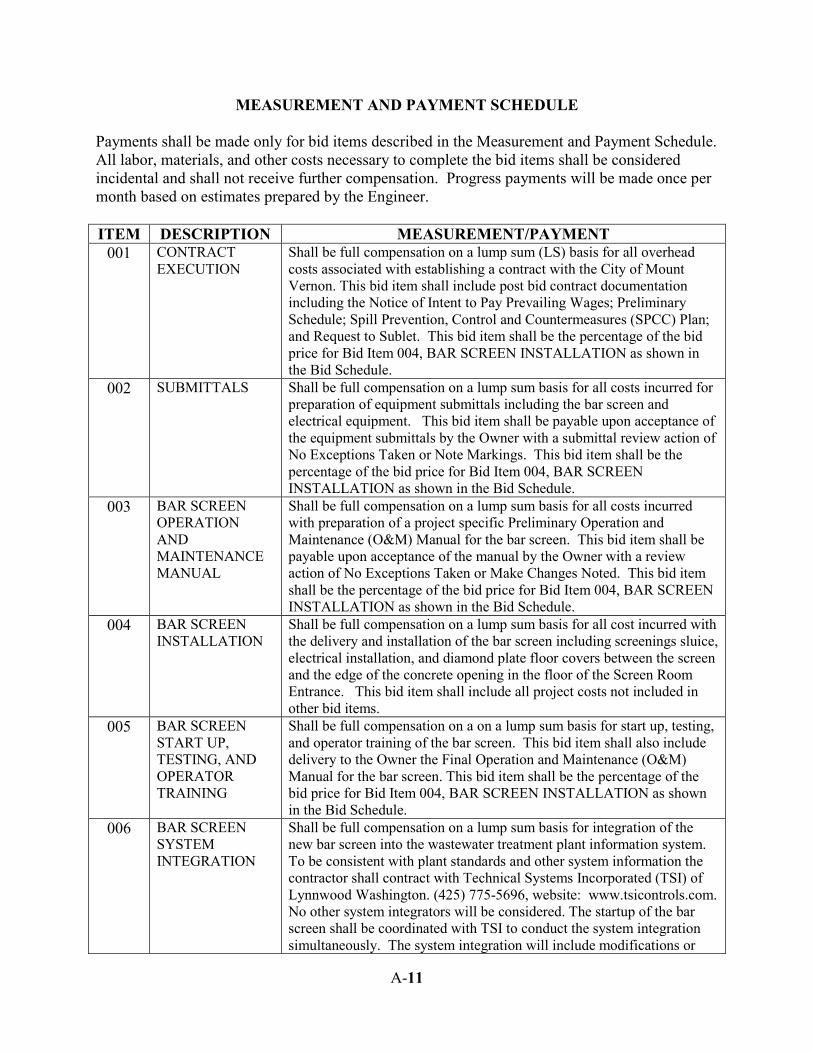
MEASUREMENT AND PAYMENT SCHEDULE
Payments shall be made only for bid items described in the Measurement and Payment Schedule. All labor, materials, and other costs necessary to complete the bid items shall be considered incidental and shall not receive further compensation. Progress payments will be made once per month based on estimates prepared by the Engineer. ITEM DESCRIPTION MEASUREMENT/PAYMENT
001 CONTRACT EXECUTION
Shall be full compensation on a lump sum (LS) basis for all overhead costs associated with establishing a contract with the City of Mount Vernon. This bid item shall include post bid contract documentation including the Notice of Intent to Pay Prevailing Wages; Preliminary Schedule; Spill Prevention, Control and Countermeasures (SPCC) Plan; and Request to Sublet. This bid item shall be the percentage of the bid price for Bid Item 004, BAR SCREEN INSTALLATION as shown in the Bid Schedule.
002 SUBMITTALS Shall be full compensation on a lump sum basis for all costs incurred for preparation of equipment submittals including the bar screen and electrical equipment. This bid item shall be payable upon acceptance of the equipment submittals by the Owner with a submittal review action of No Exceptions Taken or Note Markings. This bid item shall be the percentage of the bid price for Bid Item 004, BAR SCREEN INSTALLATION as shown in the Bid Schedule.
003 BAR SCREEN OPERATION AND MAINTENANCE MANUAL
Shall be full compensation on a lump sum basis for all costs incurred with preparation of a project specific Preliminary Operation and Maintenance (O&M) Manual for the bar screen. This bid item shall be payable upon acceptance of the manual by the Owner with a review action of No Exceptions Taken or Make Changes Noted. This bid item shall be the percentage of the bid price for Bid Item 004, BAR SCREEN INSTALLATION as shown in the Bid Schedule.
004 BAR SCREEN INSTALLATION
Shall be full compensation on a lump sum basis for all cost incurred with the delivery and installation of the bar screen including screenings sluice, electrical installation, and diamond plate floor covers between the screen and the edge of the concrete opening in the floor of the Screen Room Entrance. This bid item shall include all project costs not included in other bid items.
005 BAR SCREEN START UP, TESTING, AND OPERATOR TRAINING
Shall be full compensation on a on a lump sum basis for start up, testing, and operator training of the bar screen. This bid item shall also include delivery to the Owner the Final Operation and Maintenance (O&M) Manual for the bar screen. This bid item shall be the percentage of the bid price for Bid Item 004, BAR SCREEN INSTALLATION as shown in the Bid Schedule.
006 BAR SCREEN SYSTEM INTEGRATION
Shall be full compensation on a lump sum basis for integration of the new bar screen into the wastewater treatment plant information system. To be consistent with plant standards and other system information the contractor shall contract with Technical Systems Incorporated (TSI) of Lynnwood Washington. (425) 775-5696, website: www.tsicontrols.com. No other system integrators will be considered. The startup of the bar screen shall be coordinated with TSI to conduct the system integration simultaneously. The system integration will include modifications or
A-11
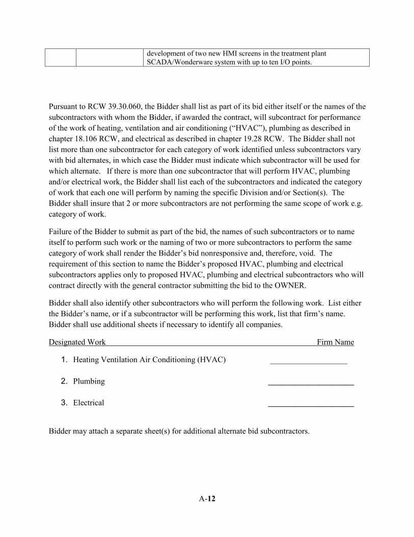
development of two new HMI screens in the treatment plant SCADA/Wonderware system with up to ten I/O points.
Pursuant to RCW 39.30.060, the Bidder shall list as part of its bid either itself or the names of the subcontractors with whom the Bidder, if awarded the contract, will subcontract for performance of the work of heating, ventilation and air conditioning (“HVAC”), plumbing as described in chapter 18.106 RCW, and electrical as described in chapter 19.28 RCW. The Bidder shall not list more than one subcontractor for each category of work identified unless subcontractors vary with bid alternates, in which case the Bidder must indicate which subcontractor will be used for which alternate. If there is more than one subcontractor that will perform HVAC, plumbing and/or electrical work, the Bidder shall list each of the subcontractors and indicated the category of work that each one will perform by naming the specific Division and/or Section(s). The Bidder shall insure that 2 or more subcontractors are not performing the same scope of work e.g. category of work.
Failure of the Bidder to submit as part of the bid, the names of such subcontractors or to name itself to perform such work or the naming of two or more subcontractors to perform the same category of work shall render the Bidder’s bid nonresponsive and, therefore, void. The requirement of this section to name the Bidder’s proposed HVAC, plumbing and electrical subcontractors applies only to proposed HVAC, plumbing and electrical subcontractors who will contract directly with the general contractor submitting the bid to the OWNER.
Bidder shall also identify other subcontractors who will perform the following work. List either the Bidder’s name, or if a subcontractor will be performing this work, list that firm’s name. Bidder shall use additional sheets if necessary to identify all companies.
Designated Work Firm Name
1. Heating Ventilation Air Conditioning (HVAC) ___________________
2. Plumbing ___________________
3. Electrical ___________________
Bidder may attach a separate sheet(s) for additional alternate bid subcontractors.
A-12
PROPOSAL SIGNATURE AND ADDENDUM ACKNOWLEDGEMENT
The Bidder is hereby advised that by signature of this proposal, he/she is deemed to have acknowledged all requirements and signed all certificates contained herein. The undersigned hereby agrees to pay labor not less than the prevailing rates of wages or less than the hourly minimum rate of wages as specified in the Specifications and Conditions, for this project. A proposal guaranty in an amount of five percent (5%) of the total bid, based upon the approximation estimate of quantities at the above prices and in the form as indicated below, is attached hereto: CASH IN THE AMOUNT OF ______________________ CASHIER’S CHECK _________________________________________ CERTIFIED CHECK Dollars ($_________) Payable to the city of Mount PROPOSAL BOND Vernon IN THE AMOUNT OF 5% OF THE BID. Receipt is hereby acknowledged by addendum(s) No(s). _______, ______. and ______.
SIGNATURE OF AUTHORIZED OFFICIAL(S) (PROPOSAL MUST BE SIGNED) __________________________________________ __________________________________________ SIGNATURE: __________________________________________ FIRM NAME: STATE OF WASHINGTON ) ) ss. COUNTY OF SKAGIT ) On this _____ day of _________ 2015, before me personally appeared ______________________ to me personally known to be the person described in and who executed the above instrument and who acknowledged that _____had the authority to submit this proposal on behalf of said firm.
NOTARY PUBLIC, in and for the State of Washington, Residing at:___________________________________ My Commission Expires: ____________
This proposal form is not transferable and any alteration of the firm’s name entered hereon without prior permission from the City of Mount Vernon will be cause for considering the proposal irregular and for subsequent rejection of the Bid.
A-13
RESPONSIBLE BIDDER CRITERIA FORM
In order for the City of Mount Vernon to award a contract to the apparent low bidder on Public Works Contracts, evidence of the following must be submitted:
1. Certificate of registration in compliance with RCW 18.27
2. State unified business identifier number: ________________________
3. Industrial insurance coverage (RCW 51)
4. Employment Security Department number: _______________________
5. State excise tax registration number: _________________________
6. Bidder must not be disqualified from bidding on any public works contracts. Please confirm that your firm is not disqualified from bidding.
Signature: _______________________________________________ Date:________________
A-14
A-15
BID BOND KNOW ALL MEN BY THESE PRESENTS, that we __________________________ as
principal, and the _____________________________ a corporation duly organized under the
laws of the State of ____________________ and having its principal place of business at
_______________________________, in the State of Washington, as Surety, are held and firmly
bound unto the City of Mount Vernon, a Municipal Corporation in the State of Washington, in
the full and penal sum of five percent (5%) of the total bid amount appearing on the bid proposal
of said principal for the work hereinafter described, for the payment of which, well and truly to
be made, we bind our heirs, executors, administrators and assigns, and successors and assigns,
jointly and severally, firmly by these presents.
The condition of this bond is such that, whereas, the principal herein is herewith submitting his or its bid proposal for INFLUENT PUMPING STATION BAR SCREEN INSTALLATION, Project No. 15-19, said bid proposal, by reference thereto, being hereby made a part hereof. NOW, THEREFORE, if the bid proposal submitted by the PRINCIPAL is accepted, and the contract is awarded to said PRINCIPAL, and if said PRINCIPAL shall duly make and enter into and execute said contract and shall furnish the performance bond as required by the bidding and contract documents within a period of ten (10) days from and after said award, exclusive of the day of such award, then its obligation to pay the above-mentioned penal sum as liquidated damages shall be null and void, otherwise it shall remain and be in full force and effect. Signed and Sealed this ______ day of _____________________, 2015. Principal: By:________________________________ (Seal) Surety: By:________________________________ (Seal) Attorney-In-Fact The Attorney-in-fact who executes this bond in behalf of the surety, must attach a copy of his power of attorney as evidence of his authority.
A-16
CONTRACT
INFLUENT PUMPING STATION BAR SCREEN INSTALLATION
Project No. 15-19 THIS AGREEMENT, made and entered into in duplicate this _____ day of __________________, 2015, by and between the City of Mount Vernon, Washington hereinafter called the City of Mount Vernon and _______________________ hereinafter called the Contractor. WITNESSETH: That in consideration of the terms and conditions contained herein and attached and made a part of this agreement, the parties hereto covenant and agree as follows: 1. The Contractor shall do all work and furnish all tools, equipment and materials for the
INFLUENT PUMPING STATION BAR SCREEN INSTALLATION as described in the attached proposal of work, including addenda, for the amount bid which are by this reference incorporated herein and made a part hereof, and shall perform any alterations in or additions to the work provided under this contract and every part thereof.
2. All work shall be completed in accordance with the Special Provisions of the Bid Documents
and the 2014 Standard Specifications for Road, Bridge, and Municipal Construction, including the amendments thereto.
3. If said work is not completed within the time specified, the Contractor agrees to pay to the City
of Mount Vernon the sum as specified in Section 1-08.9 of the 2014 WSDOT/APWA Standard Specifications for each and every working day said work remains uncompleted and after expiration of the specified time, as liquidated damages. The Contractor shall provide and bear the expense of all equipment, work and labor of any sort whatsoever that may be required for the transfer of materials and for constructing and completing the work provided for in this contract and every part thereof and shall guarantee said materials and work for a period of one year after completion of this contract, except as may be modified by the plans, specifications, and/or contract documents.
4. The City of Mount Vernon agrees to pay the Contractor for the actual quantities in the
completed work according to the schedule of unit prices set forth in the bid proposal hereto attached and made a part of this contract.
5. The Contractor for himself, and for his heirs, executors, administrators, successors and assigns,
does hereby agree to the full performance of all the covenants herein contained upon the part of the Contractor.
6. It is further provided that no liability shall attach to the City of Mount Vernon by reason of
entering into this contract, except as expressly provided herein.
A-17
7. The Contractor shall defend indemnify and hold the City its officers, officials, employees, HDR and volunteers harmless from any and all claims, injuries, damages, loss or suits including attorney fees, arising out of or in connection with the performance of this Contract, except for injuries and damages caused by the sole negligence of the City.
Should a court of competent jurisdiction determine that this Contract is subject to RCW 4.24.115, then, in the event of liability for damages arising out of bodily injury to persons or damages to property caused by or resulting from the concurrent negligence of the Contractor and the City, its officers, officials, employees, HDR and volunteers, the Contractor’s liability hereunder shall be only to the extent of the Contractor’s negligence. It is further specifically and expressly understood that the indemnification provided herein constitutes the Contractor’s waiver of immunity under Industrial Insurance, Title 51 RCW, solely for the purposes of this indemnification. This waiver has been mutually negotiated by the parties. The provisions of this section shall survive the expiration of termination of this Contract. Insurance The Contractor shall procure and maintain for the duration of the Contract, insurance against claims for injuries to persons or damage to property which may arise from or in connection with the performance of the work hereunder by the Contractor, their agents, representatives, employees or subcontractors. A. Minimum Scope of Insurance Contractor shall obtain insurance of the types described below:
1. Automobile Liability insurance covering all owned, non-owned, hired and leased vehicles.
Coverage shall be written on Insurance Services Office (ISO) form CA 00 01 or a substitute form providing equivalent liability coverage. If necessary, the policy shall be endorsed to provide contractual liability coverage.
2. Commercial General Liability insurance shall be written on ISO occurrence form CG 00 01
and shall cover liability arising from premises, operations, independent contractors, products-completed operations, personal injury and advertising injury, and liability assumed under an insured contract. The Commercial General Liability insurance shall be endorsed to provide the Aggregate Per Project Endorsement ISO form CG 25 03 11 85. There shall be no endorsement or modification of the commercial General Liability insurance for liability arising from explosion, collapse or underground property damage. The City shall be named as an insured under the Contractor’s Commercial General Liability insurance policy with respect to the work performed for the City, using ISO additional insured endorsement CG 20 10 11 85 or a substitute endorsement providing equivalent coverage.
3. Workers’ Compensation coverage as required by the Industrial Insurance laws of the State
of Washington.
A-18
B. Minimum Amounts of Insurance Contractor shall maintain the following insurance limits:
1. Automobile Liability insurance with a minimum combined single limit for bodily injury and
property damage of $1,000,000 per accident.
2. Commercial General Liability insurance shall be written with limits no less than $1,000,000 each occurrence, $2,000,000 general aggregate and a $2,000,000 products-completed operations aggregate limit.
C. Other Insurance Provisions The insurance policies are to contain, or be endorsed to contain, the following provisions for Automobile Liability and Commercial General Liability:
1. The Contractor’s insurance coverage shall be primary insurance as respect to the City. Any
insurance, self-insurance, or insurance pool coverage maintained by the City shall be excess of the Contractor’s insurance and shall not contribute with it.
2. The Contractor’s insurance shall be endorsed to state that coverage shall not be cancelled by
either party, except after thirty (30) days prior written notice by certified mail, return receipt requested, has been given to the City.
D. Contractor’s Insurance for Other Losses The Contractor shall assume full responsibility for all loss or damage from any cause whatsoever to any tools, Contractor’s employee owned tools, machinery, equipment, or motor vehicles owned or rented by the Contractor, or the Contractor’s agents, suppliers or contractors as well as to any temporary structures, scaffolding and protective fences.
E. Waiver of Subrogation The Contractor and the City waive all rights against each other, any of their Subcontractors, Sub-subcontractors, agents and employees, each of the other, for damages caused by fire or other perils to the extent covered by Builder’s Risk insurance or other property insurance obtained pursuant to the Insurance Requirements Section of this Contract or other property insurance applicable to the work. The policies shall provide such waivers by endorsement or otherwise.
F. Acceptability of Insurers
Insurance is to be placed with insurers with a current A.M. Best rating of not less than A: VII.
A-19
G. Verification of Coverage Contractor shall furnish the City with original certificates and a copy of the amendatory endorsements, including, but not necessarily limited to the additional insured endorsement, evidencing the Automobile Liability and Commercial General Liability insurance of the Contractor before commencement of the work. H. Subcontractors Contractor shall include all subcontractors as insureds under its policies or shall furnish separate certificates and endorsements for each subcontractor. All coverages for subcontractors shall be subject to all of the same insurance requirements as stated herein for the Contractor.
IN WITNESS WHEREOF, the parties hereto have caused this agreement to be executed the day and year first above written. This _______ day of _____________________, 2015. CONTRACTOR: CITY OF MOUNT VERNON: _________________________________ _____________________________ Authorized Signature Jill Boudreau, Mayor _________________________________ Printed Tax ID No. _______________________ Attest: _____________________________ Alicia D. Huschka, Finance Director Approved as to Form: _____________________________ Kevin Rogerson, City Attorney
A-20
RETAINAGE INVESTMENT OPTION CONTRACTOR: ______________________________ PROJECT NAME: INFLUENT PUMPING STATION BAR SCREEN INSTALLATION
DATE: _____________________ Pursuant to R.C.W. 60.28.010, as amended, you may choose how your retainage under this contract will be held and invested. Please complete and sign this form indicating your preference. If you fail to do so, the Owner will hold your retainage as described in "Current Expense" option 1 below. ____1. Current Expense: The Owner will retain your money in its Current Expense Fund
Account until thirty days following final acceptance of the improvement or work as completed. You will not receive interest earned on this money.
____2. Interest Bearing Account: The Owner will deposit retainage checks in an interest-
bearing account in a bank, mutual savings bank, or savings and loan association, not subject to withdrawal until after the final acceptance of the improvement or work as completed or until agreed to by both parties. Interest on the account will be paid to you.
____3. Escrow/Investments: The Owner will place the retainage checks in escrow with a
bank or trust company until thirty days following the final acceptance of the improvement or work as completed. When the moneys reserved are to be placed in escrow, the Owner will issue a check representing the sum of the moneys reserve payable to the bank or trust company and you jointly. This check will be converted into bonds and securities chosen by you and approved by the Owner and these bonds and securities will be held in escrow. Interest on these bonds and securities will be paid to you as interest accrues.
___4. Surety Bond: The Contractor will obtain a bond from a Surety Company, licensed to
conduct business in the State of Washington for the estimated amount of Retainage based on 5% of the bid price.
____________________________ Contractor’s signature ____________________________ Title
A-21
PERFORMANCE BOND TO THE CITY OF MOUNT VERNON, WASHINGTON
KNOW ALL MEN BY THESE PRESENTS, that whereas the City of Mount Vernon, Washington has awarded to _____________________________________________. Hereinafter designated as the “Principal” a contract for the ________________________________________, as hereto attached and made a part hereof and whereas, said Principal is required under the terms of said contract to furnish a bond for the faithful performance of said contract. NOW THEREFORE, we the Principal and _______________________________________________ (surety) a corporation, organized and existing under and by the virtue of the laws of the State of Washington, duly authorized to do business in the State of Washington, as surety are held and firmly bound unto the City of Mount Vernon, Washington in the sum of: _______________________________ _________________________________________________ ( ) Total Contract Amount Lawful money of the United States, for the payment of which sum well and truly to be made, we bind ourselves, our heirs, executors, administrators, successors and assigns, jointly and severally, firmly by those presents. THE CONDITION OF THIS OBLIGATION IS SUCH, that if the above bonded Principal, his or its heirs, executors, administrators, successors, or assigns, shall in all things stand to and abide by, and well and truly keep and perform the covenants, conditions and agreements in the said Contract, and shall faithfully perform all the provisions of such Contract and shall also well and truly perform and fulfill all the undertakings, covenants, terms, conditions and agreements of any and all duly authorized modifications of said contract that may hereafter be made, at the time and in the manner therein specified or within such extensions of time as may be granted under said contract, and shall pay all laborer, mechanics, subcontractors, and material men and all persons who shall supply such person or persons, or subcontractors, with provisions and supplies for the carrying on of such work, on his or their part, the claims of any persons or persons arising under the contract to the extent such claims are provided for in RCW 39.08.010; the State of Washington with respect to taxes imposed pursuant to Titles 50,51, and 82 RCW which may be due; and shall indemnify and save harmless the City of Mount Vernon, Washington, their officers and agents from any claim for such payment and from any damage or expense by reason of failure of performance as specified in said contract; and shall further save harmless and indemnify said City of Mount Vernon, Washington, from any defect or defects in any of the workmanship entering into any part of the work or designated equipment covered by said contract, which shall develop or be discovered within one (1) year after the final acceptance of such work, then this obligation shall become null and void; otherwise, it shall be and remain in full force and effect; provided that the liability hereunder for defects in materials and workmanship for a period of one year after the acceptance of the works shall not exceed the sum of: ________________________________________________________ ____________________________________________________( ) Total Contract Amount And the said surety, for value received, hereby further stipulates and agrees that no change, extension of time, alteration or addition to the terms of the Contract or to the work to be performed thereunder or the specifications accompanying the same shall in any way affects its obligation this bond, and it does hereby waive notice of any change, extension of time, alterations, or additions to the terms of the Contract or the work or to the specifications. The Surety hereby agrees that the modifications and changes may be made in the terms and provisions of the aforesaid Contract without notice to Surety, and any such modifications or changes increasing the
A-22
total amount to be paid the Principal shall automatically increase the obligation of the Surety on this Performance Bond in a like amount, such increase, however, not to exceed twenty-five percent (25%) of the original amount of this bond without the consent of the Surety. IN WITNESS WHEREOF, the said Principal and the said Surety have caused this bond and two counterparts thereof to be signed and sealed by their duly authorized officers this ______ day of ________________, 20___.
_____________________________________ Principal
By: __________________________________ Signature
__________________________________ Printed Title: __________________________________ ATTEST (if corporation): (Corporate Seal) By: ___________________________________ Title: ___________________________________ ______________________________ Surety
By: ______________________________ Signature
______________________________ Printed Name and address of local office/agent of Surety Company is:
______________________________
______________________________
Approved as to form:
_______________________ City Attorney
A-23
INTRO.AP1 1
INTRODUCTION 2
The following Amendments and Special Provisions shall be used in conjunction with the 3 2014 Standard Specifications for Road, Bridge, and Municipal Construction. 4 5
AMENDMENTS TO THE STANDARD SPECIFICATIONS 6 7 The following Amendments to the Standard Specifications are made a part of this contract 8 and supersede any conflicting provisions of the Standard Specifications. For informational 9 purposes, the date following each Amendment title indicates the implementation date of the 10 Amendment or the latest date of revision. 11 12 Each Amendment contains all current revisions to the applicable section of the Standard 13 Specifications and may include references which do not apply to this particular project. 14 15 1-01.AP1 16
Section 1-01, Definitions and Terms 17 August 3, 2015 18
1-01.3 Definitions 19 The definition for “Engineer” is revised to read: 20 21
The Contracting Agency’s representative who directly supervises the engineering and 22 administration of a construction Contract. 23 24
The definition for “Inspector” is revised to read: 25 26
The Engineer’s representative who inspects Contract performance in detail. 27 28
The definition for “Project Engineer” is revised to read: 29 30
Same as Engineer. 31 32
The following new term and definition is inserted after the definition for “Proposal Form”: 33 34
Reference Information – Information provided to the Contractor by the Contracting 35 Agency that is not part of the Contract. 36
37 The definition for “Working Drawings” is revised to read: 38 39
Drawings, plans, diagrams, or any other supplementary data or calculations, including a 40 schedule of submittal dates for Working Drawings where specified, which the Contractor 41 must submit to the Engineer. 42
43
AMENDMENTS TO THE 2014 STANDARD SPECIFICATIONS BOOK Revised: 8/3/15
1-02.AP1 1
Section 1-02, Bid Procedures and Conditions 2 August 3, 2015 3
1-02.8(1) Noncollusion Declaration 4 The third paragraph is revised to read: 5 6
Therefore, by including the Non-collusion Declaration as part of the signed bid Proposal, 7 the Bidder is deemed to have certified and agreed to the requirements of the 8 Declaration. 9
10 1-02.9 Delivery of Proposal 11 This section is revised to read: 12 13
For projects scheduled for Bid opening in Olympia, the Proposal shall be sealed and 14 submitted in the envelope provided with it to the address below or shall be submitted 15 electronically via Trns∙Port Expedite® software and BidExpress®. The Bidder shall fill in 16 all blanks on this envelope to ensure proper handling and delivery. Bids are to be 17 received no later than until 11:00:59 A.M. Pacific time on the date of Bid opening: 18 19
Washington State Department of Transportation 20 Room 2D20 21 310 Maple Park Avenue SE 22 Olympia WA 98501-2361 23
24 For projects scheduled for Bid opening in other locations the Proposal shall be sealed 25 and submitted in the envelope provided with it at the location and time identified in the 26 Special Provisions. The Bidder shall fill in all blanks on this envelope to ensure proper 27 handling and delivery. 28 29 Proposals that are received as required will be publicly opened and read as specified in 30 Section 1-02.12. The Contracting Agency will not open or consider any Proposal when 31 the Proposal or Bid deposit is received after the time specified for receipt of Proposals 32 or received in a location other than that specified for receipt of Proposals. 33 34 When a Bid deposit is furnished in a physical format as specified in Section 1-02.7 the 35 Bid deposit shall be submitted in a sealed envelope marked as “BID SUPPLEMENT” 36 and with the Bidder’s company name, project title, and Bid date. 37
38 1-02.10 Withdrawing, Revising, or Supplementing Proposal 39 The first sentence of the third paragraph is revised to read: 40 41
Unless specifically allowed in the Contract, emailed requests to withdraw, revise, or 42 supplement a Proposal are not acceptable. 43
44 1-02.13 Irregular Proposals 45 This section is revised to read: 46 47
1. A Proposal will be considered irregular and may be rejected if: 48 49
a. The Bidder is not prequalified; 50
AMENDMENTS TO THE 2014 STANDARD SPECIFICATIONS BOOK Revised: 8/3/15
1 b. The Bidder adds provisions reserving the right to reject or accept the Award, or 2
enter into the Contract; 3 4 c. A price per unit cannot be determined from the Bid Proposal; 5 6 d. The Proposal form is not properly executed; 7 8 e. The Bidder fails to submit or properly complete a Subcontractor list, if 9
applicable, as required in Section 1-02.6; 10 11 f. The Bidder fails to submit or properly complete a Disadvantaged Business 12
Enterprise Utilization Certification, if applicable, as required in Section 1-02.6; 13 14 g. The Bidder fails to submit written confirmation from each DBE firm listed on the 15
Bidder’s completed Disadvantaged Business Enterprise Utilization Certification 16 that they are in agreement with the Bidder’s DBE participation commitment, if 17 applicable, as required in Section 1-02.6, or if the written confirmation that is 18 submitted fails to meet the requirements of the Special Provisions; 19
20 h. The Bidder fails to submit Disadvantaged Business Enterprise Good Faith 21
Effort documentation, if applicable, as required in Section 1-02.6, or if the 22 documentation that is submitted fails to demonstrate that a Good Faith Effort to 23 meet the Condition of Award was made; or 24
25 i. The Bid Proposal does not constitute a definite and unqualified offer to meet 26
the material terms of the Bid invitation. 27 28 2. A Proposal may be considered irregular and may be rejected if: 29 30
a. The Proposal does not include a unit price for every Bid item; 31 32 b. Any of the unit prices are excessively unbalanced (either above or below the 33
amount of a reasonable Bid) to the potential detriment of the Contracting 34 Agency; 35
36 c. The authorized Proposal Form furnished by the Contracting Agency is not 37
used or is altered; 38 39 d. The completed Proposal form contains any unauthorized additions, deletions, 40
alternate Bids, or conditions; 41 42 e. Receipt of Addenda is not acknowledged; 43 44 f. A member of a joint venture or partnership and the joint venture or partnership 45
submit Proposals for the same project (in such an instance, both Bids may be 46 rejected); or 47
48 g. If Proposal form entries are not made in ink. 49
50
AMENDMENTS TO THE 2014 STANDARD SPECIFICATIONS BOOK Revised: 8/3/15
1-03.AP1 1
Section 1-03, Award and Execution of Contract 2 January 5, 2015 3
1-03.3 Execution of Contract 4 The first paragraph is revised to read: 5 6
Within 20 calendar days after the Award date, the successful Bidder shall return the 7 signed Contracting Agency-prepared Contract, an insurance certification as required by 8 Section 1-07.18, and a satisfactory bond as required by law and Section 1-03.4, and 9 shall be registered as a contractor in the state of Washington. 10
11 1-03.4 Contract Bond 12 The last word of item 3 is deleted. 13 14 Item 4 is renumbered to 5. 15 16 The following is inserted after item 3 (after the preceding Amendments are applied): 17 18
4. Be conditioned upon the payment of taxes, increases, and penalties incurred on the 19 project under titles 50, 51, and 82 RCW; and 20
21 1-03.5 Failure to Execute Contract 22 The first sentence is revised to read: 23 24
Failure to return the insurance certification and bond with the signed Contract as 25 required in Section 1-03.3, or failure to provide Disadvantaged, Minority or Women’s 26 Business Enterprise information if required in the Contract, or failure or refusal to sign 27 the Contract, or failure to register as a contractor in the state of Washington shall result 28 in forfeiture of the proposal bond or deposit of this Bidder. 29
30 1-04.AP1 31
Section 1-04, Scope of the Work 32 August 3, 2015 33
1-04.3 Vacant 34 This section, including title, is revised to read: 35 36
1-04.3 Reference Information 37 Reference Information provided to the Contractor is not part of the Contract. The 38 Contracting Agency does not guarantee the accuracy of the Reference Information and 39 is not responsible for the content of the Reference Information in any manner. Any use 40 of Reference Information by the Contractor is done solely at the Contractor’s risk. 41
42 1-04.4 Changes 43 In the third paragraph, item number 1 and 2 are revised to read: 44 45
A. When the character of the Work as altered differs materially in kind or nature from 46 that involved or included in the original proposed construction; or 47
AMENDMENTS TO THE 2014 STANDARD SPECIFICATIONS BOOK Revised: 8/3/15
1 B. When an item of Work, as defined elsewhere in the Contract, is increased in 2
excess of 125 percent or decreased below 75 percent of the original Contract 3 quantity. For the purpose of this Section, an item of Work will be defined as any 4 item that qualifies for adjustment under the provisions of Section 1-04.6. 5
6 The following two new sentences are inserted at the beginning of the eighth paragraph: 7 8
Within 14 calendar days of delivery of the change order the contractor shall endorse 9 and return the change order, request an extension of time for endorsement or respond 10 in accordance with Section 1-04.5. The Contracting Agency may unilaterally process the 11 change order if the Contractor fails to comply with these requirements. 12
13 The last two paragraphs are deleted. 14 15 This section is supplemented with the following new subsections: 16 17
1-04.4(2) Value Engineering Change Proposal (VECP) 18 1-04.4(2)A General 19 A VECP is a Contractor proposed change to the Contract Provisions which will 20 accomplish the projects functional requirements in a manner that is equal to or 21 better than the requirements in the Contract. The VECP may be: (1) at a less cost 22 or time, or (2) either no cost savings or a minor increase in cost with a reduction in 23 Contract time. The net savings or added costs to the Contract Work are shared by 24 the Contractor and Contracting Agency. 25 26 The Contractor may submit a VECP for changing the Plans, Specifications, or other 27 requirements of the Contract. The Engineer’s decision to accept or reject all or part 28 of the proposal is final and not subject to arbitration under the arbitration clause or 29 otherwise subject to litigation. 30 31 The VECP shall meet all of the following: 32 33
1. Not adversely affect the long term life cycle costs. 34 35 2. Not adversely impact the ability to perform maintenance. 36 37 3. Provide the required safety and appearance. 38 39 4. Provide substitution for deleted or reduced Disadvantaged Business 40
Enterprise Condition of Award Work, Apprentice Utilization and Training. 41 42 VECPs that provide a time reduction shall meet the following requirements: 43 44
1. Time saving is a direct result of the VECP. 45 46 2. Liquidated damages penalties are not used to calculate savings. 47 48 3. Administrative/overhead cost savings experienced by either the 49
Contractor or Contracting Agency as a result of time reduction accrue to 50 each party and are not used to calculate savings. 51
52
AMENDMENTS TO THE 2014 STANDARD SPECIFICATIONS BOOK Revised: 8/3/15
1-04.4(2)B VECP Savings 1 1-04.4(2)B1 Proposal Savings 2 The incentive payment to the Contractor shall be one-half of the net savings of 3 the proposal calculated as follows: 4 5
1. (gross cost of deleted work) – (gross cost of added work) = (gross 6 savings) 7
8 2. (gross savings) – (Contractor’s engineering costs) – (Contracting 9
Agency’s costs) = (net savings) 10 11 3. (net savings) / 2 = (incentive pay) 12
13 The Contracting Agency’s costs shall be the actual consultant costs billed to 14 the Contracting Agency and in-house costs. Costs for personnel assigned to 15 the Engineer’s office shall not be included. 16 17 1-04.4(2)B2 Added Costs to Achieve Time Savings 18 The cost to achieve the time savings shall be calculated as follows: 19 20
1. (cost of added work) + (Contractor’s engineering costs - Contracting 21 Agency’s engineering costs) = (cost to achieve time savings) 22
23 2. (cost to achieve time savings) / 2 = (Contracting Agency’s share of 24
added cost) 25 26 If the timesaving proposal also involves deleting work and, as a result, creates 27 a savings for the Contracting Agency, then the Contractor shall also receive 28 one-half of the savings realized through the deletion. 29 30
1-04.4(2)C VECP Approval 31 1-04.4(2)C1 Concept Approval 32 The Contractor shall submit a written proposal to the Engineer for 33 consideration. The proposal shall contain the following information: 34 35
1. An explanation outlining the benefit provided by the change(s). 36 37 2. A narrative description of the proposed change(s). If applicable, the 38
discussion shall include a demonstration of functional equivalency or 39 a description of how the proposal meets the original contract scope of 40 work. 41
42 3. A cost discussion estimating any net savings. Savings estimates will 43
generally follow the outline below under the section, “Proposal 44 Savings”. 45
46 4. A statement providing the Contracting Agency with the right to use all 47
or any part of the proposal on future projects without future obligation 48 or compensation. 49
50 5. A statement acknowledging and agreeing that the Engineer’s 51
decision to accept or reject all or part of the proposal is final and not 52
AMENDMENTS TO THE 2014 STANDARD SPECIFICATIONS BOOK Revised: 8/3/15
subject to arbitration under the arbitration clause or otherwise be 1 subject to claims or disputes. 2
3 6. A statement giving the dates the Engineer must make a decision to 4
accept or reject the conceptual proposal, the date that approval to 5 proceed must be received, and the date the work must begin in order 6 to not delay the contract. If the Contracting Agency does not approve 7 the VECP by the date specified by the Contractor in their proposal the 8 VECP will be deemed rejected. 9
10 7. The submittal will include an analysis on other Work that may have 11
costs that changed as a result of the VECP. Traffic control and 12 erosion control shall both be included in addition to any other 13 impacted Work. 14
15 After review of the proposal, the Engineer will respond in writing with 16 acceptance or rejection of the concept. This acceptance shall not be 17 construed as authority to proceed with any change contract work. Concept 18 approval allows the Contractor to proceed with the Work needed to develop 19 final plans and other information to receive formal approval and to support 20 preparation of a change order. 21 22 1-04.4(2)C2 Formal Approval 23 The Contractor’s submittal to the Engineer for formal approval shall include the 24 following: 25 26
1. Deleted Work – Include the calculated quantities of unit price Work to 27 be deleted. Include the proposed partial prices for portions of lump 28 sum Work deleted. For deletion of force account items include the 29 time and material estimates. 30
31 2. Added Work – Include the calculated quantities of unit price Work to 32
be added, either by original unit Contract prices or by new, negotiated 33 unit prices. For new items of Work include the quantities and 34 proposed prices. 35
36 3. Contractor’s Engineering Costs – Submit the labor costs for the 37
engineering to develop the proposal; costs for Contractor employees 38 utilized in contract operations on a regular basis shall not be included. 39
40 4. Schedule Analysis – If the VECP is related to time savings, the 41
Contractor shall submit a partial progress schedule showing the 42 changed Work. The submittal shall also include a discussion 43 comparing the partial progress schedule with the approved progress 44 schedule for the project. 45
46 5. Working Drawings – Type 3 Working Drawings shall be submitted; 47
those drawings which require engineering shall be a Type 3E. 48 49 Formal approval of the proposal will be documented by issuance of a change 50 order. The VECP change order will contain the following statements which the 51 Contractor agrees to by signing the change order: 52
AMENDMENTS TO THE 2014 STANDARD SPECIFICATIONS BOOK Revised: 8/3/15
1 1. The Contractor accepts design risk of all features, both temporary 2
and permanent, of the changed Work. 3 4 2. The Contractor accepts risk of constructability of the changed Work. 5 6 3. The Contractor provides the Contracting Agency with the right to use 7
all or any part of the proposal on future projects without further 8 obligation or compensation. 9
10 VECP change orders will contain separate pay items for the items that are 11 applicable to the Proposal. These are as follows: 12 13
1. Deleted Work. 14 15 2. Added Work. 16 17 3. The Contractor’s engineering costs, reimbursed at 100 percent of the 18
Contractor’s cost. 19 20 4. Incentive payment to the Contractor. 21
22 When added Work costs exceed Deleted Work costs, but time savings make a 23 viable proposal, then items 3 and 4 above are replaced with the following: 24 25
3. The Contracting Agency’s share of added cost to achieve time 26 savings. 27
28 4. The Contractor’s share of savings from deleted Work. 29
30 1-04.4(2)C3 Authority to Proceed with Changed Work 31 The authority for the Contractor to proceed with the VECP Work will be 32 provided by one of the following options: 33 34
1. Execution of the VECP change order, or 35 36 2. At the Contractor’s request the Contracting Agency may provide 37
approval by letter from the Engineer for the Work to proceed prior to 38 execution of a change order. All of the risk for proceeding with the 39 VECP shall be the responsibility of the Contractor. Additionally, the 40 following criteria are required to have been met: 41
42 a) Concept approval has been granted by the Contracting Agency. 43 44 b) All design reviews and approvals have been completed, 45
including plans and specifications. 46 47 c) The Contractor has guaranteed, in writing, the minimum savings 48
to the Contracting Agency. 49 50 1-04.4(1) Minor Changes 51 The first sentence of the first paragraph is revised to read: 52
AMENDMENTS TO THE 2014 STANDARD SPECIFICATIONS BOOK Revised: 8/3/15
1 Payments or credits for changes amounting to $25,000 or less may be made under the 2 Bid item “Minor Change”. 3
4 1-04.5 Procedure and Protest by the Contractor 5 The first sentence of the first paragraph is revised to read: 6 7
The Contractor accepts all requirements of a change order by: (1) endorsing it, (2) 8 writing a separate acceptance, (3) not responding within the allotted time as outlined in 9 Section 1-04.4, or (4) not protesting in the way this Section provides. 10
11 1-05.AP1 12
Section 1-05, Control of Work 13 August 4, 2014 14
1-05.1 Authority of the Engineer 15 In this section, “Project Engineer” is revised to read “Engineer”. 16 17 The second paragraph (up until the colon) is revised to read: 18 19
The Engineer’s decisions will be final on all questions including the following: 20 21 The first sentence in the third paragraph is revised to read: 22 23
The Engineer represents the Contracting Agency with full authority to enforce Contract 24 requirements. 25 26
1-05.2 Authority of Assistants and Inspectors 27 The first paragraph is revised to read: 28 29
The Engineer may appoint assistants and Inspectors to assist in determining that the 30 Work and materials meet the Contract requirements. Assistants and Inspectors have 31 the authority to reject defective material and suspend Work that is being done 32 improperly, subject to the final decisions of the Engineer. 33 34
In the third paragraph, “Project Engineer” is revised to read “Engineer”. 35 36 1-05.3 Plans and Working Drawings 37 This section’s title is revised to read: 38 39
Working Drawings 40 41
This section is revised to read: 42 43
The Contract may require the Contractor to submit Working Drawings for the 44 performance of the Work. Working Drawings shall be submitted by the Contractor 45 electronically to the Engineer in PDF format; drawing details shall be prepared in 46 accordance with conventional detailing practices. If the PDF format is found to be 47 unacceptable, at the request of the Engineer, the Contractor shall provide paper copies 48 of the Working Drawings with drawings on 11 by 17 inch sheets and calculations/text on 49 8½ by 11 inch sheets. 50
AMENDMENTS TO THE 2014 STANDARD SPECIFICATIONS BOOK Revised: 8/3/15
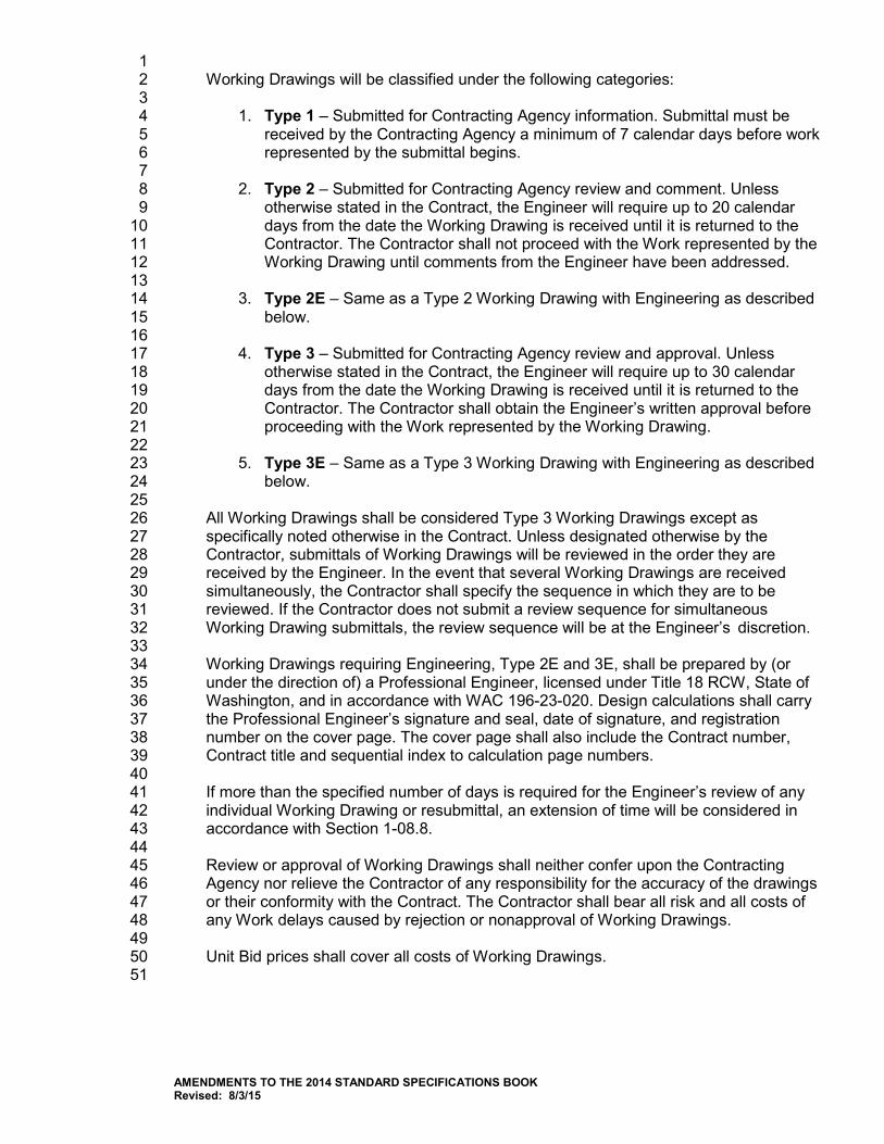
1 Working Drawings will be classified under the following categories: 2 3
1. Type 1 – Submitted for Contracting Agency information. Submittal must be 4 received by the Contracting Agency a minimum of 7 calendar days before work 5 represented by the submittal begins. 6 7
2. Type 2 – Submitted for Contracting Agency review and comment. Unless 8 otherwise stated in the Contract, the Engineer will require up to 20 calendar 9 days from the date the Working Drawing is received until it is returned to the 10 Contractor. The Contractor shall not proceed with the Work represented by the 11 Working Drawing until comments from the Engineer have been addressed. 12 13
3. Type 2E – Same as a Type 2 Working Drawing with Engineering as described 14 below. 15 16
4. Type 3 – Submitted for Contracting Agency review and approval. Unless 17 otherwise stated in the Contract, the Engineer will require up to 30 calendar 18 days from the date the Working Drawing is received until it is returned to the 19 Contractor. The Contractor shall obtain the Engineer’s written approval before 20 proceeding with the Work represented by the Working Drawing. 21 22
5. Type 3E – Same as a Type 3 Working Drawing with Engineering as described 23 below. 24
25 All Working Drawings shall be considered Type 3 Working Drawings except as 26 specifically noted otherwise in the Contract. Unless designated otherwise by the 27 Contractor, submittals of Working Drawings will be reviewed in the order they are 28 received by the Engineer. In the event that several Working Drawings are received 29 simultaneously, the Contractor shall specify the sequence in which they are to be 30 reviewed. If the Contractor does not submit a review sequence for simultaneous 31 Working Drawing submittals, the review sequence will be at the Engineer’s discretion. 32 33 Working Drawings requiring Engineering, Type 2E and 3E, shall be prepared by (or 34 under the direction of) a Professional Engineer, licensed under Title 18 RCW, State of 35 Washington, and in accordance with WAC 196-23-020. Design calculations shall carry 36 the Professional Engineer’s signature and seal, date of signature, and registration 37 number on the cover page. The cover page shall also include the Contract number, 38 Contract title and sequential index to calculation page numbers. 39 40 If more than the specified number of days is required for the Engineer’s review of any 41 individual Working Drawing or resubmittal, an extension of time will be considered in 42 accordance with Section 1-08.8. 43 44 Review or approval of Working Drawings shall neither confer upon the Contracting 45 Agency nor relieve the Contractor of any responsibility for the accuracy of the drawings 46 or their conformity with the Contract. The Contractor shall bear all risk and all costs of 47 any Work delays caused by rejection or nonapproval of Working Drawings. 48 49 Unit Bid prices shall cover all costs of Working Drawings. 50
51
AMENDMENTS TO THE 2014 STANDARD SPECIFICATIONS BOOK Revised: 8/3/15
1-06.AP1 1
Section 1-06, Control of Material 2 August 3, 2015 3
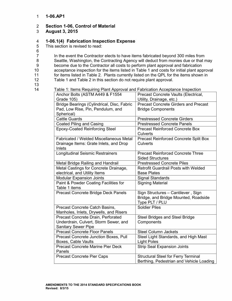
1-06.1(4) Fabrication Inspection Expense 4 This section is revised to read: 5 6
In the event the Contractor elects to have items fabricated beyond 300 miles from 7 Seattle, Washington, the Contracting Agency will deduct from monies due or that may 8 become due to the Contractor all costs to perform plant approval and fabrication 9 acceptance inspection for the items listed in Table 1 and costs for initial plant approval 10 for items listed in Table 2. Plants currently listed on the QPL for the items shown in 11 Table 1 and Table 2 in this section do not require plant approval. 12 13 Table 1: Items Requiring Plant Approval and Fabrication Acceptance Inspection 14 Anchor Bolts (ASTM A449 & F1554 Grade 105)
Precast Concrete Vaults (Electrical, Utility, Drainage, etc.)
Bridge Bearings (Cylindrical, Disc, Fabric Pad, Low Rise, Pin, Pendulum, and Spherical)
Precast Concrete Girders and Precast Bridge Components
Cattle Guards Prestressed Concrete Girders Coated Piling and Casing Prestressed Concrete Panels Epoxy-Coated Reinforcing Steel Precast Reinforced Concrete Box
Culverts Fabricated / Welded Miscellaneous Metal Drainage Items: Grate Inlets, and Drop Inlets
Precast Reinforced Concrete Split Box Culverts
Longitudinal Seismic Restrainers Precast Reinforced Concrete Three Sided Structures
Metal Bridge Railing and Handrail Prestressed Concrete Piles Metal Castings for Concrete Drainage, electrical, and Utility Items
Retrofit Guardrail Posts with Welded Base Plates
Modular Expansion Joints Signal Standards Paint & Powder Coating Facilities for Table 1 items
Signing Material
Precast Concrete Bridge Deck Panels Sign Structures – Cantilever , Sign Bridge, and Bridge Mounted, Roadside Type PLT / PLU
Precast Concrete Catch Basins, Manholes, Inlets, Drywells, and Risers
Soldier Piles
Precast Concrete Drain, Perforated Underdrain, Culvert, Storm Sewer, and Sanitary Sewer Pipe
Steel Bridges and Steel Bridge Components
Precast Concrete Floor Panels Steel Column Jackets Precast Concrete Junction Boxes, Pull Boxes, Cable Vaults
Steel Light Standards, and High Mast Light Poles
Precast Concrete Marine Pier Deck Panels
Strip Seal Expansion Joints
Precast Concrete Pier Caps Structural Steel for Ferry Terminal Berthing, Pedestrian and Vehicle Loading
AMENDMENTS TO THE 2014 STANDARD SPECIFICATIONS BOOK Revised: 8/3/15
Structures Precast Concrete Retaining Walls, including Lagging Panels
Timber Bridges
Precast Concrete Roof Panels Treated Timber and Lumber 6 inch by 6 inch or larger
Precast Concrete Structural Earth Walls, Noise Barrier Walls, Wall Panels, and Wall Stem Panels
Welded Structural Steel (Miscellaneous)
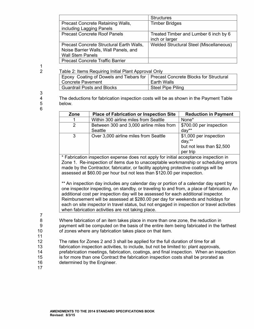
Precast Concrete Traffic Barrier 1 Table 2: Items Requiring Initial Plant Approval Only 2 Epoxy Coating of Dowels and Tiebars for Concrete Pavement
Precast Concrete Blocks for Structural Earth Walls
Guardrail Posts and Blocks Steel Pipe Piling 3 The deductions for fabrication inspection costs will be as shown in the Payment Table 4 below. 5 6
Zone Place of Fabrication or Inspection Site Reduction in Payment 1 Within 300 airline miles from Seattle None* 2 Between 300 and 3,000 airline miles from
Seattle $700.00 per inspection day**
3 Over 3,000 airline miles from Seattle $1,000 per inspection day,** but not less than $2,500 per trip
* Fabrication inspection expense does not apply for initial acceptance inspection in Zone 1. Re-inspection of items due to unacceptable workmanship or scheduling errors made by the Contractor, fabricator, or facility applying protective coatings will be assessed at $60.00 per hour but not less than $120.00 per inspection. ** An inspection day includes any calendar day or portion of a calendar day spent by one inspector inspecting, on standby, or traveling to and from, a place of fabrication. An additional cost per inspection day will be assessed for each additional inspector. Reimbursement will be assessed at $280.00 per day for weekends and holidays for each on site inspector in travel status, but not engaged in inspection or travel activities when fabrication activities are not taking place.
7 Where fabrication of an item takes place in more than one zone, the reduction in 8 payment will be computed on the basis of the entire item being fabricated in the farthest 9 of zones where any fabrication takes place on that item. 10 11 The rates for Zones 2 and 3 shall be applied for the full duration of time for all 12 fabrication inspection activities, to include, but not be limited to: plant approvals, 13 prefabrication meetings, fabrication, coatings, and final inspection. When an inspection 14 is for more than one Contract the fabrication inspection costs shall be prorated as 15 determined by the Engineer. 16
17
AMENDMENTS TO THE 2014 STANDARD SPECIFICATIONS BOOK Revised: 8/3/15
1-07.AP1 1
Section 1-07, Legal Relations and Responsibilities to the Public 2 August 3, 2015 3
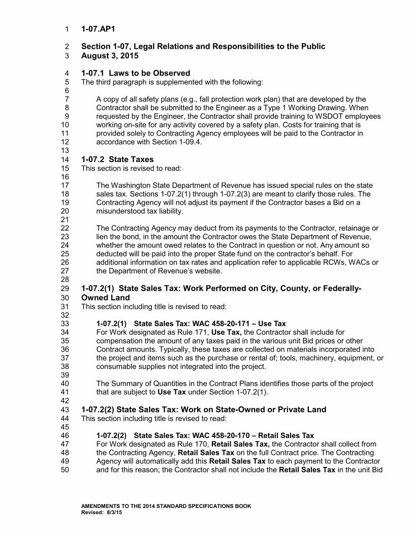
1-07.1 Laws to be Observed 4 The third paragraph is supplemented with the following: 5 6
A copy of all safety plans (e.g., fall protection work plan) that are developed by the 7 Contractor shall be submitted to the Engineer as a Type 1 Working Drawing. When 8 requested by the Engineer, the Contractor shall provide training to WSDOT employees 9 working on-site for any activity covered by a safety plan. Costs for training that is 10 provided solely to Contracting Agency employees will be paid to the Contractor in 11 accordance with Section 1-09.4. 12
13 1-07.2 State Taxes 14 This section is revised to read: 15 16
The Washington State Department of Revenue has issued special rules on the state 17 sales tax. Sections 1-07.2(1) through 1-07.2(3) are meant to clarify those rules. The 18 Contracting Agency will not adjust its payment if the Contractor bases a Bid on a 19 misunderstood tax liability. 20 21 The Contracting Agency may deduct from its payments to the Contractor, retainage or 22 lien the bond, in the amount the Contractor owes the State Department of Revenue, 23 whether the amount owed relates to the Contract in question or not. Any amount so 24 deducted will be paid into the proper State fund on the contractor’s behalf. For 25 additional information on tax rates and application refer to applicable RCWs, WACs or 26 the Department of Revenue’s website. 27 28
1-07.2(1) State Sales Tax: Work Performed on City, County, or Federally-29 Owned Land 30 This section including title is revised to read: 31 32
1-07.2(1) State Sales Tax: WAC 458-20-171 – Use Tax 33 For Work designated as Rule 171, Use Tax, the Contractor shall include for 34 compensation the amount of any taxes paid in the various unit Bid prices or other 35 Contract amounts. Typically, these taxes are collected on materials incorporated into 36 the project and items such as the purchase or rental of; tools, machinery, equipment, or 37 consumable supplies not integrated into the project. 38
39 The Summary of Quantities in the Contract Plans identifies those parts of the project 40 that are subject to Use Tax under Section 1-07.2(1). 41 42
1-07.2(2) State Sales Tax: Work on State-Owned or Private Land 43 This section including title is revised to read: 44 45
1-07.2(2) State Sales Tax: WAC 458-20-170 – Retail Sales Tax 46 For Work designated as Rule 170, Retail Sales Tax, the Contractor shall collect from 47 the Contracting Agency, Retail Sales Tax on the full Contract price. The Contracting 48 Agency will automatically add this Retail Sales Tax to each payment to the Contractor 49 and for this reason; the Contractor shall not include the Retail Sales Tax in the unit Bid 50
AMENDMENTS TO THE 2014 STANDARD SPECIFICATIONS BOOK Revised: 8/3/15
prices or in any other Contract amount. However, the Contracting Agency will not 1 provide additional compensation to the Prime Contractor or Subcontractor for Retail 2 Sales Taxes paid by the Contractor in addition to the Retail Sales Tax on the total 3 contract amount. Typically, these taxes are collected on items such as the purchase or 4 rental of; tools, machinery, equipment, or consumable supplies not integrated into the 5 project. Such sales taxes shall be included in the unit Bid prices or in any other Contract 6 amounts. 7 8 The Summary of Quantities in the Contract Plans identifies those parts of the project 9 that are subject to Retail Sales Tax under Section 1-07.2(2). 10 11
1-07.2(3) Services 12 This section is revised to read: 13 14
Any contract wholly for professional or other applicable services is generally not subject 15 to Retail Sales Tax and therefore the Contractor shall not collect Retail Sales Tax from 16 the Contracting Agency on those Contracts. Any incidental taxes paid as part of 17 providing the services shall be included in the payments under the contract. 18 19
1-07.15 Temporary Water Pollution/Erosion Control 20 This section’s title is revised to read: 21 22
1-07.15 Temporary Water Pollution Prevention 23 24 This section’s content is deleted. 25 26 1-07.23(1) Construction Under Traffic 27 In the second paragraph, the following new sentence is inserted after the second sentence: 28 29
Accessibility to existing or temporary pedestrian push buttons shall not be impaired. 30 31 1-08.AP1 32
Section 1-08, Prosecution and Progress 33 August 3, 2015 34
1-08.1 Subcontracting 35 The eighth paragraph is revised to read: 36 37
On all projects, the Contractor shall certify to the actual amounts paid to Disadvantaged, 38 Minority, Women’s, or Small Business Enterprise firms that were used as 39 Subcontractors, lower tier subcontractors, manufacturers, regular dealers, or service 40 providers on the Contract. This Certification shall be submitted to the Project Engineer 41 on a monthly basis each month between Execution of the Contract and Physical 42 Completion of the Contract using the application available at: 43 https://remoteapps.wsdot.wa.gov/mapsdata/tools/dbeparticipation. The monthly report is 44 due 20 calendar days following the end of the month. A monthly report shall be 45 submitted for every month between Execution of the Contract and Physical Completion 46 regardless of whether payments were made or work occurred. 47 48
The ninth paragraph is deleted and replaced with the following new paragraph: 49 50
AMENDMENTS TO THE 2014 STANDARD SPECIFICATIONS BOOK Revised: 8/3/15
The Contractor shall comply with the requirements of RCW 39.04.250, 39.76.011, 1 39.76.020, and 39.76.040, in particular regarding prompt payment to Subcontractors. 2 Whenever the Contractor withholds payment to a Subcontractor for any reason 3 including disputed amounts, the Contractor shall provide notice to the Subcontractor 4 with a copy to the Contracting Agency identifying the reason for the withholding and a 5 clear description of what the Subcontractor must do to have the withholding released. 6 Following receipt of a progress payment from the Contracting Agency, a Monthly 7 Payment Summary form shall be submitted to the Engineer in PDF format within 20 8 calendar days. The Monthly Payment Summary shall include all Subcontractors that 9 completed Work that was paid on the progress estimate by the Contracting Agency. 10 Retainage withheld by the Contractor prior to completion of the Subcontractors work is 11 exempt from reporting as a payment withheld and is not included in the withheld 12 amount. The Monthly Payment Summary form is available from the Engineer. The 13 Contracting Agency’s copy of the notice to Subcontractor for deferred payments shall be 14 submitted with the Monthly Payment Summary. 15 16
1-08.1(1) Subcontract Completion and Return of Retainage Withheld 17 This section is revised to read: 18 19
The following procedure shall apply to all subcontracts entered into as a part of 20 this Contract: 21 22
Requirements 23 1. Upon request, the Engineer will provide a copy of any or all progress payment 24
estimates, with regard to contract payments to any interested party to the 25 project. 26
27 2. The Contractor shall make payment to the Lower Tier Subcontractor not later 28
than ten calendar days after receipt of payment for work satisfactorily 29 completed by the Lower Tier Subcontractor, to the extent of the Lower Tier 30 Subcontractor’s interest therein. 31
32 3. In the event the Contractor believes they have the right under the Contract or 33
Subcontract to withhold payment in part or whole from a Lower Tier 34 Subcontractor they shall provide immediate notification to that Lower Tier 35 Subcontractor and the Engineer. The notice shall include an accounting of 36 payments to date, the value and reason for the withheld amount, and an 37 explanation of what must be done to have the withheld amount released. The 38 Lower Tier Subcontractor shall be paid within eight calendar days after the 39 Subcontractor completes the remedial action identified. 40
41 4. Every subcontract and lower tier subcontract shall have a dispute resolution 42
process incorporated for resolving issues between the parties to the 43 subcontract, or one shall be established as necessary. 44
45 5. If the parties agree, the WSDOT will make a third party neutral available 46
provided the parties to the dispute agree that the cost of doing so is split 47 between them. 48
49 6. The Engineer will withhold the same amount of funds from the Contractor as 50
was withheld if the issue is not resolved by the next progress estimate. 51 52
AMENDMENTS TO THE 2014 STANDARD SPECIFICATIONS BOOK Revised: 8/3/15
7. Failure by a Contractor or Subcontractor to comply with these requirements 1 may result in one or more of the following: 2
3 a) Reflected in the Prime Contractor’s Performance Evaluation. 4 5 b) Cancellation, termination or suspension of the Contract, in whole or in 6
part. 7 8 c) Sanctions as provided by the Contract; subcontract; or by law under 9
applicable prompt payment statutes including RCW 39.04.250. 10 11
8. The Subcontractor shall make a written request to the Contractor for the 12 release of the Subcontractor’s retainage or retainage bond. 13
14 9. Within 10 calendar days of the request, the Contractor shall determine if the 15
subcontract has been satisfactorily completed including any required lien 16 releases, documentation and material testing and shall inform the 17 Subcontractor, in writing, of the Contractor’s determination. 18
19 10. If the Contractor determines that the subcontract has been satisfactorily 20
completed, the Subcontractor’s retainage or retainage bond shall be released 21 by the Contractor within 10 calendar days from the date of the written notice. If 22 the Contractor determines that the Subcontractor has not achieved satisfactory 23 completion of the subcontract, the Contractor must provide the Subcontractor 24 with written notice, stating specifically why the subcontract Work is not 25 satisfactorily completed and what has to be done to achieve completion. The 26 Contractor shall release the Subcontractor’s retainage or retainage bond within 27 10 calendar days after the Subcontractor has satisfactorily completed the Work 28 identified in the notice. 29
30 11. In determining whether satisfactory completion has been achieved, the 31
Contractor may require the Subcontractor to provide documentation such as 32 certifications and releases, showing that all laborers, lower-tiered 33 Subcontractors, suppliers of material and equipment, and others involved in 34 the Subcontractor’s Work have been paid in full. The Contractor may also 35 require any documentation from the Subcontractor that is required by the 36 subcontract or by the Contract between the Contractor and Contracting 37 Agency or by law such as affidavits of wages paid, material acceptance 38 certifications and releases from applicable governmental agencies to the 39 extent that they relate to the Subcontractor’s Work. 40
41 12. If the Contractor fails to comply with the requirements of the Specification and 42
the Subcontractor’s retainage or retainage bond is wrongfully withheld, the 43 Subcontractor may seek recovery against the Contractor under applicable 44 prompt pay statutes in addition to any other remedies provided for by the 45 subcontract or by law. 46
47 Conditions 48 1. This clause does not create a contractual relationship between the Contracting 49
Agency and any Subcontractor as stated in Section 1-08.1. Also, it is not 50 intended to bestow upon any Subcontractor, the status of a third-party 51
AMENDMENTS TO THE 2014 STANDARD SPECIFICATIONS BOOK Revised: 8/3/15
beneficiary to the Contract between the Contracting Agency and the 1 Contractor. 2
3 2. This Section of the Contract does not apply to retainage withheld by the 4
Contracting Agency from monies earned by the Contractor. The Contracting 5 Agency shall continue to process the release of that retainage based upon the 6 Completion Date of the project as defined in Section 1-08.5 Time for 7 Completion and in accordance with the requirements and procedures set forth 8 in RCW 60.28. 9
10 Payment 11 The Contractor shall be solely responsible for any additional costs involved in 12 paying retainage to the Subcontractors prior to total project completion. Those 13 costs shall be incidental to the respective Bid items. 14
15 1-09.AP1 16
Section 1-09, Measurement and Payment 17 January 5, 2015 18
1-09.6 Force Account 19 In the third paragraph of item number 3, the last sentence is revised to read: 20 21
In the event that prior quotations are not obtained and the vendor is not a firm 22 independent from the Contractor or Subcontractor, then after-the-fact quotations may be 23 obtained by the Engineer from the open market in the vicinity and the lowest such 24 quotation may be used in place of submitted invoice. 25
26 1-10.AP1 27
Section 1-10, Temporary Traffic Control 28 August 4, 2014 29
1-10.1(1) Materials 30 The following material reference is deleted from this section: 31 32
Barrier Drums 9-35.8 33 34
1-10.1(2) Description 35 The first paragraph is revised to read: 36 37
The Contractor shall provide flaggers, and all other personnel required for labor for 38 traffic control activities and not otherwise specified as being furnished by the 39 Contracting Agency. 40
41 1-10.2(1) General 42 In the third paragraph, the first two sentences are revised to read: 43 44
The primary and alternate TCS shall be certified by one of the organizations listed in the 45 Special Provisions. Possession of a current Washington State TCS card and flagging 46 card by the primary and alternate TCS is mandatory. 47
AMENDMENTS TO THE 2014 STANDARD SPECIFICATIONS BOOK Revised: 8/3/15
1 1-10.2(1)B Traffic Control Supervisor 2 The first paragraph is revised to read: 3 4
A Traffic Control Supervisor (TCS) shall be present on the project whenever flagging or 5 other traffic control labor is being utilized or less frequently, as authorized by the 6 Engineer. 7 8
The last paragraph is revised to read: 9 10
The TCS may perform the Work described in Section 1-10.3(1)A Flaggers or in Section 11 1-10.3(1)B Other Traffic Control Labor and be compensated under those Bid items, 12 provided that the duties of the TCS are accomplished. 13 14
1-10.2(2) Traffic Control Plans 15 The first paragraph is revised to read: 16 17
The traffic control plan or plans appearing in the Contract documents show a method of 18 handling vehicle, bicycle, and pedestrian traffic. All construction signs, flaggers, and 19 other traffic control devices are shown on the traffic control plan(s) except for 20 emergency situations. If the Contractor proposes adding the use of flaggers to a plan, 21 this will constitute a modification requiring approval by the Engineer. The modified plans 22 shall show locations for all the required advance warning signs and a safe, protected 23 location for the flagging station. If flagging is to be performed during hours of darkness, 24 the plan shall include appropriate illumination for the flagging station. 25 26
In the second paragraph, the second sentence is revised to read: 27 28
Any Contractor-proposed modification, supplement or replacement shall show the 29 necessary construction signs, flaggers, and other traffic control devices required to 30 support the Work. 31 32
1-10.2(3) Conformance to Established Standards 33 In the second paragraph, the second sentence is revised to read: 34 35
The National Cooperative Highway Research Project (NCHRP) Report 350 and the 36 AASHTO Manual for Assessing Safety Hardware (MASH) have established 37 requirements for crash testing. 38 39
In the third paragraph, “NCHRP 350” is revised to read “NCHRP 350 or MASH”. 40 41 In the fourth paragraph, “NCHRP 350” is revised to read “NCHRP 350 or MASH”. 42 43 In the fifth paragraph, “NCHRP 350” is revised to read “NCHRP 350 or MASH”. 44
45 1-10.3(1) Traffic Control Labor 46 The first paragraph is revised to read: 47 48
The Contractor shall furnish all personnel for flagging, for the execution of all 49 procedures related to temporary traffic control and for the setup, maintenance and 50 removal of all temporary traffic control devices and construction signs necessary to 51 control vehicular, bicycle, and pedestrian traffic during construction operations. 52
AMENDMENTS TO THE 2014 STANDARD SPECIFICATIONS BOOK Revised: 8/3/15
1 1-10.3(1)A Flaggers and Spotters 2 This section’s title is revised to read: 3 4
Flaggers 5 6
The first paragraph is revised to read: 7 8
Flaggers shall be posted where shown on approved Traffic Control Plans or where 9 directed by the Engineer. All flaggers shall possess a current flagging card issued by 10 the State of Washington, Oregon, Montana, or Idaho. The flagging card shall be 11 immediately available and shown to the Contracting Agency upon request. 12
13 The last paragraph is deleted. 14
15 1-10.3(1)B Other Traffic Control Labor 16 This section is revised to read: 17 18
In addition to flagging duties, the Contractor shall provide personnel for all other traffic 19 control procedures required by the construction operations and for the labor to install, 20 maintain and remove any traffic control devices shown on Traffic Control Plans. 21
22 1-10.3(3)B Sequential Arrow Signs 23 This section is supplemented with the following: 24 25
A sequential arrow sign is required for all lane closure tapers on a multilane facility. A 26 separate sequential arrow sign shall be used for each closed lane. The arrow sign shall 27 not be used to laterally shift traffic. When used in the caution mode, the four corner 28 mode shall be used. 29 30
1-10.3(3)C Portable Changeable Message Signs 31 This section is revised to read: 32 33
Where shown on an approved traffic control plan or where ordered by the Engineer, the 34 Contractor shall provide, operate, and maintain portable changeable message signs 35 (PCMS). A PCMS shall be placed behind a barrier or guardrail whenever possible, but 36 shall at a minimum provide 4 ft. of lateral clearance to edge of travelled lane and be 37 delineated by channelization devices. The Contractor shall remove the PCMS from the 38 clear zone when not in use unless protected by barrier or guardrail. 39 40
1-10.3(3)F Barrier Drums 41 This section including title is deleted in its entirety and replaced with the following: 42 43
1-10.3(3)F Vacant 44 45
1-10.3(3)K Portable Temporary Traffic Control Signal 46 The fifth paragraph is revised to read: 47 48
The Project Engineer or designee will inspect the signal system at initial 49 installation/operation and approve the signal timing. Final approval will be based on the 50 results of the operational inspection. 51
52
AMENDMENTS TO THE 2014 STANDARD SPECIFICATIONS BOOK Revised: 8/3/15
1-10.4(2) Item Bids With Lump Sum for Incidentals 1 In the second paragraph, the first and second sentences are revised to read: 2 3
“Flaggers” will be measured by the hour. Hours will be measured for each flagging 4 station, shown on an approved Traffic Control Plan, when that station is staffed in 5 accordance with Section 1-10.3(1)A. 6
7 The first sentence of the last bulleted item in this section is revised to read: 8 9
Installing and removing Barricades, Traffic Safety Drums, Cones, Tubular Markers and 10 Warning Lights and Flashers to carry out approved Traffic Control Plan(s). 11
12 1-10.5(2) Item Bids With Lump Sum for Incidentals 13 This section is deleted and replaced with the following: 14 15
“Traffic Control Supervisor”, lump sum. 16 17 The lump sum Contract payment shall be full compensation for all costs incurred by the 18 Contractor in performing the Work defined in Section 1-10.2(1)B. 19 20 “Pedestrian Traffic Control”, lump sum. 21 22 The lump sum Contract payment shall be full compensation for all costs incurred by the 23 Contractor in performing the Work for pedestrian traffic control defined in Section 1-10. 24 25 “Flaggers”, per hour. 26 27 The unit Contract price, when applied to the number of units measured for this item in 28 accordance with Section 1-10.4(2), shall be full compensation for all costs incurred 29 by the Contractor in performing the Work defined in Section 1-10.3(1)A. 30 31 “Other Traffic Control Labor”, per hour. 32 33 The unit Contract price, when applied to the number of units measured for this item in 34 accordance with Section 1-10.4(2), shall be full compensation for all labor costs incurred 35 by the Contractor in performing the Work specified for this item in Section 1-10.4(2). 36 37 “Construction Signs Class A”, per square foot. 38 39 The unit Contract price, when applied to the number of units measured for this item in 40 accordance with Section 1-10.4(2), shall be full compensation for all costs incurred by 41 the Contractor in performing the Work described in Section 1-10.3(3)A. In the event that 42 “Do Not Pass” and “Pass With Care” signs must be left in place, a change order, as 43 described in Section 1-04.4, will be required. When the Bid Proposal contains the item 44 “Sign Covering”, then covering those signs indicated in the Contract will be measured 45 and paid according to Section 8-21. 46 47 “Sequential Arrow Sign”, per hour. 48 49 The unit Contract price, when applied to the number of units measured for this item in 50 accordance with Section 1-10.4(2), shall be full compensation for all costs incurred by 51 the Contractor in performing the Work described in Section 1-10.3(3)B. 52
AMENDMENTS TO THE 2014 STANDARD SPECIFICATIONS BOOK Revised: 8/3/15
1 “Portable Changeable Message Sign”, per hour. 2 3 The unit Contract price, when applied to the number of units measured for this item in 4 accordance with Section 1-10.4(2), shall be full compensation for all costs incurred by 5 the Contractor in performing the Work for procuring all portable changeable message 6 signs required for the project and for transporting these signs to and from the project. 7 8 “Transportable Attenuator”, per each. 9 10 The unit Contract price, when applied to the number of units measured for this item in 11 accordance with Section 1-10.4(2), shall be full compensation for all costs incurred by 12 the Contractor in performing the Work described in Section 1-10.3(3)J except for costs 13 compensated separately under the items “Operation of Transportable Attenuator” and 14 “Repair Transportable Attenuator”. 15 16 “Operation of Transportable Attenuator”, per hour. 17 18 The unit Contract price, when applied to the number of units measured for this item in 19 accordance with Section 1-10.4(2), shall be full compensation for all costs incurred by 20 the Contractor in performing the Work for operating transportable attenuators on the 21 project. 22 23 “Repair Transportable Attenuator”, by force account. 24 25 All costs of repairing or replacing transportable attenuators that are damaged by the 26 motoring public while in use as shown on an approved Traffic Control Plan will be paid 27 for by force account as specified in Section 1-09.6. To provide a common Proposal for 28 all Bidders, the Contracting Agency has estimated the amount of force account for 29 “Repair Transportable Attenuator” and has entered the amount in the Proposal to 30 become a part of the total Bid by the Contractor. Transportable attenuators damaged 31 due to the Contractor’s operation or damaged in any manner when not in use shall be 32 repaired or replaced by the Contractor at no expense to the Contracting Agency. 33 34 “Other Temporary Traffic Control”, lump sum. 35 36 The lump sum Contract payment shall be full compensation for all costs incurred by the 37 Contractor in performing the Work defined in Section 1-10, and which costs are not 38 compensated by one of the above-listed items. 39 40 “Portable Temporary Traffic Control Signal”, lump sum. 41 42 The lump sum Contract payment shall be full compensation for all costs incurred by the 43 Contractor in performing the Work as described in Section 1-10.3(3)K, including all 44 costs for traffic control during manual control, adjustment, malfunction, or failure of the 45 portable traffic control signals and during replacement of failed or malfunctioning 46 signals. 47
48
AMENDMENTS TO THE 2014 STANDARD SPECIFICATIONS BOOK Revised: 8/3/15
2-01.AP2 1
Section 2-01, Clearing, Grubbing, and Roadside Cleanup 2 August 3, 2015 3
2-01.2 Disposal of Usable Materials and Debris 4 This section is revised to read: 5 6
The Contractor shall meet all requirements of state, county, and municipal regulations 7 regarding health, safety, and public welfare in the disposal of all usable material and 8 debris. 9 10 The Contractor shall dispose of debris by one or more of the disposal methods 11 described below. 12
13 2-01.2(1) Disposal Method No. 1 – Open Burning 14 The first paragraph is supplemented with the following: 15 16
All burning operations shall be strictly in accordance with these authorizations. 17 18 The second paragraph is deleted. 19 20 2-01.2(3) Disposal Method No. 3 – Chipping 21 This section is revised to read: 22 23
Wood chips may be disposed of on-site in accordance with the following: 24 25
1. Chips shall be no larger than 6 square inches and no thicker than ½ inch. 26 27 2. Chips shall be disposed outside of environmentally sensitive areas, and in 28
areas that aren’t in conflict with permanent Work. 29 30 3. Chips shall not be incorporated into the embankment but may be spread on 31
slopes where feasible at depths no greater than 2 inches. 32 33 4. Chips shall be tractor-walked into the ground. 34
35 2-01.3(1) Clearing 36 In the second paragraph, item number 3 (up until the colon) is revised to read: 37 38
3. Follow these requirements for all stumps that will be buried deeper than 5 feet from 39 the top, side, or end surface of the embankment or any structure and are in a 40 location that will not be terraced as described in Section 2-03.3(14): 41
42 2-02.AP2 43
Section 2-02, Removal of Structures and Obstructions 44 January 5, 2015 45
2-02.3(2) Removal of Bridges, Box Culverts, and Other Drainage Structures 46 This section is supplemented with the following new subsections: 47
AMENDMENTS TO THE 2014 STANDARD SPECIFICATIONS BOOK Revised: 8/3/15
1 2-02.3(2)A Bridge Removal 2
2-02.3(2)A1 Bridge Demolition Plan Submittal 3 The Contractor shall submit a Type 2E Working Drawing consisting of a bridge 4 demolition plan, showing the method of removing the existing bridge(s), or portions 5 of bridges, as specified. 6 7 The bridge demolition plan shall show all equipment, sequence of operations, and 8 details required to complete the work, including containment, collection, and 9 disposal of all debris. The plan shall include a crane foundation stability analysis 10 and crane load calculations for the work. The plan shall detail the containment, 11 collection, and disposal of all debris. The plan shall show all stages of demolition. 12 13 When the bridge removal work includes removal of a truss, and when the 14 Contractor’s removal method involves use of a crane or cranes to pick, lift, and 15 remove the truss, the Contractor shall confirm the truss dead load weight prior to 16 beginning the truss removal operation. The operation of confirming the truss dead 17 load shall be performed at both ends of the truss, and shall ensure that the truss is 18 broken free of its support bearings. The Contractor’s method of confirming the 19 truss dead load, whether by hydraulic jacks or other means, shall be included in the 20 Contractor’s bridge demolition plan submittal. 21 22 When the bridge removal work involves removing portions of existing concrete 23 without replacement, the methods and tools used to achieve the smooth surface 24 and profile specified in Section 2-02.3(2)A2 shall be included in the Contractor’s 25 bridge demolition plan submittal. 26 27 2-02.3(2)A2 Removing Portions of Existing Concrete 28 Care shall be taken in removing concrete to prevent overbreakage or damage to 29 portions of the existing Structure which are to remain. Before concrete removal 30 begins, a saw cut shall be made into the surface of the concrete at the perimeter of 31 the removal limits. The saw cut shall be 3/4-inch deep when the steel 32 reinforcement is to remain, and may be deeper when the steel reinforcement is 33 removed with the concrete. 34 35 Concrete shall be completely removed (exposing the deformed surface of the bar) 36 from existing steel reinforcing bars which extend from the existing members and 37 are specified to remain. Steel reinforcing bars that are not designated to remain 38 shall be cut a minimum of 1-inch behind the final surface. The void left by removal 39 of the steel reinforcing bar shall be filled with mortar conforming to Section 9-40 20.4(2). The mortar shall match the color of the existing concrete surface as nearly 41 as practicable. 42 43 The Contractor shall roughen, clean, and saturate existing concrete surfaces, 44 against which fresh concrete will be placed, in accordance with Section 6-45 02.3(12)B. When a portion of existing concrete is to be removed without 46 replacement, concrete shall be removed to a clean line with a smooth surface of 47 less than 1/16 inch profile. 48 49 2-02.3(2)A3 Use of Explosives for Bridge Demolition 50 Explosives shall not be used for bridge demolition, except as specifically allowed by 51 the Special Provisions. 52
AMENDMENTS TO THE 2014 STANDARD SPECIFICATIONS BOOK Revised: 8/3/15
1 2-02.5 Payment 2 This section is supplemented with the following new Bid items: 3 4
“Removing Existing Bridge___”, lump sum. 5 6 “Removing Existing Structure___”, lump sum. 7 8 “Removing Portion of Existing Bridge___”, lump sum. 9 10 “Removing Portion of Existing Structure___”, lump sum. 11
12 2-03.AP2 13
Section 2-03, Roadway Excavation and Embankment 14 August 3, 2015 15
2-03.1 Description 16 The first paragraph is supplemented with the following: 17 18
The Work includes the removal of pavement, sidewalks, curbs and gutters as described 19 in Section 2-02 when these items lie within an excavation area. 20
21 2-03.3 Construction Requirements 22 This section is supplemented with the following new sub-section: 23 24
2-03.3(19) Removal of Pavement, Sidewalks, Curbs, and Gutters 25 The requirements of Section 2-02.3(3) shall also apply when pavements, sidewalks, 26 curbs, and gutters lie within an excavation. 27
28 2-03.3(1) Widening of Cuts 29 This section is revised to read: 30 31
If routine cuts do not supply enough material to form the embankment, the Contractor 32 shall obtain more material from areas inside or outside the Right of Way and/or from 33 widening one or both sides of existing cuts as determined by the Engineer. The 34 Contractor shall dress the sides of the cuts to any slopes the Engineer may require. If 35 the Contractor has dressed a cut before the Engineer determines to widen it, the 36 Contracting Agency will pay for the resloping as provided in Section 1-04.4. In addition, 37 material obtained from areas beyond the cuts shown in the Plans that result in 38 additional haul will be paid by the Contracting Agency as provided in Section 1-04.4. 39
40 2-03.3(14) Embankment Construction 41 The third paragraph is revised to read: 42 43
Hillside Terraces – The Contractor shall terrace the original ground or embankment 44 when the slope of the surface is 2H:1V or steeper unless otherwise directed by the 45 Engineer. The face of each terrace shall be a minimum of 1 foot and a maximum of 5 46 feet in height and shall be vertical or near vertical as required to remain stable during 47 material placement and compaction. The bench of the terrace shall slope outward to 48 drain and shall not be inclined steeper than 0.05 foot per foot. Terraces damaged 49
AMENDMENTS TO THE 2014 STANDARD SPECIFICATIONS BOOK Revised: 8/3/15
during work shall be reestablished. The Engineer may order the Contractor to place 1 gravel backfill, pipe drains or both to drain any seepage. 2 3
2-03.3(14)C Compacting Earth Embankments 4 The last nine paragraphs are deleted and replaced with the following three new paragraphs: 5 6
Moisture Content – The Contractor shall adjust moisture content during compaction to 7 produce a firm, stable and unyielding embankment. The embankment shall be free from 8 pumping and rutting due to excessive moisture and is the Contractor’s responsibility to 9 manage and adjust as necessary. 10 11 The Contracting Agency will consider all costs for drying embankment material to be 12 incidental to other Work, including excessive moisture due to inclement weather. If, 13 however, the Contract includes an aeration item, the Contracting Agency will pay for 14 such Work as specified in Sections 2-03.4 and 2-03.5. 15 16 The Contractor shall repair, at no expense to the Contracting Agency, any partial or 17 complete embankment that loses stability because of continued hauling across it. 18 Evidence of lost stability includes pumping, rutting or lateral displacement of 19 embankment. The Contractor shall also alter hauling equipment or procedures to 20 prevent further damage. 21
22 2-03.3(14)L Embankment Widening for Guardrail 23 The first sentence is revised to read: 24 25
Embankments widened for the installation of beam guardrail shall be terraced in 26 accordance with the requirements for hillside terraces in Section 2-03.3(14). 27 28
The second sentence is deleted. 29 30 2-09.AP2 31
Section 2-09, Structure Excavation 32 August 3, 2015 33
2-09.3(2) Classification of Structure Excavation 34 The first sentence of item number 1 is revised to read: 35 36
Class A – Structure excavation required for bridge and retaining wall footings, precast 37 reinforced concrete three sided structure footings, geosynthetic retaining walls, 38 structural earth walls, sign structure footings, pile or drilled shaft caps, seals, wingwall 39 footings, precast reinforced concrete box culverts, precast reinforced concrete split box 40 culverts, detention vaults, and noise barrier wall footings shall be classified as Structure 41 excavation Class A. 42
43 2-09.4 Measurement 44 The second paragraph is revised to read: 45 46
Horizontal Limits – The Contracting Agency will use the sides of the trench or pit as 47 horizontal limits in measuring excavation. No payment for Structure excavation will be 48 made for material removed (1) more than 1 foot outside the perimeter of any pile cap, 49 footing, or seal; (2) more than 3 feet beyond the Roadway side of a wing wall; (3) more 50
AMENDMENTS TO THE 2014 STANDARD SPECIFICATIONS BOOK Revised: 8/3/15
than 1 foot beyond the other sides and end of a wing wall; (4) more than 1 foot outside 1 the perimeter of the soil reinforcement area for geosynthetic and structural earth walls; 2 and (5) more than 4-feet beyond the inside opening of precast reinforced concrete box 3 culverts and precast reinforced concrete split box culverts. For precast reinforced 4 concrete three sided structures, no payment for Structure excavation will be made for 5 material removed more than 1 foot outside the perimeter of the footing or more than 4 6 feet beyond the inside opening, whichever is greater. 7
8 The seventh paragraph is revised to read: 9 10
For pipelines the lower limit in measuring structure excavation will be the foundation 11 level as shown in the Plans or as directed by the Engineer. 12
13 2-12.AP2 14
Section 2-12, Construction Geosynthetic 15 January 5, 2015 16
2-12.3(4) Permanent Erosion Control and Ditch Lining 17 In the fourth paragraph, “Section 9-13.2” is revised to read “Section 9-13.1(4)”. 18 19 3-01.AP3 20
Section 3-01, Production From Quarry and Pit Sites 21 August 3, 2015 22
3-01.2(2) Preparation of Site 23 This section is supplemented with the following three new paragraphs: 24 25
The Contractor shall provide sufficient space as required for the setup and operation of 26 the Contracting Agency’s field testing facilities at the site of crushing or hot mix asphalt 27 production. 28 29 As directed by the Engineer, the Contractor shall provide one of the following to ensure 30 24-hour per day operation of the Contracting Agency’s laboratory trailer(s) that may be 31 set up at the site during production: 32 33
1. A power source and a power cord of sufficient length to reach the Contracting 34 Agency’s laboratory trailer(s) which may be set up at the site. The cord shall 35 be capable of carrying at least 120/240 volts, 60 cycles at a sustained load of 36 up to 200 amps. The cord and trailer(s) electrical hookup shall meet the NEC 37 code. Power shall be provided and connected when requested by the 38 Engineer. The laboratory trailer(s) hookup shall be protected by a 2 pole 50 39 amp 240 VAC circuit breaker. 40
41 2. A daily supply of fuel adequate for operation of the Contracting Agency’s 42
generator(s). 43 44
Potable water shall be provided to the Contracting Agency’s laboratory trailer(s) for use 45 during plant operations when requested by the Engineer. 46
47
AMENDMENTS TO THE 2014 STANDARD SPECIFICATIONS BOOK Revised: 8/3/15
3-04.AP3 1
Section 3-04, Acceptance of Aggregate 2 April 6, 2015 3
3-04.5 Payment 4 In Table 1, the “Maximum Sublot Size (Tons)” value for the item HMA Aggregate is revised 5 to read “2000”. 6 7 In Table 2, the row containing the item “HMA Aggregate” is revised to read: 8
9 9-03.8(2) HMA Aggregate 15 15 Uncompact
ed Void Content 15
10 11 5-01.AP5 12
Section 5-01, Cement Concrete Pavement Rehabilitation 13 August 4, 2014 14
5-01.2 Materials 15 The referenced section for the following item is revised to read: 16 17
Dowel Bars 9-07.5 18 19
5-01.3(4) Replace Portland Cement Concrete Panel 20 In the third paragraph, the last sentence is deleted. 21 22 The seventeenth paragraph (beginning with “The Contractor shall place a bond-breaking 23 material…”) is deleted. 24 25 5-02.AP5 26
Section 5-02, Bituminous Surface Treatment 27 August 4, 2014 28
5-02.3(11) Temporary Raised Pavement Markings 29 This section’s title is revised to read: 30 31
Temporary Pavement Markings 32 33
The word “raised” is deleted from this section. 34 35 5-04.AP5 36
Section 5-04, Hot Mix Asphalt 37 August 3, 2015 38
5-04.2 Materials 39 The third through eighth paragraphs are deleted and replaced with the following: 40
AMENDMENTS TO THE 2014 STANDARD SPECIFICATIONS BOOK Revised: 8/3/15
1 The Contractor may choose to utilize recycled asphalt pavement (RAP) or reclaimed 2 asphalt shingles (RAS) in the production of HMA. The RAP may be from pavements 3 removed under the Contract, if any, or pavement material from an existing stockpile. 4 The RAS may be from reclaimed shingles. 5 6 The Contractor may use up to 20 percent RAP by total weight of HMA with no additional 7 sampling or testing of the RAP. If greater than 20 percent RAP by total weight of HMA 8 or any amount of RAS is utilized in the production of HMA, the Contractor shall sample 9 and test the RAP and RAS during stockpile construction in accordance with WSDOT 10 FOP for AASHTO T 308 for determination of asphalt binder content and WSDOT FOP 11 for WAQTC/AASHTO T 27/T 11 for gradation of the aggregates. The RAP shall be 12 sampled and tested at a frequency of one sample for every 1,000 tons produced and 13 not less than ten samples per project. The RAS shall be sampled and tested at a 14 frequency of one sample for every 100 tons produced and not less than ten samples per 15 project. The asphalt content and gradation test data shall be reported to the Contracting 16 Agency when submitting the mix design for approval on the QPL. If utilized, the amount 17 of RAS shall not exceed 5-percent of the total weight of the HMA. The Contractor shall 18 include the RAP and RAS as part of the mix design as defined in these Specifications. 19 20 The grade of asphalt binder shall be as required by the Contract. Blending of asphalt 21 binder from different sources is not permitted. 22 23 The Contractor may only use warm mix asphalt (WMA) processes in the production of 24 HMA with 20 percent or less RAP by total weight of HMA and no RAS. The Contractor 25 shall submit to the Engineer for approval the process that is proposed and how it will be 26 used in the manufacture of HMA. 27 28 When the Contracting Agency provides aggregates or provides a source for the 29 production of aggregates, the Contract Provisions will establish the approximate 30 percentage of asphalt binder required in the mixture for each class of HMA. 31 32 Production of aggregates shall comply with the requirements of Section 3-01. 33 34 Preparation of stockpile site, the stockpiling of aggregates, and the removal of 35 aggregates from stockpiles shall comply with the requirements of Section 3-02. 36
37 5-04.3(1) Hot Mix Asphalt Mixing Plant 38 In the first paragraph, the last sentence of item number 4 is revised to read: 39 40
The Contractor shall provide for the setup and operation of the field testing facilities of 41 the Contracting Agency as provided for in Section 3-01.2(2). 42
43 The first paragraph is supplemented with the following: 44 45
6. Equipment for Processing RAP and RAS. When producing HMA for mix designs 46 with greater than 20 percent RAP by total weight of HMA or any amount of RAS the 47 HMA plant shall be equipped with screens or a lump breaker to eliminate oversize 48 RAP/RAS particles from entering the pug mill or drum mixer. 49
50 5-04.3(3)A Material Transfer Device/Vehicle 51 The first paragraph is supplemented with the following new sentence: 52
AMENDMENTS TO THE 2014 STANDARD SPECIFICATIONS BOOK Revised: 8/3/15
1 At the Contractor’s request the Engineer may approve paving without an MTD/V; the 2 Engineer will determine if an equitable adjustment in cost or time is due. 3
4 In the last sentence of the second paragraph, “Project Engineer” is revised to read 5 “Engineer”. 6 7 5-04.3(5)A Preparation of Existing Surfaces 8 The first sentence of the last paragraph is revised to read: 9 10
Unless otherwise approved by the Engineer, the tack coat shall be CSS-1 or CSS-1h 11 emulsified asphalt. 12
13 5-04.3(7) Preparation of Aggregates 14 This section is revised to read: 15 16
The aggregates, RAP and RAS shall be stockpiled according to the requirements of 17 Section 3-02. Sufficient storage space shall be provided for each size of aggregate, 18 RAP and RAS. The Contractor may uniformly blend fine aggregate or RAP with the 19 RAS as a method of preventing the agglomeration of RAS particles. The aggregates, 20 RAP and RAS shall be removed from stockpile(s) in a manner to ensure minimal 21 segregation when being moved to the HMA plant for processing into the final mixture. 22 Different aggregate sizes shall be kept separated until they have been delivered to the 23 HMA plant. 24
25 5-04.3(7)A1 General 26 This section is revised to read: 27 28
An approved mix design, listed on the Qualified Products List (QPL), is required for all 29 HMA paving. The Contractor shall develop a mix design prior to the initial production of 30 HMA and no more than 3 months prior to submitting for QPL evaluation. The mix design 31 shall be developed in accordance with WSDOT Standard Operating Procedure 732 and 32 meet the requirements of Sections 9-03.8(2) and 9-03.8(6). 33 34 Mix designs shall be submitted by the Contractor to the WSDOT State Materials 35 Laboratory on WSDOT Form 350-042EF. If the mix design is approved it will be listed 36 on the QPL for up to 24 consecutive months. Mix designs not listed on the QPL or past 37 the 24 month approved period shall not be used. After a mix design has been on the 38 QPL for 12 months the listing will be extended provided the Contractor submits a 39 certification letter to the Qualified Products Engineer verifying that the aggregate and 40 asphalt binder have not changed. The Contractor may submit the certification one 41 month prior to expiration of the mix design approval. Within 7 calendar days of receipt of 42 the Contractor’s certification the QPL will be updated. The maximum duration for 43 approval of a mix design and listing on the QPL will be 24 months from the date of initial 44 approval or as approved by the Engineer. 45 46 Changes to the job mix formula of a mix design may require the development of a new 47 mix design and resubmittal for QPL approval. 48 49 Changes to aggregate that may require a new mix design include the source of material 50 or a change in the percentage of material from a stockpile greater than 5 percent. 51
AMENDMENTS TO THE 2014 STANDARD SPECIFICATIONS BOOK Revised: 8/3/15
Changes to the percentage of material from a stockpile will be calculated exclusive of 1 the RAP content for mix designs with 20 percent RAP or less by total weight of HMA. 2 3 Changes to asphalt binder that may require a new mix design include the source of the 4 crude petroleum supplied to the refinery, the refining process, and additives or modifiers 5 in the asphalt binder. 6 7 The Contractor shall include the brand and type of anti-stripping additive in the mix 8 design submittal and provide certification from the asphalt binder manufacture that the 9 anti-stripping additive is compatible with the crude source and formulation of asphalt 10 binder proposed in the mix design. All changes to anti-strip require the submittal of a 11 new mix design for approval. 12 13 Mix designs with 20 percent RAP or less by total weight of HMA and no RAS will be 14 completed without the inclusion of the RAP. For HMA mix designs with greater than 20 15 percent RAP by total weight of HMA or any amount of RAS the Contractor shall develop 16 a mix design including RAP, RAS, recycling agent and new asphalt binder. Asphalt 17 binder contributed from RAS shall be determined in accordance with AASHTO PP 78. 18 The total quantity of asphalt binder from the RAP and RAS shall not exceed 40 percent 19 of the total asphalt binder content of the HMA. 20 21 Once the RAP and RAS stockpiles have been constructed the Contractor shall extract, 22 recover and test the asphalt residue from the RAP and RAS stockpiles to determine the 23 percent of recycling agent and/or grade of new asphalt binder needed to meet the grade 24 of asphalt binder required by the contract. The asphalt extraction testing shall be 25 performed in accordance with AASHTO T 164 or ASTM D 2172 using reagent grade 26 trichloroethylene. The asphalt recovery shall be performed in accordance with AASHTO 27 R 59 orASTM D 1856. The recovered asphalt residue shall be tested in accordance with 28 AASHTO R 29 to determine the asphalt binder grade in accordance with Section 9-29 02.1(4). Once the recovered asphalt binder grade is determined the percent of recycling 30 agent and/or grade of new asphalt binder shall be determined in accordance with ASTM 31 D 4887. The final blend of recycling agent, recovered and new asphalt shall be tested in 32 accordance with AASHTO R 29. The final blended asphalt binder shall be the grade as 33 required by the Contract and comply with the requirements of in accordance with 34 Section 9-02.1(4). 35
36 5-04.3(7)A2 Statistical or Nonstatistical Evaluation 37 This section is revised to read: 38 39
The Contractor shall submit WSDOT Form 350-041EF to the Engineer for approval to 40 use a mix design from the QPL. The Contractor may include changes to the job mix 41 formula that have been approved on other contracts. The request to use a mix design 42 from the QPL may be rejected if production of the HMA from another contract is not in 43 compliance with Section 5-04.3(11)D. 44 45 The Contractor shall submit representative samples of the materials that are to be used 46 in the HMA production to the State Materials Laboratory in Tumwater. For HMA mix 47 designs with 20 percent RAP or less by total weight of HMA and no RAS, the Contractor 48 shall submit representative samples of the mineral materials that are to be used in the 49 HMA production; the submittal of RAP samples is not required for these mix designs. 50 For HMA mix designs with greater than 20 percent RAP by total weight of HMA or any 51 amount of RAS the Contractor shall submit representative samples of the mineral 52
AMENDMENTS TO THE 2014 STANDARD SPECIFICATIONS BOOK Revised: 8/3/15
materials, RAP, RAS and 100 grams of recovered asphalt residue from the RAP and 1 RAS that are to be used in the HMA production. The Contracting Agency will use these 2 samples to evaluate the mix design for approval on the QPL in accordance with 3 WSDOT Standard Practice QC-8. 4
5 5-04.3(7)A3 Commercial Evaluation 6 This section is revised to read: 7
8 Approval of a Commercial Evaluation mix design for listing on the QPL will be based on 9 a review of the Contractor’s submittal of WSDOT Form 350-042EF for conformance to 10 the requirements of Section 9-03.8(2). Testing of the HMA by the Contracting Agency 11 for mix design approval is not required. Mix designs for HMA with greater than 20 12 percent RAP by total weight of HMA or any amount of RAS may be evaluated in 13 accordance with Section 5-04.3(7)A2. 14 15 For the Bid item Commercial HMA, the Contractor shall select a class of HMA and 16 design level of Equivalent Single Axle Loads (ESAL’s) appropriate for the required use. 17
18 5-04.3(8) Mixing 19 The first sentence of the second paragraph is revised to read: 20 21
When discharged, the temperature of the HMA shall not exceed the optimum mixing 22 temperature by more than 25°F as shown on the reference mix design report or as 23 approved by the Engineer. 24
25 The last paragraph is supplemented with the following new sentence: 26 27
After the required amount of mineral materials, RAP, RAS, new asphalt binder and 28 asphalt rejuvenator have been introduced into the mixer the HMA shall be mixed until 29 complete and uniform coating of the particles and thorough distribution of the asphalt 30 binder throughout the mineral materials, RAP and RAS is ensured. 31
32 33 5-04.3(8)A4 Definition of Sampling and Sublot 34 The second sentence of the second paragraph is revised to read: 35 36
The sublots shall be approximately uniform in size with a maximum sublot size based 37 on original Plan quantity tons as specified in the following table. 38
39 This section is supplemented with the following new table: 40 41
HMA Original Plan Quantity (tons) Sublot Size (tons) <20,000 1,000
20,000 to 30,000 1,500 >30,000 2,000
42 5-04.3(8)A7 Test Section – HMA Mixtures 43 This section is revised to read: 44 45
For each class of HMA accepted by statistical evaluation with 20 percent RAP or less by 46 total weight of HMA and no RAS, the Contractor may request a single test section to 47 determine whether the mixture meets the requirements of Section 9-03.8(2) and 9-48
AMENDMENTS TO THE 2014 STANDARD SPECIFICATIONS BOOK Revised: 8/3/15
03.8(6). For each HMA mix design accepted by statistical evaluation with greater than 1 20 percent RAP by weight of HMA or any amount of RAS, the Contractor shall construct 2 a test section to determine whether the mixture meets the requirements of Sections 9-3 03.8(2) and 9-03.8(6). Test sections shall be constructed at the beginning of paving and 4 will be at least 600 tons and a maximum of 1,000 tons or as approved by the Engineer. 5 For a test section to be acceptable the pay factor (PF) for gradation, asphalt binder and 6 Va shall be 0.95 or greater for each constituent and the remaining test requirements in 7 Section 9-03.8(2) (fracture, uncompacted void, sand equivalent, dust/asphalt ratio, 8 Hamburg and IDT) shall conform to the requirements of that section. No further wearing 9 or leveling HMA will be paved on any of the four calendar days following construction of 10 the test section. The mixture in the test section will be evaluated as a lot with a 11 minimum of three sublots required. If more than one test section is required, each test 12 section shall be a separate lot. 13
14 5-04.3(10)A General 15 In the first paragraph, “checking” and “cracking” are deleted. 16 17 In the third paragraph, the following new sentence is inserted after the second sentence: 18 19
Coverage with a steel wheel roller may precede pneumatic tired rolling. 20 21
In the third paragraph, the following new sentence is inserted before the last sentence: 22 23
Regardless of mix temperature, a roller shall not be operated in a mode that results in 24 checking or cracking of the mat. 25 26
5-04.3(10)B1 General 27 In this section, “Project Engineer” is revised to read “Engineer”. 28 29 The first paragraph is revised to read: 30 31
HMA mixture accepted by statistical or nonstatistical evaluation that is used in traffic 32 lanes, including lanes for ramps, truck climbing, weaving, and speed change, and 33 having a specified compacted course thickness greater than 0.10-foot, shall be 34 compacted to a specified level of relative density. The specified level of relative density 35 shall be a Composite Pay Factor (CPF) of not less than 0.75 when evaluated in 36 accordance with Section 1-06.2, using a minimum of 91 percent of the maximum 37 density. The specified level of density attained will be determined by the statistical 38 evaluation of the density of the pavement. The density of the pavement shall be 39 determined in accordance with WSDOT FOP for WAQTC TM 8 when using the nuclear 40 density gauge and WSDOT SOP 736 when using cores to determine density. 41 42
The following four new paragraphs are inserted after the first paragraph: 43 44
Tests for the determination of the pavement density will be taken in accordance the 45 required procedures for measurement by a nuclear density gauge or roadway cores 46 after completion of the finish rolling. 47 48 If the Contracting Agency uses a nuclear density gauge to determine density the test 49 procedures FOP for WAQTC TM 8 and WSDOT SOP T 729 will be used on the day the 50 mix is placed. 51 52
AMENDMENTS TO THE 2014 STANDARD SPECIFICATIONS BOOK Revised: 8/3/15
Roadway cores for density may be obtained by either the Contracting Agency or the 1 Contractor in accordance with WSDOT SOP 734. The core diameter shall be 4-inches 2 unless otherwise approved by the Engineer. Roadway cores will be tested by the 3 Contracting Agency in accordance with WSDOT FOP for AASHTO T 166. 4 5 If the Contract includes the Bid item “Roadway Core” the cores shall be obtained by the 6 Contractor in the presence of the Engineer on the same day the mix is placed and at 7 locations designated by the Engineer. If the Contract does not include the Bid item 8 “Roadway Core” the Contracting Agency will obtain the cores. 9
10 In the sixth paragraph (after the preceding Amendments are applied), the second sentence 11 is revised to read: 12 13
Sublots will be uniform in size with a maximum sublot size based on original Plan 14 quantity tons of HMA as specified in the table below. 15
16 The following new table is inserted before the second to last paragraph: 17 18
HMA Original Plan Quantity (tons) Sublot Size (tons) <20,000 100
20,000 to 30,000 150 >30,000 200
19 5-04.3(10)B4 Test Results 20 The first paragraph is revised to read: 21 22
The results of all compaction acceptance testing and the CPF of the lot after three 23 sublots have been tested will be available to the Contractor through WSDOT’s website. 24 Determination of the relative density of the HMA with a nuclear density gauge requires a 25 correlation factor and may require resolution after the correlation factor is known. When 26 a core is taken for gauge correlation at the location of a sublot, the relative density of 27 the core will be used for the sublot test result and is exempt from retesting. Acceptance 28 of HMA compaction will be based on the statistical evaluation and CPF so determined. 29 30
In the second paragraph, the first sentence is revised to read: 31 32
For a sublot that has been tested with a nuclear density gauge that did not meet the 33 minimum of 91 percent of the reference maximum density in a compaction lot with a 34 CPF below 1.00 and thus subject to a price reduction or rejection, the Contractor may 35 request that a core be used for determination of the relative density of the sublot. 36 37
In the second sentence of the second paragraph, “moisture-density” is revised to read 38 “density”. 39 40 In the second paragraph, the fourth sentence is deleted. 41 42 5-04.3(20) Anti-Stripping Additive 43 This section is revised to read: 44 45
Anti-stripping additive shall be added to the liquid asphalt by the asphalt supplier prior to 46 shipment to the asphalt mixing plant. Anti-stripping additive shall be added in the 47
AMENDMENTS TO THE 2014 STANDARD SPECIFICATIONS BOOK Revised: 8/3/15
amount designated on the QPL for the mix design. Anti-strip is not required for 1 temporary work that will be removed prior to Completion. 2
3 5-04.4 Measurement 4 The following new paragraph is inserted after the first paragraph: 5 6
Roadway cores will be measured per each for the number of cores taken. 7 8 The second to last paragraph is deleted. 9 10 5-04.5 Payment 11 The bid item “Removing Temporary Pavement Marking”, per linear foot and paragraph 12 following bid item are deleted. 13 14 The following new bid item is inserted before the second to last paragraph: 15 16
“Roadway Core”, per each. 17 18 The Contractor’s costs for all other Work associated with the coring (e.g., traffic control) 19 shall be incidental and included within the unit Bid price per each and no additional 20 payments will be made. 21
22 5-05.AP5 23
Section 5-05, Cement Concrete Pavement 24 April 6, 2015 25
5-05.3(1) Concrete Mix Design for Paving 26 In item number 1, the first sentence of the third paragraph is revised to read: 27 28
Ground granulated blast furnace slag, if used, shall not exceed 30 percent by weight of 29 the total cementitious material and shall conform to Section 9-23.10. 30
31 The second and third rows of the table in item number 3 are revised to read: 32 33
Coarse Aggregate + 30 Pounds - 30 Pounds Fine Aggregate + 30 Pounds - 30 Pounds
34 5-05.4 Measurement 35 The fourth paragraph is supplemented with the following new sentence: 36 37
Tie bars with drill holes in cement concrete pavement placed under the Contract will not 38 be measured. 39 40
5-05.5 Payment 41 The paragraph following the Bid item “Tie Bar with Drill Hole”, per each is supplemented with 42 the following new sentence: 43 44
All costs for tie bars with drill holes in cement concrete pavement placed under the 45 Contract shall be included in the unit Contract price per cubic yard for “Cement Conc. 46 Pavement”. 47
AMENDMENTS TO THE 2014 STANDARD SPECIFICATIONS BOOK Revised: 8/3/15
1 6-01.AP6 2
Section 6-01, General Requirements for Structures 3 January 5, 2015 4
6-01.6 Load Restrictions on Bridges Under Construction 5 The first sentence of the second paragraph is revised to read: 6 7
If necessary and safe to do so, and if the Contractor requests it through a Type 2E 8 Working Drawing, the Engineer may allow traffic on a bridge prior to completion. 9 10
In the second paragraph, item number 3 (up until the colon) is revised to read: 11 12
3. Provide stress calculations under the design criteria specified in the AASHTO LRFD 13 Bridge Design Specifications, current edition, including at a minimum the following: 14
15 6-01.9 Working Drawings 16 This section is revised to read: 17 18
All Working Drawings required for bridges and other Structures shall conform to Section 19 1-05.3. 20 21
6-01.10 Utilities Supported by or Attached to Bridges 22 In the second paragraph, “bridge structures” is revised to read “bridges”. 23 24 6-01.14 Premolded Joint Filler 25 In the second paragraph, the first sentence is revised to read: 26 27
The Contractor may substitute for the nails any adhesive acceptable to the Engineer. 28 29 6-02.AP6 30
Section 6-02, Concrete Structures 31 August 3, 2015 32
6-02.2 Materials 33 The reference to “Prestressed Concrete Girders” (Section 9-19) is deleted. 34 35 6-02.3(1) Classification of Structural Concrete 36 In paragraph two, item number 1 is revised to read: 37 38
Mix design and proportioning specified in Sections 6-02.3(2), 6-02.3(2)A and 6-39 02.3(2)A1. 40 41
Item number 3 is renumbered to 4. 42 43 After the preceding Amendments are applied, the following new numbered item is inserted 44 after item number 2: 45
46 3. Temperature and time for placement requirements specified in Section 6-02.3(4)D. 47
AMENDMENTS TO THE 2014 STANDARD SPECIFICATIONS BOOK Revised: 8/3/15
1 6-02.3(2) Proportioning Materials 2 In the third paragraph, the first sentence is revised to read: 3 4
The use of fly ash is required for Class 4000P concrete, except that ground granulated 5 blast furnace slag may be substituted for fly ash at a 1:1 ratio. 6
7 In the table titled “Cementitious Requirement for Concrete”, the row beginning with “4000D” 8 is deleted. 9 10 The fourth paragraph is revised to read: 11 12
When both ground granulated blast furnace slag and fly ash are included in the 13 concrete mix, the total weight of both these materials is limited to 40 percent by weight 14 of the total cementitious material for concrete class 4000A, and 50 percent by weight of 15 the total cementitious material for all other classes of concrete. 16 17
6-02.3(2)A Contractor Mix Design 18 The first paragraph is revised to read: 19 20
The Contractor shall provide a mix design in writing to the Engineer for all classes of 21 concrete specified in the Plans except for lean concrete and commercial concrete. No 22 concrete shall be placed until the Engineer has reviewed the mix design. The required 23 average 28-day compressive strength shall be selected in accordance with ACI 301, 24 Chapter 4, Section 4.2.3.3. ACI 211.1 shall be used to determine proportions. All 25 proposed concrete mixes except Class 4000D shall meet the requirements in 26 Cementitious Requirement for Concrete in Section 6-02.3(2). 27
28 In the fourth paragraph, the fourth sentence is deleted. 29 30 The sixth paragraph is revised to read: 31 32
A retarding admixture is required in concrete Class 4000P. 33 34 The seventh paragraph is deleted. 35 36 The eighth paragraph is revised to read: 37 38
Air content for concrete Class 4000D shall conform to Section 6-02.3(2)A1. For all 39 other concrete, air content shall be a minimum of 4.5 percent and a maximum of 7.5 40 percent for all concrete placed above the finished ground line. 41 42
The following new sub-sections are added: 43 44
6-02.3(2)A1 Contractor Mix Design for Concrete Class 4000D 45 All Class 4000D concrete shall conform to the following requirements: 46 47
1. Aggregate shall use combined gradation in accordance with Section 9-03.1(5) 48 with a nominal maximum aggregate size of 1-1/2 inches. 49
50 2. Permeability shall be less than 2,000 coulombs at 56 days in accordance with 51
AASHTO T 277. 52
AMENDMENTS TO THE 2014 STANDARD SPECIFICATIONS BOOK Revised: 8/3/15
1 3. Freeze-thaw durability shall be provided by one of the following methods: 2 3
a. The concrete shall maintain an air content between 4.5 and 7.5 percent. 4 5 b. The concrete shall maintain a minimum air content that achieves a 6
durability factor of 90 percent, minimum, after 300 cycles in accordance 7 with AASHTO T 161, Procedure A. This air content shall not be less than 8 3.0 percent. Test samples shall be obtained from concrete batches of a 9 minimum of 3.0 cubic yards. 10
11 4. Scaling shall have a visual rating less than or equal to 2 after 50 cycles in 12
accordance with ASTM C 672. 13 14 5. Shrinkage at 28 days shall be less than 0.032 percent in accordance with 15
AASHTO T 160. 16 17 6. Modulus of elasticity shall be measured in accordance with ASTM C 469. 18 19 7. Density shall be measured in accordance with ASTM C 138. 20
21 The Contractor shall submit the mix design in accordance with Section 6-02.3(2)A. The 22 submittal shall include test reports for all tests listed above that follow the reporting 23 requirements of the AASHTO/ASTM procedures. Samples for testing may be obtained 24 from either laboratory or concrete plant batches. If concrete plant batches are used, the 25 minimum batch size shall be 3.0 cubic yards. The Contractor shall submit the mix 26 design to the Engineer at least 30 calendar days prior to the placement of concrete in 27 the bridge deck. 28 29 6-02.3(2)A2 Contractor Mix Design for Self-Consolidating Concrete 30 Self-consolidating concrete (SCC) is concrete that is able to flow under its own weight 31 and completely fill the formwork without the need for vibration while maintaining 32 homogeneity, even in the presence of dense reinforcement. SCC shall be capable of 33 being pumped, and of flowing through the steel reinforcing bar cage without segregation 34 or buildup of differential head inside or outside of the steel reinforcing bar cage. 35 36 Type III cement may be used in SCC. 37 38 SCC may be used for the following concrete Structure elements: 39 40
1. All cast-in-place concrete elements except bridge decks, bridge approach 41 slabs, and any cast-in-place concrete element excluded by the Special 42 Provisions. 43
44 2. Prestressed concrete girders in accordance with Sections 6-02.3(25). 45 46 3. All precast concrete elements identified in Section 6-02.3(27)A. 47 48
The mix design submittal shall include items specified in Section 6-02.3(2)A and results 49 of the following tests conducted on concrete that has slump flow within the slump flow 50 range defined below: 51 52
AMENDMENTS TO THE 2014 STANDARD SPECIFICATIONS BOOK Revised: 8/3/15
1. Slump Flow. 1 2
a. The mix design shall specify the target slump flow in inches, in 3 accordance with WSDOT FOP for ASTM C 1611. The slump flow range is 4 defined as the target slump flow plus or minus 2-inches. 5
6 b. The visual stability index (VSI) shall be less than or equal to 1, in 7
accordance with ASTM C 1611, Appendix X1, using Filling Procedure B. 8 9 c. The T50 flow rate results shall be less than 6-seconds in accordance with 10
ASTM C 1611, Appendix X1, using Filling Procedure B. 11 12
2. Column Segregation. 13 14
a. The maximum static segregation shall be 10-percent in accordance with 15 ASTM C 1610. 16
17 b. The Maximum Hardened Visual Stability Index (HVSI) shall be 1 in 18
accordance with AASHTO PP 58. 19 20
3. J ring test results for passing ability shall be less than or equal to 1.5-inches in 21 accordance with the WSDOT FOP for ASTM C 1621. 22
23 4. Rapid assessment of static segregation resistance of self-consolidating 24
concrete using penetration test in accordance with ASTM C 1712 shall be less 25 than or equal to 15 mm. 26
27 5. Air content shall be tested in accordance with WSDOT Test Method T 818, 28
and shall conform to Section 6-02.3(2)A. 29 30 6. Concrete unit weight results in pounds per cubic foot shall be recorded in 31
accordance with AASHTO T 121, except that the concrete shall not be 32 consolidated in the test mold. 33
34 7. The temperature of all concrete laboratory test samples shall be tested in 35
accordance with AASHTO T 309 and shall conform to the placement limits 36 specified in Section 6-02.3(4)D. 37
38 8. The modulus of elasticity in pounds per square inch at 28 days shall be 39
recorded in accordance with ASTM C 469. 40 41 In lieu of a Contractor-Provided mix design for SCC for Section 6-02.3(27)A Structure 42 elements 3, 7 and 8, a representative full-size example Structure element shall be cast 43 for inspection by the Contracting Agency in accordance with Section 6-02.3(27)B as a 44 component of the precast fabricating facility’s annual plant approval process. 45 46
6-02.3(4)C Consistency 47 This section is supplemented with the following new paragraph: 48 49
For self-consolidating concrete (SCC), the slump requirements specified above do not 50 apply, and are instead replaced by the target slump flow and slump flow range specified 51 as part of the SCC mix design. 52
AMENDMENTS TO THE 2014 STANDARD SPECIFICATIONS BOOK Revised: 8/3/15
1 6-02.3(4)D Temperature and Time For Placement 2 The first two sentences are revised to read: 3 4
Concrete temperatures shall remain between 55ºF and 90ºF while it is being placed, 5 except that Class 4000D concrete temperatures shall remain between 55°F and 75°F 6 during placement. Precast concrete that is heat cured in accordance with Section 6-7 02.3(25)D shall remain between 50ºF and 90ºF while being placed. 8 9
6-02.3(5)A General 10 The first paragraph is revised to read: 11 12
Concrete for the following applications will be accepted based on a Certificate of 13 Compliance to be provided by the supplier as described in Section 6-02.3(5)B: 14 15
1. Lean concrete. 16 17 2. Commercial concrete. 18 19 3. Class 4000P concrete for Roadside Steel Sign Support Foundations. 20 21 4. Class 4000P concrete for Type II, III, and CCTV Signal Standard Foundations 22
that are 12’-0” or less in depth. 23 24 5. Class 4000P concrete for Type IV and V Strain Pole Foundations that are 12’-25
0” or less in depth. 26 27 6. Class 4000P concrete for Steel Light Standard Foundations Types A & B. 28
29 The following new sentence is inserted at the beginning of the second paragraph: 30 31
Slip-form barrier concrete will be accepted based on conformance to the requirements 32 for temperature, air content and compressive strength at 28 days for sublots as tested 33 and determined by the Contracting Agency. 34
35 6-02.3(5)B Certification of Compliance 36 In the list within the first paragraph, “Fly ash (if used) brand and Type” is revised to read “Fly 37 ash (if used) brand and Class”. 38 39 The first sentence of the second to last paragraph is deleted. 40 41 6-02.3(5)D Test Methods 42 43 The list in this section is supplemented with the following two new test methods: 44 45
ASTM C 1611 Standard Test Method for Slump Flow of Self-46 Consolidating Concrete 47
48 ASTM C 1621 Standard Test Method for Passing Ability of Self-49
Consolidating Concrete by J-Ring 50 51
AMENDMENTS TO THE 2014 STANDARD SPECIFICATIONS BOOK Revised: 8/3/15
6-02.3(5)G Sampling and Testing Frequency for Temperature, Consistency, 1 and Air Content 2 This section’s title is revised to read: 3 4
6-02.3(5)G Sampling and Testing for Temperature, Consistency, and Air Content 5 6 The first paragraph is revised to read: 7 8
Concrete properties shall be determined from concrete as delivered to the project and 9 as accepted by the Contractor for placement. The Contracting Agency will perform 10 acceptance testing on all concrete for temperature, and air content, if applicable. 11 Concrete that is not self-consolidating concrete will be tested for slump. The following 12 additional acceptance tests will be performed on self-consolidating concrete: 13 14
1. Slump flow within the target slump flow range. 15 16 2. J ring passing ability less than or equal to 1.5 inches. 17 18 3. VSI less than or equal to 1. 19
20 In the fifth sentence of the second paragraph, “five truck loads” is revised to read “ten truck 21 loads”. 22 23 The second paragraph is supplemented with the following: 24 25
If the remaining quantity to be placed is less than ten truck loads; then a sample shall 26 be randomly taken from one of the remaining truck loads. 27
28 In the last sentence of the third paragraph, “five truck loads” is revised to read “ten truck 29 loads”. 30 31 6-02.3(5)H Sampling and Testing for Compressive Strength and Initial Curing 32 The second paragraph is revised to read: 33 34
The Contractor shall provide and maintain a sufficient number of cure boxes in 35 accordance with WSDOT FOP for AASHTO T 23 for curing concrete cylinders. The cure 36 boxes shall be readily accessible and no more than 500 feet from the point of 37 acceptance testing, unless otherwise approved by the Engineer. The Contractor shall 38 also provide, maintain and operate all necessary power sources and connections 39 needed to operate the cure boxes. The cure boxes shall be in-place and functioning at 40 the specified temperature for curing cylinders prior to concrete placement. Concrete 41 cylinders shall be cured in the cure boxes in accordance with WSDOT FOP for 42 AASHTO T 23. The cure boxes shall have working locks and the Contractor shall 43 provide the Engineer with one key to each of the locks. Once concrete cylinders are 44 placed in the cure box, the cure box shall not be disturbed until the cylinders have been 45 removed. The Contractor shall retain the cure box Temperature Measuring Device log 46 and provide it to the Engineer upon request. 47 48
The following new paragraph is inserted after the last paragraph: 49 50
All cure box costs shall be incidental to the associated item of work. 51
AMENDMENTS TO THE 2014 STANDARD SPECIFICATIONS BOOK Revised: 8/3/15
1 6-02.3(5)I Vacant 2 This section, including title, is revised to read: 3 4
6-02.3(5)I Test Section for Cast-In-Place SCC 5 Unless otherwise approved by the Engineer, the Contractor shall construct a test 6 section of the element being constructed of cast-in-place SCC. The Contractor shall 7 confirm, through the SCC placement operation in the test section, the SCC flows the 8 distance required, completely filling the forms and encapsulating the reinforcement as 9 required without leaving voids and pockets and causing segregation of the SCC mix. 10 The test section forms, reinforcing steel and concrete placing operations shall be 11 identical to those to be used in the production elements. 12 13 For horizontal elements, the test section shall simulate the flow of concrete for the 14 maximum distance anticipated during production concrete placement. The depth and 15 width of the test section for horizontal element may be smaller than the actual depth and 16 width of the element to be cast. For vertical elements, the test section shall be a 17 minimum of 33-percent of the height of the tallest element to be constructed. The 18 Contractor shall submit Type 2 Working Drawings consisting of formwork and 19 reinforcement details of the test section and SCC placement procedures. 20 21 After removing the forms, the test section will be inspected for signs of honeycombs, 22 cracks, aggregate segregation, sedimentation, cold joints, and other surface and 23 concrete placement defects. If such defects are present, the Contractor shall revise the 24 formwork and SCC placement procedures as necessary to eliminate such defects. 25 26 Acceptance of the test section and the SCC mix design is contingent on acceptable 27 visual inspection, and a minimum of two 4-inch minimum diameter core samples taken 28 from the placement location and the furthest-most limits of the concrete as identified by 29 the Engineer. The number of core locations will be specified by the Engineer. The 30 difference in average unit weight of the locations represented by the core samples shall 31 be less than 5-percent. 32 33 The Contractor shall use the same SCC placement procedures confirmed by the 34 Engineer accepted test section for casting the production members. 35
36 6-02.3(6)A2 Cold Weather Protection 37 The first sentence in the first paragraph is revised to read: 38 39
This Specification applies when the weather forecast on the day of concrete placement 40 predicts air temperatures below 35°F at any time during the 7 days following placement. 41
42 The first sentence of the second paragraph is revised to read: 43 44
The temperature of the concrete shall be maintained above 50°F during the entire 45 curing period or 7 days, whichever is greater. 46 47
6-02.3(9) Vibration of Concrete 48 This section is supplemented with the following two new paragraphs: 49 50
Vibration of SCC shall only be used as described below or as approved by the 51 Engineer: 52
AMENDMENTS TO THE 2014 STANDARD SPECIFICATIONS BOOK Revised: 8/3/15
1 1. To prevent the formation of a cold joint in between placement of successive 2
batches of SCC. 3 4 2. Near the end of an SCC placement to aid in leveling the SCC in the forms. 5 6
When vibration of SCC is allowed, the magnitude and duration of the applied vibration 7 shall be kept as minimal as possible. 8
9 6-02.3(10)A Preconstruction Meeting 10 This section including title is revised to read: 11 12
6-02.3(10)A Pre-Deck Pour Meeting 13 A pre-deck pour meeting shall be held 5 to 10 working days before placing deck 14 concrete to discuss construction procedures, personnel, equipment to be used, 15 concrete sampling and testing and deck finishing and curing operations. Those 16 attending shall include, at a minimum, the superintendent, foremen in charge of placing 17 and finishing concrete, and representatives from the concrete supplier and the concrete 18 pump truck supplier. 19 20 If the project includes more than one bridge deck, and if the Contractor’s key personnel 21 change between concreting operations, or at request of the Engineer, additional 22 conferences shall be held before each deck placement. 23
24 6-02.3(10)D Concrete Placement, Finishing, and Texturing 25 This section’s content is deleted and replaced with the following new sub-sections: 26 27
6-02.3(10)D1 Test Slab Using Bridge Deck Concrete 28 After the Contractor receives the Engineer’s approval for the Class 4000D concrete mix 29 design, and a minimum of seven calendar days prior to the first placement of bridge 30 deck concrete, the Contractor shall construct a test slab using concrete of the approved 31 mix design. 32 33 The test slab may be constructed on grade, shall have a minimum thickness of eight-34 inches, shall have minimum plan dimensions of 10-feet along all four edges, and shall 35 be square or rectangular. 36 37 During construction of the test slab, the Contractor shall demonstrate concrete sampling 38 and testing, use of the concrete temperature monitoring system, the concrete fogging 39 system, concrete placement system, and the concrete finishing operation. The 40 Contractor shall conduct the demonstration using the same type of equipment to be 41 used for the production bridge decks, except that the Contractor may elect to finish the 42 test slab with a hand-operated strike-board. 43 44 After the construction of the test slab and the demonstration of bridge deck construction 45 operations is complete, the Contractor shall remove and dispose of the test slab in 46 accordance with Sections 2-02.3 and 2-03.3(7)C. 47 48 6-02.3(10)D2 Preparation for Concrete Placement 49 Before placing bridge approach slab concrete, the subgrade shall be constructed in 50 accordance with Sections 2-06 and 5-05.3(6). 51 52
AMENDMENTS TO THE 2014 STANDARD SPECIFICATIONS BOOK Revised: 8/3/15
Before any concrete is placed, the finishing machine shall be operated over the entire 1 length of the deck/slab to check screed deflection. Concrete placement may begin only 2 if the Engineer approves after this test. 3 4 Immediately before placing concrete, the Contractor shall check (and adjust if 5 necessary) all falsework and wedges to minimize settlement and deflection from the 6 added mass of the concrete deck/slab. The Contractor shall also install devices, such 7 as telltales, by which the Engineer can readily measure settlement and deflection. 8 9 6-02.3(10)D3 Concrete Placement 10 The placement operation shall cover the full width of the bridge deck or the full width 11 between construction joints. The Contractor shall locate any construction joint over a 12 beam or web that can support the deck/slab on either side of the joint. The joint shall not 13 occur over a pier unless the Plans permit. Each joint shall be formed vertically and in 14 true alignment. The Contractor shall not release falsework or wedges supporting bridge 15 deck placement sections on either side of a joint until each side has aged as these 16 Specifications require. 17 18 Placement of concrete for bridge decks and bridge approach slabs shall comply with 19 Section 6-02.3(6). In placing the concrete, the Contractor shall: 20 21
1. Place it (without segregation) against concrete placed earlier, as near as 22 possible to its final position, approximately to grade, and in shallow, closely 23 spaced piles; 24
25 2. Consolidate it around reinforcing steel by using vibrators before strike-off by 26
the finishing machine; 27 28 3. Not use vibrators to move concrete; 29 30 4. Not revibrate any concrete surface areas where workers have stopped prior to 31
screeding; 32 33 5. Remove any concrete splashed onto reinforcing steel in adjacent segments 34
before concreting them; 35 36 6. Maintain a slight excess of concrete in front of the screed across the entire 37
width of the placement operation; 38 39 7. Operate the finishing machine to create a surface that is true and ready for 40
final finish without overfinishing or bringing excessive amounts of mortar to the 41 surface; and 42
43 8. Leave a thin, even film of mortar on the concrete surface after the last pass of 44
the finishing machine pan. 45 46 Workers shall complete all post screeding operations without walking on the concrete. 47 This may require work bridges spanning the full width of the deck/slab. 48 49 After removing the screed supports, the Contractor shall fill the voids with concrete (not 50 mortar). 51 52
AMENDMENTS TO THE 2014 STANDARD SPECIFICATIONS BOOK Revised: 8/3/15
If the surface left by the finishing machine is porous, rough, or has minor irregularities, 1 the Contractor shall float the surface of the concrete. Floating shall leave a smooth and 2 even surface. Float finishing shall be kept to the minimum number of passes necessary 3 to seal the surface. The floats shall be at least 4-feet long. Each transverse pass of the 4 float shall overlap the previous pass by at least half the length of the float. The first 5 floating shall be at right angles to the strike-off. The second floating shall be at right 6 angles to the centerline of the span. A smooth riding surface shall be maintained across 7 construction joints. 8 9 The edge of completed roadway slabs at expansion joints and compression seals shall 10 have a 3/8-inch radius. 11 12 After floating, but while the concrete remains plastic, the Contractor shall test the entire 13 deck/slab for flatness (allowing for crown, camber, and vertical curvature). The testing 14 shall be done with a 10-foot straightedge held on the surface. The straightedge shall be 15 advanced in successive positions parallel to the centerline, moving not more than one 16 half the length of the straightedge each time it advances. This procedure shall be 17 repeated with the straightedge held perpendicular to the centerline. An acceptable 18 surface shall be one free from deviations of more than 1/8-inch under the 10-foot 19 straightedge. 20 21 If the test reveals depressions, the Contractor shall fill them with freshly mixed concrete, 22 strike off, consolidate, and refinish them. High areas shall be cut down and refinished. 23 Retesting and refinishing shall continue until a surface conforming to the requirements 24 specified above is produced. 25 26 6-02.3(10)D4 Monitoring Bridge Deck Concrete Temperature After Placement 27 The Contractor shall monitor and record the concrete temperature and ambient 28 temperature hourly for seven calendar days after placement. The Contractor shall 29 monitor and record concrete temperature by placing two maturity meter temperature 30 monitoring devices in the bridge deck at locations specified by the Engineer. The 31 Contractor shall monitor ambient temperature using maturity meters near the locations 32 where concrete temperature is being monitored. When the bridge deck is being 33 enclosed and heated to meet cold weather requirements, ambient temperature readings 34 shall be taken within the enclosure. The Contractor shall submit the concrete 35 temperature and ambient temperature data to the Engineer in spreadsheet format within 36 14 calendar days from placing the bridge deck concrete. 37 38 The Contractor shall submit the type and model of maturity meter temperature 39 monitoring device, and the associated devices responsible for recording and 40 documenting the temperature and curing time, to the Engineer at least 14 calendar days 41 prior to the pre-concreting conference for the first bridge deck to be cast. The 42 placement and operation of the temperature monitoring devices and associated devices 43 will be an agenda item at the pre-concreting conference for the first bridge deck to be 44 cast. 45 46 6-02.3(10)D5 Bridge Deck Concrete Finishing and Texturing 47 Except as otherwise specified for portions of bridge decks receiving an overlay or 48 sidewalk under the same Contract, the Contractor shall texture the surface of the bridge 49 deck as follows: 50 51
AMENDMENTS TO THE 2014 STANDARD SPECIFICATIONS BOOK Revised: 8/3/15
The Contractor shall texture the bridge deck using diamond tipped saw blades 1 mounted on a power driven, self-propelled machine that is designed to texture 2 concrete surfaces. The grooving equipment shall provide grooves that are 1/8" ± 3 1/64" wide, 3/16" ± 1/16" deep, and spaced at 3/4" ± 1/8". The bridge deck shall 4 not be textured with a metal tined comb. 5 6 The Contractor shall submit the type of grooving equipment to be used to the 7 Engineer for approval 30 calendar days prior to performing the work. The 8 Contractor shall demonstrate that the method and equipment for texturing the 9 bridge deck will not chip, spall or otherwise damage the deck. The Contractor shall 10 not begin texturing the bridge deck until receiving the Engineer’s approval of the 11 Contractor’s method and equipment. 12 13 Unless otherwise approved by the Engineer, the Contractor shall texture the 14 concrete bridge deck surface either in a longitudinal direction, parallel with 15 centerline or in a transverse direction, perpendicular with centerline. The 16 Contractor shall texture the bridge deck surface to within 3-inches minimum and 17 15-inches maximum of the edge of concrete at expansion joints, within 1-foot 18 minimum and 2-feet maximum of the curb line, and within 3-inches minimum and 9-19 inches maximum of the perimeter of bridge drain assemblies. 20 21 The Contractor shall contain and collect all concrete dust and debris generated by 22 the bridge deck texturing process, and shall dispose of the collected concrete dust 23 and debris in accordance with Section 2-03.3(7)C. 24
25 If the Plans call for placement of a sidewalk or an HMA or concrete overlay on the 26 bridge deck, the Contractor shall produce the final finish of these areas by dragging a 27 strip of damp, seamless burlap lengthwise over the bridge deck or by brooming it lightly. 28 Approximately 3-feet of the drag shall contact the surface, with the least possible bow in 29 its leading edge. It shall be kept wet and free of hardened lumps of concrete. When the 30 burlap drag fails to produce the required finish, the Contractor shall replace it. When not 31 in use, it shall be lifted clear of the bridge deck. 32 33 After the bridge deck has cured, the surface shall conform to the surface smoothness 34 requirements specified in Section 6-02.3(10)D3. 35 36 The surface texture on any area repaired to address out-of-tolerance surface 37 smoothness shall match closely that of the surrounding bridge deck area at the 38 completion of the repair. Methods used to remove high spots shall cut through the 39 mortar and aggregate without breaking or dislodging the aggregate or causing spalls. 40 41 6-02.3(10)D6 Bridge Approach Slab Finishing and Texturing 42 Bridge approach slabs that are being built as part of a bridge construction project shall 43 be textured in accordance with Section 6-02.3(10)D5. All other bridge approach slabs 44 shall be textured, using metal tined combs in the transverse direction, except bridge 45 approach slabs receiving an overlay in the same Contract shall be finished as specified 46 in Section 6-02.3(10)D5 only. 47 48 The comb shall be made of a single row of metal tines. It shall leave striations in the 49 fresh concrete approximately 3/16-inch deep by 1/8-inch wide and spaced 50 approximately 1/2-inch apart. The Engineer will decide actual depths at the site. If the 51 comb has not been approved, the Contractor shall obtain the Engineer’s approval by 52
AMENDMENTS TO THE 2014 STANDARD SPECIFICATIONS BOOK Revised: 8/3/15
demonstrating it on a test section. The Contractor may operate the combs manually or 1 mechanically, either singly or with several placed end to end. The timing and method 2 used shall produce the required texture without displacing larger particles of aggregate. 3 4 Texturing shall end 2-feet from curb lines. This 2-foot untextured strip shall be hand 5 finished with a steel trowel. 6 7 Surface smoothness, high spots, and low spots shall be addressed as specified in 8 Section 6-02.3(10)D5. The surface texture on any area cut down or built up shall match 9 closely that of the surrounding bridge approach slab area. The entire bridge approach 10 slab shall provide a smooth riding surface. 11 12
6-02.3(10)F Bridge Approach Slab Orientation and Anchors 13 In the first paragraph, the following sentence is inserted after the first sentence: 14 15
Unless otherwise shown in the Plans, the pavement end of the bridge approach slab 16 shall be constructed normal to the Roadway centerline. 17
18 The following new paragraph is inserted before the last paragraph: 19 20
The compression seal shall be a 2-1/2 inch wide gland selected from the current 21 Qualified Products List. 22
23 6-02.3(11) Curing Concrete 24 Items number 1 through 4 are deleted and replaced with the following 5 new numbered 25 items: 26 27
1. Bridge sidewalks, roofs of cut and cover tunnels — curing compound covered by 28 white, reflective type sheeting or continuous wet curing. Curing by either method 29 shall be for at least 10 days. 30
31 2. Bridge decks — See Section 6-02.3(11)B. 32 33 3. Bridge approach slabs (Class 4000A concrete) - 2 coats of curing compound and 34
continuous wet cure for at least 10-days. 35 36 4. Concrete barriers and rail bases – See Section 6-02.3(11)A. 37 38 5. All other concrete surfaces — continuous wet cure for at least three days. 39
40 In the second paragraph, the first sentence is replaced with the following three new 41 sentences: 42 43
During the continuous wet cure, the Contractor shall keep all exposed concrete surfaces 44 saturated with water. Formed concrete surfaces shall be kept in a continuous wet cure 45 by leaving the forms in place. If forms are removed during the continuous wet cure 46 period, the Contractor shall treat the concrete as an exposed concrete surface. 47
48 The third paragraph is revised to read: 49 50
When curing Class 4000A, two coats of curing compound that complies with Section 9-51 23.2 shall be applied immediately (not to exceed 15 min.) after tining any portion of the 52
AMENDMENTS TO THE 2014 STANDARD SPECIFICATIONS BOOK Revised: 8/3/15
bridge approach slab. The continuous wet cure shall be established as soon as the 1 concrete has set enough to allow covering without damaging the finish. 2 3
In the fifth paragraph, the first sentence is revised to read: 4 5
If the Plans call for an asphalt overlay on the bridge approach slab, the Contractor shall 6 use the clear curing compound (Type 1, Class B), applying at least 1 gallon per 150 7 square feet to the concrete surface. 8
9 The eighth paragraph is deleted. 10 11 6-02.3(11)A2 Slip-Form Barrier 12 In the fourth paragraph, item number 1, “Type 1D” is revised to read “Type 1”. 13 14 6-02.3(11)B Curing Bridge Decks 15 This new section is supplemented with the following new sub-sections: 16
17 6-02.3(11)B1 Equipment 18 The Contractor shall maintain a wet sheen, without developing pooling or sheeting 19 water, using a fogging apparatus consisting of pressure washers with a minimum nozzle 20 output of 1,500 psi, or other means approved by the Engineer. 21 22 The Contractor shall submit a bridge deck curing plan to the Engineer a minimum 14 23 calendar days prior to the pre-concreting conference. The Contractor’s plan shall 24 describe the sequence and timing that will be used to fog the bridge deck, apply pre-25 soaked burlap, install soaker hoses and cover the deck with white reflective sheeting. 26 27 6-02.3(11)B2 Curing 28 The fogging apparatus shall be in place and charged for fogging prior to beginning 29 concrete placement for the bridge deck. 30 31 The Contractor shall presoak all burlap to be used to cover the deck during curing. 32 33 Immediately after the finishing machine passes over finished concrete, the Contractor 34 shall implement the following tasks: 35 36
1. The Contractor shall fog the bridge deck while maintaining a wet sheen without 37 developing pooling or sheeting water. 38
39 2. The Contractor shall apply the presoaked burlap to the top surface to fully 40
cover the deck without damaging the finish, other than minor marring of the 41 concrete surface. The Contractor shall not apply curing compound. 42
43 3. The Contractor shall continue to keep the burlap wet by fog spraying until the 44
burlap is covered by soaker hoses and white reflective sheeting. The 45 Contractor shall place the soaker hoses and whiter reflective sheeting after the 46 concrete has achieved initial set. The Contractor shall charge the soaker 47 hoses frequently so as to keep the burlap covering the entire deck wet during 48 the course of curing. 49
50 As an alternative to tasks 2 and 3 above, the Contractor may propose a curing system 51 using proprietary curing blankets specifically manufactured for bridge deck curing. 52
AMENDMENTS TO THE 2014 STANDARD SPECIFICATIONS BOOK Revised: 8/3/15
Details of the proprietary curing blanket system, including product literature and details 1 of how the system is to be installed and maintained, shall be submitted to the Engineer 2 for approval. 3 4 The wet curing regime as described shall remain in place for at least 14 consecutive 5 calendar days. 6
7 6-02.3(12)A Construction Joints in New Construction 8 The third paragraph is deleted and replaced with the following three new paragraphs: 9 10
If the Plans require a roughened surface on the joint, the Contractor shall strike it off to 11 leave grooves at right angles to the length of the member. Grooves shall be installed 12 using one of the following options: 13 14
1. Grooves shall be ½ to 1 inch wide, ¼ to ½ inch deep, and spaced equally at 15 twice the width of the groove. Grooves shall terminate approximately 1 ½-16 inches from the face of concrete. 17
18 2. Grooves shall be 1 to 2 inches wide, a minimum of ½-inch deep, and spaced a 19
maximum of three times the width of the groove. Grooves shall terminate 20 approximately 1 ½-inches from the face of concrete. 21
22 If the Engineer approves, the Contractor may use an alternate method to produce a 23 roughened surface on the joint, provided that such an alternate method leaves a 24 roughened surface of at least a ¼-inch amplitude. 25 26 If the first strike-off does not produce the required roughness, the Contractor shall 27 repeat the process before the concrete reaches initial set. The final surface shall be 28 clean and without laitance or loose material. 29 30
6-02.3(12)B Construction Joints Between Existing and New Construction 31 The phrase “by method(s) as approved by the Engineer” is deleted from each paragraph in 32 this section. 33 34 6-02.3(13) Expansion Joints 35 The first sentence of the second paragraph is revised to read: 36 37
Joints made of a vulcanized, elastomeric compound (with neoprene as the only 38 polymer) shall be installed with a lubricant adhesive as recommended by the 39 manufacturer. 40 41
In the third paragraph, “injuring” is revised to read “damaging”. 42 43 The following two new subsections are added: 44 45
6-02.3(13)A Strip Seal Expansion Joint System 46 The Contractor shall submit Working Drawings consisting of the strip seal expansion 47 joint shop drawings in accordance with Section 6-03.3(7). These plans shall include, at 48 a minimum, the following: 49 50
1. Plan, elevation, and sections of the joint system and all components, with 51 dimensions and tolerances. 52
AMENDMENTS TO THE 2014 STANDARD SPECIFICATIONS BOOK Revised: 8/3/15
1 2. All material designations. 2 3 3. Manufacturer's written installation procedure. 4 5 4. Corrosion protection system used on the metal components. 6 7 5. Locations of welded shear studs, lifting mechanisms, temperature setting 8
devices, and construction adjustment devices. 9 10 6. Method of sealing the system to prevent leakage of water through the joint. 11
12 The strip seal shall be removable and replaceable. 13 14 The metal components shall conform to ASTM A 36, ASTM A 992, or ASTM A 572, and 15 shall be protected against corrosion by one of the following methods: 16 17
1. Zinc metallized in accordance with Section 6-07.3(14). 18 19 2. Hot-dip galvanized in accordance with AASHTO M 111. 20 21 3. Paint in accordance with Section 6-07.3(9). The color of the top coat shall be 22
Federal Standard 595 Color No. 26420. The surfaces embedded in concrete 23 shall be painted only with a shop primer coat of paint conforming to Section 9-24 08.1(2)C. 25
26 The strip seal gland shall be continuous for the full length of the joint with no splices 27 permitted, unless otherwise shown in the Plans. 28 29 Other than items shown in the Plans, threaded studs used for construction adjustments 30 are the only items that may be welded to the steel shapes provided they are removed 31 by grinding after use, and the area repaired by application of an approved corrosion 32 protection system. 33 34 If the opening between the steel shapes is anticipated to be less than 1-1/2 inches at 35 the time of seal installation, the seal may be installed prior to encasement of the steel 36 shapes in concrete. 37 38 After the joint system is installed, the joint shall be flooded with water and inspected, 39 from below the joint, for leakage. If leakage is observed, the joint system shall be 40 repaired by the Contractor, as recommended by the manufacturer. 41 42 6-02.3(13)B Compression Seal Expansion Joint System 43 Compression seal glands shall be selected from the current Qualified Products List and 44 sized as shown in the Plans. 45 46 The compression seal expansion joint system shall be installed in accordance with the 47 manufacturer's written recommendations. The Contractor shall submit a Type 1 Working 48 Drawing consisting of the manufacturer's written installation procedure and repair 49 procedures if leakage testing fails. 50 51
AMENDMENTS TO THE 2014 STANDARD SPECIFICATIONS BOOK Revised: 8/3/15
After the joint system is installed, the joint area shall be flooded with water and 1 inspected, from below the joint, for leakage. If leakage is observed, the joint system 2 shall be repaired by the Contractor, as recommended by the manufacturer. 3
4 6-02.3(14) Finishing Concrete Surfaces 5 The last sentence of the first paragraph is revised to read: 6 7
The Contractor shall clean and refinish any stained or discolored surfaces. 8 9 The following new subsection is added: 10 11
6-02.3(14)D General Requirements for Concrete Surface Finishes Produced by 12 Form Liners 13 Horizontal and vertical joints shall be spliced in accordance with the manufacturer's 14 printed instructions. The Contractor shall submit a Type 1 Working Drawing consisting 15 of the manufacturer’s joint splice instructions. 16 17 Horizontal splicing of ABS and plastic form liners to achieve the required height is not 18 permitted and there shall be no horizontal joints. The concrete formed with ABS and 19 plastic form liners shall be given a light sandblast to remove the glossy finish. 20 21 Side forms, traffic barrier forms, and pedestrian barrier forms using these form liners 22 may be removed after 24 hours provided the concrete mix used includes a water-23 reducing admixture, and the concrete reaches 1,400 psi minimum compressive strength 24 before form removal. Concrete in load supporting forms utilizing these form liners shall 25 be cured in accordance with Section 6-02.3(17)N. Once the forms are removed, the 26 Contractor shall treat the joint areas by patching or light sandblasting as required by the 27 Engineer to ensure that the joints are not visible. 28 29 Form liners shall be cleaned, reconditioned, and repaired before each use. Form liners 30 with repairs, patches, or defects which, in the opinion of the Engineer, would result in 31 adverse effects to the concrete finish shall not be used. 32 33 Care shall be taken to ensure uniformity of color throughout the textured surface. A 34 change in form release agent will not be allowed. 35 36 All surfaces formed by the form liner shall also receive a Class 2 surface finish. Form 37 ties shall be a type that leaves a clean hole when removed. All spalls and form tie holes 38 shall be filled as specified for a Class 2 surface finish. 39
40 6-02.3(14)C Pigmented Sealer for Concrete Surfaces 41 The first sentence (up until the colon) is revised to read: 42 43
The Contractor shall submit a Type 1 Working Drawing consisting of the pigmented 44 sealer manufacturer’s written instructions covering, at a minimum, the following: 45 46
The second paragraph is deleted. 47 48 In the last sentence of the third paragraph, “approval” is revised to read “acceptance”. 49 50 6-02.3(15) Date Numerals 51 The third sentence in the first paragraph is revised to read: 52
AMENDMENTS TO THE 2014 STANDARD SPECIFICATIONS BOOK Revised: 8/3/15
1 When an existing Structure is widened or when traffic barrier is placed on an existing 2 Structure, the date shall be for the year in which the original Structure was completed. 3 4
6-02.3(16) Plans for Falsework and Formwork 5 This section is revised to read: 6 7
The Contractor shall submit all plans for falsework and formwork as Type 2E Working 8 Drawings. Submittal is not required for footing or retaining wall formwork if the wall is 4 9 feet or less in height (excluding pedestal height). 10 11 The design of falsework and formwork shall be based on: 12 13
1. Applied loads and conditions which are no less severe than those described in 14 Section 6-02.3(17)A, Design Loads; 15
16 2. Allowable stresses and deflections which are no greater than those described 17
in Section 6-02.3(17)B, Allowable Stresses and Deflections; 18 19 3. Special loads and requirements no less severe than those described in 20
Section 6-02.3(17)C, Falsework and Formwork at Special Locations; 21 22 4. Conditions required by other Sections of 6-02.3(17), Falsework and Formwork. 23
24 The falsework and formwork plans shall be scale drawings showing the details of 25 proposed construction, including: sizes and properties of all members and components; 26 spacing of bents, posts, studs, wales, stringers, wedges and bracing; rates of concrete 27 placement, placement sequence, direction of placement, and location of construction 28 joints; identification of falsework devices and safe working loads as well as identification 29 of any bolts or threaded rods used with the devices including their diameter, length, 30 type, grade, and required torque. The falsework plans shall show the proximity of 31 falsework to utilities or any nearby Structures including underground Structures. 32 Formwork accessories shall be identified according to Section 6-02.3(17)H, Formwork 33 Accessories. All assumptions, dimensions, material properties, and other data used in 34 making the structural analysis shall be noted on the drawing. 35 36 The Contractor shall furnish associated design calculations to the Engineer as part of 37 the submittal. The design calculations shall show the stresses and deflections in load 38 supporting members. Construction details which may be shown in the form of sketches 39 on the calculation sheets shall be shown in the falsework or formwork drawings as well. 40 Falsework or formwork plans will be rejected in cases where it is necessary to refer to 41 the calculation sheets for information needed for complete understanding of the 42 falsework and formwork plans or how to construct the falsework and formwork. 43 44 Each sheet of falsework and formwork plans shall carry the following: 45 46
1. The initials and dates of all participating design professionals. 47 48 2. Clear notation of all revisions including identification of who authorized the 49
revision, who made the revision, and the date of the revision. 50 51
AMENDMENTS TO THE 2014 STANDARD SPECIFICATIONS BOOK Revised: 8/3/15
3. The Contract number, Contract title, and sequential sheet number. These shall 1 also be on any related documents. 2
3 4. Identify where the falsework and formwork plan will be utilized by referencing 4
Contract Plan sheet number and related item or detail. 5 6
6-02.3(16)A Nonpreapproved Falsework and Formwork Plans 7 This section, including title, is deleted in its entirety and replaced with the following: 8 9
6-02.3(16)A Vacant 10 11
6-02.3(16)B Preapproved Formwork Plans 12 This section, including title, is revised to read: 13 14
6-02.3(16)B Pre-Contract Review of Falsework and Formwork Plans 15 The Contractor may request pre-contract review of formwork plans for abutments, 16 wingwalls, diaphragms, retaining walls, columns, girders and beams, box culverts, 17 railings, and bulkheads. Plans for falsework supporting the bridge deck for interior 18 spans between precast prestressed concrete girders may also be submitted for pre-19 contract review. 20 21 To obtain pre-contract review, the Contractor shall electronically submit drawings and 22 design calculations in PDF format directly to: 23 24
[email protected] 25 26
The Bridge and Structures Office, Construction Support Engineer will return the 27 falsework or formwork plan to the Contractor with review notes, an effective date of 28 review, and any revisions needed prior to use. For each contract on which the pre-29 reviewed falsework or formwork plans will be used, the Contractor shall submit a copy 30 to the Engineer. Construction shall not begin until the Engineer has given concurrence. 31 32 If the falsework or formwork being constructed has any deviations to the preapproved 33 falsework or formwork plan, the Contractor shall submit plan revisions for review and 34 approval in accordance with Section 6-02.3(16). 35 36
6-02.3(17)A Design Loads 37 The fifth paragraph is revised to read: 38 39
Live loads shall consist of a minimum uniform load of not less than 25 psf, applied over 40 the entire falsework plan area, plus the greater of: 41 42
1. Actual weights of the deck finishing equipment applied at the rails, or; 43 44 2. A minimum load of 75 pounds per linear foot applied at the edge of the bridge 45
deck. 46 47
6-02.3(17)J Face Lumber, Studs, Wales, and Metal Forms 48 The second and third to last paragraphs are deleted. 49 50 6-02.3(17)K Concrete Forms on Steel Spans 51 The second sentence of the last paragraph is revised to read: 52
AMENDMENTS TO THE 2014 STANDARD SPECIFICATIONS BOOK Revised: 8/3/15
1 The Contractor shall fill the holes with fully torqued ASTM A 325 bolts in accordance 2 with Section 6-03.3(33). 3
4 6-02.3(17)O Early Concrete Test Cylinder Breaks 5 The third paragraph is revised to read: 6 7
The cylinders shall be cured in the field in accordance with WSDOT FOP for AASHTO T 8 23 Section 10.2 Field Curing. 9
10 6-02.3(20) Grout for Anchor Bolts and Bridge Bearings 11 The first five paragraphs are deleted and replaced with the following two new paragraphs: 12 13
Grout shall conform to Section 9-20.3(2) for anchor bolts and for bearing assemblies 14 with bearing plates. Grout shall conform to Section 9-20.3(3) for elastomeric bearing 15 pads and fabric pad bearings without bearing plates. 16 17 Grout shall be a workable mix with a viscosity that is suitable for the intended 18 application. The Contractor shall receive approval from the Engineer before using the 19 grout. 20
21 6-02.3(24)C Placing and Fastening 22 The twelfth paragraph is revised to read: 23 24
In bridge decks, a “mat” is two adjacent and perpendicular layers of reinforcing steel. 25 Top and bottom mats shall be supported adequately to hold both in their proper 26 positions. If No. 4 bars make up the lower layer of steel in a mat, it shall be blocked at 27 not more than 3-foot intervals (or 4-foot intervals for bars No. 5 and larger). Wire ties to 28 girder stirrups shall not be considered as blocking. To provide a rigid mat, the 29 Contractor shall add other supports and tie wires to the top mat as needed. 30
31 In the fourteenth paragraph, the description following “2½ inches between” is revised to 32 read: 33 34
Adjacent bars in a layer. Bridge deck and bridge approach slab bars and the top of the 35 slab. 36
37 In the fourteenth paragraph, the description following “2 inches between” is supplemented 38 with the following new sentence: 39 40
Bars and the surface of concrete when not specified otherwise in this Section or in the 41 Plans. 42
43 In the fourteenth paragraph, the first sentence in the description following “1½ inches 44 between” is deleted. 45 46 The fifteenth paragraph is revised to read: 47 48
Except for top cover in bridge decks and bridge approach slabs, cover to ties and 49 stirrups may be ½ inch less than the values specified for main bars but shall not be less 50 than 1 inch. Minimum concrete cover and clearances to headed steel reinforcing bars 51 shall also be provided to the outermost part of the head of the bar. 52
AMENDMENTS TO THE 2014 STANDARD SPECIFICATIONS BOOK Revised: 8/3/15
1 In the sixteenth paragraph, the first item in the second subparagraph is revised to read: 2 3
The clearance to the top surface of bridge decks 4 and bridge approach slabs +¼ in/-0”. 5
6 6-02.3(24)E Welding Reinforced Steel 7 This section is revised to read: 8 9
Welding of steel reinforcing bars shall conform to the requirements of ANSI/AWS D1.4 10 Structural Welding Code - Reinforcing Steel, latest edition, except where superseded by 11 the Special Provisions, Plans, and these Specifications. 12 13 Before any welding begins, the Contractor shall submit a Type 2 Working Drawing 14 consisting of the welding procedure for each type of welded splice to be used, including 15 the weld procedure specifications and joint details. The weld procedure specifications 16 shall be written on a form taken from AWS D1.4 Annex A, or equivalent. Test results of 17 tensile strength, macroetch, and visual examination shall be included. The form shall 18 be signed and dated. 19 20 Welders shall be qualified in accordance with AWS D1.4. The Contractor shall be 21 responsible for the testing and qualification of welders, and shall submit Type 2 Working 22 Drawings consisting of welder qualification and retention records. The weld joint and 23 welding position a welder is qualified in shall be in accordance with AWS D1.4. The 24 welder qualifications shall remain in effect indefinitely unless, (1) the welder is not 25 engaged in a given process of welding for which the welder is qualified for a period 26 exceeding six months, or (2) there is some specific reason to question a welder's ability. 27 28 Filler metals used for welding reinforcing bars shall be in accordance with AWS D1.4 29 Table 5.1. All filler metals shall be low-hydrogen and handled in compliance with low-30 hydrogen practices specified in the AWS code. 31 32 Short circuiting transfer with gas metal arc welding will not be allowed. Slugging of 33 welds will not be allowed. 34 35 For the purpose of compatibility with AWS D1.4, welded lap splices for spiral or hoop 36 reinforcing shall be considered Flare-V groove welds, indirect butt joints. 37 38 The Contractor is responsible for using a welding sequence that will limit the alignment 39 distortion of the bars due to the effects of welding. The maximum out-of-line permitted 40 will be 1/4 inch from a 3.5-foot straight-edge centered on the weld and in line with the 41 bar. 42 43 The ground wire from the welding machine shall be clamped to the bar being welded. 44 45 Where epoxy-coated steel reinforcing bars are specified to be spliced by welding, the 46 epoxy coating shall be left off or removed from the surfaces to be heated, but in no 47 cases less than six inches of each bar being welded. After the welding is complete, the 48 Contractor shall apply epoxy patching material to the uncoated portions of the bar in 49 accordance with Section 6-02.3(24)H. 50
51
AMENDMENTS TO THE 2014 STANDARD SPECIFICATIONS BOOK Revised: 8/3/15
6-02.3(25) Prestressed Concrete Girders 1 This section is revised to read: 2 3
The Contractor shall perform quality control inspection. The manufacturing plant of 4 prestressed concrete girders shall be certified by the Precast/Prestressed Concrete 5 Institute’s Plant Certification Program for the type of prestressed member to be 6 produced and shall be approved by WSDOT as a Certified Prestress Concrete 7 Fabricator prior to the start of production. WSDOT certification will be granted at, and 8 renewed during, the annual prestressed plant review and approval process in 9 accordance with WSDOT Materials Manual M 46-01.04 Standard Practice QC 6. 10 11 Prior to the start of production of girders, the Contractor shall advise the Engineer of the 12 production schedule. The Contractor shall give the Inspector safe and free access to the 13 Work. If the Inspector observes any nonspecification Work or unacceptable quality 14 control practices, the Inspector will advise the plant manager. If the corrective action is 15 not acceptable to the Engineer, the girder(s) will be subject to rejection by the Engineer. 16 17 The Contracting Agency intends to perform Quality Assurance Inspection. By its 18 inspection, the Contracting Agency intends only to facilitate the Work and verify the 19 quality of that Work. This inspection shall not relieve the Contractor of any responsibility 20 for identifying and replacing defective material and workmanship. 21 22 The various types of prestressed concrete girders are: 23 24 Prestressed Concrete I Girder – Refers to a prestressed concrete girder with a 25 flanged I shaped cross section, requiring a cast-in-place concrete deck to support traffic 26 loads. WSDOT standard girders in this category include Series W42G, W50G, W58G, 27 and W74G. 28 29 Prestressed Concrete Wide Flange I Girder – Refers to a prestressed concrete girder 30 with an I shaped cross section with wide top and bottom flanges, requiring a cast-in-31 place concrete deck to support traffic loads. WSDOT standard girders in this category 32 include Series WF36G, WF42G, WF50G, WF58G, WF66G, WF74G, WF83G, WF95G, 33 and WF100G. 34 35 Prestressed Concrete Wide Flange Deck Girder – Refers to a prestressed concrete 36 wide flange I girder with extended top flange widths designed to support traffic loads, 37 and designed to be mechanically connected at the flange edges to adjacent girders at 38 the job site. WSDOT standard girders in this category include Series WF39DG, 39 WF45DG, WF53DG, WF61DG, WF69DG, WF77DG, WF86DG, WF98DG, and 40 WF103DG. 41 42 Prestressed Concrete Wide Flange Thin Deck Girder – Refers to a prestressed 43 concrete wide flange I girder with extended top flange widths requiring a cast-in-place 44 concrete deck to support traffic loads. Flange edges extend to flange edges of adjacent 45 girders at the job site. WSDOT standard girders in this category include Series 46 WF36TDG, WF42TDG, WF50TDG, WF58TDG, WF66TDG, WF74TDG, WF83TDG, 47 WF95TDG, and WF100TDG. 48 49 Prestressed Concrete Deck Bulb Tee Girder – Refers to a prestressed concrete 50 girder with a top flange designed to support traffic loads, and designed to be 51 mechanically connected at the flange edges to adjacent girders at the job site. WSDOT 52
AMENDMENTS TO THE 2014 STANDARD SPECIFICATIONS BOOK Revised: 8/3/15
standard girders in this category include Series W35DG, W41DG, W53DG, and 1 W65DG. 2 3 Prestressed Concrete Slab Girder – Refers to a prestressed concrete slab girder, with 4 or without voids. Prestressed concrete slab girders are mechanically connected at the 5 member edges to adjacent girders at the job site. Prestressed concrete ribbed section 6 girders and prestressed concrete double tee girders shall conform to the requirements 7 specified for prestressed concrete slab girders. 8 9 Prestressed Concrete Tub Girder – Refers to prestressed concrete tub girders with a 10 U shaped cross section, requiring a cast-in-place concrete deck to support traffic loads. 11 WSDOT standard girders in this category include Series U**G* or Series UF**G*, where 12 U specifies webs without top flanges, UF specifies webs with top flanges, ** specifies 13 the girder height in inches, and * specifies the bottom flange width in feet. 14 15 Spliced Prestressed Concrete Girder – Refers to prestressed concrete girders initially 16 fabricated in segments which are longitudinally spliced together with cast-in-place 17 concrete closures and post tensioning. Post tensioning materials and construction shall 18 conform to Section 6-02.3(26), except that ducts for prestressed concrete wide flange I 19 girders may be 24-gage, semi-rigid, galvanized, corrugated, ferrous metal. WSDOT 20 prestressed concrete wide flange I girders in this category include Series WF74PTG, 21 WF83PTG, WF95PTG, and WF100PTG. WSDOT prestressed concrete tub girders in 22 this category include Series U**PTG* and UF**PTG* where U, UF, **, and * are as 23 defined for prestressed concrete tub girders. 24 25
6-02.3(25)A Shop Drawings 26 This section is revised to read: 27 28
Shop drawings for prestressed concrete girders shall be submitted as Type 2 Working 29 Drawings. The only deviations to the Plans that will be permitted are those approved by 30 the annual plant approval process and those listed below: 31 32
1. Addition of inserts for construction purposes including falsework 33 34 2. Small penetrations no larger than 1” diameter for construction purposes 35
including overhang bracket supports, deck formwork hangers and temporary 36 girder bracing. Penetrations in top flanges shall be offset from the edge of the 37 flange the minimum distance shown in the Plans. 38
39 3. Small penetrations no larger than 2” in diameter for girder shipping tie-downs. 40 41 4. Small adjustments in girder length to account for elastic shortening, creep and 42
shrinkage 43 44 5. Strand adjustments, as long as the center of gravity of the strands remains at 45
the location shown in the plans and concrete cover is not reduced 46 47 6. Diaphragm web hole vertical adjustments to avoid harped strands 48 49 7. Substitution of welded wire reinforcement for conventional reinforcing steel 50
51
AMENDMENTS TO THE 2014 STANDARD SPECIFICATIONS BOOK Revised: 8/3/15
Shop drawings shall show the size and location of all inserts and penetrations. 1 Penetrations for deck formwork and falsework shall match the deck formwork Working 2 Drawings. Field-drilled holes in prestressed concrete girders are not allowed. 3 4 Deformed welded wire reinforcement conforming to Sections 9-07.7 and 9-07.8 may be 5 substituted for the mild steel reinforcement shown in the plans. The substitution shall be 6 submitted as a Type 2E Working Drawing. The AASHTO LRFD Bridge Design 7 Specification requirements (latest edition including interims) shall be satisfied, including 8 at a minimum the following Articles: 9 10
5.8.2.6 Types of Transverse Reinforcement 11 12 5.8.2.8 Design and Detailing Requirements 13 14 5.10.3 Spacing of Reinforcement 15 16 5.10.6.3 Ties 17 18 5.10.7 Transverse Reinforcement for Flexural Members 19 20 5.10.8 Shrinkage and Temperature Reinforcement 21 22 5.10.10 Pretensioned Anchorage Zones 23 24 5.11.2.5 Welded Wire Fabric 25 26 5.11.2.6.3 Anchorage of Wire Fabric Reinforcement 27 28 5.11.6 Splices of Welded Wire Fabric 29 30
Yield strengths in excess of 75.0 ksi shall not be used for welded wire reinforcement. 31 32 The spacing of vertical welded wire reinforcement within slabs and girder webs shall not 33 exceed 18 inches or the height of the member minus 3 inches, whichever is less. 34 Longitudinal wires and welds are permitted in girder flanges but shall be excluded from 35 girder webs. For vertical welded wire reinforcement in prestressed concrete slab 36 girders, no welded joints other than those required for anchorage shall be permitted. 37 Epoxy-coated wire and welded wire reinforcement shall conform to Section 9-07.3 with 38 the exception that ASTM A884 Class A Type I shall be used instead of ASTM A775. 39 40 End regions of prestressed concrete girders shall meet the requirements of WSDOT 41 Bridge Design Manual LRFD (M23-50) Sections 5.6.2.F and 5.6.2.G. 42 43 Shop drawings for spliced prestressed concrete girders shall also conform to Section 6-44 02.3(26)A. The Working Drawings for spliced prestressed concrete girders shall include 45 all details related to the post-tensioning operations in the field, including details of 46 hardware required, tendon geometry, blockout details, and details of additional or 47 modified steel reinforcing bars required in cast-in-place closures. 48
49 6-02.3(25)B Casting 50 This section, including title, is revised to read: 51 52
AMENDMENTS TO THE 2014 STANDARD SPECIFICATIONS BOOK Revised: 8/3/15
6-02.3(25)B Prestressing 1 Each stressing system shall have a pressure gauge or load cell that will measure 2 jacking force. The gauge shall display pressure accurately and readably with a dial at 3 least 6 inches in diameter or with a digital display. Each jack and its gauge shall be 4 calibrated as a unit and shall be accompanied by a certified calibration chart. The 5 Contractor shall submit a Type 1 Working Drawing consisting of 1 copy of this chart. 6 The cylinder extension during calibration shall be in approximately the position it will 7 occupy at final jacking force. 8 9 Jacks and gauges shall be recalibrated and recertified: 10 11
1. Annually, 12 13 2. After any repair or adjustment, and 14 15 3. Anytime there are indications that the jack calibration is in error. 16
17 The Engineer may use load cells to check jacks, gauges, and calibration charts before 18 and during tensioning. 19 20 All load cells shall be calibrated and shall have an indicator that shows prestressing 21 force in the strand. The range of this cell shall be broad enough that the lowest 10 22 percent of the manufacturer’s rated capacity will not be used to measure jacking force. 23 24 From manufacture to encasement in concrete, prestressing strand shall be protected 25 against dirt, oil, grease, damage, and all corrosives. Strand shall be stored in a dry, 26 covered area and shall be kept in the manufacturer’s original packaging until placement 27 in the forms. If prestressing strand has been damaged or pitted, it will be rejected. 28 Prestressing strand with rust shall be spot-cleaned with a nonmetallic pad to inspect for 29 any sign of pitting or section loss. Once the prestressing steel has been installed, no 30 welds or grounds for welders shall be made on the forms or the steel in the girder, 31 except as specified. 32 33 Post-tensioning of spliced prestressed concrete girders shall conform to Section 6-34 02.3(26) and the following requirements: 35 36
1. Before tensioning, the Contractor shall remove all side forms from the cast-in-37 place concrete closures. From this point until 48 hours after grouting the 38 tendons, the Contractor shall keep all construction and other live loads off the 39 Superstructure and shall keep the falsework supporting the superstructure in 40 place. 41
42 2. The Contractor shall not tension the post-tensioning reinforcement until the 43
concrete in the cast-in-place closures reaches the minimum compressive 44 strength specified in the Plans. This strength shall be measured with concrete 45 cylinders made of the same concrete and cured under the same conditions as 46 the cast-in-place closures. 47
48 3. All post-tensioning shall be completed before placing the sidewalks and 49
barriers on the Superstructure. 50 51
AMENDMENTS TO THE 2014 STANDARD SPECIFICATIONS BOOK Revised: 8/3/15
6-02.3(25)C Prestressing 1 This section, including title, is revised to read: 2 3
6-02.3(25)C Casting 4 Side forms shall be steel except that cast-in-place concrete closure forms for spliced 5 prestressed concrete girders, interior forms of prestressed concrete tub girders, and end 6 bulkhead forms of prestressed concrete girders may be wood. Interior voids for 7 prestressed concrete slab girders with voids shall be formed by either wax soaked 8 cardboard or expanded polystyrene forms. The interior void forms shall be secured in 9 the position as shown in the Working Drawings, and shall remain in place. 10 11 All concrete mixes to be used shall be preapproved in the WSDOT plant certification 12 process. The temperature of the concrete when placed shall be between 50°F and 13 90°F. 14 15 Slump shall not exceed 4 inches for normal concrete nor 7 inches with the use of a high 16 range water-reducing admixture, nor 9 inches when both a high range water-reducing 17 admixture is used and the water/cement ratio is less than or equal to 0.35. For self-18 consolidating concrete (SCC), the slump requirements specified above do not apply, 19 and are instead replaced by the target slump flow and slump flow range specified as 20 part of the SCC mix design. 21 22 Air-entrainment is not required in the concrete placed into prestressed concrete girders, 23 including cast-in-place concrete closures for spliced prestressed concrete girders. 24
25 This section is supplemented with the following new sub-section: 26 27
6-02.3(25)C1 Acceptance Testing of Concrete for Prestressed Concrete Girders 28 Compressive strength cylinders and concrete acceptance testing shall be performed 29 once per prestressed concrete girder or once per fabrication line of prestressed 30 concrete girders. Concrete shall not be placed until fresh concrete testing indicates 31 concrete is within acceptable limits. 32 33 Acceptance testing shall be performed by the Contractor and test results shall be 34 submitted to the Engineer. Unless otherwise noted below, the test methods described 35 in Section 6-02.3(5)D shall be followed. Concrete compressive strength shall be in 36 accordance with Section 6-02.3(25)E. 37 38 Concrete that is not self-consolidating concrete will be accepted as follows: 39 40
1. Temperature within the allowable temperature band. 41 42 2. Slump below the maximum allowed. 43 44
Concrete that is self-consolidating concrete will be accepted as follows: 45 46
1. Temperature within the allowable temperature band. 47 48 2. Slump flow within the target slump flow range. 49 50 3. VSI less than or equal to 1 in accordance with ASTM C 1611, Appendix X1, 51
using Filling Procedure B. 52
AMENDMENTS TO THE 2014 STANDARD SPECIFICATIONS BOOK Revised: 8/3/15
1 4. J ring passing ability less than or equal to 1.5-inches. 2 3 5. Rapid assessment of static segregation resistance of self-consolidating 4
concrete using penetration test in accordance with ASTM C 1712 shall be less 5 than or equal to 15 mm. 6
7 6-02.3(25)D Curing 8 The first paragraph is revised to read: 9 10
During curing, the Contractor shall keep the girder in a saturated curing atmosphere 11 until the girder concrete has reached the required release strength. If the Engineer 12 concurs, the Contractor may shorten curing time by heating the outside of impervious 13 forms. Heat may be radiant, convection, conducted steam, or hot air. With steam, the 14 arrangement shall envelop the entire surface with saturated steam. Hot air curing will 15 not be allowed, unless the Contractor submits Type 2 Working Drawings consisting of 16 the proposed method to envelop and maintain the girder in a saturated atmosphere. 17 Saturated atmosphere means a relative humidity of at least 90 percent. The Contractor 18 shall never allow dry heat to touch the girder surface at any point. 19
20 6-02.3(25)E Contractors Control Strength 21 This section is revised to read: 22 23
Concrete strength shall be measured on test cylinders cast from the same concrete as 24 that in the girder. These cylinders shall be cured under time-temperature relationships 25 and conditions that simulate those of the girder. If the forms are heated by steam or hot 26 air, test cylinders will remain in the coolest zone throughout curing. If forms are heated 27 another way, the Contractor shall provide a record of the curing time-temperature 28 relationship for the cylinders for each girder to the Engineer. When two or more girders 29 are cast in a continuous line and in a continuous pour, a single set of test cylinders may 30 represent all girders provided the Contractor demonstrates uniformity of casting and 31 curing to the satisfaction of the Engineer. 32 33 The Contractor shall mold, cure, and test enough of these cylinders to satisfy 34 Specification requirements for measuring concrete strength. The Contractor may use 4- 35 by 8-inch or 6- by 12-inch cylinders. 36 37 Test cylinders may be cured in a moist room or water tank in accordance with WSDOT 38 FOP for AASHTO T 23 after the girder concrete has obtained the required release 39 strength. If, however, the Contractor intends to ship the girder prior to the standard 28-40 day strength test, the design strength for shipping shall be determined from cylinders 41 placed with the girder and cured under the same conditions as the girder. These 42 cylinders may be placed in a noninsulated, moisture-proof envelope. 43 44 To measure concrete strength in the girder, the Contractor shall randomly select two 45 test cylinders. The average compressive strength of the two cylinders shall be equal or 46 greater than the specified strength and neither cylinder shall have a compressive 47 strength that is more than 5% below the specified strength. 48 49 If too few cylinders were molded to carry out all required tests on the girder, the 50 Contractor shall remove and test cores from the girder under the surveillance of the 51 Engineer. If the Contractor casts cylinders to represent more than one girder, all girders 52
AMENDMENTS TO THE 2014 STANDARD SPECIFICATIONS BOOK Revised: 8/3/15
in that line shall be cored and tested. Cores shall avoid all prestressing strands, steel 1 reinforcing bars and interior voids. 2 3 For prestressed concrete slab girders, a test shall consist of four cores measuring 3 4 inches in diameter by 6 inches in length (for slabs) or by the thickness of the web (for 5 ribbed and double tee sections). Two cores shall be taken from each side of the girder 6 with one on each side of the girder span midpoint, at locations accepted by the 7 Engineer. The core locations for prestressed concrete ribbed and double tee sections 8 shall be immediately beneath the top flange. 9 10 For prestressed concrete tub girders, a test shall consist of four cores measuring 3 11 inches in diameter by the thickness of the web. Two cores shall be taken from each 12 web, approximately 3 feet to the left and to the right of the center of the girder span. 13 14 For all other prestressed concrete girders, a test shall consist of three cores measuring 15 3 inches in diameter by the thickness of the web and shall be removed from just below 16 the top flange; one at the midpoint of the girder’s length and the other two approximately 17 3 feet to the left and approximately 3 feet to the right. 18 19 The cores shall be taken in accordance with AASHTO T 24 and shall be tested in 20 accordance with WSDOT FOP for AASHTO T 22. The Engineer may accept the girder if 21 the average compressive strength of all test cores from the girder are at least 85 22 percent of the specified compressive strength with no one core less than 75 percent of 23 specified compressive strength. 24 25 If there are more than four cored holes in a girder, the prestressing reinforcement shall 26 not be released until the holes are patched and the patch material has attained a 27 minimum compressive strength equal to the required release compressive strength. 28 29 All cored holes shall be patched and cured prior to shipment of the girder. The girder 30 shall not be shipped until tests show the patch material has attained a minimum 31 compressive strength of 4,000 psi. 32 33 If the annual plant approval includes procedures for patching cored holes, the cored 34 holes shall be patched in accordance with this procedure. Otherwise, the Contractor 35 shall submit a core hole patching procedure as a Type 2 Working Drawing. 36
37 6-02.3(25)F Prestress Release 38 The second and third paragraphs are revised to read: 39 40
All strands shall be released in a way that will minimize eccentricity of the prestressing 41 force about the centerline of the girder. This release shall not occur until tests show 42 each girder has reached the minimum compressive strength required by the Plans. 43 44 The Contractor may request permission to release the prestressing reinforcement at a 45 minimum concrete compressive strength less than specified in the Plans. This request 46 shall be submitted as a Type 2E Working Drawing and shall be accompanied with 47 calculations showing the adequacy of the proposed release concrete compressive 48 strength and any effects on girder camber. The calculated release strength shall meet 49 the requirements outlined in the WSDOT Bridge Design Manual LRFD (M23-50) for 50 tension and compression at release. 51
52
AMENDMENTS TO THE 2014 STANDARD SPECIFICATIONS BOOK Revised: 8/3/15
6-02.3(25)G Protection of Exposed Reinforcement 1 The last paragraph is deleted. 2 3 6-02.3(25)H Finishing 4 The first sentence of the third paragraph is revised to read: 5 6
The interface on girders that contact a cast-in-place concrete deck shall have a finish of 7 dense, screeded concrete without a smooth sheen or laitance on the surface. 8
9 The third and fourth paragraphs are revised to read: 10 11
On prestressed concrete wide flange deck girders, deck bulb tee girders, ribbed section 12 girders and double tee girders, the Contractor shall test the top surface for flatness and 13 make corrections in accordance with Section 6-02.3(10)D3 except that the straightedge 14 need not exceed the width of the girder top flange when checking the transverse 15 direction. The top surface shall be finished in accordance with Section 6-02.3(10)D6. 16 17 The Contractor may repair defects in the girder provided the repair is covered in the 18 annual plant approval package. Any repairs that are not covered by the annual plant 19 approval process shall be submitted to the Engineer as Type 2 Working Drawings or 20 shall be submitted through the email resolution process. 21
22 6-02.3(25)I Fabrication Tolerances 23 This section is revised to read: 24 25
The girders shall be fabricated as shown in the processed shop drawings, and shall 26 meet the dimensional tolerances listed below. Construction tolerances of cast-in-place 27 closures for spliced prestressed concrete girders shall conform to the tolerances 28 specified for spliced prestressed concrete girders. Actual acceptance or rejection will 29 depend on how the Engineer believes a defect outside these tolerances will affect the 30 Structure’s strength or appearance: 31 32
1. Length: ± ¼ inch per 25 feet of beam length, up to a maximum of ± 1½ inches. 33 34 2. Width: 35 36
Flanges and webs: + ⅜ inch, - ¼ inch. 37 38 Slab girders: ± ¼ inch. 39
40 3. Girder Depth (overall): ± ¼ inch. 41 42 4. Flange Depth: 43 44
For I and wide flange I girders: ± ¼ inch 45 46 For all other girders: + ¼ inch, - ⅛ inch 47
48 5. Strand Position: 49 50
Straight strands: ± ¼ inch 51 52
AMENDMENTS TO THE 2014 STANDARD SPECIFICATIONS BOOK Revised: 8/3/15
Bundled strand group center of gravity: ± ½ inch 1 2 Harped strand group center of gravity at the girder ends: ± 1 inch 3 4
6. Longitudinal Location of Harp Points for Harped Strands from Design 5 Locations: ± 20 inches 6
7 7. Position of an Interior Void, vertically and horizontally (slab girders): ± ½ inch. 8 9 8. Bearing Recess (center of recess to girder end): ± ¼ inch. 10 11 9. Girder Ends (deviation from square or designated skew): 12 13
Horizontal: ± ½ inch 14 15 Vertical: ± ⅛ inch per foot of girder depth 16
17 10. Bearing Area Deviation from Plane (in length or width of bearing): 1⁄16 inch. 18 19 11. Stirrup Reinforcing Spacing: ± 1 inch. 20 21 12. Stirrup Projection from Top of Girder: 22 23
Wide flange thin deck and slab girders: ± ¼ inch 24 25 All other girders: ± ¾ inch 26 27
13. Mild Steel Concrete Cover: - ⅛ inch, + ⅜ inch. 28 29 14. Offset at Form Joints (deviation from a straight line extending 5 feet on each 30
side of joint): ± ¼ inch. 31 32 15. Differential Camber Between Girders in a Span (measured in place at the job 33
site): 34 35
For wide flange deck, wide flange thin deck, deck bulb tee and slab girders with a reinforced concrete topping:
Cambers shall be equalized when the differences in cambers between adjacent girders exceeds ± ½ inch
For all other wide flange deck, deck bulb tee and slab girders:
Cambers shall be equalized when the differences in cambers between adjacent girders exceeds ± ¼ inch
For all other prestressed concrete girders:
± ⅛ inch per 10 feet of girder length
36 16. Position of Inserts for Structural Connections: ± 1 inch. 37 38 17. Position of Lifting Loops: ± 3 inches longitudinal, ± ¼ inch transverse. 39 40 18. Weld Ties: ± ½ inch longitudinal, ± ⅛ inch vertical. 41 42
AMENDMENTS TO THE 2014 STANDARD SPECIFICATIONS BOOK Revised: 8/3/15
19. Position of post tensioning ducts in spliced prestressed concrete girders: ± ¼ 1 inch. 2
3 20. Deviation from a smooth curve for post-tensioning ducts at closures based on 4
the sum total of duct placement and alignment tolerances: ± ⅜ inch. 5 6 6-02.3(25)J Horizontal Alignment 7 This section is revised to read: 8 9
The Contractor shall check and record the horizontal alignment of the top and bottom 10 flanges of each girder at the following times: 11 12
1. Initial – Upon removal of the girder from the casting bed. 13 14 2. Shipment – Within 7 days prior to shipment. 15 16 3. Erection – After girder erection and cutting temporary top strands but prior to 17
any equalization, placement of weld ties or placement of diaphragms. 18 19
Each check shall be made by measuring the distance between each flange and a chord 20 that extends the full length of the girder. The Contractor shall perform and record each 21 check at a time when the alignment of the girder is not influenced by temporary 22 differences in surface temperature. Records for the initial check (Item 1 above) shall be 23 included in the Contractor’s prestressed concrete certificate of compliance. Records for 24 all other checks shall be submitted as a Type 1 Working Drawing. 25 26 Immediately after the girder is removed from the casting bed, neither flange shall be 27 offset more than ⅛ inch for each 10 feet of girder length. During storage and prior to 28 shipping, the offset (with girder ends plumb and upright and with no external force) shall 29 not exceed ¼ inch per 10 feet of girder length. Any girder within this tolerance may be 30 shipped, but shall be corrected at the job site to the ⅛ inch maximum offset per 10 feet 31 of girder length before concrete is placed into the diaphragms. 32 33 The Engineer may permit the use of external force to correct girder alignment at the 34 plant or job site if the Contractor provides stress calculations and a proposed procedure. 35 If external force is permitted, it shall not be released until after the bridge deck has been 36 placed and cured 10 days. 37 38 The maximum deviation of the side of a prestressed concrete slab girder, or the edge of 39 the top flange of a wide flange deck, wide flange thin deck, deck bulb tee, double tee or 40 ribbed girder, measured from a chord that extends end to end of the member, shall be ± 41 ⅛ inch per 10 feet of member length, but not greater than ½ inch total. 42
43 6-02.3(25)K Girder Deflection 44 This section, including title, is revised to read: 45 46
6-02.3(25)K Vertical Deflection 47 The Contractor shall check and record the vertical deflection (camber) of each girder at 48 the following times: 49 50
1. Initial – Upon removal of the girder from the casting bed; 51 52
AMENDMENTS TO THE 2014 STANDARD SPECIFICATIONS BOOK Revised: 8/3/15
2. Shipment – Within 7 days prior to shipment; 1 2 3. Erection – After girder erection and cutting temporary top strands but prior to 3
any equalization, placement of weld ties or placement of diaphragms. 4 5
At a minimum, survey data shall be taken at each girder end and at midspan. The 6 Contractor shall perform and record each check at a time when the alignment of the 7 girder is not influenced by temporary differences in surface temperature. Records for 8 the initial check (Item 1 above) shall be included in the Contractor’s Prestressed 9 Concrete Certificate of Compliance. Records for all other checks shall be submitted as a 10 Type 1 Working Drawing. 11 12 The “D” dimensions shown in the Plans are computed upper and lower bounds of girder 13 vertical deflections at midspan based on a time lapse of 40 and 120 days after release 14 of the prestressing strands. Any temporary top strands are assumed to be cut 30 days 15 prior to these elapsed times (10 and 90 days after release of the prestressing strands). 16 The “D” dimensions are intended to advise the Contractor of the expected range of 17 girder vertical deflection at the time of deck placement. A positive (+) “D” dimension 18 indicates upward deflection. 19 20 If the girder vertical deflection measured for the shipment check (Item 2 above) is not 21 between the lower bound shown in the Plans and the upper bound shown in the Plans, 22 the Contractor shall immediately notify the Engineer and shall submit the camber data 23 as a Type 2 Working Drawing. The Engineer shall be notified prior to shipping the 24 girders. 25 26 If the girder vertical deflection measured for the erection check (Item 3 above) is not 27 between the lower bound shown in the Plans and the upper bound shown in the Plans 28 plus ¾ inches, the Contractor shall submit a Type 2 Working Drawing describing how 29 the deficient or excess girder camber will be addressed. 30 31 All costs including bridge deck form adjustments, maintaining steel reinforcing bar 32 clearances, changes in deck profile or thickness, or any other modifications needed to 33 accommodate girder deflections shall be at the Contractor’s expense. 34
35 6-02.3(25)L Handling and Storage 36 The first paragraph is revised to read: 37 38
During handling and storage, each prestressed concrete girder shall always be kept 39 plumb and upright. It shall be lifted only by the lifting embedments (strand lift loops or 40 high-strength threaded steel bars) at either end. 41
42 The first sentence of the third paragraph is revised to read: 43 44
For high-strength threaded steel bars, a minimum of two 1⅜-inch diameter bars 45 conforming to Section 9-07.11 shall be used at each end of the girder. 46
47 The third sentence of the fourth paragraph is revised to read: 48 49
Alternatively, these temporary strands may be post-tensioned provided the strands are 50 stressed on the same day that the permanent prestress is released into the girder and 51 the strands are tensioned prior to lifting the girder from the form. 52
AMENDMENTS TO THE 2014 STANDARD SPECIFICATIONS BOOK Revised: 8/3/15
1 The last two paragraphs are revised to read: 2 3
The Contractor may request permission to use lifting embedments, lifting embedment 4 locations, lifting angles, concrete release strengths, or temporary top strand 5 configurations other than specified in the Plans. The request shall be submitted as a 6 Type 2E Working Drawing and shall conform to the Criteria for Girder Stresses and 7 Stability for Handling, Shipping and Erecting in Section 6-02.3(25)M. The request 8 shall also address any effects on girder camber. 9 10 If girders are to be stored, the Contractor shall place them on a stable foundation that 11 will keep them in a vertical position. Stored girders shall be supported at the bearing 12 recesses or, if there are no recesses, approximately 2 to 3 feet from the girder ends. 13 After post-tensioning, spliced prestressed concrete girders shall be supported at points 14 between 2 and 5 feet from the girder ends, unless otherwise shown in the Plans. For 15 long-term storage of girders with initial horizontal curvature, the Contractor may wedge 16 one side of the bottom flange, tilting the girders to control curvature. If the Contractor 17 elects to set girders out of plumb during storage, the Contractor shall have the proposed 18 method analyzed by the Contractor’s engineer to ensure against damaging the girder. 19
20 6-02.3(25)M Shipping 21 This section is revised to read: 22 23
After the girder has reached its 28-day design strength, the girder and a completed 24 Certification of Compliance, signed by a Precast/Prestressed Concrete Institute 25 Certified Technician or a Professional Engineer, shall be submitted to the Engineer for 26 inspection. If the Engineer finds the certification and the girder to be acceptable, the 27 Engineer will stamp the girder “Approved for Shipment”. 28 29 No prestressed concrete slab girder shall be shipped for at least 3 days after concrete 30 placement. No prestressed concrete wide flange deck, deck bulb tee or tub girder shall 31 be shipped for at least 7 days after concrete placement, except that they may be 32 shipped 3 days after concrete placement when L/(bd) is less than or equal to 5.0, where 33 L equals the shipping length of the girder, b equals the girder top flange width (for 34 prestressed concrete wide flange deck and deck bulb tee girders) or the bottom flange 35 width (for prestressed concrete tub girders), and d equals the girder depth, all in feet. 36 No other girder shall be shipped for at least 10 days after concrete placement. 37 38 Girder support locations during shipping shall be no closer than the girder depth to the 39 ends of the girder at the girder centerline. Support locations shown in the Plans have 40 been determined in accordance with the criteria specified below. The Contractor shall 41 verify the applicability of these criteria to the trucking configuration intended for transport 42 of the girders. If the trucking configuration differs from these criteria, or the Contractor 43 proposes to use support locations other than those shown in the Plans, the Contractor 44 shall submit a girder shipping plan with supporting calculations conforming to the criteria 45 specified below as a Type 2E Working Drawing. 46 47 If the Contractor elects to assemble spliced prestressed concrete girders into 48 components of two or more segments prior to shipment, the Contractor shall submit a 49 girder shipping plan with supporting calculations conforming to the criteria specified 50 below as a Type 2E Working Drawing. 51 52
AMENDMENTS TO THE 2014 STANDARD SPECIFICATIONS BOOK Revised: 8/3/15
The Contractor shall determine if girder bracing to control lateral bending during 1 shipping is required and shall provide it if necessary. When bracing is required, the 2 Contractor shall submit a girder shipping plan with supporting calculations conforming to 3 the criteria specified below as a Type 2E Working Drawing. The Contractor shall 4 perform all bracing operations at no additional cost to the Contracting Agency. 5 6 Criteria for Girder Stresses and Stability for Handling, Shipping and Erecting: 7 Girder stresses and lateral stability shall conform to the requirements of the WSDOT 8 Bridge Design Manual LRFD (M23-50) including Sections 5.2.1.C, 5.6.2.C.2 and 5.6.3. 9
10 6-02.3(25)N Prestressed Concrete Girder Erection 11 This section is revised to read: 12 13
Before erecting any prestressed concrete girders, the Contractor shall submit an 14 erection plan as a Type 2E Working Drawing. The erection plan shall conform to the 15 Criteria for Girder Stresses and Stability for Handling, Shipping and Erecting in 16 Section 6-02.3(25)M. The erection plan shall provide complete details of the erection 17 process including at a minimum: 18 19
1. Temporary falsework support, bracing, guys, deadmen, and attachments to 20 other Structure components or objects; 21
22 2. Procedure and sequence of operation; 23 24 3. Girder stresses during progressive stages of erection; 25 26 4. Girder weights, lift points, lifting embedments and devices, spreaders, and 27
angle of lifting cables in accordance with Section 6-02.3(25)L, etc.; 28 29 5. Crane(s) make and model, mass, geometry, lift capacity, outrigger size, and 30
reactions; 31 32 6. Girder launcher or trolley details and capacity (if intended for use); and 33 34 7. Locations of cranes, barges, trucks delivering girders, and the location of 35
cranes and outriggers relative to other Structures, including retaining walls and 36 wing walls. 37
38 The erection plan shall include drawings, notes, catalog cuts, and calculations clearly 39 showing the above listed details, assumptions, and dimensions. Material properties and 40 Specifications, structural analysis, and any other data used shall also be included. 41 42 The concrete in piers and crossbeams shall reach at least 80 percent of design strength 43 before girders are placed on them. 44 45 The Contractor shall hoist girders only by the lifting embedments at the ends, always 46 keeping the girders plumb and upright. When the girders are to receive a cast-in-place 47 concrete deck, lifting embedments shall be removed after erection to provide a 48 minimum 2½-inch clearance to the top of the deck. When the girders are not to receive 49 a cast-in-place concrete deck, lifting embedments shall be removed 1-inch below the 50 girder surface and grouted with an epoxy grout conforming to Section 9-26.3(1)A. 51 52
AMENDMENTS TO THE 2014 STANDARD SPECIFICATIONS BOOK Revised: 8/3/15
The girders shall be braced in accordance with Sections 6-02.3(17)F4 and 6-1 02.3(17)F5. When temporary strands in the top flange are used, they shall be cut 2 after the girders are braced and before the girder deflections are equalized and 3 intermediate diaphragms are cast. 4 5 Instead of the oak block wedges shown in the Plans, the Contractor may use Douglas fir 6 blocks if the grain is vertical. The height of oak block wedges at the girder centerline 7 shall not exceed the width. 8 9 The Contractor shall fill all block-out holes with a mortar or grout acceptable to the 10 Engineer. 11 12 For prestressed concrete slab girders, the Contractor shall set stop plates and dowel 13 bars at the top of pier walls with either epoxy grout conforming to Section 9-26.3 or type 14 IV epoxy bonding agent conforming to Section 9-26.1. 15
16 6-02.3(25)O Deck Bulb Tee Girder Flange Connection 17 This section, including title, is revised to read: 18 19
Girder to Girder Connections 20 When differential camber between adjacent girders in a span exceeds the tolerance in 21 Section 6-02.3(25)I, the Contractor shall submit a method of equalizing deflections as a 22 Type 1 Working Drawing. Any temporary strands in the top flange shall be cut in 23 accordance with Section 6-02.3(25)N prior to equalizing girder deflections. 24 25 Prestressed concrete wide flange deck, deck bulb tee and slab girders with grouted 26 shear keys shall be constructed in the following sequence: 27 28
1. Deflections shall be equalized in accordance with the Contractor’s equalization 29 plan. 30
31 2. Intermediate diaphragms shall be placed and weld ties shall be welded. 32
Welding ground shall be attached directly to the steel plates being welded 33 when welding the weld-ties. 34
35 3. The keyways shown in the Plans to receive grout shall be filled flush with the 36
surrounding surfaces using a grout conforming to Section 9-20.3(2). 37 38 4. Equalization equipment shall not be removed and other construction 39
equipment shall not be placed on the structure until intermediate diaphragms 40 and keyway grout have attained a minimum compressive strength of 2,500 psi. 41
42 Prestressed concrete wide flange deck, deck bulb tee and slab girders without grouted 43 shear keys and prestressed concrete wide flange thin deck girders shall be constructed 44 in the following sequence: 45 46
1. Deflections shall be equalized in accordance with the Contractor’s equalization 47 plan. 48
49 2. Intermediate diaphragms shall be placed and any weld ties shall be welded. 50
Welding ground shall be attached directly to the steel plates being welded 51 when welding the weld-ties. 52
AMENDMENTS TO THE 2014 STANDARD SPECIFICATIONS BOOK Revised: 8/3/15
1 3. Equalization equipment shall not be removed and other construction 2
equipment shall not be placed on the structure until intermediate diaphragms 3 have attained a minimum compressive strength of 2,500 psi. 4
5 6-02.3(26)F Prestressing Reinforcement 6 The last sentence in the fourth paragraph is revised to read: 7 8
If the prestressing reinforcement will not be stressed and grouted for more than 7 9 calendar days after it is placed in the ducts, the Contractor shall place an approved 10 corrosion inhibitor conforming to Federal Specification MIL-I-22110C in the ducts. 11 12
6-02.3(27)A Use of Self-Consolidating Concrete for Precast Units 13 The first paragraph is deleted. 14 15 The second paragraph (up until the colon) is revised to read: 16 17
Self-consolidating concrete (SCC) may be used for the following precast concrete 18 structure elements: 19
20 Item number 2 of the second paragraph is revised to read: 21 22
2. Precast reinforced concrete three-sided structures in accordance with Section 6-23 02.3(29). 24
25 6-02.3(27)B Submittals for Self-Consolidating Concrete for Precast Units 26 This section is revised to read: 27 28
With the exception of items 3, 7, and 8 in Section 6-02.3(27)A, the Contractor shall 29 submit the mix design for SCC to the Engineer for annual plant approval in accordance 30 with Section 6-02.3(28)B. The mix design submittal shall include items specified in 31 Sections 6-02.3(2)A and 6-02.3(2)C1. 32 33 Items 3, 7, and 8 in Section 6-02.3(27)A require the precast plant to cast one 34 representative structure acceptable to the Engineer and have the structure sawn in half 35 for examination by the Contracting Agency to determine that segregation has not 36 occurred. The Contracting Agency’s approval of the sawn structure will constitute 37 approval of the precast plant to use SCC, and a concrete mix design submittal is not 38 required. 39
40 6-02.3(27)C Acceptance Testing of Self-Consolidating Concrete for Precast 41 Units 42 This section’s title is revised to read: 43 44
6-02.3(27)C Acceptance Testing of Concrete for Precast Units 45 46 This section is revised to read: 47 48
Acceptance testing shall be performed by the Contractor and test results shall be 49 submitted to the Engineer. Concrete shall conform to the requirements specified in 50 Section 6-02.3(2)A. Unless otherwise noted below, the test methods described in 51 Section 6-02.3(5)D shall be followed. Concrete compressive strength shall be in 52
AMENDMENTS TO THE 2014 STANDARD SPECIFICATIONS BOOK Revised: 8/3/15
accordance with Section 6-02.3(27). Compressive strength testing shall be performed a 1 minimum of once per day and once for every 20 cubic yards of concrete that is placed. 2 3 Concrete for items 1, 2, 4, 5, and 6 in Section 6-02.3(27)A that is not self-consolidating 4 concrete will be accepted as follows: 5 6
1. Temperature within the allowable temperature band. 7 8 2. Slump below the maximum allowed. 9 10 3. Air content within the required range. 11
12 SCC for items 1, 2, 4, 5, and 6 in Section 6-02.3(27)A will be accepted as follows: 13 14
1. Temperature within the allowable temperature band. 15 16 2. Slump flow within the target slump flow range. 17 18 3. VSI less than or equal to 1 in accordance with ASTM C 1611, Appendix X1, 19
using Filling Procedure B. 20 21 4. J ring passing ability less than or equal to 1.5-inches. 22 23 5. Air content within the required range. 24 25
SCC for concrete barrier will be accepted in accordance with temperature, air, and 26 compressive strength testing listed above. 27 28 SCC for precast junction boxes, cable vaults, and pull boxes will be accepted in 29 accordance with the temperature and compressive strength testing listed above. 30 31 SCC for precast drainage structure elements will be accepted in accordance with the 32 requirements of AASHTO M 199. 33
34 6-02.3(28) Precast Concrete Panels 35 In the first paragraph, the third sentence is revised to read: 36 37
WSDOT Certification will be granted at, and renewed during, the annual precast plant 38 review and approval process in accordance with WSDOT Materials Manual M 46-01.04 39 Standard Practice QC 7. 40
41 6-02.4 Measurement 42 The seventh paragraph (up until the colon) is revised to read: 43 44
All reinforcing steel will be measured by the computed weight of all steel required by the 45 Plans. The weight of mechanical splices will be based on the weight specified in the 46 manufacturer’s catalog cut for the specific item. Splices noted as optional in the Plans 47 but installed by the Contractor will be included in the measurement. Epoxy-coated bars 48 will be measured before coating. The Contractor shall furnish (without extra allowance): 49
50 Item number 1 in the seventh paragraph is revised to read: 51 52
AMENDMENTS TO THE 2014 STANDARD SPECIFICATIONS BOOK Revised: 8/3/15
1. Bracing, spreaders, form blocks, wire clips, and other fasteners. 1 2 The eighth paragraph is deleted. 3 4 The following three new paragraphs are inserted before the last paragraph: 5 6
Expansion joint system___seal - superstr. will be measured by the linear foot along its 7 completed line and slope. 8 9 Expansion joint modification will be measured by the linear foot of expansion joint 10 modified along its completed line and slope. 11 12 Prestressed concrete girder will be measured by the linear foot of girder specified in the 13 Proposal. 14
15 6-02.5 Payment 16 In the paragraph following the bid item “Commercial Concrete”, per cubic yard the second 17 sentence is revised to read: 18 19
All costs in connection with concrete curing, producing concrete surface finish with form 20 liners, and furnishing and applying pigmented sealer to concrete surfaces as specified, 21 shall be included in the unit contract price per cubic yard for "Conc. Class ____". 22 23
The following new paragraph is inserted after the bid item “Superstructure (name bridge)”, 24 lump sum: 25 26
All costs in connection with constructing, finishing and removing the bridge deck test 27 slab as specified in Section 6-02.3(10)D1 shall be included in the lump sum Contract 28 price for “Superstructure___” or “Bridge Deck___” for one bridge in each project, as 29 applicable. 30
31 In the paragraph following the bid item “Epoxy-Coated St. Reinf. Bar ___”, per pound, the 32 first sentence is revised to read: 33 34
Payment for reinforcing steel shall include the cost of drilling holes in concrete for, and 35 setting, steel reinforcing bar dowels with epoxy bonding agent, and furnishing, 36 fabricating, placing, and splicing the reinforcement. 37
38 The bid item “Cure Box”, lump sum and paragraph following bid item are deleted. 39 40 The following three new bid items are inserted before the bid item “Bridge Approach Slab”, 41 per square yard: 42 43
“Expansion Joint System _____ - Superstr.”, per linear foot. 44 45 “Expansion Joint Modification - ___”, per linear foot. 46 47 “Prestressed Conc. Girder ___”, per linear foot. 48
49
AMENDMENTS TO THE 2014 STANDARD SPECIFICATIONS BOOK Revised: 8/3/15
6-03.AP6 1
Section 6-03, Steel Structures 2 April 6, 2015 3
6-03.2 Materials 4 The first sentence in the fifth paragraph is revised to read: 5 6
The Contractor shall submit Type 1 Working Drawings describing the methods for 7 visibly marking the material so that it can be traced. 8
9 6-03.3 Construction Requirements 10 This section is revised to read: 11 12
Structural steel fabricators of plate and box girders, floorbeams, truss members, 13 stringers, cross frames, diaphragms, and laterals shall be certified under the AISC 14 Certification Program for Steel Bridge Fabricators, Advanced Bridges Category. When 15 fracture critical members are specified in the contract, structural steel fabricators shall 16 also meet the supplemental requirements F, Bridges with Fracture-Critical Members, 17 under the AISC Certification Program for Steel Bridge Fabricators. 18
19 6-03.3(7) Shop Plans 20 This section is revised to read: 21 22
The Contractor shall submit all shop detail plans for fabricating the steel as Type 2 23 Working Drawings. 24 25 If these plans will be submitted directly from the fabricator, the Contractor shall so notify 26 the Engineer in writing. 27 28 No material shall be fabricated until: (1) the Working Drawing review is complete, and 29 (2) the Engineer has accepted the materials source. 30 31 Before physical completion of the project, the Contractor shall furnish the Engineer one 32 set of reproducible copies of the as-built shop plans. The reproducible copies shall be 33 clear, suitable for microfilming, and on permanent sheets that measure no smaller than 34 11 by 17-inches. Alternatively, the shop drawings may be provided in an electronic 35 format with the concurrence of the Engineer. 36
37 6-03.3(7)A Erection Methods 38 The first paragraph is revised to read: 39 40
Before beginning to erect any steel Structure, the Contractor shall submit Type 2E 41 Working Drawings consisting of the erection plan and procedure describing the methods 42 the Contractor intends to use. 43
44 The second paragraph (up until the colon) is revised to read: 45 46
The erection plan and procedure shall provide complete details of the erection process 47 including, at a minimum, the following: 48
49 The third paragraph (up until the colon) is revised to read: 50
AMENDMENTS TO THE 2014 STANDARD SPECIFICATIONS BOOK Revised: 8/3/15
1 As part of the erection plan Working Drawings, the Contractor may submit details of an 2 engineered and fabricated lifting bracket bolted to the girder top flanges providing the 3 following requirements are satisfied: 4
5 In the third paragraph, the second sentence of item number 4 is revised to read: 6 7
Certification documentation from a previous project may be submitted; 8 9 The last sentence of the fourth paragraph is deleted. 10 11 The last paragraph is deleted. 12 13 6-03.3(10) Straightening Bent Material 14 In the first paragraph, the last sentence is revised to read: 15 16
A limited amount of localized heat may be applied only if carefully planned and 17 supervised, and only in accordance with the heat-straightening procedure Working 18 Drawing submittal. 19
20 The third paragraph is revised to read: 21 22
After straightening, the Contractor shall inspect the member for fractures using a 23 method proposed by the Contractor and accepted by the Contracting Agency. 24
25 The last paragraph is revised to read: 26 27
The procedure for heat straightening of universal mill (UM) plates by the mill or the 28 fabricator shall be submitted as a Type 2 Working Drawing. 29
30 6-03.3(14) Edge Finishing 31 In the first paragraph, the last sentence is revised to read: 32 33
Corners along exposed edges shall be broken by light grinding or another method 34 acceptable to the Engineer to achieve an approximate 1/16-inch chamfer or rounding. 35
36 In the fifth paragraph, the last sentence is revised to read: 37 38
The fabricator shall prevent excessive hardening of flange edges through preheating, 39 post heating, or control of the burning process as recommended by the steel 40 manufacturer. 41
42 The sixth paragraph is revised to read: 43 44
Hardness testing shall consist of testing thermal-cut edges with a portable hardness 45 tester. The hardness tester, and its operating test procedures, shall be submitted as a 46 Type 1 Working Drawing. The hardness tester shall be convertible to Rockwell C scale 47 values. 48
49 In the last paragraph, the last sentence is revised to read: 50 51
AMENDMENTS TO THE 2014 STANDARD SPECIFICATIONS BOOK Revised: 8/3/15
If thermal-cutting operations conform to procedures established by the steel 1 manufacturer, and hardness testing results are consistently within acceptable limits, the 2 Engineer may authorize a reduction in the testing frequency. 3
4 6-03.3(15) Planing of Bearing Surfaces 5 This section is supplemented with the following new paragraph: 6 7
Where mill to bear is specified in the Plans, the bearing end of the stiffener shall be 8 flush and square with the flange and shall have at least 75 percent of this area in 9 contact with the flange. 10
11 6-03.3(25) Welding and Repair Welding 12 In the first paragraph, the first sentence is revised to read: 13 14
Welding and repair welding of all steel bridges shall comply with the AASHTO/AWS 15 D1.5M/D1.5, latest edition, Bridge Welding Code. 16
17 In the second paragraph, the last sentence is revised to read: 18 19
No welding, including tack and temporary welds shall be done in the shop or field unless 20 the location of the welds is shown on the shop drawings reviewed and accepted by the 21 Engineer. 22
23 In the third paragraph, the first sentence is revised to read: 24 25
Welding procedures shall accompany the shop drawing Working Drawing submittal. 26 27 In the fourth paragraph, the first sentence is revised to read: 28 29
Welding shall not begin until completion of the shop plan Working Drawing review as 30 required in Section 6-03.3(7). 31
32 In item number 1 of the ninth paragraph, “approves” is revised to read “concurs”. 33 34 6-03.3(25)A3 Ultrasonic Inspection 35 The following new paragraph is inserted before the last paragraph: 36 37
A minimum of 30 percent of complete penetration vertical welds on steel column jackets 38 thicker than 5/16-inch, within 1.50 column jacket diameter of the top and bottom of each 39 column, shall be inspected. If any rejectable flaws are found, 100 percent of the weld 40 within the specified limits shall be inspected. The largest column cross section diameter 41 for tapered column jackets shall constitute one column jacket diameter. 42
43 6-03.3(25)A4 Magnetic Particle Inspection 44 Items number 3 and 4 are revised to read: 45 46
3. Complete penetration groove welds on plates 5⁄16-inch or thinner (excluding steel 47 column jackets) shall be 100 percent tested by the magnetic particle method. 48 Testing shall apply to both sides of the weld, if backing plate is not used. The ends 49 of each complete penetration groove weld at plate edges shall be tested by the 50 magnetic particle method. 51 52
AMENDMENTS TO THE 2014 STANDARD SPECIFICATIONS BOOK Revised: 8/3/15
4. A minimum of 30 percent of complete penetration vertical welds on steel column 1 jackets 5⁄16-inch or thinner, within 1.50 column jacket diameters of the top and 2 bottom of each column, shall be magnetic particle inspected. The largest column 3 cross section diameter for tapered column jackets shall constitute one column jacket 4 diameter. 5
6 The last paragraph is supplemented with the following new sentence: 7 8
If any rejectable flaws are found in any test length of item 4 above, 100 percent of the 9 weld within the specified limits shall be inspected. 10
11 6-03.3(27) High Strength Bolt Holes 12 The last paragraph is revised to read: 13 14
The Contractor shall submit Type 2 Working Drawings consisting of a detailed outline of 15 the procedures proposed to accomplish the work from initial drilling through shop 16 assembly. 17
18 6-03.3(27)C Numerically Controlled Drilled Connections 19 In the second paragraph, the first sentence is revised to read: 20 21
The Contractor shall submit Type 1 Working Drawings consisting of a detailed outline of 22 proposed N/C procedures. 23
24 6-03.3(29) Welded Shear Connectors 25 This section’s content is deleted and replaced with the following: 26 27
Installation, production control, and inspection of welded shear connectors shall 28 conform to Chapter 7 of the AASHTO/AWS D1.5M/D1.5:2010 Bridge Welding Code. If 29 welded shear connectors are installed in the shop, installation shall be completed prior 30 to applying the shop primer coat in accordance with Section 6-07.3(9)G. If welded shear 31 connectors are installed in the field, the steel surface to be welded shall be prepared to 32 SSPC-SP 11, power tool cleaning, just prior to welding. 33
34 6-03.3(33) Bolted Connections 35 In the second paragraph, the first sentence is revised to read: 36 37
The Contractor shall submit Type 1 Working Drawings providing documentation of the 38 bolt tension calibrator, including brand, capacity, model, date of last calibration, and 39 manufacturer’s instructions for use. 40
41 In the second sentence of the second paragraph, the word “approved” is deleted. 42 43 In item number 3 of the fifth paragraph, “approved” is revised to read “specified”. 44 45 In the center column header of table 1, “AASHTO M 164” is revised to read “ASTM A 325”. 46 47 In the column headings of table 3, “M 164” is revised to read “A 325”. 48 49 In the tenth paragraph, item number 3, “approved” is revised to read “accepted” in the 50 second and third sentences of the first paragraph. 51 52
AMENDMENTS TO THE 2014 STANDARD SPECIFICATIONS BOOK Revised: 8/3/15
In the tenth paragraph, item number 3, the third paragraph is revised to read: 1 2
The Contractor shall submit Type 1 Working Drawings of the tension control bolt 3 assembly, including bolt capacities, type of bolt, nut, and washer lubricant, method of 4 packaging and protection of the lubricated bolt, installation equipment, calibration 5 equipment, and installation procedures. 6
7 In the first sentence of the last paragraph, “AASHTO M 164” is revised to read “ASTM A 8 325”. 9 10 The second sentence of the last paragraph is revised to read: 11 12
Black ASTM A 325 bolts may be reused once if accepted by the Engineer. 13 In the last paragraph, the fourth sentence is revised to read: 14 15
Bolts to be reused shall be relubricated in accordance with the manufacturer’s 16 recommendations. 17
18 6-03.3(33)A Pre-Erection Testing 19 In the fifth sentence of the first paragraph, “approved” is revised to read “accepted”. 20 21 The third paragraph is revised to read: 22 23
The Contractor shall submit Type 1 Working Drawings consisting of the manufacturer’s 24 detailed procedure for pre-erection (rotational capacity) testing of tension control bolt 25 assemblies. 26
27 6-03.3(33)B Bolting Inspection 28 In the last sentence of the first paragraph, “approved” is revised to read “specified”. 29 30 The last paragraph is revised to read: 31 32
The Contractor shall submit Type 1 Working Drawings consisting of the manufacturer’s 33 detailed procedure for routine observation to ensure proper use of the tension control 34 bolt assemblies. 35
36 6-03.3(42) Surface Condition 37 The first subparagraph is revised to read: 38 39
Painted steel surfaces shall be cleaned by methods required for the type of staining. 40 The Contractor shall submit a Type 1 Working Drawing of the cleaning method. 41
42 6-04.AP6 43
Section 6-04, Timber Structures 44 January 5, 2015 45
6-04.3(3) Shop Details 46 This section is revised to read: 47 48
AMENDMENTS TO THE 2014 STANDARD SPECIFICATIONS BOOK Revised: 8/3/15
The Contractor shall submit Type 2 Working Drawings consisting of shop detail plans 1 for all treated timber. These plans shall show dimensions for all cut, framed, or bored 2 timbers. 3
4 6-05.AP6 5
Section 6-05, Piling 6 January 5, 2015 7
6-05.3(2) Ordering Piling 8 The last paragraph is deleted. 9 10 6-05.3(3)A Casting and Stressing 11 In the second sentence of the first paragraph, “poured” is revised to read “cast”. 12 13 6-05.3(4) Manufacture of Steel Casings for Cast-In-Place Concrete Piles 14 This section is revised to read: 15 16
The diameter of steel casings shall be as specified in the Contract. A full-penetration 17 groove weld between welded edges is required. 18 19
6-05.3(5) Manufacture of Steel Piles 20 This section is revised to read: 21 22
Steel piles shall be made of rolled steel H-pile sections, steel pipe piles, or of other 23 structural steel sections described in the Contract. A full-penetration groove weld 24 between welded edges is required. 25 26
6-05.3(6) Splicing Steel Casings and Steel Piles 27 This section is revised to read: 28 29
The Engineer will normally permit steel piles and steel casings for cast-in-place 30 concrete piles to be spliced. But in each case, the Contractor shall submit Type 2 31 Working Drawings supporting the need and describing the method for splicing. Welded 32 splices shall be spaced at a minimum distance of 10 feet. Only welded splices will be 33 permitted. 34 35 Splice welds for steel piles shall comply with Section 6-03.3(25) and AWS D1.1/D1.1M, 36 latest edition, Structural Welding Code. Splicing of steel piles shall be performed in 37 accordance with an approved weld procedure. The Contractor shall submit a Type 2 38 Working Drawing consisting of the weld procedure. For ASTM A 252 material, mill 39 certification for each lot of pipe to be welded shall accompany the submittal. The ends 40 of all steel pipe piling shall meet the fit-up requirements of AWS D1.1/D1.1M, latest 41 edition, Structural Welding Code Section 5.22.3.1, “Girth Weld Alignment (Tubular),” 42 when the material is spliced utilizing a girth weld. 43 44 Splice welds of steel casings for cast-in-place concrete piles shall be the Contractor’s 45 responsibility and shall be welded in accordance with AWS D1.1/D1.1M, latest edition, 46 Structural Welding Code. A weld procedure submittal is not required for steel casings 47 used for cast-in-place concrete piles. Casings that collapse or are not watertight, shall 48 be replaced at the Contractor’s expense. 49
50
AMENDMENTS TO THE 2014 STANDARD SPECIFICATIONS BOOK Revised: 8/3/15
6-05.3(7)B Precast Concrete Piles 1 The second to last sentence of the second paragraph is revised to read: 2 3
The Contractor shall submit Type 2 Working Drawings consisting of the method of lifting 4 the piles. 5
6 6-05.3(8) Pile Tips and Shoes 7 In the last paragraph, the second and third sentences are deleted and replaced with the 8 following new sentence: 9 10
If pile tips or shoes other than those denoted in the Qualified Products List are 11 proposed, the Contractor shall submit Type 2 Working Drawings consisting of shop 12 drawings of the proposed pile tip along with design calculations, specifications, material 13 chemistry and installation requirements, along with evidence of a pile driving test 14 demonstrating suitability of the proposed pile tip. 15
16 6-05.3(9)A Pile Driving Equipment Approval 17 In the first paragraph, the first sentence is revised to read: 18 19
Prior to driving any piles, the Contractor shall submit Type 2 Working Drawings 20 consisting of details of each proposed pile driving system. 21
22 In the second paragraph, the first sentence is revised to read: 23 24
The Contractor shall submit Type 2E Working Drawings consisting of a wave equation 25 analysis for all pile driving systems used to drive piling with required ultimate bearing 26 capacities of greater than 300 tons. 27
28 In the second paragraph, the second sentence is deleted. 29 30 The last paragraph is revised to read: 31 32
Changes to the pile driving system after completion of the Working Drawing review 33 require a revised Working Drawing submittal. 34
35 6-05.3(9)B Pile Driving Equipment Minimum Requirements 36 In the first paragraph, the first sentence is revised to read: 37 38
For each drop hammer used, the Contractor shall weigh it in the Engineer’s presence or 39 submit a Type 1 Working Drawing consisting of a certificate of its weight. 40 41
In the third paragraph, the first sentence is revised to read: 42 43
For each diesel, hydraulic, steam, or air-driven hammer used, the Contractor shall 44 submit a Type 1 Working Drawing consisting of the manufacturer’s specifications and 45 catalog. 46 47
In the fourth paragraph, “approval” is revised to read “permission”. 48 49 The ninth paragraph is revised to read: 50 51
AMENDMENTS TO THE 2014 STANDARD SPECIFICATIONS BOOK Revised: 8/3/15
These requirements for minimum hammer size may be waived if a Type 2E Working 1 Drawing is submitted consisting of a wave equation analysis demonstrating the ability of 2 the hammer to obtain the required bearing capacity and minimum tip elevation without 3 damage to the pile. 4 5
6-05.3(9)C Pile Driving Leads 6 In the third paragraph, “approved” is revised to read “permitted”. 7 8 6-05.3(11)F Pile Damage 9 In the first sentence of the second paragraph, “approved” is revised to read “accepted”. 10 11 6-05.3(11)G Pile Cutoff 12 In the first paragraph, “Engineer’s approval” is revised to read “Engineer’s permission”. 13 14 6-05.3(11)H Pile Driving From or Near Adjacent Structures 15 In the first paragraph, item number 3 is revised to read: 16 17
3. Type 2E Working Drawings are submitted in accordance with Sections 1-05.3 and 6-18 02.3(16), showing the structural adequacy of the existing Structure to safely support 19 all of the construction loads. 20
21 6-05.3(12) Determination of Bearing Values 22 In the footnote below the formula, “approved by the Engineer” is revised to read “acceptable 23 to the Engineer”. 24 25 6-05.3(13) Treatment of Timber Pile Heads 26 In the second paragraph, the first sentence is revised to read: 27 28
After cutting treated timber piles to correct elevation, the Contractor shall brush three 29 coats of a preservative that meets the requirements of Section 9-09 on all pile heads 30 (except those to be covered with concrete footings or concrete caps). 31
32 6-05.3(15) Completion of Cast-In-Place Concrete Piles 33 In the first paragraph, “approval” is revised to read “acceptance”. 34 35 6-06.AP6 36
Section 6-06, Bridge Railings 37 January 5, 2015 38
6-06.3(2) Metal Railings 39 The second paragraph is revised to read: 40 41
Before fabricating the railing, the Contractor shall submit Type 2 Working Drawings 42 consisting of the shop plans. The Contractor may substitute other rail connection details 43 for those shown in the Plans if details of these changes show in the shop plans and if 44 the Engineer accepts them in the Working Drawing response comments. In reviewing 45 the shop plan Working Drawings, the Engineer indicates only that they are adequate 46 and complete enough. The review does not indicate a check on dimensions. 47
48
AMENDMENTS TO THE 2014 STANDARD SPECIFICATIONS BOOK Revised: 8/3/15
6-07.AP6 1
Section 6-07, Painting 2 January 5, 2015 3
6-07.3 Painting 4 This section is supplemented with the following new subsections: 5 6
6-07.3(14) Metallic Coatings 7 8 6-07.3(14)A General Requirements 9 This specification covers the requirements for thermal spray metallic coatings, with 10 and without additional paint coats, as a means to prevent corrosion. 11 12 The coating system consists of surface preparation by wash cleaning and abrasive 13 blast cleaning, thermal spray application of a metallic coating using a material 14 made specifically for that purpose, and, when specified, shop primer coat or shop 15 primer coat plus top coat in accordance with Section 6-07.3(11)A. The system also 16 includes inspection and acceptance requirements. 17 18 6-07.3(14)B Reference Standards 19 SSPC-SP 10/NACE No. 2 Near White Blast Cleaning 20 SSPC CS 23.00 Guide for Thermal Spray Metallic Coating Systems 21 ASTM-C-633 Standard Test Method for Adhesion or Cohesion 22
Strength of Thermal Spray Coatings 23 ASTM D 4417 Standard Test Methods for Field Measurement of 24
Surface Profile of Blast-Cleaned Steel 25 ASTM D 6386 Standard Practice for Preparation of Zinc (Hot-Dip 26
Galvanized) Coated Iron and Steel Product and 27 Hardware Surfaces for Painting 28
ASTM D 4541 Standard Test Method for Pull-Off Strength of Coatings 29 Using Portable Adhesion Testers 30
ANSI/AWS C2.18 Guide for the Protection of Steel with Thermal Sprayed 31 Coatings of Aluminum, Zinc and their Alloys and 32 Composites 33
34 6-07.3(14)C Quality Assurance 35 A representative sample of each lot of the coating material used shall be submitted 36 to the Engineer for analysis prior to use. Zinc shall have a minimum purity of 99.9 37 percent. Zinc Aluminum 85/15 wire shall be 14 percent minimum to 16 percent 38 maximum aluminum. 39 40 The thermal sprayed coating shall have a uniform appearance. The coating shall 41 not contain any blisters, cracks, chips or loosely adhering particles, oil or other 42 surface contaminants, nodules, or pits exposing the substrate. 43 44 The thermal spray coating shall adhere to the substrate with a minimum bond of 45 700 psi. The Contractor's QA program shall include thermal spray coating bond 46 testing. 47 48 The Engineer may cut through the coating with a knife or chisel. If upon doing so, 49 any part of the coating lifts away from the base metal 1/4 in. or more ahead of the 50
AMENDMENTS TO THE 2014 STANDARD SPECIFICATIONS BOOK Revised: 8/3/15
cutting blade without cutting the metal, then the bond is considered not effective 1 and is rejected. 2 3 Coated areas which have been rejected or damaged in the inspection procedure 4 described shall have the defective sections blast cleaned to remove all of the 5 thermal sprayed coating and shall then be recoated. Before resubmittal and 6 inspection, those sections where coating has not reached the required thickness 7 shall be sprayed with additional metal until that thickness is achieved. 8 9 6-07.3(14)D Submittals 10 The Contractor shall submit to the Engineer, prior to abrasive blast cleaning, a 12 11 inch square steel plate, of the same material and approximate thickness of the steel 12 to be coated, blasted clean in accordance with Section 6-07.3(14)E. The sample 13 plate will be checked for specified angular surface pattern, the abrasive grit size 14 and type used, and the procedure used. This plate shall be used as the visual 15 standard to determine the acceptability of the cleaned surface. In the event the 16 Contractor's cleaning operation is inferior to the sample plate, the Contractor shall 17 be required to correct the cleaning operation to do a job comparable to the 18 specimen submitted. 19 20 At the same time as submitting the abrasive blast cleaned steel plate sample, the 21 Contractor shall submit to the Engineer, a second 12 inch square steel plate of the 22 same material and thickness, cleaned and thermal spray coated in accordance with 23 the same processes and with the same equipment as intended for use in applying 24 the thermal spray coatings. The Engineer may request additional cleaned and 25 thermal spray coated samples to be produced and submitted coincident with 26 thermal spray coating of the items specified in the Plans to receive thermal spray 27 coatings. 28 29 6-07.3(14)E Surface Preparation 30 Surface irregularities (e.g., sharp edges and/or carburized edges, cracks, 31 delaminations, pits, etc.) interfering with the application of the coating shall be 32 removed or repaired, prior to wash cleaning. Thermal cut edges shall be ground to 33 reduce hardness to attain the surface profile required from abrasive blast cleaning. 34 35 All dirt, oil, scaling, etc. shall be removed prior to blast cleaning. All surfaces shall 36 be wash cleaned with either clean water at 8000 psi or water and detergent at 2000 37 psi with two rinses with clean water. 38 39 The surface shall be abrasive blast cleaned to near white metal (SSPC-SP 10). 40 The surface profile shall be measured using a surface profile comparator, replica 41 tape, or other method suitable for the abrasive being used in accordance with 42 ASTM D 4417. 43 44 Where zinc coatings up to and including 0.009 inch thick are to be applied, one of 45 the following abrasive grits shall be used with pressure blast equipment to produce 46 a 3.0 mils AA anchor tooth pattern: 47 48
1. Aluminum oxide or silicon carbide 49 mesh size: SAE G-25 to SAE G-40 50 51
2. Hardened steel grit 52
AMENDMENTS TO THE 2014 STANDARD SPECIFICATIONS BOOK Revised: 8/3/15
mesh size: SAE G-25 to SAE G-40 1 2
3. Garnet, flint, or crushed nickel or black beauty coal slag 3 mesh size: SAE G-25 to SAE G-50 4
5 Where zinc coatings greater than 0.010 inch thick are to be applied, one of the 6 following abrasive grits shall be used with pressure blast equipment to produce a 7 5.0 mils AA anchor tooth pattern: 8 9
1. Aluminum oxide or silicon carbide 10 mesh size: SAE G-18 to SAE G-25 11 12
2. Hardened steel grit 13 mesh size: SAE G-18 to SAE G-25 14 15
3. Garnet, flint, or crushed nickel or black beauty coal slag 16 mesh size: SAE G-18 to SAE G-25 17
18 The pressure of the blast nozzle, as measured with a needle probe gauge, with 19 pressure type blasting equipment shall be as follows: 20 21
1. With aluminum oxide, silicon carbide, flint, or slag - 50 psi minimum and 60 22 psi maximum. 23
24 2. With garnet or steel grit - 75 psi minimum. 25
26 The pressure at the blast nozzle, with siphon blasting (suction blasting), shall be as 27 follows: 28 29
1. With aluminum oxide, silicon carbide, flint, or slag - 75 psi maximum. 30 31 2. With garnet or steel grit - 90 psi maximum. 32
33 The abrasive blast stream shall be directed onto the substrate surface at a spray 34 angle of 75 to 90 degrees, and moved side to side. The nozzle to substrate 35 distance shall be 4 to 12 inches. 36 37 6-07.3(14)F Application of Metallic Coating 38 No surface shall be sprayed which shows any sign of condensed moisture or which 39 does not comply with Section 6-07.3(14)E. If rust bloom occurs within the holding 40 time between abrasive blast cleaning and thermal spraying, the surface shall be 41 reblasted at a blast angle as close to perpendicular to the surface as possible to 42 achieve a 2.0 to 4.0 mil anchor tooth pattern. Thermal spraying shall not take place 43 when the relative humidity is 90% or greater, when the steel temperature is less 44 than 5°F above the dew point, or when the air or steel temperature is less than 45 40°F. 46 47 Clean, dry air shall be used with not less than 50 psi air pressure at the air 48 regulator. Not more than 50 feet of 3/8 in. ID hose shall be used between the air 49 regulator and the metallizing gun. The metallizing gun shall be started and 50 adjusted with the spray directed away from the work. During the spraying operation 51 and depending upon the equipment being used, the gun shall be held as close to 52
AMENDMENTS TO THE 2014 STANDARD SPECIFICATIONS BOOK Revised: 8/3/15
perpendicular as possible to the surface from 5 to 8 inches from the surface of the 1 work. 2 3 Manual spraying shall be done in a block pattern, typically 2 feet by 2 feet square. 4 The sprayed metal shall overlap on each pass to ensure uniform coverage. The 5 specified thickness of the coating shall be applied in multiple layers. In no case are 6 fewer than two passes of thermal spraying, overlapping at right angles, acceptable. 7 8 At least one single layer of coating shall be applied within 4 hours of blasting and 9 the surface shall be completely coated to the specified thickness within 8 hours of 10 blasting. 11 12 The minimum coating thickness shall be 6 mils unless otherwise shown in the 13 Plans. 14 15 6-07.3(14)G Applications of Shop Coats and Field Coats 16 The surface shall be wiped clean with solvent immediately before applying the 17 wash primer. The wash primer shall have a low viscosity appropriate for absorption 18 into the thermal spray coating, and shall be applied within 8 hours after completion 19 of thermal spraying or before oxidation occurs. The dry film thickness of the wash 20 primer shall not exceed 0.5 mils or be less than 0.3 mils. It shall be applied using 21 an appropriate spray gun except in those areas where brush or roller application is 22 necessary. The subsequent shop primer or field coats shall be applied no less than 23 one-half hour after a wash primer. 24 25 The shop primer coat, when specified, shall be applied in accordance with Section 26 6-07.3(11)A and the paint manufacturer's recommendations. 27 28 All field coats, when specified, shall be applied in accordance with Section 6-29 07.3(11)A and the paint manufacturer's recommendations. The color of the top 30 coat shall conform to Section 6-03.3(30) as supplemented in these Special 31 Provisions. 32 33
6-07.3(2) Submittals 34 The first paragraph is revised to read: 35 36
The Contractor shall submit Type 2 Working Drawings of the painting plan. 37 38 6-07.3(10)A Containment 39 The second paragraph is revised to read: 40 41
The containment length shall not exceed the length of a span (defined as pier to pier). 42 The containment system shall not cause any damage to the existing structure. All 43 clamps and other attachment devices shall be padded or designed such that they shall 44 not mark or otherwise damage the steel member to which they are attached. All clamps 45 and other attachment devices shall be fully described in the Contractor's painting plan 46 Working Drawing submittal. Field welding of attachments to the existing structure will 47 not be allowed. The Contractor shall not drill holes into the existing structure or through 48 existing structural members except as shown in the Contractor's painting plan Working 49 Drawing submittal. All provisions for dust collection, ventilation and auxiliary lighting 50 within the containment system shall be fully described the Contractor's painting plan 51 Working Drawing submittal. 52
AMENDMENTS TO THE 2014 STANDARD SPECIFICATIONS BOOK Revised: 8/3/15
1 In the second to last paragraph, “approved” is revised to read “accepted”. 2 3 6-07.3(10)E Surface Preparation – Full Paint Removal 4 This section is revised to read: 5
6 For structures where full removal of existing paint is specified, the Contractor shall 7 remove any visible oil, grease, and road tar in accordance with SSPC-SP 1. 8 9 Following preparation by SSPC-SP 1, all steel surfaces to be painted shall be prepared 10 in accordance with SSPC-SP 10, near-white metal blast cleaning. Surfaces inaccessible 11 to near-white metal blast cleaning shall be prepared in accordance with SSPC-SP 11, 12 power tool cleaning to bare metal, as allowed by the Engineer. 13
14 6-07.3(10)F Collecting, Testing and Disposal of Containment Waste 15 In the first paragraph, the last sentence before the numbered list is revised (up until the 16 colon) to read: 17 18
The sealed waste containers shall be stored in accordance with Section 1-06.4, the 19 painting plan, and the following requirements: 20
21 In the second paragraph, the first sentence is revised to read: 22 23
All material collected by and removed from the containment system shall be taken to a 24 landside staging area, provided by the Contractor, for further processing and storage 25 prior to transporting for disposal. 26
27 The ninth paragraph is revised to read: 28 29
The Contractor shall submit a Type 1 Working Drawing of all TCLP results. 30 31 The first sentence of the last paragraph is revised to read: 32 33
The Contractor shall submit a Type 1 Working Drawing consisting of waste disposal 34 documentation within 15 working days of each disposal. 35
36 6-07.3(10)K Coating Thickness 37 The last paragraph is revised to read: 38 39
If the specified number of coats does not produce a combined dry film thickness of at 40 least the sum of the thicknesses required per coat, or if an individual coat does not meet 41 the minimum thickness, or if visual inspection shows incomplete coverage, the coating 42 system will be rejected, and the Contractor shall discontinue painting and surface 43 preparation operations and shall submit a Type 2 Working Drawing of the repair 44 proposal. The repair proposal shall include documentation demonstrating the cause of 45 the less than minimum thickness along with physical test results, as necessary, and 46 modifications to work methods to prevent similar results. The Contractor shall not 47 resume painting or surface preparation operations until receiving the Engineer’s 48 acceptance of the completed repair. 49
50
AMENDMENTS TO THE 2014 STANDARD SPECIFICATIONS BOOK Revised: 8/3/15
6-07.3(10)L Environmental Condition Requirements Prior to Application of 1 Paint 2 In the last paragraph, the second to last sentence is revised to read: 3 4
If a paint system manufacturer's recommendations allow for application of a paint under 5 environmental conditions other than those specified, the Contractor shall submit a Type 6 2 Working Drawing consisting of a letter from the paint manufacturer specifying the 7 environmental conditions under which the paint can be applied. 8
9 In the last sentence of the last paragraph, “approval” is revised to read “concurrence”. 10 11 6-07.3(11)B1 Submittals 12 The first paragraph (up until the colon) is revised to read: 13 14
The Contractor shall submit Type 2 Working Drawings consisting of the following 15 information: 16
17 6-07.3(11)B3 Galvanized Surface Cleaning and Preparation 18 The first paragraph is revised to read: 19 20
Galvanized surfaces receiving the powder coating shall be cleaned and prepared for 21 coating in accordance with ASTM D 6386, and the project-specific powder coating plan. 22
23 6-07.3(11)B4 Powder Coating Application and Curing 24 The first paragraph (up until the colon) is revised to read: 25 26
After surface preparation, the two-component powder coating shall be applied in 27 accordance with the powder coating manufacturer’s recommendations, the project-28 specific powder coating plan, and as follows: 29
30 6-07.3(11)B5 Testing 31 In the fifth sentence of the first paragraph, the phrase “as approved by the Engineer” is 32 deleted. 33 34 The second paragraph is revised to read: 35 36
The results of the QC testing shall be documented in a QC report, and submitted as a 37 Type 2 Working Drawing. 38
39 In the fourth paragraph, the phrase “as approved by the Engineer” is deleted. 40 41 In the last paragraph, “Engineer’s approval” is revised to read “Engineer’s acceptance”. 42 43 6-07.3(11)B6 Coating Protection for Shipping 44 The phrase “as approved by the Engineer” is deleted from this section. 45 46 The first sentence of the last paragraph is revised to read: 47 48
After erection, all coating damage due to the Contractor’s shipping, storage, handling, 49 and erection operations shall be repaired by the Contractor in accordance with the 50 project-specific powder coating plan. 51
52
AMENDMENTS TO THE 2014 STANDARD SPECIFICATIONS BOOK Revised: 8/3/15
6-07.5 Payment 1 The following new paragraph is inserted before the last paragraph: 2 3
All costs in connection with producing the metallic coatings as specified shall be 4 included in the unit contract price for the applicable item or items of work. 5
6 6-09.AP6 7
Section 6-09, Modified Concrete Overlays 8 January 5, 2015 9
6-09.2 Materials 10 The second sentence of the fifth paragraph is revised to read: 11 12
Microsilica will be accepted based on submittal of a Manufacturer’s Certificate of 13 Compliance. 14 15
The seventh paragraph is revised to read: 16 17
Latex admixture will be accepted based on submittal of a Manufacturer’s Certificate of 18 Compliance. 19 20
6-09.3(1)H Mobile Mixer for Latex Modified Concrete 21 In item number 2 of the first paragraph, “An approved recording meter” is revised to read “A 22 recording meter”. 23 24 In item number 3 of the first paragraph, “an approved flow meter” is revised to read “a flow 25 meter”. 26 27 6-09.3(1)J Finishing Machine 28 The last two sentences of the last paragraph are revised to read: 29 30
A machine with a vibrating pan as an integral part may be proposed. Other finishing 31 machines will be allowed subject to concurrence of the Engineer. 32 33
6-09.3(2) Submittals 34 This section is revised to read: 35 36
The Contractor shall submit the following Working Drawings in accordance with Section 37 1-05.3: 38 39
1. A Type 1 Working Drawing of the type of machine (rotary milling, hydro-40 demolition, or shot blasting) selected by the Contractor for use in this project to 41 scarify concrete surfaces. 42
43 2. A Type 1 Working Drawing of the axle loads and axle spacing of the rotary 44
milling machine (if used). 45 46
3. A Type 2 Working Drawing of the Runoff Water Disposal Plan (if a hydro-47 demolition machine is used). The Runoff Water Disposal Plan shall describe all 48 provisions for the containment, collection, filtering, and disposal of all runoff 49 water and associated contaminants generated by the hydro-demolition process, 50
AMENDMENTS TO THE 2014 STANDARD SPECIFICATIONS BOOK Revised: 8/3/15
including containment, collection and disposal of runoff water and debris 1 escaping through breaks in the bridge deck. 2
3 4. A Type 2 Working Drawing of the method and materials used to contain, collect, 4
and dispose of all concrete debris generated by the scarifying process, 5 including provisions for protecting adjacent traffic from flying debris. 6
7 5. A Type 1 Working Drawing of the mix design for concrete Class M, and either 8
fly ash modified concrete, microsilica modified concrete, or latex modified 9 concrete, as selected by the Contractor for use in this project in accordance 10 with Section 6-09.3(3). 11
12 6. A Type 1 Working Drawing of samples of the latex admixture and the portland 13
cement for testing and compatibility (if latex modified concrete is used). 14 15
7. A Type 2 Working Drawing of the paving equipment specifications and details 16 of the screed rail support system, including details of anchoring the rails and 17 providing rail continuity. 18
19 6-09.3(3)A General 20 In the last paragraph, the phrase “and as approved by the Engineer” is deleted. 21 22 6-09.3(4)B Latex Admixture 23 In the second sentence of the second paragraph, the phrase “and as approved by the 24 Engineer” is deleted. 25 26 6-09.3(5)A General 27 The second paragraph is deleted. 28 29 In the third and fourth paragraphs, the phrase “and as approved by the Engineer” is deleted. 30 31 In the fifth paragraph, “approved by the Engineer” is revised to read “acceptable to the 32 Engineer”. 33 34 6-09.3(5)B Testing of Hydro-Demolition and Shot Blasting Machines 35 In the last sentence of the last paragraph, “approval” is revised to read “acceptance”. 36 37 6-09.3(5)C Hydro-Demolishing 38 In the third and fourth paragraphs, the phrase “as approved by the Engineer” is deleted. 39 40 6-09.3(6)B Deck Repair Preparation 41 The second to last paragraph is revised to read the following three new paragraphs: 42 43
The exposed steel reinforcing bars and concrete in the repair area shall be sandblasted 44 or hydro-blasted and blown clean just prior to placing concrete. 45 46 Where existing steel reinforcing bars inside deck repair areas show deterioration 47 exceeding the limits defined in the Plans, the Contractor shall furnish and place steel 48 reinforcing bars alongside the deteriorated bars in accordance with the details shown in 49 the Plans. Payment for such extra Work will be by force account as provided in Section 50 1-09.6. 51 52
AMENDMENTS TO THE 2014 STANDARD SPECIFICATIONS BOOK Revised: 8/3/15
Bridge deck areas outside the repair area or steel reinforcing bar inside or outside the 1 repair area damaged by the Contractor’s operations, shall be repaired by the Contractor 2 at no additional expense to the Contracting Agency, and to the satisfaction of the 3 Engineer. 4
5 6-09.3(6)C Placing Deck Repair Concrete 6 The third paragraph is supplemented with the following: 7 8
The Work of Type 1 further deck preparation shall consist of removing and disposing of 9 the concrete within the repair area. 10
11 The following new sentence is inserted before the last sentence of the last paragraph: 12 13
The Work of Type 2 further deck preparation shall consist of removing and disposing of 14 concrete within the repair area, and furnishing, placing, finishing, and curing the repair 15 concrete. 16
17 6-09.3(7) Surface Preparation for Concrete Overlay 18 The first sentence of the second paragraph is revised to read: 19 20
If either a rotary milling machine or a shot blasting machine is used for concrete 21 scarification, then the concrete deck shall be sandblasted or shot blasted, using 22 equipment identified in the Working Drawing submittals, until sound concrete is 23 exposed. 24
25 The third paragraph is revised to read: 26 27
If a hydro-demolition machine is used for concrete scarification, then the concrete deck 28 shall be cleaned by water blasting with 7,000 psi minimum pressure, until sound 29 concrete is exposed. 30
31 In the fourth paragraph, “as approved by the Engineer” is revised to read “accepted by the 32 Engineer”. 33 34 In the last sentence of the eighth paragraph, the phrase “as approved by the Engineer” is 35 deleted. 36 37 In the first sentence of the last paragraph, “approved” is revised to read “allowed”. 38 39 6-09.3(8)B Quality Assurance for Latex Modified Concrete Overlays 40 The second sentence of the last paragraph is revised to read: 41 42
The technical representative shall be capable of performing, demonstrating, inspecting, 43 and testing all of the functions required for placement of the latex modified concrete as 44 specified in Section 6-09.3(11). 45
46 The fourth sentence of the last paragraph is revised to read: 47 48
Recommendations made by the technical representative on or off the jobsite shall be 49 adhered to by the Contractor at no additional expense to the Contracting Agency. 50
51
AMENDMENTS TO THE 2014 STANDARD SPECIFICATIONS BOOK Revised: 8/3/15
6-09.3(10)A Survey of Existing Bridge Deck Prior to Scarification 1 The third sentence of the fourth paragraph is revised to read: 2 3
A Type 1 Working Drawing of each day's survey record shall be provided to the 4 Engineer within three working days after the end of the shift. 5
6 6-09.3(10)B Establishing Finish Overlay Profile 7 In the fourth sentence of the first paragraph, “approved by the Engineer” is revised to read 8 “specified by the Engineer”. 9 10 In the second paragraph, the phrase “and as approved by the Engineer” is deleted. 11 12 6-09.3(11) Placing Concrete Overlay 13 In the fourth paragraph, the last sentence of item number 3 is revised to read: 14 15
If the Contractor elects to work at night to meet these criteria, adequate lighting shall be 16 provided at no additional expense to the Contracting Agency. 17
18 6-09.4 Measurement 19 The last paragraph is deleted and replaced with the following: 20 21
Further deck preparation for Type 1 deck repair and for Type 2 deck repair will be 22 measured by the square foot of surface area of deck concrete removed in accordance 23 with Section 6-09.3(6). 24
25 6-09.5 Payment 26 The Bid item “Further Deck Preparation”, per cubic foot and the paragraph following this Bid 27 item are deleted and replaced with the following two new Bid items: 28 29
“Further Deck Preparation for Type 1 Deck Repair”, per square foot. 30 31 “Further Deck Preparation for Type 2 Deck Repair”, per square foot. 32
33 The Bid item “Further Deck Preparation”, force account and the paragraph following this Bid 34 item are deleted. 35 36 6-10.AP6 37
Section 6-10, Concrete Barrier 38 January 5, 2015 39
6-10.1 Description 40 In the second paragraph, “approved” is revised to read “specified”. 41 42 6-10.3 Construction Requirements 43 In the first paragraph, “approved” is revised to read “specified”. 44 45 6-10.3(5) Temporary Concrete Barrier 46 The last sentence of the first paragraph is deleted. 47 48 The second paragraph is revised to read: 49
AMENDMENTS TO THE 2014 STANDARD SPECIFICATIONS BOOK Revised: 8/3/15
1 If the Contract calls for the removal and resetting of permanent barrier, and the 2 permanent barrier is not required to remain in place until reset, the permanent barrier 3 may be substituted for temporary concrete barrier. Any of the permanent barrier 4 damaged during its use as temporary barrier will become the property of the Contractor 5 and be replaced with permanent barrier when the permanent barrier is reset to its 6 permanent location. 7
8 The third paragraph is revised to read: 9 10
All barrier shall be in good condition, without cracks, chips, spalls, dirt, or traffic marks. If 11 any barrier segment is damaged during or after placement, the Contractor shall 12 immediately repair it to the Engineer’s satisfaction or replace it with an undamaged 13 section. 14
15 The following new paragraph is inserted after the third paragraph: 16 17
Delineators shall be placed on the traffic face of the barrier 6 inches from the top and 18 spaced a maximum of 40 feet on tangents and 20 feet through curves. The reflector 19 color shall be white on the right side of traffic and yellow on the left side of traffic. The 20 Contractor shall maintain, replace and clean the delineators when ordered by the 21 Engineer. 22
23 6-11.AP6 24
Section 6-11, Reinforced Concrete Walls 25 January 5, 2015 26
6-11.3(1) Submittals 27 The first paragraph is revised to read: 28 29
The Contractor shall submit Type 2E Working Drawings consisting of excavation 30 shoring plans in accordance with Section 2-09.3(3)D. 31
32 The second paragraph is revised to read: 33 34
The Contractor shall submit Type 2E Working Drawings of falsework and formwork 35 plans in accordance with Sections 6-02.3(16) and 6-02.3(17). 36
37 The third paragraph (up until the colon) is revised to read: 38 39
If the Contractor elects to fabricate and erect precast concrete wall stem panels, Type 40 2E Working Drawings of the following information shall be submitted in accordance with 41 Section 6-02.3(28)A: 42
43 The last paragraph is deleted. 44 45 6-11.3(3) Precast Concrete Wall Stem Panels 46 In the third paragraph, the phrase “as approved by the Engineer” is deleted. 47 48
AMENDMENTS TO THE 2014 STANDARD SPECIFICATIONS BOOK Revised: 8/3/15
6-12.AP6 1
Section 6-12, Noise Barrier Walls 2 January 5, 2015 3
6-12.3(1) Submittals 4 In the first paragraph, the second sentence is revised to read: 5 6
The Contractor shall submit a Type 2 Working Drawing consisting of the noise barrier 7 wall access plan. 8
9 The second paragraph (up until the colon) is revised to read: 10 11
For construction of all noise barrier walls with shafts, the Contractor shall submit a Type 12 2 Working Drawing consisting of the shaft construction plan, including at a minimum the 13 following information: 14
15 In the third paragraph, the first sentence is revised to read: 16 17
For construction of precast concrete noise barrier walls, the Contractor shall submit 18 Type 2 Working Drawings consisting of shop drawings for the precast concrete panels 19 in accordance with Section 6-02.3(28)A. 20
21 6-12.3(2) Work Access and Site Preparation 22 In the first paragraph, the first sentence is revised to read: 23 24
The Contractor shall construct work access in accordance with the work access plan. 25 26
6-12.3(3) Shaft Construction 27 The first paragraph is revised to read: 28 29
The Contractor shall excavate and construct the shafts in accordance with the shaft 30 construction plan. 31
32 In the last sentence of the third paragraph, “approved by the Engineer” is revised to read 33 “acceptable to the Engineer”. 34 35 The fourth paragraph is revised to read: 36 37
When caving conditions are encountered, the Contractor shall stop further excavation 38 until implementing the method to prevent ground caving as specified in the shaft 39 construction plan. 40
41 In the last sentence of the fifth paragraph, “approved” is revised to read “accepted”. 42 43 In the seventh paragraph, “approval” is revised to read “acceptance”. 44 45 In the eighth paragraph, the third sentence is revised to read: 46 47
The Contractor shall install the steel reinforcing bar cage as specified in the shaft 48 construction plan. 49 50
AMENDMENTS TO THE 2014 STANDARD SPECIFICATIONS BOOK Revised: 8/3/15
In the second sentence of the last paragraph, “approval” is revised to read “acceptance”. 1 2 In the fourth sentence of the last paragraph, the word “approved” is deleted. 3 4 6-12.3(6) Precast Concrete Panel Fabrication and Erection 5 In item number 3, the second paragraph is revised to read: 6 7
After receiving the Engineer’s review of the shop drawings, the Contractor shall cast 8 one precast concrete panel to be used as the sample panel. The Contractor shall 9 construct the sample panel in accordance with the procedure and details specified in 10 the shop drawings. The Contractor shall make the sample panel available to the 11 Engineer for acceptance. 12
13 In item number 3, the first sentence of the third paragraph is revised to read: 14 15
Upon receiving the Engineer’s acceptance of the sample panel, the Contractor shall 16 continue production of precast concrete panels for the noise barrier wall. 17
18 In item number 3, the third sentence of the third paragraph is revised to read: 19 20
The sample panel shall be retained at the fabrication site until all precast concrete 21 panels have been fabricated and accepted. 22
23 6-12.3(10) Finish Line Ground Dressing 24 In the last sentence of the second paragraph, the phrase “as approved by the Engineer” is 25 deleted. 26 27 6-13.AP6 28
Section 6-13, Structural Earth Walls 29 January 5, 2015 30
6-13.3(1) Quality Assurance 31 In the first paragraph, the first sentence is revised to read: 32 33
The structural earth wall manufacturer shall provide a qualified and experienced 34 representative to resolve wall construction problems. 35
36 In the first paragraph, the last sentence is revised to read: 37 38
Recommendations made by the structural earth wall manufacturer’s representative shall 39 be followed by the Contractor. 40
41 In the second paragraph, item number 4 is revised to read: 42 43
4. The base of the structural earth wall excavation shall be within three inches of the 44 staked elevations, unless otherwise accepted or specified by the Engineer. 45
46 In the second paragraph, item number 6 is revised to read: 47 48
6. The backfill reinforcement layers shall be located horizontally and vertically within 49 one inch of the locations shown in the structural earth wall working drawings. 50
AMENDMENTS TO THE 2014 STANDARD SPECIFICATIONS BOOK Revised: 8/3/15
1 6-13.3(2) Submittals 2 In the first paragraph, the first sentence is revised to read: 3 4
The Contractor, or the supplier as the Contractor’s agent, shall furnish a Manufacturer’s 5 Certificate of Compliance certifying that the structural earth wall materials conform to 6 the specified material requirements. 7
8 The second paragraph is revised to read: 9 10
A Type 1 Working Drawing of all test results, performed by the Contractor or the 11 Contractor’s supplier, which are necessary to assure compliance with the specifications, 12 shall submitted along with each Manufacturer’s Certificate of Compliance. 13
14 In the third paragraph, the first sentence is revised to read: 15 16
Before fabrication, the Contractor shall submit a Type 1 Working Drawing consisting of 17 the field construction manual for the structural earth walls, prepared by the wall 18 manufacturer. 19
20 In the fourth paragraph, the first sentence is revised to read: 21 22
The Contractor, through the license/patent holder for the structural earth wall system, 23 shall submit Type 2E Working Drawings consisting of detailed design calculations and 24 details. 25
26 The last paragraph is deleted. 27 28 6-13.3(3) Excavation and Foundation Preparation 29 In the first paragraph, the last two sentences are revised to read: 30 31
The foundation for the structure shall be graded level for a width equal to or exceeding 32 the length of reinforcing as shown in the structural earth wall working drawings and, for 33 walls with geogrid reinforcing, in accordance with Section 2-12.3. Prior to wall 34 construction, the foundation, if not in rock, shall be compacted as accepted by the 35 Engineer. 36
37 6-13.3(6) Welded Wire Faced Structural Earth Wall Erection 38 The first two sentences are revised to read: 39 40
The Contractor shall erect the welded wire wall reinforcement in accordance with the 41 wall manufacturer’s field construction manual. Construction geotextile for wall facing 42 shall be placed between the backfill material within the reinforced zone and the coarse 43 granular material immediately behind the welded wire wall facing, as shown in the Plans 44 and the structural earth wall working drawings. 45
46 6-13.3(7) Backfill 47 The third paragraph is revised to read: 48 49
Misalignment or distortion of the precast concrete facing panels or concrete blocks due 50 to placement of backfill outside the limits of this specification shall be corrected in a 51 manner acceptable to the Engineer. 52
AMENDMENTS TO THE 2014 STANDARD SPECIFICATIONS BOOK Revised: 8/3/15
1 In item number 4 of the fifth paragraph, the phrase “as approved by the Engineer” is deleted. 2 3 The last paragraph is deleted. 4 5 6-13.3(8) Guardrail Placement 6 In the first sentence of the second paragraph, “approval” is revised to read “permission”. 7 8 6-13.3(9) SEW Traffic Barrier and SEW Pedestrian Barrier 9 The first paragraph (up until the colon) is revised to read: 10 11
The Contractor, in conjunction with the structural earth wall manufacturer, shall design 12 and detail the SEW traffic barrier and SEW pedestrian barrier in accordance with 13 Section 6-12.3(2) and the above ground geometry details shown in the Plans. The 14 barrier Working Drawings and supporting calculations shall be Type 2E and shall 15 include, at a minimum, the following: 16
17 6-14.AP6 18
Section 6-14, Geosynthetic Retaining Walls 19 January 5, 2015 20
6-14.2 Materials 21 In the first paragraph, the section number next to “Anchor rods and associated nuts, washers 22 and couplers” is revised to read: 23 24
9-06.5(4) 25 26
The following new paragraph is inserted after the first paragraph: 27 28
Anchor plate shall conform to ASTM A 36, ASTM A 572 Grade 50, or ASTM A 588. 29 30 6-14.3(2) Submittals 31 The first paragraph (up until the colon) is revised to read: 32 33
The Contractor shall submit Type 2 Working Drawings consisting of detailed plans for 34 each wall. As a minimum, the submittals shall include the following: 35
36 6-14.3(4) Erection and Backfill 37 In the second sentence of the second paragraph, “approved by” is revised to read 38 “acceptable to”. 39 40 In the last sentence of the fifth paragraph, “approval” is revised to read “permission”. 41 42 The sixth paragraph is deleted. 43 44 In item number 5 in the eighth paragraph, the phrase “as approved by the Engineer” is 45 deleted. 46 47 In the ninth paragraph, the first sentence is revised to read: 48 49
AMENDMENTS TO THE 2014 STANDARD SPECIFICATIONS BOOK Revised: 8/3/15
The Contractor shall construct wall corners at the locations shown in the Plans, and in 1 accordance with the wall corner construction sequence and method in the Working 2 Drawing submittal. 3
4 In the last paragraph, the first sentence is revised to read: 5 6
Where required by retaining wall profile grade, the Contractor shall terminate top layers 7 of retaining wall geosynthetic and backfill in accordance with the method in the Working 8 Drawing submittal. 9
10 6-14.5 Payment 11 In the paragraph following the Bid item “Concrete Fascia Panel”, per square foot, “concrete 12 leveling pad” is revised to read “concrete footing”. 13 14 6-15.AP6 15
Section 6-15, Soil Nail Walls 16 January 15, 2015 17
6-15.3(3) Submittals 18 The first paragraph (excluding the numbered list) is revised to read: 19 20
The Contractor shall submit Type 2 Working Drawings of the following information: 21 22 6-15.3(6) Soil Nailing 23 In the first paragraph, the last sentence is revised to read: 24 25
Damaged or defective encapsulation shall be repaired in accordance with the 26 manufacturer’s recommendations. 27
28 The eighth paragraph is revised to read: 29 30
If sections of the wall are constructed at different times than the adjacent soil nail 31 sections, the Contractor shall use stabilizing berms, temporary slopes, or other 32 measures acceptable to the Engineer, to prevent sloughing or failure of the adjacent soil 33 nail sections. 34
35 6-15.3(8) Soil Nail Testing and Acceptance 36 In the first paragraph, the second sentence is revised to read: 37 38
The Contractor shall submit Type 1 Working Drawings of all test data. 39 40 The last sentence of the seventh paragraph is revised to read: 41 42
The Contractor shall submit Type 2E Working Drawings of the reaction frame. 43 44 6-15.3(8)A Verification Testing 45 In the third paragraph, the first sentence is revised to read: 46 47
The Contractor shall submit Type 2E Working Drawings consisting of design details of 48 the verification testing, including the system for distributing test load pressures to the 49 excavation surface and appropriate nail bar size and reaction plate. 50
AMENDMENTS TO THE 2014 STANDARD SPECIFICATIONS BOOK Revised: 8/3/15
1 6-16.AP6 2
Section 6-16, Soldier Pile and Soldier Pile Tieback Walls 3 January 5, 2015 4
6-16.3(2) Submittals 5 The first paragraph is revised to read: 6 7
The Contractor shall submit Type 2 Working Drawings consisting of shop plans as 8 specified in Section 6-03.3(7) for all structural steel, including the steel soldier piles, and 9 shall submit Type 2 Working Drawings consisting of shop plans and other details as 10 specified in Section 6-17.3(3) for permanent ground anchors. 11
12 The second paragraph is revised to read: 13 14
The Contractor shall submit Type 1 Working Drawings consisting of the permanent 15 ground anchor grout mix design and the procedures for placing the grout. 16
17 The third paragraph (excluding the numbered list) is revised to read: 18 19
The Contractor shall submit Type 2E Working Drawings consisting of forming plans for 20 the concrete fascia panels, as specified in Sections 6-02.3(16) and 6-02.3(17). 21
22 In the fourth paragraph, the first sentence is revised to read: 23 24
The Contractor shall submit Type 2 Working Drawings consisting of a shaft installation 25 plan. 26
27 The last paragraph is deleted. 28 29 6-16.3(3) Shaft Excavation 30 In the third paragraph, the last sentence is revised to read: 31 32
A temporary casing, slurry, or other methods specified in the shaft installation plan shall 33 be used if necessary to ensure such safety and stability. 34
35 The fourth paragraph is revised to read: 36 37
Where caving in conditions are encountered, no further excavation will be allowed until 38 the Contractor has implemented the method to prevent ground caving as submitted in 39 accordance with item 4 of the Shaft Installation Plan. 40
41 The sixth paragraph is revised to read: 42 43
The excavated shaft shall be inspected and receive acceptance by the Engineer prior to 44 proceeding with construction. 45
46 6-16.3(6)B Temporary Lagging 47 The second paragraph (up until the colon) is revised to read: 48 49
AMENDMENTS TO THE 2014 STANDARD SPECIFICATIONS BOOK Revised: 8/3/15
The Contractor shall submit Type 2E Working Drawings consisting of the soldier pile 1 wall lagging design details and supporting design calculations. The submittal shall 2 include, at a minimum, the following: 3
4 In item number 4 of the second paragraph, “approved by” is revised to read “acceptable to”. 5 6 The last paragraph (excluding the table) is revised to read: 7 8
Notwithstanding the requirements of Section 1-06.1, steel materials used by the 9 Contractor as temporary lagging may be salvaged steel provided that the use of such 10 salvaged steel materials shall be subject to visual inspection and acceptance by the 11 Engineer. For salvaged steel materials where the grade of steel cannot be positively 12 identified, the design stresses for the steel shall conform to the Section 6-02.3(17)B 13 requirements for salvaged steel, regardless of whether rivets are present or not. 14
15 6-16.3(6)D Installing Lagging and Permanent Ground Anchor 16 In the last sentence of the second paragraph, the phrase “as approved by the Engineer” is 17 deleted. 18 19 In the last sentence of the fourth paragraph, the phrase “as approved by the Engineer” is 20 deleted. 21 22 6-16.3(8) Concrete Fascia Panel 23 In the first paragraph, the phrase “as approved by the Engineer” is deleted. 24 25 26 6-17.AP6 27
Section 6-17, Permanent Ground Anchors 28 August 3, 2015 29
6-17.3(3) Submittals 30 The first paragraph is revised to read: 31 32
The Contractor shall submit Type 2E Working Drawings consisting of details and 33 structural design calculations for the ground anchor system or systems intended for use. 34
35 The second paragraph is revised to read: 36 37
The Contractor shall submit a Type 1 Working Drawing consisting of a detailed 38 description of the construction procedure proposed for use. 39
40 The third paragraph (up until the colon) is revised to read: 41 42
The Contractor shall submit a Type 2 Working Drawing consisting of ground anchor 43 schedule giving: 44
45 In the fourth paragraph, the first sentence is revised to read: 46 47
The Contractor shall submit a Type 2 Working Drawing detailing the ground anchor 48 tendon and the corrosion protection system. 49
50
AMENDMENTS TO THE 2014 STANDARD SPECIFICATIONS BOOK Revised: 8/3/15
In the fourth paragraph, item number 3 is revised to read: 1 2
3. Unbonded length corrosion protection system, including the permanent rubber seal 3 between the trumpet and the tendon unbonded length corrosion protection and the 4 transition between the tendon bond length and the unbonded tendon length 5 corrosion protection. 6
7 The last five paragraphs are deleted and replaced with the following four new paragraphs: 8 9
The Contractor shall submit Type 2 Working Drawings consisting of shop plans as 10 specified in Section 6-03.3(7) for all structural steel, including the permanent ground 11 anchors. 12 13 The Contractor shall submit Type 1 Working Drawings consisting of the mix design for 14 the grout conforming to Section 9-20.3(4) and the procedures for placing the grout. The 15 Contractor shall also submit the methods and materials used in filling the annulus over 16 the unbonded length of the anchor. 17 18 The Contractor shall submit Type 2 Working Drawings consisting of the method 19 proposed to be followed for the permanent ground anchor testing. This shall include all 20 necessary drawings and details to clearly describe the method proposed. 21 22 The Contractor shall submit Type 2 Working Drawings consisting of calibration data for 23 each load cell, test jack, pressure gauge and master pressure gauge to be used. The 24 calibration tests shall have been performed by an independent testing laboratory and 25 tests shall have been performed within 60 calendar days of the date submitted. 26
27 6-17.3(5) Tendon Fabrication 28 In the tenth paragraph, the last sentence is deleted. 29 30 The twelfth paragraph is revised to read: 31 32
The total anchor length shall not be less than that indicated in the Plans or the Working 33 Drawing submittal. 34
35 In the last paragraph, the phrase “as approved by the Engineer” is deleted. 36 37 6-17.3(7) Installing Permanent Ground Anchor 38 In the second paragraph, the third sentence is revised to read: 39 40
The Contractor’s method to prevent ground movement shall be submitted as a Type 2 41 Working Drawing. 42
43 In the second paragraph, the second to last sentence is revised to read: 44 45
At the point of entry the ground anchor shall be installed within plus or minus three 46 degrees of the inclination from horizontal shown in the Plans or the Working Drawing 47 submittal. 48
49
AMENDMENTS TO THE 2014 STANDARD SPECIFICATIONS BOOK Revised: 8/3/15
6-18.AP6 1
Section 6-18, Shotcrete Facing 2 January 5, 2015 3
6-18.3(1) Submittals 4 In the first paragraph, the first sentence (up until the colon) is revised to read: 5 6
The Contractor shall submit Type 2 Working Drawings consisting of the following: 7 8 In the first paragraph, item number 2 is revised to read: 9 10
2. Method and equipment used to apply, finish and cure the shotcrete facing. 11 12 The last paragraph is deleted. 13 14 6-18.3(2) Mix Design 15 In the first paragraph, the second and third sentences are deleted. 16 17 In the last sentence of the second paragraph, “and approved by the Engineer” is deleted. 18 19 6-18.3(3)A Preproduction Testing 20 In the last sentence, “approved” is revised to read “accepted”. 21 22 6-18.3(7) Shotcrete Application 23 In the last paragraph, the first sentence is revised to read: 24 25
If field inspection or testing, by the Engineer, indicates that any shotcrete produced, fails 26 to meet the requirements, the Contractor shall immediately modify procedures, 27 equipment, or system, as necessary to produce specification material. 28
29 6-19.AP6 30
Section 6-19, Shafts 31 August 3, 2015 32
6-19.3(2) Shaft Construction Submittal 33 The last sentence is revised to read: 34 35
The submittals shall be Type 2 Working Drawings, except the shaft slurry technical 36 assistance submittal shall be Type 1. 37
38 6-19.3(3) Shaft Excavation 39 In the first paragraph, the phrase “as approved by the Engineer” is deleted. 40 41 6-19.3(3)B4 Temporary Telescoping Shaft Casing 42 In the first paragraph, the first sentence of item number 1 is revised to read: 43 44
The Contractor shall submit the request to use temporary telescoping casing as a Type 45 2 Working Drawing. 46
47
AMENDMENTS TO THE 2014 STANDARD SPECIFICATIONS BOOK Revised: 8/3/15
6-19.3(3)D Bottom of Shaft Excavation 1 In the first sentence of the second paragraph, “approved” is revised to read “accepted”. 2 3 6-19.3(3)E Shaft Obstruction 4 In the last sentence, “approved” is revised to read “accepted”. 5 6 6-19.3(3)F Voids Between Permanent Casing and Shaft Excavation 7 In the last sentence, the words “and as approved by the Engineer” are deleted. 8 9 6-19.3(3)G Operating Shaft Excavation Equipment From an Existing Bridge 10 The second sentence is revised to read: 11 12
If necessary and safe to do so, and if the Contractor submits a Type 2 Working Drawing 13 consisting of a written request in accordance with Section 6-01.6, the Engineer may 14 permit operation of drilling equipment on a bridge. 15
16 6-19.3(3)H Seals for Shaft Excavation in Water 17 The first paragraph is revised to read: 18 19
When shafts are constructed in water and the Plans show a seal between the casing 20 shoring and the upper portion of the permanent casing of the shaft, the Contractor shall 21 construct a seal in accordance with the shaft installation narrative specified in Section 6-22 19.3(2)B Item 7. 23
24 The last sentence of the last paragraph is revised to read: 25 26
If the Contractor uses a casing shoring diameter other than that specified in the Plans, 27 the Contractor shall submit a revised seal design in accordance with Section 6-19.3(2)B 28 Item 7. 29
30 6-19.3(4)C Slurry Sampling and Testing 31 The second to last sentence of the first paragraph is revised to read: 32 33
Synthetic slurry shall conform to Section 9-36.2(2), the quality control plan included in 34 the shaft installation narrative in accordance with Section 6-19.3(2)B Item 4. 35
36 The second sentence of the second paragraph is revised to read: 37 38
These records shall be submitted as a Type 1 Working Drawing once the slurry system 39 has been established in the first drilled shaft on the project. 40
41 6-19.3(4)E Maintenance of a Stable Shaft Excavation 42 In the last sentence of the first paragraph, “approval” is revised to read “review”. 43 44 6-19.3(4)F Disposal of Slurry and Slurry Contacted Spoils 45 This section is revised to read: 46 47
The Contractor shall manage and dispose of the slurry wastewater in accordance with 48 Section 8-01.3(1)C. Slurry-contacted spoils shall be disposed of as specified in the 49 shaft installation narrative in accordance with Section 6-19.3(2)B, item 8, and in 50 accordance with the following requirements: 51
AMENDMENTS TO THE 2014 STANDARD SPECIFICATIONS BOOK Revised: 8/3/15
1 1. Uncontaminated spoils in contact with water-only slurry may be disposed of as 2
clean fill. 3 4 2. Uncontaminated spoils in contact with water slurry mixed with flocculants 5
approved in Section 8-01.3(1)C3 may be disposed of as clean fill away from 6 areas that drain to surface waters of the state. 7
8 3. Spoils in contact with synthetic slurry or water slurry with polymer-based 9
additives or flocculants not approved in Section 8-01.3(1)C3 shall be disposed 10 of in accordance with Section 2-03.3(7)C. With permission of the Engineer, the 11 Contractor may re-use these spoils on-site. 12
13 4. Spoils in contact with mineral slurry shall be disposed of in accordance with 14
Section 2-03.3(7)C. With permission of the Engineer, the Contractor may re-use 15 these spoils on-site. 16
17 6-19.3(5)A Steel Reinforcing Bar Cage Assembly 18 In the second to last sentence of the first paragraph, the phrase “as approved by the 19 Engineer” is deleted. 20 21 6-19.3(5)D Steel Reinforcing Bar Cage Support at Base of Shaft Excavation 22 The first sentence is revised to read: 23 24
For shafts with temporary casing within 15-feet of the bottom of shaft elevation as 25 specified in the Plans, the Contractor may place quarry spalls or other rock backfill 26 acceptable to the Engineer into the shaft below the specified bottom of shaft elevation 27 as a means to support the steel reinforcing bar cage, provided that the materials and 28 means to accomplish this have been addressed by the shaft installation narrative, as 29 specified in Section 6-19.3(2)B Item 9. 30
31 6-19.3(6)C Care for CSL Access Tubes From Erection Through CSL Testing 32 In the last sentence, “as approved by the Engineer” is revised to read “acceptable to the 33 Engineer”. 34 35 6-19.3(8)C Requirements for Leaving Temporary Casing in Place 36 Item number 1 (up until the colon) is revised to read: 37 38
1. The Contractor shall submit a Type 2E Working Drawing of the following 39 information: 40
41 In item C of item number 1, the phrase “in accordance with Section 6-01.9” is deleted. 42 43 Item number 2 is deleted. 44 45 6-19.3(9)D Requirements to Continue Shaft Excavation Prior to Acceptance of 46 First Shaft 47 This section is revised to read: 48 49
Except as otherwise noted, the Contractor shall not commence subsequent shaft 50 excavations until receiving the Engineer's acceptance of the first shaft, based on the 51 results and analysis of the crosshole sonic log testing for the first shaft. The Contractor 52
AMENDMENTS TO THE 2014 STANDARD SPECIFICATIONS BOOK Revised: 8/3/15
may commence subsequent shaft excavations prior to receiving the Engineer’s 1 acceptance of the first shaft, provided the following condition is satisfied: 2 3
The Engineer permits continuing with shaft construction based on the Engineer’s 4 observations of the construction of the first shaft, including, but not limited to, 5 conformance to the shaft installation narrative in accordance with Section 6-6 19.3(2)B, and the Engineer’s review of Contractor’s daily reports and Inspector’s 7 daily logs concerning excavation, steel reinforcing bar placement, and concrete 8 placement. 9
10 6-19.3(9)F Contractor’s Investigation and Remedial Action Plan 11 This section is revised to read: 12 13
For all shafts determined to be unacceptable, the Contractor shall submit a Type 2 14 Working Drawing consisting of a plan for further investigation or remedial action. All 15 modifications to the dimensions of the shafts, as shown in the Plans, required by the 16 investigation and remedial action plan shall be supported by calculations and working 17 drawings. All investigation and remedial correction procedures and designs shall be 18 submitted. 19
20 6-19.3(9)H Cored Holes 21 The first sentence of the second paragraph is revised to read: 22 23
Prior to beginning coring, the Contractor shall submit Type 2 Working Drawings 24 consisting of the method and equipment used to drill and remove cores from shaft 25 concrete. 26
27 6-19.4 Measurement 28 The ninth paragraph is revised to read: 29 30
Steel reinforcing bar for shaft and epoxy-coated steel reinforcing bar for shaft will be 31 measured as specified in Section 6-02.4. 32
33 6-19.5 Payment 34 The following new paragraph is inserted before the second to last paragraph: 35 36
If drilled shaft tools, cutting teeth, casing or Kelly bar is damaged as a result of the 37 obstruction removal work, the Contractor will be compensated for the costs to repair this 38 equipment in accordance with Section 1-09.6. 39
40 7-02.AP7 41
Section 7-02, Culverts 42 August 3, 2015 43
7-02.2 Materials 44 This first two paragraphs are revised to read: 45 46
Materials shall meet the requirements of the following Sections: 47 48
Portland Cement 9-01 49 Aggregate for Portland Cement Concrete 9-03.1 50
AMENDMENTS TO THE 2014 STANDARD SPECIFICATIONS BOOK Revised: 8/3/15
Plain Concrete Culvert Pipe 9-05.3(1) 1 Reinforced Concrete Culvert Pipe 9-05.3(2) 2 Beveled Concrete End Sections 9-05.3(3) 3 Steel Culvert Pipe and Pipe Arch 9-05.4 4 Steel Nestable Pipe and Pipe Arch 9-05.4(8) 5 Steel End Sections 9-05.4(9) 6 Aluminum Culvert Pipe 9-05.5 7 Aluminum End Sections 9-05.5(6) 8 Solid Wall PVC Culvert Pipe 9-05.12(1) 9 Profile Wall PVC Culvert Pipe 9-05.12(2) 10 Corrugated Polyethylene Culvert Pipe 9-05.19 11 Steel Rib Reinforced Polyethylene Culvert Pipe 9-05.21 12 High-Density Polyethylene (HDPE) Pipe 9-05.23 13 Polypropylene Culvert Pipe 9-05.24 14 Steel Reinforcing Bar 9-07.2 15 Epoxy-Coated Steel Reinforcing Bar 9-07.3 16 Wire Mesh 9-07.7 17 Deformed Wire 9-07.8 18 Cold Drawn Wire 9-07.9 19 Grout 9-20.3(2) 20 Mortar 9-20.4 21 Concrete Curing Materials and Admixtures 9-23 22 23
This section is supplemented with the following new paragraph: 24 25
Elastomeric gaskets shall conform to ASTM D 1056 Type 2 Class C Grade 1. 26 27 7-02.3 Construction Requirements 28 This section is supplemented with the following new sub-sections: 29 30
7-02.3(6) Precast Reinf. Conc. Three Sided Structures, Box Culverts and Split Box 31 Culverts 32 The Contractor shall design, fabricate, and erect precast reinforced concrete three sided 33 structures (PRCTSS), precast reinforced concrete box culverts (PRCBC), and precast 34 reinforced concrete split box culverts (PRCSBC) in accordance with these specifications 35 and the details shown in the Plans, including associated footings, slab bases, wingwalls, 36 cutoff walls, and headwalls. 37 38
7-02.3(6)A General 39 Except as otherwise noted by these specifications, the precast Structures 40 (PRCTSS, PRCBC and PRCSBC) shall conform to all requirements of Section 6-41 02.3(28). 42 43
7-02.3(6)A1 Design Criteria 44 The precast Structures shall be designed for a minimum service life of 75-45 years in accordance with the WSDOT Geotechnical Design Manual (M46-03), 46 WSDOT Bridge Design Manual LRFD (M23-50), and AASHTO LRFD Bridge 47 Design Specifications, latest edition and current interims in effect on the Bid 48 advertising date, including an HL-93 vehicular live load. Live load for the 49 Extreme Event-I Limit State shall be applied in accordance with WSDOT 50 Bridge Design Manual LRFD (M23-50) Section 3.5. 51 52
AMENDMENTS TO THE 2014 STANDARD SPECIFICATIONS BOOK Revised: 8/3/15
Precast Structures with an overall span length greater than 20-feet (measured 1 along the centerline of Roadway from inside face to inside face of hydraulic 2 opening) shall be designed for seismic loads in accordance with FHWA-NHI-3 10-034, Technical Manual for Design and Construction of Road Tunnels – Civil 4 Elements, Chapter 13. The AASHTO LRFD Bridge Design Specifications 5 Section 12.6.1 exemption from seismic loading does not apply. The design 6 shall evaluate the seismic effects of transient racking deformations. 7 8 Wingwalls, cutoff walls, and headwalls associated with the precast Structures 9 shall be designed in accordance with the WSDOT Geotechnical Design 10 Manual (M46-03) and Chapter 11 of AASHTO LRFD Bridge Design 11 Specifications, latest edition and current interims in effect on the Bid 12 advertising date, including seismic loads. 13 14 The Contractor shall use the geotechnical report prepared for this project and 15 available through the source(s) specified in the Special Provisions under 16 Section 1-02.4(2). 17 18 Whenever the minimum finished backfill or surfacing depth above the top of 19 the Structure is less than 1'-0" (except when the top of the Structure is directly 20 exposed to vehicular traffic), either all steel reinforcing bars in the span unit 21 shall be epoxy-coated with 1-1/2” minimum concrete cover from the face of 22 concrete to the face of the top mat of steel reinforcing bars, or the minimum 23 concrete cover shall be 2-1/2”. Whenever the top of the Structure is directly 24 exposed to vehicular traffic, all steel reinforcing bars in the span unit shall be 25 epoxy-coated and the minimum concrete cover dimension from face of 26 concrete to the face of the top mat of steel reinforcing bars shall be 2-1/2”. 27 Concrete cover from the face of any concrete surface to the face of any steel 28 reinforcement shall be 1-inch minimum at all other locations. 29 30 7-02.3(6)A2 Submittals 31 The Contractor shall submit Type 2E Working Drawings consisting of shop 32 drawings of the precast Structures with supporting design calculations. 33 34 In addition to items 1 through 6 under shop drawing content requirements in 35 Section 6-02.3(28)A, the following shop drawing details shall be submitted: 36 37
1. Footing and slab base details for PRCTSS. 38 39 2. Wingwall, headwall, and cutoff wall details. 40 41 3. Erection and backfill procedure. 42 43 4. Complete, site specific, itemized bar list for all steel reinforcement. 44
45 If water is expected to be present in the excavation, or is found to be present 46 once excavation begins, the Contractor shall submit a Type 2 Working 47 Drawing consisting of a dewatering plan. 48 49 For precast Structures with a span length greater than 20-feet (as defined in 50 Section 7-02.3(6)A1), the Working Drawing submittal shall include a load rating 51 prepared in accordance with the AASHTO Manual for Bridge Evaluation and 52
AMENDMENTS TO THE 2014 STANDARD SPECIFICATIONS BOOK Revised: 8/3/15
WSDOT Bridge Design Manual LRFD (M23-50) Section 13. Soil pressures 1 used shall include effects from the backfill material and compaction methods, 2 and shall be in accordance with the WSDOT Geotechnical Design Manual 3 (M46-03) and the geotechnical report prepared for the project. 4 5 7-02.3(6)A3 Casting 6 Concrete shall conform to Section 6-02.3(28)B, with a 28-day compressive 7 strength as specified in the Working Drawings submittal. 8 9 7-02.3(6)A4 Excavation and Bedding Preparation 10 All excavated material shall be disposed of in accordance with Section 2-11 09.3(1)D. 12 13 If water is present within the excavation, the Contractor shall dewater the 14 excavated area in accordance with the dewatering plan Working Drawing 15 submittal before placing the bedding material. 16 17 The bedding for the precast Structure, consisting of the backfill elements 18 shown in the Plans, shall be placed and compacted in accordance with Section 19 7-08.3(1)C. 20 21
7-02.3(6)B Precast Reinf. Conc. Three Sided Structures (PRCTSS) 22 7-02.3(6)B1 Design Criteria 23 In addition to the design criteria specified in Section 7-02.3(6)A1, the following 24 shall apply. 25 26 PRCTSS shall be precast rigid frames with monolithic upper corners internally 27 reinforced for moment and shear resistance, except as otherwise noted. 28 Connecting separate and individually precast concrete panels together to form 29 the specified three sided frame geometry is acceptable provided the Structure 30 system provides moment and shear resistance from the lateral load from 31 backfill placed full width and full height at one side only of the PRCTSS. 32 33 7-02.3(6)B2 Finishing 34 The Contractor shall mark the following information, using waterproof paint, on 35 the inside of a vertical leg of each precast section of the Structure: 36 37
1. PRCTSS span and rise dimensions, minimum and maximum design 38 earth cover dimensions, and vehicular live load for design (HL-93). 39
40 2. WSDOT Contract Number and date of fabrication. 41 42 3. Name or trademark of the fabricator. 43 44
7-02.3(6)B3 Erection 45 PRCTSS shall be erected and backfilled in accordance with the erection 46 sequence specified in the processed Working Drawings, and the construction 47 equipment restrictions specified in Section 6-02.3(25)O. 48 49 Adjacent precast sections shall be connected by welding the weld-tie anchors 50 in accordance with Section 6-02.3(25)O. After connecting the weld-tie anchors, 51 the Contractor shall paint the exposed metal surfaces with one coat of field 52
AMENDMENTS TO THE 2014 STANDARD SPECIFICATIONS BOOK Revised: 8/3/15
primer conforming to Section 9-08.1(2)F. Keyways shall be filled with grout 1 conforming to Section 6-02.3(25)O. 2 3
7-02.3(6)C Precast Reinf. Conc. Box Culverts (PRCBC) and Precast Reinf. 4 Conc. Split Box Culverts (PRCSBC) 5
7-02.3(6)C1 Casting 6 PRCSBC shall consist of lid elements and “U” shaped base elements. The 7 vertical legs of the “U” shaped base elements shall be full height matching the 8 rise of the culvert, except as otherwise specified for culvert spans greater than 9 20-feet. For PRCSBC spans greater than 20-feet (as defined in Section 7-10 02.3(6)A1), the lid elements may include vertical legs of a maximum length of 11 4-feet, provided the legs of the base and top units are connected in 12 accordance with Section 7-02.3(6)C3. 13 14 The joints of the “U” shaped base elements and the lid elements shall be 15 staggered such that the lid element joints occur between quarter-points of the 16 base element. 17 18 When the top unit includes vertical legs, the legs of the base and top units 19 shall be connected by weld-tie anchors in accordance with Section 6-20 02.3(25)O. The weld-tie anchor spacing shall not exceed 6’-0”. 21 22 7-02.3(6)C2 Finishing 23 The following information shall be legibly and permanently marked on one 24 inside face of each PRCBC element, or one inside face of each PRCSBC “U” 25 shaped base element by indentation, waterproof paint, or other means 26 acceptable to the Engineer: 27 28
1. Box section span and rise dimensions, minimum and maximum 29 design earth cover dimensions, and vehicular live load for design 30 (HL-93). 31
32 2. WSDOT Contract Number and date of fabrication. 33 34 3. Name or trademark of the fabricator. 35
36 7-02.3(6)C3 Erection 37 PRCBC and PRCSBC shall be erected and backfilled in accordance with the 38 erection sequence specified in the Working Drawing submittal, and the 39 construction equipment restrictions specified in Section 6-02.3(25)O. 40 41 Elastomeric gaskets shall be installed at all joints between precast elements 42 (except weld-tie connected joints), and shall be in full contact with both precast 43 elements at the joint prior to the remainder of the joint being completely filled 44 with grout. 45 46 When the top unit of a PRCSBC includes vertical legs, the legs of the base 47 and top units shall be connected by welding the weld-tie anchors in 48 accordance with Section 6-02.3(25)O. After connecting the weld-tie anchors, 49 the Contractor shall paint the exposed metal surfaces with one coat of field 50 primer conforming to Section 9-08.1(2)F. Keyways shall be filled with grout 51 conforming to Section 6-02.3(25)O. 52
AMENDMENTS TO THE 2014 STANDARD SPECIFICATIONS BOOK Revised: 8/3/15
1 7-02.5 Payment 2 This section is supplemented with the following three new Bid items: 3 4
“Precast Reinf. Conc. Three Sided Structure No.___”, lump sum. 5 6 “Precast Reinf. Conc. Box Culvert No.___”, lump sum. 7 8 “Precast Reinf. Conc. Split Box Culvert No.___”, lump sum. 9
10 8-01.AP8 11
Section 8-01, Erosion Control and Water Pollution Control 12 August 3, 2015 13
8-01.2 Materials 14 This section is supplemented with the following new paragraph: 15 16
For all seed the Contractor shall furnish the Engineer with the following documentation: 17 18
1. The state or provincial seed dealer license and endorsements. 19 20
2. Copies of Washington State Department of Agriculture (WSDA) test results on 21 each lot of seed. Test results must be within six months prior to the date of 22 application. 23
24 8-01.3(1)A Submittals 25 The first sentence in the second paragraph is revised to read: 26 27
Modified TESC Plans shall meet all requirements of the current edition of the WSDOT 28 Temporary Erosion and Sediment Control Manual M 3109. 29 30
8-01.3(1)C Water Management 31 Items number 1 through 3 are deleted. 32 33 This section is supplemented with the following new subsections: 34 35
8-01.3(1)C1 Disposal of Dewatering Water 36 When uncontaminated groundwater with a pH range of 6.5 – 8.5 is encountered in an 37 excavation on a project covered by a NPDES Construction Stormwater General Permit, 38 it may be disposed of as follows: 39 40
1. When the turbidity of the groundwater is 25 NTU or less, it may bypass 41 detention and treatment facilities and be discharged into the stormwater 42 conveyance system at a rate that will not cause erosion or flooding in the 43 receiving surface water body. 44
45 2. When the turbidity of the groundwater is not more than 25 NTU above or 125% 46
of the turbidity of the site stormwater runoff, whichever is greater, the same 47 detention and treatment facilities as used to treat the site runoff may be used. 48
49
AMENDMENTS TO THE 2014 STANDARD SPECIFICATIONS BOOK Revised: 8/3/15
3. When the turbidity of the groundwater is more than 25 NTU above or 125% of 1 the turbidity of the site stormwater runoff, whichever is greater, the groundwater 2 shall be treated separately from the site stormwater. 3
4 Alternatively, the Contractor may pursue independent disposal and treatment 5 alternatives that do not use the stormwater conveyance system. 6 7 8-01.3(1)C2 Process Wastewater 8 Wastewater generated on-site as a byproduct of a construction process shall not be 9 discharged to surface waters of the State. Some sources of process wastewater may be 10 infiltrated in accordance with the NPDES Construction Stormwater General Permit. 11 12 8-01.3(1)C3 Shaft Drilling Slurry Wastewater 13 Wastewater generated on-site during shaft drilling activity shall be managed and 14 disposed of in accordance with the requirements below. No shaft drilling slurry 15 wastewater shall be discharged to surface waters of the State. Neither the sediment nor 16 liquid portions of the shaft drilling slurry wastewater shall be contaminated, as 17 detectable by visible or olfactory indication (e.g., chemical sheen or smell). 18 19
1. Water-only shaft drilling slurry or water slurry with approved flocculants may be 20 infiltrated on-site. Flocculants used shall meet the requirements of Section 9-21 14.5(1) or shall be chitosan products listed as General Use Level Designation 22 (GULD) on the Department of Ecology’s stormwater treatment technologies 23 webpage for construction treatment. Infiltration is permitted if the following 24 requirements are met: 25
26 a. Wastewater shall have a pH of 6.5 – 8.5 prior to discharge. 27 28 b. The source water meets drinking water standards or the Groundwater 29
Quality Criteria listed in WAC 173-200-040. 30 31
c. The amount of flocculant added to the slurry shall be kept to the minimum 32 needed to adequately settle out solids. The flocculant shall be thoroughly 33 mixed into the slurry. 34
35 d. Infiltration locations shall be at least 100 feet away from surface waters, 36
wells, on-site sewage systems, aquifer-sensitive recharge areas, sole 37 source aquifers, and well-head protection areas. Before infiltration begins, 38 there shall be a minimum of 5 feet of unsaturated soil between the soil 39 surface receiving the wastewater for infiltration and the groundwater 40 surface (i.e., saturated soil). 41
42 e. The slurry removed from the shaft shall be contained in a leak proof cell or 43
tank for a minimum of 3 hours. 44 45
f. Within a 24 hour period, a maximum of 21,000 gallons of slurry wastewater 46 may be infiltrated in an infiltration location. The infiltration rate shall be 47 reduced if needed to prevent wastewater from leaving the infiltration 48 location. The infiltration site shall be monitored regularly during infiltration 49 activity. All wastewater discharged to the ground must fully infiltrate and 50 discharges must stop before the end of each work day. 51
52
AMENDMENTS TO THE 2014 STANDARD SPECIFICATIONS BOOK Revised: 8/3/15
g. After infiltration activity is complete, loose sediment in the infiltration 1 location that may have resulted from the infiltration activity or the removal 2 of BMPs used to manage infiltration activity shall be stabilized to prevent 3 mobilization by stormwater runoff. 4
5 h. Drilling spoils and settled sediments remaining in the containment cell or 6
tank shall be disposed of in accordance with Section 6-19.3(4)F. 7 8
i. Infiltration locations shall be marked on the on-site temporary erosion and 9 sediment control (TESC) plan sheets before the infiltration activity begins. 10
11 j. Prior to infiltrating water-only shaft drilling slurry or water slurry with 12
approved flocculants, the Contractor shall submit a Shaft Drilling Slurry 13 Wastewater Management and Infiltration Plan as a Type 2 Working 14 Drawing. This Plan shall be kept on-site, adapted if needed to meet the 15 construction requirements, and updated to reflect what is being done in the 16 field. The Working Drawing shall include, at a minimum, the following 17 information: 18
19 i. Plan sheet showing the proposed infiltration location and all surface 20
waters, wells, on-site sewage systems, aquifer-sensitive recharge 21 areas, sole source aquifers, and well-head protection areas within 22 150 feet. 23
24 ii. The proposed elevation of soil surface receiving the wastewater for 25
infiltration and the anticipated phreatic surface (i.e., saturated soil). 26 27
iii. The source of the water used to produce the slurry. 28 29
iv. The estimated total volume of wastewater to be infiltrated. 30 31
v. The approved flocculant to be used (if any). 32 33
vi. The controls or methods (e.g., trenches, traps, berms, silt fence, 34 dispersion, or discharge metering devices) that will be used to 35 prevent surface wastewater runoff from leaving the infiltration 36 location. The Working Drawing shall include all pertinent design 37 details (e.g., sizing of trenches or traps, placement or height of 38 berms, application techniques) needed to demonstrate the proposed 39 controls or methods are adequate to prevent surface wastewater 40 runoff from leaving the infiltration location. 41
42 vii. The strategy for removing slurry wastewater from the shaft and 43
containing the slurry wastewater once it has been removed from the 44 shaft. 45
46 viii. The strategy for monitoring infiltration activity and adapting methods 47
to ensure compliance. 48 49
ix. A contingency plan that can be implemented immediately if it 50 becomes evident that the controls in place or methods being used 51 are not adequate. 52
AMENDMENTS TO THE 2014 STANDARD SPECIFICATIONS BOOK Revised: 8/3/15
1 x. The strategy for cleaning up the infiltration location after the infiltration 2
activity is done. Cleanup shall include stabilizing any loose sediment 3 on the surface within the infiltration area generated as a byproduct of 4 suspended solids in the infiltrated wastewater or soil disturbance 5 associated with BMP placement and removal. 6
7 2. Shaft drilling mineral slurry, synthetic slurry, or slurry with polymer additives not 8
approved for infiltration shall be contained and disposed of by the Contractor at 9 an approved disposal facility in accordance with Section 2-03.3(7)C. Spoils that 10 have come into contact with mineral slurry shall be disposed of in accordance 11 with Section 6-19.3(4)F. 12
13 8-01.3(1)C4 Management of Off-Site Water 14 Prior to disruption of the normal watercourse, the Contractor shall intercept the off-site 15 surface water and pipe it either through or around the project site to prevent it from 16 coming into contact with construction activity or mixing with construction stormwater. It 17 shall be discharged at its preconstruction outfall point in such a manner that there is no 18 increase in erosion downstream of the site. The Contractor shall submit a Type 2 19 Working Drawing consisting of the method for performing this Work. 20
21 8-01.3(2)A Preparation for Application 22 This section’s content is deleted and replaced with the following two new subsections: 23 24
8-01.3(2)A1 Seeding 25 Areas to be cultivated are shown in the Plans or specified in the Special Provisions. The 26 areas shall be cultivated to the depths specified to provide a reasonably firm but friable 27 seedbed. Cultivation shall take place no sooner than 2 weeks prior to seeding. 28 29 All areas to be seeded, including excavated slopes shall be compacted and prepared 30 unless otherwise specified or ordered by the Engineer. A cleated roller, crawler tractor, 31 or similar equipment that forms longitudinal depressions at least 2 inches deep shall be 32 used for compaction and preparation of the surface to be seeded. 33 34 The entire area shall be uniformly covered with longitudinal depressions formed 35 perpendicular to the natural flow of water on the slope. The soil shall be conditioned 36 with sufficient water so the longitudinal depressions remain in the soil surface until 37 completion of the seeding. 38 39 Prior to seeding, the finished grade of the soil shall be 1 inch below the top of all curbs, 40 junction and valve boxes, walks, driveways, and other Structures. The soil shall be in a 41 weed free and bare condition. 42 43 All bags of seed shall be brought to the site in sealed bags and shall have seed labels 44 attached showing the seed meets the Specifications. Seed which has become wet, 45 moldy, or otherwise damaged in transit or storage will not be accepted. 46 47 8-01.3(2)A2 Temporary Seeding 48 A cleated roller, crawler tractor, or similar equipment that forms longitudinal depressions 49 at least 2 inches deep shall be used for compaction and preparation of the surface to be 50 seeded. The entire area shall be uniformly covered with longitudinal depressions formed 51 perpendicular to the natural flow of water on the slope. The soil shall be conditioned 52
AMENDMENTS TO THE 2014 STANDARD SPECIFICATIONS BOOK Revised: 8/3/15
with sufficient water so the longitudinal depressions remain in the soil surface until 1 completion of the seeding. 2 3
8-01.3(2)B Seeding and Fertilizing 4 In the list in the second paragraph, item numbers 1-5 are revised to read: 5 6
1. A hydro seeder that utilizes water as the carrying agent, and maintains continuous 7 agitation through paddle blades. It shall have an operating capacity sufficient to 8 agitate, suspend, and mix into a homogeneous slurry the specified amount of seed 9 and water or other material. Distribution and discharge lines shall be large enough to 10 prevent stoppage and shall be equipped with a set of hydraulic discharge spray 11 nozzles that will provide a uniform distribution of the slurry. 12 13
2. Blower equipment with an adjustable disseminating device capable of maintaining a 14 constant, measured rate of material discharge that will ensure an even distribution of 15 seed at the rates specified. 16 17
3. Helicopters properly equipped for aerial seeding. 18 19
4. Power-drawn drills or seeders. 20 21
5. Areas in which the above methods are impractical may be seeded by hand 22 methods. 23
24 8-01.3(2)C Liming 25 This section including title is deleted in its entirety and replaced with the following: 26 27
8-01.3(2)C Vacant 28 29
8-01.3(2)D Mulching 30 The first sentence of the second paragraph is revised to read: 31 32
Distribution of straw mulch material shall be by means that utilizes forced air to blow 33 mulch material on seeded areas. 34 35
8-01.3(11) Outlet Protection 36 In the last sentence, “Section 9-13.6” is revised to read “Section 9-13.1(5)”. 37 38 8-01.4 Measurement 39 In the twelfth paragraph, “liming” is deleted. 40 41 8-01.5 Payment 42 The bid item “Liming”, per acre is deleted. 43 44 8-02.AP8 45
Section 8-02, Roadside Restoration 46 January 5, 2015 47
8-02.3(1) Responsibility During Construction 48 The last sentence of the second paragraph is revised to read: 49
AMENDMENTS TO THE 2014 STANDARD SPECIFICATIONS BOOK Revised: 8/3/15
1 This Work shall include keeping the planted and seeded areas free from insect 2 infestation, weeds or unwanted vegetation, litter, and other debris along with retaining 3 the finished grades and mulch in a neat uniform condition. 4 5
8-02.3(2) Roadside Work Plan 6 This section’s title is revised to read: 7 8
Work Plans 9 10
This section’s content is deleted in its entirety and replaced with the following new 11 subsections: 12 13
8-02.3(2)A Roadside Work Plan 14 Before starting any Work that disturbs the earth and as described in Sections 8-01, 8-02 15 and 8-03, the Contractor shall submit a roadside work plan. The roadside work plan 16 shall be submitted as a Type 1 Working Drawing and shall define the Work necessary to 17 provide all Contract requirements, including: wetland excavation, soil preparation, 18 habitat structure placement, planting area preparation, seeding area preparation, bark 19 mulch and compost placement, seeding, planting, plant replacement, irrigation, and 20 weed control in narrative form. 21 22 The Roadside Work Plan shall also include a copy of the approved progress schedule. 23 24 8-02.3(2)B Weed and Pest Control Plan 25 The Weed and Pest Control Plan shall be submitted as a Type 1 Working Drawing. The 26 weed and pest control plan shall include scheduling and methods of all control 27 measures required under the Contract or proposed by the Contractor including soil 28 preparation methods to meet the required soil surface conditions in the planting, bark 29 mulch, and wetland areas. The weed control plan shall show general weed control 30 including hand, mechanical and chemical methods, timing, application of herbicides 31 including type, rate, use and timing, mowing, and noxious weed control. Target weeds 32 and unwanted vegetation to be removed shall be identified and listed in the weed 33 control plan. 34 35 The plan shall be prepared and signed by a licensed Commercial Pest Control Operator 36 or Consultant when chemical pesticides are proposed. The plan shall include methods 37 of weed control; dates of weed control operations; and the name, application rate, and 38 Material Safety Data Sheets of all proposed herbicides. In addition, the Contractor shall 39 furnish the Engineer with a copy of the current product label for each pesticide and 40 spray adjuvant to be used. These product labels shall be submitted with the weed 41 control plan for approval. 42 43 8-02.3(2)C Plant Establishment Plan 44 The Plant Establishment Plan shall be prepared in accordance with the requirements of 45 Section 8-02.3(13) and submitted as a Type 1 Working Drawing. The Plan shall show 46 the proposed scheduling of activities, materials, equipment to be utilized for the first-47 year plant establishment, and an emergency contact person. The Plan shall include the 48 management of the irrigation system, when applicable. Should the plan become 49 unworkable at any time during the first-year plant establishment, the Contractor shall 50 submit a revised plan prior to proceeding with further Work. 51 52
AMENDMENTS TO THE 2014 STANDARD SPECIFICATIONS BOOK Revised: 8/3/15
8-02.3(3) Weed and Pest Control 1 This section is supplemented with the following new paragraph: 2 3
Grass, including grass applied in accordance with Section 8-01, growing within the 4 mulch ring of a plant shall be considered a weed and be controlled on the project in 5 accordance with the weed and pest control plan. 6 7
8-02.3(4) Topsoil 8 The last sentence of the first paragraph is revised to read: 9 10
After the topsoil has been spread, all large clods, hard lumps, and rocks 2 inches in 11 diameter and larger, and litter shall be raked up, removed, and disposed of by the 12 Contractor. 13 14
The following new paragraph is inserted after the first paragraph: 15 16
Topsoil stockpiled for project use shall be protected to prevent erosion and weed 17 growth. Weed growth on topsoil stockpile sites shall be immediately eliminated in 18 accordance with the approved Weed and Pest Control Plan. 19 20
8-02.3(4)C Topsoil Type C 21 The last sentence is revised to read: 22 23
Topsoil Type C shall meet the requirements of Sections 8-02.3(4), 8-02.3(4)B, and 9-24 14.1(3). 25 26
8-02.3(12) Completion of Initial Planting 27 Item number 4 in the last paragraph is deleted. 28 29 8-02.3(13) Plant Establishment 30 The first sentence of the second paragraph is deleted. 31 32 The second paragraph is supplemented with the following new sentence: 33 34
The 1 calendar year shall be extended an amount equal to any periods where the 35 Contractor does not comply with the plant establishment plan. 36 37
The first sentence of the fourth paragraph is revised to read: 38 39
During the first year of plant establishment under PSIPE (Plant Selection Including Plant 40 Establishment), the Contractor shall meet monthly with the Engineer for the purpose of 41 joint inspection of the planting material on a mutually agreed upon schedule. 42 43
The last two paragraphs are deleted. 44 45 8-02.4 Measurement 46 This section is supplemented with the following: 47 48
Plant selection will be measured per each. 49 50 PSIPE __ (Plant Selection Including Plant Establishment) will be measured per each. 51
52
AMENDMENTS TO THE 2014 STANDARD SPECIFICATIONS BOOK Revised: 8/3/15
8-02.5 Payment 1 The paragraph following the bid item “Topsoil Type ____”, per acre is revised to read: 2 3
The unit Contract price per acre for “Topsoil Type ____” shall be full payment for all 4 costs for the specified Work. 5 6
The bid item “PSIPE ___”, per each and the paragraph following the bid item are revised to 7 read: 8 9
“PSIPE ___”, per each. 10 11 The unit Contract price for “Plant Selection ___”, per each, and “PSIPE ___”, per each, 12 shall be full pay for all Work necessary for weed control within the planting area, 13 planting area preparation, fine grading, planting, cultivating, plant storage and 14 protection, fertilizer and root dip, staking, cleanup, and water necessary to complete 15 planting operations as specified to the end of first year plant establishment. 16
17 The bid item “Plant Establishment - ____ Year” is deleted. 18 19 8-04.AP8 20
Section 8-04, Curbs, Gutters, and Spillways 21 January 5, 2015 22
8-04.2 Materials 23 The referenced section for the following item is revised to read: 24 25
Hand Placed Riprap 9-13.1(4) 26 27 8-04.3(1) Cement Concrete Curbs, Gutters, and Spillways 28 The first sentence in the fourth paragraph is revised to read: 29 30
Expansion joints in the curb or curb and gutter shall be spaced as shown in the Plans, 31 and placed at the beginning and ends of curb returns, drainage Structures, bridges, and 32 cold joints with existing curbs and gutters. 33
34 In the third sentence of the fourth paragraph, “¼-inch” is revised to read “⅜-inch”. 35 36 8-04.3(1)A Extruded Cement Concrete Curb 37 The second sentence in the second paragraph is revised to read: 38 39
Cement concrete curbs shall be anchored to the existing pavement by placing steel 40 reinforcing bars 1 foot on each side of every joint. 41 42
The third paragraph is revised to read: 43 44
Steel reinforcing bars shall meet the dimensions shown in the Standard Plans. 45 46
AMENDMENTS TO THE 2014 STANDARD SPECIFICATIONS BOOK Revised: 8/3/15
8-09.AP8 1
Section 8-09, Raised Pavement Markers 2 April 7, 2014 3
8-09.3(6) Recessed Pavement Marker 4 The following sentence is inserted after the first sentence of the first paragraph: 5 6
The Contractor shall ensure that grinding of the pavement does not result in any 7 damage, (e.g. chipping, spalling or raveling) to the pavement to remain. 8
9 8-11.AP8 10
Section 8-11, Guardrail 11 April 7, 2014 12
8-11.3(1) Beam Guardrail 13 14 After the below Amendments to 8-11.3(1)F and 8-11.3(1)G are applied, this section is 15 supplemented with the following new sub-section: 16 17
8-11.3(1)F Removing and Resetting Beam Guardrail 18 The Contractor shall remove and reset existing guardrail posts, rail element, hardware 19 and blocks to the location shown in the Plans. The mounting height of reset rail element 20 shall be at the height shown in the Plans. The void caused by the removal of the post 21 shall be backfilled and compacted. 22 23 The Contractor shall remove and replace any existing guardrail posts and blocks that 24 are not suited for re-use, as staked by the Engineer. The void caused by the removal of 25 the post shall be backfilled and compacted. The Contractor shall then furnish and install 26 a new guardrail post to provide the necessary mounting height. 27
28 8-11.3(1)A Erection of Posts 29 The second paragraph in this section is deleted. 30 31 8-11.3(1)C Terminal and Anchor Installation 32 The last sentence in the last paragraph is deleted. 33 34 8-11.3(1)F Plans 35 This section number is revised to: 36 37
8-11.3(1)G 38 39 8-11.3(1)G Guardrail Construction Exposed to Traffic 40 This section number is revised to: 41 42
8-11.3(1)H 43 44
AMENDMENTS TO THE 2014 STANDARD SPECIFICATIONS BOOK Revised: 8/3/15
8-18.AP8 1
Section 8-18, Mailbox Support 2 August 4, 2014 3
8-18.3(1) Type 3 Mailbox Support 4 In the third paragraph, the first sentence is revised to read: 5 6
With the Engineer’s consent, a Type 3 Mailbox Support design, made of steel or other 7 durable material, that meets the NCHRP 350 or the Manual for Assessing Safety 8 Hardware (MASH) crash test criteria may be used in place of the design shown in the 9 Standard Plans. 10
11 8-20.AP8 12
Section 8-20, Illumination, Traffic Signal Systems, Intelligent Transportation 13 Systems, and Electrical 14 August 3, 2015 15
8-20.2(1) Equipment List and Drawings 16 The second sentence of the second paragraph is revised to read: 17 18
Supplemental data would include such items as catalog cuts, product Specifications, 19 shop drawings, wiring diagrams, etc. 20
21 The third paragraph (up until the colon) is revised to read: 22 23
If the luminaires are not listed in the Qualified Products List, the Contractor shall submit 24 the following information for each different type of luminaire required on the Contract: 25
26 The fourth paragraph (up until the colon) is revised to read: 27 28
The Contractor shall submit for approval Type 3E Working Drawings in accordance with 29 Section 1-05.3 for each of the following types of standards called for on this project: 30
31 The fifth paragraph is revised to read: 32 33
The Contractor will not be required to submit shop drawings for approval for light 34 standards and traffic signal standards conforming to the preapproved plans listed in the 35 Special Provisions. The Contractor may use preapproved plans posted on the WSDOT 36 website with a more current revision date than published in the Special Provisions. 37
38 8-20.3(1) General 39 The following six new paragraphs are inserted after the second paragraph: 40 41
If a portion of an existing communication conduit system is damaged due to the 42 Contractor’s activities, the affected system shall be restored to original condition. 43 Conduit shall be repaired. Communication cables shall be replaced and the 44 communication system shall be made fully operational within 24 hours of being 45 damaged. 46 47
AMENDMENTS TO THE 2014 STANDARD SPECIFICATIONS BOOK Revised: 8/3/15
Damaged communication cable shall be replaced between existing termination or splice 1 points. No additional termination or splice points will be allowed. An existing 2 termination or splice point is defined as a location where all existing fiber strands or 3 twisted pair wires are terminated or spliced at one point. Communication cable shall be 4 defined as either copper twisted pair or fiber optic cables. The Contractor may use 5 temporary splices to restore Contracting Agency communication systems until the 6 permanent communication cable system is restored. 7 8 When damage to an existing communication system has occurred, the Contractor shall 9 perform the following in addition to other restoration requirements: 10 11
1. Inspect the communication raceway system including locate wire or tape to 12 determine the extent of damage. 13
14 2. Contact the Engineer for Fiber Optic Cable and Twisted Pair (TWP) Copper 15
Cable acceptance testing requirements and communication system restoration 16 requirements. 17
18 3. Initially perform the acceptance tests to determine the extent of damage and 19
also perform the acceptance tests after repairs are completed. Provide written 20 certification that the communication cable system, including the locate wire or 21 tape, is restored to test standard requirements. 22
23 Communication cables shall be restored by Contractor personnel that are WSDOT 24 prequalified for communication installation work. Restoration shall be considered 25 electrical work when the path of the communication system interfaces with electrical 26 systems. Electrical work of this nature shall be performed by Contractor personnel that 27 are WSDOT prequalified for work on both electrical and communication systems. 28 29 If the Contractor or Subcontractors are unable or unqualified to complete the restoration 30 work, the Engineer may have the communication or electrical systems restored by other 31 means and subtract the cost from the money that will be or is due the Contractor. 32 33 When field repair of existing conduit, innerduct or outerduct is required, the repair kits 34 shall be installed per manufacturer’s recommendations. Repair kits and each 35 connection point between the repair kit and the existing raceway system shall be sealed 36 to prevent air leakage during future cable installation. 37
38 8-20.3(5)B Conduit Type 39 This section is revised to read: 40 41
Conduit shall be rigid polyvinyl chloride (PVC), high density polyethylene (HDPE), rigid 42 metal or flexible metal depending on the application. 43 44 Rigid metal conduit shall be installed at the following locations: 45 46
1. Within railroad right of way. 47 48 2. All surface-mounted conduit, with the exception of pole risers. 49 50 3. All runs within slip form placed concrete. 51
52
AMENDMENTS TO THE 2014 STANDARD SPECIFICATIONS BOOK Revised: 8/3/15
Unless otherwise required by the owning utility: 1 2
1. Service lateral runs shall be Schedule 80 PVC or Schedule 80 HDPE. 3 4 2. Pole risers shall be Schedule 80 PVC. 5
6 Conduit runs, including outer-duct, that enter the traveled way or shoulders shall be 7 Schedule 80 HDPE, Schedule 80 PVC, or rigid metal. 8 9 Conduit runs, including outer-duct, that do not enter the traveled way or shoulders shall 10 be Schedule 80 HDPE, Schedule 40 PVC or rigid metal. 11 12 Flexible metal conduit is allowed only at locations called for in the Plans. 13 14 Except as described under Non-Metallic Conduit, unless otherwise indicated in the 15 Plans or Standard Plans, the same type of conduit shall be used for the entire length of 16 the run, from outlet to outlet. 17 18 Innerduct shall have a smooth wall non ribbed interior surface, with factory pre-19 lubricated coating. 20 21 Innerduct within the Traveled Way or Shoulders and innerduct which is not factory 22 installed shall be Schedule 40 HDPE. The innerduct shall be continuous with no splices. 23 Innerduct which is pulled into the outer duct in the field shall be installed with an extra 2 24 feet of conduit beyond each end of the outer-duct and shall be allowed to finish 25 contracting for 21 calendar days before it is terminated. Innerduct shall be terminated 26 with end bells flush to ¼-inch out of the outer-duct and the space between the outer-27 duct and innerduct shall be sealed with rodent and moisture resistant foam designed for 28 this application and installed per manufacturer’s recommendations. 29
30 8-20.3(8) Wiring 31 The second sentence in the eleventh paragraph is revised to read: 32 33
Every conductor at every wire termination, connector, or device shall have an approved 34 wire marking sleeve bearing, as its legend, the circuit number indicated in the Contract. 35 36
8-20.3(13)A Light Standards 37 In the third paragraph, the last sentence of item number 1 is revised to read: 38 39
Conduit shall extend a maximum of 1 inch above the top of the foundation, including 40 grounding end bushing or end bell bushing. 41 42
In the fourth paragraph, the second sentence of item number 1 is revised to read: 43 44
Conduits shall be cut to a maximum height of 2 inches above the foundation including 45 grounding end bushing or end bell bushing. 46
47
AMENDMENTS TO THE 2014 STANDARD SPECIFICATIONS BOOK Revised: 8/3/15
8-21.AP8 1
Section 8-21, Permanent Signing 2 August 3, 2015 3
8-21.2 Materials 4 This section is revised to read: 5 6
Materials shall meet the requirements of the following sections: 7 8
Roadside Sign Structures 9-06.16 9 Permanent Signs 9-28 10 Sign Support Structures 9-28.14 11
12 The Contractor shall submit a Manufacturer’s Certificate of Compliance for all 13 permanent signs; a copy of the Manufacturer’s Certificate of Compliance shall be 14 available at the fabricator’s plant. Permanent signs will be inspected at the fabricator’s 15 plant prior to shipment to the project unless otherwise accepted by the Engineer. Signs 16 without an approved decal shall not be installed on the project with the exception of 17 double-faced signs which do not receive decals or fabricator’s stickers. 18
19 8-21.3(9)F Foundations 20 The first sentence of the first paragraph is revised to read: 21 22
The excavation and backfill shall conform to the requirements of Section 2-09.3. 23 24 8-22.AP8 25
Section 8-22, Pavement Marking 26 April 6, 2015 27
8-22.3(6) Removal of Pavement Markings 28 The second and third sentences of the first paragraph are revised to read: 29 30
Grinding to remove pavement markings is allowed prior to application of a Bituminous 31 Surface Treatment. Grinding to remove pavement marking from hot mix asphalt and 32 cement concrete pavements is allowed to a depth just above the pavement surface, 33 then water blasting or shot blasting shall be required to remove the remaining markings. 34
35 8-23.AP8 36
Section 8-23, Temporary Pavement Markings 37 January 5, 2015 38
This section’s content is deleted in its entirety and replaced with the following new sub-39 sections: 40 41
8-23.1 Description 42 The Work consists of furnishing, installing, and removing temporary pavement 43 markings. Temporary pavement markings shall be provided where noted in the Plans; 44
AMENDMENTS TO THE 2014 STANDARD SPECIFICATIONS BOOK Revised: 8/3/15
for all lane shifts and detours resulting from construction activities; or when permanent 1 markings are removed because of construction operations. 2
3 8-23.2 Materials 4 Materials for temporary markings shall be paint, plastic, tape, raised pavement markers 5 or flexible raised pavement markers. Materials for pavement markings shall meet the 6 following requirements: 7
8 Raised Pavement Markers 9-21 9 Temporary Marking Paint 9-34.2(6) 10 Plastic 9-34.3 11 Glass Beads for Pavement Marking Materials 9-34.4 12 Temporary Pavement Marking Tape 9-34.5 13 Temporary Flexible Raised Pavement Markers 9-34.6 14
15 8.23.3 Construction Requirements 16 17
8-23.3(1) General 18 The Contractor shall select the type of pavement marking material in accordance 19 with the Contract. 20
21 8-23.3(2) Preliminary Spotting 22 All preliminary layout and marking in preparation for application or removal of 23 temporary pavement markings shall be the responsibility of the Contractor. 24
25 8-23.3(3) Preparation of Roadway Surface 26 Surface preparation for temporary pavement markings shall be in accordance with 27 the manufacturer’s recommendations. 28
29 8-23.3(4) Pavement Marking Application 30
31 8-23.3(4)A Temporary Pavement Markings – Short Duration 32 Temporary pavement markings – short duration shall meet the following 33 requirements: 34
35 Temporary Center Line – A BROKEN line used to delineate adjacent 36 lanes of traffic moving in opposite directions. The broken pattern shall be 37 based on a 40-foot unit, consisting of a 4-foot line with a 36-foot gap if 38 paint or tape is used. If temporary raised pavement markers are used, the 39 pattern shall be based on a 40-foot unit, consisting of a grouping of three 40 temporary raised pavement markers, each spaced 3 feet apart, with a 34 41 foot gap. 42 43 Temporary Edge Line – A SOLID line used on the edges of Traveled 44 Way. The line shall be continuous if paint or tape is used. If temporary 45 raised pavement markers are used, the line shall consist of markers 46 installed continuously at 5-foot spacing. 47 48 Temporary Lane Line – A BROKEN line used to delineate adjacent lanes 49 with traffic traveling in the same direction. The broken pattern shall be 50 based on a 40-foot unit, consisting of a 4-foot line with a 36-foot gap, if 51 paint or tape is used. If temporary raised pavement markers are used, the 52
AMENDMENTS TO THE 2014 STANDARD SPECIFICATIONS BOOK Revised: 8/3/15
pattern shall be based on a 40-foot unit, consisting of a grouping of three 1 temporary raised pavement markers, each spaced 3 feet apart, with a 34 2 foot gap. 3
4 Lane line and right edge line shall be white in color. Center line and left edge 5 line shall be yellow in color. Edge lines shall be installed only if specifically 6 required in the Contract. All temporary pavement markings shall be 7 retroreflective. 8
9 8-23.3(4)A1 Temporary Pavement Marking Paint 10 Paint used for short duration temporary pavement markings shall be 11 applied in one application at a thickness of 15 mils or 108 square feet per 12 gallon. Glass beads shall be in accordance with Section 8-22.3(3)G. 13
14 8-23.3(4)A2 Temporary Pavement Marking Tape 15 Application of temporary pavement marking tape shall be in conformance 16 with the manufacturer’s recommendations. 17 18 Black mask pavement marking tape shall mask the existing line in its 19 entirety. 20
21 8-23.3(4)A3 Temporary Raised Pavement Markers 22 Temporary raised pavement markers are not allowed on bituminous 23 surface treatments. 24
25 8-23.3(4)A4 Temporary Flexible Raised Pavement Markers 26 Flexible raised pavement markers are required for new applications of 27 bituminous surface treatments. Flexible raised pavement markers are not 28 allowed on other pavement types unless otherwise specified or approved 29 by the Engineer. Flexible raised pavement markers shall be installed with 30 the protective cover in place. The cover shall be removed immediately 31 after spraying asphaltic material. 32
33 8-23.3(4)B Temporary Pavement Markings – Long Duration 34 Application of paint, pavement marking tape and plastic for long duration 35 pavement markings shall meet the requirements of Section 8-22.3(3); 36 application of raised pavement markers shall meet the requirements of Section 37 8-09.3; and application of flexible pavement markings shall be in conformance 38 with the manufacturer’s recommendations. 39
40 8-23.3(4)C Tolerance for Lines 41 Tolerance for lines shall conform to Section 8-22.3(4). 42
43 8-23.3(4)D Maintenance of Pavement Markings 44 Temporary pavement markings shall be maintained in serviceable condition 45 throughout the project until permanent pavement markings are installed. As 46 directed by the Engineer; temporary pavement markings that are damaged, 47 including normal wear by traffic, shall be repaired or replaced immediately. 48 Repaired and replaced pavement markings shall meet the requirements for the 49 original pavement marking. 50
51
AMENDMENTS TO THE 2014 STANDARD SPECIFICATIONS BOOK Revised: 8/3/15
8-23.3(4)E Removal of Pavement Markings 1 Removal of temporary paint is not required prior to paving; all other temporary 2 pavement markings shall be removed. 3 4 All temporary pavement markings that are required on the wearing course prior 5 to construction of permanent pavement markings and are not a part of the 6 permanent markings shall be completely removed concurrent with or 7 immediately subsequent to the construction of the permanent pavement 8 markings. Temporary flexible raised pavement markers on bituminous surface 9 treatment pavements shall be cut off flush with the surface if their location 10 conflicts with the alignment of the permanent pavement markings. All other 11 temporary pavement markings shall be removed in accordance with Section 8-12 22.3(6). 13 14 All damage to the permanent Work caused by removing temporary pavement 15 markings shall be repaired by the Contractor at no additional cost to the 16 Contracting Agency. 17
18 8-23.4 Measurement 19 Temporary pavement markings will be measured by the linear foot of each installed line 20 or grouping of markers, with no deduction for gaps in the line or markers and no 21 additional measurement for the second application of paint required for long duration 22 paint lines. Short duration and long duration temporary pavement markings will be 23 measured for the initial installation only. 24 25 8-23.5 Payment 26 Payment will be made in accordance with Section 1-04.1, for each of the following Bid 27 items that are included in the Proposal: 28
29 “Temporary Pavement Marking – Short Duration”, per linear foot. 30 31 “Temporary Pavement Marking – Long Duration”, per linear foot. 32 33 The unit Contract price per linear foot for “Temporary Pavement Marking – Short 34 Duration” and “Temporary Pavement Marking – Long Duration” shall be full pay for 35 all Work. 36
37 9-01.AP9 38
Section 9-01, Portland Cement 39 August 3, 2015 40
9-01.2(3) Low Alkali Cement 41 This section is revised to read: 42 43
When low alkali portland cement is required, the percentage of alkalies in the cement 44 shall not exceed 0.60 percent by weight calculated as Na20 plus 0.658 K20. This 45 limitation shall apply to all types of portland cement. 46
47 9-01.2(4) Blended Hydraulic Cement 48 The first paragraph is revised to read: 49 50
AMENDMENTS TO THE 2014 STANDARD SPECIFICATIONS BOOK Revised: 8/3/15
Blended hydraulic cement shall be either Type IP(X)(MS), Type IS(X)(MS), Type 1 IT(PX)(LY), Type IT(SX)(LY), or Type IL(X) cement conforming to AASHTO M 240 or 2 ASTM C 595, except that the portland cement used to produce blended hydraulic 3 cement shall not contain more than 0.75 percent alkalies by weight calculated as Na20 4 plus 0.658 K20 and shall meet the following additional requirements: 5 6
1. Type IP(X)(MS) - Portland-Pozzolan Cement where (X) equals the targeted 7 percentage of fly ash, the fly ash is limited to a maximum of 35 percent by 8 weight of the cementitious material; (MS) indicates moderate sulfate 9 resistance. 10
11 2. Type IS(X)(MS) - Portland Blast- Furnace Slag Cement, where: (X) equals the 12
targeted percentage of ground granulated blast-furnace slag, the ground 13 granulated blast furnace slag is limited to a maximum of 50 percent by weight 14 of the cementitious material; (MS) indicates moderate sulfate resistance. 15
16 3. Type IT(PX)(LY), where (PX) equals the targeted percentage of pozzolan, and 17
(LY) equals the targeted percentage of limestone. The pozzolan (PX) shall be 18 Class F fly ash and shall be a minimum of 25% and a maximum of 35%. (LY) 19 shall be a minimum of 5% and a maximum of 15%. Separate testing of each 20 source of fly ash at each proposed replacement level shall be conducted in 21 accordance with ASTM C 1012 at the storage temperature prescribed in 22 Section 9.3 of the test procedure, as well as at a storage temperature of 5.0 ± 23 2.0 °C. Expansion at 1 year shall be 0.10% or less for each test temperature. 24
25 4. Type IT(SX)(LY), where (SX) equals the targeted percentage of slag cement, 26
and (LY) equals the targeted percentage of limestone. (SX) shall be a 27 minimum of 30% and a maximum of 50%. (LY) shall be a minimum of 5% and 28 a maximum of 15%. Separate testing of each source of slag at each proposed 29 replacement level shall be conducted in accordance with ASTM C 1012 at the 30 storage temperature prescribed in Section 9.3 of the test procedure, as well as 31 at a storage temperature of 5.0 ± 2.0 °C. Expansion at 1 year shall be 0.10% 32 or less for each test temperature. 33
34 5. Type IL(X), where (X) equals the targeted percentage of limestone, and shall 35
be a minimum of 5% and a maximum of 15%. Type IL(X) shall only be used 36 with either 25% to 35% replacement with Class F fly ash, or with 30% to 50% 37 replacement with slag cement. Separate testing of each source of fly ash or 38 slag at each proposed replacement level shall be conducted in accordance 39 with ASTM C 1012 at the storage temperature prescribed in Section 9.3 of the 40 test procedure, as well as at a storage temperature of 5.0 ± 2.0 °C. Expansion 41 at 1 year shall be 0.10% or less for each test temperature. 42
43 The first sentence of the second paragraph is revised to read: 44 45
The source and weight of the fly ash or ground granulated blast-furnace slag shall be 46 certified on the cement mill test report or cement certificate of analysis and shall be 47 reported as a percent by weight of the total cementitious material. 48
49 This section is supplemented with the following new paragraph: 50 51
Limestone shall meet the requirements of AASHTO M 240 or ASTM C 595. 52
AMENDMENTS TO THE 2014 STANDARD SPECIFICATIONS BOOK Revised: 8/3/15
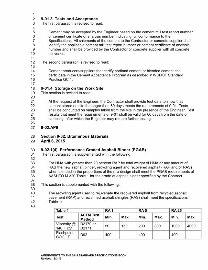
1 9-01.3 Tests and Acceptance 2 The first paragraph is revised to read: 3 4
Cement may be accepted by the Engineer based on the cement mill test report number 5 or cement certificate of analysis number indicating full conformance to the 6 Specifications. All shipments of the cement to the Contractor or concrete supplier shall 7 identify the applicable cement mill test report number or cement certificate of analysis 8 number and shall be provided by the Contractor or concrete supplier with all concrete 9 deliveries. 10
11 The second paragraph is revised to read: 12 13
Cement producers/suppliers that certify portland cement or blended cement shall 14 participate in the Cement Acceptance Program as described in WSDOT Standard 15 Practice QC 1. 16
17 9-01.4 Storage on the Work Site 18 This section is revised to read: 19 20
At the request of the Engineer, the Contractor shall provide test data to show that 21 cement stored on site for longer than 60 days meets the requirements of 9-01. Tests 22 shall be conducted on samples taken from the site in the presence of the Engineer. Test 23 results that meet the requirements of 9-01 shall be valid for 60 days from the date of 24 sampling, after which the Engineer may require further testing. 25
26 9-02.AP9 27
Section 9-02, Bituminous Materials 28 April 6, 2015 29
9-02.1(4) Performance Graded Asphalt Binder (PGAB) 30 The first paragraph is supplemented with the following: 31 32
For HMA with greater than 20 percent RAP by total weight of HMA or any amount of 33 RAS the new asphalt binder, recycling agent and recovered asphalt (RAP and/or RAS) 34 when blended in the proportions of the mix design shall meet the PGAB requirements of 35 AASHTO M 320 Table 1 for the grade of asphalt binder specified by the Contract. 36
37 This section is supplemented with the following: 38 39
The recycling agent used to rejuvenate the recovered asphalt from recycled asphalt 40 pavement (RAP) and reclaimed asphalt shingles (RAS) shall meet the specifications in 41 Table 1: 42 43
Table 1 RA 1 RA 5 RA 25
Test ASTM Test Method Min. Max. Min. Max. Min. Max.
Viscosity @ 140˚F cSt
D2170 or D2171 50 150 200 800 1000 4000
Flashpoint COC, ˚F D92 400 400 400
AMENDMENTS TO THE 2014 STANDARD SPECIFICATIONS BOOK Revised: 8/3/15
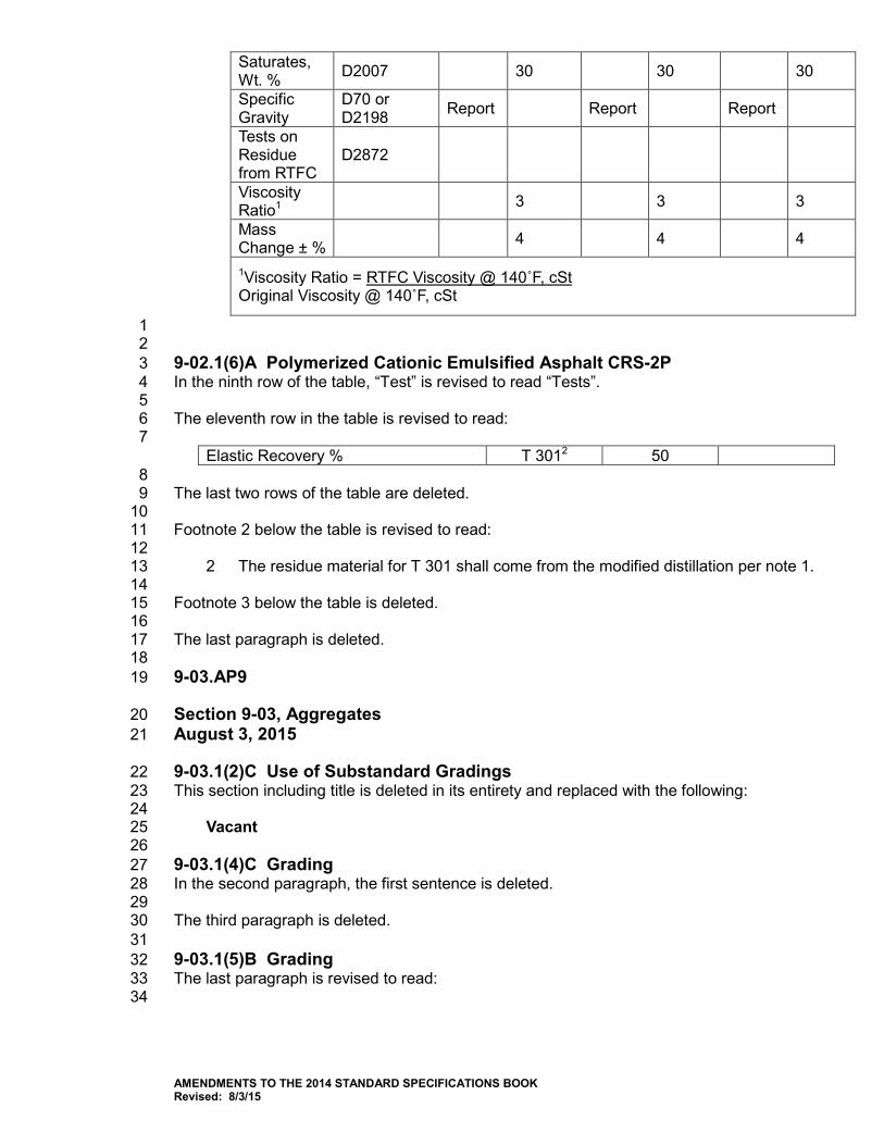
Saturates, Wt. % D2007 30 30 30
Specific Gravity
D70 or D2198 Report Report Report
Tests on Residue from RTFC
D2872
Viscosity Ratio1 3 3 3
Mass Change ± % 4 4 4
1Viscosity Ratio = RTFC Viscosity @ 140˚F, cSt Original Viscosity @ 140˚F, cSt
1 2 9-02.1(6)A Polymerized Cationic Emulsified Asphalt CRS-2P 3 In the ninth row of the table, “Test” is revised to read “Tests”. 4 5 The eleventh row in the table is revised to read: 6 7
Elastic Recovery % T 3012 50 8
The last two rows of the table are deleted. 9 10 Footnote 2 below the table is revised to read: 11 12
2 The residue material for T 301 shall come from the modified distillation per note 1. 13 14 Footnote 3 below the table is deleted. 15 16 The last paragraph is deleted. 17 18 9-03.AP9 19
Section 9-03, Aggregates 20 August 3, 2015 21
9-03.1(2)C Use of Substandard Gradings 22 This section including title is deleted in its entirety and replaced with the following: 23 24
Vacant 25 26 9-03.1(4)C Grading 27 In the second paragraph, the first sentence is deleted. 28 29 The third paragraph is deleted. 30 31 9-03.1(5)B Grading 32 The last paragraph is revised to read: 33 34
AMENDMENTS TO THE 2014 STANDARD SPECIFICATIONS BOOK Revised: 8/3/15
The Contracting Agency may sample each aggregate component prior to introduction to 1 the weigh batcher or as otherwise determined by the Engineer. Each component will be 2 sieve analyzed separately in accordance with WSDOT FOP for WAQTC/AASHTO Test 3 Method T-27/11. All aggregate components will be mathematically re-combined by the 4 proportions (percent of total aggregate by weight) provided by the Contractor on 5 Concrete Mix Design Form 350-040. 6
7 9-03.8(1) General Requirements 8 The first paragraph up until the colon is revised to read: 9 10
Preliminary testing of aggregates for source approval shall meet the following test 11 requirements: 12
13 The list in the first paragraph is supplemented with the following: 14 15
Sand Equivalent 45 min. 16 17
The following new paragraph is inserted after the first paragraph: 18 19
Aggregate sources that have 100 percent of the mineral material passing the No. 4 20 sieve shall be limited to no more than 5 percent of the total weight of aggregate. 21 22
9-03.8(2) HMA Test Requirements 23 The second paragraph (up until the colon) is revised to read: 24 25
The mix design shall produce HMA mixtures when combined with RAP, RAS, coarse 26 and fine aggregate within the limits set forth in Section 9-03.8(6) and mixed in the 27 laboratory with the designated grade of asphalt binder, using the Superpave gyratory 28 compactor in accordance with WSDOT FOP for AASHTO T 312, and at the required 29 gyrations for N initial, N design, and N maximum with the following properties: 30
31 The third paragraph is revised to read: 32 33
The mix criteria for Hamburg Wheel-Track Testing and Indirect Tensile Strength do not 34 apply to HMA accepted by commercial evaluation. 35
36 9-03.8(3)B Gradation – Recycled Asphalt Pavement and Mineral Aggregate 37 This section is supplemented with the following: 38 39
For HMA with greater than 20 percent RAP by total weight of HMA the RAP shall be 40 processed to ensure that 100 percent of the material passes a sieve twice the size of 41 the maximum aggregate size for the class of mix to be produced. 42 43 When any amount of RAS is used in the production of HMA the RAS shall be milled, 44 crushed or processed to ensure that 100 percent of the material passes the ½ inch 45 sieve. Extraneous materials in RAS such as metals, glass, rubber, soil, brick, tars, 46 paper, wood and plastic shall not exceed 2.0 percent by mass as determined on 47 material retained on the No. 4 sieve. 48
49 9-03.14(3) Common Borrow 50 This section is revised to read: 51 52
AMENDMENTS TO THE 2014 STANDARD SPECIFICATIONS BOOK Revised: 8/3/15
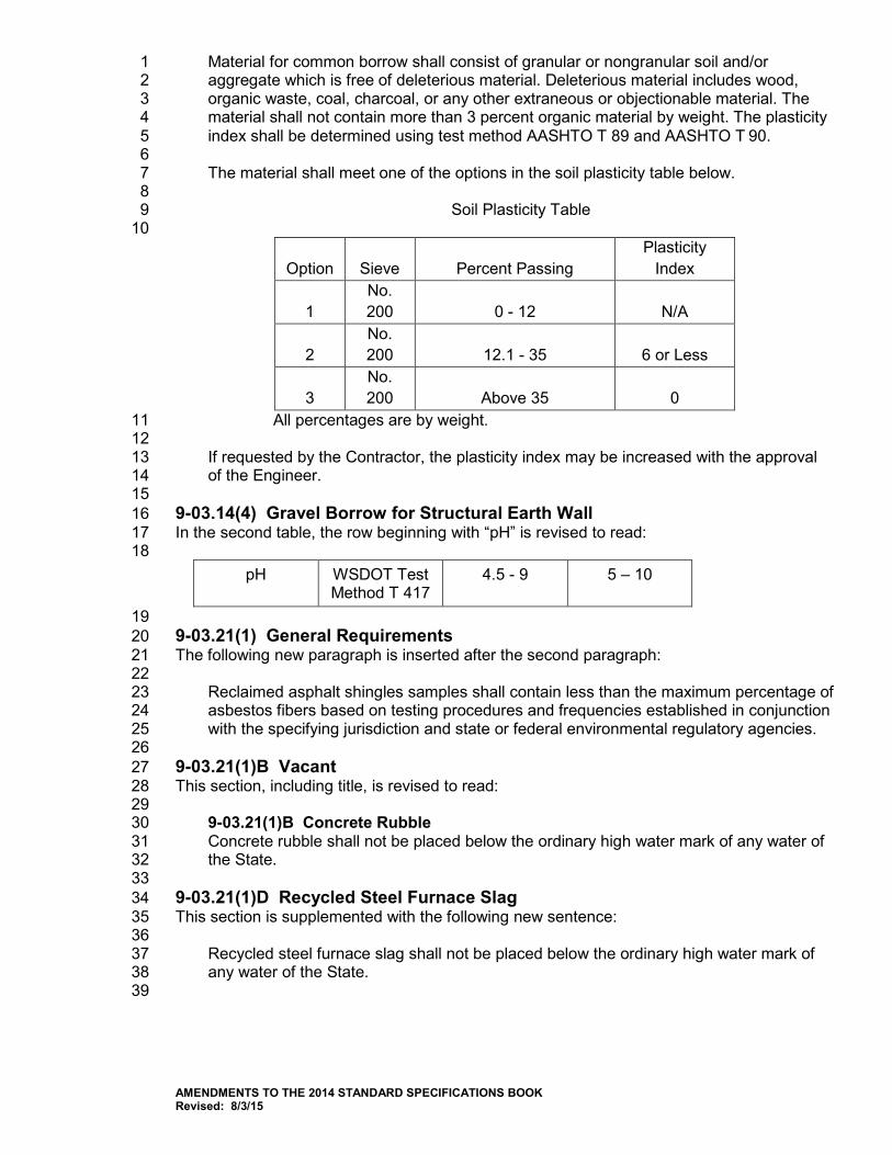
Material for common borrow shall consist of granular or nongranular soil and/or 1 aggregate which is free of deleterious material. Deleterious material includes wood, 2 organic waste, coal, charcoal, or any other extraneous or objectionable material. The 3 material shall not contain more than 3 percent organic material by weight. The plasticity 4 index shall be determined using test method AASHTO T 89 and AASHTO T 90. 5 6 The material shall meet one of the options in the soil plasticity table below. 7 8
Soil Plasticity Table 9 10
Option Sieve Percent Passing Plasticity
Index
1 No. 200 0 - 12 N/A
2 No. 200 12.1 - 35 6 or Less
3 No. 200 Above 35 0
All percentages are by weight. 11 12 If requested by the Contractor, the plasticity index may be increased with the approval 13 of the Engineer. 14 15
9-03.14(4) Gravel Borrow for Structural Earth Wall 16 In the second table, the row beginning with “pH” is revised to read: 17
18 pH WSDOT Test
Method T 417 4.5 - 9 5 – 10
19 9-03.21(1) General Requirements 20 The following new paragraph is inserted after the second paragraph: 21 22
Reclaimed asphalt shingles samples shall contain less than the maximum percentage of 23 asbestos fibers based on testing procedures and frequencies established in conjunction 24 with the specifying jurisdiction and state or federal environmental regulatory agencies. 25
26 9-03.21(1)B Vacant 27 This section, including title, is revised to read: 28 29
9-03.21(1)B Concrete Rubble 30 Concrete rubble shall not be placed below the ordinary high water mark of any water of 31 the State. 32
33 9-03.21(1)D Recycled Steel Furnace Slag 34 This section is supplemented with the following new sentence: 35 36
Recycled steel furnace slag shall not be placed below the ordinary high water mark of 37 any water of the State. 38
39
AMENDMENTS TO THE 2014 STANDARD SPECIFICATIONS BOOK Revised: 8/3/15
9-03.21(1)E Table on Maximum Allowable Percent (By Weight) of Recycled 1 Material 2 In the table, the “Concrete Rubble” value for the item "Gravel Backfill for Drains" is revised to 3 read “0”. 4 5 In the table, the “Concrete Rubble” value for the item "Backfill for Sand Drains" is revised to 6 read “0”. 7 8 In the table, the “Concrete Rubble” value for the item "Sand Drainage Blanket" is revised to 9 read “0”. 10 11 9-04.AP9 12
Section 9-04, Joint and Crack Sealing Materials 13 August 3, 2015 14
9-04.1(4) Elastomeric Expansion Joint Seals 15 In this section, “AASHTO M 220” is revised to read “ASTM D 2628”. 16 17 9-04.2 Joint Sealants 18 In the first paragraph, “AASHTO M 324” is revised to read “ASTM D 6690”. 19 20 9-04.2(2) Poured Rubber Joint Sealer 21 In item number 9, “WSDOT Test Method No. 412” is revised to read “ASTM D 5329”. 22 23 9-04.2(3) Polyurethane Sealant 24 The first paragraph is revised to read: 25 26
Polyurethane sealant shall conform to ASTM C 920 Type S Grade NS Class 25 Use M 27 or ASTM C 920 Type S Grade NS Class 35 Use M. 28
29 9-05.AP9 30
Section 9-05, Drainage Structures and Culverts 31 April 7, 2014 32
9-05.13 Ductile Iron Sewer Pipe 33 The first paragraph is deleted. 34 35 9-06.AP9 36
Section 9-06, Structural Steel and Related Materials 37 January 5, 2015 38
9-06.5(4) Anchor Bolts 39 The third sentence of the second paragraph is revised to read: 40 41
Nuts for ASTM F 1554 Grade 36 or 55 black or galvanized anchor bolts shall conform to 42 ASTM A 563, Grade A or DH. 43
44
AMENDMENTS TO THE 2014 STANDARD SPECIFICATIONS BOOK Revised: 8/3/15
9-07.AP9 1
Section 9-07, Reinforcing Steel 2 August 3, 2015 3
9-07.2 Deformed Steel Bars 4 The first sentence is revised to read: 5 6
Deformed steel bars for concrete reinforcement shall conform to either AASHTO M 31 7 Grade 60 or ASTM A 706 Grade 60, except as otherwise noted in this Section or as 8 shown in the Plans. 9
10 This section is supplemented with the following new sub-section: 11 12
9-07.2(1) Headed Steel Reinforcing Bar 13 Headed steel reinforcing bars shall conform to Section 9-07.2 and ASTM A 970, 14 including Annex A1 requirements for Class HA head dimensions. Headed steel 15 reinforcing bars shall be forged headed bars or threaded headed bars. 16
17 9-07.5(1) Epoxy-Coated Dowel Bars (for Cement Concrete Pavement 18 Rehabilitation) 19 This section is revised to read: 20 21
Epoxy-coated dowel bars shall be round plain steel bars of the dimensions shown in the 22 Standard Plans. They shall conform to AASHTO M 31, Grade 60 or ASTM A 615, 23 Grade 60 and shall be coated in accordance with ASTM A 1078 Type 2 coating, except 24 that the bars may be cut to length after being coated. Cut ends shall be coated in 25 accordance with ASTM A 1078 with a patching material that is compatible with the 26 coating, inert in concrete and recommended by the coating manufacturer. The thickness 27 of the epoxy coating shall be 10 mils plus or minus 2 mils. The Contractor shall furnish a 28 written certification that properly identifies the coating material, the number of each 29 batch of coating material used, quantity represented, date of manufacture, name and 30 address of manufacturer, and a statement that the supplied coating material meets the 31 requirements of ASTM A 1078 Type 2 coating. Patching material, compatible with the 32 coating material and inert in concrete and recommended by the manufacturer shall be 33 supplied with each shipment for field repairs by the Contractor. 34
35 9-07.5(2) Corrosion Resistant Dowel Bars (for Cement Concrete Pavement) 36 This section’s title is revised to read: 37 38
9-07.5(2) Corrosion Resistant Dowel Bars (for Cement Concrete Pavement and 39 Cement Concrete Pavement Rehabilitation) 40
41 9-08.AP9 42
Section 9-08, Paints and Related Materials 43 January 5, 2015 44
9-08.1(2)H Top Coat, Single Component, Moisture-Cured Polyurethane 45 The second paragraph is revised to read: 46 47
AMENDMENTS TO THE 2014 STANDARD SPECIFICATIONS BOOK Revised: 8/3/15
Color and Gloss: As specified in the Plans or Special Provisions 1 2
The last item in the requirements list is revised to read: 3 4
The top coat shall be a gloss or semi-gloss 5 6 9-08.1(8) Standard Colors 7 The second paragraph is deleted. 8 9 The third paragraph is revised to read: 10 11
Unless otherwise specified, all top or finish coats shall be gloss or semi-gloss, with the 12 paint falling within the range of greater than 70 for gloss and 35 to 70 for semi-gloss on 13 the 60-degree gloss meter. 14
15 9-09.AP9 16
Section 9-09, Timber and Lumber 17 January 6, 2014 18
9-09.3(1) General Requirements 19 The fourth paragraph is revised to read: 20 21
All orders of treated timber and lumber shall be accompanied by a Certificate of 22 Treatment record. The Certificate of Treatment showing conformance to this 23 specification and AWPA standards shall include the following information: 24 25
Name and location of the wood preserving company, 26 27 Customer identification, 28 29 Date of treatment and charge number, 30 31 Type of chemical used and amount of retention, 32 33 Treating process and identification of the Specification used, 34 35 Boring records verifying treatment penetration for timber and lumber with a nominal 36 dimension of 6” x 6” or larger, 37 38 Description of material that was treated, and 39 40 Signature of a responsible plant official. 41 42
The fifth paragraph is deleted. 43 44 The first sentence in the last paragraph is revised to read: 45 46
All timber and lumber to be used in aquatic environments, unless specified otherwise in 47 the Contract, shall be chemically treated using Western Wood Preservers Institute Best 48 Management Practices (BMPs). 49
50
AMENDMENTS TO THE 2014 STANDARD SPECIFICATIONS BOOK Revised: 8/3/15
9-10.AP9 1
Section 9-10, Piling 2 August 3, 2015 3
9-10.2(1) Concrete 4 The first paragraph is deleted. 5 6 The first sentence of the second paragraph is deleted. 7 8 9-10.5 Steel Piling 9 This section is revised to read: 10 11
The material for rolled steel piling H-piling and pile splices shall conform to ASTM A 36, 12 ASTM A 572 or ASTM A 992. The material for steel pipe piling and splices shall 13 conform to one of the following requirements except as specifically noted in the Plans: 14 15
1. API 5L Grade X42 or X52 material may be used for longitudinal seam welded 16 or helical (spiral) seam submerged-arc welded pipe piles of any diameter. 17
18 2. ASTM A 252 Grade 2 or 3 material may be used for longitudinal seam welded 19
or helical (spiral) seam submerged-arc welded pipe piles of any diameter. For 20 the purposes of welding and prequalification of base metal, steel pipe pile 21 designated as ASTM A 252 may be treated as prequalified provided the 22 chemical composition conforms to a prequalified base metal classification 23 listed in Table 3.1 of the AWS D1.1/D1.1M, latest edition, Structural Welding 24 Code, the grade of pipe piling meets or exceeds the grade specified in the 25 Plans, and the carbon equivalent (CE) is a maximum of 0.45-percent. 26
27 3. ASTM A 572 or ASTM A 588 material may be used for longitudinal seam 28
welded piles of any diameter. 29 30 For helical (spiral) seam submerged-arc welded pipe piles, the maximum radial offset of 31 strip/plate edges shall be 1/8 inch. The offset shall be transitioned with a taper weld and 32 the slope shall not be less than a 1 in 2.5 taper. The weld reinforcement shall not be 33 greater than 3/16 inches and misalignment of weld beads shall not exceed 1/8 inch. 34 35 Steel soldier piles, and associated steel bars and plates, shall conform to ASTM A 36, 36 ASTM A 572 or ASTM A 992, except as otherwise noted in the Plans. 37 38 All steel piling may be accepted by the Engineer based on the Manufacturer’s 39 Certificate of Compliance submitted in accordance with Section 1-06.3. The 40 manufacturer’s certificate of compliance submittal for steel pipe piles shall be 41 accompanied by certified mill test reports, including chemical analysis and carbon 42 equivalence, for each heat of steel used to fabricate the steel pipe piling. 43
44
AMENDMENTS TO THE 2014 STANDARD SPECIFICATIONS BOOK Revised: 8/3/15
9-13.AP9 1
Section 9-13, Riprap, Quarry Spalls, Slope Protection, and Rock for Erosion 2 and Scour Protection and Rock Walls 3 January 5, 2015 4
This section’s content is deleted. 5 6 9-13.1 Loose Riprap 7 This section’s content, including title and subsections, is revised to read the following: 8 9
9-13.1 Riprap and Quarry Spalls 10 11
9-13.1(1) General 12 Riprap and quarry spalls shall consist of broken stone or broken concrete rubble 13 and shall be free of rock fines, soil, or other extraneous material. Concrete rubble 14 shall not be contaminated by foreign materials such as fibers, wood, steel, asphalt, 15 sealant, soil, plastic and other contaminants or deleterious material. Concrete 16 rubble that is imported to the job site will require testing and certification for toxicity 17 characteristics per Section 9-03.21(1). 18 19 The grading of the riprap shall be determined by the Engineer by visual inspection 20 of the load before it is dumped into place, or, if so ordered by the Engineer, by 21 dumping individual loads on a flat surface and sorting and measuring the individual 22 rocks contained in the load. Should the riprap contain insufficient spalls, as defined 23 in Section 9-13.1(5), the Contractor shall furnish and place supplementary spall 24 material. 25 26 Riprap and quarry spalls shall be free from segregation, seams, cracks, and other 27 defects tending to destroy its resistance to weather and shall conform to the 28 following requirements for quality. 29 30
Aggregate Property Test Method Requirement Degradation Factor WSDOT T 113 15 minimum
Los Angeles Wear, 500 Rev. AASHTO T 96 50% maximum Specific Gravity, SSD AASHTO T 85 2.55 minimum
31 9-13.1(2) Heavy Loose Riprap 32 Heavy loose riprap shall meet the following requirements for grading: 33 34
Minimum Size Maximum Size 40% to 90% 1 ton (½ cubic yd.) 70% to 90% 300 lbs. (2 cu. ft.) 10% to 30% 3 inch 50 lbs. (spalls)
35 36 9-13.1(3) Light Loose Riprap 37 Light loose riprap shall meet the following requirements for grading: 38 39
Size Range Maximum Size 20% to 90% 300 lbs. to 1 ton
AMENDMENTS TO THE 2014 STANDARD SPECIFICATIONS BOOK Revised: 8/3/15
(2 cu. ft. to ½ cu. yd.)
15% to 80% 50 lbs. to 1 ton (⅓ cu. ft. to ½ cu. yd.)
10% to 20% 3 inch 50 lbs. (spalls) 1 9-13.1(4) Hand Placed Riprap 2 Hand placed riprap shall be as nearly rectangular as possible, 60 percent shall 3 have a volume of not less than 1 cubic foot. No stone shall be used which is less 4 than 6 inches thick, nor which does not extend through the wall. 5 6 9-13.1(5) Quarry Spalls 7 Quarry spalls shall meet the following requirements for grading: 8 9
Sieve Size Percent Passing 8″ 100 3″ 40 max. ¾″ 10 max.
10 9-13.2 Hand Placed Riprap 11 This section, including title, is deleted in its entirety and replaced with the following: 12 13
9-13.2 Vacant 14 15 9-13.4 Rock for Erosion Control and Scour Protection 16 The last sentence is revised to read: 17 18
The use of recycled materials and concrete rubble is not permitted for this application. 19 20 9-13.6 Quarry Spalls 21 This section, including title, is deleted in its entirety and replaced with the following: 22 23
9-13.6 Vacant 24 25 9-14.AP9 26
Section 9-14, Erosion Control and Roadside Planting 27 August 3, 2015 28
9.14.1 Soil 29 This section, including title, is revised to read: 30 31
9-14.1 Topsoil 32 Topsoil shall not contain any recycled material, foreign materials, or any listed Noxious 33 and Nuisance weeds of any Class designated by authorized State or County officials. 34 Aggregate shall not comprise more than 10% by volume of Topsoil and shall not be 35 greater than two inches in diameter. 36 37
9-14.1(2) Topsoil Type B 38 The last sentence of the second paragraph is deleted. 39
AMENDMENTS TO THE 2014 STANDARD SPECIFICATIONS BOOK Revised: 8/3/15
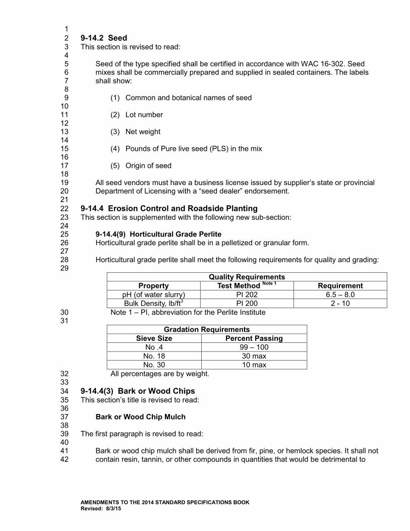
1 9-14.2 Seed 2 This section is revised to read: 3 4
Seed of the type specified shall be certified in accordance with WAC 16-302. Seed 5 mixes shall be commercially prepared and supplied in sealed containers. The labels 6 shall show: 7 8
(1) Common and botanical names of seed 9 10 (2) Lot number 11 12 (3) Net weight 13 14 (4) Pounds of Pure live seed (PLS) in the mix 15 16 (5) Origin of seed 17
18 All seed vendors must have a business license issued by supplier’s state or provincial 19 Department of Licensing with a “seed dealer” endorsement. 20 21
9-14.4 Erosion Control and Roadside Planting 22 This section is supplemented with the following new sub-section: 23 24
9-14.4(9) Horticultural Grade Perlite 25 Horticultural grade perlite shall be in a pelletized or granular form. 26 27 Horticultural grade perlite shall meet the following requirements for quality and grading: 28 29
Quality Requirements Property Test Method Note 1 Requirement
pH (of water slurry) PI 202 6.5 – 8.0 Bulk Density, lb/ft3 PI 200 2 - 10
Note 1 – PI, abbreviation for the Perlite Institute 30 31
Gradation Requirements Sieve Size Percent Passing
No .4 99 – 100 No. 18 30 max No. 30 10 max
All percentages are by weight. 32 33
9-14.4(3) Bark or Wood Chips 34 This section’s title is revised to read: 35 36
Bark or Wood Chip Mulch 37 38
The first paragraph is revised to read: 39 40
Bark or wood chip mulch shall be derived from fir, pine, or hemlock species. It shall not 41 contain resin, tannin, or other compounds in quantities that would be detrimental to 42
AMENDMENTS TO THE 2014 STANDARD SPECIFICATIONS BOOK Revised: 8/3/15
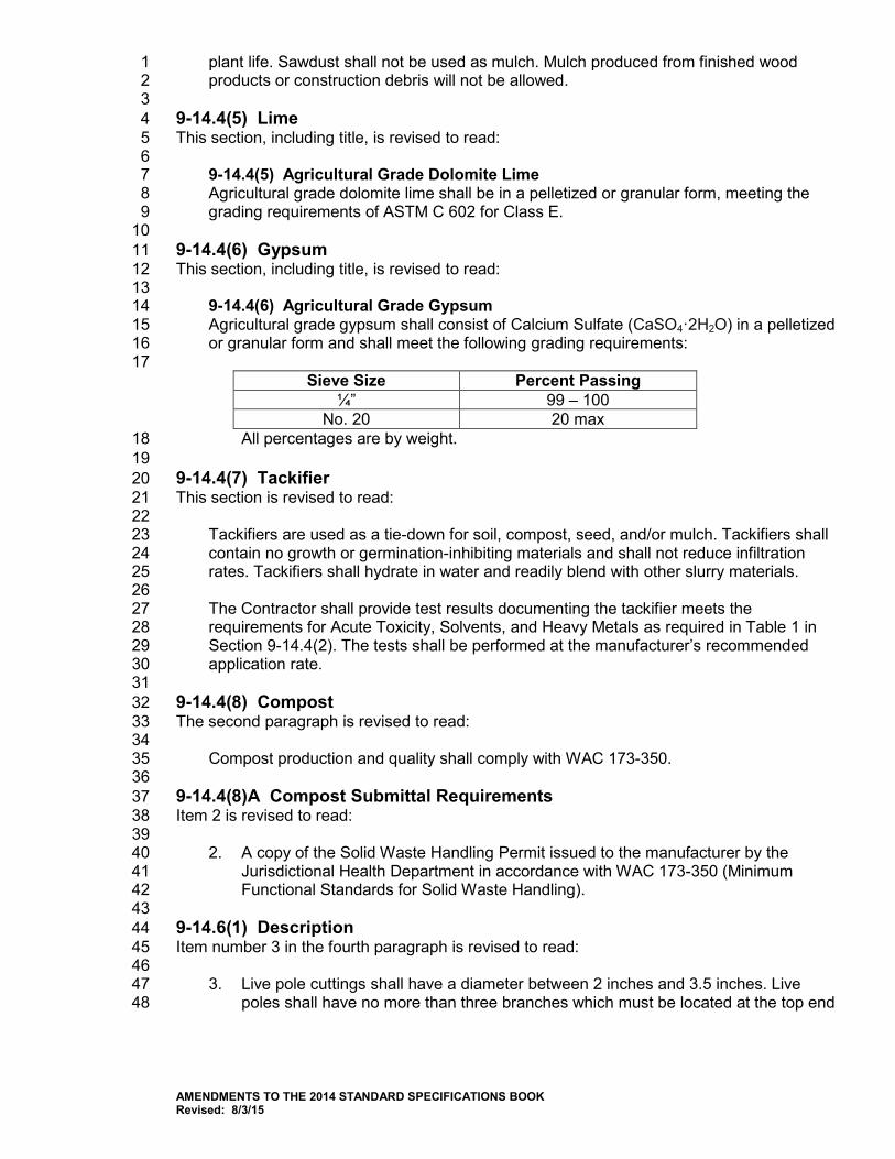
plant life. Sawdust shall not be used as mulch. Mulch produced from finished wood 1 products or construction debris will not be allowed. 2 3
9-14.4(5) Lime 4 This section, including title, is revised to read: 5 6
9-14.4(5) Agricultural Grade Dolomite Lime 7 Agricultural grade dolomite lime shall be in a pelletized or granular form, meeting the 8 grading requirements of ASTM C 602 for Class E. 9
10 9-14.4(6) Gypsum 11 This section, including title, is revised to read: 12 13
9-14.4(6) Agricultural Grade Gypsum 14 Agricultural grade gypsum shall consist of Calcium Sulfate (CaSO4·2H2O) in a pelletized 15 or granular form and shall meet the following grading requirements: 16 17
Sieve Size Percent Passing ¼” 99 – 100
No. 20 20 max All percentages are by weight. 18
19 9-14.4(7) Tackifier 20 This section is revised to read: 21 22
Tackifiers are used as a tie-down for soil, compost, seed, and/or mulch. Tackifiers shall 23 contain no growth or germination-inhibiting materials and shall not reduce infiltration 24 rates. Tackifiers shall hydrate in water and readily blend with other slurry materials. 25 26 The Contractor shall provide test results documenting the tackifier meets the 27 requirements for Acute Toxicity, Solvents, and Heavy Metals as required in Table 1 in 28 Section 9-14.4(2). The tests shall be performed at the manufacturer’s recommended 29 application rate. 30 31
9-14.4(8) Compost 32 The second paragraph is revised to read: 33 34
Compost production and quality shall comply with WAC 173-350. 35 36 9-14.4(8)A Compost Submittal Requirements 37 Item 2 is revised to read: 38 39
2. A copy of the Solid Waste Handling Permit issued to the manufacturer by the 40 Jurisdictional Health Department in accordance with WAC 173-350 (Minimum 41 Functional Standards for Solid Waste Handling). 42
43 9-14.6(1) Description 44 Item number 3 in the fourth paragraph is revised to read: 45 46
3. Live pole cuttings shall have a diameter between 2 inches and 3.5 inches. Live 47 poles shall have no more than three branches which must be located at the top end 48
AMENDMENTS TO THE 2014 STANDARD SPECIFICATIONS BOOK Revised: 8/3/15

of the pole and those branches shall be pruned back to the first bud from the main 1 stem. 2
3 9-14.6(2) Quality 4 The second and third paragraphs in this section are revised to read: 5 6
All plant material shall comply with State and Federal laws with respect to inspection 7 for plant diseases and insect infestation. Plants must meet Washington State 8 Department of Agriculture plant quarantines and have a certificate of inspection. Plants 9 originating in Canada must be accompanied by a phytosanitary certificate stating the 10 plants meet USDA health requirements. 11 12 All plant material shall be purchased from a nursery licensed to sell plants in their state 13 or province. 14
15 9-15.AP9 16
Section 9-15, Irrigation System 17 August 4, 2014 18
9-15.18 Detectable Marking Tape 19 In the second paragraph, the table is supplemented with the following new row: 20 21
Non-Potable Water Purple 22 23 9-16.AP9 24
Section 9-16, Fence and Guardrail 25 August 4, 2014 26
9-16.2(1)B Wood Fence Posts and Braces 27 In the table, the row beginning with “ACA” is deleted. 28 29 9-19.AP9 30
Section 9-19, Prestressed Concrete Girders 31 August 3, 2015 32
This section, including title, is deleted in its entirety and replaced with the following: 33 34
Vacant 35 36 9-29.AP9 37
Section 9-29, Illumination, Signal, Electrical 38 August 3, 2015 39
9-29.1 Conduit, Innerduct, and Outerduct 40 This section is supplemented with the following new subsection: 41 42
AMENDMENTS TO THE 2014 STANDARD SPECIFICATIONS BOOK Revised: 8/3/15
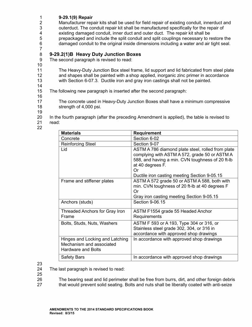
9-29.1(9) Repair 1 Manufacturer repair kits shall be used for field repair of existing conduit, innerduct and 2 outerduct. The conduit repair kit shall be manufactured specifically for the repair of 3 existing damaged conduit, inner duct and outer duct. The repair kit shall be 4 prepackaged and include the split conduit and split couplings necessary to restore the 5 damaged conduit to the original inside dimensions including a water and air tight seal. 6
7 9-29.2(1)B Heavy Duty Junction Boxes 8 The second paragraph is revised to read: 9 10
The Heavy-Duty Junction Box steel frame, lid support and lid fabricated from steel plate 11 and shapes shall be painted with a shop applied, inorganic zinc primer in accordance 12 with Section 6-07.3. Ductile iron and gray iron castings shall not be painted. 13 14
The following new paragraph is inserted after the second paragraph: 15 16
The concrete used in Heavy-Duty Junction Boxes shall have a minimum compressive 17 strength of 4,000 psi. 18 19
In the fourth paragraph (after the preceding Amendment is applied), the table is revised to 20 read: 21 22
Materials Requirement Concrete Section 6-02 Reinforcing Steel Section 9-07 Lid ASTM A 786 diamond plate steel, rolled from plate
complying with ASTM A 572, grade 50 or ASTM A 588, and having a min. CVN toughness of 20 ft-lb at 40 degrees F. Or Ductile iron casting meeting Section 9-05.15
Frame and stiffener plates ASTM A 572 grade 50 or ASTM A 588, both with min. CVN toughness of 20 ft-lb at 40 degrees F Or Gray iron casting meeting Section 9-05.15
Anchors (studs) Section 9-06.15
Threaded Anchors for Gray Iron Frame
ASTM F1554 grade 55 Headed Anchor Requirements
Bolts, Studs, Nuts, Washers ASTM F 593 or A 193, Type 304 or 316, or Stainless steel grade 302, 304, or 316 in accordance with approved shop drawings
Hinges and Locking and Latching Mechanism and associated Hardware and Bolts
In accordance with approved shop drawings
Safety Bars In accordance with approved shop drawings 23
The last paragraph is revised to read: 24 25
The bearing seat and lid perimeter shall be free from burrs, dirt, and other foreign debris 26 that would prevent solid seating. Bolts and nuts shall be liberally coated with anti-seize 27
AMENDMENTS TO THE 2014 STANDARD SPECIFICATIONS BOOK Revised: 8/3/15
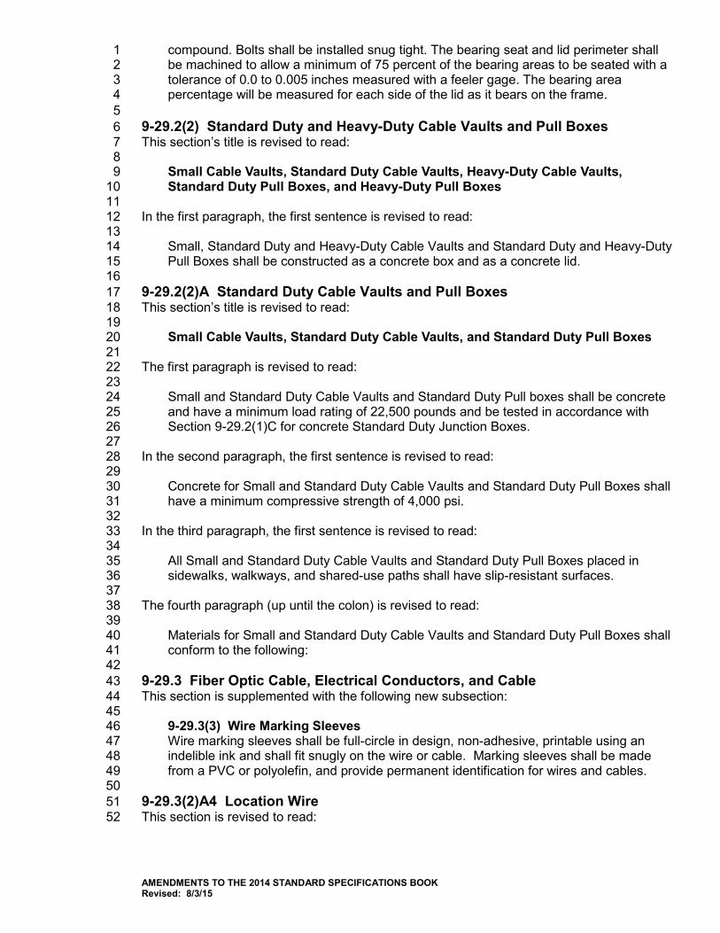
compound. Bolts shall be installed snug tight. The bearing seat and lid perimeter shall 1 be machined to allow a minimum of 75 percent of the bearing areas to be seated with a 2 tolerance of 0.0 to 0.005 inches measured with a feeler gage. The bearing area 3 percentage will be measured for each side of the lid as it bears on the frame. 4
5 9-29.2(2) Standard Duty and Heavy-Duty Cable Vaults and Pull Boxes 6 This section’s title is revised to read: 7 8
Small Cable Vaults, Standard Duty Cable Vaults, Heavy-Duty Cable Vaults, 9 Standard Duty Pull Boxes, and Heavy-Duty Pull Boxes 10
11 In the first paragraph, the first sentence is revised to read: 12 13
Small, Standard Duty and Heavy-Duty Cable Vaults and Standard Duty and Heavy-Duty 14 Pull Boxes shall be constructed as a concrete box and as a concrete lid. 15
16 9-29.2(2)A Standard Duty Cable Vaults and Pull Boxes 17 This section’s title is revised to read: 18 19
Small Cable Vaults, Standard Duty Cable Vaults, and Standard Duty Pull Boxes 20 21 The first paragraph is revised to read: 22 23
Small and Standard Duty Cable Vaults and Standard Duty Pull boxes shall be concrete 24 and have a minimum load rating of 22,500 pounds and be tested in accordance with 25 Section 9-29.2(1)C for concrete Standard Duty Junction Boxes. 26
27 In the second paragraph, the first sentence is revised to read: 28 29
Concrete for Small and Standard Duty Cable Vaults and Standard Duty Pull Boxes shall 30 have a minimum compressive strength of 4,000 psi. 31 32
In the third paragraph, the first sentence is revised to read: 33 34
All Small and Standard Duty Cable Vaults and Standard Duty Pull Boxes placed in 35 sidewalks, walkways, and shared-use paths shall have slip-resistant surfaces. 36 37
The fourth paragraph (up until the colon) is revised to read: 38 39
Materials for Small and Standard Duty Cable Vaults and Standard Duty Pull Boxes shall 40 conform to the following: 41
42 9-29.3 Fiber Optic Cable, Electrical Conductors, and Cable 43 This section is supplemented with the following new subsection: 44 45
9-29.3(3) Wire Marking Sleeves 46 Wire marking sleeves shall be full-circle in design, non-adhesive, printable using an 47 indelible ink and shall fit snugly on the wire or cable. Marking sleeves shall be made 48 from a PVC or polyolefin, and provide permanent identification for wires and cables. 49 50
9-29.3(2)A4 Location Wire 51 This section is revised to read: 52
AMENDMENTS TO THE 2014 STANDARD SPECIFICATIONS BOOK Revised: 8/3/15
1 Location wire shall be steel core copper clad minimum size AWG 14 insulated 2 conductor. The insulation shall be orange High Molecular Weight High Density 3 Polyethylene (HMHDPE). 4 5
9-29.13(2) Manufacturing Quality 6 This section, including title, is revised to read: 7 8
9-29.13(2) Traffic Signal Controller Assembly Testing 9 Each traffic signal controller assembly shall be tested as follows. The Contractor shall: 10 11
1. Prior to shipping, arrange appointment for testing at the WSDOT Materials 12 Laboratory. 13
14 2. Assembly shall be defined as tightening all screws, nuts and bolts, verifying 15
that all wiring is clear of moving parts and properly secured, installing all 16 pluggables, connecting all cables and ensure that all Contract required 17 documents are present, proper documentation is provided, and all equipment 18 required by the Contract is installed. 19
20 3. The Contractor shall demonstrate that all of the functions required by the 21
Contract perform as intended. Demonstration shall include energizing the 22 cabinet and verifying that all 8 phases, 4 pedestrian movements and 4 23 overlaps (as required by the Contract Provisions) operate per Section 9-29.13. 24 The Contractor shall place the controller in minimum recall with interval timing 25 set at convenient value for testing purposes. Upon a satisfactory 26 demonstration the controller assembly will then be accepted by WSDOT for 27 testing. 28
29 4. If the assembly and acceptance for testing is not complete within 7 calendar 30
days of delivery, the Project Engineer may authorize the return of the 31 assembly to the Contractor, with collect freight charges to the Contractor. 32
33 5. WSDOT will test each traffic signal control assembly in accordance with the 34
following test methods, WSDOT T 421, T 422, T 423, T 424, T 425, T 427, and 35 T 428. 36
37 6. If the traffic signal control assembly passes all testing, the Contractor will be 38
notified where the assembly is to be picked-up for delivery to the project. The 39 Contractor shall pick-up the assembly within 7 calendar days of notification. 40
41 7. If the traffic signal control assembly fails testing, the Contractor has 7 calendar 42
days to repair or replace any components that fail during the testing process at 43 no cost to the Contracting Agency. All repairs shall be completed during 44 normal business hours for the State Materials Lab. A failure shall be defined 45 as a component that no longer functions as intended under the conditions 46 required or does not meet the requirements of the Contract and is at the sole 47 discretion of WSDOT. Once all repairs and replacement of components is 48 complete WSDOT will retest the traffic controller as specified in step 6 and all 49 costs for retesting will be deducted from monies due or that may become due 50 the Contractor. 51
52
AMENDMENTS TO THE 2014 STANDARD SPECIFICATIONS BOOK Revised: 8/3/15
9-29.13(2)A Traffic Signal Controller Assembly Testing 1 This section is deleted. 2 3 9-29.16 Vehicular Signal Heads, Displays, and Housing 4 The last sentence of the last paragraph is revised to read: 5 6
A 1-inch-wide strip of yellow retro-reflective, type IV prismatic sheeting, conforming to 7 the requirements of Section 9-28.12, shall be applied around the perimeter of each 8 backplate with the exception of installations where all sections of the display will be dark 9 as part of normal operation such as ramp meters, hawk signals and tunnels. 10
11 9-31.AP9 12
Section 9-31, Elastomeric Bearing Pads 13 August 4, 2014 14
This section’s title is revised to read: 15 16
Elastomeric Pads 17 18
9-31.1 Requirements 19 In the first paragraph, the word “bearing” is deleted from the first sentence. 20 21 In the first sentence of the second paragraph, the word “bearing” is deleted and replaced 22 with “elastomeric”. 23 24 In the last sentence of the second paragraph, the word “Bearing” is deleted and replaced 25 with “Elastomeric”. 26 27 In the third paragraph, the word “bearing” is deleted and replaced with the word 28 “elastomeric”. 29 30 9-32.AP9 31
Section 9-32, Mailbox Support 32 August 4, 2014 33
9-32.7 Type 2 Mailbox Support 34 The first sentence is revised to read: 35 36
Type 2 mailbox supports shall be 2-inch 14-gage steel tube and shall meet the NCHRP 37 350 or the Manual for Assessing Safety Hardware (MASH) crash test criteria. 38
39 9-33.AP9 40
Section 9-33, Construction Geosynthetic 41 August 3, 2015 42
9-33.4(1) Geosynthetic Material Approval 43 This section is revised to read: 44 45
AMENDMENTS TO THE 2014 STANDARD SPECIFICATIONS BOOK Revised: 8/3/15
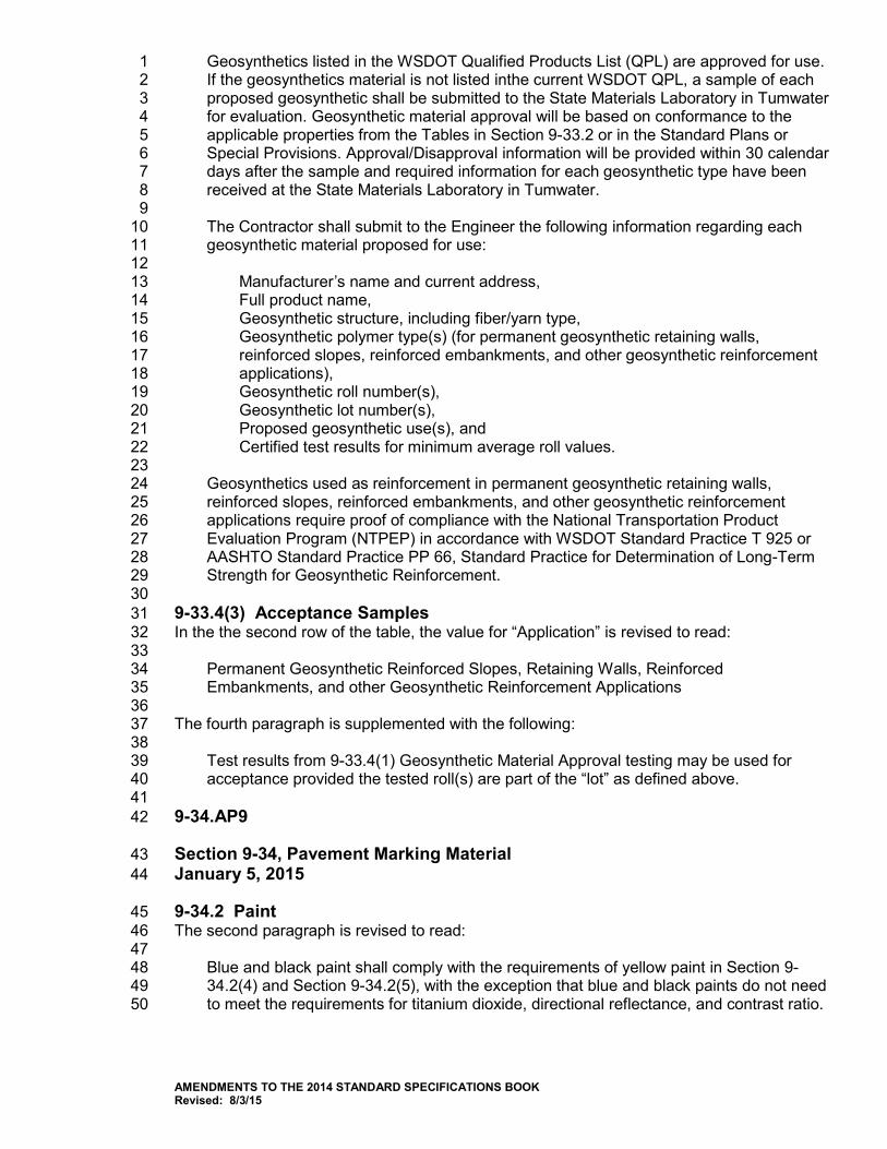
Geosynthetics listed in the WSDOT Qualified Products List (QPL) are approved for use. 1 If the geosynthetics material is not listed inthe current WSDOT QPL, a sample of each 2 proposed geosynthetic shall be submitted to the State Materials Laboratory in Tumwater 3 for evaluation. Geosynthetic material approval will be based on conformance to the 4 applicable properties from the Tables in Section 9-33.2 or in the Standard Plans or 5 Special Provisions. Approval/Disapproval information will be provided within 30 calendar 6 days after the sample and required information for each geosynthetic type have been 7 received at the State Materials Laboratory in Tumwater. 8 9 The Contractor shall submit to the Engineer the following information regarding each 10 geosynthetic material proposed for use: 11 12
Manufacturer’s name and current address, 13 Full product name, 14 Geosynthetic structure, including fiber/yarn type, 15 Geosynthetic polymer type(s) (for permanent geosynthetic retaining walls, 16 reinforced slopes, reinforced embankments, and other geosynthetic reinforcement 17 applications), 18 Geosynthetic roll number(s), 19 Geosynthetic lot number(s), 20 Proposed geosynthetic use(s), and 21 Certified test results for minimum average roll values. 22 23
Geosynthetics used as reinforcement in permanent geosynthetic retaining walls, 24 reinforced slopes, reinforced embankments, and other geosynthetic reinforcement 25 applications require proof of compliance with the National Transportation Product 26 Evaluation Program (NTPEP) in accordance with WSDOT Standard Practice T 925 or 27 AASHTO Standard Practice PP 66, Standard Practice for Determination of Long-Term 28 Strength for Geosynthetic Reinforcement. 29
30 9-33.4(3) Acceptance Samples 31 In the the second row of the table, the value for “Application” is revised to read: 32 33
Permanent Geosynthetic Reinforced Slopes, Retaining Walls, Reinforced 34 Embankments, and other Geosynthetic Reinforcement Applications 35 36
The fourth paragraph is supplemented with the following: 37 38
Test results from 9-33.4(1) Geosynthetic Material Approval testing may be used for 39 acceptance provided the tested roll(s) are part of the “lot” as defined above. 40
41 9-34.AP9 42
Section 9-34, Pavement Marking Material 43 January 5, 2015 44
9-34.2 Paint 45 The second paragraph is revised to read: 46 47
Blue and black paint shall comply with the requirements of yellow paint in Section 9-48 34.2(4) and Section 9-34.2(5), with the exception that blue and black paints do not need 49 to meet the requirements for titanium dioxide, directional reflectance, and contrast ratio. 50
AMENDMENTS TO THE 2014 STANDARD SPECIFICATIONS BOOK Revised: 8/3/15
1 9-34.4 Glass Beads for Pavement Marking Materials 2 In the third paragraph, the table titled “Metal Concentration Limits” is revised to read: 3 4
Metal Concentration Limits Element Test Method Max. Parts Per Million (ppm) Arsenic EPA 3052 SW-846 6010C 10.0 Barium EPA 3052 SW-846 6010C 100.0
Cadmium EPA 3052 SW-846 6010C 1.0 Chromium EPA 3052 SW-846 6010C 5.0
Lead EPA 3052 SW-846 6010C 50.0 Silver EPA 3052 SW-846 6010C 5.0
Mercury EPA 3052 SW-846 7471B 4.0 5
6 9-34.5 Temporary Pavement Marking Tape 7 This section is revised to read: 8 9
Biodegradable tape with paper backing is not allowed. 10 11
This section is supplemented with the following new sub-sections: 12 13
9-34.5(1) Temporary Pavement Marking Tape – Short Duration 14 Temporary pavement marking tape for short duration shall conform to ASTM D4592 15 Type II except that black tape, black mask tape and the black portion of the contrast 16 removable tape, shall be non-reflective. 17 18 9-34.5(2) Temporary Pavement Marking Tape – Long Duration 19 Temporary pavement marking tape for long duration shall conform to ASTM D4592 20 Type I. Temporary pavement marking tape for long duration, except for black tape, 21 shall have a minimum initial coefficient of retroreflective luminance of 200 mcd*m-2*lx-1 22 when measured in accordance with ASTM E 2832 or ASTM E 2177. Black tape, black 23 mask tape and the black portion of the contrast removable tape, shall be non-reflective. 24 25
9-34.6 Temporary Raised Pavement Markers 26 This section’s title is revised to read: 27 28
Temporary Flexible Raised Pavement Markers 29 30
The second paragraph is deleted. 31 32 9-35.AP9 33
Section 9-35, Temporary Traffic Control Materials 34 August 4, 2014 35
9-35.0 General Requirements 36 The following item is deleted from the list of temporary traffic control materials: 37 38
Barrier Drums 39 40
AMENDMENTS TO THE 2014 STANDARD SPECIFICATIONS BOOK Revised: 8/3/15
The last sentence of the second paragraph is revised to read: 1 2
Certification for crashworthiness according to NCHRP 350 or the Manual for Assessing 3 Safety Hardware (MASH) will be required as described in Section 1-10.2(3). 4 5
9-35.2 Construction Signs 6 The first sentence is revised to read: 7 8
Construction signs shall conform to the requirements of the MUTCD and shall meet the 9 requirements of NCHRP Report 350 for Category 2 devices or MASH. 10 11
9-35.7 Traffic Safety Drums 12 The third paragraph is revised to read: 13 14
Drums and light units shall meet the crashworthiness requirements of NCHRP 350 or 15 MASH as described in Section 1-10.2(3). 16 17
9-35.8 Barrier Drums 18 This section including title is deleted in its entirety and replaced with the following: 19 20
9-35.8 Vacant 21 22 9-35.12 Transportable Attenuator 23 In the first paragraph, the fourth sentence is revised to read: 24 25
The Contractor shall provide certification that the transportable attenuator complies with 26 NCHRP 350 Test level 3 or MASH Test Level 3 requirements. 27 28
9-35.13 Tall Channelizing Devices 29 In the sixth paragraph, the last sentence is revised to read: 30 31
The method of attachment must ensure that the light does not separate from the device 32 upon impact and light units shall meet the crashworthiness requirements of NCHRP 350 33 or MASH as described in Section 1-10.2(3). 34
35 36
AMENDMENTS TO THE 2014 STANDARD SPECIFICATIONS BOOK Revised: 8/3/15

This page left intentionally blank.
1
2
3
4
SPECIAL PROVISIONS 5
6
7
8
9
10
11
12
13
14
15
16
17
18
19
20
21
22
SPECIAL PROVISIONS 1 2 The following Special Provisions are made a part of this contract and supersede any conflicting 3 provisions of the 2014 Standard Specifications for Road, Bridge and Municipal Construction, 4 and the foregoing Amendments to the Standard Specifications. 5 6 Several types of Special Provisions are included in this contract; General, Region, Bridges and 7 Structures, and Project Specific. Special Provisions types are differentiated as follows: 8 9
(date) General Special Provision 10 (*****) Notes a revision to a General Special Provision 11 and also notes a Project Specific Special 12 Provision. 13 (Regions1 date) Region Special Provision 14 (BSP date) Bridges and Structures Special Provision 15 16
General Special Provisions are similar to Standard Specifications in that they typically apply to 17 many projects, usually in more than one Region. Usually, the only difference from one project to 18 another is the inclusion of variable project data, inserted as a “fill-in”. 19 20 Region Special Provisions are commonly applicable within the designated Region. Region 21 designations are as follows: 22 23
Regions1 24 ER Eastern Region 25 NCR North Central Region 26 NWR Northwest Region 27 OR Olympic Region 28 SCR South Central Region 29 SWR Southwest Region 30 31 WSF Washington State Ferries Division 32
33 Bridges and Structures Special Provisions are similar to Standard Specifications in that they 34 typically apply to many projects, usually in more than one Region. Usually, the only difference 35 from one project to another is the inclusion of variable project data, inserted as a “fill-in”. 36 37 Project Specific Special Provisions normally appear only in the contract for which they were 38 developed. 39
40 41
INTRODUCTION TO THE SPECIAL PROVISIONS 42 43 (August 14, 2013 APWA GSP) 44 45 The work on this project shall be accomplished in accordance with the Standard Specifications 46 for Road, Bridge and Municipal Construction, 2014 edition, as issued by the Washington State 47 Department of Transportation (WSDOT) and the American Public Works Association (APWA), 48 Washington State Chapter (hereafter “Standard Specifications”). The Standard Specifications, 49 as modified or supplemented by the Amendments to the Standard Specifications and these 50
SP-1
Special Provisions, all of which are made a part of the Contract Documents, shall govern all of 1 the Work. 2 3 These Special Provisions are made up of both General Special Provisions (GSPs) from various 4 sources, which may have project-specific fill-ins; and project-specific Special Provisions. Each 5 Provision either supplements, modifies, or replaces the comparable Standard Specification, or is 6 a new Provision. The deletion, amendment, alteration, or addition to any subsection or portion 7 of the Standard Specifications is meant to pertain only to that particular portion of the section, 8 and in no way should it be interpreted that the balance of the section does not apply. 9 10 The project-specific Special Provisions are not labeled as such. The GSPs are labeled under 11 the headers of each GSP, with the effective date of the GSP and its source. For example: 12 13 (March 8, 2013 APWA GSP) 14 (April 1, 2013 WSDOT GSP) 15 (May 1, 2013 MV GSP) 16 17 Also incorporated into the Contract Documents by reference are: 18
• Manual on Uniform Traffic Control Devices for Streets and Highways, currently adopted 19 edition, with Washington State modifications, if any 20
• Standard Plans for Road, Bridge and Municipal Construction, WSDOT/APWA, current 21 edition 22
23 Contractor shall obtain copies of these publications, at Contractor’s own expense. 24 25 26
DIVISION 1 27 GENERAL REQUIREMENTS 28
29 1-01 Definitions and Terms 30 31 1-01.3 Definitions 32 (*****) 33 34 Supplement the heading Contracting Agency with the following: 35 36 The Contracting Agency is the City of Mount Vernon. 37 38 Delete the heading Completion Dates and the three paragraphs that follow it, and replace them 39 with the following: 40
41 Dates 42
Bid Opening Date 43 The date on which the Contracting Agency publicly opens and reads the Bids. 44 Award Date 45 The date of the formal decision of the Contracting Agency to accept the lowest 46 responsible and responsive Bidder for the Work. 47 Contract Execution Date 48 The date the Contracting Agency officially binds the Agency to the Contract. 49
SP-2
Notice to Proceed Date 1 The date stated in the Notice to Proceed on which the Contract time begins. 2 Substantial Completion Date 3 The day the Engineer determines the Contracting Agency has full and unrestricted use 4 and benefit of the facilities, both from the operational and safety standpoint, any 5 remaining traffic disruptions will be rare and brief, and only minor incidental work, 6 replacement of temporary substitute facilities, plant establishment periods, or correction 7 or repair remains for the Physical Completion of the total Contract. 8 Physical Completion Date 9 The day all of the Work is physically completed on the project. All documentation 10 required by the Contract and required by law does not necessarily need to be furnished 11 by the Contractor by this date. 12 Completion Date 13 The day all the Work specified in the Contract is completed and all the obligations of the 14 Contractor under the contract are fulfilled by the Contractor. All documentation required 15 by the Contract and required by law must be furnished by the Contractor before 16 establishment of this date. 17 Final Acceptance Date 18 The date on which the Contracting Agency accepts the Work as complete. 19
20 Supplement this Section with the following: 21 22
All references in the Standard Specifications, Amendments, or WSDOT General Special 23 Provisions, to the terms “State”, “Department of Transportation”, “Washington State 24 Transportation Commission”, “Commission”, “Secretary of Transportation”, “Secretary”, 25 “Headquarters”, and “State Treasurer” shall be revised to read “Contracting Agency”. 26 27 All references to “State Materials Laboratory” shall be revised to read “Contracting Agency 28 designated location”. 29 30 All references to “final contract voucher certification” shall be interpreted to mean the final 31 payment form established by the Contracting Agency. 32 33 Additive 34 A supplemental unit of work or group of bid items, identified separately in the Bid Proposal, 35 which may, at the discretion of the Contracting Agency, be awarded in addition to the base 36 bid. 37 38 Alternate 39 One of two or more units of work or groups of bid items, identified separately in the Bid 40 Proposal, from which the Contracting Agency may make a choice between different 41 methods or material of construction for performing the same work. 42 43 Business Day 44 A business day is any day from Monday through Friday except holidays as listed in Section 45 1-08.5. 46 47 City 48 The Contracting Agency and the City of Mount Vernon 49
SP-3
1 Contract Bond 2 The definition in the Standard Specifications for “Contract Bond” applies to whatever bond 3 form(s) are required by the Contract Documents, which may be a combination of a Payment 4 Bond and a Performance Bond. 5 6 Contract Documents 7 See definition for “Contract”. 8 9 Contract Time 10 The period of time established by the terms and conditions of the Contract within which the 11 Work must be physically completed. 12 13 HDR and HDR Engineering 14 HDR is the project designer. HDR is a representative of the City of Mount Vernon and may 15 be requested by the City to assist in administration of the Contract by reviewing contract 16 information, reviewing submittals, and observing the Work to determine, in general, if the 17 Work is proceeding in accordance with the Contract Documents. HDR will not have any 18 authority of the Project Engineer or the Contracting Agency. HDR will not supervise, direct, 19 control, or have authority over or be responsible for Contractor’s means, methods, 20 techniques, sequences or procedures of construction or the safety or the safety precautions 21 of the Contractor. HDR will not be responsible for the acts or omissions of the Contractor or 22 of any Subcontractor, supplier, or of any other individual or entity performing any of the 23 Work. 24 25 Owner 26 The Contracting Agency and the City of Mount Vernon 27 28 Notice of Award 29 The written notice from the Contracting Agency to the successful Bidder signifying the 30 Contracting Agency’s acceptance of the Bid Proposal. 31 32 Notice to Proceed 33 The written notice from the Contracting Agency or Engineer to the Contractor authorizing 34 and directing the Contractor to proceed with the Work and establishing the date on which 35 the Contract time begins. 36 37 Traffic 38 Both vehicular and non-vehicular traffic, such as pedestrians, bicyclists, wheelchairs, and 39 equestrian traffic. 40
41 42 1-02 BID PROCEDURES AND CONDITIONS 43 (*****) 44 45 1-02.1 Prequalification of Bidders 46 47 Delete this Section and replace it with the following: 48 49
1-02.1 Qualifications of Bidder 50 51
SP-4
Bidders must meet at least the minimum qualifications of RCW 39.04.350(1) to be 1 considered a responsible bidder and qualified to be awarded a public works project. 2 3 RCW 39.04.350(1) Responsibility Criteria: 4 5 1. At the time of Bid submittal, a Certificate of Registration in compliance with chapter 6 18.27 RCW; 7 8 2. A current Washington Unified Business Identifier (UBI) number; 9 10 3. If applicable, Industrial Insurance (workers’ compensation) coverage for the Bidder’s 11 employees working in Washington, as required in Title 51 RCW; a Washington Employment 12 Security Department number, as required in Title 50 RCW; a Washington Department of 13 Revenue state excise tax registration number, as required in Title 82 RCW; and/or an 14 electrical contractor license, if required by Chapter 19.28 RCW; and 15 16 4. If bidding on a public works project subject to the apprenticeship utilization requirements 17 in RCW 39.04.320, not have been found to be out of compliance by the Washington State 18 Apprenticeship and Training Council for working apprentices out of ratio, without appropriate 19 supervision, or outside their approved work processes as outlined in their standards of 20 apprenticeship under chapter 49.04 RCW for the one-year period immediately preceding the 21 date of the bid solicitation. 22 23 5. Bidder must not be disqualified from bidding on any public works contract under 24 RCW 39.06.010 or 39.12.065 (3). 25 26 Additionally, in accordance with RCW 39.06.020, the Bidder shall verify responsibility criteria 27 for each first tier subcontractor, and a subcontractor of any tier that hires other 28 Subcontractors shall verify responsibility criteria for each of its subcontractors. Verification 29 shall include that each subcontractor, at the time of subcontract execution, meets the 30 responsibility criteria listed in items 1. through 5. above, and possess an Electrical 31 Contractor license, if required by Chapter 19.28 RCW, or an Elevator Contractor license, if 32 required by Chapter 70.87 RCW. This verification requirement, as well as the responsibility 33 criteria, shall be included in every subcontract of every tier. 34 35 EVALUATION OF BIDDER RESPONSIBILITY: 36 37 A Contract shall only be awarded to a Bidder that demonstrates to the City’s satisfaction that 38 the Bidder is qualified to perform the Work and is, therefore, a responsible bidder. To be 39 determined responsible, the Bidder must, in addition to satisfying the bidder responsibility 40 criteria listed in section 1, ELIGIBILITY TO BID above: 41 42 (a) Have adequate financial resources to perform the contract, or the ability to obtain them; 43 (b) Have a satisfactory performance record; 44 (c) Have a satisfactory record of integrity and business ethics; 45 (d) Have the necessary production, construction, and technical equipment and facilities or 46 the ability to obtain them; and 47 (e) Be otherwise qualified and eligible to receive an award under applicable laws and 48 regulations. 49 50
SP-5
To assist the City in the review of the Bidder’s qualifications, the Bidder shall, within five (5) 1 days of being requested to do so by the City, provide the following information: 2 3 1. Past Experience in Similar Projects. Provide a list of all construction contracts 4 (whether completed or in progress) entered into or performed by the Bidder within the past 5 five (5) years for projects similar in scope, time and complexity to the work called for under 6 this Contract. Provide the names of the contracts, the contract price, and the names and 7 phone numbers of the owners. 8 9 2. References. Provide a list of five (5) references. 10 11 References will be asked to rate performance on the following items: overall project 12 performance; acceptable experience and technical knowledge; effective coordination of 13 subcontractors; ability to coordinate and work with utility companies and governmental 14 entities; responsiveness to owner requests; attention to safety; quality and timeliness of 15 submittals, change order proposals, project schedule, schedule updates and other 16 applicable paperwork. 17 18 If the Bidder is a joint venture, the Bidder shall submit information for the joint venture if the 19 members have worked together in the past and also information about each member of the 20 joint venture. The Joint Venture Agreement shall be included in the submission. 21 22 If the Bidder fails to supply information requested concerning responsibility within the time 23 and the manner specified, the City may base its determination of responsibility upon any 24 available information related to the responsibility criteria or may find the Bidder is not 25 responsible. 26 27 The City reserves the right to inspect records, reports and other information which may be 28 maintained by or for the Bidder to the extent necessary, as determined by the City to verify, 29 clarify or otherwise consider the information provided by the Bidder. 30
31 DETERMINATION OF NON-RESPONSIBILITY: 32 33 If the City determines a Bidder to be not responsible, the City will provide, in writing, the 34 reasons for the determination. The Bidder may appeal the determination in accordance with 35 the time period and procedures in Section 1-03.7 by presenting additional information. The 36 City shall consider the additional information before issuing its final determination. If the City 37 Public Work’s Director’s final determination affirms that the Bidder is not responsible, the 38 City shall not execute a contract with any other bidder until two (2) business days after the 39 Bidder determined to be not responsible has received the final determination. 40
41 42 43 1-02.2 Plans and Specifications 44 (June 27, 2011 APWA GSP) 45 46 Delete this section and replace it with the following: 47 48
Information as to where Bid Documents can be obtained or reviewed can be found in the 49 Call for Bids (Advertisement for Bids) for the work. 50 51
SP-6
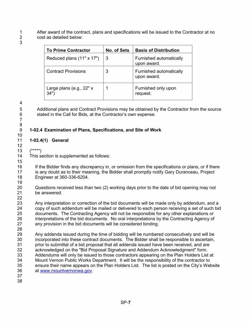
After award of the contract, plans and specifications will be issued to the Contractor at no 1 cost as detailed below: 2 3
To Prime Contractor No. of Sets Basis of Distribution
Reduced plans (11" x 17") 3 Furnished automatically upon award.
Contract Provisions
3 Furnished automatically
upon award.
Large plans (e.g., 22" x 34")
1 Furnished only upon request.
4 Additional plans and Contract Provisions may be obtained by the Contractor from the source 5 stated in the Call for Bids, at the Contractor’s own expense. 6
7 8 1-02.4 Examination of Plans, Specifications, and Site of Work 9 10 1-02.4(1) General 11 12 (*****) 13 This section is supplemented as follows: 14
15 If the Bidder finds any discrepancy in, or omission from the specifications or plans, or if there 16 is any doubt as to their meaning, the Bidder shall promptly notify Gary Duranceau, Project 17 Engineer at 360-336-6204. 18
19 Questions received less than two (2) working days prior to the date of bid opening may not 20 be answered. 21
22 Any interpretation or correction of the bid documents will be made only by addendum, and a 23 copy of such addendum will be mailed or delivered to each person receiving a set of such bid 24 documents. The Contracting Agency will not be responsible for any other explanations or 25 interpretations of the bid documents. No oral interpretations by the Contracting Agency of 26 any provision in the bid documents will be considered binding. 27
28 Any addenda issued during the time of bidding will be numbered consecutively and will be 29 incorporated into these contract documents. The Bidder shall be responsible to ascertain, 30 prior to submittal of a bid proposal that all addenda issued have been received, and are 31 acknowledged on the "Bid Proposal Signature and Addendum Acknowledgment" form. 32 Addendums will only be issued to those contractors appearing on the Plan Holders List at 33 Mount Vernon Public Works Department. It will be the responsibility of the contractor to 34 ensure their name appears on the Plan Holders List. The list is posted on the City’s Website 35 at www.mountvernonwa.gov. 36
37 38
SP-7
1-02.5 Proposal Forms 1 (June 27, 2011 APWA GSP) 2 3 Delete this section and replace it with the following: 4 5
The Proposal Form will identify the project and its location and describe the work. It will also 6 list estimated quantities, units of measurement, the items of work, and the materials to be 7 furnished at the unit bid prices. The bidder shall complete spaces on the proposal form that 8 call for, but are not limited to, unit prices; extensions; summations; the total bid amount; 9 signatures; date; and, where applicable, retail sales taxes and acknowledgment of addenda; 10 the bidder’s name, address, telephone number, and signature; the bidder’s D/M/WBE 11 commitment, if applicable; a State of Washington Contractor’s Registration Number; and a 12 Business License Number, if applicable. Bids shall be completed by typing or shall be 13 printed in ink by hand, preferably in black ink. The required certifications are included as part 14 of the Proposal Form. 15
16 The Contracting Agency reserves the right to arrange the proposal forms with alternates and 17 additives, if such be to the advantage of the Contracting Agency. The bidder shall bid on all 18 alternates and additives set forth in the Proposal Form unless otherwise specified. 19
20 21 1-02.6 Preparation of Proposal 22 (June 27, 2011 APWA GSP) 23
Supplement the second paragraph with the following: 24
4. If a minimum bid amount has been established for any item, the unit or lump sum price 25 must equal or exceed the minimum amount stated. 26
5. Any correction to a bid made by interlineation, alteration, or erasure, shall be initialed 27 by the signer of the bid. 28
Delete the last paragraph, and replace it with the following: 29
The Bidder shall make no stipulation on the Bid Form, nor qualify the bid in any manner. 30
A bid by a corporation shall be executed in the corporate name, by the president or a vice 31 president (or other corporate officer accompanied by evidence of authority to sign). 32
A bid by a partnership shall be executed in the partnership name, and signed by a partner. A 33 copy of the partnership agreement shall be submitted with the Bid Form if any D/M/WBE 34 requirements are to be satisfied through such an agreement. 35
A bid by a joint venture shall be executed in the joint venture name and signed by a member 36 of the joint venture. A copy of the joint venture agreement shall be submitted with the Bid 37 Form if any D/W/MBE requirements are to be satisfied through such an agreement. 38
39 40
SP-8
1-02.7 Bid Deposit 1 (March 8, 2013 APWA GSP) 2 3 Supplement this section with the following: 4
5 Bid bonds shall contain the following: 6 1. Contracting Agency-assigned number for the project; 7 2. Name of the project; 8 3. The Contracting Agency named as obligee; 9 4. The amount of the bid bond stated either as a dollar figure or as a percentage which 10
represents five percent of the maximum bid amount that could be awarded; 11 5. Signature of the bidder’s officer empowered to sign official statements. The signature of 12
the person authorized to submit the bid should agree with the signature on the bond, and 13 the title of the person must accompany the said signature; 14
6. The signature of the surety’s officer empowered to sign the bond and the power of 15 attorney. 16
17 If so stated in the Contract Provisions, bidder must use the bond form included in the 18 Contract Provisions. 19 20 If so stated in the Contract Provisions, cash will not be accepted for a bid deposit. 21
22 (*****) 23 24
All bid bonds shall be made payable to the City of Mount Vernon. 25 26 27 1-02.9 Delivery of Proposal 28 (August 15, 2012 APWA GSP, Option A) 29 30 Delete this section and replace it with the following: 31
32 Each proposal shall be submitted in a sealed envelope, with the Project Name and Project 33 Number as stated in the Call for Bids clearly marked on the outside of the envelope, or as 34 otherwise required in the Bid Documents, to ensure proper handling and delivery. 35 36 If the project has FHWA funding and requires DBE Written Confirmation Documents or 37 Good Faith Effort Documentation, then to be considered responsive, the Bidder shall submit 38 with their Bid Proposal, written Confirmation Documentation from each DBE firm listed on 39 the Bidder’s completed DBE Utilization Certification, form 272-056A EF, as required by 40 Section 1-02.6. 41 42 The Contracting Agency will not open or consider any Bid Proposal that is received after the 43 time specified in the Call for Bids for receipt of Bid Proposals, or received in a location other 44 than that specified in the Call for Bids. 45
46 47 1-02.10 Withdrawing, Revising, or Supplementing Proposal 48 (July 23, 2015 APWA GSP) 49
SP-9
1 Delete this section in its entirety, and replace it with the following: 2
3 After submitting a physical Bid Proposal to the Contracting Agency, the Bidder may 4 withdraw, revise, or supplement it if: 5
6 1. The Bidder submits a written request signed by an authorized person and 7
physically delivers it to the place designated for receipt of Bid Proposals, and 8 2. The Contracting Agency receives the request before the time set for receipt of Bid 9
Proposals, and 10 3. The revised or supplemented Bid Proposal (if any) is received by the Contracting 11
Agency before the time set for receipt of Bid Proposals. 12 13
If the Bidder’s request to withdraw, revise, or supplement its Bid Proposal is received 14 before the time set for receipt of Bid Proposals, the Contracting Agency will return the 15 unopened Proposal package to the Bidder. The Bidder must then submit the revised or 16 supplemented package in its entirety. If the Bidder does not submit a revised or 17 supplemented package, then its bid shall be considered withdrawn. 18 19 Late revised or supplemented Bid Proposals or late withdrawal requests will be date 20 recorded by the Contracting Agency and returned unopened. Mailed, Emailed, or faxed 21 requests to withdraw, revise, or supplement a Bid Proposal are not acceptable. 22
23 24 1-02.12 Public Opening of Proposals 25 (May 4, 2012 APWA GSP) 26 27 Delete this section and replace it with the following: 28
29 Proposals will be opened and publicly read at the time indicated in the Call for Bids, after the 30 deadline(s) for submitting all elements of the Bid Proposal including DBE Written 31 Confirmation Documents and/or Good Faith Effort Documentation, unless the Bid opening 32 has been delayed or canceled. Bidders, their authorized agents, and other interested 33 parties are invited to be present. 34
35 (*****) 36 37 The completed Bid Proposal and any other documents required in accordance with the Special 38 Provisions, shall be received at the following location: 39 40
City Financial Director 41 Mount Vernon City Hall 42 910 Cleveland Avenue 43 Mount Vernon, WA 98273 44
45 All bid envelopes must be in an opaque envelope and plainly marked on the outside: 46 47
Proposal for Contract 48 (Name of Bidder) 49 Influent Pumping Station Bar Screen Installation 50 City of Mount Vernon 51
SP-10
Mount Vernon, WA 98273 1 2 Bid proposals shall be deposited prior to the date and time for receipt of bid proposals as 3 indicated in the “Invitation to Bid”, or such revised date as may be specified by an addendum. 4 No oral, telephonic, telegraphic, or electronic bids or modifications will be considered. 5 6 The bid opening date for this project is indicated in the “Invitation to Bid”. The bids will be 7 publicly opened and read after 10:00 A.M. on this date. 8 9 10 1-02.13 Irregular Proposals 11 (March 13, 2012 APWA GSP) 12 13 Revise item 1 to read: 14 15
1. A proposal will be considered irregular and will be rejected if: 16 a. The Bidder is not prequalified when so required; 17 b. The authorized proposal form furnished by the Contracting Agency is not used or 18
is altered; 19 c. The completed proposal form contains any unauthorized additions, deletions, 20
alternate Bids, or conditions; 21 d. The Bidder adds provisions reserving the right to reject or accept the award, or 22
enter into the Contract; 23 e. A price per unit cannot be determined from the Bid Proposal; 24 f. The Proposal form is not properly executed; 25 g. The Bidder fails to submit or properly complete a Subcontractor list, if applicable, 26
as required in Section 1-02.6; 27 h. The Bidder fails to submit or properly complete a Disadvantaged Business 28
Enterprise Certification, if applicable, as required in Section 1-02.6; 29 i. The Bidder fails to submit written confirmation from each DBE firm listed on the 30
Bidder’s completed DBE Utilization Certification that they are in agreement with 31 the bidders DBE participation commitment, if applicable, as required in Section 1-32 02.6, or if the written confirmation that is submitted fails to meet the requirements 33 of the Special Provisions; 34
j The Bidder fails to submit DBE Good Faith Effort documentation, if applicable, as 35 required in Section 1-02.6, or if the documentation that is submitted fails to 36 demonstrate that a Good Faith Effort to meet the Condition of Award was made; 37
k. The Bid Proposal does not constitute a definite and unqualified offer to meet the 38 material terms of the Bid invitation; or 39
l. More than one proposal is submitted for the same project from a Bidder under 40 the same or different names. 41
42 43 1-02.14 Disqualification of Bidders 44
(March 8, 2013 APWA GSP, Option A) 45
46 Delete this Section and replace it with the following: 47 48
A Bidder will be deemed not responsible if the Bidder does not meet the mandatory bidder 49 responsibility criteria in RCW 39.04.350(1), as amended. 50
SP-11
1 As evidence that the Bidder meets the mandatory bidder responsibility criteria, the apparent 2 two lowest Bidders must submit to the Contracting Agency within 24 hours of the bid 3 submittal deadline, documentation (sufficient in the sole judgment of the Contracting 4 Agency) demonstrating compliance with all responsibility criteria. The Contracting Agency 5 reserves the right to request such documentation from other Bidders as well, and to request 6 further documentation as needed to assess bidder responsibility. The Contracting Agency 7 also reserves the right to obtain information from third parties concerning a Bidder’s 8 compliance with the mandatory bidder responsibility criteria. 9 10 If the Contracting Agency determines the Bidder does not meet the mandatory bidder 11 responsibility criteria in RCW 39.04.350(1) and is therefore not a responsible Bidder, the 12 Contracting Agency shall notify the Bidder in writing, with the reasons for its determination. 13 If the Bidder disagrees with this determination, it may appeal the determination within two 14 (2) business days of the Contracting Agency’s determination by presenting its appeal and 15 any additional information to the Contracting Agency. The Contracting Agency will consider 16 the appeal and any additional information before issuing its final determination. If the final 17 determination affirms that the Bidder is not responsible, the Contracting Agency will not 18 execute a contract with any other Bidder until at least two business days after the Bidder 19 determined to be not responsible has received the Contracting Agency’s final determination. 20
21 22 1-02.15 Pre Award Information 23 (August 14, 2013 APWA GSP) 24 25 Revise this section to read: 26
27 Before awarding any contract, the Contracting Agency may require one or more of these 28 items or actions of the apparent lowest responsible bidder: 29 1. A complete statement of the origin, composition, and manufacture of any or all materials 30
to be used, 31 2. Samples of these materials for quality and fitness tests, 32 3. A progress schedule (in a form the Contracting Agency requires) showing the order of 33
and time required for the various phases of the work, 34 4. A breakdown of costs assigned to any bid item, 35 5. Attendance at a conference with the Engineer or representatives of the Engineer, 36 6. Obtain, and furnish a copy of, a business license to do business in the city or county 37
where the work is located. 38 7. Any other information or action taken that is deemed necessary to ensure that the bidder 39
is the lowest responsible bidder. 40 41 42 1-03 Award and Execution of Contract 43 44 45 1-03.2 Award of Contract 46 (*****) 47 48 Replace the first sentence in this section with the following: 49 50
SP-12
Contract Award or Bid rejection will occur within 30 calendar days after Bid opening. 1 2 (*****) 3 4 Replace the third sentence in this section with the following: 5 6 If they cannot agree on an extension by the 30 day deadline, the Contracting Agency reserves 7 the right to Award the Contract to the next lowest responsible Bidder or reject all Bids. 8 9 10 1-03.3 Execution of Contract 11 (October 1, 2005 APWA GSP) 12 13 Revise this section to read: 14 15
Copies of the Contract Provisions, including the unsigned Form of Contract, will be available 16 for signature by the successful bidder on the first business day following award. The number 17 of copies to be executed by the Contractor will be determined by the Contracting Agency. 18 19 Within 10 calendar days after the award date, the successful bidder shall return the signed 20 Contracting Agency-prepared contract, an insurance certification as required by Section 1-21 07.18, and a satisfactory bond as required by law and Section 1-03.4. Before execution of 22 the contract by the Contracting Agency, the successful bidder shall provide any pre-award 23 information the Contracting Agency may require under Section 1-02.15. 24 25 Until the Contracting Agency executes a contract, no proposal shall bind the Contracting 26 Agency nor shall any work begin within the project limits or within Contracting Agency-27 furnished sites. The Contractor shall bear all risks for any work begun outside such areas 28 and for any materials ordered before the contract is executed by the Contracting Agency. 29 30 If the bidder experiences circumstances beyond their control that prevents return of the 31 contract documents within the calendar days after the award date stated above, the 32 Contracting Agency may grant up to a maximum of 10 additional calendar days for return of 33 the documents, provided the Contracting Agency deems the circumstances warrant it. 34 35
36 1-03.4 Contract Bond 37 (December 8, 2014 APWA GSP) 38 39 Revise the first paragraph to read: 40 41
The successful bidder shall provide executed payment and performance bond(s) for the full 42 contract amount. The bond may be a combined payment and performance bond; or be 43 separate payment and performance bonds. In the case of separate payment and 44 performance bonds, each shall be for the full contract amount. The bond(s) shall: 45 1. Be on Contracting Agency-furnished form(s); 46 2. Be signed by an approved surety (or sureties) that: 47
a. Is registered with the Washington State Insurance Commissioner, and 48 b. Appears on the current Authorized Insurance List in the State of Washington 49
published by the Office of the Insurance Commissioner, 50
SP-13
3. Guarantee that the Contractor will perform and comply with all obligations, duties, and 1 conditions under the Contract, including but not limited to the duty and obligation to 2 indemnify, defend, and protect the Contracting Agency against all losses and claims 3 related directly or indirectly from any failure: 4 a. Of the Contractor (or any of the employees, subcontractors, or lower tier 5
subcontractors of the Contractor) to faithfully perform and comply with all contract 6 obligations, conditions, and duties, or 7
b. Of the Contractor (or the subcontractors or lower tier subcontractors of the 8 Contractor) to pay all laborers, mechanics, subcontractors, lower tier subcontractors, 9 material person, or any other person who provides supplies or provisions for carrying 10 out the work; 11
4. Be conditioned upon the payment of taxes, increases, and penalties incurred on the 12 project under titles 50, 51, and 82 RCW; and 13
5. Be accompanied by a power of attorney for the Surety’s officer empowered to sign the 14 bond; and 15
6. Be signed by an officer of the Contractor empowered to sign official statements (sole 16 proprietor or partner). If the Contractor is a corporation, the bond(s) must be signed by 17 the president or vice president, unless accompanied by written proof of the authority of 18 the individual signing the bond(s) to bind the corporation (i.e., corporate resolution, 19 power of attorney, or a letter to such effect signed by the president or vice president). 20
21 22
1-03.7 Judicial Review 23 (*****) 24 25 Amend and Supplement WSDOT Section 1-03.7 so that it provides: 26 27
1-03.7 Judicial Review 28 Any decision made by the City regarding the Award and execution of the Contract or 29 Bid rejection shall be conclusive subject to the scope of judicial review permitted 30 under Washington law. All requests for judicial review shall be timely filed in the 31 Superior Court of Skagit County, Washington. 32 33 Add the following to 2014 WSDOT Standard Specification Section 1-03.7 Judicial 34 Review 35 36 ADMINISTRATIVE PROTEST PROCEDURES 37 38 Bidder agrees to comply with the protest procedures herein as a prerequisite to 39 seeking judicial review of any decision by the City regarding the Award and 40 execution of the Contract or Bid rejection. 41 42 Any protest concerning the Award and execution of the Contract or Bid rejection 43 including without limitation: 44 45
SP-14
1. Notice of Award; 1 2. Notice that a Bid or Proposal is irregular or non-responsive; 2 3. Notice that a Bidder is not responsible; or 3 4. Notice of Bid rejection 4 5 shall be submitted in writing by 5:00 PM on the third business day after the 6 notification date. The notification date is defined as the date on which the City gave 7 notification. 8 9 All such protests shall be in writing and submitted by hand, courier, faxsimile, or US 10 mail. The protestor accepts all risks of the delivery method it chooses. The City is 11 not responsible to assure the protest is received by the City within the protest 12 deadlines. If the City does not receive the protest in a timely manner, the protest 13 may be refused. Submit the protest to: 14 15 Public Works Director 16 City of Mount Vernon 17 1024 Cleveland Avenue 18 P. O. Box 809 19 Mount Vernon, WA 98273-0809 20 FAX: (360) 336-6299 21 22 To be considered, the protest must meet the following requirements: 23 24
1. The protestor must have submitted a Bid; 25 26
1. The protest must not be on a matter which should have been known to the 27 Bidder before the bid deadline, including matters addressed under Section 28 1-02.4; 29
30 3. The protest must allege: 31
32 a. A matter of bias, discrimination, or conflict of interest; 33 b. Errors in determination of responsiveness or responsibility; and/or 34 c. Non-compliance with the bid evaluation procedures described in 35
the Contract Documents; and 36 37
4. The protest must be in writing, be submitted within the required deadline, 38 state clearly that the Bidder is submitting a formal protest and include the 39 following: 40
SP-15
1 a. The Bidder’s company name, mailing address, phone number, 2
and name of company individual responsible for submission of the protest; 3 b. The project name; 4 c. The specific action or decision protested; 5 d. Indicate the basis and support for the protest, including specific 6
facts and all documentation to support the protest; 7 e. Indicate what relief or corrective action the Bidder believes the 8
City should make; 9 f. Demonstrate that the Bidder made every reasonable effort within 10
the bidding process to resolve the issue, including asking questions, attending 11 the pre-bid conference, seeking clarification, requesting addenda, and 12 otherwise alerting the City to any perceived problems; 13
g. Be signed by an authorized agent of the company; 14 h. Where a bidder is protesting the City’s determination that the bidder 15
is not responsible, the City of Mount Vernon Public Works will consider 16 additional information presented by the bidder before issuing a final decision. 17
18 19 The City of Mount Vernon Public Works Director will review and decide all such 20 protests. The City of Mount Vernon Public Works Director's decision on the protest 21 is conclusive and exhausts all administrative remedies. 22
23 24 25 1-04 Scope of the Work 26 27 1-04.1 Intent of the Contract 28 (*****) 29 30 This section is supplemented with the following: 31 32
This work includes the installation of a new mechanical bar screen and associated 33 equipment in the Influent Pump Station of the City of Mount Vernon Wastewater Treatment 34 Plant. Additional information on the installation requirements is included in the Technical 35 Special Provision in Division 10 of these Special Provisions. 36 37
38 1-04.1(2) Bid Items Not Included in the Proposal 39 (*****) 40 41 Delete this section and replace with the following: 42 43
The CONTRACTOR shall include all costs of doing the work within the bid item prices. If the 44 Contract Plans, Contract Provisions, Addenda, or any other part of the Contract requires 45
SP-16
work that has no specific bid item in the Proposal Form, the entire cost of that work shall be 1 considered incidental and included within other bid items in the proposal. 2 3
4 1-04.2 Coordination of Contract Documents, Plans, Special Provisions, 5
Specifications, and Addenda 6 (March 13, 2012 APWA GSP) 7 8 Revise the second paragraph to read: 9
10 Any inconsistency in the parts of the contract shall be resolved by following this order of 11 precedence (e.g., 1 presiding over 2, 2 over 3, 3 over 4, and so forth): 12 1. Addenda, 13 2. Proposal Form, 14 3. Special Provisions, 15 4. Contract Plans, 16 5. Amendments to the Standard Specifications, 17 6. Standard Specifications, 18 7. Contracting Agency’s Standard Plans or Details (if any), and 19 8. WSDOT Standard Plans for Road, Bridge, and Municipal Construction. 20
21 1-04.4(2) Value Engineering Change Proposal (VECP) 22 (******) 23 24 Insert the following sentence to the beginning of 1-04.4(2)A: 25 26
VECPs from the contractor for the purpose of obtaining approval from the City to use a 27 screen manufacturer other than the manufacturers specified in Technical Special Provision 28 11093 Part 2.1 “Acceptable Manufacturers” will not be considered or approved. 29
30 1-05 Control of Work 31 32 33 1-05.7 Removal of Defective and Unauthorized Work 34 (October 1, 2005 APWA GSP) 35 36 Supplement this section with the following: 37 38
If the Contractor fails to remedy defective or unauthorized work within the time specified in a 39 written notice from the Engineer, or fails to perform any part of the work required by the 40 Contract Documents, the Engineer may correct and remedy such work as may be identified 41 in the written notice, with Contracting Agency forces or by such other means as the 42 Contracting Agency may deem necessary. 43 44 If the Contractor fails to comply with a written order to remedy what the Engineer determines 45 to be an emergency situation, the Engineer may have the defective and unauthorized work 46 corrected immediately, have the rejected work removed and replaced, or have work the 47 Contractor refuses to perform completed by using Contracting Agency or other forces. An 48 emergency situation is any situation when, in the opinion of the Engineer, a delay in its 49
SP-17
remedy could be potentially unsafe, or might cause serious risk of loss or damage to the 1 public. 2 3 Direct or indirect costs incurred by the Contracting Agency attributable to correcting and 4 remedying defective or unauthorized work, or work the Contractor failed or refused to 5 perform, shall be paid by the Contractor. Payment will be deducted by the Engineer from 6 monies due, or to become due, the Contractor. Such direct and indirect costs shall include in 7 particular, but without limitation, compensation for additional professional services required, 8 and costs for repair and replacement of work of others destroyed or damaged by correction, 9 removal, or replacement of the Contractor’s unauthorized work. 10 11 No adjustment in contract time or compensation will be allowed because of the delay in the 12 performance of the work attributable to the exercise of the Contracting Agency’s rights 13 provided by this Section. 14 15 The rights exercised under the provisions of this section shall not diminish the Contracting 16 Agency’s right to pursue any other avenue for additional remedy or damages with respect to 17 the Contractor’s failure to perform the work as required. 18 19
20 1-05.11 Final Inspection 21 22 Delete this section and replace it with the following: 23 24
1-05.11 Final Inspections and Operational Testing 25 (October 1, 2005 APWA GSP) 26 27 1-05.11(1) Substantial Completion Date 28 29 When the Contractor considers the work to be substantially complete, the Contractor shall 30 so notify the Engineer and request the Engineer establish the Substantial Completion Date. 31 The Contractor’s request shall list the specific items of work that remain to be completed in 32 order to reach physical completion. The Engineer will schedule an inspection of the work 33 with the Contractor to determine the status of completion. The Engineer may also establish 34 the Substantial Completion Date unilaterally. 35 36 If, after this inspection, the Engineer concurs with the Contractor that the work is 37 substantially complete and ready for its intended use, the Engineer, by written notice to the 38 Contractor, will set the Substantial Completion Date. If, after this inspection the Engineer 39 does not consider the work substantially complete and ready for its intended use, the 40 Engineer will, by written notice, so notify the Contractor giving the reasons therefor. 41 42 Upon receipt of written notice concurring in or denying substantial completion, whichever is 43 applicable, the Contractor shall pursue vigorously, diligently and without unauthorized 44 interruption, the work necessary to reach Substantial and Physical Completion. The 45 Contractor shall provide the Engineer with a revised schedule indicating when the 46 Contractor expects to reach substantial and physical completion of the work. 47 48 The above process shall be repeated until the Engineer establishes the Substantial 49 Completion Date and the Contractor considers the work physically complete and ready for 50 final inspection. 51
SP-18
1 1-05.11(2) Final Inspection and Physical Completion Date 2 3 When the Contractor considers the work physically complete and ready for final inspection, 4 the Contractor by written notice, shall request the Engineer to schedule a final inspection. 5 The Engineer will set a date for final inspection. The Engineer and the Contractor will then 6 make a final inspection and the Engineer will notify the Contractor in writing of all particulars 7 in which the final inspection reveals the work incomplete or unacceptable. The Contractor 8 shall immediately take such corrective measures as are necessary to remedy the listed 9 deficiencies. Corrective work shall be pursued vigorously, diligently, and without interruption 10 until physical completion of the listed deficiencies. This process will continue until the 11 Engineer is satisfied the listed deficiencies have been corrected. 12 13 If action to correct the listed deficiencies is not initiated within 7 days after receipt of the 14 written notice listing the deficiencies, the Engineer may, upon written notice to the 15 Contractor, take whatever steps are necessary to correct those deficiencies pursuant to 16 Section 1-05.7. 17 The Contractor will not be allowed an extension of contract time because of a delay in the 18 performance of the work attributable to the exercise of the Engineer’s right hereunder. 19 20 Upon correction of all deficiencies, the Engineer will notify the Contractor and the 21 Contracting Agency, in writing, of the date upon which the work was considered physically 22 complete. That date shall constitute the Physical Completion Date of the contract, but shall 23 not imply acceptance of the work or that all the obligations of the Contractor under the 24 contract have been fulfilled. 25 26 1-05.11(3) Operational Testing 27 28 It is the intent of the Contracting Agency to have at the Physical Completion Date a 29 complete and operable system. Therefore when the work involves the installation of 30 machinery or other mechanical equipment; street lighting, electrical distribution or signal 31 systems; irrigation systems; buildings; or other similar work it may be desirable for the 32 Engineer to have the Contractor operate and test the work for a period of time after final 33 inspection but prior to the physical completion date. Whenever items of work are listed in the 34 Contract Provisions for operational testing they shall be fully tested under operating 35 conditions for the time period specified to ensure their acceptability prior to the Physical 36 Completion Date. During and following the test period, the Contractor shall correct any items 37 of workmanship, materials, or equipment which prove faulty, or that are not in first class 38 operating condition. Equipment, electrical controls, meters, or other devices and equipment 39 to be tested during this period shall be tested under the observation of the Engineer, so that 40 the Engineer may determine their suitability for the purpose for which they were installed. 41 The Physical Completion Date cannot be established until testing and corrections have been 42 completed to the satisfaction of the Engineer. 43 44 The costs for power, gas, labor, material, supplies, and everything else needed to 45 successfully complete operational testing, shall be included in the unit contract prices 46 related to the system being tested, unless specifically set forth otherwise in the proposal. 47 48 Operational and test periods, when required by the Engineer, shall not affect a 49 manufacturer’s guaranties or warranties furnished under the terms of the contract. 50 51
SP-19
1 1-05.13 Superintendents, Labor and Equipment of Contractor 2 (August 14, 2013 APWA GSP) 3
4 Delete the sixth and seventh paragraphs of this section. 5 6 7 Add the following new section: 8 9
1-05.16 Water and Power 10 (October 1, 2005 APWA GSP) 11 12 The Contractor shall make necessary arrangements, and shall bear the costs for power and 13 water necessary for the performance of the work, unless the contract includes power and 14 water as a pay item. 15
16 17 1-07 Legal Relations and Responsibilities to the Public 18 19 20 1-07.1 Laws to be Observed 21 (October 1, 2005 APWA GSP) 22 23 Supplement this section with the following: 24
25 In cases of conflict between different safety regulations, the more stringent regulation shall 26 apply. 27 28 The Washington State Department of Labor and Industries shall be the sole and paramount 29 administrative agency responsible for the administration of the provisions of the Washington 30 Industrial Safety and Health Act of 1973 (WISHA). 31 32 The Contractor shall maintain at the project site office, or other well known place at the 33 project site, all articles necessary for providing first aid to the injured. The Contractor shall 34 establish, publish, and make known to all employees, procedures for ensuring immediate 35 removal to a hospital, or doctor’s care, persons, including employees, who may have been 36 injured on the project site. Employees should not be permitted to work on the project site 37 before the Contractor has established and made known procedures for removal of injured 38 persons to a hospital or a doctor’s care. 39 40 The Contractor shall have sole responsibility for the safety, efficiency, and adequacy of the 41 Contractor’s plant, appliances, and methods, and for any damage or injury resulting from 42 their failure, or improper maintenance, use, or operation. The Contractor shall be solely and 43 completely responsible for the conditions of the project site, including safety for all persons 44 and property in the performance of the work. This requirement shall apply continuously, and 45 not be limited to normal working hours. The required or implied duty of the Engineer to 46 conduct construction review of the Contractor’s performance does not, and shall not, be 47 intended to include review and adequacy of the Contractor’s safety measures in, on, or near 48 the project site. 49 50
(*****) 51
SP-20
1 Sentence 2 of paragraph 1 shall be revised to read: 2 3
The Contractor shall indemnify, defend, and save harmless the City of Mount Vernon 4 (including the Mayor, Council Members, any agents, officers, and employees) against 5 any claims that may arise because the Contractor (or any employee of the Contractor or 6 Subcontractor or material person) violated a legal requirement. 7 8 9
1-07.2 State Taxes 10 11 Delete this section, including its sub-sections, in its entirety and replace it with the following: 12 13
1-07.2 State Sales Tax 14 (June 27, 2011 APWA GSP) 15 16 The Washington State Department of Revenue has issued special rules on the State sales 17 tax. Sections 1-07.2(1) through 1-07.2(3) are meant to clarify those rules. The Contractor 18 should contact the Washington State Department of Revenue for answers to questions in 19 this area. The Contracting Agency will not adjust its payment if the Contractor bases a bid 20 on a misunderstood tax liability. 21 22 The Contractor shall include all Contractor-paid taxes in the unit bid prices or other contract 23 amounts. In some cases, however, state retail sales tax will not be included. Section 1-24 07.2(2) describes this exception. 25 26 The Contracting Agency will pay the retained percentage (or release the Contract Bond if a 27 FHWA-funded Project) only if the Contractor has obtained from the Washington State 28 Department of Revenue a certificate showing that all contract-related taxes have been paid 29 (RCW 60.28.051). The Contracting Agency may deduct from its payments to the Contractor 30 any amount the Contractor may owe the Washington State Department of Revenue, 31 whether the amount owed relates to this contract or not. Any amount so deducted will be 32 paid into the proper State fund. 33 34 1-07.2(1) State Sales Tax — Rule 171 35 36 WAC 458-20-171, and its related rules, apply to building, repairing, or improving streets, 37 roads, etc., which are owned by a municipal corporation, or political subdivision of the state, 38 or by the United States, and which are used primarily for foot or vehicular traffic. This 39 includes storm or combined sewer systems within and included as a part of the street or 40 road drainage system and power lines when such are part of the roadway lighting system. 41 For work performed in such cases, the Contractor shall include Washington State Retail 42 Sales Taxes in the various unit bid item prices, or other contract amounts, including those 43 that the Contractor pays on the purchase of the materials, equipment, or supplies used or 44 consumed in doing the work. 45 46 1-07.2(2) State Sales Tax — Rule 170 47 48 WAC 458-20-170, and its related rules, apply to the constructing and repairing of new or 49 existing buildings, or other structures, upon real property. This includes, but is not limited to, 50 the construction of streets, roads, highways, etc., owned by the state of Washington; water 51
SP-21
mains and their appurtenances; sanitary sewers and sewage disposal systems unless such 1 sewers and disposal systems are within, and a part of, a street or road drainage system; 2 telephone, telegraph, electrical power distribution lines, or other conduits or lines in or above 3 streets or roads, unless such power lines become a part of a street or road lighting system; 4 and installing or attaching of any article of tangible personal property in or to real property, 5 whether or not such personal property becomes a part of the realty by virtue of installation. 6 7 For work performed in such cases, the Contractor shall collect from the Contracting Agency, 8 retail sales tax on the full contract price. The Contracting Agency will automatically add this 9 sales tax to each payment to the Contractor. For this reason, the Contractor shall not 10 include the retail sales tax in the unit bid item prices, or in any other contract amount subject 11 to Rule 170, with the following exception. 12 13 Exception: The Contracting Agency will not add in sales tax for a payment the Contractor or 14 a subcontractor makes on the purchase or rental of tools, machinery, equipment, or 15 consumable supplies not integrated into the project. Such sales taxes shall be included in 16 the unit bid item prices or in any other contract amount. 17 18 1-07.2(3) Services 19 20 The Contractor shall not collect retail sales tax from the Contracting Agency on any contract 21 wholly for professional or other services (as defined in Washington State Department of 22 Revenue Rules 138 and 244). 23 24 25
1-07.13 Contractor’s Responsibility for Work 26 27
1-07.13(1) General 28 (*****) 29 30 This section is supplemented with the following: 31
32 It is understood that the plans, specifications and standard details do not purport to control 33 the method of performing the work, but only the requirements as to the nature of the 34 completed work. 35 36 The Contractor shall be responsible for the method of performing the work. Suggestions as 37 to the method included in the plans and special provisions shall be deemed advisory only; 38 and the feasibility of such methods, or the lack thereof, shall not affect the Contractor’s 39 liability or status as an independent Contractor under this contract. 40
41 The City of Mount Vernon provides no specific staging area. The Contractor will be 42 responsible for detaining, staging, and storage areas. 43 44
45 1-07.17 Utilities and Similar Facilities 46
47 Section 1-07.17(2) Utility Construction, Removal, or Relocation by Others 48 (*****) 49
SP-22
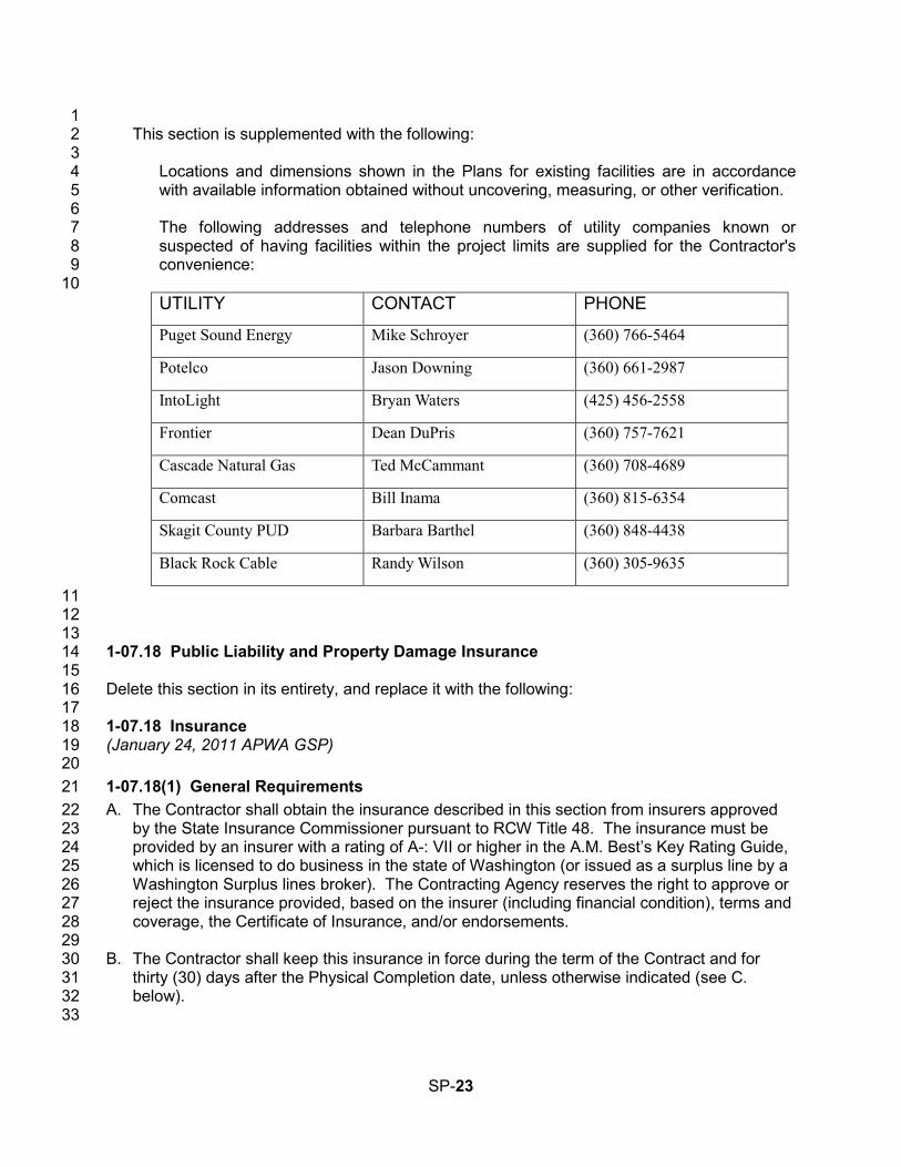
1 This section is supplemented with the following: 2
3 Locations and dimensions shown in the Plans for existing facilities are in accordance 4 with available information obtained without uncovering, measuring, or other verification. 5 6 The following addresses and telephone numbers of utility companies known or 7 suspected of having facilities within the project limits are supplied for the Contractor's 8 convenience: 9 10 UTILITY CONTACT PHONE
Puget Sound Energy Mike Schroyer (360) 766-5464
Potelco Jason Downing (360) 661-2987
IntoLight Bryan Waters (425) 456-2558
Frontier Dean DuPris (360) 757-7621
Cascade Natural Gas Ted McCammant (360) 708-4689
Comcast Bill Inama (360) 815-6354
Skagit County PUD Barbara Barthel (360) 848-4438
Black Rock Cable Randy Wilson (360) 305-9635
11 12 13
1-07.18 Public Liability and Property Damage Insurance 14 15 Delete this section in its entirety, and replace it with the following: 16 17 1-07.18 Insurance 18 (January 24, 2011 APWA GSP) 19 20 1-07.18(1) General Requirements 21 A. The Contractor shall obtain the insurance described in this section from insurers approved 22
by the State Insurance Commissioner pursuant to RCW Title 48. The insurance must be 23 provided by an insurer with a rating of A-: VII or higher in the A.M. Best’s Key Rating Guide, 24 which is licensed to do business in the state of Washington (or issued as a surplus line by a 25 Washington Surplus lines broker). The Contracting Agency reserves the right to approve or 26 reject the insurance provided, based on the insurer (including financial condition), terms and 27 coverage, the Certificate of Insurance, and/or endorsements. 28
29 B. The Contractor shall keep this insurance in force during the term of the Contract and for 30
thirty (30) days after the Physical Completion date, unless otherwise indicated (see C. 31 below). 32
33
SP-23
C. If any insurance policy is written on a claims made form, its retroactive date, and that of all 1 subsequent renewals, shall be no later than the effective date of this Contract. The policy 2 shall state that coverage is claims made, and state the retroactive date. Claims-made form 3 coverage shall be maintained by the Contractor for a minimum of 36 months following the 4 Final Completion or earlier termination of this Contract, and the Contractor shall annually 5 provide the Contracting Agency with proof of renewal. If renewal of the claims made form of 6 coverage becomes unavailable, or economically prohibitive, the Contractor shall purchase 7 an extended reporting period (“tail”) or execute another form of guarantee acceptable to the 8 Contracting Agency to assure financial responsibility for liability for services performed. 9
10 D. The insurance policies shall contain a “cross liability” provision. 11 12 E. The Contractor’s and all subContractors’ insurance coverage shall be primary and non-13
contributory insurance as respects the Contracting Agency’s insurance, self-insurance, or 14 insurance pool coverage. 15
16 F. The Contractor shall provide the Contracting Agency and all Additional Insureds with written 17
notice of any policy cancellation, within two business days of their receipt of such notice. 18 19 G. Upon request, the Contractor shall forward to the Contracting Agency a full and certified 20
copy of the insurance policy(s). 21 22 H. The Contractor shall not begin work under the Contract until the required insurance has 23
been obtained and approved by the Contracting Agency. 24 25 I. Failure on the part of the Contractor to maintain the insurance as required shall constitute a 26
material breach of contract, upon which the Contracting Agency may, after giving five 27 business days notice to the Contractor to correct the breach, immediately terminate the 28 Contract or, at its discretion, procure or renew such insurance and pay any and all premiums 29 in connection therewith, with any sums so expended to be repaid to the Contracting Agency 30 on demand, or at the sole discretion of the Contracting Agency, offset against funds due the 31 Contractor from the Contracting Agency. 32
33 J. All costs for insurance shall be incidental to and included in the unit or lump sum prices of 34
the contract and no additional payment will be made. 35 36 1-07.18(2) Additional Insured 37 (*****) 38 All insurance policies, with the exception of Professional Liability and Workers Compensation, 39 shall name the following listed entities as additional insured(s): 40 the Contracting Agency and its officers, elected officials, employees, agents, HDR and 41
volunteers 42
The above-listed entities shall be additional insured(s) for the full available limits of liability 43 maintained by the Contractor, whether primary, excess, contingent or otherwise, irrespective of 44 whether such limits maintained by the Contractor are greater than those required by this 45 Contract, and irrespective of whether the Certificate of Insurance provided by the Contractor 46 pursuant to 1-07.18(3) describes limits lower than those maintained by the Contractor. 47 48
SP-24
1-07.18(3) Subcontractors 1 Contractor shall ensure that each subcontractor of every tier obtains and maintains at a 2 minimum the insurance coverages listed in 1-07.18(5)A and 1-07.18(5)B. Upon request of the 3 Contracting Agency, the Contractor shall provide evidence of such insurance. 4 5 1-07.18(4) Evidence of Insurance 6 The Contractor shall deliver to the Contracting Agency a Certificate(s) of Insurance and 7 endorsements for each policy of insurance meeting the requirements set forth herein when the 8 Contractor delivers the signed Contract for the work. The certificate and endorsements must 9 conform to the following requirements: 10
1. An ACORD certificate or a form determined by the Contracting Agency to be equivalent. 11
2. Copies of all endorsements naming Contracting Agency and all other entities listed in 1-12 07.18(2) as Additional Insured(s), showing the policy number. The Contractor may submit a 13 copy of any blanket additional insured clause from its policies instead of a separate 14 endorsement. A statement of additional insured status on an ACORD Certificate of 15 Insurance shall not satisfy this requirement. 16
3. Any other amendatory endorsements to show the coverage required herein. 17 18 1-07.18(5) Coverages and Limits 19 The insurance shall provide the minimum coverages and limits set forth below. Providing 20 coverage in these stated minimum limits shall not be construed to relieve the Contractor from 21 liability in excess of such limits. All deductibles and self-insured retentions must be disclosed 22 and are subject to approval by the Contracting Agency. The cost of any claim payments falling 23 within the deductible shall be the responsibility of the Contractor. 24 25 1-07.18(5)A Commercial General Liability 26 A policy of Commercial General Liability Insurance, including: 27 28
Per project aggregate 29 Premises/Operations Liability 30 Products/Completed Operations – for a period of one year following final acceptance of the 31 work. 32 Personal/Advertising Injury 33 Contractual Liability 34 Independent Contractors Liability 35 Stop Gap / Employers’ Liability 36 Explosion, Collapse, or Underground Property Damage (XCU) 37 Blasting (only required when the Contractor’s work under this Contract includes exposures 38
to which this specified coverage responds) 39 40 Such policy must provide the following minimum limits: 41
$1,000,000 Each Occurrence 42 $2,000,000 General Aggregate 43 $1,000,000 Products & Completed Operations Aggregate 44 $1,000,000 Personal & Advertising Injury, each offence 45
46 Stop Gap / Employers’ Liability 47
SP-25
$1,000,000 Each Accident 1 $1,000,000 Disease - Policy Limit 2 $1,000,000 Disease - Each Employee 3
4 1-07.18(5)B Automobile Liability 5 Automobile Liability for owned, non-owned, hired, and leased vehicles, with an MCS 90 6 endorsement and a CA 9948 endorsement attached if “pollutants” are to be transported. Such 7 policy(ies) must provide the following minimum limit: 8
$1,000,000 combined single limit 9 10
1-07.18(5)C Workers’ Compensation 11 The Contractor shall comply with Workers’ Compensation coverage as required by the Industrial 12 Insurance laws of the state of Washington. 13 14 15 1-07.24 Rights of Way 16 (October 1, 2005 APWA GSP) 17 18 Delete this section in its entirety, and replace it with the following: 19 20
Street right of way lines, limits of easements, and limits of construction permits are indicated 21 in the Plans. The Contractor’s construction activities shall be confined within these limits, 22 unless arrangements for use of private property are made. 23 24 Generally, the Contracting Agency will have obtained, prior to bid opening, all rights of way 25 and easements, both permanent and temporary, necessary for carrying out the work. 26 Exceptions to this are noted in the Bid Documents or will be brought to the Contractor’s 27 attention by a duly issued Addendum. 28 29 Whenever any of the work is accomplished on or through property other than public right of 30 way, the Contractor shall meet and fulfill all covenants and stipulations of any easement 31 agreement obtained by the Contracting Agency from the owner of the private property. 32 Copies of the easement agreements may be included in the Contract Provisions or made 33 available to the Contractor as soon as practical after they have been obtained by the 34 Engineer. 35 36 Whenever easements or rights of entry have not been acquired prior to advertising, these 37 areas are so noted in the Plans. The Contractor shall not proceed with any portion of the 38 work in areas where right of way, easements or rights of entry have not been acquired until 39 the Engineer certifies to the Contractor that the right of way or easement is available or that 40 the right of entry has been received. If the Contractor is delayed due to acts of omission on 41 the part of the Contracting Agency in obtaining easements, rights of entry or right of way, the 42 Contractor will be entitled to an extension of time. The Contractor agrees that such delay 43 shall not be a breach of contract. 44 45 Each property owner shall be given 48 hours notice prior to entry by the Contractor. This 46 includes entry onto easements and private property where private improvements must be 47 adjusted. 48 49
SP-26
The Contractor shall be responsible for providing, without expense or liability to the 1 Contracting Agency, any additional land and access thereto that the Contractor may desire 2 for temporary construction facilities, storage of materials, or other Contractor needs. 3 However, before using any private property, whether adjoining the work or not, the 4 Contractor shall file with the Engineer a written permission of the private property owner, 5 and, upon vacating the premises, a written release from the property owner of each property 6 disturbed or otherwise interfered with by reasons of construction pursued under this 7 contract. The statement shall be signed by the private property owner, or proper authority 8 acting for the owner of the private property affected, stating that permission has been 9 granted to use the property and all necessary permits have been obtained or, in the case of 10 a release, that the restoration of the property has been satisfactorily accomplished. The 11 statement shall include the parcel number, address, and date of signature. Written releases 12 must be filed with the Engineer before the Completion Date will be established. 13
14 15 1-07.26 Personal Liability of Public Officers 16 (*****) 17 18 This section is revised to read: 19
20 Neither the Mayor, the Council Members, the Engineer, nor any other officer, employee, 21 HDR or agent of the City of Mount Vernon shall be personally liable for any acts or failure to 22 act in connection with the Contract, it being understood that in such matters, they are acting 23 solely as agents of the City of Mount Vernon. 24
25 26 1-08 PROSECUTION AND PROGRESS 27 28 Add the following new section: 29 30
1-08.0 Preliminary Matters 31 (May 25, 2006 APWA GSP) 32
33 Add the following new section: 34
35 1-08.0(1) Preconstruction Conference 36 (October 10, 2008 APWA GSP) 37 38 Prior to the Contractor beginning the work, a preconstruction conference will be held 39 between the Contractor, the Engineer and such other interested parties as may be invited. 40 The purpose of the preconstruction conference will be: 41 1. To review the initial progress schedule; 42 2. To establish a working understanding among the various parties associated or affected 43
by the work; 44 3. To establish and review procedures for progress payment, notifications, approvals, 45
submittals, etc.; 46 4. To establish normal working hours for the work; 47 5. To review safety standards and traffic control; and 48 6. To discuss such other related items as may be pertinent to the work. 49
SP-27
1 The Contractor shall prepare and submit at the preconstruction conference the following: 2 1. A breakdown of all lump sum items; 3 2. A preliminary schedule of working drawing submittals; and 4 3. A list of material sources for approval if applicable. 5
6 7 Add the following new section: 8
9 1-08.0(2) Hours of Work 10
(*****) 11 12 Except in the case of emergency or unless otherwise approved by the Engineer, the normal 13 working hours for the Contract shall be between 7:00 a.m. and 4:30 p.m. Monday through 14 Friday. If the Contractor desires different than the normal working hours stated above, the 15 request must be submitted in writing prior to the preconstruction conference, subject to the 16 provisions below. The working hours for the Contract shall be established at or prior to the 17 preconstruction conference. 18 19
All working hours and days are also subject to local permit and ordinance conditions (such 20 as noise ordinances). 21 22 If the Contractor wishes to deviate from the established working hours, the Contractor shall 23 submit a written request to the Engineer for consideration. This request shall state what 24 hours are being requested, and why. Requests shall be submitted for review no later than 2 25 working days prior to the day(s) the Contractor is requesting to change the hours. 26 27 If the Contracting Agency approves such a deviation, such approval may be subject to 28 certain other conditions, which will be detailed in writing. For example: 29
1. On non-Federal aid projects, requiring the Contractor to reimburse the Contracting 30 Agency for the costs in excess of straight-time costs for Contracting Agency 31 representatives who worked during such times. (The Engineer may require 32 designated representatives to be present during the work. Representatives who may 33 be deemed necessary by the Engineer include, but are not limited to: survey crews; 34 personnel from the Contracting Agency’s material testing lab; inspectors; and other 35 Contracting Agency employees or third party consultants when, in the opinion of the 36 Engineer, such work necessitates their presence.) 37
2. Considering the work performed on Saturdays, Sundays, and holidays as working 38 days with regard to the contract time. 39
3. Considering multiple work shifts as multiple working days with respect to contract 40 time even though the multiple shifts occur in a single 24-hour period. 41
4. If a 4-10 work schedule is requested and approved the non working day for the week 42 will be charged as a working day. 43
5. If Davis Bacon wage rates apply to this Contract, all requirements must be met and 44 recorded properly on certified payroll 45
46
SP-28
1-08.1 Subcontracting 1 (December 8, 2014 APWA GSP) 2 3 Revise the eighth paragraph to read: 4 5
On all projects funded with federal assistance the Contractor shall submit “Quarterly Report 6 of Amounts Credited as DBE Participation” (form 422-102 EF) on a quarterly basis, in which 7 DBE Work is accomplished, for every quarter in which the Contract is active or upon 8 completion of the project, as appropriate. The quarterly reports are due on the 20th of April, 9 July, October, and January for the four respective quarters. 10
11 (*****) 12 13 Supplement this section with: 14 15
“Prior to any Subcontractor or Agent beginning work on this project, the Contractor shall 16 submit to the Engineer a certification (WSDOT Form 420-004) that a written agreement 17 between the Contractor and the Subcontractor, or between the Subcontractor and any Agent 18 to the Subcontractor, has been executed. 19 20 A Subcontractor or an Agent to the Subcontractor will not be permitted to perform any work 21 under the contract until the following documents have been completed and submitted to the 22 Engineer. 23
24 1. Request to Sublet Work (Form 421-012) 25 2. Statement of Intent to Pay Prevailing Wages (Form 700-029-000) 26
27 The Contractor’s records pertaining to the requirements of this Special Provision shall be 28 open to inspection or audit by representatives of the Department during the life of the 29 contract and for a period of not less than three years after the date of acceptance of the 30 contract. The Contractor shall retain these records for that period. The Contractor shall also 31 guarantee that these records of all Subcontractors and Agents shall be open to similar 32 inspection or audit for the same period. 33
34 35 1-08.3(2)A Type A Progress Schedule 36 (March 13, 2012 APWA GSP) 37 38 Revise this section to read: 39 40
The Contractor shall submit (1) copies of a Type A Progress Schedule no later than at the 41 preconstruction conference, or some other mutually agreed upon submittal time. The 42 schedule may be a critical path method (CPM) schedule, bar chart, or other standard 43 schedule format. Regardless of which format used, the schedule shall identify the critical 44 path. The Engineer will evaluate the Type A Progress Schedule and approve or return the 45 schedule for corrections within 15 calendar days of receiving the submittal. 46
47 1-08.3(2)D Weekly Look-Ahead Schedule 48 (*****) 49 50 Replace the last sentence with the following: 51
SP-29
1 The Weekly Look-Ahead schedule shall be submitted to the Engineer at each construction 2 progress meeting or by email the same day if the construction progress meeting is cancelled. 3 4
1-08.4 Prosecution of Work 5 6 Delete this section and replace it with the following: 7 8
1-08.4 Notice to Proceed and Prosecution of Work 9 (July 23, 2015 APWA GSP) 10
11 Notice to Proceed will be given after the contract has been executed and the contract bond 12 and evidence of insurance have been approved and filed by the Contracting Agency. The 13 Contractor shall not commence with the work until the Notice to Proceed has been given by 14 the Engineer. The Contractor shall commence construction activities on the project site 15 within ten days of the Notice to Proceed Date, unless otherwise approved in writing. The 16 Contractor shall diligently pursue the work to the physical completion date within the time 17 specified in the contract. Voluntary shutdown or slowing of operations by the Contractor 18 shall not relieve the Contractor of the responsibility to complete the work within the time(s) 19 specified in the contract. 20 21 When shown in the Plans, the first order of work shall be the installation of high visibility 22 fencing to delineate all areas for protection or restoration, as described in the Contract. 23 Installation of high visibility fencing adjacent to the roadway shall occur after the placement 24 of all necessary signs and traffic control devices in accordance with 1-10.1(2). Upon 25 construction of the fencing, the Contractor shall request the Engineer to inspect the fence. 26 No other work shall be performed on the site until the Contracting Agency has accepted the 27 installation of high visibility fencing, as described in the Contract. 28
29 30 1-08.5 Time for Completion 31 (August 14, 2013 APWA GSP, Option A) 32 33 Revise the third and fourth paragraphs to read: 34 35
Contract time shall begin on the first working day following the Notice to Proceed Date. 36 37 Each working day shall be charged to the contract as it occurs, until the contract work is 38 physically complete. If substantial completion has been granted and all the authorized 39 working days have been used, charging of working days will cease. Each week the 40 Engineer will provide the Contractor a statement that shows the number of working days: (1) 41 charged to the contract the week before; (2) specified for the physical completion of the 42 contract; and (3) remaining for the physical completion of the contract. The statement will 43 also show the nonworking days and any partial or whole day the Engineer declares as 44 unworkable. Within 10 calendar days after the date of each statement, the Contractor shall 45 file a written protest of any alleged discrepancies in it. To be considered by the Engineer, 46 the protest shall be in sufficient detail to enable the Engineer to ascertain the basis and 47 amount of time disputed. By not filing such detailed protest in that period, the Contractor 48 shall be deemed as having accepted the statement as correct. If the Contractor is approved 49 to work 10 hours a day and 4 days a week (a 4-10 schedule) and the fifth day of the week in 50
SP-30
which a 4-10 shift is worked would ordinarily be charged as a working day then the fifth day 1 of that week will be charged as a working day whether or not the Contractor works on that 2 day. 3
4 Revise the sixth paragraph to read: 5 6
The Engineer will give the Contractor written notice of the completion date of the contract 7 after all the Contractor’s obligations under the contract have been performed by the 8 Contractor. The following events must occur before the Completion Date can be 9 established: 10
1. The physical work on the project must be complete; and 11
2. The Contractor must furnish all documentation required by the contract and required by 12 law, to allow the Contracting Agency to process final acceptance of the contract. The 13 following documents must be received by the Project Engineer prior to establishing a 14 completion date: 15
a. Certified Payrolls (per Section 1-07.9(5)). 16 b. Material Acceptance Certification Documents 17 c. Quarterly Reports of Amounts Credited as DBE Participation, as required by the 18
Contract Provisions. 19 d. Final Contract Voucher Certification 20 e. Copies of the approved “Affidavit of Prevailing Wages Paid” for the Contractor and all 21
Subcontractors 22 f. Property owner releases per Section 1-07.24 23
24 (*****) 25 26 Supplement this section with: 27 28 Following the Notice to Proceed, the Contractor shall begin by executing the Contract by 29 providing equipment submittals and additional documentation required by the Contract. An 30 additional Notice to Proceed with Physical Work at the site will be issued. Until such time no 31 work will be allowed to be performed by the Contractor at the site. From the date of this Notice 32 to Proceed with Physical Work the work shall be physically complete in 60 calendar days or by 33 September 15, 2016 whichever is earlier. 34 35 1-08.9 Liquidated Damages 36 (August 14, 2013 APWA GSP) 37 38 Revise the fourth paragraph to read: 39 40
When the Contract Work has progressed to Substantial Completion as defined in the 41 Contract, the Engineer may determine that the work is Substantially Complete. The 42 Engineer will notify the Contractor in writing of the Substantial Completion Date. For 43 overruns in Contract time occurring after the date so established, the formula for liquidated 44 damages shown above will not apply. For overruns in Contract time occurring after the 45 Substantial Completion Date, liquidated damages shall be assessed on the basis of direct 46 engineering and related costs assignable to the project until the actual Physical Completion 47 Date of all the Contract Work. The Contractor shall complete the remaining Work as 48
SP-31
promptly as possible. Upon request by the Project Engineer, the Contractor shall furnish a 1 written schedule for completing the physical Work on the Contract. 2
3 4 1-09.9 Payments 5 (March 13, 2012 APWA GSP) 6 7 Delete the first four paragraphs and replace them with the following: 8
9 The basis of payment will be the actual quantities of Work performed according to the 10 Contract and as specified for payment. 11 12 The Contractor shall submit a breakdown of the cost of lump sum bid items at the 13 Preconstruction Conference, to enable the Project Engineer to determine the Work 14 performed on a monthly basis. A breakdown is not required for lump sum items that include 15 a basis for incremental payments as part of the respective Specification. Absent a lump 16 sum breakdown, the Project Engineer will make a determination based on information 17 available. The Project Engineer’s determination of the cost of work shall be final. 18 19 Progress payments for completed work and material on hand will be based upon progress 20 estimates prepared by the Engineer. A progress estimate cutoff date will be established at 21 the preconstruction conference. 22
23 The initial progress estimate will be made not later than 30 days after the Contractor 24 commences the work, and successive progress estimates will be made every month 25 thereafter until the Completion Date. Progress estimates made during progress of the work 26 are tentative, and made only for the purpose of determining progress payments. The 27 progress estimates are subject to change at any time prior to the calculation of the final 28 payment. 29
30 The value of the progress estimate will be the sum of the following: 31
1. Unit Price Items in the Bid Form — the approximate quantity of acceptable units of 32 work completed multiplied by the unit price. 33
2. Lump Sum Items in the Bid Form — based on the approved Contractor’s lump sum 34 breakdown for that item, or absent such a breakdown, based on the Engineer’s 35 determination. 36
3. Materials on Hand — 100 percent of invoiced cost of material delivered to Job site or 37 other storage area approved by the Engineer. 38
4. Change Orders — entitlement for approved extra cost or completed extra work as 39 determined by the Engineer. 40
41 Progress payments will be made in accordance with the progress estimate less: 42
1. Retainage per Section 1-09.9(1), on non FHWA-funded projects; 43 2. The amount of progress payments previously made; and 44 3. Funds withheld by the Contracting Agency for disbursement in accordance with the 45
Contract Documents. 46
SP-32
1 Progress payments for work performed shall not be evidence of acceptable performance or 2 an admission by the Contracting Agency that any work has been satisfactorily completed. 3 The determination of payments under the contract will be final in accordance with Section 4 1-05.1. 5
6 7 1-09.11(3) Time Limitation and Jurisdiction 8 (July 23, 2015 APWA GSP) 9 10 Revise this section to read: 11
12 For the convenience of the parties to the Contract it is mutually agreed by the parties that 13 any claims or causes of action which the Contractor has against the Contracting Agency 14 arising from the Contract shall be brought within 180 calendar days from the date of final 15 acceptance (Section 1-05.12) of the Contract by the Contracting Agency; and it is further 16 agreed that any such claims or causes of action shall be brought only in the Superior Court 17 of the county where the Contracting Agency headquarters is located, provided that where 18 an action is asserted against a county, RCW 36.01.05 shall control venue and jurisdiction. 19 The parties understand and agree that the Contractor’s failure to bring suit within the time 20 period provided, shall be a complete bar to any such claims or causes of action. It is further 21 mutually agreed by the parties that when any claims or causes of action which the 22 Contractor asserts against the Contracting Agency arising from the Contract are filed with 23 the Contracting Agency or initiated in court, the Contractor shall permit the Contracting 24 Agency to have timely access to any records deemed necessary by the Contracting Agency 25 to assist in evaluating the claims or action. 26
27 28 1-09.13(3)A Administration of Arbitration 29 (July 23, 2015 APWA GSP) 30 31 Revise the third paragraph to read: 32 33
The Contracting Agency and the Contractor mutually agree to be bound by the decision of 34 the arbitrator, and judgment upon the award rendered by the arbitrator may be entered in 35 the Superior Court of the county in which the Contracting Agency’s headquarters is located, 36 provided that where claims subject to arbitration are asserted against a county, RCW 37 36.01.05 shall control venue and jurisdiction of the Superior Court. The decision of the 38 arbitrator and the specific basis for the decision shall be in writing. The arbitrator shall use 39 the Contract as a basis for decisions. 40 41 42
1-10.2(2) Traffic Control Plans 43 (*****) 44 45 Delete the first sentence and insert the following paragraph: 46 47
The Contractor shall provide a traffic control plan for each work site at least 10 days in 48 advance of the work. The traffic control plan shall be in accordance with MUTCD 2009 49 revision 2. Work shall not begin until the traffic control plan has been approved by the 50
SP-33
Engineer. The Contractor shall keep an approved traffic control plan on site while work is in 1 progress and provide it on request. 2 3
4
(*****) 5 Add the following Division 10: 6 7
DIVISION 10 8 CITY OF MOUNT VERNON TECHNICAL SPECIAL PROVISION 9
10 10-01 GENERAL 11 12 The attached technical specifications in the Construction Specification Institute (CSI) format are 13 made a part of this project. 14 15
DIVISION 01 - GENERAL REQUIREMENTS 16 01010 SUMMARY OF WORK 17
DIVISION 05 – METALS 18 05505 METAL FABRICATION 19
DIVISION 10 – SPECIALTIES 20 10400 IDENTIFICATION DEVICES 21
DIVISION 11 - EQUIPMENT 22 11005 EQUIPMENT: BASIC REQUIREMENTS 23 11093 MECHANICALLY CLEANED TRAVELING MULTI-RAKE BAR SCREEN 24
DIVISION 16 - ELECTRICAL 25 16010 ELECTRICAL: BASIC REQUIREMENTS 26 16060 GROUNDING 27 16120 WIRE AND CABLE - 600 VOLT AND BELOW 28 16130 RACEWAYS AND BOXES 29 16490 OVERCURRENT AND SHORT CIRCUIT PROTECTIVE DEVICES 30 16493 CONTROL EQUIPMENT ACCESSORIES 31
32 33 34
35
SP-34

This page left intentionally blank.
SECTION 01010 SUMMARY OF WORK
PART 1 GENERAL
1.1 SUMMARY
A. General work included in this section: 1. Furnish all labor, materials, and equipment required in accordance with provisions
of the Contract Documents. 2. Completely coordinate work of all trades. 3. Although such work may not be specifically indicated, furnish and install all
miscellaneous items incidental to or necessary.
1.2 WORK COVERED BY CONTRACT
A. The Work includes but is not limited to the furnishing of the labor, materials and equipment to install a mechanical bar screen (bar screen) in the existing Influent Pump Station. Specific work includes: 1. Demolition including cutting a penetration through the existing reinforced concrete
floor of the Influent Pump Station Screen Room Entrance. 2. Providing and installing the mechanical bar screen including electrical equipment to
provide power to the screen, installation of bar screen control panel, local control panel and associated appurtenances including channel level sensors.
3. Design, fabrication, and installation of a screening sluice to convey screenings from the bar screen to the Owner’s existing washer compactor.
4. Provide screening sluice flush valve to discharge non-potable water to the sluice to convey screenings to the washer compactor.
5. Coordination of the mechanical bar screen, sluice flush valve, and existing washer compactor to operate as a system.
6. Coordination with the system integrator to incorporate the bar screen operating information into the treatment plant information system.(SCADA System – Wonderware).
7. Successful startup, testing, and operation of the bar screen.
1.3 OWNER’S OCCUPANCY
A. The Mount Vernon Wastewater Treatment Plant operates continuously and is regulated by a Federal National Pollution Discharge Elimination System (NPDES) permit. Any interruptions in the operation of the plant may result in a violation of the permit.
B. The Owner shall be responsible at all times for the operation of plant process equipment.
C. At no time shall Contractor or his employees modify operation of the existing facilities, equipment or start construction modifications without approval of the Owner except in emergency to prevent or minimize damage. The Contractor shall immediately notify the Owner of the emergency, any modifications made, and why.
D. The influent pumping and screening shall be maintained at all times.
E. The screenings washer compactor shall remain in service at all times except for short duration outages as approved by the Owner to facilitate integration of the new screening equipment.
City of Mount Vernon – Influent Pumping Station Bar Screen Installation 01010 - 1
F. Contractor shall provide safe access at all times to the Owner to operate and maintain the plant equipment and process units.
G. Contractor shall coordinate with Owner in all construction operations to minimize conflicts and to facilitate Owner usage.
1.4 CONTRACTOR'S USE OF PREMISES
A. Contractor shall limit his use of the premises for Work and storage in the immediate vicinity of the Influent Pump Station in areas as approved by the Engineer and allow for: 1. Work by other contractors/subcontractors. 2. Owner occupancy.
B. Coordinate use of premises under direction of Owner and Engineer.
C. Contractor assumes full responsibility for the protection and safekeeping of products and materials Contractor has stored on the site, including Owner’s pre-purchased equipment, which has been turned over to the Contractor.
D. Contractor shall move any stored products, or materials, under Contractor's responsibility, which interfere with operations of Owner.
E. Contractor shall obtain and pay for the use of any additional storage or work areas if needed for Contractor operations.
F. Contractor shall confine all materials storage, equipment storage and employee and subcontractor parking to areas that will not interfere with the Owner’s operations of the wastewater treatment plant or the employees of the Owner. The areas used for these purposes shall be as approved by the Engineer.
G. Contractor shall restore any areas used for materials storage, equipment storage, or employee and subcontractor parking to their original condition or better, unless specified otherwise.
H. Contractor shall submit to Engineer a materials laydown, storage and parking plan. Parking plan shall outline where employees of the Contractor and subcontractors will park.
1.5 WORK SEQUENCE
A. Work Sequence Requirements: 1. Following Notice to Proceed provide all required contract documentation. 2. Provide technical submittals as required by this section and in accordance with the
technical specifications. 3. Communicate with the Owner regularly but not less than monthly on the
procurement status of the new bar screen. 4. Submit the Preliminary O&M manuals between 30 and 60 days prior to the
anticipated date of the screen delivery and installation. 5. Coordinate with the Owner on the requested date of the Notice to Proceed with
Physical Work. 6. Upon receipt of the Notice to Proceed with Physical Work proceed with installation
of the bar screen and associated equipment.
B. Work Constraints: 1. The daily wastewater flow into the treatment plant ranges from approximately 3 mgd
during dry weather to 25 mgd during wet weather. During extreme wet weather
City of Mount Vernon – Influent Pumping Station Bar Screen Installation 01010 - 2
wastewater may flood the floor of the Screening Room. At these times or at any time when directed by the Engineer the Contractor shall abandon all construction activities in this area until flows recede. The Engineer will be the sole person to determine when the contractor may resume work in this area.
2. Periods of high flow generally occur during winter months; however, storms can cause high flows at any time during the year.
3. Contractor shall schedule construction activities in the Screen Room during periods of anticipated low flows as determined by the Owner.
1.6 TECHNICAL SUBMITTALS
A. Provide equipment submittals and shop drawings as required within specific technical specifications.
B. Review Actions – Engineer will review submittals and will provide one of the following review actions: 1. No Exceptions Taken - In this case, implement the work covered in the submittal. 2. Note Markings.- In this case, begin to implement the work covered in the submittal
in accordance with the markings noted. 3. Revise and Resubmit – Do not allow implementation of the work covered by the
submittal until the information in the submittal has been revised, resubmitted, and returned to the Contractor with a review action of No Exceptions Taken or Note Markings
C. Mechanical Bar Screen Submittal per Section 11093. 1. Provide within two weeks of the Notice to Proceed. 2. Submittal Review Meeting:
a. Within two weeks of providing the submittal, meet with the Owner and other Owner’s representatives at the wastewater treatment plant to discuss submittal review comments. The date and time of the meeting will be arranged by the Owner.
b. Be prepared to discuss in detail the design, installation and startup requirements of the bar screen.
c. Contractor to coordinate the following minimum required attendance at the meeting: 1) Contractor. 2) Local mechanical bar screen manufacturer’s representative. 3) Mechanical bar screen manufacturer’s representative responsible for the
design and preparation the bar screen submittal. 4) Contractor’s electrical subcontractor responsible for the electrical
installation of the mechanical bar screen. 5) System integrator (Technical Systems Incorporated).
3. If required by Owner, incorporate comments from the Owner’s review and the submittal review meeting and resubmit within one week of the meeting.
D. Effect of Review of Submittals 1. Review of submittals shall not relieve the Contractor of its responsibility for errors or
omission therein and shall not be regarded as an assumption of risks or liability by the Owner.
2. Unless Contractor specifically identifies and the Owner accepts a deviation or substitution on the submittal, no disposition of the submittal by the Owner changes the requirements of the Specification and Drawings.
1.7 CONSTRUCTION MEETINGS
A. In addition to the Preconstruction Conference attend the following meetings:
City of Mount Vernon – Influent Pumping Station Bar Screen Installation 01010 - 3
1. Bar Screen Submittal Review Meeting. 2. Preconstruction meeting in preparation for work at the site 30 days from the
beginning of work. Contractor shall discuss in detail the construction approach and coordination required by the Owner, subcontractors and manufacturers representatives.
3. Project Work Initiation Meeting – One day before beginning physical work on site.
B. Unless otherwise noted, the Engineer will schedule meetings.
1.8 EXISTING FACILITY DOCUMENTATION
A. Owner will provide copies of the original design structural and mechanical drawings for the Influent Pump Station. It is the responsibility of the Contract to become familiar with the original design and construction of the facility and how any changes may affect the installation of the bar screen.
B. Contractor shall request from the Owner other facility information as may be related to the installation of the bar screen.
1.9 REGULATORY REQUIREMENTS
A. Comply with all Federal, State, and local laws, regulations, codes, and ordinance applicable to the Work.
B. References in the Contract Documents to local codes shall mean The City of Mount Vernon, Washington.
C. Other standards and codes that apply to the Work are designated in the Specifications.
1.10 ACCESS BY GOVERNMENT OFFICIALS
A. Authorized representatives of governmental agencies shall at all times have access to the Work where it is in preparation or progress. Contractor shall provide proper facilities for access and inspection.
1.11 CUTTING AND PATCHING
A. Contractor shall be responsible for all cutting, fitting, and patching, required to complete the Work or to: 1. Make all parts fit together properly. 2. Uncover portions of the Work to provide for installation of ill-timed work. 3. Remove and replace defective work. 4. Remove and replace work not conforming to the requirements of Contract
Documents.
B. Provide products as specified or as required to complete cutting and patching operations.
C. Inspection: 1. Inspect existing conditions of the Project, including elements subject to damage or
to movement during cutting and patching. 2. After uncovering Work, inspect the conditions affecting the installation of products
or performance of the Work. 3. Report unsatisfactory or questionable conditions to the Engineer in writing; do not
proceed with the Work until the Engineer has provided further instructions.
City of Mount Vernon – Influent Pumping Station Bar Screen Installation 01010 - 4
D. Preparation: 1. Provide adequate temporary support as necessary to assure the structural value or
integrity of the affected portion of the Work. 2. Provide devices and methods to protect other portions of the Project from damage. 3. Provide protection from the elements for that portion of the Project that may be
exposed by cutting and patching work. 4. Execute fitting and adjustment of products to provide a finished installation to
comply with specified products, functions, tolerances, and finishes. 5. Restore Work that has been cut or removed; install new products to provide
completed Work in accordance with requirements of Contract Documents. 6. Fit work airtight to pipes, sleeves, ducts, conduit, and other penetrations through
surfaces.
1.12 FENCES
A. Maintain all fences affected by the Work until completion of the Work. Erect temporary fencing as approved to maintain continuous plant security where existing fencing is to be removed.
B. Keep gates closed and locked when not in use.
1.13 PROTECTION OF PUBLIC AND PRIVATE PROPERTY
A. Restore to their original condition, pavement, surfacing, driveways, curbs, walks, buildings, utility poles, guy wires, fences, and other surface structures affected by construction operations, together with sod and shrubs, in yards and parking areas, whether within or outside the easement.
B. Use new materials for replacements of all items.
C. Contractor shall be responsible for all damage to streets, roads, highways, shoulders, ditches, embankments, culverts, bridges, and other public or private property, regardless of location or character, that may be caused by transporting equipment, materials, or workers to or from the Work or any part or site thereof, whether by Contractor or Contractor’s subcontractors or suppliers.
D. Make satisfactory and acceptable arrangements with the Owner of, or the agency or authority having jurisdiction over, any damaged property concerning its repair, replacement, or payment of costs incurred in connection with the damage.
E. Keep fire hydrants and water control valves free from obstruction and available for use at all times.
F. In areas where the Contractor's operations are adjacent to or near a utility and such operations may cause damage which might result in considerable expense, loss, and inconvenience, the operation shall be suspended until all arrangements necessary for the protection thereof have been made by the Contractor.
1.14 MAINTENANCE OF TRAFFIC
A. Maintain plant entry roads.
B. Conduct Work to interfere as little as possible with public travel, whether vehicular or pedestrian.
City of Mount Vernon – Influent Pumping Station Bar Screen Installation 01010 - 5
PART 2 PRODUCTS (NOT USED)
PART 3 EXECUTION (NOT USED)
END OF SECTION
City of Mount Vernon – Influent Pumping Station Bar Screen Installation 01010 - 6
SECTION 05505 METAL FABRICATIONS
PART 1 - GENERAL 1.1 SUMMARY
A. Section Includes: 1. Custom fabricated metal items and certain manufactured units not otherwise
indicated to be supplied under work of other Specification Sections. 2. Design of all temporary bracing not indicated on Drawings. 3. Design of systems and components, including but not limited to:
a. Stairs. b. Landings. c. Ladders. d. Modular framing system.
1.2 QUALITY ASSURANCE
A. Referenced Standards: 1. Aluminum Association (AA):
a. ADM 1, Aluminum Design Manual. 2. American Association of State Highway and Transportation Officials (AASHTO):
a. HB, Standard Specifications for Highway Bridges. 3. American Institute of Steel Construction (AISC):
a. 325, Manual of Steel Construction - Allowable Stress Design (ASD). b. 360, Specifications for Structural Steel Buildings (referred to herein as AISC
Specification). 4. American National Standards Institute (ANSI):
a. A14.3, Ladders - Fixed - Safety Requirements. 5. American Society of Civil Engineers (ASCE):
a. 7, Minimum Design Loads for Buildings and Other Structures. 6. ASTM International (ASTM):
a. A6, Standard Specification for General Requirements for Rolled Structural Steel Bars, Plates, Shapes, and Sheet Piling.
b. A36, Standard Specification for Carbon Structural Steel. c. A47, Standard Specification for Ferritic Malleable Iron Castings. d. A48, Standard Specification for Gray Iron Castings. e. A53, Standard Specification for Pipe, Steel, Black and Hot-Dipped, Zinc-
Coated, Welded and Seamless. f. A108, Standard Specification for Steel Bar, Carbon and Alloy, Cold Finished. g. A123/A123M, Standard Specification for Zinc (Hot-Dip Galvanized) Coatings on
Iron and Steel Products. h. A153/A153M, Standard Specification for Zinc Coating (Hot-Dip) on Iron and
Steel Hardware. i. A197, Standard Specification for Cupola Malleable Iron. j. A269, Standard Specification for Seamless and Welded Austenitic Stainless
Steel Tubing for General Service. k. A276, Standard Specification for Stainless Steel Bars and Shapes. l. A307, Standard Specification for Carbon Steel Bolts and Studs, 60,000 PSI
Tensile Strength. m. A312, Standard Specification for Seamless, Welded, and Heavily Cold Worked
Austenitic Stainless Steel Pipes. n. A325, Standard Specification for Structural Bolts, Steel, Heat Treated, 120/105
ksi Minimum Tensile Strength.
City of Mount Vernon – Influent Pumping Station Bar Screen Installations 05505 - 1
o. A380, Standard Practice for Cleaning, Descaling, and Passivation of Stainless Steel Parts, Equipment, and Systems.
p. A496, Standard Specification for Steel Wire, Deformed, for Concrete Reinforcement.
q. A500, Standard Specification for Cold-Formed Welded and Seamless Carbon Steel Structural Tubing in Rounds and Shapes.
r. A501, Standard Specification for Hot-Formed Welded and Seamless Carbon Steel Structural Tubing.
s. A536, Standard Specification for Ductile Iron Castings. t. A554, Standard Specification for Welded Stainless Steel Mechanical Tubing. u. A572, Standard Specification for High-Strength Low-Alloy Columbium-
Vanadium Structural Steel. v. A666, Standard Specification for Annealed or Cold-Worked Austenitic Stainless
Steel Sheet, Strip, Plate, and Flat Bar. w. A668, Standard Specification for Steel Forgings, Carbon and Alloy, for General
Industrial Use. x. A780, Standard Practice for Repair of Damaged and Uncoated Areas of Hot-
Dip Galvanized Coatings. y. A786, Standard Specification for Hot-Rolled Carbon, Low-Alloy, High-Strength
Low-Alloy, and Alloy Steel Floor Plates. z. A992, Standard Specification for Steel for Structural Shapes. aa. A1064, Standard Specification for Steel Wire and Welded Wire Reinforcement,
Plain and Deformed, for Concrete. bb. B26, Standard Specification for Aluminum-Alloy Sand Castings. cc. B209, Standard Specification for Aluminum and Aluminum-Alloy Sheet and
Plate. dd. B221, Standard Specification for Aluminum and Aluminum-Alloy Extruded Bars,
Rods, Wire, Profiles, and Tubes. ee. B308, Standard Specification for Aluminum-Alloy 6061-T6 Standard Structural
Profiles. ff. B429, Standard Specification for Aluminum-Alloy Extruded Structural Pipe and
Tube. gg. B632, Standard Specification for Aluminum-Alloy Rolled Tread Plate. hh. F467, Standard Specification for Nonferrous Nuts for General Use. ii. F468, Standard Specification for Nonferrous Bolts, Hex Cap Screws, and Studs
for General Use. jj. F593, Standard Specification for Stainless Steel Bolts, Hex Cap Screws, and
Studs. kk. F835, Standard Specification for Alloy Steel Socket Button and Flat
Countersunk Head Cap Screws. ll. F879, Standard Specification for Stainless Steel Socket Button and Flat
Countersunk Head Cap Screws. mm. F1554, Standard Specification for Anchor Bolts, Steel, 36, 55, and 105-
ksi Yield Strength. nn. F1789, Standard Terminology for F16 Mechanical Fasteners.
7. American Welding Society (AWS): a. A5.1/A5.1M, Specification for Carbon Steel Electrodes for Shielded Metal Arc
Welding. b. D1.1, Structural Welding Code - Steel. c. D1.2, Structural Welding Code - Aluminum. d. D1.6/D1.6M, Structural Welding Code - Stainless Steel.
8. National Association of Architectural Metal Manufacturers (NAAMM): a. AMP 510, Metal Stairs Manual. b. AMP 555, Code of Standard Practice for the Architectural Metal Industry
(Including Miscellaneous Iron). c. MBG 531, Metal Bar Grating Manual.
City of Mount Vernon – Influent Pumping Station Bar Screen Installations 05505 - 2
9. NACE International (NACE). 10. Nickel Development Institute (NiDI):
a. Publication 11 007, Guidelines for the welded fabrication of nickel-containing stainless steels for corrosion resistant services.
11. Occupational Safety and Health Administration (OSHA): a. 29 CFR 1910, Occupational Safety and Health Standards, referred to herein as
OSHA Standards. 12. Building code:
a. International Code Council (ICC): 1) International Building Code and associated standards,
{2006}{2009}{2012}{2015} Edition including all amendments, referred to herein as Building Code.
B. Qualifications: 1. Qualify welding procedures and welding operators in accordance with AWS. 2. Fabricator shall have minimum of 10 years experience in fabrication of metal items
specified. 3. Engineer for contractor-designed systems and components: Professional structural
engineer licensed in the State of Washington. 4. NACE certified inspector shall have minimum of two (2) years experience
performing inspections as indicated. a. Have a current Level III coating inspector certification.
1.3 DEFINITIONS
A. Fasteners: As defined in ASTM F1789.
B. Galvanizing: Hot-dip galvanizing per ASTM A123/A123M or ASTM A153/A153M with minimum coating of 2.0 OZ of zinc per square foot of metal (average of specimens) unless noted otherwise or dictated by standard.
C. Hardware: As defined in ASTM A153/A153M.
D. Installer or Applicator: 1. Installer or applicator is the person actually installing or applying the product in the
field at the Project site. 2. Installer and applicator are synonymous.
1.4 SUBMITTALS
A. Shop Drawings: 1. See Specification Section 01 33 00 for requirements for the mechanics and
administration of the submittal process. 2. Fabrication and/or layout drawings and details:
a. Submit drawings for all fabrications and assemblies. 1) Include erection drawings, plans, sections, details and connection details.
b. Identify materials of construction, shop coatings and third party accessories. 3. Product technical data including:
a. Acknowledgement that products submitted meet requirements of standards referenced.
b. Manufacturer's installation instructions. c. Provide manufacturer's standard allowable load tables for the following:
1) Grating and checkered plate. 2) Expansion anchor bolts. 3) Adhesive anchor bolts. 4) Castings, trench covers and accessories. 5) Modular framing systems.
4. Contractor designed systems and components, including but not limited to, stairs, landings and ladders: a. Certification that manufactured units meet all design loads specified.
City of Mount Vernon – Influent Pumping Station Bar Screen Installations 05505 - 3
b. Shop Drawings and engineering design calculations: 1) Indicate design live loads. 2) Sealed by a professional structural engineer. 3) Engineer will review for general compliance with Contract Documents.
B. Informational Submittals: 1. See Specification Section 01 33 00 for requirements for the mechanics and
administration of the submittal process. 2. Certification of welders and welding processes.
a. Indicate compliance with AWS. 3. NACE inspector qualifications. 4. NACE certification of surface preparation. 5. NACE certification of paint application.
1.5 DELIVERY, STORAGE, AND HANDLING
A. Deliver and handle fabrications to avoid damage.
B. Store above ground on skids or other supports to keep items free of dirt and other foreign debris and to protect against corrosion.
PART 2 - PRODUCTS 2.1 ACCEPTABLE MANUFACTURERS
A. Subject to compliance with the Contract Documents, the following manufacturers are acceptable: 1. Abrasive stair nosings (embedded in concrete stairs):
a. American Safety Tread. b. Balco.
2. Headed studs and deformed bar anchors: a. Nelson Stud Welding Div., TRW Inc. b. Stud Welding Products, Inc.
3. Expansion anchor bolts: a. Hilti Inc. b. ITW Ramset/Red Head. c. Simpson Strong-Tie.
4. Epoxy adhesive anchor bolts: a. Hilti Inc. b. ITW Ramset/Red Head. c. Simpson Strong-Tie.
5. Self-tapping concrete anchors: a. ITW Buildex. b. Powers Fasteners.
6. Castings, trench covers and accessories: a. Neenah Foundry Co. b. Deeter Foundry Co. c. Barry Craft Construction Casting Co. d. McKinley Iron Works.
7. Aluminum ladders: a. Any manufacturer capable of meeting the requirements of this Specification
Section. 8. Galvanizing repair paint:
a. Clearco Products Co., Inc. b. ZRC Products.
9. Modular framing system: a. Unistrut Building Systems. b. B-Line Systems.
City of Mount Vernon – Influent Pumping Station Bar Screen Installations 05505 - 4
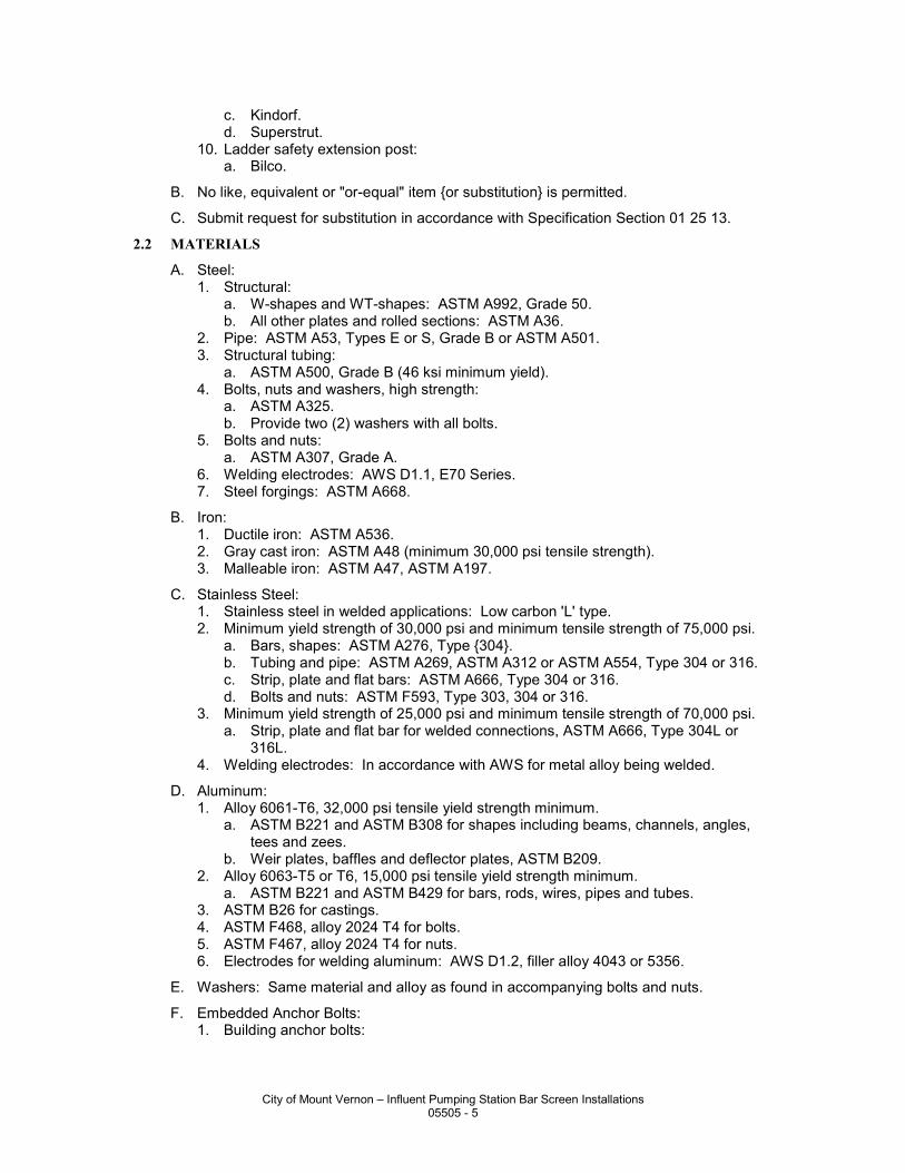
c. Kindorf. d. Superstrut.
10. Ladder safety extension post: a. Bilco.
B. No like, equivalent or "or-equal" item {or substitution} is permitted.
C. Submit request for substitution in accordance with Specification Section 01 25 13.
2.2 MATERIALS
A. Steel: 1. Structural:
a. W-shapes and WT-shapes: ASTM A992, Grade 50. b. All other plates and rolled sections: ASTM A36.
2. Pipe: ASTM A53, Types E or S, Grade B or ASTM A501. 3. Structural tubing:
a. ASTM A500, Grade B (46 ksi minimum yield). 4. Bolts, nuts and washers, high strength:
a. ASTM A325. b. Provide two (2) washers with all bolts.
5. Bolts and nuts: a. ASTM A307, Grade A.
6. Welding electrodes: AWS D1.1, E70 Series. 7. Steel forgings: ASTM A668.
B. Iron: 1. Ductile iron: ASTM A536. 2. Gray cast iron: ASTM A48 (minimum 30,000 psi tensile strength). 3. Malleable iron: ASTM A47, ASTM A197.
C. Stainless Steel: 1. Stainless steel in welded applications: Low carbon 'L' type. 2. Minimum yield strength of 30,000 psi and minimum tensile strength of 75,000 psi.
a. Bars, shapes: ASTM A276, Type {304}. b. Tubing and pipe: ASTM A269, ASTM A312 or ASTM A554, Type 304 or 316. c. Strip, plate and flat bars: ASTM A666, Type 304 or 316. d. Bolts and nuts: ASTM F593, Type 303, 304 or 316.
3. Minimum yield strength of 25,000 psi and minimum tensile strength of 70,000 psi. a. Strip, plate and flat bar for welded connections, ASTM A666, Type 304L or
316L. 4. Welding electrodes: In accordance with AWS for metal alloy being welded.
D. Aluminum: 1. Alloy 6061-T6, 32,000 psi tensile yield strength minimum.
a. ASTM B221 and ASTM B308 for shapes including beams, channels, angles, tees and zees.
b. Weir plates, baffles and deflector plates, ASTM B209. 2. Alloy 6063-T5 or T6, 15,000 psi tensile yield strength minimum.
a. ASTM B221 and ASTM B429 for bars, rods, wires, pipes and tubes. 3. ASTM B26 for castings. 4. ASTM F468, alloy 2024 T4 for bolts. 5. ASTM F467, alloy 2024 T4 for nuts. 6. Electrodes for welding aluminum: AWS D1.2, filler alloy 4043 or 5356.
E. Washers: Same material and alloy as found in accompanying bolts and nuts.
F. Embedded Anchor Bolts: 1. Building anchor bolts:
City of Mount Vernon – Influent Pumping Station Bar Screen Installations 05505 - 5
a. ASTM F1554, Grade 55 with weldability supplement S1 or ASTM A36 for threaded rods galvanized.
b. ASTM A307, Grade A for headed bolts galvanized. 2. All other anchor bolts: Type 304 or 316 stainless steel with matching nut and
washer.
G. Expansion Anchor Bolts and Adhesive Anchor Bolts: 1. Stainless steel, Type 304, 314 or 316. 2. Provide minimum edge distance cover and spacing as recommended by
manufacturer, or as indicated on Drawings whichever is larger. a. Minimum embedment as recommended by manufacturer or eight (8) diameters
of bolt, whichever is larger. b. Notify Engineer if required depth of embedment cannot be achieved at a
particular anchor bolt location. c. Follow manufacturer's recommendations for installation and torque.
3. Submit manufacturer's load test data to verify at least the anchor bolt capacities at the following embedment depths: a. Data must be based on actual tests performed in unreinforced mass of
concrete of not more than 4000 psi compressive strength. b. Capacity must be at a concrete temperature of at least 130 DegF.
ANCHOR BOLT DIAMETER (IN)
EMBEDMENT (IN)
MINIMUM ULTIMATE TENSION CAPACITY (KIP)*, **
3/8 3 4.8 1/2 4 8.1 5/8 5 11.4 3/4 6 15.4 7/8 7 20.0 1 8 24.7
1-1/4 10 34.3 * Data must be based on actual tests preformed in unreinforced mass concrete of not more than 4000 psi
compressive strength. ** Capacity must be at a concrete temperature of at least 130 DegF.
4. Expansion anchor bolts: a. Kwik Bolt by Hilti, Inc. b. Trubolt by ITW Ramset/Red Head. c. Wedge-All by Simpson Strong-Tie.
5. Adhesive anchor bolts: a. HVA Adhesive Anchor System by Hilti. b. HIT HY 150 Adhesive Anchor by Hilti. c. HSE 2411 Epoxy Adhesive Anchor by Hilti. d. EPCON Ceramic 6 Epoxy by ITW Ramset/Red Head. e. Acrylic-Tie by Simpson Strong-Tie.
6. Self-tapping concrete anchors: a. Tapcon by ITW Buildex. b. 410 stainless steel. c. 1/4 IN DIA with 5/16 IN hex head.
1) Minimum embedment as recommended by manufacturer. d. {#3 Phillips flat head.}
H. Headed Studs: ASTM A108 with a minimum yield strength of 50,000 psi and a minimum tensile strength of 60,000 psi.
I. Deformed Bar Anchors: ASTM A496 or ASTM A1064 with a minimum yield strength of 70,000 psi and a minimum tensile strength of 80,000 psi.
City of Mount Vernon – Influent Pumping Station Bar Screen Installations 05505 - 6
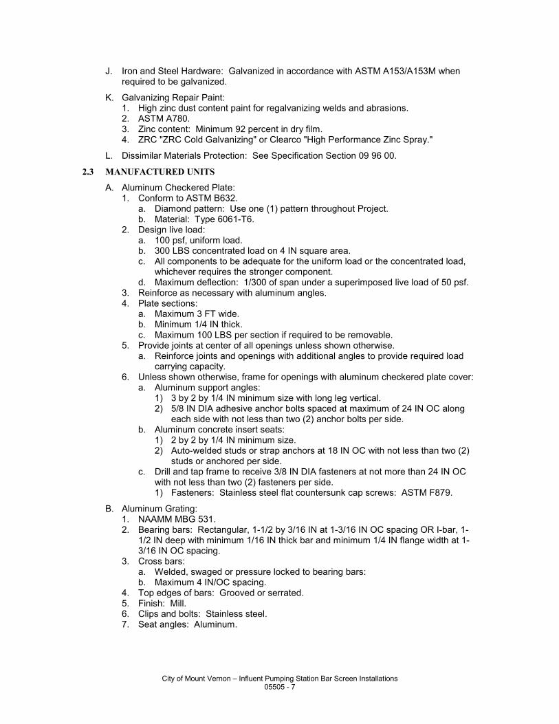
J. Iron and Steel Hardware: Galvanized in accordance with ASTM A153/A153M when required to be galvanized.
K. Galvanizing Repair Paint: 1. High zinc dust content paint for regalvanizing welds and abrasions. 2. ASTM A780. 3. Zinc content: Minimum 92 percent in dry film. 4. ZRC "ZRC Cold Galvanizing" or Clearco "High Performance Zinc Spray."
L. Dissimilar Materials Protection: See Specification Section 09 96 00.
2.3 MANUFACTURED UNITS
A. Aluminum Checkered Plate: 1. Conform to ASTM B632.
a. Diamond pattern: Use one (1) pattern throughout Project. b. Material: Type 6061-T6.
2. Design live load: a. 100 psf, uniform load. b. 300 LBS concentrated load on 4 IN square area. c. All components to be adequate for the uniform load or the concentrated load,
whichever requires the stronger component. d. Maximum deflection: 1/300 of span under a superimposed live load of 50 psf.
3. Reinforce as necessary with aluminum angles. 4. Plate sections:
a. Maximum 3 FT wide. b. Minimum 1/4 IN thick. c. Maximum 100 LBS per section if required to be removable.
5. Provide joints at center of all openings unless shown otherwise. a. Reinforce joints and openings with additional angles to provide required load
carrying capacity. 6. Unless shown otherwise, frame for openings with aluminum checkered plate cover:
a. Aluminum support angles: 1) 3 by 2 by 1/4 IN minimum size with long leg vertical. 2) 5/8 IN DIA adhesive anchor bolts spaced at maximum of 24 IN OC along
each side with not less than two (2) anchor bolts per side. b. Aluminum concrete insert seats:
1) 2 by 2 by 1/4 IN minimum size. 2) Auto-welded studs or strap anchors at 18 IN OC with not less than two (2)
studs or anchored per side. c. Drill and tap frame to receive 3/8 IN DIA fasteners at not more than 24 IN OC
with not less than two (2) fasteners per side. 1) Fasteners: Stainless steel flat countersunk cap screws: ASTM F879.
B. Aluminum Grating: 1. NAAMM MBG 531. 2. Bearing bars: Rectangular, 1-1/2 by 3/16 IN at 1-3/16 IN OC spacing OR I-bar, 1-
1/2 IN deep with minimum 1/16 IN thick bar and minimum 1/4 IN flange width at 1-3/16 IN OC spacing.
3. Cross bars: a. Welded, swaged or pressure locked to bearing bars: b. Maximum 4 IN/OC spacing.
4. Top edges of bars: Grooved or serrated. 5. Finish: Mill. 6. Clips and bolts: Stainless steel. 7. Seat angles: Aluminum.
City of Mount Vernon – Influent Pumping Station Bar Screen Installations 05505 - 7
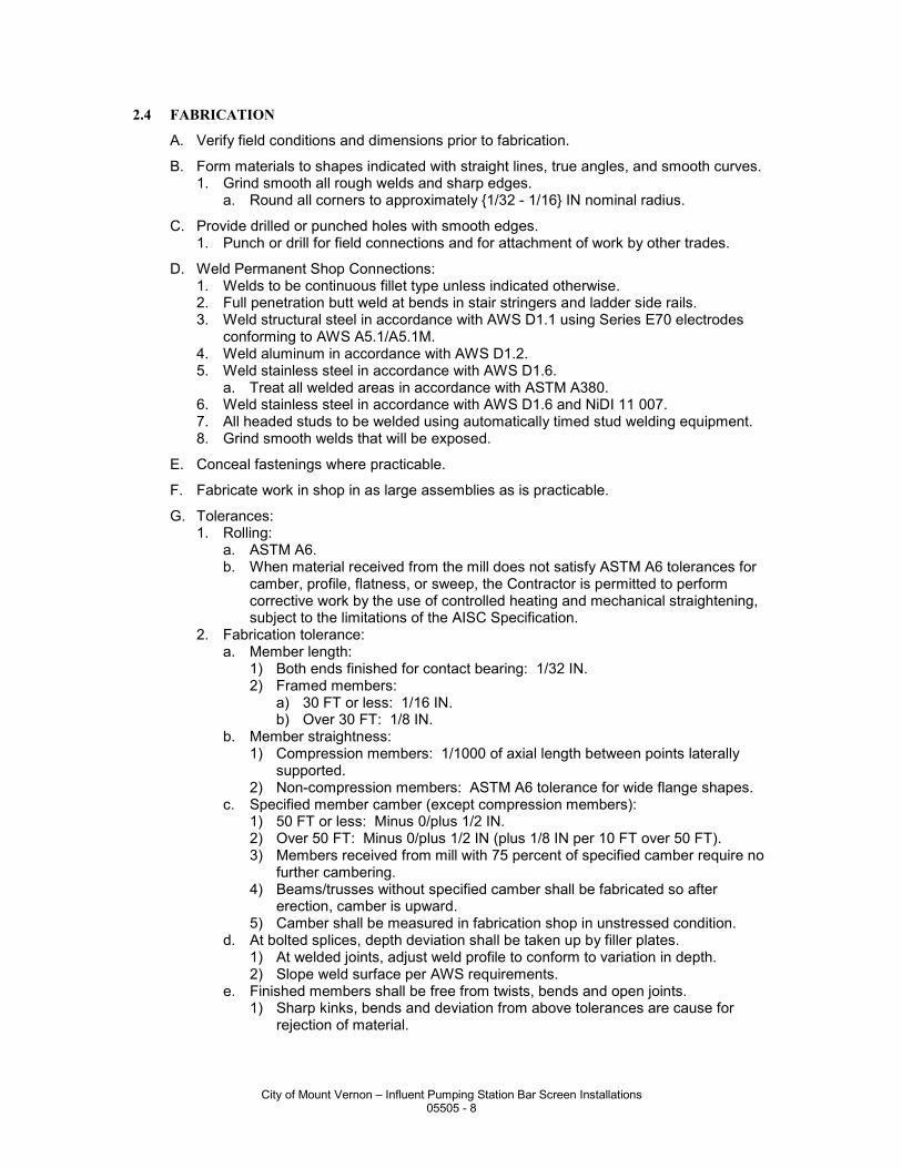
2.4 FABRICATION
A. Verify field conditions and dimensions prior to fabrication.
B. Form materials to shapes indicated with straight lines, true angles, and smooth curves. 1. Grind smooth all rough welds and sharp edges.
a. Round all corners to approximately {1/32 - 1/16} IN nominal radius.
C. Provide drilled or punched holes with smooth edges. 1. Punch or drill for field connections and for attachment of work by other trades.
D. Weld Permanent Shop Connections: 1. Welds to be continuous fillet type unless indicated otherwise. 2. Full penetration butt weld at bends in stair stringers and ladder side rails. 3. Weld structural steel in accordance with AWS D1.1 using Series E70 electrodes
conforming to AWS A5.1/A5.1M. 4. Weld aluminum in accordance with AWS D1.2. 5. Weld stainless steel in accordance with AWS D1.6.
a. Treat all welded areas in accordance with ASTM A380. 6. Weld stainless steel in accordance with AWS D1.6 and NiDI 11 007. 7. All headed studs to be welded using automatically timed stud welding equipment. 8. Grind smooth welds that will be exposed.
E. Conceal fastenings where practicable.
F. Fabricate work in shop in as large assemblies as is practicable.
G. Tolerances: 1. Rolling:
a. ASTM A6. b. When material received from the mill does not satisfy ASTM A6 tolerances for
camber, profile, flatness, or sweep, the Contractor is permitted to perform corrective work by the use of controlled heating and mechanical straightening, subject to the limitations of the AISC Specification.
2. Fabrication tolerance: a. Member length:
1) Both ends finished for contact bearing: 1/32 IN. 2) Framed members:
a) 30 FT or less: 1/16 IN. b) Over 30 FT: 1/8 IN.
b. Member straightness: 1) Compression members: 1/1000 of axial length between points laterally
supported. 2) Non-compression members: ASTM A6 tolerance for wide flange shapes.
c. Specified member camber (except compression members): 1) 50 FT or less: Minus 0/plus 1/2 IN. 2) Over 50 FT: Minus 0/plus 1/2 IN (plus 1/8 IN per 10 FT over 50 FT). 3) Members received from mill with 75 percent of specified camber require no
further cambering. 4) Beams/trusses without specified camber shall be fabricated so after
erection, camber is upward. 5) Camber shall be measured in fabrication shop in unstressed condition.
d. At bolted splices, depth deviation shall be taken up by filler plates. 1) At welded joints, adjust weld profile to conform to variation in depth. 2) Slope weld surface per AWS requirements.
e. Finished members shall be free from twists, bends and open joints. 1) Sharp kinks, bends and deviation from above tolerances are cause for
rejection of material.
City of Mount Vernon – Influent Pumping Station Bar Screen Installations 05505 - 8
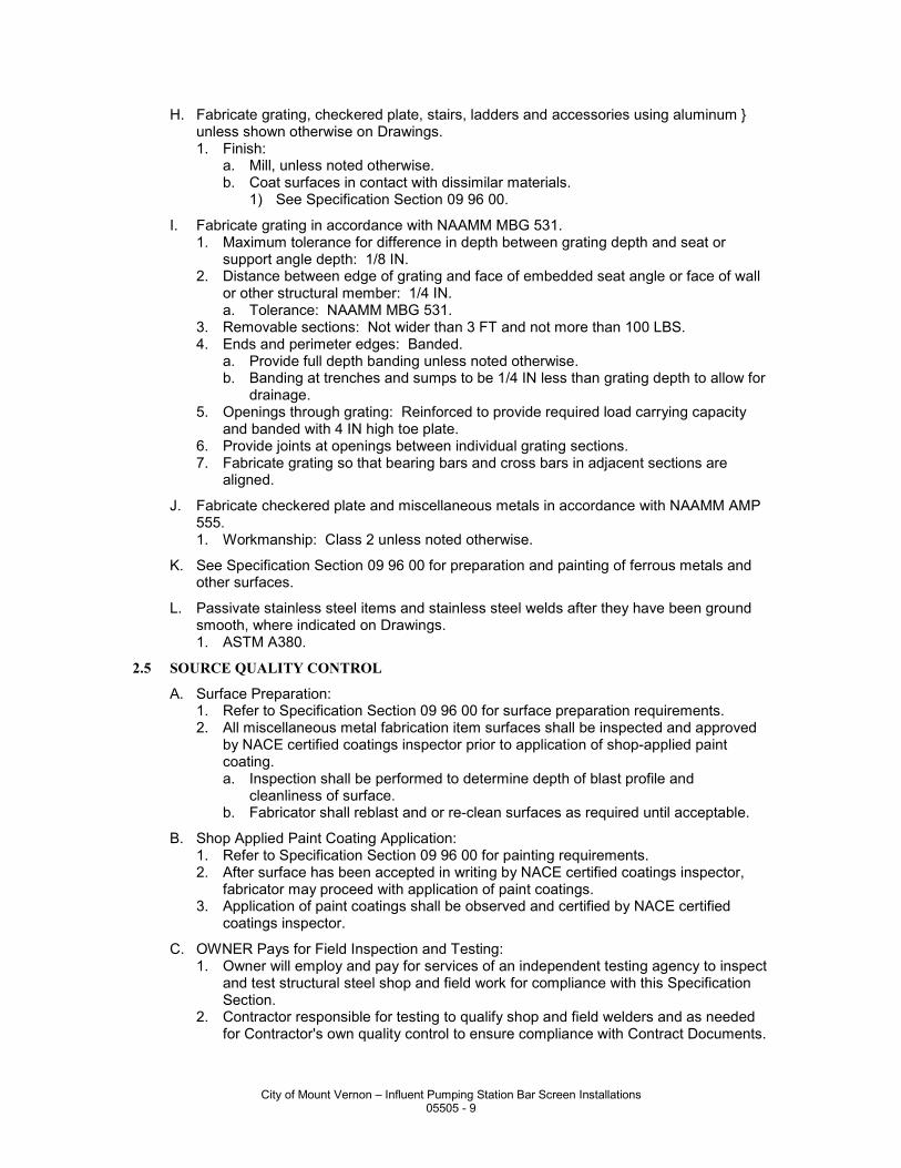
H. Fabricate grating, checkered plate, stairs, ladders and accessories using aluminum } unless shown otherwise on Drawings. 1. Finish:
a. Mill, unless noted otherwise. b. Coat surfaces in contact with dissimilar materials.
1) See Specification Section 09 96 00.
I. Fabricate grating in accordance with NAAMM MBG 531. 1. Maximum tolerance for difference in depth between grating depth and seat or
support angle depth: 1/8 IN. 2. Distance between edge of grating and face of embedded seat angle or face of wall
or other structural member: 1/4 IN. a. Tolerance: NAAMM MBG 531.
3. Removable sections: Not wider than 3 FT and not more than 100 LBS. 4. Ends and perimeter edges: Banded.
a. Provide full depth banding unless noted otherwise. b. Banding at trenches and sumps to be 1/4 IN less than grating depth to allow for
drainage. 5. Openings through grating: Reinforced to provide required load carrying capacity
and banded with 4 IN high toe plate. 6. Provide joints at openings between individual grating sections. 7. Fabricate grating so that bearing bars and cross bars in adjacent sections are
aligned.
J. Fabricate checkered plate and miscellaneous metals in accordance with NAAMM AMP 555. 1. Workmanship: Class 2 unless noted otherwise.
K. See Specification Section 09 96 00 for preparation and painting of ferrous metals and other surfaces.
L. Passivate stainless steel items and stainless steel welds after they have been ground smooth, where indicated on Drawings. 1. ASTM A380.
2.5 SOURCE QUALITY CONTROL
A. Surface Preparation: 1. Refer to Specification Section 09 96 00 for surface preparation requirements. 2. All miscellaneous metal fabrication item surfaces shall be inspected and approved
by NACE certified coatings inspector prior to application of shop-applied paint coating. a. Inspection shall be performed to determine depth of blast profile and
cleanliness of surface. b. Fabricator shall reblast and or re-clean surfaces as required until acceptable.
B. Shop Applied Paint Coating Application: 1. Refer to Specification Section 09 96 00 for painting requirements. 2. After surface has been accepted in writing by NACE certified coatings inspector,
fabricator may proceed with application of paint coatings. 3. Application of paint coatings shall be observed and certified by NACE certified
coatings inspector.
C. OWNER Pays for Field Inspection and Testing: 1. Owner will employ and pay for services of an independent testing agency to inspect
and test structural steel shop and field work for compliance with this Specification Section.
2. Contractor responsible for testing to qualify shop and field welders and as needed for Contractor's own quality control to ensure compliance with Contract Documents.
City of Mount Vernon – Influent Pumping Station Bar Screen Installations 05505 - 9
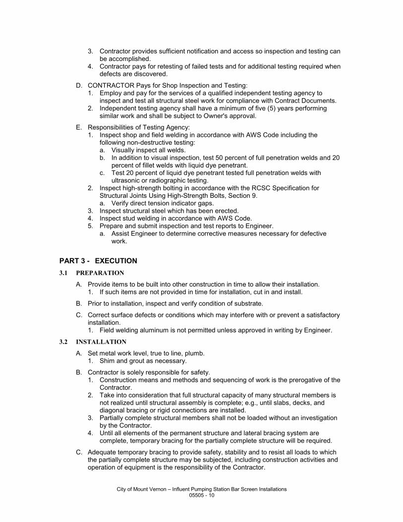
3. Contractor provides sufficient notification and access so inspection and testing can be accomplished.
4. Contractor pays for retesting of failed tests and for additional testing required when defects are discovered.
D. CONTRACTOR Pays for Shop Inspection and Testing: 1. Employ and pay for the services of a qualified independent testing agency to
inspect and test all structural steel work for compliance with Contract Documents. 2. Independent testing agency shall have a minimum of five (5) years performing
similar work and shall be subject to Owner's approval.
E. Responsibilities of Testing Agency: 1. Inspect shop and field welding in accordance with AWS Code including the
following non-destructive testing: a. Visually inspect all welds. b. In addition to visual inspection, test 50 percent of full penetration welds and 20
percent of fillet welds with liquid dye penetrant. c. Test 20 percent of liquid dye penetrant tested full penetration welds with
ultrasonic or radiographic testing. 2. Inspect high-strength bolting in accordance with the RCSC Specification for
Structural Joints Using High-Strength Bolts, Section 9. a. Verify direct tension indicator gaps.
3. Inspect structural steel which has been erected. 4. Inspect stud welding in accordance with AWS Code. 5. Prepare and submit inspection and test reports to Engineer.
a. Assist Engineer to determine corrective measures necessary for defective work.
PART 3 - EXECUTION 3.1 PREPARATION
A. Provide items to be built into other construction in time to allow their installation. 1. If such items are not provided in time for installation, cut in and install.
B. Prior to installation, inspect and verify condition of substrate.
C. Correct surface defects or conditions which may interfere with or prevent a satisfactory installation. 1. Field welding aluminum is not permitted unless approved in writing by Engineer.
3.2 INSTALLATION
A. Set metal work level, true to line, plumb. 1. Shim and grout as necessary.
B. Contractor is solely responsible for safety. 1. Construction means and methods and sequencing of work is the prerogative of the
Contractor. 2. Take into consideration that full structural capacity of many structural members is
not realized until structural assembly is complete; e.g., until slabs, decks, and diagonal bracing or rigid connections are installed.
3. Partially complete structural members shall not be loaded without an investigation by the Contractor.
4. Until all elements of the permanent structure and lateral bracing system are complete, temporary bracing for the partially complete structure will be required.
C. Adequate temporary bracing to provide safety, stability and to resist all loads to which the partially complete structure may be subjected, including construction activities and operation of equipment is the responsibility of the Contractor.
City of Mount Vernon – Influent Pumping Station Bar Screen Installations 05505 - 10
1. Plumb, align, and set structural steel members to specified tolerances. 2. Use temporary guys, braces, shoring, connections, etc., necessary to maintain the
structural framing plumb and in proper alignment until permanent connections are made, the succeeding work is in place, and temporary work is no longer necessary.
3. Use temporary guys, bracing, shoring, and other work to prevent injury or damage to adjacent work or construction from stresses due to erection procedures and operation of erection equipment, construction loads, and wind.
4. Contractor shall be responsible for the design of the temporary bracing system and must consider the sequence and schedule of placement of such elements and effects of loads imposed on the structural steel members by partially or completely installed work, including work of all other trades. a. If not obvious from experience or from the Drawings, the Contractor shall confer
with the Engineer to identify those structural steel elements that must be complete before the temporary bracing system is removed.
5. Remove and dispose of all temporary work and facilities off-site.
D. Examine work-in-place on which specified work is in any way dependent to ensure that conditions are satisfactory for the installation of the work. 1. Report defects in work-in-place which may influence satisfactory completion of the
work. 2. Absence of such notification will be construed as acceptance of work-in-place.
E. Field Measurement: 1. Take field measurements as necessary to verify or supplement dimensions
indicated on the Drawings. 2. Contractor responsible for the accurate fit of the work.
F. Check the elevations of all finished footings or foundations and the location and alignment of all anchor bolts before starting erection. 1. Use surveyor's level. 2. Notify Engineer of any errors or deviations found by such checking.
G. Framing member location tolerances after erection shall not exceed the frame tolerances listed in the FIELD QUALITY CONTROL Article in PART 3 of this Specification Section.
H. Erect plumb and level; introduce temporary bracing required to support erection loads.
I. Use light drifting necessary to draw holes together. 1. Drifting to match unfair holes is not allowed.
J. Welding: 1. Conform to AWS D1.1 and requirements of the FABRICATION Article in PART 2 of
this Specification Section. 2. When joining two (2) sections of steel of different ASTM designations, welding
techniques shall be in accordance with a qualified AWS D1.1 procedure.
K. Shore existing members when unbolting of common connections is required. 1. Use new bolts for rebolting connections.
L. Clean stored material of all foreign matter accumulated during erection period.
M. Bolt Field Connections: Where practicable, conceal fastenings.
N. Field Welding: 1. Follow AWS procedures. 2. Grind welds smooth where field welding is required.
O. Field cutting grating or checkered plate to correct fabrication errors is not acceptable. 1. Replace entire section.
City of Mount Vernon – Influent Pumping Station Bar Screen Installations 05505 - 11
P. Remove all burrs and radius all sharp edges and corners of miscellaneous plates, angles, framing system elements, etc.
Q. Unless noted or specified otherwise: 1. Connect steel members to steel members with 3/4 IN DIA ASTM A325 high
strength bolts. 2. Connect aluminum to aluminum with 3/4 IN DIA aluminum bolts. 3. Connect aluminum to structural steel using 3/4 IN DIA stainless steel bolts.
a. Provide dissimilar metals protection. 4. Connect aluminum and steel members to concrete and masonry using stainless
steel expansion anchor bolts or adhesive anchor bolts unless shown otherwise. a. Provide dissimilar materials protection.
5. Provide washers for all bolted connections. 6. Where exposed, bolts shall extend a maximum of 3/4 IN and a minimum of 1/2 IN
above the top nut. a. If bolts are cut off to required maximum height, threads must be dressed to
allow nuts to be removed without damage to the bolt or the nuts.
R. Install and tighten ASTM A325 high-strength bolts in accordance with the AISC 325, Allowable Stress Design (ASD). 1. Provide hardened washers for all ASTM A325 bolts.
a. Provide the hardened washer under the element (nut or bolt head) turned in tightening.
S. After bolts are tightened, upset threads of ASTM A307 unfinished bolts or anchor bolts to prevent nuts from backing off.
T. Do not field splice fabricated items unless said items exceed standard shipping length or change of direction requires splicing. 1. Provide full penetration welded splices where continuity is required.
U. Provide each fabricated item complete with attachment devices as indicated or required to install.
V. Anchor such that work will not be distorted nor fasteners overstressed from expansion and contraction.
W. Set beam and column base plates accurately on nonshrink grout as indicated on Drawings. 1. See Division 03 Specification Sections for non-shrink grout. 2. Set and anchor each base plate to proper line and elevation.
a. Use metal wedges, shims, or setting nuts for leveling and plumbing columns and beams. 1) Wedges, shims and setting nuts to be of same metal as base plate they
support. 2) Tighten nuts on anchor bolts.
b. Fill space between bearing surface and bottom of base plate with nonshrink grout. 1) Fill space until voids are completely filled and base plates are fully bedded
on wedges, shims, and grout. c. Do not remove wedges or shims.
1) Where they protrude, cut off flush with edge of base plate. d. Fill sleeves around anchor bolts solid with non-shrink grout.
X. Tie anchor bolts in position to embedded reinforcing steel using wire. 1. Tack welding prohibited.
a. Coat bolt threads and nuts with heavy coat of clean grease. 2. Anchor bolt location tolerance:
a. 1/16 IN. b. Provide steel templates for all column anchor bolts.
City of Mount Vernon – Influent Pumping Station Bar Screen Installations 05505 - 12
Y. Attach grating to end and intermediate supports with grating saddle clips and bolts. 1. Maximum spacing: 2 FT OC with minimum of two (2) per side. 2. Attach individual units of aluminum grating together with clips at 2 FT OC maximum
with a minimum of two (2) clips per side.
Z. Repair damaged galvanized surfaces in accordance with ASTM A780. 1. Prepare damaged surfaces by abrasive blasting or power sanding. 2. Apply galvanizing repair paint to minimum 6 mils DFT in accordance with
manufacturer's instructions.
3.3 FIELD QUALITY CONTROL
A. Tolerances shall meet structural requirements of Specification Section 05 12 00 for erecting items of structural nature.
B. Tolerances (unless otherwise noted on the Drawings): 1. Frame placement, after assembly and before welding or tightening.
a. Deviation from plumb, level and alignment: 1 in 500, maximum. b. Displacement of centerlines of columns: 1/2 IN maximum, each side of
centerline location shown on Drawings.
3.4 CLEANING
A. After fabrication, erection, installation or application, clean all miscellaneous metal fabrication surfaces of all dirt, weld slag and other foreign matter.
B. All stainless steel products in addition to Paragraph A. above: 1. Remove all heat tint, rusting, discoloration by passivation, ASTM A380, or other
acceptable means as listed in NiDI 11 007 as approved by the Engineer.
C. Provide surface acceptable to receive field applied paint coatings specified in Specification Section 09 96 00.
END OF SECTION
City of Mount Vernon – Influent Pumping Station Bar Screen Installations 05505 - 13

This page left intentionally blank.
City of Mount Vernon – Influent Pumping Station Bar Screen Installations 05505 - 14
..
SECTION 10400 IDENTIFICATION DEVICES
PART 1 GENERAL
1.1 SUMMARY
A. Section includes: 1. Tag, tape and stenciling systems for equipment, piping, valves, pumps, ductwork and
similar items, and hazard and safety signs.
1.2 QUALITY ASSURANCE
A. Referenced Standards: 1. American National Standards Institute (ANSI):
a. A13.1, Scheme for Identification of Piping Systems. b. Z535.1, Safety Color Code. c. Z535.2, Environmental and Facility Safety Signs. d. Z535.3, Criteria for Safety Symbols. e. Z535.4, Product Safety Signs and Labels.
2. National Fire Protection Association (NFPA): a. 70, National Electrical Code (NEC). b. 820, Standard for Fire Protection in Wastewater Treatment and Collection Facilities.
3. Occupational, Health and Safety Administration (OSHA): a. 1910.145, Specification for Accident Prevention Signs and Tags.
1.3 SUBMITTALS
A. Shop Drawings: 1. Product technical data:
a. Catalog information for all identification systems. b. Acknowledgement that products submitted meet requirements of standards
referenced. 2. Identification register, listing all items in Part 3 to be identified, type of identification
system to be used, lettering, location and color.
PART 2 PRODUCTS
2.1 ACCEPTABLE MANUFACTURERS
A. Subject to compliance with the Contract Documents, the following manufacturers are acceptable: 1. W.H. Brady Co. 2. Panduit. 3. Seton. 4. National Band and Tag Co. 5. Carlton Industries, Inc. 6. Or equal.
2.2 MANUFACTURED UNITS
A. Type A1 - Round Metal Tags: 1. Materials: Aluminum or stainless steel. Stainless steel shall be used in corrosive
environments.
City of Mount Vernon – Influent Pumping Station Bar Screen Installations 10400 - 1
..
2. Size: a. Diameter: 1-1/2 IN minimum. b. Thickness: 0.035 IN (20 gage) minimum.
3. Fabrication: a. 3/16 IN minimum mounting hole. b. Legend stamped and filled with black coloring.
4. Color: Natural.
B. Type A2 - Rectangle Metal Tags: 1. Materials: Stainless steel. 2. Size:
a. 3-1/2 IN x 1-1/2 IN minimum. b. Thickness: 0.036 IN (20 gage) minimum.
3. Fabrication: a. 3/16 IN minimum mounting hole. b. Legend stamped and filled with black coloring.
4. Color: Natural.
C. Type A3 - Metal Tape Tags: 1. Materials: Aluminum or stainless steel. 2. Size:
a. Width 1/2 IN minimum. b. Length as required by text.
3. Fabrication: a. 3/16 IN minimum mounting hole. b. Legend Embossed.
4. Color: Natural.
D. Type B1- Square Non-Metallic Tags: 1. Materials: Fiberglass reinforced plastic. 2. Size:
a. Surface: 2 x 2 IN minimum. b. Thickness: 100 mils.
3. Fabrication: a. 3/16 IN mounting hole with metal eyelet. b. Legend preprinted and permanently embedded and fade resistant.
4. Color: a. Background: Manufacturer standard or as specified. b. Lettering: Black.
E. Type B2 - Non-Metallic Signs: 1. Materials: Fiberglass reinforced or durable plastic. 2. Size:
a. Surface: As required by text. b. Thickness: 60 mils minimum.
3. Fabrication: a. Rounded corners. b. Drilled holes in corners with grommets. c. Legend: Preprinted, permanently embedded and fade resistant for a 10 year
minimum outdoor durability. 4. Color:
a. Background: Manufacturer standard or as specified. b. Lettering: Black.
5. Standards for OSHA signs: ANSI Z535.1, Z535.2, Z535.3, Z535.4, OSHA 1910.145.
City of Mount Vernon – Influent Pumping Station Bar Screen Installations 10400 - 2
..
F. Type C - Phenolic Name Plates: 1. Materials: Phenolic. 2. Size:
a. Surface: As required by text. b. Thickness: 1/16 IN.
3. Fabrication: a. Two layers laminated. b. Legend engraved through top lamination into bottom lamination. c. Two drilled side holes, for screw mounting.
4. Color: Black top surface, white core, unless otherwise indicated.
G. Type D - Self-Adhesive Tape Tags and Signs: 1. Materials: Vinyl tape or vinyl cloth. 2. Size:
a. Surface: As required by text. b. Thickness: 5 mils minimum.
3. Fabrication: a. Indoor/Outdoor grade. b. Weather and UV resistant inks. c. Permanent adhesive. d. Preprinted legend. e. Wire markers to be self-laminating.
4. Color: White with black lettering or as specified. 5. Standards for OSHA signs: ANSI Z535.1, Z535.2, Z535.3, Z535.4, OSHA 1910.145.
H. Type E - Heat Shrinkable Tape Tags: 1. Materials: Polyolefin. 2. Size: As required by text. 3. Fabrication: Legend preprinted. 4. Color: White background, black printing.
I. Type F - Underground Warning Tape: 1. Materials: Polyethylene. 2. Size:
a. 6 IN wide (minimum). b. Thickness: 3.5 mils.
3. Fabrication: a. Legend: Preprinted and permanently imbedded. b. Message continuous printed. c. Tensile strength: 1750 psi.
4. Color: As specified.
J. Type G - Stenciling System: 1. Materials:
a. Exterior type stenciling enamel. b. Either brushing grade or pressurized spray can form and grade.
2. Size: As required. 3. Fabrication: Legend as required. 4. Color: Black or white for best contrast.
2.3 ACCESSORIES
A. Fasteners: 1. Bead chain: #6 brass, aluminum or stainless steel. 2. Plastic strap: Nylon, urethane or polypropylene. 3. Screws: Self-tapping, stainless steel.
City of Mount Vernon – Influent Pumping Station Bar Screen Installations 10400 - 3
..
4. Adhesive, solvent activated.
2.4 MAINTENANCE MATERIALS
A. Where stenciled markers are provided, clean and retain stencils after completion and include in extra stock, along with required stock of paints and applicators.
PART 3 EXECUTION
3.1 GENERAL INSTALLATION
A. Install identification devices at specified locations.
B. All identification devices to be printed by mechanical process, hand printing is not acceptable.
C. Attach tags to equipment with sufficient surface or body area with solvent activated adhesive applied to back of each tag.
D. Attach tags with 1/8 IN round or flat head screws to equipment without sufficient surface or body area, or porous surfaces. Where attachment with screws should not or cannot penetrate substrate, attach with plastic strap.
E. Single items of equipment enclosed in a housing or compartment to be tagged on outside of housing. Several items of equipment mounted in housing to be individually tagged inside the compartment.
3.2 SCHEDULES
A. Process Systems: 1. General:
a. Provide arrows and markers on piping. 1) At 20 FT maximum centers along continuous lines. 2) At changes in direction (route) or obstructions. 3) At valves, risers, "T" joints, machinery or equipment. 4) Where pipes pass through floors, walls, ceilings, cladding assemblies and like
obstructions provide markers on both sides. b. Position markers on both sides of pipe with arrow markers pointing in flow direction.
If flow is in both directions use double headed arrow markers. c. Apply tapes and stenciling in uniform manner parallel to piping.
2. Trenches with piping: a. Tag type: Type F - Underground Warning Tape b. Location: Halfway between top of piping and finished grade. c. Letter height: 1-1/4 IN minimum. d. Natural gas or digester gas:
1) Color: Yellow with black letters. 2) Legend:
a) First line: “CAUTION CAUTION CAUTION” b) Second line: “BURIED GAS LINE BELOW”
e. Potable Water: 1) Color: Blue with black letters. 2) Legend:
a) First line: “CAUTION CAUTION CAUTION” b) Second line: “BURIED WATER LINE BELOW”
f. Storm and sanitary sewer lines:
City of Mount Vernon – Influent Pumping Station Bar Screen Installations 10400 - 4
..
1) Color: Green with black letters. 2) Legend:
a) First line: “CAUTION CAUTION CAUTION” b) Second line: “BURIED SEWER LINE BELOW”
g. (Non-potable) water piping, except 3 IN and smaller irrigation pipe: 1) Color: Green with black letters. 2) Legend:
a) First line: “CAUTION CAUTION CAUTION” b) Second line: “BURIED NON-POTABLE WATER LINE BELOW”
h. Chemical feed piping (e.g., chlorine solution, polymer solution, caustic solution, etc.): 1) Color: Yellow with black letters. 2) Legend:
a) First line: “CAUTION CAUTION CAUTION” b) Second line: “BURIED CHEMICAL LINE BELOW”
i. Other piping (e.g., compressed air, irrigation, refrigerant, heating water, etc.): 1) Color: Yellow with black letters. 2) Legend:
a) First line: “CAUTION CAUTION CAUTION” b) Second line: “BURIED PIPE LINE BELOW”
3. Yard valves, buried, with valve box and concrete pad: a. Tag type: Type A2 - Rectangle Metal Tags. b. Fastener: 3/16 IN x 7/8 IN plastic screw anchor with 1 IN #6 stainless steel pan
head screw. c. Legend:
1) Letter height: 1/4 IN minimum. 2) First line: "Buried Yard Valve."
4. Valves and slide gates: a. Tag type:
1) Outdoor locations: Type B1 - Square Non-Metallic Tags. 2) Indoor non-corrosive:
a) Type A1 - Round Metal Tags. b) Type B1 - Square Non-Metallic Tags.
3) Indoor corrosive: a) Stainless steel Type A1 - Round Metal Tags. b) Type B1 - Square Non-Metallic Tags.
b. Fastener: 1) Type A1: Chain of the same material. 2) Type B1: Stainless steel chain.
c. Color: Per ANSI A13.1 corresponding to the piping system. d. Legend:
1) Letter height: 1/4 IN minimum. 2) Valve/slide gates designation as indicated on the Drawings. (e.g. "GT-14311")
5. Process equipment (e.g., pumps, pump motors, blowers, air compressors, bar screens, clarifier drive mechanism, etc.): a. Tag type:
1) Type B2 - Non-Metallic Signs. 2) Type D - Self-Adhesive Tape Tags and Signs. 3) Type G - Stenciling System.
b. Fastener: 1) Self. 2) Screws. 3) Adhesive.
c. Legend: 1) Letter height: 1/2 IN minimum.
City of Mount Vernon – Influent Pumping Station Bar Screen Installations 10400 - 5
..
2) Equipment designation as indicated on the Drawings (e.g., “Primary Sludge Pump P-20410”).
6. Piping systems: a. Tag type:
1) Outdoor locations: Type G - Stenciling System. 2) Indoor locations:
a) Type D - Self-Adhesive Tape Tags and Signs. b) Type G - Stenciling System.
b. Fastener: Self. c. Color: Per ANSI A13.1. d. Legend:
1) Letter height: Manufacturers standard for the pipe diameter. 2) Mark piping in accordance with ANSI A13.1. 3) Use piping designation as indicated on The Drawings. 4) Arrow: Single arrow.
7. Process tanks (over 1000 gallons) and basins, (e.g., chemical storage, clarifiers, trickling filters, digesters, etc): a. Tag type:
1) Type B2 - Non-Metallic Signs. 2) Type G - Stenciling System.
b. Fastener: 1) Screw. 2) Self.
c. Location as directed by Owner. d. Legend:
1) Letter height: 4 IN minimum. 2) Equipment designation as indicated on the Drawings (e.g., “Secondary
Clarifier 1”). 8. Tanks (less than 1000 gallons) (e.g., break tanks, chemical tanks, hydro-pneumatic
tanks, air receivers, etc.): a. Tag type:
1) Type D - Self-Adhesive Tape Tags and Signs. 2) Type G - Stenciling System.
b. Fastener: Self. c. Legend:
1) Letter height: 2 IN minimum. 2) Equipment designation as indicated on the Drawings.
9. Equipment that starts automatically: a. Tag type:
1) Type B2 - Non-Metallic Signs. 2) Type D - Self-Adhesive Tape Tags and Signs.
b. Fastener: 1) Type B2 - Screw or adhesive. 2) Type D - Self.
c. Size: 5 IN x 7 IN d. Location:
1) Mechanical Bar Screen. e. Legend:
1) OSHA Warning Sign. 2) Description of Warning: “THIS MACHINE STARTS AUTOMATICALLY”.
B. Instrumentation Systems: 1. Instrumentation Equipment (e.g., flow control valves, primary elements, etc.):
a. Tag type: 1) Outdoor locations: Type B1 - Square Non-Metallic Tags. 2) Indoor non-corrosive:
City of Mount Vernon – Influent Pumping Station Bar Screen Installations 10400 - 6
..
a) Type A1 - Round Metal Tags. b) Type B1 - Square Non-Metallic Tags.
3) Indoor corrosive: a) Stainless steel Type A1 - Round Metal Tags. b) Type B1 - Square Non-Metallic Tags.
b. Fastener: 1) Type A1: Chain of the same material. 2) Type B1: Stainless steel chain.
c. Legend: 1) Letter height: 1/4 IN minimum. 2) Equipment ISA designation as indicated on the Drawings (e.g., “FIT-38353”).
2. Enclosure for instrumentation and control equipment, (e.g., PLC control panels, etc.): a. Tag type: Type C - Phenolic Name Plates. b. Fastener: Screws. c. Legend:
1) Letter height: 1/2 IN minimum. 2) Equipment name (e.g., "Local Control Panel LCP-38000").
3. Components inside equipment enclosure, (e.g., PLC’s, control relays, contactors, and timers): a. Tag type: Type D - Self-Adhesive Tape Tags. b. Fastener: Self. c. Legend:
1) Letter height: 3/16 IN minimum. 2) Description or function of component (e.g., "PLC-38080").
4. Through enclosure door mounted components (e.g., selector switches, controller digital displays, etc.): a. Tag type: Type C - Phenolic Name Plates. b. Fastener: Screws. c. Legend:
1) Letter height: 1/4 IN minimum. 2) Component ISA tag number as indicated on the Drawings (e.g., “HS-38320”).
C. HVAC Systems: 1. General:
a. Provide arrows and markers on ducts. 1) At 20 FT maximum centers along continuous lines. 2) At changes in direction (route) or obstructions. 3) At dampers, risers, branches, machinery or equipment. 4) Where ducts pass through floors, walls, ceilings, cladding assemblies and like
obstructions provide markers on both sides. b. Position markers on both sides of duct with arrow markers pointing in flow direction.
If flow is in both directions use double headed arrow markers. c. Apply tapes and stenciling in uniform manner parallel to ducts.
2. HVAC Equipment (e.g., unit heaters, exhaust fans, air handlers, etc.): a. Tag type:
1) Type B2 - Non-Metallic Signs. 2) Type C - Phenolic Name Plates.
b. Fastener: Screws. c. Legend:
1) Letter height: 1 IN minimum. 2) Equipment designation as indicated on the Drawings (e.g., "EF-10120").
3. Ductwork: a. Tag type:
1) Type D - Self-Adhesive Tape Tags and Signs. 2) Type G - Stenciling System.
b. Fastener: Self.
City of Mount Vernon – Influent Pumping Station Bar Screen Installations 10400 - 7
..
c. Legend: 1) Letter height: 1 IN minimum. 2) Description of ductwork, (e.g., “AIR SUPPLY”). 3) Arrows: Single arrow.
4. Enclosure for instrumentation and control equipment, (e.g., fan control panels, etc.): a. Tag type: Type C - Phenolic Name Plates. b. Fastener: Screws. c. Legend:
1) Letter height: 1/2 IN minimum. 2) Equipment designation as indicated on the Drawings (e.g., "Local Control Panel
LCP-60000"). 5. Wall mounted thermostats:
a. Tag type: Type D - Self-Adhesive Tape Tags and Signs. b. Fastener: Self. c. Legend:
1) Letter height: 3/16 IN minimum. 2) Description of equipment controlled (e.g., "TS-80321").
6. Components inside equipment enclosure, (e.g., controller’s, control relays, contactors, and timers): a. Tag type: Type D - Self-Adhesive Tape Tags and Signs. b. Fastener: Self. c. Legend:
1) Letter height: 3/16 IN minimum. 2) Description or function of component (e.g., "YA-38726").
7. Through enclosure door mounted equipment (e.g., selector switches, controller digital displays, etc.): a. Tag type: Type C - Phenolic Name Plates. b. Fastener: Screws. c. Legend:
1) Letter height: 1/4 IN minimum. 2) Component tag number as indicated on the Drawings or as defined by
contractor (e.g., “HS-38751"). 8. Odor control ventilation system: Per NFPA820.
D. Electrical Systems: 1. Trenches with ductbanks, direct-buried conduit, or direct-buried wire and cable.
a. Tag type: Type F - Underground Warning Tape. b. Letter height: 1-1/4 IN minimum. c. Location:
1) Where trench is 12 IN or more below finished grade: In trench 6 IN below finished grade.
2) Where trench is less than 12 IN below finished grade: In trench 3 IN below finished grade.
d. Electrical Power (e.g., low and medium voltage): 1) Color: Red with black letters. 2) Legend:
a) First line: “CAUTION CAUTION CAUTION”. b) Second line: “BURIED ELECTRIC LINE BELOW”.
e. Communications (e.g., telephone, instrumentation, LAN, SCADA): 1) Color: Orange with black letters. 2) Legend:
a) First line: “CAUTION CAUTION CAUTION”. b) Second line: “BURIED COMMUNICATION LINE BELOW”.
2. Switchgear, switchboards and motor control centers: a. Tag type: Type C - Phenolic Name Plates. b. Fastener: Screws.
City of Mount Vernon – Influent Pumping Station Bar Screen Installations 10400 - 8
..
c. Main equipment legend: 1) Letter height:
a) First line: 1 IN minimum. b) Subsequent lines: 3/8 IN minimum.
2) First line: Equipment name (e.g., "MAIN SWITCHBOARD MSB-#####"). 3) Second line: Source of power (e.g., "FED FROM MCC-##### LOCATED IN
Pretreatment Building Electrical Room"). The source of power room number is only required when there are multiple electrical rooms, if the source is in another building, the building name or number shall be used.
4) Third line: System voltage and phase (e.g., “480/277 V, 3PH”). d. Main and feeder device legend:
1) Letter height: 3/8 IN minimum. 2) Description of load (e.g., “MAIN DISCONNECT”).
3. Panelboards and transformers: a. Tag type: Type C - Phenolic Name Plates. b. Fastener: Screws. c. Legend:
1) Letter height: a) First line: 3/8 IN minimum. b) Subsequent lines: 3/16 IN minimum.
2) First line: Equipment name (e.g., "TRANSFORMER T-#####"). 3) Second line (panelboards only): System voltage and phase (e.g., “208/120V,
3PH”). 4. Transfer switches:
a. Tag type: Type C - Phenolic Name Plates. b. Fastener: Screws. c. Legend:
1) Letter height: a) First line: 3/8 IN minimum. b) Subsequent lines: 3/16 IN minimum.
2) First line: Equipment name (e.g., "AUTOMATIC TRANSFER SWITCH ATS-#####").
5. Safety switches, separately mounted circuit breakers and motor starters, VFD’s, etc.: a. Tag type: Type C - Phenolic Name Plates. b. Fastener: Screws. c. Legend:
1) Letter height: 1/4 IN minimum. 2) First line: Description of load equipment is connected to (e.g., "PUMP
P-38210"). 6. Enclosure for instrumentation and control equipment, (e.g., lighting control panels, etc.):
a. Tag type: Type C - Phenolic Name Plates. b. Fastener: Screws. c. Legend:
1) Letter height: 1/2 IN minimum. 2) Equipment name (e.g., "LIGHTING CONTROL PANEL LCP-#####").
7. Components inside equipment enclosures (e.g., circuit breakers, fuses, control power transformers, control relays, contactors, timers, etc.): a. Tag type: Type D - Self-Adhesive Tape Tags and Signs. b. Fastener: Self. c. Legend:
1) Letter height: 3/16 IN minimum. 2) Description or function of component.
8. Through enclosure door mounted equipment (e.g., selector switches, controller digital displays, etc.): a. Tag type: Type C - Phenolic Name Plates. b. Fastener: Screws.
City of Mount Vernon – Influent Pumping Station Bar Screen Installations 10400 - 9
..
c. Legend: 1) Letter height: 1/4 IN minimum. 2) Component tag number as indicated on the Drawings or as defined by
contractor. 9. Conductors in control panels and in pull or junction boxes where multiple circuits exist.
a. Tag type: Type D - Self-Adhesive Tape Tags. b. Fastener: Self. c. Tag conductor at both ends. d. Legend:
1) Letter height: 1/8 IN minimum. 2) Circuit number or wire number as scheduled on the Drawings or as furnished
with the equipment. 10. Conductors in handholes and manholes.
a. Tag type: Type A3 - Metal Tape Tags. b. Fastener: Nylon strap. c. Tag conductor at both ends. d. Legend:
1) Letter height: 1/8 IN minimum. 2) Circuit number or wire number as scheduled on the Drawings.
11. Grounding conductors associated with grounding electrode system in accordance with the following: a. Tag type: Type D - Self-Adhesive Tape Tags. b. Fastener: Self. c. Legend:
1) Letter height: 1/8 IN minimum. 2) Function of conductor (e.g., "MAIN BONDING JUMPER", "TO GROUND
RING", "TO MAIN WATER PIPE"). 12. Flash protection for switchboards, panelboards, industrial control panels and motor
control centers: a. Tag type: Type D - Self-Adhesive Tape Signs. b. Fastener: Self. c. Legend: Per NFPA 70.
13. Entrances to electrical rooms: a. Tag type: Type B2 - Non-Metallic Signs. b. Fastener: Screw or adhesive. c. Size: 5 IN x 7 IN. d. Location: Each door to room. e. Legend:
1) OSHA Danger Sign. 2) Description of Danger: “HIGH VOLTAGE, AUTHORIZED PERSONNEL
ONLY”. 14. Equipment where more than one voltage source is present:
a. Tag type: 1) Type B2 - Non-Metallic Signs. 2) Type D - Self-Adhesive Tape Signs.
b. Fastener: 1) Screw or adhesive. 2) Self.
c. Size: 1-3/4 IN x 2-1/2 IN. d. Location: Exterior face of enclosure or cubical. e. Legend:
1) OSHA Danger Sign. 2) Description of Danger: “MULTIPLE VOLTAGE SOURCES”.
END OF SECTION
City of Mount Vernon – Influent Pumping Station Bar Screen Installations 10400 - 10
..
SECTION 11005 EQUIPMENT: BASIC REQUIREMENTS
PART 1 GENERAL
1.1 SUMMARY
A. Section includes: 1. Requirements of this Section apply to all equipment provided on the Project including
that found in Divisions 11, 12, 13, 14, 15, and 16, even if not specifically referenced in individual "Equipment" articles of those Specifications.
B. Related Sections include but are not necessarily limited to: 1. Section 05505 - Metal Fabrications. 2. Section 10400 - Identification Devices. 3. Section 16010 - Electrical: Basic Requirements.
1.2 QUALITY ASSURANCE
A. Referenced Standards: 1. American Bearing Manufacturers Association (ABMA). 2. American Gear Manufacturers Association (AGMA). 3. ASTM International (ASTM):
a. F593, Standard Specification for Stainless Steel Bolts, Hex Cap Screws, and Studs. 4. Institute of Electrical and Electronics Engineers (IEEE):
a. 112, Standard Test Procedure for Polyphase Induction Motors and Generators. 5. National Electrical Manufacturers Association (NEMA):
a. 250, Enclosures for Electrical Equipment. b. ICS 6, Enclosures for Industrial Control and System. c. MG 1, Motors and Generators.
6. National Fire Protection Association (NFPA): a. 70, National Electrical Code (NEC).
7. U.S. Department of Labor, Occupational Safety and Health Administration (OSHA): a. 29 CFR 1910, OSHA Safety and Health Standards for General Industry (referred to
herein as OSHA standards).
B. Miscellaneous: 1. A single manufacturer of a "product" to be selected and utilized uniformly throughout
Project even though: a. More than one manufacturer is listed for a given "product" in Specifications. b. No manufacturer is listed.
2. Equipment, electrical assemblies, related electrical wiring, instrumentation, controls, and system components shall FULLY comply with specific NEC requirements related to area classification and to NEMA 250 and NEMA ICS 6 designations shown on Electrical Power Drawings and defined in Section 16010.
3. Utilize most current equipment and software.
1.3 DEFINITIONS
A. Product: Manufactured materials and equipment.
B. Major Equipment Supports - Supports for Equipment: 1. Located on or suspended from elevated slabs with supported equipment weighing 2000
LBS or greater, or:
City of Mount Vernon – Influent Pumping Station Bar Screen Installations 11005 - 1
..
2. Located on or suspended from roofs with supported equipment weighing 500 LBS or greater, or:
3. Located on slab-on-grade or earth with supported equipment weighing 5000 LBS or more.
C. Equipment: One or more assemblies capable of performing a complete function. Mechanical, electrical, instrumentation or other devices requiring an electrical, pneumatic, electronic or hydraulic connection. Not limited to items listed under "Equipment" article within specifications.
D. .
E. Installer or Applicator: Installer or applicator is the person actually installing or applying the product in the field at the Project site. 1. Installer and applicator are synonymous.
1.4 SUBMITTALS
A. Shop Drawings: 1. General for all equipment:
a. See Section 11093. b. Data sheets that include manufacturer's name and complete product model
number. Clearly identify all optional accessories that are included. c. Acknowledgement that products submitted comply with the requirements of the
standards referenced. d. Manufacturer's delivery, storage, handling, and installation instructions. e. Equipment identification utilizing numbering system and name utilized in Drawings. f. Equipment installation details:
1) Location of anchorage. 2) Type, size, and materials of construction of anchorage. 3) Anchorage setting templates. 4) Manufacturer's installation instructions.
g. Equipment area classification rating. h. Shipping and operating weight. i. Equipment physical characteristics:
1) Dimensions (both horizontal and vertical). 2) Materials of construction and construction details.
j. Equipment factory primer and paint data. k. Manufacturer's recommended spare parts list. l. Equipment lining and coatings. m. Equipment utility requirements include air, natural gas, electricity, and water. n. Ladders and platforms provided with equipment:
1) Certification that all components comply fully with OSHA requirements. 2) Full details of construction/fabrication. 3) Scaled plan and sections showing relationship to equipment.
2. Mechanical and process equipment: a. Operating characteristics:
1) Technical information including applicable performance curves showing specified equipment capacity, rangeability, and efficiencies.
2) Brake horsepower requirements. 3) Copies of equipment data plates.
b. Piping and duct connection size, type and location. c. Equipment bearing life certification. d. Equipment foundation data:
1) Equipment center of gravity.
City of Mount Vernon – Influent Pumping Station Bar Screen Installations 11005 - 2
..
2) Criteria for designing vibration, special or unbalanced forces resulting from equipment operation.
3. Electrical and control equipment: a. Electric motor information:
1) Documentation that motors provided are manufacturer's energy efficient type and not standard efficiency motors.
a) When standard efficiency motors are submitted, provide documentation why energy efficient motors are not available.
2) Nameplate data as required by the NEC. a) Manufacturer's name. b) Rated voltage. c) Full load current. d) Rated frequency. e) Number of phases. f) Rated full load speed. g) Insulation system class and rated ambient temperature or rated
temperature rise. h) Time rating: 5, 15, 30 or 60 minutes or continuous. i) Rated HP. j) Code letter or locked rotor current. k) NEMA design letter. l) Marked "Thermally Protected" where applicable.
3) Motor service factor. 4) Motor enclosure type. 5) NEMA frame size. 6) NEMA design code. 7) Insulation type and temperature rise. 8) Motor locked rotor current. 9) Current, efficiency and power factor at 1/2, 3/4 and full load. 10) Power factor correction data for motors 40 HP and above.
a) Define KVAR required to correct power factor to 94 to 96 percent lagging. b. Electrical gear:
1) Equipment ratings: Voltage, continuous current, kVa, watts, short circuit with stand, etc., as applicable.
c. Control panels: 1) Panel construction. 2) Point-to-point ladder diagrams. 3) Scaled panel face and subpanel layout. 4) Technical product data on panel components. 5) Panel and subpanel dimensions and weights. 6) Panel access openings. 7) Nameplate schedule. 8) Panel anchorage.
4. Systems schematics and data: a. Provide system schematics where required in system specifications.
1) Acknowledge all system components being supplied as part of the system. 2) Utilize equipment, instrument and valving tag numbers defined in the contract
documents for all components. 3) Provide technical data for each system component showing compliance with
the Contract Document requirements. 4) For piping components, identify all utility connections, vents and drains which
will be included as part of the system.
B. Operation and Maintenance Manuals: 1. See Section 11093.
City of Mount Vernon – Influent Pumping Station Bar Screen Installations 11005 - 3
..
C. Miscellaneous Submittals: 1. Sample form letter for equipment field certification. 2. Certification that equipment has been installed properly, has been initially started up,
has been calibrated and/or adjusted as required, and is ready for operation. 3. Certification for major equipment supports that equipment foundation design loads
shown on the Drawings or specified have been compared to actual loads exhibited by equipment provided for this Project and that said design loadings are equal to or greater than the loads produced by the equipment provided.
4. Field noise testing reports if such testing is specified in narrow scope sections. 5. Field vibration testing reports if vibration testing is specified in narrow scope sections. 6. Notification, at least 1 week in advance, that motor testing will be conducted at factory. 7. Certification from equipment manufacturer that all manufacturer-supplied control panels
that interface in any way with other controls or panels have been submitted to and coordinated with the supplier/installer of those interfacing systems.
8. Motor test reports. 9. Certification prior to Project closeout that electrical panel drawings for manufacturer-
supplied control panels truly represent panel wiring including any field-made modifications.
PART 2 PRODUCTS
2.1 ACCEPTABLE MANUFACTURERS
A. Subject to compliance with the Contract Documents, the following manufacturers are acceptable: 1. Motors:
a. Baldor. b. General Electric. c. Marathon Electric. d. Reliance Electric. e. Siemens. f. Teco-Westinghouse. g. U.S. Motors. h. Or equal.
2. Mechanical variable speed drives: a. Reeves. b. U.S. Motors (VariDrive). c. Or equal.
B. Submit requests for substitution in accordance with Specification Section 11093.
2.2 MANUFACTURED UNITS
A. Electric Motors: 1. Where used in conjunction with adjustable speed AC or DC drives, provide motors that
are fully compatible with the speed controllers (inverter duty rated). 2. Design for frequent starting duty equivalent to duty service required by driven
equipment. 3. Design for full voltage starting. 4. Design bearing life based upon actual operating load conditions imposed by driven
equipment. 5. Size for altitude of project. 6. Furnish with stainless steel nameplates which include all data required by Article 430 of
the National Electrical Code.
City of Mount Vernon – Influent Pumping Station Bar Screen Installations 11005 - 4
..
7. Use of manufacturer's standard motor will be permitted on integrally constructed motor driven equipment specified by model number in which a redesign of the complete unit would be required in order to provide a motor with features specified.
8. AC electric motors 1-1/2 to 10 HP: a. Single or three phase, 60 Hz, designed for the supply voltage shown on the
Drawings. b. Permanently lubricated sealed bearings conforming to ABMA standards. c. For vertical motors provide 15 year, average-life thrust bearings conforming to
ABMA standards. d. Oil or grease lubricated antifriction bearings conforming to ABMA standards.
Design bearing life for 90 percent survival rating at 50,000 HRS of operation for motors up to and including 100 HP.
e. For vertical motors provide 15 year, average-life thrust bearings conforming to ABMA standards.
B. Mechanical Variable Speed Drives: 1. Oil-lubricated shaft-mounted reduction gear drive capable of 300 percent shock load
and providing a 1.5 service factor in accordance with AGMA. 2. Assure infinite speed adjustment over a 6:1 range. 3. Secure drive to equipment base. 4. Flexible coupling between drive shaft and equipment shaft.
2.3 COMPONENTS
A. Gear Drives and Drive Components: 1. Size drive equipment capable of supporting full load including losses in speed reducers
and power transmission. 2. Provide nominal input horsepower rating of each gear or speed reducer at least equal
to nameplate horsepower of drive motor. 3. Design drive units for 24 HR continuous service, constructed so oil leakage around
shafts is precluded. 4. Utilize gears, gear lubrication systems, gear drives, speed reducers, speed increasers
and flexible couplings meeting applicable standards of American Gear Manufacturers Association.
5. Gear reducers: a. Provide gear reducer totally enclosed and oil lubricated. b. Utilize antifriction bearings throughout. c. Provide worm gear reducers having a service factor of at least 1.20. d. Furnish other helical, spiral bevel, and combination bevel-helical gear reducers with
a service factor of at least 1.50.
2.4 ACCESSORIES
A. Guards: 1. Provide each piece of equipment having exposed moving parts with full length, easily
removable guards, meeting OSHA requirements. 2. Interior applications:
a. Construct from expanded galvanized steel rolled to conform to shaft or coupling surface.
b. Utilize non-flattened type 16 GA galvanized steel with nominal 1/2 IN spacing. c. Connect to equipment frame with hot-dip galvanized bolts and wing nuts.
3. Exterior applications: a. Construct from 16 GA stainless steel or aluminum. b. Construct to preclude entrance of rain, snow, or moisture. c. Roll to conform to shaft or coupling surface. d. Connect to equipment frame with stainless steel bolts and wing nuts.
City of Mount Vernon – Influent Pumping Station Bar Screen Installations 11005 - 5
..
B. Anchorage: 1. Cast-in-place anchorage:
a. Provide ASTM F593, Type 316 stainless steel anchorage for all equipment. b. Configuration and number of anchor bolts shall be per manufacturer's
recommendations. c. Provide two nuts for each bolt.
2. Drilled anchorage: a. Adhesive anchors per Section 05505. b. Threaded rods same as cast-in-place.
C. Data Plate: 1. Attach a stainless steel data plate to each piece of rotary or reciprocating equipment. 2. Permanently stamp information on data plate including manufacturer's name,
equipment operating parameters, serial number and speed.
D. Lifting Eye Bolts or Lugs: 1. Provide on all equipment 50 LBS or greater. 2. Provide on other equipment or products as specified in the narrow specifications.
2.5 FABRICATION
A. Design, fabricate, and assemble equipment in accordance with modern engineering and shop practices.
B. Manufacture individual parts to standard sizes and gages so that repair parts, furnished at any time, can be installed in field.
C. Furnish like parts of duplicate units to be interchangeable.
D. Ensure that equipment has not been in service at any time prior to delivery, except as required by tests.
E. Furnish equipment which requires periodic internal inspection or adjustment with access panels which will not require disassembly of guards, dismantling of piping or equipment or similar major efforts. Quick opening but sound, securable access ports or windows shall be provided for inspection of chains, belts, or similar items.
F. Provide common, lipped base plate mounting for equipment and equipment motor where said mounting is a manufacturer's standard option. Provide drain connection for 3/4 IN PVC tubing.
G. Machine the mounting feet of rotating equipment.
H. Fabricate equipment which will be subject to Corrosive Environment in such a way as to avoid back to back placement of surfaces that can not be properly prepared and painted. When such back to back fabrication can not be avoided, provide continuous welds to seal such surfaces from contact with corrosive environment.
2.6 SOURCE QUALITY CONTROL
A. Motor Tests: 1. Test motors in accordance with NEMA and IEEE standards. 2. Provide routine test for all motors.
1) Temperature rise at rated load. 2) Percent slip.
City of Mount Vernon – Influent Pumping Station Bar Screen Installations 11005 - 6
..
3) Locked rotor torque. 4) Breakdown torque.
3. The Owner reserves the right to select and have tested, either routine or complete, any motor included in the project. a. The Owner will pay all costs, including shipping and handling, for all motors
successfully passing the tests. b. The Contractor shall pay all costs, including shipping and handling, for all motors
failing the tests. c. If two successive motors of the same manufacturer fail testing, the Owner has the
right to reject all motors from that manufacturer.
PART 3 EXECUTION
3.1 INSTALLATION
A. Install equipment as shown on Drawings and in accordance with manufacturer's directions.
B. Utilize templates for anchorage placement for slab-mounted equipment.
C. For equipment having drainage requirements such as seal water, provide 3/4 IN PVC or clear plastic tubing from equipment base to nearest floor or equipment drain. Route clear of major traffic areas and as approved by Engineer.
D. DO NOT construct foundations until major equipment supports are approved.
E. Extend all non-accessible grease fittings using stainless steel tubing to a location which allows easy access of fittings.
F. Construct subbases, either concrete, steel or cast iron, level in both directions. Particular care shall be taken at hold-down bolt locations so these areas are flat and level.
G. Machine Base: 1. Mount machine bases of rotating equipment on subbases in manner that they are level
in both directions according to machined surfaces on base. Use machinist level for this procedure.
2. Level machine bases on subbases and align couplings between driver and driven unit using steel blocks and shims. a. Size blocks and shims to provide solid support at each anchor bolt location. Area
size of blocks and shims shall be approximately 1-1/2 times area support surface at each anchor bolt point.
b. Provide blocks and shims at each anchor bolt. Blocks and shims that are square shape with "U" cut out to allow blocks and shims to be centered on anchor bolts.
c. After all leveling and alignment has been completed and before grouting, tighten anchor bolts to proper torque value.
d. Do not use nuts below the machine base on anchor bolts for base leveling.
H. Couplings: 1. Align in the annular and parallel positions.
a. For equipment rotating at 1200 rpm or less, align both annular and parallel within 0.001 IN tolerance for couplings 4 IN size and smaller. Couplings larger than 4 IN size: Increase tolerance 0.0005 IN per inches of coupling diameter, i.e., allow 6 IN coupling 0.002 IN tolerance, and allow a 10 IN coupling 0.004 IN tolerance.
b. For equipment rotating at speeds greater than 1200 rpm allow both annular and parallel positions within a tolerance rate of 0.00025 IN per inch coupling diameter.
City of Mount Vernon – Influent Pumping Station Bar Screen Installations 11005 - 7
..
2. If equipment is delivered as a mounted unit from factory, verify factory alignment on site after installation and realigned if necessary.
3. Check surfaces for runout before attempting to trim or align units.
I. Grouting: 1. After machine base has been shimmed, leveled, couplings aligned and anchor bolts
tightened to correct torque value, a dam or formwork shall be placed around base to contain grouting. Extend dam or formwork at least 1/2 IN above the top of leveling shims and blocks.
2. Saturate top of roughened concrete subbase with water before grouting. Add grout until entire space under machine base is filled to the top of the base underside. Puddle grout by working a stiff wire through the grout and vent holes to work grout in place and release any entrained air in the grout or base cavity.
3. When the grout has sufficiently hardened, remove dam or formwork and finish the exposed grout surface to fine, smooth surface. Cover exposed grout surfaces with wet burlap and keep covering sufficiently wet to prevent too rapid evaporation of water from the grout. When the grout has fully hardened (after a minimum of 7 days) tighten all anchor bolts and recheck driver-driven unit for proper alignment.
3.2 INSTALLATION CHECKS
A. For all equipment specifically required in detailed specifications, secure services of experienced, competent, and authorized representative(s) of equipment manufacturer to visit site of work and inspect, check, adjust and approve equipment installation. In each case, representative(s) shall be present during placement and startup of equipment and as often as necessary to resolve any operational issues which may arise.
B. Secure from equipment manufacturer's representative(s) a written report certifying that equipment: 1. Has been properly installed and lubricated. 2. Is in accurate alignment. 3. Is free from any undue stress imposed by connecting piping or anchor bolts. 4. Has been operated under full load conditions and that it operated satisfactorily. Secure
and deliver a field written report to Owner immediately prior to leaving jobsite.
C. No separate payment shall be made for installation checks. All or any time expended during installation check does not qualify as O&M training or instruction time when specified.
3.3 IDENTIFICATION OF EQUIPMENT AND HAZARD WARNING SIGNS
A. Identify equipment and install hazard warning signs in accordance with Section 10400.
3.4 WIRING CONNECTIONS AND TERMINATION
A. Clean wires before installing lugs and connectors.
B. Coat connection with oxidation eliminating compound for aluminum wire.
C. Terminate motor circuit conductors with copper lugs bolted to motor leads.
D. Tape stripped ends of conductors and associated connectors with electrical tape. Wrapping thickness shall be 150 percent of the conductor insulation thickness.
E. Connections to carry full ampacity of conductors without temperature rise.
City of Mount Vernon – Influent Pumping Station Bar Screen Installations 11005 - 8
..
F. Terminate spare conductors with electrical tape.
3.5 FIELD QUALITY CONTROL
A. Furnish equipment manufacturer services as specified in the individual equipment specifications.
B. Inspect wire and connections for physical damage and proper connection.
C. After installation and prior to energizing the motor, provide insulation resistance test of all motors 3 HP and above. 1. Conduct test with 500 or 1000 Vdc megger. 2. Test each phase separately. 3. Disconnect all extraneous leads to the motor. 4. Comply with NEMA MG-1 safety requirements and test procedures.
D. Bump motor to check for correct rotation: 1. Ensure motor has been lubricated. 2. Check prior to connection to driven equipment.
E. Subbase that supports the equipment base and that is made in the form of a cast iron or steel structure that has supporting beams, legs and cross member that are cast welded or bolted, shall be tested for a natural frequency of vibration after equipment is mounted. Keep the ratio of the natural frequency of the structure to the frequency of the disturbing force out of the range from 0.5 to 1.5.
3.6 DEMONSTRATION
A. Demonstrate equipment in accordance with Section 11093.
END OF SECTION
City of Mount Vernon – Influent Pumping Station Bar Screen Installations 11005 - 9

..
This page left intentionally blank.
City of Mount Vernon – Influent Pumping Station Bar Screen Installations 11005 - 10
SECTION 11093 MECHANICALLY CLEANED TRAVELING MULTI-RAKE BAR SCREEN
PART 1 - GENERAL
1.1 SUMMARY
A. Section Includes: 1. Mechanically cleaned bar screens. 2. Screenings sluice.
B. Coordination: 1. Discharge to existing sluice/screenings Huber Washer Compactor dewatering
equipment. 2. Coordinate delivery, installation, and startup of screen and conveyor/dewatering
system. 3. Screen manufacturer is designated to have single source responsibility for coordination
of the screen, control and drive system.
1.2 QUALITY ASSURANCE
A. Referenced Standards: 1. American Iron and Steel Institute (AISI):
a. Steel Products Manual. 2. ASTM International (ASTM):
a. A36, Standard Specification for Carbon Structural Steel.
B. Qualifications: 1. Supplied by a single manufacturer or supplier.
C. Miscellaneous: 1. All materials used shall be new, of high grade, and with properties best suited to the
working environment.
D. Factory Testing: 1. The screen shall be factory assembled and factory tested before being shipped. The
Owner reserves the right to be present or have a representative present during the factory testing. The Owner shall be notified at least six weeks prior to the test date.
E. Definitions: 1. Screen Height: The height between the base of the screen in the raw sewage channel
in the Screen Room and the top of the bar screen. 2. Discharge Height: The height between the Screen Room Entrance floor and the
screenings discharge. 3. Head Loss: Total difference in elevation of the water level upstream of the screening
elements and downstream of the return elements. 4. Percent Blinded: Percentage of submerged area of partially blinded bar openings
relative to total submerged area on non-blinded bar openings. 5. Maximum Differential Head: Maximum difference in elevation of the water level
upstream and downstream of the screening elements the screen will experience during emergency conditions (i.e. screen fully plugged).
6. Screen Angle: Angle of screen frame incline from horizontal plane parallel with mounting floor.
City of Mount Vernon – Influent Pumping Station Bar Screen Installation 11093 - 1
1.3 SYSTEM DESCRIPTION
A. Furnish, install and test mechanically cleaned screen equipment.
B. The final equipment layout and connections shall be as determined by the manufacturer. Equipment shown on drawings show approximate size and location.
C. Screen shall remove solids from raw wastewater.
D. Screenings shall be mechanically raised on screen to the dead plate and automatically discharged as indicated on the plans or specified in this section.
E. Design, furnish and install screenings sluice to convey screening to existing washer compactor from discharge of mechanical bar screen.
1.4 SUBMITTALS
A. Product Data: 1. Descriptive literature, brochures, and/or catalogs of the equipment. 2. Motor characteristics and performance information. 3. Electrical motor operator data, including Vendor’s catalog information, complete
dimensional data, drive unit size, calculations substantiating selection. 4. Catalog data on all ancillary electrical components. 5. Gear reducer data including service factor, efficiency, torque rating, and materials. 6. Parts list including a list of recommended spare parts.
B. Shop Drawings: 1. Scaled floor plan and sections showing dimensions, weights, structural supports,
embedments, clearances, and screen discharge interface. 2. Written confirmation of field verification of all site dimensions applicable to the screen
design and installation. 3. Detailed sluice design drawings showing coordination with screen and existing Owner’s
washer compactor. 4. Minimum screenings lifting capacity. 5. Minimum gear reducer output torque. 6. Installation list. 7. Field lift test report. 8. Certified drawings including motor data. 9. A copy of the manufacturer's warranty. 10. Control panel layout drawings indicating the front door and rear panel equipment
arrangement and dimensions. 11. Wiring and schematic diagrams.
C. Manufacturer’s delivery, storage, handling and installation instructions.
D. Operation and Maintenance Manuals: 1. Operating instructions with descriptive literature, including a cross-sectional view of
screen and motor combination, which indicates materials of construction, weights, principle dimensions and other important details.
2. Provide preliminary operation and maintenance (O&M) manuals 30 to 60 days prior to equipment installation, startup and testing. Preliminary (O&M) may be submitted in electronic format.
City of Mount Vernon – Influent Pumping Station Bar Screen Installation 11093 - 2
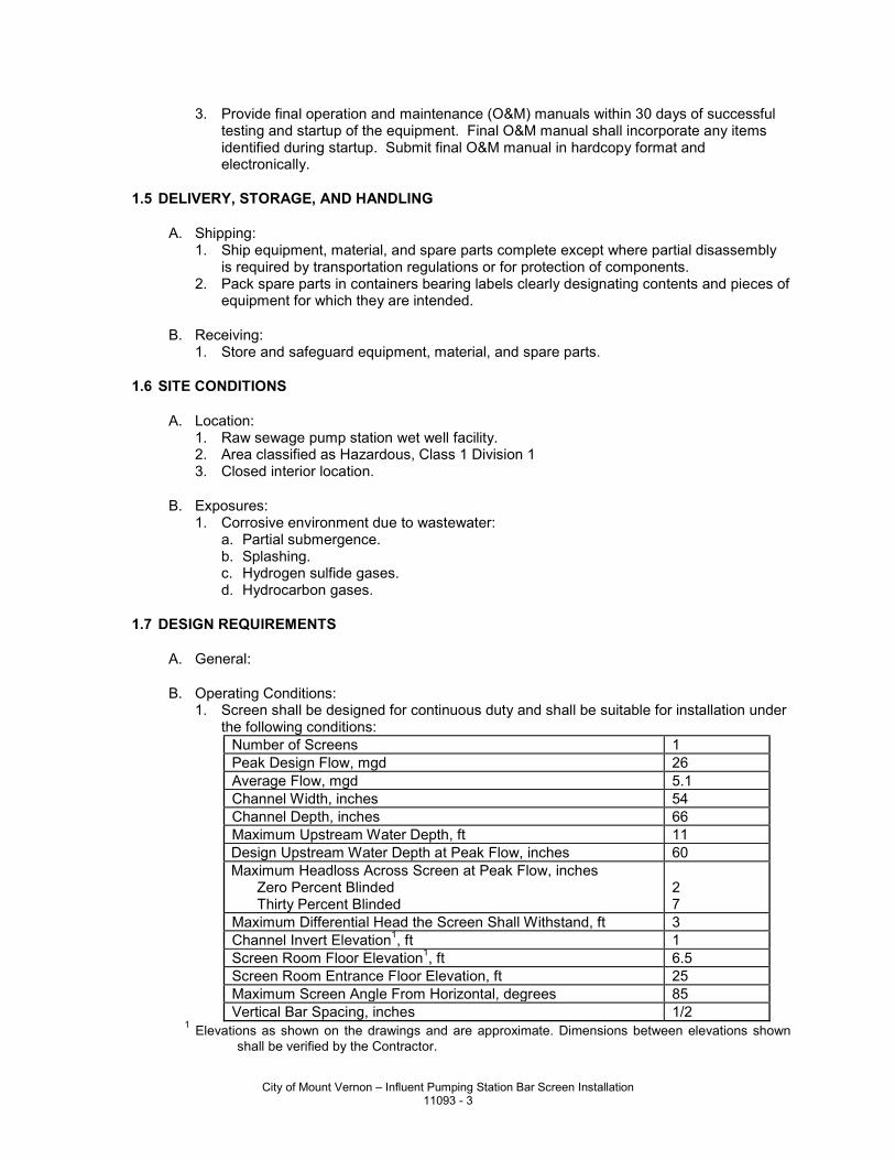
3. Provide final operation and maintenance (O&M) manuals within 30 days of successful testing and startup of the equipment. Final O&M manual shall incorporate any items identified during startup. Submit final O&M manual in hardcopy format and electronically.
1.5 DELIVERY, STORAGE, AND HANDLING
A. Shipping: 1. Ship equipment, material, and spare parts complete except where partial disassembly
is required by transportation regulations or for protection of components. 2. Pack spare parts in containers bearing labels clearly designating contents and pieces of
equipment for which they are intended.
B. Receiving: 1. Store and safeguard equipment, material, and spare parts.
1.6 SITE CONDITIONS
A. Location: 1. Raw sewage pump station wet well facility. 2. Area classified as Hazardous, Class 1 Division 1 3. Closed interior location.
B. Exposures: 1. Corrosive environment due to wastewater:
a. Partial submergence. b. Splashing. c. Hydrogen sulfide gases. d. Hydrocarbon gases.
1.7 DESIGN REQUIREMENTS
A. General:
B. Operating Conditions: 1. Screen shall be designed for continuous duty and shall be suitable for installation under
the following conditions: Number of Screens 1 Peak Design Flow, mgd 26 Average Flow, mgd 5.1 Channel Width, inches 54 Channel Depth, inches 66 Maximum Upstream Water Depth, ft 11 Design Upstream Water Depth at Peak Flow, inches 60 Maximum Headloss Across Screen at Peak Flow, inches
Zero Percent Blinded Thirty Percent Blinded
2 7
Maximum Differential Head the Screen Shall Withstand, ft 3 Channel Invert Elevation1, ft 1 Screen Room Floor Elevation1, ft 6.5 Screen Room Entrance Floor Elevation, ft 25 Maximum Screen Angle From Horizontal, degrees 85 Vertical Bar Spacing, inches 1/2
1 Elevations as shown on the drawings and are approximate. Dimensions between elevations shown shall be verified by the Contractor.
City of Mount Vernon – Influent Pumping Station Bar Screen Installation 11093 - 3
PART 2 - PRODUCTS
2.1 ACCEPTABLE MANUFACTURERS
A. The manufacturers listed have been determined to be capable of meeting this Specification.
B. Subject to compliance with the Contract Documents, the following manufacturers are acceptable: 1. Headworks, Inc. – Type MS1. 2. Huber Technology, Inc – RakeMax.
C. Manufacturer Experience: 1. The manufacturer shall have at least 50 screens of this design installed and operating
in the United States with the oldest having been in operation at least 10 years. 2. The manufacturer shall have at least 25 years experience manufacturing wastewater
treatment equipment. 3. The manufacturer shall have a proven record of providing service and support in the
maintenance of the screens provided. 4. The manufacturers listed above have been determined to comply with the experience
requirements listed herein.
D. No alternate manufacturers shall be accepted.
2.2 MATERIALS
A. Bar Screens and sluice: 1. Rake Bars: 316 stainless steel. 2. Roller Chains: 316 stainless steel. 3. Dead plate: 316 stainless steel. 4. Discharge Chute: 316 stainless steel. 5. Framework: 316 stainless steel. 6. Upper Bearing: 304 stainless steel, biodegradable grease lubricated. 7. Chain Guide: 316 stainless steel. 8. Lower Bushing: UHMWPE or silicon carbide. 9. Lower Stub Shaft: 304 stainless steel with bonded ceramic coating or white cast iron. 10. Drive Shafting: Solid 304 stainless steel. 11. Bar Rack: 316 stainless steel. 12. Fasteners: Type 304 stainless steel. 13. Enclosure: 304 stainless steel. 14. Torque Switches: Manufacturer’s standard 15. Screening Sluice and supports: Type 304 stainless steel.
B. Any welded stainless steel shall be L grade and passivated.
C. Unless otherwise specified or permitted, all items fabricated from stainless steel shall be thoroughly cleaned, degreased, and treated in a fully immersed pickling bath, to protect the stainless steel against corrosion. Pickling shall produce a modest etch and shall remove all embedded iron and heat tint. Pickled surfaces shall be subjected to a 24 HR water test or a ferroxyl test to detect the presence of residual embedded iron and shall be repickled as required to remove all traces of iron contamination. Pickled surfaces shall be adequately protected during shipping, handling, and installation to prevent contact with iron or steel objects or surfaces. Blast cleaning of stainless steel shall not be allowed except for glass bead blasting. The bead blast shall remove all weld discoloration and surface contaminants and provide for spontaneous passivation as recognized in ASTM A380-99. Stainless steel components shall be provided with an ASTM 480, No.1 finish.
City of Mount Vernon – Influent Pumping Station Bar Screen Installation 11093 - 4
D. Screen Sluice Flush Valve: 1. Acceptable manufacturers:
a. Apollo. b. Jamesbury. c. Watts. d. Stockham. e. Nibco.
2. Materials: a. Body: Bronze. b. Stem, stem gland nut: Brass. c. Ball: Brass, chrome plated. d. Seats, stuffing box ring, and thrust washer: Reinforced Teflon. e. Handle: Vinyl coated or zinc- or cadmium-plated steel
3. Design Requirements: a. Rated for 400 psi and 250 degrees F, WOG for threaded end applications. b. Handles showing direction of opening. c. Stuffing boxes capable of being repacked under pressure and adjustable for wear. d. Stem with reinforced Teflon stuffing box ring and blowout-proof design. e. Renewable reinforced Teflon seats. f. Ball design which does not allow media contact with stem. g. Balancing stop for all applications. h. Bodies with mounting pad for applications requiring actuators.
4. Motor Actuator: a. Rated for the environment. b. Suitable for the intended service.
2.3 ACCESSORIES
A. Controls: 1. Control Panel provided by screen manufacturer. 2. Drive Motor controlled via VFD and PLC.
a. Screen cleaning frequency minimum 10 seconds. 3. VFD shall have integral solid state overload protection. 4. Overload: Automatic reversal of direction for three tries. Fourth unsuccessful try at
blockage removal initiates alarm. 5. Over torque switch. 6. High motor temperature switches. 7. Screen manufacturer shall supply pressure transducer level sensors to initiate screen
operation based upon differential. 8. Provide a local control station located at the equipment, NEMA 7/9, to provide the
following functions: a. Control and indicators:
1) Remote/local switch. 2) Forward/Off/Reverse switch. 3) Emergency Stop pushbutton.
9. Manufacturer’s VFD and PLC are to be located in the Influent Pump Station Electrical Room, NEMA 12 minimum rating.
10. Automatic reverse to remove obstructions. 11. Torque switches as required for specified operation and for equipment overload
protection.
B. Control panel shall contain all power and control devices necessary for the proper function of the screen and shall include the following: 1. 600-Volt rated main circuit breaker disconnect with lockable handle. 2. 480 – 120 Volt control power transformer. 3. Reversible Screen VFD.
City of Mount Vernon – Influent Pumping Station Bar Screen Installation 11093 - 5
4. HAND-OFF-AUTO selector switch for the operation of the bar screen drive. 5. FORWARD-OFF-REVERSE selector switch for HAND operation:
a. Switch shall spring return from REVERSE to OFF. 6. Pilot light for “Screen Run” indication. 7. Amber pilot light for “Fault” indication. 8. White pilot light for “Control Power” indication. 9. Alarm silence and reset push buttons. 10. Push-to-Stop/Pull-to Run emergency stop maintained push button. 11. Dry contacts for remote indication of “Fault”, “Screen Running”, and “High Level”. 12. Control relays, wiring and circuitry required to implement the control logic. 13. Programmable controller (PLC) Micrologix 1400 minimum or equal. 14. Operator interface Allen Bradley PanelView C400 or equal to provide following:
a. Alarm History b. Motor Hour Meter c. Operator access to user adjustable setpoints d. Running Status e. Motor Runtime per week f. VFD Fault Status g. VFD/Motor Amps h. VFD/Motor Volts i. VFD/Motor Horsepower j. Operator Graphic Display with controls and indication k. Trend Display of Upstream Level, Downstream Level, and Differential Level l. Status of HI-HI Level Switch (LSHH). m. Status of Position and Torque Switches n. Control and Indication of the wash-down valve. o. Status of E-Stop
15. When LSHH has been engaged, screen shall operate at high speed for an adjustable duration, 0-600 seconds, after the alarm has cleared.
2.4 FABRICATION
A. General: 1. Provide assembly consisting of:
a. Bar rack and deadplate. b. Scraper Blade and Discharge Chute. c. Side Frame. d. Traveling rake assembly including rake bars, roller chains, guides, bearings, and
sprockets. e. Drive unit.
2. Design mechanism to automatically remove solids from the bar screen and deposit them onto the sluice as shown on the Drawings.
3. Design so that maintenance to the mechanism can be accomplished at operating floor level.
4. Assure mechanism is capable of automatic reverse operation for removal of oversized objects.
5. Factory assemble unit prior to shipment.
B. Bar Rack and Deadplate: 1. Fasten bars top and bottom. Bars shall be replaceable without welding. 2. Round bars shall not be used. 3. Extend bar rack from channel bottom to 8 IN minimum above maximum depth of water
in channel. 4. Provide 5/32 IN minimum thick dead plate continuous from top of bar rack to point of
discharge. 5. Provide 10 GA apron from discharge point to 6 IN above centerline of sluice.
City of Mount Vernon – Influent Pumping Station Bar Screen Installation 11093 - 6
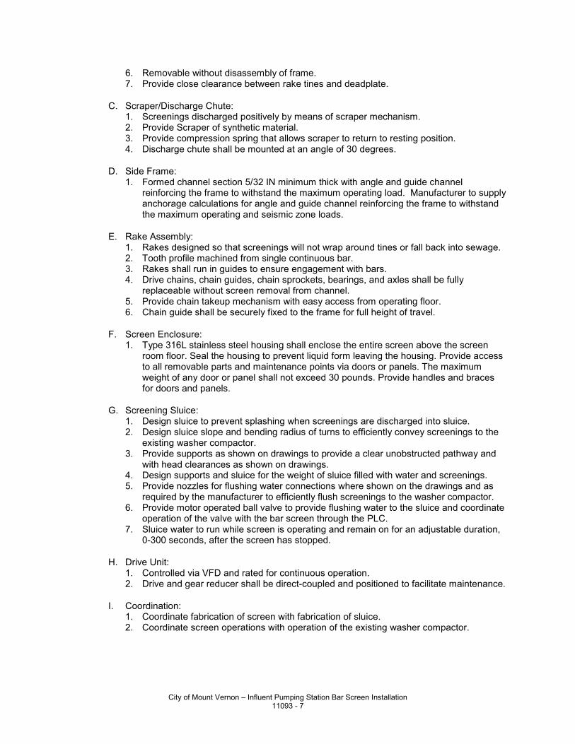
6. Removable without disassembly of frame. 7. Provide close clearance between rake tines and deadplate.
C. Scraper/Discharge Chute: 1. Screenings discharged positively by means of scraper mechanism. 2. Provide Scraper of synthetic material. 3. Provide compression spring that allows scraper to return to resting position. 4. Discharge chute shall be mounted at an angle of 30 degrees.
D. Side Frame: 1. Formed channel section 5/32 IN minimum thick with angle and guide channel
reinforcing the frame to withstand the maximum operating load. Manufacturer to supply anchorage calculations for angle and guide channel reinforcing the frame to withstand the maximum operating and seismic zone loads.
E. Rake Assembly: 1. Rakes designed so that screenings will not wrap around tines or fall back into sewage. 2. Tooth profile machined from single continuous bar. 3. Rakes shall run in guides to ensure engagement with bars. 4. Drive chains, chain guides, chain sprockets, bearings, and axles shall be fully
replaceable without screen removal from channel. 5. Provide chain takeup mechanism with easy access from operating floor. 6. Chain guide shall be securely fixed to the frame for full height of travel.
F. Screen Enclosure: 1. Type 316L stainless steel housing shall enclose the entire screen above the screen
room floor. Seal the housing to prevent liquid form leaving the housing. Provide access to all removable parts and maintenance points via doors or panels. The maximum weight of any door or panel shall not exceed 30 pounds. Provide handles and braces for doors and panels.
G. Screening Sluice: 1. Design sluice to prevent splashing when screenings are discharged into sluice. 2. Design sluice slope and bending radius of turns to efficiently convey screenings to the
existing washer compactor. 3. Provide supports as shown on drawings to provide a clear unobstructed pathway and
with head clearances as shown on drawings. 4. Design supports and sluice for the weight of sluice filled with water and screenings. 5. Provide nozzles for flushing water connections where shown on the drawings and as
required by the manufacturer to efficiently flush screenings to the washer compactor. 6. Provide motor operated ball valve to provide flushing water to the sluice and coordinate
operation of the valve with the bar screen through the PLC. 7. Sluice water to run while screen is operating and remain on for an adjustable duration,
0-300 seconds, after the screen has stopped.
H. Drive Unit: 1. Controlled via VFD and rated for continuous operation. 2. Drive and gear reducer shall be direct-coupled and positioned to facilitate maintenance.
I. Coordination: 1. Coordinate fabrication of screen with fabrication of sluice. 2. Coordinate screen operations with operation of the existing washer compactor.
City of Mount Vernon – Influent Pumping Station Bar Screen Installation 11093 - 7
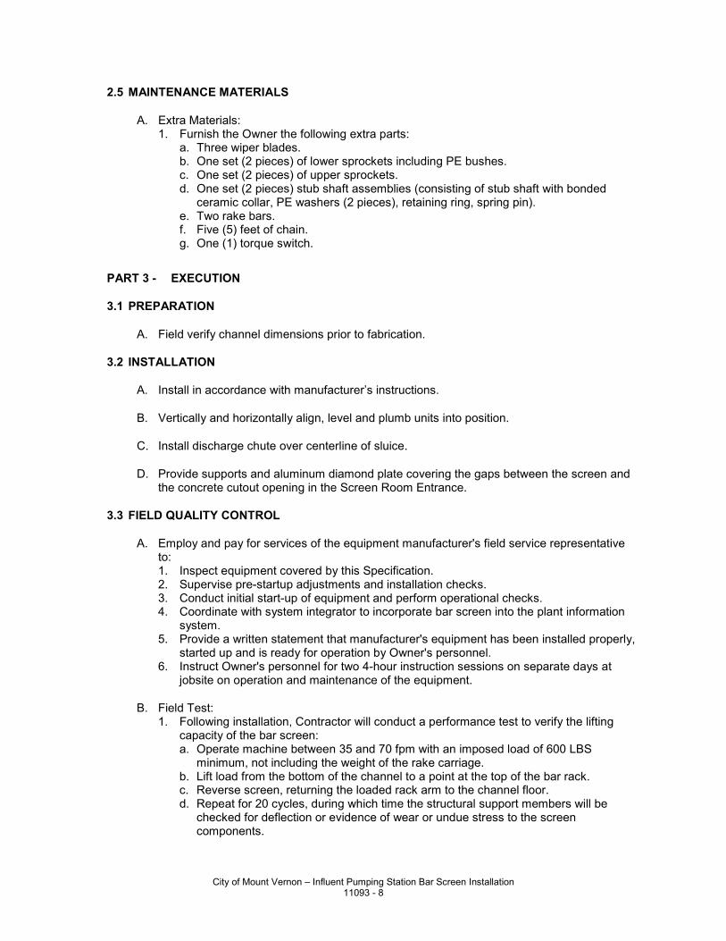
2.5 MAINTENANCE MATERIALS
A. Extra Materials: 1. Furnish the Owner the following extra parts:
a. Three wiper blades. b. One set (2 pieces) of lower sprockets including PE bushes. c. One set (2 pieces) of upper sprockets. d. One set (2 pieces) stub shaft assemblies (consisting of stub shaft with bonded
ceramic collar, PE washers (2 pieces), retaining ring, spring pin). e. Two rake bars. f. Five (5) feet of chain. g. One (1) torque switch.
PART 3 - EXECUTION
3.1 PREPARATION
A. Field verify channel dimensions prior to fabrication.
3.2 INSTALLATION
A. Install in accordance with manufacturer’s instructions.
B. Vertically and horizontally align, level and plumb units into position.
C. Install discharge chute over centerline of sluice.
D. Provide supports and aluminum diamond plate covering the gaps between the screen and the concrete cutout opening in the Screen Room Entrance.
3.3 FIELD QUALITY CONTROL
A. Employ and pay for services of the equipment manufacturer's field service representative to: 1. Inspect equipment covered by this Specification. 2. Supervise pre-startup adjustments and installation checks. 3. Conduct initial start-up of equipment and perform operational checks. 4. Coordinate with system integrator to incorporate bar screen into the plant information
system. 5. Provide a written statement that manufacturer's equipment has been installed properly,
started up and is ready for operation by Owner's personnel. 6. Instruct Owner's personnel for two 4-hour instruction sessions on separate days at
jobsite on operation and maintenance of the equipment.
B. Field Test: 1. Following installation, Contractor will conduct a performance test to verify the lifting
capacity of the bar screen: a. Operate machine between 35 and 70 fpm with an imposed load of 600 LBS
minimum, not including the weight of the rake carriage. b. Lift load from the bottom of the channel to a point at the top of the bar rack. c. Reverse screen, returning the loaded rack arm to the channel floor. d. Repeat for 20 cycles, during which time the structural support members will be
checked for deflection or evidence of wear or undue stress to the screen components.
City of Mount Vernon – Influent Pumping Station Bar Screen Installation 11093 - 8
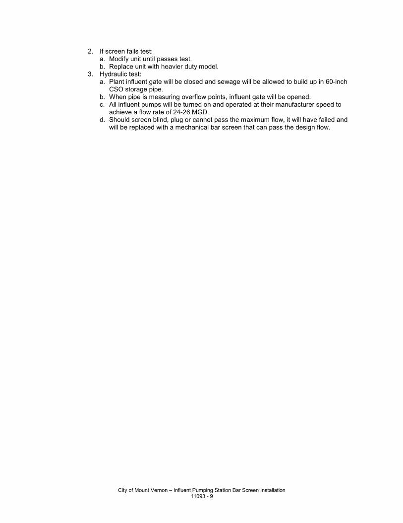
2. If screen fails test: a. Modify unit until passes test. b. Replace unit with heavier duty model.
3. Hydraulic test: a. Plant influent gate will be closed and sewage will be allowed to build up in 60-inch
CSO storage pipe. b. When pipe is measuring overflow points, influent gate will be opened. c. All influent pumps will be turned on and operated at their manufacturer speed to
achieve a flow rate of 24-26 MGD. d. Should screen blind, plug or cannot pass the maximum flow, it will have failed and
will be replaced with a mechanical bar screen that can pass the design flow.
City of Mount Vernon – Influent Pumping Station Bar Screen Installation 11093 - 9

This page left intentionally blank.
City of Mount Vernon – Influent Pumping Station Bar Screen Installation 11093 - 10
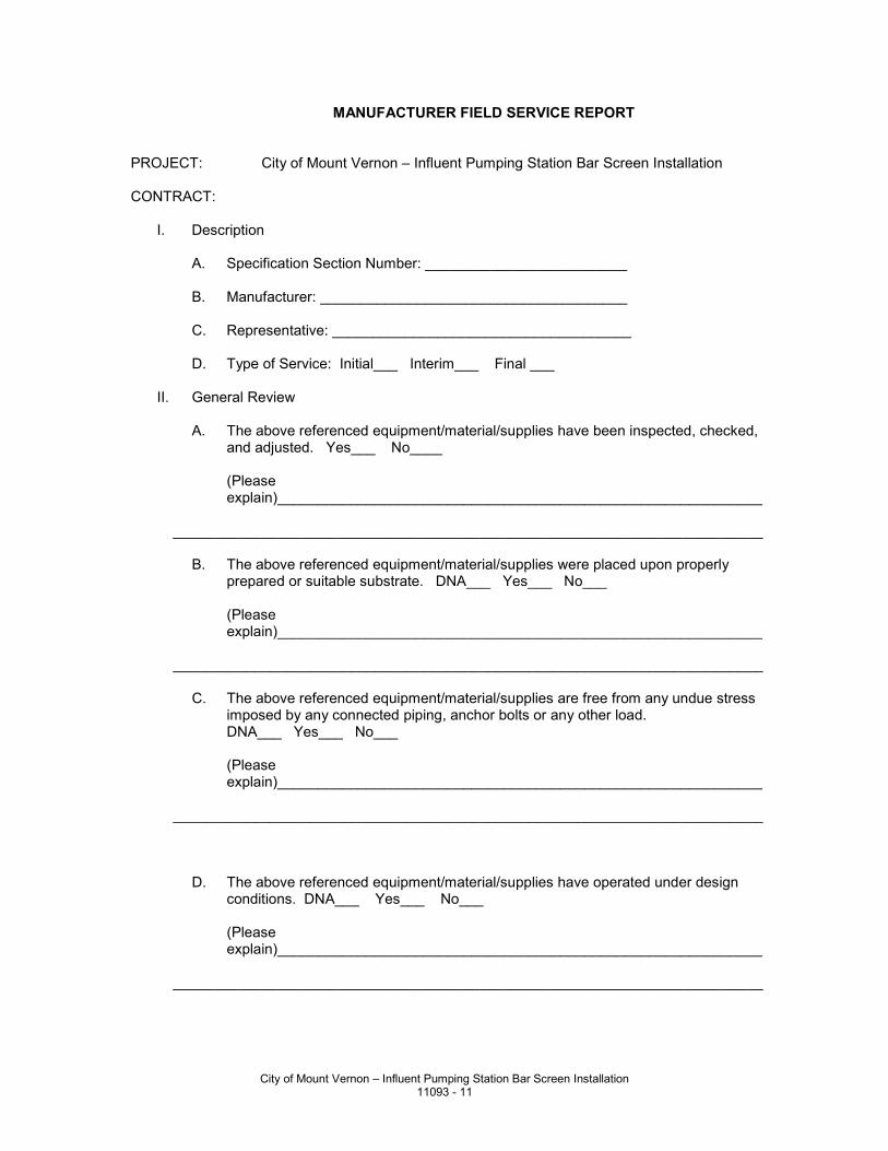
MANUFACTURER FIELD SERVICE REPORT PROJECT: City of Mount Vernon – Influent Pumping Station Bar Screen Installation CONTRACT: I. Description A. Specification Section Number: _________________________ B. Manufacturer: ______________________________________ C. Representative: _____________________________________ D. Type of Service: Initial___ Interim___ Final ___ II. General Review A. The above referenced equipment/material/supplies have been inspected, checked,
and adjusted. Yes___ No____ (Please
explain)____________________________________________________________ _________________________________________________________________________ B. The above referenced equipment/material/supplies were placed upon properly
prepared or suitable substrate. DNA___ Yes___ No___ (Please
explain)____________________________________________________________ _________________________________________________________________________ C. The above referenced equipment/material/supplies are free from any undue stress
imposed by any connected piping, anchor bolts or any other load. DNA___ Yes___ No___ (Please
explain)____________________________________________________________ _________________________________________________________________________ D. The above referenced equipment/material/supplies have operated under design
conditions. DNA___ Yes___ No___ (Please
explain)____________________________________________________________ _________________________________________________________________________
City of Mount Vernon – Influent Pumping Station Bar Screen Installation 11093 - 11
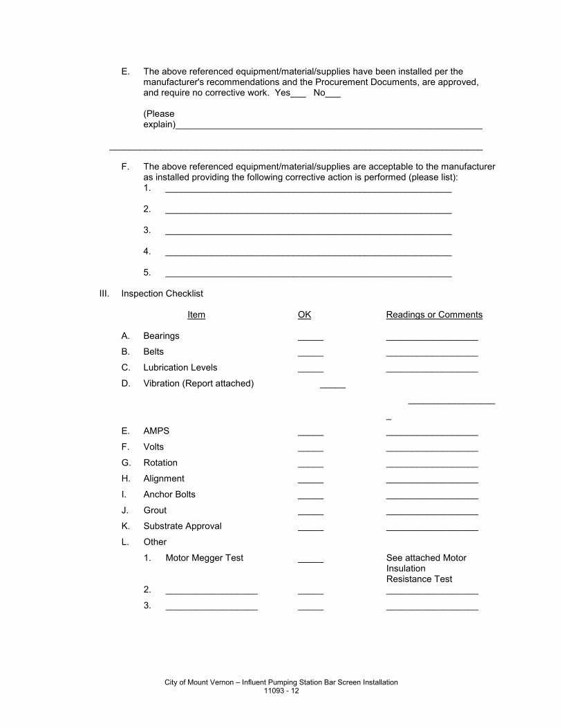
E. The above referenced equipment/material/supplies have been installed per the manufacturer's recommendations and the Procurement Documents, are approved, and require no corrective work. Yes___ No___
(Please
explain)____________________________________________________________ _________________________________________________________________________ F. The above referenced equipment/material/supplies are acceptable to the manufacturer
as installed providing the following corrective action is performed (please list): 1. ________________________________________________________ 2. ________________________________________________________ 3. ________________________________________________________ 4. ________________________________________________________ 5. ________________________________________________________ III. Inspection Checklist Item OK Readings or Comments A. Bearings _____ __________________
B. Belts _____ __________________
C. Lubrication Levels _____ __________________
D. Vibration (Report attached) _____
_________________
_
E. AMPS _____ __________________
F. Volts _____ __________________
G. Rotation _____ __________________
H. Alignment _____ __________________
I. Anchor Bolts _____ __________________
J. Grout _____ __________________
K. Substrate Approval _____ __________________
L. Other
1. Motor Megger Test _____ See attached Motor Insulation
Resistance Test 2. __________________ _____ __________________
3. __________________ _____ __________________
City of Mount Vernon – Influent Pumping Station Bar Screen Installation 11093 - 12
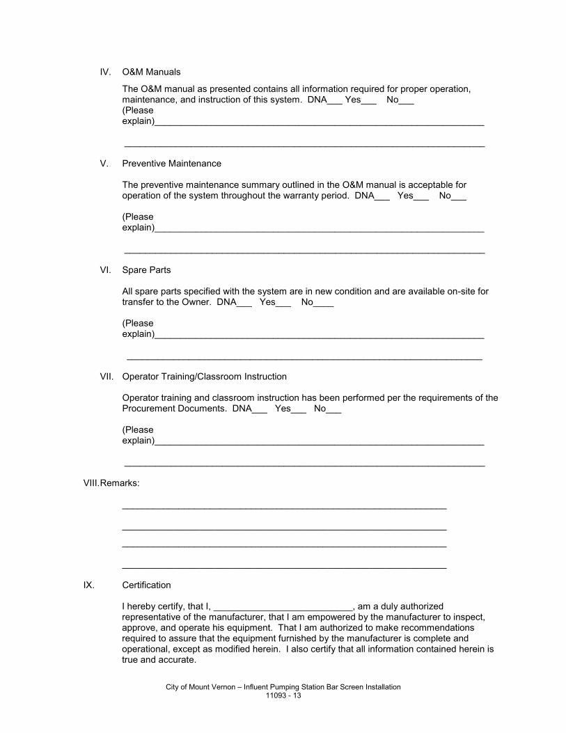
IV. O&M Manuals
The O&M manual as presented contains all information required for proper operation, maintenance, and instruction of this system. DNA___ Yes___ No___
(Please explain)________________________________________________________________
______________________________________________________________________ V. Preventive Maintenance The preventive maintenance summary outlined in the O&M manual is acceptable for
operation of the system throughout the warranty period. DNA___ Yes___ No___ (Please
explain)________________________________________________________________ ______________________________________________________________________ VI. Spare Parts All spare parts specified with the system are in new condition and are available on-site for
transfer to the Owner. DNA___ Yes___ No____ (Please
explain)________________________________________________________________ _____________________________________________________________________ VII. Operator Training/Classroom Instruction Operator training and classroom instruction has been performed per the requirements of the
Procurement Documents. DNA___ Yes___ No___ (Please
explain)________________________________________________________________ ______________________________________________________________________ VIII. Remarks: _______________________________________________________________ _______________________________________________________________
_______________________________________________________________ _______________________________________________________________ IX. Certification I hereby certify, that I, ___________________________, am a duly authorized
representative of the manufacturer, that I am empowered by the manufacturer to inspect, approve, and operate his equipment. That I am authorized to make recommendations required to assure that the equipment furnished by the manufacturer is complete and operational, except as modified herein. I also certify that all information contained herein is true and accurate.
City of Mount Vernon – Influent Pumping Station Bar Screen Installation 11093 - 13
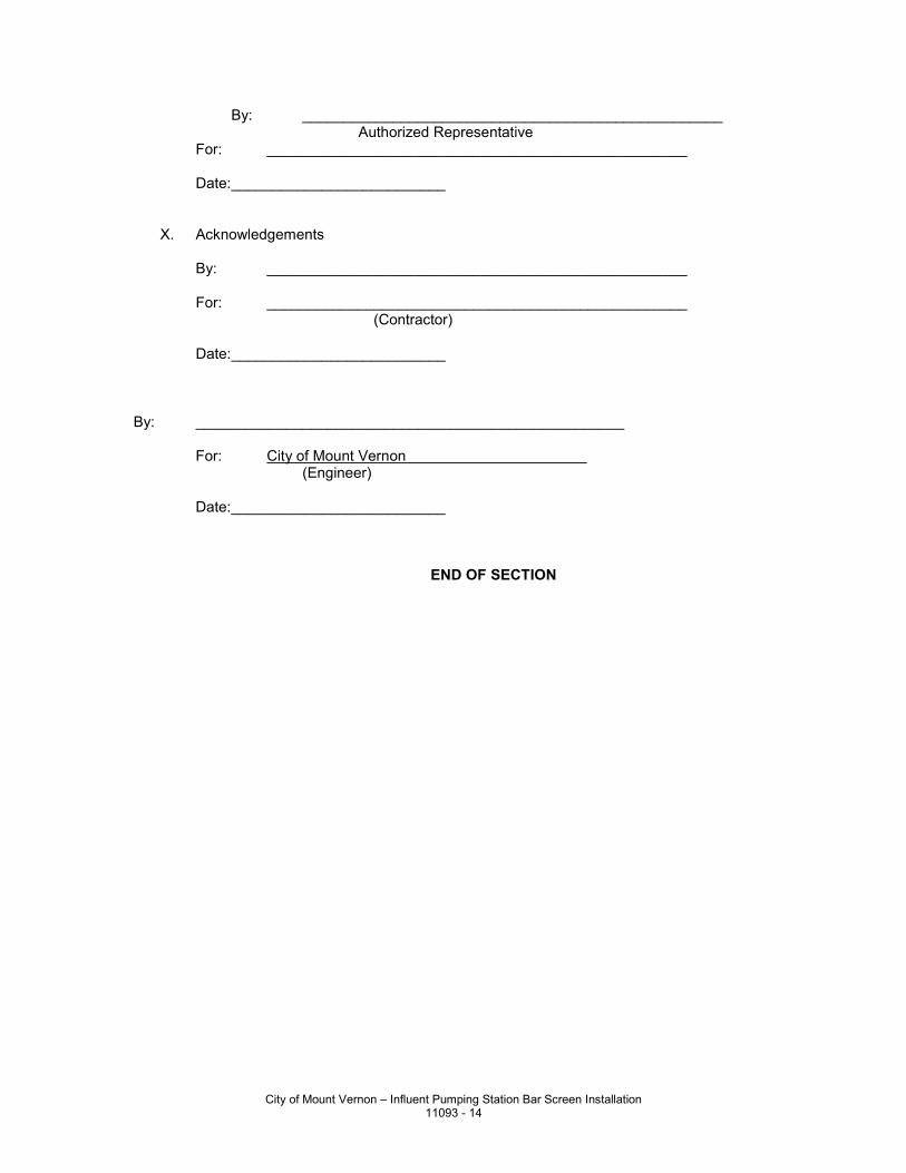
By: ___________________________________________________ Authorized Representative For: ___________________________________________________ Date: __________________________ X. Acknowledgements By: ___________________________________________________ For: ___________________________________________________ (Contractor) Date: __________________________ By: ____________________________________________________ For: City of Mount Vernon
(Engineer) Date: __________________________ END OF SECTION
City of Mount Vernon – Influent Pumping Station Bar Screen Installation 11093 - 14
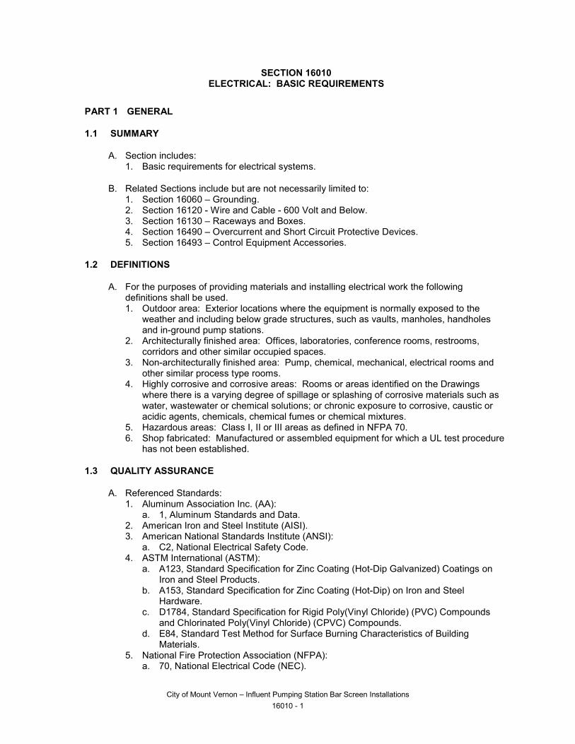
SECTION 16010 ELECTRICAL: BASIC REQUIREMENTS
PART 1 GENERAL
1.1 SUMMARY
A. Section includes: 1. Basic requirements for electrical systems.
B. Related Sections include but are not necessarily limited to: 1. Section 16060 – Grounding. 2. Section 16120 - Wire and Cable - 600 Volt and Below. 3. Section 16130 – Raceways and Boxes. 4. Section 16490 – Overcurrent and Short Circuit Protective Devices. 5. Section 16493 – Control Equipment Accessories.
1.2 DEFINITIONS
A. For the purposes of providing materials and installing electrical work the following definitions shall be used. 1. Outdoor area: Exterior locations where the equipment is normally exposed to the
weather and including below grade structures, such as vaults, manholes, handholes and in-ground pump stations.
2. Architecturally finished area: Offices, laboratories, conference rooms, restrooms, corridors and other similar occupied spaces.
3. Non-architecturally finished area: Pump, chemical, mechanical, electrical rooms and other similar process type rooms.
4. Highly corrosive and corrosive areas: Rooms or areas identified on the Drawings where there is a varying degree of spillage or splashing of corrosive materials such as water, wastewater or chemical solutions; or chronic exposure to corrosive, caustic or acidic agents, chemicals, chemical fumes or chemical mixtures.
5. Hazardous areas: Class I, II or III areas as defined in NFPA 70. 6. Shop fabricated: Manufactured or assembled equipment for which a UL test procedure
has not been established.
1.3 QUALITY ASSURANCE
A. Referenced Standards: 1. Aluminum Association Inc. (AA):
a. 1, Aluminum Standards and Data. 2. American Iron and Steel Institute (AISI). 3. American National Standards Institute (ANSI):
a. C2, National Electrical Safety Code. 4. ASTM International (ASTM):
a. A123, Standard Specification for Zinc Coating (Hot-Dip Galvanized) Coatings on Iron and Steel Products.
b. A153, Standard Specification for Zinc Coating (Hot-Dip) on Iron and Steel Hardware.
c. D1784, Standard Specification for Rigid Poly(Vinyl Chloride) (PVC) Compounds and Chlorinated Poly(Vinyl Chloride) (CPVC) Compounds.
d. E84, Standard Test Method for Surface Burning Characteristics of Building Materials.
5. National Fire Protection Association (NFPA): a. 70, National Electrical Code (NEC).
City of Mount Vernon – Influent Pumping Station Bar Screen Installations 16010 - 1
B. Where Underwriters Laboratories, Inc. (UL) test procedures have been established for the product type, use UL or ETL Testing Laboratories (ETL) approved electrical equipment and provide with the UL or ETL label.
1.4 SUBMITTALS
A. Shop Drawings: 1. See Section 01010Non-equipment requirements:
a. Provide manufacturer's technical information on products to be used, including product descriptive bulletin.
b. Include data sheets that include manufacturer's name and product model number. Clearly identify all optional accessories.
c. Acknowledgement that products are UL or ETL listed or are constructed utilizing UL or ETL recognized components.
d. Manufacturer's delivery, storage, handling and installation instructions. e. Product installation details. f. See individual Specification Sections for any additional requirements.
2. Cable and conductor numbering system (consistent with City’s existing numbering scheme, no exceptions).
3. Interconnection diagrams: a. Prepare interconnection diagrams indicating wiring between panels, terminal boxes,
remotely mounted devices, and motor control centers. b. Interface the diagrams with the manufacturer's internal connection diagrams for
panels. c. Indicate the terminations to terminal blocks of field devices at each end of the cable,
the number of conductors in the cable, the size of wire, and the number of spare conductors.
d. Indicate for each termination the terminal number, wire color, and wire number as it appears on the wire marker.
e. Indicate all terminal blocks, including spares. f. Submit interconnection diagrams for approval.
B. When a Specification Section includes products specified in another Specification Section, each section shall have the required Shop Drawing transmittal form and all sections shall be submitted simultaneously.
1.5 SYSTEM DESCRIPTION
A. Provide functioning systems in compliance with National Electric Code (NEC), manufacturer's instruction, performance requirements specified or shown in the Contract Documents, and modifications resulting from reviewed shop drawings and field coordinated drawings.
B. Provide complete 120/208, 120/240 and 480 volt power distribution systems including raceways, wiring, and power supply to all equipment shown: 1. Includes design of required raceways and wiring where only the electrical device is in
the Contract Documents.
1.6 DELIVERY, STORAGE, AND HANDLING
A. Store in accordance with manufacturer’s requirements.
B. Protect nameplates on electrical equipment to prevent defacing.
City of Mount Vernon – Influent Pumping Station Bar Screen Installations 16010 - 2
1.7 AREA DESIGNATIONS
A. Designation of an area will determine the NEMA rating of the electrical equipment enclosures, types of conduits and installation methods to be used in that area. 1. Outdoor areas: Wet. Also, corrosive and/or hazardous when specifically designated on
the Drawings or in the Specifications. 2. Indoor areas: Dry. Also, wet, corrosive and/or hazardous when specifically designated
on the Drawings or in the Specifications.
PART 2 PRODUCTS
2.1 ACCEPTABLE MANUFACTURERS
A. Refer to specific Division 16 sections and specific material paragraphs below.
B. Provide all components of a similar type by one manufacturer.
2.2 MATERIALS
A. Electrical Equipment Support Pedestals and Racks: 1. Approved manufacturers:
a. Modular strut: 1) Unistrut Building Systems. 2) B-Line. 3) Globe Strut. 4) Or equal.
2. Material requirements: a. Modular strut:
1) Galvanized steel: ASTM A123 or ASTM A153. 2) Stainless steel: AISI Type 316. 3) PVC coat galvanized steel: ASTM A123 or ASTM A153 and 20 mil PVC
coating. b. Structural members:
1) Galvanized steel: ASTM A123. 2) Aluminum: AA Type 6063-T6.
c. Mounting plates: 1) Galvanized steel: ASTM A123. 2) Aluminum: AA Type 6063-T6.
d. Mounting hardware: 1) Galvanized steel. 2) Stainless steel.
e. Anchorage per manufacturer’s specifications.
PART 3 EXECUTION
3.1 INSTALLATION
A. Install and wire all equipment, including prepurchased equipment, and perform all tests necessary to assure conformance to the Drawings and Specifications and ensure that equipment is ready and safe for energization.
B. Install equipment in accordance with the requirements of: 1. NFPA 70 (NEC). 2. ANSI C2.
City of Mount Vernon – Influent Pumping Station Bar Screen Installations 16010 - 3
3. The manufacturer's instructions.
C. In general, conduit routing is not shown on the Drawings. The Contractor is responsible for routing all conduits including those shown on one-line and control diagrams and home runs shown on floor plans. Conduit routings and stub-up locations that are shown are approximate, exact routing to be, as required, for equipment furnished and field conditions.
D. When branch circuiting is not shown on the Drawings, the Contractor is to furnish and install all conduit and conductors required. The indicated home run conduit and conductor size shall be used for the entire branch circuit. See Section 16120 for combining multiple branch circuits.
E. Do not use equipment that exceed dimensions or reduce clearances indicated on the Drawings or as required by the NFPA 70.
F. Install equipment plumbed, square and true with construction features and securely fastened.
G. Install electrical equipment, including pull and junction boxes, minimum of 6 IN from process, gas, air and water piping and equipment.
H. Install equipment so it is readily accessible for operation and maintenance, is not blocked or concealed and does not interfere with normal operating and maintenance requirements of other equipment.
I. Device Mounting Schedule: 1. Mounting heights as indicated below:
a. Pushbutton or selector switch control station (to center): 48 IN. b. Panelboard (to top): 72 IN.
J. Avoid interference of electrical equipment operation and maintenance with structural members, building features and equipment of other trades. When it is necessary to adjust the intended location of electrical equipment, unless specifically dimensioned or detailed, the Contractor may make adjustments of up to 3 IN in equipment location without Engineer's approval. 1. Changes in equipment location exceeding those defined above require the Engineer's
approval.
K. Provide all necessary anchoring devices and supports rated for the equipment load based on dimensions and weights verified from approved submittals, or as recommended by the manufacturer. 1. Do not cut, or weld to, building structural members. 2. Do not mount safety switches or other equipment to equipment enclosures, unless
enclosure mounting surface is properly braced to accept mounting of external equipment.
L. Provide corrosion resistant spacers to maintain 1/4 IN separation between equipment and mounting surface in wet areas, on below grade walls and on walls of liquid containment or processing areas such as Clarifiers, Digesters, Reservoirs, etc.
M. Do not place equipment fabricated from aluminum in direct contact with earth or concrete.
N. Screen or seal all openings into equipment mounted outdoors to prevent the entrance of rodents and insects.
City of Mount Vernon – Influent Pumping Station Bar Screen Installations 16010 - 4
O. Do not use materials that may cause the walls or roof of a building to discolor or rust.
P. Identify electrical equipment and components in accordance with existing City naming convention.
3.2 FIELD QUALITY CONTROL
A. Verify exact rough-in location and dimensions for connection to electrified equipment, provided by others.
B. Replace equipment and systems found inoperative or defective and re-test.
C. Apply touch-up paint as required to repair scratches and other marks.
D. Replace nameplates damaged during installation.
3.3 DEMONSTRATION
A. Demonstrate equipment in accordance with Section 01010.
END OF SECTION
City of Mount Vernon – Influent Pumping Station Bar Screen Installations 16010 - 5

This page left intentionally blank.
City of Mount Vernon – Influent Pumping Station Bar Screen Installations 16010 - 6
..
SECTION 16060 GROUNDING
PART 1 GENERAL
1.1 SUMMARY
A. Section includes: 1. Material and installation requirements for grounding system(s).
B. Related Sections include but are not necessarily limited to: 1. Section 16010 - Electrical: Basic Requirements. 2. Section 16120 - Wire and Cable - 600 Volt and Below. 3. Section 16130 - Raceways and Boxes.
1.2 QUALITY ASSURANCE
A. Referenced Standards: 1. American Association of State Highway and Transportation Officials (AASHTO):
a. Standard Specification for Highway Bridges. 2. ASTM International (ASTM):
a. B8, Standard Specification for Concentric-Lay-Stranded Copper Conductors, Hard, Medium-Hard, or Soft.
3. Institute of Electrical and Electronics Engineers (IEEE): a. 837, Qualifying Permanent Connections Used in Substation Grounding.
4. National Fire Protection Association (NFPA): a. 70, National Electrical Code (NEC).
5. Underwriters Laboratories, Inc. (UL): a. 467, Electrical Grounding and Bonding Equipment.
B. Assure ground continuity is continuous throughout the entire Project.
1.3 SUBMITTALS
A. Shop Drawings: 1. See Section 16010. 2. Fabrication and/or layout drawings:
a. Plan drawing(s) showing type, size and locations of all grounding system components.
B. Miscellaneous: 1. Grounding system resistance and continuity test reports signed by the Project's
supervising electrical foreman.
PART 2 PRODUCTS
2.1 ACCEPTABLE MANUFACTURERS
A. Subject to compliance with the Contract Documents, the following manufacturers are acceptable: 1. Ground rods and bars and grounding clamps, connectors and terminals:
a. Burndy. b. Harger Lightning Protection. c. Heary Brothers.
City of Mount Vernon – Influent Pumping Station Bar Screen Installations 16060 - 1
..
d. Joslyn. e. Robbins Lightning Protection. f. Thompson. g. Or equal.
2. Exothermic weld connections: a. Erico Products Inc., Cadweld. b. Harger Lightning Protection. c. Thermoweld. d. Or equal.
2.2 COMPONENTS
A. Wire and Cable: 1. Bare conductors: Soft drawn stranded copper meeting ASTM B8. 2. Insulated conductors: Color coded green, per Section 16120.
B. Conduit: As specified in Section 16130.
C. Ground Bars: 1. Solid copper:
a. 1/4 IN thick. b. 4 IN wide. c. 24 IN long minimum in main service entrance electrical rooms.
2. Predrilled grounding lug mounting holes. 3. Stainless steel or galvanized steel mounting brackets. 4. Insulated standoffs.
D. Ground Rods: 1. 3/4 IN x 10 FT. 2. Copperclad:
a. Heavy uniform coating of electrolytic copper molecularly bonded to a rigid steel core.
b. Corrosion resistant bond between the copper and steel. c. Hard drawn for a scar-resistant surface.
E. Grounding Clamps, Connectors and Terminals: 1. Mechanical type:
a. Standards: UL 467. b. High copper alloy content.
2. Compression type for interior locations: a. Standards: UL 467. b. High copper alloy content. c. Non-reversible. d. Terminals for connection to bus bars shall have two bolt holes.
3. Compression type suitable for direct burial in earth or concrete: a. Standards: UL 467, IEEE 837. b. High copper alloy content. c. Non-reversible.
F. Exothermic Weld Connections: 1. Copper oxide reduction by aluminum process. 2. Molds properly sized for each application.
PART 3 EXECUTION
City of Mount Vernon – Influent Pumping Station Bar Screen Installations 16060 - 2
..
3.1 INSTALLATION
A. General: 1. Install products in accordance with manufacturer's instructions. 2. Size grounding conductors and bonding jumpers in accordance with NFPA 70 Article
250, except where larger sizes are specified or indicated on the Drawings. 3. Remove paint, rust, or other nonconducting material from contact surfaces before
making ground connections. 4. Do not splice grounding conductors except at ground bus bar. 5. Install ground rods and grounding conductors in undisturbed, firm soil.
a. Provide excavation required for installation of ground rods and ground conductors. b. Use driving studs or other suitable means to prevent damage to threaded ends of
sectional rods. c. Unless otherwise specified, connect conductors to ground rods with compressor
type connectors or exothermic weld. d. Provide sufficient slack in grounding conductor to prevent conductor breakage
during backfill or due to ground movement. e. Backfill excavation completely, thoroughly tamping to provide good contact between
backfill materials and ground rods and conductors. 6. Do not use exothermic welding if it will damage the structure the grounding conductor is
being welded to.
B. Other Bonding Requirements: 1. Other metal piping: Connect in a daisy chain or radial fashion: interior hot and cold
water piping system, process piping, fire sprinkler system service water pipe to the building ground bus or as indicated on the Drawings.
2. Provide bonding as required by the Local Inspection Authority.
C. Raceway Grounding: 1. All metallic conduit shall be installed so that it is electrically continuous. 2. All conduits to contain a grounding conductor with insulation identical to the phase
conductors, unless otherwise indicated on the Drawings. 3. Provide grounding-type insulating bushings:
a. For all equipment not supplied with a conduit hub. b. On ends of metallic ductbank conduit.
4. Provide double locknuts at all panels. 5. Bond all conduit, at entrance and exit of equipment, to the equipment ground bus or lug. 6. Provide bonding jumpers if conduits are installed in concentric knockouts. 7. Make all metallic raceway fittings and grounding clamps tight to ensure equipment
grounding system will operate continuously at ground potential to provide low impedance current path for proper operation of overcurrent devices during possible ground fault conditions.
D. Equipment Grounding: 1. Ground all equipment supplied from electrical gear through the gear's equipment
ground bus. Provide an equipment grounding conductor connected to the ground bus and equipment ground lug.
2. Use generator manufacturer's provisions for grounding electric generators, or manufacturer's written instructions, except as shown on the Contract Drawings.
City of Mount Vernon – Influent Pumping Station Bar Screen Installations 16060 - 3
..
3.2 FIELD QUALITY CONTROL
A. Leave grounding system uncovered until observed by Owner.
B. Provide a continuity test on the components of the grounding electrode system.
C. Complete grounding system: Resistance of 5 ohms or less.
D. Test resistance of installed ground system after backfilling and before connection to any other grounded system including underground piping, utility services or other building ground systems. 1. Test ground grid resistance by fall-of-potential method. 2. Perform test at each ground bar.
END OF SECTION
City of Mount Vernon – Influent Pumping Station Bar Screen Installations 16060 - 4
..
SECTION 16120 WIRE AND CABLE - 600 VOLT AND BELOW
PART 1 GENERAL
1.1 SUMMARY
A. Section includes: 1. Material and installation requirements for:
a. Building wire. b. Power control. c. Control cable. d. Shielded VFD cable. e. Instrumentation cable. f. Fiber optic cable. g. Wire connectors. h. Insulating tape. i. Pulling lubricant.
B. Related Sections include but are not necessarily limited to: 1. Section 16010 - Electrical: Basic Requirements.
1.2 QUALITY ASSURANCE
A. Referenced Standards: 1. Insulated Cable Engineers Association:
a. S-58-679, Control Cable Conductor Identification. 2. National Electrical Manufacturers Association (NEMA):
a. ICS 4, Terminal Blocks for Industrial Use. 3. National Electrical Manufacturers Association/Insulated Cable Engineers Association
(NEMA/ICEA): a. WC 57/ICEA S-73-532, Standard for Control Cables. b. WC 70/ICEA S-95-658, Standard for Nonshielded Power Cables Rated 2000 Volts
or Less for the Distribution of Electrical Energy. 4. National Fire Protection Association (NFPA):
a. 70, National Electrical Code (NEC). 5. Underwriters Laboratories, Inc. (UL):
a. 44, Thermoset-Insulated Wires and Cables. b. 83, Thermoplastic-Insulated Wires and Cables. c. 467, Grounding and Bonding Equipment. d. 486A, Wire Connectors and Soldering Lugs for use with Copper Conductors. e. 486C, Splicing Wire Connections. f. 510, Polyvinyl Chloride, Polyethylene and Rubber Insulating Tape. g. 1277, Electrical Power and Control Tray Cables with Optional Optical-Fiber
Members. h. 1581, Reference Standard for Electrical Wires, Cables, and Flexible Cords. i. 2250, Instrumentation Tray Cable.
1.3 DEFINITIONS
A. Cable: Multi-conductor, insulated, with outer sheath containing either building wire or instrumentation wire.
B. Instrumentation Cable: 1. Multiple conductor, insulated, twisted or untwisted, with outer sheath.
City of Mount Vernon – Influent Pumping Station Bar Screen Installations 16120 - 1
..
2. The following are specific types of instrumentation cables: a. Analog signal cable:
1) Used for the transmission of low current (e.g., 4-20mA DC) or low voltage (e.g., 0-10 Vdc) signals, using No. 16 AWG and smaller conductors.
2) Commonly used types are defined in the following: a) TSP: Twisted shielded pair. b) TST: Twisted shielded triad.
b. Profibus cable: Used for the transmission of digital signals between computers, PLCs, VFDs, etc.
c. Ethernet cable: Used for the transmission of digital signals between computers, PLCs and power monitor.
d. Fiber optic communication cable.
C. Power Cable: Multi-conductor, insulated, with outer sheath containing building wire, #8 AWG and larger.
D. Shielded VFD Cable: Multi-conductor, insulated, with shield, drain wire and building wires, #12 and larger.
E. Control Cable: Multi-conductor, insulated, with outer sheath containing building wires, #16, #14, #12 or #10 AWG.
F. Building Wire: Single conductor, insulated, with or without outer jacket depending upon type.
1.4 SUBMITTALS
A. Shop Drawings: 1. See Section 16010.
B. Test reports: 1. Fiber optic cable test reports.
C. Cable and conductor numbering scheme: consistent with City’s existing numbering scheme, no exceptions.
1.5 DELIVERY, STORAGE, AND HANDLING
A. See Section 16010.
PART 2 PRODUCTS
2.1 ACCEPTABLE MANUFACTURERS
A. Subject to compliance with the Contract Documents, the following manufacturers are acceptable: 1. Building wire, power and control cable:
a. American Insulated Wire Corporation. b. General Cable. c. Rome Cable Corporation. d. Manhattan/CDT. e. Southwire Company. f. Or equal.
2. Shielded VFD cable: a. Belden Wire and Cable Company.
City of Mount Vernon – Influent Pumping Station Bar Screen Installations 16120 - 2
..
b. Olflex Wire and Cable, Inc./LAPPUSA c. Or equal.
3. Instrumentation cable: a. Analog cable:
1) Alpha Wire Corporation. 2) American Insulated Wire Corporation. 3) Belden Wire and Cable. 4) General Cable. 5) Manhattan/CDT. 6) Or equal.
b. Profibus cable: 1) Belden Profibus DP. 2) Or equal.
c. Ethernet cable: 1) Belden Enhanced Category 5e. 2) Or equal.
4. Fiber optic cable: a. Sterlite Optical Technologies, Ltd., optical cable Droplite SMLT-12F. b. Or equal.
5. Wire connectors: a. Burndy Corporation. b. Buchanan. c. Ideal. d. Ilsco. e. Minnesota Mining and Manufacturing Co. f. Teledyne Penn Union. g. Thomas and Betts. h. Phoenix Contact. i. Or equal.
6. Insulating tape: a. Minnesota Mining and Manufacturing Co. b. Plymouth Bishop Tapes. c. Red Seal Electric Co. d. Or equal.
2.2 MANUFACTURED UNITS
A. Building Wire: 1. Conductor shall be copper with 600 V rated insulation. 2. Conductors shall be stranded, except for conductors used in lighting and receptacle
circuits may be stranded or solid. 3. Surface mark with manufacturer’s name or trademark, conductor size, insulation type
and UL label. 4. Conform to NEMA/ICEA WC 70/S-95-658 and UL 44 for type XHHW-2 insulation.
B. Power Cable: 1. Multi-conductor insulated cable. 2. Conductor shall be copper with 600 V rated insulation. 3. Surface mark with manufacturers name or trademark, conductor size, insulation type
and UL label. 4. Conform to NEMA/ICEA WC 70/S-95-658 and UL 44 and UL 1277 for type XHHW-2
insulation with an overall PVC jacket. 5. Number of conductors as required, including a bare ground conductor. 6. Individual conductor color coding:
a. ICEA Method 4. b. See Part 3 of this specification for additional requirements.
City of Mount Vernon – Influent Pumping Station Bar Screen Installations 16120 - 3
..
7. Conform to NFPA 70 Type TC.
C. Control Cable: 1. Multi-conductor insulated cable. 2. Conductor shall be copper with 600 V rated insulation. 3. Surface mark with manufacturer's name or trademark, conductor size, insulation type
and UL label. 4. Conform to NEMA/ICEA WC 57/S-73-532 and UL 44 and UL 1277 for type XHHW-2
insulation with an overall PVC jacket. 5. Number of conductors as required, provided with or without bare ground conductor of
the same AWG size. When a bare ground conductor is not provided, an additional insulated conductor shall be provided and used as the ground conductor (e.g., 6/c #14 w/g and 7/c #14 are equal).
6. Individual conductor color coding: a. NEMA/ICEA Method 1, Table E-2. b. See Part 3 of this Specification for additional requirements.
7. Conform to NFPA 70 Type TC.
D. Shielded VFD Cable: 1. Conductor shall be copper, stranded with 600 V rated insulation. 2. Surface mark with manufacturer’s name or trademark, conductor size, insulation type
and UL label. 3. Conform to NEMA/ICEA WC 70/S-95-658 and UL 44 and UL 1277 for type RHW-2 or
XHHW-2 insulation with an overall PVC jacket. 4. Shielding: 85 percent tinned copper braid, full size tinned copper drain wire and 100
percent foil shield. 5. Number of conductors: 3 PH and 1 full size ground. 6. Individual conductor color coding:
a. ICEA Method 4. b. See Part 3 of this specification for additional requirements.
7. Conform to NFPA 70, Type TC.
E. Instrumentation Cable: 1. Surface mark with manufacturers name or trademark, conductor size, insulation type
and UL label. 2. Analog cable:
a. Belden 1120A for TSP and TST cables. b. Tinned copper conductors. c. 600 V PVC/nylon insulation with PVC jacket. d. Twisted pair or triad with 100 percent foil shield coverage with drain wire. e. Individual conductor color coding: ICEA Method 1, Table K-2. f. Conform to UL 1277, UL 1685 and NFPA 70 Type ITC.
3. Profibus Cable: a. Profibus DP cable, Belden part number 3079A.
1) 22 AWG wire size, solid bare copper. 2) 300 volt, 75 degree C. 3) Beldfoil +65 percent tinned copper braid shield (100 percent shield coverage).
4. Ethernet Cable: a. Enhanced Category 5e Unbonded-Pair Cable, Belden part number 1500A. For use
on gigabit Ethernet.
City of Mount Vernon – Influent Pumping Station Bar Screen Installations 16120 - 4
..
5. Fiber Optic Cable: a. Design and fabrication:
1) Type: a) Outdoor: Loose tube with wet or dry gel water blocking system.
2) Single mode. 3) Number of fibers: As indicated on Drawings. 4) Fiber size: 8.45/125 micrometer (core diameter/cladding diameter). 5) Glass fiber core. 6) Maximum attenuation:
a) At 1310 nm ≤ 0.35 dB/km. b) At 1550 nm, ≤ 0.35 dB/km.
7) Maximum tensile load: a) Installation: 225 LBS. b) Long term: 67 LBS.
8) Cable shall be resistant to spread of fire in accordance with NEC. 9) Cable jacket material:
a) PVC or polyethylene. 10) Cables shall be listed and marked in accordance with the requirements of the
NEC. 11) Termination type connectors shall be provided each fiber. Coordinate the style
of fiber connector with the equipment the fiber is being connected to. 12) Manufacturer: Sterlite Optical Cable Droplite SMLT 12F, or approved equal.
F. Wire Connectors: 1. Twist/screw on type:
a. Insulated pressure or spring type solderless connector. b. 600 V rated. c. Ground conductors: Conform to UL 486C and/or UL 467 when required by local
codes. d. Phase and neutral conductors: Conform to UL 486C.
2. Compression and mechanical screw type: a. 600 V rated. b. Ground conductors: Conform to UL 467. c. Phase and neutral conductors: Conform to UL 486A.
3. Terminal block type: a. High density, screw-post barrier-type with white center marker strip. b. 600 V and ampere rating as required, for power circuits. c. 600 V, 20 ampere rated for control circuits. d. 300 V, 15 ampere rated for instrumentation circuits. e. Conform to NEMA ICS 4 and UL 486A.
G. Insulating Tape: 1. Pressure sensitive vinyl. 2. Premium grade. 3. Heat, cold, moisture, and sunlight resistant. 4. Thickness, depending on use conditions: 7, 8.5, or 10 mil. 5. For cold weather or outdoor location, tape must also be all-weather. 6. Comply with UL 510.
H. Pulling Lubricant: Cable manufacturer's standard containing no petroleum or other products which will deteriorate insulation.
City of Mount Vernon – Influent Pumping Station Bar Screen Installations 16120 - 5
..
PART 3 EXECUTION
3.1 INSTALLATION
A. Permitted Usage of Insulation Types: 1. Type XHHW-2:
a. Building wire and power and control cable in architectural and non-architectural finished areas.
b. Building wire and power and control cable in conduit below grade. 2. Shielded VFD Cable:
a. All VFD supply and motor branch circuits.
B. Conductor Size Limitations: 1. Feeder and branch power conductors shall not be smaller than No. 12 AWG unless
otherwise indicated on the Drawings. 2. Control conductors shall not be smaller than No. 14 AWG unless otherwise indicated on
the Drawings. 3. Instrumentation conductors shall not be smaller than No. 18 AWG unless otherwise
indicated on the Drawings.
C. Color Code All Wiring as follows: 1. Building wire:
240 V, 208 V, 240/120
V, 208/120 V 480 V, 480/277 V Phase 1 Black Brown Phase 2 Red * Orange Phase 3 Blue Yellow Neutral White White or Gray Ground Green Green
* Orange when it is a high leg of a 120/240 V Delta system.
a. Conductors #6 AWG or smaller: Insulated phase, neutral and ground conductors shall be identified by a continuous colored outer finish along its entire length.
b. Conductors larger than #6 AWG: 1) Insulated phase and neutral conductors shall be identified by one of the
following methods: a) Continuous colored outer finish along its entire length. b) 3 IN of colored tape applied at the termination.
2) Insulated grounding conductor shall be identified by one of the following methods:
a) Continuous green outer finish along its entire length. b) Stripping the insulation from the entire exposed length. c) Using green tape to cover the entire exposed length.
3) The color coding shall be applied at all accessible locations, including but not limited to: Junction and pull boxes, wireways, manholes and handholes.
2. Power cables ICEA Method 4 with: a. Phase and neutral conductors identified with 3 IN of colored tape, per the Table
herein, applied at the terminations. b. Ground conductor: Bare.
3. Shielded VFD cable ICEA Method 4 with: a. Phase conductors identified with 3 IN of colored tape, per the Table herein, applied
at the terminations. b. Ground conductor: Green color insulation.
City of Mount Vernon – Influent Pumping Station Bar Screen Installations 16120 - 6
..
4. Control cables NEMA/ICEA Method 1, Table E-2: a. When a bare ground is not provided, one of the colored insulated conductors shall
be re-identified by stripping the insulation from the entire exposed length or using green tape to cover the entire exposed length.
b. When used in power applications the colored insulated conductors used as phase and neutral conductors may have to be re-identified with 3 IN of colored tape, per the Table herein, applied at the terminations.
D. Install all wiring in raceway unless otherwise indicated on the Drawings.
E. Feeder, branch, control and instrumentation circuits shall not be combined in a raceway, cable tray, junction or pull box, except as permitted in the following: 1. Where specifically indicated on the Drawings. 2. Where field conditions dictate and written permission is obtained from the Engineer. 3. Control circuits shall be isolated from feeder and branch power and instrumentation
circuits but combining of control circuits is permitted. The combinations shall comply with the following: a. 12 Vdc, 24 Vdc and 48 Vdc may utilize a common raceway. b. 125 Vdc shall be isolated from all other AC and DC circuits. c. AC control circuits shall be isolated from all DC circuits.
4. Instrumentation circuits shall be isolated from feeder and branch power and control circuits but combining of instrumentation circuits is permitted. The combinations shall comply with the following: a. Analog signal circuits may utilize a common raceway. b. Digital signal circuits may utilize a common raceway but isolated from analog signal
circuits. 5. For lighting and receptacle circuits, multiple branch circuits may be installed in a
raceway as allowed by the NEC, with the wire ampacity derated in accordance with the requirements of the NEC. Raceway fill shall not exceed the limits established by the NEC.
F. Ground the drain wire of shielded instrumentation cables at one end only. The preferred grounding location is at the load (e.g., control panel), not at the source (e.g., field mounted transmitter).
G. Splices and taps for the following circuit types shall be made in the indicated enclosure type using the indicated method. 1. Feeder and branch power circuits:
a. Device outlet boxes: 1) Twist/screw on type connectors.
b. Junction and pull boxes and wireways: 1) Twist/screw on type connectors for use on #8 and smaller wire. 2) Compression, mechanical screw or terminal block or terminal strip type
connectors for use on #6 AWG and larger wire. c. Motor terminal boxes:
1) Twist/screw on type connectors for use on #10 AWG and smaller wire. 2) Mechanical screw type connectors for use on #8 AWG and larger wire.
d. Manholes or handholes: 1) Twist/screw on type connectors pre-filled with epoxy for use on #8 AWG and
smaller wire. 2) Watertight compression or mechanical screw type connectors for use on #6
AWG and larger wire. 2. Control circuits:
a. Junction and pull boxes: Terminal block type connector. b. Manholes or handholes: Twist/screw on type connectors pre-filled with epoxy.
City of Mount Vernon – Influent Pumping Station Bar Screen Installations 16120 - 7
..
c. Control panels and motor control centers: Terminal block or strips provided within the equipment or field installed within the equipment by the Contractor.
3. Instrumentation circuits can be spliced where field conditions dictate and written permission is obtained from the Engineer. Maintain electrical continuity of the shield when splicing twisted shielded conductors. a. Junction and pull boxes: Terminal block type connector. b. Control panels and motor control centers: Terminal block or strip provided within
the equipment or field installed within the equipment by the Contractor. 4. Non-insulated compression and mechanical screw type connectors shall be insulated
with tape or hot or cold shrink type insulation to the insulation level of the conductors.
H. Insulating Tape Usage: 1. For insulating connections of #8 AWG wire and smaller: 7 mil vinyl tape. 2. For insulating splices and taps of #6 AWG wire or larger: 10 mil vinyl tape. 3. For insulating connections made in cold weather or in outdoor locations: 8.5 mil, all
weather vinyl tape.
I. Fiber Optic Cable: 1. Unless indicated otherwise, install all fiber optic cable in conduit. 2. Splicing:
a. Optical fibers shall not be spliced. 3. Utilize dust tight wall-mounted interconnect center to provide the following:
a. Interconnect fiber optic cable to jumper cable assemblies for connection to the opto-electronic interface.
4. Where exposed to contact with electric light or power conductors, the non-current carrying metallic members (if applicable) of optical fiber cables entering buildings shall be grounded as close to the point of entrance as practicable in accordance with NEC.
5. Install cables in accordance with the requirements of NEC.
J. Test installed fiber optic cable system to verify the following: 1. Continuity of all installed fibers and associated connectors. 2. Maximum attenuation requirements of specification are not exceeded.
END OF SECTION
City of Mount Vernon – Influent Pumping Station Bar Screen Installations 16120 - 8
..
SECTION 16130 RACEWAYS AND BOXES
PART 1 GENERAL
1.1 SUMMARY
A. Section includes: 1. Material and installation requirements for:
a. Conduits. b. Conduit fittings. c. Conduit supports. d. Wireways. e. Outlet boxes. f. Pull and junction boxes.
B. Related Sections include but are not necessarily limited to: 1. Section 16010 - Electrical: Basic Requirements.
1.2 QUALITY ASSURANCE
A. Referenced Standards: 1. American Iron and Steel Institute (AISI). 2. American National Standards Institute (ANSI):
a. C80.1, Rigid Steel Conduit - Zinc-Coated. 3. ASTM International (ASTM):
a. A123, Standard Specification for Zinc Coating (Hot-Dip Galvanized) Coatings on Iron and Steel Products.
b. A153, Standard Specification for Zinc Coating (Hot-Dip) on Iron and Steel Hardware.
c. D1784, Standard Specification for Rigid Poly(Vinyl Chloride) (PVC) Compounds and Chlorinated Poly(Vinyl Chloride) (CPVC) Compounds.
d. D2564, Solvent Cements for (PVC) Plastic Pipe, Tubing, and Fittings. e. E84, Standard Test Method for Surface Burning Characteristics of Building
Materials. f. F512, Standard Specification for Smooth-Wall Poly(Vinyl Chloride) (PVC) Conduit
and Fittings for Underground Installation. 4. National Electrical Manufacturers Association (NEMA):
a. RN 1, Polyvinyl-Chloride (PVC) Externally Coated Galvanized Rigid Steel Conduit. b. TC 2, Electrical Plastic Tubing (EPT) and Conduit (EPC-40). c. TC 3, PVC Fittings for Use with Rigid PVC Conduit and Tubing. d. TC 6, PVC Plastic Utilities Duct for Underground Installations. e. 250, Enclosures for Electrical Equipment (1000 Volts Maximum).
5. National Fire Protection Association (NFPA): a. 70, National Electrical Code (NEC).
6. Underwriters Laboratories, Inc. (UL): a. 6, Rigid Metal Conduit. b. 50, Standard for Safety Enclosures for Electrical Equipment. c. 360, Liquid-Tight Flexible Steel Conduit. d. 467, Grounding and Bonding Equipment. e. 514B, Fittings for Cable and Conduit. f. 651, Schedule 40 Rigid PVC Conduit. g. 870, Wireways and Associated Fittings. h. 886, Outlet Boxes and Fittings for Use in Hazardous (Classified) Locations.
City of Mount Vernon – Influent Pumping Station Bar Screen Installations 16130 - 1
..
1.3 SUBMITTALS
A. Shop Drawings: 1. See Section 16010. 2. Fabrication and/or layout drawings:
a. Proposed routing of raceways buried under concrete floors and embedded in concrete walls. Identify conduit by tag number of equipment served or by circuit schedule number.
b. Proposed routing and details of construction, including raceway and rebar, for raceways embedded in floor slabs, walls and columns. Identify conduit by tag number of equipment served or by circuit schedule number.
c. Proposed location and details of construction for openings in slabs and walls for raceway runs.
3. Identify dimensional size of pull and junction boxes to be used.
1.4 DELIVERY, STORAGE, AND HANDLING
A. See Section 16010.
PART 2 PRODUCTS
2.1 ACCEPTABLE MANUFACTURERS
A. Subject to compliance with the Contract Documents, the following manufacturers are acceptable: 1. Rigid metallic conduits:
a. Allied Tube and Conduit Corporation. b. Triangle PWC Inc. c. Western Tube and Conduit Corporation. d. Wheatland Tube Company. e. LTV Steel Company. f. Or equal.
2. PVC coated rigid metallic conduits and repair kits: a. Occidental Coating Company. b. Perma-Cote. c. Rob-Roy Ind. d. Raychem "GelTek" tape. e. Or equal.
3. Rigid non-metallic conduit: a. Carlon. b. Certainteed Corporation. c. Canadian General Electric Company. d. Western Plastics Corporation. e. Or equal.
4. Flexible conduit: a. AFC Cable Systems. b. Anamet, Inc. c. Electri-Flex. d. Flexible Metal Hose Company. e. International Metal Hose Company. f. Triangle PWC Inc. g. LTV Steel Company. h. Or equal.
5. Wireway: a. Hoffman Engineering Company.
City of Mount Vernon – Influent Pumping Station Bar Screen Installations 16130 - 2
..
b. Wiegmann. c. Square D. d. Or equal.
6. Conduit fittings and accessories: a. Appleton. b. Carlon. c. Crouse-Hinds. d. Killark. e. OZ Gedney Company. f. RACO. g. Steel City. h. Thomas and Betts. i. Western Plastics Company. j. Or equal.
7. Outlet, pull and junction boxes: a. Appleton Electric Co. b. Crouse-Hinds. c. Killark. d. O-Z/Gedney. e. Steel City. f. Raco. g. Bell. h. Hoffman Engineering Co. i. Wiegmann. j. B-Line Circle AW. k. Adalet. l. Or equal.
2.2 RIGID METALLIC CONDUITS
A. Rigid Galvanized Steel Conduit (RGS): 1. Mild steel with continuous welded seam. 2. Metallic zinc applied by hot-dip galvanizing or electro-galvanizing. Threads galvanized
after cutting. 3. Internal coating: Baked lacquer, varnish or enamel for a smooth surface. 4. Standards: ANSI C80.1, UL 6.
B. PVC-Coated Rigid Steel Conduit (PVC-RGS): 1. Nominal 40 mil Polyvinyl Chloride Exterior Coating:
a. Coating: Bonded to hot-dipped galvanized rigid steel conduit conforming to ANSI C80.1.
b. The bond between the PVC coating and the conduit surface: Greater than the tensile strength of the coating.
2. Nominal 2 mil, minimum, urethane interior coating. 3. Urethane coating on threads. 4. Conduit: Epoxy prime coated prior to application of PVC and urethane coatings. 5. Female Ends: Have a plastic sleeve extending a minimum of 1 pipe diameter or 2 IN,
whichever is less beyond the opening. The inside diameter of the sleeve shall be the same as the outside diameter of the conduit to be used with it.
6. Standards: ANSI C80.1, UL 6, NEMA RN 1.
2.3 RIGID NON-METALLIC CONDUIT
A. Schedule 40 (PVC-40): 1. Polyvinyl-chloride (PVC) plastic compound which meets, as a minimum, ASTM D1784
cell classification PVC 12233-A, B, or C.
City of Mount Vernon – Influent Pumping Station Bar Screen Installations 16130 - 3
..
2. Rated for direct sunlight exposure. 3. Fire retardant and low smoke emission. 4. Shall be suitable for use with 90 DegC wire and shall be marked "maximum 90 DegC". 5. Standards: ASTM D1784, NEMA TC 2, UL 651.
2.4 FLEXIBLE CONDUIT
A. PVC-Coated Flexible Galvanized Steel (liquid-tight) Conduit (FLEX-LT): 1. Core formed of continuous, spiral wound, hot-dip galvanized steel strip with successive
convolutions securely interlocked. 2. Extruded PVC outer jacket positively locked to the steel core. 3. Liquid and vaportight. 4. Standard: UL 360.
2.5 WIREWAY
A. General: 1. Suitable for lay-in conductors. 2. Designed for continuous grounding. 3. Covers:
a. Hinged or removable in accessible areas. b. Non-removable when passing through partitions
4. Finish: Rust inhibiting primer and manufacturers standard paint inside and out except for stainless steel type.
5. Standards: UL 870, NEMA 250.
B. Dusttight (NEMA 12 rated) Wireway: 1. 14 GA steel bodies and covers without knockouts and 10 GA steel flanges. 2. Cover: Fully gasketed and held in place with captive clamp type latches. 3. Flanges: Fully gasketed and bolted.
2.6 CONDUIT FITTINGS AND ACCESSORIES
A. Fittings for Use with RGS: 1. In hazardous locations listed for use in Class I, Groups C and D locations. 2. Locknuts:
a. Threaded steel or malleable iron. b. Gasketed or non-gasketed. c. Grounding or non-grounding type.
3. Bushings: a. Threaded, insulated metallic. b. Grounding or non-grounding type.
4. Hubs: Threaded, insulated and gasketed metallic for raintight connection. 5. Couplings:
a. Threaded straight type: Same material and finish as the conduit with which they are used on.
b. Threadless type: Gland compression or self-threading type, concrete tight. 6. Unions:
a. Threaded galvanized steel or zinc plated malleable iron. 7. Conduit bodies (elbows and tees):
a. Body: Zinc plated cast iron or cast copper free aluminum with threaded hubs. b. Standard and mogul size. c. Cover: Clip-on type with stainless steel screws. Gasketed or non-gasketed
galvanized steel, zinc plated cast iron or cast copper free aluminum. 8. Conduit bodies (round):
a. Body: Zinc plated cast iron or cast copper free aluminum with threaded hubs.
City of Mount Vernon – Influent Pumping Station Bar Screen Installations 16130 - 4
..
b. Cover: Threaded screw on type, gasketed, galvanized steel, zinc plated cast iron or cast copper free aluminum.
9. Sealing fittings: a. Body: Zinc plated cast iron or cast copper free aluminum with threaded hubs. b. Standard and mogul size. c. With or without drain and breather. d. Fiber and sealing compound: UL listed for use with the sealing fitting.
10. Hazardous location flexible coupling (HAZ-FLEX): a. Liquid tight and arc resistant. b. Electrically conductive so no bonding jumper is required. c. Dry and wet areas:
1) Bronze braided covering over flexible brass core. 2) Bronze end fittings. 3) Zinc-plated steel or malleable iron unions and nipples.
d. Corrosive areas: 1) Stainless steel braided covering over flexible stainless steel core. 2) Stainless steel end fittings. 3) Aluminum unions and nipples.
11. Expansion couplings: a. 2 IN nominal straight-line conduit movement in either direction. b. Galvanized steel with insulated bushing. c. Gasketed for wet locations. d. Internally or externally grounded.
12. Expansion/deflection couplings: a. 3/4 IN nominal straight-line conduit movement in either direction. b. 30-degree nominal deflection from the normal in all directions. c. Metallic hubs, neoprene outer jacket and stainless steel jacket clamps. d. Internally or externally grounded. e. Watertight, raintight and concrete tight.
13. Standards: UL 467, UL 514B, UL 886.
B. Fittings for Use with PVC-RGS: 1. The same material and construction as those fittings listed under paragraph "Fittings for
Use with RGS and coated as defined under paragraph "PVC Coated Rigid Steel Conduit (PVC-RGS)."
C. Fittings for Use with FLEX-LT: 1. Connector:
a. Straight or angle type. b. Metal construction, insulated and gasketed. c. Composed of locknut, grounding ferrule and gland compression nut. d. Liquid tight.
2. Standard: UL 467, UL 514B.
D. Fittings for Use with Rigid Non-Metallic Conduit: 1. Coupling and adapters shall be of the same material, thickness, and construction as the
conduits with which they are used. 2. Standards: UL 651, NEMA TC 3. 3. Solvent cement for welding fittings shall be supplied by the same manufacturer as the
conduit and fittings. a. Standard: ASTM D2564.
E. Weather and Corrosion Protection Tape: 1. PVC based tape, 10 mils thick. 2. Protection against moisture, acids, alkalis, salts and sewage and suitable for direct
bury.
City of Mount Vernon – Influent Pumping Station Bar Screen Installations 16130 - 5
..
3. Used with appropriate pipe primer.
2.7 ALL RACEWAY AND FITTINGS
A. Mark Products: 1. Identify the nominal trade size on the product. 2. Stamp with the name or trademark of the manufacturer.
2.8 OUTLET BOXES
A. Cast Outlet Boxes: 1. Zinc plated cast iron or die-cast copper free aluminum with manufacturers standard
finish. 2. Threaded hubs and grounding screw. 3. Styles:
a. "FS" or "FD". b. "Bell". c. Single or multiple gang and tandem. d. "EDS" or "EFS" for hazardous locations.
4. Accessories: 40 mil PVC exterior coating and 2 mil urethane interior coating. 5. Standards: UL 514A and UL 886.
B.
2.9 PULL AND JUNCTION BOXES
A. NEMA 4X Rated (metallic): 1. Body and cover: 14 GA Type 304 or 316 stainless steel. 2. Seams continuously welded and ground smooth. 3. No knockouts. 4. External mounting flanges. 5. Hinged door and stainless steel screws and clamps. 6. Door with oil-resistant gasket.
B. NEMA 7 Rated: 1. Cast gray iron alloy or copper-free aluminum with manufacturers standard finish. 2. Drilled and tapped openings or tapered threaded hub. 3. Cover bolted-down with stainless steel bolts or threaded cover with neoprene gasket. 4. External mounting flanges. 5. Grounding lug. 6. Accessories: 40 mil PVC exterior coating and 2 mil urethane interior coating.
C. NEMA 12 Rated: 1. Body and cover: 14 GA steel finished with rust inhibiting primer and manufacturers
standard paint inside and out. 2. Seams continuously welded and ground smooth. 3. No knockouts. 4. External mounting flanges. 5. Non-hinged cover held closed with captivated cover screws threaded into sealed wells
or hinged cover held closed with stainless steel screws and clamps. 6. Flat door with oil resistant gasket.
D. Miscellaneous Accessories: 1. Rigid handles for covers larger than 9 SF or heavier than 25 LBS. 2. Split covers when heavier than 25 LBS.
City of Mount Vernon – Influent Pumping Station Bar Screen Installations 16130 - 6
..
3. Weldnuts for mounting optional panels and terminal kits. 4. Terminal blocks: Screw-post barrier-type, rated 600 volt and 20 ampere minimum.
E. Standards: NEMA 250, UL 50.
2.10 SUPPORT SYSTEMS
A. Single or Multi-conduit surface or trapeze type support and pull or junction box supports;
2.11 OPENINGS AND PENETRATONS IN WALLS AND FLOORS
A. Sleeves, smoke and fire stop fitting through walls and floors.
PART 3 EXECUTION
3.1 RACEWAY INSTALLATION - GENERAL
A. Shall be in accordance with the requirements of NFPA 70.
B. Size of Raceways: 1. Raceway sizes are shown on the Drawings, if not shown on the Drawings, then size in
accordance with NFPA 70. 2. Unless specifically indicated otherwise, the minimum raceway size shall be:
a. Conduit: 3/4 IN, 1 IN if embedded in underground duckbanks or embedded in concrete walls/floors.
b. Wireway: 4 IN x 4 IN minimum.
C. Field Bending and Cutting of Conduits: 1. Utilize tools and equipment recommended by the manufacturer of the conduit, designed
for the purpose and the conduit material to make all field bends and cuts. 2. Do not reduce the internal diameter of the conduit when making conduit bends. 3. Prepare tools and equipment to prevent damage to the PVC coating. 4. Degrease threads after threading and apply a zinc rich paint. 5. Debur interior and exterior after cutting.
D. Male threads of conduit systems shall be coated with an electrically conductive anti-seize compound.
E. The protective coating integrity of conduits, fittings, and accessories shall be maintained. 1. Repair RGS utilizing a zinc rich paint. 2. Repair PVC-RGS utilizing a patching compound, of the same material as the coating,
provided by the manufacturer of the conduit; or a self-adhesive, highly conformable, cross-linked silicone composition strip, followed by a protective coating of vinyl tape. The total nominal thickness: 40 mil.
3. Repair surfaces which will be inaccessible after installation prior to installation.
F. Remove moisture and debris from conduit before wire is pulled into place. 1. Pull mandrel with diameter nominally 1/4 IN smaller than the interior of the conduit, to
remove obstructions. 2. Swab conduit by pulling a clean, tight-fitting rag through the conduit. 3. Tightly plug ends of conduit with tapered wood plugs or plastic inserts until wire is
pulled.
G. Only nylon or polyethylene rope shall be used to pull wire and cable in conduit systems.
City of Mount Vernon – Influent Pumping Station Bar Screen Installations 16130 - 7
..
H. Where portions of a raceway are subject to different temperatures and where condensation is known to be a problem, as in cold storage areas of buildings or where passing from the interior to the exterior of a building, the raceway shall be sealed to prevent circulation of warm air to colder section of the raceway.
I. Fill openings in walls, floors, and ceilings and finish flush with surface.
J. Where conduit terminates at a cable tray system, fit conduit with an insulated bonding and grounding bushing.
3.2 RACEWAY ROUTING
A. Raceways shall be routed in the field unless otherwise indicated. 1. Conduit and fittings shall be installed, as required, for a complete system that has a
neat appearance and is in compliance with all applicable codes. 2. Run in straight lines parallel to or at right angles to building lines. 3. Do not route conduits:
a. Through areas of high ambient temperature or radiant heat. b. In suspended concrete slabs.
4. Conduit shall not interfere with, or prevent access to, piping, valves, ductwork, or other equipment for operation, maintenance and repair.
5. Provide pull boxes or conduit bodies as needed so that there is a maximum of 360 degrees of bends in the conduit run or in long straight runs to limit pulling tensions.
B. All rigid conduits within a structure shall be installed exposed except as follows: 1. As indicated on the Drawings. 2. Concealed above gypsum wall board or acoustical tile suspended ceilings. 3. Concealed within stud frame, poured concrete, concrete block and brick walls of an
architecturally finished area. 4. Embedded in floor slabs or buried under floor serving equipment in non-architecturally
finished areas that are not located on or near a wall or column and the ceiling height is greater than 12 FT.
C. Maintain minimum spacing between parallel conduit and piping runs in accordance with the following when the runs are greater than 30 FT: 1. Between instrumentation and telecommunication: 1 IN. 2. Between instrumentation and 125 V, 48 V and 24 Vdc, 2 IN. 3. Between instrumentation and 600 V and less AC power or control: 6 IN. 4. Between instrumentation and greater than 600 Vac power: 12 IN. 5. Between telecommunication and 125 V, 48 V and 24 Vdc, 2 IN. 6. Between telecommunication and 600 V and less AC power or control: 6 IN. 7. Between telecommunication and greater than 600 Vac power: 12 IN. 8. Between 125 V, 48 V and 24 Vdc and 600 V and less AC power or control: 2 IN. 9. Between 125 V, 48 V and 24 Vdc and greater than 600 Vac power: 2 IN. 10. Between 600 V and less AC and greater than 600 Vac: 2 IN. 11. Between process, gas, air and water pipes: 6 IN.
D. Conduits shall be installed to eliminate moisture pockets. Where water cannot drain to openings, provide drain fittings in the low spots of the conduit run.
E. Conduit shall not be routed on the exterior of structures except as specifically indicated on the Drawings.
F. Where sufficient room exists within the housing of roof-mounted equipment, the conduit shall be stubbed up inside the housing.
City of Mount Vernon – Influent Pumping Station Bar Screen Installations 16130 - 8
..
G. Provide all required openings in walls, floors, and ceilings for conduit penetration.
3.3 RACEWAY APPLICATIONS
A. Permitted raceway types per wire or cable types: 1. Power wire or cables: All raceway types. 2. Control wire or cables: All raceway types. 3. Instrumentation cables: Metallic raceway. 4. Motor leads from a VFD: Metallic conduits except non-metallic underground when
shielded VFD power cable is used. 5. Telecommunication cables: All raceway types.
B. Permitted raceway types per area designations: 1. Dry areas:
a. RGS. 2. Wet areas:
a. RGS. 3. Corrosive areas:
a. PVC-RGS. 4. Highly corrosive areas:
a. PVC-RGS. 5. Class I hazardous areas:
a. RGS. b. PVC-RGS when required in other designated areas.
C. Permitted raceway types per routing locations: 1. In stud framed walls:
a. RGS. 2. In concrete block or brick walls:
a. PVC-40. 3. Above acoustical tile ceilings:
a. RGS. b. NEMA 12 rated wireway.
4. Embedded in poured concrete walls and floors: a. PVC-40. b. RGS wrapped with factory applied weather and corrosion protection tape when
emerging from concrete into areas designated as dry, wet, corrosive or highly corrosive.
c. PVC-RGS when emerging from concrete into areas designated as wet, corrosive or highly corrosive.
5. Beneath floor slab-on-grade: a. PVC-40.
6. Through floor penetrations, see Section 01800: a. RGS wrapped with factory applied weather and corrosion protection tape when
emerging from concrete into areas designated as dry, wet, corrosive or highly corrosive.
b. PVC-RGS in areas designated as wet, corrosive or highly corrosive. 7. Concrete encased ductbanks:
a. PVC-40. b. 90 degree elbows for transitions to above grade:
1) RGS wrapped with factory applied weather and corrosion protection tape. 2) PVC-RGS.
c. Long sweeping bends greater than 15 degrees: 1) RGS for sizes 2 IN and larger.
City of Mount Vernon – Influent Pumping Station Bar Screen Installations 16130 - 9
..
D. FLEX-LT conduits shall be install as the final conduit connection to light fixtures, dry type transformers, motors, electrically operated valves, instrumentation primary elements, and other electrical equipment that is liable to vibrate. The maximum length shall not exceed: 1. 6 FT to light fixtures. 2. 3 FT to motors. 3. 2 FT to all other equipment.
E. HAZ-FLEX coupling shall be installed as the final conduit to motors, electrically operated valves, instrumentation primary elements and electrical equipment that is liable to vibrate. The maximum length shall not exceed: 1. 3 FT to motors. 2. 2 FT to all other equipment.
F. NEMA 12 Rated Wireway: 1. Surface mounted in electrical rooms or mounting as shown on Drawings. 2. Surface mounted above removable ceilings tiles of an architecturally finished area.
G. NEMA 4X Rated Wireway: 1. Surface mounted in areas designated as wet and or corrosive.
3.4 CONDUIT FITTINGS AND ACCESSORIES
A. Conduit Seals: 1. Installed in conduit systems located in hazardous areas as required by the NFPA 70.
B. Rigid non-metallic conduit and fittings shall be joined utilizing solvent cement. 1. Immediately after installation of conduit and fitting, the fitting or conduit shall be rotated
1/4 turn to provide uniform contact.
C. Install Expansion Fittings: 1. Where conduits span structural expansions joints. 2. Where conduits are exposed to the sun and conduit run is greater than 200 FT. 3. Elsewhere as identified on the Drawings.
D. Install Expansion/Deflection Fittings: 1. Where conduits enter a structure.
a. Except electrical manholes and handholes. b. Except where the ductbank is tied to the structure with rebar.
2. Elsewhere as identified on the Drawings.
E. Threaded connections shall be made wrench-tight.
F. Conduit Joints shall be watertight: 1. Where subjected to possible submersion. 2. In areas classified as wet. 3. Underground.
G. Terminate Conduits: 1. In outlet boxes:
a. With a threaded, insulated, and gasketed hub. 2. In NEMA 1 rated enclosures:
a. With a threaded, insulated, and gasketed hub. 3. In NEMA 12 rated enclosures:
a. With a threaded, insulated, and gasketed hub. 4. In NEMA 4 and 4X rated enclosures:
City of Mount Vernon – Influent Pumping Station Bar Screen Installations 16130 - 10
..
a. With a threaded, insulated and gasketed hub. 5. In NEMA 7 rated enclosures:
a. Into a factory installed drilled and taped hole (Division 1). b. Into an integral threaded hub (Division 2).
6. When stubbed up through the floor into floor mount equipment: a. With an insulated grounding bushing.
H. Threadless couplings shall only be used to join new RGS to existing RGS conduit when the existing conduit end is not threaded and it is not practical or possible to cut threads on the existing conduit with a pipe threader.
3.5 CONDUIT SUPPORT
A. In seismic locations provide required sway bracing per local building codes.
B. Conduit Support General Requirements: 1. Maximum spacing between conduit supports per NFPA 70. 2. Support conduit from the building structure. 3. Do not support conduit from process, gas, air or water piping; or from other conduits. 4. Provide hangers and brackets to limit the maximum uniform load on a single support to
25 LBS or to the maximum uniform load recommended by the manufacturer if the support is rated less than 25 LBS. a. Do not exceed maximum concentrated load recommended by the manufacturer on
any support. b. Conduit hangers: Continuous threaded rods combined with struts or conduit
clamps: Do not use perforated strap hangers and iron bailing wire. c. Do not use suspended ceiling support systems to support raceways. d. Hangers in metal roof decks:
1) Utilize fender washers. 2) Not extend above top of ribs. 3) Not interfere with vapor barrier, insulation, or roofing.
5. Conduit support system fasteners: a. Use sleeve-type expansion anchors as fasteners in masonry wall construction. Do
not use concrete nails and powder-driven fasteners.
3.6 OUTLET, PULL AND JUNCTION BOX INSTALLATION
A. General: 1. Install products in accordance with manufacturer's instructions. 2. See Section 16010 and the Drawings for area classifications. 3. Fill unused punched-out, tapped, or threaded hub openings with insert plugs. 4. Size boxes to accommodate quantity of conductors enclosed and quantity of conduits
connected to the box.
B. Outlet Boxes: 1. Pull or junction box:
a. Above gypsum wall board or acoustical tile ceilings. b. Above 10 FT in an architecturally finished area where there is no ceiling.
2. Permitted uses of cast outlet boxes: a. Housing of wiring devices surface mounted in non-architecturally finished dry, wet
corrosive, highly corrosive and hazardous areas. b. Pull and junction box surface mounted in non-architecturally finished dry, wet
corrosive and highly corrosive areas. 3. Mount device outlet boxes where indicated on the Drawings and at heights as
scheduled in Section 16010. 4. Set device outlet boxes plumb and vertical to the floor.
City of Mount Vernon – Influent Pumping Station Bar Screen Installations 16130 - 11
..
5. Outlet boxes recessed in walls: a. Install with appropriate stud wall support brackets or adjustable bar hangers so that
they are flush with the face of the wall. b. Locate in ungrouted cell of concrete block with bottom edge of box flush with
bottom edge of block and flush with the face of the block. 6. Place barriers between switches in boxes with 277 V switches on opposite phases. 7. Back-to-back are not permitted. 8. Cast outlet boxes in highly corrosive areas shall be PVC coated in the same manner as
the conduit.
C. Pull and Junction Boxes: 1. Install pull or junction boxes in conduit runs where indicated or required to facilitate
pulling of wires or making connections. Make covers of boxes accessible. 2. Permitted uses of NEMA 4X metallic enclosure:
a. Pull or junction box surface mounted in areas designated as wet and/or corrosive. 3. Permitted uses of NEMA 7 enclosure:
a. Pull or junction box surface mounted in areas designated as Class I hazardous. Provide PVC coating in corrosive and highly corrosive areas when PVC coated conduit is used.
4. Permitted uses of NEMA 12 enclosure: a. Pull or junction box surface mounted in areas designated as dry.
END OF SECTION
City of Mount Vernon – Influent Pumping Station Bar Screen Installations 16130 - 12
..
SECTION 16490 OVERCURRENT AND SHORT CIRCUIT PROTECTIVE DEVICES
PART 1 GENERAL
1.1 SUMMARY
A. Section includes: 1. Low voltage circuit breakers. 2. Low voltage fuses.
B. Related Sections include but are not necessarily limited to: 1. Section 16010 - Electrical: Basic Requirements.
1.2 QUALITY ASSURANCE
A. Referenced Standards: 1. Institute of Electrical and Electronics Engineers, Inc. (IEEE):
a. 242, Protection and Coordination of Industrial and Commercial Power Systems (Buff Book).
b. 399, Power System Analysis (Brown Book). 2. National Electrical Manufacturers Association (NEMA):
a. AB 1, Molded Case Circuit Breakers, Molded Case Switches, and Circuit-Breaker Enclosures.
3. Underwriters Laboratories, Inc. (UL): a. 198C, High-Interrupting-Capacity Fuses, Current Limiting Types. b. 198E, Class R Fuses. c. 489, Molded Case Circuit Breakers and Circuit Breaker Enclosures. d. 943, Ground Fault Circuit Interrupters. e. 1053, Ground-Fault Sensing and Relaying Equipment.
1.3 SUBMITTALS
A. Shop Drawings: 1. See Section 16010. 2. Reports:
a. Short circuit study report. b. Protective coordination study report.
B. Miscellaneous: 1. Ground fault protection system test reports signed by the projects supervising electrical
foreman.
PART 2 PRODUCTS
2.1 ACCEPTABLE MANUFACTURERS
A. Subject to compliance with the Contract Documents, the following manufacturers are acceptable: 1. Circuit breakers:
a. Cutler-Hammer. b. General Electric Company. c. Square D Company. d. Siemens.
City of Mount Vernon – Influent Pumping Station Bar Screen Installation 16490 - 1
..
e. Or equal. 2. Fuses:
a. Bussmann, Inc. b. Littelfuse, Inc. c. Gould Shawmut. d. Or equal.
2.2 CIRCUIT BREAKERS
A. Molded case type: 1. General:
a. Standards: NEMA AB 1, UL 489. b. Unit construction. c. Over-center, toggle handle operated. d. Quick-make, quick-break, independent of toggle handle operation. e. Manual and automatic operation. f. All poles open and close simultaneously. g. Three position handle: On, off and tripped. h. Molded-in ON and OFF markings on breaker cover. i. One-, two- or three-pole as indicated on the Drawings. j. Current and interrupting ratings as indicated on the Drawings. k. Bolt on type.
2. Thermal magnetic type: a. Inverse time overload and instantaneous short circuit protection by means of a
thermal magnetic element. b. Frame size 150 amp and below:
1) Non-interchangeable, non-adjustable thermal magnetic trip units. c. Frame sizes 225 to 250 amp:
1) Interchangeable and adjustable instantaneous thermal magnetic trip units. d. Ground Fault Circuit Interrupter (GFCI) Listed:
1) Standard: UL 943. 2) One- or two-pole as indicated on the Drawings. 3) Class A ground fault circuit. 4) Trip on 5 mA ground fault (4-6 mA range).
e. HACR listed: 1) Heating, air conditioning and refrigeration applications.
3. Solid state trip type: a. Inverse time overload, instantaneous short circuit and ground fault protection by
means of a solid state trip element, associated current monitors and flux shunt trip mechanism.
b. Frame size maximum: 400 to 800 amp 1) Standard rating. 2) Interchangeable current sensor or rating plug. 3) Adjustable long time pick-up setting. Adjustable from 50 to 100 percent of the
current sensor or rating plug. 4) Adjustable short time pick-up setting. 5) Adjustable instantaneous pick-up. 6) Adjustable ground fault pick-up, when indicated on the Drawings.
4. Motor circuit protector: a. Adjustable instantaneous short circuit protection by means of a magnetic or solid
state trip element. b. Sized for the connected motor.
City of Mount Vernon – Influent Pumping Station Bar Screen Installation 16490 - 2
..
B. Insulated Case Type: 1. Inverse time overload, instantaneous short circuit and ground fault protection by means
of a solid state trip element, associated current monitors and two-step stored energy trip mechanism.
2. Standards: NEMA AB 1, UL 489. 3. 100 percent rated. 4. Electrically operated (EO) is indicated on the Drawings. 5. Electrically operated breakers:
a. 120 Vac operators. b. Close/open pushbuttons. c. Red and green indicators to indicate breaker position. d. AC source: Control power transformer internal to the switchboard.
6. Motor driven operator for charging mechanism with open, close and charge push button.
7. Draw out construction: a. Roll out type operated by removable crank handle and interlocked with the door. b. Four positions: Connected, test, disconnected and removed. c. Cell switches to short out ground fault relay when main or tie breaker is drawn out.
8. Current and interrupting ratings as indicated on the Drawings. 9. Selective override circuit on breakers with short time settings and without instantaneous
settings that allow selectivity up to the breakers RMS symmetrical short time rating. The selective override circuit shall allow the breaker to ride through a fully offset (asymmetrical) fault equal to its RMS symmetrical short time rating in a system having an X/R ration of 6.6 with a maximum single phase peak current of 2.3 times the RMS symmetrical short time range.
10. Frame size 1,000 amp and above: a. Interchangeable current sensor or rating plug:
1) Adjustable long time pick-up setting. Adjustable from 50 to 100 percent of the current sensor or rating plug.
2) Adjustable long time delay setting. 3) Adjustable short time pick-up setting. 4) Adjustable instantaneous pick-up setting. 5) Adjustable ground fault pick-up setting, when indicated on the Drawings. 6) Adjustable ground fault delay setting, when indicated on the Drawings.
C. Low Voltage Power Type: 1. Inverse time overload, instantaneous short circuit and ground fault protection by means
of a solid state trip element, associated current monitors and two-step stored energy trip mechanism.
2. Standards: ANSI C37.13, ANSI C37.16, ANSI C37.17, NEMA SG 3, UL 1066. 3. 100 percent rated. 4. Electrically operated (EO) as indicated on the Drawings. 5. Electrically operated breakers:
a. 120 or 240 Vac operators (confirm existing switchgear internal power source). b. Close/open pushbuttons. c. Red and green indicators to indicate breaker position. d. AC source: Existing control power transformer internal to the existing switchgear.
6. Motor driven operator for charging mechanism with open, close and charge push button.
7. Draw out construction: a. Roll out type operated by removable crank handle and interlocked with the door. b. Four positions: Connected, test, disconnected and removed.
8. Current and interrupting ratings as indicated on the Drawings and a 30-cycle short-time withstand ratings equal to their symmetrical interrupting ratings, regardless of whether equipped with instantaneous trip protection or not.
9. Frame size 800 amp and above:
City of Mount Vernon – Influent Pumping Station Bar Screen Installation 16490 - 3
..
a. Interchangeable current sensor or rating plug. b. Adjustable long time pick-up setting. Adjustable from 50 to 100 percent of the
current sensor or rating plug. c. Adjustable long time delay setting. d. Adjustable short time pick-up setting. e. Adjustable instantaneous pick-up setting. f. Adjustable ground fault pick-up setting. g. Adjustable ground fault delay setting. h. Unit status indicator. i. Cause of trip indicator. j. Current display.
2.3 FUSES
A. UL Class L fuses: 1. Standard: UL 198C. 2. Dual-element time-delay and current limiting type. 3. Ratings: 600V, 601-6000 amps and 200,000 RMS AIC symmetrical.
B. UL Class J fuses: 1. Standard: UL 198C. 2. Dual-element time delay and current limiting rejection type. 3. Ratings: 600V, 0-600 amps and 200,000 RMS AIC symmetrical.
PART 3 EXECUTION
3.1 INSTALLATION
A. Current and interrupting ratings as indicated on the Drawings.
B. Series rated systems not acceptable.
C. Devices shall be ambient temperature compensated.
D. Circuit Breakers: 1. Molded case circuit breakers shall incorporate the following, unless indicated otherwise
on the Drawings: a. Frame sizes 250 amp and less shall be thermal magnetic type. b. Frame sizes 400 amp and larger shall be solid state trip type.
1) Current sensor or rating plugs long time pick-up setting shall be set so that the indicated trip level is near the 75 percent trip point.
c. Frame sizes 400 to 800 amp shall include integral ground fault protection, when indicated on the Drawings.
d. Motor circuit protectors sized for the connected motor. 2. Insulated case circuit breakers shall incorporate the following, unless indicated
otherwise on the Drawings: a. Current sensor or rating plugs long time pick-up setting shall be set so that the
indicated trip level is near the 75 percent trip point. b. Frame sizes 1000 amp and above shall include integral ground fault protection,
when indicated on the Drawings. 3. Low voltage power circuit breakers shall incorporate the following, unless indicated
otherwise on the Drawings: a. Current sensor or rating plugs long time pick-up setting shall be set so that the
indicated trip level is near the 75 percent trip point.
City of Mount Vernon – Influent Pumping Station Bar Screen Installation 16490 - 4
..
b. Frame sizes 1000 amp and above shall include integral ground fault protection, when indicated on the Drawings.
c. Remove, override or turn off instantaneous setting when indicated on the drawings.
E. Fuses: 1. UL Class L: Use where indicated. 2. UL Class J: Use where indicated.
3.2 FIELD QUALITY CONTROL
A. Coordinated Power System Protection: 1. A study shall be prepared to demonstrate that the equipment and system constructed
meet the specified requirements for equipment ratings, coordination and protection. 2. The studies shall be performed in accordance with IEEE 242 and 399. 3. Computer generated studies shall include the information about the software: name of
the developer and software package and version number. 4. System short circuit study report:
a. The study shall begin at the main service electrical gear and extend down the system through all buses. A balanced three-phase fault, bolted line-to-line fault and line-to-ground fault study shall be performed.
b. A one-line diagram shall be prepared to show the electrical system buses, transformers and all sources of fault current including generators and motors.
c. Manufacturer's data for the actual proposed equipment shall be utilized (e.g. transformer impedance).
d. The available utility fault current shall be coordinated with the power utility company.
e. Input data shall be shown in tabular form in the report and/or on the one-line diagram. Input data shall include but not limited to: 1) Utility fault current or MVA and X/R ratio. 2) Bus voltages. 3) Conductor sizes and type of conduit. 4) Generator and motor sizes and contributions. 5) Transformer sizes and impedances.
f. Available fault current at each bus shall be shown in tabular form in the report and/or on the one-line diagram.
g. Perform studies for both normal power and standby power scenarios. 5. System protective coordination study report:
a. The study shall begin at the main service electrical gear and extend down the system through all buses as required to ensure a coordinated power system.
b. The study shall demonstrate that the maximum possible degree of selectivity has been obtained between devices specified for the protection of equipment and conductors from damage from overloads and fault conditions. Where necessary an appropriate compromise shall be made between system protection and service continuity. System protection and service continuity shall be considered to be of equal importance.
c. A one-line diagram shall be prepared to show the electrical system buses, transformers and protective devices.
d. Manufacturer's data for the actual proposed protective devices shall be utilized. e. Summarize the coordination study, conclusions and recommendations. As a
minimum, include the following: 1) The manufacturer's information used to prepare the study. 2) Assumptions made during the study. 3) Recommended taps and settings of all adjustable devices in tabulated form. 4) Composite coordination time-current curves on log-log paper showing:
a) That the settings for each protective device will provide protection and selectivity.
City of Mount Vernon – Influent Pumping Station Bar Screen Installation 16490 - 5
..
b) Identify each curve. c) Cable and equipment damage points. d) Circuit interrupting device operating and interrupting times. e) One-line sketch of the part of the system being investigated. f) Include as many curves as possible on a graph while maintaining
readability. 5) Position time-current curves for each device to provide for maximum selectivity
to minimize system disturbances during fault clearing. 6) Advise the Engineer of potential coordination problems discovered during the
study and include recommendations to resolve the problem. 7) Submit the report for approval 90 days prior to equipment energization.
B. Adjustable Circuit Breakers: 1. Set all circuit breaker adjustable taps as defined in system protective coordination study
report. 2. Test and verify all circuit breaker trip functions using a test set provided by the
manufacturer for that purpose for circuit breakers 400 A and above.
C. Ground Fault Protection System: 1. Single source system:
a. Main breaker using the residual sensing method system.
D. Ground Fault Protection System Testing: 1. Performance test installed ground fault protection system as required by the NFPA 70. 2. Use high current injection method to test system. 3. Test report shall indicate:
a. Device settings. b. Tripping time in cycles for each device. c. Test current. d. Date of test. e. Name of certified testing firm that performed the test.
END OF SECTION
City of Mount Vernon – Influent Pumping Station Bar Screen Installation 16490 - 6
..
SECTION 16493 CONTROL EQUIPMENT ACCESSORIES
PART 1 GENERAL
1.1 SUMMARY
A. Section includes: 1. Operator control devices (selector switches, pushbuttons, indicator lights, etc.). 2. Control devices (timers, relays, contactors, etc.). 3. Control panels and operator stations.
B. Related Sections include but are not necessarily limited to: 1. Section 16010 - Electrical: Basic Requirements.
1.2 QUALITY ASSURANCE
A. Referenced Standards: 1. National Electrical Manufacturers Association (NEMA):
a. ICS 2, Industrial Control Devices, Controllers, and Assemblies. b. 250, Enclosures for Electrical Equipment (1000 Volt Maximum).
2. Underwriters Laboratories, Inc. (UL): a. 508, Industrial Control Equipment.
1.3 SUBMITTALS
A. Shop Drawings: 1. See Section 16010.
PART 2 PRODUCTS
2.1 ACCEPTABLE MANUFACTURERS
A. Subject to compliance with the Contract Documents, the following manufacturers are acceptable: 1. Pilot devices and relays:
a. Idec. b. Potter & Brumsfield. c. Time Mark. d. ATC Diversified Electronics. e. Or equal.
2. Contactors: a. Automatic Switch Company (ASCO). b. Cutler-Hammer. c. General Electric Company. d. Square D Company. e. Siemens. f. Allen Bradley. g. Or equal.
3. Photocells: a. Grasslin. b. Tork. c. Intermatic. d. Paragon.
City of Mount Vernon – Influent Pumping Station Bar Screen Installations 16493 - 1
..
e. Or equal. 4. Alarm devices:
a. Edwards Signaling. b. Federal Signal Corp. c. Or equal.
5. Terminal blocks: a. Phoenix Contact. b. Allen-Bradley. c. Or equal.
6. Enclosures: a. Hoffman Engineering Co. b. Wiegmann. c. B-Line Circle AW. d. Adalet. e. Or equal.
2.2 PILOT DEVICES
A. General Requirements: 1. Standards: NEMA ICS 2, UL 508. 2. Heavy-duty NEMA 4/13 watertight/oiltight. 3. Heavy-duty NEMA 4/4X corrosion resistant. 4. Heavy-duty factory sealed, explosion-proof and dust ignition-proof (Class I and II). 5. Mounting hole: 30.5 mm. 6. Contact blocks: 10 amp, NEMA A600 rated, number as required to fulfill functions
shown or specified. 7. Legend plate marked as indicated on Drawings or specified.
B. Selector Switches: 1. Two, three- or four-position rotary switch as required to fulfill functions shown or
specified. 2. Maintained contact type. 3. Knob or lever type operators.
C. Pushbuttons: 1. Non-illuminated type:
a. Protective boot. b. Momentary contact. c. Standard flush and mushroom operators. d. Red colored buttons for START or ON and green color for STOP or OFF. e. Emergency stop pushbuttons: Mushroom head operator and maintained contact.
2. Illuminating type: a. Protective boot. b. Momentary contact. c. Standard flush operator. d. Serves as both pushbutton control and indicating light. e. Red colored lenses for START or ON and green color for STOP or OFF. f. LED type full voltage light unit with lens and panel gasket.
D. Indicating Lights: 1. Allowing replacement of bulb without removal from control panel. 2. Lamp: LED, 120 V. 3. Full voltage type. 4. Push-to-test indicating lights. 5. Glass lens. 6. Color code lights as follows:
City of Mount Vernon – Influent Pumping Station Bar Screen Installations 16493 - 2
..
a. Green: OFF or stopped; valve closed. b. Amber: Standby; auto mode; ready. c. Red: ON or running; valve open.
2.3 RELAYS
A. General Requirements: 1. Standards: NEMA ICS 2, UL 508.
B. Control Relays: 1. General purpose (ice cube) type:
a. Plug-in housing. b. Clear polycarbonate dust cover with clip fastener. c. Coil voltage: 120 Vac or as required. d. Contacts:
1) 10 amp continuous. 2) Silver cadmium oxide. 3) Minimum of 3 SPDT contacts.
e. Sockets: DIN rail mounted. f. Internal neon or LED indicator is lit when coil is energized. g. Manual operator switch.
2. Industrial type: a. Coil voltage: 120 Vac or as required. b. Contacts:
1) 10 amp, NEMA A600 rated. 2) Double break, silver alloy. 3) Convertible from normally open to normally closed or vice versa, without
removing any wiring. 4) Expandable from 2 poles to 12 poles.
c. Provide contacts for all required control plus two spares.
C. Time Delay Relays: 1. General purpose type:
a. Timing modes: On and Off delay, interval, one shot and repeat cycle. b. Plug-in housing. c. Polycarbonate dust cover with clip fastener. d. Coil voltage: 120 Vac or as required. e. Contacts:
1) 10 amp continuous. 2) Silver cadmium oxide. 3) Two normally open and two normally closed DPDT contacts.
f. Sockets: DIN rail mounted. g. External timing adjustment knob. h. Timing ranges: 0.05 seconds to 16.65 HRS. i. Repeat accuracy: +1 percent.
2. Solid State industrial type: a. Timing modes: On and Off delay and repeat cycle. b. Industrial housing. c. Coil voltage: 120 Vac or as required. d. Contacts:
1) 5 amp, NEMA B150 rated. 2) Silver alloy. 3) Convertible On Delay and Off Delay contacts. 4) One normally open and one normally closed timed contacts. 5) One normally open and one normally closed instantaneous contacts.
e. Furnish with "on" and "timing out" indicators.
City of Mount Vernon – Influent Pumping Station Bar Screen Installations 16493 - 3
..
f. External timing adjustment knob. g. Timing ranges: 0.05 seconds to 10 HRS. h. Repeat accuracy: +1 percent.
3. Mechanical industrial type: a. Timing modes: On and Off delay. b. Coil voltage: 120 Vac or as required. c. Contacts:
1) 10 amp, NEMA A600 rated. 2) Double break, silver alloy. 3) Convertible On Delay and Off Delay contacts. 4) Convertible normally open and normally closed timed contacts. 5) Convertible normally open instantaneous contacts.
d. External timing adjustment knob. e. Timing ranges: 0.2 - 60 sec or 5 - 180 sec. f. Repeat accuracy: Greater than +10 percent.
2.4 CONTACTORS
A. General Requirements: 1. Standards: NEMA ICS 2, UL 508.
B. Lighting and Remote Control Switches: 1. Electrically operated, electrically held. 2. Coil voltage: 120 Vac or as required. 3. Contacts: Totally enclosed, double-break silver-cadmium-oxide. 4. Rated for ballasted lighting, tungsten and general use loads. 5. Number of poles, continuous ampere rating and voltage, as indicated on Drawings or as
specified. 6. Auxiliary control relays, as indicated on Drawings or as specified. 7. Auxiliary contacts, as indicated on Drawings or as specified.
C. Definite Purpose: 1. Coil voltage: 120 Vac or as required. 2. Contacts: Totally enclosed, double-break silver-cadmium-oxide. 3. Resistive load and horsepower rated. 4. Number of poles, continuous ampere rating and voltage, as indicated on Drawings or as
specified. 5. Auxiliary contacts, as indicated on Drawings or as specified.
2.5 PHOTOCELLS
A. Photocells: 1. Weatherproof enclosure. 2. Adjustable turn-on range, initially set at 1.0 footcandles. Turn-off level approximately
three times turn-on. 3. Provide time delay device to eliminate nuisance switching. 4. Voltage, amperage and/or wattage ratings as required for the application.
2.6 ALARM DEVICES
A. Alarm Horns: 1. Vibrating horn type. 2. PLC compatible as required. 3. Heavy-duty die cast housing with corrosion resistant finish. 4. Adjustable volume: 78 to 103 dB at 10 FT. 5. Voltage: 120 Vac or as required.
City of Mount Vernon – Influent Pumping Station Bar Screen Installations 16493 - 4
..
6. Enclosures/mountings: a. Flush wall or panel mounting in dry areas. b. NEMA 4X panel mounting in wet areas. c. Surface mounting in dry areas. d. NEMA 4X surface mounting in wet areas. e. NEMA 4X, hazardous location surface mounting in wet and hazardous areas.
1) Fixed volume: 97 dB at 10 FT.
B. Alarm Lights: 1. Panel mounted:
a. Strobe type. b. Shatter resistant polycarbonate lens and base. c. Lens color as indicated on Drawings. d. NEMA 4X enclosure. e. PLC compatible. f. Voltage: 120 Vac.
2. Wall mounted: a. Heavy-duty strobe type. b. Weatherproof shatter resistant polycarbonate lens and cast base. c. Optically designed fresnel lens with color as indicated on Drawings. d. Immune to shock and vibration, no moving parts. e. Xenon flash tube providing a minimum of 65 single flashes per minute. f. Mounting: Wall or corner wall brackets.
3. Hazardous and corrosive locations: a. Heavy-duty strobe type. b. Weatherproof and rated for the indicated hazardous location. c. Body: Zinc plated cast iron or cast copper free aluminum and/or coated with 20
mils of PVC. d. High impact glass dome with guard. e. Shatter resistant polycarbonate lens with color as indicated on Drawings. f. Immune to shock and vibration, no moving parts. g. Xenon flash tube providing a minimum of 65 single flashes per minute. h. Mounting: Wall bracket or pendant.
2.7 MISCELLANEOUS DEVICES
A. Run Time Meters: 1. Six-digit wheels including a 1/10 digit. 2. Non-reset type. 3. Time range in hours. 4. Automatic recycle at zero. 5. Accuracy: 1 percent. 6. Sealed against dirt and moisture. 7. Tamperproof.
2.8 TERMINATION EQUIPMENT
A. General Requirements: 1. Modular type with screw compression clamp. 2. Screws: Stainless steel. 3. Current bar: Nickel-plated copper alloy. 4. Thermoplastic insulation rated for -40 to +90 DegC. 5. Wire insertion area: Funnel-shaped to guide all conductor strands into terminal. 6. End sections and end stops at each end of terminal strip. 7. Machine-printed terminal markers on both sides of block. 8. Spacing: 6 mm.
City of Mount Vernon – Influent Pumping Station Bar Screen Installations 16493 - 5
..
9. Wire size: 22-12 AWG. 10. Rated voltage: 600 V. 11. DIN rail mounting.
B. Standard-type block: 1. Rated current: 30 A. 2. Color: Gray body.
C. Bladed-type disconnect block: 1. Terminal block with knife blade disconnect which connects or isolated the two sides of
the block. 2. Rated current: 10 A. 3. Color:
a. Panel control voltage leaves enclosure - normal: Gray body, orange switch. b. Foreign voltage entering enclosure: Orange body, orange switch.
D. Grounded-type block: 1. Electrically grounded to mounting rail. 2. Terminal ground wires and analog cable shields. 3. Color: Green and yellow body.
E. Fuse Holders: 1. Blocks can be ganged for multi-pole operation. 2. Spacing: 9.1 mm. 3. Wire size: 30-12 AWG. 4. Rated voltage: 300 V. 5. Rated current: 12 A. 6. Fuse size: 1/4 x 1-1/4. 7. Blown fuse indication. 8. DIN rail mounting.
2.9 ENCLOSURES
A. Control Panels: 1. NEMA 4 rated:
a. Seams continuously welded and ground smooth. b. No knockouts. c. External mounting flanges. d. Hinged or non-hinged cover held closed with stainless steel screws and clamps. e. Cover with oil resistant gasket.
2. NEMA 4X rated: a. Body and cover: 14 GA Type 304 or 316 stainless steel. b. Seams continuously welded and ground smooth. c. No knockouts. d. External mounting flanges. e. Hinged door and stainless steel screws and clamps. f. Door with oil-resistant gasket.
3. NEMA 7 rated: a. Cast gray iron alloy or copper-free aluminum. b. Drilled and tapped openings or tapered threaded hub. c. Cover bolted-down with stainless steel bolts or threaded cover with neoprene
gasket. d. External mounting flanges. e. Grounding lug. f. Accessories: 40 mil PVC exterior coating and 2 mil urethane interior coating.
4. NEMA 12 enclosure:
City of Mount Vernon – Influent Pumping Station Bar Screen Installations 16493 - 6
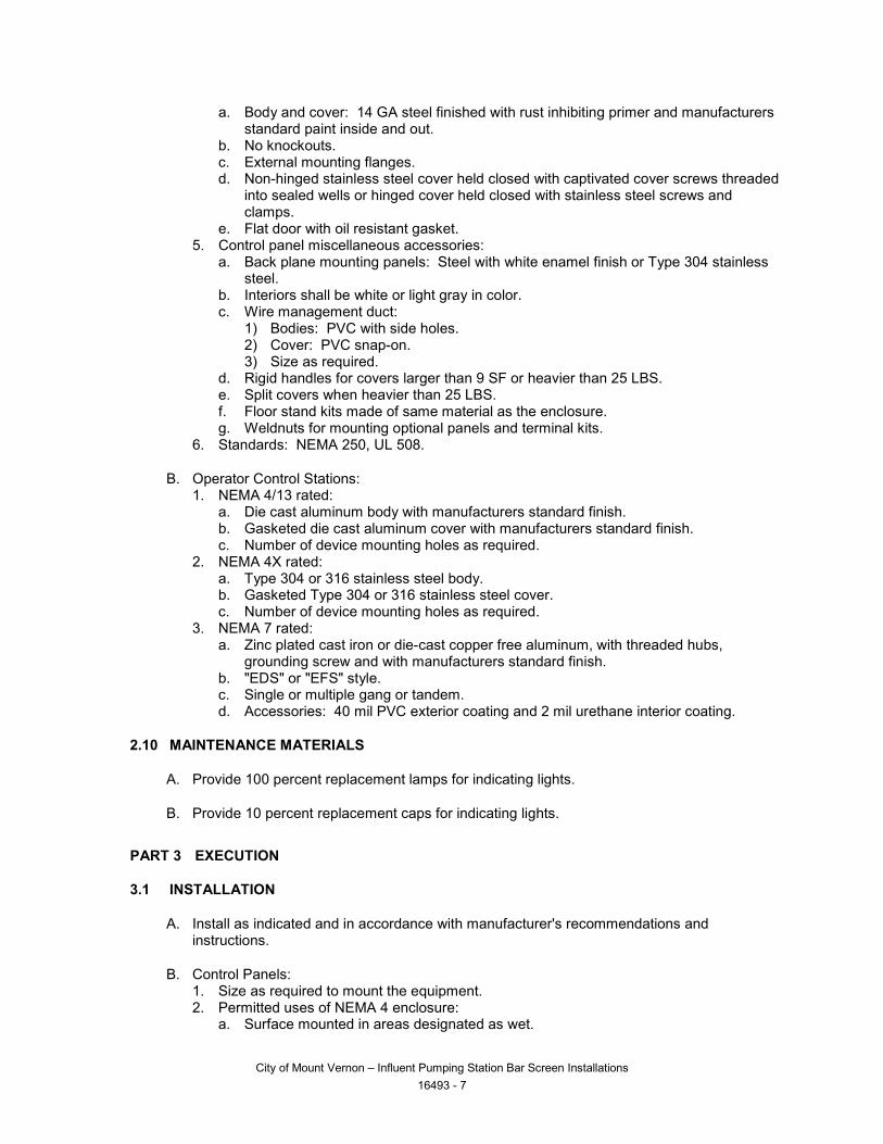
..
a. Body and cover: 14 GA steel finished with rust inhibiting primer and manufacturers standard paint inside and out.
b. No knockouts. c. External mounting flanges. d. Non-hinged stainless steel cover held closed with captivated cover screws threaded
into sealed wells or hinged cover held closed with stainless steel screws and clamps.
e. Flat door with oil resistant gasket. 5. Control panel miscellaneous accessories:
a. Back plane mounting panels: Steel with white enamel finish or Type 304 stainless steel.
b. Interiors shall be white or light gray in color. c. Wire management duct:
1) Bodies: PVC with side holes. 2) Cover: PVC snap-on. 3) Size as required.
d. Rigid handles for covers larger than 9 SF or heavier than 25 LBS. e. Split covers when heavier than 25 LBS. f. Floor stand kits made of same material as the enclosure. g. Weldnuts for mounting optional panels and terminal kits.
6. Standards: NEMA 250, UL 508.
B. Operator Control Stations: 1. NEMA 4/13 rated:
a. Die cast aluminum body with manufacturers standard finish. b. Gasketed die cast aluminum cover with manufacturers standard finish. c. Number of device mounting holes as required.
2. NEMA 4X rated: a. Type 304 or 316 stainless steel body. b. Gasketed Type 304 or 316 stainless steel cover. c. Number of device mounting holes as required.
3. NEMA 7 rated: a. Zinc plated cast iron or die-cast copper free aluminum, with threaded hubs,
grounding screw and with manufacturers standard finish. b. "EDS" or "EFS" style. c. Single or multiple gang or tandem. d. Accessories: 40 mil PVC exterior coating and 2 mil urethane interior coating.
2.10 MAINTENANCE MATERIALS
A. Provide 100 percent replacement lamps for indicating lights.
B. Provide 10 percent replacement caps for indicating lights.
PART 3 EXECUTION
3.1 INSTALLATION
A. Install as indicated and in accordance with manufacturer's recommendations and instructions.
B. Control Panels: 1. Size as required to mount the equipment. 2. Permitted uses of NEMA 4 enclosure:
a. Surface mounted in areas designated as wet.
City of Mount Vernon – Influent Pumping Station Bar Screen Installations 16493 - 7
..
3. Permitted uses of NEMA 4X enclosure: a. Surface mounted in areas designated as wet and/or corrosive or highly corrosive.
4. Permitted uses of NEMA 7 enclosure: a. Surface mounted in areas designated as Class I hazardous.
5. Permitted uses of NEMA 12 enclosure: a. Surface mounted in areas designated as dry architecturally or non-architecturally
finished areas.
C. Operator Control Stations: 1. Permitted uses of NEMA 4/13 enclosure:
a. Surface mounted in areas designated as dry architecturally or non-architecturally finished areas and wet.
2. Permitted uses of NEMA 4X enclosure: a. Surface mounted in areas designated as wet and/or corrosive or highly corrosive.
3. Permitted uses of NEMA 7 enclosure: a. Surface mounted in areas designated as Class I hazardous with PVC coating in
corrosive and highly corrosive areas when PVC coated conduit is used.
3.2 FIELD QUALITY CONTROL
A. See Section 16010.
END OF SECTION
City of Mount Vernon – Influent Pumping Station Bar Screen Installations 16493 - 8

State of Washington Department of Labor & Industries
Prevailing Wage Section - Telephone 360-902-5335 PO Box 44540, Olympia, WA 98504-4540
Washington State Prevailing Wage The PREVAILING WAGES listed here include both the hourly wage rate and the hourly rate of fringe benefits. On public works projects, worker's wage and benefit rates must add to
not less than this total. A brief description of overtime calculation requirements are provided on the Benefit Code Key.
Journey Level Prevailing Wage Rates for the Effective Date: 11/13/2015
County Trade Job Classification Wage Holiday Overtime NoteSkagit Asbestos Abatement Workers Journey Level $43.95 5D 1HSkagit Boilermakers Journey Level $64.29 5N 1CSkagit Brick Mason Journey Level $52.82 5A 1MSkagit Brick Mason Pointer-Caulker-Cleaner $52.82 5A 1MSkagit Building Service Employees Janitor $10.00 1Skagit Building Service Employees Shampooer $9.47 1Skagit Building Service Employees Waxer $9.47 1Skagit Building Service Employees Window Cleaner $9.47 1Skagit Cabinet Makers (In Shop) Journey Level $18.85 1Skagit Carpenters Acoustical Worker $54.02 5D 4CSkagit Carpenters Bridge, Dock And Wharf
Carpenters$54.02 5D 4C
Skagit Carpenters Carpenter $54.02 5D 4CSkagit Carpenters Carpenters on Stationary Tools $54.15 5D 4CSkagit Carpenters Creosoted Material $54.12 5D 4CSkagit Carpenters Floor Finisher $54.02 5D 4CSkagit Carpenters Floor Layer $54.02 5D 4CSkagit Carpenters Scaffold Erector $54.02 5D 4CSkagit Cement Masons Journey Level $53.95 7A 1MSkagit Divers & Tenders Diver $107.22 5D 4C 8ASkagit Divers & Tenders Diver On Standby $64.42 5D 4CSkagit Divers & Tenders Diver Tender $58.33 5D 4CSkagit Divers & Tenders Surface Rcv & Rov Operator $58.33 5D 4CSkagit Divers & Tenders Surface Rcv & Rov Operator
Tender$54.27 5A 4C
Skagit Dredge Workers Assistant Engineer $56.44 5D 3FSkagit Dredge Workers Assistant Mate (Deckhand) $56.00 5D 3FSkagit Dredge Workers Boatmen $56.44 5D 3FSkagit Dredge Workers Engineer Welder $57.51 5D 3FSkagit Dredge Workers Leverman, Hydraulic $58.67 5D 3F
Page 1 of 17
11/13/2015https://fortress.wa.gov/lni/wagelookup/prvWagelookup.aspx
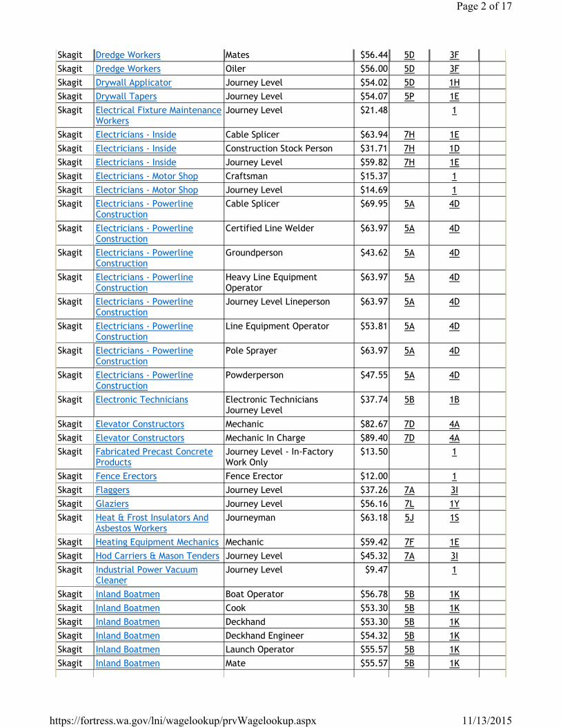
Skagit Dredge Workers Mates $56.44 5D 3FSkagit Dredge Workers Oiler $56.00 5D 3FSkagit Drywall Applicator Journey Level $54.02 5D 1HSkagit Drywall Tapers Journey Level $54.07 5P 1ESkagit Electrical Fixture Maintenance
WorkersJourney Level $21.48 1
Skagit Electricians - Inside Cable Splicer $63.94 7H 1ESkagit Electricians - Inside Construction Stock Person $31.71 7H 1DSkagit Electricians - Inside Journey Level $59.82 7H 1ESkagit Electricians - Motor Shop Craftsman $15.37 1Skagit Electricians - Motor Shop Journey Level $14.69 1Skagit Electricians - Powerline
ConstructionCable Splicer $69.95 5A 4D
Skagit Electricians - Powerline Construction
Certified Line Welder $63.97 5A 4D
Skagit Electricians - Powerline Construction
Groundperson $43.62 5A 4D
Skagit Electricians - Powerline Construction
Heavy Line Equipment Operator
$63.97 5A 4D
Skagit Electricians - Powerline Construction
Journey Level Lineperson $63.97 5A 4D
Skagit Electricians - Powerline Construction
Line Equipment Operator $53.81 5A 4D
Skagit Electricians - Powerline Construction
Pole Sprayer $63.97 5A 4D
Skagit Electricians - Powerline Construction
Powderperson $47.55 5A 4D
Skagit Electronic Technicians Electronic Technicians Journey Level
$37.74 5B 1B
Skagit Elevator Constructors Mechanic $82.67 7D 4ASkagit Elevator Constructors Mechanic In Charge $89.40 7D 4ASkagit Fabricated Precast Concrete
ProductsJourney Level - In-Factory Work Only
$13.50 1
Skagit Fence Erectors Fence Erector $12.00 1Skagit Flaggers Journey Level $37.26 7A 3ISkagit Glaziers Journey Level $56.16 7L 1YSkagit Heat & Frost Insulators And
Asbestos WorkersJourneyman $63.18 5J 1S
Skagit Heating Equipment Mechanics Mechanic $59.42 7F 1ESkagit Hod Carriers & Mason Tenders Journey Level $45.32 7A 3ISkagit Industrial Power Vacuum
CleanerJourney Level $9.47 1
Skagit Inland Boatmen Boat Operator $56.78 5B 1KSkagit Inland Boatmen Cook $53.30 5B 1KSkagit Inland Boatmen Deckhand $53.30 5B 1KSkagit Inland Boatmen Deckhand Engineer $54.32 5B 1KSkagit Inland Boatmen Launch Operator $55.57 5B 1KSkagit Inland Boatmen Mate $55.57 5B 1K
Page 2 of 17
11/13/2015https://fortress.wa.gov/lni/wagelookup/prvWagelookup.aspx
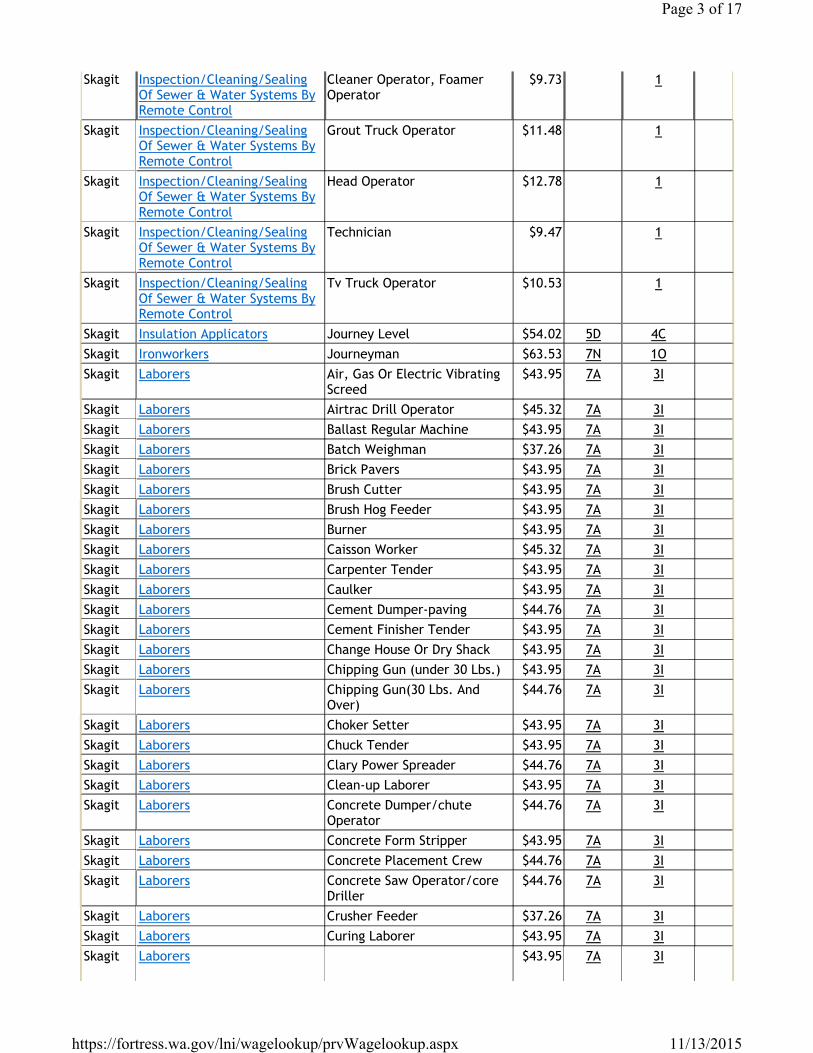
Skagit Inspection/Cleaning/Sealing Of Sewer & Water Systems By Remote Control
Cleaner Operator, Foamer Operator
$9.73 1
Skagit Inspection/Cleaning/Sealing Of Sewer & Water Systems By Remote Control
Grout Truck Operator $11.48 1
Skagit Inspection/Cleaning/Sealing Of Sewer & Water Systems By Remote Control
Head Operator $12.78 1
Skagit Inspection/Cleaning/Sealing Of Sewer & Water Systems By Remote Control
Technician $9.47 1
Skagit Inspection/Cleaning/Sealing Of Sewer & Water Systems By Remote Control
Tv Truck Operator $10.53 1
Skagit Insulation Applicators Journey Level $54.02 5D 4CSkagit Ironworkers Journeyman $63.53 7N 1OSkagit Laborers Air, Gas Or Electric Vibrating
Screed$43.95 7A 3I
Skagit Laborers Airtrac Drill Operator $45.32 7A 3ISkagit Laborers Ballast Regular Machine $43.95 7A 3ISkagit Laborers Batch Weighman $37.26 7A 3ISkagit Laborers Brick Pavers $43.95 7A 3ISkagit Laborers Brush Cutter $43.95 7A 3ISkagit Laborers Brush Hog Feeder $43.95 7A 3ISkagit Laborers Burner $43.95 7A 3ISkagit Laborers Caisson Worker $45.32 7A 3ISkagit Laborers Carpenter Tender $43.95 7A 3ISkagit Laborers Caulker $43.95 7A 3ISkagit Laborers Cement Dumper-paving $44.76 7A 3ISkagit Laborers Cement Finisher Tender $43.95 7A 3ISkagit Laborers Change House Or Dry Shack $43.95 7A 3ISkagit Laborers Chipping Gun (under 30 Lbs.) $43.95 7A 3ISkagit Laborers Chipping Gun(30 Lbs. And
Over)$44.76 7A 3I
Skagit Laborers Choker Setter $43.95 7A 3ISkagit Laborers Chuck Tender $43.95 7A 3ISkagit Laborers Clary Power Spreader $44.76 7A 3ISkagit Laborers Clean-up Laborer $43.95 7A 3ISkagit Laborers Concrete Dumper/chute
Operator$44.76 7A 3I
Skagit Laborers Concrete Form Stripper $43.95 7A 3ISkagit Laborers Concrete Placement Crew $44.76 7A 3ISkagit Laborers Concrete Saw Operator/core
Driller$44.76 7A 3I
Skagit Laborers Crusher Feeder $37.26 7A 3ISkagit Laborers Curing Laborer $43.95 7A 3ISkagit Laborers $43.95 7A 3I
Page 3 of 17
11/13/2015https://fortress.wa.gov/lni/wagelookup/prvWagelookup.aspx
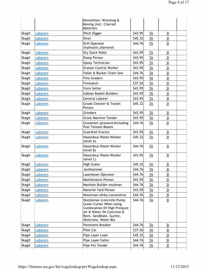
Demolition: Wrecking & Moving (incl. Charred Material)
Skagit Laborers Ditch Digger $43.95 7A 3ISkagit Laborers Diver $45.32 7A 3ISkagit Laborers Drill Operator
(hydraulic,diamond)$44.76 7A 3I
Skagit Laborers Dry Stack Walls $43.95 7A 3ISkagit Laborers Dump Person $43.95 7A 3ISkagit Laborers Epoxy Technician $43.95 7A 3ISkagit Laborers Erosion Control Worker $43.95 7A 3ISkagit Laborers Faller & Bucker Chain Saw $44.76 7A 3ISkagit Laborers Fine Graders $43.95 7A 3ISkagit Laborers Firewatch $37.26 7A 3ISkagit Laborers Form Setter $43.95 7A 3ISkagit Laborers Gabian Basket Builders $43.95 7A 3ISkagit Laborers General Laborer $43.95 7A 3ISkagit Laborers Grade Checker & Transit
Person$45.32 7A 3I
Skagit Laborers Grinders $43.95 7A 3ISkagit Laborers Grout Machine Tender $43.95 7A 3ISkagit Laborers Groutmen (pressure)including
Post Tension Beams$44.76 7A 3I
Skagit Laborers Guardrail Erector $43.95 7A 3ISkagit Laborers Hazardous Waste Worker
(level A)$45.32 7A 3I
Skagit Laborers Hazardous Waste Worker (level B)
$44.76 7A 3I
Skagit Laborers Hazardous Waste Worker (level C)
$43.95 7A 3I
Skagit Laborers High Scaler $45.32 7A 3ISkagit Laborers Jackhammer $44.76 7A 3ISkagit Laborers Laserbeam Operator $44.76 7A 3ISkagit Laborers Maintenance Person $43.95 7A 3ISkagit Laborers Manhole Builder-mudman $44.76 7A 3ISkagit Laborers Material Yard Person $43.95 7A 3ISkagit Laborers Motorman-dinky Locomotive $44.76 7A 3ISkagit Laborers Nozzleman (concrete Pump,
Green Cutter When Using Combination Of High Pressure Air & Water On Concrete & Rock, Sandblast, Gunite, Shotcrete, Water Bla
$44.76 7A 3I
Skagit Laborers Pavement Breaker $44.76 7A 3ISkagit Laborers Pilot Car $37.26 7A 3ISkagit Laborers Pipe Layer Lead $45.32 7A 3ISkagit Laborers Pipe Layer/tailor $44.76 7A 3ISkagit Laborers Pipe Pot Tender $44.76 7A 3I
Page 4 of 17
11/13/2015https://fortress.wa.gov/lni/wagelookup/prvWagelookup.aspx
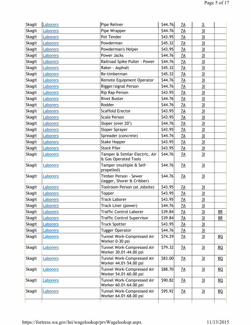
Skagit Laborers Pipe Reliner $44.76 7A 3ISkagit Laborers Pipe Wrapper $44.76 7A 3ISkagit Laborers Pot Tender $43.95 7A 3ISkagit Laborers Powderman $45.32 7A 3ISkagit Laborers Powderman's Helper $43.95 7A 3ISkagit Laborers Power Jacks $44.76 7A 3ISkagit Laborers Railroad Spike Puller - Power $44.76 7A 3ISkagit Laborers Raker - Asphalt $45.32 7A 3ISkagit Laborers Re-timberman $45.32 7A 3ISkagit Laborers Remote Equipment Operator $44.76 7A 3ISkagit Laborers Rigger/signal Person $44.76 7A 3ISkagit Laborers Rip Rap Person $43.95 7A 3ISkagit Laborers Rivet Buster $44.76 7A 3ISkagit Laborers Rodder $44.76 7A 3ISkagit Laborers Scaffold Erector $43.95 7A 3ISkagit Laborers Scale Person $43.95 7A 3ISkagit Laborers Sloper (over 20") $44.76 7A 3ISkagit Laborers Sloper Sprayer $43.95 7A 3ISkagit Laborers Spreader (concrete) $44.76 7A 3ISkagit Laborers Stake Hopper $43.95 7A 3ISkagit Laborers Stock Piler $43.95 7A 3ISkagit Laborers Tamper & Similar Electric, Air
& Gas Operated Tools$44.76 7A 3I
Skagit Laborers Tamper (multiple & Self-propelled)
$44.76 7A 3I
Skagit Laborers Timber Person - Sewer (lagger, Shorer & Cribber)
$44.76 7A 3I
Skagit Laborers Toolroom Person (at Jobsite) $43.95 7A 3ISkagit Laborers Topper $43.95 7A 3ISkagit Laborers Track Laborer $43.95 7A 3ISkagit Laborers Track Liner (power) $44.76 7A 3ISkagit Laborers Traffic Control Laborer $39.84 7A 3I 8RSkagit Laborers Traffic Control Supervisor $39.84 7A 3I 8RSkagit Laborers Truck Spotter $43.95 7A 3ISkagit Laborers Tugger Operator $44.76 7A 3ISkagit Laborers Tunnel Work-Compressed Air
Worker 0-30 psi$74.29 7A 3I 8Q
Skagit Laborers Tunnel Work-Compressed Air Worker 30.01-44.00 psi
$79.32 7A 3I 8Q
Skagit Laborers Tunnel Work-Compressed Air Worker 44.01-54.00 psi
$83.00 7A 3I 8Q
Skagit Laborers Tunnel Work-Compressed Air Worker 54.01-60.00 psi
$88.70 7A 3I 8Q
Skagit Laborers Tunnel Work-Compressed Air Worker 60.01-64.00 psi
$90.82 7A 3I 8Q
Skagit Laborers Tunnel Work-Compressed Air Worker 64.01-68.00 psi
$95.92 7A 3I 8Q
Page 5 of 17
11/13/2015https://fortress.wa.gov/lni/wagelookup/prvWagelookup.aspx
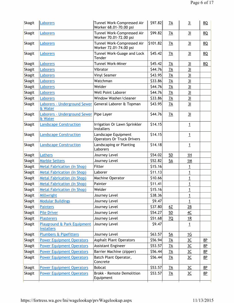
Skagit Laborers Tunnel Work-Compressed Air Worker 68.01-70.00 psi
$97.82 7A 3I 8Q
Skagit Laborers Tunnel Work-Compressed Air Worker 70.01-72.00 psi
$99.82 7A 3I 8Q
Skagit Laborers Tunnel Work-Compressed Air Worker 72.01-74.00 psi
$101.82 7A 3I 8Q
Skagit Laborers Tunnel Work-Guage and Lock Tender
$45.42 7A 3I 8Q
Skagit Laborers Tunnel Work-Miner $45.42 7A 3I 8QSkagit Laborers Vibrator $44.76 7A 3ISkagit Laborers Vinyl Seamer $43.95 7A 3ISkagit Laborers Watchman $33.86 7A 3ISkagit Laborers Welder $44.76 7A 3ISkagit Laborers Well Point Laborer $44.76 7A 3ISkagit Laborers Window Washer/cleaner $33.86 7A 3ISkagit Laborers - Underground Sewer
& WaterGeneral Laborer & Topman $43.95 7A 3I
Skagit Laborers - Underground Sewer & Water
Pipe Layer $44.76 7A 3I
Skagit Landscape Construction Irrigation Or Lawn Sprinkler Installers
$14.15 1
Skagit Landscape Construction Landscape Equipment Operators Or Truck Drivers
$14.15 1
Skagit Landscape Construction Landscaping or Planting Laborers
$14.18 1
Skagit Lathers Journey Level $54.02 5D 1HSkagit Marble Setters Journey Level $52.82 5A 1MSkagit Metal Fabrication (In Shop) Fitter $15.16 1Skagit Metal Fabrication (In Shop) Laborer $11.13 1Skagit Metal Fabrication (In Shop) Machine Operator $10.66 1Skagit Metal Fabrication (In Shop) Painter $11.41 1Skagit Metal Fabrication (In Shop) Welder $15.16 1Skagit Millwright Journey Level $38.36 1Skagit Modular Buildings Journey Level $9.47 1Skagit Painters Journey Level $37.80 6Z 2BSkagit Pile Driver Journey Level $54.27 5D 4CSkagit Plasterers Journey Level $51.68 7Q 1RSkagit Playground & Park Equipment
InstallersJourney Level $9.47 1
Skagit Plumbers & Pipefitters Journey Level $63.57 5A 1GSkagit Power Equipment Operators Asphalt Plant Operators $56.94 7A 3C 8PSkagit Power Equipment Operators Assistant Engineer $53.57 7A 3C 8PSkagit Power Equipment Operators Barrier Machine (zipper) $56.44 7A 3C 8PSkagit Power Equipment Operators Batch Plant Operator,
Concrete$56.44 7A 3C 8P
Skagit Power Equipment Operators Bobcat $53.57 7A 3C 8PSkagit Power Equipment Operators Brokk - Remote Demolition
Equipment$53.57 7A 3C 8P
Page 6 of 17
11/13/2015https://fortress.wa.gov/lni/wagelookup/prvWagelookup.aspx
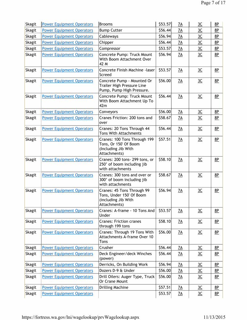
Skagit Power Equipment Operators Brooms $53.57 7A 3C 8PSkagit Power Equipment Operators Bump Cutter $56.44 7A 3C 8PSkagit Power Equipment Operators Cableways $56.94 7A 3C 8PSkagit Power Equipment Operators Chipper $56.44 7A 3C 8PSkagit Power Equipment Operators Compressor $53.57 7A 3C 8PSkagit Power Equipment Operators Concrete Pump: Truck Mount
With Boom Attachment Over 42 M
$56.94 7A 3C 8P
Skagit Power Equipment Operators Concrete Finish Machine -laser Screed
$53.57 7A 3C 8P
Skagit Power Equipment Operators Concrete Pump - Mounted Or Trailer High Pressure Line Pump, Pump High Pressure.
$56.00 7A 3C 8P
Skagit Power Equipment Operators Concrete Pump: Truck Mount With Boom Attachment Up To 42m
$56.44 7A 3C 8P
Skagit Power Equipment Operators Conveyors $56.00 7A 3C 8PSkagit Power Equipment Operators Cranes Friction: 200 tons and
over$58.67 7A 3C 8P
Skagit Power Equipment Operators Cranes: 20 Tons Through 44 Tons With Attachments
$56.44 7A 3C 8P
Skagit Power Equipment Operators Cranes: 100 Tons Through 199 Tons, Or 150' Of Boom (Including Jib With Attachments)
$57.51 7A 3C 8P
Skagit Power Equipment Operators Cranes: 200 tons- 299 tons, or 250’ of boom including jib with attachments
$58.10 7A 3C 8P
Skagit Power Equipment Operators Cranes: 300 tons and over or 300’ of boom including jib with attachments
$58.67 7A 3C 8P
Skagit Power Equipment Operators Cranes: 45 Tons Through 99 Tons, Under 150' Of Boom (including Jib With Attachments)
$56.94 7A 3C 8P
Skagit Power Equipment Operators Cranes: A-frame - 10 Tons And Under
$53.57 7A 3C 8P
Skagit Power Equipment Operators Cranes: Friction cranes through 199 tons
$58.10 7A 3C 8P
Skagit Power Equipment Operators Cranes: Through 19 Tons With Attachments A-frame Over 10 Tons
$56.00 7A 3C 8P
Skagit Power Equipment Operators Crusher $56.44 7A 3C 8PSkagit Power Equipment Operators Deck Engineer/deck Winches
(power)$56.44 7A 3C 8P
Skagit Power Equipment Operators Derricks, On Building Work $56.94 7A 3C 8PSkagit Power Equipment Operators Dozers D-9 & Under $56.00 7A 3C 8PSkagit Power Equipment Operators Drill Oilers: Auger Type, Truck
Or Crane Mount$56.00 7A 3C 8P
Skagit Power Equipment Operators Drilling Machine $57.51 7A 3C 8PSkagit Power Equipment Operators $53.57 7A 3C 8P
Page 7 of 17
11/13/2015https://fortress.wa.gov/lni/wagelookup/prvWagelookup.aspx
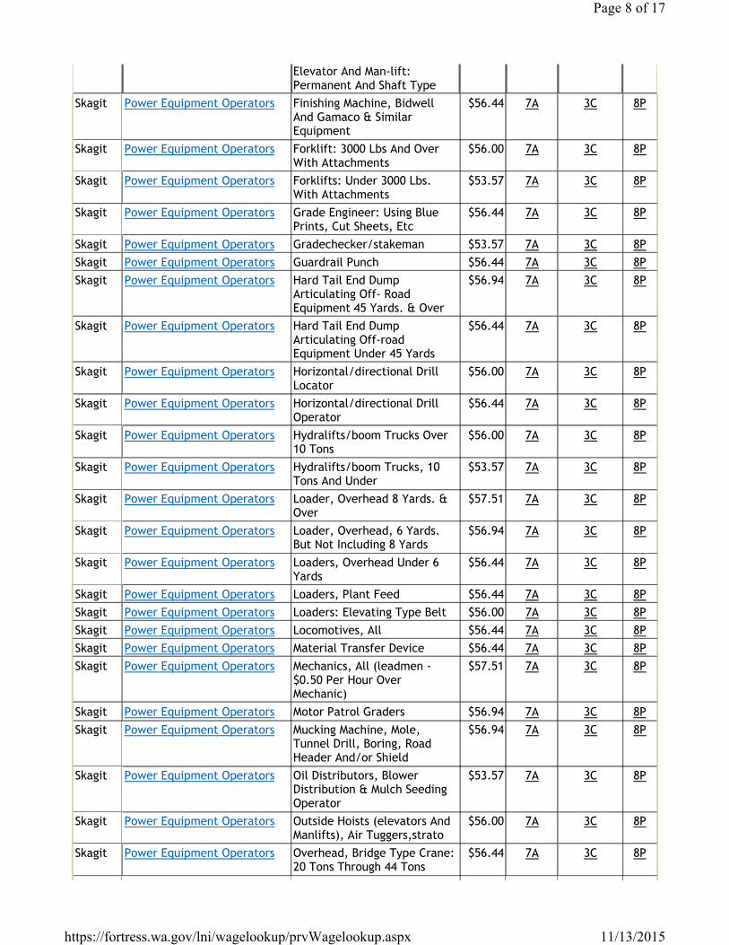
Elevator And Man-lift: Permanent And Shaft Type
Skagit Power Equipment Operators Finishing Machine, Bidwell And Gamaco & Similar Equipment
$56.44 7A 3C 8P
Skagit Power Equipment Operators Forklift: 3000 Lbs And Over With Attachments
$56.00 7A 3C 8P
Skagit Power Equipment Operators Forklifts: Under 3000 Lbs. With Attachments
$53.57 7A 3C 8P
Skagit Power Equipment Operators Grade Engineer: Using Blue Prints, Cut Sheets, Etc
$56.44 7A 3C 8P
Skagit Power Equipment Operators Gradechecker/stakeman $53.57 7A 3C 8PSkagit Power Equipment Operators Guardrail Punch $56.44 7A 3C 8PSkagit Power Equipment Operators Hard Tail End Dump
Articulating Off- Road Equipment 45 Yards. & Over
$56.94 7A 3C 8P
Skagit Power Equipment Operators Hard Tail End Dump Articulating Off-road Equipment Under 45 Yards
$56.44 7A 3C 8P
Skagit Power Equipment Operators Horizontal/directional Drill Locator
$56.00 7A 3C 8P
Skagit Power Equipment Operators Horizontal/directional Drill Operator
$56.44 7A 3C 8P
Skagit Power Equipment Operators Hydralifts/boom Trucks Over 10 Tons
$56.00 7A 3C 8P
Skagit Power Equipment Operators Hydralifts/boom Trucks, 10 Tons And Under
$53.57 7A 3C 8P
Skagit Power Equipment Operators Loader, Overhead 8 Yards. & Over
$57.51 7A 3C 8P
Skagit Power Equipment Operators Loader, Overhead, 6 Yards. But Not Including 8 Yards
$56.94 7A 3C 8P
Skagit Power Equipment Operators Loaders, Overhead Under 6 Yards
$56.44 7A 3C 8P
Skagit Power Equipment Operators Loaders, Plant Feed $56.44 7A 3C 8PSkagit Power Equipment Operators Loaders: Elevating Type Belt $56.00 7A 3C 8PSkagit Power Equipment Operators Locomotives, All $56.44 7A 3C 8PSkagit Power Equipment Operators Material Transfer Device $56.44 7A 3C 8PSkagit Power Equipment Operators Mechanics, All (leadmen -
$0.50 Per Hour Over Mechanic)
$57.51 7A 3C 8P
Skagit Power Equipment Operators Motor Patrol Graders $56.94 7A 3C 8PSkagit Power Equipment Operators Mucking Machine, Mole,
Tunnel Drill, Boring, Road Header And/or Shield
$56.94 7A 3C 8P
Skagit Power Equipment Operators Oil Distributors, Blower Distribution & Mulch Seeding Operator
$53.57 7A 3C 8P
Skagit Power Equipment Operators Outside Hoists (elevators And Manlifts), Air Tuggers,strato
$56.00 7A 3C 8P
Skagit Power Equipment Operators Overhead, Bridge Type Crane: 20 Tons Through 44 Tons
$56.44 7A 3C 8P
Page 8 of 17
11/13/2015https://fortress.wa.gov/lni/wagelookup/prvWagelookup.aspx
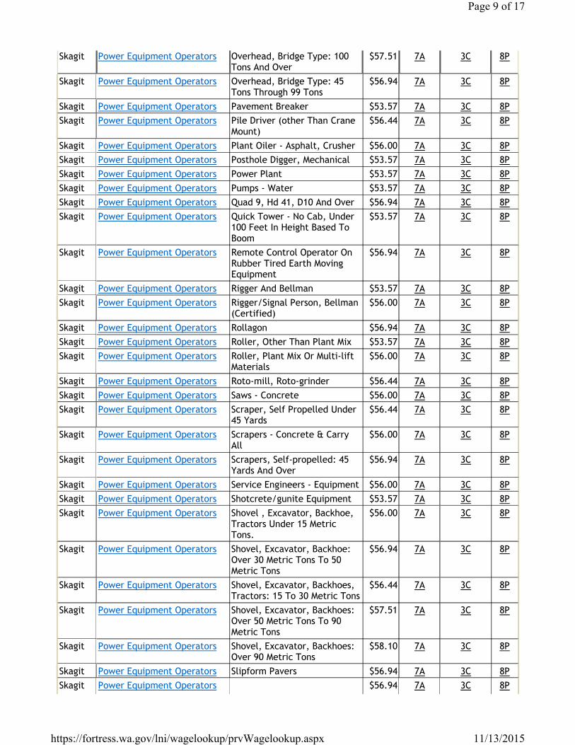
Skagit Power Equipment Operators Overhead, Bridge Type: 100 Tons And Over
$57.51 7A 3C 8P
Skagit Power Equipment Operators Overhead, Bridge Type: 45 Tons Through 99 Tons
$56.94 7A 3C 8P
Skagit Power Equipment Operators Pavement Breaker $53.57 7A 3C 8PSkagit Power Equipment Operators Pile Driver (other Than Crane
Mount)$56.44 7A 3C 8P
Skagit Power Equipment Operators Plant Oiler - Asphalt, Crusher $56.00 7A 3C 8PSkagit Power Equipment Operators Posthole Digger, Mechanical $53.57 7A 3C 8PSkagit Power Equipment Operators Power Plant $53.57 7A 3C 8PSkagit Power Equipment Operators Pumps - Water $53.57 7A 3C 8PSkagit Power Equipment Operators Quad 9, Hd 41, D10 And Over $56.94 7A 3C 8PSkagit Power Equipment Operators Quick Tower - No Cab, Under
100 Feet In Height Based To Boom
$53.57 7A 3C 8P
Skagit Power Equipment Operators Remote Control Operator On Rubber Tired Earth Moving Equipment
$56.94 7A 3C 8P
Skagit Power Equipment Operators Rigger And Bellman $53.57 7A 3C 8PSkagit Power Equipment Operators Rigger/Signal Person, Bellman
(Certified)$56.00 7A 3C 8P
Skagit Power Equipment Operators Rollagon $56.94 7A 3C 8PSkagit Power Equipment Operators Roller, Other Than Plant Mix $53.57 7A 3C 8PSkagit Power Equipment Operators Roller, Plant Mix Or Multi-lift
Materials$56.00 7A 3C 8P
Skagit Power Equipment Operators Roto-mill, Roto-grinder $56.44 7A 3C 8PSkagit Power Equipment Operators Saws - Concrete $56.00 7A 3C 8PSkagit Power Equipment Operators Scraper, Self Propelled Under
45 Yards$56.44 7A 3C 8P
Skagit Power Equipment Operators Scrapers - Concrete & Carry All
$56.00 7A 3C 8P
Skagit Power Equipment Operators Scrapers, Self-propelled: 45 Yards And Over
$56.94 7A 3C 8P
Skagit Power Equipment Operators Service Engineers - Equipment $56.00 7A 3C 8PSkagit Power Equipment Operators Shotcrete/gunite Equipment $53.57 7A 3C 8PSkagit Power Equipment Operators Shovel , Excavator, Backhoe,
Tractors Under 15 Metric Tons.
$56.00 7A 3C 8P
Skagit Power Equipment Operators Shovel, Excavator, Backhoe: Over 30 Metric Tons To 50 Metric Tons
$56.94 7A 3C 8P
Skagit Power Equipment Operators Shovel, Excavator, Backhoes, Tractors: 15 To 30 Metric Tons
$56.44 7A 3C 8P
Skagit Power Equipment Operators Shovel, Excavator, Backhoes: Over 50 Metric Tons To 90 Metric Tons
$57.51 7A 3C 8P
Skagit Power Equipment Operators Shovel, Excavator, Backhoes: Over 90 Metric Tons
$58.10 7A 3C 8P
Skagit Power Equipment Operators Slipform Pavers $56.94 7A 3C 8PSkagit Power Equipment Operators $56.94 7A 3C 8P
Page 9 of 17
11/13/2015https://fortress.wa.gov/lni/wagelookup/prvWagelookup.aspx
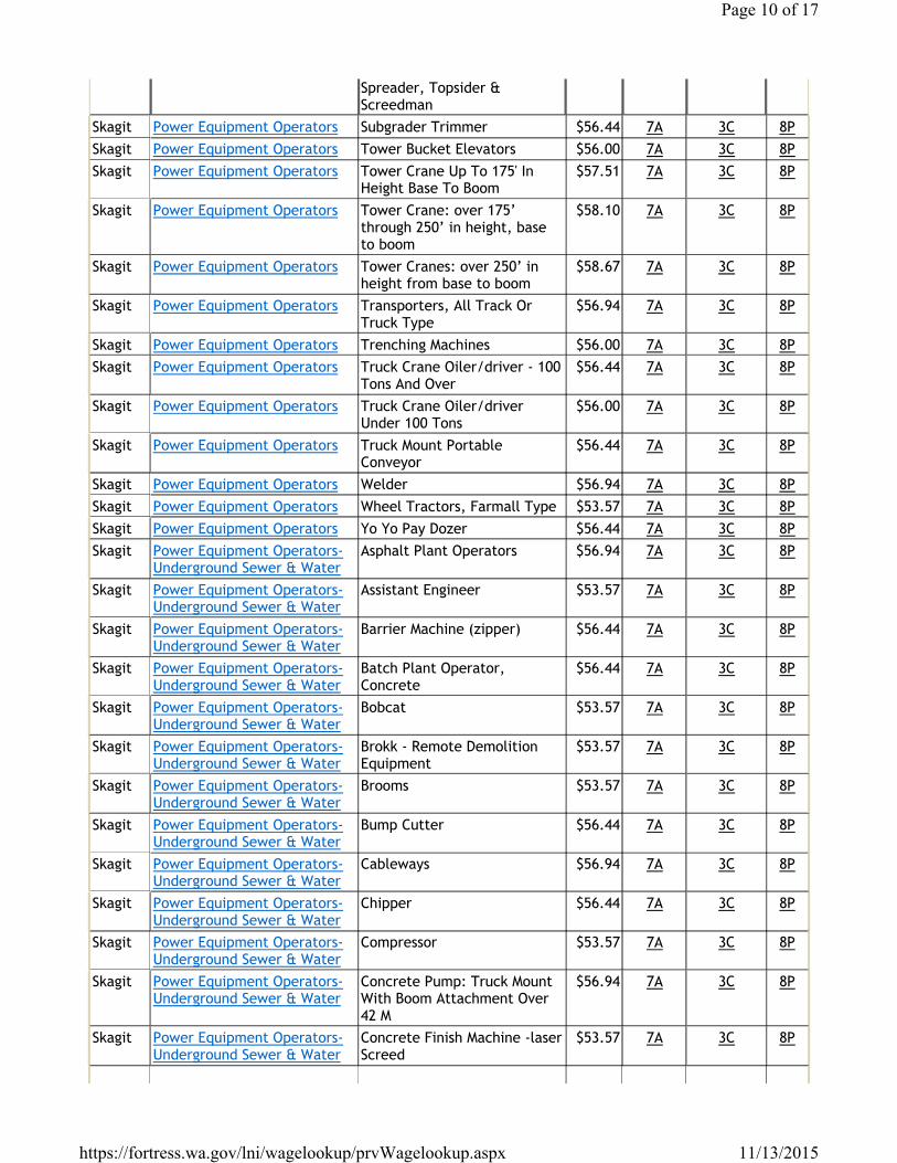
Spreader, Topsider & Screedman
Skagit Power Equipment Operators Subgrader Trimmer $56.44 7A 3C 8PSkagit Power Equipment Operators Tower Bucket Elevators $56.00 7A 3C 8PSkagit Power Equipment Operators Tower Crane Up To 175' In
Height Base To Boom$57.51 7A 3C 8P
Skagit Power Equipment Operators Tower Crane: over 175’ through 250’ in height, base to boom
$58.10 7A 3C 8P
Skagit Power Equipment Operators Tower Cranes: over 250’ in height from base to boom
$58.67 7A 3C 8P
Skagit Power Equipment Operators Transporters, All Track Or Truck Type
$56.94 7A 3C 8P
Skagit Power Equipment Operators Trenching Machines $56.00 7A 3C 8PSkagit Power Equipment Operators Truck Crane Oiler/driver - 100
Tons And Over$56.44 7A 3C 8P
Skagit Power Equipment Operators Truck Crane Oiler/driver Under 100 Tons
$56.00 7A 3C 8P
Skagit Power Equipment Operators Truck Mount Portable Conveyor
$56.44 7A 3C 8P
Skagit Power Equipment Operators Welder $56.94 7A 3C 8PSkagit Power Equipment Operators Wheel Tractors, Farmall Type $53.57 7A 3C 8PSkagit Power Equipment Operators Yo Yo Pay Dozer $56.44 7A 3C 8PSkagit Power Equipment Operators-
Underground Sewer & WaterAsphalt Plant Operators $56.94 7A 3C 8P
Skagit Power Equipment Operators- Underground Sewer & Water
Assistant Engineer $53.57 7A 3C 8P
Skagit Power Equipment Operators- Underground Sewer & Water
Barrier Machine (zipper) $56.44 7A 3C 8P
Skagit Power Equipment Operators- Underground Sewer & Water
Batch Plant Operator, Concrete
$56.44 7A 3C 8P
Skagit Power Equipment Operators- Underground Sewer & Water
Bobcat $53.57 7A 3C 8P
Skagit Power Equipment Operators- Underground Sewer & Water
Brokk - Remote Demolition Equipment
$53.57 7A 3C 8P
Skagit Power Equipment Operators- Underground Sewer & Water
Brooms $53.57 7A 3C 8P
Skagit Power Equipment Operators- Underground Sewer & Water
Bump Cutter $56.44 7A 3C 8P
Skagit Power Equipment Operators- Underground Sewer & Water
Cableways $56.94 7A 3C 8P
Skagit Power Equipment Operators- Underground Sewer & Water
Chipper $56.44 7A 3C 8P
Skagit Power Equipment Operators- Underground Sewer & Water
Compressor $53.57 7A 3C 8P
Skagit Power Equipment Operators- Underground Sewer & Water
Concrete Pump: Truck Mount With Boom Attachment Over 42 M
$56.94 7A 3C 8P
Skagit Power Equipment Operators- Underground Sewer & Water
Concrete Finish Machine -laser Screed
$53.57 7A 3C 8P
Page 10 of 17
11/13/2015https://fortress.wa.gov/lni/wagelookup/prvWagelookup.aspx
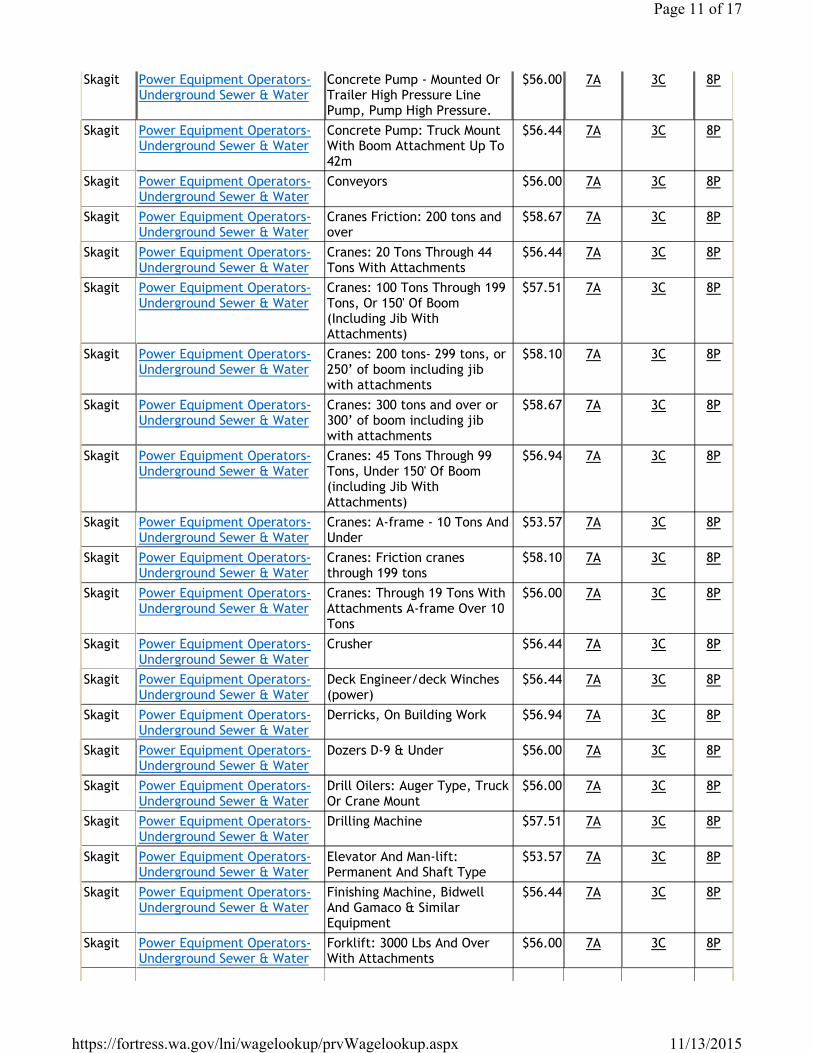
Skagit Power Equipment Operators- Underground Sewer & Water
Concrete Pump - Mounted Or Trailer High Pressure Line Pump, Pump High Pressure.
$56.00 7A 3C 8P
Skagit Power Equipment Operators- Underground Sewer & Water
Concrete Pump: Truck Mount With Boom Attachment Up To 42m
$56.44 7A 3C 8P
Skagit Power Equipment Operators- Underground Sewer & Water
Conveyors $56.00 7A 3C 8P
Skagit Power Equipment Operators- Underground Sewer & Water
Cranes Friction: 200 tons and over
$58.67 7A 3C 8P
Skagit Power Equipment Operators- Underground Sewer & Water
Cranes: 20 Tons Through 44 Tons With Attachments
$56.44 7A 3C 8P
Skagit Power Equipment Operators- Underground Sewer & Water
Cranes: 100 Tons Through 199 Tons, Or 150' Of Boom (Including Jib With Attachments)
$57.51 7A 3C 8P
Skagit Power Equipment Operators- Underground Sewer & Water
Cranes: 200 tons- 299 tons, or 250’ of boom including jib with attachments
$58.10 7A 3C 8P
Skagit Power Equipment Operators- Underground Sewer & Water
Cranes: 300 tons and over or 300’ of boom including jib with attachments
$58.67 7A 3C 8P
Skagit Power Equipment Operators- Underground Sewer & Water
Cranes: 45 Tons Through 99 Tons, Under 150' Of Boom (including Jib With Attachments)
$56.94 7A 3C 8P
Skagit Power Equipment Operators- Underground Sewer & Water
Cranes: A-frame - 10 Tons And Under
$53.57 7A 3C 8P
Skagit Power Equipment Operators- Underground Sewer & Water
Cranes: Friction cranes through 199 tons
$58.10 7A 3C 8P
Skagit Power Equipment Operators- Underground Sewer & Water
Cranes: Through 19 Tons With Attachments A-frame Over 10 Tons
$56.00 7A 3C 8P
Skagit Power Equipment Operators- Underground Sewer & Water
Crusher $56.44 7A 3C 8P
Skagit Power Equipment Operators- Underground Sewer & Water
Deck Engineer/deck Winches (power)
$56.44 7A 3C 8P
Skagit Power Equipment Operators- Underground Sewer & Water
Derricks, On Building Work $56.94 7A 3C 8P
Skagit Power Equipment Operators- Underground Sewer & Water
Dozers D-9 & Under $56.00 7A 3C 8P
Skagit Power Equipment Operators- Underground Sewer & Water
Drill Oilers: Auger Type, Truck Or Crane Mount
$56.00 7A 3C 8P
Skagit Power Equipment Operators- Underground Sewer & Water
Drilling Machine $57.51 7A 3C 8P
Skagit Power Equipment Operators- Underground Sewer & Water
Elevator And Man-lift: Permanent And Shaft Type
$53.57 7A 3C 8P
Skagit Power Equipment Operators- Underground Sewer & Water
Finishing Machine, Bidwell And Gamaco & Similar Equipment
$56.44 7A 3C 8P
Skagit Power Equipment Operators- Underground Sewer & Water
Forklift: 3000 Lbs And Over With Attachments
$56.00 7A 3C 8P
Page 11 of 17
11/13/2015https://fortress.wa.gov/lni/wagelookup/prvWagelookup.aspx
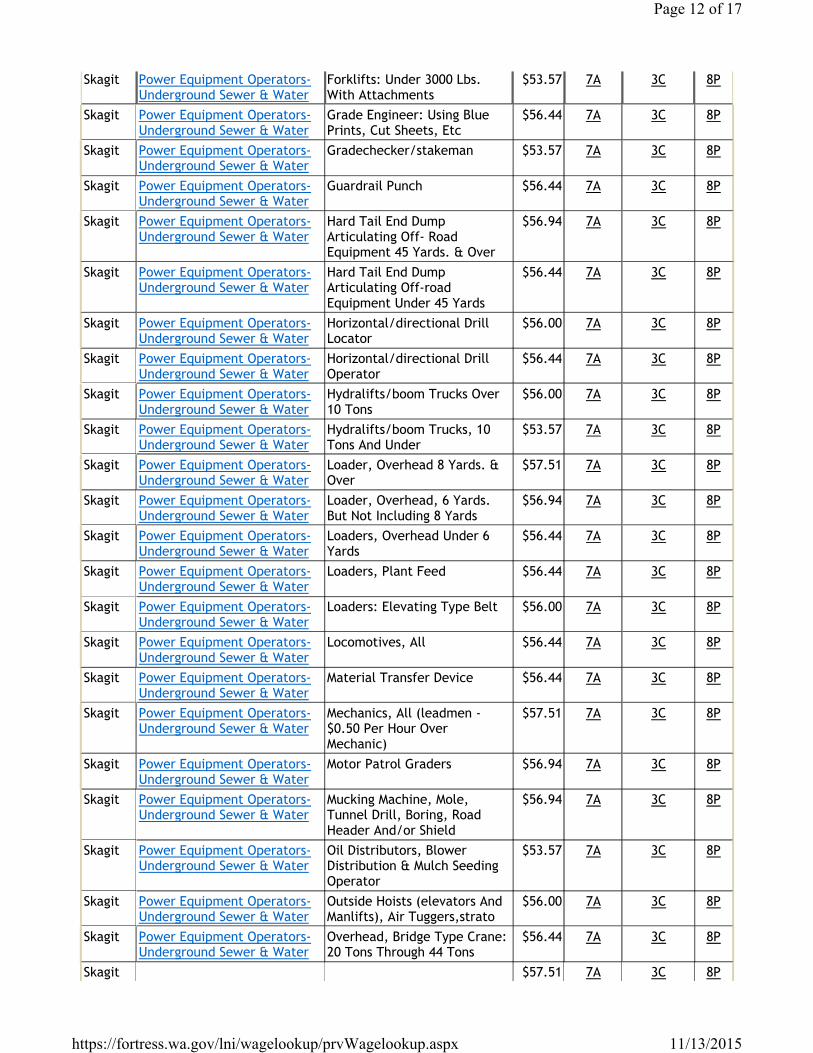
Skagit Power Equipment Operators- Underground Sewer & Water
Forklifts: Under 3000 Lbs. With Attachments
$53.57 7A 3C 8P
Skagit Power Equipment Operators- Underground Sewer & Water
Grade Engineer: Using Blue Prints, Cut Sheets, Etc
$56.44 7A 3C 8P
Skagit Power Equipment Operators- Underground Sewer & Water
Gradechecker/stakeman $53.57 7A 3C 8P
Skagit Power Equipment Operators- Underground Sewer & Water
Guardrail Punch $56.44 7A 3C 8P
Skagit Power Equipment Operators- Underground Sewer & Water
Hard Tail End Dump Articulating Off- Road Equipment 45 Yards. & Over
$56.94 7A 3C 8P
Skagit Power Equipment Operators- Underground Sewer & Water
Hard Tail End Dump Articulating Off-road Equipment Under 45 Yards
$56.44 7A 3C 8P
Skagit Power Equipment Operators- Underground Sewer & Water
Horizontal/directional Drill Locator
$56.00 7A 3C 8P
Skagit Power Equipment Operators- Underground Sewer & Water
Horizontal/directional Drill Operator
$56.44 7A 3C 8P
Skagit Power Equipment Operators- Underground Sewer & Water
Hydralifts/boom Trucks Over 10 Tons
$56.00 7A 3C 8P
Skagit Power Equipment Operators- Underground Sewer & Water
Hydralifts/boom Trucks, 10 Tons And Under
$53.57 7A 3C 8P
Skagit Power Equipment Operators- Underground Sewer & Water
Loader, Overhead 8 Yards. & Over
$57.51 7A 3C 8P
Skagit Power Equipment Operators- Underground Sewer & Water
Loader, Overhead, 6 Yards. But Not Including 8 Yards
$56.94 7A 3C 8P
Skagit Power Equipment Operators- Underground Sewer & Water
Loaders, Overhead Under 6 Yards
$56.44 7A 3C 8P
Skagit Power Equipment Operators- Underground Sewer & Water
Loaders, Plant Feed $56.44 7A 3C 8P
Skagit Power Equipment Operators- Underground Sewer & Water
Loaders: Elevating Type Belt $56.00 7A 3C 8P
Skagit Power Equipment Operators- Underground Sewer & Water
Locomotives, All $56.44 7A 3C 8P
Skagit Power Equipment Operators- Underground Sewer & Water
Material Transfer Device $56.44 7A 3C 8P
Skagit Power Equipment Operators- Underground Sewer & Water
Mechanics, All (leadmen - $0.50 Per Hour Over Mechanic)
$57.51 7A 3C 8P
Skagit Power Equipment Operators- Underground Sewer & Water
Motor Patrol Graders $56.94 7A 3C 8P
Skagit Power Equipment Operators- Underground Sewer & Water
Mucking Machine, Mole, Tunnel Drill, Boring, Road Header And/or Shield
$56.94 7A 3C 8P
Skagit Power Equipment Operators- Underground Sewer & Water
Oil Distributors, Blower Distribution & Mulch Seeding Operator
$53.57 7A 3C 8P
Skagit Power Equipment Operators- Underground Sewer & Water
Outside Hoists (elevators And Manlifts), Air Tuggers,strato
$56.00 7A 3C 8P
Skagit Power Equipment Operators- Underground Sewer & Water
Overhead, Bridge Type Crane: 20 Tons Through 44 Tons
$56.44 7A 3C 8P
Skagit $57.51 7A 3C 8P
Page 12 of 17
11/13/2015https://fortress.wa.gov/lni/wagelookup/prvWagelookup.aspx
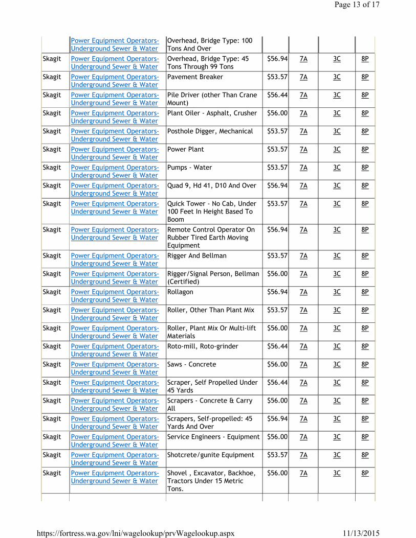
Power Equipment Operators- Underground Sewer & Water
Overhead, Bridge Type: 100 Tons And Over
Skagit Power Equipment Operators- Underground Sewer & Water
Overhead, Bridge Type: 45 Tons Through 99 Tons
$56.94 7A 3C 8P
Skagit Power Equipment Operators- Underground Sewer & Water
Pavement Breaker $53.57 7A 3C 8P
Skagit Power Equipment Operators- Underground Sewer & Water
Pile Driver (other Than Crane Mount)
$56.44 7A 3C 8P
Skagit Power Equipment Operators- Underground Sewer & Water
Plant Oiler - Asphalt, Crusher $56.00 7A 3C 8P
Skagit Power Equipment Operators- Underground Sewer & Water
Posthole Digger, Mechanical $53.57 7A 3C 8P
Skagit Power Equipment Operators- Underground Sewer & Water
Power Plant $53.57 7A 3C 8P
Skagit Power Equipment Operators- Underground Sewer & Water
Pumps - Water $53.57 7A 3C 8P
Skagit Power Equipment Operators- Underground Sewer & Water
Quad 9, Hd 41, D10 And Over $56.94 7A 3C 8P
Skagit Power Equipment Operators- Underground Sewer & Water
Quick Tower - No Cab, Under 100 Feet In Height Based To Boom
$53.57 7A 3C 8P
Skagit Power Equipment Operators- Underground Sewer & Water
Remote Control Operator On Rubber Tired Earth Moving Equipment
$56.94 7A 3C 8P
Skagit Power Equipment Operators- Underground Sewer & Water
Rigger And Bellman $53.57 7A 3C 8P
Skagit Power Equipment Operators- Underground Sewer & Water
Rigger/Signal Person, Bellman (Certified)
$56.00 7A 3C 8P
Skagit Power Equipment Operators- Underground Sewer & Water
Rollagon $56.94 7A 3C 8P
Skagit Power Equipment Operators- Underground Sewer & Water
Roller, Other Than Plant Mix $53.57 7A 3C 8P
Skagit Power Equipment Operators- Underground Sewer & Water
Roller, Plant Mix Or Multi-lift Materials
$56.00 7A 3C 8P
Skagit Power Equipment Operators- Underground Sewer & Water
Roto-mill, Roto-grinder $56.44 7A 3C 8P
Skagit Power Equipment Operators- Underground Sewer & Water
Saws - Concrete $56.00 7A 3C 8P
Skagit Power Equipment Operators- Underground Sewer & Water
Scraper, Self Propelled Under 45 Yards
$56.44 7A 3C 8P
Skagit Power Equipment Operators- Underground Sewer & Water
Scrapers - Concrete & Carry All
$56.00 7A 3C 8P
Skagit Power Equipment Operators- Underground Sewer & Water
Scrapers, Self-propelled: 45 Yards And Over
$56.94 7A 3C 8P
Skagit Power Equipment Operators- Underground Sewer & Water
Service Engineers - Equipment $56.00 7A 3C 8P
Skagit Power Equipment Operators- Underground Sewer & Water
Shotcrete/gunite Equipment $53.57 7A 3C 8P
Skagit Power Equipment Operators- Underground Sewer & Water
Shovel , Excavator, Backhoe, Tractors Under 15 Metric Tons.
$56.00 7A 3C 8P
Page 13 of 17
11/13/2015https://fortress.wa.gov/lni/wagelookup/prvWagelookup.aspx
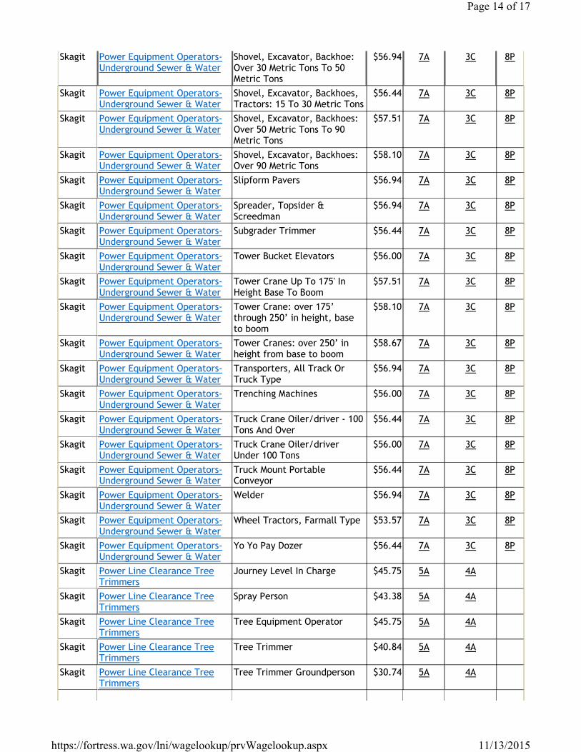
Skagit Power Equipment Operators- Underground Sewer & Water
Shovel, Excavator, Backhoe: Over 30 Metric Tons To 50 Metric Tons
$56.94 7A 3C 8P
Skagit Power Equipment Operators- Underground Sewer & Water
Shovel, Excavator, Backhoes, Tractors: 15 To 30 Metric Tons
$56.44 7A 3C 8P
Skagit Power Equipment Operators- Underground Sewer & Water
Shovel, Excavator, Backhoes: Over 50 Metric Tons To 90 Metric Tons
$57.51 7A 3C 8P
Skagit Power Equipment Operators- Underground Sewer & Water
Shovel, Excavator, Backhoes: Over 90 Metric Tons
$58.10 7A 3C 8P
Skagit Power Equipment Operators- Underground Sewer & Water
Slipform Pavers $56.94 7A 3C 8P
Skagit Power Equipment Operators- Underground Sewer & Water
Spreader, Topsider & Screedman
$56.94 7A 3C 8P
Skagit Power Equipment Operators- Underground Sewer & Water
Subgrader Trimmer $56.44 7A 3C 8P
Skagit Power Equipment Operators- Underground Sewer & Water
Tower Bucket Elevators $56.00 7A 3C 8P
Skagit Power Equipment Operators- Underground Sewer & Water
Tower Crane Up To 175' In Height Base To Boom
$57.51 7A 3C 8P
Skagit Power Equipment Operators- Underground Sewer & Water
Tower Crane: over 175’ through 250’ in height, base to boom
$58.10 7A 3C 8P
Skagit Power Equipment Operators- Underground Sewer & Water
Tower Cranes: over 250’ in height from base to boom
$58.67 7A 3C 8P
Skagit Power Equipment Operators- Underground Sewer & Water
Transporters, All Track Or Truck Type
$56.94 7A 3C 8P
Skagit Power Equipment Operators- Underground Sewer & Water
Trenching Machines $56.00 7A 3C 8P
Skagit Power Equipment Operators- Underground Sewer & Water
Truck Crane Oiler/driver - 100 Tons And Over
$56.44 7A 3C 8P
Skagit Power Equipment Operators- Underground Sewer & Water
Truck Crane Oiler/driver Under 100 Tons
$56.00 7A 3C 8P
Skagit Power Equipment Operators- Underground Sewer & Water
Truck Mount Portable Conveyor
$56.44 7A 3C 8P
Skagit Power Equipment Operators- Underground Sewer & Water
Welder $56.94 7A 3C 8P
Skagit Power Equipment Operators- Underground Sewer & Water
Wheel Tractors, Farmall Type $53.57 7A 3C 8P
Skagit Power Equipment Operators- Underground Sewer & Water
Yo Yo Pay Dozer $56.44 7A 3C 8P
Skagit Power Line Clearance Tree Trimmers
Journey Level In Charge $45.75 5A 4A
Skagit Power Line Clearance Tree Trimmers
Spray Person $43.38 5A 4A
Skagit Power Line Clearance Tree Trimmers
Tree Equipment Operator $45.75 5A 4A
Skagit Power Line Clearance Tree Trimmers
Tree Trimmer $40.84 5A 4A
Skagit Power Line Clearance Tree Trimmers
Tree Trimmer Groundperson $30.74 5A 4A
Page 14 of 17
11/13/2015https://fortress.wa.gov/lni/wagelookup/prvWagelookup.aspx
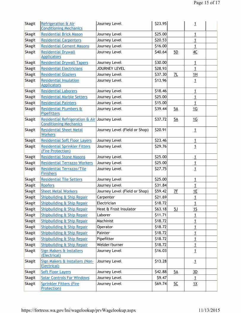
Skagit Refrigeration & Air Conditioning Mechanics
Journey Level $23.95 1
Skagit Residential Brick Mason Journey Level $25.00 1Skagit Residential Carpenters Journey Level $20.53 1Skagit Residential Cement Masons Journey Level $16.00 1Skagit Residential Drywall
ApplicatorsJourney Level $40.64 5D 4C
Skagit Residential Drywall Tapers Journey Level $30.00 1Skagit Residential Electricians JOURNEY LEVEL $28.93 1Skagit Residential Glaziers Journey Level $37.30 7L 1HSkagit Residential Insulation
ApplicatorsJourney Level $13.96 1
Skagit Residential Laborers Journey Level $18.46 1Skagit Residential Marble Setters Journey Level $25.00 1Skagit Residential Painters Journey Level $15.00 1Skagit Residential Plumbers &
PipefittersJourney Level $39.44 5A 1G
Skagit Residential Refrigeration & Air Conditioning Mechanics
Journey Level $37.72 5A 1G
Skagit Residential Sheet Metal Workers
Journey Level (Field or Shop) $20.91 1
Skagit Residential Soft Floor Layers Journey Level $23.46 1Skagit Residential Sprinkler Fitters
(Fire Protection)Journey Level $29.76 1
Skagit Residential Stone Masons Journey Level $25.00 1Skagit Residential Terrazzo Workers Journey Level $25.00 1Skagit Residential Terrazzo/Tile
FinishersJourney Level $27.75 1
Skagit Residential Tile Setters Journey Level $25.00 1Skagit Roofers Journey Level $31.84 1Skagit Sheet Metal Workers Journey Level (Field or Shop) $59.42 7F 1ESkagit Shipbuilding & Ship Repair Carpenter $21.69 1Skagit Shipbuilding & Ship Repair Electrician $18.72 1Skagit Shipbuilding & Ship Repair Heat & Frost Insulator $63.18 5J 1SSkagit Shipbuilding & Ship Repair Laborer $11.71 1Skagit Shipbuilding & Ship Repair Machinist $18.72 1Skagit Shipbuilding & Ship Repair Operator $18.72 1Skagit Shipbuilding & Ship Repair Painter $18.72 1Skagit Shipbuilding & Ship Repair Pipefitter $18.72 1Skagit Shipbuilding & Ship Repair Welder/burner $18.72 1Skagit Sign Makers & Installers
(Electrical)Journey Level $16.03 1
Skagit Sign Makers & Installers (Non-Electrical)
Journey Level $13.28 1
Skagit Soft Floor Layers Journey Level $42.88 5A 3DSkagit Solar Controls For Windows Journey Level $9.47 1Skagit Sprinkler Fitters (Fire
Protection)Journey Level $69.74 5C 1X
Page 15 of 17
11/13/2015https://fortress.wa.gov/lni/wagelookup/prvWagelookup.aspx
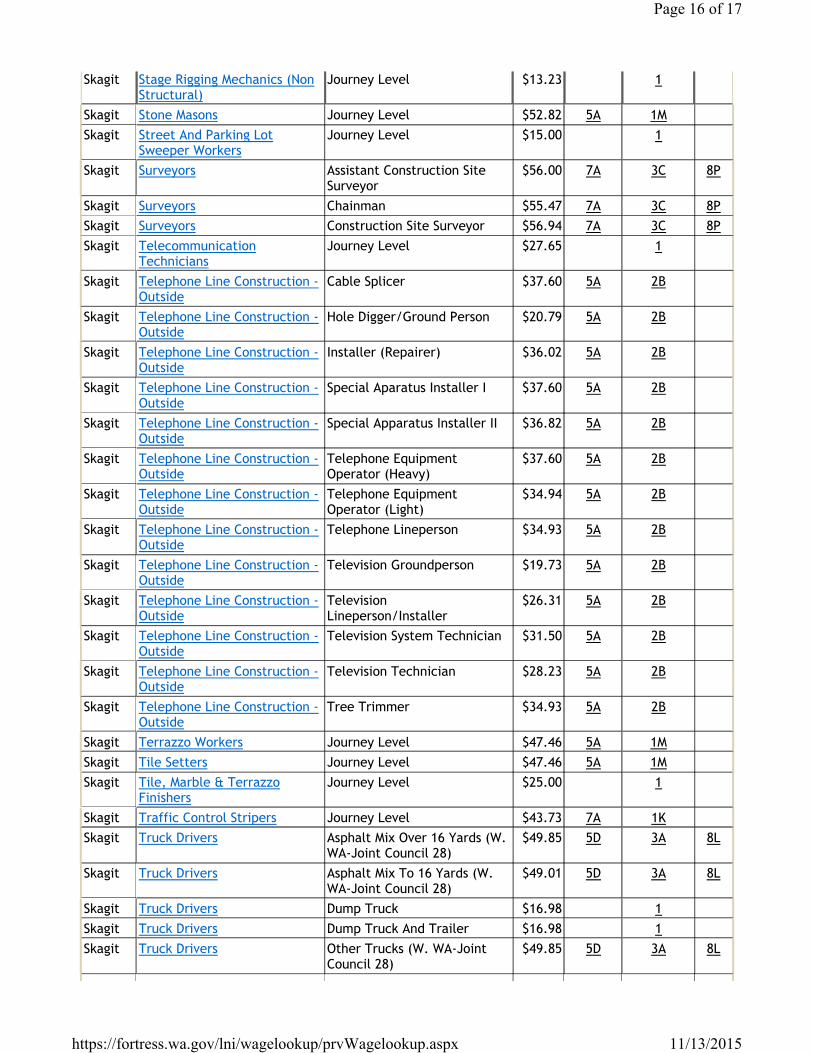
Skagit Stage Rigging Mechanics (Non Structural)
Journey Level $13.23 1
Skagit Stone Masons Journey Level $52.82 5A 1MSkagit Street And Parking Lot
Sweeper WorkersJourney Level $15.00 1
Skagit Surveyors Assistant Construction Site Surveyor
$56.00 7A 3C 8P
Skagit Surveyors Chainman $55.47 7A 3C 8PSkagit Surveyors Construction Site Surveyor $56.94 7A 3C 8PSkagit Telecommunication
TechniciansJourney Level $27.65 1
Skagit Telephone Line Construction - Outside
Cable Splicer $37.60 5A 2B
Skagit Telephone Line Construction - Outside
Hole Digger/Ground Person $20.79 5A 2B
Skagit Telephone Line Construction - Outside
Installer (Repairer) $36.02 5A 2B
Skagit Telephone Line Construction - Outside
Special Aparatus Installer I $37.60 5A 2B
Skagit Telephone Line Construction - Outside
Special Apparatus Installer II $36.82 5A 2B
Skagit Telephone Line Construction - Outside
Telephone Equipment Operator (Heavy)
$37.60 5A 2B
Skagit Telephone Line Construction - Outside
Telephone Equipment Operator (Light)
$34.94 5A 2B
Skagit Telephone Line Construction - Outside
Telephone Lineperson $34.93 5A 2B
Skagit Telephone Line Construction - Outside
Television Groundperson $19.73 5A 2B
Skagit Telephone Line Construction - Outside
Television Lineperson/Installer
$26.31 5A 2B
Skagit Telephone Line Construction - Outside
Television System Technician $31.50 5A 2B
Skagit Telephone Line Construction - Outside
Television Technician $28.23 5A 2B
Skagit Telephone Line Construction - Outside
Tree Trimmer $34.93 5A 2B
Skagit Terrazzo Workers Journey Level $47.46 5A 1MSkagit Tile Setters Journey Level $47.46 5A 1MSkagit Tile, Marble & Terrazzo
FinishersJourney Level $25.00 1
Skagit Traffic Control Stripers Journey Level $43.73 7A 1KSkagit Truck Drivers Asphalt Mix Over 16 Yards (W.
WA-Joint Council 28)$49.85 5D 3A 8L
Skagit Truck Drivers Asphalt Mix To 16 Yards (W. WA-Joint Council 28)
$49.01 5D 3A 8L
Skagit Truck Drivers Dump Truck $16.98 1Skagit Truck Drivers Dump Truck And Trailer $16.98 1Skagit Truck Drivers Other Trucks (W. WA-Joint
Council 28)$49.85 5D 3A 8L
Page 16 of 17
11/13/2015https://fortress.wa.gov/lni/wagelookup/prvWagelookup.aspx
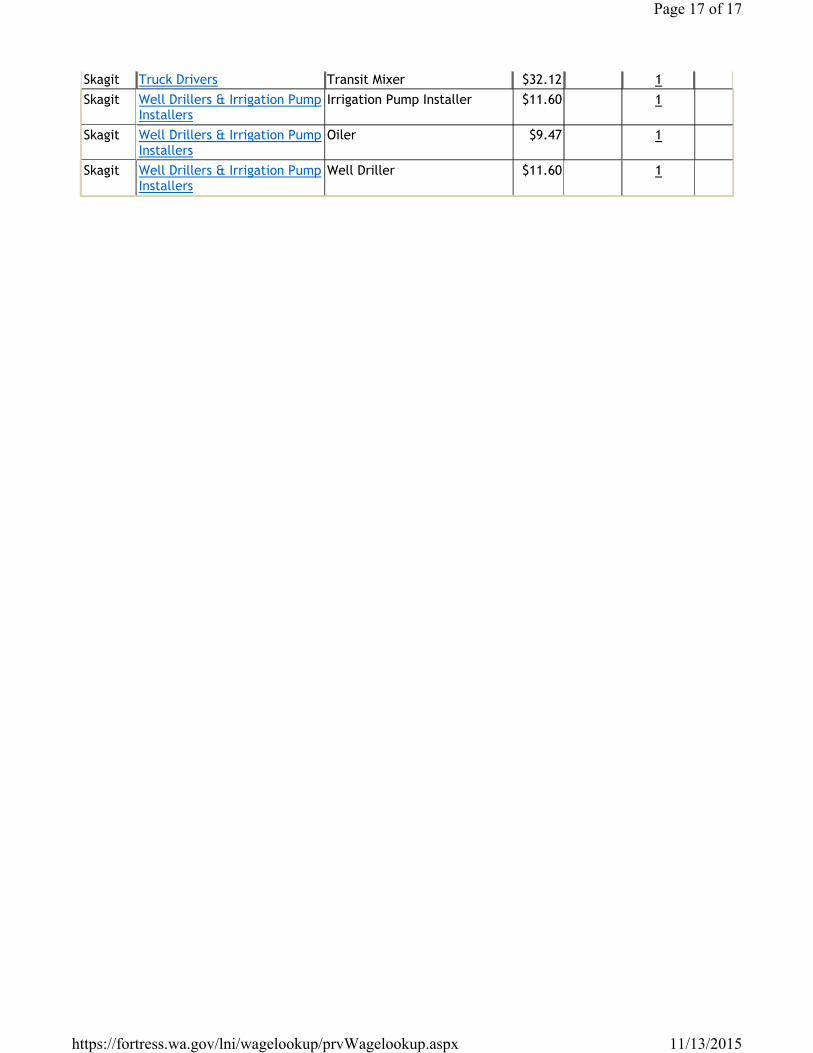
Skagit Truck Drivers Transit Mixer $32.12 1Skagit Well Drillers & Irrigation Pump
InstallersIrrigation Pump Installer $11.60 1
Skagit Well Drillers & Irrigation Pump Installers
Oiler $9.47 1
Skagit Well Drillers & Irrigation Pump Installers
Well Driller $11.60 1
Page 17 of 17
11/13/2015https://fortress.wa.gov/lni/wagelookup/prvWagelookup.aspx

This page left intentionally blank.


