Embed Size (px)
Citation preview
Contact Displacement Sensors
D5V
D5M
D5SN
Contact Displacement Sensors Warranty and Application Considerations 1
Warranty and Application Considerations
Warranty and Limitations of Liability
Read and Understand this Catalog
Please read and understand this catalog before purchasing the products. Please consult your OMRON representative if you have any questions or comments.
Warranty and Limitations of Liability
WARRANTY
OMRON's exclusive warranty is that the products are free from defects in materials and workmanship for a period of one year (or other period if specified) from date of sale by OMRON.
OMRON MAKES NO WARRANTY OR REPRESENTATION, EXPRESS OR IMPLIED, REGARDING NON-INFRINGEMENT, MERCHANTABILITY, OR FITNESS FOR PARTICULAR PURPOSE OF THE PRODUCTS. ANY BUYER OR USER ACKNOWLEDGES THAT THE BUYER OR USER ALONE HAS DETERMINED THAT THE PRODUCTS WILL SUITABLY MEET THE REQUIREMENTS OF THEIR INTENDED USE. OMRON DISCLAIMS ALL OTHER WARRANTIES, EXPRESS OR IMPLIED.
LIMITATIONS OF LIABILITY
OMRON SHALL NOT BE RESPONSIBLE FOR SPECIAL, INDIRECT, OR CONSEQUENTIAL DAMAGES, LOSS OF PROFITS, OR COMMERCIAL LOSS IN ANY WAY CONNECTED WITH THE PRODUCTS, WHETHER SUCH CLAIM IS BASED ON CONTRACT, WARRANTY, NEGLIGENCE, OR STRICT LIABILITY.
In no event shall the responsibility of OMRON for any act exceed the individual price of the product on which liability is asserted.
IN NO EVENT SHALL OMRON BE RESPONSIBLE FOR WARRANTY, REPAIR, OR OTHER CLAIMS REGARDING THE PRODUCTS UNLESS OMRON'S ANALYSIS CONFIRMS THAT THE PRODUCTS WERE PROPERLY HANDLED, STORED, INSTALLED, AND MAINTAINED AND NOT SUBJECT TO CONTAMINATION, ABUSE, MISUSE, OR INAPPROPRIATE MODIFICATION OR REPAIR.
2 Contact Displacement Sensors Warranty and Application Considerations
Application Considerations
Disclaimers
Application Considerations
BASIC CONSIDERATIONS
At OMRON, we are constantly working to improve the quality and reliability of our products.
SELECTION OF PRODUCTS
The applications, illustrations, and charts shown in this catalog are intended solely for purposes of example. Because there are many variables and requirements associated with any particular application, the final design can only be made in view of the specific parameters of each application. OMRON does not assume responsibility or liability for actual use based upon the examples shown in this catalog. Please consult one of our sales offices if you have any doubts or questions concerning your application.
SUITABILITY FOR USE
OMRON shall not be responsible for conformity with any standards, codes, or regulations that apply to the combination of products in the customer's application or use of the products.
At the customer's request, OMRON will provide applicable third party certification documents identifying ratings and limitations of use that apply to the products. This information by itself is not sufficient for a complete determination of the suitability of the products in combination with the end product, machine, system, or other application or use.
The following are some examples of applications for which particular attention must be given. This is not intended to be an exhaustive list of all possible uses of the products, nor is it intended to imply that the uses listed may be suitable for the products.
• Outdoor use, uses involving potential chemical contamination or electrical interference, or conditions or uses not described inthis catalog.
• Nuclear energy control systems, combustion systems, railroad systems, aviation systems, medical equipment, amusementmachines, vehicles, safety equipment, and installations subject to separate industry or government regulations.
• Systems, machines, and equipment that could present a risk to life or property.
Please know and observe all prohibitions of use applicable to the products.
NEVER USE THE PRODUCTS FOR AN APPLICATION INVOLVING SERIOUS RISK TO LIFE OR PROPERTY WITHOUT ENSURING THAT THE SYSTEM AS A WHOLE HAS BEEN DESIGNED TO ADDRESS THE RISKS, AND THAT THE OMRON PRODUCTS ARE PROPERLY RATED AND INSTALLED FOR THE INTENDED USE WITHIN THE OVERALL EQUIPMENT OR SYSTEM.
Disclaimers
PERFORMANCE DATA
Performance data given in this catalog is provided as a guide for the user in determining suitability and does not constitute a warranty. It may represent the result of OMRON's test conditions, and the users must correlate it to actual application requirements. Actual performance is subject to the OMRON Warranty and Limitations of Liability.
CHANGE IN SPECIFICATIONS
Product specifications and accessories may be changed at any time based on improvements and other reasons.
It is our practice to change model numbers when published ratings or features are changed, or when significant construction changes are made. However, some specifications of the products may be changed without any notice. When in doubt, special model numbers may be assigned to fix or establish key specifications for your application on your request. Please consult with your OMRON representative at any time to confirm actual specifications of purchased products.
DIMENSIONS AND WEIGHTS
Dimensions and weights are nominal and are not to be used for manufacturing purposes, even when tolerances are shown.
ERRORS AND OMISSIONS
The information in this catalog has been carefully checked and is believed to be accurate; however, no responsibility is assumed for clerical, typographical, or proofreading errors, or omissions.
Contact Displacement Sensors Warranty and Application Considerations 3
Copyright and Copy Permission
Copyright and Copy Permission
COPYRIGHT AND COPY PERMISSION
This catalog shall not be copied for sales or promotions without permission.
This catalog is protected by copyright and is intended solely for use in conjunction with the products. Please notify us before copying or reproducing this catalog in any manner, for any other purpose. If copying or transmitting this catalog to another, please copy or transmit it in its entirety.
4 Contact Displacement Sensors Safety Precautions
Safety Precautions
Meaning of Signal WordsThe following signal words are used in this catalog.
Meaning of Alert SymbolsThe following alert symbols are used in this catalog.
Alert Statements in this CatalogThe following alert statements apply to the products in this catalog. Each alert statement also appears at the locations needed inthis catalog to attract your attention.
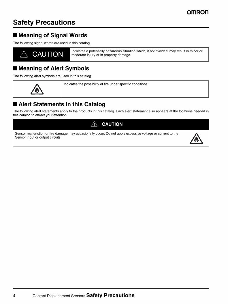
@ CAUTIONIndicates a potentially hazardous situation which, if not avoided, may result in minor or moderate injury or in property damage.
Indicates the possibility of fire under specific conditions.
@ CAUTION
Sensor malfunction or fire damage may occasionally occur. Do not apply excessive voltage or current to the Sensor input or output circuits.

Contact Displacement Sensors Safety Precautions 5
6 Contact Displacement Sensors Selection Guide
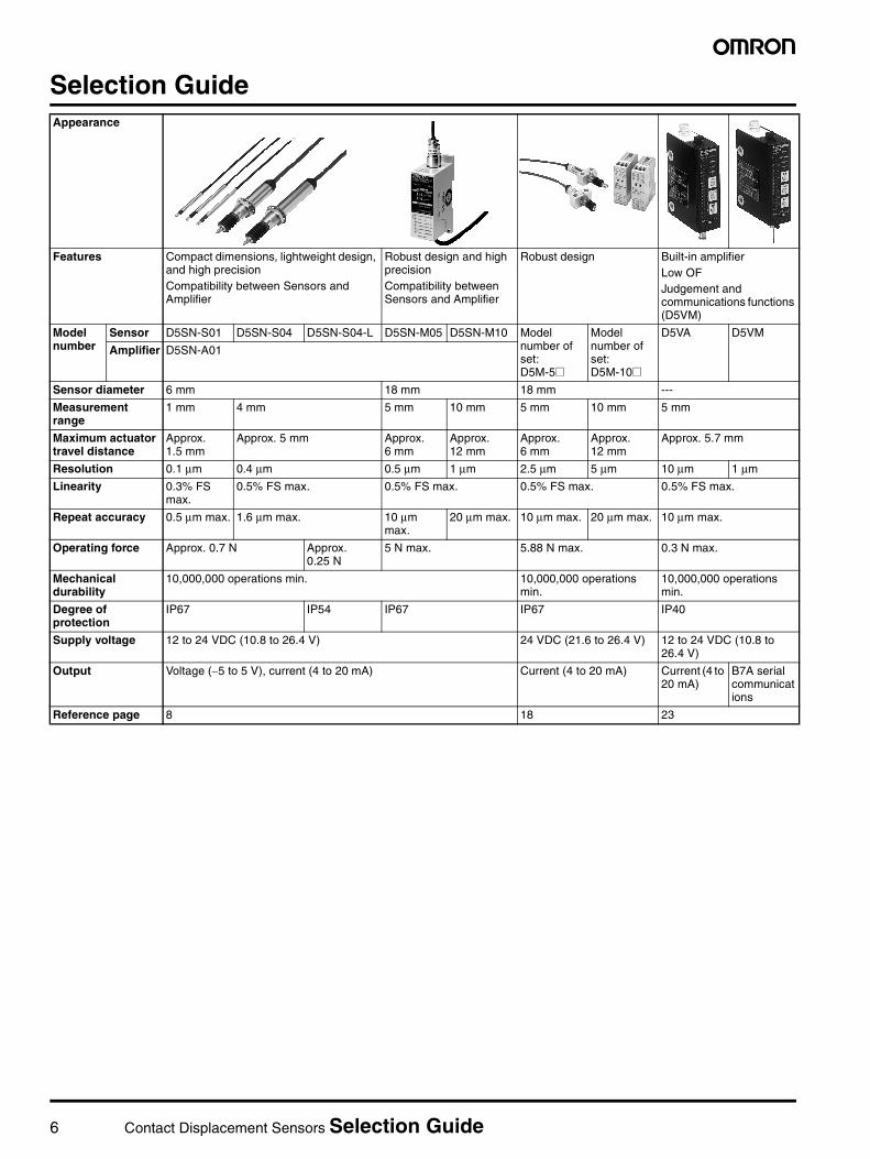
Selection GuideAppearance
Features Compact dimensions, lightweight design, and high precisionCompatibility between Sensors and Amplifier
Robust design and high precisionCompatibility between Sensors and Amplifier
Robust design Built-in amplifierLow OFJudgement and communications functions (D5VM)
Model number
Sensor D5SN-S01 D5SN-S04 D5SN-S04-L D5SN-M05 D5SN-M10 Model number of set: D5M-5@
Model number of set: D5M-10@
D5VA D5VM
Amplifier D5SN-A01
Sensor diameter 6 mm 18 mm 18 mm ---
Measurement range
1 mm 4 mm 5 mm 10 mm 5 mm 10 mm 5 mm
Maximum actuator travel distance
Approx. 1.5 mm
Approx. 5 mm Approx. 6 mm
Approx. 12 mm
Approx. 6 mm
Approx. 12 mm
Approx. 5.7 mm
Resolution 0.1 µm 0.4 µm 0.5 µm 1 µm 2.5 µm 5 µm 10 µm 1 µm
Linearity 0.3% FS max.
0.5% FS max. 0.5% FS max. 0.5% FS max. 0.5% FS max.
Repeat accuracy 0.5 µm max. 1.6 µm max. 10 µm max.
20 µm max. 10 µm max. 20 µm max. 10 µm max.
Operating force Approx. 0.7 N Approx. 0.25 N
5 N max. 5.88 N max. 0.3 N max.
Mechanical durability
10,000,000 operations min. 10,000,000 operations min.
10,000,000 operations min.
Degree of protection
IP67 IP54 IP67 IP67 IP40
Supply voltage 12 to 24 VDC (10.8 to 26.4 V) 24 VDC (21.6 to 26.4 V) 12 to 24 VDC (10.8 to 26.4 V)
Output Voltage (−5 to 5 V), current (4 to 20 mA) Current (4 to 20 mA) Current (4 to 20 mA)
B7A serial communications
Reference page 8 18 23

7
TABLE OF CONTENTSD5SN . . . . . . . . . . . . . . . . . . . . . . . . . . . . . . . . . . . . . . . . . . . . 8
D5M . . . . . . . . . . . . . . . . . . . . . . . . . . . . . . . . . . . . . . . . . . . . . 18
D5V . . . . . . . . . . . . . . . . . . . . . . . . . . . . . . . . . . . . . . . . . . . . . 23
8 Contact Displacement Sensor D5SN
Contact Displacement Sensor
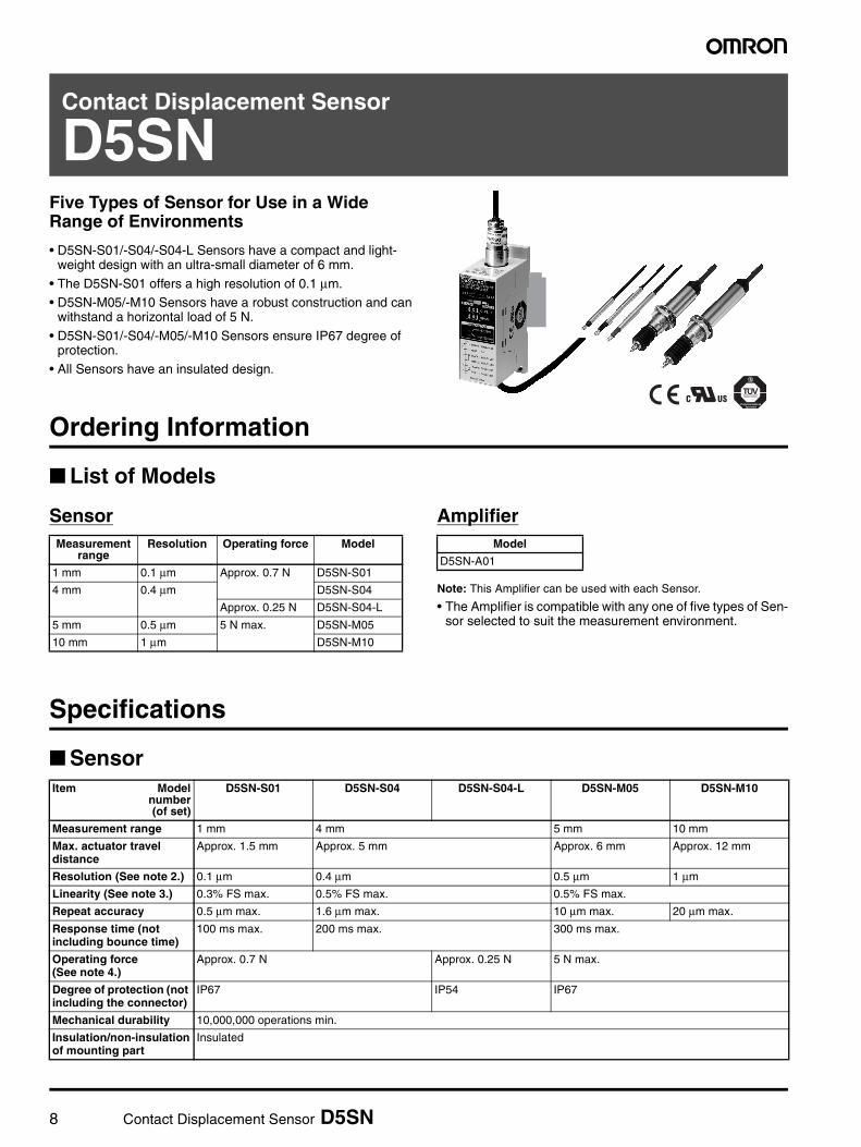
D5SNFive Types of Sensor for Use in a Wide Range of Environments
• D5SN-S01/-S04/-S04-L Sensors have a compact and light-weight design with an ultra-small diameter of 6 mm.
• The D5SN-S01 offers a high resolution of 0.1 µm.• D5SN-M05/-M10 Sensors have a robust construction and can
withstand a horizontal load of 5 N.
• D5SN-S01/-S04/-M05/-M10 Sensors ensure IP67 degree of protection.
• All Sensors have an insulated design.
Ordering Information
List of Models
Sensor Amplifier
Note: This Amplifier can be used with each Sensor.
• The Amplifier is compatible with any one of five types of Sen-sor selected to suit the measurement environment.
Specifications
Sensor
Measurement range
Resolution Operating force Model
1 mm 0.1 µm Approx. 0.7 N D5SN-S01
4 mm 0.4 µm D5SN-S04
Approx. 0.25 N D5SN-S04-L
5 mm 0.5 µm 5 N max. D5SN-M05
10 mm 1 µm D5SN-M10
Model
D5SN-A01
Item Modelnumber(of set)
D5SN-S01 D5SN-S04 D5SN-S04-L D5SN-M05 D5SN-M10
Measurement range 1 mm 4 mm 5 mm 10 mm
Max. actuator travel distance
Approx. 1.5 mm Approx. 5 mm Approx. 6 mm Approx. 12 mm
Resolution (See note 2.) 0.1 µm 0.4 µm 0.5 µm 1 µm
Linearity (See note 3.) 0.3% FS max. 0.5% FS max. 0.5% FS max.
Repeat accuracy 0.5 µm max. 1.6 µm max. 10 µm max. 20 µm max.
Response time (not including bounce time)
100 ms max. 200 ms max. 300 ms max.
Operating force(See note 4.)
Approx. 0.7 N Approx. 0.25 N 5 N max.
Degree of protection (not including the connector)
IP67 IP54 IP67
Mechanical durability 10,000,000 operations min.
Insulation/non-insulation of mounting part
Insulated
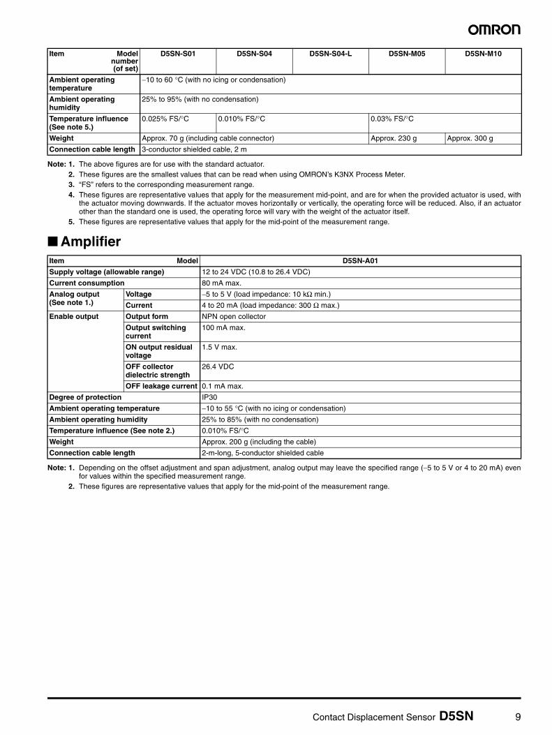
Contact Displacement Sensor D5SN 9
Note: 1. The above figures are for use with the standard actuator.2. These figures are the smallest values that can be read when using OMRON’s K3NX Process Meter.3. “FS” refers to the corresponding measurement range.4. These figures are representative values that apply for the measurement mid-point, and are for when the provided actuator is used, with
the actuator moving downwards. If the actuator moves horizontally or vertically, the operating force will be reduced. Also, if an actuatorother than the standard one is used, the operating force will vary with the weight of the actuator itself.
5. These figures are representative values that apply for the mid-point of the measurement range.
Amplifier
Note: 1. Depending on the offset adjustment and span adjustment, analog output may leave the specified range (−5 to 5 V or 4 to 20 mA) evenfor values within the specified measurement range.
2. These figures are representative values that apply for the mid-point of the measurement range.
Ambient operating temperature
−10 to 60 °C (with no icing or condensation)
Ambient operating humidity
25% to 95% (with no condensation)
Temperature influence (See note 5.)
0.025% FS/°C 0.010% FS/°C 0.03% FS/°C
Weight Approx. 70 g (including cable connector) Approx. 230 g Approx. 300 g
Connection cable length 3-conductor shielded cable, 2 m
Item Modelnumber(of set)
D5SN-S01 D5SN-S04 D5SN-S04-L D5SN-M05 D5SN-M10
Item Model D5SN-A01
Supply voltage (allowable range) 12 to 24 VDC (10.8 to 26.4 VDC)
Current consumption 80 mA max.
Analog output (See note 1.)
Voltage −5 to 5 V (load impedance: 10 kΩ min.)
Current 4 to 20 mA (load impedance: 300 Ω max.)
Enable output Output form NPN open collector
Output switching current
100 mA max.
ON output residual voltage
1.5 V max.
OFF collector dielectric strength
26.4 VDC
OFF leakage current 0.1 mA max.
Degree of protection IP30
Ambient operating temperature −10 to 55 °C (with no icing or condensation)
Ambient operating humidity 25% to 85% (with no condensation)
Temperature influence (See note 2.) 0.010% FS/°CWeight Approx. 200 g (including the cable)
Connection cable length 2-m-long, 5-conductor shielded cable
10 Contact Displacement Sensor D5SN
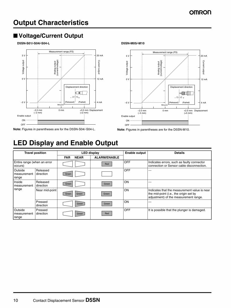
Output Characteristics
Voltage/Current Output
Note: Figures in parentheses are for the D5SN-S04/-S04-L. Note: Figures in parentheses are for the D5SN-M10.
LED Display and Enable Output
測定範囲(F.S.)
中心
5 VA
nalo
g ou
tput
(cur
rent
/vol
tage
)20 mA
Current output
Displacement direction
+−
(Pushed)(Released)−5 V
0 V
Vol
tage
out
put
12 mA
4 mA
Displacement 0 mm +0.5 mm(+2 mm)
−0.5 mm(−2 mm)
ON
Enable output
OFF
Measurement range (FS)
Mid-point
D5SN-S01/-S04/-S04-L
Ana
log
outp
ut(c
urre
nt/v
olta
ge)
5 V 20 mA
+−
−5 V
0 V 12 mA
4 mA
Displacement 0 mm +2.5 mm(+5 mm)
−2.5 mm(−5 mm)
ON
Enable output
OFF
Measurement range (FS)
Mid-point
Displacement direction
(Pushed)(Released)
Vol
tage
out
put C
urrent output
D5SN-M05/-M10
Travel position LED display Enable output Details
FAR NEAR ALARM/ENABLE
Entire range (when an error occurs)
OFF Indicates errors, such as faulty connector connection or Sensor cable disconnection.
Outside measurement range
Released direction
OFF ---
Inside measurement range
Released direction
ON ---
Near mid-point ON Indicates that the measurement value is near the mid-point (i.e., the origin set by adjustment) of the measurement range.
Pressed direction
ON ---
Outside measurement range
Pressed direction
OFF It is possible that the plunger is damaged.
Red
Green
Green Green
Green Green Green
Green Green
Green Red
Contact Displacement Sensor D5SN 11
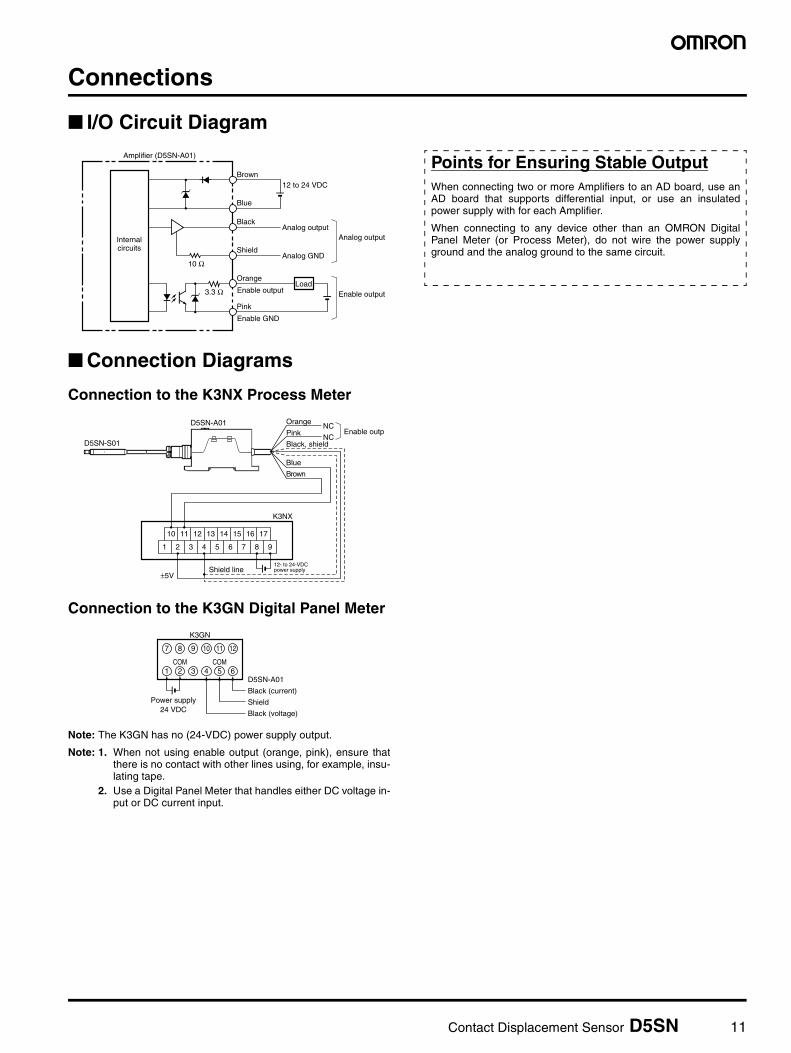
Connections
I/O Circuit Diagram
Connection Diagrams
Connection to the K3NX Process Meter
Connection to the K3GN Digital Panel Meter
Note: The K3GN has no (24-VDC) power supply output.
Note: 1. When not using enable output (orange, pink), ensure thatthere is no contact with other lines using, for example, insu-lating tape.
2. Use a Digital Panel Meter that handles either DC voltage in-put or DC current input.
Internalcircuits
12 to 24 VDC
Amplifier (D5SN-A01)
Analog outputAnalog output
Enable output
Analog GND
LoadEnable output3.3 Ω
Pink
Orange
Shield
Black
Blue
Brown
10 Ω
Enable GND
Shield line
Black, shield
Pink
OrangeNC
Enable outpNC
Brown
Blue
±5V
K3NX
12- to 24-VDCpower supply
10 11 12 13 14 15 16 17
987654321
D5SN-A01
D5SN-S01
1 2 3 4 5 6
7 8 9 10 11 12
Black (current)Power supply
24 VDC
COM COM
Shield
Black (voltage)
D5SN-A01
K3GN
Points for Ensuring Stable OutputWhen connecting two or more Amplifiers to an AD board, use anAD board that supports differential input, or use an insulatedpower supply with for each Amplifier.
When connecting to any device other than an OMRON DigitalPanel Meter (or Process Meter), do not wire the power supplyground and the analog ground to the same circuit.
12 Contact Displacement Sensor D5SN
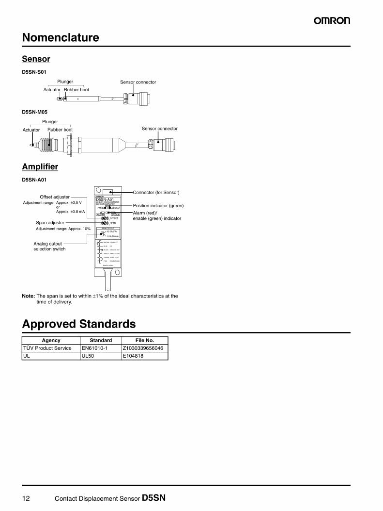
Nomenclature
SensorD5SN-S01
D5SN-M05
AmplifierD5SN-A01
Note: The span is set to within ±1% of the ideal characteristics at thetime of delivery.
Approved Standards
Sensor connectorPlunger
Actuator Rubber boot
Sensor connector
Plunger
Actuator Rubber boot
BROWN : 12to24V DC
BLUE : 0V
BLACK : ANALOG OUT
SHIELD : ANALOG GND
ORANGE : ENABLE OUT
PINK : ENABLE GND
MADE IN JAPAN
D5SN-A01LINEAR DISPLACEMENTSENSOR AMPLIFIER
FAR NEAR
ALARM ENABLE
OFFSET
SPAN
ANALOG OUT
V(–5to5V)
I (4to20mA)
+–
+–
Adjustment range: Approx. 10%
Analog outputselection switch
Connector (for Sensor)
Position indicator (green)
Alarm (red)/enable (green) indicator
Offset adjusterAdjustment range: Approx. ±0.5 V
orApprox. ±0.8 mA
Span adjuster
Agency Standard File No.
TÜV Product Service EN61010-1 Z1030339656046
UL UL50 E104818
Contact Displacement Sensor D5SN 13
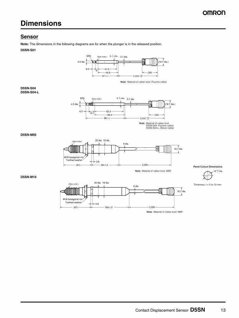
Dimensions
SensorNote: The dimensions in the following diagrams are for when the plunger is in the released position.
D5SN-S01
D5SN-S04D5SN-S04-L
D5SN-M05
D5SN-M10
4.5 dia.
SR3
(16.7 dia.)
57.1±1
44.6
41.66
3.7 dia.
6.5
(34)
Note: Material of rubber boot: Fluorine rubber
6 dia.0−0.1
+150−502,000
(See note.)
4.5 dia.
SR3
(16.7 dia.)
66.4
63.413.1
3.7 dia.
6.5
(34)86±1.5
6 dia.0−0.1
+150−502,000
(See note.)
Note: Material of rubber bootD5SN-S04: Fluorine rubberD5SN-S04-L: Silicon rubber
Toothed washer
(61)
3.8
20 dia. 18 dia.
6 dia.
59±1.2 2,000
16.7 dia.
M18 hexagonal nut
(See note.)
Note: Material of rubber boot: NBR 18 dia.+0.10
Panel Cutout Dimensions
Thickness, t = 5 to 12 mm
(67)
3.8
20 dia. 18 dia.
6 dia.
83±1.2 2,000
16.7 dia.
(See note.)
M18 hexagonal nutToothed washer
Note: Material of rubber boot: NBR
14 Contact Displacement Sensor D5SN
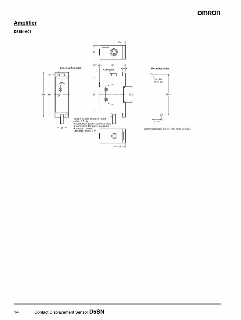
Amplifier
D5SN-A01
25
25
30
0.7
Connector
89±0.2
21±0.2
Two, M4or 4.3 dia.
Two, mounting holes 6
55
80
21
98 89 35.2
Vinyl-insulated shielded round cable, 5.0 dia.5 conductors (cross-sectional area of conductor: 0.2 mm2; insulation diameter: 1.0 mm)Standard length: 2 m
Mounting Holes
Tightening torque: 0.6 to 1.0 N·m (M4 screw)
Contact Displacement Sensor D5SN 15
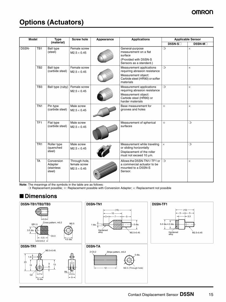
Options (Actuators)
Note: The meanings of the symbols in the table are as follows:: Replacement possible; : Replacement possible with Conversion Adapter; ×: Replacement not possible
Dimensions
Model Type (material)
Screw hole Appearance Applications Applicable Sensor
D5SN-S@ D5SN-M@D5SN- TB1 Ball type
(steel)Female screwM2.5 × 0.45
General-purpose measurement on a flat surface(Provided with D5SN-S Sensors as a standard.)
×
TB2 Ball type(carbide steel)
Female screwM2.5 × 0.45
Measurement applications requiring abrasion resistanceMeasurement object: Carbide steel (HR90) or softer materials
×
TB3 Ball type (ruby) Female screwM2.5 × 0.45
Measurement applications requiring abrasion resistanceMeasurement object: Carbide steel (HR90) or harder materials
×
TN1 Pin type (carbide steel)
Male screwM2.5 × 0.45
Base measurement for grooves and holes
×
TF1 Flat type (carbide steel)
Male screwM2.5 × 0.45
Measurement of spherical surfaces
TR1 Roller type (quenched steel)
Male screwM2.5 × 0.45
Measurement while traveling or sliding horizontallyDisplacement of the roller must not exceed 10 µm.
×
TA Conversion Adapter (stainless steel)
Through-hole, female screwM2.5 × 0.45
Allows the D5SN-TN1/-TF1 or a commercial actuator to be mounted to a D5SN-S Sensor.
×
D5SN-TB1/TB2/TB3 D5SN-TN1 D5SN-TF1
D5SN-TR1 D5SN-TA
4.5 dia.5.5
SR1.5
6.5±0.2
C0.3
3.5
Cross pattern, m0.2 M2.5
3.5 dia.
3 7
10
(15)
5
1 dia. 5 dia.
Hardened alloy M2.5×0.45
4.3 dia.5.2 dia.
M2.5×0.45
55
3.3
(10)
Hardened alloy
M2.5×0.45
1.6
1523
C2 7
3 13
3
10 dia.9
R5
Stripe pattern, m0.22-C0.2
12
5 dia.
M2.5 (Through-hole)
16 Contact Displacement Sensor D5SN
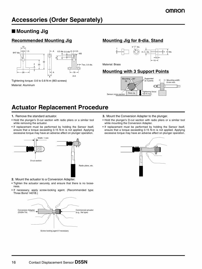
Accessories (Order Separately)
Mounting Jig
Recommended Mounting Jig
Tightening torque: 0.6 to 0.8 N·m (M3 screws)
Material: Aluminum
Mounting Jig for 8-dia. Stand
Material: Brass
Mounting with 3 Support Points
Actuator Replacement Procedure1. Remove the standard actuator.• Hold the plunger’s D-cut section with radio pliers or a similar tool
while removing the actuator.• If replacement must be performed by holding the Sensor itself,
ensure that a torque exceeding 0.15 N·m is not applied. Applyingexcessive torque may have an adverse affect on plunger operation.
2. Mount the actuator to a Conversion Adapter.• Tighten the actuator securely, and ensure that there is no loose-
ness.• If necessary, apply screw-locking agent. (Recommended type:
Three Bond 1401B.)
3. Mount the Conversion Adapter to the plunger.• Hold the plunger’s D-cut section with radio pliers or a similar tool
while mounting the Conversion Adapter.• If replacement must be performed by holding the Sensor itself,
ensure that a torque exceeding 0.15 N·m is not applied. Applyingexcessive torque may have an adverse affect on plunger operation.
A-A
26
3220
8
A
A
18
Two, 3.5 dia.
M33.53.5 dia.6.5 dia.
8
4
1.56H7 dia.
101
15
5
12 dia.18 dia.0−0.03
6 dia.+0.010
Supportedat 3 points
60°Mountingjig
Sensor cross-sectionTightening force:100 N max.Base jig
Mounting width:8 mm min.
D-cut section
Width: 1 mm
Radio pliers, etc.
Commercial actuator(e.g., flat type)
Conversion Adapter(D5SN-TA)
Screw-locking agent if necessary
Contact Displacement Sensor D5SN 17
Safety Precautions
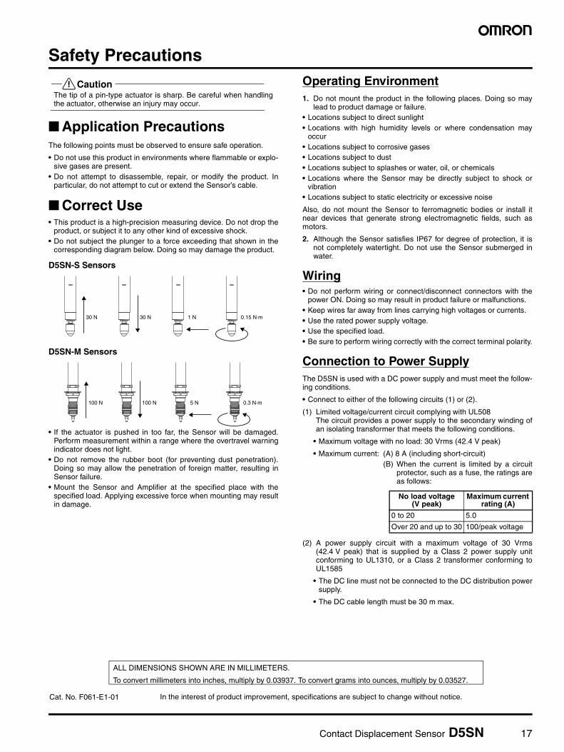
!CautionThe tip of a pin-type actuator is sharp. Be careful when handlingthe actuator, otherwise an injury may occur.
Application PrecautionsThe following points must be observed to ensure safe operation.
• Do not use this product in environments where flammable or explo-sive gases are present.
• Do not attempt to disassemble, repair, or modify the product. Inparticular, do not attempt to cut or extend the Sensor’s cable.
Correct Use• This product is a high-precision measuring device. Do not drop the
product, or subject it to any other kind of excessive shock.• Do not subject the plunger to a force exceeding that shown in the
corresponding diagram below. Doing so may damage the product.
D5SN-S Sensors
D5SN-M Sensors
• If the actuator is pushed in too far, the Sensor will be damaged.Perform measurement within a range where the overtravel warningindicator does not light.
• Do not remove the rubber boot (for preventing dust penetration).Doing so may allow the penetration of foreign matter, resulting inSensor failure.
• Mount the Sensor and Amplifier at the specified place with thespecified load. Applying excessive force when mounting may resultin damage.
Operating Environment1. Do not mount the product in the following places. Doing so may
lead to product damage or failure.• Locations subject to direct sunlight• Locations with high humidity levels or where condensation may
occur• Locations subject to corrosive gases• Locations subject to dust• Locations subject to splashes or water, oil, or chemicals• Locations where the Sensor may be directly subject to shock or
vibration• Locations subject to static electricity or excessive noise
Also, do not mount the Sensor to ferromagnetic bodies or install itnear devices that generate strong electromagnetic fields, such asmotors.
2. Although the Sensor satisfies IP67 for degree of protection, it isnot completely watertight. Do not use the Sensor submerged inwater.
Wiring• Do not perform wiring or connect/disconnect connectors with the
power ON. Doing so may result in product failure or malfunctions.• Keep wires far away from lines carrying high voltages or currents.• Use the rated power supply voltage.• Use the specified load.• Be sure to perform wiring correctly with the correct terminal polarity.
Connection to Power SupplyThe D5SN is used with a DC power supply and must meet the follow-ing conditions.
• Connect to either of the following circuits (1) or (2).
(1) Limited voltage/current circuit complying with UL508The circuit provides a power supply to the secondary winding ofan isolating transformer that meets the following conditions.
• Maximum voltage with no load: 30 Vrms (42.4 V peak)
• Maximum current: (A) 8 A (including short-circuit)(B) When the current is limited by a circuit
protector, such as a fuse, the ratings areas follows:
(2) A power supply circuit with a maximum voltage of 30 Vrms(42.4 V peak) that is supplied by a Class 2 power supply unitconforming to UL1310, or a Class 2 transformer conforming toUL1585
• The DC line must not be connected to the DC distribution powersupply.
• The DC cable length must be 30 m max.
30 N 30 N 1 N 0.15 N·m
100 N 100 N 5 N 0.3 N·m
No load voltage (V peak)
Maximum current rating (A)
0 to 20 5.0
Over 20 and up to 30 100/peak voltage
In the interest of product improvement, specifications are subject to change without notice.
ALL DIMENSIONS SHOWN ARE IN MILLIMETERS.
To convert millimeters into inches, multiply by 0.03937. To convert grams into ounces, multiply by 0.03527.
Cat. No. F061-E1-01
18 Contact Linear Sensor D5M
Contact Linear Sensor
D5MContact Linear Sensor Conforming to IP67 Makes In-line Detection Possible Even in Harsh Environments
• Sensor satisfies IP67 (IEC standards) requirements.
• Ensures a current linear output of 4 to 20 mA.• Easy offset adjustment with the Amplifier. • Conforms to EMC Directives (certified by TÜV) and bears the
CE marking.
Ordering Information
List of Models
Note: 1. Specify the set when ordering.2. A Sensor and Amplifier are adjusted together as a set. Purchase Sensors in combination with Amplifiers.
Connection Diagrams
Construction Connection between Sensor and Amplifier
Terminal Arrangement
Note: Nothing connects to terminals 3, 6,10, and 11. Terminals 1, 4, and 12 areconnected together internally.
Travel Distance Actuator Accessory Model5 mm Ball type --- D5M-5B
Securing block D5M-5BB
Roller type --- D5M-5R
Securing block D5M-5RB10 mm Ball type --- D5M-10B
Securing block D5M-10BB
Roller type --- D5M-10R
Securing block D5M-10RB
Ball plunger Securing block Rubber cap
CableCaseRubber boot
4 to 20 mA
GND
ShieldBrown BlackBlue
D5M Amplifier
G IH
J LK
D FE
A CB
24 VDC
No. Terminal1 GND
24 VDC2
3 N.C.
4 GND
Output 4 to 20 mA5
6 N.C.
7 Brown
Sensor head
8 Blue
9 Black
10 N.C.11 N.C.
12 Shield
Contact Linear Sensor D5M 19
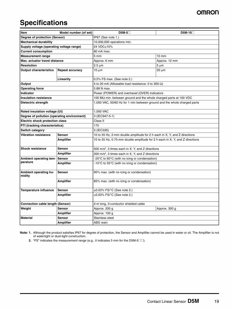
Specifications
Note: 1. Although the product satisfies IP67 for degree of protection, the Sensor and Amplifier cannot be used in water or oil. The Amplifier is notof watertight or dust-tight construction.
2. “FS” indicates the measurement range (e.g., it indicates 5 mm for the D5M-5@@).
Item Model number (of set) D5M-5@ D5M-10@Degree of protection (Sensor) IP67 (See note 1.)
Mechanical durability 10,000,000 operations min.
Supply voltage (operating voltage range) 24 VDC±10%
Current consumption 80 mA max.
Measurement range 5 mm 10 mm
Max. actuator travel distance Approx. 6 mm Approx. 12 mm
Resolution 2.5 µm 5 µm
Output characteristics Repeat accuracy 10 µm 20 µm
Linearity 0.5% FS max. (See note 2.)
Output 4 to 20 mA (Allowable load resistance: 0 to 300 Ω)
Operating force 5.88 N max.
Indicator Power (POWER) and overtravel (OVER) indicators
Insulation resistance 100 MΩ min. between ground and the whole charged parts at 100 VDC
Dielectric strength 1,000 VAC, 50/60 Hz for 1 min between ground and the whole charged parts
Rated insulation voltage (Ui) 1,000 VAC
Degree of pollution (operating environment) 3 (IEC947-5-1)
Electric shock protection class Class II
PTI (tracking characteristics) 175
Switch category 3 (IEC335)
Vibration resistance Sensor 10 to 55 Hz, 2-mm double amplitude for 2 h each in X, Y, and Z directions
Amplifier 10 to 55 Hz, 0.75-mm double amplitude for 2 h each in X, Y, and Z directions
Shock resistance Sensor 500 m/s2, 3 times each in X, Y, and Z directions
Amplifier 200 m/s2, 3 times each in X, Y, and Z directions
Ambient operating tem-perature
Sensor −20°C to 60°C (with no icing or condensation)
Amplifier −10°C to 55°C (with no icing or condensation)
Ambient operating hu-midity
Sensor 95% max. (with no icing or condensation)
Amplifier 85% max. (with no icing or condensation)
Temperature influence Sensor ±0.03% FS/°C (See note 2.)
Amplifier ±0.03% FS/°C (See note 2.)
Connection cable length (Sensor) 2-m long, 3-conductor shielded cable
Weight Sensor Approx. 200 g Approx. 300 g
Amplifier Approx. 100 g
Material Sensor Stainless steel
Amplifier ABS resin
20 Contact Linear Sensor D5M
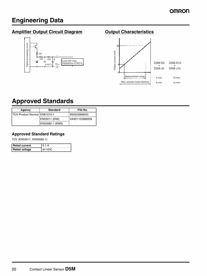
Engineering Data
Amplifier Output Circuit Diagram Output Characteristics
Approved Standards
Approved Standard RatingsTÜV (EN55011, EN50082-1)
Load with max. impedance of 300 Ω
Sig
nal p
roce
ssin
g ci
rcui
t
150
100 100
10 µ0.047 µ
Out
put c
urre
nt (
mA
)
Measurement range
Max. actuator travel distance
D5M-S5+
D5M-J5
5 mm
6 mm
10 mm
12 mm
D5M-S10+
D5M-J10
Agency Standard File No.
TÜV Product Service EN61010-1 950522868003
EN55011 (EMI) XA951122868008
EN50082-1 (EMS)
Rated current 0.1 ARated voltage 24 VDC
Contact Linear Sensor D5M 21
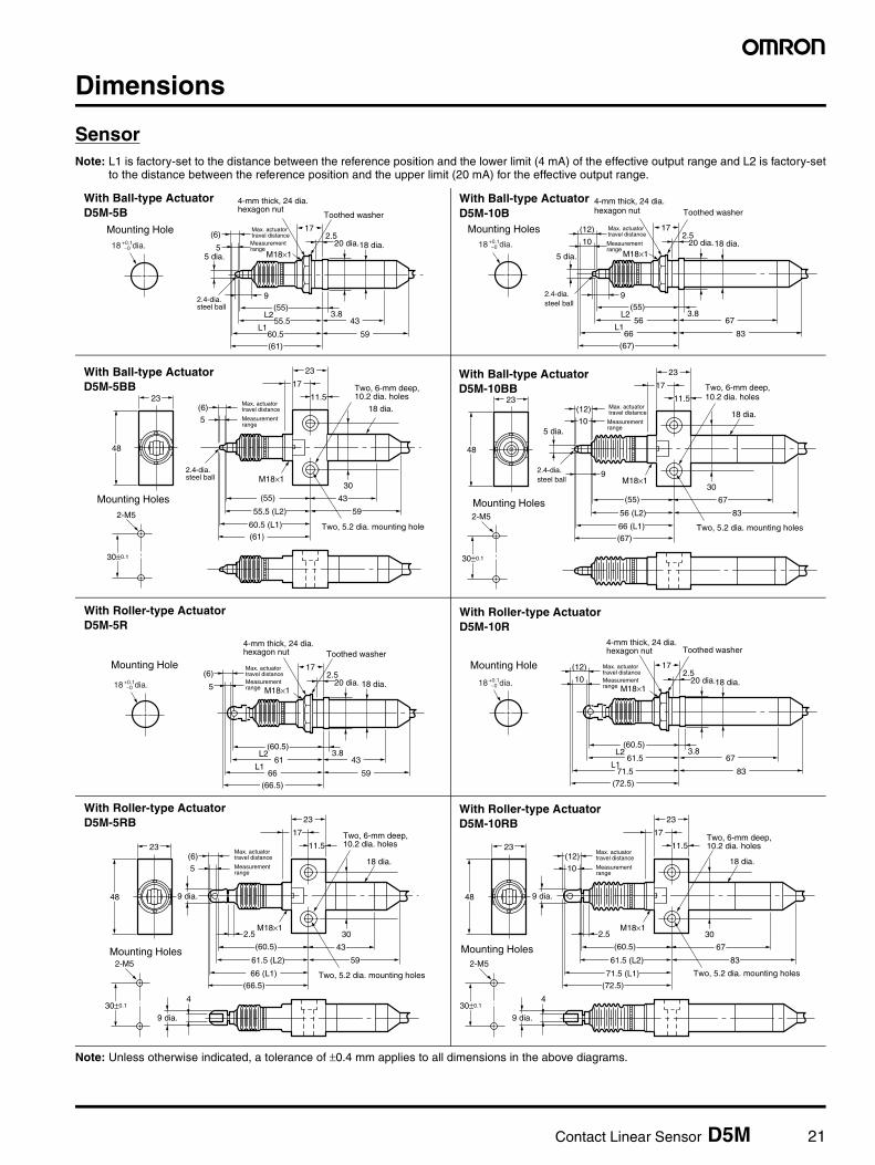
Dimensions
SensorNote: L1 is factory-set to the distance between the reference position and the lower limit (4 mA) of the effective output range and L2 is factory-set
to the distance between the reference position and the upper limit (20 mA) for the effective output range.
Note: Unless otherwise indicated, a tolerance of ±0.4 mm applies to all dimensions in the above diagrams.
(6)
55 dia.
2.4-dia.steel ball
172.5
3.8(55)
9
55.5
60.5
43L2
L159
(61)
20 dia.18 dia.
Max. actuator travel distance
Toothed washer
Measurement range
M18×1
4-mm thick, 24 dia.hexagon nut
Mounting Hole
18 dia.+0.1−0
With Ball-type ActuatorD5M-5B
(12)
10
172.5
Mounting Holes
3.8(55)
56
66
67L2
L183
(67)
20 dia.18 dia.M18×15 dia.
9
18 dia.+0.1−0
2.4-dia.steel ball
Max. actuator travel distance
Toothed washer
Measurement range
4-mm thick, 24 dia.hexagon nut
With Ball-type ActuatorD5M-10B
(6)23
48
30±0.1
5
17
23
11.5
30
(55)
55.5 (L2)
60.5 (L1)
59
Two, 5.2 dia. mounting holes2-M5
(61)
Two, 6-mm deep, 10.2 dia. holes
18 dia.
M18×1
43Mounting Holes
2.4-dia.steel ball
Max. actuator travel distance
Measurement range
With Ball-type ActuatorD5M-5BB
(12)23
48
30±0.1
10
17
23
11.5
30
(55)
56 (L2)
66 (L1)
832-M5
(67)
18 dia.
M18×1
67
9
5 dia.
Two, 5.2 dia. mounting holes
Two, 6-mm deep, 10.2 dia. holes
Mounting Holes
2.4-dia.steel ball
Max. actuator travel distance
Measurement range
With Ball-type ActuatorD5M-10BB
(6)
5
172.5
3.8(60.5)
61
66
43L2
L159
(66.5)
20 dia. 18 dia.M18×1
18 dia.+0.1−0
Max. actuator travel distance
Toothed washer
Measurement range
4-mm thick, 24 dia.hexagon nut
Mounting Hole
With Roller-type ActuatorD5M-5R
(12)
10
172.5
3.8(60.5)
61.5
71.5
67L2
L183
(72.5)
20 dia.18 dia.M18×1
18 dia.+0.1−0
Max. actuator travel distance
Toothed washer
Measurement range
4-mm thick, 24 dia.hexagon nut
Mounting Hole
With Roller-type ActuatorD5M-10R
(6)23
48
9 dia.
430±0.1
5
17
23
11.5
30
(60.5)
61.5 (L2)
66 (L1)
592-M5
(66.5)
18 dia.
M18×12.5
43
9 dia.
Two, 5.2 dia. mounting holes
Two, 6-mm deep, 10.2 dia. holes
Mounting Holes
Max. actuator travel distance
Measurement range
With Roller-type ActuatorD5M-5RB
(12)23
48
9 dia.
430±0.1
10
17
23
11.5
30
(60.5)
61.5 (L2)
71.5 (L1)
832-M5
(72.5)
18 dia.
M18×12.5
67
9 dia.
Two, 5.2 dia. mounting holes
Two, 6-mm deep, 10.2 dia. holes
Mounting Holes
Max. actuator travel distance
Measurement range
With Roller-type ActuatorD5M-10RB
22 Contact Linear Sensor D5M
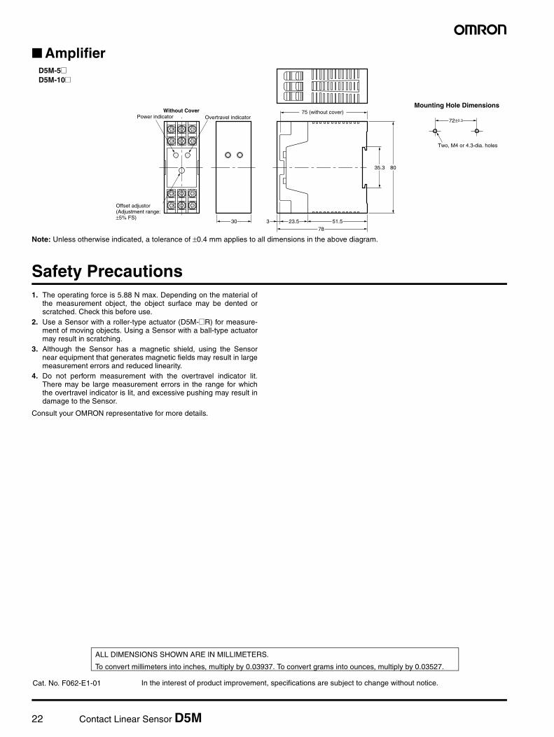
Amplifier
Note: Unless otherwise indicated, a tolerance of ±0.4 mm applies to all dimensions in the above diagram.
Safety Precautions1. The operating force is 5.88 N max. Depending on the material of
the measurement object, the object surface may be dented orscratched. Check this before use.
2. Use a Sensor with a roller-type actuator (D5M-@R) for measure-ment of moving objects. Using a Sensor with a ball-type actuatormay result in scratching.
3. Although the Sensor has a magnetic shield, using the Sensornear equipment that generates magnetic fields may result in largemeasurement errors and reduced linearity.
4. Do not perform measurement with the overtravel indicator lit.There may be large measurement errors in the range for whichthe overtravel indicator is lit, and excessive pushing may result indamage to the Sensor.
Consult your OMRON representative for more details.
Two, M4 or 4.3-dia. holes
72±0.3
8035.3
51.523.530
Overtravel indicatorWithout Cover
Power indicator
Offset adjustor(Adjustment range:±5% FS)
78
3
75 (without cover)Mounting Hole Dimensions
D5M-5@D5M-10@
In the interest of product improvement, specifications are subject to change without notice.
ALL DIMENSIONS SHOWN ARE IN MILLIMETERS.
To convert millimeters into inches, multiply by 0.03937. To convert grams into ounces, multiply by 0.03527.
Cat. No. F062-E1-01
Contact Displacement Sensor D5V 23
Contact Displacement Sensor
D5VContact Displacement Sensor with Built-in Amplifier That Enables In-line Measurement of a Wide Range of Objects with a Low Operating Force
• Works with a low operating force (0.29 N) to detect a wide vari-ety of objects including glass, plastic, and rubber objects.
• Models with digital output for B7A Units and models with 4- to 20-mA linear output corresponding to the 0- to 5-mm measure-ment range are available.
• Models with ball-, flat-, or pin-type actuators are available for a wide variety of objects.
• The XS3 Sensor I/O Connector makes Sensor connections sim-ple.
Ordering Information
List of Models
Note: 1. Flat-type actuators have a hole 5-mm deep for an M2.5 screw in the tip so that an actuator can be mounted externally.2. Use the D5VM-3@1 in combination with the B7A Link Terminal Output Unit or a C200H or CQM1 B7A Interface Unit. Use 16- or 32-point
Units with a standard transmission delay time (19.2 ms).
Measurement range Output specifications Actuator Resolution Model
5 mm 4 to 20 mA Ball type 10 µm D5VA-3B1
Pin type D5VA-3P1
Flat type (See note 1.) D5VA-3F1
B7A serial communications output(See note 2.)
Ball type 1 µm D5VM-3B1
Pin type D5VM-3P1
Flat type (See note 1.) D5VM-3F1
24 Contact Displacement Sensor D5V
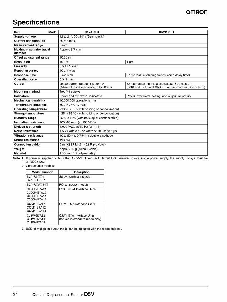
Specifications
Note: 1. If power is supplied to both the D5VM-3@1 and B7A Output Link Terminal from a single power supply, the supply voltage must be24 VDC±10%.
2. Connectable models:
3. BCD or multipoint output mode can be selected with the mode selector.
Item Model D5VA-3@1 D5VM-3@1Supply voltage 12 to 24 VDC±10% (See note 1.)
Current consumption 80 mA max.
Measurement range 5 mmMaximum actuator travel distance
Approx. 5.7 mm
Offset adjustment range ±0.25 mm
Resolution 10 µm 1 µm
Linearity 0.5% FS max.
Repeat accuracy 10 µm max.
Response time 6 ms max. 37 ms max. (including transmission delay time)Operating force 0.3 N max.
Output Linear current output: 4 to 20 mA(Allowable load resistance: 0 to 300 Ω)
B7A serial communications output (See note 2.)(BCD and multipoint ON/OFF output modes) (See note 3.)
Mounting method Two M4 screws
Indicators Power and overtravel indicators Power, overtravel, setting, and output indicators
Mechanical durability 10,000,000 operations min.
Temperature influence ±0.04% FS/°C max.
Operating temperature −10 to 55 °C (with no icing or condensation)Storage temperature −25 to 65 °C (with no icing or condensation)
Humidity range 35% to 85% (with no icing or condensation)
Insulation resistance 100 MΩ min. (at 100 VDC)
Dielectric strength 1,000 VAC, 50/60 Hz for 1 min
Noise resistance 1.5 kV with a pulse width of 100 ns to 1 µs
Vibration resistance 10 to 55 Hz, 0.75-mm double amplitudeShock resistance 196 m/s2
Connection cable 2 m (XS3F-M421-402-R provided)Weight Approx. 80 g (without cable)
Material ABS and PC polymer alloy
Model number Description
B7A-R6@@1B7AS-R6B@1
Screw-terminal models
B7A-R@A@3-@ PC-connector models
C200H-B7A21C200H-B7A22C200H-B7A11C200H-B7A12
C200H B7A Interface Units
CQM1-B7A21CQM1-B7A12CQM1-B7A13
CQM1 B7A Interface Units
CJ1W-B7A22CJ1W-B7A14CJ1W-B7A04
CJW1 B7A Interface Units(for use in standard mode only)
Contact Displacement Sensor D5V 25
Engineering Data
Output Characteristics
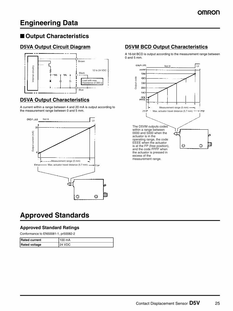
D5VA Output Circuit Diagram
D5VA Output CharacteristicsA current within a range between 4 and 20 mA is output according tothe measurement range between 0 and 5 mm.
D5VM BCD Output CharacteristicsA 16-bit BCD is output according to the measurement range between0 and 5 mm.
Approved Standards
Approved Standard RatingsConformance to EN50081-1, pr50082-2
Inte
rnal
circ
uitr
y
Load with max. impedance of 300 Ω
Brown
Black
Blue
12 to 24 VDC
Not litLit
Out
put c
urre
nt (
mA
)
Measurement range (5 mm)
Max. actuator travel distance (5.7 mm)
Not lit Lit
Out
put c
ode
Measurement range (5 mm)
Max. actuator travel distance (5.7 mm)
The D5VM outputs codes within a range between 0000 and 5000 when the actuator is in the operating range, the code EEEE when the actuator is at the FP (free position), and the code FFFF when the actuator is pressed in excess of the measurement range.
Rated current 100 mA
Rated voltage 24 VDC
26 Contact Displacement Sensor D5V
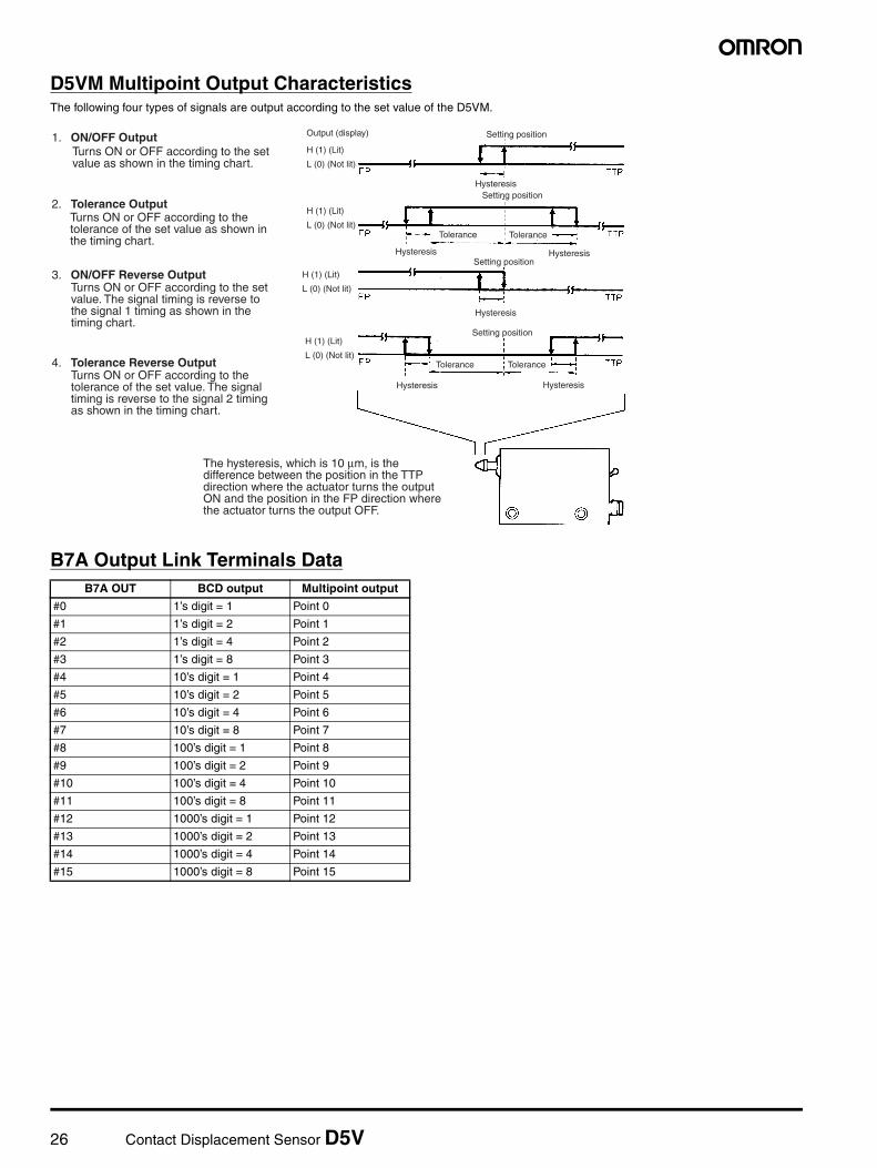
D5VM Multipoint Output CharacteristicsThe following four types of signals are output according to the set value of the D5VM.
B7A Output Link Terminals Data
1. ON/OFF OutputTurns ON or OFF according to the set value as shown in the timing chart.
2. Tolerance OutputTurns ON or OFF according to the tolerance of the set value as shown in the timing chart.
3. ON/OFF Reverse OutputTurns ON or OFF according to the set value. The signal timing is reverse to the signal 1 timing as shown in the timing chart.
4. Tolerance Reverse OutputTurns ON or OFF according to the tolerance of the set value. The signal timing is reverse to the signal 2 timing as shown in the timing chart.
Output (display)
H (1) (Lit)
L (0) (Not lit)
Setting position
HysteresisSetting position
H (1) (Lit)
L (0) (Not lit)
Hysteresis Hysteresis
Tolerance Tolerance
Setting positionH (1) (Lit)
L (0) (Not lit)
Hysteresis
H (1) (Lit)
L (0) (Not lit)
Setting position
Hysteresis Hysteresis
Tolerance Tolerance
The hysteresis, which is 10 µm, is the difference between the position in the TTP direction where the actuator turns the output ON and the position in the FP direction where the actuator turns the output OFF.
B7A OUT BCD output Multipoint output
#0 1’s digit = 1 Point 0
#1 1’s digit = 2 Point 1
#2 1’s digit = 4 Point 2
#3 1’s digit = 8 Point 3
#4 10’s digit = 1 Point 4
#5 10’s digit = 2 Point 5
#6 10’s digit = 4 Point 6
#7 10’s digit = 8 Point 7
#8 100’s digit = 1 Point 8
#9 100’s digit = 2 Point 9
#10 100’s digit = 4 Point 10
#11 100’s digit = 8 Point 11
#12 1000’s digit = 1 Point 12
#13 1000’s digit = 2 Point 13
#14 1000’s digit = 4 Point 14
#15 1000’s digit = 8 Point 15
Contact Displacement Sensor D5V 27
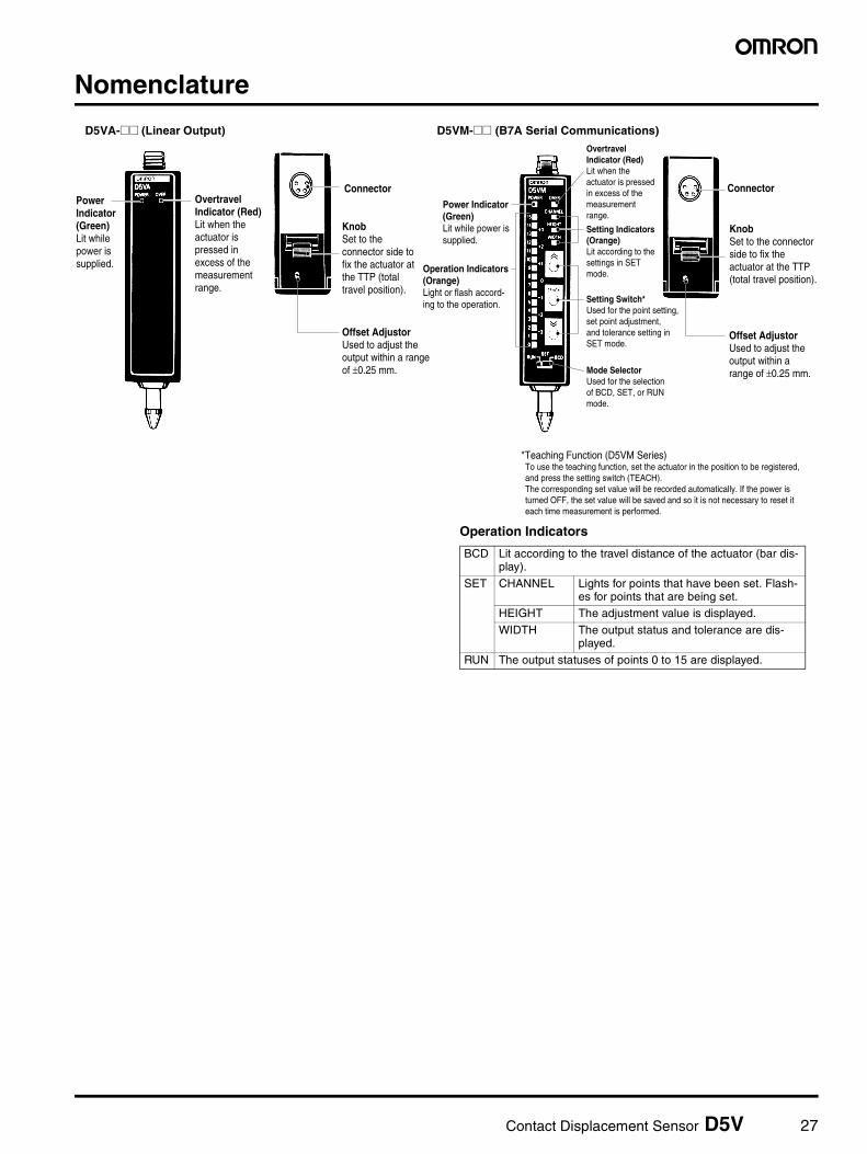
Nomenclature
Power Indicator(Green)Lit while power is supplied.
Overtravel Indicator (Red)Lit when the actuator is pressed in excess of the measurement range.
Offset AdjustorUsed to adjust the output within a range of ±0.25 mm.
PowerIndicator(Green)Lit while power is supplied.
Overtravel Indicator (Red)Lit when the actuator is pressed in excess of the measurement range.
Connector
KnobSet to the connector side to fix the actuator at the TTP (total travel position).
Setting Indicators (Orange)Lit according to the settings in SET mode.
Setting Switch*Used for the point setting, set point adjustment, and tolerance setting in SET mode.
Mode SelectorUsed for the selection of BCD, SET, or RUN mode.
Operation Indicators (Orange)Light or flash accord-ing to the operation.
Offset AdjustorUsed to adjust the output within a range of ±0.25 mm.
Connector
KnobSet to the connector side to fix the actuator at the TTP (total travel position).
*Teaching Function (D5VM Series)To use the teaching function, set the actuator in the position to be registered, and press the setting switch (TEACH).The corresponding set value will be recorded automatically. If the power is turned OFF, the set value will be saved and so it is not necessary to reset it each time measurement is performed.
Operation Indicators
BCD Lit according to the travel distance of the actuator (bar dis-play).
SET CHANNEL Lights for points that have been set. Flash-es for points that are being set.
HEIGHT The adjustment value is displayed.
WIDTH The output status and tolerance are dis-played.
RUN The output statuses of points 0 to 15 are displayed.
D5VA-@@ (Linear Output) D5VM-@@ (B7A Serial Communications)
28 Contact Displacement Sensor D5V
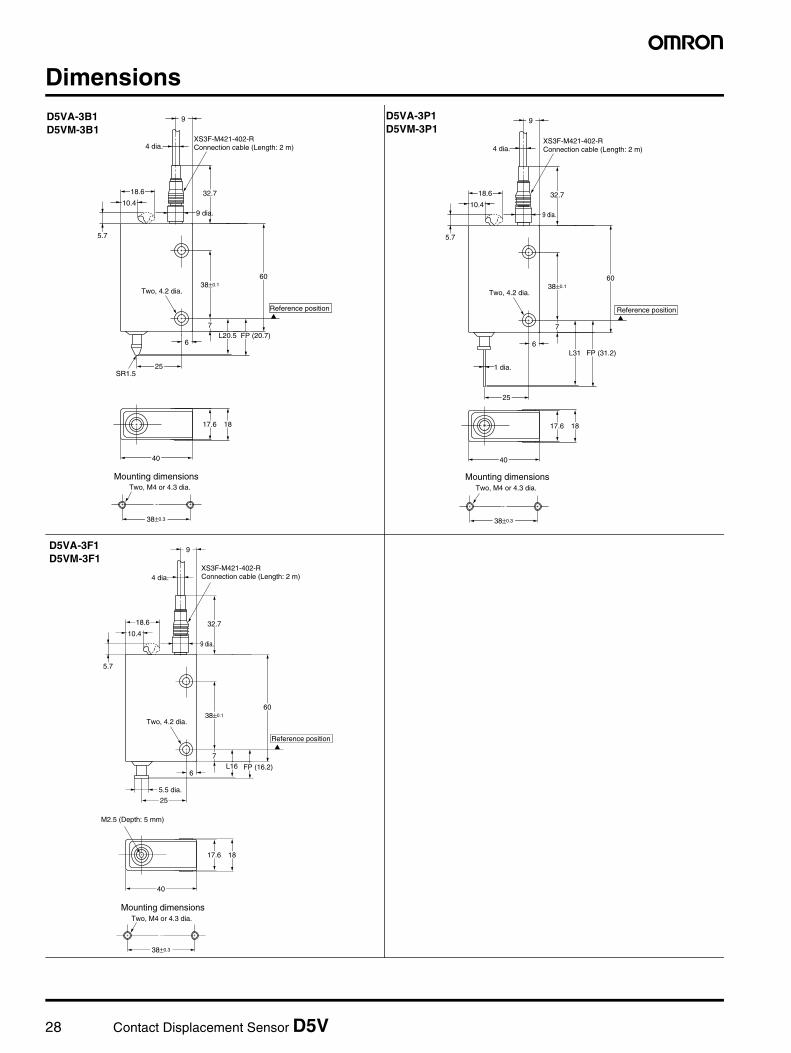
Dimensions
Reference position
38±0.3
40
25SR1.5
L20.5 FP (20.7)6
7
38±0.1
5.7
9 dia.
4 dia.
9
32.710.4
18.6
60
17.6 18
Two, M4 or 4.3 dia.Mounting dimensions
Two, 4.2 dia.
XS3F-M421-402-R Connection cable (Length: 2 m)
D5VA-3B1D5VM-3B1
40
25
L31 FP (31.2)6
1 dia.
7
38±0.1
5.7
9 dia.
4 dia.
9
32.710.4
18.6
60
17.6 18
Two, 4.2 dia.
38±0.3
Reference position
Two, M4 or 4.3 dia.
Mounting dimensions
XS3F-M421-402-R Connection cable (Length: 2 m)
D5VA-3P1D5VM-3P1
40
25
M2.5 (Depth: 5 mm)
L16 FP (16.2)6
5.5 dia.
7
38±0.1
5.7
9 dia.
4 dia.
9
32.710.4
18.6
60
17.6 18
Two, 4.2 dia.
38±0.3
Reference position
Two, M4 or 4.3 dia.
Mounting dimensions
XS3F-M421-402-R Connection cable (Length: 2 m)
D5VA-3F1D5VM-3F1
Contact Displacement Sensor D5V 29
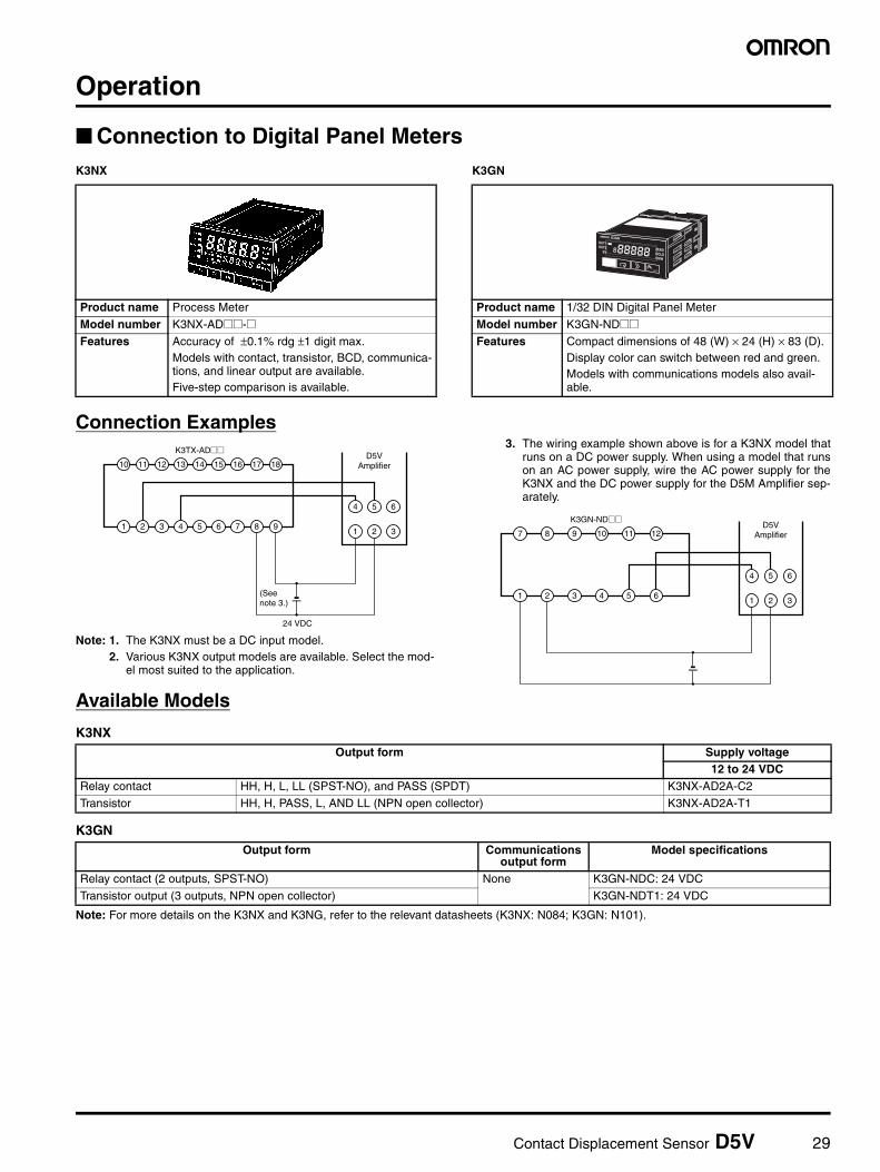
Operation
Connection to Digital Panel MetersK3NX K3GN
Connection Examples
Note: 1. The K3NX must be a DC input model.2. Various K3NX output models are available. Select the mod-
el most suited to the application.
3. The wiring example shown above is for a K3NX model thatruns on a DC power supply. When using a model that runson an AC power supply, wire the AC power supply for theK3NX and the DC power supply for the D5M Amplifier sep-arately.
Available Models
K3NX
K3GN
Note: For more details on the K3NX and K3NG, refer to the relevant datasheets (K3NX: N084; K3GN: N101).
Product name Process Meter
Model number K3NX-AD@@-@Features Accuracy of ±0.1% rdg ±1 digit max.
Models with contact, transistor, BCD, communica-tions, and linear output are available.Five-step comparison is available.
Product name 1/32 DIN Digital Panel Meter
Model number K3GN-ND@@Features Compact dimensions of 48 (W) × 24 (H) × 83 (D).
Display color can switch between red and green.Models with communications models also avail-able.
K3TX-AD@@
24 VDC
D5VAmplifier
(See note 3.)
1 2 3 4 5 61 2 3
4 5 6
7 8 9
10 11 12 13 14 15 16 17 18
K3GN-ND@@D5V
Amplifier
1 2 3 4 5 6
7 8 9 10 11 12
1 2 3
4 5 6
Output form Supply voltage12 to 24 VDC
Relay contact HH, H, L, LL (SPST-NO), and PASS (SPDT) K3NX-AD2A-C2
Transistor HH, H, PASS, L, AND LL (NPN open collector) K3NX-AD2A-T1
Output form Communications output form
Model specifications
Relay contact (2 outputs, SPST-NO) None K3GN-NDC: 24 VDC
Transistor output (3 outputs, NPN open collector) K3GN-NDT1: 24 VDC
30 Contact Displacement Sensor D5V
Safety Precautions
!CautionThe tip of a pin-type actuator is sharp. Be careful when handlingthe actuator, otherwise an injury may occur.
Correct Use• Do not disassemble the D5V, otherwise an electric shock or injury
may occur or the D5V may malfunction.• The D5V will have detection errors if the operating speed of the
actuator exceeds the response time.• The operating force of the actuator is 0.3 N (30 gf). Before using
the D5V to detect objects, make sure that the actuator will not dam-age the objects.
• The D5V will have large detection errors if it is used near genera-tors, motors, or other machines generating strong magnetic fields.
• Make sure that the overtravel indicator of the D5V in operation isnot lit. The Sensor will be damaged if the actuator is pressed inexcess of the measurement range.
• Do not impose horizontal loads on the actuator, otherwise the actu-ator will deform and have difficulty in detecting objects correctly.
• The D5V is not of watertight or dust-tight construction. Do not useor store the D5V in an area with excessive humidity or dust orwhere water may be sprayed onto the D5V.
• An adapter may be attached to the flat-type actuator. The operatingforce may, however, change due to the weight of the adapter. Sometypes of adapters, such as roller-type adapters, may cause detec-tion errors.
• The white lead wire of the cord is not used. Insulate the end of thewhite cord so that it will not come in contact with other lead wires.
• The D5V will not detect objects correctly if the knob is set to theconnector side to fix the actuator at the TTP.
In the interest of product improvement, specifications are subject to change without notice.
ALL DIMENSIONS SHOWN ARE IN MILLIMETERS.
To convert millimeters into inches, multiply by 0.03937. To convert grams into ounces, multiply by 0.03527.
Cat. No. F063-E1-01
Displacement Sensor Terminology 31
Displacement Sensor Terminology
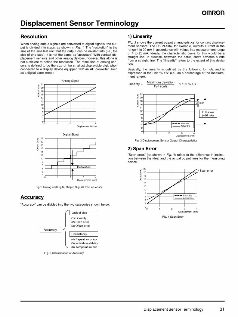
ResolutionWhen analog output signals are converted to digital signals, the out-put is divided into steps, as shown in Fig. 1. The “resolution” is thesize of the smallest unit that the output can be divided into (i.e., thesize of one step). It is not the same as “accuracy.” With contact dis-placement sensors and other analog devices, however, this alone isnot sufficient to define the resolution. The resolution of analog sen-sors is defined to be the size of the smallest displayable digit whenconnected to a display device equipped with an AD converter, suchas a digital panel meter.
Accuracy“Accuracy” can be divided into the two categories shown below.
1) LinearityFig. 3 shows the current output characteristics for contact displace-ment sensors. The D5SN-S04, for example, outputs current in therange 4 to 20 mA in accordance with values in a measurement rangeof 4 to 20 mA. Ideally, the characteristic curve for this would be astraight line. In practice, however, the actual curve deviates a littlefrom a straight line. The “linearity” refers to the extent of this devia-tion.
Basically, the linearity is defined by the following formula and isexpressed in the unit “% FS” (i.e., as a percentage of the measure-ment range).
Linearity = × 100 % FS
2) Span Error”Span error,” (as shown in Fig. 4) refers to the difference in inclina-tion between the ideal and the actual output lines for the measuringdevice.
22
20
18
16
14
12
10
8
6
4
2
0
Analog Signal
Displacement (mm)0 1 2 3 4
Out
put (
mA
)
Resolution
22
20
18
16
14
12
10
8
6
4
2
0
Out
put (
mA
)
Displacement (mm)0 1 2 3 4
Digital Signal
Fig.1 Analog and Digital Output Signals from a Sensor
AccuracyConsistency
(1) Linearity(2) Span error(3) Offset error
(4) Repeat accuracy(5) Indication stability(6) Temperature drift
Lack of bias
Fig. 2 Classification of Accuracy
Maximum deviationFull scale
---------------------------------------------------
22
20
18
16
14
12
10
8
6
4
2
0
Out
put (
mA
)Displacement (mm)
0 1 2 3 4
Ideal lineActual line
Deviation
Full scale(=16 mA)
Fig. 3 Displacement Sensor Output Characteristics
Ideal lineActual line
22
20
18
16
14
12
10
8
6
4
2
0
Out
put (
mA
)
Displacement (mm)0 1 2 3 4
Span error
Fig. 4 Span Error
32 Displacement Sensor Terminology
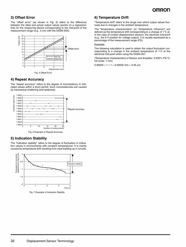
3) Offset ErrorThe “offset error,” (as shown in Fig. 5) refers to the differencebetween the ideal and actual output values (points on a regressionline) for the measuring device corresponding to the mid-point of themeasurement range (e.g., 2 mm with the D5SN-S04).
4) Repeat AccuracyThe “repeat accuracy” refers to the degree of inconsistency in indi-cated values within a short period. Such inconsistencies are causedby mechanical chattering and hysteresis.
5) Indication StabilityThe “indication stability” refers to the degree of fluctuation in indica-tion values in environments with constant temperatures. It is mainlycaused by temperature drift resulting from heat building up in circuits.
6) Temperature Drift”Temperature drift” refers to the range over which output values fluc-tuate due to changes in the ambient temperature.
The “temperature characteristics” (or “temperature influence”) aredefined as the temperature drift corresponding to a change of 1°C at,in the case of contact displacement sensors, the electrical mid-point(e.g., the 0-V position for voltage output). It is usually expressed as apercentage of the measurement range (FS).
Example:
The following calculation is used to obtain the output fluctuation cor-responding to a change in the ambient temperature of 1°C at theelectrical mid-point when using the D5SN-S01.
(Temperature characteristics of Sensor and Amplifier: 0.035% FS/°C;full scale: 1 mm)
0.00035 × 1 × 1 = 0.00035 mm = 0.35 µm
22
20
18
16
14
12
10
8
6
4
2
0
Out
put (
mA
)
Displacement (mm)0 1 2 3 4
Offset error
Ideal lineActual line
Fig. 5 Offset Error
1.9950
1.9949
1.9948
1.9947
1.9946
1.9945
1.9944
1.9943
1.9942
1.9941
1.9940
1.9939
Indi
cate
d va
lue
(mm
)
Number of measurements0 5 10 15 20 25
Repeat accuracy
Fig. 6 Example of Repeat Accuracy
0
−0.5
−1
−1.5
−2
Flu
ctua
tion
of c
onve
rted
disp
lace
men
t out
put (
µm)
Time (h)0 1 2 3 4
Indication stability
Fig. 7 Example of Indication Stability

OMRON CorporationIndustrial Automation Company
Industrial Devices and Components Division H.Q.Industrial Control Components DepartmentShiokoji Horikawa, Shimogyo-ku,Kyoto, 600-8530 JapanTel: (81)75-344-7119/Fax: (81)75-344-7149
Authorized Distributor:
Cat. No. X071-E1-01