Embed Size (px)
Citation preview
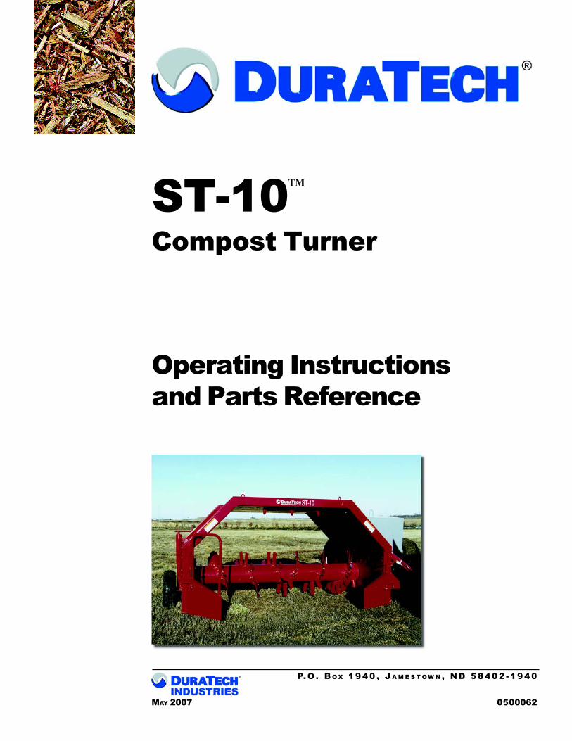
ST-10Compost Turner
Operating Instructionsand Parts Reference
P. O. B O X 1 9 4 0 , J A M E S T O W N , N D 5 8 4 0 2 - 1 9 4 0
MAY 2007 0500062
TM

ST-10Compost Turner
Operating Instructionsand Parts Reference
P. O. B O X 1 9 4 0 , J A M E S T O W N , N D 5 8 4 0 2 - 1 9 4 0
MAY 2007 0500062
TM

DuraTech Industries International Inc. (Duratech Industries) has made every effort to assure thatthis manual completely and accurately describes the operation and maintenance of the ST-10Compost Turner as of the date of publication. Duratech Industries reserves the right to makeupdates to the machine from time to time. Even in the event of such updates, you should still findthis manual to be appropriate for the safe operation and maintenance of your unit.
This manual, as well as materials provided by component suppliers to Duratech Industries are allconsidered to be part of the information package. Every operator is required to read and understandthese manuals, and they should be located within easy access for periodic review.
TMST-10Compost Turner
Operating Instructionsand Parts Reference
& are registered trademarks of Duratech IndustriesInternational, Inc. ST-10 is a trademarks of Duratech Industries International, Inc.

iS T - 1 0 C O M P O S T T U R N E R O P E R A T I N G I N S T R U C T I O N S
F O R E W O R D
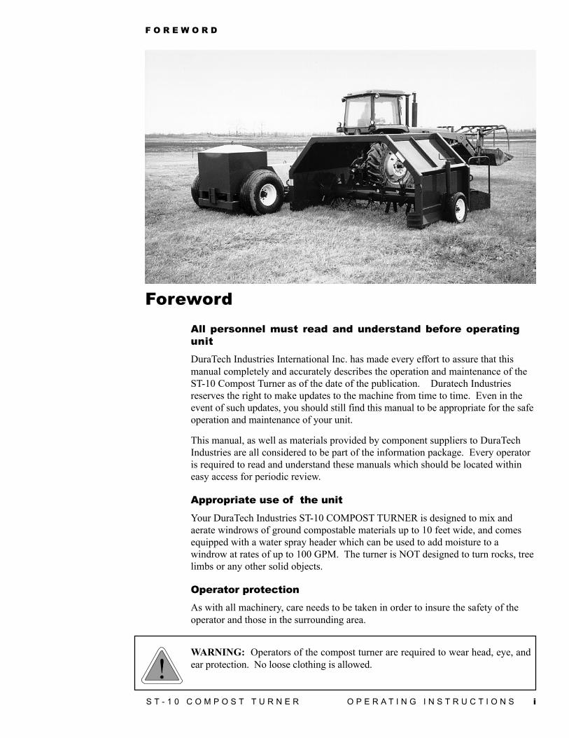
ForewordAll personnel must read and understand before operatingunitDuraTech Industries International Inc. has made every effort to assure that thismanual completely and accurately describes the operation and maintenance of theST-10 Compost Turner as of the date of the publication. Duratech Industriesreserves the right to make updates to the machine from time to time. Even in theevent of such updates, you should still find this manual to be appropriate for the safeoperation and maintenance of your unit.
This manual, as well as materials provided by component suppliers to DuraTechIndustries are all considered to be part of the information package. Every operatoris required to read and understand these manuals which should be located withineasy access for periodic review.
Appropriate use of the unit
Your DuraTech Industries ST-10 COMPOST TURNER is designed to mix andaerate windrows of ground compostable materials up to 10 feet wide, and comesequipped with a water spray header which can be used to add moisture to awindrow at rates of up to 100 GPM. The turner is NOT designed to turn rocks, treelimbs or any other solid objects.
Operator protectionAs with all machinery, care needs to be taken in order to insure the safety of theoperator and those in the surrounding area.
WARNING: Operators of the compost turner are required to wear head, eye, andear protection. No loose clothing is allowed.
ii
T A B L E O F C O N T E N T S
S T - 1 0 C O M P O S T T U R N E R O P E R A T I N G I N S T R U C T I O N S
Part I: Operating Instructions .......................................... 1Introduction ................................................................................ 2Purpose ....................................................................................... 2
Section 1: Safety ....................................................................... 21.1 Safety-alert symbols .......................................................................................... 31.2 Operator - personal equipment .......................................................................... 51.3 Machine safety labels ..................................................................................... 61.4 Shielding ............................................................................................................ 81.5 Personal equipment ........................................................................................... 81.6 Compost turner safety review ........................................................................... 81.7 Towing.............................................................................................................. 9
Section 2: Dealer Preparation ................................................. 102.1 ST-10 compost turner shipping list ................................................................ 102.2 Assembly instructions .................................................................................... 112.3 Pre-delivery checklist ................................................................................... 122.4 Machine operation check .............................................................................. 12
Section 3: Operation ............................................................... 133.1 Daily pre-operation inspection ....................................................................... 133.2 Introduction to the major system components ............................................... 14
3.2.1 Description of the Duratech Industries ST-10 compost turner ............... 153.2.2 Rotor ....................................................................................................... 153.2.3 Hood ....................................................................................................... 153.2.4 Hitch ....................................................................................................... 153.2.5 Outer jack ............................................................................................... 153.2.6 Water system .......................................................................................... 153.2.7 Inoculation system .................................................................................. 163.2.8 Overview of operator controls ................................................................ 16
3.3 Machine operations ....................................................................................... 163.3.1 Tractor set up and PTO hitch safety ..................................................... 163.3.2 Checking the maximum turning angles for the hitch ............................... 173.3.3 Hitching the ST-10 to a tractor ............................................................... 183.3.4 Unhitching the ST-10 from a tractor ....................................................... 193.3.5 Operating the machine as a unit ............................................................. 193.3.6 How to make adjustments and evaluate performance ............................ 203.3.7 Shutdown procedures .............................................................................. 213.3.8 Preparing the ST-10 for transport ........................................................... 21
iii
T A B L E O F C O N T E N T S
S T - 1 0 C O M P O S T T U R N E R O P E R A T I N G I N S T R U C T I O N S
3.3.9 Preparing the ST-10 for operation after transport .................................. 223.3.10 Preparing the ST-10 for storage .......................................................... 223.3.11 Removing the ST-10 from storage ....................................................... 22
Section 4: General Maintenance ............................................. 234.1 General service and maintenance .................................................................... 234.2 Lubrication ...................................................................................................... 24
4.2.1 Lubricating the Comer gearbox .............................................................. 254.2.2 Lubricating the Prairie gearbox .............................................................. 26
4.3 Axle, wheels, and tires .................................................................................... 264.4 General appearance ........................................................................................ 26
Section 5: Troubleshooting the ST-10 .................................... 27Appendix A: Warranty .............................................................. 28Appendix B: Specifications ..................................................... 29Appendix C: Delivery Notification Form ................................. 30
Appendix D: User Training Verification Form ......................... 31Appendix E: Operator Training Form....................................... 32Appendix F: Required For Operation ...................................... 33
Part II: Parts Reference ................................................. 35
HITCH ASSEMBLY ............................................................................................. 36DRIVELINE ASSEMBLY P.N. 3600311 - SN 0101 TO 0130 ............................. 38DRIVELINE ASSEMBLY P.N. 3600312 - SN 0101 TO 0130 ............................. 40DRIVELINE ASSEMBLY P.N. 3600432 - SN 0131 AND UP ............................ 42DRIVELINE ASSEMBLY P.N. 3600431 - SN 0131 TO SN 0151 ...................... 44DRIVELINE ASSEMBLY P.N. 3600496 - SN 0152 AND UP ............................ 46HOOD ASSEMBLY - COMER GEARBOX ....................................................... 48HOOD ASSEMBLY - PRAIRIE GEARBOX ...................................................... 50ROTOR ASSEMBLY ............................................................................................ 52JACK ASSEMBLY ............................................................................................... 54WATER SYSTEM ASSEMBLY ........................................................................... 56HYDRAULIC ASSEMBLY ................................................................................. 58GEAR BOX ........................................................................................................... 60DECALS ................................................................................................................ 62
ST-10 Compost Turner Documentation Comment Form........ 65

iv
T A B L E O F C O N T E N T S
S T - 1 0 C O M P O S T T U R N E R O P E R A T I N G I N S T R U C T I O N S
1 S T - 1 0 C O M P O S T T U R N E R O P E R A T I N G I N S T R U C T I O N S 1
TMST-10Compost Turner
Part 1:Operating Instructions
2 S T - 1 0 C O M P O S T T U R N E R O P E R A T I N G I N S T R U C T I O N S
Introduction
PurposeYour Duratech Industries ST-10 COMPOST TURNER is designed to mix and aerate windrows of ground compostablematerials up to 10 feet wide, and comes equipped with a water spray header which can be used to add moisture to awindrow at rates of up to 100 GPM. The turner is NOT designed to turn rocks, tree limbs or any other solid objects.
SPECIAL NOTE: When reference is made as to front, rear, left hand, or right hand of thismachine, the reference is always made from standing at the rear end of the machine andlooking toward the hitch. Always use serial number and model number when referring toparts or problems. Please obtain your serial number and write it below for your futurereference.
MODEL: ST-10 Compost Turner SERIAL NO. ________________________
Section 1: SafetyThank you for taking the time to read the operation and maintenance manual for the Duratech Industries ST-10Compost Turner. Because your safety and that of others is of the utmost importance, you should familiarize yourselfwith this entire manual before operating this unit. The safety of the operator is of great importance to DuratechIndustries. We have provided decals, shield and other safety features to aid you in using your machine safely. Inaddition, we ask you to be a careful operator who will properly use and service your Duratech Industries equipment.
Safety is an ongoing job experience, and Duratech Industries has made every effort to make sure that the ST-10Compost Turner provides operator comfort and security. Duratech Industries encourages you to bring to our attentionas quickly as possible any suggestions you may have concerning the safety of the equipment. Duratech Industries isdedicated to enhancing the safety of the ST-10 Compost Turner .
This unit is supplied with an operation and maintenance manual and this manual should be kept with the unit forperiodic review by operational personnel.
Operators of the ST-10 Compost Turner are required to wear head, eye, and ear protection as well as clothingappropriate for the application. Individuals with loose clothing, unrestrained long hair, jewelry, or other accessorieswhich may hang loosely away from the body should not be allowed on or near the machine.
Make sure that the tractor conforms to the tractor specifications described in Appendix F: Required For Operation.
3S T - 1 0 C O M P O S T T U R N E R O P E R A T I N G I N S T R U C T I O N S
WARNING: FAILURE TO COMPLY WITH SAFETY INSTRUCTIONS THAT FOLLOWWITHIN THIS MANUAL COULD RESULT IN SEVERE PERSONAL INJURY OR DEATH.BEFORE ATTEMPTING TO OPERATE THIS MACHINE, CAREFULLY READ ALLINSTRUCTIONS CONTAINED WITHIN THIS MANUAL.
THIS MACHINE IS NOT TO BE USED FOR ANY PURPOSE OTHER THAN THOSEEXPLAINED IN THE OPERATOR’S MANUAL, ADVERTISING LITERATURE OROTHER DURATECH INDUSTRIES WRITTEN MATERIAL PERTAINING TO THE ST-10.
1.1 Safety-alert symbols
Decals are illustrated in Part 2: Parts Reference.
The safety decals located on your machine contain important and useful information that will help you operate yourequipment safely.
To assure that all decals remain in place and in good condition, follow the instructions below:
• Keep decals clean. Use soap and water - not mineral spirits, adhesive cleaners and other similar cleanersthat will damage the decal.
• Replace all damaged or missing decals. When attaching decals, surface temperature of the machine mustbe at least 40° F (5° C). The surface must be also be clean and dry.
• When replacing a machine component to which a decal is attached, be sure to also replace the decal.
• Replacement decals can be purchased from your Duratech Industries dealer.

4 S T - 1 0 C O M P O S T T U R N E R O P E R A T I N G I N S T R U C T I O N S
Duratech Industries uses industry accepted ANSI standards in labeling its products for safety and operationalcharacteristics.
DANGER: Indicates an imminentlyhazardous situation that, if not avoided, willresult in death or serious injury. This signalword is to be limited to the most extremesituations, typically for machine componentsthat, for functional purposes, cannot beguarded.
WARNING: Indicates a potentiallyhazardous situation that, if not avoided, couldresult in death or serious injury, and includeshazards that are exposed when guards areremoved. It may also be used to alert againstunsafe practices.
CAUTION: Indicates a potentially hazardoussituation that, if not avoided, may result inminor or moderate injury. It may also be usedto alert against unsafe practices.
SafSafSafSafSafety-Alerety-Alerety-Alerety-Alerety-Alert Symbolt Symbolt Symbolt Symbolt SymbolRead and recognize safety information. Be alert tothe potential for personal injury when you see thissafety-alert symbol.
DANGER
INFORMATION
CAUTION
WARNING
This manual uses the symbols to the right to denoteimportant safety instructions and information.
The DANGER, WARNING and CAUTION symbols areused to denote conditions as stated in the text above.Furthermore, the text dealing with these situations issurrounded by a box with a white background, will beginwith DANGER, WARNING, or CAUTION.
The INFORMATION symbol is used to denote importantinformation or notes in regards to maintenance and use ofthe machine. The text for this information is surroundedby a box with a light grey background, and will begin witheither IMPORTANT or NOTE.
5S T - 1 0 C O M P O S T T U R N E R O P E R A T I N G I N S T R U C T I O N S
1.2 Operator - personal equipment
THE OPERATOR
Physical ConditionYou must be in good physical condition and mental health and not under the influence of any substance (drugs, alcohol)which might impair vision, dexterity or judgment.
Do not operate a ST-10 Compost Turner when you are fatigued. Be alert - If you get tired while operating your ST-10,take a break. Fatigue may result in loss of control. Working with any industrial equipment can be strenuous. If youhave any condition that might be aggravated by strenuous work, check with your doctor before operating
Proper Clothing
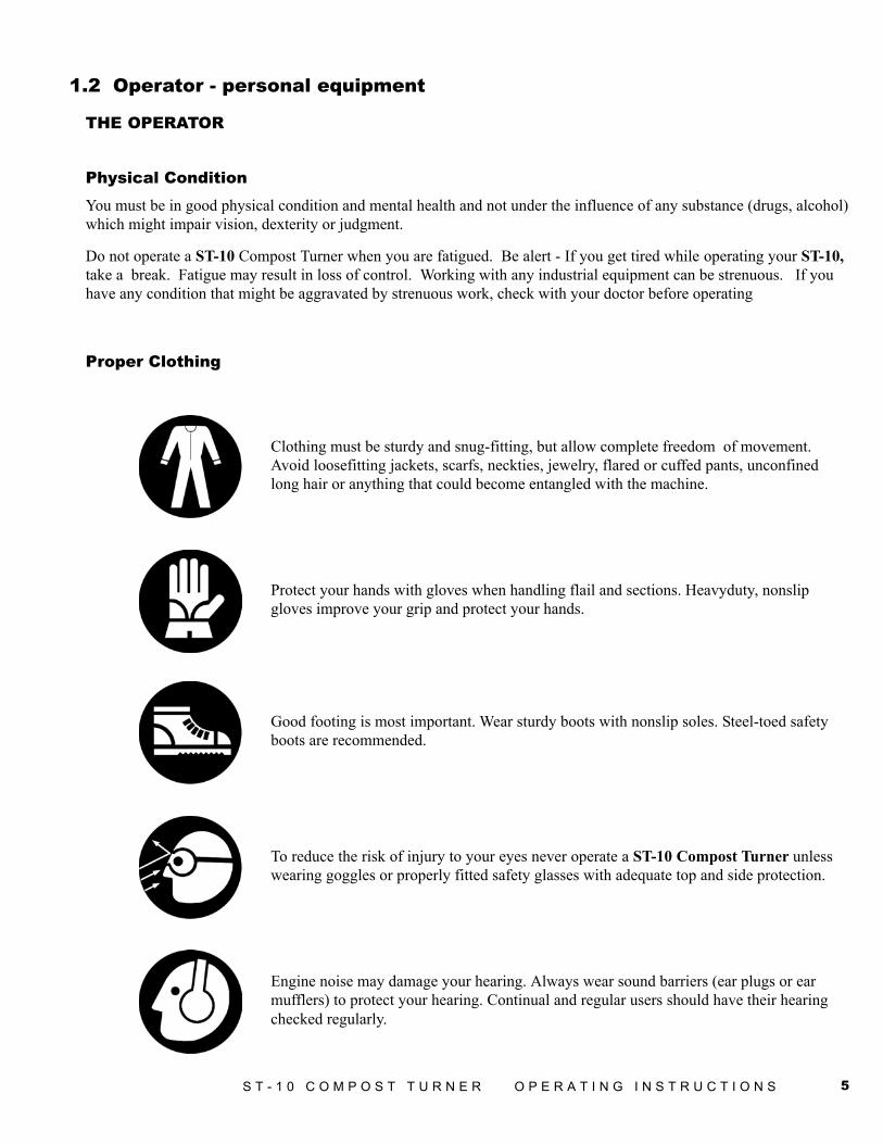
Clothing must be sturdy and snug-fitting, but allow complete freedom of movement.Avoid loosefitting jackets, scarfs, neckties, jewelry, flared or cuffed pants, unconfinedlong hair or anything that could become entangled with the machine.
Protect your hands with gloves when handling flail and sections. Heavyduty, nonslipgloves improve your grip and protect your hands.
Good footing is most important. Wear sturdy boots with nonslip soles. Steel-toed safetyboots are recommended.
To reduce the risk of injury to your eyes never operate a ST-10 Compost Turner unlesswearing goggles or properly fitted safety glasses with adequate top and side protection.
Engine noise may damage your hearing. Always wear sound barriers (ear plugs or earmufflers) to protect your hearing. Continual and regular users should have their hearingchecked regularly.

6 S T - 1 0 C O M P O S T T U R N E R O P E R A T I N G I N S T R U C T I O N S
1.3 Machine safety labels
The safety decals located on your machine contain important information that will help you operate your equipment.Become familiar with the decals and their locations.
WARNING: FOR YOUR PROTECTION KEEP ALLSHIELDS IN PLACE AND SECURED WHILE MACHINEIS OPERATING MOVING PARTS WITHIN CAN CAUSESEVERE PERSONAL INJURY.
WARNING: WAIT FOR ALL MOVEMENT TO STOP.FAILURE TO USE CAUTION COULD RESULT INSERIOUS INJURY OR DEATH.
WARNING: BE CERTAIN THAT ALL PERSONNEL ARECLEAR OF WINGS BEFORE FOLDING OR UNFOLDING.
FAILURE TO FOLLOW THESE INSTRUCTIONS MAYRESULT IN SEVERE INJURY OR DEATH.
6500040
6500110
6500179
7S T - 1 0 C O M P O S T T U R N E R O P E R A T I N G I N S T R U C T I O N S
6500208
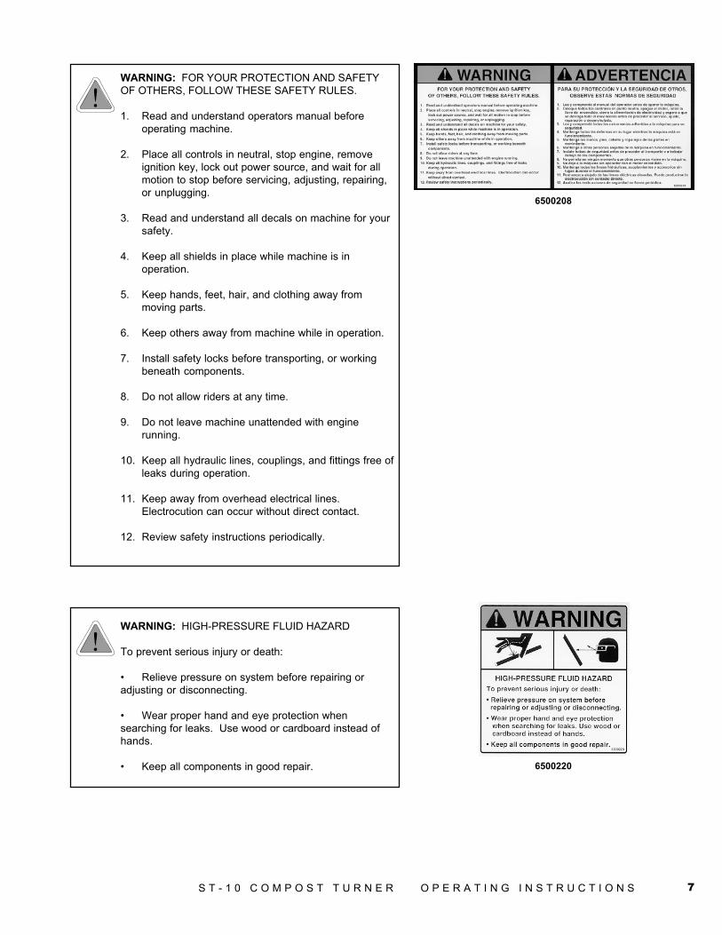
WARNING: FOR YOUR PROTECTION AND SAFETYOF OTHERS, FOLLOW THESE SAFETY RULES.
1. Read and understand operators manual beforeoperating machine.
2. Place all controls in neutral, stop engine, removeignition key, lock out power source, and wait for allmotion to stop before servicing, adjusting, repairing,or unplugging.
3. Read and understand all decals on machine for yoursafety.
4. Keep all shields in place while machine is inoperation.
5. Keep hands, feet, hair, and clothing away frommoving parts.
6. Keep others away from machine while in operation.
7. Install safety locks before transporting, or workingbeneath components.
8. Do not allow riders at any time.
9. Do not leave machine unattended with enginerunning.
10. Keep all hydraulic lines, couplings, and fittings free ofleaks during operation.
11. Keep away from overhead electrical lines.Electrocution can occur without direct contact.
12. Review safety instructions periodically.
WARNING: HIGH-PRESSURE FLUID HAZARD
To prevent serious injury or death:
• Relieve pressure on system before repairing oradjusting or disconnecting.
• Wear proper hand and eye protection whensearching for leaks. Use wood or cardboard instead ofhands.
• Keep all components in good repair. 6500220
8 S T - 1 0 C O M P O S T T U R N E R O P E R A T I N G I N S T R U C T I O N S
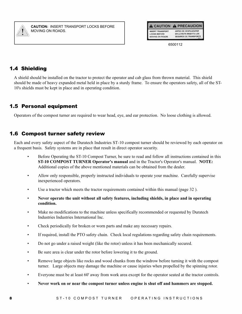
6500112
CAUTION: INSERT TRANSPORT LOCKS BEFOREMOVING ON ROADS.
1.4 ShieldingA shield should be installed on the tractor to protect the operator and cab glass from thrown material. This shieldshould be made of heavy expanded metal held in place by a sturdy frame. To ensure the operators safety, all of the ST-10's shields must be kept in place and in operating condition.
1.5 Personal equipmentOperators of the compost turner are required to wear head, eye, and ear protection. No loose clothing is allowed.
1.6 Compost turner safety reviewEach and every safety aspect of the Duratech Industries ST-10 compost turner should be reviewed by each operator ona frequent basis. Safety systems are in place that result in direct operator security.
• Before Operating the ST-10 Compost Turner, be sure to read and follow all instructions contained in thisST-10 COMPOST TURNER Operator's manual and in the Tractor's Operator's manual. NOTE:Additional copies of the above mentioned materials can be obtained from the dealer.
• Allow only responsible, properly instructed individuals to operate your machine. Carefully superviseinexperienced operators.
• Use a tractor which meets the tractor requirements contained within this manual (page 32 ).
• Never operate the unit without all safety features, including shields, in place and in operatingcondition.
• Make no modifications to the machine unless specifically recommended or requested by DuratechIndustries Industries International Inc.
• Check periodically for broken or worn parts and make any necessary repairs.
• If required, install the PTO safety chain. Check local regulations regarding safety chain requirements.
• Do not go under a raised weight (like the rotor) unless it has been mechanically secured.
• Be sure area is clear under the rotor before lowering it to the ground.
• Remove large objects like rocks and wood chunks from the windrow before turning it with the compostturner. Large objects may damage the machine or cause injuries when propelled by the spinning rotor.
• Everyone must be at least 60' away from work area except for the operator seated at the tractor controls.
• Never work on or near the compost turner unless engine is shut off and hammers are stopped.
9S T - 1 0 C O M P O S T T U R N E R O P E R A T I N G I N S T R U C T I O N S
• Disengage PTO and make sure everyone is clear of machine before starting engine.
• Power takeoff shafts must be locked in place with protective PTO shields in place.
• Never leave tractor controls unattended while the engine is running.
• Exercise extreme care when operating on rough and/or steep terrain. Avoid operation on terrain which isexcessively rough or steep. Serious injury could result if the machine is allowed to tip.
• Make sure tractor PTO speed never exceeds 540 RPM!
1.7 TowingA commercial driver's licence may be required to tow this unit on public roads; verify with traffic control or licensingauthorities.
• When towing the ST-10, watch for low power lines.
• Use good judgment and drive slowly over rough or uneven terrain.
• Be sure tractor brakes are properly adjusted and that the tractor's foot pedals are locked together.
• Tires and rims are rated for 20 mph or less.
• Check all lights, brakes, safety chains and hitch connections before towing. Check your state lawsregarding the use of lights, slow moving vehicle signs, safety chains, and other possible requirements.
10 S T - 1 0 C O M P O S T T U R N E R O P E R A T I N G I N S T R U C T I O N S
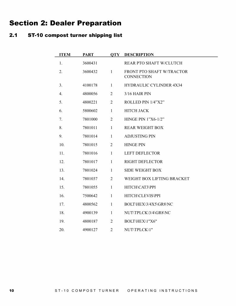
Section 2: Dealer Preparation2.1 ST-10 compost turner shipping list
ITEM PART QTY DESCRIPTION
1. 3600431 REAR PTO SHAFT W/CLUTCH
2. 3600432 1 FRONT PTO SHAFT W/TRACTORCONNECTION
3. 4100178 1 HYDRAULIC CYLINDER 4X34
4. 4800056 2 3/16 HAIR PIN
5. 4800221 2 ROLLED PIN 1/4”X2”
6. 5800602 1 HITCH JACK
7. 7801000 2 HINGE PIN 1”X6-1/2”
8. 7801011 1 REAR WEIGHT BOX
9. 7801014 1 ADJUSTING PIN
10. 7801015 2 HINGE PIN
11. 7801016 1 LEFT DEFLECTOR
12. 7801017 1 RIGHT DEFLECTOR
13. 7801024 1 SIDE WEIGHT BOX
14. 7801037 2 WEIGHT BOX LIFTING BRACKET
15. 7801055 1 HITCH\CAT3\PPI
16. 7500642 1 HITCH\CLEVIS\PPI
17. 4800562 1 BOLT\HEX\3/4X5\GR8\NC
18. 4900139 1 NUT\TPLCK\3/4\GR8\NC
19. 4800187 2 BOLT\HEX\1"X6"
20. 4900127 2 NUT\TPLCK\1"
11S T - 1 0 C O M P O S T T U R N E R O P E R A T I N G I N S T R U C T I O N S
2.2 Assembly instructions1. Adjust the tractor drawbar so that the distance from the end of the 540 RPM PTO shaft on the tractor to
the center of the drawbar hitch pin hole is 14" (36 cm.). Refer to pages 17-18.
2. Attach hitch jack (5800620) to hitch frame. See page 34.
3. Attach hitch (7500641) and hitch clevis(7500642) to hitch frame. See page 34.
4. Attach hood jack (7801033) and tire to hood.See page 41.
5. Connect the compost turner to the tractor drawbar. Adjust the hitch so that the hood is parallel withground. The hitch can be adjusted at the front by setting 7500641, the hitch, up or down as needed. Thehitch can be adjusted at the axle by 4 bolts (7801022) connecting the axle to the frame.
6. Raise the hitch jack. Pull the lock pin and store in the transport position.
7. Remove hydraulic cylinder from shipping position. Run hoses through the hose minders on the hitch.Then connect the two hydraulic hoses from the hydraulic cylinder to one set of hydraulic couplers on thetractor.
8. Cycle cylinder several times to remove air from hydraulic system. Attach cylinder to hood and hitch.(Grease pins before installing).
9. Set hood & rotor assembly near hitch. Align hinge points, insert (2) Hinge Pins 7801000, and (2) rolledpins 4800221. See page 34.
10. Attach the rear PTO shaft 3600431 to the gearbox and intermediate 12" shaft. Attach the front PTOshaft 3600432 to the front end of the intermediate shaft, making sure that the yokes on both shafts lineup. If they are not aligned, it may cause high noise levels and/or shaft breakage. Insert bolts into the 3yokes and tighten bolts to secure the yokes to the stub shafts. Depress front coupling and slide thecoupling onto the tractor PTO shaft. Make sure the spring loaded safety catch is properly seated.
11. Fill steel boxes with concrete. Set lifting bracket 7801037 so there is a 3" clearance between the bracketand the concrete. Both boxes must be bolted securely to hitch frame. The two boxes will require over 2cubic yards of concrete. Concrete density is to be 150 pounds per cubic foot. Weights are to keep hitchdown when lifting the rotor. Boxes can be filled earlier, but the hitch is harder to move around forconnecting to the hood. You are better off having extra concrete and rounding at the top instead of beingshort on weight.
12. Clevis bolts are not tight. Set the unit height so that the tractor drawbar is level with the hitch thentighten the clevis bolts.
13. Attach left and right deflectors 7801016 and 7801017 to hood with pins 7801014 and 7801015. See page36.
14. This machine is set up to operate on 540 RPM PTO only!
15. If required, install the safety chain. Check local regulations regarding safety chain requirements.
16. Grease the PTO before using the machine.
12 S T - 1 0 C O M P O S T T U R N E R O P E R A T I N G I N S T R U C T I O N S
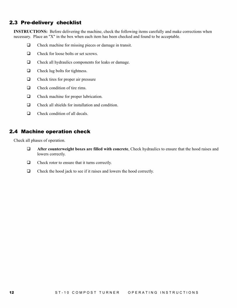
2.3 Pre-delivery checklistINSTRUCTIONS: Before delivering the machine, check the following items carefully and make corrections whennecessary. Place an "X" in the box when each item has been checked and found to be acceptable.
Check machine for missing pieces or damage in transit.
Check for loose bolts or set screws.
Check all hydraulics components for leaks or damage.
Check lug bolts for tightness.
Check tires for proper air pressure
Check condition of tire rims.
Check machine for proper lubrication.
Check all shields for installation and condition.
Check condition of all decals.
2.4 Machine operation checkCheck all phases of operation.
After counterweight boxes are filled with concrete, Check hydraulics to ensure that the hood raises andlowers correctly.
Check rotor to ensure that it turns correctly.
Check the hood jack to see if it raises and lowers the hood correctly.
13S T - 1 0 C O M P O S T T U R N E R O P E R A T I N G I N S T R U C T I O N S
Section 3: Operation3.1 Daily pre-operation inspection
To insure long life and economical operation, thorough and complete instruction in the maintenance and operation ofthe machine is highly recommended.
There is no substitute for a sound preventative maintenance program and a well-trained operator.
Prior to starting the engine of the tractor, it is recommended that the operator make a visual inspection of the unit.This can be done as the lubrication is being carried out. Any items that are worn, broken, missing or needingadjustment must be serviced accordingly before operating the compost turner.
Before working on or near the compost turner for any reason, including servicing, cleaning, unplugging or inspectingmachine, use normal shutdown procedures unless instructed differently in this manual.
Check the following:Check hydraulic components for leaks or damage.
WARNING: Hydraulic fluid escaping under pressure can be almost invisible and can have sufficientforce to penetrate the skin. When searching for suspected leaks, use a piece of wood or cardboardrather than your hands. If injured, seek medical attention immediately to prevent serious infection orreaction.
Check the condition of hammers and attachment bolts.
Check the rotor for bent hammer mounts.
Check that all shields are in place and in operating condition.
Check lug nuts for tightness.
Check the condition of tire rims, and check tires for proper air pressure, 36 psi max.
If slow moving vehicle (SMV) sign is required, check the condition of the SMV sign.
Check the condition of decals.
Check lubrication points and lubricate as recommended in section "4.2 Lubrication" which can be foundin the general maintenance portion of this manual.
14 S T - 1 0 C O M P O S T T U R N E R O P E R A T I N G I N S T R U C T I O N S
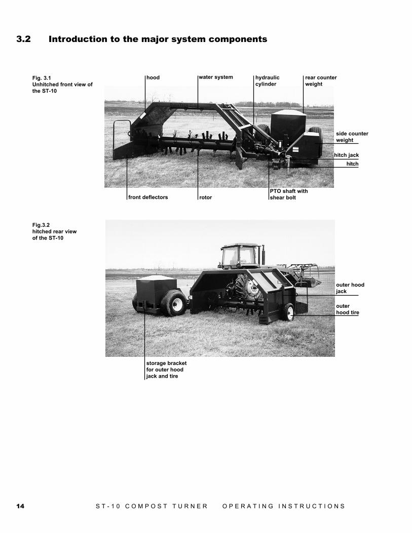
Fig. 3.1Unhitched front view ofthe ST-10
water system
rotor
hood hydrauliccylinder
rear counterweight
side counterweight
hitch jack hitch
PTO shaft withshear bolt front deflectors
outer hoodjack
outerhood tire
storage bracketfor outer hoodjack and tire
Fig.3.2hitched rear viewof the ST-10
3.2 Introduction to the major system components
15S T - 1 0 C O M P O S T T U R N E R O P E R A T I N G I N S T R U C T I O N S
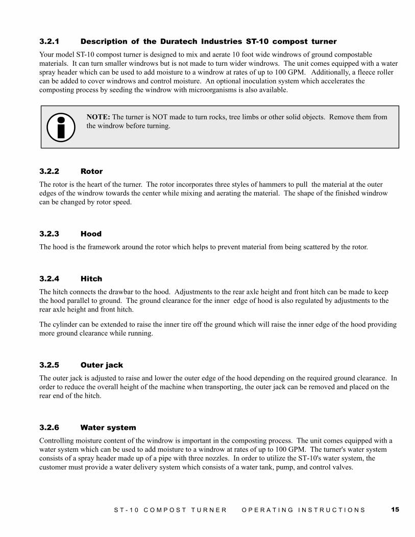
3.2.1 Description of the Duratech Industries ST-10 compost turnerYour model ST-10 compost turner is designed to mix and aerate 10 foot wide windrows of ground compostablematerials. It can turn smaller windrows but is not made to turn wider windrows. The unit comes equipped with a waterspray header which can be used to add moisture to a windrow at rates of up to 100 GPM. Additionally, a fleece rollercan be added to cover windrows and control moisture. An optional inoculation system which accelerates thecomposting process by seeding the windrow with microorganisms is also available.
NOTE: The turner is NOT made to turn rocks, tree limbs or other solid objects. Remove them fromthe windrow before turning.
3.2.2 RotorThe rotor is the heart of the turner. The rotor incorporates three styles of hammers to pull the material at the outeredges of the windrow towards the center while mixing and aerating the material. The shape of the finished windrowcan be changed by rotor speed.
3.2.3 HoodThe hood is the framework around the rotor which helps to prevent material from being scattered by the rotor.
3.2.4 HitchThe hitch connects the drawbar to the hood. Adjustments to the rear axle height and front hitch can be made to keepthe hood parallel to ground. The ground clearance for the inner edge of hood is also regulated by adjustments to therear axle height and front hitch.
The cylinder can be extended to raise the inner tire off the ground which will raise the inner edge of the hood providingmore ground clearance while running.
3.2.5 Outer jackThe outer jack is adjusted to raise and lower the outer edge of the hood depending on the required ground clearance. Inorder to reduce the overall height of the machine when transporting, the outer jack can be removed and placed on therear end of the hitch.
3.2.6 Water systemControlling moisture content of the windrow is important in the composting process. The unit comes equipped with awater system which can be used to add moisture to a windrow at rates of up to 100 GPM. The turner's water systemconsists of a spray header made up of a pipe with three nozzles. In order to utilize the ST-10's water system, thecustomer must provide a water delivery system which consists of a water tank, pump, and control valves.
16 S T - 1 0 C O M P O S T T U R N E R O P E R A T I N G I N S T R U C T I O N S
3.2.7 Inoculation systemThis option gives the operator the flexibility to add an inoculation package to the process. The inoculation systemaccelerates the composting process by seeding the windrow with microorganisms.
3.2.8 Overview of operator controlsSince operation of the ST-10 is accomplished through the unit's connection to a tractor and through other third partysystems, there are no operator controls on the ST-10 unit.
In a typical configuration, the operator controls operate in the following manners:
• The tractor throttle controls the speed of the rotor, and the tractor PTO lever is used to engage ordisengage the PTO. Engaging the PTO causes the rotor to turn, and disengaging the PTO causes the rotorto slow down and eventually stop.
• The ST-10's hydraulic system performs only one function; raising and lowering the hood and rotor fortransport. In order to utilize this function, the ST-10's hydraulic lines must be connected to the tractor'shydraulic system. Once connected, raising and lowering of the hood and rotor is controlled by thetractor's hydraulic controls.
• In order to utilize the ST-10's water system, the customer must provide a water delivery system whichconsists of a water tank, pump, and control valves. The water spray output of the ST-10 is adjusted bywater line pressure, which is set by the water pump and any control valves present in the water deliverysystem.
3.3 Machine operationsThis sub-section describes how to operate the ST-10 compost turner as well as how to optimize the unit's performance.
3.3.1 Tractor set up and PTO hitch safety
A tractor drawbar and 3-point arms can cause interference with the PTO driveline IID (Implement Input Driveline).This interference can cause serious damage to the IID guarding and the IID telescoping members.
17S T - 1 0 C O M P O S T T U R N E R O P E R A T I N G I N S T R U C T I O N S
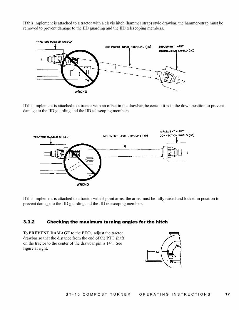
If this implement is attached to a tractor with a clevis hitch (hammer strap) style drawbar, the hammer-strap must beremoved to prevent damage to the IID guarding and the IID telescoping members.
If this implement is attached to a tractor with an offset in the drawbar, be certain it is in the down position to preventdamage to the IID guarding and the IID telescoping members.
If this implement is attached to a tractor with 3-point arms, the arms must be fully raised and locked in position toprevent damage to the IID guarding and the IID telescoping members.
3.3.2 Checking the maximum turning angles for the hitch
To PREVENT DAMAGE to the PTO, adjust the tractordrawbar so that the distance from the end of the PTO shafton the tractor to the center of the drawbar pin is 14". Seefigure at right.
18 S T - 1 0 C O M P O S T T U R N E R O P E R A T I N G I N S T R U C T I O N S
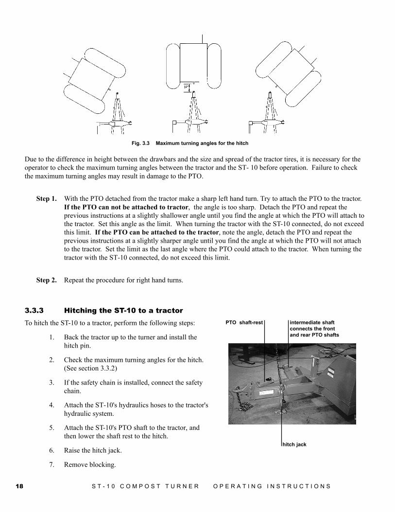
Due to the difference in height between the drawbars and the size and spread of the tractor tires, it is necessary for theoperator to check the maximum turning angles between the tractor and the ST- 10 before operation. Failure to checkthe maximum turning angles may result in damage to the PTO.
Step 1. With the PTO detached from the tractor make a sharp left hand turn. Try to attach the PTO to the tractor.If the PTO can not be attached to tractor, the angle is too sharp. Detach the PTO and repeat theprevious instructions at a slightly shallower angle until you find the angle at which the PTO will attach tothe tractor. Set this angle as the limit. When turning the tractor with the ST-10 connected, do not exceedthis limit. If the PTO can be attached to the tractor, note the angle, detach the PTO and repeat theprevious instructions at a slightly sharper angle until you find the angle at which the PTO will not attachto the tractor. Set the limit as the last angle where the PTO could attach to the tractor. When turning thetractor with the ST-10 connected, do not exceed this limit.
Step 2. Repeat the procedure for right hand turns.
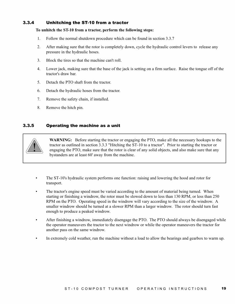
3.3.3 Hitching the ST-10 to a tractorTo hitch the ST-10 to a tractor, perform the following steps:
1. Back the tractor up to the turner and install thehitch pin.
2. Check the maximum turning angles for the hitch.(See section 3.3.2)
3. If the safety chain is installed, connect the safetychain.
4. Attach the ST-10's hydraulics hoses to the tractor'shydraulic system.
5. Attach the ST-10's PTO shaft to the tractor, andthen lower the shaft rest to the hitch.
6. Raise the hitch jack.
7. Remove blocking.
Fig. 3.3 Maximum turning angles for the hitch
intermediate shaftconnects the frontand rear PTO shafts
hitch jack
PTO shaft-rest
19S T - 1 0 C O M P O S T T U R N E R O P E R A T I N G I N S T R U C T I O N S
3.3.4 Unhitching the ST-10 from a tractorTo unhitch the ST-10 from a tractor, perform the following steps:
1. Follow the normal shutdown procedure which can be found in section 3.3.7
2. After making sure that the rotor is completely down, cycle the hydraulic control levers to release anypressure in the hydraulic hoses.
3. Block the tires so that the machine can't roll.
4. Lower jack, making sure that the base of the jack is setting on a firm surface. Raise the tongue off of thetractor's draw bar.
5. Detach the PTO shaft from the tractor.
6. Detach the hydraulic hoses from the tractor.
7. Remove the safety chain, if installed.
8. Remove the hitch pin.
3.3.5 Operating the machine as a unit
WARNING: Before starting the tractor or engaging the PTO, make all the necessary hookups to thetractor as outlined in section 3.3.3 "Hitching the ST-10 to a tractor". Prior to starting the tractor orengaging the PTO, make sure that the rotor is clear of any solid objects, and also make sure that anybystanders are at least 60' away from the machine.
• The ST-10's hydraulic system performs one function: raising and lowering the hood and rotor fortransport.
• The tractor's engine speed must be varied according to the amount of material being turned. Whenstarting or finishing a windrow, the rotor must be slowed down to less than 130 RPM, or less than 250RPM on the PTO. Operating speed in the windrow will vary according to the size of the windrow. Asmaller windrow should be turned at a slower RPM than a larger windrow. The rotor should turn fastenough to produce a peaked windrow.
• After finishing a windrow, immediately disengage the PTO. The PTO should always be disengaged whilethe operator maneuvers the tractor to the next windrow or while the operator maneuvers the tractor foranother pass on the same windrow.
• In extremely cold weather, run the machine without a load to allow the bearings and gearbox to warm up.
20 S T - 1 0 C O M P O S T T U R N E R O P E R A T I N G I N S T R U C T I O N S
3.3.6 How to make adjustments and evaluate performanceADJUSTING HOOD HEIGHT
Hood height is controlled at the following 4 points: the outer hood jack, the hitch axle, the hitch connection and withthe hydraulic cylinder over extension.
The hood clearance should initially be set at 1/2" on asphalt lots and 1-1/2" on dirt or gravel lots. The hoodclearance is defined as the distance from the ground to the bottom edge of the hood. Hood clearance should beminimized so that as little product as possible is left unturned. In order to keep the end of the hood or the rotor paddlesfrom digging into the ground, hood clearance must be maintained over the entire length of the windrow.
• The hitch connection and hitch axle adjustments will set depending on how parallel the hood is to theground. The hitch connection (7500641) is set according to the tractor hitch to keep the hitch roughlyparallel to the ground. The hitch axle is set by 4 bolts and 8 nuts which connects the axle to the hitch.The hitch axle should be set for the initial hood clearance described above, after the counterweight boxeshave been filled.
• The outer hood jack adjusts the outer edge-to-ground clearance. This is set by turning the crank on thejack, which raises or lowers the hood.
• During operation, the hydraulic cylinder can be adjusted to raise the inner edge of the hood. The cylinderhas extra travel in it which could be used to raise the inner edge and the inner tire.
ADJUSTING ROTOR SPEED
Rotor speed is adjusted by the tractor engine's RPM. The speed of the rotor will determine the shape of the pile.
ADJUSTING GROUND SPEED
Ground speed is set by the tractor engine unless there is a pusher axle. If there is a pusher axle, the ground speedshould be set slow enough to prevent material from plugging the rotor. In general, the ground speed varies fromapproximately 1/4 to 1/2 miles per hour.
ADJUSTING WATER SPRAY OUTPUT
Water spray output is determined by the water line pressure and the water line pressure is determined by pump andcontrol valves of the water delivery system. The accompanying chart shows how the water output varies with linepressure.
With original nozzles:
Water System Pressure Output/Nozzle Total Output(3 nozzles)
10 psi 12 GPM 36 GPM
30 psi 21 GPM 63 GPM
60 psi 29 GPM 87 GPM
100 psi 38 GPM 114 GPM
21S T - 1 0 C O M P O S T T U R N E R O P E R A T I N G I N S T R U C T I O N S
3.3.7 Shutdown proceduresFor your safety and the safety of others, you must use the following normal shutdown procedure before leaving thetractor controls unattended for any reason; including servicing, cleaning, or inspecting the compost turner. A variationof the following procedure may be used if so instructed within this manual, the tractor's manual or if an emergencyrequires it.
• Disengage the PTO.
• Lower machine to ground level.
• Place transmission in park or set the parking brake.
• Shut off the tractor's engine and remove the tractor's ignition key.
• Wait for all movement on the compost turner to stop before exiting the tractor's cockpit or operators seat.
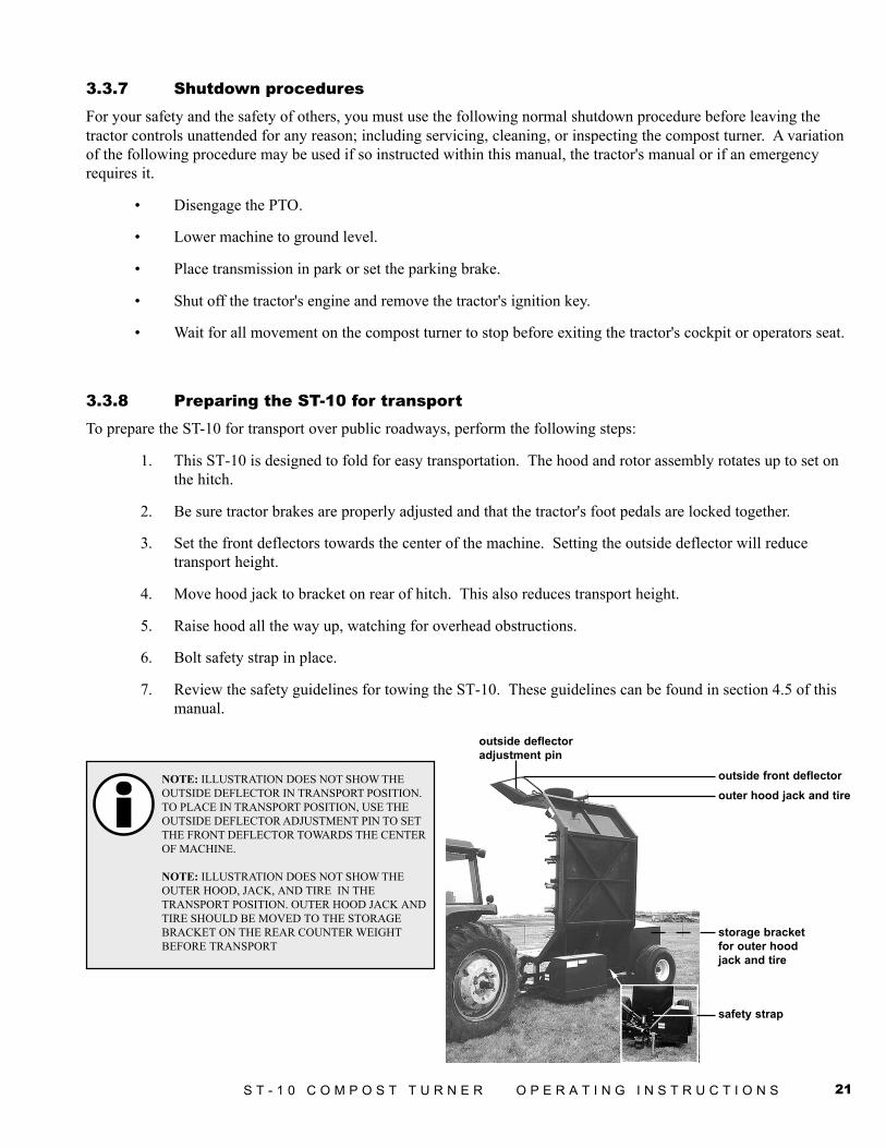
3.3.8 Preparing the ST-10 for transportTo prepare the ST-10 for transport over public roadways, perform the following steps:
1. This ST-10 is designed to fold for easy transportation. The hood and rotor assembly rotates up to set onthe hitch.
2. Be sure tractor brakes are properly adjusted and that the tractor's foot pedals are locked together.
3. Set the front deflectors towards the center of the machine. Setting the outside deflector will reducetransport height.
4. Move hood jack to bracket on rear of hitch. This also reduces transport height.
5. Raise hood all the way up, watching for overhead obstructions.
6. Bolt safety strap in place.
7. Review the safety guidelines for towing the ST-10. These guidelines can be found in section 4.5 of thismanual.
storage bracketfor outer hoodjack and tire
outer hood jack and tireoutside front deflector
outside deflectoradjustment pin
safety strap
NOTE: ILLUSTRATION DOES NOT SHOW THEOUTSIDE DEFLECTOR IN TRANSPORT POSITION.TO PLACE IN TRANSPORT POSITION, USE THEOUTSIDE DEFLECTOR ADJUSTMENT PIN TO SETTHE FRONT DEFLECTOR TOWARDS THE CENTEROF MACHINE.
NOTE: ILLUSTRATION DOES NOT SHOW THEOUTER HOOD, JACK, AND TIRE IN THETRANSPORT POSITION. OUTER HOOD JACK ANDTIRE SHOULD BE MOVED TO THE STORAGEBRACKET ON THE REAR COUNTER WEIGHTBEFORE TRANSPORT
22 S T - 1 0 C O M P O S T T U R N E R O P E R A T I N G I N S T R U C T I O N S
3.3.9 Preparing the ST-10 for operation after transportTo prepare the ST-10 for operation after transporting it over public roads, perform the following steps:
1. Park the ST-10 on level ground.
2. Unbolt the safety straps.
3. Lower the hood to the ground.
4. Move the hood jack to its operating position on the hood.
5. Set the front deflectors to their operating position.
3.3.10 Preparing the ST-10 for storageTo prepare the ST-10 for storage, preform the following steps:
1. Shutdown the ST-10 using the normal shutdown procedure.
2. Clean all mud, dirt, grease and other foreign material from the exterior of the machine. If washing thecompost turner with a high pressure washer, keep the nozzle away from the sealed bearings. To inhibitrusting, repaint places on the machine where the bare metal is exposed.
3. Rest the hitch on the hitch jack, and take the weight off the tires by setting the rear axle up on blocks. Donot deflate the tires. Raise the hood tire off ground using the hood jack. If possible, store the machine ina dry, protected place. If it is necessary to store the machine outside, cover it with waterproof canvas,plastic, or other protective covering.
4. To inhibit rusting, use blocks to raise the hood off of the ground.
5. Coat the exposed lift cylinder rod with grease and follow the lubrication instructions which can be foundin the General maintenance section of this manual. Clean and repack the wheel bearings.
6. Check the machine for any worn or broken parts.
By ordering parts now, you will avoid delays when it is time to remove the machine from storage. When orderingparts, always specify the machine's serial number and the part number of the replacement part. Part numbers can befound in the parts section of this manual.
3.3.11 Removing the ST-10 from storageTo remove the ST-10 from storage, preform the following steps:
1. Remove all the protective coverings from the unit.
2. Remove the blocking from under compost turner and check the tire pressure.
3. Lubricate the machine following the lubrication instructions which can be found in the Generalmaintenance section of this manual.
4. Check all of the hydraulic hoses for deterioration and, if necessary, replace the hoses. Inspect thehydraulic cylinder tightening any loose bolts, nuts or hydraulic fittings.
5. Preform a pre-operation inspection.
23S T - 1 0 C O M P O S T T U R N E R O P E R A T I N G I N S T R U C T I O N S
Section 4: General Maintenance
WARNING: Before inspecting the machine, use the normal shutdown procedure on page 19.
4.1 General service and maintenance
CAUTION: Before performing any maintenance or adjustments make sure the machine is NOTrunning. If for any reason arc welding is to be done on this machine, always ground the rotor to frameof machine to prevent arcing within the bearings.
Never work on the compost turner with the hood & rotor in the raised position. Lower the hood and rotor to groundlevel.
Use only replacement parts that are recommended and approved by Duratech Industries International Inc.
Cycle the hydraulic control levers to relieve all pressure in the hydraulic system before disconnecting the hoses orperforming other work on the system. Make sure all connections are tight and the hoses are in good working conditionbefore applying pressure to the hydraulic system.
24 S T - 1 0 C O M P O S T T U R N E R O P E R A T I N G I N S T R U C T I O N S
4.2 Lubrication
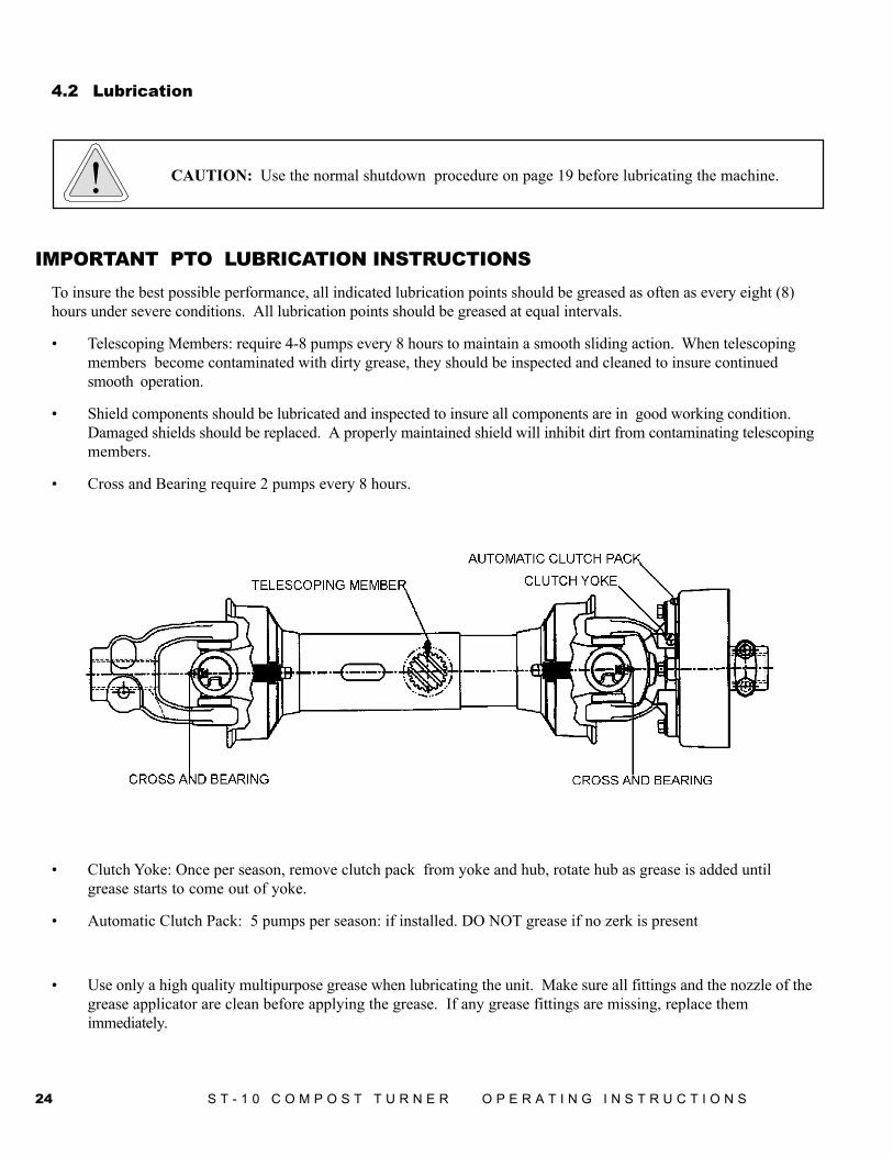
IMPORTANT PTO LUBRICATION INSTRUCTIONSTo insure the best possible performance, all indicated lubrication points should be greased as often as every eight (8)hours under severe conditions. All lubrication points should be greased at equal intervals.
• Telescoping Members: require 4-8 pumps every 8 hours to maintain a smooth sliding action. When telescopingmembers become contaminated with dirty grease, they should be inspected and cleaned to insure continuedsmooth operation.
• Shield components should be lubricated and inspected to insure all components are in good working condition.Damaged shields should be replaced. A properly maintained shield will inhibit dirt from contaminating telescopingmembers.
• Cross and Bearing require 2 pumps every 8 hours.
• Clutch Yoke: Once per season, remove clutch pack from yoke and hub, rotate hub as grease is added untilgrease starts to come out of yoke.
• Automatic Clutch Pack: 5 pumps per season: if installed. DO NOT grease if no zerk is present
• Use only a high quality multipurpose grease when lubricating the unit. Make sure all fittings and the nozzle of thegrease applicator are clean before applying the grease. If any grease fittings are missing, replace themimmediately.
CAUTION: Use the normal shutdown procedure on page 19 before lubricating the machine.
25S T - 1 0 C O M P O S T T U R N E R O P E R A T I N G I N S T R U C T I O N S
Periodically apply grease to sliding track of support wheel on hood.
Wheel hub bearings on axle and hood jack should be checked for adjustment and lubrication annually, preferably at theend of the season. If there is a generous amount of grease on the bearing and the housing, and if the grease is soft, thegrease will not need changing. If the grease is caked, or the bearing seems dry, the bearing should be cleaned to removeold grease and contaminants. The bearings should be repacked and reinstalled.
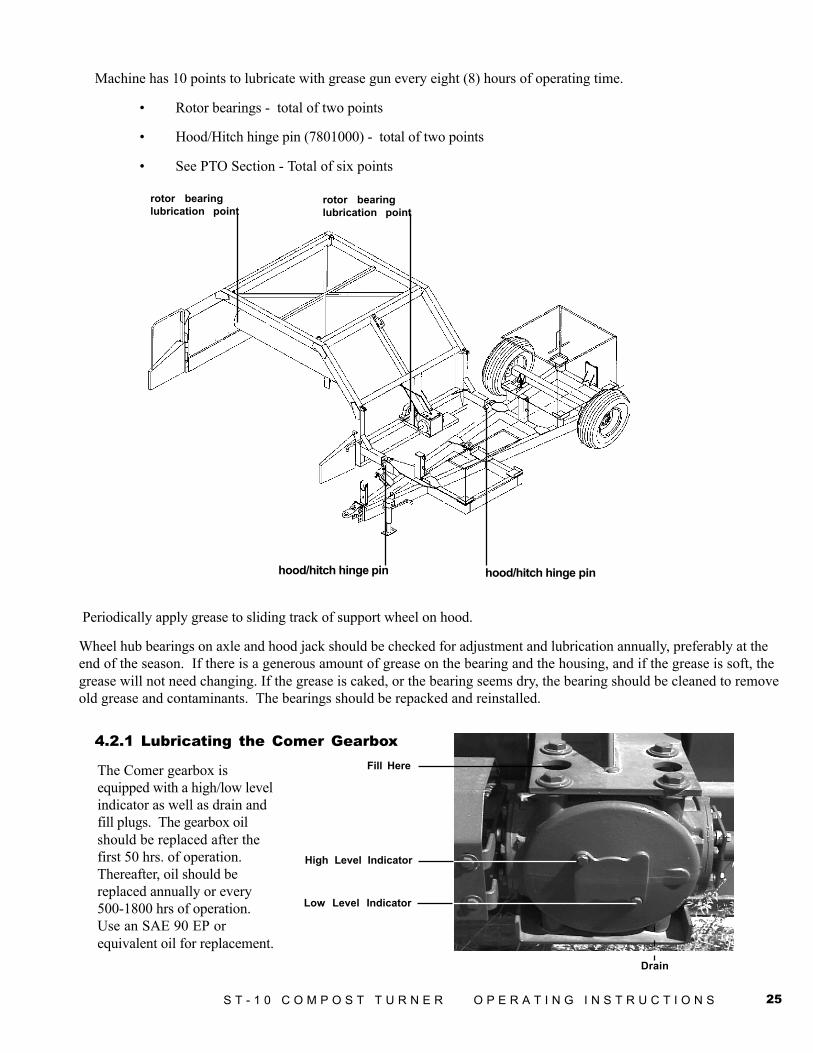
Machine has 10 points to lubricate with grease gun every eight (8) hours of operating time.
• Rotor bearings - total of two points
• Hood/Hitch hinge pin (7801000) - total of two points
• See PTO Section - Total of six points
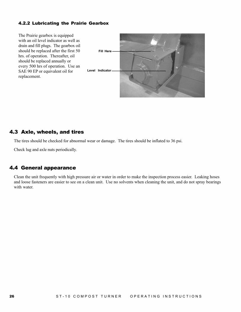
High Level Indicator
Low Level Indicator
Drain
Fill HereThe Comer gearbox isequipped with a high/low levelindicator as well as drain andfill plugs. The gearbox oilshould be replaced after thefirst 50 hrs. of operation.Thereafter, oil should bereplaced annually or every500-1800 hrs of operation.Use an SAE 90 EP orequivalent oil for replacement.
rotor bearinglubrication point
hood/hitch hinge pin
rotor bearinglubrication point
hood/hitch hinge pin
4.2.1 Lubricating the Comer Gearbox
26 S T - 1 0 C O M P O S T T U R N E R O P E R A T I N G I N S T R U C T I O N S
4.3 Axle, wheels, and tiresThe tires should be checked for abnormal wear or damage. The tires should be inflated to 36 psi.
Check lug and axle nuts periodically.
4.4 General appearanceClean the unit frequently with high pressure air or water in order to make the inspection process easier. Leaking hosesand loose fasteners are easier to see on a clean unit. Use no solvents when cleaning the unit, and do not spray bearingswith water.
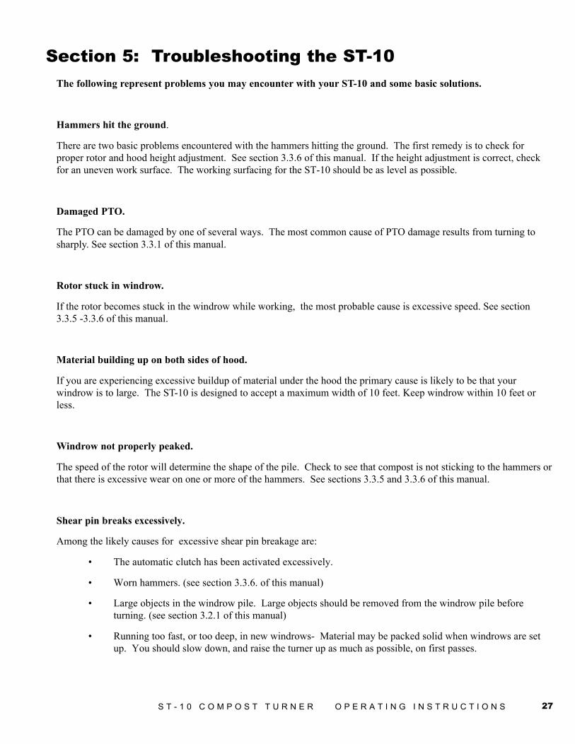
Fill Here
Level Indicator
4.2.2 Lubricating the Prairie Gearbox
The Prairie gearbox is equippedwith an oil level indicator as well asdrain and fill plugs. The gearbox oilshould be replaced after the first 50hrs. of operation. Thereafter, oilshould be replaced annually orevery 500 hrs of operation. Use anSAE 90 EP or equivalent oil forreplacement.
27S T - 1 0 C O M P O S T T U R N E R O P E R A T I N G I N S T R U C T I O N S
Section 5: Troubleshooting the ST-10The following represent problems you may encounter with your ST-10 and some basic solutions.
Hammers hit the ground.
There are two basic problems encountered with the hammers hitting the ground. The first remedy is to check forproper rotor and hood height adjustment. See section 3.3.6 of this manual. If the height adjustment is correct, checkfor an uneven work surface. The working surfacing for the ST-10 should be as level as possible.
Damaged PTO.
The PTO can be damaged by one of several ways. The most common cause of PTO damage results from turning tosharply. See section 3.3.1 of this manual.
Rotor stuck in windrow.
If the rotor becomes stuck in the windrow while working, the most probable cause is excessive speed. See section3.3.5 -3.3.6 of this manual.
Material building up on both sides of hood.
If you are experiencing excessive buildup of material under the hood the primary cause is likely to be that yourwindrow is to large. The ST-10 is designed to accept a maximum width of 10 feet. Keep windrow within 10 feet orless.
Windrow not properly peaked.
The speed of the rotor will determine the shape of the pile. Check to see that compost is not sticking to the hammers orthat there is excessive wear on one or more of the hammers. See sections 3.3.5 and 3.3.6 of this manual.
Shear pin breaks excessively.
Among the likely causes for excessive shear pin breakage are:
• The automatic clutch has been activated excessively.
• Worn hammers. (see section 3.3.6. of this manual)
• Large objects in the windrow pile. Large objects should be removed from the windrow pile beforeturning. (see section 3.2.1 of this manual)
• Running too fast, or too deep, in new windrows- Material may be packed solid when windrows are setup. You should slow down, and raise the turner up as much as possible, on first passes.

28 S T - 1 0 C O M P O S T T U R N E R O P E R A T I N G I N S T R U C T I O N S
Appendix A: WarrantyDuratech Industries International Inc. warrants to the original purchaser for 1 year from purchase date that this productwill be free from defects in material and workmanship when used as intended and under normal maintenance andoperating conditions. This warranty is limited to the replacement of any defective part or parts returned to our factory inJamestown, North Dakota, USA, within thirty (30) days of failure.
This warranty shall become void if in the judgment of Duratech Industries International, Inc. the machine has beensubject to misuse, negligence, alterations, damaged by accident or lack of required normal maintenance, or if the producthas been used for a purpose for which it was not designed.
All claims for warranty must be made through the dealer which originally sold the product and all warranty adjustmentsmust be made through same.
This warranty does not apply to tires or bearings or any other trade accessories not manufactured by DuratechIndustries International Inc. Buyer must rely solely on the existing warranty, if any, of these respective manufacturers.
Duratech Industries International Inc., shall not be held liable for damages of any kind, direct, contingent, orconsequential to property under this warranty. Duratech Industries International Inc., cannot be held liable for anydamages resulting from causes beyond its control. Duratech Industries International Inc., shall not be held liable underthis warranty for rental costs or any expense or loss for labor or supplies.
Duratech Industries International Inc., reserves the right to make changes in material and/or designs of this product atany time without notice.
This warranty is void if Duratech Industries International Inc. does not receive a valid warranty registration card at itsoffice in Jamestown, North Dakota, USA, within 10 days from date of original purchase.
All other warranties made with respect to this product, either expressed or implied, are hereby disclaimed by DuratechIndustries International Inc.
29S T - 1 0 C O M P O S T T U R N E R O P E R A T I N G I N S T R U C T I O N S
Appendix B: SpecificationsGeneralTractor H.P. required (see also Appendix F) ........................................ Min. 70 H.P.Capacity .....................................................................Maximum windrow width 10"Rotor Length .................................................................................................... 117.5"Rotor Diameter .............................................................................................. 31-1/2"Rotor Bearings - Ball ....................................................................................... 2-1/2"Hammers, total ....................................................................................................... 68Wheel - Taper Roller Bearings - Tire Size ................................. 16.5x16.1SL-10 PlyWorking Position Height ........................................................................................ 66"Length ................................................................................................................. 177"Width ................................................................................................................... 220"Transport Position:Height .................................................................................... 162"Length ................................................................................................................. 177"Width ..................................................................................................................... 82"Total Operating Weight ............................................................................ 11700 Lbs.Axle Weight ................................................................................................ 9000 Lbs.Hitch Weight .............................................................................................. 2700 Lbs.Shipping Weight(without concrete) ............................................................ 5000 Lbs.PTO............................................................................................................ 540 RPMCylinder 4x34" Double Acting with pilot operated check valveShear pin, Front PTO shaft ....................................................... 3/8x2 NF GRADE 5
30 S T - 1 0 C O M P O S T T U R N E R O P E R A T I N G I N S T R U C T I O N S
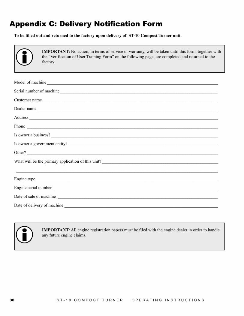
Appendix C: Delivery Notification FormTo be filled out and returned to the factory upon delivery of ST-10 Compost Turner unit.
IMPORTANT: No action, in terms of service or warranty, will be taken until this form, together withthe “Verification of User Training Form” on the following page, are completed and returned to thefactory.
Model of machine ______________________________________________________________________________
Serial number of machine________________________________________________________________________
Customer name ________________________________________________________________________________
Dealer name __________________________________________________________________________________
Address ______________________________________________________________________________________
Phone _______________________________________________________________________________________
Is owner a business? ____________________________________________________________________________
Is owner a government entity? ____________________________________________________________________
Other? _______________________________________________________________________________________
What will be the primary application of this unit? _____________________________________________________
____________________________________________________________________________________________
Engine type ___________________________________________________________________________________
Engine serial number ___________________________________________________________________________
Date of sale of machine _________________________________________________________________________
Date of delivery of machine ______________________________________________________________________
IMPORTANT: All engine registration papers must be filed with the engine dealer in order to handleany future engine claims.
31S T - 1 0 C O M P O S T T U R N E R O P E R A T I N G I N S T R U C T I O N S
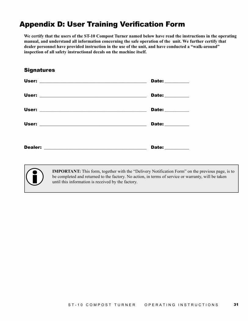
Appendix D: User Training Verification FormWe certify that the users of the ST-10 Compost Turner named below have read the instructions in the operatingmanual, and understand all information concerning the safe operation of the unit. We further certify thatdealer personnel have provided instruction in the use of the unit, and have conducted a “walk-around”inspection of all safety instructional decals on the machine itself.
Signatures
User: ________________________________________________ Date: ___________
User: ________________________________________________ Date: ___________
User: ________________________________________________ Date: ___________
User: ________________________________________________ Date: ___________
Dealer: ______________________________________________ Date: ___________
IMPORTANT: This form, together with the “Delivery Notification Form” on the previous page, is tobe completed and returned to the factory. No action, in terms of service or warranty, will be takenuntil this information is received by the factory.
32 S T - 1 0 C O M P O S T T U R N E R O P E R A T I N G I N S T R U C T I O N S
Appendix E: Operator Training FormThe following personnel, by their signature, certify that they have read this manual in its entirety andcomprehend its instructions. Only personnel so qualified are allowed to operate this unit.
Printed Name Review Date Signature
33S T - 1 0 C O M P O S T T U R N E R O P E R A T I N G I N S T R U C T I O N S
Appendix F: Required For Operation
WARNING: Do not operate the ST-10 compost turner unless the tractor complies with the followingrequirements:
1. Horsepower - 70 H.P. minimum. 540 rpm PTO shaft.
2. Rollover protective structure and seat-belts.
3. An enclosed cab is preferred.
4. One set of two-way hydraulic outlets.
5. A shield should be installed on the tractor to protect the operator and cab glass from thrown material.This shield should be made of heavy expanded metal held in place by a sturdy frame.
6. A water delivery system capable of providing 100 GPM at 100 psi. A water delivery system is onlyrequired if the operator wishes to use the ST-10’ s water system to and moisture to a windrow.
7. Counter weight boxes require 2 to 2-1/4 yards of concrete. It is best to round pile on top of both boxes forrain run-off and extra weight. (see page 14)

34 S T - 1 0 C O M P O S T T U R N E R O P E R A T I N G I N S T R U C T I O N S
ST-10Compost Turner
Part 2:Parts Reference
35

36 S T - 1 0 C O M P O S T T U R N E R P A R T S R E F E R E N C E
HITCH ASSEMBLY
7801032 Hitch AssemblyPART # QTY DESCRIPTION2000058 2 BRG\INS\1-3/8\CYL\W/COLLR2600040 2 TIRE\16.5X16.1SL\10PLY2600639 2 WHL\8BOLT\16.1X14\>2900140 2 HUB\8BOLT\COMP\>2900125 1 OUTER CONE H817 HUB2900128 1 INNER CONE H817 HUB2900129 1 HUB\8BOLT\W/RACES\W/NUTS>2900130 1 DUST CAP H817
37S T - 1 0 C O M P O S T T U R N E R P A R T S R E F E R E N C E
HITCH ASSEMBLY
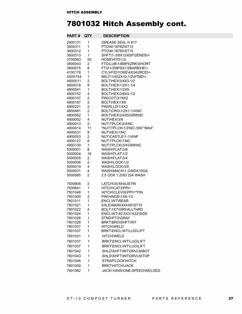
7801032 Hitch Assembly cont.PART # QTY DESCRIPTION2900131 1 GREASE SEAL H 8173600311 1 PTO\M-18782\ST103600312 1 PTO\M-18783\ST103600313 1 SHFT\1-3/8X12\6SP\2ENDS\>3700083 50 HOSE\HYD\1/23800043 2 FTG\LUB\1/8MPXZRK\SHORT3800075 8 FTG\1/2MPSX1/2BARB\HE\>4100178 1 CYL\HYD\YOKE\4X34\2ROD\>4500754 1 BELT\1/4X2X10-1/2\STND\>4800011 2 BOLT\HEX\3/4X3-1/24800018 8 BOLT\HEX\1/2X1-1/44800041 1 BOLT\HEX\1/2X54800152 4 BOLT\HEX\3/8X4-1/24800157 2 PIN\COT\3/16X24800187 2 BOLT\HEX\1X64800221 2 PIN\RLLD\1/4X24800481 2 BOLT\CRG\1/2X1-1/4\NC4800562 1 BOLT\HEX\3/4X5\GR8\NC4900002 4 NUT\HEX\3/84900013 2 NUT\TPLCK\3/4\NC4900014 11 “NUT\TPLCK\1/2\NC\.500””MAX”4900031 8 NUT\HEX\1\NC4900053 2 NUT\CASTLE\1-1/4\NF4900127 6 NUT\TPLCK\1\NC4900139 1 NUT\TPLCK\3/4\GR8\NC5000001 8 WASH\FLAT\3/85000004 16 WASH\FLAT\1/25000005 2 WASH\FLAT\3/45000006 2 WASH\LOCK\1/25000019 4 WASH\LOCK\3/85000031 4 WASH\MACH\1-3/8IDX10GA5000065 2 2.5 ODX 1.25ID 224 WASH
7500606 2 LATCH\35-M\AUSTIN7500641 1 HITCH\CAT3\PPI>7501048 1 HITCH\CLEVIS\PPI\1"PIN7801000 2 PIN\HINGE\1X6-1/27801011 1 ENCL\WT\REAR7801021 1 AXLE\MAIN\4X4X6'\ST107801022 4 BOLT\1X7\GR5\ALLTHRD7801024 1 ENCL\WT\40.5X31X22\SIDE7801026 1 STND\PTO\GRAY7801028 1 BRKT\BRG\SHFT\INT7801031 1 HITCH\WELD7801037 1 BRKT\ENCL\WT\LUG\LIFT7801031 1 HITCH\WELD7801037 1 BRKT\ENCL\WT\LUG\LIFT7801037 1 BRKT\ENCL\WT\LUG\LIFT7801042 1 SHLD\SHFT\INT\DRVLN\BOT7801043 1 SHLD\SHFT\INT\DRVLN\TOP7801046 1 STRAP\LOCK\HITCH7801059 1 BRKT\HITCH\JACK7801062 1 JACK\10000\ONE;SPEED\WELDED
38 S T - 1 0 C O M P O S T T U R N E R P A R T S R E F E R E N C E
D R I V E L I N E A S S E M B L Y P. N . 3 6 0 0 3 1 1 - S N 0 1 0 1 T O 0 1 3 0
39S T - 1 0 C O M P O S T T U R N E R P A R T S R E F E R E N C E
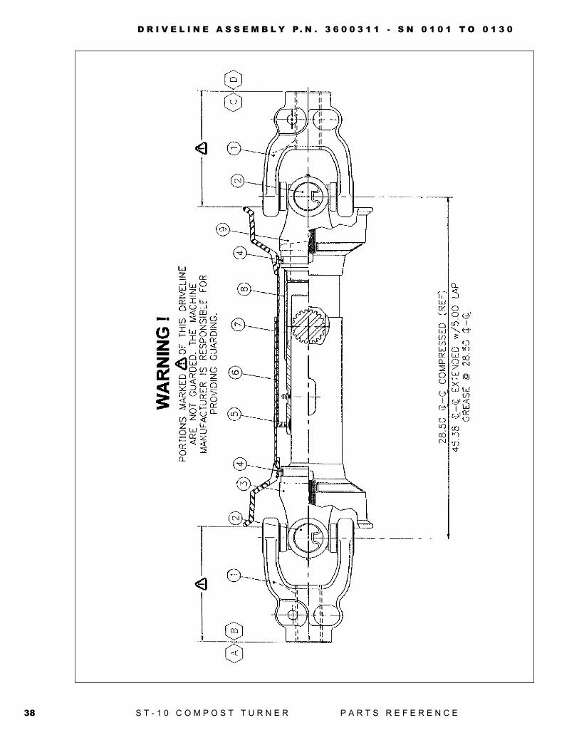
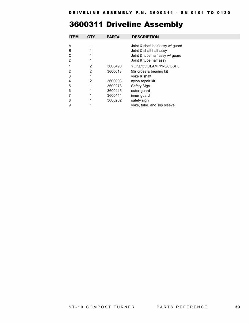
3600311 Driveline AssemblyITEM QTY PART# DESCRIPTION
A 1 Joint & shaft half assy w/ guardB 1 Joint & shaft half assyC 1 Joint & tube half assy w/ guardD 1 Joint & tube half assy1 2 3600490 YOKE\55\CLAMP\1-3/8\6SPL2 2 3600013 55r cross & bearing kit3 1 yoke & shaft4 2 3600093 nylon repair kit5 1 3600278 Safety Sign6 1 3600445 outer guard7 1 3600444 inner guard8 1 3600282 safety sign9 1 yoke, tube. and slip sleeve
D R I V E L I N E A S S E M B L Y P. N . 3 6 0 0 3 1 1 - S N 0 1 0 1 T O 0 1 3 0
40 S T - 1 0 C O M P O S T T U R N E R P A R T S R E F E R E N C E
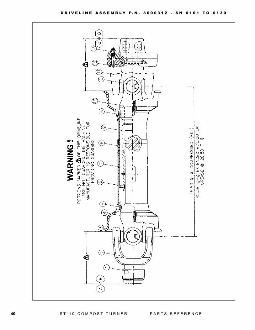
D R I V E L I N E A S S E M B L Y P. N . 3 6 0 0 3 1 2 - S N 0 1 0 1 T O 0 1 3 0
41S T - 1 0 C O M P O S T T U R N E R P A R T S R E F E R E N C E
3600312 Driveline AssemblyITEM QTY PART# DESCRIPTION
A 1 3600412 PTO\Quick Disconnect\Tractor Half\for 3600312B 1 Joint & shaft half assyC 1 3600411 PTO\Shear\Machine Half\for 3600312D 1 Joint & tube half assy1 1 3600271 safety slide lock repair kit2 1 3600442 safety slide lock yoke assy3 2 3600013 55r cross & bearing kit4 1 yoke & shaft5 2 3600093 nylon repair kit6 1 3600278 safety sign7 1 3600445 outer guard8 1 3600444 inner guard9 1 3600282 safety sign10 1 yoke, tube. and slip sleeve11 1 3600410 Yoke\55\Shear\1-3/8\6Spline\for 360031212 1 4800526 3/8X2 NF Hex Bolt, Gr 513 1 4900085 3/8 Nylon Lock Nut
D R I V E L I N E A S S E M B L Y P. N . 3 6 0 0 3 1 2 - S N 0 1 0 1 T O 0 1 3 0
42 S T - 1 0 C O M P O S T T U R N E R P A R T S R E F E R E N C E
D R I V E L I N E A S S E M B L Y P. N . 3 6 0 0 4 3 2 - S N 0 1 3 1 A N D U P
43S T - 1 0 C O M P O S T T U R N E R P A R T S R E F E R E N C E
D R I V E L I N E A S S E M B L Y P. N . 3 6 0 0 4 3 2 - S N 0 1 3 1 A N D U P
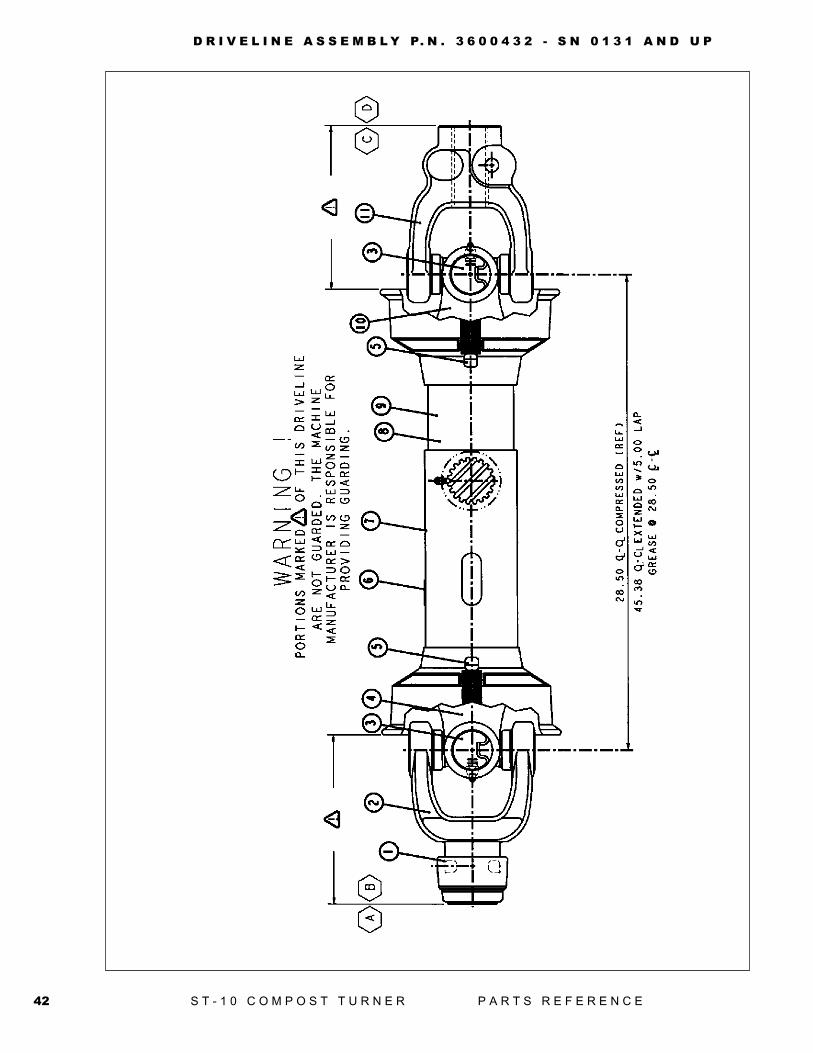
3600432 PTO\QD&CLAMP:YOKE\ST10\55RItem Qty Part Description
A 1 3600412 PTO\Quick Disconnect\Tractor Half\For 3600312B 1 Joint & Shaft Half AssyC 1 Joint & Tube Half Assy W/ GuardD 1 Joint & Tube Half Assy1 1 3600271 Safety Slide Lock Repair Kit2 1 3600442 Safety Slide Lock Yoke Assy3 2 3600013 55r Cross & Bearing Kit4 1 Yoke & Shaft5 2 3600093 Nylon Repair Kit6 1 3600278 Safety Sign7 1 3600445 Outer Guard8 1 3600444 Inner Guard9 1 3600282 Safety Sign10 1 Yoke, Tube. And Slip Sleeve11 1 3600490 YOKE\55\CLAMP\1-3/8\6SPL
44 S T - 1 0 C O M P O S T T U R N E R P A R T S R E F E R E N C E
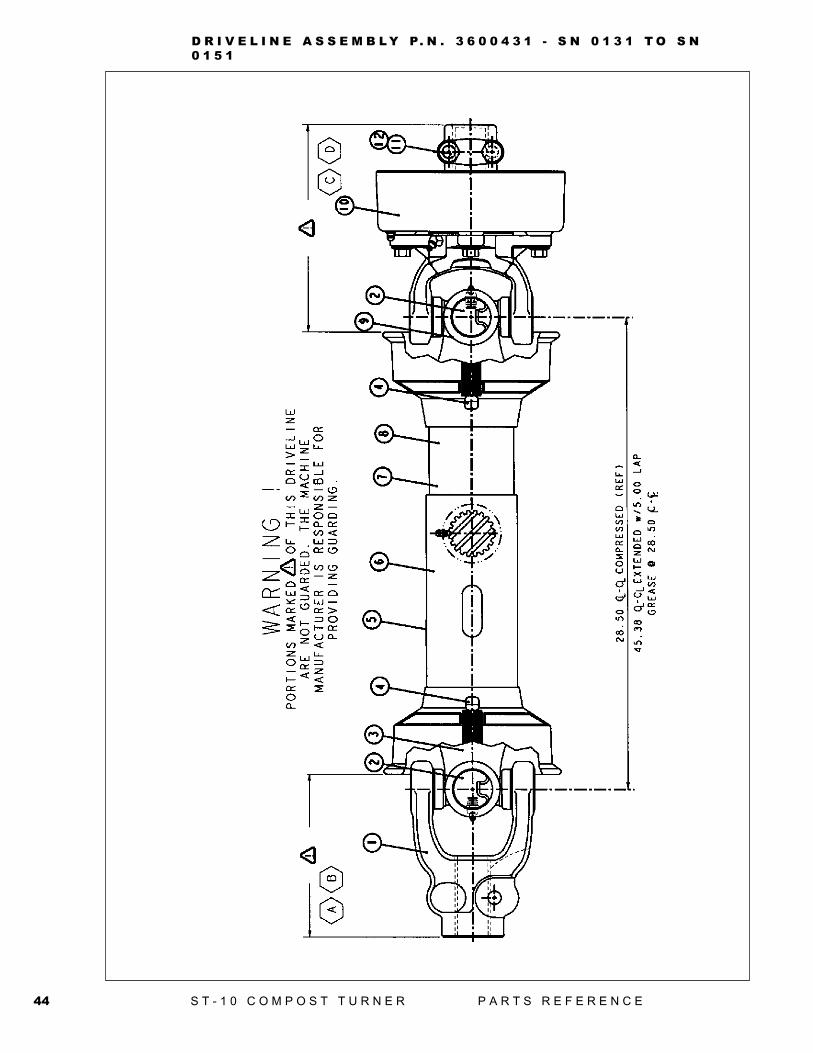
D R I V E L I N E A S S E M B L Y P. N . 3 6 0 0 4 3 1 - S N 0 1 3 1 T O S N0 1 5 1
45S T - 1 0 C O M P O S T T U R N E R P A R T S R E F E R E N C E
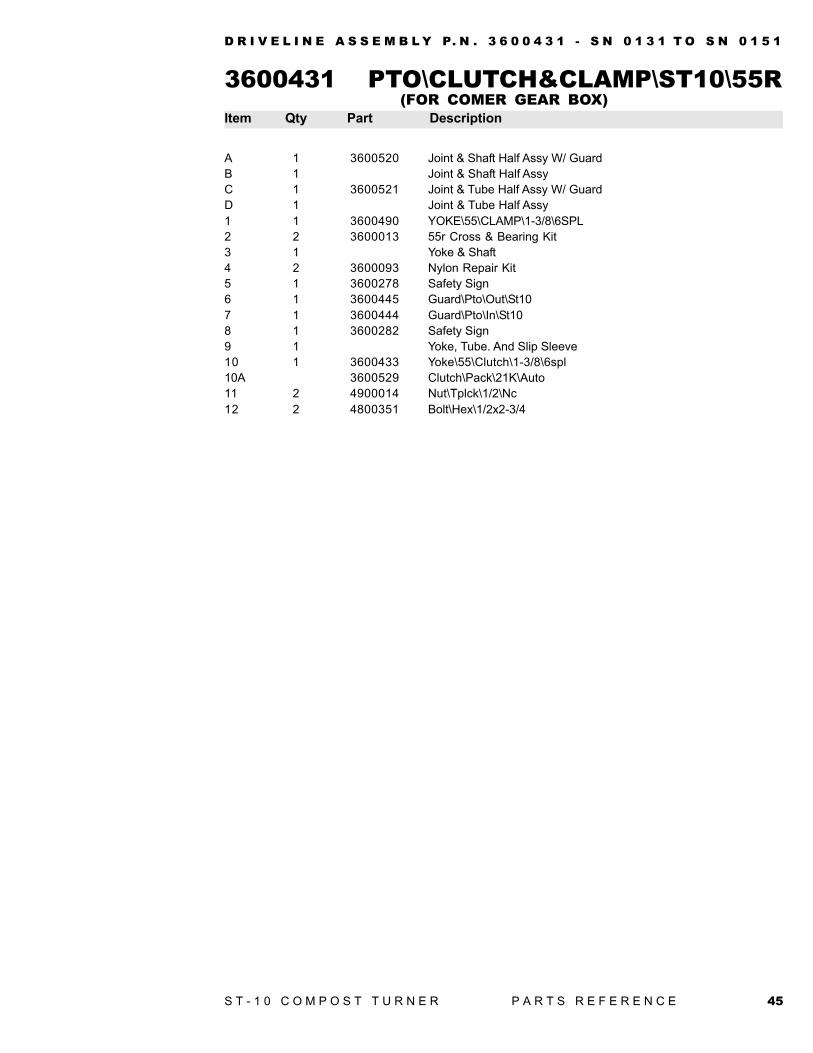
3600431 PTO\CLUTCH&CLAMP\ST10\55RItem Qty Part Description
A 1 3600520 Joint & Shaft Half Assy W/ GuardB 1 Joint & Shaft Half AssyC 1 3600521 Joint & Tube Half Assy W/ GuardD 1 Joint & Tube Half Assy1 1 3600490 YOKE\55\CLAMP\1-3/8\6SPL2 2 3600013 55r Cross & Bearing Kit3 1 Yoke & Shaft4 2 3600093 Nylon Repair Kit5 1 3600278 Safety Sign6 1 3600445 Guard\Pto\Out\St107 1 3600444 Guard\Pto\In\St108 1 3600282 Safety Sign9 1 Yoke, Tube. And Slip Sleeve10 1 3600433 Yoke\55\Clutch\1-3/8\6spl10A 3600529 Clutch\Pack\21K\Auto11 2 4900014 Nut\Tplck\1/2\Nc12 2 4800351 Bolt\Hex\1/2x2-3/4
D R I V E L I N E A S S E M B L Y P. N . 3 6 0 0 4 3 1 - S N 0 1 3 1 T O S N 0 1 5 1
(FOR COMER GEAR BOX)
46 S T - 1 0 C O M P O S T T U R N E R P A R T S R E F E R E N C E
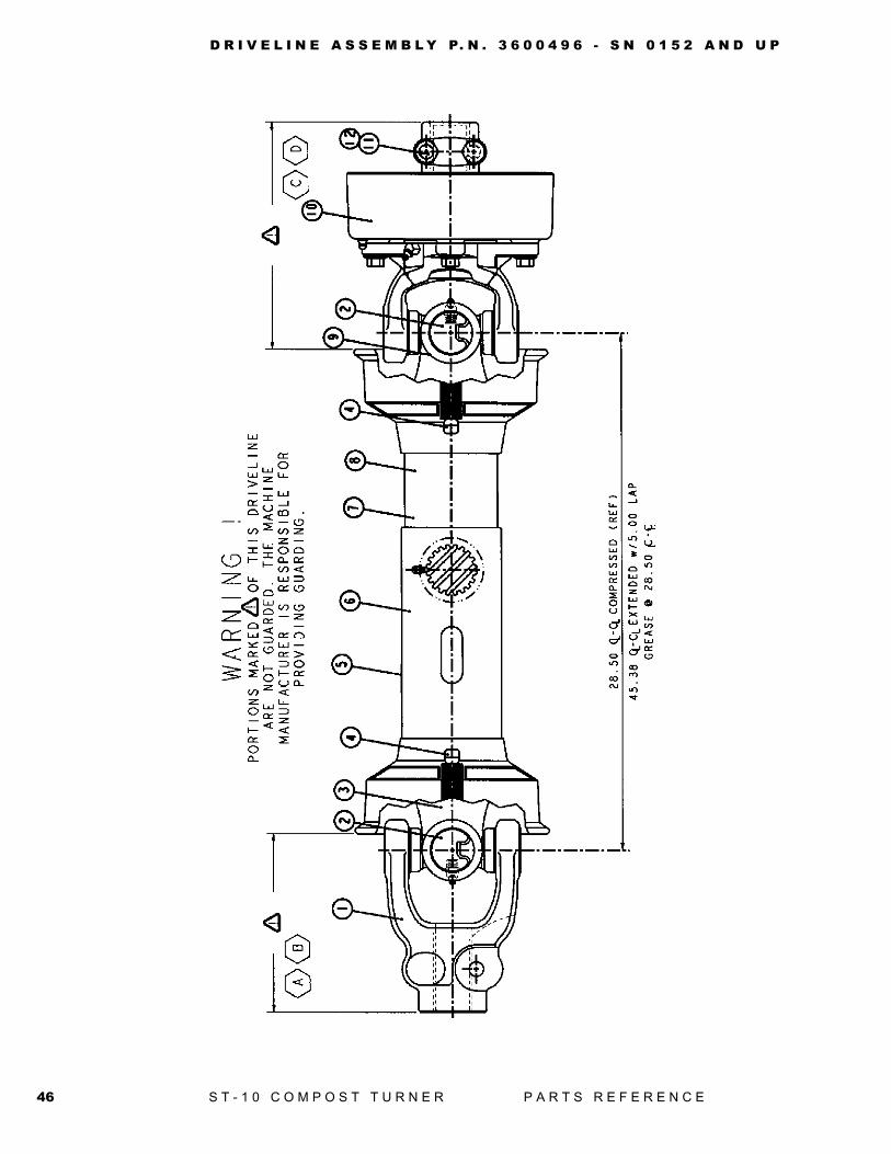
D R I V E L I N E A S S E M B L Y P. N . 3 6 0 0 4 9 6 - S N 0 1 5 2 A N D U P
47S T - 1 0 C O M P O S T T U R N E R P A R T S R E F E R E N C E
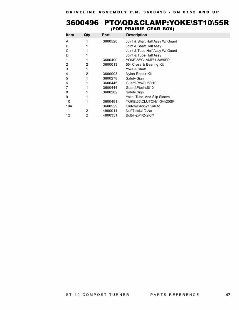
(FOR PRAIRIE GEAR BOX)3600496 PTO\QD&CLAMP:YOKE\ST10\55RItem Qty Part Description
D R I V E L I N E A S S E M B L Y P. N . 3 6 0 0 4 9 6 - S N 0 1 5 2 A N D U P
A 1 3600520 Joint & Shaft Half Assy W/ GuardB 1 Joint & Shaft Half AssyC 1 Joint & Tube Half Assy W/ GuardD 1 Joint & Tube Half Assy1 1 3600490 YOKE\55\CLAMP\1-3/8\6SPL2 2 3600013 55r Cross & Bearing Kit3 1 Yoke & Shaft4 2 3600093 Nylon Repair Kit5 1 3600278 Safety Sign6 1 3600445 Guard\Pto\Out\St107 1 3600444 Guard\Pto\In\St108 1 3600282 Safety Sign9 1 Yoke, Tube. And Slip Sleeve10 1 3600491 YOKE\55\CLUTCH\1-3/4\20SP10A 3600529 Clutch\Pack\21K\Auto11 2 4900014 Nut\Tplck\1/2\Nc12 2 4800351 Bolt\Hex\1/2x2-3/4
48 S T - 1 0 C O M P O S T T U R N E R P A R T S R E F E R E N C E
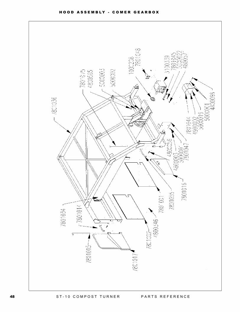
H O O D A S S E M B L Y - C O M E R G E A R B O X
49S T - 1 0 C O M P O S T T U R N E R P A R T S R E F E R E N C E
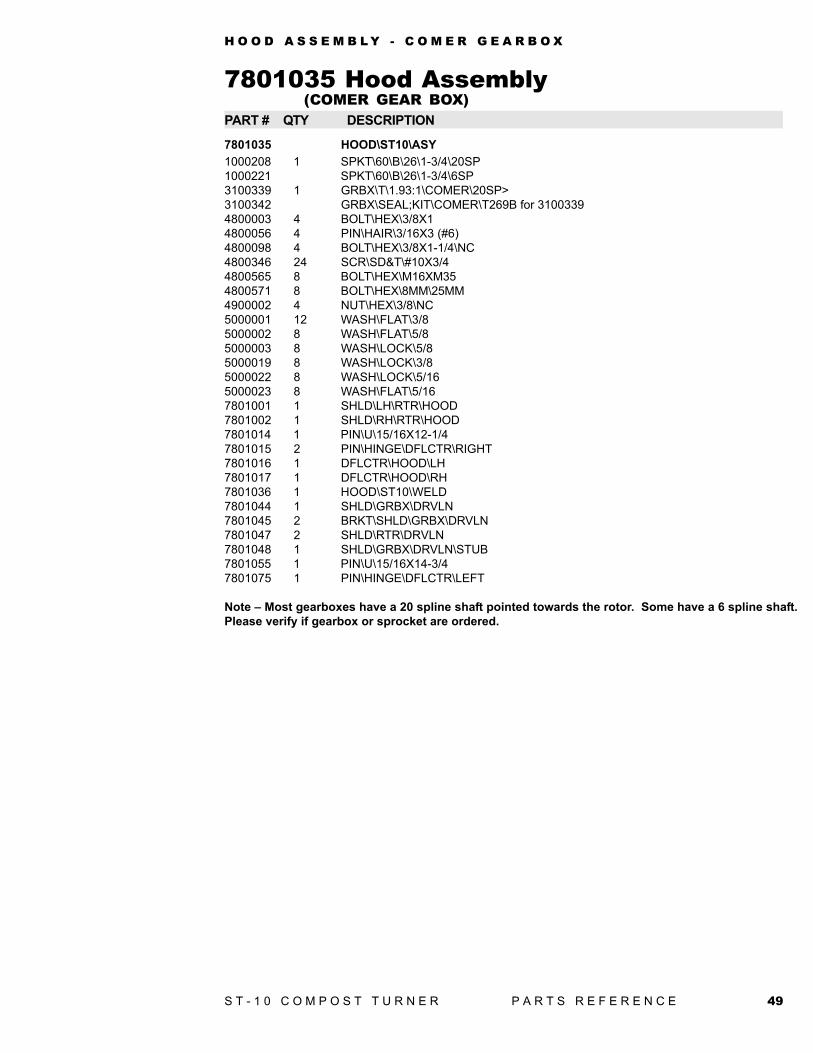
7801035 Hood AssemblyPART # QTY DESCRIPTION
7801035 HOOD\ST10\ASY1000208 1 SPKT\60\B\26\1-3/4\20SP1000221 SPKT\60\B\26\1-3/4\6SP3100339 1 GRBX\T\1.93:1\COMER\20SP>3100342 GRBX\SEAL;KIT\COMER\T269B for 31003394800003 4 BOLT\HEX\3/8X14800056 4 PIN\HAIR\3/16X3 (#6)4800098 4 BOLT\HEX\3/8X1-1/4\NC4800346 24 SCR\SD&T\#10X3/44800565 8 BOLT\HEX\M16XM354800571 8 BOLT\HEX\8MM\25MM4900002 4 NUT\HEX\3/8\NC5000001 12 WASH\FLAT\3/85000002 8 WASH\FLAT\5/85000003 8 WASH\LOCK\5/85000019 8 WASH\LOCK\3/85000022 8 WASH\LOCK\5/165000023 8 WASH\FLAT\5/167801001 1 SHLD\LH\RTR\HOOD7801002 1 SHLD\RH\RTR\HOOD7801014 1 PIN\U\15/16X12-1/47801015 2 PIN\HINGE\DFLCTR\RIGHT7801016 1 DFLCTR\HOOD\LH7801017 1 DFLCTR\HOOD\RH7801036 1 HOOD\ST10\WELD7801044 1 SHLD\GRBX\DRVLN7801045 2 BRKT\SHLD\GRBX\DRVLN7801047 2 SHLD\RTR\DRVLN7801048 1 SHLD\GRBX\DRVLN\STUB7801055 1 PIN\U\15/16X14-3/47801075 1 PIN\HINGE\DFLCTR\LEFT
Note – Most gearboxes have a 20 spline shaft pointed towards the rotor. Some have a 6 spline shaft.Please verify if gearbox or sprocket are ordered.
(COMER GEAR BOX)
H O O D A S S E M B L Y - C O M E R G E A R B O X
50 S T - 1 0 C O M P O S T T U R N E R P A R T S R E F E R E N C E
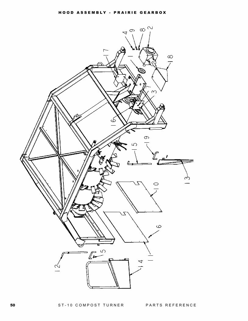
H O O D A S S E M B L Y - P R A I R I E G E A R B O X
51S T - 1 0 C O M P O S T T U R N E R P A R T S R E F E R E N C E
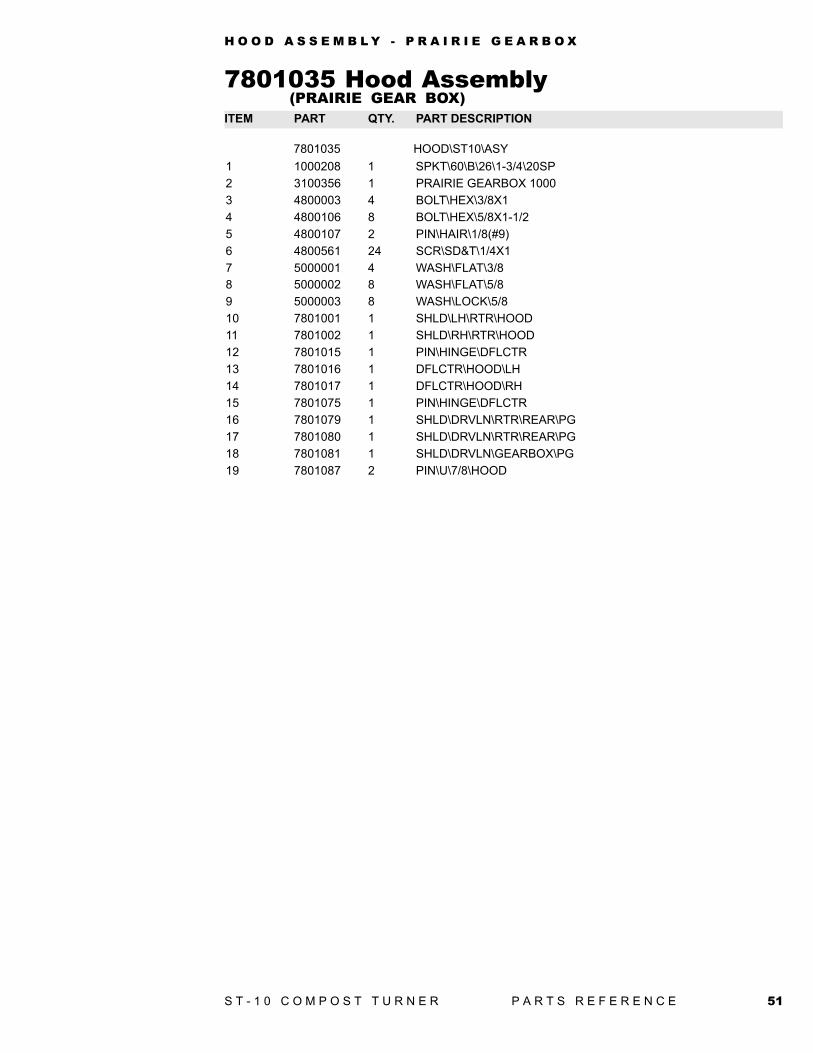
7801035 HOOD\ST10\ASY1 1000208 1 SPKT\60\B\26\1-3/4\20SP2 3100356 1 PRAIRIE GEARBOX 10003 4800003 4 BOLT\HEX\3/8X14 4800106 8 BOLT\HEX\5/8X1-1/25 4800107 2 PIN\HAIR\1/8(#9)6 4800561 24 SCR\SD&T\1/4X17 5000001 4 WASH\FLAT\3/88 5000002 8 WASH\FLAT\5/89 5000003 8 WASH\LOCK\5/810 7801001 1 SHLD\LH\RTR\HOOD11 7801002 1 SHLD\RH\RTR\HOOD12 7801015 1 PIN\HINGE\DFLCTR13 7801016 1 DFLCTR\HOOD\LH14 7801017 1 DFLCTR\HOOD\RH15 7801075 1 PIN\HINGE\DFLCTR16 7801079 1 SHLD\DRVLN\RTR\REAR\PG17 7801080 1 SHLD\DRVLN\RTR\REAR\PG18 7801081 1 SHLD\DRVLN\GEARBOX\PG19 7801087 2 PIN\U\7/8\HOOD
ITEM PART QTY. PART DESCRIPTION(PRAIRIE GEAR BOX)
7801035 Hood Assembly
H O O D A S S E M B L Y - P R A I R I E G E A R B O X
52 S T - 1 0 C O M P O S T T U R N E R P A R T S R E F E R E N C E
R O T O R A S S E M B L Y
53S T - 1 0 C O M P O S T T U R N E R P A R T S R E F E R E N C E
R O T O R A S S E M B L Y
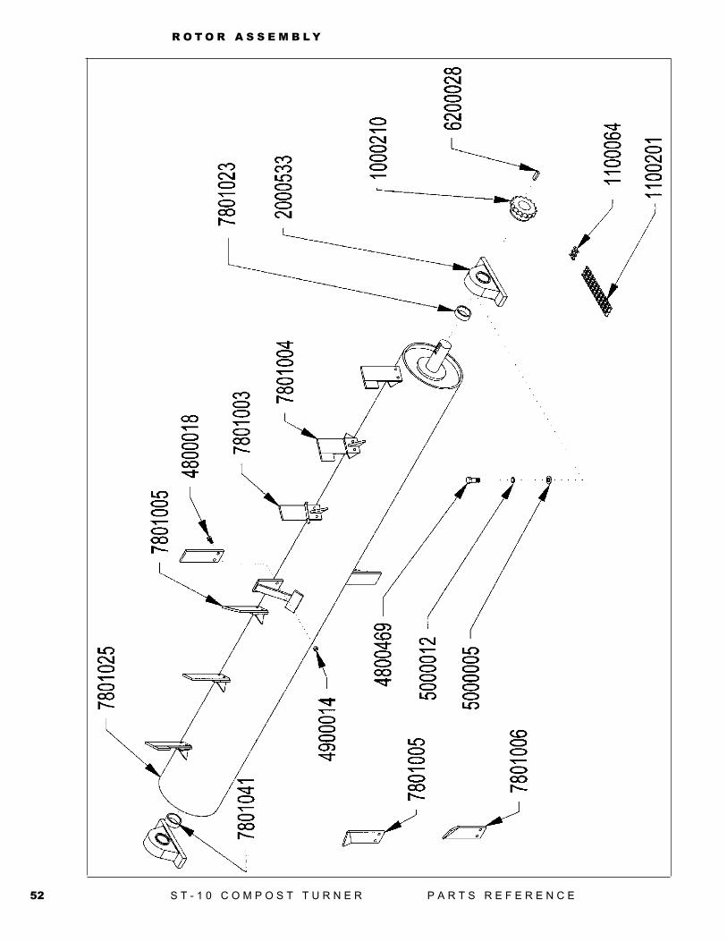
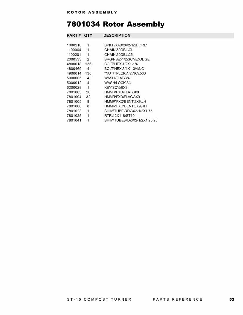
1000210 1 SPKT\60\B\26\2-1/2BORE\1100064 1 CHAIN\60DBL\CL1100201 1 CHAIN\60DBL\252000533 2 BRG\PB\2-1/2\SCM\DODGE4800018 136 BOLT\HEX\1/2X1-1/44800469 4 BOLT\HEX\3/4X1-3/4\NC4900014 136 "NUT\TPLCK\1/2\NC\.5005000005 4 WASH\FLAT\3/45000012 4 WASH\LOCK\3/46200028 1 KEY\SQ\5/8X37801003 20 HMMR\FXD\FLAT\3X97801004 32 HMMR\FXD\FLAG\3X97801005 8 HMMR\FXD\BENT\3X9\LH7801006 8 HMMR\FXD\BENT\3X9\RH7801023 1 SHIM\TUBE\RD\3X2-1/2X1.757801025 1 RTR\12X118\ST107801041 1 SHIM\TUBE\RD\3X2-1/2X1.25.25
7801034 Rotor AssemblyPART # QTY DESCRIPTION
54 S T - 1 0 C O M P O S T T U R N E R P A R T S R E F E R E N C E
J A C K A S S E M B L Y

55S T - 1 0 C O M P O S T T U R N E R P A R T S R E F E R E N C E
J A C K A S S E M B L Y
PART # QTY DESCRIPTION
7801033 Jack Assembly
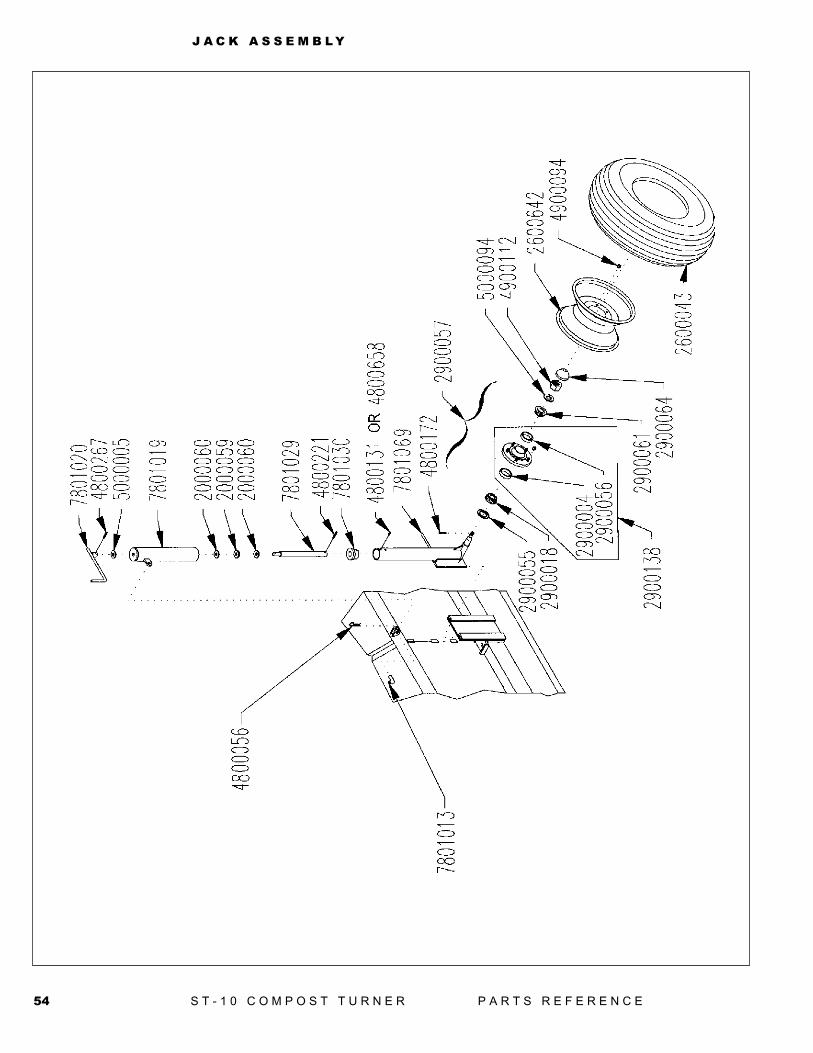
7801033 JACK\ST10\ASY2000059 1 BRG\THRST\.75ID\1.25OD2000060 2 WASH\THRST\.75ID\1.25OD2600043 1 TIRE\ST225/75/D15\8 PLY2600642 1 WHL\5BOLT\152900057 1 HUB\5BOLT\(985)\COMP2900018 1 CONE\OUTER\WHL;HUB(670482900055 1 SEAL/WHEEL HUB(16069)2900061 1 OUTER CONE/WHL HUB(119492900064 1 CAP/WHEEL HUB(985)2900138 1 NA, order 29000574800056 1 PIN\HAIR\3/16X3 (#6)4800131 PIN\RLLD\1/4X14800172 1 PIN\COT\1/8X24800221 1 PIN\RLLD\1/4X24800267 1 PIN\RLLD\1/4X1-3/44800658 2 PIN\RLLD\5/16X3/44900112 1 NUT\SLOT.\5/8\NF5000005 1 WASH\FLAT\3/45000094 1 WASH\SPNDL\5/87801013 1 PIN\BENT\5/8X27801018 Obsolete JACK\HSG\INNER\HOOD7801069 1 JACK\HSG\INNER\HOOD\11"_SPNDL7801019 1 JACK\HSG\OUTER\HOOD7801020 1 JACK\CRANK\HOOD7801029 1 RD\1-1/4X16\THRDD\ACME\>7801030 1 NUT\ACME\1-1/4X5\SPCL
56 S T - 1 0 C O M P O S T T U R N E R P A R T S R E F E R E N C E
W A T E R S Y S T E M A S S E M B L Y

57S T - 1 0 C O M P O S T T U R N E R P A R T S R E F E R E N C E
W A T E R S Y S T E M A S S E M B L Y
PART # QTY DESCRIPTION
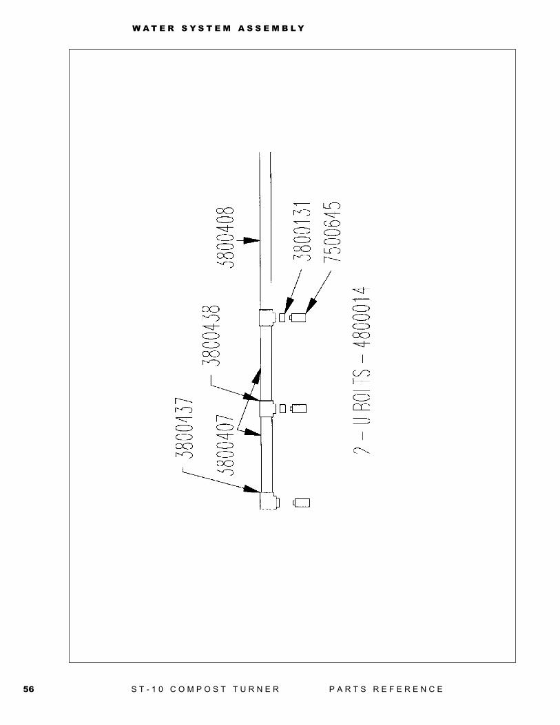
7801040 SPRY\SYSTM\ASSY\WTR3800131 2 FTG\1MPX3/4FP\BUSH\LW3800407 2 FTG\1-1/2MPX15\NPL3800408 1 FTG\1-1/2MPX36\NPL3800437 1 FTG\1-1/2FPX3/4FP\90D\LW3800438 2 FTG\1-1/2FPX1-1/2FPX1FP>4800014 2 BOLT\U\3/8X2X2-5/87500645 3 FTG\NOZ\3/4MP\120\WLJT
7801040 Water System Assembly
58 S T - 1 0 C O M P O S T T U R N E R P A R T S R E F E R E N C E
H Y D R A U L I C A S S E M B L Y
59S T - 1 0 C O M P O S T T U R N E R P A R T S R E F E R E N C E
H Y D R A U L I C A S S E M B L Y
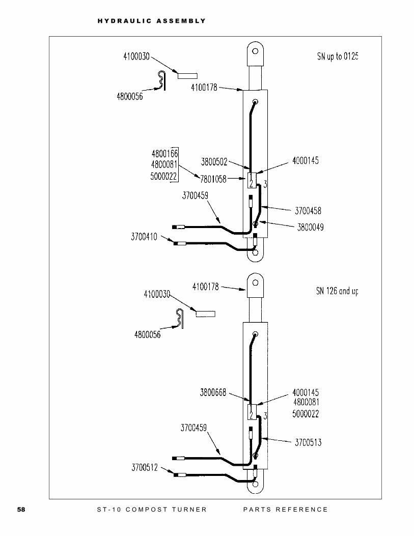
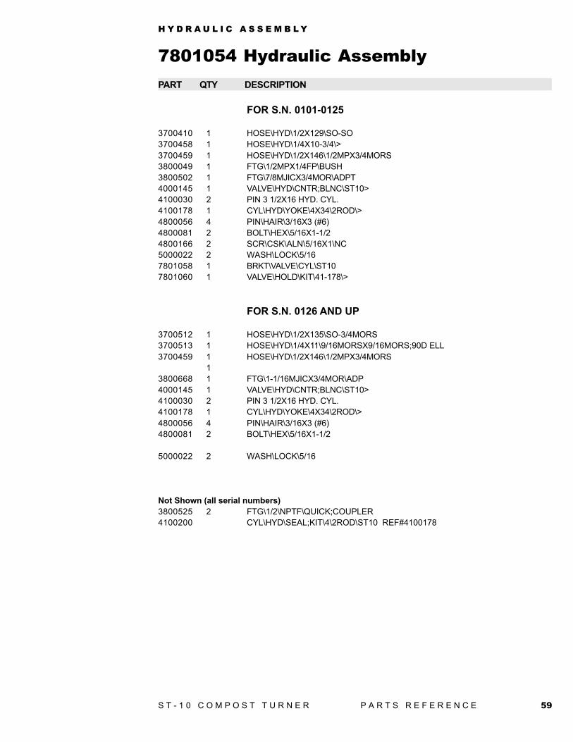
7801054 Hydraulic AssemblyPART QTY DESCRIPTION
FOR S.N. 0101-0125
3700410 1 HOSE\HYD\1/2X129\SO-SO3700458 1 HOSE\HYD\1/4X10-3/4\>3700459 1 HOSE\HYD\1/2X146\1/2MPX3/4MORS3800049 1 FTG\1/2MPX1/4FP\BUSH3800502 1 FTG\7/8MJICX3/4MOR\ADPT4000145 1 VALVE\HYD\CNTR;BLNC\ST10>4100030 2 PIN 3 1/2X16 HYD. CYL.4100178 1 CYL\HYD\YOKE\4X34\2ROD\>4800056 4 PIN\HAIR\3/16X3 (#6)4800081 2 BOLT\HEX\5/16X1-1/24800166 2 SCR\CSK\ALN\5/16X1\NC5000022 2 WASH\LOCK\5/167801058 1 BRKT\VALVE\CYL\ST107801060 1 VALVE\HOLD\KIT\41-178\>
FOR S.N. 0126 AND UP
3700512 1 HOSE\HYD\1/2X135\SO-3/4MORS3700513 1 HOSE\HYD\1/4X11\9/16MORSX9/16MORS;90D ELL3700459 1 HOSE\HYD\1/2X146\1/2MPX3/4MORS
13800668 1 FTG\1-1/16MJICX3/4MOR\ADP4000145 1 VALVE\HYD\CNTR;BLNC\ST10>4100030 2 PIN 3 1/2X16 HYD. CYL.4100178 1 CYL\HYD\YOKE\4X34\2ROD\>4800056 4 PIN\HAIR\3/16X3 (#6)4800081 2 BOLT\HEX\5/16X1-1/2
5000022 2 WASH\LOCK\5/16
Not Shown (all serial numbers)3800525 2 FTG\1/2\NPTF\QUICK;COUPLER4100200 CYL\HYD\SEAL;KIT\4\2ROD\ST10 REF#4100178
60 S T - 1 0 C O M P O S T T U R N E R P A R T S R E F E R E N C E
G E A R B O X
61S T - 1 0 C O M P O S T T U R N E R P A R T S R E F E R E N C E
G E A R B O X
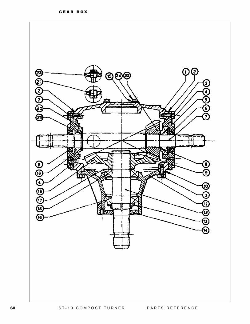
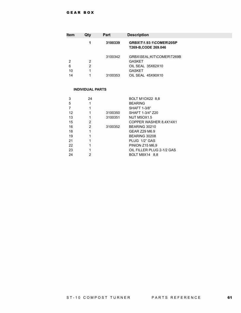
Item Qty Part Description
1 3100339 GRBX\T\1.93:1\COMER\20SPT269-B,CODE 269.046
3100342 GRBX\SEAL;KIT\COMER\T269B2 2 GASKET6 2 OIL SEAL 35X62X1010 1 GASKET14 1 3100353 OIL SEAL 45X90X10
INDIVIDUAL PARTS
3 24 BOLT M1OX22 8,85 1 BEARING7 1 SHAFT 1-3/8”12 1 3100350 SHAFT 1-3/4" Z2013 1 3100351 NUT M5OX1.515 2 COPPER WASHER 8,4X14X116 2 3100352 BEARING 3021018 1 GEAR Z29 M6.919 1 BEARING 3020821 1 PLUG 1/2” GAS22 1 PINION Z15 M6,923 1 OIL FILLER PLUG 2-1/2 GAS24 2 BOLT M8X14 8,8
62 S T - 1 0 C O M P O S T T U R N E R P A R T S R E F E R E N C E
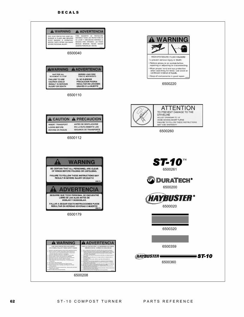
D E C A L S
6500040
6500110
6500112
6500179
6500208
6500220
6500260
6500261
6500200
®®®®®
TM
®®®®®
STSTSTSTST-10-10-10-10-10
6500020
6500320
6500359
6500360
STSTSTSTST-10-10-10-10-106500261
63S T - 1 0 C O M P O S T T U R N E R P A R T S R E F E R E N C E
D E C A L S
DecalsPART # QTY DESCRIPTION
6500040 1 DECAL\WARN\SHIELD\PROT6500110 2 DECAL\WARN\WAIT;FOR;MVMNT6500112 1 DECAL\INFO\INSRT;TRNSPRT6500179 2 DECAL\WARN\PRSNNL;STAY;CLEAR6500200 2 DECAL\LOGO\DURATECH\SILVR6500208 1 DECAL\WARN\GENERAL6500220 1 DECAL\WARN\HI;PRESS;FLUID6500260 1 DECAL\INFO\DRVLN\ANGL\14"6500261 2 DECAL\LOGO\ST-10\BLACK
7500105 Quart Red Paint7500104 Gallon Red Paint7500078 12 oz. Spray Can Red Paint
For SN up to 1407500406 Quart Gray Paint7500407 Gallon Gray Paint7500408 12 oz. Spray Can Gray Paint
SN 141 and up7500932 12 oz. Spray Can Met Silver Paint
Duratech Decals
Haybuster Decals6500020 2 DECAL\LOGO\HYBSTR\SNBRS\36500040 1 DECAL\WARN\SHIELD\PROT6500110 2 DECAL\WARN\WAIT;FOR;MVMNT6500112 1 DECAL\INFO\INSRT;TRNSPRT6500179 2 DECAL\WARN\PRSNNL;STAY;CLEAR6500208 1 DECAL\WARN\GENERAL6500220 1 DECAL\WARN\HI;PRESS;FLUID6500260 1 DECAL\INFO\DRVLN\ANGL\14"6500302 6 ft DECAL\LOGO\STRIP\3\RD&BLK6500359 12 ft DECAL\LOGO\STRIP\8\YELLOW6500360 2 DECAL\LOGO\ST-10\HAYBUSTR
7500105 Quart Red Paint7500104 Gallon Red Paint7500078 12 oz. Spray Can Red Paint
For SN up to 1407500406 Quart Gray Paint7500407 Gallon Gray Paint7500408 12 oz. Spray Can Gray Paint
SN 141 and up7500932 12 oz. Spray Can Met Silver Paint

Notes
D O C U M E N T A T I O N C O M M E N T F O R M
ST-10 Compost Turner Documentation Comment FormDuraTech Industries welcomes your comments and suggestions regarding thequality and usefulness of this manual. Your comments help us improve thedocumentation to better meet your needs.
• Did you find any errors?
• Is the information clearly presented?
• Does the manual give you all the information you need to operate the equipmentsafely and effectively?
• Are the diagrams and illustrations correct?
• Do you need more illustrations?
• What features do you like most about the manual? What features do you like least?
If you find errors or have specific suggestions, please note the topic, chapter andpage number.
__________________________________________________________________
__________________________________________________________________
__________________________________________________________________
__________________________________________________________________
__________________________________________________________________
__________________________________________________________________
__________________________________________________________________
__________________________________________________________________
__________________________________________________________________
__________________________________________________________________
__________________________________________________________________
__________________________________________________________________
__________________________________________________________________
Send your comments to:
DuraTech Industries International, Inc.P.O. Box 1940Jamestown, ND 58402-1940 ORContact us through our website: www.duratechindustries.net
Thank you for taking the time to help us improve our documentation.


![O Diário de Turner [Andew Macdonald] - VISIONVOX](https://img.dokumen.tips/doc/110x75/6332430d5696ca44730323d1/o-diario-de-turner-andew-macdonald-visionvox.jpg)


