Embed Size (px)
Citation preview
Optimization Methods and Software
Vol. 22, No. 3, June 2007, 485–509
Comparative study of serial and parallel heuristics used to
design combinational logic circuits
ENRIQUEALBA†, GABRIEL LUQUE†, CARLOSA. COELLO COELLO*‡and ERIKA HERNÁNDEZ LUNA‡
†Departamento de Lenguajes y Ciencias de la Computación, E.T.S.I. Informática,Campus Teatinos 29071, Málaga, Spain
‡CINVESTAV-IPN (Evolutionary Computation Group), Sección Computación, Departamento de Ing.Eléctrica, Av. IPN No 2508, Col. San Pedro Zacatenco, México, DF 07300, Mexico
(Received 1 February 2005; revised 10 November 2005; in final form 13 March 2006)
In this article, we perform a comparative study of different heuristics used to design combinationallogic circuits. This studymainly emphasizes the use of local search hybridizedwith a genetic algorithm(GA) and the impact of introducing parallelism. Our results indicate that a hybridization of a GA witha local search algorithm (simulated annealing) is beneficial and that the use of parallelism not onlyintroduces a speedup in the algorithms compared (as expected) but also allows us to improve thequality of the solutions found.
Keywords: Combinational logic circuits; Genetic algorithms; Metaheuristics; Simulated annealing;Parallelization; Hybridization
1. Introduction
There are several standard graphical aids widely used by humans to design combinationallogic circuits (e.g. Karnaugh maps [1,2] and the Quine–McCluskey method [3,4]). Despitetheir advantages, these methods do not guarantee that an optimum circuit can be found, givenan arbitrary truth table. Additionally, some of these methods (e.g. Karnaugh maps) havesome well-known scalability problems and can be used only in circuits with very few inputs(normally no more than five or six).In this article, we see the design of combinational logic circuits as an optimization problem
in which we aim to find Boolean expressions that produce the outputs required, given a set ofinputs (as defined by the truth table of a circuit). Seen as an optimization problem, the designof combinational circuits has several interesting features.
• It is a discrete optimization problem in which the decision variables are either integers orbinary numbers (as in this article). The solutions produced are Boolean expressions that canbe graphically depicted.
*Corresponding author. Email: [email protected]
Optimization Methods and SoftwareISSN 1055-6788 print/ISSN 1029-4937 online © 2007 Taylor & Francis
http://www.tandf.co.uk/journalsDOI: 10.1080/10556780600724979
Dow
nlo
aded
by [
UM
A U
niv
ersi
ty o
f M
alag
a] a
t 03:5
2 2
8 O
ctober
2011
486 E. Alba et al.
• The size of the search space grows very rapidly as we increase the number of inputs and/oroutputs of a circuit.
• As it is required to produce circuits that match exactly all the outputs of the truth tablegiven over all the inputs provided, this problem can be considered as having (a usually largenumber of) hard equality constraints.
• Several parameters of the problem may be modified in order to produce different variationswhose degree of difficulty may be higher than that of the original problem. For example, wemay vary the types of gates available and the number of inputs that each of them may have.
Because of its complexity, the design of combinational circuits has been tackled with a vari-ety of heuristics (mainly evolutionary algorithms) in the last few years [5,6]. Despite their goodresults on small and medium-size circuits, heuristics tend to be victims of the ‘dimensionalitycurse’. Over the years, however, a different goal was envisioned for evolutionary algorithmsapplied to the solution of combinational logic circuits. The new goal aims to optimize (smalland medium-size) circuits (using a certain metric) such that novel designs (as there is nohuman intervention) can arise. Such novel designs have been shown in the past in a number ofstudies [5–8]. In fact, some researchers have pointed out the usefulness of extracting designpatterns from such evolutionary-generated solutions. This could lead to a practical designprocess in which a small (optimal) circuit is used as a building block to produce complexcircuits.This article presents a comparative study among a traditional genetic algorithm (GA), sim-
ulated annealing (SA), and three heuristics powered by local search capabilities. The rationalebehind adopting these approaches is to determine whether the design of combinational logiccircuits (operating on a binary encoding) can benefit from local search strategies that are notincluded in a traditional GA. For the study, we use both serial and parallel versions of eachalgorithm, so that we can analyze whether the use of parallelism brings any benefits in termsof performance, other than the obvious computational speedup.The remainder of the article is organized as follows. In section 2, we provide the state-
ment of the problem of interest to us. In section 3, we briefly discuss the matrix encodingadopted to represent a combinational logic circuit in the heuristics compared. Section 4 brieflydescribes the most relevant previous related work. In section 5, we provide a brief descriptionof the approaches adopted in our study. Section 6 contains the examples and the results of thecomparative study. Then, there is a further discussion of the results in section 7. Finally, weprovide some conclusions and possible ideas of future research in section 8. The truth tablesand graphical representations of the best circuits found are included in anAppendix at the endof this article.
2. Statement of the problem
The problem of interest consists of designing a circuit that performs a desired function (speci-fied by a truth table), given a certain specified set of available logic gates. This problem istreated, however, as a discrete optimization problem.In circuit design, it is possible to use various criteria to be minimized. For example, from
a mathematical perspective, it is possible to minimize the total number of literals or the totalnumber of binary operations or the total number of symbols in an expression.Theminimizationproblem is difficult for all such cost criteria.The complexity of a combinational logic circuit is related to the number of gates in the
circuit. The complexity of a gate generally is related to the number of inputs to it. Becausea logic circuit is a realization (implementation) of a Boolean function in hardware, reducing
Dow
nlo
aded
by [
UM
A U
niv
ersi
ty o
f M
alag
a] a
t 03:5
2 2
8 O
ctober
2011
Heuristics for logic circuit design 487
the number of literals in the function should reduce the number of inputs to each gate and thenumber of gates in the circuit – thus reducing the complexity of the circuit.Thus, our overall measure of circuit optimality is the total number of gates used, regardless
of their kind. This is approximately proportional to the total part cost of the circuit. Obviously,thisminimization criterion is applied only to fully functional circuits (i.e. those that completelymatch the outputs defined in the corresponding truth table) because it is evidently irrelevant toattempt to minimize infeasible circuits. A feasible circuit is one that produces exactly all theoutputs required for each set of inputs, as indicated in its truth table. To exemplify this, let usconsider the circuit shown in tableA1. In this case, we have as a solution the followingBooleanexpression:F = (WX + (Y ⊕ W)) ⊕ ((X + Y )′ + Z). So, in order to check feasibility of thiscircuit, we have to replace each of its inputs (Z, W , X, and Y ) by each of the sets of valuesdepicted in tableA1. So, in row 1, we have Z = 0,W = 0,X = 0, Y = 0. By replacing thesevalues in F (as defined before), we obtain that F = 1. This is precisely the value indicatedat the end of row 1. Thus, our circuit matches its first output. This same procedure has to berepeated for each of the rows. If the circuit does not match any of its required values (e.g. ifthe output is 1 when it is required to be 0), the circuit is considered to be infeasible.Twopopularminimization techniques used by electrical engineers are theKarnaughmap [1],
which is based on a graphical representation of Boolean functions, and the Quine–McCluskeyprocedure [3,4], which is a tabular method. Both these methods are mechanical in nature.Karnaugh maps are useful in minimizing the number of literals with up to five or six variables.The Quine–McCluskey procedure is useful for functions of any number of variables and caneasily be programmed to run on a digital computer. Generally, several Boolean functions witha minimum number of literals can be obtained for a given truth table using either method,based on the choices made during the minimization process. All minimum functions with thesame number of literals yield circuits of the same complexity; hence, any of them can beselected for implementation.Note that the algebraic simplification process depends entirely on one’s familiarity with
the postulates and theorems and one’s ability to recognize their application. Of course, thisability varies from individual to individual. Depending on the sequence in which the theoremsand postulates are applied, more than one simplified form of the expression may be obtained.Usually all such simplified forms are valid and acceptable. Thus, there is (in the generalcase) no single, unique minimized form of a Boolean expression. However, the solutions thatwill be shown later on (in section 6) as corresponding to human designers are really the bestsolution (based on theminimization of the number of gates,which is our optimization criterion)chosen from a set produced by individuals who can be considered as ‘expert designers’ ofcombinational logic circuits. Nevertheless, this does not mean that a human cannot improveany of the solutions that we will provide, mainly if we consider that the global optimum of allof the problems adopted remains unknown.
3. The encoding adopted
In order to allow a fair comparison, all of the heuristics compared in this article adopted amatrix to represent a circuit as in our previous work [5,9] (figure 1).More formally, we can say that any circuit can be represented as a bi-dimensional array of
gates Si,j , where j indicates the level of a gate, so that those gates closer to the inputs havelower values of j . (Level values are incremented from left to right in figure 1.) For a fixedj , the index i varies with respect to the gates that are ‘next’ to each other in the circuit, butwithout being necessarily connected. Each matrix element is a gate (there are five types of
Dow
nlo
aded
by [
UM
A U
niv
ersi
ty o
f M
alag
a] a
t 03:5
2 2
8 O
ctober
2011
488 E. Alba et al.
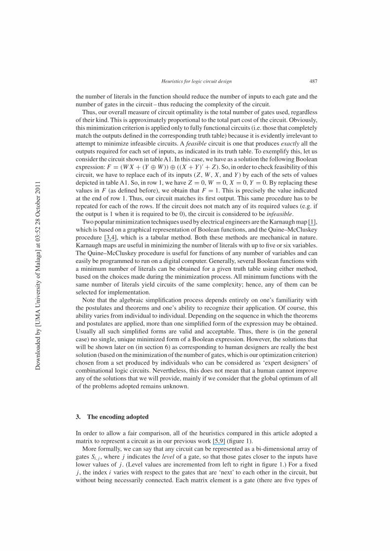
Figure 1. Matrix used to represent a circuit. Each gate gets its inputs from either of the gates in the previous column.Note the encoding adopted for each element of the matrix as well as the set of available gates used.
gates: AND, NOT, OR, XOR, and WIRE†) that receives its two inputs from any gate at theprevious column as shown in figure 1. It is important to clarify that a number of rows andcolumns of the matrix used to encode a circuit are values defined by the user. Given a circuitto be optimized, we suggest the usage of the following procedure in order to define the matrixsize (i.e. number of rows and columns) to encode it.
(i) Start with a square matrix of size 5 (i.e., number of rows = number of columns = 5).(ii) If no feasible solution is found using this matrix, then increase the number of columns
by one, without changing the number of rows.(iii) If no feasible solution is found using this matrix, then increase the number of rows by
one, without changing the number of columns.(iv) Repeat steps 2 and 3 until a suitable matrix is produced. In each case, at least 10 indepen-
dent runs (using different random seeds for the initial population) must be performed inorder to determine feasibility. If none of these runs produces at least one feasible solution,then it is considered that ‘no feasible solution was found’.
As we will see in table 6 from section 6, it is normally the case that for small circuits,a matrix of 5× 5 is sufficient. However, in two of the examples reported in section 6, wereached a matrix size of 6× 7. This situation normally arises with circuits having severaloutputs, although in some cases, such as in the 2-bit multiplier described in section 6, evena 5× 5 matrix is enough to find the best known circuit. The above guidelines have beensuccessfully adopted with a variety of circuits in some of our previous work [5].A chromosomic string encodes the matrix shown in figure 1 by using triplets in which the
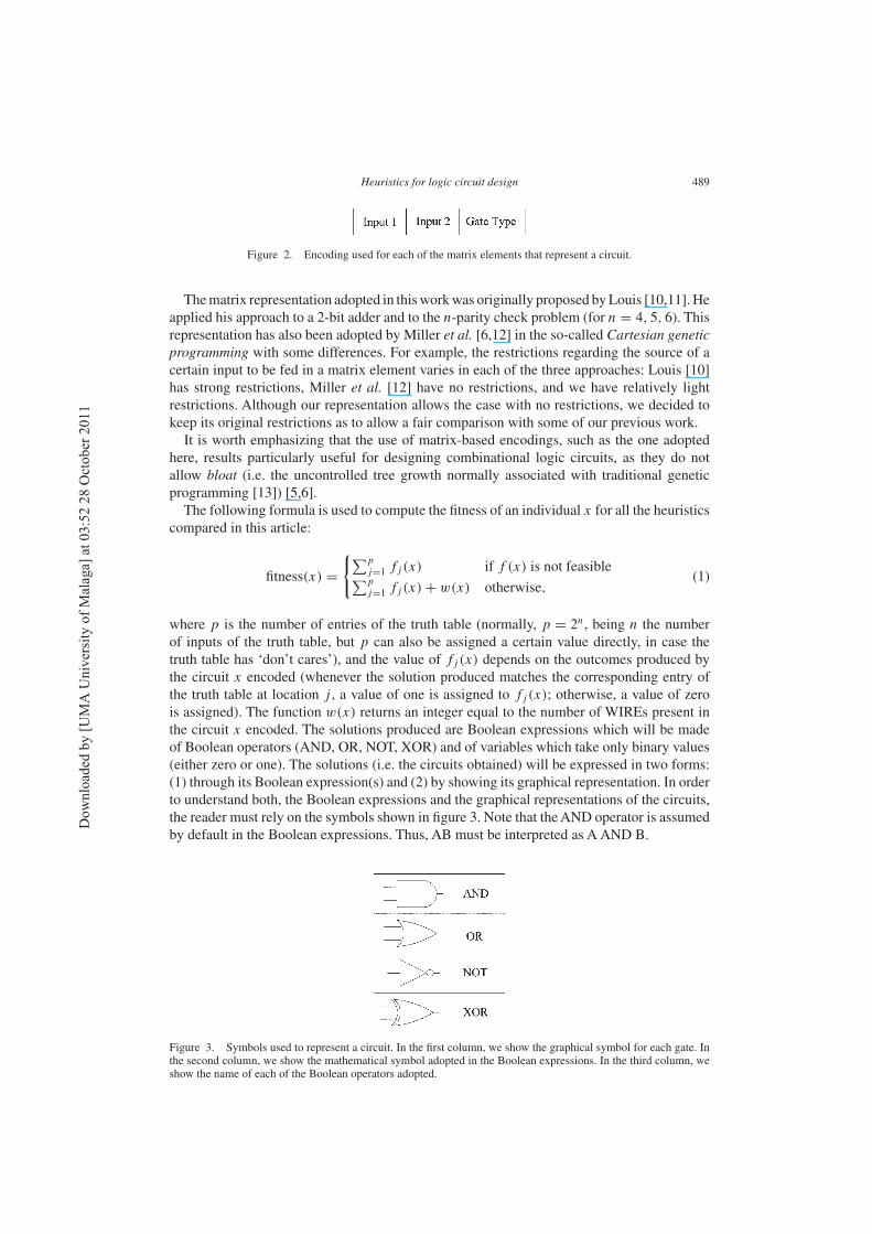
first two elements refer to each of the inputs used and the third is the corresponding gate fromthe available set (figure 2).
†WIRE basically indicates a null operation or, in other words, the absence of gate, and it is used just to keepregularity in the representation used. Otherwise, we would have to use variable-length strings.
Dow
nlo
aded
by [
UM
A U
niv
ersi
ty o
f M
alag
a] a
t 03:5
2 2
8 O
ctober
2011
Heuristics for logic circuit design 489
Figure 2. Encoding used for each of the matrix elements that represent a circuit.
Thematrix representation adopted in thisworkwas originally proposed byLouis [10,11].Heapplied his approach to a 2-bit adder and to the n-parity check problem (for n = 4, 5, 6). Thisrepresentation has also been adopted by Miller et al. [6,12] in the so-called Cartesian genetic
programming with some differences. For example, the restrictions regarding the source of acertain input to be fed in a matrix element varies in each of the three approaches: Louis [10]has strong restrictions, Miller et al. [12] have no restrictions, and we have relatively lightrestrictions. Although our representation allows the case with no restrictions, we decided tokeep its original restrictions as to allow a fair comparison with some of our previous work.It is worth emphasizing that the use of matrix-based encodings, such as the one adopted
here, results particularly useful for designing combinational logic circuits, as they do notallow bloat (i.e. the uncontrolled tree growth normally associated with traditional geneticprogramming [13]) [5,6].The following formula is used to compute the fitness of an individual x for all the heuristics
compared in this article:
fitness(x) =
{
∑p
j=1 fj (x) if f (x) is not feasible∑p
j=1 fj (x) + w(x) otherwise,(1)
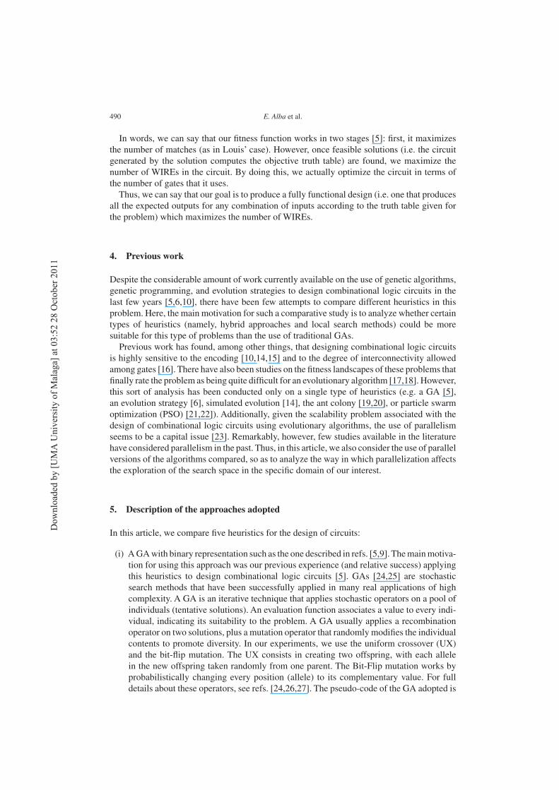
where p is the number of entries of the truth table (normally, p = 2n, being n the numberof inputs of the truth table, but p can also be assigned a certain value directly, in case thetruth table has ‘don’t cares’), and the value of fj (x) depends on the outcomes produced bythe circuit x encoded (whenever the solution produced matches the corresponding entry ofthe truth table at location j , a value of one is assigned to fj (x); otherwise, a value of zerois assigned). The function w(x) returns an integer equal to the number of WIREs present inthe circuit x encoded. The solutions produced are Boolean expressions which will be madeof Boolean operators (AND, OR, NOT, XOR) and of variables which take only binary values(either zero or one). The solutions (i.e. the circuits obtained) will be expressed in two forms:(1) through its Boolean expression(s) and (2) by showing its graphical representation. In orderto understand both, the Boolean expressions and the graphical representations of the circuits,the reader must rely on the symbols shown in figure 3. Note that theAND operator is assumedby default in the Boolean expressions. Thus, AB must be interpreted as A AND B.
Figure 3. Symbols used to represent a circuit. In the first column, we show the graphical symbol for each gate. Inthe second column, we show the mathematical symbol adopted in the Boolean expressions. In the third column, weshow the name of each of the Boolean operators adopted.
Dow
nlo
aded
by [
UM
A U
niv
ersi
ty o
f M
alag
a] a
t 03:5
2 2
8 O
ctober
2011
490 E. Alba et al.
In words, we can say that our fitness function works in two stages [5]: first, it maximizesthe number of matches (as in Louis’ case). However, once feasible solutions (i.e. the circuitgenerated by the solution computes the objective truth table) are found, we maximize thenumber of WIREs in the circuit. By doing this, we actually optimize the circuit in terms ofthe number of gates that it uses.Thus, we can say that our goal is to produce a fully functional design (i.e. one that produces
all the expected outputs for any combination of inputs according to the truth table given forthe problem) which maximizes the number of WIREs.
4. Previous work
Despite the considerable amount of work currently available on the use of genetic algorithms,genetic programming, and evolution strategies to design combinational logic circuits in thelast few years [5,6,10], there have been few attempts to compare different heuristics in thisproblem. Here, the main motivation for such a comparative study is to analyze whether certaintypes of heuristics (namely, hybrid approaches and local search methods) could be moresuitable for this type of problems than the use of traditional GAs.Previous work has found, among other things, that designing combinational logic circuits
is highly sensitive to the encoding [10,14,15] and to the degree of interconnectivity allowedamong gates [16]. There have also been studies on the fitness landscapes of these problems thatfinally rate the problem as being quite difficult for an evolutionary algorithm [17,18]. However,this sort of analysis has been conducted only on a single type of heuristics (e.g. a GA [5],an evolution strategy [6], simulated evolution [14], the ant colony [19,20], or particle swarmoptimization (PSO) [21,22]). Additionally, given the scalability problem associated with thedesign of combinational logic circuits using evolutionary algorithms, the use of parallelismseems to be a capital issue [23]. Remarkably, however, few studies available in the literaturehave considered parallelism in the past. Thus, in this article, we also consider the use of parallelversions of the algorithms compared, so as to analyze the way in which parallelization affectsthe exploration of the search space in the specific domain of our interest.
5. Description of the approaches adopted
In this article, we compare five heuristics for the design of circuits:
(i) AGAwith binary representation such as the one described in refs. [5,9]. Themainmotiva-tion for using this approach was our previous experience (and relative success) applyingthis heuristics to design combinational logic circuits [5]. GAs [24,25] are stochasticsearch methods that have been successfully applied in many real applications of highcomplexity. A GA is an iterative technique that applies stochastic operators on a pool ofindividuals (tentative solutions). An evaluation function associates a value to every indi-vidual, indicating its suitability to the problem. A GA usually applies a recombinationoperator on two solutions, plus a mutation operator that randomly modifies the individualcontents to promote diversity. In our experiments, we use the uniform crossover (UX)and the bit-flip mutation. The UX consists in creating two offspring, with each allelein the new offspring taken randomly from one parent. The Bit-Flip mutation works byprobabilistically changing every position (allele) to its complementary value. For fulldetails about these operators, see refs. [24,26,27]. The pseudo-code of the GA adopted is
Dow
nlo
aded
by [
UM
A U
niv
ersi
ty o
f M
alag
a] a
t 03:5
2 2
8 O
ctober
2011
Heuristics for logic circuit design 491
Figure 4. Scheme of the GA adopted.
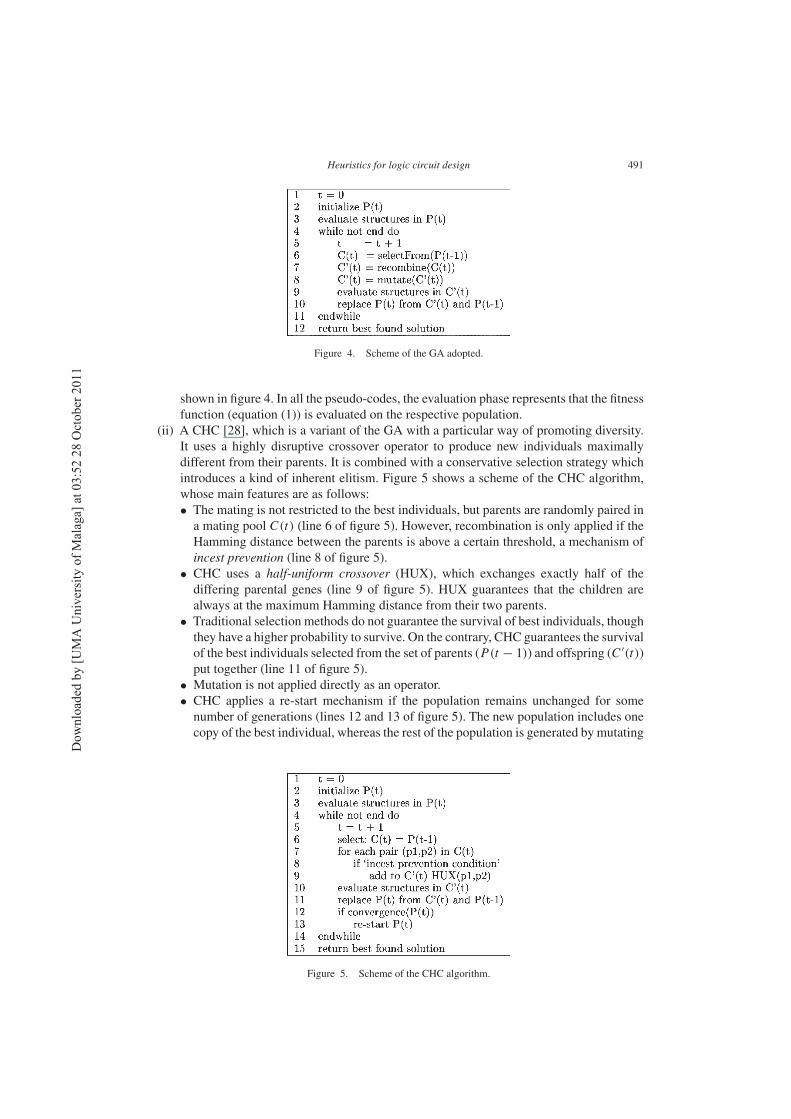
shown in figure 4. In all the pseudo-codes, the evaluation phase represents that the fitnessfunction (equation (1)) is evaluated on the respective population.
(ii) A CHC [28], which is a variant of the GA with a particular way of promoting diversity.It uses a highly disruptive crossover operator to produce new individuals maximallydifferent from their parents. It is combined with a conservative selection strategy whichintroduces a kind of inherent elitism. Figure 5 shows a scheme of the CHC algorithm,whose main features are as follows:• The mating is not restricted to the best individuals, but parents are randomly paired ina mating pool C(t) (line 6 of figure 5). However, recombination is only applied if theHamming distance between the parents is above a certain threshold, a mechanism ofincest prevention (line 8 of figure 5).
• CHC uses a half-uniform crossover (HUX), which exchanges exactly half of thediffering parental genes (line 9 of figure 5). HUX guarantees that the children arealways at the maximum Hamming distance from their two parents.
• Traditional selection methods do not guarantee the survival of best individuals, thoughthey have a higher probability to survive. On the contrary, CHC guarantees the survivalof the best individuals selected from the set of parents (P(t − 1)) and offspring (C ′(t))put together (line 11 of figure 5).
• Mutation is not applied directly as an operator.• CHC applies a re-start mechanism if the population remains unchanged for somenumber of generations (lines 12 and 13 of figure 5). The new population includes onecopy of the best individual, whereas the rest of the population is generated by mutating
Figure 5. Scheme of the CHC algorithm.
Dow
nlo
aded
by [
UM
A U
niv
ersi
ty o
f M
alag
a] a
t 03:5
2 2
8 O
ctober
2011
492 E. Alba et al.
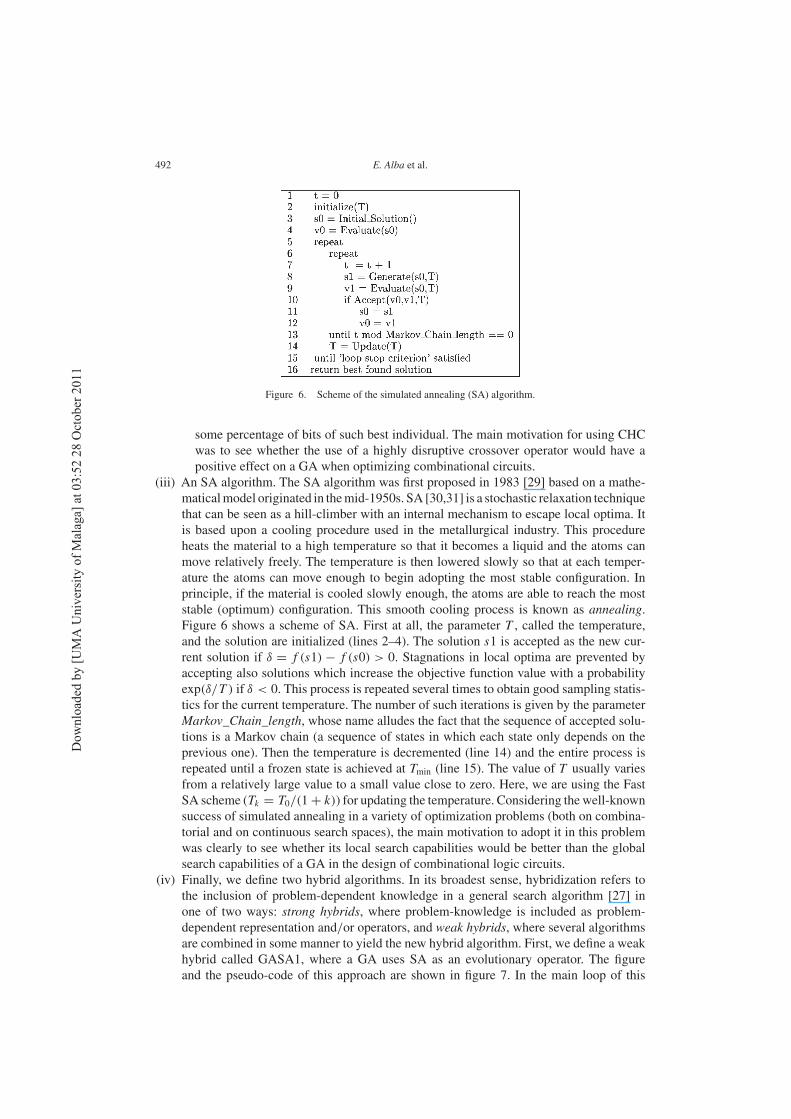
Figure 6. Scheme of the simulated annealing (SA) algorithm.
some percentage of bits of such best individual. The main motivation for using CHCwas to see whether the use of a highly disruptive crossover operator would have apositive effect on a GA when optimizing combinational circuits.
(iii) An SA algorithm. The SA algorithm was first proposed in 1983 [29] based on a mathe-maticalmodel originated in themid-1950s. SA [30,31] is a stochastic relaxation techniquethat can be seen as a hill-climber with an internal mechanism to escape local optima. Itis based upon a cooling procedure used in the metallurgical industry. This procedureheats the material to a high temperature so that it becomes a liquid and the atoms canmove relatively freely. The temperature is then lowered slowly so that at each temper-ature the atoms can move enough to begin adopting the most stable configuration. Inprinciple, if the material is cooled slowly enough, the atoms are able to reach the moststable (optimum) configuration. This smooth cooling process is known as annealing.Figure 6 shows a scheme of SA. First at all, the parameter T , called the temperature,and the solution are initialized (lines 2–4). The solution s1 is accepted as the new cur-rent solution if δ = f (s1) − f (s0) > 0. Stagnations in local optima are prevented byaccepting also solutions which increase the objective function value with a probabilityexp(δ/T ) if δ < 0. This process is repeated several times to obtain good sampling statis-tics for the current temperature. The number of such iterations is given by the parameterMarkov_Chain_length, whose name alludes the fact that the sequence of accepted solu-tions is a Markov chain (a sequence of states in which each state only depends on theprevious one). Then the temperature is decremented (line 14) and the entire process isrepeated until a frozen state is achieved at Tmin (line 15). The value of T usually variesfrom a relatively large value to a small value close to zero. Here, we are using the FastSA scheme (Tk = T0/(1+ k)) for updating the temperature. Considering the well-knownsuccess of simulated annealing in a variety of optimization problems (both on combina-torial and on continuous search spaces), the main motivation to adopt it in this problemwas clearly to see whether its local search capabilities would be better than the globalsearch capabilities of a GA in the design of combinational logic circuits.
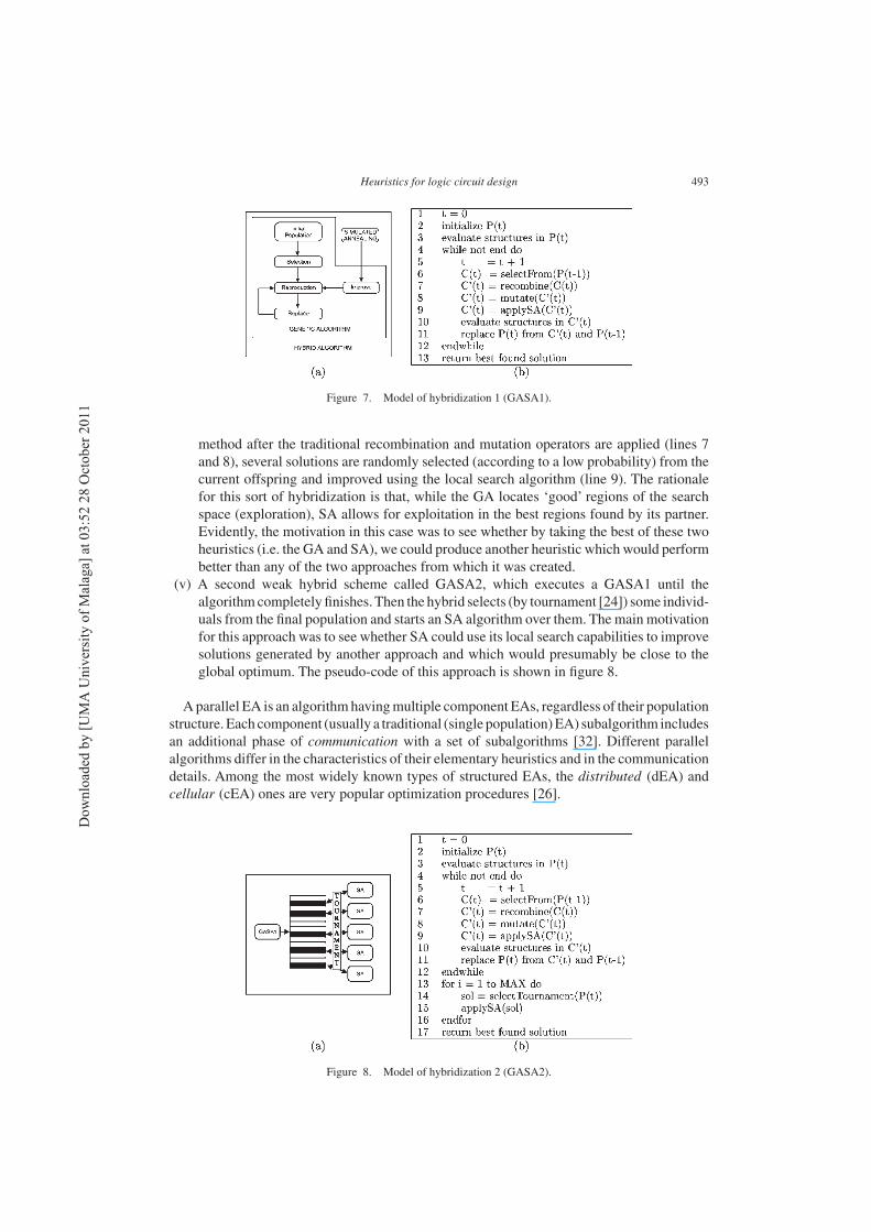
(iv) Finally, we define two hybrid algorithms. In its broadest sense, hybridization refers tothe inclusion of problem-dependent knowledge in a general search algorithm [27] inone of two ways: strong hybrids, where problem-knowledge is included as problem-dependent representation and/or operators, and weak hybrids, where several algorithmsare combined in some manner to yield the new hybrid algorithm. First, we define a weakhybrid called GASA1, where a GA uses SA as an evolutionary operator. The figureand the pseudo-code of this approach are shown in figure 7. In the main loop of this
Dow
nlo
aded
by [
UM
A U
niv
ersi
ty o
f M
alag
a] a
t 03:5
2 2
8 O
ctober
2011
Heuristics for logic circuit design 493
Figure 7. Model of hybridization 1 (GASA1).
method after the traditional recombination and mutation operators are applied (lines 7and 8), several solutions are randomly selected (according to a low probability) from thecurrent offspring and improved using the local search algorithm (line 9). The rationalefor this sort of hybridization is that, while the GA locates ‘good’ regions of the searchspace (exploration), SA allows for exploitation in the best regions found by its partner.Evidently, the motivation in this case was to see whether by taking the best of these twoheuristics (i.e. the GA and SA), we could produce another heuristic which would performbetter than any of the two approaches from which it was created.
(v) A second weak hybrid scheme called GASA2, which executes a GASA1 until thealgorithmcompletely finishes.Then the hybrid selects (by tournament [24]) some individ-uals from the final population and starts an SA algorithm over them. The main motivationfor this approach was to see whether SA could use its local search capabilities to improvesolutions generated by another approach and which would presumably be close to theglobal optimum. The pseudo-code of this approach is shown in figure 8.
A parallel EA is an algorithmhavingmultiple component EAs, regardless of their populationstructure. Each component (usually a traditional (single population)EA) subalgorithm includesan additional phase of communication with a set of subalgorithms [32]. Different parallelalgorithms differ in the characteristics of their elementary heuristics and in the communicationdetails. Among the most widely known types of structured EAs, the distributed (dEA) andcellular (cEA) ones are very popular optimization procedures [26].
Figure 8. Model of hybridization 2 (GASA2).
Dow
nlo
aded
by [
UM
A U
niv
ersi
ty o
f M
alag
a] a
t 03:5
2 2
8 O
ctober
2011
494 E. Alba et al.
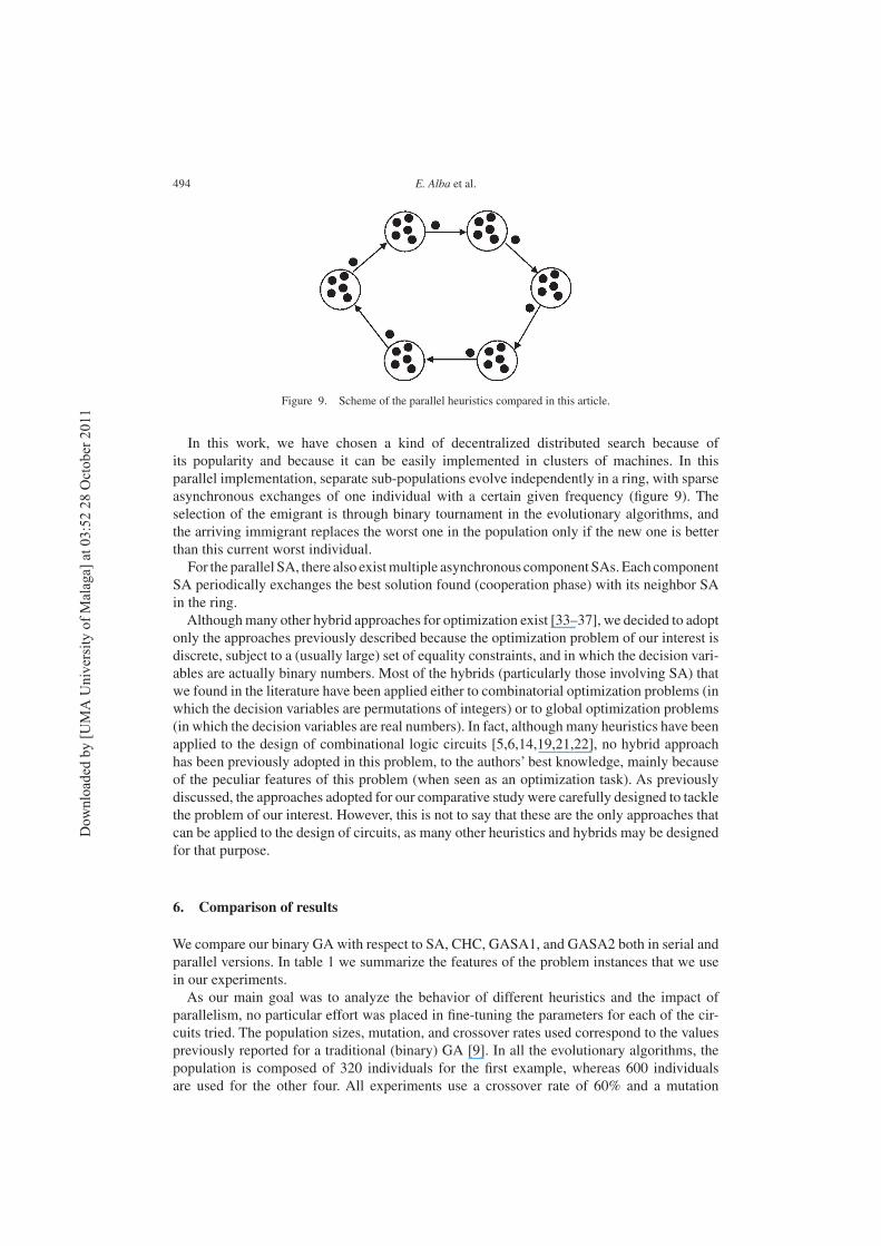
Figure 9. Scheme of the parallel heuristics compared in this article.
In this work, we have chosen a kind of decentralized distributed search because ofits popularity and because it can be easily implemented in clusters of machines. In thisparallel implementation, separate sub-populations evolve independently in a ring, with sparseasynchronous exchanges of one individual with a certain given frequency (figure 9). Theselection of the emigrant is through binary tournament in the evolutionary algorithms, andthe arriving immigrant replaces the worst one in the population only if the new one is betterthan this current worst individual.For the parallel SA, there also existmultiple asynchronous component SAs.Each component
SA periodically exchanges the best solution found (cooperation phase) with its neighbor SAin the ring.Althoughmany other hybrid approaches for optimization exist [33–37], we decided to adopt
only the approaches previously described because the optimization problem of our interest isdiscrete, subject to a (usually large) set of equality constraints, and in which the decision vari-ables are actually binary numbers. Most of the hybrids (particularly those involving SA) thatwe found in the literature have been applied either to combinatorial optimization problems (inwhich the decision variables are permutations of integers) or to global optimization problems(in which the decision variables are real numbers). In fact, although many heuristics have beenapplied to the design of combinational logic circuits [5,6,14,19,21,22], no hybrid approachhas been previously adopted in this problem, to the authors’ best knowledge, mainly becauseof the peculiar features of this problem (when seen as an optimization task). As previouslydiscussed, the approaches adopted for our comparative study were carefully designed to tacklethe problem of our interest. However, this is not to say that these are the only approaches thatcan be applied to the design of circuits, as many other heuristics and hybrids may be designedfor that purpose.
6. Comparison of results
We compare our binary GA with respect to SA, CHC, GASA1, and GASA2 both in serial andparallel versions. In table 1 we summarize the features of the problem instances that we usein our experiments.As our main goal was to analyze the behavior of different heuristics and the impact of
parallelism, no particular effort was placed in fine-tuning the parameters for each of the cir-cuits tried. The population sizes, mutation, and crossover rates used correspond to the valuespreviously reported for a traditional (binary) GA [9]. In all the evolutionary algorithms, thepopulation is composed of 320 individuals for the first example, whereas 600 individualsare used for the other four. All experiments use a crossover rate of 60% and a mutation
Dow
nlo
aded
by [
UM
A U
niv
ersi
ty o
f M
alag
a] a
t 03:5
2 2
8 O
ctober
2011
Heuristics for logic circuit design 495
Table 1. Features of the circuits: size, matrix size in rows × columns; codesize, lengthof the binary string; BKS, best known solution (i.e. the fitness value of the best solution
reported in the literature for the corresponding circuit).
Name Inputs Outputs Size Codesize BKS
Sasao 4 1 5× 5 225 34 [41]Catherine 5 1 6× 7 278 67 [39]Katz 1 4 3 6× 7 278 81 [38]2-bit multiplier 4 4 5× 5 225 82 [38]Katz 2 5 3 5× 5 225 114 [40]
rate of 50% of the chromosomic length. The CHC method restarts the population (an uni-form mutation (pm = 0.7) is applied to the 35% of the population) whenever convergenceis detected. The hybrid GASA1 uses the SA operator (100 iterations for the first and thirdexamples and 500 iterations for the rest) with probability 0.01, i.e. this improvement pro-cess only is applied to approximately one of each 100 solutions of the current offspring.The second hybrid (GASA2) executes an SA (with 3000 iterations for the first instanceand 10,000 for the rest) when GASA1 finishes. The migration in dEAs occurs in a unidi-rectional ring manner, sending one single individual (chosen by binary tournament) to theneighboring sub-population. The target population incorporates this individual only if it isbetter than its presently worst solution. The migration step is performed every 20 iterationsin every island in an asynchronous way. The selected migration policy configuration allowsus to maintain a global good diversity and to lead the global search to good regions of thesearch space. The asynchronous communications that we used provoke that the communica-tion overhead was insignificant. As we want to compare against the sequential EAs, dEAsuse the same population size, but now the whole population of the sequential EA is splitinto as many sub-populations as processes involved in the parallel computation. Our parallelalgorithms are composed of eight sub-populations. Finally, the number of iterations of theSA has been chosen in order to compute a similar number of evaluations as to the GA, andthe Markov chain length is preset to max_iter/10. We performed 20 independent runs peralgorithm per circuit per version (either serial or parallel) using the parameters summarizedearlier.The most relevant aspects that were measured in this comparison are the following: the best
fitness value obtained (we call this opt), the number of times that the approach found the bestfitness value (we call this hits), the average final fitness (called avg), and the average numberof fitness function evaluations required to find the best fitness value reported (#evals).A short note regarding the stopping criteria adopted is in place. Each algorithm stops when
reaching the target fitness or a maximum (predefined) number of generations. At the end ofeach generation, the algorithm checks whether the stopping criterion is satisfied, i.e. whetherthe current generation number exceeds the predefined limit or whether an end signal has beenreceived (for parallel executions).
6.1 Example 1
Our first example has four inputs and one output, as shown in table A1. Our comparison ofresults for this example is shown in table 2. In this case both GASA1 and GASA2 were able toconverge to the best known solution for this circuit (which has seven gates and a fitness of 34)[38]. The best solution found is graphically depicted in figure A1, and its Boolean expressionis F = (WX + (Y ⊕ W)) ⊕ ((X + Y )′ + Z). Note that both, GASA1 and GASA2, requiredthe highest number of evaluations to reach their best fitness value, but their final solution was
Dow
nlo
aded
by [
UM
A U
niv
ersi
ty o
f M
alag
a] a
t 03:5
2 2
8 O
ctober
2011
496 E. Alba et al.
Table 2. Comparison of results for the first example.
Sequential Parallel
Algorithm opt hits (%) avg #evals opt hits (%) avg #evals
GA 31 10 15.8 96,806 33 5 18.1 79,107CHC 27 5 15.1 107,680 32 5 16.4 75,804SA 30 35 15.6 70,724 31 5 15.2 69,652GASA1 34 10 23.2 145,121 34 20 25.5 151,327GASA2 34 10 24.2 147,381 34 30 27.8 155,293
significantly better than the solutions found by the other algorithms.Also note that the parallelversions of GASA1 and GASA2 increased the average fitness value and the number of hits.However, the average number of fitness function evaluations to find the best fitness value didnot decrease in the parallel versions of GASA1 and GASA2, as it occurred for the parallelversions of the traditional GA, CHC, and SA. Finally, we observed that the average fitnessvalue of parallel SA was slightly worse than the value of the serial version, which indicatesthat the parallel algorithm behavior is not adequate for this instance. Interestingly, SA was theonly approach whose average fitness did not increase when using parallelism.Another aspect that is worth analyzing is the percentage of feasible solutions that each
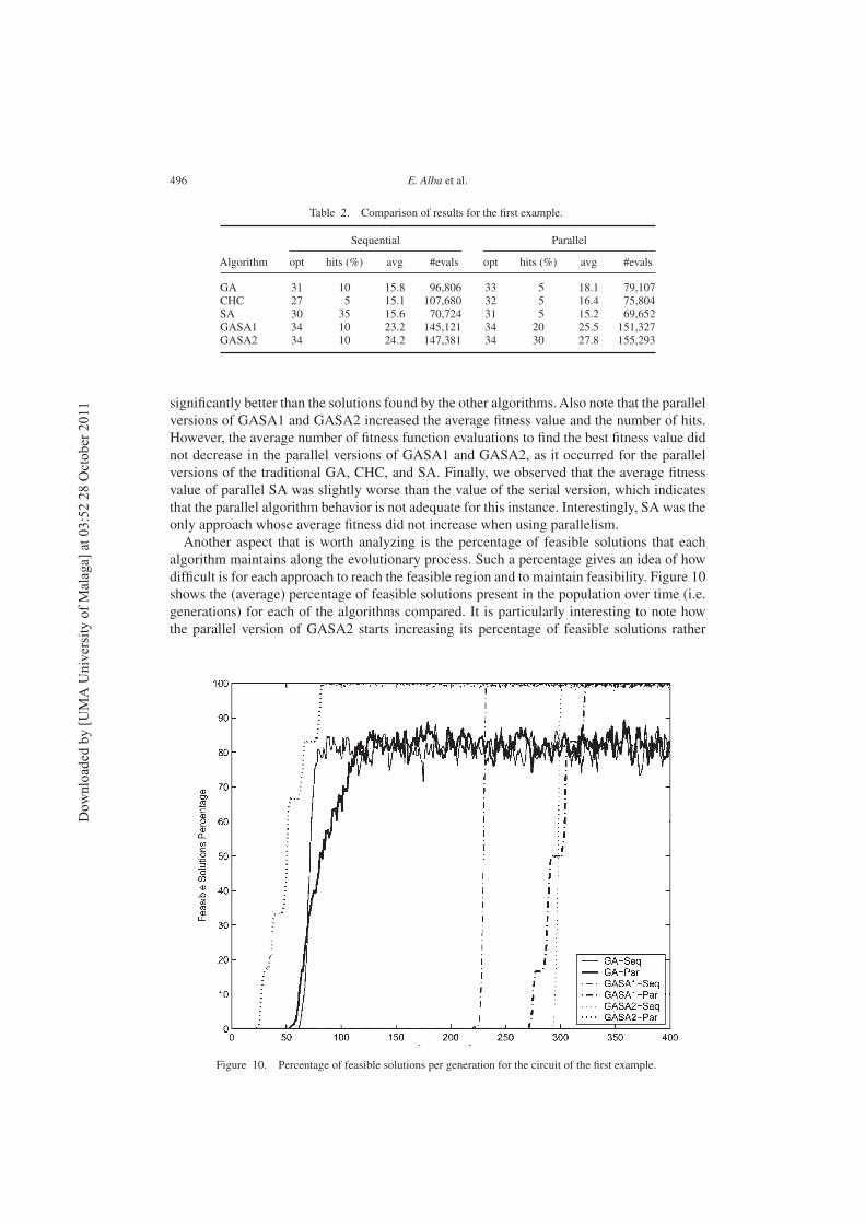
algorithm maintains along the evolutionary process. Such a percentage gives an idea of howdifficult is for each approach to reach the feasible region and to maintain feasibility. Figure 10shows the (average) percentage of feasible solutions present in the population over time (i.e.generations) for each of the algorithms compared. It is particularly interesting to note howthe parallel version of GASA2 starts increasing its percentage of feasible solutions rather
Figure 10. Percentage of feasible solutions per generation for the circuit of the first example.
Dow
nlo
aded
by [
UM
A U
niv
ersi
ty o
f M
alag
a] a
t 03:5
2 2
8 O
ctober
2011
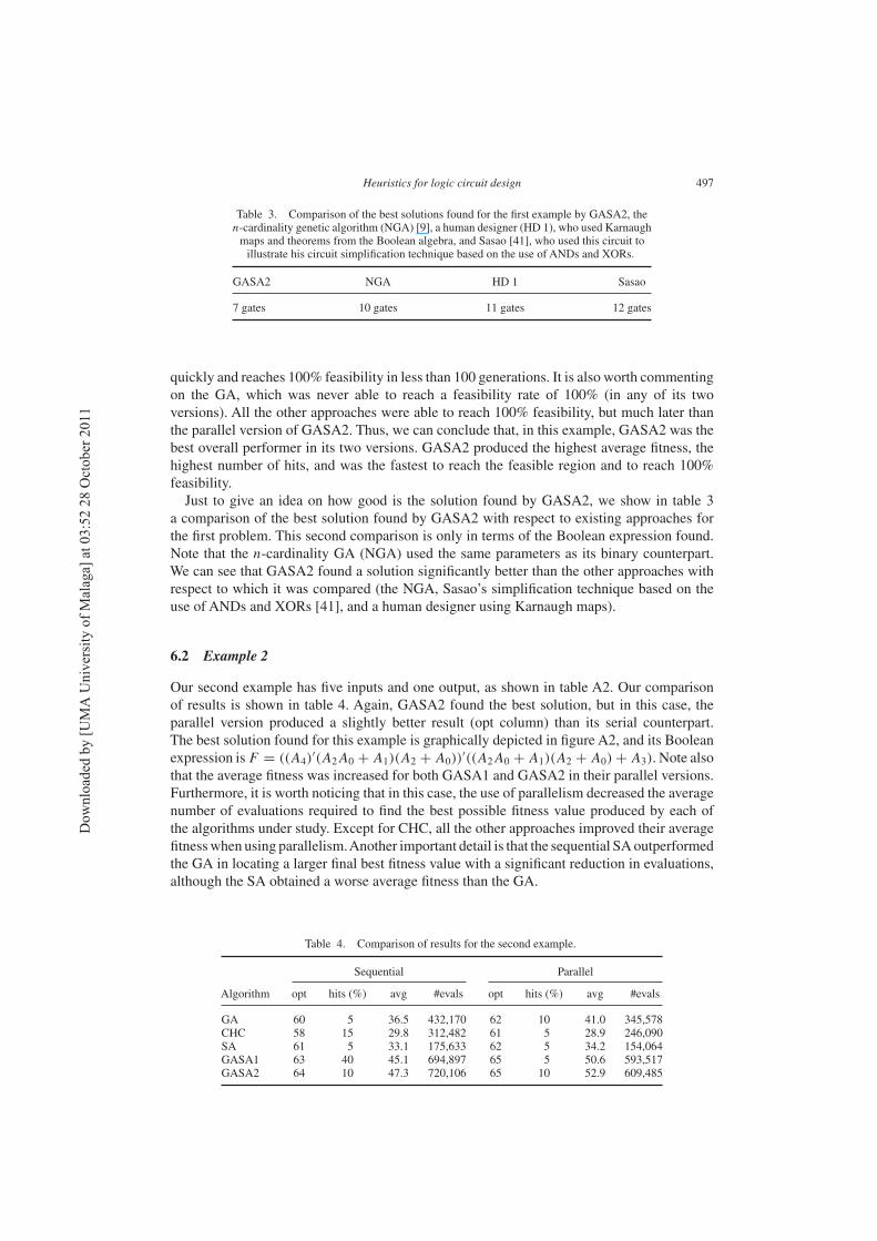
Heuristics for logic circuit design 497
Table 3. Comparison of the best solutions found for the first example by GASA2, then-cardinality genetic algorithm (NGA) [9], a human designer (HD 1), who used Karnaughmaps and theorems from the Boolean algebra, and Sasao [41], who used this circuit toillustrate his circuit simplification technique based on the use of ANDs and XORs.
GASA2 NGA HD 1 Sasao
7 gates 10 gates 11 gates 12 gates
quickly and reaches 100% feasibility in less than 100 generations. It is also worth commentingon the GA, which was never able to reach a feasibility rate of 100% (in any of its twoversions). All the other approaches were able to reach 100% feasibility, but much later thanthe parallel version of GASA2. Thus, we can conclude that, in this example, GASA2 was thebest overall performer in its two versions. GASA2 produced the highest average fitness, thehighest number of hits, and was the fastest to reach the feasible region and to reach 100%feasibility.Just to give an idea on how good is the solution found by GASA2, we show in table 3
a comparison of the best solution found by GASA2 with respect to existing approaches forthe first problem. This second comparison is only in terms of the Boolean expression found.Note that the n-cardinality GA (NGA) used the same parameters as its binary counterpart.We can see that GASA2 found a solution significantly better than the other approaches withrespect to which it was compared (the NGA, Sasao’s simplification technique based on theuse of ANDs and XORs [41], and a human designer using Karnaugh maps).
6.2 Example 2
Our second example has five inputs and one output, as shown in table A2. Our comparisonof results is shown in table 4. Again, GASA2 found the best solution, but in this case, theparallel version produced a slightly better result (opt column) than its serial counterpart.The best solution found for this example is graphically depicted in figure A2, and its Booleanexpression isF = ((A4)
′(A2A0 + A1)(A2 + A0))′((A2A0 + A1)(A2 + A0) + A3). Note also
that the average fitness was increased for both GASA1 and GASA2 in their parallel versions.Furthermore, it is worth noticing that in this case, the use of parallelism decreased the averagenumber of evaluations required to find the best possible fitness value produced by each ofthe algorithms under study. Except for CHC, all the other approaches improved their averagefitnesswhen using parallelism.Another important detail is that the sequential SAoutperformedthe GA in locating a larger final best fitness value with a significant reduction in evaluations,although the SA obtained a worse average fitness than the GA.
Table 4. Comparison of results for the second example.
Sequential Parallel
Algorithm opt hits (%) avg #evals opt hits (%) avg #evals
GA 60 5 36.5 432,170 62 10 41.0 345,578CHC 58 15 29.8 312,482 61 5 28.9 246,090SA 61 5 33.1 175,633 62 5 34.2 154,064GASA1 63 40 45.1 694,897 65 5 50.6 593,517GASA2 64 10 47.3 720,106 65 10 52.9 609,485
Dow
nlo
aded
by [
UM
A U
niv
ersi
ty o
f M
alag
a] a
t 03:5
2 2
8 O
ctober
2011
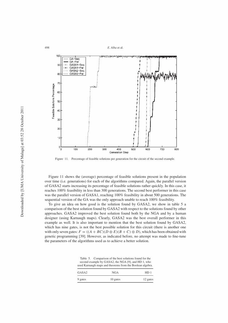
498 E. Alba et al.
Figure 11. Percentage of feasible solutions per generation for the circuit of the second example.
Figure 11 shows the (average) percentage of feasible solutions present in the populationover time (i.e. generations) for each of the algorithms compared. Again, the parallel versionof GASA2 starts increasing its percentage of feasible solutions rather quickly. In this case, itreaches 100% feasibility in less than 300 generations. The second best performer in this casewas the parallel version of GASA1, reaching 100% feasibility in about 500 generations. Thesequential version of the GA was the only approach unable to reach 100% feasibility.To give an idea on how good is the solution found by GASA2, we show in table 5 a
comparison of the best solution found by GASA2 with respect to the solutions found by otherapproaches. GASA2 improved the best solution found both by the NGA and by a humandesigner (using Karnaugh maps). Clearly, GASA2 was the best overall performer in thisexample as well. It is also important to mention that the best solution found by GASA2,which has nine gates, is not the best possible solution for this circuit (there is another onewith only seven gates:F = ((A + BC)(D ⊕ E)(B + C) ⊕ D), which has been obtainedwithgenetic programming [39]. However, as indicated before, no attempt was made to fine-tunethe parameters of the algorithms used as to achieve a better solution.
Table 5. Comparison of the best solutions found for thesecond example by GASA2, the NGA [9], and HD 1, who
used Karnaugh maps and theorems from the Boolean algebra.
GASA2 NGA HD 1
9 gates 10 gates 12 gates
Dow
nlo
aded
by [
UM
A U
niv
ersi
ty o
f M
alag
a] a
t 03:5
2 2
8 O
ctober
2011
Heuristics for logic circuit design 499
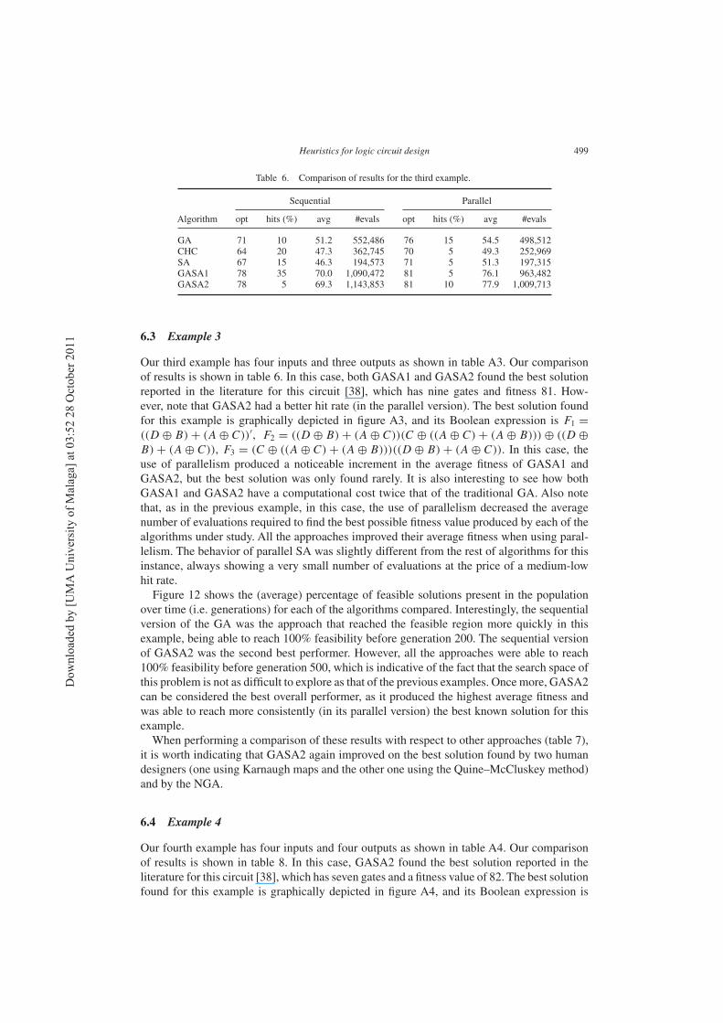
Table 6. Comparison of results for the third example.
Sequential Parallel
Algorithm opt hits (%) avg #evals opt hits (%) avg #evals
GA 71 10 51.2 552,486 76 15 54.5 498,512CHC 64 20 47.3 362,745 70 5 49.3 252,969SA 67 15 46.3 194,573 71 5 51.3 197,315GASA1 78 35 70.0 1,090,472 81 5 76.1 963,482GASA2 78 5 69.3 1,143,853 81 10 77.9 1,009,713
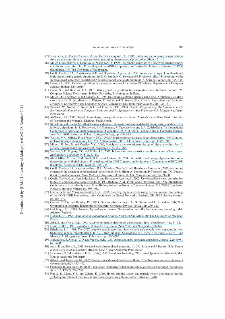
6.3 Example 3
Our third example has four inputs and three outputs as shown in table A3. Our comparisonof results is shown in table 6. In this case, both GASA1 and GASA2 found the best solutionreported in the literature for this circuit [38], which has nine gates and fitness 81. How-ever, note that GASA2 had a better hit rate (in the parallel version). The best solution foundfor this example is graphically depicted in figure A3, and its Boolean expression is F1 =
((D ⊕ B) + (A ⊕ C))′, F2 = ((D ⊕ B) + (A ⊕ C))(C ⊕ ((A ⊕ C) + (A ⊕ B))) ⊕ ((D ⊕
B) + (A ⊕ C)), F3 = (C ⊕ ((A ⊕ C) + (A ⊕ B)))((D ⊕ B) + (A ⊕ C)). In this case, theuse of parallelism produced a noticeable increment in the average fitness of GASA1 andGASA2, but the best solution was only found rarely. It is also interesting to see how bothGASA1 and GASA2 have a computational cost twice that of the traditional GA. Also notethat, as in the previous example, in this case, the use of parallelism decreased the averagenumber of evaluations required to find the best possible fitness value produced by each of thealgorithms under study. All the approaches improved their average fitness when using paral-lelism. The behavior of parallel SA was slightly different from the rest of algorithms for thisinstance, always showing a very small number of evaluations at the price of a medium-lowhit rate.Figure 12 shows the (average) percentage of feasible solutions present in the population
over time (i.e. generations) for each of the algorithms compared. Interestingly, the sequentialversion of the GA was the approach that reached the feasible region more quickly in thisexample, being able to reach 100% feasibility before generation 200. The sequential versionof GASA2 was the second best performer. However, all the approaches were able to reach100% feasibility before generation 500, which is indicative of the fact that the search space ofthis problem is not as difficult to explore as that of the previous examples. Once more, GASA2can be considered the best overall performer, as it produced the highest average fitness andwas able to reach more consistently (in its parallel version) the best known solution for thisexample.When performing a comparison of these results with respect to other approaches (table 7),
it is worth indicating that GASA2 again improved on the best solution found by two humandesigners (one using Karnaugh maps and the other one using the Quine–McCluskey method)and by the NGA.
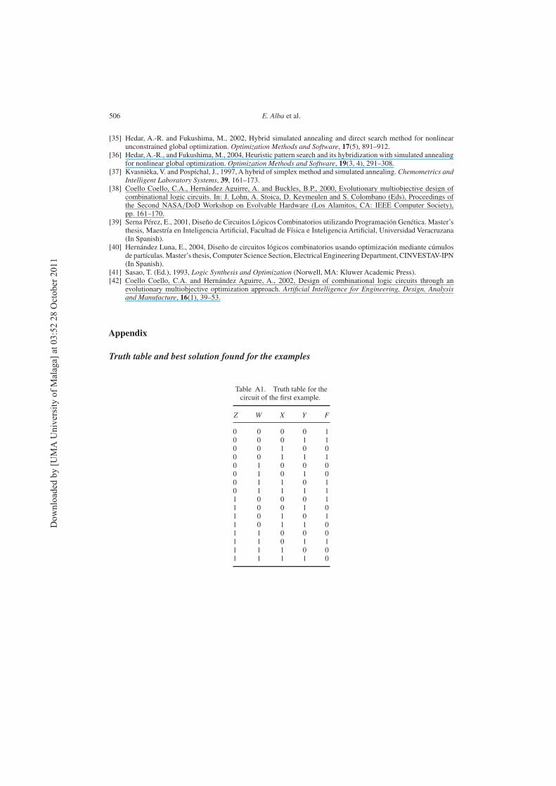
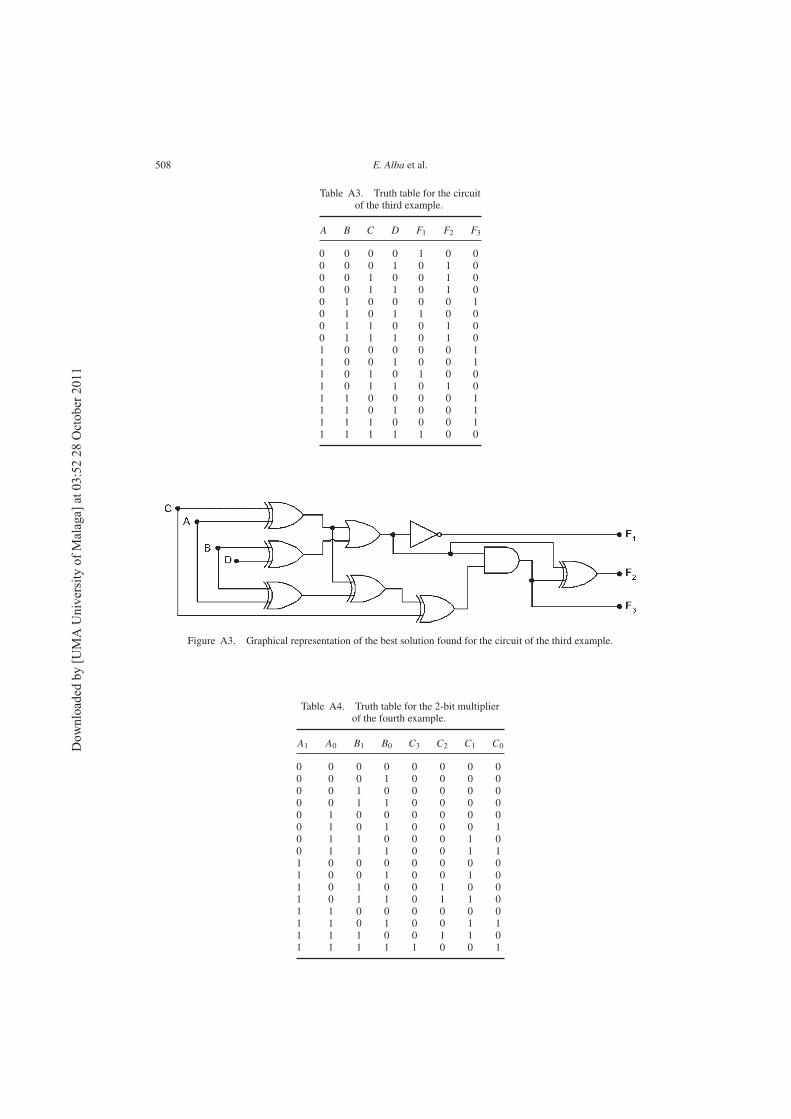
6.4 Example 4
Our fourth example has four inputs and four outputs as shown in table A4. Our comparisonof results is shown in table 8. In this case, GASA2 found the best solution reported in theliterature for this circuit [38], which has seven gates and a fitness value of 82. The best solutionfound for this example is graphically depicted in figure A4, and its Boolean expression is
Dow
nlo
aded
by [
UM
A U
niv
ersi
ty o
f M
alag
a] a
t 03:5
2 2
8 O
ctober
2011
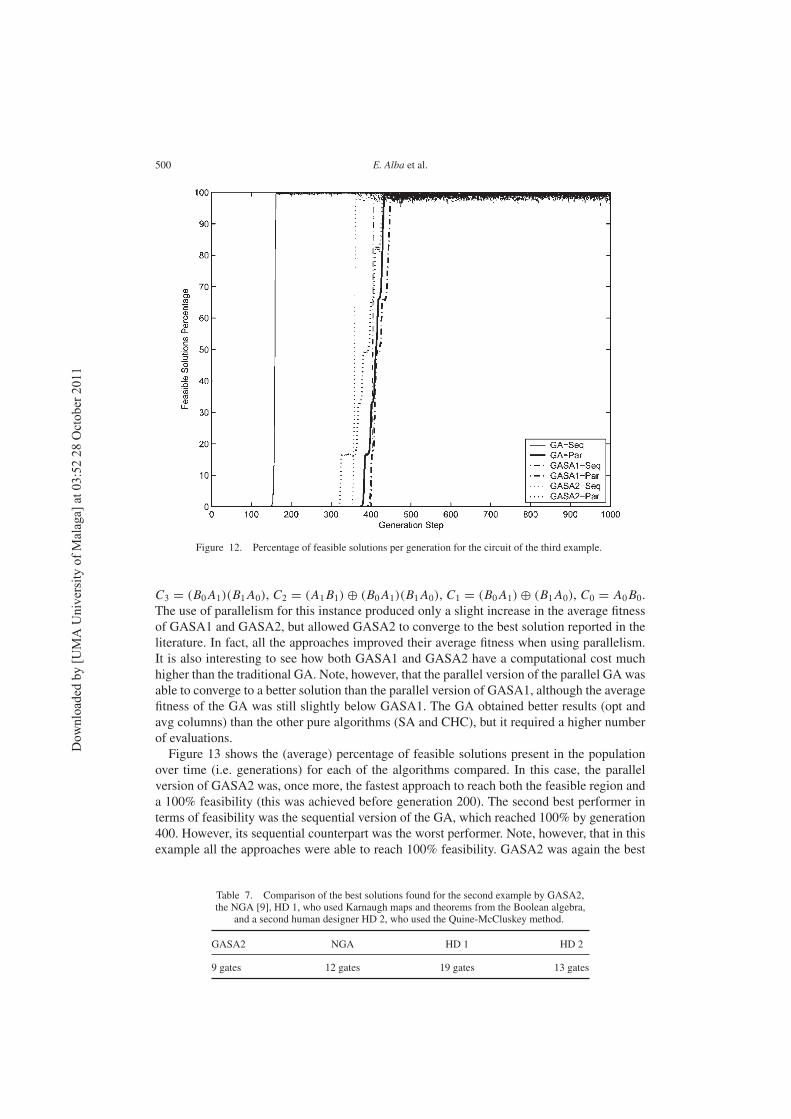
500 E. Alba et al.
Figure 12. Percentage of feasible solutions per generation for the circuit of the third example.
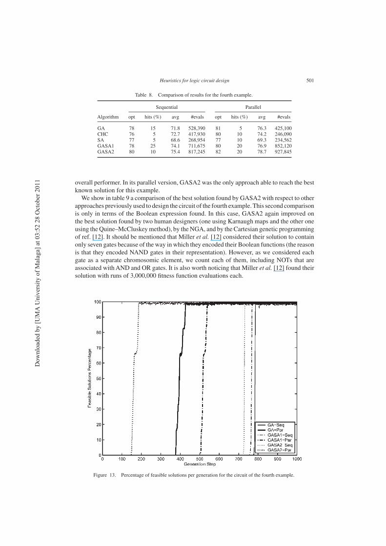
C3 = (B0A1)(B1A0), C2 = (A1B1) ⊕ (B0A1)(B1A0), C1 = (B0A1) ⊕ (B1A0), C0 = A0B0.The use of parallelism for this instance produced only a slight increase in the average fitnessof GASA1 and GASA2, but allowed GASA2 to converge to the best solution reported in theliterature. In fact, all the approaches improved their average fitness when using parallelism.It is also interesting to see how both GASA1 and GASA2 have a computational cost muchhigher than the traditional GA. Note, however, that the parallel version of the parallel GA wasable to converge to a better solution than the parallel version of GASA1, although the averagefitness of the GA was still slightly below GASA1. The GA obtained better results (opt andavg columns) than the other pure algorithms (SA and CHC), but it required a higher numberof evaluations.Figure 13 shows the (average) percentage of feasible solutions present in the population
over time (i.e. generations) for each of the algorithms compared. In this case, the parallelversion of GASA2 was, once more, the fastest approach to reach both the feasible region anda 100% feasibility (this was achieved before generation 200). The second best performer interms of feasibility was the sequential version of the GA, which reached 100% by generation400. However, its sequential counterpart was the worst performer. Note, however, that in thisexample all the approaches were able to reach 100% feasibility. GASA2 was again the best
Table 7. Comparison of the best solutions found for the second example by GASA2,the NGA [9], HD 1, who used Karnaugh maps and theorems from the Boolean algebra,
and a second human designer HD 2, who used the Quine-McCluskey method.
GASA2 NGA HD 1 HD 2
9 gates 12 gates 19 gates 13 gates
Dow
nlo
aded
by [
UM
A U
niv
ersi
ty o
f M
alag
a] a
t 03:5
2 2
8 O
ctober
2011
Heuristics for logic circuit design 501
Table 8. Comparison of results for the fourth example.
Sequential Parallel
Algorithm opt hits (%) avg #evals opt hits (%) avg #evals
GA 78 15 71.8 528,390 81 5 76.3 425,100CHC 76 5 72.7 417,930 80 10 74.2 246,090SA 77 5 68.6 268,954 77 10 69.3 234,562GASA1 78 25 74.1 711,675 80 20 76.9 852,120GASA2 80 10 75.4 817,245 82 20 78.7 927,845
overall performer. In its parallel version, GASA2 was the only approach able to reach the bestknown solution for this example.We show in table 9 a comparison of the best solution found by GASA2 with respect to other
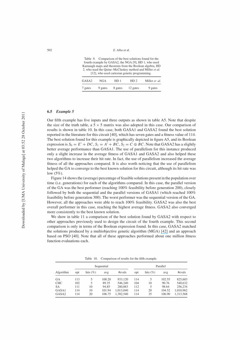
approaches previously used to design the circuit of the fourth example.This second comparisonis only in terms of the Boolean expression found. In this case, GASA2 again improved onthe best solution found by two human designers (one using Karnaugh maps and the other oneusing theQuine–McCluskeymethod), by theNGA, and by the Cartesian genetic programmingof ref. [12]. It should be mentioned that Miller et al. [12] considered their solution to containonly seven gates because of the way in which they encoded their Boolean functions (the reasonis that they encoded NAND gates in their representation). However, as we considered eachgate as a separate chromosomic element, we count each of them, including NOTs that areassociated withAND and OR gates. It is also worth noticing that Miller et al. [12] found theirsolution with runs of 3,000,000 fitness function evaluations each.
Figure 13. Percentage of feasible solutions per generation for the circuit of the fourth example.
Dow
nlo
aded
by [
UM
A U
niv
ersi
ty o
f M
alag
a] a
t 03:5
2 2
8 O
ctober
2011
502 E. Alba et al.
Table 9. Comparison of the best solutions found for thefourth example by GASA2, the NGA [9], HD 1, who usedKarnaugh maps and theorems from the Boolean algebra, HD2, who used the Quine–McCluskey method and Miller et al.
[12], who used cartesian genetic programming.
GASA2 NGA HD 1 HD 2 Miller et al.
7 gates 9 gates 8 gates 12 gates 9 gates
6.5 Example 5
Our fifth example has five inputs and three outputs as shown in table A5. Note that despitethe size of the truth table, a 5× 5 matrix was also adopted in this case. Our comparison ofresults is shown in table 10. In this case, both GASA1 and GASA2 found the best solutionreported in the literature for this circuit [40], which has seven gates and a fitness value of 114.The best solution found for this example is graphically depicted in figure A5, and its Booleanexpression is S0 = E′
+ DC, S1 = A′+ BC, S2 = C ⊕ BC. Note that GASA2 has a slightly
better average performance than GASA1. The use of parallelism for this instance producedonly a slight increase in the average fitness of GASA1 and GASA2 and also helped thesetwo algorithms to increase their hit rate. In fact, the use of parallelism increased the averagefitness of all the approaches compared. It is also worth noticing that the use of parallelismhelped the GA to converge to the best known solution for this circuit, although its hit rate waslow (5%).Figure 14 shows the (average) percentage of feasible solutions present in the population over
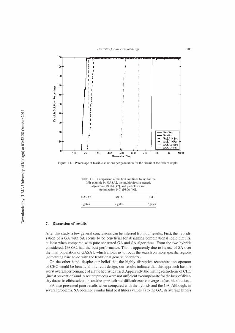
time (i.e. generations) for each of the algorithms compared. In this case, the parallel versionof the GA was the best performer (reaching 100% feasibility before generation 200), closelyfollowed by both the sequential and the parallel versions of GASA1 (which reached 100%feasibility before generation 300). The worst performer was the sequential version of the GA.However, all the approaches were able to reach 100% feasibility. GASA2 was also the bestoverall performer in this case, reaching the highest average fitness. GASA2 also convergedmore consistently to the best known solution.We show in table 11 a comparison of the best solution found by GASA2 with respect to
other approaches previously used to design the circuit of the fourth example. This secondcomparison is only in terms of the Boolean expression found. In this case, GASA2 matchedthe solutions produced by a multiobjective genetic algorithm (MGA) [42] and an approachbased on PSO [40]. Note that all of these approaches performed about one million fitnessfunction evaluations each.
Table 10. Comparison of results for the fifth example.
Sequential Parallel
Algorithm opt hits (%) avg #evals opt hits (%) avg #evals
GA 113 5 100.20 933,120 114 5 102.55 825,603CHC 102 5 89.35 546,240 104 10 90.76 540,632SA 111 10 94.85 280,883 112 5 98.64 256,234GASA1 114 10 101.94 1,013,040 114 20 104.52 1,010,962GASA2 114 20 106.75 1,382,540 114 35 106.90 1,313,568
Dow
nlo
aded
by [
UM
A U
niv
ersi
ty o
f M
alag
a] a
t 03:5
2 2
8 O
ctober
2011
Heuristics for logic circuit design 503
Figure 14. Percentage of feasible solutions per generation for the circuit of the fifth example.
Table 11. Comparison of the best solutions found for thefifth example by GASA2, the multiobjective genetic
algorithm (MGA) [42], and particle swarmoptimization [40] (PSO) [40].
GASA2 MGA PSO
7 gates 7 gates 7 gates
7. Discussion of results
After this study, a few general conclusions can be inferred from our results. First, the hybridi-zation of a GA with SA seems to be beneficial for designing combinational logic circuits,at least when compared with pure separated GA and SA algorithms. From the two hybridsconsidered, GASA2 had the best performance. This is apparently due to its use of SA overthe final population of GASA1, which allows us to focus the search on more specific regions(something hard to do with the traditional genetic operators).On the other hand, despite our belief that the highly disruptive recombination operator
of CHC would be beneficial in circuit design, our results indicate that this approach has theworst overall performance of all the heuristics tried.Apparently, themating restrictions ofCHC(incest prevention) and its restart processwere not sufficient to compensate for the lack of diver-sity due to its elitist selection, and the approach haddifficulties to converge to feasible solutions.SA also presented poor results when compared with the hybrids and the GA. Although, in
several problems, SA obtained similar final best fitness values as to the GA, its average fitness
Dow
nlo
aded
by [
UM
A U
niv
ersi
ty o
f M
alag
a] a
t 03:5
2 2
8 O
ctober
2011
504 E. Alba et al.
is often lower than the other methods. The reason for this is that SA rapidly finds a localoptimum from which it cannot escape, in spite of the internal mechanism explicitly added tothe algorithm to avoid them. However, this method gets fairly accurate results with a fewernumber of evaluations than the other algorithms.Finally, we also found that, in most cases, the use of parallelism improves the average fitness
of the approaches compared. This is something interesting, as it constitutes an additional moti-vation to parallelize the heuristics adopted to design combinational logic circuits. However,it was also found that this increase in the average fitness of the approaches was normallyaccompanied by a decrease in the hit rate. In other words, some consistency (or robustness)was sacrificed at the expense of achieving solutions of a higher quality.
8. Conclusions and future work
The comparative study conducted in this article has shown that the hybridization of an evo-lutionary algorithm with SA may bring benefits when designing combinational logic circuits.Emphasis is placed on the fact that the GA hybridized is using binary encoding. Additionally,the use of parallelism also brought benefits in terms of the quality of solutions produced, but itdid not necessarily improve the hit rate (i.e. the number of times that an algorithm convergedto its best found solution). Note however, that the use of parallelism tended to decrease theaverage number of evaluations required by each algorithm to achieve their best possible fit-ness value. Nevertheless, a more in-depth study of the impact of parallelism in combinationalcircuit design remains as an open research area.As part of our future work, we are interested in using a population-based multiobjective
optimization approach (the so-called MGA that we proposed in ref. [38]) hybridized with anSA. Intuitively, this sort of approach should produce better results when hybridized, as byitself is a very powerful search engine for combinational circuit design. However, we ignorethe possible bias that could arise from combining the local search capabilities of SA with thepopulation-based selection mechanism of the MGA. Alternatively, the use of Pareto-basedselection mechanisms [42] also constitutes a promising topic that deserves further study.
Acknowledgements
The authors thank the anonymous reviewers for their comments, which greatly helped usto improve the contents of this article. The two first authors are partially supported by theMinistry of Science and Technology and FEDER under contract TIN2005-08818-C04-01 (theOPLINK project). The third author acknowledges support from the NSF-CONACyT projectno. 42435-Y.
References
[1] Karnaugh, M., 1953, A map method for synthesis of combinational logic circuits. Transactions of the AIEE,
Communications and Electronics, I(72), 593–599.[2] Veitch, E.W., 1952, A chart method for simplifying boolean functions. Proceedings of the ACM, (New York:
ACM Press), pp. 127–133.[3] McCluskey, E.J., 1956, Minimization of boolean functions. Bell Systems Technical Journal, 35(5), 1417–1444.[4] Quine, M.V., 1955, A way to simplify truth functions. American Mathematical Monthly, 62(9), 627–631.[5] Coello Coello, C.A., Christiansen, A.D. and Hernández Aguirre, A., 2000, Use of evolutionary techniques to
automate the design of combinational circuits. International Journal of Smart Engineering System Design, 2(4),299–314.
[6] Miller, J.F., Job, D. and Vassilev, V.K., 2000, Principles in the evolutionary design of digital circuits – part I.Genetic Programming and Evolvable Machines, 1(1/2), 7–35.
Dow
nlo
aded
by [
UM
A U
niv
ersi
ty o
f M
alag
a] a
t 03:5
2 2
8 O
ctober
2011
Heuristics for logic circuit design 505
[7] Islas Pérez, E., Coello Coello, C.A. and Hernández Aguirre, A., 2003, Extracting and re-using design patternsfrom genetic algorithms using case-based reasoning. Engineering Optimization, 35(2), 121–141.
[8] Miller, J., Kalganova, T., Lipnitskaya, N. and Job, D., 1999, The genetic algorithm as a discovery engine: strangecircuits and new principles. Proceedings of the AISB Symposium on Creative Evolutionary Systems (CES’99)(Edinburgh, UK: The University of Edinburgh).
[9] Coello Coello, C.A., Christiansen, A.D. and Hernández Aguirre, A., 1997, Automated design of combinationallogic circuits using genetic algorithms. In: D.G. Smith, N.C. Steele, and R.F.Albrecht (Eds), Proceedings of theInternational Conference onArtificial Neural Nets and GeneticAlgorithms (UK: Springer-Verlag), pp. 335–338.
[10] Louis, S.J., 1993, Genetic algorithms as a computational tool for design. PhD thesis, Department of ComputerScience, Indiana University.
[11] Louis, S.J. and Rawlins, G.J., 1991, Using genetic algorithms to design structures. Technical Report 326,Computer Science Department, Indiana University, Bloomington, Indiana.
[12] Miller, J.F., Thomson, P. and Fogarty, T., 1998, Designing electronic circuits using EAs. Arithmetic circuits: acase study. In: D. Quagliarella, J. Périaux, C. Poloni and G. Winter (Eds) Genetic Algorithms and Evolution
Strategy in Engineering and Computer Science (Chichester, UK: John Wiley & Sons), pp. 105–131.[13] Banzhaf, W., Nordin, P., Keller, R.E. and Francone, F.D., 1998, Genetic Programming. An Introduction. On
the Automatic Evolution of Computer Programs and Its Applications (San Francisco, CA: Morgan KaufmannPublishers).
[14] Al-Saiari, U.S., 2003, Digital circuit design through simulated evolution. Master’s thesis, King Fahd Universityof Petroleum and Minerals, Dhahran, Saudi Arabia.
[15] Slowik, A. and Bialko. M., 2004, Design and optimization of combinational digital circuits using modified evo-lutionary algorithm. In: L. Rutkowski, J.H. Siekmann, R. Tadeusiewicz and L.A. Zadeh (Eds), 7th InternationalConference in Artificial Intelligence and Soft Computing – ICAISC 2004, Lecture Notes in Computer Science,June, Vol. 3070 (Zakopane, Poland: Springer-Verlag), pp. 468–473.
[16] Vassilev,V.K.,Miller, J.F. andFogarty,T.C., 1999,Digital circuit evolution and fitness landscapes. 1999Congresson Evolutionary Computation, July, Vol. 2 (Washington, DC: IEEE Service Center), pp. 1299–1306.
[17] Miller, J.F., Job, D. and Vassilev, V.K., 2000, Principles in the evolutionary design of digital circuits – Part II.Genetic Programming and Evolvable Machines, 1(3), 259–288.
[18] Vassilev, V.K., Fogarty, T.C. and Miller, J.F., 2000, Information characteristics and the structure of landscapes.Evolutionary Computation, 8(1), 31–60.
[19] Abd-El-Barr, M., Sait, S.M., Sarif, B.A.B and Al-Saiari, U., 2003, A modified ant colony algorithm for evolu-tionary design of digital circuits. Proceedings of the 2003 Congress on Evolutionary Computation (CEC’2003)(Canberra, Australia: IEEE Press), pp. 708–715.
[20] Coello Coello, C.A., Zavala Gutiérrez, R.L., Mendoza García, B. and HernándezAguirre, A., 2000, Ant colonysystem for the design of combinational logic circuits. In: J. Miller, A. Thompson, P. Thomson and T.C. Fogarty(Eds) Evolvable Systems: From Biology to Hardware (Edinburgh, UK: Springer-Verlag), pp. 21–30.
[21] Coello Coello, C.A., Hernández Luna, E. and HernándezAguirre, A., 2003, Use of particle swarm optimizationto design combinational logic circuits. In: P.C. Haddow, A.M. Tyrell, and J. Torresen (Eds), 5th InternationalConference in Evolvable Systems: From Biology to Lecture Notes in Computer Science,Vol. 2606 (Trondheim,Norway: Springer-Verlag), pp. 398–409.
[22] Gudise, V.G. and Venayagamoorthy, G.K., 2003, Evolving digital circuits using particle swarm. Proceedingsof the INNS-IEEE International Joint Conference on Neural Networks (Porland, OR: IEEE Service Center),pp. 468–472.
[23] Gordon, T.G.W. and Bentley, P.J., 2003, On evolvable hardware. In: S. Ovaska and L. Sztandera (Eds) SoftComputing in Industrial Electronics (Heidelberg, Germany: Physica-Verlag), pp. 279–323.
[24] Goldberg, D.E., 1989, Genetic Algorithms in Search, Optimization and Machine Learning (Reading, MA:Addison-Wesley).
[25] Holland, J.H., 1975, Adaptation in Natural and Artificial Systems (AnnArbor, MI: The University of MichiganPress).
[26] Alba, E. and Troya, J.M., 1999, A survey of parallel distributed genetic algorithms. Complexity, 4(4), 31–52.[27] Davis, L. (Ed.), 1991, Handbook of Genetic Algorithms (NewYork: Van Nostrand Reinhold).[28] Eshelman, L.J., 1991, The CHC adaptive search algorithm: how to have safe search when engaging in non-
traditional genetic recombination. In: G.E. Rawlins (Ed) Foundations of Genetic Algorithms (FOGA) (SanMateo, CA: Morgan Kaufmann Publishers), pp. 265–283.
[29] Kirkpatrick, S., Gellatt, C.D. andVecchi, M.P., 1983, Optimization by simulated annealing. Science, 220(4598),671–680.
[30] Aarts, E. and Korst, J., 2002, Selected topics in simulated annealing. In: C.C. Ribero and P. Hansen (Eds) Essays
and Surveys un Metaheuristics (Boston, MA: Kluwer Academic Publishers).[31] Laarhoven, P.J.M. andAarts, E.H.L. (Eds), 1987, Simulated Annealing: Theory and Applications (Norwell, MA:
Kluwer Academic Publishers).[32] Alba, E. and Tomassini, M., 2002, Parallelism and evolutionary algorithms. IEEE Transactions on Evolutionary
Computation, 6(5), 443–462.[33] Chelouah, R. and Siarry, P., 2000, Tabu search applied to global optimization. European Journal of Operational
Research, 123(2), 256–270.[34] Fan, S.-K., Liang, Y.-C. and Zahara, E., 2004, Hybrid simplex search and particle swarm optimization for the
global optimization of multimodal functions. Engineering Optimization, 36(4), 401–418.
Dow
nlo
aded
by [
UM
A U
niv
ersi
ty o
f M
alag
a] a
t 03:5
2 2
8 O
ctober
2011
506 E. Alba et al.
[35] Hedar, A.-R. and Fukushima, M., 2002, Hybrid simulated annealing and direct search method for nonlinearunconstrained global optimization. Optimization Methods and Software, 17(5), 891–912.
[36] Hedar,A.-R., and Fukushima, M., 2004, Heuristic pattern search and its hybridization with simulated annealingfor nonlinear global optimization. Optimization Methods and Software, 19(3, 4), 291–308.
[37] Kvasnièka,V. and Pospíchal, J., 1997,A hybrid of simplex method and simulated annealing. Chemometrics and
Intelligent Laboratory Systems, 39, 161–173.[38] Coello Coello, C.A., Hernández Aguirre, A. and Buckles, B.P., 2000, Evolutionary multiobjective design of
combinational logic circuits. In: J. Lohn, A. Stoica, D. Keymeulen and S. Colombano (Eds), Proceedings ofthe Second NASA/DoD Workshop on Evolvable Hardware (Los Alamitos, CA: IEEE Computer Society),pp. 161–170.
[39] Serna Pérez, E., 2001, Diseño de Circuitos Lógicos Combinatorios utilizando Programación Genética. Master’sthesis, Maestría en Inteligencia Artificial, Facultad de Física e Inteligencia Artificial, Universidad Veracruzana(In Spanish).
[40] Hernández Luna, E., 2004, Diseño de circuitos lógicos combinatorios usando optimización mediante cúmulosde partículas.Master’s thesis, Computer Science Section, Electrical EngineeringDepartment, CINVESTAV-IPN(In Spanish).
[41] Sasao, T. (Ed.), 1993, Logic Synthesis and Optimization (Norwell, MA: Kluwer Academic Press).[42] Coello Coello, C.A. and Hernández Aguirre, A., 2002, Design of combinational logic circuits through an
evolutionary multiobjective optimization approach. Artificial Intelligence for Engineering, Design, Analysis
and Manufacture, 16(1), 39–53.
Appendix
Truth table and best solution found for the examples
Table A1. Truth table for thecircuit of the first example.
Z W X Y F
0 0 0 0 10 0 0 1 10 0 1 0 00 0 1 1 10 1 0 0 00 1 0 1 00 1 1 0 10 1 1 1 11 0 0 0 11 0 0 1 01 0 1 0 11 0 1 1 01 1 0 0 01 1 0 1 11 1 1 0 01 1 1 1 0
Dow
nlo
aded
by [
UM
A U
niv
ersi
ty o
f M
alag
a] a
t 03:5
2 2
8 O
ctober
2011

Heuristics for logic circuit design 507
Figure A1. Graphical representation of the best solution found for the circuit of the first example.
Table A2. Truth table for the circuitof the second example.
A0 A1 A2 A3 A4 F
0 0 0 0 0 00 0 0 0 1 00 0 0 1 0 10 0 0 1 1 10 0 1 0 0 00 0 1 0 1 00 0 1 1 0 10 0 1 1 1 10 1 0 0 0 00 1 0 0 1 00 1 0 1 0 10 1 0 1 1 10 1 1 0 0 00 1 1 0 1 10 1 1 1 0 00 1 1 1 1 11 0 0 0 0 01 0 0 0 1 01 0 0 1 0 11 0 0 1 1 11 0 1 0 0 01 0 1 0 1 11 0 1 1 0 01 0 1 1 1 11 1 0 0 0 01 1 0 0 1 11 1 0 1 0 01 1 0 1 1 11 1 1 0 0 01 1 1 0 1 11 1 1 1 0 01 1 1 1 1 1
Figure A2. Graphical representation of the best solution found for the circuit of the second example.
Dow
nlo
aded
by [
UM
A U
niv
ersi
ty o
f M
alag
a] a
t 03:5
2 2
8 O
ctober
2011
508 E. Alba et al.
Table A3. Truth table for the circuitof the third example.
A B C D F1 F2 F3
0 0 0 0 1 0 00 0 0 1 0 1 00 0 1 0 0 1 00 0 1 1 0 1 00 1 0 0 0 0 10 1 0 1 1 0 00 1 1 0 0 1 00 1 1 1 0 1 01 0 0 0 0 0 11 0 0 1 0 0 11 0 1 0 1 0 01 0 1 1 0 1 01 1 0 0 0 0 11 1 0 1 0 0 11 1 1 0 0 0 11 1 1 1 1 0 0
Figure A3. Graphical representation of the best solution found for the circuit of the third example.
Table A4. Truth table for the 2-bit multiplierof the fourth example.
A1 A0 B1 B0 C3 C2 C1 C0
0 0 0 0 0 0 0 00 0 0 1 0 0 0 00 0 1 0 0 0 0 00 0 1 1 0 0 0 00 1 0 0 0 0 0 00 1 0 1 0 0 0 10 1 1 0 0 0 1 00 1 1 1 0 0 1 11 0 0 0 0 0 0 01 0 0 1 0 0 1 01 0 1 0 0 1 0 01 0 1 1 0 1 1 01 1 0 0 0 0 0 01 1 0 1 0 0 1 11 1 1 0 0 1 1 01 1 1 1 1 0 0 1
Dow
nlo
aded
by [
UM
A U
niv
ersi
ty o
f M
alag
a] a
t 03:5
2 2
8 O
ctober
2011
Heuristics for logic circuit design 509
Figure A4. Graphical representation of the best solution found for the circuit of the fourth example.
Table A5. Truth table for the fifth example.
E D C B A S0 S1 S2
0 0 0 0 0 1 1 00 0 0 0 1 1 0 00 0 0 1 0 1 1 00 0 0 1 1 1 0 00 0 1 0 0 1 1 10 0 1 0 1 1 0 10 0 1 1 0 1 1 00 0 1 1 1 1 1 00 1 0 0 0 1 1 00 1 0 0 1 1 0 00 1 0 1 0 1 1 00 1 0 1 1 1 0 00 1 1 0 0 1 1 10 1 1 0 1 1 0 10 1 1 1 0 1 1 00 1 1 1 1 1 1 01 0 0 0 0 0 1 01 0 0 0 1 0 0 01 0 0 1 0 0 1 01 0 0 1 1 0 0 01 0 1 0 0 0 1 11 0 1 0 1 0 0 11 0 1 1 0 0 1 01 0 1 1 1 0 1 01 1 0 0 0 0 1 01 1 0 0 1 0 0 01 1 0 1 0 0 1 01 1 0 1 1 0 0 01 1 1 0 0 1 1 11 1 1 0 1 1 0 11 1 1 1 0 1 1 01 1 1 1 1 1 1 0
Figure A5. Graphical representation of the best solution found for the circuit of the fifth example.
Dow
nlo
aded
by [
UM
A U
niv
ersi
ty o
f M
alag
a] a
t 03:5
2 2
8 O
ctober
2011


![The Chanticleer [serial]](https://img.dokumen.tips/doc/110x75/63296b32eedc98f54f012f30/the-chanticleer-serial.jpg)


