Embed Size (px)
Citation preview
Presenied at the Sixth Midwinter Convention ofthe American Institute of Electrical Engineers,New York, February 16, 1918.
Copyright 1918. By A_ I. E. E.
COMMUTATION IN ALTERNATING-CURRENTMACHINERY
BY MARIUS C. A. LATOUR
ABSTRACT OF PAPERAs is now well known, the inductive reactive effect of a com-
muted winding in a revolving magnetic field decreases directlywith the increase in speed from standstill to synchronism, whenits value becomes zero. As first pointed out by the authorsome years ago, it becomes negative at speeds above syn-chronism, under which condition the rotor of a motor operatesas a capacity.The author introduces into the discussion of the commutating
characteristics of alternating-current commutating motors, histheory that perfect commutation in a continuous-current motordepends substantially on the production of a mean resultantneutral field in the region where commutation is taking place,and shows that the production of a perfect revolving field in apolyphase commutator motor assists in insuring perfect commu-tation at exact synchronism.
In a single-phase commutator motor a "polyphase" revolvingfield can be produced at synchronism by utilizing supplementarybrushes, short-circuited upon themselves, displaced by 90 elec-trical space degrees from the main single-phase brushes on thecommutator.As in the case of polyphase motors, the problem of securing
perfect commutation at synchronism becomes that of producing!aperfect rotating field. It is shown by the author that the use offractional-pitch windings on the rotor and a sinusoidal distri-bution of conductors on the stator is of much assistance in thisconnection.
In a motor buLilt in accordance with the principles set forth, thecommutator difficulties are not serious, the overload range isin excess of that of an induction motor, and the machine canact as a condenser on the system.
THE writer has already had the honor of presenting two com-munications on the use of commutators with alternating
currents before the American engineering public, the first being inJune, 1903, in co-operation with Mr. A. S. Garfield (see The Com-pounding of Self-Excited Alternating Current Generators, for Vari-ation in Load-Factor, in A. I. E. E. TRANSACTIONS, VOl. XXI, pages569-577, and discussion, pages 583-585); the other being a paperpresented at the St. Louis Congress, 1904, ("Alternating CurrentMachines with Gramme Commutators,' published in Transactionsof the International Electrical Congress of St. Louis, 1904, Vol.III, pages 149-154).
355
356 LATOUR: COMMUTATION [Feb. 16
The purpose of the present paper is to enter more deeply intothe theoretical considerations which were outlined by the writerin his earlier publications, and which have since been verifiedby practical experience. A distinction will be made between theuse of commutators for polyphase and for single-phase alternat-ing currents.
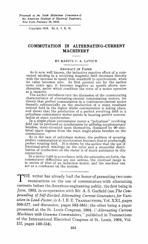
I-COMMUTATOR IN POLYPHASE MACHINERYLet us consider a direct-current bipolar armature, A, Fig. 1,
placed in a uniform air gap inside the laminated stator, B, withregularly spaced slots and receiving sinusoidal currents of pphases, of frequency equal to w/2 7r through p brushes located atpoints situated 2 wr/p in angular distance from each other.
Fig. 1 shows diagrammatically a smooth core armature, onwhich four brushes, a, b, c, d, make contacts through whichtwo-phase (more properly four-phase) currents are supplied.The brushes, a, c, receive a current I sin w t, and the brushes b, d,receive a current I cos w t. Suppose the armature to be at restand let Lw be its inductance per phase. If the armature ismade to turn at the angular velocity co,, measured in the direc-tion of the rotating field developed by the polyphase currents, itwill be found that the inductance of the armature becomesL (co- co,); consequently, it will vanish at synchronism and,above synchionism, the ar?angement will operate as a capacity(condenser).When this property was first made known by the writer, in
his patents, in 1900-1901, its correctness was questioned byseveral prominent electricians. Among these, M. MauriceLeblanc devoted a long article (see Eclairage Electrique, October26th, 1901, pages 113 et seq) to the refutation of the writer'sconclusions. Many electricians have, since then, accepted assatisfactory the theory which introduces the relative velocity(- w1) of the revolving field developed by the armature withrespect to the armature itself. Mr. Leblanc, however, main-tained, in his article, that since the current, i, in each turn of thearmature winding, preserved its variable character, no matterwhat the velocity co, might be, at any instant i was subject to the
disame rate of variation, dt , and consequently the e. m. f. of
self-induction between the brushes should persist at all speedsAs was shown by the writer, in a detailed article, published
in November, 1901, (see Eclairage Electrigue, 1901, pages 294
1918] LA TOUR: COMMUTATION 357
et seq), it is quite true that the e. m. f. of self-induction of thesections included in the circuit between the brushes persists inde-pendently of the velocity col; but, in consequence of the phenome-non of commutation, there appears between the brushes ane. m. f. of opposite sign which is proportional to the velocity co,and which is due to the mutual induction between the sectionswhich are short-circuited and those which are in the circuit.
In this connection, let us consider Fig. 1. Let M be the co-efficient of mutual induction between the sections which areshort-circuited by the brushes, b, d, and the sections that remainin circuit between the brushes a, c. Let n be the number ofsections of the armature. With brushes covering the width of acommutator segment, the duration of commutation for the sec-
FIG. 1
tions of winding passing under the brushes b, d, at the velocity
wi, will be T-= t) n The e. m. f. EM developed by mutual
induction between the short-circuited sections passing under thebrushes b, d, (where the reversal of a current I I cos w t is takingplace during the time T) and the sections which are in circuitbetween the brushes a, c, (through which the current I sin co I
passes )will be T I cos co t= - co, I cos cwt.T 2
We first ascertain that EM is opposed in polarity to the e. m. f.of self-induction EL = L w I cos w t, due to the self-inductionof the armature; and we then can show that, in the case where
358 LA TOUR: COMMUTATION [Feb. 16
each section of the armature is supposed to produce a sinusoidalMnflux at the armature periphery, we will have Mn = L and con-
sequently EL -EM = L (o - cw1).It is to be noted that the same expression may be obtained for
the e. m. f. (EM) by supposing it to be induced by the rotationof the armature in its own field produced by the current sentthrough brushes a, c; but this explanation of the appearance ofthe e. m. f. EM, though it may always be correct from the mathe-matical point of view, is not quite so near the physical reality,since, as a matter of fact, the field of the armature itself mustfollow the armature in its rotation.The fact that the armature in the arrangement shown in Fig. 1
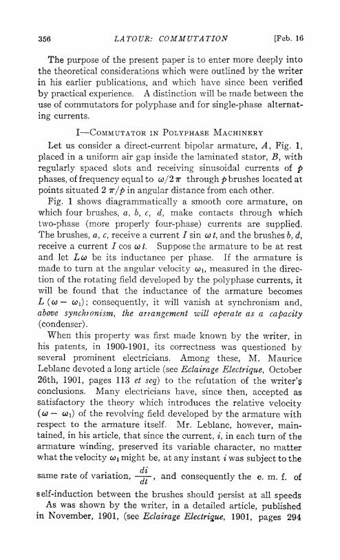
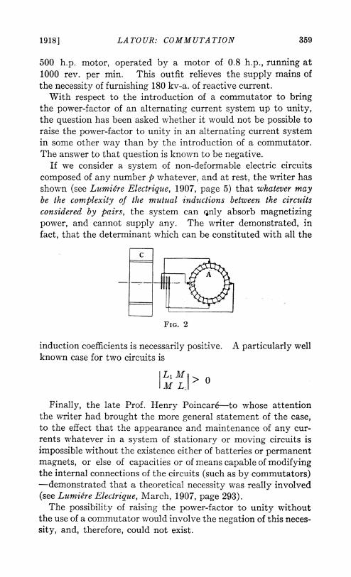
can operate as a capacity (namely when co, exceeds c) was ofparticular interest to Mr. Leblanc, who, about that time (in1902) was endeavoring to find a simple electrical system suscep-tible of being used in place of the condensers which he was placingin the rotors of induction motors, for the purpose of improvingtheir power-factor. He had even, for that purpose, devised thecombination of two single-phase machines provided with com-mutators. In Mr. Leblanc's arrangement an induction motor Cwas connected in cascade with a simple armature A, such as thatshown in Fig. 1, running at a speed greatly in excess of synchron-ism with respect to the frequency of the rotor currents of ma-chine C (see Fig. 2). This was an immediate indication of thevalue of the writer's article of November 23rd, 1901, as Mr.Leblanc himself has since expressly acknowledged, (see LaLumigre Electrique, July 12th, 1913, page 60, and the Electricien,July 25th, 1913, page 658).*The Swiss firm of Brown-Boveri, utilizing the methods
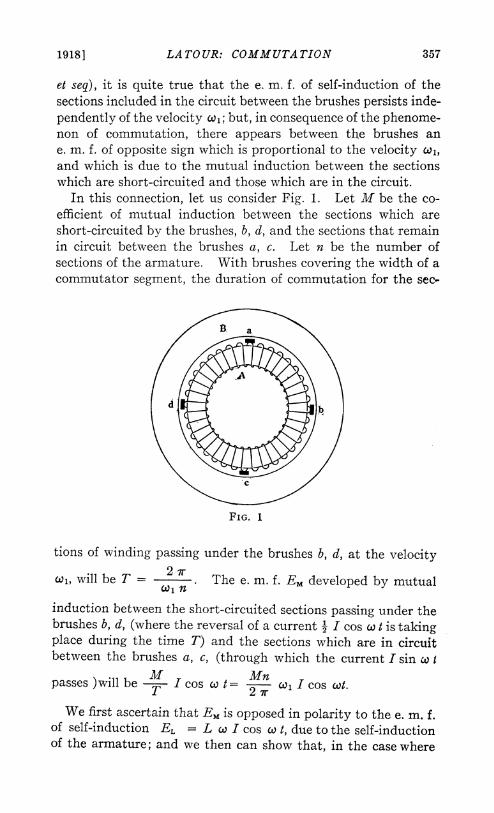
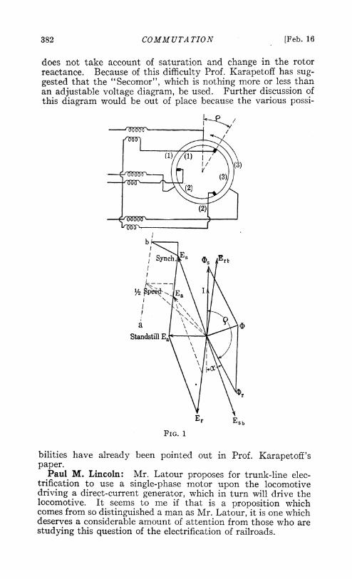
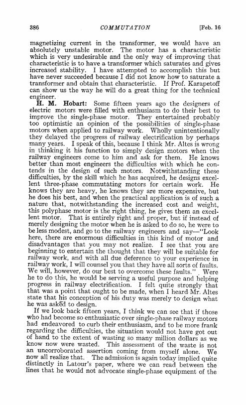
patented by M. Leblanc for improving the power-factor of in-duction motors, has put on the market, in the last few years,under the name of phase-compensator, armatures with commu-tators rotating above synchronous speed. Fig. 3, made from a-photograph, shows one of these arrangements, designed for a
*The writer had formally proposed that combination in a letteraddressed to Industrie Electrique (in 1902) which was not pub-lished; but the writer, in any case, considers that M. Leblanc should becredited with the idea of placing condensers or any dynamic apparatusequivalent to them in the rotor of induction motors for the purposeof improving their power-factor. It is by mistake that the arrangementshown in Fig. 2 was, during a certain time, attributed to Mr. Scherbius.
1918] LA TOUR: COMMUTATION 359
500 h.p. motor, operated by a motor of 0.8 h.p., running at1000 rev. per min. This outfit relieves the supply mains ofthe necessity of furnishing 180 kv-a. of reactive current.With respect to the introduction of a commutator to bring
the power-factor of an alternating current system up to unity,the question has been asked whether it would not be possible toraise the power-factor to unity in an alternating current systemin some other way than by the introduction of a commutator.The answer to that question is known to be negative.
If we consider a system of non-deformable electric circuitscomposed of any number p whatever, and at rest, the writer hasshown (see Lumiere Electrique, 1907, page 5) that whatever maybe the complexity of the mutual inductions between the circuitsconsidered by pairs, the system can Qnly absorb magnetizingpower, and cannot supply any. The writer demonstrated, infact, that the determinant which can be constituted with all the
FIG. 2
induction coefficients is necessarily positive. A particularly wellknown case for two circuits is
L1M> 0M LI
Finally, the late Prof. Henry Poincar6-to whose attentionthe writer had brought the more general statement of the case,to the effect that the appearance and maintenance of any cur-rents whatever in a system of stationary or moving circuits isi-mpossible without the existence either of batteries or permanentmagnets, or else of capacities or of means capable of modifyingthe internal connections of the circuits (such as by commutators)-demonstrated that a theoretical necessity was really involved(see Lumiere Electrique, March, 1907, page 293).The possibility of raising the power-factor to unity without
the use of a commutator would involve the negation of this neces-sity, and, therefore, could not exist.
360 LATOUR: COMMUTATION [Feb. 16
In accordance with what has been said previously, with refer-ence to the expression of the armature inductance in Fig. 1,under the form L (w - cl), it can be supposed, in order to obtaina first classical approximation, that the flux per phase on thearmature-periphery is sinusoidal. But the distribution hereconsidered is a theoretical one, which does not correspond to thereal distribution. Let us begin by noting on what fictitioussurface this distribution may be defined.
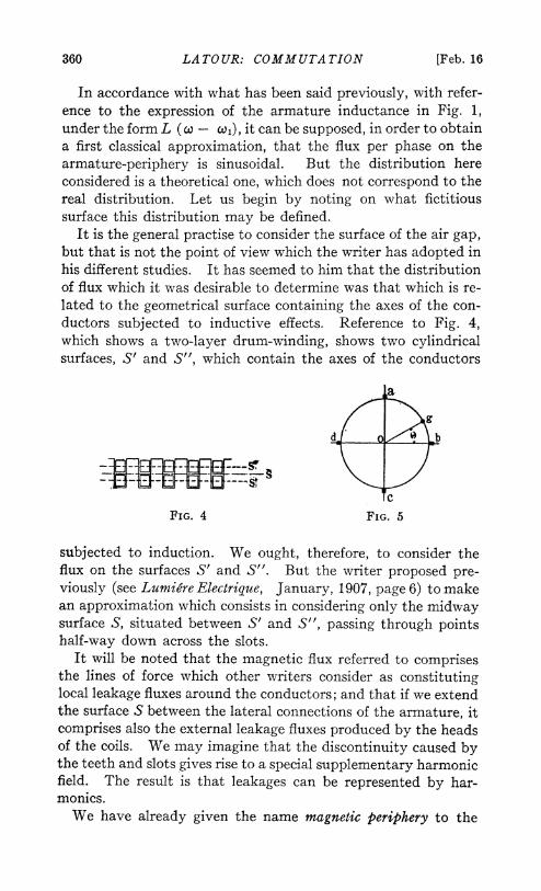
It is the general practise to consider the surface of the air gap,but that is not the point of view which the writer has adopted inhis different studies. It has seemed to him that the distributionof flux which it was desirable to determine was that which is re-lated to the geometrical surface containing the axes of the con-ductors subjected to inductive effects. Reference to Fig. 4,which shows a two-layer drum-winding, shows two cylindricalsurfaces, S' and S", which contain the axes of the conductors
la
dj 0 b
cFIG. 4 FIG. 5
subjected to induction. We ought, therefore, to consider theflux on the surfaces S' and S". But the writer proposed pre-viously (see Lumiere Electrique, January, 1907, page 6) to makean approximation which consists in considering only the midwaysurface S, situated between S' and S", passing through pointshalf-way down across the slots.
It will be noted that the magnetic flux referred to comprisesthe lines of force which other writers consider as constitutinglocal leakage fluxes around the conductors; and that if we extendthe surface S between the lateral connections of the armature, itcomprises also the external leakage fluxes produced by the headsof the coils. We may imagine that the discontinuity caused bythe teeth and slots gives rise to a special supplementary harmonicfield. The result is that leakages can be represented by har-monics.We have already given the name magnetic periphery to the
1918] LATOUR: COMMUTATION 361
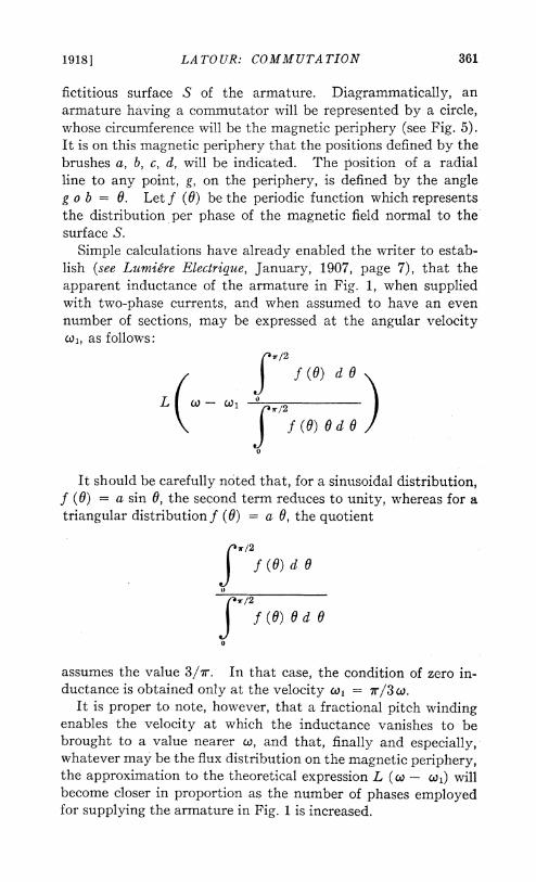
fictitious surface S of the armature. Diagrammatically, anarmature having a commutator will be represented by a circle,whose circumference will be the magnetic periphery (see Fig. 5).It is on this magnetic periphery that the positions defined by thebrushes a, b, c, d, will be indicated. The position of a radialline to any point, g, on the periphery, is defined by the angleg o b = 0. Let f (0) be the periodic function which representsthe distribution per phase of the magnetic field normal to thesurface S.
Simple calculations have already enabled the writer to estab-lish (see Lumi&re Electrique, January, 1907, page 7), that theapparent inductance of the armature in Fig. 1, when suppliedwith two-phase currents, and when assumed to have an evennumber of sections, may be expressed at the angular velocityco,, as follows:
7r/2
/ ~ ~~~f(0) da0
0
It should be carefully noted that, for a sinusoidal distribution,f (0) = a sin 0, the second term reduces to unity, whereas for atriangular distribution f (6) = a 0, the quotient
4r/2
f (O)d 0
r/2
f (0) 0 d 00
assumes the value 3/7r. In that case, the condition of zero in-ductance is obtained only at the velocity co, - 7r/3 co.
It is proper to note, however, that a fractional pitch windingenables the velocity at which the inductance vanishes to bebrought to a value nearer co, and that, finally and especially,whatever may be the flux distribution on the magnetic periphery,the approximation to the theoretical expression L (w - coi) willbecome closer in proportion as the number of phases employedfor supplying the armature in Fig. 1 is increased.
362 LATOUR: COMMUTATION [Feb. 16
The very important question which remains to be consideredin connection with the operation of the armature in Fig. 1 is thatof commutation. We! may here recall the manner in which thatquestion was approached in the writer's study in 1901 (see Eclair-age Electrique, page 294). Let X be the full coefficient of self-induction of the sections of armature winding undergoing com-mutation under the brushes, a, c, through which is passing thecurrent I sin w t. This coefficient (X), it should be noted, in-cludes, in the case of windings of the drum type, the effect dueto mutual induction between two sections in process of commu-tation under the brushes a, c. of opposite polarity. Now, letT represent the time that is consumed in the commutation ofone section of winding. The condition which is necessary andsufficient in order to obtain perfect or "linear" commutation(which is gone into more fully in the article referred to), is thatthere should be available, in the winding sections which are in
short-circuit, a reversal e. m. f. equal to T I sin X t.
Now the flux developed along the rectangular axis b, d isproportional to cos w t. Consequently, the induction resultingfrom its periodic variation produces an e.m.f. in the sectionsshort-circuited by the brushes a, c, which is proportional to
- Cdos X t and, therefore, to sin co t. This e.m.f. is constant
for a given current I cos co t. There is, therefore, a certainvelocity wl, for which there is produced, exactly, in the commu-tated sections, the reversal e.m.f. necessary and sufficient,
. I sin w t, to produce a perfect or linear commutation.
Below that velocity the reversal e.m.f. will be too high andcommutating conditions will be produced which are analogousto those existing in a continuous-current dynamo when thebrushes are set too far forward in the direction of rotation.Above that velocity, on the other hand, the reversal e.m.f.produced will be too weak, and the commutating conditionsproduced will be analogous to those which exist in a continuous-current dynamo when the brushes are not set sufficiently farforward in the direction of rotation, or even e-hen they areset in the opposite direction. It will be pointed out later,that precisely this same condition of operation exists (namely
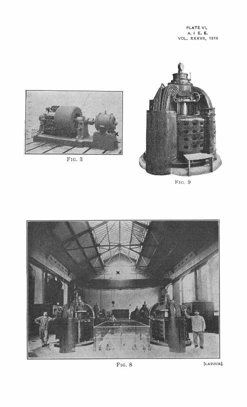
PLATE VI.A. I E. E.
VOL. XXXVII, 1918
FIG. 3
_ ~~~~~~~~~~~~~~~~~~~~~~~~~~- -16
FIG. 9
~~~~F. 8 3 ElA; OURi.
19181 LA TOUR: COMMUTATION 363
insufficient reversal e.m.f.) when the armature in Fig. 1 is oper-ating as a capacity, and it will be interesting to note that inthe production of reactive current by a commutator we en-counter the same commutating difficulties as the reduction ofthe normal armature reaction or the production of an armaturereaction which assists the field excitation in a continuous-currentdynamo.
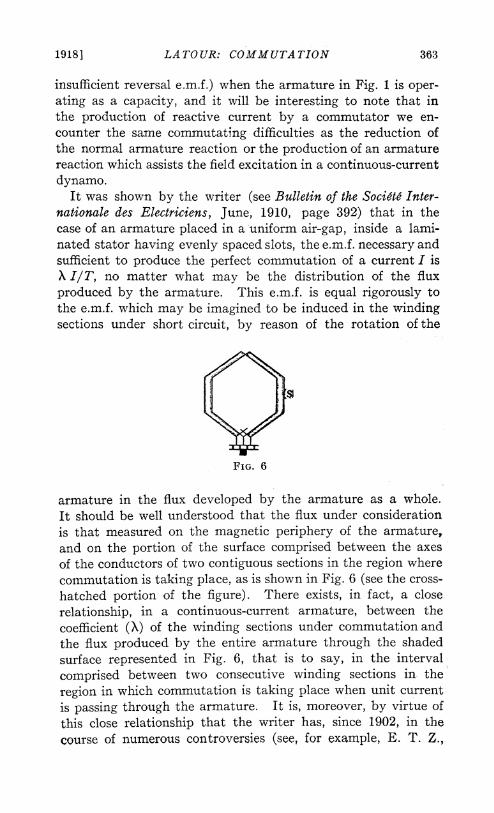
It was shown by the writer (see Bulletin of the Societe Inter-nationale des Electriciens, June, 1910, page 392) that in thecase of an armature placed in a uniform air-gap, inside a lami-nated stator having evenly spaced slots, the e.m.f. necessary andsufficient to prodtuce the perfect commutation of a current I isX I/T, no matter what may be the distribution of the fluxproduced by the armature. This e.m.f. is equal rigorously tothe e.m.f. which may be imagined to be induced in the windingsections under short circuit, by reason of the rotation of the
FIG. 6
armature in the flux developed by the armature as a whole.It should be well understood that the flux under considerationis that measured on the magnetic periphery of the armature,and on the portion of the surface comprised between the axesof the conductors of two contiguous sections in the region wherecommutation is taking place, as is shown in Fig. 6 (see the cross-hatched portion of the figure). There exists, in fact, a closerelationship, in a continuous-current armature, between thecoefficient (X) of the winding sections under commutation andthe flux produced by the entire armature through the shadedsurface represented in Fig. 6, that is to say, in the intervalcomprised between two consecutive winding sections in theregion in which commutation is taking place when unit currentis passing through the armature. It is, moreover, by virtue ofthis close relationship that the writer has, since 1902, in thecourse of numerous controversies (see, for example, E. T. Z.,
364 LA TOUR: COMMUTATION [Feb. 16
1906, page 781; Lumiere Electrique, 1902, page 53; Electrician,1913, pages 105 and 325; Elektrotechnik und Maschinenbau, 1913,page 633), defended the very simple point of view accordingto which the matter of obtaining perfect commutation in acontinuous-current dynamo depends substantially on the neu-tralization of the magnetic field of the armature, or, moreproperly, on the production of a mean resultant neutral fieldin the region where commutation is taking place. It is under-stood that the field is measured on the portion shown shadedin Fig. 6, on a surface S which passes about half-way acrossthe armature slots, and not through a surface situated in theair gap, The exactness of this view seems to be recognizedmore or less explicitly at the present time.
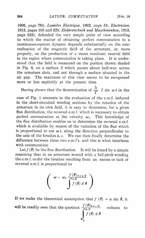
Having shown that the determination of T I sin w t in theTcase of Fig. 1 amounts to the evaluation of the e.m.f. inducedin the short-circuited winding sections by the rotation of thearmature in its own field, it is easy to determine, for a givenflux distribution, the reversal e.m.f. which is necessary to obtainperfect commutation at the velocity w.. This knowledge ofthe flux distribution enables us to determine the reversal e.m.f.which is available by reason of the variation of the flux whichis proportional to cos w t, along the direction perpendicular tothe axis of the brushes a, c. We can then finally determine thedifference between these two e.m.f's. and this is what interfereswith commutation.Letf (0) be the flux distribution. It will be found by a simple
reasoning that in an armature wound with a full pitch windingthe e.m.f. under the brushes resulting from an excess or lack ofreversal e.m.f. is proportional to
tCd @ 1 r /2
( rf (0) d 0
If we make the theoretical assumption that f (0) = a sin 0, it
will be readily seen that the quotient f (0)0=,/2 reduces to
f (0) dO
0
1918] LA TOUR: COMMUTATION 365
unity, and that perfect commutation is obtained at synchronismfor the condition co, = w.
If we suppose that f (0) is of the form a 0, which is nearerthe actual condition, it will be found that perfect commutation
is obtained at the velocity w, =7
X 0.79 co. However, the4
conditions are changed if the number of phases employed forsupplying current to the armature in Fig. 1 is increased. Withsix phases, we find, for the velocity of perfect commutation
w = 0.86 co
and finally, for twelve phases, we find l = w. By adoptinga fractional pitch for the winding of the armature it is possibleto approach more rapidly the condition co, = c. It is importantto note that if the commutation is not perfect at synchronismin all cases, it is because we are not dealing, in general, witha uniform revolving field, in consequence of a non-sinusoidaldistribution of flux on the magnetic periphery of the armature.The simple reasoning which the writer followed in a first ap-proximation (1900-1901), and in which he asserted that commu-tation must always be perfect at synchronism when there is areal revolving field, is exact, for the very reason that the variationof flux in the short-circuited sections vanishes at synchronism.
Everything that can be done to obtain a perfect revolvingfield (such as increasing the number of phases and using frac-tional pitch winding) unquestionably assists in insuring per-fect commutation at exact synchronism.When the revolving field produced by a rotor having a com-
mutator is imperfect, the commutation is disturbed at syn-chronism under conditions equivalent to those wherein it wouldbe disturbed by an external imperfect revolving field producedby the stator surrounding it.
In reality, the increase in the number of phases for the supplyof current to the rotor of a commutator machine, as set forthin the writer's German patent No. 145,433 of 1901, is relatedrather to a specific purpose, and it has less immediate relationto commutation. It may be interesting to note the principalreasons for this.
In the first place, in increasing the number of phases for
366 LATOUR: COMMUTATION [Feb. 16
supplying current to the rotor, the current to be commutatedper phase for a given total current in the armature is materiallydiminished. The frictional surface on the periphery of thecommutator remains the same in the two cases, but it is dif-ferently distributed. The result of reducing the current perphase is that the resistance of a single line of brushes in thecase of a bipolar armature, or of the assemblage of lines ofbrushes coupled in parallel in the case of a multipolararmature, increases with the number of phases. Now, theincrease of this resistance, as is well known, is favorable togood commutation, so long as the machine is not working ata theoretical load corresponding to perfect commutation.
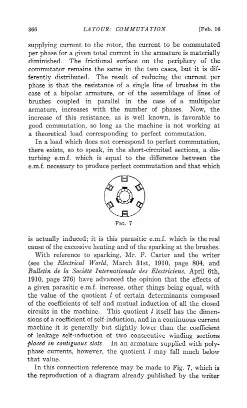
In a load which does not correspond to perfect commutation,there exists, so to speak, in the short-circuited sections, a dis-turbing e.m.f. which is equal to the difference between thee.m.f. necessary to produce perfect commutation and that which
FIG. 7
is actually induced; it is this parasitic e.m.f. which is the realcause of the excessive heating and of the sparking at the brushes.With reference to sparking, Mr. F. Carter and the writer
(see the Electrical World, March 31st, 1910, page 804, andBulletin de la Societ Internationale des Electriciens, April 6th,1910, page 276) have advanced the opinion that the effects ofa given parasitic e.m.f. increase, other things being equal, withthe value of the quotient I of certain determinants composedof the coefficients of self and mutual induction of all the closedcircuits in the machine. This quotient I itself has the dimen-sions of a coefficient of self-induction, and in a continuous currentmachine it is generally but slightly lower than the coefficientof leakage self-induction of two consecutive winding sectionsplaced in contiguous slots. In an armature supplied with poly-phase currents, however, the quotient I may fall much belowthat value.
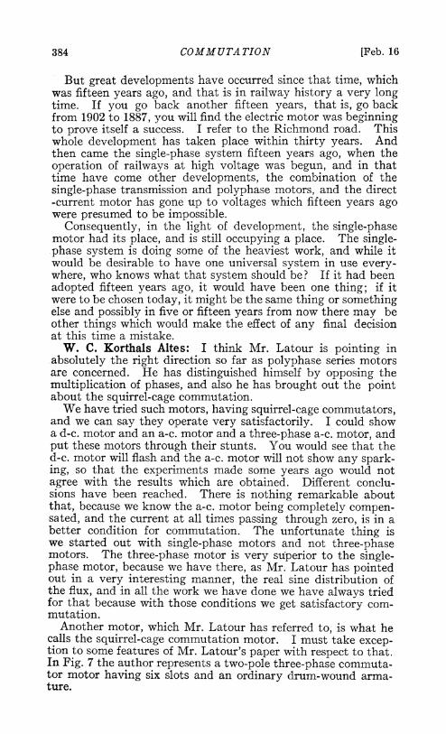
In this connection reference may be made to Fig. 7, which isthe reproduction of a diagram already published by the writer
1918] LA TOUR: COMMUTATION 367
(see A. I. E. E. TRANSACTIONS, 1903, page 583). The diagramrepresents an armature with a drum winding composed oftwelve sections, supplied by three-phase currents. It will beeasily seen that, as the width of the brushes exceeds the widthof the commutator segments, there is always, at any instant,at least one short-circuited section per slot. Armatures havingas few as three slots per pole are seldom used, but if we adopta higher number of phases, preferably an odd number (7 or 9,for example, as indicated in the writer's A. I. E. E. communica-tion of 1903) the remarks relative to the conditions shown inFig. 7 can be extended to the case of an armature having anumber of slots actually used in current practise. Under thoseconditions, the quotient I becomes lower than the coefficient ofself-induction due to leakage between two sections placed inthe same slots. The parasitic e.m.f. will then produce practicallya simple short-circuit current as if the armature was at rest orrevolving slightly. Under these conditions, we will have thesparkless commutation which I named "squirrel-cage commuta-tion."The three types of a-c. polyphase commutator machines
which can be rationally constituted by taking synchronism asthe mean working condition, are analogous to continuous-current machines, namely, the shunt machine, the series machine,and the compound-wound machine. The theory of these ma-chines was published by the writer in 1902 (see Eclairage Elec-trique, 1902, pages 50 and 358), and different authors havegone over the subject since in a more detailed manner. Whenthese machines are working above or below synchronism, then,from the point of view of commutation, it is necessary to takeinto consideration the e.m.f. induced by the resultant field ofthe stator and rotor in the short-circuited winding sections, andto judge the commutation accordingly. If a machine is intendedto have the greatest possible range of speed, then it is immediatelyobvious that it is important to arrange matters in such way thatsynchronism shall correspond to a speed of perfect operation sofar as commutation is concerned. Allowance can then be madefor equal values of slip above and below synchronism, and inthis way the allowable variation of speed becomes greater.With an absolute slip of 20 per cent, for example, it is possibleto obtain speed variations in the ratio of two to three.When the slip is to be materially increased, the width of the
brushes should be reduced as much as possible, in order that
368 LATOUR: COMMUTATION [Feb. 16
the e.m.f. induced between the opposite edges of the brush maybe as low as possible; but for mechanical reasons it is scarcelypractical to reduce the thickness of the brushes to less than9 to 10 mm.
This minimum width of brushes being a limitation, it isdesirable (for the same e.m.f. developed between the two edgesof the brush) to divide this e.m.f. in some way by adopting atype of winding which allows the commutator segments tohave a width of half that of the brush (see the writer's articlein the Electrical World of December 3rd, 1904). As a rule,commutator segments of 4.5 to 5.0 mm. will be used.With brushes of good quality the e.m.f. allowable between
the segments under those conditions will be 1.5 volts. Thise.m.f. allows high values of slip to be attained without necessi-tating a commutator of excessive size.The writer has devoted much attention in the last ten years
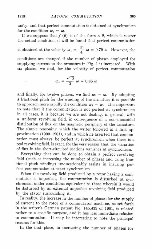
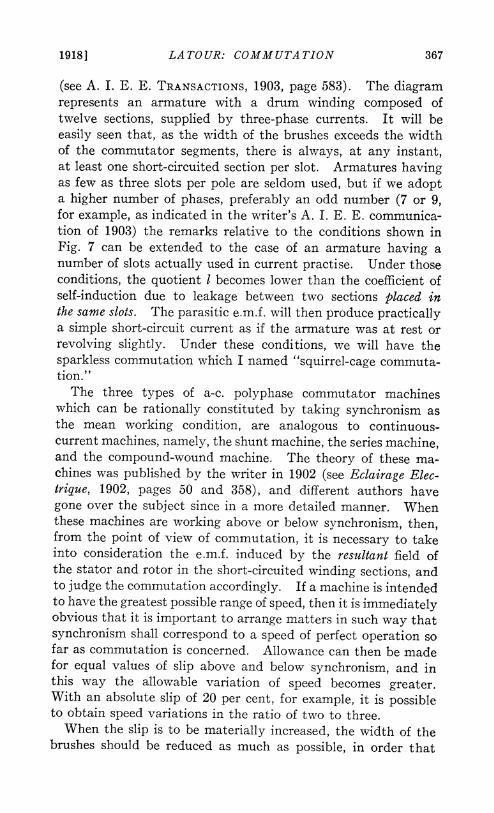
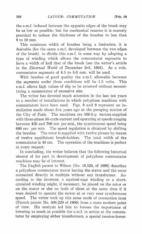
to a number of installations in which polyphase machines withcommutators have been used. Figs. 8 and 9 represent an in-stallation made about five years ago at the pumping station ofthe City of Paris. The machines are 500-h.p. motors suppliedwith three-phase 50-cycle current and operating at speeds rangingbetween 450 and 700 rev. per min., the synchronous speed being600 rev. per min. The speed regulation is obtained by shiftingthe brushes. The rotor is supplied with twelve phases by meansof twelve equidistant brush-holders. The total width of thecommutator is 40 cm. The operation of the machines is perfectin every respect.
In concluding, the writer believes that the following historicalresume of his part in development of polyphase commutatormachines may be of interest.The English patent to Wilson (No. 18,525, of 1888) describes
a polyphase commutator motor having the stator and the rotorconnected directly in multiple without any transformer. Ac-cording to the inventor, a squirrel-cage winding or a short-circuited winding might, if necessary, be placed on the rotor oron the stator or else on both of them at the same time if itwere desired to operate the motor at or very near synchronousspeed. The writer took up this same mode of connection later(French patent No. 306,229 of 1900) from a more modern pointof view. His analysis led him to foresee the importance oflowering as much as possible the e.m.f. in action at the commu-tator by employing either transformers, a special tension-lower-
19181 LA TOUR: COMMUTATION 369
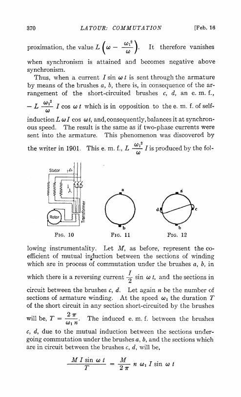
ing device, or else sectional windings placed on the stator asmeans of supplying current to the rotor. In a German patentof 1891 (No. 61,951 to Georges) a series polyphase commutatormotor is described. The writer has also introduced in thatarrangement a series transformer between the stator and therotor. Later, the writer adopted the plan of constructing thesetransformers with an air-gap, in order to improve the charac-teristics of the motor; and the connections employed are of thestar-delta type, as shown in Fig. 10 (German Patent, No. 237,849).The star-delta connection enables one to regulate the speed
in a practical way, within wide limits, by simply shifting thebrushes. The star connection is used for starting and for run-ning at lower speeds; the delta connection is used at higher speeds.
Besides the shunt and series connections, mentioned in the twopatents just referred to, the writer has also indicated how a com-pound connection could be used between the stator and the rotor(German patent No. 154,509 of 1901) and has favored the pro-vision of a rotor with a greater number of phases than are ob-tainable directly from the supply mains (German patent No.145,433 of 1901). This greater number of phases is obtained bymeans of a transformer, or else, in the case of a shunt machine,by means of auxiliary windings placed on the stator.
Finally, the writer has also proposed the use of all these kindsof machines as generators, and has called attention to theiradvantages in regard to their coupling in multiple and theircompounding. Before the war, the writer had begun the con-struction of 100 kv-a. three-phase generators, which were tooperate as boosters for mains supplying three-phase currents of50 cycles. The writer is confident that this question of a-c.commutator generators, in which, by the way, the commutator isrelatively very small, is a development which is sure to commandattention in the near future.
II-COMMUTATOR IN SINGLE-PHASE MACHINERYLet us suppose that the armature in Fig. 1 is supplied with a
simple alternating current through two brushes a, b, placed 180deg. apart, instead of being supplied with two-phase currents(see Fig. 11). The armature-reactance then retains the samevalue Lco, whatever may be the angular velocity co,. But, ifwe place, 90 deg. from the brushes a, b, some supplementalbrushes c, d, connected together by a short-circuit connection(see Fig. 12), the armature-reactance then takes, as a first ap-
370 LATOUR: COMMUTATION [Feb. 16
proximation, the value L -co ). It therefore vanishes
when synchronism is attained and becomes negative abovesynchronism.
Thus, when a current I sin co t is sent through the armatureby means of the brushes a, b, there is, in consequence of the ar-rangement of the short-circuited brushes c, d, an e. m. f.,
- Lw
I cos co t which is in opposition to the e. m. f. of self-
induction L cwI cos cot, and, consequently, balances it at synchron-ous speed. The result is the same as if two-phase currents weresent into the armature. This phenomenon was discovered by
the writer in 1901. This e. m. f., Lc
Iis produced by the fol-
Stator a Q
a bi
FIG. 10 FIG. 11 FIG. 12
lowing instrumentality. Let M, as before, represent the co-efficient of mutual induction between the sections of windingwhich are in process of commutation under the brushes a, b, in
which there is a reversing current 2 sin X t, and the sections in
circuit between the brushes c, d. Let again n be the number ofsections of armature winding. At the speed co, the duration Tof the short circuit in any section short-circuited by the brushes
will be, T = 27r. The induced e. m. f. between the brushes
c, d, due to the mutual induction between the sections under-going commutation under the brushes a, b, and the sections whichare in circuit between the brushes c, d, will be,
MI sin co t MT - 2wzr n cOlsin cot
1918] LA TOUR: COMMUTATION 371
This e. m. f. will produce, in the conductor connecting the
brushes c, d, a short-circuit current which is ~2 out of phase2
with respect to that e. m. f. 2 L I cos cot. This current,
in phase with cos X t is, in turn, commutated under the brushesc, d, and the mutual induction between the armature windingsshort-circuited by the brushes c, d, and the windings short-circuited by the brushes a, b, develops, between the brushes a, b,an e. m. f.,
Mn co, Mn Mn\2 1 CJ122w L . 2 Ios cot 2 L Co os t
If we suppose the flux to be distributed sinusoidallywe find that
Mn = L, as we have already noted; and the e. m. f. induced2 7r
in consequence of the rotation of the armature becomes equal to
L C1 I cos co t. In reality, the distribution of fluxes on theco
magnetic periphery is not sinusoidal.Let f (6) express the periodic function which represents the
actual distribution of flux, and let r represent the resistance ofthe armature between the brushes. The writer has alreadyshown, by simple calculations (see i'Eclairage Electrique, January,1907, page 811) that the armature-reactance at the velocity wlis, in reality equal to,
f(6dO22
_ _ _ _ _ _ ~~~~~1C2L(r/2fr (AL Lx-( S f (0) 0 d ) t2 W'o~ ~ ~~~~2o
0
On the assumption that the flux has a triangular distribution,f (0) = a (0), it will be found that the quotient
P7/2f (6) d 0
_0 r/2(6) 6 d 0
0
372 LA TOUR: COMMUTATION [Feb. 16
is equal to 3 and that the armature-reactance may be ex-'71
pressed as follows:
9 1 Co2L co - -~r2 r2 co
L+2 w2
The armature-reactance vanishes, under those conditions,
when the velocity attains the value co, i +-2r ~ ~ ~ ndi iht be said that theGenerally,L( is very small, and it mightb adta h
7rreactance vanishes when co- 3 co, exactly as in the case
when the machine is supplied by two-phase currents.Let us consider now the important question of commutation.
The reversal e. m. f. necessary for commutating the currentI sin w t under the brushes a, b, in Fig. 12, is induced by variationof the flux in phase with cos w t which exists along, c, d.
If we imagine the distribution of flux to be represented by thefunction f (0) it will be seen, from what precedes, that the com-mutation under the brushes a, b, requires, in the case of an arma-ture of even (full) winding pitch, a reversal e. m. f. which isproportional tof (0)oa=/2 cliOn the other hand, it is easily shown, after calculating the
current in the short circuit, c, d, that the e. m. f. induced by thevariation of flux along c, d, in the section short-circuited by thebrushes a, b, is proportional to
( rT
I f (0) OdO0
The ratio of the two e. m. f. considered, is therefore equal toIf (e, d 0
0ir/2
f (O)e.r1 X J f () O dO0
1918 LA TOUR: COMMUTATION 373
Assuming a sinusoidal flux-distribution (f (0) = a sin 0), it isactually found that this ratio is equal to unity, so that the e. m. f.necessary to insure perfect commutation under the brushesa, b, is always equal to the e. m. f. actually induced by the fieldvariation along c, d. But, if we assume that the flux-distributionis triangular f (0) = ad, it will be found that the ratio, abovementioned, becomes equal to 3 simply.Under those conditions the e. m. f. actually induced in the
armature sections which are short-circuited by the brushes a, b,is not sufficient to insure perfect commutation of the currentI sin X t, and 25 per cent of the volume of that current will haveto be commutated by brush-resistance.
Let us consider the commutation obtained under the brushesc, d. The e. m. f. necessary to obtain perfect commutation isproportional to the current passing through the short-circuitconnection between the brushes c, d, and proportional to thevelocity .)l.As the current in the short-circuit connection between the
brushes c, d, is already proportional to the velocity wi, thee.m.f. necessary is proportional to co2; and, taking into accountthe flux distribution, it will be found to be proportional to
<7r/2
f (0)0=-7/2 f (0) d 0___ _ _ _ _ _ _ _ _ _
W i1
T7 /2 cf (0) 0 d 0
0
On the other hand the e.m.f. induced by the variation of fluxalong a, b is proportional to
ir/2f(0) d 0. W
0
Consequently the e.m.f. causing disturbance in the armature-sections which are short-circuited under the brushes c, d, whichis the result of either excess or insufficiency of the e.m.f. ofreversal, will be proportional to
( _ Q)12 f (0)0=X/2 )
f(0)0 d 0
374 LATOUR: COMMUTATION [Feb. 16
Assuming a sinusoidal flux distribution f (6) = a sin 0, per-fect commutation will actually take place when, coI = w.
In the case of triangular flux distribution f (0) = a 0, wehave
f (0)0=/2 12>X/2 - 2
f (0) Hd e0
7rand perfect commutation will be obtained when w, = 12 Co
In the case of an armature wound with fractional pitchwinding in which each section corresponds to an arc equal to7r- a instead of a half circumference, 7r, if we assume that awinding of this character produces a trapezoidal flux-distribu-tion, the results obtained are as will be described.With regard to the commutation obtained under the brushes
a, b, the expression of the ratio of the e.m.f. actually inducedto the e.m.f. necessary to obtain perfect commutation, will nowbe as follows:
(2 )(2 23(j-a( j +a)
(w- a)3 ( + 2 a)7r
A numerical application, such as for instance, when a =3
gives 0.92 for the value of this ratio, which is quite near unity,and, consequently, there is a perceptible improvement as com-pared with full pitch winding, which gives 0.75 for that ratio.With regard to the commutation obtained under brushes c, d,the disturbing e.m.f. in the sections which are short-circuitedby the brushes c, d, and which results from either excess orinsufficiency of the e.m.f. of reversal, becomes proportional to
/ coi2 12t69-~ (-,a-) (1r + 2 at)
A numerical application, such as that corresponding to
a = leads to the conclusion that perfect commutation will
1918] LA TOUR: COMMUTATION 375
be obtained for a velocity wl = co, which is very near
that of synchronism.In addition to the use of armatures with fractional pitch
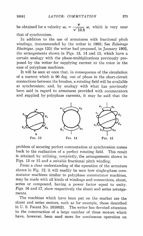
windings, (recommended by the writer in 1905; See EclairageElectrique, page 125) the writer had proposed, in January 1903,the arrangements shown in Figs. 13, 14 and 15, which have acertain analogy with the phase-multiplications previously pro-posed by the writer for supplying current to the rotor in thecase of polyphase machines.
It will be seen at once that, in consequence of the circulationof a current which is 90 deg. out of phase in the short-circuitconnections between the brushes, a rotating field will be availableat synchronism; and, by analogy with what has previouslybeen said in regard to armatures provided with commutatorsand supplied by polyphase currents, it may be said that the
FIG. 13 FIG. 14 FIG. 15
problem of securing perfect commutation at synchronism comesback to the realization of a perfect rotating field. This resultis attained by utilizing, conjointly, the arrangements shown inFigs. 13 or 15 and a suitable fractional pitch winding.
F?rom a clear understanding of the operation of the armatureshown in Fig. 12, it will readily be seen how single-phase com-mutator machines similar to polyphase commutator machines,may be made with all kinds of windings and connections, shunt,series or compound, having a power factor equal to unity.iFigs. 16 and 17, show respectively the shunt and series arrange-ments.The machines which have been put on the market are the
shunt and series motors, such as for example, those describedin U. S. Patent No. 1016021. The writer has devoted attentionto the construction of a large number of these motors whichhave, however, been used more for continuous operation on
376 LA TOUR: COMMUTATION [Feb. 16
ordinary power circuits than for electric traction by single-phase current.
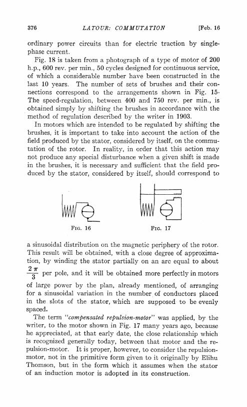
Fig. 18 is taken from a photograph of a type of motor of 200h.p., 600 rev. per min., 50 cycles designed for continuous service,of which a considerable number have been constructed in thelast 10 years. The number of sets of brushes and their con-nections correspond to the arrangements shown in Fig. 15.The speed-regulation, between 400 and 750 rev. per min., isobtained simply by shifting the brushes in accordance with themethod of regulation described by the writer in 1903.
In motors which are intended to be regulated by shifting thebrushes, it is important to take into account the action of thefield produced by the stator, considered by itself, on the commu-tation of the rotor. In reality, in order that this action maynot produce any special disturbance when a given shift is madein the brushes, it is necessary and sufficient that the field pro-duced by the stator, considered by itself, should correspond to
FIG. 16 FIG. 17
a sinusoidal distribution on the magnetic periphery of the rotor.This result will be obtained, with a close degree of approxima-tion, by winding the stator partially on an arc equal to about2 r per pole, and it will be obtained more perfectly in motors
of large power by the plan, already mentioned, of arrangingfor a sinusoidal variation in the number of conductors placedin the slots of the stator, which are supposed to be evenlyspaced.The term "compensated repulsion-motor" was applied, by the
writer, to the motor shown in Fig. 17 many years ago, becausehe appreciated, at that early date, the close relationship whichis recognized generally today, between that motor and the re-pulsion-motor. It is proper, however, to consider the repulsion-motor, not in the primitive form given to it originally by ElihuThomson, but in the form which it assumes when the statorof an induction motor is adopted in its construction.
PLATE Vil.A. I. E. E.
VOL. XXXVII, 1918
0
14
-4
C1~~~~~~~~~~~~~~~~~~~~~
001-4
o~~~~~~~~~R~~~~~~~~~~~~;
1918] LA TOUR: COMMUTATION 377
The writer published his first theory of this form of repulsion-motor (see E. T. Z., June 11, 1903) before entering upon adetailed consideration of the compensated repulsion-motor. Thegreat peculiarity of the repulsion-motor when constructed withthe stator of an induction motor, is that a rotating field isproduced in that type of motor at synchronism, and that, atthat speed, the existence of that rotating field insures perfectcommutation. Before the publication, by the writer, of thefundamental theory, the only theory known was that of Stein-metz, which related to the repulsion-motor constructed withpole-pieces, and which consequently did not foresee the forma-tion of a rotating field and its consequences.
Of course, in order to obtain a perfect rotating field, it isnecessary to resort to the precautions which have just beenmentioned and discussed with respect to the compensated repul-sion- motor, namely, the rotor must have fractional pitch wind-ing and multiple short circuits; and the stator must have asinusoidal distribution of conductors.With regard to the motors having a high power-factor, shown
diagrammatically in Fig. 16, it is the shunt type of motor whichhas found most numerous commercial applications. The supplyof current to the rotor is effected, as already indicated in thecase of polyphase motors, either by a transformer or by anauxiliary winding placed on the stator.The detailed theory of this motor, published ten years ago by
the writer, (see Eclairage Electrique, January 1907, page 8)showed the great importance of flux distribution in that motorfrom the point of view of the torque produced, and also showedthat great overload capacity may be given to this motor.
It is interesting to note that this motor can be constructedfor very large powers with a commutator of very small dimen-sions when a heavy torque is not necessary in starting. Ifproper care has been taken in the design of the winding and inthe distribution of the brushes on the commutator, this motorcan operate at full load with extraordinary commutation. Thedrawback of a commutator is therefore, not as serious as mightbe supposed. On the other hand this motor has in its favorthe following advantages:
1. It can supply a reactive current to the electrical mains,2. Its overload capacity is much higher than that of the in-
duction motor.These advantages are sufficiently real, in the opinion of the
378 LATOUR: COMMUTATION [Feb. 16
writer, to warrant his considering quite practicable an electri-cal traction system based upon the use of single-phase currentof 50 or 60 cycles involving the conversion, on thelocomotiveitself, of the single-phase current into a continous current by amotor-generator set comprising a commutating shunt motor.By employing high speeds, these motor-generator sets can bemade quite light.The fact that regulating resistances and all accessory appa-
ratus are eliminated, and also the possibility of recovering energyat all speeds without any special complication, render thissystem more attractive than it might seem to be at first glance.The writer expects to return to this subject later with com-parative figures.With regard to electric traction by the direct use of single-
phase alternating current, although that system does not appear
e r
FIG. 19 FIG. 20
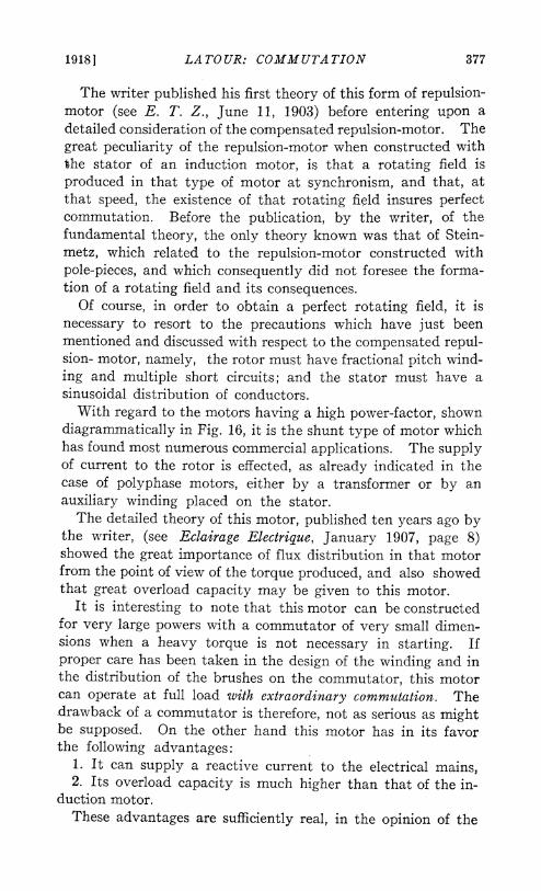
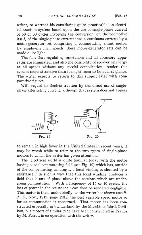
to remain in high favor in the United States in recent years, itmay be worth while to refer to the two types of single-phasemotors to which the writer has given attention.The electrical world is quite familiar today with the motor
having a local commutating field (see Fig. 19) which has, outsideof the compensating winding c, a local winding e, shunted by aresistance r in such a way that this local winding produces afield that is out of phase above the sections which are under-going commutation. With a frequency of 15 or 16 cycles, theloss of power in the resistance r can then be rendered negligible.This motor is then, undoubtedly, as the writer has shown (see E.T. Z., Nov., 1912, page 1231) the best variable speed motor sofar as commutation is concerned. That motor has been con-structed especially in Switzerland by the Maschinenfabrik Oerli-kon, but motors of similar type have been constructed in Franceby M. Perret, in co-operation with the writer.
19181 LA TOUR: COMMUTATION 379
At a frequency of 25 cycles the introduction of the resistance rwould occasion too high a loss of energy, and the writer thengives preference to a motor which is designated by him the"elliptical field series motor," which is represented diagrammatic-ally in Fig. 20 (see also U. S. Patent 841257 and E. T. Z., 1906,volume 27, page 89). As the diagram indicates, the arrange-ment of connections of that motor implies the presence of atransformer T for supplying current to the motor. The de-phased commutating field is produced by the compensatingwinding itself. The resemblance of this motor with the motorconstructed by Mr. Alexanderson in America, will be readilynoted.
Subsequently to the introduction of this type of motor by thewriter in German technical publications, under the name of"Series-motor with Elliptical Field" (see article by the writer inE. T. Z. 1906, volume 27 page 89) German authors gave it thename of "doppel gepeist" ("double fed"), which seems to have
FIG. 23
become more or less current to-day in America. Nevertheless,it seems preferable to the writer to retain in the designation of themotor, the peculiarity which gives it good commutation insomuchas good commutation is the matter of utmost importance incommutating motors. It seems proper to the writer also thatthis designation should suggest a trace of the difficulty whichinspired the very conception of the motor itself.
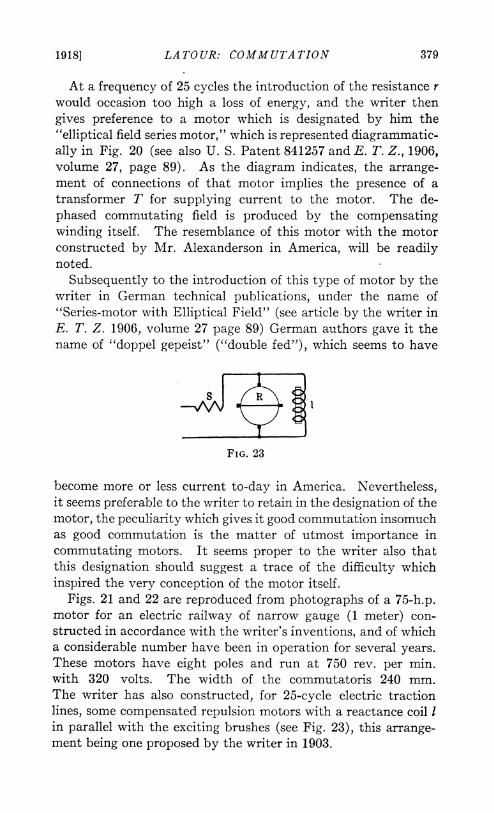
Figs. 21 and 22 are reproduced from photographs of a 75-h.p.motor for an electric railway of narrow gauge (1 meter) con-structed in accordance with the writer's inventions, and of whicha considerable number have been in operation for several years.These motors have eight poles and run at 750 rev. per min.with 320 volts. The width of the commutatoris 240 mm.The writer has also constructed, for 25-cycle electric tractionlines, some compensated repulsion motors with a reactance coil Iin parallel with the exciting brushes (see Fig. 23), this arrange-ment being one proposed by the writer in 1903.
380 LATOUR: COMMUTATION [Feb. 16
The reactance coil is useful at the time of starting because itallows a greater excess of current in the induced circuit (stator)without requiring an excessive strength of inducing field (rotor),which latter is shunted at low speed. The result is that, auto-matically, as foreseen by the writer, there is, at the time ofstarting, a low flux with a heavy current, so that the commutatorsuffers less. Moreover, the reactance coil limits the hyper-synchronous speed of the motor, which is always to be feared fromthe point of view of commutation. The limiting hyper-synchron-ous speed is exactly that for which the reactance of the coil I comesinto resonance with the capacitance of the rotor. The adjust-ments are made in such a way that this hyper-synchronous speedcannot exceed a rise of 50 per cent above synchronism. Motorsof this type, which have been in practical operation about 10years under particularly severe conditions, have given entiresatisfaction.
It is well known that the drawback of a single-phase tractionmotor designed for 25 cycles, is the necessity of a very large com-mutator, owing to the high starting torque required. The volumeof the commutator is indeed directly proportional to the frequencyof current used, and to the starting torque required (see thewriter's article in the Electrical World, Dec. 3, 1904). The com-mutation may, however, be very good at normal load, and it isthe belief of the writer that opinions have been much too pes-simistic on that point. At the same time, it is not our intentionat this time to defend single-phase traction, which was onlyan incidental object of this paper.
19181 DISCUSSION AT NEW YORK 381
DISCUSSION ON "THE POLYPHASE SHUNT MOTOR (ALTES),"THE SECOMoR-A KINEMATIC DEVICE WHICH IMITATESTHE PERFORMANCE OF A SERIES WOUND POLYPHASE COM-MUTATOR MOTOR" (KARAPETOFF) AND "COMMUTATION INALTERNATING-CURRENT MACHINERY" (LATOUR). NEWYORK FEBRUARY 16, 1918.
A. M. Gray: It might be worth while to spend a few minutesin showing how Prof. Karapetoff's diagram is derived.The a-c. series commutator motor consists essentially of
an induction motor stator and a d-c. armature supplied, inthe case of an n-phase machine with n sets of brushes perpair of poles. These brushes make the armature equivalent toa stationary n-phase armature, because in any one phase, asone coil leaves the coil group another moves in to take its place.Since the stator and rotor are connected in series, two revolvingfields are produced, which rotate at synchronous speed nomatter what the actual speed of the rotor may be. The con-nections are such that these fields rotate in the same directionand a torque is produced whose value depends on the strengthsof the fields and on the distance between them. If the brushesare moved backwards against the direction of motion of thefields the torque will tend to make the armature rotate in thesame direction as the fields.
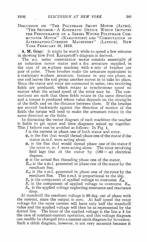
In discussing the vector diagram of such machines the teacheris liable to get space and time diagrams mixed up together.This I believe can be avoided as follows: In Fig. 1.
1 is the current in phase one of both stator and rotor.4jb is the flux that would thread phase one of the stator if the
stator m.m.f. were acting alone.br is the flux that would thread phase one of the stator ifthe rotor m. m. f. were acting alone. The rotor revolvingfield lags that of the stator by (180 - a) electricaldegrees.
4 is the actual flux threading phase one of the stator.Es b iS the e.m.f. generated in phase one of the stator by theresultant flux.
E,t is the e.m.f. generated in phase one of the rotor by theresultant flux. This e.m.f. is proportional to the slip.
E8 is the component of applied voltage to overcome E,b.Er is the component of applied voltage to overcome ETb.Ea is the applied voltage neglecting resistance and reactance
drop.At standstill the resultant voltage is 90 deg. out of phase with
the current, since the output is zero. At half speed the rotorvoltage for the same current will have only half the standstillvalue and the applied voltage will then be as represented by thedotted line. The locus of the applied voltage is the line a b forthe case of constant-current operation, and this voltage diagramcan readily be changed into a current circle diagram by inversion.Such a circle diagram, however, is not very accurate because it
382 COMMUTATION [Feb. 16
does not take account of saturation and change in the rotorreactance. Because of this difficulty Prof. Karapetoff has sug-gested that the "Secomor", which is nothing more or less thanan adjustable voltage diagram, be used. Further discussion ofthis diagram would be out of place because the various possi-
b
Sych. E Os'
/2 ~PPeE
Standstill Ea X
Er EsbFIG. 1
bilities have already been pointed out in Prof. Karapetoff'spaper.Paul M. Lincoln: Mr. Latour proposes for trunk-line elec-
trification to use a single-phase motor upon the locomotivedriving a direct-current generator, which in turn will drive thelocomotive. It seems to me if that is a proposition whichcomes from so distinguished a man as Mr. Latour, it is one whichdeserves a considerable amount of attention from those who arestudying this question of the electrification of railroads.
19181 DISCUSSION AT NEW YORK 383
Charles F. Scott: I was struck with one of Prof. Karapetoff'sfirst sentences in which he says: "A combination of movableand adjustable bars which can be set to represent a vector dia-gram." What is a vector diagram? I would say that a vectordiagram is itself a representation of certain physical things, andthose physical things are the coils on an armature. If you takethe simplest form of an alternator, one having two poles and asimple diametral coil on a rotating armature, and look at theend of the machine, you see a straight line which is the end of acoil which produces a complete cycle during a revolution. Theangular position of the coil at a given time- determines itsrelation to the field poles, and therefore represents the phasewhich the coil is producing. A second coil, placed at rightangles gives an electromotive force 90 deg. from the first. Twolines at right angles, representing the physical angle betweenthese coils, can be used in a diagram as a picture of the coils andare called vectors.Go a step further, and make the length of a line correspond to
the number of turns, and it follows that a straight line of properlength and direction (a vector) is simply a physical picture of acoil with a certain number of turns. If two coils are connectedin series physically, we simply on the diagram join the lines inseries with their proper angular relations and get the resultant.The vector diagram is a simple representation of the physicalstructure, as to angular position, number of turns and order ofconnection of the coils. Prof. Karapetoff has reversed the order,and starting from the vector diagram obtains a physical rep-resentation by an admirable structure using adjustable bars.
It has been suggested that I take part in the discussion of thesingle-phase motor as a factor in the railway situation and ithas been pointed out now that the single-phase motor has notpreempted the whole field of railway work, as some thought itmight a number of years ago.
It is easy to look back and comment from the present stand-point. What was the standpoint in 1902, some fifteen years agowhen the single-phase motor for railway work was first presented?That subject, by the way, was presented at a meeting of theInstitute in the fall of that year. The previous session of theInstitute had been a convention at Great Barrington, at whichrailway motors were considered. There were several railwaypapers and many pages of discussion. The discussion lookedforward to the future of railway work, and the great cry was fora higher transmission voltage, and the great lament was that there-was no way known to use such a voltage. Four or five differentschemes were presented and discussed, but they were discussedmerely as schemes, and nothing seemed practicable.Then the single-phase system was presented, it was adopted
and used on a number of roads, as the one thing which was com-mercially practicable under a good many of the situationswhere 600-volt direct-current apparatus was inapplicable.
384 COMMUTATION [Feb. 16
But great developments have occurred since that time, whichwas fifteen years ago, and that is in railway history a very longtime. If you go back another fifteen years, that is, go backfrom 1902 to 1887, you will find the electric motor was beginningto prove itself a success. I refer to the Richmond road. Thiswhole development has taken place within thirty years. Andthen came the single-phase system fifteen years ago, when theoperation of railways at high voltage was begun, and in thattime have come other developments, the combination of thesingle-phase transmission and polyphase motors, and the direct-current motor has gone up to voltages which fifteen years agowere presumed to be impossible.
Consequently, in the light of development, the single-phasemotor had its place, and is still occupying a place. The single-phase system is doing some of the heaviest work, and while itwould be desirable to have one universal system in use every-where, who knows what that system should be? If it had beenadopted fifteen years ago, it would have been one thing; if itwere to be chosen today, it might be the same thing or somethingelse and possibly in five or fifteen years from now there may beother things which would make the effect of any final decisionat this time a mistake.W. C. Korthals Altes: I think Mr. Latour is pointing in
absolutely the right direction so far as polyphase series motorsare concerned. He has distinguished himself by opposing themultiplication of phases, and also he has brought out the pointabout the squirrel-cage commutation.We have tried such motors, having squirrel-cage commutators,
and we can say they operate very satisfactorily. I could showa d-c. motor and an a-c. motor and a three-phase a-c. motor, andput these motors through their stunts. You would see that thed-c. motor will flash and the a-c. motor will not show any spark-ing, so that the experiments made some years ago would notagree with the results which are obtained. Different conclu-sions have been reached. There is nothing remarkable aboutthat, because we know the a-c. motor being completely compen-sated, and the current at all times passing through zero, is in abetter condition for commutation. The unfortunate thing iswe started out with single-phase motors and not three-phasemotors. The three-phase motor is very su-perior to the single-phase motor, because we have there, as Mr. Latour has pointedout in a very interesting manner, the real sine distribution ofthe flux, and in all the work we have done we have always triedfor that because with those conditions we get satisfactory com-mutation.Another motor, which Mr. Latour has referred to, is what he
calls the squirrel-cage commutation motor. I must take excep-tion to some features of Mr. Latour's paper with respect to that.In Fig. 7 the author represents a two-pole three-phase commuta-tor motor having six slots and an ordinary drum-wound arma-ture.
1918] DISCUSSION AT NEW YORK 385
Now, if there is a brush which short-circuits two commutatorbars, there will be a short-circuited coil in two slots. If thereare twelve commutator bars, a brush spanning two commutatorbars, no matter in what position the armature is, there will atall times be at least a slot and coil which are short-circuited.You know if you take a direct-current motor with anotherwinding in the links of the field winding, and you suddenlybreak the field, you will not have a series circuit, because thestored energy of the magnetic field would be equal in the circuit,which is formed.On a single-phase machine, when the coil passes under the
brush, we have to reverse the currenlt. If we have a three-phasearmature, we have to pass that current through 120 deg. Yousee immediately the inductive circuit by shifting through120 deg. is much reduced on the 6-phase; on the 9-phase it isreduced to 40 deg. By shifting the current through a smallernumber of degrees we get a more satisfactory operation, andthat is the important thing Mr. Latour brought out. We getideal current commutation.We have only built a few motors so far, and I can mention as
an example, a 60-cycle, 12-pole, 250-h. p. motor, and it cannotbe made to spark. That is the very important work which Mr.Latour has done on three-phase motors.As far as the single-phase motor is concerned, he has also
distinguished himself by his so-called Latour connections. Wehave built quite a few motors with Latour connections, or some-thing very similar. The two-circuit repulsion motor is notentirely new, but Mr. Latour has combined this with rotorexcitation. The single-phase motor, built with many rheostats,as proposed by Mr. Latour, having, moreover, a series trans-former to limit the possible voltage which can appear at thebrushes, is an ideal motor from a commutation standpoint. Butwhat Mr. Latour has said, in regard to the possibility of buildinglarge single-phase motors of high frequency, is absolutely true,although it would be practicable to build them three phase, andin that case they would be less sensitive. That it is absolutelyimpossible to build large single-phase motors of the commercialtype of repulsion motors built in this country is not true. Wehave no demand for large single-phase motors and so havebuilt none, but we could at any time build the largest. Thereis no question that motors can be built which operate satisfac-torily but whether the motor works well in connection with therailway telephones and transmission and distribution systems,sub-stations, etc., is entirely a railway problem.
Referring to the characteristics of the series motor Prof.Karapetoff has succeeded in taking into account the saturationof the motor itself, which is most important, but of equal if notgreater importance, is the saturation characteristic of the trans-former.
If we should build a motor in which we had no increase of
386 COMMUTATION [Feb. 16
magnetizing current in the transformer, we would have anabsolutely unstable motor. The motor has a characteristicwhich is very undesirable and the only way of improving thatcharacteristic is to have a transformer which saturates and givesincreased stability. I have attempted to accomplish this buthave never succeeded because I did not know how to saturate atransformer and obtain that characteristic. If Prof. Karapetoffcan show us the way he will do a great thing for the technicalengineer.H. M. Hobart: Some fifteen years ago the designers of
electric motors were filled with enthusiasm to do their best toimprove the single-phase motor. They entertained probablytoo optimistic an opinion of the possibilities of single-phasemotors when applied to railway work. Wholly unintentionallythey delayed the progress of railway electrification by perhapsmany years. I speak of this, because I think Mr. Altes is wrongin, thinking it his function to simply design motors when therailway engineers come to him and ask for them. He knowsbetter than most engineers the difficulties with which he con-tends in the design of such- motors. Notwithstanding thesedifficulties, by the skill which he has acquired, he designs excel-lent three-phase commutating motors for certain work. Heknows they are heavy, he knows they are more expensive, buthe does his best, and when the practical application is of such anature that, notwithstanding the increased cost and weight,this polyphase motor is the right thing, he gives them an excel-lent motor. That is entirely right and proper, but if instead ofmerely designing the motor when he is asked to do so, he were tobe less modest, and go to the railway engineers and say-"Lookhere, there are enormous difficulties in this kind of motor anddisadvantages that you may not realize. I see that you arebeginning to entertain the thought that they will be suitable forrailway work, and with all due deference to your experience inrailway work, I will counsel you that they have all sorts of faults.We will, however, do our best to overcome these faults." Werehe to do this, he would be serving a useful purpose and helpingprogress in railway electrification. I felt quite strongly thatthat was a point that ought to be made, when I heard Mr. Altesstate that his conception of his duty was merely to design whathe was asked to design.
If we look back fifteen years, I think we can see that if thosewho had become so enthusiastic over single-phase railway motorshad endeavored to curb their enthusiasm, and to be more frankregarding the difficulties, the situation would not have got outof hand to the extent of wasting so many million dollars as weknow now were wasted. This assessment of the waste is notan uncorroborated assertion coming from myself alone. Wenow all realize that. The admission is again today implied quitedistinctly in Latour's paper, where we can read between thelines that he would not advocate single-phase equipment of the
1918] DISCUSSION AT: NEW YORK 387
rolling stock. He would put in a motor generator and use d-c.motors. Mr. Murray some years ago came out with the sameadmission when he said that by putting a rectifier on his loco-motive he would be able to rate up the motors to one and halftimes the load of which they were capable when operatingdirectly from a single-phase circuit.
Furthermore, I do not think those who did so much in tryingto develop the single-phase railway system should feel so dis-heartened, as I gather they are inclined to feel from some of theremarks which have been made. They did admirably anddeveloped a really substantial working system in several in-stances. Large values in train mileage have been performed bylocomotives and cars operated by single-phase motors, andconsidering the enormous difficulty with which these single-phase advocates weref contending, they did better than couldreasonably have been supposed possible. They only producedthese relatively satisfactory results by dint of the ablest sort ofengineering.
B. A. Behrend: Mr. Latour refers most suggestively to thetransformation, in the locomotive itself, of single-phase currentinto direct current. In the powerful electric engines-of the Nor-folk & Western Railway, single-phase current is being trans-formed into three-phase current. Thus we note broadly thetendency to utilize single-phase alternating current-on the trolleywith motors of a type other than single-phase. There are manyin this audience here to-day who, sixteen years ago, discussedwith great enthusiasm the promise of the application of single-phase currents to railroad work, while others, like Mr. Hobartand myself, showed greater skepticism. These remarks aremade, not to deprecate the great credit due those who developedthe single-phase railway system, but to point out that theremust be reached an agreement among the engineers of thecountry in regard to the system of electrification, if the greatwork of operating the trunk lines of the country electrically isto be accomplished with the least opposition and the maximumamount of co-operation.
It is time that such a decision be reached. Almost twentyyears ago the turbo-generator began its evolution. Numeroustypes were developed which have now all been superseded bythe radial-slot type, upon which those who started with this typelook back with satisfaction. There is likely to be the same resultin the field of electrification. It would seem as though it behoovedthe engineers of the country to understand the issue of commonaim and to unite upon one system after weighing with care andunderstanding the advantages and disadvantages of the availablemethods of electric propulsion. Thus the directors of ourgreat transportation system can be met by a united front,advocating for each problem in electrification as it may come upthe same system, thus infusing confidence into the great problembefore us, viz., that of bringing the railroad system of our
388 COMMUTATION [Feb. 16
country up to the utmost demands that may at any time beplaced upon it.William B. Jackson: In considering these papers I naturally
think of the large practical suggestion that is made by them,which has been referred to by several of the speakers, namely,the work that must still be done, in developing the most effectiveand satisfactory motor for operation upon a-c. systems.
It has been stated that we are considering merely a rail-road problem, that is, the electrification of our trunk linerailways. We are doing this and are doing considerablymore, for the reason that we need very little vision to seein the not distant future a comprehensive a-c. electric systemcovering almost every square mile of the now populated territoryof the United States. This means the development and regularuse of electric current in ways that are now unusual. It meansthat we need to arrive at the most efficient and most effectivea-c. motor for general use, having good speed-regulation charac-teristics.There is another phase of the situation which is illustrative of
the need for simplicity with flexibility in a-c. motors; the ques-tion in the equipment of our large power stations, whether tohave alternating current alone for operating auxiliaries or directcurrent alone, or must we have two systems throughout thepower station; one of which to serve constant-current motorsand the other to serve variable-speed motors? This seems avery unnecessary situation when we come to the final analysis,since if we need motors operating at both constant speed andvariable speeds, motors should and will be developed so as toeliminate even a question as to the installation of a dual system.
It thus seems to me that the problem set out by these papersis a very broad one, taking in the railways as one of the importantfeatures, but also involving the general distribution and utiliza-tion of power throughout the United States to an extent to whichit has not yet been developed but such as our vision readilyshows us must be the case in the not distant future.
V. Karapetoff: Prof. Gray combines the time diagram of thee.m.fs. with the space diagram of m.m.fs., and this is exactlywhat I have done in both the device and Fig. 7. Fig. 6, showsonly the spce diagram, and then I incorporate that diagram intoa figure showing the e.m.f. diagram, and I point out that thestator bar is used both for currents and voltages, which isequivalent to saying it is used for the space diagram and timediagram as well. If the time diagram is in the usual counter-clockwise representation, then the space diagram comes inthe clockwise representation. While I am not sure that this isalways so, I was careful to point the clockwise representation inFig. 6 and counter-clockwise for the time diagram in Fig. 7.
I am glad to know that at least one manufacturing companyin this country has undertaken to further develop the Schrage mo-tor, to which Mr. Altes makes a detailed reference. When I first
1918] DISCUSSION AT NEW YORK 389
saw a description of the Schrage motor I was full of hope that thatwas really the most satisfactory coming type. I could see it, fromthe principle incorporated in the motor. It is really a combina-tion of an induction motor with the commutator motor incor-porated in it, only for the fraction of the output differing fromsynchronous speed. For that part of the output which correspondsto the synchronous speed we need no commutator, and the ordinaryinduction motor is satisfactory. What you need is the countere.m.f. of the proper frequency to be applied at the terminals ofthe rotor to force the induction motor to operate without 12 Rlosses in the resistance at any designed speed, either above orbelow synchronism, and that is just what the additional circuit inthe Scharge motor does.W. C. K. Altes: I find that I did not express myself properly
when I spoke about single-phase motors. What I meant to saywas that the single-phase motor has low starting torque referringto the generator set, referred to by Mr. Latour. I will leaveit to the railway engineers to judge if it is a practical scheme.We would like to provide a motor which will make it unneces-
sary in many cases to obtain direct-current, to change fromalternating-current to direct-current. It has great advantagein simplicity and efficiency, the only reason why we do proposeto build two kinds of motors, a series motor and a shunt motor,instead of building one shunt motor, is that the series motor isso much cheaper than the shunt motor. In cases where wedo not require the shunt characteristics, as with fans and pumpsand similar applications, we use a series motor, and in caseswhere we do require the shunt-motor characteristic, as on tools,we will have to use the shunt motor.


