Embed Size (px)
Citation preview

I
pnoscppctti
dSCaeeibpmbepssmyflh�tec
p
J
Downloa
Daniel Sequera
Ajay K. Agrawal
Department of Mechanical Engineering,The University of Alabama,
Tuscaloosa, AL 35487
Scott K. Spear
Daniel T. Daly
Alabama Institute for Manufacturing Excellence,The University of Alabama,
Tuscaloosa, AL 35487
Combustion Performance ofLiquid Biofuels in aSwirl-Stabilized BurnerFuels produced from renewable sources offer an economically viable pathway to curtailemissions of greenhouse gases. Two such liquid fuels in common usage are biodiesel andethanol derived from soybean, corn, or other food crops. In recent years, significant efforthas been devoted to identify alternate feedstock sources and conversion techniques todiversify the biofuels portfolio. In this study, we have measured emissions from flames ofdiesel, biodiesel, emulsified bio-oil, and diesel-biodiesel blends. Experiments are con-ducted in an atmospheric pressure burner with an air-atomized injector and swirlingprimary air around it to replicate typical features of a gas turbine combustor. Experi-ments were conducted for fixed air and fuel flow rates, while the airflow split between theinjector and the coflow swirler was varied. Results show a significant reduction in emis-sions as the fraction of total air fed into the atomizer is increased. Blue flames, reminis-cent of premixed combustion, and low emissions of nitric oxides and carbon monoxidewere observed for all fuel blends. In general, the emissions from biofuel flames werecomparable or lower than those from diesel flames. �DOI: 10.1115/1.2836747�
ntroductionRenewable fuels produced from homegrown biomass are ex-
ected to constitute a greater portion of the fuel feedstock in theear to midterm. Increased production and use of biofuels will notnly benefit the environment but also contribute to the energyecurity and economic growth. Ideally, the CO2 emitted from theombustion of biofuels is recycled through the environment toroduce biomass or the feedstock for biofuels. A recent studyrojects that with relatively modest changes in land use and agri-ultural and forestry practices, an annual supply of 1.36�109 dryons of biomass could be available for large-scale biofuel produc-ion in the United States by the mid-21st century, while still meet-ng demands for forestry products, food, and fiber �1�.
Biomass can be converted into solid, gaseous, or liquid fuelepending on the conversion processes and economic factors.everal current biomass technologies are reviewed in Ref. �2�.o-firing of biomass with coal is among the most cost effectivepproaches �3�. Since combustion of solid fuels results in highermissions �e.g., soot and nitric oxides or NOx�, liquid and/or gas-ous fuels produced from biomass are likely to become increas-ngly prevalent in the near term. Biomass can be gasified in air-lown or oxygen-blown gasifiers, followed by the cleanup of theroduct gas �known as synthetic gas or syngas� containing carbononoxide �CO� and hydrogen �H2� as the primary reactants. The
iomass syngas can serve as the fuel to generate power in a high-fficiency combined cycle power plant. The combined cycleower plant integrated with the gasification system can operateynergistically with biomass and/or coal as feedstocks, since theyngas produced from gasification of either of these sources �bio-ass or coal� contains the same reactive ingredients. In recent
ears, considerable interest has been generated to develop fuel-exible power systems using advanced gas turbines to achieveigh efficiency with ultralow emissions �4�. Lean premixedLPM� combustion of hydrogen-rich syngas can cause autoigni-ion, flame flashback, and/or dynamic instabilities, which must beliminated to ensure reliable operation, structural rigidity, and ac-eptable NOx and CO emissions �5–7�.
In contrast to biomass syngas requiring large scale operation,
Manuscript received June 20, 2007; final manuscript received June 22, 2007;
ublished online April 2, 2008. Review conducted by Dilip R. Ballal.ournal of Engineering for Gas Turbines and PowerCopyright © 20
ded 02 Apr 2008 to 130.160.61.179. Redistribution subject to ASM
liquid biofuels offer greater flexibility since the fuel can be trans-ported easily. Liquid biofuels offer the prospects of distributedgeneration, whereby the power is produced closer to the sourcewithout hauling the bulky biomass to a distant central location. Atpresent, ethanol and biodiesel are the two commonly used liquidbiofuels. However, the feedstocks for these fuels compete with thefood-chain crops. For example, virtually all of the ethanol pro-duced in the US comes from corn and biodiesel is produced by thetransesterification of vegetable oils, such as soybean oil. Thus, along-term strategy will require liquid fuels from biomass feed-stocks, such as wood and other energy crops that do not interferewith the food chain.
The biomass must undergo gasification or pyrolysis to producethe liquid fuel. Starting with the biomass syngas, the well-knownFischer–Tropsch �FT� process can be used to produce liquid bio-fuels of desired composition and physical characteristics. Al-though the FT process is attractive to produce liquid biofuels forvehicular transportation �8�, the fuels produced by pyrolysis ofbiomass can be economic alternatives for power generation appli-cations. Pyrolysis is the thermal destruction of organic material inthe absence of or limited supply of oxygen �3�. In fast pyrolysis,the thermal decomposition occurs at moderate temperatures with ahigh heat transfer rate to the biomass particles and a short hot-vapor residence time in the reaction zone �9–11�. The main prod-uct is the pyrolysis oil, also known as bio-oil, which is usually adark-brown free-flowing liquid with a distinctive smoky odor.Bio-oils have been successfully tested in diesel engines and gasturbines �12–15�, although modifications to the fuel handling sys-tem can incur unacceptable financial cost. Thus, a near-term strat-egy would be to emulsify bio-oil using fuels compatible with thefuel handling equipment. Ikura et al. �16� produced bio-oil emul-sified with the diesel fuel. The cost for producing emulsions withzero stratification increased with increasing amounts of bio-oil inthe diesel fuel.
The literature review shows few studies on combustion perfor-mance of liquid biofuels for gas turbine applications. Thus, theprimary objective of this study is to isolate the effects of fuelcomposition and fluid dynamics on emissions from different liq-uid fuels in an atmospheric pressure burner replicating typicalfeatures of a gas turbine combustor. The burner utilized a com-mercial twin-fluid injector with primary air swirling around the
injector. The fuels include diesel, biodiesel, emulsified bio-oil, andMAY 2008, Vol. 130 / 032810-108 by ASME
E license or copyright; see http://www.asme.org/terms/Terms_Use.cfm
dbdifetaaff
F
bscAsoEtmas
aoTkb�ao�Sbas
MADc
a
b
c
F
DBBSS
0
Downloa
iesel-biodiesel blends. Bio-oil emulsions were produced usinglends of biodiesel and diesel to increase the amount of biomasserived fuel in the final product. The emulsified bio-oil producedn this manner is expected to require minimal modifications to theuel handling system. For fixed volume flow rates of fuel and air,xperiments were conducted by varying the airflow split betweenhe injector and coflow swirler. Results include visual flame im-ges, and axial and radial profiles of NOx and CO concentrationst different operating conditions. In the following sections, theuel preparation steps and experimental setup details are outlinedollowed by results and discussions.
uel PreparationAs mentioned above, the fuels in this study included diesel,
iodiesel, emulsified bio-oil, and diesel-biodiesel blends. The die-el fuel used was of a commercial grade �No. 2 diesel fuel� pur-hased from a local filling station. The biodiesel was supplied bylabama Biodiesel Corporation �Moundville, AL� and it was a
oybean oil methyl ester �SME�. Pyrolysis oil, also known as bio-il �from hardwood�, was provided by the National Renewablenergy Laboratory �NREL, Boulder, CO�. It was a hot-vapor fil-
ered bio-oil with very low ash content. The bio-oil was approxi-ately one-year old, and was not phase separated or treated with
ny viscosity reducing agents. The NREL bio-oil composition isummarized in Table 1.
The emulsified bio-oil was formulated by mixing diesel, bio-oil,nd “surfactants.” The surfactants used in this study was a blendf biodiesel, 2-ethyl-1-hexanol �an alcohol�, and n-octylamine.he latter two chemicals were purchased from Aldrich �Milwau-ee, WI�. The emulsified fuel was produced by mixing diesel,iodiesel, bio-oil, alcohol, and amine using a high shear10,000 rpm� Oster blender �Boca Raton, FL�. Mixing was donet room temperature and pressure until an emulsified liquid wasbtained in about 2 min. In this study, two types of biodieselSME and 90% soybean oil ethyl ester hereafter referred to asEE� were mixed with diesel by gentle stirring to form diesel-iodiesel fuel blends. These blends are completely miscible overll concentration ranges. Table 2 summarizes the fuels used in thistudy.
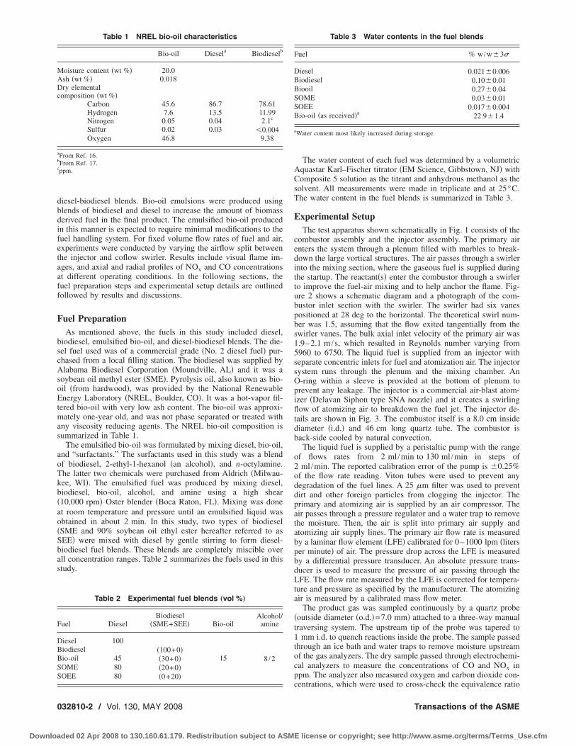
Table 1 NREL bio-oil characteristics
Bio-oil Diesela Biodieselb
oisture content �wt %� 20.0sh �wt %� 0.018ry elemental
omposition �wt %�Carbon 45.6 86.7 78.61Hydrogen 7.6 13.5 11.99Nitrogen 0.05 0.04 2.1c
Sulfur 0.02 0.03 �0.004Oxygen 46.8 9.38
From Ref. 16.From Ref. 17.ppm.
Table 2 Experimental fuel blends „vol %…
uel DieselBiodiesel
�SME+SEE� Bio-oilAlcohol/
amine
iesel 100iodiesel �100+0�io-oil 45 �30+0� 15 8 /2OME 80 �20+0�OEE 80 �0+20�
32810-2 / Vol. 130, MAY 2008
ded 02 Apr 2008 to 130.160.61.179. Redistribution subject to ASM
The water content of each fuel was determined by a volumetricAquastar Karl–Fischer titrator �EM Science, Gibbstown, NJ� withComposite 5 solution as the titrant and anhydrous methanol as thesolvent. All measurements were made in triplicate and at 25°C.The water content in the fuel blends is summarized in Table 3.
Experimental SetupThe test apparatus shown schematically in Fig. 1 consists of the
combustor assembly and the injector assembly. The primary airenters the system through a plenum filled with marbles to break-down the large vortical structures. The air passes through a swirlerinto the mixing section, where the gaseous fuel is supplied duringthe startup. The reactant�s� enter the combustor through a swirlerto improve the fuel-air mixing and to help anchor the flame. Fig-ure 2 shows a schematic diagram and a photograph of the com-bustor inlet section with the swirler. The swirler had six vanespositioned at 28 deg to the horizontal. The theoretical swirl num-ber was 1.5, assuming that the flow exited tangentially from theswirler vanes. The bulk axial inlet velocity of the primary air was1.9–2.1 m /s, which resulted in Reynolds number varying from5960 to 6750. The liquid fuel is supplied from an injector withseparate concentric inlets for fuel and atomization air. The injectorsystem runs through the plenum and the mixing chamber. AnO-ring within a sleeve is provided at the bottom of plenum toprevent any leakage. The injector is a commercial air-blast atom-izer �Delavan Siphon type SNA nozzle� and it creates a swirlingflow of atomizing air to breakdown the fuel jet. The injector de-tails are shown in Fig. 3. The combustor itself is a 8.0 cm insidediameter �i.d.� and 46 cm long quartz tube. The combustor isback-side cooled by natural convection.
The liquid fuel is supplied by a peristaltic pump with the rangeof flows rates from 2 ml /min to 130 ml /min in steps of2 ml /min. The reported calibration error of the pump is �0.25%of the flow rate reading. Viton tubes were used to prevent anydegradation of the fuel lines. A 25 �m filter was used to preventdirt and other foreign particles from clogging the injector. Theprimary and atomizing air is supplied by an air compressor. Theair passes through a pressure regulator and a water trap to removethe moisture. Then, the air is split into primary air supply andatomizing air supply lines. The primary air flow rate is measuredby a laminar flow element �LFE� calibrated for 0–1000 lpm �litersper minute� of air. The pressure drop across the LFE is measuredby a differential pressure transducer. An absolute pressure trans-ducer is used to measure the pressure of air passing through theLFE. The flow rate measured by the LFE is corrected for tempera-ture and pressure as specified by the manufacturer. The atomizingair is measured by a calibrated mass flow meter.
The product gas was sampled continuously by a quartz probe�outside diameter �o.d.�=7.0 mm� attached to a three-way manualtraversing system. The upstream tip of the probe was tapered to1 mm i.d. to quench reactions inside the probe. The sample passedthrough an ice bath and water traps to remove moisture upstreamof the gas analyzers. The dry sample passed through electrochemi-cal analyzers to measure the concentrations of CO and NOx inppm. The analyzer also measured oxygen and carbon dioxide con-
Table 3 Water contents in the fuel blends
Fuel % w /w�3�
Diesel 0.021�0.006Biodiesel 0.10�0.01Biooil 0.27�0.04SOME 0.03�0.01SOEE 0.017�0.004Bio-oil �as received�a 22.9�1.4
aWater content most likely increased during storage.
centrations, which were used to cross-check the equivalence ratio
Transactions of the ASME
E license or copyright; see http://www.asme.org/terms/Terms_Use.cfm

oru
abad
+st
Fm
J
Downloa
btained from the measured fuel and air flow rates. The uncor-ected emission data on dry basis are reported with measurementncertainty of �2 ppm.
The experiment was started by supplying the gaseous methanend then igniting the methane-air reactant mixtures in the com-ustor. Next, the liquid fuel flow rate was gradually increased tottain the desired value, while the methane flow rate was slowlyecreased to zero.
In this study, the volume flow rates of total air �primaryatomizing� and fuel were kept constant, respectively, at 150
tandard lpm and 12 ml /min. It would result in small variations in
ig. 1 Schematic diagram of the experimental setup; all di-ensions are in cm
he amount of heat released since the heating value of fuels is
ournal of Engineering for Gas Turbines and Power
ded 02 Apr 2008 to 130.160.61.179. Redistribution subject to ASM
different. The combustion performance is strongly dependent onthe spray characteristics determined by the atomizing air flow rate.Initial experiments indicated yellow, sooty flames dominated bythe diffusion mode of combustion for atomizing air flow ratesbelow 10% of the total air. Thus, experiments focused on thepremixed combustion mode with strong fuel-air premixingprompted by fine droplets formed with large atomizing air flowrates. Accordingly, the experiments were conducted by varyingthe percentage of the atomizing air �AA� from 15% to 25% of thetotal air. Since the overall air-fuel ratio is constant, the effects ofAA on combustion emissions can be ascertained from thesemeasurements.
Results and Discussion
Visual Flame Images. Direct photographs of flame were takenby a digital camera to obtain qualitative understanding of theflame characteristics. These photographs are reproduced in Fig. 4
Fig. 2 Schematic diagram „top… and photograph of the swirler„bottom… at the combustor inlet plane; all dimensions are in cm
Fig. 3 Injector details
MAY 2008, Vol. 130 / 032810-3
E license or copyright; see http://www.asme.org/terms/Terms_Use.cfm
032810-4 / Vol. 130, MAY 2008
Downloaded 02 Apr 2008 to 130.160.61.179. Redistribution subject to ASM
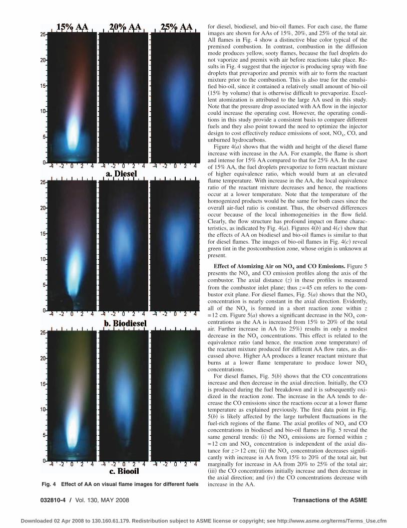
for diesel, biodiesel, and bio-oil flames. For each case, the flameimages are shown for AAs of 15%, 20%, and 25% of the total air.All flames in Fig. 4 show a distinctive blue color typical of thepremixed combustion. In contrast, combustion in the diffusionmode produces yellow, sooty flames, because the fuel droplets donot vaporize and premix with air before reactions take place. Re-sults in Fig. 4 suggest that the injector is producing spray with finedroplets that prevaporize and premix with air to form the reactantmixture prior to the combustion. This is also true for the emulsi-fied bio-oil, since it contained a relatively small amount of bio-oil�15% by volume� that is otherwise difficult to prevaporize. Excel-lent atomization is attributed to the large AA used in this study.Note that the pressure drop associated with AA flow in the injectorcould increase the operating cost. However, the operating condi-tions in this study provide a consistent basis to compare differentfuels and they also point toward the need to optimize the injectordesign to cost effectively reduce emissions of soot, NOx, CO, andunburned hydrocarbons.
Figure 4�a� shows that the width and height of the diesel flameincrease with increase in the AA. For example, the flame is shortand intense for 15% AA compared to that for 25% AA. In the caseof 15% AA, the fuel droplets prevaporize to form reactant mixtureof higher equivalence ratio, which would burn at an elevatedflame temperature. With increase in the AA, the local equivalenceratio of the reactant mixture decreases and hence, the reactionsoccur at a lower temperature. Note that the temperature of thehomogenized products would be the same for both cases since theoverall air-fuel ratio is constant. Thus, the observed differencesoccur because of the local inhomogeneities in the flow field.Clearly, the flow structure has profound impact on flame charac-teristics, as indicated by Fig. 4�a�. Figures 4�b� and 4�c� show thatthe effects of AA on biodiesel and bio-oil flames is similar to thatfor diesel flames. The images of bio-oil flames in Fig. 4�c� revealgreen tint in the postcombustion zone, whose origin is unknown atpresent.
Effect of Atomizing Air on NOx and CO Emissions. Figure 5presents the NOx and CO emission profiles along the axis of thecombustor. The axial distance �z� in these profiles is measuredfrom the combustor inlet plane; thus z=45 cm refers to the com-bustor exit plane. For diesel flames, Fig. 5�a� shows that the NOxconcentration is nearly constant in the axial direction. Evidently,all of the NOx is formed in a short reaction zone within z=12 cm. Figure 5�a� shows a significant decrease in the NOx con-centrations as the AA is increased from 15% to 20% of the totalair. Further increase in AA �to 25%� results in only a modestdecrease in the NOx concentrations. This effect is related to theequivalence ratio �and hence, the reaction zone temperature� ofthe reactant mixture produced for different AA flow rates, as dis-cussed above. Higher AA produces a leaner reactant mixture thatburns at a lower flame temperature to produce lower NOxconcentrations.
For diesel flames, Fig. 5�b� shows that the CO concentrationsincrease and then decrease in the axial direction. Initially, the COis produced during the fuel breakdown and it is subsequently oxi-dized in the reaction zone. The increase in the AA tends to de-crease the CO emissions since the reactions occur at a lower flametemperature as explained previously. The first data point in Fig.5�b� is likely affected by the large turbulent fluctuations in thefuel-rich regions of the flame. The axial profiles of NOx and COconcentrations in biodiesel and bio-oil flames in Fig. 5 reveal thesame general trends: �i� the NOx emissions are formed within z=12 cm and NOx concentration is independent of the axial dis-tance for z�12 cm; �ii� the NOx concentration decreases signifi-cantly with increase in AA from 15% to 20% of the total air, butmarginally for increase in AA from 20% to 25% of the total air;�iii� the CO concentrations initially increase and then decrease inthe axial direction; and �iv� the CO concentrations decrease with
Fig. 4 Effect of AA on visual flame images for different fuels
increase in the AA.Transactions of the ASME
E license or copyright; see http://www.asme.org/terms/Terms_Use.cfm

pfltic
J
Downloa
Emission measurements were also taken at the combustor exitlane to identify unmixedness in the radial direction. For dieselames, Figs. 6�a� and 6�b� show that the NOx and CO concentra-
ions are nearly constant at the combustor exit plane. These resultsndicate that sufficient flow mixing has taken place within the
Fig. 5 Axial profiles of NOx and CO emissionsbiodiesel and †„e… and „f…‡ bio-oil
ombustor to form a homogeneous product gas mixture at the exit
ournal of Engineering for Gas Turbines and Power
ded 02 Apr 2008 to 130.160.61.179. Redistribution subject to ASM
plane. Figures 6�a� and 6�b� show that NOx and CO concentra-tions at the combustor exit plane decrease with increase in the AA.The radial profiles of NOx and CO concentrations at combustorexit plane for biodiesel and bio-oil flames in Fig. 6 show the samegeneral trends: �i� the NOx emissions are constant in the radial
different fuels; †„a… and „b…‡ diesel, †„c… and „d…‡
fordirection; �ii� the NOx concentrations decrease with increase in
MAY 2008, Vol. 130 / 032810-5
E license or copyright; see http://www.asme.org/terms/Terms_Use.cfm

tcbi
wst
0
Downloa
he AA; �iii� the CO concentrations are independent of the radialoordinate except for 15% AA in the bio-oil flame, where a para-olic profile is observed; and �iv� the CO emissions decrease withncrease in AA.
Overall, the results show that the fluid mechanics associatedith the atomization process has significant effect on the flame
tructure and emissions, and that different fuels respond similarly
Fig. 6 Radial profiles of NOx and CO emissionsbiodiesel and †„e… and „f…‡ bio-oil
o the flow-induced effects of the injector. Clearly, emissions are
32810-6 / Vol. 130, MAY 2008
ded 02 Apr 2008 to 130.160.61.179. Redistribution subject to ASM
dependent not only on the fuel properties but also on the flamestructure determined by the flow processes. Next, the fuel effectsare isolated by comparing the NOx and CO emissions for differentfuels using the same volume flow rates of fuel, AA, and total air.
Fuel Effects on NOx and CO Emissions. Figure 7 shows axialprofiles of NOx and CO emissions for different fuels. Profiles in
different Fuels; †„a… and „b…‡ diesel, †„c… and „d…‡
forFigs. 7�e� and 7�f� show that with 25% AA, the NOx emissions are
Transactions of the ASME
E license or copyright; see http://www.asme.org/terms/Terms_Use.cfm

htsen
J
Downloa
ighest for the bio-oil and lowest for the biodiesel. Among thehree remaining fuels �diesel, SOME, and SOEE�, the NOx emis-ions are highest for the diesel fuel. The high NOx emissions withmulsified bio-oil are likely caused by the nitrogen present in the
Fig. 7 Axial Profiles of NOx and CO emissions fand „d…‡ 20% AA, and †„e… and „f…‡ 25% AA
-octylamine used as surfactants. Thus, alternate surfactants must
ournal of Engineering for Gas Turbines and Power
ded 02 Apr 2008 to 130.160.61.179. Redistribution subject to ASM
be considered in the future to reduce NOx emission from thefuel-bound nitrogen. Figure 7�f� shows that the CO emissions aregenerally higher for diesel, lowest for biodiesel, and similar forthe remaining fuels �bio-oil, SOME, and SOEE�.
ifferent AA flow rates; †„a… and „b…‡ 15% AA, †„c…
or dResults show that both NOx and CO emissions are lowest for
MAY 2008, Vol. 130 / 032810-7
E license or copyright; see http://www.asme.org/terms/Terms_Use.cfm

bcec
0
Downloa
iodiesel with 25% AA. The bio-oil CO emissions are low, and byhoosing an alternative to the nitrogen-containing surfactant toliminate the fuel-bound nitrogen, the bio-oil NOx emissionsould be reduced significantly. The CO and NOx emissions for
Fig. 8 Radial profiles of NOx and CO emissions fand „d…‡ 20% AA, and †„e… and „f…‡ 25% AA
32810-8 / Vol. 130, MAY 2008
ded 02 Apr 2008 to 130.160.61.179. Redistribution subject to ASM
diesel-biodiesel fuel blends �SOME and SOEE� are generallylower than those for the diesel fuel. Thus, biodiesel, emulsifiedbio-oil, and biodiesel blends could provide emission performancesuperior to the diesel fuel. Results for 20% and 15% AA show the
different AA flow rates; †„a… and „b…‡ 15% AA, †„c…
orTransactions of the ASME
E license or copyright; see http://www.asme.org/terms/Terms_Use.cfm

sttpapcdt
C
eigwgahecwasetd
A
Epolbp
N
J
Downloa
ame general trends in Figs. 7�a�–7�d�. The only exception is thathe NOx emissions for biodiesel with 15% AA are higher thanhose for the diesel fuel. This result suggests that the emissionerformance must be optimized by tailoring the injector design forgiven fuel. The emission measurements at the combustor exit
lane are summarized in Fig. 8 for different fuels. Results areonsistent with the previous observations, i.e., the biodiesel pro-uced lowest CO and NOx emissions, bio-oil NOx emissions arehe highest, and the CO emissions are highest for the diesel fuel.
onclusionsIn this study, NOx and CO emissions from diesel, biodiesel,
mulsified bio-oil, and diesel-biodiesel fuel blends were measuredn an atmospheric pressure burner simulating typical features of aas turbine. The emulsified bio-oil was made by blending bio-oilith surfactants containing biodiesel, alcohol, and amine. For aiven fuel flow rate, the biodiesel flames produced the leastmounts of NOx and CO concentrations. Diesel flames producedigher CO emissions compared to the other fuels. The high NOxmissions from bio-oil flames were attributed to the nitrogen-ontaining surfactants in the fuel. Both NOx and CO emissionsere affected significantly by the fraction of the total air used for
tomization; emissions decreased with increase in the AA. Resultshow that even though the fuel properties are important, the flowffects can dominate the NOx and CO emissions. For a given fuel,he emissions can be minimized by properly tailoring the injectoresign and the associated combustion processes.
cknowledgmentThe authors thank Dr. Stefan Czernik of the U.S. Department of
nergy, National Renewable Energy Laboratory for supplying theyrolysis oil. The authors also thank Professor Duane T. Johnsonf The University of Alabama Department of Chemical and Bio-ogical Engineering and Alabama Biodiesel, Inc. for providing theiodiesel used in this study. Heena Panchasara assisted with post-rocessing of the data.
omenclatureLFE � laminar flow elementSEE � soybean oil ethyl ester
ournal of Engineering for Gas Turbines and Power
ded 02 Apr 2008 to 130.160.61.179. Redistribution subject to ASM
SME � soybean oil methyl esterSOEE � soybean oil ethyl ester blended with diesel
SOME � soybean oil methyl ester blended with diesel
References�1� De La Torre Ugarte, D. G., 2003, “The Economic Impact of Bioenergy Crop
Production on U.S. Agriculture, US Department of Agriculture and Depart-ment of Energy,” Agricultural Economic Report No. 816, www.usda.gov/oce/reports/energy/AER816Bi.pdf.
�2� Demirbas, A., 2004, “Combustion Characteristics of Different Biomass Fuels,”Prog. Energy Combust. Sci., 30, pp. 219–230.
�3� Damstedt, B., Pederson, J. M., Hansen, D., Knighton, T., Jones, J., Chris-tensen, C., Baxter, L., and Tree, D., 2007, “Biomass Cofiring Impacts onFlame Structure and Emissions,” Proc. Combust. Inst., 31, pp. 2813–2820.
�4� Richards, G. A., McMillian, M. M., Gemmen, R. S., Rogers, W. A., and Cully,S. R., 2001, “Issues for Low-Emission, Fuel-Flexible Power Systems,” Prog.Energy Combust. Sci., 27, pp. 141–169.
�5� Lieuwen, T., McDonnell, V., Petersen, E., and Santavicca, D., 2006, “FuelFlexibility Influences on Premixed Combustor Blowout, Flashback, Autoigni-tion, and Stability,” ASME Paper No. GT2006-90770.
�6� Jayasuria, J., MAnrique, A., Fakhrai, R., Fredriksson, J., and Fransson, T.,2006, “Gasified Biomass Fuelled Gas Turbine: Combustion Stability and Se-lective Catalytic Oxidation of Fuel-Bound Nitrogen,” ASME Paper No.GT2006-90988.
�7� Moriconi, A., Quirini, C., Moriconi, D., and Moriconi, E., 2005, “Gas TurbineFed by Gas Produced from Biomass Pyrolysis,” ASME Paper No. GT2005-69032.
�8� William, E. Harrison, Clean Fuel Initiative, www.cffs.uky.edu/C1/2002meeting/WPAFBharrison.pdf.
�9� Oasmaa, A., and Czernik, S., 1999, “Fuel Oil Quality of Biomass PyrolysisOils—State of the Art for the End Users,” Energy Fuels, 13, pp. 914–921.
�10� Czernik, S., and Bridgewater, A. V., 2004, “Overview of Applications of Bio-mass Fast Pyrolysis Oil,” Energy Fuels, 18, pp. 590–598.
�11� Mohan, D., Pittman, C. U., and Steele, P. H., 2006, “Pyrolysis of Wood/Biomass for Biooil: A Critical Review,” Energy Fuels, 20, pp. 848–889.
�12� Strenziok, R., Hansen, U., and Knunster, H., 2001, “Combustion of Biooil in aGas Turbine,” Progress in Thermochemical Biomass Conversion, A. V. Bridg-water, ed., Blackwell Science, Oxford, pp. 1452–1458.
�13� Bertoli, C., D’Alessio, J., Del Giacomo, N., Lazzaro, M., Massoli, P., andMoccia, V., 2000, “Running Light-Duty DI Diesel Engines With Wood Pyroly-sis Oil,” SAE Paper No. 200-01-2975.
�14� Lupandin, V., Thamburaj, R., and Nikolayev, A., 2006, “Test Results of theOGT2500 Gas Turbine Engine Running on Alternative Fuels: Biooil, Ethanol,Biodiesel, and Crude Oil,” ASME Paper No. GT2005-68488.
�15� Chiaramonti, D., Oasmaa, A., and Solantausta, Y., 2006, “Fast Pyrolysis Oilfor Power Generation,” ASME Paper No. GT2006-90245.
�16� Ikura, M., Stanciulescu, M., and Hogan, E., 2003, “Emulsification of PyrolysisOil Derived Biooil in Diesel Fuel,” Biomass Bioenergy, 24, pp. 221–232.
�17� Gardner, J. M., Biodiesel Fuel Quality Study, http://www.biodiesel.org/resources/reportsdatabase/reports/gen/19951229_gen-227.pdf.
MAY 2008, Vol. 130 / 032810-9
E license or copyright; see http://www.asme.org/terms/Terms_Use.cfm


