Embed Size (px)
Citation preview
Cisco ICM Software ACD Supplement for Avaya Agent Routing Integration June, 2007
Corporate Headquarters Cisco Systems, Inc. 170 West Tasman Drive San Jose, CA 95134-1706 USA http://www.cisco.com Tel: 408 526-4000 800 553-NETS (64387) Fax: 408 526-4100

THE SPECIFICATIONS AND INFORMATION REGARDING THE PRODUCTS IN THIS MANUAL ARE SUBJECT TO CHANGE WITHOUT NOTICE. ALL STATEMENTS, INFORMATION, AND RECOMMENDATIONS IN THIS MANUAL ARE BELIEVED TO BE ACCURATE BUT ARE PRESENTED WITHOUT WARRANTY OF ANY KIND, EXPRESS OR IMPLIED. USERS MUST TAKE FULL RESPONSIBILITY FOR THEIR APPLICATION OF ANY PRODUCTS. THE SOFTWARE LICENSE AND LIMITED WARRANTY FOR THE ACCOMPANYING PRODUCT ARE SET FORTH IN THE INFORMATION PACKET THAT SHIPPED WITH THE PRODUCT AND ARE INCORPORATED HEREIN BY THIS REFERENCE. IF YOU ARE UNABLE TO LOCATE THE SOFTWARE LICENSE OR LIMITED WARRANTY, CONTACT YOUR CISCO REPRESENTATIVE FOR A COPY.
The Cisco implementation of TCP header compression is an adaptation of a program developed by the University of California, Berkeley (UCB) as part of UCB’s public domain version of the UNIX operating system. All rights reserved. Copyright © 1981, Regents of the University of California.
NOTWITHSTANDING ANY OTHER WARRANTY HEREIN, ALL DOCUMENT FILES AND SOFTWARE OF THESE SUPPLIERS ARE PROVIDED “AS IS” WITH ALL FAULTS. CISCO AND THE ABOVE-NAMED SUPPLIERS DISCLAIM ALL WARRANTIES, EXPRESSED OR IMPLIED, INCLUDING, WITHOUT LIMITATION, THOSE OF MERCHANTABILITY, FITNESS FOR A PARTICULAR PURPOSE AND NONINFRINGEMENT OR ARISING FROM A COURSE OF DEALING, USAGE, OR TRADE PRACTICE.
IN NO EVENT SHALL CISCO OR ITS SUPPLIERS BE LIABLE FOR ANY INDIRECT, SPECIAL, CONSEQUENTIAL, OR INCIDENTAL DAMAGES, INCLUDING, WITHOUT LIMITATION, LOST PROFITS OR LOSS OR DAMAGE TO DATA ARISING OUT OF THE USE OR INABILITY TO USE THIS MANUAL, EVEN IF CISCO OR ITS SUPPLIERS HAVE BEEN ADVISED OF THE POSSIBILITY OF SUCH DAMAGES.
CCVP, the Cisco Logo, and the Cisco Square Bridge logo are trademarks of Cisco Systems, Inc.; Changing the Way We Work, Live, Play, and Learn is a service mark of Cisco Systems, Inc.; and Access Registrar, Aironet, BPX, Catalyst, CCDA, CCDP, CCIE, CCIP, CCNA, CCNP, CCSP, Cisco, the Cisco Certified Internetwork Expert logo, Cisco IOS, Cisco Press, Cisco Systems, Cisco Systems Capital, the Cisco Systems logo, Cisco Unity, Enterprise/Solver, EtherChannel, EtherFast, EtherSwitch, Fast Step, Follow Me Browsing, FormShare, GigaDrive, GigaStack, HomeLink, Internet Quotient, IOS, iPhone, IP/TV, iQ Expertise, the iQ logo, iQ Net Readiness Scorecard, iQuick Study, LightStream, Linksys, MeetingPlace, MGX, Networking Academy, Network Registrar, Packet, PIX, ProConnect, RateMUX, ScriptShare, SlideCast, SMARTnet, StackWise, The Fastest Way to Increase Your Internet Quotient, and TransPath are registered trademarks of Cisco Systems, Inc. and/or its affiliates in the United States and certain other countries.
All other trademarks mentioned in this document or Website are the property of their respective owners. The use of the word partner does not imply a partnership relationship between Cisco and any other company. (0705R)
Cisco ICM Software ACD Supplement for Avaya Agent Routing Integration Copyright ©2002-2007, Cisco Systems, Inc. All rights reserved.
iii
Contents
Preface..........................................................................................vii
Purpose ........................................................................................................ vii
Audience....................................................................................................... vii
Related Documentation .............................................................................. vii
Organization................................................................................................. vii
Typographic Conventions ......................................................................... viii
Other Publications...................................................................................... viii
Obtaining Documentation............................................................................ ix
Documentation Feedback............................................................................ ix
Product Alerts and Field Notices................................................................. x
Cisco Product Security Overview................................................................ x
Obtaining Technical Assistance ................................................................. xi
Obtaining Additional Publications and Information ............................... xiii
1. Overview .................................................................................15
1.1. Avaya ARS PG Architecture................................................................ 16
1.2. Avaya ARS PG Implementation........................................................... 17
1.3. Fault Tolerance for Avaya ARS PG Gateway..................................... 17
1.4. Minimum PBX Hardware and Software Requirements ..................... 18
1.5. Avaya PBX Limits ................................................................................. 18 1.5.1. Maximum ASAI Links................................................................. 18 1.5.2. Maximum Number of Notification Associations ......................... 18 1.5.3. Domain Control Station Associations......................................... 18 1.5.4. Maximum Outstanding Route Requests System-Wide.............. 19
iv Contents
1.6. ARS Feature Support ........................................................................... 20 1.6.1. Queue Points ............................................................................. 20 1.6.2. Pre-Routing ................................................................................ 20 1.6.3. Post-Routing .............................................................................. 21 1.6.4. Translation Routing.................................................................... 21 1.6.5. Configuration.............................................................................. 21 1.6.6. Hard Phone/Soft Phone Support ............................................... 21 1.6.7. Virtual VRU Scripts .................................................................... 22
1.7. Unsupported Features ......................................................................... 22
1.8. Avaya Notes and Restrictions............................................................. 23
2. Avaya ARS ICM Configuration ..............................................25
2.1. Object Mapping between Avaya and ICM .......................................... 26
2.2. Avaya Gateway Installation ................................................................. 26
2.3. ARS PIM Configuration ........................................................................ 26 2.3.1. PBX Host Port Number .............................................................. 27
2.4. Configuring the ARS PG...................................................................... 28
2.5. Peripheral Monitor Configuration ....................................................... 28 2.5.1. Skill Group Configuration ........................................................... 28 2.5.2. VDN Configuration ..................................................................... 28
2.6. Peripheral Monitor Screen................................................................... 29
2.7. Skill Groups........................................................................................... 31
2.8. Persons.................................................................................................. 31
2.9. Device Targets ...................................................................................... 31 2.9.1. Device Target Configuration ...................................................... 32 2.9.2. Configuring Device Targets in Peripheral Monitor Table ........... 34
2.10. Dialed Numbers .................................................................................. 36
2.11. Device Target Labels.......................................................................... 36
2.12. Maintaining Your Configuration........................................................ 38
3. Avaya PBX Configuration for ARS........................................39
3.1. ASAI/CTI Link Configuration ............................................................... 40
3.2. Station Configuration........................................................................... 40
3.3. Hard Phone Configuration................................................................... 40 3.3.1. Avaya PBX Feature Access Code Configuration....................... 40
Contents v
3.4. VDN Configuration ............................................................................... 40 3.4.1. ARS Avaya VDN Types ............................................................. 41 3.4.2. New Call VDN ............................................................................ 41 3.4.3. Request Instruction VDN ........................................................... 42 3.4.4. Uninterruptible Script VDN......................................................... 42 3.4.5. Interruptible Script VDN ............................................................. 43 3.4.6. Ready VDN ................................................................................ 43 3.4.7. Script Result VDN ...................................................................... 43 3.4.8. Busy VDN................................................................................... 44 3.4.9. Ring No Answer VDN ................................................................ 44 3.4.10. Disconnect VDN......................................................................... 44 3.4.11. Default Action VDN .................................................................... 44
4. Additional Avaya Gateway Registry Settings ......................45
4.1. Config Registry Settings...................................................................... 46 4.1.1. Cluster IDs ................................................................................. 46
4.2. Dynamic Configuration Settings......................................................... 47
5. ICM Scripting in the ARS Environment ................................49
5.1. Pre-Routing and Post-Routing Scripts............................................... 50 5.1.1. An Example of ICM Scripting for New Calls .............................. 50
5.2. Translation Routing Scripts ................................................................ 51 5.2.1. An Example of ICM Scripting for Translation Routes ................ 51
Appendix A: Process Monitor (Procmon) Commands .............53
Index .................................................................................... Index-1
vi Contents
Figures Figure 1: Avaya ARS PG Architecture .................................................... 16 Figure 2: Avaya ARS Interface ............................................................... 17 Figure 3: ARS PIM Configuration Screen ............................................... 26 Figure 4: Peripheral Monitor Screen ....................................................... 29 Figure 5: Device Target Configuration .................................................... 32 Figure 6: Device Target Configuration .................................................... 37 Figure 7: New Call VDN Vector .............................................................. 42 Figure 8: ICM Script for Routing New Calls ............................................ 50 Figure 9: ICM Script for Translation Routes............................................ 51
Tables Table 1: Object Mapping between ICM and Avaya ................................ 26 Table 2: ARS PIM Configuration............................................................. 27 Table 3: Peripheral Monitor Tab Description .......................................... 30 Table 4: Device Target Configuration Fields........................................... 33 Table 5: Device Target Configuration Fields........................................... 37 Table 6: New Call VDN Vector Form ...................................................... 41 Table 7: Request Instruction VDN Vector Form ..................................... 42 Table 8: Uninterruptible Script VDN Vector Form................................... 43 Table 9: Interruptible Script VDN Vector Form ....................................... 43 Table 10: Ready VDN Vector Form ........................................................ 43 Table 11: Script Result VDN Vector Form .............................................. 43 Table 12: Busy VDN Vector Form........................................................... 44 Table 13: Ring No Answer VDN Vector Form......................................... 44 Table 14: Disconnect VDN Vector Form................................................. 44 Table 15: Default Action VDN Vector Form ............................................ 44 Table 16: Config Registry Entries ........................................................... 46 Table 17: Config Registry Entries ........................................................... 47 Table 18: EMS Tracing Details ............................................................... 54 Table 19: Trace Level Enabled in the Gateway...................................... 54
vii
Preface
Purpose This document provides supplementary information to the ARI Deployment Guide for Cisco Unified Intelligent Contact Manager Enterprise that is specific to the Avaya Agent Routing Service PG. Administrators responsible for the installation of the Cisco ICM ARS with an Avaya PBX should read and understand the ARI Deployment Guide for Cisco Unified Intelligent Contact Manager Enterprise before reading this document.
Audience This document is intended for ICM system managers and those responsible for the installation and maintenance of the Avaya ARS PG and the Avaya ARS PIM software. The reader is assumed to understand ICM system functions and how to install and configure ICM. They must also have general knowledge of the Avaya PBX, its terminology, and the steps needed to configure the switch.
Related Documentation The following documents contain information related to the topics covered in this document.
ARI Deployment Guide for Cisco Unified Intelligent Contact Manager Enterprise
Organization Chapter 1, “Overview”
Provides an overview of Avaya ARS interface to ICM and its hardware and software requirements
Chapter 2, “ARS ICM Configuration” Describes items in the Avaya ARS configuration that need to be mapped to ICM
Chapter 3, “Avaya PBX Configuration for ARS” Describes the steps needed to configure the Avaya PBX for the ARS.
viii Preface
Chapter 4, “Additional Avaya Gateway Registry Settings” Describes additional registry settings for the Avaya Gateway
Chapter 5, “ICM Scripting in the ARS Environment” Describes the ICM scripts for Pre, Post and Translation Routing
Typographic Conventions This manual uses the following conventions:
Boldface type is used for emphasis; for example: Real-time information is not stored in the central database.
Italic type indicates one of the following: A newly introduced term; for example:
A skill group is a collection of agents who share similar skills. A generic syntax item that you must replace with a specific value; for
example: IF (condition, true-value, false-value)
A title of a publication; for example: For more information see the Database Schema Handbook for Cisco ICM/IPCC Enterprise & Hosted Editions.
Sans serif type with small caps is used to represent keys on your keyboard; for example: Press the SHIFT key to select a range of items.
An arrow (→) indicates an item from a pull-down menu. For example, the Save command from the File menu is referenced as File→Save.
Other Publications For more information on Cisco ICM software, see the following documents:
ICM Administration Guide for Cisco ICM Enterprise Edition ICM Installation Guide for Cisco ICM Enterprise Edition ICM Configuration Guide for Cisco ICM Enterprise Edition ICM Scripting and Media Routing Guide for Cisco ICM/IPCC
Enterprise & Hosted Editions For information on Cisco Network Applications Manager (NAM), see the following documents:
Setup and Configuration Guide for Cisco ICM Hosted Edition Product Description Guide for Cisco ICM Hosted Edition Multiple-NAM Setup and Configuration Guide for Cisco ICM Hosted
Edition
Preface ix
Obtaining Documentation Cisco documentation and additional literature are available on Cisco.com. Cisco also provides several ways to obtain technical assistance and other technical resources. These sections explain how to obtain technical information from Cisco Systems.
Cisco.com You can access the most current Cisco documentation at this URL: http://www.cisco.com/techsupportYou can access the Cisco website at this URL: http://www.cisco.com You can access international Cisco websites at this URL: http://www.cisco.com/public/countries_languages.shtml
Product Documentation DVD The Product Documentation DVD is a comprehensive library of technical product documentation on a portable medium. The DVD enables you to access multiple versions of installation, configuration, and command guides for Cisco hardware and software products. With the DVD, you have access to the same HTML documentation that is found on the Cisco website without being connected to the Internet. Certain products also have .PDF versions of the documentation available. The Product Documentation DVD is available as a single unit or as a subscription. Registered Cisco.com users (Cisco direct customers) can order a Product Documentation DVD (product number DOC-DOCDVD= or DOC-DOCDVD=SUB) from Cisco Marketplace at this URL: http://www.cisco.com/go/marketplace/
Ordering Documentation Registered Cisco.com users may order Cisco documentation at the Product Documentation Store in the Cisco Marketplace at this URL: http://www.cisco.com/go/marketplace/Nonregistered Cisco.com users can order technical documentation from 8:00 a.m. to 5:00 p.m. (0800 to 1700) PDT by calling 1 866 463-3487 in the United States and Canada, or elsewhere by calling 011 408 519-5055. You can also order documentation by e-mail at [email protected] or by fax at 1 408 519-5001 in the United States and Canada, or elsewhere at 011 408 519-5001.
Documentation Feedback You can rate and provide feedback about Cisco technical documents by completing the online feedback form that appears with the technical documents on Cisco.com.
x Preface
You can submit comments about Cisco documentation by using the response card (if present) behind the front cover of your document or by writing to the following address: Cisco Systems Attn: Customer Document Ordering 170 West Tasman Drive San Jose, CA 95134-9883 We appreciate your comments.
Product Alerts and Field Notices Cisco products may be modified or key processes may be determined important. These are announced through use of the Cisco Product Alert and Cisco Field Notice mechanisms. You can register to receive Product Alerts and Field Notices through the Product Alert Tool on Cisco.com. This tool enables you to create a profile to receive announcements by selecting all products of interest. Access the tool at this URL: http://tools.cisco.com/Support/PAT/do/ViewMyProfiles.do?local=en
Cisco Product Security Overview Cisco provides a free online Security Vulnerability Policy portal at this URL: http://www.cisco.com/en/US/products/products_security_vulnerability_policy.htmlFrom this site, you will find information about how to: Report security vulnerabilities in Cisco products. Obtain assistance with security incidents that involve Cisco products. Register to receive security information from Cisco.
A current list of security advisories, security notices, and security responses for Cisco products is available at this URL: http://www.cisco.com/go/psirtTo see security advisories, security notices, and security responses as they are updated in real time, you can subscribe to the Product Security Incident Response Team Really Simple Syndication (PSIRT RSS) feed. Information about how to subscribe to the PSIRT RSS feed is found at this URL: http://www.cisco.com/en/US/products/products_psirt_rss_feed.html
Reporting Security Problems in Cisco Products Cisco is committed to delivering secure products. We test our products internally before we release them, and we strive to correct all vulnerabilities quickly. If you think that you have identified vulnerability in a Cisco product, contact PSIRT: For Emergencies only—[email protected]
Preface xi
An emergency is either a condition in which a system is under active attack or a condition for which severe and urgent security vulnerability should be reported. All other conditions are considered nonemergencies. For Nonemergencies—[email protected] an emergency, you can also reach PSIRT by telephone: 1 877 228-7302 1 408 525-6532 Tip: We encourage you to use Pretty Good Privacy (PGP) or a compatible product (for example, GnuPG) to encrypt any sensitive information that you send to Cisco. PSIRT can work with information that has been encrypted with PGP versions 2.x through 9.x. Never use a revoked or an expired encryption key. The correct public key to use in your correspondence with PSIRT is the one linked in the Contact Summary section of the Security Vulnerability Policy page at this URL: http://www.cisco.com/en/US/products/products_security_vulnerability_policy.html The link on this page has the current PGP key ID in use. If you do not have or use PGP, contact PSIRT at the aforementioned e-mail addresses or phone numbers before sending any sensitive material to find other means of encrypting the data.
Obtaining Technical Assistance Cisco Technical Support provides 24-hour-a-day award-winning technical assistance. The Cisco Technical Support & Documentation website on Cisco.com features extensive online support resources. In addition, if you have a valid Cisco service contract, Cisco Technical Assistance Center (TAC) engineers provide telephone support. If you do not have a valid Cisco service contract, contact your reseller.
Cisco Technical Support & Documentation Website The Cisco Technical Support & Documentation website provides online documents and tools for troubleshooting and resolving technical issues with Cisco products and technologies. The website is available 24 hours a day, at this URL: http://www.cisco.com/techsupportAccess to all tools on the Cisco Technical Support & Documentation website requires a Cisco.com user ID and password. If you have a valid service contract but do not have a user ID or password, you can register at this URL: http://tools.cisco.com/RPF/register/register.do
Use the Cisco Product Identification (CPI) tool to locate your product serial number before submitting a web or phone request for service. You can access the CPI tool from the Cisco Technical Support & Documentation website by clicking the Tools & Resources link under Documentation & Tools. Choose Cisco Product Identification Tool from the Alphabetical Index drop-down list, or click the Cisco Product Identification Tool link
xii Preface
under Alerts & RMAs. The CPI tool offers three search options: by product ID or model name; by tree view; or for certain products, by copying and pasting show command output. Search results show an illustration of your product with the serial number label location highlighted. Locate the serial number label on your product and record the information before placing a service call.
Submitting a Service Request Using the online TAC Service Request Tool is the fastest way to open S3 and S4 service requests. (S3 and S4 service requests are those in which your network is minimally impaired or for which you require product information.) After you describe your situation, the TAC Service Request Tool provides recommended solutions. If your issue is not resolved using the recommended resources, your service request is assigned to a Cisco engineer. The TAC Service Request Tool is located at this URL: http://www.cisco.com/techsupport/servicerequestFor S1 or S2 service requests, or if you do not have Internet access, contact the Cisco TAC by telephone. (S1 or S2 service requests are those in which your production network is down or severely degraded.) Cisco engineers are assigned immediately to S1 and S2 service requests to help keep your business operations running smoothly. To open a service request by telephone, use one of the following numbers: Asia-Pacific: +61 2 8446 7411 (Australia: 1 800 805 227) EMEA: +32 2 704 55 55 USA: 1 800 553-2447 For a complete list of Cisco TAC contacts, go to this URL: http://www.cisco.com/techsupport/contacts
Definitions of Service Request Severity To ensure that all service requests are reported in a standard format, Cisco has established severity definitions. Severity 1 (S1)—An existing network is down, or there is a critical impact to your business operations. You and Cisco will commit all necessary resources around the clock to resolve the situation. Severity 2 (S2)—Operation of an existing network is severely degraded, or significant aspects of your business operations are negatively affected by inadequate performance of Cisco products. You and Cisco will commit full-time resources during normal business hours to resolve the situation. Severity 3 (S3)—Operational performance of the network is impaired, while most business operations remain functional. You and Cisco will commit resources during normal business hours to restore service to satisfactory levels. Severity 4 (S4)—You require information or assistance with Cisco product capabilities, installation, or configuration. There is little or no effect on your business operations.
Preface xiii
Obtaining Additional Publications and Information Information about Cisco products, technologies, and network solutions is available from various online and printed sources. The Cisco Product Quick Reference Guide is a handy, compact reference tool that includes brief product overviews, key features, sample part numbers, and abbreviated technical specifications for many Cisco products that are sold through channel partners. It is updated twice a year and includes the latest Cisco offerings. To order and find out more about the Cisco Product Quick Reference Guide, go to this URL: http://www.cisco.com/go/guideCisco Marketplace provides a variety of Cisco books, reference guides, documentation, and logo merchandise. Visit Cisco Marketplace, the company store, at this URL: http://www.cisco.com/go/marketplace/Cisco Press publishes a wide range of general networking, training and certification titles. Both new and experienced users will benefit from these publications. For current Cisco Press titles and other information, go to Cisco Press at this URL: http://www.ciscopress.comPacket magazine is the Cisco Systems technical user magazine for maximizing Internet and networking investments. Each quarter, Packet delivers coverage of the latest industry trends, technology breakthroughs, and Cisco products and solutions, as well as network deployment and troubleshooting tips, configuration examples, customer case studies, certification and training information, and links to scores of in-depth online resources. You can access Packet magazine at this URL: http://www.cisco.com/packetiQ Magazine is the quarterly publication from Cisco Systems designed to help growing companies learn how they can use technology to increase revenue, streamline their business, and expand services. The publication identifies the challenges facing these companies and the technologies to help solve them, using real-world case studies and business strategies to help readers make sound technology investment decisions. You can access iQ Magazine at this URL: http://www.cisco.com/go/iqmagazine or view the digital edition at this URL: http://ciscoiq.texterity.com/ciscoiq/sample/Internet Protocol Journal is a quarterly journal published by Cisco Systems for engineering professionals involved in designing, developing, and operating public and private internets and intranets. You can access the Internet Protocol Journal at this URL: http://www.cisco.com/ipjNetworking products offered by Cisco Systems, as well as customer support services, can be obtained at this URL: http://www.cisco.com/en/US/products/index.html
xiv Preface
Networking Professionals Connection is an interactive website for networking professionals to share questions, suggestions, and information about networking products and technologies with Cisco experts and other networking professionals. Join a discussion at this URL:http://www.cisco.com/discuss/networkingWorld-class networking training is available from Cisco. You can view current offerings at this URL: http://www.cisco.com/en/US/learning/index.html
15
1. Overview
Traditional ICM Peripheral Gateways (PGs) interface with a physical automatic call distributor (ACD) (for example, the Avaya ACD). The PG monitors call and agent activity on the ACD. It interfaces with the ICM Call Router for real-time and historical data reports as well as for dynamic call routing. The PG also works in conjunction with the CTI Server to allow software applications to both monitor and control agent telephones (for instance, screen pops). With the ARS PG, the ACD functions are performed by ICM rather than the Avaya ACD. The Avaya ACD functions as a PBX, that is, it is only required to provide connections for agent phones and execute Virtual VRU (VVRU) scripts as requested by an ICM script (if required). The telephony devices used by agents are the actual phones supported by the PBX. The ARS PG uses the ICM SoftACD Gateway Interface (ISAGI) protocol to talk to the PBX through the Avaya Gateway to monitor and control agent phones. The agents can log in and perform call control using the agent phones supported by the PBX (hard phone support) or by using the ICM desktop software (soft phone support).
16 Overview
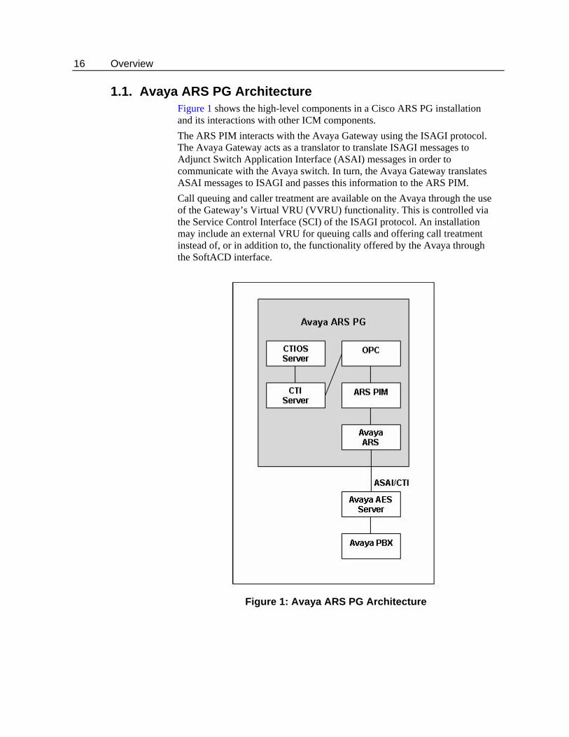
1.1. Avaya ARS PG Architecture Figure 1 shows the high-level components in a Cisco ARS PG installation and its interactions with other ICM components. The ARS PIM interacts with the Avaya Gateway using the ISAGI protocol. The Avaya Gateway acts as a translator to translate ISAGI messages to Adjunct Switch Application Interface (ASAI) messages in order to communicate with the Avaya switch. In turn, the Avaya Gateway translates ASAI messages to ISAGI and passes this information to the ARS PIM. Call queuing and caller treatment are available on the Avaya through the use of the Gateway’s Virtual VRU (VVRU) functionality. This is controlled via the Service Control Interface (SCI) of the ISAGI protocol. An installation may include an external VRU for queuing calls and offering call treatment instead of, or in addition to, the functionality offered by the Avaya through the SoftACD interface.
Figure 1: Avaya ARS PG Architecture
Fault Tolerance for Avaya ARS PG Gateway 17
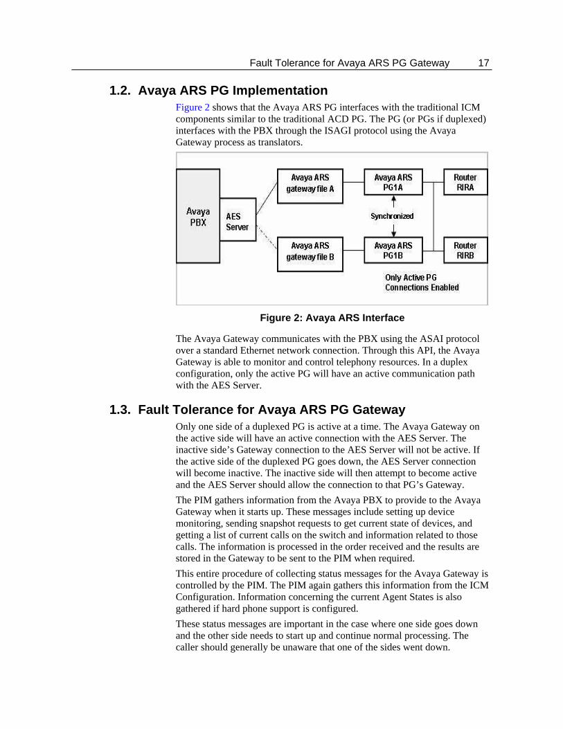
1.2. Avaya ARS PG Implementation Figure 2 shows that the Avaya ARS PG interfaces with the traditional ICM components similar to the traditional ACD PG. The PG (or PGs if duplexed) interfaces with the PBX through the ISAGI protocol using the Avaya Gateway process as translators.
Figure 2: Avaya ARS Interface
The Avaya Gateway communicates with the PBX using the ASAI protocol over a standard Ethernet network connection. Through this API, the Avaya Gateway is able to monitor and control telephony resources. In a duplex configuration, only the active PG will have an active communication path with the AES Server.
1.3. Fault Tolerance for Avaya ARS PG Gateway Only one side of a duplexed PG is active at a time. The Avaya Gateway on the active side will have an active connection with the AES Server. The inactive side’s Gateway connection to the AES Server will not be active. If the active side of the duplexed PG goes down, the AES Server connection will become inactive. The inactive side will then attempt to become active and the AES Server should allow the connection to that PG’s Gateway. The PIM gathers information from the Avaya PBX to provide to the Avaya Gateway when it starts up. These messages include setting up device monitoring, sending snapshot requests to get current state of devices, and getting a list of current calls on the switch and information related to those calls. The information is processed in the order received and the results are stored in the Gateway to be sent to the PIM when required. This entire procedure of collecting status messages for the Avaya Gateway is controlled by the PIM. The PIM again gathers this information from the ICM Configuration. Information concerning the current Agent States is also gathered if hard phone support is configured. These status messages are important in the case where one side goes down and the other side needs to start up and continue normal processing. The caller should generally be unaware that one of the sides went down.
18 Overview
1.4. Minimum PBX Hardware and Software Requirements The following are the minimum PBX hardware and software requirements:
An Avaya PBX, version 3.0 or 3.1.2. AES Server version 3.1.2 ASAI/CTI version 3.0
1.5. Avaya PBX Limits The following limitations should be kept in mind while configuring the Avaya ARS PG to ensure optimum performance:
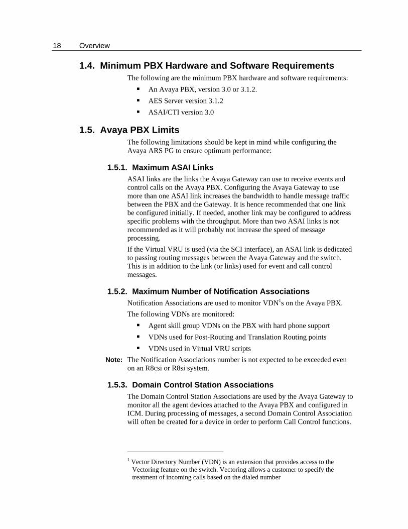
1.5.1. Maximum ASAI Links ASAI links are the links the Avaya Gateway can use to receive events and control calls on the Avaya PBX. Configuring the Avaya Gateway to use more than one ASAI link increases the bandwidth to handle message traffic between the PBX and the Gateway. It is hence recommended that one link be configured initially. If needed, another link may be configured to address specific problems with the throughput. More than two ASAI links is not recommended as it will probably not increase the speed of message processing. If the Virtual VRU is used (via the SCI interface), an ASAI link is dedicated to passing routing messages between the Avaya Gateway and the switch. This is in addition to the link (or links) used for event and call control messages.
1.5.2. Maximum Number of Notification Associations Notification Associations are used to monitor VDN1s on the Avaya PBX. The following VDNs are monitored:
Agent skill group VDNs on the PBX with hard phone support VDNs used for Post-Routing and Translation Routing points VDNs used in Virtual VRU scripts
Note: The Notification Associations number is not expected to be exceeded even on an R8csi or R8si system.
1.5.3. Domain Control Station Associations The Domain Control Station Associations are used by the Avaya Gateway to monitor all the agent devices attached to the Avaya PBX and configured in ICM. During processing of messages, a second Domain Control Association will often be created for a device in order to perform Call Control functions.
1 Vector Directory Number (VDN) is an extension that provides access to the
Vectoring feature on the switch. Vectoring allows a customer to specify the treatment of incoming calls based on the dialed number
ARS Feature Support 19
Note: In no case will more than two Domain Control Associations to a single device exist.
Note: For the Avaya ARS PIM /Gateway to operate successfully, the number of ARS phones configured on the PBX should not exceed one half the PBX published limit.
1.5.4. Maximum Outstanding Route Requests System-Wide In an ARS installation, when calls are queued to the Avaya Gateway or when Virtual VRU scripts are used, the calls will be under the control of a VDN. In many cases, the call will wait on an outstanding route request command. To know the maximum number of outstanding requests that Avaya supports contact Avaya. If this number is exceeded, error processing is performed that may include dropping the caller. Through careful planning of ICM scripts and VDN vectors, the system can be optimized to handle many calls in queue. You should carefully plan the ARS installation to assure that you do not run out of available route request resources.
20 Overview
1.6. ARS Feature Support The key features supported by the ARS PG are listed below and detailed in the subsequent sections.
Queue Points Pre-Routing Post-Routing Translation Routing Configuration Soft Phone Support Hard Phone Support Virtual VRU Scripts Call Tracking CTI Support Fault Tolerance Supervisor Functions Reporting
1.6.1. Queue Points With the Avaya ARS PG, queue points can be on the Avaya switch through the Virtual VRU. Special configuration is required if calls are to be queued to the Avaya PBX in the ARS environment. The existence of one or more external VRUs attached to the Avaya PBX does not negate the use of the Avaya as a queue point. Queuing to the Avaya PBX uses the Avaya Gateway and the SCI interface to park calls on an Avaya Vector Directory Number (VDN). External queue points are configured in the same manner as in IPCC.
Note: Avaya ACD Queues are not supported. All calls need to be routed by ICM.
1.6.2. Pre-Routing For traditional physical ACDs, ICM routes are a collection of peripheral targets. For the Avaya ARS PG, device targets are used to indicate individual agents to whom calls can be Pre-Routed. Peripheral targets are used to indicate VDNs on the Avaya PBX that are used for Translation and Post-Route points. (Calls can be Pre-Routed to an Avaya VDN to enable Post-Routing as well). If the calls are to be sent to an agent on the Avaya PBX, you must configure routes to route directly to the Avaya agent phones. A label must be configured for each destination (each agent telephone/device target) to which calls are routed by the routing client. If Agent Targeting Rules are used, the label configuration will not be required. To route calls to an internal resource, such as an agent telephone, you must create a label that contains the extension number on the Avaya PBX.
ARS Feature Support 21
To route calls to an external resource, you must create a label that contains the number that would be dialed from a phone on the Avaya PBX to reach that external resource.
1.6.3. Post-Routing Post-Routing by using the Avaya PBX as a VRU is enabled with special configuration in ICM and on the Avaya PBX. A special VDN on the switch is configured in ICM to act as a Post-Routing entry point on the switch. The VDN that is created on the switch causes the Gateway to ask the Call Router for a destination for the call. After creating a Post-Route VDN on the Avaya PBX, add a dialed number to the routing client for the peripheral in the ICM corresponding to the VDN’s extension. You must also configure all the other normal ICM items associated with Post-Routing, such as call types, labels, scripts, etc.
1.6.4. Translation Routing Translation route with traditional ACDs allows the ICM to pass data along with a call even when the call is delivered to a generic resource at an ACD, such as a queue or an application. In Avaya ARS PG, translation routes are used to queue a call temporarily at a CTI route point and then send it to the appropriate available agent along with any data associated with that call. In order to accomplish translation routing on the Avaya ARS PG, special configuration (similar to Post-Routing configuration) is required.
1.6.5. Configuration Special configuration is required in both ICM and on the Avaya PBX to support ARS functionality. In addition to the configuration discussed in the ARI Deployment Guide for Cisco Unified Intelligent Contact Manager Enterprise, this manual describes the required additional ICM and Avaya PBX configuration required.
1.6.6. Hard Phone/Soft Phone Support Hard phone support is a feature that enables an agent to use a hard phone (an actual telephone) instead of (or in addition to) the software-based soft phones to perform agent actions (log in, log out, change states, answer calls, etc.). Hard phones can be used in combination with soft phones. In this case, the hard phone and soft phone are synchronized. When the hard phone and soft phone are synchronized, they look like a single device to the ICM system and the user. For example, using the hard phone to log in an agent will cause ICM to see the agent as logged in and the soft phone to display results as if the agent had logged in using the soft phone. The synchronization is performed for agent state activities and call related actions. Agent state activities include logging in, changing state, and logging out. Call related actions include answering, transferring, conferencing, holding, and releasing calls. Hard phone/soft phone synchronization is performed through special configuration in both ICM and the Avaya PBX. ICM needs to know which
22 Overview
hard phone devices need to be synchronized. This is done with a configuration parameter in the Device Target configuration. The Avaya PBX will need an agent skill group/hunt group set up so agents can log in using their hard phone. Avaya agents will also need to be defined on the PBX that have the same agent ID as those used in the ICM configuration. These agents are then assigned to the Avaya skill group. When using the hard phone to change state, the agent is encouraged to pick up, then quickly hang up (this is referred to as “jiggling” the phone). This action alerts the software to check the agent’s new state and report it to ICM immediately.
Note: If an agent logs in via his (or her) hard phone, his (or her) soft phone will not reflect this change of state. In fact, the PIM will log the agent out again (on the switch) if the agent does not log in via the soft phone. Once the agent logs in with the soft phone, the agent states will be synchronized.
1.6.7. Virtual VRU Scripts In the absence of an attached VRU, the Avaya PBX can act as a VRU and run Virtual VRU scripts via ICM routing scripts. A VVRU script is a specially configured VDN on the Avaya PBX. The VDNs run one or more Avaya vectors to offer call treatment to the caller. The vectors may play announcements via announcement boards, collect digits from the caller, and play music-on-hold. When the VVRU script is done, another special VDN is called which returns the script’s result to the ICM script that executed the VVRU script.
1.7. Unsupported Features The following features are unsupported:
Trunk and Trunk Group Reporting Peripheral Service Level Reporting RONA Avaya ACD Queues Silent Monitoring
Avaya Notes and Restrictions 23
1.8. Avaya Notes and Restrictions If the hard phone is used to change agent state via a dedicated button
on the phone, it may take several seconds (a configurable value) to be informed of the state change. This can be overcome by jiggling the handset. See Table 17 for details on configuration settings.
There is a very small window during startup in which an agent can log in via his hard phone but will not be seen as “Logged In” by ICM. Two actions can be performed if this happens: The agent sees that ICM shows he is logged out on his soft phone
and logged in on his hard phone (if equipped to do so). If he logs in again using the soft phone, ICM accepts the login.
The agent can change his state via his hard phone. This causes ICM to see the state change and mark the agent as logged in.
Each agent device is allowed only one line appearance. This means that an agent will not be able to answer a second call using the soft phone, although they may be able to do so with his (or her) hard phone.
Callers in a VVRU script on the switch may be lost if the ARS PIM is restarted or a switch from Side A to Side B occurs.
If hard phone support is enabled, agent state changes via the hard phone will be delayed because the phone is not periodically checked for status. Soft phone agent state control is the preferred method.
If an agent logs into an extension that has not been configured using either device target configuration or peripheral monitor table, no errors will be displayed. If the phone is not monitored, agent state control and call control will not work properly.
Due to an issue with the Avaya PBX, if a conference call is made between three agents by calling the Agent ID instead of their extensions, call control will be lost.
Soft phone reconnect will return an error. Avaya clears the consult call but does not allow the held call to be retrieved. The agent must retrieve the held call using the hard phone.

24 Overview
25
2. Avaya ARS ICM Configuration
This chapter describes the object mapping between the ICM and the Avaya PBX and how the PG has to be configured in the ICM environment. Note that some of the items normally configured for traditional ACDs need not be configured for ARS and vice versa. Before continuing with this chapter, make sure you have read and understood the basic ARS configuration described in ARI Deployment Guide for Cisco Unified Intelligent Contact Manager Enterprise. The configuration steps shown in this chapter should be used in concert with the steps shown in the above mentioned document.
Note: In the tables described in this chapter, the term A valid value for the ICM configuration is used to denote a correct value for your ICM configuration. The value does not affect the ARS PG setup, but it must be a value that supports your ICM system and components.
26 Avaya ARS ICM Configuration
2.1. Object Mapping between Avaya and ICM Refer to Table 1 for the object mapping between ICM and the Avaya PG.
Table 1: Object Mapping between ICM and Avaya
Cisco Term Avaya Term Peripheral target trunk group + DNIS Service VDN Skill group Skill or hunt group Trunk Trunk Trunk group trunk group
2.2. Avaya Gateway Installation The Avaya Gateway will be installed with the ARS PIM.
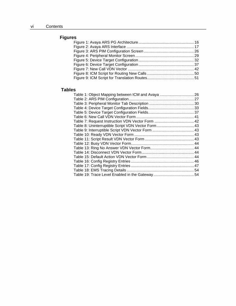
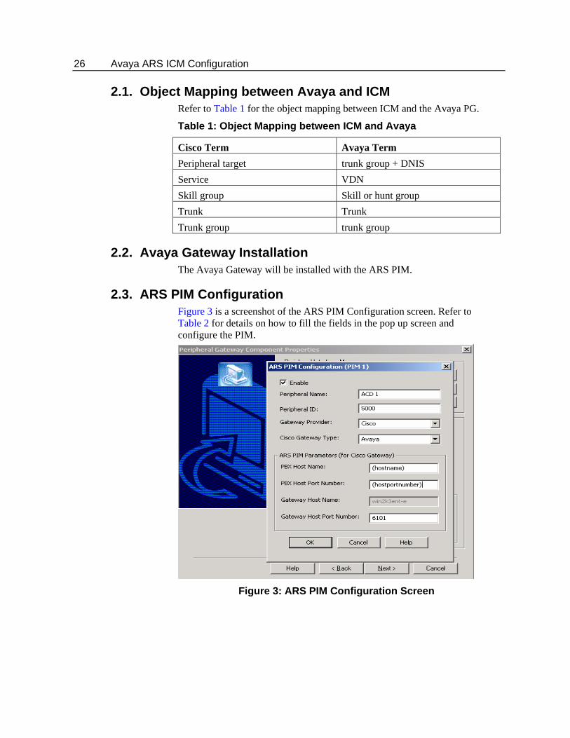
2.3. ARS PIM Configuration Figure 3 is a screenshot of the ARS PIM Configuration screen. Refer to Table 2 for details on how to fill the fields in the pop up screen and configure the PIM.
Figure 3: ARS PIM Configuration Screen
ARS PIM Configuration 27
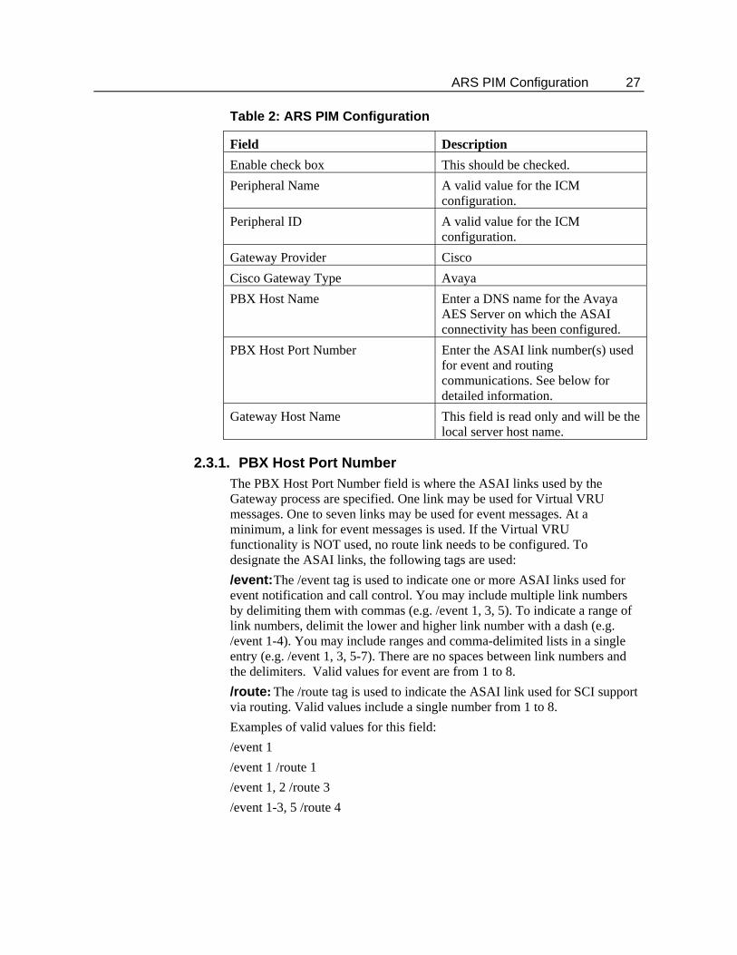
Table 2: ARS PIM Configuration
Field Description Enable check box This should be checked. Peripheral Name A valid value for the ICM
configuration. Peripheral ID A valid value for the ICM
configuration. Gateway Provider Cisco Cisco Gateway Type Avaya PBX Host Name Enter a DNS name for the Avaya
AES Server on which the ASAI connectivity has been configured.
PBX Host Port Number Enter the ASAI link number(s) used for event and routing communications. See below for detailed information.
Gateway Host Name This field is read only and will be the local server host name.
2.3.1. PBX Host Port Number The PBX Host Port Number field is where the ASAI links used by the Gateway process are specified. One link may be used for Virtual VRU messages. One to seven links may be used for event messages. At a minimum, a link for event messages is used. If the Virtual VRU functionality is NOT used, no route link needs to be configured. To designate the ASAI links, the following tags are used: /event: The /event tag is used to indicate one or more ASAI links used for event notification and call control. You may include multiple link numbers by delimiting them with commas (e.g. /event 1, 3, 5). To indicate a range of link numbers, delimit the lower and higher link number with a dash (e.g. /event 1-4). You may include ranges and comma-delimited lists in a single entry (e.g. /event 1, 3, 5-7). There are no spaces between link numbers and the delimiters. Valid values for event are from 1 to 8. /route: The /route tag is used to indicate the ASAI link used for SCI support via routing. Valid values include a single number from 1 to 8. Examples of valid values for this field: /event 1 /event 1 /route 1 /event 1, 2 /route 3 /event 1-3, 5 /route 4
28 Avaya ARS ICM Configuration
2.4. Configuring the ARS PG The ICM Peripheral Gateway (PG) corresponds to an Avaya G3 PBX type of switch. You should configure only one ICM Peripheral in ICM Configuration Manager for each Avaya G3 PBX. If there is to be hard phone support on the Avaya, it must have the Expert Agent Selection (EAS) environment.
2.5. Peripheral Monitor Configuration Peripheral Monitors are used to designate two classes of objects for the Avaya SoftACD. The first object is the skill group/hunt group defined on the Avaya PBX that Avaya agents can log into for hard phone support. The second set of objects is Avaya VDNs that are used for Post-Routing and Translation-Routing. (Calls can be Pre-Routed to Post-Routing VDNs). This includes all the Virtual VRU script VDNs. The extensions of these objects require an appropriately configured VDN on the Avaya. Refer to Section VDN Configuration for more information on Avaya VDN configuration.
2.5.1. Skill Group Configuration A peripheral monitor is configured for the extension representing the agent skill that agents on the Avaya log into via their hard phones. Note that calls are not actually sent to this skill extension. This extension is monitored solely as a method to inform the Avaya Gateway at startup that the Avaya skill group should be monitored to detect when agents log in or log out via their hard phones.
2.5.2. VDN Configuration A VDN is an extension on the switch that does not terminate at an actual device. It is an internal end-point that can take a call and perform programmable actions with the call. You may associate a vector1 with a VDN. When the call is delivered to a VDN with an attached vector, the vector begins to execute. Vectors may be chained together to create longer vectors or as a way to modularize vector applications. In order to support the service control interface (SCI), the Gateway uses VDNs and vectors on the Avaya PBX to queue calls and offer call treatment to callers while queued. They are also used to accept Pre-Routed, Post-Routed, and Translation Routed calls for routing by the ICM system. The types of VDNs and their associated vectors are shown below. Note that the term “VDN type” is an invented term for use with the Avaya Gateway. To the PBX, there is only a single type of VDN. The Gateway differentiates different types of VDNs by configuration strings included in the ICM configuration. For VDNs that represent scripts on the VVRU (interruptible or uninterruptible), you will need to add entries to the Network VRU Scripts
1 A vector is a program written in a proprietary language of the Avaya switch.
Peripheral Monitor Screen 29
table that have the same VDN number as used in the Peripheral Monitor entry. This is to allow the ICM script writer to select these VVRU script.
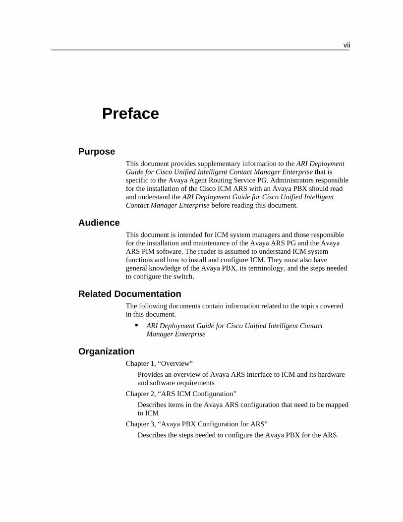
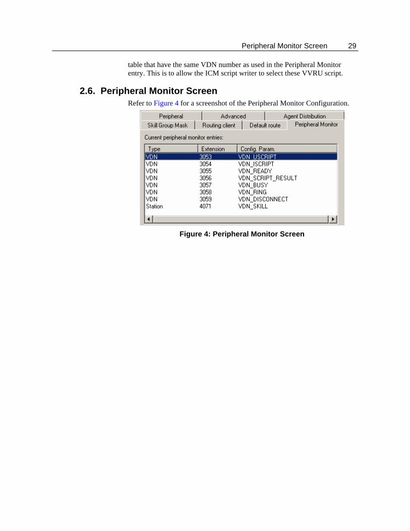
2.6. Peripheral Monitor Screen Refer to Figure 4 for a screenshot of the Peripheral Monitor Configuration.
Figure 4: Peripheral Monitor Screen
30 Avaya ARS ICM Configuration
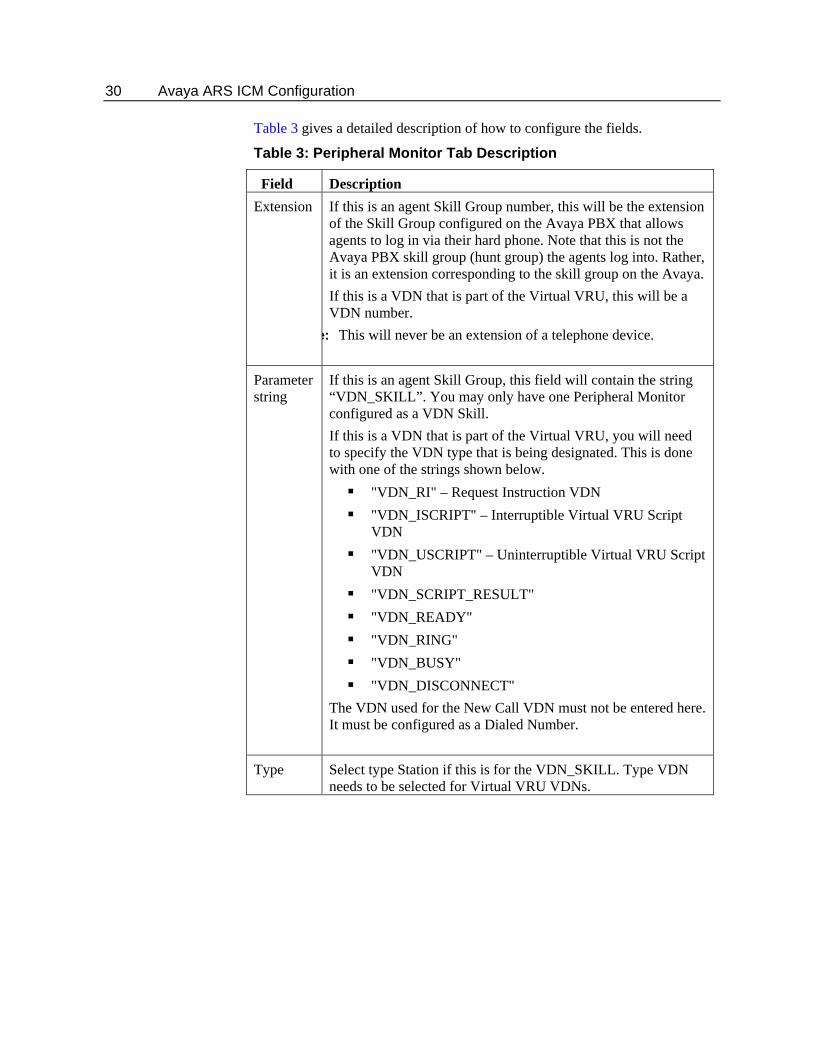
Table 3 gives a detailed description of how to configure the fields.
Table 3: Peripheral Monitor Tab Description
Field Description Extension If this is an agent Skill Group number, this will be the extension
of the Skill Group configured on the Avaya PBX that allows agents to log in via their hard phone. Note that this is not the Avaya PBX skill group (hunt group) the agents log into. Rather, it is an extension corresponding to the skill group on the Avaya. If this is a VDN that is part of the Virtual VRU, this will be a VDN number.
e: This will never be an extension of a telephone device.
Parameter string
If this is an agent Skill Group, this field will contain the string “VDN_SKILL”. You may only have one Peripheral Monitor configured as a VDN Skill. If this is a VDN that is part of the Virtual VRU, you will need to specify the VDN type that is being designated. This is done with one of the strings shown below.
"VDN_RI" – Request Instruction VDN "VDN_ISCRIPT" – Interruptible Virtual VRU Script
VDN "VDN_USCRIPT" – Uninterruptible Virtual VRU Script
VDN "VDN_SCRIPT_RESULT" "VDN_READY" "VDN_RING" "VDN_BUSY" "VDN_DISCONNECT"
The VDN used for the New Call VDN must not be entered here. It must be configured as a Dialed Number.
Type Select type Station if this is for the VDN_SKILL. Type VDN needs to be selected for Virtual VRU VDNs.
Device Targets 31
2.7. Skill Groups An ICM skill group is a group of agents who share a certain skill. For ARS agents to log in, the agents must be assigned to at least one skill group. This is true whether or not the installation includes hard phone support. If hard phone support is used, the skill group extension configured on the Avaya PBX must match the skill group ID configured in ICM.
2.8. Persons A “Person” is required to be configured before an agent can be created. For each agent, create a person record. The only requirement for the Avaya ARS is, if hard phone support is required, the person’s login name must match the agent ID configured on the Avaya PBX and the password must be blank.
2.9. Device Targets For each hard phone attached to the Avaya PBX that agents can log into or may receive routed calls, you will need to configure a Device Target and a routing label.
32 Avaya ARS ICM Configuration
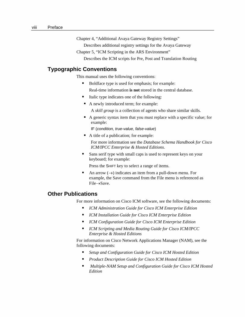
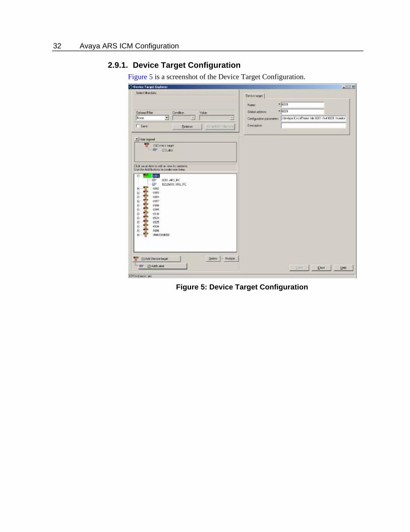
2.9.1. Device Target Configuration Figure 5 is a screenshot of the Device Target Configuration.
Figure 5: Device Target Configuration
Device Targets 33
Refer to Table 4 for a description on how to fill the fields.
Table 4: Device Target Configuration Fields
Field Description Name The enterprise name field must be set to a string that is
unique across all device targets in the enterprise. It is suggested that the enterprise name includes the directory number of the agent phone on the PBX. The name cannot contain spaces.
Global Address Although this field is not used by the ARS, it must be set to a value that is unique across all device targets in the enterprise. It is suggested that the global address field be set to the same value as the enterprise name field for ARS.
Configuration Parameters
Configuration parameters provide information that identifies the device target. Currently, five parameters can be specified:
/devType <PhoneType>: The /devtype parameter identifies the type of phone device. This parameter is required. Currently, the only valid value for ARS is “CiscoPhone”. Note that no spaces are allowed and the string is case sensitive.
/dn <Full Phone Number>: The /dn parameter identifies the extension of the phone device. This parameter is required. This value must be unique across all device targets in the enterprise. The number specified in the /dn parameter is also known as the instrument number. When an agent logs in with a soft phone, the agent must specify this string as the instrument for the phone that he or she will be using.
/ext <extension>: The /ext parameter identifies the shortened form of the phone number that is used by other ARS agents as the instrument number. This parameter should be the same as the /dn parameter.
/monitor <peripheral id>: The /monitor parameter is used to set up monitoring of agent phones at startup. This allows the Avaya Gateway to receive device events and report them to the PIM. This is a required parameter.
/hardPhone 2: Required only if hard phone support is needed.
34 Avaya ARS ICM Configuration
2.9.2. Configuring Device Targets in Peripheral Monitor Table When Agent Targeting Rules are used, device targets can be configured in the peripheral monitor table. A single peripheral monitor (PM) table entry can now take the place of some or all of the device targets (DT) previously configured for hard phone monitoring in ARS. The PM table can be used to configure the stations you want to monitor for ARS. The ARS PIM uses the PM entries to internally create device targets (synthesizing the equivalent behavior as if device target configuration entries had been received).
Note: The PIM populates a device target config string based on the PM table entries.
Ranges of extensions to be monitored can now be configured in one or more peripheral monitor table entries. All agent phones configured in the PM table will be monitored at startup. This allows the ARS Gateway to receive device events and report them to the PIM. Alternatively, the peripheral configuration string parameter “monitor” can be used to explicitly set the value (defaults to “y” – always monitor). An agent’s phone also is monitored upon their login. A Peripheral monitor table entry has the following limits:
Extension field = 10 chars Parameter String = 32 chars
Note: The peripheral monitor Type must be "Station" for the ARS PIM to treat the entry properly.
The Peripheral Configuration String for an ARS Peripheral may contain:
/MONITOR <y or n>
The monitor parameter specifies whether the hard phone extensions identified in the PM table entry should be monitored all the time. A value of ‘y’ (default) (monitor hard phones all the time), or ‘n’ (do not monitor the hard phones all the time) may be specified. This value will be used for Peripheral Monitor table entries unless explicitly overridden in an individual PM table entry.
/HARDPHONE <y or n>
This is required only if hard phone support is needed. The valid values that can follow this parameter are ‘y’ (default) for full hard phone/soft phone synchronization, or ‘n’ for no hard phone/soft phone synchronization. This value will be used for Peripheral Monitor table entries unless explicitly overridden in an individual PM table entry. The Peripheral Monitor Configuration Parameter field of a Peripheral Monitor table entry may contain:
Device Targets 35
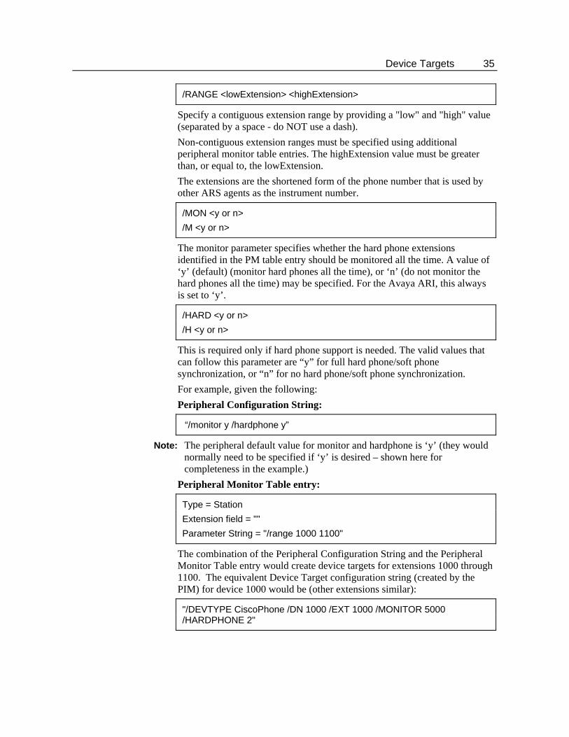
/RANGE <lowExtension> <highExtension>
Specify a contiguous extension range by providing a "low" and "high" value (separated by a space - do NOT use a dash). Non-contiguous extension ranges must be specified using additional peripheral monitor table entries. The highExtension value must be greater than, or equal to, the lowExtension. The extensions are the shortened form of the phone number that is used by other ARS agents as the instrument number.
/MON <y or n> /M <y or n>
The monitor parameter specifies whether the hard phone extensions identified in the PM table entry should be monitored all the time. A value of ‘y’ (default) (monitor hard phones all the time), or ‘n’ (do not monitor the hard phones all the time) may be specified. For the Avaya ARI, this always is set to ‘y’.
/HARD <y or n> /H <y or n>
This is required only if hard phone support is needed. The valid values that can follow this parameter are “y” for full hard phone/soft phone synchronization, or “n” for no hard phone/soft phone synchronization. For example, given the following: Peripheral Configuration String:
“/monitor y /hardphone y”
Note: The peripheral default value for monitor and hardphone is ‘y’ (they would normally need to be specified if ‘y’ is desired – shown here for completeness in the example.)
Peripheral Monitor Table entry:
Type = Station Extension field = "" Parameter String = "/range 1000 1100"
The combination of the Peripheral Configuration String and the Peripheral Monitor Table entry would create device targets for extensions 1000 through 1100. The equivalent Device Target configuration string (created by the PIM) for device 1000 would be (other extensions similar):
"/DEVTYPE CiscoPhone /DN 1000 /EXT 1000 /MONITOR 5000 /HARDPHONE 2"
36 Avaya ARS ICM Configuration
Caveats/Warnings: Do not overlap peripheral monitor extension ranges. Overlapping
Peripheral monitor extension ranges may cause undesirable behavior. For example, given two PM entries, each containing "/range 6611 6612". The PIM processes the PM entries in the order received. If the 2nd is deleted, the PIM will remove the Device Targets even though the 1st PM entry still exists. This will cause confusion if one just looks at the Peripheral Monitor table and yet does not see the equivalent Device Targets in the PIM anymore (nor the stations being necessarily monitored).
Do not configure a device target and a peripheral monitor entry for the same device.
/RANGE must always be specified even if the entry is only for one device. In this case, the lowExtension will be the same as the highExtension, “/range 1000 1000.
2.10. Dialed Numbers Dialed numbers are used to represent entry points on the Avaya PBX related to new calls. Ultimately, dialed numbers equate to a VDN on the Avaya PBX. Dialed numbers are configured for the VDN(s) on the Avaya that will cause a New Call message to be sent to the PIM. The Dialed Number associated with a new call will cause ICM to run a particular routing script. The Dialed Number configured in ICM must match the VDN configured on the Avaya that is responsible for handling new calls. The VDN number of the New Call VDN must be entered here to enable this functionality.
Note: Do not configure this VDN number as a peripheral monitor.
2.11. Device Target Labels A label is a string that identifies how to reach a particular target for a particular routing client. In order to route calls to a device target, you must configure a label for the device target for each routing client that will send calls to it. For example, for a Post-Routing client such as an Avaya ARS PG, the label is whatever string a phone on that peripheral needs to dial in order to reach this particular device. For the routing client for the local PG this is typically the extension.
Maintaining Your Configuration 37
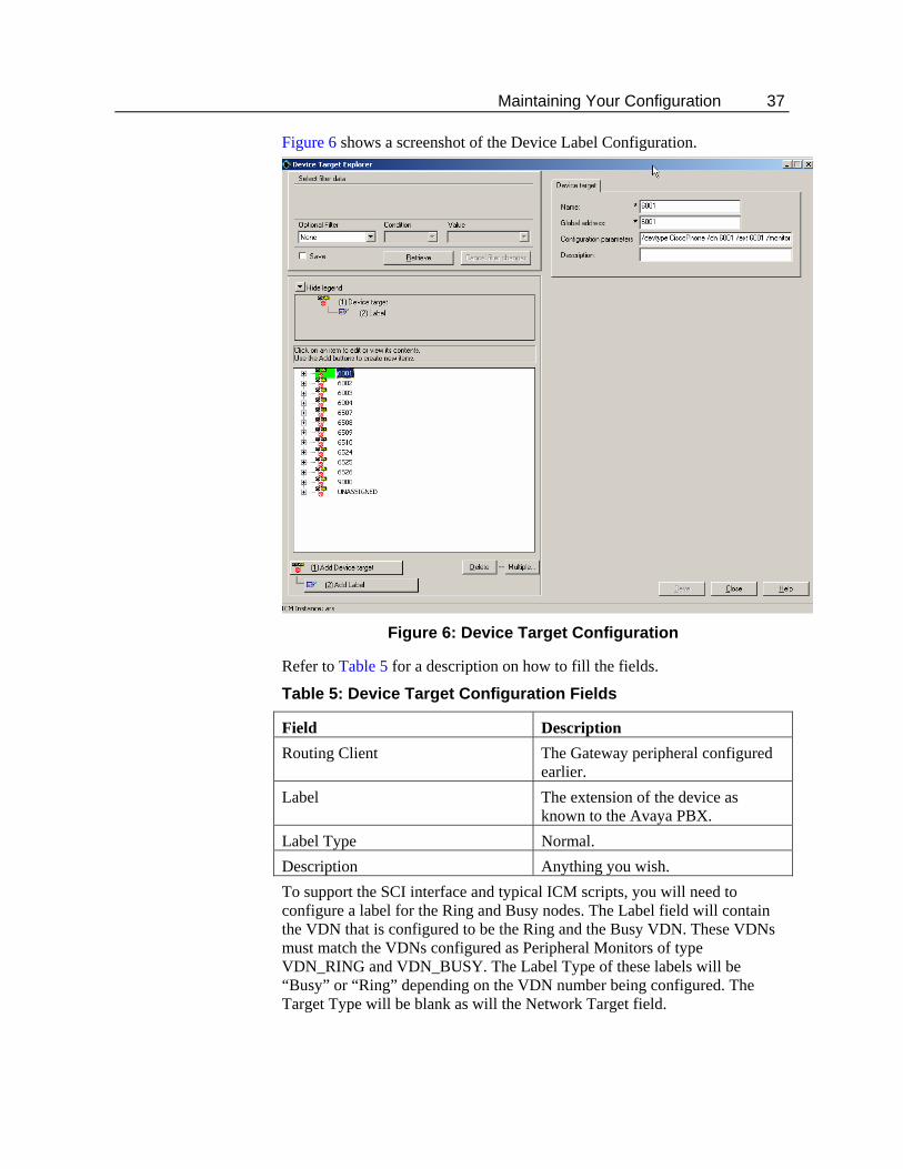
Figure 6 shows a screenshot of the Device Label Configuration.
Figure 6: Device Target Configuration
Refer to Table 5 for a description on how to fill the fields.
Table 5: Device Target Configuration Fields
Field Description Routing Client The Gateway peripheral configured
earlier. Label The extension of the device as
known to the Avaya PBX. Label Type Normal. Description Anything you wish. To support the SCI interface and typical ICM scripts, you will need to configure a label for the Ring and Busy nodes. The Label field will contain the VDN that is configured to be the Ring and the Busy VDN. These VDNs must match the VDNs configured as Peripheral Monitors of type VDN_RING and VDN_BUSY. The Label Type of these labels will be “Busy” or “Ring” depending on the VDN number being configured. The Target Type will be blank as will the Network Target field.
38 Avaya ARS ICM Configuration
2.12. Maintaining Your Configuration It is important to keep your ICM configuration up to date as you make configuration changes on your PBX. The following types of PBX changes need to be reflected in the ICM configuration:
If you are adding or changing agent telephones, these changes must be reflected on the Avaya PBX by adding devices with the same extension.
If adding or changing CTI Route Points or associated directory numbers, the corresponding VDNs on the Avaya PBX must be changed as well.
If adding or removing VDNs that act as Virtual VRU scripts, the appropriate peripheral monitors must be added to the ICM configuration. VDNs not used should be removed from the ICM configuration. Configured VDNs that are not used will use up PG and PBX resources (cluster IDs) and add to message traffic.
If adding agents to ICM, the agents must also be added to the Avaya PBX configuration with the same ID. These agents must be added to the Avaya skill group (only for hard phone).
If removing extensions from the Avaya, the corresponding device target or peripheral monitor entry for that device should be removed. Device targets or peripheral monitor entries that are not used will cause excess message traffic between the PBX and the PG. Only configure the devices that will be used by the ICM system
39
3. Avaya PBX Configuration for ARS
The Avaya PBX needs to be configured in order to work with the ARS. The steps needed to configure the Avaya PBX to work with the ARS are summarized below:
PBX configuration of one or more ASAI/CTI links. PBX configuration of agent devices (stations). PBX configuration of an agent skill that hard phone agents can log
into. PBX configuration of hard phone agents. PBX configuration of VDNs and vectors used for the Service Control
Interface: call treatment, Post-Routing, queuing, and other processing of calls.
These are discussed in more detail in the subsequent sections.
40 Avaya PBX Configuration for ARS
3.1. ASAI/CTI Link Configuration Event Minimization must be set to NO. Agent Soft Phones will not have call control if it is enabled.
3.2. Station Configuration In the station configuration, only two line appearances should be configured. Avaya ARS does not support three line appearances. “Restrict Last Line Appearance” should be set to ‘y’. “Auto Answer” should be set to ‘n’.
3.3. Hard Phone Configuration If you wish to use the hard phone support provided by the ARS PIM/Gateway, you must have certain configuration settings in both the Avaya and ICM. On the Avaya PBX, you need to set up the agents and a skill group (hunt group) for the agents to log in to. Only one skill group should be configured.
3.3.1. Avaya PBX Feature Access Code Configuration In most cases, the Feature Access Codes (FACs) for various agent actions is already defined for the Avaya PBX. The features that we are interested in including are:
Agent Login Agent Logout Auto In Aux Work
The access codes supported must be programmed into the programmable buttons on the hard phones. The agents using their hard phones will need to know these codes to control their states with the hard phone. Manual entries of the Feature Access Codes are not supported. All other Feature Access Codes that are not mentioned here are not supported and should not be used. If Service Observation is used on a logged in phone, the agent state and call state of the observed agent will be affected and call control will be lost on the soft phone. If Service Observation is used on a non-logged in phone, the side affects will not exist.
3.4. VDN Configuration The Avaya Gateway requires creation of eight types of VDNs and associated vectors on the Avaya. From the perspective of the configuration requirements, these are the only types to support the Gateway and SoftACD. They do not appear to the Avaya Gateway as nonstandard. With the exception of the call treatment vector, each vector corresponds to an SCI message to be sent to the PIM The VDN extensions must match the extensions used in the ICM configuration for Peripheral Monitors and the ICM dialed numbers configured for new calls.
VDN Configuration 41
3.4.1. ARS Avaya VDN Types The ARS VDN types are listed below and discussed in brief subsequently.
New Call VDN Request Instruction VDN Interruptible Call Treatment VDN(s) Uninterruptible Call Treatment VDN(s) Ready VDN Script Result VDN Busy VDN Ring No Answer VDN Disconnect VDN Default Action VDN
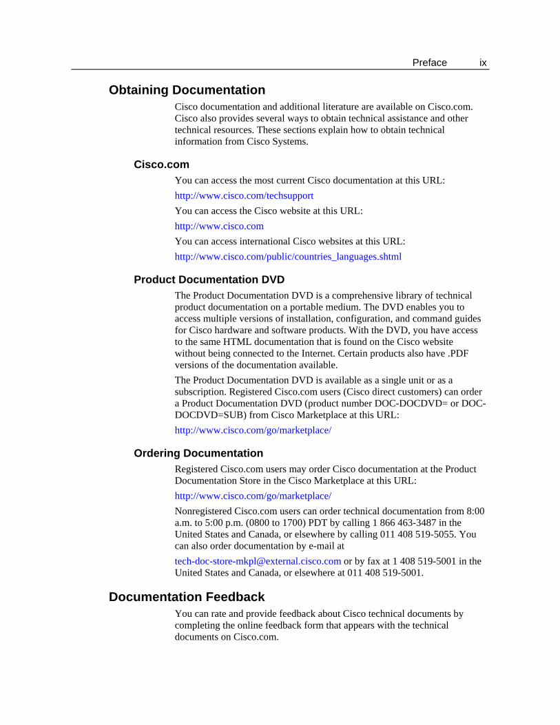
3.4.2. New Call VDN The New Call VDN vector applies to calls arriving at the Avaya Virtual VRU that should go initially under ICM control for Post-Routing. The VDN number used here is also configured as a Dialed Number in ICM with an associated ICM routing script. The New Call vector has the form given in Table 6.
Table 6: New Call VDN Vector Form
Line 1. Adjunct route. Line 2. Wait a short interval on silence. Line 3. Go to Default Action VDN.
42 Avaya PBX Configuration for ARS
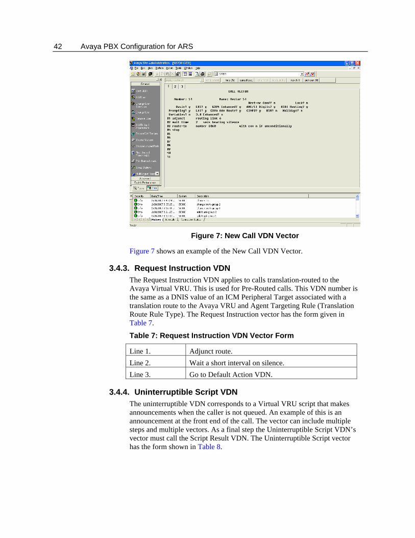
Figure 7: New Call VDN Vector
Figure 7 shows an example of the New Call VDN Vector.
3.4.3. Request Instruction VDN The Request Instruction VDN applies to calls translation-routed to the Avaya Virtual VRU. This is used for Pre-Routed calls. This VDN number is the same as a DNIS value of an ICM Peripheral Target associated with a translation route to the Avaya VRU and Agent Targeting Rule (Translation Route Rule Type). The Request Instruction vector has the form given in Table 7.
Table 7: Request Instruction VDN Vector Form
Line 1. Adjunct route. Line 2. Wait a short interval on silence. Line 3. Go to Default Action VDN.
3.4.4. Uninterruptible Script VDN The uninterruptible VDN corresponds to a Virtual VRU script that makes announcements when the caller is not queued. An example of this is an announcement at the front end of the call. The vector can include multiple steps and multiple vectors. As a final step the Uninterruptible Script VDN’s vector must call the Script Result VDN. The Uninterruptible Script vector has the form shown in Table 8.
VDN Configuration 43
Table 8: Uninterruptible Script VDN Vector Form
Lines 1, 2, 3 Steps to do the announcements. Last line Call the Script Result vector.
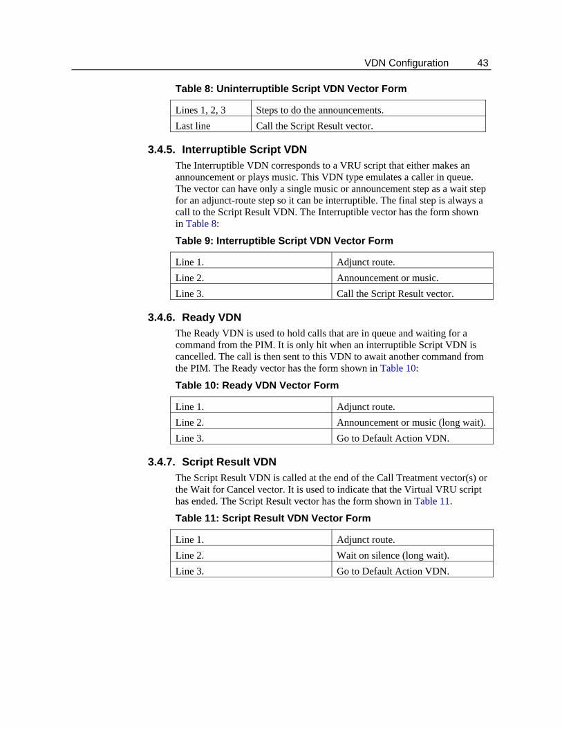
3.4.5. Interruptible Script VDN The Interruptible VDN corresponds to a VRU script that either makes an announcement or plays music. This VDN type emulates a caller in queue. The vector can have only a single music or announcement step as a wait step for an adjunct-route step so it can be interruptible. The final step is always a call to the Script Result VDN. The Interruptible vector has the form shown in Table 8:
Table 9: Interruptible Script VDN Vector Form
Line 1. Adjunct route. Line 2. Announcement or music. Line 3. Call the Script Result vector.
3.4.6. Ready VDN The Ready VDN is used to hold calls that are in queue and waiting for a command from the PIM. It is only hit when an interruptible Script VDN is cancelled. The call is then sent to this VDN to await another command from the PIM. The Ready vector has the form shown in Table 10:
Table 10: Ready VDN Vector Form
Line 1. Adjunct route. Line 2. Announcement or music (long wait). Line 3. Go to Default Action VDN.
3.4.7. Script Result VDN The Script Result VDN is called at the end of the Call Treatment vector(s) or the Wait for Cancel vector. It is used to indicate that the Virtual VRU script has ended. The Script Result vector has the form shown in Table 11.
Table 11: Script Result VDN Vector Form
Line 1. Adjunct route. Line 2. Wait on silence (long wait). Line 3. Go to Default Action VDN.
44 Avaya PBX Configuration for ARS
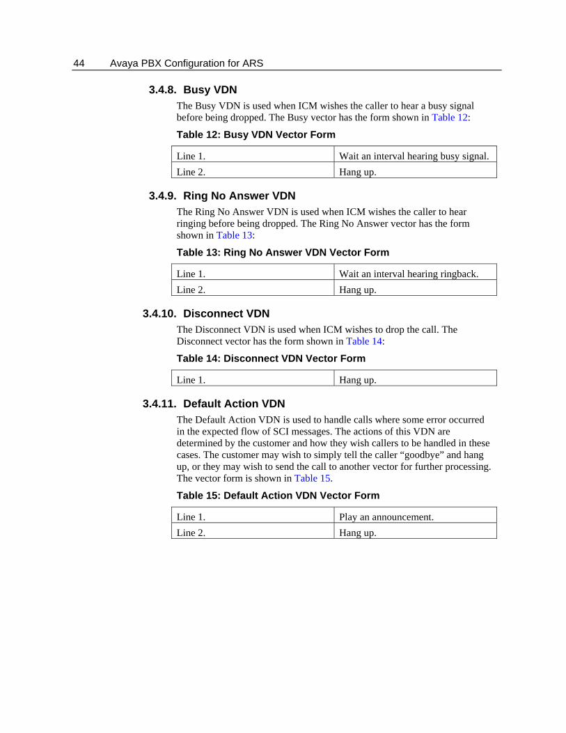
3.4.8. Busy VDN The Busy VDN is used when ICM wishes the caller to hear a busy signal before being dropped. The Busy vector has the form shown in Table 12:
Table 12: Busy VDN Vector Form
Line 1. Wait an interval hearing busy signal. Line 2. Hang up.
3.4.9. Ring No Answer VDN The Ring No Answer VDN is used when ICM wishes the caller to hear ringing before being dropped. The Ring No Answer vector has the form shown in Table 13:
Table 13: Ring No Answer VDN Vector Form
Line 1. Wait an interval hearing ringback. Line 2. Hang up.
3.4.10. Disconnect VDN The Disconnect VDN is used when ICM wishes to drop the call. The Disconnect vector has the form shown in Table 14:
Table 14: Disconnect VDN Vector Form
Line 1. Hang up.
3.4.11. Default Action VDN The Default Action VDN is used to handle calls where some error occurred in the expected flow of SCI messages. The actions of this VDN are determined by the customer and how they wish callers to be handled in these cases. The customer may wish to simply tell the caller “goodbye” and hang up, or they may wish to send the call to another vector for further processing. The vector form is shown in Table 15.
Table 15: Default Action VDN Vector Form
Line 1. Play an announcement. Line 2. Hang up.
45
4. Additional Avaya Gateway Registry Settings
There are a number of configurable settings that are used by the Avaya Gateway that may be stored in the Registry. These registry entries are not supported by the ICM configuration interface. If the entries are not found by the Avaya Gateway, default values will be used. If they are found, the values in the registry will be used. The default settings will work fine for most installations. If there are problems seen that are related to message timeouts, excessive memory usage, etc., they may disappear by tuning these entries. The entries are broken up into two categories dynamic and config. These are discussed in subsequent sections.
46 Additional Avaya Gateway Registry Settings
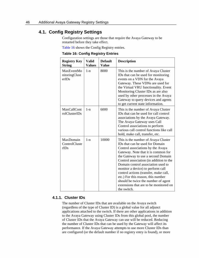
4.1. Config Registry Settings Configuration settings are those that require the Avaya Gateway to be restarted before they take effect. Table 16 shows the Config Registry entries.
Table 16: Config Registry Entries
Registry Key String
Valid Values
Default Value
Description
MaxEventMonitoringClusterIDs
1-n 8000 This is the number of Avaya Cluster IDs that can be used for monitoring events on a VDN for the Avaya Gateway. These VDNs are used for the Virtual VRU functionality. Event Monitoring Cluster IDs as are also used by other processes in the Avaya Gateway to query devices and agents to get current state information.
MaxCallControlClusterIDs
1-n 6000 This is the number of Avaya Cluster IDs that can be used for call control associations by the Avaya Gateway. The Avaya Gateway uses Call Control associations to perform various call control functions like call hold, make call, transfer, etc.
MaxDomainControlClusterIDs
1-n 10000 This is the number of Avaya Cluster IDs that can be used for Domain Control associations by the Avaya Gateway. Note that it is common for the Gateway to use a second Domain Control association (in addition to the Domain control association used to monitor a device) to perform call control actions (transfer, make call, etc.) For this reason, this number should be twice the number of agent extensions that are to be monitored on the switch.
4.1.1. Cluster IDs The number of Cluster IDs that are available on the Avaya switch (regardless of the type of Cluster ID) is a global value for all adjunct applications attached to the switch. If there are other applications in addition to the Avaya Gateway using Cluster IDs from this global pool, the number of Cluster IDs that the Avaya Gateway can use will be reduced. Reducing the number of Cluster IDs that can be used by the Gateway will affect its performance. If the Avaya Gateway attempts to use more Cluster IDs than are configured (or the default number if no registry entry is found), or more
Dynamic Configuration Settings 47
than are actually available on the switch, errors will occur. This may include the dropping of calls from the system or Avaya Gateway shutdowns and restarts. The entry “1-n” in the Valid Values column indicates that you should enter as many Cluster IDs as are available to the Avaya Gateway. If there are no other applications using Cluster IDs, then these values can be set to the maximum for the version of the Avaya G3 switch.
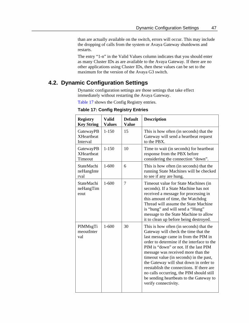
4.2. Dynamic Configuration Settings Dynamic configuration settings are those settings that take effect immediately without restarting the Avaya Gateway. Table 17 shows the Config Registry entries.
Table 17: Config Registry Entries
Registry Key String
Valid Values
Default Value
Description
GatewayPBXHeartbeatInterval
1-150 15 This is how often (in seconds) that the Gateway will send a heartbeat request to the PBX.
GatewayPBXHeartbeatTimeout
1-150 10 Time to wait (in seconds) for heartbeat response from the PBX before considering the connection “down”.
StateMachineHangInterval
1-600 6 This is how often (in seconds) that the running State Machines will be checked to see if any are hung.
StateMachineHangTimeout
1-600 7 Timeout value for State Machines (in seconds). If a State Machine has not received a message for processing in this amount of time, the Watchdog Thread will assume the State Machine is “hung” and will send a “Hung” message to the State Machine to allow it to clean up before being destroyed.
PIMMsgTimeoutInterval
1-600 30 This is how often (in seconds) that the Gateway will check the time that the last message came in from the PIM in order to determine if the interface to the PIM is “down” or not. If the last PIM message was received more than the timeout value (in seconds) in the past, the Gateway will shut down in order to reestablish the connections. If there are no calls occurring, the PIM should still be sending heartbeats to the Gateway to verify connectivity.
48 Additional Avaya Gateway Registry Settings
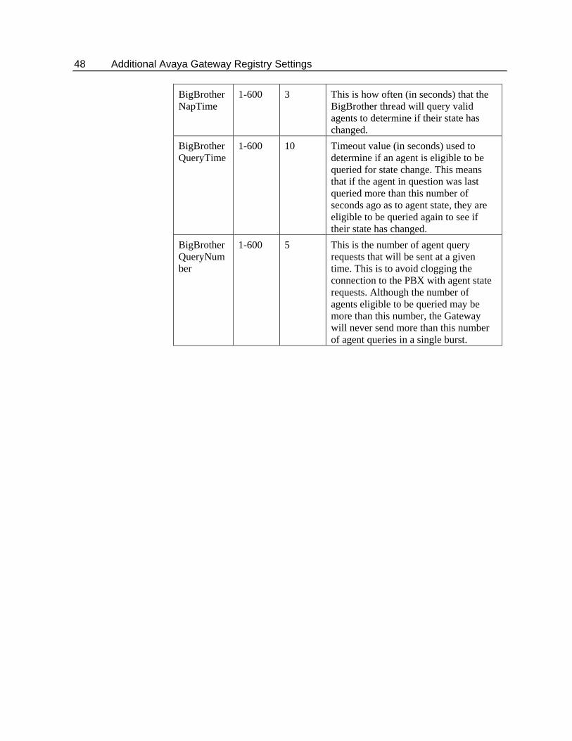
BigBrotherNapTime
1-600 3 This is how often (in seconds) that the BigBrother thread will query valid agents to determine if their state has changed.
BigBrotherQueryTime
1-600 10 Timeout value (in seconds) used to determine if an agent is eligible to be queried for state change. This means that if the agent in question was last queried more than this number of seconds ago as to agent state, they are eligible to be queried again to see if their state has changed.
BigBrotherQueryNumber
1-600 5 This is the number of agent query requests that will be sent at a given time. This is to avoid clogging the connection to the PBX with agent state requests. Although the number of agents eligible to be queried may be more than this number, the Gateway will never send more than this number of agent queries in a single burst.
49
5. ICM Scripting in the ARS Environment
This section discusses the pre-routing, post-routing, and translation routing scripts needed in ICM for the Avaya ARS PG. Pre-Routing and Post-Routing scripts can be very similar. The chapter also illustrates two examples of scripts in the ARS Environment.
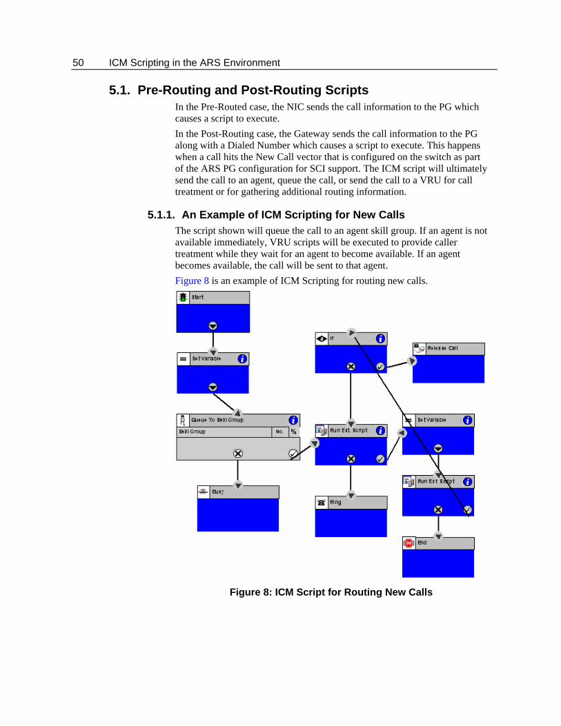
50 ICM Scripting in the ARS Environment
5.1. Pre-Routing and Post-Routing Scripts In the Pre-Routed case, the NIC sends the call information to the PG which causes a script to execute. In the Post-Routing case, the Gateway sends the call information to the PG along with a Dialed Number which causes a script to execute. This happens when a call hits the New Call vector that is configured on the switch as part of the ARS PG configuration for SCI support. The ICM script will ultimately send the call to an agent, queue the call, or send the call to a VRU for call treatment or for gathering additional routing information.
5.1.1. An Example of ICM Scripting for New Calls The script shown will queue the call to an agent skill group. If an agent is not available immediately, VRU scripts will be executed to provide caller treatment while they wait for an agent to become available. If an agent becomes available, the call will be sent to that agent. Figure 8 is an example of ICM Scripting for routing new calls.
Figure 8: ICM Script for Routing New Calls
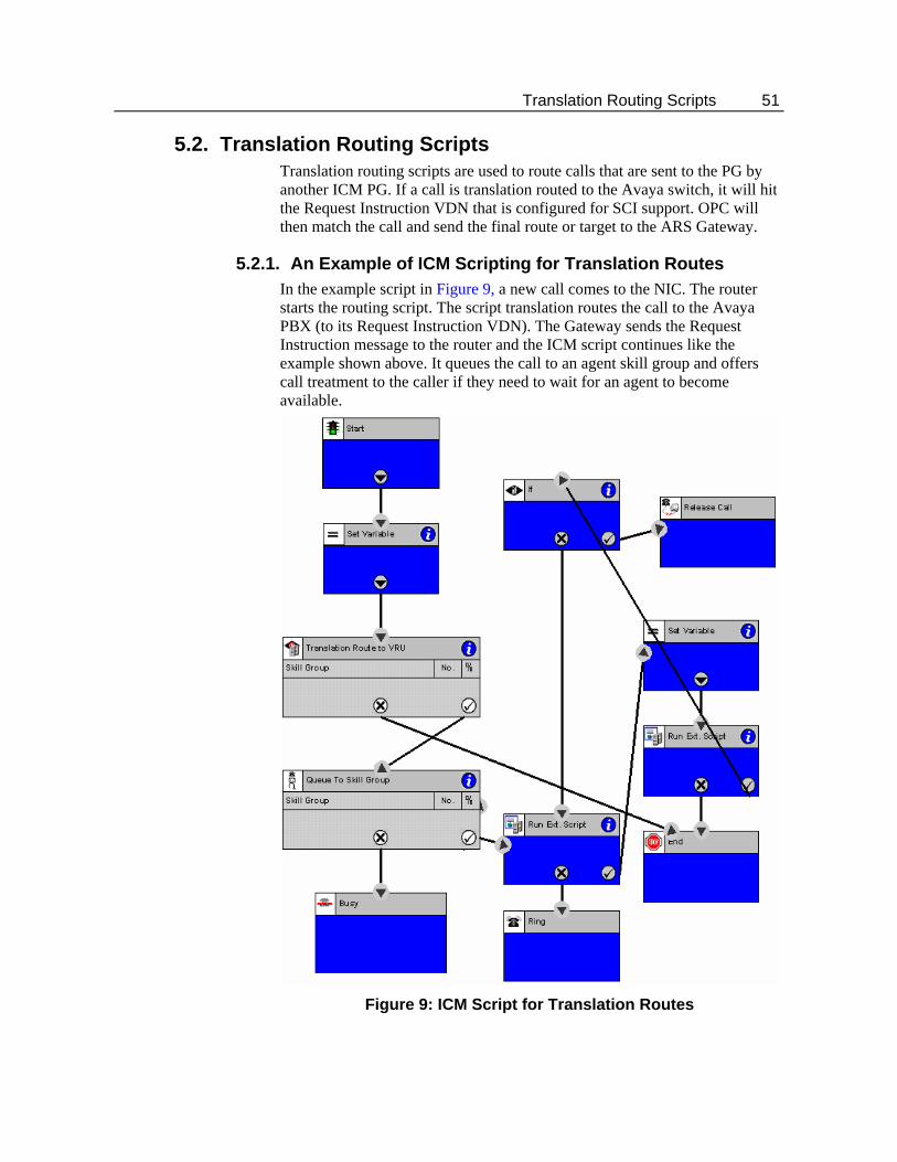
Translation Routing Scripts 51
5.2. Translation Routing Scripts Translation routing scripts are used to route calls that are sent to the PG by another ICM PG. If a call is translation routed to the Avaya switch, it will hit the Request Instruction VDN that is configured for SCI support. OPC will then match the call and send the final route or target to the ARS Gateway.
5.2.1. An Example of ICM Scripting for Translation Routes In the example script in Figure 9, a new call comes to the NIC. The router starts the routing script. The script translation routes the call to the Avaya PBX (to its Request Instruction VDN). The Gateway sends the Request Instruction message to the router and the ICM script continues like the example shown above. It queues the call to an agent skill group and offers call treatment to the caller if they need to wait for an agent to become available.
Figure 9: ICM Script for Translation Routes

52 ICM Scripting in the ARS Environment
Appendix-A
Appendix A: Process Monitor (Procmon) Commands
The procmon commands are built for the PIM and the Avaya Gateway and are available by using the respective procmon interface. Procmon <customer name> <node name> <process name>
A.1. pim_trace Commands The list for pim_trace bits can be retrieved through the procmon ltrace command
A.2. EMS Tracing Levels in Detail The registry contains an entry called “EMSTraceMask” which is used to determine what information is output to the log. The trace mask is 32 bits long (4 bytes) where each bit is used to determine whether a certain level will be output to the log file. Certain levels are dedicated to particular libraries and some levels are for general use. The Avaya Gateway uses the right-most byte (8 bits) for its tracing. By changing the value of the EMSTraceMask in the Registry, you may determine what types of traces are generated by the Gateway. In Table 18, the Define Name column shows the internal definition for the trace level. You may see references to this name in other ICM documentation. The Hex and Binary columns show the same information in two different ways. What is shown is the value of the Define Name that is used to enable a certain level of tracing output. Setting a bit to 1 will turn on tracing for that level. Finally, the Description column describes the type of trace output that is generated when the bit is set.
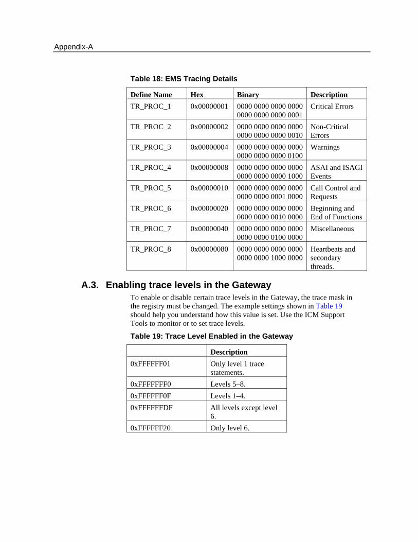
Appendix-A
Table 18: EMS Tracing Details
Define Name Hex Binary Description TR_PROC_1 0x00000001 0000 0000 0000 0000
0000 0000 0000 0001 Critical Errors
TR_PROC_2 0x00000002 0000 0000 0000 0000 0000 0000 0000 0010
Non-Critical Errors
TR_PROC_3 0x00000004 0000 0000 0000 0000 0000 0000 0000 0100
Warnings
TR_PROC_4 0x00000008 0000 0000 0000 0000 0000 0000 0000 1000
ASAI and ISAGI Events
TR_PROC_5 0x00000010 0000 0000 0000 0000 0000 0000 0001 0000
Call Control and Requests
TR_PROC_6 0x00000020 0000 0000 0000 0000 0000 0000 0010 0000
Beginning and End of Functions
TR_PROC_7 0x00000040 0000 0000 0000 0000 0000 0000 0100 0000
Miscellaneous
TR_PROC_8 0x00000080 0000 0000 0000 0000 0000 0000 1000 0000
Heartbeats and secondary threads.
A.3. Enabling trace levels in the Gateway To enable or disable certain trace levels in the Gateway, the trace mask in the registry must be changed. The example settings shown in Table 19 should help you understand how this value is set. Use the ICM Support Tools to monitor or to set trace levels.
Table 19: Trace Level Enabled in the Gateway
Description 0xFFFFFF01 Only level 1 trace
statements. 0xFFFFFFF0 Levels 5–8. 0xFFFFFF0F Levels 1–4. 0xFFFFFFDF All levels except level
6. 0xFFFFFF20 Only level 6.
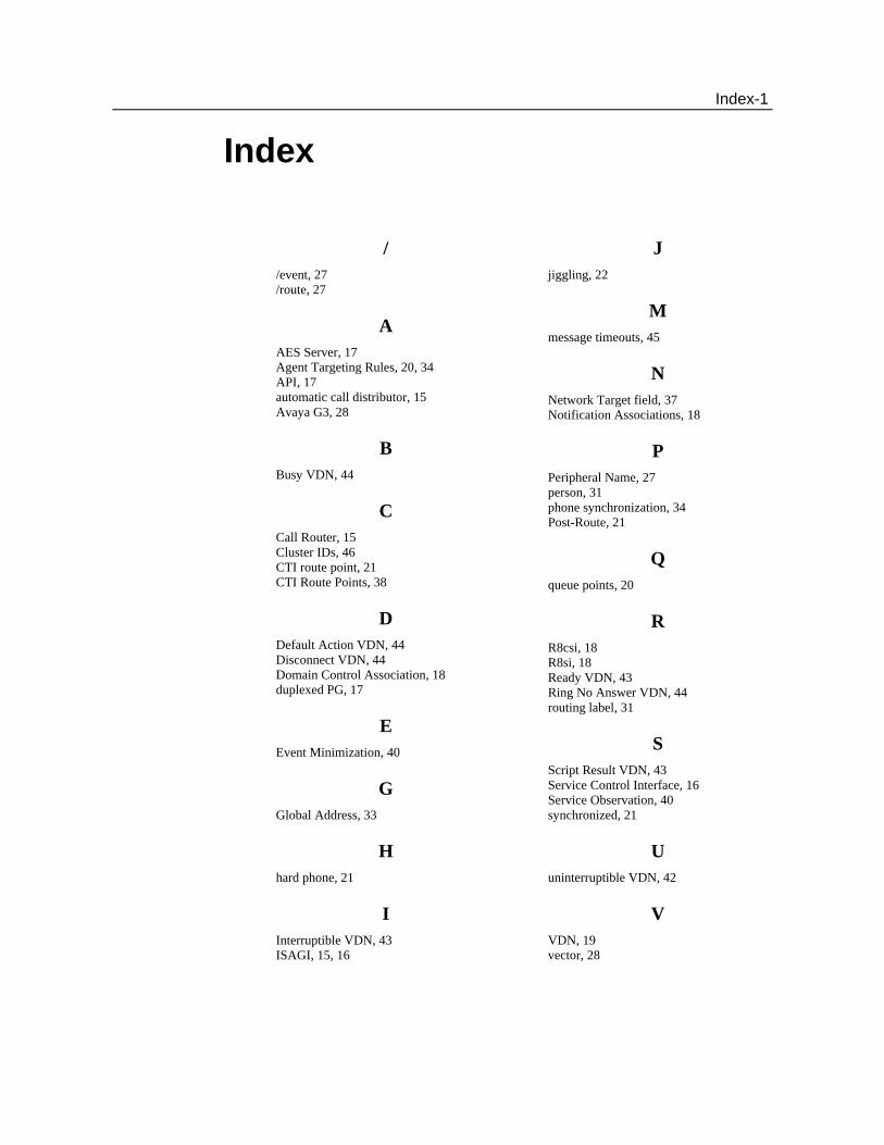
Index-1
Index
/ /event, 27 /route, 27
A AES Server, 17 Agent Targeting Rules, 20, 34 API, 17 automatic call distributor, 15 Avaya G3, 28
B Busy VDN, 44
C Call Router, 15 Cluster IDs, 46 CTI route point, 21 CTI Route Points, 38
D Default Action VDN, 44 Disconnect VDN, 44 Domain Control Association, 18 duplexed PG, 17
E Event Minimization, 40
G Global Address, 33
H hard phone, 21
I Interruptible VDN, 43 ISAGI, 15, 16
J jiggling, 22
M message timeouts, 45
N Network Target field, 37 Notification Associations, 18
P Peripheral Name, 27 person, 31 phone synchronization, 34 Post-Route, 21
Q queue points, 20
R R8csi, 18 R8si, 18 Ready VDN, 43 Ring No Answer VDN, 44 routing label, 31
S Script Result VDN, 43 Service Control Interface, 16 Service Observation, 40 synchronized, 21
U uninterruptible VDN, 42
V VDN, 19 vector, 28