Embed Size (px)
Citation preview
lable at ScienceDirect
Biomaterials 32 (2011) 1068e1079
Contents lists avai
Biomaterials
journal homepage: www.elsevier .com/locate/biomateria ls
Chitosan/Poly(3-caprolactone) blend scaffolds for cartilage repair
Sara C. Neves a,b, Liliana S. Moreira Teixeira c, Lorenzo Moroni c, Rui L. Reis a,b,Clemens A. Van Blitterswijk c, Natália M. Alves a,b, Marcel Karperien c, João F. Mano a,b,*
a3B’s Research Group e Biomaterials, Biodegradables and Biomimetics, Headquarters of the European Institute of Excellence on Tissue Engineering and Regenerative Medicine,Department of Polymer Engineering, University of Minho, AvePark, Zona Industrial da Gandra, S. Cláudio do Barco 4806-909, Caldas das Taipas, Guimarães, Portugalb IBB e Institute for Biotechnology and Bioengineering, PT Associated Laboratory, Guimarães, PortugalcMIRA e Institute for BioMedical Technology and Technical Medicine, University of Twente, Department of Tissue Regeneration, P.O. Box 217, Enschede 7500 AE, The Netherlands
a r t i c l e i n f o
Article history:Received 23 July 2010Accepted 19 September 2010Available online 27 October 2010
Keywords:ChitosanPolycaprolactoneScaffoldCartilage tissue engineering
* Corresponding author. 3B’s Research Group e BiomBiomimetics, Headquarters of the European Instituteneering and Regenerative Medicine, Department of Poof Minho, AvePark, Zona Industrial da Gandra, S. Cláuddas Taipas, Guimarães, Portugal. Tel.: þ351 253510904
E-mail address: [email protected] (J.F. Mano)
0142-9612/$ e see front matter � 2010 Elsevier Ltd.doi:10.1016/j.biomaterials.2010.09.073
a b s t r a c t
Chitosan (CHT)/poly(3-caprolactone) (PCL) blend 3D fiber-mesh scaffolds were studied as possiblesupport structures for articular cartilage tissue (ACT) repair. Micro-fibers were obtained by wet-spinningof three different polymeric solutions: 100:0 (100CHT), 75:25 (75CHT) and 50:50 (50CHT) wt.% CHT/PCL,using a common solvent solution of 100 vol.% of formic acid. Scanning electron microscopy (SEM)analysis showed a homogeneous surface distribution of PCL. PCL was well dispersed throughout the CHTphase as analyzed by differential scanning calorimetry and Fourier transform infrared spectroscopy. Thefibers were folded into cylindrical moulds and underwent a thermal treatment to obtain the scaffolds.mCT analysis revealed an adequate porosity, pore size and interconnectivity for tissue engineeringapplications. The PCL component led to a higher fiber surface roughness, decreased the scaffolds swellingratio and increased their compressive mechanical properties. Biological assays were performed afterculturing bovine articular chondrocytes up to 21 days. SEM analysis, live-dead and metabolic activityassays showed that cells attached, proliferated, and were metabolically active over all scaffolds formu-lations. Cartilaginous extracellular matrix (ECM) formation was observed in all formulations. The 75CHTscaffolds supported the most neo-cartilage formation, as demonstrated by an increase in glycosamino-glycan production. In contrast to 100CHT scaffolds, ECM was homogenously deposited on the 75CHT and50CHT scaffolds. Although mechanical properties of the 50CHT scaffold were better, the 75CHT scaffoldfacilitated better neo-cartilage formation.
� 2010 Elsevier Ltd. All rights reserved.
1. Introduction
Articular cartilage (AC) regeneration using tissue engineering(TE) approaches has been primarily proposed due to its limitedcapacity of self-repair [1,2]. This mainly derives from the lack ofa vasculature network, resulting in insufficient turn-over of healthychondrocytes to the defective sites and low productivity of char-acteristic proteins of the surrounding extracellular matrix (ECM)[1,2]. Three-dimensional (3D) scaffolds are particularly importantfor AC TE approaches because the chondrogenic phenotype ismaintained when chondrocytes are placed in a proper 3D envi-ronment [2].
aterials, Biodegradables andof Excellence on Tissue Engi-lymer Engineering, Universityio do Barco 4806-909, Caldas; fax: þ351 253510909..
All rights reserved.
Cartilage-specific ECM components play an important role inregulating expression of the chondrogenic phenotype and sup-porting chondrogenesis [3,4]. Chitosan (CHT), a naturally derivedpolysaccharide, is an excellent candidate as AC TE scaffoldingbiomaterial, due to its structural similarity with various glycos-aminoglycans (GAGs) found in cartilage [5]. It was shown tosupport chondrogenic activity [5] and to allow cartilage ECMproteins expression by chondrocytes [6,7]. However, the brittlenessin the wet state (40e50% of strain at break) of CHT scaffolds [8] isa major drawback for application in AC TE.
Among synthetic biomaterials, poly(3-caprolactone) (PCL) ishighly appealing due to its (a) physical-chemical and mechanicalcharacteristics [9], (b) easy process ability related to a relatively lowmelting temperature (ca. 60 �C) [8], (c) non-toxic degradationproducts and (d) Food and Drug Administration (FDA) approval forbiomedical applications [9]. It has been previously reported thatchondrocytes attach and proliferate on PCL films [10] and, addi-tionally, start to produce a cartilaginous ECM in PCL scaffolds[11,12]. However, PCL main drawbacks as scaffolding material
S.C. Neves et al. / Biomaterials 32 (2011) 1068e1079 1069
comprise the (a) absence of cell recognition sites, (b) its hydro-phobicity and (c) its relatively slower degradation/resorptionkinetics compared to other polyesters [13,14].
When combined, the hydrophilic nature of CHTwill enhance thewettability and permeability, with a consequent acceleration of PCLhydrolytic degradation. The PCL component is expected to lowerthe swelling ratio and improve the wet state mechanical propertiesof CHT scaffolds [15]. Moreover, the bioactivity of PCL can beenhanced when combined with natural polymers [16], as sub-micron phase separation of hydrophilic and hydrophobic domainscould be beneficial for cell adhesion.
Different methodologies have been used to combine CHT andPCL. Due to its simplicity and effectiveness, blending allowstailoring the materials properties by adjusting the blend compo-sition [17]. Moreover, polymers can co-exist with minimal chem-ical modification [8]. However, common solvents for CHT and PCLare scarce. 1,1,1,3,3,3-hexa-fluoro-2-propanol (HFlP) [18,19] oracetic acid [8,20] are, by far, the most used solvents. However,HFlP is very toxic, carcinogenic, expensive and difficult to remove[21]. Alternatively, diluted acetic acid solutions lead to phaseseparation [20].
3D scaffolds of blends of CHT and PCL for TE applications havebeen previously developed by freeze-drying [22] and particle-leaching [23,24]. 3D fiber-mesh scaffolds started to be used in TEapplications [25,26] as they present (a) an increased surface areafor cell attachment [2], (b) improved pore architecture [2], and(c) good mechanical stability [2]. Processing CHT/PCL blends fiberswas reported for the first time by electros pinning, first for neuralTE applications [27], and later in bone TE applications [28].Recently, Malheiro et al. [17] processed non-woven fibers of blendsof CHT and PCL, by wet-spinning. A common solvent solution of70:30 vol.% formic acid/acetone was used and preliminary studieswere performed on folding the fibers to obtain 3D fiber-meshes.Shalumon et al. [29] processed CHT/PCL blend electrospun fibersusing this solvent solution.
The aim of the present work was to develop CHT/PCL blendscaffolds, based on a previous methodology to produce CHT/PCLfibers [17]. Furthermore, the suitability of these structures ascartilage TE supports was analyzed. Three different formulations e100:0, 75:25 and 50:50 wt.% CHT/PCL e were used, in order toinvestigate the effect of polymer composition in the physical-chemical and biological properties of the fiber-meshes.
2. Materials and methods
2.1. Materials
CHT (low molecular weight, 75e85% deacetylation degree, Ref. 448869), PCL(80 KDa, Ref. 440744), formic acid, and methanol were purchased from SigmaeAldrich. The solvents were used without further purification. CHT was purified byrecrystallization before being used, as described elsewhere [17]. Briefly, it was dis-solved in 1% (wt./vol.) acetic acid solution and then filtered through porousmembranes (Whatman� ashes filter paper, 20e25 mm, and nylon filter sheet) intoa Buckner flask under vacuum. Adjusting the pH of the solution to about 8, throughthe addition of NaOH, caused flocculation due to deprotonation and insolubility ofthe polymer at neutral pH. The polymer was then neutralized until the pH equaledthat of distilled water, frozen at �80 �C and lyophilized. Polymeric solutions withdistinct concentrations were prepared according to the concentrations presented inTable 1.
Table 1Total polymer concentration of each fiber composition [47].
Formulation CHT/PCL weight ratio Total PolymerConcentration (wt./vol. %)
100CHT 100:0 1375CHT 75:25 1750CHT 50:50 21
2.2. Methods
2.2.1. Scaffold preparationThe polymeric solutions of CHTand CHT/PCL blends were prepared by dissolving
CHT and PCL in 100 vol.% formic acid, in the proportions of 100, 75, and 50 wt.% inCHT content (Table 1), from now referred to as 100CHT, 75CHT, and 50CHT,respectively. The solutions were left at 30 �C overnight for a complete dissolution ofboth polymers. After that, the solutions were placed into a 5 mL syringe witha capillary tip having an inner diameter of 0.8 mm. A syringe pump was used to feedthe solutions into the needle tip. A coagulation bath of methanol was used toprecipitate the solutions (0.1 mL to obtain a continuous fiber, in order to process onescaffold), and no air gap was left between the tip and the referred bath during theextrusion. The fibers were left in the methanol bath overnight to complete thesolidification process. They were neutralized with 1M NaOH solution to fullyregenerate the free amine form of the polymer chains and to avoid any CHT re-dissolution. Afterwards, the fibers were washed (at least four times) with distilledwater until the pH reached a physiological value. Subsequently, they were dehy-drated in a series of ethanol aqueous solutions (50, 70, 90 and 99.9 vol.% ethanol),folded in plastic cylindrical moulds and dried in an oven at different temperatures(Ta ¼ 45, 50, 55, 60, 65 and 75 �C) for either ta ¼ 1.5 h or 3 h, in a similar way asdescribed in [17].
2.2.2. Characterization2.2.2.1. Scanning electron microscopy (SEM). An XL 30 ESEM-FEG Philips microscopewas used to analyze the phase structures of the fibers, before and after solventetching, to evaluate the over all 3D structure of the constructs and for chondrocyteproliferation and differentiation studies. Prior SEM analysis, the constructs werefixedwith formalin (only for the biological assays), dehydrated using graded ethanolsolutions and critical point dried (Balzers CPD 030). All samples were coated withgold (Cressington Sputter Coater). The analysis was performed at an acceleratingvoltage of 10 kV and magnifications from 200� to 2000�.
2.2.2.2. Differential scanning calorimetry (DSC). The DSC experiments were con-ducted in a Q100 calorimeter with refrigerated cooling system (TA Instruments).Prior the scans, the temperature and energy calibrations were performed with anindium standard. All the samples were (a) left at 0 �C for 2 min, (b) heated from 0 to100 �C, (c) left at 100 �C for 2 min to erase the thermal history, (d) cooled down to0 �C, (e) left again at 0 �C for 2 min, and (f) re-heated to 100 �C. The heating andcooling rate was of 10 �C/min. The melting temperature (Tm) and melting enthalpy(DHm) of PCL were determined from the first and second heating scans. The peaktemperature (Tm) and peak area (DHm) values were calculated using the TAInstruments Universal Analysis software. The crystallinity degree (cc) can becalculated applying equation (1).
cc ¼ DHm=DH0uw (1)
where DHu0w is the melting enthalpy of 100% crystalline PCL (i.e. 166 J/g [17]) and w
is the weight fraction of PCL in the blend.
2.2.2.3. Fourier transform infrared (FTIR) Spectroscopic imaging measurements. APerkineElmer Spectrum Spotlight 200 FTIR Microscope Systemwas used to performthe imaging measurements. The sample fibers were embedded in a resin (Epofix Kit,Struers, composition as given by the company: bisphenol-A-(epichlorhydrin), epoxyresin, oxirane and mono[(C12-14-alkyloxy)methyl] resin) for further cross-sectionsobservation and consequent analysis in order to study the distribution of thepolymers in the fibers. The preparation of the raw PCL sample consisted in a trans-versal cut of a PCL bead. The resinwas left to solidify overnight at room temperatureand the samples were subsequently cut into z10 mm thick slices. The sectioning ofthe resin embedded samples was performed with a Leitz 1401 microtome usinga glass knife at room temperature. Spectra were collected in continuous scan modein order to construct FTIR maps, with an area of 240 � 240 mm2 and a spectralresolution of 16 cm�1, by averaging 15 scans for each spectrum. The samples wereanalyzed in transmittance. Both spectra were collected in the spectral range of4000e720 cm�1 and integrated by taking the areas under the curve between thelimits of the peaks of interest. The chosen region for CHT identification correspondsto C]O stretching of amide I, centered at approximately 1650 cm�1 [30], and for thePCL the carbonyl stretching absorption at about 1730 cm�1 [30]. There is alsoa characteristic peak of CHT that corresponds to the amine deformation vibration,centered at 1590 cm�1, but it could not be used due to overlap with an epoxy resincharacteristic peak. To represent PCL and CHT in the chemical maps, the carbonylstretching band was integrated between 1760 and 1710 cm�1, while for CHT theintegrated intensity of the band from 1670 to 1630 cm�1 was evaluated.
2.2.2.4. Micro-computed tomography (mCT). The fiber-mesh scaffolds were analyzedusing a high-resolution micro-computed tomography (mCT) Skyscan 1072 scanner(Skyscan, Kontich, Belgium). The scaffolds were scanned in a high-resolution modeusing a pixel size of 8.70 mm and integration time of 1.7 ms. The X-ray source was setat 50 keV of energy and 201 mA of current. Representative data sets of 150 slices weretransformed into a binary picture using a dynamic threshold of 60e255 (greyvalues) to distinguish polymer material from pore voids. This data was used for
S.C. Neves et al. / Biomaterials 32 (2011) 1068e10791070
morphometric analysis (CT Analyser v1.5.1.5, SkyScan), which included quantifyingthe porosity and pore size. 3D virtual models of representative regions in the bulk ofthe scaffolds were also created, visualized, and registered using both image pro-cessing softwares (ANT 3-D creator v2.4, SkyScan).
2.2.2.5. Swelling tests. For the swelling studies, dried scaffolds of each formulationwere weighted (Wd) e prior immersion in phosphate-buffered saline (PBS) for 24 h,at 37 �C. After 2, 4, 6, 8 and 24 h of immersion, the samples were weighted (wet, Ws)(n ¼ 2). The superficial water was removed prior weighing with oil paper. Theswelling ratio (Q) was obtained using equation (2).
Q ¼ ðWs �WdÞ=Wd (2)
2.2.2.6. Mechanical properties. The mechanical behavior of the three formulationscaffolds inwet state was tested, under static compression solicitation. The scaffoldswere immersed in phosphate-buffered solution (PBS) at physiological pH (z7.4) andtemperature (z37 �C) for 3 days for complete hydration. The unconfined staticcompressive mechanical properties of the scaffolds were measured using an INS-TRON 5543 (Instron Int. Ltd., U.S.A.), with a load cell of 1 kN, for 60% of strain, ata loading rate of 2 mm/min. The initial linear modulus on the stress/strain curves(n ¼ 3), obtained by the secant method, defines the compressive modulus (or Youngmodulus).
2.2.2.7. Chondrocyte Isolation and seeding. Bovine cartilage was harvested from thepatellarefemoral groove of calf legs. Cartilage tissue was cut into small pieces andchondrocytes were isolated by incubation in Dulbecco’s modified Eagle’s medium(Gibco) (DMEM) containing 0.2% type II collagenase at 37 �C for 8 h. The isolatedchondrocytes were washed, centrifuged and re-suspended in DMEM with 10% heatinactivated fetal bovine serum (FBS, SigmaeAldrich), Penicillin/Streptomycin 100U/100 mg/mL (Invitrogen), 0.1 mM MEMnonessential amino acids (Gibco), 0.2 mM
ascorbic acid 2-phosphate (Invitrogen) and 0.4 mM proline (SigmaeAldrich) andculture expanded. At confluence, the cells were detached using 0.25 wt.% trypsin insterile PBS, washed with PBS, re-suspended in culturemedium, and seeded (passage2) on the scaffolds. The seeded constructs were incubated with the medium referredabove.
For chondrogenic activity assessment studies, freshly isolated chondrocytes(passage 0) from the cartilage tissuewere immediately seeded on the scaffolds and theconstructs were cultured in chondrocyte differentiation medium composed of highglucose DMEM with 0.1 mM dexamethasone (Sigma), 2 mM L-glutamine (Glutamax,Gibco), 100 mg/mL sodium pyruvate (Sigma), 0.2 mM ascorbic acid 2-phosphate(Invitrogen), 0.4mMproline (SigmaeAldrich), 50mg/mL insulinetransferrineselenite(ITS þ Premix, BD biosciences), 100 mg/mL penicillin, 100 mg/mL streptomycin and10 ng/mL transforming growth factor-b3 (TGF-b3, R&D Systems).
Prior cell seeding in both studies, the scaffolds were sterilized by immersion ina solution of 70 vol.% of ethanol for 4 h, washed in PBS for 1 h (three times) and leftimmersed in PBS overnight. Then, the scaffolds were incubated in the followingculture media for 2 days: proliferation medium for cell viability studies and differ-entiation medium (serum-free) for chondrogenic activity studies. Cells in cultureflasks and on scaffolds were incubated in a humidified atmosphere of 5% CO2 at37 �C. The medium was replaced every 2 or 3 days. For both proliferation anddifferentiation studies, each scaffold was seeded with 5 � 105 cells (in 20 mL of cellsuspension).
2.2.2.8. Cell viability studies. Cell viability and metabolic activity was studied usinga Live-dead assay and MTT [3-(4,5-dimethyl-2-thiazolyl)-2,5-diphenyl-2HO tetra-zolium bromide] assay. At days 1, 3, 7, 14 and 21, the 3D constructs were rinsed withsterile PBS and stained with calcein/ethidium homodimer using the Live-dead assayKit (Invitrogen). Sections were immediately examined with an inverted fluorescencemicroscope (Nikon Eclipse E400) using a FITC/Texas Red filter. Calcein AM is capableof permeating the plasma membrane of viable cells, where it is cleaved by intra-cellular esterases - and produces green fluorescence. Ethidium-bromide homo-dimer-1 is able to enter cells with damaged membranes and binds to fragmentednucleic acids, thereby producing red fluorescence in dead cells.
MTT staining was performed using 1% (total medium volume) of MTT solution(5 mg/mL, Gibco) and an incubation time of 2h. Samples were visualized usinga light microscope. Dissolved MTT can be converted to an insoluble purple for-mazan by dehydrogenase enzymes that catalyze the cleavage of the tetrazoliumring in MTT.
2.2.2.9. Chondrogenic activity and extracellular matrix production assessmentstudies. For histological analysis, samples were fixed in 10% formalin for 1 h,embedded inparaffin, andprocessedusing standardhistological procedures. Sections(5 mm thick) were obtained with a microtome and used for all stainings. After rehy-dration with xylene and an ethanol series (from 100 to 70 vol.%) the samples werestained with safranin-O/fast green [31] and alcian blue/nuclear fast red [32]. Slideswere assembled with resinous medium for visualization using a light microscope(NikonEclipseE400) and representative imagescapturedusingadigital camera (SonyCorporation, Japan) and Matrix Vision Software (Matrix Vision GmbH, Germany).
DNA and GAG quantification assays were performed after 1, 14, and 21 days ofculture in differentiation medium. The constructs were taken from the chondrocytedifferentiation medium, washed in PBS and frozen at �80 �C until further pro-cessing. Afterwards, they were digested overnight at 56 �C (>16 h) in a Tris-EDTAbuffered solution containing 1 mg/mL proteinase-K, 18.5 mg/mL pepstatin A, and1 mg/mL iodoacetamide (SigmaeAldrich).
Quantification of total DNAwas performedwith Cyquant dye kit according to themanufacturers description (Molecular Probes, Eugene, Oregon, U.S.A.), usinga spectrofluorometer (Victor3, PerkineElmer, U.S.A.), at an excitation wavelength of480 nm and an emission wavelength of 520 nm (n ¼ 3, in triplicate).
GAG amount was determined spectrophotometrically (Monochromator Micro-plate Reader TECAN Safire2, Austria) after reaction with dimethylmethylene bluedye (DMMB, SigmaeAldrich) by measuring absorbance at 520 nm. The final amountwas calculated using a standard of chondroitin sulphate B (SigmaeAldrich) (n¼ 3, intriplicate).
2.2.2.10. Statistical analysis. Values on this study are reported asmean and standarddeviation. Statistical analysis was performed using the one-way ANOVA test, withp < 0.05 considered as being statistically significant.
3. Results and discussion
3.1. Physical-chemical characterization of cht/pcl fibers
100CHT, 75CHT and 50CHT fibers were successfully obtained.The approach reported by Malheiro et al. [17] was modified intoa simpler system, where the solvent solution is composed of100 vol.% of formic acid.
Phase morphology and surface properties are importantparameters to be considered when a scaffold is being designed. Thehomogeneity of the CHT/PCL polymeric blends is not only impor-tant in terms of their internal structural and mechanical integrity,but also in terms of PCL superficial domains distribution. Therefore,solvent etching was performed and the fiber surfaces wereanalyzed by SEM (Fig. 1), before and after etching. In order toremove the PCL phase of the blends, sample fibers were immersedin chloroform for 24 h, which dissolves PCL but not CHT. Beforeetching, fiber’s topography (Fig. 1 (aec)) varied between the threeformulations with an increase in surface roughness with increasingPCL concentration. After etching (Fig. 1 (def)), the blends kept theirdimensional stability, indicating that the CHT is the continuousphase in the blend. This is consistent with Cruz et al. [20], whoreported the presence of a continuous CHT phase starting at20 wt.% CHT content. Pore formationwas also observed on the fibersurface after etching, thus confirming PCL extracted domains, withsizes in the micron scale. The distribution of the pores was ratherhomogeneous in both blends. As expected, lower pore formationwas observed in etched 75CHT fibers, when compared to 50CHTfibers. Such distribution of more hydrophobic (PCL) regionsdispersed in a more hydrophilic phase (CHT) may promote proteinadsorption and cell attachment under physiological conditions.
The miscibility of the blend components was analyzed by eval-uating the changes in the Tm as a function of composition using DSC.The DSC analysis was focused on the thermal properties of the PCLphase in the blends. Thus, the temperature range chosen was from0 �C to 100 �C to cover the melting and crystallization processes ofthe PCL component. The trends obtained (from the first and secondheat scans) are presented in Fig. 2(a, b). Two heating scans werecarried out, being the first one used to infer about any effect ofprocessing on the development of the PCL structure. Analyzing thegraphs presented on Fig. 2 (c, d), both the Tm and cc values of PCL inthe blends did not vary significantly from the values of pure PCL.
The information given by the DSC analysis about polymermixing homogeneity could offer a preliminary insight about theinteraction of both polymer phases in the blends. CHT and PCL arethermodynamically not miscible, and although they may presentsome compatibility degree, this mainly depends on the preparationmethod [30]. As already pointed out by Olabarrieta et al. [33], a high
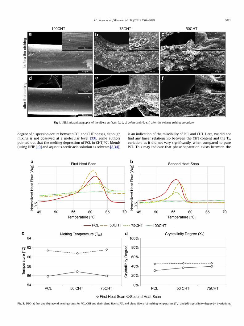
Fig. 1. SEM microphotographs of the fibers surfaces, (a, b, c) before and (d, e, f) after the solvent etching procedure.
S.C. Neves et al. / Biomaterials 32 (2011) 1068e1079 1071
degree of dispersion occurs between PCL and CHT phases, althoughmixing is not observed at a molecular level [33]. Some authorspointed out that the melting depression of PCL in CHT/PCL blends(using HFlP [19] and aqueous acetic acid solution as solvents [8,34])
Fig. 2. DSC (a) first and (b) second heating scans for PCL, CHT and their blend fibers; PCL an
is an indication of the miscibility of PCL and CHT. Here, we did notfind any linear relationship between the CHT content and the Tmvariation, as it did not vary significantly, when compared to purePCL. This may indicate that phase separation exists between the
d blend fibers (c) melting temperature (Tm) and (d) crystallinity degree (cc) variations.
S.C. Neves et al. / Biomaterials 32 (2011) 1068e10791072
two polymers. The PCL domains may aggregate and crystallizewithout significant interference from CHT. Such assumption issupported by the SEM images (Fig. 1 (def)) that show the superfi-cial features of the removed PCL domains. Corroborating thisassumption, no significant variations on the cc of the blend fiberswere observed when compared to pure PCL (Fig. 2 (d)).
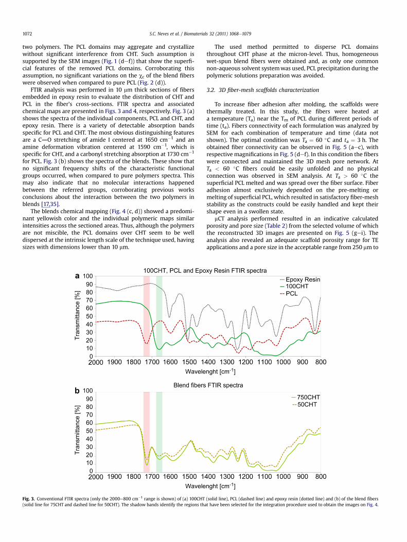
FTIR analysis was performed in 10 mm thick sections of fibersembedded in epoxy resin to evaluate the distribution of CHT andPCL in the fiber’s cross-sections. FTIR spectra and associatedchemical maps are presented in Figs. 3 and 4, respectively. Fig. 3 (a)shows the spectra of the individual components, PCL and CHT, andepoxy resin. There is a variety of detectable absorption bandsspecific for PCL and CHT. The most obvious distinguishing featuresare a C]O stretching of amide I centered at 1650 cm�1 and anamine deformation vibration centered at 1590 cm�1, which isspecific for CHT, and a carbonyl stretching absorption at 1730 cm�1
for PCL. Fig. 3 (b) shows the spectra of the blends. These show thatno significant frequency shifts of the characteristic functionalgroups occurred, when compared to pure polymers spectra. Thismay also indicate that no molecular interactions happenedbetween the referred groups, corroborating previous worksconclusions about the interaction between the two polymers inblends [17,35].
The blends chemical mapping (Fig. 4 (c, d)) showed a predomi-nant yellowish color and the individual polymeric maps similarintensities across the sectioned areas. Thus, although the polymersare not miscible, the PCL domains over CHT seem to be welldispersed at the intrinsic length scale of the technique used, havingsizes with dimensions lower than 10 mm.
Fig. 3. Conventional FTIR spectra (only the 2000e800 cm�1 range is shown) of (a) 100CHT(solid line for 75CHT and dashed line for 50CHT). The shadow bands identify the regions tha
The used method permitted to disperse PCL domainsthroughout CHT phase at the micron-level. Thus, homogeneouswet-spun blend fibers were obtained and, as only one commonnon-aqueous solvent systemwas used, PCL precipitation during thepolymeric solutions preparation was avoided.
3.2. 3D fiber-mesh scaffolds characterization
To increase fiber adhesion after molding, the scaffolds werethermally treated. In this study, the fibers were heated ata temperature (Ta) near the Tm of PCL during different periods oftime (ta). Fibers connectivity of each formulation was analyzed bySEM for each combination of temperature and time (data notshown). The optimal condition was Ta ¼ 60 �C and ta ¼ 3 h. Theobtained fiber connectivity can be observed in Fig. 5 (aec), withrespective magnifications in Fig. 5 (def). In this condition the fiberswere connected and maintained the 3D mesh pore network. AtTa < 60 �C fibers could be easily unfolded and no physicalconnection was observed in SEM analysis. At Ta > 60 �C thesuperficial PCL melted and was spread over the fiber surface. Fiberadhesion almost exclusively depended on the pre-melting ormelting of superficial PCL, which resulted in satisfactory fiber-meshstability as the constructs could be easily handled and kept theirshape even in a swollen state.
mCT analysis performed resulted in an indicative calculatedporosity and pore size (Table 2) from the selected volume of whichthe reconstructed 3D images are presented on Fig. 5 (gei). Theanalysis also revealed an adequate scaffold porosity range for TEapplications and a pore size in the acceptable range from 250 mm to
(solid line), PCL (dashed line) and epoxy resin (dotted line) and (b) of the blend fiberst have been selected for the integration procedure used to obtain the images on Fig. 4.
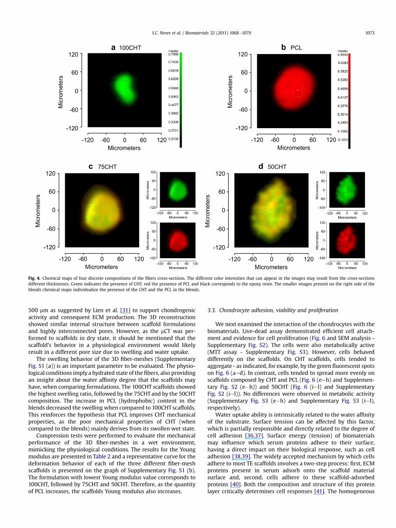
Fig. 4. Chemical maps of four discrete compositions of the fibers cross-sections. The different color intensities that can appear in the images may result from the cross-sectionsdifferent thicknesses. Green indicates the presence of CHT, red the presence of PCL and black corresponds to the epoxy resin. The smaller images present on the right side of theblends chemical maps individualize the presence of the CHT and the PCL in the blends.
S.C. Neves et al. / Biomaterials 32 (2011) 1068e1079 1073
500 mm as suggested by Lien et al. [31] to support chondrogenicactivity and consequent ECM production. The 3D reconstructionshowed similar internal structure between scaffold formulationsand highly interconnected pores. However, as the mCT was per-formed to scaffolds in dry state, it should be mentioned that thescaffold’s behavior in a physiological environment would likelyresult in a different pore size due to swelling and water uptake.
The swelling behavior of the 3D fiber-meshes (SupplementaryFig. S1 (a)) is an important parameter to be evaluated. The physio-logical conditions imply a hydrated state of thefibers, also providingan insight about the water affinity degree that the scaffolds mayhave, when comparing formulations. The 100CHT scaffolds showedthe highest swelling ratio, followed by the 75CHTand by the 50CHTcomposition. The increase in PCL (hydrophobic) content in theblends decreased the swelling when compared to 100CHT scaffolds.This reinforces the hypothesis that PCL improves CHT mechanicalproperties, as the poor mechanical properties of CHT (whencompared to the blends) mainly derives from its swollen wet state.
Compression tests were performed to evaluate the mechanicalperformance of the 3D fiber-meshes in a wet environment,mimicking the physiological conditions. The results for the Youngmodulus are presented in Table 2 and a representative curve for thedeformation behavior of each of the three different fiber-meshscaffolds is presented on the graph of Supplementary Fig. S1 (b).The formulation with lowest Young modulus value corresponds to100CHT, followed by 75CHT and 50CHT. Therefore, as the quantityof PCL increases, the scaffolds Young modulus also increases.
3.3. Chondrocyte adhesion, viability and proliferation
We next examined the interaction of the chondrocytes with thebiomaterials. Live-dead assay demonstrated efficient cell attach-ment and evidence for cell proliferation (Fig. 6 and SEM analysis -Supplementary Fig. S2). The cells were also metabolically active(MTT assay - Supplementary Fig. S3). However, cells behaveddifferently on the scaffolds. On CHT scaffolds, cells tended toaggregate - as indicated, for example, by the green fluorescent spotson Fig. 6 (aed). In contrast, cells tended to spread more evenly onscaffolds composed by CHT and PCL (Fig. 6 (eeh) and Supplemen-tary Fig. S2 (e�h)) and 50CHT (Fig. 6 (iel) and SupplementaryFig. S2 (iel)). No differences were observed in metabolic activity(Supplementary Fig. S3 (e�h) and Supplementary Fig. S3 (iel),respectively).
Water uptake ability is intrinsically related to the water affinityof the substrate. Surface tension can be affected by this factor,which is partially responsible and directly related to the degree ofcell adhesion [36,37]. Surface energy (tension) of biomaterialsmay influence which serum proteins adhere to their surface,having a direct impact on their biological response, such as celladhesion [38,39]. The widely accepted mechanism by which cellsadhere to most TE scaffolds involves a two-step process: first, ECMproteins present in serum adsorb onto the scaffold materialsurface and, second, cells adhere to these scaffold-adsorbedproteins [40]. Both the composition and structure of this proteinlayer critically determines cell responses [41]. The homogeneous
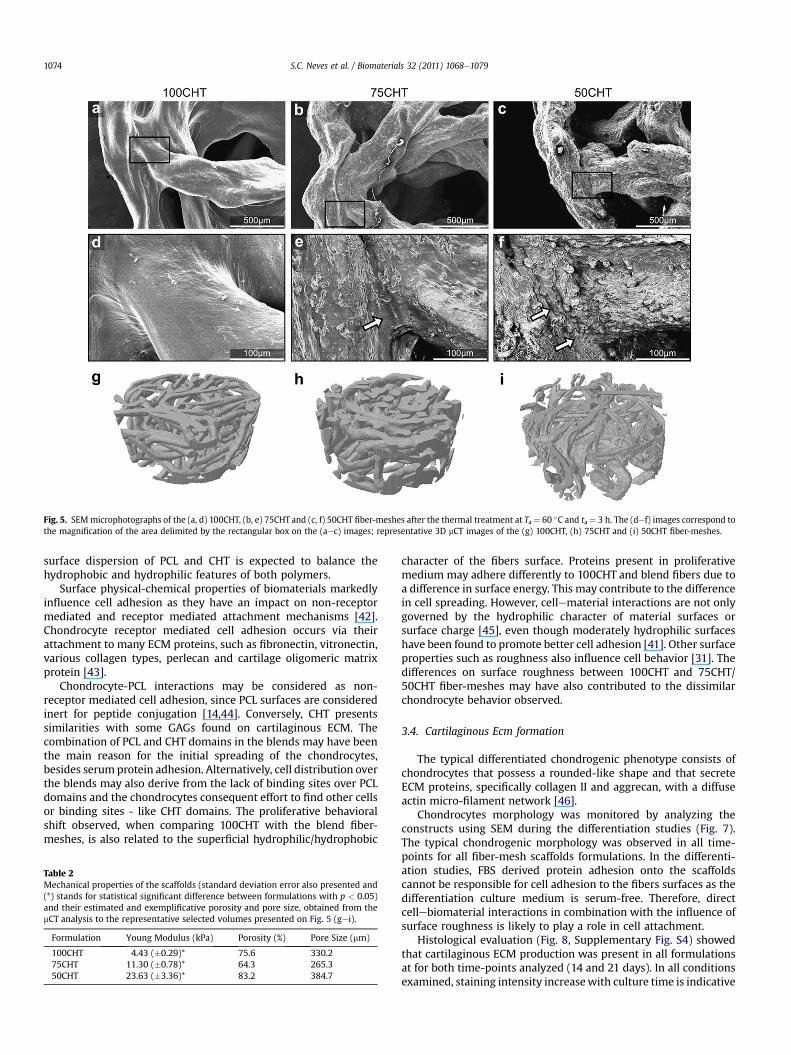
Fig. 5. SEMmicrophotographs of the (a, d) 100CHT, (b, e) 75CHT and (c, f) 50CHT fiber-meshes after the thermal treatment at Ta ¼ 60 �C and ta ¼ 3 h. The (def) images correspond tothe magnification of the area delimited by the rectangular box on the (aec) images; representative 3D mCT images of the (g) 100CHT, (h) 75CHT and (i) 50CHT fiber-meshes.
S.C. Neves et al. / Biomaterials 32 (2011) 1068e10791074
surface dispersion of PCL and CHT is expected to balance thehydrophobic and hydrophilic features of both polymers.
Surface physical-chemical properties of biomaterials markedlyinfluence cell adhesion as they have an impact on non-receptormediated and receptor mediated attachment mechanisms [42].Chondrocyte receptor mediated cell adhesion occurs via theirattachment to many ECM proteins, such as fibronectin, vitronectin,various collagen types, perlecan and cartilage oligomeric matrixprotein [43].
Chondrocyte-PCL interactions may be considered as non-receptor mediated cell adhesion, since PCL surfaces are consideredinert for peptide conjugation [14,44]. Conversely, CHT presentssimilarities with some GAGs found on cartilaginous ECM. Thecombination of PCL and CHT domains in the blends may have beenthe main reason for the initial spreading of the chondrocytes,besides serum protein adhesion. Alternatively, cell distribution overthe blends may also derive from the lack of binding sites over PCLdomains and the chondrocytes consequent effort to find other cellsor binding sites - like CHT domains. The proliferative behavioralshift observed, when comparing 100CHT with the blend fiber-meshes, is also related to the superficial hydrophilic/hydrophobic
Table 2Mechanical properties of the scaffolds (standard deviation error also presented and(*) stands for statistical significant difference between formulations with p < 0.05)and their estimated and exemplificative porosity and pore size, obtained from themCT analysis to the representative selected volumes presented on Fig. 5 (gei).
Formulation Young Modulus (kPa) Porosity (%) Pore Size (mm)
100CHT 4.43 (�0.29)* 75.6 330.275CHT 11.30 (�0.78)* 64.3 265.350CHT 23.63 (�3.36)* 83.2 384.7
character of the fibers surface. Proteins present in proliferativemedium may adhere differently to 100CHT and blend fibers due toa difference in surface energy. This may contribute to the differencein cell spreading. However, cellematerial interactions are not onlygoverned by the hydrophilic character of material surfaces orsurface charge [45], even though moderately hydrophilic surfaceshave been found to promote better cell adhesion [41]. Other surfaceproperties such as roughness also influence cell behavior [31]. Thedifferences on surface roughness between 100CHT and 75CHT/50CHT fiber-meshes may have also contributed to the dissimilarchondrocyte behavior observed.
3.4. Cartilaginous Ecm formation
The typical differentiated chondrogenic phenotype consists ofchondrocytes that possess a rounded-like shape and that secreteECM proteins, specifically collagen II and aggrecan, with a diffuseactin micro-filament network [46].
Chondrocytes morphology was monitored by analyzing theconstructs using SEM during the differentiation studies (Fig. 7).The typical chondrogenic morphology was observed in all time-points for all fiber-mesh scaffolds formulations. In the differenti-ation studies, FBS derived protein adhesion onto the scaffoldscannot be responsible for cell adhesion to the fibers surfaces as thedifferentiation culture medium is serum-free. Therefore, directcellebiomaterial interactions in combination with the influence ofsurface roughness is likely to play a role in cell attachment.
Histological evaluation (Fig. 8, Supplementary Fig. S4) showedthat cartilaginous ECM production was present in all formulationsat for both time-points analyzed (14 and 21 days). In all conditionsexamined, staining intensity increasewith culture time is indicative
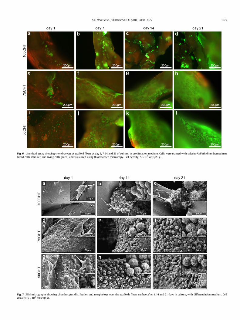
Fig. 6. Live-dead assay showing chondrocytes at scaffold fibers at day 1, 7, 14 and 21 of culture, in proliferation medium. Cells were stained with calcein-AM/ethidium homodimer(dead cells stain red and living cells green) and visualized using fluorescence microscopy. Cell density: 5�105 cells/20 mL.
Fig. 7. SEM micrographs showing chondrocytes distribution and morphology over the scaffolds fibers surface after 1, 14 and 21 days in culture, with differentiation medium. Celldensity: 5�105 cells/20 mL.
S.C. Neves et al. / Biomaterials 32 (2011) 1068e1079 1075
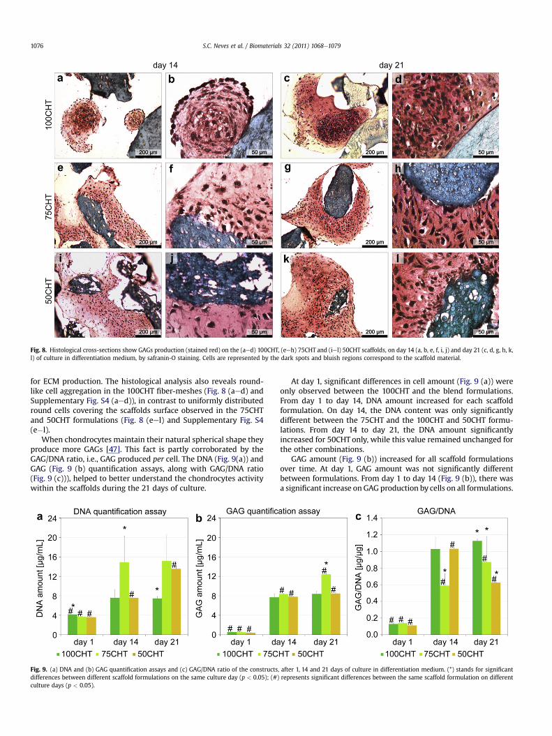
Fig. 8. Histological cross-sections show GAGs production (stained red) on the (aed) 100CHT, (eeh) 75CHT and (iel) 50CHT scaffolds, on day 14 (a, b, e, f, i, j) and day 21 (c, d, g, h, k,l) of culture in differentiation medium, by safranin-O staining. Cells are represented by the dark spots and bluish regions correspond to the scaffold material.
S.C. Neves et al. / Biomaterials 32 (2011) 1068e10791076
for ECM production. The histological analysis also reveals round-like cell aggregation in the 100CHT fiber-meshes (Fig. 8 (aed) andSupplementary Fig. S4 (aed)), in contrast to uniformly distributedround cells covering the scaffolds surface observed in the 75CHTand 50CHT formulations (Fig. 8 (eel) and Supplementary Fig. S4(e�l).
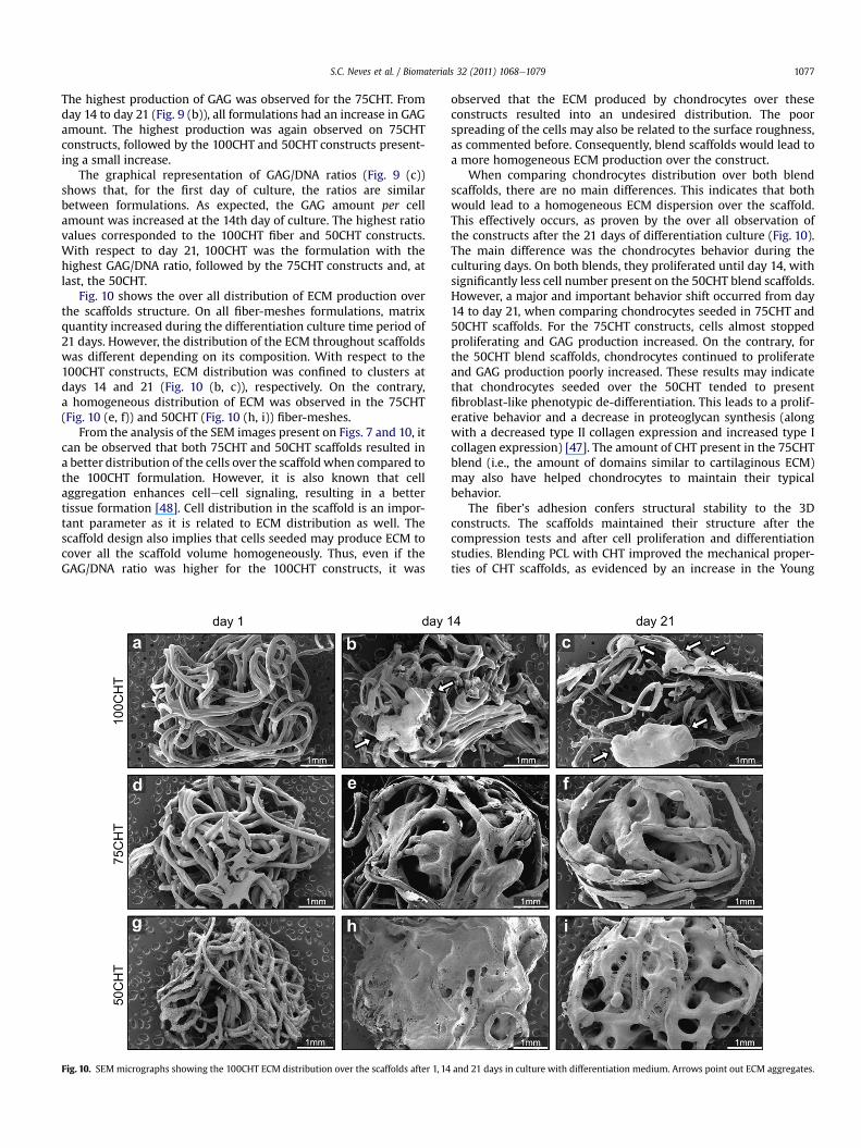
When chondrocytes maintain their natural spherical shape theyproduce more GAGs [47]. This fact is partly corroborated by theGAG/DNA ratio, i.e., GAG produced per cell. The DNA (Fig. 9(a)) andGAG (Fig. 9 (b) quantification assays, along with GAG/DNA ratio(Fig. 9 (c))), helped to better understand the chondrocytes activitywithin the scaffolds during the 21 days of culture.
Fig. 9. (a) DNA and (b) GAG quantification assays and (c) GAG/DNA ratio of the constructsdifferences between different scaffold formulations on the same culture day (p < 0.05); (#)culture days (p < 0.05).
At day 1, significant differences in cell amount (Fig. 9 (a)) wereonly observed between the 100CHT and the blend formulations.From day 1 to day 14, DNA amount increased for each scaffoldformulation. On day 14, the DNA content was only significantlydifferent between the 75CHT and the 100CHT and 50CHT formu-lations. From day 14 to day 21, the DNA amount significantlyincreased for 50CHT only, while this value remained unchanged forthe other combinations.
GAG amount (Fig. 9 (b)) increased for all scaffold formulationsover time. At day 1, GAG amount was not significantly differentbetween formulations. From day 1 to day 14 (Fig. 9 (b)), there wasa significant increase on GAG production by cells on all formulations.
, after 1, 14 and 21 days of culture in differentiation medium. (*) stands for significantrepresents significant differences between the same scaffold formulation on different
S.C. Neves et al. / Biomaterials 32 (2011) 1068e1079 1077
The highest production of GAG was observed for the 75CHT. Fromday 14 to day 21 (Fig. 9 (b)), all formulations had an increase in GAGamount. The highest production was again observed on 75CHTconstructs, followed by the 100CHT and 50CHT constructs present-ing a small increase.
The graphical representation of GAG/DNA ratios (Fig. 9 (c))shows that, for the first day of culture, the ratios are similarbetween formulations. As expected, the GAG amount per cellamount was increased at the 14th day of culture. The highest ratiovalues corresponded to the 100CHT fiber and 50CHT constructs.With respect to day 21, 100CHT was the formulation with thehighest GAG/DNA ratio, followed by the 75CHT constructs and, atlast, the 50CHT.
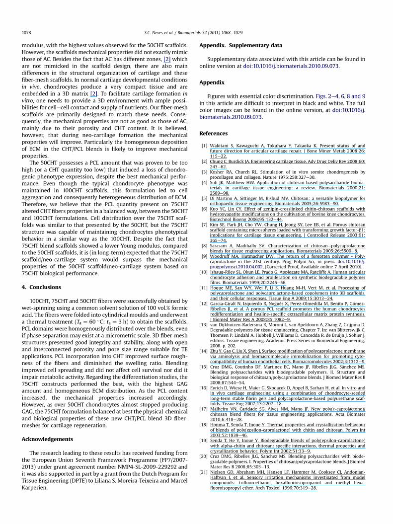
Fig. 10 shows the over all distribution of ECM production overthe scaffolds structure. On all fiber-meshes formulations, matrixquantity increased during the differentiation culture time period of21 days. However, the distribution of the ECM throughout scaffoldswas different depending on its composition. With respect to the100CHT constructs, ECM distribution was confined to clusters atdays 14 and 21 (Fig. 10 (b, c)), respectively. On the contrary,a homogeneous distribution of ECM was observed in the 75CHT(Fig. 10 (e, f)) and 50CHT (Fig. 10 (h, i)) fiber-meshes.
From the analysis of the SEM images present on Figs. 7 and 10, itcan be observed that both 75CHT and 50CHT scaffolds resulted ina better distribution of the cells over the scaffold when compared tothe 100CHT formulation. However, it is also known that cellaggregation enhances cellecell signaling, resulting in a bettertissue formation [48]. Cell distribution in the scaffold is an impor-tant parameter as it is related to ECM distribution as well. Thescaffold design also implies that cells seeded may produce ECM tocover all the scaffold volume homogeneously. Thus, even if theGAG/DNA ratio was higher for the 100CHT constructs, it was
Fig. 10. SEM micrographs showing the 100CHT ECM distribution over the scaffolds after 1, 14
observed that the ECM produced by chondrocytes over theseconstructs resulted into an undesired distribution. The poorspreading of the cells may also be related to the surface roughness,as commented before. Consequently, blend scaffolds would lead toa more homogeneous ECM production over the construct.
When comparing chondrocytes distribution over both blendscaffolds, there are no main differences. This indicates that bothwould lead to a homogeneous ECM dispersion over the scaffold.This effectively occurs, as proven by the over all observation ofthe constructs after the 21 days of differentiation culture (Fig. 10).The main difference was the chondrocytes behavior during theculturing days. On both blends, they proliferated until day 14, withsignificantly less cell number present on the 50CHT blend scaffolds.However, a major and important behavior shift occurred from day14 to day 21, when comparing chondrocytes seeded in 75CHT and50CHT scaffolds. For the 75CHT constructs, cells almost stoppedproliferating and GAG production increased. On the contrary, forthe 50CHT blend scaffolds, chondrocytes continued to proliferateand GAG production poorly increased. These results may indicatethat chondrocytes seeded over the 50CHT tended to presentfibroblast-like phenotypic de-differentiation. This leads to a prolif-erative behavior and a decrease in proteoglycan synthesis (alongwith a decreased type II collagen expression and increased type Icollagen expression) [47]. The amount of CHT present in the 75CHTblend (i.e., the amount of domains similar to cartilaginous ECM)may also have helped chondrocytes to maintain their typicalbehavior.
The fiber’s adhesion confers structural stability to the 3Dconstructs. The scaffolds maintained their structure after thecompression tests and after cell proliferation and differentiationstudies. Blending PCL with CHT improved the mechanical proper-ties of CHT scaffolds, as evidenced by an increase in the Young
and 21 days in culture with differentiation medium. Arrows point out ECM aggregates.
S.C. Neves et al. / Biomaterials 32 (2011) 1068e10791078
modulus, with the highest values observed for the 50CHT scaffolds.However, the scaffoldsmechanical properties did not exactlymimicthose of AC. Besides the fact that AC has different zones, [2] whichare not mimicked in the scaffold design, there are also maindifferences in the structural organization of cartilage and thesefiber-mesh scaffolds. In normal cartilage developmental conditionsin vivo, chondrocytes produce a very compact tissue and areembedded in a 3D matrix [2]. To facilitate cartilage formation invitro, one needs to provide a 3D environment with ample possi-bilities for cellecell contact and supply of nutrients. Our fiber-meshscaffolds are primarily designed to match these needs. Conse-quently, the mechanical properties are not as good as those of AC,mainly due to their porosity and CHT content. It is believed,however, that during neo-cartilage formation the mechanicalproperties will improve. Particularly the homogeneous depositionof ECM in the CHT/PCL blends is likely to improve mechanicalproperties.
The 50CHT possesses a PCL amount that was proven to be toohigh (or a CHT quantity too low) that induced a loss of chondro-genic phenotype expression, despite the best mechanical perfor-mance. Even though the typical chondrocyte phenotype wasmaintained in 100CHT scaffolds, this formulation led to cellaggregation and consequently heterogeneous distribution of ECM.Therefore, we believe that the PCL quantity present on 75CHTaltered CHT fibers properties in a balancedway, between the 50CHTand 100CHT formulations. Cell distribution over the 75CHT scaf-folds was similar to that presented by the 50CHT, but the 75CHTstructure was capable of maintaining chondrocytes phenotypicalbehavior in a similar way as the 100CHT. Despite the fact that75CHT blend scaffolds showed a lower Young modulus, comparedto the 50CHT scaffolds, it is (in long-term) expected that the 75CHTscaffold/neo-cartilage system would surpass the mechanicalproperties of the 50CHT scaffold/neo-cartilage system based on75CHT biological performance.
4. Conclusions
100CHT, 75CHT and 50CHT fibers were successfully obtained bywet-spinning using a common solvent solution of 100 vol.% formicacid. The fibers were folded into cylindrical moulds and underwenta thermal treatment (Ta ¼ 60 �C; ta ¼ 3 h) to obtain the scaffolds.PCL domains were homogenously distributed over the blends, evenif phase separation may exist at a micrometric scale. 3D fiber-meshstructures presented good integrity and stability, along with openand interconnected porosity and pore size range suitable for TEapplications. PCL incorporation into CHT improved surface rough-ness of the fibers and diminished the swelling ratio. Blendingimproved cell spreading and did not affect cell survival nor did itimpair metabolic activity. Regarding the differentiation studies, the75CHT constructs performed the best, with the highest GAGamount and homogeneous ECM distribution. As the PCL contentincreased, the mechanical properties increased accordingly.However, as over 50CHT chondrocytes almost stopped producingGAG, the 75CHT formulation balanced at best the physical-chemicaland biological properties of these new CHT/PCL blend 3D fiber-meshes for cartilage regeneration.
Acknowledgements
The research leading to these results has received funding fromthe European Union Seventh Framework Programme (FP7/2007-2013) under grant agreement number NMP4-SL-2009-229292 andit was also supported in part by a grant from the Dutch Program forTissue Engineering (DPTE) to Liliana S. Moreira-Teixeira and MarcelKarperien.
Appendix. Supplementary data
Supplementary data associated with this article can be found inonline version at doi:10.1016/j.biomaterials.2010.09.073.
Appendix
Figures with essential color discrimination. Figs. 2e4, 6, 8 and 9in this article are difficult to interpret in black and white. The fullcolor images can be found in the online version, at doi:10.1016/j.biomaterials.2010.09.073.
References
[1] Wakitani S, Kawaguchi A, Tokuhara Y, Takaoka K. Present status of andfuture direction for articular cartilage repair. J Bone Miner Metab 2008;26:115e22.
[2] Chung C, Burdick JA. Engineering cartilage tissue. Adv Drug Deliv Rev 2008;60:243e62.
[3] Kosher RA, Church RL. Stimulation of in vitro somite chondrogenesis byprocollagen and collagen. Nature 1975;258:327e30.
[4] Suh JK, Matthew HW. Application of chitosan-based polysaccharide bioma-terials in cartilage tissue engineering: a review. Biomaterials 2000;21:2589e98.
[5] Di Martino A, Sittinger M, Risbud MV. Chitosan: a versatile biopolymer fororthopaedic tissue-engineering. Biomaterials 2005;26:5983e90.
[6] Kuo YC, Lin CY. Effect of genipin-crosslinked chitin-chitosan scaffolds withhydroxyapatite modifications on the cultivation of bovine knee chondrocytes.Biotechnol Bioeng 2006;95:132e44.
[7] Kim SE, Park JH, Cho YW, Chung H, Jeong SY, Lee EB, et al. Porous chitosanscaffold containing microspheres loaded with transforming growth factor-b1:implications for cartilage tissue engineering. J Controlled Release 2003;91:365e74.
[8] Sarasam A, Madihally SV. Characterization of chitosanepolycaprolactoneblends for tissue engineering applications. Biomaterials 2005;26:5500e8.
[9] Woodruff MA, Hutmacher DW. The return of a forgotten polymer - Poly-caprolactone in the 21st century. Prog Polym Sci, in press. doi:10.1016/j.progpolymsci.2010.04.002, [Corrected Proof, Available online 7 April 2010].
[10] Ishaug-Riley SL, Okun LE, Prado G, Applegate MA, Ratcliffe A. Human articularchondrocyte adhesion and proliferation on synthetic biodegradable polymerfilms. Biomaterials 1999;20:2245e56.
[11] Hoque ME, San WY, Wei F, Li S, Huang M-H, Vert M, et al. Processing ofpolycaprolactone and polycaprolactone-based copolymers into 3D scaffolds,and their cellular responses. Tissue Eng A 2009;15:3013e24.
[12] Garcia-Giralt N, Izquierdo R, Nogués X, Perez-Olmedilla M, Benito P, Gómez-Ribelles JL, et al. A porous PCL scaffold promotes the human chondrocytesredifferentiation and hyaline-specific extracellular matrix protein synthesis.J Biomed Mater Res A 2008;85:1082e9.
[13] van Dijkhuizen-Radersma R, Moroni L, van Apeldoorn A, Zhang Z, Grijpma D.Degradable polymers for tissue engineering. Chapter 7. In: van Blitterswijk C,Thomsen P, Lindahl A, Hubbell J, Williams D, Cancedda R, de Bruijn J, Sohier J,editors. Tissue engineering. Academic Press Series in Biomedical Engineering;2008. p. 202.
[14] Zhu Y, Gao C, Liu X, Shen J. Surfacemodification of polycaprolactonemembranevia aminolysis and biomacromolecule immobilization for promoting cyto-compatibility of human endothelial cells. Biomacromolecules 2002;3:1312e9.
[15] Cruz DMG, Coutinho DF, Martinez EC, Mano JF, Ribelles JLG, Sánchez MS.Blending polysaccharides with biodegradable polymers. II. Structure andbiological response of chitosan/polycaprolactone blends. J Biomed Mater Res B2008;87:544e54.
[16] Eyrich D, Wiese H, Maier G, Skodacek D, Appel B, Sarhan H, et al. In vitro andin vivo cartilage engineering using a combination of chondrocyte-seededlong-term stable fibrin gels and polycaprolactone-based polyurethane scaf-folds. Tissue Eng 2007;13:2207e18.
[17] Malheiro VN, Caridade SG, Alves NM, Mano JF. New poly(3-caprolactone)/chitosan blend fibers for tissue engineering applications. Acta Biomater2010;6:418e28.
[18] Honma T, Senda T, Inoue Y. Thermal properties and crystallization behaviourof blends of poly(epsilon-caprolactone) with chitin and chitosan. Polym Int2003;52:1839e46.
[19] Senda T, He Y, Inoue Y. Biodegradable blends of poly(epsilon-caprolactone)with alpha-chitin and chitosan: specific interactions, thermal properties andcrystallization behavior. Polym Int 2002;51:33e9.
[20] Cruz DMG, Ribelles JLG, Sanchez MS. Blending polysaccharides with biode-gradable polymers. I. Properties of chitosan/polycaprolactone blends. J BiomedMater Res B 2008;85:303e13.
[21] Nielsen GD, Abraham MH, Hansen LF, Hammer M, Cooksey CJ, Andonian-Haftvan J, et al. Sensory irritation mechanisms investigated from modelcompounds: trifluoroethanol, hexafluoroisopropanol and methyl hexa-fluoroisopropyl ether. Arch Toxicol 1996;70:319e28.
S.C. Neves et al. / Biomaterials 32 (2011) 1068e1079 1079
[22] Sarasam AR, Samli AI, Hess L, Ihnat MA, Madihally SV. Blending chitosan withpolycaprolactone: porous scaffolds and toxicity. Macromol Biosci 2007;7:1160e7.
[23] Wan Y, Wu H, Cao X, Dalai S. Compressive mechanical properties and biode-gradability of porous poly(caprolactone)/chitosan scaffolds. PolymDegrad Stab2008;93:1736e41.
[24] Wan Y, Xiao B, Dalai S, Cao X, Wu Q. Development of polycaprolactone/chi-tosan blend porous scaffolds. J Mater Sci Mater Med 2009;20:719e24.
[25] Wan Y, Cao X, Zhang S, Wang S, Wu Q. Fibrous poly(chitosan-g-DL-lactic acid)scaffolds prepared via electro-wet-spinning. Acta Biomater 2008;4:876e86.
[26] Tuzlakoglu K, Alves CM, Mano JF, Reis RL. Production and characterization ofchitosan fibers and 3-D fiber mesh scaffolds for tissue engineering applica-tions. Macromol Biosci 2004;4:811e9.
[27] Prabhakaran MP, Venugopal JR, Chyan TT, Hai LB, Chan CK, Lim AY, et al.Electrospun biocomposite nanofibrous scaffolds for neural tissue engineering.Tissue Eng A 2008;14:1787e97.
[28] Yang X, Chen X, Wang H. Acceleration of osteogenic differentiation of preosteo-blastic cells by chitosan containing nanofibrous scaffolds. Biomacromolecules2009;10:2772e8.
[29] Shalumon KT, Anulekha KH, Girish CM, Prasanth R, Nair SV, Jayakumar R.Single step electrospinning of chitosan/poly(caprolactone) nanofibers usingformic acid/acetone solvent mixture. Carbohydr Polym 2010;80:413e9.
[30] Chiono V, Vozzi G, D’Acunto M, Brinzi S, Domenici C, Vozzi F, et al. Charac-terisation of blends between poly(3-caprolactone) and polysaccharides fortissue engineering applications. Materi Sci Eng C 2009;29:2174e87.
[31] Lien SM, Ko LY, Huang TJ. Effect of pore size on ECM secretion and cell growthin gelatin scaffold for articular cartilage tissue engineering. Acta Biomater2009;5:670e9.
[32] Alves da Silva ML, Crawford A, Mundy JM, Correlo VM, Sol P, Bhattacharya M.Chitosan/polyester-based scaffolds for cartilage tissue engineering: assess-ment of extracellular matrix formation. Acta Biomater 2010;6:1149e57.
[33] Olabarrieta I, Forsstrom D, Gedde UW, Hedenqvist MS. Transport properties ofchitosan and whey blended with poly(3-caprolactone) assessed by standardpermeability measurements and microcalorimetry. Polymer 2001;42:4401e8.
[34] She H, Xiao X, Liu R. Preparation and characterization of polycaprolactone-chi-tosancomposites for tissueengineeringapplications. JMaterSci2007;42:8113e9.
[35] Wan Y, Lu X, Dalai S, Zhang J. Thermophysical properties of polycaprolactone/chitosan blend membranes. Thermochim Acta 2009;487:33e8.
[36] Lampin M, Warocquier-Clérout Legris C, Degrange M, Sigot-Luizard MF.Correlation between substratum roughness and wettability, cell adhesion, andcell migration. J Biomed Mater Res 1998;36:99e108.
[37] Chang G, Absolom DR, Strong AB, Stubley GD, Zingg W. Physical and hydro-dynamic factors affecting chondrocyte adhesion to polymer surfaces. J BiomedMater Res 1988;22:13e29.
[38] Boyan BD, Hummert TW, Dean DD, Schwartz Z. Role of material surfaces inregulating bone and cartilage cell response. Biomaterials 1996;17:137e46.
[39] Olivieri MP, Rittle KH, Tweden KS, Loomis RE. Comparative biophysical studyof adsorbed calf serum, fetal bovine serum and mussel adhesive protein.Biomaterials 1992;13:201e8.
[40] Liu H, Webster TJ. Nanomedicine for implants: a review of studies andnecessary experimental tools. Biomaterials 2007;28:354e69.
[41] Elbert DL, Hubbell JA. Surface treatments of polymers for biocompatibility.Annu Rev Mater Sci 1996;26:365e94.
[42] Tsai WB, Wang MC. Effects of an avidin-biotin binding system on chondrocyteadhesion and growth on biodegradable polymers. Macromol Biosci 2005;5:214e21.
[43] Wyre RM,Downes S. The role of protein adsorption on chondrocyte adhesion toa heterocyclic methacrylate polymer system. Biomaterials 2002;23:357e64.
[44] Santiago LY, Nowak RW, Rubin JP, Marra KG. Peptide-surface modification ofpoly(caprolactone) with laminin-derived sequences for adipose-derived stemcell applications. Biomaterials 2006;27:2962e9.
[45] Lee JH, Khang G, Lee JW, Lee HB. Platelet adhesion onto chargeable functionalgroup gradient surfaces. J Biomed Mater Res 1998;40:180e6.
[46] Wang L, Verbruggen G, Almqvist K, Elewaut D, Broddelez C, Veys E. Flowcytometric analysis of the human articular chondrocyte phenotype in vitro.Osteoarthritis Cartilage 2001;9:73e84.
[47] Moroni L, Schotel R, Hamann D, de Wijn JR, van Blitterswijk CA. 3D fiber-deposited electrospun integrated scaffolds enhance cartilage tissue formation.Adv Func Mater 2008;18:53e60.
[48] Wong M, Kireeva ML, Kolesnikova TV, Lau LF. Cyr61, product of a growthfactor-inducible immediate-early gene, regulates chondrogenesis in mouselimb bud mesenchymal cells. Dev Biol 1997;192:492e508.


![VSI[sub i] space–times and the ɛ-property](https://img.dokumen.tips/doc/110x75/634fa0652630aed5000888fb/vsisub-i-spacetimes-and-the-property.jpg)


