Embed Size (px)
Citation preview
1
CHAPTER EIGHT
ELECTRIC CURRENT AND RESISTANCE
LEARNING OBJECTIVES
By the end of this chapter, you should be able to:
1. Define the following terms:- Ampere, a Coulomb, and Volt
2. (a) State Ohm’s law
(b) Define the Ohm
(c) Define resistance of a conductor and state the factors that affect the resistance
of a conductor
(d) Sketch graphs to show the variation of p.d with current for different conductors
(e) Calculate the total resistance in an electrical circuit
3. (a) Describe an experiment to determine the internal resistance of a cell
(b) Calculate the total e.m.f and internal resistance when cells are connected in
series and parallel
Electricity is a flow of charged particles which may be electrons or ions.
Electric current is defined as the rate of flow of charge round a circuit.
If Q represents the quantity of charge passing through a point in a time t seconds (s), then the
current represented by I is given by
t
QI ………………… (i)
The quantity of charge Q is measured in coulombs (C) and the current I is measured in
amperes (A).
From (i) it flows that
s
CIA
1
1 or 1 coulomb = 1 ampere x 1 second
One coulomb is the charge passing any point in a circuit when a steady current of 1 ampere
flows for 1second.
Its given by Q = I x t
The charge on about 6 million million million (6 x 10¹⁸) electrons equals 1C.
1C = 6 x 10¹⁸ electrons.
1A = 103 mA (miliampere).
1A = 106 µA (microampere).
Current measuring instruments

2
Electric current is measured using a sensitive instrument called an ammeter. The ammeter is
used for large current; for smaller current a milliammeter or micro ammeter is used.
Galvanometers are also used for detecting electric current.
The circuit symbols for galvanometer, ammeter and a cell are shown below.
For a cell, the long bar is for the positive terminal and the short bar for the negative terminal.
An ammeter is always connected in a circuit such that:
i) its positive terminal is connected to the positive terminal of the cell.
ii) the current flows directly through it, that is in series with the cell.
Potential difference (p.d)
When an electric current flows through a wire a potential difference is said to exist
between ends of wire.
The potential difference between any two points is defined as the work done, in joules, when
one coulomb of electricity (charge) moves from one point to another.
Electrons flow from a lower to a higher potential.
The unit of p.d is the volt.
Other units of p.d are millivolt (mV) and kilo volts (kV)
1V = 103mV
1kV = 103V
Volt defined as the potential difference between two points when 1 J of work is done in moving
1 C of charge between the points.
3
Electromotive force (e.m.f) The electromotive force of a cell is regarded as the sum total of the potential differences
which it can produce across all the various components of a circuit in which it is connected.
The electromotive force of a cell is defined as the total work done in joules per coulomb of electricity
conveyed in a circuit in which the cell is connected. Its unit is volt (V )
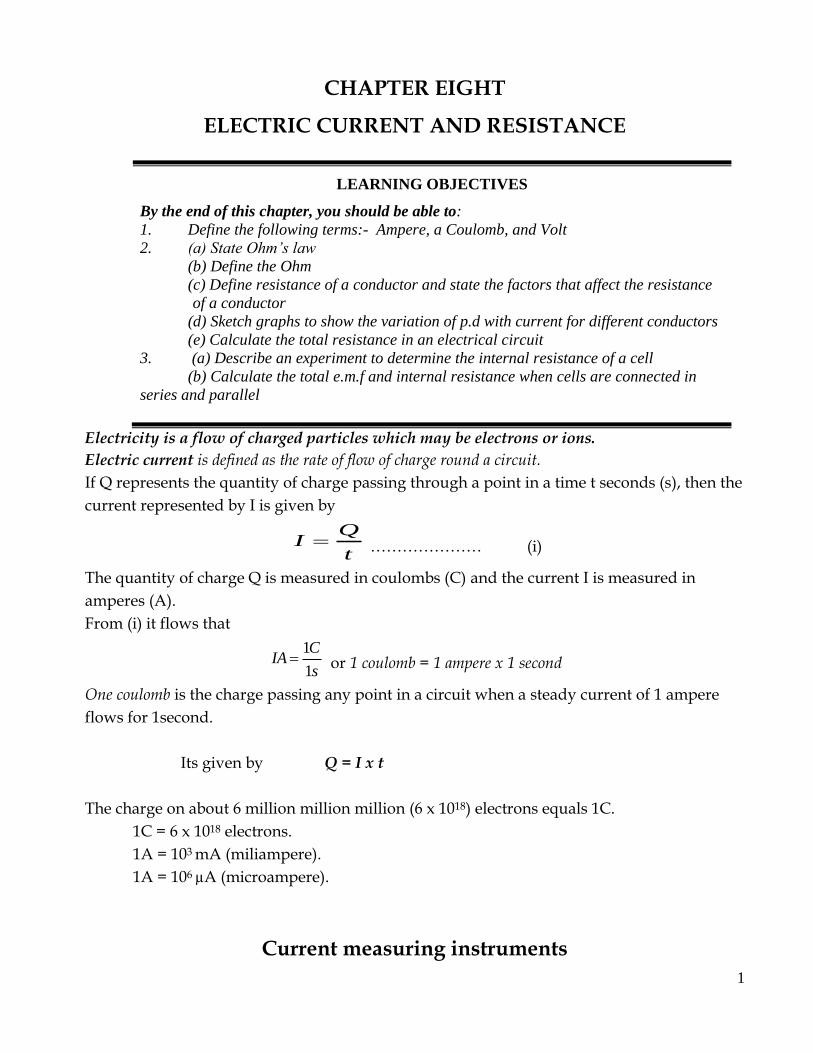
The p.d is measured by an instrument called a voltmeter. See diagrams for the symbol and
connection.
The voltmeter is connected across or in parallel with any section of where p.d is to be
measured.
Resistance
Electric resistance is opposition to the flow of electric charges in a circuit.
A good conductor has a low resistance, while a good insulator has a very high
resistance.
Generally, metals such as silver and copper have very low resistances and they are
used in connecting wires and cables in electric circuits.
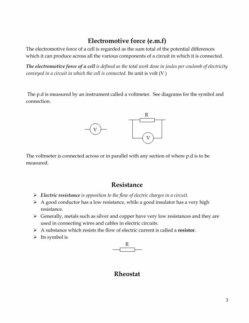
A substance which resists the flow of electric current is called a resistor.
Its symbol is
Rheostat
4
The amount of current that flows through a resistance wire can be reduced if the
length of the wire is increased. This can be reduced by a variable resistor called a
rheostat.
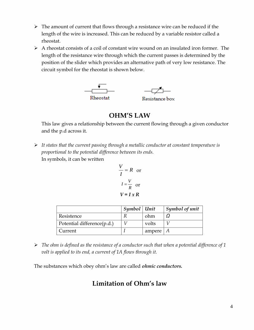
A rheostat consists of a coil of constant wire wound on an insulated iron former. The
length of the resistance wire through which the current passes is determined by the
position of the slider which provides an alternative path of very low resistance. The
circuit symbol for the rheostat is shown below.
OHM’S LAW This law gives a relationship between the current flowing through a given conductor
and the p.d across it.
It states that the current passing through a metallic conductor at constant temperature is
proportional to the potential difference between its ends.
In symbols, it can be written
RI
V or
R
VI or
V = I x R
Symbol Unit Symbol of unit
Resistence R ohm Ω
Potential difference(p.d.) V volts V
Current I ampere A
The ohm is defined as the resistance of a conductor such that when a potential difference of 1
volt is applied to its end, a current of 1A flows through it.
The substances which obey ohm’s law are called ohmic conductors.
Limitation of Ohm’s law
5
Ohm’s law is obeyed only when physical conditions of the conductor such as
temperature, length and cross-sectional area remain constant.
Ohm’s law doesn’t apply to semi conductors such as diodes, transistors and electrolytes.
These are called non- ohmic conductors
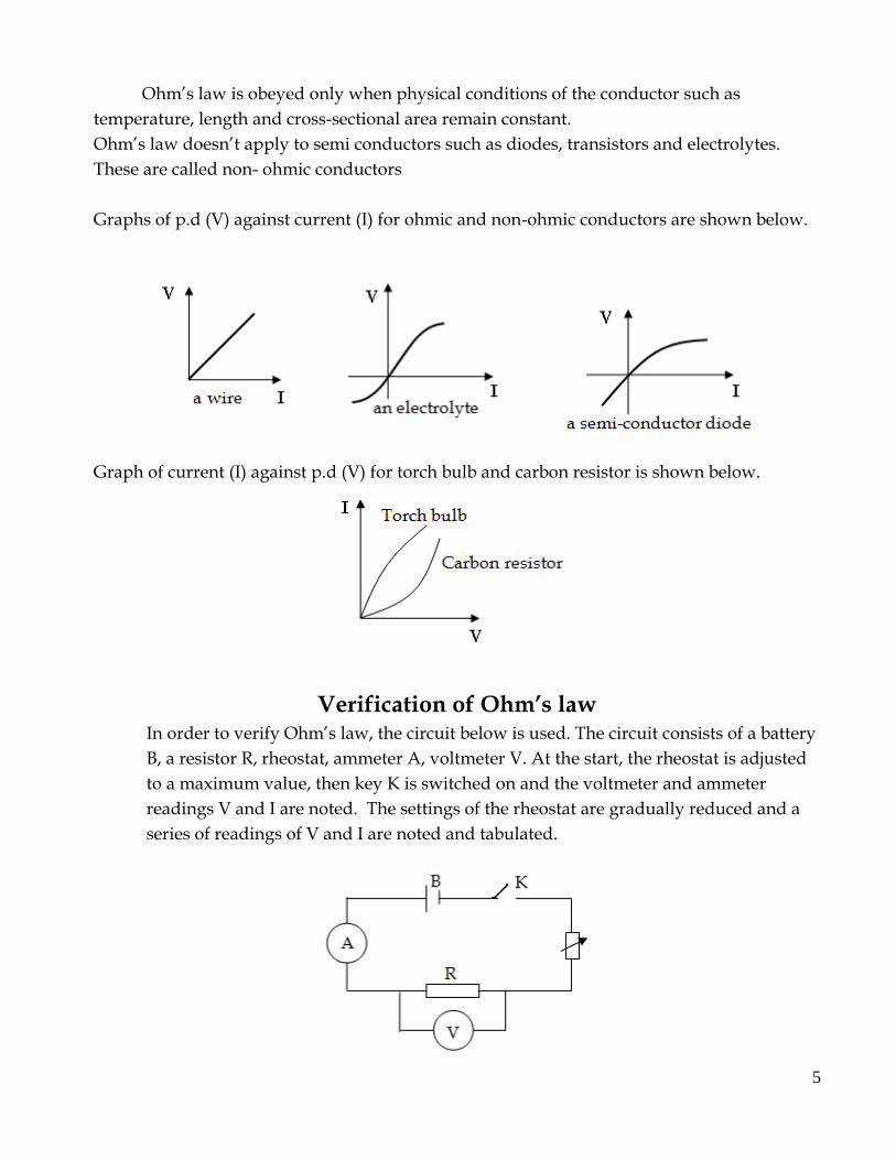
Graphs of p.d (V) against current (I) for ohmic and non-ohmic conductors are shown below.
Graph of current (I) against p.d (V) for torch bulb and carbon resistor is shown below.
Verification of Ohm’s law In order to verify Ohm’s law, the circuit below is used. The circuit consists of a battery
B, a resistor R, rheostat, ammeter A, voltmeter V. At the start, the rheostat is adjusted
to a maximum value, then key K is switched on and the voltmeter and ammeter
readings V and I are noted. The settings of the rheostat are gradually reduced and a
series of readings of V and I are noted and tabulated.
6
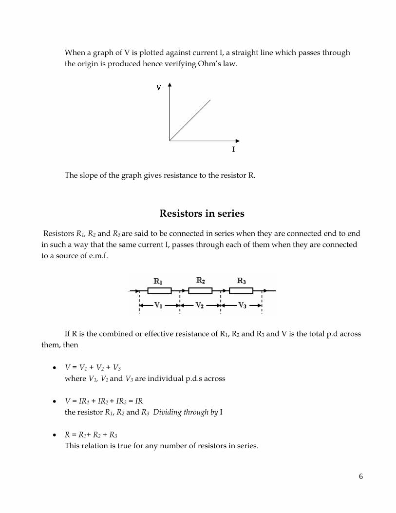
When a graph of V is plotted against current I, a straight line which passes through
the origin is produced hence verifying Ohm’s law.
The slope of the graph gives resistance to the resistor R.
Resistors in series
Resistors R1, R2 and R3 are said to be connected in series when they are connected end to end
in such a way that the same current I, passes through each of them when they are connected
to a source of e.m.f.
If R is the combined or effective resistance of R1, R2 and R3 and V is the total p.d across
them, then
V = V1 + V2 + V3
where V1, V2 and V3 are individual p.d.s across
V = IR1 + IR2 + IR3 = IR
the resistor R1, R2 and R3 Dividing through by I
R = R1+ R2 + R3
This relation is true for any number of resistors in series.
7
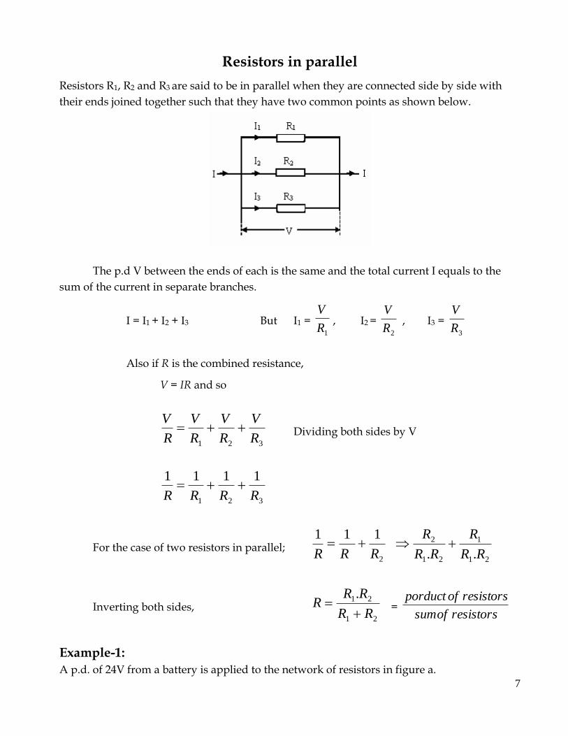
Resistors in parallel
Resistors R1, R2 and R3 are said to be in parallel when they are connected side by side with
their ends joined together such that they have two common points as shown below.
The p.d V between the ends of each is the same and the total current I equals to the
sum of the current in separate branches.
I = I1 + I2 + I3 But I1 = 1R
V, I2 =
2R
V , I3 =
3R
V
Also if R is the combined resistance,
V = IR and so
321 R
V
R
V
R
V
R
V Dividing both sides by V
321
1111
RRRR
For the case of two resistors in parallel; 2
111
RRR
21
1
21
2
.. RR
R
RR
R
Inverting both sides, 21
21.
RR
RRR
=
resistorsofsum
resistorsofporduct
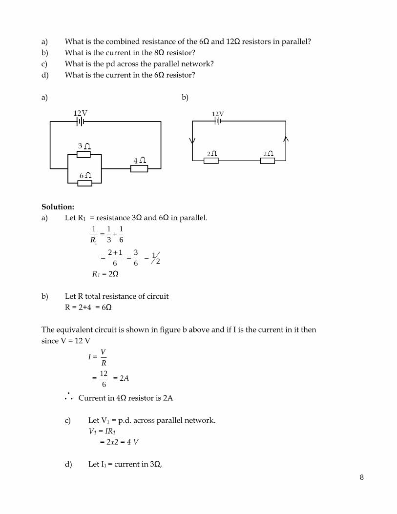
Example-1:
A p.d. of 24V from a battery is applied to the network of resistors in figure a.
8
a) What is the combined resistance of the 6Ω and 12Ω resistors in parallel?
b) What is the current in the 8Ω resistor?
c) What is the pd across the parallel network?
d) What is the current in the 6Ω resistor?
a) b)
Solution:
a) Let R1 = resistance 3Ω and 6Ω in parallel.
6
1
3
11
1
R
6
12
6
3
21
R1 = 2Ω
b) Let R total resistance of circuit
R = 2+4 = 6Ω
The equivalent circuit is shown in figure b above and if I is the current in it then
since V = 12 V
I = R
V
= 6
12 = 2A
Current in 4Ω resistor is 2A
c) Let V1 = p.d. across parallel network.
V1 = IR1
= 2x2 = 4 V
d) Let I1 = current in 3Ω,
9
then since V1 = 4 V
I1 = 3
1V
= 3
4 = 1.33A
Effects of physical properties of conductors
1. Length:
The resistance of a wire increases when the length of the wire increases
2. Cross-sectional area:
The resistance of a wire decreases when its cross-sectional area increases
3. Temperature:
The resistance of a pure metal increases when the temperature increases. For certain
conducting materials such as carbon and semi –conductors such as silicon, germanium, the
resistance decreases as the temperature increases. However, the resistance of the alloys which
are used for making standard resistors show very small resistance changes in tempo under
normal laboratory conditions.
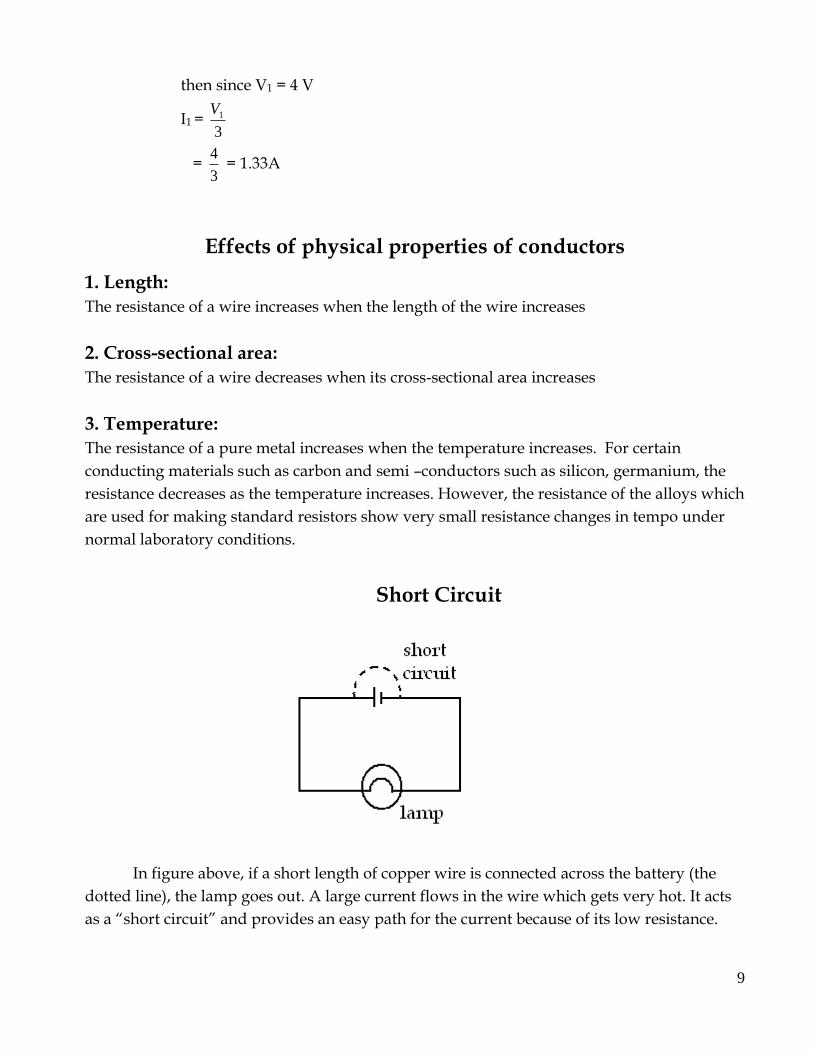
Short Circuit
In figure above, if a short length of copper wire is connected across the battery (the
dotted line), the lamp goes out. A large current flows in the wire which gets very hot. It acts
as a “short circuit” and provides an easy path for the current because of its low resistance.
10
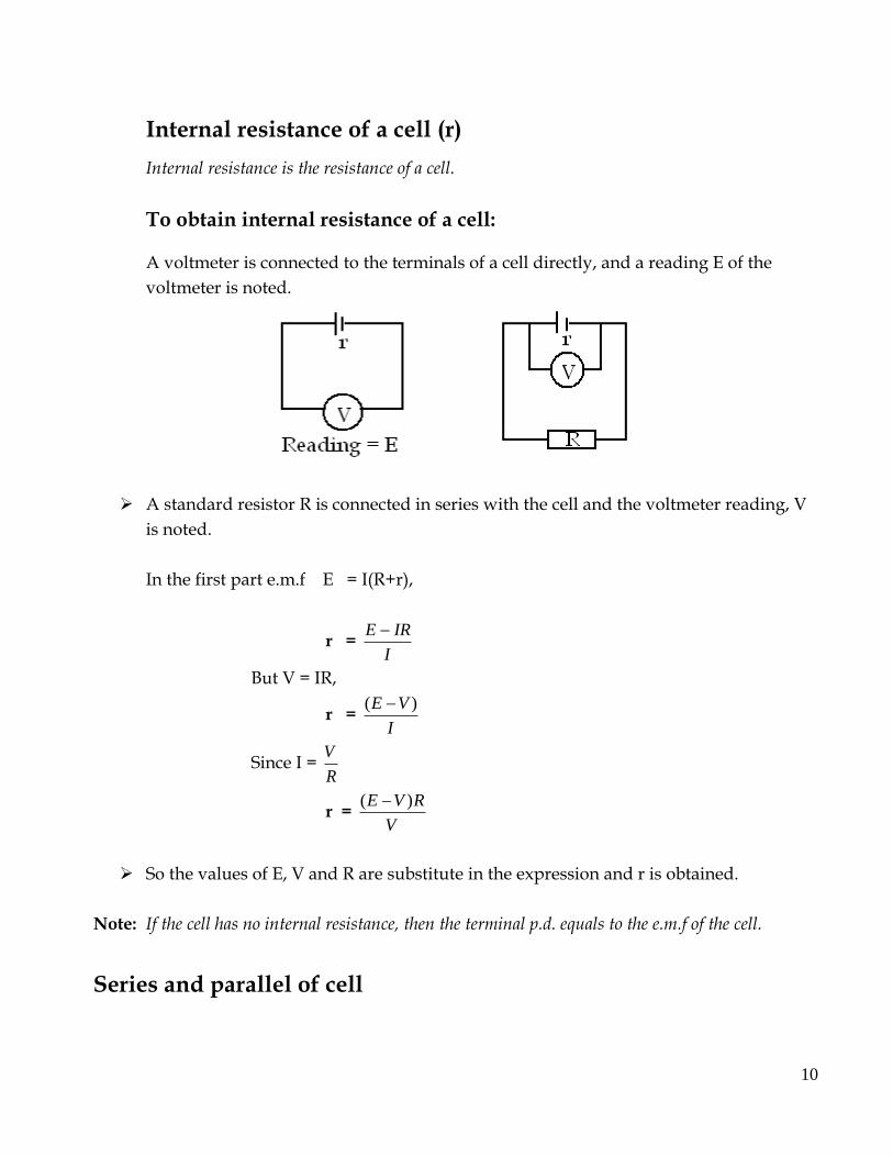
Internal resistance of a cell (r)
Internal resistance is the resistance of a cell.
To obtain internal resistance of a cell:
A voltmeter is connected to the terminals of a cell directly, and a reading E of the
voltmeter is noted.
A standard resistor R is connected in series with the cell and the voltmeter reading, V
is noted.
In the first part e.m.f E = I(R+r),
r = I
IRE
But V = IR,
r = I
VE )(
Since I = R
V
r = V
RVE )(
So the values of E, V and R are substitute in the expression and r is obtained.
Note: If the cell has no internal resistance, then the terminal p.d. equals to the e.m.f of the cell.
Series and parallel of cell
11
A group of cells connected together is called a battery. If n identical cells each of e.m.f E and
internal resistance r are connected in series as shown in the figure below (a), then the
combined e.m.f is the sum of all e.m.f`s that is nE.
The combined internal resistance is the sum of all internal resistances of individual
cells, that is nr.
When three cells are connected in parallel as shown in b, the combined e.m.f is E, since
all the cells have two common points and the combined resistance = n
r
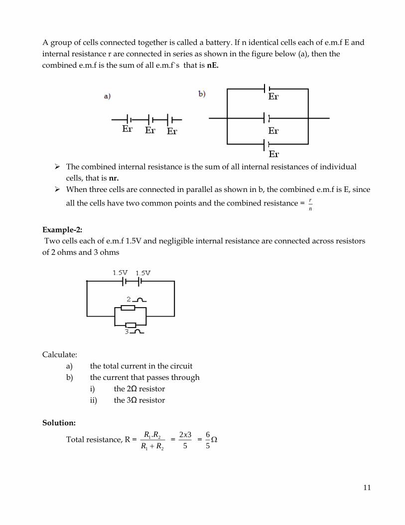
Example-2:
Two cells each of e.m.f 1.5V and negligible internal resistance are connected across resistors
of 2 ohms and 3 ohms
Calculate:
a) the total current in the circuit
b) the current that passes through
i) the 2Ω resistor
ii) the 3Ω resistor
Solution:
Total resistance, R = 21
21.
RR
RR
=
5
32x =
5
6

12
Equivalent circuit,
a) Total current, I = 6
53
56
3 x
R
V = 2.5A
b) (i) Current through 2Ω = I1 = A5.12
3
(ii) current through 3Ω = I2 = A0.13
3
Example-3:
Two cells each having an emf of 1.5V and an internal resistance of 2Ω are connected a) in
series, and b) in parallel.
Find the current in each case when the cells are connected to a 1Ω resistor.
a) b)
Solution:
a) Total resistance R = R1+R2+R3 (in series)
= 2+2+1 = 5Ω
current flowing I = 5
0.3
R
V = 0.6A
b) Total resistance in parallel R3 = 21
21.
RR
RR
=
1
4
4
22
22x
total resistance = R = R + R3 = 1+1 = 2Ω
13
current flowing = 2
5.1
R
V= 0.75A
TEST SIX
SECTION A
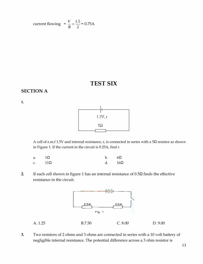
1.
A cell of e.m.f 1.5V and internal resistance, r, is connected in series with a 5Ω resistor as shown
in Figure 1. If the current in the circuit is 0.25A, find r.
a. 1Ω b. 6Ω
c. 11Ω d. 16Ω
2. If each cell shown in figure 1 has an internal resistance of 0.5Ω finds the effective
resistance in the circuit.
A. 1.25 B.7.50 C. 8.00 D. 9.00
3. Two resistors of 2 ohms and 3 ohms are connected in series with a 10 volt battery of
negligible internal resistance. The potential difference across a 3 ohm resistor is

14
a) 2V b) 5V c) 6V d) 10V
4. A bulb is rated 40V, 60W. Find its resistance
a) 26.7Ω b)410Ω c) 120Ω d) 960Ω
5. In figure below, the ammeter A reads 4A and the voltmeter V reads 4V.find the value
of R.
A. 1Ω B. 2Ω C. 3Ω D. 4Ω
6. Three cells each of e.m.f 2V and negligible internal resistance are connected to two
resistors as shown in the circuit in the figure. The reading of the ammeter is
(a) 0.40 A (b) 0.83 A (c) 1.20 A (d) 7.20 A
7. Figure below shows a network of resistors. The effective resistance between points P
and Q is

15
A. 0.97Ω. B. 1.2Ω. C. 2.5Ω. D. 10Ω.
8. The resistance of a metal in the form of a wire increases with
(a) decrease in length
(b) increase in temperature
(c) decrease in temperature
(d) increase in cross-sectional area
9. The diagram in the below figure shows three resistors connected in a circuit.
What is the effective resistance of the current
A. 20.0Ω B. 47.5Ω C. 60.0Ω D. 90.0Ω
10. A battery of e. m. f. 12 V is connected across two resistors of
6 Ω and 3Ω as shown in the figure.

16
Which of the following statements is true about the circuit? The
a) p.d across 6Ω is half the p.d across 3Ω
b) p.d across 6 Ω is twice the p.d across 3Ω
c) p.d across 6Ω is equal to p.d across 3Ω
d) reading of the voltmeter V is greater than 12V
11. Two coils of wire of resistances 2Ω and 3 Ω are connected in series to a 10V battery of
negligible internal resistance. The current through the 2Ω resistor is
a) 0.5 A b) 2 A c) 5 A d) 50 A
12. The total resistance between X and Y in the figure below is
(a) 20.0Ω (b) 9.50Ω (c) 6.50Ω (d) 4.20Ω
13. Two cells each of e.m.f 1.5V and internal resistance 0.5Ω are connected in series with a
resistor of 2Ω as in the figure below.
The reading of the voltmeter V when S is closed is
(a) 1.0V (b) 1.5V (c) 2.0V (d) 3.0V
14.
17
The voltage supply in the circuit in the above figure is
(a) 0.25V (b) 4.0V (c) 25V (d) 250V
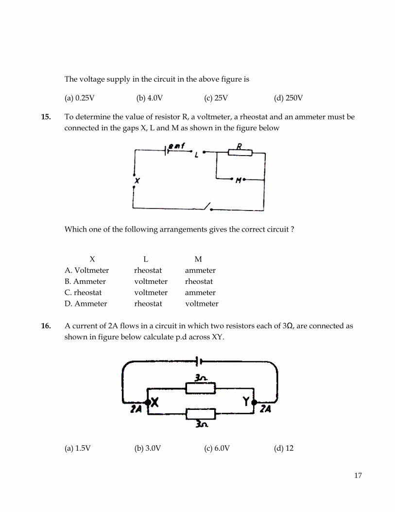
15. To determine the value of resistor R, a voltmeter, a rheostat and an ammeter must be
connected in the gaps X, L and M as shown in the figure below
Which one of the following arrangements gives the correct circuit ?
X L M
A. Voltmeter rheostat ammeter
B. Ammeter voltmeter rheostat
C. rheostat voltmeter ammeter
D. Ammeter rheostat voltmeter
16. A current of 2A flows in a circuit in which two resistors each of 3Ω, are connected as
shown in figure below calculate p.d across XY.
(a) 1.5V (b) 3.0V (c) 6.0V (d) 12

18
17. Which of the following is true about both alternating current and direct current
(i) Cause heating
(ii) can be stepped up or down with transformer
(iii) Can be used to charge a battery
a) (i) only b) (i) and (ii)
c) (ii) and (iii) d) (i), (ii), (iii)
18.
When the circuit in the above figure is switched on, the voltmeter.
A. shows no deflection.
B. deflects in the wrong direction.
C. reads e.m.f of the cell.
D. reads the terminal difference across the cell.
SECTION B
1. (a) Define the volt.
(b) (i) What is the effective resistance in the circuit in the figure.
(The cell has negligible resistance).
(ii) What will be the reading of the voltmeter when the key K is closed?

19
2. When two identical heating elements of a kettle are connected in series to a 240V
supply, the power developed is 400W. Find;
(i) the resistance of the either element
(ii) the power developed when the elements are connected in parallel to the same
supply
3. (a) Draw sketch graphs of p.d, V against current, I, for the following
(i) a wire
(ii) an electrolyte
(iii) a semi conductor diode
4. a) Explain the differences between a voltimeter and an ammeter
interms of their
(i) construction
(ii) use
b) State three physical properties that affect the resistance of a solid conductor
5.
Two cells each of e.m.f 1.5V and negligible internal resistance are connected in series
across two resistors of 2Ω and 3Ω as shown in the above figure. Calculate the current
(i) supplied by the cells
(ii) that passes through the 3Ω resistor
6. (a) State ohm’s law?
(b) Describe a simple experiment to measure the internal resistance of a
Cell.
7.
20
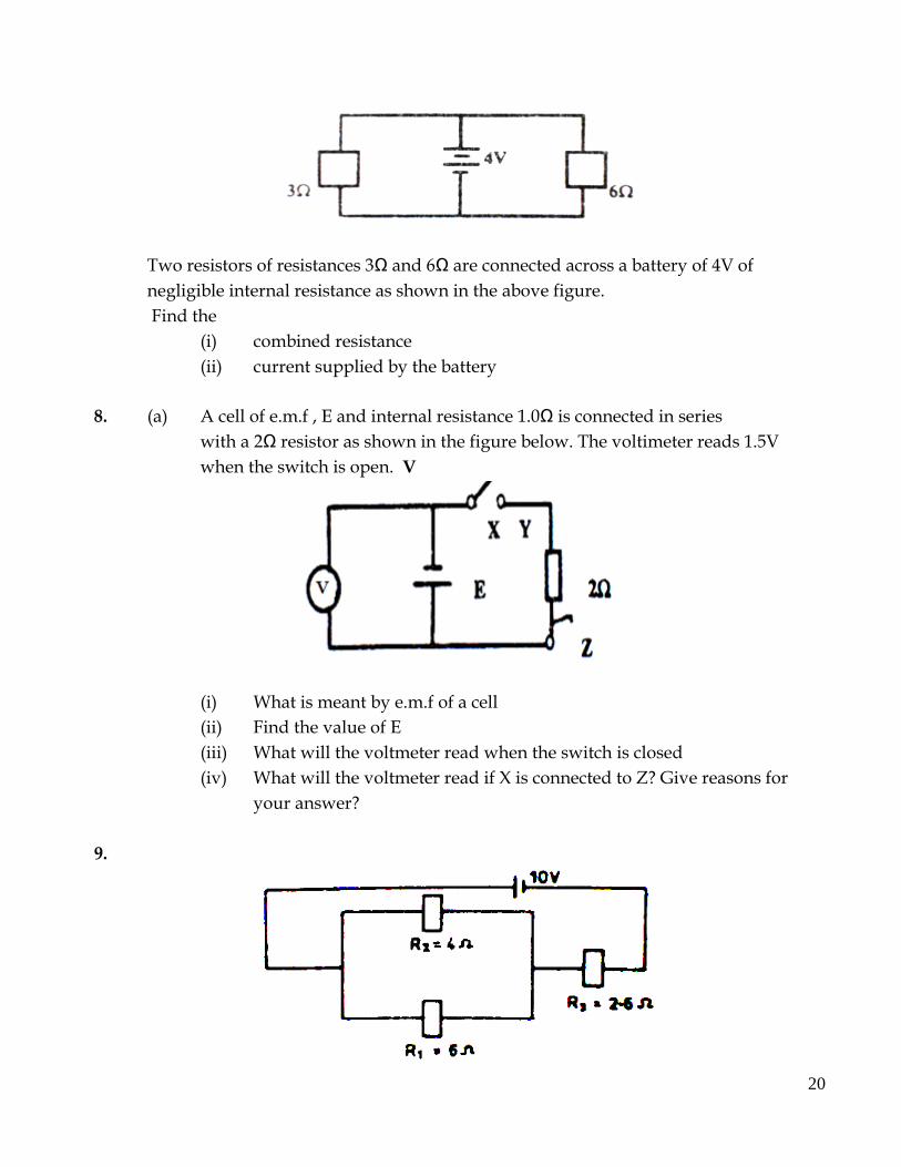
Two resistors of resistances 3Ω and 6Ω are connected across a battery of 4V of
negligible internal resistance as shown in the above figure.
Find the
(i) combined resistance
(ii) current supplied by the battery
8. (a) A cell of e.m.f , E and internal resistance 1.0Ω is connected in series
with a 2Ω resistor as shown in the figure below. The voltimeter reads 1.5V
when the switch is open. V
(i) What is meant by e.m.f of a cell
(ii) Find the value of E
(iii) What will the voltmeter read when the switch is closed
(iv) What will the voltmeter read if X is connected to Z? Give reasons for
your answer?
9.
21
A battery of e.m.f 10V and negligible internal resistance is connected to resistors R1,
R2 and R3 of resistances 6Ω, 4Ω and 2.6Ω respectively as shown in the above figure.
(i) Calculate the effective resistance of the circuit
(ii) Find the rate at which the electrical energy is converted to heat energy in R3.
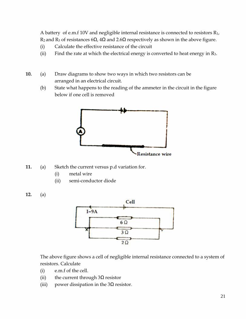
10. (a) Draw diagrams to show two ways in which two resistors can be
arranged in an electrical circuit.
(b) State what happens to the reading of the ammeter in the circuit in the figure
below if one cell is removed
11. (a) Sketch the current versus p.d variation for.
(i) metal wire
(ii) semi-conductor diode
12. (a)
The above figure shows a cell of negligible internal resistance connected to a system of
resistors. Calculate
(i) e.m.f of the cell.
(ii) the current through 3Ω resistor
(iii) power dissipation in the 3Ω resistor.
22
13. Describe the energy changes which occur from the time an electric bulb is switched on.
14. (a) Draw a circuit diagram which can be used to investigate the p.d-
current relationship for a wire
(b) Sketch a graph of current against p.d for
(i) carbon resistor
(ii) a semi-conductor diode
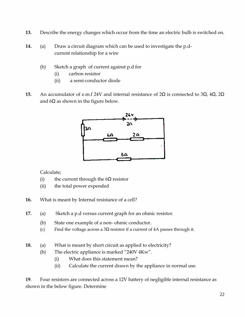
15. An accumulator of e.m.f 24V and internal resistance of 2Ω is connected to 3Ω, 4Ω, 2Ω
and 6Ω as shown in the figure below.
Calculate;
(i) the current through the 6Ω resistor
(ii) the total power expended
16. What is meant by Internal resistance of a cell?
17. (a) Sketch a p.d versus current graph for an ohmic resistor.
(b) State one example of a non- ohmic conductor.
(c) Find the voltage across a 3Ω resistor if a current of 4A passes through it.
18. (a) What is meant by short circuit as applied to electricity?
(b) The electric appliance is marked “240V 4Kw”.
(i) What does this statement mean?
(ii) Calculate the current drawn by the appliance in normal use.
19. Four resistors are connected across a 12V battery of negligible internal resistance as
shown in the below figure. Determine

23
(i) the reading of the ammeter A
(ii) the p.d across the parallel combination of resistors
20.
The above graph shows the variation of current with p.d across a device. Use the
graph to find the resistance of the device
24
TEST SIX 1.A 2.D 3.C 4.A 5.B 6.C 7.C 8.B 9.B 10.C 11.B 12.C 13.C 14.D 15.D 16.B 17.A 18.B


