Embed Size (px)
Citation preview
Copyright ©2011 by Pearson Education, Inc.
publishing as Pearson [imprint] Introductory Circuit Analysis, 12/e
Boylestad
Chapter 10
Capacitors
Introductory Circuit Analysis, 12/e
Boylestad
Copyright ©2011 by Pearson Education, Inc.
publishing as Pearson [imprint]
OBJECTIVES
• Become familiar with the basic construction of a capacitor and the factors that affect its ability to store charge on its plates.
• Be able to determine the transient (time-varying) response of a capacitive network and plot the resulting voltages and currents.
• Understand the impact of combining capacitors in series or parallel and how to read the nameplate data.
• Develop some familiarity with the use of computer methods to analyze networks with capacitive elements.
Introductory Circuit Analysis, 12/e
Boylestad
Copyright ©2011 by Pearson Education, Inc.
publishing as Pearson [imprint]
INTRODUCTION
• The capacitor has a significant impact on
the types of networks that you will be able
to design and analyze.
• Like the resistor, it is a two-terminal device,
but its characteristics are totally different
from those of a resistor.
• In fact, the capacitor displays its true
characteristics only when a change in the
voltage or current is made in the network.
Introductory Circuit Analysis, 12/e
Boylestad
Copyright ©2011 by Pearson Education, Inc.
publishing as Pearson [imprint]
THE ELECTRIC FIELD
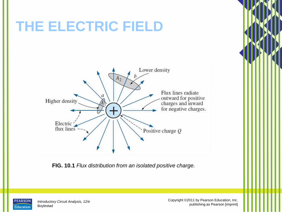
• This electric field is represented by
electric flux lines, which are drawn
to indicate the strength of the electric
field at any point around the charged
body.
• The denser the lines of flux, the
stronger is the electric field.
Introductory Circuit Analysis, 12/e
Boylestad
Copyright ©2011 by Pearson Education, Inc.
publishing as Pearson [imprint]
THE ELECTRIC FIELD
FIG. 10.1 Flux distribution from an isolated positive charge.
Introductory Circuit Analysis, 12/e
Boylestad
Copyright ©2011 by Pearson Education, Inc.
publishing as Pearson [imprint]
THE ELECTRIC FIELD
Introductory Circuit Analysis, 12/e
Boylestad
Copyright ©2011 by Pearson Education, Inc.
publishing as Pearson [imprint]
THE ELECTRIC FIELD
Introductory Circuit Analysis, 12/e
Boylestad
Copyright ©2011 by Pearson Education, Inc.
publishing as Pearson [imprint]
THE ELECTRIC FIELD
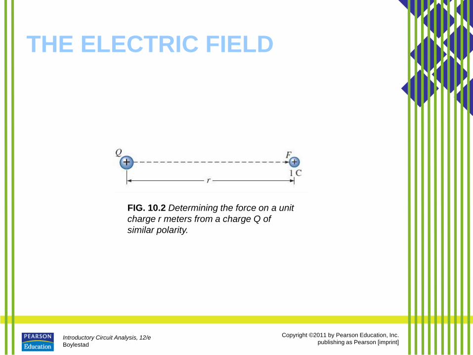
FIG. 10.2 Determining the force on a unit
charge r meters from a charge Q of
similar polarity.
Introductory Circuit Analysis, 12/e
Boylestad
Copyright ©2011 by Pearson Education, Inc.
publishing as Pearson [imprint]
THE ELECTRIC FIELD
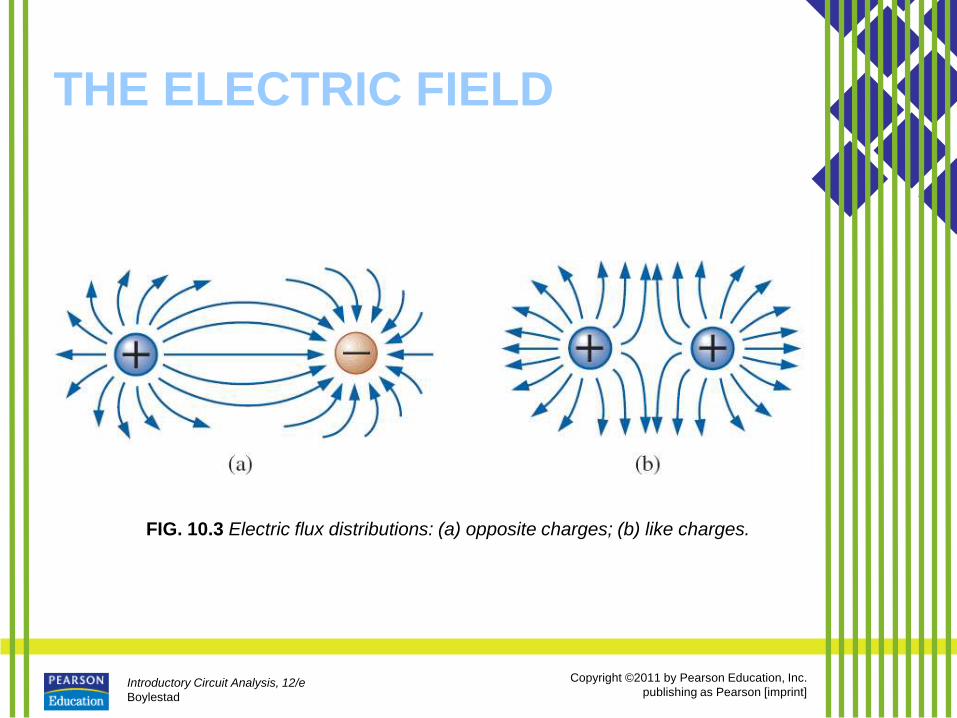
FIG. 10.3 Electric flux distributions: (a) opposite charges; (b) like charges.
Introductory Circuit Analysis, 12/e
Boylestad
Copyright ©2011 by Pearson Education, Inc.
publishing as Pearson [imprint]
THE ELECTRIC FIELD
• In general, electric flux lines always
extend from a positively charged
body to a negatively charged body,
always extend or terminate
perpendicular to the charged
surfaces, and never intersect.
Introductory Circuit Analysis, 12/e
Boylestad
Copyright ©2011 by Pearson Education, Inc.
publishing as Pearson [imprint]
CAPACITANCE
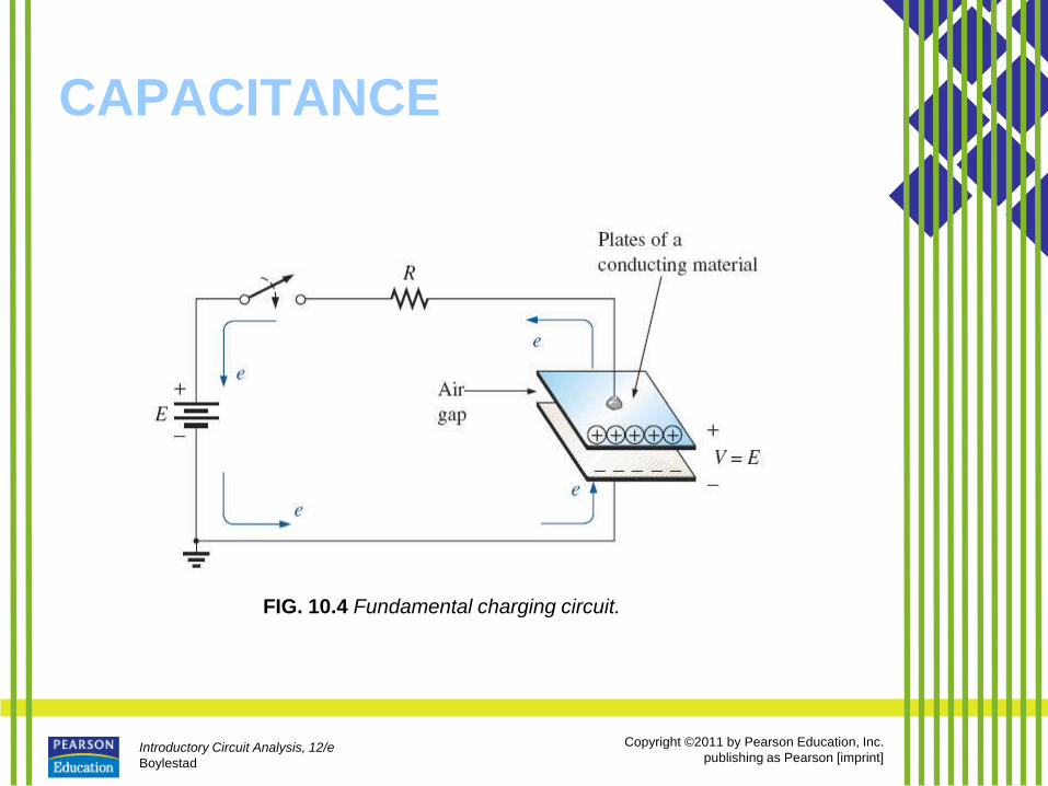
FIG. 10.4 Fundamental charging circuit.
Introductory Circuit Analysis, 12/e
Boylestad
Copyright ©2011 by Pearson Education, Inc.
publishing as Pearson [imprint]
CAPACITANCE
• Capacitance is a measure of a
capacitor’s ability to store charge
on its plates—in other words, its
storage capacity.
– In addition, the higher the capacitance
of a capacitor, the greater is the
amount of charge stored on the
plates for the same applied voltage.
Introductory Circuit Analysis, 12/e
Boylestad
Copyright ©2011 by Pearson Education, Inc.
publishing as Pearson [imprint]
CAPACITANCE
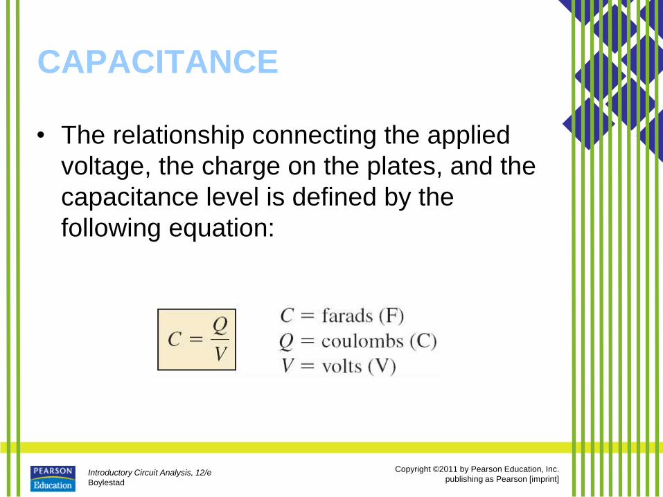
• The relationship connecting the applied
voltage, the charge on the plates, and the
capacitance level is defined by the
following equation:
Introductory Circuit Analysis, 12/e
Boylestad
Copyright ©2011 by Pearson Education, Inc.
publishing as Pearson [imprint]
CAPACITANCE
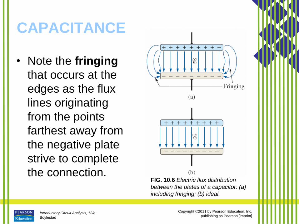
• Note the fringing
that occurs at the
edges as the flux
lines originating
from the points
farthest away from
the negative plate
strive to complete
the connection. FIG. 10.6 Electric flux distribution
between the plates of a capacitor: (a)
including fringing; (b) ideal.

Introductory Circuit Analysis, 12/e
Boylestad
Copyright ©2011 by Pearson Education, Inc.
publishing as Pearson [imprint]
CAPACITANCE
• The electric field strength between the
plates is determined by the voltage across
the plates and the distance between the
plates as follows:
Introductory Circuit Analysis, 12/e
Boylestad
Copyright ©2011 by Pearson Education, Inc.
publishing as Pearson [imprint]
CAPACITANCE
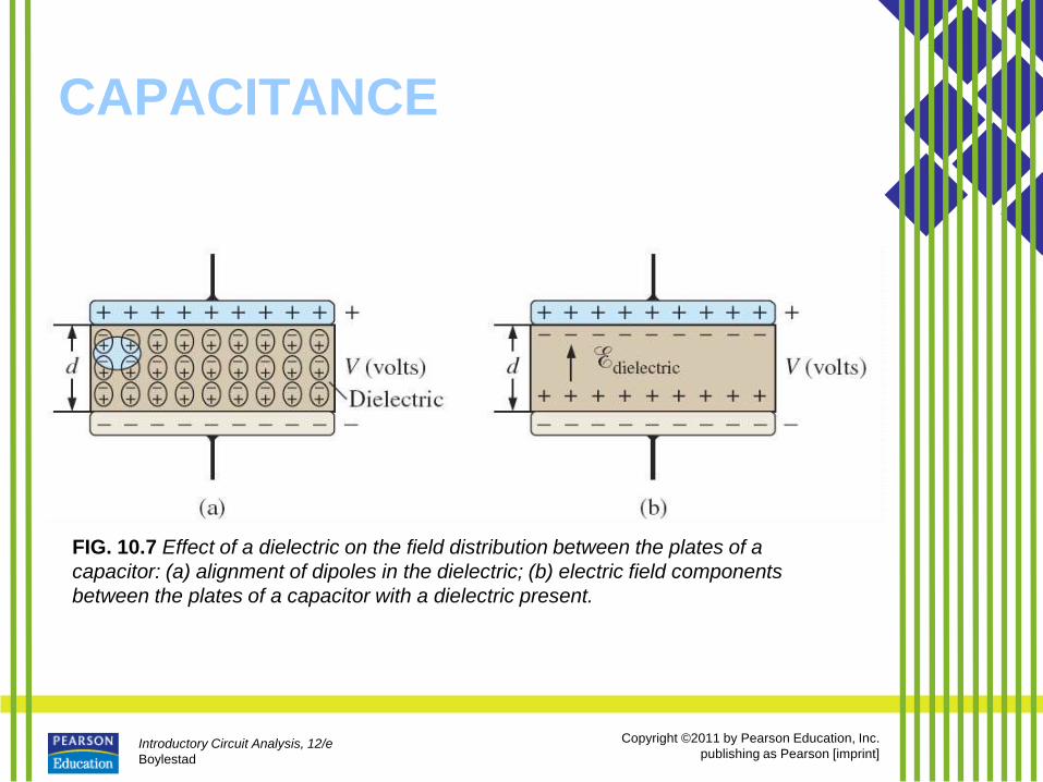
FIG. 10.7 Effect of a dielectric on the field distribution between the plates of a
capacitor: (a) alignment of dipoles in the dielectric; (b) electric field components
between the plates of a capacitor with a dielectric present.
Introductory Circuit Analysis, 12/e
Boylestad
Copyright ©2011 by Pearson Education, Inc.
publishing as Pearson [imprint]
CAPACITANCE
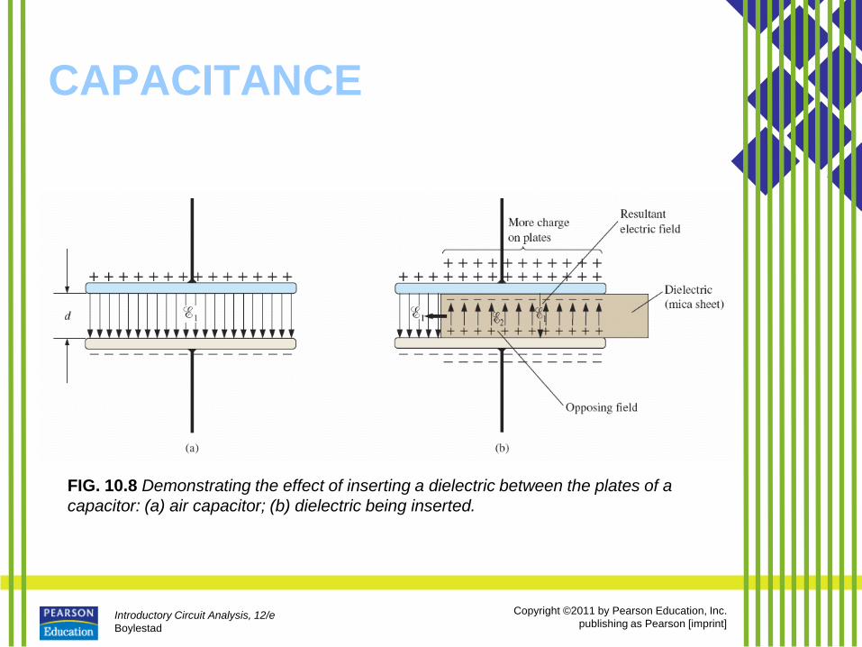
FIG. 10.8 Demonstrating the effect of inserting a dielectric between the plates of a
capacitor: (a) air capacitor; (b) dielectric being inserted.
Introductory Circuit Analysis, 12/e
Boylestad
Copyright ©2011 by Pearson Education, Inc.
publishing as Pearson [imprint]
CAPACITANCE
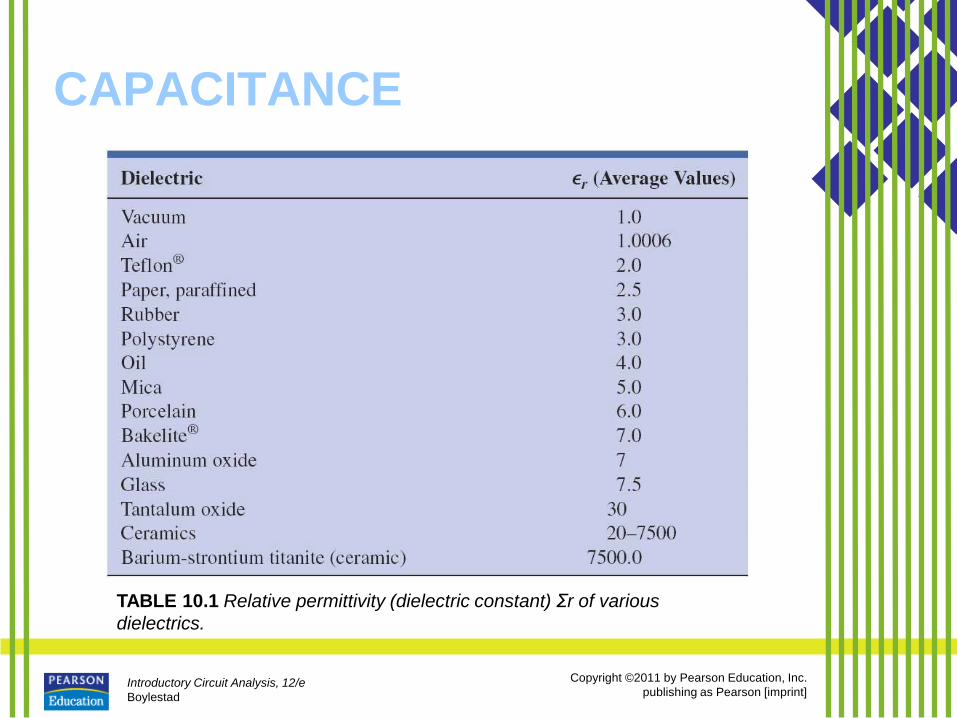
TABLE 10.1 Relative permittivity (dielectric constant) Σr of various
dielectrics.
Introductory Circuit Analysis, 12/e
Boylestad
Copyright ©2011 by Pearson Education, Inc.
publishing as Pearson [imprint]
CAPACITANCE
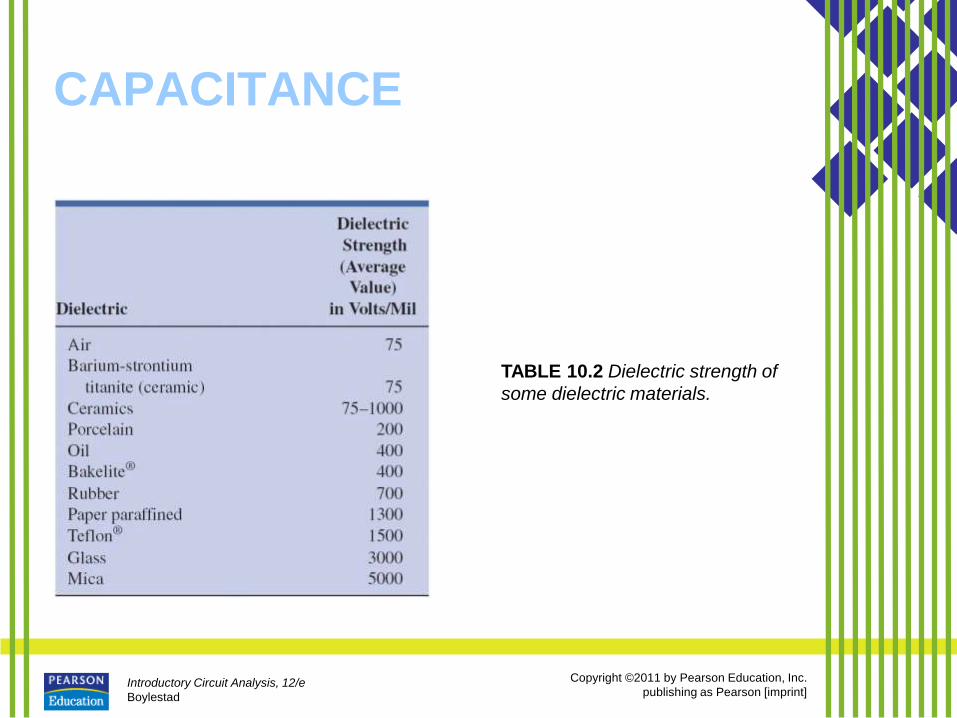
TABLE 10.2 Dielectric strength of
some dielectric materials.
Introductory Circuit Analysis, 12/e
Boylestad
Copyright ©2011 by Pearson Education, Inc.
publishing as Pearson [imprint]
CAPACITORS Capacitor Construction
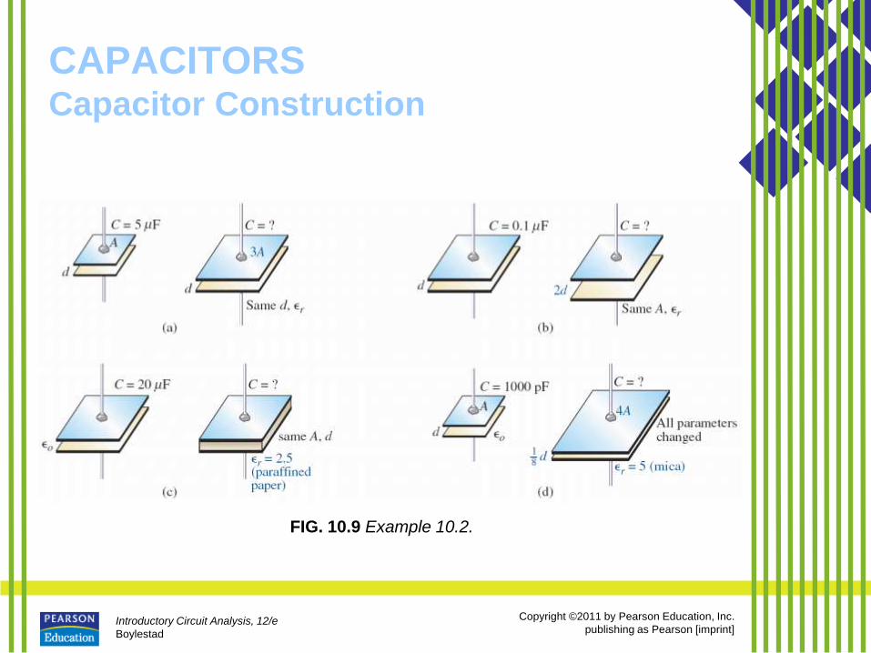
• The basic components of a capacitor are: conductive plates, separation, and dielectric.
• Larger plates permit an increased area for the storage of charge, so the area of the plates should be in the numerator of the defining equation.
• The smaller the distance between the plates, the larger is the capacitance, so this factor should appear in the numerator of the equation.
• Finally, since higher levels of permittivity result in higher levels of capacitance, the factor should appear in the numerator of the defining equation.
Introductory Circuit Analysis, 12/e
Boylestad
Copyright ©2011 by Pearson Education, Inc.
publishing as Pearson [imprint]
CAPACITORS Capacitor Construction
Introductory Circuit Analysis, 12/e
Boylestad
Copyright ©2011 by Pearson Education, Inc.
publishing as Pearson [imprint]
CAPACITORS Capacitor Construction
FIG. 10.9 Example 10.2.
Introductory Circuit Analysis, 12/e
Boylestad
Copyright ©2011 by Pearson Education, Inc.
publishing as Pearson [imprint]
CAPACITORS Capacitor Construction
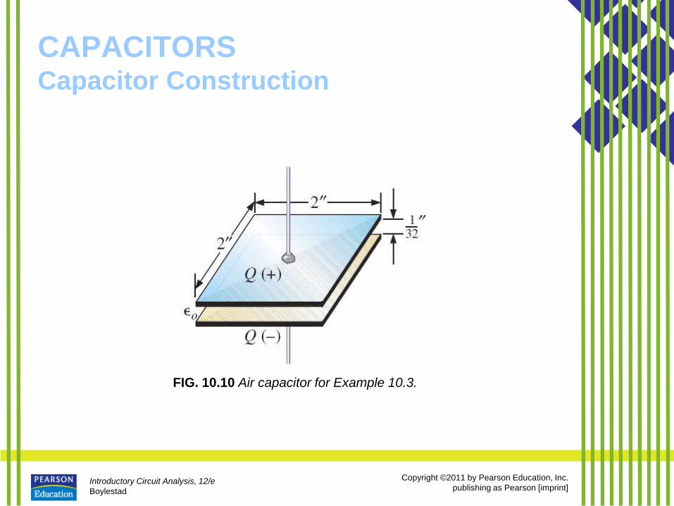
FIG. 10.10 Air capacitor for Example 10.3.
Introductory Circuit Analysis, 12/e
Boylestad
Copyright ©2011 by Pearson Education, Inc.
publishing as Pearson [imprint]
CAPACITORS Types of Capacitors
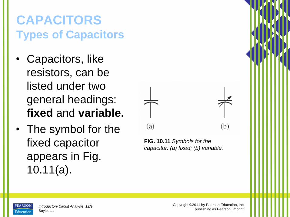
• Capacitors, like
resistors, can be
listed under two
general headings:
fixed and variable.
• The symbol for the
fixed capacitor
appears in Fig.
10.11(a).
FIG. 10.11 Symbols for the
capacitor: (a) fixed; (b) variable.
Introductory Circuit Analysis, 12/e
Boylestad
Copyright ©2011 by Pearson Education, Inc.
publishing as Pearson [imprint]
CAPACITORS Types of Capacitors
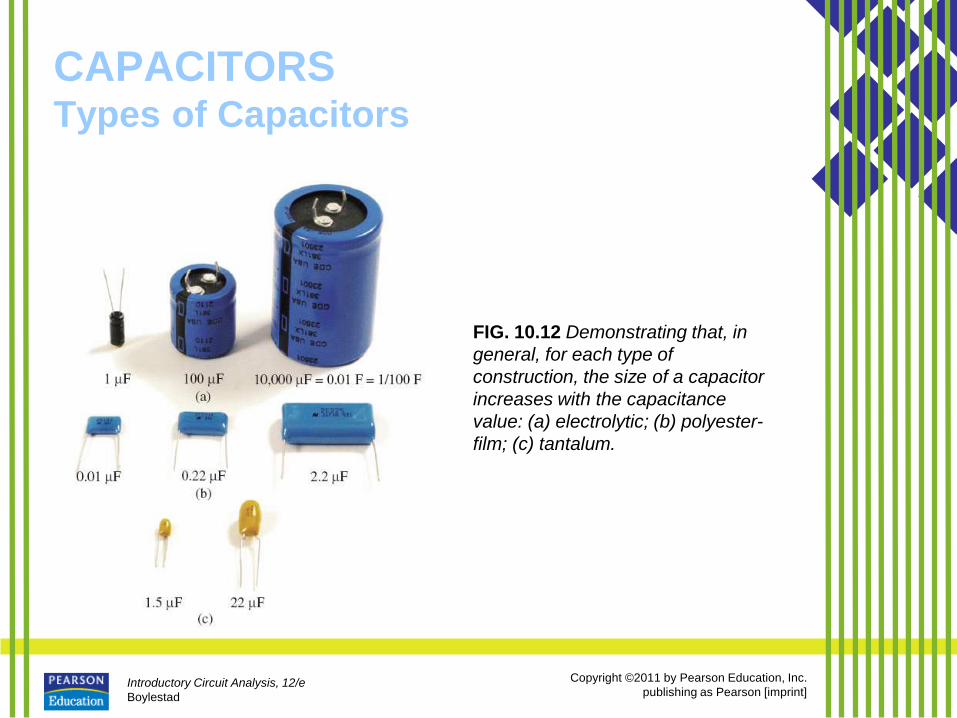
• Fixed Capacitors
– Fixed-type capacitors come in all shapes
and sizes.
– However, in general, for the same type
of construction and dielectric, the
larger the required capacitance, the
larger is the physical size of the
capacitor.
Introductory Circuit Analysis, 12/e
Boylestad
Copyright ©2011 by Pearson Education, Inc.
publishing as Pearson [imprint]
CAPACITORS Types of Capacitors
FIG. 10.12 Demonstrating that, in
general, for each type of
construction, the size of a capacitor
increases with the capacitance
value: (a) electrolytic; (b) polyester-
film; (c) tantalum.
Introductory Circuit Analysis, 12/e
Boylestad
Copyright ©2011 by Pearson Education, Inc.
publishing as Pearson [imprint]
CAPACITORS Types of Capacitors
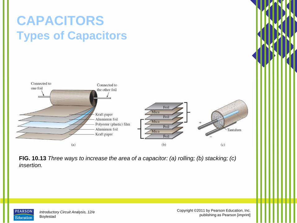
FIG. 10.13 Three ways to increase the area of a capacitor: (a) rolling; (b) stacking; (c)
insertion.
Introductory Circuit Analysis, 12/e
Boylestad
Copyright ©2011 by Pearson Education, Inc.
publishing as Pearson [imprint]
CAPACITORS Types of Capacitors
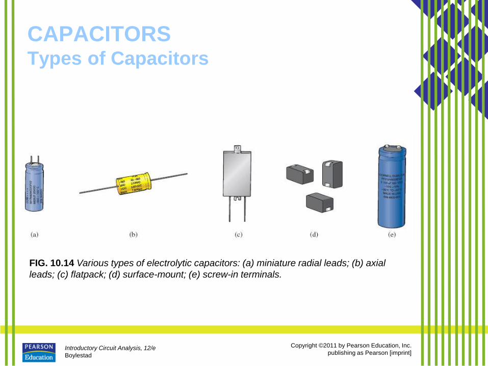
FIG. 10.14 Various types of electrolytic capacitors: (a) miniature radial leads; (b) axial
leads; (c) flatpack; (d) surface-mount; (e) screw-in terminals.
Introductory Circuit Analysis, 12/e
Boylestad
Copyright ©2011 by Pearson Education, Inc.
publishing as Pearson [imprint]
CAPACITORS Types of Capacitors
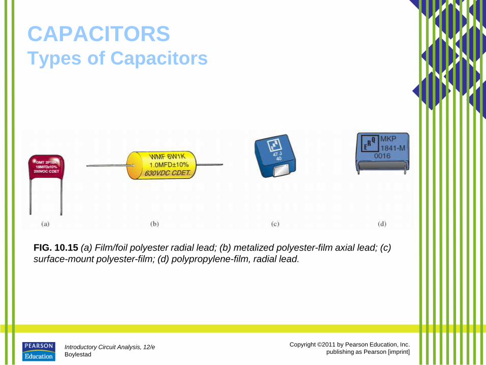
FIG. 10.15 (a) Film/foil polyester radial lead; (b) metalized polyester-film axial lead; (c)
surface-mount polyester-film; (d) polypropylene-film, radial lead.
Introductory Circuit Analysis, 12/e
Boylestad
Copyright ©2011 by Pearson Education, Inc.
publishing as Pearson [imprint]
CAPACITORS Types of Capacitors
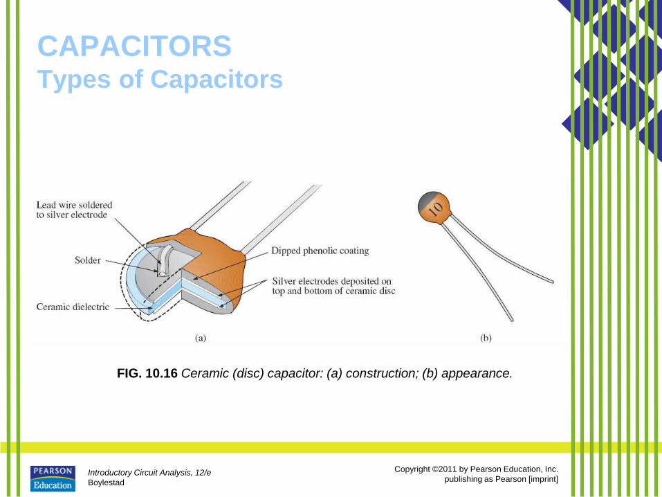
FIG. 10.16 Ceramic (disc) capacitor: (a) construction; (b) appearance.
Introductory Circuit Analysis, 12/e
Boylestad
Copyright ©2011 by Pearson Education, Inc.
publishing as Pearson [imprint]
CAPACITORS Types of Capacitors
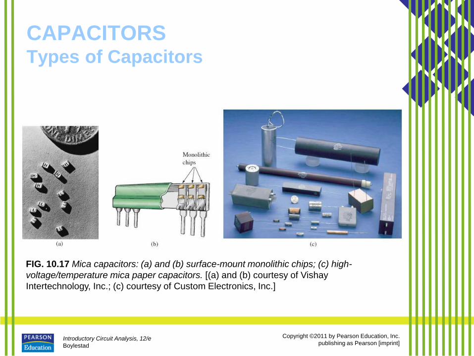
FIG. 10.17 Mica capacitors: (a) and (b) surface-mount monolithic chips; (c) high-
voltage/temperature mica paper capacitors. [(a) and (b) courtesy of Vishay
Intertechnology, Inc.; (c) courtesy of Custom Electronics, Inc.]
Introductory Circuit Analysis, 12/e
Boylestad
Copyright ©2011 by Pearson Education, Inc.
publishing as Pearson [imprint]
CAPACITORS Types of Capacitors
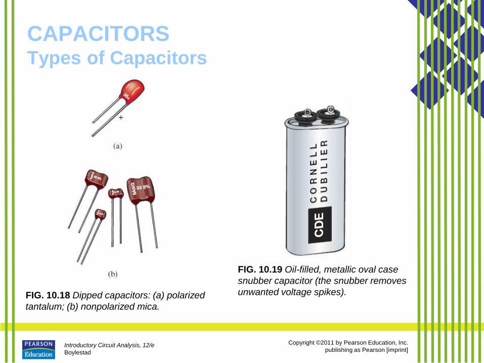
FIG. 10.18 Dipped capacitors: (a) polarized
tantalum; (b) nonpolarized mica.
FIG. 10.19 Oil-filled, metallic oval case
snubber capacitor (the snubber removes
unwanted voltage spikes).
Introductory Circuit Analysis, 12/e
Boylestad
Copyright ©2011 by Pearson Education, Inc.
publishing as Pearson [imprint]
CAPACITORS Types of Capacitors
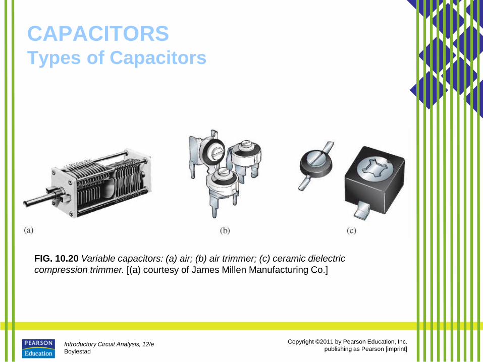
• Variable Capacitors
– All the parameters in Eq. (10.11) can be
changed to some degree to create a
variable capacitor.
– For example, in Fig. 10.20(a), the
capacitance of the variable air capacitor
is changed by turning the shaft at the
end of the unit.
Introductory Circuit Analysis, 12/e
Boylestad
Copyright ©2011 by Pearson Education, Inc.
publishing as Pearson [imprint]
CAPACITORS Types of Capacitors
FIG. 10.20 Variable capacitors: (a) air; (b) air trimmer; (c) ceramic dielectric
compression trimmer. [(a) courtesy of James Millen Manufacturing Co.]
Introductory Circuit Analysis, 12/e
Boylestad
Copyright ©2011 by Pearson Education, Inc.
publishing as Pearson [imprint]
CAPACITORS Leakage Current and ESR
• Although we would like to think of
capacitors as ideal elements,
unfortunately, this is not the case.
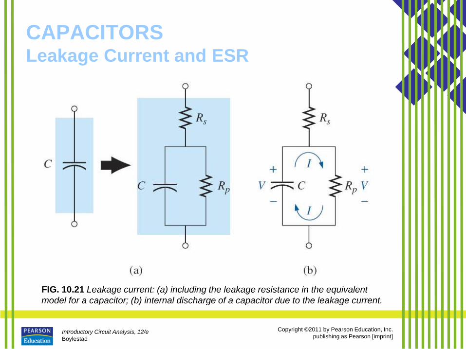
• There is a dc resistance appearing as
Rs in the equivalent model of Fig.
10.21 due to the resistance
introduced by the contacts, the leads,
or the plate or foil materials.
Introductory Circuit Analysis, 12/e
Boylestad
Copyright ©2011 by Pearson Education, Inc.
publishing as Pearson [imprint]
CAPACITORS Leakage Current and ESR
• In addition, up to this point, we have
assumed that the insulating characteristics
of dielectrics prevent any flow of charge
between the plates unless the breakdown
voltage is exceeded.
• In reality, however, dielectrics are not
perfect insulators, and they do carry a few
free electrons in their atomic structure.
Introductory Circuit Analysis, 12/e
Boylestad
Copyright ©2011 by Pearson Education, Inc.
publishing as Pearson [imprint]
CAPACITORS Leakage Current and ESR
FIG. 10.21 Leakage current: (a) including the leakage resistance in the equivalent
model for a capacitor; (b) internal discharge of a capacitor due to the leakage current.
Introductory Circuit Analysis, 12/e
Boylestad
Copyright ©2011 by Pearson Education, Inc.
publishing as Pearson [imprint]
CAPACITORS Temperature Effects: ppm
• Every capacitor is temperature sensitive, with the nameplate capacitance level specified at room temperature.
• Depending on the type of dielectric, increasing or decreasing temperatures can cause either a drop or a rise in capacitance.
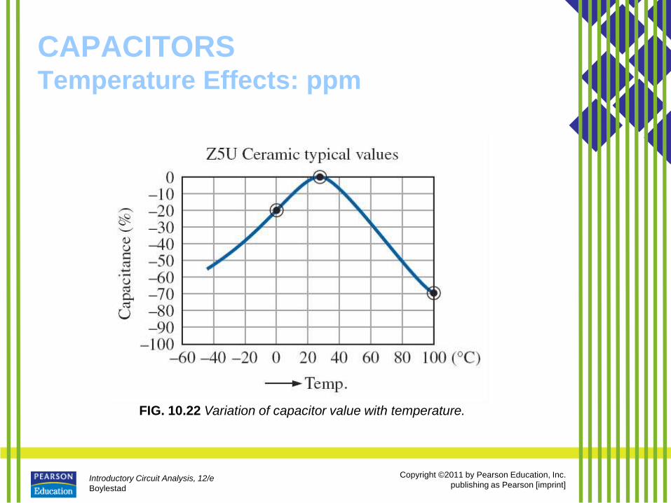
• If temperature is a concern for a particular application, the manufacturer will provide a temperature plot, such as shown in Fig. 10.22, or a ppm/°C (parts per million per degree Celsius) rating for the capacitor.
Introductory Circuit Analysis, 12/e
Boylestad
Copyright ©2011 by Pearson Education, Inc.
publishing as Pearson [imprint]
CAPACITORS Temperature Effects: ppm
FIG. 10.22 Variation of capacitor value with temperature.
Introductory Circuit Analysis, 12/e
Boylestad
Copyright ©2011 by Pearson Education, Inc.
publishing as Pearson [imprint]
CAPACITORS Capacitor Labeling
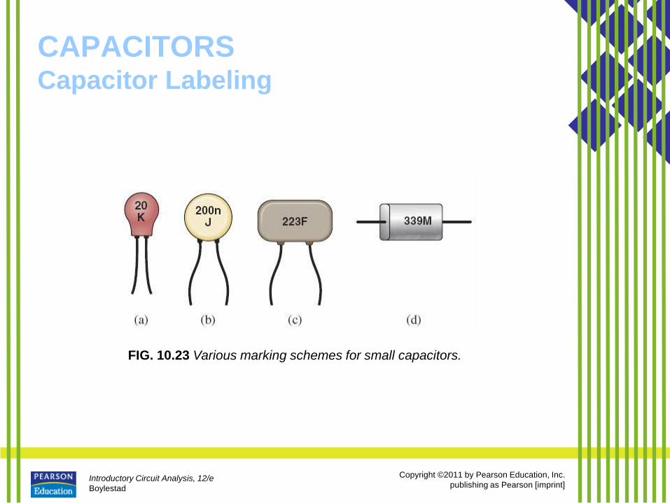
• Due to the small size of some
capacitors, various marking schemes
have been adopted to provide the
capacitance level, tolerance, and, if
possible, working voltage.
– In general, however, as pointed out
above, the size of the capacitor is the
first indicator of its value.
Introductory Circuit Analysis, 12/e
Boylestad
Copyright ©2011 by Pearson Education, Inc.
publishing as Pearson [imprint]
CAPACITORS Capacitor Labeling
FIG. 10.23 Various marking schemes for small capacitors.
Introductory Circuit Analysis, 12/e
Boylestad
Copyright ©2011 by Pearson Education, Inc.
publishing as Pearson [imprint]
CAPACITORS
Measurement and Testing of Capacitors
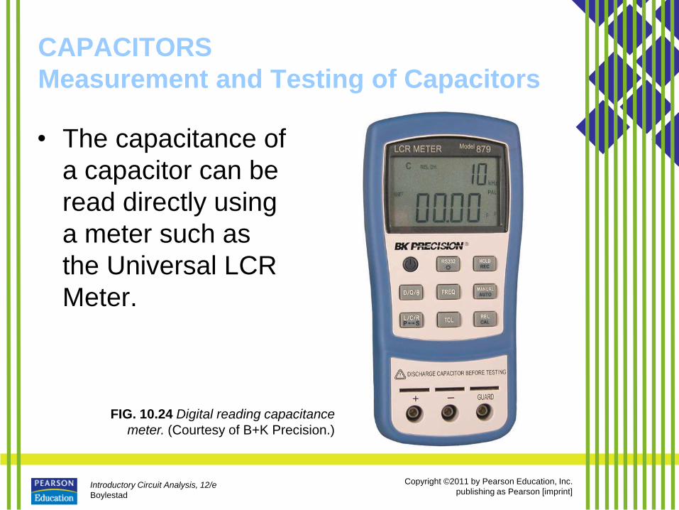
• The capacitance of
a capacitor can be
read directly using
a meter such as
the Universal LCR
Meter.
FIG. 10.24 Digital reading capacitance
meter. (Courtesy of B+K Precision.)
Introductory Circuit Analysis, 12/e
Boylestad
Copyright ©2011 by Pearson Education, Inc.
publishing as Pearson [imprint]
CAPACITORS
Measurement and Testing of Capacitors
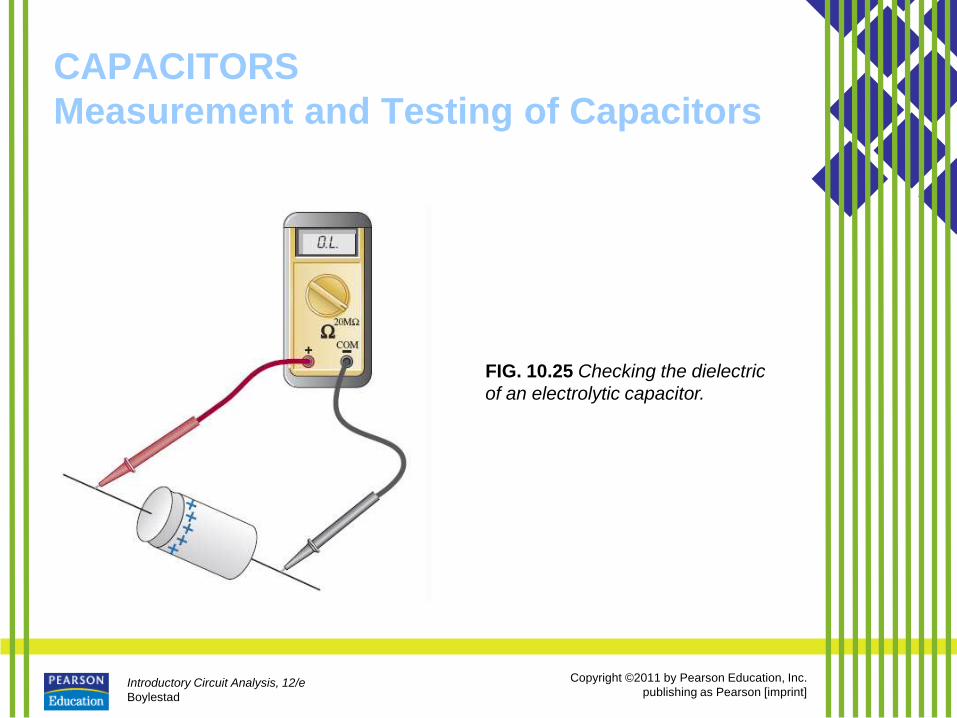
FIG. 10.25 Checking the dielectric
of an electrolytic capacitor.
Introductory Circuit Analysis, 12/e
Boylestad
Copyright ©2011 by Pearson Education, Inc.
publishing as Pearson [imprint]
CAPACITORS Standard Capacitor Values
• The most common capacitors use
the same numerical multipliers
encountered for resistors.
– The vast majority are available with 5%,
10%, or 20% tolerances.
– There are capacitors available, however,
with tolerances of 1%, 2%, or 3%, if you
are willing to pay the price.
Introductory Circuit Analysis, 12/e
Boylestad
Copyright ©2011 by Pearson Education, Inc.
publishing as Pearson [imprint]
TRANSIENTS IN CAPACITIVE
NETWORKS: THE CHARGING
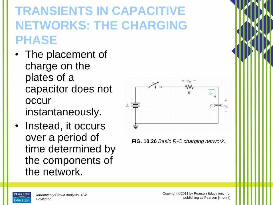
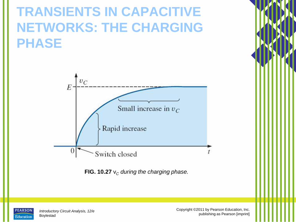
PHASE • The placement of
charge on the plates of a capacitor does not occur instantaneously.
• Instead, it occurs over a period of time determined by the components of the network.
FIG. 10.26 Basic R-C charging network.
Introductory Circuit Analysis, 12/e
Boylestad
Copyright ©2011 by Pearson Education, Inc.
publishing as Pearson [imprint]
TRANSIENTS IN CAPACITIVE
NETWORKS: THE CHARGING
PHASE
FIG. 10.27 vC during the charging phase.
Introductory Circuit Analysis, 12/e
Boylestad
Copyright ©2011 by Pearson Education, Inc.
publishing as Pearson [imprint]
TRANSIENTS IN CAPACITIVE
NETWORKS: THE CHARGING
PHASE
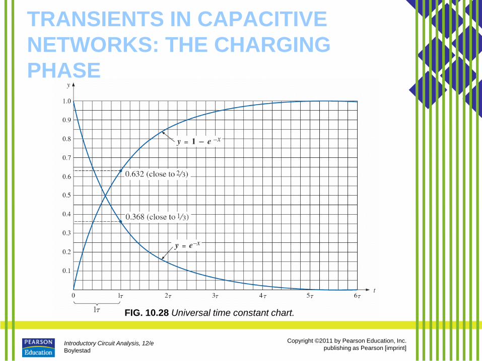
FIG. 10.28 Universal time constant chart.
Introductory Circuit Analysis, 12/e
Boylestad
Copyright ©2011 by Pearson Education, Inc.
publishing as Pearson [imprint]
TRANSIENTS IN CAPACITIVE
NETWORKS: THE CHARGING
PHASE
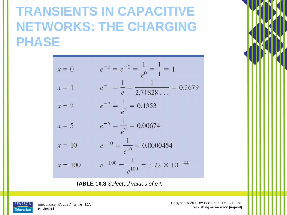
TABLE 10.3 Selected values of e-x.
Introductory Circuit Analysis, 12/e
Boylestad
Copyright ©2011 by Pearson Education, Inc.
publishing as Pearson [imprint]
TRANSIENTS IN CAPACITIVE
NETWORKS: THE CHARGING
PHASE
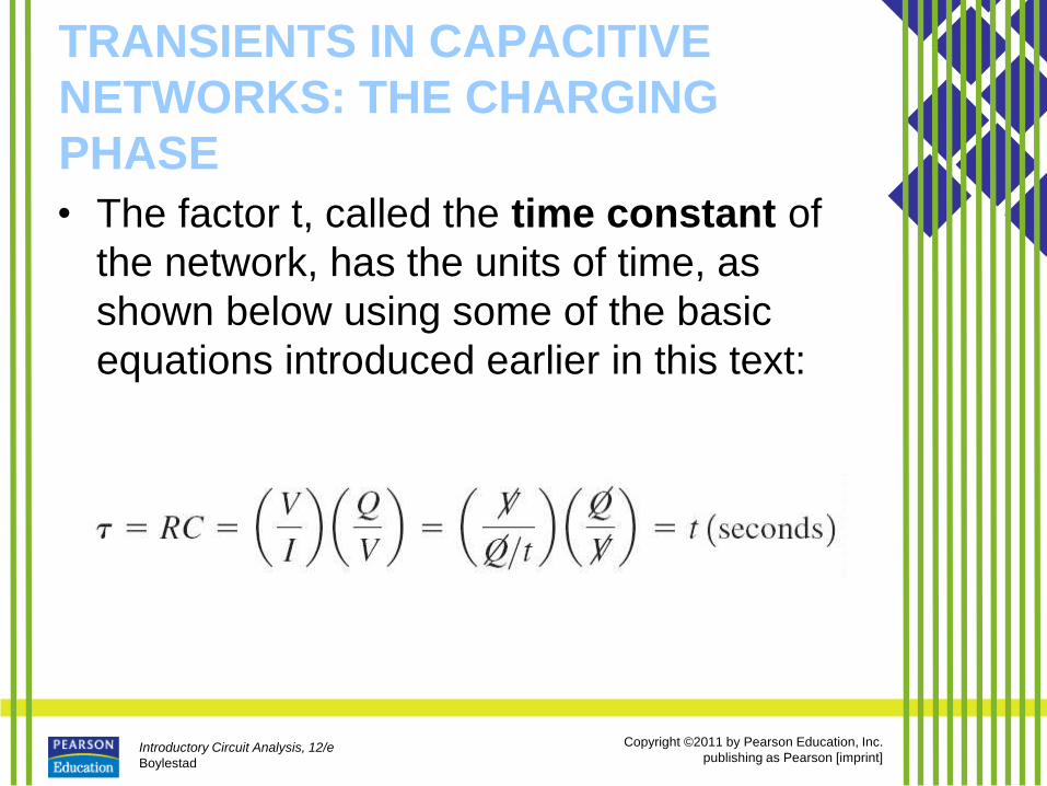
• The factor t, called the time constant of
the network, has the units of time, as
shown below using some of the basic
equations introduced earlier in this text:
Introductory Circuit Analysis, 12/e
Boylestad
Copyright ©2011 by Pearson Education, Inc.
publishing as Pearson [imprint]
TRANSIENTS IN CAPACITIVE
NETWORKS: THE CHARGING
PHASE
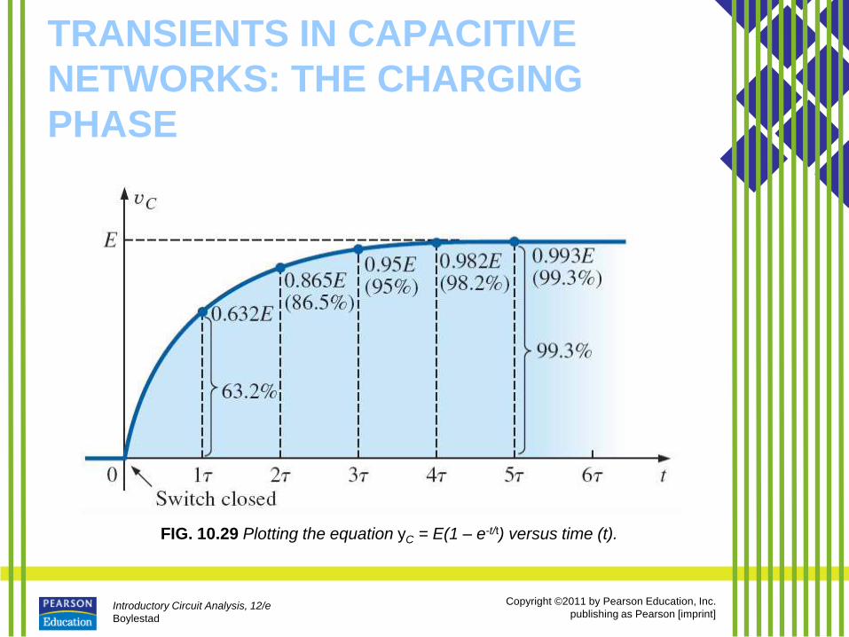
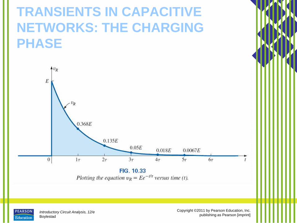
FIG. 10.29 Plotting the equation yC = E(1 – e-t/t) versus time (t).

Introductory Circuit Analysis, 12/e
Boylestad
Copyright ©2011 by Pearson Education, Inc.
publishing as Pearson [imprint]
TRANSIENTS IN CAPACITIVE
NETWORKS: THE CHARGING
PHASE
Introductory Circuit Analysis, 12/e
Boylestad
Copyright ©2011 by Pearson Education, Inc.
publishing as Pearson [imprint]
TRANSIENTS IN CAPACITIVE
NETWORKS: THE CHARGING
PHASE
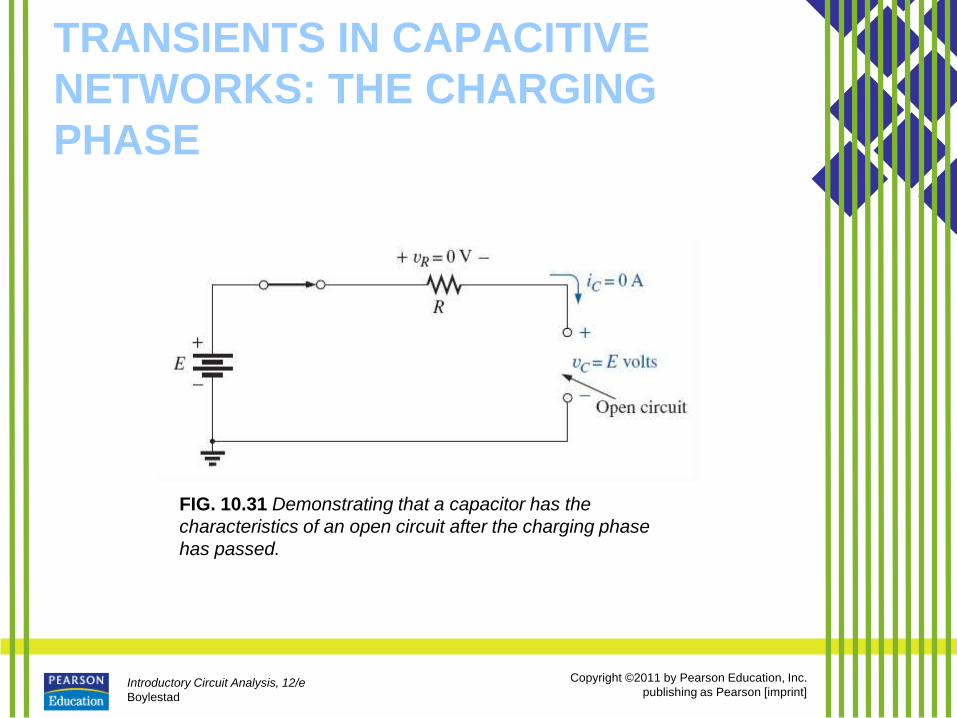
FIG. 10.31 Demonstrating that a capacitor has the
characteristics of an open circuit after the charging phase
has passed.
Introductory Circuit Analysis, 12/e
Boylestad
Copyright ©2011 by Pearson Education, Inc.
publishing as Pearson [imprint]
TRANSIENTS IN CAPACITIVE
NETWORKS: THE CHARGING
PHASE
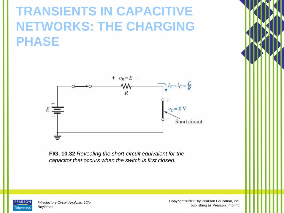
FIG. 10.32 Revealing the short-circuit equivalent for the
capacitor that occurs when the switch is first closed.
Introductory Circuit Analysis, 12/e
Boylestad
Copyright ©2011 by Pearson Education, Inc.
publishing as Pearson [imprint]
TRANSIENTS IN CAPACITIVE
NETWORKS: THE CHARGING
PHASE
Introductory Circuit Analysis, 12/e
Boylestad
Copyright ©2011 by Pearson Education, Inc.
publishing as Pearson [imprint]
TRANSIENTS IN CAPACITIVE NETWORKS: THE
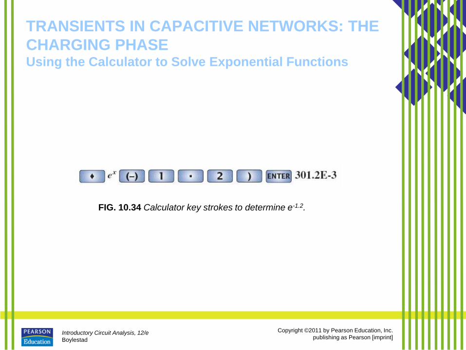
CHARGING PHASE Using the Calculator to Solve Exponential Functions
FIG. 10.34 Calculator key strokes to determine e-1.2.
Introductory Circuit Analysis, 12/e
Boylestad
Copyright ©2011 by Pearson Education, Inc.
publishing as Pearson [imprint]
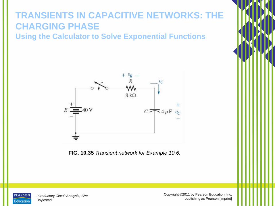
TRANSIENTS IN CAPACITIVE NETWORKS: THE
CHARGING PHASE Using the Calculator to Solve Exponential Functions
FIG. 10.35 Transient network for Example 10.6.
Introductory Circuit Analysis, 12/e
Boylestad
Copyright ©2011 by Pearson Education, Inc.
publishing as Pearson [imprint]
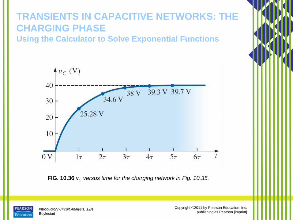
TRANSIENTS IN CAPACITIVE NETWORKS: THE
CHARGING PHASE Using the Calculator to Solve Exponential Functions
FIG. 10.36 vC versus time for the charging network in Fig. 10.35.
Introductory Circuit Analysis, 12/e
Boylestad
Copyright ©2011 by Pearson Education, Inc.
publishing as Pearson [imprint]
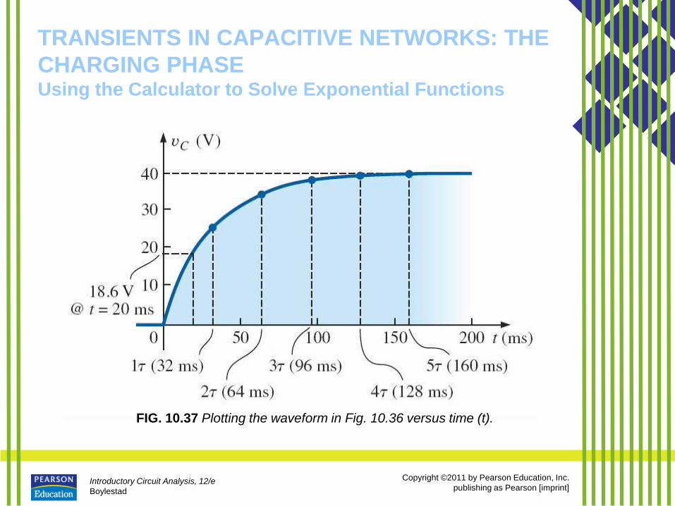
TRANSIENTS IN CAPACITIVE NETWORKS: THE
CHARGING PHASE Using the Calculator to Solve Exponential Functions
FIG. 10.37 Plotting the waveform in Fig. 10.36 versus time (t).
Introductory Circuit Analysis, 12/e
Boylestad
Copyright ©2011 by Pearson Education, Inc.
publishing as Pearson [imprint]
TRANSIENTS IN CAPACITIVE NETWORKS: THE
CHARGING PHASE Using the Calculator to Solve Exponential Functions
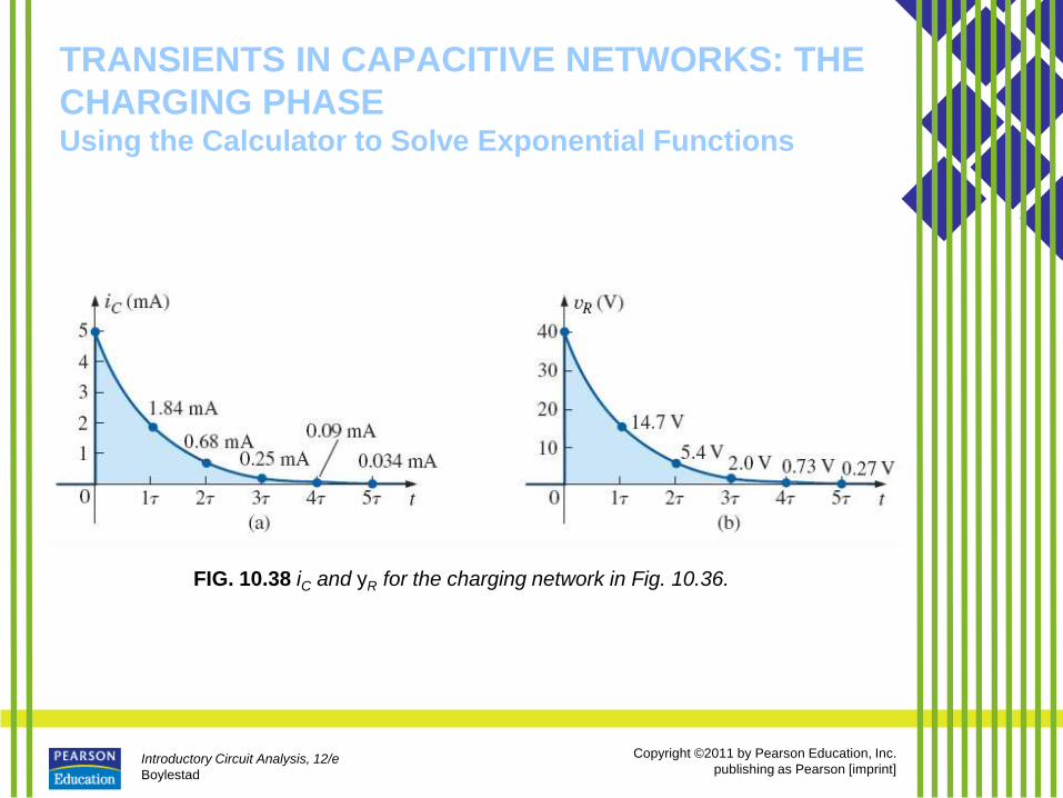
FIG. 10.38 iC and yR for the charging network in Fig. 10.36.
Introductory Circuit Analysis, 12/e
Boylestad
Copyright ©2011 by Pearson Education, Inc.
publishing as Pearson [imprint]
TRANSIENTS IN CAPACITIVE
NETWORKS: THE DISCHARGING
PHASE • We now investigate how to discharge a
capacitor while exerting some control on how long the discharge time will be.
• You can, of course, place a lead directly across a capacitor to discharge it very quickly—and possibly cause a visible spark.
• For larger capacitors such those in TV sets, this procedure should not be attempted because of the high voltages involved—unless, of course, you are trained in the maneuver.
Introductory Circuit Analysis, 12/e
Boylestad
Copyright ©2011 by Pearson Education, Inc.
publishing as Pearson [imprint]
TRANSIENTS IN CAPACITIVE
NETWORKS: THE DISCHARGING
PHASE
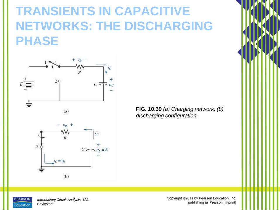
FIG. 10.39 (a) Charging network; (b)
discharging configuration.
Introductory Circuit Analysis, 12/e
Boylestad
Copyright ©2011 by Pearson Education, Inc.
publishing as Pearson [imprint]
TRANSIENTS IN CAPACITIVE
NETWORKS: THE DISCHARGING
PHASE
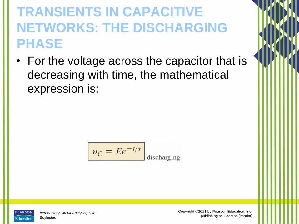
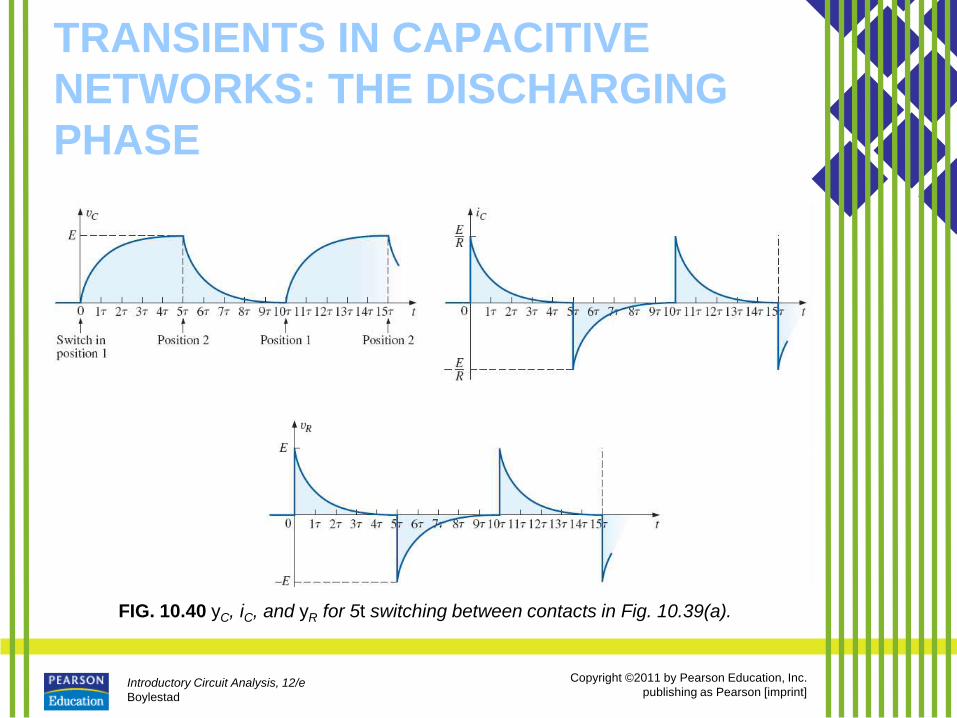
• For the voltage across the capacitor that is
decreasing with time, the mathematical
expression is:
Introductory Circuit Analysis, 12/e
Boylestad
Copyright ©2011 by Pearson Education, Inc.
publishing as Pearson [imprint]
TRANSIENTS IN CAPACITIVE
NETWORKS: THE DISCHARGING
PHASE
FIG. 10.40 yC, iC, and yR for 5t switching between contacts in Fig. 10.39(a).
Introductory Circuit Analysis, 12/e
Boylestad
Copyright ©2011 by Pearson Education, Inc.
publishing as Pearson [imprint]
TRANSIENTS IN CAPACITIVE
NETWORKS: THE DISCHARGING
PHASE
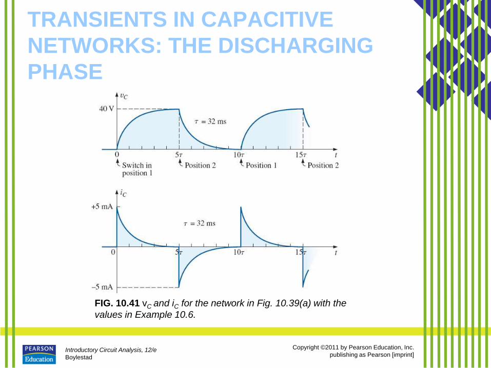
FIG. 10.41 vC and iC for the network in Fig. 10.39(a) with the
values in Example 10.6.
Introductory Circuit Analysis, 12/e
Boylestad
Copyright ©2011 by Pearson Education, Inc.
publishing as Pearson [imprint]
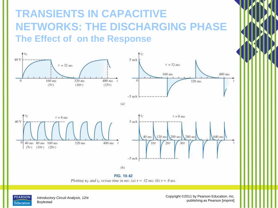
TRANSIENTS IN CAPACITIVE
NETWORKS: THE DISCHARGING PHASE The Effect of on the Response
Introductory Circuit Analysis, 12/e
Boylestad
Copyright ©2011 by Pearson Education, Inc.
publishing as Pearson [imprint]
TRANSIENTS IN CAPACITIVE
NETWORKS: THE DISCHARGING PHASE The Effect of on the Response
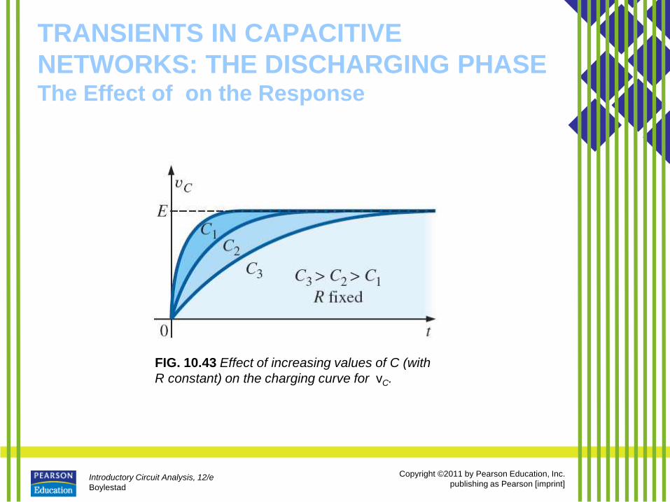
FIG. 10.43 Effect of increasing values of C (with
R constant) on the charging curve for vC.
Introductory Circuit Analysis, 12/e
Boylestad
Copyright ©2011 by Pearson Education, Inc.
publishing as Pearson [imprint]
TRANSIENTS IN CAPACITIVE
NETWORKS: THE DISCHARGING PHASE The Effect of on the Response
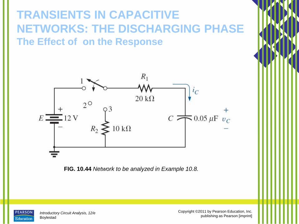
FIG. 10.44 Network to be analyzed in Example 10.8.
Introductory Circuit Analysis, 12/e
Boylestad
Copyright ©2011 by Pearson Education, Inc.
publishing as Pearson [imprint]
TRANSIENTS IN CAPACITIVE
NETWORKS: THE DISCHARGING PHASE The Effect of on the Response
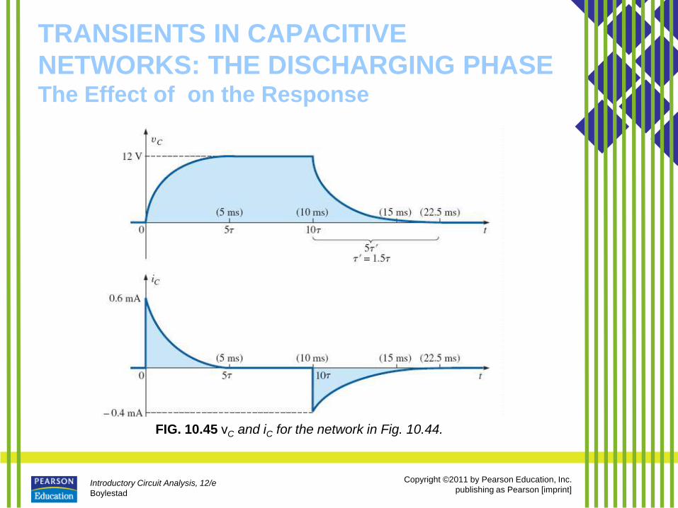
FIG. 10.45 vC and iC for the network in Fig. 10.44.
Introductory Circuit Analysis, 12/e
Boylestad
Copyright ©2011 by Pearson Education, Inc.
publishing as Pearson [imprint]
TRANSIENTS IN CAPACITIVE
NETWORKS: THE DISCHARGING PHASE The Effect of on the Response
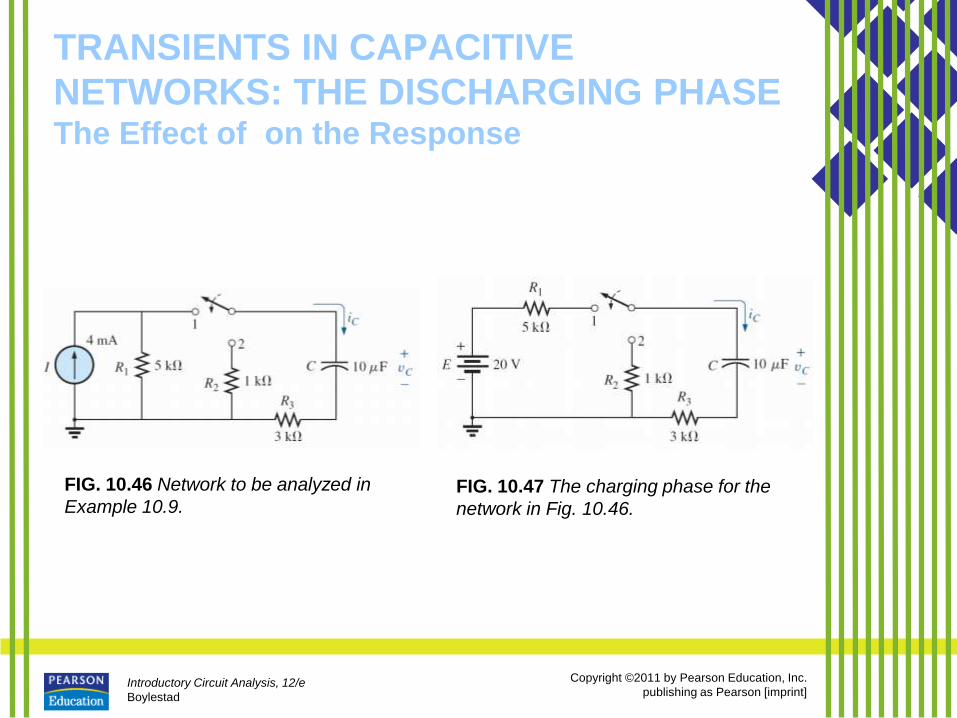
FIG. 10.46 Network to be analyzed in
Example 10.9. FIG. 10.47 The charging phase for the
network in Fig. 10.46.
Introductory Circuit Analysis, 12/e
Boylestad
Copyright ©2011 by Pearson Education, Inc.
publishing as Pearson [imprint]
TRANSIENTS IN CAPACITIVE
NETWORKS: THE DISCHARGING PHASE The Effect of on the Response
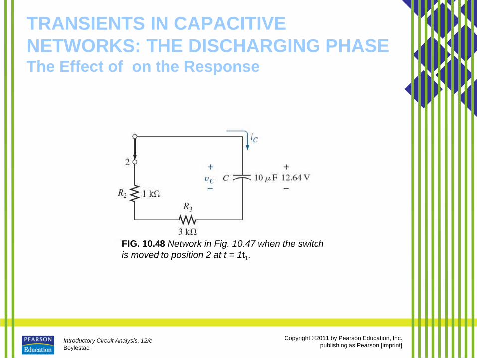
FIG. 10.48 Network in Fig. 10.47 when the switch
is moved to position 2 at t = 1t1.
Introductory Circuit Analysis, 12/e
Boylestad
Copyright ©2011 by Pearson Education, Inc.
publishing as Pearson [imprint]
TRANSIENTS IN CAPACITIVE
NETWORKS: THE DISCHARGING PHASE The Effect of on the Response
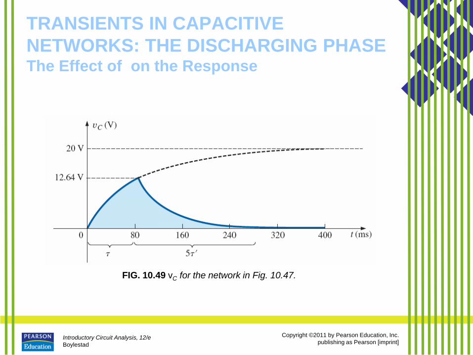
FIG. 10.49 vC for the network in Fig. 10.47.
Introductory Circuit Analysis, 12/e
Boylestad
Copyright ©2011 by Pearson Education, Inc.
publishing as Pearson [imprint]
TRANSIENTS IN CAPACITIVE
NETWORKS: THE DISCHARGING PHASE The Effect of on the Response
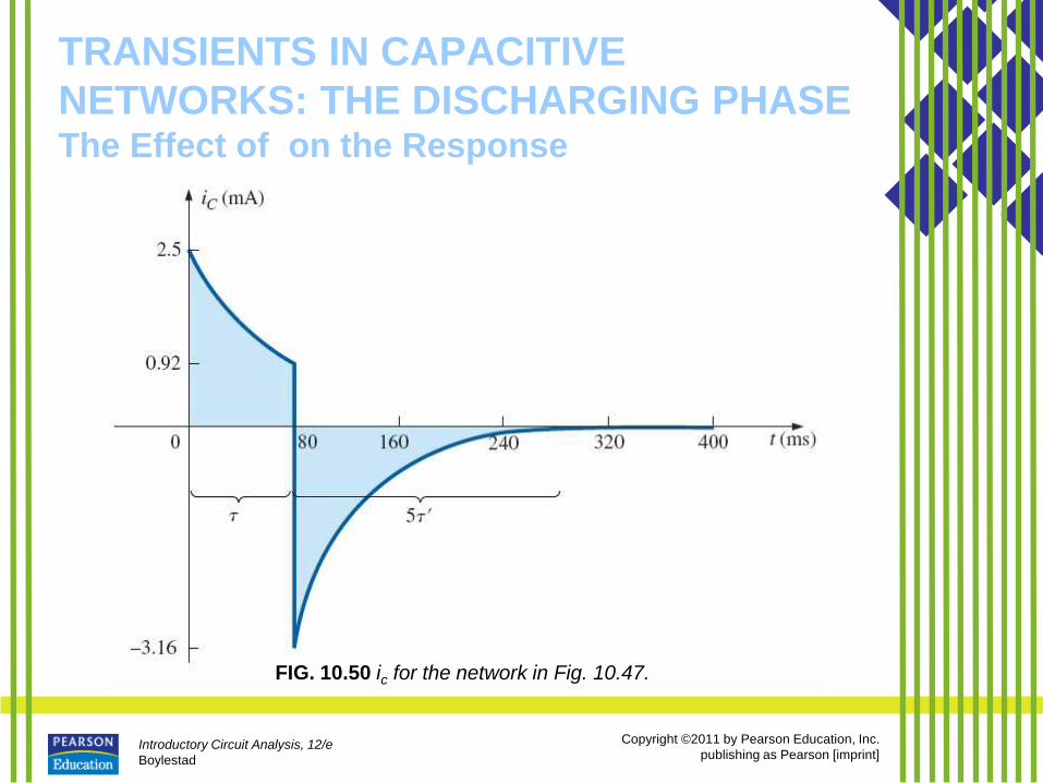
FIG. 10.50 ic for the network in Fig. 10.47.
Introductory Circuit Analysis, 12/e
Boylestad
Copyright ©2011 by Pearson Education, Inc.
publishing as Pearson [imprint]
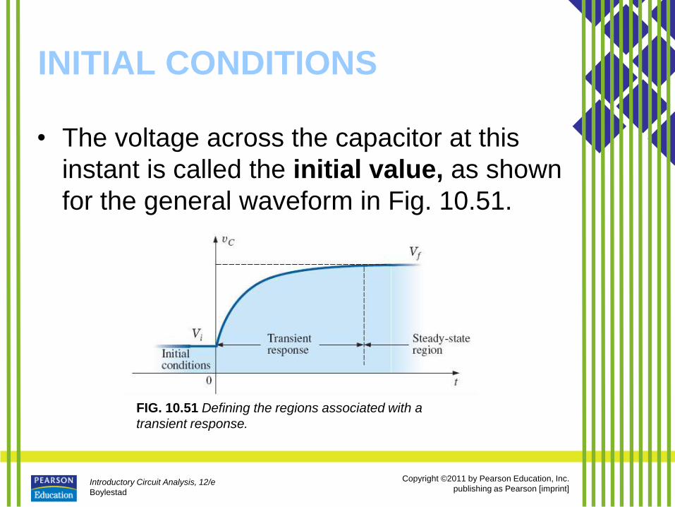
INITIAL CONDITIONS
• The voltage across the capacitor at this
instant is called the initial value, as shown
for the general waveform in Fig. 10.51.
FIG. 10.51 Defining the regions associated with a
transient response.
Introductory Circuit Analysis, 12/e
Boylestad
Copyright ©2011 by Pearson Education, Inc.
publishing as Pearson [imprint]
INITIAL CONDITIONS
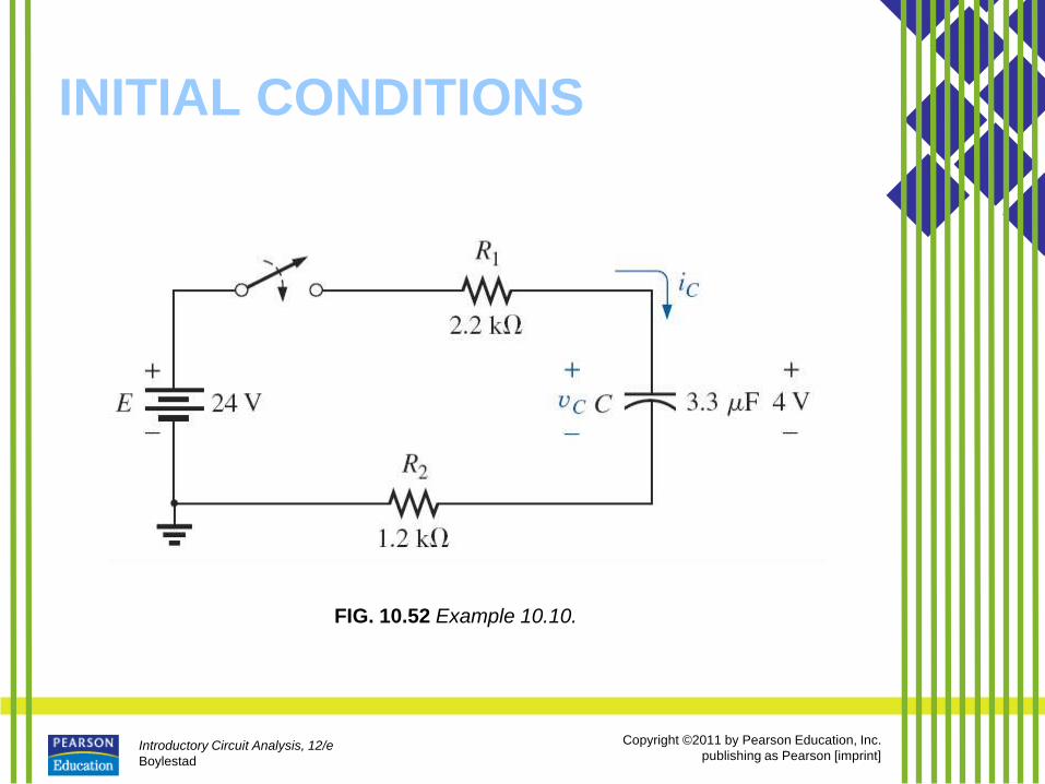
FIG. 10.52 Example 10.10.
Introductory Circuit Analysis, 12/e
Boylestad
Copyright ©2011 by Pearson Education, Inc.
publishing as Pearson [imprint]
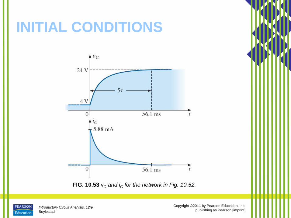
INITIAL CONDITIONS
FIG. 10.53 vC and iC for the network in Fig. 10.52.
Introductory Circuit Analysis, 12/e
Boylestad
Copyright ©2011 by Pearson Education, Inc.
publishing as Pearson [imprint]
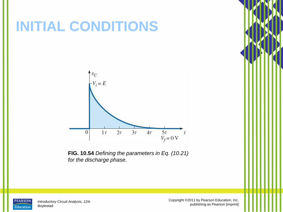
INITIAL CONDITIONS
FIG. 10.54 Defining the parameters in Eq. (10.21)
for the discharge phase.
Introductory Circuit Analysis, 12/e
Boylestad
Copyright ©2011 by Pearson Education, Inc.
publishing as Pearson [imprint]
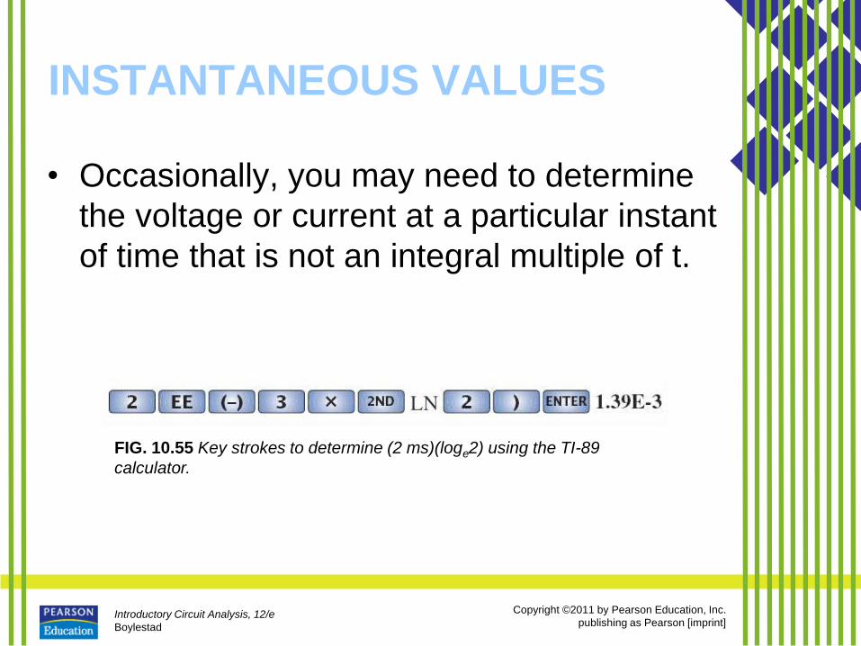
INSTANTANEOUS VALUES
• Occasionally, you may need to determine
the voltage or current at a particular instant
of time that is not an integral multiple of t.
FIG. 10.55 Key strokes to determine (2 ms)(loge2) using the TI-89
calculator.
Introductory Circuit Analysis, 12/e
Boylestad
Copyright ©2011 by Pearson Education, Inc.
publishing as Pearson [imprint]
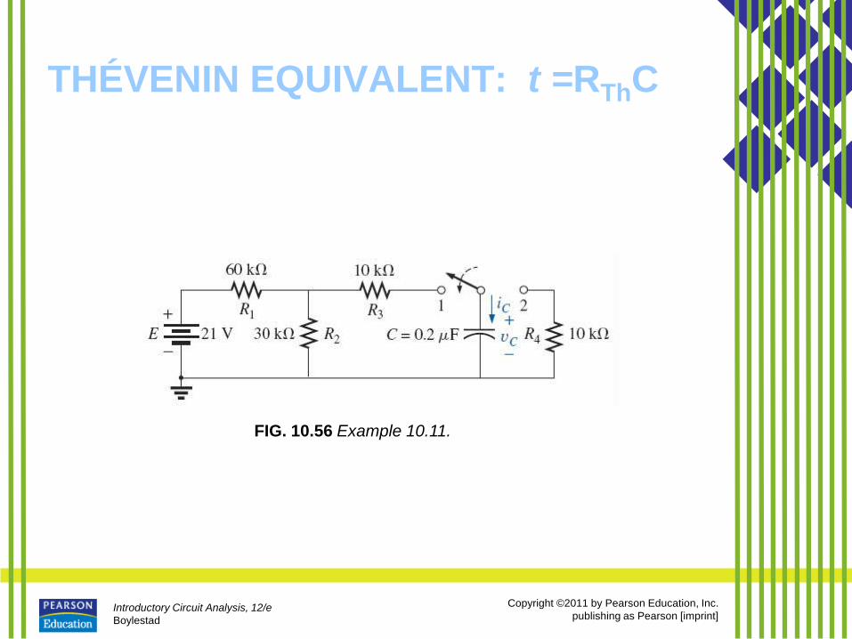
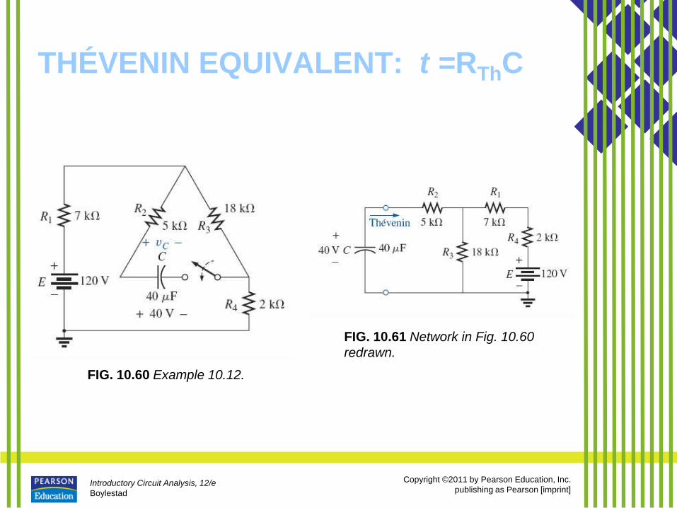
THÉVENIN EQUIVALENT: t =RThC
• You may encounter instances in
which the network does not have the
simple series form in Fig. 10.26.
• You then need to find the Thévenin
equivalent circuit for the network
external to the capacitive element.
Introductory Circuit Analysis, 12/e
Boylestad
Copyright ©2011 by Pearson Education, Inc.
publishing as Pearson [imprint]
THÉVENIN EQUIVALENT: t =RThC
FIG. 10.56 Example 10.11.
Introductory Circuit Analysis, 12/e
Boylestad
Copyright ©2011 by Pearson Education, Inc.
publishing as Pearson [imprint]
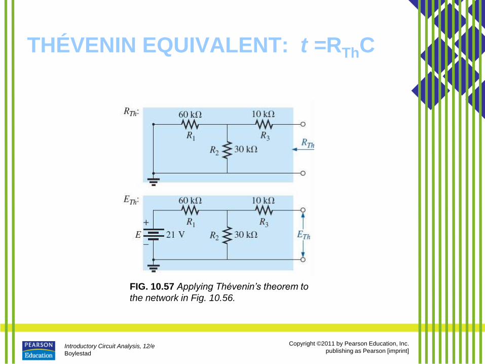
THÉVENIN EQUIVALENT: t =RThC
FIG. 10.57 Applying Thévenin’s theorem to
the network in Fig. 10.56.
Introductory Circuit Analysis, 12/e
Boylestad
Copyright ©2011 by Pearson Education, Inc.
publishing as Pearson [imprint]
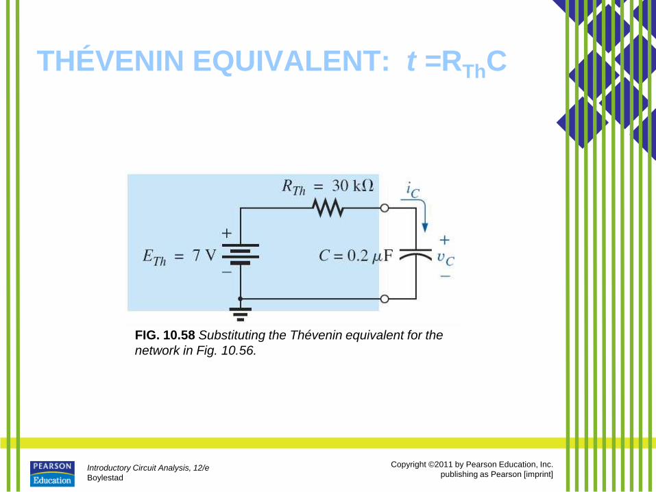
THÉVENIN EQUIVALENT: t =RThC
FIG. 10.58 Substituting the Thévenin equivalent for the
network in Fig. 10.56.
Introductory Circuit Analysis, 12/e
Boylestad
Copyright ©2011 by Pearson Education, Inc.
publishing as Pearson [imprint]
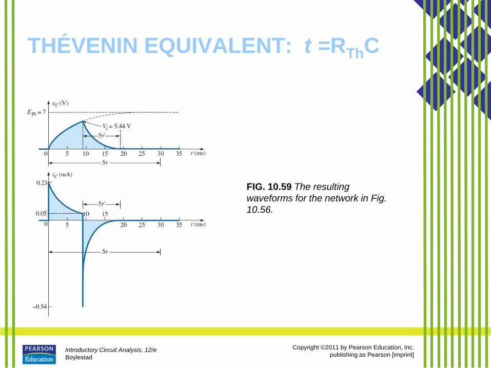
THÉVENIN EQUIVALENT: t =RThC
FIG. 10.59 The resulting
waveforms for the network in Fig.
10.56.
Introductory Circuit Analysis, 12/e
Boylestad
Copyright ©2011 by Pearson Education, Inc.
publishing as Pearson [imprint]
THÉVENIN EQUIVALENT: t =RThC
FIG. 10.60 Example 10.12.
FIG. 10.61 Network in Fig. 10.60
redrawn.
Introductory Circuit Analysis, 12/e
Boylestad
Copyright ©2011 by Pearson Education, Inc.
publishing as Pearson [imprint]
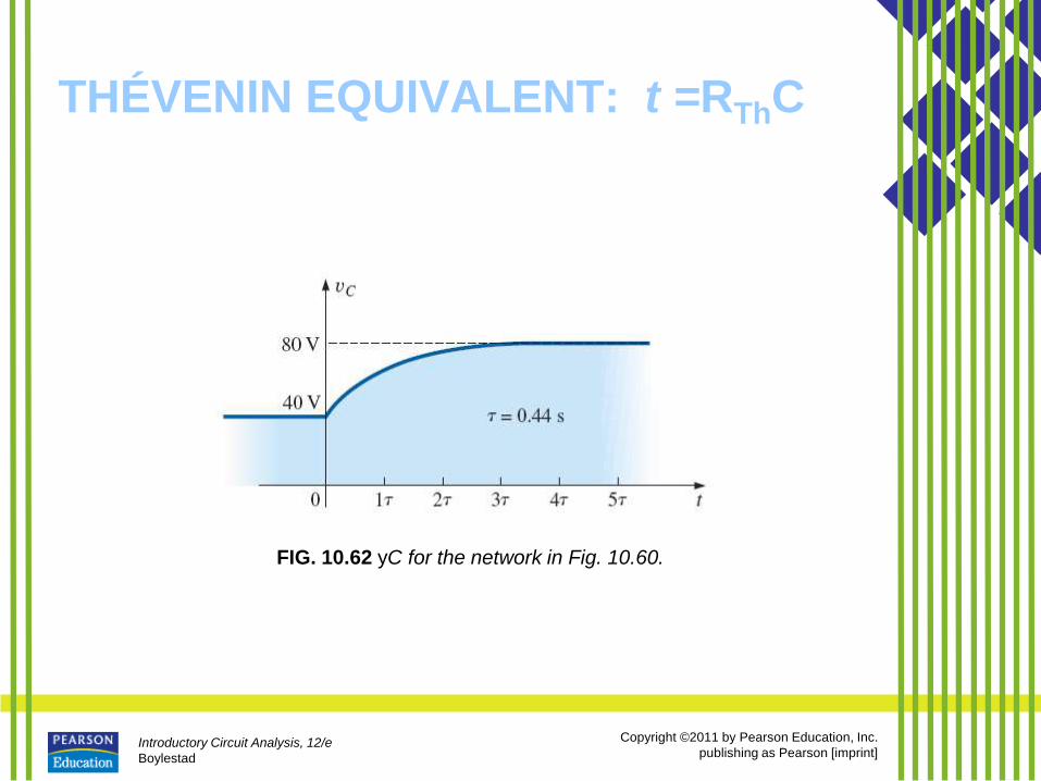
THÉVENIN EQUIVALENT: t =RThC
FIG. 10.62 yC for the network in Fig. 10.60.
Introductory Circuit Analysis, 12/e
Boylestad
Copyright ©2011 by Pearson Education, Inc.
publishing as Pearson [imprint]
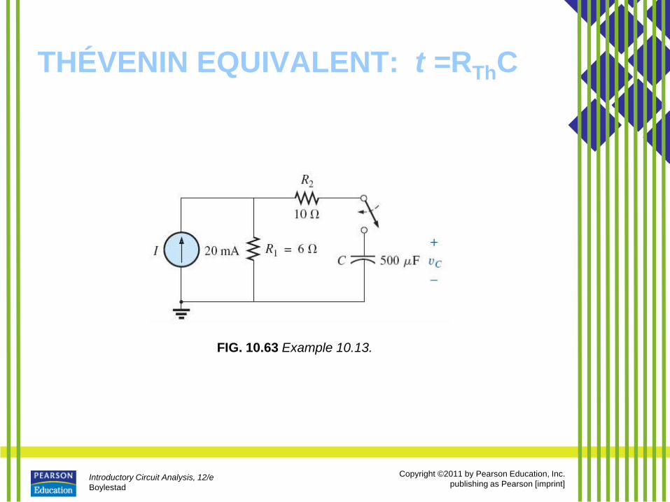
THÉVENIN EQUIVALENT: t =RThC
FIG. 10.63 Example 10.13.
Introductory Circuit Analysis, 12/e
Boylestad
Copyright ©2011 by Pearson Education, Inc.
publishing as Pearson [imprint]
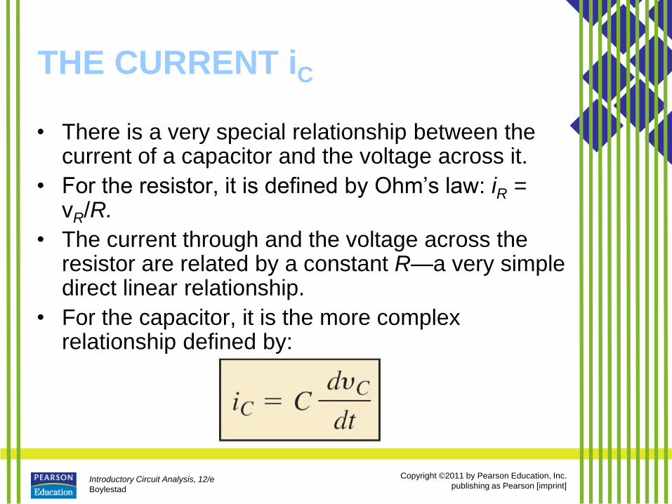
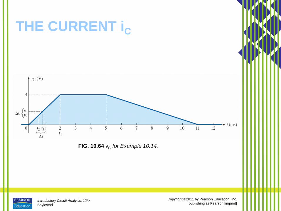
THE CURRENT iC
• There is a very special relationship between the current of a capacitor and the voltage across it.
• For the resistor, it is defined by Ohm’s law: iR = vR/R.
• The current through and the voltage across the resistor are related by a constant R—a very simple direct linear relationship.
• For the capacitor, it is the more complex relationship defined by:
Introductory Circuit Analysis, 12/e
Boylestad
Copyright ©2011 by Pearson Education, Inc.
publishing as Pearson [imprint]
THE CURRENT iC
FIG. 10.64 vC for Example 10.14.
Introductory Circuit Analysis, 12/e
Boylestad
Copyright ©2011 by Pearson Education, Inc.
publishing as Pearson [imprint]
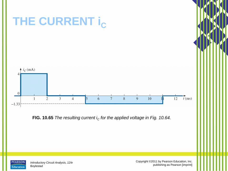
THE CURRENT iC
FIG. 10.65 The resulting current iC for the applied voltage in Fig. 10.64.
Introductory Circuit Analysis, 12/e
Boylestad
Copyright ©2011 by Pearson Education, Inc.
publishing as Pearson [imprint]
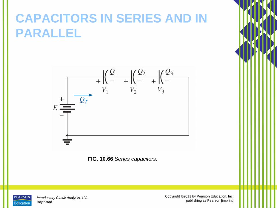
CAPACITORS IN SERIES AND IN
PARALLEL
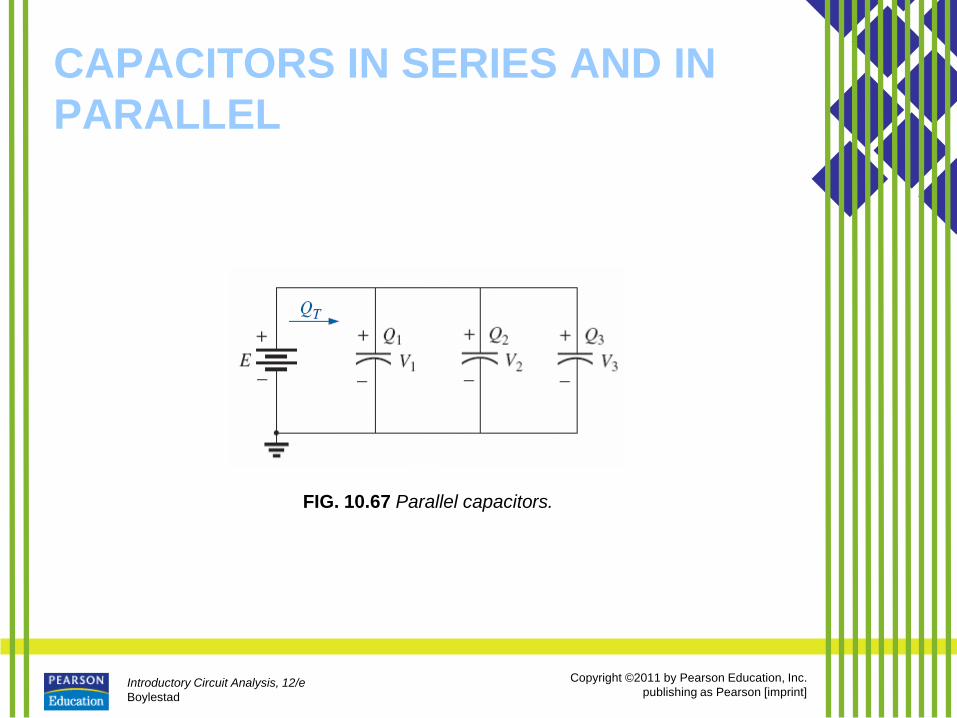
• Capacitors, like resistors, can be
placed in series and in parallel.
• Increasing levels of capacitance can
be obtained by placing capacitors in
parallel, while decreasing levels can
be obtained by placing capacitors in
series.
Introductory Circuit Analysis, 12/e
Boylestad
Copyright ©2011 by Pearson Education, Inc.
publishing as Pearson [imprint]
CAPACITORS IN SERIES AND IN
PARALLEL
FIG. 10.66 Series capacitors.
Introductory Circuit Analysis, 12/e
Boylestad
Copyright ©2011 by Pearson Education, Inc.
publishing as Pearson [imprint]
CAPACITORS IN SERIES AND IN
PARALLEL
FIG. 10.67 Parallel capacitors.
Introductory Circuit Analysis, 12/e
Boylestad
Copyright ©2011 by Pearson Education, Inc.
publishing as Pearson [imprint]
CAPACITORS IN SERIES AND IN
PARALLEL
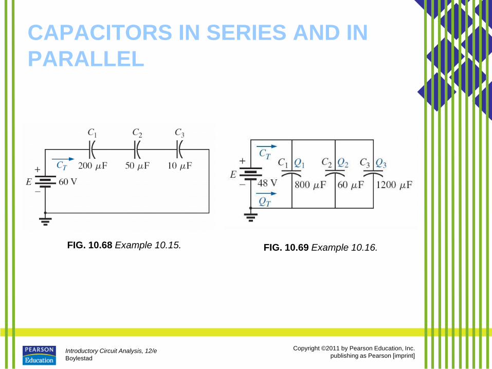
FIG. 10.68 Example 10.15. FIG. 10.69 Example 10.16.
Introductory Circuit Analysis, 12/e
Boylestad
Copyright ©2011 by Pearson Education, Inc.
publishing as Pearson [imprint]
CAPACITORS IN SERIES AND IN
PARALLEL
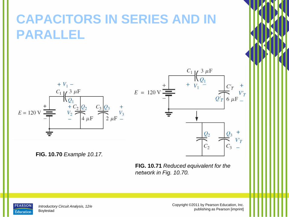
FIG. 10.70 Example 10.17.
FIG. 10.71 Reduced equivalent for the
network in Fig. 10.70.
Introductory Circuit Analysis, 12/e
Boylestad
Copyright ©2011 by Pearson Education, Inc.
publishing as Pearson [imprint]
CAPACITORS IN SERIES AND IN
PARALLEL
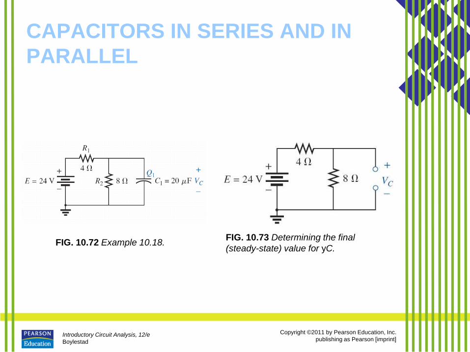
FIG. 10.72 Example 10.18. FIG. 10.73 Determining the final
(steady-state) value for yC.
Introductory Circuit Analysis, 12/e
Boylestad
Copyright ©2011 by Pearson Education, Inc.
publishing as Pearson [imprint]
CAPACITORS IN SERIES AND IN
PARALLEL
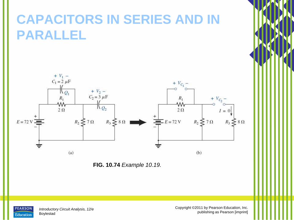
FIG. 10.74 Example 10.19.
Introductory Circuit Analysis, 12/e
Boylestad
Copyright ©2011 by Pearson Education, Inc.
publishing as Pearson [imprint]
ENERGY STORED BY A CAPACITOR
• An ideal capacitor does not dissipate any of the energy supplied to it.
• It stores the energy in the form of an electric field between the conducting surfaces.
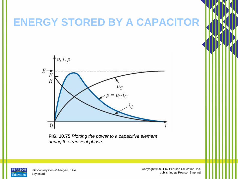
• A plot of the voltage, current, and power to a capacitor during the charging phase is shown in Fig. 10.75.
• The power curve can be obtained by finding the product of the voltage and current at selected instants of time and connecting the points obtained.
• The energy stored is represented by the shaded area under the power curve.
Introductory Circuit Analysis, 12/e
Boylestad
Copyright ©2011 by Pearson Education, Inc.
publishing as Pearson [imprint]
ENERGY STORED BY A CAPACITOR
FIG. 10.75 Plotting the power to a capacitive element
during the transient phase.
Introductory Circuit Analysis, 12/e
Boylestad
Copyright ©2011 by Pearson Education, Inc.
publishing as Pearson [imprint]
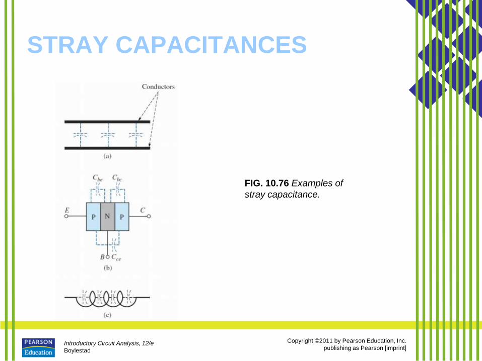
STRAY CAPACITANCES
• In addition to the capacitors discussed so
far in this chapter, there are stray
capacitances that exist not through design
but simply because two conducting
surfaces are relatively close to each other.
• Two conducting wires in the same network
have a capacitive effect between them, as
shown in Fig. 10.76(a).
Introductory Circuit Analysis, 12/e
Boylestad
Copyright ©2011 by Pearson Education, Inc.
publishing as Pearson [imprint]
STRAY CAPACITANCES
FIG. 10.76 Examples of
stray capacitance.
Introductory Circuit Analysis, 12/e
Boylestad
Copyright ©2011 by Pearson Education, Inc.
publishing as Pearson [imprint]
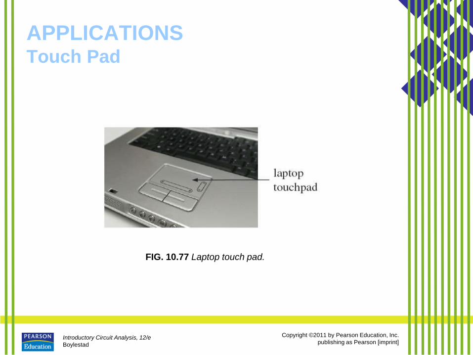
APPLICATIONS Touch Pad
FIG. 10.77 Laptop touch pad.
Introductory Circuit Analysis, 12/e
Boylestad
Copyright ©2011 by Pearson Education, Inc.
publishing as Pearson [imprint]
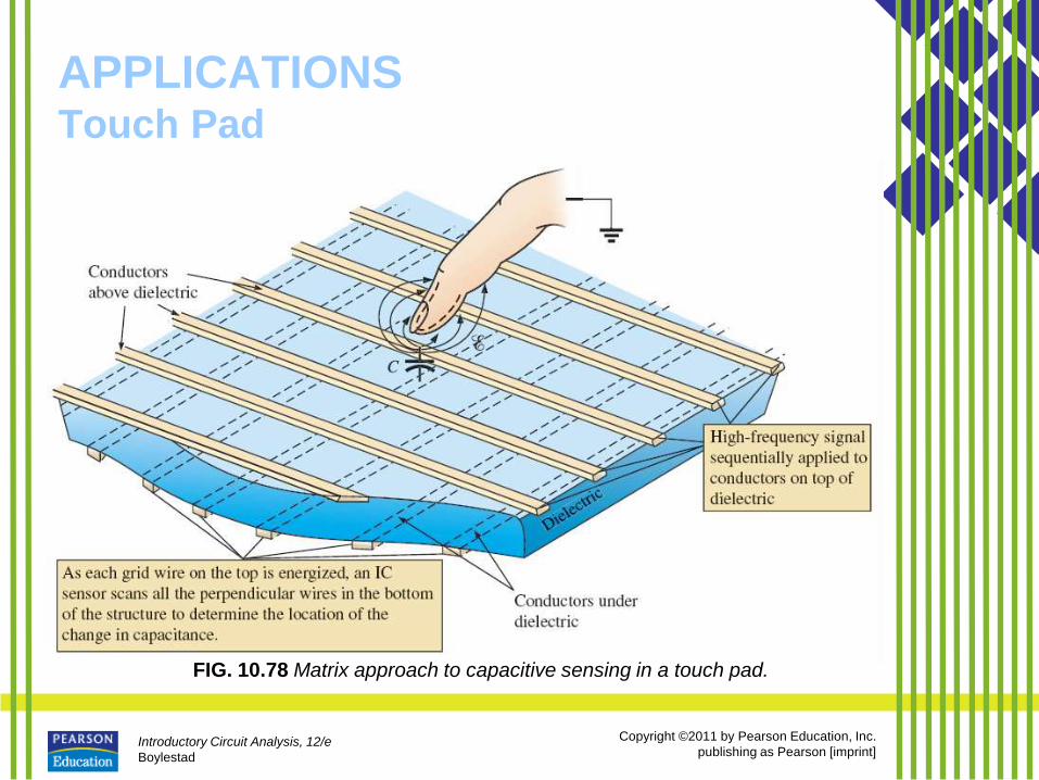
APPLICATIONS Touch Pad
FIG. 10.78 Matrix approach to capacitive sensing in a touch pad.
Introductory Circuit Analysis, 12/e
Boylestad
Copyright ©2011 by Pearson Education, Inc.
publishing as Pearson [imprint]
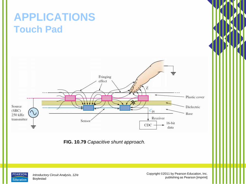
APPLICATIONS Touch Pad
FIG. 10.79 Capacitive shunt approach.
Introductory Circuit Analysis, 12/e
Boylestad
Copyright ©2011 by Pearson Education, Inc.
publishing as Pearson [imprint]
APPLICATIONS Touch Pad
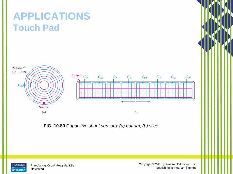
FIG. 10.80 Capacitive shunt sensors: (a) bottom, (b) slice.
Introductory Circuit Analysis, 12/e
Boylestad
Copyright ©2011 by Pearson Education, Inc.
publishing as Pearson [imprint]
APPLICATIONS Flash Lamp
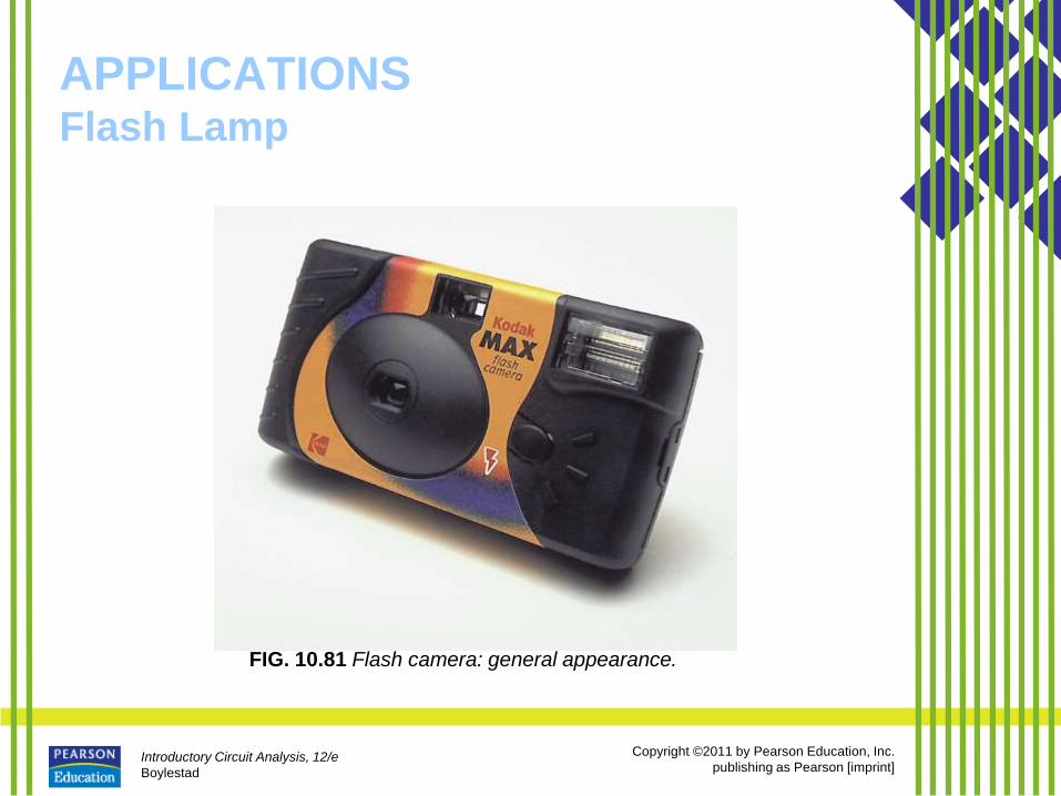
FIG. 10.81 Flash camera: general appearance.
Introductory Circuit Analysis, 12/e
Boylestad
Copyright ©2011 by Pearson Education, Inc.
publishing as Pearson [imprint]
APPLICATIONS Flash Lamp
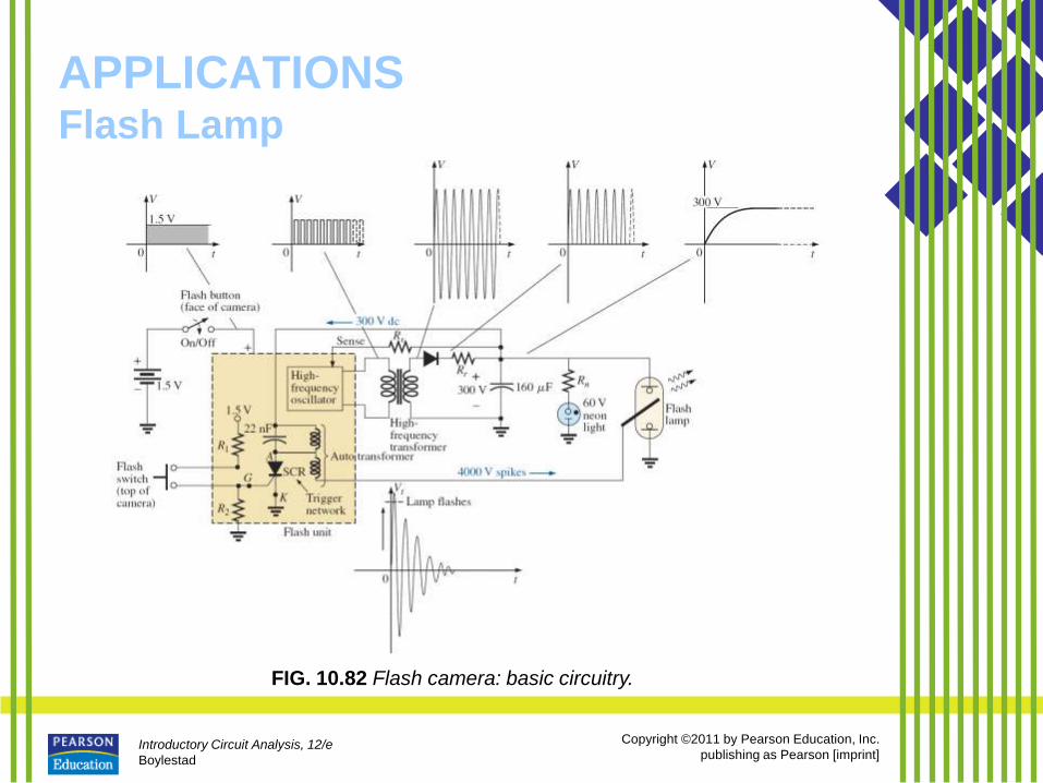
FIG. 10.82 Flash camera: basic circuitry.
Introductory Circuit Analysis, 12/e
Boylestad
Copyright ©2011 by Pearson Education, Inc.
publishing as Pearson [imprint]
APPLICATIONS Flash Lamp
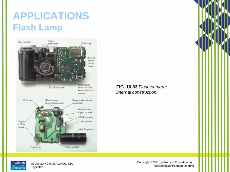
FIG. 10.83 Flash camera:
internal construction.
Introductory Circuit Analysis, 12/e
Boylestad
Copyright ©2011 by Pearson Education, Inc.
publishing as Pearson [imprint]
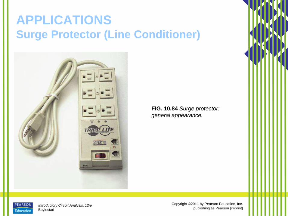
APPLICATIONS Surge Protector (Line Conditioner)
FIG. 10.84 Surge protector:
general appearance.
Introductory Circuit Analysis, 12/e
Boylestad
Copyright ©2011 by Pearson Education, Inc.
publishing as Pearson [imprint]
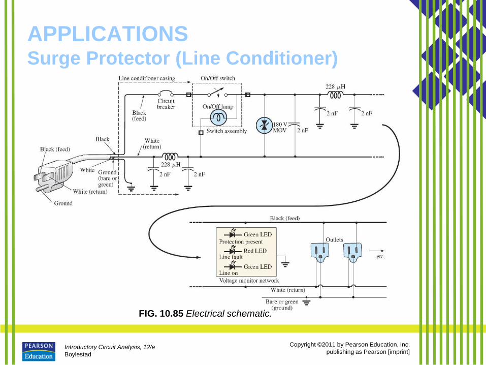
APPLICATIONS Surge Protector (Line Conditioner)
FIG. 10.85 Electrical schematic.
Introductory Circuit Analysis, 12/e
Boylestad
Copyright ©2011 by Pearson Education, Inc.
publishing as Pearson [imprint]
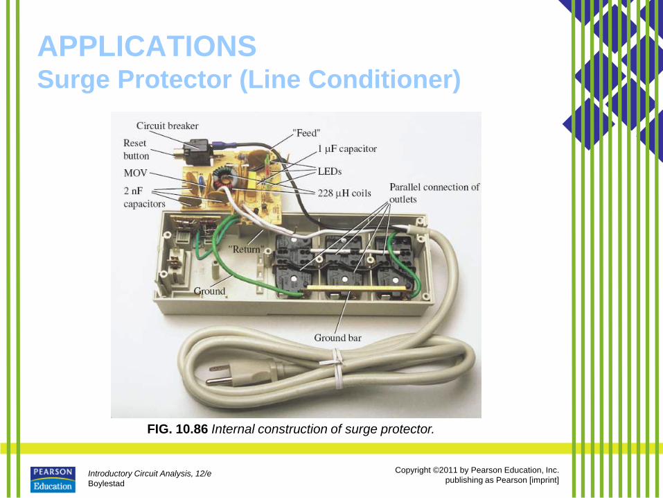
APPLICATIONS Surge Protector (Line Conditioner)
FIG. 10.86 Internal construction of surge protector.
Introductory Circuit Analysis, 12/e
Boylestad
Copyright ©2011 by Pearson Education, Inc.
publishing as Pearson [imprint]
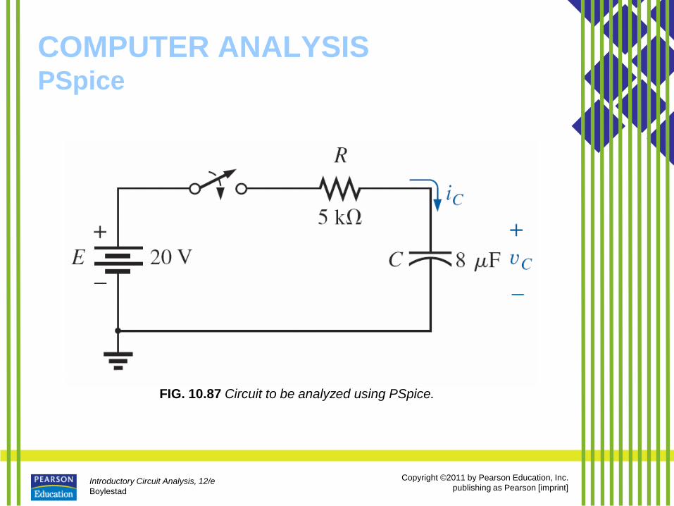
COMPUTER ANALYSIS PSpice
FIG. 10.87 Circuit to be analyzed using PSpice.
Introductory Circuit Analysis, 12/e
Boylestad
Copyright ©2011 by Pearson Education, Inc.
publishing as Pearson [imprint]
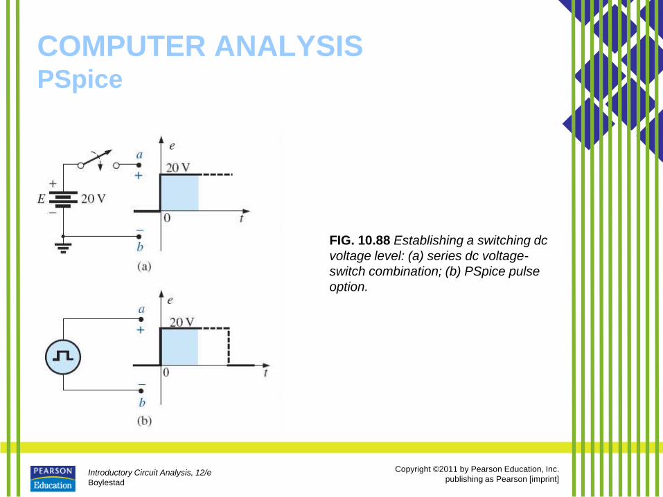
COMPUTER ANALYSIS PSpice
FIG. 10.88 Establishing a switching dc
voltage level: (a) series dc voltage-
switch combination; (b) PSpice pulse
option.
Introductory Circuit Analysis, 12/e
Boylestad
Copyright ©2011 by Pearson Education, Inc.
publishing as Pearson [imprint]
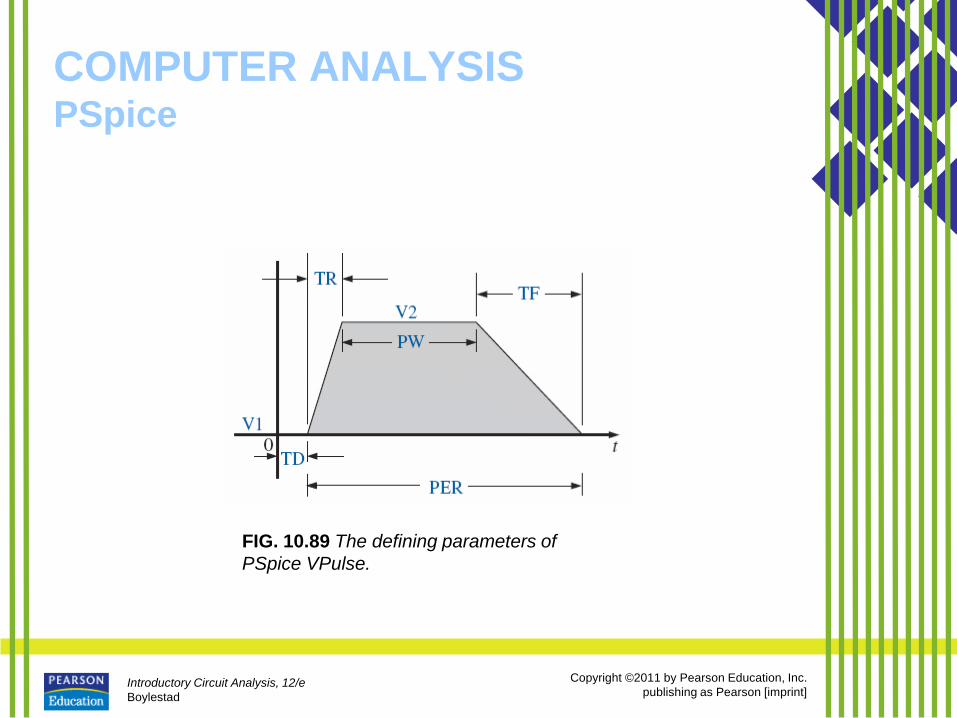
COMPUTER ANALYSIS PSpice
FIG. 10.89 The defining parameters of
PSpice VPulse.
Introductory Circuit Analysis, 12/e
Boylestad
Copyright ©2011 by Pearson Education, Inc.
publishing as Pearson [imprint]
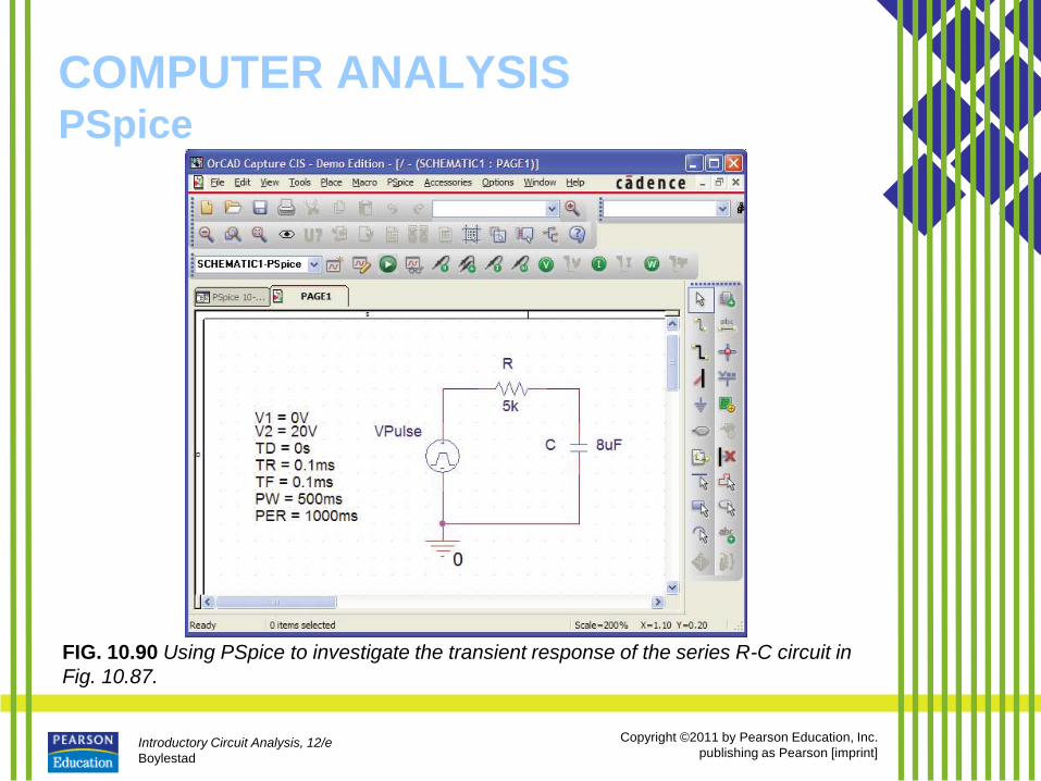
COMPUTER ANALYSIS PSpice
FIG. 10.90 Using PSpice to investigate the transient response of the series R-C circuit in
Fig. 10.87.
Introductory Circuit Analysis, 12/e
Boylestad
Copyright ©2011 by Pearson Education, Inc.
publishing as Pearson [imprint]
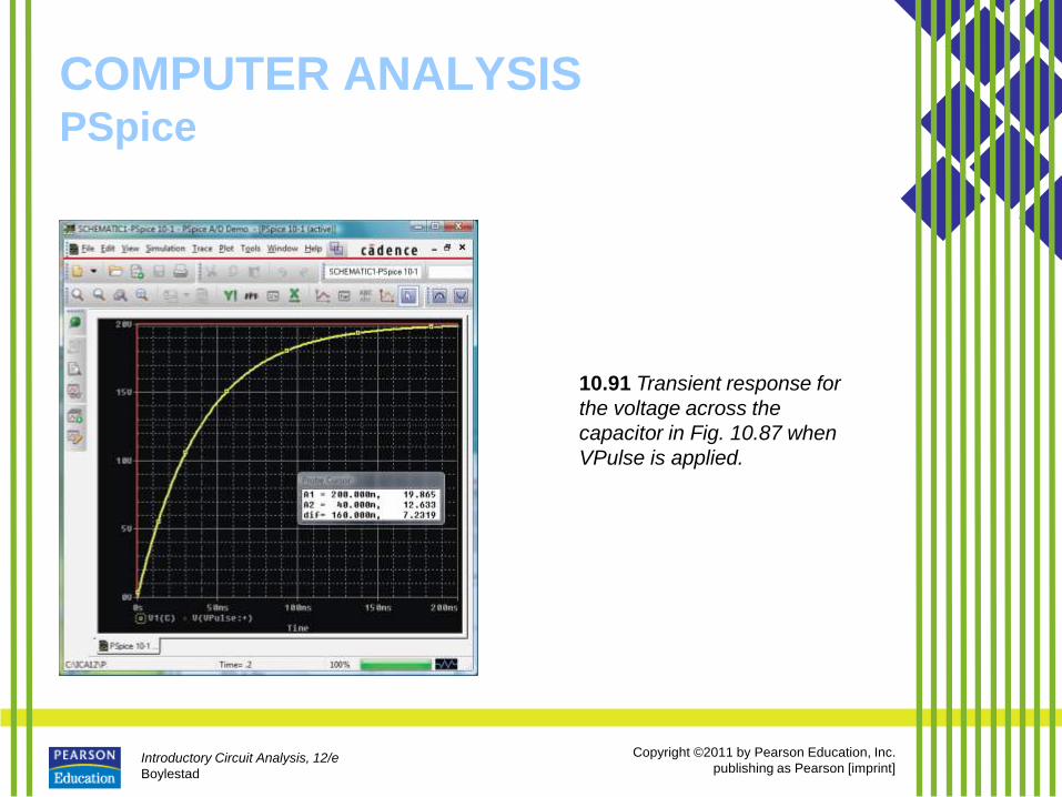
COMPUTER ANALYSIS PSpice
10.91 Transient response for
the voltage across the
capacitor in Fig. 10.87 when
VPulse is applied.
Introductory Circuit Analysis, 12/e
Boylestad
Copyright ©2011 by Pearson Education, Inc.
publishing as Pearson [imprint]
COMPUTER ANALYSIS PSpice
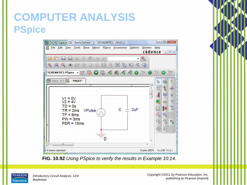
FIG. 10.92 Using PSpice to verify the results in Example 10.14.
Introductory Circuit Analysis, 12/e
Boylestad
Copyright ©2011 by Pearson Education, Inc.
publishing as Pearson [imprint]
COMPUTER ANALYSIS PSpice
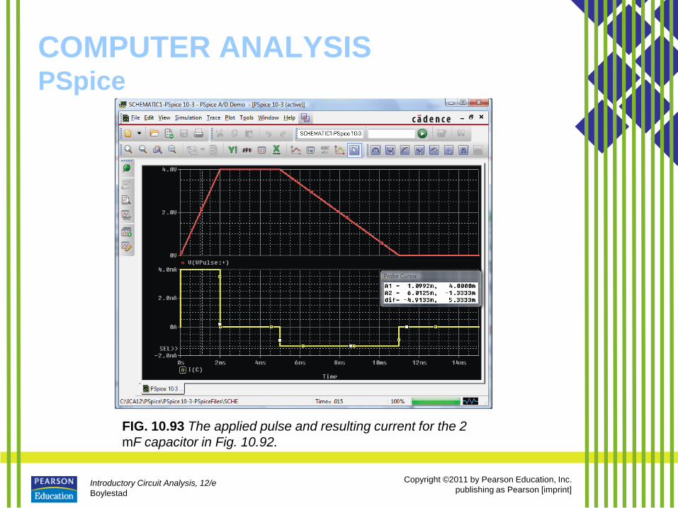
FIG. 10.93 The applied pulse and resulting current for the 2
mF capacitor in Fig. 10.92.


