Embed Size (px)
Citation preview
Principle of Microcomputer 8051 Instruction sets 1
Principle of Microcomputer(UEE 2301/1071 )
Chap 6. MCS-51 Instruction sets
微算機原理與實驗
宋開泰
Office:EE709 Phone:5731865(校內分機:31865)
E-mail:[email protected] URL:http://isci.cn.nctu.edu.tw
Lab#3 5 x 7 單色點矩陣LED(Dot Matrix)實驗
Principle of Microcomputer 8051 Instruction sets
原理說明
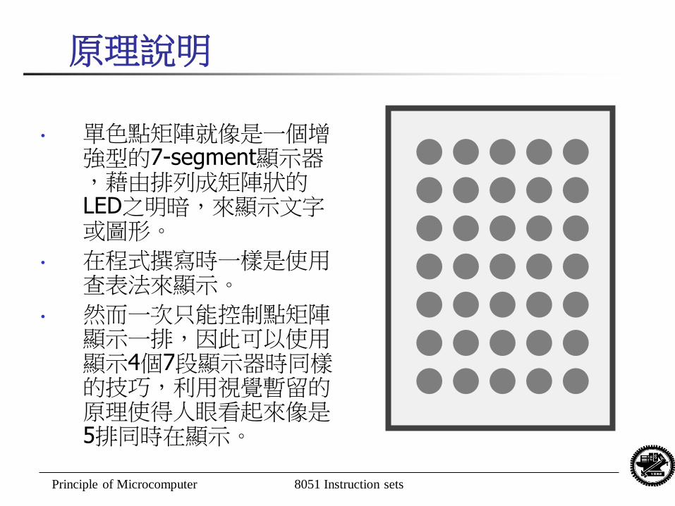
• 單色點矩陣就像是一個增強型的7-segment顯示器,藉由排列成矩陣狀的LED之明暗,來顯示文字或圖形。
• 在程式撰寫時一樣是使用查表法來顯示。
• 然而一次只能控制點矩陣顯示一排,因此可以使用顯示4個7段顯示器時同樣的技巧,利用視覺暫留的原理使得人眼看起來像是5排同時在顯示。
Principle of Microcomputer 8051 Instruction sets
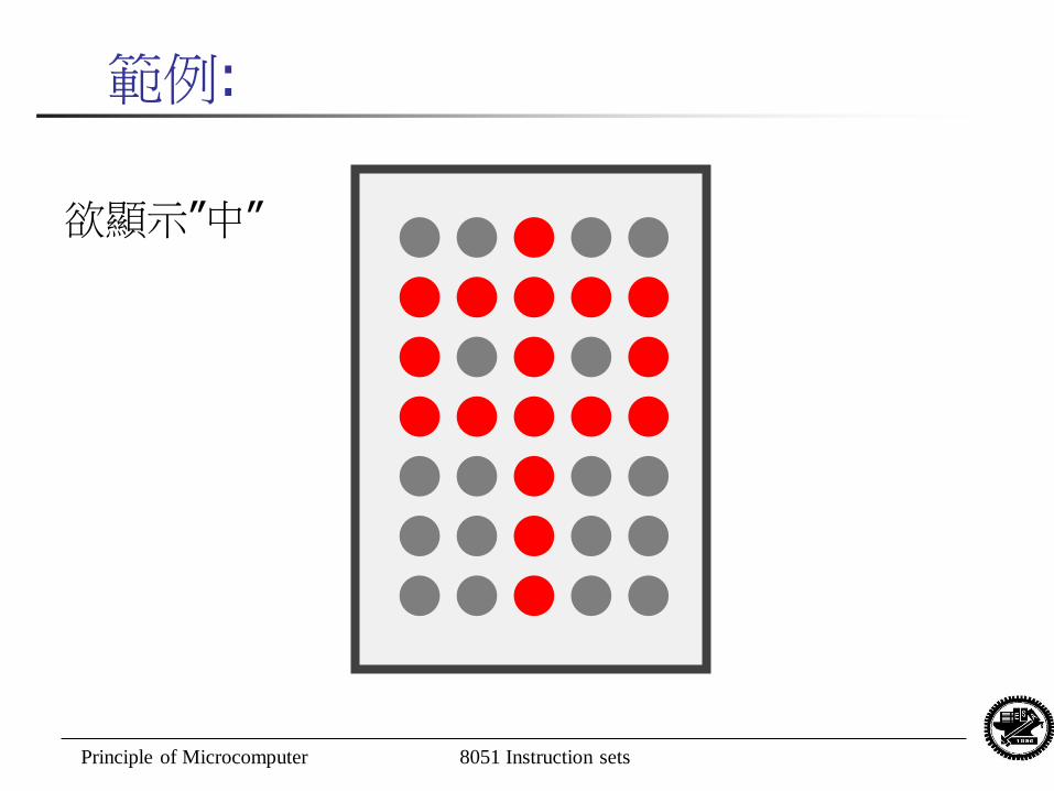
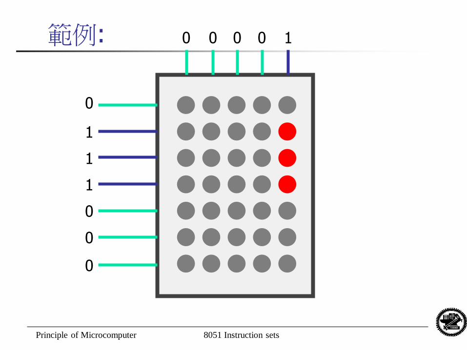
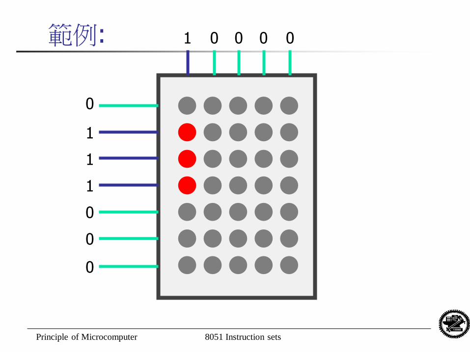
範例:
欲顯示”中”
Principle of Microcomputer 8051 Instruction sets
範例: 0 0 0 0 1
0
0
0
0
1
1
1
Principle of Microcomputer 8051 Instruction sets
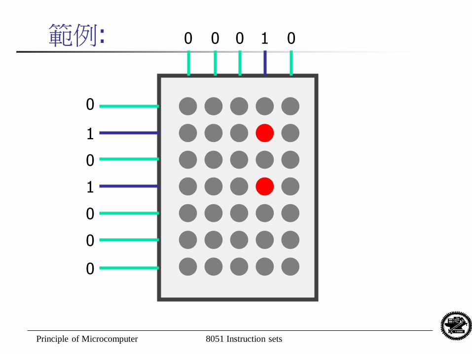
範例: 0 0 0 1 0
0
0
0
0
1
1
0
Principle of Microcomputer 8051 Instruction sets
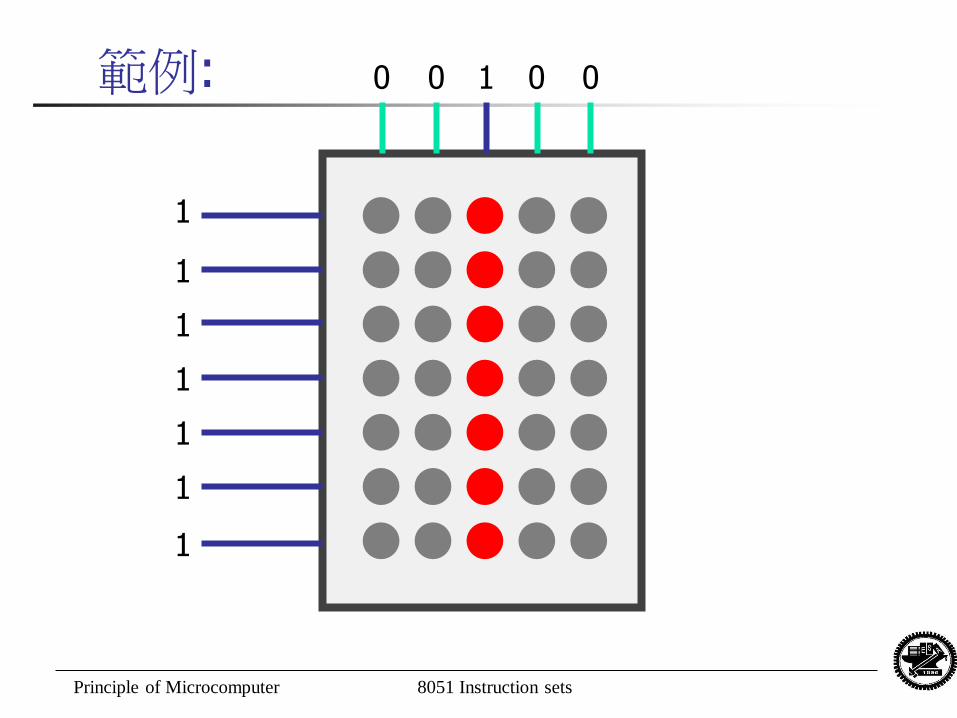
範例: 0 0 1 0 0
1
1
1
1
1
1
1
Principle of Microcomputer 8051 Instruction sets
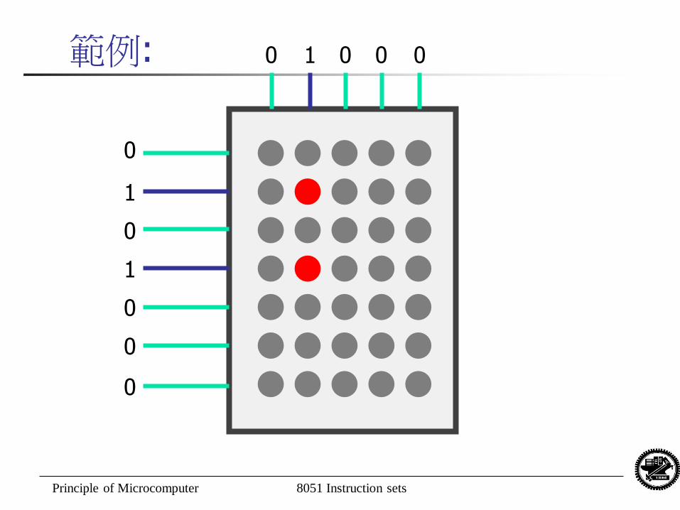
範例: 0 1 0 0 0
0
0
0
0
1
1
0
Principle of Microcomputer 8051 Instruction sets
範例: 1 0 0 0 0
0
0
0
0
1
1
1
Principle of Microcomputer 8051 Instruction sets
DEMO
1. 請撰寫一個程式,在點矩陣顯示器上顯示一個字或部首。
2. 請撰寫一個程式,在點矩陣顯示器上顯示一串文字跑馬燈或動畫(至少有3個不同畫面) 。
Principle of Microcomputer 8051 Instruction sets
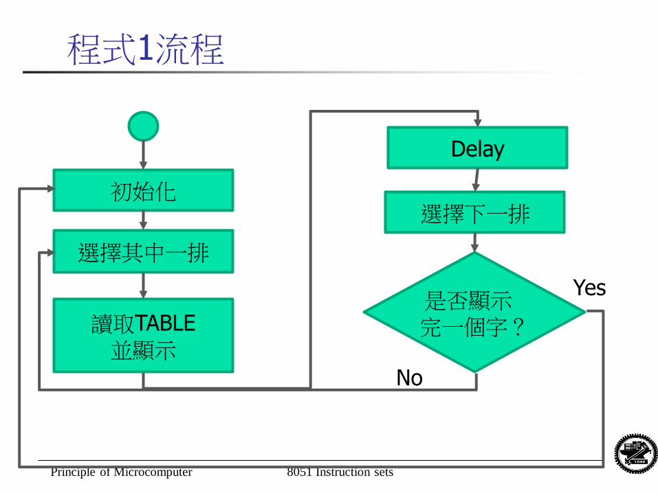
程式1流程
初始化
是否顯示完一個字?
選擇其中一排
選擇下一排
No
Yes
讀取TABLE 並顯示
Delay
Principle of Microcomputer 8051 Instruction sets
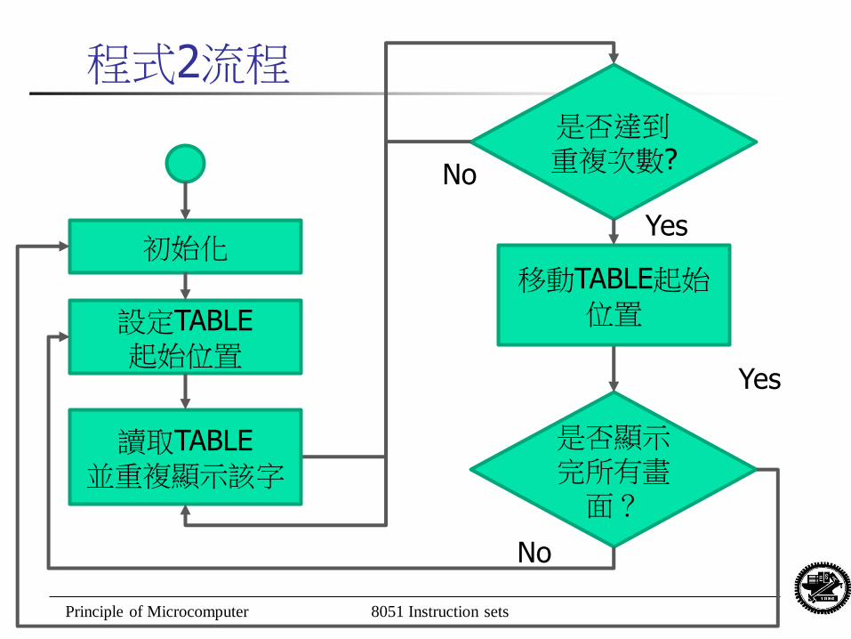
程式2流程
初始化
是否顯示完所有畫
面?
設定TABLE 起始位置
No
Yes
讀取TABLE 並重複顯示該字
是否達到重複次數?
Yes
No
移動TABLE起始位置
Principle of Microcomputer 8051 Instruction sets 13
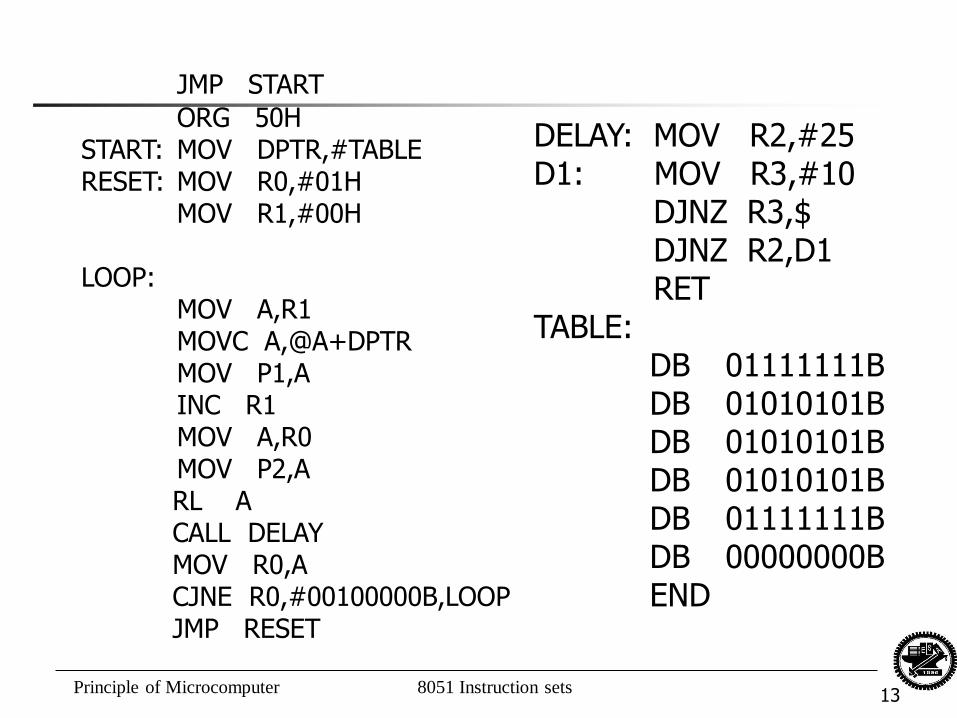
JMP START
ORG 50H START: MOV DPTR,#TABLE RESET: MOV R0,#01H MOV R1,#00H LOOP: MOV A,R1 MOVC A,@A+DPTR MOV P1,A INC R1 MOV A,R0 MOV P2,A RL A CALL DELAY MOV R0,A CJNE R0,#00100000B,LOOP JMP RESET
DELAY: MOV R2,#25 D1: MOV R3,#10 DJNZ R3,$ DJNZ R2,D1 RET TABLE: DB 01111111B DB 01010101B DB 01010101B DB 01010101B DB 01111111B DB 00000000B END
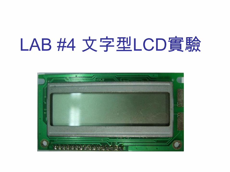
LAB #4 文字型LCD實驗
Principle of Microcomputer 8051 Instruction sets 15
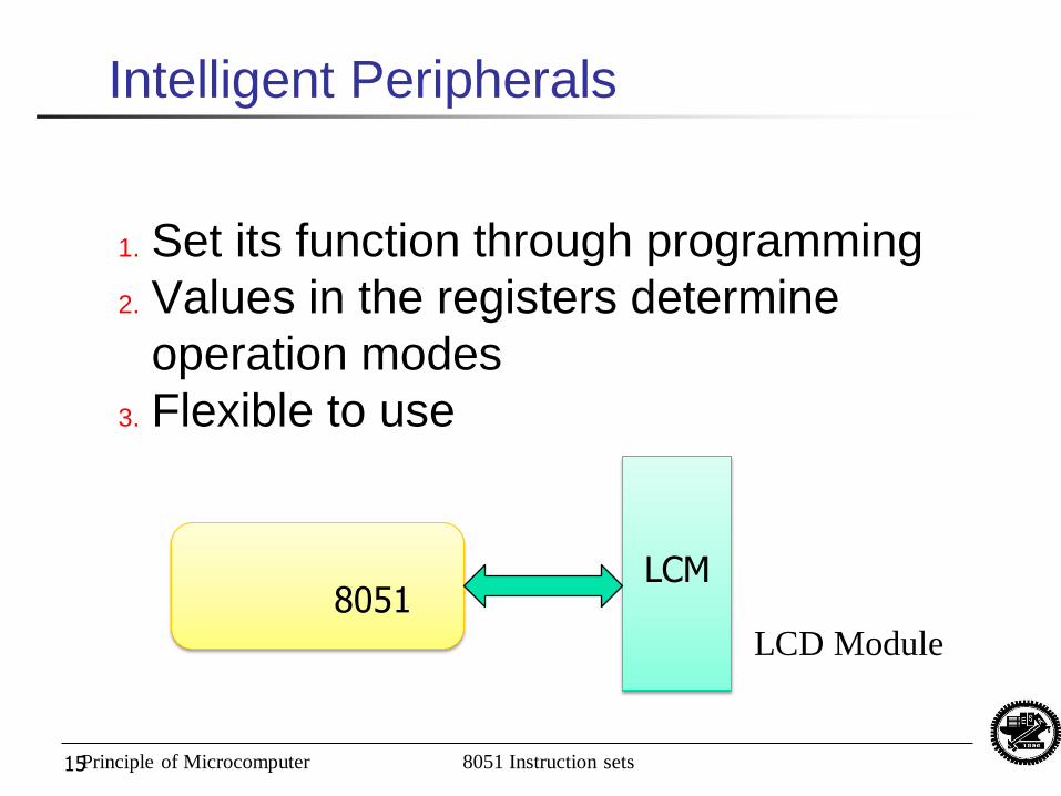
Intelligent Peripherals
1. Set its function through programming
2. Values in the registers determine
operation modes
3. Flexible to use
8051
LCM
LCD Module
Principle of Microcomputer 8051 Instruction sets
實驗原理
本次實驗使用16×2的文字型LCD顯示器。
目前所使用之LCD顯示器多半整合了控制
電路以及驅動電路,所以又可稱為LCD模
組(LCD Module, LCM)。
因LCM與8051之執行速度有所差異,程
式當中必須加入適當的延遲,或是透過檢
查LCM的忙碌旗標來得知傳送下一筆指
令或資料的時機。
Principle of Microcomputer 8051 Instruction sets
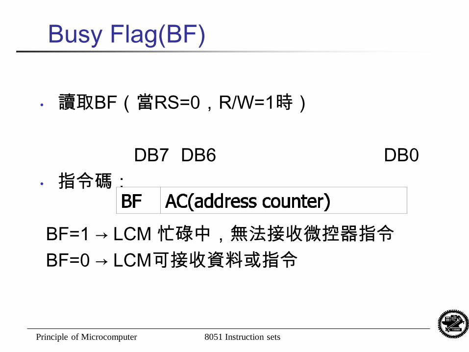
Busy Flag(BF)
• 讀取BF(當RS=0,R/W=1時)
DB7 DB6 DB0
• 指令碼:
BF=1 → LCM 忙碌中,無法接收微控器指令
BF=0 → LCM可接收資料或指令
Principle of Microcomputer 8051 Instruction sets 18
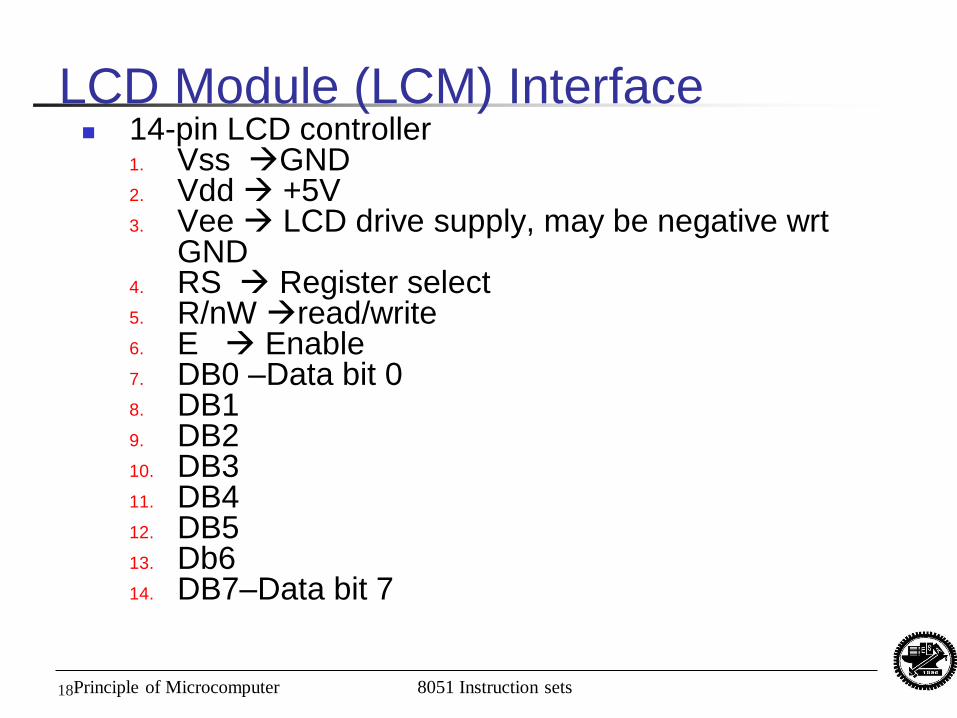
LCD Module (LCM) Interface 14-pin LCD controller
1. Vss GND 2. Vdd +5V 3. Vee LCD drive supply, may be negative wrt
GND 4. RS Register select 5. R/nW read/write 6. E Enable 7. DB0 –Data bit 0 8. DB1 9. DB2 10. DB3 11. DB4 12. DB5 13. Db6 14. DB7–Data bit 7
Principle of Microcomputer 8051 Instruction sets 19
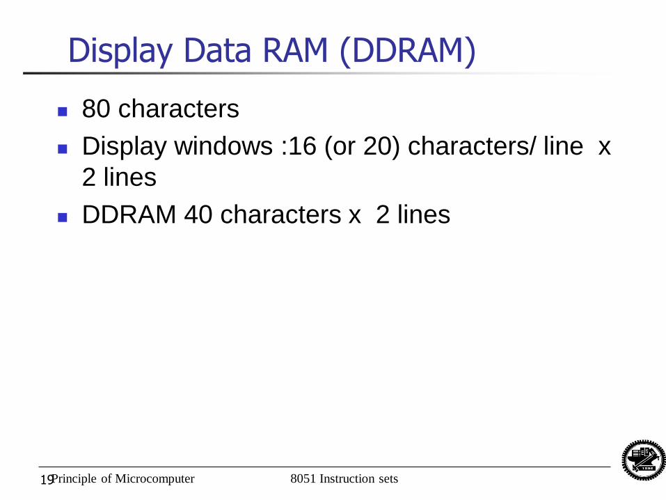
Display Data RAM (DDRAM)
80 characters
Display windows :16 (or 20) characters/ line x
2 lines
DDRAM 40 characters x 2 lines
Principle of Microcomputer 8051 Instruction sets 20
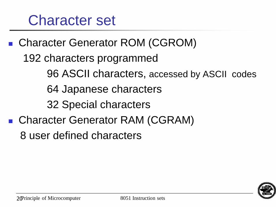
Character set
Character Generator ROM (CGROM)
192 characters programmed
96 ASCII characters, accessed by ASCII codes
64 Japanese characters
32 Special characters
Character Generator RAM (CGRAM)
8 user defined characters
Principle of Microcomputer 8051 Instruction sets 21
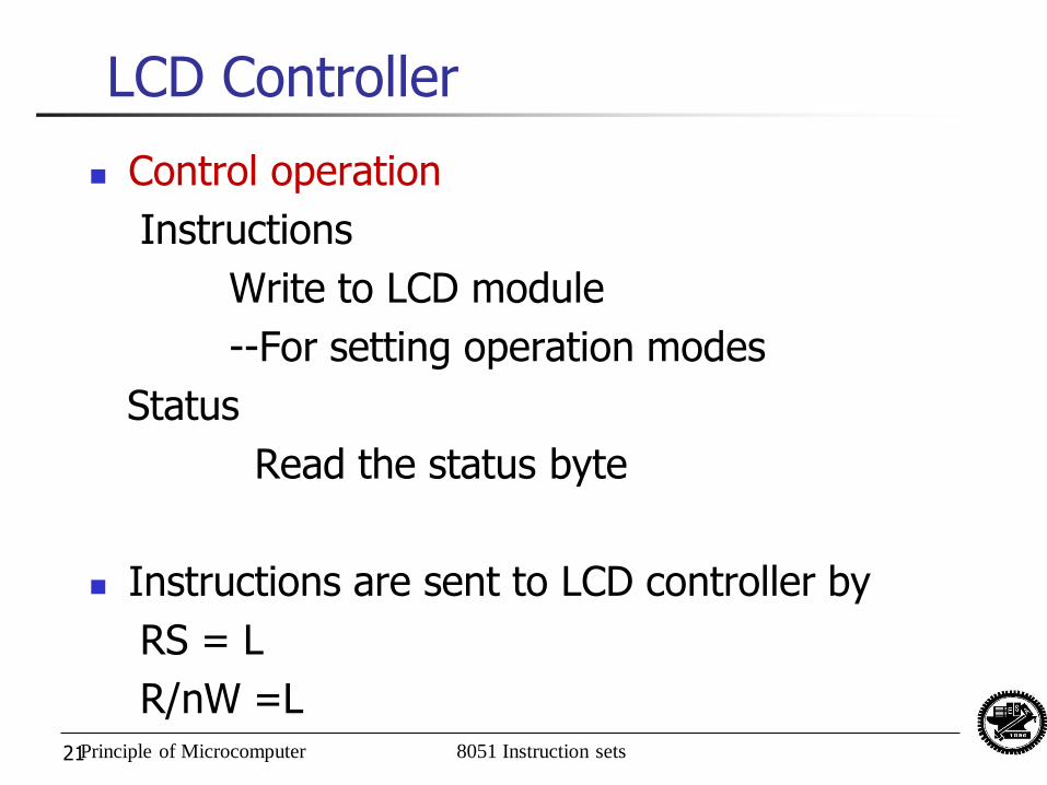
LCD Controller
Control operation
Instructions
Write to LCD module
--For setting operation modes
Status
Read the status byte
Instructions are sent to LCD controller by
RS = L
R/nW =L
Principle of Microcomputer 8051 Instruction sets 22
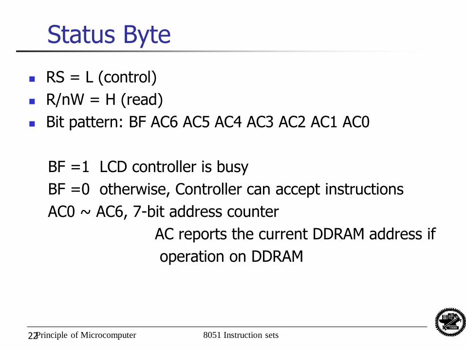
Status Byte
RS = L (control)
R/nW = H (read)
Bit pattern: BF AC6 AC5 AC4 AC3 AC2 AC1 AC0
BF =1 LCD controller is busy
BF =0 otherwise, Controller can accept instructions
AC0 ~ AC6, 7-bit address counter
AC reports the current DDRAM address if
operation on DDRAM
23
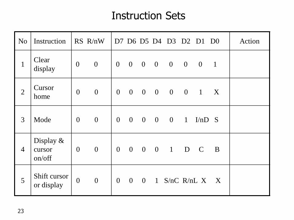
Instruction Sets
No Instruction RS R/nW D7 D6 D5 D4 D3 D2 D1 D0 Action
1 Clear
display 0 0 0 0 0 0 0 0 0 1
2 Cursor
home 0 0 0 0 0 0 0 0 1 X
3 Mode 0 0 0 0 0 0 0 1 I/nD S
4
Display &
cursor
on/off
0 0 0 0 0 0 1 D C B
5 Shift cursor
or display 0 0 0 0 0 1 S/nC R/nL X X
24
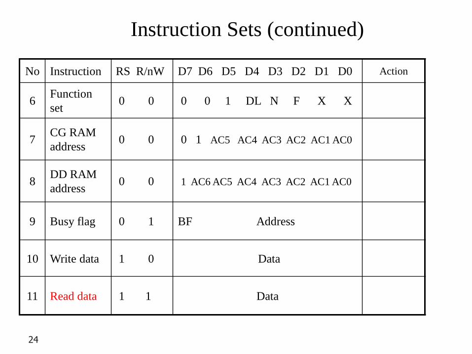
No Instruction RS R/nW D7 D6 D5 D4 D3 D2 D1 D0 Action
6 Function
set 0 0 0 0 1 DL N F X X
7 CG RAM
address 0 0 0 1 AC5 AC4 AC3 AC2 AC1 AC0
8 DD RAM
address 0 0 1 AC6 AC5 AC4 AC3 AC2 AC1 AC0
9 Busy flag 0 1 BF Address
10 Write data 1 0 Data
11 Read data 1 1 Data
Instruction Sets (continued)
Principle of Microcomputer 8051 Instruction sets 25
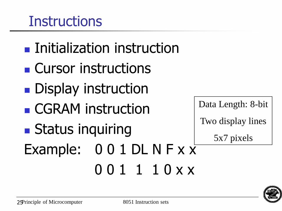
Instructions
Initialization instruction
Cursor instructions
Display instruction
CGRAM instruction
Status inquiring
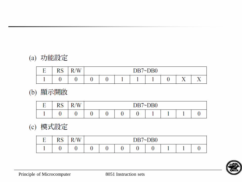
Example: 0 0 1 DL N F x x
0 0 1 1 1 0 x x
Data Length: 8-bit
Two display lines
5x7 pixels
Principle of Microcomputer 8051 Instruction sets
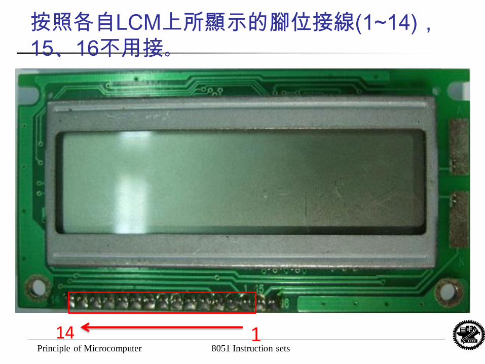
1
14
按照各自LCM上所顯示的腳位接線(1~14),
15、16不用接。
Principle of Microcomputer 8051 Instruction sets
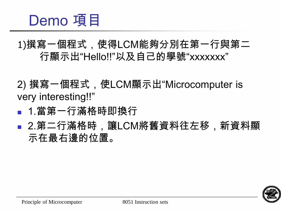
Demo 項目
2) 撰寫一個程式,使LCM顯示出“Microcomputer is
very interesting!!”
1.當第一行滿格時即換行
2.第二行滿格時,讓LCM將舊資料往左移,新資料顯
示在最右邊的位置。
1)撰寫一個程式,使得LCM能夠分別在第一行與第二
行顯示出“Hello!!”以及自己的學號“xxxxxxx”
Principle of Microcomputer 8051 Instruction sets
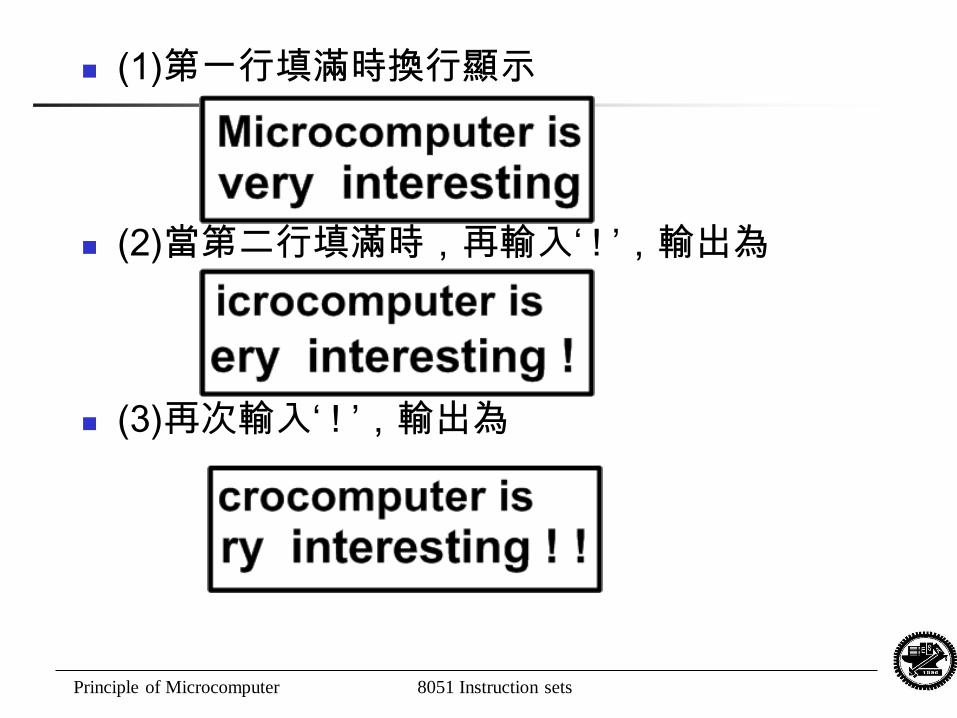
(1)第一行填滿時換行顯示
(2)當第二行填滿時,再輸入‘ ! ’,輸出為
(3)再次輸入‘ ! ’,輸出為
Principle of Microcomputer 8051 Instruction sets
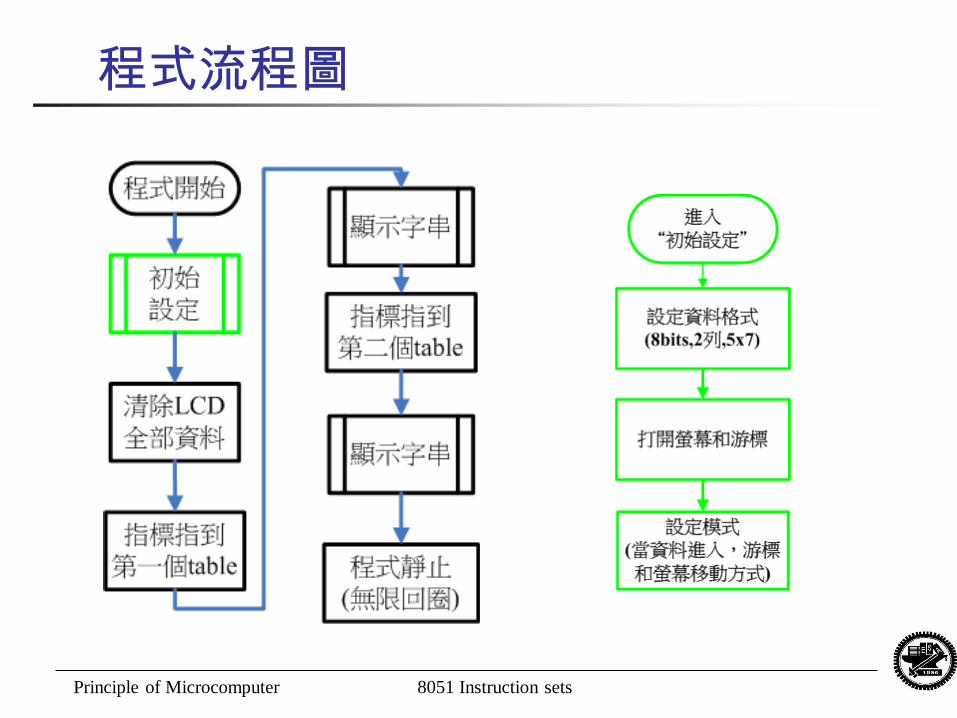
程式流程圖
Principle of Microcomputer 8051 Instruction sets
Principle of Microcomputer 8051 Instruction sets
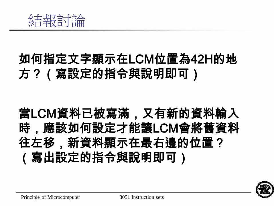
結報討論
如何指定文字顯示在LCM位置為42H的地
方?(寫設定的指令與說明即可)
當LCM資料已被寫滿,又有新的資料輸入
時,應該如何設定才能讓LCM會將舊資料
往左移,新資料顯示在最右邊的位置?
(寫出設定的指令與說明即可)
Principle of Microcomputer 8051 Instruction sets 32
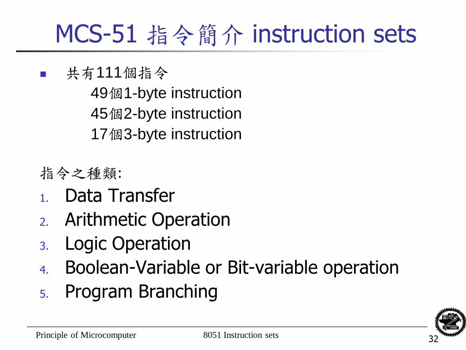
MCS-51 指令簡介 instruction sets
共有111個指令
49個1-byte instruction
45個2-byte instruction
17個3-byte instruction
指令之種類:
1. Data Transfer
2. Arithmetic Operation
3. Logic Operation
4. Boolean-Variable or Bit-variable operation
5. Program Branching
Principle of Microcomputer 8051 Instruction sets 33
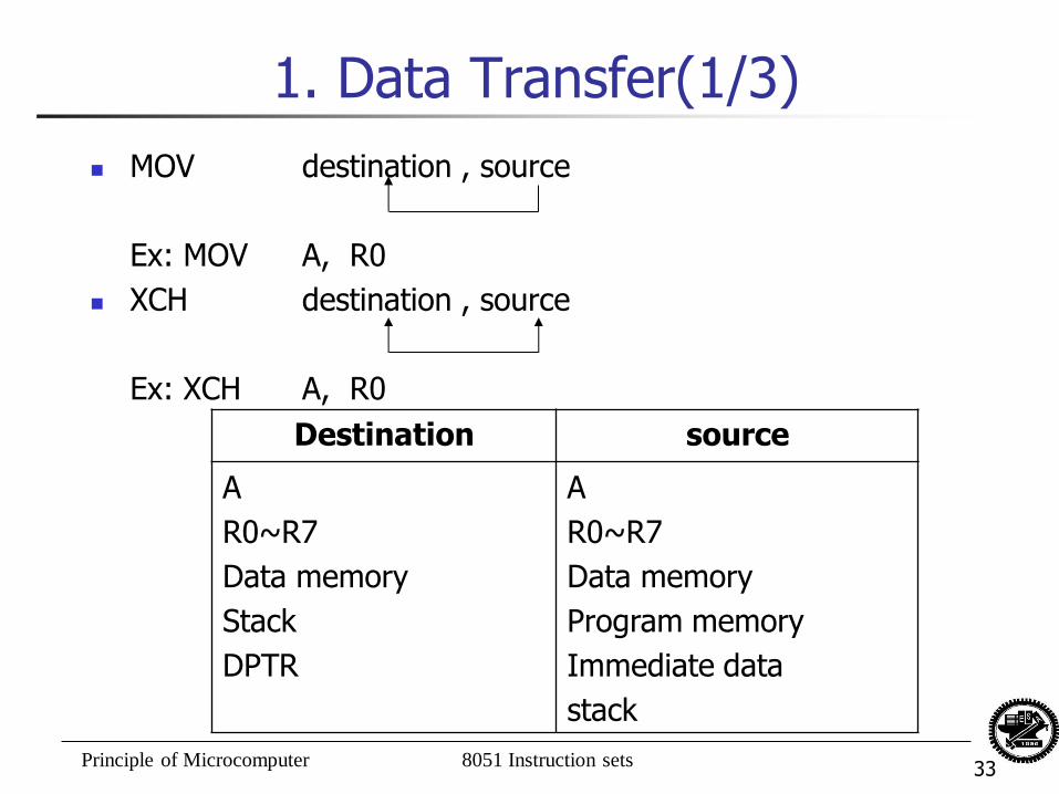
1. Data Transfer(1/3)
MOV destination , source
Ex: MOV A, R0
XCH destination , source
Ex: XCH A, R0
Destination source
A
R0~R7
Data memory
Stack
DPTR
A
R0~R7
Data memory
Program memory
Immediate data
stack
Principle of Microcomputer 8051 Instruction sets 34
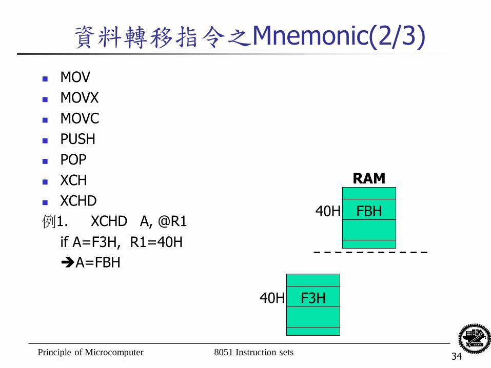
資料轉移指令之Mnemonic(2/3)
MOV
MOVX
MOVC
PUSH
POP
XCH
XCHD
例1. XCHD A, @R1
if A=F3H, R1=40H
A=FBH
FBH 40H
RAM
F3H 40H
Principle of Microcomputer 8051 Instruction sets 35
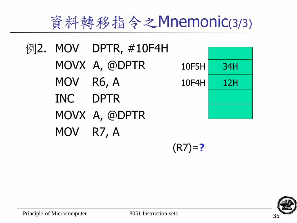
資料轉移指令之Mnemonic(3/3)
例2. MOV DPTR, #10F4H
MOVX A, @DPTR
MOV R6, A
INC DPTR
MOVX A, @DPTR
MOV R7, A
34H
12H
10F5H
10F4H
(R7)=?
Principle of Microcomputer 8051 Instruction sets 36
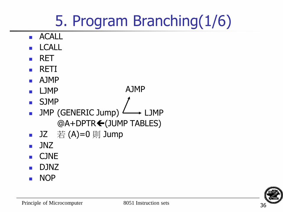
5. Program Branching(1/6) ACALL
LCALL
RET
RETI
AJMP
LJMP
SJMP
JMP (GENERIC Jump)
@A+DPTR(JUMP TABLES)
JZ 若 (A)=0 則 Jump
JNZ
CJNE
DJNZ
NOP
AJMP
LJMP
Principle of Microcomputer 8051 Instruction sets 37
5. Program Branching (2/6)
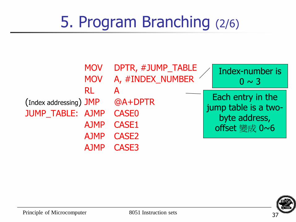
MOV DPTR, #JUMP_TABLE
MOV A, #INDEX_NUMBER
RL A
(Index addressing) JMP @A+DPTR
JUMP_TABLE: AJMP CASE0
AJMP CASE1
AJMP CASE2
AJMP CASE3
Index-number is 0 ~ 3
Each entry in the jump table is a two-
byte address, offset 變成 0~6
Principle of Microcomputer 8051 Instruction sets 38
5. Program Branching (3/6)
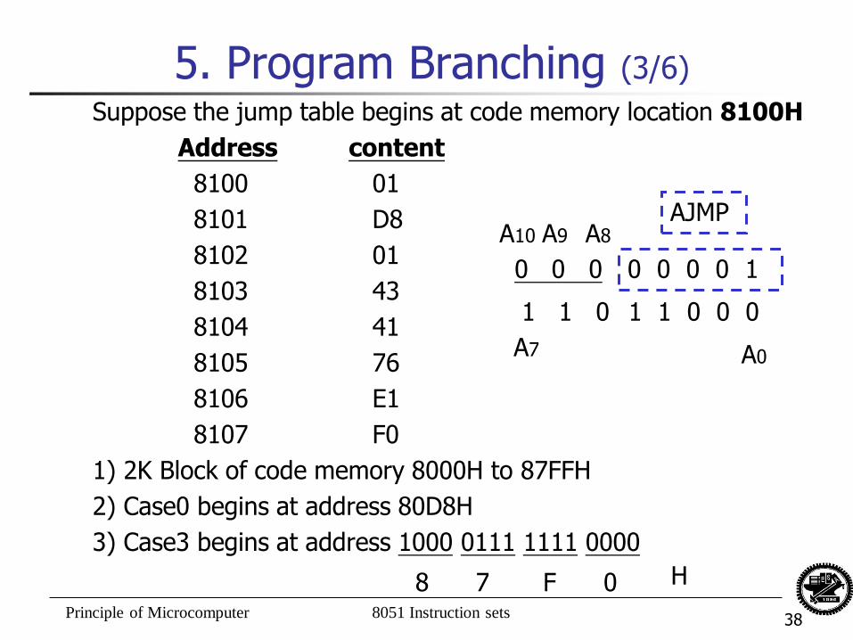
Suppose the jump table begins at code memory location 8100H
Address content
8100 01
8101 D8
8102 01
8103 43
8104 41
8105 76
8106 E1
8107 F0
1) 2K Block of code memory 8000H to 87FFH
2) Case0 begins at address 80D8H
3) Case3 begins at address 1000 0111 1111 0000
A10
0 0 0 0 0 0 0 1
AJMP
1 1 0 1 1 0 0 0
A0 A7
8 7 F 0 H
A9 A8
Principle of Microcomputer 8051 Instruction sets 39
5. Program Branching (4/6)
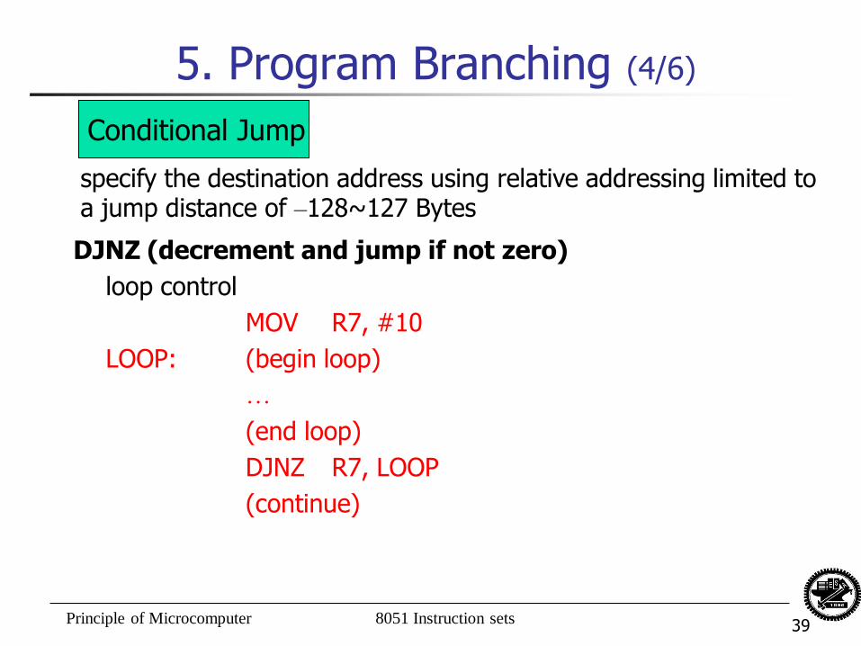
DJNZ (decrement and jump if not zero)
loop control
MOV R7, #10
LOOP: (begin loop)
…
(end loop)
DJNZ R7, LOOP
(continue)
Conditional Jump
specify the destination address using relative addressing limited to a jump distance of –128~127 Bytes
Principle of Microcomputer 8051 Instruction sets 40
5. Program Branching (5/6)
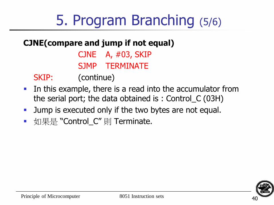
CJNE(compare and jump if not equal)
CJNE A, #03, SKIP
SJMP TERMINATE
SKIP: (continue)
In this example, there is a read into the accumulator from the serial port; the data obtained is : Control_C (03H)
Jump is executed only if the two bytes are not equal.
如果是 “Control_C” 則 Terminate.
Principle of Microcomputer 8051 Instruction sets 41
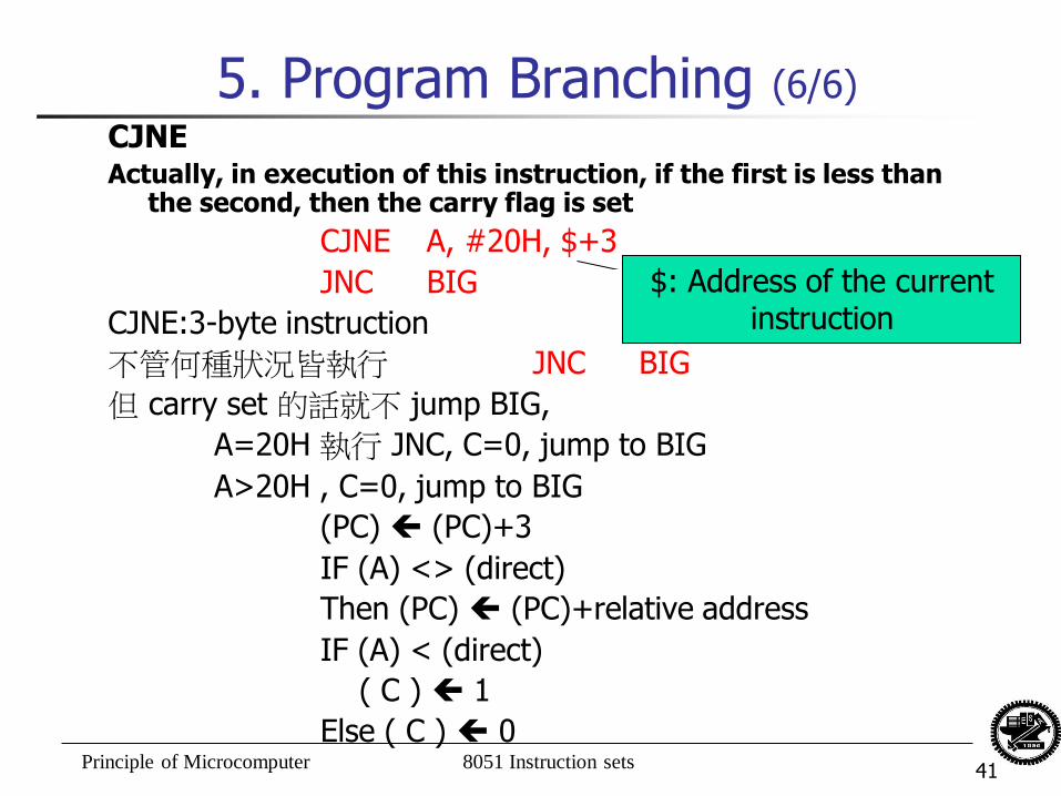
5. Program Branching (6/6)
CJNE Actually, in execution of this instruction, if the first is less than
the second, then the carry flag is set
CJNE A, #20H, $+3
JNC BIG
CJNE:3-byte instruction
不管何種狀況皆執行 JNC BIG
但 carry set 的話就不 jump BIG,
A=20H 執行 JNC, C=0, jump to BIG
A>20H , C=0, jump to BIG
(PC) (PC)+3
IF (A) <> (direct)
Then (PC) (PC)+relative address
IF (A) < (direct)
( C ) 1
Else ( C ) 0
$: Address of the current instruction
Principle of Microcomputer 8051 Instruction sets 42
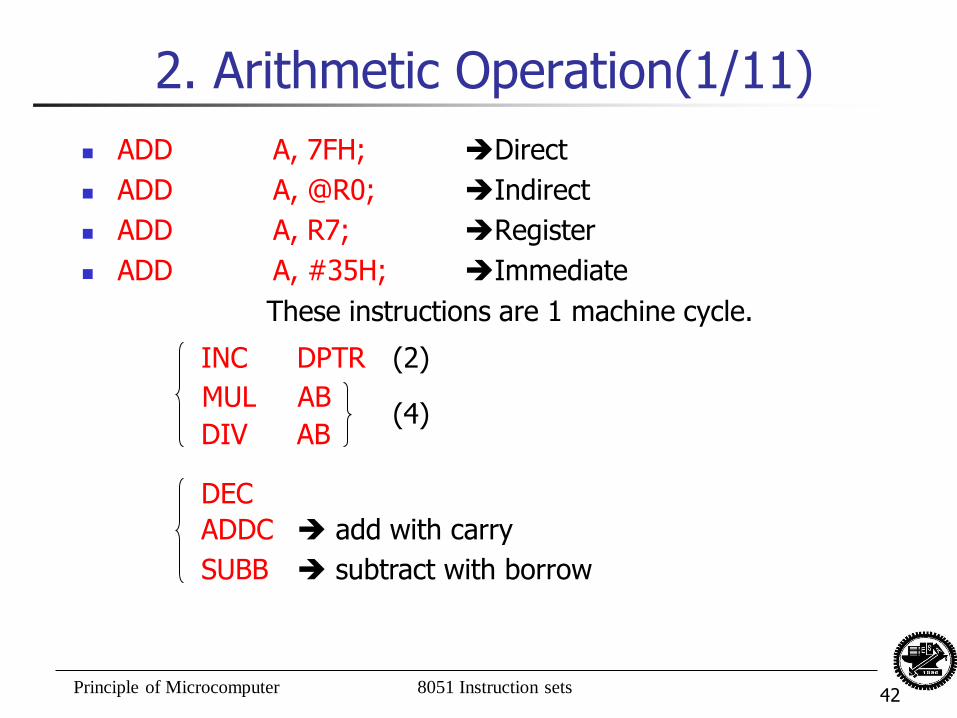
2. Arithmetic Operation(1/11)
ADD A, 7FH; Direct
ADD A, @R0; Indirect
ADD A, R7; Register
ADD A, #35H; Immediate
These instructions are 1 machine cycle.
INC DPTR (2)
MUL AB
DIV AB (4)
DEC
ADDC add with carry
SUBB subtract with borrow
Principle of Microcomputer 8051 Instruction sets 43
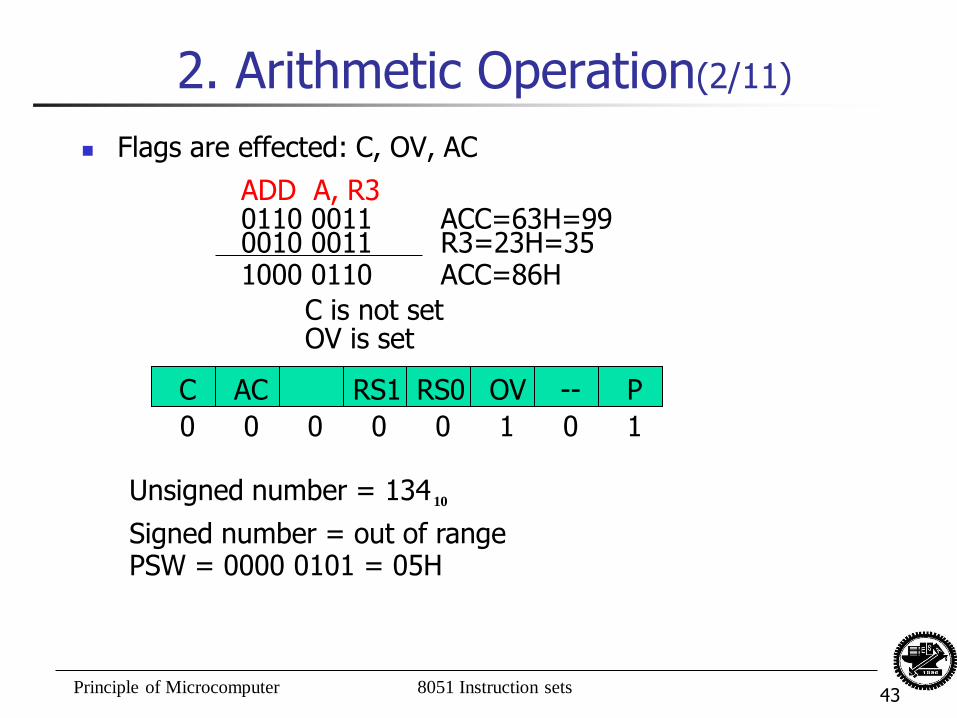
2. Arithmetic Operation(2/11)
Flags are effected: C, OV, AC
ADD A, R3 0110 0011 0010 0011 1000 0110
ACC=63H=99 R3=23H=35 ACC=86H
C is not set OV is set
RS0 RS1 AC C OV -- P
0 0 0 0 0 1 0 1
Unsigned number = 134 10
Signed number = out of range PSW = 0000 0101 = 05H
Principle of Microcomputer 8051 Instruction sets 44
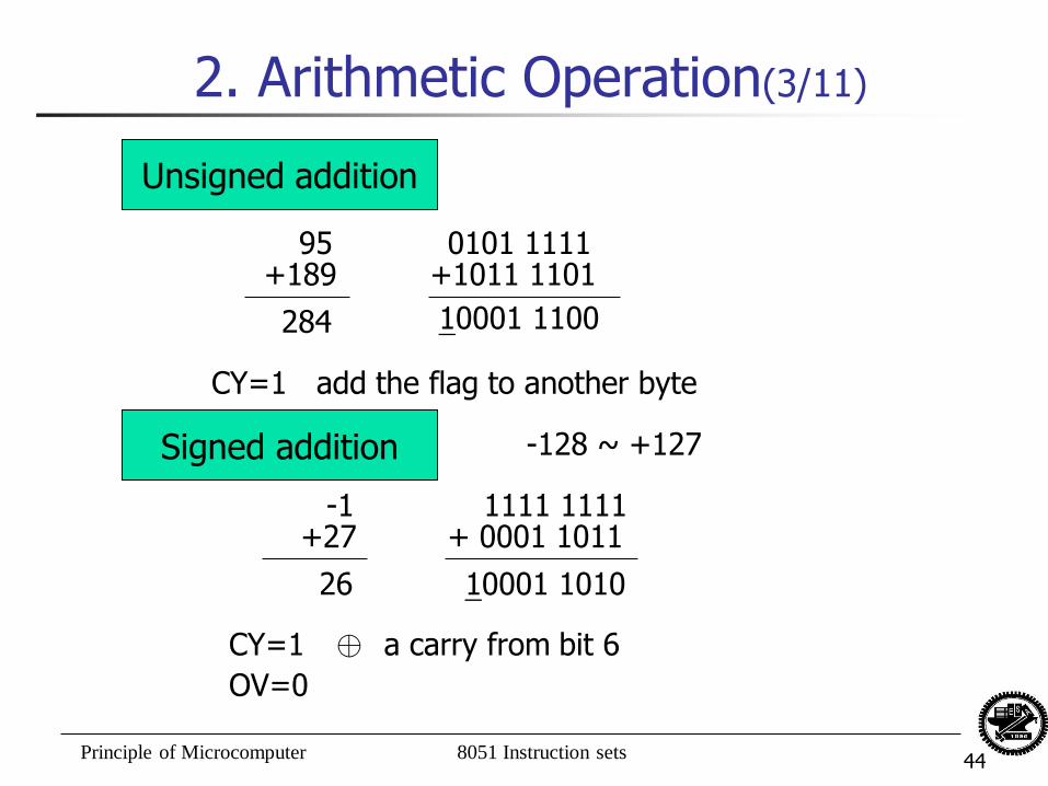
2. Arithmetic Operation(3/11)
Unsigned addition
95 +189
284
0101 1111 +1011 1101
10001 1100
CY=1 add the flag to another byte
Signed addition -128 ~ +127
-1 +27
26
1111 1111 + 0001 1011
10001 1010
CY=1 ⊕ a carry from bit 6
OV=0
Principle of Microcomputer 8051 Instruction sets 45
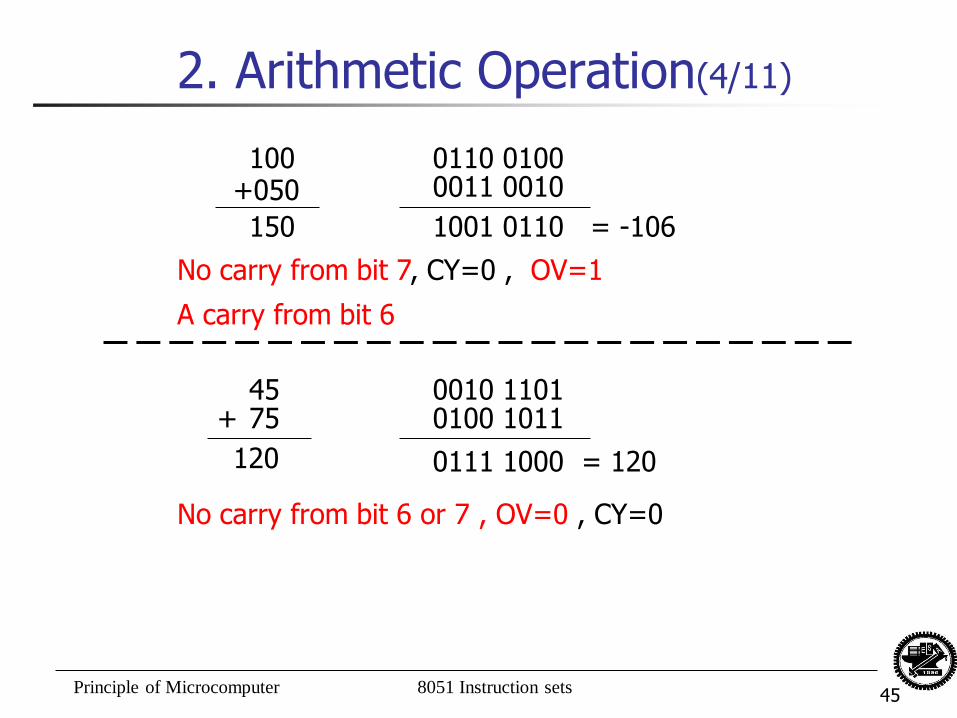
2. Arithmetic Operation(4/11)
100 +050
150
0110 0100 0011 0010
1001 0110 = -106
No carry from bit 7, CY=0 , OV=1
A carry from bit 6
45 75 +
120
0010 1101 0100 1011
0111 1000 = 120
No carry from bit 6 or 7 , OV=0 , CY=0
Principle of Microcomputer 8051 Instruction sets 46
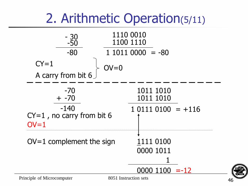
2. Arithmetic Operation(5/11)
-50
-80
1110 0010 1100 1110
1011 0000 = -80
A carry from bit 6
-70 -70 +
-140
1011 1010 1011 1010
0111 0100 = +116 CY=1 , no carry from bit 6
- 30
1
CY=1 OV=0
1
OV=1
1111 0100
0000 1011
1
0000 1100 =-12
OV=1 complement the sign
Principle of Microcomputer 8051 Instruction sets 47
Signed addition with OV set
A general rule is that if the OV flag is set, then complement the sign.
The OV flag also signals that the sum exceeds the largest positive or negative numbers thought to be needed in the program.
Principle of Microcomputer 8051 Instruction sets 48
ADDC, add with carry
The need to add the carry flag to higher order byte in signed or unsigned addition operations.
ADDC A, #n
ADDC A, R0
(A)(A) +(C)+(R0)
Principle of Microcomputer 8051 Instruction sets 49
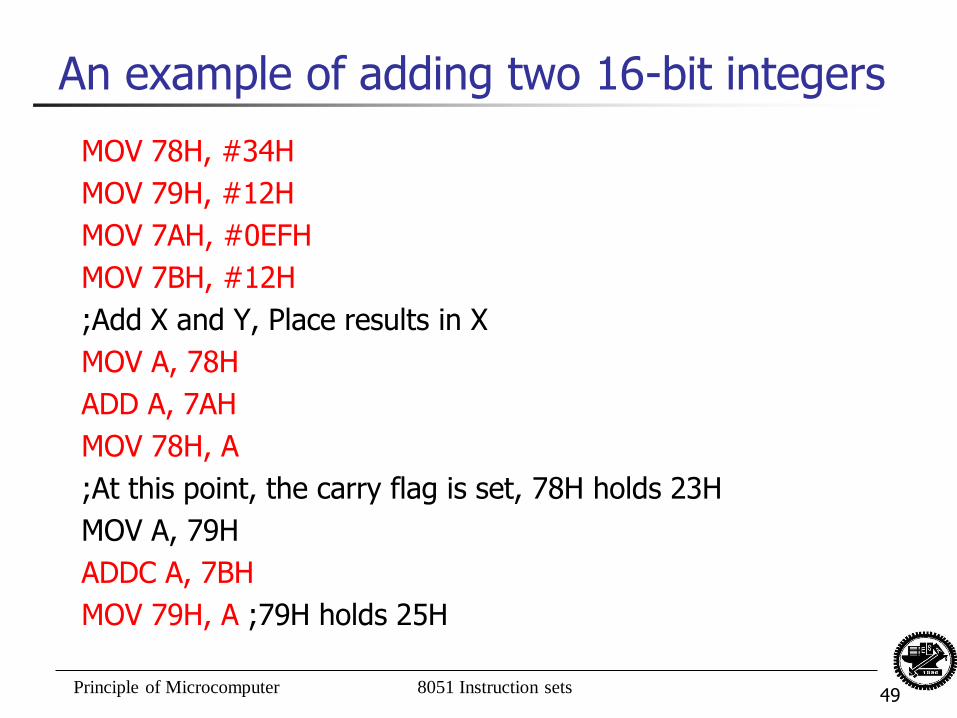
An example of adding two 16-bit integers
MOV 78H, #34H
MOV 79H, #12H
MOV 7AH, #0EFH
MOV 7BH, #12H
;Add X and Y, Place results in X
MOV A, 78H
ADD A, 7AH
MOV 78H, A
;At this point, the carry flag is set, 78H holds 23H
MOV A, 79H
ADDC A, 7BH
MOV 79H, A ;79H holds 25H
Principle of Microcomputer 8051 Instruction sets 50
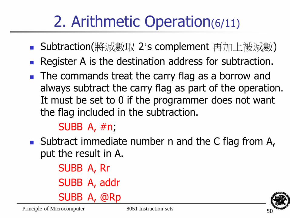
2. Arithmetic Operation(6/11)
Subtraction(將減數取 2‘s complement 再加上被減數)
Register A is the destination address for subtraction.
The commands treat the carry flag as a borrow and always subtract the carry flag as part of the operation. It must be set to 0 if the programmer does not want the flag included in the subtraction.
SUBB A, #n;
Subtract immediate number n and the C flag from A, put the result in A.
SUBB A, Rr
SUBB A, addr
SUBB A, @Rp
Principle of Microcomputer 8051 Instruction sets 51
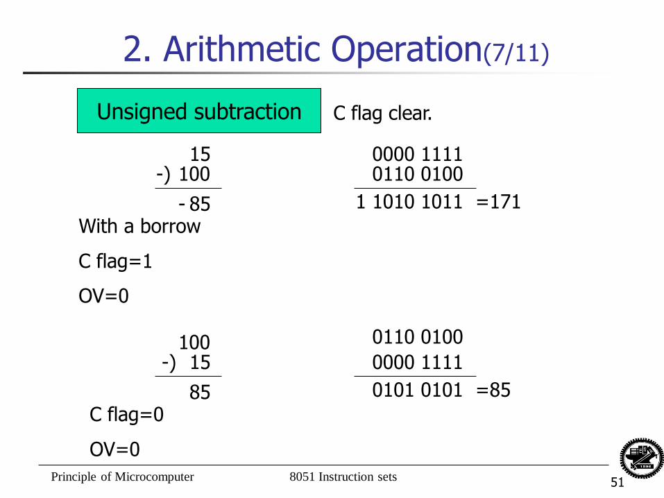
2. Arithmetic Operation(7/11)
Unsigned subtraction
15
85
0000 1111
C flag clear.
100 -)
-
0110 0100
1010 1011 =171 1
With a borrow
C flag=1
OV=0
15
85
100 -)
C flag=0
OV=0
0000 1111
0110 0100
0101 0101 =85
Principle of Microcomputer 8051 Instruction sets 52
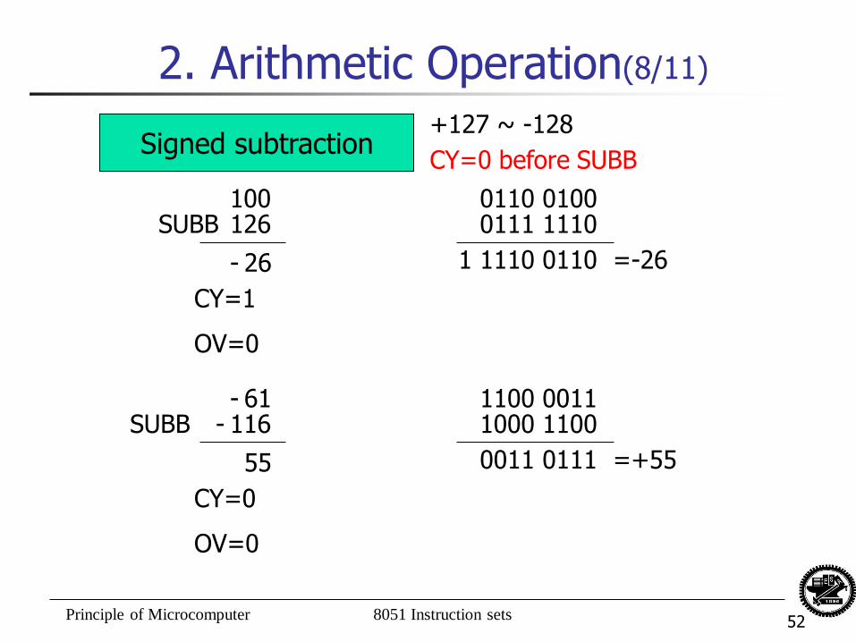
2. Arithmetic Operation(8/11)
Signed subtraction
26
0110 0100
+127 ~ -128
126 SUBB
-
0111 1110
1110 0110 =-26 1
CY=1
OV=0
CY=0 before SUBB
100
55
1100 0011 116 SUBB 1000 1100
0011 0111 =+55
CY=0
OV=0
61 - -
Principle of Microcomputer 8051 Instruction sets 53
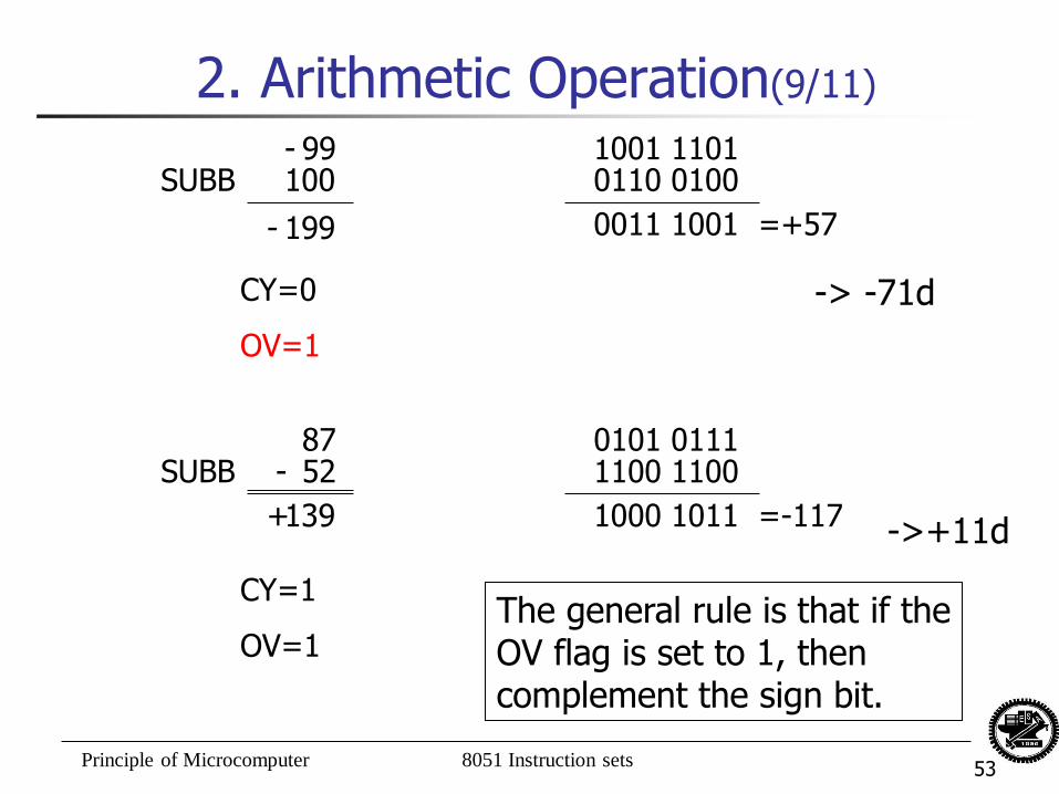
2. Arithmetic Operation(9/11)
0101 0111 SUBB 1100 1100
1000 1011 =-117
CY=1
OV=1
87 -
1001 1101 100 SUBB 0110 0100
0011 1001 =+57
CY=0
OV=1
99 -
199 -
52
139 +
The general rule is that if the OV flag is set to 1, then complement the sign bit.
->+11d
-> -71d
Principle of Microcomputer 8051 Instruction sets 54
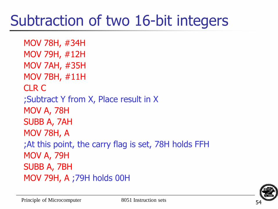
Subtraction of two 16-bit integers
MOV 78H, #34H
MOV 79H, #12H
MOV 7AH, #35H
MOV 7BH, #11H
CLR C
;Subtract Y from X, Place result in X
MOV A, 78H
SUBB A, 7AH
MOV 78H, A
;At this point, the carry flag is set, 78H holds FFH
MOV A, 79H
SUBB A, 7BH
MOV 79H, A ;79H holds 00H
Principle of Microcomputer 8051 Instruction sets 55
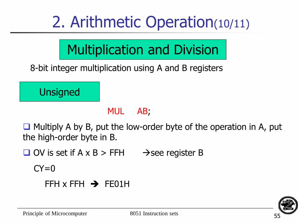
2. Arithmetic Operation(10/11)
Multiplication and Division
8-bit integer multiplication using A and B registers
Unsigned
MUL AB;
Multiply A by B, put the low-order byte of the operation in A, put the high-order byte in B.
OV is set if A x B > FFH see register B
CY=0
FFH x FFH FE01H
Principle of Microcomputer 8051 Instruction sets 56
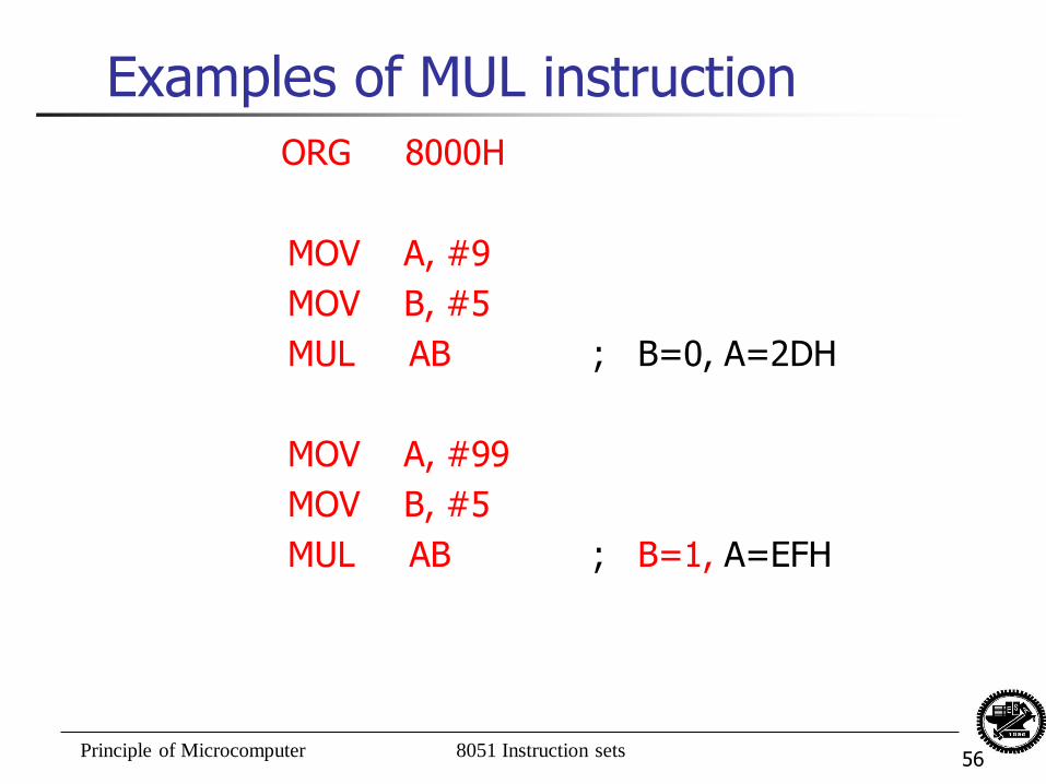
Examples of MUL instruction
ORG 8000H
MOV A, #9
MOV B, #5
MUL AB ; B=0, A=2DH
MOV A, #99
MOV B, #5
MUL AB ; B=1, A=EFH
Principle of Microcomputer 8051 Instruction sets 57
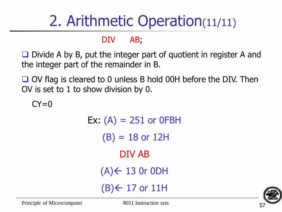
2. Arithmetic Operation(11/11)
DIV AB;
Divide A by B, put the integer part of quotient in register A and the integer part of the remainder in B.
OV flag is cleared to 0 unless B hold 00H before the DIV. Then OV is set to 1 to show division by 0.
CY=0
Ex: (A) = 251 or 0FBH
(B) = 18 or 12H
DIV AB
(A) 13 0r 0DH
(B) 17 or 11H
Principle of Microcomputer 8051 Instruction sets 58
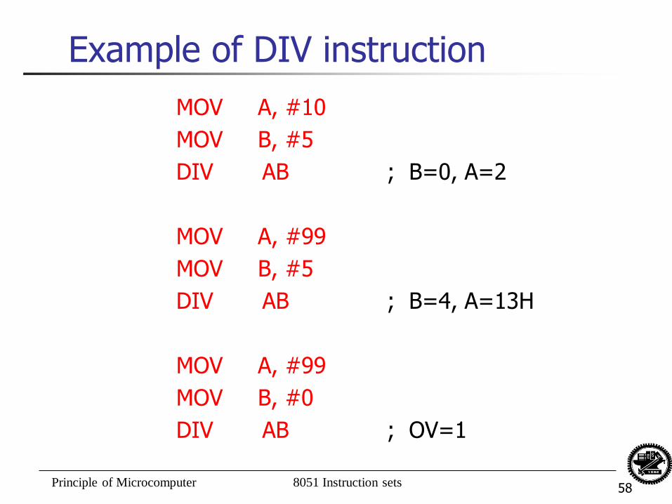
Example of DIV instruction
MOV A, #10
MOV B, #5
DIV AB ; B=0, A=2
MOV A, #99
MOV B, #5
DIV AB ; B=4, A=13H
MOV A, #99
MOV B, #0
DIV AB ; OV=1
Principle of Microcomputer 8051 Instruction sets 59
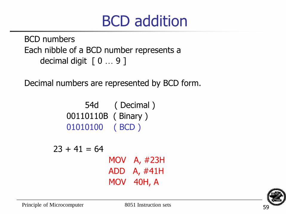
BCD addition BCD numbers
Each nibble of a BCD number represents a
decimal digit [ 0 … 9 ]
Decimal numbers are represented by BCD form.
54d ( Decimal )
00110110B ( Binary )
01010100 ( BCD )
23 + 41 = 64
MOV A, #23H
ADD A, #41H
MOV 40H, A
Principle of Microcomputer 8051 Instruction sets 60
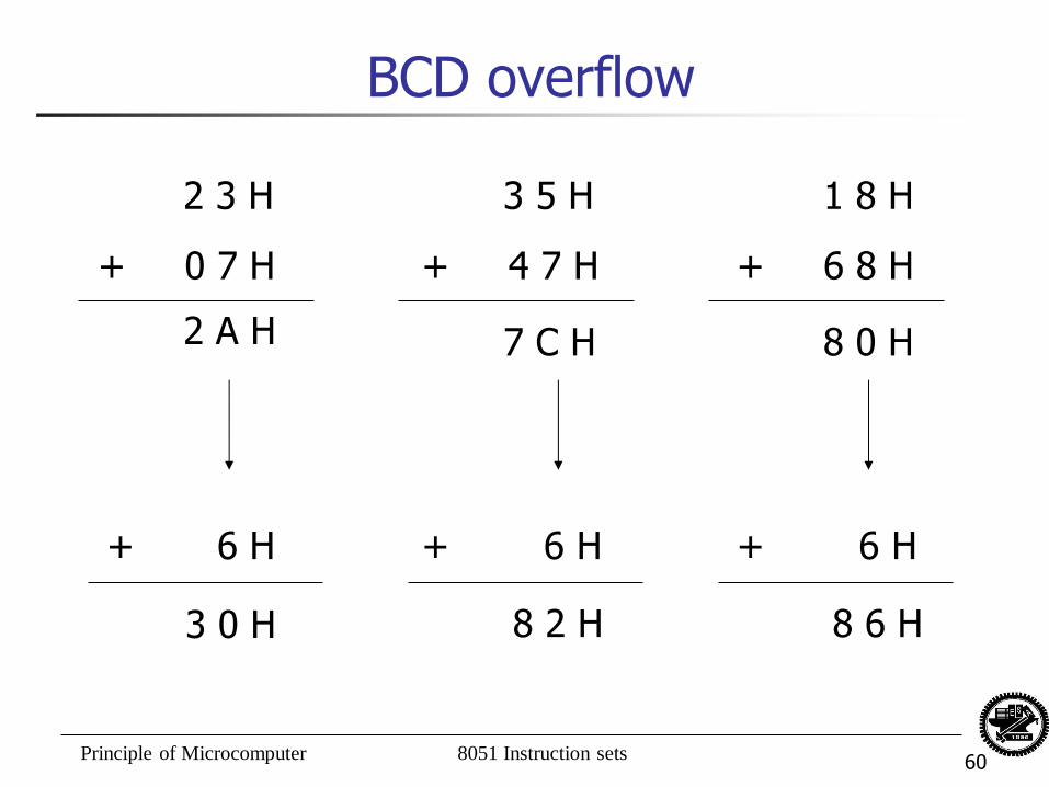
BCD overflow
2 3 H
+ 0 7 H
3 5 H
+ 4 7 H
1 8 H
+ 6 8 H
2 A H 7 C H 8 0 H
+ 6 H + 6 H + 6 H
3 0 H 8 2 H 8 6 H
Principle of Microcomputer 8051 Instruction sets 61
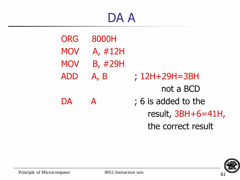
DA A
ORG 8000H
MOV A, #12H
MOV B, #29H
ADD A, B ; 12H+29H=3BH
not a BCD
DA A ; 6 is added to the
result, 3BH+6=41H,
the correct result
Principle of Microcomputer 8051 Instruction sets 62
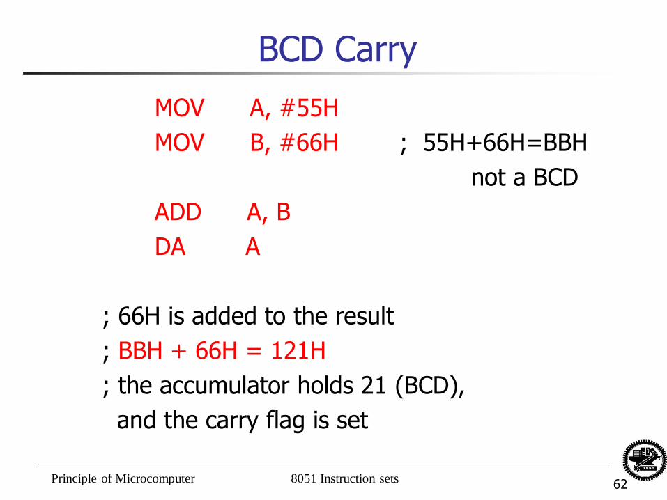
BCD Carry
MOV A, #55H
MOV B, #66H ; 55H+66H=BBH
not a BCD
ADD A, B
DA A
; 66H is added to the result
; BBH + 66H = 121H
; the accumulator holds 21 (BCD),
and the carry flag is set
Principle of Microcomputer 8051 Instruction sets 63
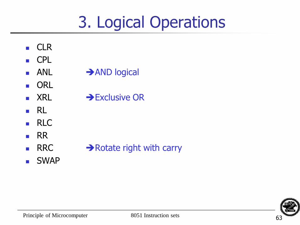
3. Logical Operations
CLR
CPL
ANL AND logical
ORL
XRL Exclusive OR
RL
RLC
RR
RRC Rotate right with carry
SWAP
Principle of Microcomputer 8051 Instruction sets 64
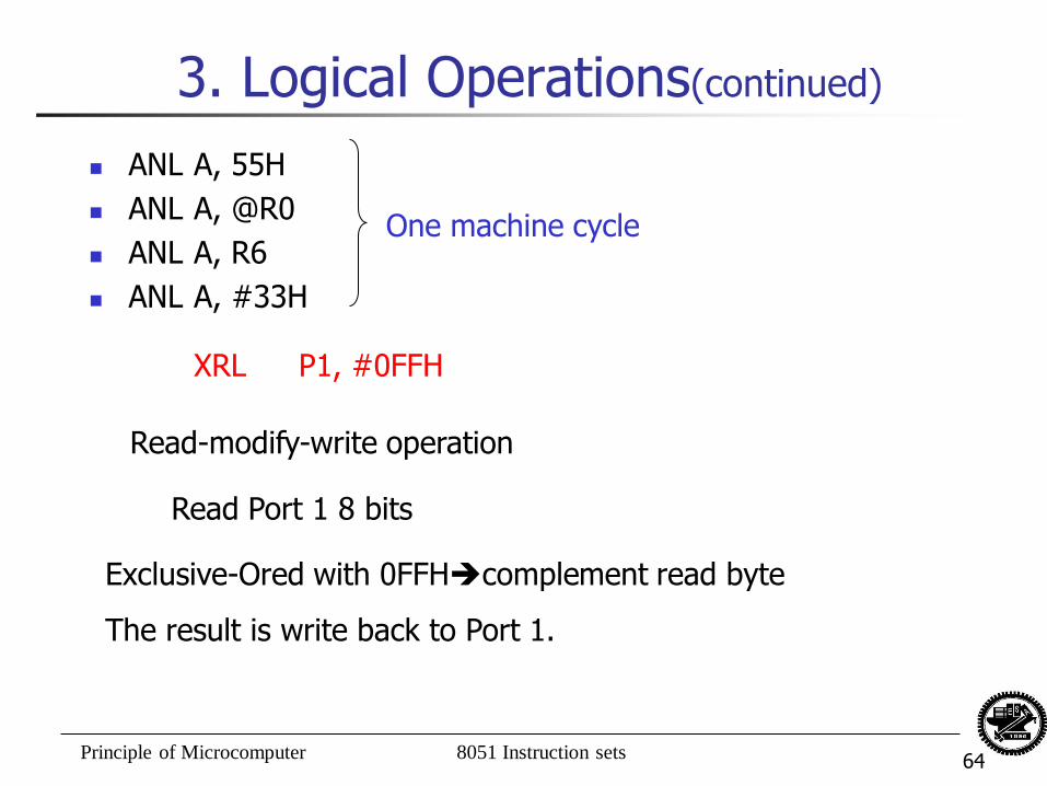
3. Logical Operations(continued)
ANL A, 55H
ANL A, @R0
ANL A, R6
ANL A, #33H
One machine cycle
XRL P1, #0FFH
Read-modify-write operation
Read Port 1 8 bits
Exclusive-Ored with 0FFHcomplement read byte
The result is write back to Port 1.
Principle of Microcomputer 8051 Instruction sets 65
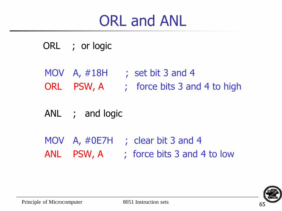
ORL and ANL
ORL ; or logic
MOV A, #18H ; set bit 3 and 4
ORL PSW, A ; force bits 3 and 4 to high
ANL ; and logic
MOV A, #0E7H ; clear bit 3 and 4
ANL PSW, A ; force bits 3 and 4 to low
Principle of Microcomputer 8051 Instruction sets 66
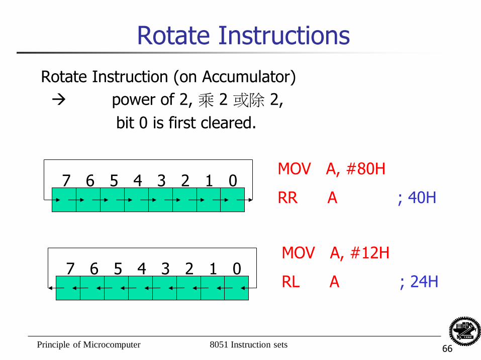
Rotate Instructions
Rotate Instruction (on Accumulator)
power of 2, 乘 2 或除 2,
bit 0 is first cleared.
7 6 5 4 3 2 1 0 MOV A, #80H
RR A ; 40H
7 6 5 4 3 2 1 0 MOV A, #12H
RL A ; 24H
Principle of Microcomputer 8051 Instruction sets 67
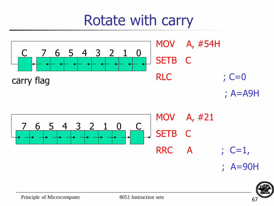
Rotate with carry
C 7 6 5 4 3 2 1 0
carry flag
MOV A, #54H
SETB C
RLC ; C=0
; A=A9H
7 6 5 4 3 2 1 0 C MOV A, #21
SETB C
RRC A ; C=1,
; A=90H
Principle of Microcomputer 8051 Instruction sets 68
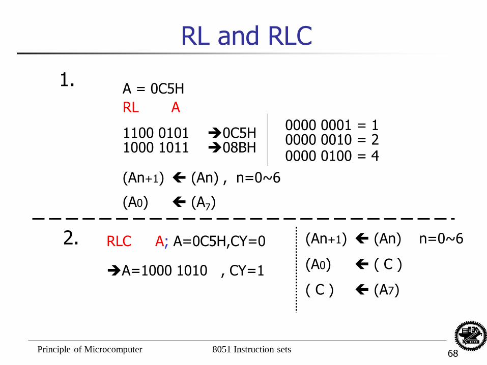
RL and RLC
A = 0C5H 1.
RL A
1100 0101 0C5H 1000 1011 08BH
0000 0001 = 1 0000 0010 = 2 0000 0100 = 4
(An+1) (An) , n=0~6
(A0) (A7)
2. RLC A; A=0C5H,CY=0
A=1000 1010 , CY=1
(An+1) (An) n=0~6
(A0) ( C )
( C ) (A7)
Principle of Microcomputer 8051 Instruction sets 69
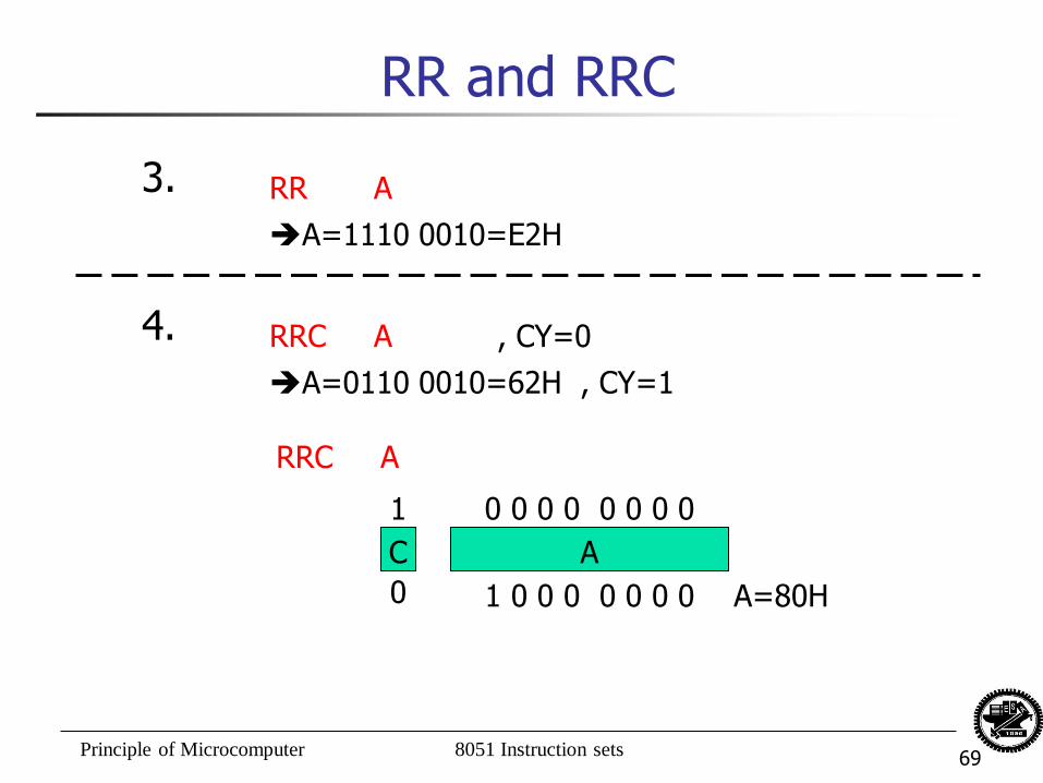
RR and RRC
3. RR A
A=1110 0010=E2H
4. RRC A , CY=0
A=0110 0010=62H , CY=1
RRC A
C
0 1 0 0 0 0 0 0 0
A
0 0 0 0 0 0 0 0 1
A=80H
Principle of Microcomputer 8051 Instruction sets 70
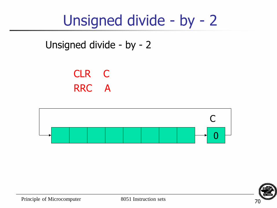
Unsigned divide - by - 2
Unsigned divide - by - 2
CLR C
RRC A
C
0
Principle of Microcomputer 8051 Instruction sets 71
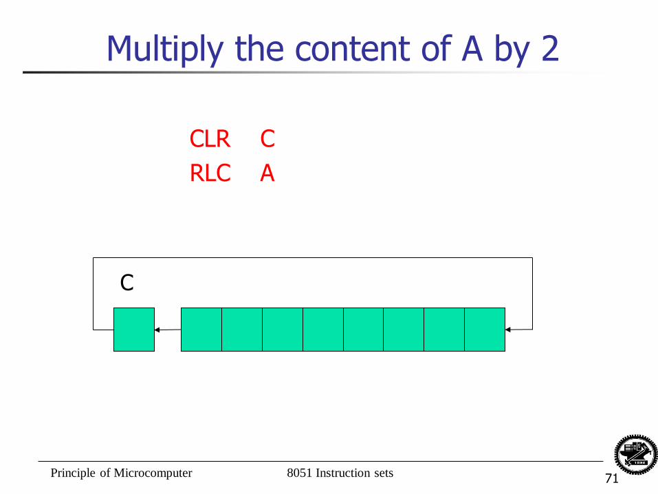
Multiply the content of A by 2
CLR C
RLC A
C
Principle of Microcomputer 8051 Instruction sets 72
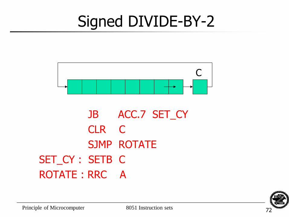
Signed DIVIDE-BY-2
JB ACC.7 SET_CY
CLR C
SJMP ROTATE
SET_CY : SETB C
ROTATE : RRC A
C
Principle of Microcomputer 8051 Instruction sets 73
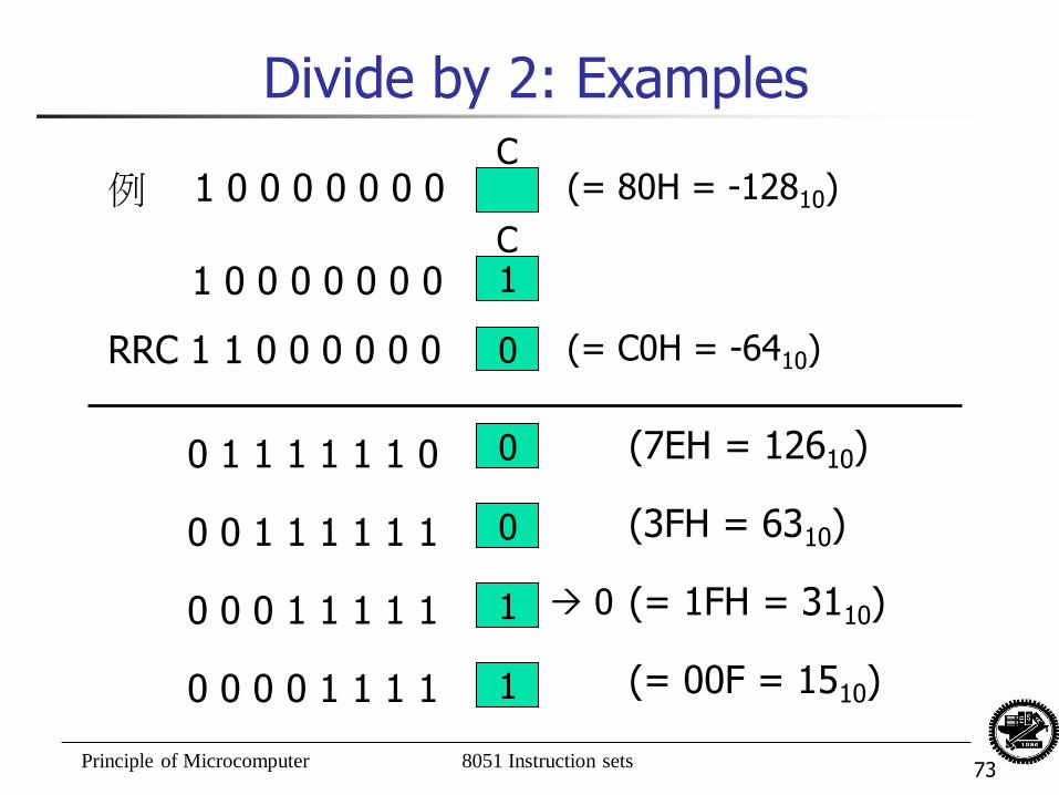
Divide by 2: Examples
例 1 0 0 0 0 0 0 0
1 0 0 0 0 0 0 0
RRC 1 1 0 0 0 0 0 0
(= 80H = -12810)
(= C0H = -6410)
0 1 1 1 1 1 1 0
0 0 1 1 1 1 1 1
0 0 0 1 1 1 1 1
0 0 0 0 1 1 1 1
(7EH = 12610)
(3FH = 6310)
(= 1FH = 3110)
(= 00F = 1510)
1
0
0
0
1
1
C
C
0
Principle of Microcomputer 8051 Instruction sets 74
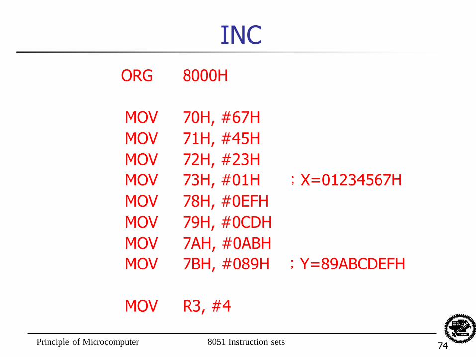
INC
ORG 8000H
MOV 70H, #67H
MOV 71H, #45H
MOV 72H, #23H
MOV 73H, #01H ;X=01234567H
MOV 78H, #0EFH
MOV 79H, #0CDH
MOV 7AH, #0ABH
MOV 7BH, #089H ;Y=89ABCDEFH
MOV R3, #4
Principle of Microcomputer 8051 Instruction sets 75
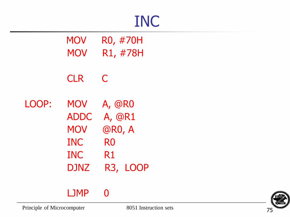
INC MOV R0, #70H
MOV R1, #78H
CLR C
LOOP: MOV A, @R0
ADDC A, @R1
MOV @R0, A
INC R0
INC R1
DJNZ R3, LOOP
LJMP 0
Principle of Microcomputer 8051 Instruction sets 76
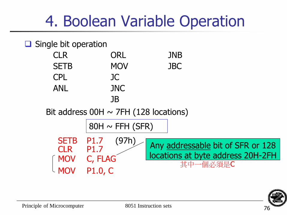
4. Boolean Variable Operation
Single bit operation
CLR ORL JNB
SETB MOV JBC
CPL JC
ANL JNC
JB
Bit address 00H ~ 7FH (128 locations)
80H ~ FFH (SFR)
SETB P1.7 (97h) CLR P1.7 MOV C, FLAG
MOV P1.0, C
Any addressable bit of SFR or 128 locations at byte address 20H-2FH
其中一個必須是C
Principle of Microcomputer 8051 Instruction sets 77
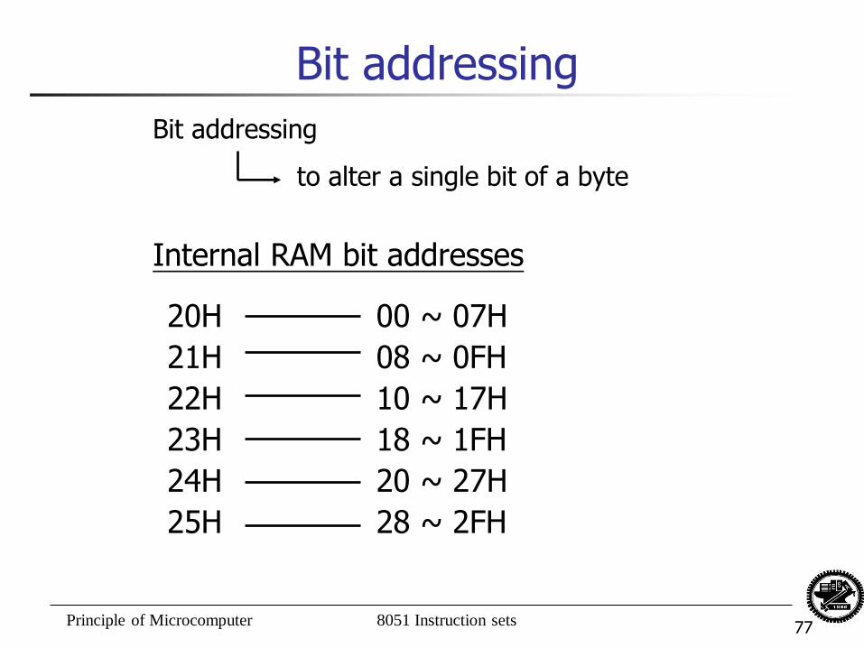
Bit addressing
Internal RAM bit addresses
Bit addressing
to alter a single bit of a byte
20H
21H
22H
23H
24H
25H
00 ~ 07H
08 ~ 0FH
10 ~ 17H
18 ~ 1FH
20 ~ 27H
28 ~ 2FH
Principle of Microcomputer 8051 Instruction sets 78
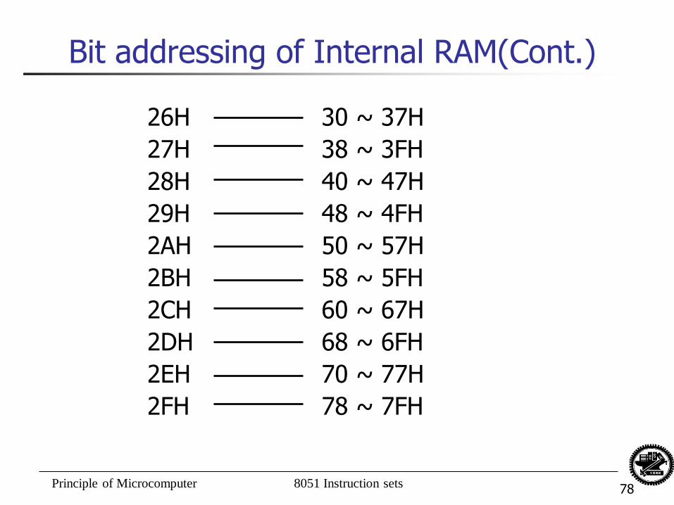
Bit addressing of Internal RAM(Cont.)
26H
27H
28H
29H
2AH
2BH
2CH
2DH
2EH
2FH
30 ~ 37H
38 ~ 3FH
40 ~ 47H
48 ~ 4FH
50 ~ 57H
58 ~ 5FH
60 ~ 67H
68 ~ 6FH
70 ~ 77H
78 ~ 7FH
Principle of Microcomputer 8051 Instruction sets 79
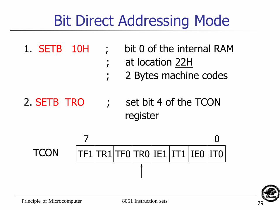
Bit Direct Addressing Mode
1. SETB 10H ; bit 0 of the internal RAM
; at location 22H
; 2 Bytes machine codes
2. SETB TRO ; set bit 4 of the TCON
register
TF1 TR1 TF0 TR0 IE1 IT1 IE0 IT0
7 0
TCON
Principle of Microcomputer 8051 Instruction sets 80
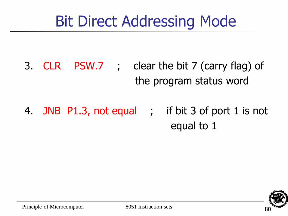
Bit Direct Addressing Mode
3. CLR PSW.7 ; clear the bit 7 (carry flag) of
the program status word
4. JNB P1.3, not equal ; if bit 3 of port 1 is not
equal to 1
Principle of Microcomputer 8051 Instruction sets 81
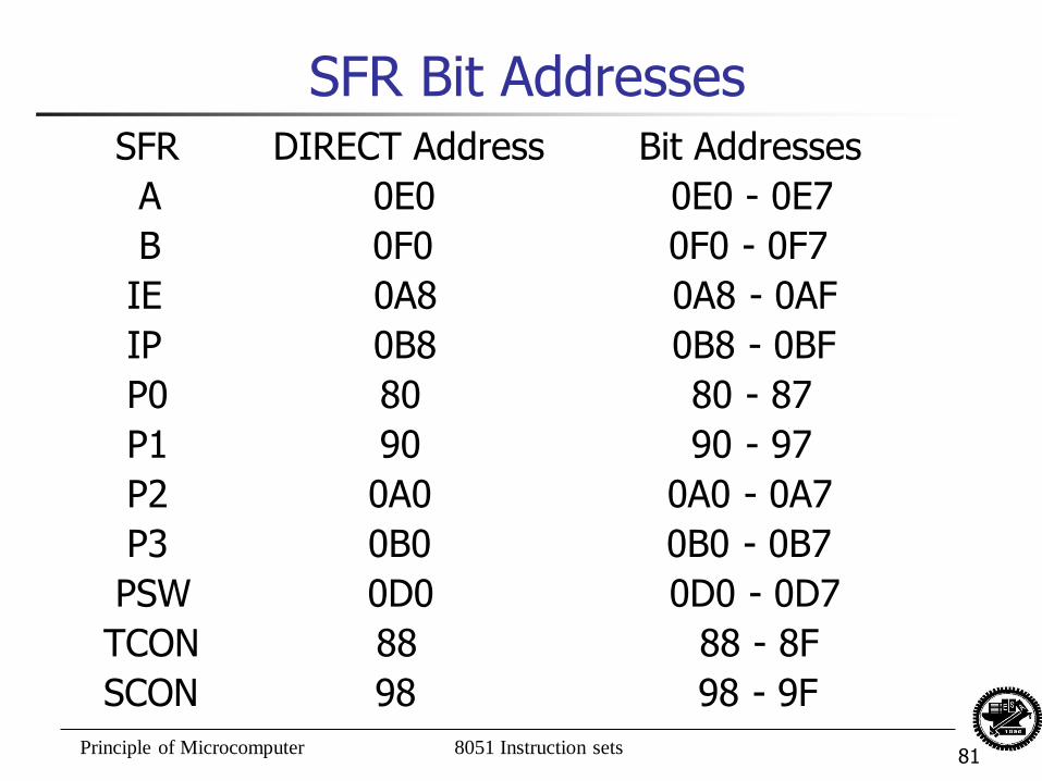
SFR Bit Addresses SFR DIRECT Address Bit Addresses
A 0E0 0E0 - 0E7
B 0F0 0F0 - 0F7
IE 0A8 0A8 - 0AF
IP 0B8 0B8 - 0BF
P0 80 80 - 87
P1 90 90 - 97
P2 0A0 0A0 - 0A7
P3 0B0 0B0 - 0B7
PSW 0D0 0D0 - 0D7
TCON 88 88 - 8F
SCON 98 98 - 9F
Principle of Microcomputer 8051 Instruction sets 82
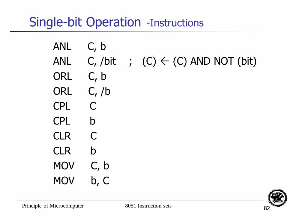
Single-bit Operation -Instructions
ANL C, b
ANL C, /bit ; (C) (C) AND NOT (bit)
ORL C, b
ORL C, /b
CPL C
CPL b
CLR C
CLR b
MOV C, b
MOV b, C

Principle of Microcomputer 8051 Instruction sets 83
Single-bit Operation -Examples
SETB C ; 1 Byte
SETB bit ; 2 Bytes
SETB C ; (C) = 1
MOV 40H, C ; (bit 40H) = 1
ANL C, 40H ; (C) = 1
SETB C ; (C) = 1
MOV 41H, C ; (bit 41H) = 1
ANL C, /41H ; (C) = 0, (bit 41H) = 1
Principle of Microcomputer 8051 Instruction sets 84
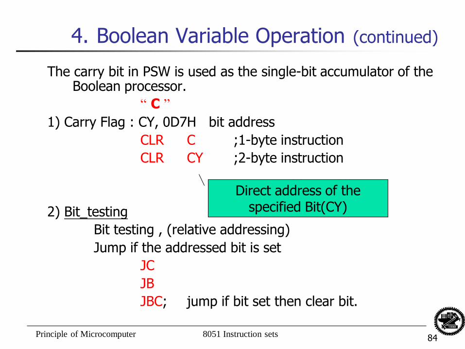
4. Boolean Variable Operation (continued)
The carry bit in PSW is used as the single-bit accumulator of the Boolean processor.
“ C ”
1) Carry Flag : CY, 0D7H bit address
CLR C ;1-byte instruction
CLR CY ;2-byte instruction
2) Bit_testing
Bit testing , (relative addressing)
Jump if the addressed bit is set
JC
JB
JBC; jump if bit set then clear bit.
Direct address of the specified Bit(CY)
Principle of Microcomputer 8051 Instruction sets 85
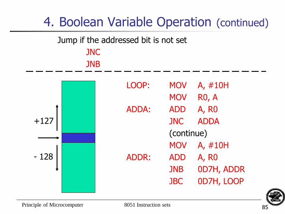
4. Boolean Variable Operation (continued)
Jump if the addressed bit is not set
JNC
JNB
LOOP: MOV A, #10H
MOV R0, A
ADDA: ADD A, R0
JNC ADDA
(continue)
MOV A, #10H
ADDR: ADD A, R0
JNB 0D7H, ADDR
JBC 0D7H, LOOP
- 128
+127
Principle of Microcomputer 8051 Instruction sets 86
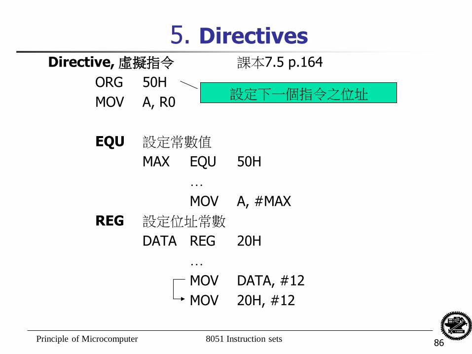
5. Directives Directive, 虛擬指令 課本7.5 p.164
ORG 50H
MOV A, R0
EQU 設定常數值
MAX EQU 50H
…
MOV A, #MAX
REG 設定位址常數
DATA REG 20H
…
MOV DATA, #12
MOV 20H, #12
設定下一個指令之位址
Principle of Microcomputer 8051 Instruction sets 87
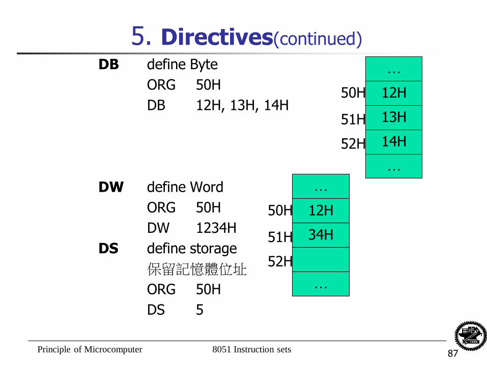
5. Directives(continued)
DB define Byte
ORG 50H
DB 12H, 13H, 14H
DW define Word
ORG 50H
DW 1234H
DS define storage
保留記憶體位址
ORG 50H
DS 5
…
12H
13H
14H
…
50H
51H
52H
…
12H
34H
…
50H
51H
52H
Principle of Microcomputer 8051 Instruction sets 88
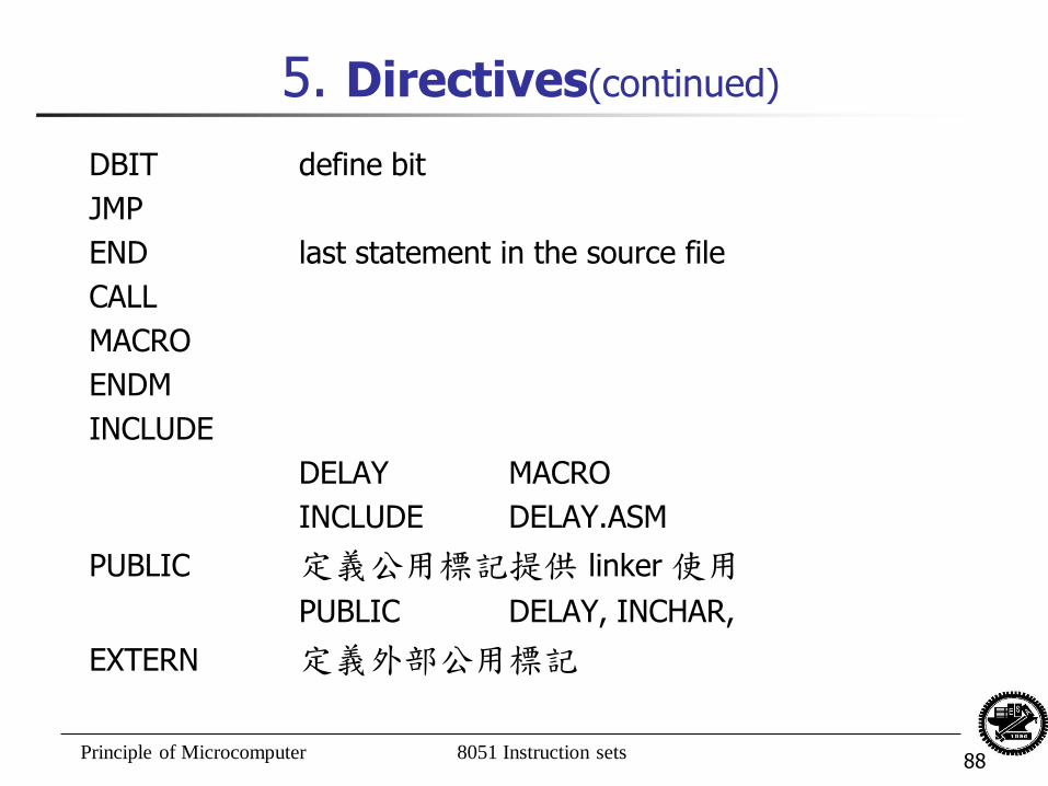
5. Directives(continued)
DBIT define bit
JMP
END last statement in the source file
CALL
MACRO
ENDM
INCLUDE
DELAY MACRO
INCLUDE DELAY.ASM
PUBLIC 定義公用標記提供 linker 使用
PUBLIC DELAY, INCHAR,
EXTERN 定義外部公用標記
Principle of Microcomputer 8051 Instruction sets 89
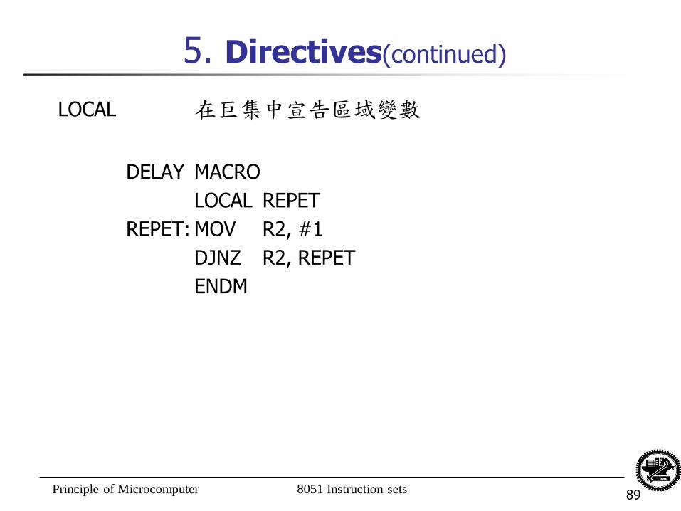
5. Directives(continued)
LOCAL 在巨集中宣告區域變數
DELAY MACRO
LOCAL REPET
REPET: MOV R2, #1
DJNZ R2, REPET
ENDM


![ทฤษฏีที่เกี่ยวข้อง 2.1 ไมโครคอนโทรลเลอร์ MCS-51[4]](https://img.dokumen.tips/doc/110x75/63343a014e43a4bcd80d2244/-21-.jpg)


