Embed Size (px)
Citation preview

Transactions, SMiRT-23 Manchester, United Kingdom - August 10-14, 2015
Division X, Paper ID 082
CHALLENGES OF NEW REACTOR SITING EVALUATION IN THE
GEOTECHNICAL ENGINEERING FIELDWeijun Wang
1and Zuhan Xi
2
1Senior Geotechnical Engineer, US Nuclear Regulatory Commission, Washington D.C. USA
([email protected]) 2Geotechnical Engineer, US Nuclear Regulatory Commission, Washington D.C. USA
ABSTRACT
With the renewed interest in nuclear energy worldwide, new reactors have been designed, new
nuclear power plant sites are being planned, and some are already under construction in the United States.
While new reactor technologies have significantly advanced, none of the new reactor designs have
actually been built in the U.S. for the past 30 years, especially at deep soil sites, therefore it is no surprise
that there are many challenges not only related to the new reactor technologies, but also to siting and
safety evaluations. As new regulations and industrial standards are established and new technologies
become available, some of the conventional engineering practices no longer meet the new reactor
requirements, as in the case of the geotechnical engineering field.
During the new reactor design and new reactor siting evaluations, the geotechnical engineers now
are facing many challenges, such as: how to reasonably account for the great variability when determining
subsurface material and mechanical properties in a practical way; how to determine design parameters for
the subsurface materials with adequate safety margin while not being over-conservative; how to ensure
that the static and dynamic properties of the in-place backfill soil will have the same as, or better than the
design properties that were used in structural and foundation stability analyses; how to conduct a
confident soil liquefaction evaluation when so many uncertainties, from soil property to seismic loadings,
are involved; how to estimate the dynamic bearing capacity of the foundation when there is no well-
established and commonly accepted method that considers the actual failure mode and soil property
changes under seismic loading; how to realistically estimate the lateral earth pressure under seismic
loading, as assumptions used in available analysis method are generally over-simplified and the models
still need to be verified; how to account for the effect of induced settlement from seismic loading in
foundation and slope stability analyses; what method can be used to adequately and realistically evaluate
slope stability under the worst loading combination conditions; and what is the best and most practical
acceptance criteria when evaluating the stability of subsurface materials, foundations, and slopes to meet
the new reactor design and regulation requirements in place of the commonly used factor of safety.
This paper summarizes the challenges in new reactor design and siting evaluations in the
geotechnical engineering field and discusses some new developments, both technical and regulatory,
related to these challenges. It also explores possible ways to meet these challenges based on lessons
learned from current combined license application reviews by the U.S. Nuclear Regulatory Commission
(USNRC).
INTRODUCTION
During the past decade, new reactors have been designed, new nuclear power plants have been
planned and some are already under construction, however none of the new generation of reactors has
actually been built and operated in the U.S up to date. It is therefore no surprise that there are many
challenges that regulators and engineers are facing in new reactor siting and safety evaluations. As new

23rd
Conference on Structural Mechanics in Reactor Technology
Manchester, United Kingdom - August 10-14, 2015
Division X
regulations and industrial standards are being established or updated, and new technologies become
available, the conventional engineering practices need to be improved in order to meet today’s needs.
Since siting evaluation is an important part in new reactor applications, and geotechnical
engineering is heavily involved in the siting evaluations, it is necessary and important for geotechnical
engineers to clearly identify the new challenges and find solutions to ensure the safety of new reactors
from the geotechnical engineering point of view. This paper discusses some lessons learned during new
reactor application siting evaluations, which are related to the new requirements of regulations and
criteria in the new reactor designs, in addition to a wide range of uncertainties involved in geotechnical
engineering practices. This paper also discusses some methods that may have potential to help us to meet
the challenges and to increase the level of confidence in siting evaluation for new reactors.
NEW CHALLENGES IN NEW REACTOR SITING EVALUATION IN THE GEOTECHNICAL
ENGINEERING FIELD
The challenges that are associated with the new requirements of regulations and new reactor
design criteria in the geotechnical engineering field include, but are not limited to the following:
1) How to determine subsurface material engineering properties that reasonably account for the
variability of subsurface materials in a practical way;
2) How to determine design parameters for subsurface materials with adequate safety margin
without being overly conservative;
3) How to ensure that the assumed static and dynamic properties of foundation backfills, when
actually placed in the field, will be the same or better than the design properties that were used in
structural and foundation stability analyses, especially if/when the source of the backfill material may be
unknown during the design stage;
4) How to conduct a confident soil liquefaction evaluation when so many uncertainties, from soil
property to seismic loading, are involved and no liquefaction would be expected at a new nuclear power
plant site;
5) How to estimate the dynamic bearing capacity of the foundation when there is no well-
established and commonly accepted method that considers the actual failure mode and soil property
changes under seismic loading conditions;
6) How to realistically estimate the lateral earth pressure under seismic loading while many
simplified assumptions used in currently available analysis methods still need to be verified and the
models need to be further validated;
7) How to adequately evaluate slope stability that can determine the realistic mode of failure and
sliding surface under the worst loading combination conditions; and
8) How to determine the best and most practical acceptance criteria other than the traditional
factor of safety measure when evaluating the stability of subsurface materials, foundations and slopes,
thus to meet the new reactor design and regulation requirements.
Based on lessons learned from new reactor application reviews by the USNRC, some of the
challenges are discussed in the following sections.
Seismic soil liquefaction potential analysis in new reactor siting evaluation
Seismic soil liquefaction potential at a nuclear power plant site is a very important issue that will
directly affect the stability of foundations and structures. None of the new reactor designs that USNRC
reviewed allowed liquefaction to occur for the materials supporting safety related structures at a nuclear
power plant site.

23rd
Conference on Structural Mechanics in Reactor Technology
Manchester, United Kingdom - August 10-14, 2015
Division X
Currently used methods for liquefaction potential evaluation
The USNRC Regulatory Guide (RG) 1.198 provides guidance on assessing soil liquefaction potential
under seismic loading at nuclear power plant sites. The siting evaluation for soil liquefaction potential is
measured by a factor of safety, FS, against liquefaction and it is defined as
FS = CRR/CSR (1)
where CRR (cyclic resistance ratio) is the available soil resistance to liquefaction, expressed in
terms of the cyclic stresses required to cause liquefaction, and CSR (cyclic stress ratio) is the cyclic stress
induced by the design earthquake.
The magnitude-corrected cyclic stress ratio CSR7.5 at a particular depth z (m) is given by Seed
and Idriss (1971) as
(2)
where PGA (g) is the geometric mean of peak ground accelerations of two horizontal components
at the ground surface (Youd et al., 2001); g is the gravitational acceleration; and σv are the initial
effective vertical overburden stress and the total overburden stress at the depth z, respectively; MSF (M)
is the magnitude scaling factor and is given by MSF(M)=(M/7.5)-2.56
(Youd et al., 2001); and rd(z)is the
shear stress reduction factor and is given by Liao et al. (1988) and Youd et al. (2001) as
(3)
The CRR can be determined by laboratory tests or empirical methods that are widely used in
routine engineering practices. The often used empirical methods are based on the standard penetration test
(SPT), cone penetration test (CPT) and shear wave velocity (Vs) test to evaluate liquefaction potential.
The empirical SPT, CPT and Vs methods are illustrated in Figure 1.
Figure 1. Empirical Methods Used in Seismic Liquefaction Potential Evaluation

23rd
Conference on Structural Mechanics in Reactor Technology
Manchester, United Kingdom - August 10-14, 2015
Division X
Challenges associated with the currently used liquefaction potential evaluation methods
The USNRC allows the use of both laboratory testing based and empirical methods to estimate
the seismic liquefaction potential in siting evaluation. The U.S Regulatory Guide (RG) 1.198 (2003)
allows to use factor of safety, FS, in empirical procedures for the evaluation of liquefaction potential.
Although the guidance specifies the FS values that can be used in evaluation of liquefaction
potential, there are many questions that need to be answered when engineers are trying to draw
conclusion on how reliable the liquefaction potential evaluation is. As there are so many uncertainties
related to engineering input parameters, the seismic input parameters, the quality of laboratory test results,
etc., it is questionable that the FS value can adequately takes those uncertainties into consideration.
Another important issue is that no model, neither analytical nor empirical, can provide 100 percent
accuracy to predict the liquefaction potential. Figure 1 clearly illustrates the range of variation among all
three empirical methods; therefore the FS cannot provide us confidence level of the analysis results even
if a higher value of FS is obtained. There is no doubt that a better method is needed in order to assess the
seismic liquefaction potential with certain confidence level in new reactor siting evaluations.
Seismic soil lateral earth pressure analysis in nuclear power plant structural stability evaluation
In nuclear power plant structure stability analyses, the lateral earth pressure on the foundation
wall needs to be determined for evaluation of sliding and overturning stability, as well as the structural
stability of the foundation. The total lateral earth pressure includes pressures induced by surface
surcharge, side fill soil self-weight and compaction, seismic and hydraulic loadings. Among all
components of the total earth pressure, it is very important to realistically estimate the seismic loading
induced earth pressure.
Currently used methods for seismic soil lateral earth pressure analysis
The seismic loading induced earth pressure includes “active” and “at-rest” earth pressures. The
active pressure is often estimated by using the Mononobe-Okabe (M-O) method that was published in the
late 1920’s. The M-O method is based on the following assumptions: the backfill materials are dry
cohesionless materials; the retaining wall yields equally and sufficiently to produce minimum active soil
pressure; the active soil pressure is associated with a soil wedge behind the wall which is at the point of
incipient failure and the maximum shear strength is mobilized along the potential sliding surface; and the
soil behind the wall behaves as a rigid body and the acceleration is uniform in the soil wedge. The M-O
model is expressed by
PAE = 0.5g H2 (1 - ) * KAE (4)
where PAE is the active thrust per unit length of the wall; g is unit weight of the soil; H is the
height of the wall; Kv is vertical wedge acceleration (in g); and KAE is the seismic active earth pressure
coefficient, which is a function of the angle of internal friction of the soil, the angle of wall friction, slope
of ground surface behind the wall, slope of the wall relative to the vertical, and angle of the vertical and
horizontal seismic forces acting on the wall, q= tan-1
(Kh /(1-Kv)), where Kh is horizontal wedge
acceleration (in g).
The M-O method and the associated analytical relationships were later simplified by Seed and
Whitman (1970) for design of earth retaining structures under dynamic loads. Using the developed charts,
the designer only needs to know the basic properties of the backfill (the angle of internal friction) and the
peak ground acceleration to obtain the seismic soil pressure.

23rd
Conference on Structural Mechanics in Reactor Technology
Manchester, United Kingdom - August 10-14, 2015
Division X
Since the amplifications of the motion in the soil mass around the non-yielding (at-rest condition)
foundation walls were found to be significant in some cases, efforts have been made to establish models
to estimate the seismic loading induced at-rest earth pressure. Currently, the mostly used methods are the
Wood and Ostadan’s methods.
Wood’s method is an equivalent static elastic solution of seismic soil pressure on non-yielding
walls. This solution is based on finite element analysis of a soil-wall system in which a wall rests on a
rigid base and a uniform soil layer is behind the wall. In general, Wood’s solution yields a lateral force
that acts at about 0.63 times the height of the wall above its base and the soil pressure is approximate to a
parabolic distribution, other than M-O’s inverted triangular distribution. Wood’s solution predicts larger
(a factor of 2-3) seismic soil pressure compared with that predicted by the M-O method. The elastic
solution proposed by Wood has been adopted by the ASCE Standards for nuclear power plant structures
(1986). Wood’s solution requires knowledge of the maximum ground acceleration along with the density
and Poisson’s ratio of the soil to calculate the seismic soil pressure behind the wall.
The Ostadan method is another method commonly used in nuclear power plant siting evaluation
in the U.S. The Ostadan method used the concept of a single degree-of-freedom (SDOF) system to
develop a simplified method to predict maximum seismic soil pressure for building resting on firm
foundation materials. This method incorporates the dynamic soil properties and the frequency content of
the design ground motion in its formulation and allows soil nonlinear effects to be considered. This
method requires the use of conventional one-dimensional soil column analysis to obtain the free field
ground soil response at the base of the wall with the use of Ψν factor to account for the soil property of
Poisson’s ratio. This factor is expressed by
(5)
and the total soil mass involved is expressed by
m = 0.50 ρ H2 Ψν (6)
where ρ is the mass density of the soil (total weight density divided by the acceleration of gravity), and H
is the height of the wall.
The Ostadan method consists of four steps by calculating: 1) the total mass for a representative
SDOF system using the Poisson’s ratio and mass density of the soil; 2) lateral seismic force from the
product of the total mass and the acceleration spectral value of the free-field response at the soil column
frequency obtained at the depth of the bottom of the wall; 3) the maximum lateral seismic soil pressure at
the ground surface level by dividing the lateral force by the area under the normalized seismic soil
pressure (the considered area is 0.744 H); and 4) the pressure profile by multiplying the peak pressure
using the pressure distribution relationship
p(y)= -.0015 + 5.05y - 15.84y2 + 28.25y3 - 24.59y4 + 8.14y5 (7)
where y = Y/H is normalized height with Y measured from the bottom of the wall and varies from 0 to H.
Challenges associated with currently used soil lateral earth pressure analysis methods
Although many methods/procedures have been developed to evaluate seismic loading induced
lateral earth pressure on the nuclear power plant foundation, the USNRC accepted only a few. A common
issue for those methods is the lack of model validation. To show an example, Figure 2 presents the
comparison of recorded seismic lateral earth pressure data from a scaled reactor building with predictions
by models SASSI and LS-DYNA, showing a large mismatch at low frequency range (Xu et al. 2008).

23rd
Conference on Structural Mechanics in Reactor Technology
Manchester, United Kingdom - August 10-14, 2015
Division X
The discrepancy between measured data and model predictions raises some questions, such as
how much inaccuracy is associated with the uncertainty of the soil properties and seismic loading, and
how much is associated with model approximation? More importantly, what level of confidence do we
really have when using these commonly accepted methods to estimate seismic lateral earth pressure?
Again, it is clear that a better approach is desired.
Dynamic bearing capacity of soil
Soil bearing capacity is another important aspect when evaluating foundation stability. Since the
nuclear power plant structures must be able to withstand both static and dynamic (mainly seismic)
loadings, the bearing capacity of materials supporting the structure under all loading conditions must meet
the design requirement with an adequate safety margin.
Currently used methods for soil bearing capacity evaluation
One of the commonly used methods for bearing capacity evaluation were originally developed to
estimate the bearing capacity of soil under static loading condition. These methods usually assume that
the soil below the foundation, along a critical plane of failure (slip path), is on the verge of failure. The
bearing capacity is determined by calculating the pressure applied by the foundation which will result in
such a failure.
This method provides ultimate bearing capacity qu and its general expression is:
(8)
where qu = ultimate bearing capacity pressure, c = soil cohesion (or undrained shear strength Cu), B =
foundation width, g’H = effective unit weight beneath foundation base within failure zone, s’D = effective
soil or surcharge pressure at the foundation depth D, g’D = effective unit weight of surcharge soil within
depth D, Nc, Ng, Nq = dimensionless bearing capacity factors for cohesion c, soil weight in the failure
wedge, and surcharge q terms, and zc, zg, zq = dimensionless correction factors for cohesion, soil weight
in the failure wedge, and surcharge q terms accounting for foundation geometry and soil type.
Figure 2. Comparison of Recording Data with Model Predictions (Figure 4.3-7 of NUREG/CR
6957)

23rd
Conference on Structural Mechanics in Reactor Technology
Manchester, United Kingdom - August 10-14, 2015
Division X
The general ultimate bearing capacity equation is based on Terzaghi’s bearing capacity theory
(1948), although it has been improved during the past several decades and other bearing capacity analysis
models exist, that assumes a shallow, rough, rigid and continuous foundation supported by a
homogeneous soil layer extending to a great depth. The general shear failure of the foundation occurs
when the static loading exceeds the strength of the soil. The more advanced analysis methods utilize the
finite element method (FEM) to more realistically model soil layers, foundations and structures above the
foundation.
In engineering practice, allowable bearing capacity is used in design and it is defined as
(9)
where qall is allowable bearing capacity, and FS is factor of safety. The factor of safety is usually
determined by the loading conditions and other factors. For static loading conditions, factor of 3 to 4 is
generally accepted.
Despite the efforts of determining the ultimate bearing capacity of soil under dynamic, including
seismic loading conditions, there is no generally accepted method in engineering practices. Engineers
normally estimate the allowable dynamic bearing capacity using equation (9) but with a smaller value of
FS because both static and seismic loadings are accounted for in foundation dynamic response analysis
and the seismic loading is a transient load.
Challenges associated with the currently used soil dynamic bearing capacity analysis methods
The response of a foundation to dynamic loading generally is affected by the (1) nature and
magnitude of dynamic loads, (2) number of pulses (or cyclic loading duration) and (3) the strain rate
response of soil. The laboratory experiment and field observation showed that the mechanism of
foundation failure is different under different loading conditions. Foundations normally fail in general
shear mode under static loadings but local shear failure occurs under dynamic loadings. Large
settlements at failure have been observed under dynamic loading conditions. Experimental results
indicate that for the given value of settlement, the dynamic bearing capacity may be lower than the static
bearing capacity for certain type of soils.
Based on the above facts, we need answers to the following questions regarding dynamic bearing
capacity evaluation: (1) Are the methods currently used in engineering practices adequate to estimate soil
dynamic bearing capacity? (2) Which method(s) can be used to realistically estimate dynamic bearing
capacity? (3) What value of FS should be used when determining allowable dynamic bearing capacity for
soil and for rock as well? and (4) How to assess the confident level when we use factor of safety to
evaluate soil/rock bearing capacity? It is no doubt that we need a method that can better estimate soil
dynamic bearing capacity with reasonable accuracy and an acceptable level of confidence.
MEET THE CHALLENGES IN NEW REACTOR SITING EVALUATION IN THE
GEOTECHNICAL ENGINEERING FIELD
To meet the challenges in new reactor siting evaluation with respect to geotechnical engineering,
we need to study the state-of-the-art and state-of-the-practice in all engineering fields and to identify the
methods that best fit geotechnical engineering practices and provide solutions to the challenges.
Among all potential solutions, the performance based design approach may be a good candidate.
There is no secret that the USNRC has been making great efforts in the development and implementation
of risk-informed performance-based approaches in its regulations since the 1990’s. The risk-informed

23rd
Conference on Structural Mechanics in Reactor Technology
Manchester, United Kingdom - August 10-14, 2015
Division X
performance-based approach currently is used in USNRC regulatory decision-making, and also applied in
some technical evaluation areas. For example, the performance-based approach has been used in
determining the site-specific earthquake ground motion response spectrum which is an important factor in
site suitability determination. The performance-based approach may be a powerful weapon because this
approach can account for uncertainties. Its probability basis is risk consistent and can provide better
confidence level measures.
Although the performance-based method has many advantages, there are challenges when apply
this method in geotechnical engineering practice. The first and very basic issue is how to adequately
determine the target of performance. For example, what is the reasonable targeted performance goal for
liquefaction potential for a site when the coefficient of variation (c.o.v) of soil property is not
uncommonly more than 30%? Similar issue is also held for evaluation of bearing capacity, settlement,
lateral earth pressure, slope stability, etc. However, despite those challenges, we should first consider
applying probability-based methods in some areas as a step forward. An example is given as the
following.
Probability approach application in slope stability analysis
When performing slope stability analysis, uncertainties exist in many variables/parameters, such as
geometry of slope, loading conditions, pore water pressure distribution, the shear strength of soils, and
dynamic loads including earthquake induced seismic loading. In current engineering practices, factor of
safety is normally used to account for the uncertainties, but probabilistic approaches can provide a measure
of degree of confidence on the design and analysis results. To illustrate how to apply the probabilistic
approach in slope stability analysis, an example is presented as follows.
Deterministic slope stability analysis
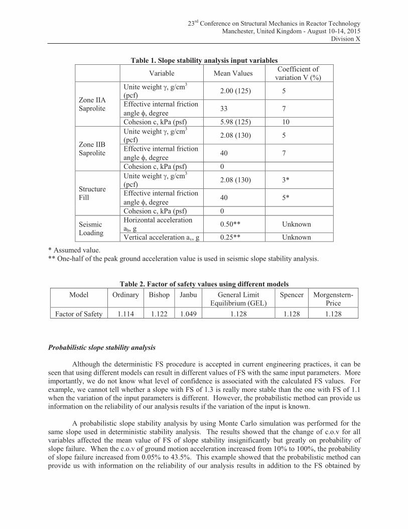
For a slope as shown in Figure 3, with input variable parameters as listed in Table 1, the factor of
safety can be calculated using different methods, such as Ordinary, Bishop, Janbu, Spencer, Morgenstern-
Price and General Limit Equilibrium (GLE) methods. As each method has its own advantages and
limitations, either a best suitable method or more than one method should be used to analyse the slope
stability in practices. The results of calculations using mean parameter values as input in the GeoSlope
program are listed in Table 2.
Figure 3. Cross section, material properties of an example slope used in slope stability analysis
IIa Saprolite
g = 2.00 g/cm3
c = 5.98 kPaf = 33 degree
Structure Fill
IIa Saprolite
IIb Saprolite
Distance (m)
-6.1 0 6.1 12.2 18.3 24.4 30.5 36.6 42.7 48.8 54.9 61.0 67.1 73.2 79.2 85.3 91.4
Ele
vation (
m)
67.1
70.1
73.2
76.2
79.2
82.3
85.3
88.4
91.4
94.5
97.5
100.6
103.6
IIb Saprolite
c = 0g = 2.08 g/cm
3
f = 40 degree
Structure Fillg = 2.08 g/cm
3
f = 40 degreec = 0
23rd
Conference on Structural Mechanics in Reactor Technology
Manchester, United Kingdom - August 10-14, 2015
Division X
Table 1. Slope stability analysis input variables
Variable Mean Values Coefficient of
variation V (%)
Zone IIA
Saprolite
Unite weight g, g/cm3
(pcf) 2.00 (125) 5
Effective internal friction
angle f, degree 33 7
Cohesion c, kPa (psf) 5.98 (125) 10
Zone IIB
Saprolite
Unite weight g, g/cm3
(pcf) 2.08 (130) 5
Effective internal friction
angle f, degree 40 7
Cohesion c, kPa (psf) 0
Structure
Fill
Unite weight g, g/cm3
(pcf) 2.08 (130) 3*
Effective internal friction
angle f, degree 40 5*
Cohesion c, kPa (psf) 0
Seismic
Loading
Horizontal acceleration
ah, g 0.50** Unknown
Vertical acceleration av, g 0.25** Unknown
* Assumed value.
** One-half of the peak ground acceleration value is used in seismic slope stability analysis.
Table 2. Factor of safety values using different models
Model Ordinary Bishop Janbu General Limit
Equilibrium (GEL)
Spencer Morgenstern-
Price
Factor of Safety 1.114 1.122 1.049 1.128 1.128 1.128
Probabilistic slope stability analysis
Although the deterministic FS procedure is accepted in current engineering practices, it can be
seen that using different models can result in different values of FS with the same input parameters. More
importantly, we do not know what level of confidence is associated with the calculated FS values. For
example, we cannot tell whether a slope with FS of 1.3 is really more stable than the one with FS of 1.1
when the variation of the input parameters is different. However, the probabilistic method can provide us
information on the reliability of our analysis results if the variation of the input is known.
A probabilistic slope stability analysis by using Monte Carlo simulation was performed for the
same slope used in deterministic stability analysis. The results showed that the change of c.o.v for all
variables affected the mean value of FS of slope stability insignificantly but greatly on probability of
slope failure. When the c.o.v of ground motion acceleration increased from 10% to 100%, the probability
of slope failure increased from 0.05% to 43.5%. This example showed that the probabilistic method can
provide us with information on the reliability of our analysis results in addition to the FS obtained by

23rd
Conference on Structural Mechanics in Reactor Technology
Manchester, United Kingdom - August 10-14, 2015
Division X
conventional deterministic methods, but the wide range of variation exist in geotechnical engineering
posts a challenge in its application in practices.
SUMMARY AND CONCLUSIONS
This paper identifies and discusses some challenges in new reactor design and siting evaluations in
the geotechnical engineering field based on lessons learned from current combined license application
reviews by the U.S. NRC. It discusses some developments, both technical and regulatory, related to these
challenges and explores possible solution to meet these challenges. Based on the lessons learned, we can
conclude that:
1. Geotechnical engineers face many challenges in today’s new reactor design and siting
evaluations because of new technology and regulation requirements. We need to identify these
challenges and find solutions to meet the challenges.
2. With so many uncertainties and variations existing in our engineering practices, many
conventional methods cannot meet today’s needs because they either do not utilize the state-of-
the-art methods, or cannot provide a result with a known level of confidence in nuclear power
plant siting evaluations.
3. To meet the new challenges in new reactor siting evaluations, state-of-the-art and state-of-the-
practice methods should be carefully studied. Suitable methods need to be selected or
developed, which requires great effort from all people, including engineers, researchers and
regulators who are involved in the new reactor siting evaluations. The performance-based
approach is one of the solutions but many questions have not been answered, and detailed
practical methods/procedures still need to be developed. The example provided in this paper
indicates that we may be able to first use the probabilistic method in our engineering practices
before fully developing performance-based methods, but many details need to be worked out.
REFERENCES
Das, B. M. (2009. Shallow Foundations Bearing Capacity and Settlement, 2nd
ed., CRC Press.
Mononobe, N. and H, Matuo (1929). “On the determination of earth pressures during earthquakes,”
Proceeding of World Engineering Congress, Tokyo, Vol. 9, Paper 388, 1929.
Ostadan, F. and W. H. White (1998). “\“Lateral Seismic Soil Pressure- an Updated Approach,” presented
at the US-Japan SSI Workshop, September 22-23, 1998
Richards, R., Jr., Elms, D.G and Budhu, M (1993). “Seismic Bearing Capacity and Settlement of
Foundations.” J. Geotechnical Engineering, ASCE, 119(4):622-674.
Seed, H.B. and R.V. Whitman (1970), “Design of Earth Retaining Structures for Seismic Loads,” ASCE
Specialty Conference on Lateral Stresses in the Ground and Design of Earth Retaining Structures,
June, 1970.
Seed, H. B., and I. M. Idriss (1971). “Simplified procedure for evaluating soil liquefaction potential”. J.
Soil Mech. Found. Div. 97, 1249–1273.
Wood, J. H. (1973) “Earthquake Induced Soil Pressures on Structures,” Doctoral Dissertation, EERL 73-
05, California Institute of Technology, Pasadena, CA, 1973.
USNRC Regulatory Guide 1.208 “Performance Based Approach to Define the Site Specific Earthquake
Ground Motion.” March 2007.
USNRC Regulatory Guide 1.198 “Procedures and Criteria for Assessing Seismic Soil Liquefaction at
Nuclear Power Plant Sites.” November 2003.
Xu, J., J. Nie, C. Costantino and C. Hofmayer (2008), “Correlation Analysis of JNES Seismic Wall
Pressure Data for ABWR Model Structures.” NUREG/CR-6957, March 2008
Youd, T. L., I. M. Idriss (2001), “Liquefaction Resistance of Soils: Summary Report from the 1996
NCEER and 1998 NCEER/NSF Workshops on Evaluation of Liquefaction Resistance of Soils, J.
Geotechnical and. Geoenvironmental Engineering Vol 127, No. 4, April 2001, pp. 297–313.


