Embed Size (px)
Citation preview
franklin-electric.com
ENGLISHEN
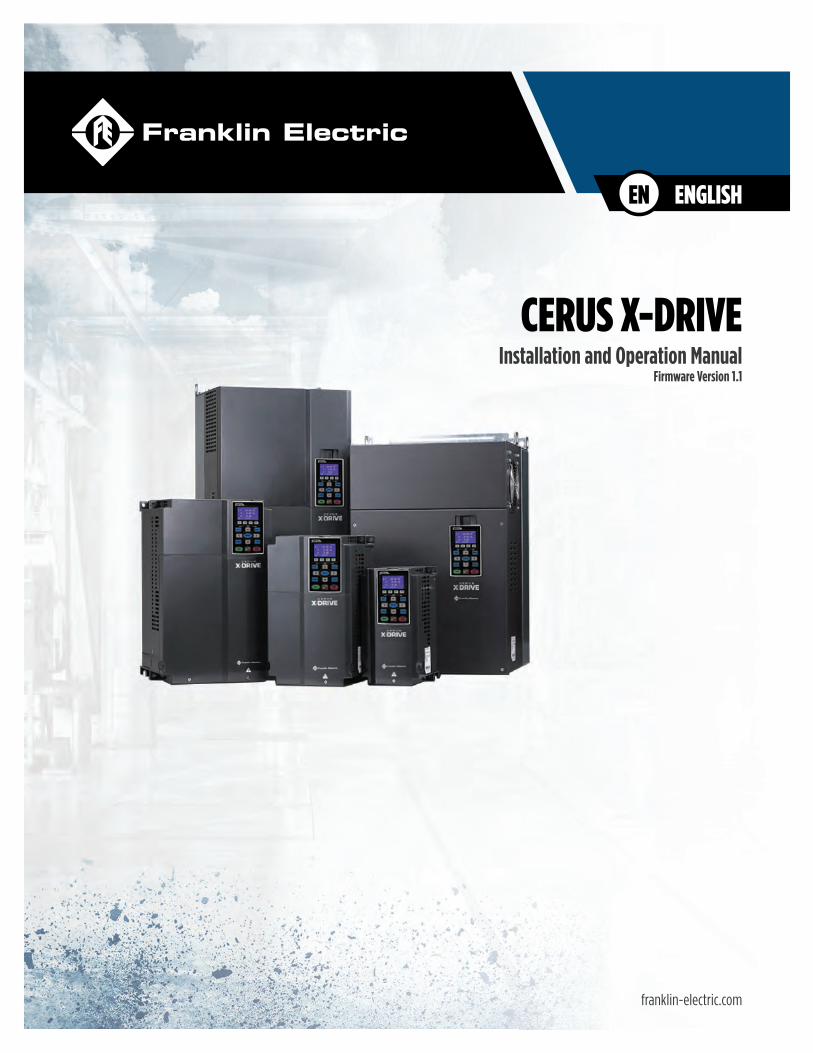
CERUS X-DRIVEInstallation and Operation Manual
Firmware Version 1.1

CERUS® X-DRIVEINSTALLATION AND OPERATION MANUAL
Firmware Version 1.1
Franklin Electric Co., Inc.
4
COPYRIGHT INFORMATION
Copyright © 2021, Franklin Electric, Co., Inc. All rights reserved.The entire contents of this publication are copyrighted under United States law and protected by worldwide copyright laws and treaty provisions. No part of this material may be copied, reproduced, distributed, republished, downloaded, displayed, posted or transmitted in any form by any means, including electronic, mechanical, photocopying, recording, or otherwise, without prior written permission of Franklin Electric. You may download one copy of the publication from 35T35TUwww.franklinwater.comU35T onto a single computer for your personal, non-commercial internal use only. This is a single copy, single use license, not a transfer of title, and is subject to the following restric-tions: you may not modify the materials, use them for any commercial purpose, display them publicly, or remove any copyright or other proprietary notices from them.
The information in this publication is provided for reference only and is subject to change without notice. While every effort has been made to ensure the accuracy of this manual at the time of release, ongoing product improvements and updates can render copies obso-lete. Refer to 35T35TUwww.franklinwater.com U35T for the current version.
This publication is provided “as is” without warranties of any kind, either express or implied. To the fullest extent possible pursuant to applicable law, Franklin Electric disclaims all warranties, express or implied, including but not limited to, implied warranties of merchant-ability, fitness for a particular purpose, and non-infringement of intellectual property rights or other violation of rights. Franklin Electric does not warrant or make any representations regarding the use, validity, accuracy, or reliability of the material in this publication.
Under no circumstances, including but not limited to, negligence, shall Franklin Electric be liable for any direct, indirect, special, inciden-tal, consequential, or other damages, including, but not limited to, loss of data, property damage, or expense arising from, or in any way connected with, installation, operation, use, or maintenance of the product based on the material in this manual.
Trademarks used in this publication:The trademarks, service marks, and logos used in this publication are registered and unregistered trademarks of Franklin Electric and others. You are not granted, expressly, by implication, estoppel or otherwise, any license or right to use any trademark, service mark, or logo displayed on this site, without the express written permission of Franklin Electric.
FE Logo and Design®, MagForce™, and Cerus® are registered trademarks of Franklin Electric.NEMA is a trademark of The Association of Electrical Equipment and Medical Imaging Manufacturers.NEC® is a registered trademark of the National Fire Protection Association (NFPA).UL® is a registered trademark of Underwriters Laboratories.CSA is a registered mark of the CSA Group, formerly the Canadian Standards AssociationBluetooth is a registered trademark of Bluetooth SIG, Inc.Modbus is a registered trademark of Schneider Electric USA, Inc.BACnet is a registered trademark of the American Society of Heating, Refrigerating and Air Conditioning Engineers (ASHRAE).EtherNet/IP™ and DeviceNet™ are trademarks licenced by ODVA.
Franklin ElectricTechnical Publications9255 Coverdale RoadFort Wayne, IN 46809
5
TABLE OF CONTENTSPRODUCT INFORMATION - - - - - - - - - - - - - - - - - - - - - - - - - - - - - - - - - - - - - 11
Description - - - - - - - - - - - - - - - - - - - - - - - - - - - - - - - - - - - - - - - - - - 11Features - - - - - - - - - - - - - - - - - - - - - - - - - - - - - - - - - - - - - - - - - - - 11Models - - - - - - - - - - - - - - - - - - - - - - - - - - - - - - - - - - - - - - - - - - - -12
UNPACKING AND INSPECTION - - - - - - - - - - - - - - - - - - - - - - - - - - - - - - - - - - -13Transportation and Storage - - - - - - - - - - - - - - - - - - - - - - - - - - - - - - - - - -13Unpacking - - - - - - - - - - - - - - - - - - - - - - - - - - - - - - - - - - - - - - - - - -13
INSTALLATION PLANNING - - - - - - - - - - - - - - - - - - - - - - - - - - - - - - - - - - - - -15Basic VFD Configuration - - - - - - - - - - - - - - - - - - - - - - - - - - - - - - - - 16
PHYSICAL INSTALLATION - - - - - - - - - - - - - - - - - - - - - - - - - - - - - - - - - - - - -17Environmental Requirements - - - - - - - - - - - - - - - - - - - - - - - - - - - - - - - - -17Mounting the Drive - - - - - - - - - - - - - - - - - - - - - - - - - - - - - - - - - - - - - -18
Mounting Frames A, B, and C - - - - - - - - - - - - - - - - - - - - - - - - - - - - - - 19Mounting Frames D0, D, and E - - - - - - - - - - - - - - - - - - - - - - - - - - - - - 19Mounting Frames F, G, and H - - - - - - - - - - - - - - - - - - - - - - - - - - - - - - 19
Conduit Box Installation - - - - - - - - - - - - - - - - - - - - - - - - - - - - - - - - - - - 20Frames D0 and D Conduit Box Installation - - - - - - - - - - - - - - - - - - - - - - - - 20Frame E Conduit Box Installation - - - - - - - - - - - - - - - - - - - - - - - - - - - - 21Frame F Conduit Box Installation - - - - - - - - - - - - - - - - - - - - - - - - - - - - 22Frame G Conduit Box Installation - - - - - - - - - - - - - - - - - - - - - - - - - - - - 23Frame H Conduit Box Installation - - - - - - - - - - - - - - - - - - - - - - - - - - - - 24
Drive Dimensions - - - - - - - - - - - - - - - - - - - - - - - - - - - - - - - - - - - - - - 26ELECTRICAL INSTALLATION - - - - - - - - - - - - - - - - - - - - - - - - - - - - - - - - - - - 33
Wiring Guidelines - - - - - - - - - - - - - - - - - - - - - - - - - - - - - - - - - - - - - - 33Branch Circuit Protection - - - - - - - - - - - - - - - - - - - - - - - - - - - - - - - - 34Fuse and Circuit Breaker Sizing - - - - - - - - - - - - - - - - - - - - - - - - - - - - - 34Wire Sizing - - - - - - - - - - - - - - - - - - - - - - - - - - - - - - - - - - - - - - 36
Motor Cable Lengths for Submersible Pumping Applications - - - - - - - - - - - - - - 36Suggested Maximum Motor Cable Lengths for Non-Submersible Applications - - - - - 37
Power Wiring Connections - - - - - - - - - - - - - - - - - - - - - - - - - - - - - - - - - 39Power Wiring Diagram - - - - - - - - - - - - - - - - - - - - - - - - - - - - - - - - 39
Control Circuit Connections - - - - - - - - - - - - - - - - - - - - - - - - - - - - - - - - - -41Terminal Identification - - - - - - - - - - - - - - - - - - - - - - - - - - - - - - - - - 41Example Configurations - - - - - - - - - - - - - - - - - - - - - - - - - - - - - - - - 43
4-20mA Speed Control Signal from an External BMS or PLC: - - - - - - - - - - - - - 430-10V Speed Control Signal from an External BMS or PLC: - - - - - - - - - - - - - - 434-20mA Transducer with VFD 10 VDC Power: - - - - - - - - - - - - - - - - - - - - - 434-20mA Transducer with VFD 24 VDC Power: - - - - - - - - - - - - - - - - - - - - - 434-20mA Transducer with External 24 VDC Power: - - - - - - - - - - - - - - - - - - - 440-10VDC Transducer with VFD 10 VDC Power: - - - - - - - - - - - - - - - - - - - - - 440-10VDC Transducer with VFD 24 VDC Power: - - - - - - - - - - - - - - - - - - - - 440-10VDC Transducer with External 24 VDC Power: - - - - - - - - - - - - - - - - - - 44Temperature Protection or PID Control with PT-100 or PTC Sensor: - - - - - - - - - - 45Speed Control using 0-10 VDC Potentiometer: - - - - - - - - - - - - - - - - - - - - 45
NPN and PNP Digital Inputs Configuration - - - - - - - - - - - - - - - - - - - - - - - - 46DRIVE PROGRAMMING - - - - - - - - - - - - - - - - - - - - - - - - - - - - - - - - - - - - - 47
Using the Keypad - - - - - - - - - - - - - - - - - - - - - - - - - - - - - - - - - - - - - - 47
6
Home Screen Display Options - - - - - - - - - - - - - - - - - - - - - - - - - - - - - - 47Setting Operating Parameters - - - - - - - - - - - - - - - - - - - - - - - - - - - - - - - - 48
Enter Required Parameters Before Starting VFD - - - - - - - - - - - - - - - - - - - - - 48Verify Default Settings - - - - - - - - - - - - - - - - - - - - - - - - - - - - - - - - - 48Verify Control Terminal Settings - - - - - - - - - - - - - - - - - - - - - - - - - - - - - 49Enter or Verify Optional Settings - - - - - - - - - - - - - - - - - - - - - - - - - - - - - 49
Default Settings Tables - - - - - - - - - - - - - - - - - - - - - - - - - - - - - - - - - - - 50Default Settings Table - SET Menu - - - - - - - - - - - - - - - - - - - - - - - - - - - - - - 50Default Settings Table - VFD Menu - - - - - - - - - - - - - - - - - - - - - - - - - - - - - - 51Default Settings Table - I/O Menu - - - - - - - - - - - - - - - - - - - - - - - - - - - - - - 52Default Settings Table - ADV Menu - - - - - - - - - - - - - - - - - - - - - - - - - - - - - - 54Default Settings Table - PROT Menu - - - - - - - - - - - - - - - - - - - - - - - - - - - - - 54Default Settings Table - COMM Menu - - - - - - - - - - - - - - - - - - - - - - - - - - - - - 56Default Settings Table - PLC Menu - - - - - - - - - - - - - - - - - - - - - - - - - - - - - - 57Default Settings Table - Option Menu - - - - - - - - - - - - - - - - - - - - - - - - - - - - 58Default Settings Table - ADV2 Menu - - - - - - - - - - - - - - - - - - - - - - - - - - - - - 59Default Settings Table - Motor Menu - - - - - - - - - - - - - - - - - - - - - - - - - - - - - 60
INSTALLATION TESTING - - - - - - - - - - - - - - - - - - - - - - - - - - - - - - - - - - - - - 61Rotation Check - - - - - - - - - - - - - - - - - - - - - - - - - - - - - - - - - - - - - - - 61Feedback Checks - - - - - - - - - - - - - - - - - - - - - - - - - - - - - - - - - - - - - - 61Performance Checks - - - - - - - - - - - - - - - - - - - - - - - - - - - - - - - - - - - - - 61Sleep Mode Check (Pump Applications) - - - - - - - - - - - - - - - - - - - - - - - - - - - 62
OPERATION - - - - - - - - - - - - - - - - - - - - - - - - - - - - - - - - - - - - - - - - - - - 63Control Options - - - - - - - - - - - - - - - - - - - - - - - - - - - - - - - - - - - - - - - 63
Hand/Auto Controls - - - - - - - - - - - - - - - - - - - - - - - - - - - - - - - - - - - 63Forward or Reverse Selection - - - - - - - - - - - - - - - - - - - - - - - - - - - - - - 64Jog Feature - - - - - - - - - - - - - - - - - - - - - - - - - - - - - - - - - - - - - - - 64Step Frequencies - - - - - - - - - - - - - - - - - - - - - - - - - - - - - - - - - - - - 65Shutdown - - - - - - - - - - - - - - - - - - - - - - - - - - - - - - - - - - - - - - - 65Standard Operation with an Automated Control System - - - - - - - - - - - - - - - - - 66Standard Operation with PID Feedback Control - - - - - - - - - - - - - - - - - - - - - 66Damper Control (HVAC Applications) - - - - - - - - - - - - - - - - - - - - - - - - - - 67Fireman’s Override - - - - - - - - - - - - - - - - - - - - - - - - - - - - - - - - - - - 67Pump Application Features - - - - - - - - - - - - - - - - - - - - - - - - - - - - - - - 68
Sleep Mode with Pressure Boost - - - - - - - - - - - - - - - - - - - - - - - - - - - 68Pipe Fill Feature - - - - - - - - - - - - - - - - - - - - - - - - - - - - - - - - - - - 68Lubrication Relay - - - - - - - - - - - - - - - - - - - - - - - - - - - - - - - - - - - 69Screen Clean Relay - - - - - - - - - - - - - - - - - - - - - - - - - - - - - - - - - - 70
Timers - - - - - - - - - - - - - - - - - - - - - - - - - - - - - - - - - - - - - - - - - 70Power On Run Delay - - - - - - - - - - - - - - - - - - - - - - - - - - - - - - - - - 70Run Delay Timer (For Auto Mode) - - - - - - - - - - - - - - - - - - - - - - - - - - - 70Minimum Run Timer - - - - - - - - - - - - - - - - - - - - - - - - - - - - - - - - - 70Backspin Timer - - - - - - - - - - - - - - - - - - - - - - - - - - - - - - - - - - - - 71
Performance Control Features - - - - - - - - - - - - - - - - - - - - - - - - - - - - - - 71Acceleration/Deceleration Control - - - - - - - - - - - - - - - - - - - - - - - - - - 71
Monitoring Functions - - - - - - - - - - - - - - - - - - - - - - - - - - - - - - - - - - - - 72Home Screen Status Displays - - - - - - - - - - - - - - - - - - - - - - - - - - - - - - 72View Screens - - - - - - - - - - - - - - - - - - - - - - - - - - - - - - - - - - - - - - 73
Protection Features - - - - - - - - - - - - - - - - - - - - - - - - - - - - - - - - - - - - - 75High Load Detection - - - - - - - - - - - - - - - - - - - - - - - - - - - - - - - - - - 75
7
Underload Protection (Dry Well or Belt Loss) - - - - - - - - - - - - - - - - - - - - - - 76Overpressure - - - - - - - - - - - - - - - - - - - - - - - - - - - - - - - - - - - - - 77No Flow Protection - - - - - - - - - - - - - - - - - - - - - - - - - - - - - - - - - - - 78Broken Pipe Protection (for Pump Applications) - - - - - - - - - - - - - - - - - - - - - 78
ADVANCED APPLICATION OPTIONS - - - - - - - - - - - - - - - - - - - - - - - - - - - - - - - 79Operation with Permanent Magnet Motors - - - - - - - - - - - - - - - - - - - - - - - - - - 79
Setup MagForce Pump Motor - - - - - - - - - - - - - - - - - - - - - - - - - - - - - - 80Basic Setup - - - - - - - - - - - - - - - - - - - - - - - - - - - - - - - - - - - - - 80Permanent Magnet Specific Parameters - - - - - - - - - - - - - - - - - - - - - - - 80Motor Specific Parameters - - - - - - - - - - - - - - - - - - - - - - - - - - - - - - -81Autotune Characteristic Parameters - - - - - - - - - - - - - - - - - - - - - - - - - -81Tune motor control – DC Alignment - - - - - - - - - - - - - - - - - - - - - - - - - -81Tune motor control - I/F Control - - - - - - - - - - - - - - - - - - - - - - - - - - - -81Tune motor control - PM Control - - - - - - - - - - - - - - - - - - - - - - - - - - - -81
Setup Non-Franklin Electric PM Motors - - - - - - - - - - - - - - - - - - - - - - - - - 81Basic Setup - - - - - - - - - - - - - - - - - - - - - - - - - - - - - - - - - - - - - -81Permanent Magnet Specific Parameters - - - - - - - - - - - - - - - - - - - - - - - 82Motor Specific Parameters - - - - - - - - - - - - - - - - - - - - - - - - - - - - - - 82Autotune Characteristic Parameters - - - - - - - - - - - - - - - - - - - - - - - - - 82Tune motor control – DC Alignment - - - - - - - - - - - - - - - - - - - - - - - - - 82Tune motor control - I/F Control - - - - - - - - - - - - - - - - - - - - - - - - - - - 82Tune motor control - PM Control - - - - - - - - - - - - - - - - - - - - - - - - - - - 83
Multi-Motor Configurations - - - - - - - - - - - - - - - - - - - - - - - - - - - - - - - - - 83Multi-Motor (MMC) Relay Control for Pump Applications - - - - - - - - - - - - - - - - - 84
COMMUNICATIONS - - - - - - - - - - - - - - - - - - - - - - - - - - - - - - - - - - - - - - - 85FE Connect for Cerus X-Drive Mobile Application - - - - - - - - - - - - - - - - - - - - - - - 85
Setup Bluetooth Connection - - - - - - - - - - - - - - - - - - - - - - - - - - - - - - 85Using the Mobile App - - - - - - - - - - - - - - - - - - - - - - - - - - - - - - - - - - 86
Modbus Communication - - - - - - - - - - - - - - - - - - - - - - - - - - - - - - - - - - 87X-Drive Configuration for Modbus - - - - - - - - - - - - - - - - - - - - - - - - - - - - 87
Communication Parameters Setup - - - - - - - - - - - - - - - - - - - - - - - - - - 87System Parameters Setup - - - - - - - - - - - - - - - - - - - - - - - - - - - - - - 88
ModBus Commands and Data Addresses - - - - - - - - - - - - - - - - - - - - - - - - 89BACnet Communication - - - - - - - - - - - - - - - - - - - - - - - - - - - - - - - - - - 90
X-Drive Configuration for BACnet - - - - - - - - - - - - - - - - - - - - - - - - - - - - 90Communication Parameters Setup - - - - - - - - - - - - - - - - - - - - - - - - - - 90System Parameters Setup - - - - - - - - - - - - - - - - - - - - - - - - - - - - - - 90
BACnet Device ID Setup - - - - - - - - - - - - - - - - - - - - - - - - - - - - - - - - 91BACnet Objects - - - - - - - - - - - - - - - - - - - - - - - - - - - - - - - - - - - - 91
Commandable Analog Value Objects - - - - - - - - - - - - - - - - - - - - - - - - - -91Status Analog Value Objects (Read Only) - - - - - - - - - - - - - - - - - - - - - - - -91Commandable Binary Value Objects - - - - - - - - - - - - - - - - - - - - - - - - - 92Status Binary Value Objects (Read Only) - - - - - - - - - - - - - - - - - - - - - - - 93
ACCESSORIES - - - - - - - - - - - - - - - - - - - - - - - - - - - - - - - - - - - - - - - - - - 95Optional Extension Cards - - - - - - - - - - - - - - - - - - - - - - - - - - - - - - - - - - 95
Extension Card Installation - - - - - - - - - - - - - - - - - - - - - - - - - - - - - - - 97Setup Optional Ethernet Communication Card - - - - - - - - - - - - - - - - - - - - 101
MAINTENANCE - - - - - - - - - - - - - - - - - - - - - - - - - - - - - - - - - - - - - - - - - 103Troubleshooting - - - - - - - - - - - - - - - - - - - - - - - - - - - - - - - - - - - - - - 103
Diagnostic Fault Codes - - - - - - - - - - - - - - - - - - - - - - - - - - - - - - - - - 103
8
Fan Replacement - - - - - - - - - - - - - - - - - - - - - - - - - - - - - - - - - - - - - - 108Frame A Heat Sink Fan - - - - - - - - - - - - - - - - - - - - - - - - - - - - - - - - - 108Frame B Heat Sink Fan - - - - - - - - - - - - - - - - - - - - - - - - - - - - - - - - - 108Frame B and C Capacitor Fan - - - - - - - - - - - - - - - - - - - - - - - - - - - - - - 109Frame C Heat Sink Fan - - - - - - - - - - - - - - - - - - - - - - - - - - - - - - - - - 109Frame D Heat Sink Fan - - - - - - - - - - - - - - - - - - - - - - - - - - - - - - - - - 110Frame D Capacitor Fan - - - - - - - - - - - - - - - - - - - - - - - - - - - - - - - - - 110Frame E Heat Sink Fan - - - - - - - - - - - - - - - - - - - - - - - - - - - - - - - - - 111Frame E Capacitor Fan - - - - - - - - - - - - - - - - - - - - - - - - - - - - - - - - - 111Frame F Heat Sink Fan - - - - - - - - - - - - - - - - - - - - - - - - - - - - - - - - - 112Frame F Capacitor Fan - - - - - - - - - - - - - - - - - - - - - - - - - - - - - - - - - 112Frame G Heat Sink Fan - - - - - - - - - - - - - - - - - - - - - - - - - - - - - - - - - 113Frame H Heat Sink Fan - - - - - - - - - - - - - - - - - - - - - - - - - - - - - - - - - 114
PARAMETER REFERENCE TABLES - - - - - - - - - - - - - - - - - - - - - - - - - - - - - - - - 115Parameter Descriptions > SET Menu - - - - - - - - - - - - - - - - - - - - - - - - - - - - - 115Parameter Descriptions > VFD Menu - - - - - - - - - - - - - - - - - - - - - - - - - - - - - 119Parameter Descriptions > I/O Menu - - - - - - - - - - - - - - - - - - - - - - - - - - - - - 122Parameter Descriptions > ADV Menu - - - - - - - - - - - - - - - - - - - - - - - - - - - - - 128Parameter Descriptions > PROTECTION Menu - - - - - - - - - - - - - - - - - - - - - - - - - 130Parameter Descriptions > COMM Menu - - - - - - - - - - - - - - - - - - - - - - - - - - - - 132Parameter Descriptions > PLC Menu - - - - - - - - - - - - - - - - - - - - - - - - - - - - - 134Parameter Descriptions > Option Menu - - - - - - - - - - - - - - - - - - - - - - - - - - - - 136Parameter Descriptions > ADV2 Menu - - - - - - - - - - - - - - - - - - - - - - - - - - - - 138Parameter Descriptions > Motor Menu - - - - - - - - - - - - - - - - - - - - - - - - - - - - 139
SPECIFICATIONS - - - - - - - - - - - - - - - - - - - - - - - - - - - - - - - - - - - - - - - - - 141Common Specifications - - - - - - - - - - - - - - - - - - - - - - - - - - - - - - - - - - - 141200~230V Class 1~125HP (0.75~90kW) - - - - - - - - - - - - - - - - - - - - - - - - - - - - 142460V Class 1~75HP (5.5~55kW) - - - - - - - - - - - - - - - - - - - - - - - - - - - - - - - 143460V Class 100~675HP (75~500kW) - - - - - - - - - - - - - - - - - - - - - - - - - - - - - 144575~690V Class 1~150HP (1.5~175kW) - - - - - - - - - - - - - - - - - - - - - - - - - - - - 145575~690V Class 150~700HP (160~522kW) - - - - - - - - - - - - - - - - - - - - - - - - - - 146De-Rating Charts - - - - - - - - - - - - - - - - - - - - - - - - - - - - - - - - - - - - - - 147
Carrier Frequency De-Rating - - - - - - - - - - - - - - - - - - - - - - - - - - - - - - 147230 V / 460 V Induction Motor with VF or SVC Control - - - - - - - - - - - - - - - - - 147230 V / 460 V Permanent Magnet Motor with SVC Control - - - - - - - - - - - - - - - 147575 V / 690 V Induction Motor with VF or SVC Control - - - - - - - - - - - - - - - - - 148
Ambient Temperature De-Rating - - - - - - - - - - - - - - - - - - - - - - - - - - - - 149Altitude De-Rating - - - - - - - - - - - - - - - - - - - - - - - - - - - - - - - - - - - 149
Replacement Components List - - - - - - - - - - - - - - - - - - - - - - - - - - - - - - - - 150Applicable Standards - - - - - - - - - - - - - - - - - - - - - - - - - - - - - - - - - - - - 152
GLOSSARY - - - - - - - - - - - - - - - - - - - - - - - - - - - - - - - - - - - - - - - - - - - 153STANDARD LIMITED WARRANTY - - - - - - - - - - - - - - - - - - - - - - - - - - - - - - - - - 155
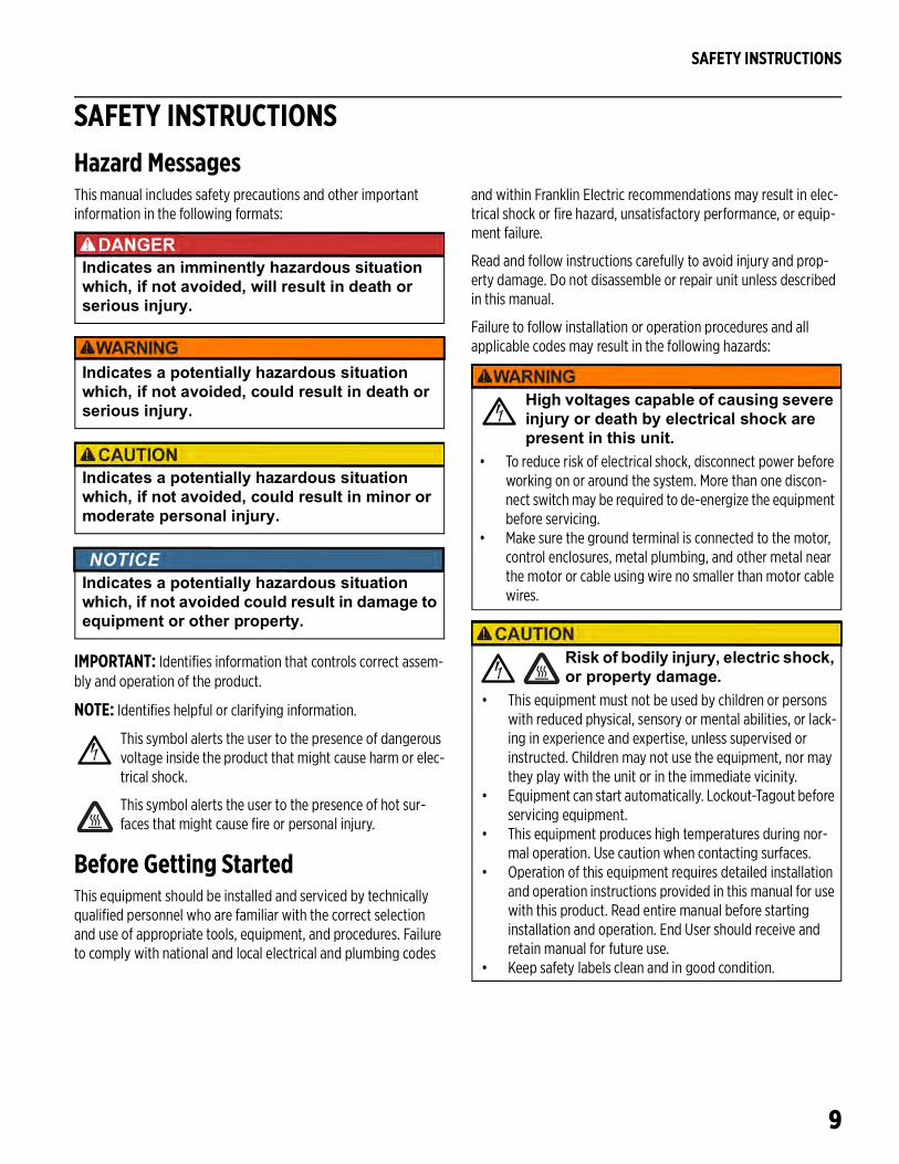
SAFETY INSTRUCTIONS
9
SAFETY INSTRUCTIONSHazard MessagesThis manual includes safety precautions and other important information in the following formats:
IMPORTANT: Identifies information that controls correct assem-bly and operation of the product.
NOTE: Identifies helpful or clarifying information.
This symbol alerts the user to the presence of dangerous voltage inside the product that might cause harm or elec-trical shock.
This symbol alerts the user to the presence of hot sur-faces that might cause fire or personal injury.
Before Getting StartedThis equipment should be installed and serviced by technically qualified personnel who are familiar with the correct selection and use of appropriate tools, equipment, and procedures. Failure to comply with national and local electrical and plumbing codes
and within Franklin Electric recommendations may result in elec-trical shock or fire hazard, unsatisfactory performance, or equip-ment failure.
Read and follow instructions carefully to avoid injury and prop-erty damage. Do not disassemble or repair unit unless described in this manual.
Failure to follow installation or operation procedures and all applicable codes may result in the following hazards:
Indicates an imminently hazardous situation which, if not avoided, will result in death or serious injury.
Indicates a potentially hazardous situation which, if not avoided, could result in death or serious injury.
Indicates a potentially hazardous situation which, if not avoided, could result in minor or moderate personal injury.
Indicates a potentially hazardous situation which, if not avoided could result in damage to equipment or other property.
High voltages capable of causing severe injury or death by electrical shock are present in this unit.
• To reduce risk of electrical shock, disconnect power before working on or around the system. More than one discon-nect switch may be required to de-energize the equipment before servicing.
• Make sure the ground terminal is connected to the motor, control enclosures, metal plumbing, and other metal near the motor or cable using wire no smaller than motor cable wires.
Risk of bodily injury, electric shock, or property damage.
• This equipment must not be used by children or persons with reduced physical, sensory or mental abilities, or lack-ing in experience and expertise, unless supervised or instructed. Children may not use the equipment, nor may they play with the unit or in the immediate vicinity.
• Equipment can start automatically. Lockout-Tagout before servicing equipment.
• This equipment produces high temperatures during nor-mal operation. Use caution when contacting surfaces.
• Operation of this equipment requires detailed installation and operation instructions provided in this manual for use with this product. Read entire manual before starting installation and operation. End User should receive and retain manual for future use.
• Keep safety labels clean and in good condition.
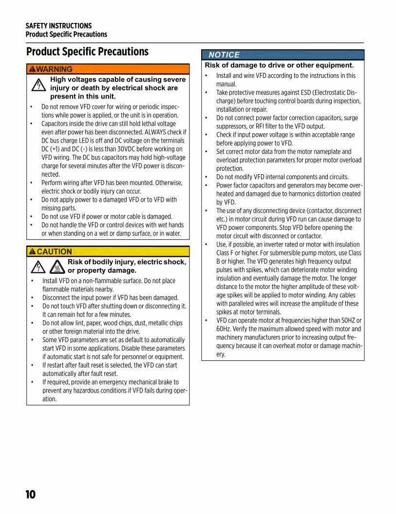
SAFETY INSTRUCTIONSProduct Specific Precautions
10
Product Specific Precautions
High voltages capable of causing severe injury or death by electrical shock are present in this unit.
• Do not remove VFD cover for wiring or periodic inspec-tions while power is applied, or the unit is in operation.
• Capacitors inside the drive can still hold lethal voltage even after power has been disconnected. ALWAYS check if DC bus charge LED is off and DC voltage on the terminals DC (+1) and DC (-) is less than 30VDC before working on VFD wiring. The DC bus capacitors may hold high-voltage charge for several minutes after the VFD power is discon-nected.
• Perform wiring after VFD has been mounted. Otherwise, electric shock or bodily injury can occur.
• Do not apply power to a damaged VFD or to VFD with missing parts.
• Do not use VFD if power or motor cable is damaged.• Do not handle the VFD or control devices with wet hands
or when standing on a wet or damp surface, or in water.
Risk of bodily injury, electric shock, or property damage.
• Install VFD on a non-flammable surface. Do not place flammable materials nearby.
• Disconnect the input power if VFD has been damaged.• Do not touch VFD after shutting down or disconnecting it.
It can remain hot for a few minutes.• Do not allow lint, paper, wood chips, dust, metallic chips
or other foreign material into the drive.• Some VFD parameters are set as default to automatically
start VFD in some applications. Disable these parameters if automatic start is not safe for personnel or equipment.
• If restart after fault reset is selected, the VFD can start automatically after fault reset.
• If required, provide an emergency mechanical brake to prevent any hazardous conditions if VFD fails during oper-ation.
Risk of damage to drive or other equipment.• Install and wire VFD according to the instructions in this
manual.• Take protective measures against ESD (Electrostatic Dis-
charge) before touching control boards during inspection, installation or repair.
• Do not connect power factor correction capacitors, surge suppressors, or RFI filter to the VFD output.
• Check if input power voltage is within acceptable range before applying power to VFD.
• Set correct motor data from the motor nameplate and overload protection parameters for proper motor overload protection.
• Do not modify VFD internal components and circuits.• Power factor capacitors and generators may become over-
heated and damaged due to harmonics distortion created by VFD.
• The use of any disconnecting device (contactor, disconnect etc.) in motor circuit during VFD run can cause damage to VFD power components. Stop VFD before opening the motor circuit with disconnect or contactor.
• Use, if possible, an inverter rated or motor with insulation Class F or higher. For submersible pump motors, use Class B or higher. The VFD generates high frequency output pulses with spikes, which can deteriorate motor winding insulation and eventually damage the motor. The longer distance to the motor the higher amplitude of these volt-age spikes will be applied to motor winding. Any cables with paralleled wires will increase the amplitude of these spikes at motor terminals.
• VFD can operate motor at frequencies higher than 50HZ or 60Hz. Verify the maximum allowed speed with motor and machinery manufacturers prior to increasing output fre-quency because it can overheat motor or damage machin-ery.
PRODUCT INFORMATIONDescription
11
PRODUCT INFORMATIONDescription
The Cerus X-Drive is a variable frequency drive (VFD) designed to control and protect three phase motors in industrial, municipal, and agricultural sites. The X-Drive family offers an extensive range of amperage and configuration options, making it versatile enough for nearly any constant or variable torque application.
Industry standard application settings are pre-configured for submersible or centrifugal pumps, supply or exhaust fans, cooling towers, vacuum pumps, and constant torque motors. In addition, many input/output and control options are available for application specific features, such as PID speed control, pressure control, temperature or fluid level controls, and scheduling.
Native Modbus and BACnet communication protocols allow integration with many auto-mated control and building management systems. In addition, an optional Bluetooth com-munication card provides access for programming, operating, and monitoring the drive using the FE Connect for Cerus X-Drive Mobile App. Refer to “Optional Extension Cards” on page 95.
FeaturesConfiguration• Compatible with three-phase induction or permanent magnet motors• Extensive selection of models available. Refer “Models” on page 12.• Easy setup with built-in application defaults• Many programmable Input/Output terminal options• Available NEMA 1, NEMA 3R, UL Type 1, IP21, or 4X enclosure offerings
Application-specific features• Sleep mode• Damper control• Lubrication for hollow-shaft motors• Pipe fill mode• Broken pipe protection• Screen clean• Multi-motor control
Operation• Integrated HOA functionality• Integrated display with keypad control of all functions• Real-time fault logging with date and time stamps
Protection• Protection against short circuit, incorrect wiring, surges, underload, overload, drive overheat, under-
voltage, over-voltage, phase loss, phase imbalance, output open phase, overpressure, sensor fault, etc.• The X-Drive allows your motor to gradually ramp up and down, saving equipment from sudden, harsh
rushes of current that can shorten its lifespan
Communication• RS-485 communications (Modbus, BACnet) for remote control or monitoring• Bluetooth connectivity with optional FE Connect Communication Card
PRODUCT INFORMATIONModels
12
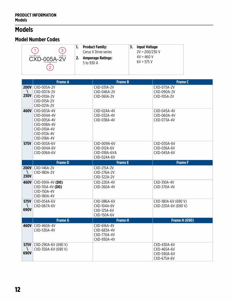
ModelsModel Number Codes
1. Product Family:Cerus X Drive series
2. Amperage Ratings:5 to 930 A
3. Input Voltage2V = 200/230 V4V = 460 V6V = 575 VCXD-005A-2V
1
2
3
Frame A Frame B Frame C200V
\230V
CXD-005A-2VCXD-007A-2VCXD-010A-2VCXD-015A-2VCXD-021A-2V
CXD-031A-2VCXD-046A-2VCXD-061A-2V
CXD-075A-2VCXD-090A-2VCXD-105A-2V
460V CXD-003A-4VCXD-004A-4VCXD-005A-4VCXD-008A-4VCXD-010A-4VCXD-013A-4VCXD-018A-4V
CXD-024A-4VCXD-032A-4VCXD-038A-4V
CXD-045A-4VCXD-060A-4VCXD-073A-4V
575V CXD-003A-6VCXD-004A-6VCXD-006A-6V
CXD-009A-6VCXD-012A-6VCXD-018A-6VACXD-024A-6V
CXD-030A-6VCXD-036A-6VCXD-045A-6V
Frame D Frame E Frame F200V
\230V
CXD-146A-2VCXD-180A-2V
CXD-215A-2VCXD-276A-2VCXD-322A-2V
460V CXD-091A-4V (D0)CXD-110A-4V (D0)CXD-150A-4VCXD-180A-4V
CXD-220A-4VCXD-260A-4V
CXD-310A-4VCXD-370A-4V
575V\
690V
CXD-054A-6VCXD-067A-6V
CXD-086A-6VCXD-104A-6VCXD-125A-6VCXD-150A-6V
CXD-180A-6V (690 V)CXD-220A-6V (690 V)
Frame G Frame H Frame H (690)460V CXD-460A-4V
CXD-530A-4VCXD-616A-4VCXD-683A-4VCXD-770A-4VCXD-930A-4V
575V\
690V
CXD-290A-6V (690 V)CXD-350A-6V (690 V)
CXD-430A-6VCXD-465A-6VCXD-590A-6VCXD-675A-6V
UNPACKING AND INSPECTIONTransportation and Storage
13
UNPACKING AND INSPECTIONTransportation and Storage
The VFD should be stored in the shipping carton or crate before installation, in a controlled environment that meets the following requirements:
The performance of capacitors in the drive will degrade if not charged occasionally. It is recommended to charge a stored drive every 2 years to restore the performance of the capacitors.
NOTE: If the VFD is kept in storage for longer than 2 years, when powering the drive, use an adjustable AC power source (ex. AC autotransformer) to charge the drive at 70 to 80% of the rated voltage for 30 minutes (do not run the drive). Then, charge the drive at 100% of rated voltage for an hour (do not run the drive).
Unpacking
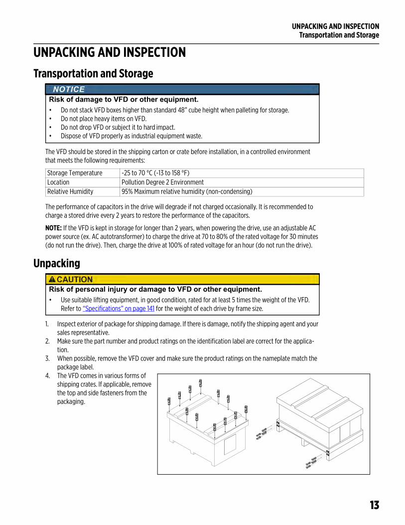
1. Inspect exterior of package for shipping damage. If there is damage, notify the shipping agent and your sales representative.
2. Make sure the part number and product ratings on the identification label are correct for the applica-tion.
3. When possible, remove the VFD cover and make sure the product ratings on the nameplate match the package label.
4. The VFD comes in various forms of shipping crates. If applicable, remove the top and side fasteners from the packaging.
Risk of damage to VFD or other equipment.• Do not stack VFD boxes higher than standard 48” cube height when palleting for storage.• Do not place heavy items on VFD.• Do not drop VFD or subject it to hard impact.• Dispose of VFD properly as industrial equipment waste.
Storage Temperature -25 to 70 °C (-13 to 158 °F)Location Pollution Degree 2 EnvironmentRelative Humidity 95% Maximum relative humidity (non-condensing)
Risk of personal injury or damage to VFD or other equipment.• Use suitable lifting equipment, in good condition, rated for at least 5 times the weight of the VFD.
Refer to “Specifications” on page 141 for the weight of each drive by frame size.
UNPACKING AND INSPECTIONUnpacking
14
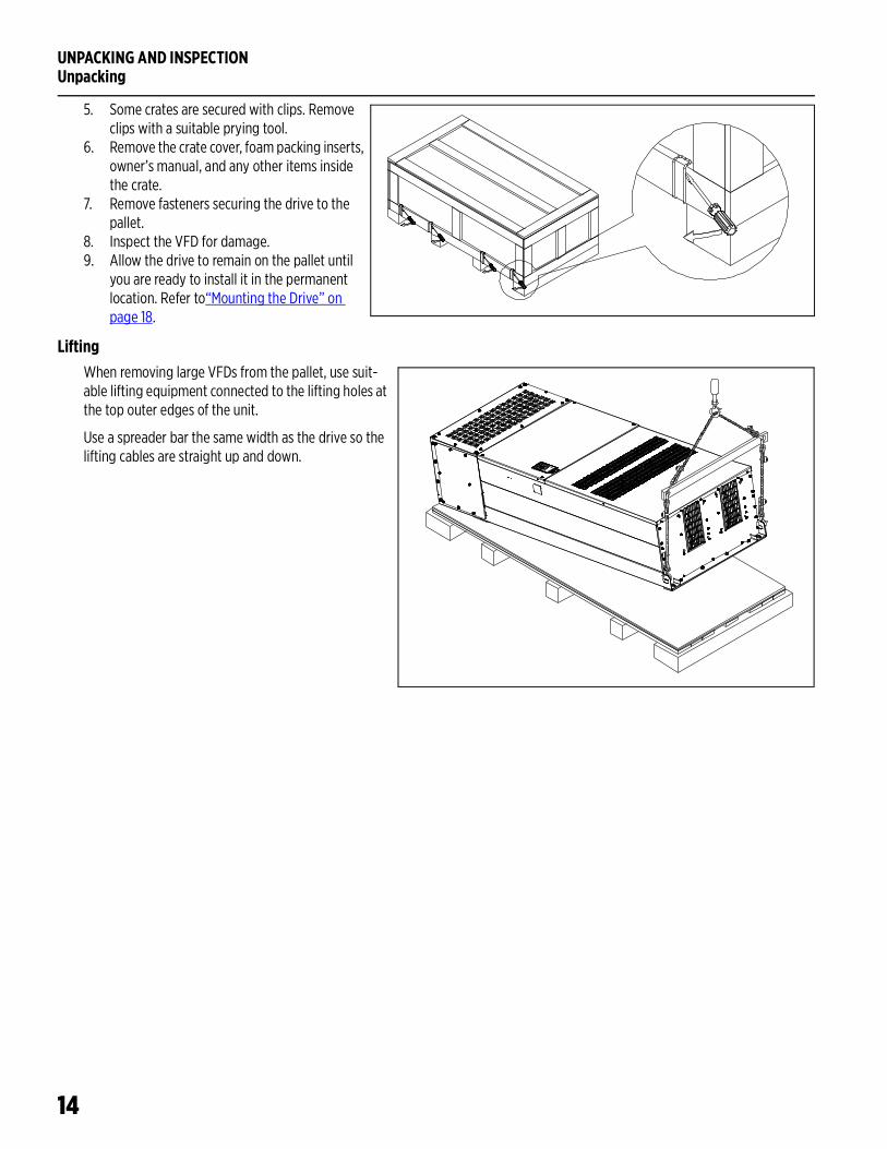
5. Some crates are secured with clips. Remove clips with a suitable prying tool.
6. Remove the crate cover, foam packing inserts, owner’s manual, and any other items inside the crate.
7. Remove fasteners securing the drive to the pallet.
8. Inspect the VFD for damage.9. Allow the drive to remain on the pallet until
you are ready to install it in the permanent location. Refer to“Mounting the Drive” on page 18.
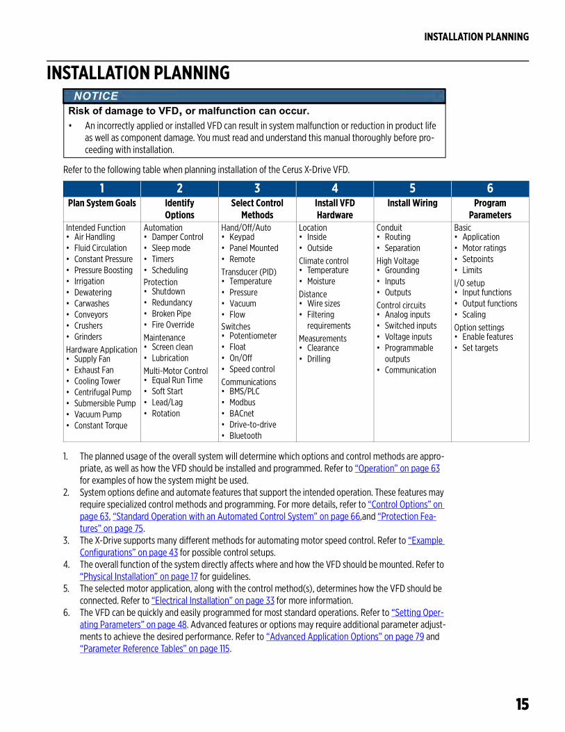
LiftingWhen removing large VFDs from the pallet, use suit-able lifting equipment connected to the lifting holes at the top outer edges of the unit.
Use a spreader bar the same width as the drive so the lifting cables are straight up and down.
INSTALLATION PLANNING
15
INSTALLATION PLANNING
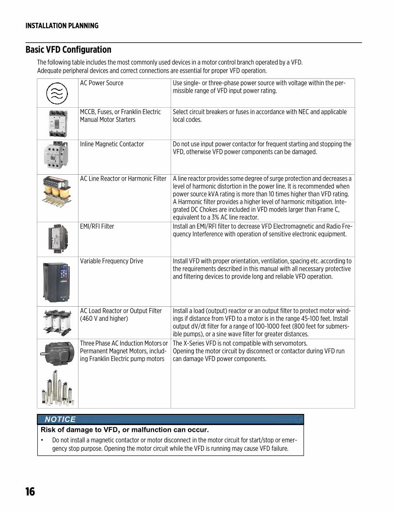
Refer to the following table when planning installation of the Cerus X-Drive VFD.
1. The planned usage of the overall system will determine which options and control methods are appro-priate, as well as how the VFD should be installed and programmed. Refer to “Operation” on page 63 for examples of how the system might be used.
2. System options define and automate features that support the intended operation. These features may require specialized control methods and programming. For more details, refer to “Control Options” on page 63, “Standard Operation with an Automated Control System” on page 66,and “Protection Fea-tures” on page 75.
3. The X-Drive supports many different methods for automating motor speed control. Refer to “Example Configurations” on page 43 for possible control setups.
4. The overall function of the system directly affects where and how the VFD should be mounted. Refer to “Physical Installation” on page 17 for guidelines.
5. The selected motor application, along with the control method(s), determines how the VFD should be connected. Refer to “Electrical Installation” on page 33 for more information.
6. The VFD can be quickly and easily programmed for most standard operations. Refer to “Setting Oper-ating Parameters” on page 48. Advanced features or options may require additional parameter adjust-ments to achieve the desired performance. Refer to “Advanced Application Options” on page 79 and “Parameter Reference Tables” on page 115.
Risk of damage to VFD, or malfunction can occur.• An incorrectly applied or installed VFD can result in system malfunction or reduction in product life
as well as component damage. You must read and understand this manual thoroughly before pro-ceeding with installation.
1 2 3 4 5 6Plan System Goals Identify
OptionsSelect Control
MethodsInstall VFDHardware
Install Wiring Program Parameters
Intended Function• Air Handling• Fluid Circulation• Constant Pressure• Pressure Boosting• Irrigation• Dewatering• Carwashes• Conveyors• Crushers• GrindersHardware Application• Supply Fan• Exhaust Fan• Cooling Tower• Centrifugal Pump• Submersible Pump• Vacuum Pump• Constant Torque
Automation• Damper Control• Sleep mode• Timers• SchedulingProtection• Shutdown• Redundancy• Broken Pipe• Fire OverrideMaintenance• Screen clean• LubricationMulti-Motor Control• Equal Run Time• Soft Start• Lead/Lag• Rotation
Hand/Off/Auto• Keypad• Panel Mounted• RemoteTransducer (PID)• Temperature• Pressure• Vacuum• FlowSwitches• Potentiometer• Float• On/Off• Speed controlCommunications• BMS/PLC• Modbus• BACnet• Drive-to-drive• Bluetooth
Location• Inside• OutsideClimate control• Temperature• MoistureDistance• Wire sizes• Filtering
requirementsMeasurements• Clearance• Drilling
Conduit• Routing• SeparationHigh Voltage• Grounding• Inputs• OutputsControl circuits• Analog inputs• Switched inputs• Voltage inputs• Programmable
outputs• Communication
Basic• Application• Motor ratings• Setpoints• LimitsI/O setup• Input functions• Output functions• ScalingOption settings• Enable features• Set targets
INSTALLATION PLANNING
16
Basic VFD ConfigurationThe following table includes the most commonly used devices in a motor control branch operated by a VFD. Adequate peripheral devices and correct connections are essential for proper VFD operation.
AC Power Source Use single- or three-phase power source with voltage within the per-missible range of VFD input power rating.
MCCB, Fuses, or Franklin Electric Manual Motor Starters
Select circuit breakers or fuses in accordance with NEC and applicable local codes.
Inline Magnetic Contactor Do not use input power contactor for frequent starting and stopping the VFD, otherwise VFD power components can be damaged.
AC Line Reactor or Harmonic Filter A line reactor provides some degree of surge protection and decreases a level of harmonic distortion in the power line. It is recommended when power source kVA rating is more than 10 times higher than VFD rating. A Harmonic filter provides a higher level of harmonic mitigation. Inte-grated DC Chokes are included in VFD models larger than Frame C, equivalent to a 3% AC line reactor.
EMI/RFI Filter Install an EMI/RFI filter to decrease VFD Electromagnetic and Radio Fre-quency Interference with operation of sensitive electronic equipment.
Variable Frequency Drive Install VFD with proper orientation, ventilation, spacing etc. according to the requirements described in this manual with all necessary protective and filtering devices to provide long and reliable VFD operation.
AC Load Reactor or Output Filter(460 V and higher)
Install a load (output) reactor or an output filter to protect motor wind-ings if distance from VFD to a motor is in the range 45-100 feet. Install output dV/dt filter for a range of 100-1000 feet (800 feet for submers-ible pumps), or a sine wave filter for greater distances.
Three Phase AC Induction Motors or Permanent Magnet Motors, includ-ing Franklin Electric pump motors
The X-Series VFD is not compatible with servomotors. Opening the motor circuit by disconnect or contactor during VFD run can damage VFD power components.
Risk of damage to VFD, or malfunction can occur.• Do not install a magnetic contactor or motor disconnect in the motor circuit for start/stop or emer-
gency stop purpose. Opening the motor circuit while the VFD is running may cause VFD failure.
PHYSICAL INSTALLATIONEnvironmental Requirements
17
PHYSICAL INSTALLATIONEnvironmental Requirements
The VFD must be installed and used in a controlled environment that meets the following requirements:
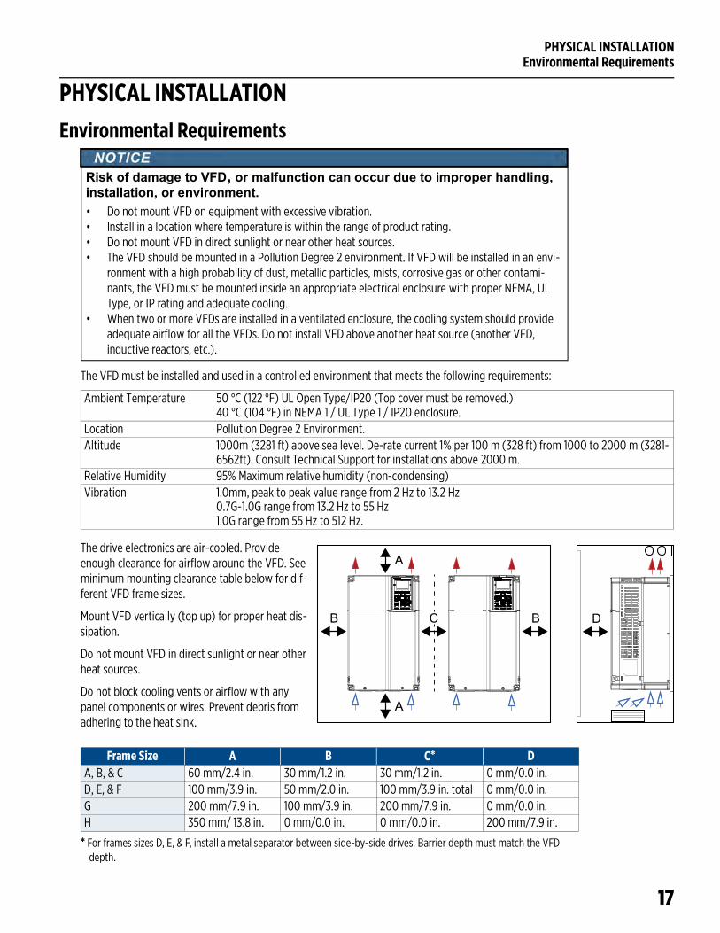
The drive electronics are air-cooled. Provide enough clearance for airflow around the VFD. See minimum mounting clearance table below for dif-ferent VFD frame sizes.
Mount VFD vertically (top up) for proper heat dis-sipation.
Do not mount VFD in direct sunlight or near other heat sources.
Do not block cooling vents or airflow with any panel components or wires. Prevent debris from adhering to the heat sink.
* For frames sizes D, E, & F, install a metal separator between side-by-side drives. Barrier depth must match the VFD depth.
Risk of damage to VFD, or malfunction can occur due to improper handling, installation, or environment.• Do not mount VFD on equipment with excessive vibration.• Install in a location where temperature is within the range of product rating.• Do not mount VFD in direct sunlight or near other heat sources.• The VFD should be mounted in a Pollution Degree 2 environment. If VFD will be installed in an envi-
ronment with a high probability of dust, metallic particles, mists, corrosive gas or other contami-nants, the VFD must be mounted inside an appropriate electrical enclosure with proper NEMA, UL Type, or IP rating and adequate cooling.
• When two or more VFDs are installed in a ventilated enclosure, the cooling system should provide adequate airflow for all the VFDs. Do not install VFD above another heat source (another VFD, inductive reactors, etc.).
Ambient Temperature 50 °C (122 °F) UL Open Type/IP20 (Top cover must be removed.)40 °C (104 °F) in NEMA 1 / UL Type 1 / IP20 enclosure.
Location Pollution Degree 2 Environment.Altitude 1000m (3281 ft) above sea level. De-rate current 1% per 100 m (328 ft) from 1000 to 2000 m (3281-
6562ft). Consult Technical Support for installations above 2000 m.Relative Humidity 95% Maximum relative humidity (non-condensing)Vibration 1.0mm, peak to peak value range from 2 Hz to 13.2 Hz
0.7G-1.0G range from 13.2 Hz to 55 Hz1.0G range from 55 Hz to 512 Hz.
A
A
B BC D
Frame Size A B C* DA, B, & C 60 mm/2.4 in. 30 mm/1.2 in. 30 mm/1.2 in. 0 mm/0.0 in.D, E, & F 100 mm/3.9 in. 50 mm/2.0 in. 100 mm/3.9 in. total 0 mm/0.0 in.G 200 mm/7.9 in. 100 mm/3.9 in. 200 mm/7.9 in. 0 mm/0.0 in.H 350 mm/ 13.8 in. 0 mm/0.0 in. 0 mm/0.0 in. 200 mm/7.9 in.
PHYSICAL INSTALLATIONMounting the Drive
18
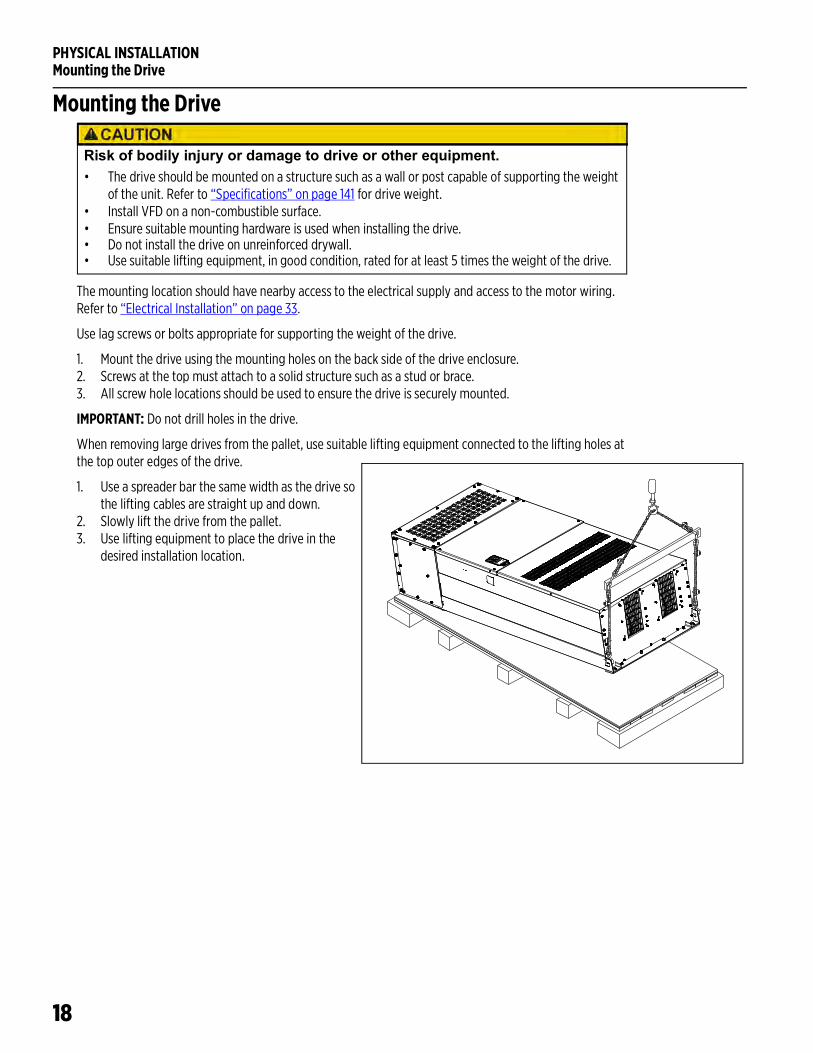
Mounting the Drive
The mounting location should have nearby access to the electrical supply and access to the motor wiring. Refer to “Electrical Installation” on page 33.
Use lag screws or bolts appropriate for supporting the weight of the drive.
1. Mount the drive using the mounting holes on the back side of the drive enclosure.2. Screws at the top must attach to a solid structure such as a stud or brace.3. All screw hole locations should be used to ensure the drive is securely mounted.
IMPORTANT: Do not drill holes in the drive.
When removing large drives from the pallet, use suitable lifting equipment connected to the lifting holes at the top outer edges of the drive.
1. Use a spreader bar the same width as the drive so the lifting cables are straight up and down.
2. Slowly lift the drive from the pallet.3. Use lifting equipment to place the drive in the
desired installation location.
Risk of bodily injury or damage to drive or other equipment.• The drive should be mounted on a structure such as a wall or post capable of supporting the weight
of the unit. Refer to “Specifications” on page 141 for drive weight.• Install VFD on a non-combustible surface. • Ensure suitable mounting hardware is used when installing the drive. • Do not install the drive on unreinforced drywall.• Use suitable lifting equipment, in good condition, rated for at least 5 times the weight of the drive.
PHYSICAL INSTALLATIONMounting the Drive
19
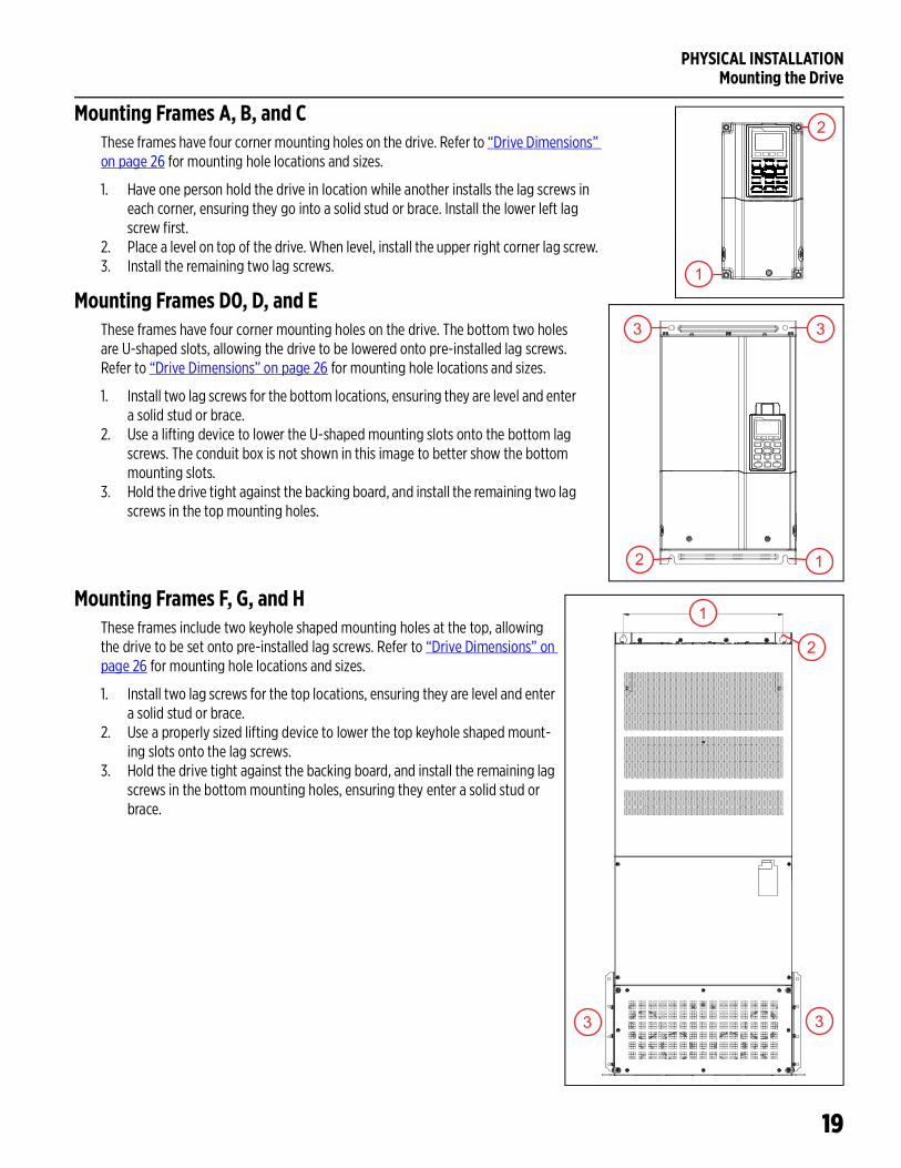
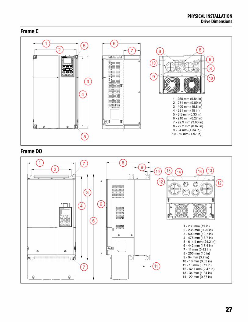
Mounting Frames A, B, and CThese frames have four corner mounting holes on the drive. Refer to “Drive Dimensions” on page 26 for mounting hole locations and sizes.
1. Have one person hold the drive in location while another installs the lag screws in each corner, ensuring they go into a solid stud or brace. Install the lower left lag screw first.
2. Place a level on top of the drive. When level, install the upper right corner lag screw. 3. Install the remaining two lag screws.
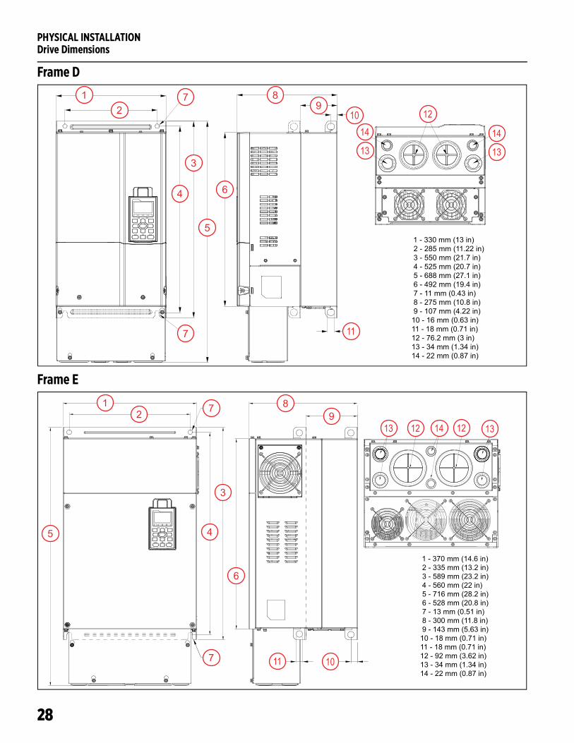
Mounting Frames D0, D, and EThese frames have four corner mounting holes on the drive. The bottom two holes are U-shaped slots, allowing the drive to be lowered onto pre-installed lag screws. Refer to “Drive Dimensions” on page 26 for mounting hole locations and sizes.
1. Install two lag screws for the bottom locations, ensuring they are level and enter a solid stud or brace.
2. Use a lifting device to lower the U-shaped mounting slots onto the bottom lag screws. The conduit box is not shown in this image to better show the bottom mounting slots.
3. Hold the drive tight against the backing board, and install the remaining two lag screws in the top mounting holes.
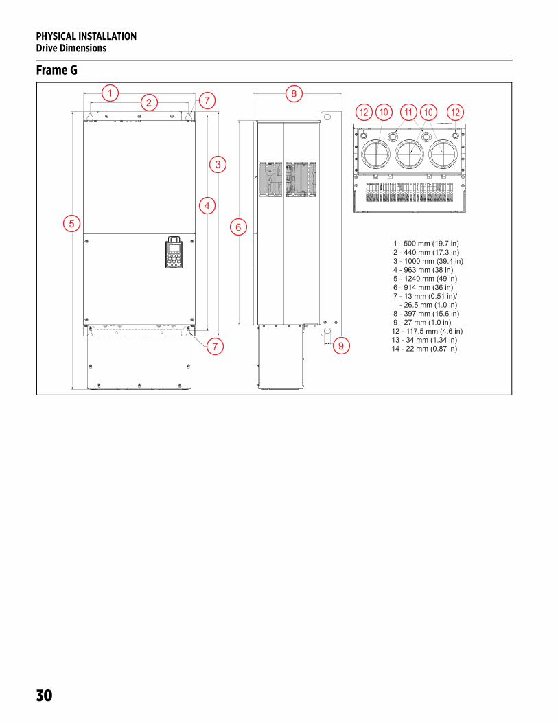
Mounting Frames F, G, and HThese frames include two keyhole shaped mounting holes at the top, allowing the drive to be set onto pre-installed lag screws. Refer to “Drive Dimensions” on page 26 for mounting hole locations and sizes.
1. Install two lag screws for the top locations, ensuring they are level and enter a solid stud or brace.
2. Use a properly sized lifting device to lower the top keyhole shaped mount-ing slots onto the lag screws.
3. Hold the drive tight against the backing board, and install the remaining lag screws in the bottom mounting holes, ensuring they enter a solid stud or brace.
1
2
3 3
2 1
1
2
3 3
PHYSICAL INSTALLATIONConduit Box Installation
20
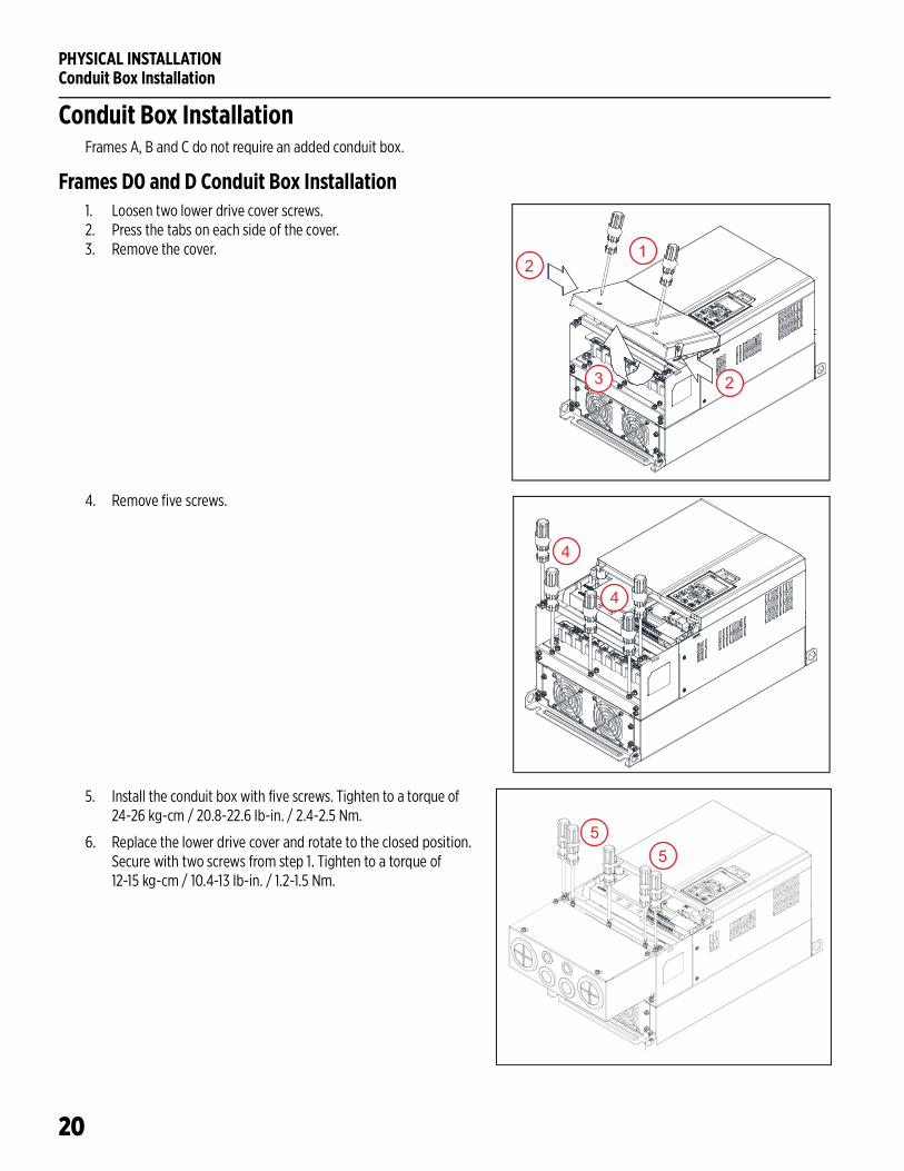
Conduit Box InstallationFrames A, B and C do not require an added conduit box.
Frames D0 and D Conduit Box Installation1. Loosen two lower drive cover screws. 2. Press the tabs on each side of the cover.3. Remove the cover.
4. Remove five screws.
5. Install the conduit box with five screws. Tighten to a torque of 24-26 kg-cm / 20.8-22.6 Ib-in. / 2.4-2.5 Nm.
6. Replace the lower drive cover and rotate to the closed position. Secure with two screws from step 1. Tighten to a torque of 12-15 kg-cm / 10.4-13 Ib-in. / 1.2-1.5 Nm.
1
2
2
3
4
4
55
PHYSICAL INSTALLATIONConduit Box Installation
21
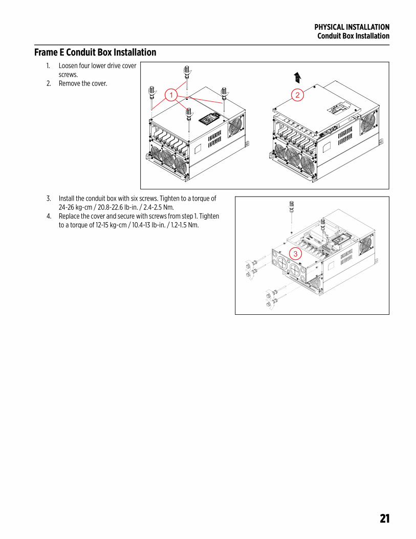
Frame E Conduit Box Installation1. Loosen four lower drive cover
screws. 2. Remove the cover.
3. Install the conduit box with six screws. Tighten to a torque of 24-26 kg-cm / 20.8-22.6 Ib-in. / 2.4-2.5 Nm.
4. Replace the cover and secure with screws from step 1. Tighten to a torque of 12-15 kg-cm / 10.4-13 Ib-in. / 1.2-1.5 Nm.
21
3
PHYSICAL INSTALLATIONConduit Box Installation
22
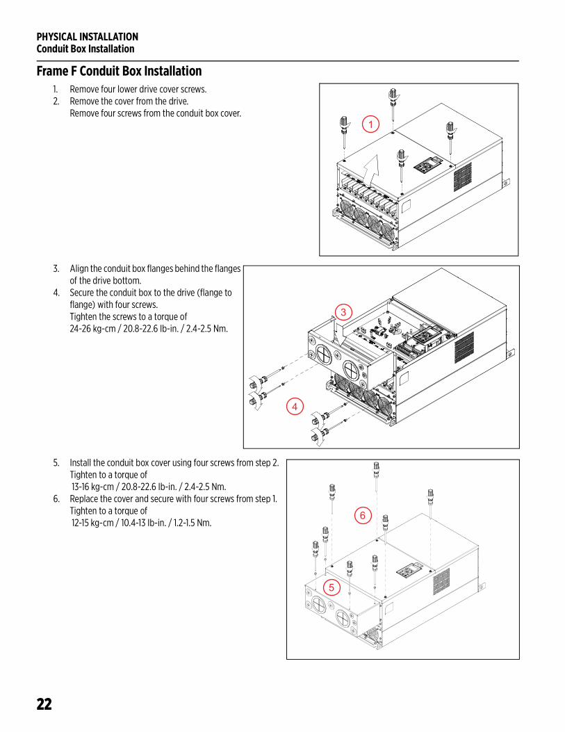
Frame F Conduit Box Installation1. Remove four lower drive cover screws. 2. Remove the cover from the drive.
Remove four screws from the conduit box cover.
3. Align the conduit box flanges behind the flanges of the drive bottom.
4. Secure the conduit box to the drive (flange to flange) with four screws. Tighten the screws to a torque of 24-26 kg-cm / 20.8-22.6 Ib-in. / 2.4-2.5 Nm.
5. Install the conduit box cover using four screws from step 2. Tighten to a torque of 13-16 kg-cm / 20.8-22.6 Ib-in. / 2.4-2.5 Nm.
6. Replace the cover and secure with four screws from step 1. Tighten to a torque of 12-15 kg-cm / 10.4-13 Ib-in. / 1.2-1.5 Nm.
1
4
3
5
6
PHYSICAL INSTALLATIONConduit Box Installation
23
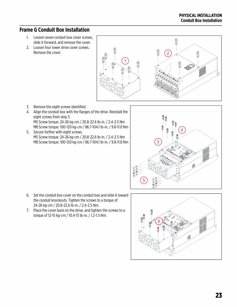
Frame G Conduit Box Installation1. Loosen seven conduit box cover screws,
slide it forward, and remove the cover.2. Loosen four lower drive cover screws.
Remove the cover.
3. Remove the eight screws identified.4. Align the conduit box with the flanges of the drive. Reinstall the
eight screws from step 3. M5 Screw torque: 24-26 kg-cm / 20.8-22.6 Ib-in. / 2.4-2.5 NmM8 Screw torque: 100-120 kg-cm / 86.7-104.1 Ib-in. / 9.8-11.8 Nm
5. Secure further with eight screws. M5 Screw torque: 24-26 kg-cm / 20.8-22.6 Ib-in. / 2.4-2.5 NmM8 Screw torque: 100-120 kg-cm / 86.7-104.1 Ib-in. / 9.8-11.8 Nm
6. Set the conduit box cover on the conduit box and slide it toward the conduit knockouts. Tighten the screws to a torque of 24-26 kg-cm / 20.8-22.6 Ib-in. / 2.4-2.5 Nm.
7. Place the cover back on the drive, and tighten the screws to a torque of 12-15 kg-cm / 10.4-13 Ib-in. / 1.2-1.5 Nm.
1
2
3
4
5
6
PHYSICAL INSTALLATIONConduit Box Installation
24
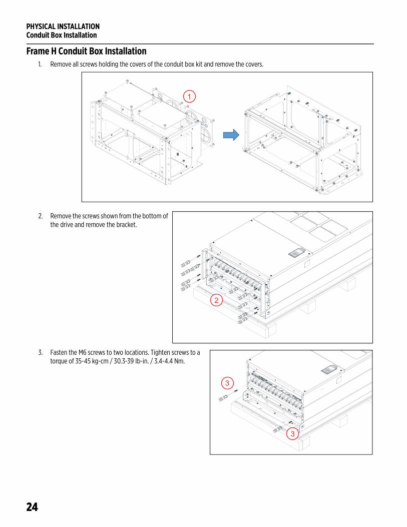
Frame H Conduit Box Installation1. Remove all screws holding the covers of the conduit box kit and remove the covers.
2. Remove the screws shown from the bottom of the drive and remove the bracket.
3. Fasten the M6 screws to two locations. Tighten screws to a torque of 35-45 kg-cm / 30.3-39 Ib-in. / 3.4-4.4 Nm.
1
2
3
3
PHYSICAL INSTALLATIONConduit Box Installation
25
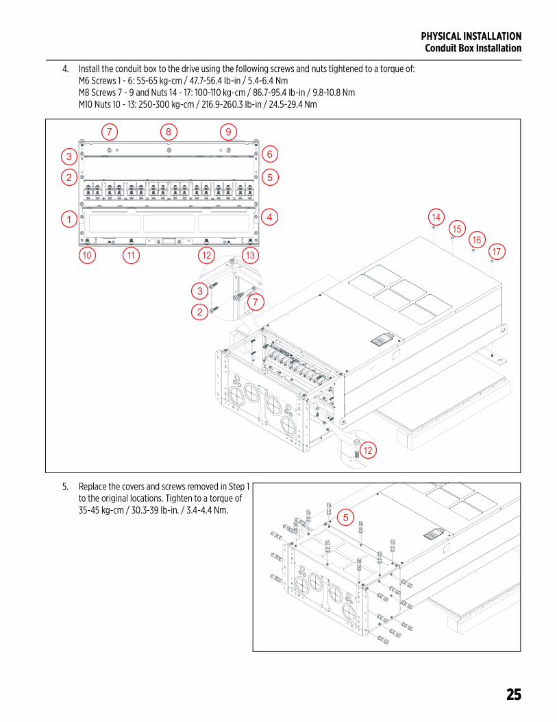
4. Install the conduit box to the drive using the following screws and nuts tightened to a torque of:M6 Screws 1 - 6: 55-65 kg-cm / 47.7-56.4 Ib-in / 5.4-6.4 NmM8 Screws 7 - 9 and Nuts 14 - 17: 100-110 kg-cm / 86.7-95.4 Ib-in / 9.8-10.8 NmM10 Nuts 10 - 13: 250-300 kg-cm / 216.9-260.3 Ib-in / 24.5-29.4 Nm
5. Replace the covers and screws removed in Step 1 to the original locations. Tighten to a torque of 35-45 kg-cm / 30.3-39 Ib-in. / 3.4-4.4 Nm.
13
1
8
6
10
2
9
11
3
5
12
7
4
17
1516
141
2
3
4
5
6
7 8 9
10 11 12 13
1415
1617
12
2
37
5
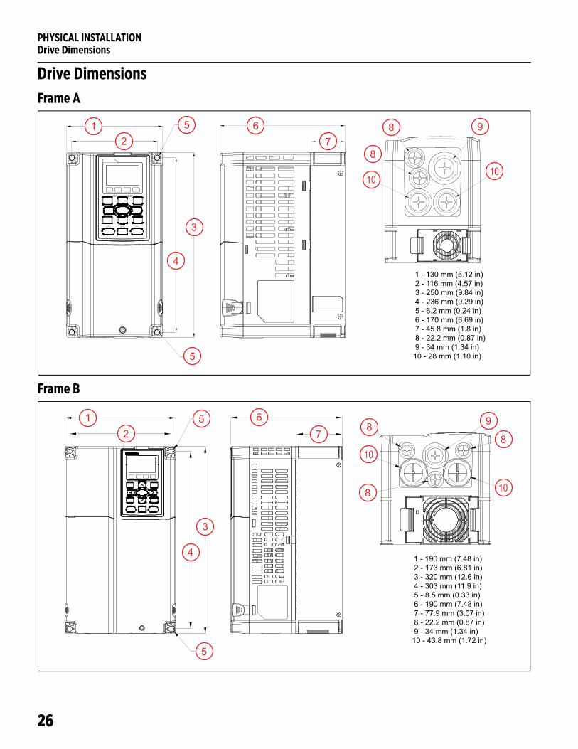
PHYSICAL INSTALLATIONDrive Dimensions
26
Drive DimensionsFrame A
Frame B
12
3
4
5
5
78 9
1 - 130 mm (5.12 in) 2 - 116 mm (4.57 in) 3 - 250 mm (9.84 in) 4 - 236 mm (9.29 in) 5 - 6.2 mm (0.24 in) 6 - 170 mm (6.69 in) 7 - 45.8 mm (1.8 in) 8 - 22.2 mm (0.87 in) 9 - 34 mm (1.34 in)10 - 28 mm (1.10 in)
6
8
1010
1 - 190 mm (7.48 in) 2 - 173 mm (6.81 in) 3 - 320 mm (12.6 in) 4 - 303 mm (11.9 in) 5 - 8.5 mm (0.33 in) 6 - 190 mm (7.48 in) 7 - 77.9 mm (3.07 in) 8 - 22.2 mm (0.87 in) 9 - 34 mm (1.34 in)10 - 43.8 mm (1.72 in)
12
3
4
5 67
8
9
5
88
10
10
PHYSICAL INSTALLATIONDrive Dimensions
27
Frame C
Frame D0
1 - 250 mm (9.84 in) 2 - 231 mm (9.09 in) 3 - 400 mm (15.8 in) 4 - 381 mm (15 in) 5 - 8.5 mm (0.33 in) 6 - 210 mm (8.27 in) 7 - 92.9 mm (3.66 in) 8 - 22.2 mm (0.87 in) 9 - 34 mm (1.34 in)10 - 50 mm (1.97 in)
10
12
3
4
5
67 8
9
58
8
810
12
3
4
5
7
89
10
11
12
7
1 - 280 mm (11 in) 2 - 235 mm (9.25 in) 3 - 500 mm (19.7 in) 4 - 475 mm (18.7 in) 5 - 614.4 mm (24.2 in) 6 - 442 mm (17.4 in) 7 - 11 mm (0.43 in) 8 - 255 mm (10 in) 9 - 94 mm (3.7 in)10 - 16 mm (0.63 in)11 - 18 mm (0.71 in)12 - 62.7 mm (2.47 in)13 - 34 mm (1.34 in)14 - 22 mm (0.87 in)
6
12
13 14 1314
PHYSICAL INSTALLATIONDrive Dimensions
28
Frame D
Frame E
12
3
4
5
7
89
10
11
7
1 - 330 mm (13 in) 2 - 285 mm (11.22 in) 3 - 550 mm (21.7 in) 4 - 525 mm (20.7 in) 5 - 688 mm (27.1 in) 6 - 492 mm (19.4 in) 7 - 11 mm (0.43 in) 8 - 275 mm (10.8 in) 9 - 107 mm (4.22 in)10 - 16 mm (0.63 in)11 - 18 mm (0.71 in)12 - 76.2 mm (3 in)13 - 34 mm (1.34 in)14 - 22 mm (0.87 in)
6
12
14
13
14
13
12
3
45
6
7 89
1011
1213
7
14 12 13
1 - 370 mm (14.6 in) 2 - 335 mm (13.2 in) 3 - 589 mm (23.2 in) 4 - 560 mm (22 in) 5 - 716 mm (28.2 in) 6 - 528 mm (20.8 in) 7 - 13 mm (0.51 in) 8 - 300 mm (11.8 in) 9 - 143 mm (5.63 in)10 - 18 mm (0.71 in)11 - 18 mm (0.71 in)12 - 92 mm (3.62 in)13 - 34 mm (1.34 in)14 - 22 mm (0.87 in)

PHYSICAL INSTALLATIONDrive Dimensions
29
Frame F
12
3
4
5
6
78
9
1 - 420 mm (16.5 in) 2 - 380 mm (16 in) 3 - 800 mm (31.5 in) 4 - 770 mm (30.3 in) 5 - 940 mm (37 in) 6 - 717 mm (28 in) 7 - 13 mm (0.51 in)/ - 25 mm (0.98 in) 8 - 300 mm (11.8 in) 9 - 124 mm (4.9 in)10 - 18 mm (0.71 in)11 - 18 mm (0.71 in)12 - 92 mm (3.62 in)13 - 35 mm (1.38 in)14 - 22 mm (0.87 in)7 1011
1213 13 12 14
PHYSICAL INSTALLATIONDrive Dimensions
30
Frame G
1 - 500 mm (19.7 in) 2 - 440 mm (17.3 in) 3 - 1000 mm (39.4 in) 4 - 963 mm (38 in) 5 - 1240 mm (49 in) 6 - 914 mm (36 in) 7 - 13 mm (0.51 in)/ - 26.5 mm (1.0 in) 8 - 397 mm (15.6 in) 9 - 27 mm (1.0 in)12 - 117.5 mm (4.6 in)13 - 34 mm (1.34 in)14 - 22 mm (0.87 in)
12 121110 10
12
3
4
5 6
78
97
PHYSICAL INSTALLATIONDrive Dimensions
31
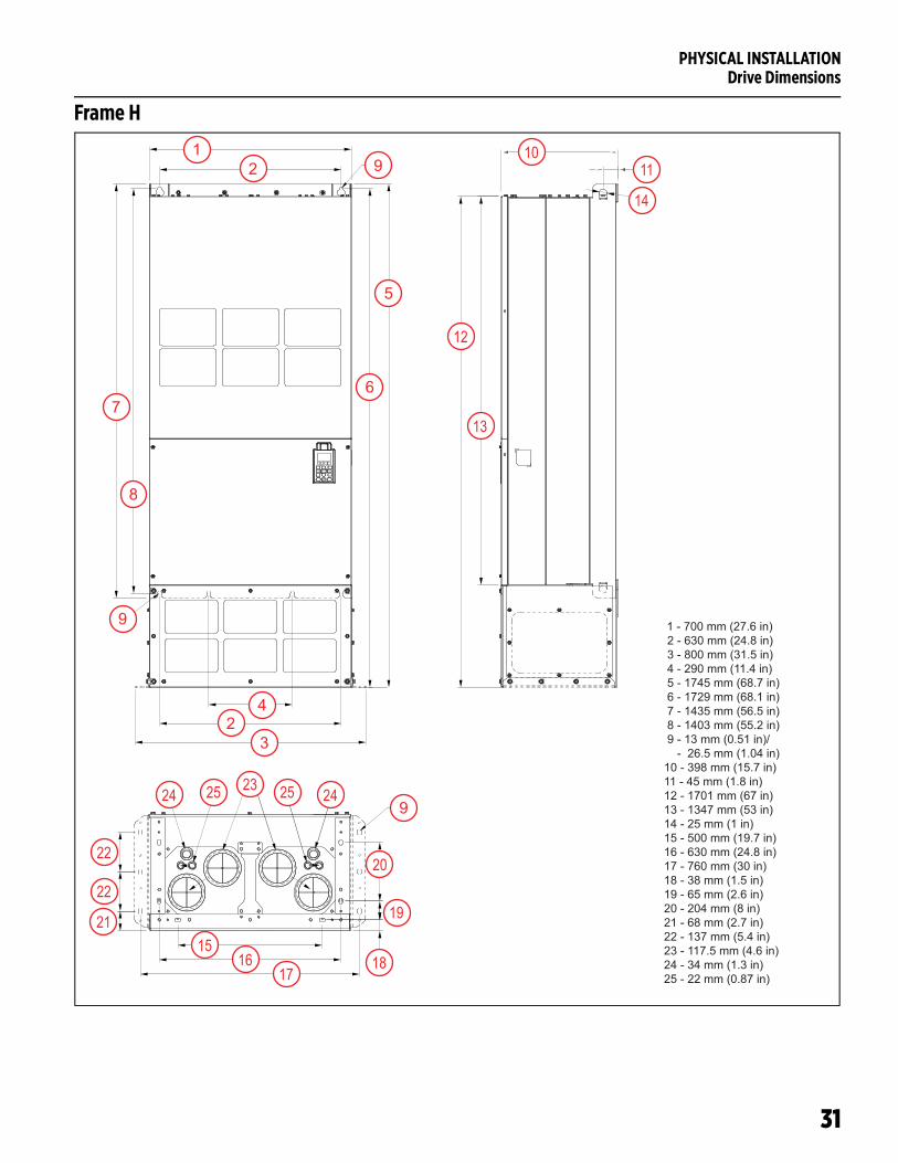
Frame H
1
24
5
67
8
9
1 - 700 mm (27.6 in) 2 - 630 mm (24.8 in) 3 - 800 mm (31.5 in) 4 - 290 mm (11.4 in) 5 - 1745 mm (68.7 in) 6 - 1729 mm (68.1 in) 7 - 1435 mm (56.5 in) 8 - 1403 mm (55.2 in) 9 - 13 mm (0.51 in)/ - 26.5 mm (1.04 in)10 - 398 mm (15.7 in)11 - 45 mm (1.8 in)12 - 1701 mm (67 in)13 - 1347 mm (53 in)14 - 25 mm (1 in)15 - 500 mm (19.7 in)16 - 630 mm (24.8 in)17 - 760 mm (30 in)18 - 38 mm (1.5 in)19 - 65 mm (2.6 in)20 - 204 mm (8 in)21 - 68 mm (2.7 in)22 - 137 mm (5.4 in)23 - 117.5 mm (4.6 in)24 - 34 mm (1.3 in)25 - 22 mm (0.87 in)
3
9
1011
12
13
14
1516
1718
19
20
21
22
2324 25
22
24259
2
PHYSICAL INSTALLATIONDrive Dimensions
32
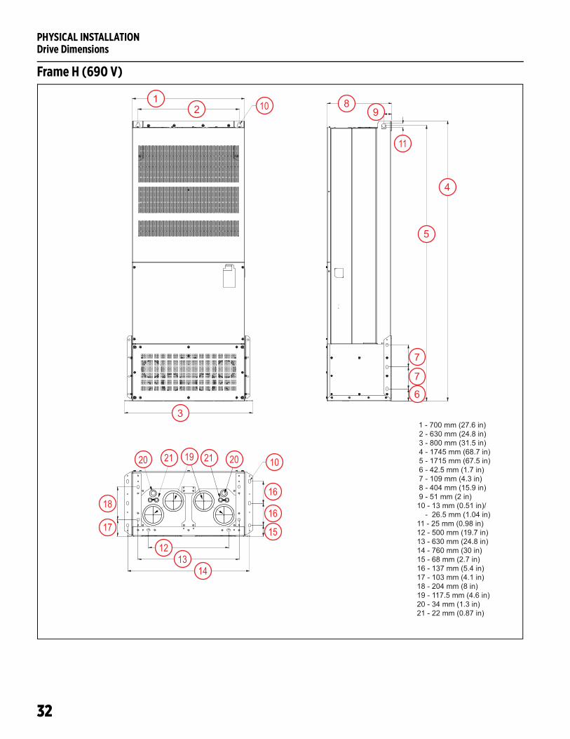
Frame H (690 V)
1 - 700 mm (27.6 in) 2 - 630 mm (24.8 in) 3 - 800 mm (31.5 in) 4 - 1745 mm (68.7 in) 5 - 1715 mm (67.5 in) 6 - 42.5 mm (1.7 in) 7 - 109 mm (4.3 in) 8 - 404 mm (15.9 in) 9 - 51 mm (2 in)10 - 13 mm (0.51 in)/ - 26.5 mm (1.04 in)11 - 25 mm (0.98 in)12 - 500 mm (19.7 in)13 - 630 mm (24.8 in)14 - 760 mm (30 in)15 - 68 mm (2.7 in)16 - 137 mm (5.4 in)17 - 103 mm (4.1 in)18 - 204 mm (8 in)19 - 117.5 mm (4.6 in)20 - 34 mm (1.3 in)21 - 22 mm (0.87 in)
12
3
4
5
6
7
89
7
10
11
1213
14
15
1617
18
10
16
20 2021 19 21
ELECTRICAL INSTALLATIONWiring Guidelines
33
ELECTRICAL INSTALLATIONWiring Guidelines
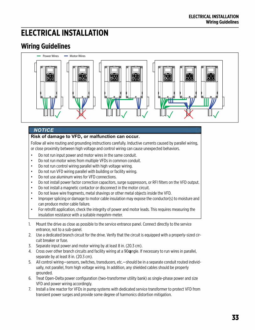
1. Mount the drive as close as possible to the service entrance panel. Connect directly to the service entrance, not to a sub-panel.
2. Use a dedicated branch circuit for the drive. Verify that the circuit is equipped with a properly-sized cir-cuit breaker or fuse.
3. Separate input power and motor wiring by at least 8 in. (20.3 cm). 4. Cross over other branch circuits and facility wiring at a 90 angle. If necessary to run wires in parallel,
separate by at least 8 in. (20.3 cm).5. All control wiring—sensors, switches, transducers, etc.—should be in a separate conduit routed individ-
ually, not parallel, from high voltage wiring. In addition, any shielded cables should be properly grounded.
6. Treat Open-Delta power configuration (two-transformer utility bank) as single-phase power and size VFD and power wiring accordingly.
7. Install a line reactor for VFDs in pump systems with dedicated service transformer to protect VFD from transient power surges and provide some degree of harmonics distortion mitigation.
Power Wires Motor Wires
Risk of damage to VFD, or malfunction can occur.Follow all wire routing and grounding instructions carefully. Inductive currents caused by parallel wiring, or close proximity between high voltage and control wiring can cause unexpected behaviors.
• Do not run input power and motor wires in the same conduit.• Do not run motor wires from multiple VFDs in common conduit.• Do not run control wiring parallel with high voltage wiring.• Do not run VFD wiring parallel with building or facility wiring.• Do not use aluminum wires for VFD connections.• Do not install power factor correction capacitors, surge suppressors, or RFI filters on the VFD output.• Do not install a magnetic contactor or disconnect in the motor circuit.• Do not leave wire fragments, metal shavings or other metal objects inside the VFD.• Improper splicing or damage to motor cable insulation may expose the conductor(s) to moisture and
can produce motor cable failure.• For retrofit application, check the integrity of power and motor leads. This requires measuring the
insulation resistance with a suitable megohm-meter.
ELECTRICAL INSTALLATIONWiring Guidelines
34
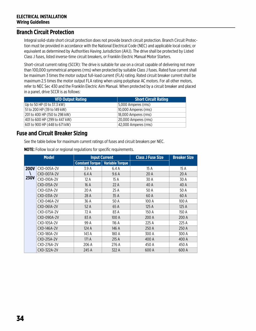
Branch Circuit ProtectionIntegral solid-state short circuit protection does not provide branch circuit protection. Branch Circuit Protec-tion must be provided in accordance with the National Electrical Code (NEC) and applicable local codes; or equivalent as determined by Authorities Having Jurisdiction (AHJ). The drive shall be protected by Listed Class J fuses, listed inverse-time circuit breakers, or Franklin Electric Manual Motor Starters.
Short-circuit current rating (SCCR): The drive is suitable for use on a circuit capable of delivering not more than 100,000 symmetrical amperes (rms) when protected by suitable Class J fuses. Rated fuse current shall be maximum 3 times the motor output full-load current (FLA) rating. Rated circuit breaker current shall be maximum 2.5 times the motor output FLA rating when using polyphase AC motors. For all other motors, refer to NEC Sec 430 and the Franklin Electric Aim Manual. When protected by a circuit breaker and placed in a panel, drive SCCR is as follows:
Fuse and Circuit Breaker SizingSee the table below for maximum current ratings of fuses and circuit breakers per NEC.
NOTE: Follow local or regional regulations for specific requirements.
VFD Output Rating Short Circuit RatingUp to 50 HP (0 to 37.3 kW) 5,000 Amperes (rms)51 to 200 HP (39 to 149 kW) 10,000 Amperes (rms)201 to 400 HP (150 to 298 kW) 18,000 Amperes (rms)401 to 600 HP (299 to 447 kW) 20,000 Amperes (rms)601 to 900 HP (448 to 671 kW) 42,000 Amperes (rms)
Model Input Current Class J Fuse Size Breaker SizeConstant Torque Variable Torque
200V\
230V
CXD-005A-2V 3.9 A 6.4 A 15 A 15 ACXD-007A-2V 6.4 A 9.6 A 20 A 20 ACXD-010A-2V 12 A 15 A 30 A 30 ACXD-015A-2V 16 A 22 A 40 A 40 ACXD-021A-2V 20 A 25 A 50 A 50 ACXD-031A-2V 28 A 35 A 60 A 60 ACXD-046A-2V 36 A 50 A 100 A 100 ACXD-061A-2V 52 A 65 A 125 A 125 ACXD-075A-2V 72 A 83 A 150 A 150 ACXD-090A-2V 83 A 100 A 200 A 200 ACXD-105A-2V 99 A 116 A 225 A 225 ACXD-146A-2V 124 A 146 A 250 A 250 ACXD-180A-2V 143 A 180 A 300 A 300 ACXD-215A-2V 171 A 215 A 400 A 400 ACXD-276A-2V 206 A 276 A 450 A 450 ACXD-322A-2V 245 A 322 A 600 A 600 A
ELECTRICAL INSTALLATIONWiring Guidelines
35
Model Input Current Class J Fuse Size Breaker SizeConstant Torque Variable Torque
380V\
480V
CXD-003A-4V 3.5 A 4.3 A 10 A 10 ACXD-004A-4V 4.3 A 6.0 A 10 A 10 ACXD-005A-4V 5.9 A 8.1 A 15 A 15 ACXD-008A-4V 8.7 A 12.4 A 25 A 25 ACXD-010A-4V 14 A 16 A 30 A 30 ACXD-013A-4V 15.5 A 20 A 40 A 40 ACXD-018A-4V 17 A 22 A 40 A 40ACXD-024A-4V 20 A 26 A 50 A 50 ACXD-032A-4V 25 A 35 A 60 A 60 ACXD-038A-4V 35 A 42 A 75 A 75 ACXD-045A-4V 40 A 50 A 100 A 100 ACXD-060A-4V 47 A 66 A 125 A 125 ACXD-073A-4V 63 A 80 A 150 A 150 ACXD-091A-4V 74 A 91 A 175 A 175 ACXD-110A-4V 101 A 110 A 250 A 250 ACXD-150A-4V 114 A 150 A 300 A 300 ACXD-180A-4V 157 A 180 A 300 A 300 ACXD-220A-4V 167 A 220 A 400 A 400 ACXD-260A-4V 207 A 260 A 500 A 500 ACXD-310A-4V 240 A 310 A 600 A 600 ACXD-370A-4V 300 A 370 A 600 A 600 ACXD-460A-4V 380 A 460 A 800 A 800 ACXD-530A-4V 400 A 530 A 1000 A 1000 ACXD-616A-4V 494 A 616 A 1200 A 1200 ACXD-683A-4V 555 A 683 A 1350 A 1350 ACXD-770A-4V 625 A 770 A 1500 A 1500 ACXD-930A-4V 866 A 930 A 1600 A 2000 A
575V\
600V
CXD-003A-6V 3.1 A 3.8 A 7 A 7 ACXD-004A-6V 4.5 A 5.4 A 10 A 10 ACXD-006A-6V 7.2 A 10.2 A 15 A 15 ACXD-009A-6V 12.3 A 14.9 A 25 A 25 ACXD-012A-6V 15 A 16.9 A 32 A 32 ACXD-018A-6V 18 A 21.3 A 50 A 50 ACXD-024A-6V 22.8 A 26.3 A 63 A 63 ACXD-030A-6V 29 A 36 A 70 A 70 ACXD-036A-6V 36 A 43 A 80 A 80 ACXD-045A-6V 43 A 54 A 100 A 100 ACXD-054A-6V 54 A 65 A 100 A 100 ACXD-067A-6V 65 A 81 A 125 A 125 ACXD-086A-6V 66 A 84 A 175 A 175 ACXD-104A-6V 84 A 102 A 200 A 200 ACXD-125A-6V 102 A 122 A 250 A 250 ACXD-150A-6V 122 A 147 A 300 A 300 A
ELECTRICAL INSTALLATIONWiring Guidelines
36
Wire SizingSize power wire to maintain a voltage drop less than 2% at VFD or motor terminals.
Frame A: Use only copper conductors rated for at least 75 C and 600 V. Use cable with a 90 C rating if ambient environment is greater than 50 C.
Frame B and above: Use only copper conductors rated for at least 75 C and 600 V. Use cable with a 90 C rating if ambient environment is greater than 40 C (30 C for models CXD-061A-2V, CXD-105A-2V, CXD-370A-4V, or CXD-930A-4V).
460 and 575 V applications: Install a load (output) reactor to protect motor windings if distance from VFD to a motor is in the range 45-100 feet. Install output dV/dt filter for a range 100-1000 feet (800 feet for sub-mersible pumps) or a sine wave filter for greater distances.
Motor Cable Lengths for Submersible Pumping ApplicationsRefer to the Franklin Electric AIM Manual for wire gauge and distance information.
NOTE: Output reactors or filters are not required for 200/230V applications.
Model Input Current Class J Fuse Size Breaker SizeConstant Torque Variable Torque
575V\
690V
CXD-180A-6V 148 A 178 A 350 A 350 ACXD-220A-6V 178 A 217 A 400 A 400 ACXD-290A-6V 222 A 292 A 450 A 450 ACXD-350A-6V 292 A 353 A 500 A 500 ACXD-430A-6V 353 A 454 A 700 A 700 ACXD-465A-6V 388 A 469 A 800 A 800 ACXD-590A-6V 504 A 595 A 1250 A 1250 ACXD-675A-6V 681 A 681 A 1400 A 1400 A
ELECTRICAL INSTALLATIONWiring Guidelines
37
Suggested Maximum Motor Cable Lengths for Non-Submersible ApplicationsNOTE: Output reactors or filters are not required for 200/230V applications.
Model Without output reactor With output reactor With dV/dt Filter380V
\480V
CXD-003A-4V
13.7 m (45 ft) 30.5 m (100 ft) 305 m (1000 ft)
CXD-004A-4VCXD-005A-4VCXD-008A-4VCXD-010A-4VCXD-013A-4VCXD-018A-4VCXD-024A-4VCXD-032A-4VCXD-038A-4VCXD-045A-4VCXD-060A-4VCXD-073A-4VCXD-091A-4VCXD-110A-4VCXD-150A-4VCXD-180A-4VCXD-220A-4VCXD-260A-4VCXD-310A-4VCXD-370A-4VCXD-460A-4VCXD-530A-4VCXD-616A-4VCXD-683A-4VCXD-770A-4VCXD-930A-4V
ELECTRICAL INSTALLATIONWiring Guidelines
38
Model Without output reactor With output reactor525V
\600V
CXD-003A-6V
13.7 m (45 ft) 30.5 m (100 ft) 305 m (1000 ft)
CXD-004A-6VCXD-006A-6VCXD-009A-6VCXD-012A-6VCXD-018A-6VCXD-024A-6VCXD-030A-6VCXD-036A-6VCXD-045A-6VCXD-054A-6VCXD-067A-6VCXD-086A-6VCXD-104A-6VCXD-125A-6VCXD-150A-6V
690V CXD-180A-6VCXD-220A-6VCXD-290A-6VCXD-350A-6VCXD-430A-6VCXD-465A-6VCXD-590A-6VCXD-675A-6V
ELECTRICAL INSTALLATIONPower Wiring Connections
39
Power Wiring Connections
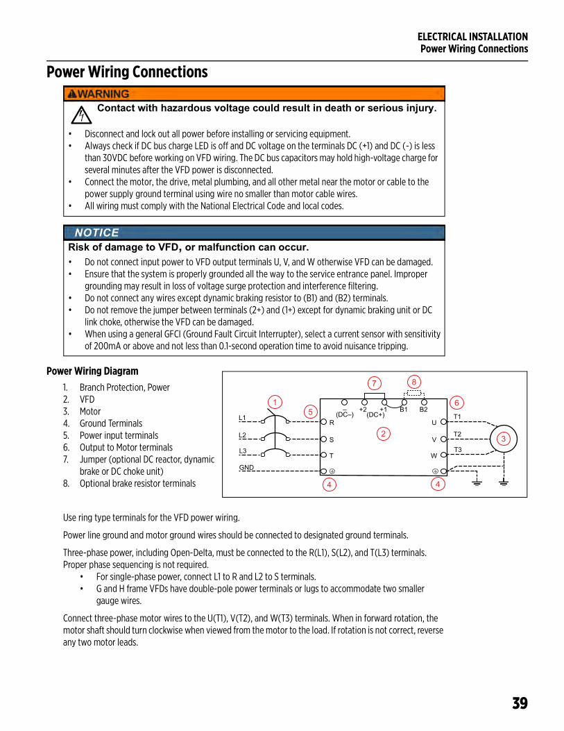
Power Wiring Diagram1. Branch Protection, Power2. VFD3. Motor4. Ground Terminals5. Power input terminals6. Output to Motor terminals7. Jumper (optional DC reactor, dynamic
brake or DC choke unit)8. Optional brake resistor terminals
Use ring type terminals for the VFD power wiring.
Power line ground and motor ground wires should be connected to designated ground terminals.
Three-phase power, including Open-Delta, must be connected to the R(L1), S(L2), and T(L3) terminals. Proper phase sequencing is not required.
• For single-phase power, connect L1 to R and L2 to S terminals.• G and H frame VFDs have double-pole power terminals or lugs to accommodate two smaller
gauge wires.
Connect three-phase motor wires to the U(T1), V(T2), and W(T3) terminals. When in forward rotation, the motor shaft should turn clockwise when viewed from the motor to the load. If rotation is not correct, reverse any two motor leads.
Contact with hazardous voltage could result in death or serious injury.
• Disconnect and lock out all power before installing or servicing equipment.• Always check if DC bus charge LED is off and DC voltage on the terminals DC (+1) and DC (-) is less
than 30VDC before working on VFD wiring. The DC bus capacitors may hold high-voltage charge for several minutes after the VFD power is disconnected.
• Connect the motor, the drive, metal plumbing, and all other metal near the motor or cable to the power supply ground terminal using wire no smaller than motor cable wires.
• All wiring must comply with the National Electrical Code and local codes.
Risk of damage to VFD, or malfunction can occur.• Do not connect input power to VFD output terminals U, V, and W otherwise VFD can be damaged.• Ensure that the system is properly grounded all the way to the service entrance panel. Improper
grounding may result in loss of voltage surge protection and interference filtering. • Do not connect any wires except dynamic braking resistor to (B1) and (B2) terminals.• Do not remove the jumper between terminals (2+) and (1+) except for dynamic braking unit or DC
link choke, otherwise the VFD can be damaged.• When using a general GFCI (Ground Fault Circuit Interrupter), select a current sensor with sensitivity
of 200mA or above and not less than 0.1-second operation time to avoid nuisance tripping.
+2 (DC+)
R
–(DC–)
+1 B1 B2L1
L2
L3S
T
U
V
W
T1
T2
T3
2
1
3
65
7 8
4 4
GND
ELECTRICAL INSTALLATIONPower Wiring Connections
40
Frame A: Power terminals accept wire sizes up to 8 AWG and should be tightened to a torque of 17.4 in-lbs (1.96 Nm).
Frame B: Power terminals accept wire sizes up to 4 AWG and should be tightened to a torque of 30.4 in-lbs (3.43 Nm).
Frame C: Power terminals accept wire sizes up to 1/0 AWG and should be tightened to a torque of 69.4 in-lbs (7.84 Nm).
Frame D0: Power terminals accept wire sizes up to 2/0 AWG and should be tightened to a torque of 69.4 in-lbs (7.84 Nm).
Frame D: Power terminals accept wire sizes up to 300 MCM or 4/0 AWG and should be tightened to a torque of 156 in-lbs (18 Nm).
Frame E: Power terminals accept wire sizes up to 4/0 AWG*2 and should be tightened to a torque of 174 in-lbs (20 Nm).
Frame F: Power terminals accept wire sizes up to 300 MCM*2 or 4/0 AWG*2 and should be tightened to a torque of 156 in-lbs (18 Nm).
Frame G: Terminals R, S & T accept wire sizes up to 250 MCM*4 and should be tightened to a torque of 156 in-lbs (18 Nm). Terminals U, V, & T accept wire sizes up to 500 MCM*2 and should be tightened to a torque of 354 in-lbs (40 Nm).
Frame H: Power terminals accept wire sizes up to 350 MCM*4 and should be tightened to a torque of 156 in-lbs (18 Nm).
ELECTRICAL INSTALLATIONControl Circuit Connections
41
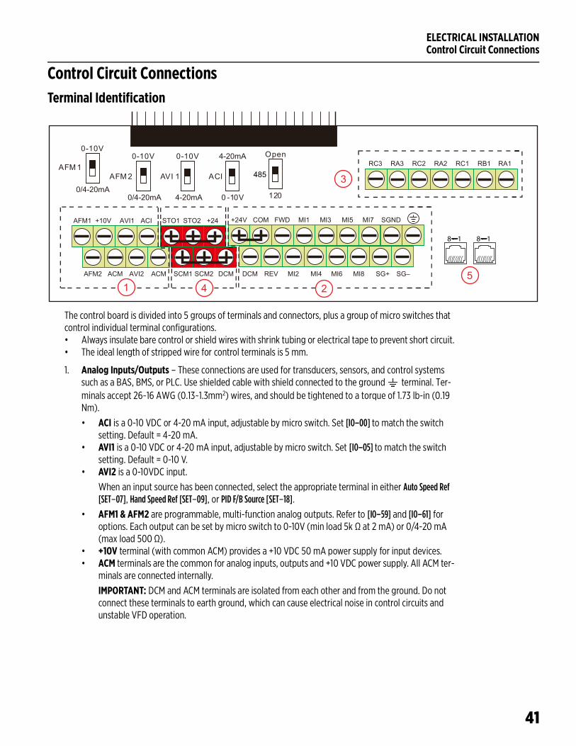
Control Circuit ConnectionsTerminal Identification
The control board is divided into 5 groups of terminals and connectors, plus a group of micro switches that control individual terminal configurations.• Always insulate bare control or shield wires with shrink tubing or electrical tape to prevent short circuit.• The ideal length of stripped wire for control terminals is 5 mm.
1. Analog Inputs/Outputs – These connections are used for transducers, sensors, and control systems such as a BAS, BMS, or PLC. Use shielded cable with shield connected to the ground terminal. Ter-minals accept 26~16 AWG (0.13~1.3mm2) wires, and should be tightened to a torque of 1.73 lb-in (0.19 Nm).
• ACI is a 0-10 VDC or 4-20 mA input, adjustable by micro switch. Set [IO–00] to match the switch setting. Default = 4-20 mA.
• AVI1 is a 0-10 VDC or 4-20 mA input, adjustable by micro switch. Set [IO–05] to match the switch setting. Default = 0-10 V.
• AVI2 is a 0-10VDC input.
When an input source has been connected, select the appropriate terminal in either Auto Speed Ref [SET–07], Hand Speed Ref [SET–09], or PID F/B Source [SET–18].
• AFM1 & AFM2 are programmable, multi-function analog outputs. Refer to [IO–59] and [IO–61] for options. Each output can be set by micro switch to 0-10V (min load 5k Ω at 2 mA) or 0/4-20 mA (max load 500 Ω).
• +10V terminal (with common ACM) provides a +10 VDC 50 mA power supply for input devices.• ACM terminals are the common for analog inputs, outputs and +10 VDC power supply. All ACM ter-
minals are connected internally.
IMPORTANT: DCM and ACM terminals are isolated from each other and from the ground. Do not connect these terminals to earth ground, which can cause electrical noise in control circuits and unstable VFD operation.
0-10V
0 -10V
Open
120
AFM 1AFM 2 AVI 1 ACI
0/4-20mA0/4-20mA 4-20mA
4-20mA
485RC3 RA3 RC2 RA2 RC1 RB1 RA1
AFM1 +10V AVI1 ACI STO1 STO2 +24
AFM2 ACM AVI2 ACM SCM1 SCM2 DCM
+24V COM FWD MI1 MI3 MI5 MI7
0-10V 0-10V
SGND
DCM REV MI2 MI4 MI6 MI8 SG+ SG–
1 2
3
54
8 1 8 1
ELECTRICAL INSTALLATIONControl Circuit Connections
42
2. Digital Inputs & RS-485 Communication – These connections provide input for a wide selection of switches or programmable controls. Use shielded cable or twisted wires for 24 VDC digital control cir-cuits wiring and separate these wires from the main power and motor wiring and other high voltage circuits. Terminals accept wire sizes from 26~16 AWG (0.2~1.5mm2), and should be tightened to a torque of 6.9 lb-in (0.78 Nm).
NOTES:• Digital inputs are configured for NPN (Sink) mode by default, with a jumper across +24 and
COM terminals. Refer to “NPN and PNP Digital Inputs Configuration” on page 46.• All digital inputs can be re-programmed from Normally Open to Normally Closed. • Digital inputs are activated by voltage 11 VDC or greater. Maximum input voltage rating is 27
VDC at 3.5 mA.
• MI1-MI8 are programmable, multi-function digital inputs that can be used for a variety of switch-ing features with common terminal DCM. Refer to [IO–21] through [IO–28] for options.
• FWD & REV are dedicated Forward and Reverse run commands. If any digital input is programmed for FWD or REV, corresponding dedicated FWD or REV input will be disabled automatically.
• SG+, SG–, & SGND are RS485 communication terminals for PLC, Modbus, or BACnet. Use [PLC–23] to set the com type. Termination resistance is controlled by micro switch. Set the 485 switch to the Down position to connect 120 Ω termination resistance for long distance or for an electrically noisy environment.
• +24 terminal provides 24 VDC (with DCM common) 50 mA power for digital control circuits and 150 mA for external transducers.
• COM terminal is a digital inputs common. By default, it is connected by jumper to +24 to configure NPN (Sink) mode.
• DCM is the internal 24 VDC power supply common.• Earth ground. Use this terminal to connect shield wires.
IMPORTANT: DCM and ACM terminals are isolated from each other and from the ground. Do not connect these terminals to earth ground, which can cause electrical noise in control circuits and unstable VFD operation.
3. Relay Outputs – These are configurable, multi-function, dry contact relays. Refer to [IO–47] through [IO–49] for options. Terminals accept wire sizes from 26~16 AWG (0.2~1.5mm2), and should be tightened to a torque of 4.3 lb-in (0.49 Nm).
• Relays ratings are 1.25A at 250 VAC, or 3A at 30 VDC.• RA1-RB1-RC1 is a single-pole, double throw relay. RA1-RC1 is N.O. (normally open), and RB1-RC1 is
N.C. (normally closed).• RA2-RC2 and RA3-RC3 are independent single pole, single throw, normally open relays.
4. Safety Off Inputs – These connections provide emergency stop control from an external system. By default, the inputs are closed through jumper wires, allowing the drive to run.
5. RJ-45 Sockets – These connections are communication terminals for PLC, Modbus, or BACnet. Use [PLC–23] to set the Com Type. Then set both Speed Reference and Run Command to RS485. Both RJ-45 sockets are connected internally.
ELECTRICAL INSTALLATIONControl Circuit Connections
43
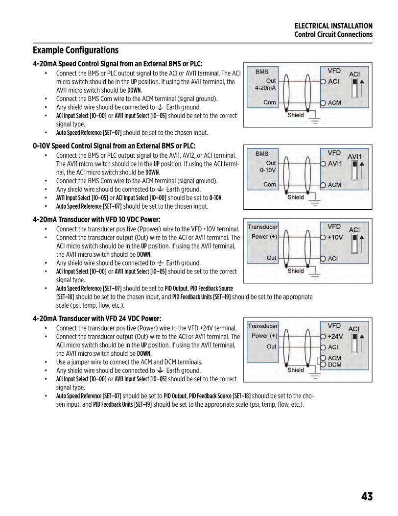
Example Configurations4-20mA Speed Control Signal from an External BMS or PLC:
• Connect the BMS or PLC output signal to the ACI or AVI1 terminal. The ACI micro switch should be in the UP position. If using the AVI1 terminal, the AVI1 micro switch should be DOWN.
• Connect the BMS Com wire to the ACM terminal (signal ground).• Any shield wire should be connected to Earth ground.• ACI Input Select [IO–00] or AVI1 Input Select [IO–05] should be set to the correct
signal type.• Auto Speed Reference [SET–07] should be set to the chosen input.
0-10V Speed Control Signal from an External BMS or PLC: • Connect the BMS or PLC output signal to the AVI1, AVI2, or ACI terminal.
The AVI1 micro switch should be in the UP position. If using the ACI termi-nal, the ACI micro switch should be DOWN.
• Connect the BMS Com wire to the ACM terminal (signal ground).• Any shield wire should be connected to Earth ground.• AVI1 Input Select [IO–05] or ACI Input Select [IO–00] should be set to 0-10V.• Auto Speed Reference [SET–07] should be set to the chosen input.
4-20mA Transducer with VFD 10 VDC Power:• Connect the transducer positive (Ppower) wire to the VFD +10V terminal. • Connect the transducer output (Out) wire to the ACI or AVI1 terminal. The
ACI micro switch should be in the UP position. If using the AVI1 terminal, the AVI1 micro switch should be DOWN.
• Any shield wire should be connected to Earth ground.• ACI Input Select [IO–00] or AVI1 Input Select [IO–05] should be set to the correct
signal type.• Auto Speed Reference [SET–07] should be set to PID Output, PID Feedback Source
[SET–18] should be set to the chosen input, and PID Feedback Units [SET–19] should be set to the appropriate scale (psi, temp, flow, etc.).
4-20mA Transducer with VFD 24 VDC Power:• Connect the transducer positive (Power) wire to the VFD +24V terminal. • Connect the transducer output (Out) wire to the ACI or AVI1 terminal. The
ACI micro switch should be in the UP position. If using the AVI1 terminal, the AVI1 micro switch should be DOWN.
• Use a jumper wire to connect the ACM and DCM terminals.• Any shield wire should be connected to Earth ground.• ACI Input Select [IO–00] or AVI1 Input Select [IO–05] should be set to the correct
signal type.• Auto Speed Reference [SET–07] should be set to PID Output, PID Feedback Source [SET–18] should be set to the cho-
sen input, and PID Feedback Units [SET–19] should be set to the appropriate scale (psi, temp, flow, etc.).
ELECTRICAL INSTALLATIONControl Circuit Connections
44
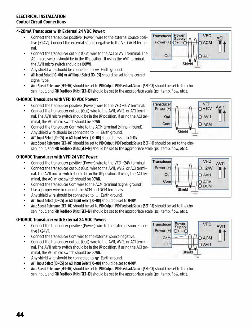
4-20mA Transducer with External 24 VDC Power:• Connect the transducer positive (Power) wire to the external source posi-
tive [+24V]. Connect the external source negative to the VFD ACM termi-nal.
• Connect the transducer output (Out) wire to the ACI or AVI1 terminal. The ACI micro switch should be in the UP position. If using the AVI1 terminal, the AVI1 micro switch should be DOWN.
• Any shield wire should be connected to Earth ground.• ACI Input Select [IO–00] or AVI1 Input Select [IO–05] should be set to the correct
signal type.• Auto Speed Reference [SET–07] should be set to PID Output, PID Feedback Source [SET–18] should be set to the cho-
sen input, and PID Feedback Units [SET–19] should be set to the appropriate scale (psi, temp, flow, etc.).
0-10VDC Transducer with VFD 10 VDC Power:• Connect the transducer positive (Power) wire to the VFD +10V terminal. • Connect the transducer output (Out) wire to the AVI1, AVI2, or ACI termi-
nal. The AVI1 micro switch should be in the UP position. If using the ACI ter-minal, the ACI micro switch should be DOWN.
• Connect the transducer Com wire to the ACM terminal (signal ground).• Any shield wire should be connected to Earth ground.• AVI1 Input Select [IO–05] or ACI Input Select [IO–00] should be sset to 0-10V.• Auto Speed Reference [SET–07] should be set to PID Output, PID Feedback Source [SET–18] should be set to the cho-
sen input, and PID Feedback Units [SET–19] should be set to the appropriate scale (psi, temp, flow, etc.).
0-10VDC Transducer with VFD 24 VDC Power:• Connect the transducer positive (Power) wire to the VFD +24V terminal. • Connect the transducer output (Out) wire to the AVI1, AVI2, or ACI termi-
nal. The AVI1 micro switch should be in the UP position. If using the ACI ter-minal, the ACI micro switch should be DOWN.
• Connect the transducer Com wire to the ACM terminal (signal ground).• Use a jumper wire to connect the ACM and DCM terminals.• Any shield wire should be connected to Earth ground.• AVI1 Input Select [IO–05] or ACI Input Select [IO–00] should be set to 0-10V.• Auto Speed Reference [SET–07] should be set to PID Output, PID Feedback Source [SET–18] should be set to the cho-
sen input, and PID Feedback Units [SET–19] should be set to the appropriate scale (psi, temp, flow, etc.).
0-10VDC Transducer with External 24 VDC Power:• Connect the transducer positive (Power) wire to the external source posi-
tive [+24V]. • Connect the transducer Com wire to the external source negative.• Connect the transducer output (Out) wire to the AVI1, AVI2, or ACI termi-
nal. The AVI1 micro switch should be in the UP position. If using the ACI ter-minal, the ACI micro switch should be DOWN.
• Any shield wire should be connected to Earth ground.• AVI1 Input Select [IO–05] or ACI Input Select [IO–00] should be set to 0-10V.• Auto Speed Reference [SET–07] should be set to PID Output, PID Feedback Source [SET–18] should be set to the cho-
sen input, and PID Feedback Units [SET–19] should be set to the appropriate scale (psi, temp, flow, etc.).
ELECTRICAL INSTALLATIONControl Circuit Connections
45
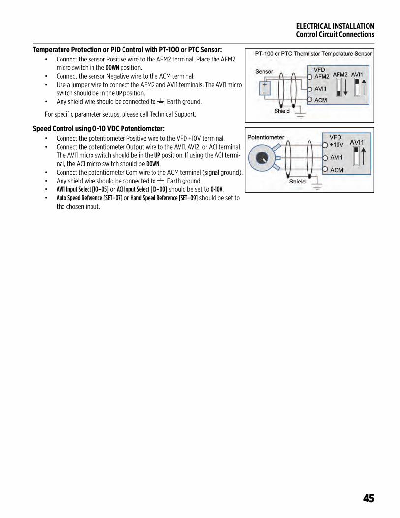
Temperature Protection or PID Control with PT-100 or PTC Sensor:• Connect the sensor Positive wire to the AFM2 terminal. Place the AFM2
micro switch in the DOWN position.• Connect the sensor Negative wire to the ACM terminal.• Use a jumper wire to connect the AFM2 and AVI1 terminals. The AVI1 micro
switch should be in the UP position. • Any shield wire should be connected to Earth ground.
For specific parameter setups, please call Technical Support.
Speed Control using 0-10 VDC Potentiometer:• Connect the potentiometer Positive wire to the VFD +10V terminal. • Connect the potentiometer Output wire to the AVI1, AVI2, or ACI terminal.
The AVI1 micro switch should be in the UP position. If using the ACI termi-nal, the ACI micro switch should be DOWN.
• Connect the potentiometer Com wire to the ACM terminal (signal ground).• Any shield wire should be connected to Earth ground.• AVI1 Input Select [IO–05] or ACI Input Select [IO–00] should be set to 0-10V.• Auto Speed Reference [SET–07] or Hand Speed Reference [SET–09] should be set to
the chosen input.
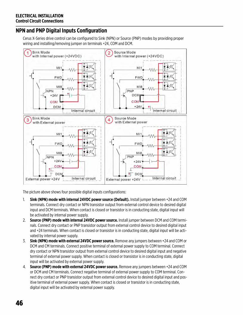
ELECTRICAL INSTALLATIONControl Circuit Connections
46
NPN and PNP Digital Inputs ConfigurationCerus X-Series drive control can be configured to Sink (NPN) or Source (PNP) modes by providing proper wiring and installing/removing jumper on terminals +24, COM and DCM.
The picture above shows four possible digital inputs configurations:
1. Sink (NPN) mode with internal 24VDC power source (Default). Install jumper between +24 and COM terminals. Connect dry contact or NPN transistor output from external control device to desired digital input and DCM terminals. When contact is closed or transistor is in conducting state, digital input will be activated by internal power supply.
2. Source (PNP) mode with internal 24VDC power source. Install jumper between DCM and COM termi-nals. Connect dry contact or PNP transistor output from external control device to desired digital input and +24 terminals. When contact is closed or transistor is in conducting state, digital input will be acti-vated by internal power supply.
3. Sink (NPN) mode with external 24VDC power source. Remove any jumpers between +24 and COM or DCM and CM terminals. Connect positive terminal of external power supply to COM terminal. Connect dry contact or NPN transistor output from external control device to desired digital input and negative terminal of external power supply. When contact is closed or transistor is in conducting state, digital input will be activated by external power supply.
4. Source (PNP) mode with external 24VDC power source. Remove any jumpers between +24 and COM or DCM and CM terminals. Connect negative terminal of external power supply to COM terminal. Con-nect dry contact or PNP transistor output from external control device to desired digital input and pos-itive terminal of external power supply. When contact is closed or transistor is in conducting state, digital input will be activated by external power supply.
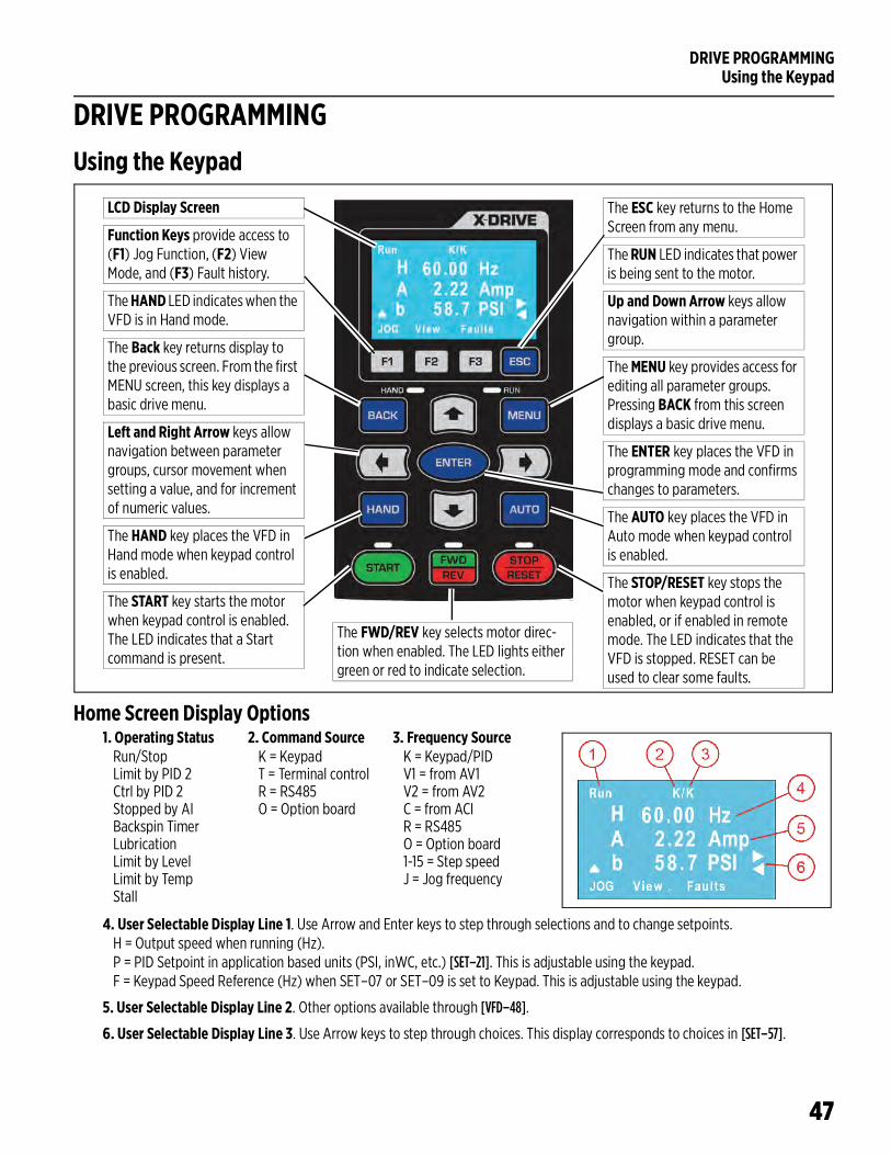
DRIVE PROGRAMMINGUsing the Keypad
47
DRIVE PROGRAMMINGUsing the Keypad
Home Screen Display Options
The ESC key returns to the Home Screen from any menu.
The RUN LED indicates that power is being sent to the motor.
Up and Down Arrow keys allow navigation within a parameter group.
The MENU key provides access for editing all parameter groups. Pressing BACK from this screen displays a basic drive menu.
The ENTER key places the VFD in programming mode and confirms changes to parameters.
The AUTO key places the VFD in Auto mode when keypad control is enabled.
The STOP/RESET key stops the motor when keypad control is enabled, or if enabled in remote mode. The LED indicates that the VFD is stopped. RESET can be used to clear some faults.
LCD Display Screen
Function Keys provide access to (F1) Jog Function, (F2) View Mode, and (F3) Fault history.
The HAND LED indicates when the VFD is in Hand mode.
The Back key returns display to the previous screen. From the first MENU screen, this key displays a basic drive menu.
Left and Right Arrow keys allow navigation between parameter groups, cursor movement when setting a value, and for increment of numeric values.
The HAND key places the VFD in Hand mode when keypad control is enabled.
The START key starts the motor when keypad control is enabled. The LED indicates that a Start command is present.
The FWD/REV key selects motor direc-tion when enabled. The LED lights either green or red to indicate selection.
1. Operating StatusRun/StopLimit by PID 2Ctrl by PID 2Stopped by AIBackspin TimerLubricationLimit by LevelLimit by TempStall
2. Command SourceK = KeypadT = Terminal controlR = RS485O = Option board
3. Frequency SourceK = Keypad/PIDV1 = from AV1V2 = from AV2C = from ACIR = RS485O = Option board1-15 = Step speedJ = Jog frequency
4. User Selectable Display Line 1. Use Arrow and Enter keys to step through selections and to change setpoints.H = Output speed when running (Hz).P = PID Setpoint in application based units (PSI, inWC, etc.) [SET–21]. This is adjustable using the keypad.F = Keypad Speed Reference (Hz) when SET–07 or SET–09 is set to Keypad. This is adjustable using the keypad.
5. User Selectable Display Line 2. Other options available through [VFD–48].
6. User Selectable Display Line 3. Use Arrow keys to step through choices. This display corresponds to choices in [SET–57].
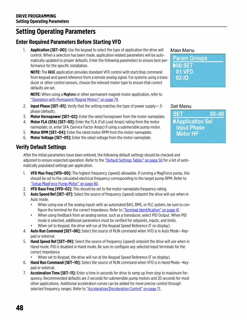
DRIVE PROGRAMMINGSetting Operating Parameters
48
Setting Operating ParametersEnter Required Parameters Before Starting VFD
1. Application [SET–00]: Use the keypad to select the type of application the drive will control. When a selection has been made, application related parameters will be auto-matically updated to proper defaults. Enter the following parameters to ensure best per-formance for the specific installation.
NOTE: The BASIC application provides standard VFD control with start/stop command from keypad and speed reference from a remote analog signal. For systems using a trans-ducer or other control sensors, choose the relevant motor type to ensure that correct defaults are set.
NOTE: When using a MagForce or other permanent magnet motor application, refer to “Operation with Permanent Magnet Motors” on page 79.
2. Input Phase [SET–01]: Verify that the setting matches the type of power supply— 3-phase (default).
3. Motor Horsepower [SET–02]: Enter the rated horsepower from the motor nameplate.4. Motor FLA (SFA) [SET–03]: Enter the FLA (Full Load Amps) rating from the motor
nameplate; or, enter SFA (Service Factor Amps) if using a submersible pump motor.5. Motor RPM [SET–04]: Enter the rated motor RPM from the motor nameplate.6. Motor Voltage [SET–05]: Enter the rated voltage from the motor nameplate.
Verify Default SettingsAfter the initial parameters have been entered, the following default settings should be checked and adjusted to ensure expected operation. Refer to the “Default Settings Tables” on page 50 for a list of auto-matically populated settings per application.
1. VFD Max Freq [VFD–00]: The highest frequency (speed) allowable. If running a MagForce pump, this should be set to the calculated electrical frequency corresponding to the target pump RPM. Refer to “Setup MagForce Pump Motor” on page 80.
2. VFD Base Freq [VFD–02]: This should be set to the motor nameplate frequency rating.3. Auto Speed Ref [SET–07]: Select the source of frequency (speed) setpoint the drive will use when in
Auto mode. • When using one of the analog inputs with an automated BAS, BMS, or PLC system, be sure to con-
figure the terminal for the correct impedance. Refer to “Terminal Identification” on page 41.• When using feedback from an analog sensor, such as a transducer, select PID Output. When PID
mode is selected, additional parameters must be verified for setpoints, inputs, and limits. • When set to Keypad, the drive will run at the Keypad Speed Reference (F on display).
4. Auto Run Command [SET–08]: Select the source of RUN command when VFD is in Auto Mode—Key-pad or external.
5. Hand Speed Ref [SET–09]: Select the source of frequency (speed) setpoint the drive will use when in Hand mode. PID is disabled in Hand mode. Be sure to configure any selected input terminals for the correct impedance.• When set to Keypad, the drive will run at the Keypad Speed Reference (F on display).
6. Hand Run Command [SET–10]: Select the source of RUN command when VFD is in Hand Mode—Key-pad or external.
7. Acceleration Time [SET–11]: Enter a time in seconds for drive to ramp up from stop to maximum fre-quency. Recommended defaults are 2 seconds for submersible pump motors and 20 seconds for most other applications. Additional acceleration curves can be added for more precise control through selected frequency ranges. Refer to “Acceleration/Deceleration Control” on page 71.
DRIVE PROGRAMMINGSetting Operating Parameters
49
8. Deceleration Time [SET–12]: Enter a time in seconds to slow down from maximum frequency to stop. Recommended defaults are 2 seconds for submersibles and 30 seconds for surface/boost pumps. This setting is only effective when Stop Mode [SET–16] is set to Decelerate. Additional deceleration curves can be added for more precise control through selected frequency ranges. Refer to “Acceleration/Deceleration Control” on page 71.
9. Low Frequency Limit [SET–13]: The lowest frequency (speed in Hz) allowed by the VFD in any mode.10. High Frequency Limit [SET–14]: Enter the highest frequency (speed in Hz) allowed by the VFD in any
mode.11. PID Mode [SET–17]: Enables or disables PID control, either direct or inverse.12. PID Feedback Source [SET–18]: Selects an input terminal for PID Feedback source. Be sure to config-
ure the terminal for the correct impedance.13. PID Feedback Unit [SET–19]: Selects a measurement unit for PID feedback.14. Feedback Max [SET–20]: Enter the maximum reading of the feedback source. This is used to scale the
sensor. For example: if using a 0–200 psi transducer, enter 200.15. PID Setpoint [SET–21]: Enter the desired value for the drive to maintain in PID mode, running in Auto.
This parameter can also be changed through keypad control. 16. PID Low Frequency Limit [SET–22]: PID frequency output will be limited to this value.17. PID High Frequency Limit [SET–23]: PID frequency output will be limited to this value.18. Language: Select a desired language for the display. Press the Menu button and then press the Back but-
ton. Use the Down keys to display Set Language.19. Clock: Set current time and date. This setting is used to record real-time data for faults, parameter
changes, etc. Press the Menu button and then press the Back button. Use the Down keys to display Set Time.
Verify Control Terminal SettingsFor each type of control hardware that has been connected to the system—sensors, switches, BAS, etc., make sure that the matching function parameters have been identified for the input terminals. For more information, refer to “Example Configurations” on page 43 or to “Parameter Descriptions > I/O Menu” on page 122.
Enter or Verify Optional SettingsIf using any of the optional features available in the system, make sure that all related parameters are set for the desired operation. Refer to the application descriptions in “Operation” on page 63 for information about these features:
• Automation features: Refer to “Standard Operation with an Automated Control System” on page 66.• Protection features: Refer to “Protection Features” on page 75.• Communications features: Refer to “Communications” on page 85.• Multi-Motor applications: Refer to “Multi-Motor (MMC) Relay Control for Pump Applications” on
page 84.
For more details on individual parameter settings, refer to “Parameter Reference Tables” on page 115.
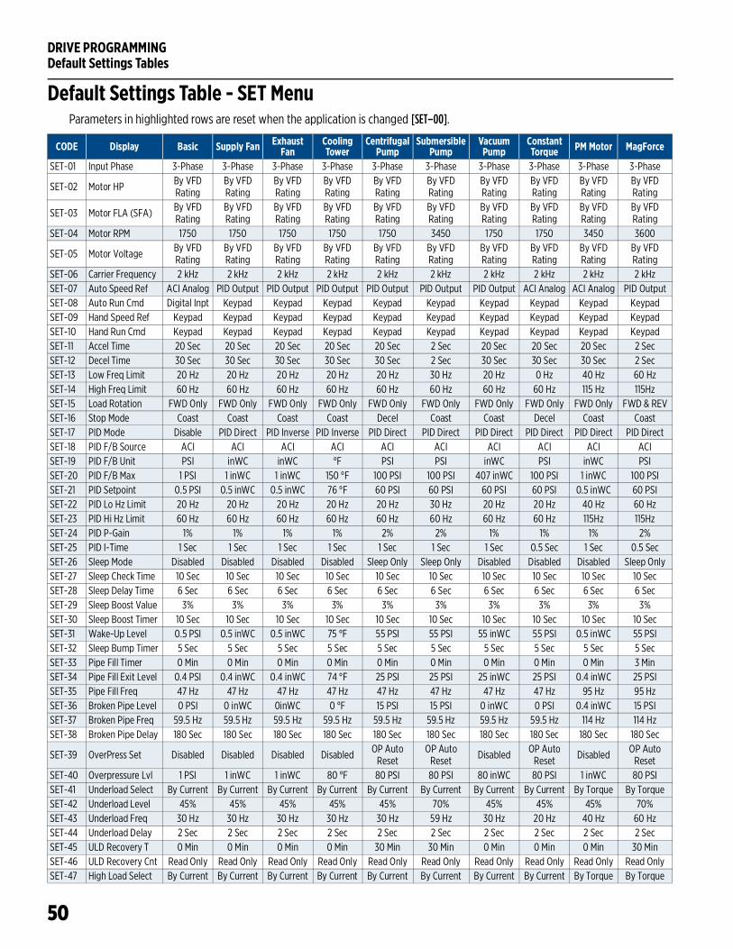
DRIVE PROGRAMMINGDefault Settings Tables
50
Default Settings TablesDefault Settings Table - SET MenuParameters in highlighted rows are reset when the application is changed [SET–00].
CODE Display Basic Supply Fan Exhaust Fan
Cooling Tower
Centrifugal Pump
Submersible Pump
Vacuum Pump
Constant Torque PM Motor MagForce
SET-01 Input Phase 3-Phase 3-Phase 3-Phase 3-Phase 3-Phase 3-Phase 3-Phase 3-Phase 3-Phase 3-Phase
SET-02 Motor HP By VFD Rating
By VFD Rating
By VFD Rating
By VFD Rating
By VFD Rating
By VFD Rating
By VFD Rating
By VFD Rating
By VFD Rating
By VFD Rating
SET-03 Motor FLA (SFA) By VFD Rating
By VFD Rating
By VFD Rating
By VFD Rating
By VFD Rating
By VFD Rating
By VFD Rating
By VFD Rating
By VFD Rating
By VFD Rating
SET-04 Motor RPM 1750 1750 1750 1750 1750 3450 1750 1750 3450 3600
SET-05 Motor Voltage By VFD Rating
By VFD Rating
By VFD Rating
By VFD Rating
By VFD Rating
By VFD Rating
By VFD Rating
By VFD Rating
By VFD Rating
By VFD Rating
SET-06 Carrier Frequency 2 kHz 2 kHz 2 kHz 2 kHz 2 kHz 2 kHz 2 kHz 2 kHz 2 kHz 2 kHzSET-07 Auto Speed Ref ACI Analog PID Output PID Output PID Output PID Output PID Output PID Output ACI Analog ACI Analog PID OutputSET-08 Auto Run Cmd Digital Inpt Keypad Keypad Keypad Keypad Keypad Keypad Keypad Keypad KeypadSET-09 Hand Speed Ref Keypad Keypad Keypad Keypad Keypad Keypad Keypad Keypad Keypad KeypadSET-10 Hand Run Cmd Keypad Keypad Keypad Keypad Keypad Keypad Keypad Keypad Keypad KeypadSET-11 Accel Time 20 Sec 20 Sec 20 Sec 20 Sec 20 Sec 2 Sec 20 Sec 20 Sec 20 Sec 2 SecSET-12 Decel Time 30 Sec 30 Sec 30 Sec 30 Sec 30 Sec 2 Sec 30 Sec 30 Sec 30 Sec 2 SecSET-13 Low Freq Limit 20 Hz 20 Hz 20 Hz 20 Hz 20 Hz 30 Hz 20 Hz 0 Hz 40 Hz 60 HzSET-14 High Freq Limit 60 Hz 60 Hz 60 Hz 60 Hz 60 Hz 60 Hz 60 Hz 60 Hz 115 Hz 115HzSET-15 Load Rotation FWD Only FWD Only FWD Only FWD Only FWD Only FWD Only FWD Only FWD Only FWD Only FWD & REVSET-16 Stop Mode Coast Coast Coast Coast Decel Coast Coast Decel Coast CoastSET-17 PID Mode Disable PID Direct PID Inverse PID Inverse PID Direct PID Direct PID Direct PID Direct PID Direct PID DirectSET-18 PID F/B Source ACI ACI ACI ACI ACI ACI ACI ACI ACI ACISET-19 PID F/B Unit PSI inWC inWC °F PSI PSI inWC PSI inWC PSISET-20 PID F/B Max 1 PSI 1 inWC 1 inWC 150 °F 100 PSI 100 PSI 407 inWC 100 PSI 1 inWC 100 PSISET-21 PID Setpoint 0.5 PSI 0.5 inWC 0.5 inWC 76 °F 60 PSI 60 PSI 60 PSI 60 PSI 0.5 inWC 60 PSISET-22 PID Lo Hz Limit 20 Hz 20 Hz 20 Hz 20 Hz 20 Hz 30 Hz 20 Hz 20 Hz 40 Hz 60 HzSET-23 PID Hi Hz Limit 60 Hz 60 Hz 60 Hz 60 Hz 60 Hz 60 Hz 60 Hz 60 Hz 115Hz 115HzSET-24 PID P-Gain 1% 1% 1% 1% 2% 2% 1% 1% 1% 2%SET-25 PID I-Time 1 Sec 1 Sec 1 Sec 1 Sec 1 Sec 1 Sec 1 Sec 0.5 Sec 1 Sec 0.5 SecSET-26 Sleep Mode Disabled Disabled Disabled Disabled Sleep Only Sleep Only Disabled Disabled Disabled Sleep OnlySET-27 Sleep Check Time 10 Sec 10 Sec 10 Sec 10 Sec 10 Sec 10 Sec 10 Sec 10 Sec 10 Sec 10 SecSET-28 Sleep Delay Time 6 Sec 6 Sec 6 Sec 6 Sec 6 Sec 6 Sec 6 Sec 6 Sec 6 Sec 6 SecSET-29 Sleep Boost Value 3% 3% 3% 3% 3% 3% 3% 3% 3% 3%SET-30 Sleep Boost Timer 10 Sec 10 Sec 10 Sec 10 Sec 10 Sec 10 Sec 10 Sec 10 Sec 10 Sec 10 SecSET-31 Wake-Up Level 0.5 PSI 0.5 inWC 0.5 inWC 75 °F 55 PSI 55 PSI 55 inWC 55 PSI 0.5 inWC 55 PSISET-32 Sleep Bump Timer 5 Sec 5 Sec 5 Sec 5 Sec 5 Sec 5 Sec 5 Sec 5 Sec 5 Sec 5 SecSET-33 Pipe Fill Timer 0 Min 0 Min 0 Min 0 Min 0 Min 0 Min 0 Min 0 Min 0 Min 3 MinSET-34 Pipe Fill Exit Level 0.4 PSI 0.4 inWC 0.4 inWC 74 °F 25 PSI 25 PSI 25 inWC 25 PSI 0.4 inWC 25 PSISET-35 Pipe Fill Freq 47 Hz 47 Hz 47 Hz 47 Hz 47 Hz 47 Hz 47 Hz 47 Hz 95 Hz 95 HzSET-36 Broken Pipe Level 0 PSI 0 inWC 0inWC 0 °F 15 PSI 15 PSI 0 inWC 0 PSI 0.4 inWC 15 PSISET-37 Broken Pipe Freq 59.5 Hz 59.5 Hz 59.5 Hz 59.5 Hz 59.5 Hz 59.5 Hz 59.5 Hz 59.5 Hz 114 Hz 114 HzSET-38 Broken Pipe Delay 180 Sec 180 Sec 180 Sec 180 Sec 180 Sec 180 Sec 180 Sec 180 Sec 180 Sec 180 Sec
SET-39 OverPress Set Disabled Disabled Disabled Disabled OP Auto Reset
OP Auto Reset Disabled OP Auto
Reset Disabled OP Auto Reset
SET-40 Overpressure Lvl 1 PSI 1 inWC 1 inWC 80 °F 80 PSI 80 PSI 80 inWC 80 PSI 1 inWC 80 PSISET-41 Underload Select By Current By Current By Current By Current By Current By Current By Current By Current By Torque By TorqueSET-42 Underload Level 45% 45% 45% 45% 45% 70% 45% 45% 45% 70%SET-43 Underload Freq 30 Hz 30 Hz 30 Hz 30 Hz 30 Hz 59 Hz 30 Hz 20 Hz 40 Hz 60 HzSET-44 Underload Delay 2 Sec 2 Sec 2 Sec 2 Sec 2 Sec 2 Sec 2 Sec 2 Sec 2 Sec 2 SecSET-45 ULD Recovery T 0 Min 0 Min 0 Min 0 Min 30 Min 30 Min 0 Min 0 Min 0 Min 30 MinSET-46 ULD Recovery Cnt Read Only Read Only Read Only Read Only Read Only Read Only Read Only Read Only Read Only Read OnlySET-47 High Load Select By Current By Current By Current By Current By Current By Current By Current By Current By Torque By Torque
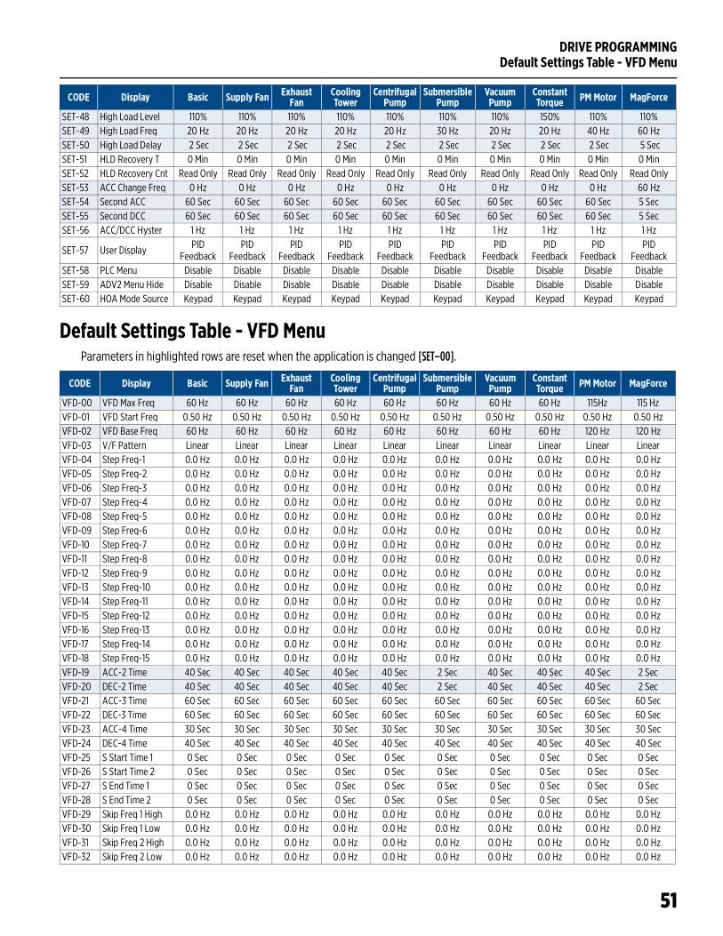
DRIVE PROGRAMMINGDefault Settings Table - VFD Menu
51
Default Settings Table - VFD MenuParameters in highlighted rows are reset when the application is changed [SET–00].
SET-48 High Load Level 110% 110% 110% 110% 110% 110% 110% 150% 110% 110%SET-49 High Load Freq 20 Hz 20 Hz 20 Hz 20 Hz 20 Hz 30 Hz 20 Hz 20 Hz 40 Hz 60 HzSET-50 High Load Delay 2 Sec 2 Sec 2 Sec 2 Sec 2 Sec 2 Sec 2 Sec 2 Sec 2 Sec 5 SecSET-51 HLD Recovery T 0 Min 0 Min 0 Min 0 Min 0 Min 0 Min 0 Min 0 Min 0 Min 0 MinSET-52 HLD Recovery Cnt Read Only Read Only Read Only Read Only Read Only Read Only Read Only Read Only Read Only Read OnlySET-53 ACC Change Freq 0 Hz 0 Hz 0 Hz 0 Hz 0 Hz 0 Hz 0 Hz 0 Hz 0 Hz 60 HzSET-54 Second ACC 60 Sec 60 Sec 60 Sec 60 Sec 60 Sec 60 Sec 60 Sec 60 Sec 60 Sec 5 SecSET-55 Second DCC 60 Sec 60 Sec 60 Sec 60 Sec 60 Sec 60 Sec 60 Sec 60 Sec 60 Sec 5 SecSET-56 ACC/DCC Hyster 1 Hz 1 Hz 1 Hz 1 Hz 1 Hz 1 Hz 1 Hz 1 Hz 1 Hz 1 Hz
SET-57 User Display PID Feedback
PID Feedback
PID Feedback
PID Feedback
PID Feedback
PID Feedback
PID Feedback
PID Feedback
PID Feedback
PID Feedback
SET-58 PLC Menu Disable Disable Disable Disable Disable Disable Disable Disable Disable DisableSET-59 ADV2 Menu Hide Disable Disable Disable Disable Disable Disable Disable Disable Disable DisableSET-60 HOA Mode Source Keypad Keypad Keypad Keypad Keypad Keypad Keypad Keypad Keypad Keypad
CODE Display Basic Supply Fan Exhaust Fan
Cooling Tower
Centrifugal Pump
Submersible Pump
Vacuum Pump
Constant Torque PM Motor MagForce
CODE Display Basic Supply Fan Exhaust Fan
Cooling Tower
Centrifugal Pump
Submersible Pump
Vacuum Pump
Constant Torque PM Motor MagForce
VFD-00 VFD Max Freq 60 Hz 60 Hz 60 Hz 60 Hz 60 Hz 60 Hz 60 Hz 60 Hz 115Hz 115 HzVFD-01 VFD Start Freq 0.50 Hz 0.50 Hz 0.50 Hz 0.50 Hz 0.50 Hz 0.50 Hz 0.50 Hz 0.50 Hz 0.50 Hz 0.50 HzVFD-02 VFD Base Freq 60 Hz 60 Hz 60 Hz 60 Hz 60 Hz 60 Hz 60 Hz 60 Hz 120 Hz 120 HzVFD-03 V/F Pattern Linear Linear Linear Linear Linear Linear Linear Linear Linear LinearVFD-04 Step Freq-1 0.0 Hz 0.0 Hz 0.0 Hz 0.0 Hz 0.0 Hz 0.0 Hz 0.0 Hz 0.0 Hz 0.0 Hz 0.0 HzVFD-05 Step Freq-2 0.0 Hz 0.0 Hz 0.0 Hz 0.0 Hz 0.0 Hz 0.0 Hz 0.0 Hz 0.0 Hz 0.0 Hz 0.0 HzVFD-06 Step Freq-3 0.0 Hz 0.0 Hz 0.0 Hz 0.0 Hz 0.0 Hz 0.0 Hz 0.0 Hz 0.0 Hz 0.0 Hz 0.0 HzVFD-07 Step Freq-4 0.0 Hz 0.0 Hz 0.0 Hz 0.0 Hz 0.0 Hz 0.0 Hz 0.0 Hz 0.0 Hz 0.0 Hz 0.0 HzVFD-08 Step Freq-5 0.0 Hz 0.0 Hz 0.0 Hz 0.0 Hz 0.0 Hz 0.0 Hz 0.0 Hz 0.0 Hz 0.0 Hz 0.0 HzVFD-09 Step Freq-6 0.0 Hz 0.0 Hz 0.0 Hz 0.0 Hz 0.0 Hz 0.0 Hz 0.0 Hz 0.0 Hz 0.0 Hz 0.0 HzVFD-10 Step Freq-7 0.0 Hz 0.0 Hz 0.0 Hz 0.0 Hz 0.0 Hz 0.0 Hz 0.0 Hz 0.0 Hz 0.0 Hz 0.0 HzVFD-11 Step Freq-8 0.0 Hz 0.0 Hz 0.0 Hz 0.0 Hz 0.0 Hz 0.0 Hz 0.0 Hz 0.0 Hz 0.0 Hz 0.0 HzVFD-12 Step Freq-9 0.0 Hz 0.0 Hz 0.0 Hz 0.0 Hz 0.0 Hz 0.0 Hz 0.0 Hz 0.0 Hz 0.0 Hz 0.0 HzVFD-13 Step Freq-10 0.0 Hz 0.0 Hz 0.0 Hz 0.0 Hz 0.0 Hz 0.0 Hz 0.0 Hz 0.0 Hz 0.0 Hz 0.0 HzVFD-14 Step Freq-11 0.0 Hz 0.0 Hz 0.0 Hz 0.0 Hz 0.0 Hz 0.0 Hz 0.0 Hz 0.0 Hz 0.0 Hz 0.0 HzVFD-15 Step Freq-12 0.0 Hz 0.0 Hz 0.0 Hz 0.0 Hz 0.0 Hz 0.0 Hz 0.0 Hz 0.0 Hz 0.0 Hz 0.0 HzVFD-16 Step Freq-13 0.0 Hz 0.0 Hz 0.0 Hz 0.0 Hz 0.0 Hz 0.0 Hz 0.0 Hz 0.0 Hz 0.0 Hz 0.0 HzVFD-17 Step Freq-14 0.0 Hz 0.0 Hz 0.0 Hz 0.0 Hz 0.0 Hz 0.0 Hz 0.0 Hz 0.0 Hz 0.0 Hz 0.0 HzVFD-18 Step Freq-15 0.0 Hz 0.0 Hz 0.0 Hz 0.0 Hz 0.0 Hz 0.0 Hz 0.0 Hz 0.0 Hz 0.0 Hz 0.0 HzVFD-19 ACC-2 Time 40 Sec 40 Sec 40 Sec 40 Sec 40 Sec 2 Sec 40 Sec 40 Sec 40 Sec 2 SecVFD-20 DEC-2 Time 40 Sec 40 Sec 40 Sec 40 Sec 40 Sec 2 Sec 40 Sec 40 Sec 40 Sec 2 SecVFD-21 ACC-3 Time 60 Sec 60 Sec 60 Sec 60 Sec 60 Sec 60 Sec 60 Sec 60 Sec 60 Sec 60 SecVFD-22 DEC-3 Time 60 Sec 60 Sec 60 Sec 60 Sec 60 Sec 60 Sec 60 Sec 60 Sec 60 Sec 60 SecVFD-23 ACC-4 Time 30 Sec 30 Sec 30 Sec 30 Sec 30 Sec 30 Sec 30 Sec 30 Sec 30 Sec 30 SecVFD-24 DEC-4 Time 40 Sec 40 Sec 40 Sec 40 Sec 40 Sec 40 Sec 40 Sec 40 Sec 40 Sec 40 SecVFD-25 S Start Time 1 0 Sec 0 Sec 0 Sec 0 Sec 0 Sec 0 Sec 0 Sec 0 Sec 0 Sec 0 SecVFD-26 S Start Time 2 0 Sec 0 Sec 0 Sec 0 Sec 0 Sec 0 Sec 0 Sec 0 Sec 0 Sec 0 SecVFD-27 S End Time 1 0 Sec 0 Sec 0 Sec 0 Sec 0 Sec 0 Sec 0 Sec 0 Sec 0 Sec 0 SecVFD-28 S End Time 2 0 Sec 0 Sec 0 Sec 0 Sec 0 Sec 0 Sec 0 Sec 0 Sec 0 Sec 0 SecVFD-29 Skip Freq 1 High 0.0 Hz 0.0 Hz 0.0 Hz 0.0 Hz 0.0 Hz 0.0 Hz 0.0 Hz 0.0 Hz 0.0 Hz 0.0 HzVFD-30 Skip Freq 1 Low 0.0 Hz 0.0 Hz 0.0 Hz 0.0 Hz 0.0 Hz 0.0 Hz 0.0 Hz 0.0 Hz 0.0 Hz 0.0 HzVFD-31 Skip Freq 2 High 0.0 Hz 0.0 Hz 0.0 Hz 0.0 Hz 0.0 Hz 0.0 Hz 0.0 Hz 0.0 Hz 0.0 Hz 0.0 HzVFD-32 Skip Freq 2 Low 0.0 Hz 0.0 Hz 0.0 Hz 0.0 Hz 0.0 Hz 0.0 Hz 0.0 Hz 0.0 Hz 0.0 Hz 0.0 Hz
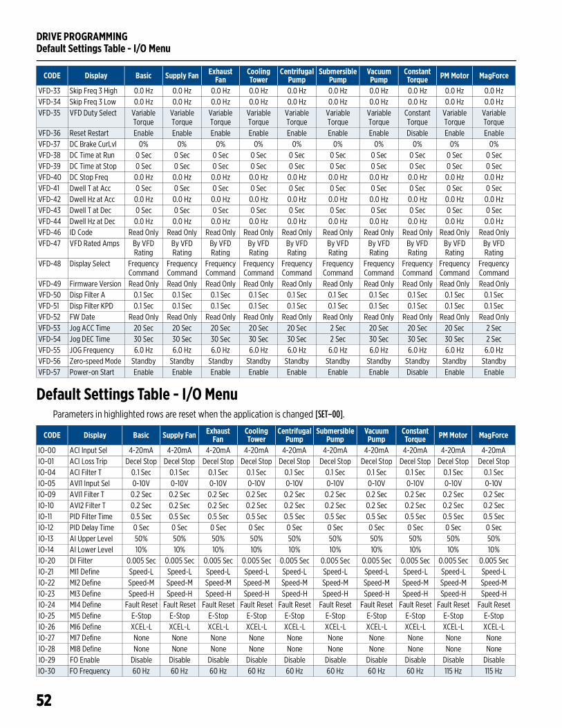
DRIVE PROGRAMMINGDefault Settings Table - I/O Menu
52
Default Settings Table - I/O MenuParameters in highlighted rows are reset when the application is changed [SET–00].
VFD-33 Skip Freq 3 High 0.0 Hz 0.0 Hz 0.0 Hz 0.0 Hz 0.0 Hz 0.0 Hz 0.0 Hz 0.0 Hz 0.0 Hz 0.0 HzVFD-34 Skip Freq 3 Low 0.0 Hz 0.0 Hz 0.0 Hz 0.0 Hz 0.0 Hz 0.0 Hz 0.0 Hz 0.0 Hz 0.0 Hz 0.0 HzVFD-35 VFD Duty Select Variable
TorqueVariable Torque
Variable Torque
Variable Torque
Variable Torque
Variable Torque
Variable Torque
Constant Torque
Variable Torque
Variable Torque
VFD-36 Reset Restart Enable Enable Enable Enable Enable Enable Enable Disable Enable EnableVFD-37 DC Brake CurLvl 0% 0% 0% 0% 0% 0% 0% 0% 0% 0%VFD-38 DC Time at Run 0 Sec 0 Sec 0 Sec 0 Sec 0 Sec 0 Sec 0 Sec 0 Sec 0 Sec 0 SecVFD-39 DC Time at Stop 0 Sec 0 Sec 0 Sec 0 Sec 0 Sec 0 Sec 0 Sec 0 Sec 0 Sec 0 SecVFD-40 DC Stop Freq 0.0 Hz 0.0 Hz 0.0 Hz 0.0 Hz 0.0 Hz 0.0 Hz 0.0 Hz 0.0 Hz 0.0 Hz 0.0 HzVFD-41 Dwell T at Acc 0 Sec 0 Sec 0 Sec 0 Sec 0 Sec 0 Sec 0 Sec 0 Sec 0 Sec 0 SecVFD-42 Dwell Hz at Acc 0.0 Hz 0.0 Hz 0.0 Hz 0.0 Hz 0.0 Hz 0.0 Hz 0.0 Hz 0.0 Hz 0.0 Hz 0.0 HzVFD-43 Dwell T at Dec 0 Sec 0 Sec 0 Sec 0 Sec 0 Sec 0 Sec 0 Sec 0 Sec 0 Sec 0 SecVFD-44 Dwell Hz at Dec 0.0 Hz 0.0 Hz 0.0 Hz 0.0 Hz 0.0 Hz 0.0 Hz 0.0 Hz 0.0 Hz 0.0 Hz 0.0 HzVFD-46 ID Code Read Only Read Only Read Only Read Only Read Only Read Only Read Only Read Only Read Only Read OnlyVFD-47 VFD Rated Amps By VFD
RatingBy VFD Rating
By VFD Rating
By VFD Rating
By VFD Rating
By VFD Rating
By VFD Rating
By VFD Rating
By VFD Rating
By VFD Rating
VFD-48 Display Select Frequency Command
Frequency Command
Frequency Command
Frequency Command
Frequency Command
Frequency Command
Frequency Command
Frequency Command
Frequency Command
Frequency Command
VFD-49 Firmware Version Read Only Read Only Read Only Read Only Read Only Read Only Read Only Read Only Read Only Read OnlyVFD-50 Disp Filter A 0.1 Sec 0.1 Sec 0.1 Sec 0.1 Sec 0.1 Sec 0.1 Sec 0.1 Sec 0.1 Sec 0.1 Sec 0.1 SecVFD-51 Disp Filter KPD 0.1 Sec 0.1 Sec 0.1 Sec 0.1 Sec 0.1 Sec 0.1 Sec 0.1 Sec 0.1 Sec 0.1 Sec 0.1 SecVFD-52 FW Date Read Only Read Only Read Only Read Only Read Only Read Only Read Only Read Only Read Only Read OnlyVFD-53 Jog ACC Time 20 Sec 20 Sec 20 Sec 20 Sec 20 Sec 2 Sec 20 Sec 20 Sec 20 Sec 2 SecVFD-54 Jog DEC Time 30 Sec 30 Sec 30 Sec 30 Sec 30 Sec 2 Sec 30 Sec 30 Sec 30 Sec 2 SecVFD-55 JOG Frequency 6.0 Hz 6.0 Hz 6.0 Hz 6.0 Hz 6.0 Hz 6.0 Hz 6.0 Hz 6.0 Hz 6.0 Hz 6.0 HzVFD-56 Zero-speed Mode Standby Standby Standby Standby Standby Standby Standby Standby Standby StandbyVFD-57 Power-on Start Enable Enable Enable Enable Enable Enable Enable Disable Enable Enable
CODE Display Basic Supply Fan Exhaust Fan
Cooling Tower
Centrifugal Pump
Submersible Pump
Vacuum Pump
Constant Torque PM Motor MagForce
CODE Display Basic Supply Fan Exhaust Fan
Cooling Tower
Centrifugal Pump
Submersible Pump
Vacuum Pump
Constant Torque PM Motor MagForce
IO-00 ACI Input Sel 4-20mA 4-20mA 4-20mA 4-20mA 4-20mA 4-20mA 4-20mA 4-20mA 4-20mA 4-20mAIO-01 ACI Loss Trip Decel Stop Decel Stop Decel Stop Decel Stop Decel Stop Decel Stop Decel Stop Decel Stop Decel Stop Decel StopIO-04 ACI Filter T 0.1 Sec 0.1 Sec 0.1 Sec 0.1 Sec 0.1 Sec 0.1 Sec 0.1 Sec 0.1 Sec 0.1 Sec 0.1 SecIO-05 AVI1 Input Sel 0-10V 0-10V 0-10V 0-10V 0-10V 0-10V 0-10V 0-10V 0-10V 0-10VIO-09 AVI1 Filter T 0.2 Sec 0.2 Sec 0.2 Sec 0.2 Sec 0.2 Sec 0.2 Sec 0.2 Sec 0.2 Sec 0.2 Sec 0.2 SecIO-10 AVI2 Filter T 0.2 Sec 0.2 Sec 0.2 Sec 0.2 Sec 0.2 Sec 0.2 Sec 0.2 Sec 0.2 Sec 0.2 Sec 0.2 SecIO-11 PID Filter Time 0.5 Sec 0.5 Sec 0.5 Sec 0.5 Sec 0.5 Sec 0.5 Sec 0.5 Sec 0.5 Sec 0.5 Sec 0.5 SecIO-12 PID Delay Time 0 Sec 0 Sec 0 Sec 0 Sec 0 Sec 0 Sec 0 Sec 0 Sec 0 Sec 0 SecIO-13 AI Upper Level 50% 50% 50% 50% 50% 50% 50% 50% 50% 50%IO-14 AI Lower Level 10% 10% 10% 10% 10% 10% 10% 10% 10% 10%IO-20 DI Filter 0.005 Sec 0.005 Sec 0.005 Sec 0.005 Sec 0.005 Sec 0.005 Sec 0.005 Sec 0.005 Sec 0.005 Sec 0.005 SecIO-21 MI1 Define Speed-L Speed-L Speed-L Speed-L Speed-L Speed-L Speed-L Speed-L Speed-L Speed-LIO-22 MI2 Define Speed-M Speed-M Speed-M Speed-M Speed-M Speed-M Speed-M Speed-M Speed-M Speed-MIO-23 MI3 Define Speed-H Speed-H Speed-H Speed-H Speed-H Speed-H Speed-H Speed-H Speed-H Speed-HIO-24 MI4 Define Fault Reset Fault Reset Fault Reset Fault Reset Fault Reset Fault Reset Fault Reset Fault Reset Fault Reset Fault ResetIO-25 MI5 Define E-Stop E-Stop E-Stop E-Stop E-Stop E-Stop E-Stop E-Stop E-Stop E-StopIO-26 MI6 Define XCEL-L XCEL-L XCEL-L XCEL-L XCEL-L XCEL-L XCEL-L XCEL-L XCEL-L XCEL-LIO-27 MI7 Define None None None None None None None None None NoneIO-28 MI8 Define None None None None None None None None None NoneIO-29 FO Enable Disable Disable Disable Disable Disable Disable Disable Disable Disable DisableIO-30 FO Frequency 60 Hz 60 Hz 60 Hz 60 Hz 60 Hz 60 Hz 60 Hz 60 Hz 115 Hz 115 Hz
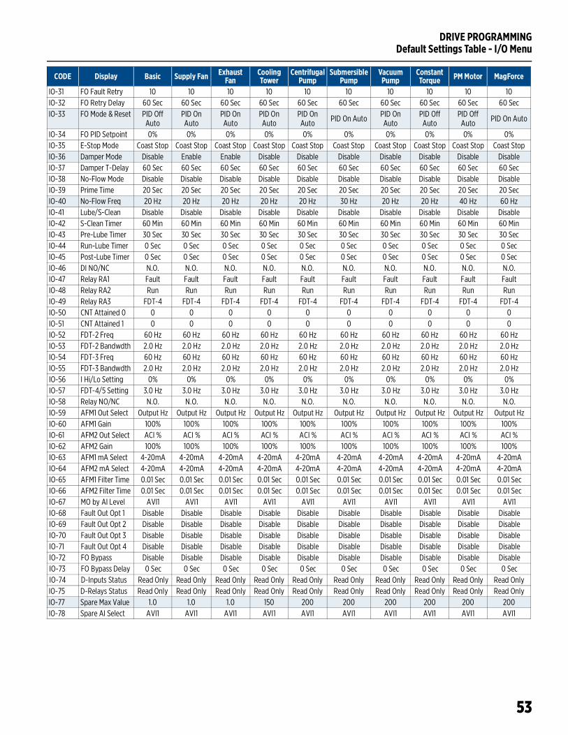
DRIVE PROGRAMMINGDefault Settings Table - I/O Menu
53
IO-31 FO Fault Retry 10 10 10 10 10 10 10 10 10 10IO-32 FO Retry Delay 60 Sec 60 Sec 60 Sec 60 Sec 60 Sec 60 Sec 60 Sec 60 Sec 60 Sec 60 SecIO-33 FO Mode & Reset PID Off
AutoPID On Auto
PID On Auto
PID On Auto
PID On Auto PID On Auto PID On
AutoPID Off
AutoPID Off
Auto PID On Auto
IO-34 FO PID Setpoint 0% 0% 0% 0% 0% 0% 0% 0% 0% 0%IO-35 E-Stop Mode Coast Stop Coast Stop Coast Stop Coast Stop Coast Stop Coast Stop Coast Stop Coast Stop Coast Stop Coast StopIO-36 Damper Mode Disable Enable Enable Disable Disable Disable Disable Disable Disable DisableIO-37 Damper T-Delay 60 Sec 60 Sec 60 Sec 60 Sec 60 Sec 60 Sec 60 Sec 60 Sec 60 Sec 60 SecIO-38 No-Flow Mode Disable Disable Disable Disable Disable Disable Disable Disable Disable DisableIO-39 Prime Time 20 Sec 20 Sec 20 Sec 20 Sec 20 Sec 20 Sec 20 Sec 20 Sec 20 Sec 20 SecIO-40 No-Flow Freq 20 Hz 20 Hz 20 Hz 20 Hz 20 Hz 30 Hz 20 Hz 20 Hz 40 Hz 60 HzIO-41 Lube/S-Clean Disable Disable Disable Disable Disable Disable Disable Disable Disable DisableIO-42 S-Clean Timer 60 Min 60 Min 60 Min 60 Min 60 Min 60 Min 60 Min 60 Min 60 Min 60 MinIO-43 Pre-Lube Timer 30 Sec 30 Sec 30 Sec 30 Sec 30 Sec 30 Sec 30 Sec 30 Sec 30 Sec 30 SecIO-44 Run-Lube Timer 0 Sec 0 Sec 0 Sec 0 Sec 0 Sec 0 Sec 0 Sec 0 Sec 0 Sec 0 SecIO-45 Post-Lube Timer 0 Sec 0 Sec 0 Sec 0 Sec 0 Sec 0 Sec 0 Sec 0 Sec 0 Sec 0 SecIO-46 DI NO/NC N.O. N.O. N.O. N.O. N.O. N.O. N.O. N.O. N.O. N.O.IO-47 Relay RA1 Fault Fault Fault Fault Fault Fault Fault Fault Fault Fault IO-48 Relay RA2 Run Run Run Run Run Run Run Run Run RunIO-49 Relay RA3 FDT-4 FDT-4 FDT-4 FDT-4 FDT-4 FDT-4 FDT-4 FDT-4 FDT-4 FDT-4IO-50 CNT Attained 0 0 0 0 0 0 0 0 0 0 0IO-51 CNT Attained 1 0 0 0 0 0 0 0 0 0 0IO-52 FDT-2 Freq 60 Hz 60 Hz 60 Hz 60 Hz 60 Hz 60 Hz 60 Hz 60 Hz 60 Hz 60 HzIO-53 FDT-2 Bandwdth 2.0 Hz 2.0 Hz 2.0 Hz 2.0 Hz 2.0 Hz 2.0 Hz 2.0 Hz 2.0 Hz 2.0 Hz 2.0 HzIO-54 FDT-3 Freq 60 Hz 60 Hz 60 Hz 60 Hz 60 Hz 60 Hz 60 Hz 60 Hz 60 Hz 60 HzIO-55 FDT-3 Bandwdth 2.0 Hz 2.0 Hz 2.0 Hz 2.0 Hz 2.0 Hz 2.0 Hz 2.0 Hz 2.0 Hz 2.0 Hz 2.0 HzIO-56 I Hi/Lo Setting 0% 0% 0% 0% 0% 0% 0% 0% 0% 0%IO-57 FDT-4/5 Setting 3.0 Hz 3.0 Hz 3.0 Hz 3.0 Hz 3.0 Hz 3.0 Hz 3.0 Hz 3.0 Hz 3.0 Hz 3.0 HzIO-58 Relay NO/NC N.O. N.O. N.O. N.O. N.O. N.O. N.O. N.O. N.O. N.O.IO-59 AFM1 Out Select Output Hz Output Hz Output Hz Output Hz Output Hz Output Hz Output Hz Output Hz Output Hz Output HzIO-60 AFM1 Gain 100% 100% 100% 100% 100% 100% 100% 100% 100% 100%IO-61 AFM2 Out Select ACI % ACI % ACI % ACI % ACI % ACI % ACI % ACI % ACI % ACI %IO-62 AFM2 Gain 100% 100% 100% 100% 100% 100% 100% 100% 100% 100%IO-63 AFM1 mA Select 4-20mA 4-20mA 4-20mA 4-20mA 4-20mA 4-20mA 4-20mA 4-20mA 4-20mA 4-20mAIO-64 AFM2 mA Select 4-20mA 4-20mA 4-20mA 4-20mA 4-20mA 4-20mA 4-20mA 4-20mA 4-20mA 4-20mAIO-65 AFM1 Filter Time 0.01 Sec 0.01 Sec 0.01 Sec 0.01 Sec 0.01 Sec 0.01 Sec 0.01 Sec 0.01 Sec 0.01 Sec 0.01 SecIO-66 AFM2 Filter Time 0.01 Sec 0.01 Sec 0.01 Sec 0.01 Sec 0.01 Sec 0.01 Sec 0.01 Sec 0.01 Sec 0.01 Sec 0.01 SecIO-67 MO by AI Level AVI1 AVI1 AVI1 AVI1 AVI1 AVI1 AVI1 AVI1 AVI1 AVI1IO-68 Fault Out Opt 1 Disable Disable Disable Disable Disable Disable Disable Disable Disable DisableIO-69 Fault Out Opt 2 Disable Disable Disable Disable Disable Disable Disable Disable Disable DisableIO-70 Fault Out Opt 3 Disable Disable Disable Disable Disable Disable Disable Disable Disable DisableIO-71 Fault Out Opt 4 Disable Disable Disable Disable Disable Disable Disable Disable Disable DisableIO-72 FO Bypass Disable Disable Disable Disable Disable Disable Disable Disable Disable DisableIO-73 FO Bypass Delay 0 Sec 0 Sec 0 Sec 0 Sec 0 Sec 0 Sec 0 Sec 0 Sec 0 Sec 0 SecIO-74 D-Inputs Status Read Only Read Only Read Only Read Only Read Only Read Only Read Only Read Only Read Only Read OnlyIO-75 D-Relays Status Read Only Read Only Read Only Read Only Read Only Read Only Read Only Read Only Read Only Read OnlyIO-77 Spare Max Value 1.0 1.0 1.0 150 200 200 200 200 200 200IO-78 Spare AI Select AVI1 AVI1 AVI1 AVI1 AVI1 AVI1 AVI1 AVI1 AVI1 AVI1
CODE Display Basic Supply Fan Exhaust Fan
Cooling Tower
Centrifugal Pump
Submersible Pump
Vacuum Pump
Constant Torque PM Motor MagForce
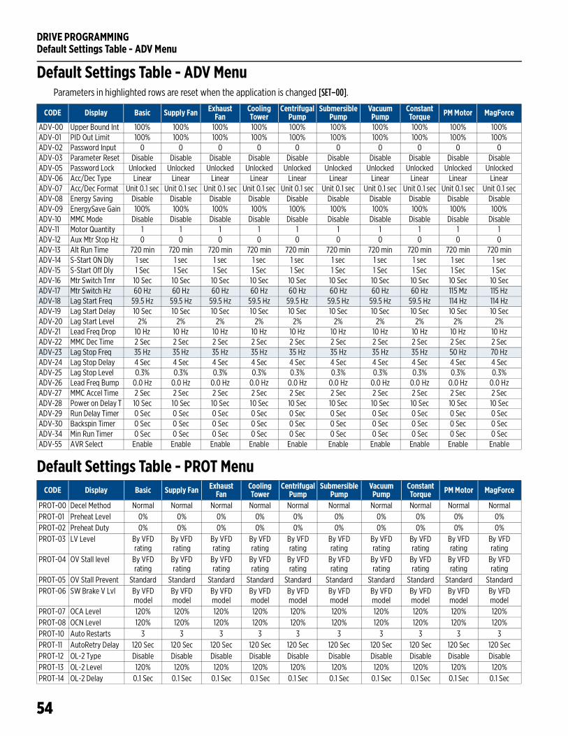
DRIVE PROGRAMMINGDefault Settings Table - ADV Menu
54
Default Settings Table - ADV MenuParameters in highlighted rows are reset when the application is changed [SET–00].
Default Settings Table - PROT Menu
CODE Display Basic Supply Fan Exhaust Fan
Cooling Tower
Centrifugal Pump
Submersible Pump
Vacuum Pump
Constant Torque PM Motor MagForce
ADV-00 Upper Bound Int 100% 100% 100% 100% 100% 100% 100% 100% 100% 100%ADV-01 PID Out Limit 100% 100% 100% 100% 100% 100% 100% 100% 100% 100%ADV-02 Password Input 0 0 0 0 0 0 0 0 0 0ADV-03 Parameter Reset Disable Disable Disable Disable Disable Disable Disable Disable Disable DisableADV-05 Password Lock Unlocked Unlocked Unlocked Unlocked Unlocked Unlocked Unlocked Unlocked Unlocked UnlockedADV-06 Acc/Dec Type Linear Linear Linear Linear Linear Linear Linear Linear Linear LinearADV-07 Acc/Dec Format Unit 0.1 sec Unit 0.1 sec Unit 0.1 sec Unit 0.1 sec Unit 0.1 sec Unit 0.1 sec Unit 0.1 sec Unit 0.1 sec Unit 0.1 sec Unit 0.1 secADV-08 Energy Saving Disable Disable Disable Disable Disable Disable Disable Disable Disable DisableADV-09 EnergySave Gain 100% 100% 100% 100% 100% 100% 100% 100% 100% 100%ADV-10 MMC Mode Disable Disable Disable Disable Disable Disable Disable Disable Disable DisableADV-11 Motor Quantity 1 1 1 1 1 1 1 1 1 1ADV-12 Aux Mtr Stop Hz 0 0 0 0 0 0 0 0 0 0ADV-13 Alt Run Time 720 min 720 min 720 min 720 min 720 min 720 min 720 min 720 min 720 min 720 minADV-14 S-Start ON Dly 1 sec 1 sec 1 sec 1 sec 1 sec 1 sec 1 sec 1 sec 1 sec 1 secADV-15 S-Start Off Dly 1 Sec 1 Sec 1 Sec 1 Sec 1 Sec 1 Sec 1 Sec 1 Sec 1 Sec 1 SecADV-16 Mtr Switch Tmr 10 Sec 10 Sec 10 Sec 10 Sec 10 Sec 10 Sec 10 Sec 10 Sec 10 Sec 10 SecADV-17 Mtr Switch Hz 60 Hz 60 Hz 60 Hz 60 Hz 60 Hz 60 Hz 60 Hz 60 Hz 115 Mz 115 HzADV-18 Lag Start Freq 59.5 Hz 59.5 Hz 59.5 Hz 59.5 Hz 59.5 Hz 59.5 Hz 59.5 Hz 59.5 Hz 114 Hz 114 HzADV-19 Lag Start Delay 10 Sec 10 Sec 10 Sec 10 Sec 10 Sec 10 Sec 10 Sec 10 Sec 10 Sec 10 SecADV-20 Lag Start Level 2% 2% 2% 2% 2% 2% 2% 2% 2% 2%ADV-21 Lead Freq Drop 10 Hz 10 Hz 10 Hz 10 Hz 10 Hz 10 Hz 10 Hz 10 Hz 10 Hz 10 HzADV-22 MMC Dec Time 2 Sec 2 Sec 2 Sec 2 Sec 2 Sec 2 Sec 2 Sec 2 Sec 2 Sec 2 SecADV-23 Lag Stop Freq 35 Hz 35 Hz 35 Hz 35 Hz 35 Hz 35 Hz 35 Hz 35 Hz 50 Hz 70 HzADV-24 Lag Stop Delay 4 Sec 4 Sec 4 Sec 4 Sec 4 Sec 4 Sec 4 Sec 4 Sec 4 Sec 4 SecADV-25 Lag Stop Level 0.3% 0.3% 0.3% 0.3% 0.3% 0.3% 0.3% 0.3% 0.3% 0.3%ADV-26 Lead Freq Bump 0.0 Hz 0.0 Hz 0.0 Hz 0.0 Hz 0.0 Hz 0.0 Hz 0.0 Hz 0.0 Hz 0.0 Hz 0.0 HzADV-27 MMC Accel Time 2 Sec 2 Sec 2 Sec 2 Sec 2 Sec 2 Sec 2 Sec 2 Sec 2 Sec 2 SecADV-28 Power on Delay T 10 Sec 10 Sec 10 Sec 10 Sec 10 Sec 10 Sec 10 Sec 10 Sec 10 Sec 10 SecADV-29 Run Delay Timer 0 Sec 0 Sec 0 Sec 0 Sec 0 Sec 0 Sec 0 Sec 0 Sec 0 Sec 0 SecADV-30 Backspin Timer 0 Sec 0 Sec 0 Sec 0 Sec 0 Sec 0 Sec 0 Sec 0 Sec 0 Sec 0 SecADV-34 Min Run Timer 0 Sec 0 Sec 0 Sec 0 Sec 0 Sec 0 Sec 0 Sec 0 Sec 0 Sec 0 SecADV-55 AVR Select Enable Enable Enable Enable Enable Enable Enable Enable Enable Enable
CODE Display Basic Supply Fan Exhaust Fan
Cooling Tower
Centrifugal Pump
Submersible Pump
Vacuum Pump
Constant Torque PM Motor MagForce
PROT-00 Decel Method Normal Normal Normal Normal Normal Normal Normal Normal Normal NormalPROT-01 Preheat Level 0% 0% 0% 0% 0% 0% 0% 0% 0% 0%PROT-02 Preheat Duty 0% 0% 0% 0% 0% 0% 0% 0% 0% 0%PROT-03 LV Level By VFD
ratingBy VFD rating
By VFD rating
By VFD rating
By VFD rating
By VFD rating
By VFD rating
By VFD rating
By VFD rating
By VFD rating
PROT-04 OV Stall level By VFD rating
By VFD rating
By VFD rating
By VFD rating
By VFD rating
By VFD rating
By VFD rating
By VFD rating
By VFD rating
By VFD rating
PROT-05 OV Stall Prevent Standard Standard Standard Standard Standard Standard Standard Standard Standard StandardPROT-06 SW Brake V Lvl By VFD
modelBy VFD model
By VFD model
By VFD model
By VFD model
By VFD model
By VFD model
By VFD model
By VFD model
By VFD model
PROT-07 OCA Level 120% 120% 120% 120% 120% 120% 120% 120% 120% 120%PROT-08 OCN Level 120% 120% 120% 120% 120% 120% 120% 120% 120% 120%PROT-10 Auto Restarts 3 3 3 3 3 3 3 3 3 3PROT-11 AutoRetry Delay 120 Sec 120 Sec 120 Sec 120 Sec 120 Sec 120 Sec 120 Sec 120 Sec 120 Sec 120 SecPROT-12 OL-2 Type Disable Disable Disable Disable Disable Disable Disable Disable Disable DisablePROT-13 OL-2 Level 120% 120% 120% 120% 120% 120% 120% 120% 120% 120%PROT-14 OL-2 Delay 0.1 Sec 0.1 Sec 0.1 Sec 0.1 Sec 0.1 Sec 0.1 Sec 0.1 Sec 0.1 Sec 0.1 Sec 0.1 Sec
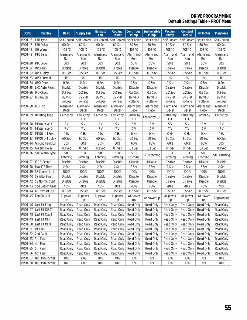
DRIVE PROGRAMMINGDefault Settings Table - PROT Menu
55
PROT-16 ETH Type Self Cooled Self Cooled Self Cooled Self Cooled Self Cooled Self Cooled Self Cooled Self Cooled Self Cooled Self CooledPROT-17 ETH Delay 60 Sec 60 Sec 60 Sec 60 Sec 60 Sec 60 Sec 60 Sec 60 Sec 60 Sec 60 SecPROT-18 OH Warn 105 °C 105 °C 105 °C 105 °C 105 °C 105 °C 105 °C 105 °C 105 °C 105 °CPROT-19 PTC Select Alarm and
RunAlarm and
RunAlarm and
RunAlarm and
RunAlarm and
RunAlarm and
RunAlarm and
RunAlarm and
RunAlarm and
RunAlarm and
RunPROT-20 PTC Level 50% 50% 50% 50% 50% 50% 50% 50% 50% 50%PROT-21 OPO Trip Disable Disable Disable Disable Disable Disable Disable Disable Disable DisablePROT-22 OPO Delay 0.5 Sec 0.5 Sec 0.5 Sec 0.5 Sec 0.5 Sec 0.5 Sec 0.5 Sec 0.5 Sec 0.5 Sec 0.5 SecPROT-23 OPO Current 1% 1% 1% 1% 1% 1% 1% 1% 1% 1%PROT-24 OPO Decel 0 Sec 0 Sec 0 Sec 0 Sec 0 Sec 0 Sec 0 Sec 0 Sec 0 Sec 0 SecPROT-25 LvX Auto Reset Disable Disable Disable Disable Disable Disable Disable Disable Disable DisablePROT-26 IPO Check 0.2 Sec 0.2 Sec 0.2 Sec 0.2 Sec 0.2 Sec 0.2 Sec 0.2 Sec 0.2 Sec 0.2 Sec 0.2 SecPROT-27 IPO Ripple By VFD
voltageBy VFD voltage
By VFD voltage
By VFD voltage
By VFD voltage
By VFD voltage
By VFD voltage
By VFD voltage
By VFD voltage
By VFD voltage
PROT-28 IPO Trip Alarm and Decel
Alarm and Decel
Alarm and Decel
Alarm and Decel
Alarm and Decel
Alarm and Decel
Alarm and Decel
Alarm and Decel
Alarm and Decel
Alarm and Decel
PROT-29 Derating Type Carrier by I_T
Carrier by I_T
Carrier by I_T
Carrier by I_T
Carrier by I_T Carrier by I_T Carrier by
I_TCarrier by
I_TCarrier by
I_TCarrier by
I_TPROT-30 PT100 Level 1 5 V 5 V 5 V 5 V 5 V 5 V 5 V 5 V 5 V 5 VPROT-31 PT100 Level 2 7 V 7 V 7 V 7 V 7 V 7 V 7 V 7 V 7 V 7 VPROT-32 PT100 L- 1 Freq 0 Hz 0 Hz 0 Hz 0 Hz 0 Hz 0 Hz 0 Hz 0 Hz 0 Hz 0 HzPROT-33 PT100 L- 1 Delay 60 Sec 60 Sec 60 Sec 60 Sec 60 Sec 60 Sec 60 Sec 60 Sec 60 Sec 60 SecPROT-34 Ground Fault Lvl 60% 60% 60% 60% 60% 60% 60% 60% 60% 60%PROT-35 G-Fault Delay 0.1 Sec 0.1 Sec 0.1 Sec 0.1 Sec 0.1 Sec 0.1 Sec 0.1 Sec 0.1 Sec 0.1 Sec 0.1 SecPROT-36 STO Alarm Type STO
LatchingSTO
LatchingSTO
LatchingSTO
LatchingSTO
Latching STO Latching STO Latching
STO Latching
STO Latching STO Latching
PROT-37 IPF S-Search Disable Disable Disable Disable Disable Disable Disable Disable Disable DisablePROT-38 Max IPF Time 2 Sec 2 Sec 2 Sec 2 Sec 2 Sec 2 Sec 2 Sec 2 Sec 2 Sec 2 SecPROT-39 SS Current Lmt 100% 100% 100% 100% 100% 100% 100% 100% 100% 100%PROT-40 SS After Fault Disable Disable Disable Disable Disable Disable Disable Disable Disable DisablePROT-42 SS Normal Start Disable Disable Disable Disable Disable Disable Disable Disable Disable DisablePROT-43 Spd Search Gain 40% 40% 40% 40% 40% 40% 40% 40% 40% 40%PROT-44 IPF Restart Dly 0.5 Sec 0.5 Sec 0.5 Sec 0.5 Sec 0.5 Sec 0.5 Sec 0.5 Sec 0.5 Sec 0.5 Sec 0.5 SecPROT-45 Fan Control At power
upAt power
upAt power
upAt power
upAt power
up At power up At power up
At power up
At power up At power up
PROT-46 Last Flt Freq Read Only Read Only Read Only Read Only Read Only Read Only Read Only Read Only Read Only Read OnlyPROT-47 Last Flt IGBTT Read Only Read Only Read Only Read Only Read Only Read Only Read Only Read Only Read Only Read OnlyPROT-48 Last Flt Cap T Read Only Read Only Read Only Read Only Read Only Read Only Read Only Read Only Read Only Read OnlyPROT-49 Last Flt MFI Read Only Read Only Read Only Read Only Read Only Read Only Read Only Read Only Read Only Read OnlyPROT-50 Last Flt MFO Read Only Read Only Read Only Read Only Read Only Read Only Read Only Read Only Read Only Read OnlyPROT-51 1st Fault Read Only Read Only Read Only Read Only Read Only Read Only Read Only Read Only Read Only Read OnlyPROT-52 2nd Fault Read Only Read Only Read Only Read Only Read Only Read Only Read Only Read Only Read Only Read OnlyPROT-53 3rd Fault Read Only Read Only Read Only Read Only Read Only Read Only Read Only Read Only Read Only Read OnlyPROT-54 4th Fault Read Only Read Only Read Only Read Only Read Only Read Only Read Only Read Only Read Only Read OnlyPROT-55 5th Fault Read Only Read Only Read Only Read Only Read Only Read Only Read Only Read Only Read Only Read OnlyPROT-56 6th Fault Read Only Read Only Read Only Read Only Read Only Read Only Read Only Read Only Read Only Read OnlyPROT-57 ULD Min Torque 10% 10% 10% 10% 10% 10% 10% 10% 10% 10%PROT-58 HLD Min Torque 10% 10% 10% 10% 10% 10% 10% 10% 10% 10%
CODE Display Basic Supply Fan Exhaust Fan
Cooling Tower
Centrifugal Pump
Submersible Pump
Vacuum Pump
Constant Torque PM Motor MagForce
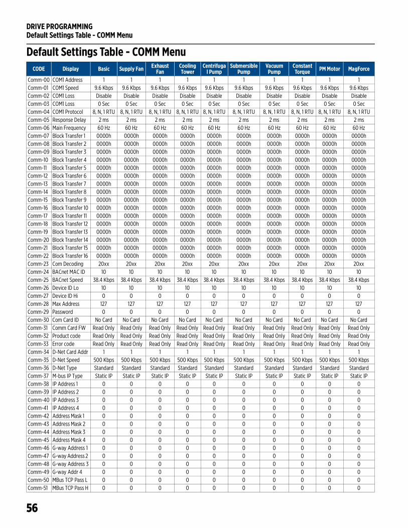
DRIVE PROGRAMMINGDefault Settings Table - COMM Menu
56
Default Settings Table - COMM MenuCODE Display Basic Supply Fan Exhaust
FanCooling Tower
Centrifugal Pump
Submersible Pump
Vacuum Pump
Constant Torque PM Motor MagForce
Comm-00 COM1 Address 1 1 1 1 1 1 1 1 1 1 Comm-01 COM1 Speed 9.6 Kbps 9.6 Kbps 9.6 Kbps 9.6 Kbps 9.6 Kbps 9.6 Kbps 9.6 Kbps 9.6 Kbps 9.6 Kbps 9.6 KbpsComm-02 COM1 Loss Disable Disable Disable Disable Disable Disable Disable Disable Disable DisableComm-03 COM1 Loss 0 Sec 0 Sec 0 Sec 0 Sec 0 Sec 0 Sec 0 Sec 0 Sec 0 Sec 0 SecComm-04 COM1 Protocol 8, N, 1 RTU 8, N, 1 RTU 8, N, 1 RTU 8, N, 1 RTU 8, N, 1 RTU 8, N, 1 RTU 8, N, 1 RTU 8, N, 1 RTU 8, N, 1 RTU 8, N, 1 RTUComm-05 Response Delay 2 ms 2 ms 2 ms 2 ms 2 ms 2 ms 2 ms 2 ms 2 ms 2 msComm-06 Main Frequency 60 Hz 60 Hz 60 Hz 60 Hz 60 Hz 60 Hz 60 Hz 60 Hz 60 Hz 60 HzComm-07 Block Transfer 1 0000h 0000h 0000h 0000h 0000h 0000h 0000h 0000h 0000h 0000hComm-08 Block Transfer 2 0000h 0000h 0000h 0000h 0000h 0000h 0000h 0000h 0000h 0000hComm-09 Block Transfer 3 0000h 0000h 0000h 0000h 0000h 0000h 0000h 0000h 0000h 0000hComm-10 Block Transfer 4 0000h 0000h 0000h 0000h 0000h 0000h 0000h 0000h 0000h 0000hComm-11 Block Transfer 5 0000h 0000h 0000h 0000h 0000h 0000h 0000h 0000h 0000h 0000hComm-12 Block Transfer 6 0000h 0000h 0000h 0000h 0000h 0000h 0000h 0000h 0000h 0000hComm-13 Block Transfer 7 0000h 0000h 0000h 0000h 0000h 0000h 0000h 0000h 0000h 0000hComm-14 Block Transfer 8 0000h 0000h 0000h 0000h 0000h 0000h 0000h 0000h 0000h 0000hComm-15 Block Transfer 9 0000h 0000h 0000h 0000h 0000h 0000h 0000h 0000h 0000h 0000hComm-16 Block Transfer 10 0000h 0000h 0000h 0000h 0000h 0000h 0000h 0000h 0000h 0000hComm-17 Block Transfer 11 0000h 0000h 0000h 0000h 0000h 0000h 0000h 0000h 0000h 0000hComm-18 Block Transfer 12 0000h 0000h 0000h 0000h 0000h 0000h 0000h 0000h 0000h 0000hComm-19 Block Transfer 13 0000h 0000h 0000h 0000h 0000h 0000h 0000h 0000h 0000h 0000hComm-20 Block Transfer 14 0000h 0000h 0000h 0000h 0000h 0000h 0000h 0000h 0000h 0000hComm-21 Block Transfer 15 0000h 0000h 0000h 0000h 0000h 0000h 0000h 0000h 0000h 0000hComm-22 Block Transfer 16 0000h 0000h 0000h 0000h 0000h 0000h 0000h 0000h 0000h 0000hComm-23 Com Decoding 20xx 20xx 20xx 20xx 20xx 20xx 20xx 20xx 20xx 20xxComm-24 BACnet MAC ID 10 10 10 10 10 10 10 10 10 10Comm-25 BACnet Speed 38.4 Kbps 38.4 Kbps 38.4 Kbps 38.4 Kbps 38.4 Kbps 38.4 Kbps 38.4 Kbps 38.4 Kbps 38.4 Kbps 38.4 KbpsComm-26 Device ID Lo 10 10 10 10 10 10 10 10 10 10Comm-27 Device ID Hi 0 0 0 0 0 0 0 0 0 0Comm-28 Max Address 127 127 127 127 127 127 127 127 127 127Comm-29 Password 0 0 0 0 0 0 0 0 0 0Comm-30 Com Card ID No Card No Card No Card No Card No Card No Card No Card No Card No Card No CardComm-31 Comm Card FW Read Only Read Only Read Only Read Only Read Only Read Only Read Only Read Only Read Only Read OnlyComm-32 Product code Read Only Read Only Read Only Read Only Read Only Read Only Read Only Read Only Read Only Read OnlyComm-33 Error code Read Only Read Only Read Only Read Only Read Only Read Only Read Only Read Only Read Only Read OnlyComm-34 D-Net Card Addr 1 1 1 1 1 1 1 1 1 1Comm-35 D-Net Speed 500 Kbps 500 Kbps 500 Kbps 500 Kbps 500 Kbps 500 Kbps 500 Kbps 500 Kbps 500 Kbps 500 KbpsComm-36 D-Net Type Standard Standard Standard Standard Standard Standard Standard Standard Standard StandardComm-37 M-bus IP Type Static IP Static IP Static IP Static IP Static IP Static IP Static IP Static IP Static IP Static IPComm-38 IP Address 1 0 0 0 0 0 0 0 0 0 0Comm-39 IP Address 2 0 0 0 0 0 0 0 0 0 0Comm-40 IP Address 3 0 0 0 0 0 0 0 0 0 0Comm-41 IP Address 4 0 0 0 0 0 0 0 0 0 0Comm-42 Address Mask 1 0 0 0 0 0 0 0 0 0 0Comm-43 Address Mask 2 0 0 0 0 0 0 0 0 0 0Comm-44 Address Mask 3 0 0 0 0 0 0 0 0 0 0Comm-45 Address Mask 4 0 0 0 0 0 0 0 0 0 0Comm-46 G-way Address 1 0 0 0 0 0 0 0 0 0 0Comm-47 G-way Address 2 0 0 0 0 0 0 0 0 0 0Comm-48 G-way Address 3 0 0 0 0 0 0 0 0 0 0Comm-49 G-way Addr 4 0 0 0 0 0 0 0 0 0 0Comm-50 MBus TCP Pass L 0 0 0 0 0 0 0 0 0 0Comm-51 MBus TCP Pass H 0 0 0 0 0 0 0 0 0 0
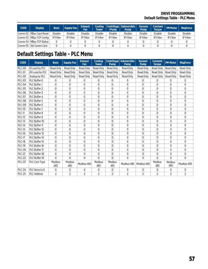
DRIVE PROGRAMMINGDefault Settings Table - PLC Menu
57
Default Settings Table - PLC Menu
Comm-52 MBus Card Reset Disable Disable Disable Disable Disable Disable Disable Disable Disable DisableComm-53 MBus TCP Config IP Filter IP Filter IP Filter IP Filter IP Filter IP Filter IP Filter IP Filter IP Filter IP FilterComm-54 MBus TCP Status 0 0 0 0 0 0 0 0 0 0Comm-55 Set Comm Card 0 0 0 0 0 0 0 0 0 0
CODE Display Basic Supply Fan Exhaust Fan
Cooling Tower
Centrifugal Pump
Submersible Pump
Vacuum Pump
Constant Torque PM Motor MagForce
CODE Display Basic Supply Fan Exhaust Fan
Cooling Tower
Centrifugal Pump
Submersible Pump
Vacuum Pump
Constant Torque PM Motor MagForce
PLC-00 DI used by PLC Read Only Read Only Read Only Read Only Read Only Read Only Read Only Read Only Read Only Read OnlyPLC-01 DO used by PLC Read Only Read Only Read Only Read Only Read Only Read Only Read Only Read Only Read Only Read OnlyPLC-02 Analog by PLC Read Only Read Only Read Only Read Only Read Only Read Only Read Only Read Only Read Only Read OnlyPLC-03 PLC Buffer 0 0 0 0 0 0 0 0 0 0 0PLC-04 PLC Buffer 1 0 0 0 0 0 0 0 0 0 0PLC-05 PLC Buffer 2 0 0 0 0 0 0 0 0 0 0PLC-06 PLC Buffer 3 0 0 0 0 0 0 0 0 0 0PLC-07 PLC Buffer 4 0 0 0 0 0 0 0 0 0 0PLC-08 PLC Buffer 5 0 0 0 0 0 0 0 0 0 0PLC-09 PLC Buffer 6 0 0 0 0 0 0 0 0 0 0PLC-10 PLC Buffer 7 0 0 0 0 0 0 0 0 0 0PLC-11 PLC Buffer 8 0 0 0 0 0 0 0 0 0 0PLC-12 PLC Buffer 9 0 0 0 0 0 0 0 0 0 0PLC-13 PLC Buffer 10 0 0 0 0 0 0 0 0 0 0PLC-14 PLC Buffer 11 0 0 0 0 0 0 0 0 0 0PLC-15 PLC Buffer 12 0 0 0 0 0 0 0 0 0 0PLC-16 PLC Buffer 13 0 0 0 0 0 0 0 0 0 0PLC-17 PLC Buffer 14 0 0 0 0 0 0 0 0 0 0PLC-18 PLC Buffer 15 0 0 0 0 0 0 0 0 0 0PLC-19 PLC Buffer 16 0 0 0 0 0 0 0 0 0 0PLC-20 PLC Buffer 17 0 0 0 0 0 0 0 0 0 0PLC-21 PLC Buffer 18 0 0 0 0 0 0 0 0 0 0PLC-22 PLC Buffer 19 0 0 0 0 0 0 0 0 0 0PLC-23 PLC Com Type Modbus
485Modbus
485Modbus 485
Modbus 485
Modbus 485
Modbus 485 Modbus 485Modbus
485Modbus
485 Modbus 485
PLC-24 PLC force to 0 0 0 0 0 0 0 0 0 0 0PLC-25 PLC Address 2 2 2 2 2 2 2 2 2 2
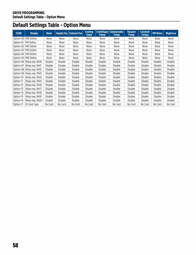
DRIVE PROGRAMMINGDefault Settings Table - Option Menu
58
Default Settings Table - Option MenuCODE Display Basic Supply Fan Exhaust Fan Cooling
TowerCentrifugal
PumpSubmersible
PumpVacuum
PumpConstant Torque PM Motor MagForce
Option-00 M10 Define None None None None None None None None None NoneOption-01 M11 Define None None None None None None None None None NoneOption-02 M12 Define None None None None None None None None None NoneOption-03 M13 Define None None None None None None None None None NoneOption-04 M14 Define None None None None None None None None None NoneOption-05 M15 Define None None None None None None None None None NoneOption-06 Relay exp. RA10 Disable Disable Disable Disable Disable Disable Disable Disable Disable DisableOption-07 Relay exp. RA11 Disable Disable Disable Disable Disable Disable Disable Disable Disable DisableOption-08 Relay exp. RA12 Disable Disable Disable Disable Disable Disable Disable Disable Disable DisableOption-09 Relay exp. RA13 Disable Disable Disable Disable Disable Disable Disable Disable Disable DisableOption-10 Relay exp. RA14 Disable Disable Disable Disable Disable Disable Disable Disable Disable DisableOption-11 Relay exp. RA15 Disable Disable Disable Disable Disable Disable Disable Disable Disable DisableOption-12 Relay exp. RA16 Disable Disable Disable Disable Disable Disable Disable Disable Disable DisableOption-13 Relay exp. RA17 Disable Disable Disable Disable Disable Disable Disable Disable Disable DisableOption-14 Relay exp. RA18 Disable Disable Disable Disable Disable Disable Disable Disable Disable DisableOption-15 Relay exp. RA19 Disable Disable Disable Disable Disable Disable Disable Disable Disable DisableOption-16 Relay exp. RA20 Disable Disable Disable Disable Disable Disable Disable Disable Disable DisableOption-17 IO Card Type No Card No Card No Card No Card No Card No Card No Card No Card No Card No Card
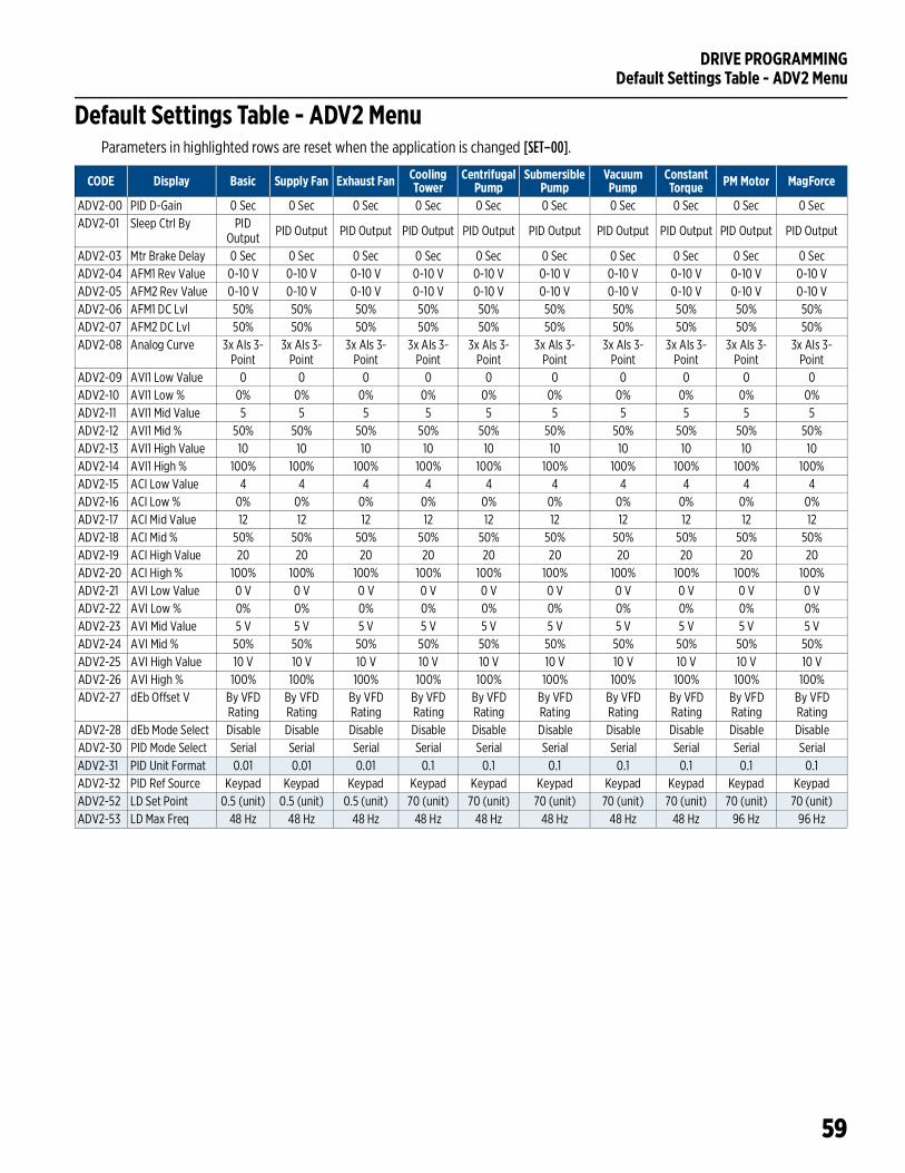
DRIVE PROGRAMMINGDefault Settings Table - ADV2 Menu
59
Default Settings Table - ADV2 MenuParameters in highlighted rows are reset when the application is changed [SET–00].
CODE Display Basic Supply Fan Exhaust Fan Cooling Tower
Centrifugal Pump
Submersible Pump
Vacuum Pump
Constant Torque PM Motor MagForce
ADV2-00 PID D-Gain 0 Sec 0 Sec 0 Sec 0 Sec 0 Sec 0 Sec 0 Sec 0 Sec 0 Sec 0 SecADV2-01 Sleep Ctrl By PID
Output PID Output PID Output PID Output PID Output PID Output PID Output PID Output PID Output PID Output
ADV2-03 Mtr Brake Delay 0 Sec 0 Sec 0 Sec 0 Sec 0 Sec 0 Sec 0 Sec 0 Sec 0 Sec 0 SecADV2-04 AFM1 Rev Value 0-10 V 0-10 V 0-10 V 0-10 V 0-10 V 0-10 V 0-10 V 0-10 V 0-10 V 0-10 VADV2-05 AFM2 Rev Value 0-10 V 0-10 V 0-10 V 0-10 V 0-10 V 0-10 V 0-10 V 0-10 V 0-10 V 0-10 VADV2-06 AFM1 DC Lvl 50% 50% 50% 50% 50% 50% 50% 50% 50% 50%ADV2-07 AFM2 DC Lvl 50% 50% 50% 50% 50% 50% 50% 50% 50% 50%ADV2-08 Analog Curve 3x AIs 3-
Point3x AIs 3-
Point3x AIs 3-
Point3x AIs 3-
Point3x AIs 3-
Point3x AIs 3-
Point3x AIs 3-
Point3x AIs 3-
Point3x AIs 3-
Point3x AIs 3-
PointADV2-09 AVI1 Low Value 0 0 0 0 0 0 0 0 0 0ADV2-10 AVI1 Low % 0% 0% 0% 0% 0% 0% 0% 0% 0% 0%ADV2-11 AVI1 Mid Value 5 5 5 5 5 5 5 5 5 5ADV2-12 AVI1 Mid % 50% 50% 50% 50% 50% 50% 50% 50% 50% 50%ADV2-13 AVI1 High Value 10 10 10 10 10 10 10 10 10 10ADV2-14 AVI1 High % 100% 100% 100% 100% 100% 100% 100% 100% 100% 100%ADV2-15 ACI Low Value 4 4 4 4 4 4 4 4 4 4ADV2-16 ACI Low % 0% 0% 0% 0% 0% 0% 0% 0% 0% 0%ADV2-17 ACI Mid Value 12 12 12 12 12 12 12 12 12 12ADV2-18 ACI Mid % 50% 50% 50% 50% 50% 50% 50% 50% 50% 50%ADV2-19 ACI High Value 20 20 20 20 20 20 20 20 20 20ADV2-20 ACI High % 100% 100% 100% 100% 100% 100% 100% 100% 100% 100%ADV2-21 AVI Low Value 0 V 0 V 0 V 0 V 0 V 0 V 0 V 0 V 0 V 0 VADV2-22 AVI Low % 0% 0% 0% 0% 0% 0% 0% 0% 0% 0%ADV2-23 AVI Mid Value 5 V 5 V 5 V 5 V 5 V 5 V 5 V 5 V 5 V 5 VADV2-24 AVI Mid % 50% 50% 50% 50% 50% 50% 50% 50% 50% 50%ADV2-25 AVI High Value 10 V 10 V 10 V 10 V 10 V 10 V 10 V 10 V 10 V 10 VADV2-26 AVI High % 100% 100% 100% 100% 100% 100% 100% 100% 100% 100%ADV2-27 dEb Offset V By VFD
RatingBy VFD Rating
By VFD Rating
By VFD Rating
By VFD Rating
By VFD Rating
By VFD Rating
By VFD Rating
By VFD Rating
By VFD Rating
ADV2-28 dEb Mode Select Disable Disable Disable Disable Disable Disable Disable Disable Disable DisableADV2-30 PID Mode Select Serial Serial Serial Serial Serial Serial Serial Serial Serial Serial ADV2-31 PID Unit Format 0.01 0.01 0.01 0.1 0.1 0.1 0.1 0.1 0.1 0.1ADV2-32 PID Ref Source Keypad Keypad Keypad Keypad Keypad Keypad Keypad Keypad Keypad KeypadADV2-52 LD Set Point 0.5 (unit) 0.5 (unit) 0.5 (unit) 70 (unit) 70 (unit) 70 (unit) 70 (unit) 70 (unit) 70 (unit) 70 (unit)ADV2-53 LD Max Freq 48 Hz 48 Hz 48 Hz 48 Hz 48 Hz 48 Hz 48 Hz 48 Hz 96 Hz 96 Hz
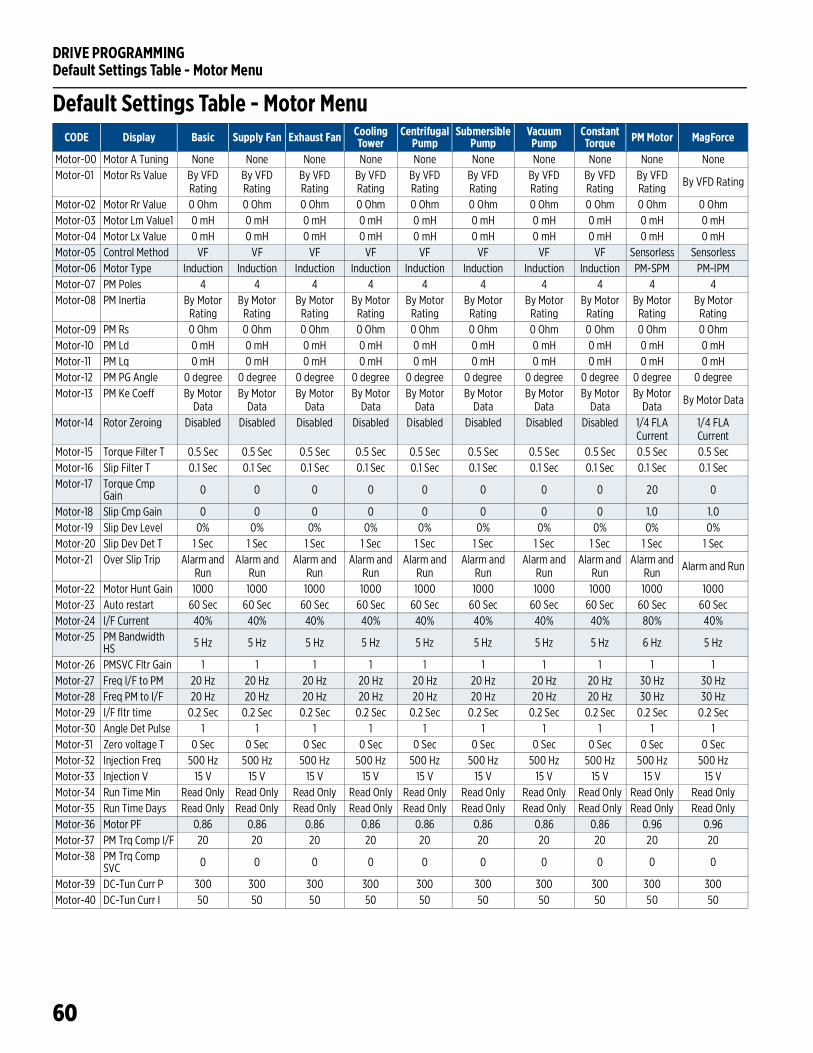
DRIVE PROGRAMMINGDefault Settings Table - Motor Menu
60
Default Settings Table - Motor MenuCODE Display Basic Supply Fan Exhaust Fan Cooling
TowerCentrifugal
PumpSubmersible
PumpVacuum
PumpConstant Torque PM Motor MagForce
Motor-00 Motor A Tuning None None None None None None None None None NoneMotor-01 Motor Rs Value By VFD
RatingBy VFD Rating
By VFD Rating
By VFD Rating
By VFD Rating
By VFD Rating
By VFD Rating
By VFD Rating
By VFD Rating By VFD Rating
Motor-02 Motor Rr Value 0 Ohm 0 Ohm 0 Ohm 0 Ohm 0 Ohm 0 Ohm 0 Ohm 0 Ohm 0 Ohm 0 OhmMotor-03 Motor Lm Value1 0 mH 0 mH 0 mH 0 mH 0 mH 0 mH 0 mH 0 mH 0 mH 0 mHMotor-04 Motor Lx Value 0 mH 0 mH 0 mH 0 mH 0 mH 0 mH 0 mH 0 mH 0 mH 0 mHMotor-05 Control Method VF VF VF VF VF VF VF VF Sensorless SensorlessMotor-06 Motor Type Induction Induction Induction Induction Induction Induction Induction Induction PM-SPM PM-IPMMotor-07 PM Poles 4 4 4 4 4 4 4 4 4 4Motor-08 PM Inertia By Motor
RatingBy Motor
RatingBy Motor
RatingBy Motor
RatingBy Motor
RatingBy Motor
RatingBy Motor
RatingBy Motor
RatingBy Motor
RatingBy Motor
RatingMotor-09 PM Rs 0 Ohm 0 Ohm 0 Ohm 0 Ohm 0 Ohm 0 Ohm 0 Ohm 0 Ohm 0 Ohm 0 OhmMotor-10 PM Ld 0 mH 0 mH 0 mH 0 mH 0 mH 0 mH 0 mH 0 mH 0 mH 0 mHMotor-11 PM Lq 0 mH 0 mH 0 mH 0 mH 0 mH 0 mH 0 mH 0 mH 0 mH 0 mHMotor-12 PM PG Angle 0 degree 0 degree 0 degree 0 degree 0 degree 0 degree 0 degree 0 degree 0 degree 0 degreeMotor-13 PM Ke Coeff By Motor
DataBy Motor
DataBy Motor
DataBy Motor
DataBy Motor
DataBy Motor
DataBy Motor
DataBy Motor
DataBy Motor
Data By Motor Data
Motor-14 Rotor Zeroing Disabled Disabled Disabled Disabled Disabled Disabled Disabled Disabled 1/4 FLA Current
1/4 FLA Current
Motor-15 Torque Filter T 0.5 Sec 0.5 Sec 0.5 Sec 0.5 Sec 0.5 Sec 0.5 Sec 0.5 Sec 0.5 Sec 0.5 Sec 0.5 SecMotor-16 Slip Filter T 0.1 Sec 0.1 Sec 0.1 Sec 0.1 Sec 0.1 Sec 0.1 Sec 0.1 Sec 0.1 Sec 0.1 Sec 0.1 SecMotor-17 Torque Cmp
Gain 0 0 0 0 0 0 0 0 20 0
Motor-18 Slip Cmp Gain 0 0 0 0 0 0 0 0 1.0 1.0Motor-19 Slip Dev Level 0% 0% 0% 0% 0% 0% 0% 0% 0% 0%Motor-20 Slip Dev Det T 1 Sec 1 Sec 1 Sec 1 Sec 1 Sec 1 Sec 1 Sec 1 Sec 1 Sec 1 SecMotor-21 Over Slip Trip Alarm and
RunAlarm and
RunAlarm and
RunAlarm and
RunAlarm and
RunAlarm and
RunAlarm and
RunAlarm and
RunAlarm and
Run Alarm and Run
Motor-22 Motor Hunt Gain 1000 1000 1000 1000 1000 1000 1000 1000 1000 1000Motor-23 Auto restart 60 Sec 60 Sec 60 Sec 60 Sec 60 Sec 60 Sec 60 Sec 60 Sec 60 Sec 60 SecMotor-24 I/F Current 40% 40% 40% 40% 40% 40% 40% 40% 80% 40%Motor-25 PM Bandwidth
HS 5 Hz 5 Hz 5 Hz 5 Hz 5 Hz 5 Hz 5 Hz 5 Hz 6 Hz 5 Hz
Motor-26 PMSVC Fltr Gain 1 1 1 1 1 1 1 1 1 1Motor-27 Freq I/F to PM 20 Hz 20 Hz 20 Hz 20 Hz 20 Hz 20 Hz 20 Hz 20 Hz 30 Hz 30 HzMotor-28 Freq PM to I/F 20 Hz 20 Hz 20 Hz 20 Hz 20 Hz 20 Hz 20 Hz 20 Hz 30 Hz 30 HzMotor-29 I/F fltr time 0.2 Sec 0.2 Sec 0.2 Sec 0.2 Sec 0.2 Sec 0.2 Sec 0.2 Sec 0.2 Sec 0.2 Sec 0.2 SecMotor-30 Angle Det Pulse 1 1 1 1 1 1 1 1 1 1Motor-31 Zero voltage T 0 Sec 0 Sec 0 Sec 0 Sec 0 Sec 0 Sec 0 Sec 0 Sec 0 Sec 0 SecMotor-32 Injection Freq 500 Hz 500 Hz 500 Hz 500 Hz 500 Hz 500 Hz 500 Hz 500 Hz 500 Hz 500 HzMotor-33 Injection V 15 V 15 V 15 V 15 V 15 V 15 V 15 V 15 V 15 V 15 VMotor-34 Run Time Min Read Only Read Only Read Only Read Only Read Only Read Only Read Only Read Only Read Only Read OnlyMotor-35 Run Time Days Read Only Read Only Read Only Read Only Read Only Read Only Read Only Read Only Read Only Read OnlyMotor-36 Motor PF 0.86 0.86 0.86 0.86 0.86 0.86 0.86 0.86 0.96 0.96Motor-37 PM Trq Comp I/F 20 20 20 20 20 20 20 20 20 20Motor-38 PM Trq Comp
SVC 0 0 0 0 0 0 0 0 0 0
Motor-39 DC-Tun Curr P 300 300 300 300 300 300 300 300 300 300Motor-40 DC-Tun Curr I 50 50 50 50 50 50 50 50 50 50
INSTALLATION TESTINGRotation Check
61
INSTALLATION TESTINGRotation Check
Start VFD in forward direction and check the motor rotation. If the motor is running backwards, disconnect power to the VFD and reverse any two motor leads to change the motor rotation.• For submersible pumps or other applications that cannot be checked visually, rotation can be deter-
mined by evaluating performance. For example, if the system is not building the expected pressure, or the motor is running at less than 80% FLA or SFA at full speed, or if current does not go down as expected, it may be running backwards.
• Performance comparisons can also be made using the Load Rotation settings available in the drive. Refer to “Forward or Reverse Selection” on page 64.
IMPORTANT: Do not use the Load Rotation setting to correct a motor that is running backwards because of incorrect wiring.
Feedback ChecksCheck the motor run current on the VFD display while running at full speed. If it is higher than motor FLA (or SFA), check motor wiring and for any mechanical problems (valves, dampers, etc.) that could create extra load on the motor shaft.
When running in PID mode, check to see that transducer feedback (i.e. pressure) matches any gauges that may be installed. If the target is not accurate, verify that the transducer scaling (Feedback Max) has been set correctly.
Performance ChecksIf PID is disabled, run the system and vary speed from VFD Low Frequency Limit to VFD High Frequency Limit. Monitor output current, which should not exceed motor FLA or SFA. Check that equipment produces the proper output (air flow, water flow, etc.) at nominal speed.
If PID is enabled, run the system with constant demand. Then change demand and monitor how system pressure or temperature reaches the setpoint value. If the system responds very slowly, or very quickly with overshooting, PID parameters P-Gain and I-Time should be adjusted.
If multiple acceleration/deceleration curves have been programmed, verify that motor performs as expected.
INSTALLATION TESTINGSleep Mode Check (Pump Applications)
62
Sleep Mode Check (Pump Applications)All default settings related to Sleep mode have been calculated for best system performance for most appli-cations. However, some well conditions may require a slight adjustment.
During system setup it is recommended to test the Sleep feature by closing a main valve to simulate a no-demand condition. The system should be running at normal demand, maintaining pressure setpoint, then flow should be decreased slowly until stopped.
• If the system does not enter Sleep mode, it may be necessary to increase the PID Lo Hz Limit [SET–22] to ensure that system pressure reaches PID Setpoint [SET–21] (plus boost, if enabled).
• If, during normal operation, the system enters Sleep mode, but cycles on and off rapidly as it nears the Setpoint, it may be necessary to slightly lower the PID Lo Hz Limit [SET–22] to prevent Sleep mode prob-lems.
Refer to “Sleep Mode with Pressure Boost” on page 68.
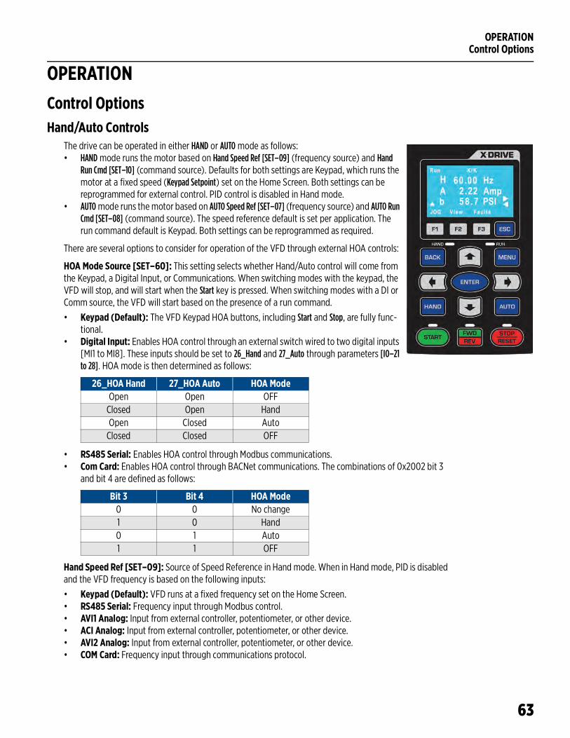
OPERATIONControl Options
63
OPERATIONControl OptionsHand/Auto Controls
The drive can be operated in either HAND or AUTO mode as follows:• HAND mode runs the motor based on Hand Speed Ref [SET–09] (frequency source) and Hand
Run Cmd [SET–10] (command source). Defaults for both settings are Keypad, which runs the motor at a fixed speed (Keypad Setpoint) set on the Home Screen. Both settings can be reprogrammed for external control. PID control is disabled in Hand mode.
• AUTO mode runs the motor based on AUTO Speed Ref [SET–07] (frequency source) and AUTO Run Cmd [SET–08] (command source). The speed reference default is set per application. The run command default is Keypad. Both settings can be reprogrammed as required.
There are several options to consider for operation of the VFD through external HOA controls:
HOA Mode Source [SET–60]: This setting selects whether Hand/Auto control will come from the Keypad, a Digital Input, or Communications. When switching modes with the keypad, the VFD will stop, and will start when the Start key is pressed. When switching modes with a DI or Comm source, the VFD will start based on the presence of a run command.
• Keypad (Default): The VFD Keypad HOA buttons, including Start and Stop, are fully func-tional.
• Digital Input: Enables HOA control through an external switch wired to two digital inputs [MI1 to MI8]. These inputs should be set to 26_Hand and 27_Auto through parameters [IO–21 to 28]. HOA mode is then determined as follows:
• RS485 Serial: Enables HOA control through Modbus communications.• Com Card: Enables HOA control through BACNet communications. The combinations of 0x2002 bit 3
and bit 4 are defined as follows:
Hand Speed Ref [SET–09]: Source of Speed Reference in Hand mode. When in Hand mode, PID is disabled and the VFD frequency is based on the following inputs:
• Keypad (Default): VFD runs at a fixed frequency set on the Home Screen.• RS485 Serial: Frequency input through Modbus control.• AVI1 Analog: Input from external controller, potentiometer, or other device.• ACI Analog: Input from external controller, potentiometer, or other device.• AVI2 Analog: Input from external controller, potentiometer, or other device.• COM Card: Frequency input through communications protocol.
26_HOA Hand 27_HOA Auto HOA ModeOpen Open OFF
Closed Open HandOpen Closed Auto
Closed Closed OFF
Bit 3 Bit 4 HOA Mode0 0 No change1 0 Hand0 1 Auto1 1 OFF
OPERATIONControl Options
64
Hand Run Command [SET–10]: Source of Run Command in Hand mode. VFD starts based on input from:
• Keypad (Default): Run command from Start/Stop buttons.• Digital Input: Run command from digital input FWD or REV terminal.• RS485: Run command from RS485 interface. Keypad STOP is disabled.• Com Card: Run command from communications card.• Ext HOA in Hand: Run command from digital input [IO-21~28] set to HAND.
Auto Speed Ref [SET–07]: Source of Speed Reference in Auto mode. VFD runs at a frequency based on the following inputs:
• Keypad: VFD runs at a fixed frequency set on the Home Screen.• Up/Down DI: Digital input increases or decreases speed when DI terminals [IO-21~28] set to Up and
Down.• AVI1 Analog: Input from external controller, potentiometer, or other device.• ACI Analog: Input from external controller, potentiometer, or other device.• AVI2 Analog: Input from external controller, potentiometer, or other device.• RS485 Serial: Frequency input through Modbus control.• COM Card: Frequency input through communications protocol.• PID Output: VFD speed reference will be provided by PID control based on the difference between PID
Setpoint [SET–21] and transducer feedback values.
IMPORTANT: When PID Mode is selected, additional parameter settings should be verified to ensure correct operation. Refer to “Standard Operation with PID Feedback Control” on page 66 for more infor-mation.
Auto Run Command [SET–08]: Source of Run Command in Auto mode. VFD starts based on input from:
• Keypad (Default): Run command from Start/Stop buttons.• Digital Input: Run command from digital input FWD or REV terminal. • RS485: Run command from RS485 interface. Keypad STOP is disabled.• Com Card: Run command from communications card.• Ext HOA in Auto: Run command from digital input [IO-21~28] set to AUTO.
Forward or Reverse SelectionThis feature provides the ability to change the direction of rotation of a motor used in an industrial applica-tion. The direction can be set using either the keypad FWD/REV button, or by setting the following parameter:
Load Rotation [SET–15]: Setting this parameter to FWD & REV enables the keypad button. Selection of either FWD Only or REV Only permanently sets the direction and disables the keypad button. This provides protection to prevent a motor from running in a direction that could damage equipment, such as a pump or fan.
IMPORTANT: Do not use the Load Rotation setting to correct a motor that is running backwards because of incorrect wiring.
Jog FeatureThe Jog feature provides the ability to activate a motor momentarily. The command can be executed using either the keypad F1 button, or switches connected to a digital input.• When using the keypad, the motor direction depends on the Load Rotation [SET–15] setting. Digital inputs
can be set to either forward or reverse.• The jog command cannot be used when the drive is running.• When the jog command is active, other run commands are unavailable.
Jog Frequency [VFD–55]: This sets the speed the motor will run when the jog command is active.Jog ACC Time [VFD–53]: This sets the acceleration time from 0 Hz to [VFD–55].Jog DEC Time [VFD–55]: This sets the deceleration time from [VFD–55] to 0 Hz.

OPERATIONControl Options
65
FWD Jog [IO–21 through 28]: To execute a forward jog command externally, connect a momentary switch to one of the Digital Inputs (MI1–8) and set the corresponding parameter to 21 FWD Jog.REV Jog [IO–21 through 28]: To execute a reverse jog command externally, connect a momentary switch to one of the Digital Inputs (MI1–8) and set the corresponding parameter to 22 REV Jog.
NOTE: If an external HOA switch is set to OFF, the keypad F1 button is disabled.
Step FrequenciesThe VFD can be operated in a selection of up to 15 user defined pre-set frequencies (speeds) through a com-bination of switched digital inputs [IO-21~28]. These speeds are defined through parameters [VFD–04 to 18].
When a run command is present, selection of a step frequency overrides any previously active speed refer-ence.
The switching combinations for step frequency selection are as follows:
Shutdown The Shutdown feature uses a Digital Input signal [MI1 through MI8] from an external source to stop VFD output in the event of an emergency. The VFD will trip on Shutdown when the DI signal is activated. This function overrides all other functions and VFD cannot be started with any HOA change until stop signal is removed.
Two options are available for restarting:
Latching Mode [IO–21 through 28]: The Shutdown signal must be removed and the Shutdown fault must be manually reset; no auto restarts or retries are available. The VFD can then be restarted with a RUN com-mand. To enable this function, connect the external emergency stop signal to one of the Digital Inputs (MI1–8) and set the corresponding parameter to 36 Shutdown Latched.Non-Latching Mode [IO–21 through 28]: If a RUN command is present when the Shutdown signal is removed, the VFD will restart based on HOA mode. To enable this function, connect the external emergency stop signal to one of the Digital Inputs (MI1–8) and set the corresponding parameter to 35 Shutdown N-Latch.
Only one Digital Input can be set to Shutdown.
Input Selection Parameter Step SpeedSpeed L Speed M Speed H Speed X
1 0 0 0 [VFD-04] Speed 10 1 0 0 [VFD-05] Speed 21 1 0 0 [VFD-06] Speed 30 0 1 0 [VFD-07] Speed 41 0 1 0 [VFD-08] Speed 50 1 1 0 [VFD-09] Speed 61 1 1 0 [VFD-10] Speed 70 0 0 1 [VFD-11] Speed 81 0 0 1 [VFD-12] Speed 90 1 0 1 [VFD-13 Speed 101 1 0 1 [VFD-14] Speed 110 0 1 1 [VFD-15] Speed 121 0 1 1 [VFD-16] Speed 130 1 1 1 [VFD-17 Speed 141 1 1 1 [VFD-18] Speed 15
OPERATIONControl Options
66
Standard Operation with an Automated Control SystemIn many VFD applications, including ventilation, water supply, or irrigation, motor speed is often determined by an automated system such as a BAS, BMS, or PLC. These systems provide control information to the VFD either through a communications protocol such as Modbus or BACnet, or through direct electrical connec-tion to one of the analog input terminals.
When the drive is in AUTO mode, it runs the motor at a variable frequency based on information from the automation system through the input selected in Auto Speed Ref [SET–07].
Standard Operation with PID Feedback ControlA PID controlled application, such as a fan system or a constant pressure pump system, uses feedback from a transducer to measure system performance against a user defined Setpoint (target) to control motor speed. The VFD can use several types of measurement, including pressure, flow, level, air volume, tempera-ture, speed, etc.
For example:• In a pumping application, the default measurement unit is PSI. As user demand (flow) causes pressure
changes, the drive varies the output frequency (motor speed) to maintain pressure at the target set-point. When the drive determines a no-demand condition, it enters Sleep mode and stops the motor.
• In a fan application, the default measurement unit is inWC (air pressure).
When the drive is in AUTO mode, it runs the motor at a variable frequency based on a comparison between the PID Setpoint [SET–21] and feedback from the PID transducer, up to the PID Hi Hz Limit [SET–23]. PID operation is disabled in HAND mode.
When basic setup is complete, including motor specifications, verify or set the following parameters for PID operation:
Auto Speed Ref [SET–07]: This should be set to PID Output.Auto Run Command [SET–08]: Select source of Run Command, either Keypad or external. If using a Digital Input (M1-8) with a switch, set the terminal to FWD (or REV) [IO–21 ~ 28].PID Mode [SET–17]: Set to PID Direct for most PID operations (exceptions are noted in the tables).Feedback Source [SET–18]: Set to the terminal used for transducer connection. Make sure impedance is set correctly.PID Feedback Units [SET–19]: Set to the appropriate measurement unit for the transducer type.PID Feedback Max [SET–20]: Set to the maximum rating of the transducer.PID Setpoint [SET–21]: Set to the desired measurement target.Sleep Mode [SET–26]: This should be enabled for most pump applications, and Disabled for most HVAC applications.PID P-Gain [SET–24]: Proportional Gain controls motor speed adjustments based on the proportional dif-ference between the PID setpoint and PID feedback. Higher settings result in faster response. However, if the value is too high, it may cause system oscillation and instability. Used along with PID I-TIme [SET-25] to smooth and balance system response.PID I Time [SET–25]: Integral Time determines PID response time. Lower values increase system response to the feedback signal, which reduces overshoot, but may cause system oscillation if set too low. Greater values provide slower response, which may cause overshoot of the setpoint and oscillation of output fre-quency.
OPERATIONControl Options
67
Damper Control (HVAC Applications)The VFD can provide a relay output to open a damper actuator before starting a fan motor. When enabled, the damper relay output is activated when the system receives a RUN command and the motor will start based on the following configurations:
• With Damper Limit Switch: If any Digital Input [IO–21 through 28] is set to Damper Limit Sw and the VFD receives a RUN command, the damper relay is activated and when the damper limit switch is closed (damper is fully open and DI is activated), the VFD will start the motor.
If the limit switch is not closed within the Damper Time Delay [IO–37], the VFD will trip on Damper Fault. If at any point during run mode damper limit switch is open for more than 2 seconds, the VFD will trip on Damper Fault. VFD will try to restart based on the retry number setting [PROT–41].
• Without Damper Limit Switch. If no Digital Input is configured for a damper limit switch and the VFD receives a RUN command, the damper relay is activated and when Damper Time Delay [IO–37] is complete, the VFD will start the motor. There is no damper fault detection because there is no damper limit switch feedback.
NOTE: If any other delay timer is set and the VFD receives a RUN command, the damper relay will start after the first timer expires.
During run mode the damper relay stays activated. When a STOP command is received, the damper relay will be deactivated only in VFD stop state. If stop mode is set to deceleration, the relay will be deactivated after VFD reaches zero speed (0.00Hz).
Set the following parameters to use the Damper Control function:
Damper Mode [IO–36]: This setting enables or disables damper mode. When enabled, the damper relay is activated before every start, including auto restarts.Damper T-Delay [IO–37]: This setting provides a run time delay without a damper limit switch; or, provides a Damper Fault delay for systems that include a damper limit switch. The delay should be greater than damper opening time.Damper Output Terminal [IO–47 through 49]: Connect the damper actuator to one of the Relay Outputs (RA1–3), and set the corresponding parameter to 38 Damper Output.Damper Limit SW Terminal [IO–21 through 28]: If the system includes a damper limit switch, connect the switch to one of the Digital Inputs (MI1–8) and set the corresponding parameter to 34 Damper Limit SW.
Fireman’s OverrideFireman’s Override provides the ability to force the drive to run in an emergency situation.
In FO mode, if Damper Mode is enabled [IO–36], the damper relay output will be activated, but damper time delay [IO–37] will be reduced by half before VFD starts. The VFD will not monitor a Damper Switch, if present, and no damper faults will be available. Set the following parameters to use the Fireman’s Override function:
FO Input Terminal [IO–21 through 28]: Connect the Fireman’s Override switch to one of the Digital Inputs (MI1–8) and set the corresponding parameter to either 32 FO with RUN Cmd or 33 FO w/o RUN Cmd.FO Enable [IO–29]: This setting enables Fireman’s Override in either Forward or Reverse.FO Frequency [IO–30]: Setpoint for non-PID operation during Fire Override.FO Fault Retry [IO–31]: Number of fault resets allowed during Fire Override.FO Retry Delay [IO–32: Delay until restart during Fire Override.FO Mode & Reset [IO–33]: Sets control method and reset method during Fire Override: PID Off Manual, PID Off Auto, PID On Manual, or PID On Auto.FO PID S-Point [IO–34]: Setpoint for PID operation during Fire Override. FO Bypass [IO–72]: Enables Bypass for Fire Override.FO Bypass Delay [IO–73]: Time delay between Fire Override becoming active and enabling relay output.
OPERATIONControl Options
68
Pump Application FeaturesSleep Mode with Pressure Boost
The Sleep feature monitors pressure and frequency to detect a no-demand condition, at which point it stops the motor. The Sleep Feature also has the option to boost system pressure by a set amount before stopping.
The Sleep feature works only in Auto mode using PID. PID2 operation does not have Sleep function.
The following parameters control Sleep functions:
Sleep Mode [SET–26]: This setting enables or disables sleep mode and the sleep plus boost option. The default value for submersibles and surface/boost applications is Sleep Only. If a pressure boost is desired while the system is at rest, select Sleep + Boost and set a Sleep Boost Value [SET–29].Sleep Check Time [SET–27]: Time delay (sleep check cycle time) before each Sleep Check procedure. Default = 10 sec.Sleep Delay [SET–28]: Delay before VFD triggers Sleep Mode when all other conditions are met. Default = 6 sec.Sleep Boost Value [SET–29]: Value added to original setpoint to provide pressure boost—0.0 to 10.0% of Feedback Max Value [SET–20]. Default = 3%.Sleep-Boost Timer [SET–30]: Timer that limits sleep boost duration if Sleep Boost setpoint is not reached—5 to 120 seconds. Default = 10 sec.Wakeup Level [SET–31]: Sets a wakeup level for VFD to quit Sleep mode and start running—0.0 to [SET-21]. Default = 55 PSI.Sleep Bump Timer [SET–32]: Sets a duration time for pressure bump to increase system pressure as part of the no-demand calculation. Default = 5 sec. No Flow Mode [IO–38]: If a flow switch is installed on one of the Digital Inputs (MI1–8) and [IO-38] is set to Sleep, the flow switch becomes an additional condition for sleep mode. If Sleep Delay timer has started and at any time before the timer expires the flow switch opens, the VFD will immediately go to either sleep mode (no Sleep Boost) or to Sleep Boost mode (with S-boost enabled).
All default settings related to Sleep mode have been calculated for best system performance for most appli-cations. However, some well conditions may require a slight adjustment.
During system setup it is recommended to test the Sleep feature by closing a main valve to simulate a no-demand condition. The system should be running at normal demand, maintaining pressure setpoint, then flow should be decreased slowly until stopped.
• If the system does not enter Sleep mode, it may be necessary to increase the PID Lo Hz Limit [SET–22] to ensure that system pressure reaches PID Setpoint [SET–21] (plus boost, if enabled).
• If, during normal operation, the system enters Sleep mode, but cycles on and off rapidly as it nears the Setpoint, it may be necessary to slightly lower the PID Lo Hz Limit [SET–22] to prevent Sleep mode prob-lems.
Pipe Fill FeatureThis feature automates the process of building pressure in an empty pipe system at a reduced speed before the VFD switches to PID control. This can reduce water hammer in some systems, and can also help prevent an Underload fault if the drive runs for an extended period at low pressure. The VFD must be running with PID Control in Auto mode for this feature to be active.
Set the following parameters to activate the Pipe Fill Feature:
OPERATIONControl Options
69
Pipe Fill Timer [SET–33]: Pipe Fill mode exit timer to switch to PID control.
• Enter a time between 0.1 and 60 minutes to allow the pipe system to fill.• If set to 0.0, Pipe Fill is disabled.• When the timer expires, the VFD cancels Pipe Fill mode and switches to PID control, regardless of
whether [SET–34] pressure has been reached.
Pipe Fill Exit Level [SET–34]: Pipe Fill mode exit pressure to switch to PID control.
• Enter a pressure setting between 0 and the PID Setpoint [SET–21] (default = 25 psi).• During Pipe Fill mode, if pressure reaches the set value, VFD switches to PID control.
Pipe Fill Freq [SET–35]: Pipe Fill mode High frequency limit setting.
• Range is between PID Low Freq Limit [SET–22] and PID Hi Hz Limit [SET–23] (default = 47 Hz).• The Pipe Fill mode frequency should be equal to or greater than [SET–22] +2 Hz to provide enough sys-
tem pressure at the end of pipe fill mode to switch to PID control.
Upon start, if system pressure is less than [SET–34], VFD will ramp up to Low Freq Limit + 2 and start pipe fill mode.
• If system pressure is less than 0.5 x [SET–34], the frequency reference will be increased at a rate of 0.5 Hz per second.
• If system pressure is equal to or greater than 0.5 x [SET–34] but less than 0.6 x [SET–34], the frequency reference will stay at the current value.
• If system pressure is equal to or greater than 0.6 x [SET–34] but less than [SET–34] setting, the fre-quency reference will be decreased at a 0.5Hz per second rate. However, the rate will not be decreased below PID Low Hz Limit [SET–22] +2 Hz.
• If at any point system pressure is equal to or greater than [SET–34], VFD will cancel Pipe Fill mode and switch to PID control.
Lubrication RelayThe VFD has the capability to automatically activate a lubrication solenoid for line shaft turbine pumps, or for industrial machines with an external lubrication supply, before starting the motor.
Timers are available to enable lubrication before, during, or after running the motor, in any combination.
To enable the lubrication function, set the following parameters:
Lubrication Output Terminal [IO–47 through 49]: Connect the lubrication actuator to one of the Relay Outputs (RA1–3), and set the corresponding parameter to 41 Lube/S-Clean.Lube/S-Clean [IO–41]: Select the Lubrication option.Pre-Lube Timer [IO–43]: 0 to 6000 seconds. This setting determines relay activation time after a run com-mand is received and before the VFD starts. When the timer expires, the lubrication solenoid will be deacti-vated and the VFD will start the motor. If a stop command is received, or the VFD trips during Pre-lubrication, the relay will be deactivated and the timer accumulated value will be reset.Run-Lube Timer [IO–44]: 0 to 6000 seconds. This setting determines relay activation time while the VFD is running.• When set to a value greater than 0 and less than 6000, the relay will be activated at VFD start and will
deactivate when the timer expires. If the VFD stops while the timer is active, the relay will deactivate and the timer will be reset.
• If the timer is set to the maximum 6000 sec, the relay will be activated during run mode until the VFD stops (no timing). If the VFD stops or trips, the relay will deactivate.
Post-Lube Tmr [IO–45]: 0 to 6000 seconds. This setting determines relay activation time after the VFD comes to a stop (0 Hz).
OPERATIONControl Options
70
Screen Clean RelayWhen water is pumped from a lake or pond, the suction screen requires periodic cleaning. The VFD can automate this process by providing a relay output to an external solenoid valve that will discharge pressur-ized water to clean the screen.
This feature works only in run mode in HOA Hand or Auto. If HOA is in OFF, or the VFD stops or trips on a fault, the Clean Screen mode will be deactivated and related timers will be reset.
The VFD provides a one minute (non-adjustable) cleaning pulse at every start. When the cleaning pulse is done, the S-Clean Timer [IO–42] starts. When the timer ends, another cleaning pulse is activated. This cycle continues until the VFD stops.
To enable the Clean Screen function, set the following parameters:
Screen Clean Output Terminal [IO–47 through 49]: Connect the lubrication actuator to one of the Relay Outputs (RA1–3), and set the corresponding parameter to 41 Lube/S-Clean.Lube/S-Clean [IO–41]: Select the Screen Clean option.S-Clean Timer [IO–42]: 0 to 600 minutes. Time between cleaning pulses.
TimersIMPORTANT: If two or more timers are activated with different time settings, the greater value timer will override other timers with a similar function.
Power On Run DelayThis timer provides run delay at VFD power-up with run command present to prevent multiple starts during power surges.
Set the following parameter to activate this feature:
Power On Delay [ADV–28]: Range from 0 to 6000 sec. (Default=10sec). When set to 0 sec, it is disabled.
When set to a value greater than 0 and VFD is powered up in any HOA mode, the timer will start counting and VFD start will be disabled until the timer expires.
Run Delay Timer (For Auto Mode)This timer provides a delay at every VFD start when a run command is applied. The timer takes effect before every VFD start by run command, auto-restarts, fault reset, sleep wake-up, etc.
NOTE: FO (Fire Override) mode will disable this timer.
Set the following parameter to activate this feature:
Run Delay Timer [ADV–29]: Range from 0 to 6000 sec. (Default=0 sec). When set to 0 sec, it is disabled.
When set to value greater than 0 and VFD receives a start command, wakes up, auto resets, or restarts after a fault reset, the Start Delay timer will start counting. During timer counting, start is disabled and the VFD cannot be started in Hand or Auto mode. Stop command, Sleep mode, or tripping on a fault will reset this timer.
Minimum Run TimerThe Minimum Run timer delays VFD stop when a run command is removed. This timer is useful in vacuum pump, pressure washer and similar applications.
Submersible motors should run for a minimum of one minute to dissipate heat build-up from starting cur-rent.
Set the following parameter to activate this feature:
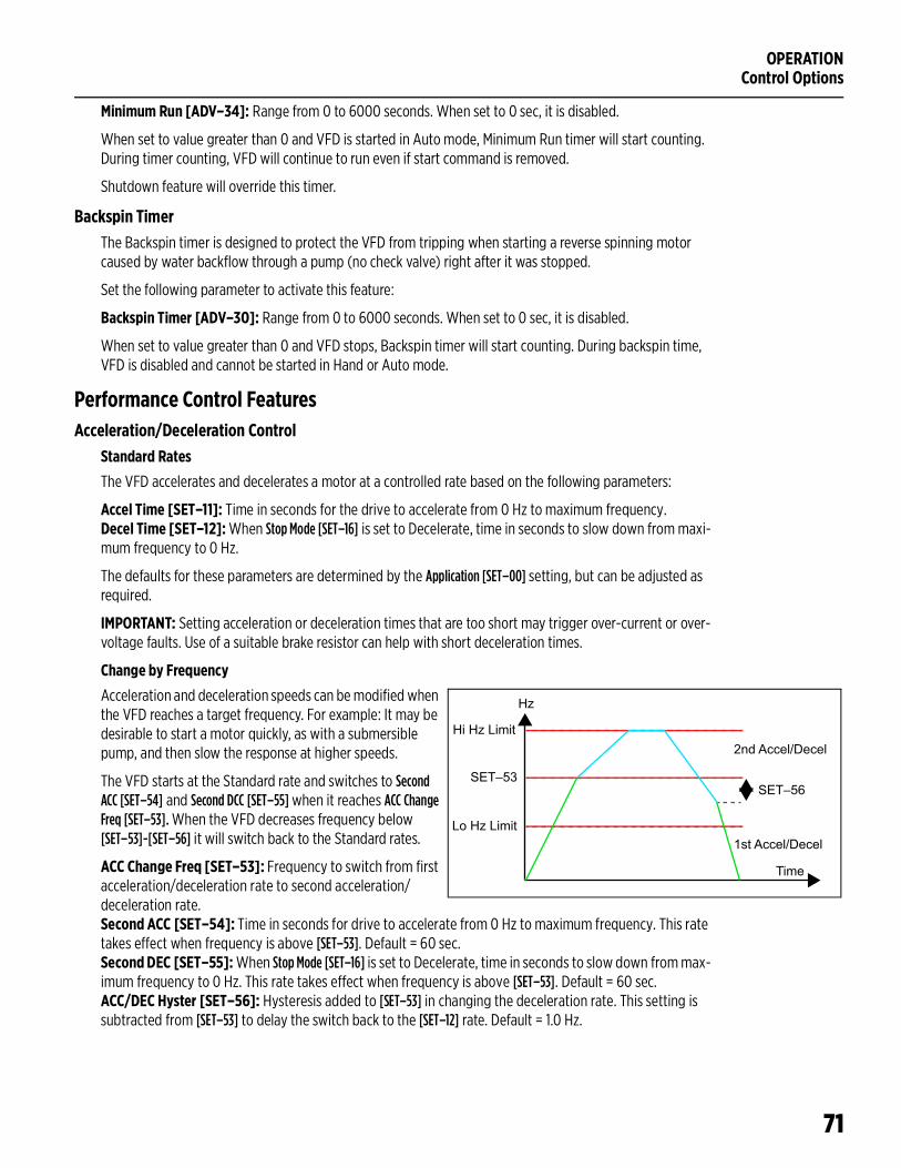
OPERATIONControl Options
71
Minimum Run [ADV–34]: Range from 0 to 6000 seconds. When set to 0 sec, it is disabled.
When set to value greater than 0 and VFD is started in Auto mode, Minimum Run timer will start counting. During timer counting, VFD will continue to run even if start command is removed.
Shutdown feature will override this timer.
Backspin TimerThe Backspin timer is designed to protect the VFD from tripping when starting a reverse spinning motor caused by water backflow through a pump (no check valve) right after it was stopped.
Set the following parameter to activate this feature:
Backspin Timer [ADV–30]: Range from 0 to 6000 seconds. When set to 0 sec, it is disabled.
When set to value greater than 0 and VFD stops, Backspin timer will start counting. During backspin time, VFD is disabled and cannot be started in Hand or Auto mode.
Performance Control FeaturesAcceleration/Deceleration Control
Standard Rates
The VFD accelerates and decelerates a motor at a controlled rate based on the following parameters:
Accel Time [SET–11]: Time in seconds for the drive to accelerate from 0 Hz to maximum frequency.Decel Time [SET–12]: When Stop Mode [SET–16] is set to Decelerate, time in seconds to slow down from maxi-mum frequency to 0 Hz.
The defaults for these parameters are determined by the Application [SET–00] setting, but can be adjusted as required.
IMPORTANT: Setting acceleration or deceleration times that are too short may trigger over-current or over-voltage faults. Use of a suitable brake resistor can help with short deceleration times.
Change by Frequency
Acceleration and deceleration speeds can be modified when the VFD reaches a target frequency. For example: It may be desirable to start a motor quickly, as with a submersible pump, and then slow the response at higher speeds.
The VFD starts at the Standard rate and switches to Second ACC [SET–54] and Second DCC [SET–55] when it reaches ACC Change Freq [SET–53]. When the VFD decreases frequency below [SET–53]-[SET–56] it will switch back to the Standard rates.
ACC Change Freq [SET–53]: Frequency to switch from first acceleration/deceleration rate to second acceleration/deceleration rate.Second ACC [SET–54]: Time in seconds for drive to accelerate from 0 Hz to maximum frequency. This rate takes effect when frequency is above [SET–53]. Default = 60 sec.Second DEC [SET–55]: When Stop Mode [SET–16] is set to Decelerate, time in seconds to slow down from max-imum frequency to 0 Hz. This rate takes effect when frequency is above [SET–53]. Default = 60 sec.ACC/DEC Hyster [SET–56]: Hysteresis added to [SET–53] in changing the deceleration rate. This setting is subtracted from [SET–53] to delay the switch back to the [SET–12] rate. Default = 1.0 Hz.
Hz
Hi Hz Limit
Lo Hz Limit
SET–53SET–56
Time
2nd Accel/Decel
1st Accel/Decel
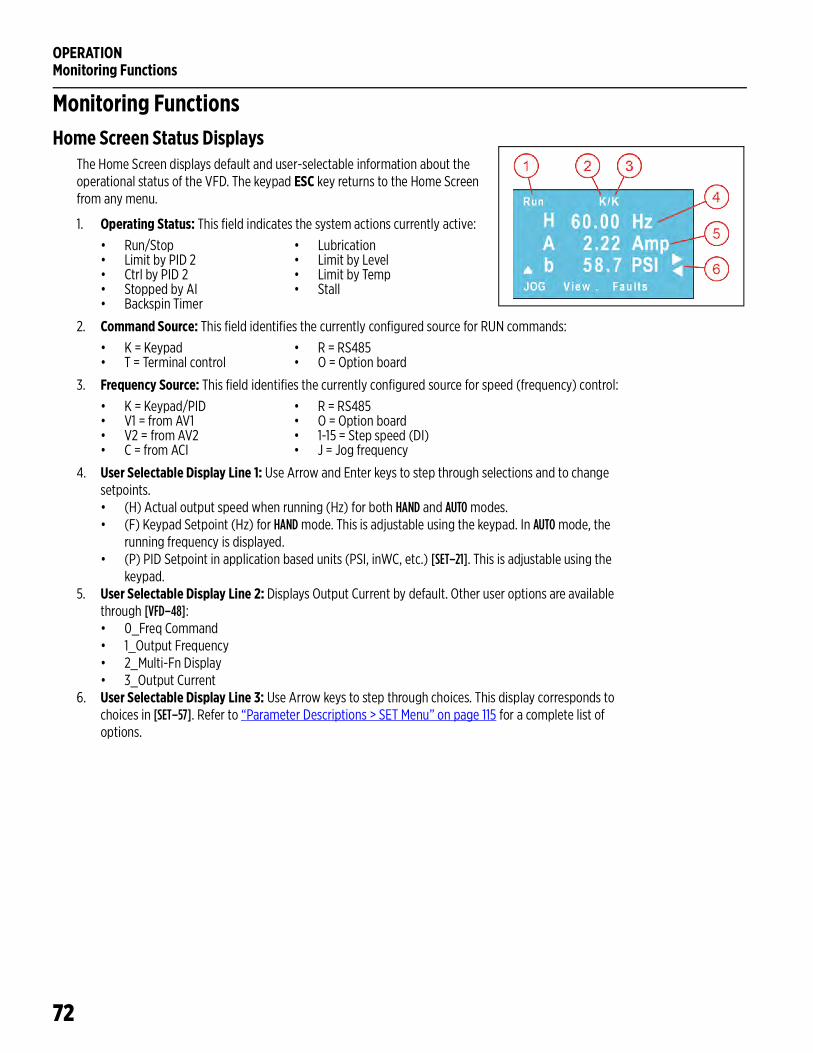
OPERATIONMonitoring Functions
72
Monitoring FunctionsHome Screen Status Displays
The Home Screen displays default and user-selectable information about the operational status of the VFD. The keypad ESC key returns to the Home Screen from any menu.
1. Operating Status: This field indicates the system actions currently active:
2. Command Source: This field identifies the currently configured source for RUN commands:
3. Frequency Source: This field identifies the currently configured source for speed (frequency) control:
4. User Selectable Display Line 1: Use Arrow and Enter keys to step through selections and to change setpoints.• (H) Actual output speed when running (Hz) for both HAND and AUTO modes.• (F) Keypad Setpoint (Hz) for HAND mode. This is adjustable using the keypad. In AUTO mode, the
running frequency is displayed.• (P) PID Setpoint in application based units (PSI, inWC, etc.) [SET–21]. This is adjustable using the
keypad.5. User Selectable Display Line 2: Displays Output Current by default. Other user options are available
through [VFD–48]:• 0_Freq Command• 1_Output Frequency• 2_Multi-Fn Display• 3_Output Current
6. User Selectable Display Line 3: Use Arrow keys to step through choices. This display corresponds to choices in [SET–57]. Refer to “Parameter Descriptions > SET Menu” on page 115 for a complete list of options.
• Run/Stop • Lubrication• Limit by PID 2 • Limit by Level• Ctrl by PID 2 • Limit by Temp• Stopped by AI • Stall• Backspin Timer
• K = Keypad • R = RS485• T = Terminal control • O = Option board
• K = Keypad/PID • R = RS485• V1 = from AV1 • O = Option board• V2 = from AV2 • 1-15 = Step speed (DI)• C = from ACI • J = Jog frequency
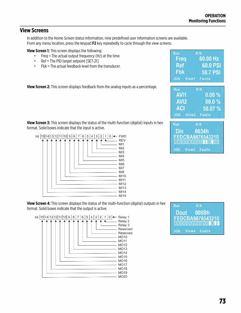
OPERATIONMonitoring Functions
73
View ScreensIn addition to the Home Screen status information, nine predefined user information screens are available. From any menu location, press the keypad F2 key repeatedly to cycle through the view screens.
View Screen 1: This screen displays the following:• Freq = The actual output frequency (Hz) at the time• Ref = The PID target setpoint [SET-21]• Fbk = The actual feedback level from the transducer.
View Screen 2: This screen displays feedback from the analog inputs as a percentage.
View Screen 3: This screen displays the status of the multi-function (digital) inputs in hex format. Solid boxes indicate that the input is active.
View Screen 4: This screen displays the status of the multi-function (digital) outputs in hex format. Solid boxes indicate that the output is active.
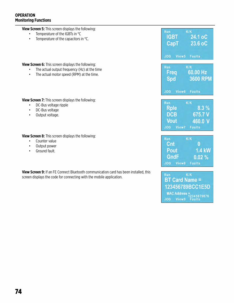
OPERATIONMonitoring Functions
74
View Screen 5: This screen displays the following:• Temperature of the IGBTs in °C• Temperature of the capacitors in °C.
View Screen 6: This screen displays the following:• The actual output frequency (Hz) at the time• The actual motor speed (RPM) at the time.
View Screen 7: This screen displays the following:• DC-Bus voltage ripple• DC-Bus voltage• Output voltage.
View Screen 8: This screen displays the following:• Counter value• Output power• Ground fault.
View Screen 9: If an FE Connect Bluetooth communication card has been installed, this screen displays the code for connecting with the mobile application.
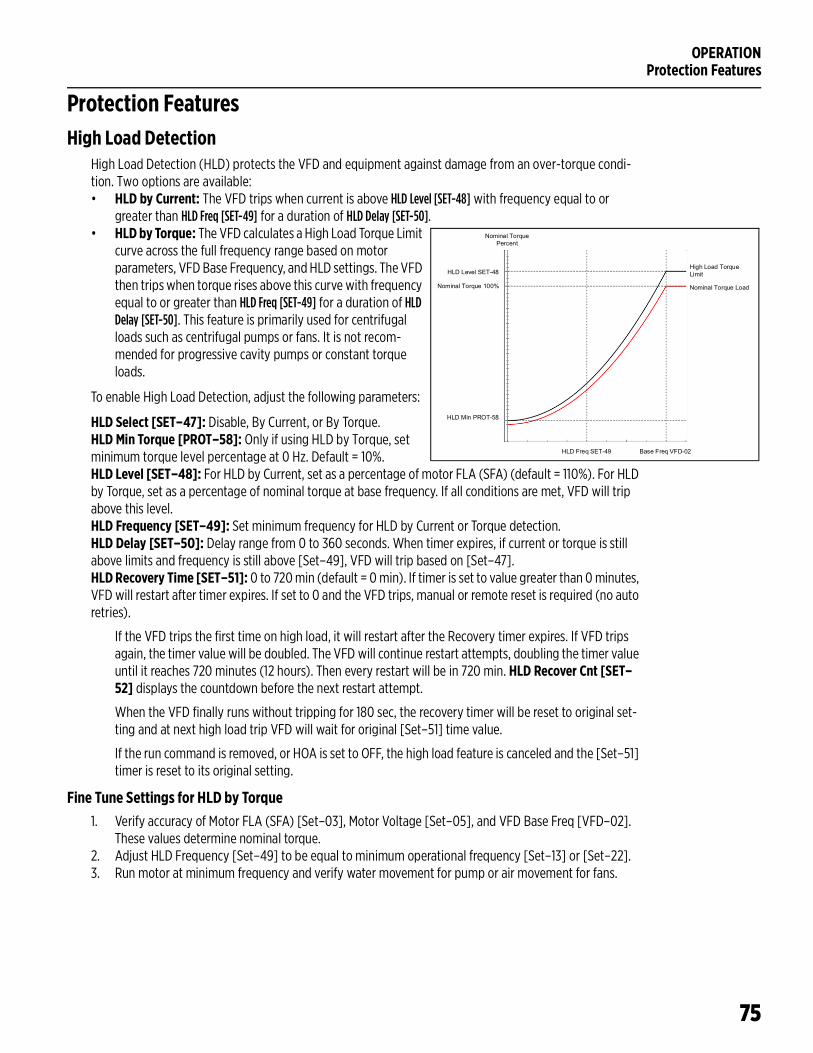
OPERATIONProtection Features
75
Protection FeaturesHigh Load Detection
High Load Detection (HLD) protects the VFD and equipment against damage from an over-torque condi-tion. Two options are available:• HLD by Current: The VFD trips when current is above HLD Level [SET-48] with frequency equal to or
greater than HLD Freq [SET-49] for a duration of HLD Delay [SET-50].• HLD by Torque: The VFD calculates a High Load Torque Limit
curve across the full frequency range based on motor parameters, VFD Base Frequency, and HLD settings. The VFD then trips when torque rises above this curve with frequency equal to or greater than HLD Freq [SET-49] for a duration of HLD Delay [SET-50]. This feature is primarily used for centrifugal loads such as centrifugal pumps or fans. It is not recom-mended for progressive cavity pumps or constant torque loads.
To enable High Load Detection, adjust the following parameters:
HLD Select [SET–47]: Disable, By Current, or By Torque.HLD Min Torque [PROT–58]: Only if using HLD by Torque, set minimum torque level percentage at 0 Hz. Default = 10%.HLD Level [SET–48]: For HLD by Current, set as a percentage of motor FLA (SFA) (default = 110%). For HLD by Torque, set as a percentage of nominal torque at base frequency. If all conditions are met, VFD will trip above this level.HLD Frequency [SET–49]: Set minimum frequency for HLD by Current or Torque detection.HLD Delay [SET–50]: Delay range from 0 to 360 seconds. When timer expires, if current or torque is still above limits and frequency is still above [Set–49], VFD will trip based on [Set–47].HLD Recovery Time [SET–51]: 0 to 720 min (default = 0 min). If timer is set to value greater than 0 minutes, VFD will restart after timer expires. If set to 0 and the VFD trips, manual or remote reset is required (no auto retries).
If the VFD trips the first time on high load, it will restart after the Recovery timer expires. If VFD trips again, the timer value will be doubled. The VFD will continue restart attempts, doubling the timer value until it reaches 720 minutes (12 hours). Then every restart will be in 720 min. HLD Recover Cnt [SET–52] displays the countdown before the next restart attempt.
When the VFD finally runs without tripping for 180 sec, the recovery timer will be reset to original set-ting and at next high load trip VFD will wait for original [Set–51] time value.
If the run command is removed, or HOA is set to OFF, the high load feature is canceled and the [Set–51] timer is reset to its original setting.
Fine Tune Settings for HLD by Torque1. Verify accuracy of Motor FLA (SFA) [Set–03], Motor Voltage [Set–05], and VFD Base Freq [VFD–02].
These values determine nominal torque.2. Adjust HLD Frequency [Set–49] to be equal to minimum operational frequency [Set–13] or [Set–22].3. Run motor at minimum frequency and verify water movement for pump or air movement for fans.
Nominal Torque Percent
High Load Torque Limit
Nominal Torque Load
Base Freq VFD-02HLD Freq SET-49
HLD Level SET-48
HLD Min PROT-58
Nominal Torque 100%
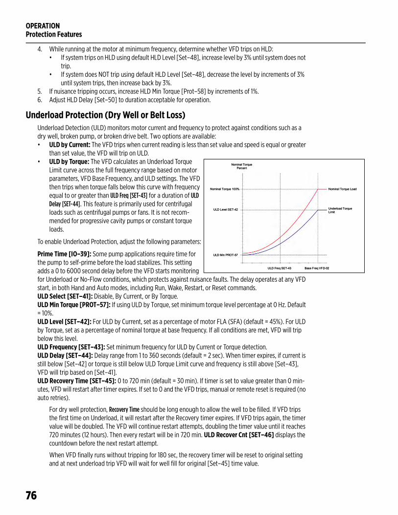
OPERATIONProtection Features
76
4. While running at the motor at minimum frequency, determine whether VFD trips on HLD:• If system trips on HLD using default HLD Level [Set–48], increase level by 3% until system does not
trip.• If system does NOT trip using default HLD Level [Set–48], decrease the level by increments of 3%
until system trips, then increase back by 3%.5. If nuisance tripping occurs, increase HLD Min Torque [Prot–58] by increments of 1%.6. Adjust HLD Delay [Set–50] to duration acceptable for operation.
Underload Protection (Dry Well or Belt Loss) Underload Detection (ULD) monitors motor current and frequency to protect against conditions such as a dry well, broken pump, or broken drive belt. Two options are available:• ULD by Current: The VFD trips when current reading is less than set value and speed is equal or greater
than set value, the VFD will trip on ULD.• ULD by Torque: The VFD calculates an Underload Torque
Limit curve across the full frequency range based on motor parameters, VFD Base Frequency, and ULD settings. The VFD then trips when torque falls below this curve with frequency equal to or greater than ULD Freq [SET-43] for a duration of ULD Delay [SET-44]. This feature is primarily used for centrifugal loads such as centrifugal pumps or fans. It is not recom-mended for progressive cavity pumps or constant torque loads.
To enable Underload Protection, adjust the following parameters:
Prime Time [IO–39]: Some pump applications require time for the pump to self-prime before the load stabilizes. This setting adds a 0 to 6000 second delay before the VFD starts monitoring for Underload or No-Flow conditions, which protects against nuisance faults. The delay operates at any VFD start, in both Hand and Auto modes, including Run, Wake, Restart, or Reset commands.ULD Select [SET–41]: Disable, By Current, or By Torque.ULD Min Torque [PROT–57]: If using ULD by Torque, set minimum torque level percentage at 0 Hz. Default = 10%.ULD Level [SET–42]: For ULD by Current, set as a percentage of motor FLA (SFA) (default = 45%). For ULD by Torque, set as a percentage of nominal torque at base frequency. If all conditions are met, VFD will trip below this level. ULD Frequency [SET–43]: Set minimum frequency for ULD by Current or Torque detection.ULD Delay [SET–44]: Delay range from 1 to 360 seconds (default = 2 sec). When timer expires, if current is still below [Set–42] or torque is still below ULD Torque Limit curve and frequency is still above [Set–43], VFD will trip based on [Set–41].ULD Recovery Time [SET–45]: 0 to 720 min (default = 30 min). If timer is set to value greater than 0 min-utes, VFD will restart after timer expires. If set to 0 and the VFD trips, manual or remote reset is required (no auto retries).
For dry well protection, Recovery Time should be long enough to allow the well to be filled. If VFD trips the first time on Underload, it will restart after the Recovery timer expires. If VFD trips again, the timer value will be doubled. The VFD will continue restart attempts, doubling the timer value until it reaches 720 minutes (12 hours). Then every restart will be in 720 min. ULD Recover Cnt [SET–46] displays the countdown before the next restart attempt.
When VFD finally runs without tripping for 180 sec, the recovery timer will be reset to original setting and at next underload trip VFD will wait for well fill for original [Set–45] time value.
Nominal Torque Percent
Nominal Torque Load
Underload Torque Limit
Base Freq VFD-02ULD Freq SET-43
ULD Level SET-42
ULD Min PROT-57
Nominal Torque 100%
Nominal Torque Percent
Nominal Torque Load
Underload Torque Limit
Base Freq VFD-02ULD Freq SET-43
ULD Level SET-42
ULD Min PROT-57
Nominal Torque 100%
OPERATIONProtection Features
77
If the run command is removed, or HOA is set to OFF, the Underload feature is canceled and the [Set–45] timer is reset to its original setting.
Fine Tune Settings for ULD by Torque1. Verify accuracy of Motor FLA (SFA) [Set–03], Motor Voltage [Set–05], and VFD Base Freq [VFD–02].
These values determine nominal torque.2. Adjust ULD Frequency [Set–43] to be equal to minimum operational frequency [Set–13] or [Set–22].3. Run motor at minimum frequency and verify water movement for pump or air movement for fans.4. While running the motor at minimum frequency, determine whether VFD trips on ULD:
• If system trips on HLD using default ULD Level [Set–42], decrease level by 03% until system does not trip.
• If system does NOT trip using default ULD Level [Set–42], increase the level by increments of 3% until system trips, then decrease back by 3%.
5. If nuisance tripping occurs, lower ULD Min Torque [Prot–57] by increments of 1%.6. Adjust ULD Delay [Set–44] to duration acceptable for operation.7. Adjust ULD Recovery Time [Set–45] to a duration that fills-up well enough to allow motor to run mini-
mum time before another ULD trip.
OverpressureThe Overpressure feature stops the VFD when PID feedback exceeds a set value in either Hand or Auto.
To enable this feature, adjust the following parameters:
OverPress Set [SET–39]: Disable, OP Trip, or OP Auto Reset.• When enabled, if PID Feedback exceeds OverPress Level [SET–40], the VFD trips on Overpressure fault.• If setting is OP Trip, manual or remote reset is required. If Reset Restart [VFD–36] is enabled and a run
command is present, the VFD will restart when reset.• If setting is OP Auto Reset, the VFD will restart when PID feedback falls below Wake-Up Level [SET–31]
and a run command is still present.
OverPress Level [SET–40]: Overpressure trigger level in PID feedback units, 0.0 to SET-20 (Unit) PID F/B Max.
OPERATIONProtection Features
78
No Flow ProtectionThe VFD can monitor a system flow switch to provide pump protection and more reliable sleep mode oper-ation.
Flow Switch Terminal [IO–21 through 28]: Connect the flow switch to one of the Digital Inputs (MI1–8) and set the corresponding parameter to 37 Flow Switch.No Flow Mode [IO–38]: Disabled, Trip, or Sleep. Default = Disabled.Prime Time [IO–39]: Some pump applications require time for the pump to self-prime before the load sta-bilizes. This setting adds a 0 to 6000 second delay before the VFD starts monitoring for Underload or No-Flow conditions, which protects against nuisance faults. The delay operates at any VFD start, in both Hand and Auto modes, including Run, Wake, Restart, or Reset commands.No Flow Freq [IO–40]: Range from PID/VFD Freq Low Limit to PID/VFD Freq High Limit. Default= 20.0Hz or 40Hz based on application.
When [IO–38] is set to Trip and the VFD runs at a frequency greater than [IO–40] longer than [IO–39] with the flow switch contact open, the VFD will trip on No Flow Fault. If the switch closes during the delay, the delay timer will be reset and will start again if the flow switch contact opens again.
When [IO–38] is set to Sleep, the flow switch will become an additional condition for sleep mode. When VFD runs with PID control and determines that all sleep mode conditions are met and the flow switch is open during Sleep delay, VFD will go into sleep mode.
Broken Pipe Protection (for Pump Applications)The VFD has the ability to detect a broken pipe in the system. The VFD must be running with PID Control in Auto mode for this feature to be active.
To enable this feature, adjust the following parameters:
Broken Pipe Level [SET–36]: 0.0 to PID F/B Max [Set–20]. Setting of 0.0 disables the feature. When pres-sure falls below this level and VFD continues to run above [Set–37], delay timer [SET-38] starts.Broken Pipe Freq [SET–37]: PID Low Freq [Set–22] to PID High Freq [Set–23] (default = 59.5 Hz).Broken Pipe Delay [SET–38]: 0.0 to 6000 seconds (default = 180 sec). If either of the first two conditions is removed, the timer will reset. If the timer expires with both conditions still active, the VFD will trip on Bro-ken Pipe fault.
Manual or remote reset is required.
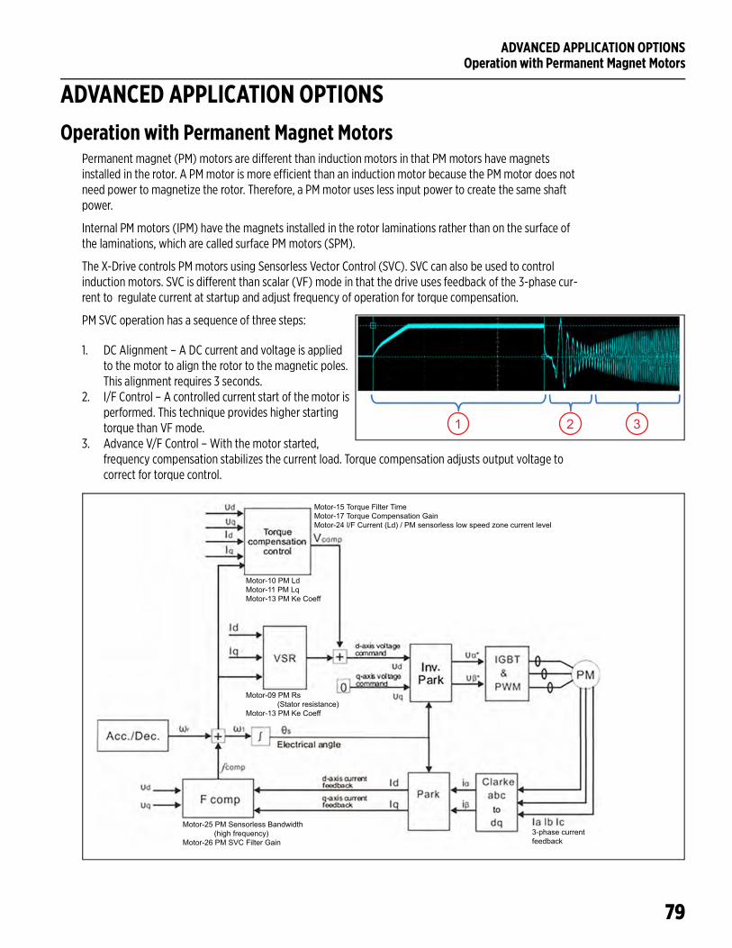
ADVANCED APPLICATION OPTIONSOperation with Permanent Magnet Motors
79
ADVANCED APPLICATION OPTIONSOperation with Permanent Magnet Motors
Permanent magnet (PM) motors are different than induction motors in that PM motors have magnets installed in the rotor. A PM motor is more efficient than an induction motor because the PM motor does not need power to magnetize the rotor. Therefore, a PM motor uses less input power to create the same shaft power.
Internal PM motors (IPM) have the magnets installed in the rotor laminations rather than on the surface of the laminations, which are called surface PM motors (SPM).
The X-Drive controls PM motors using Sensorless Vector Control (SVC). SVC can also be used to control induction motors. SVC is different than scalar (VF) mode in that the drive uses feedback of the 3-phase cur-rent to regulate current at startup and adjust frequency of operation for torque compensation.
PM SVC operation has a sequence of three steps:
1. DC Alignment – A DC current and voltage is applied to the motor to align the rotor to the magnetic poles. This alignment requires 3 seconds.
2. I/F Control – A controlled current start of the motor is performed. This technique provides higher starting torque than VF mode.
3. Advance V/F Control – With the motor started, frequency compensation stabilizes the current load. Torque compensation adjusts output voltage to correct for torque control.
1 2 3
Motor-15 Torque Filter TimeMotor-17 Torque Compensation GainMotor-24 I/F Current (Ld) / PM sensorless low speed zone current level
Motor-10 PM LdMotor-11 PM LqMotor-13 PM Ke Coeff
Motor-09 PM Rs (Stator resistance)Motor-13 PM Ke Coeff
Motor-25 PM Sensorless Bandwidth (high frequency)Motor-26 PM SVC Filter Gain
3-phase current feedback
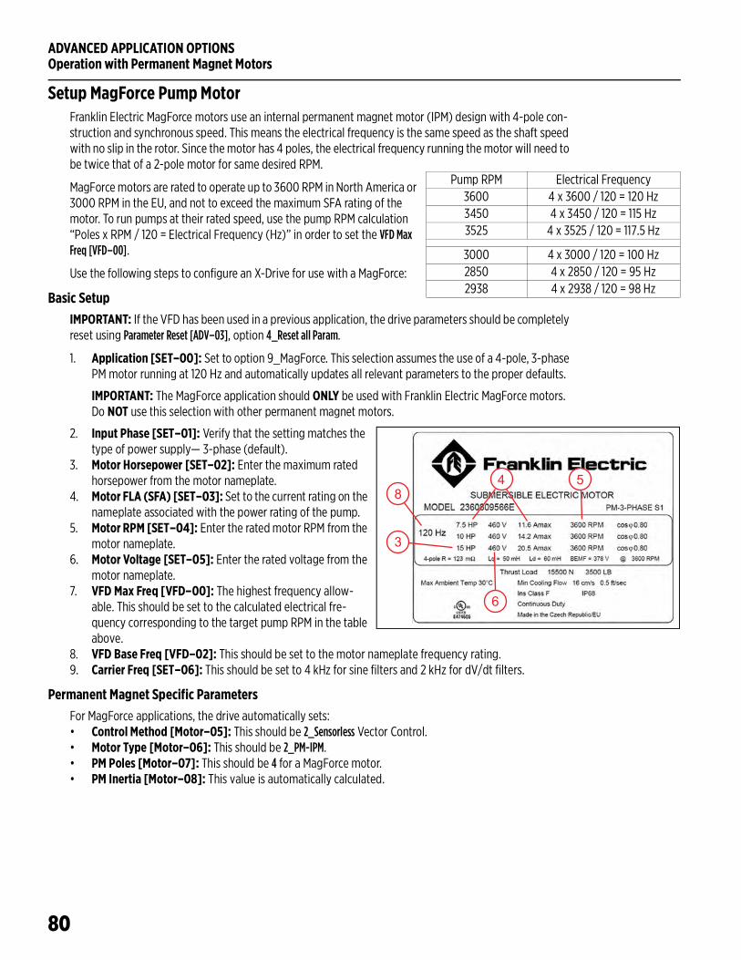
ADVANCED APPLICATION OPTIONSOperation with Permanent Magnet Motors
80
Setup MagForce Pump MotorFranklin Electric MagForce motors use an internal permanent magnet motor (IPM) design with 4-pole con-struction and synchronous speed. This means the electrical frequency is the same speed as the shaft speed with no slip in the rotor. Since the motor has 4 poles, the electrical frequency running the motor will need to be twice that of a 2-pole motor for same desired RPM.
MagForce motors are rated to operate up to 3600 RPM in North America or 3000 RPM in the EU, and not to exceed the maximum SFA rating of the motor. To run pumps at their rated speed, use the pump RPM calculation “Poles x RPM / 120 = Electrical Frequency (Hz)” in order to set the VFD Max Freq [VFD–00].
Use the following steps to configure an X-Drive for use with a MagForce:
Basic SetupIMPORTANT: If the VFD has been used in a previous application, the drive parameters should be completely reset using Parameter Reset [ADV–03], option 4_Reset all Param.
1. Application [SET–00]: Set to option 9_MagForce. This selection assumes the use of a 4-pole, 3-phase PM motor running at 120 Hz and automatically updates all relevant parameters to the proper defaults.
IMPORTANT: The MagForce application should ONLY be used with Franklin Electric MagForce motors. Do NOT use this selection with other permanent magnet motors.
2. Input Phase [SET–01]: Verify that the setting matches the type of power supply— 3-phase (default).
3. Motor Horsepower [SET–02]: Enter the maximum rated horsepower from the motor nameplate.
4. Motor FLA (SFA) [SET–03]: Set to the current rating on the nameplate associated with the power rating of the pump.
5. Motor RPM [SET–04]: Enter the rated motor RPM from the motor nameplate.
6. Motor Voltage [SET–05]: Enter the rated voltage from the motor nameplate.
7. VFD Max Freq [VFD–00]: The highest frequency allow-able. This should be set to the calculated electrical fre-quency corresponding to the target pump RPM in the table above.
8. VFD Base Freq [VFD–02]: This should be set to the motor nameplate frequency rating.9. Carrier Freq [SET–06]: This should be set to 4 kHz for sine filters and 2 kHz for dV/dt filters.
Permanent Magnet Specific ParametersFor MagForce applications, the drive automatically sets:• Control Method [Motor–05]: This should be 2_Sensorless Vector Control.• Motor Type [Motor–06]: This should be 2_PM-IPM.• PM Poles [Motor–07]: This should be 4 for a MagForce motor.• PM Inertia [Motor–08]: This value is automatically calculated.
Pump RPM Electrical Frequency3600 4 x 3600 / 120 = 120 Hz3450 4 x 3450 / 120 = 115 Hz3525 4 x 3525 / 120 = 117.5 Hz
3000 4 x 3000 / 120 = 100 Hz2850 4 x 2850 / 120 = 95 Hz2938 4 x 2938 / 120 = 98 Hz
3
84 5
6
ADVANCED APPLICATION OPTIONSOperation with Permanent Magnet Motors
81
Motor Specific ParametersFor MagForce applications, the drive automatically sets:• PM Rs [Motor-09]: Motor stator resistance. • PM Ld [Motor-10]: Motor inductance d-axis.• PM Lq [Motor-11]: Motor inductance q-axis.• PM Ke Coeff [Motor-13]: Motor parameter Ke (Vphase, rms / krpm).
Autotune Characteristic ParametersFor MagForce applications, autotune is not needed. However, if the drive consistently exceeds the motor current specification during DC Alignment and I/F control, then an autotune may be needed. Refer to “Autotune Characteristic Parameters” on page 82.
Tune motor control – DC AlignmentFor MagForce applications, no adjustments are needed. However, if there are problems during DC Align-ment, refer to “Tune motor control – DC Alignment” on page 82.
Tune motor control - I/F Control For MagForce applications, no adjustments are needed. However, if there are problems during I/F Control, refer to “Tune motor control - I/F Control” on page 82.
Tune motor control - PM ControlFor MagForce applications, no adjustments are needed. However, if there are problems during PM Control, refer to “Tune motor control - PM Control” on page 83.
Setup Non-Franklin Electric PM MotorsThe X-Drive can be programmed to operate general purpose permanent magnet motors through the follow-ing procedure:
Basic SetupIMPORTANT: If the VFD has been used in a previous application, the drive parameters should be completely reset using Parameter Reset [ADV–03], option 4_Reset all Param.
1. Application [SET–00]: Set to option 8_PM Motor. This selection assumes the use of a 4-pole, 3-phase PM motor running at 120 Hz and automatically updatesrelevant parameters to the proper defaults.
IMPORTANT: Do NOT use the MagForce selection with non-Franklin Electric permanent magnet motors.
2. Input Phase [SET–01]: Verify that the setting matches the type of power supply— 3-phase (default).3. Motor Horsepower [SET–02]: Enter the maximum rated horsepower from the motor nameplate.4. Motor FLA (SFA) [SET–03]: Enter the rated motor FLA, found on the motor nameplate.5. Motor RPM [SET–04]: Enter the rated motor RPM from the motor nameplate.6. Motor Voltage [SET–05]: Enter the rated voltage from the motor nameplate.7. VFD Max Freq [VFD–00]: The highest frequency (speed) allowable. 8. VFD Base Freq [VFD–02]: This should be set to the motor nameplate frequency rating.9. Carrier Freq [SET–06]: This should be set to 4 kHz for sine filters and 2 kHz for dV/dt filters. Carrier
frequency should be at least 1.5 times the resonant frequency of the filter.
ADVANCED APPLICATION OPTIONSOperation with Permanent Magnet Motors
82
Permanent Magnet Specific ParametersEnter motor parameters unique to the installation:• Control Method [Motor–05]: This should be 2_Sensorless Vector Control.• Motor Type [Motor–06]: Set to 1_PM-SPM or 2_PM-IPM.• PM Poles [Motor–07]: Set the number of poles in the motor. (Poles = Base Freq x 120 / RPM.)• PM Inertia [Motor–08]: If unknown, use the value calculated by the drive.
Motor Specific ParametersInput motor characteristic parameters. If any motor characteristic parameters are unknown besides PM PG Angle [Motor-12], then an autotune is required to measure these values.• PM Rs [Motor-09]: Motor stator resistance. If unknown, leave blank.• PM Ld [Motor-10]: Motor inductance d-axis. If unknown, leave blank.• PM Lq [Motor-11]: Motor inductance q-axis. If unknown, leave blank.• PM PG Angle [Motor-12]: Motor offset angle. If unknown, leave blank.• PM Ke Coeff [Motor-13]: Motor control coefficient. If unknown, leave blank.
Autotune Characteristic Parameters1. If a sine filter is connected to output of drive, either disconnect the capacitors or remove sine filter
between drive and motor cable so that motor cable is directly connected to the drive. Make sure all power to the drive is disconnected before changing wiring.
2. Set Motor A-Tuning [Motor-00] to 3_SPM No-Rotation or 4_IPM No-Rotation. If a load is on the motor and cannot be removed, then a “no-rotation” option should be selected. Remove load from the motor to then use “Rotating.”a. An autotune “no-rotation” will output high frequency into the motor to calculate the motor
impedance values but not the Ke Coeff.b. An autotune with rotation will do same as “no-rotation” and then turn the rotor of the motor to
calculate the Ke Coeff (Vphase, rms / krpm). 3. Start Autotune by initiating a start command.4. Once Autotune is complete, the drive will populate PM characteristic parameters.5. If using a sine filter, reconnect filter between drive and motor cable.
Tune motor control – DC AlignmentRelated parameters:• I/F Current [Motor-24]: Percentage of nominal motor current [SET-03] used to regulate output cur-
rent during DC current during PM DC Alignment.• DC-Tun Curr P [Motor-39]: Proportional gain value regulating DC current during DC Alignment of PM
motor.• DC-Tun Curr I [Motor-40]: Integral gain regulating DC current during DC Alignment of PM motor.
The DC Alignment process rarely needs adjusting. However, if the motor is not aligning properly, the user may detect unexpected high current loads, or an unusual rumbling sound at low frequency. This might occur when the motor leads are very long (> 3000 ft) or high load prevents motor movement. In this case, start by increasing the I/F Current [Motor-24], and then DC-Tun Curr P [Motor-39] if necessary.
Tune motor control - I/F Control Related parameters:• I/F Current [Motor-24]: Percentage of nominal motor current [SET-03] used to regulate AC current
during I/F Control.• Freq I/F to PM [Motor-27]: When increasing frequency, the frequency to switch modes from I/F mode
to PMSVC mode.
ADVANCED APPLICATION OPTIONSMulti-Motor Configurations
83
• Freq PM to I/F [Motor-28]: When decreasing frequency, the frequency to switch modes from PMSVC mode to I/F mode.
• I/F Fltr Time [Motor-29]: Low-pass filter time of current being commanded from I/F Current [Motor-24].
The drive regulates current level at I/F Current as frequency ramps up to Freq I/F to PM. Once above this fre-quency, the Advance V/F Control becomes active. Ramping down to Freq PM to I/F switches out of Advance V/F Control to I/F current regulation. The current regulation averages current value base on I/F fltr time.
If the motor load does not rotate up to Freq I/F to PM, the I/F Current needs to increase. If the I/F Current is at maximum without load rotating, reduce I/F current to below 100% and set acceleration rate to a higher value. If more torque is required, increase switching frequency [SET-06].
Tune motor control - PM ControlRelated parameters:• Torque Filter T [Motor-15]: Response time in controlling torque to motor.• Torque Cmp Gain [Motor-17]: Gain value for output voltage increase to compensate for voltage drop
on stator resistance at high motor loads in torque compensation function. For PM motors, max value is 5000. Setting Torque Cmp Gain to 0 will remove I/F control and disable stability.
• PM Bandwidth HS [Motor-25]: Allowable frequency bandwidth around desired frequency in order to adjust operating frequency to prevent vibrations in motor operation.
• PMSVC Fltr Gain [Motor-26]: Gain value in adjusting the operating frequency from the desired fre-quency to prevent vibrations in motor operation.
• PM Trq Comp I/F [Motor-37]: PM Torque Compensation in I/F Mode.• PM Trq Comp SVC [Motor-38]: PM Torque Compensation in SVC Mode (Advance V/F Control).
IMPORTANT: PM Trq Comp I/F and PM Trq Comp SVC are only operable in MagForce application. PM Motor Applica-tion uses Torque Cmp Gain.
The drive outputs nominal voltage based on desired frequency. Frequency compensation (stabilizer) is quickly adjusting the desired frequency to prevent overcurrent or high voltage on DC bus. The torque com-pensation control is adjusting output voltage to ensure rotor magnetization is at correct level for desired torque with respect to operating frequency. The switching frequency should be increased by at least 1.5 times the resonant frequency of the sine filter.
PM motors can be unstable with no loads at high frequencies. If there is a light or no load, the Torque Cmp Gain will need to be increased until stability is achieved. Increasing the switching frequency helps in provid-ing stability. If a more precise output frequency is desired, lower the PM Bandwidth HS.
Multi-Motor ConfigurationsSeveral multi-motor configurations are available:• Equal Run Time• Soft Start Mode• Lead-Lag• Run Time Alt• Rotate Lead
ADVANCED APPLICATION OPTIONSMulti-Motor Configurations
84
Multi-Motor (MMC) Relay Control for Pump ApplicationsThe multi-motor configuration for constant pressure systems provides control for up to 4 pump motors (8 with optional I/O board) in a Lead, Lag configuration.
The VFD controls speed of the Lead pump using its own PID feedback loop and the VFD motor output. If the Lead pump cannot maintain setpoint pressure, the VFD uses relay outputs to trigger Lag pumps through a starter, soft-starter, or another VFD. Relay output function [IO–47, –48, or –49 etc.] should be set to 47_MMC Out. The lowest number relay set to MMC will be Lag 1.
This feature does not provide an alternation or Lead pump replacement in case of pump or VFD failure.
To enable Lead, Lag Relay Control, set the following parameters:
MMC Mode [ADV–10]: Set to 3_Lead-Lag.Lag Start Freq [ADV–18]: When the lead pump runs above this frequency, it sets the first condition for starting a Lag pump. Range is Lag Stop Freq [ADV–23] to PID Hi Hz Limit [SET–23]. Default = 59.5 Hz. Lag Start Delay [ADV–19]: Sets a delay time to start Lag pump when both frequency and pressure condi-tions are met. Default = 10 sec.Lag Start Level [ADV–20]: Sets a percentage below PID F/B Max [SET–20] (pressure) to calculate MMC Below Set-point as the second condition for starting a Lag pump. Range is 0.1 to 10%. Default = 2%. MMC Below Setpoint = [SET–21] – {[SET–20] x [ADV–20]/100}.Lead Freq Drop [ADV–21]: PID Hi Hz Limit [SET–23] drop value with [ADV–22] at Lag pump start to prevent sys-tem overpressure condition. Default = 10 Hz.MMC Decel Time [ADV–22]: Sets the deceleration time for the [ADV–21] frequency drop. Default = 2 sec.Lag Stop Freq [ADV–23]: When the Lead runs below this frequency, it sets the first condition for stopping Lag pumps. Default = 35 Hz.Lag Stop Delay [ADV–24]: Sets a delay time to stop Lag pump when both frequency and pressure condi-tions are met. Default = 4 sec.Lag Stop Level [ADV–25]: Sets a percentage above PID F/B Max [SET–20] (pressure) to calculate MMC At Setpoint as the second condition for stopping a Lag pump. Default = 0.3%. MMC At Setpoint = [SET–21] + {[SET–20] x [ADV–25]/100}.Lead Freq Bump [ADV–26]: PID Lo Hz Limit [SET–22] increase value with [ADV–27] at Lag pump stop to prevent system underpressure condition. Range is 0 to [SET–23]*0.4. Default = 0 Hz.MMC Accel Time [ADV–27]: Sets the acceleration time for the [ADV–26] frequency bump. Default = 2 sec.
Lag Pump Start sequence: If the Lead motor runs at a speed equal or greater than [ADV–18] with system pressure less than MMC Below Setpoint for [ADV–19] delay, the VFD will decrease PID High Freq Limit [SET–23] by [ADV–21] value for [ADV–22] time and then activate relay output to start the first Lag Pump in sequence. After a non-adjustable 1 sec delay, the VFD will change [SET–23] to its original value and check for Lag Start/Stop conditions. If demand is still high, the VFD will repeat Lag Start sequence for additional Lag pumps.
Lag Pump Stop sequence: If the Lead motor runs at a speed equal or less than [ADV–23] with system pres-sure equal or greater than MMC At Setpoint for [ADV–24] delay, the VFD will increase PID Lo Hz Limit [SET–22] by [ADV–26] value for [ADV–27] time and then it will deactivate relay output to stop the first Lag Pump. After a non-adjustable 1 sec delay, the VFD will change [SET–22] to its original value and check for Lag Start/Stop conditions. If demand is still low, the VFD will repeat Lag Stop sequence for additional Lag pumps. If all Lag pumps are stopped, the VFD will check for Sleep Mode conditions.
If the VFD run command is removed during MMC operation, all Lag pump relays will deactivate in sequence with a 1 sec delay between each relay. The delay will protect from voltage surges in the power line when Lag pumps stop. The VFD will then stop the Lead based on the selected method (Decel or Coast).
If the VFD trips on a fault during MMC operation, the VFD will immediately deactivate all Lag pump relays and it will coast stop.
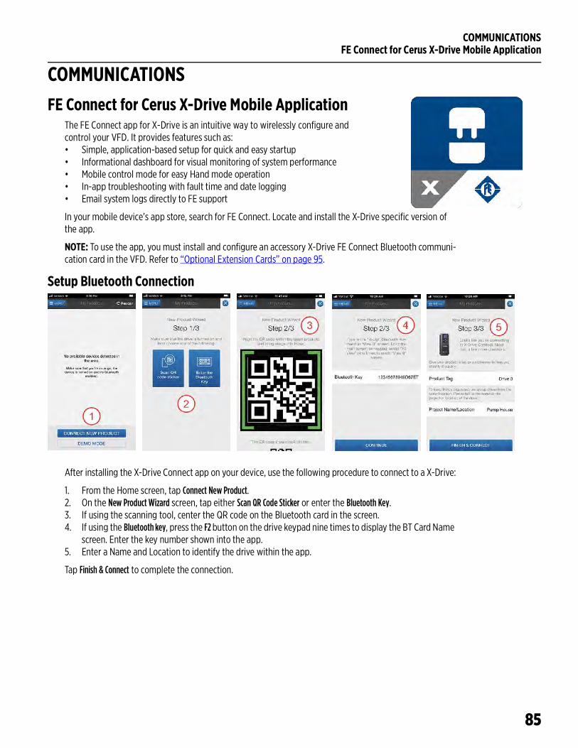
COMMUNICATIONSFE Connect for Cerus X-Drive Mobile Application
85
COMMUNICATIONSFE Connect for Cerus X-Drive Mobile Application
The FE Connect app for X-Drive is an intuitive way to wirelessly configure and control your VFD. It provides features such as:• Simple, application-based setup for quick and easy startup• Informational dashboard for visual monitoring of system performance• Mobile control mode for easy Hand mode operation• In-app troubleshooting with fault time and date logging• Email system logs directly to FE support
In your mobile device’s app store, search for FE Connect. Locate and install the X-Drive specific version of the app.
NOTE: To use the app, you must install and configure an accessory X-Drive FE Connect Bluetooth communi-cation card in the VFD. Refer to “Optional Extension Cards” on page 95.
Setup Bluetooth Connection
After installing the X-Drive Connect app on your device, use the following procedure to connect to a X-Drive:
1. From the Home screen, tap Connect New Product.2. On the New Product Wizard screen, tap either Scan QR Code Sticker or enter the Bluetooth Key.3. If using the scanning tool, center the QR code on the Bluetooth card in the screen.4. If using the Bluetooth key, press the F2 button on the drive keypad nine times to display the BT Card Name
screen. Enter the key number shown into the app.5. Enter a Name and Location to identify the drive within the app.
Tap Finish & Connect to complete the connection.
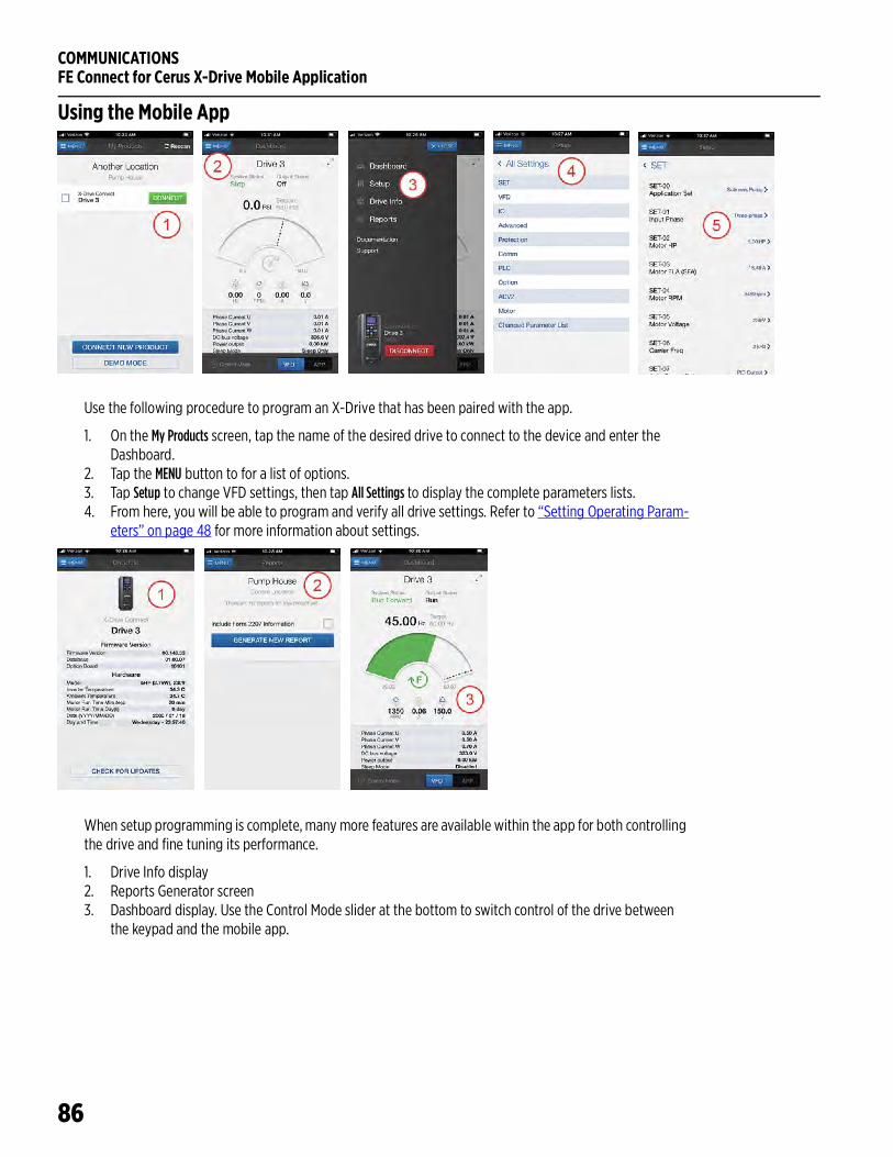
COMMUNICATIONSFE Connect for Cerus X-Drive Mobile Application
86
Using the Mobile App
Use the following procedure to program an X-Drive that has been paired with the app.
1. On the My Products screen, tap the name of the desired drive to connect to the device and enter the Dashboard.
2. Tap the MENU button to for a list of options.3. Tap Setup to change VFD settings, then tap All Settings to display the complete parameters lists.4. From here, you will be able to program and verify all drive settings. Refer to “Setting Operating Param-
eters” on page 48 for more information about settings.
When setup programming is complete, many more features are available within the app for both controlling the drive and fine tuning its performance.
1. Drive Info display2. Reports Generator screen3. Dashboard display. Use the Control Mode slider at the bottom to switch control of the drive between
the keypad and the mobile app.
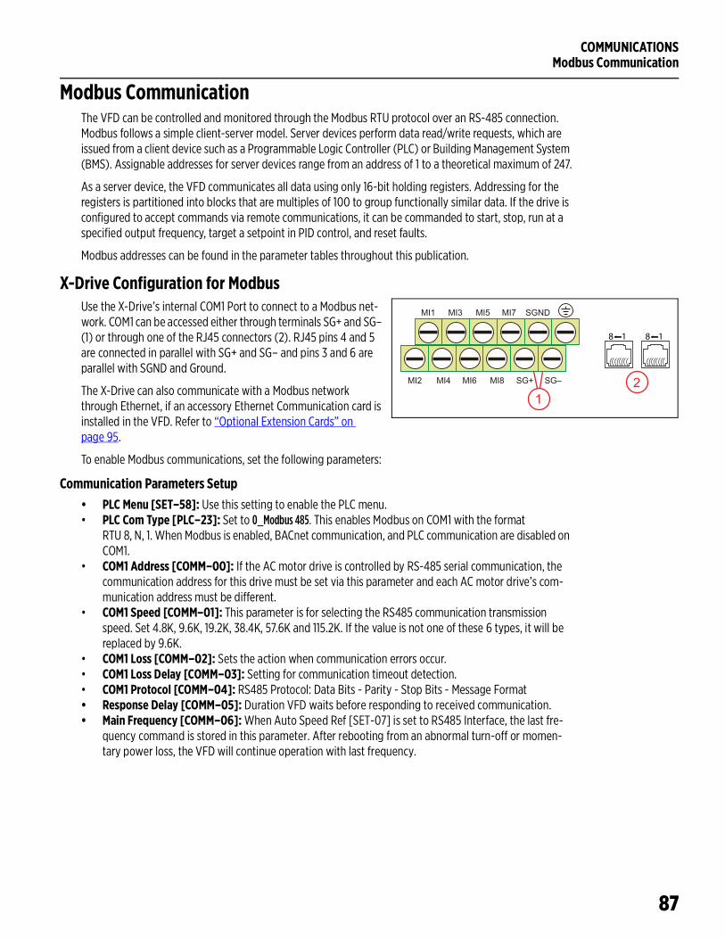
COMMUNICATIONSModbus Communication
87
Modbus CommunicationThe VFD can be controlled and monitored through the Modbus RTU protocol over an RS-485 connection. Modbus follows a simple client-server model. Server devices perform data read/write requests, which are issued from a client device such as a Programmable Logic Controller (PLC) or Building Management System (BMS). Assignable addresses for server devices range from an address of 1 to a theoretical maximum of 247.
As a server device, the VFD communicates all data using only 16-bit holding registers. Addressing for the registers is partitioned into blocks that are multiples of 100 to group functionally similar data. If the drive is configured to accept commands via remote communications, it can be commanded to start, stop, run at a specified output frequency, target a setpoint in PID control, and reset faults.
Modbus addresses can be found in the parameter tables throughout this publication.
X-Drive Configuration for ModbusUse the X-Drive’s internal COM1 Port to connect to a Modbus net-work. COM1 can be accessed either through terminals SG+ and SG– (1) or through one of the RJ45 connectors (2). RJ45 pins 4 and 5 are connected in parallel with SG+ and SG– and pins 3 and 6 are parallel with SGND and Ground.
The X-Drive can also communicate with a Modbus network through Ethernet, if an accessory Ethernet Communication card is installed in the VFD. Refer to “Optional Extension Cards” on page 95.
To enable Modbus communications, set the following parameters:
Communication Parameters Setup• PLC Menu [SET–58]: Use this setting to enable the PLC menu.• PLC Com Type [PLC–23]: Set to 0_Modbus 485. This enables Modbus on COM1 with the format
RTU 8, N, 1. When Modbus is enabled, BACnet communication, and PLC communication are disabled on COM1.
• COM1 Address [COMM–00]: If the AC motor drive is controlled by RS-485 serial communication, the communication address for this drive must be set via this parameter and each AC motor drive’s com-munication address must be different.
• COM1 Speed [COMM–01]: This parameter is for selecting the RS485 communication transmission speed. Set 4.8K, 9.6K, 19.2K, 38.4K, 57.6K and 115.2K. If the value is not one of these 6 types, it will be replaced by 9.6K.
• COM1 Loss [COMM–02]: Sets the action when communication errors occur.• COM1 Loss Delay [COMM–03]: Setting for communication timeout detection.• COM1 Protocol [COMM–04]: RS485 Protocol: Data Bits - Parity - Stop Bits - Message Format• Response Delay [COMM–05]: Duration VFD waits before responding to received communication.• Main Frequency [COMM–06]: When Auto Speed Ref [SET-07] is set to RS485 Interface, the last fre-
quency command is stored in this parameter. After rebooting from an abnormal turn-off or momen-tary power loss, the VFD will continue operation with last frequency.
MI1 MI3 MI5 MI7 SGND
MI2 MI4 MI6 MI8 SG+ SG–
12
8 1 8 1
COMMUNICATIONSModbus Communication
88
System Parameters Setup• HOA Mode Source [SET–60]: Set to 2_RS485 Serial. This enables Modbus to switch between Hand and
Auto modes.• Auto Speed Ref [SET–07]: Set to 5_RS485 Serial. This enables Modbus to control the speed when in Auto
mode.• Auto Run Cmd [SET–08]: Set to 2_RS485 Serial. This enables Modbus to initiate a Run Command in Auto
mode.• Hand Speed Ref [SET–09]: Set to 1_RS485 Serial. This enables Modbus to control the speed when in
Hand mode.• Hand Run Cmd [SET–10]: Set to 2_RS485 Serial. This enables Modbus to initiate a Run Command in Hand
mode.
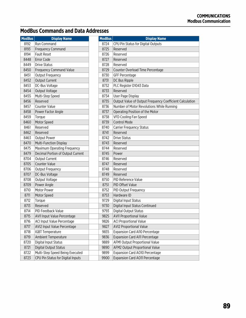
COMMUNICATIONSModbus Communication
89
ModBus Commands and Data Addresses–
ModBus Display Name ModBus Display Name8192 Run Command 8724 CPU Pin Status for Digital Outputs8193 Frequency Command 8725 Reserved8194 Fault Reset 8726 Reserved8448 Error Code 8727 Reserved8449 Drive Status 8728 Reserved8450 Frequency Command Value 8729 Counter Overload Time Percentage8451 Output Frequency 8730 GFF Percentage8452 Output Current 8731 DC Bus Ripple8453 DC-Bus Voltage 8732 PLC Register D1043 Data8454 Output Voltage 8733 Reserved8455 Multi-Step Speed 8734 User Page Display8456 Reserved 8735 Output Value of Output Frequency Coefficient Calculation8457 Counter Value 8736 Number of Motor Revolutions While Running8458 Power Factor Angle 8737 Operating Position of the Motor8459 Torque 8738 VFD Cooling Fan Speed8460 Motor Speed 8739 Control Mode8461 Reserved 8740 Carrier Frequency Status8462 Reserved 8741 Reserved8463 Output Power 8742 Drive Status8470 Multi-Function Display 8743 Reserved8475 Maximum Operating Frequency 8744 Reserved8479 Decimal Portion of Output Current 8745 Power8704 Output Current 8746 Reserved8705 Counter Value 8747 Reserved8706 Output Frequency 8748 Reserved8707 DC-Bus Voltage 8749 Reserved8708 Output Voltage 8750 PID Reference Value8709 Power Angle 8751 PID Offset Value8710 Motor Power 8752 PID Output Frequency8711 Motor Speed 8753 Hardware ID8712 Torque 9729 Digital Input Status8713 Reserved 9730 Digital Input Status Continued8714 PID Feedback Value 9793 Digital Output Status8715 AVI1 Input Value Percentage 9825 AVI1 Proportional Value8716 ACI Input Value Percentage 9826 ACI Proportional Value8717 AVI2 Input Value Percentage 9827 AVI2 Proportional Value8718 IGBT Temperature 9835 Expansion Card AI10 Percentage8719 Ambient Temperature 9836 Expansion Card AI11 Percentage8720 Digital Input Status 9889 AFM1 Output Proportional Value8721 Digital Output Status 9890 AFM2 Output Proportional Value8722 Multi-Step Speed Being Executed 9899 Expansion Card AO10 Percentage8723 CPU Pin Status for Digital Inputs 9900 Expansion Card AO11 Percentage
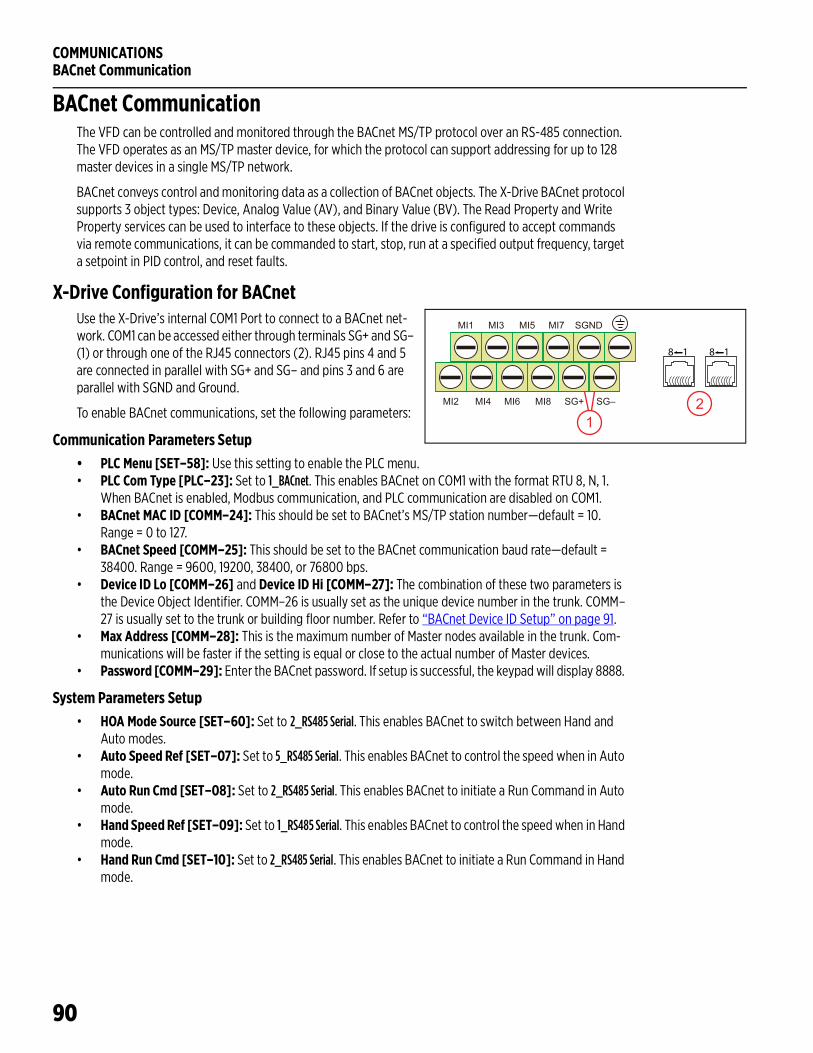
COMMUNICATIONSBACnet Communication
90
BACnet CommunicationThe VFD can be controlled and monitored through the BACnet MS/TP protocol over an RS-485 connection. The VFD operates as an MS/TP master device, for which the protocol can support addressing for up to 128 master devices in a single MS/TP network.
BACnet conveys control and monitoring data as a collection of BACnet objects. The X-Drive BACnet protocol supports 3 object types: Device, Analog Value (AV), and Binary Value (BV). The Read Property and Write Property services can be used to interface to these objects. If the drive is configured to accept commands via remote communications, it can be commanded to start, stop, run at a specified output frequency, target a setpoint in PID control, and reset faults.
X-Drive Configuration for BACnetUse the X-Drive’s internal COM1 Port to connect to a BACnet net-work. COM1 can be accessed either through terminals SG+ and SG– (1) or through one of the RJ45 connectors (2). RJ45 pins 4 and 5 are connected in parallel with SG+ and SG– and pins 3 and 6 are parallel with SGND and Ground.
To enable BACnet communications, set the following parameters:
Communication Parameters Setup• PLC Menu [SET–58]: Use this setting to enable the PLC menu.• PLC Com Type [PLC–23]: Set to 1_BACnet. This enables BACnet on COM1 with the format RTU 8, N, 1.
When BACnet is enabled, Modbus communication, and PLC communication are disabled on COM1.• BACnet MAC ID [COMM–24]: This should be set to BACnet’s MS/TP station number—default = 10.
Range = 0 to 127.• BACnet Speed [COMM–25]: This should be set to the BACnet communication baud rate—default =
38400. Range = 9600, 19200, 38400, or 76800 bps.• Device ID Lo [COMM–26] and Device ID Hi [COMM–27]: The combination of these two parameters is
the Device Object Identifier. COMM–26 is usually set as the unique device number in the trunk. COMM–27 is usually set to the trunk or building floor number. Refer to “BACnet Device ID Setup” on page 91.
• Max Address [COMM–28]: This is the maximum number of Master nodes available in the trunk. Com-munications will be faster if the setting is equal or close to the actual number of Master devices.
• Password [COMM–29]: Enter the BACnet password. If setup is successful, the keypad will display 8888.
System Parameters Setup• HOA Mode Source [SET–60]: Set to 2_RS485 Serial. This enables BACnet to switch between Hand and
Auto modes.• Auto Speed Ref [SET–07]: Set to 5_RS485 Serial. This enables BACnet to control the speed when in Auto
mode.• Auto Run Cmd [SET–08]: Set to 2_RS485 Serial. This enables BACnet to initiate a Run Command in Auto
mode.• Hand Speed Ref [SET–09]: Set to 1_RS485 Serial. This enables BACnet to control the speed when in Hand
mode.• Hand Run Cmd [SET–10]: Set to 2_RS485 Serial. This enables BACnet to initiate a Run Command in Hand
mode.
MI1 MI3 MI5 MI7 SGND
MI2 MI4 MI6 MI8 SG+ SG–
12
8 1 8 1
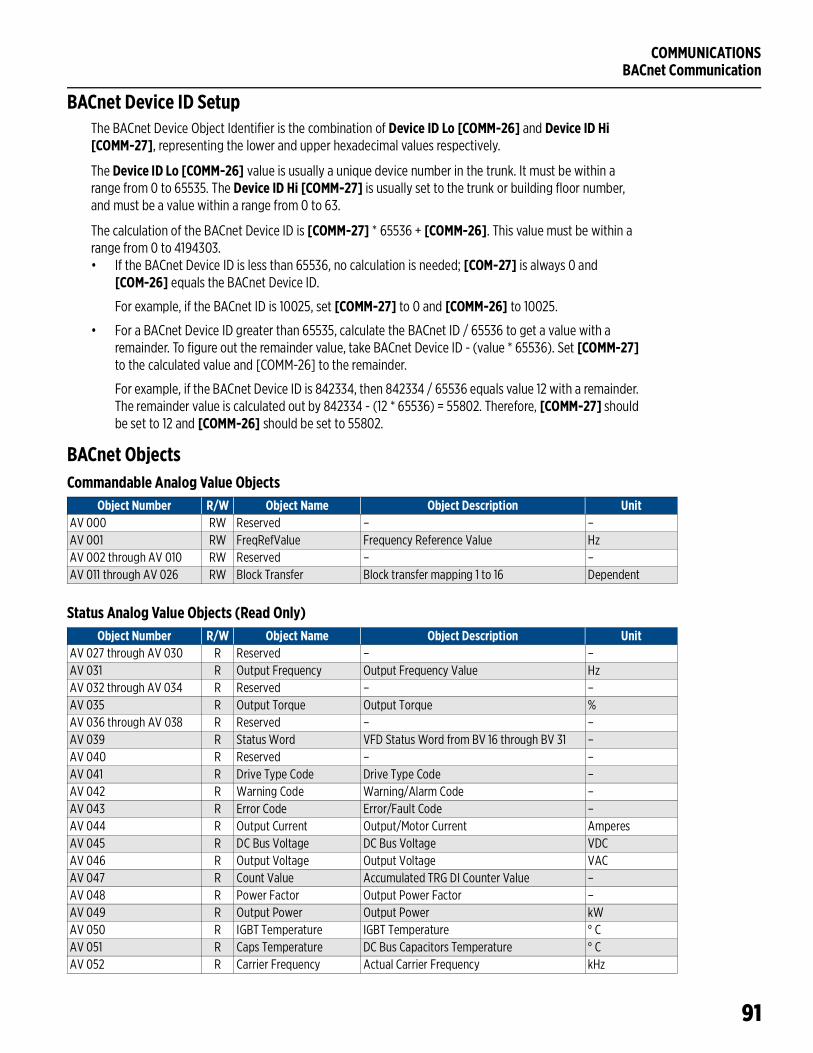
COMMUNICATIONSBACnet Communication
91
BACnet Device ID SetupThe BACnet Device Object Identifier is the combination of Device ID Lo [COMM-26] and Device ID Hi [COMM-27], representing the lower and upper hexadecimal values respectively.
The Device ID Lo [COMM-26] value is usually a unique device number in the trunk. It must be within a range from 0 to 65535. The Device ID Hi [COMM-27] is usually set to the trunk or building floor number, and must be a value within a range from 0 to 63.
The calculation of the BACnet Device ID is [COMM-27] * 65536 + [COMM-26]. This value must be within a range from 0 to 4194303.• If the BACnet Device ID is less than 65536, no calculation is needed; [COM-27] is always 0 and
[COM-26] equals the BACnet Device ID.
For example, if the BACnet ID is 10025, set [COMM-27] to 0 and [COMM-26] to 10025.
• For a BACnet Device ID greater than 65535, calculate the BACnet ID / 65536 to get a value with a remainder. To figure out the remainder value, take BACnet Device ID - (value * 65536). Set [COMM-27] to the calculated value and [COMM-26] to the remainder.
For example, if the BACnet Device ID is 842334, then 842334 / 65536 equals value 12 with a remainder. The remainder value is calculated out by 842334 - (12 * 65536) = 55802. Therefore, [COMM-27] should be set to 12 and [COMM-26] should be set to 55802.
BACnet ObjectsCommandable Analog Value Objects
Status Analog Value Objects (Read Only)
Object Number R/W Object Name Object Description UnitAV 000 RW Reserved – –AV 001 RW FreqRefValue Frequency Reference Value HzAV 002 through AV 010 RW Reserved – –AV 011 through AV 026 RW Block Transfer Block transfer mapping 1 to 16 Dependent
Object Number R/W Object Name Object Description UnitAV 027 through AV 030 R Reserved – –AV 031 R Output Frequency Output Frequency Value HzAV 032 through AV 034 R Reserved – –AV 035 R Output Torque Output Torque %AV 036 through AV 038 R Reserved – –AV 039 R Status Word VFD Status Word from BV 16 through BV 31 –AV 040 R Reserved – –AV 041 R Drive Type Code Drive Type Code –AV 042 R Warning Code Warning/Alarm Code –AV 043 R Error Code Error/Fault Code –AV 044 R Output Current Output/Motor Current AmperesAV 045 R DC Bus Voltage DC Bus Voltage VDCAV 046 R Output Voltage Output Voltage VACAV 047 R Count Value Accumulated TRG DI Counter Value –AV 048 R Power Factor Output Power Factor –AV 049 R Output Power Output Power kWAV 050 R IGBT Temperature IGBT Temperature ° CAV 051 R Caps Temperature DC Bus Capacitors Temperature ° CAV 052 R Carrier Frequency Actual Carrier Frequency kHz
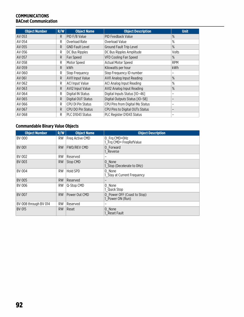
COMMUNICATIONSBACnet Communication
92
Commandable Binary Value Objects
AV 053 R PID F/B Value PID Feedback Value %AV 054 R Overload Rate Overload Value %AV 055 R GND Fault Level Ground Fault Trip Level %AV 056 R DC Bus Ripples DC Bus Ripples Amplitude VoltsAV 057 R Fan Speed VFD Cooling Fan Speed %AV 058 R Motor Speed Actual Motor Speed RPMAV 059 R kWh Kilowatts per hour kWhAV 060 R Step Frequency Step Frequency ID number –AV 061 R AVI1 Input Value AVI1 Analog Input Reading %AV 062 R ACI Input Value ACI Analog Input Reading %AV 063 R AVI2 Input Value AVI2 Analog Input Reading %AV 064 R Digital IN Status Digital Inputs Status [IO–46] –AV 065 R Digital OUT Status Digital Outputs Status [IO–58] –AV 066 R CPU DI Pin Status CPU Pins from Digital INs Status –AV 067 R CPU DO Pin Status CPU Pins to Digital OUTs Status –AV 068 R PLC D1043 Status PLC Register D1043 Status –
Object Number R/W Object Name Object Description Unit
Object Number R/W Object Name Object DescriptionBV 000 RW Freq Active CMD 0_Frq CMD=0Hz
1_Frq CMD= FreqRefValueBV 001 RW FWD/REV CMD 0_Forward
1_ReverseBV 002 RW Reserved –BV 003 RW Stop CMD 0_None
1_Stop (Decelerate to 0Hz)BV 004 RW Hold SPD 0_None
1_Stay at Current FrequencyBV 005 RW Reserved –BV 006 RW Q-Stop CMD 0_None
1_Quick StopBV 007 RW Power Out CMD 0_Power OFF (Coast to Stop)
1_Power ON (Run)BV 008 through BV 014 RW Reserved –BV 015 RW Reset 0_None
1_Reset Fault
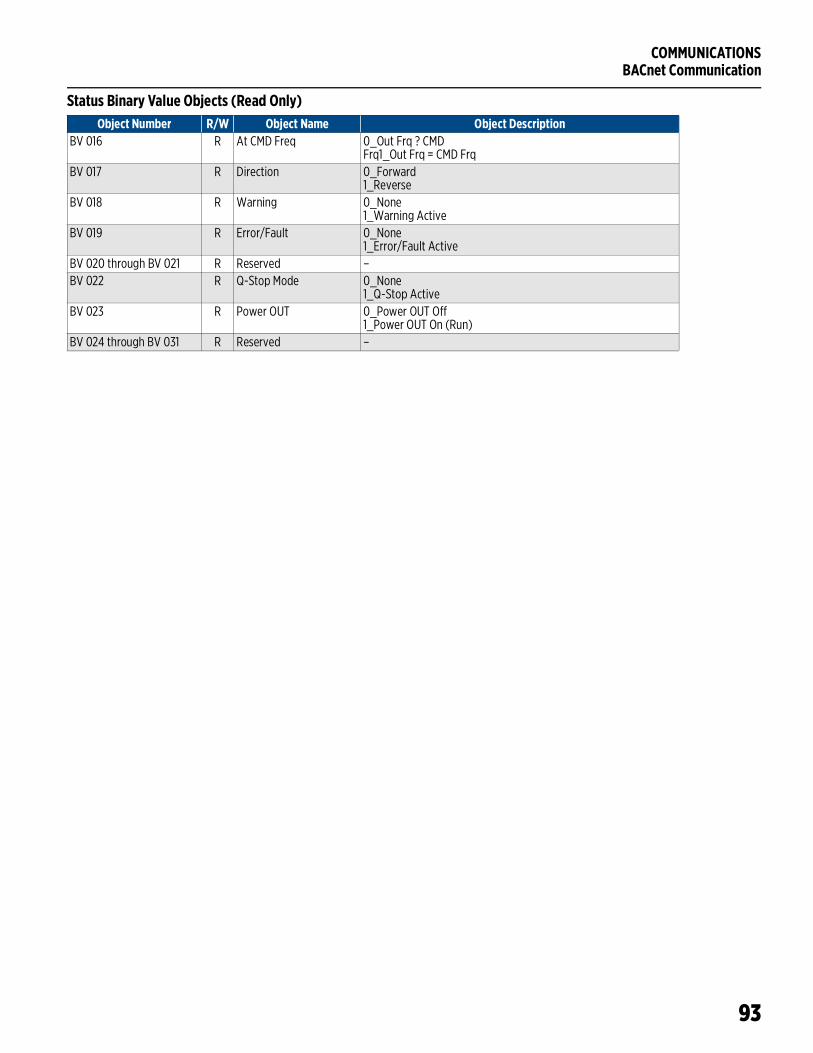
COMMUNICATIONSBACnet Communication
93
Status Binary Value Objects (Read Only)Object Number R/W Object Name Object Description
BV 016 R At CMD Freq 0_Out Frq ? CMD Frq1_Out Frq = CMD Frq
BV 017 R Direction 0_Forward1_Reverse
BV 018 R Warning 0_None1_Warning Active
BV 019 R Error/Fault 0_None1_Error/Fault Active
BV 020 through BV 021 R Reserved –BV 022 R Q-Stop Mode 0_None
1_Q-Stop ActiveBV 023 R Power OUT 0_Power OUT Off
1_Power OUT On (Run)BV 024 through BV 031 R Reserved –

COMMUNICATIONSBACnet Communication
94
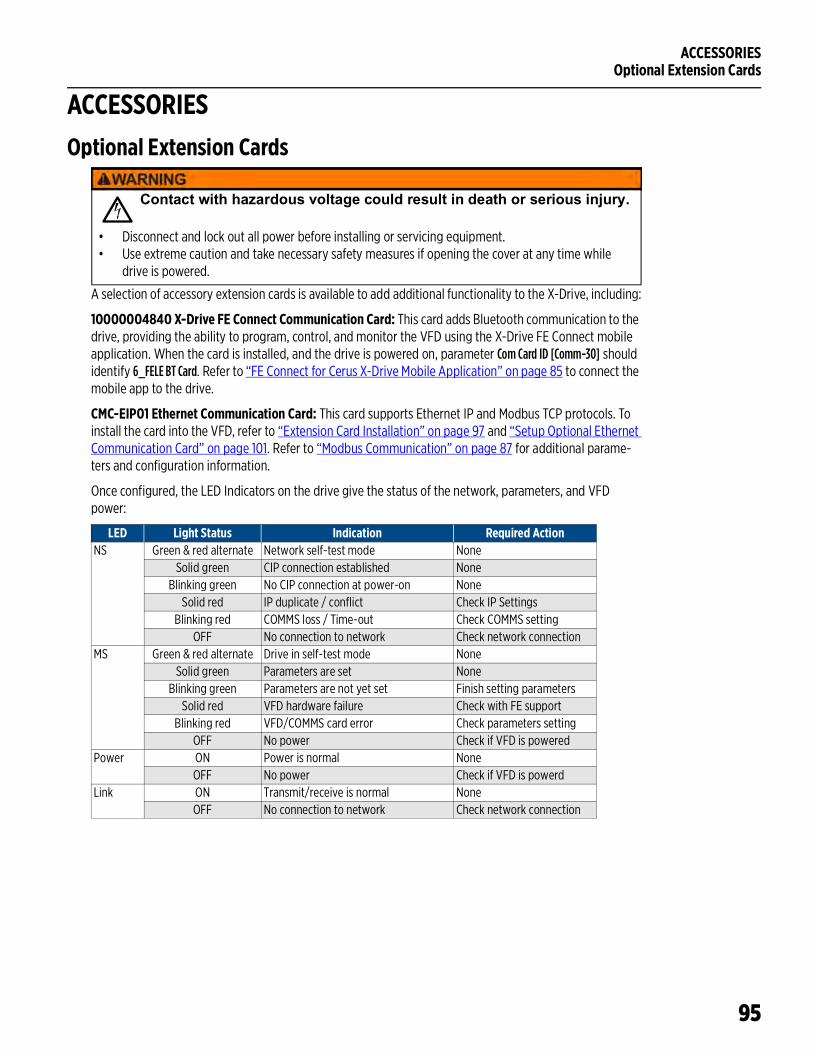
ACCESSORIESOptional Extension Cards
95
ACCESSORIESOptional Extension Cards
A selection of accessory extension cards is available to add additional functionality to the X-Drive, including:
10000004840 X-Drive FE Connect Communication Card: This card adds Bluetooth communication to the drive, providing the ability to program, control, and monitor the VFD using the X-Drive FE Connect mobile application. When the card is installed, and the drive is powered on, parameter Com Card ID [Comm-30] should identify 6_FELE BT Card. Refer to “FE Connect for Cerus X-Drive Mobile Application” on page 85 to connect the mobile app to the drive.
CMC-EIP01 Ethernet Communication Card: This card supports Ethernet IP and Modbus TCP protocols. To install the card into the VFD, refer to “Extension Card Installation” on page 97 and “Setup Optional Ethernet Communication Card” on page 101. Refer to “Modbus Communication” on page 87 for additional parame-ters and configuration information.
Once configured, the LED Indicators on the drive give the status of the network, parameters, and VFD power:
LED Light Status Indication Required ActionNS Green & red alternate Network self-test mode None
Solid green CIP connection established NoneBlinking green No CIP connection at power-on None
Solid red IP duplicate / conflict Check IP SettingsBlinking red COMMS loss / Time-out Check COMMS setting
OFF No connection to network Check network connectionMS Green & red alternate Drive in self-test mode None
Solid green Parameters are set NoneBlinking green Parameters are not yet set Finish setting parameters
Solid red VFD hardware failure Check with FE supportBlinking red VFD/COMMS card error Check parameters setting
OFF No power Check if VFD is poweredPower ON Power is normal None
OFF No power Check if VFD is powerdLink ON Transmit/receive is normal None
OFF No connection to network Check network connection
Contact with hazardous voltage could result in death or serious injury.
• Disconnect and lock out all power before installing or servicing equipment.• Use extreme caution and take necessary safety measures if opening the cover at any time while
drive is powered.

ACCESSORIESOptional Extension Cards
96
EMC-D42A Extension DC I/O Card: This card adds four Digital Inputs, MI10–MI13 with COM common terminal and two polarity insensitive Transistor Outputs with MXM common terminal.
MI10–MI13 inputs functionality is programmable through parameters [OPTION–00 to 03]. Ratings are the same as VFD inputs MI1–MI8. The COM terminal should be connected the same way as VFD COM terminal. For default VFD DIs configuration it should be connected to +24V terminal.
MO10–MO11 outputs functionality is programmable through [OPTION–00 to 03]. Ratings are 48 VDC at 50 mA maximum. The MXM terminal should be connected to the common terminal of external power source and MO10 and MO11 to the load (Example: PL pilot light on the diagram).
EMC-611A Extension AC Input Card: This card adds six Digital Inputs, MI10–MI15 with AC common terminal (Neutral).
MI10–MI13 inputs functionality is programmable through parameters [OPTION–00 to 05].
Ratings are 100-130VAC, 47-63Hz, 27k impedance. Response time for ON is 10ms and for OFF is 20ms.
EMC-R6AA Extension Relay Card: This card adds six Relay Outputs, R10–R15 with SPST (single-pole single-throw) form A (N.O.) contacts.
R10–R15 relay functionality is programmable through parameters [OPTION–06 to 16].
Contact ratings for:• Resistive load 3A at 250VAC and 5A at 30VDC• Inductive load (COS 0.4) 1.2A at 250VAC and 2A at 30VDC
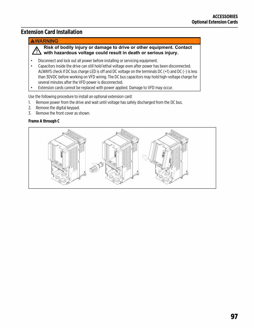
ACCESSORIESOptional Extension Cards
97
Extension Card Installation
Use the following procedure to install an optional extension card:1. Remove power from the drive and wait until voltage has safely discharged from the DC bus. 2. Remove the digital keypad.3. Remove the front cover as shown.
Frame A through C
Risk of bodily injury or damage to drive or other equipment. Contact with hazardous voltage could result in death or serious injury.
• Disconnect and lock out all power before installing or servicing equipment.• Capacitors inside the drive can still hold lethal voltage even after power has been disconnected.
ALWAYS check if DC bus charge LED is off and DC voltage on the terminals DC (+1) and DC (-) is less than 30VDC before working on VFD wiring. The DC bus capacitors may hold high-voltage charge for several minutes after the VFD power is disconnected.
• Extension cards cannot be replaced with power applied. Damage to VFD may occur.
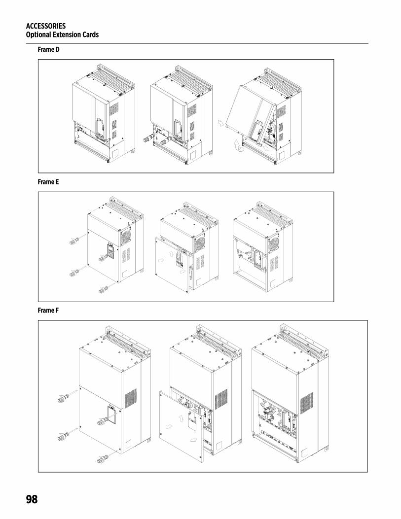
ACCESSORIESOptional Extension Cards
98
Frame D
Frame E
Frame F
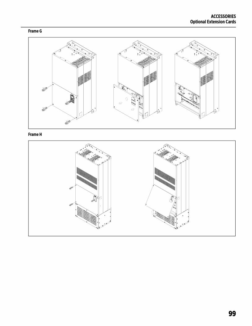
ACCESSORIESOptional Extension Cards
99
Frame G
Frame H
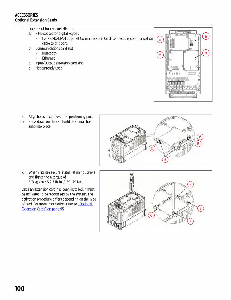
ACCESSORIESOptional Extension Cards
100
4. Locate slot for card installation.a. RJ45 socket for digital keypad
• For a CMC-EIP01 Ethernet Communication Card, connect the communication cable to this port.
b. Communications card slot• Bluetooth• Ethernet
c. Input/Output extension card slotd. Not currently used
5. Align holes in card over the positioning pins.6. Press down on the card until retaining clips
snap into place.
7. When clips are secure, install retaining screws and tighten to a torque of 6-8 kg-cm / 5.2-7 Ib-in. / .59-.79 Nm.
Once an extension card has been installed, it must be activated to be recognized by the system. The activation procedure differs depending on the type of card. For more information, refer to “Optional Extension Cards” on page 95.
a
b
c
d
5
6
56
6
67
7

ACCESSORIESOptional Extension Cards
101
Setup Optional Ethernet Communication CardInstall the card following the instructions in “Extension Card Installation” on page 97.
1. Verify card detection.• Check Com Card ID [COMM–30] to determine whether a Communications Card has been installed
and recognized by the drive. A value of No Com Card indicates that a card has not been detected.• To activate the card in the drive, set Comm Card [COMM–55] to 2h (bit 1 on). This will detect the
installed card and automatically change [COMM–30] to Ethernet/IP.2. Download card values to the drive.
• Set MBus Card Reset [COMM–52] to 1_Enable. This populates default values from the card into the appropriate drive parameters. For example:– IP Address: 192.168.1.5 to [COMM–38 through 41]– Address Mask: 255.255.255.0 to [COMM–42 through 45]– Gateway Address: 192.168.1.1 to [COMM–46 through 49]
• When complete, [COMM–52] will automatically return to 0_Disable.3. Adjust settings as required for the network and upload to card.
• Use [COMM–38 through 49] to set each address segment.• When complete, set MBus TCP Config [COMM–53] to 2_I-net Par On. This loads the new addresses
to the card, enabling communication with the network.

ACCESSORIESOptional Extension Cards
102
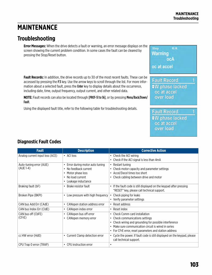
MAINTENANCETroubleshooting
103
MAINTENANCETroubleshooting
Error Messages: When the drive detects a fault or warning, an error message displays on the screen showing the current problem condition. In some cases the fault can be cleared by pressing the Stop/Reset button.
Fault Records: In addition, the drive records up to 30 of the most recent faults. These can be accessed by pressing the F3 key. Use the arrow keys to scroll through the list. For more infor-mation about a selected fault, press the Enter key to display details about the occurrence, including date, time, output frequency, output current, and other related data.
NOTE: Fault records can also be located through [PROT-51 to 56], or by pressing Menu/Back/Down/Fault.
Using the displayed fault title, refer to the following table for troubleshooting details.
Diagnostic Fault Codes
Fault Description Corrective ActionAnalog current input loss (ACE) • ACI loss • Check the ACI wiring
• Check if the ACI signal is less than 4mAAuto-tuning error (AUE)(AUE 1-4)
• Error during motor auto tuning• No feedback current• Motor phase loss• No load current• Leakage inductance
• Restart tuning• Check motor capacity and parameter settings• Accel/Decel times too short• Check cabling between drive and motor
Braking fault (bF) • Brake resistor fault • If the fault code is still displayed on the keypad after pressing “RESET” key, please call technical support.
Broken Pipe (BKPI) • Low pressure with high frequency • Check piping for leaks• Verify parameter settings
CAN bus Add Err (CAdE) • CANopen station address error • Reset addressCAN bus Index Err (CIdE) • CANopen index error • Reset indexCAN bus off (CbFE)(CFrE)
• CANopen bus off error• CANopen memory error
• Check Comm card installation• Check communications settings• Check wiring and grounding for possible interference• Make sure communication circuit is wired in series• For CFrE error, reset parameters and station address
cc HW error (Hd0) • Current Clamp detection error • Cycle the power. If fault code is still displayed on the keypad, please call technical support.
CPU Trap 0 error (TRAP) • CPU instruction error •

MAINTENANCETroubleshooting
104
Damper Fault (DPR) • Damper limit switch has not closed in time to start fan motor; or, switch has opened for more than 2 seconds while motor is running.
• Check limit switch connections and function• Check damper relay connections and damper function• Verify all damper related parameters
Dec Energy Back (dEb) • Deceleration energy backup error. When ADV2-28 is not disabled and power is off or momentarily off, VFD will display dEb during accel./decel. stop.
• Check if input power is stable
Derating Error (oL3) • The VFD detects excessive drive output current.
• Check if the motor is overloaded.
EEPROM read err (cF2) • Internal memory cannot be read. • Press “RESET” key • Reset all parameters to default• If error still exists, please call Technical Support..
EEPROM write err (cF1) • Internal memory cannot be programmed.
• Press “RESET” key • Reset all parameters to default• If error still exists, please call Technical Support.
Emergency stop (EF1) • Emergency stop • When a multi-function input terminal (MI1 to MI6) is set to emergency stop and the contact is closed, the AC motor drive stops output U, V, W and the motor coasts to stop.
• Press RESET after condition has been corrected.External Fault (EF) • External Fault • Input EF (N.O.) on external terminal is closed to GND. Output U, V, W
will be turned off.• Give RESET command after fault has been cleared.
Ground fault (GFF) • Output current exceeds [PROT-34] for more than [PROT-35] time delay.NOTE: This protection is provided for VFD, not to protect user.
• Check the wiring connections between the VFD and motor for possible short circuits, also to ground.
• Check for possible poor insulation at the output.• Verify grounding of communication circuit• Ensure separation of communication circuits and high-voltage wiring• Check whether the IGBT power module is damaged.
Guarding T-out (CGdE) • CANopen guarding error. When CANopen Node Guarding detects that one of the slaves does not respond.
• Increase guarding time and detection times.• Verify wiring and grounding of communication circuit.• Make sure communication circuit is wired in series.• Use CANopen cable or add terminating resistance.
Heartbeat T-out (CHbE) • CANopen heartbeat error. When CANopen Heartbeat detects that one of the slaves does not respond.
• Increase heartbeat time• Verify wiring and grounding of communication circuit.• Make sure communication circuit is wired in series.• Use CANopen cable or add terminating resistance.
Heat Sink oH (oH2) • Capacitance temperature causes heatsink overheating.
• Ensure that the ambient temperature falls within the specified temperature range.
• Make sure heat sink is not obstructed. Check if the fan is operating• Check if there is enough ventilation clearance for the drive.
High Load (HLD) • Current or Torque is above [SET-48] HLD Level and [SET-49] HLD Frequency.
• Refer to “High Load Detection” on page 75.
Ias sensor Err (cd1) • U-phase output error • Cycle the power. If error still exists, please call Technical support.Ibs sensor Err (cd2) • V-phase output error • Cycle the power. If error still exists, please call Technical support.Ics sensor Err (cd3) • W-phase output error • Cycle the power. If error still exists, please call Technical support.
Fault Description Corrective Action
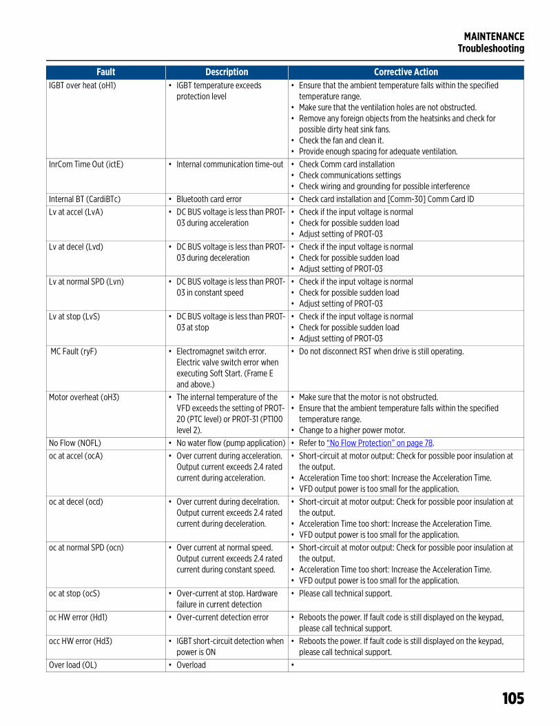
MAINTENANCETroubleshooting
105
IGBT over heat (oH1) • IGBT temperature exceeds protection level
• Ensure that the ambient temperature falls within the specified temperature range.
• Make sure that the ventilation holes are not obstructed.• Remove any foreign objects from the heatsinks and check for
possible dirty heat sink fans.• Check the fan and clean it.• Provide enough spacing for adequate ventilation.
InrCom Time Out (ictE) • Internal communication time-out • Check Comm card installation• Check communications settings• Check wiring and grounding for possible interference
Internal BT (CardiBTc) • Bluetooth card error • Check card installation and [Comm-30] Comm Card IDLv at accel (LvA) • DC BUS voltage is less than PROT-
03 during acceleration• Check if the input voltage is normal• Check for possible sudden load• Adjust setting of PROT-03
Lv at decel (Lvd) • DC BUS voltage is less than PROT-03 during deceleration
• Check if the input voltage is normal• Check for possible sudden load• Adjust setting of PROT-03
Lv at normal SPD (Lvn) • DC BUS voltage is less than PROT-03 in constant speed
• Check if the input voltage is normal• Check for possible sudden load• Adjust setting of PROT-03
Lv at stop (LvS) • DC BUS voltage is less than PROT-03 at stop
• Check if the input voltage is normal• Check for possible sudden load• Adjust setting of PROT-03
MC Fault (ryF) • Electromagnet switch error. Electric valve switch error when executing Soft Start. (Frame E and above.)
• Do not disconnect RST when drive is still operating.
Motor overheat (oH3) • The internal temperature of the VFD exceeds the setting of PROT-20 (PTC level) or PROT-31 (PT100 level 2).
• Make sure that the motor is not obstructed.• Ensure that the ambient temperature falls within the specified
temperature range. • Change to a higher power motor.
No Flow (NOFL) • No water flow (pump application) • Refer to “No Flow Protection” on page 78.oc at accel (ocA) • Over current during acceleration.
Output current exceeds 2.4 rated current during acceleration.
• Short-circuit at motor output: Check for possible poor insulation at the output.
• Acceleration Time too short: Increase the Acceleration Time.• VFD output power is too small for the application.
oc at decel (ocd) • Over current during decelration. Output current exceeds 2.4 rated current during deceleration.
• Short-circuit at motor output: Check for possible poor insulation at the output.
• Acceleration Time too short: Increase the Acceleration Time.• VFD output power is too small for the application.
oc at normal SPD (ocn) • Over current at normal speed. Output current exceeds 2.4 rated current during constant speed.
• Short-circuit at motor output: Check for possible poor insulation at the output.
• Acceleration Time too short: Increase the Acceleration Time.• VFD output power is too small for the application.
oc at stop (ocS) • Over-current at stop. Hardware failure in current detection
• Please call technical support.
oc HW error (Hd1) • Over-current detection error • Reboots the power. If fault code is still displayed on the keypad, please call technical support.
occ HW error (Hd3) • IGBT short-circuit detection when power is ON
• Reboots the power. If fault code is still displayed on the keypad, please call technical support.
Over load (OL) • Overload •
Fault Description Corrective Action
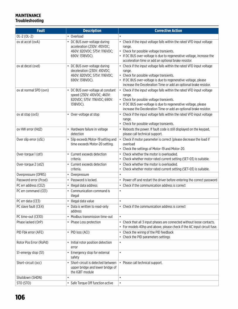
MAINTENANCETroubleshooting
106
OL-2 (OL-2) • Overload •ov at accel (ovA) • DC BUS over-voltage during
acceleration (230V: 410VDC; 460V: 820VDC; 575V: 1116VDC; 690V: 1318VDC).
• Check if the input voltage falls within the rated VFD input voltage range.
• Check for possible voltage transients.• If DC BUS over-voltage is due to regenerative voltage, increase the
acceleration time or add an optional brake resistor.ov at decel (ovd) • DC BUS over-voltage during
deceleration (230V: 410VDC; 460V: 820VDC; 575V: 1116VDC; 690V: 1318VDC).
• Check if the input voltage falls within the rated VFD input voltage range.
• Check for possible voltage transients.• If DC BUS over-voltage is due to regenerative voltage, please
increase the Deceleration Time or add an optional brake resistor.ov at normal SPD (ovn) • DC BUS over-voltage at constant
speed (230V: 410VDC; 460V: 820VDC; 575V: 1116VDC; 690V: 1318VDC).
• Check if the input voltage falls within the rated VFD input voltage range.
• Check for possible voltage transients.• If DC BUS over-voltage is due to regenerative voltage, please
increase the Deceleration Time or add an optional brake resistor.ov at stop (ovS) • Over-voltage at stop • Check if the input voltage falls within the rated VFD input voltage
range.• Check for possible voltage transients.
ov HW error (Hd2) • Hardware failure in voltage detection
• Reboots the power. If fault code is still displayed on the keypad, please call technical support.
Over slip error (oSL) • Slip exceeds Motor-19 setting and time exceeds Motor-20 setting.
• Check if motor parameter is correct (please decrease the load if overload
• Check the settings of Motor-19 and Motor-20.Over-torque 1 (ot1) • Current exceeds detection
criteria.• Check whether the motor is overloaded.• Check whether motor rated current setting (SET-03) is suitable.
Over-torque 2 (ot2) • Current exceeds detection criteria.
• Check whether the motor is overloaded.• Check whether motor rated current setting (SET-03) is suitable.
Overpressure (OPRS) • Overpressure •Password error (Pcod) • Password is locked. • Power off and restart the driver before entering the correct passwordPC err address (CE2) • Illegal data address • Check if the communication address is correctPC err command (CE1) • Communication command is
illegal•
PC err data (CE3) • Illegal data value •PC slave fault (CE4) • Data is written to read-only
address• Check if the communication address is correct
PC time-out (CE10) • Modbus transmission time-out •Phase lacked (OrP) • Phase Loss protection • Check that all 3 input phases are connected without loose contacts.
• For models 40hp and above, please check if the AC input circuit fuse.PID Fbk error (AFE) • PID loss (ACI) • Check the wiring of the PID feedback
• Check the PID parameters settingsRotor Pos Error (RoPd) • Initial rotor position detection
error•
S1-emergy stop (S1) • Emergency stop for external safety
•
Short-circuit (occ) • Short-circuit is detected between upper bridge and lower bridge of the IGBT module
• Please call technical support.
Shutdown (SHDN) • •STO (STO) • Safe Torque Off function active •
Fault Description Corrective Action
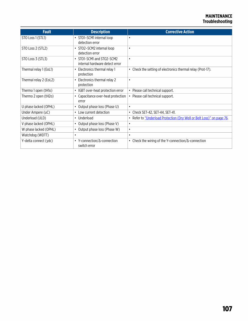
MAINTENANCETroubleshooting
107
STO Loss 1 (STL1) • STO1–SCM1 internal loop detection error
•
STO Loss 2 (STL2) • STO2–SCM2 internal loop detection error
•
STO Loss 3 (STL3) • STO1~SCM1 and STO2~SCM2 internal hardware detect error
•
Thermal relay 1 (EoL1) • Electronics thermal relay 1 protection
• Check the setting of electronics thermal relay (Prot-17).
Thermal relay 2 (EoL2) • Electronics thermal relay 2 protection
•
Thermo 1 open (tH1o) • IGBT over-heat protection error • Please call technical support.Thermo 2 open (tH2o) • Capacitance over-heat protection
error• Please call technical support.
U phase lacked (OPHL) • Output phase loss (Phase U) •Under Ampere (uC) • Low current detection • Check SET-42, SET-44, SET-41.Underload (ULD) • Underload • Refer to “Underload Protection (Dry Well or Belt Loss)” on page 76.V phase lacked (OPHL) • Output phase loss (Phase V) •W phase lacked (OPHL) • Output phase loss (Phase W) •Watchdog (WDTT) • •Y-delta connect (ydc) • Y-connection/Δ-connection
switch error• Check the wiring of the Y-connection/Δ-connection
Fault Description Corrective Action
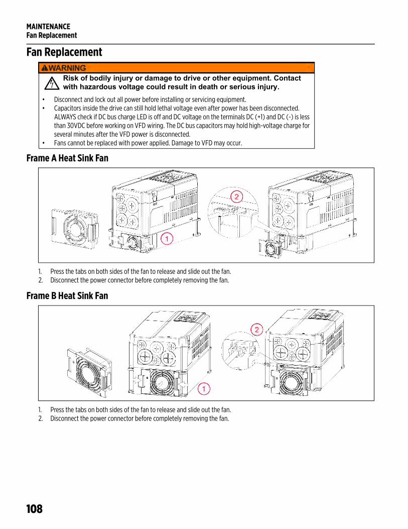
MAINTENANCEFan Replacement
108
Fan Replacement
Frame A Heat Sink Fan
1. Press the tabs on both sides of the fan to release and slide out the fan.2. Disconnect the power connector before completely removing the fan.
Frame B Heat Sink Fan
1. Press the tabs on both sides of the fan to release and slide out the fan.2. Disconnect the power connector before completely removing the fan.
Risk of bodily injury or damage to drive or other equipment. Contact with hazardous voltage could result in death or serious injury.
• Disconnect and lock out all power before installing or servicing equipment.• Capacitors inside the drive can still hold lethal voltage even after power has been disconnected.
ALWAYS check if DC bus charge LED is off and DC voltage on the terminals DC (+1) and DC (-) is less than 30VDC before working on VFD wiring. The DC bus capacitors may hold high-voltage charge for several minutes after the VFD power is disconnected.
• Fans cannot be replaced with power applied. Damage to VFD may occur.
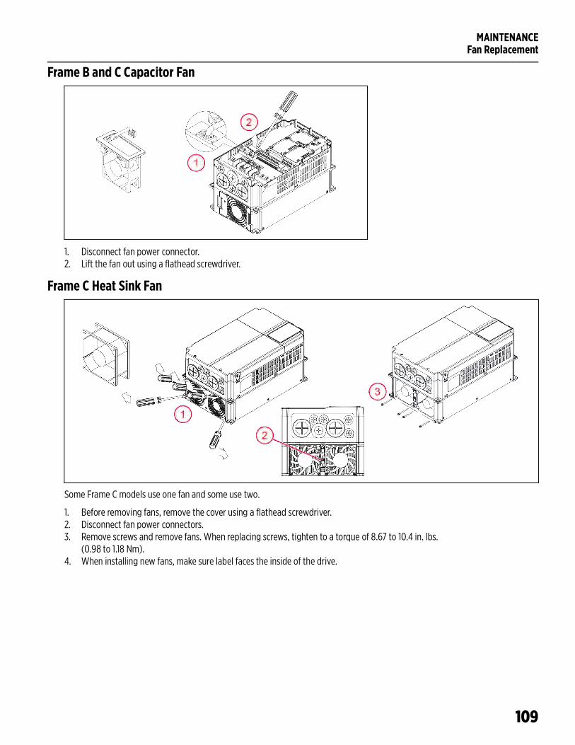
MAINTENANCEFan Replacement
109
Frame B and C Capacitor Fan
1. Disconnect fan power connector.2. Lift the fan out using a flathead screwdriver.
Frame C Heat Sink Fan
Some Frame C models use one fan and some use two.
1. Before removing fans, remove the cover using a flathead screwdriver.2. Disconnect fan power connectors.3. Remove screws and remove fans. When replacing screws, tighten to a torque of 8.67 to 10.4 in. lbs.
(0.98 to 1.18 Nm).4. When installing new fans, make sure label faces the inside of the drive.
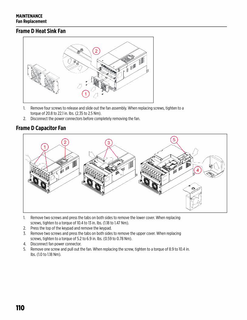
MAINTENANCEFan Replacement
110
Frame D Heat Sink Fan
1. Remove four screws to release and slide out the fan assembly. When replacing screws, tighten to a torque of 20.8 to 22.1 in. lbs. (2.35 to 2.5 Nm).
2. Disconnect the power connectors before completely removing the fan.
Frame D Capacitor Fan
1. Remove two screws and press the tabs on both sides to remove the lower cover. When replacing screws, tighten to a torque of 10.4 to 13 in. lbs. (1.18 to 1.47 Nm).
2. Press the top of the keypad and remove the keypad.3. Remove two screws and press the tabs on both sides to remove the upper cover. When replacing
screws, tighten to a torque of 5.2 to 6.9 in. lbs. (0.59 to 0.78 Nm).4. Disconnect fan power connector.5. Remove one screw and pull out the fan. When replacing the screw, tighten to a torque of 8.9 to 10.4 in.
lbs. (1.0 to 1.18 Nm).
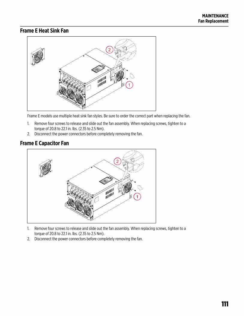
MAINTENANCEFan Replacement
111
Frame E Heat Sink Fan
Frame E models use multiple heat sink fan styles. Be sure to order the correct part when replacing the fan.
1. Remove four screws to release and slide out the fan assembly. When replacing screws, tighten to a torque of 20.8 to 22.1 in. lbs. (2.35 to 2.5 Nm).
2. Disconnect the power connectors before completely removing the fan.
Frame E Capacitor Fan
1. Remove four screws to release and slide out the fan assembly. When replacing screws, tighten to a torque of 20.8 to 22.1 in. lbs. (2.35 to 2.5 Nm).
2. Disconnect the power connectors before completely removing the fan.
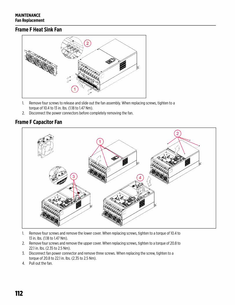
MAINTENANCEFan Replacement
112
Frame F Heat Sink Fan
1. Remove four screws to release and slide out the fan assembly. When replacing screws, tighten to a torque of 10.4 to 13 in. lbs. (1.18 to 1.47 Nm).
2. Disconnect the power connectors before completely removing the fan.
Frame F Capacitor Fan
1. Remove four screws and remove the lower cover. When replacing screws, tighten to a torque of 10.4 to 13 in. lbs. (1.18 to 1.47 Nm).
2. Remove four screws and remove the upper cover. When replacing screws, tighten to a torque of 20.8 to 22.1 in. lbs. (2.35 to 2.5 Nm).
3. Disconnect fan power connector and remove three screws. When replacing the screw, tighten to a torque of 20.8 to 22.1 in. lbs. (2.35 to 2.5 Nm).
4. Pull out the fan.
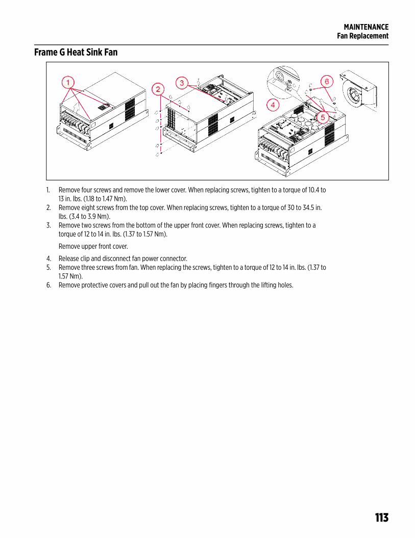
MAINTENANCEFan Replacement
113
Frame G Heat Sink Fan
1. Remove four screws and remove the lower cover. When replacing screws, tighten to a torque of 10.4 to 13 in. lbs. (1.18 to 1.47 Nm).
2. Remove eight screws from the top cover. When replacing screws, tighten to a torque of 30 to 34.5 in. lbs. (3.4 to 3.9 Nm).
3. Remove two screws from the bottom of the upper front cover. When replacing screws, tighten to a torque of 12 to 14 in. lbs. (1.37 to 1.57 Nm).
Remove upper front cover.
4. Release clip and disconnect fan power connector.5. Remove three screws from fan. When replacing the screws, tighten to a torque of 12 to 14 in. lbs. (1.37 to
1.57 Nm).6. Remove protective covers and pull out the fan by placing fingers through the lifting holes.
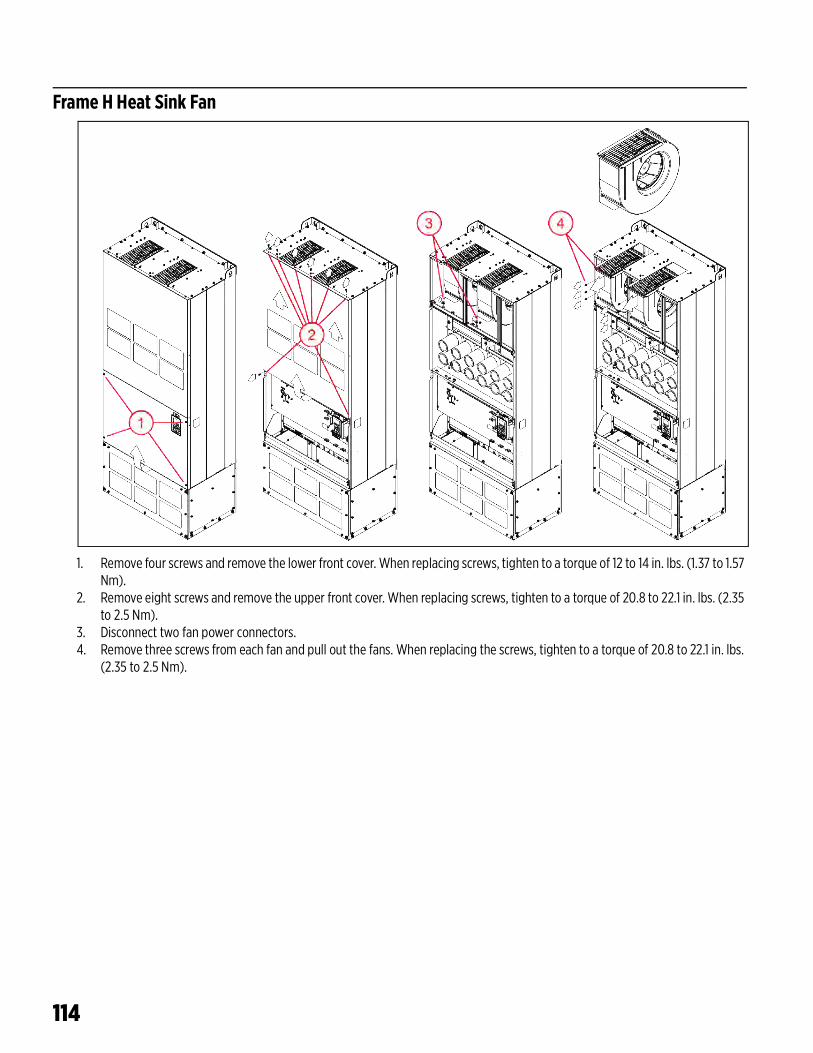
114
Frame H Heat Sink Fan
1. Remove four screws and remove the lower front cover. When replacing screws, tighten to a torque of 12 to 14 in. lbs. (1.37 to 1.57 Nm).
2. Remove eight screws and remove the upper front cover. When replacing screws, tighten to a torque of 20.8 to 22.1 in. lbs. (2.35 to 2.5 Nm).
3. Disconnect two fan power connectors.4. Remove three screws from each fan and pull out the fans. When replacing the screws, tighten to a torque of 20.8 to 22.1 in. lbs.
(2.35 to 2.5 Nm).
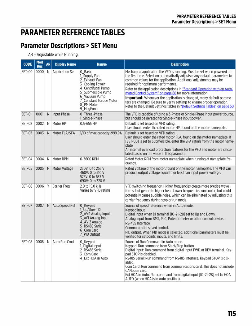
PARAMETER REFERENCE TABLESParameter Descriptions > SET Menu
115
PARAMETER REFERENCE TABLESParameter Descriptions > SET Menu
AR = Adjustable while Running.
CODE ModBus AR Display Name Range Description
SET-00 0000 N Application Sel 0_Basic 1_Supply Fan 2_Exhaust Fan3_Cooling Tower4_Centrifugal Pump5_Submersible Pump6_Vacuum Pump7_Constant Torque Motor8_PM Motor9_MagForce
Mechanical application the VFD is running. Must be set when powered up the first time. Selection automatically adjusts many default parameters to common values for the application. Additional adjustments may be required for optimum performance.Refer to the application descriptions in “Standard Operation with an Auto-mated Control System” on page 66 for more information.Important: Whenever the application is changed, many default parame-ters are changed. Be sure to verify settings to ensure proper operation. Refer to the Default Settings tables in “Default Settings Tables” on page 50.
SET-01 0001 N Input Phase 0_Three-Phase1_Single-Phase
The VFD is capable of using a 3-Phase or Single-Phase input power source, but should be derated for Single-Phase input power.
SET-02 0002 N Motor HP 0.5~655 HP Default is set based on VFD rating.User should enter the rated motor HP, found on the motor nameplate.
SET-03 0003 N Motor FLA/SFA 1/10 of max capacity~999.9A Default is set based on VFD rating. User should enter the rated motor FLA, found on the motor nameplate. If [SET-00] is set to Submersible, enter the SFA rating from the motor name-plate.All internal overload protection features for the VFD and motor are calcu-lated based on the value in this parameter.
SET-04 0004 N Motor RPM 0-3600 RPM Rated Motor RPM from motor nameplate when running at nameplate fre-quency.
SET-05 0005 N Motor Voltage 230V: 0 to 255 V460V: 0 to 510 V575V: 0 to 637 V690V: 0 to 720 V
Rated voltage of the motor, found on the motor nameplate. The VFD can produce output voltage equal to or less than input power voltage.
SET-06 0006 Y Carrier Freq 2.0 to 15.0 kHzVaries by VFD rating
VFD switching frequency. Higher frequencies create more precise wave forms, but generate higher heat. Lower frequencies run cooler, but could potentially cause audible noise, which can be eliminated by adjusting this carrier frequency during stop or run mode.
SET-07 0007 N Auto Speed Ref 0_Keypad1_Up/Down DI2_AVI1 Analog Input3_ACI Analog Input4_AVI2 Analog5_RS485 Serial6_Com Card7_PID Output
Source of speed reference when in Auto mode.Keypad input.Digital Input when DI terminal [IO-21~28] set to Up and Down.Analog input from BMS, PLC, Potentiometer or other control device.RS-485 InterfaceCommunications card control.PID output. When PID mode is selected, additional parameters must be verified for setpoints, inputs, and limits.
SET-08 0008 N Auto Run Cmd 0_Keypad1_Digital Input2_RS485 Serial3_Com Card4_Ext HOA in Auto
Source of Run Command in Auto mode.Keypad: Run command from Start/Stop button.Digital Input: Run command from digital input FWD or REV terminal. Key-pad STOP is disabled.RS485 Serial: Run command from RS485 interface. Keypad STOP is dis-abled.Com Card: Run command from communications card. This does not include CANopen card.Ext HOA in Auto: Run command from digital input [IO-21~28] set to HOA AUTO (when HOA is in Auto position).
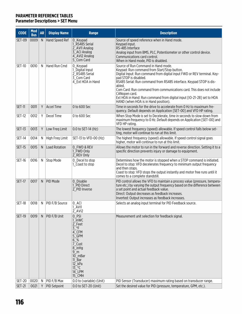
PARAMETER REFERENCE TABLESParameter Descriptions > SET Menu
116
SET-09 0009 N Hand Speed Ref 0_Keypad 1_RS485 Serial2_AVI1 Analog3_ACI Analog4_AVI2 Analog5_Com Card
Source of speed reference when in Hand mode.Keypad input.RS-485 InterfaceAnalog input from BMS, PLC, Potentiometer or other control device.Communications card control.When in Hand mode, PID is disabled.
SET-10 0010 N Hand Run Cmd 0_Keypad1_Digital Input2_RS485 Serial3_Com Card4_Ext HOA in Hand
Source of Run Command in Hand mode.Keypad: Run command from Start/Stop button.Digital Input: Run command from digital input FWD or REV terminal. Key-pad STOP is disabled.RS485 Serial: Run command from RS485 interface. Keypad STOP is dis-abled.Com Card: Run command from communications card. This does not include CANopen card.Ext HOA in Hand: Run command from digital input [IO-21~28] set to HOA HAND (when HOA is in Hand position).
SET-11 0011 Y Accel Time 0 to 600 Sec Time in seconds for the drive to accelerate from 0 Hz to maximum fre-quency. Default depends on Application [SET-00] and VFD HP rating.
SET-12 0012 Y Decel Time 0 to 600 Sec When Stop Mode is set to Decelerate, time in seconds to slow down from maximum frequency to 0 Hz. Default depends on Application [SET-00] and VFD HP rating.
SET-13 0013 Y Low Freq Limit 0.0 to SET-14 (Hz) The lowest frequency (speed) allowable. If speed control falls below set-ting, motor will continue to run at this limit.
SET-14 0014 N High Freq Limit SET-13 to VFD-00 (Hz) The highest frequency (speed) allowable. If speed control signal goes higher, motor will continue to run at this limit.
SET-15 0015 N Load Rotation 0_FWD & REV1_FWD Only2_REV Only
Allows the motor to run in the forward and reverse direction. Setting it to a specific direction prevents injury or damage to equipment.
SET-16 0016 N Stop Mode 0_Decel to stop1_Coast to stop
Determines how the motor is stopped when a STOP command is initiated.Decel to stop: VFD decelerates frequency to minimum output frequency and then stops.Coast to stop: VFD stops the output instantly and motor free runs until it comes to a complete standstill.
SET-17 0017 N PID Mode 0_Disable1_PID Direct 2_PID Inverse
PID control allows the VFD to maintain a process value (pressure, tempera-ture etc.) by varying the output frequency based on the difference between a set point and actual feedback value. Direct: Output decreases as feedback increases.Inverted: Output increases as feedback increases.
SET-18 0018 N PID F/B Source 0_ACI1_AVI12_AVI2
Selects an analog input terminal for PID Feedback source.
SET-19 0019 N PID F/B Unit 0_PSI1_inWC2_Feet3_°F4_CFM5_GPM6_%7_Cust8_inHg9_m10_mBar11_Bar12_kPa13_°C14_LPM15_CMH
Measurement unit selection for feedback signal.
SET-20 0020 N PID F/B Max 0.0 to (variable) (Unit) PID Sensor (Transducer) maximum rating based on transducer range. SET-21 0021 Y PID Setpoint 0.0 to SET-20 (Unit) Set the desired value for PID (pressure, temperature, GPM, etc.).
CODE ModBus AR Display Name Range Description
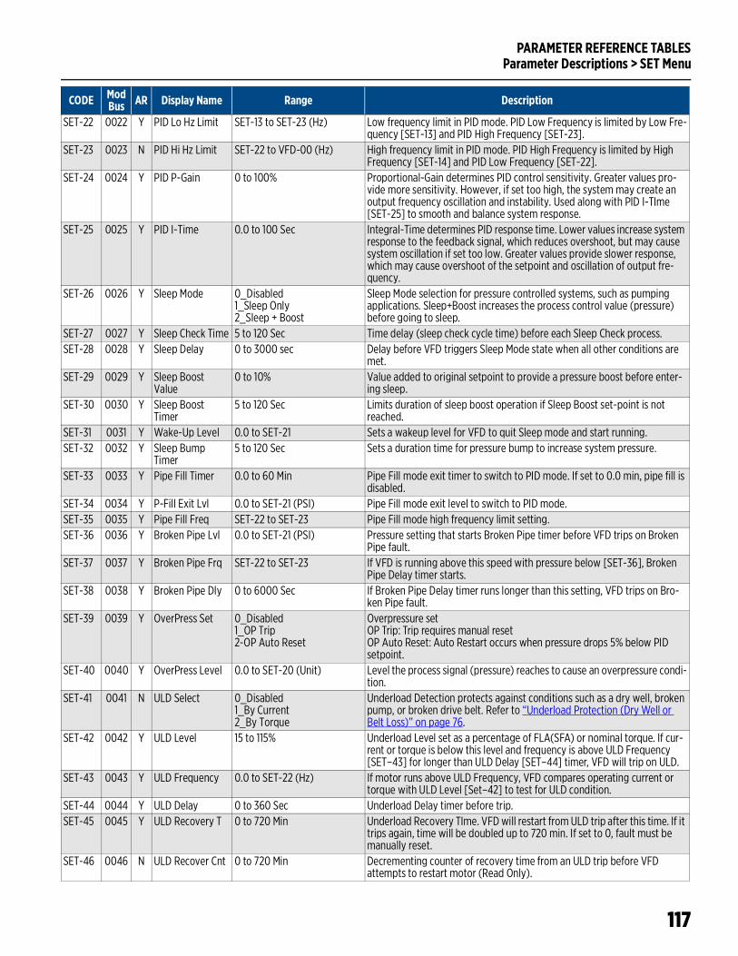
PARAMETER REFERENCE TABLESParameter Descriptions > SET Menu
117
SET-22 0022 Y PID Lo Hz Limit SET-13 to SET-23 (Hz) Low frequency limit in PID mode. PID Low Frequency is limited by Low Fre-quency [SET-13] and PID High Frequency [SET-23].
SET-23 0023 N PID Hi Hz Limit SET-22 to VFD-00 (Hz) High frequency limit in PID mode. PID High Frequency is limited by High Frequency [SET-14] and PID Low Frequency [SET-22].
SET-24 0024 Y PID P-Gain 0 to 100% Proportional-Gain determines PID control sensitivity. Greater values pro-vide more sensitivity. However, if set too high, the system may create an output frequency oscillation and instability. Used along with PID I-TIme [SET-25] to smooth and balance system response.
SET-25 0025 Y PID I-Time 0.0 to 100 Sec Integral-Time determines PID response time. Lower values increase system response to the feedback signal, which reduces overshoot, but may cause system oscillation if set too low. Greater values provide slower response, which may cause overshoot of the setpoint and oscillation of output fre-quency.
SET-26 0026 Y Sleep Mode 0_Disabled1_Sleep Only2_Sleep + Boost
Sleep Mode selection for pressure controlled systems, such as pumping applications. Sleep+Boost increases the process control value (pressure) before going to sleep.
SET-27 0027 Y Sleep Check Time 5 to 120 Sec Time delay (sleep check cycle time) before each Sleep Check process.SET-28 0028 Y Sleep Delay 0 to 3000 sec Delay before VFD triggers Sleep Mode state when all other conditions are
met.SET-29 0029 Y Sleep Boost
Value0 to 10% Value added to original setpoint to provide a pressure boost before enter-
ing sleep.SET-30 0030 Y Sleep Boost
Timer5 to 120 Sec Limits duration of sleep boost operation if Sleep Boost set-point is not
reached.SET-31 0031 Y Wake-Up Level 0.0 to SET-21 Sets a wakeup level for VFD to quit Sleep mode and start running.SET-32 0032 Y Sleep Bump
Timer5 to 120 Sec Sets a duration time for pressure bump to increase system pressure.
SET-33 0033 Y Pipe Fill Timer 0.0 to 60 Min Pipe Fill mode exit timer to switch to PID mode. If set to 0.0 min, pipe fill is disabled.
SET-34 0034 Y P-Fill Exit Lvl 0.0 to SET-21 (PSI) Pipe Fill mode exit level to switch to PID mode.SET-35 0035 Y Pipe Fill Freq SET-22 to SET-23 Pipe Fill mode high frequency limit setting.SET-36 0036 Y Broken Pipe Lvl 0.0 to SET-21 (PSI) Pressure setting that starts Broken Pipe timer before VFD trips on Broken
Pipe fault.SET-37 0037 Y Broken Pipe Frq SET-22 to SET-23 If VFD is running above this speed with pressure below [SET-36], Broken
Pipe Delay timer starts.SET-38 0038 Y Broken Pipe Dly 0 to 6000 Sec If Broken Pipe Delay timer runs longer than this setting, VFD trips on Bro-
ken Pipe fault.SET-39 0039 Y OverPress Set 0_Disabled
1_OP Trip2-OP Auto Reset
Overpressure setOP Trip: Trip requires manual resetOP Auto Reset: Auto Restart occurs when pressure drops 5% below PID setpoint.
SET-40 0040 Y OverPress Level 0.0 to SET-20 (Unit) Level the process signal (pressure) reaches to cause an overpressure condi-tion.
SET-41 0041 N ULD Select 0_Disabled1_By Current2_By Torque
Underload Detection protects against conditions such as a dry well, broken pump, or broken drive belt. Refer to “Underload Protection (Dry Well or Belt Loss)” on page 76.
SET-42 0042 Y ULD Level 15 to 115% Underload Level set as a percentage of FLA(SFA) or nominal torque. If cur-rent or torque is below this level and frequency is above ULD Frequency [SET–43] for longer than ULD Delay [SET–44] timer, VFD will trip on ULD.
SET-43 0043 Y ULD Frequency 0.0 to SET-22 (Hz) If motor runs above ULD Frequency, VFD compares operating current or torque with ULD Level [Set–42] to test for ULD condition.
SET-44 0044 Y ULD Delay 0 to 360 Sec Underload Delay timer before trip.SET-45 0045 Y ULD Recovery T 0 to 720 Min Underload Recovery TIme. VFD will restart from ULD trip after this time. If it
trips again, time will be doubled up to 720 min. If set to 0, fault must be manually reset.
SET-46 0046 N ULD Recover Cnt 0 to 720 Min Decrementing counter of recovery time from an ULD trip before VFD attempts to restart motor (Read Only).
CODE ModBus AR Display Name Range Description
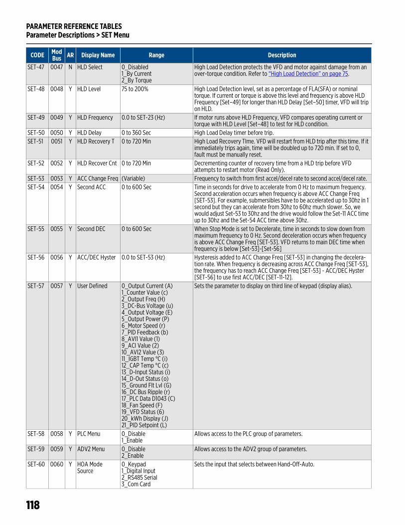
PARAMETER REFERENCE TABLESParameter Descriptions > SET Menu
118
SET-47 0047 N HLD Select 0_Disabled1_By Current2_By Torque
High Load Detection protects the VFD and motor against damage from an over-torque condition. Refer to “High Load Detection” on page 75.
SET-48 0048 Y HLD Level 75 to 200% High Load Detection level, set as a percentage of FLA(SFA) or nominal torque. If current or torque is above this level and frequency is above HLD Frequency [Set–49] for longer than HLD Delay [Set–50] timer, VFD will trip on HLD.
SET-49 0049 Y HLD Frequency 0.0 to SET-23 (Hz) If motor runs above HLD Frequency, VFD compares operating current or torque with HLD Level [Set–48] to test for HLD condition.
SET-50 0050 Y HLD Delay 0 to 360 Sec High Load Delay timer before trip.SET-51 0051 Y HLD Recovery T 0 to 720 Min High Load Recovery TIme. VFD will restart from HLD trip after this time. If it
immediately trips again, time will be doubled up to 720 min. If set to 0, fault must be manually reset.
SET-52 0052 Y HLD Recover Cnt 0 to 720 Min Decrementing counter of recovery time from a HLD trip before VFD attempts to restart motor (Read Only).
SET-53 0053 Y ACC Change Freq (Variable) Frequency to switch from first accel/decel rate to second accel/decel rate.SET-54 0054 Y Second ACC 0 to 600 Sec Time in seconds for drive to accelerate from 0 Hz to maximum frequency.
Second acceleration occurs when frequency is above ACC Change Freq [SET-53]. For example, submersibles have to be accelerated up to 30hz in 1 second but they can accelerate from 30hz to 60hz much slower. So, we would adjust Set-53 to 30hz and the drive would follow the Set-11 ACC time up to 30hz and the Set-54 ACC time above 30hz.
SET-55 0055 Y Second DEC 0 to 600 Sec When Stop Mode is set to Decelerate, time in seconds to slow down from maximum frequency to 0 Hz. Second deceleration occurs when frequency is above ACC Change Freq [SET-53]. VFD returns to main DEC time when frequency is below [Set-53]-[Set-56]
SET-56 0056 Y ACC/DEC Hyster 0.0 to SET-53 (Hz) Hysteresis added to ACC Change Freq [SET-53] in changing the decelera-tion rate. When frequency is decreasing across ACC Change Freq [SET-53], the frequency has to reach ACC Change Freq [SET-53] - ACC/DEC Hyster [SET-56] to use first ACC/DEC [SET-11-12].
SET-57 0057 Y User Defined 0_Output Current (A)1_Counter Value (c)2_Output Freq (H)3_DC-Bus Voltage (u)4_Output Voltage (E)5_Output Power (P)6_Motor Speed (r)7_PID Feedback (b)8_AVI1 Value (1)9_ACI Value (2)10_AVI2 Value (3)11_IGBT Temp °C (i)12_CAP Temp °C (c)13_D-Input Status (i)14_D-Out Status (o)15_Ground Flt Lvl (G)16_DC Bus Ripple (r)17_PLC Data D1043 (C)18_Fan Speed (F)19_VFD Status (6)20_kWh Display (J)21_PID Setpoint (L)
Sets the parameter to display on third line of keypad (display alias).
SET-58 0058 Y PLC Menu 0_Disable1_Enable
Allows access to the PLC group of parameters.
SET-59 0059 Y ADV2 Menu 0_Disable2_Enable
Allows access to the ADV2 group of parameters.
SET-60 0060 Y HOA Mode Source
0_Keypad1_Digital Input2_RS485 Serial3_Com Card
Sets the input that selects between Hand-Off-Auto.
CODE ModBus AR Display Name Range Description
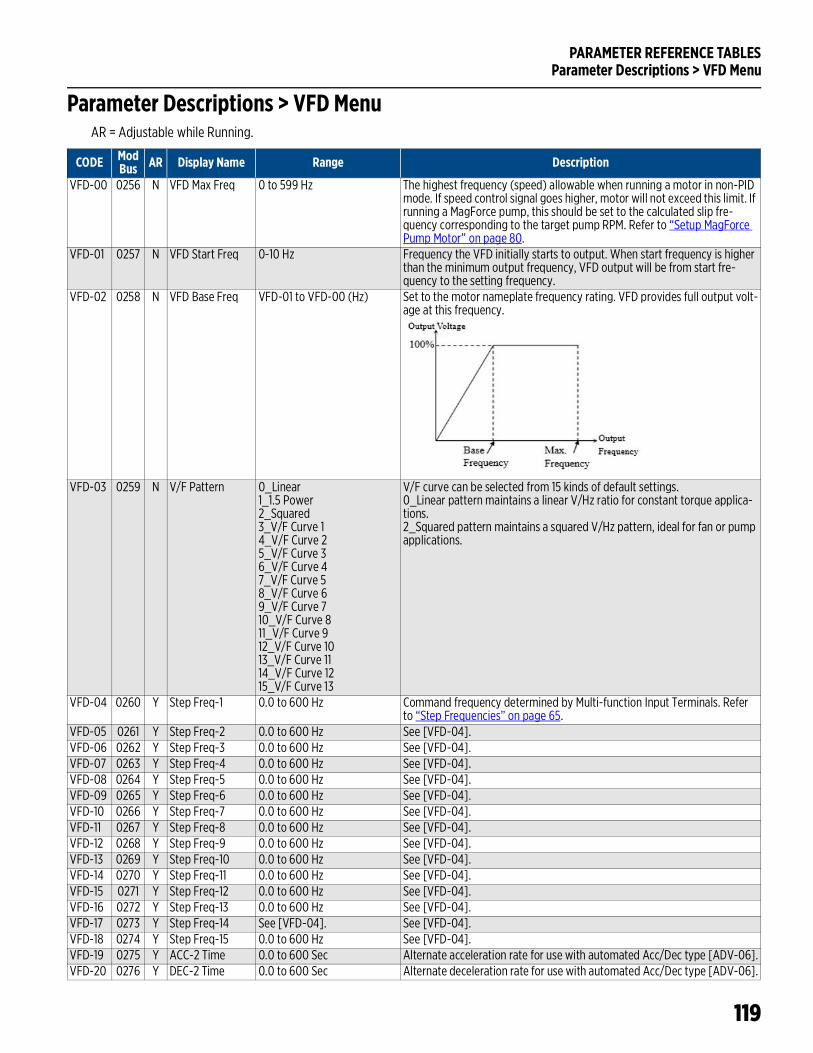
PARAMETER REFERENCE TABLESParameter Descriptions > VFD Menu
119
Parameter Descriptions > VFD MenuAR = Adjustable while Running.
CODE ModBus AR Display Name Range Description
VFD-00 0256 N VFD Max Freq 0 to 599 Hz The highest frequency (speed) allowable when running a motor in non-PID mode. If speed control signal goes higher, motor will not exceed this limit. If running a MagForce pump, this should be set to the calculated slip fre-quency corresponding to the target pump RPM. Refer to “Setup MagForce Pump Motor” on page 80.
VFD-01 0257 N VFD Start Freq 0-10 Hz Frequency the VFD initially starts to output. When start frequency is higher than the minimum output frequency, VFD output will be from start fre-quency to the setting frequency.
VFD-02 0258 N VFD Base Freq VFD-01 to VFD-00 (Hz) Set to the motor nameplate frequency rating. VFD provides full output volt-age at this frequency.
VFD-03 0259 N V/F Pattern 0_Linear1_1.5 Power2_Squared3_V/F Curve 14_V/F Curve 25_V/F Curve 36_V/F Curve 47_V/F Curve 58_V/F Curve 69_V/F Curve 710_V/F Curve 811_V/F Curve 912_V/F Curve 1013_V/F Curve 1114_V/F Curve 1215_V/F Curve 13
V/F curve can be selected from 15 kinds of default settings.0_Linear pattern maintains a linear V/Hz ratio for constant torque applica-tions. 2_Squared pattern maintains a squared V/Hz pattern, ideal for fan or pump applications.
VFD-04 0260 Y Step Freq-1 0.0 to 600 Hz Command frequency determined by Multi-function Input Terminals. Refer to “Step Frequencies” on page 65.
VFD-05 0261 Y Step Freq-2 0.0 to 600 Hz See [VFD-04].VFD-06 0262 Y Step Freq-3 0.0 to 600 Hz See [VFD-04].VFD-07 0263 Y Step Freq-4 0.0 to 600 Hz See [VFD-04].VFD-08 0264 Y Step Freq-5 0.0 to 600 Hz See [VFD-04].VFD-09 0265 Y Step Freq-6 0.0 to 600 Hz See [VFD-04].VFD-10 0266 Y Step Freq-7 0.0 to 600 Hz See [VFD-04].VFD-11 0267 Y Step Freq-8 0.0 to 600 Hz See [VFD-04].VFD-12 0268 Y Step Freq-9 0.0 to 600 Hz See [VFD-04].VFD-13 0269 Y Step Freq-10 0.0 to 600 Hz See [VFD-04].VFD-14 0270 Y Step Freq-11 0.0 to 600 Hz See [VFD-04].VFD-15 0271 Y Step Freq-12 0.0 to 600 Hz See [VFD-04].VFD-16 0272 Y Step Freq-13 0.0 to 600 Hz See [VFD-04].VFD-17 0273 Y Step Freq-14 See [VFD-04]. See [VFD-04].VFD-18 0274 Y Step Freq-15 0.0 to 600 Hz See [VFD-04].VFD-19 0275 Y ACC-2 Time 0.0 to 600 Sec Alternate acceleration rate for use with automated Acc/Dec type [ADV-06].VFD-20 0276 Y DEC-2 Time 0.0 to 600 Sec Alternate deceleration rate for use with automated Acc/Dec type [ADV-06].

PARAMETER REFERENCE TABLESParameter Descriptions > VFD Menu
120
VFD-21 0277 Y ACC-3 Time 0.0 to 600 Sec Alternate acceleration rate for use with automated Acc/Dec type [ADV-06].VFD-22 0278 Y DEC-3 Time 0.0 to 600 Sec Alternate deceleration rate for use with automated Acc/Dec type [ADV-06]VFD-23 0279 Y ACC-4 Time 0.0 to 600 Sec Alternate acceleration rate for use with automated Acc/Dec type [ADV-06].VFD-24 0280 Y DEC-4 Time 0.0 to 600 Sec Alternate deceleration rate for use with automated Acc/Dec type [ADV-06]VFD-25 0281 Y S Start Time 1 0.0 to (variable) Sec S-curve acceleration time leaving initial frequency.VFD-26 0282 Y S Start Time 2 0.0 to (variable) Sec S-curve acceleration time approaching next frequency.VFD-27 0283 Y S End Time 1 0.0 to (variable) Sec S-curve deceleration time leaving initial frequency.VFD-28 0284 Y S End Time 2 0.0 to (variable) Sec S-curve deceleration time approaching next frequency.VFD-29 0285 N Skip Freq 1 High 0.0 to 599 Hz Used to bypass mechanical system resonance frequencies. If the received
speed reference is in the skip zone, VFD will run at Low Skip Freq until speed reference is at or above High Skip Freq. Then, speed will be ramped up based on acceleration time.
VFD-30 0286 N Skip Freq 1 Low 0.0 to 599 Hz Low frequency in skip zone 1.VFD-31 0287 N Skip Freq 2 High 0.0 to 599 Hz High frequency in skip zone 2.VFD-32 0288 N Skip Freq 2 Low 0.0 to 599 Hz Low frequency in skip zone 2.VFD-33 0289 N Skip Freq 3 High 0.0 to 599 Hz High frequency in skip zone 3.VFD-34 0290 N Skip Freq 3 Low 0.0 to 599 Hz Low frequency in skip zone 3.VFD-35 0291 N VFD Duty Select 0_Variable Torque
1_Constant Torque0_Variable Torque (Light Duty)01_Constant Torque (Normal Duty)VFD Rated Amps [VFD-47] and Over-Current levels [PROT-07-08] are affected by this setting.
VFD-36 0292 Y Reset Restart 0_Disable1_Enable
The VFD will automatically initiate operation once fault is cleared and run command is received.
VFD-37 0293 Y DC Brake Lvl 0.0 to 100% Level of DC Brake Current output to the motor during start-up and stopping.VFD-38 0294 Y DC Time at Run 0.0 to 60 Sec Duration of the DC Brake current after a run command to apply DC current
to motor to force stop motor for a stable start.VFD-39 0295 Y DC Time at Stop 0.0 to 60 Sec Duration of the DC Brake current after a stop command to apply DC current
to the motor inorder to force stop the motor.VFD-40 0296 Y DC Stop Freq 0.0 to 599 Hz Frequency when DC Brake will begin during deceleration.VFD-41 0297 Y Dwell T at Acc 0.0 to 600 Sec When increasing in frequency to Dwell Frequency at Accel, the duration to
then hold at frequency before continuing to increase frequency.VFD-42 0297 Y Dwell Hz at Acc 0.0 to 599 Hz Frequency to hold when increasing in frequency.VFD-43 0299 Y Dwell T at Dec 0.0 to 600 Sec When decreasing in frequency to Dwell Frequency at Decel, the duration to
then hold at frequency before continuing to decrease frequency.VFD-44 0300 Y Dwell Hz at Dec 0.0 to 599 Hz Frequency to hold when decreasing in frequency.
CODE ModBus AR Display Name Range Description
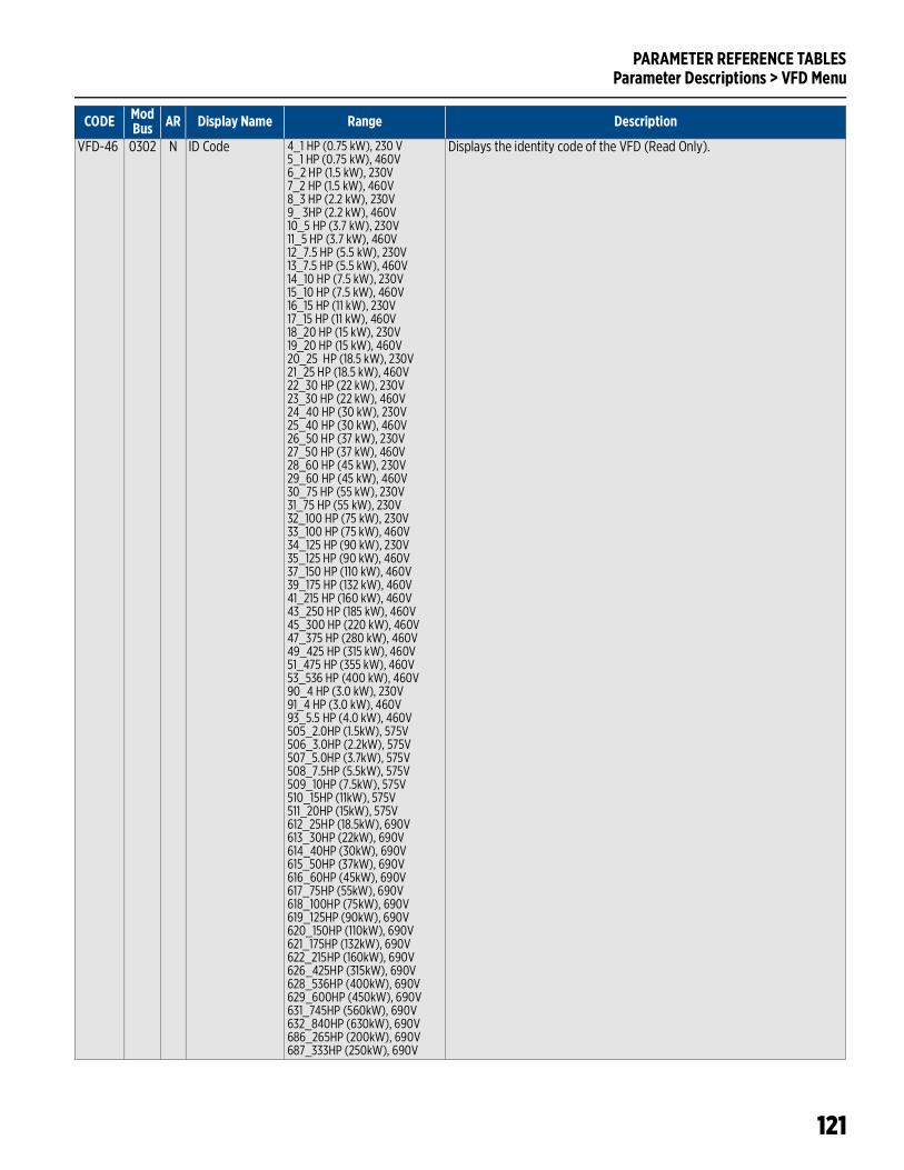
PARAMETER REFERENCE TABLESParameter Descriptions > VFD Menu
121
VFD-46 0302 N ID Code 4_1 HP (0.75 kW), 230 V5_1 HP (0.75 kW), 460V6_2 HP (1.5 kW), 230V7_2 HP (1.5 kW), 460V8_3 HP (2.2 kW), 230V9_ 3HP (2.2 kW), 460V10_5 HP (3.7 kW), 230V11_5 HP (3.7 kW), 460V12_7.5 HP (5.5 kW), 230V13_7.5 HP (5.5 kW), 460V14_10 HP (7.5 kW), 230V15_10 HP (7.5 kW), 460V16_15 HP (11 kW), 230V17_15 HP (11 kW), 460V18_20 HP (15 kW), 230V19_20 HP (15 kW), 460V20_25 HP (18.5 kW), 230V21_25 HP (18.5 kW), 460V22_30 HP (22 kW), 230V23_30 HP (22 kW), 460V24_40 HP (30 kW), 230V25_40 HP (30 kW), 460V26_50 HP (37 kW), 230V27_50 HP (37 kW), 460V28_60 HP (45 kW), 230V29_60 HP (45 kW), 460V30_75 HP (55 kW), 230V31_75 HP (55 kW), 230V32_100 HP (75 kW), 230V33_100 HP (75 kW), 460V34_125 HP (90 kW), 230V35_125 HP (90 kW), 460V37_150 HP (110 kW), 460V39_175 HP (132 kW), 460V41_215 HP (160 kW), 460V43_250 HP (185 kW), 460V45_300 HP (220 kW), 460V47_375 HP (280 kW), 460V49_425 HP (315 kW), 460V51_475 HP (355 kW), 460V53_536 HP (400 kW), 460V90_4 HP (3.0 kW), 230V91_4 HP (3.0 kW), 460V93_5.5 HP (4.0 kW), 460V505_2.0HP (1.5kW), 575V506_3.0HP (2.2kW), 575V507_5.0HP (3.7kW), 575V508_7.5HP (5.5kW), 575V509_10HP (7.5kW), 575V510_15HP (11kW), 575V511_20HP (15kW), 575V612_25HP (18.5kW), 690V613_30HP (22kW), 690V614_40HP (30kW), 690V615_50HP (37kW), 690V616_60HP (45kW), 690V617_75HP (55kW), 690V618_100HP (75kW), 690V619_125HP (90kW), 690V620_150HP (110kW), 690V621_175HP (132kW), 690V622_215HP (160kW), 690V626_425HP (315kW), 690V628_536HP (400kW), 690V629_600HP (450kW), 690V631_745HP (560kW), 690V632_840HP (630kW), 690V686_265HP (200kW), 690V687_333HP (250kW), 690V
Displays the identity code of the VFD (Read Only).
CODE ModBus AR Display Name Range Description
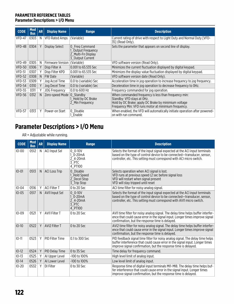
PARAMETER REFERENCE TABLESParameter Descriptions > I/O Menu
122
Parameter Descriptions > I/O MenuAR = Adjustable while running.
VFD-47 0303 N VFD Rated Amps (Variable) Current rating of drive with respect to Light Duty and Normal Duty [VFD-35] (Read Only).
VFD-48 0304 Y Display Select 0_Freq Command1_Output Frequency2_Multi-Fn Display3_Output Current
Sets the parameter that appears on second line of display.
VFD-49 0305 N Firmware Version (Variable) VFD software version (Read Only).VFD-50 0306 Y Disp Filter A 0.001 to 65.535 Sec Minimizes the current fluctuation displayed by digital keypad.VFD-51 0307 Y Disp Filter KPD 0.001 to 65.535 Sec Minimizes the display value fluctuation displayed by digital keypad.VFD-52 0308 N FW Date (Variable) VFD software version date (Read Only).VFD-53 0309 Y Jog Accel Time 0.0 to (variable) Sec Acceleration time in jog operation to increase frequency to jog frequency.VFD-54 0310 Y Jog Decel Time 0.0 to (variable) Sec Deceleration time in jog operation to decrease frequency to 0Hz.VFD-55 0311 Y JOG Frequency 0.0 to 600 Hz Frequency commanded for jog operation.VFD-56 0312 N Zero-speed Mode 0_Standby
1_Hold by DC Brake2_Min Frequency
When commanded frequency is less than frequency min:Standby: VFD stays at 0Hz.Hold by DC Brake: apply DC Brake by minimium voltageFrequency Min: VFD runs motor at minimium frequency.
VFD-57 0313 Y Power-on Start 0_Disable1_Enable
When enabled, the VFD will automatically initiate operation after powered-on with run command.
CODE ModBus AR Display Name Range Description
CODE ModBus AR Display Name Range Description
IO-00 0512 N ACI Input Sel 0_0-10V1_0-20mA2_4-20mA3_PTC4_PT100
Selects the format of the input signal expected at the ACI input terminals based on the type of control device to be connected—transducer, sensor, controller, etc. This setting must correspond with ACI micro switch.
IO-01 0513 N ACI Loss Trip 0_Disable1_Hold Speed2_Decel Stop3_Trip Stop
Selects operation when ACI signal is lost.VFD runs at previous speed (2 sec before signal lossVFD will restart when signal presentVFD will stay tripped until reset
IO-04 0516 Y ACI Filter T 0 to 20 Sec ACI time filter for noisy analog signal.IO-05 0517 N AVI1 Input Sel 0_0-10V
1_0-20mA2_4-20mA3_PTC4_PT100
Selects the format of the input signal expected at the ACI input terminals based on the type of control device to be connected—transducer, sensor, controller, etc. This setting must correspond with AVI1 micro switch.
IO-09 0521 Y AVI1 Filter T 0 to 20 Sec AVI1 time filter for noisy analog signal. The delay time helps buffer interfer-ence that could cause error in the signal input. Longer times improve signal confirmation, but the response time is delayed.
IO-10 0522 Y AVI2 Filter T 0 to 20 Sec AVI2 time filter for noisy analog signal. The delay time helps buffer interfer-ence that could cause error in the signal input. Longer times improve signal confirmation, but the response time is delayed.
IO-11 0523 Y PID Filter Time 0.1 to 300 Sec PID feedback signal time filter for noisy analog signal. The delay time helps buffer interference that could cause error in the signal input. Longer times improve signal confirmation, but the response time is delayed.
IO-12 0524 Y PID Delay Time 0 to 35 Sec Time delay for frequency command.IO-13 0525 Y AI Upper Level -100 to 100% High level limit of analog input.IO-14 0526 Y AI Lower Level -100 to 100% Low level limit of analog input.IO-20 0532 Y DI Filter 0 to 30 Sec Response time of digital input terminals MI1~MI8. The delay time helps buf-
fer interference that could cause error in the signal input. Longer times improve signal confirmation, but the response time is delayed.

PARAMETER REFERENCE TABLESParameter Descriptions > I/O Menu
123
IO-21 0533 Y MI1 Define 0_No Function1_Speed-L2_Speed-M3_Speed-H4_Speed-X5_Fault Reset6_Jog Speed7_Hold Speed8_XCEL-L9_XCEL-M10_Ext. Trip12_AVI1 Analog Spd13_ACI Analog Spd14_AVI2 Analog Spd16_Digital Up17_Digital Down18_PID Disable19_CLR CNT20_Input CNT (MI6)21_FWD Jog22_REV Jog25_E-Stop26_HOA HAND27_HOA AUTO28_Drive Enabled29_PLC mode bit 030_PLC mode bit 132_FO with RUN Cmd33_FO w/o RUN Cmd34_Damper Limit Sw35_Shutdown N-Latch36_Shutdown Latched37_Flow Switch40_Aux Motor-1 OFF41_Aux Motor-2 OFF42_Aux Motor-3 OFF43_Aux Motor-4 OFF44_Aux Motor-5 OFF45_Aux Motor-6 OFF46_Aux Motor-7 OFF47_All Aux Mtr Off
MI1 Default = Speed-L1_Multi-step speed command 1. Refer to “Step Frequencies” on page 65.2_Multi-step speed command 2. Refer to “Step Frequencies” on page 65.3_Multi-step speed command 3. Refer to “Step Frequencies” on page 65.4_Multi-step speed command 4. Refer to “Step Frequencies” on page 65.5_Use to reset fault after cause is corrected6_Changes speed in jog mode to value set in VFD-557_When active, VFD will hold current speed8_ACC/DEC time will be changed to VFD-19 and VFD-209_ACC/DEC time will be changed to VFD-21 and VFD-2210_Trips VFD by external protective device and requires reset12_In non-PID mode, changes speed reference to AVI113_In non-PID mode, changes speed reference to ACI14_In non-PID mode, changes speed reference to AVI216_Increases speed reference when SET-07 is set to (1)17_Decreases speed reference when SET-07 is set to (1)18_Disables PID and switches speed reference to keypad19_Clears pulse counter accumulated value (MI6 only)20_Pulse counter input (MI6 only)21_Jog Command Forward22_Jog Command Reverse25_VFD stops by Emergency Stop device (requires reset)26_External HOA Hand position contact27_External HOA Auto position contact28_Enables and disables the drive (not a run command)29_ PLC Function Disable 29 and 30=(0) or Run 29= (1)30_ PLC Function Disable 29 and 30=(0) or Stop 30= (1)32_VFD will start in FO Mode by FO DI and Run Command33_VFD will start in FO Mode by FO DI (No Run Command)34_When damper is closed, Damper LSW DI is activated35_Activates Shutdown. When inactive, VFD operates normally36_Activates Shutdown. Requires reset to operate normally37_Detects water or air flow by Flow Switch40_Aux Motor-1 in MMC mode is off sequence41_Aux Motor-2 in MMC mode is off sequence42_Aux Motor-3 in MMC mode is off sequence43_Aux Motor-4 in MMC mode is off sequence44_Aux Motor-5 in MMC mode is off sequence45_Aux Motor-6 in MMC mode is off sequence46_Aux Motor-7 in MMC mode is off sequence47_All Aux Motors in MMC mode are off sequence
IO-22 0534 Y MI2 Define See [IO-21] MI2 Default = Preset Speed-MIO-23 0535 Y MI3 Define See [IO-21] MI3 Default = Preset Speed-HIO-24 0536 Y MI4 Define See [IO-21] MI4 Default = Fault ResetIO-25 0537 Y MI5 Define See [IO-21] MI5 Default = Emergency StopIO-26 0538 Y MI6 Define See [IO-21] MI6 Default = XCEL-L (ACC-2/ DEC-2 Time)IO-27 0539 Y MI7 Define See [IO-21] MI7 Default = HOA HandIO-28 0540 Y MI8 Define See [IO-21] MI8 Default = HOA AutoIO-29 0541 N FO Enable 0_Disable
1_FWD Operation2_REV Operation
Enables Fireman’s Override mode in either forward or reverse.
IO-30 0542 Y FO Frequency SET-13 to SET-14 (Hz) Preset frequency for non-PID Fireman’s Override mode.IO-31 0543 Y FO Fault Retry 0 to 10 Number of auto-retries during fault in Fireman’s Override modeIO-32 0544 Y FO Retry Delay 0 to 6000 Sec Delay of auto-retries during fault in Fireman’s Override modeIO-33 0545 N FO Mode & Reset 0_PID Off Manual
1_PID Off Auto2_PID On Manual3_PID On Auto
Sets control method and reset method for Fireman’s Override mode. For example, (1)-FO mode no-PID and auto return to normal operation.
IO-34 0546 Y FO PID S-Point 0 to 100% PID Setpoint in Fireman’s Override mode (when IO-33 is 2 or 3)
CODE ModBus AR Display Name Range Description
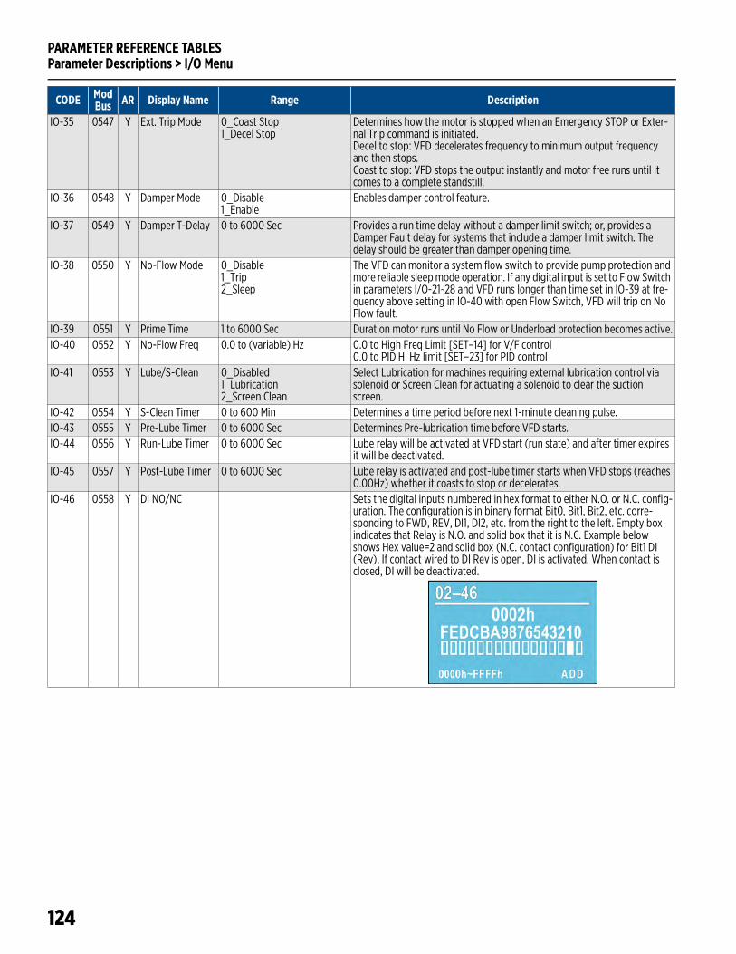
PARAMETER REFERENCE TABLESParameter Descriptions > I/O Menu
124
IO-35 0547 Y Ext. Trip Mode 0_Coast Stop1_Decel Stop
Determines how the motor is stopped when an Emergency STOP or Exter-nal Trip command is initiated.Decel to stop: VFD decelerates frequency to minimum output frequency and then stops.Coast to stop: VFD stops the output instantly and motor free runs until it comes to a complete standstill.
IO-36 0548 Y Damper Mode 0_Disable1_Enable
Enables damper control feature.
IO-37 0549 Y Damper T-Delay 0 to 6000 Sec Provides a run time delay without a damper limit switch; or, provides a Damper Fault delay for systems that include a damper limit switch. The delay should be greater than damper opening time.
IO-38 0550 Y No-Flow Mode 0_Disable1_Trip2_Sleep
The VFD can monitor a system flow switch to provide pump protection and more reliable sleep mode operation. If any digital input is set to Flow Switch in parameters I/O-21~28 and VFD runs longer than time set in IO-39 at fre-quency above setting in IO-40 with open Flow Switch, VFD will trip on No Flow fault.
IO-39 0551 Y Prime Time 1 to 6000 Sec Duration motor runs until No Flow or Underload protection becomes active.IO-40 0552 Y No-Flow Freq 0.0 to (variable) Hz 0.0 to High Freq Limit [SET–14] for V/F control
0.0 to PID Hi Hz limit [SET–23] for PID controlIO-41 0553 Y Lube/S-Clean 0_Disabled
1_Lubrication2_Screen Clean
Select Lubrication for machines requiring external lubrication control via solenoid or Screen Clean for actuating a solenoid to clear the suction screen.
IO-42 0554 Y S-Clean Timer 0 to 600 Min Determines a time period before next 1-minute cleaning pulse. IO-43 0555 Y Pre-Lube Timer 0 to 6000 Sec Determines Pre-lubrication time before VFD starts.IO-44 0556 Y Run-Lube Timer 0 to 6000 Sec Lube relay will be activated at VFD start (run state) and after timer expires
it will be deactivated.IO-45 0557 Y Post-Lube Timer 0 to 6000 Sec Lube relay is activated and post-lube timer starts when VFD stops (reaches
0.00Hz) whether it coasts to stop or decelerates.IO-46 0558 Y DI NO/NC Sets the digital inputs numbered in hex format to either N.O. or N.C. config-
uration. The configuration is in binary format Bit0, Bit1, Bit2, etc. corre-sponding to FWD, REV, DI1, DI2, etc. from the right to the left. Empty box indicates that Relay is N.O. and solid box that it is N.C. Example below shows Hex value=2 and solid box (N.C. contact configuration) for Bit1 DI (Rev). If contact wired to DI Rev is open, DI is activated. When contact is closed, DI will be deactivated.
CODE ModBus AR Display Name Range Description
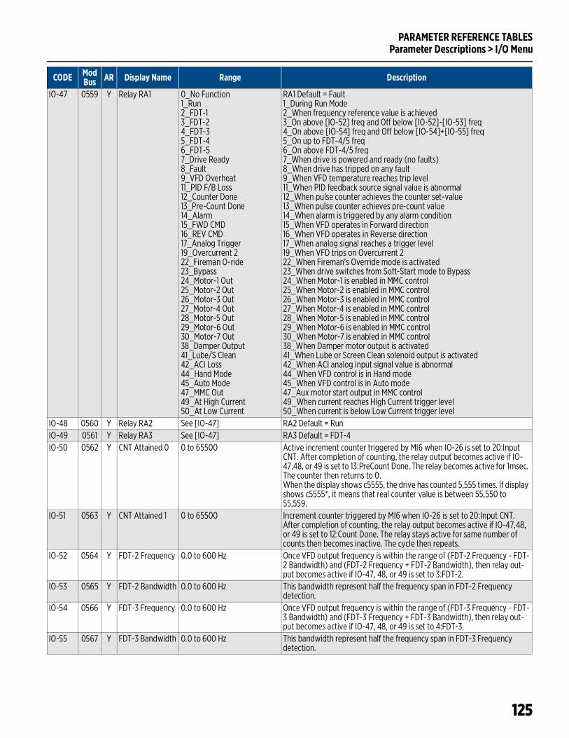
PARAMETER REFERENCE TABLESParameter Descriptions > I/O Menu
125
IO-47 0559 Y Relay RA1 0_No Function1_Run2_FDT-13_FDT-24_FDT-35_FDT-46_FDT-57_Drive Ready8_Fault9_VFD Overheat11_PID F/B Loss12_Counter Done13_Pre-Count Done14_Alarm15_FWD CMD16_REV CMD17_Analog Trigger19_Overcurrent 222_Fireman O-ride23_Bypass24_Motor-1 Out25_Motor-2 Out26_Motor-3 Out27_Motor-4 Out28_Motor-5 Out29_Motor-6 Out30_Motor-7 Out38_Damper Output41_Lube/S Clean42_ACI Loss44_Hand Mode45_Auto Mode47_MMC Out49_At High Current50_At Low Current
RA1 Default = Fault1_During Run Mode2_When frequency reference value is achieved3_On above [IO-52] freq and Off below [IO-52]-[IO-53] freq4_On above [IO-54] freq and Off below [IO-54]+[IO-55] freq5_On up to FDT-4/5 freq6_On above FDT-4/5 freq7_When drive is powered and ready (no faults)8_When drive has tripped on any fault9_When VFD temperature reaches trip level11_When PID feedback source signal value is abnormal12_When pulse counter achieves the counter set-value13_When pulse counter achieves pre-count value14_When alarm is triggered by any alarm condition15_When VFD operates in Forward direction16_When VFD operates in Reverse direction17_When analog signal reaches a trigger level19_When VFD trips on Overcurrent 222_When Fireman’s Override mode is activated23_When drive switches from Soft-Start mode to Bypass24_When Motor-1 is enabled in MMC control25_When Motor-2 is enabled in MMC control26_When Motor-3 is enabled in MMC control27_When Motor-4 is enabled in MMC control28_When Motor-5 is enabled in MMC control29_When Motor-6 is enabled in MMC control30_When Motor-7 is enabled in MMC control38_When Damper motor output is activated41_When Lube or Screen Clean solenoid output is activated42_When ACI analog input signal value is abnormal44_When VFD control is in Hand mode45_When VFD control is in Auto mode47_Aux motor start output in MMC control49_When current reaches High Current trigger level50_When current is below Low Current trigger level
IO-48 0560 Y Relay RA2 See [IO-47] RA2 Default = RunIO-49 0561 Y Relay RA3 See [IO-47] RA3 Default = FDT-4IO-50 0562 Y CNT Attained 0 0 to 65500 Active increment counter triggered by MI6 when IO-26 is set to 20:Input
CNT. After completion of counting, the relay output becomes active if IO-47,48, or 49 is set to 13:PreCount Done. The relay becomes active for 1msec. The counter then returns to 0.When the display shows c5555, the drive has counted 5,555 times. If display shows c5555*, it means that real counter value is between 55,550 to 55,559.
IO-51 0563 Y CNT Attained 1 0 to 65500 Increment counter triggered by MI6 when IO-26 is set to 20:Input CNT. After completion of counting, the relay output becomes active if IO-47,48, or 49 is set to 12:Count Done. The relay stays active for same number of counts then becomes inactive. The cycle then repeats.
IO-52 0564 Y FDT-2 Frequency 0.0 to 600 Hz Once VFD output frequency is within the range of (FDT-2 Frequency - FDT-2 Bandwidth) and (FDT-2 Frequency + FDT-2 Bandwidth), then relay out-put becomes active if IO-47, 48, or 49 is set to 3:FDT-2.
IO-53 0565 Y FDT-2 Bandwidth 0.0 to 600 Hz This bandwidth represent half the frequency span in FDT-2 Frequency detection.
IO-54 0566 Y FDT-3 Frequency 0.0 to 600 Hz Once VFD output frequency is within the range of (FDT-3 Frequency - FDT-3 Bandwidth) and (FDT-3 Frequency + FDT-3 Bandwidth), then relay out-put becomes active if IO-47, 48, or 49 is set to 4:FDT-3.
IO-55 0567 Y FDT-3 Bandwidth 0.0 to 600 Hz This bandwidth represent half the frequency span in FDT-3 Frequency detection.
CODE ModBus AR Display Name Range Description

PARAMETER REFERENCE TABLESParameter Descriptions > I/O Menu
126
IO-56 0568 Y I Hi/Lo Setting 0 to 100% When any relay is set to (49) At High Current in IO-47~49 and motor cur-rent is at or above IO-56 set level (% of FLA), corresponding relay will be activated.When any relay is set to (50) At Low Current in IO-47~49 and motor current is below IO-56 set level (% of FLA), corresponding relay will be activated
IO-57 0569 Y FDT-4/5 Setting 0.0 to 60 Hz Frequency setting for FDT-4 and FDT-5 functions.
IO-58 0570 Y Relay NO/NC Sets the relay outputs numbered in hex format to either N.O. or N.C. config-uration. The configuration is in binary format Bit0, Bit1, Bit2, etc. corre-sponding to RA1, RA2, etc. from right to left. Empty box indicates that Relay is N.O. and solid box that it is N.C. Example below shows solid box (N.C. contact configuration) for Bit0 DO (RA1). The physical N.O. contact of RA1 relay is always closed (relay is activated) until the selected function in IO-47~49 is activated, then contact will be open.
IO-59 0571 Y AFM1 Out Select 0_Output FREQ1_Output AMP (rms)2_Output voltage3_DC Bus voltage4_Power Factor5_Power6_AVI1 %7_ACI %8_AVI2 %9_Constant Output
Defines functionality of Analog Output 1 (AFM1).
IO-60 0572 Y AFM1 Gain 0 to 500% Adjusts the analog voltage level output of AFM1.IO-61 0573 Y AFM2 Out Select See [IO-59] Defines functionality of Analog Output 2 (AFM2).IO-62 0574 Y AFM2 Gain 0 to 500% Adjusts the analog voltage level output of AFM2.IO-63 0575 Y AFM1 mA Select 0_0-20mA output
1_4-20mA outputSelects current range of AFM1 output.
IO-64 0576 Y AFM2 mA Select 0_0-20mA output1_4-20mA output
Selects current range of AFM2 output.
IO-65 0577 Y AFM1 Filter Time 0 to 20 Sec Noise filtering of AFM1 output.IO-66 0578 Y AFM2 Filter Time 0 to 20 Sec Noise filtering of AFM2 output.IO-67 0579 Y MO by AI Level 0_AVI1
1_ACI2_AVI2
When input signal selected is higher than AI Upper Level [IO-13], then MO becomes active. Once input signal decreases below AI Lower Level [IO-14], then MO becomes inactive.
CODE ModBus AR Display Name Range Description
Hz
Freq Command
FDT-4 MO
Time
FDT-4/5 setting
FDT-5 MO
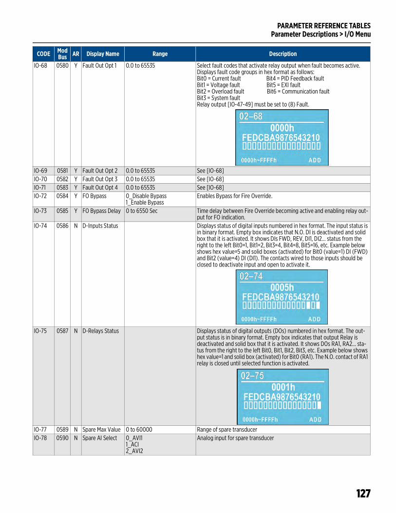
PARAMETER REFERENCE TABLESParameter Descriptions > I/O Menu
127
IO-68 0580 Y Fault Out Opt 1 0.0 to 65535 Select fault codes that activate relay output when fault becomes active. Displays fault code groups in hex format as follows:Bit0 = Current fault Bit4 = PID Feedback faultBit1 = Voltage fault Bit5 = EXI faultBit2 = Overload fault Bit6 = Communication faultBit3 = System faultRelay output [IO-47-49] must be set to (8) Fault.
IO-69 0581 Y Fault Out Opt 2 0.0 to 65535 See [IO-68]IO-70 0582 Y Fault Out Opt 3 0.0 to 65535 See [IO-68]IO-71 0583 Y Fault Out Opt 4 0.0 to 65535 See [IO-68]IO-72 0584 Y FO Bypass 0_Disable Bypass
1_Enable BypassEnables Bypass for Fire Override.
IO-73 0585 Y FO Bypass Delay 0 to 6550 Sec Time delay between Fire Override becoming active and enabling relay out-put for FO indication.
IO-74 0586 N D-Inputs Status Displays status of digital inputs numbered in hex format. The input status is in binary format. Empty box indicates that N.O. DI is deactivated and solid box that it is activated. It shows DIs FWD, REV, DI1, DI2… status from the right to the left Bit0=1, Bit1=2, Bit3=4, Bit4=8, Bit5=16, etc. Example below shows hex value=5 and solid boxes (activated) for Bit0 (value=1) DI (FWD) and Bit2 (value=4) DI (DI1). The contacts wired to those inputs should be closed to deactivate input and open to activate it.
IO-75 0587 N D-Relays Status Displays status of digital outputs (DOs) numbered in hex format. The out-put status is in binary format. Empty box indicates that output Relay is deactivated and solid box that it is activated. It shows DOs RA1, RA2… sta-tus from the right to the left Bit0, Bit1, Bit2, Bit3, etc. Example below shows hex value=1 and solid box (activated) for Bit0 (RA1). The N.O. contact of RA1 relay is closed until selected function is activated.
IO-77 0589 N Spare Max Value 0 to 60000 Range of spare transducerIO-78 0590 N Spare AI Select 0_AVI1
1_ACI2_AVI2
Analog input for spare transducer
CODE ModBus AR Display Name Range Description

PARAMETER REFERENCE TABLESParameter Descriptions > ADV Menu
128
Parameter Descriptions > ADV MenuAR = Adjustable while running.
CODE ModBus AR Display Name Range Description
ADV-00 0768 Y Upper Bound Int 0 to 100% Upper limit for the integral gain (I), which limits the output frequency.Upper Limit Freq = VFD Max Freq Main [VFD-00] x Upper Bound Int [ADV-00].Too large integral value will cause a slow response to sudden load changes. This could cause motor stall or machine damage.
ADV-01 0769 Y PID Out Limit 0 to 110% Maximum PID command limit. Percentage of Maximum Output Frequency [VFD-00].
ADV-02 0770 Y Password Input 0 to 65535 Password protect from modifying parameters.ADV-03 0771 N Parameter Reset 0_Disabled
1_Write protect2_3_Reset KWH4_Reset all Param5_Reset M Run T
Select stored data to be reset.
ADV-05 0773 Y Password Lock 0_Unlocked1_Locked
When setting password protection for the first time, set password in Pass-word Input [ADV-02] and then Password Lock [ADV-05] becomes 1-Locked. To permanently disable password protection, unlock parameters by entering password in Password Input [ADV-02] and then set Password Lock [ADV-05] to 0-Unlocked. If drive is unlocked by a password and pass-word lock is not set to 0-Unlocked, the next reboot of the VFD will lock the VFD again.
ADV-06 0774 Y Acc/Dec Type 0_Linear Acc/Dec1_Auto Acc/L-Dec2_L-Acc/Auto Dec3_Auto Acc/Dec4_Lin, Auto Stall
Provides automated acceleration and deceleration with stall prevention.0_Linear Acc/Dec: Accelerates and decelerates according to the setting of SET-11~12 and VFD-19~24.1_Auto Acc/L-Dec: Auto detects the load torque and accelerates for the fastest acceleration time and smoothest start current. Deceleration is linear according to setting of SET-11-12 and VFD-19-24.2_L-Acc/Auto Dec: Linear acceleration according to setting SET-11~12 and VFD-19~24. Auto detects the load re-generation and stops the motor smoothly with the fastest decel time.3_Auto Acc /Dec: Auto detects load for smoothest operation for accelera-tion and deceleration.4_Lin, Auto Stall: Stall prevention by auto accel./decel being limited by SET-11~12 and VFD-19~24.
ADV-07 0775 N Acc/Dec Format 0_Unit 0.01 Sec1_Unit 0.1 Sec
Precision of acceleration and deceleration.
ADV-08 0776 Y Energy Saving 0_Disable1_Enable
When the output frequency is constant, the output voltage will auto decrease by the load reduction. The drive will operate with minimum power.
ADV-09 0777 Y E-Saving Gain 10 to 1000% Determines speed of adjusting output voltage in relationship to load reduc-tion. If the motor oscillates or has a quick temperature rise, the value should be increased.
ADV-10 0778 N MMC Mode 0_Disabled (default)1_Equal Run Time2_Soft Start mode3_Lead-Lag4_Run Time Alt5_Rotate Lead
Type of operation for Multi-Motor Control.
ADV-11 0779 N Motor Quantity 1 (default) to 7 Number of motors in MMC relay control setup. Limit is 3 without I/O card. When I/O card is installed, selections 1-7 are available.
ADV-12 0780 N Aux Mtr Stop Hz 0 to VFD-00 When output frequency is less than value and remains for duration of ADV-15, motors will be shut down one by one.
ADV-13 0781 N Alt Run Time 0.0 to 60000 Min Duration of running a motor before switching to another motor.ADV-14 0782 N S-Start ON Dly 0.0 to 3600 Sec Delay time before switching on motor.ADV-15 0783 N S-Start Off Dly 0.0 to 3600 Sec Delay time before switching off motor.
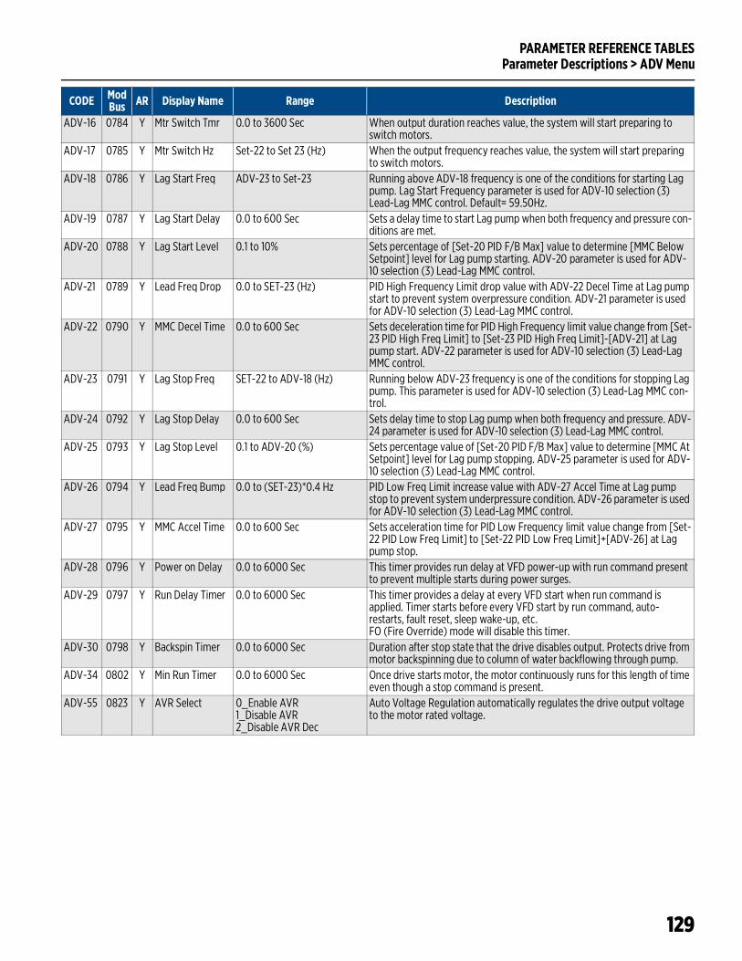
PARAMETER REFERENCE TABLESParameter Descriptions > ADV Menu
129
ADV-16 0784 Y Mtr Switch Tmr 0.0 to 3600 Sec When output duration reaches value, the system will start preparing to switch motors.
ADV-17 0785 Y Mtr Switch Hz Set-22 to Set 23 (Hz) When the output frequency reaches value, the system will start preparing to switch motors.
ADV-18 0786 Y Lag Start Freq ADV-23 to Set-23 Running above ADV-18 frequency is one of the conditions for starting Lag pump. Lag Start Frequency parameter is used for ADV-10 selection (3) Lead-Lag MMC control. Default= 59.50Hz.
ADV-19 0787 Y Lag Start Delay 0.0 to 600 Sec Sets a delay time to start Lag pump when both frequency and pressure con-ditions are met.
ADV-20 0788 Y Lag Start Level 0.1 to 10% Sets percentage of [Set-20 PID F/B Max] value to determine [MMC Below Setpoint] level for Lag pump starting. ADV-20 parameter is used for ADV-10 selection (3) Lead-Lag MMC control.
ADV-21 0789 Y Lead Freq Drop 0.0 to SET-23 (Hz) PID High Frequency Limit drop value with ADV-22 Decel Time at Lag pump start to prevent system overpressure condition. ADV-21 parameter is used for ADV-10 selection (3) Lead-Lag MMC control.
ADV-22 0790 Y MMC Decel Time 0.0 to 600 Sec Sets deceleration time for PID High Frequency limit value change from [Set-23 PID High Freq Limit] to [Set-23 PID High Freq Limit]-[ADV-21] at Lag pump start. ADV-22 parameter is used for ADV-10 selection (3) Lead-Lag MMC control.
ADV-23 0791 Y Lag Stop Freq SET-22 to ADV-18 (Hz) Running below ADV-23 frequency is one of the conditions for stopping Lag pump. This parameter is used for ADV-10 selection (3) Lead-Lag MMC con-trol.
ADV-24 0792 Y Lag Stop Delay 0.0 to 600 Sec Sets delay time to stop Lag pump when both frequency and pressure. ADV-24 parameter is used for ADV-10 selection (3) Lead-Lag MMC control.
ADV-25 0793 Y Lag Stop Level 0.1 to ADV-20 (%) Sets percentage value of [Set-20 PID F/B Max] value to determine [MMC At Setpoint] level for Lag pump stopping. ADV-25 parameter is used for ADV-10 selection (3) Lead-Lag MMC control.
ADV-26 0794 Y Lead Freq Bump 0.0 to (SET-23)*0.4 Hz PID Low Freq Limit increase value with ADV-27 Accel Time at Lag pump stop to prevent system underpressure condition. ADV-26 parameter is used for ADV-10 selection (3) Lead-Lag MMC control.
ADV-27 0795 Y MMC Accel Time 0.0 to 600 Sec Sets acceleration time for PID Low Frequency limit value change from [Set-22 PID Low Freq Limit] to [Set-22 PID Low Freq Limit]+[ADV-26] at Lag pump stop.
ADV-28 0796 Y Power on Delay 0.0 to 6000 Sec This timer provides run delay at VFD power-up with run command present to prevent multiple starts during power surges.
ADV-29 0797 Y Run Delay Timer 0.0 to 6000 Sec This timer provides a delay at every VFD start when run command is applied. Timer starts before every VFD start by run command, auto-restarts, fault reset, sleep wake-up, etc. FO (Fire Override) mode will disable this timer.
ADV-30 0798 Y Backspin Timer 0.0 to 6000 Sec Duration after stop state that the drive disables output. Protects drive from motor backspinning due to column of water backflowing through pump.
ADV-34 0802 Y Min Run Timer 0.0 to 6000 Sec Once drive starts motor, the motor continuously runs for this length of time even though a stop command is present.
ADV-55 0823 Y AVR Select 0_Enable AVR1_Disable AVR2_Disable AVR Dec
Auto Voltage Regulation automatically regulates the drive output voltage to the motor rated voltage.
CODE ModBus AR Display Name Range Description
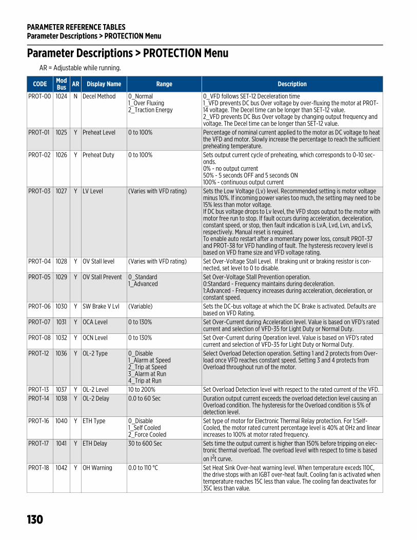
PARAMETER REFERENCE TABLESParameter Descriptions > PROTECTION Menu
130
Parameter Descriptions > PROTECTION MenuAR = Adjustable while running.
CODE ModBus AR Display Name Range Description
PROT-00 1024 N Decel Method 0_Normal1_Over Fluxing2_Traction Energy
0_VFD follows SET-12 Deceleration time1_VFD prevents DC bus Over voltage by over-fluxing the motor at PROT-14 voltage. The Decel time can be longer than SET-12 value.2_VFD prevents DC Bus Over voltage by changing output frequency and voltage. The Decel time can be longer than SET-12 value.
PROT-01 1025 Y Preheat Level 0 to 100% Percentage of nominal current applied to the motor as DC voltage to heat the VFD and motor. Slowly increase the percentage to reach the sufficient preheating temperature.
PROT-02 1026 Y Preheat Duty 0 to 100% Sets output current cycle of preheating, which corresponds to 0-10 sec-onds.0% - no output current50% - 5 seconds OFF and 5 seconds ON100% - continuous output current
PROT-03 1027 Y LV Level (Varies with VFD rating) Sets the Low Voltage (Lv) level. Recommended setting is motor voltage minus 10%. If incoming power varies too much, the setting may need to be 15% less than motor voltage.If DC bus voltage drops to Lv level, the VFD stops output to the motor with motor free run to stop. If fault occurs during acceleration, deceleration, constant speed, or stop, then fault indication is LvA, Lvd, Lvn, and LvS, respectively. Manual reset is required.To enable auto restart after a momentary power loss, consult PROT-37 and PROT-38 for VFD handling of fault. The hysteresis recovery level is based on VFD frame size and VFD voltage rating.
PROT-04 1028 Y OV Stall level (Varies with VFD rating) Set Over-Voltage Stall Level. If braking unit or braking resistor is con-nected, set level to 0 to disable.
PROT-05 1029 Y OV Stall Prevent 0_Standard1_Advanced
Set Over-Voltage Stall Prevention operation.0:Standard - Frequency maintains during deceleration.1:Advanced - Frequency increases during acceleration, deceleration, or constant speed.
PROT-06 1030 Y SW Brake V Lvl (Variable) Sets the DC-bus voltage at which the DC Brake is activated. Defaults are based on VFD Rating.
PROT-07 1031 Y OCA Level 0 to 130% Set Over-Current during Acceleration level. Value is based on VFD's rated current and selection of VFD-35 for Light Duty or Normal Duty.
PROT-08 1032 Y OCN Level 0 to 130% Set Over-Current during Operation level. Value is based on VFD's rated current and selection of VFD-35 for Light Duty or Normal Duty.
PROT-12 1036 Y OL-2 Type 0_Disable1_Alarm at Speed2_Trip at Speed3_Alarm at Run4_Trip at Run
Select Overload Detection operation. Setting 1 and 2 protects from Over-load once VFD reaches constant speed. Setting 3 and 4 protects from Overload throughout run of the motor.
PROT-13 1037 Y OL-2 Level 10 to 200% Set Overload Detection level with respect to the rated current of the VFD.PROT-14 1038 Y OL-2 Delay 0.0 to 60 Sec Duration output current exceeds the overload detection level causing an
Overload condition. The hysteresis for the Overload condition is 5% of detection level.
PROT-16 1040 Y ETH Type 0_Disable1_Self Cooled2_Force Cooled
Set type of motor for Electronic Thermal Relay protection. For 1:Self-Cooled, the motor rated current percentage level is 40% at 0Hz and linear increases to 100% at motor rated frequency.
PROT-17 1041 Y ETH Delay 30 to 600 Sec Sets time the output current is higher than 150% before tripping on elec-tronic thermal overload. The overload level with respect to time is based on I2t curve.
PROT-18 1042 Y OH Warning 0.0 to 110 °C Set Heat Sink Over-heat warning level. When temperature exceds 110C, the drive stops with an IGBT over-heat fault. Cooling fan is activated when temperature reaches 15C less than value. The cooling fan deactivates for 35C less than value.
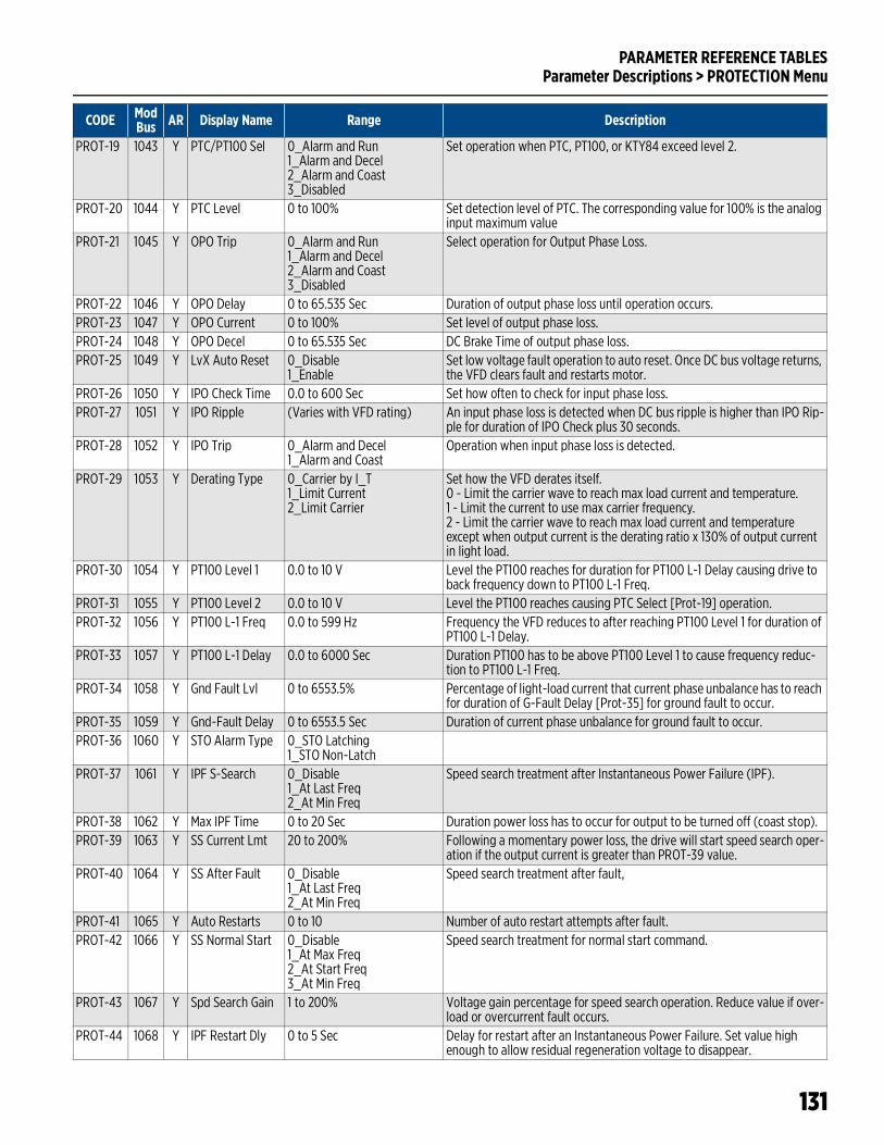
PARAMETER REFERENCE TABLESParameter Descriptions > PROTECTION Menu
131
PROT-19 1043 Y PTC/PT100 Sel 0_Alarm and Run1_Alarm and Decel2_Alarm and Coast3_Disabled
Set operation when PTC, PT100, or KTY84 exceed level 2.
PROT-20 1044 Y PTC Level 0 to 100% Set detection level of PTC. The corresponding value for 100% is the analog input maximum value
PROT-21 1045 Y OPO Trip 0_Alarm and Run1_Alarm and Decel2_Alarm and Coast3_Disabled
Select operation for Output Phase Loss.
PROT-22 1046 Y OPO Delay 0 to 65.535 Sec Duration of output phase loss until operation occurs.PROT-23 1047 Y OPO Current 0 to 100% Set level of output phase loss.PROT-24 1048 Y OPO Decel 0 to 65.535 Sec DC Brake Time of output phase loss.PROT-25 1049 Y LvX Auto Reset 0_Disable
1_EnableSet low voltage fault operation to auto reset. Once DC bus voltage returns, the VFD clears fault and restarts motor.
PROT-26 1050 Y IPO Check Time 0.0 to 600 Sec Set how often to check for input phase loss.PROT-27 1051 Y IPO Ripple (Varies with VFD rating) An input phase loss is detected when DC bus ripple is higher than IPO Rip-
ple for duration of IPO Check plus 30 seconds.PROT-28 1052 Y IPO Trip 0_Alarm and Decel
1_Alarm and CoastOperation when input phase loss is detected.
PROT-29 1053 Y Derating Type 0_Carrier by I_T1_Limit Current2_Limit Carrier
Set how the VFD derates itself.0 - Limit the carrier wave to reach max load current and temperature.1 - Limit the current to use max carrier frequency.2 - Limit the carrier wave to reach max load current and temperature except when output current is the derating ratio x 130% of output current in light load.
PROT-30 1054 Y PT100 Level 1 0.0 to 10 V Level the PT100 reaches for duration for PT100 L-1 Delay causing drive to back frequency down to PT100 L-1 Freq.
PROT-31 1055 Y PT100 Level 2 0.0 to 10 V Level the PT100 reaches causing PTC Select [Prot-19] operation.PROT-32 1056 Y PT100 L-1 Freq 0.0 to 599 Hz Frequency the VFD reduces to after reaching PT100 Level 1 for duration of
PT100 L-1 Delay.PROT-33 1057 Y PT100 L-1 Delay 0.0 to 6000 Sec Duration PT100 has to be above PT100 Level 1 to cause frequency reduc-
tion to PT100 L-1 Freq.PROT-34 1058 Y Gnd Fault Lvl 0 to 6553.5% Percentage of light-load current that current phase unbalance has to reach
for duration of G-Fault Delay [Prot-35] for ground fault to occur.PROT-35 1059 Y Gnd-Fault Delay 0 to 6553.5 Sec Duration of current phase unbalance for ground fault to occur.PROT-36 1060 Y STO Alarm Type 0_STO Latching
1_STO Non-LatchPROT-37 1061 Y IPF S-Search 0_Disable
1_At Last Freq2_At Min Freq
Speed search treatment after Instantaneous Power Failure (IPF).
PROT-38 1062 Y Max IPF Time 0 to 20 Sec Duration power loss has to occur for output to be turned off (coast stop).PROT-39 1063 Y SS Current Lmt 20 to 200% Following a momentary power loss, the drive will start speed search oper-
ation if the output current is greater than PROT-39 value.PROT-40 1064 Y SS After Fault 0_Disable
1_At Last Freq2_At Min Freq
Speed search treatment after fault,
PROT-41 1065 Y Auto Restarts 0 to 10 Number of auto restart attempts after fault.PROT-42 1066 Y SS Normal Start 0_Disable
1_At Max Freq2_At Start Freq3_At Min Freq
Speed search treatment for normal start command.
PROT-43 1067 Y Spd Search Gain 1 to 200% Voltage gain percentage for speed search operation. Reduce value if over-load or overcurrent fault occurs.
PROT-44 1068 Y IPF Restart Dly 0 to 5 Sec Delay for restart after an Instantaneous Power Failure. Set value high enough to allow residual regeneration voltage to disappear.
CODE ModBus AR Display Name Range Description
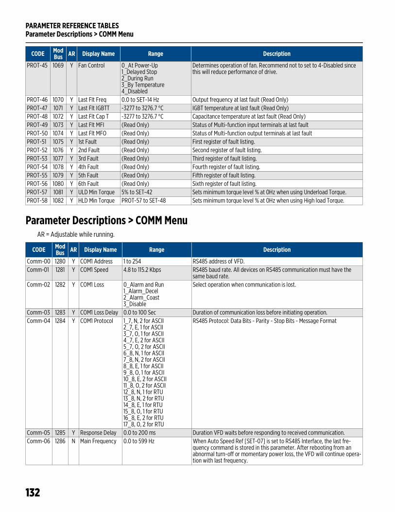
PARAMETER REFERENCE TABLESParameter Descriptions > COMM Menu
132
Parameter Descriptions > COMM MenuAR = Adjustable while running.
PROT-45 1069 Y Fan Control 0_At Power-Up1_Delayed Stop2_During Run3_By Temperature4_Disabled
Determines operation of fan. Recommend not to set to 4-Disabled since this will reduce performance of drive.
PROT-46 1070 Y Last Flt Freq 0.0 to SET-14 Hz Output frequency at last fault (Read Only)PROT-47 1071 Y Last Flt IGBTT -3277 to 3276.7 °C IGBT temperature at last fault (Read Only)PROT-48 1072 Y Last Flt Cap T -3277 to 3276.7 °C Capacitance temperature at last fault (Read Only)PROT-49 1073 Y Last Flt MFI (Read Only) Status of Multi-function input terminals at last fault PROT-50 1074 Y Last Flt MFO (Read Only) Status of Multi-function output terminals at last faultPROT-51 1075 Y 1st Fault (Read Only) First register of fault listing.PROT-52 1076 Y 2nd Fault (Read Only) Second register of fault listing.PROT-53 1077 Y 3rd Fault (Read Only) Third register of fault listing.PROT-54 1078 Y 4th Fault (Read Only) Fourth register of fault listing.PROT-55 1079 Y 5th Fault (Read Only) Fifth register of fault listing.PROT-56 1080 Y 6th Fault (Read Only) Sixth register of fault listing.PROT-57 1081 Y ULD Min Torque 5% to SET-42 Sets minimum torque level % at 0Hz when using Underload Torque. PROT-58 1082 Y HLD Min Torque PROT-57 to SET-48 Sets minimum torque level % at 0Hz when using High load Torque.
CODE ModBus AR Display Name Range Description
CODE ModBus AR Display Name Range Description
Comm-00 1280 Y COM1 Address 1 to 254 RS485 address of VFD.Comm-01 1281 Y COM1 Speed 4.8 to 115.2 Kbps RS485 baud rate. All devices on RS485 communication must have the
same baud rate.Comm-02 1282 Y COM1 Loss 0_Alarm and Run
1_Alarm_Decel2_Alarm_Coast3_Disable
Select operation when communication is lost.
Comm-03 1283 Y COM1 Loss Delay 0.0 to 100 Sec Duration of communication loss before initiating operation.Comm-04 1284 Y COM1 Protocol 1_7, N, 2 for ASCII
2_7, E, 1 for ASCII3_7, O, 1 for ASCII4_7, E, 2 for ASCII5_7, O, 2 for ASCII6_8, N, 1 for ASCII7_8, N, 2 for ASCII8_8, E, 1 for ASCII9_8, O, 1 for ASCII10_8, E, 2 for ASCII11_8, O, 2 for ASCII12_8, N, 1 for RTU13_8, N, 2 for RTU14_8, E, 1 for RTU15_8, O, 1 for RTU16_8, E, 2 for RTU17_8, O, 2 for RTU
RS485 Protocol: Data Bits - Parity - Stop Bits - Message Format
Comm-05 1285 Y Response Delay 0.0 to 200 ms Duration VFD waits before responding to received communication.Comm-06 1286 N Main Frequency 0.0 to 599 Hz When Auto Speed Ref [SET-07] is set to RS485 Interface, the last fre-
quency command is stored in this parameter. After rebooting from an abnormal turn-off or momentary power loss, the VFD will continue opera-tion with last frequency.
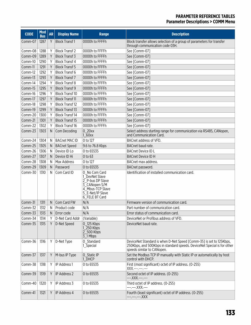
PARAMETER REFERENCE TABLESParameter Descriptions > COMM Menu
133
Comm-07 1287 Y Block Transf 1 0000h to FFFFh Block transfer allows selection of a group of parameters for transfer through communication code 03H.
Comm-08 1288 Y Block Transf 2 0000h to FFFFh See [Comm-07]Comm-09 1289 Y Block Transf 3 0000h to FFFFh See [Comm-07]Comm-10 1290 Y Block Transf 4 0000h to FFFFh See [Comm-07]Comm-11 1291 Y Block Transf 5 0000h to FFFFh See [Comm-07]Comm-12 1292 Y Block Transf 6 0000h to FFFFh See [Comm-07]Comm-13 1293 Y Block Transf 7 0000h to FFFFh See [Comm-07]Comm-14 1294 Y Block Transf 8 0000h to FFFFh See [Comm-07]Comm-15 1295 Y Block Transf 9 0000h to FFFFh See [Comm-07]Comm-16 1296 Y Block Transf 10 0000h to FFFFh See [Comm-07]Comm-17 1297 Y Block Transf 11 0000h to FFFFh See [Comm-07]Comm-18 1298 Y Block Transf 12 0000h to FFFFh See [Comm-07]Comm-19 1299 Y Block Transf 13 0000h to FFFFh See [Comm-07]Comm-20 1300 Y Block Transf 14 0000h to FFFFh See [Comm-07]Comm-21 1301 Y Block Transf 15 0000h to FFFFh See [Comm-07]Comm-22 1302 Y Block Transf 16 0000h to FFFFh See [Comm-07]Comm-23 1303 N Com Decoding 0_20xx
1_60xxSelect address starting range for communication via RS485, CANopen, and Communication Card.
Comm-24 1304 N BACnet MAC ID 0 to 127 BACnet address of VFD.Comm-25 1305 N BACnet Speed 9.6 to 76.8 Kbps BACnet baud rate.Comm-26 1306 N Device ID Lo 0 to 65535 BACnet Device ID LComm-27 1307 N Device ID Hi 0 to 63 BACnet Device ID HComm-28 1308 N Max Address 0 to 127 BACnet max address.Comm-29 1309 N Password 0 to 65535 BACnet password.Comm-30 1310 N Com Card ID 0_No Com Card
1_DevNet Slave2_P-bus DP Slave3_CANopen S/M4_Mbus-TCP Slave5_E-Net/IP Slave6_FELE BT Card
Identification of installed communication card.
Comm-31 1311 N Com Card FW N/A Firmware version of communication card.Comm-32 1312 N Product code N/A Part number of communication card.Comm-33 1313 N Error code N/A Error status of communication card.Comm-34 1314 Y D-Net Card Addr (Variable) DeviceNet or Profibus address of VFD.Comm-35 1315 Y D-Net Speed 0_125 Kbps
1_250 Kbps2_500 Kbps3_1 Mbps
DeviceNet baud rate.
Comm-36 1316 Y D-Net Type 0_Standard1_Special
DeviceNet Standard is when D-Net Speed [Comm-35] is set to 125Kbps, 250Kbps, and 500Kbps in standard speeds. DeviceNet Special is for other speeds similar to CANopen.
Comm-37 1317 Y M-bus IP Type 0_Static IP1_DHCP
Set the Modbus TCP IP manually with Static IP or automatically by host control with DHCP.
Comm-38 1318 Y IP Address 1 0 to 65535 First (most significant) octet of IP address. (0-255)XXX.---.---.---
Comm-39 1319 Y IP Address 2 0 to 65535 Second octet of IP address. (0-255)---.XXX.---.---
Comm-40 1320 Y IP Address 3 0 to 65535 Third octet of IP address. (0-255)---.---.XXX.---
Comm-41 1321 Y IP Address 4 0 to 65535 Fourth (least significant) octet of IP address. (0-255)---.---.---.XXX
CODE ModBus AR Display Name Range Description
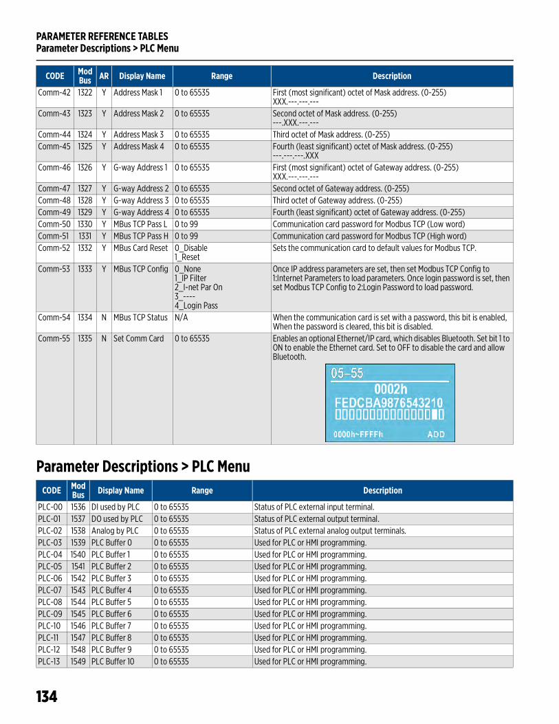
PARAMETER REFERENCE TABLESParameter Descriptions > PLC Menu
134
Parameter Descriptions > PLC Menu
Comm-42 1322 Y Address Mask 1 0 to 65535 First (most significant) octet of Mask address. (0-255)XXX.---.---.---
Comm-43 1323 Y Address Mask 2 0 to 65535 Second octet of Mask address. (0-255)---.XXX.---.---
Comm-44 1324 Y Address Mask 3 0 to 65535 Third octet of Mask address. (0-255)Comm-45 1325 Y Address Mask 4 0 to 65535 Fourth (least significant) octet of Mask address. (0-255)
---.---.---.XXXComm-46 1326 Y G-way Address 1 0 to 65535 First (most significant) octet of Gateway address. (0-255)
XXX.---.---.---Comm-47 1327 Y G-way Address 2 0 to 65535 Second octet of Gateway address. (0-255)Comm-48 1328 Y G-way Address 3 0 to 65535 Third octet of Gateway address. (0-255)Comm-49 1329 Y G-way Address 4 0 to 65535 Fourth (least significant) octet of Gateway address. (0-255)Comm-50 1330 Y MBus TCP Pass L 0 to 99 Communication card password for Modbus TCP (Low word)Comm-51 1331 Y MBus TCP Pass H 0 to 99 Communication card password for Modbus TCP (High word)Comm-52 1332 Y MBus Card Reset 0_Disable
1_ResetSets the communication card to default values for Modbus TCP.
Comm-53 1333 Y MBus TCP Config 0_None1_IP Filter2_I-net Par On3_----4_Login Pass
Once IP address parameters are set, then set Modbus TCP Config to 1:Internet Parameters to load parameters. Once login password is set, then set Modbus TCP Config to 2:Login Password to load password.
Comm-54 1334 N MBus TCP Status N/A When the communication card is set with a password, this bit is enabled, When the password is cleared, this bit is disabled.
Comm-55 1335 N Set Comm Card 0 to 65535 Enables an optional Ethernet/IP card, which disables Bluetooth. Set bit 1 to ON to enable the Ethernet card. Set to OFF to disable the card and allow Bluetooth.
CODE ModBus AR Display Name Range Description
CODE ModBus Display Name Range Description
PLC-00 1536 DI used by PLC 0 to 65535 Status of PLC external input terminal.PLC-01 1537 DO used by PLC 0 to 65535 Status of PLC external output terminal.PLC-02 1538 Analog by PLC 0 to 65535 Status of PLC external analog output terminals.PLC-03 1539 PLC Buffer 0 0 to 65535 Used for PLC or HMI programming.PLC-04 1540 PLC Buffer 1 0 to 65535 Used for PLC or HMI programming.PLC-05 1541 PLC Buffer 2 0 to 65535 Used for PLC or HMI programming.PLC-06 1542 PLC Buffer 3 0 to 65535 Used for PLC or HMI programming.PLC-07 1543 PLC Buffer 4 0 to 65535 Used for PLC or HMI programming.PLC-08 1544 PLC Buffer 5 0 to 65535 Used for PLC or HMI programming.PLC-09 1545 PLC Buffer 6 0 to 65535 Used for PLC or HMI programming.PLC-10 1546 PLC Buffer 7 0 to 65535 Used for PLC or HMI programming.PLC-11 1547 PLC Buffer 8 0 to 65535 Used for PLC or HMI programming.PLC-12 1548 PLC Buffer 9 0 to 65535 Used for PLC or HMI programming.PLC-13 1549 PLC Buffer 10 0 to 65535 Used for PLC or HMI programming.
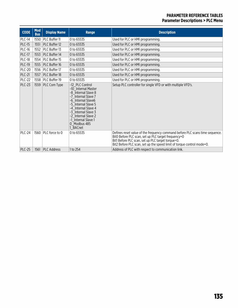
PARAMETER REFERENCE TABLESParameter Descriptions > PLC Menu
135
PLC-14 1550 PLC Buffer 11 0 to 65535 Used for PLC or HMI programming.PLC-15 1551 PLC Buffer 12 0 to 65535 Used for PLC or HMI programming.PLC-16 1552 PLC Buffer 13 0 to 65535 Used for PLC or HMI programming.PLC-17 1553 PLC Buffer 14 0 to 65535 Used for PLC or HMI programming.PLC-18 1554 PLC Buffer 15 0 to 65535 Used for PLC or HMI programming.PLC-19 1555 PLC Buffer 16 0 to 65535 Used for PLC or HMI programming.PLC-20 1556 PLC Buffer 17 0 to 65535 Used for PLC or HMI programming.PLC-21 1557 PLC Buffer 18 0 to 65535 Used for PLC or HMI programming.PLC-22 1558 PLC Buffer 19 0 to 65535 Used for PLC or HMI programming.PLC-23 1559 PLC Com Type -12_PLC Control
-10_Internal Master-8_Internal Slave 8-7_Internal Slave 7-6_Internal Slave6-5_Internal Slave 5-4_Internal Slave 4-3_Internal Slave 3-2_Internal Slave 2-1_Internal Slave 10_Modbus 4851_BACnet
Setup PLC controller for single VFD or with multiple VFD's.
PLC-24 1560 PLC force to 0 0 to 65535 Defines reset value of the frequency command before PLC scans time sequence.Bit0 Before PLC scan, set up PLC target frequency=0Bit1 Before PLC scan, set up PLC target torque=0.Bit2 Before PLC scan, set up the speed limit of torque control mode=0.
PLC-25 1561 PLC Address 1 to 254 Address of PLC with respect to communication link.
CODE ModBus Display Name Range Description
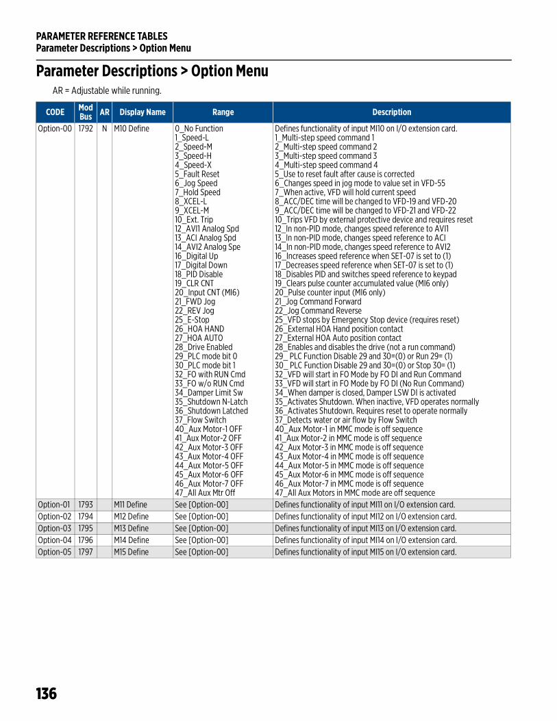
PARAMETER REFERENCE TABLESParameter Descriptions > Option Menu
136
Parameter Descriptions > Option MenuAR = Adjustable while running.
CODE ModBus AR Display Name Range Description
Option-00 1792 N M10 Define 0_No Function1_Speed-L2_Speed-M3_Speed-H4_Speed-X5_Fault Reset6_Jog Speed7_Hold Speed8_XCEL-L9_XCEL-M10_Ext. Trip12_AVI1 Analog Spd13_ACI Analog Spd14_AVI2 Analog Spe16_Digital Up17_Digital Down18_PID Disable19_CLR CNT20_Input CNT (MI6)21_FWD Jog22_REV Jog25_E-Stop26_HOA HAND27_HOA AUTO28_Drive Enabled29_PLC mode bit 030_PLC mode bit 132_FO with RUN Cmd33_FO w/o RUN Cmd34_Damper Limit Sw35_Shutdown N-Latch36_Shutdown Latched37_Flow Switch40_Aux Motor-1 OFF41_Aux Motor-2 OFF42_Aux Motor-3 OFF43_Aux Motor-4 OFF44_Aux Motor-5 OFF45_Aux Motor-6 OFF46_Aux Motor-7 OFF47_All Aux Mtr Off
Defines functionality of input MI10 on I/O extension card.1_Multi-step speed command 12_Multi-step speed command 23_Multi-step speed command 34_Multi-step speed command 45_Use to reset fault after cause is corrected6_Changes speed in jog mode to value set in VFD-557_When active, VFD will hold current speed8_ACC/DEC time will be changed to VFD-19 and VFD-209_ACC/DEC time will be changed to VFD-21 and VFD-2210_Trips VFD by external protective device and requires reset12_In non-PID mode, changes speed reference to AVI113_In non-PID mode, changes speed reference to ACI14_In non-PID mode, changes speed reference to AVI216_Increases speed reference when SET-07 is set to (1)17_Decreases speed reference when SET-07 is set to (1)18_Disables PID and switches speed reference to keypad19_Clears pulse counter accumulated value (MI6 only)20_Pulse counter input (MI6 only)21_Jog Command Forward22_Jog Command Reverse25_VFD stops by Emergency Stop device (requires reset)26_External HOA Hand position contact27_External HOA Auto position contact28_Enables and disables the drive (not a run command)29_ PLC Function Disable 29 and 30=(0) or Run 29= (1)30_ PLC Function Disable 29 and 30=(0) or Stop 30= (1)32_VFD will start in FO Mode by FO DI and Run Command33_VFD will start in FO Mode by FO DI (No Run Command)34_When damper is closed, Damper LSW DI is activated35_Activates Shutdown. When inactive, VFD operates normally36_Activates Shutdown. Requires reset to operate normally37_Detects water or air flow by Flow Switch40_Aux Motor-1 in MMC mode is off sequence41_Aux Motor-2 in MMC mode is off sequence42_Aux Motor-3 in MMC mode is off sequence43_Aux Motor-4 in MMC mode is off sequence44_Aux Motor-5 in MMC mode is off sequence45_Aux Motor-6 in MMC mode is off sequence46_Aux Motor-7 in MMC mode is off sequence47_All Aux Motors in MMC mode are off sequence
Option-01 1793 M11 Define See [Option-00] Defines functionality of input MI11 on I/O extension card.Option-02 1794 M12 Define See [Option-00] Defines functionality of input MI12 on I/O extension card.Option-03 1795 M13 Define See [Option-00] Defines functionality of input MI13 on I/O extension card.Option-04 1796 M14 Define See [Option-00] Defines functionality of input MI14 on I/O extension card.Option-05 1797 M15 Define See [Option-00] Defines functionality of input MI15 on I/O extension card.
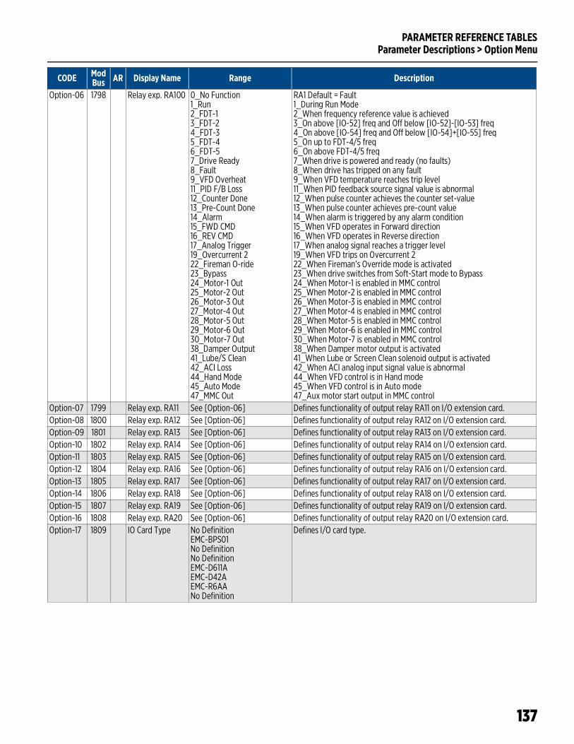
PARAMETER REFERENCE TABLESParameter Descriptions > Option Menu
137
Option-06 1798 Relay exp. RA100 0_No Function1_Run2_FDT-13_FDT-24_FDT-35_FDT-46_FDT-57_Drive Ready8_Fault9_VFD Overheat11_PID F/B Loss12_Counter Done13_Pre-Count Done14_Alarm15_FWD CMD16_REV CMD17_Analog Trigger19_Overcurrent 222_Fireman O-ride23_Bypass24_Motor-1 Out25_Motor-2 Out26_Motor-3 Out27_Motor-4 Out28_Motor-5 Out29_Motor-6 Out30_Motor-7 Out38_Damper Output41_Lube/S Clean42_ACI Loss44_Hand Mode45_Auto Mode47_MMC Out
RA1 Default = Fault1_During Run Mode2_When frequency reference value is achieved3_On above [IO-52] freq and Off below [IO-52]-[IO-53] freq4_On above [IO-54] freq and Off below [IO-54]+[IO-55] freq5_On up to FDT-4/5 freq6_On above FDT-4/5 freq7_When drive is powered and ready (no faults)8_When drive has tripped on any fault9_When VFD temperature reaches trip level11_When PID feedback source signal value is abnormal12_When pulse counter achieves the counter set-value13_When pulse counter achieves pre-count value14_When alarm is triggered by any alarm condition15_When VFD operates in Forward direction16_When VFD operates in Reverse direction17_When analog signal reaches a trigger level19_When VFD trips on Overcurrent 222_When Fireman’s Override mode is activated23_When drive switches from Soft-Start mode to Bypass24_When Motor-1 is enabled in MMC control25_When Motor-2 is enabled in MMC control26_When Motor-3 is enabled in MMC control27_When Motor-4 is enabled in MMC control28_When Motor-5 is enabled in MMC control29_When Motor-6 is enabled in MMC control30_When Motor-7 is enabled in MMC control38_When Damper motor output is activated41_When Lube or Screen Clean solenoid output is activated42_When ACI analog input signal value is abnormal44_When VFD control is in Hand mode45_When VFD control is in Auto mode47_Aux motor start output in MMC control
Option-07 1799 Relay exp. RA11 See [Option-06] Defines functionality of output relay RA11 on I/O extension card.Option-08 1800 Relay exp. RA12 See [Option-06] Defines functionality of output relay RA12 on I/O extension card.Option-09 1801 Relay exp. RA13 See [Option-06] Defines functionality of output relay RA13 on I/O extension card.Option-10 1802 Relay exp. RA14 See [Option-06] Defines functionality of output relay RA14 on I/O extension card.Option-11 1803 Relay exp. RA15 See [Option-06] Defines functionality of output relay RA15 on I/O extension card.Option-12 1804 Relay exp. RA16 See [Option-06] Defines functionality of output relay RA16 on I/O extension card.Option-13 1805 Relay exp. RA17 See [Option-06] Defines functionality of output relay RA17 on I/O extension card.Option-14 1806 Relay exp. RA18 See [Option-06] Defines functionality of output relay RA18 on I/O extension card.Option-15 1807 Relay exp. RA19 See [Option-06] Defines functionality of output relay RA19 on I/O extension card.Option-16 1808 Relay exp. RA20 See [Option-06] Defines functionality of output relay RA20 on I/O extension card.Option-17 1809 IO Card Type No Definition
EMC-BPS01No DefinitionNo DefinitionEMC-D611AEMC-D42AEMC-R6AANo Definition
Defines I/O card type.
CODE ModBus AR Display Name Range Description
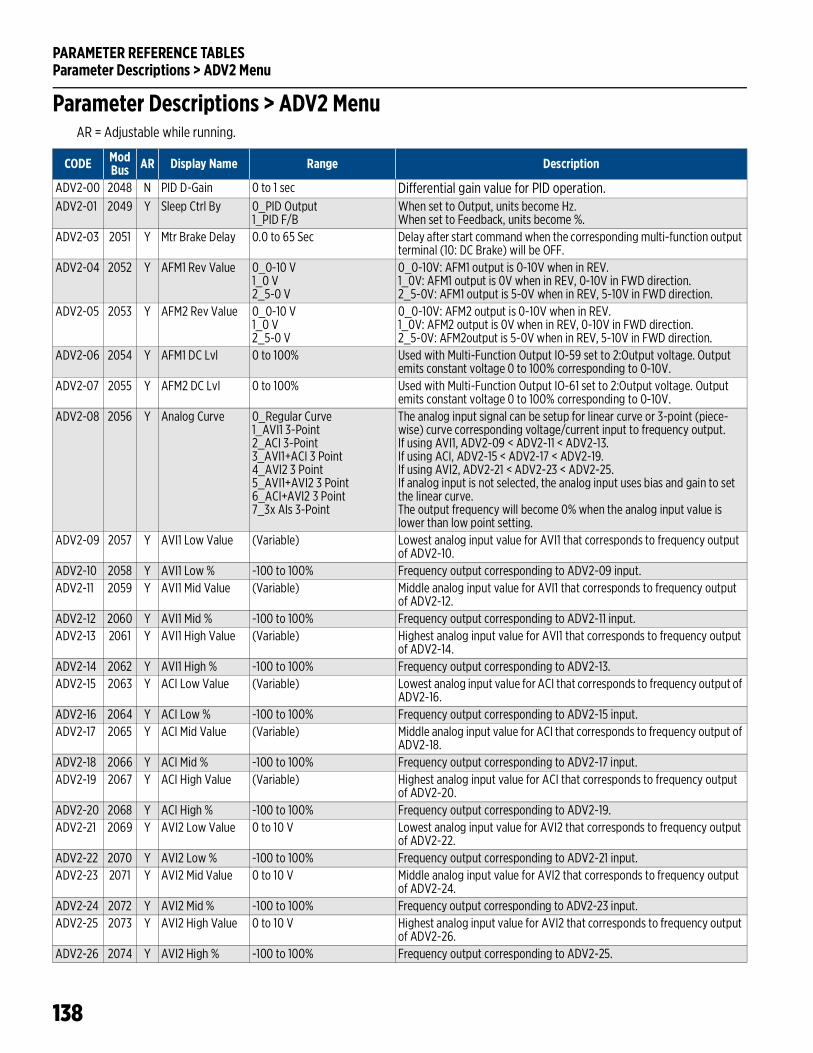
PARAMETER REFERENCE TABLESParameter Descriptions > ADV2 Menu
138
Parameter Descriptions > ADV2 MenuAR = Adjustable while running.
CODE ModBus AR Display Name Range Description
ADV2-00 2048 N PID D-Gain 0 to 1 sec Differential gain value for PID operation.ADV2-01 2049 Y Sleep Ctrl By 0_PID Output
1_PID F/BWhen set to Output, units become Hz.When set to Feedback, units become %.
ADV2-03 2051 Y Mtr Brake Delay 0.0 to 65 Sec Delay after start command when the corresponding multi-function output terminal (10: DC Brake) will be OFF.
ADV2-04 2052 Y AFM1 Rev Value 0_0-10 V1_0 V2_5-0 V
0_0-10V: AFM1 output is 0-10V when in REV.1_0V: AFM1 output is 0V when in REV, 0-10V in FWD direction.2_5-0V: AFM1 output is 5-0V when in REV, 5-10V in FWD direction.
ADV2-05 2053 Y AFM2 Rev Value 0_0-10 V1_0 V2_5-0 V
0_0-10V: AFM2 output is 0-10V when in REV.1_0V: AFM2 output is 0V when in REV, 0-10V in FWD direction.2_5-0V: AFM2output is 5-0V when in REV, 5-10V in FWD direction.
ADV2-06 2054 Y AFM1 DC Lvl 0 to 100% Used with Multi-Function Output IO-59 set to 2:Output voltage. Output emits constant voltage 0 to 100% corresponding to 0-10V.
ADV2-07 2055 Y AFM2 DC Lvl 0 to 100% Used with Multi-Function Output IO-61 set to 2:Output voltage. Output emits constant voltage 0 to 100% corresponding to 0-10V.
ADV2-08 2056 Y Analog Curve 0_Regular Curve1_AVI1 3-Point2_ACI 3-Point3_AVI1+ACI 3 Point4_AVI2 3 Point5_AVI1+AVI2 3 Point6_ACI+AVI2 3 Point7_3x AIs 3-Point
The analog input signal can be setup for linear curve or 3-point (piece-wise) curve corresponding voltage/current input to frequency output.If using AVI1, ADV2-09 < ADV2-11 < ADV2-13.If using ACI, ADV2-15 < ADV2-17 < ADV2-19.If using AVI2, ADV2-21 < ADV2-23 < ADV2-25.If analog input is not selected, the analog input uses bias and gain to set the linear curve.The output frequency will become 0% when the analog input value is lower than low point setting.
ADV2-09 2057 Y AVI1 Low Value (Variable) Lowest analog input value for AVI1 that corresponds to frequency output of ADV2-10.
ADV2-10 2058 Y AVI1 Low % -100 to 100% Frequency output corresponding to ADV2-09 input.ADV2-11 2059 Y AVI1 Mid Value (Variable) Middle analog input value for AVI1 that corresponds to frequency output
of ADV2-12.ADV2-12 2060 Y AVI1 Mid % -100 to 100% Frequency output corresponding to ADV2-11 input.ADV2-13 2061 Y AVI1 High Value (Variable) Highest analog input value for AVI1 that corresponds to frequency output
of ADV2-14.ADV2-14 2062 Y AVI1 High % -100 to 100% Frequency output corresponding to ADV2-13.ADV2-15 2063 Y ACI Low Value (Variable) Lowest analog input value for ACI that corresponds to frequency output of
ADV2-16.ADV2-16 2064 Y ACI Low % -100 to 100% Frequency output corresponding to ADV2-15 input.ADV2-17 2065 Y ACI Mid Value (Variable) Middle analog input value for ACI that corresponds to frequency output of
ADV2-18.ADV2-18 2066 Y ACI Mid % -100 to 100% Frequency output corresponding to ADV2-17 input.ADV2-19 2067 Y ACI High Value (Variable) Highest analog input value for ACI that corresponds to frequency output
of ADV2-20.ADV2-20 2068 Y ACI High % -100 to 100% Frequency output corresponding to ADV2-19.ADV2-21 2069 Y AVI2 Low Value 0 to 10 V Lowest analog input value for AVI2 that corresponds to frequency output
of ADV2-22.ADV2-22 2070 Y AVI2 Low % -100 to 100% Frequency output corresponding to ADV2-21 input.ADV2-23 2071 Y AVI2 Mid Value 0 to 10 V Middle analog input value for AVI2 that corresponds to frequency output
of ADV2-24.ADV2-24 2072 Y AVI2 Mid % -100 to 100% Frequency output corresponding to ADV2-23 input.ADV2-25 2073 Y AVI2 High Value 0 to 10 V Highest analog input value for AVI2 that corresponds to frequency output
of ADV2-26.ADV2-26 2074 Y AVI2 High % -100 to 100% Frequency output corresponding to ADV2-25.
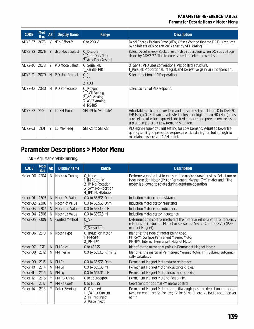
PARAMETER REFERENCE TABLESParameter Descriptions > Motor Menu
139
Parameter Descriptions > Motor MenuAR = Adjustable while running.
ADV2-27 2075 Y dEb Offset V 0 to 200 V Decel Energy Backup Error (dEb) Offset Voltage that the DC Bus reduces by to initiate dEb operation. Varies by VFD Rating.
ADV2-28 2076 Y dEb Mode Select 0_Disable1_Auto Dec/Stop2_AutoDec/Restart
Select Decel Energy Backup Error (dEb) operation when DC Bus voltage drops by ADV2-27. This feature is used to detect power loss.
ADV2-30 2078 Y PID Mode Select 0_Serial PID1_Parallel PID
0_Serial: VFD uses conventional PID control structure.1_Parallel: Proportional, Integral, and Derivative gains are independent.
ADV2-31 2079 N PID Unit Format 0_11_0.12_0.01
Select precision of PID operation.
ADV2-32 2080 N PID Ref Source 0_Keypad1_AVI1 Analog2_ACI Analog3_AVI2 Analog4_RS485
Select source of PID setpoint.
ADV2-52 2100 Y LD Set Point SET-19 to (variable) Adjustable setting for Low Demand pressure set-point from 0 to [Set-20 F/B Max]x 0.95. It can be adjusted to lower or higher than HD (Main) pres-sure set-point value to provide desired pressure and prevent overpressure trip at pump start in Low Demand situation.
ADV2-53 2101 Y LD Max Freq SET-23 to SET-22 PID High Frequency Limit setting for Low Demand. Adjust to lower fre-quency setting to prevent overpressure trips during run but enough to maintain pressure at LD Set-point.
CODE ModBus AR Display Name Range Description
CODE ModBus AR Display Name Range Description
Motor-00 2304 N Motor A-Tuning 0_None1_IM Rotating2_IM No-Rotation3_SPM No-Rotation4_IPM No-Rotation
Performs a motor test to measure the motor characteristics. Select motor type Induction Motor (IM) or Permanent Magnet (PM) motor and if the motor is allowed to rotate during autotune operation.
Motor-01 2305 N Motor Rs Value 0.0 to 65.535 Ohm Induction Motor rotor resistanceMotor-02 2306 N Motor Rr Value 0.0 to 65.535 Ohm Induction Motor stator resistanceMotor-03 2307 N Motor Lm Value 0.0 to 6553.5 mH Induction Motor rotor inductanceMotor-04 2308 N Motor Lx Value 0.0 to 6553.5 mH Induction Motor stator inductanceMotor-05 2309 N Control Method 0_VF
1________2_Sensorless
Determines the control method of the motor as either a volts to frequency relationship (Induction Motor) or Sensorless Vector Control (SVC) (Per-manent Magnet).
Motor-06 2310 N Motor Type 0_Induction Motor1_PM-SPM2_PM-IPM
Identifies the type of motor being used.PM-SPM: Surface Permanent Magnet MotorPM-IPM: Internal Permanent Magnet Motor
Motor-07 2311 N PM Poles 0 to 65535 Identifies the number of poles in Permanent Magnet Motor.Motor-08 2312 N PM Inertia 0.0 to 6553.5 Kg*m^2 Identifies the inertia in Permanent Magnet Motor. This value is automati-
cally calculated.Motor-09 2313 N PM Rs 0.0 to 65.535 Ohm Permanent Magnet Motor stator resistance.Motor-10 2314 N PM Ld 0.0 to 655.35 mH Permanent Magnet Motor inductance d-axis.Motor-11 2315 N PM Lq 0.0 to 655.35 mH Permanent Magnet Motor inductance q-axis.Motor-12 2316 Y PM PG Angle 0 to 360 degree Permanent Magnet Motor offset angle.Motor-13 2317 Y PM Ke Coeff 0 to 65535 Coefficient for optimal PM motor controlMotor-14 2318 Y Rotor Zeroing 0_Disabled
1_1/4 FLA Current2_Hi Freq Inject3_Pulse Inject
Permanent Magnet Motor rotor initial angle position detection method. Recommendation: "2" for IPM; "3" for SPM. If there is a bad effect, then set as "1".
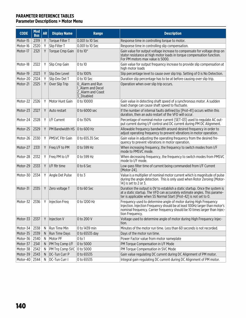
PARAMETER REFERENCE TABLESParameter Descriptions > Motor Menu
140
Motor-15 2319 Y Torque Filter T 0.001 to 10 Sec Response time in controlling torque to motor.Motor-16 2320 Y Slip Filter T 0.001 to 10 Sec Response time in controlling slip compensation.Motor-17 2321 Y Torque Cmp Gain 0 to 10* Gain value for output voltage increase to compensate for voltage drop on
stator resistance at high motor loads in torque compensation function. For PM motors max value is 5000.
Motor-18 2322 Y Slip Cmp Gain 0 to 10 Gain value for output frequency increase to provide slip compensation at high motor loads
Motor-19 2323 Y Slip Dev Level 0 to 100% Slip percentage level to cause over slip trip. Setting of 0 is No Detection.Motor-20 2324 Y Slip Dev Det T 0 to 10 Sec Duration slip percentage has to be at before causing over slip trip.Motor-21 2325 Y Over Slip Trip 0_Alarm and Run
1_Alarm and Decel2_Alarm and Coast3_Disabled
Operation when over slip trip occurs.
Motor-22 2326 Y Motor Hunt Gain 0 to 10000 Gain value in detecting shaft speed of a synchronous motor. A sudden load change can cause shaft speed to fluctuate.
Motor-23 2327 Y Auto restart 0 to 6000 sec If the number of internal faults defined by [Prot-41] occurs within this duration, then an auto restart of the VFD will occur.
Motor-24 2328 Y I/F Current 0 to 150% Percentage of nominal motor current [SET-03] used to regulate AC out-put current during I/F control and DC current during PM DC Alignment.
Motor-25 2329 Y PM Bandwidth HS 0 to 600 Hz Allowable frequency bandwidth around desired frequency in order to adjust operating frequency to prevent vibrations in motor operation.
Motor-26 2330 Y PMSVC Fltr Gain 0 to 655.35 Sec Gain value in adjusting the operating frequency from the desired fre-quency to prevent vibrations in motor operation.
Motor-27 2331 Y Freq I/F to PM 0 to 599 Hz When increasing frequency, the frequency to switch modes from I/F mode to PMSVC mode.
Motor-28 2332 Y Freq PM to I/F 0 to 599 Hz When decreasing frequency, the frequency to switch modes from PMSVC mode to I/F mode.
Motor-29 2333 Y I/F fltr time 0 to 6 Sec Low-pass filter time of current being commanded from I/F Current [Motor-24].
Motor-30 2334 Y Angle Det Pulse 0 to 3 Value is a multiplier of nominal motor current which is magnitude of pulse during the angle detection. This is only used when Rotor Zeroing [Motor-14] is set to 2 or 3.
Motor-31 2335 Y Zero voltage T 0 to 60 Sec Duration the output is 0V to establish a static startup. Once the system is at a static startup. The VFD can accurately estimate angles. This parame-ter is applicable when SS Normal Start [Prot-42] is not set to 0.
Motor-32 2336 Y Injection Freq 0 to 1200 Hz Frequency used to determine angle of motor during High Frequency Injection. Injection Frequency should be at least 100Hz larger than motor's nominal frequency. Carrier frequency should be 10 times larger than Injec-tion Frequency.
Motor-33 2337 Y Injection V 0 to 200 V Voltage used to determine angle of motor during High Frequency Injec-tion.
Motor-34 2338 N Run Time Min 0 to 1439 min Minutes of the motor run time. Less than 60 seconds is not recorded.Motor-35 2339 N Run Time Days 0 to 65535 day Days of the motor run time.Motor-36 2340 N Motor PF 0 to 1 Power Factor value from motor nameplateMotor-37 2341 N PM Trq Comp I/F 0 to 5000 PM Torque Compensation in I/F ModeMotor-38 2342 N PM Trq Comp SVC 0 to 5000 PM Torque Compensation in SVC ModeMotor-39 2343 N DC-Tun Curr P 0 to 65535 Gain value regulating DC current during DC Alignment of PM motor.Motor-40 2344 N DC-Tun Curr I 0 to 65535 Integral gain regulating DC current during DC Alignment of PM motor.
CODE ModBus AR Display Name Range Description
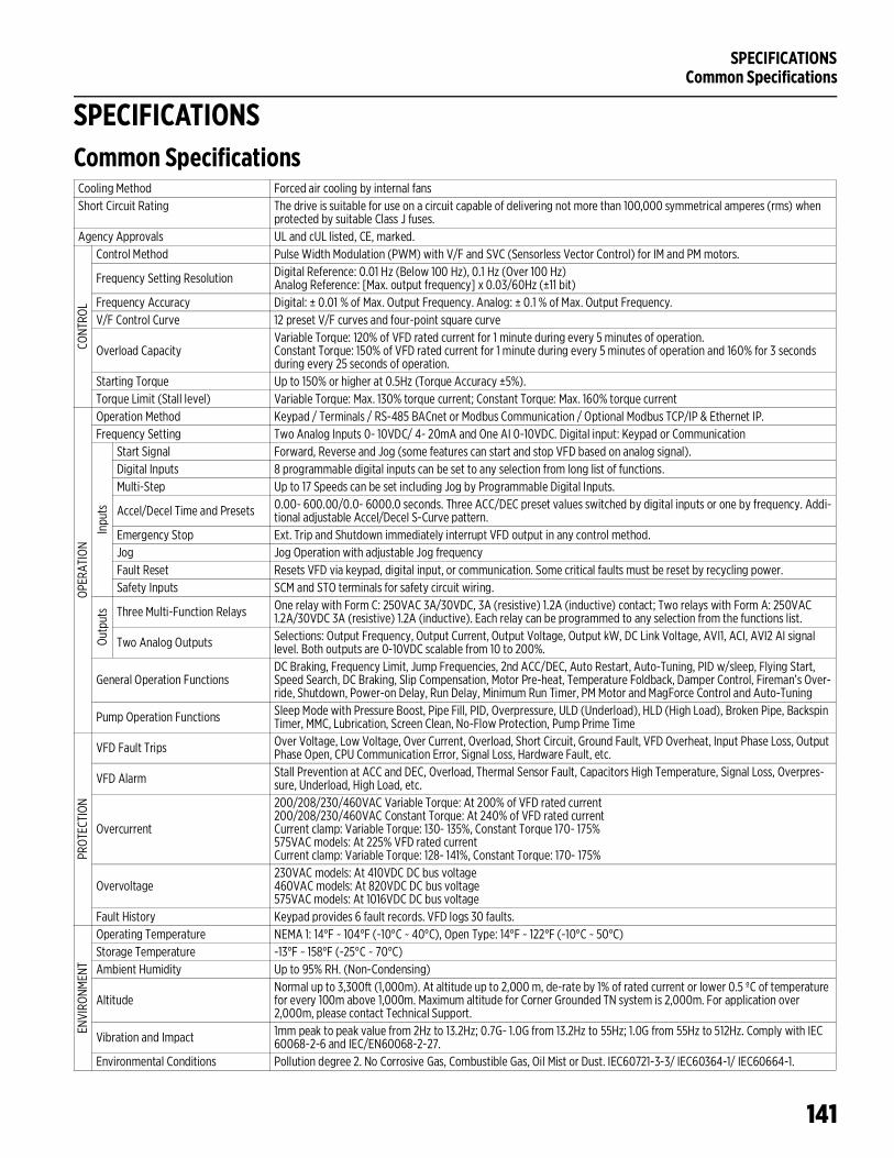
SPECIFICATIONSCommon Specifications
141
SPECIFICATIONSCommon SpecificationsCooling Method Forced air cooling by internal fansShort Circuit Rating The drive is suitable for use on a circuit capable of delivering not more than 100,000 symmetrical amperes (rms) when
protected by suitable Class J fuses. Agency Approvals UL and cUL listed, CE, marked.
CONT
ROL
Control Method Pulse Width Modulation (PWM) with V/F and SVC (Sensorless Vector Control) for IM and PM motors.
Frequency Setting Resolution Digital Reference: 0.01 Hz (Below 100 Hz), 0.1 Hz (Over 100 Hz) Analog Reference: [Max. output frequency] x 0.03/60Hz (±11 bit)
Frequency Accuracy Digital: ± 0.01 % of Max. Output Frequency. Analog: ± 0.1 % of Max. Output Frequency.V/F Control Curve 12 preset V/F curves and four-point square curve
Overload CapacityVariable Torque: 120% of VFD rated current for 1 minute during every 5 minutes of operation.Constant Torque: 150% of VFD rated current for 1 minute during every 5 minutes of operation and 160% for 3 seconds during every 25 seconds of operation.
Starting Torque Up to 150% or higher at 0.5Hz (Torque Accuracy ±5%).Torque Limit (Stall level) Variable Torque: Max. 130% torque current; Constant Torque: Max. 160% torque current
OPER
ATIO
N
Operation Method Keypad / Terminals / RS-485 BACnet or Modbus Communication / Optional Modbus TCP/IP & Ethernet IP.Frequency Setting Two Analog Inputs 0- 10VDC/ 4- 20mA and One AI 0-10VDC. Digital input: Keypad or Communication
Inpu
ts
Start Signal Forward, Reverse and Jog (some features can start and stop VFD based on analog signal).Digital Inputs 8 programmable digital inputs can be set to any selection from long list of functions.Multi-Step Up to 17 Speeds can be set including Jog by Programmable Digital Inputs.
Accel/Decel Time and Presets 0.00- 600.00/0.0- 6000.0 seconds. Three ACC/DEC preset values switched by digital inputs or one by frequency. Addi-tional adjustable Accel/Decel S-Curve pattern.
Emergency Stop Ext. Trip and Shutdown immediately interrupt VFD output in any control method.Jog Jog Operation with adjustable Jog frequencyFault Reset Resets VFD via keypad, digital input, or communication. Some critical faults must be reset by recycling power.Safety Inputs SCM and STO terminals for safety circuit wiring.
Outp
uts Three Multi-Function Relays One relay with Form C: 250VAC 3A/30VDC, 3A (resistive) 1.2A (inductive) contact; Two relays with Form A: 250VAC
1.2A/30VDC 3A (resistive) 1.2A (inductive). Each relay can be programmed to any selection from the functions list.
Two Analog Outputs Selections: Output Frequency, Output Current, Output Voltage, Output kW, DC Link Voltage, AVI1, ACI, AVI2 AI signal level. Both outputs are 0-10VDC scalable from 10 to 200%.
General Operation FunctionsDC Braking, Frequency Limit, Jump Frequencies, 2nd ACC/DEC, Auto Restart, Auto-Tuning, PID w/sleep, Flying Start, Speed Search, DC Braking, Slip Compensation, Motor Pre-heat, Temperature Foldback, Damper Control, Fireman’s Over-ride, Shutdown, Power-on Delay, Run Delay, Minimum Run Timer, PM Motor and MagForce Control and Auto-Tuning
Pump Operation Functions Sleep Mode with Pressure Boost, Pipe Fill, PID, Overpressure, ULD (Underload), HLD (High Load), Broken Pipe, Backspin Timer, MMC, Lubrication, Screen Clean, No-Flow Protection, Pump Prime Time
PROT
ECTI
ON
VFD Fault Trips Over Voltage, Low Voltage, Over Current, Overload, Short Circuit, Ground Fault, VFD Overheat, Input Phase Loss, Output Phase Open, CPU Communication Error, Signal Loss, Hardware Fault, etc.
VFD Alarm Stall Prevention at ACC and DEC, Overload, Thermal Sensor Fault, Capacitors High Temperature, Signal Loss, Overpres-sure, Underload, High Load, etc.
Overcurrent
200/208/230/460VAC Variable Torque: At 200% of VFD rated current200/208/230/460VAC Constant Torque: At 240% of VFD rated currentCurrent clamp: Variable Torque: 130- 135%, Constant Torque 170- 175%575VAC models: At 225% VFD rated currentCurrent clamp: Variable Torque: 128- 141%, Constant Torque: 170- 175%
Overvoltage230VAC models: At 410VDC DC bus voltage 460VAC models: At 820VDC DC bus voltage575VAC models: At 1016VDC DC bus voltage
Fault History Keypad provides 6 fault records. VFD logs 30 faults.
ENVI
RONM
ENT
Operating Temperature NEMA 1: 14°F ~ 104°F (-10°C ~ 40°C), Open Type: 14°F ~ 122°F (-10°C ~ 50°C)Storage Temperature -13°F ~ 158°F (-25°C ~ 70°C)Ambient Humidity Up to 95% RH. (Non-Condensing)
AltitudeNormal up to 3,300ft (1,000m). At altitude up to 2,000 m, de-rate by 1% of rated current or lower 0.5 ºC of temperature for every 100m above 1,000m. Maximum altitude for Corner Grounded TN system is 2,000m. For application over 2,000m, please contact Technical Support.
Vibration and Impact 1mm peak to peak value from 2Hz to 13.2Hz; 0.7G- 1.0G from 13.2Hz to 55Hz; 1.0G from 55Hz to 512Hz. Comply with IEC 60068-2-6 and IEC/EN60068-2-27.
Environmental Conditions Pollution degree 2. No Corrosive Gas, Combustible Gas, Oil Mist or Dust. IEC60721-3-3/ IEC60364-1/ IEC60664-1.
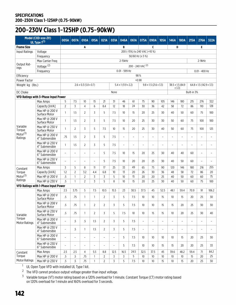
SPECIFICATIONS200~230V Class 1~125HP (0.75~90kW)
142
200~230V Class 1~125HP (0.75~90kW)
1 UL Open Type VFD with installed UL Type 1 kit.2 The VFD cannot produce output voltage greater than input voltage. 3 Variable torque (VT) motor rating based on a 120% overload for 1 minute. Constant Torque (CT) motor rating based
on 120% overload for 1 minute and 160% overload for 3 seconds.
Model (CXD-xxx-2V) UL Type 1(1)
005A 007A 010A 015A 021A 031A 046A 061A 075A 090A 105A 146A 180A 215A 276A 322A
Frame Size A B C D EInput Ratings Voltage 200 (-15%) to 240 VAC (+10 %)
Frequency 50/60 Hz (± 5 %)
Output Rat-ings
Max Carrier Freq 2-15kHz 2-9kHz
Voltage (2) 200 ~ 240 VAC (2)
Frequency 0.01 ~ 599 Hz 0.01 ~ 400 Hz
Efficiency 98 %
Power Factor >0.98
Weight kg (lbs.) 2.6 ± 0.3 (5.8 ± 0.7) 5.4 ± 1 (11.9 ± 2.2) 9.8 ± 1.5 (21.6 ± 3.3) 38.5 ± 1.5 (84.9 ± 3.3)
64.8 ± 1.5 (142.9 ± 3.3)
DC Choke None Built-in 3%
VFD Ratings with 3-Phase Input Power
VariableTorqueMotor(3)
Ratings
Max Amps 5 7.5 10 15 21 31 46 61 75 90 105 146 180 215 276 322
Capacity [kVA] 2 3 4 6 8.4 12 18 24 30 36 42 58 72 86 110 128
Max HP @ 200 VSurface Motor 1 1.5 2 3 5 7.5 10 15 20 25 30 40 50 60 75 100
Max HP @ 208 VSurface Motor 1 1.5 2 3 5 7.5 10 20 25 30 30 50 60 75 100 100
Max HP @ 230 VSurface Motor 1 2 3 5 7.5 10 15 20 25 30 40 50 60 75 100 125
Max HP @ 200 V4” Submersible .75 1.5 2 3 5 7.5 – – – – – – – – – –
Max HP @ 230 V4” Submersible 1 1.5 2 3 5 7.5 – – – – – – – – – –
Max HP @ 200 V6” Submersible – – – – 5 7.5 10 15 20 25 30 40 40 60 – –
Max HP @ 230 V6” Submersible – – – – 5 7.5 10 20 20 25 30 40 50 60 – –
ConstantTorqueMotor(3)
Ratings
Max Amps 3 5 8 11 17 25 33 49 65 75 90 120 146 180 216 255
Capacity [kVA] 1.2 2 3.2 4.4 6.8 10 13 20 26 30 36 48 58 72 86 20
Max HP @ 200 V .5 1 2 3 3 5 10 15 20 20 25 40 50 60 60 75
Max HP @ 230 V .5 1 2 3 5 8 10 15 20 25 30 40 50 60 75 100
VFD Ratings with 1-Phase Input Power
VariableTorqueMotor Ratings
Max Amps 2.5 3.75 5 7.5 10.5 15.5 23 30.5 37.5 45 52.5 48.1 59.4 70.9 91 106.2
Max HP @ 200 VSurface Motor .5 .75 1 1 2 3 5 7.5 10 10 15 10 15 20 25 30
Max HP @ 208 VSurface Motor .5 .75 1 2 2 3 5 7.5 10 10 15 15 20 25 30 30
Max HP @ 230 VSurface Motor .5 .75 1 2 3 5 7.5 10 10 15 15 10 20 25 30 40
Max HP @ 200 V4” Submersible – .5 .5 1.5 2 3 5 7.5 – – – – – – – –
Max HP @ 230 V4” Submersible – .5 1 1.5 2 3 5 7.5 – – – – – – – –
Max HP @ 200 V6” Submersible – – – – – – 5 7.5 10 10 10 10 15 20 25 30
Max HP @ 230 V6” Submersible – – – – – – 5 7.5 10 10 15 15 20 20 25 33
ConstantTorqueMotor Ratings
Max Amps 2.5 2.5 4 5.5 8.8 12.5 16.5 24.5 32.5 37.5 45 39.6 48.2 59.4 71 84.2
Max HP @ 200 V .5 .5 .75 1 2 3 3 5 10 10 10 10 10 15 20 25
Max HP @ 230 V .5 .5 .75 1 2 3 5 7.5 10 10 15 10 15 20 25 30
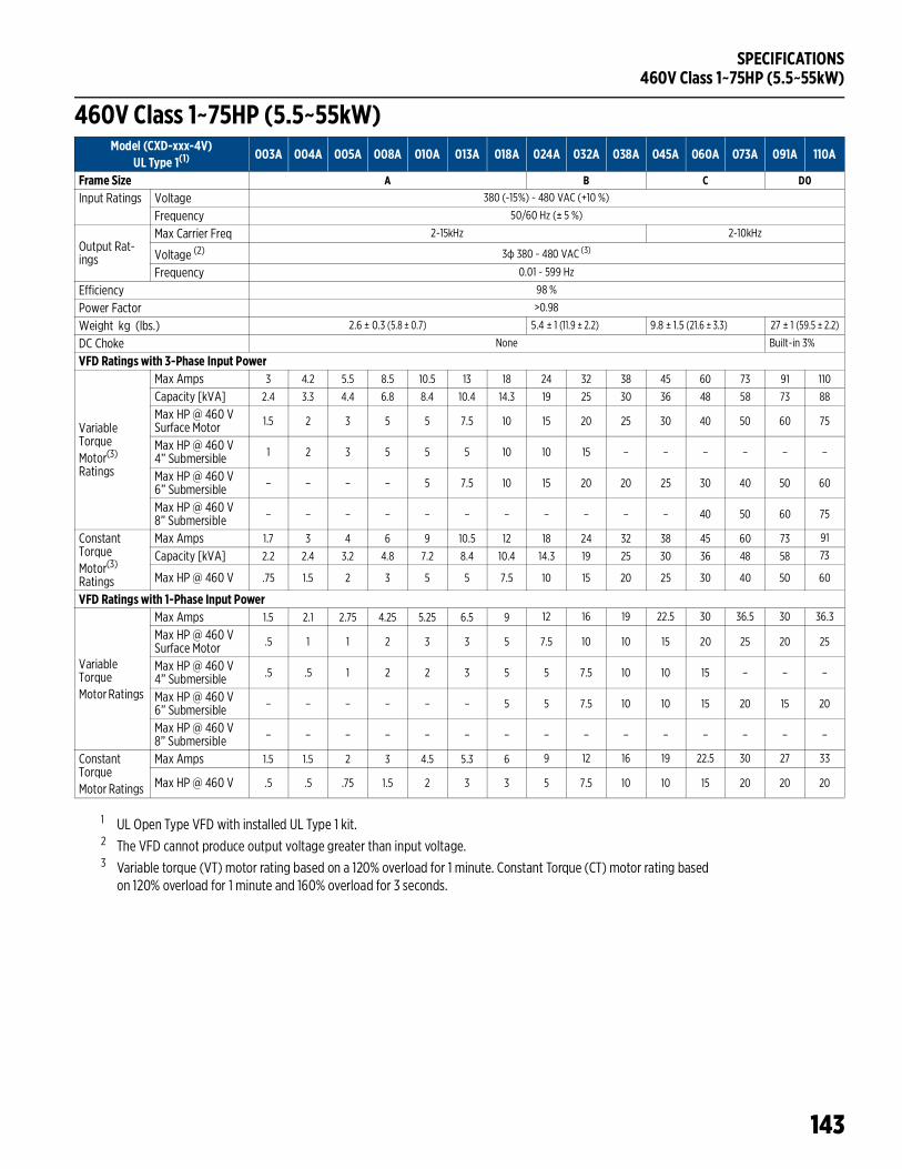
SPECIFICATIONS460V Class 1~75HP (5.5~55kW)
143
460V Class 1~75HP (5.5~55kW)
1 UL Open Type VFD with installed UL Type 1 kit.2 The VFD cannot produce output voltage greater than input voltage. 3 Variable torque (VT) motor rating based on a 120% overload for 1 minute. Constant Torque (CT) motor rating based
on 120% overload for 1 minute and 160% overload for 3 seconds.
Model (CXD-xxx-4V) UL Type 1(1)
003A 004A 005A 008A 010A 013A 018A 024A 032A 038A 045A 060A 073A 091A 110A
Frame Size A B C D0Input Ratings Voltage 380 (-15%) ~ 480 VAC (+10 %)
Frequency 50/60 Hz (± 5 %)
Output Rat-ings
Max Carrier Freq 2-15kHz 2-10kHz
Voltage (2) 3ф 380 ~ 480 VAC (3)
Frequency 0.01 ~ 599 Hz
Efficiency 98 %
Power Factor >0.98
Weight kg (lbs.) 2.6 ± 0.3 (5.8 ± 0.7) 5.4 ± 1 (11.9 ± 2.2) 9.8 ± 1.5 (21.6 ± 3.3) 27 ± 1 (59.5 ± 2.2)
DC Choke None Built-in 3%
VFD Ratings with 3-Phase Input Power
VariableTorqueMotor(3)
Ratings
Max Amps 3 4.2 5.5 8.5 10.5 13 18 24 32 38 45 60 73 91 110
Capacity [kVA] 2.4 3.3 4.4 6.8 8.4 10.4 14.3 19 25 30 36 48 58 73 88
Max HP @ 460 VSurface Motor 1.5 2 3 5 5 7.5 10 15 20 25 30 40 50 60 75
Max HP @ 460 V4” Submersible 1 2 3 5 5 5 10 10 15 – – – – – –
Max HP @ 460 V6” Submersible – – – – 5 7.5 10 15 20 20 25 30 40 50 60
Max HP @ 460 V8” Submersible – – – – – – – – – – – 40 50 60 75
ConstantTorqueMotor(3)
Ratings
Max Amps 1.7 3 4 6 9 10.5 12 18 24 32 38 45 60 73 91
Capacity [kVA] 2.2 2.4 3.2 4.8 7.2 8.4 10.4 14.3 19 25 30 36 48 58 73
Max HP @ 460 V .75 1.5 2 3 5 5 7.5 10 15 20 25 30 40 50 60
VFD Ratings with 1-Phase Input Power
VariableTorqueMotor Ratings
Max Amps 1.5 2.1 2.75 4.25 5.25 6.5 9 12 16 19 22.5 30 36.5 30 36.3
Max HP @ 460 VSurface Motor .5 1 1 2 3 3 5 7.5 10 10 15 20 25 20 25
Max HP @ 460 V4” Submersible .5 .5 1 2 2 3 5 5 7.5 10 10 15 – – –
Max HP @ 460 V6” Submersible – – – – – – 5 5 7.5 10 10 15 20 15 20
Max HP @ 460 V8” Submersible – – – – – – – – – – – – – – –
ConstantTorqueMotor Ratings
Max Amps 1.5 1.5 2 3 4.5 5.3 6 9 12 16 19 22.5 30 27 33
Max HP @ 460 V .5 .5 .75 1.5 2 3 3 5 7.5 10 10 15 20 20 20
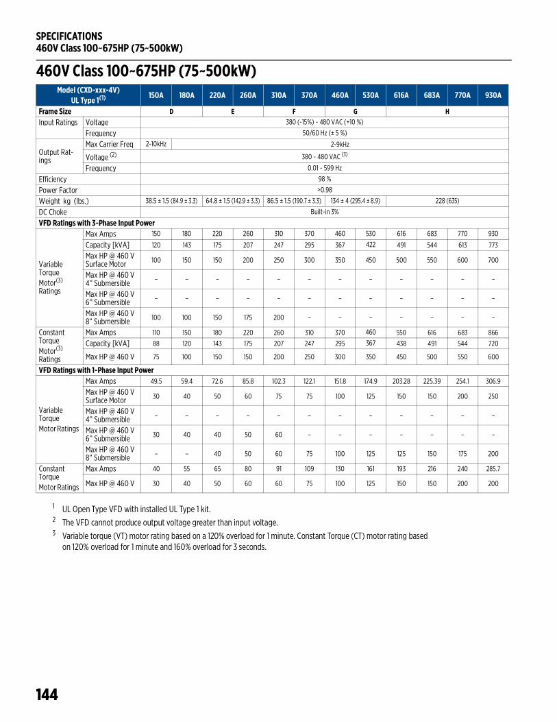
SPECIFICATIONS460V Class 100~675HP (75~500kW)
144
460V Class 100~675HP (75~500kW)
1 UL Open Type VFD with installed UL Type 1 kit.2 The VFD cannot produce output voltage greater than input voltage. 3 Variable torque (VT) motor rating based on a 120% overload for 1 minute. Constant Torque (CT) motor rating based
on 120% overload for 1 minute and 160% overload for 3 seconds.
Model (CXD-xxx-4V) UL Type 1(1)
150A 180A 220A 260A 310A 370A 460A 530A 616A 683A 770A 930A
Frame Size D E F G HInput Ratings Voltage 380 (-15%) ~ 480 VAC (+10 %)
Frequency 50/60 Hz (± 5 %)
Output Rat-ings
Max Carrier Freq 2-10kHz 2-9kHz
Voltage (2) 380 ~ 480 VAC (3)
Frequency 0.01 ~ 599 Hz
Efficiency 98 %
Power Factor >0.98
Weight kg (lbs.) 38.5 ± 1.5 (84.9 ± 3.3) 64.8 ± 1.5 (142.9 ± 3.3) 86.5 ± 1.5 (190.7 ± 3.3) 134 ± 4 (295.4 ± 8.9) 228 (635)
DC Choke Built-in 3%
VFD Ratings with 3-Phase Input Power
VariableTorqueMotor(3)
Ratings
Max Amps 150 180 220 260 310 370 460 530 616 683 770 930
Capacity [kVA] 120 143 175 207 247 295 367 422 491 544 613 773
Max HP @ 460 VSurface Motor 100 150 150 200 250 300 350 450 500 550 600 700
Max HP @ 460 V4” Submersible – – – – – – – – – – – –
Max HP @ 460 V6” Submersible – – – – – – – – – – – –
Max HP @ 460 V8” Submersible 100 100 150 175 200 – – – – – – –
ConstantTorqueMotor(3)
Ratings
Max Amps 110 150 180 220 260 310 370 460 550 616 683 866
Capacity [kVA] 88 120 143 175 207 247 295 367 438 491 544 720
Max HP @ 460 V 75 100 150 150 200 250 300 350 450 500 550 600
VFD Ratings with 1-Phase Input Power
VariableTorqueMotor Ratings
Max Amps 49.5 59.4 72.6 85.8 102.3 122.1 151.8 174.9 203.28 225.39 254.1 306.9
Max HP @ 460 VSurface Motor 30 40 50 60 75 75 100 125 150 150 200 250
Max HP @ 460 V4” Submersible – – – – – – – – – – – –
Max HP @ 460 V6” Submersible 30 40 40 50 60 – – – – – – –
Max HP @ 460 V8” Submersible – – 40 50 60 75 100 125 125 150 175 200
ConstantTorqueMotor Ratings
Max Amps 40 55 65 80 91 109 130 161 193 216 240 285.7
Max HP @ 460 V 30 40 50 60 60 75 100 125 150 150 200 200
SPECIFICATIONS575~690V Class 1~150HP (1.5~175kW)
145
575~690V Class 1~150HP (1.5~175kW)
1 UL Open Type VFD with installed UL Type 1 kit.2 The VFD cannot produce output voltage greater than input voltage. 3 Variable torque (VT) motor rating based on a 120% overload for 1 minute. Constant Torque (CT) motor rating based
on 120% overload for 1 minute and 160% overload for 3 seconds.
Model (CXD-xxx-6V) UL Type 1(1)
003A 004A 006A 009A 012A 018A 024A 030A 036A 045A 054A 067A 086A 104A 125A 150A
Frame Size A B C D EInput Ratings Voltage 525 (-15%) ~ 600 VAC (+10 %)
Frequency 50/60 Hz (± 5 %)
Output Ratings
Max Carrier Freq 2-15kHz 2-9kHz
Voltage (2) 525 ~ 600 VAC (2)
Frequency 0.01 ~ 599 Hz
Efficiency 97 % 98 % 97 %
Power Factor >0.98
Weight kg (lbs.) 3 ± 0.3 (6.6 ± 0.7) 4.8 ± 1 (10.6 ± 2.2) 10 ± 1.5 (22 ± 3.3) 39 ± 1.5 (86 ± 3.3)
61 ± 1.5 (134.5 ± 3.3)
DC Choke None Built-in 3%
VFD Ratings with 3-Phase Input Power
VariableTorqueMotor(3)
Ratings
Max Amps 3 4.3 6.7 9.9 12.1 18.7 24.2 30 36 45 54 67 86 104 125 150
Capacity [kVA] 3 4.3 6.7 9.9 12.1 18.6 24.1 36 43 54 65 80 103 124 149 179
Max HP @ 575VSurface Motor
2 3 5 7.5 10 15 20 25 30 40 50 60 75 100 125 150
Max HP @ 575 V4” Submersible 1.5 2 3 5 7.5 10 15 – – – – – – – – –
Max HP @ 575 V6” Submersible – – – 7.5 7.5 10 20 25 25 30 40 50 60 – – –
Max HP @ 575 V8” Submersible – – – – – – – – – – 40 50 75 75 100 100
ConstantTorqueMotor(3)
Ratings
Max Amps 2.5 3.6 5.5 8.2 10 15.5 20 24 30 36 45 54 67 86 104 125
Capacity [kVA] 2.5 3.6 5.5 8.2 10 15.4 19.9 29 36 43 54 65 80 103 124 149
Max HP @ 575 V 1.5 2 3 5 7.5 10 15 20 25 30 40 50 60 75 100 125
VFD Ratings with 1-Phase Input Power
VariableTorqueMotor Ratings
Max Amps 1.5 2.15 3.35 4.95 6.05 9.35 12.1 15 18 22.5 17.82 22.11 28.3 – – –
Max HP @ 575VSurface Motor .75 1 2 3 3 7.5 10 10 15 20 15 20 25 – – –
Max HP @ 575 V4” Submersible .5 1 2 3 3 5 7.5 10 10 15 – – – – – –
Max HP @ 575 V6” Submersible – – – – – 5 7.5 10 10 15 10 15 20 – – –
Max HP @ 575 V8” Submersible – – – – – – – – – – – – – – – –
ConstantTorqueMotor Ratings
Max Amps 1.25 1.8 2.75 4.1 5 7.7 9.95 10 12 15 18 14.8 17.8 22.1 – –
Max HP @ 575 V .5 1 2 3 3 5 7.7 7.5 10 10 15 10 15 20 – –
SPECIFICATIONS575~690V Class 150~700HP (160~522kW)
146
575~690V Class 150~700HP (160~522kW)
1 UL Open Type VFD with installed UL Type 1 kit.2 The VFD cannot produce output voltage greater than input voltage. 3 Variable torque (VT) motor rating based on a 120% overload for 1 minute. Constant Torque (CT) motor rating based
on 120% overload for 1 minute and 160% overload for 3 seconds.
Model (CXD-xxx-6V) UL Type 1(1)
180A 220A 290A 350A 430A 465A 590A 675A
Frame Size F G HInput Rat-ings
Voltage 525 (-15%) ~ 690 VAC (+10 %)
Frequency 50/60 Hz (± 5 %)
Output Rat-ings
Max Carrier Freq 2-9kHz
Voltage (2) 525 ~ 690 VAC (2)
Frequency 0.01 ~ 599 Hz
Efficiency 97 % 98 %
Power Factor >0.98
Weight kg (lbs.) 88± 1.5 (194± 3.3) 135 ± 4 (297.6 ± 8.8) 243 ± 5 (535.7 ± 11)
DC Choke Built-in 3%
VFD Ratings with 3-Phase Input Power
VariableTorqueMotor(3)
Ratings
Max Amps 180 220 290 350 430 465 590 675
Capacity [kVA] 215 263 347 418 494.5 534.7 678.5 776
Max HP @ 575VSurface Motor 150 200 300 350 450 450 600 700
Max HP @ 575 V8” Submersible 125 175 200 – – – – –
ConstantTorqueMotor(3)
Ratings
Max Amps 150 180 220 290 350 430 465 590
Capacity [kVA] 179 215 239 347 402.5 442.7 534.7 776
Max HP @ 575 V 150 150 200 300 350 450 450 600
SPECIFICATIONSDe-Rating Charts
147
De-Rating ChartsCarrier Frequency De-Rating230 V / 460 V Induction Motor with VF or SVC Control
230 V / 460 V Permanent Magnet Motor with SVC Control
230 V100
80
90
70
% R
ated
Out
put C
urre
nt
Carrier Frequency (kHz)4 5 6 7 8 9 10 11 12 13 14 15
CXD-(005-061)A-2V CXD-(075-180)A-2V CXD-(215-322)A-2V
460 V100
80
90
70% R
ated
Out
put C
urre
nt
Carrier Frequency (kHz)4 5 6 7 8 9 10 11 12 13 14 15
CXD-(003-038)A-4V CXD-(045-150)A-4V CXD-(180-930)A-4V
60
230 V100
80
90
70
% R
ated
Out
put C
urre
nt
Carrier Frequency (kHz)4 5 6 7 8 9 10 11 12 13 14 15
CXD-(005-061)A-2V CXD-(075-180)A-2V CXD-(215-322)A-2V
40
50
60
SPECIFICATIONSDe-Rating Charts
148
575 V / 690 V Induction Motor with VF or SVC Control
460 V100
80
90
70
% R
ated
Out
put C
urre
nt
Carrier Frequency (kHz)4 5 6 7 8 9 10 11 12 13 14 15
CXD-(003-038)A-4V CXD-(045-150)A-4V CXD-(180-930)A-4V
60
50
40
Variable Torque Applications100
80
90
70
% R
ated
Out
put C
urre
nt
Carrier Frequency (kHz)2 3 4 5 6 7 8 9 10
CXD-(003-067)A-6V CXD-(086-220)A-6V CXD-(290-675)A-6V
50
60
Constant Torque Applications100
80
90
70
% R
ated
Out
put C
urre
nt
Carrier Frequency (kHz)2 3 4 5 6 7 8 9 10
CXD-(003-067)A-6V CXD-(086-220)A-6V CXD-(290-590)A-6V
50
60
40
CXD-675A-6V
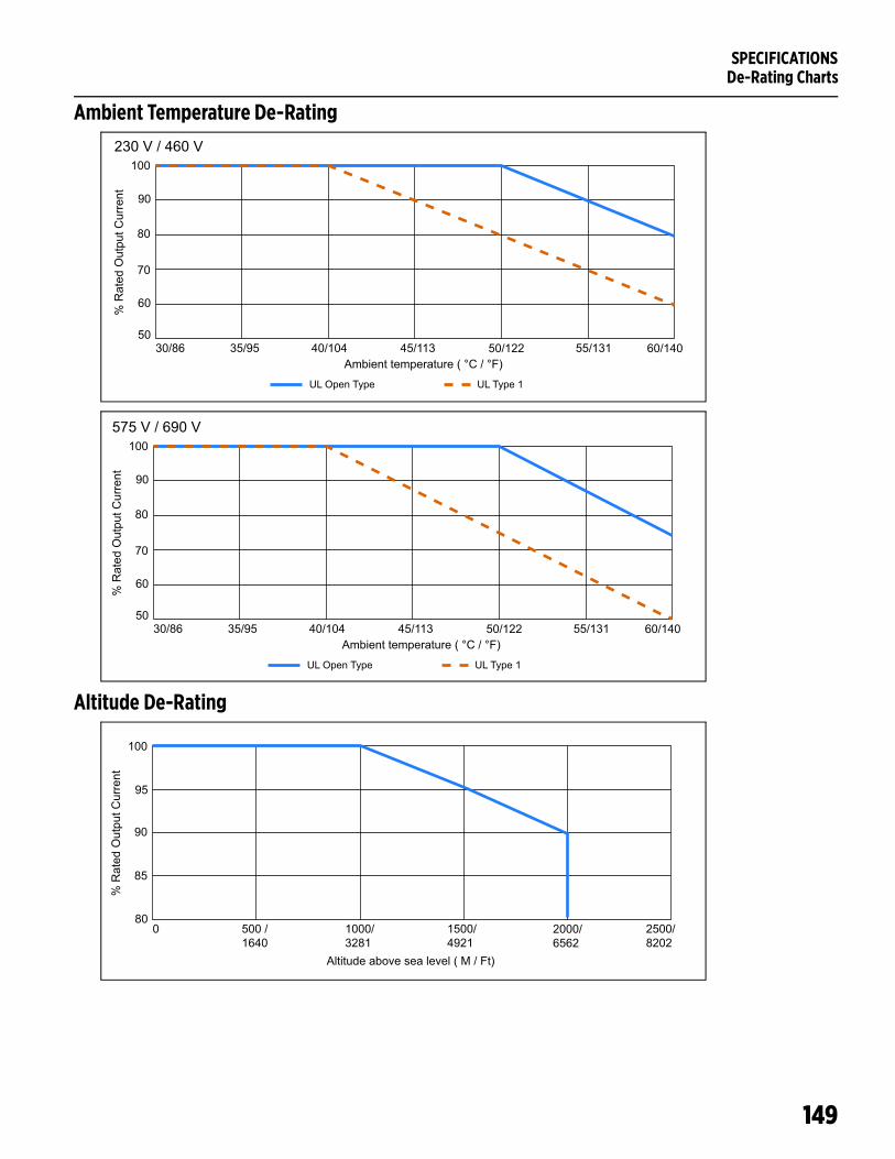
SPECIFICATIONSDe-Rating Charts
149
Ambient Temperature De-Rating
Altitude De-Rating
100
80
90
70
% R
ated
Out
put C
urre
nt
Ambient temperature ( °C / °F)30/86 35/95
UL Open Type UL Type 1
40/104 45/113 50/122 55/131 60/14050
60
230 V / 460 V
100
80
90
70
% R
ated
Out
put C
urre
nt
Ambient temperature ( °C / °F)30/86 35/95
UL Open Type UL Type 1
40/104 45/113 50/122 55/131 60/14050
60
575 V / 690 V
100
90
95
85
% R
ated
Out
put C
urre
nt
Altitude above sea level ( M / Ft)
0 500 /1640
1000/3281
1500/4921
2000/6562
2500/8202
80
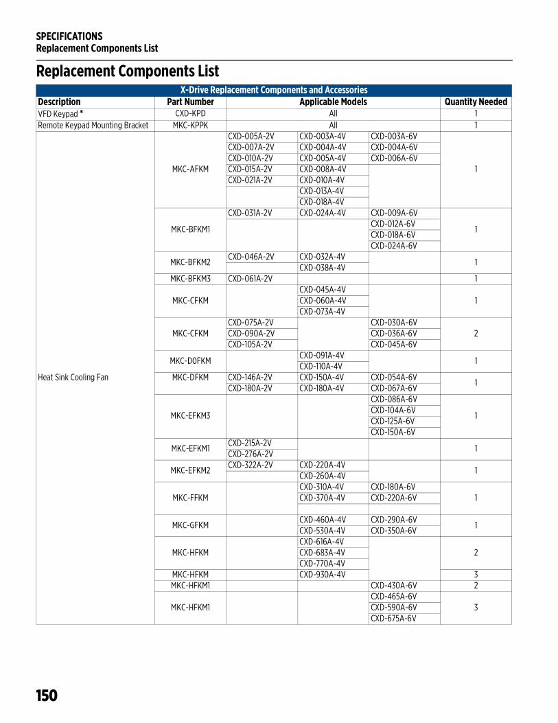
SPECIFICATIONSReplacement Components List
150
Replacement Components ListX-Drive Replacement Components and Accessories
Description Part Number Applicable Models Quantity NeededVFD Keypad * CXD-KPD All 1Remote Keypad Mounting Bracket MKC-KPPK All 1
Heat Sink Cooling Fan
MKC-AFKM
CXD-005A-2V CXD-003A-4V CXD-003A-6V
1
CXD-007A-2V CXD-004A-4V CXD-004A-6VCXD-010A-2V CXD-005A-4V CXD-006A-6VCXD-015A-2V CXD-008A-4VCXD-021A-2V CXD-010A-4V
CXD-013A-4VCXD-018A-4V
MKC-BFKM1
CXD-031A-2V CXD-024A-4V CXD-009A-6V
1CXD-012A-6VCXD-018A-6VCXD-024A-6V
MKC-BFKM2CXD-046A-2V CXD-032A-4V
1CXD-038A-4V
MKC-BFKM3 CXD-061A-2V 1
MKC-CFKMCXD-045A-4V
1CXD-060A-4VCXD-073A-4V
MKC-CFKMCXD-075A-2V CXD-030A-6V
2CXD-090A-2V CXD-036A-6VCXD-105A-2V CXD-045A-6V
MKC-D0FKMCXD-091A-4V
1CXD-110A-4V
MKC-DFKM CXD-146A-2V CXD-150A-4V CXD-054A-6V1
CXD-180A-2V CXD-180A-4V CXD-067A-6V
MKC-EFKM3
CXD-086A-6V
1CXD-104A-6VCXD-125A-6VCXD-150A-6V
MKC-EFKM1CXD-215A-2V
1CXD-276A-2V
MKC-EFKM2CXD-322A-2V CXD-220A-4V
1CXD-260A-4V
MKC-FFKMCXD-310A-4V CXD-180A-6V
1CXD-370A-4V CXD-220A-6V
MKC-GFKMCXD-460A-4V CXD-290A-6V
1CXD-530A-4V CXD-350A-6V
MKC-HFKMCXD-616A-4V
2CXD-683A-4VCXD-770A-4V
MKC-HFKM CXD-930A-4V 3MKC-HFKM1 CXD-430A-6V 2
MKC-HFKM1CXD-465A-6V
3CXD-590A-6VCXD-675A-6V
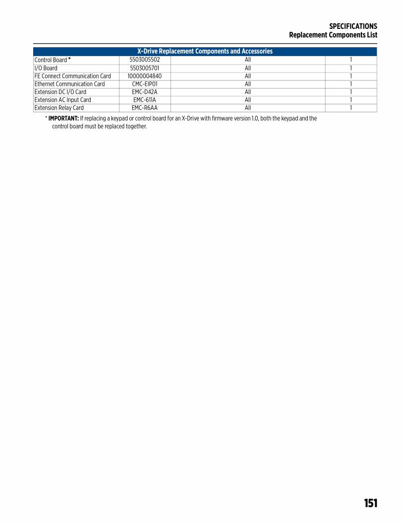
SPECIFICATIONSReplacement Components List
151
* IMPORTANT: If replacing a keypad or control board for an X-Drive with firmware version 1.0, both the keypad and the control board must be replaced together.
Control Board * 5503005502 All 1I/O Board 5503005701 All 1FE Connect Communication Card 10000004840 All 1Ethernet Communication Card CMC-EIP01 All 1Extension DC I/O Card EMC-D42A All 1Extension AC Input Card EMC-611A All 1Extension Relay Card EMC-R6AA All 1
X-Drive Replacement Components and Accessories
SPECIFICATIONSApplicable Standards
152
Applicable Standards1. UL508C – UL/cUL2. CE
a. Low Voltage• EN61800-5-1
b. EMC• EN61000-3-12• IEC61000-6-2• IEC61000-4-2• IEC61000-4-4• IEC61000-4-6• EN61800-3• IEC61000-6-4• IEC61000-4-3• IEC61000-4-5• IEC61000-4-8
3. C-Tick4. ROHS
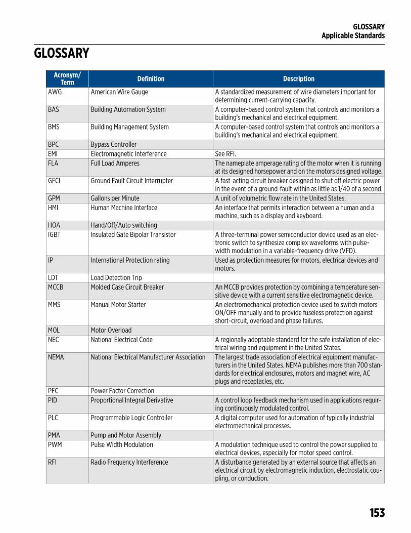
GLOSSARYApplicable Standards
153
GLOSSARYAcronym/
Term Definition Description
AWG American Wire Gauge A standardized measurement of wire diameters important for determining current-carrying capacity.
BAS Building Automation System A computer-based control system that controls and monitors a building's mechanical and electrical equipment.
BMS Building Management System A computer-based control system that controls and monitors a building's mechanical and electrical equipment.
BPC Bypass ControllerEMI Electromagnetic Interference See RFI.FLA Full Load Amperes The nameplate amperage rating of the motor when it is running
at its designed horsepower and on the motors designed voltage.GFCI Ground Fault Circuit Interrupter A fast-acting circuit breaker designed to shut off electric power
in the event of a ground-fault within as little as 1/40 of a second.GPM Gallons per Minute A unit of volumetric flow rate in the United States.HMI Human Machine Interface An interface that permits interaction between a human and a
machine, such as a display and keyboard.HOA Hand/Off/Auto switchingIGBT Insulated Gate Bipolar Transistor A three-terminal power semiconductor device used as an elec-
tronic switch to synthesize complex waveforms with pulse-width modulation in a variable-frequency drive (VFD).
IP International Protection rating Used as protection measures for motors, electrical devices and motors.
LDT Load Detection TripMCCB Molded Case Circuit Breaker An MCCB provides protection by combining a temperature sen-
sitive device with a current sensitive electromagnetic device.MMS Manual Motor Starter An electromechanical protection device used to switch motors
ON/OFF manually and to provide fuseless protection against short-circuit, overload and phase failures.
MOL Motor OverloadNEC National Electrical Code A regionally adoptable standard for the safe installation of elec-
trical wiring and equipment in the United States.NEMA National Electrical Manufacturer Association The largest trade association of electrical equipment manufac-
turers in the United States. NEMA publishes more than 700 stan-dards for electrical enclosures, motors and magnet wire, AC plugs and receptacles, etc.
PFC Power Factor CorrectionPID Proportional Integral Derivative A control loop feedback mechanism used in applications requir-
ing continuously modulated control. PLC Programmable Logic Controller A digital computer used for automation of typically industrial
electromechanical processes.PMA Pump and Motor AssemblyPWM Pulse Width Modulation A modulation technique used to control the power supplied to
electrical devices, especially for motor speed control.RFI Radio Frequency Interference A disturbance generated by an external source that affects an
electrical circuit by electromagnetic induction, electrostatic cou-pling, or conduction.
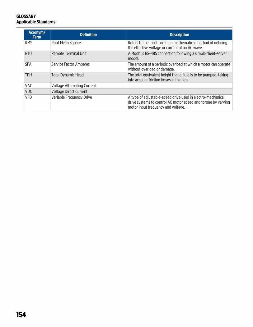
GLOSSARYApplicable Standards
154
RMS Root Mean Square Refers to the most common mathematical method of defining the effective voltage or current of an AC wave.
RTU Remote Terminal Unit A Modbus RS-485 connection following a simple client-server model.
SFA Service Factor Amperes The amount of a periodic overload at which a motor can operate without overload or damage.
TDH Total Dynamic Head The total equivalent height that a fluid is to be pumped, taking into account friction losses in the pipe.
VAC Voltage Alternating CurrentVDC Voltage Direct CurrentVFD Variable Frequency Drive A type of adjustable-speed drive used in electro-mechanical
drive systems to control AC motor speed and torque by varying motor input frequency and voltage.
Acronym/Term Definition Description
155
STANDARD LIMITED WARRANTYExcept as set forth in an Extended Warranty, for one (1) year from the date of installation, but in no event more than two (2) years from the date of manufacture, Franklin hereby warrants to the purchaser (“Purchaser”) of Franklin’s products that, for the applica-ble warranty period, the products purchased will (i) be free from defects in workmanship and material at the time of shipment, (ii) perform consistently with samples previously supplied and (iii) conform to the specifications published or agreed to in writing between the purchaser and Franklin. This limited warranty extends only to products purchased directly from Franklin. If a product is purchased other than from a distributor or directly from Franklin, such product must be installed by a Franklin Certified Installer for this limited warranty to apply. This limited warranty is not assignable or transferable to any subsequent purchaser or user.
a. THIS LIMITED WARRANTY IS IN LIEU OF ALL OTHER WARRANTIES, WRITTEN OR ORAL, STATUTORY, EXPRESS, OR IMPLIED, INCLUDING ANY WARRANTY OF MERCHANTABILITY OR FITNESS FOR A PARTICULAR PURPOSE. PURCHASER’S SOLE AND EXCLUSIVE REMEDY FOR FRANKLIN’S BREACH OF ITS OBLIGATIONS HEREUNDER, INCLUDING BREACH OF ANY EXPRESS OR IMPLIED WARRANTY OR OTHERWISE, UNLESS PROVIDED ON THE FACE HEREOF OR IN A WRITTEN INSTRUMENT MADE PART OF THIS LIMITED WARRANTY, SHALL BE FOR THE PURCHASE PRICE PAID TO FRANKLIN FOR THE NONCONFORMING OR DEFECTIVE PRODUCT OR FOR THE REPAIR OR REPLACEMENT OF NONCONFORMING OR DEFECTIVE PRODUCT, AT FRANK-LIN’S ELECTION. ANY FRANKLIN PRODUCT WHICH FRANKLIN DETERMINES TO BE DEFECTIVE WITHIN THE WARRANTY PERIOD SHALL BE, AT FRANKLIN’S SOLE OPTION, REPAIRED, REPLACED, OR A REFUND OF THE PURCHASE PRICE PAID. Some states do not allow limitations on how long an implied warranty lasts, therefore, the limitations and exclusions relating to the products may not apply.
b. WITHOUT LIMITING THE GENERALITY OF THE EXCLUSIONS OF THIS LIMITED WARRANTY, FRANKLIN SHALL NOT BE LIABLE TO THE PURCHASER OR ANY THIRD PARTY FOR ANY AND ALL (i) INCIDENTAL EXPENSES OR OTHER CHARGES, COSTS, EXPENSES (INCLUDING COSTS OF INSPECTION, TESTING, STORAGE, OR TRANSPORTATION) OR (ii) DAMAGES, INCLUDING CONSEQUENTIAL, SPECIAL DAMAGES, PUNITIVE OR INDIRECT DAMAGES, INCLUDING, WITHOUT LIMITATION, LOST PROFITS, LOST TIME AND LOST BUSINESS OPPORTUNITIES, REGARDLESS OF WHETHER FRANKLIN IS OR IS SHOWN TO BE AT FAULT, AND REGARDLESS OF WHETHER THERE IS OR THERE IS SHOWN TO HAVE BEEN A DEFECT IN MATERIALS OR WORKMAN-SHIP, NEGLIGENCE IN MANUFACTURE OR DESIGN, OR A FAILURE TO WARN.
c. Franklin’s liability arising out of the sale or delivery of its products, or their use, whether based upon warranty contract, negli-gence, or otherwise, shall not in any case exceed the cost of repair or replacement of the product and, upon expiration of any applicable warranty period, any and all such liability shall terminate.
d. Without limiting the generality of the exclusions of this limited warranty, Franklin does not warrant the adequacy of any spec-ifications provided directly or indirectly by a purchaser or that Franklin’s products will perform in accordance with such speci-fications. This limited warranty does not apply to any products that have been subject to misuse (including use in a manner inconsistent with the design of the product), abuse, neglect, accident or improper installation or maintenance, or to products that have been altered or repaired by any person or entity other than Franklin or its authorized representatives.
e. Unless otherwise specified in an Extended Warranty authorized by Franklin for a specific product or product line, this limited warranty does not apply to performance caused by abrasive materials, corrosion due to aggressive conditions or improper voltage supply.

For technical assistance, parts, or repair, please contact:
800.348.2420 | franklin-electric.comelectric.comForm 10000005064 Rev. 001 09/21