Embed Size (px)
Citation preview
�����������������
Citation: Balubaid, M.; Taylan, O.;
Yilmaz, M.T.; Eftekhari-Zadeh, E.;
Nazemi, E.; Alamoudi, M. Central
Nervous System: Overall
Considerations Based on Hardware
Realization of Digital Spiking Silicon
Neurons (DSSNs) and Synaptic
Coupling. Mathematics 2022, 10, 882.
https://doi.org/10.3390/math10060882
Academic Editor: Ilya V. Sysoev
Received: 4 February 2022
Accepted: 4 March 2022
Published: 10 March 2022
Publisher’s Note: MDPI stays neutral
with regard to jurisdictional claims in
published maps and institutional affil-
iations.
Copyright: © 2022 by the authors.
Licensee MDPI, Basel, Switzerland.
This article is an open access article
distributed under the terms and
conditions of the Creative Commons
Attribution (CC BY) license (https://
creativecommons.org/licenses/by/
4.0/).
mathematics
Article
Central Nervous System: Overall Considerations Based onHardware Realization of Digital Spiking Silicon Neurons(DSSNs) and Synaptic CouplingMohammed Balubaid 1 , Osman Taylan 1 , Mustafa Tahsin Yilmaz 1, Ehsan Eftekhari-Zadeh 2,* ,Ehsan Nazemi 3 and Mohammed Alamoudi 1
1 Department of Industrial Engineering, Faculty of Engineering, King Abdulaziz University, P.O. Box 80204,Jeddah 21589, Saudi Arabia; [email protected] (M.B.); [email protected] (O.T.);[email protected] (M.T.Y.); [email protected] (M.A.)
2 Institute of Optics and Quantum Electronics, Friedrich Schiller University Jena, Max-Wien-Platz 1,07743 Jena, Germany
3 Imec-Vision Laboratory, University of Antwerp, 2610 Antwerp, Belgium; [email protected]* Correspondence: [email protected]
Abstract: The Central Nervous System (CNS) is the part of the nervous system including the brainand spinal cord. The CNS is so named because the brain integrates the received information andinfluences the activity of different sections of the bodies. The basic elements of this important organare: neurons, synapses, and glias. Neuronal modeling approach and hardware realization design forthe nervous system of the brain is an important issue in the case of reproducing the same biologicalneuronal behaviors. This work applies a quadratic-based modeling called Digital Spiking SiliconNeuron (DSSN) to propose a modified version of the neuronal model which is capable of imitatingthe basic behaviors of the original model. The proposed neuron is modeled based on the primaryhyperbolic functions, which can be realized in high correlation state with the main model (originalone). Really, if the high-cost terms of the original model, and its functions were removed, a low-errorand high-performance (in case of frequency and speed-up) new model will be extracted comparedto the original model. For testing and validating the new model in hardware state, Xilinx Spartan-3FPGA board has been considered and used. Hardware results show the high-degree of similaritybetween the original and proposed models (in terms of neuronal behaviors) and also higher frequencyand low-cost condition have been achieved. The implementation results show that the overall savingis more than other papers and also the original model. Moreover, frequency of the proposed neuronalmodel is about 168 MHz, which is significantly higher than the original model frequency, 63 MHz.
Keywords: neuron; central nervous system; DSSN; brain
MSC: 68T07; 92B20
1. Introduction
In the past recent decades, a variety of mathematical computational approaches havebeen implemented in different research fields such as fluid mechanic engineering [1–9],chemical engineering [10–18], electrical engineering [19–28], telecommunication engineer-ing [29–34], computer engineering [35–39], petroleum engineering [40–47], energy engineer-ing [48–50], mathematics [51–59], environmental engineering [60–62], health and medicalsciences [63–65], industrial engineering [66], etc. Among the various applied computa-tional methods, artificial neural networks have been widely used, which demonstrates theircapability. So, every effort in this field is of high importance.
Spiking Neural Networks (SNNs) are a very attractive research area based on neuronalbrain cells. The time-domain field in the SNN is the main concept that is based on the
Mathematics 2022, 10, 882. https://doi.org/10.3390/math10060882 https://www.mdpi.com/journal/mathematics
Mathematics 2022, 10, 882 2 of 20
different models of neural networks. In SNNs, neurons can transmit data and informationvia synaptic connection, and this causes different levels of learning and memory in thehuman brain. In coupled neurons, when the presynaptic neuron is triggered by an appliedstimulus current, this can release the voltage signals, this voltage can trigger the synapticgap, and then the additional current is injected to the postsynaptic neurons, which isillustrated as a train of spiking behaviors in the post neurons. This behavior of neurons canbe described by the spiking neuron models [67–72].
The basic elements in this system are neurons, synapses, and glias [69,73–75]. Neuronblocks are the important organs in CNS, which have several vital roles such as receiving,processing, and transmitting information to different parts of the human brain. On theother hand, synapses connect the neurons and are responsible for transferring data betweenneurons. Moreover, another cell called a glia can protect neurons in the CNS. Indeed,glias regulate the synaptic coupling between neurons. Thus, in the first step, the neurons’behaviors must be investigated in case of simulation and realization to obtain a compactand practical hardware.
Neurons have different behaviors and reactions. These behaviors can follow thebasic pattern, which can be modeled by the mathematical equations in [76–83]. Twobasic modeling systems have been presented. The first state is the biological model withbiological parameters and reactions. Some basic models such as the Hodgkin–Huxley (HH)neuron model and the ADEX neuron model. These models have the biological aspects andmay be a complex mathematical equation. On the other hand, SNN models are based onthe spike timing patterns and less biological states. In this approach, some models such asthe Izhikevic, FHN, and other models have been presented. Among these two modelingaspects, the SNN modeling may be better than the biological ones because of their low-costimplementations in hardware form. Indeed, when a compact neuron model (in hardwarestate) is required, the SNN models are better choices. As a result, a model named theDigital Spiking Silicon Neuron (DSSN) model is proposed [84]. This model was designedto simulate several classes of neurons by simple digital arithmetic circuits.
The implementation of different models have been realized in different positions. Twobasic selections of the implementation are analog and digital states [67,68,70,71,85–90]. Inanalog implementation, CMOS elements are applied to achieve an analog architecture tofollow the mathematical modeling of the neuron. This solution is fast, but it may sufferfrom long development timing. On the other hand, in the digital realization of neuronalmodels, a high amount of silicon may be required as well as high power consumption, butthis solution can be very efficient in comparison to other methods. Some capabilities ofthe digital implementation are its high-degree of flexibility, reduced timing process, andpower supply. In this approach, using programmable boards such as FPGAs can be veryfast and flexible.
This paper presents a hardware implementation of the DSSN model in the case of adigital system. The basic challenge of this realization is the quadratic term of the originalneuron model. In the general case, the quadratic term (because of its multiplier operation)causes the speed-down in the final system. In other words, in the CNS, the speed of theneuronal activity is a very important factor. If the final system does not have an acceptablefrequency, it influences the neural system. Thus, this nonlinear term must be removed orconverted to another simple term. Different approaches can be applied to obtain simplemathematical equations. Among these approaches, converting the quadratic terms tohyperbolic functions may be the best way. Indeed, by converting the nonlinear terms ofthe original model to a set of hyperbolic functions, we have a new model (by protecting allbehaviors of the original mode) which converts all multiplier operations to a set of digitalSHIFTs and ADDs (This method will be explained). Consequently, using the proposed newmodel, we have a low-cost, high-speed, and high-efficiency system which can trace theoriginal neuron model with a high-degree of similarity and performances.
The overall method for implementing the neuronal networks can be explained. Theefficient modeling, simulation, and implementation of biological neural networks are

Mathematics 2022, 10, 882 3 of 20
significant. Neuromorphic engineering is a very significant subject that takes inspirationfrom biology, physics, mathematics, computer science, and electronic engineering to designneural systems. In the field of biology and biomedicine, the theoretical and experimentalaspects of neuroscience are evaluated to have a better understandings of the brain structure.Consequently, studying, modeling, simulation, and implementing brain-like systems torealize the brain behaviors are a vital requirement. At first step, it is necessary that theneuron model is selected. In this approach, many different neuron models have beenpresented for spiking neural networks to reproduce their dynamical behavior. Some neuronmodels have biological behaviors and other models reproduce the spiking patterns of thehuman brain. The DSSN neuron model is a widely accepted model that can reproducethe spiking patterns of the brain. After model selection, the time domain and dynamicalbehaviors of the proposed neuron model have been evaluated. Indeed, the proposedmodel is a modified case of the basic neuron model with low-error state and low-costhardware attributes. Since the original models have nonlinear terms and functions withhigh-cost realizations, it is necessary that the model is modified to a new low-cost modelfor its implementation on hardware platforms. To validate the proposed model in case offollowing the original model, spiking patterns and dynamics must be considered. Theseevaluations have been performed using MATLAB software simulations. Finally, to test andvalidate the proposed model in hardware form, we have used the FPGA system design. Infact, the Hardware Description Language (HDL) of the proposed neuron model has beenconsidered using the ModelSim and Xilinx ISE software. In this part, the proposed model’soverhead costs have been compared to the original model cost realization. The proposedmodel must be more efficient in comparison with the original model in case of overheadcosts (overall saving in FPGA) and speed-up (maximum frequency).
This paper is organized as follows. In Section 2, the background of the DSSN modelwill be explained. In Section 3, the proposed procedure is evaluated. Section 4 presents thedynamic behaviors and time domain analysis. Synaptic coupling is described in Section 5.Overall hardware implementation is performed in Section 6 in detail. Production resultsare presented in Section 7. The limitations of the method and also future directions havebeen explained in Section 8. The paper concludes in Section 9.
2. Background
The Digital Spiking Silicon Neuron (DSSN) model is a simple practical model in termsof qualitative states. This model is capable of reproducing different classes of spikingsuch as Class I and Class II patterns. The DSSN model can be formulated by two coupleddifferential equations for voltage and recovery variables. The mathematical equations ofthe model are given by following statements:
dVdt
=φ
τ( f (V)− n + I0 + IStimulus) (1)
dndt
=1τ(g(V)− n) (2)
where
f (V) =
{an(V + bn)2 − cn ; V < 0−ap(V − bp)2 + cp ; V > 0
(3)
g(V) =
{kn(V − pn)2 + qn ; V < rkp(V − pp)2 + qp ; V > r
(4)
In these equations, V and n represents the voltage and slow variable, respectively. Onthe other hand, V is the membrane potential, and n is the recovery variable for producingthe voltage variable. The parameter I0 is a bias fixed parameter, and IStimulus is the appliedcurrent for neurons. The other parameters for generating the Class I and Class II patternsare presented in Tables 1 and 2, respectively. These parameters are explained as follows:
• I0: Bias constant;

Mathematics 2022, 10, 882 4 of 20
• IStimulus: Applied current for neurons;• φ and τ: Time constant;• r, ax, bx, cx, kx, px, and qx (x = n and x = p): Constants that control the nullclines of
the variables (Dynamics of the model).
It is emphasized that the DSSN model is a spike-based neuron model, and all thevariables and constants are abstracted and do not have a physical unit. In addition, byselecting appropriate values for these parameters, both Class I and Class II neurons canbe realized with parameter settings. Finally, different spiking patterns based on these twobasic parameters can be simulated, as can be seen in Figure 1.
Table 1. Different Parameters for Reproducing the Class I Pattern.
Parameter Value Parameter Valuean 8 ap 8bn 0.25 bp 0.25cn 0.5 cp 0.5kn 2 kp 16pn −0.3125 pp −0.2187qn −0.7058 qp −0.6875φ 1 τ 0.003r −0.2053 I0 −0.205
Table 2. Different Parameters for Reproducing the Class II Pattern.
Parameter Value Parameter Valuean 8 ap 8bn 0.25 bp 0.25cn 0.5 cp 0.5kn 4 kp 16pn −0.5625 pp −0.2187qn −1.3177 qp −0.6875φ 0.5 τ 0.003r −0.1041 I0 −0.23
Figure 1. Spike-based signals of the DSSN model. (A1–A5): Spiking patterns of Class I mode fordifferent stimulation current as: IStimulus = 0.1, IStimulus = 0.2, IStimulus = 0.5, IStimulus = 1, andIStimulus = 2, respectively. (B1–B5): Spiking patterns of Class II mode for different stimulation currentas: IStimulus = 0.1, IStimulus = 0.2, IStimulus = 0.5, IStimulus = 1, and IStimulus = 2, respectively.

Mathematics 2022, 10, 882 5 of 20
3. Proposed Procedure
As can be seen in the mathematical equations of the original DSSN model, the basicnonlinear term of this model is the quadratic term which is repeated in all parts of the model.DSSN neuron is implemented on an FPGA digital board, but the quadratic terms of theequations cause the final system to be no more efficient. In this situation, the best method isto convert the nonlinear terms to new functions which have two basic conditions: first is thehigh degree of similarity between the original and proposed method and second is the low-cost digital implementation in terms of FPGA resources and higher frequency (speed-up)compared with the original DSSN model. In this approach, there are different acceptableways to approximate and modify the original models, such as piecewise linear functions,absolute functions, and hyperbolic terms. When the original models are approximatedby linear functions, the error level in the proposed model can be increased, but using thehyperbolic functions reduces the error calculation, and a high-degree of similarity will alsobe achieved. Thus, in this paper, we used the hyperbolic-based modifications. Anotheradvantage of this method is that by using these hyperbolic terms, all nonlinear terms andfunctions in the differential equations are converted to digital SHIFTs and ADDs withoutany multiplications. Consequently, we have a new model with all aspects of the originalmodel that it is efficient in terms of speed and costs compared with the original main DSSNmodel. In the proposed model, the equations are reformulated as follows:
dVdt
=φ
τ(F(V)− n + I0 + IStimulus) (5)
dndt
=1τ(G(V)− n) (6)
where
F(V) =
{an(Func(V))− cn ; V < 0−ap(Func(V)− 4Vbn) + cp ; V > 0
(7)
G(V) =
{kn(Func(V)) + qn ; V < rkp(Func(V)) + qp ; V > r
(8)
whereFunc(V) = 0.6sinh(0.65V) + 0.6cosh(1.5V)− 0.5 (9)
In other words, based on Equations (3) and (4), when these equations are simplified,we have a new nonlinear function which is repeated in all equations. This new functioncan be formulated as follows:
NL-Func(V) = V2 + 0.5V + 0.0625 (10)
Consequently, this nonlinear function can be replaced by Func(V) in all parts ofthe original mathematical equations. By this modification, the proposed model can beimplemented in low-cost and high-speed states (This procedure is elaborated in detailin the hardware section). In this approach, as can be depicted in Figure 2, the originalnonlinear function (NL-Func(V)) and the proposed hyperbolic term (Func(V)) have a highdegree of similarity, and the error level between these two equations is in the low state,which is shown in the next sections. It is noticeable that based on Figures 1 and 2, thepermissible range of parameter value changes is given between −0.5 and +0.5. Indeed,the modifications of the nonlinear terms of the neuron model have been conducted in thisvariation range.

Mathematics 2022, 10, 882 6 of 20
Figure 2. Approximation for the nonlinear function (NL-Func(V)) by the hyperbolic function (Func(V)).
4. Dynamic Behaviors and Time Domain Analysis
Two basic factors should be considered for validating the proposed model. In thisapproach, at first, it is important that the proposed model is in the same state (as dynamicalbehaviors in equilibrium points and eigenvalues) as the original model; second, the timedomain analysis for two models (original and proposed) is done with low error calculation.
4.1. Dynamics
To investigate the modified model, the behaviors of neurons in the case of dynamicsare considered. In this way, to explain the transition from resting state to spiking state(bifurcation), the interactions of the two nullclines play an important role [77,91,92].
The nullclines for the original model can be given by the following statements:dVdt = p(V, n)
dndt = q(V, n)
(11)
dVdt = 0 ; p(V, n) = 0
dndt = 0 ; q(V, n) = 0
(12)
n = f (V)− n + I0 + IStimulus
n = g(V)(13)
On the other hand, the nullclines of the proposed model are given as:n = F(V)− n + I0 + IStimulus
n = G(V)(14)
Consequently, for analyzing the equilibrium points, the Jacobean matrix and eigenval-ues are required [77,91,92], and the Jacobean matrix can be obtained as:{
A BC D
(15)
where
A = ∂p(V,n)∂V
B = ∂p(V,n)∂n
C = ∂q(V,n)∂V
D = ∂q(V,n)∂n
(16)
Mathematics 2022, 10, 882 7 of 20
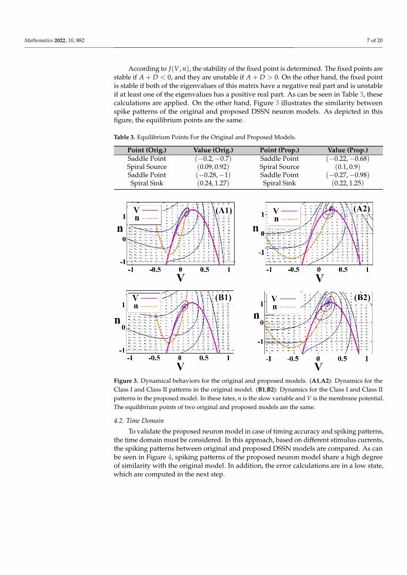
According to J(V, n), the stability of the fixed point is determined. The fixed points arestable if A + D < 0, and they are unstable if A + D > 0. On the other hand, the fixed pointis stable if both of the eigenvalues of this matrix have a negative real part and is unstableif at least one of the eigenvalues has a positive real part. As can be seen in Table 3, thesecalculations are applied. On the other hand, Figure 3 illustrates the similarity betweenspike patterns of the original and proposed DSSN neuron models. As depicted in thisfigure, the equilibrium points are the same.
Table 3. Equilibrium Points For the Original and Proposed Models.
Point (Orig.) Value (Orig.) Point (Prop.) Value (Prop.)Saddle Point (−0.2,−0.7) Saddle Point (−0.22,−0.68)Spiral Source (0.09, 0.92) Spiral Source (0.1, 0.9)Saddle Point (−0.28,−1) Saddle Point (−0.27,−0.98)Spiral Sink (0.24, 1.27) Spiral Sink (0.22, 1.25)
Figure 3. Dynamical behaviors for the original and proposed models. (A1,A2): Dynamics for theClass I and Class II patterns in the original model. (B1,B2): Dynamics for the Class I and Class IIpatterns in the proposed model. In these tates, n is the slow variable and V is the membrane potential.The equilibrium points of two original and proposed models are the same.
4.2. Time Domain
To validate the proposed neuron model in case of timing accuracy and spiking patterns,the time domain must be considered. In this approach, based on different stimulus currents,the spiking patterns between original and proposed DSSN models are compared. As canbe seen in Figure 4, spiking patterns of the proposed neuron model share a high degreeof similarity with the original model. In addition, the error calculations are in a low state,which are computed in the next step.

Mathematics 2022, 10, 882 8 of 20
Figure 4. Comparison between spiking patterns of two models (original and proposed). (a–f): Spikingpatterns for considering the stimulus currents as: IStimulus=0.1, IStimulus=0.2, IStimulus=0.5, IStimulus=1,IStimulus=2, and IStimulus=3.
As can be seen in Figure 4, in some region of the spiking patterns, there are differences(errors) between the original and proposed DSSN models. Indeed, it is attempted to reducethis error to a near-zero value. A different method is available to calculate the error valuesbetween the original and proposed models. Some of these methods are focused on theabsolute differences between two signals. In addition, some methods are emphasized onthe square of root mean values. In this paper, these two basic error methods are appliedfor validating that the proposed model is in the low-error calculation compared with theoriginal main model. These two methods are formulated as follows:
RMSE(VProp., VOrig.) =
√∑n
i=1(VProp. −VOrig.)2
n(17)
MAE =1n
n
∑i=1|VProp. −VOrig.| (18)
Moreover, as can be seen in Figure 5, the error level is based on the differences betweenthe original and proposed functions. Indeed, when this difference is accrued, the spikingpatterns between the original and proposed models may have differences. These differencesin our proposed models have been optimized, so the modified model regenerates the samebehaviors of spike-based behavior of the original model to a high degree of similarity andlow-error computations. As it is shown in Table 4, the error levels are calculated.
Table 4. Error Calculations of the Proposed Model.
IStimulus RMSE (Class I) MAE (Class I) RMSE (Class II) MAE (Class II)0.1 0.05 0.02 0.067 0.0220.2 0.08 0.01 0.1 0.0180.5 0.09 0.034 0.095 0.041 0.1 0.028 0.15 0.0392 0.075 0.014 0.035 0.0123 0.11 0.08 0.16 0.06

Mathematics 2022, 10, 882 9 of 20
Figure 5. Error level between the original (black line) and proposed (dotted line) functions.
5. Synaptic Coupling
A synapse is a connection gap that can transfer data from a presynaptic neuron to apostsynaptic neuron. Synaptic coupling is a significant issue in the case of memory andlearning. For describing the coupling behavior of two connected neurons, the synapticcoupling system can be evaluated [93,94]. In this approach, a terminal can be consideredthat incorporates a presynaptic neuron and a postsynaptic neuron. This synapse model canbe given by the following equation:
τsdZdt = [1 + tanh(Ss(Vpresynaptic − hs))](1− Z)− Z
ds
ISynapse = ks(Z− Z0)
(19)
In the above equation, the parameter Z is the synapse factor. Moreover, the synapticparameters are given by the following:
• τs : Time delay (s);• Ss : Responsible for the activation and relaxation of Z;• ds : Relaxing the parameter Z;• hs : Threshold parameter for the activation of Z;• ks : Conductivity parameter;• Z0 : Reference level of Z .
When the presynaptic neuron (Vpresynaptic) reaches its critical value (threshold voltage,hs), the signal transmission of connected neurons is computed. Moreover, the synapsestimulus, Isynapse, triggers the postsynaptic neuron. Table 5 shows the synapse parameters.
Table 5. Synapse Parameters.
τs = 10 Ss = 1 ds = 3 hs = −70 ks = 10 Z0 = 0
The synchronization effects of the coupled neurons are significant for the processingof biological signals and play significant roles in the elucidation of diseases, such asParkinson’s disease, essential tremor, and epilepsy [95]. Consequently, by the appropriateselection of input stimulus and synaptic conductance coefficient, the synchronization effectscan be controlled. This coupled proposed DSSN model is specified as follows:

Mathematics 2022, 10, 882 10 of 20
dVpredt = φ
τ (F(Vpre)− npre + I0 + IStimulus)
dnpredt = 1
τ (G(Vpre)− npre)
τsdZdt = [1 + tanh(Ss(Vpre − hs))](1− Z)− Z
ds
Isynapse = ks(Z− Z0)
dVpostdt = φ
τ (F(Vpost)− npost + I0 + ISynapse)
dnpostdt = 1
τ (G(Vpost)− npost)
(20)
Consequently, by different stimulus currents, different states of the synchronizationbetween presynaptic and postsynaptic neurons in the proposed and original models areevaluated. These states are depicted in Figure 6.
Figure 6. Time domain and dynamical portrait for two coupled DSSN models: (A) Original DSSN-coupled models that correspond to (a1–d1); (B) Proposed DSSN-coupled models by (a2–d2). Thesepatterns are evoked by different stimulus as: IStimulus = 0.1, IStimulus = 0.2, IStimulus = 0.5, andIStimulus = 1, respectively.

Mathematics 2022, 10, 882 11 of 20
6. Overall Hardware Implementation
This section presents a comprehensive digital architecture based on the proposedneuron model using FPGA board hardware. For implementing a mathematical neuronequation on FPGA hardware, different issues must be taken into account. In our paper,since the final goal is the realization of a compact hardware with low-cost and high-speedattributes, the first step is determining the bit-width, which must be in optimized state.On the other hand, based on the proposed equations, the scheduling diagrams are createdto consider the final routes in the hardware implementation. In this state, the pipelineapproach can be applied to accelerate the output signals execution. In our architecture, allof functions and terms of the model are realized without any using multiplier operations.This causes the final proposed hardware to have a high-frequency and low-resources areain comparison with the original one. After this state, we can use the Hardware DescriptionLanguage (HDL) to create the proposed digital code. In this way, different approaches areused to obtain a low-cost implementation in FPGA level. Consequently, using the proposedmethod, we have an efficient hardware that can be used as high-speed digital equipment inspiking neural networks area.
6.1. Scheduling Diagrams
In this part, based on the proposed model (equations), the final scheduling diagramsare created. In this approach, we have two basic variables (V and n) which are scheduledas two main hardware routes. For considering the proposed model in hardware form, itis essential that the hyperbolic terms of this model is reformulated (as a discretized form)as below:
Func(V[i]) = 0.6[20.65V[i] − 2−0.65V[i]
2] + 0.6[
20.65V[i] + 2−0.65V[i]
2]− 0.5 (21)
For implementing this function, the power2-based approximation can be used [68].Generating the exponential functions (EXP. Unit) with powers of 2, is the key idea ofthis approach, which is realized by a logic shift. Replacing multipliers with logic shiftoperations leads to a significant low-cost hardware realization. As a result, in this approach,the hyperbolic terms will be achieved. As depicted in Figure 7, this hyperbolic function canbe created.
Figure 7. Realizationof the proposed FUNC(V) function.
In the next step, using this FUNC(V) hardware, the hardware of the internal functions(F(V), G(V)) are realized, based on the following discretized equations:
F(V[i]) ={
an(Func(V[i]))− cn ; V[i] < 0−ap(Func(V[i])− 4V[i]bn) + cp ; V[i] > 0
(22)

Mathematics 2022, 10, 882 12 of 20
G(V[i]) ={
kn(Func(V[i])) + qn ; V[i] < rkp(Func(V[i])) + qp ; V[i] > r
(23)
These two internal terms are realized, as can be depicted in Figure 8.
Figure 8. Realization of the proposed F(V) and G(V) functions.
Consequently, using the above internal functions, the scheduling diagrams of theproposed model can be designed based on the following discretized equations:
V[i + 1] = dt ∗ φ
τ(F(V[i])− n[i] + I0 + IStimulus) + V[i] (24)
n[i + 1] = dt ∗ 1τ(G(V[i])− n[i]) + n[i] (25)
The scheduling diagrams of the proposed equations are depicted in Figure 9.
Figure 9. Scheduling diagrams for realizing the basic variables, V and n.
As can be seen from the scheduling diagrams, the proposed neuron model can beimplemented as a digital system in a multiplierless state. All of the proposed terms andequations of the implemented model have been realized based on the primary blocks suchas ADDs, SUBs, and digital SHIFTs. In other words, using the proposed method, the finaldigital costs will be significantly reduced. This approach causes a speed-up (by increasing

Mathematics 2022, 10, 882 13 of 20
the system frequency) in the digital hardware that can be implemented on FPGA platforms.One of the important issues in the neural networks is the large-scale realization of the brainnetwork. Indeed, if the maximum number of digitally implemented neurons is increased,we have a real neuromorphic hardware that is capable of reproducing brain behaviors.Consequently, the proposed model can be considered as a low-cost digital system that isused in the brain network.
6.2. Bit-Width Definition
In digital implementation, it is essential that the proposed model bit-width is describedin detail for reducing the final hardware costs. As a first step, based on all parametersand variables of the proposed model, the number of integers and fraction parts must becalculated. In this way, for the proposed DSSN model, the maximum and minimum valuesare 16 and −1.3177, respectively. These values require the bit number of 4 and 3 for theinteger and the fraction parts, respectively. Thus, in the first state, the number of 7 canbe required. Moreover, based on the scheduling diagrams of the proposed DSSN neuronmodel (Figure 9), in the generating paths of the output signals (V and n), the signals may beshifted to the right and left. In this condition, the bit-width is significantly varied. Based onthe final calculations, by shifting the signals to the right in the semi-final steps of the basicvariables, the number of 8 is added to the fraction part of the bit-width. Moreover, one bitmust be calculated for the sign bit of the proposed system. Consequently, the bit-width ofthe final system is calculated as 16. In this calculation, the number of 4 for the integer part,the number of 11 for the fraction section, and 1 bit for sign bit are required.
6.3. Architecture Design
After presenting the scheduling diagrams of the proposed model, it is required thatthe proposed architecture of the digital design is considered. The overall architecture of theproposed model is depicted in Figure 10.
Figure 10. The overall structure of the proposed architecture based on the DSSN equations andscheduling diagrams.

Mathematics 2022, 10, 882 14 of 20
As can be seen in this figure, the model parameters are saved in the Memory0 block(parameters that are presented in Tables 1 and 2). At first step, the FUNC(V) term isrealized based on the proportional scheduling diagram. After creating this basic function,some Shi f terBlocks (based on the Equations (7) and (8)) are applied for generating the twobasic functions, F(V) and G(V). Then, by considering some Multiplexer Blocks, the finalterms can be realized. These final terms and also primary signals of the basic variables(V and n) are applied to the Neuron Signal Calculator. This core unit is responsible forreproducing the final voltage signals based on the DSSN neuron model. The neuroncalculator unit is based on the scheduling diagram that is presented in Figure 9. Finally, theneuron signals are transferred to two buffers (Bu f f er V and Bu f f er n). Consequently, thefinal signals are applied to an 8-bit DAC (Digital to Analog Converter) and can be showedon the digital oscilloscope.
7. Production Results
The basic units of the hardware implementation are: scheduling diagrams of the basicvariables, the overall architecture, and the bit-width definition. Indeed, after bit-widthdefinition, the scheduling diagrams of the basic variables (V and n) are evaluated. Inthis state, all aspects have been considered to achieve an HDL digital code. On the otherhand, the overall architecture is presented to show the controlling sequence of the digitalimplementation.
To validate the proposed DSSN model and compare this model with other imple-mentations, it is essential that a digital hardware is selected for realizing these modelson digital platforms. In this paper, the original and proposed neuron models are imple-mented on Xilinx Spartan-3 FPGA Board (Model: XC3S50-TQ144 Package) for validatingthe proposed method. On the other hand, the proposed neuron model is compared bythe DSSN model that is implemented in other similar papers [96]. Using the pipeliningmethod, the number of 250 connected neurons can be implemented on this FPGA platformby resource utilization that is presented in Table 6. Two basic factors must be emphasizedin this issue: first is the maximum frequency of the digital design and second is the overallsaving in FPGA resources (in case of maximum number of implemented neurons on auniqe FPGA core). As can be seen from Table 6, these two parameters are in the better formin comparison to the main DSSN model and also in comparison to the model presentedin [96]. As previously mentioned, since in the proposed DSSN model, all of nonlinear parts(such as multipliers and quadratic functions) are replaced by digital SHIFTs, ADDs, andSUBs, the final frequency of the digital system will be increased, significantly. Moreover,by removing the multiplier operations in the proposed model, the overhead costs will bereduced compared to other similar models. As a result, one of the basic parameters inthe realization of neural networks is the large-scale implementation. In this approach, theoverall saving in the FPGA resources is an essential issue. In this paper, the overall savingin FPGA resources is higher than the original and other paper model [96]. On the otherhand, using an FPGA board, the maximum number of implemented proposed neuronsis higher than other models because in the Spartan-3 board that we used, the numberof resources are less than the Spartan-6 FPGA board that is used in [96]. Consequently,the proposed model is in the better state in the case of large numbers of implementedneurons compared to other methods. As a result, the final FPGA-based output signalscan be achieved as depicted in Figure 11. As it is illustrated in this figure, the proposedsignals (implemented on FPGA board) are in the high similarity state in comparison withthe original output voltage signals.

Mathematics 2022, 10, 882 15 of 20
Table 6. FPGA Utilization Results for the Different DSSN Models.
Resources Proposed DSSN (Spartan-3) Original DSSN (Spartan-3) J. Li [96] (Spartan-6)Number of Slices 158 (21%) 610 (82%) 14,198 (26%)
Number of Slice Flip Flops 445 (29%) 1150 (75%) NANumber of 4 input LUTs 953 (62%) 1050 (69%) 18,556 (68%)Number of bonded IOBs 27 (5%) 34 (6%) NA
Number of GCLKs 1 (6%) 1 (6%) NADSP NA NA 48 (82%)
Block RAMs NA NA 73 (63%)Max Speed 168 MHz 63 MHz NA
Figure 11. Digital oscilloscope for the proposed output signals (class I and class II in terms ofIStimulus = 1). Two basic spiking patterns (Class I and Class II) are presented for the voltage variable.
8. Discussion
Digital implementation of different parts of the central nervous system is an attractiveresearch field for achieving a real and practical system. In this area, the basic elementsof this nervous system are: neurons, synapses, and glias with large number populationsand a complex real network. Thus, to have a real system, it is necessary that the largenumber of these neuronal cells are realized and that the complexity of their connectionsare also considered. As a result, the basic limitation of this issue is the large-scale digitalimplementation of these networks and their complex connections. On the other hand, sincethe hardware platforms such as FPGA have limitations (in case of internal resources), toachieve a real and large-scale design, a large number of FPGA boards must be used, whichcan be a vital limitations in this field. Consequently, one of the topics that can be discussed,studied, and implemented in the continuation of this type of issue is the implementationof large networks of these neurons so that we can come closer to the real brain networks.With such real systems, we can study some of the underlying brain diseases and perhapsfind solutions to treat them.
9. Conclusions
The simulation and implementation of neuronal networks are the attractive researcharea and this requires knowledge of the central nervous system and its components. Thus,modeling the neuronal behaviors must be very significant in case of using in the neuromor-phic field. The realization of these models in low-cost and high-speed form is an essential

Mathematics 2022, 10, 882 16 of 20
issue targeting large-scale neuromorphic networks. Different approaches can be applied forimplementing these neuron models, but the target approach must cover all aspects of anefficient digital design (without any nonlinear and high-cost terms implementation such asmultipliers, dividers, exponential units, quadratic terms, etc.). Consequently, in this paper,a hyperbolic-based of the DSSN neuron model is presented in case of power-2 functionswithout any multiplications. The proposed architecture can reproduce two basic classes ofspiking signals in a good similarity and efficiency. This approach causes reducing in errorcalculation and increasing performances of the system in case of decreasing the requiredresources on FPGA platform. Since the nonlinear parts of the DSSN neural modeling havebeen removed, we have a multiplierless digital implementation. The proposed designedsystem is in the high-frequency state and has an observable cost reduction in FPGA re-sources compared with similar implemented neuron models. For validating and confirmingthe proposed approach design, Spartan-3 FPGA board can be used and considered. Inthis way, hardware results show that this new model is cablable for mimicking the samebehaviors of the original neuronal modeling. The new proposed hardware can follow theoriginal model in case of higher frequency and also low-cost realization condition. Theresults of implementation show the better state in overall saving in FPGA and also higherfrequency of the proposed model about 168 MHz, which is significantly higher than theoriginal model, 63 MHz.
Author Contributions: Methodology, M.B. and E.E.-Z.; software, O.T. and M.T.Y.; data curation, O.T.;writing—original draft preparation, M.T.Y. and M.A.; writing—review and editing, E.E.-Z. and M.B.;investigation, M.A. and M.B.; visualization, M.T.Y. and M.A.; supervision, E.N.; funding acquisition,M.B. All authors have read and agreed to the published version of the manuscript.
Funding: The authors extend their appreciation to the Deputyship for Research and Innovation,Ministry of Education in Saudi Arabia, for funding this research work through the project number(IFPHI-323-135-2020) and King Abdulaziz University, DSR, Jeddah, Saudi Arabia.
Institutional Review Board Statement: Not applicable.
Informed Consent Statement: Not applicable.
Data Availability Statement: Data are contained within the article.
Acknowledgments: We acknowledge support of the Open Access Publication Fund of the ThueringerUniversitaetsund Landesbibliothek Jena.
Conflicts of Interest: The authors declare no conflict of interest.
References1. Roshani, G.H.; Feghhi, S.A.H.; Mahmoudi-Aznaveh, A.; Nazemi, E.; Adineh-Vand, A. Precise volume fraction prediction in oil–
water–gas multiphase flows by means of gamma-ray attenuation and artificial neural networks using one detector. Measurement2014, 51, 34–41. [CrossRef]
2. Nazemi, E.; Feghhi, S.; Roshani, G.; Setayeshi, S.A.; Peyvandi, R.G. A radiation-based hydrocarbon two-phase flow meter forestimating of phase fraction independent of liquid phase density in stratified regime. Flow Meas. Instrum. 2015, 46, 25–32.[CrossRef]
3. Roshani, G.H.; Nazemi, E.; Feghhi, S.A.; Setayeshi, S. Flow regime identification and void fraction prediction in two-phase flowsbased on gamma ray attenuation. Measurement 2015, 62, 25–32. [CrossRef]
4. Roshani, G.H.; Nazemi, E.; Feghhi, S.A.H. Investigation of using 60Co source and one detector for determining the flow regimeand void fraction in gas–liquid two-phase flows. Flow Meas. Instrum. 2016, 50, 73–79. [CrossRef]
5. Nazemi, E.; Feghhi, S.; Roshani, G.; Peyvandi, R.G.; Setayeshi, S. Precise void fraction measurement in two-phase flows independentof the flow regime using gamma-ray attenuation. Nucl. Eng. Technol. 2016, 48, 64–71. [CrossRef]
6. Roshani, G.H.; Nazemi, E.; Roshani, M.M. Flow regime independent volume fraction estimation in three-phase flows usingdual-energy broad beam technique and artificial neural network. Neural Comput. Appl. 2016, 28, 1265–1274. [CrossRef]
7. Nazemi, E.; Roshani, G.H.; Feghhi, S.A.H.; Setayeshi, S.; Eftekhari Zadeh, E.; Fatehi, A. Optimization of a method for identifyingthe flow regime and measuring void fraction in a broad beam gamma-ray attenuation technique. Int. J. Hydrogen Energy 2016, 41,7438–7444. [CrossRef]

Mathematics 2022, 10, 882 17 of 20
8. Alanazi, A.K.; Alizadeh, S.M.; Nurgalieva, K.S.; Guerrero, J.W.G.; Abo-Dief, H.M.; Eftekhari-Zadeh, E.; Narozhnyy, I.M.Optimization of x-ray tube voltage to improve the precision of two phase flow meters used in petroleum industry. Sustainability2021, 13, 3622. [CrossRef]
9. Roshani, G.; Nazemi, E.; Roshani, M. Usage of two transmitted detectors with optimized orientation in order to three phase flowmetering. Measurement 2017, 100, 122–130. [CrossRef]
10. Roshani, G.; Nazemi, E. Intelligent densitometry of petroleum products in stratified regime of two phase flows using gamma rayand neural network. Flow Meas. Instrum. 2017, 58, 6–11. [CrossRef]
11. Roshani, G.; Nazemi, E.; Roshani, M. Intelligent recognition of gas-oil-water three-phase flow regime and determination ofvolume fraction using radial basis function. Flow Meas. Instrum. 2017, 54, 39–45. [CrossRef]
12. Roshani, G.; Nazemi, E.; Roshani, M. Identification of flow regime and estimation of volume fraction independent of liquid phasedensity in gas-liquid two-phase flow. Prog. Nucl. Energy 2017, 98, 29–37. [CrossRef]
13. Karami, A.; Roshani, G.H.; Nazemi, E.; Roshani, S. Enhancing the performance of a dual-energy gamma ray based three-phaseflow meter with the help of grey wolf optimization algorithm. Flow Meas. Instrum. 2018, 64, 164–172. [CrossRef]
14. Roshani, G.H.; Roshani, S.; Nazemi, E.; Roshani, S. Online measuring density of oil products in annular regime of gas-liquid twophase flows. Measurement 2018, 129, 296–301. [CrossRef]
15. Roshani, G.; Hanus, R.; Khazaei, A.; Zych, M.; Nazemi, E.; Mosorov, V. Density and velocity determination for single-phase flowbased on radiotracer technique and neural networks. Flow Meas. Instrum. 2018, 61, 9–14. [CrossRef]
16. Khaibullina, K.S.; Sagirova, L.R.; Sandyga, M.S. Substantiation and selection of an inhibitor for preventing the formation ofasphalt-resin-paraffin deposits. Period. Tche Quim. 2020, 17, 541–551. [CrossRef]
17. Karami, A.; Roshani, G.H.; Khazaei, A.; Nazemi, E.; Fallahi, M. Investigation of different sources in order to optimize the nuclearmetering system of gas-oil-water annular flows. Neural Comput. Appl. 2020, 32, 3619–3631. [CrossRef]
18. Roshani, M.; Sattari, M.A.; Muhammad Ali, P.J.; Roshani, G.H.; Nazemi, B.; Corniani, E.; Nazemi, E. Application of GMDH neuralnetwork technique to improve measuring precision of a simplified photon attenuation based two-phase flowmeter. Flow Meas.Instrum. 2020, 75, 101804. [CrossRef]
19. Pirasteh, A.; Roshani, S.; Roshani, S. A modified class-F power amplifier with miniaturized harmonic control circuit. AEU-Int. J.Electron. Commun. 2018, 97, 202–209. [CrossRef]
20. Roshani, S.; Roshani, S. Design of a very compact and sharp bandpass diplexer with bended lines for GSM and LTE applications.AEU-Int. J. Electron. Commun. 2019, 99, 354–360. [CrossRef]
21. Pirasteh, A.; Roshani, S.; Roshani, S. Compact microstrip lowpass filter with ultrasharp response using a square-loaded modifiedT-shaped resonator. Turk. J. Electr. Eng. Comput. Sci. 2018, 26, 1736–1746. [CrossRef]
22. Jamshidi, M.B.; Roshani, S.; Talla, J.; Roshani, S.; Peroutka, Z. Size reduction and performance improvement of a microstripWilkinson power divider using a hybrid design technique. Sci. Rep. 2021, 11, 7773. [CrossRef] [PubMed]
23. Roshani, S.; Roshani, S. Design of a high efficiency class-F power amplifier with large signal and small signal measurements.Measurement 2020, 149, 106991. [CrossRef]
24. Roshani, S.; Roshani, S.; Zarinitabar, A. A modified Wilkinson power divider with ultra harmonic suppression using open stubsand lowpass filters. Analog. Integr. Circuits Signal Process. 2019, 98, 395–399. [CrossRef]
25. Jamshidi, M.; Siahkamari, H.; Roshani, S.; Roshani, S. A compact Gysel power divider design using U-shaped and T-shapedresonators with harmonics suppression. Electromagnetics 2019, 39, 491–504. [CrossRef]
26. Roshani, S.; Jamshidi, M.B.; Mohebi, F.; Roshani, S. Design and modeling of a compact power divider with squared resonatorsusing artificial intelligence. Wirel. Pers. Commun. 2021, 117, 2085–2096. [CrossRef]
27. Chuang, M.-L. Dual-Band Impedance Transformer Using Two-Section Shunt Stubs. IEEE Trans. Microw. Theory Tech. 2010, 58 ,1257–1263. [CrossRef]
28. Roshani, S.; Roshani, S. A compact coupler design using meandered line compact microstrip resonant cell (MLCMRC) andbended lines. Wirel. Netw. 2021, 27, 677–684. [CrossRef]
29. Lalbakhsh, A.; Mohamadpour, G.; Roshani, S.; Ami, M.; Roshani, S.; Sayem, A.S.; Alibakhshikenari, M.; Koziel, S. Designof a compact planar transmission line for miniaturized rat-race coupler with harmonics suppression. IEEE Access 2021, 9,129207–129217. [CrossRef]
30. Lalbakhsh, A.; Afzal, M.U.; Esselle, K.P.; Manda, K. All-Metal Wideband Frequency-Selective Surface Bandpass Filter for TE andTM polarizations. IEEE Trans. Antennas Propag. 2022. [CrossRef]
31. Lalbakhsh, A.; Afzal, M.U.; Hayat, T.; Esselle, K.P.; Manda, K. All-metal wideband metasurface for near-field transformation ofmedium-to-high gain electromagnetic sources. Sci. Rep. 2021, 11, 9421. [CrossRef]
32. Lalbakhsh, A.; Alizadeh, S.M.; Ghaderi, A.; Golestanifar, A.; Mohamadzade, B.; Jamshidi, M.B.; Mandal, K.; Mohyuddin, W. ADesign of a Dual-Band Bandpass Filter Based on Modal Analysis for Modern Communication Systems. Electronics 2020, 9, 1770.[CrossRef]
33. Lalbakhsh, A.; Jamshidi, M.B.; Siahkamari, H.; Ghaderi, A.; Golestanifar, A.; Linhart, R.; Talla, J.; Simorangkir, R.B.; Mandal, K. ACompact Lowpass Filter for Satellite Communication Systems Based on Transfer Function Analysis. AEU-Int. J. Electron. Commun.2020, 124, 153318. [CrossRef]

Mathematics 2022, 10, 882 18 of 20
34. Lalbakhsh, A.; Ghaderi, A.; Mohyuddin, W.; Simorangkir, R.B.V.B.; Bayat-Makou, N.; Ahmad, M.S.; Lee, G.H.; Kim, K.W. ACompact C-Band Bandpass Filter with an Adjustable Dual-Band Suitable for Satellite Communication Systems. Electronics 2020,9, 1088. [CrossRef]
35. Alanazi, A.K.; Alizadeh, S.M.; Nurgalieva, K.S.; Nesic, S.; Grimaldo Guerrero, J.W.; Abo-Dief, H.M.; Eftekhari-Zadeh, E.; Nazemi,E.; Narozhnyy, I.M. Application of Neural Network and Time-Domain Feature Extraction Techniques for Determining VolumetricPercentages and the Type of Two Phase Flow Regimes Independent of Scale Layer Thickness. Appl. Sci. 2022, 12, 1336. [CrossRef]
36. Lalbakhsh, A.; Afzal, M.U.; Esselle, K. Simulation-driven particle swarm optimization of spatial phase shifters. In Proceedingsof the18th IEEE international Conference on Electromagnetics in Advanced Applications (ICEAA), Cairns, Australia, 19–23September 2016; pp. 428–430. [CrossRef]
37. Lalbakhsh, A.; Afzal, M.U.; Esselle, K.P.; Smith, S.L. Low-Cost Non-Uniform Metallic Lattice for Rectifying Aperture Near-Fieldof Electromagnetic Bandgap Resonator Antennas. IEEE Trans. Antennas Propag. 2020, 68, 3328–3335. [CrossRef]
38. Paul, G.S.; Mandal, K.; Lalbakhsh, A. Single-layer ultra-wide stop-band frequency selective surface using interconnected squarerings. AEU-Int. J. Electron. Commun. 2021, 132, 153630. [CrossRef]
39. Lalbakhsh, A.; Lotfi-Neyestanak, A.A.; Naser-Moghaddasi, M. Microstrip Hairpin Bandpass Filter Using Modified MinkowskiFractal-for Suppression of Second Harmonic. IEICE. Trans. Electron. 2012, E95-C, 378–381. [CrossRef]
40. Khaibullina, K.S.; Korobov, G.Y.; Lekomtsev, A.V. Development of an asphalt-resin-paraffin deposits inhibitor and substantiationof the technological parameters of its injection into the bottom-hole formation zone. Period. Tche Quim. 2020, 17, 769–781.[CrossRef]
41. Roshani, M.; Phan, G.; Faraj, R.H.; Phan, N.H.; Roshani, G.H.; Nazemi, B.; Corniani, E.; Nazemi, E. Proposing a gamma radiationbased intelligent system for simultaneous analyzing and detecting type and amount of petroleum by-products. Neural Eng.Technol. 2021, 53, 1277–1283. [CrossRef]
42. Roshani, M.; Phan, G.T.; Ali, P.J.M.; Roshani, G.H.; Hanus, R.; Duong, T.; Corniani, E.; Nazemi, E.; Kalmoun, E.M. Evaluation offlow pattern recognition and void fraction measurement in two phase flow independent of oil pipeline’s scale layer thickness.Alex. Eng. J. 2021, 60, 1955–1966. [CrossRef]
43. Roshani, M.; Phan, G.; Roshani, G.H.; Hanus, R.; Nazemi, B.; Corniani, E.; Nazemi, E. Combination of X-ray tube and GMDHneural network as a nondestructive and potential technique for measuring characteristics of gas-oil-water three phase flows.Measurement 2021, 168, 108427. [CrossRef]
44. Tikhomirova, E.A.; Sagirova, L.R.; Khaibullina, K.S. A review on methods of oil saturation modelling using IRAP RMS. InProceedings of the IOP Conference Series: Earth and Environmental Science, Saint-Petersburg, Russia, 24–27 April 2019;Volume 378. [CrossRef]
45. Sattari, M.A.; Roshani, G.H.; Hanus, R.; Nazemi, E. Applicability of time-domain feature extraction methods and artificialintelligence in two-phase flow meters based on gamma-ray absorption technique. Measurement 2021, 168, 108474. [CrossRef]
46. Roshani, S.; Roshani, S. Two-Section Impedance Transformer Design and Modeling for Power Amplifier Applications. Appl.Comput. Electromagn. Soc. J. 2017, 32, 1042–1047.
47. Khaibullina, K. Technology to remove asphaltene, resin and paraffin deposits in wells using organic solvents. In Proceedings ofthe SPE Annual Technical Conference and Exhibition, Dubai, United Arab Emirates, 26–28 September 2016.
48. Lv, Z.; Guo, J.; Lv, H. Safety Poka Yoke in Zero-Defect Manufacturing Based on Digital Twins. IEEE Trans. Ind. Inform. 2022.[CrossRef]
49. Liu, X.; Zhao, J.; Li, J.; Cao, B.; Lv, Z. Federated Neural Architecture Search for Medical Data Security. IEEE Trans. Ind. Inform.2022. [CrossRef]
50. Cao, B.; Zhao, J.; Liu, X.; Arabas, J.; Tanveer, M.; Singh, A.K.; Lv, Z. Multiobjective Evolution of the Explainable Fuzzy RoughNeural Network with Gene Expression Programming. IEEE Trans. Fuzzy Syst. 2022. [CrossRef]
51. He, Z.-Y.; Abbes, A.; Jahanshahi, H.; Alotaibi, N.D.; Wang, Y. Fractional-order discrete-time SIR epidemic model with vaccination:Chaos and complexity. Mathematics 2022, 10, 165. [CrossRef]
52. Li, B.; Yang, J.; Yang, Y.; Li, C.; Zhang, Y. Sign Language/Gesture Recognition Based on Cumulative Distribution Density FeaturesUsing UWB Radar. IEEE Trans. Instrum. Meas. 2021. [CrossRef]
53. Mi, C.; Chen, J.; Zhang, Z.; Huang, S.; Postolache, O. Visual Sensor Network Task Scheduling Algorithm at Automated ContainerTerminal. IEEE Sens. J. 2021. [CrossRef]
54. Che, H.; Wang, J. A Two-Timescale Duplex Neurodynamic Approach to Mixed-Integer Optimization. IEEE Trans. Neural Netw.Learn. Syst. 2021, 32, 36–48. [CrossRef] [PubMed]
55. Zheng, W.; Liu, X.; Ni, X.; Yin, L.; Yang, B. Improving Visual Reasoning Through Semantic Representation. IEEE Access 2021, 9,91476–91486. [CrossRef]
56. Zheng, W.; Liu, X.; Yin, L. Sentence Representation Method Based on Multi-Layer Semantic Network. Appl. Sci. 2021, 11, 1316.[CrossRef]
57. Tang, Y.; Liu, S.; Deng, Y.; Zhang, Y.; Yin, L.; Zheng, W. An improved method for soft tissue modeling. Biomed. Signal Process.Control. 2021, 65, 102367. [CrossRef]
58. Ghimire, P. Digitalization of Indigenous Knowledge in Nepal—Review Article. Acta Inform. Malays. 2021, 5, 42–47.59. Wang, H.; Zhao, J. The Research in Digital Slope Information Technology: Evidences from Coastal Region of China. J. Coast. Res.
2020, 103, 798–801. [CrossRef]

Mathematics 2022, 10, 882 19 of 20
60. Meng, F.; Pang, A.; Dong, X.; Han, C.; Sha, X. H Optimal Performance Design of an Unstable Plant under Bode Integral Constraint.Complexity 2018, 2018, 4942906. [CrossRef]
61. Meng, F.; Wang, D.; Yang, P.; Xie, G. Application of Sum of Squares Method in Nonlinear H Control for Satellite AttitudeManeuvers. Complexity 2019, 2019, 5124108. [CrossRef]
62. Hajiseyedazizi, S.N.; Samei, M.E.; Alzabut, J.; Chu, Y.-M. On multi-step methods for singular fractional q-integro-differentialequations. Open Math. 2021, 19, 1–28. [CrossRef]
63. Jin, F.; Qian, Z.-S.; Chu, Y.-M.; ur Rahman, M. On nonlinear evolution model for drinking behavior under Caputo-Fabrizioderivative. J. Appl. Anal. Comput. 2022. [CrossRef]
64. Rashid, S.; Abouelmagd, E.I.; Khalid, A.; Farooq, F.B.; Chu, Y.-M. Some recent developments on dynamical discrete fractionaltype inequalities in the frame of nonsingular and nonlocal kernels. Fractals 2022, 30, 2240110. [CrossRef]
65. Wang, F.-Z.; Khan, M.N.; Ahmad, I.; Ahmad, H.; Abu-Zinadah, H.; Chu, Y.-M. Numerical solution of traveling waves in chemicalkinetics: Time-fractional fishers equations. Fractals 2022, 30, 22400051. [CrossRef]
66. Murtafiah, B.; Putro, N.H. Digital Literacy in The English Curriculum: Models of Learning Activities. Acta Inform. Malays. 2019, 3,10–13. [CrossRef]
67. Haghiri, S.; Ahmadi, A.; Saif, M. VLSI implementable neuron-astrocyte control mechanism. Neurocomputing 2016, 214, 280–296.[CrossRef]
68. Gomar, S.; Ahmadi, A. Digital multiplierless implementation of biological adaptive-exponential neuron model. IEEE Trans.Circuits Syst. I 2013, 61, 1206–1219. [CrossRef]
69. Yu, T.; Sejnowski, T.J.; Cauwenberghs, G. Biophysical Neural Spiking, Bursting, and Excitability Dynamics in ReconfigurableAnalog VLSI. IEEE Trans. Biomed. Circuits Syst. 2011, 5, 420–429. [CrossRef]
70. Heidarpur, M.; Ahmadi, A.; Ahmadi, M.; Azghadi, M.R. CORDIC-SNN: On-FPGA STDP Learning With Izhikevich Neurons.IEEE Trans. Circuits Syst.-I 2019, 66, 2651–2661. [CrossRef]
71. Indiveri, G.; Chicca, E.; Douglas, R. A VLSI array of low-power spiking neurons and bistable synapses with spike-timingdependent plas-ticity. IEEE Trans. Neural Netw. 2006, 13, 211–221. [CrossRef]
72. Rinzel, J.; Ermentrout, G.B. Analysis of Neural Excitability and Oscillations. Methods Neuronal Model. Synapses Netw. 1989,135–169.
73. Araque, A.; Parpura, V.; Sanzgiri, R.P.; Haydon, P.G. Tripartite synapses: Glia, the unacknowledged partner. Trends Neurosci. 1999,22, 208–215. [CrossRef]
74. Volman, V.; Ben-Jacob, E.; Levine, H. The astrocyte as a gatekeeper of synaptic information transfer. Neural Comput. 2007, 19,303–326. [CrossRef] [PubMed]
75. Valenza, G.; Pioggia, G.; Armato, A.; Ferro, M.; Scilingo, E.P.; de Rossi, D. A neuron–astrocyte transistor-like model forneuromorphic dressed neurons. Neural Netw. 2011, 24, 679–685. [CrossRef] [PubMed]
76. Koch, C.; Segev, I. Methods in Neuronal Modeling; Massachusetts Institute of Technology: Cambridge, MA, USA, 1998; ISBN 0-262-11231-0.
77. Izhikevich, E.M. Dynamical Systems in Neuroscience: The Geometry of Excitability and Bursting; Computational Neuroscience; MITPress: Cambridge, MA, USA, 2006.
78. Gerstner, W.; Brette, R. Adaptive exponential integrate-and-fire model. Scholarpedia 2009, 4, 8427. [CrossRef]79. Pearson, M.J.; Pipe, A.G.; Mitchinson, B.; Gurney, K.; Melhuish, C.; Gilhespy, I.; Nibouche, M. Implementing spiking neural
networks for real-time signal-processing and control applications: A model-validated FPGA approach. IEEE Trans. Neural Netw.2007, 18, 1472–1487. [CrossRef] [PubMed]
80. FitzHugh, R. Impulses and physiological states in theoretical models of nerve membrane. Biophys. J. 1961, 1, 445–466. [CrossRef]81. Morris, C.; Lecar, H. Voltage oscillations in the barnacle giant musclefiber. Biophys. J. 1981, 35, 193–213. [CrossRef]82. Hodgkin, L.; Huxley, A.F. A quantitative description of membrane current and its application to conduction and excitation in
nerve. J. Physiol. 1952, 117, 500–544. [CrossRef]83. Hishiki, T.; Torikai, H. A novel rotate-and-fire digital spiking neuron and its neuron-like bifurcations and responses. IEEE Trans.
Neural Netw. 2011, 22, 752–767. [CrossRef]84. Kohno, T.; Aihara, K. Digital spikingsiliconneuron: Concept and behaviors in GJ-coupled network. In Proceedings of the
International Symposium on Artificial Lifeand Robotics, Beppu, Japan, 25–27 January 2007.85. Soleimani, H.; Bavandpour, M.; Ahmadi, A.; Abbott, D. Digital implementation of a biological astrocyte model and its application.
IEEE Trans. Neural Netw. 2014, 26, 127–139. [CrossRef]86. Soleimani, H.; Drakakis, E.M. An efficient and reconfigurable synchronous neuron model. IEEE Trans. Circuits Syst. II 2017, 6,
91–95. [CrossRef]87. Nazari, S.; Faez, K.; Karimi, E.; Amiri, M. A digital neurmorphic circuit for a simplified model of astrocyte dynamics. Neurosci.
Lett. 2014, 582, 21–26. [CrossRef] [PubMed]88. Nazari, S.; Amiri, M.; Faez, K.; Amiri, M. Multiplierless digital implementation of neuron–astrocyte signalling on FPGA.
Neurocomputing 2015, 164, 281–292. [CrossRef]89. Nazari, S.; Faez, K.; Amiri, M.; Karimi, E. A digital implementation of neuron–astrocyte interaction for neuromorphic applications.
Neural Netw. 2015, 66, 79–90. [CrossRef] [PubMed]

Mathematics 2022, 10, 882 20 of 20
90. Haghiri, S.; Ahmadi, A.; Saif, M. Complete Neuron-Astrocyte Interaction Model: Digital Multiplierless Design and NetworkingMechanism. IEEE Trans. Biomed. Circuits Syst. 2017, 11, 117–127. [CrossRef]
91. Gerstner, W.; Kistler, W.M. Spiking Neuron Models: Single Neurons, Populations, Plasticity; Cambridge University Press: Cambridge,UK, 2002.
92. Touboul, J.; Brette, R. Dynamics and bifurcations of the adaptive exponential integrate-and-fire model. Biol. Cybern. 2008, 99,319–334. [CrossRef]
93. Postnov, D.E.; Ryazanov, L.S.; Sosnovtsev, O.V. Functional modeling of neural-glial interaction. BioSystems 2007, 89, 8491.[CrossRef]
94. Postnov, D.E.; Koreshkov, R.N.; Brazhe, N.A.; Brazhe, A.R.; Sosnovtseva, O.V. Dynamical patterns of calcium signaling in afunctional model of neuron–astrocyte networks. J. Biol. Phys. 2009, 35, 425–445. [CrossRef]
95. Batista, C.A.S.; Lopes, S.R.; Viana, R.L.; Batista, A.M. Delayed feedback control of bursting synchronization in a scale-free neuronalnetwork. Neural Netw. 2010, 23, 114–124. [CrossRef]
96. Li, J.; Katori, Y.; Kohno, T. An FPGA-based silicon neuronal network with selectable excitability silicon neurons. Front. Neurosci.2012, 6, 183. [CrossRef]


