Embed Size (px)
Citation preview
CATV I BROADBAND .
OVERVIEW
CATV/BROADBAND OVERVIEW for
Data and Telecommunications Managers by
EDW ARD COOPER Systems Engine"er
Copyright, Sytek Incorporated Oct. 1981
TR-8l0S2 4 NOV. 1981
PREFACE
Since the early 1970's, Broadband coaxial systems have increasingly been used for the transportation of a number of communication services. Telecommunications and Data Network managers found the Broadband network a most valuable tool in solving their ever increasing communication requirements. Since Broadband is a multi-service medium, institutions of many types began using its wide bandwidth for supporting Television Distribution, Local Origination, Security Systems, Video Conferencing, and Audio Distribution.
During this period, several manufactures began developing and perfecting the RF Data Modem to the point that they where reliable, inexpensive, and could support low to medium speed data processing equipment. As the demand for Local Area Networks increased, many large industrial and commercial companies soon saw the advantages and flexibility of the Broadband Coaxial Network. By wiring their assembly plants and office complexes, each were able to solve not only their Data Communications requirements, but in addtion, several other communication needs on one single, easy to maintain and install system. The complexity of wires now needed with standard systems no longer would be required.
A" large void was still unfilled for the data community, as existing RF Data Modems where limited in baud rates, interconnectivity, vendor independance, and in system applications. In mid 1981, the developement and availability of Frequency Agile RF Modems, which are micro-processor based, was announced by Sytek Inc. The flexibility and interconnectivity the Packet Communications Unit (PCU) provides, enables the small and large company a vender independant network that could support in~elligent workstations, interactive terminals, timed shared computer systems and mini-computers all on one coaxial based system. In addition, the PCU allows units of dissimilar baud rates and of different vendors to communicate with each other and limit overhead on the Central Processing Units (CPU).
As a result, both the Data and Telecommunications manager require an understanding of the broadband technique, and how it may be used to solve a number of his or hers communication requirements. It is necessary, at times, to present technical and sy"stem applications to corporate division managers, so reasonable comparisions can be made to other communication mediums.
Thus, the purpose of this overview is to provide the basic guidelines in design considerations and equipment implementation for the Broadband Communications Network. Written in nontechnical language, the information presented will provide the reader with the basic understanding in system techniques, equipment components, design calculations, and applications.
Edward Cooper
1.
2.
3.
4.
5.
6.
7.
8.
9.
CONTENTS
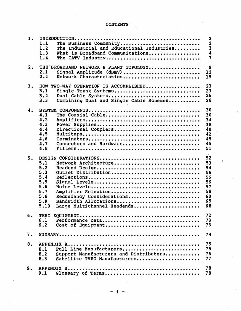
INTRODUCTION •••••••••••••••••••••••••••••••••••••••••••• 1.1 The Business Community •••••••••••••••••••••••••••• 1.2 The Industrial and Educational Industries ••••••••• 1.3 What is Broadband Communications •••••••••••••••••• 1.4 The CATV Industry •••••••••••••••••••••••••••••••••
THE BROADBAND NETWORK & PLANT TOPOLOGY •••••••••••••••••• 2.1 Signal Amplitude (dBmV) ••••••••••••••••••••••••••• 2.2 Network Characteristics ........................... .
HOW TWO-WAY OPERATION IS ACCOMPLISHED ••••••••••••••••••• 3.1 3.2 3.3
Single Trunk Systems •••••••••••••••••••••••••••••• Dual Cable Systems •••••••••••••••••••••••••••••••• Combining Dual and Single Cable Schemes •••••••••••
SYSTEM COMPONENTS ••••••••••••••••••••••••••••••••••••••• 4.1 4.2 4.3 4.4 4.5 4.6 4'.7 4.8
The Coaxial Cable ••••••••••••••••••••••••••••••••• Amplifiers •••••••••••••••••••••••••••••••••••••••• Power Supplies •••••••••••••••••••••••••••••••••••• Directional Couplers •••••••••••••••••••••••••••••• Mul ti taps ••••••••••••••••••••••••••••••••••••••••• Terminators ••••••••••••••••••••••••••••••••••••••• Connectors and Hardware ••••••••••••••••••••••••••• Filters •••••••••••••••••••••••••••••••••••••••••••
DESIGN CONSIDERATIONS ••••••••••••••••••••••••••••••••••• 5.1 Network Architecture •••••••••••••••••••••••••••••• 5.2 5.3 5.4 5.5 5.6 5.7 5.8 5.9 5.10
TEST 6.1 6.2
Headend Design •••••••••••••••••••••••••••••••••••• Outlet Distribution ••••••••••••••••••••••••••••••• Reflections ••••••••••••••••••••••••••••••••••••••• Signal Levels ••••••••••••••••••••••••••••••••••••• Noise Levels •••••••••••••••••••••••••••••••••••••• Amplifier Selection •••••••••••••••••••• ; •••••••••• Redundancy Considerations ••••••••••••••••••••••••• Bandwidth Allocations ••••••••••••••••••••••••••••• Large Multichannel Headends •••••••••••••••••••••••
EQU IPMENT .......................................... . Performance Data •••••••••••••••••••••••••••••••••• Cost of Equipment •••••••••••••••••••••••••••••••••
SUMMARY •••••••••••••••••••••• ~ ••••••••••••••••••••••••••
APPENDIX A •••••••••••••••••••••••••••••••••••••••••••••• 8.1 8.2 8.3
Full Line Manufacturers ••••••••••••••••••••••••••• Support Manufacturers and Distributers •••••••••••• Satellite TVRO Manufacturers ••••••••••••••••••••••
APPENDIX B •••••••••••••••••••••••••••••••••••••••••••••• 9.1 Glossary of Terms •••••••••••••• • • • • • • • • • • • • • • • • • • •
i
2 2 3 4 7
9 12 15
23 23 26 28
30 30 34 38 40 42 45 45 51
52 53 54 56 56 56 57 58 60 65 68
72 73 73
74
75 75 76 77
78 78

APPENDIX C •••••••••••••••••••••••••••• . . . . . . . . . . . . . . . 10.1 Cable Reference Material •••••• . . . . . . . . . . . . . . . . . .
11. APPENDIX D •••••••••••••••• . . . . . . . . . . . . . . . . . . . . . . . . . . . . 11.1 Broadband Symbols •• . . . . . . . . . . . . . . . . . . . . . . . . . . . . . . .
ii
82 82
84 84
- 2 -
1. INTRODUCTION
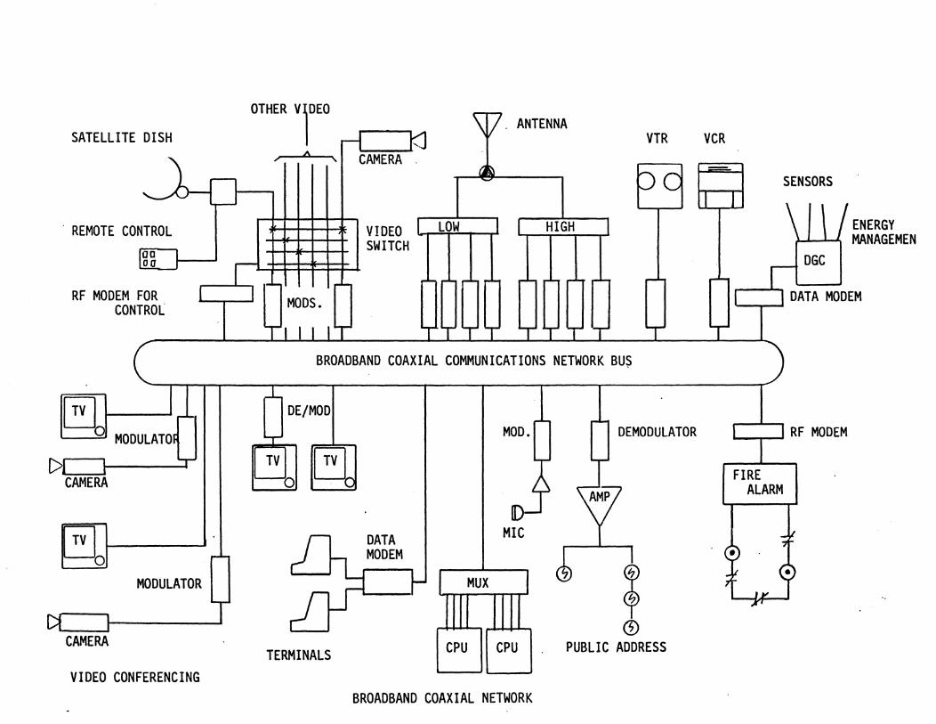
Over the past decade, electronic data communication requirements have grown at rates beyond the capabilities of existing telephone, twisted pair, and similar type communication mediums. Major advancements in Data Processing, Interactive Equipment and Networking Concepts impose an operational strain on conventional wiring schemes. Standard twisted pairs become cumbersome to use when the system requires constant expansion or reconfiguration. They also demand complex central intelligence, and they limit device placement and data flow. In addition, they are unable to provide high quality video processing necessary for video conferencing or security applications. The ·office of the future· and the ·wired city" concepts are unobtainable without using multiple, overlaying wiring schemes.
Compounding the problem faced by many facility managers are the standard wiring and cables necessary to provide each building with the required standard protection systems such as: Fire Alarm, Closed Circuit TV, Access Control, Paging, Energy Management, Intrusion Alarm and Television Entertainment. In the industrial, commercial and business environments, the results have been ceilings that bulge from the weight of the numerous twisted wire cable, telephone lines, and dedicated coaxial cable necessary to provide existing and ever expanding communication services.
An integrated multimode communications network uses a single communications medium to satisfy these requirements. The technology refinement of the CATV industry has led to the development of a Broadband distribution technique which provides reliable, inexpensive wideband communications over a coaxial cable network.
Thoughout the overview several words may not be familiar as to their meaning. To aid the reader, a glossary has been included to provide quick reference to unfamiliar terminology. In addition, a listing of CATV publications, and manufactures has been included for future reference.
1.1 The Business Community
The growth sophistication of the data communications industry, as typified by such applications as: ·work-at-home", ·office of the future" and "low-end business" applications, mandates that these services be integrated into the larger CATV information systems. The technology provided by the Broadband industry, as well as the CATV industry, must be able to provide the necessary interfacing to meet the local, regional, and national requirements of the data community.
The "Office of the Future" is directly aimed at the white collar office environment and its purpose is to increase worker productivity. To improve productivity, large and small companies
- 3 -
are providing word processors, facsimiie machines, intelligent copiers, computer terminals, and video conferencing. To support the vast amount of equipment, and to operate interactive systems such as: Electronic Mail, Word Processing, Programming, and Energy Management, the data community needs a consolidated approach to networking.
The "Work-at-home" concept has been around for several years but the high cost of implementation of the network itself and the high cost of the projected home terminal slowed its rate of growth. Newer projections of the terminal cost is now tinder the $250 figure making the availability of such terminals to the majority of users. In addition, the anouncement of "MetroNet" by Sytek Incorporated, inconjuction with.General Instruments (Taco/Jerrold Division), now provides the network structure and protocol aspects to allow integration to any two-way CATV network.
"Low-end Business" aspects could be the largest integrator to the CATV and Broadband markets. Hundreds and thousands of companies throughout the United States will use individual Broadband networks to support their local requirements and interface into CATV industrial trunks to provide the required communication links between other buildings perhaps separated by several miles. With this type of approach the business community could be supported at half the cost of traditional wiring systems for networking.
1.2 The Industrial and Educational Industries
Most business and institutional organizations already posses substantial data communications needs and welcome the capacity, topology, and cost savings of a Broadband communications network as an alternative to current twisted cables and Public Switched Telephone Networks (PSN). In similar situations are the banking community, large industrial firms, and municipal government. management information systems.
Educational campuses around the country are finding the Broadband approach as the only reliable, economical, and most efficient way to satisfy their massive requirements for communications. In such environments, the need to have a transportation medium that can support systems such as: Television, Local Origination, Stdio Productio, Data Communications, Fire Protection, Information Retrieval, and Security is mandatory.
Industrial plants across the country are finding the Broadband Network as the only solution to their requirements for applications in: Accounting, Personnel Management, Assembly Lie Automation, Graphic Designing, Time and Attendance, Energy Managment, and Program Verification. Without a Broadband Communications Network, most plants would have a wiring nightmare that would impose operational constraints, and equipment placement.
- 4 -
To accomlish these goals, and others, data managers require an efficient communications network that is easy to standardize, easy to install, easy to maintain, and imposes few restrictions on other communication services. Thus, Broadband communications is a realistic solution of those needs and can integrate multiservices on a single information network.
1.3 What is Broadband Communications
Broadband is a generic term that describes a type of widebandwidth communications network that uses coaxial cable as its distribution medium, and frequency division multiplexing as its channel allocation scheme. Some major manufacturers of CATV equipment have selected "buzz- words to describe their own twoway communications system such as: -BROADCOM-, used by the Taco/Jerrold Division of General Instruments. However, for purposes of this overview we shall use the term -Brodband.-
As a distribution medium, coaxial cables are reliable, economical, and can be installed in existing underground cableways, conduits, and plenums. Broadband components are of high quality and are available from a large number of vendors who support the CATV industry. Coaxial cable are comprised of several types which are suitable to numerous environmental conditions. If damaged or broken, the line can be spliced or short sections can be replaced in a matter of minutes by semi-skilled personnel using simple tools. Coaxial cable exibit high shielding characteristics in hostile environments that contain Electro Motive Interference (EMI) or Radio Frequency Interference (RFI) signals. This allows the use of coaxial cable in industrial applications where standard twisted pair become difficult to use. Fault isolation in a coaxial network is relatively straight-forward using a variety of test equipment, and could be enhanced by automation through use of statistical r.ecall systems, status monitoring facilities, and programmable spectrum anlayzer/sigrtal generators currently available.
One of the most appealing aspects of Broadband is that it provides the basis for an integrated approach to solving a number of communication needs. In addition, all devices attached to the network are geographically independent, i.e., their function and performance are independant of their location relative to the network. Network services can be easily relocated without incurring undue cost. Because of this, and other characteristics, buildings of any size can be pre-wired with the coaxial cable at a fraction of the cost of conventional wiring schemes. Connection to the network is done through a simple -F R type connector which allows users to connect or disconnect his or her communication units, moving if necessary from room to room with no wiring changes. Listed below are several types of interconnecting systems that can be integrated onto a Broadband Network. It must be noted, however, the implementation of each system must be done only after careful analysis, to prevent interaction between
- 5 -
dissimilar systems or conflicting freq~ency assignments.
A. SECURITY AND SAFETY
B. FIRE ALARM
C. INTRUSION ALARMS
D. CCTV SURVEILLANCE
E. BUILDING AND AREA .ACCESS CONTROL
F. ALARM/STATUS MONITORING
G. EMERGENCY/PAGING SYSTEMS
B. ENERGY MANAGEMENT
I. DATA COMMUNICATIONS
J. TELEVISION DISTRIBUTION
K. VIDEO CONFERENCING
L. CAMERA CONTROL
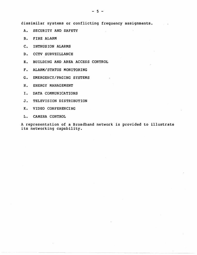
A representation of a Broadband network is provided to illustrate its networking capability.
SATELLITE DISH
. REMOTE CONTROL loa loa
RF MODEM FOR CONTROL
1
~ 11 ~_O:=.l MODULATO~
C> T CAMERA
~I-------I MODULATOR
1 I
CAMERA
VIDEO CONFERENCING
,.....;
T
r-l-
MODS.
1""'1 I I IT
CAMERA
VIDEO SWITCH
\J[7. ANTENNA VTR
bc LOW HIGH
I'" r- 1'"- ,.... r-
T BROADBAND COAXIAL COMMUNICATIONS NETWORK BUS
,..L DE/MOD
T
TV TV I~O
;-,r
TERMINALS
MOD.
u
DATA MIC MODEM
-~ MUX I
CPU CPU
BROADBAND COAXIAL NETWORK
DEMODULATOR
T
Y ~ t
CD PUBLIC ADDRESS
VCR
SENSORS
ENERGY )-J-~ MANAGEMEN
r- DGC ,....- I
"'-----'-.1 DATA MODEM
'--..,-..... 1 RF MODEM
FIRE ALARM
- 7 -
1.4 The CATV Industry
In 1949, when the first Community Antenna TV <CATV) systems appeared on the scene, it was very easy to tell if the system was well designed. The operator was satisfied if he could pick up, amplify and deliver a signal to locations where the signal could not be picked up directly. This simple pragmatic approach is no longer adequate when CATV systasare planned for two-way transmission, community services, customer response, transmissions addressed to selected receivers, central data storage and retrieval, meter reading, intrusion/fire protection -- -in other words, for complete Broadband commuications networks. The technology of CATV is progressing ever deeper into basic theoretical investigations, calling for more and more sophisticated designs. The simplicity of the components and the high reliability, made distribtion of video signals possible for small and large city atmostphers. As the number of systems grew several aspects such as; installation, operation, alignment, and maintenance became known throughout the United States.
Since then, the CATV industry has grown dramatically in the past decade and currently reaches 21 million subcribers. It is predicted that by the end of 1989 that figure will rise to 65 million and will pass 30% penetration of the available subcribers. The 30% is a critical figure which experts feel CATV must reach in order to become a major influence in thecommunications community. Predictions are that the CATV industry will achieve that 30% penetration goal by the end of 1983. With this in mind, the industry, and the technology advancements that will be developed, can bring new capabilities and design improvements beyond what exists today.
There are two areas where design concepts and techniques can be involved: the CATV system.as a NETWORK, and the CIRCUIT DESIGN of the components used in the network. Most of the 'component and circuit-theory problems have been solved more or less successfully throughout the industry, resulting in highly reliable components offered at very low prices. Massive competition for the market has resulted in improvements in designs and in component level advancements. The Network concept, however, has presented the CATV engineer with a variety of topologies, environmental conditions and situations which must be handled on a case
by case basis.
We shall examine these aspects in detail throughout this overview. As part of this article, references to CATV and Broadband are mentioned within the same text. It should be clear that both mediums are identical in equipment and design aspects and could be considered one and the same. The term Broadband is· used primarily to distinguish the geographical differences of the two systems both in indoor and outdoor applications. Furthermore, Broadband is always used in the bi-directional mode. In contrast, CATV systems are primarily used in the uni-directional mode,

- 8 -
although there has been a trend toward$ heavy bi-directionaluse to supply their users with additional services.
- 9 -
2. THE BROADBAND NETWORK & PLANT TOPOLOGY
A Broadband system consists of two basic sub-systems: The HEAD END and the DISTRIBUTION NETWORK. Each sub-system has certain responsibilities and operational characteristics which we will explore. '
The HEADEND is the point of origin for RF signals which are distributed to the network and, likewise, it is a collection point for"all RF signals which are generated by the various devices connected to the network. These two paths represent the transmitted, and received signals which are characteri~tic of bi-directional operation. Equipment normally found in Headends are: signal processors, modulators, demodulators, combiners, data translation units, power supplies, and control units.
The DISTRIBUTION NETWORK is a combination of active and passive devices which distribute and collect RF Signals generated to and from the Headend. In CATV applications, Signals normally are distributed from the Headend to thousands of connecting subscribers for the purpose of home entertainment. This service is usually operated in the uni-directional mode. However, most CATV systems today have bi-directional operation for their local origination channels, pay channels, and control or monitoring systems. It should be noted, that all CATV systems must be two-way capable per FCC regulations. The bi-directional aspects of a CATV system has not been to the extent of that of Broadband, primarily, because the market has not dictated the need. In most cases the insertion of the required filters, equalizers, and return amplifiers can convert an existing one-way system into a two-way interactive network.
In Broadband applications, bi-directional networks are required to support a variety of transmitted and received Signals used in Data Cornmunications,Close Circuit TV (CCTV), Information Retrieval Systems and Digital Controls. The components of a Distribution Network are: coaxial lines, filters, splitters, directional couplers, combiners, distribution taps, amplifiers, and related hardware". "
The graph of any CATV or Broadband Network must be a "TREE" type topology. The tree can be described as follows: The base of the tree represents thp. headend and the branches are represented by the distribution network. The branches are arranged in a pattern referred to as the backbone network. The backbone, in most cases, can support several thousands of connections with the office drops installed as the system demand dictates.
Existence of more than a single path between any two points in ~he network is forbidden since this would result in interference associated with multi-path transmissions. Thus, the system is directional in operational aspects and all the components used on the network operate under the directional coupler format. The
- 10 -
nodes of the tree are dete~inded by the location of the headend and the receivers, but there are many ways to connect the -. branches to satisfy many system requirements. The problem of an optimum layout appears very early in the design of a system. The criteria for optimization include: the initial capital cost, cost of maintenance, allowance for-future expansion, and system func-tion. -
In simple terms, any Broadband system topology can·be molded to conform to any building arrangement one may have~ In fact, the flexibility of the Broad~and technique is beyound any existing . wiring scheme currently used.
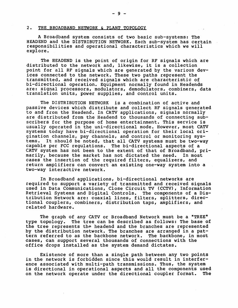
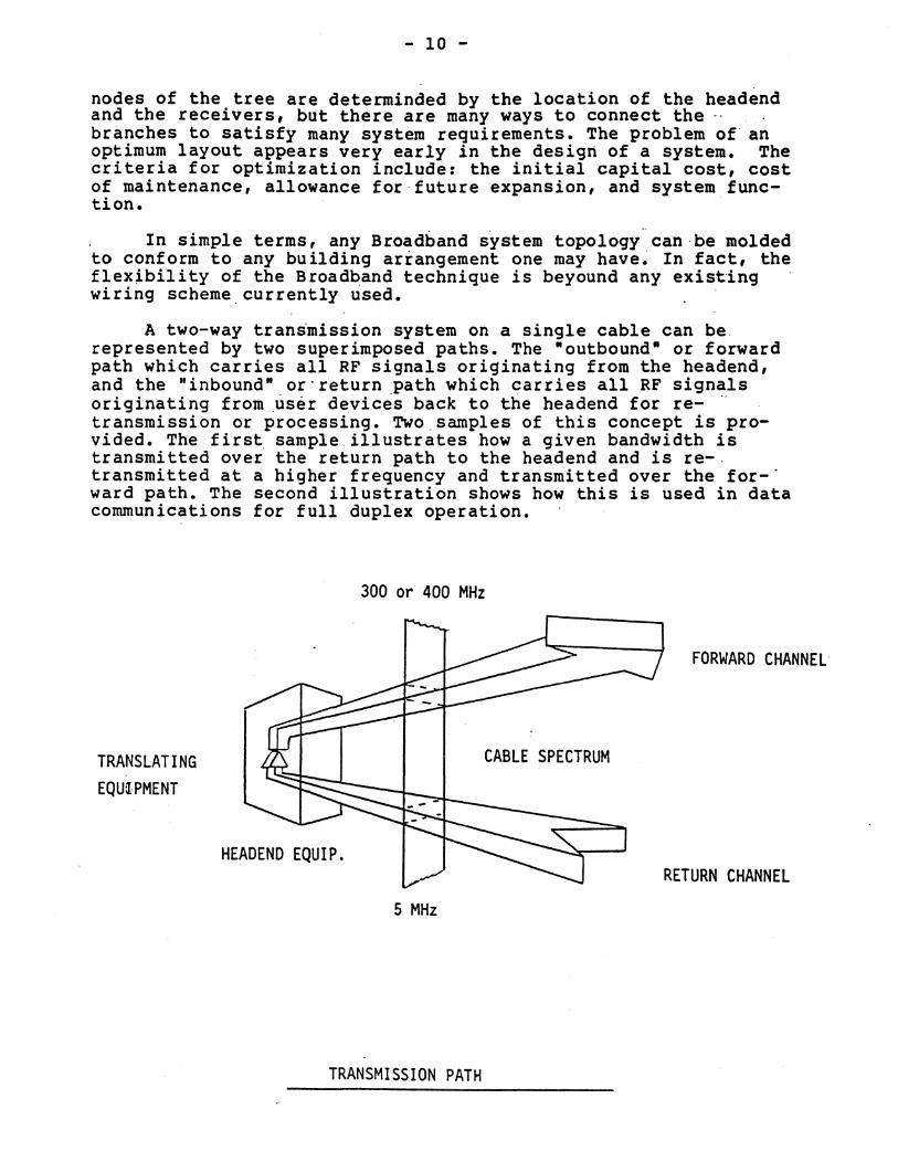
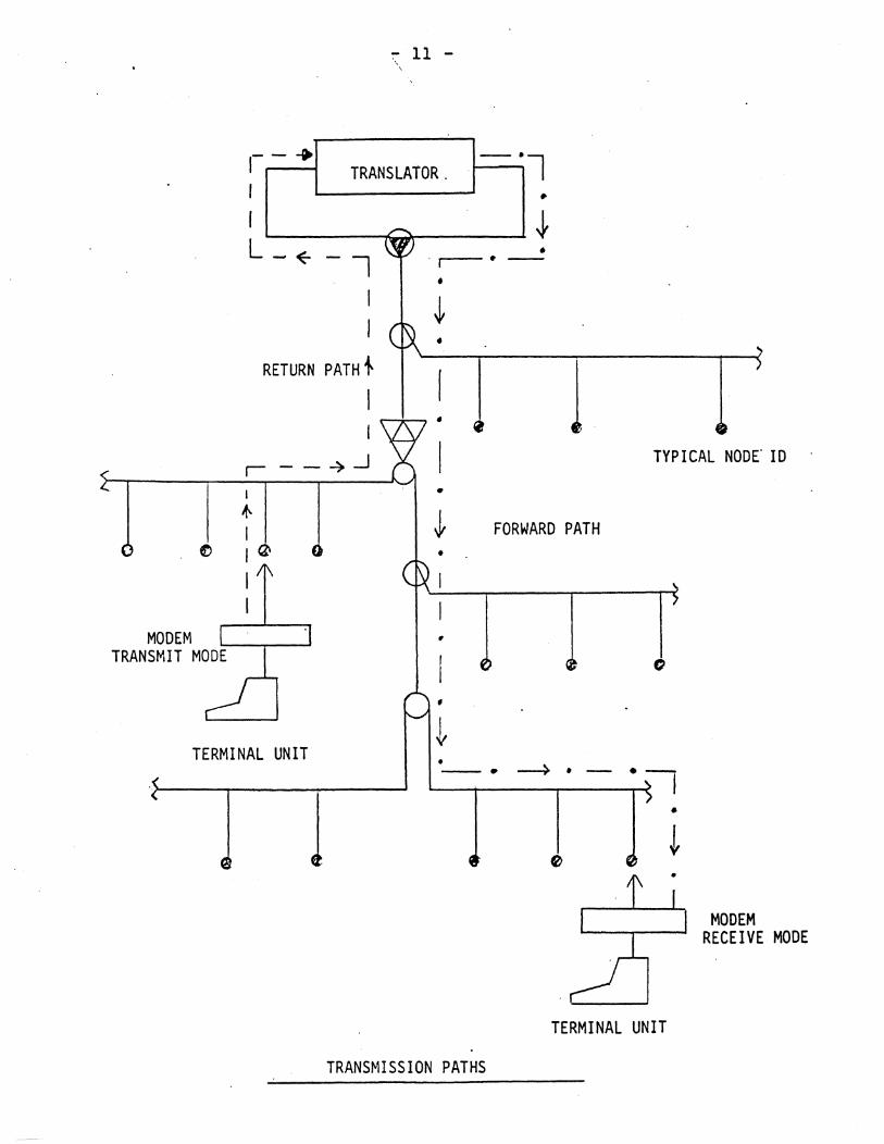
A two-way transmission system on a single cable can be. represented by two superimposed paths. The "outbound" or forward path which carries all RF signals originating from the headend, and the "inbound" or'r~turn path which carries all RF signals originating from user de.vices back to the headend for re- " transmission or processing_ Two,samples of this concept is provided. The first sample. illustrates how a given bandwidth is transmitted over the return path to the head end and is re-. transmitted at a higher frequency and transmitted over the for-" ward path. The second illustration shows how this is used in data communications for full duplex operation.
TRANSLATING EQU[,PMENT
300 or 400 MHz
CABLE SPECTRUM
HEADEND EQUIP.
5 MHz
TRANSMISSION PATH
FORWARD CHANNEL
RETURN CHANNEL
':"" 11 -
1- - .. TRANSLATOR.· - ·l I •
I~ __ ~~_~~ L_~
RETURN PATH ~
r--4>..J
TERMINAL UNIT
1
• . r-.-
•
•
TRANSMISSION PATHS
1
TERMINAL UNIT
MODEM RECEIVE MODE
- 12 -
Since two-way networks require two transmission paths, we. must allocate which frequency will be ~ssigned to each direction to limit possible interaction between the bands. Two such approaches are -midsplit- and -subsplit- each of which are explained further in upcoming sections.
Once the basic topology is determinded and the frequency assignments made we must now transport the RF signals to the users or supportive equipment. The coaxial cable performs this task along with the passive and active components of the network. Each design engineer selects the list of components that will meet the systems physical and electrical requirements and, in turn, calculates the signal loss associated with each configuration. The calculations involved when delivering signal amplitude to each user can been demonstrated by.a water pipe system analysis.
Suppose one was to design a water delivery system in which some given amount of water pressure is to be delivered to three users. The first step would be to build a large main pressure line. At three locations valves would be installed with each valve adjusted until each delivered the same amount of water pressure. Although this is a highly simplified example, the basics in RF design calculations are similar as ones calculates the signals in a Broadband system.
In order to perform this task, or understand the process, one must become familiar with the network devices and their corresponding specifications as they pertain to network design. The following sections provide technical information on the fundamentals of Broadband equipment implementation.
2.1 Signal Amplitude (dBmY)
The logarithmic unit of, signal ratio which finds wide acceptance is the decibel. Strictly speaking, the decibel (dB) is defined only for power ratios; however, as a matter of common usage, voltage or current ratios also are expressed in decibels. The use of dBmV, which is also a logarithmic expression, is utilized in the CATV industry to express signal amplitude. This expression is primarily used to have industry wide verbal and written consistency when dealing with signal amplitudes of any system.
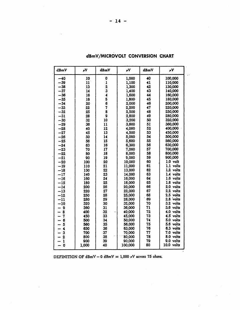
The definition of dBmV is 0 dBmV = 1000uV across a 75 ohm load. The conversion from micro-volts to dBmV is needed to provide an easy way of expressing signal levels. For example; to express 10 dBmV of video level for channel 13 at any given outlet in micro-volts would be 3,200 uV. This expression becomes more difficult to relate to as the signal level increases and additional channels are added. By using the dB or dBmV expressions gains and losses along a system can be handled with simple addition and substractio~, without the need for multiplication and
- 13 -
division associated with micro-volt expressions.
As a result, all equipment and signal requirements are expressed in dBmV or dB. The dB represents the difference or ratio of two dBmV expressions, for example; a typical carrierto-noise ratio is 43 dB which can be obtained by dividing the input signal of an amplifier by the noise floor. Both the input and the noise floor signals are expressed in dBmV, but the mathematical resultant is expressed in dB. Thus, dB is an expression of potential while dBmV is an expression of signal amplitude.
Several pages can be documented on the dB and dBmV formats and relationships. As a result we won't explore those regions but, in turn, will provide the dBmV /microvolt conversion chart. As can be see by the chart, all levels below 0 dBmV, or 1000 uv, are designated by a minus sign.
- 14 -
dBmV /MICROVOLT CONVERSION CHART
dBmV "v clBmV ,.V clBmV ,.V
-40 10 0 1,000 40 100,000 -39 11 1 1,100 41 110,000 -38 13 2 1,300 42 130,000 -37 14 3 1,400 43 140,000 -36 16 4 1,600 44 160,000 -35 18 5 1,800 45 180,000 -34 20 6 2,000 46 200,000 -33 22 7 2,200 47 220,000 -32 25 8 2,500 48 250,000 -31 28 9 2,800 49 280,000 -30 32 10 3,200 SO 320,000 -29 36 11 3,600 51 360,000 -28 40 12 4,000 52 400,000 . -27 45 13 4,500 53 450,000 -26 SO 14 5,000 54 500,000 -25 56 15 5,600 55 560,000 -24 63 16 6,300 56 630,000 -23 70 17 7,000 57 700,000 -22 SO 18 8,000 58 SOO,OOO -21 90 19 9,000 59 900,000 -20 100 20 10,000 60 1.0 volt -19 110 21 11,000 61 1.1 volts -18 130 22 13,000 62 1.2 volts -17 140 23 14,000 63 1.4 volts -16 160 24 16,000 64 1.6 volts -15 ISO 25 18,000 65 1.8 volts -14 200 26 20,000 66 2.0 volts -13 220 27 22,000 67 2.2 volts -12 250 28· 25,000 68 2.5 volts -11 280 29 2S,OOO '69 2.S volts -10 320 30 32.,000 70 3.2 volts -9 360 31 36,000 71 3.6 volts -8 400 ·32 . - 40,000 72 4.0 volts -7 450 33 45,000 73 4.5 volts -6 500 34 50,000 74 5.0 volts -5 560 35 56,000 75 5.6 volts -4 630 36 63,000 76 8.3 volts -3 700 31 70,000 77 7.0 volts -2 800 38 .- -""80,000 78 8.0 volts - 1 900 39 90,000 79 9.0 volts -0 1,000 40 100,000 80 10.0 volts
DEFINITION OF dBmV - 0 dBmV = 1,000 "V across 75 ohms.

- 15 -
2.2 Network Characteristics
Most CATV/Broadband components are currently designed to pass from 5 MHz to 400 MHz and are installed at strategic points along the network. The coaxial cable serves as the main transportation path for the RF signals and also is the physical link between the passive components. Coaxial cable used for such applications have characteristic impedances of 75 ohms. ~he selection of cable will depend on the length of the various trunks and distribution lines as well as the environment in which they must exist. The size of the cable (and corresponding cost) will determine the loss factors, which must be taken into account when designing the network.
If there were no loss in coaxial. cable, signal energy could be transported infinite distances without the need of amplifiers. In reality, however, a particular cable at a particular temperature has an attenuation signal loss characteristic that is directly related to frequency. Furthermore, as the temperature changes, the frequency attenuation characteristic of cable also changes. These aspects dictate the need for equalized amplifiers and initial system balance and alignment. To fully understand these requirements it is necessary to examine the frequency attenuation characteristics of cable and the temperature related changes that occur.
Coaxial cable is constructed of two conductors: a center conductor and an outer shield, which have a common axis. This common axis is achieved by arranging the two conductors as concentric circles. The center conductor and the outer shield conductor are held uniformly separate throughout the length of cable by an insulating or dielectric material. Both conductor resistance and dielectric conductance demonstrate frequency related loss and are the two properties directly responsible for the variation in cable attenuation with frequency. Each of these two properties are uniformly distributed throughout the length of cable and can be expressed per unit length of cable.
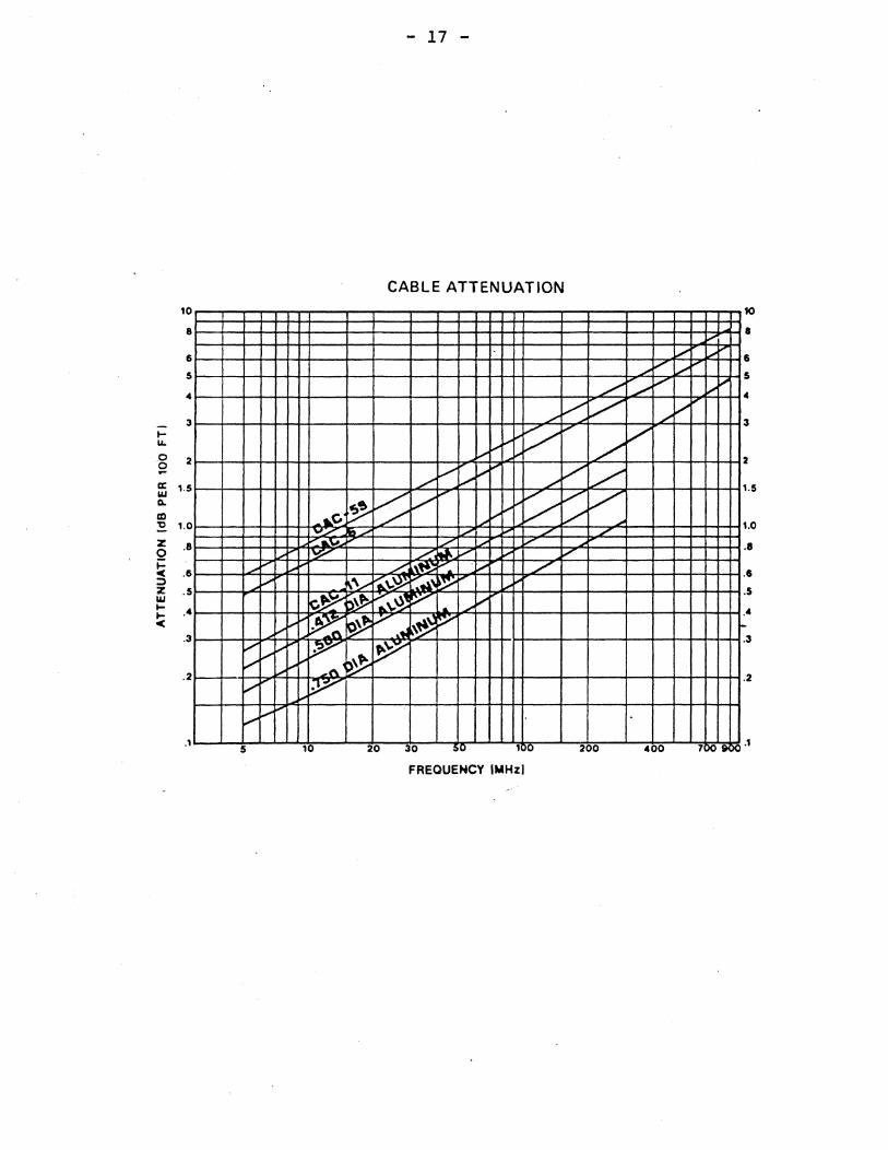
Within the CATV industry, it is accepted practice to specify cable length in dB of attenuation at the highest operational frequency. Most systems use 300 MHz as the highest operational frequency, but at times 400 MHz is used if the system requires additional bandpass for the distribution of additional signals in the forward direction. This establishes a common reference and ensures industry-wide verbal and written consistency in specifying cable length. A typical cable specification is as follows: 1.63 dB of loss per 100 feet @ 300 MHz measured @ 68 degrees F. This represents the specification of one brand of .412 seamless aluminum coaxial cable. To calculate the signal loss of a 1000 foot length of .412 coaxial cable simply multiply 1.63 x lB, the result of which equals 16.3 dB. By using the attenuation factors for each frequency assignment the loss of any given length of cable can be calculated.
- 16 -
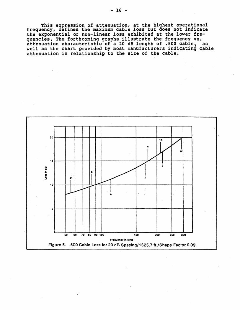
This expression of attenuation, at the highest operational frequency, d.efines the maximum cable lc;>ss but does not indicate the exponential or non-linear loss exhibited at the lower fre~ quencies. The forthcoming graphs illustrate the frequency vs. a~tenuation characteristic of a 20 dB length o~ .500 cable, as well as the chart provided by most manufacturers indicating cable attenuation in relationship to the size of the cable.
II 'II
.s
.§
13 V 7 / w
20
/ ,,-
15
V J
• • / .. 2 •
--V I ~
",..."
I i.--" .... A .
10
5 I
i 50 SO 70 10 to 100 150 200 250 300
F'eQue"c:l' ." MHz
Figure 5 .• 500 Cable Loss for 20 dB Spacing/1525.7 ft./Shape Factor 0.09.
10
8
6
5
4
3 l-II.
0 :2 0 -a: 1.5 11.1 Q.
CD ~ 1.0 ... e
""Z Z .8 0 i= e .6
: .. ~~ I~
.;
:;) "". Z .5 11.1 I- .4 l-e
.3
. 2
~~ ., ...... ~ ~ ~
i; r V ..... ""' ... ~t\
V' )~ .. ~
1/'"
.1 5 10
- 17 -
CABLE ATTENUATION
./
L ~ V ~V I-' i-'~ / ~ ~
./ ,,/ ,.,. ~io"" ,.,. V /
~ V ",
~V V /' ~ ~~ V 18/ .." ", ./ ./
./ ., ./ ./ ~. V ., V
~ l\~';: f" .~ / I\'\....--r..\.~ ":"~, ~ ... ~ ~\.~ V
"'"' /~
~ V ~ V ".~
~ ~
20 30 ,g ,,~g 200
FREQUENCY 'MHz! .....
., l/ .....
L V 1/
./ V .," ./ ~
V
400 1~ ~
10
• • 5
4
3
:2
1 .5
1 .0
IS
• 5
r-3
:2
- 18 -
From the first graph, it can be a~certained that the attenuation is different for each channel~ The difference of attenuation is called ·Spectrum Tilt· or ·Slope- and must be considered when designing a network of any size. As indicated previously the attenuation and tilt are directly affected by temperature variations. Attenuation of most coaxial cable change at the rate of .11% per degree, amounting to a change of almost 15% over the temperature range of -40 to +120 degrees F. The accepted rule-of-thumb is 1 % cable attenuation for every 10 degree of temperature change.
Frequency and temperature relationship in network 'design is referred to as ·The Operational Window·, which Is the allowable change of RF signals that can take place without degradation to the network performance. In bi-directional systems there are two such spectrum tilts: one for the forward path, and the other for the return path. Both tilts must be taken into account during the design process, for they affect the operation of the amplifiers and the overall balance of the system. As a result, amplifiers must compensate for the combination of cable loss, tilt, and temperature variations to be experienced in day to day operation to keep the system gain reasonably ,constant under all conditions.
During manufacturing or installation slight compressions in the cable can cause its characteristics to change. The insertion of amplifiers, taps, and splitters can also cause minute discontinuities on the coax. The result of such kinks can cause reflections or standing waves which can be in phase and, therefore, add. These periodic, disturbances can make a very effective filter, resonating at the frequency for which the spatial period is half a wavelength, and the return loss has a pronounced spike at that frequency. Ea'ch discontinuity may have a return l.oss of 60 dB, but the accumulated effect may be enough to caus~ a narrow-band dip in the transmission characteristic. If the dip corresponds to a desired car.rier, the result of the additional attenuation may cause serious degradation to that channel. Sweep testing of the cable prior to and after installation will detect structural problems by means,of--poor return loss readings, thereby reducing the possibilities of inadequate system performance. This type of test is called ·structural return loss.·
Another test is called ·cable sweeping- or component performance test. This test can be pe'rformed during the installation or once the system is completed. Sweep systems also allow daily trouble-shooting and preventative maintenance indications to be performed, if required, once the system is installed. Consisting' of a rack mounted (at the headend) sweep generator and a portable sweep receiver, measurements at any point in the network can be accomplished. The sweep test analyses and plots the system attenuation, cable exponential characteristics, and spectrum integrity through the passive and active components. System alignment for the amplifiers can be made much easier through this type of test. In addition, the reverse application can be done to
- 19 -
align and plot the return path in Bi-directional networks. Through sweep testing one can check the characteristics of the system vs the design expectations, giving note to areas that may not be operating at the designed levels.
The maximum length of a CATV trunk line is normally referred to in terms of amplifier cascade, i.e., the number of trunk amplifiers which can be connected in series without system degradation. Long haul trunks employ high quality amplifiers spaced approximately every 20dB of cable attenuation at the highest operational frequency •. Up to 30 amplifiers covering a distance of many miles may be cascaded in this manner. Thus, trunk "amplifier selection is determined primarily by the distance that the trunk lines must cover to minimize accumulated noise and distortion. Typically, long trunks are not required in a local Broadband Network. If one desires to connect several buildings that are miles apart then two approaches can be done. First a dedicated trunk line can be installed by a contractor which, in turn, they will provide maintenance for the owner if required. The second approach can be in the form of utilizing an "Industrial" trunk installed and maintained by the local CATV company. The bandwidth can be leased out to the owner at a reasonable fee in which the owner is allowed to use existing two-way trunks through a "gateway" device.
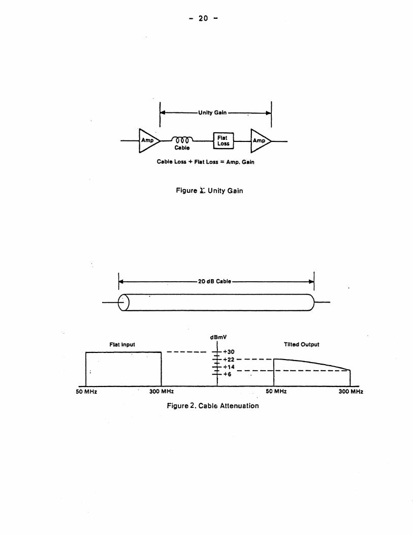
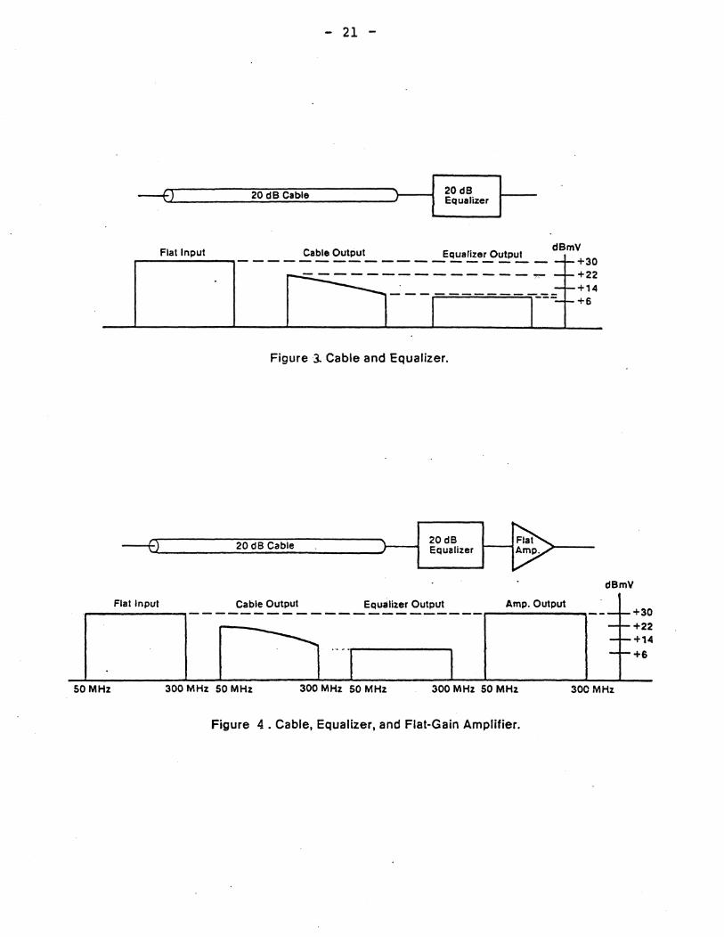
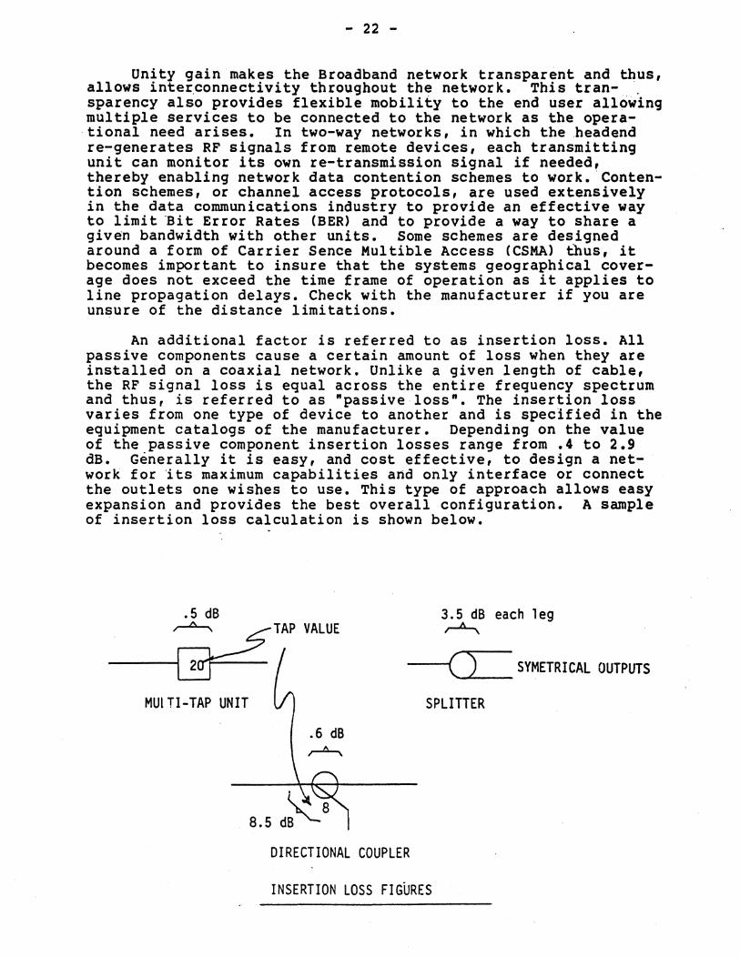
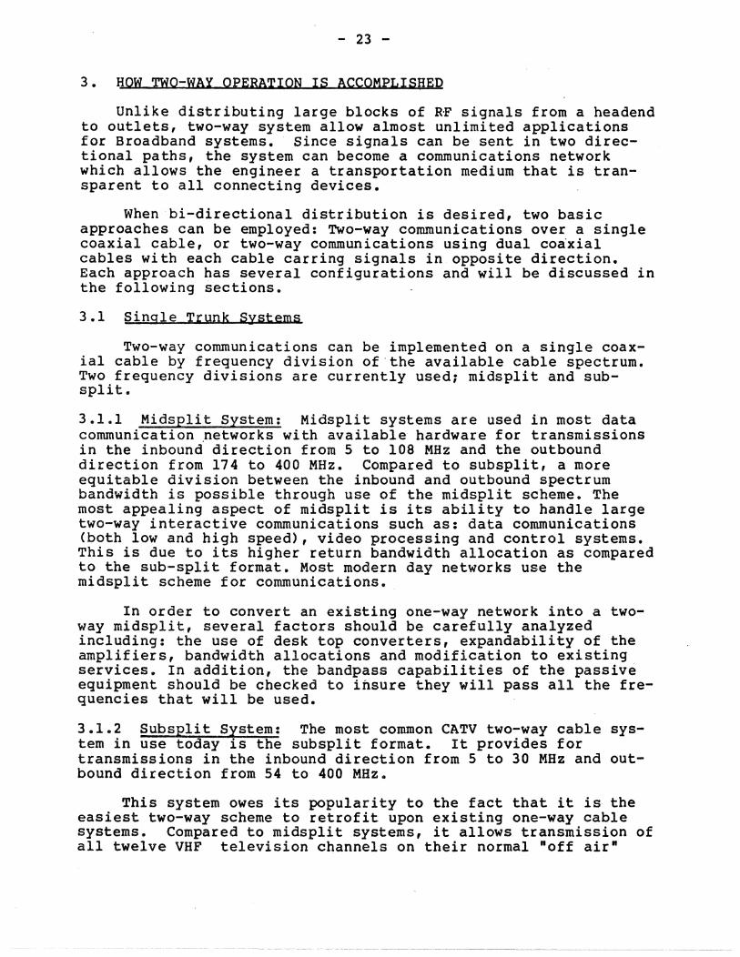
All CATV/Broadband systems are designed around the "UNITY GAIN" relationship which can be stated as follows: Cable loss + Flat loss = Amplifier gain. The flat loss is associated with the loss through each passive component. The attenuation is equal across the entire frequency spectrum and is referred to sometimes as passive loss. In order to achieve unity gain at all frequencies it is necessary to somehow compensate for the frequency attenuation (tilt) characteristics of cable. This is accomplished through the design of amplifiers that can exhibit a gain characteristic exactly the inverse of cable tilt. One method preferred by the majority of manufacturers is to design an equalizer network which, when placed in series with a given cable length,. would further-a·ttenuate" all-lower frequency components so that the loss at all frequencies is equal. A flat gain amplifier is then placed at the output of the equalizer network in order to amplify the original input signal levels. By following the figures one can see how unity gain works and also how cable tilt is handled throughout the network.
- 20 -
Cable Loss + Flat Loss = Amp. Gain
Figure l'. Unity Gain
~ II1II1--------..---20 dB cable---------~.I
C"",,--:) ______ r dBmV
Flat Input Tilted Output +30 +22-----,--__ _ +14 ___ _
+6
SO MHz 300 MHz SO MHz 300 MHz
Figure 2. Cable Attenuation
- 21 -
~S)C====22~O~d~BJc~a~b~le~=====))--11 ~~;;~,
Flat Input Cable Output Equalizer Output r--------,-------------------dBmV
+30 +22 +14 +6
-------------
Figure 3- Cable and Equalizer.
~~~ _________ 2_0_d_B_C_a_b_le ____________ >___i 20dB ~ Equalizer ~---
Flallnpul Cable Output Equalizer Output Amp. Output ,..-------....,----------------------,..--------......
dBmV
+30 +22 +14
+6
50 MHz 300 MHz 50 MHz 300 MHz SO MHz 300 MHz 50 MHz 300 MHz
Figure 4. Cable, Equalizer, and Flat-Gain Amplifier.
- 22 -
Unity gain makes the Broadband network transparent and thus, allows inte~connectivity throughout the network. This tran- " sparency also provides flexible mobility to the end user allowing multiple services to be connected to the network as the opera-,tional need arises. In two-way networks, in which the ,headend re-generates RF signals from remote devices, each transmitting unit can monitor its own re-transmission signal if needed, thereby enabling network data contention schemes to work.Contention schemes, or channel access protocols, are used extensively in the data communications industry to provide an effective way to limit 'Bit Error Rates (BER) and to provide a way to share a given bandwidth with other units. Some schemes are designed around a form of Carrier Sence Multible Access (CSMA) thus, it becomes important to insure that the systems geographical coverage does not exceed the time frame of operation as it applies to line propagation delays. Check with the manufacturer if you are unsure of the distance limitations.
An additional factor is referred to as insertion loss. All passive components cause a certain amount of loss when they are installed on a coaxial network. Unlike a given length of cable, the RF signal loss is equal across the entire frequency spectrum and thus, is referred to as ·passive loss". The insertion loss varies from one type of device to another and is specified in the equipment catalogs of the manufacturer. Depending on the value of the passive component insertion losses range from .4 to 2.9 dB. Generally it is easy, and cost effective, to design a network for its maximum capabilities artd only interface or connect the outlets one wishes to use. This type of approach allows easy expansion and provides the best overall configuration. A sample of insertion loss calculation is shown below •
• 5 dB
___ '~TAP VALUE
3.5 dB each leg ~
----f( ) SYMETRICAL OUTPUTS
SPLITTER MUI Tl-TAP UNIT
8.5
DIRECTIONAL COUPLER
INSERTION LOSS FIGURES
- 23 -
3. HOW TWO-WAY OPERATION IS ACCOMPLISHED
Unlike distributing large blocks of RF signals from a headend to outlets, two-way system allow almost unlimited applications for Broadband systems. Since signals can be sent in two directional paths, the system can become a communications network which allows the engineer a transportation medium that is transparent to all connecting devices.
When bi-directional distribution is desired, two basic approaches can be employed: Two-way communications over a single coaxial cable, or two-way communications using dual coa'xial cables with each cable carring signals in opposite direction. Each approach has several configurations and will be discussed in the following sections.
3.1 Single Trunk Systems
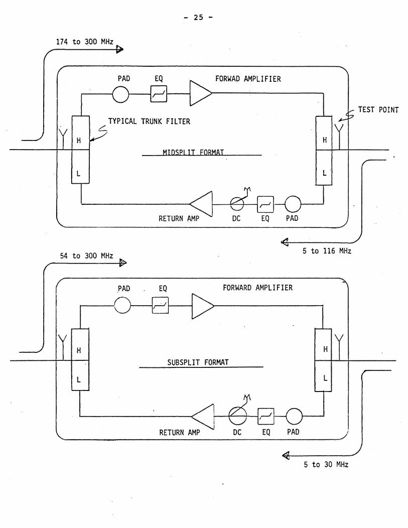
Two-way communications can be implemented on a single coaxial cable by frequency division of the available cable spectrum. Two frequency divisions are currently used; midsplit and subsplit.
3.1.1 Midsplit System: Midsplit systems are used in most data communication ,networks wi th available hardware for transmissions in the inbound direction from 5 to 108 MHz and the outbound direction from 174 to 400 MHz. Compared to subsplit, a more equitable division between the inbound and outbound spectrum bandwidth is possible through use of the midsplit scheme. The most appealing aspect of midsplit is its ability to handle large two-way interactive communications such as: data communications (both low and high speed), video processing and control systems. This is due to its higher return bandwidth allocation as compared to the sub-split format. Most modern day networks use the midsplit scheme for communications.
In order to convert an existing one-way network into a twoway midsplit, several factors should be carefully analyzed including: the use of desk top converters, expandability of the amplifiers, bandwidth allocations and modification to existing services. In addition, the bandpass capabilities of the passive equipment should be checked to insure they will pass all the frequencies that will be used.
3.1.2 Subsplit System: The most common CATV two-way cable system in use today is the subsplit format. It provides for transmissions in the inbound direction from 5 to 30 MHz and outbound direction from 54 to 400 MHz.
This system owes its popularity to the fact that it is the easiest two-way scheme to retrofit upon existing one-way cable systems. Compared to midsplit systems, it allows transmission of all twelve VHF television channels on their normal noff air n

- 24 -
frequency assignments.
Subsplit has its drawbacks, however, when-information originates from locations other than the headend. Since only 25 MHz is available for the inbound direction, only 4 television channels or their bandwidth equivalents can be originated remotely.
Block diagrams of two trunk amplifiers are provided to illustrate the electrical representation of both schemes.
- 25 -
174 to 300 MHz
H
L
TYPICAL TRUNK FILTER c:::...
FORWAD AMPLIFIER
MIDSPI IT fORMAT
I--------------R-E-TU-R-N~;;:J ~~
54 to 300 MHz
PAD
PAD EQ FORWARD AMPLIFIER
H
SUBSPLIT FORMAT
L
H
L'
5 to 116 MHz
H
L
"-________ R_E_T_UR_N_A_M_P ______________ ~
5 to 30 MHz
TEST POINT
- 26 -
3.2 Dual Cable Systems
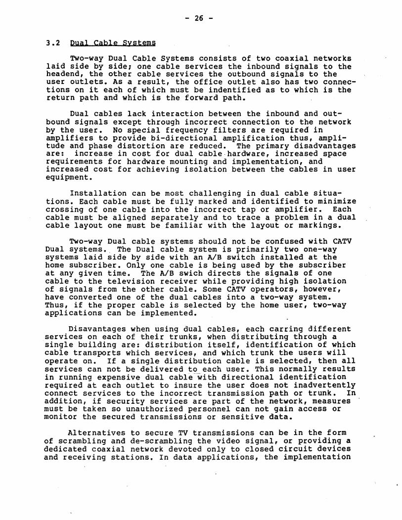
Two-way Dual Cable Systems consists of two coaxial networks laid side by side; one cable services the inbound signals to the headend, the other cable services the outbound signals to the user outlets. As a result, the office outlet also has two connections on it each of which must be indentified as to which is the return path and which is the forward path.
Dual cables lack interaction between the inbound and outbound signals except through incorrect connection to the network by the user. No special frequency filters are required in amplifiers to providebi-directional amplification thus, amplitude arid phase distortion are reduced. The primary disadvantages are: increase in cost for dual cable·hardware, increased space requirements for hardware mounting and implementation, and increased cost for achieving isolation between the cables in user equipment.
Installation can be most challenging in dual cable situations. Each cable must be fully marked and identified to minimize crossing of one cable into the incorrect tap or amplifier. Each cable must be aligned separately and to trace a problem in a dual cable layout one must be familiar with the layout or markings.
Two-way Dual cable systems should not be confused with CATV Dual systems •. The Dual cable system is primarily two one-way systems laid side by side with an AlB switch installed at tbe home subscriber. Only one cable is being used by the subscriber at any given time. The AlB swich directs the signals of one cable to the television receiver while providing high isolation of signals from the other cable. Some CATV operators, however, have converted one of the dual cables into a two-way system. Thus, if the proper cable is selected by the home user, two-way applications can be implemented.
Disavantages when using dual cables, each earring different services on each of their trunks, when distributing through a single building are: distribution itself, identification of which cable transports which services, and which trunk the users will operate on. If a single distribution cable is selected, then all services can not be delivered to each user. This normally results in running expensive dual cabl~-~ith directional identification required at each outlet to insure the user does not inadvertently connect services to the incorrect transmission path or trunk. In addition, if security services are part of the network, measures must be taken so unauthorized personnel can not gain access or monitor the secured transmissions or sensitive data.
Alternatives to secure TV transmissions can be in the form of scrambling and de-scrambling the video signal, or providing a dedicated coaxial network devoted only to closed circuit devices and receiving stations. In data applications, the implementation
- 27 -
of using Data Encryption Standard (DES) circuits can provide .the necessary protection of secure data transmissions. DES chips perform the same function as video scrambling with the data being altered through a key distribution scheme. The key is change each time a link is established with thousands of keys possible.
A dual cable block diagram is provided below. We will not be discussing the dual cable format in much detail through the remainder of the overview. As a note, Dual cable formats require two separa.te amplifier housings in most cases, however, some are avai~able in one housing as shown below.
TRUNK A IU TRUNK A OUT
TRUNK BOUT TRUNK B IN
- 28 -
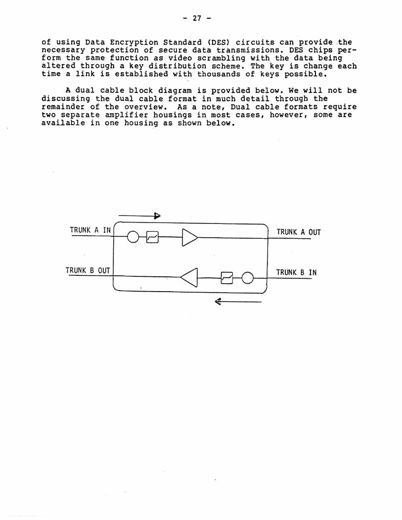
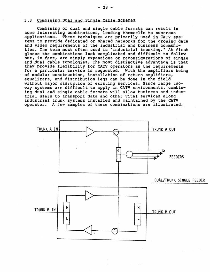
3.3 Combining Dual and Single Cable Schemes
Combining of dual and single cable format~ can result in some interesting combinations, lending themselfs to numerous applications. These techniques are primarily used in CATV systems to provide dedicated or shared networks for the growing data and video requirements of the industrial and business communities. The term most often used 'is "industr ial trunking." At first glance the combinations look complicated and difficult to follow but, in f.act, are simply expansions or reconfigurations of single and ~ual cable topologies. The most distinctive advantage is that they provide flexibility for CATV operators as the requirements for a particular service is requested. With the amplifiers being of modular construction, installation of return amplifiers, equalizers, and distribution legs can be done in the field without major disruption of existing services. Since large twoway systems are difficult to apply in CATV environments, combining dual and single cable formats will allow business and industrial users to transport data and other vital services along industrial trunk systems installed and maintained by the CATV operator. A few samples of these combinations are illustrated.
TRUNK A IN' ~ /""'\ TRUNK A 0 UT V ~
r-'-H "" f "
b.. ..
L J ~ F ." EEDERS ..
,
DUAL/TRU NK SINGLE FEEDER
1 1-T RUNK B IN H H
TRUNK B 0 UT L L
T t:?'<. V
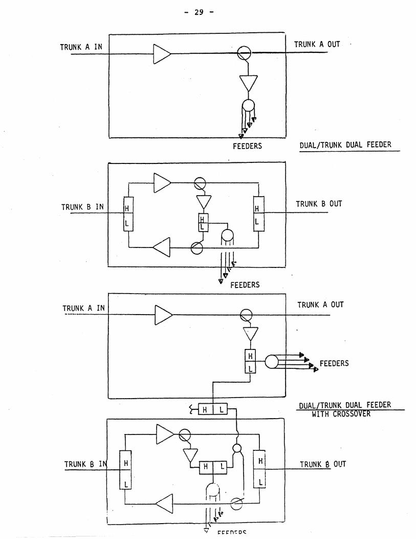
- 29 -
TRUNK A IN
FEEDERS
TRUNK B IN
" FEEDERS
TRUNK A IN
TRUNK B I
TRUNK A OUT .
DUAL/TRUNK DUAL FEEDER
TRUNK BOUT
TRUNK A OUT
-.E.E::;~ FEEDERS
DUAL/TRUNK DUAL FEEDER WITH CROSSOVER
TRUNK S OUT
- 30 -
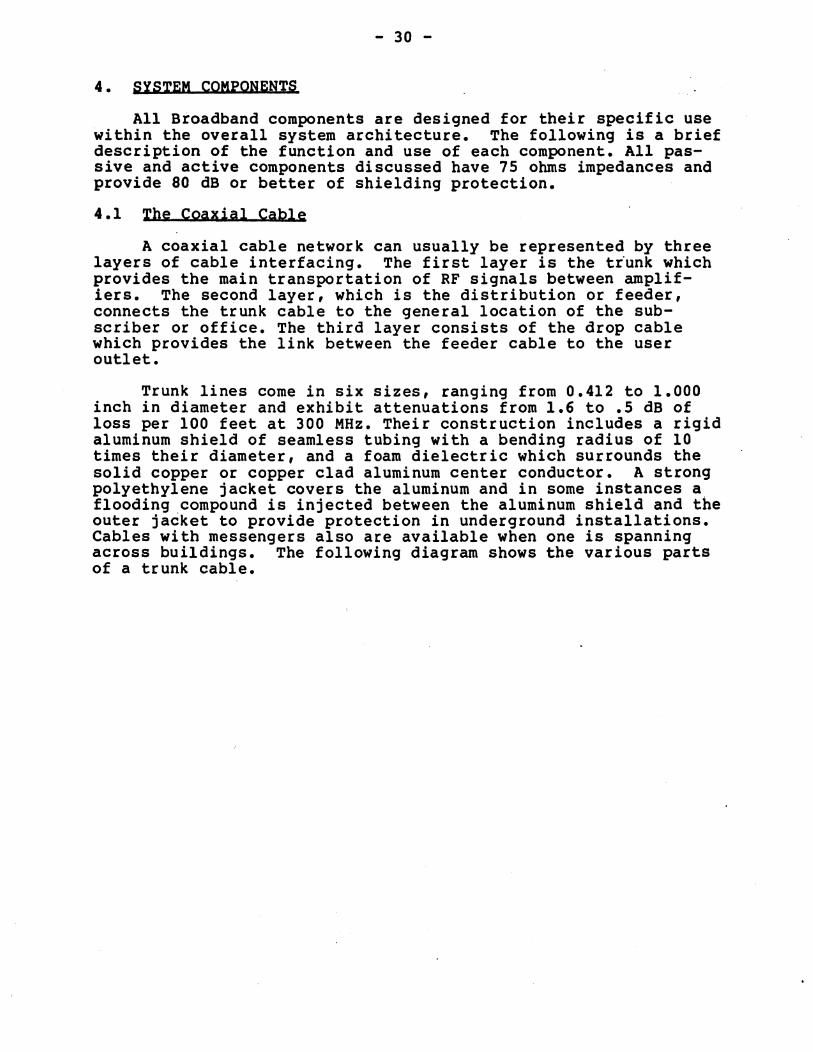
4. SYSTEM COMPONENTS
All Broadband components are designed for their specific use within the overall system architecture. The following is a brief description of the function and use of each component. All passive and active components discussed have 75 ohms impedances and provide 80 dB or better of shielding protection.
4.1 The Coaxial Cable
A coaxial cable network can usually be represented by three layers of cable interfacing. The first layer is the ttunk which provides the main transportation of RF Signals between amplifiers. The second layer, which is the distribution or feeder, connects the trunk cable to the general location of the subscriber or office. The third layer consists of the drop cable which provides the link between the feeder cable to the user outlet.
Trunk lines come in six sizes, ranging from 0.412 to 1.000 inch in diameter and exhibit attenuations from 1.6 to .5 dB of loss per 100 feet at 300 MHz. Their construction includes a rigid aluminum shield of seamless tubing with a bending radius of 10 times their diameter, and a foam dielectric which surrounds the solid copper or copper clad aluminum center conductor. A strong polyethylene jacket covers the aluminum and in some instances a flooding ,compound is injected between the aluminum shield and the outer jacket to provide protection in underground installations. Cables with messengers also are available when one is spanning across buildings. The following diagram shows the various parts of a trunk cable.
- 31 -
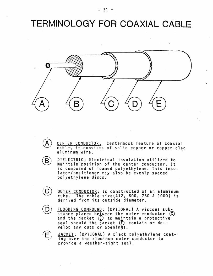
TERMINOLOGY FOR CO'AXIAL CABLE
®
CENTER CONDUCTOR; Centermost feature of coaxial cable~ it .consists of solid copper or copper clad aluminum wire.
DIELECTRIC; Electrical insulation utilized to maintain.position of the center conductor. It is composed of foamed polyethylene. This insulator/positioner may also be evenly spaced polyethylene discs.
OUTER CONDUCTOR; Is constructed of an aluminum tube. The cable size(412, 500, 750 & 1000) is derived from its outside diameter.
FLOODING COMPOUND; (OPTIONAL) A viscous substance placed be~ween the outer conductor ~ and the jacket CO to majptain a protective seal should the jacket ~ contain or de-' velop any cuts or openings.
JACKET; (OPTIONAL) A black polyethylene coat-· ing over the aluminum outer conductor to provide a weather-tight seal.
- 32 -
Generally, all trunk lines should. be .500 diameter or larger. Cables which run outside of buildings, or are mounted to poles, are usually jacketed. Cables that are in conduits, or are directly buried, should be "flooded" type cables, with corrosion-resistant gell between the outer jacket and the aluminum shield. The gell protects the aluminum from corrosion if the jacket is cut or damaged. Armored cable with flooding gell is mandatory in direct buried situations or in underground vaults where the cable can be subjected to water or rodents. If spanning of the cable on poles is dictated then the use of "messengered" type cable will provide protection and will eliminate the need of strand lines.
The distribution, or feeder cable, usually consists of the smaller sized trunk cables. Indoor applications require the selection of the feeder cable to be based on two factors. First the physical constraints of the building. Second is the amount of signal level required to provide adequate signal distribution to all users of the network. In addition, the Local and National Building Codes must be considered. High gain distribution amplifiers can be used in those situations where multiple high level feeder legs are required for several floors within a building.
Multi-Port-Taps are placed along the feeder cables to provide the connection to the user outlet, or to provide for strings of single-port-taps which loop from office to office. Since each RF network is a custom design, each situation and building must be analyzed on a one for one basis. It is suggested that the design of any network be done by a qualified CATV or Broadband engineer. It is interesting to note, if one was to take a set of system requirements to four engineers, all four layouts would be different in topology layouts in one form or another! One may think this represents a problem but, in fact, it demonstrates-the dynamic flexibility of the Broadband technique and the wide range of equipment that is available.
Drop cables range from RG-ll, RG-6 to RG-59. Each type incorporates a foil and braid shield to minimize radiation leakage. The outer jacket is made of PVC material and can be purchased in many forms. Even the least costly cable can have characteristics of 80 db shielding effectiveness, and can exhibit low loss through 400 MHz. Where fire codes prohibit PVC coated cables in celing plenums or computer floors, the owner can chose between using conduit or use cables with a Teflon jacket. It should be noted, the Teflon cable is very difficult to work with and does exhibit higher attenuation factors than do the PVC types. The cost per 1000 feet in also higher which makes the selection of its use to be based on cost and not performance. ( Quotes range from $500/1000' to $1000/1000') It is considered standard to figure conduit installation including materials to be around $1 per foot. With this in mind, and the fact that the Teflon will cause a higher labor figure, demonstrates why most
- 33 -
installations are of the conduit variety. The conduit provides. additional benefits such as: physical protection of the cable, and additional shielding characteristics. During construction, buildings can be piped with conduit for office distribution, with the conduits routing throughout the complex as needed. Terminal cans large enough to allow mounting of passive components and amplifiers should be installed. Each terminal can should be located so as to provide access during alignment and maintenance.
Length of the drops usually ranges between 10 to 150 feet and can be installed above ceilings and through walls. The end of each drop can connect directly to a user device such as: a TV, modulator, demodulator, or data modem. In some situations, the drop is provided to each office at a wall outlet. The wall outlet can simply be a female to female adapter mounted on a single gang plate or a self-terminating outlet which allows automatic termination when a user disconnects from the network. In addition, the outlet can be constructed of a directional coupler which only has one tap. This allows offices to be wired through a looping coaxial cable, with the tap used to service the user and the through portions being used to interconnect to adjacent office taps.
Since the airways are full of, in most cases, undesired signals, always use the best quality and best shielded coaxial cable for the drops. Also insure that the unused outlets are terminated by manual insertion of a 75 ohm terminator or by using those types of outlets that self-terminate themselfs. By using these procautions, you can limit the amount of return signal engress of undesired signals.
Handling of each layer of cabling does require special precautions to minimize damage to the structure of the cable. Even during transportation care should be taken not to damage the cable. It is recommended that the cable be left uncut and fastened securely until ready to be. installed. During the installation phase care should be ex~rsized so that the dable is not kinked or bent beyound the specified limits.
In overhead installations several factors such as sag, payoff, roller blocks, reel braking, lashing, loops, and clamping should be studied. It is suggested to obtain the Times/Wire article on "Trunk Cable Installation Tips" by Rex Porter. This article is easy to read yet highly informative on handling techniques. A copy can be abtained by calling the Times/Wire Cable Company. A telephone number has been included at the end of this report. The type of coaxial cable one will use is based on three factors. They are: the Physical constraints of the building, the Environmental conditions the cable will be subjected to and the Building Codes of the State and Local authorities. As a general rule, the jacketed or un-jacketed aluminum cable is used whenever possible for trunks and feeders, with the flexible RG type coaxial cables used for the drops. I perfer the .500 size for the trunk and feeders, and the RG-6 for the drops. In addition, I
- 34 -
obtain the highest quality and best shielded cable. The cost difference is small, but the operational gains are high.
4.2 Amplifiers
It should be obvious by now that no system can withstand the variations that are characteristic of the coaxial cable. As a result, all system designs are based upon the operation~l characteristics of the amplifiers. Many makes and models of amplifiers are available for CATV as well as Broadband applications. In fact, the plethora of equipment sometimes complicates the evaluation and selection process for the design engineer. Ge~era~ly, . two factors may be considered when evaluating an amplifier; 1) performance, and 2) cost. Performance is defined as the gain, output level ratings, noise figure and distortion characteristics the amplifier will deliver. The cost of an amplifier relates directly to the quality of performance, i.e., amplifiers having low noise figures and distortion are generally more costly. In addition, amplifiers have operational characteristics that are opposite of the characteristics of the coaxial cable that proceeds it. As a result, amplifier gains are usually 20 to 25dB and have "equalizer boards" which can compensate for different lengths of cable spans.
Each amplifier is constructed of a modular format so that it can be" configured to satisfy a wide variety of cable attenuation, tilt and temperature ranges. This allows a design engineer to pick the appropriate modules to meet individual system requirements. Furthermore, the amplifiers are available in two formats: those with Automatic Gain Control (AGC) and those with Manual Gain Control (MGC). The AGC function will maintain a relatively constant output with variations arriving at the input of plus or minus 6 dB. If used properly, AGC can provide constant signal levels to all user outlets in installations that have varying environmental atmospheres. (MGC) Amplifiers compensate for thermal variations only and are used extensively in Broadband applications. Primarily to the limited number of trunk cascades usually associated with shorter distance, high level distribution atmospheres. In addition, the cost is less per unit compared to AGC units. Furthermore, the controlled environmental conditions that the amplifiers and coaxial cable are subjected to, are less extreme than outdoor CATV networks.
One inportant note on MGC units. The thermal compensation will be effective only if the cable is subjected to the same temperature environment as the amplifier. This will not become a problem unless the amplifier is installed in a pedestal and the cable is underground. In this situation, the cable will not have the high temperature changes that the amlifier will be sujected to in the pedistal. To eliminated any possible over-compensation, it is suggested to remove the thermal circuit from the amplifier. In most cases, this requires no special tools or training.
- 35 ...
One must be careful when looking at the gain specificaticin of an amplifier. The term I like to use, to describe the gain of an amplifier, is neffective gain.- This represents the actual amount of gain one can operate at. Similar to system design one must insert and calculate all the modules that will be required to operate in bi-directional modes. Since each trunk filter and equalizer have an insertion loss, then that passive loss associated with each unit must be subtracted from gain of the .amplifier. Generally, 1 to 3 dB of loss can be experienced depending on the transmission configuration of the amplifier.
The following sections describe each type of amplifier and their functions as it relates to system operation~
4.2.1 Trunk Amplifiers: Trunk Amplifiers are high quality low distortion active units capable of being cascaded several times to provide communications over a large geographic area. T.runk Amplifiers typically are operated at 22 dB gain; with inputs usually of 8 to 10 dBmV and outputs of 32 to 35 dBmV for 35 channel operation. As fewer channels are carried, level outputs can increase in ranges up to +44 dBmV. When increasing the output of any amplifier above the suggested operating levels, always consult the manufacturer for advice.
As a note, the reference to 35 channels is, at times, confusing when discussing two-way operation. For example; a midsplit system operating at 300 MHz has 21 channels in the forward direction and 17 channels in the return direction assuming 6 MHz bandwidth for each channel assignment. If the above example was increased to 400 MHz,then only the forward path would be affective by the addition of 16 more channels.
Systems of 25 or more trunk amplifiers in cascade are commonly employed in large CATV networks. Trunk amplifiers are also available with bridging amplifiers which can be installed into the same housing as the trunk amplifier. Outputs associated with the bridger amplifier are usually +47 dBmV at the highest operational frequency.
A bridger derives its input from the tap of a directional coupler whose input is connected to the output stage of the trunk amplifier. Outputs available range f~om one to four for multidistribution topologies. The main use,lof the bridger is to provide high distribution levels associated with the feeder lines. Subscriber multi-taps are installed along each feeder and provide the required signal to the home. This same approach can be used in Broadband applications where a trunk line is constructed to feed several buildings and the bridger or feeder legs are used to provide signal distribution within each building. With this type of approach the trunk line signals can be adjusted to CATV standards allowing multiple cascades and future expansion.
- 36 -
Both the trunk and bridger compon~nts can be used for .. midsplit and subsplit formats by insertion of wdiplex filters·. Furthermore, the amplifier can be fitted for two-way operation by insertion of a return amplifier module. Return amplifiers usually have less gain (19 to 23 dB) as cable attenuation encountered at the lower inbound frequencies are less.
Selectable equalizers, that compensate for the cable 'tilt, can be installed into each housing. Since cable lengths may ~ary between amplifiers, equalizers are designed to compensate for each situation and are of modular construction. Convenient test points are provided both for the input and output sections of the amplifier. The input test point is installed prior to the input filter, pad and equalizer modules. In turn, an output test point is installed after the amplifier, directional coupler and filter sections. One must be aware that the terms ninput and output n pertain to the forward path only. The input and output terminology reverses when one is referring to the return path.
At this point it should be noted, the use of feeder disconnect functions associated with bridgers can be most useful in fault isolation or to shutting down a feeder that is injecting untolerable signals or noise. The control for the feeders originates from the headend and is normally associated with status monitoring systems and intelligent amplifiers. Feeder disconnect can also be incorporated, however, into standard amplifiers through plug-in modules. Each module can be selected as to which state it will operate at such as: on, remote, or off. The on and off states are manual and turn on or off the feeders during alignment or maintenance. The remote position allows a TTL compatible logic signal to control the switch function remotely.
An example of signal levels for the trunk and trunk/bridger amplifier is illustrated below as well as the block representation of the modular format •. It should be noted, the designer will normally select the levels in which the amplifier will operate at. For the installation crew, those levels given by the designer should be carefully followed. Return levels, if not given on the drawings, are equal to the forward trunk out, or slightly greater.
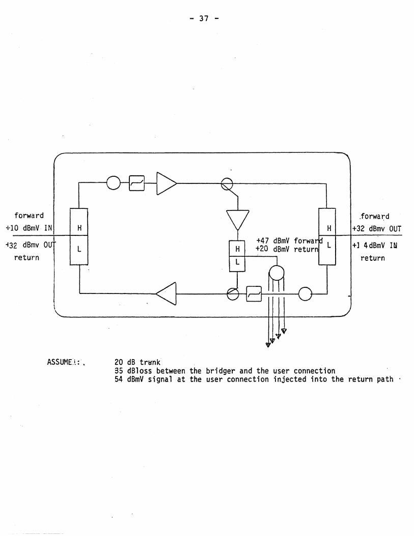
- 37 -
forward .forwar:-d +10 dBmV· IN H H +32 dBmv OUT
;32 dBmv 0 +47 dBmV forwa L +1 4dBmV Itl L +20 dBmV return
return return
20 dB trHn~ , 35 dBloss between the bridger and the user connection 54 dBmV signal at the user connection injected into the return path .
- 38 -
4.2.2 Line. Extender Amplifiers: Line. extender amplifiers are. used 'when the signal provided by the Bridger Amplifier is insufficient to drive receiving interconnecting devices. These amplifiers are lower in cost but have higher distortion arid no~se figures, thus, limiting their maximum cascade to three. Some smaller two-way networks use line extenders as their only amplifying device. Characteristics of such systems are: cascades of less than three, high penetration of office outlets and. limited geographical coverage. It also should be noted, line extenders are available only in sub-split formats for two-way applications. Midsplit formats are being developed by two manufacturers and should be available by in mid 1982. .
4.2.3, Internal Distribution Amplifiers: Internal Distribution Amplifiers are high gain units used for signal distribution with~n a building. Multiple cascading is not recommended since the higher gain they provide limits their maximum cascade. The most use~ul advantage of such amplifiers is the fact that they have built in 110 volt power supplies and thus, do not require AC power to be transmitted over the cable. Currently these amplifiers can only be used in subsplit two-way applications, but midsplit versions are being developed.
4.3 Power Supplies
W'ith the exception of the internal distr ibution amplif ier, all amplifiers require 30 or 60 volts AC power. Distributing the power over the coaxial cable eliminates the requirement for 110 volt outlets at each amplifier location. As a result, the amplifier~ can be located at any point in the.network or buildin9 complex. ,
30 volt systems are primarily found in older existing systems. In contrast, 60 volt systems are widely used in todays· two-way communications networks. The power is coupled to the coaxial cable through the use of power combiners. 'Power combiners permit the injection of power in either or both directions with minimal effect on the radio frequency signals.
Each amplifier has directional control of the AC power for use as the system topology dictates. Power can be passed on to other amplifiers or stopped at either the input or the output of each unit. For safety reasons, the AC is isolated from· the user outlet through the use of the Multi-Tap. As a result, each user is electrically isolated from the main network, and other users, reducing the possibility of total system failure from accidental or malicious causes. Care must be taken not to inject AC power through multitaps or couplers not capable of passing power. Typically, units unable to pass power have "F" type fitting interfaces. Although not prohibited, passing of AC power down cables other than of the seamless aluminum type should not be considered.
- 39 -
Grounding of the system at every amplifier will insure long reliable service. But if the grounding deteriorates then amplifier damage may occur due to high shield current developed from the electrical systems neutral. Once each year all ground points should be checked as well as ground readings taken to insure system integrity. To investigate into grounding aspects one should read "Grounding Principles" by the Copperweld Steel Company.
General rule-of-thumb has been one power supply will run 3 amplifiers in either direction adequately. Large networks, however., require careful calculations dealing with current drops, voltage levels and loop resistances. Each manufacturer will give in the cable specification the DC loop resistances that pertain to that cable. Power draw then be calculated through the use of Ohms Law. In addition, each amplifie~ specification will indicate the required voltage of operation so one can calculate and determine if additional power supplies are required. Power supplies can be installed at any point in the network and the direction of the power is controllable at each amplifier. As one calcUlates power requirements it becomes apparent that the amplifiers are voltage dependent not current dependent •. Furthermore, . one should take into account the current passing capabilities of each device to insure that their specifications are not exceeded.
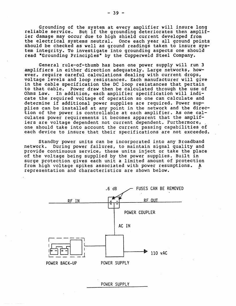
Standby power units can be incorporated into any Broadband network. During power failures, to maintain signal quality and provide continuous service, these units inject or take the place of the voltage being supplied by the power supplies. Built in surge protection gives each unit a limited amount of protection from high voltage spikes· associated with power resumptions. A representation and characteristics are shown below. -
.6 dB FUSES CAN BE REMOVED
RF IN
POWER COUPLER
AC IN
~jEf -rl....-....,...---1 L:: _ _ _ _ j '"-_--' 110 vAC
POWER BACK-UP POWER SUPPLY
pm/ER SUPPL ¥
- 40 -
4.4 Directional Couplers
In addition to the cable itself, special devices are used to get signals into and off the cable with the minimum amount of mismatch. Many of these devices operate on the principle of the directional coupler.
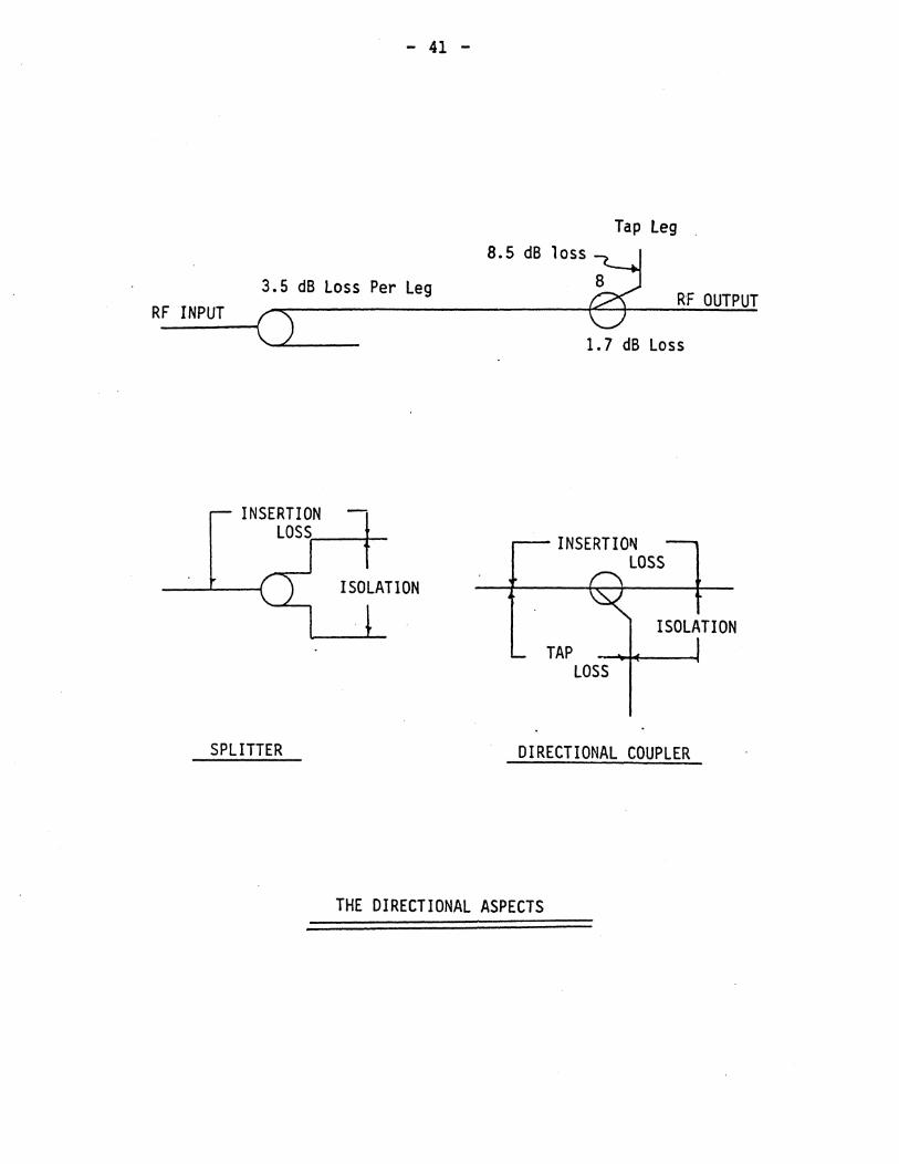
The Directional Coupler provides a means for divid~ng or combining inputs and outputs of RF signals while maintaining the 75 ohm system impedance and isolation characteristics. Each Directional Coupler p~ovides for a fractional portion of the signal to be tapped off to a network branch or outlet, whfle providing low insertion loss between the input and output trunk connections. This Directional Characteristic ensures that signals being transmitted from any network device will only be transmitted towards the headend, thus, minimizing the reflection of RF energy.
There are four parameters used to describe the performance of a Directional Coupler: Insertion loss, Tap loss, Isolation and Directivity. These, and the relationships between then, are illustrated below and are usually expressed in decibels (dB). In Broadband applications, high Isolation alone is not the important parameter. The Directivity, which is the difference between the Isolation and the Tap loss, is the significant parameter. All coaxiai devices used to combine or split signals operate on the principle of the directional coupler. During installation care should be given not to install the directional coupler backwards, as this would cause signals to be directed in the wrong direction, resulting in operational problems with that individual device. Directional arrows indicating signal flow are stamped on all devices.
- 41 -
3.5 dB loss Per leg RF INPUT
ISOLATION
Tap leg
RF OUTPUT
1. 7 dB Loss
TAP LOSS
ISOLATION
SPLITTER DIRECTIONAL COUPLER
THE DIRECTIONAL ASPECTS
- 42 -
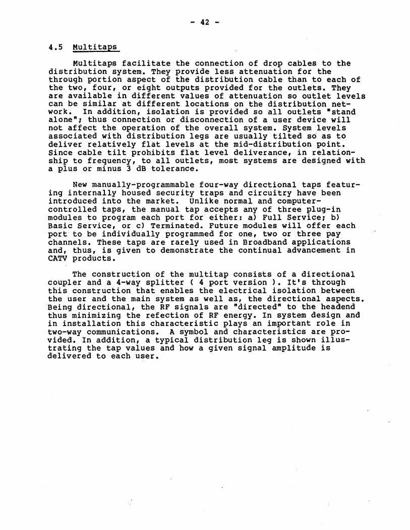
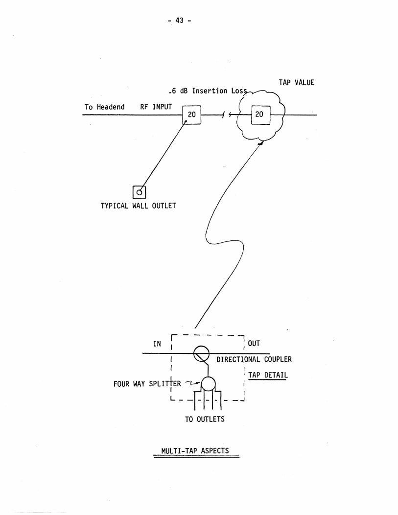
4.5 Multitaps
Multitaps facilitate the connection of drop cables to the distribution system. They provide less attenuation for the through portion aspect of the distribution cable than to each of the two, four, or eight outputs provided for the outlets. They are available in different values of attenuation so outlet levels can be similar at different locations on the distribution network. In addition, isolation is provided so all outlets ·stand alone"; thus connection or disconnection of a user device will not affect the operation of the overall system. System levels associated with distribution legs are usually tilted so as to deliver relatively flat levels at the mid-distribution point. Since cable tilt prohibits flat level deliverance, in relationship to frequency, to all outlets, most systems are designed with a plus or minus 3 dB tolerance.
New manually-programmable four-way directional taps featuring internally housed security traps and circuitry have been introduced into the market. Unlike normal and computercontrolled taps, the manual tap accepts any of three plug-in modules to program each port for either: a) Full Service; b) Basic Service, or c) Terminated. Future modules will offer each port to be individually programmed for one, two or three pay channels. These taps are rarely used in Broadband applications and, thus, is given to demonstrate the continual advancement in CATV products.
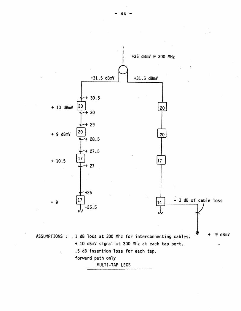
The construction of the multitap consists of a directional coupler and a 4-way splitter ( 4 port version ). It's through this construction that enables the electrical isolation between the user and the main system as well as, the directional aspects. Being directional, the RF signals are "directed" to the headend thus minimizing the refection of RF energy. In system design and in installation this characteristic plays an important role in two-way communications. A sYmbol and characteristics are provided. In addition, a typical distribution leg is shown illustrating the tap values and how a given signal amplitude is delivered to each user.
- 43 -
TAP VALUE
To Headend RF INPUT
TYPICAL WALL OUTLET
IN r ----, , OUT
FOUR WAY SPLITtER ~
DIRECTIIONAL COUPLER
I TAP DETAIL
I L ____ _
I I
- --I
TO OUTLETS
MULTI-TAP ASPECTS
- 44 -
+35 dBmV @ 300 MHz
+31.5 dBmV +31.5 dBmV
+ 10 dBmV
+ 9 dBmV
+ 10.5
+ 9
ASSUMPTIONS
- 3 dB of cable loss
. 1 dB loss at 300 Mhz for interconnecting cables. + 10 dBmV signal at 300 Mhz at each tap port • • 5 dB insertion loss for each tap. forward path only
MULTI-TAP LEGS
+ 9 dBmV
- 45 -
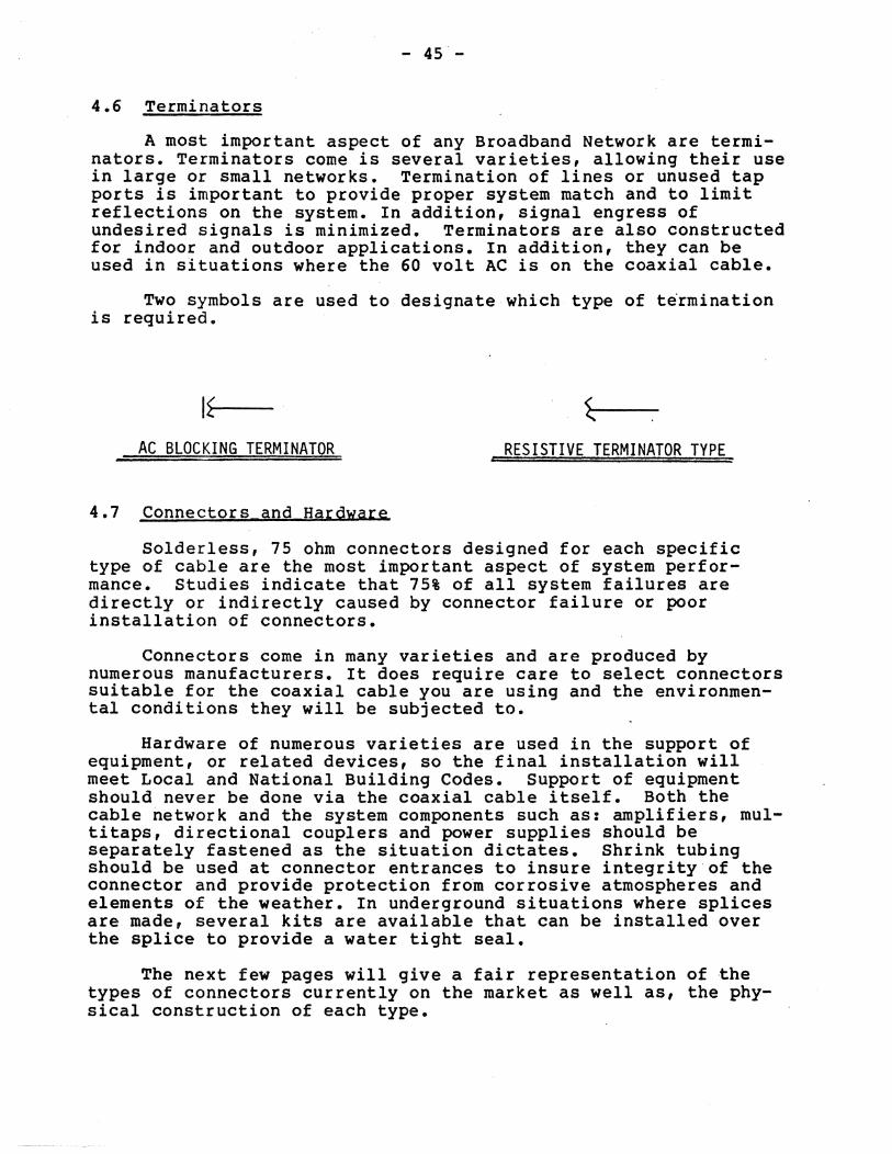
4.6 Terminators
A most important aspect of any Broadband Network are terminators. Terminators corne is several varieties, allowing their use in large or small networks. Termination of lines or unused tap ports is important to provide proper system match and to limit reflections on the system. In addition, signal engress of undesired signals is minimized. Terminators are also constructed for indoor and outdoor applications. In addition, they can be used in situations where the 60 volt AC is on the coaxial cable.
Two symbols are used to designate which type of t~rmination is required.
I~>---
AC BLOCKING TERMINATOR RESISTIVE TERMINATOR TYPE
4.1 Connectors and Hardware
Solderless, 75 ohm connectors designed for each specific type of cable are the most important aspect of system performance. Studies indicate that 75% of all system failures are directly or indirectly caused by connector failure or poor installation of connectors.
Connectors corne in many varieties and are produced by numerous manufacturers. It does require care to select connectors suitable for the coaxial cable you are using and the environmental conditions they will be subjected to.
Hardware of numerous varieties are used in the support of equipment, or related devices, so the final installation will meet Local and National Building Codes. Support of equipment should never be done via the coaxial cable itself. Both the cable network and the system components such as: amplifiers, multitaps, directional couplers and power supplies should be separately fastened as the situation dictates. Shrink tubing should be used at connector entrances to insure integrity of the connector and provide protection from corrosive atmospheres and elements of the weather. In underground situations where splices are made, several kits are available that can be installed over the splice to provide a water tight seal.
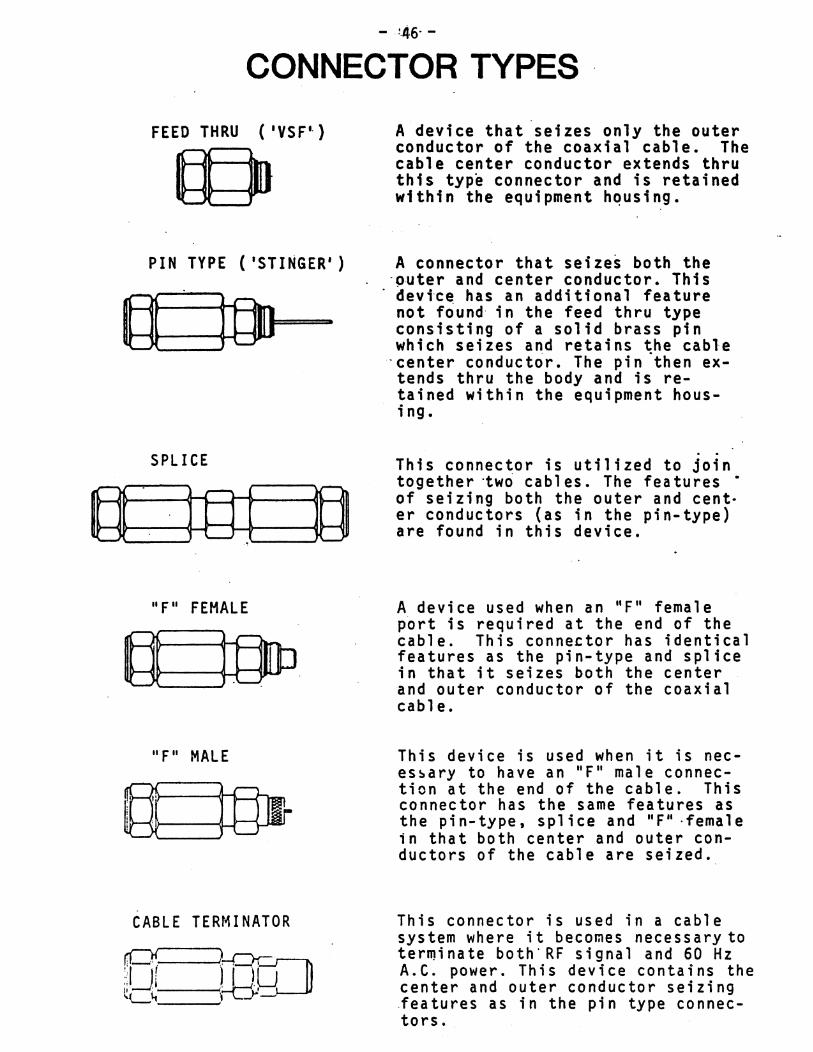
The next few pages will give a fair representation of the types of connectors currently on the market as well as, the physical construction of each type.
CONNECTOR TYPES
FEED THRU ('VSF L )
© PIN TYPE ('STINGER')
SPLICE
"F" FEMALE
"F" MALE
CABLE TERMINATOR
A device that seizes only the outer conductor of the coaxial cable. The cable center conductor extends thru this type connector and is retained within the equipment hQusing.
A connector that seizes both the . ()·uter a nd center conductor. Thi s devtce has an additional feature not friund in the feed thru type consisting of a solid brass pin which seizes and retains the cable
'center conductrir. The pin "then extends thru the body and is retained within the equipment hous; ng.
This connector is utilized to join together -two cabl es. The features • of seizing both the outer and cent· er conductors (as in the pin-type) are found in this device.
A device used when an "F" female port is required at the end of the cable. This connector has identical features as the pin-type and splice in that it seizes both the center and outer conductor of the coaxial cable.
This device is used when it is neces~ary to have an "F" male connection at the end of the cable. This connector has the same features as the pin-type, splice and "F" -female in that both center and outer conductors of the cable are seized.
This connector is used in a cable system where it becomes necessary to terminate both-RF signal and 60 Hz A.C. power. This device contains the center and outer conductor seizing .features as in the pin type connectors.
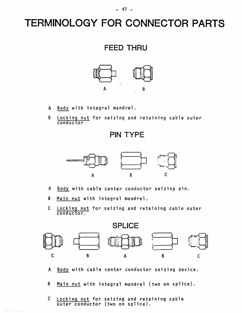
- -47-
TERMINOLOGY FOR CONNECTOR PARTS
FEED THRU
A B
A Bodv with integral mandrel. ----B locking nut for seizing and retaining cable outer
conductor
PIN TYPE
. . .. f I rF""bj ·• • ..,;. • ..,i I:
A B c
A Bod y wi t h cab 1 e c e n t e r con d u c tor s e; z ; n.9 pin.
BMain nut with integral mandrel.
C locking nut for seizing and retaining cable outer conductor.
SPLICE
@] g or§D 5 (~§ lJU .1 r J ' -. .J, .
? I '-.u.:"-{
C B A B C
A Body with cable center conductor seizing device.
B Main nut with integral mandrel (two on splice).
C locking nut for seizing and retaining cable outer conductor (two on splice).
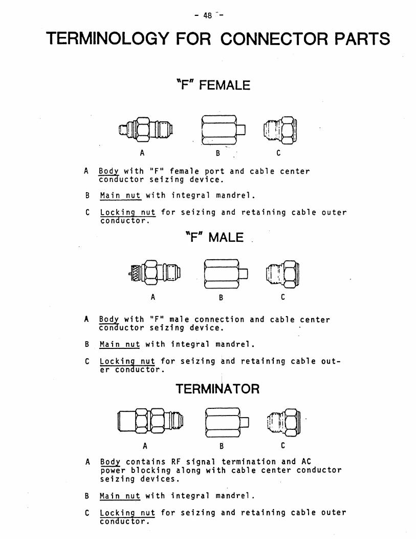
- 48 --
TERMINOLOGY FOR CONNECTOR PARTS
~ ~JJlj}1
A
"Fn FEMALE
B C
A .!!..Q..Q.y with "F" female port and cable center conauctor seizing device.
B Main nut with integral mandrel.
C Locking nut for seizing and retaining cable outer conductor.
"Fn MALE.
A B C
A BOda with "F" male connection and cable center con uctor seizing device.
B Main nut with integ~a' m~ndre'.
Lockin9 nut for seizing and retaining er con uctor. ,
C cable out-
TERMINATOR
C
A Body contains RF signal termination and AC power blocking along with cable center conductor seizing devices.
B Main nut with integral mandrel.
C Locking nut for seizing and retaining cable outer conductor.
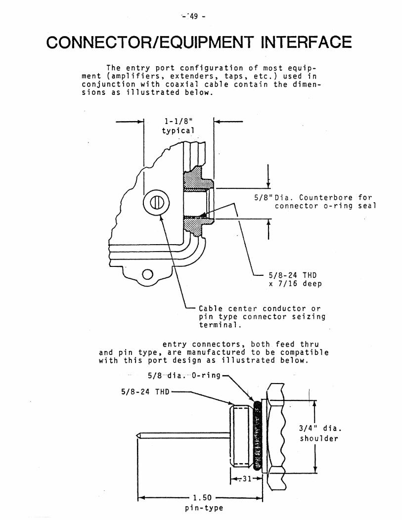
--' 49 -
CONNECTOR/EQUIPMENT INTERFACE The entry port configuration of most equip
ment (amplifiers, extenders, taps, etc.) used in conjunction with coaxial cable contain the dimensions as illustrated below.
1-1/8" typi cal
5/8" Di a. Counterbore for connector a-ring seal
5/8-24 THD x 7/16 deep
Cable center conductor or pin type connector seizing terminal.
entry connectors, both feed thru and pin type, are manufactured to be compatible with this port design as illustrated below.
5/8 --d i a. -- 0 - r i n 9
5/8-24 THD--"",-
... ---- 1. 50 -----.0411oo.f
pin-type
3/4" dia. shoulder
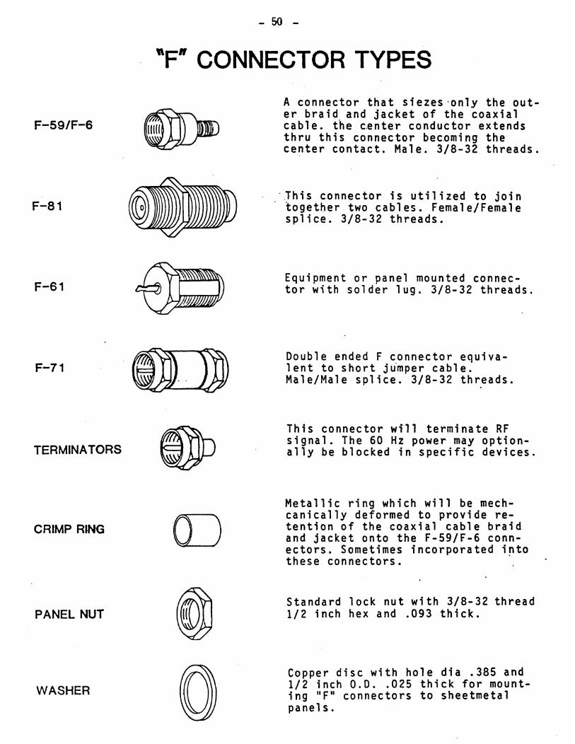
F-59/F-6
F-81
F-61
F-71
TERMINA TORS
CRIMP RING
PANEL NUT
WASHER
- 50 -
"F" CONNECTOR TYPES
o
A connector that siezes 'only the outer braid and jacket of the coaxial cable. the c~nter conductor extends thru this connector becDming the center contact. Male. 3/8-32 threads.
·~his connector is utilized to join together two cables. Female/Female splice. 3/8-32 threads.
Equipment or panel mounted connector with solder lug. 3/8-32 threads.
Double ended F connector equivalent to short j~mper cable. Male/Male splice. 3/8-32 threads.
This connector wfll terminate RF signal. The 60 Hz power may optionally be blocked in specific devices.
Metallic ring which will be mechcanically deformed to provide retention of the coaxial cable braid and jacket onto the F-59/F-6 connectors. Sometimes incorporated into these connectors. .
Standard lock nut with 3/8-32 thread 1/2 inch hex and .093 thick.
Copper disc with hole dia .385 and 1/2 inch 0.0 .. 025 thick for mounting "F" connectors to sheetmetal panels.
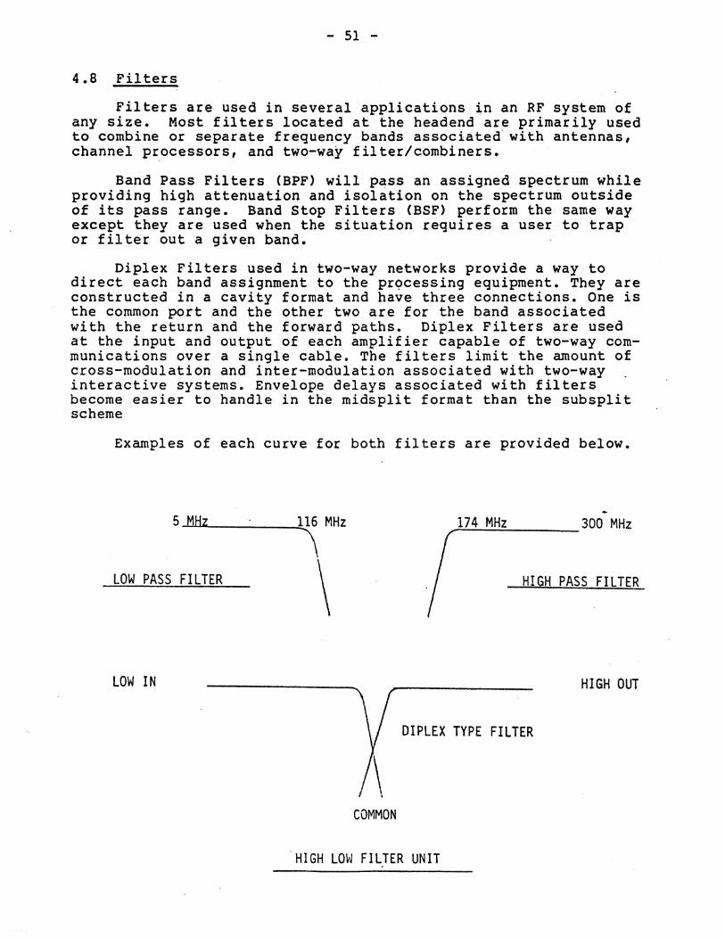
- 51 -
4.8 Filters
Filters are used in several applications ~n an RF system of any size. Most filters located at the headend are primarily used to combine or separate frequency bands associated' with antennas, channel processors, and two-way filter/combiners.
Band Pass Filters (BPF) will p~ss an assigned spectrum while providing high attenuation and isolation on the spectrum outside of its pass range. Band stop Filters (BSF) perform the same way except they are used when the situation requires a user to trap or filter out a given band.
Diplex Filters used in two-way networks provide a way to direct each band assignment to the prQcessing equipment. They are constructed in a cavity format and have three connections. One is the common port and the other two are for the band associated with the return and the forward paths. Diplex Filters are used at the input and output of each amplifier capable of two-way communications over a single cable. The filters limit the amount of cross-modulation and inter-modulation associated with two-way interactive systems. Envelope delays associated with filters become easier to handle in the midsplit format than the subsplit scheme
Examples of each curve for both filters are provided below.
5M~ 116 MHz
\ 174 MHz 300 MHz
LOW PASS FILTER \ HIGH PASS FILTER
LOW IN HIGH OUT
DIPLEX TYPE FILTER
COMMON
'HIGH LOW FILTER UNIT
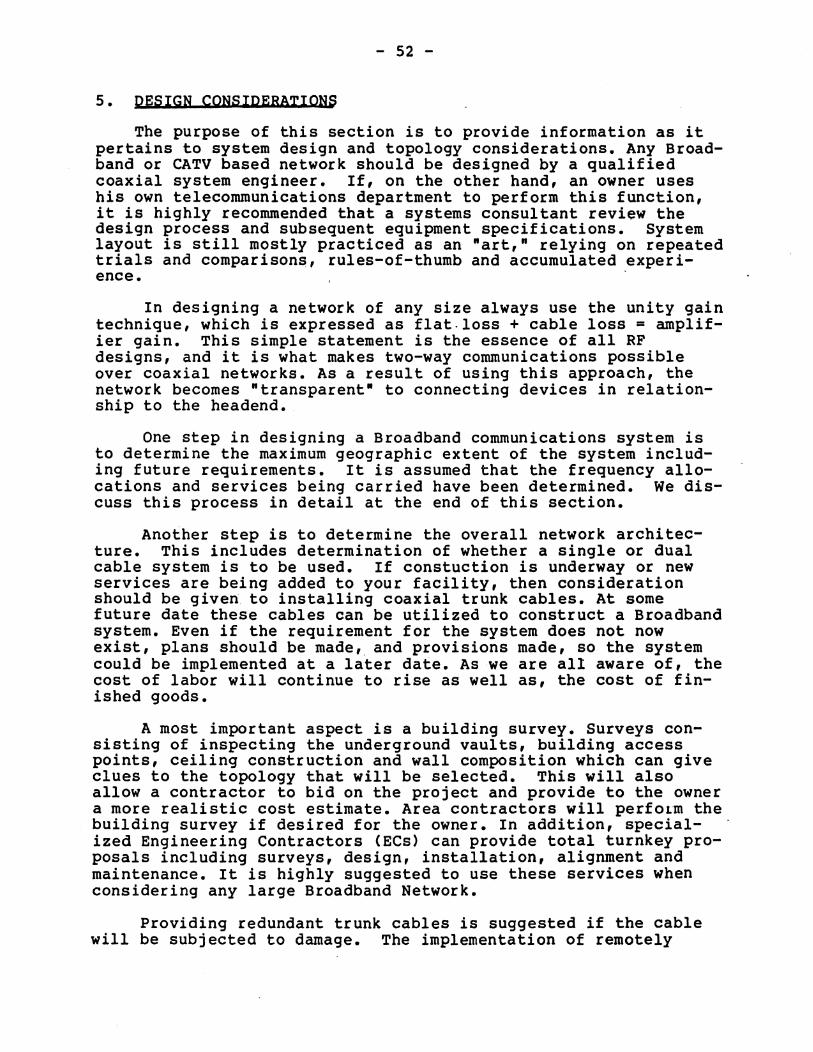
- 52 -
5. DESIGN CONSIDERATIQRS
The purpose of this section is to provide information as it pertains to system design and topology considerations. Any Broadband or CATV based network should be designed by a qualified coaxial system engineer. If, on the other hand, an owner uses his own telecommunications department to perform this function, it is highly recommended that a systems consultant review the design process and subsequent equipment specifications. System layout is still mostly practiced as an "art," relying on repeated trials and comparisons, rules-of-thumb and accumulated experi-ence. .
In designing a network of any size always use the unity gain technique, which is expressed as flat. loss + cable loss = amplifier gain. This simple statement is the essence of all RF designs, and it is what makes two-way communications possible over coaxial networks. As a result of using this approach, the network becomes "transparent" to connecting devices in relationship to the headend.
One step in designing a Broadband communications system is to determine the maximum geographic extent of the system including future requirements. It is assumed that the frequency allocations and services being carried have been determined. We discuss this process in detail at the end of this section.
Another step is to determine the overall network architecture. This includes determination of whether a single or dual cable system is to be used. If constuction is underway or new services are being added to your facility, then consideration should be given to installing coaxial trunk cables. At some future date these cables can be utilized to construct a Broadband system. Even if the requirement for the system does not now exist, plans should be made, and provisions made, so the system could be implemented at a later date. As we are all aware of, the cost of labor will continue to rise as well as, the cost of finished goods.
A most important aspect is a building survey. Surveys consisting of inspecting the underground vaults, building access points, ceiling construction and wall composition which can give clues to the topology that will be selected. This will also allow a contractor to bid on the project and provide to the owner a more realistic cost estimate. Area contractors will perfoLm the building survey if desired for the owner. In addition, specialized Engineering Contractors (ECs) can provide total turnkey proposals including surveys, design, installation, alignment and maintenance. It is highly suggested to use these services when considering any large Broadband Network.
Providing redundant trunk cables is suggested if the cable will be subjected to damage. The implementation of remotely
- 53 -
controlled coaxial switches can allow damaged sections to be bypassed at any time. The reliability of the broadband system both in system layout and in system componenets makes the use of redundancy a secondary issue and should be only considered if the information being transmitted can not have interuption of services for more than one working day.
The system headend should be centrally located within the system if possible. Adequate space should be provided f"or Signal Processing Equipment, Data Translators and Test Equipment that may be required. If Television transmission is part of the network there should be a plan in routing of antenna ~abling and location of antennas. The location and alignment of antennas can be most difficult and dangerous to installing personnel. Safety comes first prior to concerns over how they may look on top of the building. In addition, the location as to operational characteristics should be the second concern to insure top performance.
In a multiple building system the coaxial trunks should never loop through one building to another, instead the trunk runs along side each complex and through directional coupling portions of the trunk signal are directed to each building for internal distribution. This allows independent operation and in cases of building damage due to fire, etc., the overall network operation will not be affected.
Internal distribution within a building, whether multiple story or not, should be designed for independent quadrants. Thus, any user on any floor in any quadrant can function independently of any network failure in other quadrants.
5.1 Network_Architecture
Most commercial and industrial Broadband systems today are of the "tree" architecture. It is the most feasible system when all information transmitted by the system is to be.accessed within any point in the system.
A tree structure readily accommodates virtually all coaxial cable based systems and does not require switching to establish connectivity between any subset of subscriber users.
Interfacing multiple "tree" systems would simply involve appropriate inter-syst~m trunks with "Gateway· devices between trunks. The use of Gateways allows a user to interface into existing CATV Bi-directional systems. The most noted situation currently using this approach in in the New York area. Manhatton Cable TV has provided a dedicated commercial trunk which is used to service the banking community in New Yorks financial district. This trunk is primarily used for passing data communications from one branch of a banking service to another. Gateways are al~o available in interfacing to other communication mediums such as: TeleNet, EtherNet and other Local Area Networks and National
- 54 -
networks. Gateways can also be selected to pass only a selected bandpass so each user on the network can be isolated from other users using the same common trunk.
In two-way networks, the layout of the return paths is more important that the forward path. Since all return amplifiers output signals eventually converge (i.e. come together) at the headend, so does all the noise contributed by them. Thu~, in the return direction, signals are subject to noise degradation by the noise build-up of all the return amplifiers. The forward path, in contrast, only has noise build-up of those amplifier in cascade to one another. In addition, the returning signals at the input to the headend or any amplifier must as equal as possible from all the legs feeding them, so equalization can be done effectivly.
For those reasons, and others, the design of the distribution legs should be equal in cable loss. It's important to note that I said cable 10ss1 The passive components can vary in values, numbers and location, but the cable lengths should be as equal as possible.
5.2 Headend Design
The headend is the point of or1g1n for all RF signals and is also the collection point for all signals being generated from the networks interconnecting devices. The headend must be able to support large and small systems as well as multiple services. The headend is the heart of the network and must be carefully con-. sidered and designed so that expansion into additional services can be done without re-calculation of levels.
It's a good rule to design the headend, and its associated components, prior to designing the remainder of the network. This approach is done so that all of the passive loss associated with combiners, splitters and directional couplers can be figured. Once that procedure is done then it's known how much signal remains for distribution throughout the network.
To protect the headend equipment from damage, install a surge protector on the incoming AC line. This, in addition to an RF filter on the incoming AC source, can protect the headend equipment from lighting surges, noise, and ground loops which can cau~e hum in the video pictures.
A typical headend layout is illustrated to show the general layout and and how the Bi-directional aspects are handled.
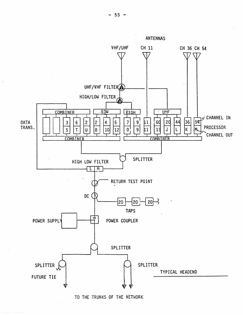
DATA TRANS.
POWER SUPPL
SPLITTER
FUTURE TIE
- 55 -
VHF/UHF
ANTENNAS
CH 11
. SPLITTER
RETURN TEST POINT
POWER COUPLER
SPLITTER
SPLITTER
CH 36 CH 54
CHANNEL IN
PROCESSOR :--...
CHANNEL OUT
TYPICAL HEADENt>
TO THE TRUNKS OF THE NETWORK
- 56 -
5.3 Outlet Distribution
Plan carefully the number and location of outlets. Allow for all potential services including Data, TV, video, control, and voice. An advantage of a coaxial cable supporting multiple communications is that a single drop can support all these services at one location. However, if multiple devices are to be connected in one office, additional Signal strength wil~ be required or multiple outlets must be provided to adequately handle all services.
Multitaps which can support up to 8 office outlets should also provide additional ports for future additions to the network as anticipated. As an example, on a system utilizing 4 port taps, I set aside one port for future and terminate it. In a large system, this gives a 25% expansion factor. If such expansions are to be done in staggered phases the use of multitaps with interchangeable circuit boards is highly recommended.
All outlets should be terminated with a 75 ohm characteristic impedance when a user device is not connected to prevent undesired reflections. This can be accomplished either by manually inserting an appropriate terminating connector, or by utilizing self-terminating outlets. The terminator's function is to convert RF energy to thermo-electric energy and to minimize reflections.
5.4 Reflections
Reflection~ or echo~ are reproductions of existing carriers on the system, and discontinuities which are caused by irregularities, such as bends in the cable, connectors, taps, and improper terminations.
When RF energy encounters such aspects, part of the signal is reflected. In systems which are properly termirtated and have high quality and properly installed equipment, most reflections are of third order. Even so, each reflection generates a smaller delayed copy of the original signal. Reflections do not become a problem until their amplitude reaches a state which will conflict or interact with the skirts or carriers of the desired signals. The use of high quality drop cables and insuring each unused port or office outlet is terminated will minimize reflection activity.
5.5 Signal Leyels
The "Dynamic Operating Range" of each user device will determine the signal requirement at each outlet. Normally, it is desired to have a video receive level of between 6 dBmV and 10 dBmV at each visual carrier, with aural levels usually 15 dBmV below visual. Data Modems require less signal-to-noise-ratios than do television signals, resulting in levels of -15 dBmV to +4 dBmV. Since data levels are of less amplitude, this lowers the
- 57 -
overall inter-modulation distortion on. the network. The same. exists for the inbound transmissions to the headend, with Video amplitude at 54 to 60 dBmV and Data at 33 to 42 dBmV respectfully. The differnce in signal levels for data depend upon the amount of bandwidth each unit accupies in a 6 MHz channel. As the bandwidth increases the signal output in higher, and just the reverse is true as the bandwidth decreases. Always check with the manufacturer to ascertain the required signal amplitude.
The output level of each piece of equipment is injected into the system via the wall outlet and are distributed back to the headend for re-transmission. Systems designed with 45 dB of forward pass loss between the headend and the receiving device allows the above mentioned levels to be used, depending on the equipment and system requirements.
The cable network should be designed such that all devices on any sUb-system (services) implemented on the cable network have the same input and output levels within 6 dB.
Amplifier signal characteristics can change dramatically depending on the number of channels and services provided. Generally, less output is available by the amplifiers as the number of channels and multi-services are increased. However, the standard operating levels of +8 dBmV to +10 dBmV of video input signal and +33 dBmV to +35 dBmV video output signal can handle 35 channel capacity with -66 dB rejection of 2nd order beats. Bridger Amplifier signals are usually higher generally around +45 dBmV to +47 dBmV of output based on the same channel capacity.
5.6 NQise Leyels
Noise considerations can be of concern in large mUlti-trunk networks. It's thus, important to know some aspects as they pertain to noise, noise contribution and thermal noise. First, large CATV networks have long trunk situations which are limited in number of cascade so they can pass FCC performance measurements. The Federal Communication Commission (FCC) regulates the airwaves as well as the CATV industry. These limitations, however, seldom affect the design stages of a Broadband network. Broadband situations are of less magnitude in size, number of users, trunk cascade, and geographical coverage. In addition, they are regulated under the section covering the Master Antenna Television System (MATV).
A fully activated Broadband system (i.e. all return paths are active) can not be duplicated in a large CATV system covering a major city. However, the industrial, educational, and business communities have seen no real limitation in Broadband applications in the CATV market place. An example of possible Broadband size, a network in operation today covers an industrial plant of over 36 million square feet of floor space for each of its two floors. It took only 11 amplifiers to support a network which
- 58 -
provides an.RF connection at an¥ point. in the system within 100 feet. Another system in the Ch1cago area will support 4000 connections to any user within 20 feet. This network also took 11 amplifiers to support 6 buildings each of which had 4 floors of distribution. If either company wished to expand to other facilities miles away, this could be accomplished by the use of existing or new industrial trunks installed and maintained by the local CATV company. Or these trunks could be installed by contractors. In addition, microwave links, satellite links, TeleNet, 'and others service mediums can provide the required links to allow nation .wide distribution of video or data ser-vices.
Now back to noise. Noise is generated by any active device and the amount of noise is a function·of bandwidth and temperature. For television ( 4 MHz bandwidth ) this noise floor is at -59 dBmV. This is the best situation one can achieve on any coaxial based network. With this in mind, each amplifier has a noise figure which is defined as the usual measure of the amount of noise that a amplifying stage contibutes to a signal passing through it. As a result, the noise figure of an amplifier is the amount of thermal noise which is contributed to the signals passing from its input to its output. The noise figure is not changeable by the user during the alignment process. Increasing the signal levels through an amplifier will change the Carrierto-Noise (C/N) ratio, but will not change amplifier noise contribution.
C/N ratio is defined as the difference between the input signal level and the noise floor. An amplifier with a noise figure of 7 dB contributes 7 dBmV to the noise floor of -59 dBmV which results in a-52 dBmV floor figure. If the signal input was 10 dBmV, the resultant C/N ratio would be 62 dB. From that point on, to calculate for C/N of a multiple trunk cascade simply use the following rule: The C/N ~atio will decrease by 3 dB every time the number of amplifiers are doubled. If one was to follow this out through a cascade of 32 amplifiers the resultant C/N ratio would be 47 dB.
5.7 Amplifier Selection
As discussed in an earlier section, amplifiers are available in two formats, AGC and MGC. The Automatic Gain Control (AGC) units compensate for varying signal strengths in the network due to temperature. In small systems there is little reason for the additional expense of using Automatic Gain Control Amplifiers. In larger systems justification for the expense is reasonable and improves the system performance dramatically.
It is not desirable for all amplifiers to have AGC gain control. If too many amplifiers in cascade contain this control then the effect of a noise spike may be detrimental to system performance. The effects could include adjacent channel problems or
- 59 -
errors in the data communications. 1.n such cases, the output . level of each amplifier would be reduced by the AGC to compensate for the high level spike. This has the effect of reducing the amplitude of the desired signals as well, to the point that the signal-to-noise ratio is severely degraded. The time constant of most AGC systems is such that a noise pulse lasting only several microseconds can cause a loss of desired signals for as much as several seconds. For this reason AGC Amplifiers are placed every third to fifth in cascade along with MGC types. This minimizes over compensation of signals while providing the necessary control of system variation.
The Control Signal for the AGC Amplifier is either one of the TV signals distributed over the cable, or a pilot carrier generated at the headend. Although rarely used AGC is possible for inbound signals through the return amplifiers. Special Blocking Filters and trunk combining considerations require careful design and component selection. Use this approach only if it suggested by the manufacturer of the Broadband equipment.
Selection on which amplifier to use depends on the application in which they will be used in. Trunk only amplifiers, fitted for midsplit applications, are used in the majority of situations. The Trunk/Bridger can be used when the distribution calls for multiple legs that are equal in cable loss. Line Extender amplifiers are used only in small networks that have limited future expansion capabilities. 1. suggest to stay away from the Line Extender until the midsplit versions become available. In the majority of systems I have looked at, the Trunk only amplifier seems to be the best overall choice for flexibility and in applications.
- 60 -
5.8 Redundancy Considerations
In the CATV and Broadband Environment the "most common cause of system failures is physical breaks in the cable introduced both by natural and man-made causes, power interruptions, processing equipment failures and user device failures. System Networks contained within buildings usually have less physical breakdowns, but possess the same electronic failure aspect as their outside counterparts.
The high quality of CATV equipment can be expressed in mean-time-between-failure (MTBF) figures. Typical life "expectancy of passive equipment properly installed can be in the area of 30 to 40 years. Since the passive components perform no active function, maintenance is not required in the terms we normally understand. Instead basic physical and signal performance checks should be done once a year. The MTBF of the active amplifier is surprisingly around 18 years, giving the average system MTBF to be around 25 years. Once the active components are adjusted for signal level, equalization, and voltage inputs, no futher adjustment should be necessary. It is fairly standard, however, to check system levels at the amplifiers once a year. In most cases no work or adjustment is done, but these yearly checks can give clues to possible system component failures. CATV situations in alignment and maintenance are much different and won't be discussed in this overview.
The "reliability factors relating to CATV equipment are mind bending when one thinks about it. All of this reliability and system performance at a very low cost is the main reason for Broadbands fast emergence into the market. In addition, the MTBF of the headend processing equipment is also long (i. e. the MTBF for data translators and video processors are around 18 years).
As described in the design section, systems properly laid out can not have a total system failure unless the "headend is disabled. To reduce the impact of a potential failure, redundant cable networks or stand-by back up of equipment can be implemented. This type of reliability enhancement can be applied to processing equipment, data translators, amplifiers and power supplies including entire networks. Coaxial switches remotely controlled can be implemented to switch a primary system to a secondary system in case of a primary failure. It should be noted, that the secondary system must be checked from time to time to insure its functions are proper, otherwise you may be switching to a dead system. The health of the secondary network can be done manually or in an automatic mode depending on the headend test equipment arrangement.
It was mentioned in the power supply section that the power sources could be backed-up with switch-over units. Keep in mind that if the network is fully redundant and the connecting devices, televisions, computers, terminals, and cameras are not,
- 61 -
then no real redundancy exists. Emerge~cy power sources for key equipment items should be considered. The debate over redundancy can be carried too far in some instances. As an example, a major network not using any form of system redundancy, except for the data translators, has operated fot over for over 5 years without a single amplifier, cable, or passive component failure!
Once a device fails, the failure must be located, the defective unit replaced, and signals readjusted if needed. 'If back-up of equipment is too costly then it is recommended that "repair by replacement" be employed. A sufficient supply of key equipment and components should be kept on hand for this purpose.' On-site repair of the modules are difficult unless one is well equipped with test equipment and trained personnel. It is easier to send the modules out for repair and upon their return are put back among the replacements.
Status Monitoring Systems currently available can help perform network Analysis. The system consists of a computer based control center located at the headend and transponders located within each amplifier and at key trunk arteries. The control unit includes a CRT terminal, microprocessor, message modem, and a printer.
The unit interrogates and evaluates replies from each status transponder module on a 24 hour basis. During failures, reporting of the defective area and which component has failed is done automatically via a status board displayed on the Control Center Monitor. Special amplifiers associated with these systems can even switch in stand by modules automatically, as well as on command from the control center. This will allow the repairs to be done at a convenient time and will prevent loss of vital communications.
Hardware for this equipment is in modular form allowing some existing systems to be up-gradable for Status Monitoring. It should also be noted, that total redundancy for two-way systems is not yet available. Indications are that this option may be in the development stages.
Technical Control Systems are microprocessor-based control systems which use automated test equipment for system analysis, fault isolation, carrier allocation and feeder switching by coaxial switch implementation. Any failure in the trunk system could be readily determined by the pattern of responses from building control units. In the event of a trunk failure, normal services could be switched from one cable to the other, thus restoring the communication link. Test equipment associated with Technical Control Stations include programmable spectrum analyzers, Signal generators and sweep oscillators with IEEE interfaces. With a computer program, one could develop a mapping scheme that would indicate by alarm or printout any change in the systems performance based on the original settings and analysis. These types of
- 62 -
test equipment are made by several companies.
Diagrams of an RF network is provided to illustrate how various needs can be supplied by the Broadband network. The first page illustrates a typical headend that can support data communications and one local origination channel. The 8 way combiner will provide the capabilities to expand into additional services. A splitter has been included to allow the addition of television distribution at a lated date. A return test point was added to allow monitoring of the return path. The second page shows a typical distribution through a single floor complex. Each office space can be installed with an RF outlet. In addition, I have show the location of computers, terminals, receivers and cameras.
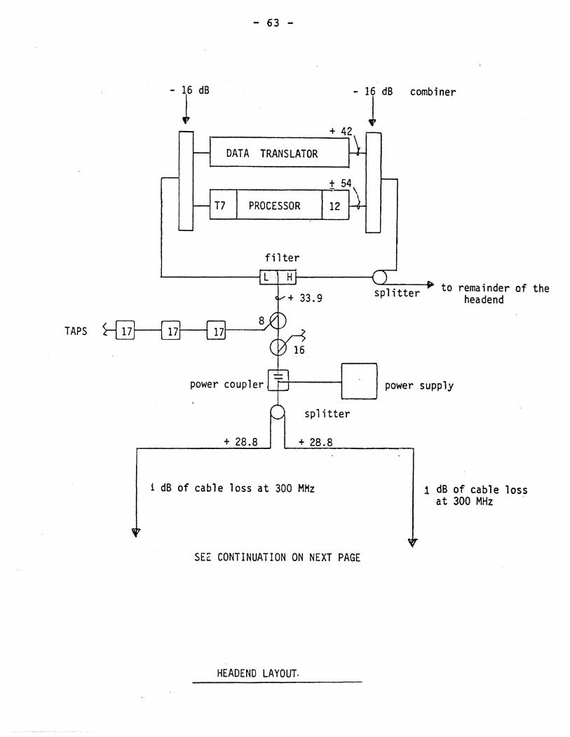
TAPS
- 63 -
combiner
DATA TRANSLATOR
T7 PROCESSOR
fil ter I...--_____ ~ L H ~---~
.... + 33.9
power coupler
spl itter
+ 28.8 + 28.8
1 dB of cable loss at 300 MHz
SEc CONTINUATION ON NEXT PAGE
HEADEND LAYOUT.
'-"----110 splitter to remainder of the
headend
power supply
1 dB of cable lass at 300 MHz '
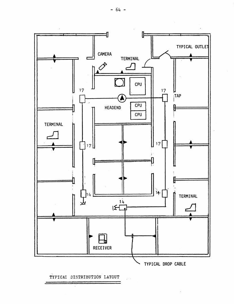
- 64 -
:[J n. U"
TYPICAL OUTlE
~ CAMERA TERMINAL (~ ~
T c:::::. T
~~ ... dJ
OJ [3 17 17
A :TAP , -l ! I ~
HEAD END Bra n
CPU r i
TERMINAL --,-
dJ ... ... ~ 17 ~ . 17
'f t' i'
0 ~ !
! ! ... ... rr
j '" ; , , ,
1+9 14 TERMINAL .. ,
14
~ - \ ~ J.. ... t' r
'f
~ (;] RECEIVER
" TYPICAL DROP CABLE
.. '
TYPICAl DISTRIBUTION LAYOUT
- 65 -
5.9 Bandwidth Allocations
Bandwidth management is vitally important for the coaxial cable implementation. Consideration must be given to the number of signals transmitted, and their bandwidth requirements, so the available spectrum can be properly allocated.
Generally, the bandwidth requirements of a system are predicated on the current and projected services which will be provided. These services may be broken down into the following categories:
A. CCTV Services: This type of service requires the most bandwidth per channel. Each security monitoring device, or educational TV channel, requires·12 MHZ of the available bandwidth; 6 MHz being used in each direction. Typically, this would involve a TV camera sending video and/or audio signals to a modulator which developes a composite RF signal tuned to a channel that occupies the return path. This RF signal is transmitted back to the headend where it will be translated to an RF signal on the forward path and distributed throughout the system. A receiver can now be connected at any point in the network and by selecting the correct channel will be able to monitor the camera. This type of configuration can be enhanced or changed to meet a wide variety of situations and needs.
B. DATA Communications: This type of service requires less bandwidth than TV or similar signals. Two major types of data communication units have emerged: 1) Discrete frequency pOint to point modems; and 2) Frequency Agile Interactive Packet Communication Units. Each type uses a standard CATV 6 MHz assignment format and is compatible with existing twoway systems. The major noticeable RF differences are: the number of channels that .reside within the 6 MHz allotment and the flexibility of the frequency agile unit in system architecture for sophisticated data communications. Both types require spectrum on both the inbound and outbound portions of the network, typically 6 to 36 M.Hz per direction for low speed networking and an additional 6 to 30 MHz per direction for high speed networking_ The size of the bandwidth can vary depending on the amount of data communications that is required~ Most systems require only 6 MHz in each direction, but if the Broadband system is to be used as a Local Area Network (LAN) then additional bandwidth may be necessary.
C. SPECIAL Services: A wide range of services can reside on the network, with each one occupying small or large portion of the network bandwidth. Local origination Signals such as studio outputs require 6 MHz for both the inbound and outbound paths. High resolution video for CCTV applications can use from 4 MHz to 14 MHz of bandwidth. If dual
- 66 -
frequency (frequency shift keying) is used for Digital Data Control, the bandwidth varies with the speed of such controls, but usually averages 300 kHz to 1 MHz. A FDM telephone system uses approximately 6 MHz in each direction to provide 300 simultaneous conversations. Manufacturer's specifications should be consulted to determine the requirement of each device and plant service that will interface to the network.
D. TELEVISION Distribution: To describe television requirements in such a short article would not convey the necessary information one needs. In short, the capturing of signals via antennas and processing those signals through channel processors, explains the required approach one may take. As with system design, the layout of a head end should be done by a qualified RF engineer. The interaction of signals, the placement of towers, the selection of antennas, the filtering required and signal amplitude takes years of experience to understand. One can learn the basics in a short period, but when designing multiple channel headends, with large amounts of interactive equipment and controlling circuitry, the design requirements can quickly get out of hand. In general, 6 MHz per Television channel is required for the forward direction. If a studio link is wanted at a remote location then 6 MHz for the return and forward paths are needed. If conversions are required from an off-air station then insure that the conversion is not a prohibited type. Some channel assignments cannot be converted to others depending on the interaction of adjacent and co-channel interferences. This may also apply to translating some return' channels to forward channel assignments. It is for this reason that an allocation chart must be done and all frequencies checked for compatibility. If television signals are to be transported on the coaxial network then one should be aware of the studies made by the Television Allocations Study Organization (TASO) in 1959. Copies can be obtain b1 writing any cable TV publication or the National Cable Television Association (NCTA).
The combination of multiple services can require large amounts of system bandwidth. Thus, its important to estimate the total requirement before designing the network. In integrated communication systems with data, video, TV and voice, manufactured by several companies, can prove to be a formidable task. As a rule, it is easier to assign those sUb-systems that can not be purchased at selectable frequencies. Once those are assigned then other sUb-systems which are flexible in assignments are taken into account and placed on the available spectrum.
As requirements grow, channel allocations should be made considering not only the requirement at hand but also future expansion. FCC regulations should be investigated to avoid assignments within prohibited frequency bands. Also be aware of,
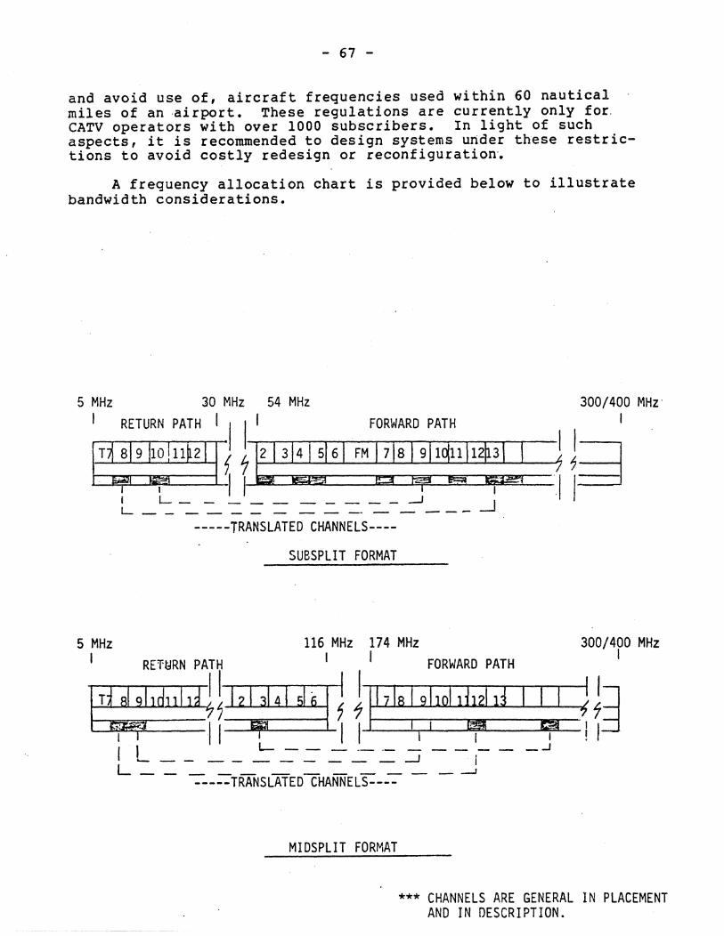
- 67 -
and avoid use of, aircraft frequencies used within 60 nautical . miles of an ·ai rport. These regulations are currently only for. CATV operators with over 1000 subscribers. In light of such aspects, it is recommended to design systems under these restrictions to avoid costly redesign or reconfi9uration~
A frequency allocation chart is provided below to illustrate bandwidth considerations.
5 MHz 30 MHz 54 MHz I RETURN PATH I I I' FORWARO PATH
IT~9~1*11~ i~3~61 FM~S~lq:~t~~ f L __________ .-J -.J L ________ - -- - - ---
-----TRANSLATED CHANNELS----
SUBSPLIT FORMAT
5 MHz 116 MHz 174 MHz
300/400 MHz' I
I I 1.'~ 11~
300/400 MHz I
I RE'ft-JRN PATH t I FORWARD PATH
I TtR" .. ldl1l d 7'11 ~I~~ , J I his! 9: 1011: d I ~. ~;J ~ ----I1iI!IB'--~ I I I I I! ,:::i I I L- - - - _.- - - - - - _...J "---- ______ -1 i
L - - -= ___ TRANSLATEDCHANNELS----=- - _--1
MIDSPLIT FORMAT
*** CHANNELS ARE GENERAL IN PLACEMENT AND IN DESCRIPTION.
- 68 -
5.10 Large Multichannel Headends
Extending the bandpass of coaxial networks to 400 MHz, and the increasement of channel useage, has created unique operational characteristics.
. A 400 MHz, 52 channel system can provide significantly more
communications bandwidth than existing 35 channel, 300 MHz networks. However, technical problems in design, maintenance and equipment should be considered. Of all the problems that relate to 52 channel operation, Composite Triple Beat (CTB), and Harmonically Related Carriers (BRC) as they effect phase locking are the most important. This section only applies to large CATV type headends and is given to illustrate how these situations can be handled.
5.10.1 Composite Triple Beat (CTB): In a 300 MHz, 35 channel system, analysis of all possible Fl +- F2 +- F3 +- type triple beats shows that the worst case number of beats falling on one channel is 334 on channel 11 or 12. Because there are so many beats close together, they tend to add on a power basis and appear as narrowband noise on a spectrum analyzer. This can be visually seen on a TV picture at approximately -52 DB <CTB) rating.
In a 52 channel system, the worst case number of beats using standard assignments is 842 for channels 0 and P. In order to maintain the same -52 DB CTB, as in 35 channel systems, all amplifier outputs would have to be lowered by 5 to 6 dB. The combination of this, coupled with higher cable losses at 400 MHz and additional amplifiers increase network cost dramatically.
5.10.2 Harmonically Related Carriers (HRC): HRC headends use a master 6 MHz generator to phase lock all channels together to retain exactly the same spacing from each other. The generator is referred to as the "comb" generator, and with its use, each channel to must be shifted by a -1.25 MHz, except CH 5 and CH 6, whIch are shifted +.75 MHz resulting in an additional channel between CH 4 and CH 5. Implementation of this phase relationship results in an additional 3 to 4 dB of output gained and a reduction in CTB. Thus a 44-46 DB CTB would be used as the limiting distortion factor.
The 6 MHz oscillator, however, creates problems for strong off-air stations. This problem in the past was solved with phase locking techniques at the channel processor. This technique is no' longer possible due to the shift of frequencies caused by the comb generator. This conflict also 'arises with aircraft navigation and communication assignments of the FAA. In some instances adjacent channels may have to be abandoned as a result of this shift, to satisfy offset requirements.
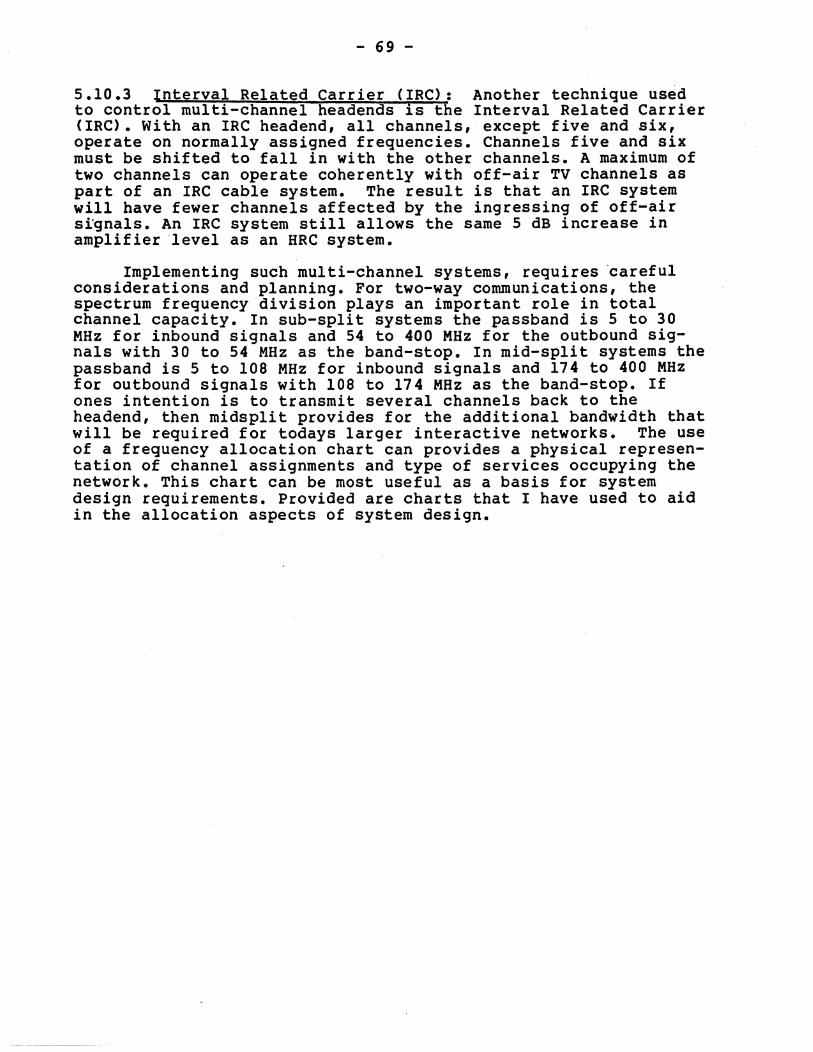
- 69 -
5.10.3 Interval Related Carrier (IRC): Another technique used to control multi-channel headends is the Interval Related Carrier (IRC). With an IRC headend, all channels, except five and six, operate on normally assigned frequencies. Channels five and six must be shifted to fall in with the other channels. A maximum of two channels can operate coherently with off-air TV channels as part of an IRC cable system. The result is that an IRC system will have fewer channels affected by the ingressing of off-air signals. An IRC system still allows the same 5 dB increase in amplifier 'level as an HRC system.
Implementing such multi-channel systems, requires 'careful considerations and planning. For two-way communications, the spectrum frequency division plays an important role in total channel capacity. In sub-split systems the passband is 5 to 30 MHz for inbound signals and 54 to 400 MHz for the outbound signals with 30 to 54 MHz as the band-stop. In mid-split systems the passband is 5 to 108 MHz for inbound signals and 174 to 400 MHz for outbound signals with 108 to 174 MHz as the band-stop. If ones intention is to transmit several channels back to the headend, then midsplit provides for the additional bandwidth that will be required for todays larger interactive networks. The use of a frequency allocation chart can provides a physical representation of channel assignments and type of services occupying the network. This chart can be most useful as a basis for system design requirements. Provided are charts that I have used to aid in the allocation aspects of system design.
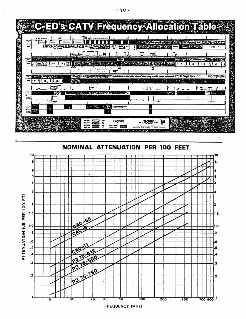
10
8
6
5
4
3
to-u.. 0 2 0 ... a:: 1.5 UJ ~
m 1.0 "0
Z '.8 o i= < .6
';:) Z .5 W to- 4 to- • <
. 3
. 2
.1
.......... ...-
...... ~
..... ..........
.......... ~
~ ~
~ :,....
- 'ro ..
..... ~ ... == == : . ---:;;;;==~ ...... _ ... --..--~ .. _ .. "--- ...... --- ~ ---.. --, ... _--' _.... .!
-:..-:.=:.:.::: =:-.:..:
NOMINAL ATTENUATION PER 100 FEET
..,,-V
L I' V-L
L v:: V L
..... "'" ~ V V
~ ..,/ ~ "'" V ~ I"'" V V ./ ~ /' ........... ~
~ V .,
V V ....., V
~ ...... 1;' / , .. ~ ....... ~ ./ ~
v~ 1Iit/ V I' IL: IL: ,fl.~ .... ./ , ./ ./
...... I' ~ /' ....... V ~ ~i-" ./ .......... '" i;o' ~ V
~y .,
V V ,
/" b~ 6.~ V ./
.....,
" i,..-'
i.-" ~9~ ~ V ~ ,
...... ../ i.-" ~jY V V I,;-
.. 1~ ~ i.-" I"'" 9Y ~ ~
..........
10 .. 0 .,0 :u ,IK/ 2;)0 4 )0
FREOUENCY IMHzl
v ~ 1.;0 "'" 1/
.....
I,..-j..oo'
~
7)09)(
10
8
6
5
4
3
2
1.5
1.0
.8
6
.5
.4
.3
.2
.1
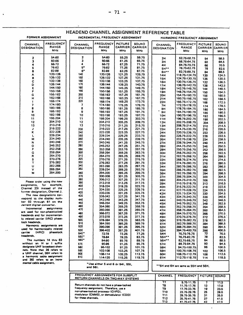
FORMER ASSIGNMENT
CHANNEL FREQUENCY DESIGNA TIQN RANGE
MHz
2 64-60 3 60-66 4 66-72 5 76.a2 6 ·82.a8 A 120·126 B 126·132 C 132·138 D 138·144 E 144·150 F 150·156 G 156·162 H 162·168 I 168.174 7 174.180 8 180·186 9 186·192 10 192·198 11 198·204 12 204·210 13 210-216 J 216·222 K 222-228 L 228.234 M 234·240 N 240·246 0 246.252 P 252-258 Q 258-264 R 264·270 S 270·276 T 276·282 U 282-288 V 288-294 W 294..300
Plea" order using the new assignments, for exampl., Chennel 231 instead of the former designation, Chann.1 J.
The new designations cor· r.spond to the displaV num· ber 02 through 8' on the Jerrold digital convener.
Incr.mental assignments are used for non~haselockecl h.adends and for incremental. Iy relatecl carrier (lRCI ph ... • lock hUdends.
Harmonic assignments are used for harmonically related carri... (HRCI pha"lOck hUdendl.
Th, numben 14 thN 83 without an H or I suffix designate UH F broadcast chan· nail. Note that 36 refen 10 a UHF channel, 36H ref.n 10 a harmonic cabl. aaignmant and 361 refen 111 an incr .. mental cabl. assignment.
- 71 -
HEADEND CHANNEL ASSIGNMENT REFERENCE TABLE INCREMENTAL FREQUENCY ASSIGNMENT .HARMONIC FREOUENCY ASSIGNMENT
CHANNEL FREQUENCY PICTURE SOUND CHANNEL FREQUENCY PICTURE SOUND DESIGNATION RANGE CARRIER CARRIER OESIGNATION RANGE CARRIER CARRIER
MHz MHz MHz MHz MHz MHz
2 54-60 55.25 59.75 2H 52.75-58.75 64 58.5 3 60~ 61.25 65.75 . 3H 58.75-64.75 60 64.5 4 66-72 67.25 71.75 4H 64.75·70.75 66 70.5 5- 76.a2 77.25 81.75 5H·· 76.75.a2.75 78 82.5 6· 82.a8 83.25 87.75 6H·· 82.75.a8.75 84 88.5
141 120·126 121.25 125.75 14H 118.75·124.75 120 124.5 151 126.132 127.25 131.75 15H 124.75·130.75 126 130.5 161 132.138 133.25 137.75 16H 130.'15·136.75 132 136.5 171 138.144 139.25 143.75 17H 136.75·142.75 138 142.5 181 144.150 145.25 149.75 18H 142.75·148.75 . 144 148.5 191 150·156 151.25 155.75 19H 148.7S·154.75 150 154.5 201 156.162 157.25 161.75 20H 154.75·160.75 156 160.5 211 162·168 163.25 167.7S 21H 160.75·166.75 162 166.5 221 168·174 169.25 173.75 22H 166.75·172.75 168 172.5
7 174·180 175.25 179.75 7H 172.75·178.75 174 178.5 8 180·186 181.25 185.75 8H 178.75·184.75 180 184.5 9 186·192 187.25 191.75 • 9H 184.75.190.75 186 190.5
10 192.198 193.25 197.75 10H 190.75·196.75 192 196.5 11 198·204 199.25 203.75 11 H 196.75-202.75 198 202.5 12 204.210 205.25 209.75 12H 202.75-208.75 204 .208.5 13 210.216 211.25 215.75 13H 2OS.75·214.75 210 214.5
231 216-222 217.25 221.75 23H 214.75·220.75 216 220.5 241 222.228 223.25 227.75 24H 220.75·226.75 222 226.5 251 228-234 229.25 233.75 25H 226.75-232.75 228 232.5 261 234·240 235.25 239.75 26H 232.75·238.75 234 238.5 271 240-246 241.25 245.75 27H 238.75·244.75 240 244.5 281 246-252 247.25 251.75 28H 244.75-250.75 246 250.5 291 252-258 253.75 257.75 29H 250.75·256.75 252 256.5 301 258-264 259.25 263.75 30H 256.75·262.75 258 262.5 311 . 264.270 265.25. 269.75 31H 262.75-268.75 264 268.5 321 270-276 271.25 275.75 32H 268.75·274.75 270 274.5 331 276·282 277.25 281.75 33H 274.75·280.75 276 280.5 341 282.288 283.25 287.75 34H 280.75·286.75 282 286.5 351 228-234 289.25 293.75 35H 286.75·292.75 288 292.5 361 294..300 295.25 299.75 36H 292.75·298.75 294 298.5 371 300..306 301.25 305.75 37H 298.75-304.75 300 304.5 381 306..312 307.25 311.75 38H 304.75..310.75 306 310.5 391 312-318 313.25 317.75 39H 310.75-31S.75 312 316.5 401 318..324 319.25 323.75 40H 316.75..322.75 318 322.5 411 324-330 325.25 329.75 41H 322.75..328.75 324 328.5 421 330..336 331.25 335.75 42H 328.75..334.75 330 334.5 431 336..342 337.25 341.75 43H 334.75..340.75 336 340.5 -441 342..348 343.25 347.75 44H 340.75-346.75 342 346.5 451 348-354 349.25 353.75 45H 346.75-352.75 .348 352.5 461 354..360 355.25 359.75 46H 352.75-358.75 354 358.5 471 360..366 361.25 365.75 47H 358.75..364.75 360 364.5 481 366..372 367.25 371.75 48H 364.75..370.75 366 370.5 491 372..378 373.25 377.75 49H 370.75..376.75 372 376:5 '. 601 378-384 379.25 383.75 50H 376.75..382.75 378 382.5 511 384-390 385.25 389.75 51H 382.75..388.75 384 388.5 521 390..396 391.25 395.75 52H 388.75-394.75 390 394.5 531 396-402 397.25 401.75 53H 394.75-400.75 396 400.5 641" 72·78 73.25 77.25 54H 70.75-7S.75 72 76.5 551" 78-84 79.25 83.75 55HoO 7S.75.a2.75 78 82.5 561· 84-80 85.'5 89.75 56Ho • 82.75.aa.75 84 88.5 571 90-96 91.25 95.75 57H 88.75-94.75 90 94.5 581 96·102 97.25 101.75 SSH 94.75·100.75 96 100.5 591 102·108 103.25 107.75 59H 100.75·106.75 102 106.5 601 108·114 109.25 113.75 60H 106.75·112.75 10S 112.5 611 114.120 115.25 119.75 61H 112.75·11Ip5 "4 118.5
"U .. either 5 and 6 or MI, 551. ··5H and SH are same as 55~ and 56H. and 561.
FREQUENCY ASSIGNMENTS FOR SUBSPLIT CHANNEL RETURN CHANNELS ON TWO·WAY SYSTEMS
FREQUENCY PICTURE SOUND
T7 5.75-11.75 7 11.5 Return channell do not hllll' a ph_locked T8 11.75·17.75 13 17.5 frequency aaignm.nt. Therefore, use a T9 17.75·23.75 19 23.5 non-phase-lockad proc.aor (CI1PDI, TtO 23.75·29.75 25 29.5 moduletor (CMMSI, or demodulltor (COOl Ttl 29.75·35.75 31 35.5 for these channell. T12 35.75-41.75 37 41.5
Tt3 41.75-47.75 43 47.5
- 72 -
6. TEST EQUIPMENT
In order to maintain a coaxial cable network, certain types of test equipment are required. Each type of test equipment is used for specific purposes such as: performance monitoring, system maintenance and system modification. It is ad~isable to obtain such equipment even for the smallest of networks.
The most popular is the signal strength meter which is a tuned RF"voltmeter used for determining Signal level of individual signal components. An RF meter is easy to use, and can be used in performance measurements, alignment of amplifiers, signal verifications and trouble-shooting. Unlike voltmeters or power meters, signal level meters can measure frequency as well as individual carrier and sideband power. Other names for these instruments are frequency selection meters, field strength meters, or wave meters.
Since data and digital controls occupy narrow bandwidths, a portable or rack-mountable spectrum analyzer can be most useful. The analyzer is an automatic tuned voltmeter, usually employing a cathode ray tube (CRT), which can display more information faster. In addition, the analyzer provides a graphic display of the frequency spectrum and is useful in system alignment, troubleshooting, carrier analysis, carrier-to-noise ratios, intermodulation aspects and numerous other performance tests.
Sweep Generators are used for system alignment and should produce RF signals from 5 MHz to 400 MHz. They should also have capabilities for both fixed frequency output and for sweeping with widths ranging from a few hundred kilohertz to 400 MHz at adjustable amplitudes. Use of the sweep generator, or sweep systems, can be one of the most important test tools one can purchase.
Multimeters are primarily used for checking p6wer supply operation and evaluating ground loops as the system ages. Such units should be portable and handle multiple ranges and several types of voltages and resistances.
Cable Reflectometers are useful in determining a cable fault due to a physical break in a given length of cable or reflections caused by a bend or kink. These instruments can give the location of the fault to the operator within a few inches, making fault isolation an easy task to perform.
programmable test equipment with IEEE interfaces can provide a wide range of implementation. Although expensive, the performance measurement capability of such equipment and the fact they can be computer controlled and analyzed opens a new world of use in automated test performance and fault isolation.
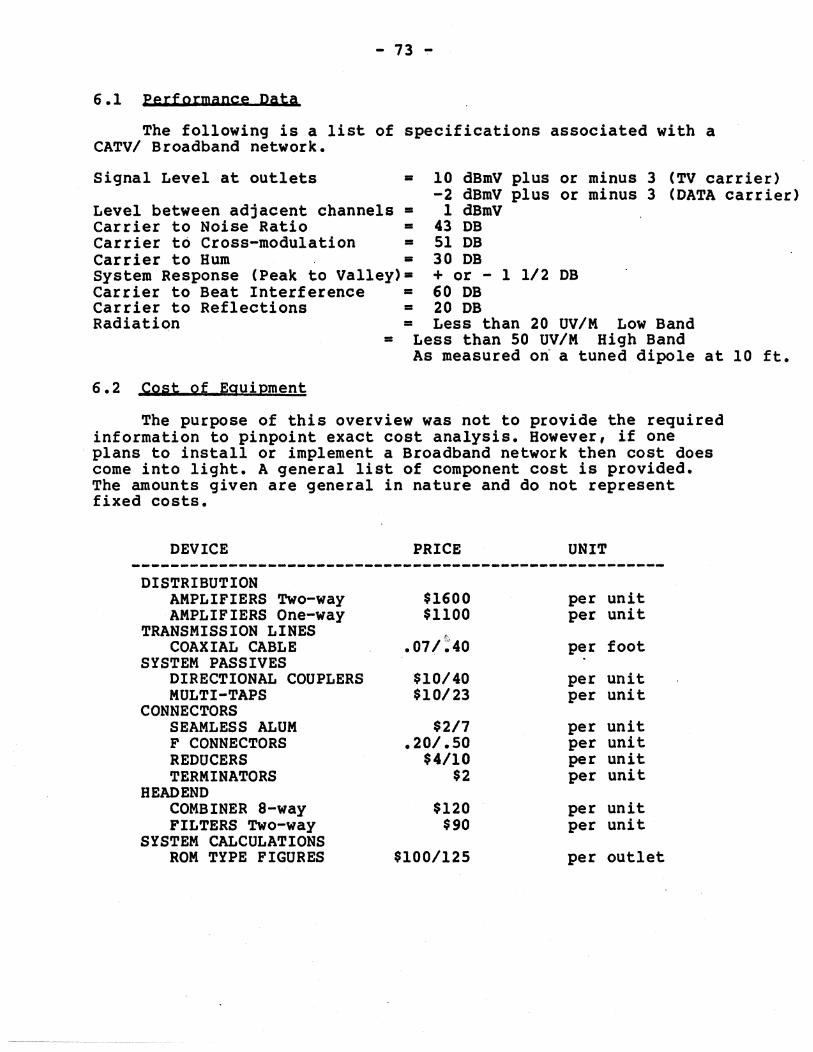
- 73 -
6.1 Performance Data
The following is a list of specifications associated with a CATVI Broadband network.
Signal Level at outlets = 10 dBmV plus -2 dBmV plus
or minus 3 (TV carrier) or minus 3 (DATA carrier)
Level between adjacent channels = Carrier to Noise Ratio = Carrier to Cross-modulation =
1 dBmV 43 DB 51 DB 30 DB Carrier to Hum =
System Response (Peak to Valley)= + or - 1 1/2 DB Carrier to Beat Interference = 60 DB Carrier to Reflections = 20 DB Radiation = Less than 20 UVIM Low Band
=
6.2 Cost of Equipment
Less than 50 UVIM High Band As measured on a tuned dipole at 10 ft.
The purpose of this overview was not to provide the required information to pinpoint exact cost analysis. However, if one plans to install or implement a Broadband network then cost does come into light. A general list of component cost is provided. The amounts given are general in nature and do not represent fixed costs.
DEVICE PRICE UNIT -------------------------------------------------------
DISTRIBUTION AMPLIFIERS Two-way $1600 per unit AMPLIFIERS One-way $1100 per unit
TRANSMISSION LINES .07/:'40 COAXIAL CA~LE per foot
SYSTEM PASSIVES .
DIRECTIONAL COUPLERS $10/40 per unit MULTI-TAPS $10/23 per unit
CONNECTORS SEAMLESS ALUM $217 per unit F CONNECTORS .20/.50 per unit REDUCERS $4110 per unit TERMINATORS $2 per unit
HEAD END COMBINER a-way $120 per unit FILTERS Two-way $90 per unit
SYSTEM CALCULATIONS ROM TYPE FIGURES $100/125 per outlet
- 74 -
7. SUMMARY
. It is hopeful that the information contained is this overview provided and related to the reader, the basic considerations and implementation strategy required for multi-service communications networks. If additional information is desired, then obtaining one of the reference materials is suggested. If you wish to discuss your requirements or needs with myself, please feel free to call and'I will try to assist you as much as my time will permit. In addition, I hope to continue to provide informational overviews, such as this one, in other areas of Broadband co'mmunications.
Items of interest such as: Manufacturers, Suppliers, Distributers, Broadband Symbols, Glossary of Terms, and Reference Materials have been included in the appendix section.
I would like to take this oper·.-t:unity to thank the many people who gave their time and knowledge in making this overview a success. First my family who had to put up with me typing on a terminal for the past several weeks. In addition, the amount of editing that was required was done by my wife Linda. Also there are a few individuals who gave me suggestions on the format and technical content. They are listed below.
1. My wife Linda Cooper, son Richard and daughter Cheralynn.
2. Helmut Hess and Cecil Turner of the Taco Division of General Instruments
3. Dave Becket, Ken Howell, Rhonda StJohn and Marcia Allen of Sytek Inc.
WELCOME TO THE WORLD OF BROADBAND COMMUNICATIONS 1111
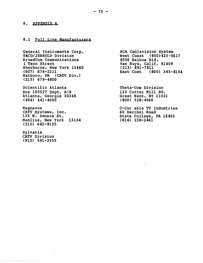
8. APPENDIX A
8~1 Full Line Manufacturers
General Instruments Corp. TACO/JERROLD Division BroadCom Communications 1 Taco street Sherburne, New,York 13460 (607) 674-2211 Hatboro, PA (CATV Div.) (215) 679-4800
Scientific Atlanta Box 105027 Dept. A-R Atlanta, Georgia 30348 (404) 441-4000
Magnavox CATV Systems, Inc. 133 w. Seneca St. Manlius, New York 13104 (315) 682-9105
Sylvania CATV Division (915) 591-3555
-- ~-~--~~~-~--~ - ~~
- 75 -
RCA Cab1evision System west Coast (800)423-5617 8500 Balboa BId. Van Nuys, Calif. 91409 (213) 891-7911 . East Cost (800) 345-8104
Theta-Com Division 122 Cutter Mill Rd. Great Neck, NY 11021 (800) 528-4066
C-Cor able TV Industries 60 Decibel Road State College, PA 16801 (814) 238-2461
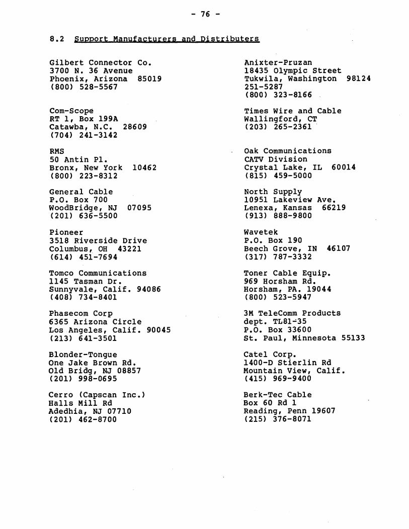
- 76 -
8.2 Support Manufacturers and Distributers
Gilbert Connector Co. 3700 N. 36 Avenue Phoenix, Arizona 85019 (800) 528-5567
Com-Scope RT 1, Box 199A Catawba, N.C. 28609 (704) 241-3142
RMS 50 Antin Pl. Bronx, New York 10462 (800) 223-8312
General Cable P.O. Box 700 woodBridge, NJ 07095 (201) 636-5500
Pioneer 3518 Riverside Drive Columbus, OH 43221 (614) 451-7694
Tomeo Communications 1145 Tasman Dr. Sunnyvale, Calif. 94086 (408) 734-8401
Phasecom Corp 6365 Arizona Circle Los Angeles, Calif. 90045 (213) 641-3501
Blonder-Tongue One Jake Brown Rd. Old Bridg, NJ 08857 (201) 998-0695
Cerro (Capscan Inc.) Halls Mill Rd Adedhia, NJ 07710 (201) 462-8700
Anixter-Pruzan 18435 Olympic Street Tukwila, Washington 98124 251-5287 (800) 323 -8166
Times Wire and Cable Wallingford, CT (203) 265-2361'
Oak Communications CATV Division Crystal Lake, IL 60014 (815) 459-5000
North Supply 10951 Lakeview Ave. Lenexa, Kansas 66219 (913) 888-9800
Wavetek P.O. Box 190 Beech Grove, IN 46107 (317) 787-3332
Toner Cable Equip. 969 Horsham Rd. Horsham, PA. 19044 (800) 523-5947
3M Te1eComm Products dept. TL81-35 P.O. Box 33600 St. Paul, Minnesota 55133
Cate1 Corp. 1400-0 Stier lin Rd Mountain View, Calif. (415) 969-9400
Berk-Tec Cable Box 60 Rd 1 Reading, Penn 19607 (215) 376-8071
- 77 -
8.3 Satellite TYRQ Manufacturers
Microwave Assoc. 63 3rd Ave. Burlington, MA 01803 (617) 272-3100
SCN RD. 1, Box 3114 Basking Ridge, NJ 07920 (201) 658-3838
Comteck 613 Rockford Dr. Temple, Arizona 85281 (602) 968-2433
Toner Cable Equipment Inc. 969 Horsham Rd. Horsham, PA. 19044 (800) 523-5947
Avantek 3175 Bowers Ave. Santa Clara, CA 95051 (408) 496-6710
Hughes Aircraft Comp. P.O. Box 2999 Torrance, Calif. 90509 (213) 534-2170
Scientific Atlanta Box 105027 Dept. A-R Atlanta, Georgia 30348
Gardiner Communications 1980 Post Oak Boulevard. Suite 2040 (713) 961-7348
A TVRO (Television Receive Only) earth station receives lowpowered TV microwave signals from orbiting communications satellites. The signals are captured with a parabolic antenna and then fed to a conventional TV through a microwave component system.
- 78 -
9. APPENDIX B
9.1 Glossary of Terms
A 11 oca t ions -
Amplifier -
Balancing (S i gna I) -
Bandwidth -
Branch -
Broadband -
Cab 1 e Ti 1 t -
The assignments of frequencies by the FCC for various communications uses (e.g., television, radio. la"d-mobile. defense. microwave. etc.) to achieve a fair division of the available spectrum and to minimize interference a~ng users.
A de~i~e used to boost the str.ength of an electronic signal. Ampl ~f,ers are spaced at intervals throughout a cable system to rebUIld the strength of TV or data signals which weaken as they pass through the cable network. Midspl it configurations use a forward and a reverse amplifier in the same enclosure to boost signals in both directions.
A method of equal izing the attenuation tha~ a particular signal encounters through the network (forward direction) so that the signal level is essentially the same at all outlets. Also produces near equal inputs to the head-end from a fixed level transmitter (reverse), no matter where the transmitter is attached to the network.
A measure of spectrum (frequency) use or capacity. For instance. a voice transmission by telephone requires a bandwidth of about 3000 cycles per second (3 KHz). A TV channel occupies a bandwidth of 6 million cycles per second (6 MHZ). Cable system bandwidth occupies 5 MHz to 300 MHz on the e~ectromagne~ic spectrum.
An intermediate cable distribution line in a broadband coax network that either feeds or is feed from a main trunk. Same as a Feeder.
A general term used to describe wide bandwidth equipment or systems which can carry a large proportion of the electromagnetic spectrum. A :"roadband communications system can accommodate all broadcast and many other services.
A reduction in the level of an r-f sweep signal passing through a cable as it sweeps from low to high frequency. This Itilt l is caused by the increase in cable attenuation as the frequency increases. A specific fixed length of cable and a fixed frequency range produces a fixed amount of tilt.
Cable TV -
Cable Power i ng -
CATV -
Compos he Video Signal
Cross Modulation -
D i rec tiona I Coupler -
I'lrop line -
Drop li ne Device -
- 79 -
. Previously called Community Ante~na Television (CATV). A com~unication system which distributes broadcast programs and original program via a coaxial cable.
. Supplying operating power to active CATV equipment by using the coaxial cable to carry this power along with the information signa 1.
See Ca b I e TV.
- The complete video signal. For monochrome, it consists of the picture signal and the blanking and synchronizing signals. For color, additional color synchronizing signals and color picture information are added.
A form of signal distortion in which modulation from one or more r-f carrieres) is imposed on another carrier.
A high quality tapping device providing isolation between a single tap outlet drop line and external devices (more than one).
A flexible coaxial cable, normally type RG-6U, which usually drops from an overhead tap in the coaxial network. The end of the drop line has the network outlet connector which is used to couple an e~ternal device.
Any external device attached to the coaxial network through a drop line (i.e., r-f modem, TV set, audio modulator, etc.)
Equalization - A means of modifying the frequency response of an amplifier or network, thereby resulting in a flat overall response. It is slope compensation done by a module within an amplifier enclosure.
Feeder (Cable) -
Filter -
Flat Loss -
Flooded Cable -
Same as a Branch.
A circuit that selects the frequency of desired channel~. Used . in trunk and feeder lines for special cable services such as twoway operation.
Equal loss at all .frequencies. such as caused by attenuators.
A special CATV cable containing a corrosion resistant gell between the outer aluminum sheath and the outer jacket. The gell flows into imperfections in the alu~inum to prevent corrosion in high moisture areas.
Frequency -
Frequency Response -
Harmonic Distortion -
r Head End -
Hub -
Insertion Loss - .
Main Trunk -
Mid Band -
Modem -
Noise -
- 80 -The number of times an electromagnetic signal repeats an identical cycle in a unit of time, usually one second. One Hertz (Hz) is one cycle per second. A KHz (Kilohertz) is one thousand cycl"es per second; a MHz (Megahertz) is one million cycles per second; a GHz (Gigahertz) is one billion cycles per second.
The change of gain with frequency.
Form of interference involving the generation of harmonics according to the frequency relationship f • nfl for each frequency present, where n is a whole number equal to 2 or more.
An electronic control center, generally located at the antenna site of a CATV system - usually including antennas, preamplifiers, frequency converters, demodulators, modulators and other related equipment which amplify, filter and convert incoming broadcast TV signals to cable system channels. Also may house a host computer in certain data systems.
Same as a head end for bi-directional (mid-split) networks except it's more centrally located within the network.
Additional loss in a system when a device such as a directional coupler is inserted; equal to the difference in signal level between input and output of such a device.
The major link(s) from the head-end (or hub) to downstream branches.
The part of the frequency band that lies between television channels 6 and 7, received by the FCC for air, maritime and land mobile units, FM radio and aeronautical and: maritime navigation. Mid band frequencies, 108 to 17~ MHz, can also be used to provide add it i ona 1 channe I s on cab 1 e te 1 evi s ion sys terns .•
A modulator-demodulator device which codes or decodes an information signal onto or off of an analog carrier signal by varying the amplitude, frequency or phase of the resulting signal •••• or detecting this variation.
The word "noise" is a carryover from audio practice. random spurts of electrical energy or interference. a "salt-and-pepper" pattern over the picture. Heavy times is called "snow."
Refers to .. May produce noi se some-
Noise Figure - A measure of the noise in dB generated at the input of an amplifier as compared with the noise generated by a 75-ohm resistor.
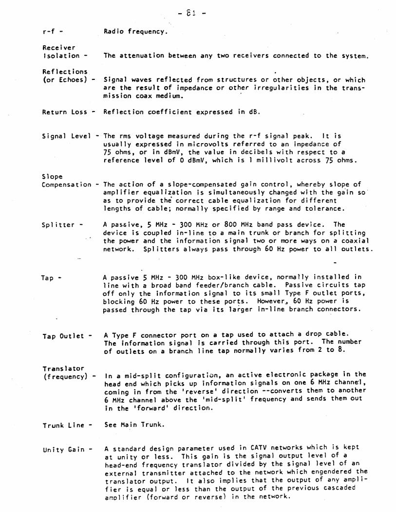
r-f -
Receiver Isolation
Reflections (or Echoes) -
Return Loss -
Signa I leve I -
Slope Compensat ion
Splitter -
Tap -
Tap Outlet -
Translator (frequency) -
Trunk Line -
Unity Gain -
- S 1 -
Radio frequency.
The attenuation between any two receivers connected to the system.
Signal waves reflected from structures or other objects, or which are the result of impedance or other irregularities in the transmission coax medium.
Reflection coefficient expressed in dB.
The rms voltage measured during the r-f signal peak. It is usually expressed in microvolts referred to an impedance of 7S ohms. or in dBmV, the value in decibels with respect to a reference level of 0 dBmV, which is I millivolt across 7S ohms.
The action of a slope-compensated gain control, whereby slope of amplifier equalization is simultaneously changed with the giin so as to provide the correct cable equalization for different lengths of cable; normally specified by range and tolerance.
A passive, 5 MHz - 300 MHz or 800 MHz band pass device. The device is coupled in-line to a main trunk or branch for splitting the power and the information signal two or more ways on a coaxial network. Spl itters always pass through 60 Hz power to all outlets.
A passive 5 MHz - 300 MHz box-like device, normally installed in line with a broad band feeder/branch cable. Passive circuits tap off only the information signal to its small Type F outlet ports. b locki ng 60 Hz power to these ports. However .• 60 Hz power is passed through the tap via its larger in-line branch connectors.
A Type F connector port on a tap used to attach a drop cable. The information signal is carried through this port. The number of outlets on a branch line tap normally varies from 2 to 8.
In a mid-split configuration. an active electronic package in the head end which picks up information signals on one 6 MHz channe·t. coming in from the 'reverse' directio'n --converts them to another 6 MHz channel above the 'mid-split' frequency and sends them out in the 'forward' direction.
See Main Trunk.
A standard design parameter used in CATV networks which is kept at unity or less. This gain is the signal output level of a head-end frequency translator divided by the signal level of an external transmitter attached to the network which engendered the translator output. It also implies that the output of any amplifier is equal or less than the output of the previous cascaded amplifier (forward or reverse) in the network.
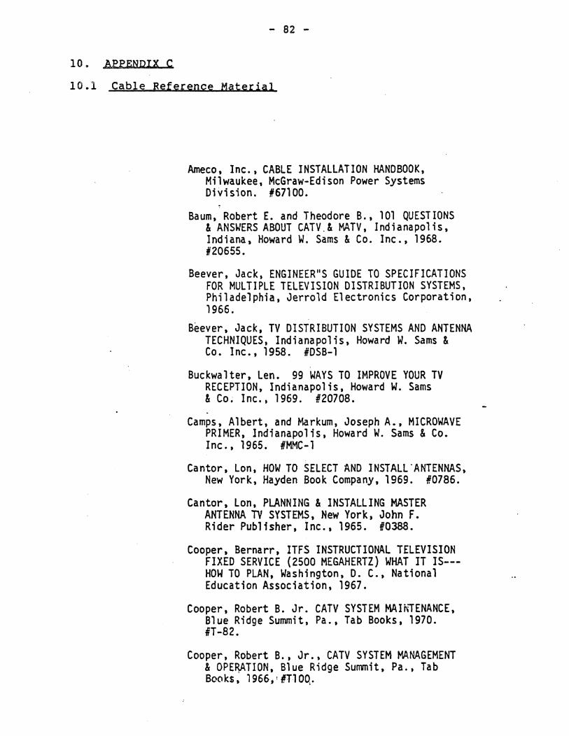
- 82 -
10. MPENDIX C
10.1 Cable Reference Material
Ameco, Inc., CABLE INSTALLATION HANDBOOK, Milwaukee, McGraw-Edison Power Systems Division. #67100.
Baum, Robert E. and Theodore B., 101 QUESTIONS & ANSWERS ABOUT CATV.& MATV, Indianapolis, Indiana, Howard W. Sams & Co. Inc., 1968. #20655.
Beever, Jack, ENGINEER"S GUIDE TO SPECIFICATIONS FOR MULTIPLE TELEVISION DISTRIBUTION SYSTEMS, Philadelphia, Jerrold Electronics Corporation, 1966.
Beever, Jack, TV DISTRIBUTION SYSTEMS AND ANTENNA TECHNIQUES, Indianapolis, Howard W. Sams & Co. Inc., 1958. #OSB-l
Buckwalter, Len. 99 WAYS TO IMPROVE YOUR TV RECEPTION, Indianapolis, Howard W. Sams & Co; Inc., 1969. 120708.
Camps, Albert, and Markum, Joseph A., MICROWAVE PRIMER, Indianapolis, Howard W. Sams & Co. Inc., 1965. IMMC-l
Cantor, Lon, HOW TO SELECT AND INSTALL·ANTENNAS, New York, Hayden Book Company, 1969. 10786.
Cantor, Lon, PLANNING & INSTALLING MASTER ANTENNA TV SYSTEMS, New York, John F. Rider Publisher, lnc., 1965. 10388.
Cooper, Bernarr, ITFS INSTRUCTIONAL TELEVISION FIXED SERVICE (2500 MEGAHERTZ) WHAT IT IS--HOW TO PLAN, Washington, D. C., National Education Association, 1967.
Cooper, Robert B. Jr. CATV SYSTEM MAINIENANCE, Blue Ridge Summit, Pa., Tab Books, 1970. IiT-a2.
Cooper, Robert B., Jr., CATV SYSTEM MANAGEMENT & OPE~TION, Blue Ridge Summit, Pa., Tab Books, 1966.! DT10Q,.
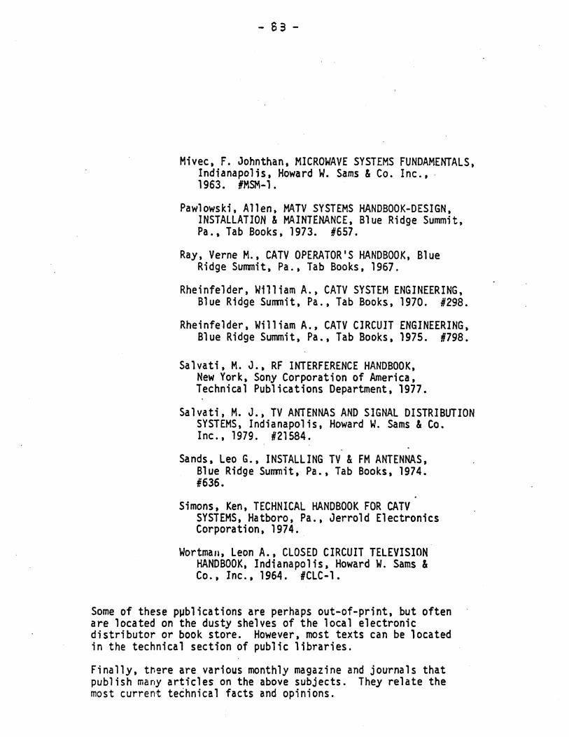
- 83 -
Mivec. F. Johnthan, MICROWAVE SYSTEMS FUNDAMENTALS. Indianapolis. Howard W. Sams & Co. Inc ••. 1963. IMSM-l.
Pawlowski, Allen, MATV SYSTEMS HANDBOOK-DESIGN. INSTALLATION & MAINTENANCE, Blue Ridge Summit, Pa., Tab Books, 1973. 1657.
Ray. Verne M .• CATV OPERATOR'S HANDBOOK, Blue Ridge Summit. Pa •• Tab Books. 1967.
Rheinfe1der. William A .• CATV SYSTEM ENGINEERING, Blue Ridge Summit, Pa., Tab Books, 1970. 1298.
Rheinfelder. William A., CATV CIRCUIT ENGINEERING, Blue Ridge Summit, Pa .. Tab Books. 1975. #798.
Salvati, M. J .• RF INTERFERENCE HANDBOOK. New Y~rk. Sony Corporation of America. Technical Publications Department. 1977.
Salvati. M. J .• TV ANTENNAS AND SIGNAL DISTRIBUTION SYSTEMS, Indianapolis, Howard W. Sams & Co. Inc •• 1979. #21584.
Sands. Leo G., INSTALLING TV & FM ANTENNAS, Blue Ridge Summit. Pa •• Tab Books. 1974. #636.
Simons. Ken. TECHNICAL HANDBOOK FOR CATV SYSTEMS. Hatboro. Pa .• Jerrold Electronics Corporation. 1974.
Wortman, Leon A •• CLOSED CIRCUIT TELEVISION HANDBOOK. Indianapolis, Howard W. Sams & Co.. Inc .• 1964. ICLC-1.
Some of these p~blications are perhaps out-of-print. but often are located on the dusty shelves of the local electronic distributor or book store. However. most texts can be located in the technical section of public libraries.
Finally. tr.~re are various monthly magazine and journals that publish many articles on the above subjects. They relate the most current te~hnica1 facts and opinions.
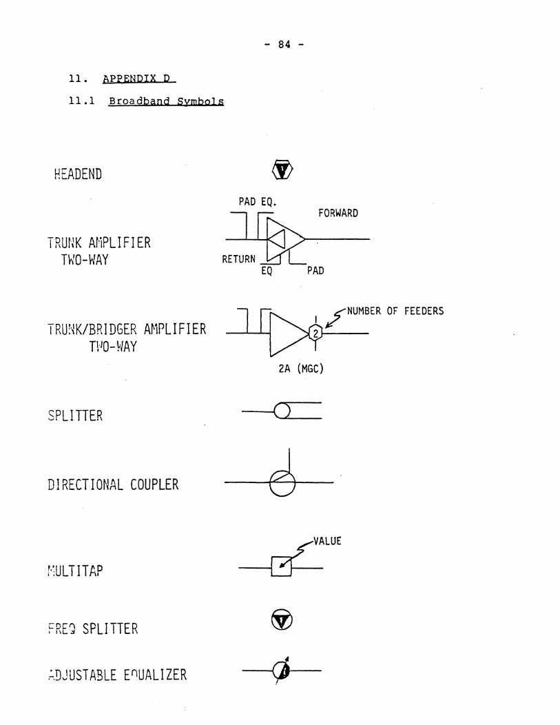
- 84 -
11. APPENDIX D
11.1 Broadband Symbols
HEADEND
TRUNK Ar'iPLIFIER THO-WAY
TRU~K/BRIDGER AMPLIFIER TPO-HAY
SPLITIER
DIRECTIONAL COUPLER
FREg SPLITTER
~DJUSTABLE EnUALIZER
PAD EQ. ll~ FORWARD
RE:RN]dL EQ PAD
I ~NUMBER OF FEEDERS
2~--
2A (MGC)
----l()
_--I~VALUE
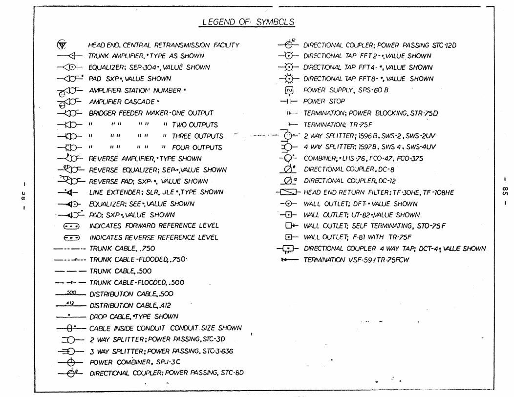
IJ a
LEGEND OF SYMBOLS
~. HEAD EW, CEIVTRAL RETRANSMISSKJN FACILITY
--<:J- TRUNK AtvIPUFIER, • TYPE AS SHOWN
~ EQUALIZER; SEP-J04·. VALUE SHOWN
--<J:J=-! PAD SXP·,'\Itl.lUE SHOWN
#- AMA:.IFIER- STAT/Of\' NUMBER·
~ AMPLIFIER CASCADE II
~ BRIDGER FEEDER MAKER -ONE OUTPUT
-m-- /I " " " It /I TWO CVTPt.JTS
-m- /I /I It II " II THREE (XfTPUTS
-{J:)-" /I " II /I "FOUR Ol/TPUTS
~ REVERSE AMPlIFIER,' TYPE SHOWN
~ REVERSE EQUALIZER; SEP.·,VALUE SHOWN
~ REVERSE ~ SXP. fI, VALUE SHOWN
~- LINE EXTENDER: SLR. JLE ",TYPE SHOWN
~y- EQU4UZER: SEE-,Vl.LUE SHOWN
'---4~ fW); SXP" VALUE SHOWN
~ /f\OCATES FORWARD REFERENCE LEVEL
~ INDICATES REVERSE REFERENCE LEVEL
-----. TRUNK CABLE • .750
------- TRUNK CABLE -FLOODED..750·
- - - TRUNK CABLE..500
- -J:- - TRUNK CABLE-FLOOOED •• 500
::go DfSTRfBUTON CAB...E..500
,"'2 DISTRIBUT()N CABL£..412
-...;."-- CI10P CABLE. ~TYPE SrK.>WN
--10+""--- cABLE /NS1[£ CONootT CONDUIT, SIZE SHONN
::()- 2 W4Y SPLITTER;PONER AtI~lNG.STC-3D
-=0- J W4Y SPLITTER; POWER Rt4SSING, Src-J-6J6
6 POWER COMSINER. SPJ-JC
6 8 DfRECTKY-J4L co:.JPLER: POWeR Ad.SS/NG, STc·ao
612 DIRECTIONAL COUPLER; POWER PASSJNG STC -120
-0- DIRECTIONAL TAPFFT 2--.VALUESNOWN
-0- CXRECTONAJ.. TAP FFT4-·, VALUE SHOWN
. -i!!- DIRECTIONAL TAP FFT8-·, VALUE SHOWN
~ FOWER SUPPLY. SPS-60 B
-i ~ PONER STOP
I~ TERM/NATKW; POWER BLOCKING, STR-75D
~ TERMINATION; TR-75F
'-_.-. -,~- 2 ~Y setITTER; 1596B.SlNS-2,SWS-2W
~ 4 W\Y SFl/TTm; 15978. SVIS 4. SWS-4UV
-<.:;r- COM8JNER;· LHS -76. FCO-47. FCO-J75
~ DfREC TlON4.L COUPLER. OC-8
~ DIRECTION4L COUPLER. OC-12
--{S}- HEAD END RETURN FILTER: TF-JOHE, TF -10aHE
-0- WALL OUTlET; OFT-· VAtiJE SHOWN
, -8- W4l..L DJTl.ET; UT-82-.VALUE SHOWN
0+- ~L WTLET; SELF TERMINATING, STO-75F
G- WALL OUTLET; F-al WITH TR-75F
-Q:J- DIRECTIONAL aJUPLER 4 WAY TAP; DCT-4 ~ \AJJ...£ SHOWN
~ TERMINATION VSF-59ITR-75FCw

SYTEK. INC.
1225 Charleston Road Mountain View, California 94043
(415) 966-7300
-J


