Embed Size (px)
Citation preview
Synthetic catalogue 0913
CERTIFIED COMPANY
UNI EN ISO 9001 : 2008
API Srl ( Apparecchiature Pneumatiche Industriali ) is an Italian company specialised in themanufacturing of pneumatic components.
API started in 1987 as an individual company, and turned into Limited in 1990.
The mission was to create a company with an international printing, our vision, to become a player witha more important role in this constantly changing market.
One of the values leading us through these years, which we always considered indispensable for anyachievement, is the importance of the human resources: work in a stimulating and rewardingenvironment are the basis for any success.
We think that creating synergies and strong partnerships can only produce remarkable results.
The first products API manufactured were circuit accessories, but for long time most of products in APIcatalogue such as valves and cylinders were manufactured elsewhere.
This state of things had a brake in year 1999 when the decision of manufacturing our own productrange was taken: property started investing in a qualified R & D and a modern manufacturing unit.
In the year 2007, another manufacturing unit was established and it also works in different fields notonly with pneumatics
After continuous investments, manufacturing became progressively bigger until reaching today’sproduction capacity and problem solving; logistics, stocks, selection and training of skilled and expertpeople were part of these many investments too.
Professional people are helping us at looking after our website and marketing material such aspublication in specialised field newspapers, exhibitions, and so on.
Our catalogue today offer a wide range of products our own made, it divides in 5 chapters: actuators,valves, airline equipment, accessories, stainless steel components.
On request, we also offer bespoke solutions on specific customer specifications and branded products.
API is an ISO:9001 certified company since 1995 and on request, can certify their products Atex.
We believe that very high quality components coupled with competitive prices, short delivery-time andflexibility can grant us a position in this market.
Over the years, we managed to build a distribution network in many Countries around the World andespecially in most industrialised nations, in facts, more than half of our turnover is made in export.
We keep market and competition constantly monitored and we are always ready to develop newproducts transforming customer needs into solutions, so we can say: we are competitive.
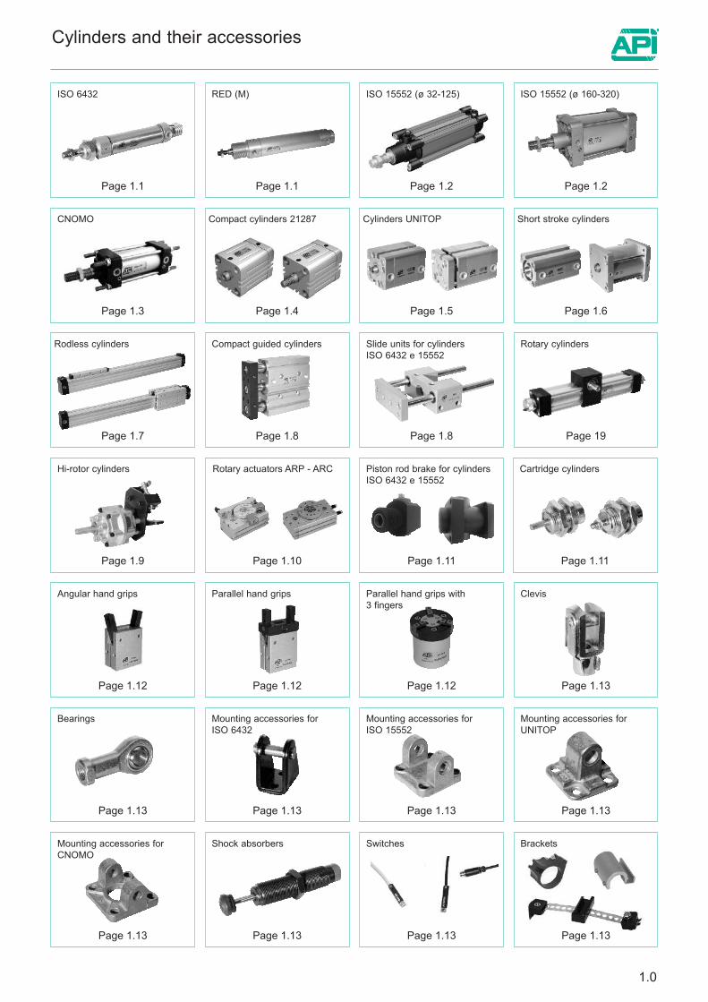
Cylinders and their accessories
RED (M) ISO 15552 (ø 32-125) ISO 15552 (ø 160-320)
Page 1.1
Rotary cylinders
Page 19
Hi-rotor cylinders
Page 1.9
Compact guided cylinders
Page 1.8
Page 1.10
Slide units for cylindersISO 6432 e 15552
Page 1.8
Rotary actuators ARP - ARC Piston rod brake for cylindersISO 6432 e 15552
Page 1.11
Parallel hand grips with3 fingers
Page 1.12
Mounting accessories forISO 6432
Page 1.13
Mounting accessories forISO 15552
Page 1.13
Mounting accessories forCNOMO
Page 1.13
Clevis
Page 1.13
Shock absorbers
Page 1.13
Switches
Page 1.13
Mounting accessories forUNITOP
Page 1.13
Page 1.2 Page 1.2
ISO 6432
Page 1.1
Compact cylinders 21287
Page 1.4
Bearings
Page 1.13
CNOMO
Page 1.3
Angular hand grips
Page 1.12
Parallel hand grips
Page 1.12
Short stroke cylinders
Page 1.6
Rodless cylinders
Page 1.7
1.0
Cylinders UNITOP
Page 1.5
Page 1.11
Cartridge cylinders
Brackets
Page 1.13
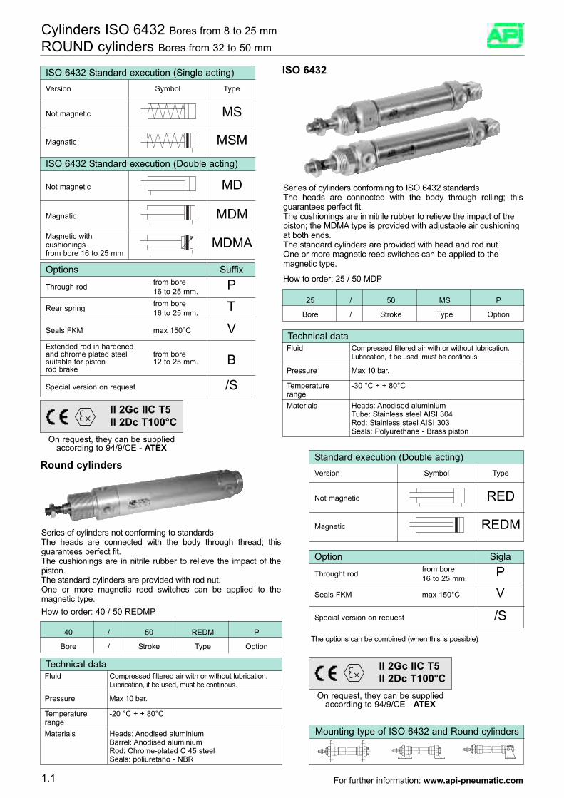
Series of cylinders conforming to ISO 6432 standardsThe heads are connected with the body through rolling; thisguarantees perfect fit.The cushionings are in nitrile rubber to relieve the impact of thepiston; the MDMA type is provided with adjustable air cushioningat both ends.The standard cylinders are provided with head and rod nut.One or more magnetic reed switches can be applied to themagnetic type.
How to order: 25 / 50 MDP
Cylinders ISO 6432 Bores from 8 to 25 mmROUND cylinders Bores from 32 to 50 mm
ISO 6432 Standard execution (Single acting)Version Symbol Type
Not magnetic MS
Magnatic MSM
ISO 6432 Standard execution (Double acting)
Not magnetic MD
Magnatic MDMMagnetic with cushionings MDMAfrom bore 16 to 25 mm
ISO 6432
Round cylinders
Series of cylinders not conforming to standardsThe heads are connected with the body through thread; thisguarantees perfect fit.The cushionings are in nitrile rubber to relieve the impact of thepiston.The standard cylinders are provided with rod nut.One or more magnetic reed switches can be applied to themagnetic type.How to order: 40 / 50 REDMP
The options can be combined (when this is possible)
Standard execution (Double acting)Version Symbol Type
Not magnetic RED
Magnetic REDM
Mounting type of ISO 6432 and Round cylinders
Technical dataFluid Compressed filtered air with or without lubrication.
Lubrication, if be used, must be continous.
Pressure Max 10 bar.
Temperature -20 °C ÷ + 80°CrangeMaterials Heads: Anodised aluminium
Barrel: Anodised aluminiumRod: Chrome-plated C 45 steelSeals: poliuretano - NBR
Technical dataFluid Compressed filtered air with or without lubrication.
Lubrication, if be used, must be continous.
Pressure Max 10 bar.
Temperature -30 °C ÷ + 80°CrangeMaterials Heads: Anodised aluminium
Tube: Stainless steel AISI 304Rod: Stainless steel AISI 303Seals: Polyurethane - Brass piston
25 / 50 MS P
Bore / Stroke Type Option
40 / 50 REDM P
Bore / Stroke Type Option
Options Suffixfrom boreThrough rod P16 to 25 mm.from boreRear spring T16 to 25 mm.
Seals FKM max 150°C VExtended rod in hardenedand chrome plated steel from boresuitable for piston 12 to 25 mm. Brod brake
Special version on request /S
Option Siglafrom boreThrought rod P16 to 25 mm.
Seals FKM max 150°C V
Special version on request /S
1.1
On request, they can be suppliedaccording to 94/9/CE - ATEX
II 2Gc IIC T5II 2Dc T100°C
On request, they can be suppliedaccording to 94/9/CE - ATEX
II 2Gc IIC T5II 2Dc T100°C
For further information: www.api-pneumatic.com
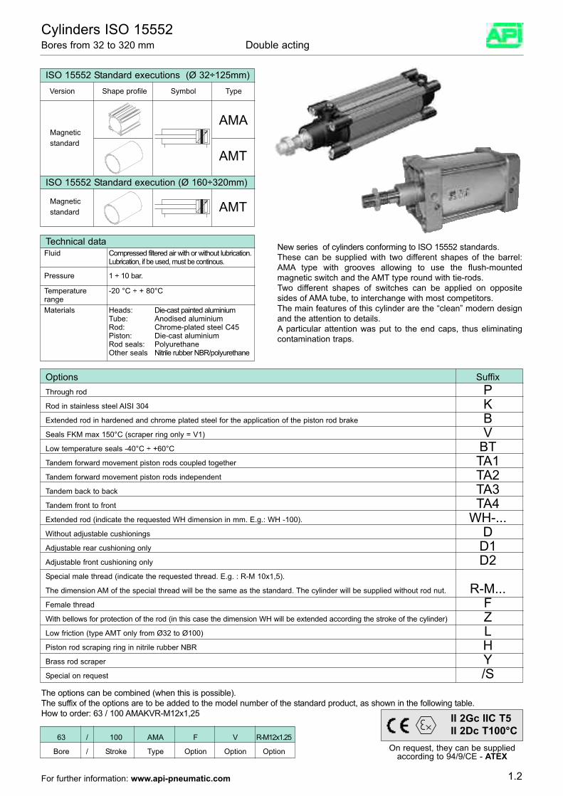
Cylinders ISO 15552Bores from 32 to 320 mm Double acting
New series of cylinders conforming to ISO 15552 standards.These can be supplied with two different shapes of the barrel:AMA type with grooves allowing to use the flush-mountedmagnetic switch and the AMT type round with tie-rods.Two different shapes of switches can be applied on oppositesides of AMA tube, to interchange with most competitors.The main features of this cylinder are the “clean” modern designand the attention to details. A particular attention was put to the end caps, thus eliminatingcontamination traps.
The options can be combined (when this is possible).The suffix of the options are to be added to the model number of the standard product, as shown in the following table.How to order: 63 / 100 AMAKVR-M12x1,25
ISO 15552 Standard executions (Ø 32÷125mm)Version Shape profile Symbol Type
AMA
AMT
Magneticstandard
ISO 15552 Standard execution (Ø 160÷320mm)
Magneticstandard AMT
Technical dataFluid Compressed filtered air with or without lubrication.
Lubrication, if be used, must be continous.
Pressure 1 ÷ 10 bar.
Temperature -20 °C ÷ + 80°CrangeMaterials Heads: Die-cast painted aluminium
Tube: Anodised aluminiumRod: Chrome-plated steel C45Piston: Die-cast aluminiumRod seals: Polyurethane Other seals Nitrile rubber NBR/polyurethane
63 / 100 AMA F V R-M12x1.25
Bore / Stroke Type Option Option Option
1.2
Options SuffixThrough rod PRod in stainless steel AISI 304 KExtended rod in hardened and chrome plated steel for the application of the piston rod brake BSeals FKM max 150°C (scraper ring only = V1) VLow temperature seals -40°C ÷ +60°C BTTandem forward movement piston rods coupled together TA1Tandem forward movement piston rods independent TA2Tandem back to back TA3Tandem front to front TA4Extended rod (indicate the requested WH dimension in mm. E.g.: WH -100). WH-...Without adjustable cushionings DAdjustable rear cushioning only D1Adjustable front cushioning only D2Special male thread (indicate the requested thread. E.g. : R-M 10x1,5).
The dimension AM of the special thread will be the same as the standard. The cylinder will be supplied without rod nut. R-M...Female thread FWith bellows for protection of the rod (in this case the dimension WH will be extended according the stroke of the cylinder) ZLow friction (type AMT only from Ø32 to Ø100) LPiston rod scraping ring in nitrile rubber NBR HBrass rod scraper YSpecial on request /S
On request, they can be suppliedaccording to 94/9/CE - ATEX
II 2Gc IIC T5II 2Dc T100°C
For further information: www.api-pneumatic.com
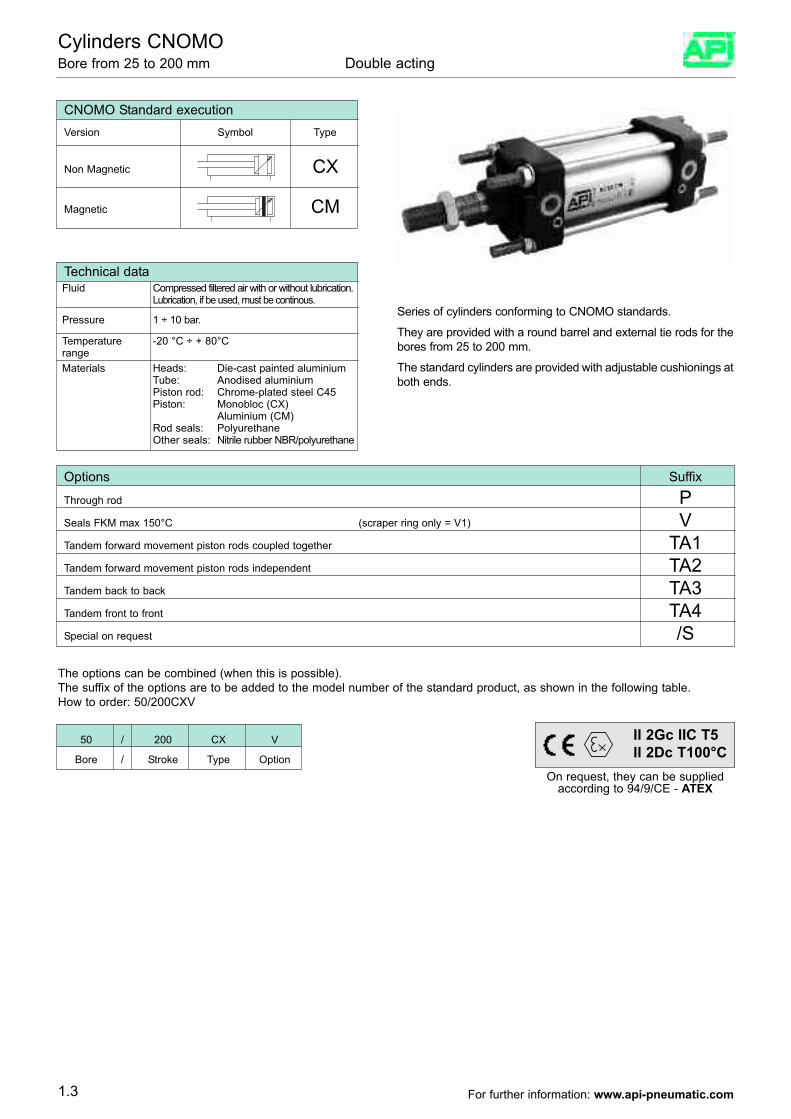
Series of cylinders conforming to CNOMO standards.
They are provided with a round barrel and external tie rods for thebores from 25 to 200 mm.
The standard cylinders are provided with adjustable cushionings atboth ends.
Cylinders CNOMO Bore from 25 to 200 mm Double acting
Non Magnetic CX
CNOMO Standard execution Version Symbol Type
Magnetic CM
Technical dataFluid Compressed filtered air with or without lubrication.
Lubrication, if be used, must be continous.
Pressure 1 ÷ 10 bar.
Temperature -20 °C ÷ + 80°CrangeMaterials Heads: Die-cast painted aluminium
Tube: Anodised aluminiumPiston rod: Chrome-plated steel C45Piston: Monobloc (CX)
Aluminium (CM)Rod seals: PolyurethaneOther seals: Nitrile rubber NBR/polyurethane
The options can be combined (when this is possible).The suffix of the options are to be added to the model number of the standard product, as shown in the following table.How to order: 50/200CXV
50 / 200 CX V
Bore / Stroke Type Option
Options Suffix
Through rod PSeals FKM max 150°C (scraper ring only = V1) VTandem forward movement piston rods coupled together TA1Tandem forward movement piston rods independent TA2Tandem back to back TA3Tandem front to front TA4Special on request /S
1.3
On request, they can be suppliedaccording to 94/9/CE - ATEX
II 2Gc IIC T5II 2Dc T100°C
For further information: www.api-pneumatic.com
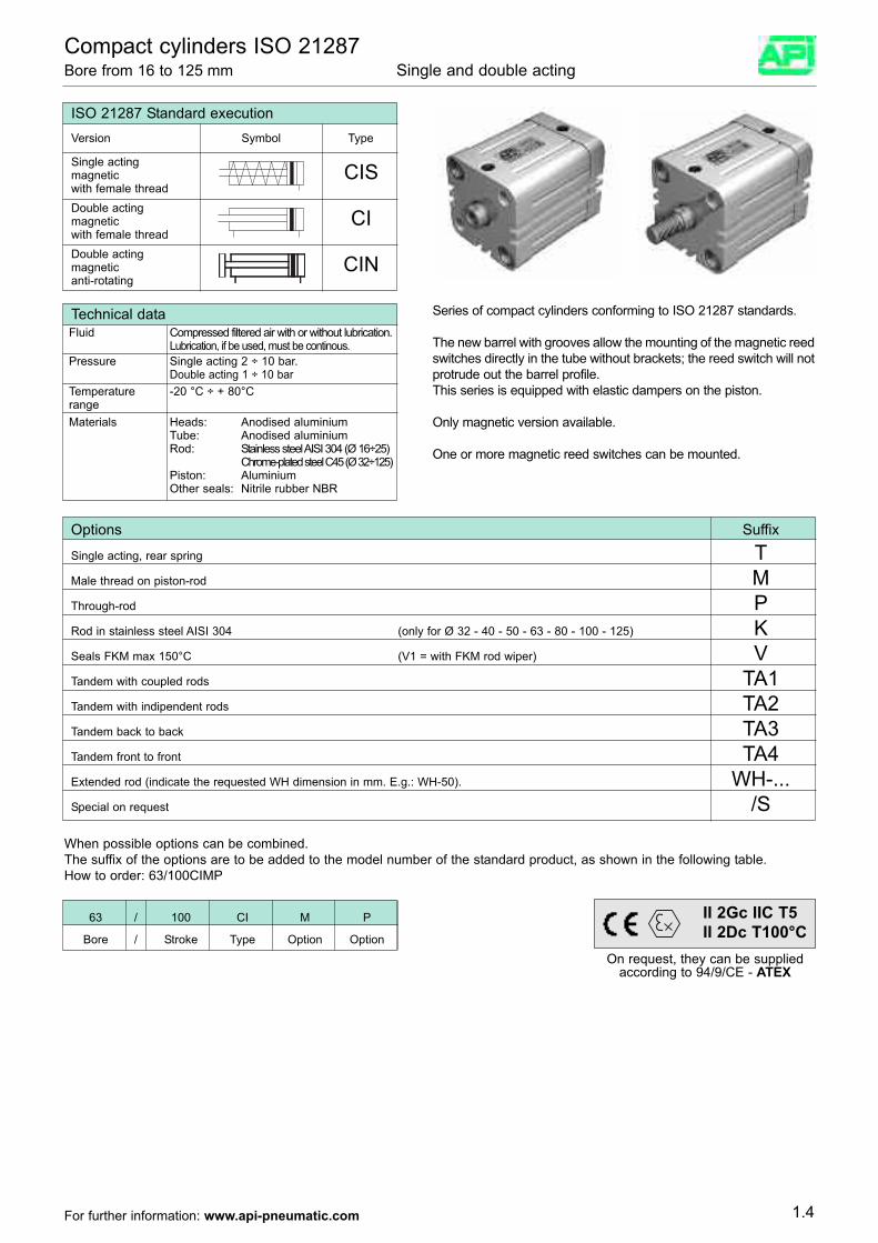
Single actingmagnetic CISwith female threadDouble actingmagnetic CIwith female threadDouble actingmagnetic CINanti-rotating
Compact cylinders ISO 21287Bore from 16 to 125 mm Single and double acting
Series of compact cylinders conforming to ISO 21287 standards.
The new barrel with grooves allow the mounting of the magnetic reedswitches directly in the tube without brackets; the reed switch will notprotrude out the barrel profile.This series is equipped with elastic dampers on the piston.
Only magnetic version available.
One or more magnetic reed switches can be mounted.
Options Suffix
Single acting, rear spring TMale thread on piston-rod MThrough-rod PRod in stainless steel AISI 304 (only for Ø 32 - 40 - 50 - 63 - 80 - 100 - 125) KSeals FKM max 150°C (V1 = with FKM rod wiper) VTandem with coupled rods TA1Tandem with indipendent rods TA2Tandem back to back TA3Tandem front to front TA4Extended rod (indicate the requested WH dimension in mm. E.g.: WH-50). WH-...Special on request /S
When possible options can be combined.The suffix of the options are to be added to the model number of the standard product, as shown in the following table.How to order: 63/100CIMP
ISO 21287 Standard execution Version Symbol Type
Technical dataFluid Compressed filtered air with or without lubrication.
Lubrication, if be used, must be continous.
Temperature -20 °C ÷ + 80°CrangeMaterials Heads: Anodised aluminium
Tube: Anodised aluminiumRod: Stainless steel AISI 304 (Ø 16÷25)
Chrome-plated steel C45 (Ø 32÷125)Piston: AluminiumOther seals: Nitrile rubber NBR
Pressure Single acting 2 ÷ 10 bar.Double acting 1 ÷ 10 bar
63 / 100 CI M P
Bore / Stroke Type Option Option
1.4
On request, they can be suppliedaccording to 94/9/CE - ATEX
II 2Gc IIC T5II 2Dc T100°C
For further information: www.api-pneumatic.com
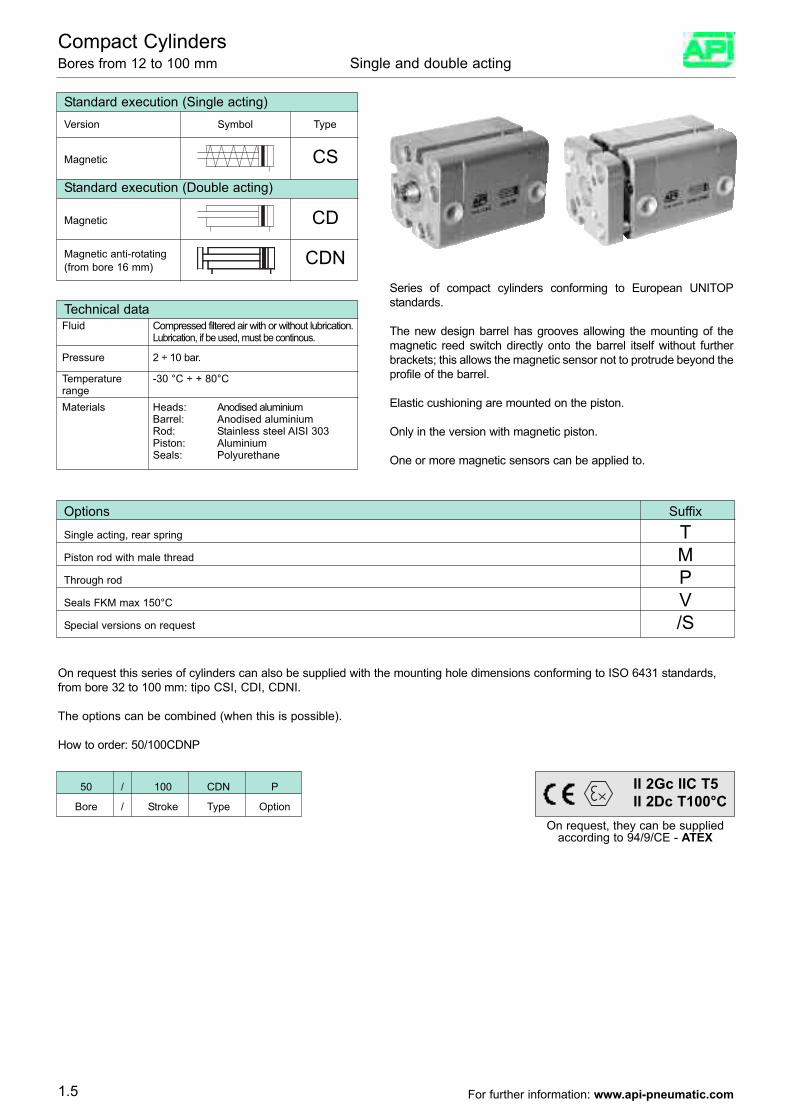
Compact CylindersBores from 12 to 100 mm Single and double acting
Series of compact cylinders conforming to European UNITOPstandards.
The new design barrel has grooves allowing the mounting of themagnetic reed switch directly onto the barrel itself without furtherbrackets; this allows the magnetic sensor not to protrude beyond theprofile of the barrel.
Elastic cushioning are mounted on the piston.
Only in the version with magnetic piston.
One or more magnetic sensors can be applied to.
Technical dataFluid Compressed filtered air with or without lubrication.
Lubrication, if be used, must be continous.
Pressure 2 ÷ 10 bar.
Temperature -30 °C ÷ + 80°CrangeMaterials Heads: Anodised aluminium
Barrel: Anodised aluminiumRod: Stainless steel AISI 303Piston: AluminiumSeals: Polyurethane
Standard execution (Single acting)Version Symbol Type
Magnetic CSStandard execution (Double acting)
Magnetic CD
Magnetic anti-rotating CDN(from bore 16 mm)
On request this series of cylinders can also be supplied with the mounting hole dimensions conforming to ISO 6431 standards,from bore 32 to 100 mm: tipo CSI, CDI, CDNI.
The options can be combined (when this is possible).
How to order: 50/100CDNP
Options Suffix
Single acting, rear spring TPiston rod with male thread MThrough rod PSeals FKM max 150°C VSpecial versions on request /S
50 / 100 CDN P
Bore / Stroke Type Option
1.5
On request, they can be suppliedaccording to 94/9/CE - ATEX
II 2Gc IIC T5II 2Dc T100°C
For further information: www.api-pneumatic.com
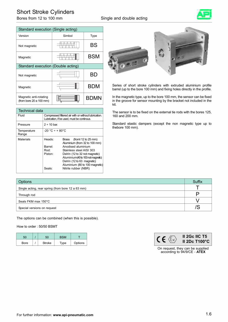
Short Stroke CylindersBores from 12 to 100 mm Single and double acting
Standard execution (Single acting)Version Simbol Type
Not magnetic BS
Magnetic BSM
Standard execution (Double acting)
Not magnetic BD
Magnetic BDM
Magnetic anti-rotating BDMN(from bore 20 a 100 mm)
Series of short stroke cylinders with extruded aluminium profilebarrel (up to the bore 100 mm) and fixing holes directly in the profile.
In the magnetic type, up to the bore 100 mm, the sensor can be fixedin the groove for sensor mounting by the bracket not included in thekit.
The sensor is to be fixed on the external tie rods with the bores 125,160 and 200 mm.
Standard elastic dampers (except the non magnetic type up tothebore 100 mm).
Options Suffix
Single acting, rear spring (from bore 12 a 63 mm) TThrough rod PSeals FKM max 150°C VSpecial versions on request /S
Technical dataFluid Compressed filtered air with or without lubrication.
Lubrication, if be used, must be continous.
Pressure 2 ÷ 10 bar.
Temperature -20 °C ÷ + 80°CRange
Materials Heads: Brass (froml 12 to 25 mm)Aluminium (from 32 to 100 mm)
Barrel: Anodised aluminiumRod: Stainless steel AISI 303Piston: Delrin (12 to 32 not magnetic)
Aluminium(40 to 100 not magnetic)Delrin (12 to 63 magnetic)Aluminium (80 to 100 magnetic)
Seals: Nitrile rubber (NBR)
The options can be combined (when this is possible).
How to order : 50/50 BSMT
50 / 50 BSM T
Bore / Stroke Type Options
1.6
On request, they can be suppliedaccording to 94/9/CE - ATEX
II 2Gc IIC T5II 2Dc T100°C
For further information: www.api-pneumatic.com
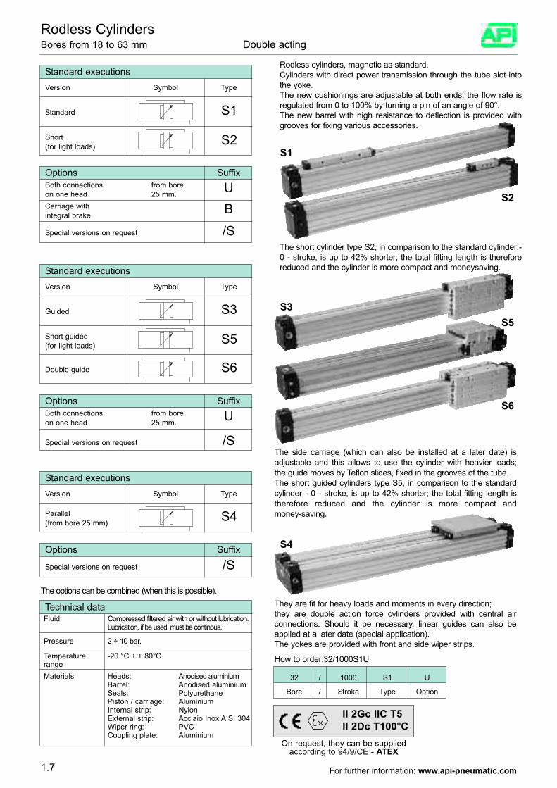
Rodless CylindersBores from 18 to 63 mm Double acting
Standard executions Version Symbol Type
Standard S1
Options SuffixBoth connections from bore Uon one head 25 mm.
Special versions on request /S
Short S2(for light loads)
Carriage with Bintegral brake
Standard executions Version Symbol Type
Guided S3
Options SuffixBoth connections from bore Uon one head 25 mm.
Special versions on request /S
Short guided S5(for light loads)
Double guide S6
Standard executions Version Symbol Type
Parallel S4(from bore 25 mm)
Options Suffix
Special versions on request /S
Technical dataFluid Compressed filtered air with or without lubrication.
Lubrication, if be used, must be continous.
Pressure 2 ÷ 10 bar.
Temperature -20 °C ÷ + 80°CrangeMaterials Heads: Anodised aluminium
Barrel: Anodised aluminiumSeals: Polyurethane Piston / carriage: AluminiumInternal strip: NylonExternal strip: Acciaio Inox AISI 304Wiper ring: PVCCoupling plate: Aluminium
The options can be combined (when this is possible).
Rodless cylinders, magnetic as standard.Cylinders with direct power transmission through the tube slot intothe yoke.The new cushionings are adjustable at both ends; the flow rate isregulated from 0 to 100% by turning a pin of an angle of 90°.The new barrel with high resistance to deflection is provided withgrooves for fixing various accessories.
The side carriage (which can also be installed at a later date) isadjustable and this allows to use the cylinder with heavier loads;the guide moves by Teflon slides, fixed in the grooves of the tube. The short guided cylinders type S5, in comparison to the standardcylinder - 0 - stroke, is up to 42% shorter; the total fitting length istherefore reduced and the cylinder is more compact andmoney-saving.
They are fit for heavy loads and moments in every direction;they are double action force cylinders provided with central airconnections. Should it be necessary, linear guides can also beapplied at a later date (special application). The yokes are provided with front and side wiper strips.
The short cylinder type S2, in comparison to the standard cylinder -0 - stroke, is up to 42% shorter; the total fitting length is thereforereduced and the cylinder is more compact and moneysaving.
How to order:32/1000S1U
32 / 1000 S1 U
Bore / Stroke Type Option
1.7
S1
S2
S3
S6
S5
S4
On request, they can be suppliedaccording to 94/9/CE - ATEX
II 2Gc IIC T5II 2Dc T100°C
For further information: www.api-pneumatic.com
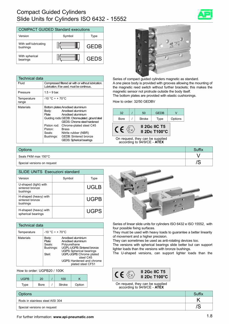
Compact Guided CylindersSlide Units for Cylinders ISO 6432 - 15552
With self-lubricatingbushings GEDB
COMPACT GUIDED Standard executions Version Symbol Type
With sphericalbearings GEDS
Technical dataFluid Compressed filtered air with or without lubrication.
Lubrication, if be used, must be continous..
Pressure 1.5 ÷ 9 bar.
Temperature -10 °C ÷ + 70°Crange
Materials Bottom plates:Anodised aluminiumBody: Anodised aluminiumPlate Anodised aluminiumGuiding rods:GEDB: Chrome-plated , ground steel
GEDS: Chrome steel hardened Piston rod: Chrome-plated steel C45Piston: BrassSeals: Nitrile rubber (NBR)Bushings: GEDB: Sintered bronze
GEDS: Spherical bearings
32 / 50 GEDB V
Bore / Stroke Type Options
Series of compact guided cylinders magnetic as standard.A one piece body is provided with grooves allowing the mounting ofthe magnetic reed switch without further brackets; this makes themagnetic sensor not protrude outside the body itself.The bottom plates are provided with elastic cushionings.
How to order: 32/50 GEDBV
Options Suffix
Seals FKM max 150°C VSpecial versions on request /S
U-shaped (light) withsintered bronze UGLBbushingsH-shaped (heavy) withsintered bronze UGPBbushings
H-shaped (heavy) with UGPSspherical bearings
SLIDE UNITS Esecuzioni standard Version Symbol Type
Technical data
Temperature -10 °C ÷ + 70°C
Materials Body: Anodised aluminiumPlate: Anodised aluminiumSeals: PolyurethaneBushings: UGPL-UGPB: Sintered bronze
UGPS: Spherical bearingsSteli: UGPL-UGPB: Chrome plated
steel C45UGPS: Hardened and chrome
plated steel CF51
Options Suffix
Rods in stainless steel AISI 304 KSpecial versions on request /S
Series of linear slide units for cylinders ISO 6432 e ISO 15552, withfour possible fixing surfaces.They must be used with heavy loads to guarantee a better linearityof movement and a higher precision.They can sometimes be used as anti-rotating devices too.The versions with spherical bearings slide better but can supportlighter loads than the versions with bronze bushings.The U-shaped versions, can support lighter loads than the
How to order: UGPB20 / 100K
UGPB 20 / 100 K
Type Bore / Stroke Option
1.8
On request, they can be suppliedaccording to 94/9/CE - ATEX
II 2Gc IIC T5II 2Dc T100°C
On request, they can be suppliedaccording to 94/9/CE - ATEX
II 2Gc IIC T5II 2Dc T100°C
For further information: www.api-pneumatic.com
Female pinion withrotation angle CRRFadjustment
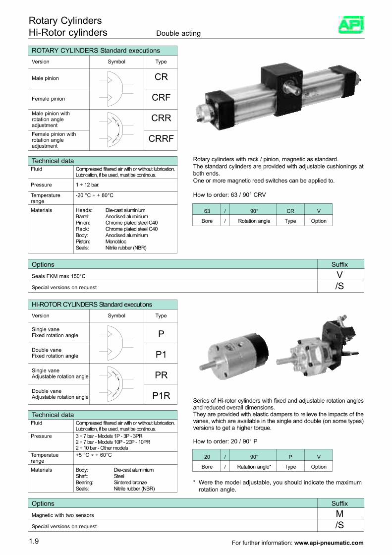
Rotary CylindersHi-Rotor cylinders Double acting
Male pinion CR
Female pinion CRFMale pinion with rotation angle CRRadjustment
ROTARY CYLINDERS Standard executions Version Symbol Type
Rotary cylinders with rack / pinion, magnetic as standard.The standard cylinders are provided with adjustable cushionings atboth ends.One or more magnetic reed switches can be applied to.
How to order: 63 / 90° CRV
Technical dataFluid Compressed filtered air with or without lubrication.
Lubrication, if be used, must be continous.
Pressure 1 ÷ 12 bar.
Temperature -20 °C ÷ + 80°Crange
Materials Heads: Die-cast aluminiumBarrel: Anodised aluminiumPinion: Chrome plated steel C40Rack: Chrome plated steel C40Body: Anodised aluminiumPiston: MonoblocSeals: Nitrile rubber (NBR)
63 / 90° CR V
Bore / Rotation angle Type Option
HI-ROTOR CYLINDERS Standard executions Version Symbol Type
Single vaneFixed rotation angle PDouble vaneFixed rotation angle P1Single vaneAdjustable rotation angle PRDouble vaneAdjustable rotation angle P1R
Technical dataFluid Compressed filtered air with or without lubrication.
Lubrication, if be used, must be continous.
Temperatue +5 °C ÷ + 60°Crange
Materials Body: Die-cast aluminiumShaft: SteelBearing: Sintered bronzeSeals: Nitrile rubber (NBR)
Pressure 3 ÷ 7 bar - Models 1P - 3P - 3PR2 ÷ 7 bar - Models 10P - 20P - 10PR2 ÷ 10 bar - Other models
Options Suffix
Magnetic with two sensors MSpecial versions on request /S
Series of Hi-rotor cylinders with fixed and adjustable rotation anglesand reduced overall dimensions.They are provided with elastic dampers to relieve the impacts of thevanes, which are available in the single and double (on some types)versions to get a higher torque.
How to order: 20 / 90° P
20 / 90° P V
Bore / Ratation angle* Type Option
* Were the model adjustable, you should indicate the maximumrotation angle.
Options Suffix
Seals FKM max 150°C VSpecial versions on request /S
1.9 For further information: www.api-pneumatic.com
Materials Body: Anodized aluminiumHeads: Anodized aluminiumPiston rod: Hardned steelRack: Stainless steelRotating plate: Anodized aluminiumSeals: Nitrile rubber(NBR)
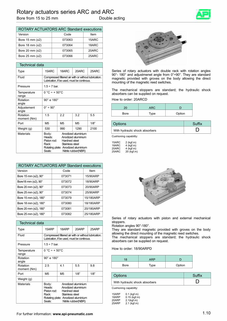
Rotary actuators series ARC and ARCBore from 15 to 25 mm Double acting
ROTARY ACTUATORS ARC Standard executionsVersion Code Item
Bore 15 mm (x2) 073063 15ARC
Bore 18 mm (x2) 073064 18ARC
Bore 20 mm (x2) 073065 20ARC
Bore 25 mm (x2) 073066 25ARC
Technical data
Fluid Compressed filtered air with or without lubrication.Lubrication, if be used, must be continous.
Pressure 1.5 ÷ 7 bar.
Temperature 0 °C ÷ + 50°Crange
Materials Body: Anodized aluminiumHeads: Anodized aluminiumPiston rod: Hardned steelRack: Stainless steelRotating plate: Anodized aluminiumSeals: Nitrile rubber(NBR)
Rotation 90° e 180°angleAdjustement 0° ÷ 90°angle
Type 15ARC 18ARC 20ARC 25ARC
Rotation 1.5 2.2 3.2 5.5moment (Nm)Port M5 M5 M5 1/8”
Weight (g) 530 990 1290 2100
Series of rotary actuators with double rack with rotation angles90°- 180° and adjustmenet angle from 0°÷90°. They are standardmagnetic provided with groves on the body allowing the directmounting of the magnetic reed switches.
The mechanical stoppers are standard; the hydraulic shockabsorbers can be supplied on request.
How to order: 20ARCD
20 ARC D
Bore Type Option
Options Suffix
With hydraulic shock absorbers DCushioning capability:
15ARC 2 (kgf.m)18ARC 4 (kgf.m)20ARC 4 (kgf.m)25ARC 20 (kgf.m)
ROTARY ACTUATORS ARP Standard executionsVersion Code Item
Bore 15 mm (x2), 90° 073071 15/90ARP
Bore18 mm (x2), 90° 073072 18/90ARP
Bore 20 mm (x2), 90° 073073 20/90ARP
Bore 25 mm (x2), 90° 073074 25/90ARP
Technical data
Fluid Compressed filtered air with or without lubrication.Lubrication, if be used, must be continous.
Pressure 1.5 ÷ 7 bar.
Temperature 0 °C ÷ + 50°CrangeRotation 90° e 180°angle
Type 15ARP 18ARP 20ARP 25ARP
Rotation 2.5 4.1 5.5 9.8moment (Nm)Port M5 M5 1/8” 1/8”
Weight (g)
18 ARP D
Bore Type Option
Options Suffix
With hydraulic shock absorbers DCushioning capability:
15ARP 0.1 (kgf.m)18ARP 0.15 (kgf.m)20ARP 2.1(kgf.m)25ARP 2.1 (kgf.m)
Bore 15 mm (x2), 180° 073079 15/180ARP
Bore 18 mm (x2), 180° 073080 18/180ARP
Bore 20 mm (x2), 180° 073081 20/180ARP
Bore 25 mm (x2), 180° 073082 25/180ARPSeries of rotary actuators with piston and external mechanicalstoppers.Rotation angles 90°-180°.They are standard magnetic provided with groves on the bodyallowing the direct mounting of the magnetic reed switches.The mechanical stoppers are standard; the hydraulic shockabsorbers can be supplied on request.
How to order: 18/90ARPD
1.10For further information: www.api-pneumatic.com
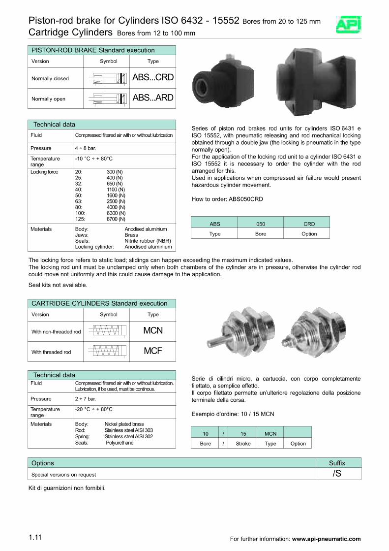
Piston-rod brake for Cylinders ISO 6432 - 15552 Bores from 20 to 125 mm
Cartridge Cylinders Bores from 12 to 100 mm
PISTON-ROD BRAKE Standard execution Version Symbol Type
Normally closed ABS...CRD
Normally open ABS...ARD
Technical dataFluid Compressed filtered air with or without lubrication
Pressure 4 ÷ 8 bar.
Temperature -10 °C ÷ + 80°CrangeLocking force 20: 300 (N)
25: 400 (N)32: 650 (N)40: 1100 (N)50: 1600 (N)63: 2500 (N)80: 4000 (N)100: 6300 (N)125: 8700 (N)
Series of piston rod brakes rod units for cylinders ISO 6431 eISO 15552, with pneumatic releasing and rod mechanical lockingobtained through a double jaw (the locking is pneumatic in the typenormally open).For the application of the locking rod unit to a cylinder ISO 6431 eISO 15552 it is necessary to order the cylinder with the rodarranged for this.Used in applications when compressed air failure would presenthazardous cylinder movement.
How to order: ABS050CRD
The locking force refers to static load; slidings can happen exceeding the maximum indicated values.The locking rod unit must be unclamped only when both chambers of the cylinder are in pressure, otherwise the cylinder rodcould move not uniformly and this could cause damage to the application.
Seal kits not available.
ABS 050 CRD
Type Bore OptionMaterials Body: Anodised aluminium
Jaws: BrassSeals: Nitrile rubber (NBR)Locking cylinder: Anodised aluminium
CARTRIDGE CYLINDERS Standard execution Version Symbol Type
With non-threaded rod MCN
With threaded rod MCF
Serie di cilindri micro, a cartuccia, con corpo completamentefilettato, a semplice effetto.Il corpo filettato permette un’ulteriore regolazione della posizioneterminale della corsa.
Esempio d’ordine: 10 / 15 MCN
Technical dataFluid Compressed filtered air with or without lubrication.
Lubrication, if be used, must be continous.
Pressure 2 ÷ 7 bar.
Temperature -20 °C ÷ + 80°Crange
Materials Body: Nickel plated brassRod: Stainless steel AISI 303Spring: Stainless steel AISI 302Seals: Polyurethane
Options Suffix
Special versions on request /S
10 / 15 MCN
Bore / Stroke Type Option
Kit di guarnizioni non fornibili.
1.11 For further information: www.api-pneumatic.com
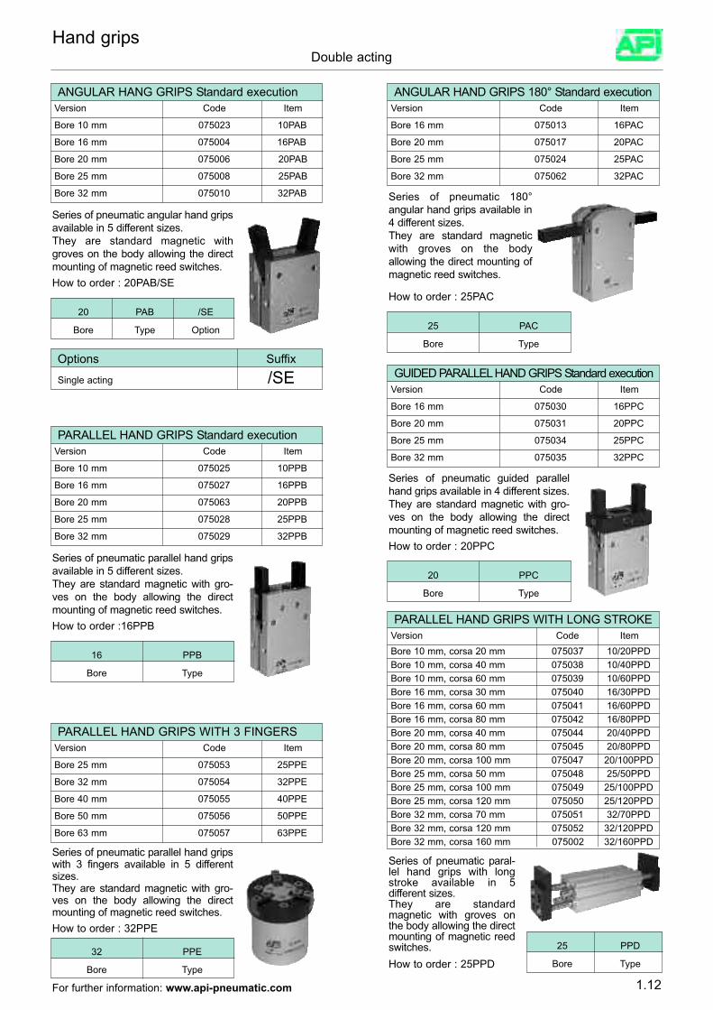
Hand gripsDouble acting
ANGULAR HANG GRIPS Standard executionVersion Code Item
Bore 10 mm 075023 10PAB
Bore 16 mm 075004 16PAB
Bore 20 mm 075006 20PAB
Bore 25 mm 075008 25PAB
Bore 32 mm 075010 32PAB
Series of pneumatic angular hand gripsavailable in 5 different sizes.They are standard magnetic withgroves on the body allowing the directmounting of magnetic reed switches.How to order : 20PAB/SE
ANGULAR HAND GRIPS 180° Standard executionVersion Code Item
Bore 16 mm 075013 16PAC
Bore 20 mm 075017 20PAC
Bore 25 mm 075024 25PAC
Bore 32 mm 075062 32PAC
Series of pneumatic 180°angular hand grips available in4 different sizes.They are standard magneticwith groves on the bodyallowing the direct mounting ofmagnetic reed switches.
How to order : 25PAC20 PAB /SE
Bore Type Option
Options Suffix
Single acting /SE
25 PAC
Bore Type
PARALLEL HAND GRIPS Standard executionVersion Code Item
Bore 10 mm 075025 10PPB
Bore 16 mm 075027 16PPB
Bore 20 mm 075063 20PPB
Bore 25 mm 075028 25PPB
Bore 32 mm 075029 32PPB
Series of pneumatic parallel hand gripsavailable in 5 different sizes.They are standard magnetic with gro-ves on the body allowing the directmounting of magnetic reed switches.How to order :16PPB
16 PPB
Bore Type
GUIDED PARALLEL HAND GRIPS Standard executionVersion Code Item
Bore 16 mm 075030 16PPC
Bore 20 mm 075031 20PPC
Bore 25 mm 075034 25PPC
Bore 32 mm 075035 32PPC
Series of pneumatic guided parallelhand grips available in 4 different sizes.They are standard magnetic with gro-ves on the body allowing the directmounting of magnetic reed switches.How to order : 20PPC
20 PPC
Bore Type
PARALLEL HAND GRIPS WITH 3 FINGERS Version Code Item
Bore 25 mm 075053 25PPE
Bore 32 mm 075054 32PPE
Bore 40 mm 075055 40PPE
Bore 50 mm 075056 50PPE
Bore 63 mm 075057 63PPE
Series of pneumatic parallel hand gripswith 3 fingers available in 5 differentsizes.They are standard magnetic with gro-ves on the body allowing the directmounting of magnetic reed switches.How to order : 32PPE
32 PPE
Bore Type
PARALLEL HAND GRIPS WITH LONG STROKEVersion Code ItemBore 10 mm, corsa 20 mm 075037 10/20PPD
Series of pneumatic paral-lel hand grips with longstroke available in 5different sizes.They are standardmagnetic with groves onthe body allowing the directmounting of magnetic reedswitches.How to order : 25PPD
25 PPD
Bore Type
Bore 10 mm, corsa 40 mm 075038 10/40PPDBore 10 mm, corsa 60 mm 075039 10/60PPDBore 16 mm, corsa 30 mm 075040 16/30PPDBore 16 mm, corsa 60 mm 075041 16/60PPDBore 16 mm, corsa 80 mm 075042 16/80PPDBore 20 mm, corsa 40 mm 075044 20/40PPDBore 20 mm, corsa 80 mm 075045 20/80PPDBore 20 mm, corsa 100 mm 075047 20/100PPDBore 25 mm, corsa 50 mm 075048 25/50PPDBore 25 mm, corsa 100 mm 075049 25/100PPDBore 25 mm, corsa 120 mm 075050 25/120PPDBore 32 mm, corsa 70 mm 075051 32/70PPDBore 32 mm, corsa 120 mm 075052 32/120PPDBore 32 mm, corsa 160 mm 075002 32/160PPD
1.12For further information: www.api-pneumatic.com
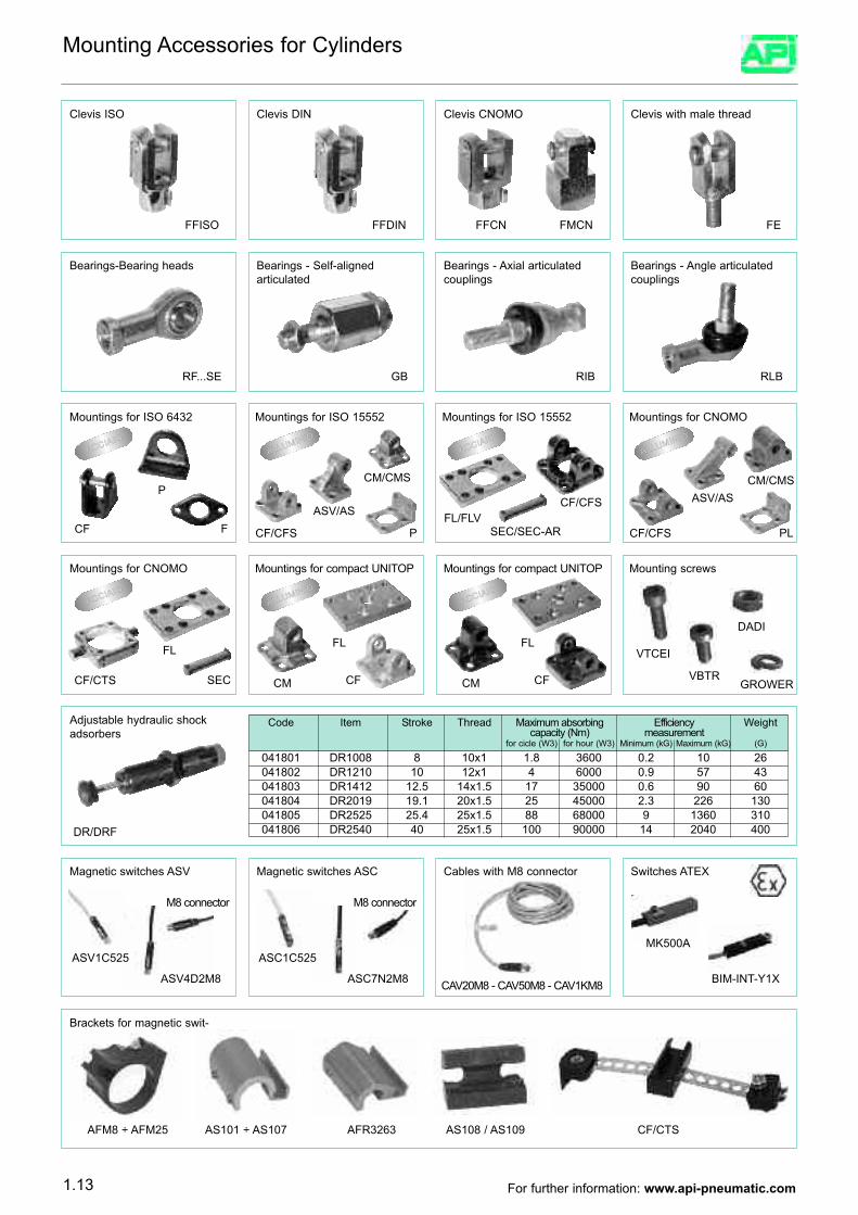
Mountings for ISO 6432
Adjustable hydraulic shockadsorbers
Cables with M8 connector
Brackets for magnetic swit-
Clevis ISO
FFISO
Clevis DIN
FFDIN
Clevis CNOMO
FMCN
Clevis with male thread
FEFFCN
Bearings-Bearing heads
RF...SE
Bearings - Self-aligned articulated
GB
Bearings - Axial articulatedcouplings
RIB
Bearings - Angle articulatedcouplings
RLB
FCF
P
ACCIAIO
Mountings for ISO 15552
PCF/CFS
ASV/AS
ALLUMINIO
CM/CMS
Mountings for ISO 15552
CF/CFSFL/FLV
SEC/SEC-AR
ACCIAIO
Mountings for CNOMO
PLCF/CFS
ASV/AS
ALLUMINIO
CM/CMS
Mountings for CNOMO
SECCF/CTS
FL
ACCIAIO
Mountings for compact UNITOP
ALLUMINIO
Mounting screws
GROWER
VTCEI
VBTR
DADI
CFCM
FL
Mountings for compact UNITOP
CFCM
FL
ACCIAIO
DR/DRF
041801 DR1008 8 10x1 1.8 3600 0.2 10 26041802 DR1210 10 12x1 4 6000 0.9 57 43041803 DR1412 12.5 14x1.5 17 35000 0.6 90 60041804 DR2019 19.1 20x1.5 25 45000 2.3 226 130041805 DR2525 25.4 25x1.5 88 68000 9 1360 310041806 DR2540 40 25x1.5 100 90000 14 2040 400
Code Item Stroke Thread Maximum absorbing Efficiency Weightcapacity (Nm) measurement
for cicle (W3) for hour (W3) Minimum (kG) Maximum (kG) (G)
Magnetic switches ASV
ASV1C525
ASV4D2M8
M8 connector
Magnetic switches ASC
ASC1C525
ASC7N2M8
M8 connector
CAV20M8 - CAV50M8 - CAV1KM8
Switches ATEX
MK500A
BIM-INT-Y1X
AFM8 ÷ AFM25 AFR3263 AS108 / AS109 CF/CTSAS101 ÷ AS107
Mounting Accessories for Cylinders
1.13 For further information: www.api-pneumatic.com
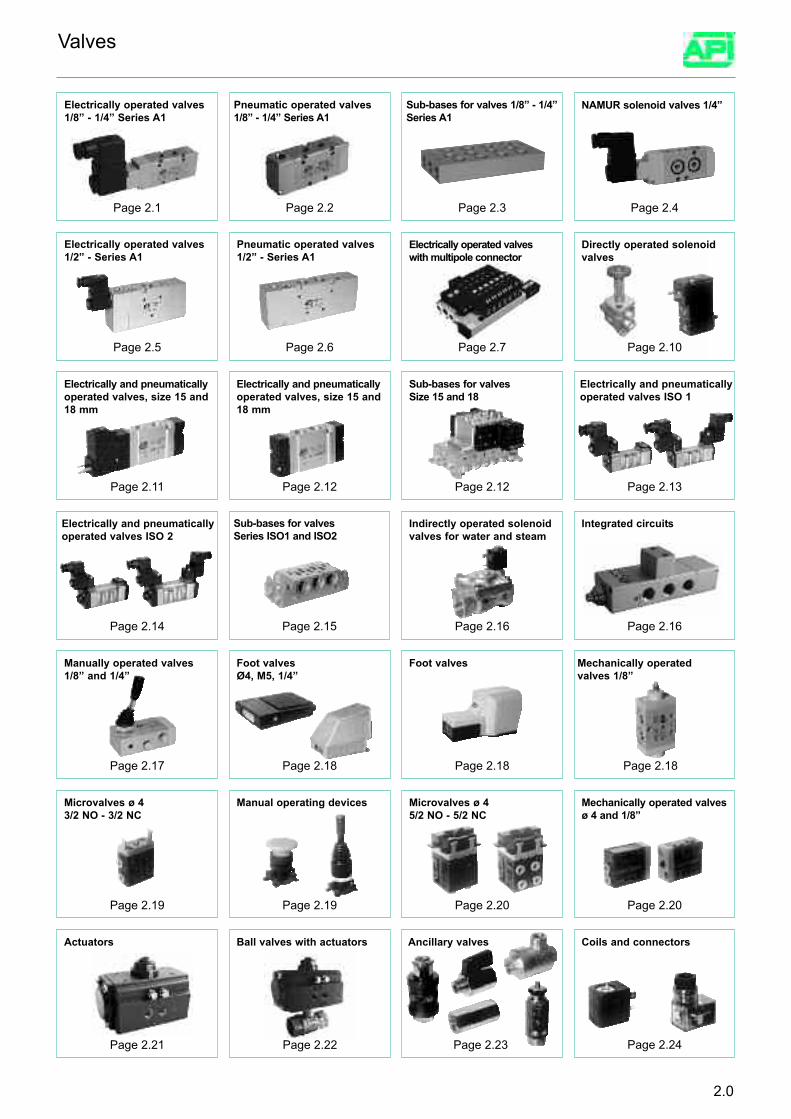
Electrically and pneumaticallyoperated valves, size 15 and18 mm
Page 2.5
Electrically and pneumaticallyoperated valves ISO 2
Page 2.14
Electrically and pneumaticallyoperated valves ISO 1
Page 2.13
Integrated circuits
Page 2.16
Foot valves
Page 2.18
Microvalves ø 4 3/2 NO - 3/2 NC
Page 2.19
Mechanically operated valvesø 4 and 1/8”
Page 2.20
Manually operated valves1/8” and 1/4”
Page 2.17
Mechanically operatedvalves 1/8”
Page 2.18
Actuators
NAMUR solenoid valves 1/4”
Page 2.4
Page 2.11
Electrically operated valves1/2” - Series A1
Ball valves with actuators
Electrically operated valveswith multipole connector
Page 2.7
Valves
2.0
Page 2.1
Electrically operated valves1/8” - 1/4” Series A1
Page 2.2
Pneumatic operated valves1/8” - 1/4” Series A1
Page 2.3
Sub-bases for valves 1/8” - 1/4”Series A1
Page 2.6
Pneumatic operated valves1/2” - Series A1
Directly operated solenoidvalves
Page 2.10
Indirectly operated solenoidvalves for water and steam
Page 2.16
Page 2.21 Page 2.22
Coils and connectors
Page 2.24
Microvalves ø 4 5/2 NO - 5/2 NC
Page 2.20
Manual operating devices
Page 2.19
Foot valvesØ4, M5, 1/4”
Page 2.18
Page 2.15
Sub-bases for valvesSeries ISO1 and ISO2
Sub-bases for valves Size 15 and 18
Page 2.12
Electrically and pneumaticallyoperated valves, size 15 and18 mm
Page 2.12
Ancillary valves
Page 2.23
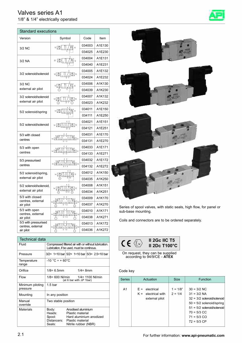
Valves series A1 1/8” & 1/4” electrically operated
2
13
12 10
Standard executions
034003 A1E130
Version Symbol Code Item
034025 A1E2303/2 NC
2
1 3
23 12034004 A1E131
034040 A1E2313/2 NA
2
13
12 10
034005 A1E132
034024 A1E2323/2 solenoid/solenoid
2
3 1
12 10034006 A1K130
034039 A1K230
3/2 NC external air pilot
2
13
12 10034007 A1K132
034023 A1K232
3/2 solenoid/solenoidexternal air pilot
14
1
24
5 3
12034011 A1E150
034111 A1E2505/2 solenoid/spring
24
35 1
14 12
034021 A1E151
034121 A1E2515/2 solenoid/solenoid
4 2
15 314 12
034031 A1E170
034131 A1E270
5/3 with closedcentres
4 2
5 1 314 12
034033 A1E171
034133 A1E271
5/3 with opencentres
4 2
5 1 3
14 12
034032 A1E172
034132 A1E272
5/3 pressurisedcentres
24
35 1
14 12034012 A1K150
034035 A1K250
5/2 solenoid/spring,external air pilot
24
35 1
14 12034008 A1K151
034034 A1K251
5/2 solenoid/solenoid,external air pilot
4 2
5 1 3
14 12
034009 A1K170
034037 A1K270
5/3 with closedcentres, externalair pilot
4 2
5 1 3
14 12
034010 A1K171
034038 A1K271
5/3 with opencentres, externalair pilot
4 2
5 1 3
14 12
034013 A1K172
034036 A1K272
5/3 with pressurisedcentres, externalair pilot
Technical dataFluid Compressed filtered air with or without lubrication.
Lubrication, if be used, must be continous.
Pressure 3/2= 1÷10 bar 5/2= 1÷10 bar 5/3= 2.5÷10 bar
Temperature -10 °C ÷ + 60°Crange
Materials Body: Anodised aluminiumHeads: Plastic materialSpool: Hard aluminium anodized Distancers: Plastic materialSeals: Nitrile rubber (NBR)
Orifice 1/8= 6.5mm 1/4= 8mm
Flow 1/8= 600 Nl/min 1/4= 1100 Nl/min(at 6 bar with ∆P 1bar)
Minimum piloting 1.5 barpressure
Mounting In any position
Manual Two stable positionoverride
Series of spool valves, with static seals, high flow, for panel orsub-base mounting.
Coils and connectors are to be ordered separately.
Series Actuation Size Function
A1 E = electricalK = electrical with
external pilot
1 = 1/8”2 = 1/4
30 = 3/2 NC31 = 3/2 NA32 = 3/2 solenoid/solenoid50 = 5/2 solenoid/spring51 = 5/2 solenoid/solenoid70 = 5/3 CC71 = 5/3 CO72 = 5/3 CP
Code key
2.1
On request, they can be suppliedaccording to 94/9/CE - ATEX
II 2Gc IIC T5II 2Dc T100°C
For further information: www.api-pneumatic.com
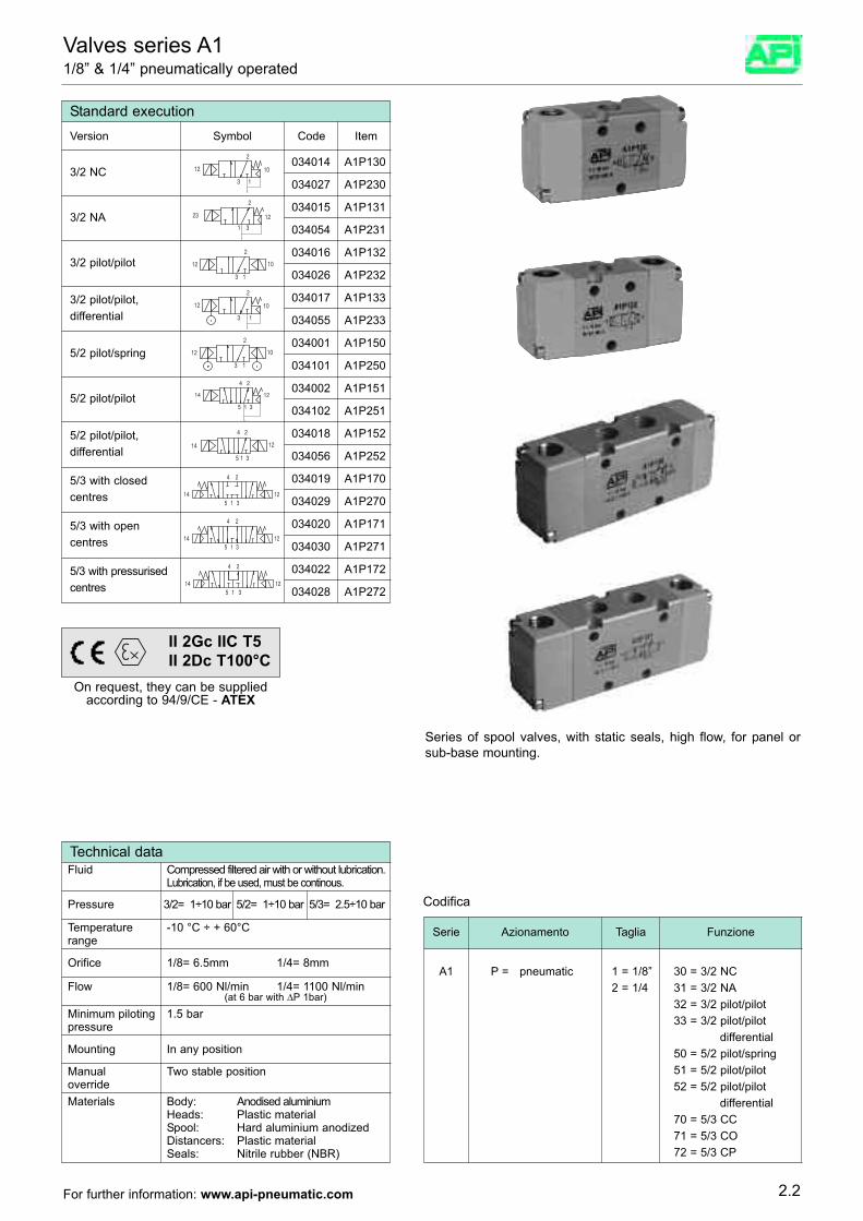
Valves series A11/8” & 1/4” pneumatically operated
2
13
12 10
Standard execution
034014 A1P130
Version Symbol Code Item
034027 A1P2303/2 NC
2
1 3
23 12034015 A1P131
034054 A1P2313/2 NA
2
13
12 10
034016 A1P132
034026 A1P2323/2 pilot/pilot
2
3 1
12 10034017 A1P133
034055 A1P233
3/2 pilot/pilot,differential
2
13
12 10034001 A1P150
034101 A1P250
14
1
24
5 3
12034002 A1P151
034102 A1P251
5/2 pilot/spring
24
35 1
14 12
034018 A1P152
034056 A1P252
5/2 pilot/pilot
4 2
15 314 12
034019 A1P170
034029 A1P270
5/3 with closedcentres
4 2
5 1 314 12
034020 A1P171
034030 A1P271
5/3 with opencentres
4 2
5 1 3
14 12
034022 A1P172
034028 A1P272
5/3 with pressurisedcentres
5/2 pilot/pilot,differential
Codifica
Serie Azionamento Taglia Funzione
A1 P = pneumatic 1 = 1/8”2 = 1/4
30 = 3/2 NC31 = 3/2 NA32 = 3/2 pilot/pilot33 = 3/2 pilot/pilot
differential50 = 5/2 pilot/spring51 = 5/2 pilot/pilot52 = 5/2 pilot/pilot
differential70 = 5/3 CC71 = 5/3 CO72 = 5/3 CP
Series of spool valves, with static seals, high flow, for panel orsub-base mounting.
2.2
On request, they can be suppliedaccording to 94/9/CE - ATEX
II 2Gc IIC T5II 2Dc T100°C
Technical dataFluid Compressed filtered air with or without lubrication.
Lubrication, if be used, must be continous.
Pressure 3/2= 1÷10 bar 5/2= 1÷10 bar 5/3= 2.5÷10 bar
Temperature -10 °C ÷ + 60°Crange
Materials Body: Anodised aluminiumHeads: Plastic materialSpool: Hard aluminium anodized Distancers: Plastic materialSeals: Nitrile rubber (NBR)
Orifice 1/8= 6.5mm 1/4= 8mm
Flow 1/8= 600 Nl/min 1/4= 1100 Nl/min(at 6 bar with ∆P 1bar)
Minimum piloting 1.5 barpressure
Mounting In any position
Manual Two stable positionoverride
For further information: www.api-pneumatic.com
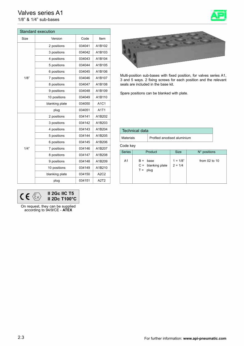
Valves series A1 1/8” & 1/4” sub-bases
Standard execution
2 positions 034041 A1B102
Size Version Code Item
3 positions 034042 A1B103
4 positions 034043 A1B104
5 positions 034044 A1B105
6 positions 034045 A1B106
7 positions 034046 A1B107
10 positions 034049 A1B110
blanking plate 034050 A1C1
8 positions 034047 A1B108
9 positions 034048 A1B109
plug 034051 A1T1
2 positions 034141 A1B202
3 positions 034142 A1B203
4 positions 034143 A1B204
5 positions 034144 A1B205
6 positions 034145 A1B206
7 positions 034146 A1B207
10 positions 034149 A1B210
blanking plate 034150 A2C2
8 positions 034147 A1B208
9 positions 034148 A1B209
plug 034151 A2T2
1/8”
1/4”
Multi-position sub-bases with fixed position, for valves series A1,3 and 5 ways. 2 fixing screws for each position and the relevantseals are included in the base kit.
Spare positions can be blanked with plate.
Series Product Size N° positions
A1 B = baseC = blanking plate T = plug
1 = 1/8”2 = 1/4
from 02 to 10
Code key
Technical data
Materials Profiled anodised aluminium
2.3
On request, they can be suppliedaccording to 94/9/CE - ATEX
II 2Gc IIC T5II 2Dc T100°C
For further information: www.api-pneumatic.com
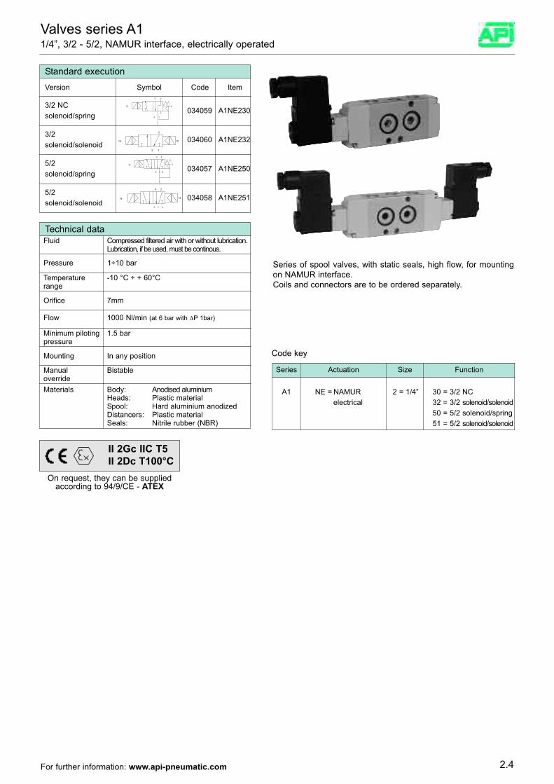
Valves series A11/4”, 3/2 - 5/2, NAMUR interface, electrically operated
Standard execution
034059 A1NE230
Version Symbol Code Item
3/2 NCsolenoid/spring
034060 A1NE2323/2 solenoid/solenoid
034057 A1NE2505/2 solenoid/spring
034058 A1NE2515/2solenoid/solenoid
Series of spool valves, with static seals, high flow, for mountingon NAMUR interface.Coils and connectors are to be ordered separately.
Technical dataFluid Compressed filtered air with or without lubrication.
Lubrication, if be used, must be continous.
Pressure 1÷10 bar
Temperature -10 °C ÷ + 60°Crange
Materials Body: Anodised aluminiumHeads: Plastic materialSpool: Hard aluminium anodized Distancers: Plastic materialSeals: Nitrile rubber (NBR)
Orifice 7mm
Flow 1000 Nl/min (at 6 bar with ∆P 1bar)
Minimum piloting 1.5 barpressure
Mounting In any position
Manual Bistableoverride
Code key
Series Actuation Size Function
A1 NE = NAMURelectrical
2 = 1/4” 30 = 3/2 NC32 = 3/2 solenoid/solenoid50 = 5/2 solenoid/spring51 = 5/2 solenoid/solenoid
On request, they can be suppliedaccording to 94/9/CE - ATEX
II 2Gc IIC T5II 2Dc T100°C
2.4For further information: www.api-pneumatic.com
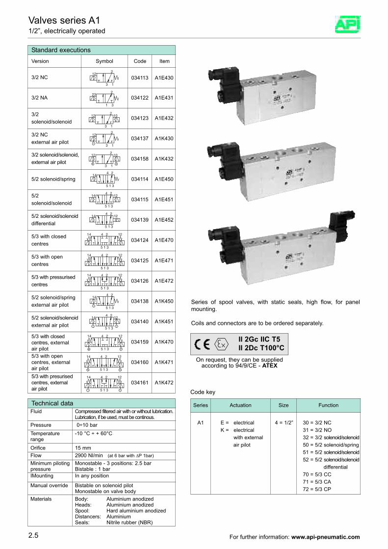
Valves series A11/2”, electrically operated
122
3 1
Standard executions
034113 A1E430
Version Symbol Code Item
3/2 NC
232
1 3
034122 A1E4313/2 NA
10122
3 1
034123 A1E4323/2solenoid/solenoid
122
3 1
034137 A1K4303/2 NC external air pilot
10122
3 1
034158 A1K4323/2 solenoid/solenoid,external air pilot
144 2
5 31
034114 A1E4505/2 solenoid/spring
12144 2
5 31
034115 A1E4515/2 solenoid/solenoid
1214 4 2
5 31
034139 A1E452
5/3 with closedcentres
1214 4 2
5 31
034124 A1E470
5/3 with opencentres
1214 4 2
5 31
034125 A1E471
5/3 with pressurisedcentres
144 2
5 31
034126 A1E472
5/2 solenoid/springexternal air pilot
12144 2
5 31
034138 A1K450
5/2 solenoid/solenoidexternal air pilot
1214 4 2
5 31
034140 A1K451
5/3 with closedcentres, externalair pilot
1214 4 2
5 31
034160 A1K4715/3 with opencentres, externalair pilot
1214 4 2
5 31
034161 A1K4725/3 with presurisedcentres, externalair pilot
034159 A1K470
5/2 solenoid/solenoiddifferential
12144 2
5 31
Series of spool valves, with static seals, high flow, for panelmounting.
Coils and connectors are to be ordered separately.
Technical dataFluid Compressed filtered air with or without lubrication.
Lubrication, if be used, must be continous.Pressure 0÷10 bar Temperature -10 °C ÷ + 60°Crange
Materials Body: Aluminium anodizedHeads: Aluminium anodized Spool: Hard aluminium anodized Distancers: Aluminium Seals: Nitrile rubber (NBR)
Orifice 15 mmFlow 2900 Nl/min (at 6 bar with ∆P 1bar)
Minimum piloting Monostable - 3 positions: 2.5 barpressure Bistable : 1 barIMounting In any position
Manual override Bistable on solenoid pilotMonostable on valve body
Code key
Series Actuation Size Function
A1 E = electricalK = electrical
with externalair pilot
4 = 1/2” 30 = 3/2 NC31 = 3/2 NO32 = 3/2 solenoid/solenoid50 = 5/2 solenoid/spring51 = 5/2 solenoid/solenoid52 = 5/2 solenoid/solenoid
differential70 = 5/3 CC71 = 5/3 CA72 = 5/3 CP
2.5
On request, they can be suppliedaccording to 94/9/CE - ATEX
II 2Gc IIC T5II 2Dc T100°C
For further information: www.api-pneumatic.com
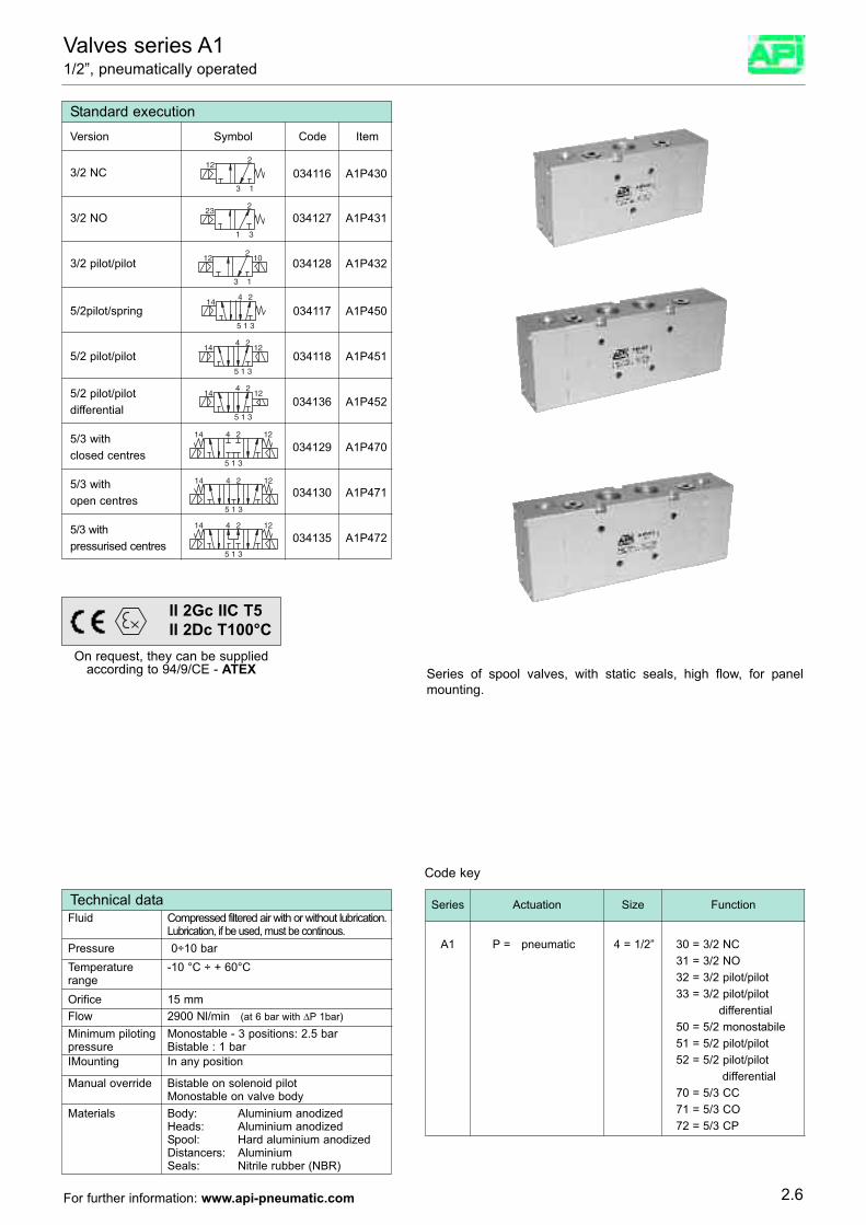
Valves series A11/2”, pneumatically operated
122
3 1
Standard execution
034116 A1P430
Version Symbol Code Item
3/2 NC
232
1 3
034127 A1P4313/2 NO
10122
3 1
034128 A1P4323/2 pilot/pilot
144 2
5 31
034117 A1P4505/2pilot/spring
12144 2
5 31
034118 A1P4515/2 pilot/pilot
1214 4 2
5 31
034136 A1P452
5/3 withclosed centres
1214 4 2
5 31
034129 A1P470
5/3 withopen centres
1214 4 2
5 31
034130 A1P471
5/3 with pressurised centres
034135 A1P472
5/2 pilot/pilotdifferential
12144 2
5 31
Series of spool valves, with static seals, high flow, for panelmounting.
Code key
Series Actuation Size Function
A1 P = pneumatic 4 = 1/2” 30 = 3/2 NC31 = 3/2 NO32 = 3/2 pilot/pilot33 = 3/2 pilot/pilot
differential50 = 5/2 monostabile51 = 5/2 pilot/pilot52 = 5/2 pilot/pilot
differential70 = 5/3 CC71 = 5/3 CO72 = 5/3 CP
On request, they can be suppliedaccording to 94/9/CE - ATEX
II 2Gc IIC T5II 2Dc T100°C
Technical dataFluid Compressed filtered air with or without lubrication.
Lubrication, if be used, must be continous.Pressure 0÷10 bar Temperature -10 °C ÷ + 60°Crange
Materials Body: Aluminium anodizedHeads: Aluminium anodized Spool: Hard aluminium anodized Distancers: Aluminium Seals: Nitrile rubber (NBR)
Orifice 15 mmFlow 2900 Nl/min (at 6 bar with ∆P 1bar)
Minimum piloting Monostable - 3 positions: 2.5 barpressure Bistable : 1 barIMounting In any position
Manual override Bistable on solenoid pilotMonostable on valve body
2.6For further information: www.api-pneumatic.com
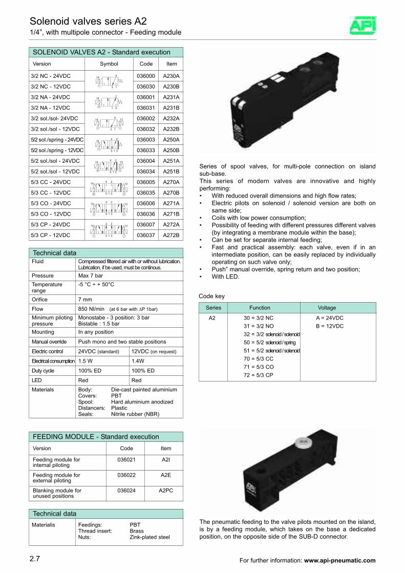
Solenoid valves series A21/4”, with multipole connector - Feeding module
14 4
3 1
SOLENOID VALVES A2 - Standard execution
036000 A230A
Version Symbol Code Item
036030 A230B
14 2
1 3
036001 A231A
036031 A231B
14 124
3 1
036002 A232A
036032 A232B
1 35
2414 036003 A250A
036033 A250B
1 35
2414 12 036004 A251A
036034 A251B
14 12
1 35
24 036005 A270A
036035 A270B
14 12
1 35
24 036006 A271A
036036 A271B
14 12
1 35
24 036007 A272A
036037 A272B
3/2 NC - 24VDC
3/2 NC - 12VDC
3/2 NA - 24VDC
3/2 NA - 12VDC
3/2 sol./sol- 24VDC
3/2 sol./sol - 12VDC
5/2 sol./spring - 24VDC
5/2 sol./spring - 12VDC
5/2 sol./sol - 24VDC
5/2 sol./sol - 12VDC
5/3 CC - 24VDC
5/3 CC - 12VDC
5/3 CO - 24VDC
5/3 CO - 12VDC
5/3 CP - 24VDC
5/3 CP - 12VDC
Series of spool valves, for multi-pole connection on islandsub-base.This series of modern valves are innovative and highlyperforming:
With reduced overall dimensions and high flow rates;•Electric pilots on solenoid / solenoid version are both on•same side;Coils with low power consumption;•Possibility of feeding with different pressures different valves•(by integrating a membrane module within the base);Can be set for separate internal feeding;•Fast and practical assembly: each valve, even if in an•intermediate position, can be easily replaced by individuallyoperating on such valve only;Push” manual override, spring return and two position;•With LED.•
Series Function Voltage
A2 30 = 3/2 NC A = 24VDC31 = 3/2 NO B = 12VDC32 = 3/2 solenoid / solenoid50 = 5/2 solenoid / spring51 = 5/2 solenoid / solenoid70 = 5/3 CC71 = 5/3 CO72 = 5/3 CP
Technical dataFluid Compressed filtered air with or without lubrication.
Lubrication, if be used, must be continous.Pressure Max 7 bar
Materials Body: Die-cast painted aluminiumCovers: PBT Spool: Hard aluminium anodized Distancers: PlasticSeals: Nitrile rubber (NBR)
Orifice 7 mm
Flow 850 Nl/min (at 6 bar with ∆P 1bar)
Minimum piloting Monostabe - 3 position: 3 barpressure Bistable : 1.5 barMounting In any position
Manual override Push mono and two stable positions
Temperature -5 °C ÷ + 50°Crange
Electric control 24VDC (standard) 12VDC (on request)
Electrical consumption 1.5 W 1.4W
Duty cycle 100% ED 100% ED
LED Red Red
Code key
FEEDING MODULE - Standard execution
Feeding module for 036021 A2Iinternal piloting
Version Code Item
Feeding module for 036022 A2Eexternal piloting
Blanking module for 036024 A2PCunused positions
The pneumatic feeding to the valve pilots mounted on the island,is by a feeding module, which takes on the base a dedicatedposition, on the opposite side of the SUB-D connector.
Technical dataMaterialis Feedings: PBT
Thread insert: BrassNuts: Zink-plated steel
2.7 For further information: www.api-pneumatic.com
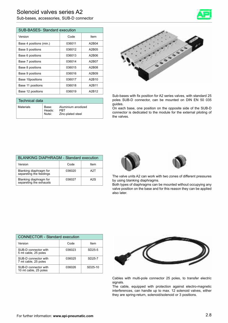
SUB-BASES- Standard execution
Base 4 positions (min.) 036011 A2B04
Base 5 positions 036012 A2B05
Base 6 positions 036013 A2B06
Base 7 positions 036014 A2B07
Base 8 positions 036015 A2B08
Base 9 positions 036016 A2B09
Base 11 positions 036018 A2B11
Base 12 positions 036019 A2B12
Base 10positions 036017 A2B10
Version Code Item
Sub-bases with fix position for A2 series valves, with standard 25poles SUB-D connector, can be mounted on DIN EN 50 035guides.On each base, one position on the opposite side of the SUB-Dconnector is dedicated to the module for the external piloting ofthe valves.
Solenoid valves series A2Sub-bases, accessories, SUB-D connector
Technical dataMaterials Base: Aluminium anodized
Heads: PBTNutsi: Zinc-plated steel
BLANKING DIAPHRAGM - Standard execution
Blanking diaphragm for 036020 A2Tsepareting the feedings
Version Code Item
Blanking diaphragm for 036027 A2Ssepareting the exhausts
The valve units A2 can work with two zones of different pressuresby using blanking diaphragms.Both types of diaphragms can be mounted without occupying anyvalve position on the base and for this reason they can be appliedalso later.
CONNECTOR - Standard execution
SUB-D connector with 036023 SD25-55 mt cable, 25 poles
Version Code Item
SUB-D connector with 036025 SD25-77 mt cable, 25 poles
SUB-D connector with 036026 SD25-1010 mt cable, 25 poles
Cables with multi-pole connector 25 poles, to transfer electricsignals.The cable, equipped with protection against electro-magneticinterferences, can handle up to max. 12 solenoid valves, eitherthey are spring-return, solenoid/solenoid or 3 positions.
2.8For further information: www.api-pneumatic.com
G 5/2 solenoid/spring A250
H 5/2 solenoid/solenoid A251
I 5/3 CC A270
L 5/3 CO A271
M 5/3 CP A272
E 3/2 solenoid/solenoid A232
D 3/2 NO A231
B 3/2 NC A230Cod Version Item
N Blanking module A2PC
04 01 11 21 31
N° Internal feeding External feeding Internal feeding External feedingof base of the pilots of the pilots of the pilots of the pilots
positions Voltage 24 VDC Voltage 24 VDC Voltage 12 VDC Voltage12 VDC
05 02 12 22 32
06 03 13 23 33
07 04 14 24 34
08 05 15 25 35
09 06 16 26 36
10 07 17 27 37
11 08 18 28 38
12 09 19 29 39
O Feddings diaphragm A2T
P Exhausts diaphragm A2S
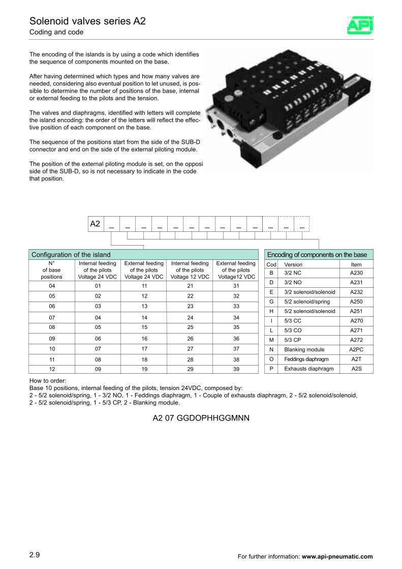
A2 _ _ _ _ _ _ _ _ _ _ _ _ _
The encoding of the islands is by using a code which identifiesthe sequence of components mounted on the base.
After having determined which types and how many valves areneeded, considering also eventual position to let unused, is pos-sible to determine the number of positions of the base, internalor external feeding to the pilots and the tension.
The valves and diaphragms, identified with letters will completethe island encoding: the order of the letters will reflect the effec-tive position of each component on the base.
The sequence of the positions start from the side of the SUB-Dconnector and end on the side of the external piloting module.
The position of the external piloting module is set, on the oppositeside of the SUB-D, so is not necessary to indicate in the codethat position.
How to order:Base 10 positions, internal feeding of the pilots, tension 24VDC, composed by:2 - 5/2 solenoid/spring, 1 - 3/2 NO, 1 - Feddings diaphragm, 1 - Couple of exhausts diaphragm, 2 - 5/2 solenoid/solenoid,2 - 5/2 solenoid/spring, 1 - 5/3 CP, 2 - Blanking module.
A2 07 GGDOPHHGGMNN
Solenoid valves series A2Coding and code
2.9
Configuration of the island Encoding of components on the base
For further information: www.api-pneumatic.com
3/2 N.C, withmanual override 034189 A1EM13012B bistable
Options Suffix
22 mm directly operated solenoid valve - 3/2 normally closed
15 mm directly operated solenoid valves - 3/2 normally closed and normaly open
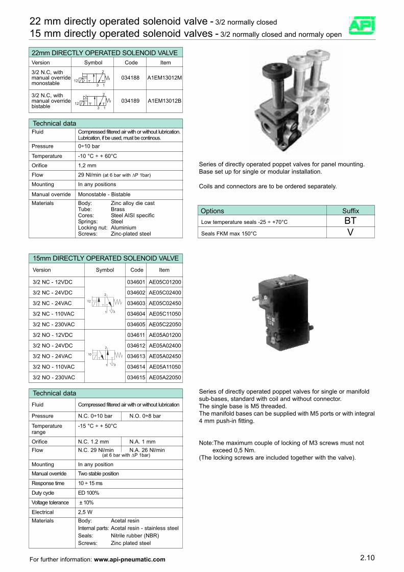
Series of directly operated poppet valves for panel mounting. Base set up for single or modular installation.
Coils and connectors are to be ordered separately.
Technical dataFluid Compressed filtered air with or without lubrication.
Lubrication, if be used, must be continous.Pressure 0÷10 bar
Temperature -10 °C ÷ + 60°C
Orifice 1,2 mm
Flow 29 Nl/min (at 6 bar with ∆P 1bar)
Mounting In any positions
Manual override Monostable - Bistable
15mm DIRECTLY OPERATED SOLENOID VALVE
034601 AE05C01200
Version Symbol Code Item
3/2 NC - 12VDC
3/2 NC - 24VDC
3/2 NC - 24VAC
3/2 NC - 110VAC
3/2 NC - 230VAC
3/2 NO - 12VDC
3/2 NO - 24VDC
3/2 NO - 24VAC
3/2 NO - 110VAC
3/2 NO - 230VAC
034602 AE05C02400
034603 AE05C02450
034604 AE05C11050
034605 AE05C22050
034611 AE05A01200
034612 AE05A02400
034613 AE05A02450
034614 AE05A11050
034615 AE05A22050
Series of directly operated poppet valves for single or manifoldsub-bases, standard with coil and without connector.The single base is M5 threaded.The manifold bases can be supplied with M5 ports or with integral4 mm push-in fitting.
Note:The maximum couple of locking of M3 screws must not exceed 0,5 Nm.
(The locking screws are included together with the valve).
Technical dataFluid Compressed filtered air with or without lubrication
Pressure N.C. 0÷10 bar N.O. 0÷8 bar
Temperature -15 °C ÷ + 50°Crange
Materials Body: Acetal resinInternal parts: Acetal resin - stainless steelSeals: Nitrile rubber (NBR)Screws: Zinc plated steel
Orifice N.C. 1.2 mm N.A. 1 mmFlow N.C. 29 Nl/min N.A. 26 Nl/min
(at 6 bar with ∆P 1bar)
Mounting In any position
Manual override Two stable position
Response time 10 ÷ 15 ms
Duty cycle ED 100%
Voltage tolerance ± 10%
Electrical 2,5 W
2.10For further information: www.api-pneumatic.com
Materials Body: Zinc alloy die castTube: BrassCores: Steel AISI specificSprings: SteelLocking nut: AluminiumScrews: Zinc-plated steel
3/2 N.C, withmanual override 034188 A1EM13012M monostable 12
2
3 1
12
2
3 1
Low temperature seals -25 ÷ +70°C BTSeals FKM max 150°C V
22mm DIRECTLY OPERATED SOLENOID VALVEVersion Symbol Code Item
Electrically operated valves, sizes 15 and 18 mmSize 15 mm (1/8”) and 18 mm (1/4”) eletric
Standard execution Version Size Symbol Code Item
5/2 solenoid/spring1/8 035051 AE15181520
1/4 035201 AE18141520
5/2 solenoid/springexternal air pilot
1/8 035061 AE15181520K
1/4 035211 AE18141520K
5/2 sol./sol.1/8 035071 AE15182520
1/4 035221 AE18142520
5/2 sol./sol.external air pilot
1/8 035081 AE15182520K
1/4 035231 AE18142520K
5/3 with closecentres
1/8 035091 AE1518253C
1/4 035241 AE1814253C
5/3 with opencentres
1/8 035094 AE1518253A
1/4 035244 AE1814253A
5/3 with pressurisedcentres
1/8 035097 AE1518253P
1/4 035247 AE1814253P
5/3 with closecentres externalair pilot
1/8 035101 AE1518253CK
1/4 035251 AE1814253CK
5/3 with opencentres externalair pilot
1/8 035104 AE1518253AK
1/4 035254 AE1814253AK
1/8 035107 AE1518253PK
1/4 035257 AE1814252PK
5/3 with pressurisedcentres external airpilot
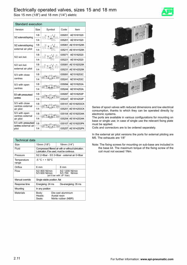
Series of spool valves with reduced dimensions and low electricalconsumption, thanks to which they can be operated directly byelectronic systems.The ports are available in various configurations for mounting onbase or single use; in case of single use the relevant fixing platemust be applied.Coils and connectors are to be ordered separately.
In the external air pilot versions the ports for external piloting areM5. The exhausts are 1/8”
Note: The fixing screws for mounting on sub-base are included inthe base kit. The maximum torque of the fixing screw of thecoil must not exceed 1Nm.
Technical data
Fluid Compressed filtered air with or without lubrication.Lubrication, if be used, must be continous.
Pressure 5/2 2÷8bar - 5/3 3÷8bar - external air 0÷8bar
Temperature -5 °C ÷ + 50°Crange
Materials Body: Die-cast aluminiumHeads: Acetal resin Seals: Nitrile rubber (NBR)
Orifice 6 mm 8 mmFlow 5/2 800 Nl/min 5/2 1200 Nl/min
5/3 600 Nl/min 5/3 700 Nl/min(at 6 bar with ∆P 1bar)
Manual override Single stable position, flat
Response time Energising: 24 ms De-energising: 35 ms
Mounting In any position
Size 15mm (1/8”) 18mm (1/4”)
2.11 For further information: www.api-pneumatic.com
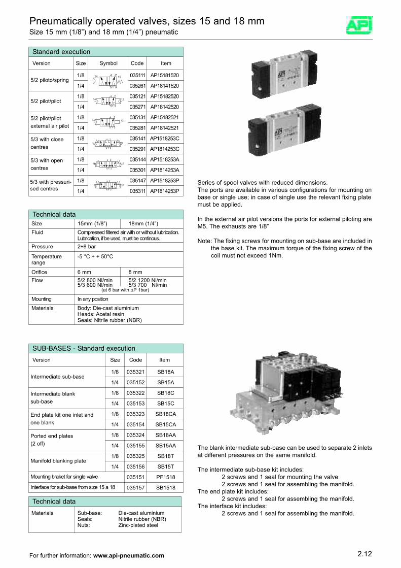
Pneumatically operated valves, sizes 15 and 18 mmSize 15 mm (1/8”) and 18 mm (1/4”) pneumatic
Standard executionVersion Size Symbol Code Item
5/2 piloto/spring1/8 035111 AP15181520
1/4 035261 AP18141520
5/2 pilot/pilot1/8 035121 AP15182520
1/4 035271 AP18142520
5/2 pilot/pilotexternal air pilot
1/8 035131 AP15182521
1/4 035281 AP18142521
5/3 with closecentres
1/8 035141 AP1518253C
1/4 035291 AP1814253C
5/3 with opencentres
1/8 035144 AP1518253A
1/4 035301 AP1814253A
5/3 with pressuri-sed centres
1/8 035147 AP1518253P
1/4 035311 AP1814253PSeries of spool valves with reduced dimensions.The ports are available in various configurations for mounting onbase or single use; in case of single use the relevant fixing platemust be applied.
In the external air pilot versions the ports for external piloting areM5. The exhausts are 1/8”
Note: The fixing screws for mounting on sub-base are included inthe base kit. The maximum torque of the fixing screw of thecoil must not exceed 1Nm.
Technical data
Fluid Compressed filtered air with or without lubrication.Lubrication, if be used, must be continous.
Pressure 2÷8 bar
Temperature -5 °C ÷ + 50°Crange
Materials Body: Die-cast aluminiumHeads: Acetal resinSeals: Nitrile rubber (NBR)
Orifice 6 mm 8 mmFlow 5/2 800 Nl/min 5/2 1200 Nl/min
5/3 600 Nl/min 5/3 700 Nl/min(at 6 bar with ∆P 1bar)
Mounting In any position
Size 15mm (1/8”) 18mm (1/4”)
SUB-BASES - Standard execution Version Size Code Item
Intermediate sub-base1/8 035321 SB18A
1/4 035152 SB15A
Intermediate blanksub-base
1/8 035322 SB18C
1/4 035153 SB15C
End plate kit one inlet andone blank
1/8 035323 SB18CA
1/4 035154 SB15CA
Manifold blanking plate1/8 035325 SB18T
1/4 035156 SB15T
Ported end plates(2 off)
1/8 035324 SB18AA
1/4 035155 SB15AA
Mounting braket for single valve 035151 PF1518
035157 SB1518Interface for sub-base from size 15 a 18
The blank intermediate sub-base can be used to separate 2 inletsat different pressures on the same manifold.
The intermediate sub-base kit includes:2 screws and 1 seal for mounting the valve2 screws and 1 seal for assembling the manifold.
The end plate kit includes:2 screws and 1 seal for assembling the manifold.
The interface kit includes:2 screws and 1 seal for assembling the manifold.
Technical dataMaterials Sub-base: Die-cast aluminium
Seals: Nitrile rubber (NBR)Nuts: Zinc-plated steel
2.12For further information: www.api-pneumatic.com
ISO 1 E = electrical CNOMO pilot 50 = 5/2 monostableK = electrical CNOMO pilot 51 = 5/2 bistabil
external pilot 52 = 5/2 bistabil EL = electrical IN LINE pilot differentialKL = electrical IN LINE pilot 70 = 5/3 CC
external pilot 71 = 5/3 CO72 = 5/3 CP
On request, they can be suppliedaccording to 94/9/CE - ATEX
II 2Gc IIC T5II 2Dc T100°C
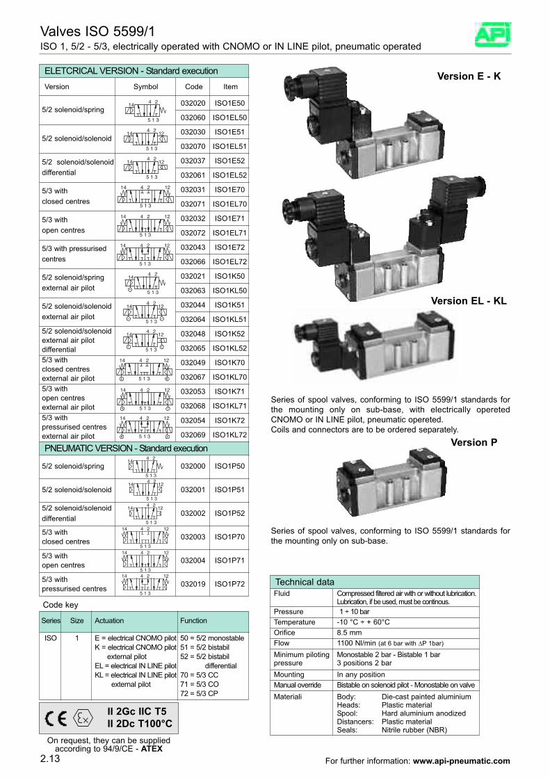
Valves ISO 5599/1ISO 1, 5/2 - 5/3, electrically operated with CNOMO or IN LINE pilot, pneumatic operated
144 2
5 31
ELETCRICAL VERSION - Standard execution
032020 ISO1E50
Version Symbol Code Item
12144 2
5 31
12144 2
5 31
1214 4 2
5 31
1214 4 2
5 31
1214 4 2
5 31
144 2
5 31
12144 2
5 31
5/2 solenoid/spring
032030 ISO1E515/2 solenoid/solenoid
032037 ISO1E525/2 solenoid/solenoiddifferential
032031 ISO1E705/3 withclosed centres
032032 ISO1E715/3 withopen centres
032043 ISO1E725/3 with pressurisedcentres
032021 ISO1K505/2 solenoid/springexternal air pilot
032044 ISO1K515/2 solenoid/solenoidexternal air pilot
12144 2
5 31
032048 ISO1K525/2 solenoid/solenoidexternal air pilotdifferential
1214 4 2
5 31
032049 ISO1K705/3 withclosed centresexternal air pilot
1214 4 2
5 31
032053 ISO1K715/3 withopen centres external air pilot
1214 4 2
5 31
032054 ISO1K725/3 withpressurised centresexternal air pilot
032060 ISO1EL50
032070 ISO1EL51
032061 ISO1EL52
032071 ISO1EL70
032072 ISO1EL71
032066 ISO1EL72
032063 ISO1KL50
032064 ISO1KL51
032065 ISO1KL52
032067 ISO1KL70
032068 ISO1KL71
032069 ISO1KL72
Series of spool valves, conforming to ISO 5599/1 standards forthe mounting only on sub-base, with electrically operetedCNOMO or IN LINE pilot, pneumatic opereted.Coils and connectors are to be ordered separately.
144 2
5 31
PNEUMATIC VERSION - Standard execution
032000 ISO1P505/2 solenoid/spring
12144 2
5 31
032001 ISO1P515/2 solenoid/solenoid
12144 2
5 31
032002 ISO1P525/2 solenoid/solenoid differential
1214 4 2
5 31
032003 ISO1P705/3 withclosed centres
1214 4 2
5 31
032004 ISO1P715/3 withopen centres
1214 4 2
5 31
032019 ISO1P725/3 withpressurised centres
Series of spool valves, conforming to ISO 5599/1 standards forthe mounting only on sub-base.
Technical dataFluid Compressed filtered air with or without lubrication.
Lubrication, if be used, must be continous.Pressure 1 ÷ 10 barTemperature -10 °C ÷ + 60°C
Materiali Body: Die-cast painted aluminiumHeads: Plastic materialSpool: Hard aluminium anodized Distancers: Plastic materialSeals: Nitrile rubber (NBR)
Orifice 8.5 mmFlow 1100 Nl/min (at 6 bar with ∆P 1bar)
Minimum piloting Monostable 2 bar - Bistable 1 barpressure 3 positions 2 barMounting In any positionManual override Bistable on solenoid pilot - Monostable on valve
2.13
Code key
Series Size Actuation Function
Version E - K
Version EL - KL
Version P
For further information: www.api-pneumatic.com
Technical dataFluid Compressed filtered air with or without lubrication.
Lubrication, if be used, must be continous.Pressure 1 ÷ 10 barTemperature -10 °C ÷ + 60°C
Materials Body: Die-cast painted aluminiumHeads: Plastic materialSpool: Hard aluminium anodized Distancers: Plastic materialSeals: Nitrile rubber (NBR)
Orifice 15 mmFlow 2900 Nl/min (a 6 bar con ∆P 1bar)
Minimum piloting Monostable 2.5 bar - Bistable 1 barpressure 3 positions 2.5 barMounting In any positionManual override Bistable on solenoid pilot - Monostable on valve
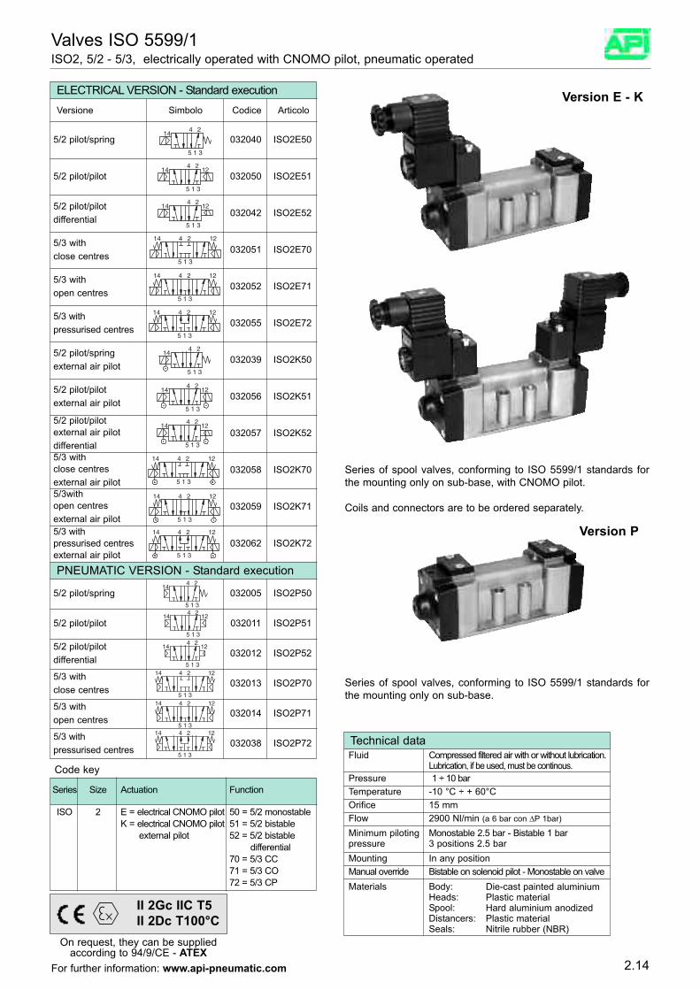
Valves ISO 5599/1ISO2, 5/2 - 5/3, electrically operated with CNOMO pilot, pneumatic operated
144 2
5 31
ELECTRICAL VERSION - Standard execution
032040 ISO2E50
Versione Simbolo Codice Articolo
12144 2
5 31
12144 2
5 31
1214 4 2
5 31
1214 4 2
5 31
1214 4 2
5 31
144 2
5 31
12144 2
5 31
5/2 pilot/spring
032050 ISO2E515/2 pilot/pilot
032042 ISO2E525/2 pilot/pilotdifferential
032051 ISO2E705/3 with close centres
032052 ISO2E715/3 with open centres
032055 ISO2E725/3 withpressurised centres
032039 ISO2K505/2 pilot/springexternal air pilot
032056 ISO2K515/2 pilot/pilotexternal air pilot
12144 2
5 31
032057 ISO2K525/2 pilot/pilotexternal air pilotdifferential
1214 4 2
5 31
032058 ISO2K705/3 with close centresexternal air pilot
1214 4 2
5 31
032059 ISO2K715/3with open centresexternal air pilot
1214 4 2
5 31
032062 ISO2K725/3 withpressurised centresexternal air pilot
144 2
5 31
PNEUMATIC VERSION - Standard execution
032005 ISO2P505/2 pilot/spring
12144 2
5 31
032011 ISO2P515/2 pilot/pilot
12144 2
5 31
032012 ISO2P525/2 pilot/pilotdifferential
1214 4 2
5 31
032013 ISO2P705/3 with close centres
1214 4 2
5 31
032014 ISO2P715/3 with open centres
1214 4 2
5 31
032038 ISO2P725/3 withpressurised centres
Code key
ISO 2 E = electrical CNOMO pilot 50 = 5/2 monostableK = electrical CNOMO pilot 51 = 5/2 bistable
external pilot 52 = 5/2 bistable differential
70 = 5/3 CC71 = 5/3 CO72 = 5/3 CP
Series Size Actuation Function
Series of spool valves, conforming to ISO 5599/1 standards forthe mounting only on sub-base, with CNOMO pilot.
Coils and connectors are to be ordered separately.
Series of spool valves, conforming to ISO 5599/1 standards forthe mounting only on sub-base.
2.14
Version E - K
Version P
On request, they can be suppliedaccording to 94/9/CE - ATEX
II 2Gc IIC T5II 2Dc T100°C
For further information: www.api-pneumatic.com
Technical data
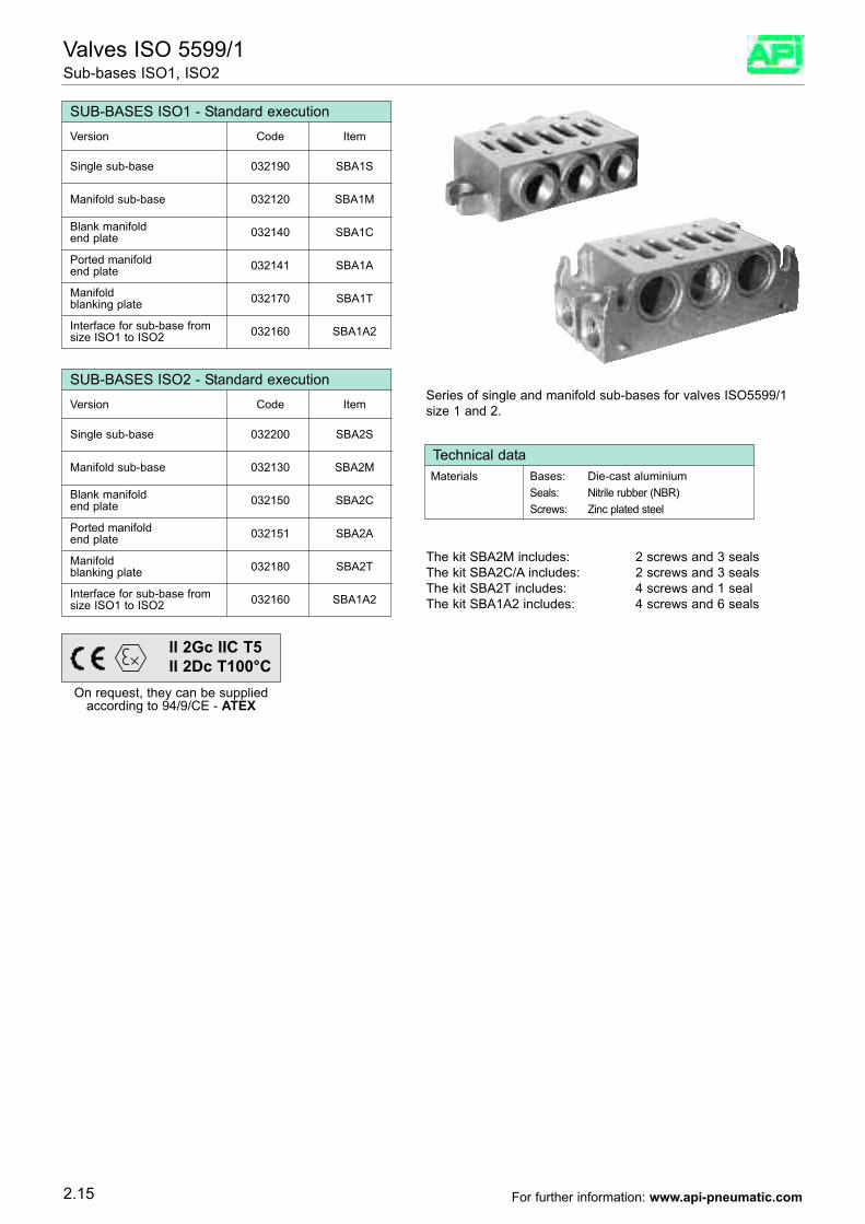
Valves ISO 5599/1Sub-bases ISO1, ISO2
SUB-BASES ISO1 - Standard execution
Single sub-base 032190 SBA1S
Version Code Item
Manifold sub-base 032120 SBA1M
Blank manifold 032140 SBA1Cend plate
Ported manifold 032141 SBA1Aend plate
Manifold 032170 SBA1Tblanking plate
Interface for sub-base from 032160 SBA1A2size ISO1 to ISO2
SUB-BASES ISO2 - Standard execution
Single sub-base 032200 SBA2S
Version Code Item
Manifold sub-base 032130 SBA2M
Blank manifold 032150 SBA2Cend plate
Ported manifold 032151 SBA2Aend plate
Manifold 032180 SBA2Tblanking plate
Interface for sub-base from 032160 SBA1A2size ISO1 to ISO2
The kit SBA2M includes: 2 screws and 3 sealsThe kit SBA2C/A includes: 2 screws and 3 sealsThe kit SBA2T includes: 4 screws and 1 sealThe kit SBA1A2 includes: 4 screws and 6 seals
Series of single and manifold sub-bases for valves ISO5599/1size 1 and 2.
Materials Bases: Die-cast aluminiumSeals: Nitrile rubber (NBR)Screws: Zinc plated steel
2.15
On request, they can be suppliedaccording to 94/9/CE - ATEX
II 2Gc IIC T5II 2Dc T100°C
For further information: www.api-pneumatic.com
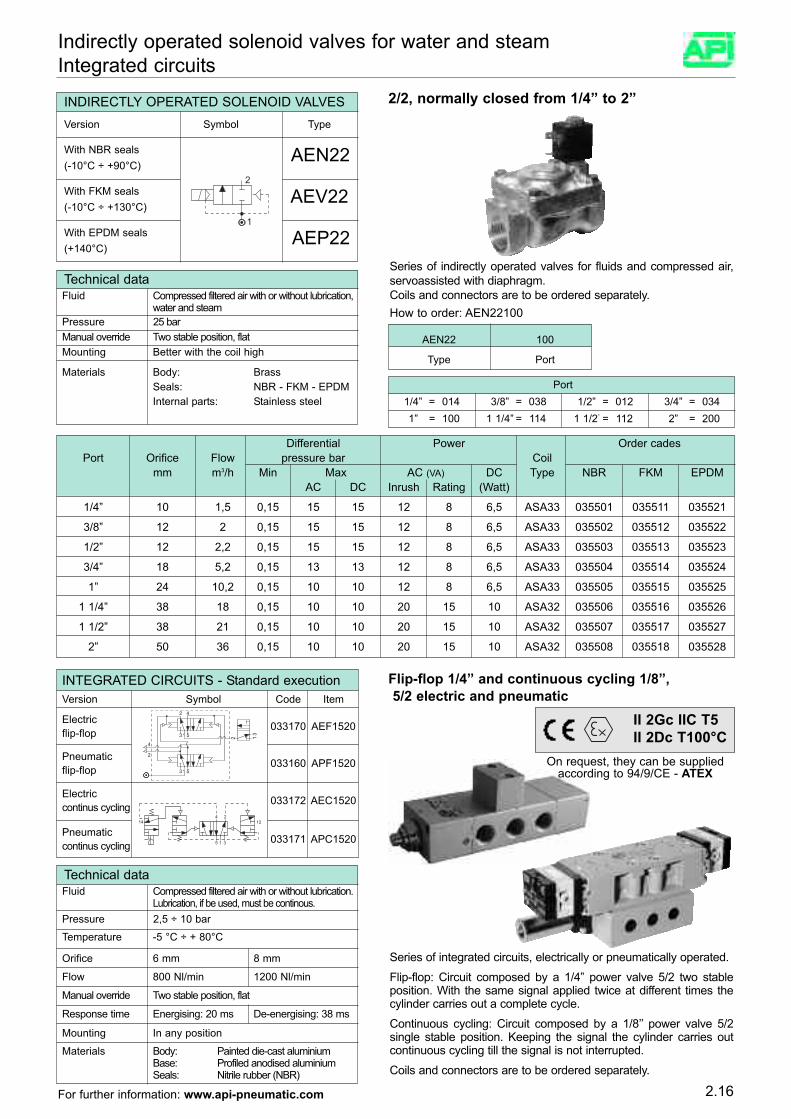
Port1/4” = 014 3/8” = 038 1/2” = 012 3/4” = 0341” = 100 1 1/4” = 114 1 1/2” = 112 2” = 200
2.16
Indirectly operated solenoid valves for water and steamIntegrated circuits
INDIRECTLY OPERATED SOLENOID VALVESVersion Symbol Type
With NBR seals AEN22(-10°C ÷ +90°C)
With FKM seals AEV22(-10°C ÷ +130°C)
With EPDM seals AEP22(+140°C)
Technical dataFluid Compressed filtered air with or without lubrication,
water and steamPressure 25 bar
Materials Body: BrassSeals: NBR - FKM - EPDMInternal parts: Stainless steel
Mounting Better with the coil highManual override Two stable position, flat
Series of indirectly operated valves for fluids and compressed air,servoassisted with diaphragm.Coils and connectors are to be ordered separately.How to order: AEN22100
2/2, normally closed from 1/4” to 2”
Differential Power Order cadesPort Orifice Flow pressure bar Coil
mm m3/h Min Max AC (VA) DC Type NBR FKM EPDMAC DC Inrush Rating (Watt)
1/4” 10 1,5 0,15 15 15 12 8 6,5 ASA33 035501 035511 035521
3/8” 12 2 0,15 15 15 12 8 6,5 ASA33 035502 035512 035522
1/2” 12 2,2 0,15 15 15 12 8 6,5 ASA33 035503 035513 035523
3/4” 18 5,2 0,15 13 13 12 8 6,5 ASA33 035504 035514 035524
1” 24 10,2 0,15 10 10 12 8 6,5 ASA33 035505 035515 035525
1 1/4” 38 18 0,15 10 10 20 15 10 ASA32 035506 035516 035526
1 1/2” 38 21 0,15 10 10 20 15 10 ASA32 035507 035517 035527
2” 50 36 0,15 10 10 20 15 10 ASA32 035508 035518 035528
Series of integrated circuits, electrically or pneumatically operated.
Flip-flop: Circuit composed by a 1/4” power valve 5/2 two stableposition. With the same signal applied twice at different times thecylinder carries out a complete cycle.
Continuous cycling: Circuit composed by a 1/8’’ power valve 5/2single stable position. Keeping the signal the cylinder carries outcontinuous cycling till the signal is not interrupted.
Coils and connectors are to be ordered separately.
Flip-flop 1/4” and continuous cycling 1/8”,5/2 electric and pneumatic
Technical dataFluid Compressed filtered air with or without lubrication.
Lubrication, if be used, must be continous.Pressure 2,5 ÷ 10 bar
Materials Body: Painted die-cast aluminiumBase: Profiled anodised aluminium Seals: Nitrile rubber (NBR)
Orifice 6 mm 8 mm
Flow 800 Nl/min 1200 Nl/min
Response time Energising: 20 ms De-energising: 38 ms
Manual override Two stable position, flat
Temperature -5 °C ÷ + 80°C
Mounting In any position
INTEGRATED CIRCUITS - Standard executionVersion Symbol Code Item
Electric 033170 AEF1520flip-flop
Pneumatic 033160 APF1520flip-flop
Electric 033172 AEC1520continus cycling
Pneumatic 033171 APC1520continus cycling
On request, they can be suppliedaccording to 94/9/CE - ATEX
II 2Gc IIC T5II 2Dc T100°C
AEN22 100
Type Port
For further information: www.api-pneumatic.com
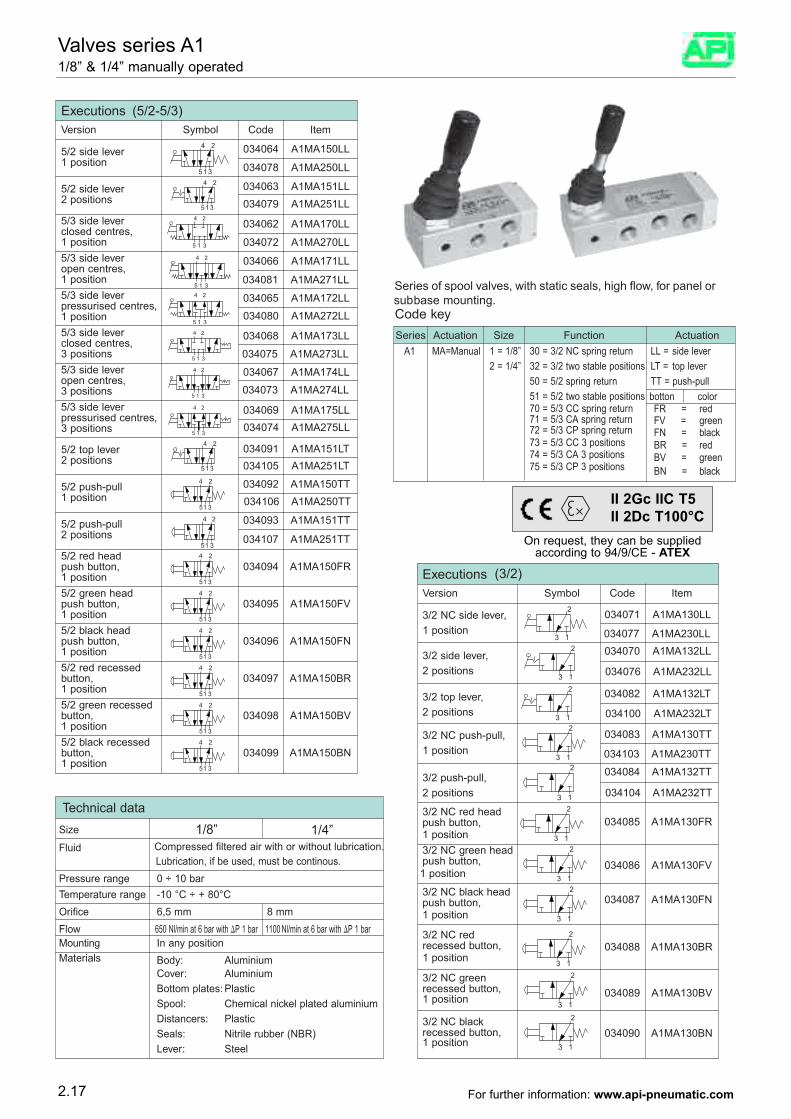
Series of spool valves, with static seals, high flow, for panel orsubbase mounting.
Technical data1/8” 1/4”
F
Size
luid Compressed filtered air with or without lubrication. Lubrication, if be used, must be continous.
Pressure range 0 ÷ 10 barTemperature range -10 °C ÷ + 80°COrifice 6,5 mm 8 mmFlow 650 Nl/min at 6 bar with P 1 bar 1100 Nl/min at 6 bar with P 1 barMounting In any positionMaterials Body: Aluminium
Cover: AluminiumBottom plates: PlasticSpool: Chemical nickel plated aluminiumDistancers: PlasticSeals: Nitrile rubber (NBR)Lever: Steel
ExecutionsVersion Symbol Code Item
3/2 NC side lever, 034071 A1MA130LL1 position
3/2 side lever, 034070 A1MA132LL
2 positions
3/2 top lever, 034082 A1MA132LT
2 positions
3/2 NC push-pull, 034083 A1MA130TT1 position
3/2 push-pull, 034084 A1MA132TT
2 positions
3/2 NC red head push button, 034085 A1MA130FR1 position3/2 NC green head
push button, 034086 A1MA130FV1 position
3/2 NC black head
push button, 034087 A1MA130FN1 position
3/2 NC red recessed button, 034088 A1MA130BR1 position
3/2 NC green recessed button, 034089 A1MA130BV1 position
3/2 NC black recessed button, 034090 A1MA130BN1 position
Series Actuation Size Function ActuationA1 MA=Manual 1 = 1/8” 30 = 3/2 NC spring return LL = side lever
2 = 1/4” 32 = 3/2 two stable positions LT = top lever50 = 5/2 spring return TT = push-pull51 = 5/2 two stable positions
FR = red 70 = 5/3 CC spring returnbotton color
71 = 5/3 CA spring return FV = green 72 = 5/3 CP spring return73 = 5/3 CC 3 positions
FN = black
74 = 5/3 CA 3 positions75 = 5/3 CP 3 positions
BR = red BV = green BN = black
Code key
034077 A1MA230LL
034076 A1MA232LL
034100 A1MA232LT
034103 A1MA230TT
034104 A1MA232TT
Executions (5/2-5/3)
(3/2)
Version Symbol Code Item
5/2 side lever 034064 A1MA150LL1 position
5/2 side lever 034063 A1MA151LL2 positions
5/3 side leverclosed centres,
034062 A1MA170LL
1 position5/3 side leveropen centres,
034066 A1MA171LL
1 position5/3 side leverpressurised centres,
034065 A1MA172LL
1 position5/3 side leverclosed centres,
034068 A1MA173LL
3 positions5/3 side leveropen centres,
034067 A1MA174LL
3 positions5/3 side leverpressurised centres,
034069 A1MA175LL
3 positions
5/2 top lever 034091 A1MA151LT2 positions
5/2 push-pull 034092 A1MA150TT1 position
5/2 push-pull 034093 A1MA151TT2 positions
5/2 red head push button, 034094 A1MA150FR1 position5/2 green head push button, 034095 A1MA150FV1 position5/2 black head push button, 034096 A1MA150FN1 position5/2 red recessed button, 034097 A1MA150BR1 position5/2 green recessed button, 034098 A1MA150BV1 position5/2 black recessed button, 034099 A1MA150BN1 position
034078 A1MA250LL
034079 A1MA251LL
034072 A1MA270LL
034081 A1MA271LL
034080 A1MA272LL
034075 A1MA273LL
034073 A1MA274LL
034074 A1MA275LL
034105 A1MA251LT
034106 A1MA250TT
034107 A1MA251TT
2.17
Valves series A11/8” & 1/4” manually operated
On request, they can be suppliedaccording to 94/9/CE - ATEX
II 2Gc IIC T5II 2Dc T100°C
For further information: www.api-pneumatic.com
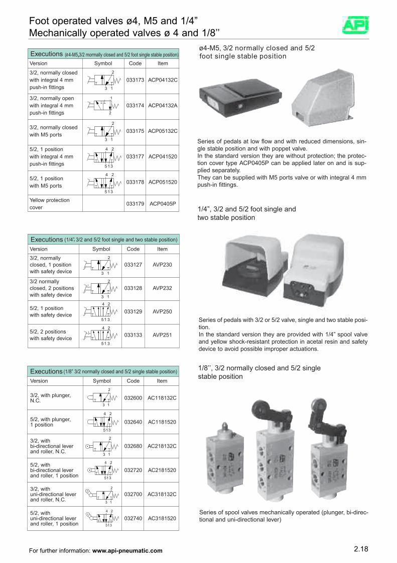
Series of pedals at low flow and with reduced dimensions, sin-gle stable position and with poppet valve.In the standard version they are without protection; the protec-tion cover type ACP0405P can be applied later on and is sup-plied separately.They can be supplied with M5 ports valve or with integral 4 mmpush-in fittings.
Executions ( 4-M5 3/2 mormally closed and 5/2 foot single stable position)Version Symbol Code Item
3/2, normally closedwith integral 4 mm 033173 ACP04132Cpush-in fittings
3/2, normally openwith integral 4 mm 033174 ACP04132Apush-in fittings
3/2, normally closed033175 ACP05132C
with M5 ports
5/2, 1 positionwith integral 4 mm 033177 ACP041520push-in fittings
5/2, 1 position033178 ACP051520
with M5 ports
Yellow protection033179 ACP0405P
cover
3 1
2
3 1
2
Series of spool valves mechanically operated (plunger, bi-direc-tional and uni-directional lever)
ExecutionsVersion Symbol Code Item
3/2, with plunger, 032600 AC118132CN.C.
5/2, with plunger, 032640 AC11815201 position
3/2, withbi-directional lever 032680 AC218132Cand roller, N.C.
5/2, withbi-directional lever 032720 AC2181520and roller, 1 position
3/2, withuni-directional lever 032700 AC318132Cand roller, N.C.
5/2, withuni-directional lever 032740 AC3181520and roller, 1 position
Series of pedals with 3/2 or 5/2 valve, single and two stable posi-tion.In the standard version they are provided with 1/4” spool valveand yellow shock-resistant protection in acetal resin and safetydevice to avoid possible improper actuations.
ExecutionsVersion Symbol Code Item
3/2, normallyclosed, 1 position 033127 AVP230with safety device
3/2 normallyclosed, 2 positions 033128 AVP232with safety device
5/2, 1 position 033129 AVP250with safety device
5/2, 2 positions 033133 AVP251with safety device
3 1
2
5 31
24
5 31
24
3 1
2
øø
4-M5, 3/2 normally closed and 5/2 foot single stable position
1/4”, 3/2 and 5/2 foot single andtwo stable position
1/8’’, 3/2 normally closed and 5/2 singlestable position
(1/4” 3/2 and 5/2 foot single and two stable position),
,
(1/8” 3/2 normally closed and 5/2 single stable position)
2.18
Foot operated valves ø4, M5 and 1/4”Mechanically operated valves ø 4 and 1/8’’
For further information: www.api-pneumatic.com
M
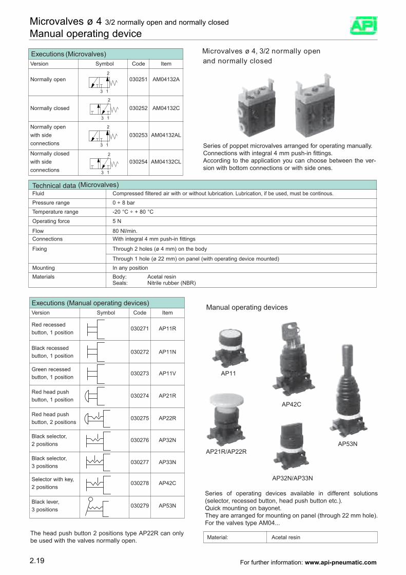
Manual operating devices
icrovalves ø 4, 3/2 normally open and normally closed
Executions (Microvalves)Version Symbol Code Item
Normally open 030251 AM04132A
Normally closed 030252 AM04132C
Normally openwith side 030253 AM04132ALconnections
Normally closedwith side 030254 AM04132CLconnections
Series of poppet microvalves arranged for operating manually.Connections with integral 4 mm push-in fittings.According to the application you can choose between the ver-sion with bottom connections or with side ones.
Technical dataFluid Compressed filtered air with or without lubrication. Lubrication, if be used, must be continous.
Pressure range 0 ÷ 8 bar
Temperature range -20 °C ÷ + 80 °C
Operating force 5 N
Flow 80 Nl/min.Connections With integral 4 mm push-in fittings
Fixing Through 2 holes (ø 4 mm) on the body
Through 1 hole (ø 22 mm) on panel (with operating device mounted)Mounting In any positionMaterials Body: Acetal resin
Seals: Nitrile rubber (NBR)
2
13
2
13
S
AP11
AP21R/AP22R
AP32N/AP33N
AP42C
AP53N
eries of operating devices available in different solutions(selector, recessed button, head push button etc.).Quick mounting on bayonet.They are arranged for mounting on panel (through 22 mm hole).For the valves type AM04...
Executions (Manual operating devices)Version Symbol Code Item
Red recessed 030271 AP11R
button, 1 position
Black recessed030272 AP11N
button, 1 position
Green recessed030273 AP11V
button, 1 position
Red head push030274 AP21R
button, 1 position
Red head push030275 AP22R
button, 2 positions
Black selector,030276 AP32N
2 positions
Black selector,030277 AP33N
3 positions
Selector with key,030278 AP42C
2 positions
Black lever,030279 AP53N
3 positions
The head push button 2 positions type AP22R can onlybe used with the valves normally open.
(Microvalves)
Material: Acetal resin
2.19
Microvalves ø 4 3/2 normally open and normally closed
Manual operating device
For further information: www.api-pneumatic.com
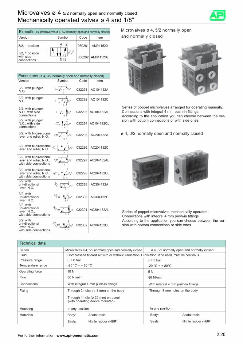
M
ø 4, 3/2 normally open and normally closed
icrovalves ø 4, 5/2 normally openand normally closed
Executions (Microvalves ø 4, 5/2 normally open and normally closed)
Version Symbol Code Item
5/2, 1 position 030261 AM041520
5/2, 1 positionwith side 030262 AM041520Lconnections
Series of poppet microvalves arranged for operating manually.Connections with integral 4 mm push-in fittings.According to the application you can choose between the ver-sion with bottom connections or with side ones.
Technical data
FSeries
luid Compressed filtered air with or without lubrication. Lubrication, if be used, must be continous.Pressure range 0 ÷ 8 barTemperature range -20 °C ÷ + 80 °C
Operating force 10 N
Flow 80 Nl/min.
Connections With integral 4 mm push-in fittings
Fixing Through 2 holes (ø 4 mm) on the body
Through 1 hole (ø 22 mm) on panel (with operating device mounted)
Mounting In any position
Materials Body: Acetal resin
Seals: Nitrile rubber (NBR)
Executions (ø 4, 3/2 normally open and normally closed)Version Symbol Code Item
3/2, with plunger, 032291 AC104132AN.O.
3/2, with plunger, 032292 AC104132CN.C.
3/2, with plunger,N.O., with side 032293 AC104132ALconnections3/2, with plunger
,
N.C., with side 032294 AC104132CLconnections
3/2, with bi-directional 032295 AC204132Alever and roller, N.O.
3/2, with bi-directional
032296 AC204132Clever and roller, N.C.
3/2, with bi-directionallever and roller, N.O., 032297 AC204132ALwith side connections
3/2, with bi-directionallever and roller, N.C., 032298 AC204132CLwith side connections3/2, withuni-directional 032299 AC304132Alever, N.O.
3/2, withuni-directional 032303 AC304132Clever, N.C.3/2, withuni-directional 032301 AC304132ALlever, N.O.,with side connections
3/2, withuni-directional 032302 AC304132CLlever, N.C.,with side connections
Series of poppet microvalves mechanically operated.Connections with integral 4 mm push-in fittings.According to the application you can choose between the ver-sion with bottom connections or side ones.
0 ÷ 8 bar
-20 °C ÷ + 80°C
5 N
80 Nl/min
With integral 4 mm push-in fittings
Through 4 mm holes on the body
In any position
Body: Acetal resin
Seals: Nitrile rubber (NBR)
ø 4, 3/2 normally open and normally closedMicrovalves ø 4, 5/2 normally open and normally closed
2.20
Microvalves ø 4 5/2 normally open and normally closed
Mechanically operated valves ø 4 and 1/8”
For further information: www.api-pneumatic.com
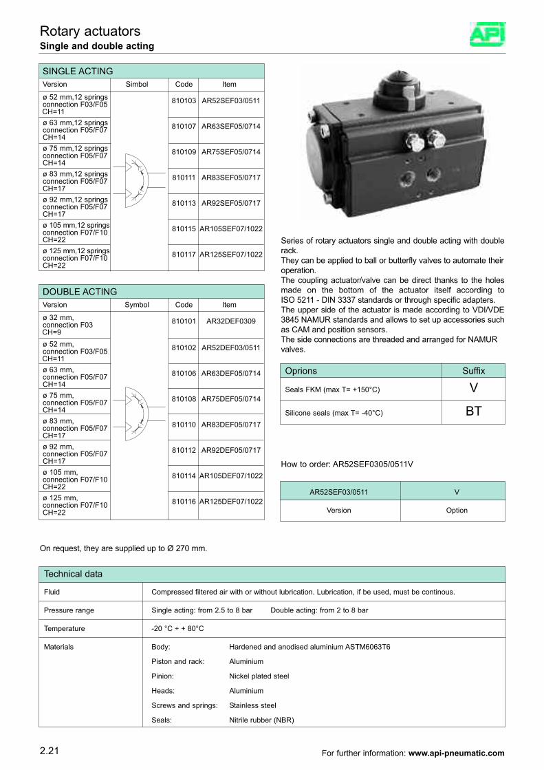
2.21
Rotary actuatorsSingle and double acting
Series of rotary actuators single and double acting with doublerack.They can be applied to ball or butterfly valves to automate theiroperation.The coupling actuator/valve can be direct thanks to the holesmade on the bottom of the actuator itself according toISO 5211 - DIN 3337 standards or through specific adapters.The upper side of the actuator is made according to VDI/VDE3845 NAMUR standards and allows to set up accessories suchas CAM and position sensors.The side connections are threaded and arranged for NAMURvalves.
AR52SEF03/0511 V
Version Option
Technical data
Fluid Compressed filtered air with or without lubrication. Lubrication, if be used, must be continous.
Pressure range Single acting: from 2.5 to 8 bar Double acting: from 2 to 8 bar
Temperature -20 °C ÷ + 80°C
Materials Body: Hardened and anodised aluminium ASTM6063T6
Piston and rack: Aluminium
Pinion: Nickel plated steel
Heads: Aluminium
Screws and springs: Stainless steel
Seals: Nitrile rubber (NBR)
Oprions Suffix
Seals FKM (max T= +150°C) V
Silicone seals (max T= -40°C) BT
On request, they are supplied up to Ø 270 mm.
DOUBLE ACTINGVersion Symbol Code Item
ø 32 mm, 810101 AR32DEF0309connection F03 CH=9ø 52 mm, 810102 AR52DEF03/0511connection F03/F05 CH=11ø 63 mm, 810106 AR63DEF05/0714connection F05/F07CH=14ø 75 mm, 810108 AR75DEF05/0714connection F05/F07CH=14ø 83 mm, 810110 AR83DEF05/0717connection F05/F07CH=17ø 92 mm, 810112 AR92DEF05/0717connection F05/F07CH=17ø 105 mm, 810114 AR105DEF07/1022connection F07/F10CH=22ø 125 mm, 810116 AR125DEF07/1022connection F07/F10CH=22
How to order: AR52SEF0305/0511V
SINGLE ACTINGVersion Simbol Code Item
ø 52 mm,12 springs 810103 AR52SEF03/0511connection F03/F05 CH=11ø 63 mm,12 springs 810107 AR63SEF05/0714connection F05/F07CH=14ø 75 mm,12 springs 810109 AR75SEF05/0714connection F05/F07CH=14ø 83 mm,12 springs 810111 AR83SEF05/0717connection F05/F07CH=17ø 92 mm,12 springs 810113 AR92SEF05/0717connection F05/F07CH=17ø 105 mm,12 springs 810115 AR105SEF07/1022connection F07/F10CH=22ø 125 mm,12 springs 810117 AR125SEF07/1022connection F07/F10CH=22
For further information: www.api-pneumatic.com
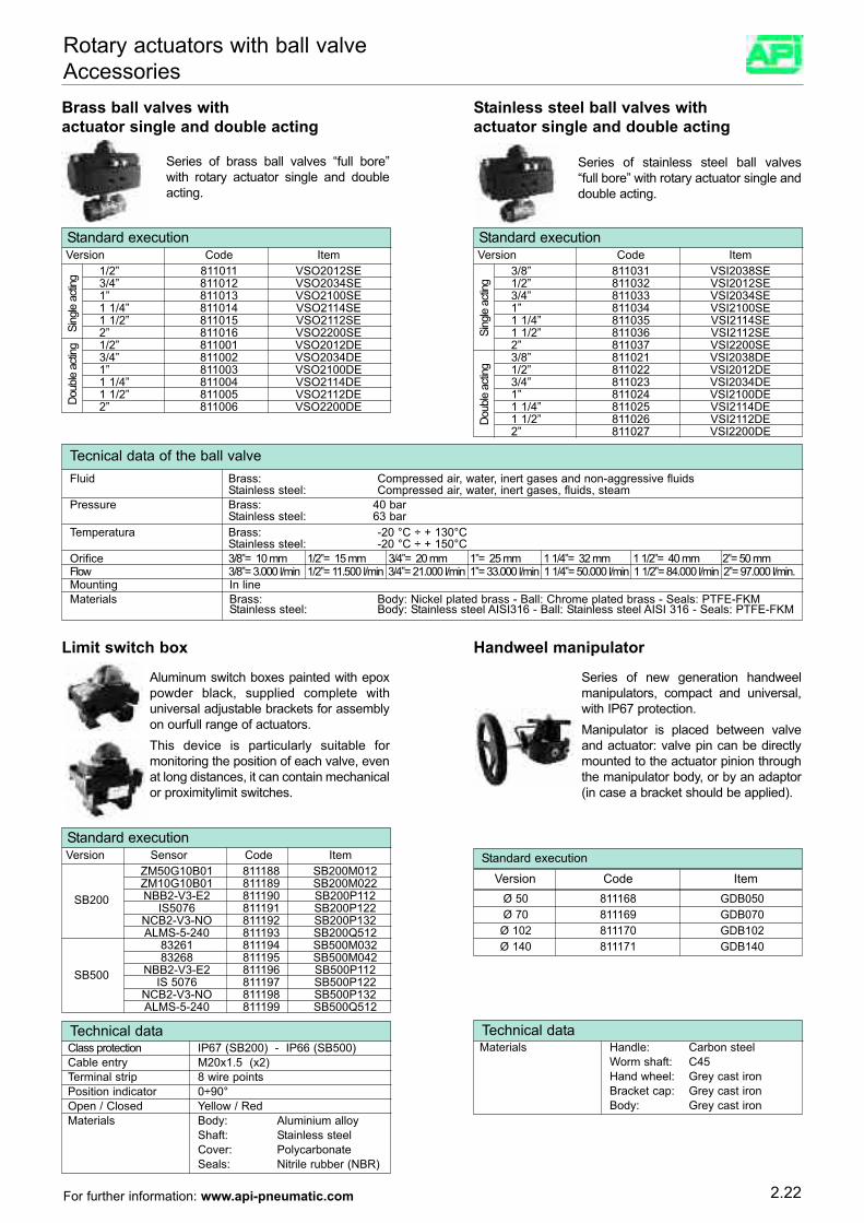
Technical dataClass protection IP67 (SB200) - IP66 (SB500)Cable entry M20x1.5 (x2)Terminal strip 8 wire pointsPosition indicator 0÷90°Open / Closed Yellow / RedMaterials Body: Aluminium alloy
Shaft: Stainless steelCover: PolycarbonateSeals: Nitrile rubber (NBR)
3/8” 811031 VSI2038SE1/2” 811032 VSI2012SE3/4” 811033 VSI2034SE1” 811034 VSI2100SE1 1/4” 811035 VSI2114SE1 1/2” 811036 VSI2112SE2” 811037 VSI2200SE3/8” 811021 VSI2038DE1/2” 811022 VSI2012DE3/4” 811023 VSI2034DE1” 811024 VSI2100DE1 1/4” 811025 VSI2114DE1 1/2” 811026 VSI2112DE2” 811027 VSI2200DE
2.22
Rotary actuators with ball valveAccessories
Standard execution
Brass ball valves withactuator single and double acting
Series of brass ball valves “full bore”with rotary actuator single and doubleacting.
Version Code Item
Stainless steel ball valves withactuator single and double acting
Series of stainless steel ball valves“full bore” with rotary actuator single anddouble acting.
Limit switch box
1/2” 811011 VSO2012SE3/4” 811012 VSO2034SE1” 811013 VSO2100SE1 1/4” 811014 VSO2114SE1 1/2” 811015 VSO2112SE2” 811016 VSO2200SE1/2” 811001 VSO2012DE3/4” 811002 VSO2034DE1” 811003 VSO2100DE1 1/4” 811004 VSO2114DE1 1/2” 811005 VSO2112DE2” 811006 VSO2200DE
Sing
le ac
ting
Doub
le ac
ting
Standard executionVersion Code Item
Sing
le ac
ting
Doub
le ac
ting
Tecnical data of the ball valveFluid Brass: Compressed air, water, inert gases and non-aggressive fluids
Stainless steel: Compressed air, water, inert gases, fluids, steamPressure Brass: 40 bar
Stainless steel: 63 barTemperatura Brass: -20 °C ÷ + 130°C
Stainless steel: -20 °C ÷ + 150°COrifice 3/8”= 10 mm 1/2”= 15 mm 3/4”= 20 mm 1”= 25 mm 1 1/4”= 32 mm 1 1/2”= 40 mm 2”= 50 mmFlow 3/8”= 3.000 l/min 1/2”= 11.500 l/min 3/4”= 21.000 l/min 1”= 33.000 l/min 1 1/4”= 50.000 l/min 1 1/2”= 84.000 l/min 2”= 97.000 l/min.Mounting In lineMaterials Brass: Body: Nickel plated brass - Ball: Chrome plated brass - Seals: PTFE-FKM
Stainless steel: Body: Stainless steel AISI316 - Ball: Stainless steel AISI 316 - Seals: PTFE-FKM
Standard executionVersion Sensor Code Item
SB200
SB500
ZM50G10B01 811188 SB200M012ZM10G10B01 811189 SB200M022NBB2-V3-E2 811190 SB200P112
IS5076 811191 SB200P122NCB2-V3-NO 811192 SB200P132ALMS-5-240 811193 SB200Q512
83261 811194 SB500M03283268 811195 SB500M042
NBB2-V3-E2 811196 SB500P112IS 5076 811197 SB500P122
NCB2-V3-NO 811198 SB500P132ALMS-5-240 811199 SB500Q512
Aluminum switch boxes painted with epoxpowder black, supplied complete withuniversal adjustable brackets for assemblyon ourfull range of actuators.This device is particularly suitable formonitoring the position of each valve, evenat long distances, it can contain mechanicalor proximitylimit switches.
Handweel manipulator
Series of new generation handweelmanipulators, compact and universal,with IP67 protection.Manipulator is placed between valveand actuator: valve pin can be directlymounted to the actuator pinion throughthe manipulator body, or by an adaptor(in case a bracket should be applied).
Technical dataMaterials Handle: Carbon steel
Worm shaft: C45Hand wheel: Grey cast ironBracket cap: Grey cast ironBody: Grey cast iron
Ø 50 811168 GDB050Ø 70 811169 GDB070
Ø 102 811170 GDB102Ø 140 811171 GDB140
Standard execution
Version Code Item
For further information: www.api-pneumatic.com
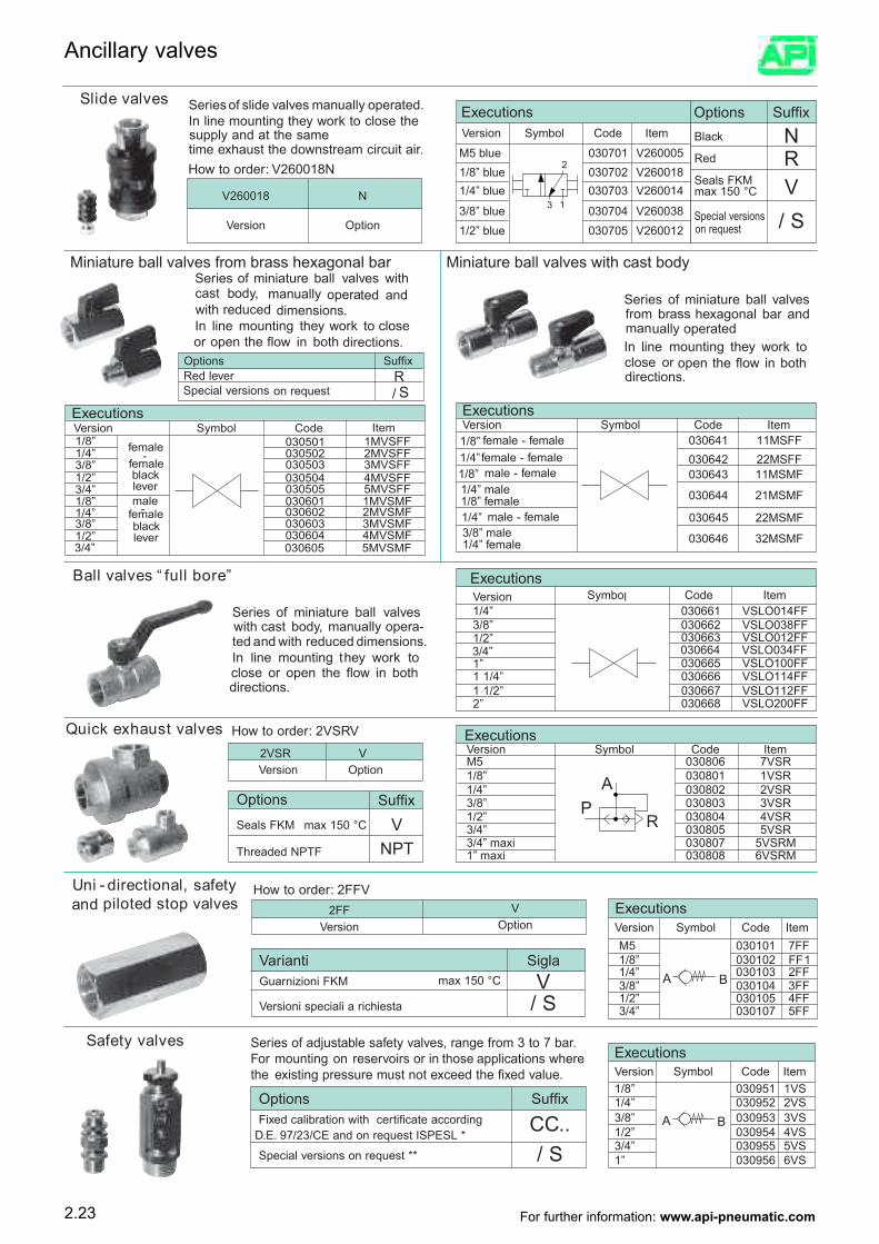
ExecutionsVersion Symbol Code ItemM5 030806 7VSR1/8” 030801 1VSR1/4” 030802 2VSR3/8” 030803 3VSR1/2” 030804 4VSR3/4” 030805 5VSR3/4” maxi 030807 5VSRM1” maxi 030808 6VSRM
Options SuffixRed lever RSpecial versions on request / S
Slide valves Series of slide valves manually operated.In line mounting they work to close the supply and at the sametime exhaust the downstream circuit air.How to order: V260018N
V260018 N
Version Option
ExecutionsVersion Symbol Code Item
M5 blue 030701 V2600051/8” blue 030702 V2600181/4” blue 030703 V260014
3/8” blue 030704 V2600381/2” blue 030705 V260012
Options SuffixBlack NRed RSeals FKMmax 150 °C VSpecial versionson request / S
Miniature ball valves from brass hexagonal bar Miniature ball valves with cast body
Series of miniature ball valves from brass hexagonal bar andmanually operated
.In line mounting they work to close or open the flow in bothdirections.
ExecutionsVersion Symbol Code Item1/8” female -
female
030501 1MVSFF
black lever
1/4” 030502 2MVSFF3/8” 030503 3MVSFF1/2” 030504 4MVSFF3/4” 030505 5MVSFF1/8” male
-female030601 1MVSMF
blacklever
1/4” 030602 2MVSMF3/8” 030603 3MVSMF1/2” 030604 4MVSMF3/4” 030605 5MVSMF
Series of miniature ball valves with cast body, manually operated and with reduced dimensions.In line mounting they work to close or open the flow in both directions.
Ball valves “ full bore” ExecutionsVersion Symbol Code Item1/4” 030661 VSLO014FF3/8” 030662 VSLO038FF1/2” 030663 VSLO012FF3/4” 030664 VSLO034FF1” 030665 VSLO100FF1 1/4” 030666 VSLO114FF1 1/2” 030667 VSLO112FF2” 030668 VSLO200FF
Series of miniature ball valves with cast body, manually opera-ted and with reduced dimensions.In line mounting they work to close or open the flow in bothdirections.
How to order: 2VSRV2VSR VVersion Option
Options SuffixSeals FKM max 150 °C VThreaded NPTF NPT
Uni - directional, safety and piloted stop valves
How to order: 2FFV2FF V
Version Option
Varianti SiglaGuarnizioni FKM max 150 °C VVersioni speciali a richiesta / S
ExecutionsVersion Symbol Code ItemM5 030101 7FF1/8” 030102 1FF1/4” 030103 2FF3/8” 030104 3FF1/2” 030105 4FF3/4” 030107 5FF
Safety valves Series of adjustable safety valves, range from 3 to 7 bar.For mounting on reservoirs or in those applications where the existing pressure must not exceed the fixed value.
Options SuffixFixed calibration with certificate according CC..
D.E. 97/23/CE and on request ISPESL *
Special versions on request ** / S
ExecutionsVersion Symbol Code Item1/8” 030951 1VS1/4” 030952 2VS3/8” 030953 3VS1/2” 030954 4VS3/4” 030955 5VS1” 030956 6VS
ExecutionsVersion Symbol Code Item1/8” 030641 11MSFFfemale - female1/4” 030642 22MSFFfemale - female1/8”
030643 11MSMFmale - female
1/4” male 030644 21MSMF1/8” female1/4” 030645 22MSMFmale - female3/8” male 030646 32MSMF1/4” female
Quick exhaust valves
2.23
Ancillary valves
For further information: www.api-pneumatic.com
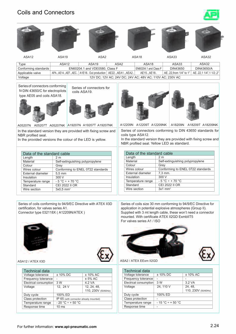
ASA12
A19207N A19207T A19207NK
ASA18ASA19 ASA2 ASA33 ASA32
A05207N A05207T A05207NK A12209N A18209T A18209NK A12209T A12209NK A18209N
Series of connectors conformingto DIN 43650/C for electropilots type AE05 and coils ASA18.
Series of connectors for coils ASA19.
Data of the standard cableLength 2 mMaterial Self-extinguishing polypropyleneColour GreyWires colour Conforming to ENEL 0722 standardsExternal diameter 5,5 mmInsulation 300 VTemperature range - 5 °C ÷ + 70 °CStandard CEI 2022 II ORWire section 3x0,5 mm2
In the standard version they are provided with fixing screw andNBR profiled seal.In the provided versions the colour of the LED is yellow.
Series of connectors conforming to DIN 43650 standards forcoils type ASA12.In the standard version they are provided with fixing screw andNBR profiled seal. Yellow LED as standard.
Data of the standard cableLength 2 mMaterial Self-extinguishing polypropyleneColour GreyWires colour Conforming to ENEL 0722 standardsExternal diameter 7,3 mm.Insulation 300 VTemperature range - 5 °C ÷ + 70 °CStandard CEI 2022 II ORWire section 3x1 mm2
ASA12 / ATEX II3D ASA2 / ATEX EExm II2GD
Series of coils conforming to 94/9/EC Directive with ATEX II3Dcertification, for valves series A1.Connector type 032118X ( A12209N/ATEX )
Series of coils size 30 mm conforming to 94/9/EC Directive forapplication in potential explosive atmospheres (Group II).Supplied with 3 mt length cable, these won’t need a connectormounted. With certificate ATEX II2GD ExmbIIT5For valves series A1 / ISO
Technical data Voltage tolerance ± 10% DC ± 10% AC Frequency tolerance - ± 5% ACElectrical consumption 3 W 4.2 VAVoltage 12, 24 V 12, 24, 48,
110, 230V (50/60Hz)
Duty cycle 100% EDClass protection IP 65 (with connector already mounted)
Temperature range - 20 °C ÷ + 50 °CResponse time 10 ms
Technical data Voltage tolerance ± 10% DC ± 10% AC Frequency tolerance - -Electrical consumption 3 W 3.2 VAVoltage 24, 110 V 24, 48,
110, 230V (50/60Hz)
Duty cycle 100% EDClass protection -Temperature range - 15 °C ÷ + 50 °CResponse time -
Type ASA12 ASA19 ASA2 ASA18 ASA33 ASA32Conforming standards EN60204.1 and VDE0580, Class F
APA..,AE14..,AEF..,AEC..12V DC; 12V AC; 24V DC; 24V AC; 48V AC; 110V AC; 230V AC
A1E18.. Out production AE22..,AEA1..,AEA2.. AE15..,AE18.. AE..22,from 1/4” to 1” AE..22,1 1/4”,1 1/2:,2”Applicable valveVoltage
EN60204.1 and Class F DIN43650 DIN43650/A
2.24
Coils and Connectors
For further information: www.api-pneumatic.com
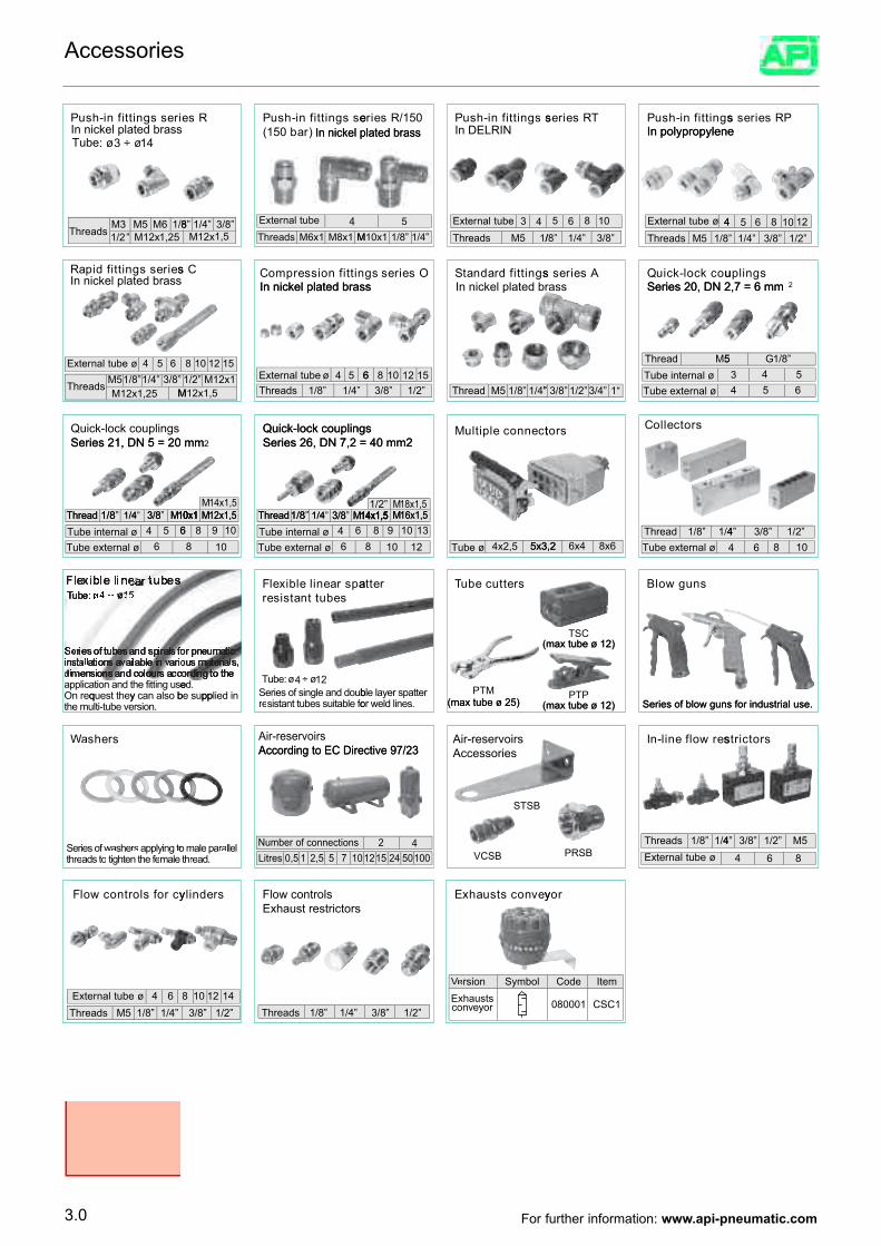
iressgnittifni-hsIn nickel plated brass
uP
3 ÷ 14øø3 ÷ 14: øTube
Rse)rab051(
essgnittifni-hsuPIn nickel plated brass
ssgnittifni-hsuIn DELRINP051/Rseire
In nickel plated brass
sgnittifni-hsuIn polypropylenePTRseires
PRseiressIn polypropylene
seiressgnittifdipaIn nickel plated brassR
52,1x21M”2/18/16M5M3M
sdaerhT
In nickel plated brassnittifnoisserpmoCCs
5,1x21M”8/3”4/1”8
M1x8M1x6MsdaerhT4ebutlanretxE
In nickel plated brassIn nickel plated brassOseiressg sgnittifdradnatS
”4/1”8/11x01M5
/15MsdaerhT43ebutlanretxE
In nickel plated brassuockcol-kciu
Series 20, DN 2,7 = 6 mmQAseiress
”8/3”4/1”8/
865 01
8/15MsdaerhT4øebutlanretxE
sgnilpu2Series 20, DN 2,7 = 6 mm
”2/1”8/3”4/1”8654 2101
Series 21, DN 5 = 20 mmQuick-lock couplings
654øebutlanretxE
M52,1x21M”8/3”4/1”8/15MsdaerhT
”8/3”4/1”8/1 10x1MdaerhT
Series 26, DN 7,2 = 40 mm2Quick-lock couplings
2Series 21, DN 5 = 20 mm
8 512101
5,1x21M1x21M”2/1
”4/1”8/1sdaerhT654øebutlanretxE
14x1,512x1,5
MM10x1 ”8/3”4/1”8/1 14x1,5MdaerhT
Series 26, DN 7,2 = 40 mm2Quick-lock couplings tcennocelpitluM
”2/1”8/386 512101
”4/1”8/15MdaerhT
”14x1,5
2/1 18x1,516x1,5M
M
srotcelloCsrot
”1”4/3”2/1”8/3”
5MdaerhTTube internal øTube external ø
”8/15 G3 4 54 65
8/34/18/1 10x1MdaerhT64 5Tube internal ø
b
6Tube external ø
oslanacyehttseuqernOesugnittttifehtdnanoitacilppa
d
esbuttnatsiserapsraenilelbixelF
12x1,5M10x110986
108
8/34/18/1 14x1,5MdaerhT64
:
Tube internal ø6Tube external ø
ebuT 12ø4ø ÷buoddnaelgnisfoseireSnideilppuseb
.de
srettucebuTTuretta
4x2,5 5x3,2Tube ø
14x1,5 16x1,5M131098
(max tube ø 12)
10 128
(max tube ø 25)PTMrettttapsreyalelb
snugwolB
Tube external ø4/1”8/1daerhT
(max tube ø 12)
8x66x45x3,2
TSC
PTP
4 1086”2/1”8/3”4
srehsaWWa
elameffeehtnethgitottosdaerrehtottogniylppasrrsehsawwafoseireS
.noisrevebut-itlumehtyq
According to EC Directive 97/23Air-reservoirs
offoelbatiussebuttnatsiserre
.daerrehtlellarraapelamo
pp
01755,215,0sertiLsnoitcennocforebmuN
AccessoriesAir-reservoirs
According to EC Directive 97/23
(max tube ø 12)
VCSB
STSB
(max tube ø 25).senildlewwero
0010542512142
serwolfenil-nI
Series of blow guns for industrial use.(max tube ø 12)
PRSB4/1”8/1sdaerhT
øebutlanretxE
srotcirts
Series of blow guns for industrial use.
5M”2/1”8/3”4
864
ycrofslortnocwolF
”4/1”8/15MsdaerhT4 6øebutlanretxE
srednilyExhaust restrictorsFlow controls
”2/1”8/3412108 1
”4/1”8/1sdaerhT
yevnocstsuahxE
”2/1”8/3
l
royevnocstsuahxE
obmySnoisreVVe
roy
m
1CSC100080
etIedoC
3.0
Accessories
For further information: www.api-pneumatic.com
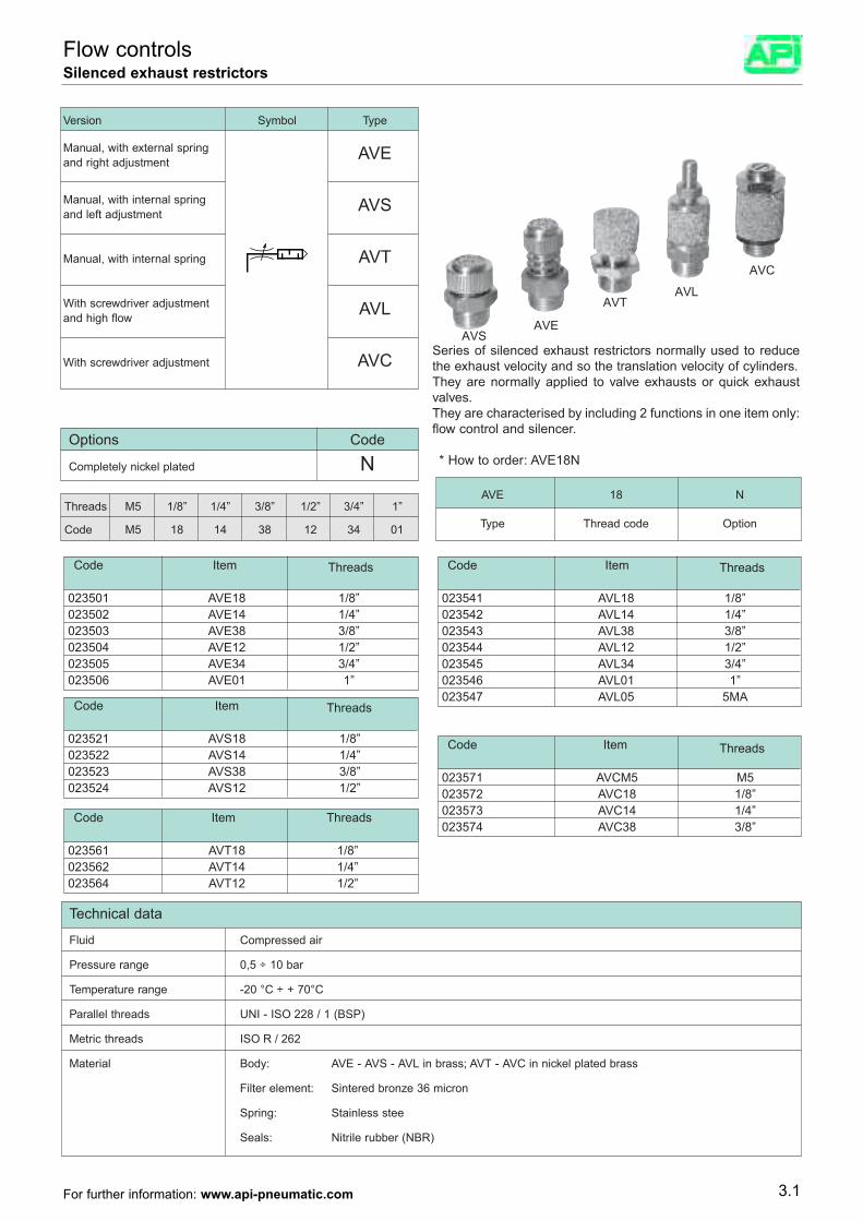
Technical data
Fluid Compressed air
Pressure range 0,5 ÷ 10 bar
Temperature range -20 °C ÷ + 70°C
Parallel threads UNI - ISO 228 / 1 (BSP)
Metric threads ISO R / 262
Material Body: AVE - AVS - AVL in brass; AVT - AVC in nickel plated brass
Filter element: Sintered bronze 36 micron
Spring: Stainless stee
Seals: Nitrile rubber (NBR)
Series of silenced exhaust restrictors normally used to reducethe exhaust velocity and so the translation velocity of cylinders.They are normally applied to valve exhausts or quick exhaustvalves.They are characterised by including 2 functions in one item only:flow control and silencer.
* How to order: AVE18N
AVE 18 N
Type Thread code Option
Version Symbol Type
Manual, with external spring AVEand right adjustment
Manual, with internal spring AVSand left adjustment
Manual, with internal spring AVT
With screwdriver adjustment AVLand high flow
With screwdriver adjustment AVC
Threads M5 1/8” 1/4” 3/8” 1/2” 3/4” 1”
Code M5 18 14 38 12 34 01
Options Code
Completely nickel plated N
Code Item
023501 AVE18 1/8”023502 AVE14 1/4”023503 AVE38 3/8”023504 AVE12 1/2”023505 AVE34 3/4”023506 AVE01 1”
Code Item
023521 AVS18 1/8”023522 AVS14 1/4”023523 AVS38 3/8”023524 AVS12 1/2”
Code Item Threads
Threads
Threads
023561 AVT18 1/8”023562 AVT14 1/4”023564 AVT12 1/2”
Code Item
023541 A
AVSAVE
AVTAVL
AVC
VL18 1/8”023542 AVL14 1/4”023543 AVL38 3/8”023544 AVL12 1/2”023545 AVL34 3/4”023546 AVL01 1”023547 AVL05 5MA
Code Item
023571 AVCM5 M5023572 AVC18 1/8”023573 AVC14 1/4”023574 AVC38 3/8”
Threads
Threads
3.1
Flow controlsSilenced exhaust restrictors
For further information: www.api-pneumatic.com
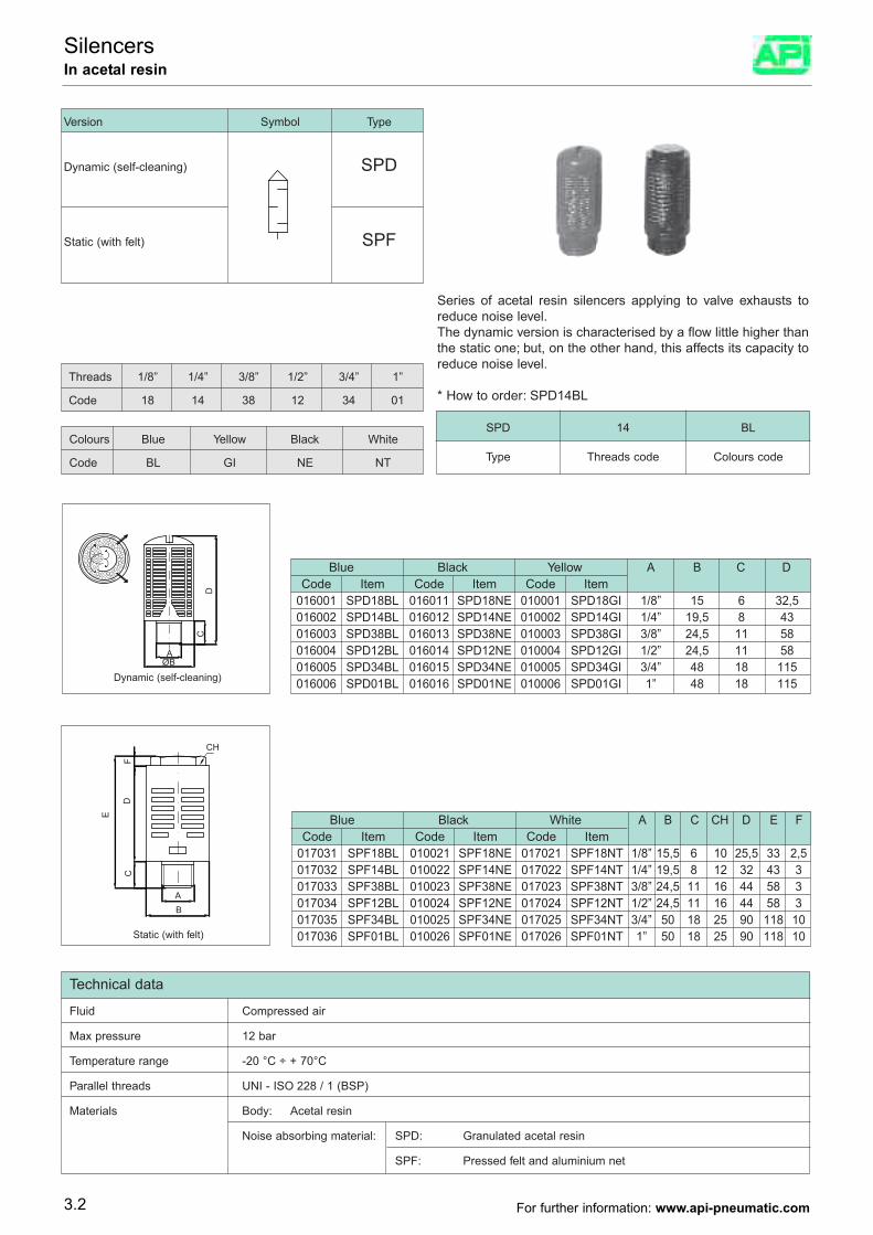
Threads 1/8” 1/4” 3/8” 1/2” 3/4” 1”
Code 18 14 38 12 34 01
Colours Blue Yellow Black White
Code BL GI NE NT
Series of acetal resin silencers applying to valve exhausts toreduce noise level.The dynamic version is characterised by a flow little higher thanthe static one; but, on the other hand, this affects its capacity toreduce noise level.
* How to order: SPD14BL
Version Symbol Type
Dynamic (self-cleaning) SPD
Static (with felt) SPF
Technical data
Fluid Compressed air
Max pressure 12 bar
Temperature range -20 °C ÷ + 70°C
Parallel threads UNI - ISO 228 / 1 (BSP)
Materials Body: Acetal resin
Noise absorbing material: SPD: Granulated acetal resin
SPF: Pressed felt and aluminium net
SPD 14 BL
Type Threads code Colours code
Blue Black Yellow A B C DCode Item Code Item Code Item
016001 SPD18BL 016011 SPD18NE 010001 SPD18GI 1/8” 15 6 32,5016002 SPD14BL 016012 SPD14NE 010002 SPD14GI 1/4” 19,5 8 43016003 SPD38BL 016013 SPD38NE 010003 SPD38GI 3/8” 24,5 11 58016004 SPD12BL 016014 SPD12NE 010004 SPD12GI 1/2” 24,5 11 58016005 SPD34BL 016015 SPD34NE 010005 SPD34GI 3/4” 48 18 115016006 SPD01BL 016016 SPD01NE 010006 SPD01GI 1” 48 18 115
Blue Black White A B C CH D E FCode Item Code Item Code Item
017031 SPF18BL 010021 SPF18NE 017021 SPF18NT 1/8” 15,5 6 10 25,5 33 2,5017032 SPF14BL 010022 SPF14NE 017022 SPF14NT 1/4” 19,5 8 12 32 43 3017033 SPF38BL 010023 SPF38NE 017023 SPF38NT 3/8” 24,5 11 16 44 58 3017034 SPF12BL 010024 SPF12NE 017024 SPF12NT 1/2” 24,5 11 16 44 58 3017035 SPF34BL 010025 SPF34NE 017025 SPF34NT 3/4” 50 18 25 90 118 10017036 SPF01BL 010026 SPF01NE 017026 SPF01NT 1” 50 18 25 90 118 10
Dynamic (self-cleaning)
Static (with felt)
3.2
SilencersIn acetal resin
For further information: www.api-pneumatic.com
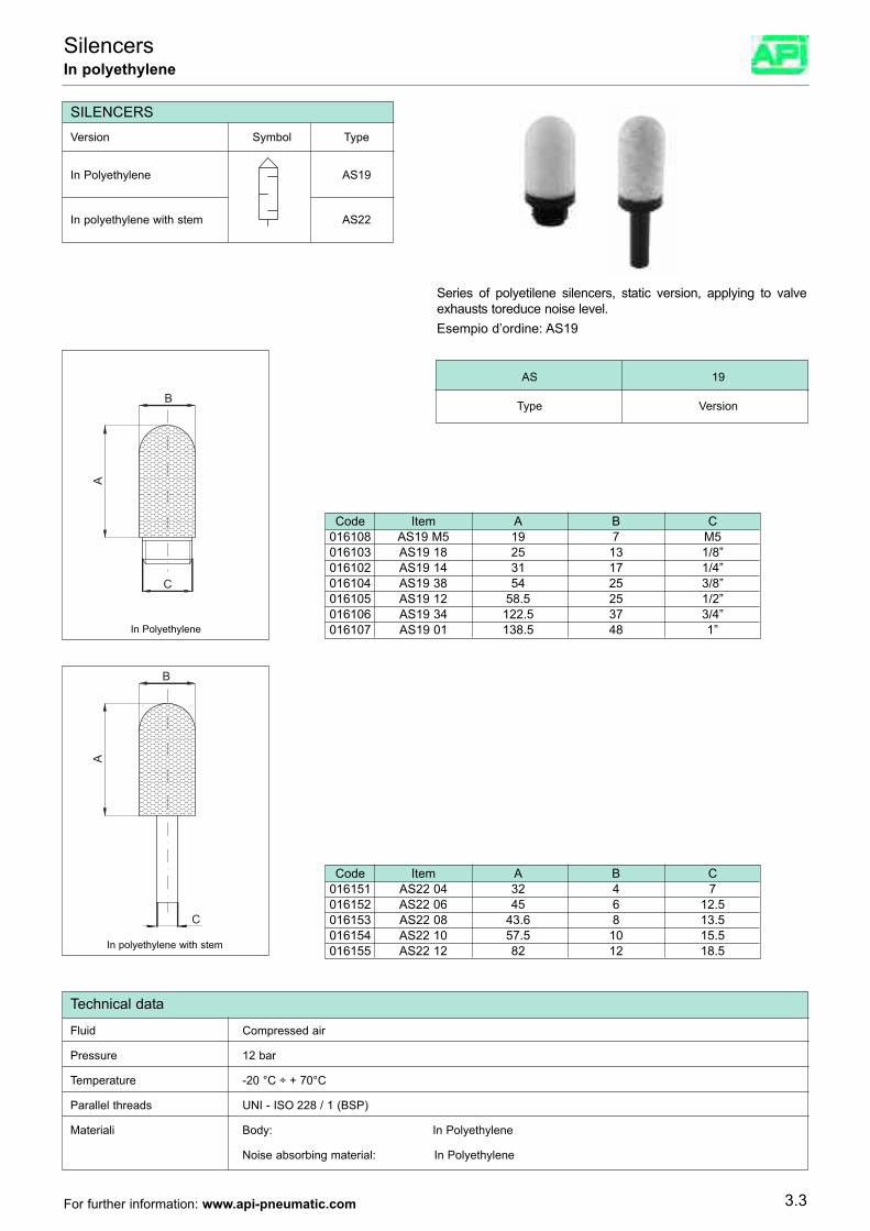
3.3
SilencersIn polyethylene
Series of polyetilene silencers, static version, applying to valveexhausts toreduce noise level.Esempio d’ordine: AS19
SILENCERS
In Polyethylene AS19
In polyethylene with stem AS22
Version Symbol Type
AS 19
Type Version
Code Item A B C016151 AS22 04 32 4 7016152 AS22 06 45 6 12.5016153 AS22 08 43.6 8 13.5016154 AS22 10 57.5 10 15.5016155 AS22 12 82 12 18.5
Code Item A B C016108 AS19 M5 19 7 M5016103 AS19 18 25 13 1/8”016102 AS19 14 31 17 1/4”016104 AS19 38 54 25 3/8”016105 AS19 12 58.5 25 1/2”016106 AS19 34 122.5 37 3/4”016107 AS19 01 138.5 48 1”
B
A
C
C
B
A
In Polyethylene
In polyethylene with stem
Technical data
Fluid Compressed air
Pressure 12 bar
Temperature -20 °C ÷ + 70°C
Parallel threads UNI - ISO 228 / 1 (BSP)
Materiali Body: In Polyethylene
Noise absorbing material: In Polyethylene
For further information: www.api-pneumatic.com
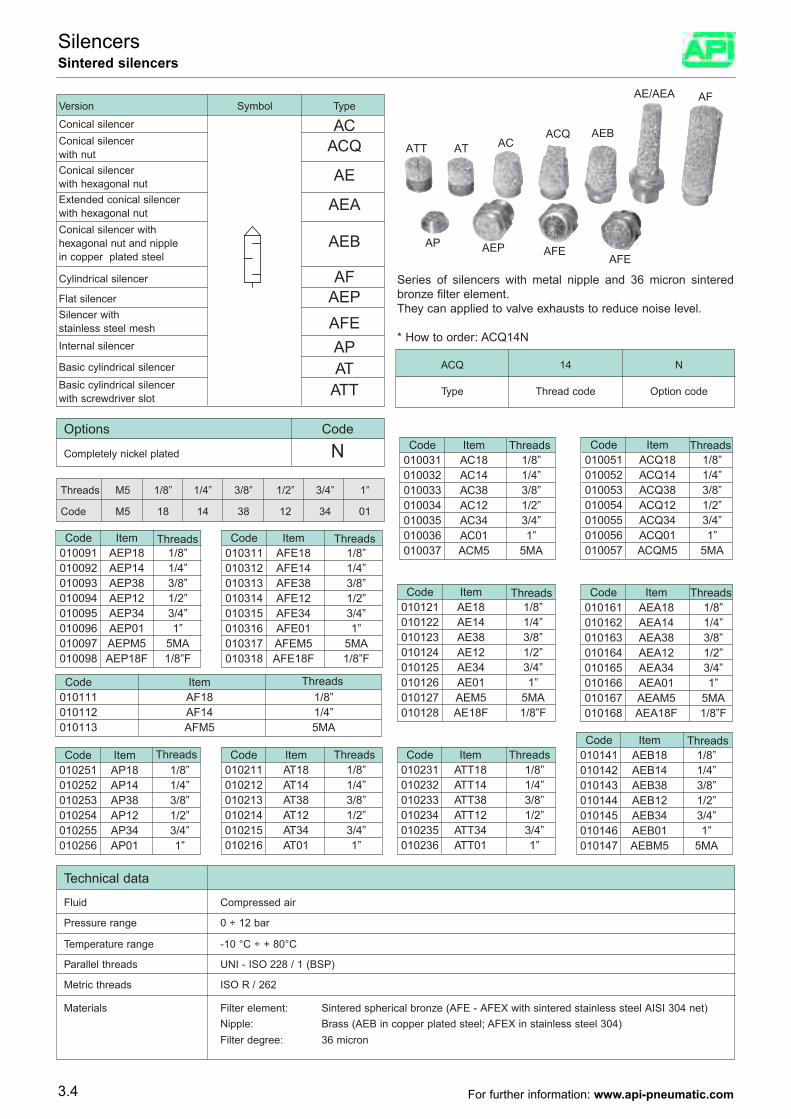
Series of silencers with metal nipple and 36 micron sinteredbronze filter element.They can applied to valve exhausts to reduce noise level.
* How to order: ACQ14N
Technical data
Fluid Compressed air
Pressure range 0 ÷ 12 bar
Temperature range -10 °C ÷ + 80°C
Parallel threads UNI - ISO 228 / 1 (BSP)
Metric threads ISO R / 262
Materials Filter element: Sintered spherical bronze (AFE - AFEX with sintered stainless steel AISI 304 net)Nipple: Brass (AEB in copper plated steel; AFEX in stainless steel 304)Filter degree: 36 micron
ACQ 14 N
Type Thread code Option code
Version Symbol Type
Conical silencer ACConical silencer ACQwith nutConical silencer AEwith hexagonal nutExtended conical silencer AEAwith hexagonal nutConical silencer withhexagonal nut and nipple AEBin copper plated steel
Cylindrical silencer AFFlat silencer AEPSilencer with AFEstainless steel meshInternal silencer APBasic cylindrical silencer ATBasic cylindrical silencer ATTwith screwdriver slot
Threads M5 1/8” 1/4” 3/8” 1/2” 3/4” 1”
Code M5 18 14 38 12 34 01
Options Code
Completely nickel plated N Code Item010031 AC18 1/8”010032 AC14 1/4”010033 AC38 3/8”010034 AC12 1/2”010035 AC34 3/4”010036 AC01 1”010037 ACM5 5MA
Code Item010051 ACQ18 1/8”010052 ACQ14 1/4”010053 ACQ38 3/8”010054 ACQ12 1/2”010055 ACQ34 3/4”010056 ACQ01 1”010057 ACQM5 5MA
Code Item010121 AE
ACQATT
AP AEP AFEAFE
AT ACAEB
AE/AEA AF
18 1/8”010122 AE14 1/4”010123 AE38 3/8”010124 AE12 1/2”010125 AE34 3/4”010126 AE01 1”010127 AEM5 5MA010128 AE18F 1/8”F
Code Item010161 AEA18 1/8”010162 AEA14 1/4”010163 AEA38 3/8”010164 AEA12 1/2”010165 AEA34 3/4”010166 AEA01 1”010167 AEAM5 5MA010168 AEA18F 1/8”F
Code Item010091 AEP18 1/8”010092 AEP14 1/4”010093 AEP38 3/8”010094 AEP12 1/2”010095 AEP34 3/4”010096 AEP01 1”010097 AEPM5 5MA010098 AEP18F 1/8”F
Code Item010141 AEB18 1/8”010142 AEB14 1/4”010143 AEB38 3/8”010144 AEB12 1/2”010145 AEB34 3/4”010146 AEB01 1”010147 AEBM5 5MA
Code Item010111 AF18 1/8”010112 AF14 1/4”010113 AFM5 5MA
Code Item010311 AFE18 1/8”010312 AFE14 1/4”010313 AFE38 3/8”010314 AFE12 1/2”010315 AFE34 3/4”010316 AFE01 1”010317 AFEM5 5MA010318 AFE18F 1/8”F
Code Item010251 AP18 1/8”010252 AP14 1/4”010253 AP38 3/8”010254 AP12 1/2”010255 AP34 3/4”010256 AP01 1”
Code Item010211 AT18 1/8”010212 AT14 1/4”010213 AT38 3/8”010214 AT12 1/2”010215 AT34 3/4”010216 AT01 1”
Code Item010231 ATT18 1/8”010232 ATT14 1/4”010233 ATT38 3/8”010234 ATT12 1/2”010235 ATT34 3/4”010236 ATT01 1”
Threads Threads Threads
ThreadsThreads
Threads
Threads
Threads
Threads
Threads
Threads
3.4
SilencersSintered silencers
For further information: www.api-pneumatic.com
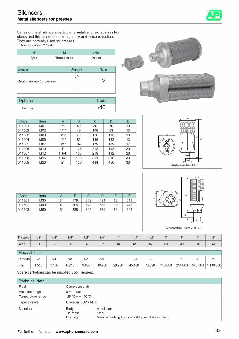
Technical dataFluid Compressed airPressure range 0 ÷ 10 barTemperature range -25 °C ÷ + 100°C
Taper threads Universal BSP - NPTF
Materials Body: AluminiumTie rods: SteelCartridge: Noise absorbing fibre coated by metal drilled plate
Series of metal silencers particularly suitable for exhausts in bigplants and this thanks to their high flow and noise reduction.They are normally used for presses.* How to order: M12/40
M 12 / 40Type Thread code Option
Version Symbol Type
Metal silencers for presses M
Options Code
Till 40 bar /40
Threads 1/8” 1/4” 3/8” 1/2” 3/4” 1” 1 1/4” 1 1/2” 2” 3” 4” 6”
Code 01 02 00 05 07 10 12 15 20 30 40 60
Flows at 6 bar
Threads 1/8” 1/4” 3/8” 1/2” 3/4” 1” 1 1/4” 1 1/2” 2” 3” 4” 6”
l/min 1.553 3.105 6.210 9.035 19.760 28.230 45.168 73.398 118.600 254.000 508.000 1.130.000
Spare cartridges can be supplied upon request.
Code Item A B C D E F011501 M30 3” 179 623 421 56 219011502 M40 4” 205 623 563 60 248011503 M60 6” 288 815 732 83 348
Code Item A B C D E011001 M01 1/8” 49 80 70 10011002 M02 1/4” 49 106 93 13011003 M00 3/8” 70 126 113 13011004 M05 1/2” 86 146 132 13011005 M07 3/4” 89 179 162 17011006 M10 1” 103 212 192 20011007 M12 1 1/4” 103 219 192 26011008 M15 1 1/2” 136 351 318 33011009 M20 2” 136 484 450 33
Single chamber (till 2’’)
Four chambers (from 3’’ to 6’’)
3.5
SilencersMetal silencers for presses
For further information: www.api-pneumatic.com
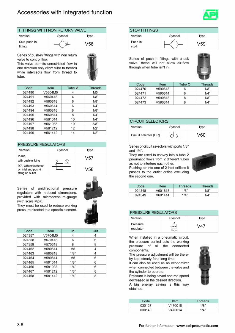
Accessories with integrated function
FITTINGS WITH NON RETURN VALVEVersion Symbol Type
Stud push-in fitting V56
Series of push-in fittings with non returnvalve to control flow.This valve permits unrestricted flow inone direction only (from tube to thread)while intercepts flow from thread totube.
Code Item Tube Ø Threads024490 V5604M5 4 M5024491 V560418 4 1/8”024492 V560618 6 1/8”024493 V560614 6 1/4”024494 V560818 8 1/8”024495 V560814 8 1/4”024496 V561014 10 1/4”024497 V561038 10 3/8”024498 V561212 12 1/2”024499 V561412 14 1/2”
STOP FITTINGSVersion Symbol Type
Push-in stud V59
Series of push-in fittings with checkvalve, these will not allow air-flowthrough when tube isn’t in.
Code Item Tube Ø Threads024470 V590618 6 1/8”024471 V590614 6 1/4”024472 V590818 8 1/8”024473 V590814 8 1/4”
CIRCUIT SELECTORSVersion Symbol Type
Circuit selector (OR) V60
Series of circuit selectors with ports 1/8’’and 1/4’’.They are used to convey into a tube 2pneumatic flows from 2 different tubesas not to interfere each other.Pushing air into one of 2 inlet orifices itpasses to the outlet orifice excludingthe second one.
Code Item Threads Threads024348 V601818 1/8” 1/8”024349 V601414 1/4” 1/4”
PRESSURE REGULATORSVersion Symbol Type
In-line,with push-in fitting V57
Series of unidirectional pressureregulators with reduced dimensions,provided with micropressure-gauge(with scale Mpa).They must be used to reduce workingpressure directed to a specific element.
90°, with male threadon inlet and push-infitting on outlet
V58
Code Item In Out024357 V5704M5 4 4024358 V570418 6 6024359 V570618 8 8024462 V580614 M5 4024463 V580818 1/8” 4024464 V580814 M5 6024465 V581014 1/8” 6024466 V581038 1/4” 6024467 V581212 1/8” 8024468 V581412 1/4” 8
PRESSURE REGULATORSVersion Symbol Type
Pressureregulator V47
Code Item Threads030127 V470018 1/8”030140 V470014 1/4”
When installed in a pneumatic circuit,the pressure control sets the workingpressure of all the connectedcomponents.The pressure adjustment will be there-by kept steady for a long time.It can also be used as an economizerwhen connected between the valve andthe cylinder to operate.Pressure is being saved and rod speeddecreased in the desired direction. A big energy saving is this wayobtained.
3.6 For further information: www.api-pneumatic.com
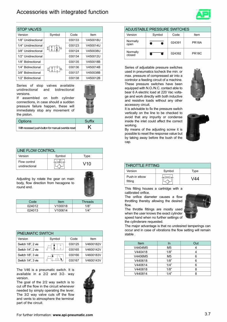
Normally 024391 PR18Aopen
Normally 024392 PR18Cclosed
Accessories with integrated function
ADJUSTABLE PRESSURE SWITCHESVersion Symbol Code Item
Series of adjustable pressure switchesused in pneumatics tocheck the min. ormax. pressure of compressed air into acontrolor a feeding circuit of a machine.These pressure switches have beenequipped with N.O./N.C. contact able tobear 6 A electric load at 220 Vac volta-ge and work directly with both inductiveand resistive loads without any otheraccessory circuit.It is advisable to fix the pressure switchvertically on the line to be checked toavoid that any impurity or condenseinside the inlet could affect the correctworking.By means of the adjusting screw it ispossible to reset the response value butby taking away before the bush of thecap.
1/8” Unidirectional 030133 V450018U
STOP VALVESVersion Symbol Code Item
1/4” Unidirectional 030123 V450014U
3/8” Unidirectional 030124 V450038U
1/2” Unidirectional 030134 V450012U
1/8” Bidirectional 030135 V450018B
1/4” Bidirectional 030136 V450014B
3/8” Bidirectional 030137 V450038B
1/2” Bidirectional 030138 V450012B
Series of stop valves availableunidirectional and bidirectionalversions.If assembled on both cylinderconnections, in case should a suddenpressure failure happen, these willimmediately stop any movement ofthe piston.
Options Suffix
With recessed push-button for manual override reset K
Code Item Threads024012 V100018 1/8”024013 V100614 1/4”
Adjusting by rotate the gear on mainbody, flow direction from hecagone toround end.
THROTTLE FITTINGVersion Symbol Type
Push-in elbowfitting V44
This fitting houses a cartridge with acalibrated orifice.The orifice diameter causes a flowthrottling thereby allowing the desiredflow.The throttle fittings are mostly usedwhen the user knows the exact cylinderspeed hand when no further settings ofthe cylinderare requested.
Item In OutV4404M5 M5 4V440418 1/8” 4V4406M5 M5 6V440618 1/8” 6V440614 1/4” 6V440818 1/8” 8V440814 1/4” 8
Switch 1/8”, 2 vie 030125 V4600182V
PNEUMATIC SWITCHVersion Symbol Code Item
Switch 1/4”, 2 vie 030165 V4600142V
Switch 1/8”, 3 vie 030166 V4600183V
Switch 1/4”, 3 vie 030167 V4600143V
The V46 is a pneumatic switch. It isavailable in a 2/2 and 3/2- wayversion.The goal of the 2/2 way switch is tocut off the flow in the circuit wheneverneeded by simply operating the lever.The 3/2 way valve cuts off the flowand vents to atmosphere the terminalpart of the circuit.
The major advantage is that no undesired tamperings canoccur and in case of vibrations the flow setting will remainstable .
3.7
LINE FLOW CONTROLVersion Symbol Type
Flow controlunidirectional V10
For further information: www.api-pneumatic.com
This fitting allows for a progressivepressurization of the installation andprevents the actuators from being hithard in case of sudden pressure fee-ding of the previously vented circuit.Depending on the desired spindlesetting, the Slow Start Fitting will opengradually, pressure will progressivelyflow into the circuit and the actuatorswill go back to their working positionwithout being hit.Pressure feeding speed is indeeddetermined by the rotation of thespindle.If turned clockwise, a very smooth pres-surization will be achieved.
Accessories with integrated function
Code Item Threads024475 V610014 1/4”024476 V610038 3/8”024477 V610012 1/2”
V62
V62
V62
THRESHOLD SENSORVersion Symbol Type
Thresholdsensor V62
Threshold sensor can detect apressure drop and signal it with acommand signal (s).This component turns out to beespecially useful whenassembled directly on thecylinder.When the piston completes its stroke (no more counterpressure available in the cylinder ), a command signal isgiven out to a direction valve to have the piston change thestroke.Sole condition required for perfect componentperformance is that the piston has to complete its stroke.No intermediate positions are allowed.Major advantage of this component is to command thepiston stroke changes without electrical connections.
Code Item Tube Ø Threads024008 V620018 4 1/8”024010 V620014 4 1/4”024011 V620038 4 3/8”
3.8
SLOW STARTERVersion Symbol Type
Slow starter V61
For further information: www.api-pneumatic.com
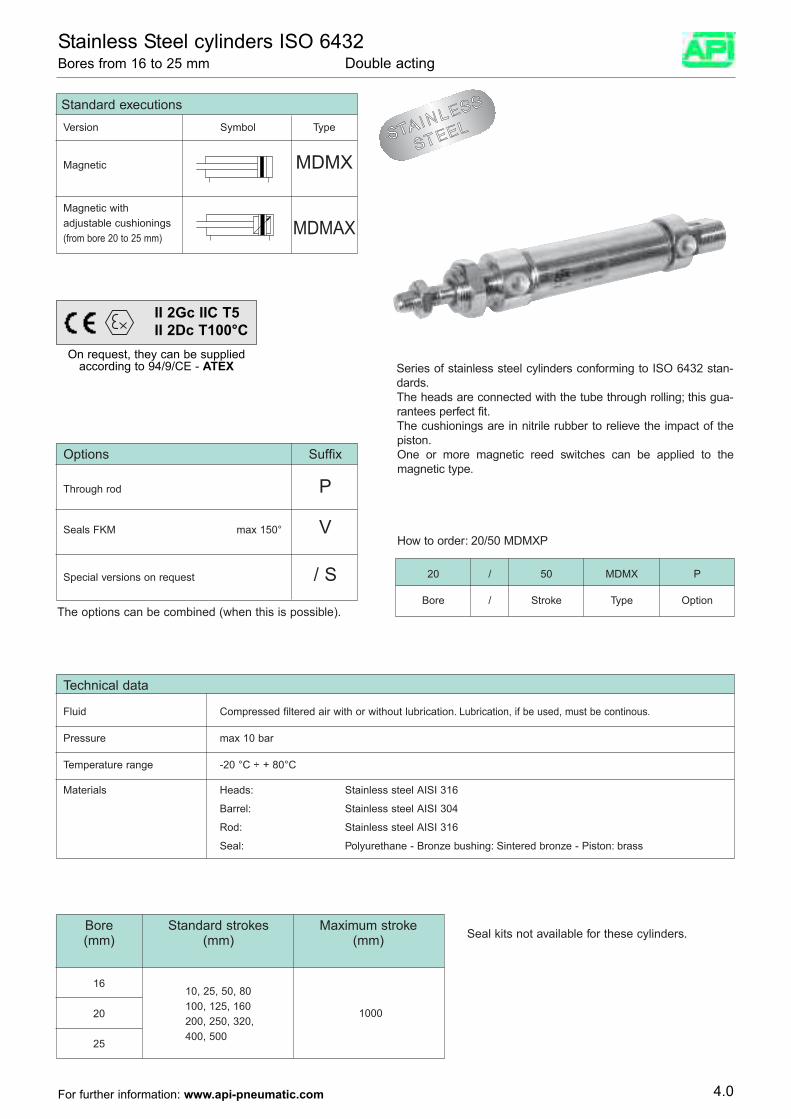
Standard executionsVersion Symbol Type
Magnetic MDMX
Magnetic withadjustable cushionings MDMAX(from bore 20 to 25 mm)
Options Suffix
Through rod P
Seals FKM max 150° V
Special versions on request / S
Series of stainless steel cylinders conforming to ISO 6432 stan-dards.The heads are connected with the tube through rolling; this gua-rantees perfect fit.The cushionings are in nitrile rubber to relieve the impact of thepiston.One or more magnetic reed switches can be applied to themagnetic type.
How to order: 20/50 MDMXP
20 / 50 MDMX P
Bore / Stroke Type Option
Bore Standard strokes Maximum stroke(mm) (mm) (mm)
16
20
25
Technical data
Fluid Compressed filtered air with or without lubrication. Lubrication, if be used, must be continous.
Pressure max 10 bar
Temperature range -20 °C ÷ + 80°C
Materials Heads: Stainless steel AISI 316
Barrel: Stainless steel AISI 304
Rod: Stainless steel AISI 316
Seal: Polyurethane - Bronze bushing: Sintered bronze - Piston: brass
The options can be combined (when this is possible).
Seal kits not available for these cylinders.
10, 25, 50, 80100, 125, 160200, 250, 320,400, 500
1000
STAINLESS
STEEL
4.0For further information: www.api-pneumatic.com
Stainless Steel cylinders ISO 6432 Bores from 16 to 25 mm Double acting
On request, they can be suppliedaccording to 94/9/CE - ATEX
II 2Gc IIC T5II 2Dc T100°C
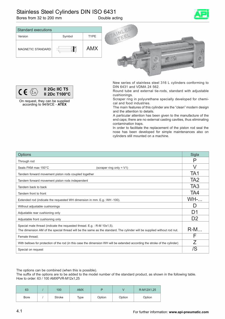
New series of stainless steel 316 L cylinders conforming toDIN 6431 and VDMA 24 562.Round tube and external tie-rods, standard with adjustablecushionings.Scraper ring in polyurethane specially developed for chemi-cal and food industries.The main features of this cylinder are the “clean” modern designand the attention to details. A particular attention has been given to the manufacture of theend caps; there are no external casting cavities, thus eliminatingcontamination traps.In order to facilitate the replacement of the piston rod seal thenose has been developed for simple maintenances also oncylinders still mounted on a machine.
Options Sigla
Through rod PSeals FKM max 150°C (scraper ring only = V1) VTandem forward movement piston rods coupled together TA1Tandem forward movement piston rods independent TA2Tandem back to back TA3Tandem front to front TA4Extended rod (indicate the requested WH dimension in mm. E.g.: WH -100). WH-...Without adjustable cushionings DAdjustable rear cushioning only D1Adjustable front cushioning only D2Special male thread (indicate the requested thread. E.g. : R-M 10x1,5).The dimension AM of the special thread will be the same as the standard. The cylinder will be supplied without rod nut. R-M...Female thread; FWith bellows for protection of the rod (in this case the dimension WH will be extended according the stroke of the cylinder) ZSpecial on request /S
The options can be combined (when this is possible).The suffix of the options are to be added to the model number of the standard product, as shown in the following table. How to order: 63 / 100 AMXPVR-M12x1,25
63 / 100 AMX P V R-M12X1,25
Bore / Stroke Type Option Option Option
Standard executionsVersion Symbol TYPE
MAGNETIC STANDARD AMX
STAINLESS
STEEL
4.1
Stainless Steel Cylinders DIN ISO 6431 Bores from 32 to 200 mm Double acting
On request, they can be suppliedaccording to 94/9/CE - ATEX
II 2Gc IIC T5II 2Dc T100°C
For further information: www.api-pneumatic.com
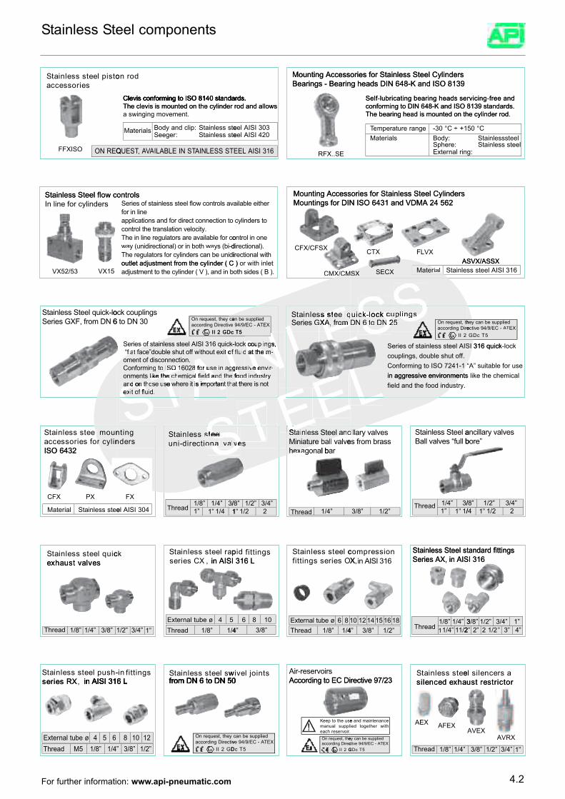
seirosseccaotsipleetssselniatS
dorno
Clevis conforming to ISO 8140 standards.
Bearings - Bearing heads DIN 648-K and ISO 8139 Mounting Accessories for Stainless Steel Cylinders
Clevis conforming to ISO 8140 standards.
Bearings - Bearing heads DIN 648-K and ISO 8139 Mounting Accessories for Stainless Steel Cylinders
essdaehgniraebgnitacirbulfleS
dnaeerfgnicivr
In line for cylindersStainless Steel flow controls
FFXISO QERNO
Stainless Steel flow controls
enilnirofvaslortnocwolfleetsstsselniatsfoseireS
a swinging movement.The clevis is mounted on the cylinder rod and allowsClevis conforming to ISO 8140 standards.
etssselniatS:regeeSetssselniatS:pilcdnaydoBslairetaM
TSSSELNIATTASNIELBALIAVVAAAV,TT,SEUQ
rehtieelbalia Mountings for DIN ISO 6431 and VDMA 24 562Mounting Accessories for Stainless Steel Cylinders
The clevis is mounted on the cylinder rod and allowsClevis conforming to ISO 8140 standards.
RFX..SE
024ISIAlee303ISIAlee
613ISIALEE
Mountings for DIN ISO 6431 and VDMA 24 562Mounting Accessories for Stainless Steel Cylinders
The bearing head is mounted on the cylinder rod.conforming to DIN 648-K and ISO 8139 standards.
essdaehgniraebgnitacirbul-fleS
nirlanretxE:erehpS
:ydoBslairetaM1+÷C°03-egnarerutarepmeTTe
The bearing head is mounted on the cylinder rod.conforming to DIN 648-K and ISO 8139 standards.
dnaeerf-gnicivr
:gleetssselniatS
leetssselniatSC°05
VX15VX52/53
6NDmorf,FXGseireSol-kciuqleetSsselniatS
bnidna,)V(rednilycehtottnemtsujdaoutlet adjustment from the cylinder ( C )
idinuebnacsrednilycroffosrotalugerehTd-ib(syawwahtobniro)lanoitceridinu(yawwaocroffoelbaliavaerasrotalugerenilniehT
.yticolevnoitalsnartehtlortnocotnoitcennoctceridrofdnasnoitacilppa
e0 vitceriDgnidroccaacyeht,tseuqernO
cDG2II
3NDot6sgnilpuockco
EmEoEAEXEeEtEsEsEsm
CMX/CMSX
LLE.)B(sedishto
or with inlet outlet adjustment from the cylinder ( C ) htiwwilanoitceri
.)lanoitceridenonilortno
otsrednilyc
CMX/CMSX
CFX/CFSX
X GETA-CE/9/49deilppusebna
5T
oAErEfE,XeEG Eq
seireSs ElEetsss EelniatS
SS2 SsSN SgSnSiSlSpScSkScSoSlS-SkSc
SECX
2EN
FLVXCTXASVX/ASSX
CMX/CMSXCMX/CMSX el lniatSlaaiiretaM
e5S5
s
riDgnidroccaht,tseuqernO2NN 6SDSoStS6 cSNSu
EDu
Ei gnilpSu SkcolkcSEuE
ASVX/ASSX613ISIAleetsss
XETAAT-CE/9/49evitcedeilppusebnacyeh
n2346OSI
r ilycrn
ofseirosseccal uomleetssselniatS
SaSlSeSeStSlSfSe AnAaAtArArtApAmAiAsAiTeTsS
n
So
Sd
Sn
Sa IgAnAaAdAfAlAaTeThTtTeTk Ti Tl IgAuArAoAfA8T
O
TS IoIt
as
g
Sl
Att Iawl A It
Sd TT.STd
redngnitn
o SaSvSllSnSoitcerid-inus eetSs SsselniatS
a
t
cDG2II
Th
SiSTs
SufeSfSoStSiSxt
So IhhItt Iet nA Ih
atrrtAopminAt
iereh TwTwhseTuTeTs Te
STo
Sh
STSttnddn
aa
SIhA ItAdA Ia
adAlfAeAiaAnscimeThl Tchtkil
1
T1
stnemno8 g
fIa IfA IAiAeAsurof8A2061OOSS
TII
Tot
Tt
Tgn
Tn
TimrofnoC
.noitcennocsidfotnemot ot Iixetuohtiwffffotuhselbuod”ecaftaallff
-“
t kciuq613ISIAleetssselniatssffooseireS
Se
Ih
EtESSv
ItItIo NsNuNdIoIfIfo NeNeIrIg NmNeNhNtNtNaN,NsNpNuNoNcNk
h
ELLEst
ELe
EETTSTLELE
hN
blel vlavlllaabbeerc
utainiMcnnaaleetSssEseEelElnEniEiaEatSS
sE
evS
5
tNys
T
onsierreehttttoIaa yrNrtNtsuuddnNn e
iNid Ndo N-o
sfrIs NrNiNvNneNv mNi Ns N-Ie dIi ehttaNd
siIuk
IlIfI NggNnpNiNluokc Nol-
l
ELELSE
blluf“sevlavllaBaleetSsselniatS
ssarbmorffrsesevlavyrallliicc
field and the food industry.field and the food industry.
2II
in aggressive environments like the chein aggressive environments like the cheConforming to ISO 7241-1 “A” suitable fConforming to ISO 7241-1 “A” suitable fcouplings, double shut off.Series of stainless steel AISI 316 quick
”erobsevlavyrallicna
5
mical Conforming to ISO 7241-1 “A” suitable f
TcDG
in aggressive environments like the cheor use Conforming to ISO 7241-1 “A” suitable f
-lock Series of stainless steel AISI 316 quickSeries of stainless steel AISI 316 quick
2346OSI
sevlavtsuahxeciuqleetssselniatS
eetssselniatSlaireta
PXCFX
M
S
in AISI 316 L,XCseiresparleetssselniatSkc
403ISIAle
FX
1”1”1/3
4/1”4/1”8/1
daerhT
aS
XOseiressgnittifcleetssselniatS
in AISI 316 Lsgnittifdip
rablanogaxxeehh
”1 22/1”4/3”2/1”8/
”4/1daerhT
613ISIAni,Xnoisserpmoc
Series AX, in AISI 316Stainless Steel standard fittings
”1”1/3/1
”4/1daerhT”2/1”8/3
Series AX, in AISI 316Stainless Steel standard fittings
”1 22/1”4/3”2/1”8/
4/
in AISI 316 LXRseires-hsupleetssselniatS
sevlavtsuahxe
”8/3”4/1”8/1daerhT
in AISI 316 Lwsleetssselniat
from DN 6 to DN 50Ssgnittifni-
4/1”8/1daerhT4 5øebutlanretxE
”1”4/3”2/1
iDCEotgnidroccAsriovreser-riAstniojleviw
from DN 6 to DN 50
”8/3”406 8 1
4/1”8/1daerhT86øebutlanretxE
32/79evitcer ahxedecneliseetssselniatS
”2/1”8/3”4816151412101
2/11”4/113”4/1”8/1
daerhT
rotcirtsertsuasrecnelisle
”4”3”2/12”2”2”1”4/3”2/1”8/3
in AISI 316 L,XRseires
4/1”8/15MdaerhT654øebutlanretxE
in AISI 316 L from DN 6 to DN 50
vitceriDgnidroccayeht,tseuqernO
DG2II”2/1”8/3”2108 1
iDCEotgnidroccAfrom DN 6 to DN 50
.riovreserhcaelppuslaunamesuehtotpeeK
!ceriDgnidroccaeht,tseuqernO
G2II
XETA-CE/9/49evdeilppusebnac
5TcD
32/79evitcer
AEX AFEX
ahxedecnelis
htiwrehtegotdeiecnanetniamdnae
XETA-CE/9/49evitcdeilppusebnacye
5TcDG ”4/1”8/1daerhT
AVRXAVEX
rotcirtsertsu
”1”4/3”2/1”8/3
4.2For further information: www.api-pneumatic.com
Stainless Steel components

Notes

Notes

A.P.I. Srl Via Cornaggia, 107 - 22076 Mozzate (CO) ItalyHead Quarters Tel. +39.0331.823511 - Fax +39.0331.823480
E-mail: [email protected] - www.api-pneumatic.com


