Embed Size (px)
Citation preview
CAP 562 Civil Aircraft Airworthiness Information and Procedures
Part 2 Leaflet 2-1 Page 1
Part 2 Engineering Practices and Processes
Leaflet 2-1 Engineering Drawings
1 Introduction
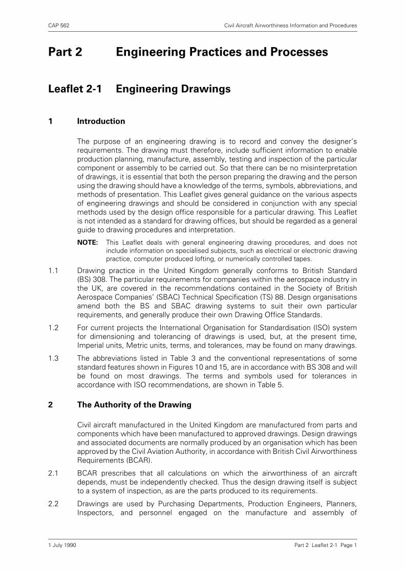
The purpose of an engineering drawing is to record and convey the designer’srequirements. The drawing must therefore, include sufficient information to enableproduction planning, manufacture, assembly, testing and inspection of the particularcomponent or assembly to be carried out. So that there can be no misinterpretationof drawings, it is essential that both the person preparing the drawing and the personusing the drawing should have a knowledge of the terms, symbols, abbreviations, andmethods of presentation. This Leaflet gives general guidance on the various aspectsof engineering drawings and should be considered in conjunction with any specialmethods used by the design office responsible for a particular drawing. This Leafletis not intended as a standard for drawing offices, but should be regarded as a generalguide to drawing procedures and interpretation.
NOTE: This Leaflet deals with general engineering drawing procedures, and does notinclude information on specialised subjects, such as electrical or electronic drawingpractice, computer produced lofting, or numerically controlled tapes.
1.1 Drawing practice in the United Kingdom generally conforms to British Standard(BS) 308. The particular requirements for companies within the aerospace industry inthe UK, are covered in the recommendations contained in the Society of BritishAerospace Companies’ (SBAC) Technical Specification (TS) 88. Design organisationsamend both the BS and SBAC drawing systems to suit their own particularrequirements, and generally produce their own Drawing Office Standards.
1.2 For current projects the International Organisation for Standardisation (ISO) systemfor dimensioning and tolerancing of drawings is used, but, at the present time,Imperial units, Metric units, terms, and tolerances, may be found on many drawings.
1.3 The abbreviations listed in Table 3 and the conventional representations of somestandard features shown in Figures 10 and 15, are in accordance with BS 308 and willbe found on most drawings. The terms and symbols used for tolerances inaccordance with ISO recommendations, are shown in Table 5.
2 The Authority of the Drawing
Civil aircraft manufactured in the United Kingdom are manufactured from parts andcomponents which have been manufactured to approved drawings. Design drawingsand associated documents are normally produced by an organisation which has beenapproved by the Civil Aviation Authority, in accordance with British Civil AirworthinessRequirements (BCAR).
2.1 BCAR prescribes that all calculations on which the airworthiness of an aircraftdepends, must be independently checked. Thus the design drawing itself is subjectto a system of inspection, as are the parts produced to its requirements.
2.2 Drawings are used by Purchasing Departments, Production Engineers, Planners,Inspectors, and personnel engaged on the manufacture and assembly of
1 July 1990

CAP 562 Civil Aircraft Airworthiness Information and Procedures
Part 2 Leaflet 2-1 Page 2
components. A drawing must therefore, contain all the necessary dimensions, limitsof accuracy, classes of fit, material specifications and any other information likely tobe required by any of the departments concerned, so that the user can carry out theirrespective responsibilities without reference back to the Design Department.
2.3 Any deviation from the approved drawings or associated documents duringmanufacture, must be approved by the CAA. During overhaul, modification,maintenance and repair, the Approved Organisation, or the appropriately licensedengineer, must ensure that all replacement parts, or repairs carried out, are inaccordance with the approved drawings and associated documents.
3 Types of Drawings
There are four types of drawings recommended in BS 308; single-part (unique partsor assemblies), collective (parts or assemblies of essentially similar shape, but ofdifferent dimensions), combined (a complete assembly including all individual partson a single drawing), and constructional (an assembly drawing with sufficientdimensional and other information to describe the component parts of amanufacture). A complete set of drawings for an aircraft and any documents orspecifications referenced on the drawings, present a complete record of theinformation required to manufacture and assemble that aircraft. They also form partof the inspection records. The manner in which a set of aircraft drawings is arranged,enables any particular component, dimension, procedure or operation, to be traced.
3.1 A main 'general arrangement' drawing of the aircraft and 'general arrangement'drawings of the main assemblies and systems are provided. These drawings usuallycontain overall profile particulars only, with locations and references of the associatedmain assembly and installation drawings; they also provide a guide to theidentification of drawing groups used by the particular design organisation.
3.2 Main assembly drawings may also contain profile particulars only, but will include theinformation required for the assembly of individual parts of sub-assemblies. Thesequence of assembly is given where appropriate, but the information contained insingle part or sub-assembly drawings, is not repeated. Parts as such are referenced,but in the case of sub-assemblies, only the sub-assembly will be referenced and notits individual parts.
3.3 Installation drawings are issued to clarify the details of external dimensions andattitudes of components, locations, adjustments, clearances, settings, connections,adaptors, and locking methods between components and assemblies.
3.4 Sub-assembly drawings are issued to convey specific information on the assembly ofcomponent parts. When the method of assembly entails welding, or a similarprocess, the drawing will include details of any heat treatment or anti-corrosivetreatment that may be necessary. Sub-assembly drawings are sometimes issued inconnection with spares provisioning and also in cases where assembly would bedifficult without special tools, jigs or techniques.
3.5 Drawings of individual parts contain all the information necessary to enable the partsto be manufactured to design requirements. The material specification, dimensionsand tolerances, machining details and surface finish, and any treatment required, willall be specified on the drawings.
1 July 1990
CAP 562 Civil Aircraft Airworthiness Information and Procedures
Part 2 Leaflet 2-1 Page 3
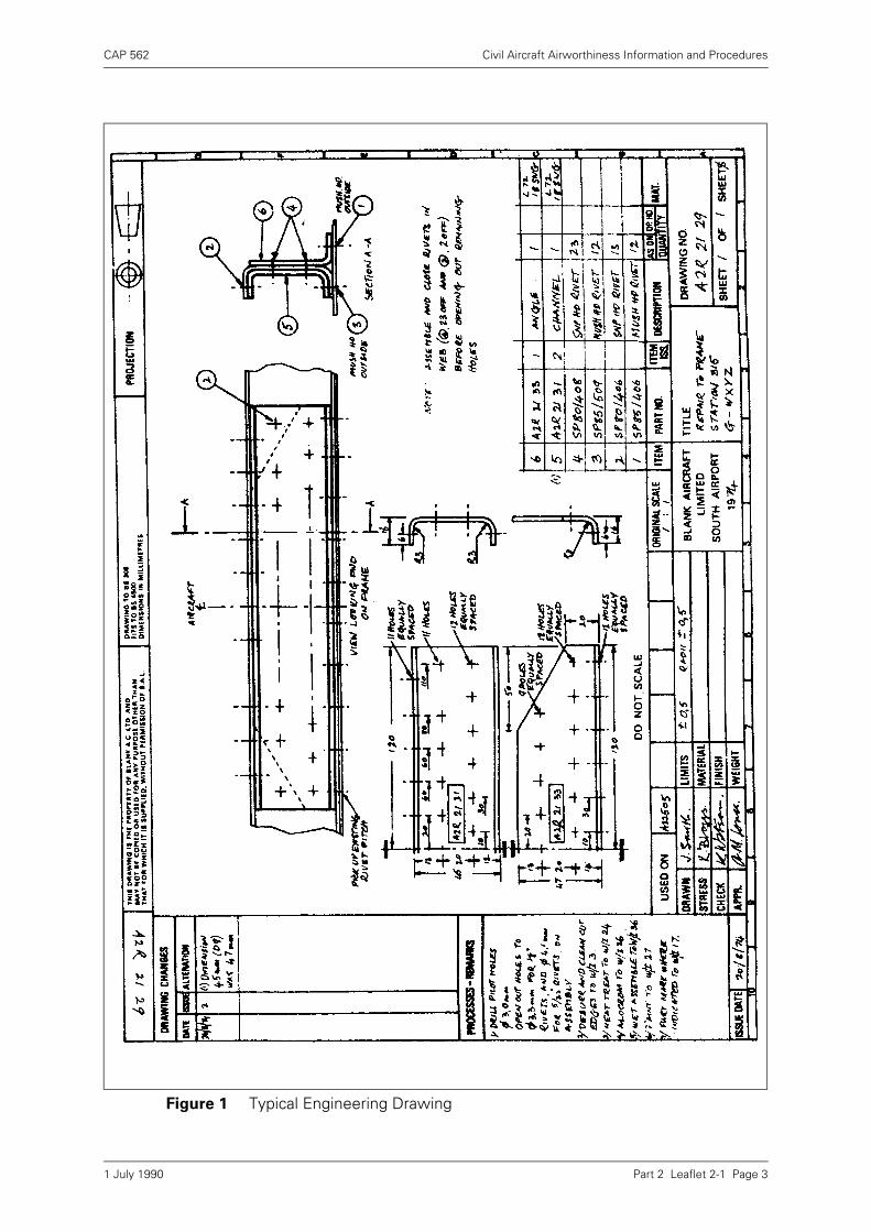
Figure 1 Typical Engineering Drawing
1 July 1990

CAP 562 Civil Aircraft Airworthiness Information and Procedures
Part 2 Leaflet 2-1 Page 4
4 Drawing Systems
Section A of BCAR, prescribes that each drawing must bear a descriptive title,drawing number, issue number and the date of issue. It also prescribes that allalterations to drawings shall be made in accordance with a drawing amendmentsystem which will ensure amendment to design records. If an alteration is made, anew issue number and date must be allocated to the drawing. To comply with therequirements, procedures must be introduced to progressively amend the totaldefinition of the product in terms of its associated list of drawings at specific issues.Each particular variant of a product and its state of modification, must be identifiablein relation to the appropriate list of drawings. The following paragraphs amplify theseprocedures and explain the purposes of various parts of a drawing, together with thesystems used and the methods of presentation. A typical drawing which illustratesmany of the features with which this Leaflet is concerned, is shown in Figure 1.
4.1 The Drawing Number
No two drawings should bear identical numbers and a design office should maintaina register of all drawings issued. The drawing number has three features, the projectidentity (A2 in Figure 1) the group breakdown (21 in Figure 1), and an individualregister number (29 in Figure 1). TS 88 describes an acceptable numbering method,but considerable discretion is allowed for particular design office requirements. InFigure 1, A2 indicates the aircraft type, R indicates a repair, 21 indicates the frontfuselage, and 29 indicates the register number in this group of drawings. Except forrepair drawings, the drawing number is also generally the part number of the item.
4.1.1 Handed Parts
Drawings of handed parts usually have the left hand (port), upper, inner, or forwardpart drawn, this item taking the odd number and the opposite hand the consecutiveeven number. Parts which are not handed have an odd drawing number. The drawingsheet bears the legend 'AS DRAWN' and 'OPP HAND' in the item quantity column.Where necessary the handed condition is indicated by a local scrap view orannotation.
4.1.2 Sheet Numbers
Where a complete drawing cannot be contained on a single sheet, successive sheetsare used. The first sheet is identified as 'SHEET 1 of X SHEETS', as applicable andsubsequent sheets by the appropriate sheet number. Where a schedule of partsapplicable to all sheets is required, it appears on Sheet 1.
4.2 Drawing Changes
Any change to a design drawing, other than the correction of minor clerical errors,must be accompanied by a new issue number and date. New parts added to thedrawing, or 'drawn on' parts affected by the change, take the new issue number, andparts which are not affected retain the original issue number. In all cases whereinterchangeability is affected, a new drawing number and part number are allocated.
4.2.1 Details of the drawing changes are recorded in the appropriate column on thedrawing, or recorded separately on an 'Alteration Sheet', which is referenced on thedrawing. Changes are related to the change number quoted in the change of issuecolumns on the drawing and the marginal grid reference is given to identify the alteredfeatures.
4.2.2 The issue 'number' may sometimes be represented by a letter. Some organisationsuse alphabetical issues for prototype aircraft drawings and numerical issues for
1 July 1990
CAP 562 Civil Aircraft Airworthiness Information and Procedures
Part 2 Leaflet 2-1 Page 5
production aircraft drawings; thus all drawings of a prototype aircraft become'Issue 1' when production commences.
4.2.3 An alteration to a single part drawing may also result in changes to associateddrawings; in addition, it may be necessary to halt manufacture or assembly of theproduct. The drawing office system usually makes provision for the proper recordingof drawing changes, by publishing, concurrently with the re-issued drawing, aninstruction detailing the effects these will have on other drawings, on work-in-progress and on existing stock. As a further safeguard, some organisations publishDrawing Master Reference Lists, which give details of the current issues of alldrawings which are associated with a particular component or assembly.
4.3 Part Referencing
Every item called up on a drawing is given an item number, which is shown in a'balloon' on the face of the drawing, as illustrated in Figure 1. No other information isgiven in or adjacent to the balloon, with the exception of information necessary formanufacture or assembly, such as 'equally spaced', 'snap head inside', or the symbol'ND', which indicates that no separate drawing exists for the part.
4.3.1 A schedule of parts is usually given in the manner shown in Figure 1, or on a separatesheet of the drawing (see paragraph 4.1.2).
4.3.2 As an alternative to the system described above, grid references may be given in thelist of parts; in such instances the actual part numbers appear in the balloons. Wherea part occurs a number of times on a drawing, e.g. as may be the case with rivets,bolts, etc., it may be impractical to list all grid references, in which case this columnis left blank.
4.3.3 In instances where ND parts are shown as items on a drawing, the part number ofsuch items may be that drawing number, followed by the drawing item number.Alternatively the part may be given its own part number, but will be identified as anND part, e.g. 'A1 31 101 ND'. The information required for the manufacture of an NDpart is contained in the description and material columns of the drawing, butreference may also be made to other drawings, where necessary.
4.3.4 Materials such as locking wire and shimming, which are available in rolls and sheets,will be detailed by specification number in the 'Part No' column, and the quantity willbe entered as 'As Required', or 'A/R'. Standard parts to BS and SBAC Specificationswill be detailed by the appropriate part numbers, but will not be drawn separately.
4.4 Drawing Queries
Drawing queries may arise through mistakes in draftsmanship, through ambiguity orthrough inability to purchase, manufacture, or assemble the items as drawn. DesignOffice procedures must be introduced which cater both for raising queries, and forproviding satisfactory answers to those queries.
4.4.1 Drawing queries are usually raised on a Drawing Query Form, which is passed to theDesign Office for action. The answer to the query may be an immediate provisionalone, detailed on the query form; a temporary, fully approved answer, issued by meansof a Drawing Office Instruction, and having the same authority as the drawing towhich it refers; or a permanent answer provided by means of a new or re-issueddrawing.
4.4.2 Drawing Query Forms and Drawing Office Instructions should be suitably identified,and should be referenced on the amended drawing. The effects on other drawings,on existing stock, and on work-in-progress, should be included in the answer to thequery.
1 July 1990

CAP 562 Civil Aircraft Airworthiness Information and Procedures
Part 2 Leaflet 2-1 Page 6
4.4.3 The number of Drawing Query Forms or Drawing Office Instructions permitted on adrawing, should be limited, and a new or re-issued drawing should be completed assoon as possible.
5 Interpretation of Drawings
The following paragraphs indicate some of the general drawing practices used onaircraft drawings. These practices are in accordance with the recommendationscontained in BS 308 and TS 88, but many drawings will have been issued to previousBritish or foreign standards, and some degree of interpretation may be necessary. Incases of doubt the Drawing Office Handbook, or similar publication issued by therelevant Design Organisation should be consulted.
5.1 Scale
Drawings are normally drawn to a uniform scale and are normally shown in the'ORIGINAL SCALE' box on the drawing in the form of a ratio, e.g. 1:2 (i.e. half size).Where details or views are drawn to a different scale, this should be clearly stated onthe drawing. Aircraft drawings are often full size, i.e. 1:1, but no drawing should bemeasured to obtain a particular dimension which is not shown; the omission shouldbe referred to the Design Office. On earlier drawings the scale may be representedby a fraction, e.g. ¼ which is 1:4.
5.2 Lines
The types and thicknesses of lines recommended in BS 308 are shown in Table 1.Drawings are often completed in pencil, however, line thickness may in practice varyconsiderably, especially after the drawing is reproduced.
Table 1 Types of Lines
Example Description Width (mm)
Application
Continuous (thick) 0·7 Visible outline and edges.
Continuous (thin) 0·3 Fictitious outlines and edges,dimensions and leader lines,hatching, outlines of adjacentparts and revolved sections.
Continuousirregular (thin)
0.3 Limits of partial views orsections when the line is not onaxis.
Short dashes (thin) 0·3 Hidden outlines and edges.
Chain (thin) 0·3 Centre lines and extremepositions moveable parts.
Chain (thick atends and changesof direction, thinelsewhere).
0·7
0.3
Cutting planes.
Chain (thick) 0·7 Indicates surfaces which have tomeet special requirements.
1 July 1990
CAP 562 Civil Aircraft Airworthiness Information and Procedures
Part 2 Leaflet 2-1 Page 7
5.3 Projections
The majority of drawings produced for aircraft purposes show the parts in third angleorthographic projection (paragraph 5.3.1), but a number of older drawings may havebeen produced in first angle orthographic projection (paragraph 5.3.2). Both systemsshow objects as they actually are, both in size (unless for convenience the drawing isscaled up or down) and shape, when viewed in the vertical and horizontal planes. Theprojection used for a drawing must be clearly stated, and the appropriate internationalprojection symbol must be placed in a prominent position on the drawing. Any viewsnot complying with the projection stipulated, e.g. a view showing the true shape ofan inclined face, are generally marked with an arrow, and suitably annotated.
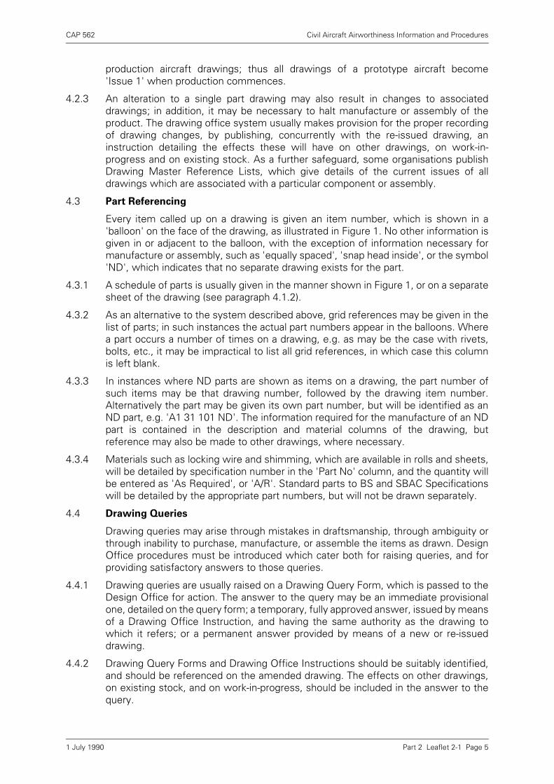
5.3.1 Third Angle Projection
The principle of third angle projection is shown in Figure 2. Each view represents theside of the object nearest to it in the adjacent view.
5.3.2 First Angle Projection
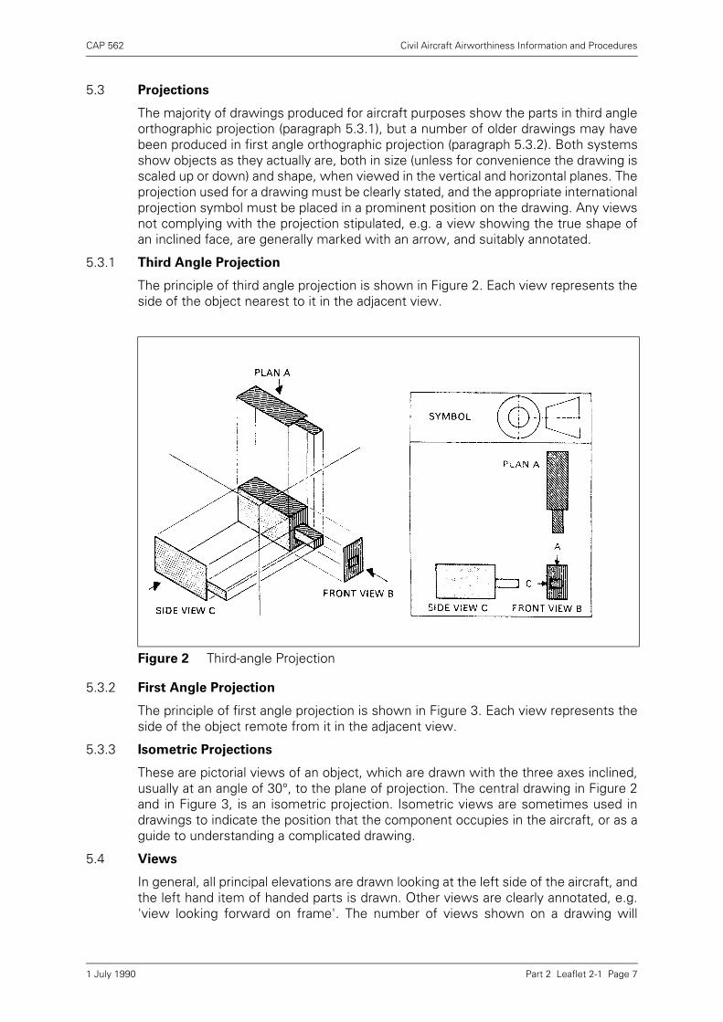
The principle of first angle projection is shown in Figure 3. Each view represents theside of the object remote from it in the adjacent view.
5.3.3 Isometric Projections
These are pictorial views of an object, which are drawn with the three axes inclined,usually at an angle of 30°, to the plane of projection. The central drawing in Figure 2and in Figure 3, is an isometric projection. Isometric views are sometimes used indrawings to indicate the position that the component occupies in the aircraft, or as aguide to understanding a complicated drawing.
5.4 Views
In general, all principal elevations are drawn looking at the left side of the aircraft, andthe left hand item of handed parts is drawn. Other views are clearly annotated, e.g.'view looking forward on frame'. The number of views shown on a drawing will
Figure 2 Third-angle Projection
1 July 1990

CAP 562 Civil Aircraft Airworthiness Information and Procedures
Part 2 Leaflet 2-1 Page 8
depend on the complexity of the part, although two views may often be sufficient. Insome cases the three main views (Figures 2 and 3) may be insufficient to clarify allthe details necessary, and a number of sectional or auxiliary views may be necessary.
Figure 3 First-angle Projection
Figure 4 Part Section
1 July 1990
CAP 562 Civil Aircraft Airworthiness Information and Procedures
Part 2 Leaflet 2-1 Page 9
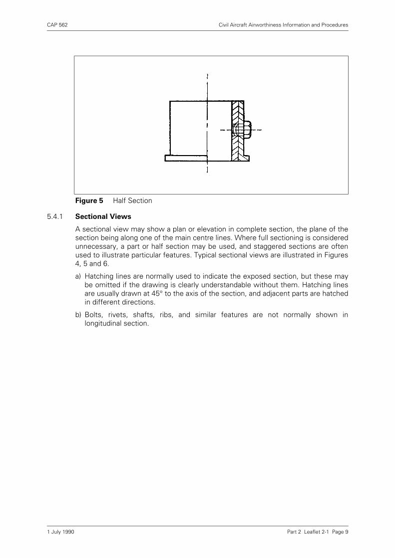
5.4.1 Sectional Views
A sectional view may show a plan or elevation in complete section, the plane of thesection being along one of the main centre lines. Where full sectioning is consideredunnecessary, a part or half section may be used, and staggered sections are oftenused to illustrate particular features. Typical sectional views are illustrated in Figures4, 5 and 6.
a) Hatching lines are normally used to indicate the exposed section, but these maybe omitted if the drawing is clearly understandable without them. Hatching linesare usually drawn at 45° to the axis of the section, and adjacent parts are hatchedin different directions.
b) Bolts, rivets, shafts, ribs, and similar features are not normally shown inlongitudinal section.
Figure 5 Half Section
1 July 1990
CAP 562 Civil Aircraft Airworthiness Information and Procedures
Part 2 Leaflet 2-1 Page 10
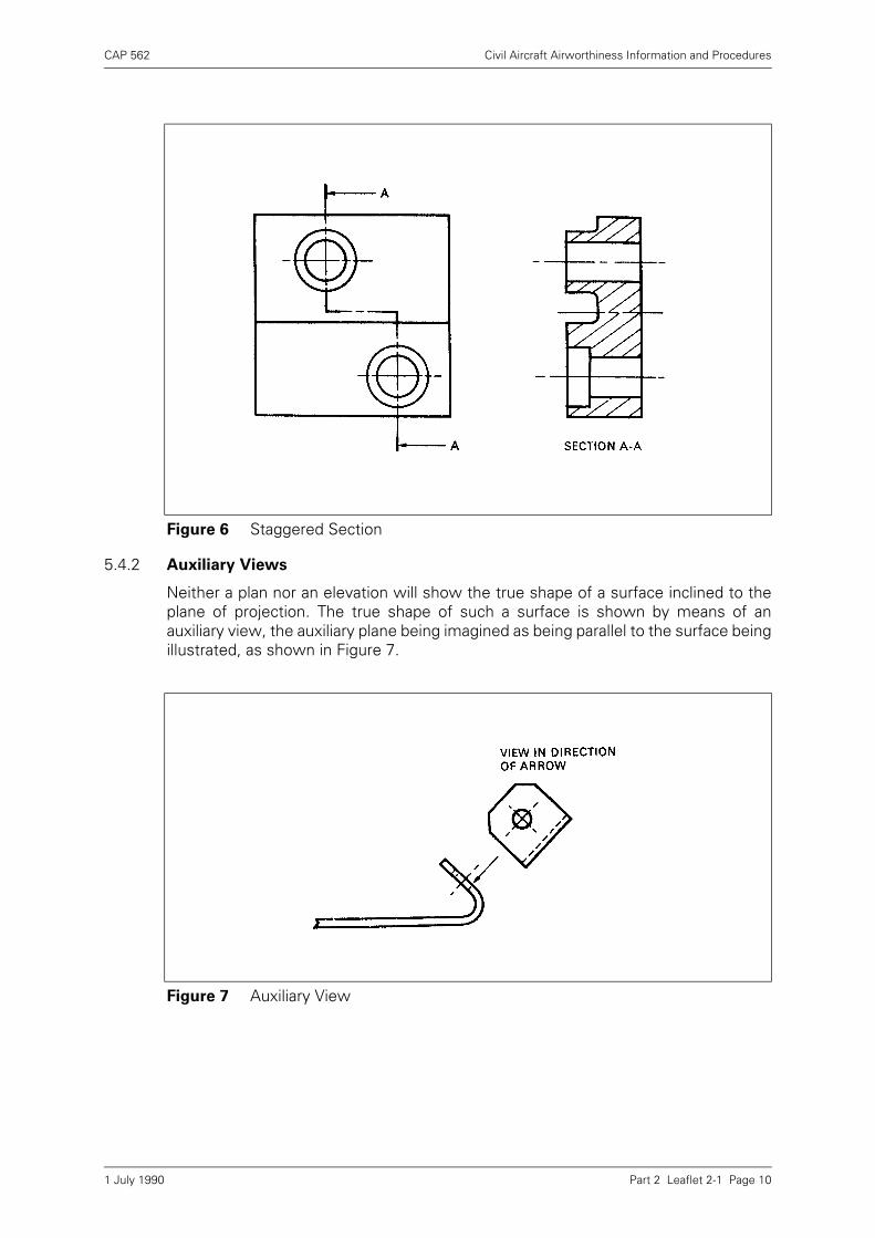
5.4.2 Auxiliary Views
Neither a plan nor an elevation will show the true shape of a surface inclined to theplane of projection. The true shape of such a surface is shown by means of anauxiliary view, the auxiliary plane being imagined as being parallel to the surface beingillustrated, as shown in Figure 7.
Figure 6 Staggered Section
Figure 7 Auxiliary View
1 July 1990
CAP 562 Civil Aircraft Airworthiness Information and Procedures
Part 2 Leaflet 2-1 Page 11
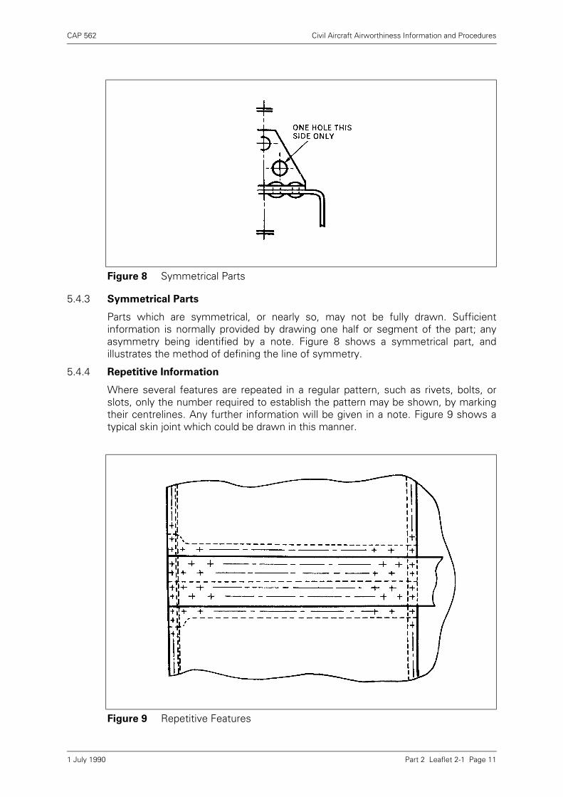
5.4.3 Symmetrical Parts
Parts which are symmetrical, or nearly so, may not be fully drawn. Sufficientinformation is normally provided by drawing one half or segment of the part; anyasymmetry being identified by a note. Figure 8 shows a symmetrical part, andillustrates the method of defining the line of symmetry.
5.4.4 Repetitive Information
Where several features are repeated in a regular pattern, such as rivets, bolts, orslots, only the number required to establish the pattern may be shown, by markingtheir centrelines. Any further information will be given in a note. Figure 9 shows atypical skin joint which could be drawn in this manner.
Figure 8 Symmetrical Parts
Figure 9 Repetitive Features
1 July 1990

CAP 562 Civil Aircraft Airworthiness Information and Procedures
Part 2 Leaflet 2-1 Page 12
5.4.5 Break Lines
Break lines are used where it would be inconvenient (because of limited space) todraw long lengths of standard section. The types of break lines used for variouscomponents are shown in Figure 10.
5.5 Dimensioning
All dimensions necessary for the manufacture of the part or assembly are given onthe drawing; it should not be necessary to deduce any dimension from otherdimensions. To avoid confusion, dimensions are normally given once only. The unitsof measurement used are usually stated on the drawing, to avoid repetition, but anydimension to which this general statement does not apply will be suitably annotated.Dimensions are placed so that they may be read from the bottom or right hand sideof the drawing.
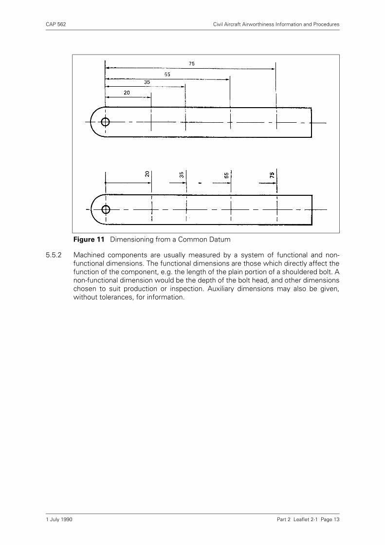
5.5.1 When dimensions are given from a common datum, one of the methods shown inFigure 11 is normally used. Chain dimensioning, i.e. dimensioning between adjacentholes, is not often used, since it allows a build up of tolerances, which may not beacceptable. An alternative method, used with riveted joints, is to locate the end holesand add a note such as '11 rivets equally spaced'; this method is useful on curvedsurfaces.
Figure 10 Break Lines
1 July 1990
CAP 562 Civil Aircraft Airworthiness Information and Procedures
Part 2 Leaflet 2-1 Page 13
5.5.2 Machined components are usually measured by a system of functional and non-functional dimensions. The functional dimensions are those which directly affect thefunction of the component, e.g. the length of the plain portion of a shouldered bolt. Anon-functional dimension would be the depth of the bolt head, and other dimensionschosen to suit production or inspection. Auxiliary dimensions may also be given,without tolerances, for information.
Figure 11 Dimensioning from a Common Datum
1 July 1990
CAP 562 Civil Aircraft Airworthiness Information and Procedures
Part 2 Leaflet 2-1 Page 14
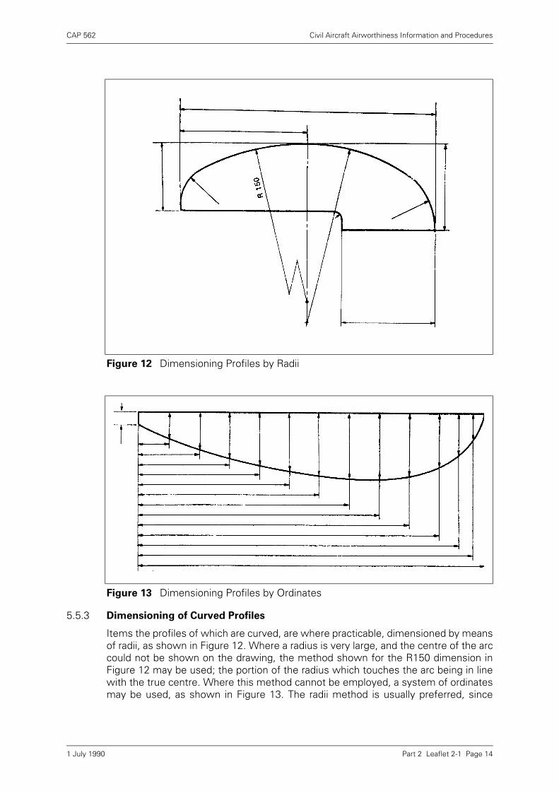
5.5.3 Dimensioning of Curved Profiles
Items the profiles of which are curved, are where practicable, dimensioned by meansof radii, as shown in Figure 12. Where a radius is very large, and the centre of the arccould not be shown on the drawing, the method shown for the R150 dimension inFigure 12 may be used; the portion of the radius which touches the arc being in linewith the true centre. Where this method cannot be employed, a system of ordinatesmay be used, as shown in Figure 13. The radii method is usually preferred, since
Figure 12 Dimensioning Profiles by Radii
Figure 13 Dimensioning Profiles by Ordinates
1 July 1990
CAP 562 Civil Aircraft Airworthiness Information and Procedures
Part 2 Leaflet 2-1 Page 15
accurate arcs can be produced; whereas with the ordinate system, deviations fromthe required curve may occur as a result of connecting the plotted points.
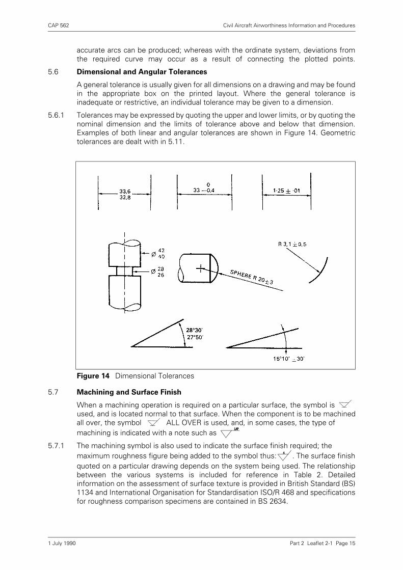
5.6 Dimensional and Angular Tolerances
A general tolerance is usually given for all dimensions on a drawing and may be foundin the appropriate box on the printed layout. Where the general tolerance isinadequate or restrictive, an individual tolerance may be given to a dimension.
5.6.1 Tolerances may be expressed by quoting the upper and lower limits, or by quoting thenominal dimension and the limits of tolerance above and below that dimension.Examples of both linear and angular tolerances are shown in Figure 14. Geometrictolerances are dealt with in 5.11.
5.7 Machining and Surface Finish
When a machining operation is required on a particular surface, the symbol isused, and is located normal to that surface. When the component is to be machinedall over, the symbol ALL OVER is used, and, in some cases, the type ofmachining is indicated with a note such as
5.7.1 The machining symbol is also used to indicate the surface finish required; themaximum roughness figure being added to the symbol thus: . The surface finishquoted on a particular drawing depends on the system being used. The relationshipbetween the various systems is included for reference in Table 2. Detailedinformation on the assessment of surface texture is provided in British Standard (BS)1134 and International Organisation for Standardisation ISO/R 468 and specificationsfor roughness comparison specimens are contained in BS 2634.
Figure 14 Dimensional Tolerances
1 July 1990
CAP 562 Civil Aircraft Airworthiness Information and Procedures
Part 2 Leaflet 2-1 Page 16
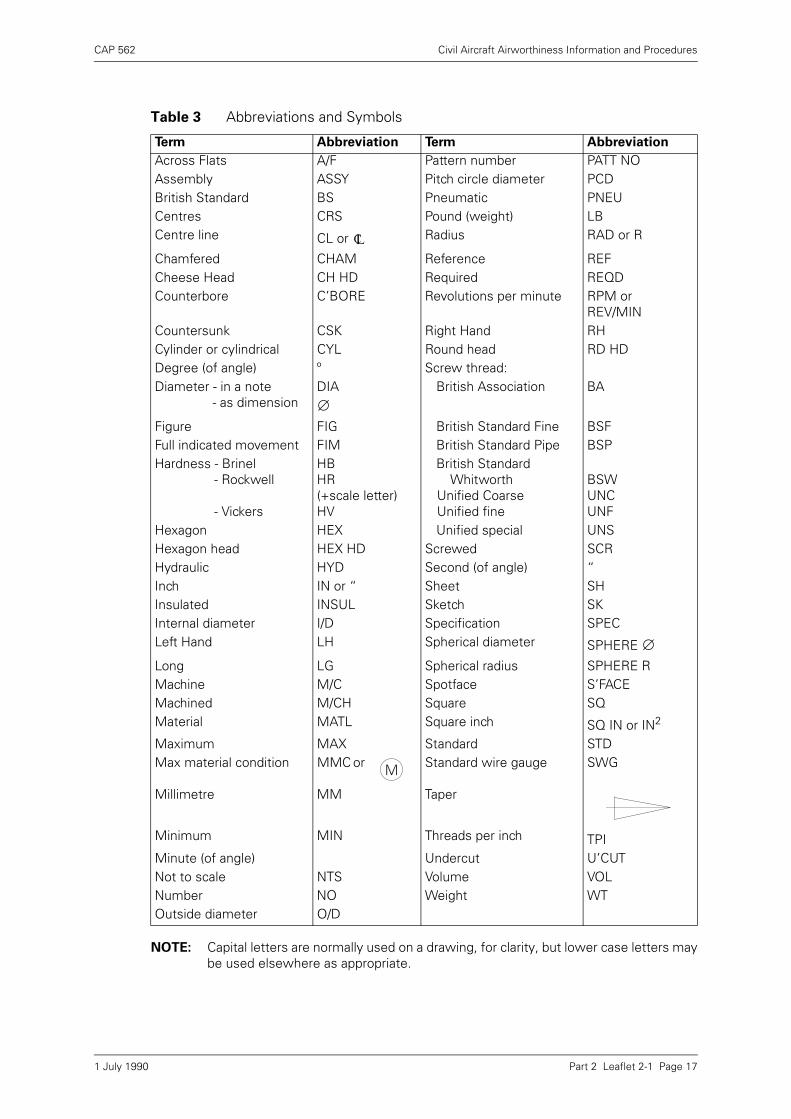
5.8 Abbreviations and Symbols
In order to save time and drawing space when compiling a drawing, a number ofabbreviations and symbols are used. Table 3 lists the main abbreviations and symbolswhich will be found on both currently produced and older drawings.
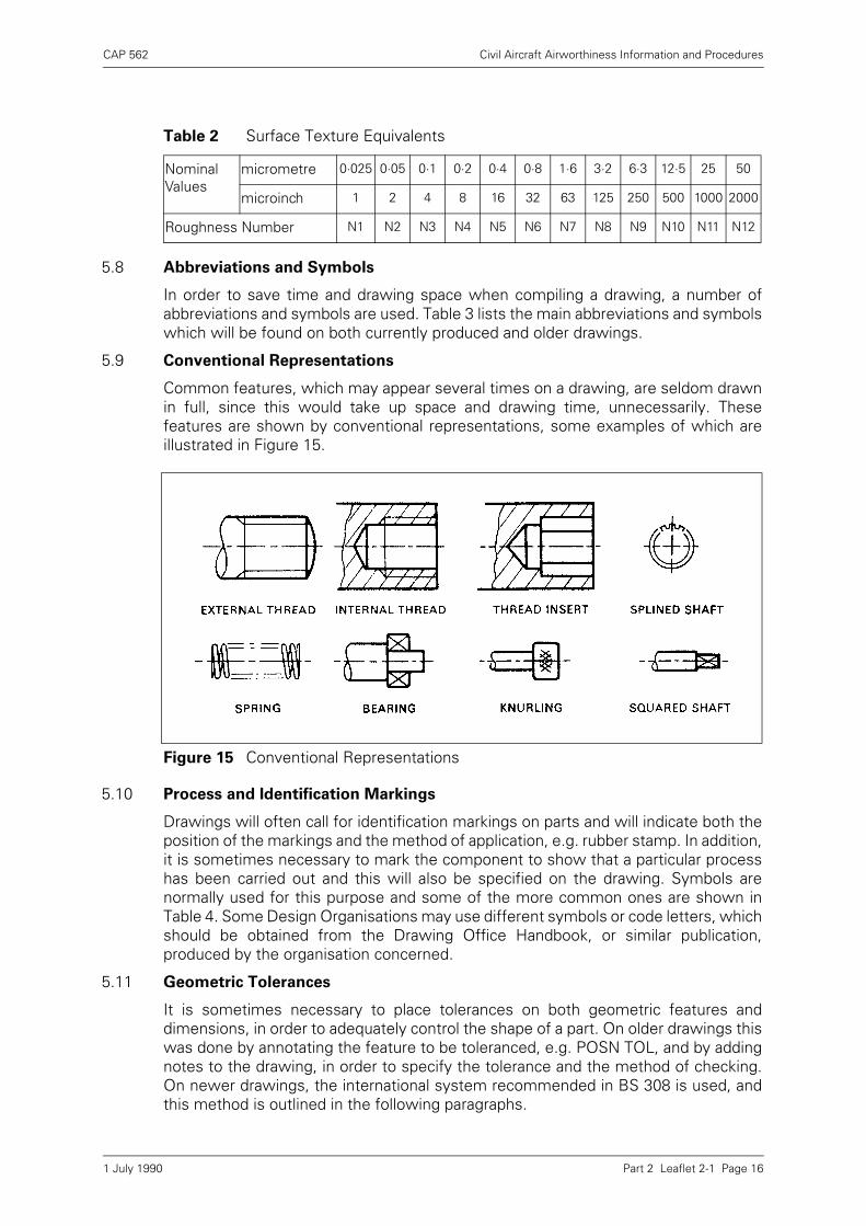
5.9 Conventional Representations
Common features, which may appear several times on a drawing, are seldom drawnin full, since this would take up space and drawing time, unnecessarily. Thesefeatures are shown by conventional representations, some examples of which areillustrated in Figure 15.
5.10 Process and Identification Markings
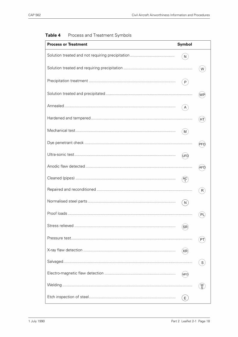
Drawings will often call for identification markings on parts and will indicate both theposition of the markings and the method of application, e.g. rubber stamp. In addition,it is sometimes necessary to mark the component to show that a particular processhas been carried out and this will also be specified on the drawing. Symbols arenormally used for this purpose and some of the more common ones are shown inTable 4. Some Design Organisations may use different symbols or code letters, whichshould be obtained from the Drawing Office Handbook, or similar publication,produced by the organisation concerned.
5.11 Geometric Tolerances
It is sometimes necessary to place tolerances on both geometric features anddimensions, in order to adequately control the shape of a part. On older drawings thiswas done by annotating the feature to be toleranced, e.g. POSN TOL, and by addingnotes to the drawing, in order to specify the tolerance and the method of checking.On newer drawings, the international system recommended in BS 308 is used, andthis method is outlined in the following paragraphs.
Table 2 Surface Texture Equivalents
Nominal Values
micrometre 0·025 0·05 0·1 0·2 0·4 0·8 1·6 3·2 6·3 12·5 25 50
microinch 1 2 4 8 16 32 63 125 250 500 1000 2000
Roughness Number N1 N2 N3 N4 N5 N6 N7 N8 N9 N10 N11 N12
Figure 15 Conventional Representations
1 July 1990
CAP 562 Civil Aircraft Airworthiness Information and Procedures
Part 2 Leaflet 2-1 Page 17
NOTE: Capital letters are normally used on a drawing, for clarity, but lower case letters maybe used elsewhere as appropriate.
Table 3 Abbreviations and Symbols
Term Abbreviation Term Abbreviation
Across Flats A/F Pattern number PATT NOAssembly ASSY Pitch circle diameter PCDBritish Standard BS Pneumatic PNEUCentres CRS Pound (weight) LBCentre line CL or Radius RAD or R
Chamfered CHAM Reference REFCheese Head CH HD Required REQDCounterbore C’BORE Revolutions per minute RPM or
REV/MINCountersunk CSK Right Hand RHCylinder or cylindrical CYL Round head RD HDDegree (of angle) º Screw thread:Diameter - in a note
- as dimensionDIA British Association BA
Figure FIG British Standard Fine BSFFull indicated movement FIM British Standard Pipe BSPHardness - Brinel
- Rockwell
- Vickers
HBHR(+scale letter)HV
British StandardWhitworth
Unified CoarseUnified fine
BSWUNCUNF
Hexagon HEX Unified special UNSHexagon head HEX HD Screwed SCRHydraulic HYD Second (of angle) “Inch IN or “ Sheet SHInsulated INSUL Sketch SKInternal diameter I/D Specification SPECLeft Hand LH Spherical diameter SPHERE
Long LG Spherical radius SPHERE RMachine M/C Spotface S’FACEMachined M/CH Square SQMaterial MATL Square inch SQ IN or IN2
Maximum MAX Standard STDMax material condition MMC or Standard wire gauge SWG
Millimetre MM Taper
Minimum MIN Threads per inch TPIMinute (of angle) Undercut U’CUTNot to scale NTS Volume VOLNumber NO Weight WTOutside diameter O/D
CL
∅
∅
M
1 July 1990
CAP 562 Civil Aircraft Airworthiness Information and Procedures
Part 2 Leaflet 2-1 Page 18
Table 4 Process and Treatment Symbols
Process or Treatment Symbol
Solution treated and not requiring precipitation ........................................
Solution treated and requiring precipitation ..............................................................
Precipitation treatment ..............................................................................
Solution treated and precipitated ..............................................................................
Annealed ....................................................................................................
Hardened and tempered ...........................................................................................
Mechanical test..........................................................................................
Dye penetrant check .................................................................................................
Ultra-sonic test...........................................................................................
Anodic flaw detected ................................................................................................
Cleaned (pipes) ..........................................................................................
Repaired and reconditioned ......................................................................................
Normalised steel parts ...............................................................................
Proof loads ................................................................................................................
Stress relieved ...........................................................................................
Pressure test.............................................................................................................
X-ray flaw detection ...................................................................................
Salvaged....................................................................................................................
Electro-magnetic flaw detection ................................................................
Welding .....................................................................................................................
Etch inspection of steel..............................................................................
N
W
P
WP
A
HT
M
PFD
UFD
AFD
AC1
R
N
PL
SR
PT
XR
S
MFD
WS
E
1 July 1990
CAP 562 Civil Aircraft Airworthiness Information and Procedures
Part 2 Leaflet 2-1 Page 19
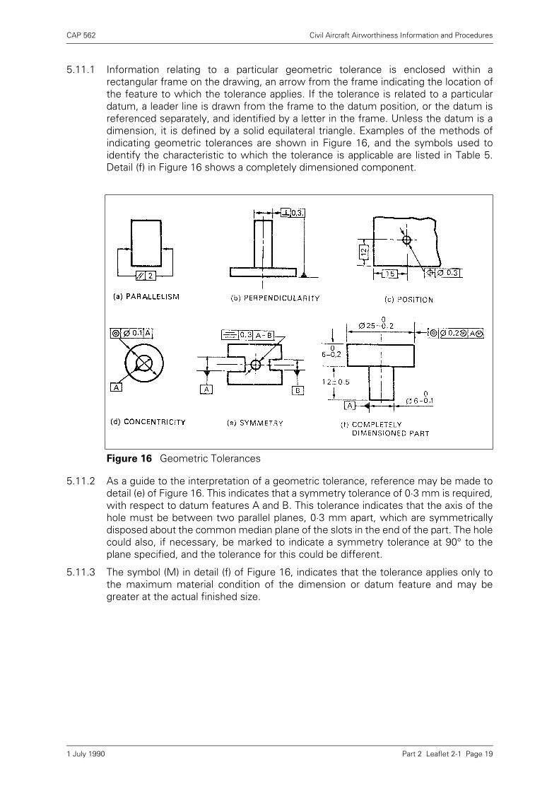
5.11.1 Information relating to a particular geometric tolerance is enclosed within arectangular frame on the drawing, an arrow from the frame indicating the location ofthe feature to which the tolerance applies. If the tolerance is related to a particulardatum, a leader line is drawn from the frame to the datum position, or the datum isreferenced separately, and identified by a letter in the frame. Unless the datum is adimension, it is defined by a solid equilateral triangle. Examples of the methods ofindicating geometric tolerances are shown in Figure 16, and the symbols used toidentify the characteristic to which the tolerance is applicable are listed in Table 5.Detail (f) in Figure 16 shows a completely dimensioned component.
5.11.2 As a guide to the interpretation of a geometric tolerance, reference may be made todetail (e) of Figure 16. This indicates that a symmetry tolerance of 0·3 mm is required,with respect to datum features A and B. This tolerance indicates that the axis of thehole must be between two parallel planes, 0·3 mm apart, which are symmetricallydisposed about the common median plane of the slots in the end of the part. The holecould also, if necessary, be marked to indicate a symmetry tolerance at 90° to theplane specified, and the tolerance for this could be different.
5.11.3 The symbol (M) in detail (f) of Figure 16, indicates that the tolerance applies only tothe maximum material condition of the dimension or datum feature and may begreater at the actual finished size.
Figure 16 Geometric Tolerances
1 July 1990
CAP 562 Civil Aircraft Airworthiness Information and Procedures
Part 2 Leaflet 2-1 Page 20
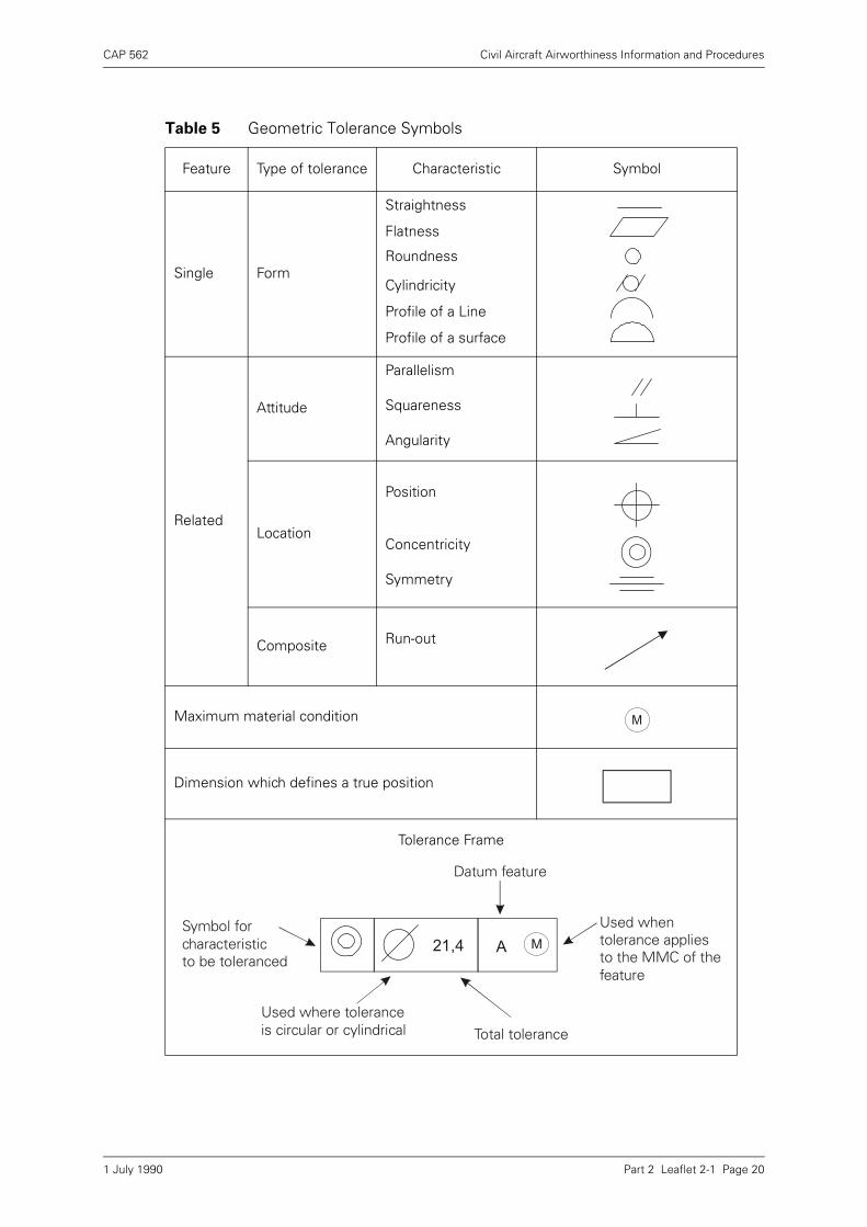
Table 5 Geometric Tolerance Symbols
Feature Type of tolerance Characteristic Symbol
Single Form
Straightness
Flatness
Roundness
Cylindricity
Profile of a Line
Profile of a surface
Related
Attitude
Parallelism
Squareness
Angularity
Location
Position
Concentricity
Symmetry
Composite Run-out
Maximum material condition
Dimension which defines a true position
Tolerance Frame
M
M21,4 A
Datum feature
Used whentolerance appliesto the MMC of thefeature
Total toleranceUsed where toleranceis circular or cylindrical
Symbol for characteristicto be toleranced
1 July 1990
CAP 562 Civil Aircraft Airworthiness Information and Procedures
Part 2 Leaflet 2-2 Page 1
Leaflet 2-2 Clean Rooms
1 Introduction
The higher reliability requirements specified for aircraft system components and inparticular, those associated with complex electronic, instrumentation and mechanicalsystems, (see Leaflet 10–5) necessitated the development of techniques forcontrolling contamination which in various forms is a common cause of componentfailure. It also became necessary to apply these techniques to selected areas ofmanufacturing and aircraft operating organisations in which the various processes ofmanufacture, overhaul and testing can be carried out under controlled environmentalconditions. Such selected areas are referred to as Clean Rooms, the design andmanufacture of which form part of an independent and highly specialised field of workto British Standard BS 5295 Parts 1, 2 and 3.
1.1 The information given in this Leaflet is intended purely as a guide to the subject ofClean Rooms. Subject headings are as follows:
2 Sources of Contamination
Any substance that causes failure or malfunctioning of a component is a contaminant,the particles of which may take a variety of forms and stem from many sources.
Subject Paragraph
Sources of Contamination 2
Control of Contamination 3
Size of Contaminants 4
Classification of Air Cleanliness 5
Classification of Clean Rooms 6
Environment and Comfort Control 7
Air Handling Systems 8
Layout of Clean Rooms 9
Manufacture of Clean Rooms 10
Clean Room Furnishings 11
Clean Room Garments 12
Clean Work Stations 13
Clean Room Operation 14
Maintenance of Clean Rooms 15
1 July 1990
CAP 562 Civil Aircraft Airworthiness Information and Procedures
Part 2 Leaflet 2-2 Page 2
2.1 Air
The air which continually surrounds the components may be considered as acontamination storehouse containing dirt and dust particles, organic and inorganicvapours.
2.2 Manufacture
Contaminants are produced during all manufacturing processes. Particles, such asswarf resulting from a machining operation, or particles forced into the surface of acomponent during a pressing or heating process, can be of such a nature that theireffect can be immediate or delayed. Depending on the composition of the particle andcomponent materials, the alloys or compounds formed by interaction can result inserious loss of a component’s structural strength over a period governed by the rateof diffusion.
2.3 Assembly
During the assembly process the possibility of introducing contaminants is probablygreatest because of exposure to the highest levels of contaminant sources. In thesoldering process for example, the vapourisation of flux causes particles to escapeinto the surrounding air which, on cooling, condense as droplets on a nearby coldsurface of the component. Depending on the location of the particles and the forcesapplied to them, they can act as a contaminant with an immediate or delayed effect.
2.3.1 The use of jointing adhesives can also produce contamination similar to that of asoldering process. In addition, vapours can be given off which can migrate to otherparts of an assembly and act as a delayed-action contaminant.
2.3.2 Assembly of components using threaded joints can produce fibre-shaped fragmentsor flakes as a result of an effect similar to wire drawing. For extremely close fit or forbalancing purposes, it may be necessary to fit individual parts of a componenttogether by grinding, lapping or honing operations. In any such operation,contaminant particles can be dispersed in the atmosphere, suspended in fluids,adhere to the surfaces of component parts, or become embedded into the surfaces.
2.3.3 Assembly of components in jigs, or while being handled or supported by tools, mayresult in deformation of surfaces and production of contaminant particles. Forexample, if during tightening of a bolt, slippage of the spanner jaws occurs, particlesare produced from the bolt head. Particles are also produced from the heads of boltsor screws and component surfaces during final tightening.
2.4 Storage and Transit
During the second period of assembled components and of associated independentparts, contamination can occur in several ways notwithstanding the use of protectivecoverings or containers. Particles from the air may be deposited as a result ofgravitational settling and also as a result of electrostatic effects. Improperly cleanedcontainers or covers may transfer particles to components, in particular wherepadded containers and plastics containers are used. In the first case, the contours ofthe container may trap particles which are not released until the component causesdeformation of the padding. In the second case, plastics containers may pick upparticles from the air due to electrostatic charging and hold them until transferred tothe packed component.
2.4.1 Containers which are not hermetically sealed are subject to a 'breathing' cycle as thetemperature of the container varies. During the intake portion of the cycle, particlesin the air surrounding the container may be drawn into a position where they cancontaminate the component.
1 July 1990
CAP 562 Civil Aircraft Airworthiness Information and Procedures
Part 2 Leaflet 2-2 Page 3
2.4.2 The movement of packed containers during transit is also a source of contaminationsince it may dislodge contaminant particles not previously cleaned off, or create newparticles by abrasion.
2.5 Component Cleaning Processes
A cleaning process is actually a process of transforming contamination from a highlevel of concentration to a lower one; therefore, tolerance levels must be consideredrelative to the component’s function and required operational accuracy.
2.5.1 The transfer of contaminant particles is dependent on the methods used in thecleaning process, i.e. whether wiping or polishing with an absorbent or collectingmaterial (dry cleaning transfer) or cleaning by means of a liquid (wet cleaning transfer).Problems exist in each of these processes.
2.5.2 The ways in which dry cleaning can contaminate include the following:
a) Removal of fibrous particles from the cleaning material.
b) The material, after use, may have a particle concentration sufficiently high so thatas much contamination is left on the component as is removed.
c) Wiping or polishing action can cause particle adhesion as a result of electrostaticcharges.
d) Particles can be moved about on a component surface without necessarily beinglifted from the surfaces.
2.5.3 In the wet cleaning process, the contaminated surfaces are exposed to clean fluidwhich will wet the particles and the surfaces. The fluid or the component is thenagitated so as to pull particles from the surfaces. After a specified period thecomponent is withdrawn and the surfaces are dried. The ways in which wet cleaningcan contaminate include the following:
a) It is often difficult to obtain clean fluid and to keep it clean when handling it.
b) Agitation of the fluid is normally done by ultrasonic means, but there is a possibilityof re-contamination of the amplitude if agitation is not large enough to removeparticles an appreciable distance from the surface of the component.
c) Often a wet surface may have particles in the liquid layer that can easily be movedlaterally over the surface but are removed from the liquid layer only with greatdifficulty.
d) Until the component is dried, any airborne particles will collect on the wet surfaceand remain.
2.6 Personnel Activity
The activity of personnel is probably the greatest single cause of contamination whicharises from several sources. The act of walking, or other movements required at awork bench, produces transient air currents which re-distribute airborne particles andthe brushing off of particles from many surfaces. Another contaminant source is theshedding of skin and hair particles. The outer layers of skin flake off almostcontinuously, the flake rate and size depending on the amount of abrasion to whichthe skin is exposed and its condition.
2.6.1 Exhaled air is another source of contamination since it contains moisture-retainingsolid particles and is usually acidic in nature. Perspiration from the skin is a similarhazard.
1 July 1990

CAP 562 Civil Aircraft Airworthiness Information and Procedures
Part 2 Leaflet 2-2 Page 4
3 Control of Contamination
Control of contamination is effected in two ways: by establishing a clean room, whichwill provide a clean atmosphere and working conditions and by rigid routines adoptedby personnel to prevent process, transfer and associated sources of contaminationwhile working within the area of the clean room.
3.1 The manufacture of a clean room and its air handling system (see paragraph 8) mustbe designed to control airborne particles over a range of sizes and suited to the natureof the work performed in the room. Control is accomplished by filtration of the airentering the room, changing the air to remove generated particles, designing walls,floors and furnishings to be resistant to particle generation and retention, protectingcomponents from impact and settling of particles and providing additional areas forcleaning of parts and personnel.
4 Size of Contaminants
The degree to which contaminants are effectively controlled is determined bymeasurements of the size of particles and the number in a given volume. Theconventional unit of measurement is the micrometre (µm). In general, the filtrationsystems of clean areas are designed to control particles of 0·5 µm and larger in size.
5 Classification of Air Cleanliness
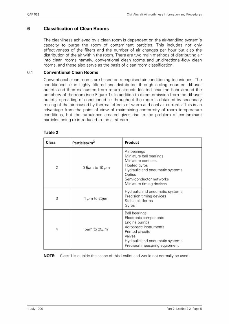
In addition to all principles of air-conditioning, certain specialised cleanlinessrequirements are defined by standards which establish classes of contamination levelto be achieved in the design of a clean room for a specific task. Classifications relateto the number of contaminant particles 0·5 µm and larger in size, present in one cubicmetre of air. Four classes of contamination level are generally adopted and these areshown in descending order of cleanliness in Table 1. Special classifications may beused for particle count levels where special conditions dictate their use. A summaryof the cleanliness requirements for some typical products is given in Table 2.
Table 1
Controlled Environment (Clean room, work station or clean box)
Recommended Air Flow Configurations
Recommended Periodicity for Air Sampling and Particle Counting
Max. Permitted Number of Particles per m3 (equal to, or greater than, stated size)
Final Filter Efficiency %0·5 1 5 10 25
Class 1 Unidirectional Daily or continuous by automatic equipment
3,0001
1. Subject to maximum particle size of 5
Not applicable
Nil Nil Nil 99·995
Class 2 Unidirectional Weekly 300,000 Not applicable
2,000 30 Nil 99·95
Class 3 Unidirectional or conventional
Monthly 1,000,000 20,000 4,000 300 95·00
Class 4 Conventional 3-monthly 200,000 40,000 4,000 70·00
Controlled Area
Normal ventilation — — — — — — —
Contained Work Station
Unidirectional To suit required class and application
99·997
Portable Clean Boxes
As selected To suit required class and application
To suit required class To suit required class
μm μm μm μm μm
μm
1 July 1990
CAP 562 Civil Aircraft Airworthiness Information and Procedures
Part 2 Leaflet 2-2 Page 5
6 Classification of Clean Rooms
The cleanliness achieved by a clean room is dependent on the air-handling system’scapacity to purge the room of contaminant particles. This includes not onlyeffectiveness of the filters and the number of air changes per hour but also thedistribution of the air within the room. There are two main methods of distributing airinto clean rooms namely, conventional clean rooms and unidirectional-flow cleanrooms, and these also serve as the basis of clean room classification.
6.1 Conventional Clean Rooms
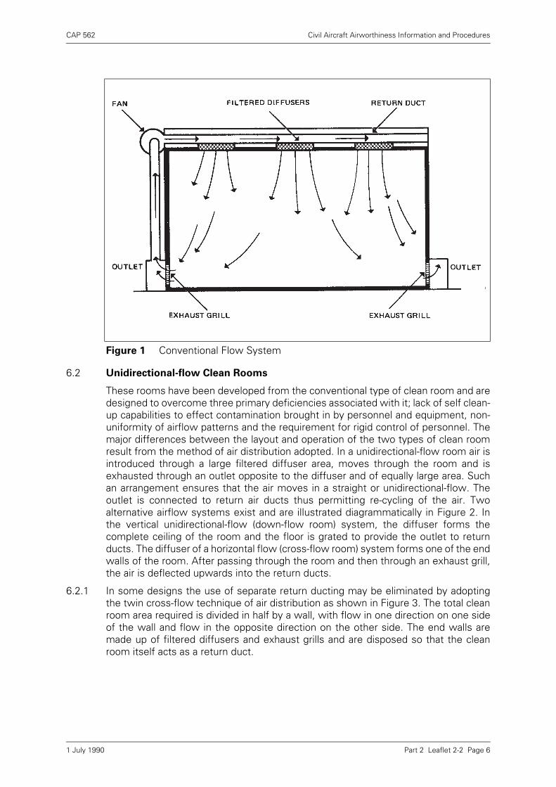
Conventional clean rooms are based on recognised air-conditioning techniques. Theconditioned air is highly filtered and distributed through ceiling-mounted diffuseroutlets and then exhausted from return airducts located near the floor around theperiphery of the room (see Figure 1). In addition to direct emission from the diffuseroutlets, spreading of conditioned air throughout the room is obtained by secondarymixing of the air caused by thermal effects of warm and cool air currents. This is anadvantage from the point of view of maintaining conformity of room temperatureconditions, but the turbulence created gives rise to the problem of contaminantparticles being re-introduced to the airstream.
NOTE: Class 1 is outside the scope of this Leaflet and would not normally be used.
Table 2
Class Particles/m3 Product
2 0·5μm to 10 μm
Air bearingsMiniature ball bearingsMiniature contactsFloated gyrosHydraulic and pneumatic systemsOpticsSemi-conductor networksMiniature timing devices
3 1 μm to 25μm
Hydraulic and pneumatic systemsPrecision timing devicesStable platformsGyros
4 5μm to 25μm
Ball bearingsElectronic componentsEngine pumpsAerospace instrumentsPrinted circuitsValvesHydraulic and pneumatic systemsPrecision measuring equipment
1 July 1990
CAP 562 Civil Aircraft Airworthiness Information and Procedures
Part 2 Leaflet 2-2 Page 6
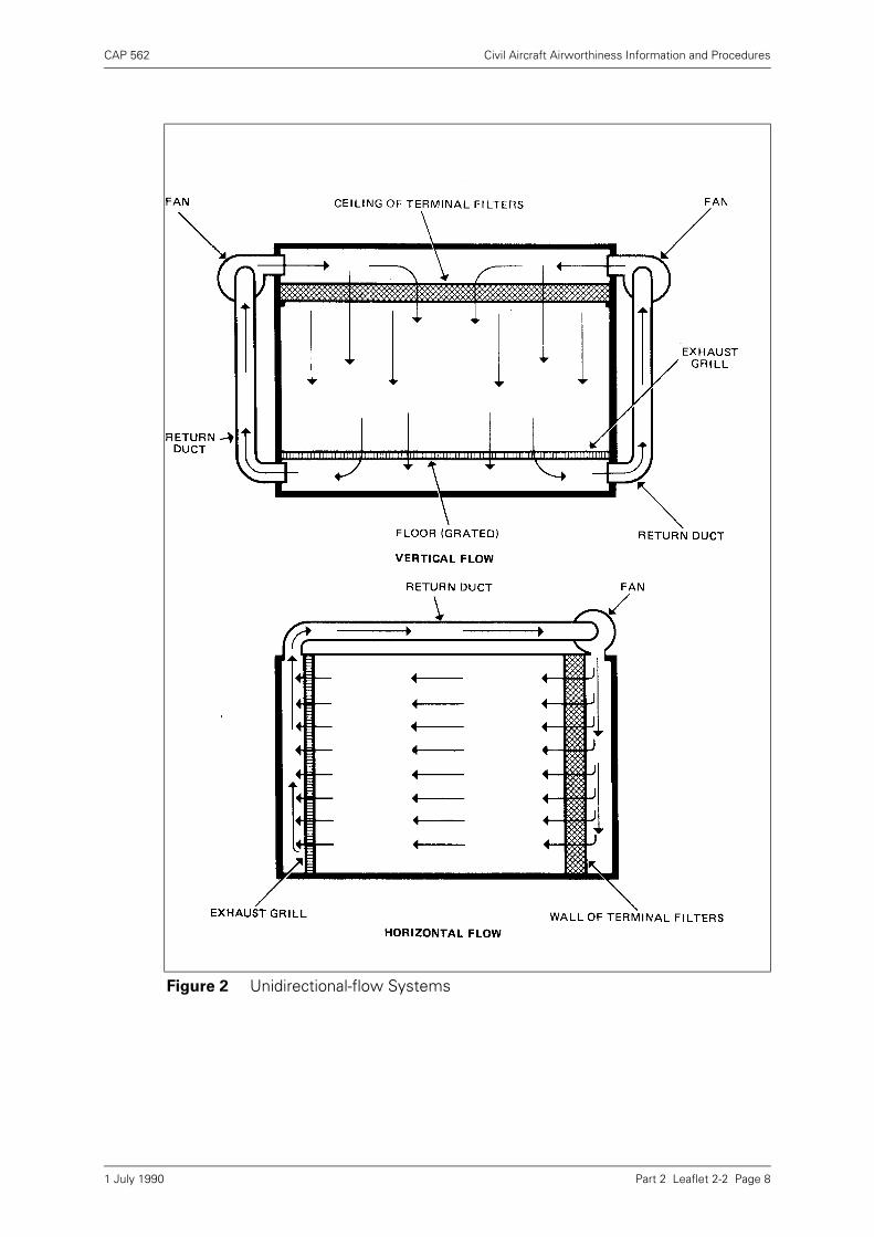
6.2 Unidirectional-flow Clean Rooms
These rooms have been developed from the conventional type of clean room and aredesigned to overcome three primary deficiencies associated with it; lack of self clean-up capabilities to effect contamination brought in by personnel and equipment, non-uniformity of airflow patterns and the requirement for rigid control of personnel. Themajor differences between the layout and operation of the two types of clean roomresult from the method of air distribution adopted. In a unidirectional-flow room air isintroduced through a large filtered diffuser area, moves through the room and isexhausted through an outlet opposite to the diffuser and of equally large area. Suchan arrangement ensures that the air moves in a straight or unidirectional-flow. Theoutlet is connected to return air ducts thus permitting re-cycling of the air. Twoalternative airflow systems exist and are illustrated diagrammatically in Figure 2. Inthe vertical unidirectional-flow (down-flow room) system, the diffuser forms thecomplete ceiling of the room and the floor is grated to provide the outlet to returnducts. The diffuser of a horizontal flow (cross-flow room) system forms one of the endwalls of the room. After passing through the room and then through an exhaust grill,the air is deflected upwards into the return ducts.
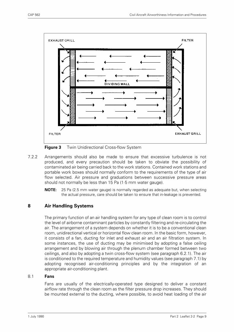
6.2.1 In some designs the use of separate return ducting may be eliminated by adoptingthe twin cross-flow technique of air distribution as shown in Figure 3. The total cleanroom area required is divided in half by a wall, with flow in one direction on one sideof the wall and flow in the opposite direction on the other side. The end walls aremade up of filtered diffusers and exhaust grills and are disposed so that the cleanroom itself acts as a return duct.
Figure 1 Conventional Flow System
1 July 1990
CAP 562 Civil Aircraft Airworthiness Information and Procedures
Part 2 Leaflet 2-2 Page 7
7 Environment and Comfort Control
The temperature, humidity and pressure characteristics of the air passing through theair handling system (see paragraph 8) should be controlled to establish anenvironment suitable for work processes to be carried out in a clean room and for thecomfort of clean room personnel.
7.1 Temperature and Humidity
The selection of temperature and humidity ranges to be controlled are dependent onthe design of the component or system and the effects on their functional accuracyunder varying environmental conditions. Normally a suitable temperature for workingconditions is 20 ± 2°C (68 ± 36°F). Humidity should be controlled and maintained at arelative humidity of 35 to 50% for all classes of clean rooms, contained work stationsand clean boxes.
7.2 Pressure
Clean rooms are always slightly pressurised in order to maintain the required outwardflow of air under closed working conditions and to prevent the entry of contaminantairborne particles when entryways or doors are opened.
7.2.1 Unidirectional-flow rooms should normally have an air velocity of 0·45 ± 0·1 m/s forhorizontal flow rooms and 0·30 ± 0·05 m/s for vertical flow rooms. Air pressure forconventional flow rooms should be such that the number of air changes, including re-circulated air, should not normally be less than 20 per hour except for Class 4 roomswhere not less than 10 changes per hour may be acceptable.
1 July 1990
CAP 562 Civil Aircraft Airworthiness Information and Procedures
Part 2 Leaflet 2-2 Page 8
Figure 2 Unidirectional-flow Systems
1 July 1990
CAP 562 Civil Aircraft Airworthiness Information and Procedures
Part 2 Leaflet 2-2 Page 9
7.2.2 Arrangements should also be made to ensure that excessive turbulence is notproduced, and every precaution should be taken to obviate the possibility ofcontaminated air being carried back to the work stations. Contained work stations andportable work boxes should normally conform to the requirements of the type of airflow selected. Air pressure and graduations between successive pressure areasshould not normally be less than 15 Pa (1·5 mm water gauge).
NOTE: 25 Pa (2.5 mm water gauge) is normally regarded as adequate but, when selectingthe actual pressure, care should be taken to ensure that in-leakage is prevented.
8 Air Handling Systems
The primary function of an air handling system for any type of clean room is to controlthe level of airborne contaminant particles by constantly filtering and re-circulating theair. The arrangement of a system depends on whether it is to be a conventional cleanroom, unidirectional vertical or horizontal flow clean room. In the basic form, however,it consists of a fan, ducting for inlet and exhaust air and an air filtration system. Insome instances, the use of ducting may be minimised by adopting a false ceilingarrangement and by blowing air through the plenum chamber formed between twoceilings, and also by adopting a twin cross-flow system (see paragraph 6.2.1). The airis conditioned to the required temperature and humidity values (see paragraph 7.1) byadopting recognised air-conditioning principles and by the integration of anappropriate air-conditioning plant.
8.1 Fans
Fans are usually of the electrically-operated type designed to deliver a constantairflow rate through the clean room as the filter pressure drop increases. They shouldbe mounted external to the ducting, where possible, to avoid heat loading of the air
Figure 3 Twin Unidirectional Cross-flow System
1 July 1990
CAP 562 Civil Aircraft Airworthiness Information and Procedures
Part 2 Leaflet 2-2 Page 10
and introduction of further contamination. Care should also be taken to avoidcontamination of the atmosphere by gaseous effluents.
8.2 Ducting
Ducting is manufactured from materials which are non-flaking and corrosion-resistant,stainless-steel and aluminium being commonly used, or should normally be treated toprevent the introduction of contaminants from the duct.
8.3 Filtration System
Filtration of airborne contaminant particles is selected on the basis of cleanliness levelrequired and, generally, a system is made up of two principal stages: pre-filter stageand final filter stage. Pre-filtering is carried out at the inlet to the air handling systemand at one or more points upstream of the clean room, and final filtering directly atthe inlet to the clean room. The filters are specifically designed for clean roomsystems and are graded at each stage, thus providing control of diminishing sizeparticles. Filtering action depends on the particles contacting and adhering to thefibres or collecting surface of the filter medium which is made from such materials asglass-fibre and asbestos. The filters utilised for final filtering are variously known assuper-inception, absolute or high-efficiency particulate air (HEPA) filters and may beused as individual units or assembled to form a filter bank or module. In the lattercase, each unit is connected to a common plenum chamber incorporating its own fan.The number of individual units in a bank is governed by design requirements for theair handling system.
9 Layout of Clean Rooms
The layout of a clean room is governed by many factors arising principally from themanufacturing processes and test procedures to be carried out on specific types ofequipment. As a result there are a variety of design and layout specifications to meetthe requirements of individual manufacturers and operators of equipment. In theirbasic form, however, layouts are directly related to the accepted methods of airdistribution, i.e. unidirectional-flow and conventional.
9.1 Unidirectional Clean Rooms
The layout of a typical clean room facility is illustrated in Figure 4. The area devotedto the facility is arranged in accordance with the operating practices common to allclean rooms, i.e. components and personnel flow progressively from an uncontrolledor 'dirty' environment to one in which the desired level of cleanliness is maintained.
9.1.1 Personnel Cleaning
Entrance to the clean room is via a change room the purpose of which is todecontaminate personnel without introducing removed contaminant particles into theclean room. A change room is divided into three distinct areas; an uncontrolled or'dirty' area, a wash-up (semi-contaminated) area and a change (uncontaminated) area.These areas are arranged so that personnel must follow a definite path for entry intothe clean room.
a) In the uncontrolled area lockers are provided for housing outdoor clothing such asovercoats and raincoats, and also shoe cleaning machines. From the uncontrolledarea, entry to the wash-up area is made via an air shower compartment, thepurpose of which is to remove gross contaminant particles from personnel. Thesize of the compartment may be large enough to accommodate only one personor a group of persons depending on the number that must enter the clean room ina given length of time. The design of the air shower may vary but, in general, it
1 July 1990

CAP 562 Civil Aircraft Airworthiness Information and Procedures
Part 2 Leaflet 2-2 Page 11
consists of an air inlet system and an exhaust system operated by independentfans. Air flows through the compartment from air inlet nozzles or louvres mountedin the ceiling or in one wall of the compartment. The entrance and exit doors of thecompartment are interlocked so that only one of them can be opened at a time.The closing of the entrance door starts the fan and, until the cleaning cycle iscompleted, the exit door remains locked. The cycle may, in some cases, beinterrupted by a safety override system in the event of an emergency. Air velocitiesare sufficiently high to cause 'flapping' of clothing but without discomfort topersonnel.
b) On leaving the air shower, personnel proceed to the change area via the semi-contaminated area in which washing and toilet facilities are located. These facilitiesinclude foot-controlled washstands, liquid-soap dispensing units and heated airhand-drying machines to prevent contamination from towelling. A section of thechange area is provided for changing into special clean room garments (seeparagraph 12) stored in racks or lockers. The entrance to this section is guardedwith a tacky or sticky mat designed to remove residual contaminant particles fromthe undersurfaces of shoes. Entrance to the clean room after changing is made viaanother air shower compartment.
9.1.2 Parts Cleaning
Prior to entry into a clean room, all parts, tools, equipment, and material must also bedecontaminated and it is therefore necessary to provide an additional area adjacent tothe clean room. The layout of a parts cleaning room depends largely on the types ofcomponent and the number of work processes involved. Similarly, the cleaningmethods adopted depend on the type of contaminant, the materials used in themanufacture of components, and the level of cleanliness required. In general, the
Figure 4 Layout of a Unidirectional Clean Room
1 July 1990

CAP 562 Civil Aircraft Airworthiness Information and Procedures
Part 2 Leaflet 2-2 Page 12
room is equipped with the required number of work tables, specialised equipment,cleaning machines and washing facilities for personnel.
a) The transfer of cleaned components to the clean room is effected by means of a'pass-through' box forming an air lock in the wall dividing the appropriate areas.Boxes are provided with double windows and doors; an interlock system ensuresthat only one door can be opened at a time. In some clean room facilities a 'pass-through' box may be of the circular type with a single opening so that the box mustbe rotated through 180º to insert or remove a component. Since the boxes aredesigned to prevent a direct opening between rooms, a means of verbalcommunication between relevant personnel must be provided adjacent to the box.This can be an intercommunication system, a voice diaphragm, or a speaking tube.
9.1.3 Additional Support Rooms
Since unidirectional clean rooms require more rigid control to prevent contaminationentering, it is usual to make provision for additional support rooms such as offices,lunch rooms, rest rooms, etc. The manufacture of these rooms follows a similarpattern to that of a clean room (see paragraph 10) although the air handling system isusually not so elaborate.
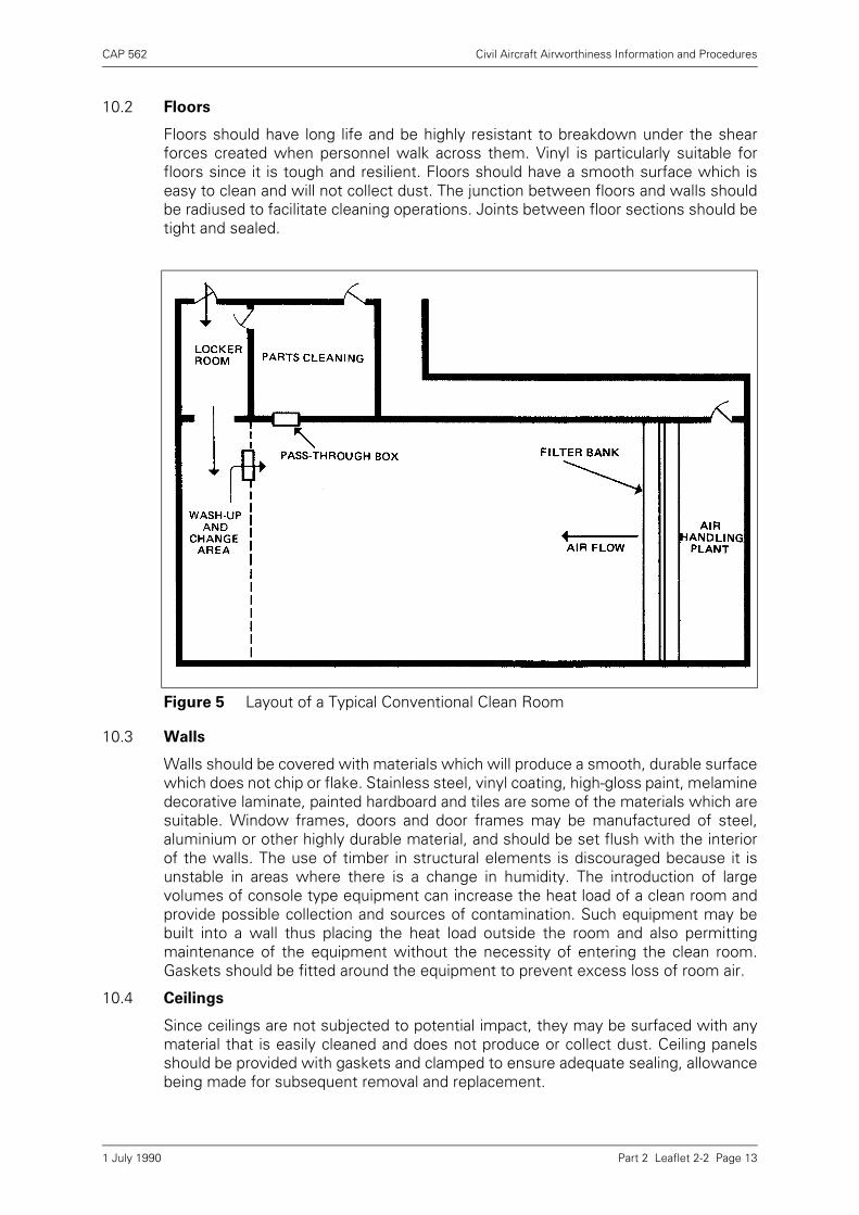
9.2 Conventional Clean Rooms
The use of conventional flow clean rooms eliminates the necessity for support areassuch as air showers and special changing rooms and, as may be seen from the typicalconventional layout illustrated in Figure 5, increased working area is available andentry procedures are much simpler. The main entrance is situated at the air outlet or'dirty' end of the room and personnel can pass through this directly from a lockerroom and change area. Work benches and equipment are disposed so that thecleanest operations are carried out closest to the filter bank forming the end wall,while dirty operations such as soldering, cleaning, etc., are performed toward theoutlet end of the room. Parts cleaning and preparation may be performed in a mannersimilar to that adopted for a unidirectional clean room (see paragraph 9.1.2) or carriedout in a parts cleaning room situated within the clean room itself.
10 Manufacture of Clean Rooms
The manufacture of clean rooms involves the application of specifically developedbuilding techniques, air-conditioning installation practices and careful selection ofmanufacture materials. This is normally undertaken by a specialist organisationworking to the detailed BS 5295 Parts 1, 2 and 3 and the specification of a userorganisation. The details given in the following paragraphs are therefore intended asa guide to the factors related to general constructional features.
10.1 Noise and Vibration
Careful consideration must be given to clean room location in relation to other workareas and the effects of noise and localised ground vibrations. Noise and vibrationgenerated by equipment, machinery, support and administrative areas must also beconsidered. If vibration insulation devices are to be employed these must notgenerate or collect dust. Special attention must be given to the framing system ofsuper-structures in order to prevent vibration transmission through ceilings, walls andfloors into the main structure. The maximum noise level of the room, work station orclean air device, in an operational but unmanned state should not normally exceed65 dB.
1 July 1990
CAP 562 Civil Aircraft Airworthiness Information and Procedures
Part 2 Leaflet 2-2 Page 13
10.2 Floors
Floors should have long life and be highly resistant to breakdown under the shearforces created when personnel walk across them. Vinyl is particularly suitable forfloors since it is tough and resilient. Floors should have a smooth surface which iseasy to clean and will not collect dust. The junction between floors and walls shouldbe radiused to facilitate cleaning operations. Joints between floor sections should betight and sealed.
10.3 Walls
Walls should be covered with materials which will produce a smooth, durable surfacewhich does not chip or flake. Stainless steel, vinyl coating, high-gloss paint, melaminedecorative laminate, painted hardboard and tiles are some of the materials which aresuitable. Window frames, doors and door frames may be manufactured of steel,aluminium or other highly durable material, and should be set flush with the interiorof the walls. The use of timber in structural elements is discouraged because it isunstable in areas where there is a change in humidity. The introduction of largevolumes of console type equipment can increase the heat load of a clean room andprovide possible collection and sources of contamination. Such equipment may bebuilt into a wall thus placing the heat load outside the room and also permittingmaintenance of the equipment without the necessity of entering the clean room.Gaskets should be fitted around the equipment to prevent excess loss of room air.
10.4 Ceilings
Since ceilings are not subjected to potential impact, they may be surfaced with anymaterial that is easily cleaned and does not produce or collect dust. Ceiling panelsshould be provided with gaskets and clamped to ensure adequate sealing, allowancebeing made for subsequent removal and replacement.
Figure 5 Layout of a Typical Conventional Clean Room
1 July 1990
CAP 562 Civil Aircraft Airworthiness Information and Procedures
Part 2 Leaflet 2-2 Page 14
10.5 Lighting
Lighting fixtures of the fluorescent type should be used and of ratings which willprovide adequate light intensity at bench level of not less than 3,000 lux. Fixtures maybe installed to permit servicing from within the clean room, or supported in tracksabove the ceiling so that they can be slid out for servicing without entering the cleanroom.
10.6 Utilities
The distribution of utilities such as water, electrical power, vacuum and compressedair supplies must be properly planned to ensure that all required work locations areserved without interference with room air distribution and work flow.
11 Clean Room Furnishings
Furnishings such as work benches, chairs and containers for component parts requirecareful selection, design and choice of materials for their manufacture. The mainstructure of work benches and chairs should be of metal and designed in such a waythat contaminant particles cannot accumulate. Items that can expect to be bumped,knocked, abraded, etc., by personnel should possess a tough, resilient, low-particlegenerating surface such as stainless steel, melamine decorative laminate typematerial, or material of equivalent surface qualities.
12 Clean Room Garments
Clean room products can be readily contaminated by particles from clothing and it istherefore necessary to make provision for the wearing of protective garments. Thesetake the form of smocks, overalls, caps and hoods. In addition, 'boottee' type shoecovers, separate clean room shoes and gloves must also be provided. The extent towhich all the garments are used depends on the type of clean room, class ofcleanliness to be achieved and the work processes carried out.
12.1 Design
The garments are of special design to prevent the transfer of contaminant particlesfrom personnel and at the same time to provide the maximum of comfort. Thematerials from which they are fabricated are usually selected from the range ofavailable man-made fibres which exhibit such properties as non-flammability, limitedlinting, and negligible electrostatic generation. These materials are available under avariety of trade names. Typical design requirements for clean room garments aregiven in the following paragraphs.
12.1.1 Smocks
Smocks should be of simple design, with no pockets and with as few seams aspossible. Seams should leave no open end of material which might become frayedand give off lint or loose strands. In addition, seams should be double-stitched withthread of the same fibre as the garment. Adjustable neck bands and cuffs should beprovided in preference to collars and loose sleeves and must provide a snug fit whenworn.
12.1.2 Overalls
Overalls should have a full-length zip fastener with flap front and be provided withadjustable neck bands and cuffs. If overalls are to be used with shoe covers, theoveralls should fit inside the covers. Overalls to be used with clean room shoes
1 July 1990

CAP 562 Civil Aircraft Airworthiness Information and Procedures
Part 2 Leaflet 2-2 Page 15
should be designed so that the legs of the overalls meet and slightly overlap theshoes.
12.1.3 Caps
These should be of the style worn in hospital operating rooms. They should fit snuglyaround the head, covering the hair to prevent hair particles and dandruff falling intothe clean room area.
12.1.4 Hoods
Hoods should be designed to confine all hair under them to eliminate contaminationby hair particles and dandruff, and to fit snugly inside overalls to provide completecoverage of personnel; if beards are permitted, masks must also be provided.
NOTE: Garments are usually white although in some cases a sea green colour may bechosen to minimise glare. As a means of identifying selected personnel, e.g.supervisors or personnel in charge of certain work processes, smocks and overallsmay be provided with distinctively coloured neckbands. Coloured caps may also beused as a means of identification.
12.1.5 Shoe Covers and Shoes
Covers should be worn over normal shoes and should be high enough to hold the legsof overalls. Covers should have a reinforced sole and be of a type which will preventpersonnel from slipping and falling on smooth floors and, for reasons of durability andeconomy, nylon is recommended as the material. To provide proper fit and comfort,and to achieve optimum cleanliness, covers should be provided with snap fasteners,and laces which can be tied around the legs and above the ankles. As an alternativeto shoe covers, shoes can be issued to personnel for exclusive wear in the cleanroom. They should be simply designed, comfortable, washable and fabricated frommaterials which will not shed particles due to abrasion and wear.
12.1.6 Gloves
Where there is a risk of contamination from contact with the hands or fingers, glovesor finger stalls must be used. Such coverings should be comfortable and shouldenable the user to maintain a delicate finger touch. If the use of plastics is necessaryfor the 'touch' portion of gloves the remainder should be made of a material that willallow 'breathing' thus preventing overheating of the hands.
12.2 Garment Storage and Cleaning
When not in use, clean room garments should not be allowed to come into contactwith any possible contaminant. They should always be stored on individual hangersin the lockers provided in changing rooms. Three sets of garments per person shouldnormally be provided: one set in use, one set being cleaned, and one set in reserve.
12.2.1 Cleaning of garments is a specialised technique based on conventional laundering anddry-cleaning processes. Ideally, a laundry should be established as a specialised unitsupporting clean room operations and functioning under similar conditions ofdecontamination as a clean room. A typical unit is divided into three distinct areas:soiled garment receiving area, washing and dry-cleaning area, and an inspection andpackaging area. Soiled garments are placed in polythene bags and transferred to thereceiving area through an air lock. The garments are then emptied into specially builttubs and transported to the washing and dry-cleaning area equipped with theappropriate machines. After cleaning and drying, the garments are transferred to thethird area for inspection, sampling of contamination level, and packaging and sealingin polythene bags.
1 July 1990

CAP 562 Civil Aircraft Airworthiness Information and Procedures
Part 2 Leaflet 2-2 Page 16
13 Clean Work Stations
These stations are work benches specifically designed to incorporate their ownfiltered air supply system. They may be utilised in a clean room, in addition to benchesor tables based on conventional patterns, or in an uncontrolled environment.
13.1 The design of work stations has been developed from bench-mounted 'dust-free'cabinets, typical examples of which are illustrated in Figure 6. Although thesecabinets provide low contamination levels, depending on the type of filter, theproblem of contamination while operations are performed inside arises.Contaminants move about in turbulent air and find their way out of the cabinet only atrandom intervals. Another design, commonly referred to as a 'glove box' is alsoillustrated in Figure 6. It utilises a recirculating air system and although it produceslower contamination levels than other forms of cabinet, it has the disadvantage ofrequiring an operator to work through arm ports and the attached gloves.
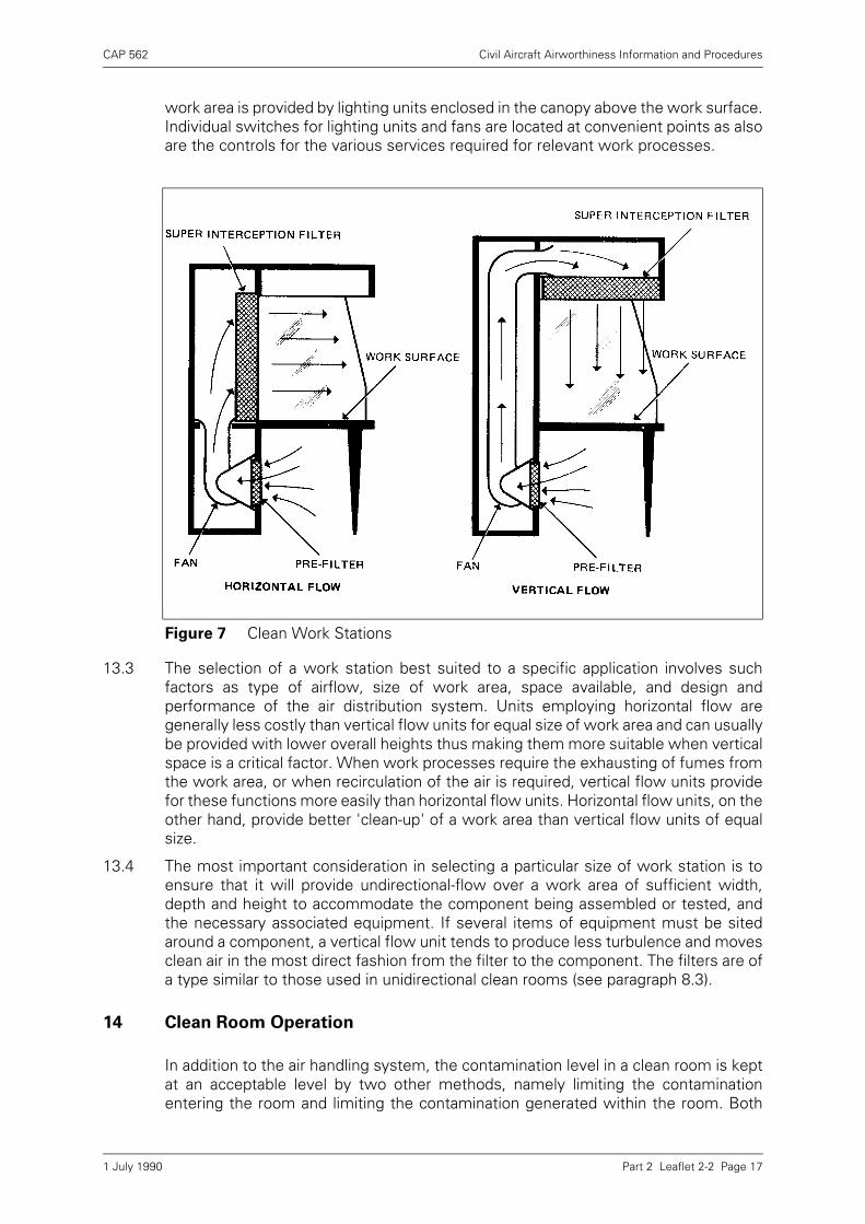
13.2 Work stations overcome the deficiencies of 'dust-free' cabinets by incorporating anair distribution system which operates on principles similar to those employed in aundirectional-flow clean room (see also paragraph 6.2). The air distribution systemconsists of a fan and a pre-filter mounted below the work surface, and an outlet witha super-interception filter, mounted so as to produce either a horizontal flow or avertical flow over the work surface. Figure 7 illustrates both airflow techniques asthey are applied to a typical console type of work station. Glass panels form the sidesof the work area which, on account of the undirectional-flow technique, is open at thefront thus permitting unrestricted movement at the work surface. Illumination of the
Figure 6 Clean Work Boxes
1 July 1990
CAP 562 Civil Aircraft Airworthiness Information and Procedures
Part 2 Leaflet 2-2 Page 17
work area is provided by lighting units enclosed in the canopy above the work surface.Individual switches for lighting units and fans are located at convenient points as alsoare the controls for the various services required for relevant work processes.
13.3 The selection of a work station best suited to a specific application involves suchfactors as type of airflow, size of work area, space available, and design andperformance of the air distribution system. Units employing horizontal flow aregenerally less costly than vertical flow units for equal size of work area and can usuallybe provided with lower overall heights thus making them more suitable when verticalspace is a critical factor. When work processes require the exhausting of fumes fromthe work area, or when recirculation of the air is required, vertical flow units providefor these functions more easily than horizontal flow units. Horizontal flow units, on theother hand, provide better 'clean-up' of a work area than vertical flow units of equalsize.
13.4 The most important consideration in selecting a particular size of work station is toensure that it will provide undirectional-flow over a work area of sufficient width,depth and height to accommodate the component being assembled or tested, andthe necessary associated equipment. If several items of equipment must be sitedaround a component, a vertical flow unit tends to produce less turbulence and movesclean air in the most direct fashion from the filter to the component. The filters are ofa type similar to those used in unidirectional clean rooms (see paragraph 8.3).
14 Clean Room Operation
In addition to the air handling system, the contamination level in a clean room is keptat an acceptable level by two other methods, namely limiting the contaminationentering the room and limiting the contamination generated within the room. Both
Figure 7 Clean Work Stations
1 July 1990

CAP 562 Civil Aircraft Airworthiness Information and Procedures
Part 2 Leaflet 2-2 Page 18
these methods are controlled to a large extent by the personnel selected for cleanroom operations. The contamination entering the room is limited by the wearing ofproper garments (see paragraph 12), personnel cleaning, parts and equipmentcleaning, etc. The contamination generated is limited by restricting movement, properwork techniques, etc. It is therefore necessary to establish routines and disciplinesrelated to personnel selection, personal hygiene, entry procedures, and control ofworking activities. The extent to which certain of these routines and disciplines areapplicable depends on the type of clean room; for example, a undirectional-flow cleanroom requires more rigid control of entry and clothing procedures than a conventionalclean room due to the air handling system used (see paragraphs 9.1 and 9.2).
14.1 Personnel Selection
The selection of personnel for clean room duties involves consideration of bothphysical and human factors, including manual dexterity, visual acuity, patience,concern for detail, attitude toward repetitive operations and reaction to the rigiddisciplines that accompany confinement in a controlled environment. Certainphysiological problems must also be considered and some examples which aredetrimental to clean room operations are: allergies to synthetic fabrics; allergies tosolvents used in cleaning processes; profuse nasal discharge; skin conditions thatresult in above normal skin shedding or flaking and dandruff; high amounts of acidfound in the hands; severe nervous conditions such as itching, scratching orclaustrophobia.
14.2 Personal Hygiene
The development of personal hygiene is of great importance in clean roomoperations, not only to limit contamination of vital components but also to maintain ahealthy working environment. Personnel with colds, temporary coughing andsneezing, should be assigned to temporary jobs outside the clean room until they aresufficiently recovered. This also applies to personnel having received severe sunburn,to prevent peeling skin from contaminating a component or the surrounding area.
14.3 Entry Procedures
Clean rooms are necessarily restricted areas and entry must only be allowed topersonnel assigned to them. The procedure to be adopted is governed by the type ofclean room. Typical activities associated with entry procedures are as follows:
a) Removal of outdoor clothing such as overcoats and raincoats and stowage in thelockers provided in the 'dirty' or uncontrolled area.
b) Checking clothes and shoes for visible contamination such as mud, dirt, sand, etc.Removal of such contamination.
c) Washing of face and hands using foot-controlled washstands, liquid soapdispensers and air driers.
d) Passing through air showers and air locks to ensure adequate air scrubbing.
e) Walking over sticky or tacky mats.
f) Changing into the requisite clean room garments. In connection with undirectional-flow clean room operations, changing is done in the uncontaminated section of thechange room adjacent to the clean room. In conventional clean rooms changing isdone in an area located at the 'dirty' end of the clean room.
14.4 General Rules for Operation
The following are general rules which should be enforced to assist in the successfuloperation of clean rooms.
1 July 1990

CAP 562 Civil Aircraft Airworthiness Information and Procedures
Part 2 Leaflet 2-2 Page 19
14.4.1 Personal Activities
a) Hands should be washed often and fingernails kept clean.
b) The specified clothing should always be worn in the approved manner.
c) Personal items such as keys, coins, cigarettes, matches, pencils, handkerchiefsand combs should be deposited in lockers prior to changing into clean roomgarments. Valuable items such as wallets may be carried into a clean room injacket or trouser pockets provided they are not removed inside the clean room.
d) Foodstuff should not be taken into a clean room.
e) Smoking is strictly forbidden.
f) The wearing of jewellery such as large rings, bracelets, watches, necklaces,earrings, lockets, etc., should be avoided.
g) Nervous mannerisms such as scratching the head, rubbing of hands or similaractions should be avoided.
h) Movement of personnel should be restricted as much as possible to preventstirring settled particles on the clean room floor. This applies particularly toconventional clean rooms.
i) Solvent contact with hands should be avoided as many solvents remove naturalskin oils causing excessive skin 'peeling' or flaking.
j) Female personnel should not wear or apply fingernail polish or cosmetics in a cleanroom.
k) Visitors or clean room maintenance personnel must be authorised to enter a cleanroom and must follow the specified entry procedures.
14.4.2 Work Activities
a) All tools including personal tool kits should be kept clean and in good condition andshould undergo cleaning processes in accordance with a periodic cleaningschedule. Tools not essential to specific work processes should be excluded fromtool kits.
b) Paper materials should not be allowed in a clean room unless the paper is plastic-coated or covered, sprayed to prevent linting or is a special limited-linting paper.Papers should not be subjected to excessive shuffling, handling, rolling or bendingas they can generate excessive amounts of small particles under these conditions.
c) Pencils and erasers are not allowed. All writing should be with ball-point pens.
d) Parts of components should be kept in their individual containers until ready forassembly. They should not be left exposed on a work bench or station.
e) Containers and any component parts surplus to requirements should always bereturned to a parts cleaning area for cleaning and re-issue.
f) Metal objects such as wire clippings and solder splashes should be deposited inwaste boxes at the end of each process.
g) Where cleaning of parts is to be carried out inside a clean room, the type ofcleaning equipment and its location within the room should be carefully selected.
1 July 1990
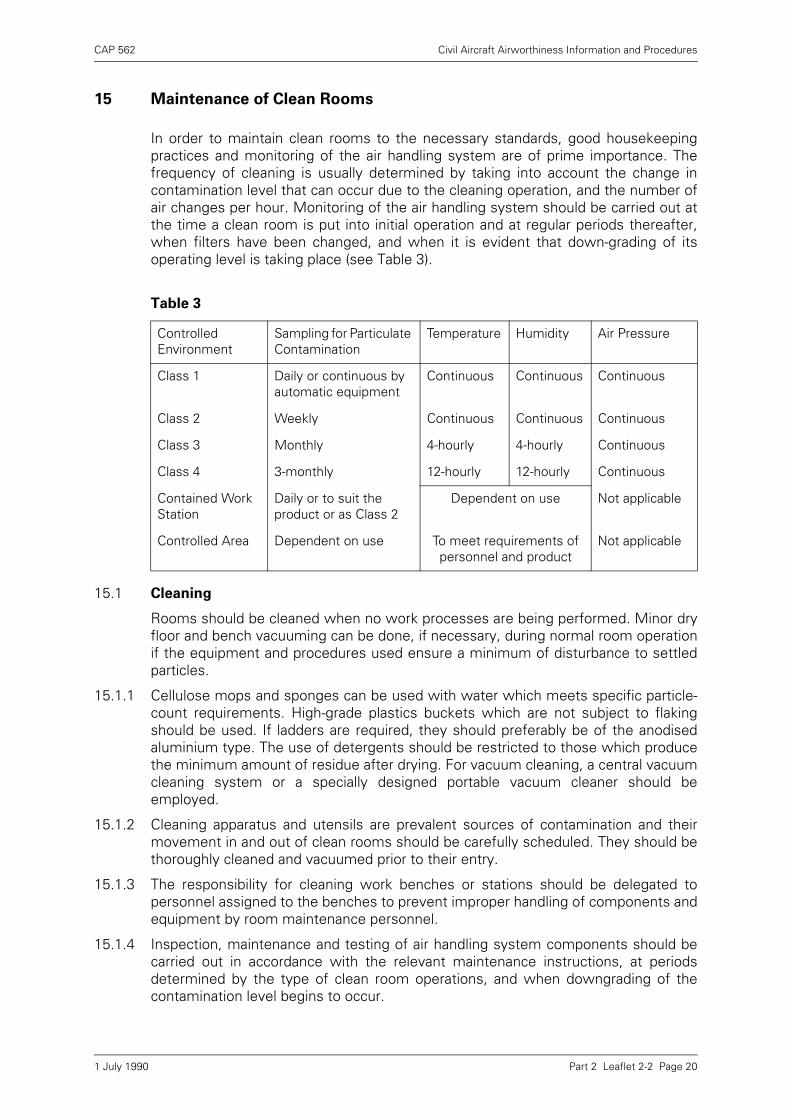
CAP 562 Civil Aircraft Airworthiness Information and Procedures
Part 2 Leaflet 2-2 Page 20
15 Maintenance of Clean Rooms
In order to maintain clean rooms to the necessary standards, good housekeepingpractices and monitoring of the air handling system are of prime importance. Thefrequency of cleaning is usually determined by taking into account the change incontamination level that can occur due to the cleaning operation, and the number ofair changes per hour. Monitoring of the air handling system should be carried out atthe time a clean room is put into initial operation and at regular periods thereafter,when filters have been changed, and when it is evident that down-grading of itsoperating level is taking place (see Table 3).
15.1 Cleaning
Rooms should be cleaned when no work processes are being performed. Minor dryfloor and bench vacuuming can be done, if necessary, during normal room operationif the equipment and procedures used ensure a minimum of disturbance to settledparticles.
15.1.1 Cellulose mops and sponges can be used with water which meets specific particle-count requirements. High-grade plastics buckets which are not subject to flakingshould be used. If ladders are required, they should preferably be of the anodisedaluminium type. The use of detergents should be restricted to those which producethe minimum amount of residue after drying. For vacuum cleaning, a central vacuumcleaning system or a specially designed portable vacuum cleaner should beemployed.
15.1.2 Cleaning apparatus and utensils are prevalent sources of contamination and theirmovement in and out of clean rooms should be carefully scheduled. They should bethoroughly cleaned and vacuumed prior to their entry.
15.1.3 The responsibility for cleaning work benches or stations should be delegated topersonnel assigned to the benches to prevent improper handling of components andequipment by room maintenance personnel.
15.1.4 Inspection, maintenance and testing of air handling system components should becarried out in accordance with the relevant maintenance instructions, at periodsdetermined by the type of clean room operations, and when downgrading of thecontamination level begins to occur.
Table 3
Controlled Environment
Sampling for Particulate Contamination
Temperature Humidity Air Pressure
Class 1 Daily or continuous by automatic equipment
Continuous Continuous Continuous
Class 2 Weekly Continuous Continuous Continuous
Class 3 Monthly 4-hourly 4-hourly Continuous
Class 4 3-monthly 12-hourly 12-hourly Continuous
Contained Work Station
Daily or to suit the product or as Class 2
Dependent on use Not applicable
Controlled Area Dependent on use To meet requirements of personnel and product
Not applicable
1 July 1990
CAP 562 Civil Aircraft Airworthiness Information and Procedures
Part 2 Leaflet 2-2 Page 21
15.2 Monitoring of Clean Rooms
Monitoring refers to the procedures adopted for checking the factors influencingclean room environment. Such factors are the level of contamination, temperature,humidity and pressure. The exact requirements for monitoring and methods to beemployed depend on the type of clean room and classification of cleanliness level,and are therefore determined on an individual basis (see Table 3).
15.2.1 Contamination Monitoring
This is the most difficult monitoring problem of clean room operation owing to thevariations in contamination level throughout a room and also to the many factorswhich must be considered in selecting a specific monitoring technique. Some of thefactors causing variations in contamination level are: filtered air entering a room at oneor more locations; contamination being generated in various amounts throughout aroom; contaminated air exhausted from a room at one or more locations. The highestlevel of contamination is not necessarily at the air exhaust locations, since air from ahighly contaminated area may be diluted with filtered air prior to its being exhausted.Higher and lower levels of contamination can thus readily exist within a given room.The areas of most concern are those immediately surrounding the component onwhich work processes are to be carried out.
a) The locations within a clean room at which sampling of the air is to be taken shouldbe carefully considered in order to obtain a representative contamination level.Samples should be taken at identical times or as near as possible, sincecontamination levels of areas vary at different periods.
b) Various techniques may be applied to contamination monitoring and some of thosemost widely accepted, together with details of principles, are listed in BS 5295Parts 1, 2 and 3.
15.2.2 Humidity Monitoring
This may be achieved by the use of conventional wet and dry bulb thermometers andpsychrometric charts. The thermometers may be supplemented, if necessary, byautomatic recording devices. Humidity can become troublesome if it is allowed toreach a level where static charges are generated by personnel or where corrosionmay be a problem. In general, a humidity level of not less than 40% is desired. Forthose components where humidity tolerance is critical, special control measuresshould be employed.
15.2.3 Pressure Monitoring
A clean room should always be slightly pressurised and it is therefore necessary tomonitor the pressure difference between the room and its outside surroundings.Monitoring may be achieved by a simple U-tube manometer, or a differential pressuregauge calibrated in mm water gauge.
1 July 1990

INTENTIONALLY LEFT BLANK
CAP 562 Civil Aircraft Airworthiness Information and Procedures
Part 2 Leaflet 2-3 Page 1
Leaflet 2-3 Timber Conversion – Spruce
1 Introduction
1.1 A good basic knowledge combined with many years’ experience in the handling oftimber is essential for the accurate assessment of the characteristics and defectswhich make it either suitable or unsuitable for aircraft parts.
1.2 This Leaflet is not intended to give guidance on how to select timber; it outlines theCAA’s recommended method of converting it into aircraft parts and mentionscommon defects which may be encountered during conversion.
2 Seasoning
2.1 Timber which has been cut from selected trees is stacked, prior to shipment, forapproximately 60 days. During this time, the timber loses much of its free moistureand it is in this condition that it should be transported.
2.2 Timber is usually seasoned in air-drying sheds for periods ranging from one to threeyears, or longer. If it is required for immediate use, it may be artificially seasoned (i.e.kiln-dried).
2.3 The process of seasoning reduces the moisture content of timber to a point where itis in equilibrium with the surrounding atmosphere and enables protective treatmentsto be applied more effectively.
3 Characteristics
After the timber has been properly seasoned, samples should be cut and tested todetermine its suitability for use on aircraft. Before taking the samples from a plank oftimber, approximately 6 inches should be cut from the end and discarded as this piecemay be drier than the remainder.
3.1 Moisture-Content
The moisture-content of the sample should be determined by weighing it and thendrying it in an oven at a temperature of 100° to 105°C (212° to 221°F) until twosuccessive weighings yield the same result. Care should be taken to ensure thatwhen the sample is split up, no material is lost and that the weighing is done promptlyso as to avoid false results. The moisture-content should be calculated from thefollowing formula:
where W1 = the weight of the sample prior to drying
and W2 = the weight of the sample after drying.
W1 – W2x 100
W2
1 July 1990

CAP 562 Civil Aircraft Airworthiness Information and Procedures
Part 2 Leaflet 2-3 Page 2
3.2 A quicker method of determining the moisture-content of timber is by the use of theMarconi Moisture Meter. This instrument will record the moisture-content in a fewseconds, whereas the method of weighing, drying and calculating takes much longer.The meter should however, be checked periodically to ascertain that it remainsaccurate. For general guidance, the correct moisture-content should be 15% with atolerance of ± 2%.
3.3 Density
The density should be determined by weighing and measuring the volume of asample cut from the plank. A practical method of calculating the density in imperialunits is to cut the sample 96 mm (3.8 inches) long, by 25 mm (1 inch) square, anddetermine its weight in grammes. The figure for the weight of the sample in grammesis equal to the figure for the density in pounds per cubic foot. The weight of sprucegenerally varies between 320 kg and 577 kg per cubic metre (20 lb. and 36 lb. percubic foot). For Grade A spruce, the density should not be less than 384.45 kg percubic metre (24 lb. per cubic foot) when the moisture-content is 15%.
3.4 Brittleness
3.4.1 A notched test piece, the sides of which are cut radially and tangentially, of thedimensions 133 mm (5¼ inches) long by 22 mm (7/8 inch) square, should be brokenin an impact test machine of the Izod type, the blow being applied tangentially; thetest piece should absorb not less than 6.78 Joules (5 foot-pounds). Care should betaken that the blow is applied in the right direction, for if broken the opposite way afalse reading will be obtained. A tolerance of 0.68 Joules (0·5 foot-pounds) is generallyallowed, provided the fracture shows a satisfactory amount of fibre.
3.4.2 The weight-dropping machine provides an alternative method of testing timber forbrittleness. A plain test piece, 305 mm (12 inches) long by 25 mm (1 inch) square,should be cut radially and tangentially, and parallel to the grain. When placed in thetesting machine, the test piece should withstand one blow of 17.63 Joules (13 foot-pounds) without showing signs of tension failure on the vertical sides. Where doubtexists, a further blow of 8.81 Joules (6.5 foot-pounds) may be applied and thereshould be no sign of failure. The opening out of a few fibres should not be interpretedas a failure.
3.5 Splitting Test
The object of this test is to determine the inclination of the grain. The sample shouldbe split with a very blunt chisel so that the wood will be split and not cut. The splitsurfaces give the true direction of the grain. The split should be made some distancefrom the edge of the sample, otherwise a misleading result may be obtained.
3.6 Rate of Growth
The number of annular rings per 25 mm (1 inch) varies to some extent. Timber with arate of growth of less than 6 rings per 25 mm (1 inch) should be rejected.
3.7 Recording of Tests
The results of the above-mentioned tests should be recorded and related to the plankof timber to which they refer. The actual test pieces should also be kept for a periodof not less than 2 years.
31 August 2006
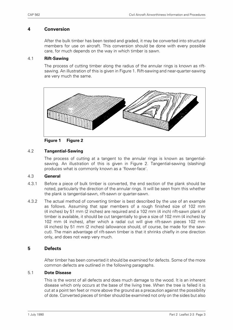
CAP 562 Civil Aircraft Airworthiness Information and Procedures
Part 2 Leaflet 2-3 Page 3
4 Conversion
After the bulk timber has been tested and graded, it may be converted into structuralmembers for use on aircraft. This conversion should be done with every possiblecare, for much depends on the way in which timber is sawn.
4.1 Rift-Sawing
The process of cutting timber along the radius of the annular rings is known as rift-sawing. An illustration of this is given in Figure 1. Rift-sawing and near-quarter-sawingare very much the same.
4.2 Tangential-Sawing
The process of cutting at a tangent to the annular rings is known as tangential-sawing. An illustration of this is given in Figure 2. Tangential-sawing (slashing)produces what is commonly known as a 'flower-face'.
4.3 General
4.3.1 Before a piece of bulk timber is converted, the end section of the plank should benoted, particularly the direction of the annular rings. It will be seen from this whetherthe plank is tangential-sawn, rift-sawn or quarter-sawn.
4.3.2 The actual method of converting timber is best described by the use of an exampleas follows. Assuming that spar members of a rough finished size of 102 mm(4 inches) by 51 mm (2 inches) are required and a 102 mm (4 inch) rift-sawn plank oftimber is available, it should be cut tangentially to give a size of 102 mm (4 inches) by102 mm (4 inches), after which a radial cut will give rift-sawn pieces 102 mm(4 inches) by 51 mm (2 inches) (allowance should, of course, be made for the saw-cut). The main advantage of rift-sawn timber is that it shrinks chiefly in one directiononly, and does not warp very much.
5 Defects
After timber has been converted it should be examined for defects. Some of the morecommon defects are outlined in the following paragraphs.
5.1 Dote Disease
This is the worst of all defects and does much damage to the wood. It is an inherentdisease which only occurs at the base of the living tree. When the tree is felled it iscut at a point ten feet or more above the ground as a precaution against the possibilityof dote. Converted pieces of timber should be examined not only on the sides but also
Figure 1 Figure 2
1 July 1990
CAP 562 Civil Aircraft Airworthiness Information and Procedures
Part 2 Leaflet 2-3 Page 4
on the ends; dote will be recognised by the presence of brownish yellow patches,somewhat similar to thin mineral oil spots. Dote is contagious and any infected woodshould be burnt.
5.2 Decay or Rot
A defect similar to dote disease can develop after a tree has been felled if the timberis exposed to excessive soaking and partial drying. Dry-rot fungus requires a certainamount of moisture to thrive on but once the disease is established it thrives on themoisture already in the wood. The decayed wood is brown in colour and appears asthough it had been charred; the timber is rendered soft and dry, and will flake offeasily.
5.3 Incorrect Grain Inclination
The limit of grain inclination for spruce is 1 in 15 for grade A, and 1 in 12 for grade B.The inclination should be checked to ensure that the above limits are not exceeded.The most usual method of determining the inclination of the grain is by examining theflower-face of the timber to find the resin ducts. It will readily be seen whether theyare straight or inclined. If the inclination exceeds the limits specified, the timbershould be classified in a lower grade.
5.4 Heart-Shake
This defect usually follows the course of a sap duct longitudinally, and is usuallyvisible on the tangential surface. The use of a small size feeler gauge will assist infinding the depth of the shake. The defect should be cut out of the timber.
5.5 Ring-Shake
This defect is indicated by a parting of the annular rings. Ring-shakes are usuallycaused by frost, particularly after a heavy rainfall. The defect should also be cut out ofthe timber.
5.6 Compression-Shake
This defect appears on a cross-section and usually takes the form of a thin wavy line.Compression-shakes are most dangerous as they are a partial fracture of the timberand any future loads may cause the fracture to be completed.
5.7 Knots
There are several kinds of knots which may be encountered when examiningconverted timber; these are the dead-knot, the bud-knot and the pin-knot. Thepresence of any of these knots can have a detrimental effect. Generally they shouldnot be more than a quarter of an inch in diameter but no hard and fast rules can bespecified; each case must be decided on its merits. Timber with 'clusters' of pin-knotsin it should be rejected.
5.8 Pitch Holes
There are two kinds of pitch holes, one being the horizontal type which usuallyappears at the base of a knot, and the other the vertical type which is sometimesreferred to as a gum pocket. Gum pockets may either be 'alive' (the gum-seam hasnot dried out) or 'dead', and in the case of the latter, the timber should be rejected.Tests on 'live' gum pockets have shown that the timber in the region of the gumpocket usually gives a better result than the remainder of the timber.
5.9 Blue Stain
This defect only occurs in sapwood which should not be used in aircraft parts.
1 July 1990
CAP 562 Civil Aircraft Airworthiness Information and Procedures
Part 2 Leaflet 2-4 Page 1
Leaflet 2-4 Synthetic Resin Adhesives
1 Introduction
This Leaflet provides guidance and advice on the gluing of wooden structures and onthe adhesives which can be used for this purpose.
1.1 Synthetic resin adhesives are used extensively for joints in wooden structures toavoid the localised stresses and strains which may be set up by the use of mechanicalmethods of attachment; the strength of such structures depends largely on theeffectiveness of the glued joints and cannot be verified by means other than thedestruction of the joints. Acceptance has therefore, to be governed by adequateinspection at various stages throughout the gluing process and by assessment of theresults obtained from representative test pieces (see paragraph 9).
1.2 Synthetic resin adhesives used for gluing aircraft structural assemblies must complywith the requirements prescribed in an acceptable Specification, usually BritishStandard 1204 Part I, for Weather and Boil Proof (WBP) or Moisture Resistant (MR)adhesives.
1.3 Information on the inspection of glued joints for evidence of deterioration underservice conditions is given in Leaflet 6–1.
1.4 The terminology used in this Leaflet is that given in BS 1204, entitled 'Synthetic Resin(Phenolic and Aminoplastic) Adhesives for Constructional Work in Wood'. For thosenot familiar with the terminology, a glossary of terms not explained in the text, is givenin paragraph 13.
2 General
Synthetic resin adhesives (see paragraph 13.12) usually consist of two separate parts,i.e. the resin and the hardener. The resin develops its adhesive properties only as aresult of a chemical reaction between it and the hardener, and will not harden withoutit. With some adhesives, an inert filler may be added to increase viscosity and toimprove gap-filling properties.
3 Preparation of Adhesives
Synthetic resins (see paragraph 13.11) can be obtained in either liquid or powderform. In general, powder resins have the longer storage life, since they are lesssusceptible to deterioration which can result from high ambient temperatures.
3.1 Powder Resins
Powder resins should be mixed with water in accordance with the manufacturer’sinstructions before they can be used in conjunction with a hardener and to obtainsatisfactory results it is essential that they should be properly mixed. Once mixed, theresin should not be diluted unless this is specifically permitted by the manufacturer.
3.2 Liquid Resins
When resins are supplied in liquid form, they are ready for immediate use inconjunction with the hardener. Liquid resin should not be diluted unless this ispermitted by the manufacturer.
1 July 1990
CAP 562 Civil Aircraft Airworthiness Information and Procedures
Part 2 Leaflet 2-4 Page 2
3.3 Hardeners
When mixing the hardener (paragraph 13.7) with the resin, the proportions should bein accordance with the manufacturer’s instructions. Hardeners should not bepermitted to come into contact with the resin except when the adhesive is mixed justprior to use, or, as is necessary with some adhesives, when the joint is assembled bycoating one face with resin and the other with hardener. When the latter method isemployed, the surface to which each is applied should be in accordance with drawingrequirements (see paragraph 6).
3.4 Mixed Adhesives
In many instances, manufacturers specify a definite period of time which must elapsebetween the mixing and the application of the adhesive and during this period theadhesive should be kept covered to prevent contamination.
3.5 Utensils
The utensils used for hardener should not subsequently be used for resin, and viceversa. These utensils and those used for the mixed adhesive should be acid-proof andshould be kept scrupulously clean. After use and before the adhesive has had time toset, they should be cleaned with warm water containing 5% sodium carbonate(washing soda).
4 Preparation of Surfaces
4.1 Plywood Surfaces
All areas of plywood surfaces to be glued should first be 'sanded' in order to removesurface glazing and loose fibres. Sanding should be done lightly and uniformly eitherin the direction of the grain or diagonally across it, using a medium grade ofglasspaper; local scratching or roughening, use of too coarse a paper and unduepressure, should be avoided. The sanding should not be excessive otherwise the fitof the joint may be affected.
4.2 Timber Surfaces
Timber surfaces should be suitably roughened so as to form a firm key for theadhesive and a medium grade of glasspaper or a wood scraper is suitable for thispurpose. To form a strong efficient joint, it is essential that the mating surfaces shouldbe a good fit. This is particularly important in the case of blind joints, the members ofwhich may be chalked on their gluing surfaces before being assembled dry as a checkon the fit; the chalk should be completely removed before application of the adhesive.
4.3 Moisture Content
It is important that the parts to be joined should have approximately the samemoisture content, since variations may cause stresses to be set up as a result ofswelling or shrinkage and thus lead to the failure of the joint. The moisture contentshould, additionally, be within the specification limits for the particular timber. A saferange would be 8 to 16%, but with resorcinols this could be extended to 20% from agluing viewpoint; however, this would not be satisfactory for aircraft components asjoints would be likely to shrink after manufacture.
4.3.1 The moisture content of timber can be determined by taking a sample of the timberto be glued, weighing it, and then drying it in an oven at a temperature of 100° to105°C (212° to 221°F) until two successive weighings yield the same result. Themoisture content can be determined by the formula:
1 July 1990

CAP 562 Civil Aircraft Airworthiness Information and Procedures
Part 2 Leaflet 2-4 Page 3
where W1 = the weight of the sample prior to drying
and W2 = the weight of the sample after drying.
4.3.2 A method of determining the approximate moisture content is by the use of anelectrical meter working on either the resistance or the capacitance principle. Whenthis instrument is used, its accuracy should be checked periodically against a sample,the moisture content of which is determined by the weighing method described inparagraph 4.3.1.
4.4 General
The surfaces to be joined should be clean and free from grease, oil, wax, crayon, paintand varnish; it is advisable not to handle the joint faces once they have been prepared.Where old timber is to be re-used, all traces of the previous adhesive should beremoved and the timber beneath cleaned; local staining of the wood by previoushardener or casein cement may be disregarded. Where any painting operations are tobe carried out, all surfaces which are to be glued should be adequately masked.
5 Conditions for Gluing
Synthetic resin adhesives are very sensitive to variations in temperature and theusable (pot) life of the adhesive, choice and proportion of hardener and clampingtimes, all depend largely on the ambient temperature at the time of gluing; it is,therefore, important to ensure that the manufacturer’s instructions regarding thesefactors are followed.
5.1 The timber to be glued should be allowed sufficient time to attain the temperature ofthe room in which the gluing is to take place; it should not be overheated or raised tooquickly from a low temperature, since this affects the surfaces of the timber andreduces the efficiency of most synthetic resin adhesives. It is important, therefore,that timber should be kept clear of radiators and other sources of heat prior to gluing.
6 Application of Adhesive
With certain exceptions, adhesives are used in the mixed form and therecommendations given in this paragraph apply only to the use of such adhesives.
6.1 It is generally desirable to apply adhesive to both surfaces of a joint. This appliesparticularly where plywood is to be glued to a fairly robust member, where the glueline (see paragraph 13.6) is likely to be variable or when it is not possible to applyuniform pressure to the joint after gluing.
6.2 Ordinary glue spreaders are satisfactory for the application of synthetic resinadhesives, but those having slightly grooved rubber rollers give the best results.Brushes may also be used provided they are perfectly clean.
6.3 The amount of adhesive required depends largely on the type of timber and theaccuracy of machining; dense timbers require less adhesive than soft or porous types.Side-grained surfaces may be satisfactorily glued with thin spreads, and while end-grain joints have virtually no structural value, generous spreads may be applied for gap
W1 – W2x 100
W2
1 July 1990
CAP 562 Civil Aircraft Airworthiness Information and Procedures
Part 2 Leaflet 2-4 Page 4
filling and sealing purposes. The general rule is that the adhesive should completelycover the surfaces to be glued and should be tacky when pressure is applied to thejoint.
6.4 Difficult gluing conditions may sometimes occur when a soft timber is to be glued toone which is much denser, because the adhesive tends to flow into the more poroustimber. In such instances, unless otherwise specified by the manufacturer of theadhesive, pre-coating and partial drying of the softer surface, prior to normalspreading, is recommended.
7 Assembly
Care should be taken before the adhesive is applied to ensure that the surfaces makegood contact and that the joint will be correctly positioned, since once contact ismade after the adhesive is applied, the joint will be below strength if furthermovement is necessary. The interval between the application of the adhesive andassembly of the joint under pressure should, unless otherwise permitted, be kept asshort as possible. Pressure should be applied quickly and should be even. All devicesused to bring the glued surfaces together should be checked (this applies particularlyto clamps) to ensure that the pressure is uniformly applied over the entire area;uneven pressure may cause uneven contact and a gaping joint.
NOTE: Some adhesives contain solvents which should be allowed to evaporate before thejoint is made. If this is not done, bubbles may be created and a weakness caused.For adhesives of this type the manufacturer will specify a time interval which shouldelapse before the joint is closed.
7.1 High clamping pressures are neither essential nor desirable provided that goodcontact between surfaces being joined is obtained. For parts which are flat andunstressed it is not always necessary to maintain the pressure until the full jointstrength is developed, but for work which is shaped by pressure, longer times maybe required to guard against opening stresses. The tightness of clamps should bechecked approximately 10 minutes after assembly.
7.2 If the parts are thin and the pressure is uniformly distributed, only a slight pressure isrequired and small pins or screws will generally provide this; care should be taken notto pump the adhesive out of the joint when hammering pins through closing strips.
7.3 When pressure is applied, a small even quantity of glue should be expressed from thejoint and this should be wiped off before it dries. The pressure should be maintainedand the joint should not be disturbed during the full setting time; this is important asthe adhesive will not re-unite if disturbed before it is fully set.
7.4 When large 'glue-face' areas are to be joined, e.g. when joining two ply surfaces, thedrawing usually specifies the drilling of small vent holes at regular intervals to preventair being trapped between the two surfaces. After the joint has been made, theseholes should be checked to ensure that adhesive has exuded from them.
8 Setting Times and Temperatures
The setting time depends on the temperature at which the jointing operation is carriedout; an increase in temperature results in a decrease in the setting time. Conversely,a decrease in temperature causes a considerable increase in the setting time and withsome adhesives a temperature below 15°C (60°F) is not recommended. It is,therefore, generally advantageous to apply heat during pressing whenever possibleso as to effect reasonably quick and strong adhesion. Heat may be applied by means
1 July 1990
CAP 562 Civil Aircraft Airworthiness Information and Procedures
Part 2 Leaflet 2-4 Page 5
of an electrically or steam heated platen such as would be used for special presswork.Local warmth may be applied with electrically heated blankets, electric fires, a batteryof electric bulbs, or drying kilns. The temperature may generally be raised toapproximately 80°C (176°F) for very rapid setting; intense surface heating should beavoided as this may scorch the timber and cause the glue to bubble, the latterresulting in the production of a very weak joint. It must be remembered that it is thetemperature of the glue line which determines cure rate and not the surface orambient temperature. The warming of a cold assembly may cause the exuded glueto harden quickly, giving a false impression that the complete joint has cured (see alsoparagraph 5.1).
8.1 Full joint strength and resistance to moisture will only develop after conditioning for aperiod of at least 2 days, depending on the temperature and the type of hardenerused. However, when repairs are made on aircraft, the joint should be of sufficientstrength after one day. When it is necessary to ensure maximum resistance tomoisture it is generally recommended that the assembled structures should be keptat room temperature of 21° to 24°C (70° to 75°F) for 2 to 3 weeks so that completechemical reaction can take place.
8.2 Further assembly work can be carried out immediately the clamps have beenremoved provided the joint is not subjected to additional stress, otherwise theconditioning period recommended by the manufacturer is necessary. The degree ofsetting of the adhesive which has squeezed from the glue line is not necessarily anindication of the strength of the joint, and precautions should be taken to ensure thatthe joints are handled with due care until they have attained full strength.
8.3 After the joint has been conditioned and all work completed, all unprotected partsshould be treated in accordance with drawing requirements.
9 Testing
Frequent tests should be made to ensure that joining techniques are satisfactory.Wherever possible, tests should be carried out on off-cuts of actual components fromeach batch. Where off-cuts are not available tests should be carried out onrepresentative test pieces glued up with each batch of mixed adhesive. In addition,the glue strength of component rejected for faults other than gluing should bechecked periodically.
9.1 Test Samples
The test samples should be cut from the timber used for the component and shouldnot be less than 50 mm (2 in) long and 25 mm (1 in) wide with one member over-hanging the other by 12 to 18 mm (½ to ¾ in). The glued test sample should, whenconditioned, be put in a vice and the joint should be broken by leverage exerted onthe overhanging member. The fractured glue faces should show at least 75% ofwood fibres, evenly distributed over the fractured glue surfaces. A typical broken testpiece is shown in Figure 1.
9.2 Wet Tests
When specified, wet tests should be made for the purpose of testing the efficiencyof the adhesive after immersing the test samples in water at different temperaturesand for different times. Such tests are prescribed in British Standard 1204, but theresults are only valid if BS 1204 test pieces are used. However, testing joints, in amanner similar to that outlined in paragraph 9.1, after immersion in cold water (15º to25°C (60° to 77°F)) for 24 hours, will give a good indication of whether they are cured.
1 July 1990
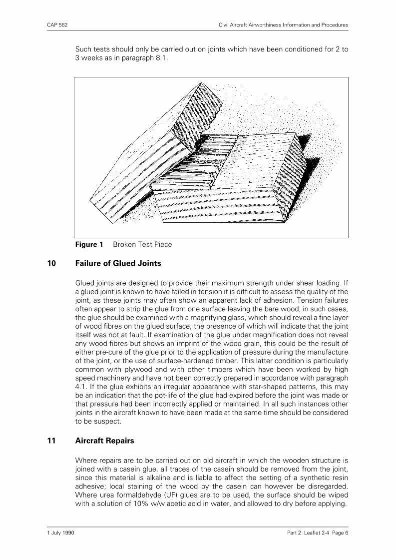
CAP 562 Civil Aircraft Airworthiness Information and Procedures
Part 2 Leaflet 2-4 Page 6
Such tests should only be carried out on joints which have been conditioned for 2 to3 weeks as in paragraph 8.1.
10 Failure of Glued Joints
Glued joints are designed to provide their maximum strength under shear loading. Ifa glued joint is known to have failed in tension it is difficult to assess the quality of thejoint, as these joints may often show an apparent lack of adhesion. Tension failuresoften appear to strip the glue from one surface leaving the bare wood; in such cases,the glue should be examined with a magnifying glass, which should reveal a fine layerof wood fibres on the glued surface, the presence of which will indicate that the jointitself was not at fault. If examination of the glue under magnification does not revealany wood fibres but shows an imprint of the wood grain, this could be the result ofeither pre-cure of the glue prior to the application of pressure during the manufactureof the joint, or the use of surface-hardened timber. This latter condition is particularlycommon with plywood and with other timbers which have been worked by highspeed machinery and have not been correctly prepared in accordance with paragraph4.1. If the glue exhibits an irregular appearance with star-shaped patterns, this maybe an indication that the pot-life of the glue had expired before the joint was made orthat pressure had been incorrectly applied or maintained. In all such instances otherjoints in the aircraft known to have been made at the same time should be consideredto be suspect.
11 Aircraft Repairs
Where repairs are to be carried out on old aircraft in which the wooden structure isjoined with a casein glue, all traces of the casein should be removed from the joint,since this material is alkaline and is liable to affect the setting of a synthetic resinadhesive; local staining of the wood by the casein can however be disregarded.Where urea formaldehyde (UF) glues are to be used, the surface should be wipedwith a solution of 10% w/w acetic acid in water, and allowed to dry before applying.
Figure 1 Broken Test Piece
1 July 1990
CAP 562 Civil Aircraft Airworthiness Information and Procedures
Part 2 Leaflet 2-4 Page 7
NOTE: This process must only be used with urea formaldehyde (UF) glues. If used prior tothe application of, for example, resorcinol formaldehyde (RF) glues, the joint strengthcould be seriously impaired.
12 Storage
Apart from the very limited pot-life of the mixed adhesive, the resin itself will not keepindefinitely, even under ideal storage conditions. Under no circumstances should theshelf life specified by the manufacturer be exceeded. Furthermore, resins in powderform which show signs of caking or corrosion of the container and liquid resins whichshow signs of 'gelling' or have become excessively viscous, should be rejected evenif the shelf life has not been exceeded. During storage, a temperature of 21°C (70°F)should not be exceeded.
13 Glossary of Terms
For the benefit of those not familiar with the terms used in relation to synthetic resinadhesives and their application, a glossary is given below.
13.1 Cold Setting Adhesive. An adhesive which sets and hardens satisfactorily atordinary room temperature, i.e. 10° to 32°C (50° to 86°F), within a reasonable period.
13.2 Close Contact Adhesive. A non-gap-filling adhesive suitable for use only in thosejoints where the surfaces to be joined can be brought into close contact by means ofadequate pressure and where glue lines (see paragraph 13.6) exceeding 0·125 mm(0·005 in) in thickness can be avoided with certainty.
13.3 Closed Assembly Time. The time elapsing between the assembly of the joints andthe application of pressure.
13.4 Double Spread. The spread of adhesive equally divided between the two surfacesto be joined.
13.5 Gap Filling Adhesive. An adhesive suitable for use in those joints where thesurfaces to be joined may or may not be in close or continuous contact, owing eitherto the impossibility of applying adequate pressure or to slight inaccuracies ofmachining. Unless otherwise stated by the manufacturer, such adhesives are notsuitable for use where the glue line (see paragraph 13.6) exceeds 1·25 mm (0·05 in)in thickness.
13.6 Glue Line. The resultant layer of adhesive effecting union between any twoadjacent wood layers in the assembly.
13.7 Hardener. A material used to promote the setting of the glue. It may be suppliedseparately in either liquid or powder form, or it may have been incorporated with theresin by the manufacturer. It is an essential part of the adhesive, the properties ofwhich depend upon using the resin and hardener as directed.
13.8 Open Assembly Time. The time elapsing between the application of the adhesiveand the assembly of the joint components.
13.9 Single Spread. The spread of adhesive to one surface only.
13.10 Spread of Adhesive. The amount of adhesive applied in order to join two surfaces,usually expressed in g/m2 or lb/100 ft2.
13.11 Synthetic Resin. A synthetic resin (phenolic) is derived from the reaction of aphenol with an aldehyde. A synthetic resin (aminoplastic) is derived from the reactionof urea, thiourea, melamine or allied compounds with formaldehyde.
1 July 1990

CAP 562 Civil Aircraft Airworthiness Information and Procedures
Part 2 Leaflet 2-4 Page 8
13.12 Synthetic Resin Adhesive. A composition substantially consisting of a syntheticresin of either the phenolic or aminoplastic type, but including any hardening agent ormodifier which may have been added by the manufacturer or which may be requiredto be added before use, according to manufacturer’s instructions.
1 July 1990
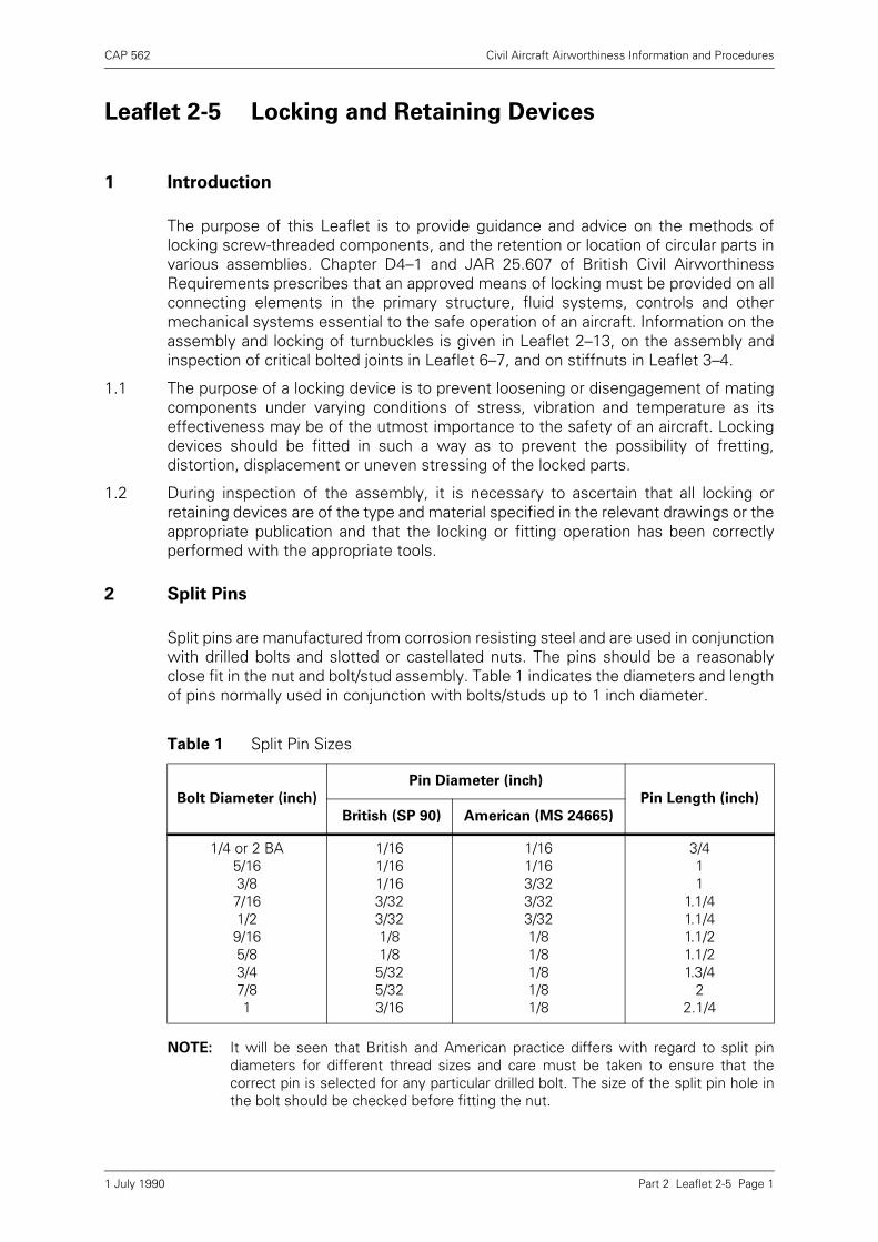
CAP 562 Civil Aircraft Airworthiness Information and Procedures
Part 2 Leaflet 2-5 Page 1
Leaflet 2-5 Locking and Retaining Devices
1 Introduction
The purpose of this Leaflet is to provide guidance and advice on the methods oflocking screw-threaded components, and the retention or location of circular parts invarious assemblies. Chapter D4–1 and JAR 25.607 of British Civil AirworthinessRequirements prescribes that an approved means of locking must be provided on allconnecting elements in the primary structure, fluid systems, controls and othermechanical systems essential to the safe operation of an aircraft. Information on theassembly and locking of turnbuckles is given in Leaflet 2–13, on the assembly andinspection of critical bolted joints in Leaflet 6–7, and on stiffnuts in Leaflet 3–4.
1.1 The purpose of a locking device is to prevent loosening or disengagement of matingcomponents under varying conditions of stress, vibration and temperature as itseffectiveness may be of the utmost importance to the safety of an aircraft. Lockingdevices should be fitted in such a way as to prevent the possibility of fretting,distortion, displacement or uneven stressing of the locked parts.
1.2 During inspection of the assembly, it is necessary to ascertain that all locking orretaining devices are of the type and material specified in the relevant drawings or theappropriate publication and that the locking or fitting operation has been correctlyperformed with the appropriate tools.
2 Split Pins
Split pins are manufactured from corrosion resisting steel and are used in conjunctionwith drilled bolts and slotted or castellated nuts. The pins should be a reasonablyclose fit in the nut and bolt/stud assembly. Table 1 indicates the diameters and lengthof pins normally used in conjunction with bolts/studs up to 1 inch diameter.
NOTE: It will be seen that British and American practice differs with regard to split pindiameters for different thread sizes and care must be taken to ensure that thecorrect pin is selected for any particular drilled bolt. The size of the split pin hole inthe bolt should be checked before fitting the nut.
Table 1 Split Pin Sizes
Bolt Diameter (inch)
Pin Diameter (inch)
Pin Length (inch)
British (SP 90) American (MS 24665)
1/4 or 2 BA5/163/87/161/29/165/83/47/81
1/161/161/163/323/321/81/8
5/325/323/16
1/16 1/163/323/323/321/81/81/81/81/8
3/411
1.1/41.1/41.1/21.1/21.3/4
22.1/4
1 July 1990
CAP 562 Civil Aircraft Airworthiness Information and Procedures
Part 2 Leaflet 2-5 Page 2
2.1 The legs of split pins should be turned as indicated on the design drawings, but whenthe method is not specified it is recommended that one of the methods illustrated inFigure 1 should be used. If necessary, pins should be cut to a suitable length toprevent pick-up in clothing, cleaning cloths, etc., and the surplus ends accounted forto prevent their becoming a loose article hazard.
2.2 After turning and closing the legs to the nut faces, an inspection should be made toensure that cracking or cutting has not occurred at the bends. The most commonmethods of split pinning are illustrated by Figure 1 (a) and (b). The method shown inFigure 1 (c) is used where clearances are critical.
2.3 For bolted joints, one pair of slots must be in alignment with the hole in the bolt whenthe specified degree of tightness has been obtained. Undrilled bolts should beprepared for drilling by tightening the nut to the specified torque loading and markingthe hole position. The nut should be removed and the split pin hole drilled with the aidof a drilling jig. Burrs should then be removed, the nut fitted and tightened to therequired torque loading and the correct size of split pin fitted.
2.4 In instances where torque loading is not specified, it may be permissible to tightenthe nut slightly to achieve alignment, but in no circumstances should a nut be easedback from the normally tight position since this may result in slackness between theparts of the assembly. Nuts must not be filed to facilitate the fitting of split pins.Alignment is more difficult with drilled bolts, and selective assembly of nuts and/orwashers may be required.
2.5 Split pins should not be used more than once. Split pin holes should not be enlarged,nor split pins filed to facilitate fitting.
3 Locking Washers
There are several types of locking washers in general use consisting of springwashers, cup washers, shakeproof washers, crinkle washers and tab washers(Figure 2).
3.1 Spring Washers
These washers are available in two forms, i.e. as a single coil (SP 47) or as a doublecoil (SP 55 and 56).
3.1.1 In some instances, particularly with light alloy assemblies, spring washers areassembled with plain facing washers between the spring washer and the component,
Figure 1 Split Pinning
1 July 1990

CAP 562 Civil Aircraft Airworthiness Information and Procedures
Part 2 Leaflet 2-5 Page 3
to prevent damage to the surface of the component or the protective treatment whenthe spring washer is compressed. Often, however, particularly in steel assemblies,plain washers are not specified.
3.1.2 It is good practice to renew spring washers during overhaul or repair. This is essentialin engines and engine components, and units with reciprocating parts, such ascompressors or pumps.
Figure 2 Types of Washers
1 July 1990
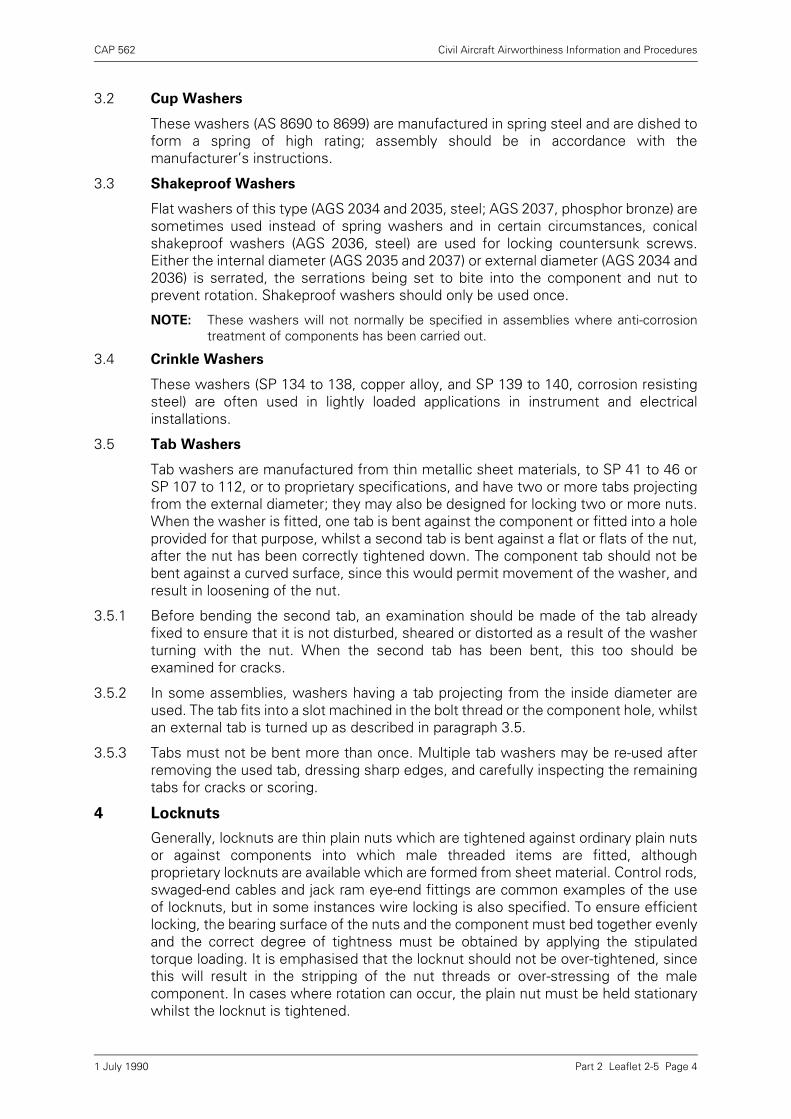
CAP 562 Civil Aircraft Airworthiness Information and Procedures
Part 2 Leaflet 2-5 Page 4
3.2 Cup Washers
These washers (AS 8690 to 8699) are manufactured in spring steel and are dished toform a spring of high rating; assembly should be in accordance with themanufacturer’s instructions.
3.3 Shakeproof Washers
Flat washers of this type (AGS 2034 and 2035, steel; AGS 2037, phosphor bronze) aresometimes used instead of spring washers and in certain circumstances, conicalshakeproof washers (AGS 2036, steel) are used for locking countersunk screws.Either the internal diameter (AGS 2035 and 2037) or external diameter (AGS 2034 and2036) is serrated, the serrations being set to bite into the component and nut toprevent rotation. Shakeproof washers should only be used once.
NOTE: These washers will not normally be specified in assemblies where anti-corrosiontreatment of components has been carried out.
3.4 Crinkle Washers
These washers (SP 134 to 138, copper alloy, and SP 139 to 140, corrosion resistingsteel) are often used in lightly loaded applications in instrument and electricalinstallations.
3.5 Tab Washers
Tab washers are manufactured from thin metallic sheet materials, to SP 41 to 46 orSP 107 to 112, or to proprietary specifications, and have two or more tabs projectingfrom the external diameter; they may also be designed for locking two or more nuts.When the washer is fitted, one tab is bent against the component or fitted into a holeprovided for that purpose, whilst a second tab is bent against a flat or flats of the nut,after the nut has been correctly tightened down. The component tab should not bebent against a curved surface, since this would permit movement of the washer, andresult in loosening of the nut.
3.5.1 Before bending the second tab, an examination should be made of the tab alreadyfixed to ensure that it is not disturbed, sheared or distorted as a result of the washerturning with the nut. When the second tab has been bent, this too should beexamined for cracks.
3.5.2 In some assemblies, washers having a tab projecting from the inside diameter areused. The tab fits into a slot machined in the bolt thread or the component hole, whilstan external tab is turned up as described in paragraph 3.5.
3.5.3 Tabs must not be bent more than once. Multiple tab washers may be re-used afterremoving the used tab, dressing sharp edges, and carefully inspecting the remainingtabs for cracks or scoring.
4 Locknuts
Generally, locknuts are thin plain nuts which are tightened against ordinary plain nutsor against components into which male threaded items are fitted, althoughproprietary locknuts are available which are formed from sheet material. Control rods,swaged-end cables and jack ram eye-end fittings are common examples of the useof locknuts, but in some instances wire locking is also specified. To ensure efficientlocking, the bearing surface of the nuts and the component must bed together evenlyand the correct degree of tightness must be obtained by applying the stipulatedtorque loading. It is emphasised that the locknut should not be over-tightened, sincethis will result in the stripping of the nut threads or over-stressing of the malecomponent. In cases where rotation can occur, the plain nut must be held stationarywhilst the locknut is tightened.
1 July 1990
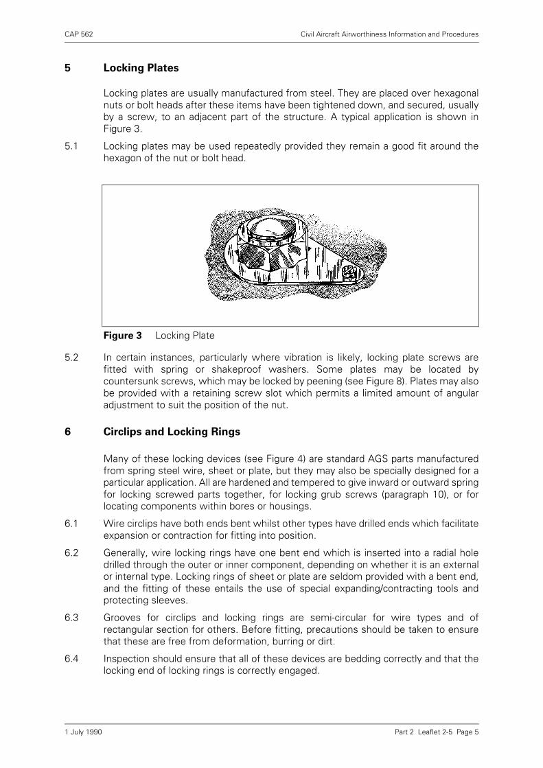
CAP 562 Civil Aircraft Airworthiness Information and Procedures
Part 2 Leaflet 2-5 Page 5
5 Locking Plates
Locking plates are usually manufactured from steel. They are placed over hexagonalnuts or bolt heads after these items have been tightened down, and secured, usuallyby a screw, to an adjacent part of the structure. A typical application is shown inFigure 3.
5.1 Locking plates may be used repeatedly provided they remain a good fit around thehexagon of the nut or bolt head.
5.2 In certain instances, particularly where vibration is likely, locking plate screws arefitted with spring or shakeproof washers. Some plates may be located bycountersunk screws, which may be locked by peening (see Figure 8). Plates may alsobe provided with a retaining screw slot which permits a limited amount of angularadjustment to suit the position of the nut.
6 Circlips and Locking Rings
Many of these locking devices (see Figure 4) are standard AGS parts manufacturedfrom spring steel wire, sheet or plate, but they may also be specially designed for aparticular application. All are hardened and tempered to give inward or outward springfor locking screwed parts together, for locking grub screws (paragraph 10), or forlocating components within bores or housings.
6.1 Wire circlips have both ends bent whilst other types have drilled ends which facilitateexpansion or contraction for fitting into position.
6.2 Generally, wire locking rings have one bent end which is inserted into a radial holedrilled through the outer or inner component, depending on whether it is an externalor internal type. Locking rings of sheet or plate are seldom provided with a bent end,and the fitting of these entails the use of special expanding/contracting tools andprotecting sleeves.
6.3 Grooves for circlips and locking rings are semi-circular for wire types and ofrectangular section for others. Before fitting, precautions should be taken to ensurethat these are free from deformation, burring or dirt.
6.4 Inspection should ensure that all of these devices are bedding correctly and that thelocking end of locking rings is correctly engaged.
Figure 3 Locking Plate
1 July 1990

CAP 562 Civil Aircraft Airworthiness Information and Procedures
Part 2 Leaflet 2-5 Page 6
6.5 Identification of these devices is difficult and every care should be taken to ensurethat the correct items are fitted. Items should be obtained by part numbers and notidentified by comparing the old and new, since the diameters of the old are likely todiffer considerably from those of new items. Part numbers of the correct part to befitted should be verified from the appropriate drawings, Overhaul or Repair Manualsor Parts Catalogue.
6.6 Some manufacturers stipulate that circlips and locking rings must not be used morethan once. However, in some instances, it is specified that the gap between the endsof a circlip or locking ring should, after fitting, be within prescribed limits and as suchindividual selection may be necessary. The radial position of the gap may also bespecified.
7 Wire Locking
Corrosion resisting steel and heat resisting nickel alloy are the materials normallyrecommended for wire locking, except in the circumstances described in 7.6. Careshould be taken to ensure that the wire used is to the correct specification and gaugerequired by the relevant drawing. In the normal twisting method of wire locking, asuitable length of wire should be cut from the coil and passed through the holeprovided for the purpose in the component. The wire should be twisted over thelength required to reach the locking point, through which one end of the wire shouldbe passed, and then twisted for not less than a further 13 mm (½inch) whilst beingpulled taut. It is necessary to pull the wire taut to ensure that the final twists are closeto the locking hole, but neither this nor the twisting should be too severe. Aftersurplus wire has been removed, the twisted ends should be bent in such a manneras to prevent their catching in clothing, cleaning cloths, etc. There should be nountwisted lengths in excess of 9·5 mm (3/8 inch) and lengths of unsupported wireshould not normally exceed 76 mm (3 inches).
Figure 4 Circlips and Locking Rings
1 July 1990

CAP 562 Civil Aircraft Airworthiness Information and Procedures
Part 2 Leaflet 2-5 Page 7
7.1 The angle of approach of the wire should not be less than 45° to the rotational axis ofthe component to be locked (see Figure 5), whilst the line of approach should betangential to the parts being locked (Figure 6). The lay of the wire must always besuch as to resist any tendency of the locked part or parts to become loose, and forthis reason it is essential to ascertain whether the parts have left or right hand threadsbefore fitting the wire.
7.2 In instances where the method of wire locking is not indicated on the drawing, greatcare is necessary when deciding on a locking method to ensure that there is nopossibility of the parts becoming loose. For example, when adaptors are used in pipejoints, it is essential that the adaptor is secured to each union nut by separate lockingwires to adjacent corners of the adaptor nut, with the approach angle shown in Figure5. It may be specified that the adaptor is locked additionally to some external point.
7.3 When locking tabs are used, they should be fitted in such a way that the tabs and thewire are in complete alignment. Examples of correct and incorrect use of locking tabsare shown in Figure 7. Whenever possible, the closed end of the wire should be inthe tab and the open end at the component to be locked.
Figure 5 Angle of Approach
Figure 6 Tangential Approach
1 July 1990
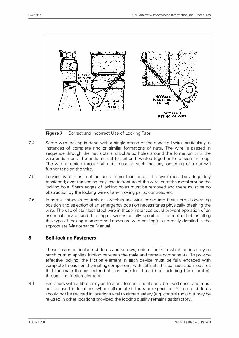
CAP 562 Civil Aircraft Airworthiness Information and Procedures
Part 2 Leaflet 2-5 Page 8
7.4 Some wire locking is done with a single strand of the specified wire, particularly ininstances of complete ring or similar formations of nuts. The wire is passed insequence through the nut slots and bolt/stud holes around the formation until thewire ends meet. The ends are cut to suit and twisted together to tension the loop.The wire direction through all nuts must be such that any loosening of a nut willfurther tension the wire.
7.5 Locking wire must not be used more than once. The wire must be adequatelytensioned; over-tensioning may lead to fracture of the wire, or of the metal around thelocking hole. Sharp edges of locking holes must be removed and there must be noobstruction by the locking wire of any moving parts, controls, etc.
7.6 In some instances controls or switches are wire locked into their normal operatingposition and selection of an emergency position necessitates physically breaking thewire. The use of stainless steel wire in these instances could prevent operation of anessential service, and thin copper wire is usually specified. The method of installingthis type of locking (sometimes known as 'wire sealing') is normally detailed in theappropriate Maintenance Manual.
8 Self-locking Fasteners
These fasteners include stiffnuts and screws, nuts or bolts in which an inset nylonpatch or stud applies friction between the male and female components. To provideeffective locking, the friction element in each device must be fully engaged withcomplete threads on the mating component; with stiffnuts this consideration requiresthat the male threads extend at least one full thread (not including the chamfer),through the friction element.
8.1 Fasteners with a fibre or nylon friction element should only be used once, and mustnot be used in locations where all-metal stiffnuts are specified. All-metal stiffnutsshould not be re-used in locations vital to aircraft safety (e.g. control runs) but may bere-used in other locations provided the locking quality remains satisfactory.
Figure 7 Correct and Incorrect Use of Locking Tabs
1 July 1990
CAP 562 Civil Aircraft Airworthiness Information and Procedures
Part 2 Leaflet 2-5 Page 9
8.1.1 Most aircraft manufacturers lay down the assembly conditions (e.g. dry or lubricated)and acceptable limits of in-built torque for the re-use of stiffnuts, and require that eachnut should be checked with a torque wrench during assembly.
NOTE: The use of torque wrenches is discussed in Leaflet 2–11.
8.1.2 A recognised method of checking the friction elements of small stiffnuts which arenot being used in locations vital to aircraft safety is to screw the nut on to the malethread, using finger pressure only. If it is possible to turn the nut far enough for themale thread to protrude through the friction element the locking is unsatisfactory. Thistest is suitable for small nuts where the torque applied by the fingers approximatesto the in-built torque requirement of the nut specification, but is unrealistic for largernuts.
8.1.3 Unsatisfactory locking may also result from a worn male thread. If either of the abovetests leads to rejection of a stiffnut the male thread should be closely inspected. If anew stiffnut fails to provide adequate friction then it may be necessary to replace thebolt or stud on which it is to be assembled.
9 Peening
The peening of bolts for locking purposes should only be carried out when specifiedin the drawing, or the relevant manual, as the operation prevents re-use of the nut andbolt and may cause difficulty in dismantling. About 1½ threads of the bolt should beprojecting and the peening carried down to the nut to prevent it slackening. Adequatesupport should be given to the bolt during the peening operation and care taken toprevent damage to the part by misdirected blows with the hammer. Countersunkscrews may be locked by the method illustrated in Figure 8 when the thread isinaccessible. Protective treatment damaged by the peening operation must berestored.
10 Grub Screws
These are used as a method of locking two threaded components together. In onemethod the outer component only is drilled and threaded and the grub screw may bemachined at the inner end to a tapered point or a parallel plain shank to fit either aconical recess or parallel hole in the inner component. Other grub screws may befitted into a single hole drilled and threaded in both inner and outer components. Grubscrews may be locked by peening using the method illustrated in Figure 8, by a wiretype locking ring or by means of a nylon insert in either the male or female thread.
Figure 8 Peening to Lock Countersunk Screws
1 July 1990
CAP 562 Civil Aircraft Airworthiness Information and Procedures
Part 2 Leaflet 2-5 Page 10
10.1 Grub screws are also used, with the variations already mentioned, in non-threadedassemblies to retain the parts and ensure correct alignment. They may be fitted asadditional or precautionary locking devices in assemblies with interference fits orbonded joints, or, in some cases, they may be the only means of retention. In thesecases, however, several grub screws may be fitted around the component and thesemay be locked by lock nuts or clamping type lock rings.
11 Taper Pins and Parallel Pins
Taper pins with taper of 1 in 48 and parallel pins, are used on both tubular and solidsections, to secure control levers to torque shafts and forked ends to control rods,etc. Some taper pins are bifurcated and the legs spread for locking, whilst other taperpins, and parallel pins, are locked by peening, or by forming reaction rivet heads. Toavoid slackness, the pins are usually assembled in reamed holes, the head beingsupported during the locking process. Careful inspection is required after fitment ofpins through hollow tubes, to ensure that undue force during the peening operationhas not bent the pins, and thus impaired the security of the fittings.
12 Locking by Adhesives
12.1 Many small components, particularly those in instruments, valves, switches, etc.,may be locked by the application of Shellac, Araldite or similar materials to DTD 900specifications. The adhesive is applied to the outside of the nut face and protrudingscrew thread, or the component and screw head, after tightening, and preventsmovement between the two parts.
12.1.1 When using Araldite it is good practice to mix a separate sample under similarconditions, to check that it hardens within the specified time period.
12.2 Threaded metal fasteners may also be locked using a liquid sealant such as Loctite.This is an approved proprietary material (DTD 900 Approval No. 4588) which hardensin the screw threads after assembly and is supplied in various grades to give apredetermined locking torque in a variety of applications from stud locking to retainingbearings in housings. In using Loctite it is advisable to have the parts free from greaseto achieve maximum strength. It is possible, however, to use Loctite on threadedparts which have not been degreased but retain the original lubrication applied by themanufacturer. In these cases a 15% decrease in the strength of locking usuallyoccurs. Loctite should only be used when specified by the approved drawings orinstructions, and applied in accordance with the manufacturer’s instructions.
1 July 1990
CAP 562 Civil Aircraft Airworthiness Information and Procedures
Part 2 Leaflet 2-6 Page 1
Leaflet 2-6 Cleanliness of Aircraft
1 Introduction
The degree of cleanliness achieved, both internally and externally, during themanufacture and maintenance of aircraft has a direct bearing on airworthiness. Toensure that engineers and inspectors are able to certify that aircraft are fit for flight, itis essential, particularly where closed structures are concerned, that the componenthistory cards and aircraft build sheets used during manufacture and overhaul, shouldcontain a clause requiring inspection to certify that each part has been inspected atthe appropriate stage and that it is free from loose articles, dirt, swarf and otherextraneous matter.
2 The Effects of Extraneous Matter
The presence of extraneous matter inside aircraft, components, systems, etc., canhave serious consequences and special care is necessary to ensure thoroughcleanliness at all times. In the following paragraphs some of the adverse effects arebriefly outlined.
2.1 Extraneous matter in the form of dirt or grit in moving parts may cause excessivewear and other damage. Working clearances of many components are relativelyminute and small particles of dirt may cause scoring or seizure of working surfacesand rapid deterioration of seals and glands. Where systems are concerned (e.g.hydraulic, fuel and pneumatic systems), scrupulous cleanliness is essential duringassembly and maintenance operations; contamination inside a system will oftenpresent a difficult cleaning problem and many cases are on record of malfunctioningdue to ingress of extraneous matter.
2.2 The presence of loose extraneous articles inside a structure is always a dangeroushazard. Such items as nuts, bolts, rivets, off-cuts of wire or sheet metal and handtools have been found inside the more intricate and boxed-in type of structures.These can cause jamming or restriction of vital controls and have been known toresult in serious aircraft incidents. Furthermore, loose items, especially of a heavynature, which are trapped inside structures can, due to vibration, erode the protectivetreatment of the structure and cause damage to bag-type fuel tanks or the sealant ofintegral tanks. Heavy loose items trapped inside control surfaces can result in theirbecoming unbalanced.
2.3 In structures where there are electrical installations, small metal particles can causedamage to the insulation of wires and looms and these can produce short-circuits atterminal points. The ingress of such particles into switches, solenoids, actuators, etc.,is a common cause of malfunctioning. Where inverters, generators, etc., are cooledby means of ducted air, special care is necessary with regard to cleanliness as thecooling air can collect dust and grit and deposit this inside the component; foreignmatter can also block the cooling-air filters of avionic equipment, resulting inoverheating and failure.
NOTE: Loose particles of ferrous metal, such as filings, in the vicinity of electromagneticmechanisms are particularly dangerous and difficult to remove; such mechanismsshould, therefore, be adequately protected prior to filing and sawing ferrous parts inthe vicinity.
1 July 1990
CAP 562 Civil Aircraft Airworthiness Information and Procedures
Part 2 Leaflet 2-6 Page 2
2.4 Where pipes run in banks, loose extraneous parts may become wedged into the pipeclearances and might restrict the natural whip or flexing of the pipes under surgeloads, resulting either in fracture or perforation through chafing.
2.5 Grit or small metal particles inside bays fitted with flexible tanks will damage the tankenvelope and produce leaks and, in the case of integral tanks, metal particlesembedded in the tank sealant might cause leaks and promote corrosion of thestructure from electrolytic action.
2.6 The presence of extraneous fluids, due to spillage or leaks, may have seriousdeleterious effects. Certain fluids, such as ester-base engine oil, hydraulic oil, glycol,de-icing fluid, etc., will damage most protective treatments or materials not intendedto be in contact with these fluids, and bonding compounds, electric cables, rubbermouldings, tyres, etc., will deteriorate rapidly if these are left in contact with suchfluids; the spillage or leaks of some fluids may increase the fire hazard, especially ifthey occur in the vicinity of electrical equipment or engine installations. Seriouscontamination can also be caused by spillages of toilet fluids, mercury, gallium andother chemicals.
NOTE: Leaflet 5–1 gives guidance on general fire precautions.
2.7 In remote areas of the structure where access and periodic cleaning are difficult, dirtor dust will tend to accumulate and could act as a wick for moisture which in time,may penetrate the protective treatment and promote corrosion.
2.8 Special precautions are required regarding oxygen installations. The presence ofextraneous matter, especially of an oily or greasy nature, in contact with pressureoxygen is explosive. It is important, therefore, to follow the special instructionsregarding cleanliness of oxygen systems given in the installation drawings orMaintenance Manual.
3 General Precautions
It will be difficult to ensure a high standard of cleanliness of aircraft, components, etc.,unless a similar standard is maintained in hangars and workshops. Vigilance isnecessary to ensure that conditions and workshop practices are such that extraneousmatter will not enter or come into contact with any part of the aircraft, its systems orits components.
NOTE: It is recommended that placards and warning notices (preferably illustrated), pointingout the seriousness of extraneous matter in aircraft, should be placed in alldepartments.
3.1 In order to prevent small tools, torches, pencils, etc., from falling into the aircraftstructure, personnel engaged on servicing operations should wear overalls fitted withclosed pockets. Suitable footwear should also be provided, or vulnerable surfacesshould be protected with mats, as even small scratches can destroy anti-corrosivetreatment and lead to deterioration of a component.
3.1.1 An inventory should be made of all tools, spares or equipment taken to an aircraft forservicing purposes, and checked when the work has been completed. This action willreduce the possibility of such items being left in the structure.
3.2 Dirty floors, stagings, benches, test equipment or open tins of jointing compound,sealants, grease, paint, etc., (which may gather extraneous matter), should not bepermitted. For instance, no matter how careful an engineer might be regarding thefinal cleanliness of a component he may not be able to detect the presence ofextraneous matter in jointing compound from a tin that has been left open; yet this
1 July 1990
CAP 562 Civil Aircraft Airworthiness Information and Procedures
Part 2 Leaflet 2-6 Page 3
may result in a serious attack of electrolytic corrosion or prevent the joint from closingcompletely. All tins and containers should be kept closed when not in use and any tinsand containers which have been open for an unknown length of time should bediscarded.
NOTE: This trouble can be avoided if the compound is obtained from squeeze tubes andapplied directly to the joint.
3.3 Engines, accessories, instruments, ball bearings, etc., which are usually supplied, asappropriate, in special transport cases or packagings, should not be unpacked untilrequired for use. Blanking plates on engines or components and blanks fitted to pipeconnections or other openings, should only be removed for installation or functioningtests.
3.4 Parts that are not required for immediate installation should be kept in stores. Forinformation on storage conditions for aeronautical supplies, see Leaflet 1–8.
3.5 Whenever it is necessary to open or dismantle an accessory, component or system,the work should be done under controlled conditions where dust, grit, etc., (e.g. fromcleaning operations), cannot enter the accessory, component or system. Strippingand cleaning sections should be adequately segregated from inspection andassembly areas.
NOTE: Care is necessary when using sawdust for cleaning hangar floors. Cases have arisenduring maintenance work on fuel systems where the lighter particles of sawdust hadentered the system and subsequently been found in the fuel filters. Investigationrevealed that these particles emanated from the sawdust used for cleaningpurposes.
3.6 Transparent plastics panels (acrylic sheet), widely used for cabin window glazing, areaffected by certain organic fluids and in some cases their vapours. Some of thesefluids are in common use during aircraft maintenance operations and cleaningprocedures.
3.7 Engine runs should be carried out at some distance from maintenance installations orother aircraft, on hardstandings with clean, firm and well drained surfaces. This willminimise damage to external parts of the aircraft and help to prevent water, grit ordebris from entering engine intakes, breathers and vents.
4 Aircraft in Service
When an aircraft is in service it should be cleaned periodically as part of the routinemaintenance. The cleaning solvents recommended for use on a particular aircraft areusually detailed in the relevant Maintenance Manual but in any case no unauthorisedsolvents or detergents should be used. Chlorinated solvents such as trichlorethyleneor carbon tetrachloride should not be used inside the aircraft due to the danger oftoxic fumes given off by these liquids.
4.1 Normal Exterior Cleaning
Before commencing cleaning operations all panels and covers should be in place andapertures sealed off. Thick mud, grease or oil should be removed by, first, handscraping using wood or soft plastic scrapers and then lint-free cloth soaked in solvent.Care should be taken to avoid damage to paint or other anti-corrosive treatment.Cleaning should then be carried out using a recommended solvent. These solventsare usually used diluted in hot water. Application to the aircraft surface is best madewith spraying equipment but care should be taken to ensure that the solution doesnot become atomised. After allowing the solution to penetrate, the dirty surfaceshould be washed thoroughly with clean water until all traces of the solution are
1 July 1990

CAP 562 Civil Aircraft Airworthiness Information and Procedures
Part 2 Leaflet 2-6 Page 4
removed. Care should be exercised when using water hoses for rinsing as too high apressure may cause damage or ingress of moisture. Undiluted solvents should neverbe allowed to come into contact with acrylic windows, etc., as crazing is likely toensue. In all cases the recommended solvent manufacturer’s instructions should beadhered to. Re-lubrication of mechanical parts may be necessary after washing, andapplication onto sealed bearings, etc., should be avoided.
4.1.1 Exterior Cleaning of Heavily Contaminated Areas
Certain areas of an aircraft may become heavily contaminated by exhaust gasdeposits, the areas varying with different types of aircraft. This contamination, if notremoved, could cause severe corrosion and require expensive repairs. Strongercleaners recommended for the particular aircraft or part should be used with extremecare. Dilution may be required with either water or white spirit and application can bemade with a non-atomising spray. In all cases, the solvent manufacturer’s instructionsmust be strictly complied with. The solution, when applied, should be allowed to soakfor a given period and care taken to avoid areas becoming dried out. After soaking,further application is usually required and agitation or scrubbing with a soft brush maybe advantageous. Very thorough rinsing, preferably with clean warm water, isnecessary. Painted surfaces as well as acrylic windows may become damaged ifthese stronger solutions are allowed to come into contact with them.
4.1.2 Snow and Ice
Chemical salts and other melting agents are often used on runways during the wintermonths. This slush will inevitably become splashed or sprayed onto the aircraft andcould be detrimental. The contaminated areas should be washed down with cleanwater as soon as possible after exposure. The use of a wetting agent may provehelpful.
4.1.3 Acrylic Windows
After aircraft washing, the windows should be washed with soap or a mild detergentin warm water. Polishing minor scratched surfaces may be accomplished with anapproved plastics polish and finally finished with an anti-static polish or cloth.
4.1.4 Radioactive Contamination
This is usually confined to aircraft regularly flying above the stratosphere. Regularmonitoring of high flying aircraft with a Geiger counter should be made. Normalregular cleaning will in most cases keep contamination within acceptable limits.
4.1.5 After cleaning of windows has been completed, the aircraft should be inspected forsigns of damage, deterioration of protective treatment, cracks, corrosion, etc. Acareful check should be made to ensure that all blanks and sealing fitted have beenremoved and that cleaning equipment such as rags, sponges, etc., are not left in theintakes, flying controls or other susceptible places. Vents and drain holes, etc., shouldbe checked and cleared if necessary.
4.2 Interior Cleaning
The inside of the aircraft should be kept clean and special attention should be givento areas where spillages can occur. Dirt and grit are best removed by use of a vacuumcleaner but oil or grease stains should be removed with the aid of a cleanerrecommended by the manufacturer. This should be applied in small quantities toprevent soaking the fabric or padding. Loose covers may be removed for washing butmust be thoroughly dry before refitting in the aircraft. Where the materials have a non-permanent flame-proof protection they must be re-proofed after washing.
1 July 1990
CAP 562 Civil Aircraft Airworthiness Information and Procedures
Part 2 Leaflet 2-6 Page 5
4.2.1 At the intervals prescribed in the appropriate Maintenance Schedule, the floor panelsshould be removed and an inspection of the underfloor skin and structure carried out.Corrosion and residues which result from spillages in the cabin, galleys or toiletsshould be removed, together with any extraneous material; if necessary, anycorrosion-prevention treatment should be restored, and soaked or damagedinsulation bags should be renewed. Debris may also be found in the compartmentsused for luggage and cargo.
4.2.2 Particular care is required when cleaning the cabins of pressurised aircraft since thesetend to produce far more condensation than those of unpressurised aircraft. Themoisture attracts dust and dirt and can quickly lead to corrosion of metal surfaces ifthe protective film is damaged. Dirt and grit could also lead to malfunction of the reliefand vent valves used in the pressurising system and result in potentially dangerouscabin pressure conditions.
4.2.3 Plastic (polyester) foam may, under conditions where it is repeatedly moistened anddried, exude a mild acid capable of causing serious corrosion to aluminium alloys,particularly in poorly ventilated areas. Such plastic foam may have been used in theupholstery of seats and also in thermal/acoustic lining. If there is evidence of stainingon such plastic it should be lifted to enable direct inspection of the adjacent seatframes or structure to be carried out. Appropriate action should be taken with thestructure dependent upon the degree of attack, but, in any case, deterioration of theprotective finish of the structure should be made good after thorough cleaning.Contaminated plastic foam should be renewed.
4.2.4 Carriage of Livestock
Very thorough internal cleaning is necessary after the carriage of livestock withparticular attention being paid to the bilge areas. A disinfectant should be usedrecommended by the aircraft manufacturer. If any signs of vermin such ascockroaches, mice, etc., are found it may be necessary to contact the HealthAuthority to ascertain whether or not complete fumigation of the aircraft is necessary.Disinfestation is usually carried out by contractors who specialise in this work andcomplete ventilation of the aircraft is required afterwards for a period of several hours.
5 Parked Aircraft
All doors and windows should be closed, and covers and protective blanks should befitted which are to stand for extended periods; this equipment often forms part of theaircraft flight kit, and is designed to protect air intakes, ducts, vents, pitot heads, etc.,from ingress of extraneous matter.
5.1 Covers, blanks and other protective devices are usually interlinked by cords or fittedwith warning streamers, to ensure that they are all removed when the aircraft isprepared for flight.
5.2 On turbine-engine aircraft, the air intake and jet pipe blanking covers should be fittedat all times when the aircraft is not in use, and only removed for maintenancepurposes or engine runs when special engine running guards might be necessary.
NOTE: Dependent on the length of time out of service, the engine may require rotating orinhibiting in accordance with the instructions in the engine Maintenance Manual.
5.3 When aircraft are to be 'parked out' for long periods, special precautions in additionto those normally given in the Maintenance Manual will be required, and themanufacturer’s advice should be sought.
1 July 1990
CAP 562 Civil Aircraft Airworthiness Information and Procedures
Part 2 Leaflet 2-6 Page 6
6 Cleanliness of Airframe Structures and Components
The task of ensuring cleanliness should begin at the initial assembly stage, eventhough further work may be required before final assembly is completed.
NOTE: Boxes or special trays should always be used for small items, such as hand tools,AGS parts, etc., which are to be used on aircraft. Items left loose on the aircraft oradjacent trestles and stagings, may fall into the structure undetected and result inserious incidents when the aircraft is in service. Supervision should also ensure thatrefreshments (e.g. mineral-waters, tea, etc.) are not taken onto the aircraft asspillages of these are common causes of corrosion.
6.1 Components such as flying control surfaces, wings, tail units and boxed-in structuresshould be inspected progressively for cleanliness. When a structure is to be closed,either permanently or by a removable panel, inspection should verify that thecompartment is entirely free of extraneous matter. The inside of structures orcomponents should be inspected for cleanliness using the visual aids and methodsoutlined in Leaflet 6–2 which gives guidance on the internal inspection of structures.
NOTE: If any part of the aircraft or engine control system is inside a closed-in compartment,consideration should be given to the requirements for duplicate inspections detailedin BCAR Chapter A6–2.
6.2 Large modifications, skin repairs, spar changes, etc., involve the production of largequantities of swarf, redundant parts and sealant; as much debris as possible shouldbe removed as it is produced but a proper cleaning programme should also beimplemented. A thorough inspection should be carried out on the internal structurebefore it is sealed. When the work involves fuel compartments the low pressurefilters and booster pump screens should be checked after filling the tanks and againafter initial engine runs.
6.3 The method of cleaning will be governed to some extent by size and structuralfeatures, but where possible the smaller structures such as ailerons, flaps, etc.,should be rotated in all directions and shaken to dislodge any items which might betrapped or retained inside. In instances where normal cleaning is not possible, full useshould be made of powerful vacuum cleaners with suitable adaptors. The use of anair jet as a cleaning medium is not recommended, since in the main it merelysucceeds in distributing the extraneous matter over a wider area, sometimes intofreshly cleaned compartments and may drive unwanted particles into lap joints,bearings or electrical components. Compressed-air supplies frequently have a highmoisture content and their use in inaccessible places could lead to corrosion.
6.4 The final inspection should be made when there is no likelihood of the compartmentbeing reopened, except of course for assembly purposes and test flight adjustmentsetc. when it is certain that no further operations are necessary which might introduceextraneous matter into the compartment. Compartments which are re-opened shouldbe given further careful examination after the work which necessitated re-openinghas been completed.
NOTE: Radiography is often used to examine boxed-in structures which have beenprogressively inspected for cleanliness, but there may be small openings throughwhich rivets or other small items could have gained access during work on adjacentstructures.
6.5 On completion of the work, the engineer, having satisfied himself that the structureor component is perfectly clean, should witness its closing and endorse thisinspection stage on the related history card.
1 July 1990
CAP 562 Civil Aircraft Airworthiness Information and Procedures
Part 2 Leaflet 2-6 Page 7
6.6 Most aircraft have provision in the lower surfaces of the fuselage, wings, controlsurfaces and cowlings for the drainage of accumulated fluids, normally water. Someof these can be fully effective only when the particular structure is correctlypositioned, e.g. stabilisers set to 'Aircraft nose-down trim position'. Engineers shouldtherefore ensure that such drainage features are clear and effective when the aircraftis parked and at all times during maintenance.
7 Cleanliness of Installations and Systems
Compartments into which engines, etc., are to be installed should be thoroughlycleaned immediately prior to the installation.
7.1 During the installation, all connections should be examined for cleanliness andfreedom from obstruction immediately prior to fitting. Any items, such as nuts, boltsand washers, which are dropped should be recovered immediately and not left untilthe installation is complete, since by that time the incident may be forgotten.
7.2 On completing the installation and immediately prior to closing the compartment, acareful final examination should be made of the compartment and installation and ofany associated cooling ducts, panels, controls, etc., to ensure complete freedomfrom loose articles and other matter.
7.3 Electrical multipin plugs and sockets, which are extensively used in engineinstallations, are particularly susceptible to trapping of fine swarf or dirt and this caneasily lead to electrical faults of a type very difficult to trace. When not coupled up, allmultipin plugs and sockets should be suitably protected.
7.4 On completion of engine installations, inspection should verify that engine bays areclean and free from loose articles. Care should also be taken to ensure that drains areclear so that no accumulations of fuel or oil can be trapped in cowlings. Wheretemporary covers or blanks are fitted to turbine engines, inspection should ensurethat covers and blanks are of the correct type, are clean and have no loose partswhich, if detached, could enter the air intakes.
7.5 The cleanliness of all systems such as hydraulic, pneumatic, fuel systems, etc.,cannot be overemphasised. This applies not only to the systems installed or beinginstalled in the aircraft, but also to any related ground equipment (see paragraph 9).
NOTE: Guidance on cleanliness procedures for systems is given in the following Leaflets:5–5 Hose and Hose Assemblies,5–6 Installation and Maintenance of Rigid Pipes,5–8 Wheels Brakes.
7.5.1 Whenever an orifice or connection in a system has to be left open, protection againstthe entry of extraneous matter must be provided by means of blanks or specially-made covers.
7.5.2 The design of blanks and covers is very important. In many cases standard AGSblanks are used in the form of plugs or caps, but where a non-standard orifice areconcerned, it is often necessary to make a special cover, in which case the design andchoice of material must be carefully considered. Cotton and other textile materialsshould not be used because of danger of small particles of fluff entering the system.For the same reason, paper, wood or cork should be avoided, as small fragments ofthese materials may become detached and enter the system. Blanks should be sodesigned that it is impossible to connect up the system with a blank in position.
7.5.3 For short-term protection, especially in the case of a group of open connections suchas a junction block, a polythene bag tied over the unit is often used. However, where
1 July 1990
CAP 562 Civil Aircraft Airworthiness Information and Procedures
Part 2 Leaflet 2-6 Page 8
plastics protective devices are concerned, it is important that they are not used onsystems the fluids of which may have an adverse effect on the plastic material. Thepossibility of slivers of plastic being cut by engagement with a metallic coupling andgaining entry into a component should also be considered.
7.5.4 Wear of control cables is accelerated very considerably where dirt clings to surplusgrease or protective films on the surface of control cables where they pass throughfibre, tufnol or ferrobestos fairleads and over pulleys. It is therefore important thatlubricants or sticky protective films to which dirt might adhere are removed fromcables in positions where wear may take place. This should be done by wiping with acloth and not by washing with solvents or detergents.
8 Cleanliness of Complete Aircraft
Prior to the final inspection of a new or overhauled aircraft, inspection should verifythat all boxed-in compartments have been checked for internal cleanliness.
8.1 Special attention should be given to compartments which have been opened for thepurpose of adjustments; all sections through which engine and flying controls pass;the cockpit and associated equipment; landing gear bays and the landing gear.
8.2 The cleanliness of warning notices, data plates, transparent covers of notices orindicators and instruments should also be checked.
8.3 On completion of the inspection, the engineer, having satisfied himself that theaircraft is clean, should endorse this inspection stage on the aircraft history sheet.
NOTE: It is good practice to carry out a final inspection for loose articles immediatelyfollowing the first flight after manufacture or overhaul.
9 Ground Equipment
The cleanliness of ground equipment is important, particularly in respect of test rigswhich are connected into an aircraft system.
9.1 The degree of filtration demanded in modern fuel and hydraulic systems is such thatparticles which are not visible to the naked eye are capable, if not filtered out, ofcausing malfunction of a component. It is therefore, most important that the filteringarrangements included in the test rig should be at least equal to those in the systemitself. Before using a rig the connections should be thoroughly cleaned and when notin use the hoses should be blanked off and properly stowed.
9.2 Mobile dispensers used for fuel, oil, de-icing fluids, etc., must be kept clean and allcovers and blanks should be fitted when the equipment is not in use.
9.3 Regular checks should be made for water contamination in fuel dispensers and in bulkstorage.
1 July 1990
CAP 562 Civil Aircraft Airworthiness Information and Procedures
Part 2 Leaflet 2-7 Page 1
Leaflet 2-7 Paint Finishing of Metal Aircraft
1 Introduction
The purpose of this Leaflet is to provide guidance and advice on the application ofpaint to metal aircraft and aircraft parts. The treatment of wooden structures isdescribed in Leaflet 2–8, and the doping of fabric-covered aircraft is described inLeaflet 2–9. The term 'paint' is used in a general sense and includes primers,varnishes, lacquers and enamels.
1.1 The primary reason for applying paint to an aircraft, is to protect the skin and structurefrom corrosion. Paint does this by excluding the atmosphere and liquids and byproviding a supply of chromate in the primer, which leaches out in the presence ofmoisture and inhibits corrosive action on the metal surface. The top coat of paintprovides an abrasion and fluid resisting cover to the primer and also the decorativefinish.
1.2 The various paint schemes used, may be in accordance with British Standards or DTDspecifications, or may be specially prepared by the manufacturer. No single schemewould be satisfactory for use on all parts of an aircraft, because of the particularrequirements for the different areas and for the different metals to be treated. Forexample, engines are subjected to heat, and require the use of a heat-resistant paint;skin and structure in the lower fuselage may be in contact with condensation andspilled corrosive fluids, and may require more protection than other areas;magnesium always requires special treatment.
1.3 The effectiveness of a paint scheme depends on the proper preparation of thesurface, the maintenance of suitable conditions in the paint shop and the applicationof the paint in accordance with the relevant specifications.
2 Painting Materials
A paint scheme is broadly classified according to the type of material used in thefinishing coats, but the undercoat or primer and, where applicable, the filler coats,may be manufactured from different materials. The various types of primers andfinishing coats are discussed in the following paragraphs.
2.1 Primers
The main purpose of a primer coat is to provide adhesion to the metal surface. Thereare four main types of primers – synthetic, stoving, etch and epoxy – with widevariations within each type.
2.1.1 Synthetic and stoving primers are very similar, and are usually derived from resins andfatty acids. They are pigmented with chromates and produce a thick coating, but theirresistance to fluids used in modern aircraft is not particularly good.
2.1.2 Etch primers contain resin, chromate, solvent, and phosphoric acid, and have verygood adhesion on untreated sheet metals. Etch primers can often be applied directlyto aluminium without any pre-treatment other than cleaning, but some sheet metalspossess a surface to which the adhesion of etch primers may be unsatisfactory; suchsurfaces should be given an etching pre-treatment prior to application of the etchprimer.
1 July 1990
CAP 562 Civil Aircraft Airworthiness Information and Procedures
Part 2 Leaflet 2-7 Page 2
2.1.3 Epoxy primers are twin-pack materials (i.e. the two ingredients must be mixed beforeuse) and often consist of an amine cured epoxy resin, with strontium chromate as aninhibitor. They have a very good resistance to fluids used in modern aircraft and mayalso be used for stoving. They are generally used where maximum resistance tocorrosion is required.
2.2 Finishes
There are many different types of finishes used on aircraft, the main types beingcellulose, synthetic, stoving enamel, acrylic, epoxy and polyurethane. Other materialsmay be used in small areas where a particular property, such as resistance to batteryacid, is required.
2.2.1 Cellulose and synthetic finishes were widely used in the past, mainly because theyare easily applied, polished, and repaired. Cellulose nitrate is used as a tautening dopeon aircraft fabric coverings and is also used, to a certain extent, on wooden and metalaircraft. Synthetic finishing schemes such as BS X 28, are often used as an alternativeto cellulose schemes on metal aircraft. As the thinners, primer and filler used in somesynthetic finishing schemes are not always compatible with cellulose materials, caremust be taken to use only the approved materials. Both cellulose and syntheticfinishes have good adhesion and weathering properties, but are not usually resistantto fluids used in modern aircraft.
2.2.2 Stoving enamels generally have a high resistance to abrasion, and are used forpowerplant and airframe components which are not adversely affected by the stovingtemperature. Stoving temperature is normally below 125°C (257°F), and does nothave any deleterious effect on aluminium alloys, although stoving must be carried outat an early stage of manufacture, before the inclusion of heat-sensitive parts. Onestoving scheme (DTD 56D) calls for one or two coats of enamel to be stovedseparately, without use of a primer, whilst with another scheme (BS X 31), a primercoat is used, which may be allowed to air dry and then both primer and top coats arestoved together.
2.2.3 Acrylic paint for use on aircraft, is usually developed from methyl methacrylate. Thispaint has good resistance to high temperatures, but has poor resistance to fluids; it israpid drying and is a single-pack material.
2.2.4 Epoxy paint relies on a chemical reaction for curing, and is supplied in twin-pack form.It produces a hard glossy surface, and is resistant to aircraft fluids and acids. Itsweathering properties are rather poor from the appearance point of view, and it tendsto 'chalk' quickly.
2.2.5 Polyurethane paint is generally derived from polyester and di-isocyanate and issupplied in twin-pack form. It dries to a hard glossy finish and has exceptionalweathering properties and resistance to organic fluids. One drawback to the use ofpolyurethane is its toxicity during spraying.
2.3 Whilst most painting materials are manufactured to meet DTD or BS specifications,individual manufacturers usually vary the chemical compositions to suit their ownparticular purposes and although a number of paints may satisfy the requirements ofa specification they may not be compatible with one another. Paints supplied bydifferent manufacturers should not, therefore, be used in the same paint scheme,unless they are proved to be compatible.
1 July 1990
CAP 562 Civil Aircraft Airworthiness Information and Procedures
Part 2 Leaflet 2-7 Page 3
3 Surface Preparation
Paint and primer are rarely applied directly to a metal surface which has not receivedsome form of anti-corrosive treatment, or surface preparation designed to assistadhesion of the paint. The type of pre-treatment applied depends on the type of metaland on the corrosive conditions likely to be encountered in service. DEF STAN 03–2/1 describes the methods which may be used for the cleaning and preparation of metalsurfaces prior to painting. These methods, which are briefly described in the followingparagraphs, consist essentially of de-greasing, followed by a pre-treatment such aschromating, etching, anodising and cadmium plating.
3.1 De-greasing
All new metal should be thoroughly de-greased, preferably using trichloroethylene,unless the metal is known to be adversely affected by chlorinated solvents. A liquidor vapour de-greasing bath may be used for small items and heavily contaminatedparts may be scrubbed with liquid solvent. Where an item is too large for de-greasingin a bath, its surface should be washed with rags dipped in solvent. It is important touse clean rags, and frequent changes of solvent, to prevent the spreading ofcontamination from one area to another.
NOTE: Trichloroethylene should not be used for hand cleaning, particularly in poorlyventilated areas, because of the health hazard to the operator.
3.2 Aluminium
Aluminium and its alloys should be anodised, or chemically pre-treated, using anapproved etching or filming process.
3.2.1 Anodising is a process by which a thin film of oxide is formed on a surface byelectrolysis. Anodising is often used on aluminium parts, since it is also a method ofcrack detection. Initially the anodic film is porous and readily absorbs dirt and grease,but after a few days the film hardens, and provides a poor surface for paint to adhereto; thus it is important that the surface is primed as soon as possible after anodising.
3.2.2 A chromic/sulphuric acid etching treatment which may be applied to unanodisedsurfaces prior to painting, is described in DEF STAN 03–2/1. Other etchingtreatments, which are approved under DTD 900, are also available. The parts to betreated are usually immersed in a bath containing the specified pre-treatmentchemicals at a pre-determined concentration. After immersion for a time governed bythe particular process, the parts are removed and thoroughly washed in water.
3.2.3 A useful combined cleaning and pre-treatment agent, which complies with DTD 900specification, is available for use on assembled aircraft and parts. This agent is in theform of a paste which, when applied to the surface, removes corrosion products andgrease, and also etches the surface. All traces of the paste must be washed off withwater, using a brush to remove it from skin joints and rivet heads. After the surfacehas dried, it is usually given a filming treatment.
3.2.4 A number of filming pre-treatment processes are approved to DTD 900 specificationsand these are generally simple chemical processes, which may be applied by dipping,spraying or brushing. A filming treatment provides a chromate rich film on the surface,which gives good protection from corrosion and good paint adhesion; this treatmentis particularly useful for repair work. On some aircraft surfaces, subsequent paintingis unnecessary.
1 July 1990
CAP 562 Civil Aircraft Airworthiness Information and Procedures
Part 2 Leaflet 2-7 Page 4
3.3 Magnesium
Magnesium rich alloys are very prone to corrosion and should be treated inaccordance with DTD 911C. The treatment consists of dipping the parts in one ofseveral types of chromating baths and is usually followed by a surface sealingprocess. One method used by a particular aircraft manufacturer consists of an epoxyprimer applied over the chromate film, followed by a nylon coating process, but otherapproved methods may be used.
3.4 Titanium
Titanium alloys have very good resistance to corrosion and do not require any specialsurface preparation. Solvent cleaning may be used, but care must be taken to ensurethat the solvent will not cause hydrogen embrittlement or stress corrosion (see DEFSTAN 03–2/1). When titanium is to be painted, an etch primer is normally used.
3.5 Steel
Non-stainless steels are generally cadmium plated, but a phosphate dip or sprayprocess is sometimes used instead. Where paint is to be applied directly to the steel,the surface to be painted should be mechanically cleaned by abrasive blasting orscouring. Stainless steels are not usually painted, but if they are, an etch primershould be used after cleaning.
3.6 Glass Fibre
Before glass fibre is painted, all traces of parting agent should be removed. Warmwater will remove water soluble agents, but white spirit or methyl-ethyl-ketone (MEK)should be used for other types. The surface to be painted should then be rubbeddown with fine emery cloth and the dust removed using a lint-free cloth soaked inwhite spirit or MEK. An epoxy primer is generally used, the first coat being brushedon, to fill any pinholes which may be present.
3.7 General Precautions
Pre-treatment materials, solvents and their vapours, may have a deleterious effect onmany components and materials used in an aircraft. Individual items can generally betreated away from parts which are liable to be affected, but when assemblies andcomplete aircraft are to be painted, precautions must be taken to prevent theseliquids and vapours from coming into contact with any parts which are liable to beaffected by them. All such parts, such as bearings, vents, drains, sealant,transparencies, aerials and insulators, must be masked, with plugs or adhesive tapeand non-absorbent paper. Any parts in the area which do not require treatment shouldalso be covered up, to guard against the effects of splashes, overspray and vapour.Masking material and plugs must be removed after the completion of painting.
3.7.1 Chemically pre-treated metal surfaces should, where possible, be primedimmediately after the pre-treatment is completed, so as to avoid any risk ofcontamination. This procedure may be difficult to follow when a complete aircraft isbeing painted externally and the use of a suitable covering is recommended. Thesurface should be covered after pre-treatment, and progressively uncovered as theprimer is applied.
3.7.2 All traces of aqueous washes containing acids or alkalies should be thoroughlywashed off, since their residues may affect the adhesion of the paint. Water used forwashing or rinsing the surface after cleaning, pre-treatment, or 'flatting', should beblown off with clean oil-free compressed air, and drops of water should be preventedfrom drying on the surface.
1 July 1990
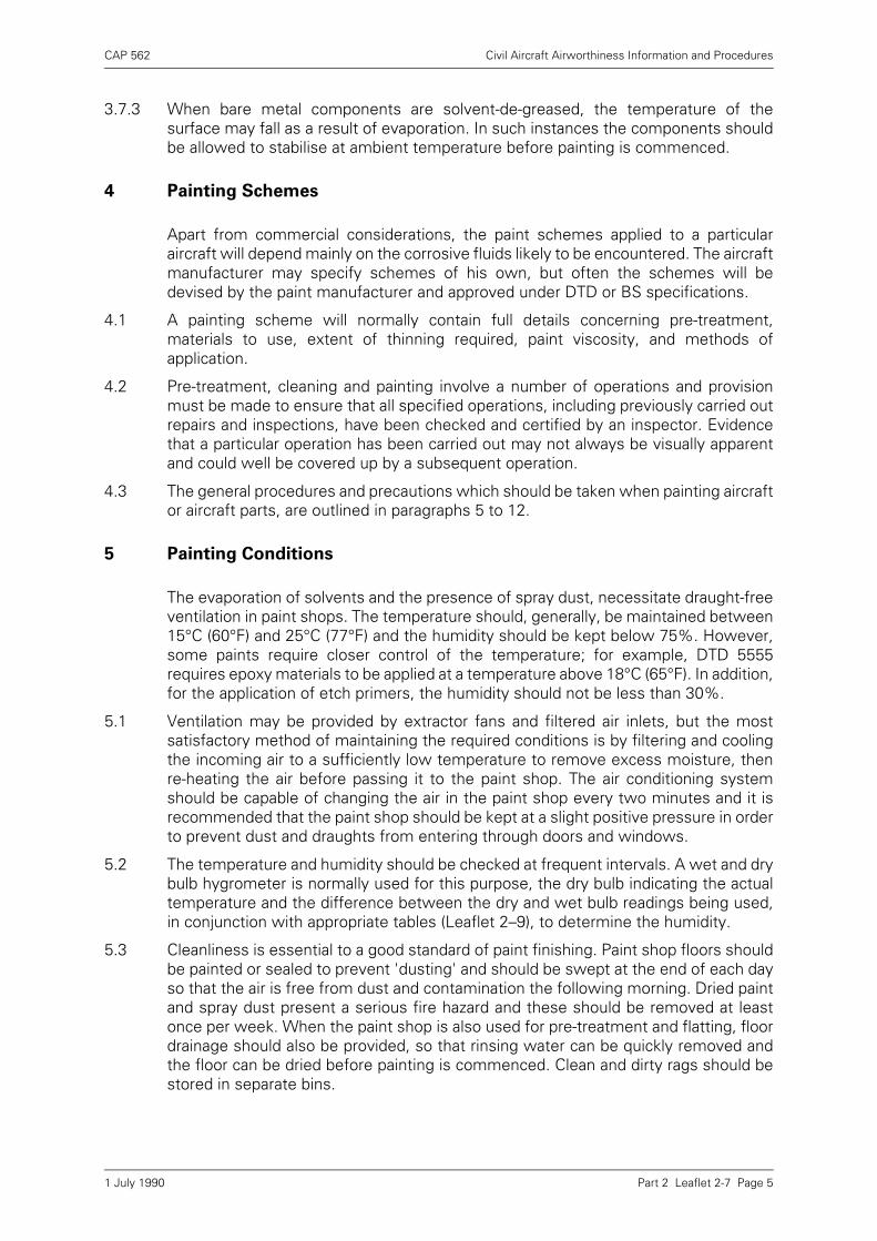
CAP 562 Civil Aircraft Airworthiness Information and Procedures
Part 2 Leaflet 2-7 Page 5
3.7.3 When bare metal components are solvent-de-greased, the temperature of thesurface may fall as a result of evaporation. In such instances the components shouldbe allowed to stabilise at ambient temperature before painting is commenced.
4 Painting Schemes
Apart from commercial considerations, the paint schemes applied to a particularaircraft will depend mainly on the corrosive fluids likely to be encountered. The aircraftmanufacturer may specify schemes of his own, but often the schemes will bedevised by the paint manufacturer and approved under DTD or BS specifications.
4.1 A painting scheme will normally contain full details concerning pre-treatment,materials to use, extent of thinning required, paint viscosity, and methods ofapplication.
4.2 Pre-treatment, cleaning and painting involve a number of operations and provisionmust be made to ensure that all specified operations, including previously carried outrepairs and inspections, have been checked and certified by an inspector. Evidencethat a particular operation has been carried out may not always be visually apparentand could well be covered up by a subsequent operation.
4.3 The general procedures and precautions which should be taken when painting aircraftor aircraft parts, are outlined in paragraphs 5 to 12.
5 Painting Conditions
The evaporation of solvents and the presence of spray dust, necessitate draught-freeventilation in paint shops. The temperature should, generally, be maintained between15°C (60°F) and 25°C (77°F) and the humidity should be kept below 75%. However,some paints require closer control of the temperature; for example, DTD 5555requires epoxy materials to be applied at a temperature above 18°C (65°F). In addition,for the application of etch primers, the humidity should not be less than 30%.
5.1 Ventilation may be provided by extractor fans and filtered air inlets, but the mostsatisfactory method of maintaining the required conditions is by filtering and coolingthe incoming air to a sufficiently low temperature to remove excess moisture, thenre-heating the air before passing it to the paint shop. The air conditioning systemshould be capable of changing the air in the paint shop every two minutes and it isrecommended that the paint shop should be kept at a slight positive pressure in orderto prevent dust and draughts from entering through doors and windows.
5.2 The temperature and humidity should be checked at frequent intervals. A wet and drybulb hygrometer is normally used for this purpose, the dry bulb indicating the actualtemperature and the difference between the dry and wet bulb readings being used,in conjunction with appropriate tables (Leaflet 2–9), to determine the humidity.
5.3 Cleanliness is essential to a good standard of paint finishing. Paint shop floors shouldbe painted or sealed to prevent 'dusting' and should be swept at the end of each dayso that the air is free from dust and contamination the following morning. Dried paintand spray dust present a serious fire hazard and these should be removed at leastonce per week. When the paint shop is also used for pre-treatment and flatting, floordrainage should also be provided, so that rinsing water can be quickly removed andthe floor can be dried before painting is commenced. Clean and dirty rags should bestored in separate bins.
1 July 1990
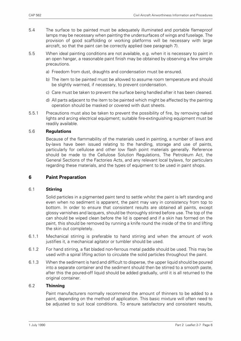
CAP 562 Civil Aircraft Airworthiness Information and Procedures
Part 2 Leaflet 2-7 Page 6
5.4 The surface to be painted must be adequately illuminated and portable flameprooflamps may be necessary when painting the undersurfaces of wings and fuselage. Theprovision of good scaffolding or working platforms will be necessary with largeaircraft, so that the paint can be correctly applied (see paragraph 7).
5.5 When ideal painting conditions are not available, e.g. when it is necessary to paint inan open hangar, a reasonable paint finish may be obtained by observing a few simpleprecautions.
a) Freedom from dust, draughts and condensation must be ensured.
b) The item to be painted must be allowed to assume room temperature and shouldbe slightly warmed, if necessary, to prevent condensation.
c) Care must be taken to prevent the surface being handled after it has been cleaned.
d) All parts adjacent to the item to be painted which might be affected by the paintingoperation should be masked or covered with dust sheets.
5.5.1 Precautions must also be taken to prevent the possibility of fire, by removing nakedlights and arcing electrical equipment; suitable fire-extinguishing equipment must bereadily available.
5.6 Regulations
Because of the flammability of the materials used in painting, a number of laws andby-laws have been issued relating to the handling, storage and use of paints,particularly for cellulose and other low flash point materials generally. Referenceshould be made to the Cellulose Solution Regulations, The Petroleum Act, theGeneral Sections of the Factories Acts, and any relevant local bylaws, for particularsregarding these materials, and the types of equipment to be used in paint shops.
6 Paint Preparation
6.1 Stirring
Solid particles in a pigmented paint tend to settle whilst the paint is left standing andeven when no sediment is apparent, the paint may vary in consistency from top tobottom. In order to ensure that consistent results are obtained all paints, exceptglossy varnishes and lacquers, should be thoroughly stirred before use. The top of thecan should be wiped clean before the lid is opened and if a skin has formed on thepaint, this should be removed by running a knife round the inside of the tin and liftingthe skin out completely.
6.1.1 Mechanical stirring is preferable to hand stirring and when the amount of workjustifies it, a mechanical agitator or tumbler should be used.
6.1.2 For hand stirring, a flat bladed non-ferrous metal paddle should be used. This may beused with a spiral lifting action to circulate the solid particles throughout the paint.
6.1.3 When the sediment is hard and difficult to disperse, the upper liquid should be pouredinto a separate container and the sediment should then be stirred to a smooth paste,after this the poured-off liquid should be added gradually, until it is all returned to theoriginal container.
6.2 Thinning
Paint manufacturers normally recommend the amount of thinners to be added to apaint, depending on the method of application. This basic mixture will often need tobe adjusted to suit local conditions. To ensure satisfactory and consistent results,
1 July 1990
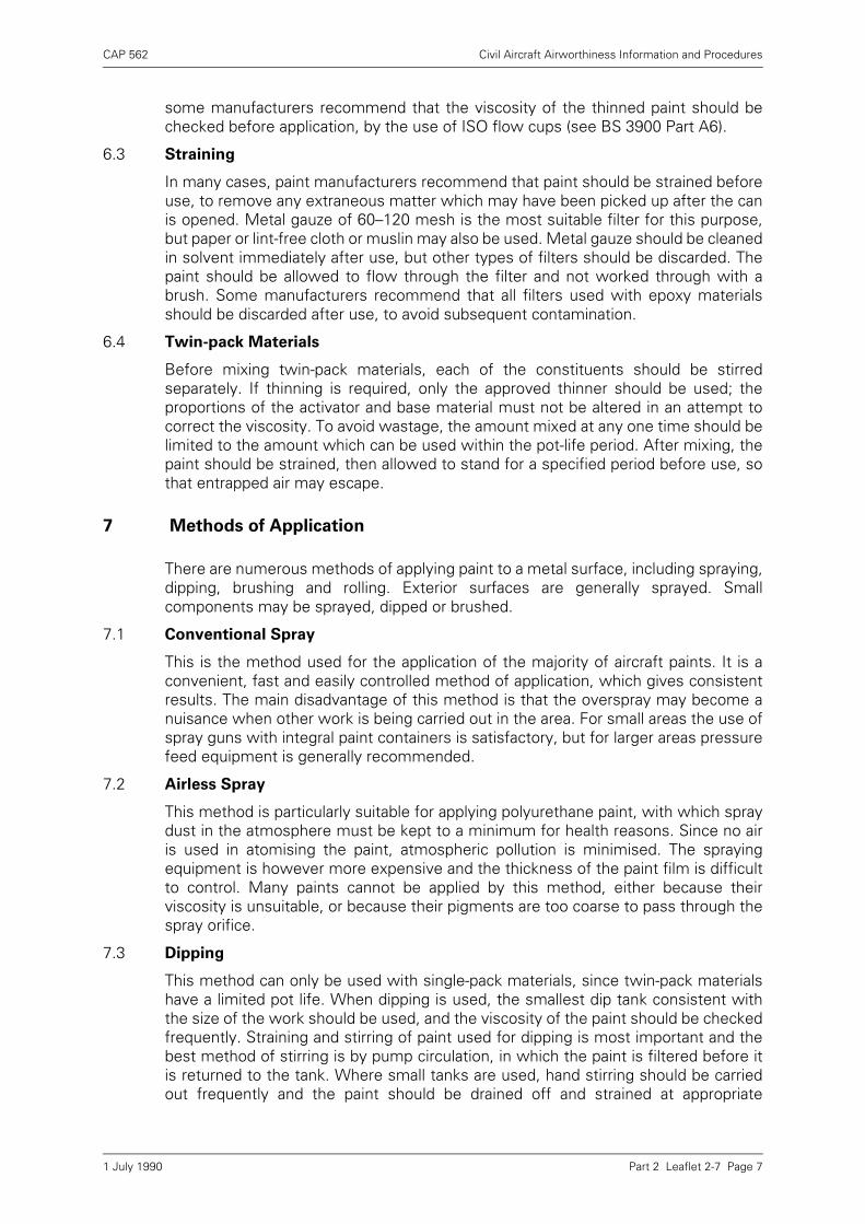
CAP 562 Civil Aircraft Airworthiness Information and Procedures
Part 2 Leaflet 2-7 Page 7
some manufacturers recommend that the viscosity of the thinned paint should bechecked before application, by the use of ISO flow cups (see BS 3900 Part A6).
6.3 Straining
In many cases, paint manufacturers recommend that paint should be strained beforeuse, to remove any extraneous matter which may have been picked up after the canis opened. Metal gauze of 60–120 mesh is the most suitable filter for this purpose,but paper or lint-free cloth or muslin may also be used. Metal gauze should be cleanedin solvent immediately after use, but other types of filters should be discarded. Thepaint should be allowed to flow through the filter and not worked through with abrush. Some manufacturers recommend that all filters used with epoxy materialsshould be discarded after use, to avoid subsequent contamination.
6.4 Twin-pack Materials
Before mixing twin-pack materials, each of the constituents should be stirredseparately. If thinning is required, only the approved thinner should be used; theproportions of the activator and base material must not be altered in an attempt tocorrect the viscosity. To avoid wastage, the amount mixed at any one time should belimited to the amount which can be used within the pot-life period. After mixing, thepaint should be strained, then allowed to stand for a specified period before use, sothat entrapped air may escape.
7 Methods of Application
There are numerous methods of applying paint to a metal surface, including spraying,dipping, brushing and rolling. Exterior surfaces are generally sprayed. Smallcomponents may be sprayed, dipped or brushed.
7.1 Conventional Spray
This is the method used for the application of the majority of aircraft paints. It is aconvenient, fast and easily controlled method of application, which gives consistentresults. The main disadvantage of this method is that the overspray may become anuisance when other work is being carried out in the area. For small areas the use ofspray guns with integral paint containers is satisfactory, but for larger areas pressurefeed equipment is generally recommended.
7.2 Airless Spray
This method is particularly suitable for applying polyurethane paint, with which spraydust in the atmosphere must be kept to a minimum for health reasons. Since no airis used in atomising the paint, atmospheric pollution is minimised. The sprayingequipment is however more expensive and the thickness of the paint film is difficultto control. Many paints cannot be applied by this method, either because theirviscosity is unsuitable, or because their pigments are too coarse to pass through thespray orifice.
7.3 Dipping
This method can only be used with single-pack materials, since twin-pack materialshave a limited pot life. When dipping is used, the smallest dip tank consistent withthe size of the work should be used, and the viscosity of the paint should be checkedfrequently. Straining and stirring of paint used for dipping is most important and thebest method of stirring is by pump circulation, in which the paint is filtered before itis returned to the tank. Where small tanks are used, hand stirring should be carriedout frequently and the paint should be drained off and strained at appropriate
1 July 1990
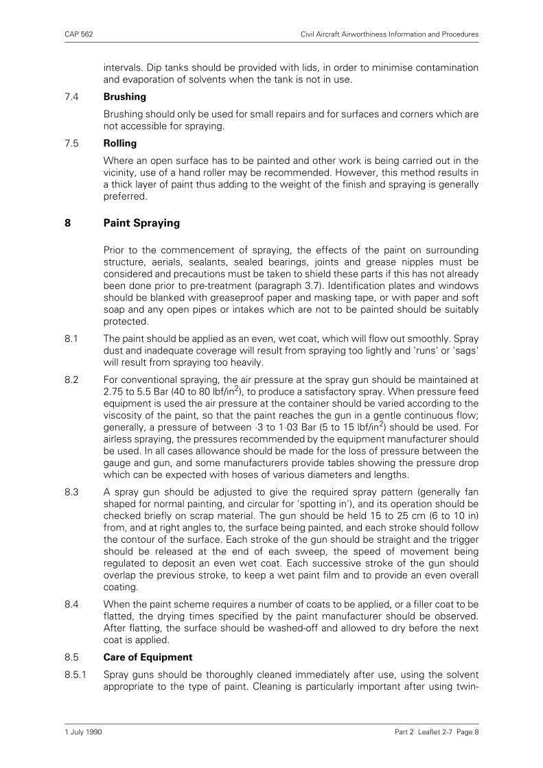
CAP 562 Civil Aircraft Airworthiness Information and Procedures
Part 2 Leaflet 2-7 Page 8
intervals. Dip tanks should be provided with lids, in order to minimise contaminationand evaporation of solvents when the tank is not in use.
7.4 Brushing
Brushing should only be used for small repairs and for surfaces and corners which arenot accessible for spraying.
7.5 Rolling
Where an open surface has to be painted and other work is being carried out in thevicinity, use of a hand roller may be recommended. However, this method results ina thick layer of paint thus adding to the weight of the finish and spraying is generallypreferred.
8 Paint Spraying
Prior to the commencement of spraying, the effects of the paint on surroundingstructure, aerials, sealants, sealed bearings, joints and grease nipples must beconsidered and precautions must be taken to shield these parts if this has not alreadybeen done prior to pre-treatment (paragraph 3.7). Identification plates and windowsshould be blanked with greaseproof paper and masking tape, or with paper and softsoap and any open pipes or intakes which are not to be painted should be suitablyprotected.
8.1 The paint should be applied as an even, wet coat, which will flow out smoothly. Spraydust and inadequate coverage will result from spraying too lightly and 'runs' or 'sags'will result from spraying too heavily.
8.2 For conventional spraying, the air pressure at the spray gun should be maintained at2.75 to 5.5 Bar (40 to 80 lbf/in2), to produce a satisfactory spray. When pressure feedequipment is used the air pressure at the container should be varied according to theviscosity of the paint, so that the paint reaches the gun in a gentle continuous flow;generally, a pressure of between ·3 to 1·03 Bar (5 to 15 lbf/in2) should be used. Forairless spraying, the pressures recommended by the equipment manufacturer shouldbe used. In all cases allowance should be made for the loss of pressure between thegauge and gun, and some manufacturers provide tables showing the pressure dropwhich can be expected with hoses of various diameters and lengths.
8.3 A spray gun should be adjusted to give the required spray pattern (generally fanshaped for normal painting, and circular for 'spotting in'), and its operation should bechecked briefly on scrap material. The gun should be held 15 to 25 cm (6 to 10 in)from, and at right angles to, the surface being painted, and each stroke should followthe contour of the surface. Each stroke of the gun should be straight and the triggershould be released at the end of each sweep, the speed of movement beingregulated to deposit an even wet coat. Each successive stroke of the gun shouldoverlap the previous stroke, to keep a wet paint film and to provide an even overallcoating.
8.4 When the paint scheme requires a number of coats to be applied, or a filler coat to beflatted, the drying times specified by the paint manufacturer should be observed.After flatting, the surface should be washed-off and allowed to dry before the nextcoat is applied.
8.5 Care of Equipment
8.5.1 Spray guns should be thoroughly cleaned immediately after use, using the solventappropriate to the type of paint. Cleaning is particularly important after using twin-
1 July 1990
CAP 562 Civil Aircraft Airworthiness Information and Procedures
Part 2 Leaflet 2-7 Page 9
pack paints, since once these have cured they are very difficult to remove. It isrecommended that, where possible, a spray gun is set aside solely for use with twin-pack materials. A gun should be cleaned by firstly flushing it through with solvent andthen partially stripping it in order to remove any residual paint; stiff bristle or nylonbrushes should be used for cleaning areas which are difficult to get at. The gun shouldnot be immersed in solvent, since this would remove lubricant from the working partsand glands.
8.5.2 Paint hoses in pressure feed and airless spray systems should also be washed outwith solvent immediately after use, since once the paint has dried it could flake offand cause blockages during future use.
8.5.3 The air compressor should be well maintained and the air storage tank should bedrained daily. Oil and water traps, and air filters, should be located adjacent to thecoupling point for the spray equipment, so as to prevent contamination from the mainsupply and to be readily available for servicing. It is recommended that a record shouldbe kept of all equipment servicing operations.
9 Painting Faults
Provided that the metal surface is properly cleaned and pre-treated and the paint isapplied in accordance with the particular specification and the manufacturer’srecommendations, the paint should adhere satisfactorily, and, when cured or dried,should not be easily removable by abrasion or washing. The main faults which canoccur when applying a paint scheme to an aircraft, are described in the followingparagraphs.
9.1 Lifting of Paint
Lifting of paint is usually the result of the lifting of the primer from the metal surface,and is usually first indicated by blistering, swelling, or wrinkling of the paint film. In themajority of cases this is caused by inefficient cleaning of the metal surface. This mayresult from the presence of corrosion under the primer. It may also be caused byincompatibility of the primer and the top coat.
9.2 Poor Adhesion
Poor adhesion may result from inadequate cleaning, pre-treatment or preparation ofthe paint, from application under adverse conditions or from failure to comply with thedrying requirement specified for the particular scheme.
9.3 Spray Mottle
Sometimes known as 'orange peel' or 'pebble', spray mottle may be caused byincorrect paint viscosity, air pressure, spray gun setting or the distance the gun is heldfrom the work.
9.4 Spray Dust
Spray dust is caused by the atomised particles of paint drying before reaching thesurface being painted. The usual causes are excessive air pressure, the gun held toofar from the surface, or incorrect gun setting.
9.5 Runs and Sags
Runs and sags result from too much paint being applied, so that the film of paint fallsunder its own weight before drying. The faults may be caused by over-thinning of thepaint, incorrect adjustment of the gun and occasionally, by inadequate surfacepreparation.
1 July 1990
CAP 562 Civil Aircraft Airworthiness Information and Procedures
Part 2 Leaflet 2-7 Page 10
9.6 Blushing
This is a fault most commonly experienced with cellulose materials and appears as a'clouding' or 'blooming' of the paint film. It may be caused by moisture in the airsupply, excessive humidity, draughts, or sudden changes of temperature. The use of'anti-chill' thinners is recommended when conditions are such that blushing can beexpected. Blushing can often be removed by softening the paint surface with thinnersand drying in a warm, dry atmosphere.
10 Paint Repairs
After an aircraft has been in use for some time, the paintwork ages and hardens andaccumulates a layer of dirt, grease and polish, which may be very difficult to remove.In addition, greases and lubricants may contaminate the paint and be absorbed intocrevices, sealing strips, soundproofing and furnishings. When it becomes necessaryto repair chipped or blemished paintwork, to re-paint part of an aircraft after repairshave been carried out, or to apply new paint over the existing paintwork (e.g. lettering,stencilled instructions and crests), these contaminants must be removed in order toobtain satisfactory adhesion of the new paint.
10.1 Parts of an assembly which may be adversely affected by the materials used in re-painting and parts not needing to be re-painted, should be blanked or masked (seealso paragraph 3.7). Any absorbent material adjacent to the areas to be re-paintedshould, where possible, be removed to prevent contamination; where removal is notpracticable, the part should be thoroughly de-greased and dried before painting iscommenced.
10.2 When an area is re-painted after the removal of corrosion, or after repairs have beencarried out, all debris, swarf, globules of sealant and oil or dye penetrant which mayhave been used for non-destructive testing, should be cleaned off.
10.3 All loosely-adhering or chipped paint should be removed from the area to be re-painted using paint stripper or aluminium wire wool and the area should be thoroughlycleaned with solvent to remove any contamination. Several applications of solventmay be required to remove contamination from older paintwork. The area should thenbe wet 'flatted' with fine emery cloth, to roughen the paint, to form a feathered edgewhere paint has been removed, and to remove pre-treatment from bare areas.Residues should then be removed, by washing and by use of a brush in seams andcrevices. The area should then be thoroughly dried, and allowed to assume roomtemperature before painting.
10.4 When painting over existing paintwork and when applying lettering, crests, orstencilled instructions, the compatibility of the new paint with the original paint shouldbe checked. The surface to be painted should be lightly wiped over with a clean clothmoistened with the thinners appropriate to the paint to be applied; a reaction such aswrinkling or blistering of the old paint will indicate incompatibility, but light removal ofpigment from the paint will indicate that the new paint is compatible and that thecleaning operation was satisfactory.
NOTES: 1) When emery cloth is used for rubbing down, care must be taken to avoiddamage to clad or plated surfaces, and to exposed joints incorporatingsealant and structural adhesives.
2) When glass fibre surfaces are being prepared for re-painting, they must bethoroughly roughened in order to ensure adhesion of the paint.
1 July 1990
CAP 562 Civil Aircraft Airworthiness Information and Procedures
Part 2 Leaflet 2-7 Page 11
10.5 After the surface to be painted has been cleaned and prepared, the original paintscheme should be restored and any dry spray edges should be polished to blend inwith the existing paintwork. Materials, drying times and painting precautions, shouldbe the same as those specified for the original paint scheme, except that if a filler coatis used it must be of the same material as the top coat. For example, the original fillermay have been synthetic and the top coat cellulose, but for the repair both filler andtop coat must be cellulose.
10.6 Any masking or plugs which have been fitted must be removed after the paint hasdried.
11 Paint Stripping
When re-finishing an aircraft, it is usual to strip back the paint to the bare metal andto re-apply the desired paint scheme. The ease with which the paint can be removeddepends on the paint type, its thickness and its age, but approved proprietary paintstrippers are available, which are specially prepared for removing particular types ofpaint. Epoxy and polyurethane paints are the most difficult to remove.
11.1 Some paint strippers may have an adverse effect upon structural bonding adhesives,some may affect the adhesives used for the attachment of sealing and chafing stripsand others may result in hydrogen embrittlement of high strength structural steelparts. Only the approved paint stripper should be used and precautions should betaken to prevent its contact with susceptible materials, by masking or plugging. Aninspection should be carried out after stripping, to ensure that these precautions wereeffective. Vents and drains should also be plugged, to prevent the entry of paintstripper, washing water and paint particles.
11.2 The paint stripper should be applied freely to the surface of the paint, and left until thepaint has softened; the paint can then be removed with a wooden scraper. Residuesshould be washed off with water and care should be taken to remove all paint andpaint remover from seams and crevices, using a short-bristled nylon brush. When thepaint is particularly thick it may be necessary to apply the paint stripper a second timeafter the initial softened coat has been removed. The removal of debris after strippingis most important, since the softened paint could harden in piano wire hinges, controlrod bearings and other moving parts, and present a serious hazard. After the surfacehas been washed, it should be wiped with a rag soaked in solvent, to remove the finaltraces of paint.
11.3 Some paint schemes involve the use of an epoxy primer, followed by an air-dryingsynthetic or acrylic finish, and, provided that the primer is in a satisfactory condition,the top coat can be selectively stripped, using a specially formulated paint remover.This paint remover is applied in the normal way, but a rubber scraper should be usedto prevent damage to the primer. After removal of the top coat, the primer should bethoroughly washed with solvent to remove any contaminants and the finish should bere-applied.
12 Health Hazards
As stated in paragraph 5, a paint shop must be well ventilated, to remove solventsand spray dust which may present a health hazard. Solvents have an irritating effecton the skin and eyes, and may be toxic. Constant contact with solvents may dry outthe skin and cause dermatitis and the use of a barrier cream is recommended.Inhalation of solvent vapours and spray dust should be avoided and a face maskshould be worn in areas where concentrations may be high.
1 July 1990
CAP 562 Civil Aircraft Airworthiness Information and Procedures
Part 2 Leaflet 2-7 Page 12
12.1 Polyurethane spray dust can cause chest irritation if inhaled, and this is the mainreason for using an airless spray to apply this material. When polyurethane is appliedby conventional spray, it is recommended that a full face mask with an independentair supply is worn.
12.2 When mixing twin-pack materials, care should be taken to avoid splashing the skin oreyes. If this does occur, the material must immediately be washed off with runningwater.
12.3 When using paint strippers, it is advisable to wear goggles and PVC gloves and allcontact between the stripper and the skin should be avoided.
13 Storage
Paints should be kept at room temperature, in a dry store. Containers should bemarked with the date of receipt and used in strict rotation; they should not be heldlonger than their stated storage life. Unpigmented glossy material should bedisturbed as little as possible, so that any sediment may settle at the bottom of thecan, but cans containing other materials should be inverted at frequent intervals, toreduce the settlement of pigments.
1 July 1990
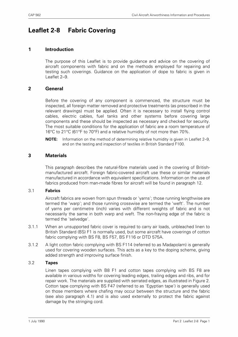
CAP 562 Civil Aircraft Airworthiness Information and Procedures
Part 2 Leaflet 2-8 Page 1
Leaflet 2-8 Fabric Covering
1 Introduction
The purpose of this Leaflet is to provide guidance and advice on the covering ofaircraft components with fabric and on the methods employed for repairing andtesting such coverings. Guidance on the application of dope to fabric is given inLeaflet 2–9.
2 General
Before the covering of any component is commenced, the structure must beinspected, all foreign matter removed and protective treatments (as prescribed in therelevant drawings) must be applied. Often it is necessary to install flying controlcables, electric cables, fuel tanks and other systems before covering largecomponents and these should be inspected as necessary and checked for security.The most suitable conditions for the application of fabric are a room temperature of16°C to 21°C (61°F to 70°F) and a relative humidity of not more than 70%.
NOTE: Information on the method of determining relative humidity is given in Leaflet 2–9,and on the testing and inspection of textiles in British Standard F100.
3 Materials
This paragraph describes the natural-fibre materials used in the covering of British-manufactured aircraft. Foreign fabric-covered aircraft use these or similar materialsmanufactured in accordance with equivalent specifications. Information on the use offabrics produced from man-made fibres for aircraft will be found in paragraph 12.
3.1 Fabrics
Aircraft fabrics are woven from spun threads or 'yarns'; those running lengthwise aretermed the 'warp'; and those running crosswise are termed the 'weft'. The numberof yarns per centimetre (inch) varies with different weights of fabric and is notnecessarily the same in both warp and weft. The non-fraying edge of the fabric istermed the 'selvedge'.
3.1.1 When an unsupported fabric cover is required to carry air loads, unbleached linen toBritish Standard (BS) F1 is normally used, but some aircraft have coverings of cottonfabric complying with BS F8, BS F57, BS F116 or DTD 575A.
3.1.2 A light cotton fabric complying with BS F114 (referred to as Madapolam) is generallyused for covering wooden surfaces. This acts as a key to the doping scheme, givingadded strength and improving surface finish.
3.2 Tapes
Linen tapes complying with B8 F1 and cotton tapes complying with BS F8 areavailable in various widths for covering leading edges, trailing edges and ribs, and forrepair work. The materials are supplied with serrated edges, as illustrated in Figure 2.Cotton tape complying with BS F47 (referred to as 'Egyptian tape') is generally usedon those members where chafing may occur between the structure and the fabric(see also paragraph 4.1) and is also used externally to protect the fabric againstdamage by the stringing cord.
1 July 1990
CAP 562 Civil Aircraft Airworthiness Information and Procedures
Part 2 Leaflet 2-8 Page 2
3.3 Thread
Linen thread complying with BS F34 is normally used. For hand sewing, No. 40 thread(minimum breaking strength 3 kg (7 lb)) used double, or No. 18 thread (minimumbreaking strength 7.25 kg (16 lb)) used single, are suitable. For machine sewing, No.30 thread (minimum breaking strength 4.5 kg (10 lb)) or No. 40 thread is used.
3.4 Stringing
Flax cordage complying with BS F35 or braided nylon cord (coreless) complying withDTD 5620 is normally used.
3.5 Eyeleted Fuselage Webbing
On a number of older types of aircraft, cotton webbing braid with hooks, or lacingeyelets and kite cord, are used for securing the fuselage fabric.
3.6 Storage
All materials used for fabric covering should be stored at a temperature of about 20°C(68°F) in dry, clean conditions and away from direct sunlight. When required for use,the materials should be inspected for possible flaws (e.g. iron mould discolouration,signs of insect, rodent, or other damage) and any affected parts rejected.
4 Preparation of Structure
The structure to be covered should be inspected as outlined in paragraph 2. Allcorners or edges and any projections such as bolts or screw heads likely to chafe thefabric must be covered with tape. Where serious chafing may occur and a strongreinforcement is required, a canvas or leather patch may be sewn to a fabric patch,then doped into position.
4.1 In order to prevent dope from reacting with any protective treatment and to preventfabric from adhering to wooden structure, all aerofoil members which will be incontact with the fabric are normally covered with adhesive cellulose or aluminiumtape, or painted with dope-resistant white paint. Exceptions to this requirement arediscussed in paragraphs 7.3, 7.4 and 12.1.
4.2 On some aircraft, which have a tubular metal fuselage frame, the fuselage shape ismade up with wooden formers attached directly to the main framework and to thesewooden formers are secured light longitudinal members onto which the fabriccovering is doped. This secondary structure must be inspected for security and anysharp edges removed with fine glass paper.
4.3 Where stringing is likely to be chafed by parts of the structure, protection should beprovided by wrapping such parts with cotton tape. Before the tape is applied thestructure should be treated with varnish to protect it from corrosion should the tapebecome wet.
4.4 Internal controls and cables should be tightened to assume their normal positions andsecured at the root rib. Their location should be noted so that stringing pitch can beselected to avoid chafing.
5 Covering Methods
An aircraft fabric may be fitted with the warp or weft running at 45º to the slipstream,or in line with the slipstream. The former (bias) method is generally considered to bestronger and more resistant to tearing, but the latter method is used on most light
1 July 1990
CAP 562 Civil Aircraft Airworthiness Information and Procedures
Part 2 Leaflet 2-8 Page 3
aircraft. The two methods used to re-cover an aircraft are outlined in paragraphs 5.1and 5.2, but the method used in a particular instance should follow that of the originalmanufacture unless otherwise approved.
5.1 Prefabricated Envelopes
A number of manufacturers produce fabric envelopes for re-covering various modelsof aircraft. Separate envelopes are made up from patterns for the mainplanes,fuselage, tailplane, fin and flying control surfaces and greatly simplify the task of re-covering. The envelopes are made loose enough to facilitate slipping them over thestructure and to achieve the proper tautness after doping.
5.1.1 Mainplanes
The envelope is drawn over the wing tip and gradually worked down over themainplane, generally keeping the spanwise seam in line with the trailing edge. Whenthe cover is located it is secured (by stitching, cementing, or retaining strip) to theinboard end of the mainplane, any necessary openings for cables, struts, tank caps,etc., are cut and stringing is applied as necessary (paragraph 6).
5.1.2 Fuselage
The fin and fuselage envelopes are often supplied separately and in some cases thefuselage envelope is open, or partially open, at the bottom, to simplify fitting. The finenvelope is usually fitted first, then the fuselage envelope is stretched forwards overthe fuselage and secured in the same way as the original fabric. The cover is usuallycemented or doped to the fuselage formers (paragraph 4).
5.1.3 Control Surfaces
Control surface envelopes are usually left open at the hinge line, where they aresecured by cementing, doping or stitching.
5.2 'Blanket' Method of Covering
With this method a bolt of fabric is used and covers are made-up on the site. Lengthsof fabric, or a number of lengths joined side-by-side, being used to cover the aircraftstructure.
5.2.1 Mainplanes and Tailplanes
The cover is normally made-up from lengths of fabric machine-stitched together side-by-side. This is laid round the surface, starting and finishing at the trailing edge andjoined by hand stitching as shown in Figure 3. On some aircraft with light alloystructure, hand stitching is dispensed with, the cover edges being wrapped round thetip and trailing edge and doped into position. The cover is then attached to the ribs bystringing (paragraph 6).
5.2.2 Fuselage
A number of different methods are used to attach fabric to the fuselage; the morecommon being as described in paragraph 4.2. The fabric is not normally attached inone piece, but usually consists of several pieces (e.g. sides, top and bottom, whichare doped separately onto the frame, or sewn together at their edges. Joins or seamsare covered with doped-on tape. Since the air loads on the fuselage are not as greatas on the mainplanes, it is not usual to employ stringing, although it may be specifiedin some instances.
1 July 1990
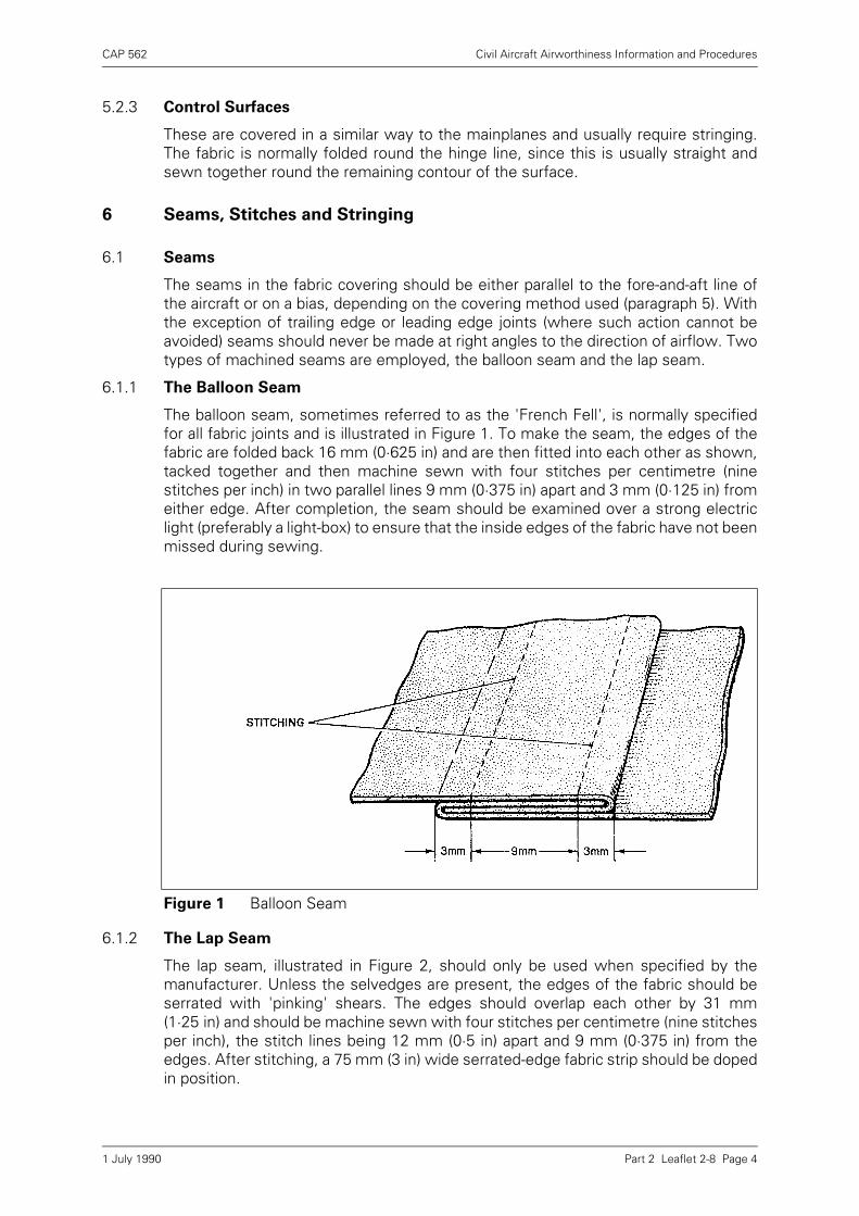
CAP 562 Civil Aircraft Airworthiness Information and Procedures
Part 2 Leaflet 2-8 Page 4
5.2.3 Control Surfaces
These are covered in a similar way to the mainplanes and usually require stringing.The fabric is normally folded round the hinge line, since this is usually straight andsewn together round the remaining contour of the surface.
6 Seams, Stitches and Stringing
6.1 Seams
The seams in the fabric covering should be either parallel to the fore-and-aft line ofthe aircraft or on a bias, depending on the covering method used (paragraph 5). Withthe exception of trailing edge or leading edge joints (where such action cannot beavoided) seams should never be made at right angles to the direction of airflow. Twotypes of machined seams are employed, the balloon seam and the lap seam.
6.1.1 The Balloon Seam
The balloon seam, sometimes referred to as the 'French Fell', is normally specifiedfor all fabric joints and is illustrated in Figure 1. To make the seam, the edges of thefabric are folded back 16 mm (0·625 in) and are then fitted into each other as shown,tacked together and then machine sewn with four stitches per centimetre (ninestitches per inch) in two parallel lines 9 mm (0·375 in) apart and 3 mm (0·125 in) fromeither edge. After completion, the seam should be examined over a strong electriclight (preferably a light-box) to ensure that the inside edges of the fabric have not beenmissed during sewing.
6.1.2 The Lap Seam
The lap seam, illustrated in Figure 2, should only be used when specified by themanufacturer. Unless the selvedges are present, the edges of the fabric should beserrated with 'pinking' shears. The edges should overlap each other by 31 mm(1·25 in) and should be machine sewn with four stitches per centimetre (nine stitchesper inch), the stitch lines being 12 mm (0·5 in) apart and 9 mm (0·375 in) from theedges. After stitching, a 75 mm (3 in) wide serrated-edge fabric strip should be dopedin position.
Figure 1 Balloon Seam
1 July 1990
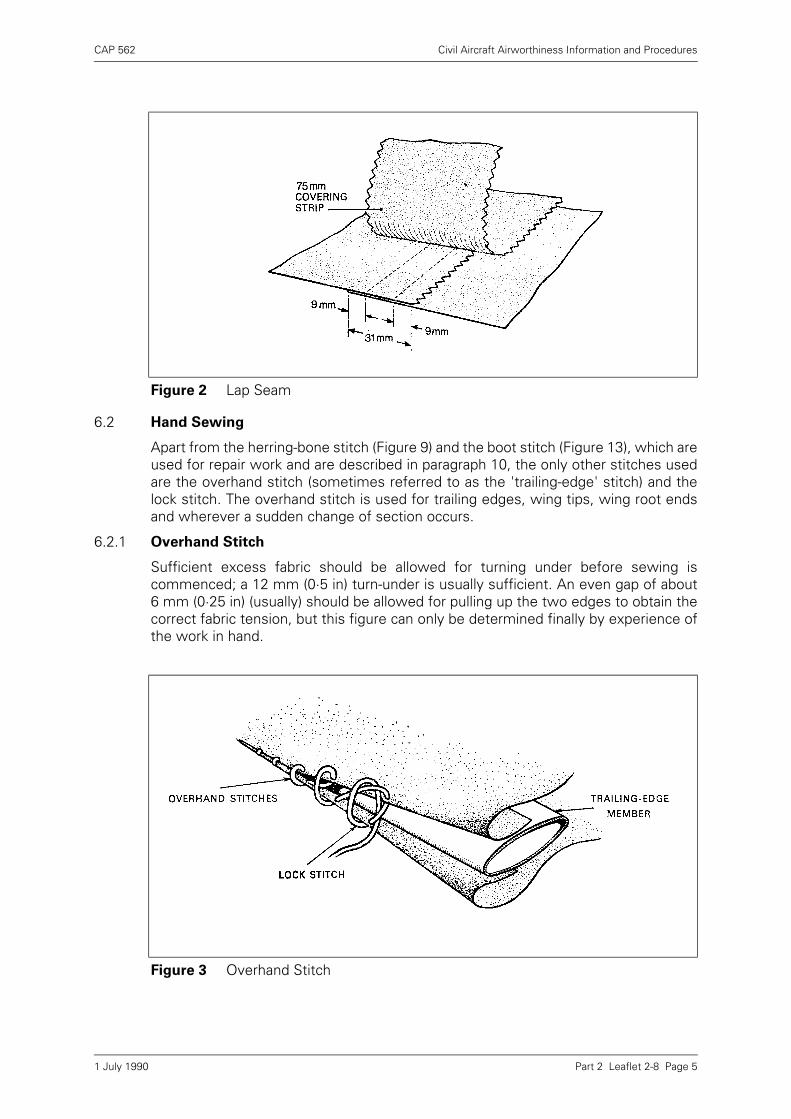
CAP 562 Civil Aircraft Airworthiness Information and Procedures
Part 2 Leaflet 2-8 Page 5
6.2 Hand Sewing
Apart from the herring-bone stitch (Figure 9) and the boot stitch (Figure 13), which areused for repair work and are described in paragraph 10, the only other stitches usedare the overhand stitch (sometimes referred to as the 'trailing-edge' stitch) and thelock stitch. The overhand stitch is used for trailing edges, wing tips, wing root endsand wherever a sudden change of section occurs.
6.2.1 Overhand Stitch
Sufficient excess fabric should be allowed for turning under before sewing iscommenced; a 12 mm (0·5 in) turn-under is usually sufficient. An even gap of about6 mm (0·25 in) (usually) should be allowed for pulling up the two edges to obtain thecorrect fabric tension, but this figure can only be determined finally by experience ofthe work in hand.
Figure 2 Lap Seam
Figure 3 Overhand Stitch
1 July 1990
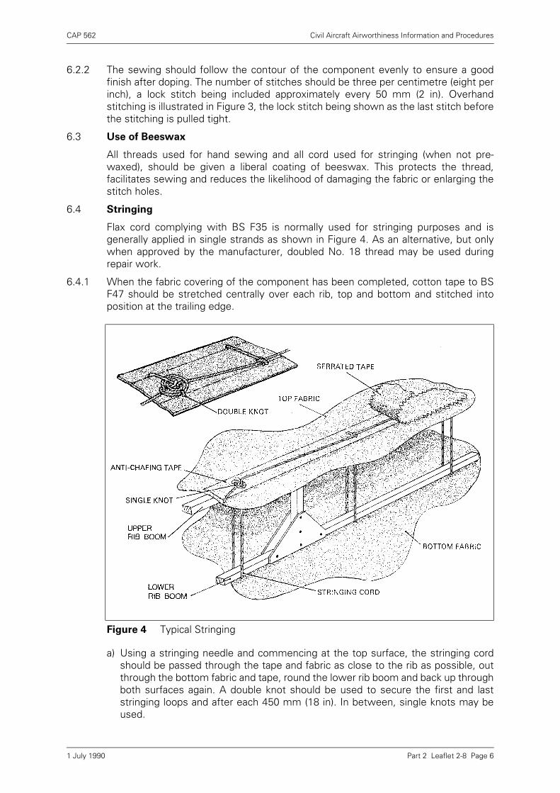
CAP 562 Civil Aircraft Airworthiness Information and Procedures
Part 2 Leaflet 2-8 Page 6
6.2.2 The sewing should follow the contour of the component evenly to ensure a goodfinish after doping. The number of stitches should be three per centimetre (eight perinch), a lock stitch being included approximately every 50 mm (2 in). Overhandstitching is illustrated in Figure 3, the lock stitch being shown as the last stitch beforethe stitching is pulled tight.
6.3 Use of Beeswax
All threads used for hand sewing and all cord used for stringing (when not pre-waxed), should be given a liberal coating of beeswax. This protects the thread,facilitates sewing and reduces the likelihood of damaging the fabric or enlarging thestitch holes.
6.4 Stringing
Flax cord complying with BS F35 is normally used for stringing purposes and isgenerally applied in single strands as shown in Figure 4. As an alternative, but onlywhen approved by the manufacturer, doubled No. 18 thread may be used duringrepair work.
6.4.1 When the fabric covering of the component has been completed, cotton tape to BSF47 should be stretched centrally over each rib, top and bottom and stitched intoposition at the trailing edge.
a) Using a stringing needle and commencing at the top surface, the stringing cordshould be passed through the tape and fabric as close to the rib as possible, outthrough the bottom fabric and tape, round the lower rib boom and back up throughboth surfaces again. A double knot should be used to secure the first and laststringing loops and after each 450 mm (18 in). In between, single knots may beused.
Figure 4 Typical Stringing
1 July 1990
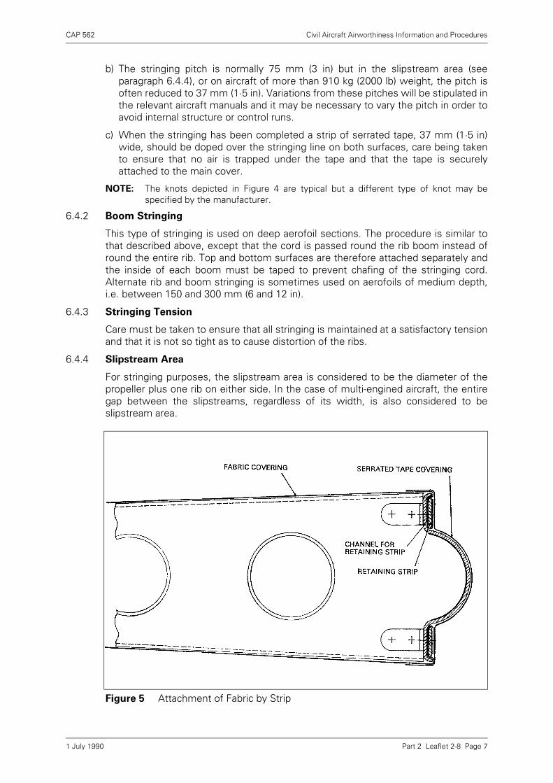
CAP 562 Civil Aircraft Airworthiness Information and Procedures
Part 2 Leaflet 2-8 Page 7
b) The stringing pitch is normally 75 mm (3 in) but in the slipstream area (seeparagraph 6.4.4), or on aircraft of more than 910 kg (2000 lb) weight, the pitch isoften reduced to 37 mm (1·5 in). Variations from these pitches will be stipulated inthe relevant aircraft manuals and it may be necessary to vary the pitch in order toavoid internal structure or control runs.
c) When the stringing has been completed a strip of serrated tape, 37 mm (1·5 in)wide, should be doped over the stringing line on both surfaces, care being takento ensure that no air is trapped under the tape and that the tape is securelyattached to the main cover.
NOTE: The knots depicted in Figure 4 are typical but a different type of knot may bespecified by the manufacturer.
6.4.2 Boom Stringing
This type of stringing is used on deep aerofoil sections. The procedure is similar tothat described above, except that the cord is passed round the rib boom instead ofround the entire rib. Top and bottom surfaces are therefore attached separately andthe inside of each boom must be taped to prevent chafing of the stringing cord.Alternate rib and boom stringing is sometimes used on aerofoils of medium depth,i.e. between 150 and 300 mm (6 and 12 in).
6.4.3 Stringing Tension
Care must be taken to ensure that all stringing is maintained at a satisfactory tensionand that it is not so tight as to cause distortion of the ribs.
6.4.4 Slipstream Area
For stringing purposes, the slipstream area is considered to be the diameter of thepropeller plus one rib on either side. In the case of multi-engined aircraft, the entiregap between the slipstreams, regardless of its width, is also considered to beslipstream area.
Figure 5 Attachment of Fabric by Strip
1 July 1990
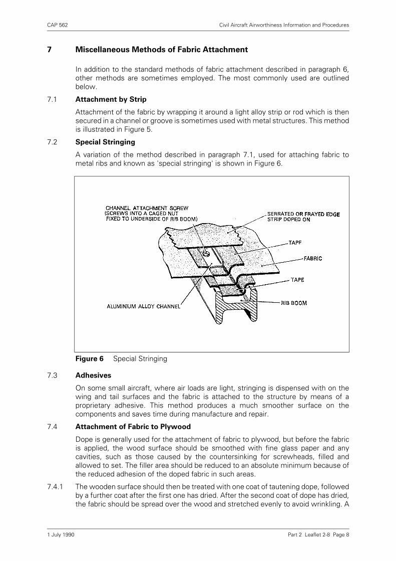
CAP 562 Civil Aircraft Airworthiness Information and Procedures
Part 2 Leaflet 2-8 Page 8
7 Miscellaneous Methods of Fabric Attachment
In addition to the standard methods of fabric attachment described in paragraph 6,other methods are sometimes employed. The most commonly used are outlinedbelow.
7.1 Attachment by Strip
Attachment of the fabric by wrapping it around a light alloy strip or rod which is thensecured in a channel or groove is sometimes used with metal structures. This methodis illustrated in Figure 5.
7.2 Special Stringing
A variation of the method described in paragraph 7.1, used for attaching fabric tometal ribs and known as 'special stringing' is shown in Figure 6.
7.3 Adhesives
On some small aircraft, where air loads are light, stringing is dispensed with on thewing and tail surfaces and the fabric is attached to the structure by means of aproprietary adhesive. This method produces a much smoother surface on thecomponents and saves time during manufacture and repair.
7.4 Attachment of Fabric to Plywood
Dope is generally used for the attachment of fabric to plywood, but before the fabricis applied, the wood surface should be smoothed with fine glass paper and anycavities, such as those caused by the countersinking for screwheads, filled andallowed to set. The filler area should be reduced to an absolute minimum because ofthe reduced adhesion of the doped fabric in such areas.
7.4.1 The wooden surface should then be treated with one coat of tautening dope, followedby a further coat after the first one has dried. After the second coat of dope has dried,the fabric should be spread over the wood and stretched evenly to avoid wrinkling. A
Figure 6 Special Stringing
1 July 1990
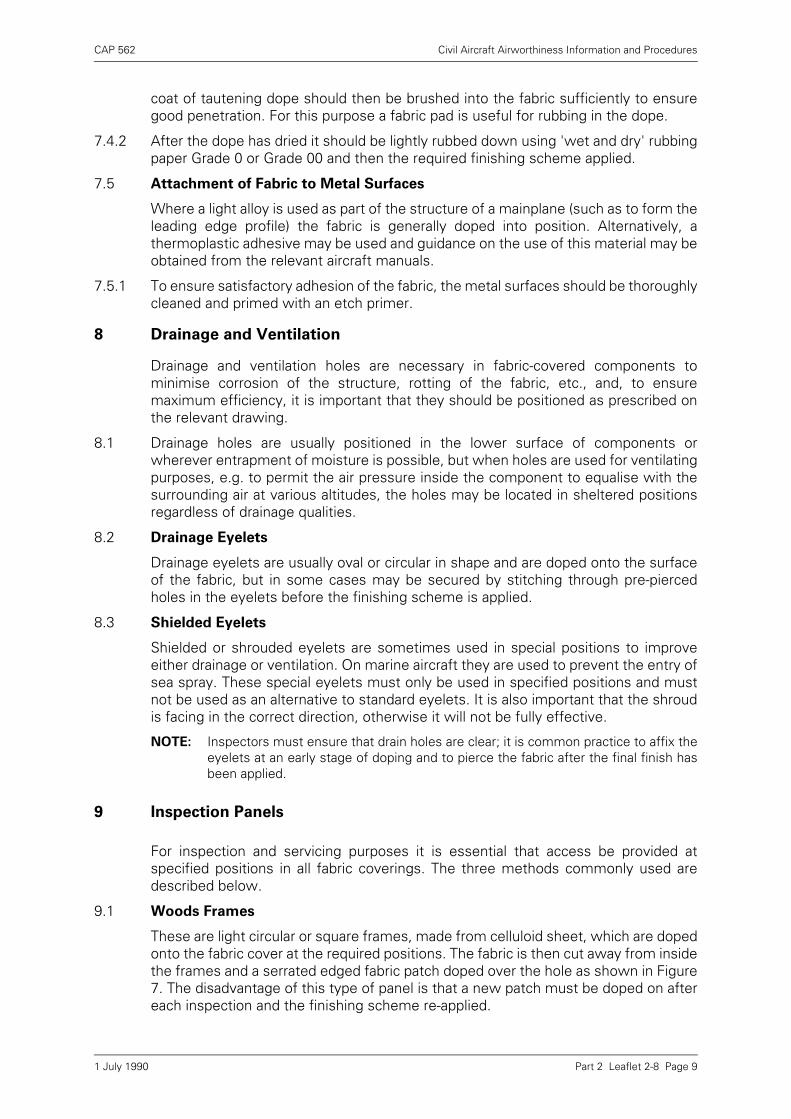
CAP 562 Civil Aircraft Airworthiness Information and Procedures
Part 2 Leaflet 2-8 Page 9
coat of tautening dope should then be brushed into the fabric sufficiently to ensuregood penetration. For this purpose a fabric pad is useful for rubbing in the dope.
7.4.2 After the dope has dried it should be lightly rubbed down using 'wet and dry' rubbingpaper Grade 0 or Grade 00 and then the required finishing scheme applied.
7.5 Attachment of Fabric to Metal Surfaces
Where a light alloy is used as part of the structure of a mainplane (such as to form theleading edge profile) the fabric is generally doped into position. Alternatively, athermoplastic adhesive may be used and guidance on the use of this material may beobtained from the relevant aircraft manuals.
7.5.1 To ensure satisfactory adhesion of the fabric, the metal surfaces should be thoroughlycleaned and primed with an etch primer.
8 Drainage and Ventilation
Drainage and ventilation holes are necessary in fabric-covered components tominimise corrosion of the structure, rotting of the fabric, etc., and, to ensuremaximum efficiency, it is important that they should be positioned as prescribed onthe relevant drawing.
8.1 Drainage holes are usually positioned in the lower surface of components orwherever entrapment of moisture is possible, but when holes are used for ventilatingpurposes, e.g. to permit the air pressure inside the component to equalise with thesurrounding air at various altitudes, the holes may be located in sheltered positionsregardless of drainage qualities.
8.2 Drainage Eyelets
Drainage eyelets are usually oval or circular in shape and are doped onto the surfaceof the fabric, but in some cases may be secured by stitching through pre-piercedholes in the eyelets before the finishing scheme is applied.
8.3 Shielded Eyelets
Shielded or shrouded eyelets are sometimes used in special positions to improveeither drainage or ventilation. On marine aircraft they are used to prevent the entry ofsea spray. These special eyelets must only be used in specified positions and mustnot be used as an alternative to standard eyelets. It is also important that the shroudis facing in the correct direction, otherwise it will not be fully effective.
NOTE: Inspectors must ensure that drain holes are clear; it is common practice to affix theeyelets at an early stage of doping and to pierce the fabric after the final finish hasbeen applied.
9 Inspection Panels
For inspection and servicing purposes it is essential that access be provided atspecified positions in all fabric coverings. The three methods commonly used aredescribed below.
9.1 Woods Frames
These are light circular or square frames, made from celluloid sheet, which are dopedonto the fabric cover at the required positions. The fabric is then cut away from insidethe frames and a serrated edged fabric patch doped over the hole as shown in Figure7. The disadvantage of this type of panel is that a new patch must be doped on aftereach inspection and the finishing scheme re-applied.
1 July 1990
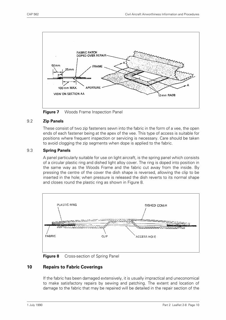
CAP 562 Civil Aircraft Airworthiness Information and Procedures
Part 2 Leaflet 2-8 Page 10
9.2 Zip Panels
These consist of two zip fasteners sewn into the fabric in the form of a vee, the openends of each fastener being at the apex of the vee. This type of access is suitable forpositions where frequent inspection or servicing is necessary. Care should be takento avoid clogging the zip segments when dope is applied to the fabric.
9.3 Spring Panels
A panel particularly suitable for use on light aircraft, is the spring panel which consistsof a circular plastic ring and dished light alloy cover. The ring is doped into position inthe same way as the Woods Frame and the fabric cut away from the inside. Bypressing the centre of the cover the dish shape is reversed, allowing the clip to beinserted in the hole; when pressure is released the dish reverts to its normal shapeand closes round the plastic ring as shown in Figure 8.
10 Repairs to Fabric Coverings
If the fabric has been damaged extensively, it is usually impractical and uneconomicalto make satisfactory repairs by sewing and patching. The extent and location ofdamage to the fabric that may be repaired will be detailed in the repair section of the
Figure 7 Woods Frame Inspection Panel
Figure 8 Cross-section of Spring Panel
1 July 1990
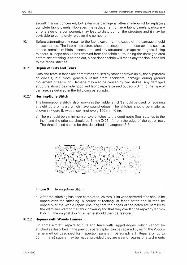
CAP 562 Civil Aircraft Airworthiness Information and Procedures
Part 2 Leaflet 2-8 Page 11
aircraft manual concerned, but extensive damage is often made good by replacingcomplete fabric panels. However, the replacement of large fabric panels, particularlyon one side of a component, may lead to distortion of the structure and it may beadvisable to completely re-cover the component.
10.1 Before attempting any repair to the fabric covering, the cause of the damage shouldbe ascertained. The internal structure should be inspected for loose objects such asstones, remains of birds, insects, etc., and any structural damage made good. Usingthinners, all dope should be removed from the fabric surrounding the damaged areabefore any stitching is carried out, since doped fabric will tear if any tension is appliedto the repair stitches.
10.2 Repair of Cuts and Tears
Cuts and tears in fabric are sometimes caused by stones thrown up by the slipstreamor wheels, but more generally result from accidental damage during groundmovement or servicing. Damage may also be caused by bird strikes. Any damagedstructure should be made good and fabric repairs carried out according to the type ofdamage, as detailed in the following paragraphs.
10.2.1 Herring-Bone Stitch
The herring-bone stitch (also known as the 'ladder stitch') should be used for repairingstraight cuts or tears which have sound edges. The stitches should be made asshown in Figure 9, with a lock knot every 150 mm (6 in).
a) There should be a minimum of two stitches to the centimetre (four stitches to theinch) and the stitches should be 6 mm (0·25 in) from the edge of the cut or tear.The thread used should be that described in paragraph 3.3.
b) After the stitching has been completed, 25 mm (1 in) wide serrated tape should bedoped over the stitching. A square or rectangular fabric patch should then bedoped over the whole repair, ensuring that the edges of the patch are parallel tothe warp and weft of the fabric covering and that they overlap the repair by 37 mm(1·5 in). The original doping scheme should then be restored.
10.2.2 Repairs with Woods Frames
On some aircraft, repairs to cuts and tears with jagged edges, which cannot bestitched as described in the previous paragraphs, can be repaired by using the Woodsframe method described for inspection panels in paragraph 9.1. Repairs of up to50 mm (2 in) square may be made, provided they are clear of seams or attachments
Figure 9 Herring-Bone Stitch
1 July 1990
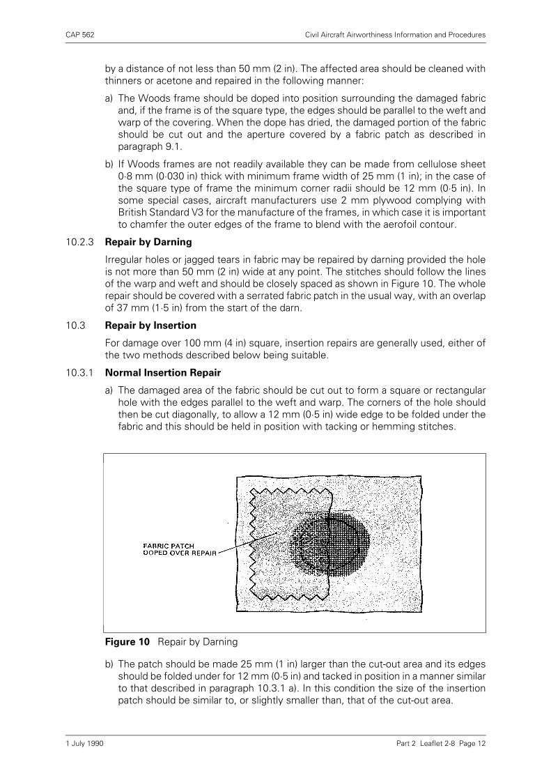
CAP 562 Civil Aircraft Airworthiness Information and Procedures
Part 2 Leaflet 2-8 Page 12
by a distance of not less than 50 mm (2 in). The affected area should be cleaned withthinners or acetone and repaired in the following manner:
a) The Woods frame should be doped into position surrounding the damaged fabricand, if the frame is of the square type, the edges should be parallel to the weft andwarp of the covering. When the dope has dried, the damaged portion of the fabricshould be cut out and the aperture covered by a fabric patch as described inparagraph 9.1.
b) If Woods frames are not readily available they can be made from cellulose sheet0·8 mm (0·030 in) thick with minimum frame width of 25 mm (1 in); in the case ofthe square type of frame the minimum corner radii should be 12 mm (0·5 in). Insome special cases, aircraft manufacturers use 2 mm plywood complying withBritish Standard V3 for the manufacture of the frames, in which case it is importantto chamfer the outer edges of the frame to blend with the aerofoil contour.
10.2.3 Repair by Darning
Irregular holes or jagged tears in fabric may be repaired by darning provided the holeis not more than 50 mm (2 in) wide at any point. The stitches should follow the linesof the warp and weft and should be closely spaced as shown in Figure 10. The wholerepair should be covered with a serrated fabric patch in the usual way, with an overlapof 37 mm (1·5 in) from the start of the darn.
10.3 Repair by Insertion
For damage over 100 mm (4 in) square, insertion repairs are generally used, either ofthe two methods described below being suitable.
10.3.1 Normal Insertion Repair
a) The damaged area of the fabric should be cut out to form a square or rectangularhole with the edges parallel to the weft and warp. The corners of the hole shouldthen be cut diagonally, to allow a 12 mm (0·5 in) wide edge to be folded under thefabric and this should be held in position with tacking or hemming stitches.
b) The patch should be made 25 mm (1 in) larger than the cut-out area and its edgesshould be folded under for 12 mm (0·5 in) and tacked in position in a manner similarto that described in paragraph 10.3.1 a). In this condition the size of the insertionpatch should be similar to, or slightly smaller than, that of the cut-out area.
Figure 10 Repair by Darning
1 July 1990
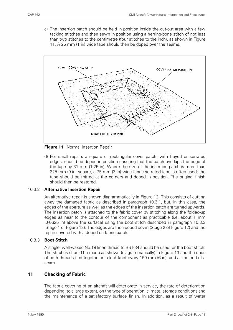
CAP 562 Civil Aircraft Airworthiness Information and Procedures
Part 2 Leaflet 2-8 Page 13
c) The insertion patch should be held in position inside the cut-out area with a fewtacking stitches and then sewn in position using a herring-bone stitch of not lessthan two stitches to the centimetre (four stitches to the inch), as shown in Figure11. A 25 mm (1 in) wide tape should then be doped over the seams.
d) For small repairs a square or rectangular cover patch, with frayed or serratededges, should be doped in position ensuring that the patch overlaps the edge ofthe tape by 31 mm (1·25 in). Where the size of the insertion patch is more than225 mm (9 in) square, a 75 mm (3 in) wide fabric serrated tape is often used; thetape should be mitred at the corners and doped in position. The original finishshould then be restored.
10.3.2 Alternative Insertion Repair
An alternative repair is shown diagrammatically in Figure 12. This consists of cuttingaway the damaged fabric as described in paragraph 10.3.1, but, in this case, theedges of the aperture as well as the edges of the insertion patch are turned upwards.The insertion patch is attached to the fabric cover by stitching along the folded-upedges as near to the contour of the component as practicable (i.e. about 1 mm(0·0625 in) above the surface) using the boot stitch described in paragraph 10.3.3(Stage 1 of Figure 12). The edges are then doped down (Stage 2 of Figure 12) and therepair covered with a doped-on fabric patch.
10.3.3 Boot Stitch
A single, well-waxed No.18 linen thread to BS F34 should be used for the boot stitch.The stitches should be made as shown (diagrammatically) in Figure 13 and the endsof both threads tied together in a lock knot every 150 mm (6 in), and at the end of aseam.
11 Checking of Fabric
The fabric covering of an aircraft will deteriorate in service, the rate of deteriorationdepending, to a large extent, on the type of operation, climate, storage conditions andthe maintenance of a satisfactory surface finish. In addition, as a result of water
Figure 11 Normal Insertion Repair
1 July 1990
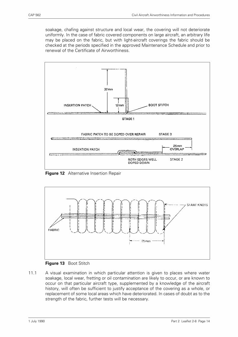
CAP 562 Civil Aircraft Airworthiness Information and Procedures
Part 2 Leaflet 2-8 Page 14
soakage, chafing against structure and local wear, the covering will not deteriorateuniformly. In the case of fabric covered components on large aircraft, an arbitrary lifemay be placed on the fabric, but with light-aircraft coverings the fabric should bechecked at the periods specified in the approved Maintenance Schedule and prior torenewal of the Certificate of Airworthiness.
11.1 A visual examination in which particular attention is given to places where watersoakage, local wear, fretting or oil contamination are likely to occur, or are known tooccur on that particular aircraft type, supplemented by a knowledge of the aircrafthistory, will often be sufficient to justify acceptance of the covering as a whole, orreplacement of some local areas which have deteriorated. In cases of doubt as to thestrength of the fabric, further tests will be necessary.
Figure 12 Alternative Insertion Repair
Figure 13 Boot Stitch
1 July 1990

CAP 562 Civil Aircraft Airworthiness Information and Procedures
Part 2 Leaflet 2-8 Page 15
11.2 One method of checking the strength of an aircraft covering is by the use of a portabletester such as the one described in paragraph 11.3 and illustrated in Figure 14. Thesetesters are, generally, only suitable for checking the condition of coverings on whichthe dope finish has penetrated the fabric. Finishes such as cellulose acetate butyratedope do not normally penetrate the fabric and experience has shown that theabsorption of moisture in humid conditions can produce unreliable test results. Inaddition, butyrate dope, even when some penetration of the fabric has occurred,produces a finish which hardens with age; as a result the conical point on the testerwill not readily penetrate the covering and the test will tend to indicate that the fabricis stronger than it actually is. Thus where butyrate dope has been used, or the dope,irrespective of type, does not penetrate the fabric, laboratory tests should be carriedout. For a laboratory test the dope should be removed from the fabric, using a suitablesolvent where necessary. Fabric having a strength of at least 70% of the strength ofnew fabric to the appropriate specification (as assessed by either test), may beconsidered airworthy, but fabric which falls only just within the acceptable rangeshould be checked more frequently thereafter to ensure continued serviceability.
11.3 Portable Tester
This consists of a penetrating cone and plunger housed within a sleeve assembly.When pressed against a surface the cone is forced up through the sleeve againstspring pressure and the plunger projects through the top of the sleeve in the sameway as a tyre pressure gauge. When inspecting fabric, the tester should be held at90º to the surface and pressure applied towards the fabric in a rotary motion, until thesleeve flange touches the surface (Figure 14). The degree to which the cone haspenetrated the fabric is indicated by the length of plunger showing above the sleeveand this is marked either by coloured bands or a graduated scale.
11.3.1 A table is provided with the tester giving the colour or scale reading required for aparticular type of fabric.
NOTE: The portable tester described here is of American manufacture and the tablesupplied refers to fabric complying with American specifications (AMS, TSO andMIL). It can be adapted for use on fabrics complying with DTD and BS specificationsby comparing the strength requirements of the fabrics.
11.3.2 The test should be repeated at various positions and the lowest reading obtained,other than in isolated repairable areas, should be considered representative of thesurface as a whole.
NOTE: It is important to ensure that the test is not made through double layers of fabric,since this would not be representative of the entire surface.
11.3.3 All punctures produced by the tester should be repaired with a 50 mm or 75 mm (2 inor 3 in) diameter doped fabric patch.
1 July 1990
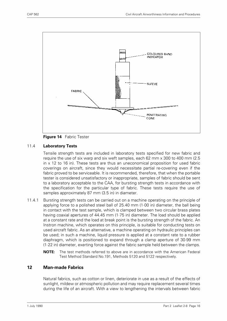
CAP 562 Civil Aircraft Airworthiness Information and Procedures
Part 2 Leaflet 2-8 Page 16
11.4 Laboratory Tests
Tensile strength tests are included in laboratory tests specified for new fabric andrequire the use of six warp and six weft samples, each 62 mm x 300 to 400 mm (2.5in x 12 to 16 in). These tests are thus an uneconomical proposition for used fabriccoverings on aircraft, since they would necessitate partial re-covering even if thefabric proved to be serviceable. It is recommended, therefore, that when the portabletester is considered unsatisfactory or inappropriate, samples of fabric should be sentto a laboratory acceptable to the CAA, for bursting strength tests in accordance withthe specification for the particular type of fabric. These tests require the use ofsamples approximately 87 mm (3.5 in) in diameter.
11.4.1 Bursting strength tests can be carried out on a machine operating on the principle ofapplying force to a polished steel ball of 25.40 mm (1·00 in) diameter, the ball beingin contact with the test sample, which is clamped between two circular brass plateshaving coaxial apertures of 44.45 mm (1·75 in) diameter. The load should be appliedat a constant rate and the load at break point is the bursting strength of the fabric. AnInstron machine, which operates on this principle, is suitable for conducting tests onused aircraft fabric. As an alternative, a machine operating on hydraulic principles canbe used; in such a machine, liquid pressure is applied at a constant rate to a rubberdiaphragm, which is positioned to expand through a clamp aperture of 30·99 mm(1·22 in) diameter, exerting force against the fabric sample held between the clamps.
NOTE: The test methods referred to above are in accordance with the American FederalTest Method Standard No.191, Methods 5120 and 5122 respectively.
12 Man-made Fabrics
Natural fabrics, such as cotton or linen, deteriorate in use as a result of the effects ofsunlight, mildew or atmospheric pollution and may require replacement several timesduring the life of an aircraft. With a view to lengthening the intervals between fabric
Figure 14 Fabric Tester
1 July 1990
CAP 562 Civil Aircraft Airworthiness Information and Procedures
Part 2 Leaflet 2-8 Page 17
replacements, several man-made fabrics have been developed and are approved insome countries for use on specific aircraft. The two main types of materials arepolyester-fibre and glass-fibre, which are marketed under various trade names. Themethods of covering aircraft with these fabrics are briefly discussed in paragraphs12.1 and 12.2, but it is important that the instructions issued by the manufacturer ofthe aircraft or fabric should be carefully followed and only the specified materialsused.
12.1 Polyester-Fibre Materials
These materials may be attached to the structure by the method described inparagraph 5, by use of pre-sewn covering envelopes or by use of an approvedadhesive at the points of contact with the structure. The materials used forattachment and stringing must be compatible with the main fabric.
12.1.1 Before stringing, polyester fibre covers are tautened by the application of heat, thedegree of shrinkage being proportional to the heat applied. The most commonmethod of applying heat is a household iron set at about 120°C ('wool' setting), andused in an ironing motion. Care is necessary to prevent the application of excessiveheat as this may melt the fibre, or overtauten the cover and distort the underlyingstructure. Where non-tautening dope is used, the cover may be fully tautened prior todoping, but where tautening dope is used the initial shrinkage should leave the coverfairly slack, since tautening will continue over a period of months after the dope hasbeen applied.
12.1.2 Repairs within the specified limits may be carried out as described in paragraph 10,or patches may be stuck on, using a suitable adhesive. Large patches should betautened in the same way as the main cover.
12.2 Glass-Fibre Materials
Glass-fibre fabric is normally fitted to the mainplane and tailplane in a spanwisedirection, being attached at the leading and trailing edges with a 50 mm (2 in) dopedseam. Fuselages may conveniently be covered using four pieces of material at thetop, bottom and sides, doped seams again being employed. Some glass-fibre materialis pre-treated to make it compatible with cellulose acetate butyrate dope and is notsuitable for use with cellulose nitrate dope.
12.2.1 The structure should be prepared by removing all sharp edges from the parts whichwill be in contact with the cover. Wooden parts should be lightly sanded and metaledges taped to prevent chafing.
12.2.2 Glass-fibre material is only slightly tautened by doping and must be a good initial fit,after which glass-fibre stringing should be fitted in the appropriate manner (paragraph6.4).
12.2.3 Repairs within the specified limits may be made by cutting out the damaged area offabric and doping on a cover patch which overlaps 50 mm (2 in) all round.
1 July 1990

INTENTIONALLY LEFT BLANK
CAP 562 Civil Aircraft Airworthiness Information and Procedures
Part 2 Leaflet 2-9 Page 1
Leaflet 2-9 Doping
1 Introduction
Fabric has been used from the early days of the aeroplane as a covering for fuselagesand aerofoils. It still continues to provide good service for light aircraft but must beprotected from deterioration by the application of a dope film. Natural fabrics, such ascotton or linen, deteriorate in use as a result of the effects of sunlight, mildew andatmospheric pollution. Man-made fibres resist some of these agents better thannatural fabrics but still require protection. The dope film then achieves the followingfunctions:
a) Tautening of natural fabrics,
b) Waterproofing,
c) Airproofing,
d) Lightproofing.
1.1 The purpose of this Leaflet is to provide guidance and advice on the appropriateworking conditions and methods of application of dope to aircraft fabric. OtherLeaflets with related information are 2–7 Paint Finishing of Metal Aircraft and 2–8Fabric Covering.
2 Materials
The basic film consists of dope but other materials are used in its application, asdescribed in the following paragraphs.
2.1 Dopes
Dope consists of a number of resins dissolved in a solvent to permit application bybrush or spray. This formulation is then modified with plasticisers and pigments toadd flexibility and the required colour (see Figure 1). There are two types of dope inuse, namely, cellulose nitrate and cellulose acetate butyrate. The former is usuallyknown simply as nitrate dope and the latter as butyrate or CAB dope. The maindifference between the two types of dope is the film base. In nitrate dope a specialcotton is dissolved in nitric acid, whilst in butyrate dope cellulose fibres are dissolvedin acetic acid and mixed with butyl alcohols. The plasticisers in the two dopes are alsodifferent, as are the resin balance and solvent balances. Dope must be stored undersuitable conditions (see Leaflet 1–8), and has a tendency to become acid with age; ifold dope is used for refinishing an aircraft it will quickly rot the fabric. Only fresh dopeshould be used, preferably buying it for the job in hand.
2.2 Dope-Proof Paints
Due to the nature of the solvents used in dope, many paints will be attacked andsoftened by it. Dope-proof paint is therefore used to coat structure which will be incontact with the doped fabric. In the case of wooden structure, spar varnish providesa good dope-resistant finish and an epoxy primer is suitable for metal structures.
2.3 Aluminium Dope
To make the fabric lightproof and so prevent damage from ultra-violet radiation, analuminium dope is used. This is usually supplied ready mixed but can be prepared bymixing aluminium paste or powder in clear dope but it is essential that the materials
1 July 1990
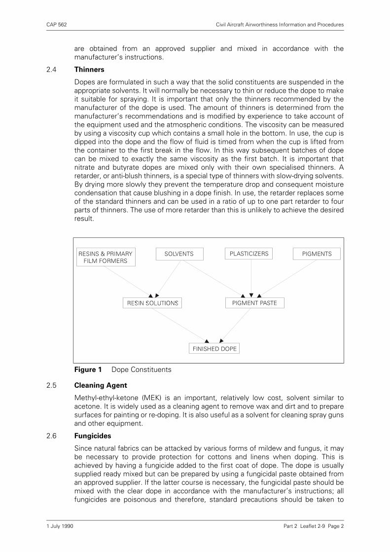
CAP 562 Civil Aircraft Airworthiness Information and Procedures
Part 2 Leaflet 2-9 Page 2
are obtained from an approved supplier and mixed in accordance with themanufacturer’s instructions.
2.4 Thinners
Dopes are formulated in such a way that the solid constituents are suspended in theappropriate solvents. It will normally be necessary to thin or reduce the dope to makeit suitable for spraying. It is important that only the thinners recommended by themanufacturer of the dope is used. The amount of thinners is determined from themanufacturer’s recommendations and is modified by experience to take account ofthe equipment used and the atmospheric conditions. The viscosity can be measuredby using a viscosity cup which contains a small hole in the bottom. In use, the cup isdipped into the dope and the flow of fluid is timed from when the cup is lifted fromthe container to the first break in the flow. In this way subsequent batches of dopecan be mixed to exactly the same viscosity as the first batch. It is important thatnitrate and butyrate dopes are mixed only with their own specialised thinners. Aretarder, or anti-blush thinners, is a special type of thinners with slow-drying solvents.By drying more slowly they prevent the temperature drop and consequent moisturecondensation that cause blushing in a dope finish. In use, the retarder replaces someof the standard thinners and can be used in a ratio of up to one part retarder to fourparts of thinners. The use of more retarder than this is unlikely to achieve the desiredresult.
2.5 Cleaning Agent
Methyl-ethyl-ketone (MEK) is an important, relatively low cost, solvent similar toacetone. It is widely used as a cleaning agent to remove wax and dirt and to preparesurfaces for painting or re-doping. It is also useful as a solvent for cleaning spray gunsand other equipment.
2.6 Fungicides
Since natural fabrics can be attacked by various forms of mildew and fungus, it maybe necessary to provide protection for cottons and linens when doping. This isachieved by having a fungicide added to the first coat of dope. The dope is usuallysupplied ready mixed but can be prepared by using a fungicidal paste obtained froman approved supplier. If the latter course is necessary, the fungicidal paste should bemixed with the clear dope in accordance with the manufacturer’s instructions; allfungicides are poisonous and therefore, standard precautions should be taken to
Figure 1 Dope Constituents
RESINS & PRIMARYFILM FORMERS
PLASTICIZERS PIGMENTS
PIGMENT PASTE
FINISHED DOPE
SOLVENTS
1 July 1990
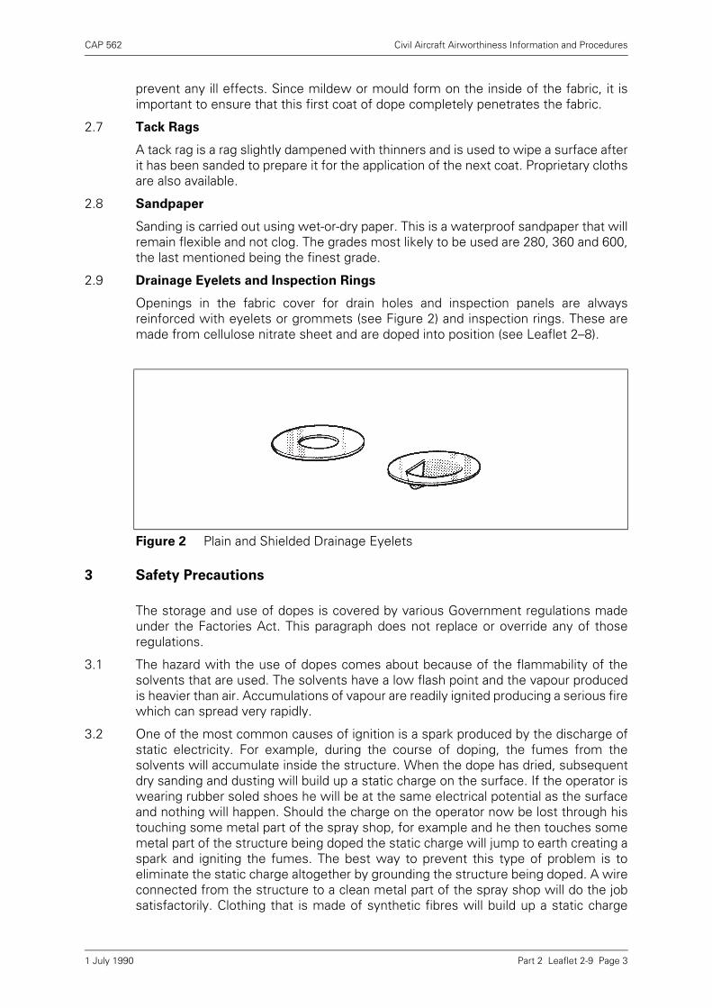
CAP 562 Civil Aircraft Airworthiness Information and Procedures
Part 2 Leaflet 2-9 Page 3
prevent any ill effects. Since mildew or mould form on the inside of the fabric, it isimportant to ensure that this first coat of dope completely penetrates the fabric.
2.7 Tack Rags
A tack rag is a rag slightly dampened with thinners and is used to wipe a surface afterit has been sanded to prepare it for the application of the next coat. Proprietary clothsare also available.
2.8 Sandpaper
Sanding is carried out using wet-or-dry paper. This is a waterproof sandpaper that willremain flexible and not clog. The grades most likely to be used are 280, 360 and 600,the last mentioned being the finest grade.
2.9 Drainage Eyelets and Inspection Rings
Openings in the fabric cover for drain holes and inspection panels are alwaysreinforced with eyelets or grommets (see Figure 2) and inspection rings. These aremade from cellulose nitrate sheet and are doped into position (see Leaflet 2–8).
3 Safety Precautions
The storage and use of dopes is covered by various Government regulations madeunder the Factories Act. This paragraph does not replace or override any of thoseregulations.
3.1 The hazard with the use of dopes comes about because of the flammability of thesolvents that are used. The solvents have a low flash point and the vapour producedis heavier than air. Accumulations of vapour are readily ignited producing a serious firewhich can spread very rapidly.
3.2 One of the most common causes of ignition is a spark produced by the discharge ofstatic electricity. For example, during the course of doping, the fumes from thesolvents will accumulate inside the structure. When the dope has dried, subsequentdry sanding and dusting will build up a static charge on the surface. If the operator iswearing rubber soled shoes he will be at the same electrical potential as the surfaceand nothing will happen. Should the charge on the operator now be lost through histouching some metal part of the spray shop, for example and he then touches somemetal part of the structure being doped the static charge will jump to earth creating aspark and igniting the fumes. The best way to prevent this type of problem is toeliminate the static charge altogether by grounding the structure being doped. A wireconnected from the structure to a clean metal part of the spray shop will do the jobsatisfactorily. Clothing that is made of synthetic fibres will build up a static charge
Figure 2 Plain and Shielded Drainage Eyelets
1 July 1990
CAP 562 Civil Aircraft Airworthiness Information and Procedures
Part 2 Leaflet 2-9 Page 4
more readily than that made from cotton. Leather soled shoes will allow any staticcharge to be dissipated to ground. When spraying nitrate dope ensure that the spraygun, the operator and the structure being doped are all grounded together.
3.3 The standard of housekeeping in the spray shop is an important aspect of safety. Ifthe floor becomes contaminated with dried nitrate dope overspray, subsequentsweeping will produce a static charge with the attendant risk of ignition and possibleexplosion. To clean the floor, it should be doused well with water and then sweptwhilst it is still wet. Since dopes will not be the only materials used in a spray shop,it should be noted that spontaneous combustion can be the result of a mixing of dopeand zinc chromate oversprays.
3.4 The fumes created during the spraying process are hazardous to health as well asbeing a fire risk. Proper operator protection must be provided as recommended in thedope manufacturer’s technical literature. At the first sign of any irritation of the skinor eyes, difficulty in breathing or a dry cough, the operator should stop work and seekmedical advice.
3.5 Electrical equipment to be used in the spray shop must be of such a nature that itcannot ignite the vapours that will be present. Lead Lamps must be of the explosion-proof variety and dopes must not be mixed using stirrers driven by portable electricdrills.
4 Working Conditions
In order to accomplish a proper dope job, it is important to control both thetemperature and humidity of the air in the spray shop. In addition to this it is necessaryto maintain sufficient air flow through the shop to remove the heavy vapours causedby atomisation and evaporation of the solvents used.
4.1 To maintain a suitable air flow through the spray shop it is necessary to install a fan atfloor level since the vapours produced are heavier than air. The fan must be explosionproof, as must be all other electrical equipment installed in the area. The rate of airflow is dictated by the size of the spray shop and is the subject of various Governmentregulations. The discharge of the vapours may also be the subject of furtherrequirements and the advice of the Factory Inspectorate should be sought. The airinlet to the spray shop should preferably be in an adjoining room, or at least behind asuitable baffle, in order to reduce draughts to a minimum. If the inlet is in a separateroom then the air temperature can be raised to that required before entering the sprayshop.
4.2 Many problems associated with doping can be traced to incorrect temperatures of theair or the dope. If the dope has been left overnight in a cold place then it will take manyhours to bring it to the room temperature. Overnight heating of the spray shop is themost satisfactory method to prepare for doping since it usually results in moreuniform temperatures throughout the shop. Rapid heating tends to result in stratifiedheating with the ceiling being considerably hotter than the floor level. Air temperatureshould be maintained between approximately 21° and 26°C (70° to 79°F) for bestresults. If the temperature is too low the rapid evaporation of the solvents will lowerthe temperature of the surface to the point where moisture will condense and betrapped in the finish. Too high a temperature causes very rapid drying of the dopewhich can result in pin holes and blisters. The only satisfactory way to operate is toconstantly monitor and control the air temperature as necessary.
1 July 1990
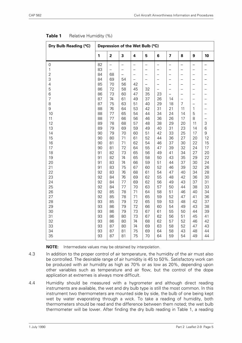
CAP 562 Civil Aircraft Airworthiness Information and Procedures
Part 2 Leaflet 2-9 Page 5
NOTE: Intermediate values may be obtained by interpolation.
4.3 In addition to the proper control of air temperature, the humidity of the air must alsobe controlled. The desirable range of air humidity is 45 to 50%. Satisfactory work canbe produced with air humidity as high as 70% or as low as 20%, depending uponother variables such as temperature and air flow, but the control of the dopeapplication at extremes is always more difficult.
4.4 Humidity should be measured with a hygrometer and although direct readinginstruments are available, the wet and dry bulb type is still the most common. In thisinstrument two thermometers are mounted side by side, the bulb of one being keptwet by water evaporating through a wick. To take a reading of humidity, boththermometers should be read and the difference between them noted; the wet bulbthermometer will be lower. After finding the dry bulb reading in Table 1, a reading
Table 1 Relative Humidity (%)
Dry Bulb Reading (°C) Depression of the Wet Bulb (°C)
1 2 3 4 5 6 7 8 9 10
01234567891011121314151617181920212223242526272829303132333435
828384848586868787888888898990909090919191919292929292929393939393939393
––68697072737475767777787979808181828283838384848485858586868686878787
–––545658606163646566686970717172737474757676777778787979798080808181
––––4245474951535456575960616264656566676869697071717272737374747575
–––––32353740424446484951525455565859606162626364656566676768696970
––––––232629313436384042444647495051525455565758595960616262636464
–––––––1418212426293133363739414344464748495051525354555657585859
––––––––7111417202325273032343537394042434446474849505152524354
–––––––––158111417202224272930323436373840414243444546474849
––––––––––––369121517202224262830313334363738394142434444
1 July 1990
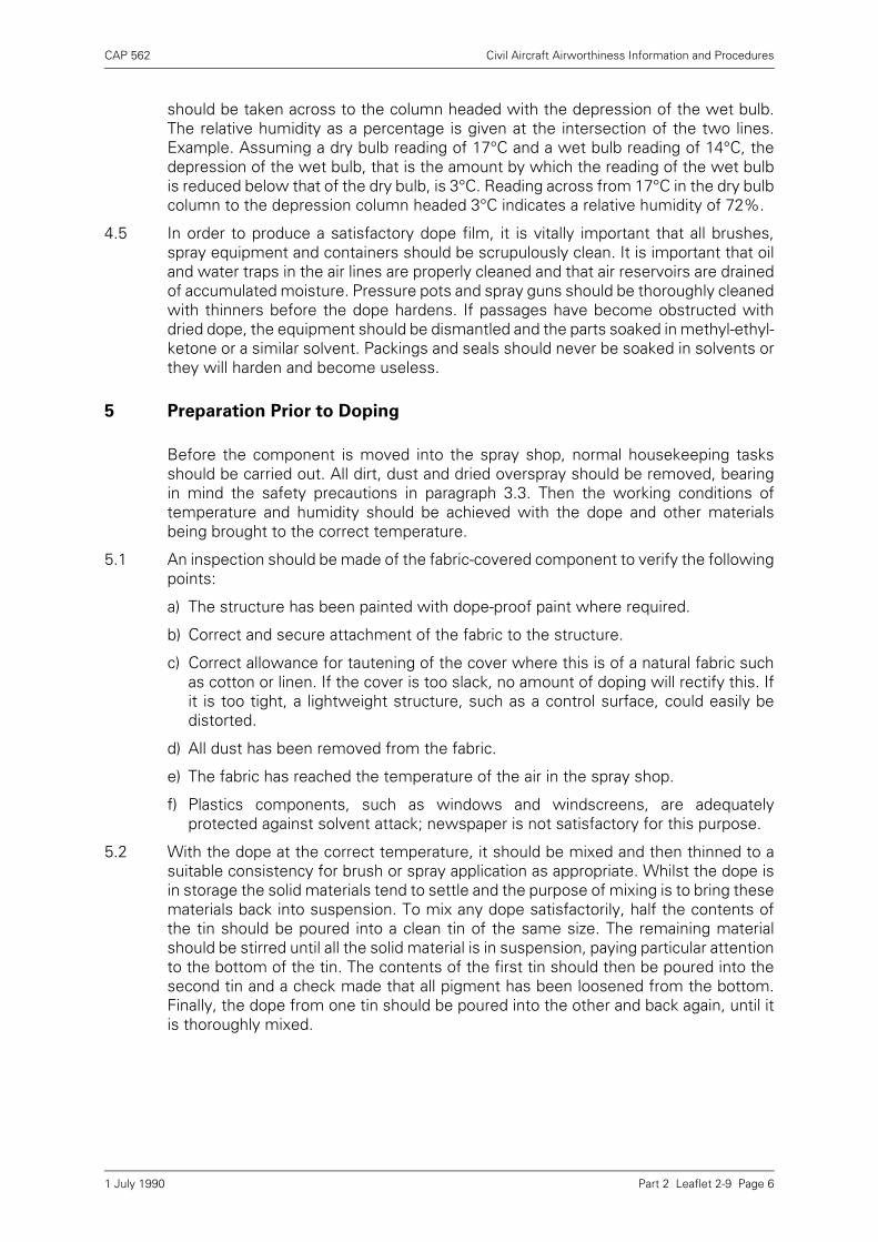
CAP 562 Civil Aircraft Airworthiness Information and Procedures
Part 2 Leaflet 2-9 Page 6
should be taken across to the column headed with the depression of the wet bulb.The relative humidity as a percentage is given at the intersection of the two lines.Example. Assuming a dry bulb reading of 17°C and a wet bulb reading of 14°C, thedepression of the wet bulb, that is the amount by which the reading of the wet bulbis reduced below that of the dry bulb, is 3°C. Reading across from 17°C in the dry bulbcolumn to the depression column headed 3°C indicates a relative humidity of 72%.
4.5 In order to produce a satisfactory dope film, it is vitally important that all brushes,spray equipment and containers should be scrupulously clean. It is important that oiland water traps in the air lines are properly cleaned and that air reservoirs are drainedof accumulated moisture. Pressure pots and spray guns should be thoroughly cleanedwith thinners before the dope hardens. If passages have become obstructed withdried dope, the equipment should be dismantled and the parts soaked in methyl-ethyl-ketone or a similar solvent. Packings and seals should never be soaked in solvents orthey will harden and become useless.
5 Preparation Prior to Doping
Before the component is moved into the spray shop, normal housekeeping tasksshould be carried out. All dirt, dust and dried overspray should be removed, bearingin mind the safety precautions in paragraph 3.3. Then the working conditions oftemperature and humidity should be achieved with the dope and other materialsbeing brought to the correct temperature.
5.1 An inspection should be made of the fabric-covered component to verify the followingpoints:
a) The structure has been painted with dope-proof paint where required.
b) Correct and secure attachment of the fabric to the structure.
c) Correct allowance for tautening of the cover where this is of a natural fabric suchas cotton or linen. If the cover is too slack, no amount of doping will rectify this. Ifit is too tight, a lightweight structure, such as a control surface, could easily bedistorted.
d) All dust has been removed from the fabric.
e) The fabric has reached the temperature of the air in the spray shop.
f) Plastics components, such as windows and windscreens, are adequatelyprotected against solvent attack; newspaper is not satisfactory for this purpose.
5.2 With the dope at the correct temperature, it should be mixed and then thinned to asuitable consistency for brush or spray application as appropriate. Whilst the dope isin storage the solid materials tend to settle and the purpose of mixing is to bring thesematerials back into suspension. To mix any dope satisfactorily, half the contents ofthe tin should be poured into a clean tin of the same size. The remaining materialshould be stirred until all the solid material is in suspension, paying particular attentionto the bottom of the tin. The contents of the first tin should then be poured into thesecond tin and a check made that all pigment has been loosened from the bottom.Finally, the dope from one tin should be poured into the other and back again, until itis thoroughly mixed.
1 July 1990
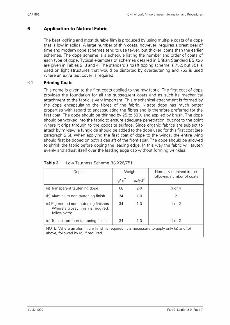
CAP 562 Civil Aircraft Airworthiness Information and Procedures
Part 2 Leaflet 2-9 Page 7
6 Application to Natural Fabric
The best looking and most durable film is produced by using multiple coats of a dopethat is low in solids. A large number of thin coats, however, requires a great deal oftime and modern dope schemes tend to use fewer, but thicker, coats than the earlierschemes. The dope scheme is a schedule listing the number and order of coats ofeach type of dope. Typical examples of schemes detailed in British Standard BS X26are given in Tables 2, 3 and 4. The standard aircraft doping scheme is 752, but 751 isused on light structures that would be distorted by overtautening and 753 is usedwhere an extra taut cover is required.
6.1 Priming Coats
This name is given to the first coats applied to the raw fabric. The first coat of dopeprovides the foundation for all the subsequent coats and as such its mechanicalattachment to the fabric is very important. This mechanical attachment is formed bythe dope encapsulating the fibres of the fabric. Nitrate dope has much betterproperties with regard to encapsulating the fibres and is therefore preferred for thefirst coat. The dope should be thinned by 25 to 50% and applied by brush. The dopeshould be worked into the fabric to ensure adequate penetration, but not to the pointwhere it drips through to the opposite surface. Since organic fabrics are subject toattack by mildew, a fungicide should be added to the dope used for this first coat (seeparagraph 2.6). When applying the first coat of dope to the wings, the entire wingshould first be doped on both sides aft of the front spar. The dope should be allowedto shrink the fabric before doping the leading edge. In this way the fabric will tautenevenly and adjust itself over the leading edge cap without forming wrinkles.
Table 2 Low Tautness Scheme BS X26/751
Dope Weight Normally obtained in the following number of coats
g/m2 oz/yd2
(a) Transparent tautening dope 68 2·0 3 or 4
(b) Aluminium non-tautening finish 34 1·0 2
(c) Pigmented non-tautening finishes Where a glossy finish is required, follow with:
34 1·0 1 or 2
(d) Transparent non-tautening finish 34 1·0 1 or 2
NOTE: Where an aluminium finish is required, it is necessary to apply only (a) and (b) above, followed by (d) if required.
1 July 1990
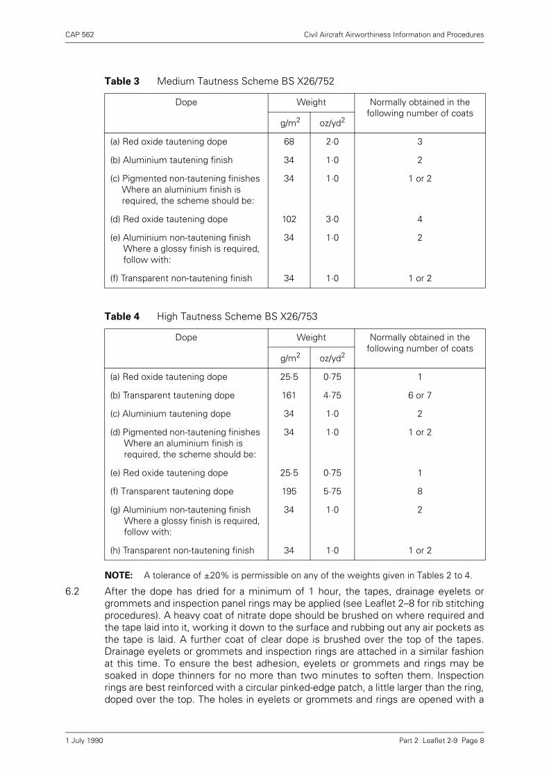
CAP 562 Civil Aircraft Airworthiness Information and Procedures
Part 2 Leaflet 2-9 Page 8
NOTE: A tolerance of ±20% is permissible on any of the weights given in Tables 2 to 4.
6.2 After the dope has dried for a minimum of 1 hour, the tapes, drainage eyelets orgrommets and inspection panel rings may be applied (see Leaflet 2–8 for rib stitchingprocedures). A heavy coat of nitrate dope should be brushed on where required andthe tape laid into it, working it down to the surface and rubbing out any air pockets asthe tape is laid. A further coat of clear dope is brushed over the top of the tapes.Drainage eyelets or grommets and inspection rings are attached in a similar fashionat this time. To ensure the best adhesion, eyelets or grommets and rings may besoaked in dope thinners for no more than two minutes to soften them. Inspectionrings are best reinforced with a circular pinked-edge patch, a little larger than the ring,doped over the top. The holes in eyelets or grommets and rings are opened with a
Table 3 Medium Tautness Scheme BS X26/752
Dope Weight Normally obtained in the following number of coats
g/m2 oz/yd2
(a) Red oxide tautening dope 68 2·0 3
(b) Aluminium tautening finish 34 1·0 2
(c) Pigmented non-tautening finishes Where an aluminium finish is required, the scheme should be:
34 1·0 1 or 2
(d) Red oxide tautening dope 102 3·0 4
(e) Aluminium non-tautening finish Where a glossy finish is required, follow with:
34 1·0 2
(f) Transparent non-tautening finish 34 1·0 1 or 2
Table 4 High Tautness Scheme BS X26/753
Dope Weight Normally obtained in the following number of coats
g/m2 oz/yd2
(a) Red oxide tautening dope 25·5 0·75 1
(b) Transparent tautening dope 161 4·75 6 or 7
(c) Aluminium tautening dope 34 1·0 2
(d) Pigmented non-tautening finishes Where an aluminium finish is required, the scheme should be:
34 1·0 1 or 2
(e) Red oxide tautening dope 25·5 0·75 1
(f) Transparent tautening dope 195 5·75 8
(g) Aluminium non-tautening finish Where a glossy finish is required, follow with:
34 1·0 2
(h) Transparent non-tautening finish 34 1·0 1 or 2
1 July 1990
CAP 562 Civil Aircraft Airworthiness Information and Procedures
Part 2 Leaflet 2-9 Page 9
sharp, pointed knife after doping is complete. The taping is followed by another coatof clear dope which may be butyrate and may be applied by spray gun.
6.3 Filling Coats
When the first butyrate coat has fully dried, the fabric will feel rough due to the shortfibre ends (the nap) standing up. This nap should be very lightly sanded off, using drysandpaper, to leave a smooth finish. The surface should then be rinsed clean withwater and dried thoroughly. Two full wet cross-coats of butyrate dope should nowfollow; a cross-coat is a coat of dope sprayed on in one direction and then coveredwith a second coat at right angles to it before the first coat dries. These in turn shouldbe followed with one good cross-coat of aluminium dope after lightly sanding theclear dope to encourage adhesion. The aluminium coat is in its turn lightly wet sandedto produce a smooth surface and the residue rinsed off with water. Once thealuminium coat has dried, it should be checked for continuity by shining a light insidethe structure. The film should be completely lightproof.
6.4 Finishing Coats
The finishing coats of pigmented butyrate dope may now be sprayed on. The numberof coats will be determined as a balance between quality and cost but should not beless than three. A high gloss finish is obtained by lightly sanding each coat when dryand spraying multiple thin coats rather than several thick coats. The use of a retarderin the colour coats will allow the dope to flow out and form a smoother film. The finalcoat should be allowed to dry for at least a month before it is polished with rubbingcompound and then waxed. The surface should be waxed at least once a year with ahard wax to reduce the possibility of oxidation of the finish.
7 Application to Polyester-fibre Fabric
Polyester-fibre fabrics are being increasingly widely used for covering aircraft becauseof their long life and resistance to deterioration. For this reason it is extremelyimportant that the dope film is of the highest quality so that its life will match that ofthe fabric.
7.1 Priming Coats
Tautening of the fabric cover is not a function of the dope film where synthetic fabricsare used, although all dopes will tauten to some extent. Polyester-fibre fabrics areheat shrunk when the structure is covered. The most notable difference in doping asynthetic cover is the difficulty, when compared with natural fabrics, of obtaining agood mechanical bond between the dope and the fibres of the material. Unlike naturalfibres the polyester filaments are not wet by the dope and the security of attachmentdepends upon them being totally encapsulated by the first coat of dope. The first coatmust be nitrate dope thinned in the ratio of two or three parts of dope to one part ofthinners. This coat is then brushed into the fabric in order to completely encapsulateevery fibre. The dope should form a wet film on the inside of the cover but it shouldnot be so wet that it drips through to the opposite side of the structure. The initial coatshould be followed by two more brush coats of nitrate dope thinned to an easybrushing consistency. Certain additives are approved by the material manufacturer foruse with the first coat for improving adhesion to the fabric. However, since polyesteris not organic, there is no need for a fungicide to be added to the first coat of dope.
7.2 Filling Coats
Taping and attaching of drainage eyelets or grommets and inspection rings followsthe same procedure as for natural fabrics. The priming coats should be followed by
1 July 1990
CAP 562 Civil Aircraft Airworthiness Information and Procedures
Part 2 Leaflet 2-9 Page 10
spraying two fullbodied cross-coats of clear butyrate dope. After these coats havecompletely dried they should be lightly sanded (400 grit) and cleaned thoroughly witha tack rag. One full cross-coat of aluminium dope should then be sprayed on andlightly wet sanded when dry, the residue being rinsed off with water. This coat shouldbe tested to verify that it is lightproof by shining a light inside the structure.
7.3 Finishing Coats
The finishing coats should now be applied in the same manner as for natural fabrics.It should be noted that with a properly finished polyester cover the weave of the fabricwill still show through the dope film. Because the fibres are continually moving, anyattempt to completely hide them will result in a finish that does not have sufficientflexibility to resist cracking.
8 Application to Glass-fibre Fabric
Glass-fibre fabric has a loose weave which tends to make it difficult to apply to aircraftstructures. To overcome this problem it is pre-treated with butyrate dope and thecovering and doping must be carried out in accordance with the manufacturer’sinstallation instructions.
8.1 Priming Coats
Nitrate dope must not be used under any circumstances with this type of fabric. Thefirst coat of clear butyrate dope is sprayed on with the dope being thinned onlyenough to permit proper atomisation. The atomising pressure must be set to thelowest possible that will permit proper atomisation without the dope being blownthrough the fabric. The coat should be heavy enough to thoroughly wet the fabric andsoften the dope in the fabric, but must not be so heavy that it causes the dope to runon the reverse side of the fabric. If the dope is allowed to run in this way an orangepeel finish will develop and the fabric will not tauten properly.
8.2 After the first coat has dried, further coats of butyrate dope should be sprayed on,each a little heavier than the one before it, until the weave fills and the fabric tautens;this may take as many as five coats. Tapes, drainage eyelets or grommets andinspection rings are applied in a coat of butyrate dope.
8.3 Filling Coats
Once the fabric is taut and the weave has been filled, two full-bodied brush coats ofclear butyrate dope should be applied and allowed to dry thoroughly. The film shouldthen be very carefully sanded, making sure that it is not sanded through to the fabric.Whilst the fabric is not damaged by ultra-violet radiation, the clear dope candeteriorate as a result of exposure and therefore, a coat of aluminium dope should besprayed on for protection and lightly wet-sanded smooth. After the aluminium dopehas been sanded, the residue should be removed by washing with water and then thesurface thoroughly dried.
8.4 Finishing Coats
The application of the finishing coats is carried out in the same manner as for naturalfabrics. Several thin, wet coats of coloured butyrate dope will allow the surface toflow out to a glossy finish.
1 July 1990
CAP 562 Civil Aircraft Airworthiness Information and Procedures
Part 2 Leaflet 2-9 Page 11
9 Doping Problems
The production of a doped finish that is both sound and attractive is dependent upona great deal of care and attention being paid to detail at each stage of the finishingprocess. In spite of this, problems do occur and the following paragraphs detail somecommon ones and their possible causes.
9.1 Adhesion
There are two basic areas in which adhesion may be poor; between the fabric and thefirst coat of dope and between the aluminium coat and subsequent coats. Adhesionto the fabric, particularly polyester fabric, is largely dependent upon the techniqueused to ensure the encapsulation of the fibres. Adhesion to the aluminium coat maybe impaired if too much aluminium powder was used or if the surface was notthoroughly cleaned after sanding. The use of a tack rag to finally clean a surfacebefore applying the next coat is always recommended.
9.2 Blushing
Blushing is a white or greyish cast that forms on a doped surface. If the humidity ofthe air is too high, or if the solvents evaporate too quickly, the temperature of thesurface drops below the dew-point of the air and moisture condenses on the surface.This water causes the nitrocellulose to precipitate out. Moisture in the spray systemor on the surface can also cause blushing. Blushing can be controlled by reducing thehumidity in the air (raising the temperature by several degrees may achieve this) or byusing a retarder in the place of some of the thinners. A blushed area can be salvagedby spraying another coat over the area using a retarder instead of some of thethinners; the solvents attack the surface and cause it to flow out.
9.3 Bubbles or Blisters
Bubbles or Blisters are caused by the surface of the dope drying before all thesolvents have had time to evaporate. This may happen if a heavy coat of dope isapplied over a previous coat that had not fully dried.
9.4 Dull Finish
The gloss of butyrate dope may be improved by the addition of up to 20% retarder inthe last coat. Excessive dullness may be caused by holding the spray gun too far fromthe surface so that the dope settles as a semi-dry mist. Small dull spots may be dueto a porous surface under the area.
9.5 Fisheyes
These are isolated areas which have not dried due to contamination of the surfacewith oil, wax or a silicone product. Cleanliness is important, especially whenrefinishing a repair. All wax should be removed using a suitable solvent beforeattempting to re-dope the surface.
9.6 Orange Peel
This is caused by insufficient thinning of the dope or holding the spray gun too farfrom the surface. It can also be caused by too high an atomising pressure, use ofthinners that is too fast drying or by a cold, damp draught over the surface.
9.7 Pinholes
These are smaller versions of a blister. Apart from the causes listed in paragraph 9.3,they can be caused by water or oil in the spray system. An air temperature that is toohigh can also be a cause.
1 July 1990
CAP 562 Civil Aircraft Airworthiness Information and Procedures
Part 2 Leaflet 2-9 Page 12
9.8 Roping
This is a condition in which the surface dries as the dope is being brushed, resultingin an uneven surface. This is common when the dope is cold and has not beenbrought up to the temperature of the spray shop. When applying dope with a brush,it should not be overbrushed. The brush should be filled with dope then strokedacross the surface and lifted off. The pressure applied to the brush should besufficient to ensure the proper penetration of the dope.
9.9 Rough Finish
Dirt and dust on the surface, insufficient sanding and too low a working temperaturecan all cause a rough finish.
9.10 Runs and Sags
This type of defect is caused by too thick a coat, especially on vertical surfaces. Thiscan be the result of incorrectly adjusted spray equipment or incorrect technique.
9.11 Wet Areas
This is a larger version of the defect described in paragraph 9.5.
10 General Considerations
10.1 The weight of the dope applied to the fabric is an indication that the scheme has beencorrectly applied. In the BS X26 doping schemes the weight per unit area is given andshould be checked by doping a test panel at the same time as the structure. The fabricis weighed before doping and then again after doping, the difference being the weightof the dope film. United States Military Specifications call for a minimum dope weightof 161 g/m2 (4.75 oz/yd2). A tolerance of ±20% may be applied to the weights givenin BS X26.
10.2 When an aircraft is re-covered and re-doped it is essential that it is re-weighed and anew Weight Schedule raised (see Leaflet 1–4).
10.3 After the re-covering, repair and doping of control surfaces it is essential that thestatic balance of each surface is checked against the manufacturer’s requirements.Addition of weight aft of the hinge line without correction of the static balance is likelyto cause flutter of the control surface.
1 July 1990
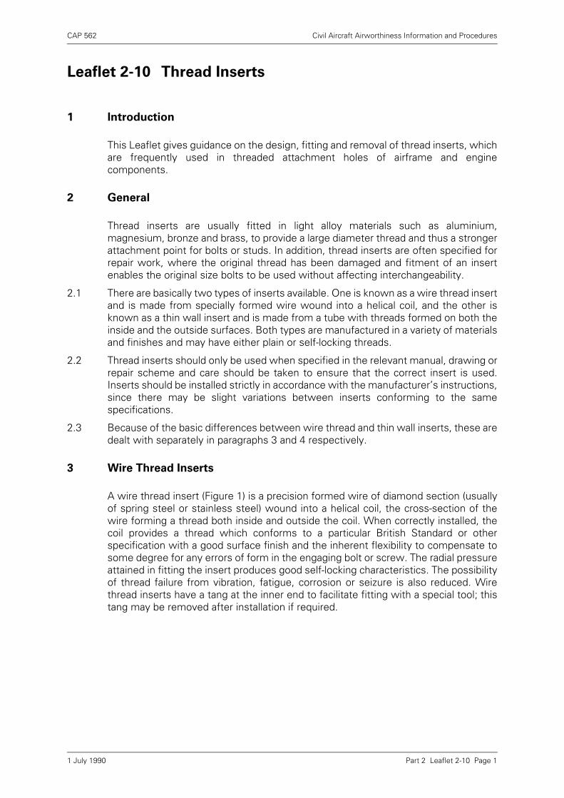
CAP 562 Civil Aircraft Airworthiness Information and Procedures
Part 2 Leaflet 2-10 Page 1
Leaflet 2-10 Thread Inserts
1 Introduction
This Leaflet gives guidance on the design, fitting and removal of thread inserts, whichare frequently used in threaded attachment holes of airframe and enginecomponents.
2 General
Thread inserts are usually fitted in light alloy materials such as aluminium,magnesium, bronze and brass, to provide a large diameter thread and thus a strongerattachment point for bolts or studs. In addition, thread inserts are often specified forrepair work, where the original thread has been damaged and fitment of an insertenables the original size bolts to be used without affecting interchangeability.
2.1 There are basically two types of inserts available. One is known as a wire thread insertand is made from specially formed wire wound into a helical coil, and the other isknown as a thin wall insert and is made from a tube with threads formed on both theinside and the outside surfaces. Both types are manufactured in a variety of materialsand finishes and may have either plain or self-locking threads.
2.2 Thread inserts should only be used when specified in the relevant manual, drawing orrepair scheme and care should be taken to ensure that the correct insert is used.Inserts should be installed strictly in accordance with the manufacturer’s instructions,since there may be slight variations between inserts conforming to the samespecifications.
2.3 Because of the basic differences between wire thread and thin wall inserts, these aredealt with separately in paragraphs 3 and 4 respectively.
3 Wire Thread Inserts
A wire thread insert (Figure 1) is a precision formed wire of diamond section (usuallyof spring steel or stainless steel) wound into a helical coil, the cross-section of thewire forming a thread both inside and outside the coil. When correctly installed, thecoil provides a thread which conforms to a particular British Standard or otherspecification with a good surface finish and the inherent flexibility to compensate tosome degree for any errors of form in the engaging bolt or screw. The radial pressureattained in fitting the insert produces good self-locking characteristics. The possibilityof thread failure from vibration, fatigue, corrosion or seizure is also reduced. Wirethread inserts have a tang at the inner end to facilitate fitting with a special tool; thistang may be removed after installation if required.
1 July 1990
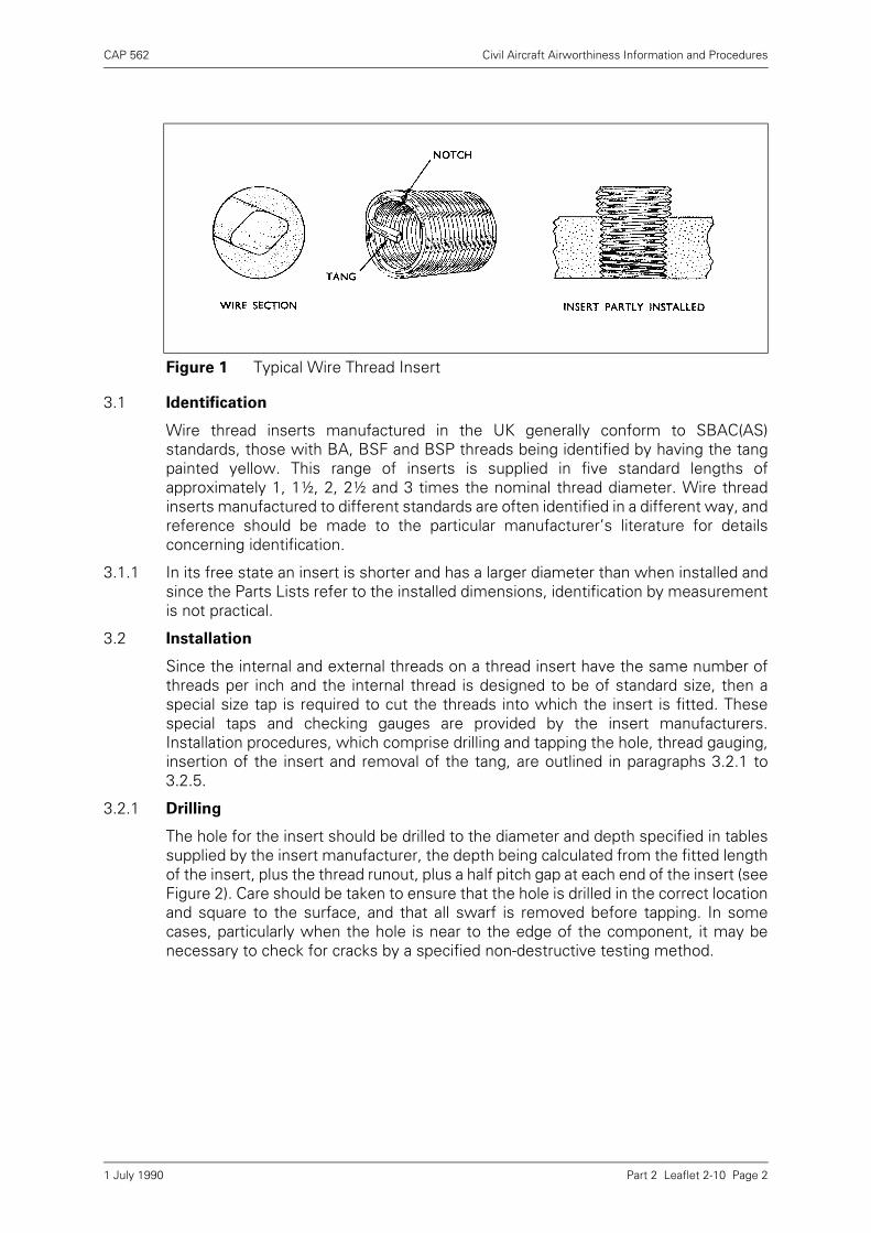
CAP 562 Civil Aircraft Airworthiness Information and Procedures
Part 2 Leaflet 2-10 Page 2
3.1 Identification
Wire thread inserts manufactured in the UK generally conform to SBAC(AS)standards, those with BA, BSF and BSP threads being identified by having the tangpainted yellow. This range of inserts is supplied in five standard lengths ofapproximately 1, 1½, 2, 2½ and 3 times the nominal thread diameter. Wire threadinserts manufactured to different standards are often identified in a different way, andreference should be made to the particular manufacturer’s literature for detailsconcerning identification.
3.1.1 In its free state an insert is shorter and has a larger diameter than when installed andsince the Parts Lists refer to the installed dimensions, identification by measurementis not practical.
3.2 Installation
Since the internal and external threads on a thread insert have the same number ofthreads per inch and the internal thread is designed to be of standard size, then aspecial size tap is required to cut the threads into which the insert is fitted. Thesespecial taps and checking gauges are provided by the insert manufacturers.Installation procedures, which comprise drilling and tapping the hole, thread gauging,insertion of the insert and removal of the tang, are outlined in paragraphs 3.2.1 to3.2.5.
3.2.1 Drilling
The hole for the insert should be drilled to the diameter and depth specified in tablessupplied by the insert manufacturer, the depth being calculated from the fitted lengthof the insert, plus the thread runout, plus a half pitch gap at each end of the insert (seeFigure 2). Care should be taken to ensure that the hole is drilled in the correct locationand square to the surface, and that all swarf is removed before tapping. In somecases, particularly when the hole is near to the edge of the component, it may benecessary to check for cracks by a specified non-destructive testing method.
Figure 1 Typical Wire Thread Insert
1 July 1990
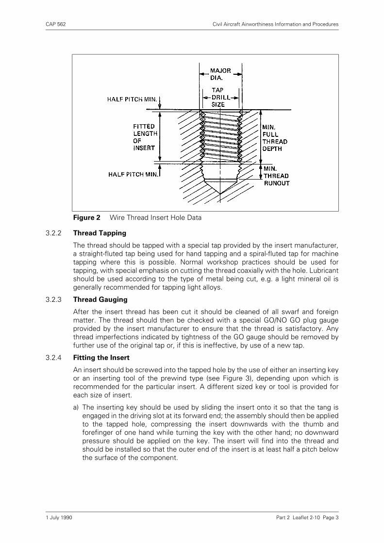
CAP 562 Civil Aircraft Airworthiness Information and Procedures
Part 2 Leaflet 2-10 Page 3
3.2.2 Thread Tapping
The thread should be tapped with a special tap provided by the insert manufacturer,a straight-fluted tap being used for hand tapping and a spiral-fluted tap for machinetapping where this is possible. Normal workshop practices should be used fortapping, with special emphasis on cutting the thread coaxially with the hole. Lubricantshould be used according to the type of metal being cut, e.g. a light mineral oil isgenerally recommended for tapping light alloys.
3.2.3 Thread Gauging
After the insert thread has been cut it should be cleaned of all swarf and foreignmatter. The thread should then be checked with a special GO/NO GO plug gaugeprovided by the insert manufacturer to ensure that the thread is satisfactory. Anythread imperfections indicated by tightness of the GO gauge should be removed byfurther use of the original tap or, if this is ineffective, by use of a new tap.
3.2.4 Fitting the Insert
An insert should be screwed into the tapped hole by the use of either an inserting keyor an inserting tool of the prewind type (see Figure 3), depending upon which isrecommended for the particular insert. A different sized key or tool is provided foreach size of insert.
a) The inserting key should be used by sliding the insert onto it so that the tang isengaged in the driving slot at its forward end; the assembly should then be appliedto the tapped hole, compressing the insert downwards with the thumb andforefinger of one hand while turning the key with the other hand; no downwardpressure should be applied on the key. The insert will find into the thread andshould be installed so that the outer end of the insert is at least half a pitch belowthe surface of the component.
Figure 2 Wire Thread Insert Hole Data
1 July 1990
CAP 562 Civil Aircraft Airworthiness Information and Procedures
Part 2 Leaflet 2-10 Page 4
b) When a prewind tool is used the insert should be placed in the chamber with thetang towards the nozzle and the mandrel pushed forward through the insert toengage the tang in the slot. The mandrel should be rotated clockwise and pushedgently forward to engage the insert coil in the nozzle threads, rotation beingcontinued until the insert is about to emerge from the outer end of the nozzle. Thetool should then be placed squarely over the tapped hole and the handle rotated totransfer the insert from the tool into the tapped hole; no forward pressure shouldbe used.
c) Unless otherwise stated, inserts should be installed so that the outer coil is at leasthalf a pitch below the component surface.
d) Absolute cleanliness of the tapped hole and freedom from burrs is essential toprevent distortion of an insert. When jointing compound or anti-corrosivecompounds are specified, they should be applied strictly according to the relevantinstructions and surplus compound should be removed as specified after installingthe insert.
3.2.5 Removal of the Tang
It is not always necessary to remove the tang of a wire thread insert, but removal maybe specified in some cases for screw clearance or product appearance, both in blindholes and through holes. A tang in a through hole is removed by use of the insertingkey used as a punch, with the tang outside the engaging slot, or by use of a specialpunch (Figure 4). A sharp blow with a hammer on the key or punch will fracture thewire at the notch where the tang joins the coil. To remove the tang from an insertfitted in a blind hole, long round-nosed pliers are required; the tang should be bentbackwards and forwards through the insert bore until it fractures at the notch and canbe removed.
Figure 3 Inserting Key and Prewind Inserting Tool
1 July 1990
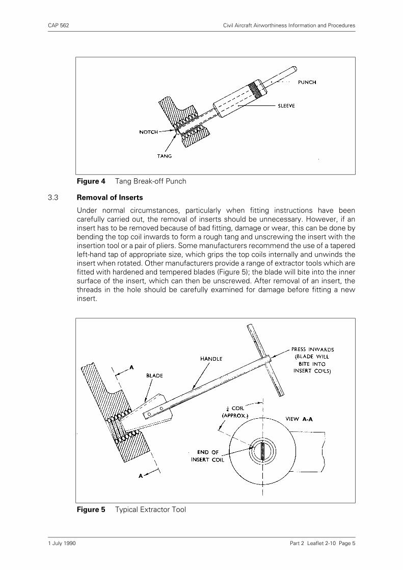
CAP 562 Civil Aircraft Airworthiness Information and Procedures
Part 2 Leaflet 2-10 Page 5
3.3 Removal of Inserts
Under normal circumstances, particularly when fitting instructions have beencarefully carried out, the removal of inserts should be unnecessary. However, if aninsert has to be removed because of bad fitting, damage or wear, this can be done bybending the top coil inwards to form a rough tang and unscrewing the insert with theinsertion tool or a pair of pliers. Some manufacturers recommend the use of a taperedleft-hand tap of appropriate size, which grips the top coils internally and unwinds theinsert when rotated. Other manufacturers provide a range of extractor tools which arefitted with hardened and tempered blades (Figure 5); the blade will bite into the innersurface of the insert, which can then be unscrewed. After removal of an insert, thethreads in the hole should be carefully examined for damage before fitting a newinsert.
Figure 4 Tang Break-off Punch
Figure 5 Typical Extractor Tool
1 July 1990
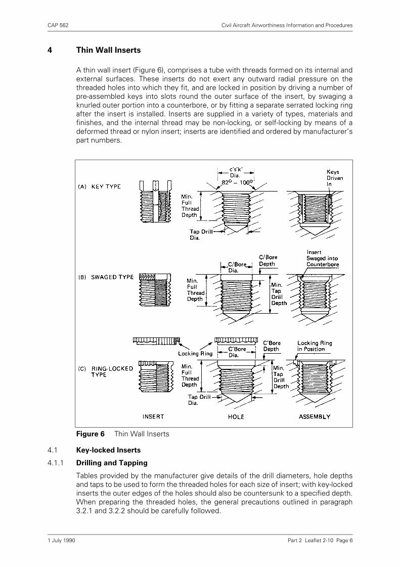
CAP 562 Civil Aircraft Airworthiness Information and Procedures
Part 2 Leaflet 2-10 Page 6
4 Thin Wall Inserts
A thin wall insert (Figure 6), comprises a tube with threads formed on its internal andexternal surfaces. These inserts do not exert any outward radial pressure on thethreaded holes into which they fit, and are locked in position by driving a number ofpre-assembled keys into slots round the outer surface of the insert, by swaging aknurled outer portion into a counterbore, or by fitting a separate serrated locking ringafter the insert is installed. Inserts are supplied in a variety of types, materials andfinishes, and the internal thread may be non-locking, or self-locking by means of adeformed thread or nylon insert; inserts are identified and ordered by manufacturer’spart numbers.
4.1 Key-locked Inserts
4.1.1 Drilling and Tapping
Tables provided by the manufacturer give details of the drill diameters, hole depthsand taps to be used to form the threaded holes for each size of insert; with key-lockedinserts the outer edges of the holes should also be countersunk to a specified depth.When preparing the threaded holes, the general precautions outlined in paragraph3.2.1 and 3.2.2 should be carefully followed.
Figure 6 Thin Wall Inserts
1 July 1990
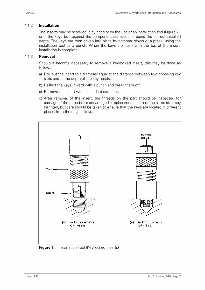
CAP 562 Civil Aircraft Airworthiness Information and Procedures
Part 2 Leaflet 2-10 Page 7
4.1.2 Installation
The inserts may be screwed in by hand or by the use of an installation tool (Figure 7),until the keys butt against the component surface, this being the correct installeddepth. The keys are then driven into place by hammer blows or a press, using theinstallation tool as a punch. When the keys are flush with the top of the insert,installation is complete.
4.1.3 Removal
Should it become necessary to remove a key-locked insert, this may be done asfollows:
a) Drill out the insert to a diameter equal to the distance between two opposing keyslots and to the depth of the key heads.
b) Deflect the keys inward with a punch and break them off.
c) Remove the insert with a standard extractor.
d) After removal of the insert, the threads on the part should be inspected fordamage. If the threads are undamaged a replacement insert of the same size maybe fitted, but care should be taken to ensure that the keys are located in differentplaces from the original keys.
Figure 7 Installation Tool (Key-locked Inserts)
1 July 1990
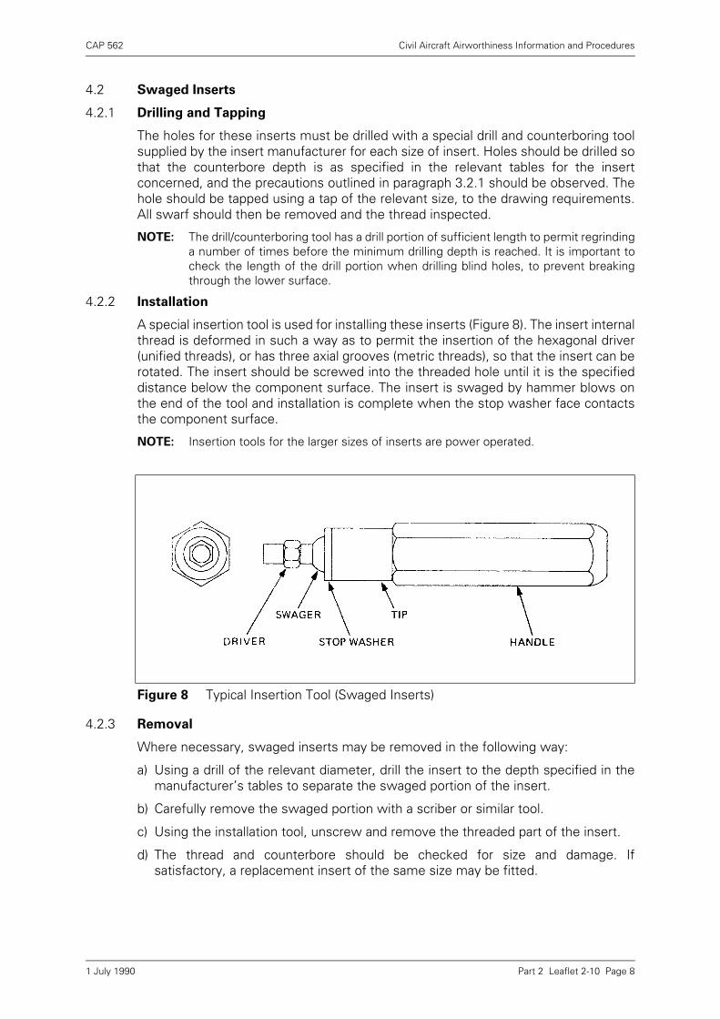
CAP 562 Civil Aircraft Airworthiness Information and Procedures
Part 2 Leaflet 2-10 Page 8
4.2 Swaged Inserts
4.2.1 Drilling and Tapping
The holes for these inserts must be drilled with a special drill and counterboring toolsupplied by the insert manufacturer for each size of insert. Holes should be drilled sothat the counterbore depth is as specified in the relevant tables for the insertconcerned, and the precautions outlined in paragraph 3.2.1 should be observed. Thehole should be tapped using a tap of the relevant size, to the drawing requirements.All swarf should then be removed and the thread inspected.
NOTE: The drill/counterboring tool has a drill portion of sufficient length to permit regrindinga number of times before the minimum drilling depth is reached. It is important tocheck the length of the drill portion when drilling blind holes, to prevent breakingthrough the lower surface.
4.2.2 Installation
A special insertion tool is used for installing these inserts (Figure 8). The insert internalthread is deformed in such a way as to permit the insertion of the hexagonal driver(unified threads), or has three axial grooves (metric threads), so that the insert can berotated. The insert should be screwed into the threaded hole until it is the specifieddistance below the component surface. The insert is swaged by hammer blows onthe end of the tool and installation is complete when the stop washer face contactsthe component surface.
NOTE: Insertion tools for the larger sizes of inserts are power operated.
4.2.3 Removal
Where necessary, swaged inserts may be removed in the following way:
a) Using a drill of the relevant diameter, drill the insert to the depth specified in themanufacturer’s tables to separate the swaged portion of the insert.
b) Carefully remove the swaged portion with a scriber or similar tool.
c) Using the installation tool, unscrew and remove the threaded part of the insert.
d) The thread and counterbore should be checked for size and damage. Ifsatisfactory, a replacement insert of the same size may be fitted.
Figure 8 Typical Insertion Tool (Swaged Inserts)
1 July 1990
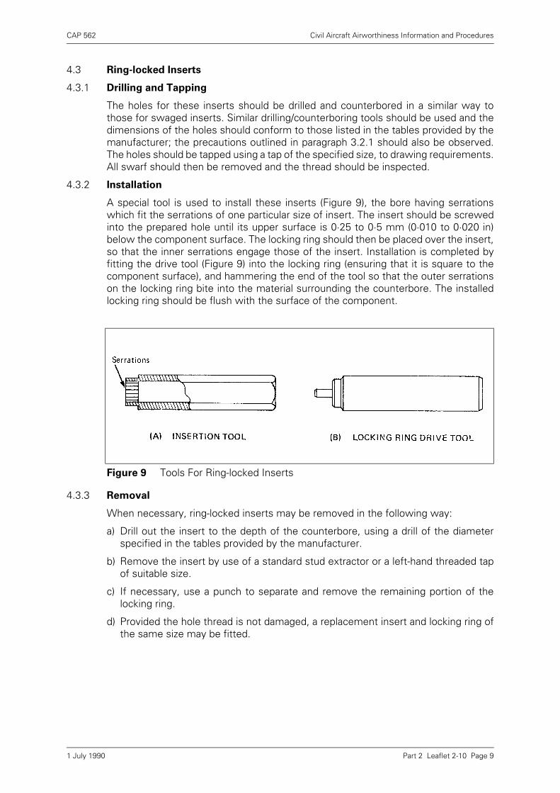
CAP 562 Civil Aircraft Airworthiness Information and Procedures
Part 2 Leaflet 2-10 Page 9
4.3 Ring-locked Inserts
4.3.1 Drilling and Tapping
The holes for these inserts should be drilled and counterbored in a similar way tothose for swaged inserts. Similar drilling/counterboring tools should be used and thedimensions of the holes should conform to those listed in the tables provided by themanufacturer; the precautions outlined in paragraph 3.2.1 should also be observed.The holes should be tapped using a tap of the specified size, to drawing requirements.All swarf should then be removed and the thread should be inspected.
4.3.2 Installation
A special tool is used to install these inserts (Figure 9), the bore having serrationswhich fit the serrations of one particular size of insert. The insert should be screwedinto the prepared hole until its upper surface is 0·25 to 0·5 mm (0·010 to 0·020 in)below the component surface. The locking ring should then be placed over the insert,so that the inner serrations engage those of the insert. Installation is completed byfitting the drive tool (Figure 9) into the locking ring (ensuring that it is square to thecomponent surface), and hammering the end of the tool so that the outer serrationson the locking ring bite into the material surrounding the counterbore. The installedlocking ring should be flush with the surface of the component.
4.3.3 Removal
When necessary, ring-locked inserts may be removed in the following way:
a) Drill out the insert to the depth of the counterbore, using a drill of the diameterspecified in the tables provided by the manufacturer.
b) Remove the insert by use of a standard stud extractor or a left-hand threaded tapof suitable size.
c) If necessary, use a punch to separate and remove the remaining portion of thelocking ring.
d) Provided the hole thread is not damaged, a replacement insert and locking ring ofthe same size may be fitted.
Figure 9 Tools For Ring-locked Inserts
1 July 1990

INTENTIONALLY LEFT BLANK
CAP 562 Civil Aircraft Airworthiness Information and Procedures
Part 2 Leaflet 2-11 Page 1
Leaflet 2-11 Torque Loading
1 Introduction
1.1 The purpose of this Leaflet is to provide guidance and advice on the torque loading ofthreaded fasteners to ensure efficient clamping of mating parts and preventoverstressing.
1.2 The subject headings are as follows:
1.3 Related Leaflets:
5–9 Oxygen Systems
6–7 Assembly and Maintenance of Critical Bolted Joints
2 General
2.1 The majority of nuts, bolts and set screws on an aircraft are subject to a standardtorque value, depending on their material, finish, lubrication, thread type and size, butparticular applications may necessitate a different torque loading and this will bespecified in the Appropriate Maintenance Manual. The normal method of applying atorque loading to a fastener is by means of a torque wrench, but in some criticalbolted joints the use of pre-load indicating (PLI) washers may be specified and theseare discussed in Leaflet 6–7.
2.2 'Standard' torque loading values are those generally applied to steel fasteners usedin tension applications on aircraft. Lower values are generally quoted for shear nutsor nuts used in shear applications. Lower torque values are also necessary for pipeunion nuts (bearing in mind the actual thread size and not the pipe diameter). 'Special'torque loadings may be used for a variety of reasons, examples of which are theloadings applied to the bolts fitted to flexible engine mountings and those applied tonon-standard fasteners such as cylinder holding-down nuts.
3 Recommended Techniques
3.1 Torque loading instructions in Aircraft Maintenance Manuals will be found to varyslightly between different aircraft and engines. Most manufacturers specifylubricated torque values, i.e. the threads and all mating surfaces lightly lubricated withoil, sealant or anti-seize compound as appropriate, but some manufacturers specifydry torque values, i.e. parts clean and dry or as pre-lubricated during manufacture.
Paragraph Subject Page
1 Introduction 1
2 General 1
3 Recommended Techniques 1
4 Torque Wrenches 3
5 Checking of Torque Wrenches 6
1 July 1990

CAP 562 Civil Aircraft Airworthiness Information and Procedures
Part 2 Leaflet 2-11 Page 2
Due to the varying effects of friction under different conditions of assembly, it isimportant that the torque applied to any particular fastener should be in accordancewith the manufacturers instructions; the pre-load applied to a fastener at a specifiedlubricated torque would be considerably higher than if the same torque were applieddry.
3.2 Initial Assembly
In order to remove the roughness from threads and mating surfaces whenassembling new components which require high torque loadings, the followingprocedure should be followed:
a) Clean and where specified, lubricate threads and mating surfaces of nut, bolt andwasher.
b) Tighten nut to approximately half the specified torque value.
c) Slacken nut then finally re-tighten to specified torque value.
NOTE: Where cadmium plated fasteners are used in locations subject to fluctuating loads,the manufacturer may recommend a different procedure.
3.3 Wherever possible, in a bolt-nut or screw-nut combination, the bolt or screw must beheld stationary and the nut turned. When it is necessary to tighten a fastener from thebolt or screw side, the torque value must approach the high side of the specifiedrange. Whenever torqued fasteners are to be secured by means of split pins or lockwire, the low side of the torque range must be used for tightening. If necessary,tighten the fastener so that the next slot aligns with the hole, provided the maximumtorque value is not exceeded. If the maximum torque value is reached and the slot inthe nut does not line up with the hole in the bolt, the nut and washer must bechanged.
3.4 Sealants
When sealant is used in a joint, the torque loading of fasteners should be carried outwithin the application time of the sealant. After ten minutes, but within twice theapplication life of the sealant, the loading should be checked and re-applied asnecessary.
3.5 Union Nuts
The component parts of a flared pipe coupling require bedding-in to ensure freedomfrom leaks and the following procedure should be adopted when tightening unionnuts:
a) Assemble the component parts of the joint and run-up the nut by hand.
b) Tighten to specified torque value.
c) Slacken the nut half a turn, then re-tighten to specified torque value.
NOTES: 1) Torque loading is not usually specified for flareless couplings. Theprocedure normally recommended is to tighten the nut using fingerpressure until positive resistance is felt, then tighten a further one sixth toone third of a turn.
2) Lubrication of components is usually by the type of fluid used in thesystem but connections in oxygen systems must be dry unless a specialpreparation is recommended, see Leaflet 5-9.
1 July 1990
CAP 562 Civil Aircraft Airworthiness Information and Procedures
Part 2 Leaflet 2-11 Page 3
3.6 Stiffnuts
In order to check the effectiveness of the friction element of a stiffnut, it is generalpractice to turn the nut onto its mating thread by hand. If it is possible to pass thethread through the friction element by hand, then the locking is unsatisfactory.However, certain manufacturers specify acceptable limits of 'in-built' or frictionaltorque for various thread types and sizes and in these instances, each stiffnut shouldbe checked with a torque wrench before re-use.
3.7 Torque Tables
3.7.1 Tables of standard torque values for different thread types and sizes and for specialapplications, are normally found in the appropriate Maintenance Manual; separatetables often being included for ordinary nuts, stiffnuts, union nuts and studs. Manualsfor older types of aircraft may be found to contain only special torque loadingrequirements and a single table applicable to non self-locking nuts; in these cases thefrictional torque of a stiffnut must be added to the torque quoted for the type and sizeof thread.
3.7.2 Torque tables usually specify the upper and lower limits of torque for different typesand sizes of fasteners, but if a single figure is quoted, it is generally accepted that thismay be exceeded for the purpose of lining up a split pin hole, tab washer or lockingplate. However, an upper torque limit should not be exceeded and nuts should neverbe slackened to line up these locking devices.
4 Torque Wrenches
4.1 There are basically two types of torque wrenches. One type contains a flexible beamwhich bends under load, the amount of bend being recorded on a dial which isgraduated in units of torque. The second type contains a spring loaded ratchet devicewhich may be preset before use and when this preset torque is reached, the wrench'breaks' to prevent further tightening.
4.2 The torque applied to a nut is a function of the force applied to the wrench handlemultiplied by the distance between the point of application of the force and the centreof the nut. This may be measured in appropriate units such as pounds inches (lb in),kilogramme centimetres (kg cm) or newton metres (Nm). The scale on the wrench ismarked to show the torque applied to its driving tang, i.e. force applied to the handlemultiplied by the distance between its driving tang and the centre of the hand grip.
4.3 If a torque wrench is used in conjunction with a socket type of spanner, the nut andtang centres will coincide and the torque applied to the nut may be read directly fromthe wrench scale. However, in some cases an extension spanner is used inconjunction with a torque wrench and the torque applied to the nut will be differentfrom the torque shown on the wrench scale.
1 July 1990
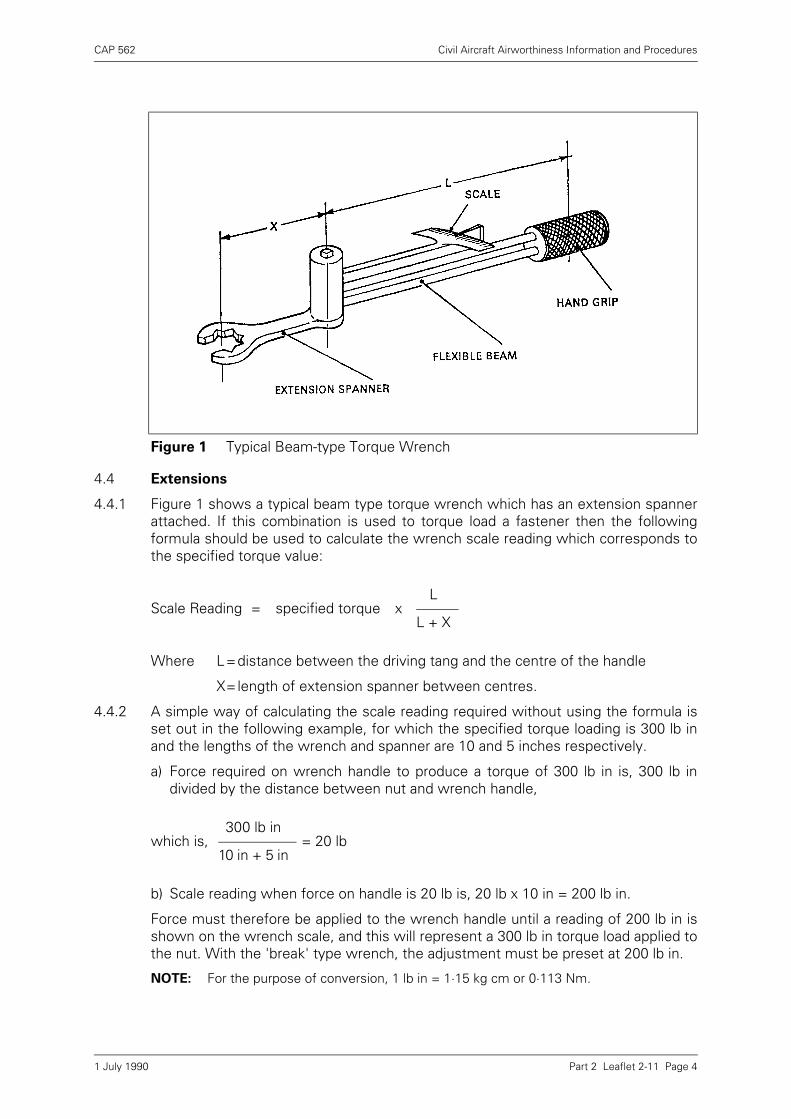
CAP 562 Civil Aircraft Airworthiness Information and Procedures
Part 2 Leaflet 2-11 Page 4
4.4 Extensions
4.4.1 Figure 1 shows a typical beam type torque wrench which has an extension spannerattached. If this combination is used to torque load a fastener then the followingformula should be used to calculate the wrench scale reading which corresponds tothe specified torque value:
Where L=distance between the driving tang and the centre of the handle
X=length of extension spanner between centres.
4.4.2 A simple way of calculating the scale reading required without using the formula isset out in the following example, for which the specified torque loading is 300 lb inand the lengths of the wrench and spanner are 10 and 5 inches respectively.
a) Force required on wrench handle to produce a torque of 300 lb in is, 300 lb individed by the distance between nut and wrench handle,
b) Scale reading when force on handle is 20 lb is, 20 lb x 10 in = 200 lb in.
Force must therefore be applied to the wrench handle until a reading of 200 lb in isshown on the wrench scale, and this will represent a 300 lb in torque load applied tothe nut. With the 'break' type wrench, the adjustment must be preset at 200 lb in.
NOTE: For the purpose of conversion, 1 lb in = 1·15 kg cm or 0·113 Nm.
Figure 1 Typical Beam-type Torque Wrench
Scale Reading = specified torque xL
L + X
which is,300 lb in
= 20 lb10 in + 5 in
1 July 1990
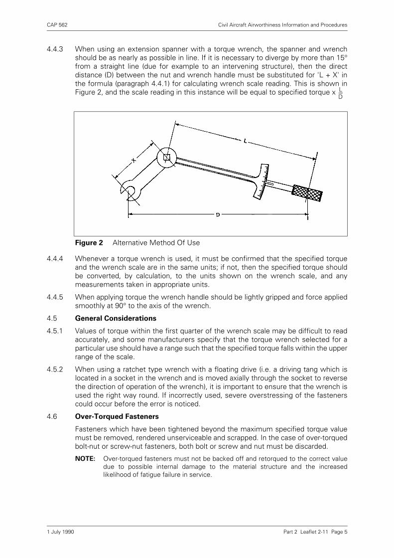
CAP 562 Civil Aircraft Airworthiness Information and Procedures
Part 2 Leaflet 2-11 Page 5
4.4.3 When using an extension spanner with a torque wrench, the spanner and wrenchshould be as nearly as possible in line. If it is necessary to diverge by more than 15°from a straight line (due for example to an intervening structure), then the directdistance (D) between the nut and wrench handle must be substituted for 'L + X' inthe formula (paragraph 4.4.1) for calculating wrench scale reading. This is shown inFigure 2, and the scale reading in this instance will be equal to specified torque x
4.4.4 Whenever a torque wrench is used, it must be confirmed that the specified torqueand the wrench scale are in the same units; if not, then the specified torque shouldbe converted, by calculation, to the units shown on the wrench scale, and anymeasurements taken in appropriate units.
4.4.5 When applying torque the wrench handle should be lightly gripped and force appliedsmoothly at 90° to the axis of the wrench.
4.5 General Considerations
4.5.1 Values of torque within the first quarter of the wrench scale may be difficult to readaccurately, and some manufacturers specify that the torque wrench selected for aparticular use should have a range such that the specified torque falls within the upperrange of the scale.
4.5.2 When using a ratchet type wrench with a floating drive (i.e. a driving tang which islocated in a socket in the wrench and is moved axially through the socket to reversethe direction of operation of the wrench), it is important to ensure that the wrench isused the right way round. If incorrectly used, severe overstressing of the fastenerscould occur before the error is noticed.
4.6 Over-Torqued Fasteners
Fasteners which have been tightened beyond the maximum specified torque valuemust be removed, rendered unserviceable and scrapped. In the case of over-torquedbolt-nut or screw-nut fasteners, both bolt or screw and nut must be discarded.
NOTE: Over-torqued fasteners must not be backed off and retorqued to the correct valuedue to possible internal damage to the material structure and the increasedlikelihood of fatigue failure in service.
Figure 2 Alternative Method Of Use
LD-----
1 July 1990

CAP 562 Civil Aircraft Airworthiness Information and Procedures
Part 2 Leaflet 2-11 Page 6
4.7 Retorquing
Where it is necessary to retorque a fastener assembly, the nut must be backed offpart of a turn and re-tightened to the specified value. Unless the installation requiresthe torque to be applied to the bolt or screw in the first instance, the bolt or screwmust be supported and not be allowed to turn during a retorquing operation.
5 Checking of Torque Wrenches
5.1 Beam-type torque wrenches should be checked before use to ensure that the scalereading is zero.
5.2 All torque wrenches should be checked for accuracy preferably before use or atintervals normally not exceeding 6 months. However, for those torque wrenchessubject to greater use, checks for accuracy should be carried out at more frequentintervals. If a spring balance is attached to the centre of the wrench handle, and forceapplied tangentially to the arc of movement, the wrench scale reading shouldcorrespond to the spring balance reading multiplied by the wrench length. Checksshould be made at several values within the wrench scale range.
1 July 1990
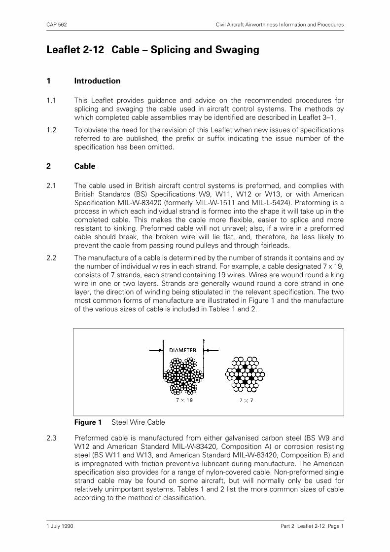
CAP 562 Civil Aircraft Airworthiness Information and Procedures
Part 2 Leaflet 2-12 Page 1
Leaflet 2-12 Cable – Splicing and Swaging
1 Introduction
1.1 This Leaflet provides guidance and advice on the recommended procedures forsplicing and swaging the cable used in aircraft control systems. The methods bywhich completed cable assemblies may be identified are described in Leaflet 3–1.
1.2 To obviate the need for the revision of this Leaflet when new issues of specificationsreferred to are published, the prefix or suffix indicating the issue number of thespecification has been omitted.
2 Cable
2.1 The cable used in British aircraft control systems is preformed, and complies withBritish Standards (BS) Specifications W9, W11, W12 or W13, or with AmericanSpecification MIL-W-83420 (formerly MIL-W-1511 and MIL-L-5424). Preforming is aprocess in which each individual strand is formed into the shape it will take up in thecompleted cable. This makes the cable more flexible, easier to splice and moreresistant to kinking. Preformed cable will not unravel; also, if a wire in a preformedcable should break, the broken wire will lie flat, and, therefore, be less likely toprevent the cable from passing round pulleys and through fairleads.
2.2 The manufacture of a cable is determined by the number of strands it contains and bythe number of individual wires in each strand. For example, a cable designated 7 x 19,consists of 7 strands, each strand containing 19 wires. Wires are wound round a kingwire in one or two layers. Strands are generally wound round a core strand in onelayer, the direction of winding being stipulated in the relevant specification. The twomost common forms of manufacture are illustrated in Figure 1 and the manufactureof the various sizes of cable is included in Tables 1 and 2.
2.3 Preformed cable is manufactured from either galvanised carbon steel (BS W9 andW12 and American Standard MIL-W-83420, Composition A) or corrosion resistingsteel (BS W11 and W13, and American Standard MIL-W-83420, Composition B) andis impregnated with friction preventive lubricant during manufacture. The Americanspecification also provides for a range of nylon-covered cable. Non-preformed singlestrand cable may be found on some aircraft, but will normally only be used forrelatively unimportant systems. Tables 1 and 2 list the more common sizes of cableaccording to the method of classification.
Figure 1 Steel Wire Cable
1 July 1990
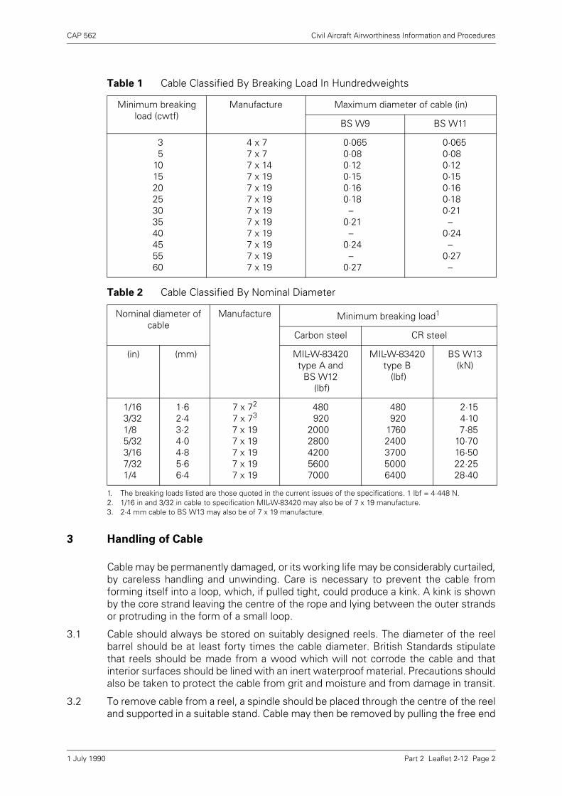
CAP 562 Civil Aircraft Airworthiness Information and Procedures
Part 2 Leaflet 2-12 Page 2
3 Handling of Cable
Cable may be permanently damaged, or its working life may be considerably curtailed,by careless handling and unwinding. Care is necessary to prevent the cable fromforming itself into a loop, which, if pulled tight, could produce a kink. A kink is shownby the core strand leaving the centre of the rope and lying between the outer strandsor protruding in the form of a small loop.
3.1 Cable should always be stored on suitably designed reels. The diameter of the reelbarrel should be at least forty times the cable diameter. British Standards stipulatethat reels should be made from a wood which will not corrode the cable and thatinterior surfaces should be lined with an inert waterproof material. Precautions shouldalso be taken to protect the cable from grit and moisture and from damage in transit.
3.2 To remove cable from a reel, a spindle should be placed through the centre of the reeland supported in a suitable stand. Cable may then be removed by pulling the free end
Table 1 Cable Classified By Breaking Load In Hundredweights
Minimum breaking load (cwtf)
Manufacture Maximum diameter of cable (in)
BS W9 BS W11
35
10152025303540455560
4 x 77 x 7 7 x 14 7 x 197 x 197 x 19 7 x 19 7 x 19 7 x 197 x 19 7 x 19 7 x 19
0·0650·08 0·12 0·15 0·160·18 – 0·21 – 0·24 – 0·27
0·0650·080·120·150·160·180·21 –0·24 –0·27 –
Table 2 Cable Classified By Nominal Diameter
Nominal diameter of cable
Manufacture Minimum breaking load1
1. The breaking loads listed are those quoted in the current issues of the specifications. 1 lbf = 4·448 N.
Carbon steel CR steel
(in) (mm) MIL-W-83420 type A and
BS W12 (lbf)
MIL-W-83420 type B (lbf)
BS W13(kN)
1/163/32 1/8 5/32 3/16 7/32 1/4
1·62·43·2 4·0 4·8 5·6 6·4
7 x 72
7 x 73
7 x 19 7 x 19 7 x 197 x 19 7 x 19
2. 1/16 in and 3/32 in cable to specification MIL-W-83420 may also be of 7 x 19 manufacture.3. 2·4 mm cable to BS W13 may also be of 7 x 19 manufacture.
480920
2000280042005600
7000
480920
17602400370050006400
2·154·107·85
10·7016·5022·2528·40
1 July 1990
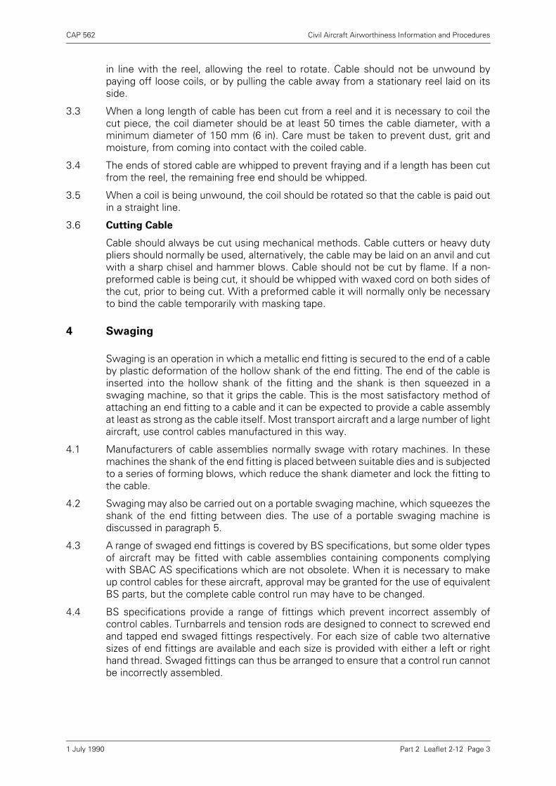
CAP 562 Civil Aircraft Airworthiness Information and Procedures
Part 2 Leaflet 2-12 Page 3
in line with the reel, allowing the reel to rotate. Cable should not be unwound bypaying off loose coils, or by pulling the cable away from a stationary reel laid on itsside.
3.3 When a long length of cable has been cut from a reel and it is necessary to coil thecut piece, the coil diameter should be at least 50 times the cable diameter, with aminimum diameter of 150 mm (6 in). Care must be taken to prevent dust, grit andmoisture, from coming into contact with the coiled cable.
3.4 The ends of stored cable are whipped to prevent fraying and if a length has been cutfrom the reel, the remaining free end should be whipped.
3.5 When a coil is being unwound, the coil should be rotated so that the cable is paid outin a straight line.
3.6 Cutting Cable
Cable should always be cut using mechanical methods. Cable cutters or heavy dutypliers should normally be used, alternatively, the cable may be laid on an anvil and cutwith a sharp chisel and hammer blows. Cable should not be cut by flame. If a non-preformed cable is being cut, it should be whipped with waxed cord on both sides ofthe cut, prior to being cut. With a preformed cable it will normally only be necessaryto bind the cable temporarily with masking tape.
4 Swaging
Swaging is an operation in which a metallic end fitting is secured to the end of a cableby plastic deformation of the hollow shank of the end fitting. The end of the cable isinserted into the hollow shank of the fitting and the shank is then squeezed in aswaging machine, so that it grips the cable. This is the most satisfactory method ofattaching an end fitting to a cable and it can be expected to provide a cable assemblyat least as strong as the cable itself. Most transport aircraft and a large number of lightaircraft, use control cables manufactured in this way.
4.1 Manufacturers of cable assemblies normally swage with rotary machines. In thesemachines the shank of the end fitting is placed between suitable dies and is subjectedto a series of forming blows, which reduce the shank diameter and lock the fitting tothe cable.
4.2 Swaging may also be carried out on a portable swaging machine, which squeezes theshank of the end fitting between dies. The use of a portable swaging machine isdiscussed in paragraph 5.
4.3 A range of swaged end fittings is covered by BS specifications, but some older typesof aircraft may be fitted with cable assemblies containing components complyingwith SBAC AS specifications which are not obsolete. When it is necessary to makeup control cables for these aircraft, approval may be granted for the use of equivalentBS parts, but the complete cable control run may have to be changed.
4.4 BS specifications provide a range of fittings which prevent incorrect assembly ofcontrol cables. Turnbarrels and tension rods are designed to connect to screwed endand tapped end swaged fittings respectively. For each size of cable two alternativesizes of end fittings are available and each size is provided with either a left or righthand thread. Swaged fittings can thus be arranged to ensure that a control run cannotbe incorrectly assembled.
1 July 1990
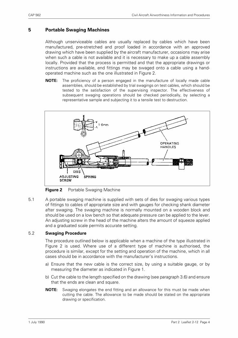
CAP 562 Civil Aircraft Airworthiness Information and Procedures
Part 2 Leaflet 2-12 Page 4
5 Portable Swaging Machines
Although unserviceable cables are usually replaced by cables which have beenmanufactured, pre-stretched and proof loaded in accordance with an approveddrawing which have been supplied by the aircraft manufacturer, occasions may arisewhen such a cable is not available and it is necessary to make up a cable assemblylocally. Provided that the process is permitted and that the appropriate drawings orinstructions are available, end fittings may be swaged onto a cable using a hand-operated machine such as the one illustrated in Figure 2.
NOTE: The proficiency of a person engaged in the manufacture of locally made cableassemblies, should be established by trial swagings on test cables, which should betested to the satisfaction of the supervising inspector. The effectiveness ofsubsequent swaging operations should be checked periodically, by selecting arepresentative sample and subjecting it to a tensile test to destruction.
5.1 A portable swaging machine is supplied with sets of dies for swaging various typesof fittings to cables of appropriate size and with gauges for checking shank diameterafter swaging. The swaging machine is normally mounted on a wooden block andshould be used on a low bench so that adequate pressure can be applied to the lever.An adjusting screw in the head of the machine alters the amount of squeeze appliedand a graduated scale permits accurate setting.
5.2 Swaging Procedure
The procedure outlined below is applicable when a machine of the type illustrated inFigure 2 is used. Where use of a different type of machine is authorised, theprocedure is similar, except for the setting and operation of the machine, which in allcases should be in accordance with the manufacturer’s instructions.
a) Ensure that the new cable is the correct size, by using a suitable gauge, or bymeasuring the diameter as indicated in Figure 1.
b) Cut the cable to the length specified on the drawing (see paragraph 3.6) and ensurethat the ends are clean and square.
NOTE: Swaging elongates the end fitting and an allowance for this must be made whencutting the cable. The allowance to be made should be stated on the appropriatedrawing or specification.
Figure 2 Portable Swaging Machine
1 July 1990
CAP 562 Civil Aircraft Airworthiness Information and Procedures
Part 2 Leaflet 2-12 Page 5
c) Select the appropriate end fitting and clean it by immersing it in solvent; then shakeand wipe dry.
d) Assemble the end fitting to drawing requirements. With drilled-through fittings,the cable end must pass the inspection hole, but be clear of the locking wire hole.For fittings with a blind hole, the cable must bottom in the hole. Bottoming may bechecked by marking the cable with paint, at a distance from the end equal to thedepth of the hole and ensuring that the paint mark reaches the fitting when thecable is inserted. When the cable and the fitting are correctly assembled, theyshould both be lightly lubricated.
e) Fit the dies for the particular end fitting in the swaging machine, open the handlesof the machine and unscrew the adjuster until the end fitting can be placed in thedies. With the end fitting centred in the die recess, close the handles fully andscrew in the adjuster until the dies grip the fitting. Open the handles and tightenthe adjuster by the amount of squeeze required for the particular end fitting;normally this should be approximately 0·18 mm (0·007 in).
f) Place the fitting in the position shown in the small sketch in Figure 2, so as toswage to within approximately 1·2 mm (0·050 in) from the inspection hole. Checkthat the cable is in the correct position (see d)) and operate the handles to squeezethe fitting.
g) Release the handles and rotate the fitting through approximately 50°. Repeat thesqueezing and rotating until the fitting has been moved one full turn.
h) Withdraw the end fitting from the dies 1·6 mm (0·0625 in) and repeat the cycle ofsqueezing and turning.
i) Continue operation until the whole shank is swaged. Check the diameter of theshank and if it has not been reduced to the size required by the appropriate drawingor specification, re-set the adjusting screw and repeat the swaging operation.
j) When the shank of the end fitting has been reduced to the correct diameter,remove and inspect the fitting (see paragraph 5.3).
k) Fit the identification device as prescribed in the drawing and mark it with the cablepart number in the prescribed manner (in some cases the part number may beetched directly onto the end fitting). The identification may be in the form of awired-on tag, as illustrated in Leaflet 3–1, or a cylindrical sleeve lightly swaged ontothe shank of the end fitting.
l) Assemble any fittings, such as cable stops, on the cable and swage on theopposite end fitting.
m)Dip the end fittings in lanolin, to prevent corrosion resulting from damaged platingand to exclude moisture.
5.3 Inspection of Swaged Fittings
On completion of the swaging operations, the following inspection should be carriedout.
a) Check that the correct combination of cable and fittings has been used.
b) Re-check the diameter of the swaged shank, using a GO-NOT GO gauge or amicrometer. If the diameter of the fitting is too small, it has been over-swaged andas such the cable and the fitting must be rejected. Excessive work hardening ofthe fitting will cause it to crack and may also damage the cable.
c) Check, by means of the inspection hole or paint mark, that the cable is correctlyengaged in the end fitting (see paragraph 5.2 d)).
1 July 1990
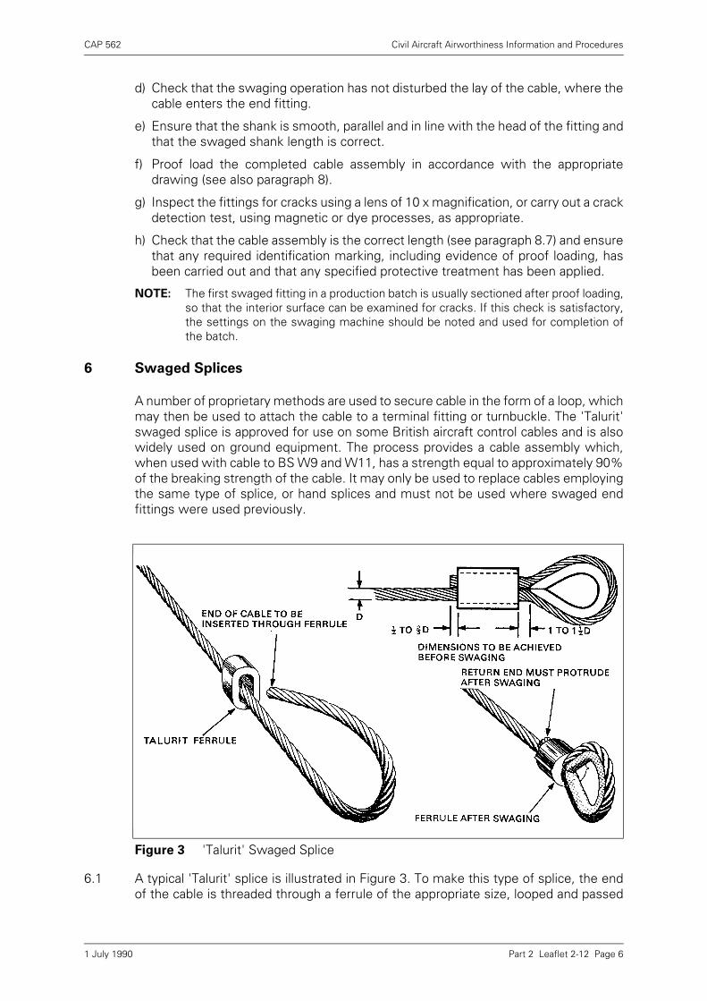
CAP 562 Civil Aircraft Airworthiness Information and Procedures
Part 2 Leaflet 2-12 Page 6
d) Check that the swaging operation has not disturbed the lay of the cable, where thecable enters the end fitting.
e) Ensure that the shank is smooth, parallel and in line with the head of the fitting andthat the swaged shank length is correct.
f) Proof load the completed cable assembly in accordance with the appropriatedrawing (see also paragraph 8).
g) Inspect the fittings for cracks using a lens of 10 x magnification, or carry out a crackdetection test, using magnetic or dye processes, as appropriate.
h) Check that the cable assembly is the correct length (see paragraph 8.7) and ensurethat any required identification marking, including evidence of proof loading, hasbeen carried out and that any specified protective treatment has been applied.
NOTE: The first swaged fitting in a production batch is usually sectioned after proof loading,so that the interior surface can be examined for cracks. If this check is satisfactory,the settings on the swaging machine should be noted and used for completion ofthe batch.
6 Swaged Splices
A number of proprietary methods are used to secure cable in the form of a loop, whichmay then be used to attach the cable to a terminal fitting or turnbuckle. The 'Talurit'swaged splice is approved for use on some British aircraft control cables and is alsowidely used on ground equipment. The process provides a cable assembly which,when used with cable to BS W9 and W11, has a strength equal to approximately 90%of the breaking strength of the cable. It may only be used to replace cables employingthe same type of splice, or hand splices and must not be used where swaged endfittings were used previously.
6.1 A typical 'Talurit' splice is illustrated in Figure 3. To make this type of splice, the endof the cable is threaded through a ferrule of the appropriate size, looped and passed
Figure 3 'Talurit' Swaged Splice
1 July 1990
CAP 562 Civil Aircraft Airworthiness Information and Procedures
Part 2 Leaflet 2-12 Page 7
back through the ferrule. A thimble is fitted in the loop and the ferrule is squeezedbetween swages (dies) in a hand-operated or power-operated press. The metal of theferrule is extruded between the two parallel lengths of cable and around the cablestrands firmly locking the cable without disturbing its lay.
6.2 Ferrules are made in a variety of shapes, sizes and materials. Aluminium alloy ferrulesare used with galvanised or tinned carbon steel cable and copper ferrules are usedwith corrosion resisting steel cable.
6.3 When making a splice, the proper ferrule should be selected by the code numbersindicated on the appropriate drawing and the associated swages should be fitted tothe press. The loop and thimble should be adjusted after the swages have closedsufficiently to grip the ferrule. The cable must grip the thimble firmly and thedimensions indicated in Figure 3 must be obtained before swaging commences.
6.4 The press should be operated until the faces of the swages are touching, then thepressure should be released. Continuing to apply pressure after the faces have met,may cause damage to the press and swages. Only one pressing operation is normallyrequired, but some long ferrules are designed for swaging in two separate operations,the swages in these cases being half the length of the ferrule.
6.5 After swaging, surplus metal is visible as a flash along each side of the ferrule, thismay be removed with a file. If no flash has been formed, the sizes of the ferrule andswages should be re-checked and it should be ascertained that the press is operatingcorrectly.
6.6 The inspection of the finished splice consists of ensuring that the ferrule is correctlyformed and not cracked carrying out a proof test, as described in paragraph 8. In someinstances a dimensional check is also specified, but, since the swages meet duringthe pressing operation, little variation in diameter will normally be obtained.
7 Manual Splicing
Although manual splicing may be permitted for some particular applications, it isseldom used on modern aircraft. It is less strong than either the swaged fitting or theswaged splice and considerable experience is required in order to consistently obtainsplices of adequate strength by this method. Persons engaged on splicing should begiven an initial competency test and representative samples of their work should beselected periodically, for tensile tests. Splices on cable manufactured to BS W9 orW11, should not fail at less than 80% of the breaking strength of the cable. There areseveral methods of splicing, the procedure in each case varying in detail. Arecommended method is given in the following paragraphs, but other methods maybe used, provided that the resulting splice is no less strong.
7.1 Splicing Procedure
The cable is normally spliced around a brass or steel thimble. The identification tagand where applicable, the turnbuckle eye-end, should be placed on the thimble andthe centre of the thimble bound to the cable. The cable should be whipped withwaxed thread on either side of the thimble, as shown in Figure 5.
NOTE: When cutting the cable to length, approximately 23 cm (9 in) should be allowed foreach splice on cable up to 3·2 mm (1/8 in) diameter and 30 cm (12 in) should beallowed for each splice in cable between 4·0 mm (5/32 in) and 6·4 mm (3/4 in)diameter.
1 July 1990
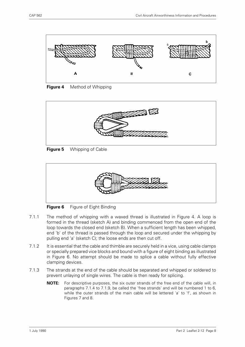
CAP 562 Civil Aircraft Airworthiness Information and Procedures
Part 2 Leaflet 2-12 Page 8
7.1.1 The method of whipping with a waxed thread is illustrated in Figure 4. A loop isformed in the thread (sketch A) and binding commenced from the open end of theloop towards the closed end (sketch B). When a sufficient length has been whipped,end 'b' of the thread is passed through the loop and secured under the whipping bypulling end 'a' (sketch C); the loose ends are then cut off.
7.1.2 It is essential that the cable and thimble are securely held in a vice, using cable clampsor specially prepared vice blocks and bound with a figure of eight binding as illustratedin Figure 6. No attempt should be made to splice a cable without fully effectiveclamping devices.
7.1.3 The strands at the end of the cable should be separated and whipped or soldered toprevent unlaying of single wires. The cable is then ready for splicing.
NOTE: For descriptive purposes, the six outer strands of the free end of the cable will, inparagraphs 7.1.4 to 7.1.9, be called the 'free strands' and will be numbered 1 to 6,while the outer strands of the main cable will be lettered 'a' to 'f', as shown inFigures 7 and 8.
Figure 4 Method of Whipping
Figure 5 Whipping of Cable
Figure 6 Figure of Eight Binding
1 July 1990
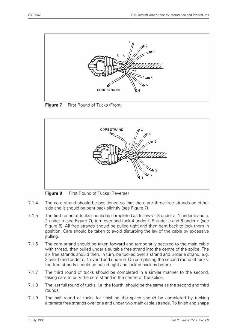
CAP 562 Civil Aircraft Airworthiness Information and Procedures
Part 2 Leaflet 2-12 Page 9
7.1.4 The core strand should be positioned so that there are three free strands on eitherside and it should be bent back slightly (see Figure 7).
7.1.5 The first round of tucks should be completed as follows – 3 under a, 1 under b and c,2 under b (see Figure 7); turn over and tuck 4 under f, 5 under e and 6 under d (seeFigure 8). All free strands should be pulled tight and then bent back to lock them inposition. Care should be taken to avoid disturbing the lay of the cable by excessivepulling.
7.1.6 The core strand should be taken forward and temporarily secured to the main cablewith thread, then pulled under a suitable free strand into the centre of the splice. Thesix free strands should then, in turn, be tucked over a strand and under a strand, e.g.3 over b and under c, 1 over d and under e. On completing the second round of tucks,the free strands should be pulled tight and locked back as before.
7.1.7 The third round of tucks should be completed in a similar manner to the second,taking care to bury the core strand in the centre of the splice.
7.1.8 The last full round of tucks, i.e. the fourth, should be the same as the second and thirdrounds.
7.1.9 The half round of tucks for finishing the splice should be completed by tuckingalternate free strands over one and under two main cable strands. To finish and shape
Figure 7 First Round of Tucks (Front)
Figure 8 First Round of Tucks (Reverse)
1 July 1990
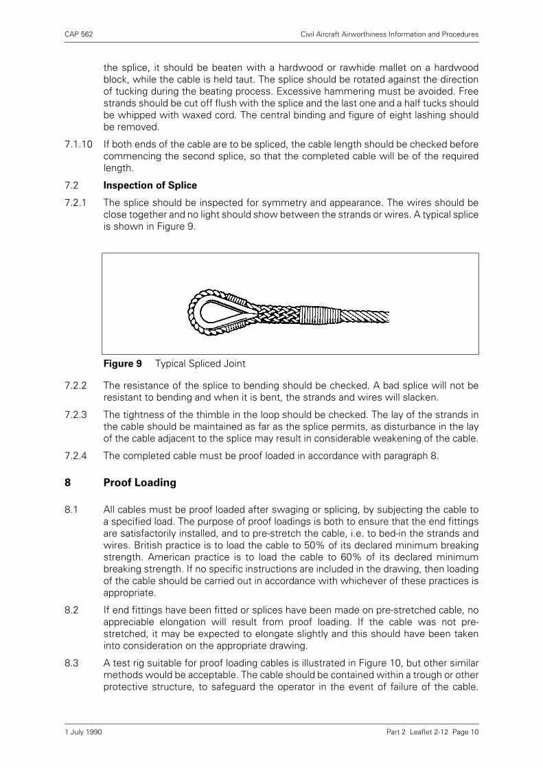
CAP 562 Civil Aircraft Airworthiness Information and Procedures
Part 2 Leaflet 2-12 Page 10
the splice, it should be beaten with a hardwood or rawhide mallet on a hardwoodblock, while the cable is held taut. The splice should be rotated against the directionof tucking during the beating process. Excessive hammering must be avoided. Freestrands should be cut off flush with the splice and the last one and a half tucks shouldbe whipped with waxed cord. The central binding and figure of eight lashing shouldbe removed.
7.1.10 If both ends of the cable are to be spliced, the cable length should be checked beforecommencing the second splice, so that the completed cable will be of the requiredlength.
7.2 Inspection of Splice
7.2.1 The splice should be inspected for symmetry and appearance. The wires should beclose together and no light should show between the strands or wires. A typical spliceis shown in Figure 9..
7.2.2 The resistance of the splice to bending should be checked. A bad splice will not beresistant to bending and when it is bent, the strands and wires will slacken.
7.2.3 The tightness of the thimble in the loop should be checked. The lay of the strands inthe cable should be maintained as far as the splice permits, as disturbance in the layof the cable adjacent to the splice may result in considerable weakening of the cable.
7.2.4 The completed cable must be proof loaded in accordance with paragraph 8.
8 Proof Loading
8.1 All cables must be proof loaded after swaging or splicing, by subjecting the cable toa specified load. The purpose of proof loadings is both to ensure that the end fittingsare satisfactorily installed, and to pre-stretch the cable, i.e. to bed-in the strands andwires. British practice is to load the cable to 50% of its declared minimum breakingstrength. American practice is to load the cable to 60% of its declared minimumbreaking strength. If no specific instructions are included in the drawing, then loadingof the cable should be carried out in accordance with whichever of these practices isappropriate.
8.2 If end fittings have been fitted or splices have been made on pre-stretched cable, noappreciable elongation will result from proof loading. If the cable was not pre-stretched, it may be expected to elongate slightly and this should have been takeninto consideration on the appropriate drawing.
8.3 A test rig suitable for proof loading cables is illustrated in Figure 10, but other similarmethods would be acceptable. The cable should be contained within a trough or otherprotective structure, to safeguard the operator in the event of failure of the cable.
Figure 9 Typical Spliced Joint
1 July 1990
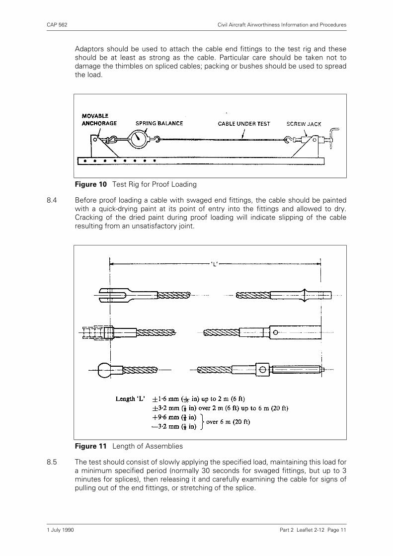
CAP 562 Civil Aircraft Airworthiness Information and Procedures
Part 2 Leaflet 2-12 Page 11
Adaptors should be used to attach the cable end fittings to the test rig and theseshould be at least as strong as the cable. Particular care should be taken not todamage the thimbles on spliced cables; packing or bushes should be used to spreadthe load.
8.4 Before proof loading a cable with swaged end fittings, the cable should be paintedwith a quick-drying paint at its point of entry into the fittings and allowed to dry.Cracking of the dried paint during proof loading will indicate slipping of the cableresulting from an unsatisfactory joint.
8.5 The test should consist of slowly applying the specified load, maintaining this load fora minimum specified period (normally 30 seconds for swaged fittings, but up to 3minutes for splices), then releasing it and carefully examining the cable for signs ofpulling out of the end fittings, or stretching of the splice.
Figure 10 Test Rig for Proof Loading
Figure 11 Length of Assemblies
1 July 1990

CAP 562 Civil Aircraft Airworthiness Information and Procedures
Part 2 Leaflet 2-12 Page 12
8.6 The end fittings should be checked for cracks using an electro-magnetic method(Leaflet 4–5) or, if the fitting is of stainless steel, a penetrant dye process (Leaflet 4-2).
8.7 The length of the completed cable assembly should be measured after proof loading.Prior to measurement, cables longer than 120 cm (4 ft) should be tensioned with aload of approximately 550 N (112 lbf), or 2% of the breaking load of the cable,whichever is the least. Figure 11 shows the datum points and tolerances for themeasurement of cables fitted with swaged end fittings to British Standards. Cableswith different types of end fittings, or loops, should be measured according to theappropriate drawings or specifications.
1 July 1990
CAP 562 Civil Aircraft Airworthiness Information and Procedures
Part 2 Leaflet 2-13 Page 1
Leaflet 2-13 Control Systems
1 Introduction
The purpose of this Leaflet is to provide general guidance and advice on theinspection procedures for control systems which are either manually operated, powerassisted or power operated. The Leaflet should be read in conjunction with therelevant approved drawings and manuals for the aircraft concerned.
2 Control Systems
A control system is defined as a system by which the flight attitude or the propulsiveforce of an aircraft is changed (BCAR Section A, Chapter A6–2).
2.1 For the purpose of duplicate inspection (see paragraph 2.2), the flight control systemincludes the main control surfaces, lift and drag devices and trim and feel systems,together with any flight control lock systems and the associated operatingmechanisms and controls. In the case of rotorcraft, the flight control system includesthe mechanisms used by the pilot to control collective pitch, cyclic pitch and yaw. Theengine control system includes the primary engine controls and related controlsystems (e.g. throttle controls, fuel cock controls, oil-cooler controls) and themechanisms used by the crew to operate them.
2.2 Duplicate Inspection
A duplicate inspection of a vital point/control system is defined as an inspection whichis first made and certified by one qualified person and subsequently made andcertified by a second qualified person.
NOTE: Vital Point. Any point on an aircraft at which single malassembly could lead tocatastrophe, i.e. result in loss of aircraft and/or in fatalities (see BCAR Section A,Chapter A5–3).
2.2.1 Components, systems or vital points subject to duplicate inspection, must not bedisturbed or re-adjusted between the first and second parts of the inspection and thesecond part of the inspection must, as nearly as possible, follow immediately after thefirst part.
2.2.2 In some circumstances, due to peculiarities of assembly or accessibility, it may benecessary for both parts of the inspection to be made simultaneously.
3 Inspection of Control System Components
3.1 Control system components, the parts of which are concealed during benchassembly before installation, shall be inspected in duplicate on assembly duringmanufacture, overhaul or repair.
3.2 Both parts of the duplicate inspection and the results of any tests made during andafter final assembly shall be certified on the Inspection Record for the part concerned.
4 Duplicate Inspection of Control Systems
4.1 A duplicate inspection of the control system in the aircraft shall be made:
1 July 1990
CAP 562 Civil Aircraft Airworthiness Information and Procedures
Part 2 Leaflet 2-13 Page 2
a) before the first flight of all aircraft after initial assembly,
b) before the first flight after the overhaul, replacement, repair, adjustment ormodification of the system. The two parts of the duplicate inspection shall be thefinal operations and as the purpose of the inspection is to establish the integrity ofthe system, all work should have been completed. If, after the duplicate inspectionhas been completed, the control system is disturbed in any way before the firstflight, that part of the system which has been disturbed shall be inspected induplicate (paragraph 2.2) before the aircraft flies.
4.2 In some instances it may not be possible after complete assembly of the aircraft toinspect all parts of the system because some sections of the system may getprogressively 'boxed in' and sealed during assembly operations. In such cases thecondition and security of any section which is liable to be sealed must be establishedto the satisfaction of the persons named in paragraph 5 before the section is sealedand the related Inspection Record endorsed accordingly.
4.3 Inspection Records should be carefully prepared to ensure that any duplicateinspection required at an early stage during assembly operations is clearly indicated,thus avoiding unnecessary dismantling at later stages.
4.4 The correct functioning of control systems is at all times of vital importance toairworthiness. It is also essential that suitably licensed aircraft engineers andmembers of approved inspection organisations responsible for the inspection orduplicate inspection should be thoroughly conversant with the systems concerned.The inspection must be carried out systematically to ensure that each and every partof the system is correctly assembled and is able to operate freely over the specifiedrange of movement without risk of fouling. Also that it is correctly and adequatelylocked, clean and correctly lubricated and is working in the correct sense in relationto the movement of the control by the crew.
5 Persons Authorised to Certify Duplicate Inspections
5.1 Persons authorised to make the first and second parts of the duplicate inspection ofcontrol systems in accordance with BCAR Section A Chapter A6–2 are as follows:
a) Aircraft engineers appropriately licensed in Categories A, B, C and D.
b) Members of an appropriately Approved Organisation who are considered by theChief Inspector competent to make such inspections, in accordance withAirworthiness Notice No. 3.
c) For minor adjustments to control systems when the aircraft is away from base, thesecond part of the duplicate inspection may be performed by a pilot or flightengineer licensed for the type of aircraft concerned.
1 July 1990
CAP 562 Civil Aircraft Airworthiness Information and Procedures
Part 2 Leaflet 2-13 Page 3
5.2 Certification
It is recommended that the certification of the duplicate inspection be in the followingform:
Duplicate inspection performed in accordance with the requirements of BCAR,
Section A Chapter A6–2
6 General
6.1 JAR 5.671(b) states that, in relation to aeroplanes, each element of each controlsystem must be designed, or distinctly and permanently marked, to minimise theprobability of incorrect assembly that could result in the malfunction of the system.The interpretive material in ACJ.671(b) states that for control systems which, ifincorrectly assembled would hazard the aeroplane, the design should be such that atall reasonably possible breakdown points it is mechanically impossible to assembleelements of the system to give an out-of-phase action, reversed controls orinterconnection between two systems which was not intended; only in exceptionalcircumstances should distinctive marking be used.
6.2 Section G of BCAR, in respect of rotorcraft, specifies that the physical features of thecontrol system elements shall be such that it is mechanically impossible to assembleany system with reversed connections or to confuse the connections betweensystems.
6.3 These requirements are satisfied in practice in a number of ways, e.g. by the use ofend fittings having different diameter threads for different cables, by the use ofdifferent diameter pins in correspondingly different diameter holes in end fittings, bystaggering the positions of breakdown points so that cross-connecting, etc., isimpossible.
6.4 The above requirements do not however, minimise the necessity of thorough end-to-end inspection of each control run. Cases are on record of control cables beingcrossed and re-crossed so that the relative movements of the controls and the controlsurfaces were correct.
7 Schedule of Inspection
A schedule of all inspections and functioning checks applicable should be compiled toensure that no part of the system is overlooked. The schedule should include as aminimum, sufficient instructions to enable the following to be completed:
a) The duplicate inspection of parts of components which will be concealed duringbench assembly.
NOTE: Where such work is the subject of a sub-contract order, instructions regardinginspection and duplicate inspection should be stated on the order and incoming
1st inspection ............................................. signature
............................................. authority
2nd inspection ............................................. signature
............................................. authority
Date.....................................
1 July 1990
CAP 562 Civil Aircraft Airworthiness Information and Procedures
Part 2 Leaflet 2-13 Page 4
release documentation should be endorsed to the effect that such inspections havebeen completed.
b) The duplicate inspection of the internal locking and critical assembly features thecorrectness of which cannot be proved during final inspection or functioning testswith the assembly installed in the aircraft.
c) The duplicate inspection of parts of the control system which may subsequentlybe obscured by the erection of further structure.
d) The duplicate inspection, functioning and checking for correct relative movementof the complete system.
e) The final inspection of the complete system to ensure that all covers, guards, etc.,are correctly fitted.
f) The recording of control surface movements and the serial numbers ofcomponents.
NOTE: In considering the instructions to be included in a Schedule of Inspection, it shouldbe noted that the term “control systems” includes (for the purpose of this Leaflet)all power-operated or power-assisted controls together with their attachments andoperating mechanism which in any way change the flight attitude or propulsivepower of the aircraft. Only when other controls, such as an engine auto-stabiliser oran automatic control unit or parts of these units are interconnected with the controlsystem in such a way that they cannot be instantly overridden by the crew in flight,are they considered as part of the control system.
8 Powered Controls
8.1 Power-assisted Controls
In this type of control, part of the force needed to move the control surface is providedby a power system and part by the physical effort of the pilot. The pilot’s 'feel' is thusprovided by the control surface loads.
8.1.1 Initial movement of the pilot’s controls produces (by mechanical connection) a smallmovement of the control surface which operates a control valve causing the controljack to follow-up, thus providing the bulk of the force to permit the movement of thecontrol surface. As the control surface reaches the position appropriate to the positionof the pilot’s control, the valve is closed and the system comes to rest.
8.1.2 In the event of power failure or faults in the power system, satisfactory control canbe maintained by manual means. A disconnecting mechanism is usually provided toprevent interference from the power system when it is not in use.
8.1.3 The trim control of power-assisted control systems is usually provided byconventional trailing-edge tabs, as for manually-operated flying control systems.
8.2 Power-operated Controls
In this type of system the whole of the force needed to operate the control surfacesis provided by power systems independent of each other but working in parallel.
8.2.1 Movement of the pilot’s control operates a valve controlling an appropriatemechanism which operates the control surfaces until they reach the positionappropriate to that of the pilot’s control, when the valve is closed and the systemcomes to rest. It is not inherent in the system that the pilot’s 'feel' should have anydirect connection to the force on the control surface and this together with the self-centring of the controls, is achieved by artificial means. The two most commonmethods of providing feel are:
1 July 1990
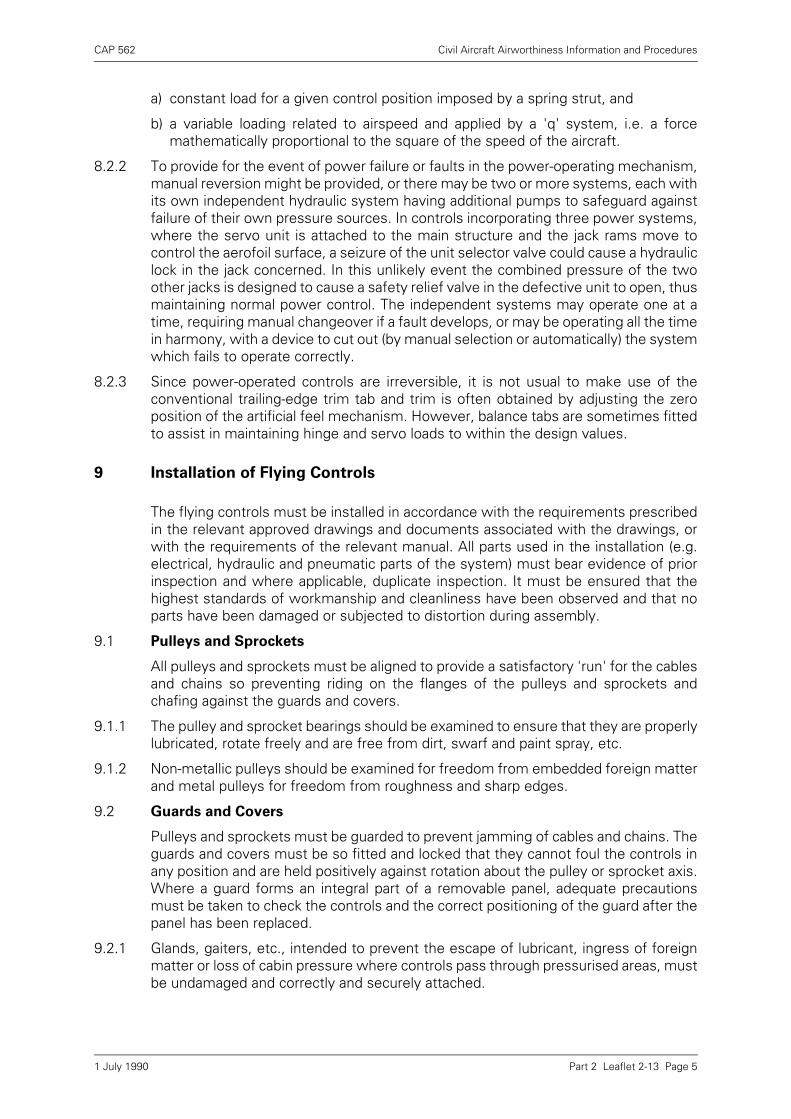
CAP 562 Civil Aircraft Airworthiness Information and Procedures
Part 2 Leaflet 2-13 Page 5
a) constant load for a given control position imposed by a spring strut, and
b) a variable loading related to airspeed and applied by a 'q' system, i.e. a forcemathematically proportional to the square of the speed of the aircraft.
8.2.2 To provide for the event of power failure or faults in the power-operating mechanism,manual reversion might be provided, or there may be two or more systems, each withits own independent hydraulic system having additional pumps to safeguard againstfailure of their own pressure sources. In controls incorporating three power systems,where the servo unit is attached to the main structure and the jack rams move tocontrol the aerofoil surface, a seizure of the unit selector valve could cause a hydrauliclock in the jack concerned. In this unlikely event the combined pressure of the twoother jacks is designed to cause a safety relief valve in the defective unit to open, thusmaintaining normal power control. The independent systems may operate one at atime, requiring manual changeover if a fault develops, or may be operating all the timein harmony, with a device to cut out (by manual selection or automatically) the systemwhich fails to operate correctly.
8.2.3 Since power-operated controls are irreversible, it is not usual to make use of theconventional trailing-edge trim tab and trim is often obtained by adjusting the zeroposition of the artificial feel mechanism. However, balance tabs are sometimes fittedto assist in maintaining hinge and servo loads to within the design values.
9 Installation of Flying Controls
The flying controls must be installed in accordance with the requirements prescribedin the relevant approved drawings and documents associated with the drawings, orwith the requirements of the relevant manual. All parts used in the installation (e.g.electrical, hydraulic and pneumatic parts of the system) must bear evidence of priorinspection and where applicable, duplicate inspection. It must be ensured that thehighest standards of workmanship and cleanliness have been observed and that noparts have been damaged or subjected to distortion during assembly.
9.1 Pulleys and Sprockets
All pulleys and sprockets must be aligned to provide a satisfactory 'run' for the cablesand chains so preventing riding on the flanges of the pulleys and sprockets andchafing against the guards and covers.
9.1.1 The pulley and sprocket bearings should be examined to ensure that they are properlylubricated, rotate freely and are free from dirt, swarf and paint spray, etc.
9.1.2 Non-metallic pulleys should be examined for freedom from embedded foreign matterand metal pulleys for freedom from roughness and sharp edges.
9.2 Guards and Covers
Pulleys and sprockets must be guarded to prevent jamming of cables and chains. Theguards and covers must be so fitted and locked that they cannot foul the controls inany position and are held positively against rotation about the pulley or sprocket axis.Where a guard forms an integral part of a removable panel, adequate precautionsmust be taken to check the controls and the correct positioning of the guard after thepanel has been replaced.
9.2.1 Glands, gaiters, etc., intended to prevent the escape of lubricant, ingress of foreignmatter or loss of cabin pressure where controls pass through pressurised areas, mustbe undamaged and correctly and securely attached.
1 July 1990
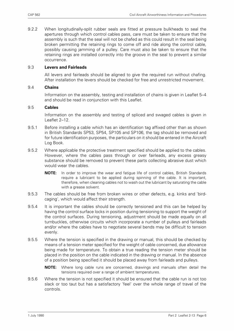
CAP 562 Civil Aircraft Airworthiness Information and Procedures
Part 2 Leaflet 2-13 Page 6
9.2.2 When longitudinally-split rubber seals are fitted at pressure bulkheads to seal theapertures through which control cables pass, care must be taken to ensure that theassembly is such that the seal will not be chafed as this could result in the seal beingbroken permitting the retaining rings to come off and ride along the control cable,possibly causing jamming of a pulley. Care must also be taken to ensure that theretaining rings are installed correctly into the groove in the seal to prevent a similaroccurrence.
9.3 Levers and Fairleads
All levers and fairleads should be aligned to give the required run without chafing.After installation the levers should be checked for free and unrestricted movement.
9.4 Chains
Information on the assembly, testing and installation of chains is given in Leaflet 5–4and should be read in conjunction with this Leaflet.
9.5 Cables
Information on the assembly and testing of spliced and swaged cables is given inLeaflet 2–12.
9.5.1 Before installing a cable which has an identification tag affixed other than as shownin British Standards SP53, SP54, SP105 and SP106, the tag should be removed andfor future identification purposes, the particulars on it should be entered in the AircraftLog Book.
9.5.2 Where applicable the protective treatment specified should be applied to the cables.However, where the cables pass through or over fairleads, any excess greasysubstance should be removed to prevent these parts collecting abrasive dust whichwould wear the cables.
NOTE: In order to improve the wear and fatigue life of control cables, British Standardsrequire a lubricant to be applied during spinning of the cable. It is important,therefore, when cleaning cables not to wash out the lubricant by saturating the cablewith a grease solvent.
9.5.3 The cables should be free from broken wires or other defects, e.g. kinks and 'bird-caging', which would affect their strength.
9.5.4 It is important the cables should be correctly tensioned and this can be helped byhaving the control surface locks in position during tensioning to support the weight ofthe control surfaces. During tensioning, adjustment should be made equally on allturnbuckles, otherwise circuits which incorporate a number of pulleys and fairleadsand/or where the cables have to negotiate several bends may be difficult to tensionevenly.
9.5.5 Where the tension is specified in the drawing or manual, this should be checked bymeans of a tension meter specified for the weight of cable concerned, due allowancebeing made for temperature. To obtain a true reading the tension meter should beplaced in the position on the cable indicated in the drawing or manual. In the absenceof a position being specified it should be placed away from fairleads and pulleys.
NOTE: Where long cable runs are concerned, drawings and manuals often detail thetensions required over a range of ambient temperatures.
9.5.6 Where the tension is not specified it should be ensured that the cable run is not tooslack or too taut but has a satisfactory 'feel' over the whole range of travel of thecontrols.
1 July 1990
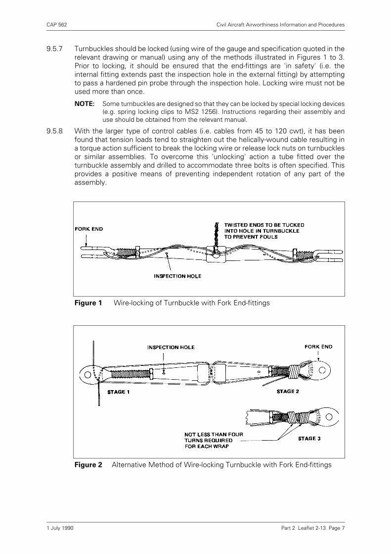
CAP 562 Civil Aircraft Airworthiness Information and Procedures
Part 2 Leaflet 2-13 Page 7
9.5.7 Turnbuckles should be locked (using wire of the gauge and specification quoted in therelevant drawing or manual) using any of the methods illustrated in Figures 1 to 3.Prior to locking, it should be ensured that the end-fittings are 'in safety' (i.e. theinternal fitting extends past the inspection hole in the external fitting) by attemptingto pass a hardened pin probe through the inspection hole. Locking wire must not beused more than once.
NOTE: Some turnbuckles are designed so that they can be locked by special locking devices(e.g. spring locking clips to MS2 1256). Instructions regarding their assembly anduse should be obtained from the relevant manual.
9.5.8 With the larger type of control cables (i.e. cables from 45 to 120 cwt), it has beenfound that tension loads tend to straighten out the helically-wound cable resulting ina torque action sufficient to break the locking wire or release lock nuts on turnbucklesor similar assemblies. To overcome this 'unlocking' action a tube fitted over theturnbuckle assembly and drilled to accommodate three bolts is often specified. Thisprovides a positive means of preventing independent rotation of any part of theassembly.
Figure 1 Wire-locking of Turnbuckle with Fork End-fittings
Figure 2 Alternative Method of Wire-locking Turnbuckle with Fork End-fittings
1 July 1990
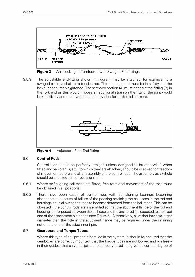
CAP 562 Civil Aircraft Airworthiness Information and Procedures
Part 2 Leaflet 2-13 Page 8
9.5.9 The adjustable end-fitting shown in Figure 4 may be attached, for example, to aswaged cable, a chain or a tension rod. The threaded end must be in safety and thelocknut adequately tightened. The screwed portion (A) must not abut the fitting (B) inthe fork end as this would impose an additional strain on the fitting, the joint wouldlack flexibility and there would be no provision for further adjustment.
9.6 Control Rods
Control rods should be perfectly straight (unless designed to be otherwise) whenfitted and bell-cranks, etc., to which they are attached, should be checked for freedomof movement before and after assembly of the control rods. The assembly as a wholeshould be checked for correct alignment.
9.6.1 Where self-aligning ball-races are fitted, free rotational movement of the rods mustbe obtained in all positions.
9.6.2 There have been cases of control rods with self-aligning bearings becomingdisconnected because of failure of the peening retaining the ball-races in the rod endhousings, thus allowing the rods to become detached from the ball-races. This can beobviated if the control rods are assembled so that the abutment flange of the rod endhousing is interposed between the ball-race and the anchored (as opposed to the free)end of the attachment pin or bolt (see Figure 5). Alternatively, a washer having a largerdiameter than the hole in the abutment flange may be required under the retainingnut on the end of the attachment pin.
9.7 Gearboxes and Torque Tubes
Where this type of equipment is installed in the system, it should be ensured that thegearboxes are correctly mounted, that the torque tubes are not bowed and run freelyin their guides, that universal joints are correctly fitted and give the correct degree of
Figure 3 Wire-locking of Turnbuckle with Swaged End-fittings
Figure 4 Adjustable Fork End-fitting
1 July 1990

CAP 562 Civil Aircraft Airworthiness Information and Procedures
Part 2 Leaflet 2-13 Page 9
angular transmission throughout a complete rotation of the torque tube and that onlythe lubricant specified by the aircraft manufacturer is used in the gearbox.
9.8 Control Surfaces, Tabs, etc.
The method of attachment varies with each type of aircraft, but it must be ensuredthat the component is assembled to the aircraft without strain and that adequateclearance exists between adjacent control surfaces, or between the control surfaceand adjacent structure and shrouds, throughout the full range of movement. Theremust be no slackness in linkage which may cause collective backlash and introducecontrol flutter.
9.9 Rotor Blades
Rotor blades are particularly susceptible to damage and are sensitive to the effects ofdamage. Particular care is necessary therefore, when handling and assembling rotorblades to prevent them becoming dented or scored. The attachment of rotor bladesmust be inspected in duplicate as must the re-securing of the blades after unfolding.
9.10 Locking
All connections of components and parts in the control system must be positivelysecured and locked in accordance with drawing requirements (see Leaflet 2–5).
9.11 Lubrication
All moving parts should be lubricated with the specified lubricant during assembly.Proprietary bearings, such as those of the oil-retaining variety, should receivelubrication only when recommended by the manufacturer.
9.12 Placarding
A check should be made to ensure that all placards and notices relating to thefunctions, direction of movement and operational positions of controls, levers,handles, etc., are clearly and correctly applied in accordance with drawingrequirements and are in their specified positions.
NOTE: It is important that all placards and labels should be maintained in a clean and legiblecondition.
9.13 General
During installation, care must be taken to avoid any possibility of the controls jammingor fouling against adjacent structure, or cables rubbing together or chafing against
Figure 5 Self-aligning Bearing
1 July 1990
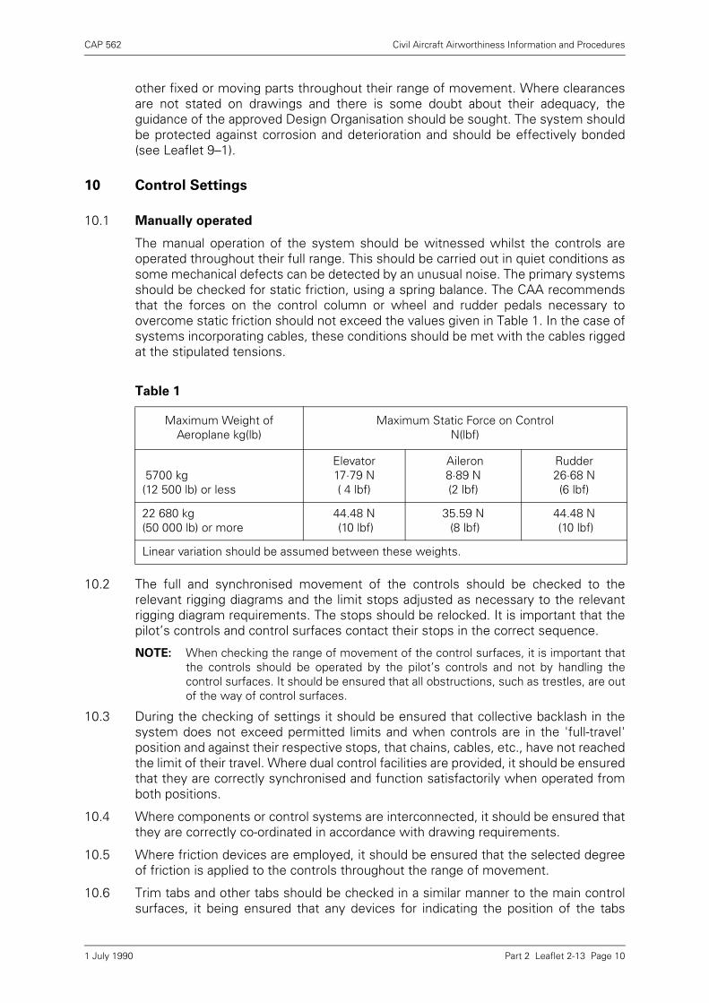
CAP 562 Civil Aircraft Airworthiness Information and Procedures
Part 2 Leaflet 2-13 Page 10
other fixed or moving parts throughout their range of movement. Where clearancesare not stated on drawings and there is some doubt about their adequacy, theguidance of the approved Design Organisation should be sought. The system shouldbe protected against corrosion and deterioration and should be effectively bonded(see Leaflet 9–1).
10 Control Settings
10.1 Manually operated
The manual operation of the system should be witnessed whilst the controls areoperated throughout their full range. This should be carried out in quiet conditions assome mechanical defects can be detected by an unusual noise. The primary systemsshould be checked for static friction, using a spring balance. The CAA recommendsthat the forces on the control column or wheel and rudder pedals necessary toovercome static friction should not exceed the values given in Table 1. In the case ofsystems incorporating cables, these conditions should be met with the cables riggedat the stipulated tensions.
10.2 The full and synchronised movement of the controls should be checked to therelevant rigging diagrams and the limit stops adjusted as necessary to the relevantrigging diagram requirements. The stops should be relocked. It is important that thepilot’s controls and control surfaces contact their stops in the correct sequence.
NOTE: When checking the range of movement of the control surfaces, it is important thatthe controls should be operated by the pilot’s controls and not by handling thecontrol surfaces. It should be ensured that all obstructions, such as trestles, are outof the way of control surfaces.
10.3 During the checking of settings it should be ensured that collective backlash in thesystem does not exceed permitted limits and when controls are in the 'full-travel'position and against their respective stops, that chains, cables, etc., have not reachedthe limit of their travel. Where dual control facilities are provided, it should be ensuredthat they are correctly synchronised and function satisfactorily when operated fromboth positions.
10.4 Where components or control systems are interconnected, it should be ensured thatthey are correctly co-ordinated in accordance with drawing requirements.
10.5 Where friction devices are employed, it should be ensured that the selected degreeof friction is applied to the controls throughout the range of movement.
10.6 Trim tabs and other tabs should be checked in a similar manner to the main controlsurfaces, it being ensured that any devices for indicating the position of the tabs
Table 1
Maximum Weight of Aeroplane kg(lb)
Maximum Static Force on Control N(lbf)
5700 kg(12 500 lb) or less
Elevator 17·79 N( 4 lbf)
Aileron 8·89 N(2 lbf)
Rudder 26·68 N(6 lbf)
22 680 kg(50 000 lb) or more
44.48 N (10 lbf)
35.59 N (8 lbf)
44.48 N (10 lbf)
Linear variation should be assumed between these weights.
1 July 1990
CAP 562 Civil Aircraft Airworthiness Information and Procedures
Part 2 Leaflet 2-13 Page 11
function correctly. When screw jacks are employed to actuate the tab, care must betaken to ensure that they are not out of safety when in the fully extended position.
10.7 Where spring devices are fitted in the control system, these should be checked forcorrect tension, cleanliness and adequate lubrication.
10.8 Guidance on control functioning checks for aeroplanes and rotorcraft is given inparagraph 11.
10.9 Powered Controls
The rigging of powered controls varies with each type of aircraft, therefore, it isimpracticable to attempt in this Leaflet to define a procedure; it is essential to followthe manufacturer’s requirements in this respect. However, reference can be made tothe nature of the precautions which should be taken when rigging such systems.
10.10 It is of the utmost importance that each system should be correctly adjusted and allmeans of adjustment correctly locked. Where cables are used in powered controlsystems, it is essential that they are correctly tensioned to prevent malfunctioning ofthe actuating units. The tensioning requirements, the type of tension meter to beused and the positions where readings are to be taken will be prescribed in therelevant manual for the aircraft concerned. To compensate for structural flexing andchanges in temperature, cable-tension compensator-units are sometimesincorporated in the control circuit; these compensators should be pre-set and thesystem adjusted as prescribed in the relevant manual. To simplify the adjustment,compensator units may be provided with scales or datum holes to indicate when theadjustment is correct.
10.11 It is important during initial setting that jacks do not bottom, unless the relevantmanual so specifies, as this may result in over-stressing of parts of the unit whichcould lead to failure in service.
10.12 Pins, usually 'rigging' pins (which must have a red warning flag permanentlyattached), are sometimes required to simplify the setting of such parts as pulleys,levers, hydraulic control units, etc., in their neutral positions by inserting the pins inthe alignment holes provided. This arrangement also simplifies the correct alignmentand tensioning of the various control systems. When rigging pins are not provided,the neutral positions may be checked by means of alignment marks, by the use ofspecial templates or by taking linear measurements; these procedures will be clearlydefined in the relevant manuals.
NOTE: To prevent damage to the control system, if by error rigging pins were left inposition, some rigging pins are designed to have a maximum shear value and onlythose designed for the system concerned should be used, but in general, theaccuracy of diameter and correct fitting are the important considerations. Groundlocking devices should never be used in lieu of rigging pins.
10.13 If the final alignment and adjustment of the system is correct, it should be possible towithdraw the rigging pins easily. Any undue tightness of the pins in the rigging holesindicates incorrect tensioning or malalignment of the system.
NOTE: All rigging pins or centralising devices must be removed immediately after therigging operation is completed and before operating the power systems, otherwisedamage may result. This precaution must be made part of the control systemclearance procedure. Similarly, precautions should be taken to ensure that allobstructions, such as trestles, are out of the way of control surfaces.
10.14 When static friction tests are prescribed for the control circuits, these should be donewith a spring balance or suitable test rig in the manner prescribed and must notexceed the limiting values permitted. In some power-assisted systems, excessive
1 July 1990
CAP 562 Civil Aircraft Airworthiness Information and Procedures
Part 2 Leaflet 2-13 Page 12
friction could upset the feel of the system to the detriment of the handling qualitiesof the aircraft.
NOTE: In some instances it may be necessary to disconnect the 'feel' spring struts in orderthat the true friction value can be obtained. It may also be necessary to check spring-strut break-out forces following the static check.
10.15 Since the hydraulic systems are independent of each other, a check should be madeto ensure that the routeing of all pipelines and electrical cables does give thenecessary isolation. In addition, pipelines and electrical cables should be checked forsigns of chafing while the systems are functioning.
10.16 It is essential that all control functioning checks and tests are carried out strictly inaccordance with the manufacturers’ publications.
NOTE: It must be ensured that test rigs contain the correct fluid and are provided with thesame standard of filtration as is provided on the aircraft.
10.17 The correct engagement and disengagement of control locks should be checked atthe same time as a check on the correct functioning of the associated warningdevices.
10.18 The range of movement of the controls and control surfaces should be checked inboth directions from the neutral position. If the range does not meet the riggingtolerances, the necessary adjustments should be made and the duplicate inspectioncompleted (see paragraph 4).
10.19 Where components in control systems are interconnected, their operation should becorrectly co-ordinated in accordance with drawing requirements. Where frictiondevices are employed, it should be ensured that the selected degree of friction isapplied to the controls throughout the range of movement.
10.20 When testing the system, all hydraulic equipment and pipelines should be checkedfor leaks. The appropriate filters should be checked for cleanliness and freedom fromdamage and particular care should be taken to follow the instructions given in therelevant manual, as a broken or disintegrated filter may cause a valve to jam. Where'tell-tale' indicators are incorporated in filters these should be checked at the periodsspecified. After checking for cleanliness, all air should be expelled from the systems.
10.21 Engine Ground Run Test
As some parts of the hydraulic systems are not tested with the hydraulic test rig, thecontrols should be operated during a convenient ground test run to ensure that allengine pumps operate satisfactorily over the speed range of the pumps. Where partof a hydraulic system has been disconnected, e.g. to change an engine or pump,precautions should be taken to expel any air which may have entered the system andthe operation of the system should be rechecked.
11 Control Functioning
The final functioning checks on control systems is of the greatest importance and itis essential that they should be completed systematically. The checks should becarried out after thorough cleaning and only when all other work on the system hasbeen completed.
11.1 Aeroplanes
11.1.1 The functioning checks must include verification that full, free and correct movementof the controls is obtained throughout the system relative to the movement of thecrew controls.
1 July 1990
CAP 562 Civil Aircraft Airworthiness Information and Procedures
Part 2 Leaflet 2-13 Page 13
11.1.2 A list of all controls and the salient checking points should be drawn up in a suitablesequence and in duplicate.
11.1.3 A person competent to certify a duplicate inspection should operate the controls inthe cockpit, maintaining the sequence specified in the checking list. Another personcompetent to certify the duplicate inspection should check on the control movementsin the same sequence. For the second part of the inspection the two persons shouldexchange positions and repeat the checks in identical sequence.
11.1.4 The relative movements of the control surfaces in relation to the pilot’s controlsshould be carefully checked to the manufacturer’s instructions.
NOTE: Where 'free operating control surfaces' are installed the relative movements ofcontrols are affected. For example, if the control column is moved back, the elevatordoes not move at all, but the tab of the elevator moves downwards causing theelevator to move upwards in flight. This type of control system requires a specialchecking technique and the manufacturer’s instructions must be closely followed.
11.1.5 The movement of wing-flaps and slats should be checked for synchronisation and acheck should be made to ensure that the relevant surface position indicator accuratelyregisters the position of the surfaces throughout their range of movement.
a) A check should be made (where applicable) to ensure that the wing-flap or slatasymmetric control device is functioning correctly.
b) Where wing-flaps are interconnected with leading-edge flaps or slats, theinstallation should be checked for correct operation during extension and retractionof the wing-flaps.
11.1.6 Where spoilers/speed brakes are interconnected with the aileron control system,their correct operation in relation to the ailerons should be checked.
11.1.7 Where an aerodynamic feel simulator is connected into the main control systems, itscorrect operation should be checked with the aid of a suitable pitot system test rig.
11.1.8 It should be ensured that when operational time limits are specified for certaincontrols, e.g. flaps, spoilers or speed brakes, these are within permitted limits.
11.2 Rotorcraft
11.2.1 A list of all controls affected and the salient checking points should be drawn up in asuitable sequence and used as indicated in the relevant parts of paragraph 7.
11.2.2 The nature of the functioning checks necessary will vary with the system concerned,but where applicable the following should be checked:
a) That the direction of movement of the main and tail rotor blades or other relatedcontrols in relation to the movement of the pilot’s controls is correct.
b) That the operation of interconnected control systems (e.g. engine-throttle andcollective-pitch controls) are co-ordinated in accordance with drawingrequirements.
c) That the range of movement and neutral positions of the pilot’s controls (i.e. cyclic-pitch control columns, collective-pitch levers and yaw pedals) are as specified inthe relevant drawings.
d) That the maximum and minimum pitch angles of the main rotor blades, in bothfore-and-aft and lateral cyclic-pitch, are within drawing requirements.
e) That the maximum and minimum pitch angles of the main rotor blades in collectivepitch are within drawing requirements.
1 July 1990

CAP 562 Civil Aircraft Airworthiness Information and Procedures
Part 2 Leaflet 2-13 Page 14
f) That, in the case of multi-rotor aircraft, the rigging and the movement of the bladesof the rotor are in correct synchronisation.
g) That the tracking of the main rotor blades is satisfactory.
h) That, when tabs are provided on main rotor blades, these are correctly set.
i) That the neutral, maximum and minimum pitch angles and coning angles of the tailrotor blades are in accordance with drawing requirements.
j) That, when dual controls are provided, these function correctly and insynchronisation when operated from both positions.
k) That, to comply with the relevant chapters of BCAR, the static operating loads ofthe system are not excessive and when specified, do not exceed drawingrequirements.
11.2.3 Tracking Checks
When the main rotors do not 'cone' by the same amount during rotation, they are saidto be 'out of track'. This may result in excessive vibration at the control column.Tracking checks should be carried out at the prescribed engine operating conditions,if possible in still air. Where it is not possible to obtain still-air conditions, the rotorcraftshould be faced into a wind not exceeding 10 knots and free from gusts.
11.2.4 Tab Setting
The setting of the tabs on main rotor blades (if provided) should be checked toeliminate out-of-balance moments which will apply torque to the rotor blades. The tabsetting should be checked for correctness by running the rotor at the prescribedspeed and ensuring that the cyclic-pitch control column remains stationary. Out-of-balance moments impart a stirring motion to the column.
11.2.5 Checking Blade Angles
Before checking blade angles it must be ensured that the rotorcraft and whereapplicable, the rotorhead, is set up in the correct lateral and longitudinal position. Theblades must be set in the specified position for the check. The blade angle should bechecked on each blade in turn and when specified, the angles of the subsidiary bladeson the main rotor must agree with those of the master blade within the prescribedlimits. When it is necessary to adjust the initial blade rigging in order to obtain correcttracking or acceptable flight characteristics, the rigging should be re-checked aftertest flying has been completed to ensure that it is within permitted limits.
11.3 Control Locks
A check should be made on internal ground control-locking systems to ensure theyare positive in action, engage fully in the 'locked' position and have adequateclearance in accordance with drawing requirements in the 'unlocked' position. Thereshould be no possibility of interference between the locks and the controls over thefull range of movement of the latter.
11.4 Inspection after Functioning
When the functioning checks have been completed, all checking equipment shouldbe removed from the aircraft and a final inspection made to ensure that the systemsare free from all foreign matter which might cause jamming (e.g. nuts, bolts and smalltools). All access panels should be replaced, care being taken to make sure thatsecuring screws are the correct length not to foul the controls and that chains andcables retaining the access panels are correctly fitted.
1 July 1990
CAP 562 Civil Aircraft Airworthiness Information and Procedures
Part 2 Leaflet 2-13 Page 15
12 Automatic-pilot Installations
The information in this paragraph does not apply to any particular type of installationof automatic-pilot but gives general guidance on essential points which relate to theflying control system. Any moving parts of the automatic-pilot that constitute integralparts of the normal control system, whether the automatic-pilot is 'in' or 'out', shouldbe regarded as part of the flying control system and should be inspected inaccordance with the procedure given in this Leaflet.
12.1 When the automatic controls are disengaged, the normal controls should functionsatisfactorily, e.g. the resistance offered by the automatic-pilot motors, whereapplicable, should not affect the control of the aircraft.
12.2 A check should be made on the means provided for disconnecting the automatic-pilotfrom the normal controls to ensure it is possible to do so at all positions of the controlsand that the manual override of the automatic-pilot is satisfactory.
12.3 The interconnecting mechanism between the automatic-pilot and the normal controlsshould give the required range of travel and should be correctly aligned and smoothand positive in operation. The clearance should be in accordance with drawingrequirements.
12.4 Operating cables, where applicable, should be checked for tension in the mannerapplicable to the particular installation.
13 Ground Test – After Overhaul or Major Dismantling
13.1 All rigging pins or retaining devices should have been removed from the controls.Where control locks are not provided, it may be necessary to support the controlsurfaces until the system is functioning. The control surfaces should be checked forfreedom from obstruction and the automatic-pilot should be disengaged.
13.2 If any one of the independent systems has been disturbed, a complete series ofchecks required to test that system should be made. Where any rectification affectsmore than one system or where there is any possibility of the functioning of allsystems being affected, then the complete series of checks to test all systemsshould be made.
14 Periodic Inspections
Periodic inspections on the complete flying control systems should be carried out inaccordance with the requirements of the Maintenance Schedule or manufacturer’sManual.
1 July 1990

INTENTIONALLY LEFT BLANK

CAP 562 Civil Aircraft Airworthiness Information and Procedures
Part 2 Leaflet 2-14 Page 1
Leaflet 2-14 Measurement and Calibration Systems
1 Introduction
1.1 Requirements within the relevant airworthiness codes applicable to the UnitedKingdom civil aviation industry such as British Civil Airworthiness Requirements(BCARs), Joint Aviation Requirements (JARs), and Air Operators Certificates(arrangements for maintenance support) prescribe that, where necessary, tools,equipment and in particular test equipment (herein after called appliances) arecalibrated to standards acceptable to the CAA.
1.2 This Leaflet gives guidance on the general aspects of establishing and maintaining aneffective calibration system acceptable to the CAA. It takes into account factors suchas the degree of accuracy required, frequency of use and reliability of the appliance.The key factor, however, is the need to establish confidence in the accuracy of theequipment when required for use. The required calibration frequency for anyparticular appliance is that which will ensure it is in compliance with the standardsapplicable to its intended use.
1.3 In all cases, standards used are predicated upon the need for ultimate traceability toone of the following:
• The standard specified by the appliance manufacturer/design organisation.
• The appropriate national/international standard.
2 General
2.1 The appropriate standards are used to achieve consistency between measurementsmade in different locations possibly using alternative measuring techniques.Calibration of appliances is best achieved by operating a methodical system ofcontrol, traceable by an unbroken chain of comparisons through measurementstandards of successively better accuracy up to the appropriate standard.
2.2 Where recommendations for calibration standards are not published or where thecalibration or standards are not specified, calibration should be carried out inaccordance with 'British Standard EN 30012–1 Quality Assurance Requirements forMeasuring Equipment.'
2.3 As an alternative to operating an internal measurement and calibration system, anApproved Organisation/Licensed Engineer may enter into a sub-contractingarrangement to use the services of an appliance calibration service. This, however,does not absolve the user from implementing suitable controls and maintainingcalibration records appropriate to paragraph three of this leaflet.
2.4 In all cases it is the responsibility of the user to satisfy himself that an unbrokentraceability chain is in place. Organisations such as those holding suitable NationalAccreditation of Measurement and Sampling (NAMAS) accreditation may beconsidered to be acceptable to provide external calibration services.
30 June 1997
CAP 562 Civil Aircraft Airworthiness Information and Procedures
Part 2 Leaflet 2-14 Page 2
3 Procedural Controls
3.1 Appliances requiring calibration are those items which are necessary to performmeasurements or tests of an aircraft, system or component to defined limits, asspecified in the Type Certificate holders technical documentation.
3.2 Procedures controlling inspection/servicing and, where appropriate, calibration ofsuch items on a regular basis and to indicate to users that the item is within anyinspection, service or calibration time-limit should be developed.
3.3 A programme should be developed to plan the periodic inspection, service orcalibration within defined time limits to ensure appliances remain in calibration. Theprogramme should consider staggering inspections, servicing or calibrations toensure that the maximum number of appliances are available at all times. A registerof such appliances is essential in order that control of the calibration system isachieved in a co-ordinated manner. Where the appliance holding does not provide alevel of redundancy, contracted loan arrangements may be acceptable.
3.4 The intervals at which calibration is required to be conducted can vary with the natureof the appliance, the conditions under which it is used and the consequences ofincorrect results. The inspection, service or calibration intervals should therefore bein accordance with the appliance supplier’s instructions, except where theorganisation can show that a different interval is warranted in a particular case. Thiswould normally require a system of continuous analysis of calibration results to beestablished to support variations to manufacturers recommended intervals.
3.5 A clear system of labelling calibrated appliances is therefore necessary setting outwhen the next inspection, service or calibration is due and indicating theserviceability, particularly where it may not be obvious.
3.6 Any appliances whose serviceability is in doubt, should be removed from service andlabelled accordingly. Such equipment shall not be returned to service until the reasonsfor the unserviceability have been eliminated and its continued calibration is re-validated. Where the results of calibration prior to adjustment or repair indicate that arisk of significant errors may have existed in any previous measurements made, thenecessary corrective action should be taken.
3.7 Records shall be maintained in order that it can be demonstrated that the appliance iscapable of functioning within the designated limits. The scope of records to bemaintained is dependant on standards used and the nature of the appliance. Therecord system may also provide a valuable reference in cases of dispute, or warrantyclaims, but they are also used for assessing calibration drift and wear. Such dataprovides a basis for development of effective calibration intervals.
Calibration records or certificates should, as a minimum, contain the followinginformation for each appliance calibrated:
• identification of equipment
• standard used
• results obtained
• uncertainty of measurement
• assigned calibration interval
• limits of permissible error
• the authority under which the release document was issued
30 June 1997
CAP 562 Civil Aircraft Airworthiness Information and Procedures
Part 2 Leaflet 2-14 Page 3
• any limitation of use of the equipment
• date on which each calibration was conducted.
3.8 Where calibration services are provided by outside Organisations, it is acceptable tothe CAA for the accuracy of the item to be attested by a release document in thename of the company which records the information specified in paragraph 3.7.
3.9 Any measurement is affected to some degree by the environmental conditions underwhich it is carried out. Appliances need to be calibrated, transported and stored underconditions compatible with the type of equipment to ensure accuracy is not impaired.
3.10 To provide valid repeatable test results, the facilities used for calibration undertakingsare expected to provide controlled environmental conditions to comply with theapplicable standard or original appliance supplier’s specification. It will therefore benecessary to control temperature, humidity, vibration, dust, cleanliness,electromagnetic interference, lighting and any other factors that may affect calibrationresults to predetermined standards. In cases where appliances cannot be placed in acontrolled environment for calibration, compensation corrections should be applied tothe calibration standard to provide the required level of accuracy.
3.11 Although not a substitute for regular calibration, confidence that an appliancecontinues to measure correctly can be obtained by the use of a checkingmeasurement standard, applied by the user. This will demonstrate that, at the valueor values checked and under the conditions of the check, the appliance is stillfunctioning correctly. The checking standard itself, which usually has to be simple androbust, will need to be calibrated in order that the results obtained by its use can, withreliance, be attributed to the instrument and not to changes in the checkingmeasurement standard.
3.12 Any calibration system adopted would need to comply with the minimumrequirements of the airworthiness code to which it has been implemented. Thecontinued effectiveness of the calibration system and associated procedures shouldbe periodically and systematically reviewed by company quality systems.
30 June 1997

INTENTIONALLY LEFT BLANK