Embed Size (px)
Citation preview
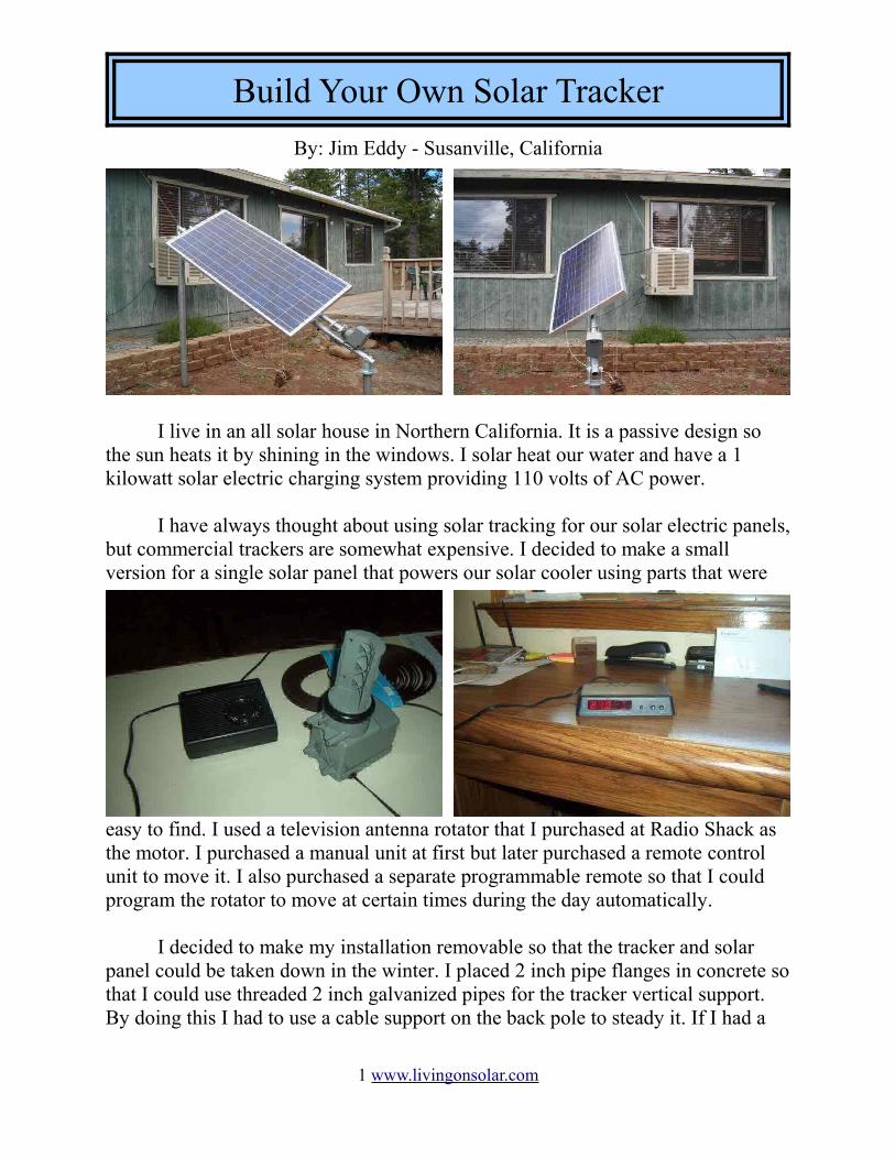
By: Jim Eddy - Susanville, California
I live in an all solar house in Northern California. It is a passive design so the sun heats it by shining in the windows. I solar heat our water and have a 1 kilowatt solar electric charging system providing 110 volts of AC power.
I have always thought about using solar tracking for our solar electric panels, but commercial trackers are somewhat expensive. I decided to make a small version for a single solar panel that powers our solar cooler using parts that were
easy to find. I used a television antenna rotator that I purchased at Radio Shack as the motor. I purchased a manual unit at first but later purchased a remote control unit to move it. I also purchased a separate programmable remote so that I could program the rotator to move at certain times during the day automatically.
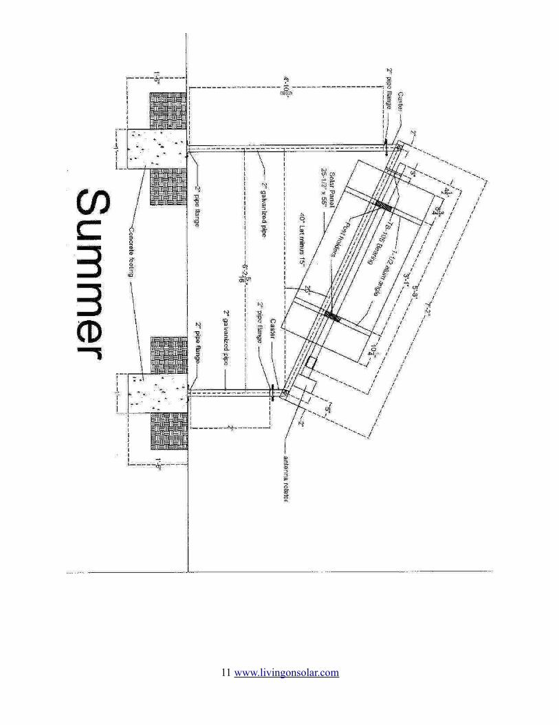
I decided to make my installation removable so that the tracker and solar panel could be taken down in the winter. I placed 2 inch pipe flanges in concrete so that I could use threaded 2 inch galvanized pipes for the tracker vertical support. By doing this I had to use a cable support on the back pole to steady it. If I had a
1 www.livingonsolar.com
Build Your Own Solar Tracker
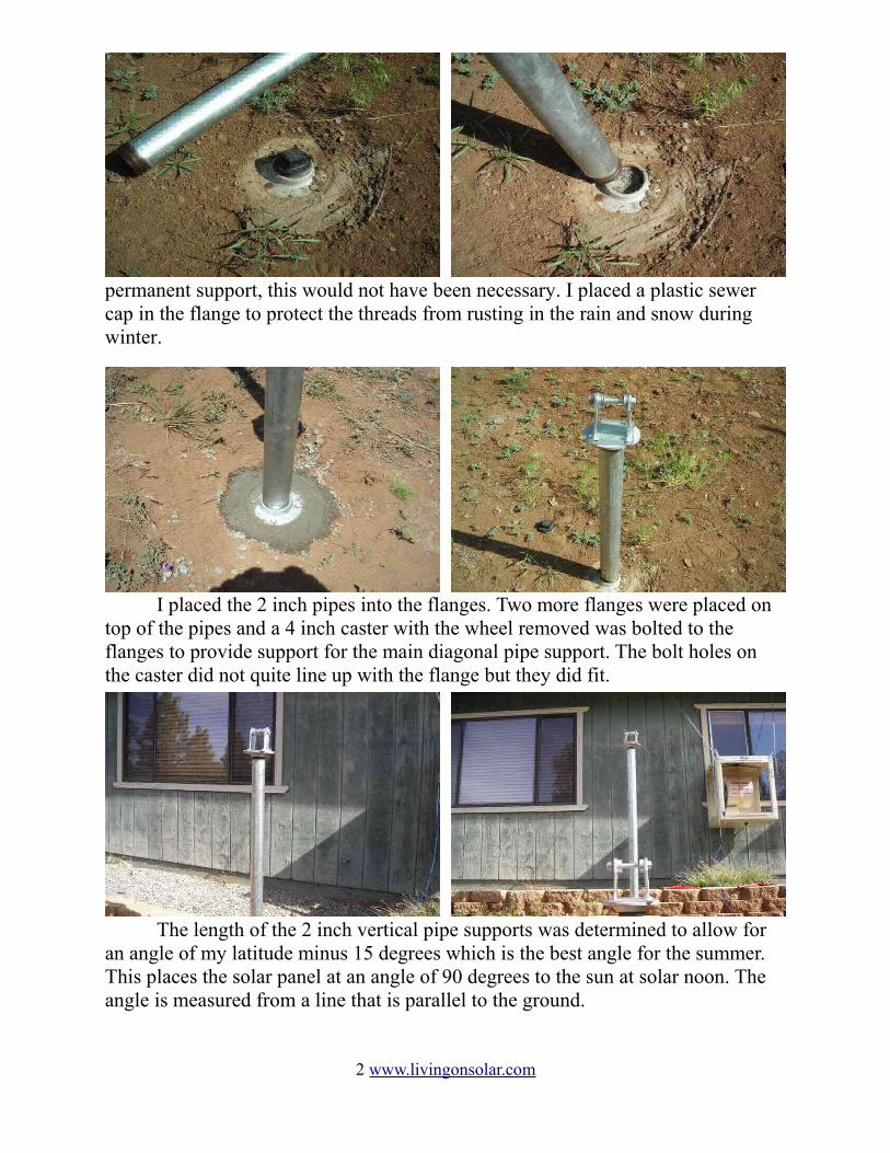
permanent support, this would not have been necessary. I placed a plastic sewer cap in the flange to protect the threads from rusting in the rain and snow during winter.
I placed the 2 inch pipes into the flanges. Two more flanges were placed on top of the pipes and a 4 inch caster with the wheel removed was bolted to the flanges to provide support for the main diagonal pipe support. The bolt holes on the caster did not quite line up with the flange but they did fit.
The length of the 2 inch vertical pipe supports was determined to allow for an angle of my latitude minus 15 degrees which is the best angle for the summer. This places the solar panel at an angle of 90 degrees to the sun at solar noon. The angle is measured from a line that is parallel to the ground.
2 www.livingonsolar.com
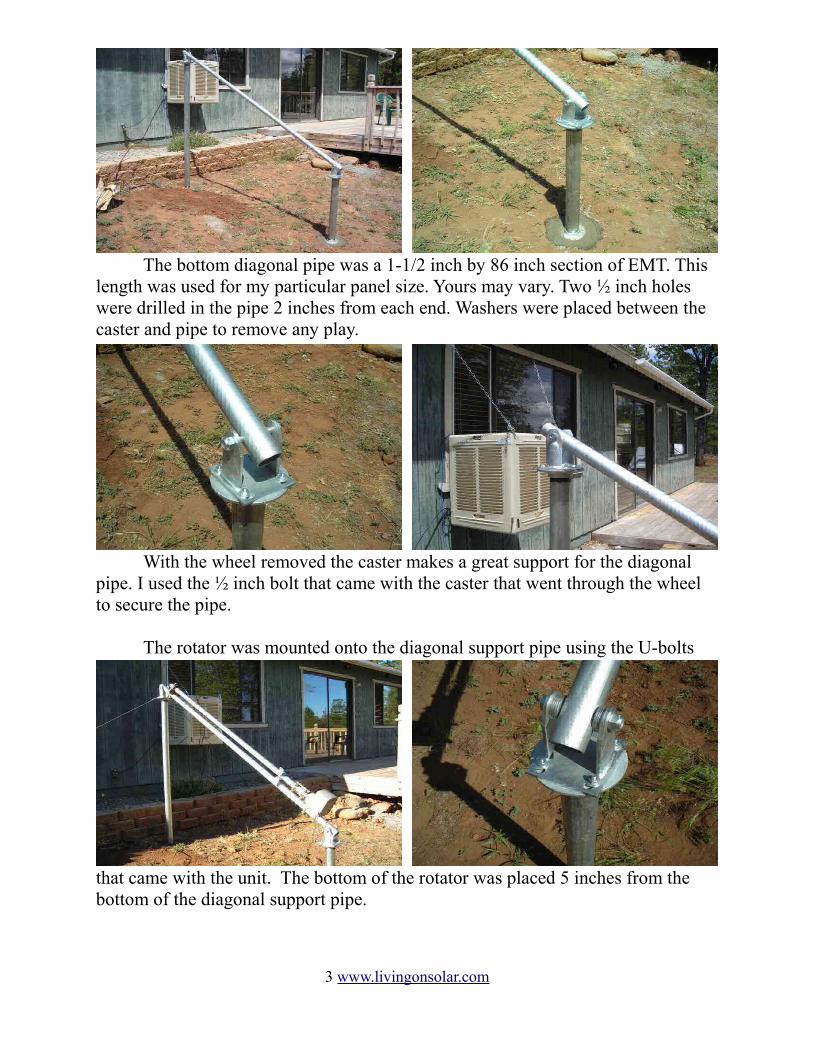
The bottom diagonal pipe was a 1-1/2 inch by 86 inch section of EMT. This length was used for my particular panel size. Yours may vary. Two ½ inch holes were drilled in the pipe 2 inches from each end. Washers were placed between the caster and pipe to remove any play.
With the wheel removed the caster makes a great support for the diagonal pipe. I used the ½ inch bolt that came with the caster that went through the wheel to secure the pipe.
The rotator was mounted onto the diagonal support pipe using the U-bolts
that came with the unit. The bottom of the rotator was placed 5 inches from the bottom of the diagonal support pipe.
3 www.livingonsolar.com
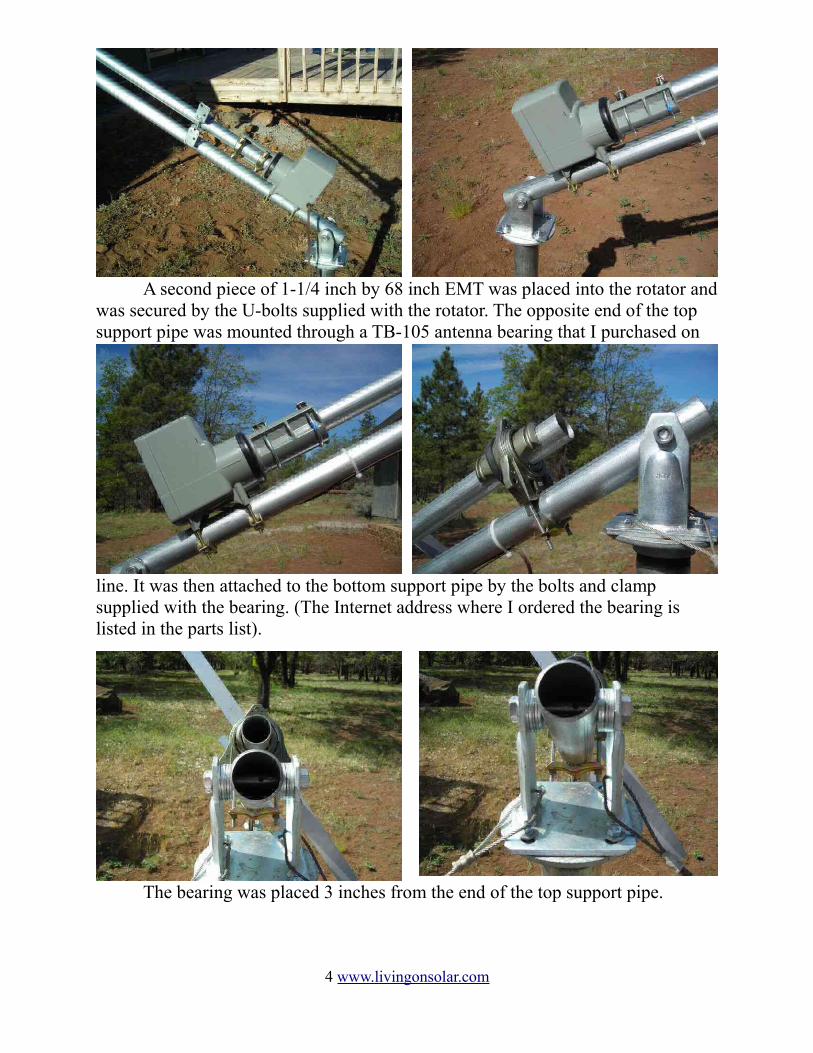
A second piece of 1-1/4 inch by 68 inch EMT was placed into the rotator and was secured by the U-bolts supplied with the rotator. The opposite end of the top support pipe was mounted through a TB-105 antenna bearing that I purchased on
line. It was then attached to the bottom support pipe by the bolts and clamp supplied with the bearing. (The Internet address where I ordered the bearing is listed in the parts list).
The bearing was placed 3 inches from the end of the top support pipe.
4 www.livingonsolar.com
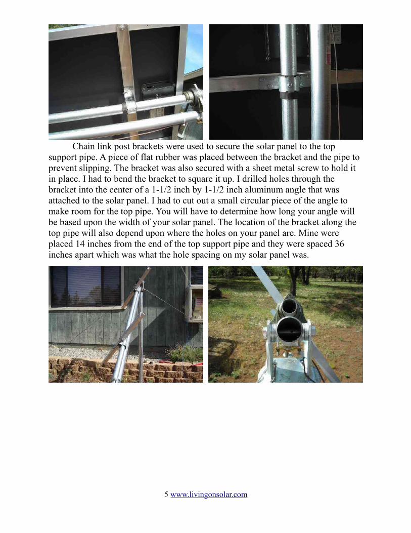
Chain link post brackets were used to secure the solar panel to the top support pipe. A piece of flat rubber was placed between the bracket and the pipe to prevent slipping. The bracket was also secured with a sheet metal screw to hold it in place. I had to bend the bracket to square it up. I drilled holes through the bracket into the center of a 1-1/2 inch by 1-1/2 inch aluminum angle that was attached to the solar panel. I had to cut out a small circular piece of the angle to make room for the top pipe. You will have to determine how long your angle will be based upon the width of your solar panel. The location of the bracket along the top pipe will also depend upon where the holes on your panel are. Mine were placed 14 inches from the end of the top support pipe and they were spaced 36 inches apart which was what the hole spacing on my solar panel was.
5 www.livingonsolar.com
The Remote Control Unit
The remote control unit that comes with the rotator can be programmed to position the rotator to different positions. It can move the rotator in a full circle from 0 to 360 degrees. If the rotator were placed on a mast that was vertical, which is the normal way to mount it, 0 degrees would position the rotator North. East would be 90 degrees, South 180 degrees, West 270 degrees and back to North again at 360 degrees. By mounting the rotator at an angle the same increments can be used. There is no need to start at 0 degrees since the rotator has to start somewhere past East or 90 degrees. I decided to start at 135 degrees which is the position of the sun at 9:00 AM solar time in the Northern hemisphere.
The rotator and control need to be synchronized. This is a little tricky due to the way the rotator is mounted since it cannot turn the full 360 degrees. I loosen the mounting bolts on the rotator and synchronize it with the unit through the full 360 degrees. I then turn the rotator back to 180 degrees and tighten the bolts.
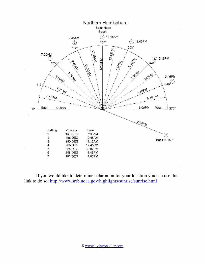
Each position that is programmed is given a number. In my case position 1 is 135 degrees. You can read the particular instructions for yourself to determine how to program the various positions. I program my unit for the following positions and times:
Position Number Position in Degrees Time to turn – Solar time1 135 7:00 AM2 158 9:45 AM3 180 11:15 AM4 203 12:45 PM5 225 2:15 PM6 248 3:45 PM7 180 7:00 PM
The positions are different if you are in the Southern Hemisphere. I have included 2 diagrams for the Northern and Southern Hemispheres.
The positions that I currently use are for 9:00AM, 10:30AM, 12:00PM, 1:30 PM, 3:00PM and 4:30PM. The rotator turns to each position 45 minutes before each time and remains at that position for 45 minutes after. The only exception is the first time in the morning which is due to a weight problem ( I'll explain later). This keeps the solar panel facing the sun within 11 degrees, plus or minus, for each position selected.
6 www.livingonsolar.com
With the original remote the tracker could only be controlled manually. I was able to find a programmable remote control that could send the same signal as the original and do it at a particular time using it's built in clock. It was normally an expensive remote, but I found a refurbished one for about 30 dollars. I spent a lot of time trying to find other similar units but the ones I found were also expensive. There are tons of inexpensive household remote control units but they use a different way of controlling individual appliances. The Sony unit that I use may be hard to find. I have not been able to find an inexpensive replacement. If I had more electronic experience, I know that a simple programmable integrated circuit could be used to control the rotator and the whole remote could be eliminated. It is my hope that someone with more experience than I have can figure this out.
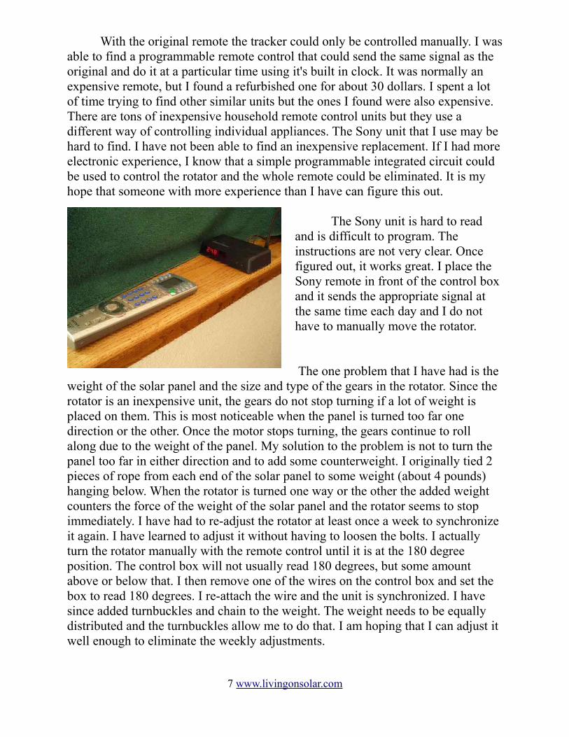
The Sony unit is hard to read and is difficult to program. The instructions are not very clear. Once figured out, it works great. I place the Sony remote in front of the control box and it sends the appropriate signal at the same time each day and I do not have to manually move the rotator.
The one problem that I have had is the weight of the solar panel and the size and type of the gears in the rotator. Since the rotator is an inexpensive unit, the gears do not stop turning if a lot of weight is placed on them. This is most noticeable when the panel is turned too far one direction or the other. Once the motor stops turning, the gears continue to roll along due to the weight of the panel. My solution to the problem is not to turn the panel too far in either direction and to add some counterweight. I originally tied 2 pieces of rope from each end of the solar panel to some weight (about 4 pounds) hanging below. When the rotator is turned one way or the other the added weight counters the force of the weight of the solar panel and the rotator seems to stop immediately. I have had to re-adjust the rotator at least once a week to synchronize it again. I have learned to adjust it without having to loosen the bolts. I actually turn the rotator manually with the remote control until it is at the 180 degree position. The control box will not usually read 180 degrees, but some amount above or below that. I then remove one of the wires on the control box and set the box to read 180 degrees. I re-attach the wire and the unit is synchronized. I have since added turnbuckles and chain to the weight. The weight needs to be equally distributed and the turnbuckles allow me to do that. I am hoping that I can adjust it well enough to eliminate the weekly adjustments.
7 www.livingonsolar.com
If you would like to determine solar noon for your location you can use this
link to do so: http://www.srrb.noaa.gov/highlights/sunrise/sunrise.html
8 www.livingonsolar.com
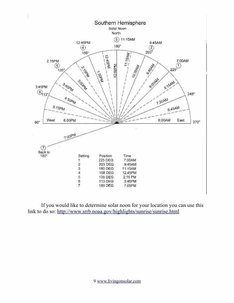
If you would like to determine solar noon for your location you can use this link to do so: http://www.srrb.noaa.gov/highlights/sunrise/sunrise.html
9 www.livingonsolar.com
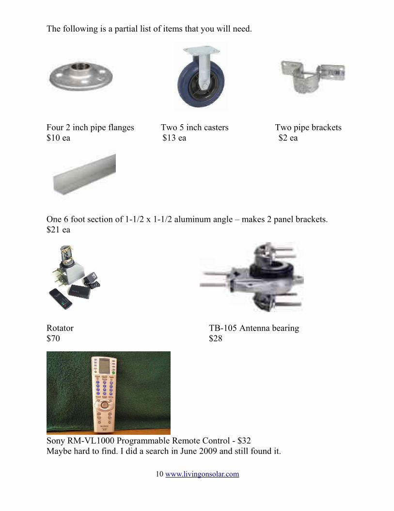
The following is a partial list of items that you will need.
Four 2 inch pipe flanges Two 5 inch casters Two pipe brackets$10 ea $13 ea $2 ea
One 6 foot section of 1-1/2 x 1-1/2 aluminum angle – makes 2 panel brackets.$21 ea
Rotator TB-105 Antenna bearing$70 $28
Sony RM-VL1000 Programmable Remote Control - $32Maybe hard to find. I did a search in June 2009 and still found it.
10 www.livingonsolar.com
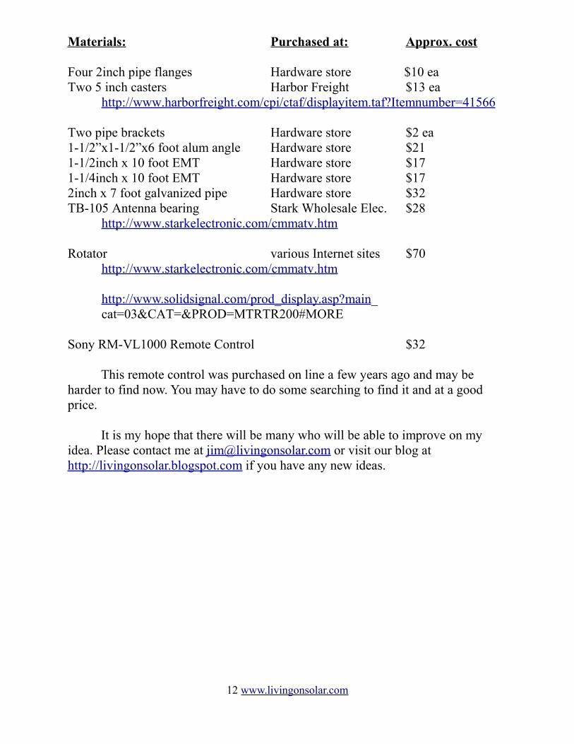
Materials: Purchased at: Approx. cost
Four 2inch pipe flanges Hardware store $10 ea Two 5 inch casters Harbor Freight $13 ea
http://www.harborfreight.com/cpi/ctaf/displayitem.taf?Itemnumber=41566
Two pipe brackets Hardware store $2 ea1-1/2”x1-1/2”x6 foot alum angle Hardware store $211-1/2inch x 10 foot EMT Hardware store $171-1/4inch x 10 foot EMT Hardware store $172inch x 7 foot galvanized pipe Hardware store $32TB-105 Antenna bearing Stark Wholesale Elec. $28
http://www.starkelectronic.com/cmmatv.htm
Rotator various Internet sites $70http://www.starkelectronic.com/cmmatv.htm
http://www.solidsignal.com/prod_display.asp?main_cat=03&CAT=&PROD=MTRTR200#MORE
Sony RM-VL1000 Remote Control $32
This remote control was purchased on line a few years ago and may be harder to find now. You may have to do some searching to find it and at a good price.
It is my hope that there will be many who will be able to improve on my idea. Please contact me at [email protected] or visit our blog at http://livingonsolar.blogspot.com if you have any new ideas.
12 www.livingonsolar.com
Sony Remote Programming
Several people have asked how to program the Sony remote. I have included this set of instructions to hopefully shed some light on how to do so.
Setting The Sony Remote to Operate the Control Box
To set the remote to control the box: Press the COMPO(component) button and then press the button with the line leading to the word CABLE. This is what my Radio Shack control box says will work with a universal remote. Yours might be different. You need to find what code to use.
Programming The Code
The Sony remote has to be programmed to operate the specific control box. My Radio Shack unit says that a code for a Pioneer Cable box should work using a universal remote.
The codes shown on the Sony component code numbers chart for a Pioneer analog cable box are 9014 and 9015. 9014 works for me. Also make sure that the control box is set to shut itself off after a given time. I believe this is the default. My unit shuts off after 8 minutes. When the Sony remote sends out a signal it sends an on/off function before sending.
1. Press the SET button for more than a second until the menu changes.2. Press the button with the line leading to the word PRESET.3. Press the button with the line leading to the word CABLE.4. Enter the 4 digit code and then the ENT (enter) button.5. Press the SET button several times to get back to component operation. At this point you can check to make sure the code worked. Press the POWER button. If the control box turns on and off, the code is correct.
To Program Timers
There are 12 total timer settings possible. I use only 71. Press the SET button for more than a second until the menu changes.2. Press the SCROLL button to get to the next menu which has TIMER in it.3. Press the button with the line leading down to the word TIMER.
The first 4 timers are displayed. If this is the first time that you have been here they should all be blinking.
4. Pressing the SCROLL button will take you to the next 4(PROG5-8) and again for the last 4(PROG9-12).If the timers have already been programmed they do not blink but stay lit. This is called the standby mode which means they are standing by to perform the already programmed steps. Before any timers have been programmed, all 12 prog timers should be blinking.
5. To program PROG1 press the button with the line leading to the word PROG1.This is the confusing and tricky part: (THE DIFFERENT FLASHING DISPLAYS)The first time you go to the numbered timer program (PROG1 for instance) The words SETUP and COPY both flash and the ON/OFF and TEST do not flash. This means no information has been programmed yet. After you have programmed the timer, the ON/OFF and TEST and SETUP and COPY will all flash. You will need to turn the timer on which is explained further down. If you press the button with the line that leads to the
13 www.livingonsolar.com
word ON/OFF after programming the timer, this will turn the timer on or off. On being in the standby mode and ready to execute and off mode meaning programmed but not ready to execute.
6. Press the button with the line leading to the word SETUP. The day of the week, the time andthe word MACRO should all be flashing.
7. Press the button leading to the day of the week. Press the joystick up or down until the word EVERYDAY is displayed. Press the joystick button straight down. This will cause all the words to blink again.
8. Press the button with the line leading to the time display. Use the up and down on the joystick to set the hours. This also controls Am and PM, so scroll through to the correct one. Use the left and right on the joystick to move to the minutes and do the same. Press the joystick straight down again. All the words will blink again
9. Press the button with the line leading to the word MACRO.If you have previously entered a sequence in the macro OK or NG will flash. OK will clear whatever was entered before. NG will not. This is the part that threw me for a long time because no display of the buttons you push show up.----- After you enter macro mode press the button with the line leading to the word CABLE. After that just push the buttons necessary for the action. In the case of PROG1 you want the Sony to turn on the control box and send the number 1 (or whatever number you use to go to your first position) to it. Press the power button and then the number 1 . Press the SET button to return to the day and date menu. Press the SET button again to return to the menu that displays the ON/Off etc display. You should be able at this point to test whether your programming worked. Make sure your control box is already off since the Sony remote will send an on/off signal - if the box is on, it will turn it off. Push the button with the line that leads to the word TEST and if you programmed the timer correctly the control box should turn on and the rotator should turn to the correct position. At this point press the button with the line that leads to the word ON/OFF to actually turn the timer on (standby mode). The ON/OFF and TEST should blink and the SETUP and COPY should not be blinking. Press the SET button again. This will return you to the menu where all the numbered timers are displayed. The timer that you just programmed should now not blink. If it does, press the button for the program number and press the ON/OFF again. Hit SET again to return and check to make sure the timer does not blink.
At this point the first timer is programmed. You need to only turn on the control box through the Sony remote and send the number of the position you want. In my case, the numbers 1 through 7. The control box turns off after 8 minutes. If the box is constantly on than only a number would have to be sent. Since leaving the control box display on is not necessary and would waste some energy, why not let it shut off after 8 minutes and let the Sony remote turn it back on when it is time.10. Enter all the other positions the same way until finished. Press the SET button several times to return to the main menu. Hopefully you are done.
14 www.livingonsolar.com