Embed Size (px)
Citation preview
FFFIIINNNAAALLL RRREEEPPPOOORRRTTT OOOFFF IIINNNVVVEEESSSTTTIIIGGGAAATTTIIIOOONNN
TTTOOO TTTHHHEEE DDDIIIEEESSSEEELLL EEEMMMIIISSSSSSIIIOOONNNSSS EEEVVVAAALLLUUUAAATTTIIIOOONNN PPPRRROOOGGGRRRAAAMMM (((DDDEEEEEEPPP)))
NNNOOORRRAAANNNDDDAAA IIINNNCCC... --- BBBRRRUUUNNNSSSWWWIIICCCKKK MMMIIINNNEEE
DDDIIIEEESSSEEELLL PPPAAARRRTTTIIICCCUUULLLAAATTTEEE FFFIIILLLTTTEEERRR (((DDDPPPFFF)))
FFFIIIEEELLLDDD SSSTTTUUUDDDYYY
OOOCCCTTTOOOBBBEEERRR 222000000444
Prepared by
S. McGinn Noranda Inc. - Technology Centre, Pointe Claire, Québec
With contributions from
M. Grenier, M. Gangal, and B. Rubeli Natural Resources Canada, CANMET, Sudbury and Bells Corners, Ontario, Canada A. Bugarksi and G. Schnakenberg NIOSH - Pittsburgh Research Laboratory, Pittsburgh, Pennsylvania, U.S.A. R. Johnson, D. Petrie, and G. Crowther Noranda Inc. – Brunswick Mine, Bathurst, New Brunswick, Canada J. Penney United Steelworkers of America, Toronto, Ontario, Canada
- 2 -
AAACCCKKKNNNOOOWWWLLLEEEDDDGGGEEEMMMEEENNNTTTSSS This report is a summary of the investigation and findings of nearly three years of field and laboratory work looking at diesel particulate filter (DPF) systems. An investigation of this length and scope requires strong collaboration from many organizations and individuals. Though the list of individuals is too long to acknowledge here it is important to make note of their organizations. By far the most important collaboration in this project came from the people at Noranda Inc. – Brunswick Mine. The management, engineering, production and maintenance people formed a large project team on their own to ensure that the project was supported by all mine groups from beginning to end. The commitment of Brunswick Mine to this project was the single most critical factor in its success. In terms of research collaboration many organizations were active participants. Natural Resources Canada – CANMET played a large role with laboratories from both Sudbury, Ontario and Bells Corners, Ontario participating in field work, laboratory work, and reporting. The Pittsburgh Research Laboratory - NIOSH group participated in field research from beginning to end of the project and contributed to reporting. The VERT program in Switzerland contributed background information and advice in building the scope of the project. The United Steelworkers of America participated in building the scope of the project, following the progress and making recommendations during the course of the project and contributed to reporting and editing. The technical committee of the Diesel Emissions Evaluation Program (DEEP) followed the project from conception to final report providing critical input and feedback to ensure a successful project. The vehicle, engine, and emissions controls manufacturers each contributed technical expertise, information and specifications, and materials needed to keep the project running successfully. Atlas Copco Construction and Mining Equipment assisted in providing materials for the four vehicles in the project. Detroit Diesel Corporation collaborated for support of the four engines in the project. The four DPF systems came from Engine Control Systems – Lubrizol Canada Ltd. of Toronto, Ontario, DCL International of Toronto, Ontario, Oberland Mangold of Germany, and Catalytic Exhaust Products of Toronto Ontario. Octel Corporation of Bletchley, United Kingdom provided the fuel additive used in the project and technical support during the project. Each of the DPF manufacturers actively participated collaboratively in design, installation and support of the DPF systems from beginning to end of the project. The project sponsor, the Diesel Emissions Evaluation Program (DEEP) would like to take this opportunity to thank all participants for their efforts in making this project a success. Sean McGinn Project Leader
- 3 -
TTTAAABBBLLLEEE OOOFFF CCCOOONNNTTTEEENNNTTTSSS
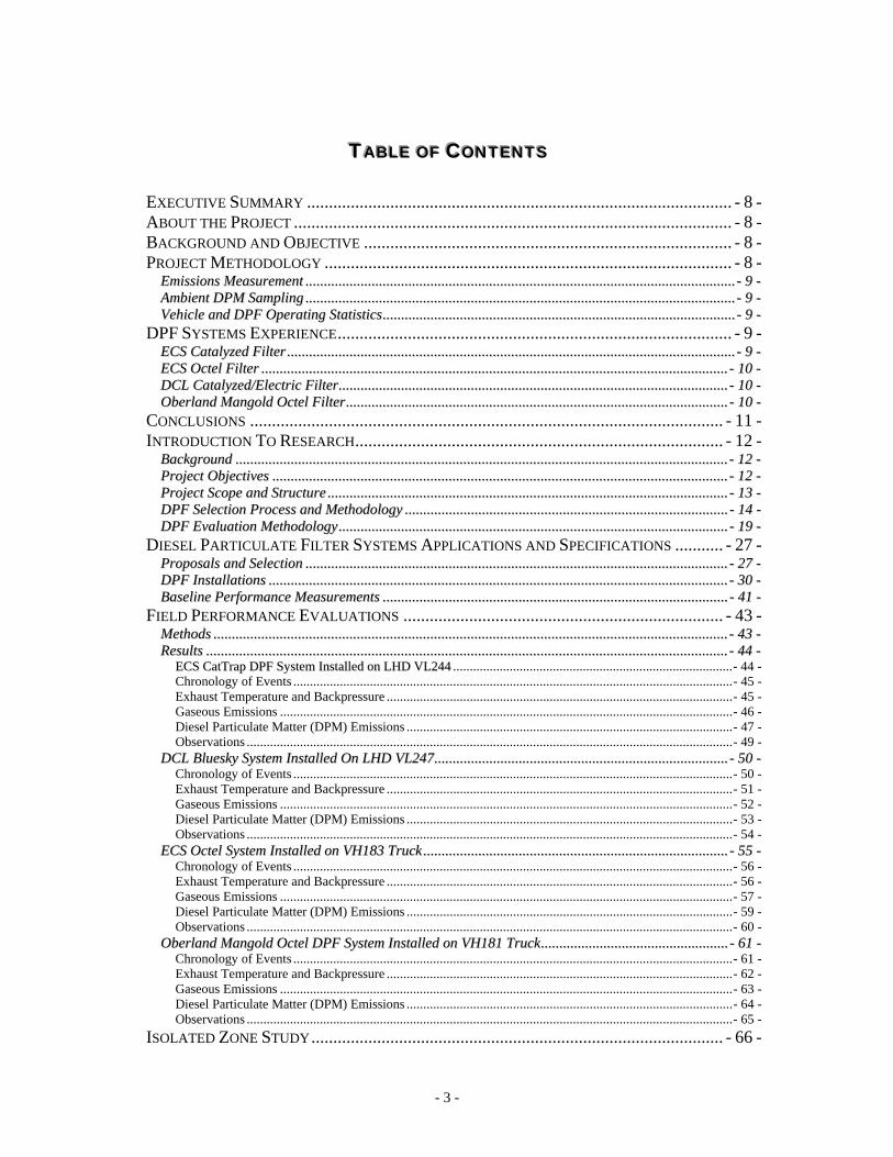
EXECUTIVE SUMMARY ................................................................................................. - 8 - ABOUT THE PROJECT .................................................................................................... - 8 - BACKGROUND AND OBJECTIVE .................................................................................... - 8 - PROJECT METHODOLOGY ............................................................................................. - 8 -
EEmmiissssiioonnss MMeeaassuurreemmeenntt .......................................................................................................................................................................................................................................... -- 99 -- AAmmbbiieenntt DDPPMM SSaammpplliinngg .......................................................................................................................................................................................................................................... -- 99 -- VVeehhiiccllee aanndd DDPPFF OOppeerraattiinngg SSttaattiissttiiccss................................................................................................................................................................................................ -- 99 --
DPF SYSTEMS EXPERIENCE.......................................................................................... - 9 - EECCSS CCaattaallyyzzeedd FFiilltteerr .................................................................................................................................................................................................................................................... -- 99 -- EECCSS OOcctteell FFiilltteerr .............................................................................................................................................................................................................................................................. -- 1100 -- DDCCLL CCaattaallyyzzeedd//EElleeccttrriicc FFiilltteerr.................................................................................................................................................................................................................... -- 1100 -- OObbeerrllaanndd MMaannggoolldd OOcctteell FFiilltteerr................................................................................................................................................................................................................ -- 1100 --
CONCLUSIONS ............................................................................................................ - 11 - INTRODUCTION TO RESEARCH.................................................................................... - 12 -
BBaacckkggrroouunndd ............................................................................................................................................................................................................................................................................ -- 1122 -- PPrroojjeecctt OObbjjeeccttiivveess ........................................................................................................................................................................................................................................................ -- 1122 -- PPrroojjeecctt SSccooppee aanndd SSttrruuccttuurree .......................................................................................................................................................................................................................... -- 1133 -- DDPPFF SSeelleeccttiioonn PPrroocceessss aanndd MMeetthhooddoollooggyy ................................................................................................................................................................................ -- 1144 -- DDPPFF EEvvaalluuaattiioonn MMeetthhooddoollooggyy .................................................................................................................................................................................................................... -- 1199 --
DIESEL PARTICULATE FILTER SYSTEMS APPLICATIONS AND SPECIFICATIONS ........... - 27 - PPrrooppoossaallss aanndd SSeelleeccttiioonn ...................................................................................................................................................................................................................................... -- 2277 -- DDPPFF IInnssttaallllaattiioonnss .......................................................................................................................................................................................................................................................... -- 3300 -- BBaasseelliinnee PPeerrffoorrmmaannccee MMeeaassuurreemmeennttss ............................................................................................................................................................................................ -- 4411 --
FIELD PERFORMANCE EVALUATIONS ......................................................................... - 43 - MMeetthhooddss ........................................................................................................................................................................................................................................................................................ -- 4433 -- RReessuullttss ............................................................................................................................................................................................................................................................................................ -- 4444 --
EECCSS CCaattTTrraapp DDPPFF SSyysstteemm IInnssttaalllleedd oonn LLHHDD VVLL224444 ....................................................................................- 44 - Chronology of Events ....................................................................................................................................- 45 - Exhaust Temperature and Backpressure ........................................................................................................- 45 - Gaseous Emissions ........................................................................................................................................- 46 - Diesel Particulate Matter (DPM) Emissions ..................................................................................................- 47 - Observations ..................................................................................................................................................- 49 -
DDCCLL BBlluueesskkyy SSyysstteemm IInnssttaalllleedd OOnn LLHHDD VVLL224477................................................................................................................................................................ -- 5500 -- Chronology of Events ....................................................................................................................................- 50 - Exhaust Temperature and Backpressure ........................................................................................................- 51 - Gaseous Emissions ........................................................................................................................................- 52 - Diesel Particulate Matter (DPM) Emissions ..................................................................................................- 53 - Observations ..................................................................................................................................................- 54 -
EECCSS OOcctteell SSyysstteemm IInnssttaalllleedd oonn VVHH118833 TTrruucckk ...................................................................................................................................................................... -- 5555 -- Chronology of Events ....................................................................................................................................- 56 - Exhaust Temperature and Backpressure ........................................................................................................- 56 - Gaseous Emissions ........................................................................................................................................- 57 - Diesel Particulate Matter (DPM) Emissions ..................................................................................................- 59 - Observations ..................................................................................................................................................- 60 -
OObbeerrllaanndd MMaannggoolldd OOcctteell DDPPFF SSyysstteemm IInnssttaalllleedd oonn VVHH118811 TTrruucckk...................................................................................................... -- 6611 -- Chronology of Events ....................................................................................................................................- 61 - Exhaust Temperature and Backpressure ........................................................................................................- 62 - Gaseous Emissions ........................................................................................................................................- 63 - Diesel Particulate Matter (DPM) Emissions ..................................................................................................- 64 - Observations ..................................................................................................................................................- 65 -
ISOLATED ZONE STUDY.............................................................................................. - 66 -
- 4 -
OObbjjeeccttiivvee aanndd SSccooppee .................................................................................................................................................................................................................................................. -- 6666 -- EExxppeerriimmeenntt MMeetthhooddoollooggyy.................................................................................................................................................................................................................................... -- 6666 -- MMeeaassuurreemmeenntt ooff AAmmbbiieenntt CCoonncceennttrraattiioonnss ooff DDPPMM...................................................................................................................................................... -- 6688 --
LABORATORY EVALUATION OF DPF SYSTEMS........................................................... - 74 - LLaabboorraattoorryy BBeenncchh TTeessttiinngg ................................................................................................................................................................................................................................ -- 7744 -- PPoosstt SSttuuddyy IInnssppeeccttiioonnss ............................................................................................................................................................................................................................................ -- 7799 --
ECS CatTrap..................................................................................................................................................- 79 - DCL Bluesky .................................................................................................................................................- 80 - ECS Octel ......................................................................................................................................................- 81 - Oberland Mangold Octel ...............................................................................................................................- 82 -
CONCLUSION .............................................................................................................. - 83 - RECOMMENDATIONS .................................................................................................. - 87 -
Selection ........................................................................................................................................................- 87 - Installation .....................................................................................................................................................- 87 - Measurement .................................................................................................................................................- 88 - Maintenance ..................................................................................................................................................- 88 - Verification....................................................................................................................................................- 88 -
REFERENCES............................................................................................................... - 89 -
- 5 -
LLLiiisssttt ooofff FFFiiiggguuurrreeesss FIGURE 1 - ATLAS COPCO WAGNER ST8B SCOOPTRAM ®®® ......................................................................... - 16 - FIGURE 2 – ATLAS COPCO WAGNER MT436-B HAULAGE TRUCK............................................................ - 17 - FIGURE 3 - ST8-B SCOOPTRAM® DUTY CYCLE ........................................................................................ - 18 - FIGURE 4 - MT436-B TRUCK DUTY CYCLE .............................................................................................. - 19 - FIGURE 5 - UGAS EMISSIONS TESTING SYSTEM ....................................................................................... - 21 - FIGURE 6 - NANOMET DIESEL PARTICULATE ANALYSIS SYSTEM ............................................................. - 22 - FIGURE 7 - RCD AND NIOSH 5040 OPERATOR DPM SAMPLING TRAINS ................................................. - 24 - FIGURE 8 - METHOD 5040 ANALYSIS EXAMPLE........................................................................................ - 25 - FIGURE 9 - DDEC REPORTS ENGINE OPERATING STATISTICS................................................................... - 26 - FIGURE 10 - ECS CATTRAP CERAMIC MONOLITHS................................................................................... - 28 - FIGURE 11 - ECS OCTEL DPF COMPONENTS ............................................................................................ - 28 - FIGURE 12 - DCL BLUESKY DPF SILICON CARBIDE MONOLITH AND HEATER ELEMENT ......................... - 29 - FIGURE 13 - OBERLAND MANGOLD DPF GLASS FIBER CARTRIDGES........................................................ - 30 - FIGURE 14 - ECS CATTRAP INSTALLATION............................................................................................... - 31 - FIGURE 15 - DCL BLUESKY INSTALLATION ON VL247............................................................................. - 33 - FIGURE 16 - DCL REGENERATION PLUG IN UNIT...................................................................................... - 34 - FIGURE 17 - ECS OCTEL INSTALLATION ON VH183 ................................................................................. - 35 - FIGURE 18 - EXHAUST TEMPERATURE AND BACKPRESSURE TRACES FOR FIRST OBERLAND MANGOLD DPF . -
37 - FIGURE 19 - ORIGINAL OBERLAND MANGOLD DPF INSTALLATION.......................................................... - 38 - FIGURE 20 - FINAL OBERLAND MANGOLD DPF INSTALLATION................................................................ - 38 - FIGURE 21 - BLENDED FUEL STORAGE ON SURFACE................................................................................. - 40 - FIGURE 22 - BLENDED FUEL STORAGE AT 1000 LEVEL............................................................................. - 40 - FIGURE 23 - ECS CATTRAP EXHAUST TEMPERATURE AND BACKPRESSURE............................................. - 46 - FIGURE 24 – GASEOUS EMISSIONS FOR VL244 WITH ECS CATTRAP....................................................... - 47 - FIGURE 25 – DPM FILTRATION EFFICIENCIES FOR ECS CATTRAP DPF SYSTEM ..................................... - 48 - FIGURE 26 – BACHARACH SMOKE INDEX MEASURED FOR ECS CATTRAP DPF SYSTEM.......................... - 49 - FIGURE 27 - EXHAUST TEMPERATURES AND ENGINE BACKPRESSURES RECORDED FOR LHD VH247 EQUIPPED
WITH DCL BLUESKY DPF SYSTEM ................................................................................................... - 51 - FIGURE 28 - GASEOUS EMISSIONS FOR VL247 WITH DCL BLUESKY DPF SYSTEM ................................. - 52 - FIGURE 29 - DPM FILTRATION EFFICIENCIES FOR DCL BLUESKY DPF SYSTEM...................................... - 53 - FIGURE 30 – BACHARACH SMOKE DENSITY RESULTS ON VL247 WITH DCL BLUSEKY DPF SYSTEM...... - 54 - FIGURE 31 - ECS OCTEL EXHAUST TEMPERATURE AND BACKPRESSURE ................................................. - 57 - FIGURE 32 - GASEOUS EMISSIONS FOR VH183 ECS OCTEL DPF SYSTEM................................................ - 58 - FIGURE 33 – DPM FILTRATION EFFICIENCIES FOR ECS OCTEL DPF SYSTEM ON VH183 TRUCK............. - 59 - FIGURE 34 - BACHARACH SMOKE DENSITY RESULTS ON VH183 WITH ECS OCTEL DPF SYSTEM ........... - 60 - FIGURE 35 - OBERLAND MANGOLD EXHAUST TEMPERATURE AND BACKPRESSURE................................. - 62 - FIGURE 36 – GASEOUS EMISSIONS FOR VH181 WITH OBERLAND MANGOLD DPF .................................. - 63 - FIGURE 37 – DPM FILTRATION EFFICIENCIES FOR OBERLAND MANGOLD DPF SYSTEM ON VH181 TRUCK .. -
64 - FIGURE 38 - OBERLAND MANGOLD OCTEL BACHARACH SMOKE DENSITY RESULTS ............................... - 65 - FIGURE 39 - 525-5 SUBLEVEL ISOLATED ZONE ......................................................................................... - 67 - FIGURE 40 – TOTAL CARBON CONCENTRATIONS IN ISOLATED ZONE FOR DIFFERENT TEST VEHICLES..... - 69 - FIGURE 41 - ELEMENTAL CARBON CONCENTRATIONS IN ISOLATED ZONE FOR DIFFERENT TEST VEHICLES- 70
- FIGURE 42 - PARTICLE CONCENTRATIONS BY NUMBER MEASURED IN ISOLATED ZONE FOR DIFFERENT TEST
VEHICLES .......................................................................................................................................... - 71 - FIGURE 43 - PARTICLE CONCENTRATIONS BY VOLUME MEASURED IN ISOLATED ZONE FOR DIFFERENT TEST
VEHICLES .......................................................................................................................................... - 72 - FIGURE 44 – RESULTS OF MEASUREMENT WITH PAS 2000, MINE TEST CYCLES ...................................... - 75 - FIGURE 45 – RESULTS OF MEASUREMENT WITH PAS 2000, SNAP ACCELERATION NO-LOAD TESTS........ - 76 - FIGURE 46 – RESULTS OF MEASUREMENT WITH PAS 2000, SNAP ACCELERATION UNDER LOAD TESTS .. - 76 - FIGURE 47 – AVERAGE TOTAL DPM EMISSIONS OVER FOUR-MODE TESTS ............................................. - 77 - FIGURE 48 – AVERAGE CARBON MONOXIDE EMISSIONS MEASURED OVER FOUR-MODE TESTS.............. - 78 -

- 6 -
FIGURE 49 – AVERAGE HYDROCARBON EMISSIONS MEASURED OVER FOUR-MODE TESTS ..................... - 78 - FIGURE 50 – AVERAGE NITROGEN DIOXIDE EMISSIONS MEASURED ACROSS FOUR-MODE TESTS ........... - 79 - FIGURE 51 - NON-DESTRUCTIVE TESTING OF ECS CATTRAP ................................................................... - 80 - FIGURE 52 - INLET AND OUTLET FACES OF DCL BLUESKY DPF............................................................... - 81 - FIGURE 53 - INLET AND OUTLET FACES OF ECS OCTEL DPF.................................................................... - 82 - FIGURE 54 - OBERLAND MANGOLD FIBER CARTRIDGES AND IRON OXIDE ACCUMULATION .................... - 83 -
- 7 -
LLLiiisssttt ooofff TTTaaabbbllleeesss
TABLE 1 - ATLAS COPCO WAGNER ST8B SCOOPTRAM ®®® SPECIFICATIONS ................................................ - 16 - TABLE 2 - ATLAS COPCO WAGNER MT436B HAULAGE TRUCK SPECIFICATIONS..................................... - 17 - TABLE 3 - ECOM AC GAS ANALYZER PARAMETERS ............................................................................... - 20 - TABLE 4 - ECS CATTRAP INSTALLATION ON VL244 SCOOPTRAM............................................................ - 31 - TABLE 5 - DCL BLUESKY INSTALLATION ON VL247 SCOOPTRAM ........................................................... - 33 - TABLE 6 - ECS OCTEL INSTALLATION ON VH183 TRUCK ........................................................................ - 35 - TABLE 7 - OBERLAND MANGOLD DPF SYSTEM INSTALLATED ON VH181 HAULAGE TRUCK................... - 37 - TABLE 8 - BASELINE EMISSIONS AND EXHAUST PROPERTIES ESTABLISH FOLLOWING INSTALLATION OF ECS
CATTRAP DPF SYSTEM ON LHD VL244........................................................................................... - 41 - TABLE 9 - BASELINE EMISSIONS AND EXHAUST PROPERTIES ESTABLISH FOLLOWING INSTALLATION OF DCL
BLUESKY DPF SYSTEM ON LHD VL247........................................................................................... - 41 - TABLE 10 - BASELINE EMISSIONS AND EXHAUST PROPERTIES ESTABLISHED FOLLOWING INSTALLATION OF
ECS OCTEL DPF SYSTEM ON VH183 TRUCK .................................................................................... - 42 - TABLE 11 - BASELINE EMISSIONS AND EXHAUST PROPERTIES ESTABLISH FOLLOWING INSTALLATION OF
OBERLAND MANGOLD DPF SYSTEM ON VH181 TRUCK.................................................................... - 42 - TABLE 12 - LABORATORY BENCH TEST PARAMETERS AND PROTOCOL .................................................... - 74 -
- 8 -
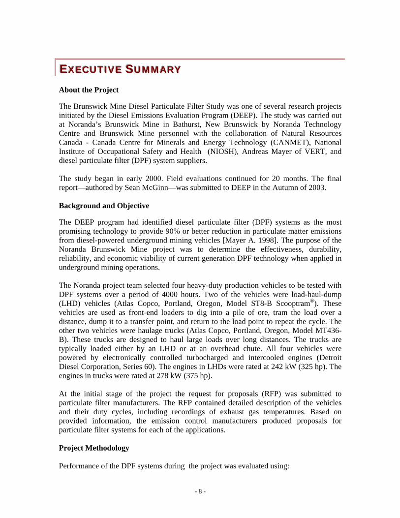
EEEXXXEEECCCUUUTTTIIIVVVEEE SSSUUUMMMMMMAAARRRYYY About the Project The Brunswick Mine Diesel Particulate Filter Study was one of several research projects initiated by the Diesel Emissions Evaluation Program (DEEP). The study was carried out at Noranda’s Brunswick Mine in Bathurst, New Brunswick by Noranda Technology Centre and Brunswick Mine personnel with the collaboration of Natural Resources Canada - Canada Centre for Minerals and Energy Technology (CANMET), National Institute of Occupational Safety and Health (NIOSH), Andreas Mayer of VERT, and diesel particulate filter (DPF) system suppliers. The study began in early 2000. Field evaluations continued for 20 months. The final report—authored by Sean McGinn—was submitted to DEEP in the Autumn of 2003. Background and Objective The DEEP program had identified diesel particulate filter (DPF) systems as the most promising technology to provide 90% or better reduction in particulate matter emissions from diesel-powered underground mining vehicles [Mayer A. 1998]. The purpose of the Noranda Brunswick Mine project was to determine the effectiveness, durability, reliability, and economic viability of current generation DPF technology when applied in underground mining operations. The Noranda project team selected four heavy-duty production vehicles to be tested with DPF systems over a period of 4000 hours. Two of the vehicles were load-haul-dump (LHD) vehicles (Atlas Copco, Portland, Oregon, Model ST8-B Scooptram®). These vehicles are used as front-end loaders to dig into a pile of ore, tram the load over a distance, dump it to a transfer point, and return to the load point to repeat the cycle. The other two vehicles were haulage trucks (Atlas Copco, Portland, Oregon, Model MT436-B). These trucks are designed to haul large loads over long distances. The trucks are typically loaded either by an LHD or at an overhead chute. All four vehicles were powered by electronically controlled turbocharged and intercooled engines (Detroit Diesel Corporation, Series 60). The engines in LHDs were rated at 242 kW (325 hp). The engines in trucks were rated at 278 kW (375 hp). At the initial stage of the project the request for proposals (RFP) was submitted to particulate filter manufacturers. The RFP contained detailed description of the vehicles and their duty cycles, including recordings of exhaust gas temperatures. Based on provided information, the emission control manufacturers produced proposals for particulate filter systems for each of the applications. Project Methodology Performance of the DPF systems during the project was evaluated using:
- 9 -
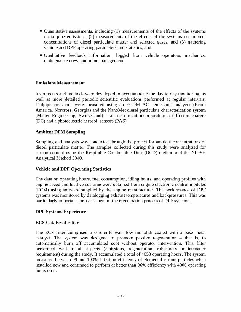
Quantitative assessments, including (1) measurements of the effects of the systems on tailpipe emissions, (2) measurements of the effects of the systems on ambient concentrations of diesel particulate matter and selected gases, and (3) gathering vehicle and DPF operating parameters and statistics, and
Qualitative feedback information, logged from vehicle operators, mechanics, maintenance crew, and mine management.
Emissions Measurement Instruments and methods were developed to accommodate the day to day monitoring, as well as more detailed periodic scientific evaluations performed at regular intervals. Tailpipe emissions were measured using an ECOM AC emissions analyzer (Ecom America, Norcross, Georgia) and the NanoMet diesel particulate characterization system (Matter Engineering, Switzerland) —an instrument incorporating a diffusion charger (DC) and a photoelectric aerosol sensors (PAS). Ambient DPM Sampling Sampling and analysis was conducted through the project for ambient concentrations of diesel particulate matter. The samples collected during this study were analyzed for carbon content using the Respirable Combustible Dust (RCD) method and the NIOSH Analytical Method 5040. Vehicle and DPF Operating Statistics The data on operating hours, fuel consumption, idling hours, and operating profiles with engine speed and load versus time were obtained from engine electronic control modules (ECM) using software supplied by the engine manufacturer. The performance of DPF systems was monitored by datalogging exhaust temperatures and backpressures. This was particularly important for assessment of the regeneration process of DPF systems. DPF Systems Experience ECS Catalyzed Filter The ECS filter comprised a cordierite wall-flow monolith coated with a base metal catalyst. The system was designed to promote passive regeneration – that is, to automatically burn off accumulated soot without operator intervention. This filter performed well in all aspects (emissions, regeneration, robustness, maintenance requirement) during the study. It accumulated a total of 4053 operating hours. The system measured between 99 and 100% filtration efficiency of elemental carbon particles when installed new and continued to perform at better than 96% efficiency with 4000 operating hours on it.
- 10 -
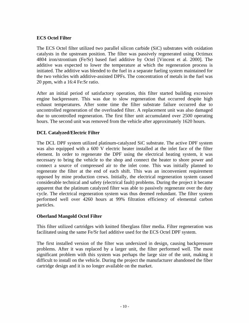
ECS Octel Filter The ECS Octel filter utilized two parallel silicon carbide (SiC) substrates with oxidation catalysts in the upstream position. The filter was passively regenerated using Octimax 4804 iron/strontium (Fe/Sr) based fuel additive by Octel [Vincent et al. 2000]. The additive was expected to lower the temperature at which the regeneration process is initiated. The additive was blended to the fuel in a separate fueling system maintained for the two vehicles with additive-assisted DPFs. The concentration of metals in the fuel was 20 ppm, with a 16:4 Fe:Sr ratio. After an initial period of satisfactory operation, this filter started building excessive engine backpressure. This was due to slow regeneration that occurred despite high exhaust temperatures. After some time the filter substrate failure occurred due to uncontrolled regeneration of the overloaded filter. A replacement unit was also damaged due to uncontrolled regeneration. The first filter unit accumulated over 2500 operating hours. The second unit was removed from the vehicle after approximately 1620 hours. DCL Catalyzed/Electric Filter The DCL DPF system utilized platinum-catalyzed SiC substrate. The active DPF system was also equipped with a 600 V electric heater installed at the inlet face of the filter element. In order to regenerate the DPF using the electrical heating system, it was necessary to bring the vehicle to the shop and connect the heater to shore power and connect a source of compressed air to the inlet cone. This was initially planned to regenerate the filter at the end of each shift. This was an inconvenient requirement opposed by mine production crews. Initially, the electrical regeneration system caused considerable technical and safety (electrical fault) problems. During the project it became apparent that the platinum catalyzed filter was able to passively regenerate over the duty cycle. The electrical regeneration system was thus deemed redundant. The filter system performed well over 4260 hours at 99% filtration efficiency of elemental carbon particles. Oberland Mangold Octel Filter This filter utilized cartridges with knitted fiberglass filter media. Filter regeneration was facilitated using the same Fe/Sr fuel additive used for the ECS Octel DPF system. The first installed version of the filter was undersized in design, causing backpressure problems. After it was replaced by a larger unit, the filter performed well. The most significant problem with this system was perhaps the large size of the unit, making it difficult to install on the vehicle. During the project the manufacturer abandoned the fiber cartridge design and it is no longer available on the market.
- 11 -
Conclusions The project demonstrated that all tested DPFs were able to provide over 90% reduction in the DPM mass emissions, as well as reductions in other emissions and in ambient DPM exposures, although the ECS Octel filter was unable to sustain this filtration over time. It was emphasized that the DPF selection process is a critical factor in successful implementation. Requirements for filter regeneration must be covered in the application engineering in the beginning and maintenance and operation requirements must be agreed upon by all parties for acceptance of the system. The study showed that current off-the-shelf DPF technology requires additional custom application engineering in order to be optimized for the each individual application. Careful application engineering is needed in every individual case. The Isolated Zone Study conducted mid-way through the project examined the capability of the DPF technologies to meet proposed and existing regulation limits for ambient diesel particulate matter concentrations in an actual underground operating environment. With more than 2000 operating hours on the systems, all with the exception of the one failed DPF demonstrated concentrations near 0.05 mg/m3 whereas the baseline non-DPF vehicles in the study were as high as 0.40 mg/m3. Upon completion of the field study the four DPF systems were sent to NRCan CANMET’s diesel certification laboratory for final bench testing with laboratory instrumentation and ISO certified procedures in parallel to instrumentation used in the field. The final validated performance results for gaseous and particulate emissions were combined with a post-bench test inspection and autopsy at the laboratory to conclude testing and evaluations. The final report contains a wealth of conclusions and recommendations on underground application of DPF systems. Ultimately, the success in implementing DPF technology in an underground mine comes down to the process and team that a mine puts together in selecting, installing, measuring, maintaining, and verifying the systems to ensure long-term performance.
- 12 -
IIINNNTTTRRROOODDDUUUCCCTTTIIIOOONNN TTTOOO RRREEESSSEEEAAARRRCCCHHH
BBaacckkggrroouunndd In 1998 the Diesel Emissions Evaluation Program (DEEP) recognized the need for technology with the potential to greatly reduce particulate matter emissions from diesel-powered underground mining equipment. DEEP decided to investigate and evaluate technologies capable of reducing diesel particulate matter (DPM) by more than 90%, and help the industry to radically reduce exposure of underground miners to DPM. At that time diesel particulate filter (DPF) technology appeared to be the relatively mature and advanced to be implemented on the underground mining equipment. Various DPF systems had been evaluated in underground mines since the 1980’s but had limited success due to problems with cleaning trapped soot from the filter body. However at the time this study was conceived, a joint research program conducted in Switzerland, Germany and Austria under sponsorship of VERT extensively field tested several new DPF systems and found them suitable for on-road, construction and tunneling applications [Mayer et al. 1999]. Those tests showed encouraging results on efficiency and durability of the tested systems. Both passive and active technologies were capable of regenerating reliably at much lower exhaust temperatures than previously demonstrated. DEEP engaged Andreas Mayer, one of the key persons on the VERT program, to assist in developing two major in-mine DPF evaluation studies. Noranda’s Brunswick Mine and INCO’s Stobie mine were selected to host the studies. The objective of these studies was to evaluate the potential of current DPF technology to reduce concentrations of DPM in Canadian underground mines by at least 90%. Shortly after, DEEP accepted a project proposal from Noranda Technology Center for conducting one of the tests at Brunswick Mine. The preliminary work on the project started in the first quarter of 2000. Four different combinations of DPFs and vehicles used in underground mine production were investigated as potential candidates for the study.
PPrroojjeecctt OObbjjeeccttiivveess The primary objectives of this project were to determine the effectiveness and suitability of current DPF technology for controlling DPM emissions from heavy-duty underground mining vehicles. A part of this objective was to investigate feasibility of implementing this technology in underground environment. The field evaluation of DPF systems was conducted in the underground mine at Noranda’s Brunswick Mine in Bathurst, New Brunswick. After completion of the field study, the systems were removed from the vehicles and bench tested at the CANMET diesel testing laboratory in Bells Corners, Ontario The following aims were established in order to accomplish this objective:
- 13 -
1. Establish a methodology for selecting DPF systems for underground mining
vehicles, using information on vehicle duty cycle, and DPF and mine characteristics. Apply the methodology to select DPF systems for targeted vehicles at Brunswick Mine ;
2. Determine the efficiency of selected DPF systems in controlling DPM emissions from underground mining diesel-powered vehicles; 2.1. Measure the effectiveness of the selected DPF systems in reducing
concentrations of DPM in tailpipe of tested vehicles 2.2. Quantify the impact of tested DPF technology on tailpipe concentration of
CO, NO, NO2, 2.3. Conduct an isolated zone study to asses the effects of DPF systems on
concentration of DPM in mine air and personal exposure of the operators 3. Investigate viability of selected DPF systems for underground mining
applications with respect to operability, durability, reliability, maintainability, and costs;
4. Develop expertise among Canadian mine personnel, corporate technical and OSH personnel, R&D service providers and DPF suppliers, with new DPF and emissions measurement technologies.
PPrroojjeecctt SSccooppee aanndd SSttrruuccttuurree The project was executed in seven stages, within a three-year time span from start to finish. Execution of the project required collaboration from many organizations and individuals from Noranda Technology Centre, Brunswick Mine, engine, vehicle and DPF manufacturers, fuel and additive companies, and research organizations from Canada, the United States, and Switzerland. Project Stage 1: Preliminary Work This preliminary stage involved identifying and allocating the human resources, test vehicles, test equipment, instrumentation and tools needed for the project. The most significant deliverable in this stage was establishing exhaust temperature and backpressure profiles for the mine vehicles selected to be outfitted with DPFs, as a preliminary step for selecting DPF test systems. Project Stage 2: Characterization and Selection At this stage the project team generated a request for proposals (RFP). The RFP was used to solicit proposals from several DPF manufacturers. The RFP sought four distinct DPF systems that would be fitted on selected mine vehicles and tested over a period of 4000 operating hours. Established temperature profiles along with specifications for engines, vehicles and mine operation were provided to the DPF manufacturers to assist them in the process of selection and optimization of DPF systems for candidate vehicles. Project Stage 3: Selection, Installation and Training – Implementation Four DPF systems were selected between those proposed. The DPF systems were installed by mine mechanics with help from the DPF manufacturers. DPF manufacturers
- 14 -
provided training to the mine maintenance people on how to operate and maintain the systems. Technical representatives from DPF manufacturers were also present during the initial baseline emissions tests. Within the first three months of the installation manufacturers provided extensive technical support to the maintenance personnel at the mine. Project Stage 4: Long Term Evaluations of DPF Performance Elaborate measurements of DPM and gaseous emissions from the vehicles equipped with DPFs were conducted four times during the field evaluation portion of the study. Several different instruments were used to monitor emissions, engine, and DPF performance. These instruments are described in more detail later in the report. During the extent of the study performance of the systems was closely monitored and recorded. This data base was used to assess durability, reliability, and viability of the systems Project Stage 5: Short Term Evaluation of DPF Systems in an Isolated Zone The vehicles equipped with DPF systems were operated in production often in the presence of other diesel vehicles. Under such conditions it was not possible to accurately assess the impact of the DPF systems on ambient concentrations of DPM and on the exposure of vehicle operators to DPM. Therefore, it was necessary to arrange a short-term study with objective to assess the effects of DPF systems on air quality in the mine and miners exposure to DPM. For that purpose a zone of the mine was isolated from other parts of the mine where diesel-powered vehicles were operated. The zone was ventilated with fresh air supplied directly from fresh ventilation shaft. The vehicles equipped with filters and two other vehicles equipped with diesel oxidation catalysts were tested in the isolated zone. Project Stage 6: Laboratory Emissions Testing and Inspection After the completion of in-mine testing, the DPF systems were removed from the vehicles and sent to CANMET’s Bells Corners engine and emissions testing laboratories for bench testing and for identification of mechanical failures and defects. Project Stage 7: Data Consolidation and Final Report A significant amount of data was generated through 4000 hours of field testing as well as through bench testing and inspections. The essential data and findings are summarized in the body of the report.
DDPPFF SSeelleeccttiioonn PPrroocceessss aanndd MMeetthhooddoollooggyy Considerable effort was invested into selecting the most suitable technologies for the applications considered in this project. A comprehensive request for proposal (RFP) was compiled and sent to manufacturers of DPF technologies in Canada, the United States and Europe. The RFP contained detailed information on the mine and operations, and on the engines, power trains, exhaust temperature and backpressure profiles collected for the test vehicles. Manufacturers were invited to submit written proposals, and to present them at a DEEP Technical Committee meeting a few months later. The final selection of
- 15 -
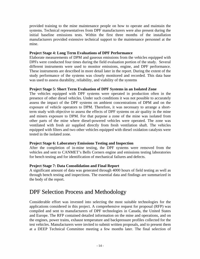
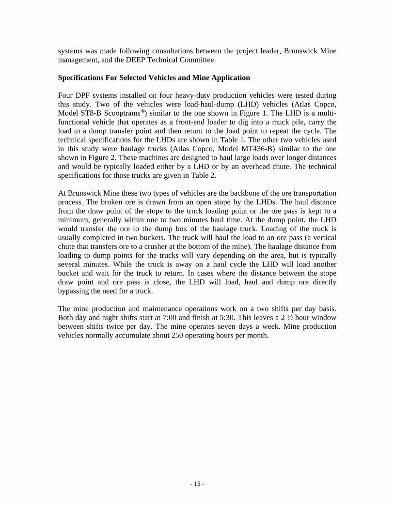
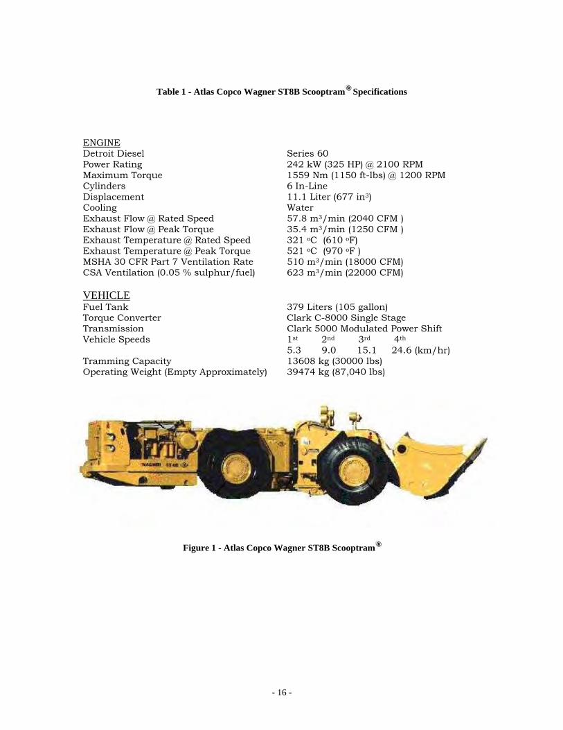
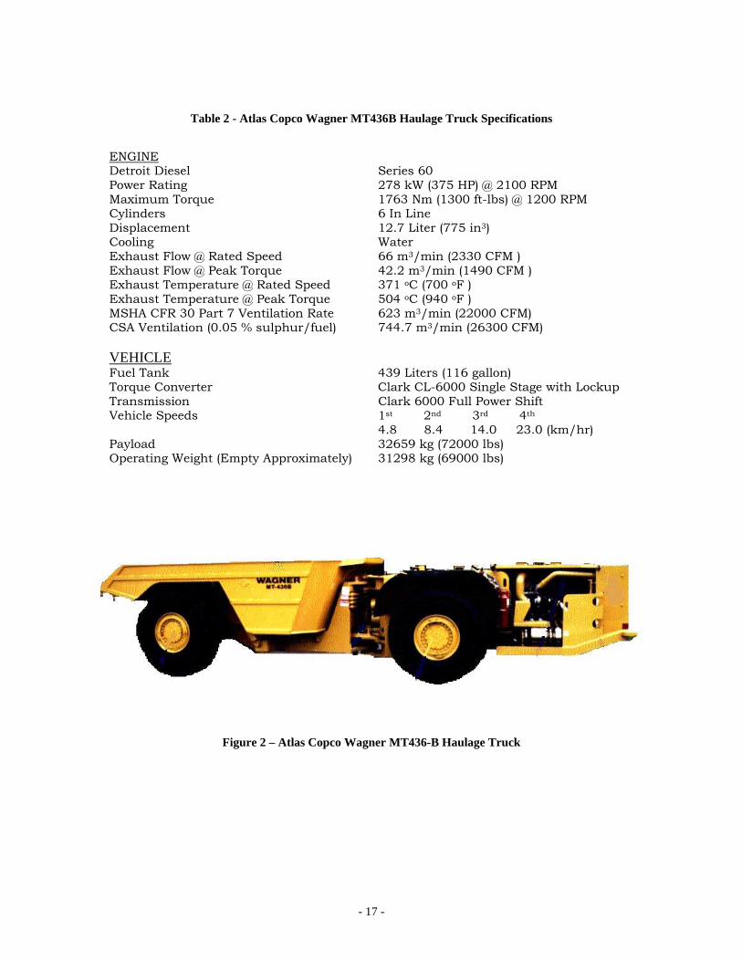
systems was made following consultations between the project leader, Brunswick Mine management, and the DEEP Technical Committee. Specifications For Selected Vehicles and Mine Application Four DPF systems installed on four heavy-duty production vehicles were tested during this study. Two of the vehicles were load-haul-dump (LHD) vehicles (Atlas Copco, Model ST8-B Scooptrams ®®®) similar to the one shown in Figure 1. The LHD is a multi-functional vehicle that operates as a front-end loader to dig into a muck pile, carry the load to a dump transfer point and then return to the load point to repeat the cycle. The technical specifications for the LHDs are shown in Table 1. The other two vehicles used in this study were haulage trucks (Atlas Copco, Model MT436-B) similar to the one shown in Figure 2. These machines are designed to haul large loads over longer distances and would be typically loaded either by a LHD or by an overhead chute. The technical specifications for those trucks are given in Table 2. At Brunswick Mine these two types of vehicles are the backbone of the ore transportation process. The broken ore is drawn from an open stope by the LHDs. The haul distance from the draw point of the stope to the truck loading point or the ore pass is kept to a minimum, generally within one to two minutes haul time. At the dump point, the LHD would transfer the ore to the dump box of the haulage truck. Loading of the truck is usually completed in two buckets. The truck will haul the load to an ore pass (a vertical chute that transfers ore to a crusher at the bottom of the mine). The haulage distance from loading to dump points for the trucks will vary depending on the area, but is typically several minutes. While the truck is away on a haul cycle the LHD will load another bucket and wait for the truck to return. In cases where the distance between the stope draw point and ore pass is close, the LHD will load, haul and dump ore directly bypassing the need for a truck. The mine production and maintenance operations work on a two shifts per day basis. Both day and night shifts start at 7:00 and finish at 5:30. This leaves a 2 ½ hour window between shifts twice per day. The mine operates seven days a week. Mine production vehicles normally accumulate about 250 operating hours per month.
- 16 -
Table 1 - Atlas Copco Wagner ST8B Scooptram ®®® Specifications
ENGINE Detroit Diesel Series 60 Power Rating 242 kW (325 HP) @ 2100 RPM Maximum Torque 1559 Nm (1150 ft-lbs) @ 1200 RPM Cylinders 6 In-Line Displacement 11.1 Liter (677 in3) Cooling Water Exhaust Flow @ Rated Speed 57.8 m3/min (2040 CFM ) Exhaust Flow @ Peak Torque 35.4 m3/min (1250 CFM ) Exhaust Temperature @ Rated Speed 321 oC (610 oF) Exhaust Temperature @ Peak Torque 521 oC (970 oF ) MSHA 30 CFR Part 7 Ventilation Rate 510 m3/min (18000 CFM) CSA Ventilation (0.05 % sulphur/fuel) 623 m3/min (22000 CFM) VEHICLE Fuel Tank 379 Liters (105 gallon) Torque Converter Clark C-8000 Single Stage Transmission Clark 5000 Modulated Power Shift Vehicle Speeds 1st 2nd 3rd 4th 5.3 9.0 15.1 24.6 (km/hr) Tramming Capacity 13608 kg (30000 lbs) Operating Weight (Empty Approximately) 39474 kg (87,040 lbs)
Figure 1 - Atlas Copco Wagner ST8B Scooptram ®®®
- 17 -
Table 2 - Atlas Copco Wagner MT436B Haulage Truck Specifications
ENGINE Detroit Diesel Series 60 Power Rating 278 kW (375 HP) @ 2100 RPM Maximum Torque 1763 Nm (1300 ft-lbs) @ 1200 RPM Cylinders 6 In Line Displacement 12.7 Liter (775 in3) Cooling Water Exhaust Flow @ Rated Speed 66 m3/min (2330 CFM ) Exhaust Flow @ Peak Torque 42.2 m3/min (1490 CFM ) Exhaust Temperature @ Rated Speed 371 oC (700 oF ) Exhaust Temperature @ Peak Torque 504 oC (940 oF ) MSHA CFR 30 Part 7 Ventilation Rate 623 m3/min (22000 CFM) CSA Ventilation (0.05 % sulphur/fuel) 744.7 m3/min (26300 CFM) VEHICLE Fuel Tank 439 Liters (116 gallon) Torque Converter Clark CL-6000 Single Stage with Lockup Transmission Clark 6000 Full Power Shift Vehicle Speeds 1st 2nd 3rd 4th 4.8 8.4 14.0 23.0 (km/hr) Payload 32659 kg (72000 lbs) Operating Weight (Empty Approximately) 31298 kg (69000 lbs)
Figure 2 – Atlas Copco Wagner MT436-B Haulage Truck
- 18 -
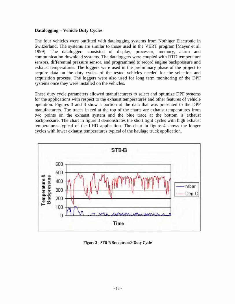
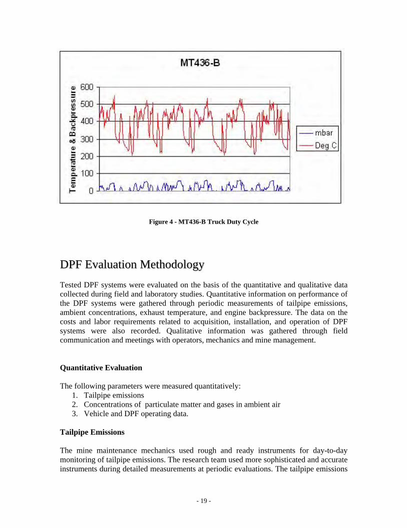
Datalogging – Vehicle Duty Cycles The four vehicles were outfitted with datalogging systems from Nothiger Electronic in Switzerland. The systems are similar to those used in the VERT program [Mayer et al. 1999]. The dataloggers consisted of display, processor, memory, alarm and communication download systems. The dataloggers were coupled with RTD temperature sensors, differential pressure sensor, and programmed to record engine backpressure and exhaust temperatures. The loggers were used in the preliminary phase of the project to acquire data on the duty cycles of the tested vehicles needed for the selection and acquisition process. The loggers were also used for long term monitoring of the DPF systems once they were installed on the vehicles. These duty cycle parameters allowed manufacturers to select and optimize DPF systems for the applications with respect to the exhaust temperatures and other features of vehicle operation. Figures 3 and 4 show a portion of the data that was presented to the DPF manufacturers. The traces in red at the top of the charts are exhaust temperatures from two points on the exhaust system and the blue trace at the bottom is exhaust backpressure. The chart in figure 3 demonstrates the short tight cycles with high exhaust temperatures typical of the LHD application. The chart in figure 4 shows the longer cycles with lower exhaust temperatures typical of the haulage truck application.
Figure 3 - ST8-B Scooptram® Duty Cycle
- 19 -
Figure 4 - MT436-B Truck Duty Cycle
DDPPFF EEvvaalluuaattiioonn MMeetthhooddoollooggyy Tested DPF systems were evaluated on the basis of the quantitative and qualitative data collected during field and laboratory studies. Quantitative information on performance of the DPF systems were gathered through periodic measurements of tailpipe emissions, ambient concentrations, exhaust temperature, and engine backpressure. The data on the costs and labor requirements related to acquisition, installation, and operation of DPF systems were also recorded. Qualitative information was gathered through field communication and meetings with operators, mechanics and mine management. Quantitative Evaluation The following parameters were measured quantitatively:
1. Tailpipe emissions 2. Concentrations of particulate matter and gases in ambient air 3. Vehicle and DPF operating data.
Tailpipe Emissions The mine maintenance mechanics used rough and ready instruments for day-to-day monitoring of tailpipe emissions. The research team used more sophisticated and accurate instruments during detailed measurements at periodic evaluations. The tailpipe emissions
- 20 -
were measured using the Undiluted Gas Analysis System (UGAS) [McGinn et al. 1998, McGinn 2000], the NanoMet diesel particulate characterization system [Kasper et al. 2001], and a new system developed during this project to measure DPM mass concentration in undiluted exhaust. UGAS and Bacharach Smoke Density Tests The UGAS system was originally developed by Noranda Technology Centre, to support emissions assisted maintenance programs at Noranda mines [McGinn et al. 1998]. Since then the system was made commercially available by Ecom America Ltd., Norcross, Georgia. This system was used by mine maintenance staff as a day-to-day tool to evaluate DPF and engine performance. The system is based on the Ecom AC emissions analyzer, UGAS software, and a testing protocol integrated into the software. The system is designed to measure gaseous emissions listed in Table 3. In addition, the Ecom analyzer is designed to draw a 1.6 liter sample of exhaust through a paper filter. The collected sample is used for Bacharach Smoke Density Test. The number is assigned to the sample after comparing a color of the smoke dot on the sampling filter to a 0 – 9 grey scale. Mechanics used this instrument to find soot density at both the inlet and outlet sides of the DPF. The smoke numbers were used to roughly assess filtration efficiency of tested DPF systems. The measurements with the UGAS system were made by the mechanical department at Brunswick Mine during 250-hour monthly inspections and occasionally for diagnostics in between inspections.
Table 3 - ECOM AC Gas Analyzer Parameters Measured Parameters Range Accuracy Resolution Oxygen (O2) 0 - 21% 2% of reading 0.1% Carbon Monoxide (CO) 0 - 4000 ppm 4% of reading 1 ppm Nitric Oxide (NO) 0 - 4000 ppm 4% of reading 1 ppm Nitrogen Dioxide 0 - 500 ppm 4% of reading 1 ppm Ambient Temperature 0 - 250° F 3 degrees 1° F Gas Temperature 0 - 1600° F 3 degrees 1° F Gas Draft (Pressure) 0 - 40.0” H2O 2% of reading 0.01” H2O Calculated Parameters Range Resolution
Combustion Efficiency 0 - 100% 1.0% Carbon Dioxide (CO2) 0 - 40% 0.1%
Lambda (λ) 0 - 50% 0.01%
Losses 0 - 100% 1.0% O2 Correction 0 - 10,000 ppm 1 ppm
- 21 -
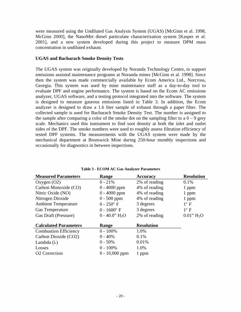
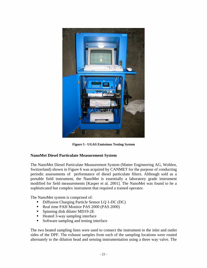
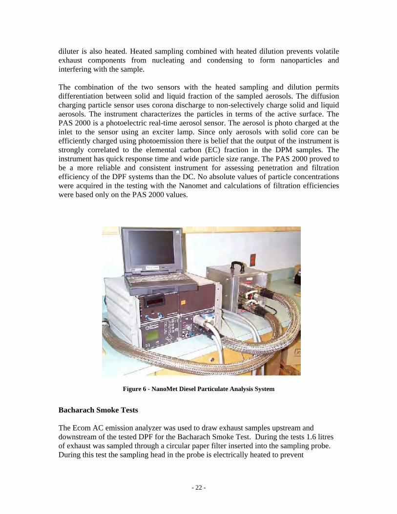
Figure 5 - UGAS Emissions Testing System NanoMet Diesel Particulate Measurement System The NanoMet Diesel Particulate Measurement System (Matter Engineering AG, Wohlen, Switzerland) shown in Figure 6 was acquired by CANMET for the purpose of conducting periodic assessments of performance of diesel particulate filters. Although sold as a portable field instrument, the NanoMet is essentially a laboratory grade instrument modified for field measurements [Kasper et al. 2001]. The NanoMet was found to be a sophisticated but complex instrument that required a trained operator. The NanoMet system is comprised of:
Diffusion Charging Particle Sensor LQ 1-DC (DC) Real time PAH Monitor PAS 2000 (PAS 2000) Spinning disk diluter MD19-2E Heated 3-way sampling interface Software sampling and testing interface
The two heated sampling lines were used to connect the instrument to the inlet and outlet sides of the DPF. The exhaust samples from each of the sampling locations were routed alternately to the dilution head and sensing instrumentation using a three way valve. The
- 22 -
diluter is also heated. Heated sampling combined with heated dilution prevents volatile exhaust components from nucleating and condensing to form nanoparticles and interfering with the sample. The combination of the two sensors with the heated sampling and dilution permits differentiation between solid and liquid fraction of the sampled aerosols. The diffusion charging particle sensor uses corona discharge to non-selectively charge solid and liquid aerosols. The instrument characterizes the particles in terms of the active surface. The PAS 2000 is a photoelectric real-time aerosol sensor. The aerosol is photo charged at the inlet to the sensor using an exciter lamp. Since only aerosols with solid core can be efficiently charged using photoemission there is belief that the output of the instrument is strongly correlated to the elemental carbon (EC) fraction in the DPM samples. The instrument has quick response time and wide particle size range. The PAS 2000 proved to be a more reliable and consistent instrument for assessing penetration and filtration efficiency of the DPF systems than the DC. No absolute values of particle concentrations were acquired in the testing with the Nanomet and calculations of filtration efficiencies were based only on the PAS 2000 values.
Figure 6 - NanoMet Diesel Particulate Analysis System Bacharach Smoke Tests The Ecom AC emission analyzer was used to draw exhaust samples upstream and downstream of the tested DPF for the Bacharach Smoke Test. During the tests 1.6 litres of exhaust was sampled through a circular paper filter inserted into the sampling probe. During this test the sampling head in the probe is electrically heated to prevent
- 23 -
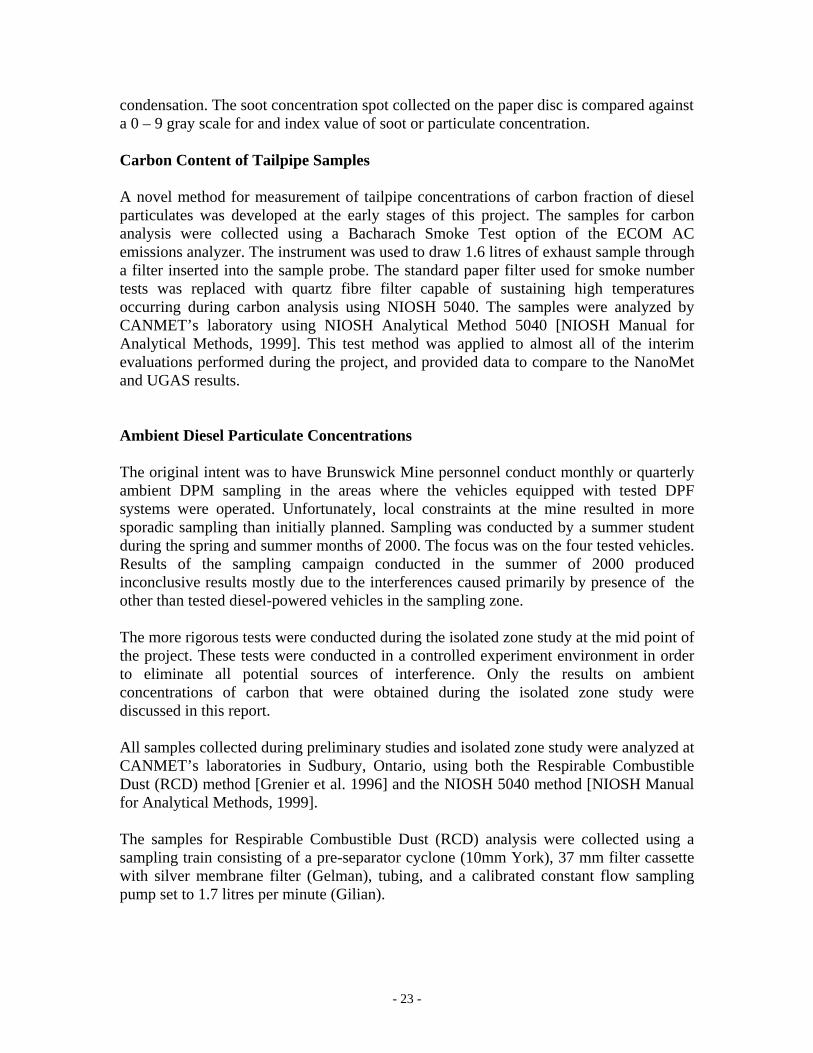
condensation. The soot concentration spot collected on the paper disc is compared against a 0 – 9 gray scale for and index value of soot or particulate concentration. Carbon Content of Tailpipe Samples A novel method for measurement of tailpipe concentrations of carbon fraction of diesel particulates was developed at the early stages of this project. The samples for carbon analysis were collected using a Bacharach Smoke Test option of the ECOM AC emissions analyzer. The instrument was used to draw 1.6 litres of exhaust sample through a filter inserted into the sample probe. The standard paper filter used for smoke number tests was replaced with quartz fibre filter capable of sustaining high temperatures occurring during carbon analysis using NIOSH 5040. The samples were analyzed by CANMET’s laboratory using NIOSH Analytical Method 5040 [NIOSH Manual for Analytical Methods, 1999]. This test method was applied to almost all of the interim evaluations performed during the project, and provided data to compare to the NanoMet and UGAS results. Ambient Diesel Particulate Concentrations The original intent was to have Brunswick Mine personnel conduct monthly or quarterly ambient DPM sampling in the areas where the vehicles equipped with tested DPF systems were operated. Unfortunately, local constraints at the mine resulted in more sporadic sampling than initially planned. Sampling was conducted by a summer student during the spring and summer months of 2000. The focus was on the four tested vehicles. Results of the sampling campaign conducted in the summer of 2000 produced inconclusive results mostly due to the interferences caused primarily by presence of the other than tested diesel-powered vehicles in the sampling zone. The more rigorous tests were conducted during the isolated zone study at the mid point of the project. These tests were conducted in a controlled experiment environment in order to eliminate all potential sources of interference. Only the results on ambient concentrations of carbon that were obtained during the isolated zone study were discussed in this report. All samples collected during preliminary studies and isolated zone study were analyzed at CANMET’s laboratories in Sudbury, Ontario, using both the Respirable Combustible Dust (RCD) method [Grenier et al. 1996] and the NIOSH 5040 method [NIOSH Manual for Analytical Methods, 1999]. The samples for Respirable Combustible Dust (RCD) analysis were collected using a sampling train consisting of a pre-separator cyclone (10mm York), 37 mm filter cassette with silver membrane filter (Gelman), tubing, and a calibrated constant flow sampling pump set to 1.7 litres per minute (Gilian).
- 24 -
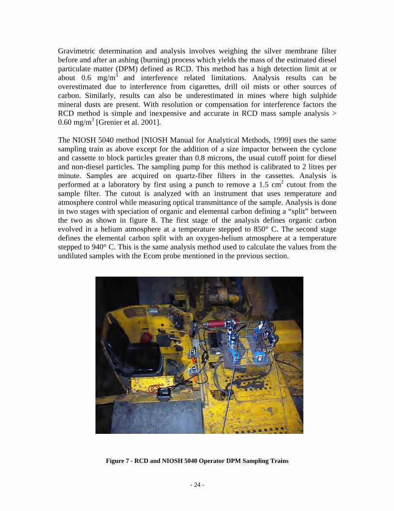
Gravimetric determination and analysis involves weighing the silver membrane filter before and after an ashing (burning) process which yields the mass of the estimated diesel particulate matter (DPM) defined as RCD. This method has a high detection limit at or about 0.6 mg/m3 and interference related limitations. Analysis results can be overestimated due to interference from cigarettes, drill oil mists or other sources of carbon. Similarly, results can also be underestimated in mines where high sulphide mineral dusts are present. With resolution or compensation for interference factors the RCD method is simple and inexpensive and accurate in RCD mass sample analysis > 0.60 mg/m3 [Grenier et al. 2001]. The NIOSH 5040 method [NIOSH Manual for Analytical Methods, 1999] uses the same sampling train as above except for the addition of a size impactor between the cyclone and cassette to block particles greater than 0.8 microns, the usual cutoff point for diesel and non-diesel particles. The sampling pump for this method is calibrated to 2 litres per minute. Samples are acquired on quartz-fiber filters in the cassettes. Analysis is performed at a laboratory by first using a punch to remove a 1.5 cm2 cutout from the sample filter. The cutout is analyzed with an instrument that uses temperature and atmosphere control while measuring optical transmittance of the sample. Analysis is done in two stages with speciation of organic and elemental carbon defining a “split” between the two as shown in figure 8. The first stage of the analysis defines organic carbon evolved in a helium atmosphere at a temperature stepped to 850° C. The second stage defines the elemental carbon split with an oxygen-helium atmosphere at a temperature stepped to 940° C. This is the same analysis method used to calculate the values from the undiluted samples with the Ecom probe mentioned in the previous section.
Figure 7 - RCD and NIOSH 5040 Operator DPM Sampling Trains
- 25 -
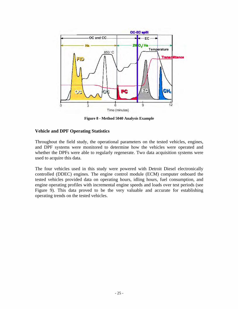
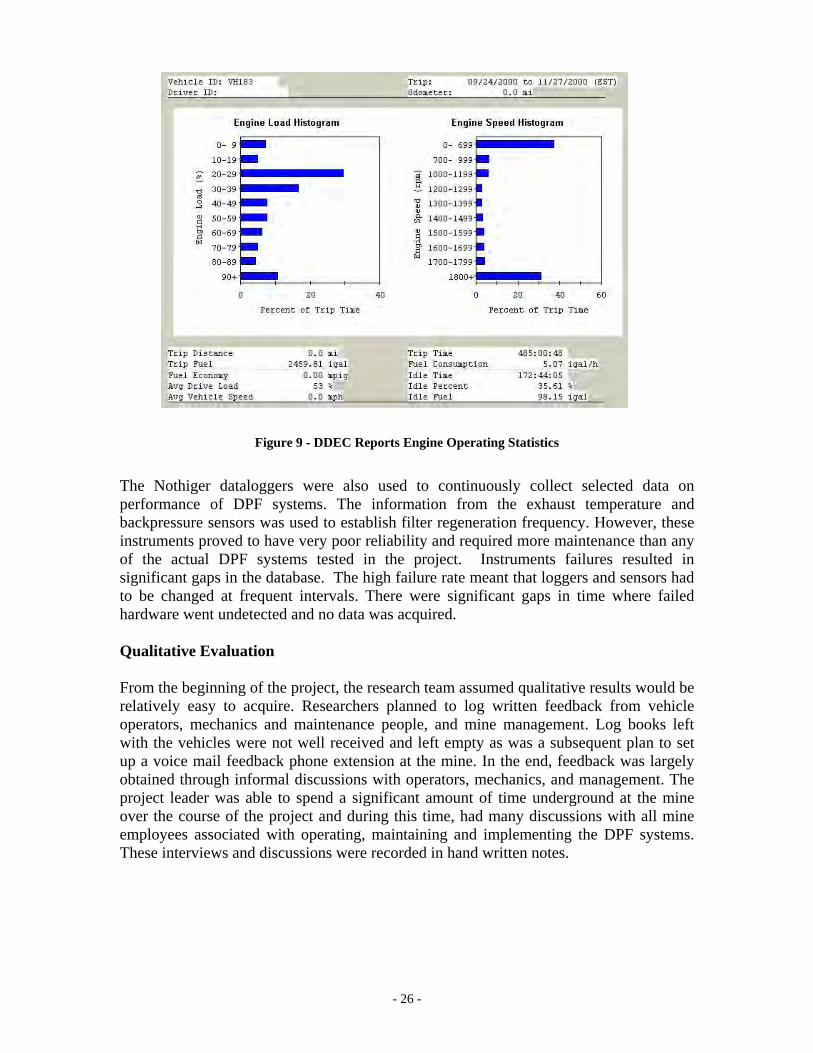
Figure 8 - Method 5040 Analysis Example Vehicle and DPF Operating Statistics Throughout the field study, the operational parameters on the tested vehicles, engines, and DPF systems were monitored to determine how the vehicles were operated and whether the DPFs were able to regularly regenerate. Two data acquisition systems were used to acquire this data. The four vehicles used in this study were powered with Detroit Diesel electronically controlled (DDEC) engines. The engine control module (ECM) computer onboard the tested vehicles provided data on operating hours, idling hours, fuel consumption, and engine operating profiles with incremental engine speeds and loads over test periods (see Figure 9). This data proved to be the very valuable and accurate for establishing operating trends on the tested vehicles.
- 26 -
Figure 9 - DDEC Reports Engine Operating Statistics
The Nothiger dataloggers were also used to continuously collect selected data on performance of DPF systems. The information from the exhaust temperature and backpressure sensors was used to establish filter regeneration frequency. However, these instruments proved to have very poor reliability and required more maintenance than any of the actual DPF systems tested in the project. Instruments failures resulted in significant gaps in the database. The high failure rate meant that loggers and sensors had to be changed at frequent intervals. There were significant gaps in time where failed hardware went undetected and no data was acquired. Qualitative Evaluation From the beginning of the project, the research team assumed qualitative results would be relatively easy to acquire. Researchers planned to log written feedback from vehicle operators, mechanics and maintenance people, and mine management. Log books left with the vehicles were not well received and left empty as was a subsequent plan to set up a voice mail feedback phone extension at the mine. In the end, feedback was largely obtained through informal discussions with operators, mechanics, and management. The project leader was able to spend a significant amount of time underground at the mine over the course of the project and during this time, had many discussions with all mine employees associated with operating, maintaining and implementing the DPF systems. These interviews and discussions were recorded in hand written notes.
- 27 -
DDDIIIEEESSSEEELLL PPPAAARRRTTTIIICCCUUULLLAAATTTEEE FFFIIILLLTTTEEERRR SSSYYYSSSTTTEEEMMMSSS
AAAPPPPPPLLLIIICCCAAATTTIIIOOONNNSSS AAANNNDDD SSSPPPEEECCCIIIFFFIIICCCAAATTTIIIOOONNNSSS
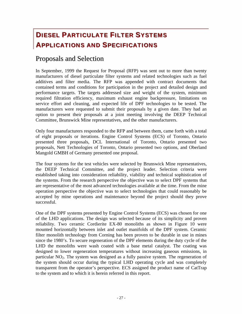
PPrrooppoossaallss aanndd SSeelleeccttiioonn In September, 1999 the Request for Proposal (RFP) was sent out to more than twenty manufacturers of diesel particulate filter systems and related technologies such as fuel additives and filter media. The RFP was appended with contract documents that contained terms and conditions for participation in the project and detailed design and performance targets. The targets addressed size and weight of the system, minimum required filtration efficiency, maximum exhaust engine backpressure, limitations on service effort and cleaning, and expected life of DPF technologies to be tested. The manufacturers were requested to submit their proposals by a given date. They had an option to present their proposals at a joint meeting involving the DEEP Technical Committee, Brunswick Mine representatives, and the other manufacturers. Only four manufacturers responded to the RFP and between them, came forth with a total of eight proposals or iterations. Engine Control Systems (ECS) of Toronto, Ontario presented three proposals, DCL International of Toronto, Ontario presented two proposals, Nett Technologies of Toronto, Ontario presented two options, and Oberland Mangold GMBH of Germany presented one proposal. The four systems for the test vehicles were selected by Brunswick Mine representatives, the DEEP Technical Committee, and the project leader. Selection criteria were established taking into consideration reliability, viability and technical sophistication of the systems. From the research perspective the objective was to select DPF systems that are representative of the most advanced technologies available at the time. From the mine operation perspective the objective was to select technologies that could reasonably be accepted by mine operations and maintenance beyond the project should they prove successful. One of the DPF systems presented by Engine Control Systems (ECS) was chosen for one of the LHD applications. The design was selected because of its simplicity and proven reliability. Two ceramic Cordierite EX-80 monoliths as shown in Figure 10 were mounted horizontally between inlet and outlet manifolds of the DPF system. Ceramic filter monolith technology from Corning has been proven to be durable in use in mines since the 1980’s. To secure regeneration of the DPF elements during the duty cycle of the LHD the monoliths were wash coated with a base metal catalyst. The coating was designed to lower regeneration temperatures without increasing gaseous emissions, in particular NO2. The system was designed as a fully passive system. The regeneration of the system should occur during the typical LHD operating cycle and was completely transparent from the operator’s perspective. ECS assigned the product name of CatTrap to the system and to which it is herein referred in this report.
- 28 -
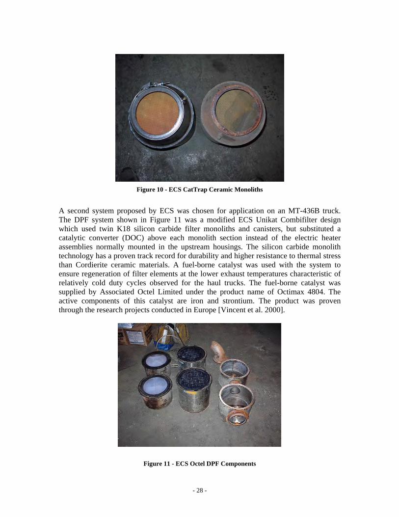
Figure 10 - ECS CatTrap Ceramic Monoliths A second system proposed by ECS was chosen for application on an MT-436B truck. The DPF system shown in Figure 11 was a modified ECS Unikat Combifilter design which used twin K18 silicon carbide filter monoliths and canisters, but substituted a catalytic converter (DOC) above each monolith section instead of the electric heater assemblies normally mounted in the upstream housings. The silicon carbide monolith technology has a proven track record for durability and higher resistance to thermal stress than Cordierite ceramic materials. A fuel-borne catalyst was used with the system to ensure regeneration of filter elements at the lower exhaust temperatures characteristic of relatively cold duty cycles observed for the haul trucks. The fuel-borne catalyst was supplied by Associated Octel Limited under the product name of Octimax 4804. The active components of this catalyst are iron and strontium. The product was proven through the research projects conducted in Europe [Vincent et al. 2000].
Figure 11 - ECS Octel DPF Components
- 29 -
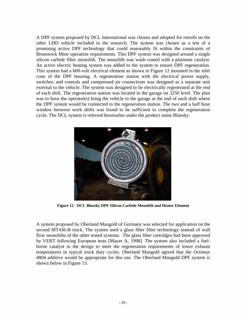
A DPF system proposed by DCL International was chosen and adopted for retrofit on the other LHD vehicle included in the research. The system was chosen as a test of a promising active DPF technology that could reasonably fit within the constraints of Brunswick Mine operation requirements. This DPF system was designed around a single silicon carbide filter monolith. The monolith was wash coated with a platinum catalyst. An active electric heating system was added to the system to ensure DPF regeneration. This system had a 600-volt electrical element as shown in Figure 12 mounted in the inlet cone of the DPF housing. A regeneration station with the electrical power supply, switches, and controls and compressed air connections was designed as a separate unit external to the vehicle. The system was designed to be electrically regenerated at the end of each shift. The regeneration station was located in the garage on 3250 level. The plan was to have the operator(s) bring the vehicle to the garage at the end of each shift where the DPF system would be connected to the regeneration station. The two and a half hour window between work shifts was found to be sufficient to complete the regeneration cycle. The DCL system is referred hereinafter under the product name Bluesky.
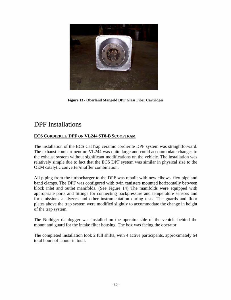
Figure 12 - DCL Bluesky DPF Silicon Carbide Monolith and Heater Element A system proposed by Oberland Mangold of Germany was selected for application on the second MT436-B truck. The system used a glass fiber filter technology instead of wall flow monoliths of the other tested systems. The glass fiber cartridges had been approved by VERT following European tests [Mayer A, 1998]. The system also included a fuel-borne catalyst in the design to meet the regeneration requirements of lower exhaust temperatures in typical truck duty cycles. Oberland Mangold agreed that the Octimax 4804 additive would be appropriate for this use. The Oberland Mangold DPF system is shown below in Figure 13.
- 30 -
Figure 13 - Oberland Mangold DPF Glass Fiber Cartridges
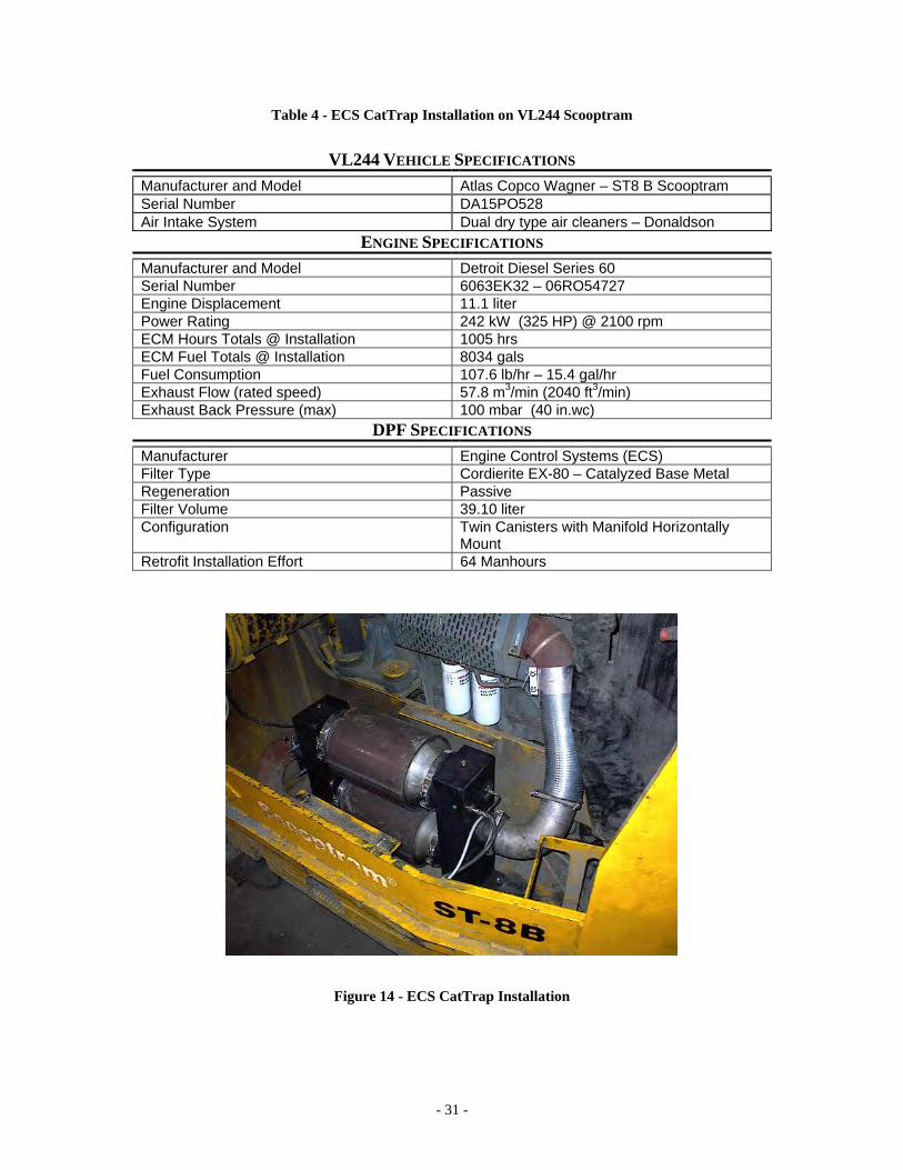
DDPPFF IInnssttaallllaattiioonnss ECS CORDIERITE DPF ON VL244 ST8-B SCOOPTRAM The installation of the ECS CatTrap ceramic cordierite DPF system was straightforward. The exhaust compartment on VL244 was quite large and could accommodate changes to the exhaust system without significant modifications on the vehicle. The installation was relatively simple due to fact that the ECS DPF system was similar in physical size to the OEM catalytic converter/muffler combination. All piping from the turbocharger to the DPF was rebuilt with new elbows, flex pipe and band clamps. The DPF was configured with twin canisters mounted horizontally between block inlet and outlet manifolds. (See Figure 14) The manifolds were equipped with appropriate ports and fittings for connecting backpressure and temperature sensors and for emissions analyzers and other instrumentation during tests. The guards and floor plates above the trap system were modified slightly to accommodate the change in height of the trap system. The Nothiger datalogger was installed on the operator side of the vehicle behind the mount and guard for the intake filter housing. The box was facing the operator. The completed installation took 2 full shifts, with 4 active participants, approximately 64 total hours of labour in total.
- 31 -
Table 4 - ECS CatTrap Installation on VL244 Scooptram
VL244 VEHICLE SPECIFICATIONS Manufacturer and Model Atlas Copco Wagner – ST8 B Scooptram Serial Number DA15PO528 Air Intake System Dual dry type air cleaners – Donaldson
ENGINE SPECIFICATIONS Manufacturer and Model Detroit Diesel Series 60 Serial Number 6063EK32 – 06RO54727 Engine Displacement 11.1 liter Power Rating 242 kW (325 HP) @ 2100 rpm ECM Hours Totals @ Installation 1005 hrs ECM Fuel Totals @ Installation 8034 gals Fuel Consumption 107.6 lb/hr – 15.4 gal/hr Exhaust Flow (rated speed) 57.8 m3/min (2040 ft3/min) Exhaust Back Pressure (max) 100 mbar (40 in.wc)
DPF SPECIFICATIONS Manufacturer Engine Control Systems (ECS) Filter Type Cordierite EX-80 – Catalyzed Base Metal Regeneration Passive Filter Volume 39.10 liter Configuration Twin Canisters with Manifold Horizontally
Mount Retrofit Installation Effort 64 Manhours
Figure 14 - ECS CatTrap Installation
- 32 -
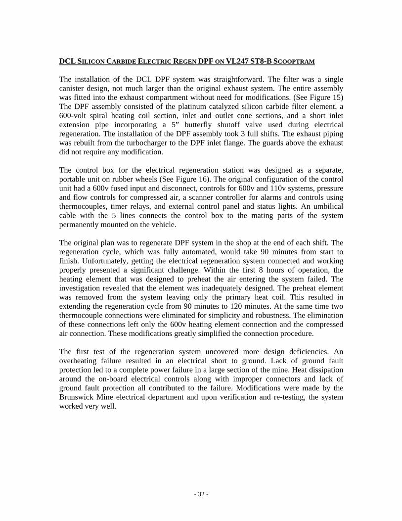
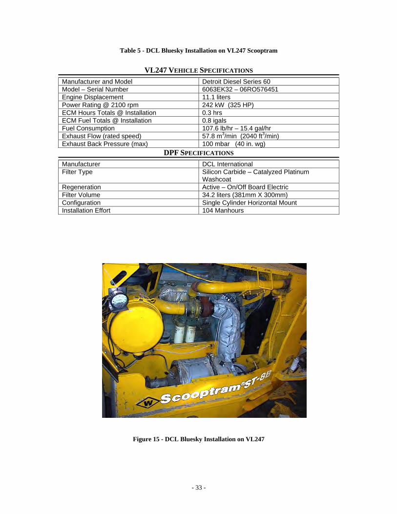
DCL SILICON CARBIDE ELECTRIC REGEN DPF ON VL247 ST8-B SCOOPTRAM The installation of the DCL DPF system was straightforward. The filter was a single canister design, not much larger than the original exhaust system. The entire assembly was fitted into the exhaust compartment without need for modifications. (See Figure 15) The DPF assembly consisted of the platinum catalyzed silicon carbide filter element, a 600-volt spiral heating coil section, inlet and outlet cone sections, and a short inlet extension pipe incorporating a 5” butterfly shutoff valve used during electrical regeneration. The installation of the DPF assembly took 3 full shifts. The exhaust piping was rebuilt from the turbocharger to the DPF inlet flange. The guards above the exhaust did not require any modification. The control box for the electrical regeneration station was designed as a separate, portable unit on rubber wheels (See Figure 16). The original configuration of the control unit had a 600v fused input and disconnect, controls for 600v and 110v systems, pressure and flow controls for compressed air, a scanner controller for alarms and controls using thermocouples, timer relays, and external control panel and status lights. An umbilical cable with the 5 lines connects the control box to the mating parts of the system permanently mounted on the vehicle. The original plan was to regenerate DPF system in the shop at the end of each shift. The regeneration cycle, which was fully automated, would take 90 minutes from start to finish. Unfortunately, getting the electrical regeneration system connected and working properly presented a significant challenge. Within the first 8 hours of operation, the heating element that was designed to preheat the air entering the system failed. The investigation revealed that the element was inadequately designed. The preheat element was removed from the system leaving only the primary heat coil. This resulted in extending the regeneration cycle from 90 minutes to 120 minutes. At the same time two thermocouple connections were eliminated for simplicity and robustness. The elimination of these connections left only the 600v heating element connection and the compressed air connection. These modifications greatly simplified the connection procedure. The first test of the regeneration system uncovered more design deficiencies. An overheating failure resulted in an electrical short to ground. Lack of ground fault protection led to a complete power failure in a large section of the mine. Heat dissipation around the on-board electrical controls along with improper connectors and lack of ground fault protection all contributed to the failure. Modifications were made by the Brunswick Mine electrical department and upon verification and re-testing, the system worked very well.
- 33 -
Table 5 - DCL Bluesky Installation on VL247 Scooptram
VL247 VEHICLE SPECIFICATIONS
Manufacturer and Model Detroit Diesel Series 60 Model – Serial Number 6063EK32 – 06RO576451 Engine Displacement 11.1 liters Power Rating @ 2100 rpm 242 kW (325 HP) ECM Hours Totals @ Installation 0.3 hrs ECM Fuel Totals @ Installation 0.8 igals Fuel Consumption 107.6 lb/hr – 15.4 gal/hr Exhaust Flow (rated speed) 57.8 m3/min (2040 ft3/min) Exhaust Back Pressure (max) 100 mbar (40 in. wg)
DPF SPECIFICATIONS Manufacturer DCL International Filter Type Silicon Carbide – Catalyzed Platinum
Washcoat Regeneration Active – On/Off Board Electric Filter Volume 34.2 liters (381mm X 300mm) Configuration Single Cylinder Horizontal Mount Installation Effort 104 Manhours
Figure 15 - DCL Bluesky Installation on VL247
- 34 -
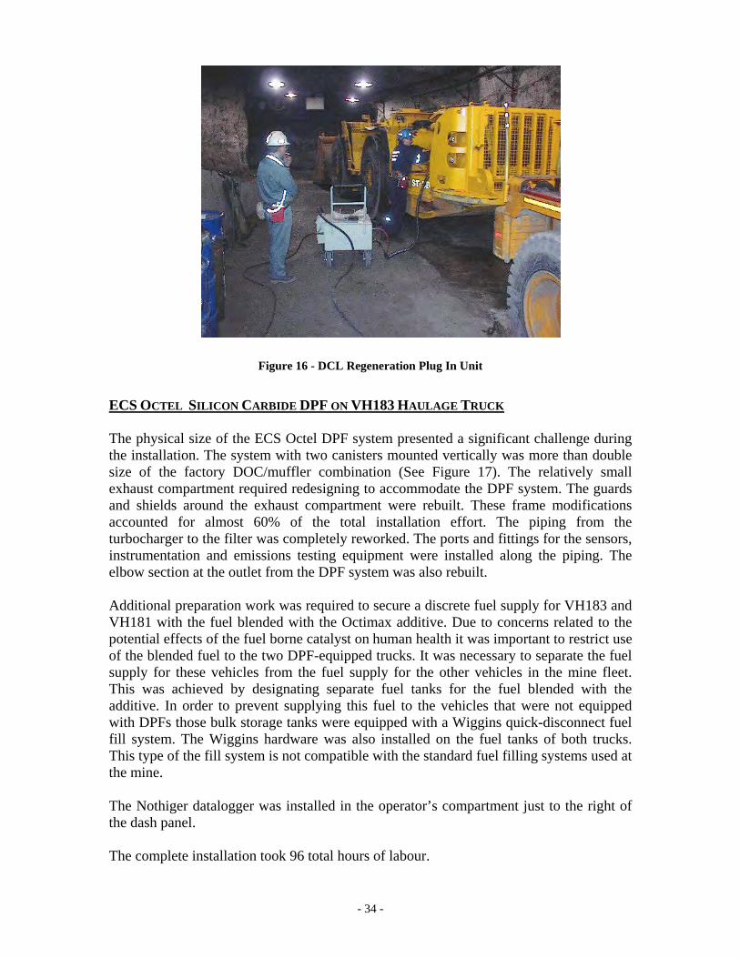
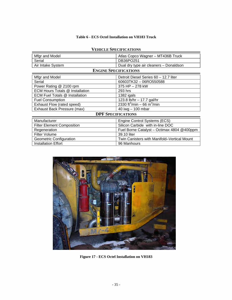
Figure 16 - DCL Regeneration Plug In Unit ECS OCTEL SILICON CARBIDE DPF ON VH183 HAULAGE TRUCK The physical size of the ECS Octel DPF system presented a significant challenge during the installation. The system with two canisters mounted vertically was more than double size of the factory DOC/muffler combination (See Figure 17). The relatively small exhaust compartment required redesigning to accommodate the DPF system. The guards and shields around the exhaust compartment were rebuilt. These frame modifications accounted for almost 60% of the total installation effort. The piping from the turbocharger to the filter was completely reworked. The ports and fittings for the sensors, instrumentation and emissions testing equipment were installed along the piping. The elbow section at the outlet from the DPF system was also rebuilt. Additional preparation work was required to secure a discrete fuel supply for VH183 and VH181 with the fuel blended with the Octimax additive. Due to concerns related to the potential effects of the fuel borne catalyst on human health it was important to restrict use of the blended fuel to the two DPF-equipped trucks. It was necessary to separate the fuel supply for these vehicles from the fuel supply for the other vehicles in the mine fleet. This was achieved by designating separate fuel tanks for the fuel blended with the additive. In order to prevent supplying this fuel to the vehicles that were not equipped with DPFs those bulk storage tanks were equipped with a Wiggins quick-disconnect fuel fill system. The Wiggins hardware was also installed on the fuel tanks of both trucks. This type of the fill system is not compatible with the standard fuel filling systems used at the mine. The Nothiger datalogger was installed in the operator’s compartment just to the right of the dash panel. The complete installation took 96 total hours of labour.
- 35 -
Table 6 - ECS Octel Installation on VH183 Truck
VEHICLE SPECIFICATIONS
Mfgr and Model Atlas Copco Wagner – MT436B Truck Serial DB36PO251 Air Intake System Dual dry type air cleaners – Donaldson
ENGINE SPECIFICATIONS Mfgr and Model Detroit Diesel Series 60 – 12.7 liter Serial 60603TK32 – 06RO550588 Power Rating @ 2100 rpm 375 HP – 278 kW ECM Hours Totals @ Installation 293 hrs ECM Fuel Totals @ Installation 1382 igals Fuel Consumption 123.8 lb/hr – 17.7 gal/hr Exhaust Flow (rated speed) 2330 ft3/min – 66 m3/min Exhaust Back Pressure (max) 40 iwg – 100 mbar
DPF SPECIFICATIONS Manufacturer Engine Control Systems (ECS) Filter Element Composition Silicon Carbide with in-line DOC Regeneration Fuel Borne Catalyst – Octimax 4804 @400ppm Filter Volume 39.10 liter Geometric Configuration Twin Canisters with Manifold–Vertical Mount Installation Effort 96 Manhours
Figure 17 - ECS Octel Installation on VH183
- 36 -
OBERLAND MANGOLD OCTEL FIBER CARTRIDGE DPF ON VH181 HAULAGE TRUCK The Oberland Mangold (OM) DPF system was the final of the four installations and probably the most straightforward due to both experience gained with installation of the other systems, and relative size and simplicity of the system. The DPF assembly was similar in dimensions to the factory exhaust system yet still required small modifications throughout the installation. The piping on both sides of the DPF had to be rebuilt. Ports for the sensors and emissions tests were welded into the new piping before assembly. The modifications to the guards and the frame structure were minimal. The Wiggins fuel filling hardware identical to the one installed on haulage truck VH183 was also installed on this truck. This hardware permitted fuelling these two trucks only with the blended fuel and at the same time prevented operators from fueling the rest of the mobile fleet with blended fuel. The Nothiger datalogger was installed in the operator’s compartment just to the right of the dash panel. The cables for the RTD temperature sensors were extended to accommodate the location of the logger. A condensate trap for the exhaust back pressure sensor was installed on the inside of the engine firewall. The completed installation took 72 hours of total labour. Although the installation went very smoothly, the preliminary tests revealed problems with high exhaust backpressure and filter efficiency. Exhaust backpressure measured with the new filter in place was 90 mbar (36 in. wc), very close to Detroit Diesel’s maximum allowed backpressure of 100 mbar (40 in. wc). The emissions test with UGAS showed that high pressure resulted in increased CO emissions. The deep bed filter technology with glass fiber cartridges evidently required a great deal of canister volume to provide the necessary filtration surface area. The 25-cartridge configuration inside the canister appeared to be undersized for the volume of exhaust gases produced by the engine. The system was closely monitored for the first few weeks to assess the efficiency and relevant performance parameters of the system. High exhaust backpressure problems eventually forced the decision to replace the original Oberland Mangold system with a larger volume unit. A new system was delivered to the mine and installed within two months Figures 19 and 20 show the two Oberland Mangold systems. The original DPF system accumulated 300 operating hours before removal and replacement with the larger volume unit. Figure 18 shows exhaust temperature (red line) and backpressure (blue line) traces for the first four days of operation. The exhaust backpressure was exceeding 200 mbar(80 in. wc) or twice the engine manufacturers limit of 100 mbar (40 in. wc)in the first days of operation.
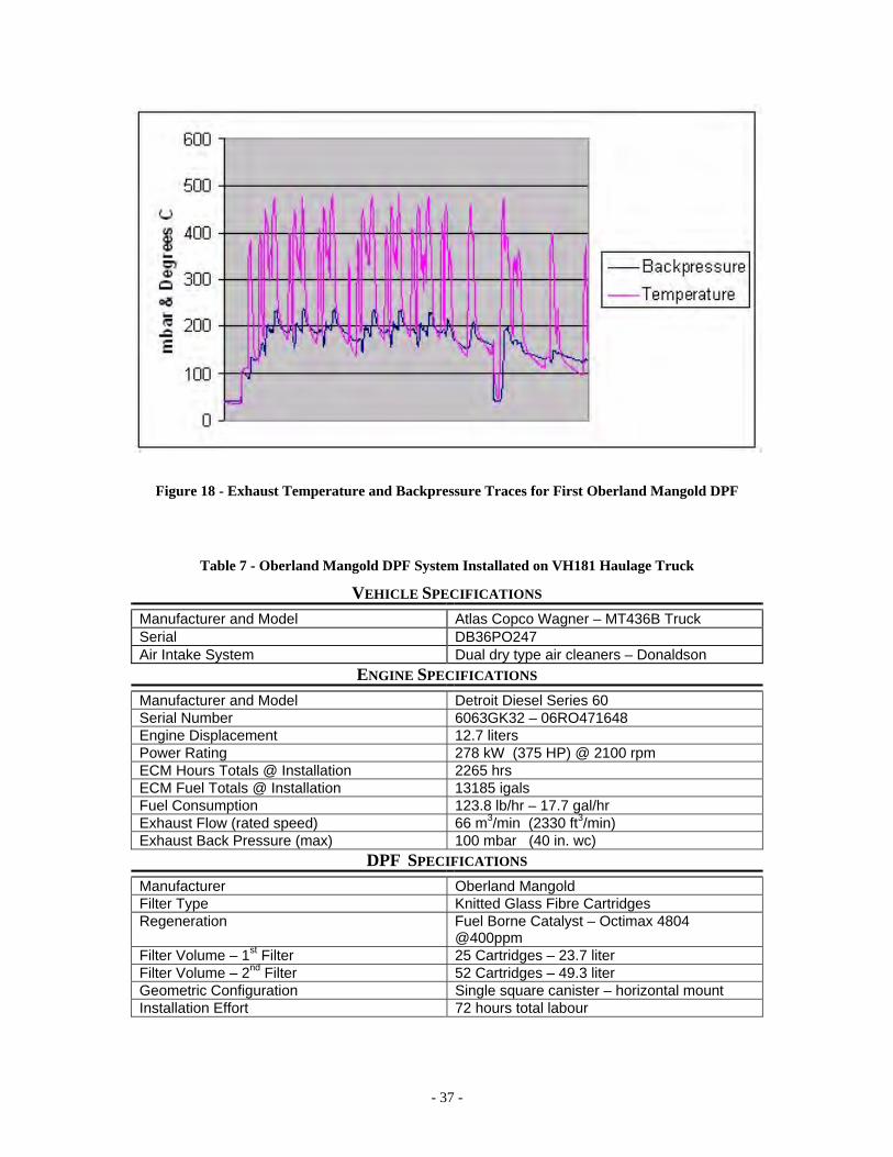
- 37 -
Figure 18 - Exhaust Temperature and Backpressure Traces for First Oberland Mangold DPF
Table 7 - Oberland Mangold DPF System Installated on VH181 Haulage Truck VEHICLE SPECIFICATIONS
Manufacturer and Model Atlas Copco Wagner – MT436B Truck Serial DB36PO247 Air Intake System Dual dry type air cleaners – Donaldson
ENGINE SPECIFICATIONS Manufacturer and Model Detroit Diesel Series 60 Serial Number 6063GK32 – 06RO471648 Engine Displacement 12.7 liters Power Rating 278 kW (375 HP) @ 2100 rpm ECM Hours Totals @ Installation 2265 hrs ECM Fuel Totals @ Installation 13185 igals Fuel Consumption 123.8 lb/hr – 17.7 gal/hr Exhaust Flow (rated speed) 66 m3/min (2330 ft3/min) Exhaust Back Pressure (max) 100 mbar (40 in. wc)
DPF SPECIFICATIONS Manufacturer Oberland Mangold Filter Type Knitted Glass Fibre Cartridges Regeneration Fuel Borne Catalyst – Octimax 4804
@400ppm Filter Volume – 1st Filter 25 Cartridges – 23.7 liter Filter Volume – 2nd Filter 52 Cartridges – 49.3 liter Geometric Configuration Single square canister – horizontal mount Installation Effort 72 hours total labour
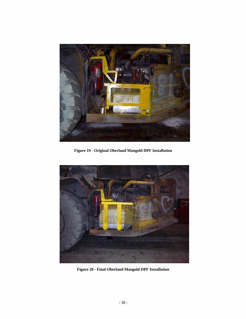
- 38 -
Figure 19 - Original Oberland Mangold DPF Installation
Figure 20 - Final Oberland Mangold DPF Installation
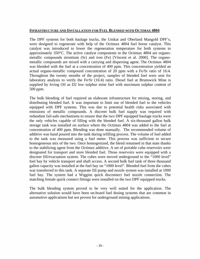
- 39 -
INFRASTRUCTURE AND INSTALLATION FOR FUEL BLENDED WITH OCTIMAX 4804 The DPF systems for both haulage trucks, the Unikat and Oberland Mangold DPF’s, were designed to regenerate with help of the Octimax 4804 fuel borne catalyst. This catalyst was introduced to lower the regeneration temperature for both systems to approximately 350°C. The active catalyst components in the Octimax 4804 are organo-metallic compounds strontium (Sr) and iron (Fe) [Vincent et al. 2000]. The organo-metallic compounds are mixed with a carrying and dispersing agent. The Octimax 4804 was blended with the fuel at a concentration of 400 ppm. This concentration yielded an actual organo-metallic compound concentration of 20 ppm with a Fe/Sr ratio of 16:4. Throughout the twenty months of the project, samples of blended fuel were sent for laboratory analysis to verify the Fe/Sr (16:4) ratio. Diesel fuel at Brunswick Mine is supplied by Irving Oil as D2 low sulphur mine fuel with maximum sulphur content of 500 ppm. The bulk blending of fuel required an elaborate infrastructure for mixing, storing, and distributing blended fuel. It was important to limit use of blended fuel to the vehicles equipped with DPF systems. This was due to potential health risks associated with emissions of metallic compounds. A discreet bulk fuel supply was required with redundant fail-safe mechanisms to ensure that the two DPF equipped haulage trucks were the only vehicles capable of filling with the blended fuel. A six-thousand gallon bulk storage tank was installed on surface where the Octimax 4804 was added to the fuel at concentration of 400 ppm. Blending was done manually. The recommended volume of additive was hand poured into the tank during refilling process. The volume of fuel added to the tank was measured using a fuel meter. This process was sufficient to secure homogeneous mix of the two. Once homogenized, the blend remained in that state thanks to the stabilizing agent from the Octimax additive. A set of portable cube reservoirs were designated for transport and store blended fuel. Those reservoirs were equipped with a discreet fill/evacuation system. The cubes were moved underground to the “1000 level” fuel bay by vehicle transport and shaft access. A second bulk fuel tank of three thousand gallon capacity was installed at the fuel bay on “1000 level”. Blended fuel from the cubes was transferred to this tank. A separate fill pump and nozzle system was installed at 1000 fuel bay. The system had a Wiggins quick disconnect fuel nozzle connection. The matching female quick connect fittings were installed on the two DPF equipped trucks. The bulk blending system proved to be very well suited for the application. The alternative solution would have been on-board fuel dosing systems that are common in automotive applications but not proven for underground mining applications.
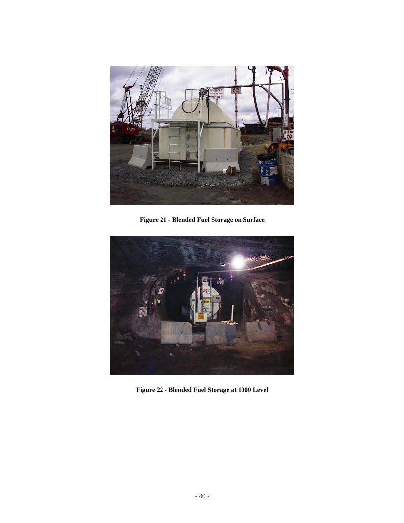
- 40 -
Figure 21 - Blended Fuel Storage on Surface
Figure 22 - Blended Fuel Storage at 1000 Level
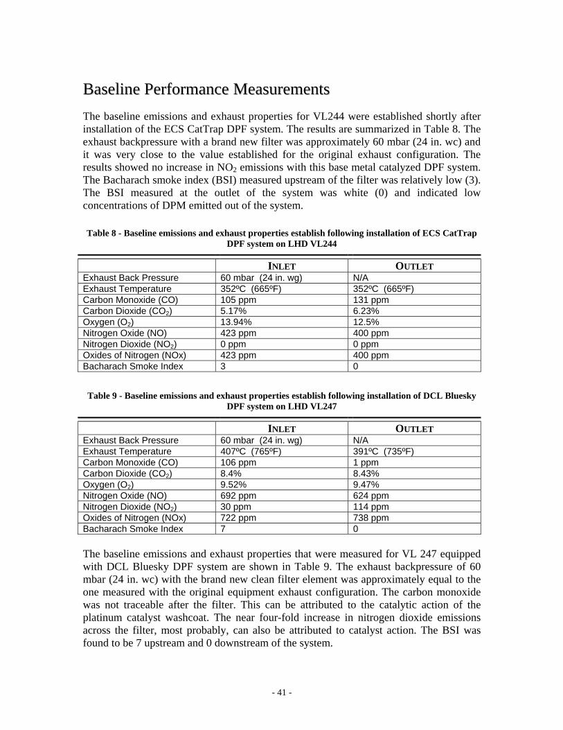
- 41 -
BBaasseelliinnee PPeerrffoorrmmaannccee MMeeaassuurreemmeennttss The baseline emissions and exhaust properties for VL244 were established shortly after installation of the ECS CatTrap DPF system. The results are summarized in Table 8. The exhaust backpressure with a brand new filter was approximately 60 mbar (24 in. wc) and it was very close to the value established for the original exhaust configuration. The results showed no increase in NO2 emissions with this base metal catalyzed DPF system. The Bacharach smoke index (BSI) measured upstream of the filter was relatively low (3). The BSI measured at the outlet of the system was white (0) and indicated low concentrations of DPM emitted out of the system.
Table 8 - Baseline emissions and exhaust properties establish following installation of ECS CatTrap DPF system on LHD VL244
INLET OUTLET Exhaust Back Pressure 60 mbar (24 in. wg) N/A Exhaust Temperature 352ºC (665ºF) 352ºC (665ºF) Carbon Monoxide (CO) 105 ppm 131 ppm Carbon Dioxide (CO2) 5.17% 6.23% Oxygen (O2) 13.94% 12.5% Nitrogen Oxide (NO) 423 ppm 400 ppm Nitrogen Dioxide (NO2) 0 ppm 0 ppm Oxides of Nitrogen (NOx) 423 ppm 400 ppm Bacharach Smoke Index 3 0 Table 9 - Baseline emissions and exhaust properties establish following installation of DCL Bluesky
DPF system on LHD VL247
INLET OUTLET Exhaust Back Pressure 60 mbar (24 in. wg) N/A Exhaust Temperature 407ºC (765ºF) 391ºC (735ºF) Carbon Monoxide (CO) 106 ppm 1 ppm Carbon Dioxide (CO2) 8.4% 8.43% Oxygen (O2) 9.52% 9.47% Nitrogen Oxide (NO) 692 ppm 624 ppm Nitrogen Dioxide (NO2) 30 ppm 114 ppm Oxides of Nitrogen (NOx) 722 ppm 738 ppm Bacharach Smoke Index 7 0 The baseline emissions and exhaust properties that were measured for VL 247 equipped with DCL Bluesky DPF system are shown in Table 9. The exhaust backpressure of 60 mbar (24 in. wc) with the brand new clean filter element was approximately equal to the one measured with the original equipment exhaust configuration. The carbon monoxide was not traceable after the filter. This can be attributed to the catalytic action of the platinum catalyst washcoat. The near four-fold increase in nitrogen dioxide emissions across the filter, most probably, can also be attributed to catalyst action. The BSI was found to be 7 upstream and 0 downstream of the system.
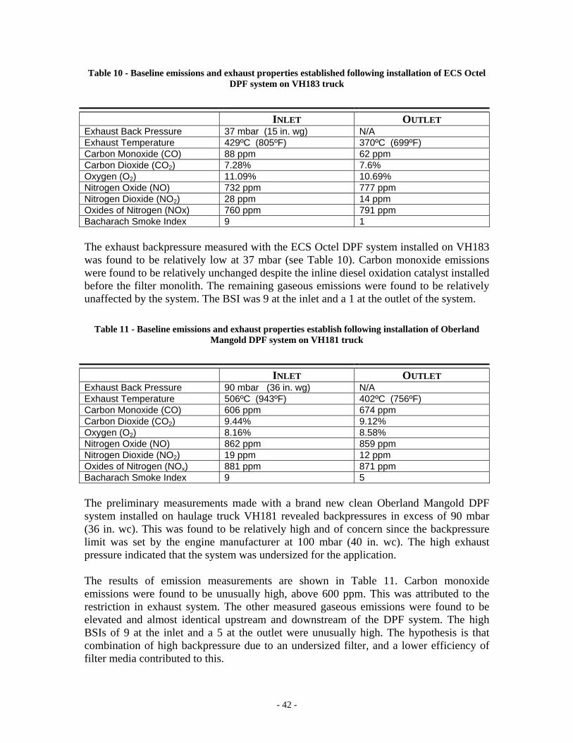
- 42 -
Table 10 - Baseline emissions and exhaust properties established following installation of ECS Octel DPF system on VH183 truck
INLET OUTLET Exhaust Back Pressure 37 mbar (15 in. wg) N/A Exhaust Temperature 429ºC (805ºF) 370ºC (699ºF) Carbon Monoxide (CO) 88 ppm 62 ppm Carbon Dioxide (CO2) 7.28% 7.6% Oxygen (O2) 11.09% 10.69% Nitrogen Oxide (NO) 732 ppm 777 ppm Nitrogen Dioxide (NO2) 28 ppm 14 ppm Oxides of Nitrogen (NOx) 760 ppm 791 ppm Bacharach Smoke Index 9 1 The exhaust backpressure measured with the ECS Octel DPF system installed on VH183 was found to be relatively low at 37 mbar (see Table 10). Carbon monoxide emissions were found to be relatively unchanged despite the inline diesel oxidation catalyst installed before the filter monolith. The remaining gaseous emissions were found to be relatively unaffected by the system. The BSI was 9 at the inlet and a 1 at the outlet of the system.
Table 11 - Baseline emissions and exhaust properties establish following installation of Oberland Mangold DPF system on VH181 truck
INLET OUTLET Exhaust Back Pressure 90 mbar (36 in. wg) N/A Exhaust Temperature 506ºC (943ºF) 402ºC (756ºF) Carbon Monoxide (CO) 606 ppm 674 ppm Carbon Dioxide (CO2) 9.44% 9.12% Oxygen (O2) 8.16% 8.58% Nitrogen Oxide (NO) 862 ppm 859 ppm Nitrogen Dioxide (NO2) 19 ppm 12 ppm Oxides of Nitrogen (NOx) 881 ppm 871 ppm Bacharach Smoke Index 9 5 The preliminary measurements made with a brand new clean Oberland Mangold DPF system installed on haulage truck VH181 revealed backpressures in excess of 90 mbar (36 in. wc). This was found to be relatively high and of concern since the backpressure limit was set by the engine manufacturer at 100 mbar (40 in. wc). The high exhaust pressure indicated that the system was undersized for the application. The results of emission measurements are shown in Table 11. Carbon monoxide emissions were found to be unusually high, above 600 ppm. This was attributed to the restriction in exhaust system. The other measured gaseous emissions were found to be elevated and almost identical upstream and downstream of the DPF system. The high BSIs of 9 at the inlet and a 5 at the outlet were unusually high. The hypothesis is that combination of high backpressure due to an undersized filter, and a lower efficiency of filter media contributed to this.
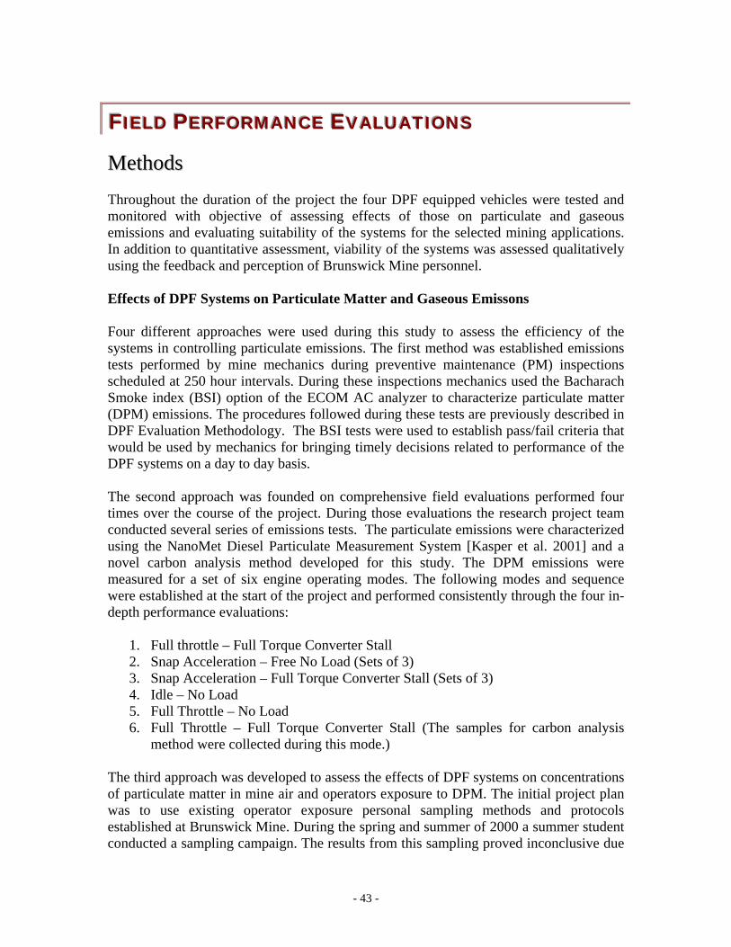
- 43 -
FFFIIIEEELLLDDD PPPEEERRRFFFOOORRRMMMAAANNNCCCEEE EEEVVVAAALLLUUUAAATTTIIIOOONNNSSS
MMeetthhooddss Throughout the duration of the project the four DPF equipped vehicles were tested and monitored with objective of assessing effects of those on particulate and gaseous emissions and evaluating suitability of the systems for the selected mining applications. In addition to quantitative assessment, viability of the systems was assessed qualitatively using the feedback and perception of Brunswick Mine personnel. Effects of DPF Systems on Particulate Matter and Gaseous Emissons Four different approaches were used during this study to assess the efficiency of the systems in controlling particulate emissions. The first method was established emissions tests performed by mine mechanics during preventive maintenance (PM) inspections scheduled at 250 hour intervals. During these inspections mechanics used the Bacharach Smoke index (BSI) option of the ECOM AC analyzer to characterize particulate matter (DPM) emissions. The procedures followed during these tests are previously described in DPF Evaluation Methodology. The BSI tests were used to establish pass/fail criteria that would be used by mechanics for bringing timely decisions related to performance of the DPF systems on a day to day basis. The second approach was founded on comprehensive field evaluations performed four times over the course of the project. During those evaluations the research project team conducted several series of emissions tests. The particulate emissions were characterized using the NanoMet Diesel Particulate Measurement System [Kasper et al. 2001] and a novel carbon analysis method developed for this study. The DPM emissions were measured for a set of six engine operating modes. The following modes and sequence were established at the start of the project and performed consistently through the four in-depth performance evaluations:
1. Full throttle – Full Torque Converter Stall 2. Snap Acceleration – Free No Load (Sets of 3) 3. Snap Acceleration – Full Torque Converter Stall (Sets of 3) 4. Idle – No Load 5. Full Throttle – No Load 6. Full Throttle – Full Torque Converter Stall (The samples for carbon analysis
method were collected during this mode.) The third approach was developed to assess the effects of DPF systems on concentrations of particulate matter in mine air and operators exposure to DPM. The initial project plan was to use existing operator exposure personal sampling methods and protocols established at Brunswick Mine. During the spring and summer of 2000 a summer student conducted a sampling campaign. The results from this sampling proved inconclusive due
- 44 -
to the abundance of interference factors present during sampling. The vehicles were sharing operating environments in varying ventilation conditions and most importantly, sharing the ventilation with non-DPF equipped vehicles making the results inconclusive. The most conclusive results for ambient PM concentrations were obtained during the isolated zone study. These results are presented and discussed in a later section in this report. The fourth approach was post field study evaluations that were done in the CANMET laboratories in Bells Corners, Ontario after the DPF systems were de-commissioned. The four systems were sent to the laboratory for testing on a Series 60 engine and dynamometer with a wide spectrum of emissions testing performed there. Following the laboratory testing the DPF systems were inspected using both destructive and non-destructive testing techniques for final evaluation. These tests and results are presented in a later section of this report. Regeneration of DPF Systems and Other Operational Issues The temperature and pressure traces gathered during this project were used to study regeneration processes for the tested DPF systems. Nothiger dataloggers were installed on all tested vehicles and used to continuously record exhaust temperatures and backpressures. The dataloggers provided accurate, but sporadic data. Frequent failures of temperature and backpressure sensors or the logger control units themselves produced large gaps in what was hoped to be a continuous set of data. The data outside of these gaps remained accurate and was pieced together to study regeneration trends of DPF systems. In addition, during the 250 hour PM inspections the Brunswick mine mechanics measured exhaust backpressure with mechanical gauges which gave general trends of regeneration and plugging of DPF systems. Throughout the project feedback and perception on performance of DPF systems was sought from Brunswick Mine production operators, mechanics, supervisors and management. The procedures involving logbooks and a dedicated telephone line voice mail were established but feedback was infrequent. Discussions and interviews between the project leader and Brunswick personnel were recorded in field notes and in some cases on video tape.
RReessuullttss
EECCSS CCaattTTrraapp DDPPFF SSyysstteemm IInnssttaalllleedd oonn LLHHDD VVLL224444 The ECS CatTrap DPF system performed well in all aspects throughout the field study. The DPF system was a good match to the LHD application. The system was regenerating successfully during the duty cycle therefore backpressure was within the limits prescribed by the engine manufacturer for most of the operating hours. The results of all periodic
- 45 -
DPM emissions measurements performed during the project showed high filtration efficiency of the system measured by smoke number, elemental carbon particle concentration and mass. The emissions and resulting concentrations of all measured gases including NO2, were well below limits set by New Brunswick regulations [New Brunswick, 1996]. The base metal catalyst did not cause any increase in NO2 emissions. This passively regenerated system was very well accepted by operators and management. An unexpected event mid-way through the field study proved the ruggedness of the system. At approximately 2500 operating hours LHD VL244 was buried in a stope cave-in while being operated on radio remote. The entire vehicle was buried under rock. The rebuild of the vehicle took some four months to complete. The DPF system not only survived the burial but also required no repairs. Chronology of Events
May 2000 - DPF system installed on LHD VL244. At the time of installation the vehicle and engine had 1005 operating hours since new.
June 2000 – First tailpipe emissions performance evaluation tests November 2000 – The system accumulated 1000 operating hours – The DPF was
sent to ECS for cleaning and inspection February 2001 – Isolated zone and second tailpipe emissions performance tests May 2001 – The system accumulated 2500 operating hours – The vehicle was
buried in a stope June 2001 – Missed third performance evaluation tests due to vehicle rebuild August 2001 – Returned to production after rebuild November 2001 – Final performance evaluation tests January 2002 – The system de-commissioned at Brunswick Mine
o The system accumulated total of 4053 operating hours o The vehicle consumed total of 32,000 gallons of fuel during test period o The vehicle was operated 22% of total hours at low idle conditions
September 2002 – The system was bench tested at CANMET, Bells Corners laboratory
2003 – The system was tested at Environment Canada laboratories (independent of the project)
2003 – The system was returned to Brunswick Mine and reinstalled on the vehicle for further evaluation
Exhaust Temperature and Backpressure The typical exhaust temperature and backpressure trace for LHD VL244 is shown in Figure 23. Temperature peaked between 375° and 400°C. The system manufacturer expected that the filter would be successfully regenerating at those temperatures for 30% or more of the total duty cycle. Backpressure reached a plateau of around 120 mbar or 50 inches of water. The backpressure values measured by mechanics at monthly PM inspections were consistent with those measured by the loggers.
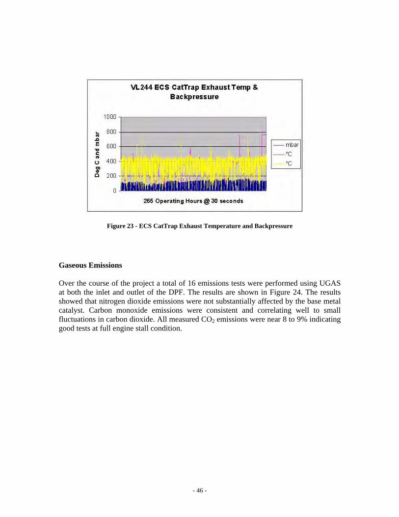
- 46 -
Figure 23 - ECS CatTrap Exhaust Temperature and Backpressure Gaseous Emissions Over the course of the project a total of 16 emissions tests were performed using UGAS at both the inlet and outlet of the DPF. The results are shown in Figure 24. The results showed that nitrogen dioxide emissions were not substantially affected by the base metal catalyst. Carbon monoxide emissions were consistent and correlating well to small fluctuations in carbon dioxide. All measured CO2 emissions were near 8 to 9% indicating good tests at full engine stall condition.
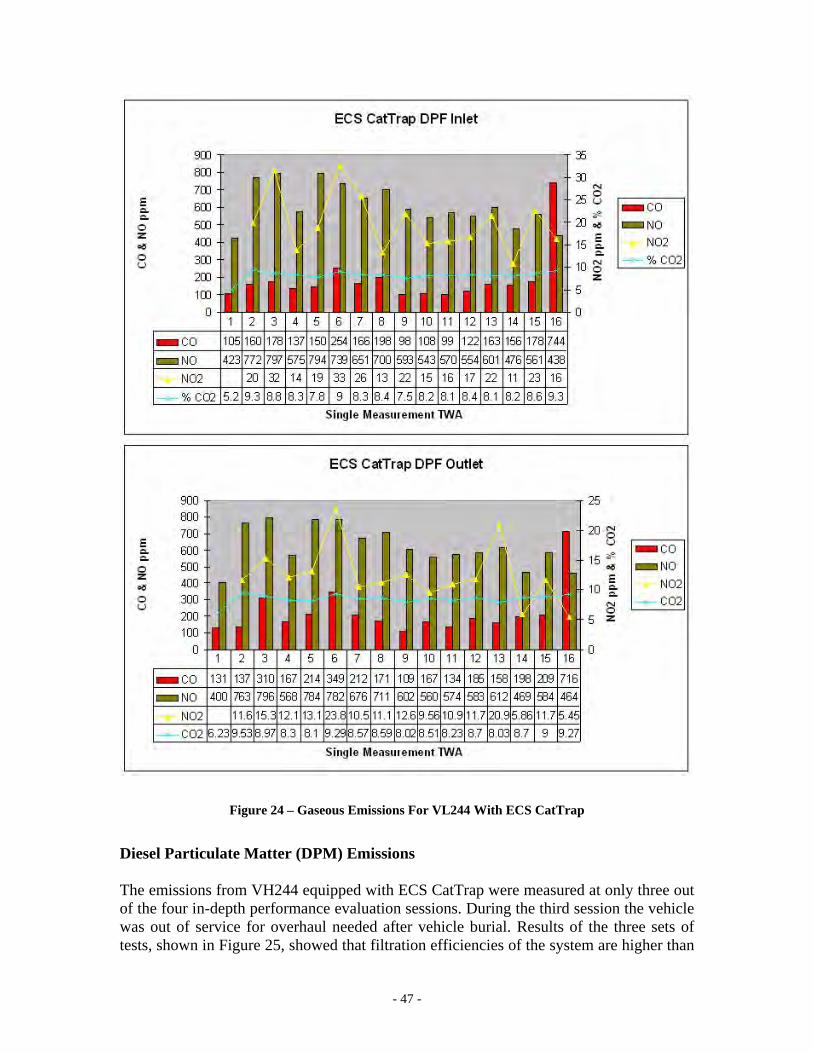
- 47 -
Figure 24 – Gaseous Emissions For VL244 With ECS CatTrap Diesel Particulate Matter (DPM) Emissions The emissions from VH244 equipped with ECS CatTrap were measured at only three out of the four in-depth performance evaluation sessions. During the third session the vehicle was out of service for overhaul needed after vehicle burial. Results of the three sets of tests, shown in Figure 25, showed that filtration efficiencies of the system are higher than
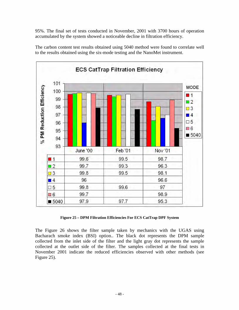
- 48 -
95%. The final set of tests conducted in November, 2001 with 3700 hours of operation accumulated by the system showed a noticeable decline in filtration efficiency. The carbon content test results obtained using 5040 method were found to correlate well to the results obtained using the six-mode testing and the NanoMet instrument.
Figure 25 – DPM Filtration Efficiencies For ECS CatTrap DPF System The Figure 26 shows the filter sample taken by mechanics with the UGAS using Bacharach smoke index (BSI) option.. The black dot represents the DPM sample collected from the inlet side of the filter and the light gray dot represents the sample collected at the outlet side of the filter. The samples collected at the final tests in November 2001 indicate the reduced efficiencies observed with other methods (see Figure 25).
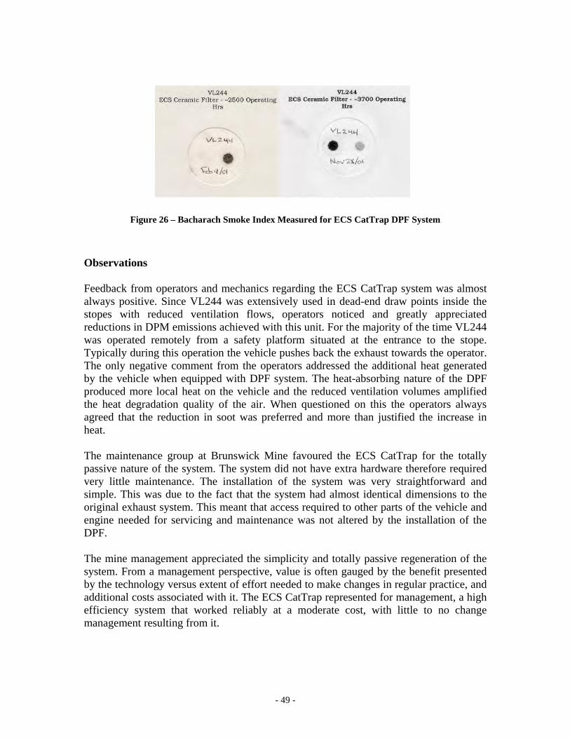
- 49 -
Figure 26 – Bacharach Smoke Index Measured for ECS CatTrap DPF System Observations Feedback from operators and mechanics regarding the ECS CatTrap system was almost always positive. Since VL244 was extensively used in dead-end draw points inside the stopes with reduced ventilation flows, operators noticed and greatly appreciated reductions in DPM emissions achieved with this unit. For the majority of the time VL244 was operated remotely from a safety platform situated at the entrance to the stope. Typically during this operation the vehicle pushes back the exhaust towards the operator. The only negative comment from the operators addressed the additional heat generated by the vehicle when equipped with DPF system. The heat-absorbing nature of the DPF produced more local heat on the vehicle and the reduced ventilation volumes amplified the heat degradation quality of the air. When questioned on this the operators always agreed that the reduction in soot was preferred and more than justified the increase in heat. The maintenance group at Brunswick Mine favoured the ECS CatTrap for the totally passive nature of the system. The system did not have extra hardware therefore required very little maintenance. The installation of the system was very straightforward and simple. This was due to the fact that the system had almost identical dimensions to the original exhaust system. This meant that access required to other parts of the vehicle and engine needed for servicing and maintenance was not altered by the installation of the DPF. The mine management appreciated the simplicity and totally passive regeneration of the system. From a management perspective, value is often gauged by the benefit presented by the technology versus extent of effort needed to make changes in regular practice, and additional costs associated with it. The ECS CatTrap represented for management, a high efficiency system that worked reliably at a moderate cost, with little to no change management resulting from it.
- 50 -
DDCCLL BBlluueesskkyy SSyysstteemm IInnssttaalllleedd OOnn LLHHDD VVLL224477 The DCL Bluesky DPF system performed well according to the majority of the criteria set at the onset of the project. However, the on-board active regenerating system with its electrical heater and power supply unit created a challenge for the management and operators. The system was designed to partially regenerate over the duty cycle. The platinum coating on the silicon carbide filter facilitated passive regeneration. The regeneration of the system was enhanced using the on-board electrical regeneration system. Electrical regeneration required the operators to park the vehicle in a designated place at the end of each shift and connect the system to 600 volt electric power. The passive regeneration worked better than expected so the requirement for active regeneration was reduced. Had the active component been essential to success, the system would undoubtedly have failed early in the project. Operators mostly resisted the requirement to bring the vehicle to the garage at 1000 level at the end of each shift and initiate the active regeneration process. Adherence to this practice was sporadic at best throughout the duration of the project. Despite these problems, the system performed well throughout the duration of the project. However, during the initial two months of operation the system had major technical problems. The original system lacked the electrical engineering suitable for an underground mining mobile application. Defects in the ground fault protection system, physical mounting and insulation of electrical components, and poor quality connections led to a series of failures that almost brought an early end to the testing of the system. Collaboration between the electrical and mechanical departments at Brunswick Mine brought a quick evaluation, re-engineering, and modifications to the system that proved itself for the duration of the project. Chronology of Events
May 2000 – The system was installed on the VL247 that had 0.5 operating hours since new;
June 2000 – The first elaborate performance evaluation session; July 2000 – The DPF system was removed from service to make modifications to
the electrical regeneration system; August 2000 – The system was reinstalled and returned to service October 2000 – The first defective 600 volt heater element was replaced with a
new one; October 2000 – The insulating blankets were removed due to corrosion problems; February 2001 – Performance of the system was examined during isolated zone
testing and second performance evaluation session May 2001 – The second 600 volt heater element was replaced with new one; June 2001 – The system was tested during the third performance evaluation
session; October 2001 – The third 600 volt heater element was replaced with new one; November 2001 – The system was tested during the final performance evaluation
session; January 2002 – The system was de-commissioned at Brunswick Mine
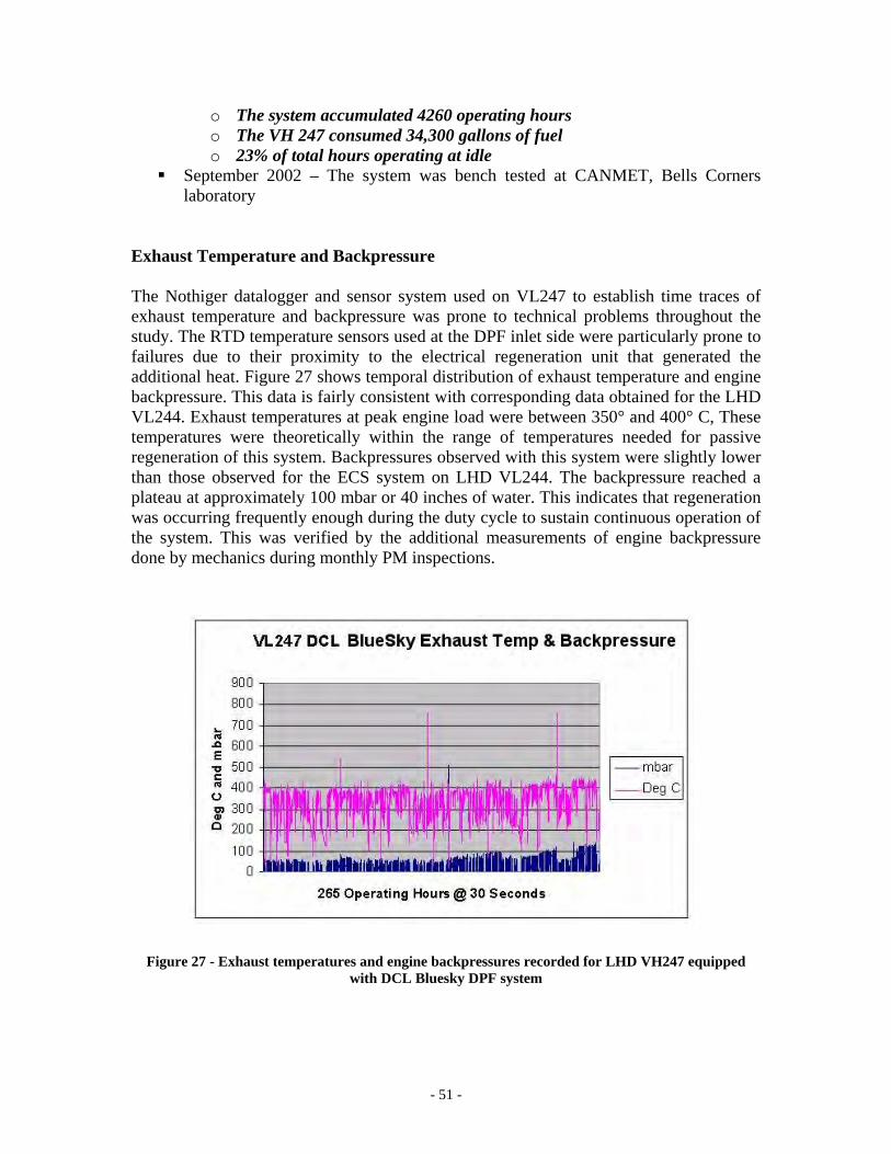
- 51 -
o The system accumulated 4260 operating hours o The VH 247 consumed 34,300 gallons of fuel o 23% of total hours operating at idle
September 2002 – The system was bench tested at CANMET, Bells Corners laboratory
Exhaust Temperature and Backpressure The Nothiger datalogger and sensor system used on VL247 to establish time traces of exhaust temperature and backpressure was prone to technical problems throughout the study. The RTD temperature sensors used at the DPF inlet side were particularly prone to failures due to their proximity to the electrical regeneration unit that generated the additional heat. Figure 27 shows temporal distribution of exhaust temperature and engine backpressure. This data is fairly consistent with corresponding data obtained for the LHD VL244. Exhaust temperatures at peak engine load were between 350° and 400° C, These temperatures were theoretically within the range of temperatures needed for passive regeneration of this system. Backpressures observed with this system were slightly lower than those observed for the ECS system on LHD VL244. The backpressure reached a plateau at approximately 100 mbar or 40 inches of water. This indicates that regeneration was occurring frequently enough during the duty cycle to sustain continuous operation of the system. This was verified by the additional measurements of engine backpressure done by mechanics during monthly PM inspections.
Figure 27 - Exhaust temperatures and engine backpressures recorded for LHD VH247 equipped
with DCL Bluesky DPF system
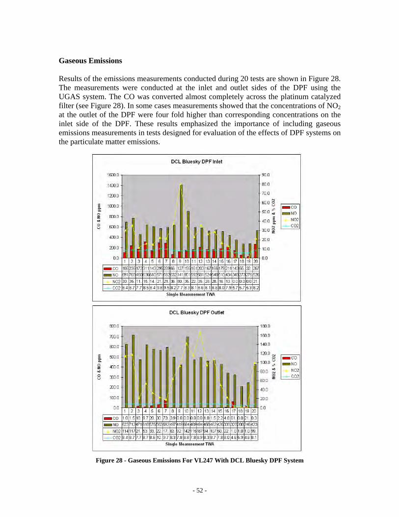
- 52 -
Gaseous Emissions Results of the emissions measurements conducted during 20 tests are shown in Figure 28. The measurements were conducted at the inlet and outlet sides of the DPF using the UGAS system. The CO was converted almost completely across the platinum catalyzed filter (see Figure 28). In some cases measurements showed that the concentrations of NO2 at the outlet of the DPF were four fold higher than corresponding concentrations on the inlet side of the DPF. These results emphasized the importance of including gaseous emissions measurements in tests designed for evaluation of the effects of DPF systems on the particulate matter emissions.
Figure 28 - Gaseous Emissions For VL247 With DCL Bluesky DPF System
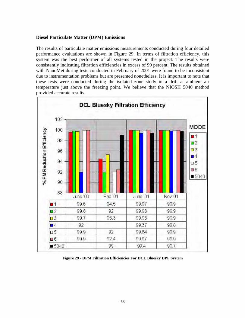
- 53 -
Diesel Particulate Matter (DPM) Emissions The results of particulate matter emissions measurements conducted during four detailed performance evaluations are shown in Figure 29. In terms of filtration efficiency, this system was the best performer of all systems tested in the project. The results were consistently indicating filtration efficiencies in excess of 99 percent. The results obtained with NanoMet during tests conducted in February of 2001 were found to be inconsistent due to instrumentation problems but are presented nonetheless. It is important to note that these tests were conducted during the isolated zone study in a drift at ambient air temperature just above the freezing point. We believe that the NIOSH 5040 method provided accurate results.
Figure 29 - DPM Filtration Efficiencies For DCL Bluesky DPF System
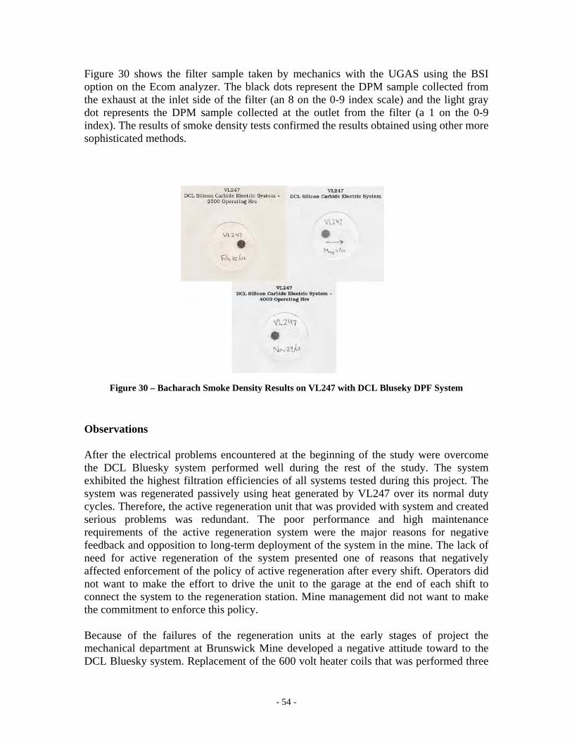
- 54 -
Figure 30 shows the filter sample taken by mechanics with the UGAS using the BSI option on the Ecom analyzer. The black dots represent the DPM sample collected from the exhaust at the inlet side of the filter (an 8 on the 0-9 index scale) and the light gray dot represents the DPM sample collected at the outlet from the filter (a 1 on the 0-9 index). The results of smoke density tests confirmed the results obtained using other more sophisticated methods.
Figure 30 – Bacharach Smoke Density Results on VL247 with DCL Bluseky DPF System Observations After the electrical problems encountered at the beginning of the study were overcome the DCL Bluesky system performed well during the rest of the study. The system exhibited the highest filtration efficiencies of all systems tested during this project. The system was regenerated passively using heat generated by VL247 over its normal duty cycles. Therefore, the active regeneration unit that was provided with system and created serious problems was redundant. The poor performance and high maintenance requirements of the active regeneration system were the major reasons for negative feedback and opposition to long-term deployment of the system in the mine. The lack of need for active regeneration of the system presented one of reasons that negatively affected enforcement of the policy of active regeneration after every shift. Operators did not want to make the effort to drive the unit to the garage at the end of each shift to connect the system to the regeneration station. Mine management did not want to make the commitment to enforce this policy. Because of the failures of the regeneration units at the early stages of project the mechanical department at Brunswick Mine developed a negative attitude toward to the DCL Bluesky system. Replacement of the 600 volt heater coils that was performed three
- 55 -
times over the length of the project was a sizeable and dirty job. The mechanics did observe and commented on the high filtration efficiency of the unit during emissions tests performed at 250-hour intervals. The size of the unit was not an issue for the mechanics. The unit did not create additional problems related to vehicle and engine maintenance. Management also developed negative attitude toward this system because of the problems encountered at the early stages of the project and because of requirements for additional work with active regeneration of the system. This system with active regeneration was seen by management as a last choice. The similar LHD VL244 had a totally passive regeneration system that worked well and there was little incentive for management to pursue an active regeneration system. Had this system been tested in an application that absolutely required active regeneration, for example in the case of the application where heat generated over duty cycle is insufficient for passive regeneration, the mine management might have been more receptive to it
EECCSS OOcctteell SSyysstteemm IInnssttaalllleedd oonn VVHH118833 TTrruucckk The ECS Octel DPF system consisted of twin silicon carbide monolith filters mounted vertically, with oxidation catalysts above the inlet sides of the filters. The system used fuel blended with the Octimax 4804 catalyst. At the early stages of the study, the system looked very promising. It offered high filtration efficiency and no backpressure problems. Approximately three months in the project, problems with backpressure arose. When the system was disassembled for visual inspection and manual cleaning it was observed that a large quantity of soot had been accumulated at the inlet face of the filters. The accumulated soot was cleaned from the filter elements using compressed air and the system re-assembled. At the request of the system manufacturer, the oxidation catalysts were modified and moved to the outlet sides of the filters. This was done in an attempt to eliminate potential source of soot buildup on the inlet side. Despite this modification, backpressure problems continued and little or no successful regenerations occurred in a period of several months. Two uncontrolled regenerations occurred six and eight months in the project. These uncontrolled regenerations were the cause of the ultimate failure of the SiC filter monoliths. During these two events the metal substrate cores of the downstream oxidation catalysts were completely melted. The first of these events occurred while the vehicle was at the PM service bay undergoing emissions testing with the engine under full load. The second uncontrolled regeneration occurred while the truck was being driven up the ramp with a full load. At the point of uncontrolled regeneration exhaust backpressure was regularly between 200 and 300 mbar (80 in. wc and 120 in. wc), up to three times the 100 mbar limit recommended by the engine manufacturer. A new set of filters was installed at the ten months point in the project. The melted oxidation catalyst cores were removed and the housings left empty in attempt to alleviate backpressure problems. However, backpressure continued to be a problem even with the new filters, and within two months approached the level of 300 mbar. The filters were again cleaned with compressed air. Before the end of the field study, the second set of filters also went through uncontrolled regeneration and was permanently damaged.
- 56 -
Managing this system provided the mine maintenance and operations people with valuable knowledge and understanding of the operational issues and sensitivity of DPF systems. Careful and continuous monitoring of the systems was found to be essential for success of the installation. The combination of several factors was found to cause slow and inadequate regeneration of the ECS Octel DPF system. The truck VH183 idled for long periods of time while waiting to be loaded by LHDs and waiting at orepasses. It was also evident that the Octimax fuel borne catalyst did not reduce regeneration temperatures to the extent claimed by supplier. There were significant periods when engine exhaust temperatures were between 350° and 400°C yet the regeneration did not occur. The design of the DPF system itself left many questions regarding sizing, location of oxidation catalysts, and exhaust flow and pressure factors that governed heat retention time inside the filter media. Chronology of Events
May 2000 – The system was installed, the vehicle had 293 operating hours since new
June 2000 – The first measurement of DPF performance and efficiency August 2000 – Backpressure problems prompted inspection and cleaning. The
DOC’s were moved to the outlet side of the filter November 2000 – Uncontrolled regeneration occurred during testing in 3250 shop January 2001 – Uncontrolled regeneration occurred while the truck was climbing
ramp with full load February 2001 – Isolated zone testing and the second measurements of DPF
efficiency April 2001 – The system accumulated 2500 hours. The set of damaged filters
were replaced with new ones June 2001 – The third evaluation of DPF efficiency October 2001 – The third uncontrolled regeneration caused partially the failure of
2nd set of filters November 2001 – Final evaluation of DPF efficiency January 2002 – The system was de-commissioned at Brunswick Mine
o 2500 total operating hours on 1st set of DPF filters and 16,000 gallons of fuel
o 1620 total operating hours on 2nd DPF filters and 11,200 gallons of fuel o 32.5% of total hours VL183 operated at idle
September 2002 – Final bench testing of the system at CANMET, Bells Corners laboratory
Exhaust Temperature and Backpressure The backpressure readings acquired from the datalogger correlated well to backpressures measured by the mechanics during the monthly preventive maintenance checks. The temperature traces shown in Figure 31 indicate that exhaust temperatures were above 350° C for substantial periods of time The Octimax fuel borne catalyst was advertised to
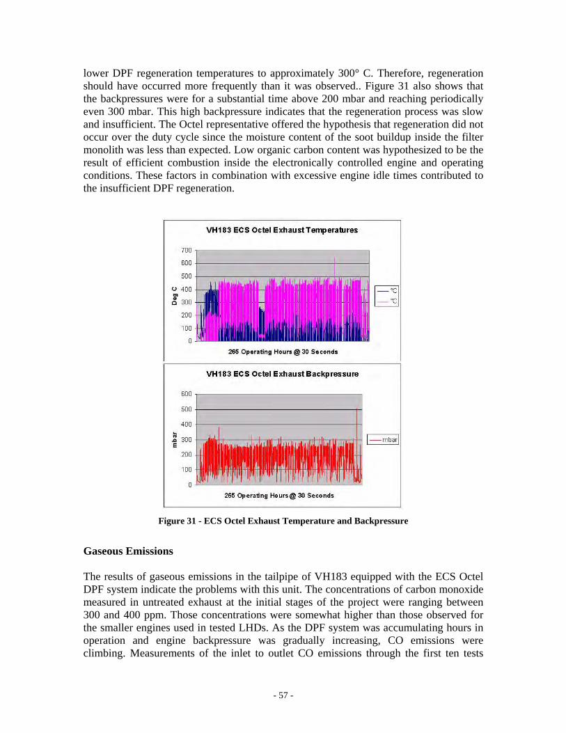
- 57 -
lower DPF regeneration temperatures to approximately 300° C. Therefore, regeneration should have occurred more frequently than it was observed.. Figure 31 also shows that the backpressures were for a substantial time above 200 mbar and reaching periodically even 300 mbar. This high backpressure indicates that the regeneration process was slow and insufficient. The Octel representative offered the hypothesis that regeneration did not occur over the duty cycle since the moisture content of the soot buildup inside the filter monolith was less than expected. Low organic carbon content was hypothesized to be the result of efficient combustion inside the electronically controlled engine and operating conditions. These factors in combination with excessive engine idle times contributed to the insufficient DPF regeneration.
Figure 31 - ECS Octel Exhaust Temperature and Backpressure Gaseous Emissions The results of gaseous emissions in the tailpipe of VH183 equipped with the ECS Octel DPF system indicate the problems with this unit. The concentrations of carbon monoxide measured in untreated exhaust at the initial stages of the project were ranging between 300 and 400 ppm. Those concentrations were somewhat higher than those observed for the smaller engines used in tested LHDs. As the DPF system was accumulating hours in operation and engine backpressure was gradually increasing, CO emissions were climbing. Measurements of the inlet to outlet CO emissions through the first ten tests
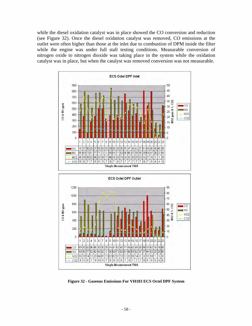
- 58 -
while the diesel oxidation catalyst was in place showed the CO conversion and reduction (see Figure 32). Once the diesel oxidation catalyst was removed, CO emissions at the outlet were often higher than those at the inlet due to combustion of DPM inside the filter while the engine was under full stall testing conditions. Measurable conversion of nitrogen oxide to nitrogen dioxide was taking place in the system while the oxidation catalyst was in place, but when the catalyst was removed conversion was not measurable.
Figure 32 - Gaseous Emissions For VH183 ECS Octel DPF System
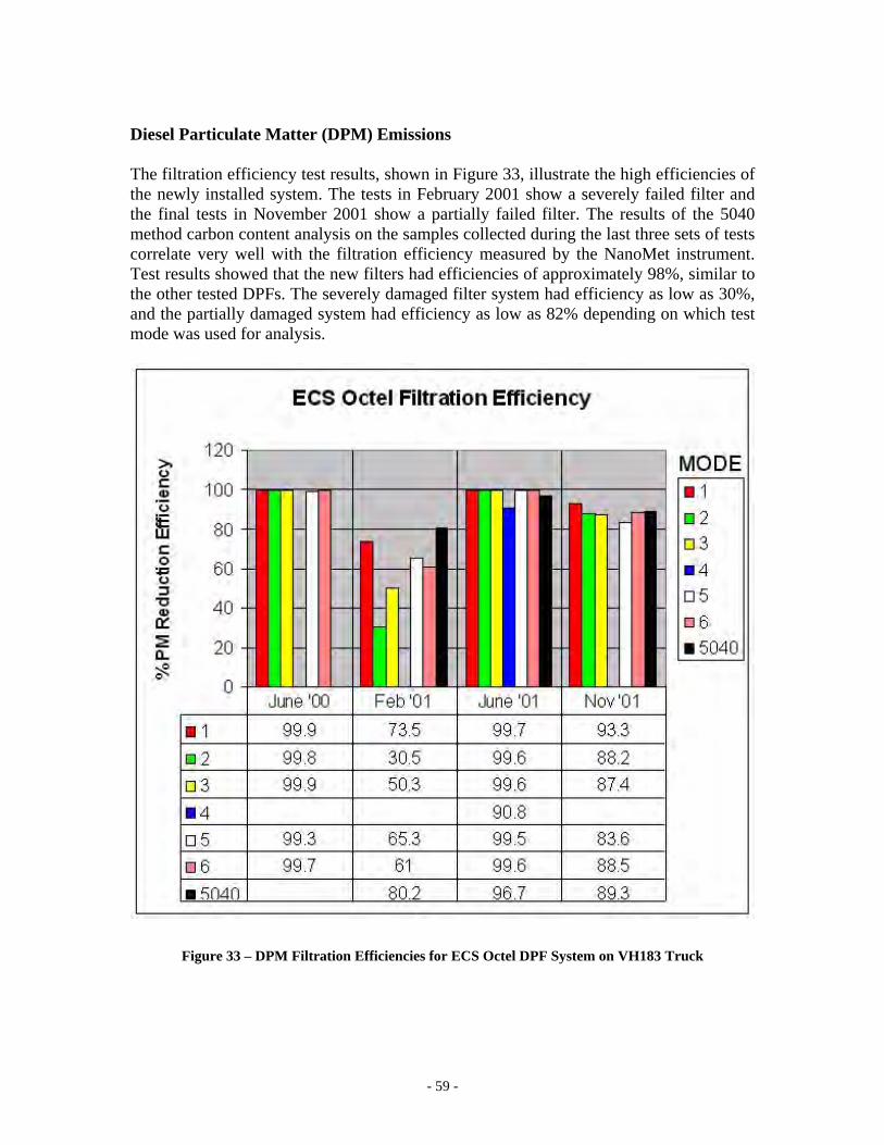
- 59 -
Diesel Particulate Matter (DPM) Emissions The filtration efficiency test results, shown in Figure 33, illustrate the high efficiencies of the newly installed system. The tests in February 2001 show a severely failed filter and the final tests in November 2001 show a partially failed filter. The results of the 5040 method carbon content analysis on the samples collected during the last three sets of tests correlate very well with the filtration efficiency measured by the NanoMet instrument. Test results showed that the new filters had efficiencies of approximately 98%, similar to the other tested DPFs. The severely damaged filter system had efficiency as low as 30%, and the partially damaged system had efficiency as low as 82% depending on which test mode was used for analysis.
Figure 33 – DPM Filtration Efficiencies for ECS Octel DPF System on VH183 Truck
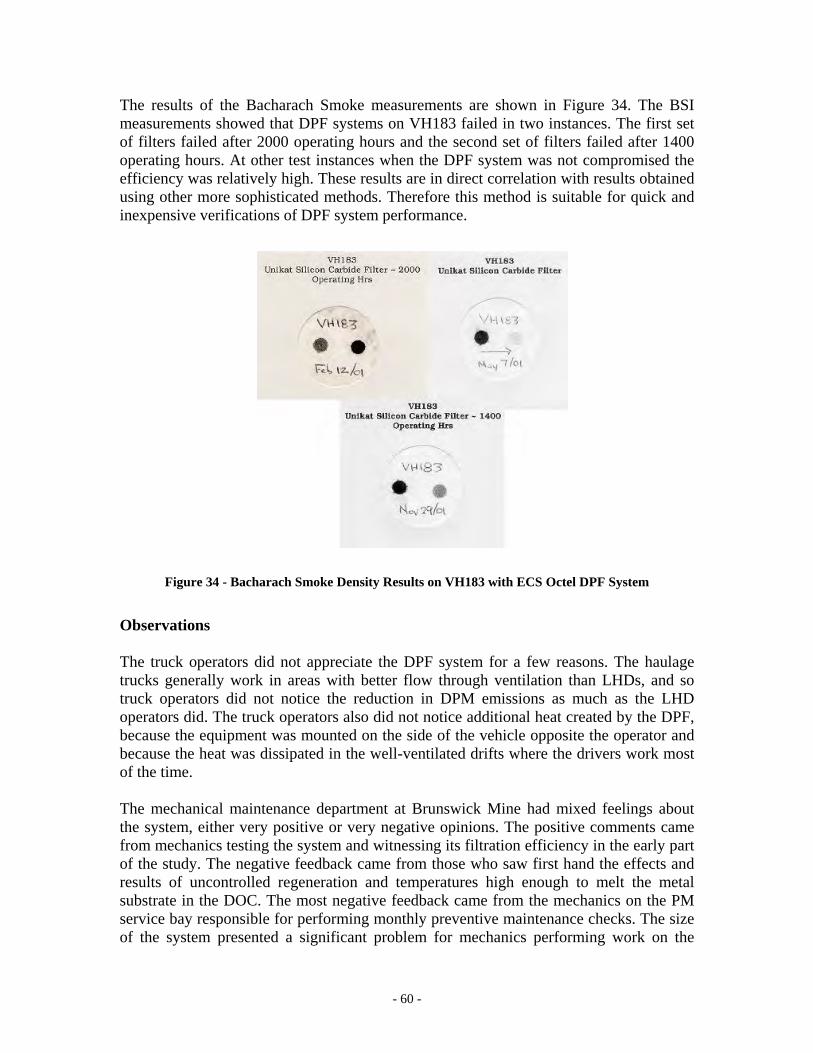
- 60 -
The results of the Bacharach Smoke measurements are shown in Figure 34. The BSI measurements showed that DPF systems on VH183 failed in two instances. The first set of filters failed after 2000 operating hours and the second set of filters failed after 1400 operating hours. At other test instances when the DPF system was not compromised the efficiency was relatively high. These results are in direct correlation with results obtained using other more sophisticated methods. Therefore this method is suitable for quick and inexpensive verifications of DPF system performance.
Figure 34 - Bacharach Smoke Density Results on VH183 with ECS Octel DPF System
Observations The truck operators did not appreciate the DPF system for a few reasons. The haulage trucks generally work in areas with better flow through ventilation than LHDs, and so truck operators did not notice the reduction in DPM emissions as much as the LHD operators did. The truck operators also did not notice additional heat created by the DPF, because the equipment was mounted on the side of the vehicle opposite the operator and because the heat was dissipated in the well-ventilated drifts where the drivers work most of the time. The mechanical maintenance department at Brunswick Mine had mixed feelings about the system, either very positive or very negative opinions. The positive comments came from mechanics testing the system and witnessing its filtration efficiency in the early part of the study. The negative feedback came from those who saw first hand the effects and results of uncontrolled regeneration and temperatures high enough to melt the metal substrate in the DOC. The most negative feedback came from the mechanics on the PM service bay responsible for performing monthly preventive maintenance checks. The size of the system presented a significant problem for mechanics performing work on the
- 61 -
engine. Work on the engine was virtually impossible while the engine and exhaust system was hot. Regardless of how well the filter worked and reduced DPM emissions, all the mechanics wanted to know was when the system would be removed. Management had a completely negative perception of this system primarily because of high operational and maintenance costs, poor reliability and questionable performance. The major costs were associated with developing and maintaining infrastructure for the bulk fuel blending. High costs made this system completely unacceptable from the management perspective. The high filtration efficiencies observed during the tests while the filters were not compromised were very encouraging for management and had they continued reliably without failures, the perception may have been quite different.
OObbeerrllaanndd MMaannggoolldd OOcctteell DDPPFF SSyysstteemm IInnssttaalllleedd oonn VVHH118811 TTrruucckk Out of the four systems tested in the project, the Oberland Mangold DPF was the only one manufactured outside of North America. Manufactured in Germany, the system was used mostly in lighter duty applications but also on a few production units at an underground mine in Germany. In the specifications for the project, DPF manufacturers were asked to keep DPF dimensions within the size limits of the exhaust components that existed on the test vehicles. For the truck applications this was a significant challenge because of the size of the large engine and relatively small space in the engine compartment available for exhaust components. The first version of Oberland Mangold’s DPF was manufactured to meet these size restrictions. However, as backpressure was a problem right from the installation, it became quickly apparent that the filter was undersized for the application. The manufacturer requested the opportunity to design and construct a second version of the system. The original DPF, which contained 25 glass fiber cartridges, was replaced with a new DPF with 52 glass fiber cartridges. The original DPF was installed in June of 2000. The replacement unit was installed two months later in August of 2000. The significantly larger second version of the DPF brought quick resolution to the problem of backpressure. This oversized DPF system with the glass fiber filter media had the least problems with backpressure of all four tested systems. However, the increase in physical dimensions created problems for the mechanical department. The mechanics encountered difficulties servicing the engine around the DPF. This DPF system exhibited somewhat lower filtration efficiency the other tested systems. Chronology of Events
June 2000 – The system was installed on VH181 that had 2265 operating hours since new
June 2000 – The first efficiency measurements performed with original version of DPF in place
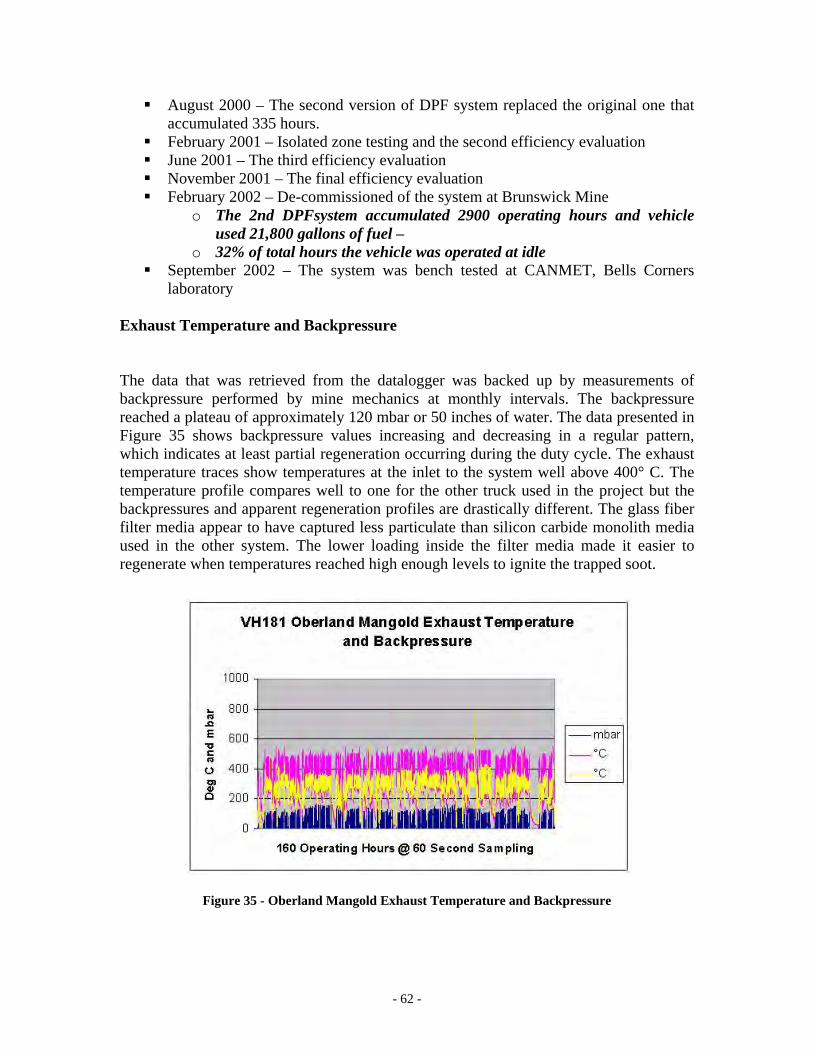
- 62 -
August 2000 – The second version of DPF system replaced the original one that accumulated 335 hours.
February 2001 – Isolated zone testing and the second efficiency evaluation June 2001 – The third efficiency evaluation November 2001 – The final efficiency evaluation February 2002 – De-commissioned of the system at Brunswick Mine
o The 2nd DPFsystem accumulated 2900 operating hours and vehicle used 21,800 gallons of fuel –
o 32% of total hours the vehicle was operated at idle September 2002 – The system was bench tested at CANMET, Bells Corners
laboratory Exhaust Temperature and Backpressure The data that was retrieved from the datalogger was backed up by measurements of backpressure performed by mine mechanics at monthly intervals. The backpressure reached a plateau of approximately 120 mbar or 50 inches of water. The data presented in Figure 35 shows backpressure values increasing and decreasing in a regular pattern, which indicates at least partial regeneration occurring during the duty cycle. The exhaust temperature traces show temperatures at the inlet to the system well above 400° C. The temperature profile compares well to one for the other truck used in the project but the backpressures and apparent regeneration profiles are drastically different. The glass fiber filter media appear to have captured less particulate than silicon carbide monolith media used in the other system. The lower loading inside the filter media made it easier to regenerate when temperatures reached high enough levels to ignite the trapped soot.
Figure 35 - Oberland Mangold Exhaust Temperature and Backpressure
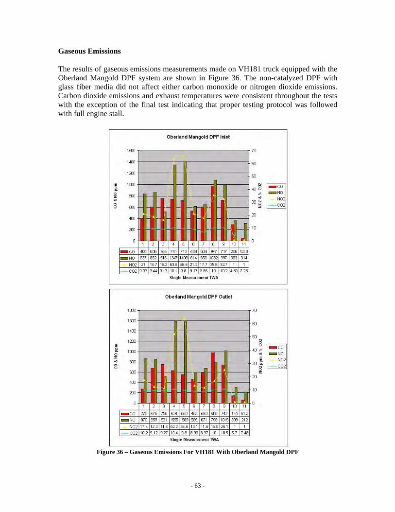
- 63 -
Gaseous Emissions The results of gaseous emissions measurements made on VH181 truck equipped with the Oberland Mangold DPF system are shown in Figure 36. The non-catalyzed DPF with glass fiber media did not affect either carbon monoxide or nitrogen dioxide emissions. Carbon dioxide emissions and exhaust temperatures were consistent throughout the tests with the exception of the final test indicating that proper testing protocol was followed with full engine stall.
Figure 36 – Gaseous Emissions For VH181 With Oberland Mangold DPF
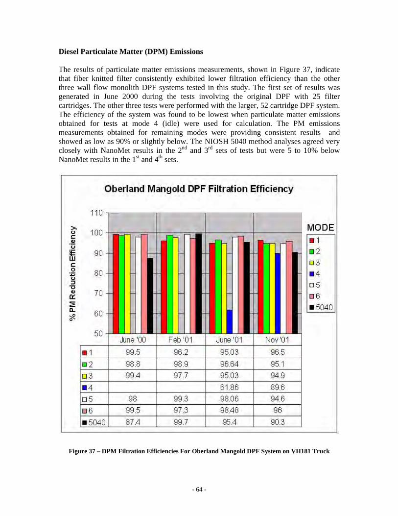
- 64 -
Diesel Particulate Matter (DPM) Emissions The results of particulate matter emissions measurements, shown in Figure 37, indicate that fiber knitted filter consistently exhibited lower filtration efficiency than the other three wall flow monolith DPF systems tested in this study. The first set of results was generated in June 2000 during the tests involving the original DPF with 25 filter cartridges. The other three tests were performed with the larger, 52 cartridge DPF system. The efficiency of the system was found to be lowest when particulate matter emissions obtained for tests at mode 4 (idle) were used for calculation. The PM emissions measurements obtained for remaining modes were providing consistent results and showed as low as 90% or slightly below. The NIOSH 5040 method analyses agreed very closely with NanoMet results in the 2nd and 3rd sets of tests but were 5 to 10% below NanoMet results in the 1st and 4th sets.
Figure 37 – DPM Filtration Efficiencies For Oberland Mangold DPF System on VH181 Truck
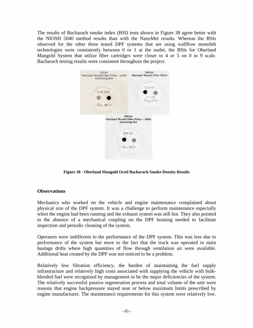
- 65 -
The results of Bacharach smoke index (BSI) tests shown in Figure 38 agree better with the NIOSH 5040 method results than with the NanoMet results. Whereas the BSIs observed for the other three tested DPF systems that are using wallflow monolith technologies were consistently between 0 or 1 at the outlet, the BSIs for Oberland Mangold System that utilize fiber cartridges were closer to 4 or 5 on 0 to 9 scale. Bacharach testing results were consistent throughout the project.
Figure 38 - Oberland Mangold Octel Bacharach Smoke Density Results
Observations Mechanics who worked on the vehicle and engine maintenance complained about physical size of the DPF system. It was a challenge to perform maintenance especially when the engine had been running and the exhaust system was still hot. They also pointed to the absence of a mechanical coupling on the DPF housing needed to facilitate inspection and periodic cleaning of the system. Operators were indifferent to the performance of the DPF system. This was less due to performance of the system but more to the fact that the truck was operated in main haulage drifts where high quantities of flow through ventilation air were available. Additional heat created by the DPF was not noticed to be a problem. Relatively low filtration efficiency, the burden of maintaining the fuel supply infrastructure and relatively high costs associated with supplying the vehicle with bulk-blended fuel were recognized by management to be the major deficiencies of the system. The relatively successful passive regeneration process and total volume of the unit were reasons that engine backpressure stayed near or below maximum limits prescribed by engine manufacturer. The maintenance requirements for this system were relatively low.
- 66 -
The extent of the requirement for supplying vehicles with fuel doped with additive was found to be ultimately the deciding factor against the acceptance of this DPF system by mine management.
IIISSSOOOLLLAAATTTEEEDDD ZZZOOONNNEEE SSSTTTUUUDDDYYY
OObbjjeeccttiivvee aanndd SSccooppee One of the objectives of the project was to assess the effectiveness of the DPF systems technology on concentrations of DPM and gases in mine air and on exposure of vehicle operators. In order to accomplish this it was necessary to design a controlled study in a section of the mine that did not contain confounding diesel exhaust contaminants from equipment not outfitted with DPF systems. This required isolating an operating zone with well-defined and controlled fresh air ventilation with no losses, and eliminating interference sources from other diesel powered vehicles.
EExxppeerriimmeenntt MMeetthhooddoollooggyy The zone at the 525-5 sub level of Brunswick Mine was found to meet criteria for conducting this study. The Brunswick management team provided an entire operating level in the mine, where production activity had ceased, but ground control and ventilation were maintained. A 400-meter section of drift on 525-5 sub level was completely isolated from the other parts of the mine by installing two bulkheads. The zone was ventilated with fresh, DPM-free air from the intake fan system. The layout of 525-5 sub level is shown in Figure 39 with the V3 intake raise at one end and the exhaust raise at the opposite end of the zone. Each of the vehicles tested in this study was operated inside the 400-meter zone while repeating a simulated production cycle. The vehicles were operated with the bucket or box filled with ore. The cycle, developed exclusively for this study, simulated duty cycles observed for LHD vehicles in normal operation at the mine. The cycle consisted of the following operations: (1) In the loading cycle simulation at the air intake side of the zone the vehicle was parked for a period of 2 minutes and operated over two steady-state operating conditions. For 15 seconds the engine was run at full throttle with torque converter and hydraulics stalled. This was followed by a 15 second period at full throttle with transmission in neutral and no load on engine. These two conditions were repeated four times each in a two minute period. This simulated the mucking cycle without producing dust normally associated with mucking process. (2) The vehicle then trammed for 400 meters along the drift to the exhaust end of the zone where the vehicle was turned around and parked to simulate the dump portion of the cycle; (3) The dump cycle simulation was simply a steady state 30-second run at full throttle with transmission in neutral and no load on engine; (4) After finishing with the dump cycle the vehicle then returned to the fresh air intake end of the zone to repeat the full cycle. Each vehicle was operated for a period of 4 hours repeating the described 8-minute cycle. A single experienced operator operated all tested vehicles in similar fashion.
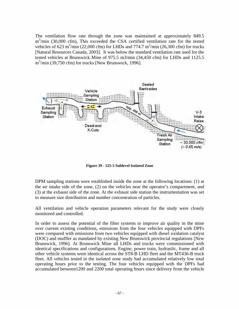
- 67 -
The ventilation flow rate through the zone was maintained at approximately 849.5 m3/min (30,000 cfm), This exceeded the CSA certified ventilation rate for the tested vehicles of 623 m3/min (22,000 cfm) for LHDs and 774.7 m3/min (26,300 cfm) for trucks [Natural Resources Canada, 2003]. It was below the standard ventilation rate used for the tested vehicles at Brunswick Mine of 975.5 m3/min (34,450 cfm) for LHDs and 1125.5 m3/min (39,750 cfm) for trucks [New Brunswick, 1996].
Figure 39 - 525-5 Sublevel Isolated Zone
DPM sampling stations were established inside the zone at the following locations: (1) at the air intake side of the zone, (2) on the vehicles near the operator’s compartment, and (3) at the exhaust side of the zone. At the exhaust side station the instrumentation was set to measure size distribution and number concentration of particles. All ventilation and vehicle operation parameters relevant for the study were closely monitored and controlled. In order to assess the potential of the filter systems to improve air quality in the mine over current existing conditions, emissions from the four vehicles equipped with DPFs were compared with emissions from two vehicles equipped with diesel oxidation catalyst (DOC) and muffler as mandated by existing New Brunswick provincial regulations [New Brunswick, 1996]. At Brunswick Mine all LHDs and trucks were commissioned with identical specifications and configurations. Engine, power train, hydraulic, frame and all other vehicle systems were identical across the ST8-B LHD fleet and the MT436-B truck fleet. All vehicles tested in the isolated zone study had accumulated relatively low total operating hours prior to the testing. The four vehicles equipped with the DPFs had accumulated between1200 and 2200 total operating hours since delivery from the vehicle
- 68 -
manufacturer. The LHD and truck equipped with DOCs were almost brand new with only 500 and 200 operating hours, respectively. The six vehicle and DPF or DOC combinations tested in the study were:
1. LHD ST8-B, VL244 equipped with ECS CatTrap DPF system; 2. LHD ST8-B, VL247 equipped with DCL BlueSky DPF system; 3. LHD ST8-B, VL254 equipped with diesel oxidation catalyst and muffler; 4. Truck MT436, VH183 equipped with ECS Octel DPF system; 5. Truck MT436, VH181 equipped with Oberland Mangold DPF system; 6. Truck MT436, VH188 equipped with diesel oxidation catalyst and muffler.
MMeeaassuurreemmeenntt ooff AAmmbbiieenntt CCoonncceennttrraattiioonnss ooff DDPPMM A total of seven samples were collected at each of the three sampling stations inside the isolated zone. Five of the samples were analyzed for carbon content using NIOSH Analytical Method 5040 [NIOSH Manual for Analytical Methods, 1999]. The other two samples were analyzed for respirable combustible dust (RCD) [Grenier et al. 1996]. The trains for carbon analysis consisted of a pre-separator 10mm York nylon cyclone, 37-mm cassette with quartz fiber filter, tubing, and sampling pump calibrated at 1.7 L/min. At the fresh air intake and exhaust sampling stations the samplers were positioned on a 2 by 4 meter screen to compensate for potential spatial variation of the concentrations across the drift. The samplers on the vehicle were placed in a basket mounted on top of the engine compartment directly in front of and within one meter of the operator. CANMET’s Sudbury U/G Mine Environment Team conducted all DPM sampling and analysis. In addition, extensive ambient measurements of particulate matter concentrations were taken at the exhaust sampling station. Because of the structured vehicle cycles and the controlled ventilation rate inside the zone, the concentration of airborne diesel particulate matter at the most downstream end of the zone were the heaviest with the most uniform spatial and temporal distribution. A team from the NIOSH Pittsburgh laboratories used the Scanning Mobility Particle Sizer (SMPS) to measure size distribution and number concentrations of airborne particles at the sampling station located at the most downstream end of the zone. The SMPS instrument was used for direct measurement of ambient concentrations of particles with electrical mobility diameter ranging from 10 – 392 nm. The measurements were performed at three points during each repetition of the duty cycle: (1) while the vehicle was performing a simulated load cycle at the most upstream section of the zone, (2) while the vehicle was tramming from load to dump location, and (3) while the vehicle was performing a simulated dump cycle at the downstream section of the zone. The quasi steady-state measurements were performed using 90-second scans. The results shown in Figure 42 are based on integral count concentrations for each vehicle and the sampling averaged over number of measurements performed during the four-hour test period. A total of 15 DPM samples for carbon analysis were gathered for each of the tested vehicles. Five samples were collected at each of the following stations: (1) the fresh air intake, (2) the vehicle operator, and (3) the exhaust sampling station. The DPM samples
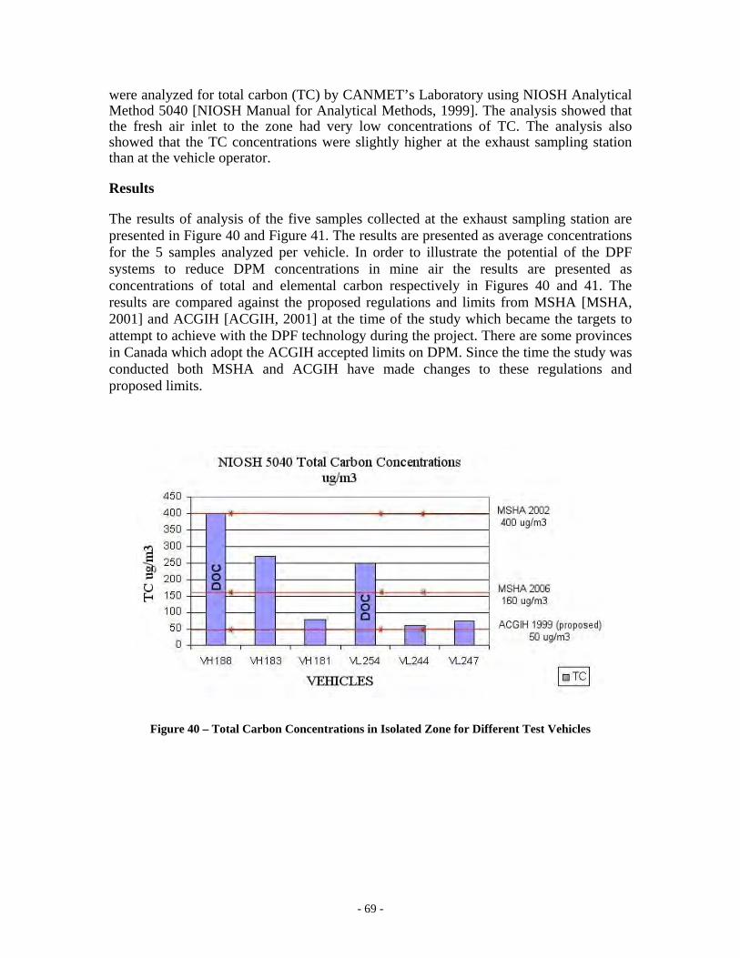
- 69 -
were analyzed for total carbon (TC) by CANMET’s Laboratory using NIOSH Analytical Method 5040 [NIOSH Manual for Analytical Methods, 1999]. The analysis showed that the fresh air inlet to the zone had very low concentrations of TC. The analysis also showed that the TC concentrations were slightly higher at the exhaust sampling station than at the vehicle operator. Results The results of analysis of the five samples collected at the exhaust sampling station are presented in Figure 40 and Figure 41. The results are presented as average concentrations for the 5 samples analyzed per vehicle. In order to illustrate the potential of the DPF systems to reduce DPM concentrations in mine air the results are presented as concentrations of total and elemental carbon respectively in Figures 40 and 41. The results are compared against the proposed regulations and limits from MSHA [MSHA, 2001] and ACGIH [ACGIH, 2001] at the time of the study which became the targets to attempt to achieve with the DPF technology during the project. There are some provinces in Canada which adopt the ACGIH accepted limits on DPM. Since the time the study was conducted both MSHA and ACGIH have made changes to these regulations and proposed limits.
Figure 40 – Total Carbon Concentrations in Isolated Zone for Different Test Vehicles
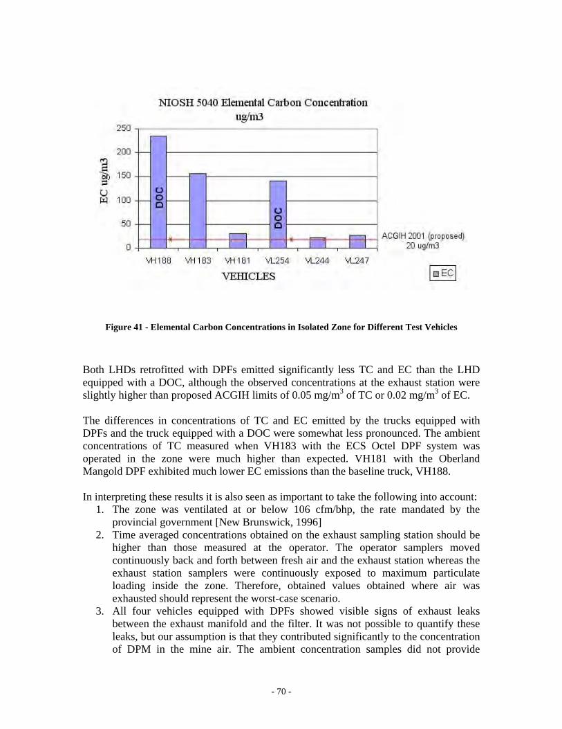
- 70 -
Figure 41 - Elemental Carbon Concentrations in Isolated Zone for Different Test Vehicles Both LHDs retrofitted with DPFs emitted significantly less TC and EC than the LHD equipped with a DOC, although the observed concentrations at the exhaust station were slightly higher than proposed ACGIH limits of 0.05 mg/m3 of TC or 0.02 mg/m3 of EC. The differences in concentrations of TC and EC emitted by the trucks equipped with DPFs and the truck equipped with a DOC were somewhat less pronounced. The ambient concentrations of TC measured when VH183 with the ECS Octel DPF system was operated in the zone were much higher than expected. VH181 with the Oberland Mangold DPF exhibited much lower EC emissions than the baseline truck, VH188. In interpreting these results it is also seen as important to take the following into account:
1. The zone was ventilated at or below 106 cfm/bhp, the rate mandated by the provincial government [New Brunswick, 1996]
2. Time averaged concentrations obtained on the exhaust sampling station should be higher than those measured at the operator. The operator samplers moved continuously back and forth between fresh air and the exhaust station whereas the exhaust station samplers were continuously exposed to maximum particulate loading inside the zone. Therefore, obtained values obtained where air was exhausted should represent the worst-case scenario.
3. All four vehicles equipped with DPFs showed visible signs of exhaust leaks between the exhaust manifold and the filter. It was not possible to quantify these leaks, but our assumption is that they contributed significantly to the concentration of DPM in the mine air. The ambient concentration samples did not provide
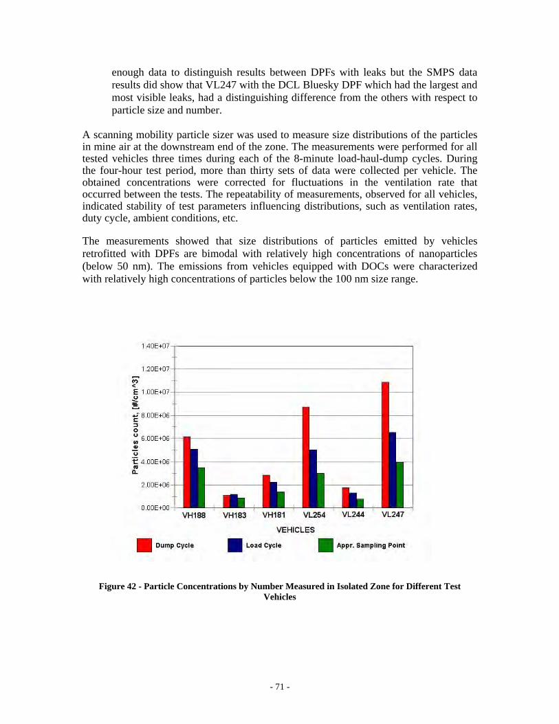
- 71 -
enough data to distinguish results between DPFs with leaks but the SMPS data results did show that VL247 with the DCL Bluesky DPF which had the largest and most visible leaks, had a distinguishing difference from the others with respect to particle size and number.
A scanning mobility particle sizer was used to measure size distributions of the particles in mine air at the downstream end of the zone. The measurements were performed for all tested vehicles three times during each of the 8-minute load-haul-dump cycles. During the four-hour test period, more than thirty sets of data were collected per vehicle. The obtained concentrations were corrected for fluctuations in the ventilation rate that occurred between the tests. The repeatability of measurements, observed for all vehicles, indicated stability of test parameters influencing distributions, such as ventilation rates, duty cycle, ambient conditions, etc. The measurements showed that size distributions of particles emitted by vehicles retrofitted with DPFs are bimodal with relatively high concentrations of nanoparticles (below 50 nm). The emissions from vehicles equipped with DOCs were characterized with relatively high concentrations of particles below the 100 nm size range.
Figure 42 - Particle Concentrations by Number Measured in Isolated Zone for Different Test
Vehicles
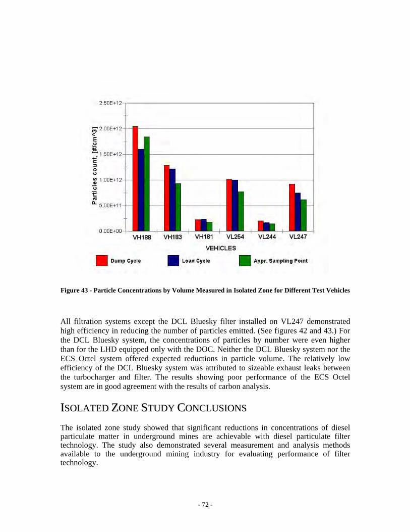
- 72 -
Figure 43 - Particle Concentrations by Volume Measured in Isolated Zone for Different Test Vehicles All filtration systems except the DCL Bluesky filter installed on VL247 demonstrated high efficiency in reducing the number of particles emitted. (See figures 42 and 43.) For the DCL Bluesky system, the concentrations of particles by number were even higher than for the LHD equipped only with the DOC. Neither the DCL Bluesky system nor the ECS Octel system offered expected reductions in particle volume. The relatively low efficiency of the DCL Bluesky system was attributed to sizeable exhaust leaks between the turbocharger and filter. The results showing poor performance of the ECS Octel system are in good agreement with the results of carbon analysis.
IISSOOLLAATTEEDD ZZOONNEE SSTTUUDDYY CCOONNCCLLUUSSIIOONNSS The isolated zone study showed that significant reductions in concentrations of diesel particulate matter in underground mines are achievable with diesel particulate filter technology. The study also demonstrated several measurement and analysis methods available to the underground mining industry for evaluating performance of filter technology.
- 73 -
Extensive measurements showed that three out of four tested filters offered excellent reductions in DPM concentrations. All DPF systems with the exception of the ECS Octel filter performed with high filtration efficiencies. The ECS Octel measurements indicated premature failure of the filter. The post-test investigation revealed that the filter media had been cracked internally. Traces of black soot were seen at the outlet face of the filter. The premature failure was attributed to uncontrolled regeneration as described earlier in the report. The comparison of the results of SMPS and tailpipe measurements revealed important issues with the complex filter efficiency evaluation process. The SMPS measurements in mine air indicated high ambient concentrations of particles emitted by a system which had shown high filtration efficiencies according to tailpipe emissions measurements. This alarming discrepancy in the tailpipe emission measurements and ambient concentrations of particles was explained by sizeable leaks discovered in the exhaust system between the engine and the DPF. Introducing a DPF into the exhaust system can significantly increase engine exhaust backpressure, resulting in leaks and increased ambient emissions. These fugitive emissions are unlikely to be caught with tailpipe measurements alone. This emphasizes the importance of maintaining integrity of the exhaust system upstream of the filter, as well as the importance of ambient exposure monitoring. The measurement methods employed in the isolated zone study provided consistent and valuable data necessary for better understanding of processes governing the formation and transformation of diesel particulate matter in mine air. The study demonstrated several methods available to the underground mining industry for assessing the efficiency of DPF systems. The methods demonstrated different levels of complexity and accuracy. The tailpipe measurement instruments were able to measure the 99% efficiency quite accurately but only the ambient measurements were able to detect the effects of the leaks.
The principal conclusions to be drawn from the testing done inside the isolated zone are:
1. Diesel particulate filter technologies were demonstrated to be very efficient in reducing DPM concentrations. At a ventilation rate appropriate for the engine, the ambient DPM concentrations achieved during this study are well below the MSHA regulatory limits at the time of the study [MSHA, 2001] and almost meet ACGIH recommended diesel particulate exposure limits proposed at the time of the study. [ACGIH, 2001]
2. The ability to attain and sustain diesel equipment within these limits would depend on the ability of mine maintenance personnel to measure performance and maintain the systems accordingly.
3. Filter efficiency must be evaluated using both tailpipe and ambient measurements. These two types of measurement complement each other.
4. The importance of maintenance cannot be overemphasized – undetected failures and leaks in the DPF system can potentially result in particulate exposure levels that can be higher than current levels.
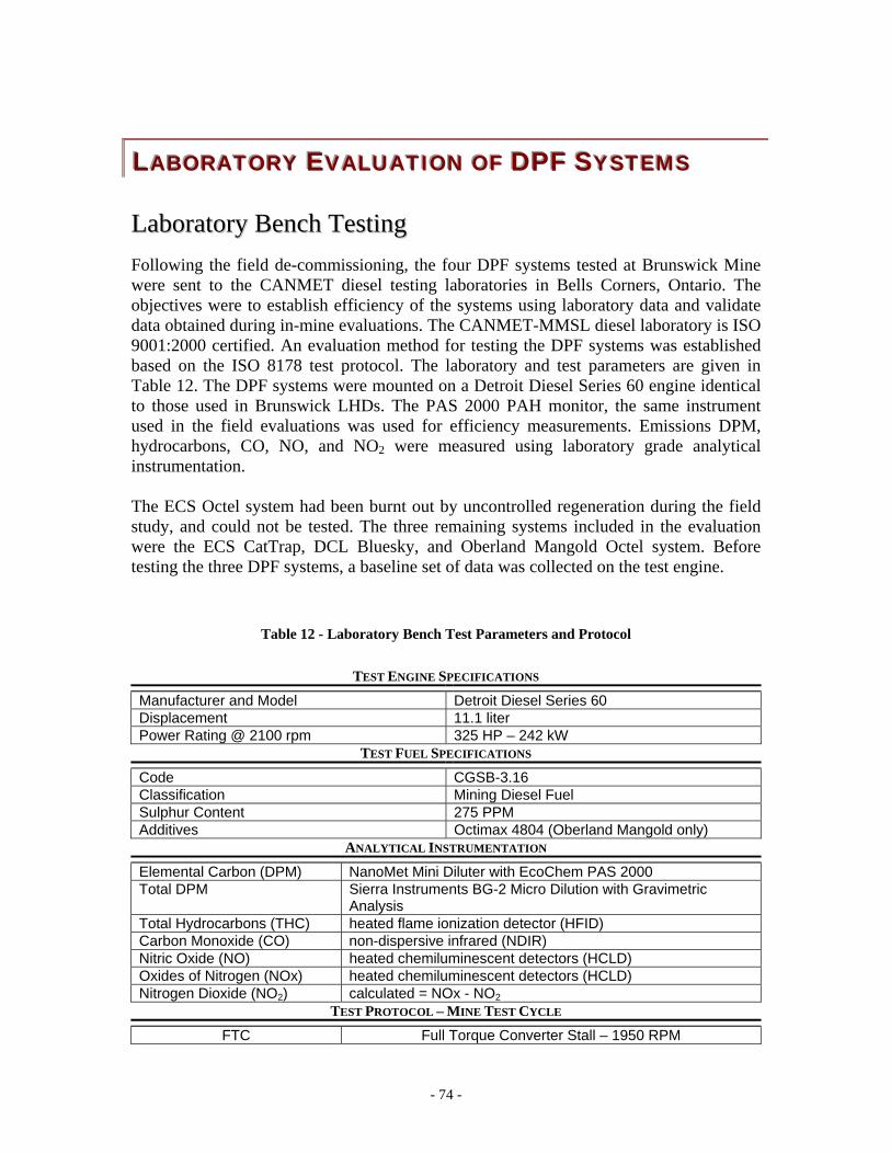
- 74 -
LLLAAABBBOOORRRAAATTTOOORRRYYY EEEVVVAAALLLUUUAAATTTIIIOOONNN OOOFFF DDDPPPFFF SSSYYYSSSTTTEEEMMMSSS LLaabboorraattoorryy BBeenncchh TTeessttiinngg Following the field de-commissioning, the four DPF systems tested at Brunswick Mine were sent to the CANMET diesel testing laboratories in Bells Corners, Ontario. The objectives were to establish efficiency of the systems using laboratory data and validate data obtained during in-mine evaluations. The CANMET-MMSL diesel laboratory is ISO 9001:2000 certified. An evaluation method for testing the DPF systems was established based on the ISO 8178 test protocol. The laboratory and test parameters are given in Table 12. The DPF systems were mounted on a Detroit Diesel Series 60 engine identical to those used in Brunswick LHDs. The PAS 2000 PAH monitor, the same instrument used in the field evaluations was used for efficiency measurements. Emissions DPM, hydrocarbons, CO, NO, and NO2 were measured using laboratory grade analytical instrumentation. The ECS Octel system had been burnt out by uncontrolled regeneration during the field study, and could not be tested. The three remaining systems included in the evaluation were the ECS CatTrap, DCL Bluesky, and Oberland Mangold Octel system. Before testing the three DPF systems, a baseline set of data was collected on the test engine.
Table 12 - Laboratory Bench Test Parameters and Protocol
TEST ENGINE SPECIFICATIONS
Manufacturer and Model Detroit Diesel Series 60 Displacement 11.1 liter Power Rating @ 2100 rpm 325 HP – 242 kW
TEST FUEL SPECIFICATIONS
Code CGSB-3.16 Classification Mining Diesel Fuel Sulphur Content 275 PPM Additives Octimax 4804 (Oberland Mangold only)
ANALYTICAL INSTRUMENTATION
Elemental Carbon (DPM) NanoMet Mini Diluter with EcoChem PAS 2000 Total DPM Sierra Instruments BG-2 Micro Dilution with Gravimetric
Analysis Total Hydrocarbons (THC) heated flame ionization detector (HFID) Carbon Monoxide (CO) non-dispersive infrared (NDIR) Nitric Oxide (NO) heated chemiluminescent detectors (HCLD) Oxides of Nitrogen (NOx) heated chemiluminescent detectors (HCLD) Nitrogen Dioxide (NO2) calculated = NOx - NO2
TEST PROTOCOL – MINE TEST CYCLE
FTC Full Torque Converter Stall – 1950 RPM
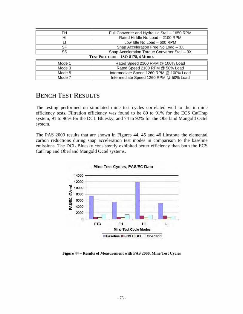
- 75 -
FH Full Converter and Hydraulic Stall – 1650 RPM HI Rated Hi Idle No Load – 2100 RPM LI Low Idle No Load – 600 RPM SF Snap Acceleration Free No Load – 3X SS Snap Acceleration Torque Converter Stall – 3X
TEST PROTOCOL – ISO-8178, 4 MODES
Mode 1 Rated Speed 2100 RPM @ 100% Load Mode 3 Rated Speed 2100 RPM @ 50% Load Mode 5 Intermediate Speed 1260 RPM @ 100% Load Mode 7 Intermediate Speed 1260 RPM @ 50% Load
BBEENNCCHH TTEESSTT RREESSUULLTTSS The testing performed on simulated mine test cycles correlated well to the in-mine efficiency tests. Filtration efficiency was found to be 80 to 91% for the ECS CatTrap system, 91 to 96% for the DCL Bluesky, and 74 to 92% for the Oberland Mangold Octel system. The PAS 2000 results that are shown in Figures 44, 45 and 46 illustrate the elemental carbon reductions during snap acceleration test modes in comparison to the baseline emissions. The DCL Bluesky consistently exhibited better efficiency than both the ECS CatTrap and Oberland Mangold Octel systems.
Figure 44 – Results of Measurement with PAS 2000, Mine Test Cycles
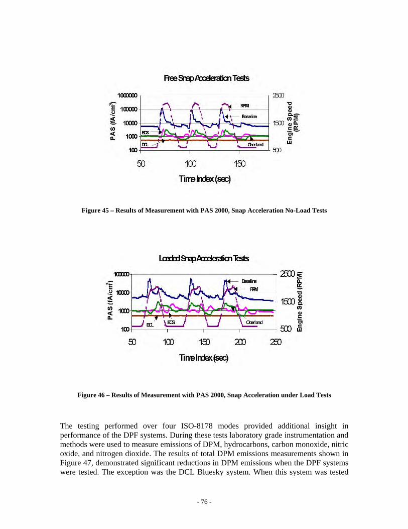
- 76 -
Figure 45 – Results of Measurement with PAS 2000, Snap Acceleration No-Load Tests
Figure 46 – Results of Measurement with PAS 2000, Snap Acceleration under Load Tests
The testing performed over four ISO-8178 modes provided additional insight in performance of the DPF systems. During these tests laboratory grade instrumentation and methods were used to measure emissions of DPM, hydrocarbons, carbon monoxide, nitric oxide, and nitrogen dioxide. The results of total DPM emissions measurements shown in Figure 47, demonstrated significant reductions in DPM emissions when the DPF systems were tested. The exception was the DCL Bluesky system. When this system was tested
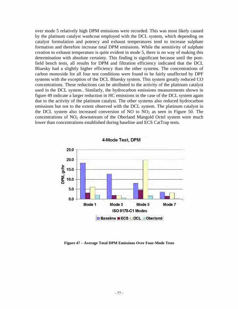
- 77 -
over mode 5 relatively high DPM emissions were recorded. This was most likely caused by the platinum catalyst washcoat employed with the DCL system, which depending on catalyst formulation and potency and exhaust temperatures tend to increase sulphate formation and therefore increase total DPM emissions. While the sensitivity of sulphate creation to exhaust temperature is quite evident in mode 5, there is no way of making this determination with absolute certainty. This finding is significant because until the post-field bench tests, all results for DPM and filtration efficiency indicated that the DCL Bluesky had a slightly higher efficiency than the other systems. The concentrations of carbon monoxide for all four test conditions were found to be fairly unaffected by DPF systems with the exception of the DCL Bluesky system. This system greatly reduced CO concentrations. These reductions can be attributed to the activity of the platinum catalyst used in the DCL system.. Similarly, the hydrocarbon emissions measurements shown in figure 49 indicate a larger reduction in HC emissions in the case of the DCL system again due to the activity of the platinum catalyst. The other systems also reduced hydrocarbon emissions but not to the extent observed with the DCL system. The platinum catalyst in the DCL system also increased conversion of NO to NO2 as seen in Figure 50. The concentrations of NO2 downstream of the Oberland Mangold Octel system were much lower than concentrations established during baseline and ECS CatTrap tests.
Figure 47 – Average Total DPM Emissions Over Four-Mode Tests
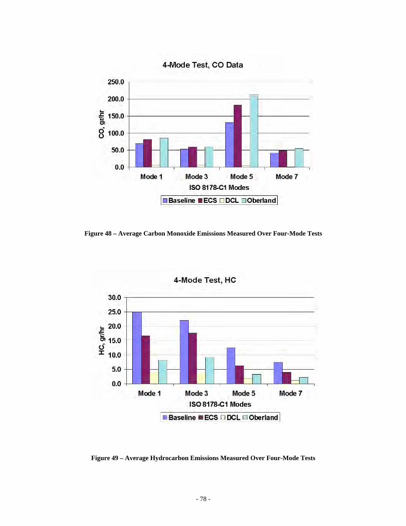
- 78 -
Figure 48 – Average Carbon Monoxide Emissions Measured Over Four-Mode Tests
Figure 49 – Average Hydrocarbon Emissions Measured Over Four-Mode Tests
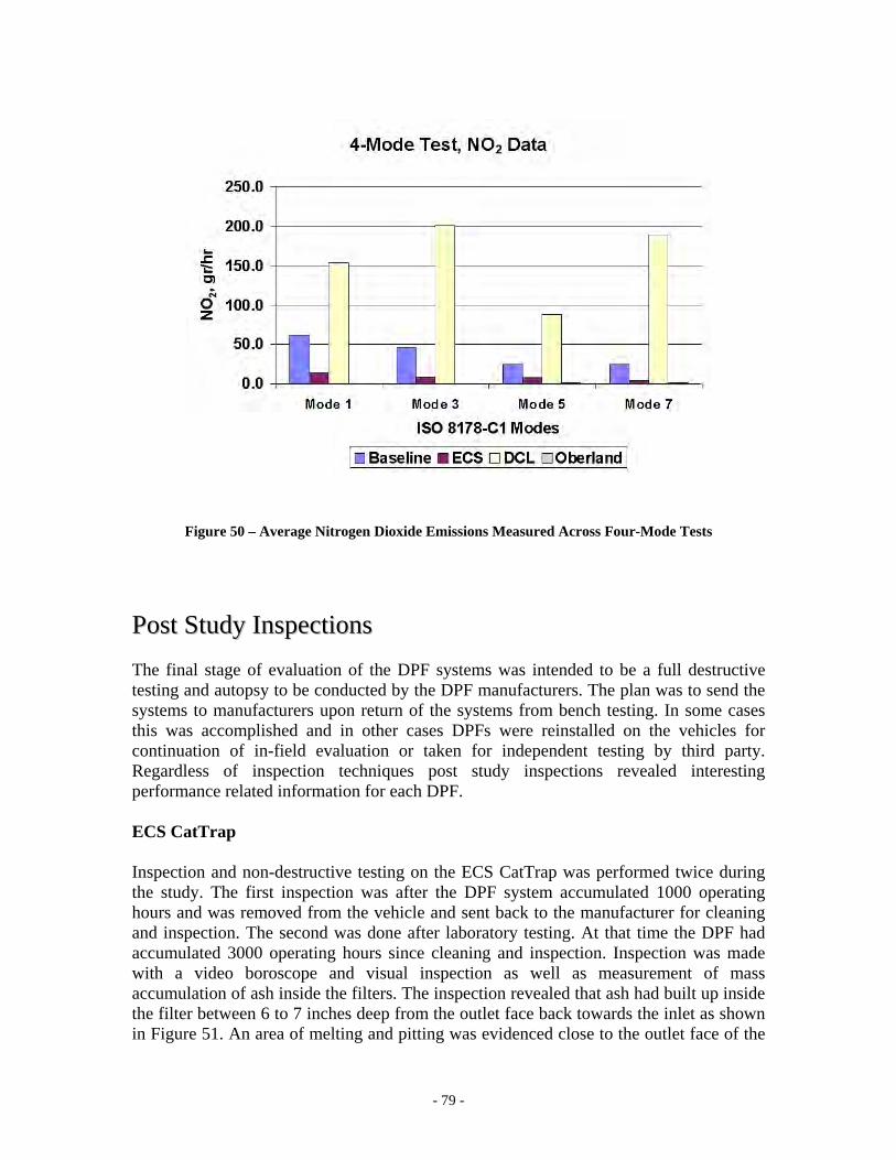
- 79 -
Figure 50 – Average Nitrogen Dioxide Emissions Measured Across Four-Mode Tests
PPoosstt SSttuuddyy IInnssppeeccttiioonnss The final stage of evaluation of the DPF systems was intended to be a full destructive testing and autopsy to be conducted by the DPF manufacturers. The plan was to send the systems to manufacturers upon return of the systems from bench testing. In some cases this was accomplished and in other cases DPFs were reinstalled on the vehicles for continuation of in-field evaluation or taken for independent testing by third party. Regardless of inspection techniques post study inspections revealed interesting performance related information for each DPF. ECS CatTrap Inspection and non-destructive testing on the ECS CatTrap was performed twice during the study. The first inspection was after the DPF system accumulated 1000 operating hours and was removed from the vehicle and sent back to the manufacturer for cleaning and inspection. The second was done after laboratory testing. At that time the DPF had accumulated 3000 operating hours since cleaning and inspection. Inspection was made with a video boroscope and visual inspection as well as measurement of mass accumulation of ash inside the filters. The inspection revealed that ash had built up inside the filter between 6 to 7 inches deep from the outlet face back towards the inlet as shown in Figure 51. An area of melting and pitting was evidenced close to the outlet face of the
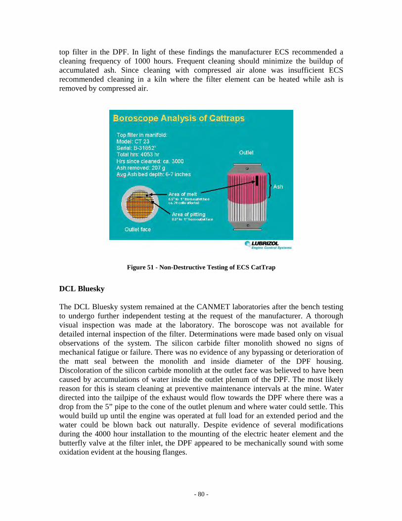
- 80 -
top filter in the DPF. In light of these findings the manufacturer ECS recommended a cleaning frequency of 1000 hours. Frequent cleaning should minimize the buildup of accumulated ash. Since cleaning with compressed air alone was insufficient ECS recommended cleaning in a kiln where the filter element can be heated while ash is removed by compressed air.
Figure 51 - Non-Destructive Testing of ECS CatTrap
DCL Bluesky The DCL Bluesky system remained at the CANMET laboratories after the bench testing to undergo further independent testing at the request of the manufacturer. A thorough visual inspection was made at the laboratory. The boroscope was not available for detailed internal inspection of the filter. Determinations were made based only on visual observations of the system. The silicon carbide filter monolith showed no signs of mechanical fatigue or failure. There was no evidence of any bypassing or deterioration of the matt seal between the monolith and inside diameter of the DPF housing. Discoloration of the silicon carbide monolith at the outlet face was believed to have been caused by accumulations of water inside the outlet plenum of the DPF. The most likely reason for this is steam cleaning at preventive maintenance intervals at the mine. Water directed into the tailpipe of the exhaust would flow towards the DPF where there was a drop from the 5” pipe to the cone of the outlet plenum and where water could settle. This would build up until the engine was operated at full load for an extended period and the water could be blown back out naturally. Despite evidence of several modifications during the 4000 hour installation to the mounting of the electric heater element and the butterfly valve at the filter inlet, the DPF appeared to be mechanically sound with some oxidation evident at the housing flanges.
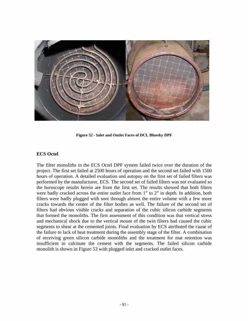
- 81 -
Figure 52 - Inlet and Outlet Faces of DCL Bluesky DPF
ECS Octel The filter monoliths in the ECS Octel DPF system failed twice over the duration of the project. The first set failed at 2500 hours of operation and the second set failed with 1500 hours of operation. A detailed evaluation and autopsy on the first set of failed filters was performed by the manufacturer, ECS. The second set of failed filters was not evaluated so the boroscope results herein are from the first set. The results showed that both filters were badly cracked across the entire outlet face from 1” to 2” in depth. In addition, both filters were badly plugged with soot through almost the entire volume with a few more cracks towards the center of the filter bodies as well. The failure of the second set of filters had obvious visible cracks and separation of the cubic silicon carbide segments that formed the monoliths. The first assessment of this condition was that vertical stress and mechanical shock due to the vertical mount of the twin filters had caused the cubic segments to shear at the cemented joints. Final evaluation by ECS attributed the cause of the failure to lack of heat treatment during the assembly stage of the filter. A combination of receiving green silicon carbide monoliths and the treatment for mat retention was insufficient to calcinate the cement with the segments. The failed silicon carbide monolith is shown in Figure 53 with plugged inlet and cracked outlet faces.
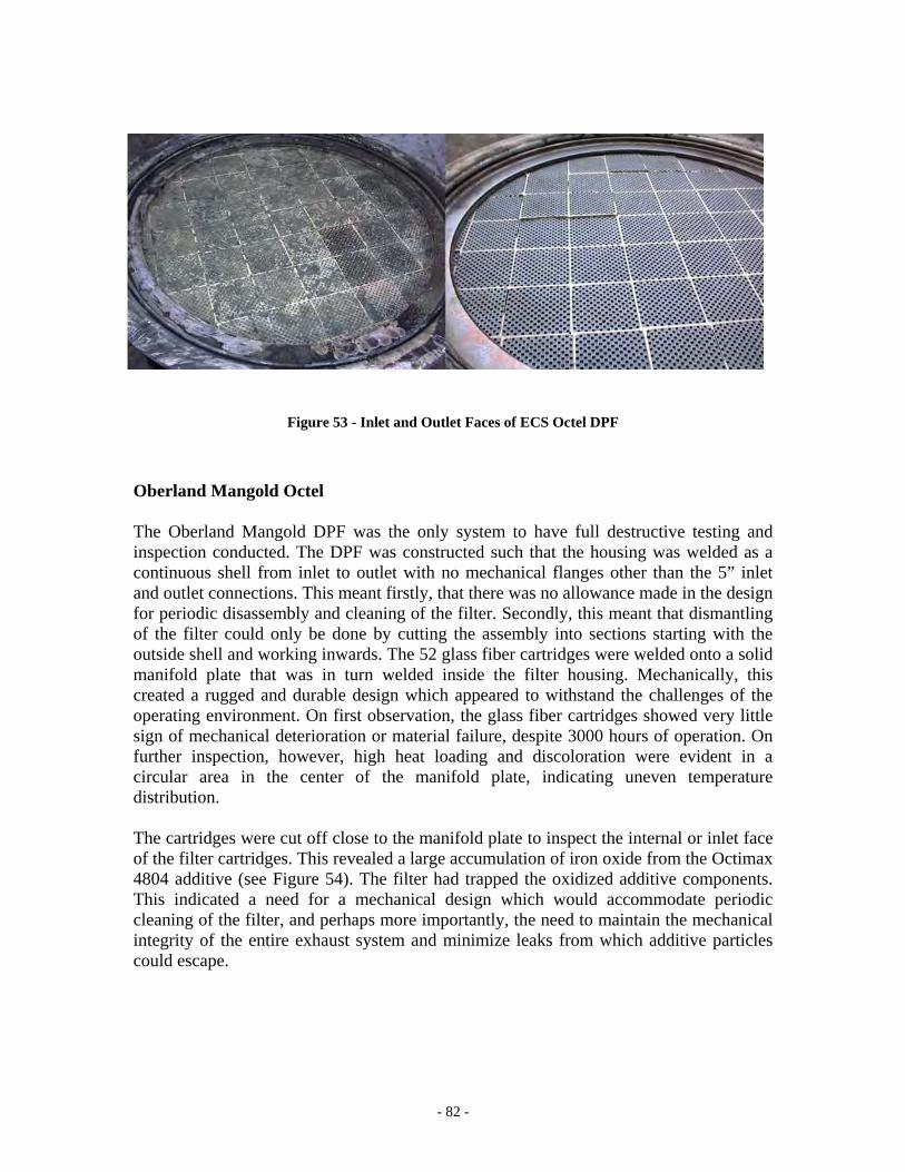
- 82 -
Figure 53 - Inlet and Outlet Faces of ECS Octel DPF
Oberland Mangold Octel The Oberland Mangold DPF was the only system to have full destructive testing and inspection conducted. The DPF was constructed such that the housing was welded as a continuous shell from inlet to outlet with no mechanical flanges other than the 5” inlet and outlet connections. This meant firstly, that there was no allowance made in the design for periodic disassembly and cleaning of the filter. Secondly, this meant that dismantling of the filter could only be done by cutting the assembly into sections starting with the outside shell and working inwards. The 52 glass fiber cartridges were welded onto a solid manifold plate that was in turn welded inside the filter housing. Mechanically, this created a rugged and durable design which appeared to withstand the challenges of the operating environment. On first observation, the glass fiber cartridges showed very little sign of mechanical deterioration or material failure, despite 3000 hours of operation. On further inspection, however, high heat loading and discoloration were evident in a circular area in the center of the manifold plate, indicating uneven temperature distribution. The cartridges were cut off close to the manifold plate to inspect the internal or inlet face of the filter cartridges. This revealed a large accumulation of iron oxide from the Octimax 4804 additive (see Figure 54). The filter had trapped the oxidized additive components. This indicated a need for a mechanical design which would accommodate periodic cleaning of the filter, and perhaps more importantly, the need to maintain the mechanical integrity of the entire exhaust system and minimize leaks from which additive particles could escape.
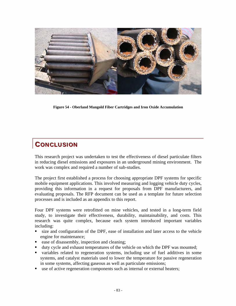
- 83 -
Figure 54 - Oberland Mangold Fiber Cartridges and Iron Oxide Accumulation
CCCOOONNNCCCLLLUUUSSSIIIOOONNN This research project was undertaken to test the effectiveness of diesel particulate filters in reducing diesel emissions and exposures in an underground mining environment. The work was complex and required a number of sub-studies. The project first established a process for choosing appropriate DPF systems for specific mobile equipment applications. This involved measuring and logging vehicle duty cycles, providing this information in a request for proposals from DPF manufacturers, and evaluating proposals. The RFP document can be used as a template for future selection processes and is included as an appendix to this report. Four DPF systems were retrofitted on mine vehicles, and tested in a long-term field study, to investigate their effectiveness, durability, maintainability, and costs. This research was quite complex, because each system introduced important variables including: size and configuration of the DPF, ease of installation and later access to the vehicle
engine for maintenance; ease of disassembly, inspection and cleaning; duty cycle and exhaust temperatures of the vehicle on which the DPF was mounted; variables related to regeneration systems, including use of fuel additives in some
systems, and catalyst materials used to lower the temperature for passive regeneration in some systems, affecting gaseous as well as particulate emissions;
use of active regeneration components such as internal or external heaters;
- 84 -
a need for vehicle operators to develop new habits and practices to keep the DPF systems regenerating on a regular basis and the engines operating within tighter performance standards .
a need for maintenance mechanics to understand the DPF system technologies and maintain them along with related vehicle systems (engines) to high performance standards with proper verification and diagnostics.
This study has reported extensively on the impact of these variables, since they are important issues for any effort to utilize DPF systems underground. The lessons of this experience are:
1. Choose vehicles and applications by a prioritized list that includes factors such as engine duty cycle for regeneration, potential impact to reducing worker exposure to DPM, operability and maintainability, and retrofit requirements.
2. Use basic off-the-shelf portable temperature sensor and logger technology to acquire exhaust temperature profiles for prospective vehicles for a sufficient period to cover the full spectrum of operating and production modes repeatedly.
3. Include mine management, production and maintenance personnel as well as vehicle and DPF manufacturers to engineer each individual installation from selection through installation and verification.
4. Begin communication and education programs with the production and maintenance departments before the DPF systems are chosen and implemented. Build and sustain the education program as a continuous process rather than a one time course.
5. Have vehicle and DPF manufacturers supply retrofit applications as a complete kit that includes all necessary hardware including frame modifications. Modification kits need to be agreed upon by mine operations and maintenance departments, engine, and vehicle manufacturers before being confirmed for installation. The kit should come with parts and service manuals that cover not only the DPF system but all of the associated hardware for the retrofit.
6. Make use of existing on-board monitoring, diagnostics and protection systems such as electronic engine controls and ECMs. Make sure a monitoring system is in place for the operator with dashboard display and protection for exhaust backpressure. This system should be as simple and maintainable as possible.
7. Ensure that regeneration assistance technologies whether passive wash coat catalysts, fuel borne catalysts or active heater systems are well understood by operators and mechanics and closely monitored. Issues such as NO2 conversion by platinum catalysts for example, need to be monitored monthly at a minimum and strict limits adhered to.
8. The installed DPF systems should be managed by the maintenance planning department as a major component as is done with engines, transmissions, axles, etc. This way component history, hours and change out and cleaning schedule can be effectively managed.
The performance of the four DPF systems each brought their own lessons and knowledge gained regardless of how successfully it performed and stood the test of time.
- 85 -
The ECS CatTrap performed well consistently through more than 4000 hours of operation in the project. The twin ceramic monolith filters with base metal catalyst wash coat supported full passive regeneration with no conversion of either CO or NO2. The filtration efficiency testing that was done a three intervals during the project showed better than 99% reduction in DPM from inlet to outlet sided of the filter when new and still above 95% efficient with 4000 operating hours. Tests done at the laboratory post field test showed 80-91% reduction efficiency based on similar engine, test cycles and analytical instrumentation. Non destructive testing done post field test revealed some ash buildup 6 to 7 inches in depth from the outlet face of the filter and some slight melting and pitting in one of the filter monoliths. Following these tests the CatTrap system was returned to Brunswick Mine and re-installed on another ST8B LHD vehicle. The DCL Bluesky system performed very well in terms of filtration efficiency but demonstrated problems with NO2 conversion due to the platinum catalyst. Problems with the active electric regeneration system followed the system from start to finish of the project. Initial design problems were rectified quickly but acceptance of the requirement for plugging in each shift was always poor. Four sets of performance tests done across 4300 hours of operation showed consistent filtration efficiencies at 99%. Testing of gaseous emissions during the field tests showed between two to four fold increases in NO2 from filter inlet to outlet. Tests done at the laboratory were consistent with the field tests for gaseous emissions and CO and NO2 in particular. The laboratory tests did reveal however a sharp increase in total DPM measured at ISO 8178 mode 5 that was not seen with the PAS 2000 instrument testing for elemental carbon. This was attributed to the creation of sulphate by the platinum catalyst wash coat on the filter. Mechanical durability of the system was very good other than the failed heater elements in the twenty months of field operation. The silicon carbide filter monolith remained structurally intact with no bypass or failure of the mat seal between filter and housing. The ECS Octel system was the most disappointing of the four systems in terms of performance and reliability. Insufficient regeneration throughout the field study led to the eventual failures of two sets of filters. The emissions tests tracked these failures well and the mechanics were able to closely monitor exhaust back pressure to protect the engine despite the failure of the DPF system. A combination of component design, DPF sizing, and below expected performance of the Octel fuel borne catalyst contributed to the failure of the system. The laboratory tests and inspection at the conclusion of the project were not performed with the DPF system as the set of filters had been compromised in the last months of the field test. The Oberland Mangold Octel system was reliable throughout the project though filtration efficiencies consistently measured less than the other three systems. This was due to the difference in applying fiber cartridge filter media instead of wall flow monoliths. Filtration efficiency was measured closer to the 90% range as compared to 98% and higher with the wallflow monolith systems. The up side of this however was that exhaust back pressure was much lower than the other systems especially the other MT 436 truck. This was attributed to the difference in filter media in combination with the over sized
- 86 -
filter volume. The laboratory test results correlated well to those from the field tests. The inspection of the DPF system following laboratory testing revealed very good structural integrity of the system after 3000 hours of operation but a large buildup of iron oxide on the inlet side of the filter cartridges. This buildup was sourced from the Octel fuel additive which contained the iron and strontium compounds. The amount of buildup highlighted the need for a system design that could accommodate disassembly and cleaning at regular intervals. As with any project at a mining operation, this project had a finite life and thus the acceptance by management, production and maintenance staff reflected that. Projects and processes are managed and accepted very differently in the mining industry. The project investigating DPF systems should have been seen sooner by the mine as an eventual process not just for DPF systems but for diesel emissions control. A diesel emissions control process would comprise gauging performance of engines, emissions control systems, tailpipe emissions quality and ambient air quality. Monitoring the performance of DPF systems within a process does not necessarily require elaborate instrumentation for precision and accuracy. Instrumentation for the field should be chosen more on the priority of reliability and repeatability than precision and accuracy. There are integrated measurement systems such as the engine control modules (ECM) on electronic engines that should be given priority on verifying and monitoring performance. Auxiliary or add-on systems for monitoring exhaust backpressure and temperature are most often prone to failure and unreliable for underground mining equipment. The most reliable instrument for monitoring exhaust backpressure is still a simple mechanical gauge in the operator’s compartment on the vehicle. Whether it is a gauge, an indicator warning light, or an automatic shut down, the system is only as good as the operator that sits in front of it and interprets the information. Acquiring exhaust temperature profiles for duty cycles can be done with small, proven and reliable single channel dataloggers that are commercially available from most instrumentation suppliers. These are only required for building duty cycle profiles of engines and vehicles so these small portable instruments work well. The exhaust temperature and backpressure loggers used during the project had a high level of complexity with too many sensors and features which made them prone to failure. The UGAS emissions testing system used throughout the project proved to work reliably in verifying gaseous and particulate tailpipe emissions. It was and continues to be used by many mechanics on a regular daily basis for verifying emissions performance. The test developed using the ECOM analyzer for measuring carbon content with NIOSH method 5040 worked well for a periodic test of DPF efficiency when higher precision was required. Though not always practical and prone to interference factors, sampling and analysis of ambient DPM concentrations demonstrated to be a good method of cross-referencing the efficiency of DPF systems. Sampling operator exposures on specific vehicles equipped with DPF systems can provide a good cross reference to tailpipe emissions and efficiencies when interference factors such as other vehicles are minimized. One objective of this study was to estimate the costs associated with different DPF systems. However, although the mine attempted to track costs associated with the project,
- 87 -
not all costs were captured, and it was difficult to attribute some costs to specific DPF systems. This project brought together researchers, engine, vehicle, fuel and emissions control manufacturers, and most importantly the people from Brunswick Mine to select, implement and test these DPF systems. Participants came from Canada, the United States and Switzerland to work in the project. Much of this participation is based in Canada which has assisted in building a critical expertise based in Canada that can continue implementing this technology with the Canadian mining industry into the future. The future of DPF systems technology and making it work successfully in underground mining will rely heavily on this type of strong collaboration. The technology remains a long way from being an off-the-shelf or plug-and-play type of solution. Applications will remain mostly retrofits on existing vehicles which require a good deal of application engineering in every case regardless of whether retrofit or factory built. This same level of collaboration will be required with specifications built between the mine users, vehicle and engine manufacturers, and a consensus on how to build measure and maintain the success that this technology is capable of delivering.
RRREEECCCOOOMMMMMMEEENNNDDDAAATTTIIIOOONNNSSS The following recommendations are directed towards anyone who might be responsible for, or involved in successfully implementing DPF technology on underground diesel mining equipment. Selection The selection process is a critical factor in successful implementation. Unfortunately, there is no current off-the-shelf DPF technology that can be easily plugged into mine vehicles and set to work. Mine staff must accurately map vehicle duty cycles and exhaust temperatures of vehicles they plan to outfit with DPF systems, and then use this data in a specification document or request for proposals to DPF manufacturers. Installation In most cases, DPFs will be installed as retrofits to vehicles. The DPF manufacturer should be asked to provide a complete retrofit kit including the associated hardware for matching to the engine and vehicle. This would include frame and guard modification hardware and proper piping along with appropriate mechanical flanges and flex couplings that will sustain operation without being prone to leaks. A critical component to the retrofit kit is properly interfaced controls for monitoring exhaust backpressure and temperature. Manufacturers of electronic engines now have the capability of interfacing these parameters with the existing engine electronic controls. This avoids the need for auxiliary monitoring systems which tend to require a great deal of maintenance.
- 88 -
Measurement The successful application of DPF technology requires emissions measurement systems that can be used in everyday operations by mine employees. There are many commercially available field ready measurement technologies that accommodate monitoring of undiluted DPM and gaseous emissions, exhaust backpressure and temperature, and monitoring of DPM in ambient concentrations. It is critical that all of these points are measured accurately and regularly by mine employees. Maintenance DPF technology requires heightened awareness from a maintenance perspective. This means paying close attention to the condition of the entire system, as well as ensuring that the measurement systems are properly maintained. Condition based maintenance decisions need to be made on accurately measured conditions. False or defective measurements due to improperly maintained instrumentation may result in maintenance-based failures of DPFs. Qualitative evaluation of system performance is also important and should be included in a well-designed DPF maintenance process. Qualitative evaluation includes visual inspections and monitoring conditions such as exhaust leaks. Verification Performance of DPF systems needs to be verified and cross checked by several criteria. Verifying the operation of a DPF by end-of-pipe exhaust measurements alone can lead to mistaken confidence in the functioning of the system. Performance should be cross checked and verified by DPM sampling in ambient concentrations as well as close monitoring of operators reports. The high capital investment of DPF systems, combined with the high impact potential for DPM reduction should justify a verification database at the mine that combines these factors and is reported on a regular basis.
- 89 -
RRREEEFFFEEERRREEENNNCCCEEESSS 66 Fed. Reg. 5706 and corrections 66 Fed. Reg. 35518 [2001]. Mine Safety and Health Administration: 30
CFR Part 57 Diesel Particulate Matter Exposure of Underground Metal and Nonmetal Miners; Final Rule.
ACGIH. American Conference of Governmental Industrial Hygienists [2001]. Notice of Intended Change
for 2001. TLVs® and BEIs®. Trashold Limit Values for Chemical Substances and Physical Agents. Biological Exposure Indices. p.62
Bagley S. T., Watts W. F., Johnson J.P., Kittelson D.B., Johnson J. H., Schauer J. J., Impact of Low-
Emission Diesel Engines on Underground Mine Air Quality, NIOSH Grant Number R01/CCR515831-01, November 2002
Baz-Dresch JJ, Bickel KL, and Watts WF [1993]. Evaluation of Catalyzed Diesel Particulate Filters in an
Underground Metal Mine. Report of Investigation 9478, U.S. Department of the Interior, Bureau of Mines.
Bugarski A [1999]. Characterization of Particulate Matter and Hydrocarbon Emissions from In-Use Heavy-
Duty Diesel Engine. Doctoral Dissertation. West Virginia University, Morgantown, West Virginia, December.
Carder DK [1999]. Performance Evaluation of Exhaust Aftertreatment Devices Used for Emissions Control
on Diesel Engines Employed in Underground Coal Mines. West Virginia University, Morgantown WV. Czerwinski J, Jaussi F, Wyser M, and Mayer A [2000]. Particulate Traps for Construction Machines:
Properties and Field Experience. SAE Technical Paper 2000-01-1923. Elemental Carbon (Diesel Particulate) Method 5040, NIOSH Manual of Analytical Methods (NMAM),
Fourth Edition, September 1999 Grenier M and Butler K [1996]. Respirable Combustible Dust (RCD) Sampling and Analysis Protocol.
Natural Resources Canada, Mining and Mineral Sciences Laboratories, Divisional Report MMSL 96-029 (TR).
Grenier M, Gangal M, Goyer N, McGinn S, Penney J, and Vergunst J, Sampling For Diesel Particulate In
Mines, October, 2001 Grenier M, Gangal M, Goyer N, McGinn S, Penney J, Vergunst J, Sampling For Diesel Particulate Matter
In Mines, CANMET Mining and Mineral Sciences Laboratories Report (MMSL) 01-052 (TR) Submitted to the Diesel Emissions Evaluation Program (DEEP), October 2001
Grenier M, Gangal M, Lastra R, Mikhail S, Turcotte A-M, Butler K, Edwardson E, Laflamme G,
Evaluation of Existing Diesel Particulate Matter Sampling and Analysis Methods at a High Sulphide Mine, CANMET Mining and Mineral Sciences Laboratories (MMSL) Submitted to the Diesel Emissions Evaluation Program (DEEP), December, 1998
Jelles SJ, Makkee M, Moulijn JA, Acres GJK, and Peter-Hoblyn JD [1999]. Diesel Particulate Control.
Application of an Activated Particulate Trap in Combination with Fuel Additives at an Ultra Low Dose Rate. SAE Paper 1999-010-0113.
- 90 -
Kahlert B [1999]. First Use of Additive-Regenerated Diesel Particulate Filters in Germany Mines. The Proceedings of the Mining Diesel Emissions Conference (MDEC), Toronto, Canada, November 3 and 4.
Kasper M, Matter U, Burtscher H, Bukowiecki N, and Mayer A. NanoMet, a new instrument for on-line
size and substance-specific particle emission analysis, SAE Technical Paper 2001-01-0216 Kauffeldt TH and Schmidt-Ott A [1998]. Investigation of the Influence of Exhaust Aftertreatment on the
Particulate Phase in Diesel Exhaust Gases. Journal of Aerosol Science, Vol. 29, Suppl.1, pp. S625 - S626.
Lanni T, Conway R, Chatterjee S, Windawi H, Rosenblatt D, Bush CW, Lowell DM, Evans J, and Mclean
RO [2001]. Particulate matter Emissions Test Results from Urban Transit buses Equipped with Continuously Regenerating Diesel Particulate Filters. SAE Technical Paper 2001-01-0511.
Larsen CA, Levendis YA, and Shimato K [1999]. Filtration Assessment and Thermal Effects of
Aerodynamic Regeneration in Silicon Carbide and Cordierite Particulate Filters. SAE Paper 1999-01-0466.
Mayer A [2000]. Particulate Traps Used in City-Buses in Switzerland. SAE Technical Paper 2000-01-1927. Mayer A, Matter U, Czerwinski J, and Heeb N [1999]. Effectiveness of Particulate Traps on Construction
Site Engines: VERT Final Measurements. DieselNet Technical Report. [URL=http://www.dieselnet.com/papers/9903mayer/index.html], March.
Mayer A, Matter U, Scheidegger G, Czerwinski J, Wyser M, Kieser D, Weidofer J, Particulate Traps For
Retrofitting Construction Site Engines. VERT: Final Measurements and Implementation, SAE Technical Paper 1999-01-0116
Mayer A, Selection Criteria For Diesel Particulate Trap Systems: VERT Experience, December, 1998 Mayer A, Stettler A, Wyser M, Scheidegger W, Czerwinski J, VERT Filter List, Tested and Approved
Particle-Trap Systems for Retrofitting Diesel Engines, Swiss Agency for the Environment Forests and Landscape (SAEFL), June, 2003
McGinn S, Gaultier P, Gavel K, Johnson R, and Petrie D, Understanding Equipment Condition and Affects
on Ventilation , Proceedings from 100thCIM Annual General Meeting, Montreal, Quebec, May, 1998. McGinn S, Grenier M, Schnakenburg G, Bugarski A, and Petrie D, Performance Evaluation of Diesel
Particulate Filter Technology In The Underground Environment , Proceedings of the North American / 9th U.S. Mine Ventilation Symposium, Kinston, Ontario, June 2002.
McGinn S, The Relationship Between Diesel Engine Maintenance and Exhaust Emissions – Final Report ,
Diesel Emissions Evaluation Program (DEEP), http://www.deep.org , June, 2000. McKinnon D, Diesel Emission Control Strategies Available to the Underground Mining Industry, ESI
International - Report to the Diesel Emissions Evaluation Program, February, 1999 Natural Resources Canada, CANMET – MMSL’s List of Approved Diesel Engines In Accordance With
the National Standard of Canada CAN/CSA-M424.2-M90, July, 2003 New Brunswick [1996], Regulations 96-105 under the Occupational Health and Safety Act (O.C. 96-968) Postnikoff JA [1999]. Diesel Particulate Matter Minimization at Agrium. The Proceedings of the Mining
Diesel Emissions Conference (MDEC), Toronto, Canada, November 3 and 4.
- 91 -
Schnakenburg G, Bugarski A, Review of Technology Available to the Underground Mining Industry For Control of Diesel Emissions, National Institute of Occupational Safety and Health (NIOSH) Information Circular (IC) 9462, August 2002
Vincent M.W., Richards P. J., The Long Distance Road Trial of a Combined Diesel Particulate Filter and
Fuel Additive, SAE Technical Paper 2000-1-2849 Watts WF, Cantrell BK, Bickel KL, Olson KS, Rubow KL, Baz-Dresch JJ, and Carlson DH [1995]. In-
Mine Evaluation of Catalyzed Diesel Particulate Filters at Two Underground Metal Mines., U.S. Department of the Interior, Bureau of Mines