Embed Size (px)
Citation preview
Brighton Wastewater Treatment Facility
Refurbishment
Prepared for:
Town of Brighton, Vermont
90 % Deliverable
Preliminary Engineering Report
April 13, 2021
Prepared by:
125 College Street, 4th Floor
Burlington, Vermont
Town of Brighton Wastewater Treatment Facility Refurbishment Preliminary Engineering Report
i
Table of Contents
90% PER Executive Summary ........................................................................................................ viii
Introduction .................................................................................................................................... ix
1. Project Planning ....................................................................................................................... 1-1
1.1. Location ............................................................................................................................. 1-1
1.2. Environmental Resources ................................................................................................. 1-1
1.3. Population Trends ............................................................................................................. 1-2
1.4. Community Engagement .................................................................................................. 1-2
2. Existing Facilities ...................................................................................................................... 2-1
2.1. Location Map .................................................................................................................... 2-1
2.2. History ............................................................................................................................... 2-1
2.3. WWTF Performance .......................................................................................................... 2-1
2.4. Condition of Existing Facilities .......................................................................................... 2-6
2.4.1. Headworks ................................................................................................................. 2-7
2.4.2. Lagoons and Blowers ................................................................................................. 2-8
2.4.3. Disinfection and Chemical Feed System .................................................................. 2-10
2.4.4. Flow Measurement .................................................................................................. 2-12
2.4.5. Outfall ...................................................................................................................... 2-13
2.4.6. Control Building and Storage Building ..................................................................... 2-13
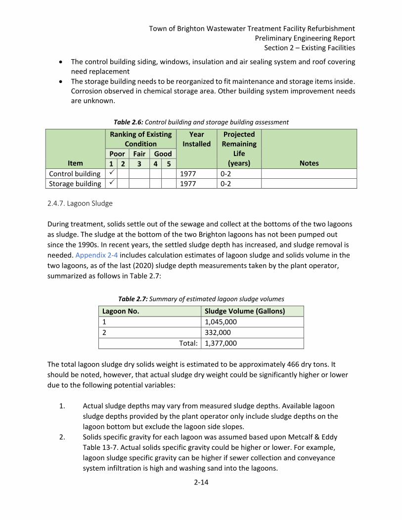
2.4.7. Lagoon Sludge .......................................................................................................... 2-14
2.4.8. Town Hall Sewer & Inflow/Infiltration ..................................................................... 2-15
2.4.9. Hotel, School & Pleasant St. Pump Stations Refurbishment ................................... 2-16
2.5. Financial Status of Any Existing Facilities ........................................................................ 2-16
2.6. Water/Energy/Waste Audits .......................................................................................... 2-16
3. Need for Project ....................................................................................................................... 3-1
3.1. Health, Sanitation, and Security ....................................................................................... 3-1
3.2. Aging Infrastructure .......................................................................................................... 3-1
3.3. Reasonable Growth........................................................................................................... 3-2
4. Alternatives Considered ........................................................................................................... 4-1
4.1. Headworks Upgrade Alternatives ..................................................................................... 4-1
4.1.1. Alternative Descriptions ............................................................................................ 4-1
Town of Brighton Wastewater Treatment Facility Refurbishment Preliminary Engineering Report
ii
4.1.2. Design Criteria ............................................................................................................ 4-3
4.1.3. Opinions of Cost ......................................................................................................... 4-3
4.1.4. Environmental Impacts .............................................................................................. 4-4
4.1.5. Land Requirements .................................................................................................... 4-4
4.1.6. Potential Construction Problems ............................................................................... 4-4
4.1.7. Sustainability Considerations and Water and Energy Efficiency ............................... 4-4
4.2. Lagoon Aeration System Upgrade Alternatives ................................................................ 4-4
4.2.1. Alternative Descriptions ............................................................................................ 4-5
4.2.2. Design Criteria ............................................................................................................ 4-6
4.2.3. Opinions of Cost ......................................................................................................... 4-7
4.2.4. Life Cycle Cost Analysis .............................................................................................. 4-7
4.2.5. Environmental Impacts .............................................................................................. 4-8
4.2.6. Land Requirements .................................................................................................... 4-8
4.2.7. Potential Construction Problems ............................................................................... 4-8
4.2.8. Sustainability Considerations and Water and Energy Efficiency ............................... 4-8
4.3. Disinfection and Chemical Feed Upgrade Alternatives .................................................... 4-8
4.3.1. Alternative Descriptions ............................................................................................ 4-8
4.3.2. Design Criteria .......................................................................................................... 4-10
4.3.3. Opinions of Cost ....................................................................................................... 4-10
4.3.4. Environmental Impacts ............................................................................................ 4-11
4.3.5. Land Requirements .................................................................................................. 4-11
4.3.6. Potential Construction Problems ............................................................................. 4-11
4.3.7. Sustainability Considerations and Water and Energy Efficiency ............................. 4-11
4.4. WWTF Building Facility Upgrade Alternatives ................................................................ 4-11
4.4.1. Alternative Descriptions .......................................................................................... 4-11
4.4.2. Design Criteria .......................................................................................................... 4-12
4.4.3. Opinions of Cost ....................................................................................................... 4-12
4.4.4. Environmental Impacts ............................................................................................ 4-13
4.3.5. Land Requirements .................................................................................................. 4-13
4.3.6. Potential Construction Problems ............................................................................. 4-13
4.4.7. Sustainability Considerations and Water and Energy Efficiency ............................. 4-13
4.5. Sludge Removal Alternatives .......................................................................................... 4-13
4.4.5. Land Requirements
4.4.6. Potential Construction Problems
Town of Brighton Wastewater Treatment Facility Refurbishment Preliminary Engineering Report
iii
4.5.1. Alternative Descriptions .......................................................................................... 4-13
4.5.2. Design Criteria .......................................................................................................... 4-14
4.5.3. Opinions of Cost ....................................................................................................... 4-15
4.5.4. Environmental Impacts ............................................................................................ 4-16
4.5.5. Land Requirements .................................................................................................. 4-16
4.5.6. Potential Construction Problems ............................................................................. 4-16
4.5.7. Sustainability Considerations and Water and Energy Efficiency ............................. 4-16
4.6. Town Hall Sewer Upgrade Alternatives .......................................................................... 4-16
4.6.1. Alternative Descriptions .......................................................................................... 4-16
4.6.2. Design Criteria .......................................................................................................... 4-17
4.6.3. Opinions of Cost ....................................................................................................... 4-17
4.6.4. Environmental Impacts ............................................................................................ 4-18
4.6.5. Land Requirements .................................................................................................. 4-18
4.6.6. Potential Construction Problems ............................................................................. 4-18
4.6.7. Sustainability Considerations and Water and Energy Efficiency ............................. 4-19
4.7. Hotel, School & Pleasant St. Pump Stations Refurbishment Alternatives ...................... 4-19
4.7.1. Alternative Descriptions .......................................................................................... 4-19
4.7.2. Design Criteria .......................................................................................................... 4-19
4.7.3. Opinions of Cost ....................................................................................................... 4-19
4.7.4. Environmental Impacts, Land Requirements and Potential Construction Problems. ............................................................................................................................................ 4-20
5. Selection of an Alternative ....................................................................................................... 5-1
5.1. Selected Alternative .......................................................................................................... 5-1
6. Proposed Project ...................................................................................................................... 6-1
6.1. Brighton Wastewater Treatment Facility Proposed Project............................................. 6-1
6.2. Project Schedule ............................................................................................................... 6-2
6.3 Permit Requirements ......................................................................................................... 6-4
6.4. Sustainability Considerations ............................................................................................ 6-4
6.5 Total Project Cost (Engineer’s Opinion of Probable Cost) ................................................. 6-5
6.5. Annual Operating Budget ................................................................................................. 6-6
6.5.1 Income ........................................................................................................................ 6-6
6.5.2 Annual O&M Costs ...................................................................................................... 6-6
6.6. Annual Operating Budget
6.6.1. Income
6.6.2. Annual O&M Costs
Town of Brighton Wastewater Treatment Facility Refurbishment Preliminary Engineering Report
iv
6.5.3 Debt Repayments........................................................................................................ 6-6
6.5.4 Reserves ...................................................................................................................... 6-7
7. 90% Deliverable Conclusions and Recommendations ............................................................. 7-1
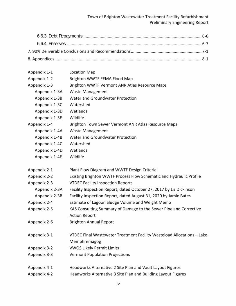
8. Appendices ............................................................................................................................... 8-1
Appendix 1-1 Location Map
Appendix 1-2 Brighton WWTF FEMA Flood Map
Appendix 1-3 Brighton WWTF Vermont ANR Atlas Resource Maps
Appendix 1-3A Waste Management
Appendix 1-3B Water and Groundwater Protection
Appendix 1-3C Watershed
Appendix 1-3D Wetlands
Appendix 1-3E Wildlife
Appendix 1-4 Brighton Town Sewer Vermont ANR Atlas Resource Maps
Appendix 1-4A Waste Management
Appendix 1-4B Water and Groundwater Protection
Appendix 1-4C Watershed
Appendix 1-4D Wetlands
Appendix 1-4E Wildlife
Appendix 2-1 Plant Flow Diagram and WWTF Design Criteria
Appendix 2-2 Existing Brighton WWTF Process Flow Schematic and Hydraulic Profile
Appendix 2-3 VTDEC Facility Inspection Reports
Appendix 2-3A Facility Inspection Report, dated October 27, 2017 by Liz Dickinson
Appendix 2-3B Facility Inspection Report, dated August 31, 2020 by Jamie Bates
Appendix 2-4 Estimate of Lagoon Sludge Volume and Weight Memo
Appendix 2-5 KAS Consulting Summary of Damage to the Sewer Pipe and Corrective
Action Report
Appendix 2-6 Brighton Annual Report
Appendix 3-1 VTDEC Final Wastewater Treatment Facility Wasteload Allocations – Lake
Memphremagog
Appendix 3-2 VWQS Likely Permit Limits
Appendix 3-3 Vermont Population Projections
Appendix 4-1 Headworks Alternative 2 Site Plan and Vault Layout Figures
Appendix 4-2 Headworks Alternative 3 Site Plan and Building Layout Figures
6.6.3. Debt Repayments
6.6.4. Reserves
Town of Brighton Wastewater Treatment Facility Refurbishment Preliminary Engineering Report
v
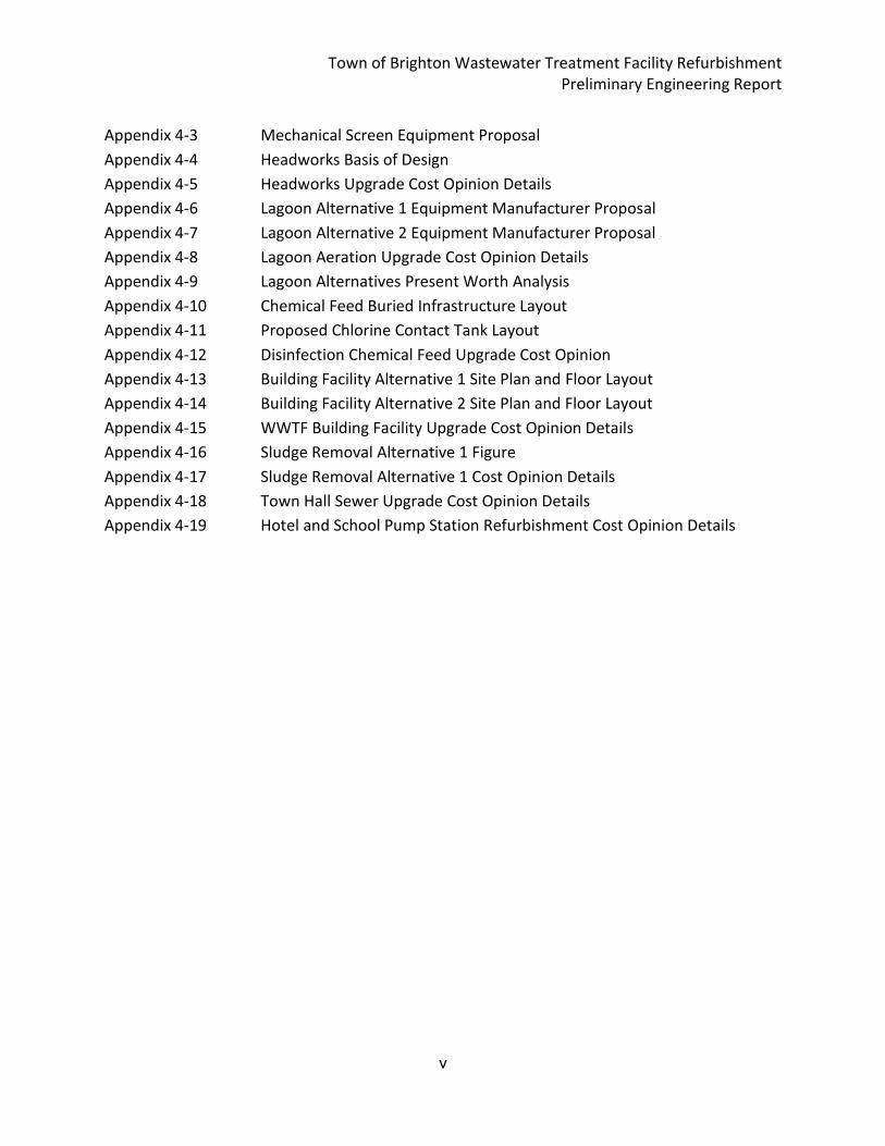
Appendix 4-3 Mechanical Screen Equipment Proposal
Appendix 4-4 Headworks Basis of Design
Appendix 4-5 Headworks Upgrade Cost Opinion Details
Appendix 4-6 Lagoon Alternative 1 Equipment Manufacturer Proposal
Appendix 4-7 Lagoon Alternative 2 Equipment Manufacturer Proposal
Appendix 4-8 Lagoon Aeration Upgrade Cost Opinion Details
Appendix 4-9 Lagoon Alternatives Present Worth Analysis
Appendix 4-10 Chemical Feed Buried Infrastructure Layout
Appendix 4-11 Proposed Chlorine Contact Tank Layout
Appendix 4-12 Disinfection Chemical Feed Upgrade Cost Opinion
Appendix 4-13 Building Facility Alternative 1 Site Plan and Floor Layout
Appendix 4-14 Building Facility Alternative 2 Site Plan and Floor Layout
Appendix 4-15 WWTF Building Facility Upgrade Cost Opinion Details
Appendix 4-16 Sludge Removal Alternative 1 Figure
Appendix 4-17 Sludge Removal Alternative 1 Cost Opinion Details
Appendix 4-18 Town Hall Sewer Upgrade Cost Opinion Details
Appendix 4-19 Hotel and School Pump Station Refurbishment Cost Opinion Details
Town of Brighton Wastewater Treatment Facility Refurbishment Preliminary Engineering Report
vi
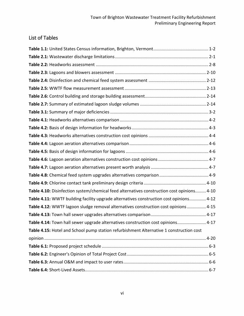
List of Tables
Table 1.1: United States Census information, Brighton, Vermont .............................................. 1-2
Table 2.1: Wastewater discharge limitations .............................................................................. 2-1
Table 2.2: Headworks assessment .............................................................................................. 2-8
Table 2.3: Lagoons and blowers assessment ............................................................................ 2-10
Table 2.4: Disinfection and chemical feed system assessment ................................................ 2-12
Table 2.5: WWTF flow measurement assessment .................................................................... 2-13
Table 2.6: Control building and storage building assessment ................................................... 2-14
Table 2.7: Summary of estimated lagoon sludge volumes ....................................................... 2-14
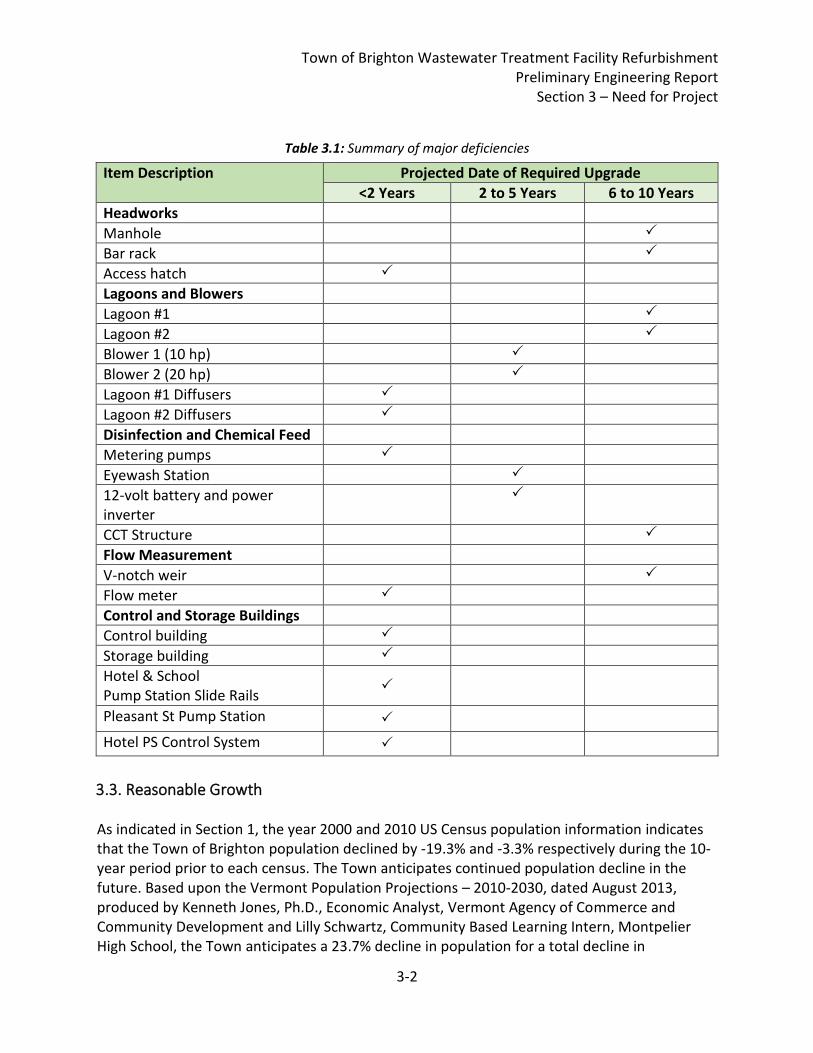
Table 3.1: Summary of major deficiencies .................................................................................. 3-2
Table 4.1: Headworks alternatives comparison .......................................................................... 4-2
Table 4.2: Basis of design information for headworks ................................................................ 4-3
Table 4.3: Headworks alternatives construction cost opinions .................................................. 4-4
Table 4.4: Lagoon aeration alternatives comparison .................................................................. 4-6
Table 4.5: Basis of design information for lagoons ..................................................................... 4-6
Table 4.6: Lagoon aeration alternatives construction cost opinions .......................................... 4-7
Table 4.7: Lagoon aeration alternatives present worth analysis ................................................ 4-7
Table 4.8: Chemical feed system upgrades alternatives comparison ......................................... 4-9
Table 4.9: Chlorine contact tank preliminary design criteria .................................................... 4-10
Table 4.10: Disinfection system/chemical feed alternatives construction cost opinions ......... 4-10
Table 4.11: WWTF building facility upgrade alternatives construction cost opinions .............. 4-12
Table 4.12: WWTF lagoon sludge removal alternatives construction cost opinions ................ 4-15
Table 4.13: Town hall sewer upgrades alternatives comparison .............................................. 4-17
Table 4.14: Town hall sewer upgrade alternatives construction cost opinions ........................ 4-17
Table 4.15: Hotel and School pump station refurbishment Alternative 1 construction cost
opinion ....................................................................................................................................... 4-20
Table 6.1: Proposed project schedule ......................................................................................... 6-3
Table 6.2: Engineer's Opinion of Total Project Cost .................................................................... 6-5
Table 6.3: Annual O&M and impact to user rates ....................................................................... 6-6
Table 6.4: Short-Lived Assets ....................................................................................................... 6-7
Town of Brighton Wastewater Treatment Facility Refurbishment Preliminary Engineering Report
vii
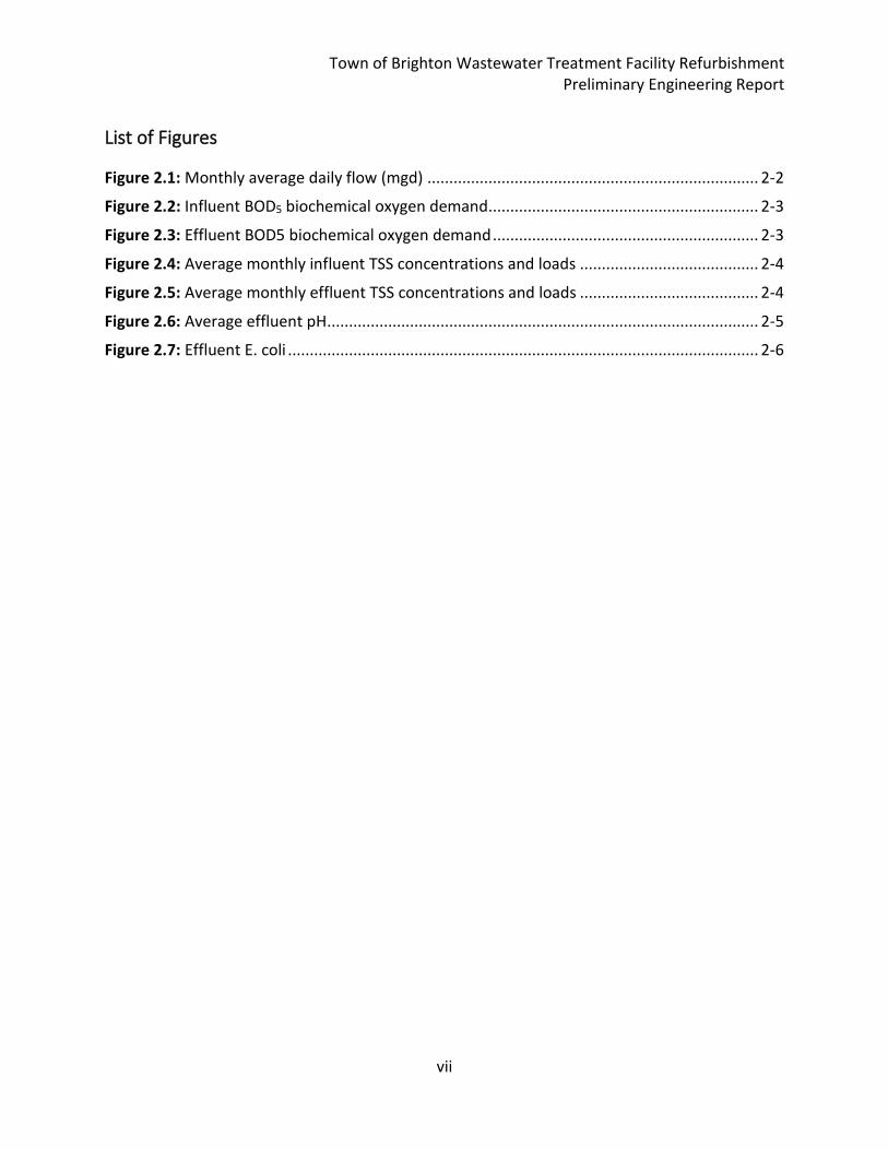
List of Figures
Figure 2.1: Monthly average daily flow (mgd) ............................................................................ 2-2
Figure 2.2: Influent BOD5 biochemical oxygen demand .............................................................. 2-3
Figure 2.3: Effluent BOD5 biochemical oxygen demand ............................................................. 2-3
Figure 2.4: Average monthly influent TSS concentrations and loads ......................................... 2-4
Figure 2.5: Average monthly effluent TSS concentrations and loads ......................................... 2-4
Figure 2.6: Average effluent pH ................................................................................................... 2-5
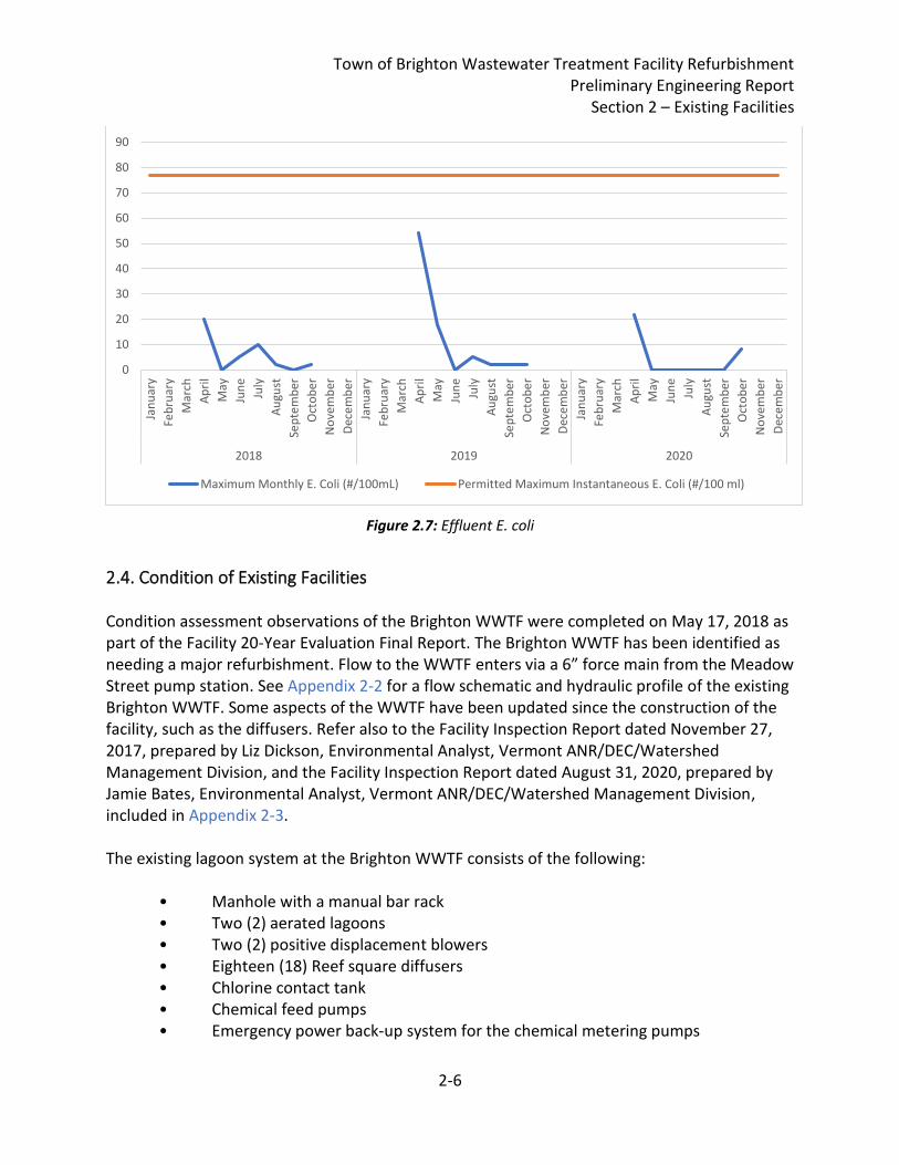
Figure 2.7: Effluent E. coli ............................................................................................................ 2-6
Town of Brighton Wastewater Treatment Facility Refurbishment Preliminary Engineering Report
viii
90% PER Executive Summary The Town of Brighton is facing the need to upgrade facilities at their wastewater treatment facility (WWTF) and within their collection system. The primary drivers for these upgrades are age-related equipment replacements, improvements to WWTF performance and operator safety, and to prepare for likely future total phosphorous permit limits. Furthermore, the WWTF exceeded permitted hydraulic capacity in April-May of 2019, indicating high potential infiltration and inflow (I/I). The peak flows experienced at the WWTF affect sizing of certain process units. On April 1, 2021, longtime chief plant operator and Brighton resident suddenly passed away. On Tuesday, April 6, 2021, the Town selected to advance the following wastewater infrastructure refurbishment with an approximate $3.756M opinion of probable Total Project Cost and including the following:
1. New Headworks Facility 2. New Blowers 3. New Lagoon Aeration Equipment 4. New Chlorine Contact Tank, incl Ancillary Equipment and Future TP Control 5. Sludge Removal 6. New Operations Building and Control Building Rehabilitation 7. Town Hall Sewer Replacement 8. Hotel, School and Pleasant St. Pump Station Improvements 9. Collection System I/I Removal
It is recommended that the Town complete the following:
1. Submit USDA RD WEP funding program application prior to the 4/16/2021 deadline. 2. Submit Environmental Information Document (EID) and Categorical Exclusion request. Hoyle, Tanner to complete for Town approval. 3. Determine if the proposed Project is necessary to alleviate a health or sanitary problem to become eligible for up to 75% construction grant. 4. Complete Qualifications-Based Selection for Final Design Engineering. 5. Hold bond vote for the proposed project.
Town of Brighton Wastewater Treatment Facility Refurbishment Preliminary Engineering Report
ix
Introduction Hoyle, Tanner & Associates, Inc. (Hoyle, Tanner) is completing a Preliminary Engineering Report for the refurbishment of the Brighton Wastewater Treatment Facility as part of the Original Agreement dated October 30, 2020. This Original Agreement focuses on the lagoon treatment plant. The Town is funding the Original Agreement scope of work with a $30,000 grant from the United States Department of Agriculture, Rural Development SEARCH program. In addition to the Original Agreement Scope of Work, Hoyle, Tanner is completing development of engineering alternatives for lagoon sludge removal and the Town Hall sewer replacement as indicated in scope of work in Amendment No. 1 (dated February 23, 2021) to the Original Agreement. The Town is funding the Amendment No. 1 scope of work with Town funds. It should be noted that the Amendment No. 1 scope of work is integrated into the Original Agreement scope of work in this Preliminary Engineering Report.
Town of Brighton Wastewater Treatment Facility Refurbishment Preliminary Engineering Report
Section 1 – Project Planning
1-1
1. Project Planning
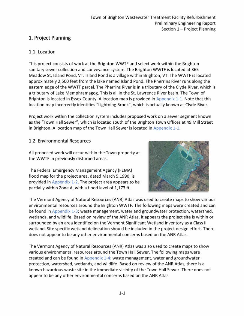
1.1. Location This project consists of work at the Brighton WWTF and select work within the Brighton sanitary sewer collection and conveyance system. The Brighton WWTF is located at 365 Meadow St, Island Pond, VT. Island Pond is a village within Brighton, VT. The WWTF is located approximately 2,500 feet from the lake named Island Pond. The Pherrins River runs along the eastern edge of the WWTF parcel. The Pherrins River is in a tributary of the Clyde River, which is a tributary of Lake Memphramagog. This is all in the St. Lawrence River basin. The Town of Brighton is located in Essex County. A location map is provided in Appendix 1-1. Note that this location map incorrectly identifies “Lightning Brook”, which is actually known as Clyde River. Project work within the collection system includes proposed work on a sewer segment known as the “Town Hall Sewer”, which is located south of the Brighton Town Offices at 49 Mill Street in Brighton. A location map of the Town Hall Sewer is located in Appendix 1-1.
1.2. Environmental Resources All proposed work will occur within the Town property at the WWTF in previously disturbed areas. The Federal Emergency Management Agency (FEMA) flood map for the project area, dated March 5,1990, is provided in Appendix 1-2. The project area appears to be partially within Zone A, with a flood level of 1,173 ft. The Vermont Agency of Natural Resources (ANR) Atlas was used to create maps to show various environmental resources around the Brighton WWTF. The following maps were created and can be found in Appendix 1-3: waste management, water and groundwater protection, watershed, wetlands, and wildlife. Based on review of the ANR Atlas, it appears the project site is within or surrounded by an area identified on the Vermont Significant Wetland Inventory as a Class II wetland. Site specific wetland delineation should be included in the project design effort. There does not appear to be any other environmental concerns based on the ANR Atlas. The Vermont Agency of Natural Resources (ANR) Atlas was also used to create maps to show various environmental resources around the Town Hall Sewer. The following maps were created and can be found in Appendix 1-4: waste management, water and groundwater protection, watershed, wetlands, and wildlife. Based on review of the ANR Atlas, there is a known hazardous waste site in the immediate vicinity of the Town Hall Sewer. There does not appear to be any other environmental concerns based on the ANR Atlas.

Town of Brighton Wastewater Treatment Facility Refurbishment Preliminary Engineering Report
Section 1 – Project Planning
1-2
1.3. Population Trends The United States Census Bureau population data for the Town of Brighton is shown below in Table 1.1.
Table 1.1: United States Census information, Brighton, Vermont
Census Year Population Previous 10-year Growth (+/-)
1990 1,562 0.3%
2000 1,260 -19.3%
2010 1,222 -3.0%
The past two censuses show negative growth in the Town of Brighton. With the population of Brighton decreasing, it is unlikely that the Town will experience capacity issues at the plant due to new connections.
1.4. Community Engagement The Town of Brighton will hold public hearings and distribute informational materials to the residents ahead of a future bond vote. Details of the bond vote will be provided upon passage.
Town of Brighton Wastewater Treatment Facility Refurbishment Preliminary Engineering Report
Section 2 – Existing Facilities
2-1
2. Existing Facilities
2.1. Location Map A location map is provided in Appendix 1-1.
2.2. History The Town of Brighton owns the Brighton Wastewater Treatment Facility (WWTF) and associated collection system serving the Island Pond Village service area. The 0.150 MGD facility discharges to the Pherrins River. Constructed in 1977, facility equipment has been replaced on an as-needed basis. The Wastewater Treatment Facility 20-Year Evaluation Final Report, dated July 20, 2018, was prepared for the Town of Brighton by Hoyle, Tanner & Associates, Inc. Hereinafter this report is referred to simply as the Facility 20-Year Evaluation Final Report.
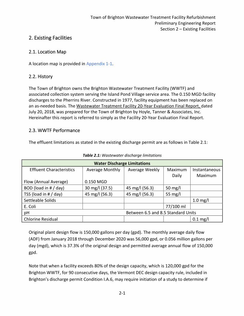
2.3. WWTF Performance The effluent limitations as stated in the existing discharge permit are as follows in Table 2.1:
Table 2.1: Wastewater discharge limitations
Water Discharge Limitations
Effluent Characteristics Average Monthly Average Weekly Maximum Daily
Instantaneous Maximum
Flow (Annual Average) 0.150 MGD
BOD (load in # / day) 30 mg/l (37.5) 45 mg/l (56.3) 50 mg/l
TSS (load in # / day) 45 mg/l (56.3) 45 mg/l (56.3) 55 mg/l
Settleable Solids 1.0 mg/l
E. Coli 77/100 ml
pH Between 6.5 and 8.5 Standard Units
Chlorine Residual 0.1 mg/l
Original plant design flow is 150,000 gallons per day (gpd). The monthly average daily flow
(ADF) from January 2018 through December 2020 was 56,000 gpd, or 0.056 million gallons per
day (mgd), which is 37.3% of the original design and permitted average annual flow of 150,000
gpd.
Note that when a facility exceeds 80% of the design capacity, which is 120,000 gpd for the
Brighton WWTF, for 90 consecutive days, the Vermont DEC design capacity rule, included in
Brighton’s discharge permit Condition I.A.6, may require initiation of a study to determine if
Town of Brighton Wastewater Treatment Facility Refurbishment Preliminary Engineering Report
Section 2 – Existing Facilities
2-2
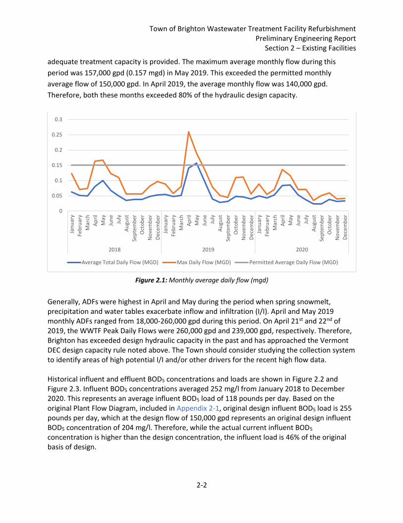
adequate treatment capacity is provided. The maximum average monthly flow during this
period was 157,000 gpd (0.157 mgd) in May 2019. This exceeded the permitted monthly
average flow of 150,000 gpd. In April 2019, the average monthly flow was 140,000 gpd.
Therefore, both these months exceeded 80% of the hydraulic design capacity.
Figure 2.1: Monthly average daily flow (mgd)
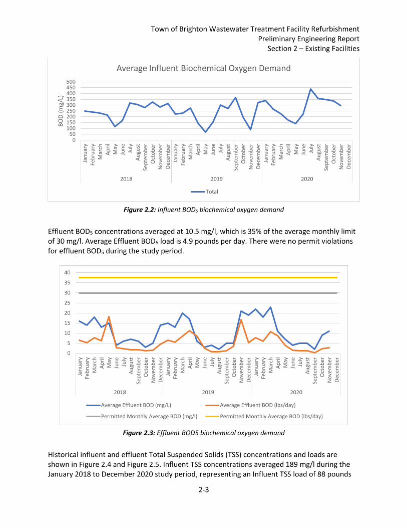
Generally, ADFs were highest in April and May during the period when spring snowmelt, precipitation and water tables exacerbate inflow and infiltration (I/I). April and May 2019 monthly ADFs ranged from 18,000-260,000 gpd during this period. On April 21st and 22nd of 2019, the WWTF Peak Daily Flows were 260,000 gpd and 239,000 gpd, respectively. Therefore, Brighton has exceeded design hydraulic capacity in the past and has approached the Vermont DEC design capacity rule noted above. The Town should consider studying the collection system to identify areas of high potential I/I and/or other drivers for the recent high flow data. Historical influent and effluent BOD5 concentrations and loads are shown in Figure 2.2 and Figure 2.3. Influent BOD5 concentrations averaged 252 mg/l from January 2018 to December 2020. This represents an average influent BOD5 load of 118 pounds per day. Based on the original Plant Flow Diagram, included in Appendix 2-1, original design influent BOD5 load is 255 pounds per day, which at the design flow of 150,000 gpd represents an original design influent BOD5 concentration of 204 mg/l. Therefore, while the actual current influent BOD5 concentration is higher than the design concentration, the influent load is 46% of the original basis of design.
0
0.05
0.1
0.15
0.2
0.25
0.3
Jan
uar
y
Feb
ruar
y
Mar
ch
Ap
ril
May
Jun
e
July
Au
gust
Sep
tem
ber
Oct
ob
er
No
vem
ber
Dec
em
ber
Jan
uar
y
Feb
ruar
y
Mar
ch
Ap
ril
May
Jun
e
July
Au
gust
Sep
tem
ber
Oct
ob
er
No
vem
ber
Dec
em
ber
Jan
uar
y
Feb
ruar
y
Mar
ch
Ap
ril
May
Jun
e
July
Au
gust
Sep
tem
ber
Oct
ob
er
No
vem
ber
Dec
em
ber
2018 2019 2020
Average Total Daily Flow (MGD) Max Daily Flow (MGD) Permitted Average Daily Flow (MGD)
Town of Brighton Wastewater Treatment Facility Refurbishment Preliminary Engineering Report
Section 2 – Existing Facilities
2-3
Figure 2.2: Influent BOD5 biochemical oxygen demand
Effluent BOD5 concentrations averaged at 10.5 mg/l, which is 35% of the average monthly limit of 30 mg/l. Average Effluent BOD5 load is 4.9 pounds per day. There were no permit violations for effluent BOD5 during the study period.
Figure 2.3: Effluent BOD5 biochemical oxygen demand
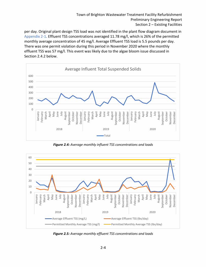
Historical influent and effluent Total Suspended Solids (TSS) concentrations and loads are shown in Figure 2.4 and Figure 2.5. Influent TSS concentrations averaged 189 mg/l during the January 2018 to December 2020 study period, representing an Influent TSS load of 88 pounds
050
100150200250300350400450500
Jan
uar
y
Feb
ruar
y
Mar
ch
Ap
ril
May
Jun
e
July
Au
gust
Sep
tem
ber
Oct
ob
er
No
vem
ber
Dec
em
ber
Jan
uar
y
Feb
ruar
y
Mar
ch
Ap
ril
May
Jun
e
July
Au
gust
Sep
tem
ber
Oct
ob
er
No
vem
ber
Dec
em
ber
Jan
uar
y
Feb
ruar
y
Mar
ch
Ap
ril
May
Jun
e
July
Au
gust
Sep
tem
ber
Oct
ob
er
No
vem
ber
Dec
em
ber
2018 2019 2020
BO
D (
mg/
L)
Average Influent Biochemical Oxygen Demand
Total
0
5
10
15
20
25
30
35
40
Jan
uar
yFe
bru
ary
Mar
chA
pri
lM
ayJu
ne
July
Au
gust
Sep
tem
ber
Oct
ob
er
No
vem
ber
Dec
em
ber
Jan
uar
yFe
bru
ary
Mar
chA
pri
lM
ayJu
ne
July
Au
gust
Sep
tem
ber
Oct
ob
er
No
vem
ber
Dec
em
ber
Jan
uar
yFe
bru
ary
Mar
chA
pri
lM
ayJu
ne
July
Au
gust
Sep
tem
ber
Oct
ob
er
No
vem
ber
Dec
em
ber
2018 2019 2020
Average Effluent BOD (mg/L) Average Effluent BOD (lbs/day)
Permitted Monthly Average BOD (mg/l) Permitted Monthly Average BOD (lbs/day)
Town of Brighton Wastewater Treatment Facility Refurbishment Preliminary Engineering Report
Section 2 – Existing Facilities
2-4
per day. Original plant design TSS load was not identified in the plant flow diagram document in Appendix 2-1. Effluent TSS concentrations averaged 11.78 mg/l, which is 26% of the permitted monthly average concentration of 45 mg/l. Average Effluent TSS load is 5.5 pounds per day. There was one permit violation during this period in November 2020 where the monthly effluent TSS was 57 mg/l. This event was likely due to the algae bloom issue discussed in Section 2.4.2 below.
Figure 2.4: Average monthly influent TSS concentrations and loads
Figure 2.5: Average monthly effluent TSS concentrations and loads
0
100
200
300
400
500
600
Jan
uar
y
Feb
ruar
y
Mar
ch
Ap
ril
May
Jun
e
July
Au
gust
Sep
tem
ber
Oct
ob
er
No
vem
ber
Dec
em
ber
Jan
uar
y
Feb
ruar
y
Mar
ch
Ap
ril
May
Jun
e
July
Au
gust
Sep
tem
ber
Oct
ob
er
No
vem
ber
Dec
em
ber
Jan
uar
y
Feb
ruar
y
Mar
ch
Ap
ril
May
Jun
e
July
Au
gust
Sep
tem
ber
Oct
ob
er
No
vem
ber
Dec
em
ber
2018 2019 2020
Average Influent Total Suspended Solids
Total
0
10
20
30
40
50
60
Jan
uar
y
Feb
ruar
y
Mar
ch
Ap
ril
May
Jun
e
July
Au
gust
Sep
tem
ber
Oct
ob
er
No
vem
ber
Dec
em
ber
Jan
uar
y
Feb
ruar
y
Mar
ch
Ap
ril
May
Jun
e
July
Au
gust
Sep
tem
ber
Oct
ob
er
No
vem
ber
Dec
em
ber
Jan
uar
y
Feb
ruar
y
Mar
ch
Ap
ril
May
Jun
e
July
Au
gust
Sep
tem
ber
Oct
ob
er
No
vem
ber
Dec
em
ber
2018 2019 2020
Average Effluent TSS (mg/L) Average Effluent TSS (lbs/day)
Permitted Monthly Average TSS (mg/l) Permitted Monthly Average TSS (lbs/day)
Town of Brighton Wastewater Treatment Facility Refurbishment Preliminary Engineering Report
Section 2 – Existing Facilities
2-5
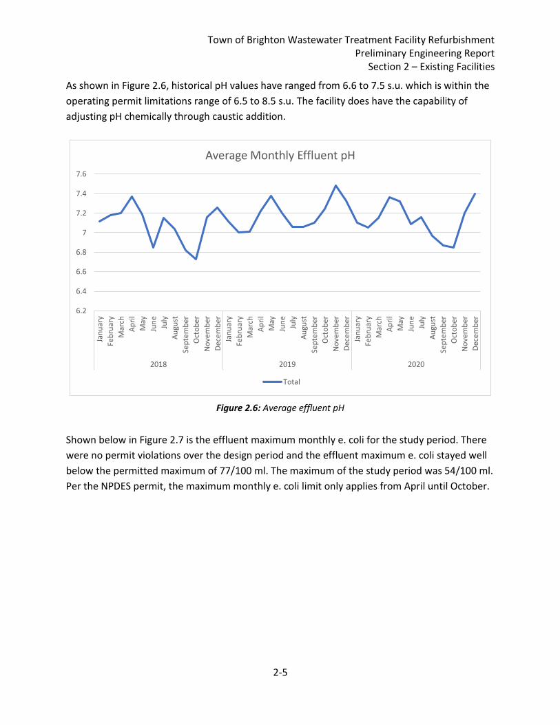
As shown in Figure 2.6, historical pH values have ranged from 6.6 to 7.5 s.u. which is within the
operating permit limitations range of 6.5 to 8.5 s.u. The facility does have the capability of
adjusting pH chemically through caustic addition.
Figure 2.6: Average effluent pH
Shown below in Figure 2.7 is the effluent maximum monthly e. coli for the study period. There
were no permit violations over the design period and the effluent maximum e. coli stayed well
below the permitted maximum of 77/100 ml. The maximum of the study period was 54/100 ml.
Per the NPDES permit, the maximum monthly e. coli limit only applies from April until October.
6.2
6.4
6.6
6.8
7
7.2
7.4
7.6
Jan
uar
y
Feb
ruar
y
Mar
ch
Ap
ril
May
Jun
e
July
Au
gust
Sep
tem
ber
Oct
ob
er
No
vem
ber
Dec
em
ber
Jan
uar
y
Feb
ruar
y
Mar
ch
Ap
ril
May
Jun
e
July
Au
gust
Sep
tem
ber
Oct
ob
er
No
vem
ber
Dec
em
ber
Jan
uar
y
Feb
ruar
y
Mar
ch
Ap
ril
May
Jun
e
July
Au
gust
Sep
tem
ber
Oct
ob
er
No
vem
ber
Dec
em
ber
2018 2019 2020
Average Monthly Effluent pH
Total
Town of Brighton Wastewater Treatment Facility Refurbishment Preliminary Engineering Report
Section 2 – Existing Facilities
2-6
Figure 2.7: Effluent E. coli
2.4. Condition of Existing Facilities Condition assessment observations of the Brighton WWTF were completed on May 17, 2018 as part of the Facility 20-Year Evaluation Final Report. The Brighton WWTF has been identified as needing a major refurbishment. Flow to the WWTF enters via a 6” force main from the Meadow Street pump station. See Appendix 2-2 for a flow schematic and hydraulic profile of the existing Brighton WWTF. Some aspects of the WWTF have been updated since the construction of the facility, such as the diffusers. Refer also to the Facility Inspection Report dated November 27, 2017, prepared by Liz Dickson, Environmental Analyst, Vermont ANR/DEC/Watershed Management Division, and the Facility Inspection Report dated August 31, 2020, prepared by Jamie Bates, Environmental Analyst, Vermont ANR/DEC/Watershed Management Division, included in Appendix 2-3. The existing lagoon system at the Brighton WWTF consists of the following:
• Manhole with a manual bar rack • Two (2) aerated lagoons • Two (2) positive displacement blowers • Eighteen (18) Reef square diffusers • Chlorine contact tank • Chemical feed pumps • Emergency power back-up system for the chemical metering pumps
0
10
20
30
40
50
60
70
80
90Ja
nu
ary
Feb
ruar
y
Mar
ch
Ap
ril
May
Jun
e
July
Au
gust
Sep
tem
ber
Oct
ob
er
No
vem
ber
Dec
em
ber
Jan
uar
y
Feb
ruar
y
Mar
ch
Ap
ril
May
Jun
e
July
Au
gust
Sep
tem
ber
Oct
ob
er
No
vem
ber
Dec
em
ber
Jan
uar
y
Feb
ruar
y
Mar
ch
Ap
ril
May
Jun
e
July
Au
gust
Sep
tem
ber
Oct
ob
er
No
vem
ber
Dec
em
ber
2018 2019 2020
Maximum Monthly E. Coli (#/100mL) Permitted Maximum Instantaneous E. Coli (#/100 ml)
Town of Brighton Wastewater Treatment Facility Refurbishment Preliminary Engineering Report
Section 2 – Existing Facilities
2-7
• V-notch weir and ultrasonic flow meter • Outfall • Control building • Storage building
An evaluation of each of the individual unit processes was performed to determine the adequacies and deficiencies of each process component relative to the design standards “Recommended Standards for Wastewater Facilities” (2004 Edition) and “TR-16, Guides for the Design of Wastewater Treatment Works” (2016 Edition).
An inventory was prepared for the existing equipment to document the type, model, age, condition (poor, fair, good) and operability. The deficiencies and adequacies of each component are discussed in the following narratives. 2.4.1. Headworks
Influent flow enters the headworks through a 6” force main from the Meadow Street pump station. The water passes through a manhole with a bar rack fixed in the channel. The bar rack was recently replaced in November of 2017. The bar rack is cleaned manually by plant operators using a rake. Relevant Design Standards
• For bar racks, clear openings between the bars shall be no less than 1” for manually
cleaned bar screens and the maximum clear openings shall be 2” (TR-16).
• The slope of the bar screens shall be from 30 to 45 degrees (TR-16). At design flow
conditions, the approach velocities shall be no less than 1.25 per second, but not more
than 3 feet per second (10 States Standards).
• Grit removal facilities should be provided for all wastewater treatment plants, and are
required for plants receiving wastewater from combined sewers or from sewer systems
receiving substantial amounts of grit. If a plant serving a separate sewer system is
designed without grit removal facilities, the design shall include provision for future
installation (TR-16, 10 States Standards).
• A stairway shall be provided for access, and an open structure shall be protected by
guard railings and/or deck gratings (TR-16).
Assessment The assessment of the major components is summarized below in Table 2.2 for the Headworks, and the major needs are described as follows:
Town of Brighton Wastewater Treatment Facility Refurbishment Preliminary Engineering Report
Section 2 – Existing Facilities
2-8
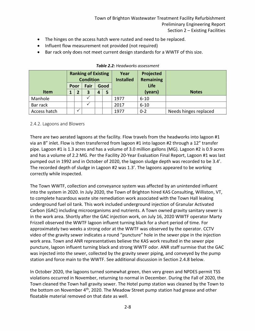
• The hinges on the access hatch were rusted and need to be replaced.
• Influent flow measurement not provided (not required)
• Bar rack only does not meet current design standards for a WWTF of this size.
Table 2.2: Headworks assessment
Item
Ranking of Existing Condition
Year Installed
Projected Remaining
Life (years)
Notes Poor Fair Good
1 2 3 4 5
Manhole 1977 6-10
Bar rack 2017 6-10
Access hatch 1977 0-2 Needs hinges replaced
2.4.2. Lagoons and Blowers
There are two aerated lagoons at the facility. Flow travels from the headworks into lagoon #1 via an 8” inlet. Flow is then transferred from lagoon #1 into lagoon #2 through a 12” transfer pipe. Lagoon #1 is 1.3 acres and has a volume of 3.0 million gallons (MG). Lagoon #2 is 0.9 acres and has a volume of 2.2 MG. Per the Facility 20-Year Evaluation Final Report, Lagoon #1 was last pumped out in 1992 and in October of 2020, the lagoon sludge depth was recorded to be 3.4’. The recorded depth of sludge in Lagoon #2 was 1.3’. The lagoons appeared to be working correctly while inspected. The Town WWTF, collection and conveyance system was affected by an unintended influent into the system in 2020. In July 2020, the Town of Brighton hired KAS Consulting, Williston, VT, to complete hazardous waste site remediation work associated with the Town Hall leaking underground fuel oil tank. This work included underground injection of Granular Activated Carbon (GAC) including microorganisms and nutrients. A Town owned gravity sanitary sewer is in the work area. Shortly after the GAC injection work, on July 16, 2020 WWTF operator Marty Frizzell observed the WWTF lagoon influent turning black for a short period of time. For approximately two weeks a strong odor at the WWTF was observed by the operator. CCTV video of the gravity sewer indicates a round “puncture” hole in the sewer pipe in the injection work area. Town and ANR representatives believe the KAS work resulted in the sewer pipe puncture, lagoon influent turning black and strong WWTF odor. ANR staff surmise that the GAC was injected into the sewer, collected by the gravity sewer piping, and conveyed by the pump station and force main to the WWTF. See additional discussion in Section 2.4.8 below. In October 2020, the lagoons turned somewhat green, then very green and NPDES permit TSS violations occurred in November, returning to normal in December. During the Fall of 2020, the Town cleaned the Town hall gravity sewer. The Hotel pump station was cleaned by the Town to the bottom on November 4th, 2020. The Meadow Street pump station had grease and other floatable material removed on that date as well.
Town of Brighton Wastewater Treatment Facility Refurbishment Preliminary Engineering Report
Section 2 – Existing Facilities
2-9
There are two positive displacement blowers located in the blower room of the control building. One blower has a 10 HP motor, while the second has a 20 hp motor and a variable frequency drive (VFD). Both blowers are exercised and checked every week, however the 20 hp blower is typically used more. Blowers typically have a useful life of 25 years. Original plant design criteria (Appendix 2-1) show the blowers were designed to maintain 4 mg/l dissolved oxygen (DO) and deliver 120 cubic feet per minute (cfm) at 9 pounds per square inch (psi). DO measurements in Lagoon #1 are typically between 1-2 mg/L and in Lagoon #2 are typically between 2-5 mg/L, although seasonally are kept higher at 8-10 mg/L. Operators noted DO concentrations in the lagoons are managed to inhibit nitrification to reduce the potential for nitrite interference with disinfection. Diffused air is provided to each lagoon through galvanized steel headers and Reef square diffusers. The diffusers in Lagoon #1 were replaced in 1990 and the diffusers in Lagoon #2 were replaced in 1993. The diffusers have not been pulled from the lagoons since then and no spares are kept onsite. Spare parts are readily available from the supplier. However, they may not be the same configuration. Relevant Design Standards
• Normal oxygen requirements are 2 lbs O2/lb BOD, but the aeration system should be
capable of transferring 3 lbs O2/lb BOD applied (TR-16).
• Aeration equipment should maintain a minimum dissolved oxygen level of 2 mg/l
throughout the liquid depth of the ponds at all time (TR-16).
• The blowers shall be provided in multiple units, so arranged and in such capacities as to
meet the maximum air demand with the single largest unit out of service. The design
shall also provide for varying the volume of air delivered in proportion to the load
demand of the plant. Aeration equipment shall be easily adjustable in increments and
shall maintain solids suspension within these limits (Ten States Standards).
Assessment The assessment of the major components is summarized in Table 2.3 for the lagoons and blowers, and the major needs are described as follows:
• Lagoon #1 has not had sludge pumped out since 1990. Lagoon #2 has never had sludge pumped. GAC injection described above may impact sludge quality. Removal of accumulated sludge is required.
• Lagoon #1 aeration diffusers were replaced in 1990 and have reached the end of their useful life
• Lagoon #2 aeration diffusers were replaced in 1993 and have reached the end of their
Town of Brighton Wastewater Treatment Facility Refurbishment Preliminary Engineering Report
Section 2 – Existing Facilities
2-10
useful life
• Condition of Lagoon liners is unknown
• Blower 1 was replaced in 2007 (motor was not replaced). Blower 2 was replaced in 2004 (including motor and VFD). Both blowers are approaching the end of their useful life.
• No mechanism for maintenance removal of sludge
• The 10 hp Blower 1 does not have a VFD
• Issues with algae bloom potentially leading to TSS violation
Table 2.3: Lagoons and blowers assessment
Item
Ranking of Existing Condition
Year Installed
Projected Remaining
Life (years)
Notes Poor Fair Good
1 2 3 4 5
Lagoon #1 1977 6-10 Sludge removal recommended; liner condition unknown
Lagoon #2 1977 6-10 Sludge removal recommended; liner condition unknown
Blower 1 (10 hp)
2007 5-7 blower only replaced, not motor, no VFD
Blower 2 (20 hp)
2004 3-5 Blower and motor replaced, VFD installed
Lagoon #1 Diffusers
1990 0-2
Lagoon #2 Diffusers
1993 0-2
2.4.3. Disinfection and Chemical Feed System
The Brighton WWTF uses chlorination/dechlorination for disinfection. Effluent from Lagoon #2 enters into a chlorine contact tank (CCT), which has a 7’ Side Water Depth (SWD) and isolated dechlorination cell. The top of the CCT is reported as elevation 1185.0’, which is approximately 12’ over the FEMA flood elevation of 1173.0’. The contact time in the tank is 44 minutes at the design flow of 150,000 gpd, but does not meet design guidance for 30 minutes contact time at peak design flow. Sodium hypochlorite and sodium bisulfite are fed into the tank by chemical feed pumps located in the chemical room. The age of the chemical metering pumps is unknown. A 1/3 horsepower sump pump is located at the inlet of the CCT to mix the chemicals by creating a turbulent flow. The plant has an emergency power back up system for the chemical metering pumps in the
Town of Brighton Wastewater Treatment Facility Refurbishment Preliminary Engineering Report
Section 2 – Existing Facilities
2-11
event of a power outage. This system utilizes a 12 Volt battery and power inverter. The battery is approximately 10 years old. The chemical room is located in the storage building adjacent to the contact tank. This room houses the chlorination/dechlorination chemicals, chemical metering pumps, and an eye wash station that appeared to be fairly corroded, and they are poorly located such that they are subject to freezing. The room has a small vent which goes on when the light is turned on. Relevant Design Standards
• Contact time shall be 30 minutes at peak design flow (TR-16).
• Duplicate disinfection feed systems shall be provided and each system shall be
capable of handling maximum flow conditions, including contact tank (TR-16).
• Continuous chlorination shall be provided during power outages (TR-16).
• Storage containers for hypochlorite solutions shall be of sturdy, non-metallic lined
construction and shall be provided with secure tank tops and pressure relief and
overflow piping. Storage tanks should be either located or vented outside. Provision
shall be made for adequate protection from light and extreme temperatures. Tanks
shall be located where leakage will not cause corrosion or damage to other
equipment. A means of secondary containment shall be provided to contain spills
and facilitate cleanup. Due to deterioration of hypochlorite solutions over time, it is
recommended that containers not be sized to hold more than one month's needs
(10 States Standards).
• With chlorination systems, forced, mechanical ventilation shall be installed which
will provide one complete fresh air change per minute when the room is occupied.
The entrance to the air exhaust duct from the room shall be near the floor. The
point of discharge shall be so located as not to contaminate the air inlet to any
buildings or present a hazard at the access to the chlorinator room or other
inhabited areas. Air inlets shall be so located as to provide cross ventilation with air
and at such temperature that will not adversely affect the chlorination equipment.
The outside air inlet shall be at least three feet above grade. The vent hose from the
chlorinator shall discharge to the outside atmosphere above grade (10 States
Standards).
• Ventilation should follow normal industrial building requirements and maintain
room temperature no higher than 80°F (TR-16).
• The following equipment must be connected to the emergency power system (TR-
16):
o All chlorine feed, mixing, and control equipment
Town of Brighton Wastewater Treatment Facility Refurbishment Preliminary Engineering Report
Section 2 – Existing Facilities
2-12
o All dechlorination chemical feed equipment
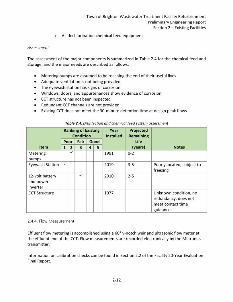
Assessment The assessment of the major components is summarized in Table 2.4 for the chemical feed and storage, and the major needs are described as follows:
• Metering pumps are assumed to be reaching the end of their useful lives
• Adequate ventilation is not being provided
• The eyewash station has signs of corrosion
• Windows, doors, and appurtenances show evidence of corrosion
• CCT structure has not been inspected
• Redundant CCT channels are not provided
• Existing CCT does not meet the 30-minute detention time at design peak flows
Table 2.4: Disinfection and chemical feed system assessment
Item
Ranking of Existing Condition
Year Installed
Projected Remaining
Life (years)
Notes Poor Fair Good
1 2 3 4 5
Metering pumps
1991 0-2
Eyewash Station 2019 3-5 Poorly located, subject to freezing
12-volt battery and power inverter
2010 2-5
CCT Structure 1977 Unknown condition, no redundancy, does not meet contact time guidance
2.4.4. Flow Measurement
Effluent flow metering is accomplished using a 60° v-notch weir and ultrasonic flow meter at the effluent end of the CCT. Flow measurements are recorded electronically by the Miltronics transmitter. Information on calibration checks can be found in Section 2.2 of the Facility 20-Year Evaluation Final Report.
Town of Brighton Wastewater Treatment Facility Refurbishment Preliminary Engineering Report
Section 2 – Existing Facilities
2-13
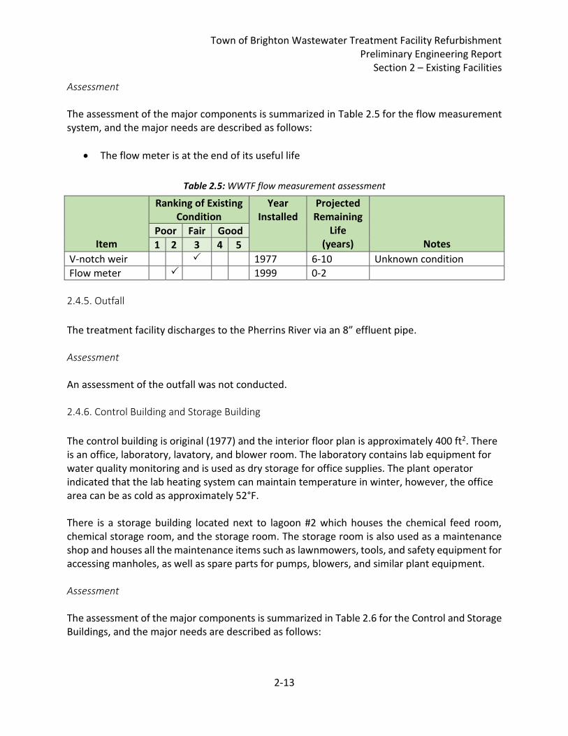
Assessment The assessment of the major components is summarized in Table 2.5 for the flow measurement system, and the major needs are described as follows:
• The flow meter is at the end of its useful life
Table 2.5: WWTF flow measurement assessment
Item
Ranking of Existing Condition
Year Installed
Projected Remaining
Life (years)
Notes Poor Fair Good
1 2 3 4 5
V-notch weir 1977 6-10 Unknown condition
Flow meter 1999 0-2
2.4.5. Outfall
The treatment facility discharges to the Pherrins River via an 8” effluent pipe. Assessment An assessment of the outfall was not conducted. 2.4.6. Control Building and Storage Building
The control building is original (1977) and the interior floor plan is approximately 400 ft2. There is an office, laboratory, lavatory, and blower room. The laboratory contains lab equipment for water quality monitoring and is used as dry storage for office supplies. The plant operator indicated that the lab heating system can maintain temperature in winter, however, the office area can be as cold as approximately 52°F. There is a storage building located next to lagoon #2 which houses the chemical feed room, chemical storage room, and the storage room. The storage room is also used as a maintenance shop and houses all the maintenance items such as lawnmowers, tools, and safety equipment for accessing manholes, as well as spare parts for pumps, blowers, and similar plant equipment. Assessment The assessment of the major components is summarized in Table 2.6 for the Control and Storage Buildings, and the major needs are described as follows:
Town of Brighton Wastewater Treatment Facility Refurbishment Preliminary Engineering Report
Section 2 – Existing Facilities
2-14
• The control building siding, windows, insulation and air sealing system and roof covering need replacement
• The storage building needs to be reorganized to fit maintenance and storage items inside. Corrosion observed in chemical storage area. Other building system improvement needs are unknown.
Table 2.6: Control building and storage building assessment
Item
Ranking of Existing Condition
Year Installed
Projected Remaining
Life (years)
Notes Poor Fair Good
1 2 3 4 5
Control building 1977 0-2
Storage building 1977 0-2
2.4.7. Lagoon Sludge
During treatment, solids settle out of the sewage and collect at the bottoms of the two lagoons
as sludge. The sludge at the bottom of the two Brighton lagoons has not been pumped out
since the 1990s. In recent years, the settled sludge depth has increased, and sludge removal is
needed. Appendix 2-4 includes calculation estimates of lagoon sludge and solids volume in the
two lagoons, as of the last (2020) sludge depth measurements taken by the plant operator,
summarized as follows in Table 2.7:
Table 2.7: Summary of estimated lagoon sludge volumes
Lagoon No. Sludge Volume (Gallons)
1 1,045,000
2 332,000
Total: 1,377,000
The total lagoon sludge dry solids weight is estimated to be approximately 466 dry tons. It
should be noted, however, that actual sludge dry weight could be significantly higher or lower
due to the following potential variables:
1. Actual sludge depths may vary from measured sludge depths. Available lagoon
sludge depths provided by the plant operator only include sludge depths on the
lagoon bottom but exclude the lagoon side slopes.
2. Solids specific gravity for each lagoon was assumed based upon Metcalf & Eddy
Table 13-7. Actual solids specific gravity could be higher or lower. For example,
lagoon sludge specific gravity can be higher if sewer collection and conveyance
system infiltration is high and washing sand into the lagoons.
Town of Brighton Wastewater Treatment Facility Refurbishment Preliminary Engineering Report
Section 2 – Existing Facilities
2-15
Refer also to Attachment 4 for a summary of lagoon sludge design related information.
It is recommended that the plant operator complete a sludge sampling and characterization
plan as soon as seasonally possible in 2021 to collect current sludge depth and quality
characteristics. Hoyle, Tanner will provide the sludge sampling plan, separate from this Report
in the near future to guide the sampling. This information will be used to improve sludge
removal scope and cost estimates.
2.4.8. Town Hall Sewer & Inflow/Infiltration
The Town Hall Sewer is approximately 260’ long and runs from the sewer manhole southwest of the Sunrise Manor on Main Street to the southwest of the Brighton Town Hall on Mill Street. The Town Hall Sewer is identified on the Plans for Construction of Water Pollution Control Facilities, Contract No. 2 by Dufresne-Henry Engineering Corporation, dated April 5, 1972, however it is understood that the full segment was not completed until a later date. Operators report that the sewer line is constructed of 6” PVC pipe. In July of 2020, the Town sought to remediate a heating oil release from the Town Hall building via carbon injection performed by KAS Consulting of Williston, Vermont. During the course of the remediation work, on July 16, 2020, WWTF operators observed a black carbon slurry at the WWTF. Following the carbon injection event, the Town performed internal inspection of the sewer line and observed a circular hole approximately 2-3 inches in diameter. It is assumed that this hole was created during geotechnical site characterization prior to the carbon injection work. The inspection after the carbon injection event also included a survey of the Town Hall Sewer, which identified several sags in the piping. Rehabilitation or replacement of the Town Hall Sewer should be considered to reduce infiltration into the sanitary sewer system. Portions of the area containing the Town Hall Sewer are known to contain petroleum-based contamination. Refer to Appendix 2-5 for select portions the KAS Consulting summary of the damage to the sewer pipe and KAS’ Corrective Action Report. Based on current influent flow data (see Table 2.1 above), it appears that the collection system experiences significant infiltration/inflow (I/I) during the spring months. Investigation and rehabilitation/replacement of select areas of the collection system should be considered to reduce I/I influent to the WWTF.
Town of Brighton Wastewater Treatment Facility Refurbishment Preliminary Engineering Report
Section 2 – Existing Facilities
2-16
2.4.9. Hotel, School & Pleasant St. Pump Stations Refurbishment
As per the Facility 20-Year Evaluation Final Report, the Hotel Pump Station is located on Derby Street just south of Lightning Brook and next to the Essex House & Tavern, a hotel and restaurant. This pump station receives flow from the entire collection system south of Railroad Street which includes Derby, Pleasant, Dale and Birch Streets from the south of the pump station and Cross, Center and Mill Streets north of the pump station. The pump station discharges to MH 13 at the intersection of Cross and Railroad Streets via a 6" diameter force main. The pump station consists of a wet well with two submersible pumps and an above grade control panel. Upon inspection, some grease was observed in the wetwell. The plant operator indicated that grease is periodically removed by manual baler. The pump station control panel enclosure is of wood construction and needs replacement. Pump #1 was rebuilt in January 2018 and Pump #2 was replaced in January 2012. The pump slide rails need to be replaced. The School Pump Station is located at the Brighton Elementary School on Railroad Street. This pump station is owned by the school and is operated by the Town. The pump station consists of a wet well with submersible pumps and a control panel above grade. The plant operator indicated he plans to install wiring and a backup float alarm. The plant operator also indicated that the pump rail system needs replacement. As per the Facility 20-Year Evaluation Final Report, the Pleasant St. Pump station is in poor condition and requires replacement.
2.5. Financial Status of Any Existing Facilities The Town’s existing wastewater debt service reportedly consists of $9,700 annual payments to the Vermont Clean Water State Revolving Loan Fund (SRF) Program for the Dale Street Pump Station project in 2012. This debt will be retired in 2034. The FY21 sewer rates for a residential users are as follows:
• $108 per quarter for the first 15,000 gallons
• $2.32 per 1,000 gallons above 15,000 gallons Rates were last increased in 2016. This project may necessitate changes to the above listed rate structure. The Town’s 2020 Annual Report including sewer system financial accounts are included in Appendix 2-6, Brighton Annual Report.
2.6. Water/Energy/Waste Audits The last formal WWTF comprehensive energy audit was completed in 2010. No waste, energy or water audits have been completed recently for the WWTF.
Town of Brighton Wastewater Treatment Facility Refurbishment Preliminary Engineering Report
Section 3 – Need for Project
3-1
3. Need for Project
3.1. Health, Sanitation, and Security Overall, the Facility typically meets the permit effluent limitations established in the Facility discharge permit, however, the facility had several permit effluent violations during the past three years including flow, BOD, TSS and chlorine residual. There have also been effluent violations since this report was completed. The Brighton WWTF is in the Lake Memphremagog watershed and is affected by the Lake Memphremagog phosphorous Total Maximum Daily Load (TMDL) determination. As indicated in Table 2 of VT DEC Final Wastewater Treatment Facility Wasteload Allocations, dated October 24, 2017, the final adopted Total Phosphorous (TP) wasteload allocation for the Brighton WWTF will be 1,532 lbs TP /year. This final wasteload allocation will be implemented through the NPDES permit reissuance. The VTDEC Final Wastewater Treatment Facility Wasteload Allocations document is provided in Appendix 3-1. As a result, Brighton’s next permit will most likely contain a monitor only requirement for TP, and it is assumed that the following permit period will include a new, lower TP permit limit. Therefore, this project will need to consider meeting a future lower TP limit. The Brighton WWTF Discharge License (Permit No. 3-1213) expired June 30, 2012 and was written prior to the 2013 Vermont Water Quality Standards (VWQS). The VWQS requires numeric modeling for nutrient limits, most notably for total ammonia nitrogen (TAN). Limited data exist, however preliminary analysis from Vermont DEC indicate that TAN limits will not be in effect for Brighton. See Appendix 3-2 for calculated critical (i.e. worst case scenario) design planning limits based on the VWQS from Vermont DEC.
3.2. Aging Infrastructure As indicated in Section 2 of this Report, the lagoon process equipment, control, and storage buildings have exceeded their useful service life and are recommended for replacement or refurbishment to improve facility reliability. The existing control building space is small and includes the operator office, laboratory, lavatory, and blower room. The existing storage building includes an unheated shop and storage room and a separate chlorine room. The shop and storage room are used to store chemicals and other facility materials as well as the riding and push mowers and other tools required to operate and maintain the facility. The shop and storage room size is inadequate for the facility needs. Currently, facility materials are also stored outside between the control building and the storage building. The facility needs additional dry storage space, and heated shop space and a staff room. Table 3.1 summarizes the needs for the Headworks, Lagoons, Blowers, Disinfection System, Flow Measurement and Building/Support Structures.
Town of Brighton Wastewater Treatment Facility Refurbishment Preliminary Engineering Report
Section 3 – Need for Project
3-2
Table 3.1: Summary of major deficiencies
Item Description Projected Date of Required Upgrade
<2 Years 2 to 5 Years 6 to 10 Years
Headworks
Manhole
Bar rack
Access hatch
Lagoons and Blowers
Lagoon #1
Lagoon #2
Blower 1 (10 hp)
Blower 2 (20 hp)
Lagoon #1 Diffusers
Lagoon #2 Diffusers
Disinfection and Chemical Feed
Metering pumps
Eyewash Station
12-volt battery and power inverter
CCT Structure
Flow Measurement
V-notch weir
Flow meter
Control and Storage Buildings
Control building
Storage building
Hotel & School Pump Station Slide Rails
Pleasant St Pump Station
Hotel PS Control System
3.3. Reasonable Growth As indicated in Section 1, the year 2000 and 2010 US Census population information indicates that the Town of Brighton population declined by -19.3% and -3.3% respectively during the 10-year period prior to each census. The Town anticipates continued population decline in the future. Based upon the Vermont Population Projections – 2010-2030, dated August 2013, produced by Kenneth Jones, Ph.D., Economic Analyst, Vermont Agency of Commerce and Community Development and Lilly Schwartz, Community Based Learning Intern, Montpelier High School, the Town anticipates a 23.7% decline in population for a total decline in
Town of Brighton Wastewater Treatment Facility Refurbishment Preliminary Engineering Report
Section 3 – Need for Project
3-3
population to 932 people in year 2030 from 1,222 people in year 2010. Select excerpts from the Vermont Population Projections document is provided in Appendix 3-3.
Although there has been a decline in population, the Town needs the current permitted hydraulic capacity of 150,000 gpd average monthly flow to meet current demands, noting that the Town experienced a violation of their permitted average monthly flow in 2019. At this time, the Town anticipates that the sanitary sewer service area population decline will be equivalent to the Town population decline. It is assumed for the purposes of this evaluation that the future wastewater capacity need during the year 2021-2038 planning period will consider the 23.7% decline in annual population. The Town has approached exceeding 80% of their design capacity for 90 days, which likely indicates infiltration/inflow issues. The Town has no contractual capacity reserved for any type of user.
Town of Brighton Wastewater Treatment Facility Refurbishment Preliminary Engineering Report
Section 4 – Alternatives Considered
4-1
4. Alternatives Considered
The primary drivers for development of WWTF upgrades are age-related equipment replacements as well as the need to prepare for likely future permit limits, specifically with regards to total phosphorous. An additional driver for potential WWTF alternatives includes operational upgrades that can improve WWTF performance and operator safety or reduce labor burden.
4.1. Headworks Upgrade Alternatives The purpose of the headworks is to remove inorganics such as large solids (sticks, stones, etc.) and potentially grit from the wastewater stream. It is common for lagoon WWTF with similar design capacities as the Brighton WWTF to provide limited screening in the headworks, and grit removal systems are frequently not provided. TR-16 states “In general, removal of objectionable material by screening is desirable. When this is not feasible, however, comminution/grinding devices may be installed to chop or shred material below the surface of the wastewater.” 4.1.1. Alternative Descriptions
Alternative 1 – Replacement of Distribution Manhole Top Access: Alternative 1 consists of leaving the existing distribution manhole (Headworks) mostly as is, only replacing the access hatch on top which has corroded. To replace the access hatch, a new precast concrete top on the distribution manhole is proposed with the new hatch cast into the top. Alternative 2 – New Headworks Vault: Alternative 2 consists of constructing a new vault with new manually raked bar rack and drainage plate. Influent flow would be intercepted with a new doghouse manhole on the 6” cast iron influent force main to divert flow to the new Headworks vault. The remaining existing influent line could be utilized as a Headworks bypass. The new vault would be designed with new hatches and improved access for daily operations (raking screenings). From the vault, wastewater would flow to the existing distribution manhole and on to the lagoons. Two options are presented for the new Headworks vault. The first includes only a new bar rack with drainage plate (Alternative 2.A), with a vault measuring approximately 6’ wide x 10’ long. The second option includes the bar rack and drainage plate, as well as influent sampling and flow measurement (Alternative 2.B). The Alternative 2.B vault would measure approximately 6’ wide x 16’ long. Due to the influent sampling and flow measurement (influent flow characterization), Alternative 2.B includes electrical and controls. See Appendix 4-1 for Headworks Alternative 2 site plan and vault layout figures.
Town of Brighton Wastewater Treatment Facility Refurbishment Preliminary Engineering Report
Section 4 – Alternatives Considered
4-2
Alternative 3 – New Headworks Building with Mechanical Screen: Alternative 3 consists of a new Headworks Building with mechanical fine screen. Influent flow would be diverted to the new Headworks Building similarly to Alternative 2, described above. The new Headworks Building would measure approximately 8’ wide x 24’ long, and would include automated influent flow sampling, mechanical screening equipment, with screenings bagger and dumpster, and influent flow measurement. See Appendix 4-2 for Headworks Alternative 3 site plan and building layout figures. See Appendix 4-3 for mechanical screen equipment proposal. The building would also include HVAC to maintain space temperature and humidity as well as electrical, instrumentation and controls. The new Headworks Building would be classified by NFPA 820 (Table 5.2, 1.c.) as a Class I, Division 1 within a 10-foot envelope around the equipment and open channel. Explosion proof equipment is required within these spaces. If enclosed, ventilation is required within the Headworks Building. Note that the new Headworks Building could be combined with a new Operations Building. See additional discussion in Section 4.4.1 below.
Table 4.1: Headworks alternatives comparison
Advantages Disadvantages
Alternative 1 – Replacement of Distribution MH Top
• Lowest capital cost • Does not improve screenings capture
• Elevated potential operator exposure to wastewater
• Poor access for regular O&M
• Potential for overflows
• No influent flow characterization
Alternative 2.A – New Headworks Vault (6x10)
• Improved access and arrangement for work activities
• Improved screenings removal (bar spacing)
• Headworks bypass for high flows
• Significant improvements for little capital cost over the Alt. 1
• Potential operator exposure to wastewater (manual raking of screenings required)
• No influent flow characterization
Alternative 2.B – New Headworks Vault (6x16)
• Same as Alt. 2.A above
• Includes Influent flow characterization
• Higher capital costs
• Potential operator exposure to wastewater
Town of Brighton Wastewater Treatment Facility Refurbishment Preliminary Engineering Report
Section 4 – Alternatives Considered
4-3
Alternative 3 – New Headworks Building
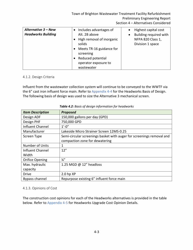
• Includes advantages of Alt. 2B above
• High removal of inorganic solids
• Meets TR-16 guidance for screening
• Reduced potential operator exposure to wastewater
• Highest capital cost
• Building required with NFPA 820 Class 1, Division 1 space
4.1.2. Design Criteria
Influent from the wastewater collection system will continue to be conveyed to the WWTF via the 6” cast iron influent force main. Refer to Appendix 4-4 for the Headworks Basis of Design. The following basis of design was used to size the Alternative 3 mechanical screen.
Table 4.2: Basis of design information for headworks
Item Description Proposed
Design ADF 150,000 gallons per day (GPD)
Design PHF 750,000 GPD
Influent Channel 1’-0”
Manufacturer Lakeside Micro Strainer Screen 12MS-0.25
Screen Type Semi-circular screenings basket with auger for screenings removal and compaction zone for dewatering
Number of Units 1
Influent Channel Width
12”
Orifice Opening ¼”
Max. hydraulic capacity
1.25 MGD @ 12” headloss
Drive 2.0 hp XP
Bypass channel Repurpose existing 6” influent force main
4.1.3. Opinions of Cost
The construction cost opinions for each of the Headworks alternatives is provided in the table below. Refer to Appendix 4-5 for Headworks Upgrade Cost Opinion Details.
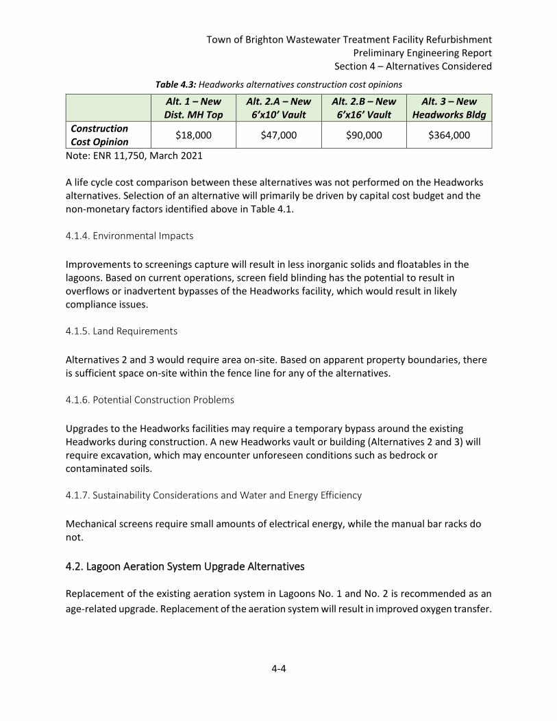
Town of Brighton Wastewater Treatment Facility Refurbishment Preliminary Engineering Report
Section 4 – Alternatives Considered
4-4
Table 4.3: Headworks alternatives construction cost opinions
Alt. 1 – New Dist. MH Top
Alt. 2.A – New 6’x10’ Vault
Alt. 2.B – New 6’x16’ Vault
Alt. 3 – New Headworks Bldg
Construction Cost Opinion
$18,000 $47,000 $90,000 $364,000
Note: ENR 11,750, March 2021 A life cycle cost comparison between these alternatives was not performed on the Headworks alternatives. Selection of an alternative will primarily be driven by capital cost budget and the non-monetary factors identified above in Table 4.1. 4.1.4. Environmental Impacts
Improvements to screenings capture will result in less inorganic solids and floatables in the lagoons. Based on current operations, screen field blinding has the potential to result in overflows or inadvertent bypasses of the Headworks facility, which would result in likely compliance issues. 4.1.5. Land Requirements
Alternatives 2 and 3 would require area on-site. Based on apparent property boundaries, there is sufficient space on-site within the fence line for any of the alternatives. 4.1.6. Potential Construction Problems
Upgrades to the Headworks facilities may require a temporary bypass around the existing Headworks during construction. A new Headworks vault or building (Alternatives 2 and 3) will require excavation, which may encounter unforeseen conditions such as bedrock or contaminated soils. 4.1.7. Sustainability Considerations and Water and Energy Efficiency
Mechanical screens require small amounts of electrical energy, while the manual bar racks do not.
4.2. Lagoon Aeration System Upgrade Alternatives Replacement of the existing aeration system in Lagoons No. 1 and No. 2 is recommended as an
age-related upgrade. Replacement of the aeration system will result in improved oxygen transfer.
Town of Brighton Wastewater Treatment Facility Refurbishment Preliminary Engineering Report
Section 4 – Alternatives Considered
4-5
Lagoon aeration equipment shall be of the diffused or mechanical mixing type, and a tapered mode of aeration shall be provided. Equipment that is retrievable from the surface shall be provided for ease of maintenance. 4.2.1. Alternative Descriptions
Alternative 1 – Fine Bubble Partial Mix Aeration with Floating Laterals: Under this alternative, fine bubble membrane diffusers are used to provide oxygen to the wastewater. The diffusers consist of an air distribution body with individual tubular EPDM membranes extending outwards in a horizontal plane. Diffusers are suspended with a marine grade rope directly under the lateral, at a uniform depth. The rope is attached to the floating header for ease of diffuser retrieval. Each diffuser is attached to an encapsulated steel weight. Diffuser assemblies can be retrieved from a boat with no special equipment.
Laterals connect to the air header with flanged connections and float on the water surface. Each lateral is individually valved for ease of maintenance. With floating laterals, there are no concrete weights required to be in contact with the bottom of the basin. Laterals are secured against wind action with a stainless-steel cable system. The cables are fastened to anchors in the berm using a lateral tensioning winch assembly. All header and lateral piping, joints, and fittings are thermally fused HDPE. With floating laterals, the cells do not have to be dewatered or taken out of service for system installation or maintenance. All maintenance can be performed from a boat with a 2-person crew.
Blowers are required to provide the air to the diffuser array. Replacement blowers shall be provided in multiple units, so arranged and in such capacities as to meet the maximum air demand with the single largest unit out of service. Blower output will be adjustable using VFDs based on manual dissolved oxygen (DO) sampling of the lagoons. In addition, blower intake and discharge piping and valves inside the Blower Room would be replaced to provide a complete upgraded air delivery system.
Equipment manufacturer proposal information from two manufacturers, Nexom/EDI and Parkson Biolac, are included in Appendix 4-6. While these floating lateral type aeration systems differ slightly, cost opinions and life cycle costs are very similar for this preliminary engineering analysis. Alternative 2 – Mechanical Aeration: Alternative 2 considers surface aerators that float on the surface of the lagoon. The aerators produce a horizontal and circular flow pattern, providing whole basin circulation. The aerator forces water outward horizontally past the end of the aerator’s shaft, creating a vacuum that draws atmospheric air down the shaft. The air is then dispersed in a large plume of fine bubbles to maximize oxygen dispersion and mixing. Blowers are not required for mechanical aerators. Refer to Appendix 4-7 for equipment manufacturer proposals from Aeration Industries International for their AIRE-O2 Aspirating Aerators.
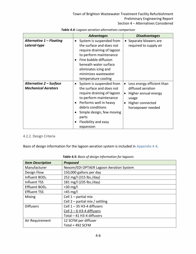
Town of Brighton Wastewater Treatment Facility Refurbishment Preliminary Engineering Report
Section 4 – Alternatives Considered
4-6
Table 4.4: Lagoon aeration alternatives comparison
Advantages Disadvantages
Alternative 1 – Floating Lateral-type
• System is suspended from the surface and does not require draining of lagoon to perform maintenance
• Fine bubble diffusion beneath water surface eliminates icing and minimizes wastewater temperature cooling
• Separate blowers are required to supply air
Alternative 2 – Surface Mechanical Aerators
• System is suspended from the surface and does not require draining of lagoon to perform maintenance
• Performs well in heavy debris conditions
• Simple design, few moving parts
• Flexibility and easy expansion
• Less energy efficient than diffused aeration
• Higher annual energy usage
• Higher connected horsepower needed
4.2.2. Design Criteria
Basis of design information for the lagoon aeration system is included in Appendix 4-4.
Table 4.5: Basis of design information for lagoons
Item Description Proposed
Manufacturer Nexom/EDI OPTAER Lagoon Aeration System
Design Flow 150,000 gallons per day
Influent BOD5 252 mg/l (315 lbs./day)
Influent TSS 181 mg/l (235 lbs./day)
Effluent BOD5 <30 mg/l
Effluent TSS <45 mg/l
Mixing Cell 1 – partial mix Cell 2 – partial mix / settling
Diffusers Cell 1 – 35 H3-4 diffusers Cell 2 – 6 H3-4 diffusers Total – 41 H3-4 diffusers
Air Requirement 12 SCFM per diffuser Total = 492 SCFM
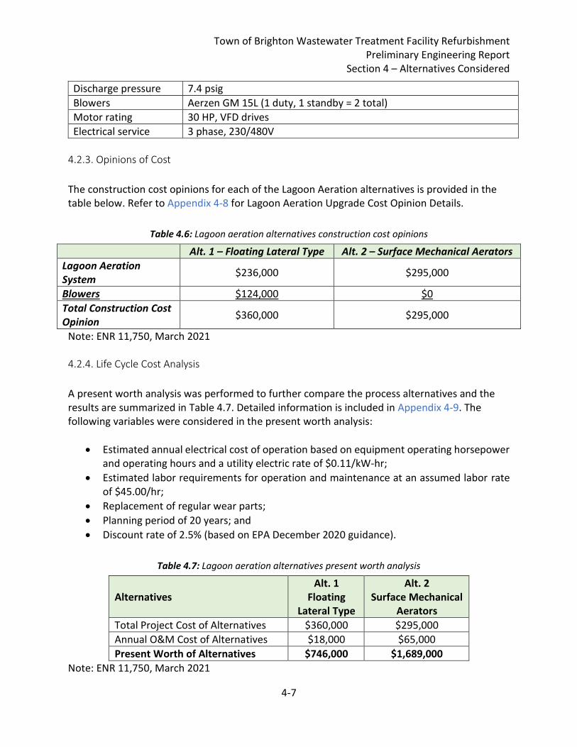
Town of Brighton Wastewater Treatment Facility Refurbishment Preliminary Engineering Report
Section 4 – Alternatives Considered
4-7
Discharge pressure 7.4 psig
Blowers Aerzen GM 15L (1 duty, 1 standby = 2 total)
Motor rating 30 HP, VFD drives
Electrical service 3 phase, 230/480V
4.2.3. Opinions of Cost
The construction cost opinions for each of the Lagoon Aeration alternatives is provided in the table below. Refer to Appendix 4-8 for Lagoon Aeration Upgrade Cost Opinion Details.
Table 4.6: Lagoon aeration alternatives construction cost opinions
Alt. 1 – Floating Lateral Type Alt. 2 – Surface Mechanical Aerators
Lagoon Aeration System
$236,000 $295,000
Blowers $124,000 $0
Total Construction Cost Opinion
$360,000 $295,000
Note: ENR 11,750, March 2021 4.2.4. Life Cycle Cost Analysis
A present worth analysis was performed to further compare the process alternatives and the results are summarized in Table 4.7. Detailed information is included in Appendix 4-9. The following variables were considered in the present worth analysis:
• Estimated annual electrical cost of operation based on equipment operating horsepower and operating hours and a utility electric rate of $0.11/kW-hr;
• Estimated labor requirements for operation and maintenance at an assumed labor rate of $45.00/hr;
• Replacement of regular wear parts;
• Planning period of 20 years; and
• Discount rate of 2.5% (based on EPA December 2020 guidance).
Table 4.7: Lagoon aeration alternatives present worth analysis
Alternatives Alt. 1
Floating Lateral Type
Alt. 2 Surface Mechanical
Aerators
Total Project Cost of Alternatives $360,000 $295,000
Annual O&M Cost of Alternatives $18,000 $65,000
Present Worth of Alternatives $746,000 $1,689,000
Note: ENR 11,750, March 2021
Town of Brighton Wastewater Treatment Facility Refurbishment Preliminary Engineering Report
Section 4 – Alternatives Considered
4-8
As shown in Table 4.7, while Alternative 2 has a lower capital cost, Alternative 1 has the lowest present worth based on the life cycle cost analysis. 4.2.5. Environmental Impacts
There are no differences between the alternatives with respect to potential environmental impacts. 4.2.6. Land Requirements
There are no differences between the alternatives with respect to land requirements. 4.2.7. Potential Construction Problems
Installation of new air piping on Alternative 1 could present additional project risk due to the need to excavate. However, it is assumed that this risk is low given that the WWTF site has been excavated and filled previously. It may be possible to consider reuse of the existing air distribution header. Removal of sludge will be required for installation of the floating lateral type aeration system (Alternative 1). Surface mechanical aerators (Alternative 2) would not require sludge removal prior installation. See additional discussion under Section 4.5 below. 4.2.8. Sustainability Considerations and Water and Energy Efficiency
Floating lateral type fine bubble aeration (Alternative 1) is more efficient at oxygen transfer into the wastewater, thus has lower energy demand (and a lower present worth cost).
4.3. Disinfection and Chemical Feed Upgrade Alternatives Disinfection and chemical feed upgrade alternatives will consider age-related replacement of equipment as well as construction of buried infrastructure for future potential metal salt addition for phosphorus removal and a redundant chlorine contact tank (CCT) channel. 4.3.1. Alternative Descriptions
Alternative 1 – Replacement of Disinfection System Feed Pumps and Support Systems: Under Alternative 1, replacement of the sodium hypochlorite and sodium bisulfite metering pumps and their auxiliary power supply are proposed to be replaced. A new eye wash station will be included. No improvements to chemical storage, mixing or layout are proposed under this alternative. Improved ventilation for the chemical storage area is considered in the Building Upgrade Alternatives in Section 4.4 below.
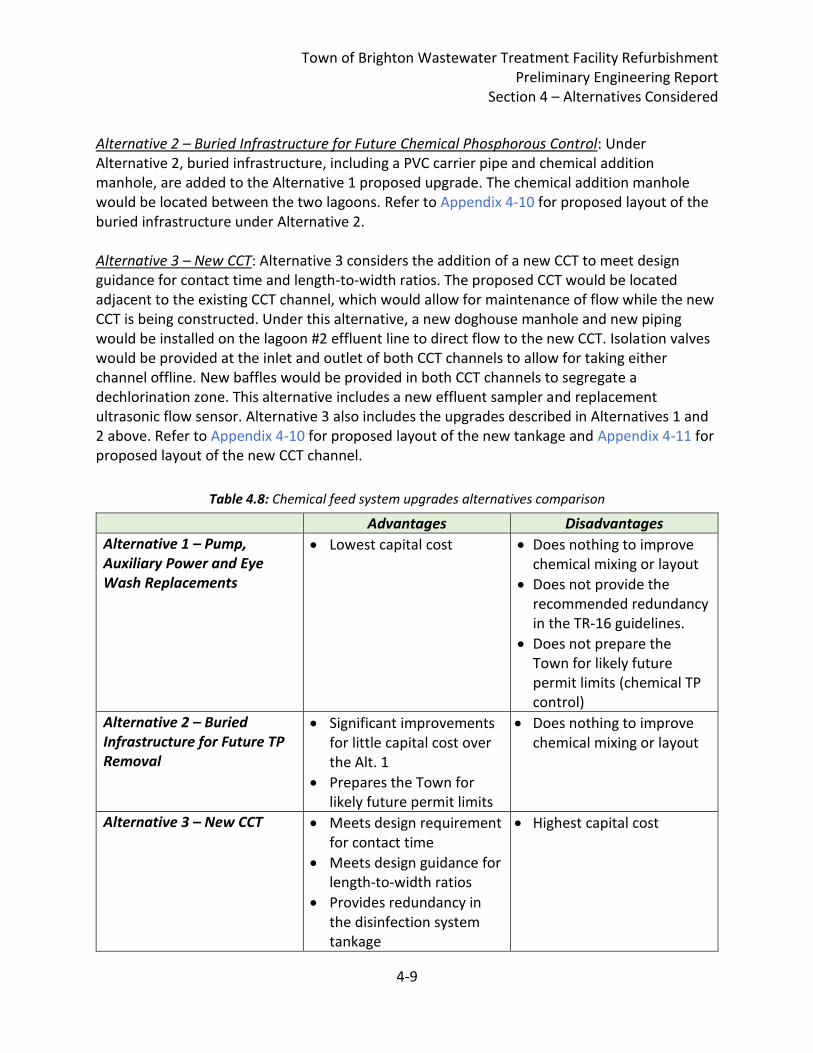
Town of Brighton Wastewater Treatment Facility Refurbishment Preliminary Engineering Report
Section 4 – Alternatives Considered
4-9
Alternative 2 – Buried Infrastructure for Future Chemical Phosphorous Control: Under Alternative 2, buried infrastructure, including a PVC carrier pipe and chemical addition manhole, are added to the Alternative 1 proposed upgrade. The chemical addition manhole would be located between the two lagoons. Refer to Appendix 4-10 for proposed layout of the buried infrastructure under Alternative 2. Alternative 3 – New CCT: Alternative 3 considers the addition of a new CCT to meet design guidance for contact time and length-to-width ratios. The proposed CCT would be located adjacent to the existing CCT channel, which would allow for maintenance of flow while the new CCT is being constructed. Under this alternative, a new doghouse manhole and new piping would be installed on the lagoon #2 effluent line to direct flow to the new CCT. Isolation valves would be provided at the inlet and outlet of both CCT channels to allow for taking either channel offline. New baffles would be provided in both CCT channels to segregate a dechlorination zone. This alternative includes a new effluent sampler and replacement ultrasonic flow sensor. Alternative 3 also includes the upgrades described in Alternatives 1 and 2 above. Refer to Appendix 4-10 for proposed layout of the new tankage and Appendix 4-11 for proposed layout of the new CCT channel.
Table 4.8: Chemical feed system upgrades alternatives comparison
Advantages Disadvantages
Alternative 1 – Pump, Auxiliary Power and Eye Wash Replacements
• Lowest capital cost • Does nothing to improve chemical mixing or layout
• Does not provide the recommended redundancy in the TR-16 guidelines.
• Does not prepare the Town for likely future permit limits (chemical TP control)
Alternative 2 – Buried Infrastructure for Future TP Removal
• Significant improvements for little capital cost over the Alt. 1
• Prepares the Town for likely future permit limits
• Does nothing to improve chemical mixing or layout
Alternative 3 – New CCT • Meets design requirement for contact time
• Meets design guidance for length-to-width ratios
• Provides redundancy in the disinfection system tankage
• Highest capital cost
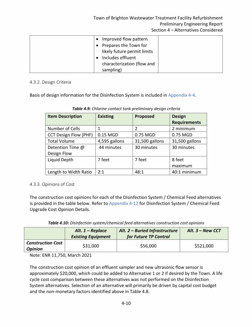
Town of Brighton Wastewater Treatment Facility Refurbishment Preliminary Engineering Report
Section 4 – Alternatives Considered
4-10
• Improved flow pattern
• Prepares the Town for likely future permit limits
• Includes effluent characterization (flow and sampling)
4.3.2. Design Criteria
Basis of design information for the Disinfection System is included in Appendix 4-4.
Table 4.9: Chlorine contact tank preliminary design criteria
Item Description Existing Proposed Design Requirements
Number of Cells 1 2 2 minimum
CCT Design Flow (PHF) 0.15 MGD 0.75 MGD 0.75 MGD
Total Volume 4,595 gallons 31,500 gallons 31,500 gallons
Detention Time @ Design Flow
44 minutes 30 minutes 30 minutes
Liquid Depth 7 feet 7 feet 8 feet maximum
Length to Width Ratio 2:1 48:1 40:1 minimum
4.3.3. Opinions of Cost
The construction cost opinions for each of the Disinfection System / Chemical Feed alternatives is provided in the table below. Refer to Appendix 4-12 for Disinfection System / Chemical Feed Upgrade Cost Opinion Details.
Table 4.10: Disinfection system/chemical feed alternatives construction cost opinions
Alt. 1 – Replace Existing Equipment
Alt. 2 – Buried Infrastructure for Future TP Control
Alt. 3 – New CCT
Construction Cost Opinion
$31,000 $56,000 $521,000
Note: ENR 11,750, March 2021 The construction cost opinion of an effluent sampler and new ultrasonic flow sensor is approximately $20,000, which could be added to Alternative 1 or 2 if desired by the Town. A life cycle cost comparison between these alternatives was not performed on the Disinfection System alternatives. Selection of an alternative will primarily be driven by capital cost budget and the non-monetary factors identified above in Table 4.8.
Town of Brighton Wastewater Treatment Facility Refurbishment Preliminary Engineering Report
Section 4 – Alternatives Considered
4-11
4.3.4. Environmental Impacts
There are no differences between the alternatives with respect to potential environmental impacts. 4.3.5. Land Requirements
Alternative 3 would require area on-site. Based on apparent property boundaries, there is sufficient space on-site within the fence line for any of the alternatives. 4.3.6. Potential Construction Problems
Upgrades to the Disinfection System may require a temporary bypass around the existing Disinfection System during construction. It is likely that maintenance of flow at the WWTF can be managed using the lagoon storage volume. A new CCT will require excavation, which may encounter unforeseen conditions such as bedrock or contaminated soils. 4.3.7. Sustainability Considerations and Water and Energy Efficiency
A new CCT channel will allow the WWTF Operators operational flexibility and resiliency that is currently not afforded at the existing Disinfection System. The increased volume will not only help Operators manage springtime high flows, but it could be used to improve settling at other times of year.
4.4. WWTF Building Facility Upgrade Alternatives Building space is needed for laboratory, staff and office space, lavatory facilities, maintenance shop, equipment/blower room, and chemical storage and feed. The following alternatives consider re-use of the existing structures and building a new Operations Building. 4.4.1. Alternative Descriptions
Alternative 1 – Control Building Addition: Under Alternative 1, additions will be made to the existing Control Building to increase floor space for office and operational needs. An addition of 14’x16’ on each side of the existing Control Building is proposed. The building upgrades include new siding, new windows and doors, new insulation, new lab and office equipment, new electrical equipment to support the new upgrades, and new plumbing and HVAC piping and equipment. Proposed modifications to the existing garage area under this alternative include new siding, new windows and doors, a new chemical storage and containment area with a new ventilation system. See Appendix 4-13 for proposed Building Facility Alternative 1 Site Plan and Floor Layout.
Town of Brighton Wastewater Treatment Facility Refurbishment Preliminary Engineering Report
Section 4 – Alternatives Considered
4-12
Alternative 2 – New Operations Building: Under Alternative 2, a new Operations Building will be constructed to the west of the influent force main. The proposed Operations Building would measure 24’ x 16’, and would house lavatory facilities, laboratory, office, and staff spaces. New mechanical/HVAC and electrical equipment would be included in the new building. Under this alternative, the existing Control Building would be repurposed as a maintenance shop, blower/equipment room, and chemical storage and containment area with a new ventilation system. This alternative also includes a $10,000 allowance to demolish or rehabilitate the existing garage. See Appendix 4-14 for proposed Building Facility Alternative 2 Site Plan and Floor Layout. If WWTF Building Facility Upgrade Alternative 2 and Headworks Alternative 3 are selected, these new building could be combined into a single building that would integrate process, electrical and controls systems. For example, a new influent sampler could easily be located in a conditioned space, and new mechanical screen controls could be located outside of the NFPA 820 classified space. 4.4.2. Design Criteria
Building upgrades will meet the current revisions of the following design standards:
• International Building Code
• Vermont Fire & Building Safety Code
• Life Safety Code NFPA 101
• Standard for Fire Protection in Wastewater Treatment and Collection Facilities NFPA 820 4.4.3. Opinions of Cost
The construction cost opinions for each of the WWTF Building Facility Upgrade Alternatives is provided in the table below. Refer to Appendix 4-15 for WWTF Building Facility Upgrade Cost Opinion Details.
Table 4.11: WWTF building facility upgrade alternatives construction cost opinions
Alt. 1 – Control Building Addition
Alt. 2 – New Operations Building
Construction Cost Opinion
$432,000 $449,000
Note: ENR 11,750, March 2021 These alternatives cost opinions could be considered equivalent as they are within the preliminary design cost opinion margin of error. A life cycle cost comparison between these alternatives was not performed on the WWTF Building Facility Upgrade Alternatives.
Town of Brighton Wastewater Treatment Facility Refurbishment Preliminary Engineering Report
Section 4 – Alternatives Considered
4-13
4.4.4. Environmental Impacts
There are no differences between the alternatives with respect to potential environmental impacts. 4.3.5. Land Requirements
Alternative 2 would require area on-site. Based on apparent property boundaries, there is sufficient space on-site within the fence line for either of the alternatives. 4.3.6. Potential Construction Problems
A new Operations Building will require excavation, which may encounter unforeseen conditions such as bedrock or contaminated soils. 4.4.7. Sustainability Considerations and Water and Energy Efficiency
There are no differences between the alternatives with respect to sustainability considerations or water and energy efficiency.
4.5. Sludge Removal Alternatives The existing lagoon aeration system includes piping laterals and aeration diffusers located across the lagoon bottom. Since the existing lagoon aeration system upgrade will require the existing lagoon aeration system infrastructure to be removed prior to replacement, the existing settled sludge in Lagoon 1 and Lagoon 2 will need to be removed to facilitate construction operations to remove and replace the existing lagoon aeration system. As such, alternatives for lagoon sludge removal are needed and described below. 4.5.1. Alternative Descriptions
Alternative 1 – Centrifuge Dewatering by Specialty Contractor Alternative 1 lagoon sludge removal by pumping, polymer aided mechanical dewatering the lagoon sludge to 20-30% total solids content, hauling the dewatered sludge cake to a landfill and landfill tipping. Alternative 1 requires an alternate plan of plant operation to be implemented during an anticipated low influent flow period. Lagoon 1 would be shut down and all plant flow would be diverted to Lagoon 2 for treatment. Lagoon 1 would be dewatered to the sludge elevation by the Town prior to the sludge dewatering specialty contractor arriving on site.
4.4.5. Land Requirements
4.4.6. Potential Construction Problems
Town of Brighton Wastewater Treatment Facility Refurbishment Preliminary Engineering Report
Section 4 – Alternatives Considered
4-14
Alternative 2 – Geobag Sludge Dewatering Alternative 2 includes lagoon sludge removal by pumping to a geobag for gravity dewatering the lagoon sludge to 20-30% total solids content and hauling the dewatered sludge cake to a landfill and landfill tipping. Alternative 2 also includes site improvements to provide adequate site setup area for the sludge dewatering operation. Other Sludge Removal Options Considered Consideration was given to lagoon sludge removal, dewatering and land application of the dewatered sludge cake, however, as per a 3/16/2021 email correspondence from Eamon Twohig, VTDEC Residuals Management Program, the lagoon sludge material cannot be land applied because there is no treatment or permit, so the only options are landfill, haul to another WWTP, or dewater and haul to a third party for management. Consideration was given to the Town managing the sludge removal directly without General Contractor involvement by directly hiring a specialty lagoon sludge removal and dewatering contractor and directly hiring a dewatered sludge cake hauling and disposal vendor. Municipal treatment plant owner/operators typically manage lagoon sludge removal in this manner to reduce overall sludge removal cost. The Town of Brighton does not anticipate having the future capability to self-manage the sludge removal task, so consideration of this option of the Town managing the sludge removal directly without General Contractor involvement was discontinued. 4.5.2. Design Criteria
Alternative 1 – Centrifuge Dewatering by Specialty Contractor Alternative 1 requires an approximate 53’x53’ minimum level site area to accommodate the sludge dewatering specialty subcontractor operation. Refer to Appendix 4-16. Plant staff would need to be available up to 12 hours per day when the specialty sludge dewatering subcontractor is on site. The sludge dewatering specialty subcontractor operation requires 480 volts, 3 phase 100-amp electrical power service within 50’ of the setup area, or a portable generator daily rate will apply. A clean source of water, 1-1/2” diameter connection, 60 psi minimum, with backflow preventer within 50’ of the setup area is required. Plant Record Drawings indicate that the plant existing potable water main is 1-1/4” diameter PVC Sch. 40 pipe. Clean water must be low iron, and low chlorine content. Access to bathroom and shower facilities is required. A forklift for loading and unloading polymer is required. Town staff will be responsible for lagoon sidewall wash down. Lagoon sludge pumping operations typically include a submersible solids handling pump and a laborer geared with waders using a high volume clean water hose to wash lagoon sludge towards the submersible pump. Dewatering is typically completed using a polymer feed system matched to the lagoon sludge quality characteristics
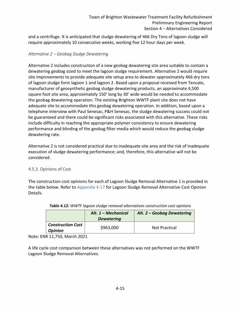
Town of Brighton Wastewater Treatment Facility Refurbishment Preliminary Engineering Report
Section 4 – Alternatives Considered
4-15
and a centrifuge. It is anticipated that sludge dewatering of 466 Dry Tons of lagoon sludge will require approximately 10 consecutive weeks, working five 12 hour days per week. Alternative 2 – Geobag Sludge Dewatering Alternative 2 includes construction of a new geobag dewatering site area suitable to contain a dewatering geobag sized to meet the lagoon sludge requirement. Alternative 2 would require site improvements to provide adequate site setup area to dewater approximately 466 dry tons of lagoon sludge form lagoon 1 and lagoon 2. Based upon a proposal received from Tencate, manufacturer of geosynthetic geobag sludge dewatering products, an approximate 4,500 square foot site area, approximately 150’ long by 30’ wide would be needed to accommodate the geobag dewatering operation. The existing Brighton WWTF plant site does not have adequate site to accommodate this geobag dewatering operation. In addition, based upon a telephone interview with Paul Senesac, P&H Senesac, the sludge dewatering success could not be guaranteed and there could be significant risks associated with this alternative. These risks include difficulty in reaching the appropriate polymer consistency to ensure dewatering performance and blinding of the geobag filter media which would reduce the geobag sludge dewatering rate. Alternative 2 is not considered practical due to inadequate site area and the risk of inadequate execution of sludge dewatering performance; and, therefore, this alternative will not be considered. 4.5.3. Opinions of Cost
The construction cost opinions for each of Lagoon Sludge Removal Alternative 1 is provided in the table below. Refer to Appendix 4-17 for Lagoon Sludge Removal Alternative Cost Opinion Details.
Table 4.12: WWTF lagoon sludge removal alternatives construction cost opinions
Alt. 1 – Mechanical Dewatering
Alt. 2 – Geobag Dewatering
Construction Cost Opinion
$963,000 Not Practical
Note: ENR 11,750, March 2021 A life cycle cost comparison between these alternatives was not performed on the WWTF Lagoon Sludge Removal Alternatives.
Town of Brighton Wastewater Treatment Facility Refurbishment Preliminary Engineering Report
Section 4 – Alternatives Considered
4-16
4.5.4. Environmental Impacts
No permanent environmental impacts are anticipated by execution of Alternative 1, however, noise and odor generation are likely during the sludge dewatering operation. 4.5.5. Land Requirements
Alternative 1 – Centrifuge Dewatering by Specialty Contractor, requires an approximate 53’x53’ minimum level site area to accommodate sludge dewatering specialty subcontractor operation. 4.5.6. Potential Construction Problems
Potential construction problems include:
• Actual sludge dry solids tonnage and costs greater than anticipated
• Actual sludge depths and volumes greater than anticipated
• Deficient sludge dewatering performance
• Availability of clean water, 1-1/2” diameter minimum, 60 psi
• Plant operation for up to 10 weeks or more with lagoon 1 shutdown
• Lagoon 1 water level drawdown by Town staff prior to dewatering
• Access to bathroom and shower facilities
• Washdown of lagoon sidewalls by Town staff 4.5.7. Sustainability Considerations and Water and Energy Efficiency
Alternative 1 will require electrical power and chemical consumption for sludge pumping and dewatering, as well as hauling of dewatered sludge cake for final recycling.
4.6. Town Hall Sewer Upgrade Alternatives Alternatives for upgrades to the Town Hall Sewer will include replacement versus rehabilitation as discussed in more detail below. A point repair of the known hole is not recommended given the existing pipe material, which is not a standard gravity sewer pipe material. 4.6.1. Alternative Descriptions
Alternative 1 – Town Hall Sewer Replacement via Open Trench Installation: Under Alternative 1, the existing Town Hall Sewer would be demolished and replaced via conventional open trench methods. A bypass would be set-up and the existing sewer would be excavated. A new 8” SDR35 sewer pipe would be installed with select material bedding and blanket. This alternative would likely require disposal of known contaminated soil and groundwater.
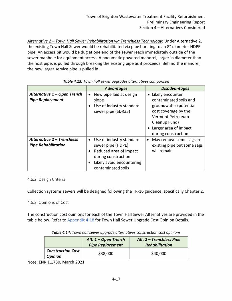
Town of Brighton Wastewater Treatment Facility Refurbishment Preliminary Engineering Report
Section 4 – Alternatives Considered
4-17
Alternative 2 – Town Hall Sewer Rehabilitation via Trenchless Technology: Under Alternative 2, the existing Town Hall Sewer would be rehabilitated via pipe bursting to an 8” diameter HDPE pipe. An access pit would be dug at one end of the sewer reach immediately outside of the sewer manhole for equipment access. A pneumatic powered mandrel, larger in diameter than the host pipe, is pulled through breaking the existing pipe as it proceeds. Behind the mandrel, the new larger service pipe is pulled in.
Table 4.13: Town hall sewer upgrades alternatives comparison
Advantages Disadvantages
Alternative 1 – Open Trench Pipe Replacement
• New pipe laid at design slope
• Use of industry standard sewer pipe (SDR35)
• Likely encounter contaminated soils and groundwater (potential cost coverage by the Vermont Petroleum Cleanup Fund)
• Larger area of impact during construction
Alternative 2 – Trenchless Pipe Rehabilitation
• Use of industry standard sewer pipe (HDPE)
• Reduced area of impact during construction
• Likely avoid encountering contaminated soils
• May remove some sags in existing pipe but some sags will remain
4.6.2. Design Criteria
Collection systems sewers will be designed following the TR-16 guidance, specifically Chapter 2. 4.6.3. Opinions of Cost
The construction cost opinions for each of the Town Hall Sewer Alternatives are provided in the table below. Refer to Appendix 4-18 for Town Hall Sewer Upgrade Cost Opinion Details.
Table 4.14: Town hall sewer upgrade alternatives construction cost opinions
Alt. 1 – Open Trench Pipe Replacement
Alt. 2 – Trenchless Pipe Rehabilitation
Construction Cost Opinion
$38,000 $40,000
Note: ENR 11,750, March 2021
Town of Brighton Wastewater Treatment Facility Refurbishment Preliminary Engineering Report
Section 4 – Alternatives Considered
4-18
These alternatives cost opinions could be considered equivalent as they are within the preliminary design cost opinion margin of error. Note that the Alternative 1 cost includes an assumed reimbursement from the Vermont Petroleum Cleanup Fund (PCF). A life cycle cost comparison between these alternatives was not performed on the Town Hall Sewer Upgrade Alternatives. However, the trenchless pipe rehabilitation may present the Town with additional operational costs as the sags in the existing sewer line may not be fully remediated requiring additional sewer cleaning effort. 4.6.4. Environmental Impacts
Open trench pipe replacement (Alternative 1) will likely generate contaminated soils and groundwater that will need to be disposed of. The Vermont Petroleum Cleanup Fund (PCF) could be utilized for reimbursement of contaminated soils and groundwater disposal. Trenchless pipe rehabilitation (Alternative 2) will likely avoid exposure to contaminated soils and groundwater during installation. 4.6.5. Land Requirements
Alternative 1 would require larger land area during construction than Alternative 2. Based on apparent property boundaries, there is sufficient space on Town property for either alternative. 4.6.6. Potential Construction Problems
Both alternatives will require excavation with potential unforeseen conditions. Both alternatives will require bypass pumping or maintenance of sewer flows. Alternative 1 has a high likelihood of encountering contaminated soils and groundwater. The Vermont PCF could be utilized for reimbursement of contaminated soils and groundwater disposal. The Vermont Sites Management Section (SMS) manages the PCF and is currently developing revised “Linear Project Guidance” that this project would have to follow in order to be eligible for reimbursement. The Linear Project Guidance generally includes a desktop review to determine potential contaminated soils; field characterization; notification to the SMS of intent to request for PCF reimbursement; and Engineer’s quantity estimates of contaminated soil and groundwater to be disposed of. The SMS can only reimbursement costs for disposal of contaminated soils and groundwater with typical average costs for contaminated material disposal. Close coordination with the SMS during bid document development will be important if Alternative 1 is selected.
Town of Brighton Wastewater Treatment Facility Refurbishment Preliminary Engineering Report
Section 4 – Alternatives Considered
4-19
4.6.7. Sustainability Considerations and Water and Energy Efficiency
Alternative 1 is preferred from an asset management perspective because it will eliminate the known sags from the existing sewer line, reducing O&M burden for the Town. Reduction of infiltration and inflow (I/I) from the collection system will lead to greater water and energy efficiency in the collection, conveyance and treatment systems. The Town should consider projects to reduce I/I.
4.7. Hotel, School & Pleasant St. Pump Stations Refurbishment Alternatives 4.7.1. Alternative Descriptions
Alternative 1 for the Hotel and School Pump Station refurbishment is limited to removal and replacement of the existing pump slide rails and slide rail supports with pump slide rails. There are no practical preliminary engineering alternatives to consider other than conventional replacement of the existing pump slide rails and supports with new pump slide rails and supports. The Town desires to replace the Hotel Pump Station control system as part of this project. The Town also desires to replace the Pleasant St. Pump Station as part of this project. 4.7.2. Design Criteria
The Alternative 1 Hotel and School Pump Station refurbishment is limited to removal and replacement of the existing pump slide rails and slide rail supports with pump slide rails made from 304 stainless steel Schedule 40 pipe and 304 stainless steel slide rail supports. The Hotel Pump Station control panel will be replaced with a control panel to meet current design standards. The Pleasant St. Pump Station will be removed and replaced with a new precast concrete wetwell, submersible pumps, slide rails, and control system to meet current design standards and regulatory requirements. 4.7.3. Opinions of Cost
The Alternative 1 construction cost opinions for the Pleasant St., Hotel and School Pump Station Refurbishment is provided in the table below. Refer to Appendix 4-19 for Pleasant St., Hotel and School Pump Station Refurbishment Cost Opinion Details.
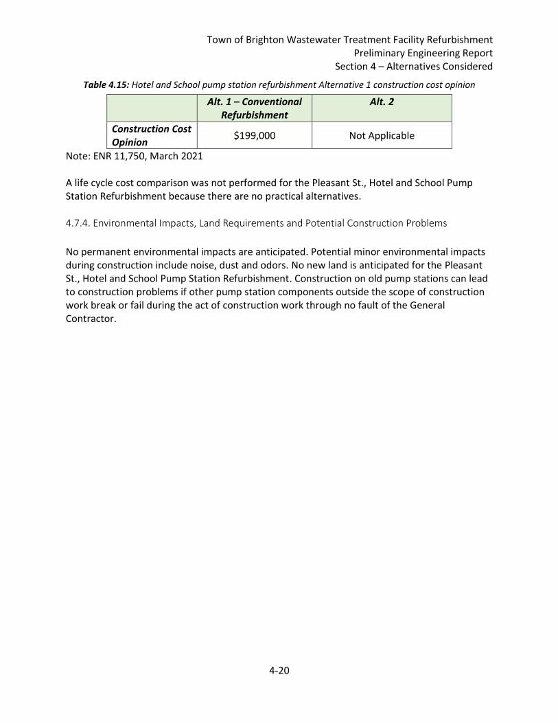
Town of Brighton Wastewater Treatment Facility Refurbishment Preliminary Engineering Report
Section 4 – Alternatives Considered
4-20
Table 4.15: Hotel and School pump station refurbishment Alternative 1 construction cost opinion
Alt. 1 – Conventional Refurbishment
Alt. 2
Construction Cost Opinion
$199,000 Not Applicable
Note: ENR 11,750, March 2021 A life cycle cost comparison was not performed for the Pleasant St., Hotel and School Pump Station Refurbishment because there are no practical alternatives. 4.7.4. Environmental Impacts, Land Requirements and Potential Construction Problems.
No permanent environmental impacts are anticipated. Potential minor environmental impacts during construction include noise, dust and odors. No new land is anticipated for the Pleasant St., Hotel and School Pump Station Refurbishment. Construction on old pump stations can lead to construction problems if other pump station components outside the scope of construction work break or fail during the act of construction work through no fault of the General Contractor.
Town of Brighton Wastewater Treatment Facility Refurbishment Preliminary Engineering Report
Section 5 – Selection of an Alternative
5-1
5. Selection of an Alternative
5.1. Selected Alternative The Wastewater Treatment Facility 20-Year Evaluation Final Report, dated July 20, 2018, was prepared for the Town of Brighton by Hoyle, Tanner & Associates, Inc. and included identification of wastewater infrastructure needs and delineation of capital improvement project needs to be addressed by the Town, and larger infrastructure refurbishment needs that the Town planned to complete as part of a federally funded project (a Project) to be completed by a General Construction Contractor. Chief plant operator Marty Frizzell, contract operator with Piscataqua Environmental Services and long-time Brighton resident, planned to lead the capital improvement plan execution. The Brighton Wastewater Treatment Facility 60% Deliverable Preliminary Engineering Report, dated March 29, 2021, prepared by Hoyle, Tanner & Associates, Inc. included defined needs, alternative refurbishment descriptions and capital costs to refurbish the existing wastewater infrastructure as part of a Project. Very sadly, on April 1, 2021 chief plant operator Marty Frizzell passed away. During meetings on April 5, 2021 and April 6, 2021, the 60% PER Deliverable Report was discussed amongst the Engineer and Town Water and Sewer Commission. Generally, the Town desired a comprehensive upgrade that will allow the Town to operate the WWTF efficiently and safely well into the future. The Town selected to advance the following Alternatives:
1. Alternative 3 – New Headworks Building: This alternative meets industry-standard design guidance for screening of inorganic material with the highest degree of material removal, which will improve operations and protect the environment. There is reduced potential for operator exposure to wastewater. The building allows for protection and maintenance of equipment and allows for required operational tasks to be performed out of the weather. While Alternative 3 was the costliest, it is selected for these non-monetary factors.
2. Alternative 1 – Fine Bubble/Floating Lateral Aeration System: This alternative is the most efficient technology considered, with the lowest connected horsepower and annual energy usage. As a result, this alternative has the lowest present worth cost.
3. Alternative 3 – New Chlorine Contact Tank: This is the only alternative that meets design guidance for disinfection contact time and redundancy. It will allow for operational flexibility and chemical addition and mixing can be optimized. This alternative also includes the installation of buried infrastructure that will facilitate future chemical addition to control phosphorous. While Alternative 3 was the costliest, it is selected for these non-monetary factors.
4. Alternative 2 – New Control Building: This alternative allows for construction of a new Control Building that will provide greater flexibility for office and laboratory layout
Town of Brighton Wastewater Treatment Facility Refurbishment Preliminary Engineering Report
Section 5 – Selection of an Alternative
5-2
design to meet the Town’s needs. The existing Operations Building will be rehabilitated, providing needed equipment and operational/maintenance spaces. Cost opinions for the two alternatives are considered roughly equivalent at this preliminary design level.
5. Alternative 1 – Mechanical Dewatering for Sludge Removal: This alternative is determined to be the only feasible alternative.
6. Alternative 1 – Town Hall Sewer Replacement: This alternative will allow for a new sewer pipe meeting standard design guidance. Cost opinions for the two alternatives are considered roughly equivalent at this preliminary design level (assuming contaminated soils and groundwater are removed with Petroleum Cleanup Fund reimbursement).
7. Alternative 1 – Hotel, School and Pleasant Street Pump Station improvements: This alternative is determined to be the only feasible alternative.
Additionally, in consideration of the loss of longtime plant operator Marty Frizzell, the Town does not anticipate having the future capability to self-manage the Hotel Pump Station Control System and Pleasant St. Pump Station refurbishment as part of a Town Capital Improvement Plan. The Town desires to add the Hotel Pump Station Control System and Pleasant St. Pump Station refurbishment to the proposed Project. As indicated in Sections 2.3 and 3.3, WWTF effluent flow has approached 80% exceedance of the WWTF design capacity for 90 days, which indicates a potential collection system inflow and/or infiltration problem. The Town desires to add the completion of an inflow and infiltration removal effort to the proposed Project.
Town of Brighton Wastewater Treatment Facility Refurbishment Preliminary Engineering Report
Section 6 – Proposed Project
6-1
6. Proposed Project The proposed project consists of an overall refurbishment project at the Brighton WWTF as well as select work in the Brighton collection system, including replacement of the Town Hall Sewer and new slide rails at the Hotel and School Pump Stations. The proposed project focuses on addressing critical refurbishment items due to equipment age as well as improving operations and energy efficiency.
6.1. Brighton Wastewater Treatment Facility Proposed Project The proposed project consists of the following items: New Headworks Facilities will consist of a new Headworks Building measuring approximately 8’x24’. Building material construction will be determined during final design. Flow will be diverted to the new Headworks Building via a new doghouse manhole. In the new doghouse manhole, an overflow weir could be installed which can act as a Headworks bypass when needed for operational and maintenance purposes. The new Headworks Building will include:
• New mechanical fine screen equipment, with bagger and screenings dumpster
• New gas detection system
• New Influent flow measurement and automated sampler
• Rated for Class 1, Division 1 hazardous space
• Provide ventilation for compliance with current NFPA 820 requirements Note that consideration should be given to combining the new Headworks Building with the new Operations Building during final design.
New Lagoon Aeration System will consist of diffuser aeration equipment, including new blowers, new air manifold, yard air piping, air control valves, aeration lateral piping, diffusers and anchor assemblies. The new blowers will be installed with VFDs and dissolved oxygen (DO) probes will be installed in the lagoons to control air supply. Blowers will be installed in the rehabilitated existing Control Building. Existing blowers and lagoon aeration system will be demolished or abandoned.
• Lagoon 1 – 35 diffusers (partial mix)
• Lagoon 2 – 6 diffusers (partial mix / settling)
• Total of 41 diffusers at 12 SCFM demand per diffuser
• Two (2) 30-hp blowers with VFDs (1 duty, 1 standby)
• Total Air Requirement of 492 SCFM at 7.4 psig New Disinfection Facilities will consist of a new chlorine contact tank (CCT), new disinfection feed pumps, new auxiliary power for the feed pumps, new disinfection instrumentation and
Town of Brighton Wastewater Treatment Facility Refurbishment Preliminary Engineering Report
Section 6 – Proposed Project
6-2
controls, and new effluent sampler and effluent flow measurement. The new CCT will be sized to meet VTDEC design guidance for hydraulic capacity and will include redundant channels to allow maximum operational flexibility. The new CCT will also include new baffling and level control devices. New Chemical Addition Facilities will consist of an underground conduit carrier pipe from the rehabilitated Control Building to an injection location between the two lagoons for future phosphorous control chemical addition. New and Rehabilitated Building Facilities will consist of a new Operations Building that will house office spaces, a laboratory, and new electrical equipment and measure approximately 24’ x 16’. The existing Control Building will be rehabilitated to include maintenance space, chemical storage and feed, and blower equipment. Sludge Removal will consist of mechanical dewatering and hauling of sludge cake to either landfill disposal or recycling. Collection System Improvements will consist of the following:
• Town Hall Sewer Upgrades will include replacement of the existing Town Hall Sewer via conventional open trench installation methods.
• Inflow and Infiltration Removal will be included in the project to improve operational efficiency of the collection, conveyance and treatment systems. The preferred method of I/I removal will be determined during final design.
• Hotel, School & Pleasant St. Pump Stations Refurbishment will consist of removal and replacement of the Hotel and School Pump Stations slide rails, the Hotel Pump Station Control System and the Pleasant St. Pump Station.
6.2. Project Schedule A proposed project schedule to implement the proposed WWTF refurbishment project is shown in the following Table 6.1:
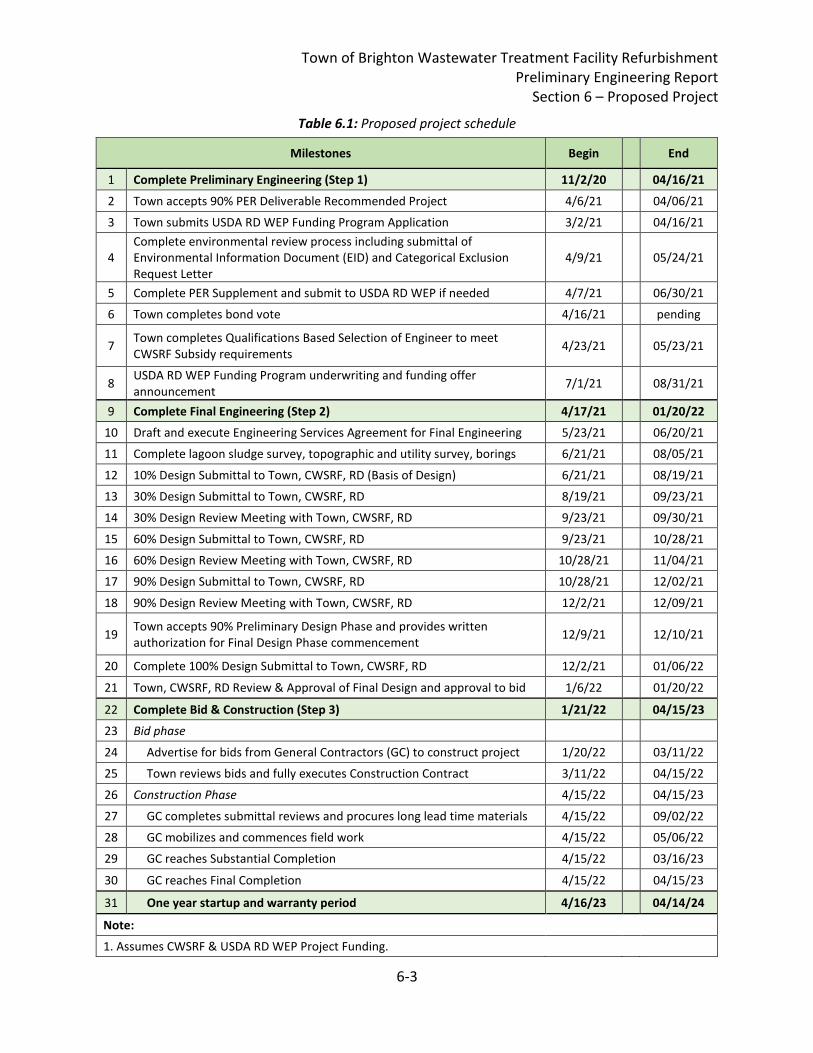
Town of Brighton Wastewater Treatment Facility Refurbishment Preliminary Engineering Report
Section 6 – Proposed Project
6-3
Table 6.1: Proposed project schedule
Milestones Begin End
1 Complete Preliminary Engineering (Step 1) 11/2/20 04/16/21
2 Town accepts 90% PER Deliverable Recommended Project 4/6/21 04/06/21
3 Town submits USDA RD WEP Funding Program Application 3/2/21 04/16/21
4 Complete environmental review process including submittal of Environmental Information Document (EID) and Categorical Exclusion Request Letter
4/9/21 05/24/21
5 Complete PER Supplement and submit to USDA RD WEP if needed 4/7/21 06/30/21
6 Town completes bond vote 4/16/21 pending
7 Town completes Qualifications Based Selection of Engineer to meet CWSRF Subsidy requirements
4/23/21 05/23/21
8 USDA RD WEP Funding Program underwriting and funding offer announcement
7/1/21 08/31/21
9 Complete Final Engineering (Step 2) 4/17/21 01/20/22
10 Draft and execute Engineering Services Agreement for Final Engineering 5/23/21 06/20/21
11 Complete lagoon sludge survey, topographic and utility survey, borings 6/21/21 08/05/21
12 10% Design Submittal to Town, CWSRF, RD (Basis of Design) 6/21/21 08/19/21
13 30% Design Submittal to Town, CWSRF, RD 8/19/21 09/23/21
14 30% Design Review Meeting with Town, CWSRF, RD 9/23/21 09/30/21
15 60% Design Submittal to Town, CWSRF, RD 9/23/21 10/28/21
16 60% Design Review Meeting with Town, CWSRF, RD 10/28/21 11/04/21
17 90% Design Submittal to Town, CWSRF, RD 10/28/21 12/02/21
18 90% Design Review Meeting with Town, CWSRF, RD 12/2/21 12/09/21
19 Town accepts 90% Preliminary Design Phase and provides written authorization for Final Design Phase commencement
12/9/21 12/10/21
20 Complete 100% Design Submittal to Town, CWSRF, RD 12/2/21 01/06/22
21 Town, CWSRF, RD Review & Approval of Final Design and approval to bid 1/6/22 01/20/22
22 Complete Bid & Construction (Step 3) 1/21/22 04/15/23
23 Bid phase
24 Advertise for bids from General Contractors (GC) to construct project 1/20/22 03/11/22
25 Town reviews bids and fully executes Construction Contract 3/11/22 04/15/22
26 Construction Phase 4/15/22 04/15/23
27 GC completes submittal reviews and procures long lead time materials 4/15/22 09/02/22
28 GC mobilizes and commences field work 4/15/22 05/06/22
29 GC reaches Substantial Completion 4/15/22 03/16/23
30 GC reaches Final Completion 4/15/22 04/15/23
31 One year startup and warranty period 4/16/23 04/14/24
Note:
1. Assumes CWSRF & USDA RD WEP Project Funding.
Town of Brighton Wastewater Treatment Facility Refurbishment Preliminary Engineering Report
Section 6 – Proposed Project
6-4
6.3 Permit Requirements A summary of the potential permits and approvals required for this project is provided below
based on input from local, State, and Federal agencies:
• Conditional Use Determination: A wetlands review will need to be conducted for the
project area to identify any existing wetlands areas in the project area.
• Archeological Assessment: As a minimum, information on the project will need to be
submitted to the State of Vermont Division for Historic Preservation for concurrence.
Depending on the level of review, a Phase IA investigation may be required.
• State General Permit for Stormwater Runoff from General Construction Sites: Coverage
as a low risk site under the General Permit will need to be submitted to the State of
Vermont Water Quality Division.
• Act 250: A request for a determination on the need for an Act 250 permit for this project
will need to be submitted to the State of Vermont District office.
• Environmental Information Document (EID): An EID will need to be prepared to request
a Categorical Exclusion (CATEX) from a detailed environmental review.
• Watershed Management Basis for Final Design: A Basis for Final Design document
describing the new and modified process elements will need to be submitted to the
Watershed Management Division for review and approval.
• Fire Safety Permit
• Town Planning and Zoning
6.4. Sustainability Considerations Proposed upgrades to the Headworks Facility will improve operations by providing a conditioned space out of the elements to remove screenings and take influent flow measurements and sampling. Installation of a mechanical screen in the Headwork Facility will improve screenings capture which will reduce operational burden in the lagoons and potential to pass inorganic material to the receiving waters. Upgraded lagoon aeration equipment will improve energy efficiency through installation of new blowers and diffusers that will likely more efficiently transfer oxygen to the lagoon water. A new CCT will improve treatment capacity and operational flexibility. Removal of the lagoon sludge will also improve treatment capacity and reduce potential for permit exceedances.
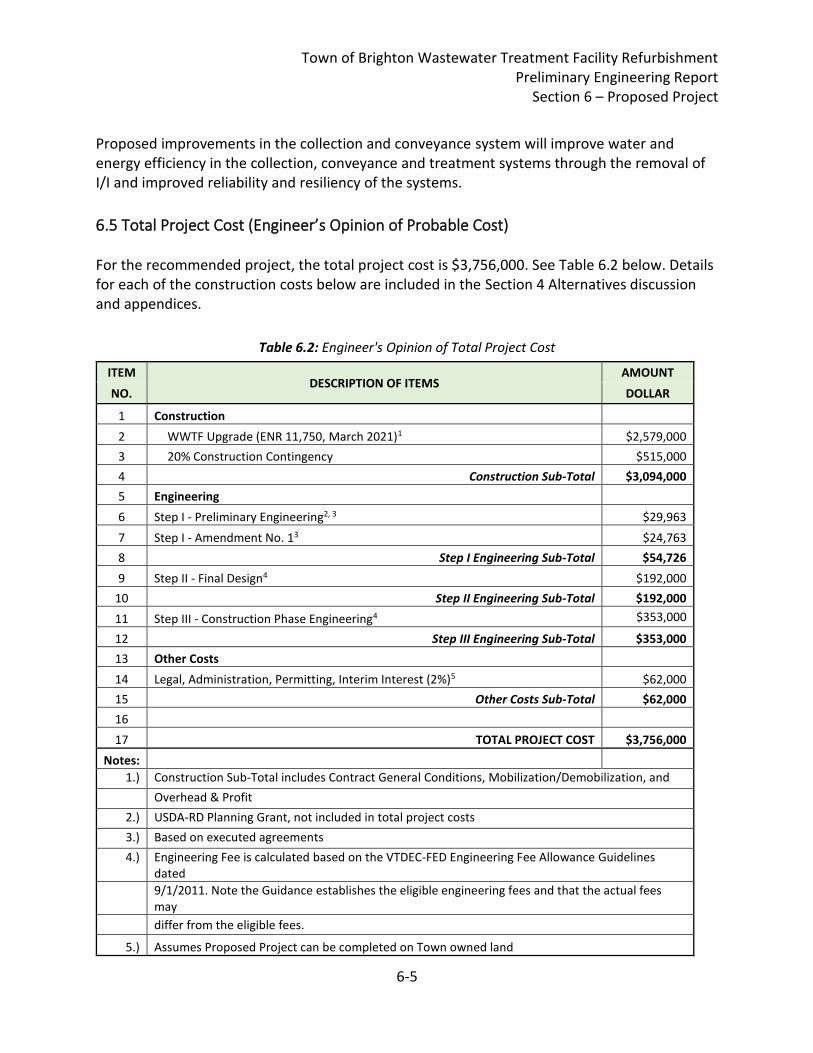
Town of Brighton Wastewater Treatment Facility Refurbishment Preliminary Engineering Report
Section 6 – Proposed Project
6-5
Proposed improvements in the collection and conveyance system will improve water and energy efficiency in the collection, conveyance and treatment systems through the removal of I/I and improved reliability and resiliency of the systems.
6.5 Total Project Cost (Engineer’s Opinion of Probable Cost) For the recommended project, the total project cost is $3,756,000. See Table 6.2 below. Details for each of the construction costs below are included in the Section 4 Alternatives discussion and appendices.
Table 6.2: Engineer's Opinion of Total Project Cost
ITEM DESCRIPTION OF ITEMS
AMOUNT
NO. DOLLAR
1 Construction
2 WWTF Upgrade (ENR 11,750, March 2021)1 $2,579,000
3 20% Construction Contingency $515,000
4 Construction Sub-Total $3,094,000
5 Engineering
6 Step I - Preliminary Engineering2, 3 $29,963
7 Step I - Amendment No. 13 $24,763
8 Step I Engineering Sub-Total $54,726
9 Step II - Final Design4 $192,000
10 Step II Engineering Sub-Total $192,000
11 Step III - Construction Phase Engineering4 $353,000
12 Step III Engineering Sub-Total $353,000
13 Other Costs
14 Legal, Administration, Permitting, Interim Interest (2%)5 $62,000
15 Other Costs Sub-Total $62,000
16
17 TOTAL PROJECT COST $3,756,000
Notes:
1.) Construction Sub-Total includes Contract General Conditions, Mobilization/Demobilization, and
Overhead & Profit
2.) USDA-RD Planning Grant, not included in total project costs
3.) Based on executed agreements
4.) Engineering Fee is calculated based on the VTDEC-FED Engineering Fee Allowance Guidelines dated
9/1/2011. Note the Guidance establishes the eligible engineering fees and that the actual fees may
differ from the eligible fees.
5.) Assumes Proposed Project can be completed on Town owned land
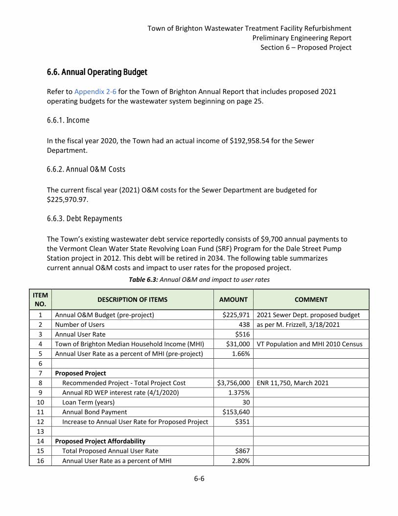
Town of Brighton Wastewater Treatment Facility Refurbishment Preliminary Engineering Report
Section 6 – Proposed Project
6-6
6.5. Annual Operating Budget Refer to Appendix 2-6 for the Town of Brighton Annual Report that includes proposed 2021 operating budgets for the wastewater system beginning on page 25. 6.5.1 Income
In the fiscal year 2020, the Town had an actual income of $192,958.54 for the Sewer Department. 6.5.2 Annual O&M Costs
The current fiscal year (2021) O&M costs for the Sewer Department are budgeted for $225,970.97. 6.5.3 Debt Repayments
The Town’s existing wastewater debt service reportedly consists of $9,700 annual payments to the Vermont Clean Water State Revolving Loan Fund (SRF) Program for the Dale Street Pump Station project in 2012. This debt will be retired in 2034. The following table summarizes current annual O&M costs and impact to user rates for the proposed project.
Table 6.3: Annual O&M and impact to user rates
ITEM NO.
DESCRIPTION OF ITEMS AMOUNT COMMENT
1 Annual O&M Budget (pre-project) $225,971 2021 Sewer Dept. proposed budget
2 Number of Users 438 as per M. Frizzell, 3/18/2021
3 Annual User Rate $516
4 Town of Brighton Median Household Income (MHI) $31,000 VT Population and MHI 2010 Census
5 Annual User Rate as a percent of MHI (pre-project) 1.66%
6
7 Proposed Project
8 Recommended Project - Total Project Cost $3,756,000 ENR 11,750, March 2021
9 Annual RD WEP interest rate (4/1/2020) 1.375%
10 Loan Term (years) 30
11 Annual Bond Payment $153,640
12 Increase to Annual User Rate for Proposed Project $351
13
14 Proposed Project Affordability
15 Total Proposed Annual User Rate $867
16 Annual User Rate as a percent of MHI 2.80%
6.6. Annual Operating Budget
6.6.1. Income
6.6.2. Annual O&M Costs
6.6.3. Debt Repayments
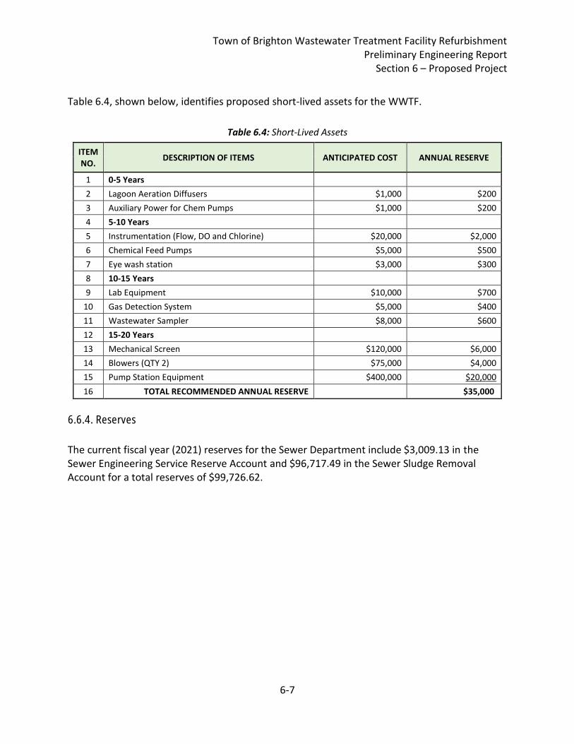
Town of Brighton Wastewater Treatment Facility Refurbishment Preliminary Engineering Report
Section 6 – Proposed Project
6-7
Table 6.4, shown below, identifies proposed short-lived assets for the WWTF.
Table 6.4: Short-Lived Assets
ITEM NO.
DESCRIPTION OF ITEMS ANTICIPATED COST ANNUAL RESERVE
1 0-5 Years
2 Lagoon Aeration Diffusers $1,000 $200
3 Auxiliary Power for Chem Pumps $1,000 $200
4 5-10 Years
5 Instrumentation (Flow, DO and Chlorine) $20,000 $2,000
6 Chemical Feed Pumps $5,000 $500
7 Eye wash station $3,000 $300
8 10-15 Years
9 Lab Equipment $10,000 $700
10 Gas Detection System $5,000 $400
11 Wastewater Sampler $8,000 $600
12 15-20 Years
13 Mechanical Screen $120,000 $6,000
14 Blowers (QTY 2) $75,000 $4,000
15 Pump Station Equipment $400,000 $20,000
16 TOTAL RECOMMENDED ANNUAL RESERVE $35,000
6.5.4 Reserves
The current fiscal year (2021) reserves for the Sewer Department include $3,009.13 in the Sewer Engineering Service Reserve Account and $96,717.49 in the Sewer Sludge Removal Account for a total reserves of $99,726.62.
6.6.4. Reserves
Town of Brighton Wastewater Treatment Facility Refurbishment Preliminary Engineering Report
Section 7 – Conclusions and Recommendations
7-1
7. 90% Deliverable Conclusions and Recommendations The following recommendations should be considered next steps for the Town of Brighton to consider: Preliminary Engineering / Funding:
1. The USDA RD WEP funding program is a federal funding program intended to assist rural communities with wastewater infrastructure project funding. According to USDA RD, grants offered from this program to Brighton to construct this project may not exceed 75 percent for projects that are necessary to alleviate a health or sanitary problem. The Town should further consider the extent and nature of the proposed Project refurbishment need and determine and document if the project is necessary to alleviate a health or sanitary problem. If it is determined that the proposed project is necessary to alleviate a health or sanitary problem, then the Town should submit the document as a PER Supplement to USDA RD prior to June 30, 2021 for consideration of the Town’s anticipated USDA RD WEP funding application.
2. Submit Environmental Information Document (EID) and Categorical Exclusion request. 3. Hold bond vote for the proposed project.
Final Engineering:
4. Complete Qualifications-Based Selection for Final Design Engineering. 5. Completion of final engineering efforts should include site survey, soil borings in the
locations of proposed buildings/structures and sludge quantity and characterization. This work should be completed in the summer of 2021.
6. Consider NFPA 820 requirements for proposed Headworks Facility upgrades, including feasibility of combining proposed Headworks Facility with the proposed Operations Building.
7. This Project proposed to include an allowance budget for I/I removal on a “find and fix” basis. Consider if I/I removal should be completed under a separate Contract from the base WWTF and pump station upgrades in the Project.
8. Coordinate with VTDEC Sites Management Section on the likely contaminated soils that will be encountered at the Town Hall Sewer site to ensure Petroleum Cleanup Fund (PCF) eligibility.
The project schedule for the WWTF upgrade anticipates beginning final design and engineering in the Summer of 2021 to allow for construction commencement during the 2022 construction season.

Town of Brighton Wastewater Treatment Facility Refurbishment Preliminary Engineering Report
Section 8 – Appendices
8-1
8. Appendices
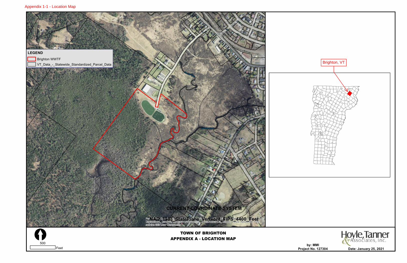
Esri, HERE, Garmin, (c) OpenStreetMap contributors, and the GIS user community, Source: Esri,DigitalGlobe, GeoEye, Earthstar Geographics, CNES/Airbus DS, USDA, USGS, AeroGRID, IGN,and the GIS User Community
TOWN OF BRIGHTONAPPENDIX A - LOCATION MAP[
LEGENDBrighton WWTFVT_Data_-_Statewide_Standardized_Parcel_Data
Date: January 25, 2021500
Feet
CURRENT CORRDINATE SYSTEMNAD_1983_StatePlane_Vermont_FIPS_4400_Feet
by: MMIProject No. 127304
Brighton, VT
Appendix 1-1 - Location Map
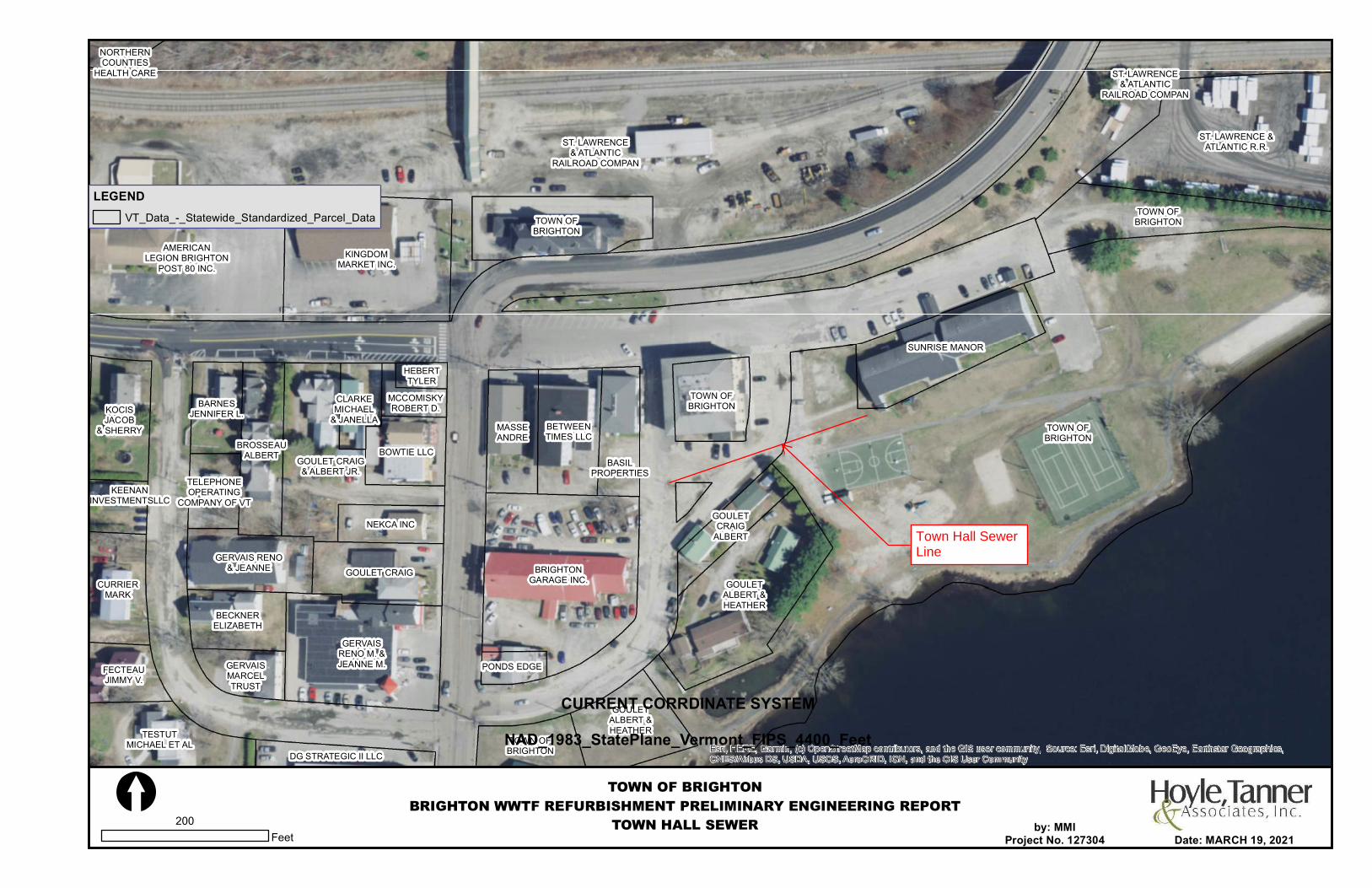
SUNRISE MANOR
AMERICANLEGION BRIGHTON
POST 80 INC.
FECTEAUJIMMY V.
BASILPROPERTIES
KOCISJACOB
& SHERRY
BRIGHTONGARAGE INC.
BROSSEAUALBERT
KEENANINVESTMENTSLLC
CLARKEMICHAEL
& JANELLA
HEBERTTYLER
BETWEENTIMES LLC
GERVAIS RENO& JEANNE
KINGDOMMARKET INC.
GERVAISMARCELTRUST
GERVAISRENO M. &JEANNE M.
GOULETALBERT &HEATHER
GOULETALBERT &HEATHER
NEKCA INC
GOULET CRAIG& ALBERT JR.
BOWTIE LLC
GOULETCRAIG
ALBERT
CURRIERMARK
GOULET CRAIG
TELEPHONEOPERATING
COMPANY OF VT
NORTHERNCOUNTIES
HEALTH CARE
PONDS EDGE
BARNESJENNIFER L.
DG STRATEGIC II LLC
MASSEANDRE
MCCOMISKYROBERT D.
ST. LAWRENCE &ATLANTIC R.R.
ST. LAWRENCE& ATLANTIC
RAILROAD COMPAN
ST. LAWRENCE& ATLANTIC
RAILROAD COMPAN
BECKNERELIZABETH
TESTUTMICHAEL ET AL
TOWN OFBRIGHTON
TOWN OFBRIGHTON
TOWN OFBRIGHTON
TOWN OFBRIGHTON
TOWN OFBRIGHTON
Esri, HERE, Garmin, (c) OpenStreetMap contributors, and the GIS user community, Source: Esri, DigitalGlobe, GeoEye, Earthstar Geographics,CNES/Airbus DS, USDA, USGS, AeroGRID, IGN, and the GIS User Community
TOWN OF BRIGHTONBRIGHTON WWTF REFURBISHMENT PRELIMINARY ENGINEERING REPORT
TOWN HALL SEWER[
LEGENDVT_Data_-_Statewide_Standardized_Parcel_Data
Date: MARCH 19, 2021200
Feet
CURRENT CORRDINATE SYSTEMNAD_1983_StatePlane_Vermont_FIPS_4400_Feet
by: MMIProject No. 127304
Town Hall SewerLine
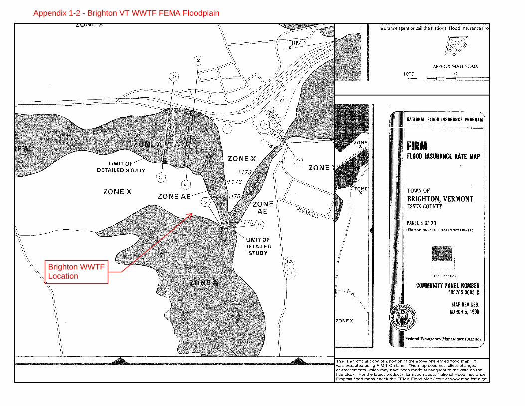
Brighton WWTFLocation
Appendix 1-2 - Brighton VT WWTF FEMA Floodplain

17,169
872.2
Waste Management Vermont Agency of Natural Resources
13,005
© Vermont Agency of Natural Resources
661.0
1:
WGS_1984_Web_Mercator_Auxiliary_Sphere
Meters661.00
NOTES
Map created using ANR's Natural Resources Atlas
LEGEND
330.00
vermont.gov
DISCLAIMER: This map is for general reference only. Data layers that appear onthis map may or may not be accurate, current, or otherwise reliable. ANR and
the State of Vermont make no representations of any kind, including but notlimited to, the warranties of merchantability, or fitness for a particular use, nor
are any such warranties to be implied with respect to the data on this map.
January 27, 2021
THIS MAP IS NOT TO BE USED FOR NAVIGATION
1" = 1084 1cm = 130Ft. Meters
Landfills
OPERATING
CLOSED
Land Use Restrictions
Class IV GW Reclass
Class VI GW Reclass
Deed Restriction
Easement
Land Record Notice
Other
Hazardous Site
Hazardous Waste Generators
Brownfields
Aboveground Storage Tank
Underground Storage Tank (working)
Parcels (standardized)
Roads
Interstate
US Highway; 1
State Highway
Town Highway (Class 1)
Town Highway (Class 2,3)
Town Highway (Class 4)
State Forest Trail
National Forest Trail
Legal Trail
Private Road/Driveway
Proposed Roads
Stream/River
Stream
Intermittent Stream
Town Boundary
Appendix 1-3A - Waste Management
Brighton WWTF
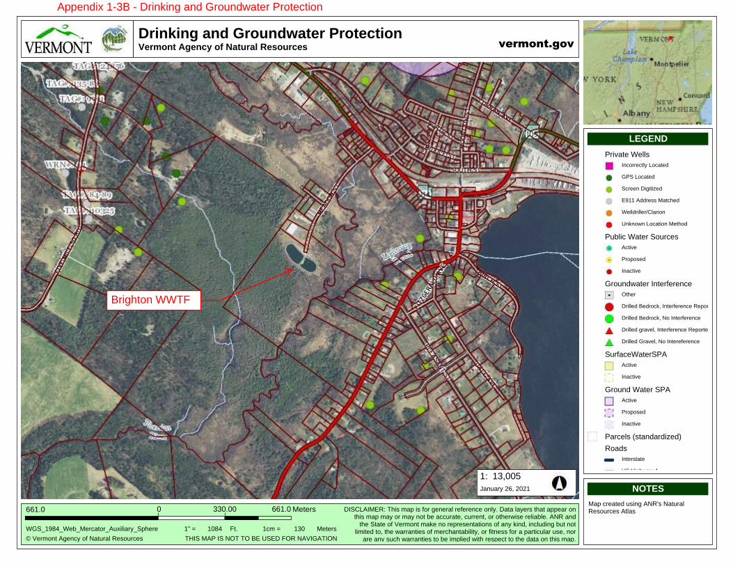
17,169
872.2
Drinking and Groundwater ProtectionVermont Agency of Natural Resources
13,005
© Vermont Agency of Natural Resources
661.0
1:
WGS_1984_Web_Mercator_Auxiliary_Sphere
Meters661.00
NOTES
Map created using ANR's Natural Resources Atlas
LEGEND
330.00
vermont.gov
DISCLAIMER: This map is for general reference only. Data layers that appear onthis map may or may not be accurate, current, or otherwise reliable. ANR and
the State of Vermont make no representations of any kind, including but notlimited to, the warranties of merchantability, or fitness for a particular use, nor
are any such warranties to be implied with respect to the data on this map.
January 26, 2021
THIS MAP IS NOT TO BE USED FOR NAVIGATION
1" = 1084 1cm = 130Ft. Meters
Private Wells
Incorrectly Located
GPS Located
Screen Digitized
E911 Address Matched
Welldriller/Clarion
Unknown Location Method
Public Water Sources
Active
Proposed
Inactive
Groundwater Interference
Other
Drilled Bedrock, Interference Reported
Drilled Bedrock, No Interference
Drilled gravel, Interference Reported
Drilled Gravel, No Intereference
SurfaceWaterSPA
Active
Inactive
Ground Water SPA
Active
Proposed
Inactive
Parcels (standardized)
Roads
Interstate
US Highway; 1
State Highway
Town Highway (Class 1)
Town Highway (Class 2,3)
Town Highway (Class 4)
State Forest Trail
National Forest Trail
Appendix 1-3B - Drinking and Groundwater Protection
Brighton WWTF
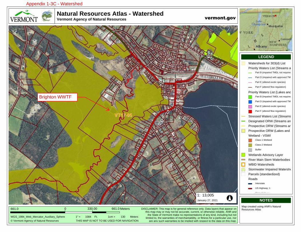
17,169
872.2
Natural Resources Atlas - WatershedVermont Agency of Natural Resources
13,005
© Vermont Agency of Natural Resources
661.0
1:
WGS_1984_Web_Mercator_Auxiliary_Sphere
Meters661.00
NOTES
Map created using ANR's Natural Resources Atlas
LEGEND
330.00
vermont.gov
DISCLAIMER: This map is for general reference only. Data layers that appear onthis map may or may not be accurate, current, or otherwise reliable. ANR and
the State of Vermont make no representations of any kind, including but notlimited to, the warranties of merchantability, or fitness for a particular use, nor
are any such warranties to be implied with respect to the data on this map.
January 27, 2021
THIS MAP IS NOT TO BE USED FOR NAVIGATION
1" = 1084 1cm = 130Ft. Meters
Watersheds for 303(d) List
Priority Waters List (Streams and Rive
Part B (impaired TMDL not required)
Part D (impaired with approved TMDL)
Part E (altered exotic species)
Part F (altered flow regulation)
Priority Waters List (Lakes and Ponds)
Part B (impaired TMDL not required)
Part D (impaired with approved TMDL)
Part E (altered exotic species)
Part F (altered flow regulation)
Stressed Waters List (Streams and Riv
Designated ORW (Streams and Rivers
Prospective ORW (Streams and River
Prospective ORW (Lakes and Ponds)
Wetland - VSWI
Class 1 Wetland
Class 2 Wetland
Buffer
Wetlands Advisory Layer
River Main Stem Waterbodies
WBID Watersheds
Stormwater Impaired Watersheds
Parcels (standardized)
Roads
Interstate
US Highway; 1
State Highway
Town Highway (Class 1)
Town Highway (Class 2,3)
Town Highway (Class 4)
State Forest Trail
National Forest Trail
Legal Trail
Brighton WWTF
Appendix 1-3C - Watershed
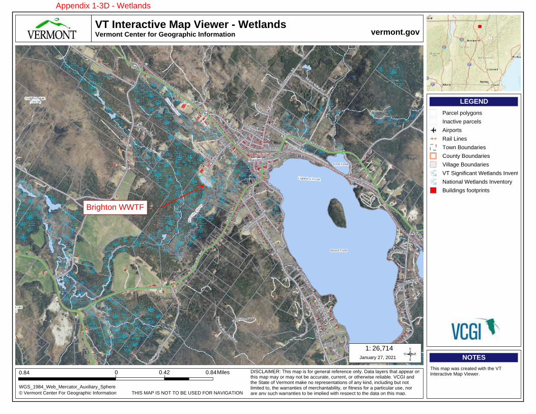
1.1 35,266
VT Interactive Map Viewer - WetlandsVermont Center for Geographic Information
26,714
© Vermont Center For Geographic Information
0.84
THIS MAP IS NOT TO BE USED FOR NAVIGATION
1:
WGS_1984_Web_Mercator_Auxiliary_Sphere
0
NOTES
This map was created with the VT Interactive Map Viewer.
LEGEND
0.42
vermont.gov
DISCLAIMER: This map is for general reference only. Data layers that appear on this map may or may not be accurate, current, or otherwise reliable. VCGI and the State of Vermont make no representations of any kind, including but not limited to, the warranties of merchantability, or fitness for a particular use, nor are any such warranties to be implied with respect to the data on this map.
January 27, 2021
0.84Miles
Parcel polygons
Inactive parcels
Airports
Rail Lines
Town Boundaries
County Boundaries
Village Boundaries
VT Significant Wetlands Inventory
National Wetlands Inventory
Buildings footprints
Appendix 1-3D - Wetlands
Brighton WWTF
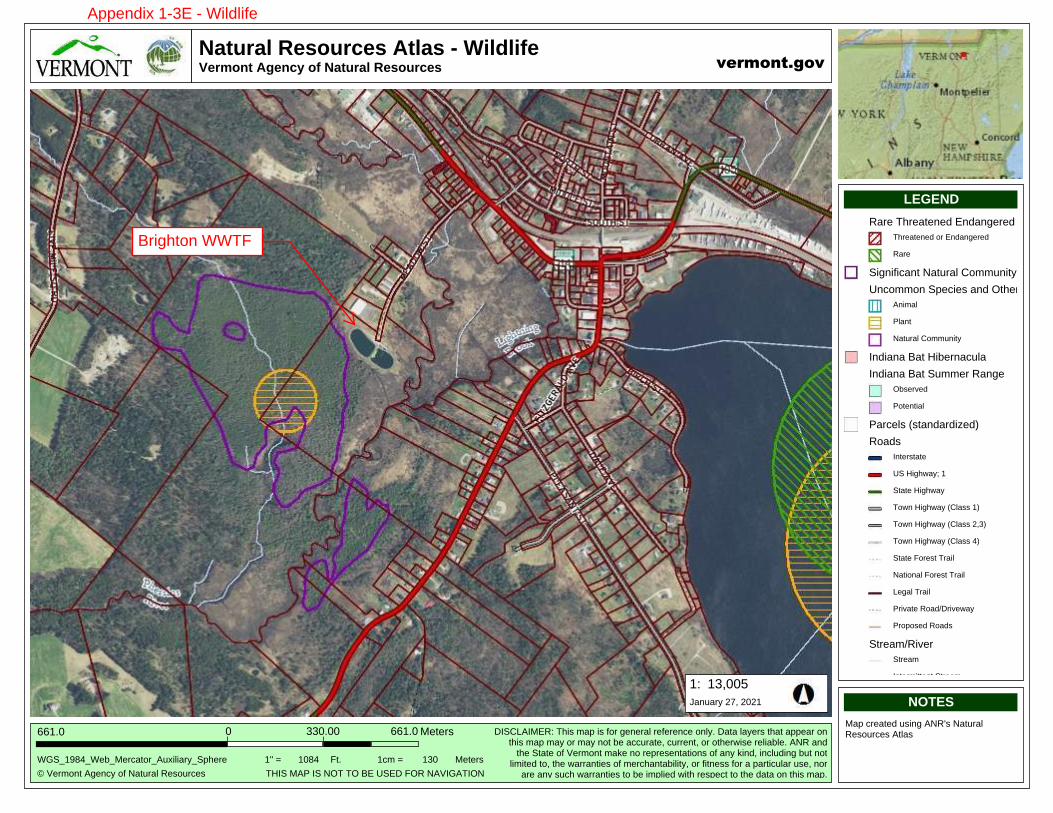
17,169
872.2
Natural Resources Atlas - WildlifeVermont Agency of Natural Resources
13,005
© Vermont Agency of Natural Resources
661.0
1:
WGS_1984_Web_Mercator_Auxiliary_Sphere
Meters661.00
NOTES
Map created using ANR's Natural Resources Atlas
LEGEND
330.00
vermont.gov
DISCLAIMER: This map is for general reference only. Data layers that appear onthis map may or may not be accurate, current, or otherwise reliable. ANR and
the State of Vermont make no representations of any kind, including but notlimited to, the warranties of merchantability, or fitness for a particular use, nor
are any such warranties to be implied with respect to the data on this map.
January 27, 2021
THIS MAP IS NOT TO BE USED FOR NAVIGATION
1" = 1084 1cm = 130Ft. Meters
Rare Threatened Endangered Species
Threatened or Endangered
Rare
Significant Natural Community
Uncommon Species and Other Featur
Animal
Plant
Natural Community
Indiana Bat Hibernacula
Indiana Bat Summer Range
Observed
Potential
Parcels (standardized)
Roads
Interstate
US Highway; 1
State Highway
Town Highway (Class 1)
Town Highway (Class 2,3)
Town Highway (Class 4)
State Forest Trail
National Forest Trail
Legal Trail
Private Road/Driveway
Proposed Roads
Stream/River
Stream
Intermittent Stream
Town Boundary
Brighton WWTF
Appendix 1-3E - Wildlife
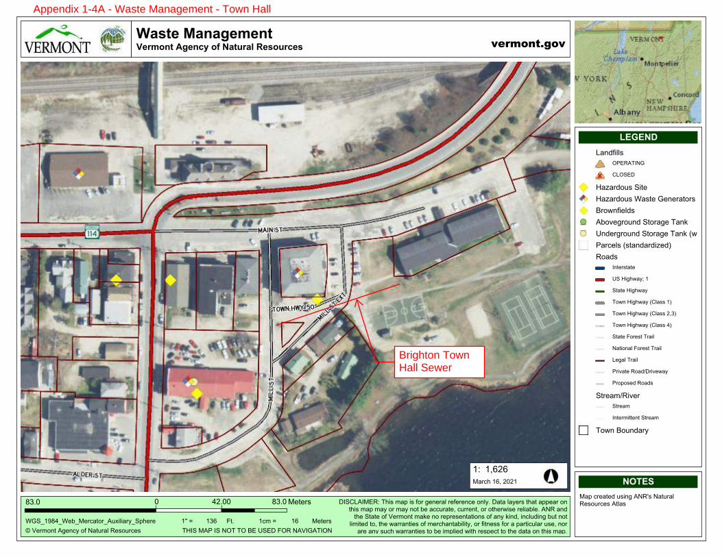
�����
�����
��� ��������������� ������ �� ����� �������
�����
��� !"#$%�&' $()�#*�+,%-!,.�/ 0#-!( 0
12��
�3
4567��1�74 879 !(,%#!7&-:;.;,!)76<= !
9 % !012���
�>?@A
9,<�(! ,% B�-0;$'�&+/C0�+,%-!,.�/ 0#-!( 0�&%.,0
D@E@�F
�����
GHIJKLMNOKG
PQ6RS&Q9T/3�U=;0�",<�;0�*#!�' $ !,.�! * ! $( �#$.)��P,%,�.,) !0�%=,%�,<< ,!�#$%=;0�",<�",)�#!�",)�$#%�8 �,((-!,% ��(-!! $%��#!�#%= !V;0 �! .;,8. ��&+/�,$B%= �6%,% �#*�� !"#$%�",W �$#�! <! 0 $%,%;#$0�#*�,$)�W;$B��;$(.-B;$'�8-%�$#%.;";% B�%#��%= �V,!!,$%; 0�#*�" !(=,$%,8;.;%)��#!�*;%$ 00�*#!�,�<,!%;(-.,!�-0 ��$#!,! �,$)�0-(=�V,!!,$%; 0�%#�8 �;"<.; B�V;%=�! 0< (%�%#�%= �B,%,�#$�%=;0�",<�
9,!(=���������
UXQ6�9&Y�Q6�+ZU�UZ�[T�\6TP�]Z/�+&�Q5&UQZ+
�̂�_� �2� �("�_� ��]%� 9 % !0
S,$B*;..0
ZYT/&UQ+5
RSZ6TP
X,̀,!B#-0�6;%
X,̀,!B#-0�4,0% �5 $ !,%#!0
[!#V$*; .B0
&8#a '!#-$B�6%#!,' �U,$W
\$B !'!#-$B�6%#!,' �U,$W�bV#!W;$'c
Y,!( .0�b0%,$B,!B;̀ Bc
/#,B0
Q$% !0%,%
\6�X;'=V,)d��
6%,% �X;'=V,)
U#V$�X;'=V,)�bR.,00��c
U#V$�X;'=V,)�bR.,00���2c
U#V$�X;'=V,)�bR.,00��c
6%,% �]#! 0%�U!,;.
+,%;#$,.�]#! 0%�U!,;.
S ',.�U!,;.
Y!;a,% �/#,BeP!;a V,)
Y!#<#0 B�/#,B0
6%! ,"e/;a !
6%! ,"
Q$% !";%% $%�6%! ,"
U#V$�[#-$B,!)
Brighton TownHall Sewer
Appendix 1-4A - Waste Management - Town Hall
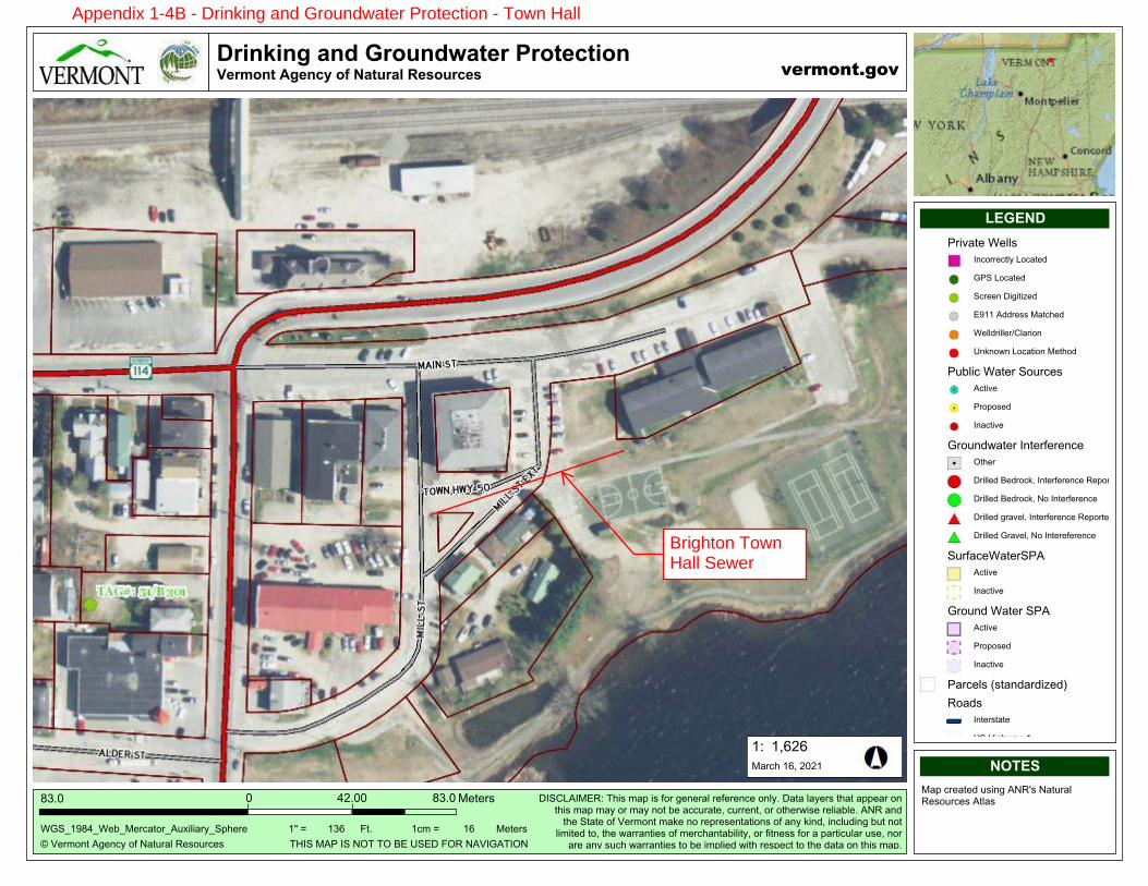
�����
�����
���� ������������������������������� ��������������� �!����!
�����
"#$%&'()*#+,%)-.#(/#01*2&13#4%5(2&-%5
67��
�8
9:;<��6�<9%=<>%&-1*(&<+2?@3@1&.<;AB%&%
>%*%&567���
�CDEF
>1A#-&%1*%G#25@),#+04H5#01*2&13#4%5(2&-%5#+*315
IE�E��
�����
JKLMNOPQRNJ
ST;UV+T>W48#XB@5#'1A#@5#/(&#,%)%&13#&%/%&%)-%#()3.�#S1*1#31.%&5#*B1*#1AA%1&#()*B@5#'1A#'1.#(&#'1.#)(*#=%#1--2&1*%�#-2&&%)*�#(&#(*B%&Y@5%#&%3@1=3%�#+04#1)G*B%#;*1*%#(/#$%&'()*#'1Z%#)(#&%A&%5%)*1*@()5#(/#1).#Z@)G�#@)-32G@),#=2*#)(*3@'@*%G#*(�#*B%#Y1&&1)*@%5#(/#'%&-B1)*1=@3@*.�#(&#/@*)%55#/(#A1&*@-231%�#)(&1&%#1).#52-B#Y1&&1)*@%5#*(#=%#@'A3@%G#Y@*B#&%5A%-*#*(#*B%#G1*1#()#*B@5#'1A�
>1&-B#���#����
X[T;#>+\#T;#0]X#X]#̂W#_;WS#̀]4#0+$T:+XT]0
�a#b# �7� �-'#b# ��*̀� >%*%&5
\&@c1*%#9%335
T)-(&&%-*3.#V(-1*%G
:\;#V(-1*%G
;-&%%)#S@,@*@d%G
W���#+GG&%55#>1*-B%G
9%33G&@33%&eU31&@()
_)Z)(Y)#V(-1*@()#>%*B(G
\2=3@-#91*%&#;(2&-%5
+-*@c%
\&(A(5%G
T)1-*@c%
:&(2)GY1*%&#T)*%&/%&%)-%
]*B%&
S&@33%G#̂%G&(-Z�#T)*%&/%&%)-%#4%A(&*%G
S&@33%G#̂%G&(-Z�#0(#T)*%&/%&%)-%
S&@33%G#,&1c%3�#T)*%&/%&%)-%#4%A(&*%G
S&@33%G#:&1c%3�#0(#T)*%&%/%&%)-%
;2&/1-%91*%&;\+
+-*@c%
T)1-*@c%
:&(2)G#91*%&#;\+
+-*@c%
\&(A(5%G
T)1-*@c%
\1&-%35#f5*1)G1&G@d%Gg
4(1G5
T)*%&5*1*%
_;#[@,BY1.h#�
;*1*%#[@,BY1.
X(Y)#[@,BY1.#fU3155#�g
X(Y)#[@,BY1.#fU3155#��7g
X(Y)#[@,BY1.#fU3155#�g
;*1*%#̀(&%5*#X&1@3
01*@()13#̀(&%5*#X&1@3
Appendix 1-4B - Drinking and Groundwater Protection - Town Hall
Brighton TownHall Sewer
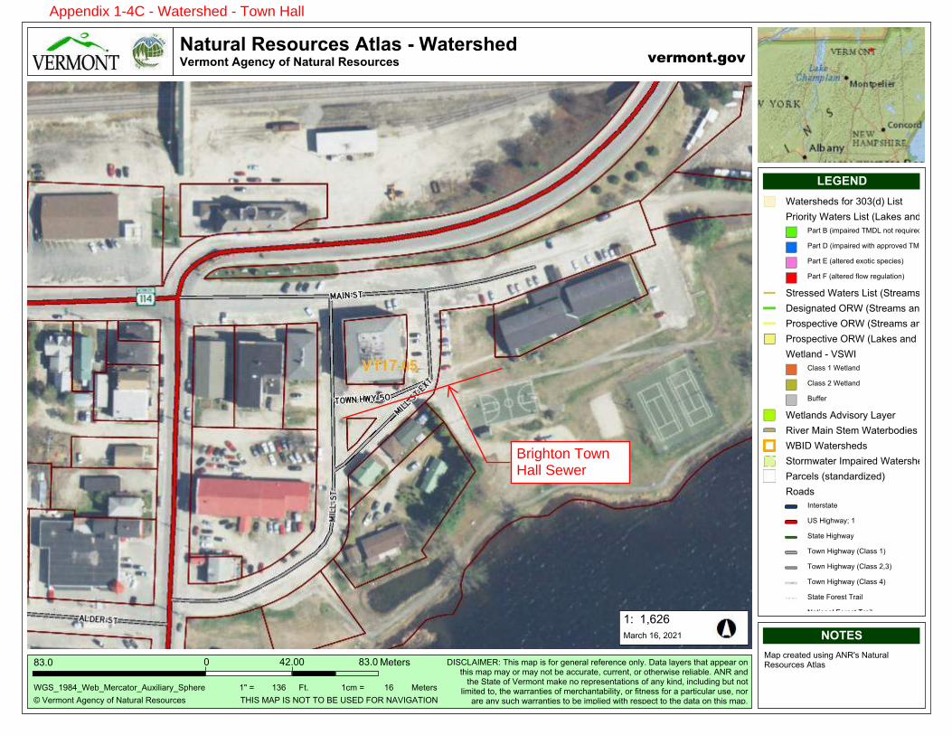
�����
�����
��� ������������ ������������������������������� ����������
�����
� !"#$%&' ()"&*+ %, -.'/#.0 1"2%/#*"2
34��
�5
6789��3�96":9;"#*.'%#9(/<=0=.#+98>?"#"
;"'"#234���
�@ABC
;.> *#".'"D /2=&) (-1E2 -.'/#.0 1"2%/#*"2 ('0.2
FBGB�H
�����
IJKLMNOPQMI
RS8TU(S;V15 W?=2 $.> =2 ,%# )"&"#.0 #","#"&*" %&0+� R.'. 0.+"#2 '?.' .>>".# %&'?=2 $.> $.+ %# $.+ &%' :" .**/#.'"� */##"&'� %# %'?"#X=2" #"0=.:0"� (-1 .&D'?" 8'.'" %, !"#$%&' $.Y" &% #">#"2"&'.'=%&2 %, .&+ Y=&D� =&*0/D=&) :/' &%'0=$='"D '%� '?" X.##.&'="2 %, $"#*?.&'.:=0='+� %# ,='&"22 ,%# . >.#'=*/0.# /2"� &%#.#" .&+ 2/*? X.##.&'="2 '% :" =$>0="D X='? #"2>"*' '% '?" D.'. %& '?=2 $.>�
;.#*? ��� ����
WZS8 ;([ S8 -\W W\ ]V ̂8VR _\1 -(!S7(WS\-
�̀ a �4� �*$ a ��_'� ;"'"#2
6.'"#2?"D2 ,%# 4�4bDc U=2'
[#=%#='+ 6.'"#2 U=2' bU.Y"2 .&D [%&D2c
[.#' ] b=$>.=#"D W;RU &%' #"d/=#"Dc
[.#' R b=$>.=#"D X='? .>>#%e"D W;RUc
[.#' V b.0'"#"D "<%'=* 2>"*="2c
[.#' _ b.0'"#"D ,0%X #")/0.'=%&c
8'#"22"D 6.'"#2 U=2' b8'#".$2 .&D 1=e
R"2=)&.'"D \16 b8'#".$2 .&D 1=e"#2
[#%2>"*'=e" \16 b8'#".$2 .&D 1=e"#
[#%2>"*'=e" \16 bU.Y"2 .&D [%&D2c
6"'0.&D f !86S
T0.22 � 6"'0.&D
T0.22 � 6"'0.&D
]/,,"#
6"'0.&D2 (De=2%#+ U.+"#
1=e"# ;.=& 8'"$ 6.'"#:%D="2
6]SR 6.'"#2?"D2
8'%#$X.'"# S$>.=#"D 6.'"#2?"D2
[.#*"02 b2'.&D.#D=g"Dc
1%.D2
S&'"#2'.'"
8̂ Z=)?X.+h �
8'.'" Z=)?X.+
W%X& Z=)?X.+ bT0.22 �c
W%X& Z=)?X.+ bT0.22 ��4c
W%X& Z=)?X.+ bT0.22 �c
8'.'" _%#"2' W#.=0
-.'=%&.0 _%#"2' W#.=0
U").0 W#.=0
[#=e.'" 1%.DiR#=e"X.+
[#%>%2"D 1%.D2
8'#".$i1=e"#
8'#".$
S&'"#$=''"&' 8'#".$
Brighton TownHall Sewer
Appendix 1-4C - Watershed - Town Hall
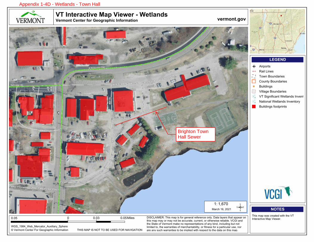
��� �����
����� ���������������� ������������ �������� ��� ����� �� ����� �����
��!"�
#$%&'()*+$,&*+&'$-)'$.&)/'01234$5*6)'(0+3)*
���7
895:$;<=$5:$>?8$8?$@A$B:AC$-?D$><%5.<85?>
�E
F.:G�HI�GF&JG;&'40+)'G<KL3M30'NG:12&'&
�
OP�QR
823S$(01$T0S$4'&0+&U$T3+2$+2&$%8$5*+&'04+3V&$;01$%3&T&'�
WQ�QOX
���Y
�� ���Z���
C5:,[<5;ADE$823S$(01$3S$6)'$/&*&'0M$'&6&'&*4&$)*MN�$C0+0$M0N&'S$+20+$011&0'$)*$+23S$(01$(0N$)'$(0N$*)+$J&$044K'0+&�$4K''&*+�$)'$)+2&'T3S&$'&M30JM&�$%,.5$0*U$+2&$:+0+&$)6$%&'()*+$(0\&$*)$'&1'&S&*+0+3)*S$)6$0*N$\3*U�$3*4MKU3*/$JK+$*)+$M3(3+&U$+)�$+2&$T0''0*+3&S$)6$(&'420*+0J3M3+N�$)'$63+*&SS$6)'$0$10'+34KM0'$KS&�$*)'$0'&$0*N$SK42$T0''0*+3&S$+)$J&$3(1M3&U$T3+2$'&S1&4+$+)$+2&$U0+0$)*$+23S$(01�
;0'42$�!�$����
���7;3M&S
<3'1)'+S
D03M$[3*&S
8)T*$@)K*U0'3&S
,)K*+N$@)K*U0'3&S
@K3MU3*/S
%3MM0/&$@)K*U0'3&S
%8$:3/*36340*+$F&+M0*US$5*V&*+)'N
>0+3)*0M$F&+M0*US$5*V&*+)'N
@K3MU3*/S$6))+1'3*+S
Brighton TownHall Sewer
Appendix 1-4D - Wetlands - Town Hall
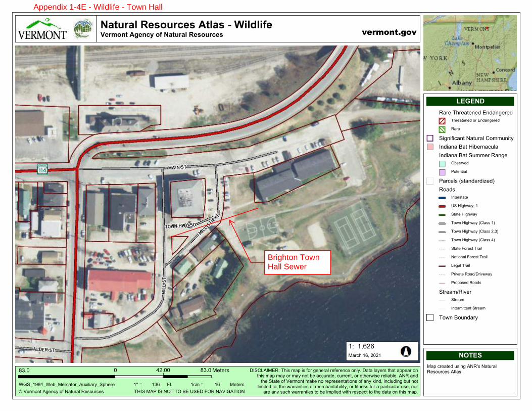
�����
�����
��� ������������ ������ � ����������������������� ����������
�����
� !"#$%&' ()"&*+ %, -.'/#.0 1"2%/#*"2
34��
�5
6789��3�96":9;"#*.'%#9(/<=0=.#+98>?"#"
;"'"#234���
�@ABC
;.> *#".'"D /2=&) (-1E2 -.'/#.0 1"2%/#*"2 ('0.2
FBGB�H
�����
IJKLMNOPQMI
RS8TU(S;V15 W?=2 $.> =2 ,%# )"&"#.0 #","#"&*" %&0+� R.'. 0.+"#2 '?.' .>>".# %&'?=2 $.> $.+ %# $.+ &%' :" .**/#.'"� */##"&'� %# %'?"#X=2" #"0=.:0"� (-1 .&D'?" 8'.'" %, !"#$%&' $.Y" &% #">#"2"&'.'=%&2 %, .&+ Y=&D� =&*0/D=&) :/' &%'0=$='"D '%� '?" X.##.&'="2 %, $"#*?.&'.:=0='+� %# ,='&"22 ,%# . >.#'=*/0.# /2"� &%#.#" .&+ 2/*? X.##.&'="2 '% :" =$>0="D X='? #"2>"*' '% '?" D.'. %& '?=2 $.>�
;.#*? ��� ����
WZS8 ;([ S8 -\W W\ ]V ̂8VR _\1 -(!S7(WS\-
�̀ a �4� �*$ a ��_'� ;"'"#2
1.#" W?#".'"&"D V&D.&)"#"D 8>"*="2
W?#".'"&"D %# V&D.&)"#"D
1.#"
8=)&=,=*.&' -.'/#.0 T%$$/&='+
S&D=.&. ].' Z=:"#&.*/0.
S&D=.&. ].' 8/$$"# 1.&)"
\:2"#b"D
[%'"&'=.0
[.#*"02 c2'.&D.#D=d"De
1%.D2
S&'"#2'.'"
8̂ Z=)?X.+f �
8'.'" Z=)?X.+
W%X& Z=)?X.+ cT0.22 �e
W%X& Z=)?X.+ cT0.22 ��4e
W%X& Z=)?X.+ cT0.22 �e
8'.'" _%#"2' W#.=0
-.'=%&.0 _%#"2' W#.=0
U").0 W#.=0
[#=b.'" 1%.DgR#=b"X.+
[#%>%2"D 1%.D2
8'#".$g1=b"#
8'#".$
S&'"#$=''"&' 8'#".$
W%X& ]%/&D.#+
Appendix 1-4E - Wildlife - Town Hall
Brighton TownHall Sewer
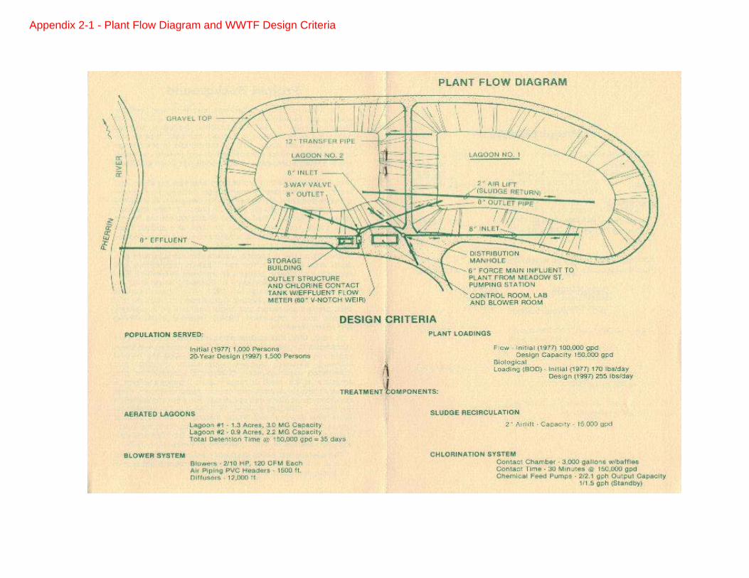
Appendix 2-1 - Plant Flow Diagram and WWTF Design Criteria
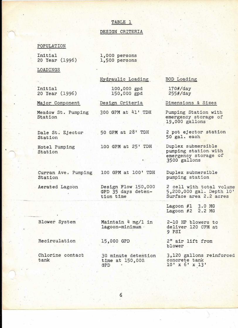
POPULATION
Initial20 Year (1996)
LOADINGS
Initial20 Year (1996)
Major Component
Meadow St. PumpingStation
Dale St; EjectorStation
Hotel PumpingStation
Curran Ave. PumpingStation
Aerated Lagoon
Blower System
Recirculation
Chlorine contacttank
TABLE 1
DESIGN CRITERIA
1,000 persons1,500 persons
Hydraulic Loading.
100,000 gpd150,000 gpd
Design Criteria
300 GPM at 41' TDH
50 GPM at 28' TDH
100 GPM at 25' TDH
100 GPM at 100' TDH
Design Flow 150,000GPD 35 days deten-tion time
Maintain 4 mg/l inlagoon-minimum .
15,000 GPD
30 minute detentiontime at 150,000.GPD
6
BOD Loading
l70#/day255#/day
Dimensions & Sizes
Pumping Station withemergency storage of19,000 gallons·
2 pot ejector station50 gal. each
Duplex submersiblepumping station withemergency storage of3500 gallons
Duplex submersiblepumping station
2 cell with total volume5,200,000 gal. Depth 10'Surface area 2.2 acres
Lagoon #1 3.0 MGLagoon #2 2.2 MG
2-10 HP blowers todeliver 120CFM at9 PSI
2" air lift fromblower
3,120 gallons reinforcedconcrete tank10' x 6' x 13'
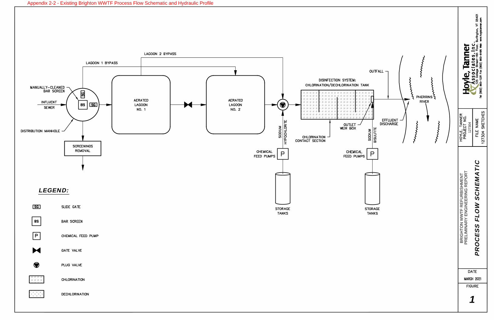
PR
ELIM
IN
AR
Y E
NG
IN
EE
RIN
G R
EP
OR
T
BR
IG
HT
ON
W
WT
F R
EF
UR
BIS
HM
EN
T
127304
PR
OC
ES
S F
LO
W S
CH
EM
AT
IC
1
LEGEND:
Appendix 2-2 - Existing Brighton WWTF Process Flow Schematic and Hydraulic Profile
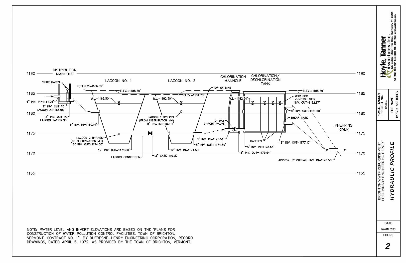
PR
ELIM
IN
AR
Y E
NG
IN
EE
RIN
G R
EP
OR
T
BR
IG
HT
ON
W
WT
F R
EF
UR
BIS
HM
EN
T
127304
HY
DR
AU
LIC
P
RO
FIL
E
2
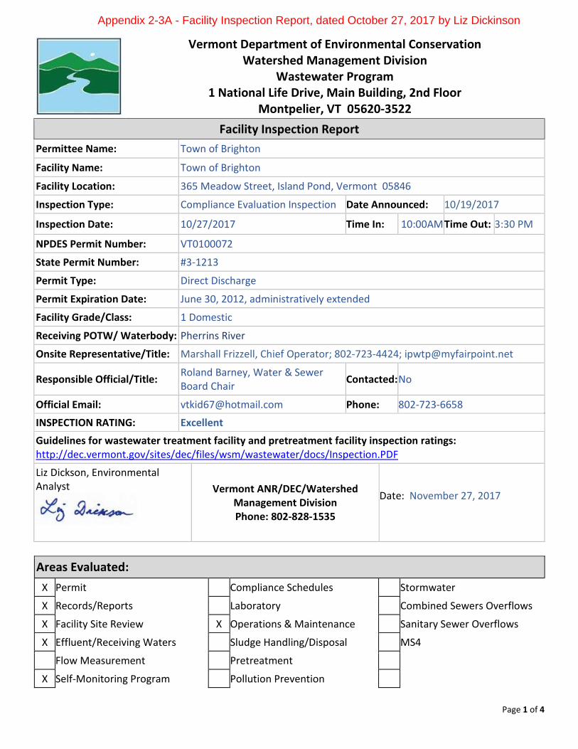
Page 1 of 4
Vermont Department of Environmental Conservation Watershed Management Division
Wastewater Program 1 National Life Drive, Main Building, 2nd Floor
Montpelier, VT 05620-3522
Facility Inspection Report Permittee Name: Town of Brighton
Facility Name: Town of Brighton
Facility Location: 365 Meadow Street, Island Pond, Vermont 05846
Inspection Type: Compliance Evaluation Inspection Date Announced: 10/19/2017
Inspection Date: 10/27/2017 Time In: 10:00AM Time Out: 3:30 PM
NPDES Permit Number: VT0100072
State Permit Number: #3-1213
Permit Type: Direct Discharge
Permit Expiration Date: June 30, 2012, administratively extended
Facility Grade/Class: 1 Domestic
Receiving POTW/ Waterbody: Pherrins River
Onsite Representative/Title: Marshall Frizzell, Chief Operator; 802-723-4424; [email protected]
Responsible Official/Title: Roland Barney, Water & Sewer Board Chair Contacted: No
Official Email: [email protected] Phone: 802-723-6658
INSPECTION RATING: Excellent Guidelines for wastewater treatment facility and pretreatment facility inspection ratings: http://dec.vermont.gov/sites/dec/files/wsm/wastewater/docs/Inspection.PDF
Liz Dickson, Environmental Analyst
Vermont ANR/DEC/Watershed Management Division Phone: 802-828-1535
Date: November 27, 2017
Areas Evaluated: X Permit Compliance Schedules Stormwater
X Records/Reports Laboratory Combined Sewers Overflows
X Facility Site Review X Operations & Maintenance Sanitary Sewer Overflows
X Effluent/Receiving Waters Sludge Handling/Disposal MS4
Flow Measurement Pretreatment
X Self-Monitoring Program Pollution Prevention
Appendix 2-3A - Facility Inspection Report, dated October 27, 2017 by Liz Dickinson
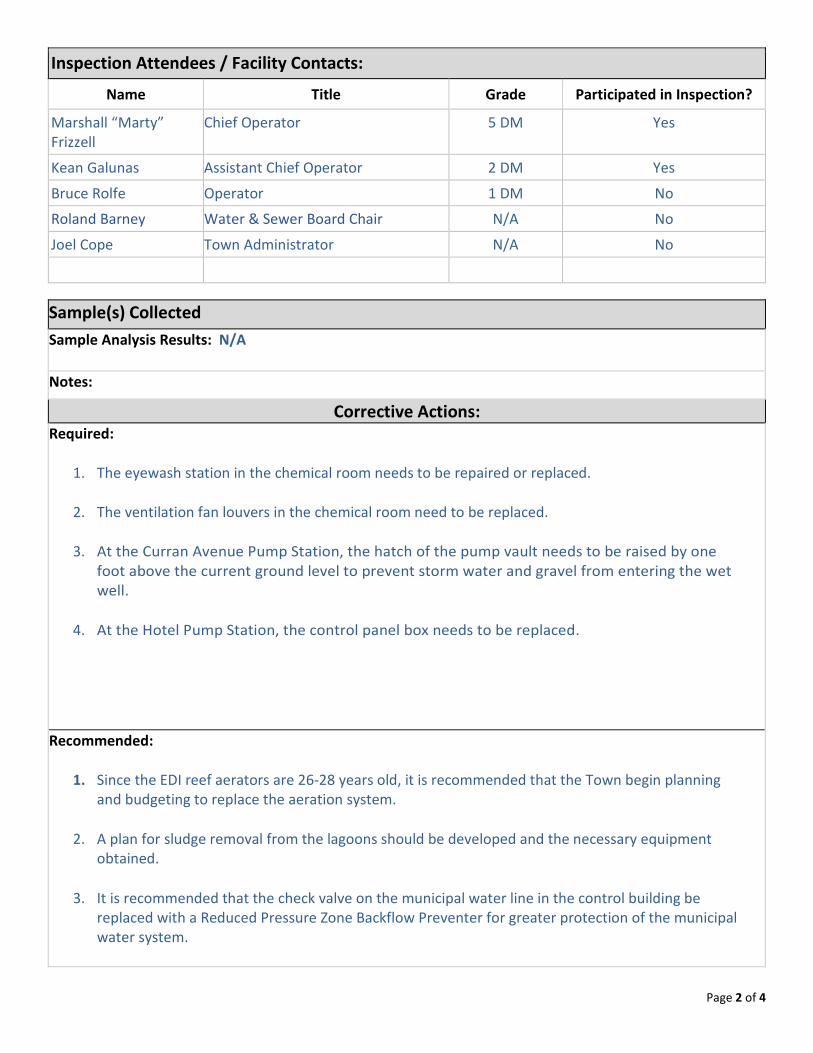
Page 2 of 4
Inspection Attendees / Facility Contacts:
Name Title Grade Participated in Inspection?
Marshall “Marty” Frizzell
Chief Operator 5 DM Yes
Kean Galunas Assistant Chief Operator 2 DM Yes
Bruce Rolfe Operator 1 DM No
Roland Barney Water & Sewer Board Chair N/A No
Joel Cope Town Administrator N/A No
Sample(s) Collected
Sample Analysis Results: N/A
Notes:
Corrective Actions: Required:
1. The eyewash station in the chemical room needs to be repaired or replaced.
2. The ventilation fan louvers in the chemical room need to be replaced.
3. At the Curran Avenue Pump Station, the hatch of the pump vault needs to be raised by one foot above the current ground level to prevent storm water and gravel from entering the wet well.
4. At the Hotel Pump Station, the control panel box needs to be replaced.
Recommended:
1. Since the EDI reef aerators are 26-28 years old, it is recommended that the Town begin planning and budgeting to replace the aeration system.
2. A plan for sludge removal from the lagoons should be developed and the necessary equipment obtained.
3. It is recommended that the check valve on the municipal water line in the control building be
replaced with a Reduced Pressure Zone Backflow Preventer for greater protection of the municipal water system.
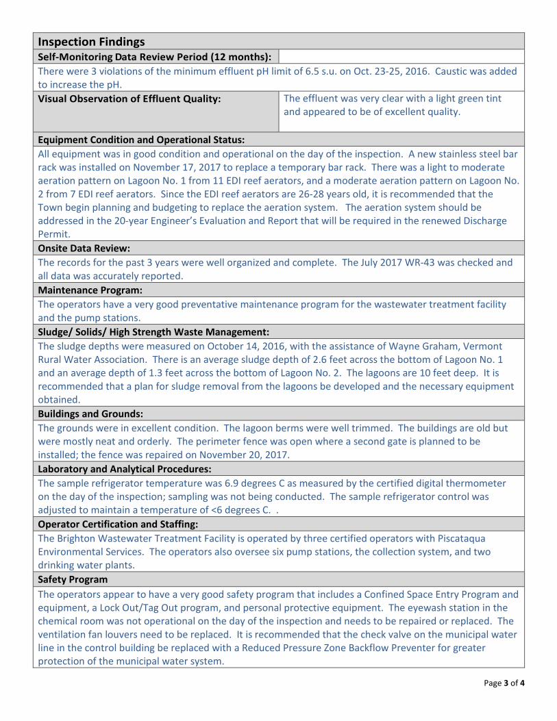
Page 3 of 4
Inspection Findings Self-Monitoring Data Review Period (12 months): There were 3 violations of the minimum effluent pH limit of 6.5 s.u. on Oct. 23-25, 2016. Caustic was added to increase the pH. Visual Observation of Effluent Quality: The effluent was very clear with a light green tint
and appeared to be of excellent quality.
Equipment Condition and Operational Status: All equipment was in good condition and operational on the day of the inspection. A new stainless steel bar rack was installed on November 17, 2017 to replace a temporary bar rack. There was a light to moderate aeration pattern on Lagoon No. 1 from 11 EDI reef aerators, and a moderate aeration pattern on Lagoon No. 2 from 7 EDI reef aerators. Since the EDI reef aerators are 26-28 years old, it is recommended that the Town begin planning and budgeting to replace the aeration system. The aeration system should be addressed in the 20-year Engineer’s Evaluation and Report that will be required in the renewed Discharge Permit. Onsite Data Review: The records for the past 3 years were well organized and complete. The July 2017 WR-43 was checked and all data was accurately reported. Maintenance Program: The operators have a very good preventative maintenance program for the wastewater treatment facility and the pump stations. Sludge/ Solids/ High Strength Waste Management: The sludge depths were measured on October 14, 2016, with the assistance of Wayne Graham, Vermont Rural Water Association. There is an average sludge depth of 2.6 feet across the bottom of Lagoon No. 1 and an average depth of 1.3 feet across the bottom of Lagoon No. 2. The lagoons are 10 feet deep. It is recommended that a plan for sludge removal from the lagoons be developed and the necessary equipment obtained. Buildings and Grounds: The grounds were in excellent condition. The lagoon berms were well trimmed. The buildings are old but were mostly neat and orderly. The perimeter fence was open where a second gate is planned to be installed; the fence was repaired on November 20, 2017. Laboratory and Analytical Procedures: The sample refrigerator temperature was 6.9 degrees C as measured by the certified digital thermometer on the day of the inspection; sampling was not being conducted. The sample refrigerator control was adjusted to maintain a temperature of <6 degrees C. . Operator Certification and Staffing: The Brighton Wastewater Treatment Facility is operated by three certified operators with Piscataqua Environmental Services. The operators also oversee six pump stations, the collection system, and two drinking water plants. Safety Program The operators appear to have a very good safety program that includes a Confined Space Entry Program and equipment, a Lock Out/Tag Out program, and personal protective equipment. The eyewash station in the chemical room was not operational on the day of the inspection and needs to be repaired or replaced. The ventilation fan louvers need to be replaced. It is recommended that the check valve on the municipal water line in the control building be replaced with a Reduced Pressure Zone Backflow Preventer for greater protection of the municipal water system.
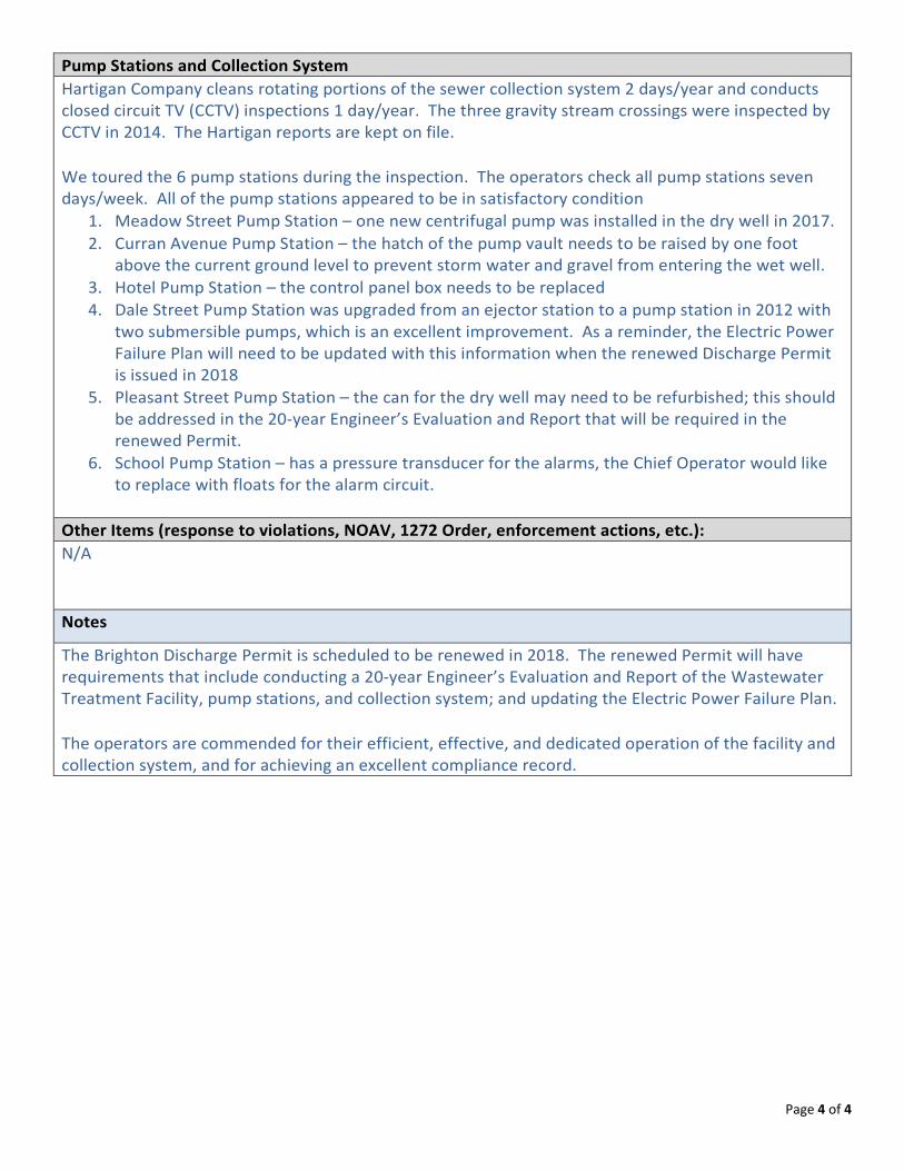
Page 4 of 4
Pump Stations and Collection System Hartigan Company cleans rotating portions of the sewer collection system 2 days/year and conducts closed circuit TV (CCTV) inspections 1 day/year. The three gravity stream crossings were inspected by CCTV in 2014. The Hartigan reports are kept on file. We toured the 6 pump stations during the inspection. The operators check all pump stations seven days/week. All of the pump stations appeared to be in satisfactory condition
1. Meadow Street Pump Station – one new centrifugal pump was installed in the dry well in 2017. 2. Curran Avenue Pump Station – the hatch of the pump vault needs to be raised by one foot
above the current ground level to prevent storm water and gravel from entering the wet well. 3. Hotel Pump Station – the control panel box needs to be replaced 4. Dale Street Pump Station was upgraded from an ejector station to a pump station in 2012 with
two submersible pumps, which is an excellent improvement. As a reminder, the Electric Power Failure Plan will need to be updated with this information when the renewed Discharge Permit is issued in 2018
5. Pleasant Street Pump Station – the can for the dry well may need to be refurbished; this should be addressed in the 20-year Engineer’s Evaluation and Report that will be required in the renewed Permit.
6. School Pump Station – has a pressure transducer for the alarms, the Chief Operator would like to replace with floats for the alarm circuit.
Other Items (response to violations, NOAV, 1272 Order, enforcement actions, etc.): N/A
Notes
The Brighton Discharge Permit is scheduled to be renewed in 2018. The renewed Permit will have requirements that include conducting a 20-year Engineer’s Evaluation and Report of the Wastewater Treatment Facility, pump stations, and collection system; and updating the Electric Power Failure Plan. The operators are commended for their efficient, effective, and dedicated operation of the facility and collection system, and for achieving an excellent compliance record.
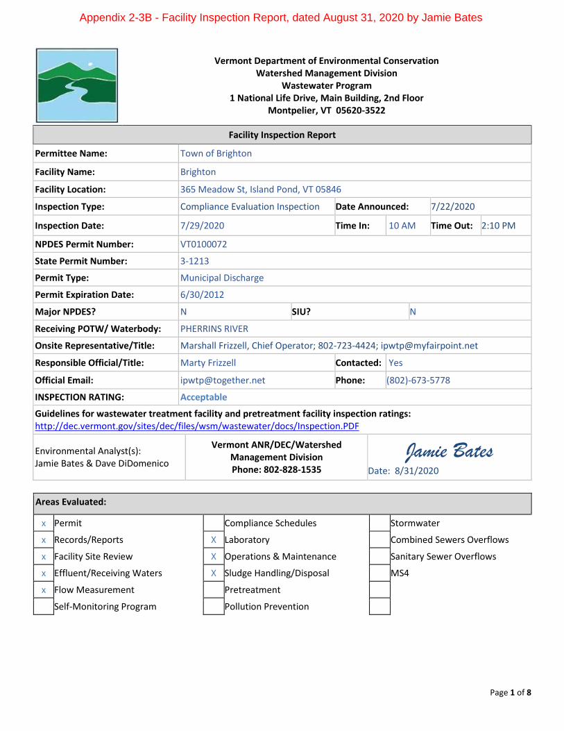
Page 1 of 8
Vermont Department of Environmental Conservation Watershed Management Division
Wastewater Program 1 National Life Drive, Main Building, 2nd Floor
Montpelier, VT 05620-3522
Facility Inspection Report
Permittee Name: Town of Brighton
Facility Name: Brighton
Facility Location: 365 Meadow St, Island Pond, VT 05846
Inspection Type: Compliance Evaluation Inspection Date Announced: 7/22/2020
Inspection Date: 7/29/2020 Time In: 10 AM Time Out: 2:10 PM
NPDES Permit Number: VT0100072
State Permit Number: 3-1213
Permit Type: Municipal Discharge
Permit Expiration Date: 6/30/2012
Major NPDES? N SIU? N
Receiving POTW/ Waterbody: PHERRINS RIVER
Onsite Representative/Title: Marshall Frizzell, Chief Operator; 802-723-4424; [email protected]
Responsible Official/Title: Marty Frizzell Contacted: Yes
Official Email: [email protected] Phone: (802)-673-5778
INSPECTION RATING: Acceptable
Guidelines for wastewater treatment facility and pretreatment facility inspection ratings: http://dec.vermont.gov/sites/dec/files/wsm/wastewater/docs/Inspection.PDF
Environmental Analyst(s): Jamie Bates & Dave DiDomenico
Vermont ANR/DEC/Watershed Management Division Phone: 802-828-1535
Jamie Bates Date: 8/31/2020
Areas Evaluated:
x Permit Compliance Schedules Stormwater
x Records/Reports X Laboratory Combined Sewers Overflows
x Facility Site Review X Operations & Maintenance Sanitary Sewer Overflows
x Effluent/Receiving Waters X Sludge Handling/Disposal MS4
x Flow Measurement Pretreatment
Self-Monitoring Program Pollution Prevention
Appendix 2-3B - Facility Inspection Report, dated August 31, 2020 by Jamie Bates
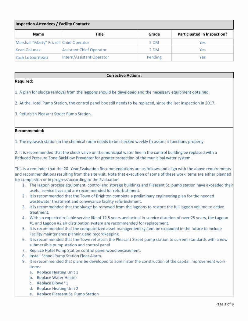
Page 2 of 8
Inspection Attendees / Facility Contacts:
Name Title Grade Participated in Inspection?
Marshall “Marty” Frizzell Chief Operator 5 DM Yes
Kean Galunas Assistant Chief Operator 2 DM Yes
Zach Letourneau Intern/Assistant Operator Pending Yes Corrective Actions: Required:
1. A plan for sludge removal from the lagoons should be developed and the necessary equipment obtained. 2. At the Hotel Pump Station, the control panel box still needs to be replaced, since the last inspection in 2017. 3. Refurbish Pleasant Street Pump Station.
Recommended: 1. The eyewash station in the chemical room needs to be checked weekly to assure it functions properly. 2. It is recommended that the check valve on the municipal water line in the control building be replaced with a Reduced Pressure Zone Backflow Preventer for greater protection of the municipal water system. This is a reminder that the 20- Year Evaluation Recommendations are as follows and align with the above requirements and recommendations resulting from the site visit. Note that execution of some of these work items are either planned for completion or in progress according to the Evaluation.
1. The lagoon process equipment, control and storage buildings and Pleasant St. pump station have exceeded their useful service lives and are recommended for refurbishment.
2. It is recommended that the Town of Brighton complete a preliminary engineering plan for the needed wastewater treatment and conveyance facility refurbishment.
3. It is recommended that the sludge be removed from the lagoons to restore the full lagoon volume to active treatment.
4. With an expected reliable service life of 12.5 years and actual in-service duration of over 25 years, the Lagoon #1 and Lagoon #2 air distribution system are recommended for replacement.
5. It is recommended that the computerized asset management system be expanded in the future to include Facility maintenance planning and recordkeeping.
6. It is recommended that the Town refurbish the Pleasant Street pump station to current standards with a new submersible pump station and control panel.
7. Replace Hotel Pump Station control panel wood encasement. 8. Install School Pump Station Float Alarm. 9. It is recommended that plans be developed to administer the construction of the capital improvement work
items: a. Replace Heating Unit 1 b. Replace Water Heater c. Replace Blower 1 d. Replace Heating Unit 2 e. Replace Pleasant St. Pump Station
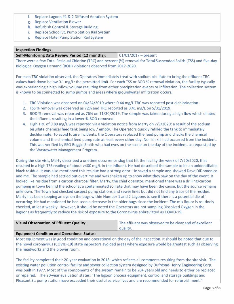
Page 3 of 8
f. Replace Lagoon #1 & 2 Diffused Aeration System g. Replace Ventilation Blower h. Refurbish Control & Storage Building i. Replace School St. Pump Station Rail System j. Replace Hotel Pump Station Rail System
Inspection Findings Self-Monitoring Data Review Period (12 months): 01/01/2017 – present There were a few Total Residual Chlorine (TRC) and percent (%) removal for Total Suspended Solids (TSS) and five-day Biological Oxygen Demand (BOD) violations observed from 2017-2020. For each TRC violation observed, the Operators immediately treat with sodium bisulfate to bring the effluent TRC values back down below 0.1 mg/L: the permitted limit. For each TSS or BOD % removal violation, the facility typically was experiencing a high inflow volume resulting from either precipitation events or infiltration. The collection system is known to be connected to sump pumps and areas where groundwater infiltration occurs.
1. TRC Violation was observed on 04/24/2019 where 0.44 mg/L TRC was reported post dichlorination. 2. TSS % removal was observed as 72% and TRC reported as 0.41 mg/L on 5/31/2019. 3. BOD % removal was reported as 76% on 11/30/2019. The sample was taken during a high flow which diluted
the influent, resulting in a lower % BOD removed. 4. High TRC of 0.89 mg/L was reported via a violation notice from Marty on 7/9/2020: a result of the sodium
bisulfate chemical feed tank being low / empty. The Operators quickly refilled the tank to immediately dechlorinate. To avoid future incidents, the Operators replaced the feed pump and checks the chemical volume and the chemical feed pump rate at least every other day. No fish kill had occurred from the incident. This was verified by EEO Reggie Smith who had eyes on the scene on the day of the incident, as requested by the Wastewater Management Program.
During the site visit, Marty described a onetime occurrence slug that hit the facility the week of 7/20/2020, that resulted in a high TSS reading of about >400 mg/L in the influent. He had described the sample to be an unidentifiable black residue. It was also mentioned this residue had a strong odor. He saved a sample and showed Dave DiDomenico and me. The sample had settled out overtime and was shaken up to show what they saw on the day of the event. It looked like residue from a carbon charcoal filter. Marty, the chief operator, mentioned there was a drilling/carbon pumping in town behind the school at a contaminated soil site that may have been the cause, but the source remains unknown. The Town had checked suspect pump stations and sewer lines but did not find any trace of the residue. Marty has been keeping an eye on the bugs within Number 1 and 2 Lagoons to see if there is a potential die off occurring. He had mentioned he had seen a decrease in the older bugs since the incident. The mix liquor is routinely checked, at least weekly. However, it should be noted the Operators are not sampling Dissolved Oxygen in the lagoons as frequently to reduce the risk of exposure to the Coronavirus abbreviated as COVID-19. Visual Observation of Effluent Quality: The effluent was observed to be clear and of excellent
quality. Equipment Condition and Operational Status: Most equipment was in good condition and operational on the day of the inspection. It should be noted that due to the novel coronavirus (COVID-19) state inspectors avoided areas where exposure would be greatest such as observing the headworks and the blower room. The facility completed their 20-year evaluation in 2018, which reflects all comments resulting from the site visit. The existing water pollution control facility and sewer collection system designed by Dufresne-Henry Engineering Corp. was built in 1977. Most of the components of the system remain to be 20+ years old and needs to either be replaced or repaired. The 20-year evaluation states: “The lagoon process equipment, control and storage buildings and Pleasant St. pump station have exceeded their useful service lives and are recommended for refurbishment.”
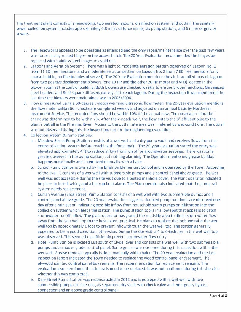
Page 4 of 8
The treatment plant consists of a headworks, two aerated lagoons, disinfection system, and outfall. The sanitary sewer collection system includes approximately 0.8 miles of force mains, six pump stations, and 6 miles of gravity sewers.
1. The Headworks appears to be operating as intended and the only repair/maintenance over the past few years was for replacing rusted hinges on the access hatch. The 20 Year Evaluation recommended the hinges be replaced with stainless steel hinges to avoid rust.
2. Lagoons and Aeration System: There was a light to moderate aeration pattern observed on Lagoon No. 1 from 11 EDI reef aerators, and a moderate aeration pattern on Lagoon No. 2 from 7 EDI reef aerators (only coarse bubble, no fine bubbles observed). The 20 Year Evaluation mentions the air is supplied to each lagoon from two positive displacement blowers (one 10 HP and the other 20 HP motor and VFD) located in the blower room at the control building. Both blowers are checked weekly to ensure proper functions. Galvanized steel headers and Reef square diffusers convey air to each lagoon. During the inspection it was mentioned the last time the blowers were maintained was in 2003/2004.
3. Flow is measured using a 60-degree v-notch weir and ultrasonic flow meter. The 20-year evaluation mentions the flow meter calibration checks are completed weekly and adjusted on an annual basis by Northeast Instrument Service. The recorded flow should be within 10% of the actual flow. The observed calibration check was determined to be within 7%. After the v-notch weir, the flow enters the 8" effluent pipe to the plant’s outfall in the Pherrins River. Access to the outfall site area was hindered by wet conditions. The outfall was not observed during this site inspection, nor for the engineering evaluation.
4. Collection system & Pump stations: a. Meadow Street Pump Station consists of a wet well and a dry pump vault and receives flows from the
entire collection system before reaching the force main. The 20-year evaluation stated the entry was elevated approximately 4 ft to reduce inflow from run off or groundwater seepage. There was some grease observed in the pump station, but nothing alarming. The Operator mentioned grease buildup happens occasionally and is removed manually with a baler.
b. School Pump Station is owned by the Brighton Elementary School and is operated by the Town. According to the Eval, it consists of a wet well with submersible pumps and a control panel above grade. The wet well was not accessible during the site visit due to a bolted manhole cover. The Plant operator indicated he plans to install wiring and a backup float alarm. The Plan operator also indicated that the pump rail system needs replacement.
c. Curran Avenue (Back Street) Pump Station consists of a wet well with two submersible pumps and a control panel above grade. The 20-year evaluation suggests, doubled pump run times are observed one day after a rain event, indicating possible inflow from household sump pumps or infiltration into the collection system which feeds the station. The pump station top is in a low spot that appears to catch stormwater runoff inflow. The plant operator has graded the roadside area to direct stormwater flow away from the wet well top to the best extent practical. He plans to replace the lock and raise the wet well top by approximately 1 foot to prevent inflow through the wet well top. The station generally appeared to be in good condition, otherwise. During the site visit, a 4 to 6-inch rise in the wet well top was observed. This seemed to sufficiently prevent stormwater flow entry.
d. Hotel Pump Station is located just south of Clyde River and consists of a wet well with two submersible pumps and an above grade control panel. Some grease was observed during this inspection within the wet well. Grease removal typically is done manually with a baler. The 20-year evaluation and the last inspection report indicated the Town needed to replace the wood control panel encasement. The plywood painted control panel box remains. The recommendation for replacement remains. The evaluation also mentioned the slide rails need to be replaced. It was not confirmed during this site visit whether this was completed.
e. Dale Street Pump Station was reconstructed in 2012 and is equipped with a wet well with two submersible pumps on slide rails, as separated dry vault with check valve and emergency bypass connection and an above grade control panel.
Page 5 of 8
f. Pleasant Street Pump Station is currently in critical condition and needs immediate repairing due to corrosion of the wet well and pump rail supports. This pump station consists of two submersible pumps in a wet well and an above ground control panel all encased in a shed. Continuous issues are observed at this location due to infiltration and rags from surrounding connections. The 20-year evaluation recommends the Town refurbish the pump station to current standards with a new submersible pump station and control panel.
5. The plant operator utilizes a portable generator to cycle each pump station during a power outage. During the site visit we had visited the Town garage where the generator was stored. This is a diesel fueled generator which is stored in a garage with an electric garage door. There seemed to be a few flaws with contingency planning to retrieve the generator in the event the power is out for a long period of time.
6. On 6/12/2020 the facility experienced a force main break along Meadow Street which is the road taken to access the facility. This was cause by the pipe resting on a rock which overtime had worn down the pipe. The force main was patched day of the incident and has been functioning properly ever since.
The 20-year evaluation plan mentioned the WWTF refurbishment alternatives were developed for lagoon process equipment, control and storage buildings expansion and Pleasant St. pump station refurbishment. The Town is working on gathering funding sources for these alternatives.
1. Alternative 1 includes adding a staff room and heated shop space by constructing an addition to the existing Control Building and refurbishing the remaining Control and Storage Buildings for a Total Estimated Conceptual Project Cost of $799,000.
2. Alternative 2 includes adding a staff room and heated shop space by constructing a new Operations Building and refurbishing the existing Control and Storage Buildings for a Total Estimated Conceptual Project Cost of $773,000.
Onsite Data Review: Monitoring reports and records were stored in an organized fashion within a file cabinet system. The WR-43s from 2019 were checked and compared with the data submitted to the Wastewater Inventory. All records observed on site matched up with the reports submitted to the Wastewater Program. The Operators had a copy of the permit, factsheet, emergency power failure plan, and operations and management emergency response plan readily available on site. All records were easily accessible. The 20-year evaluation plan explained that the operators typically keep an annual summary of all maintenance related expenses and have begun tracking such expenses via the computerized asset management plan. The evaluation plan recommended that the computerized asset management system be expanded in the future to include Facility maintenance planning and recordkeeping. Based on communications with the Operator, this effort seems to be underway. Maintenance Program: The Operators have a good preventative maintenance program for the wastewater treatment facility and the pump stations. The Town of Brighton covers both water and wastewater systems. The WWTF Asset Management Plan prepared by John Jackman (with HTA) in May of 2018 and the Collection System Asset Management Plan was prepared by Michelle G. Stewart (with HTA) was completed in June of 2017. The Operator mentioned the drinking water department is currently developing their asset management plan and expressed concern that he hopes the team putting that together consider the existing wastewater department plan, as the two department budgets are combined. Therefore, it shall be in the Town’s best interest to ensure both plans reflect and work within the same budget. According to the 20 Year Engineering Evaluation, Hartigan was typically used for pump station cleaning two days per
Page 6 of 8
year for annual collection system maintenance. During this site inspection, it was revealed the company name has changed to Wind River. Sludge/ Solids/ High Strength Waste Management: Sludge depth was last taken in November 2019 with the assistance of Wayne Graham with Vermont Rural Water Association (VRWA). It was mentioned a blizzard occurred when they were sampling which may have affected the results. Lagoon 1 averaged 3.37 ft and Lagoon 2 averaged 1.41 ft sludge depth. Each Lagoon is approximately 10 feet deep. This is an increase from the 2.6 ft depth across the bottom of Lagoon No.1 and 1.3 feet depth across from the bottom of Lagoon No. 2 recorded in 2017. It is still recommended that the Operators to develop a plan for sludge removal from the lagoons and the necessary equipment obtained. The 20-year evaluation plan mentions the Town has a reserve fund that they contribute to annually to pay for sludge removal. The fund value is approximately $86,000. The plant operator plans to borrow a sludge sled from the Town of Canaan and the Vermont Rural Water Association as necessary to pump the sludge out of the lagoon and into a geo bag. The 20 Year Evaluation plan also mentioned: “The sludge volume presence may have led to or contributed to the recent year permit limit excursions. It is recommended that the sludge be removed from the lagoons to restore the full lagoon volume to active treatment.” This is a concern as this comment was made in 2018 in the plan as well as requested from Liz Dixon in 2017 from the last inspection. Based on recent communication with the operator, it is unclear whether there are sufficient funds available to the municipal wastewater department to remove sludge as recommended in addition to repairing the Pleasant Street Pump Station sooner than later. Given the severity and safety risk presented with the Pleasant Street Pump Station current condition, the municipality may use the sludge removal plan budget to support refurbishment as soon as possible. Also, during the site visit the Operators mentioned they are looking for a boat replacement to ease sludge depth measurement sampling, as the existing boat is Marty’s personal boat and is not as stable as the Operators would like. Buildings and Grounds: The grounds were in excellent condition during the site visit. The lagoon berms were well trimmed. The buildings were neat and orderly for the most part. The facility was originally built in 1977 and most of the components of the system remain to be 20+ years old and needs to be replaced or repaired. The 20-year evaluation reflects all comments resulting from the site visit.
1. The control building is old and needs to be built out for safer working conditions. The building is about 400 square feet and consists of an office, laboratory, lavatory, and blower room. The building’s siding, windows, insulation and air sealing system and roof covering need replacement. The plant operator indicated that the lab heating system can maintain temperature in winter, however, the office area can be as cold as approximately 52°F. Refurbishing the building or rebuilding to enlarge the control building and insulate the chemical storage room was recommended in the evaluation.
2. The chemical metering pumps in the Chemical Feed Room have been replaced recently. The chemical metering pumps are not flow paced and the plant is only required to disinfect from April 1 to October 1. The plant uses 1-2 gal/day of sodium hypchlorite and ½ gal/day of sodium bisulfate on average. The plant has an emergency power back up system, a 12 Volt battery and power inverter, for the chemical metering pumps in the event of a power outage. This system is approximately 9 years old. Marty had mentioned if chemical usage required to be year-round in the renewal permit the facility would need to insulate the chemical feed room/building otherwise the chemicals and or pumps would freeze in the colder months. This room also includes the eye wash station, which also typically freezes in cold temperatures. It should be noted the eye wash station upon the site visit worked and did not show signs of corrosion as the 2017 inspection and the 2018 20-year evaluation plan indicated.
3. The Storage room is in connected to the chemical feed room. The 20-year evaluation states the facility storage room was unorganized and appeared small, therefore was suggested to make more effective use of
Page 7 of 8
the storage space. This area was not observed upon the site visit; therefore, it is unknown whether this area was organized since the evaluation.
Laboratory and Analytical Procedures: Laboratory equipment appeared in working order. The lab was observed to be in a clean and orderly condition. We reviewed lab procedures with Kean the assistant operator while at the facility. The operators perform BOD, TSS, E. coli, TRC and pH. Dissolved Oxygen was collected and analyzed for each lagoon, but due to COVID-19 exposure concerns, DO has not been analyzed for several months. The operators also analyze for total phosphorous using a Hach colorimeter. DO and TP are process control parameters only. pH calibration is performed using a pH 4.0 and 7.0 buffer and checked with a pH 7.0 of a different lot. All buffers were within expiration dates. The facility does annual proficiency testing of all lab analysis performed including DO, pH, TRC, Hardness, Settleable Solids, and E. Coli. The last test was performed in October 2019 and they passed all tests. All lab equipment is calibrated by an outside contractor. TNDE was used this year and they were scheduled to arrive later that day. All samples are collected manually, composite samples are collected over an eight-hour period. Influent samples are collected prior to the bar rack in the head works manhole. Effluent samples are collected between the plywood baffle and the weir. Samples for chlorine concentrations prior to de-chlorination are collected prior to the plywood baffle. Operator Certification and Staffing: Kean and Marty’s certifications are up to date. Zach is currently working with OPR to schedule his written Grade 1 test after the GMWEA WEF/SAC course is completed. Exam scheduling has been delayed due to COVID-19. Safety Program The operators appear to have a very good safety program that includes a Confined Space Entry Program and equipment, a Lock Out/Tag Out program, and personal protective equipment. For instance, personnel carry an oxygen meter to monitor air quality before entering and working in a confined space. The eye wash station functions and is typically only used in the warmer months. It freezes in the winter due to poor building insolation. It was mentioned that the Operators do not typically check if this is functioning properly. It is recommended the Operators check whether the eye wash station is working on a more frequent basis when chemicals are used. While general questions about safety may have been asked during the inspection, this was not a comprehensive safety inspection. As a reminder, the facility should always follow safe operating procedures. Employees must be trained in emergency shut-down, fire control, and spill response procedures, as well as in the use of safety equipment, safe sampling techniques, and safe handling of chemicals and wastes. Employees should not enter confined spaces unless properly trained and equipped. Managers must be aware of the Occupational Safety and Health Administration (OSHA) Right-to-Know laws regarding potentially dangerous chemicals in the workplace. This law specifically requires a written hazard communication program, labeling of chemicals, and the availability of material safety data sheets to employees upon request. Workplace safety laws may be found here: http://labor.vermont.gov/vosha/laws-regulations/ The Vermont Occupational Safety and Health Agency (VOSHA) can assist facilities in creating safe workplaces. VOSHA Compliance Assistance Specialists can provide general information about VOSHA standards and compliance assistance resources. http://labor.vermont.gov/vosha/compliance-assistance/ Other Items (response to violations, NOAV, 1272 Order, enforcement actions, outstanding compliance schedule item, etc.):
Page 8 of 8
N/A
Notes
The operators are commended for their efficient, effective, and dedicated operation of the facility and collection system, and for achieving an excellent compliance record.
Permit Related 1. The United States Department of Agriculture Rural Development (USDA RD) Water & Waste Disposal Loan
Program currently provides loan and up to 70% grant funding for WWTF refurbishment projects. It is unknown if future program funding will be available.
2. In addition, the Town of Brighton is eligible for the USDA RD SEARCH Program which currently provides 100%
grant funding for planning and preliminary engineering for WWTF refurbishment projects. It is unknown if future program funding will be available. The facility has been in communication with the VRWA for assistance with applying to grants and aid for future upgrades as well as finishing up plans.
3. The Brighton Discharge Permit is scheduled for renewal in 2020-2021. The renewed Permit may have the
following requirements. Once the draft permit is final, the Program will share a copy and set up a meeting to review any changes from the current permit:
a. Updating the Electric Power Failure Plan (EPFP) and Operations and Management Emergency Response Plan
(OMERP). b. This facility is covered under the Lake Memphremagog Total Maximum Daily Load (TMDL) and will be subject to
meet a water quality based effluent limitation of 1532 lbs./year of Total Phosphorus, as approved by the Environmental Protection Agency (EPA).The plant wastewater needed design capacity during the 20-year planning period from year 2018-2038 is 458-600 lbs. TP/year, which is 30-39% of the final adopted wasteload allocation of 1,532 lbs. TP/year. To show the facility is working to meet conditions of the Lake Memphremagog TMDL, the renewal will include a requirement for the Permittee to develop a Phosphorus Optimization Plan (POP) within the next permit term.
c. Acute and/or chronic WET Testing with concurrent Appendix J, or otherwise metal analysis, monitoring
requirements will likely be included in the permit renewal to gather sufficient data to assess reasonable potential.
d. The facility sampled previously for Annual Constituent Monitoring (ACM) per request of the Secretary to prepare
for the initial 2018 renewal. ACM will likely be incorporated into the next permit renewal. However, it has been noted the facility is challenged by meeting hold times and keeping samples at the appropriate temperature for testing due to the distance the Operators must travel to drop off their samples in Williston. It is about a 2 hour and 10-minute drive. There currently is no courier service in route to the Endyne Laboratory.
To: File
Subject: Town of Brighton, Vermont
Wastewater Treatment Refurbishment Alternatives PER
Estimate of Lagoon Sludge Volume and Weight
Author: Aidan P. Short, EIT
Checked by: John D. Reilly, P.E.
Date: 3/23/2021
Introduction
The Town of Brighton, VT wastewater treatment facility (WWTF) utilizes lagoon wastewater
treatment. During treatment, solids settle out of the sewage and collect at the bottoms of the
two lagoons as sludge. The sludge at the bottom of the two Brighton lagoons has not been
pumped out since the 1990s. In recent years, the sludge depth has increased to a measured
depth of over 3 ft in Lagoon 1 and the Town desires sludge removal. Estimation of the sludge
and solids volume to be pumped from the two lagoons is necessary for estimation of cost, time,
and disposal requirements. This memo details the approach used for estimation of the total
sludge volume in the lagoons.
Approach
The sludge volume estimate was based on the size of the existing lagoons and sludge depths as
measured by the plant operator in 2020. The record drawing of the existing lagoons was
brought into AutoCAD, where it was sized to scale and its contours traced. These contours were
used to build TIN surface models within the software. The sludge depth sampling data was then
analyzed to identify average depths in each lagoon in the years 2000, 2016, and 2018-2020.
Lagoon sludge and water depths were measured and recorded by the plant operator. A
representative elevation of the top of the sludge was identified from these depths in each
scenario, and each of these elevations were used to build additional TIN surface models in
AutoCAD. Sludge volume on the side slopes was included in these surfaces by assuming that the
sludge depth decreased linearly from the sampled depth at each lagoon floor to zero at the
water surface elevation, which was approximately 1182.5’ for both lagoons. A Cut/Fill Report
was then generated for comparison of the lagoon contour and sludge surfaces for each scenario
based on a tool used to estimate the resultant volume between two different surfaces.
Appendix 2-4 - Estimate of Lagoon Sludge Volume and Weight
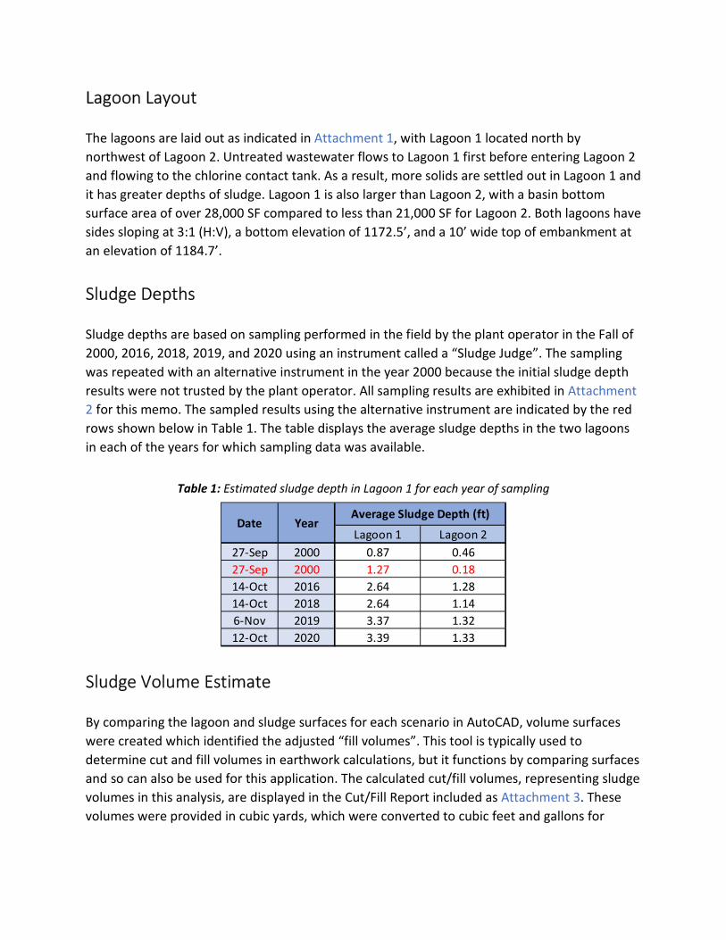
Lagoon Layout
The lagoons are laid out as indicated in Attachment 1, with Lagoon 1 located north by
northwest of Lagoon 2. Untreated wastewater flows to Lagoon 1 first before entering Lagoon 2
and flowing to the chlorine contact tank. As a result, more solids are settled out in Lagoon 1 and
it has greater depths of sludge. Lagoon 1 is also larger than Lagoon 2, with a basin bottom
surface area of over 28,000 SF compared to less than 21,000 SF for Lagoon 2. Both lagoons have
sides sloping at 3:1 (H:V), a bottom elevation of 1172.5’, and a 10’ wide top of embankment at
an elevation of 1184.7’.
Sludge Depths
Sludge depths are based on sampling performed in the field by the plant operator in the Fall of
2000, 2016, 2018, 2019, and 2020 using an instrument called a “Sludge Judge”. The sampling
was repeated with an alternative instrument in the year 2000 because the initial sludge depth
results were not trusted by the plant operator. All sampling results are exhibited in Attachment
2 for this memo. The sampled results using the alternative instrument are indicated by the red
rows shown below in Table 1. The table displays the average sludge depths in the two lagoons
in each of the years for which sampling data was available.
Table 1: Estimated sludge depth in Lagoon 1 for each year of sampling
Sludge Volume Estimate
By comparing the lagoon and sludge surfaces for each scenario in AutoCAD, volume surfaces
were created which identified the adjusted “fill volumes”. This tool is typically used to
determine cut and fill volumes in earthwork calculations, but it functions by comparing surfaces
and so can also be used for this application. The calculated cut/fill volumes, representing sludge
volumes in this analysis, are displayed in the Cut/Fill Report included as Attachment 3. These
volumes were provided in cubic yards, which were converted to cubic feet and gallons for
Lagoon 1 Lagoon 2
27-Sep 2000 0.87 0.46
27-Sep 2000 1.27 0.18
14-Oct 2016 2.64 1.28
14-Oct 2018 2.64 1.14
6-Nov 2019 3.37 1.32
12-Oct 2020 3.39 1.33
Average Sludge Depth (ft)Date Year
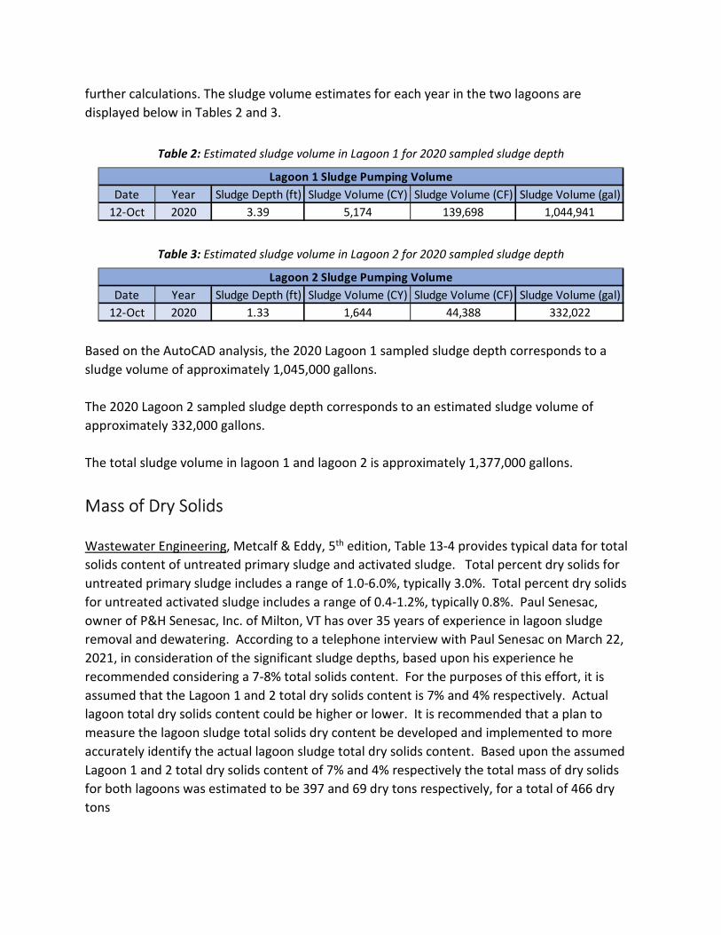
further calculations. The sludge volume estimates for each year in the two lagoons are
displayed below in Tables 2 and 3.
Table 2: Estimated sludge volume in Lagoon 1 for 2020 sampled sludge depth
Table 3: Estimated sludge volume in Lagoon 2 for 2020 sampled sludge depth
Based on the AutoCAD analysis, the 2020 Lagoon 1 sampled sludge depth corresponds to a
sludge volume of approximately 1,045,000 gallons.
The 2020 Lagoon 2 sampled sludge depth corresponds to an estimated sludge volume of
approximately 332,000 gallons.
The total sludge volume in lagoon 1 and lagoon 2 is approximately 1,377,000 gallons.
Mass of Dry Solids
Wastewater Engineering, Metcalf & Eddy, 5th edition, Table 13-4 provides typical data for total
solids content of untreated primary sludge and activated sludge. Total percent dry solids for
untreated primary sludge includes a range of 1.0-6.0%, typically 3.0%. Total percent dry solids
for untreated activated sludge includes a range of 0.4-1.2%, typically 0.8%. Paul Senesac,
owner of P&H Senesac, Inc. of Milton, VT has over 35 years of experience in lagoon sludge
removal and dewatering. According to a telephone interview with Paul Senesac on March 22,
2021, in consideration of the significant sludge depths, based upon his experience he
recommended considering a 7-8% total solids content. For the purposes of this effort, it is
assumed that the Lagoon 1 and 2 total dry solids content is 7% and 4% respectively. Actual
lagoon total dry solids content could be higher or lower. It is recommended that a plan to
measure the lagoon sludge total solids dry content be developed and implemented to more
accurately identify the actual lagoon sludge total dry solids content. Based upon the assumed
Lagoon 1 and 2 total dry solids content of 7% and 4% respectively the total mass of dry solids
for both lagoons was estimated to be 397 and 69 dry tons respectively, for a total of 466 dry
tons
Date Year Sludge Depth (ft) Sludge Volume (CY) Sludge Volume (CF) Sludge Volume (gal)
12-Oct 2020 3.39 5,174 139,698 1,044,941
Lagoon 1 Sludge Pumping Volume
Date Year Sludge Depth (ft) Sludge Volume (CY) Sludge Volume (CF) Sludge Volume (gal)
12-Oct 2020 1.33 1,644 44,388 332,022
Lagoon 2 Sludge Pumping Volume

It should be noted, however, that actual sludge dry weight could be significantly higher or
lower due to the following potential variables:
1. Actual sludge depths may vary from measured sludge depths. Available lagoon sludge
depths provided by the plant operator only include sludge depths on the lagoon bottom but
exclude the lagoon side slopes.
2. Solids specific gravity for each lagoon was assumed based upon Metcalf & Eddy. Actual
solids specific gravity could be higher or lower. For example, lagoon sludge specific gravity can
be higher if sewer collection and conveyance system infiltration is high and washing sand into
the lagoons.
Refer also to Attachment 4 for a summary of lagoon sludge design related information.
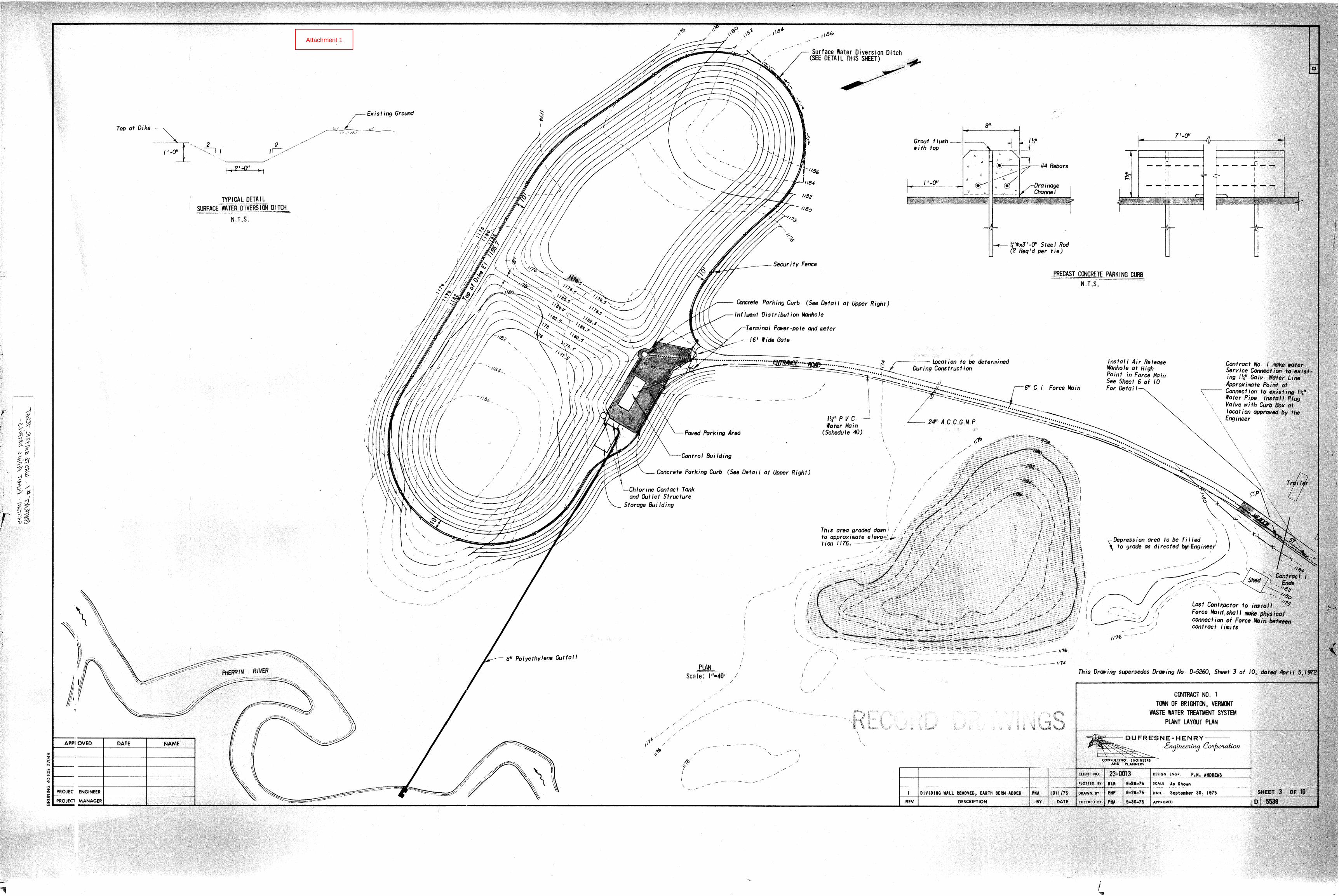
Attachment 1
o,
- .P
LJ!~GOON t 1 Op;CE SEPT 27 "z..o-oC>f
•• K *I,D
[ J .s/, L
'"[ ] [ ]
*.6I, .
*.7*I '2' p" 1-
[ J [ J []
* /.7'2.,1
*t. 1- *\ .'L.7
[ ) [ ] ( ]
~ 111: *.~~
.6
f~
;.~. ~I. I
[][]
* * ••.~'I
t~ ~ ~'S-I--
Ii
II
I
EFFLfJENT END
.• = SAMPLE POINT AVERAGE DEPTH(] ::AERATOR ~'"
T0DG--Iz:. r7cF
(Zo<--<-.J ll:..t?.s It. G- -: PH-
l~G :: I~.t. I~ r
~.
I
:. 07' ( I~.I.0 /1), J..j j
I III s II
Attachment 2
DATe f 5flPI27 2000"Ll~OOON # 2
*~~~ 'Z.-
[ J
II!
• 'L
'II:
~B.,•
I: ]
*~-;-
n
*,,'3,.,•
*q-:>o[ ]
*1I
*e J-/•
*.~[]
*."- .1
[)
*,~o
[)
*13o
II
,I "..,11 iAVERAGE DEPTH = ot-f~ 5,~ i
iIlI
I
EFFLUENT END
* = SAMPLE PC'INT
() = AERATOR
.JvDG-IL /VI cF
fl6>(AYlIL ~ /~Cr ~ PH
R. F"
/1- 2.1
I (
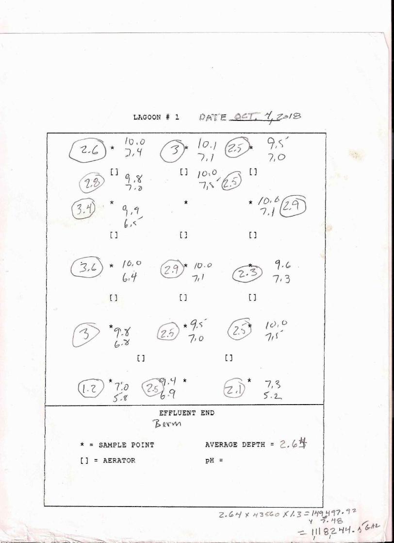
@ ~,~
7,3[J
@ Ie), D./
11(
[ ]
Ll.GOON .# 1 O.ATE. (At:.."f;: -t Ze>/B. I
®. to .o]Il( (!) /0,/ (fj) 91~./
III . 710 I .,'~.
[] 10,0 {j5 []/ ,-IJ'" ,":l
'* *~/@[] []
~* /0.0® 7,1
(]
~ * Cj,<;/l.liJ 7,0
(]
~.<-, *&bo9
[ ]~) ~,<6\!:.;JY 7 ' ()
0Y * ~,~(,J~
[]
@* 7/S5'.2...,
~ '* /0,0~ blLf
[]
qs *,\iV b,)j
c:;) * 7:Do 5:~
* = Sl1.MPLE PO !NT
[] = AERATOR
EFFLfJENT END\1>~~~~
AVERAGE DEPTH = 2. tp!tpH =
Z.~'7 y: ""3~~O ~/.3=lij~l1tlf7,1-z..,p'{ 7· 1'0 r;
~ III g '2.."i t.>-/ •• IJ G-Wz...1 I
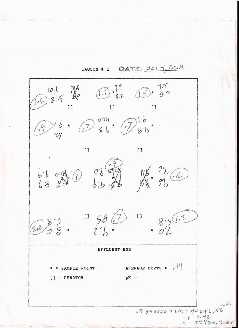
LP~GOON# 2 Q~"TE;' ()C/ '1, *'2018-,i
[0.[ ~t1@~"tJ M
[ ]
iZ)fi:; *o-;
1~,~@'p, @ 9.~1,'J * a oCJ'
t" b ()~; '(J)* I6'~, .
[ ] []
~-5'\!!;/0' 3 *
0"0/ (j)\'h6) ~:b' -: 2>"b'
[ ] [ ]
t\'x, O'b0· rb~
[] 5"Q 0 [J(1~
t b *
* = SAMPLE POINT
[] = AERATOR
EFFLUENT END
AVERAGE DEPTH = \.\1pH =
! I w~''f '111 3S'c.0 y. ,#)~ ~ '1~ ~ ~"2. , S-b
'f. 7~~/e- ~ "3 ~ 3tX>. '3 t.A/JJI
~"'•.-'<.-~,~7':";".,::t.~__ ._..J.,~ _'IL ~ zriirtr +_ .. ~..--
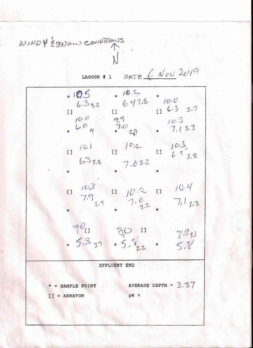
"(/A) INO ~ f gtJc;~ c..~Nf)m~/~
NLP•.GOON .# 1
r'" _"_,~ {:.. i ( U' 1."7 (' °1'",fA} E /' N C' {/
~I
* 1~/~t:~J.f, z.
* /O.L•••.>.
(~)'.~I"3.~[ j
IO'()~,O
* Ii
[]a,41,7~O 0.* f"'l
/ C'/L_[] j(),}r 1L J
bi'~s.s 7,6'>,2.'* *
* fOrO[] ~13 3,1
1°'']* -7, ( 3/3
, ()i~,/
&.'') '1 ~,;),"( ]
*
,0,37/1
[ 1 }D'Q, [1IU,l{
~, ~ -1, 0,
,;:1,'Z.,. If f 1,~
*
[ j
*
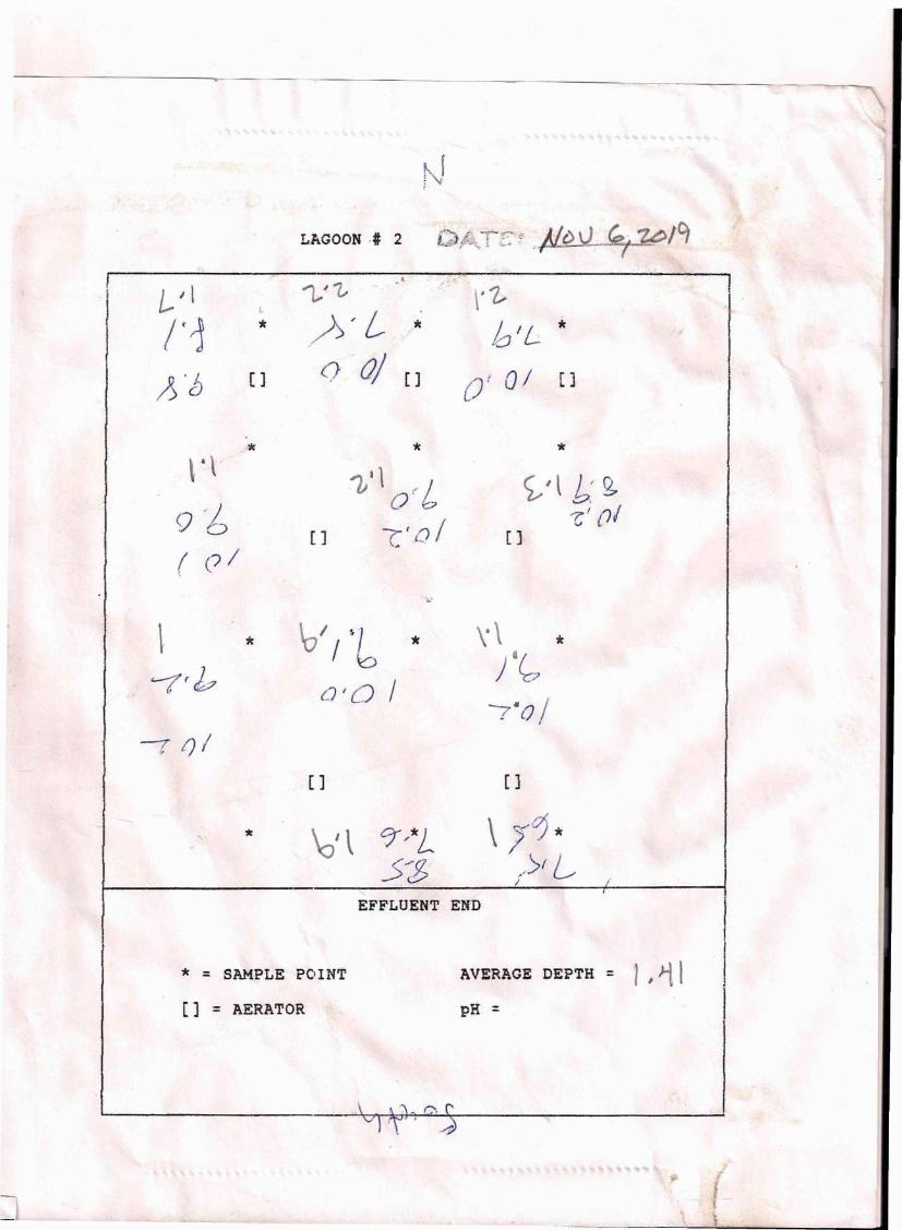
NLAGOON·# 2 ~ ./.-rt:' <' . U.l' V / . .,.,~/C'1~A t, ~ 0'; .: .v --t.=>nI- ""'" ~,
L. I l
1< r1l
*
A '[) [ J
".'*\ .\9-6( el
... :-.-~-- ,-
\'i.lolL *
01 01 []
1/~~' L- •o -OJ []
* */.; " O~b ~/l t: s
[] C:'{)! []~!()I
\/ / '10 \. \ **~ * ).~'-{rbCJIQ / =r'o]
=r '-')1[][ ]
\01 \ C)'/*L \ ;0**".)1 L
-,
->b ;
EFFLUENT END
* = SAMPLE POINT AVERAGE DEPTH = 1, 11pH =[] = AERATOR
\
\
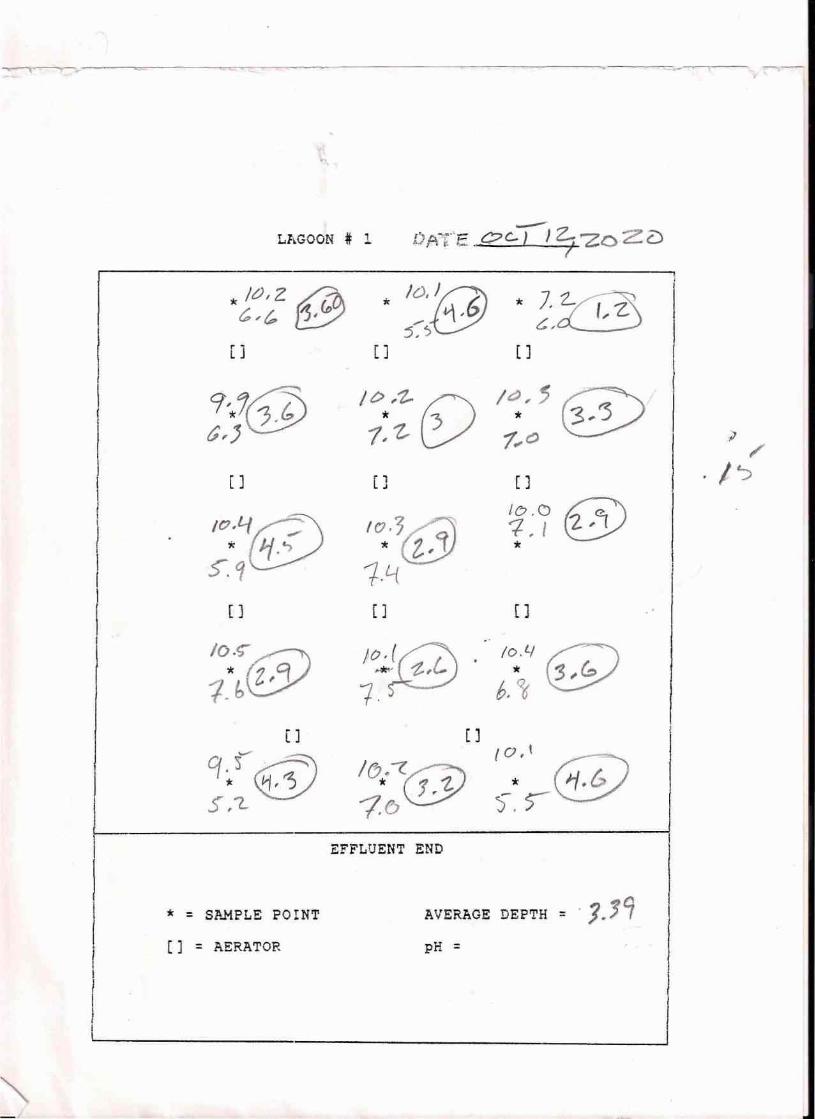
,...---"'( 1-"'" <::: "< _ "* .,. --- ~ ~-~~y
---Ll.GOON # 1 l).A-:'"fe C?c-) J Z. 'ZoZ 2). I
./t),Z ~ . '~'JgJ.:-,~c,,,~ !31(P5,~
[ j [ ] [ ]
9,.1@ /t>,1- (E) I~, ~0*Z '3 * 3, '3G,j 1, 1",C) I ;J
1
,\
[ ] • 1 [ ] ! ·/~L .J
r If?@I IO'(f!) 'C:.)@! ,
I* Ij.l; *
.~.~ 1·L{I
I [] [J [ Jt • IO.~@
ib Z/1iO'![i!J · 10.4~..•...'t, *:3,~f. 6, ~
[] [ )
CftEV 16.-y;;y (0,1 @* 1·6* .']1.'
S ,'2.. f. . , 5,),6
EFFLUENT END
.-\
AVERAGE DEPTH = . J-'~
II
I
* = S~.MPLE PO rNT
[] = AERATOR pH =
_I
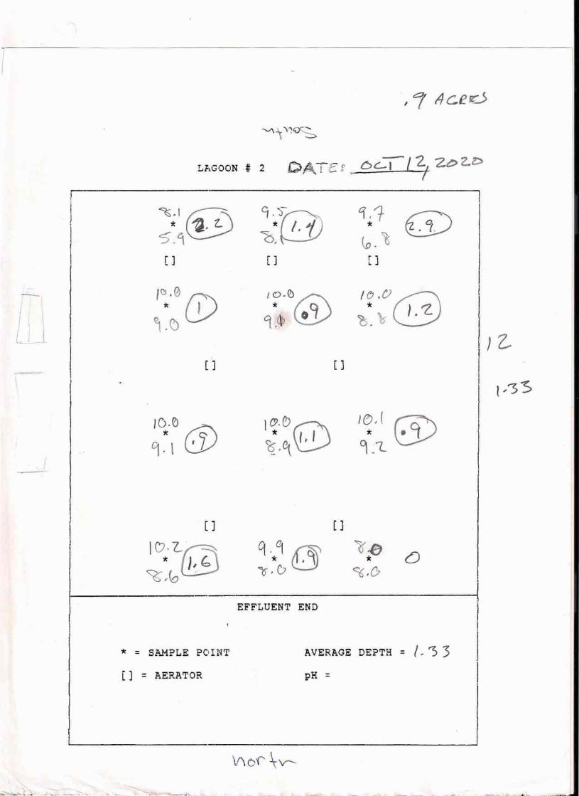
-:-----
I( II \/ I j1_.1-
" or l1c.eo
~4. Y10C::\ -:.:::::,
LP~GOON# 2 C,A.TE f. 6c.:1l 2, Ze> ZZ>v -. T
~.I@ \'fTlJ '1,1 (j)* ~. z, * .7,5.~ 6, (.0. 't[) [ ] []
,,,,(1) (j) [email protected]@* I ?s~~6 } • '2.
~.~
[] []
I~.e> ~9· \ l:Y
1o.t: ~~.~0
I(),I rs-.Q* &I_L
[][ ]
ICJ.l.~
~~6~q.q f&\1o~(J0
~-i!J*~,0
o
EFFLUENT END
* = SAMPLE POINT AVERAGE DEPTH = I, ') 3[] = AERATOR pH =
\!\ 0f' \-v--!!!lo...:~l~.••••••,•• ,......i. ., •..•.••.. ..:-, •• _~ •• , .•••. ~_,.n.. . _ -~ - - .'" -.~.'~'" ...•'
,I 2-I
r,3S
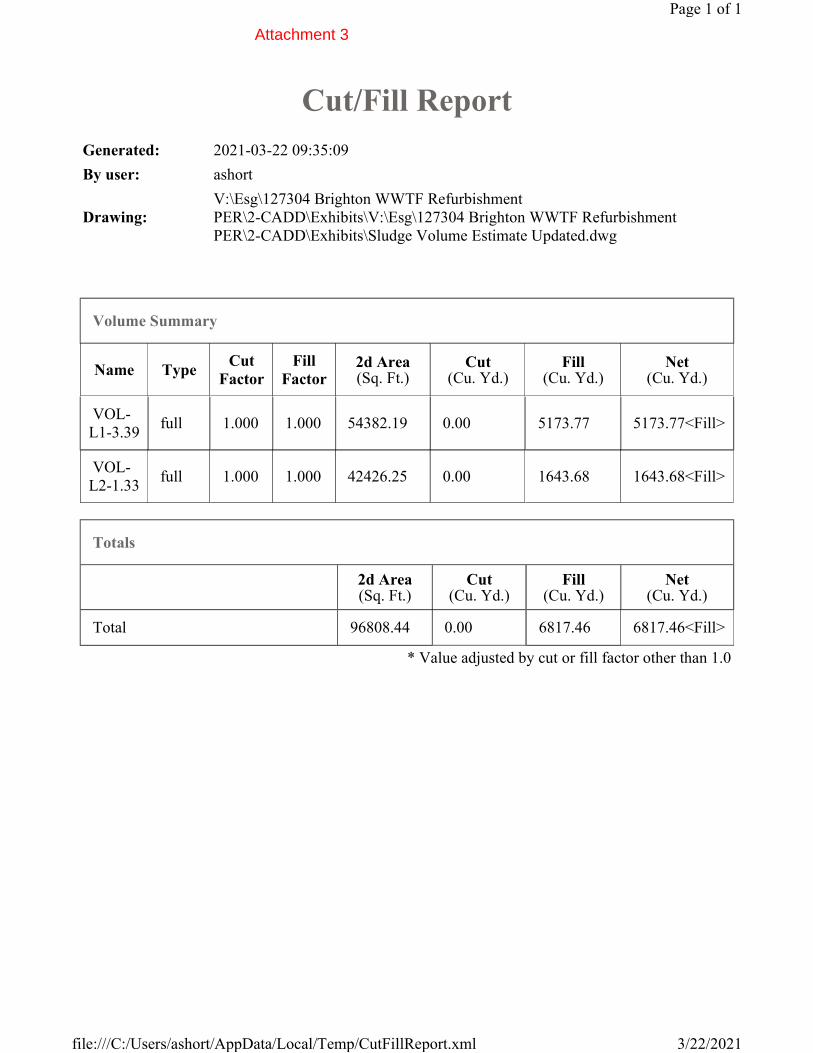
Cut/Fill Report
Generated: 2021-03-22 09:35:09
By user: ashort
Drawing:
V:\Esg\127304 Brighton WWTF Refurbishment
PER\2-CADD\Exhibits\V:\Esg\127304 Brighton WWTF Refurbishment
PER\2-CADD\Exhibits\Sludge Volume Estimate Updated.dwg
Volume Summary
Name TypeCut
Factor
Fill
Factor2d Area(Sq. Ft.)
Cut(Cu. Yd.)
Fill(Cu. Yd.)
Net(Cu. Yd.)
VOL-
L1-3.39 full 1.000 1.000 54382.19 0.00 5173.77 5173.77<Fill>
VOL-
L2-1.33 full 1.000 1.000 42426.25 0.00 1643.68 1643.68<Fill>
Totals
2d Area(Sq. Ft.)
Cut(Cu. Yd.)
Fill(Cu. Yd.)
Net(Cu. Yd.)
Total 96808.44 0.00 6817.46 6817.46<Fill>
* Value adjusted by cut or fill factor other than 1.0
Page 1 of 1
3/22/2021file:///C:/Users/ashort/AppData/Local/Temp/CutFillReport.xml
Attachment 3
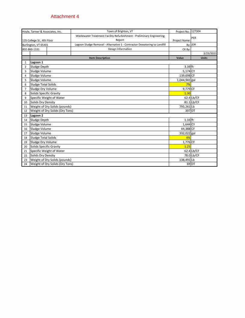
Hoyle, Tanner & Associates, Inc. Town of Brighton, VT Project No.: 127304
125 College St., 4th Floor
Wastewater Treatment Facility Refurbishment - Preliminary Engineering
Report Project Name:PER
Burlington, VT 05401 Lagoon Sludge Removal - Alternative 1 - Contractor Dewatering to Landfill By: JDR
802-860-1331 Design Information CK By:
3/23/2021
Value Units
1
2 3.39 ft
3 5,174 CY
4 139,698 CF
5 1,044,941 gal
6 7%
7 9,779 CF
8 1.30
9 62.4 Lb/CF
10 81.1 Lb/CF
11 793,261 Lb
12 397 DT
13
14 1.33 ft
15 1,644 CY
16 44,388 CF
17 332,022 gal
18 4%
19 1,776 CF
20 1.25
21 62.4 Lb/CF
22 78.0 Lb/CF
23 138,491 Lb
24 69 DT
Sludge Volume
Sludge Total Solids
Sludge Dry Volume
Solids Specific Gravity
Weight of Dry Solids (Dry Tons)
Sludge Volume
Lagoon 2
Sludge Depth
Sludge Volume
Sludge Volume
Sludge Total Solids
Sludge Dry Volume
Solids Specific Gravity
Specific Weight of Water
Solids Dry Density
Weight of Dry Solids (pounds)
Specific Weight of Water
Solids Dry Density
Weight of Dry Solids (pounds)
Weight of Dry Solids (Dry Tons)
Item Description
Lagoon 1
Sludge Depth
Sludge Volume
Sludge Volume
Attachment 4
December 31, 2020 Mr. Marshall C. Frizzell - Chief Operating Officer Town of Brighton’s Water and Sewer Department P.O. Box 402 Island Pond, Vermont 05846 RE: Damage to Sewer Pipe Summary Letter – Brighton Town Hall, 49 Mill Street
Extension, Island Pond, Vermont, SMS# 2011-4212
Dear Mr. Frizzell: This letter provides a summary of the damaged sewer pipe that was identified at the Brighton Town Hall located at 49 Mill Street Extension, Island Pond, VT (Site). The damaged sewer pipe was identified during the July 2020 carbon injection event at the Site. The carbon injection event was conducted to remediate a heating oil release at the Site which was discovered in 2011. The exact volume of heating fuel released to the subsurface is unknown. However, based on field measurements and analytical data, KAS has estimated that approximately 640 gallons of #2 heating oil was released. Carbon Injection Event On July 14, 15, 16, and 17, 2020, KAS, Inc. (KAS) oversaw the carbon injection event completed by AST Environmental, Inc (AST) of Midway, Kentucky. Prior to the carbon injection event, KAS premarked the Site for Digsafe, and hired a private utility locator (Vermont Underground Locators of Williston, VT) to identify buried utilities beneath the Site due to the number of injection points being advanced. Vermont Underground Locators provided a report to KAS with pictures indicating the location of buried utilities beneath the Site which is attached to this letter. On July 14, 2020, KAS and AST arrived at the Site and laid out the injection grid at the Site. The grid had to be adjusted to accommodate the buried utilities beneath the Site in Injection Area D. The way the grid was adjusted was by removing the row of injection points where the utilities were located and moving them further south. A copy of the injection report from AST with a map showing each injection location is attached to this letter. During the injection event, AST was extremely diligent about maintaining the utility lines anytime they began to fade. The injections started the following day on July 15, 2020. A complete log detailing the injection location, date, time, pressure, and volume for each injection point are included in the injection report from AST (attached). On July 16, 2020 at 13:45, KAS was informed that black carbon slurry was being observed at the waste water treatment plant. After being informed of this, KAS immediately asked the driller if they felt like they hit something while advancing the injection rods. The driller said they did not feel like they hit anything. Following the carbon injection event, the Town of Brighton had the sewer line scoped and surveyed. During scoping of the line, an approximately 2-inch diameter hole was observed in the line near injection points C7 and C8. A copy of this video was sent to KAS on a zip drive through the mail. Based on observations made by the Town of Brighton and KAS, it does appear that the sewer line was drilled through at some point in time. The hole appears to be a circular hole approximately 2 to 3 inches in diameter, which is approximately the size of drill rods for a Geoprobe direct push drill rig during the carbon
Appendix 2-5 - KAS Consulting Summary of Damage to the Sewer Pipe and Corrective Action Report
Mr. Marshall C. Frizzell December 31, 2020 Page 2
injection event (see attached photos). However, after KAS reviewed the pressure measurements during the injections at C7 and C8, the logs indicated that the slurry was injected into the soil formation and not into a void (like a pipe). If the carbon slurry had been injected into a void, the formation pressure would have been equal to 0. KAS confirmed this information with Mr. Bill Brab of AST in an email, which is attached. Based on this information, KAS believes that the sewer line was damaged during a previous drilling event. KAS reviewed previous soil boring locations at the Site and determined it most likely occurred during the 2015 supplemental site investigation at SB-3 (Site Map with soil boring location attached). During this site investigation the Site was premarked for Digsafe prior to drilling, but a private utility locator was not hired. At the time, the only known utilities in that area were the communication line and the water line. During the advancement of SB-3, a truck mounted geoprobe rig was used to advance the soil boring to 9 feet bsg, which is the same elevation as the sewer line. Based on the scoping video and the boring log for SB-3, it appears the hole is only in the top of the pipe and did not extend all the way through the pipe. Groundwater elevations measured at the closest monitoring well to the soil boring (MW11-04) range between 8.5 to 9.5 feet bsg. This would indicate that when the water table is high, impacted groundwater could enter the sewer pipe. Carbon Injection Slurry Makeup The carbon slurry injected into the ground at the Site was made up of BOS 200® (blend of powdered/granulated carbon, calcium, gypsum, nitrate, phosphate, and ammonia) mixed with water and bacteria. A total of 3,100 pounds of BOS 200® and 10 gallons of bacteria were injected at the Site over 68 injection points. Approximately 60 gallons of the carbon was injected while advancing injection points C7 and C8 (approximately 30 gallons each). It is unknown exactly how much of the carbon slurry spread into the sewer pipe and travelled to the waste water treatment plant. From talking with AST, they believe that the amount of slurry that would enter the pipe would be significantly less than the volume injected into the formation. Sewer Pipe Survey In addition to having the sewer pipe scoped, the Town of Brighton also had the sewer line surveyed. The line was surveyed from the manhole cover to the southwest of Sunrise Manor heading west to the manhole cover located southwest of the Brighton Town Hall building. The sewer pipe is located 9 feet below surface grade (bsg) and is constructed of 6-inch diameter PVC pipe. The survey data was plotted on the Site Map and Contaminant Distribution Maps, which are attached. When the survey points were plotted on the injection area map, the location of the hole in the sewer pipe was closer to injection points D7 and D8 (instead of C7 and C8). It is unknown why there is a discrepancy in the hole location. Regardless, KAS also looked at the pressure logs for these injection points and there was no indication that they were injected into a void. A total of 30 gallons was also injected at each of these injection points. The survey also showed an area of the sewer pipe that is sagging. Before the survey points were plotted on the map, it was unknown if the sagging could be due to the degradation of the PVC pipe from the residual heating oil in the ground. However, once the data was plotted, the location of the sagging pipe is not located within the dissolved phase plume
Mr. Marshall C. Frizzell December 31, 2020 Page 3
beneath the Site. KAS has included maps with the survey data and the dissolved phase plume from the most recent groundwater monitoring event in August 2020 (see attached). Based on this information, KAS does not believe the sagging pipe is related to the heating oil release. Proposed Sewer Pipe Repair Due to the hole, sagging, and pipe bubble observed in the sewer pipe in addition to general flow issues, the Town of Brighton would like to replace the existing sewer pipe from manhole cover to manhole cover south of the Brighton Town Hall building. Instead of replacing the existing line with 6-inch diameter PVC piping, they are proposing to upgrade the line with 8-inch diameter ductile iron, which is known for its durability and wear-resistance. This work is proposed to take place in summer 2021. Conclusions and Recommendations Based on the information presented above, it appears that the sewer line was compromised at some point in time during drilling activities at the Site; however, it is unknown exactly when the line was compromised. Based on the pressure logs from the injection event, the carbon slurry at each injection point was injected into the soil formation and not into a void space (I.e., the sewer pipe). Additionally, it was determined that the sag in the sewer pipe is likely not related to the heating oil release, due to the sag being located outside of the area of the dissolved phase plume. KAS recommends that the sewer pipe be replaced/upgraded at the Site to repair the hole in the pipe and to address the sagging pipe and flow issues near Sunrise Manor. Due to the heating oil release south of the Brighton Town Hall building, the contractors hired to excavate the sewer line and replace it must be HAZWOPER certified. KAS will prepare a soil management plan for contaminated soils anticipated to be encountered during the excavation of the sewer line. The soil management plan will outline two options for the soil, depending on Site conditions during the time of excavation. Option A will include segregating soils and back filling the excavation with grossly contaminated soil. Option B would include disposing of grossly contaminated soil.
Please feel free to contact me with any questions or comments via telephone, (802) 383-0486, or email, [email protected].
Sincerely, Reviewed By:
Monica Ladago Jeremy Roberts, P.G. Project Scientist Principal/Environmental Program Manager
Mr. Marshall C. Frizzell December 31, 2020 Page 4
Enclosure: Site Map with Injection Areas Total VOC Distribution Map – 2020 October 2015 SSI Site Map with SB-3 Location Screenshot Photos of Sewer Line Scoping Utility Location Report AST Injection Report AST Email Correspondence
CC: Mr. Joel Cope, Town Administrator for Town of Brighton Mr. Richard Spiese, VTDEC – Waste Management and Prevention Division, Sites Management Section Ms. Jamie Bates, Wastewater Program Analyst
KAS #409110444
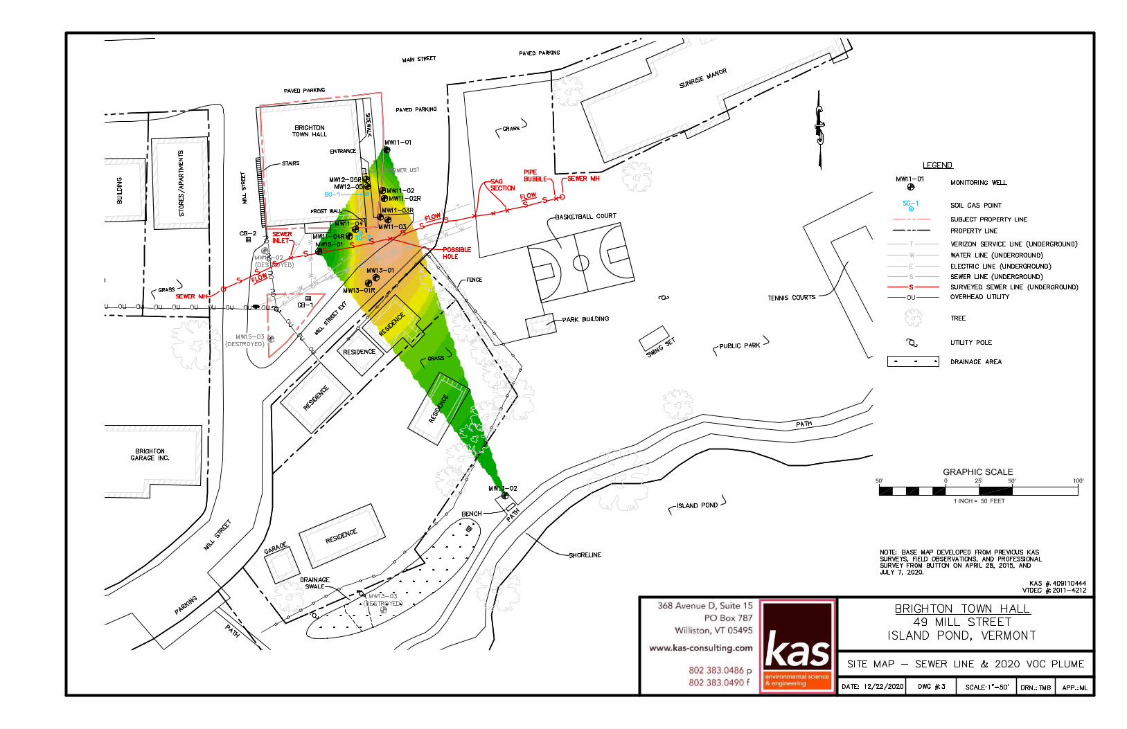
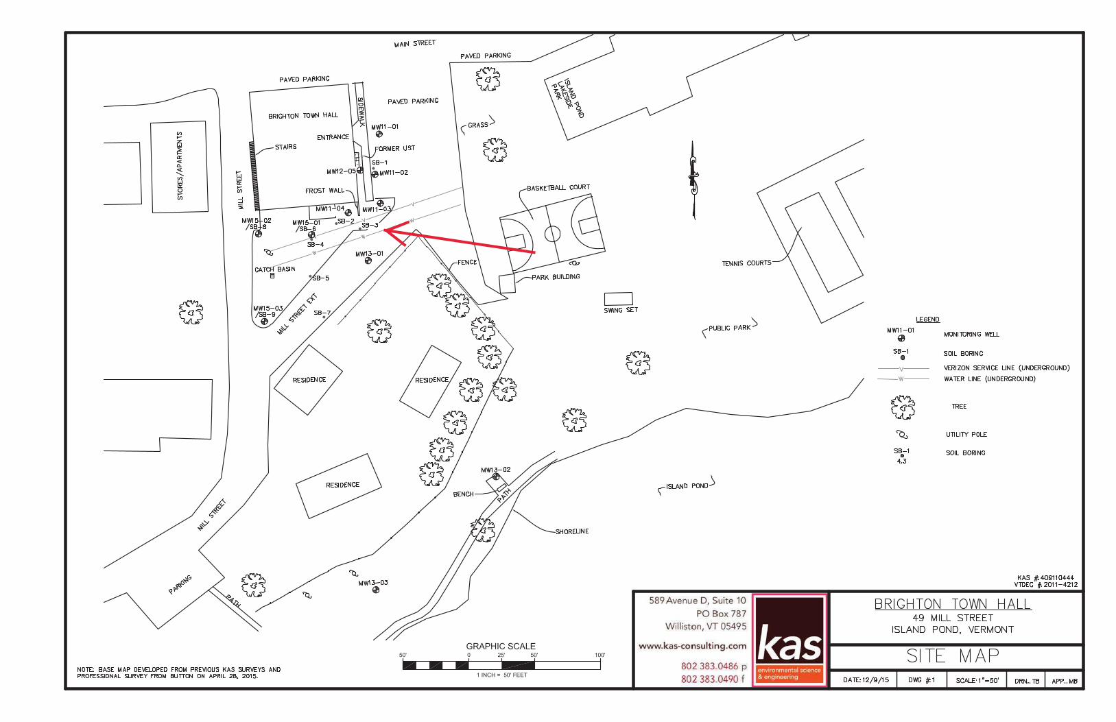
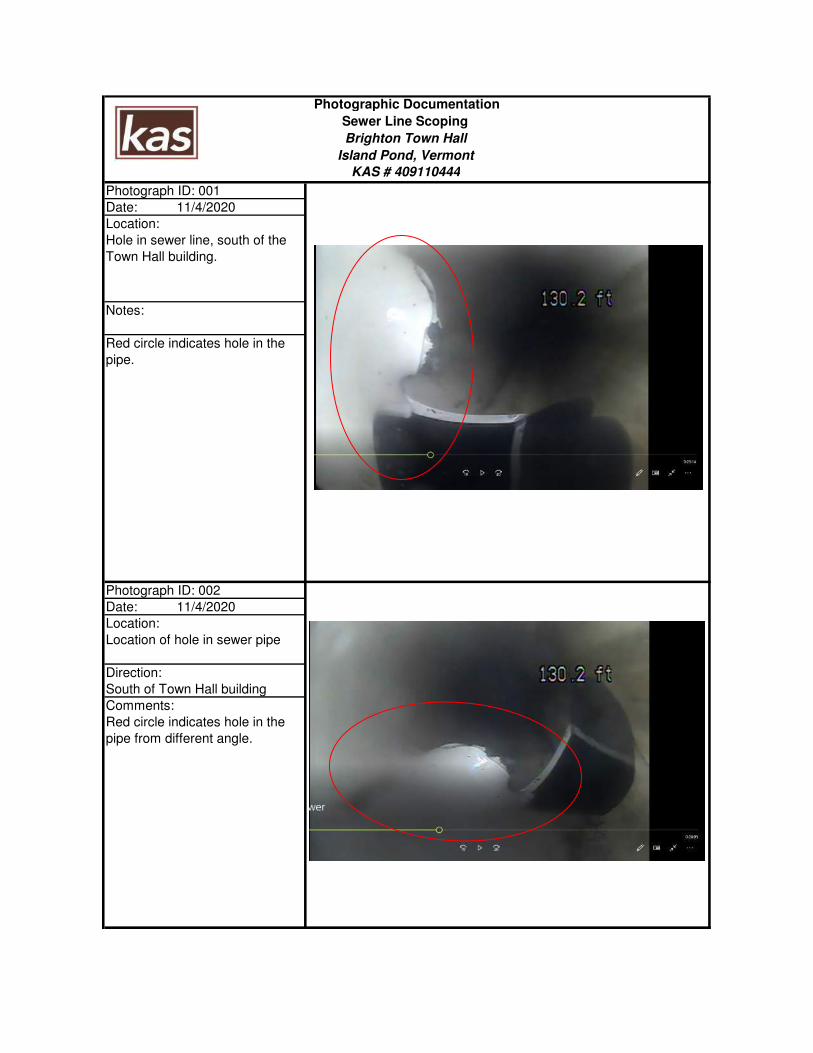
Photograph ID: 001
Date: 11/4/2020
Location:
Hole in sewer line, south of the
Town Hall building.
Notes:
Red circle indicates hole in the
pipe.
Photograph ID: 002
Date: 11/4/2020
Location:
Location of hole in sewer pipe
Direction:
South of Town Hall building
Comments:
Red circle indicates hole in the
pipe from different angle.
Photographic Documentation
Sewer Line Scoping
Brighton Town Hall
Island Pond, Vermont
KAS # 409110444

2020
Annual Report
Town of Brighton, VTFor The Year Ending December 31, 2020
Appendix 2-6 - Brighton Annual Report

Town of BrightonVERMONT

Annual Report of the Town and the Officers of
Brighton, Vermont
Oath of AllegianceI pledge allegiance to the Flag
of the United States of Americaand to the Republic for which it stands
one nation under God, indivisiblewith liberty and justice for all
For the year ending December 31,
2020
4 Town of Brighton, VT
IndexAmbulance Service Report (Newport Ambulance) 46
Auditors’ Report 35
Better Connections Grant Match Reserve Account 31
Brighton Ambulance Account 34
Brighton Recreation Report 36
Brighton Recreation Account 37
Budget Reports
Budget - 2020 Budget Report & 2021 Proposed Budget 12
Revenues - 2020 Actual Revenues & 2021 Expected Revenues 19
Building Security Reserve Account 38
Cemetery Reports
Cemetery Commissioners’ Report 41
Cemetery Report 42
Cemetery Reserve Fund 41
Cemetery Trust Fund & Savings 42
Community Information 6
CPA Reserve Account 38
Culvert Fund 34
Downtown Engineering Reserve Account 38
Efficiency Vermont 43
Emergency Generator Fund 33
Equipment Reserve Fund 32
Fire Department Reports
Fire Department Equipment Fund 32
Fire Truck Capital Reserve 33
General Information 6
Heavy Equipment Fund 35
Indebtedness, Town of Brighton 38
Infrastructure Reserve Funds 35
Lakeside Park 34
Library Reports
Gladys Brooks Foundation Grant Report 40
Librarian’s Report 39
Library Report 40
2020 Annual Report 5
Lister Training Fund 34
Miller Building Account 35
Minutes from March 2, 2020 Annual Town Meeting 54
NEK Community Broadband 52
Northeast Kingdom Learning Services 48
Northwoods Stewardship Center 51
NVDA 50
Officers, Town 8
Orleans Essex VNA & Hospice 47
Paving Project Account 32
Police Activity Report 45
Reappraisal Accounts 37
Selectboard’s Report 10
Sewer Department Reports
Sewer Capital Improvement Fund 29
Sewer Department Proposed Budget Report 25
Sewer Engineering Services Reserve Account 25
Sewer Sludge Removal Fund 27
Sidewalk Account 33
Taxes
Delinquent Property Taxes 21
Statement of Delinquent Taxes 21
Statement of Taxes Raised 20
Tax Rate Breakdown 20
Telephone Numbers Back Cover
Tri-County ATV Club 44
Umbrella 49
Vital Statistics Reports
Births 53
Deaths 53
Marriages 53
Warning for 2021 Annual Town Meeting 7
Water Department Reports
Water Capital Improvement Account 27
Water Department Proposed Budget 24
Water Engineering Services Reserve Account 28
6 Town of Brighton, VT
Community Information
Monday, March 1, 2021 - School and Town Informational Meetings - Via Zoom Videoconference: School Meeting at 7:00 PM Town Business Meeting at 7:30 PMTuesday, March 3, 2021 - Town Meeting Elections - Brighton Municipal Building:
9:00AM to 7:00 PM
Thursday, April 1, 2021 - Last day to license dogsGeneral Information
Date of Charter: August 31, 1781Population: 1,222 (per 2010 Census Records) Size: 34,368 acres2020 Educational Grand list: $ 1,391,665.902020 Municipal Grand List: $ 1,393,425.50
Town Clerk Office HoursMonday through Friday - 8:00 AM to 3:30 PM
Brighton Recycle Center HoursSaturday and Monday – 8:00 AM to 2:00 PM
Teresa DeBonville Town Clerk &
Treasurer
Joel Cope Town & Zoning Administrator
Water Equipment Reserve Fund 29
Water Reservoir Maintenance Account 28
Water Sinking Fund 26
Water-Sewer Accounts
Delinquent Water & Sewer Users 30
Water-Sewer Commissioners’ Report 22
Water-Sewer Operations Account 26
Brighton Selectboard Heather McElroy, Michael Strait
Jeanne Gervais
2020 Annual Report 7
Town of Brighton
WARNING FOR ANNUAL TOWN MEETING 2021
The legal voters for the Town of Brighton and the Brighton Water System are hereby warned and notified to meet at the Town Hall in Island Pond at 49 Mill Street Ext. on Tuesday, March 2, 2021, from 9:00 AM to 7:00 PM to transact the following business by Australian Ballot:
1. To elect the following Town and Water System Officers: Moderator, Delinquent Tax Collector all for a one-year term. One Water Commissioner, one Cemetery Commis-sioner, one Select Board member, two Listers, one Auditor, one Town Clerk, one Treasurer, all for a three-year term. One Library Trustee for a 5-year term, and one Library Trustee for the remaining 4-year term of a resignation from office.
2. To elect the following School District officers: One Moderator for a one-year term. One school director for a two-year term. One school director to serve the remaining two years of a three-year term due to a resignation. One School Treasurer and one School Direc-tor for a three-year term.
3. Shall the voters authorize total fund expenditures for operating expenses of $1,437,975.83, of which $969,783.94 shall be raised by taxes and $468,191.89 by non-tax revenues?
Dated at Brighton, County of Essex and State of Vermont, this 20th day of January, 2021.
BRIGHTON SELECTBOARD
Michael Strait, Chair ‘21 Jeanne Gervais ‘23 Heather McElroy ‘22
School & Town of Brighton Informational MeetingTime: Mar 1, 2021 07:00 PM Eastern Time
Join Zoom Meeting via Tablet or Computerhttps://zoom.us/j/92777457796
To Join via Telephone, Dial Either Number (929) 205-6099 or (301) 715-8592
Enter Meeting ID: 927 7745 7796
8 Town of Brighton, VT
Town OfficersTerm Term
Limit Expires
Moderator Thomas Donnellan 1 year 2021
Town Clerk/Treasurer Teresa DeBonville 3 years 2021
Ass't. Clerk/Treasurer Lisa Moore 3 years 2021
Selectboard Michael Strait 3 years 2021
Jeanne Gervais 3 years 2023
Heather McElroy 3 years 2022
Listers Stephanie Nagle 3 years 2022
Alan Wing 1 year 2021
Vacant
Library Trustees Krystyna Kurzej 5 years 2023
Janet Osborne 5 years 2024
Jocelyne Gervais 5 years 2025
* Rebecca Lefebvre 5 years 2020
** Judy Valente (yrs remaining)
4 years 2021
Susan Vera 5 years 2021
Cemetery Commissioners Wayne Cole 3 years 2021
Ray Fontaine 3 years 2022
Carmen Murray 3 years 2023
School Directors * Jeanne Gervais 3 years 2021
Katie Mientka 2 years 2021
Cass Lyons 3 years 2024
David Yasharian 3 years 2021
Bradley Beth 3 years 2023
** Timothy O'Bar (yrs remaining)
2 years 2023
School Director (NCUHS) David Yasharian 3 years 2022
Auditors Jocelyne Gervais 3 years 2021
Janet Osborne 2 years 2022
** Jonah Rumble-Petre 3 years 2023
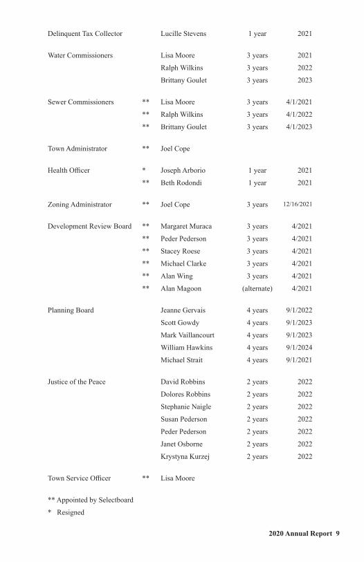
2020 Annual Report 9
Delinquent Tax Collector Lucille Stevens 1 year 2021
Water Commissioners Lisa Moore 3 years 2021
Ralph Wilkins 3 years 2022
Brittany Goulet 3 years 2023
Sewer Commissioners ** Lisa Moore 3 years 4/1/2021
** Ralph Wilkins 3 years 4/1/2022
** Brittany Goulet 3 years 4/1/2023
Town Administrator ** Joel Cope
Health Officer * Joseph Arborio 1 year 2021
** Beth Rodondi 1 year 2021
Zoning Administrator ** Joel Cope 3 years 12/16/2021
Development Review Board ** Margaret Muraca 3 years 4/2021
** Peder Pederson 3 years 4/2021
** Stacey Roese 3 years 4/2021
** Michael Clarke 3 years 4/2021
** Alan Wing 3 years 4/2021
** Alan Magoon (alternate) 4/2021
Planning Board Jeanne Gervais 4 years 9/1/2022
Scott Gowdy 4 years 9/1/2023
Mark Vaillancourt 4 years 9/1/2023
William Hawkins 4 years 9/1/2024
Michael Strait 4 years 9/1/2021
Justice of the Peace David Robbins 2 years 2022
Dolores Robbins 2 years 2022
Stephanie Naigle 2 years 2022
Susan Pederson 2 years 2022
Peder Pederson 2 years 2022
Janet Osborne 2 years 2022
Krystyna Kurzej 2 years 2022
Town Service Officer ** Lisa Moore
** Appointed by Selectboard
* Resigned
10 Town of Brighton, VT
Selectboard Report 2020
Our efforts to revitalize the Island Pond economy and upgrade our local infrastructure continue, in order to better serve our residents and attract travelers to the village. A Vermont Outdoor Recreation Economic Collaborative (VOREC) grant for $60,000 with a small match from the town will pay for a $50,000 dock on the park waterfront, big enough for people to sit on and enjoy the scenery or to hitch a boat to while visiting the downtown. That VOREC grant will also pay for a new visitors’ map to recreational assets in the area, and it will pay for a public bicycle repair station to accommodate the increasing bike traffic into the village.
Soon the Selectboard will choose a professional engineering company to take us to the next level in plans to replace sidewalks, replace old water lines and old stormwater lines on Cross Street, and to re-design the main downtown intersection of Cross & Railroad Streets. The engineering work will be paid for with two other grants of $40,000 each, with an $8,000 match from the town.
Two other big infrastructure needs are imminent as well. Our water treatment plants and our sewer plant and related equipment are over 30 years old and both have passed their design lifetimes. Engineering plans are underway for these key elements of our infrastructure. Please read the Water/Sewer Department Reports on page 22 for more information. It is likely the town is facing a bond vote in the near future, but we anticipate there will be significant state and federal funding to help pay for costs.
Efforts to move all this along have been hindered by the pandemic. But not much has hindered the pandemic until the recent development of vaccines. Even with vaccines, medical experts caution that masks and social distancing are still needed for the time being, and we strongly encourage everyone to do their part to protect everyone else. We have been fortunate so far but as the virus works its way into rural communities it is important to know we are not immune. The Selectboard has had to plan on how municipal functions would get done in the event our employees contracted the virus, as well as the best way to protect staff and the public.
Town Meeting this year will be by Australian Ballot. The normal floor meeting that takes place Monday night before Town Meeting will be conducted online. Voters may call in or attend online. Those who cannot vote in person Tuesday can request absentee ballots from the Town Clerk.
This year’s tax rate will go down, due to some unexpected revenues and underspending the 2020 approved budget by about $65,000.
The question our staff get asked more than any other is “What’s the difference between Brighton and Island Pond?” There are a couple answers to that question. Because IP is a population center, you will find it on most road maps, but you won’t see Brighton designated because it is too large an area at 54 square miles. Island

2020 Annual Report 11
Pond village has no legal boundaries, and no legal standing as a governmental entity. It does, however, have a zip code. The village of Island Pond made an attempt to be chartered, or “Organized” separately from the town in 1908, but never completed the effort. If they had, Island Pond would be run by Trustees, like Barton village, or Lyndonville. But before we start a movement here, communities that have created separate village governments have to have two of everything and that costs money. You have two governing bodies, two clerks, two boards of Listers, two road departments, etc. We think one local government is probably enough.
Sincerely,
Brighton Selectboard
Michael Strait, Chair ‘21 Jeanne Gervais ‘23 Heather McElroy’22
22 Town of Brighton, VT
Hallack, Walter (Back St. - 05L / Curran Ave. - 06L) Nevarez, Joel
Hannux, Richard Nilsen, Christopher
Hawes, Nancy O'Keefe, Michael
Hawkins, William O'Keefe, William
Hinton, James Ogden, Danielle
Hobson, Margaret Pinsonneault, Laurie
Honan, Christopher Raboin, Robert
King, Lawrence Rego, Richard
King, Russell Ruiter, Shannon
Kuczmarski, Thomas Roberto, Joseph
Leighton, Leslie Rogers, Michael
Lindquist, William Rowe, John
Little, Peter Santaw, Raymond
Littlefield, Aldon Schneider, Charles
Malerba, James Silas, Sharon
Maloney, Frank Southerland, Melissa
Marcus, Catherine Stacey, Stephen
Marsden, Pauline (Estate) Stone, Michelle (Estate of)
Maxwell, Paul Telephone Operating Co.
McComisky, Robert Thompson, William
Messier, Rodney
Nash, Jessie (000TR7.02AR/000TR7.02BR)
Toltal 2020 Delinquent Taxes $104,987.51
Grand Toltal Delinquent Taxes as of December 31, 2020 $105,075.26
2020 Water and Sewer Commissioner’s Report2020! Where to begin? It seems the world is reeling from multiple attacks from multiple fronts and the department is finding things no different. Although many issues have arisen, many can be attributed to our aging infrastructure and system. Pump stations are now 45 years old and failing, the water plants are 33 years old and are in need as well. We have been working with the State for the last few years to put together the plans necessary to upgrade our infrastructure and that will also help keep us in compliance with regulatory requirements. This has been an arduous task but there appears to be light at the end of the tunnel. However, that means we will be coming to you in the near future to pass a bond to pay for the upgrades. We also will be looking for grant programs that will help the Town receive the best financing available. We ask for your support and understanding.
2020 Annual Report 23
We have seen quite an increase in “flushable” wipes and other nonflushable items trying to make their way to the sewer treatment plant. Unfortunately, pumps are a casualty and as such we have increased the sewer equipment line to $10,000. Please, only the three p’s: pee, poop and toilet paper.
We have received a forgivable loan (think grant that cannot be called a grant) up to $50,000 from the State to create an asset management program for the water system. This program will consolidate information, help project budgetary needs and track department goals. A part of this program was the Gpsing of many of the curbstops and valves seen painted around Town this past summer and there are many more yet to do. Also the Town received a $30,000 USDA Search grant to pay for the preliminary engineering necessary to proceed with upgrades to the wastewater treatment facility and pumpstations. The Pleasant Street pumpstation is on its last leg; therefore we have begun the process of replacing it sooner. We had hoped to have already finished the project but are now shooting for this spring.
If Covid-19 was not enough, drought helped keep us busy as well. Actually, we have been experiencing drought conditions over the past few years. And although the reservoirs remained full, we increased monitoring of our steams and modified our treatment rates. The Town is blessed to have two separate water sources where we can alter filtration rates to match stream conditions and still meet the Town’s water needs. Currently we are in some very serious discussions with the State as the State has some concern over the streams being compromised by the Town’s use of the streams. Drought affects the wastewater treatment plant as well as changes in flow conditions can cause biological upsets.
Covid 19 has to be one of the biggest life changers any of us experienced in our lifetimes. It definitely has altered our ability to communicate in person and has made what were once simple tasks into time consuming chores. We have purposely avoided going into people’s homes. As such meter repairs are on hold unless they are leaking. However, if you do have an emergency, please call the Town Clerks Office.
There have been some changes over the last year: Bruce Rolfe retired and was replaced by Zach Letourneau. We wish them both well in their endeavors. Brittany Goulet filled the commissioner spot vacated by Butch Barney. Virtual replaced human contact. This has made meetings difficult but they are accessible by phone and sometimes by computer. Meetings are open to the public. Please refer to posted agendas for access numbers as they are subject to change.
During the past year we have repaired a dozen or so curbstops most of which were discovered as a result of the aforementioned asset management program. A manhole on Pleasant St. was repaired, hopefully saving many shock absorbers and complaints. The sewer force main on Meadow St. showed signs of its age in June when a stone managed to work its magic after forty-five years. It took a long day but the repair was made with very little untreated sewage making its way to the river. Two water services were improved and a few leaks were found and repaired.
Two small sewer mains took advantage of 2020. Paquette St. has a hole in it discovered after a back-up reported in March. We also discovered a hole in the sewer line behind the Town hall. It is expected that we will be replacing the main this spring as multiple agencies are involved. This hole has also caused some concern and prodding by the state to move forward on sludge removal at the WWTF. We have been putting funds away for some time and will now start using them.
Regulatory sampling costs are expected to increase as more things to sample for are discovered. Although we met all parameters of PFOA testing required by the State in 2019, we were required to sample for PFOAs again in 2020. As before, this test should be good for three years. We will also be sampling more at the WWTF as the result of the expected new NPDES permit.
2020 was a hard year for the department, the Town, the State, the Nation, not to mention the World; we ask for and appreciate your support. May thanks be to all!
The Brighton Water and Sewer Commission.
Lisa Moore - Chair - 2021 Ralph Wilkins – 2022 Brittany Goulet – 2023
24 Town of Brighton, VT
Water Department Proposed Budget 2020 Budget 2020 Actual 2021 Proposed
Income
Cash on hand: PSB Ckg. Acct.#......0072 $39,957.89 $39,957.89 $23,769.65
Water Rents 249,688.27 265,981.94 259,104.49
Interest 200.00 221.83 200.00
Sale of Materials 250.00 247.03 250.00
Camp Lease 600.00 600.00 600.00
New Connections 1,500.00 - 1,500.00
Miscellaneous
Refunds 570.00 30,000.00
Total Income $292,766.16 $307,008.69 $315,424.14
Expenses
Labor $1,000.00 373.18 $1,000.00
Commissioners stipend 3,000.00 3,000.00 3,000.00
Insurance 2,475.00 2,438.00 2,475.00
Electricity 7,000.00 7,401.84 7,000.00
Equipment purchase 5,000.00 5,000.00 5,000.00
Equipment maintenance 1,000.00 139.97 1,000.00
Equipment hire 6,500.00 2,040.00 6,500.00
Tools 500.00 - 500.00
Paving 5,000.00 - 5,000.00
Operating Supplies 6,000.00 3,394.04 6,000.00
Legal Services 2,000.00 - 2,000.00
Town service fee 8,500.00 8,500.00 8,500.00
Advertising 200.00 - 200.00
Plant Operations 119,933.24 119,933.24 124,591.22
Rent 1,500.00 1,500.00 1,500.00
Miscellaneous 2,000.00 1,333.11 2,000.00
Bond payment - Vt Bond Bank 50,000.00 50,000.00 50,000.00
Bond payment - (Lakeshore Drive) 33,232.92 33,232.92 33,232.92
Hydrant repair 5,000.00 - 5,000.00
Water testing 3,000.00 3,570.65 3,500.00
Permit fees 2,000.00 1,628.82 2,000.00
Reservoir Maintenance 10,000.00 10,000.00 10,000.00
Engineering Services 2,500.00 15,385.00 20,000.00
Building Maintenance 10,000.00 10,000.00 10,000.00
Secretary/Minutes 425.00 425.00 425.00
Reimbursement to sinking fund 5,000.00 5,000.00 5,000.00
Reimb.to Water Cap. Imp.-PSB Svg.#......0241
Total Expenses $292,766.16 284,295.77 $315,424.14
2020 Annual Report 25
Sewer Department Proposed Budget 2020 Budget 2020 Actual 2021 Proposed
Income
Cash on hand: PSB Ckg.#......0073 $11,754.76 $11,754.76 $2,081.43
Sewer rents 176,458.23 181,164.13 192,789.54
Miscellanous 30,000.00
Interest from Delinquencies 100.00 39.65 100.00
Sewer permits 1,000.00 - 1,000.00
Total Income 189,312.99 192,958.54 225,970.97
Expenses
Labor 700.00 $150.00 700.00
Commissioners stipend 3,000.00 3,000.00 3,000.00
Town service fee 7,000.00 7,000.00 7,000.00
Insurance 1,062.00 967.00 1,062.00
Electricity 16,000.00 15,744.19 16,000.00
Equipment & Supplies 3,000.00 11,279.53 10,000.00
Miscellaneous 1,200.00 1,696.30 1,200.00
Water Rent 400.00 400.00 400.00
Discharge Permit 750.00 235.00 750.00
Sludge Removal Fund 10,000.00 1,000.00 10,000.00
Contract Services $5,000.00 4,666.86 $5,000.00
Plant Operations 119,933.23 $119,933.23 124,591.21
Capital Improvements (pump) -
Sewer capital account 5,000.00 5,000.00 5,000.00
Engineering Services 5,000.00 16,950.00 30,000.00
Plant Improvements 1,000.00 - 1,000.00
Secretary/Minutes 425.00 425.00 425.00
Bond payment (Dale Ave.) 9,842.76 2,430.00 9,842.76
Total Expenses $189,312.99 190,877.11 $225,970.97
Sewer Engineering Service Reserve AccountPSB Savings Acct #......1317
Balance as of Jan. 1, 2020 $3,006.07
Interest earned in 2020 $3.06
Balance as of December 31, 2020 $3,009.13
26 Town of Brighton, VT
Water-Sewer Operations Account 2020 Budget 2020 Actual 2021 Proposed
Income
Cash on hand (CNB Ckg. #......2601) $13,093.19 $13,093.19 $11,046.02
Water payments 119,933.24 $119,933.24 124,591.22
Sewer payments 119,933.23 $119,933.24 124,591.21
Interest earned $7.40
Bank Interest
Refunds (Miscellaneous) $-
Total Income $252,959.66 $252,967.07 $260,228.45
Expenses
Contract Operations $208,959.66 $207,112.16 $215,228.45
Labor & Overtime 1,000.00 $- 1,000.00
Administration 500.00 $76.00 500.00
Utilities 4,000.00 $5,340.01 5,000.00
Propane/Fuel 5,500.00 $3,224.60 5,500.00
Vehicle Allowance 500.00 $449.40 500.00
Maintenance & Supplies 13,000.00 $12,953.50 13,000.00
Line Maintenance 5,500.00 $4,207.13 5,500.00
Chemicals 6,000.00 $5,547.60 6,000.00
Truck Expenses 7,500.00 $2,091.44 7,500.00
Miscellaneous 500.00 $430.42 500.00
Total Expenses $252,959.66 $241,432.26 $260,228.45
Water Sinking FundCNB CD Acct #......8170
Balance as of Jan. 1, 2020 $82,558.84
Interest earned in 2020 $356.39
Balance as of Dec. 31, 2020 $82,915.23
PSB Savings Acct #......1260
Balance as of January 1, 2020 $13,765.57
Deposit from water ckg acct #0072 $14,541.59
Interest earned in 2020 $13.84
Balance as of Dec. 31, 2020 $28,321.00
Balance as of December 31, 2020 $111,236.23
2020 Annual Report 27
Water Capital Improvement Account
Sewer Sludge Removal
CNB CD Acct. #......5970
Balance as of Jan. 1, 2020 $48,376.62
Interest earned in 2020 208.84
Balance as of December 31, 2020 $48,585.46
PSB CD Account #......0534
Balance as of Jan. 1, 2020 $5,145.92
Interest earned in 2020 15.48
Balance as of December 31, 2020 $5,161.40
PSB N.O.W. Acct. #......1290
Balance as of Jan. 1, 2020 $41,949.61
Interest earned in 2020 21.02
Deposit from Sewer Acct #0073 1,000.00
Balance as of December 31, 2020 $42,970.63
Total Sewer Sludge Removal Fund $96,717.49
PSB Savings Acct #0241
Balance as of Jan. 1, 2020 $5,000.01
Interest earned in 2020 $4.99
Balance as of Dec. 31, 2020 $5,005.00
PSB CDARS Acct. #5788
Balance as of Jan. 1, 2020 $46,636.22
Interest earned in 2020 $470.80
Balance as of December 31, 2020 $47,107.10
Grand total for Water Capital Improvement
as of 12/31/2020 $52,112.10
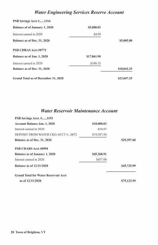
28 Town of Brighton, VT
Water Reservoir Maintenance Account
Water Engineering Services Reserve Account
PSB Savings Acct #......1314
Balance of of January 1, 2020 $5,000.01
Interest earned in 2020 $4.99
Balance as of Dec. 31, 2020 $5,005.00
PSB CDRAS Acct #0772
Balance as of Jan. 1, 2020 $17,861.90
Interest earned in 2020 $180.35
Balance as of Dec. 31, 2020 $18,042.25
Grand Total as of December 31, 2020 $23,047.25
PSB Savings Acct. #......1193
Account Balance Jan. 1, 2020 $10,000.03
Interest earned in 2020 $10.07
DEPOSIT FROM WATER CKG ACCT #...0072 $19,387.50
Balance as of Dec. 31, 2020 $29,397.60
PSB CDARS Acct #0594
Balance as of January 1, 2020 $45,268.91
Interest earned in 2020 $457.08
Balance as of 12/31/2020 $45,725.99
Grand Total for Water Reservoir Acct
as of 12/31/2020 $75,123.59
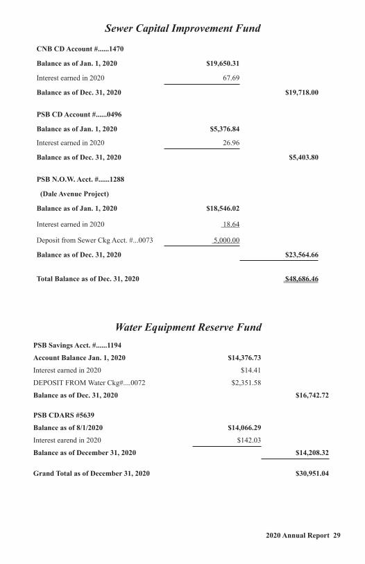
2020 Annual Report 29
Water Equipment Reserve Fund
Sewer Capital Improvement Fund
CNB CD Account #......1470
Balance as of Jan. 1, 2020 $19,650.31
Interest earned in 2020 67.69
Balance as of Dec. 31, 2020 $19,718.00
PSB CD Account #......0496
Balance as of Jan. 1, 2020 $5,376.84
Interest earned in 2020 26.96
Balance as of Dec. 31, 2020 $5,403.80
PSB N.O.W. Acct. #......1288
(Dale Avenue Project)
Balance as of Jan. 1, 2020 $18,546.02
Interest earned in 2020 18.64
Deposit from Sewer Ckg Acct. #...0073 5,000.00
Balance as of Dec. 31, 2020 $23,564.66
Total Balance as of Dec. 31, 2020 $48,686.46
PSB Savings Acct. #......1194
Account Balance Jan. 1, 2020 $14,376.73
Interest earned in 2020 $14.41
DEPOSIT FROM Water Ckg#....0072 $2,351.58
Balance as of Dec. 31, 2020 $16,742.72
PSB CDARS #5639
Balance as of 8/1/2020 $14,066.29
Interest earend in 2020 $142.03
Balance as of December 31, 2020 $14,208.32 Grand Total as of December 31, 2020 $30,951.04
Grand Total as of December 31, 2020 $30,951.04
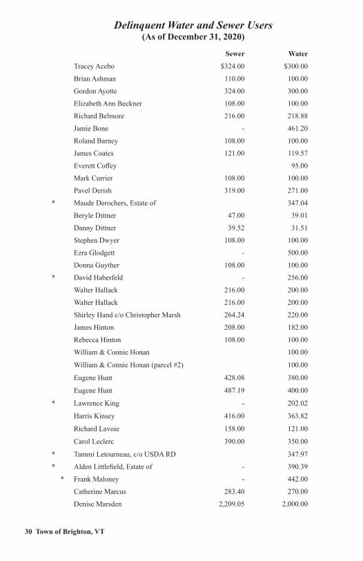
30 Town of Brighton, VT
Delinquent Water and Sewer Users (As of December 31, 2020)
Sewer Water
Tracey Acebo $324.00 $300.00
Brian Ashman 110.00 100.00
Gordon Ayotte 324.00 300.00
Elizabeth Ann Beckner 108.00 100.00
Richard Belmore 216.00 218.88
Jamie Bone - 461.20
Roland Barney 108.00 100.00
James Coates 121.00 119.57
Everett Coffey 95.00
Mark Currier 108.00 100.00
Pavel Derish 319.00 271.00
* Maude Derochers, Estate of 347.04
Beryle Dittner 47.00 39.01
Danny Dittner 39.52 31.51
Stephen Dwyer 108.00 100.00
Ezra Glodgett - 500.00
Donna Guyther 108.00 100.00
* David Haberfeld - 256.00
Walter Hallack 216.00 200.00
Walter Hallack 216.00 200.00
Shirley Hand c/o Christopher Marsh 264.24 220.00
James Hinton 208.00 182.00
Rebecca Hinton 108.00 100.00
William & Connie Honan 100.00
William & Connie Honan (parcel #2) 100.00
Eugene Hunt 428.08 380.00
Eugene Hunt 487.19 400.00
* Lawrence King - 202.02
Harris Kinsey 416.00 363.82
Richard Lavoie 158.00 121.00
Carol Leclerc 390.00 350.00
* Tammi Letourneau, c/o USDA RD 347.97
* Alden Littlefield, Estate of - 390.39
* Frank Maloney - 442.00
Catherine Marcus 283.40 270.00
Denise Marsden 2,209.05 2,000.00
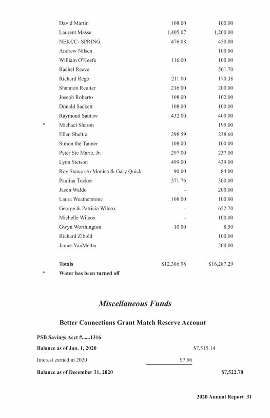
2020 Annual Report 31
Miscellaneous Funds
Better Connections Grant Match Reserve Account
David Martin 108.00 100.00
Laurent Masse 1,405.07 1,200.00
NEKCC- SPRING 476.08 450.00
Andrew Nilsen 100.00
William O'Keefe 116.00 100.00
Rachel Reeve 501.70
Richard Rego 211.00 170.38
Shannon Reutter 216.00 200.00
Joseph Roberto 108.00 102.00
Donald Sackett 108.00 100.00
Raymond Santaw 432.00 400.00
* Michael Sharon 195.00
Ellen Sheltra 298.59 238.60
Simon the Tanner 108.00 100.00
Peter Ste Marie, Jr. 297.00 237.00
Lynn Stetson 499.00 439.00
Roy Stewe c/o Monica & Gary Quick 90.00 84.00
Paulina Tucker 371.76 300.00
Jason Waldo - 200.00
Laura Weatherstone 108.00 100.00
George & Patricia Wilcox - 652.70
Michelle Wilcox - 100.00
Gwyn Worthington 10.00 8.50
Richard Zibold 100.00
James VanMetter 200.00
Totals $12,386.98 $16,287.29
* Water has been turned off
PSB Savings Acct #......1316
Balance as of Jan. 1, 2020 $7,515.14
Interest earned in 2020 $7.56
Balance as of December 31, 2020 $7,522.70
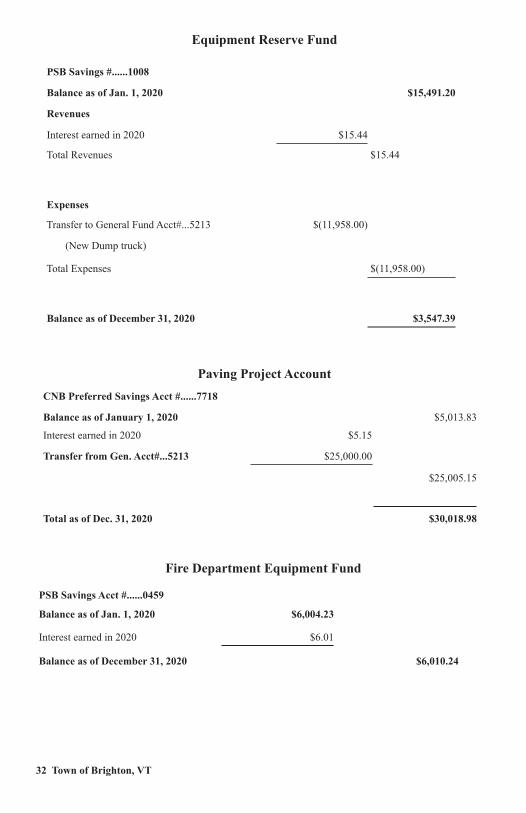
32 Town of Brighton, VT
Equipment Reserve Fund
Fire Department Equipment Fund
Paving Project Account
PSB Savings #......1008
Balance as of Jan. 1, 2020 $15,491.20
Revenues
Interest earned in 2020 $15.44
Total Revenues $15.44
Expenses
Transfer to General Fund Acct#...5213 $(11,958.00)
(New Dump truck)
Total Expenses $(11,958.00)
Balance as of December 31, 2020 $3,547.39
CNB Preferred Savings Acct #......7718
Balance as of January 1, 2020 $5,013.83
Interest earned in 2020 $5.15
Transfer from Gen. Acct#...5213 $25,000.00
$25,005.15
Total as of Dec. 31, 2020 $30,018.98
PSB Savings Acct #......0459
Balance as of Jan. 1, 2020 $6,004.23
Interest earned in 2020 $6.01
Balance as of December 31, 2020 $6,010.24
2020 Annual Report 33
Fire Truck Capital Reserve
PSB Savings Acct #......1257
Balance as of Dec. 31, 2020 $10,000.00
Interest earned in 2020 $9.99
Balance as of December 31, 2020 $10,009.99
PSB CDERS Acct #5698 $30,165.88
Interest earned in 2020 $304.58
Balance as of December 31, 2020 $30,470.46
Balance as of December 31, 2020 $40,480.45
Brighton Culvert Fund
PSB Savings Acct #......0942
Balance as of Jan. 1, 2020 $5,410.94
Revenues
Interest earned in 2020 $5.44
Transfer from Gen. acct #...5213 $5,000.00
Total Revenues 2020 $5,005.44
Balance as of December 31, 2020 $10,416.38
Sidewalk AccountCNB Preferred Savings Acct #......4818
Balance of of Dec. 31, 2020 $15,005.08
Interest earned IN in 2020 $15.07
Transfer from General Acct. # …5213 $10,000.00
Balance As Of Dec. 31, 2020 $25,020.15
Emergency Generator FundPSB Savings Acct #......1256
Balance as of Jan. 1, 2020 $6,994.79
Interest earned in 2020 $6.97
Transfer to General Acct#...5213 $(6,619.00)
(Purchase of Emergency Generator)
Balance as of December 31, 2020 $382.76
34 Town of Brighton, VT
Lakeside Park
Lister Training Fund
PSB Savings Acct #......0528
Balance as of Jan. 1, 2020 $4,282.47
Interest earned in 2020 $4.26
Balance as of December 31, 2020 $4,286.73
CNB Checking Acct. #......9201
BALANCE as of January 1, 2020 $6,530.90
REVENUES:
Town Appropriations 2020 $14,000.00
Earned Interest in 2020 $2.02
Total Revenues as of Dec. 31, 2020 $14,002.02
Expenses:
Operating expenses $(3,820.15)
Electricity $(1,148.58)
Equipment Maintenance & repair $(2,795.75)
Total Expenses as of Dec. 31, 2020 $(7,764.48)
BALANCE as of December 31, 2020 $12,768.44
Brighton Ambulance AccountCNB Ckg Acct. #......9701
Balance as of January 1, 2020 $72,966.98
Expenses
Newport Ambulance Service $(48,829.10)
EMS Call Stipend $(1,450.00)
Bound Tree (Medical Supplies) $(98.57)
Reimburse Gen. Acct #5213 for Jan./Feb. service $(10,090.82)
Expenses as of Dec. 31, 2020 $(60,468.49)
Balance as of December 31, 2020 $12,498.49
2020 Annual Report 35
Miller Building Account
Infrastructure Reserve Funds
Heavy Equipment FundPSB CD #......0943
Balance as of Jan 1, 2020 $10,052.43
Interest earned in 2020 $101.50
Blance as of Dec. 31, 2020 $10,153.93
PSB Savings Acct. #......1192
Account Balance January 1, 2020 $203,076.30
Interest earned $53.04
Repayment of Funds Transferred to Gen. Acct # 5213 $180,000.00
Total Income as of Dec. 31, 2020 $180,053.04
Expenses
Transfer to Gereral Acct #5213 to cover expenses ($180,000.00)
in lieu of tax revenue
Total Expenes ($180,000.00)
Balance as of December 31, 2020 $203,129.44
PSB Savings Acct #......1315
Balance as of January 1, 2020 $75,062.08
Interest earned in 2020 $75.21
DEPOSIT from General ACCT # …5213 $25,000.00
Revemues as of Dec. 31, 2020 $25,075.21
Balance as of December 31, 2020 $100,137.29
Auditors’ Report
As auditors for the Town of Brighton, we have examined the accounts for the Town of Brighton for the period of January 1, 2020 to December 31, 2020. Our findings are reported with each account we have listed in this town report. We are still due for an official CPA Audit which should be in the planning since our last audit was done as of December 31, 2013. We recommend the automation of all accounting procedures as soon as possible so as to eliminate duplicate work that might introduce more possibility of error.
Respectfully submitted,
Board of Auditors, Jocelyne Gervais, Janet Osborne, Jonah Petre (absent)
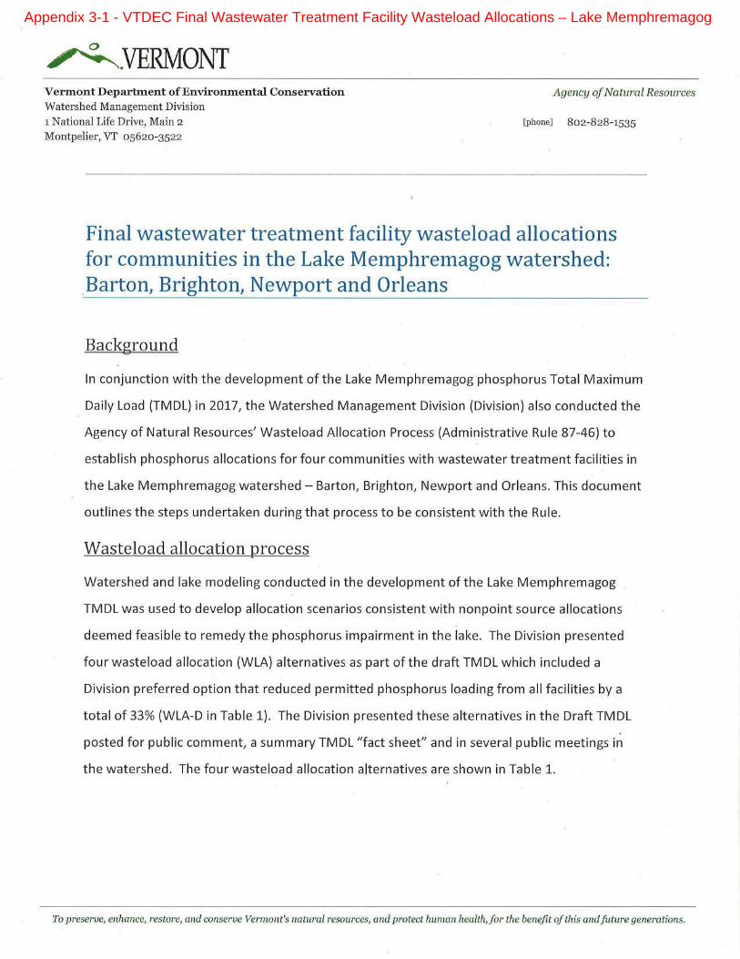
Appendix 3-1 - VTDEC Final Wastewater Treatment Facility Wasteload Allocations – Lake Memphremagog
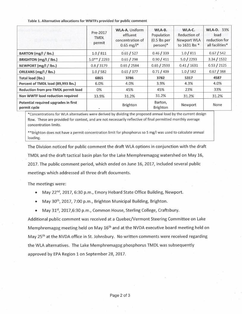
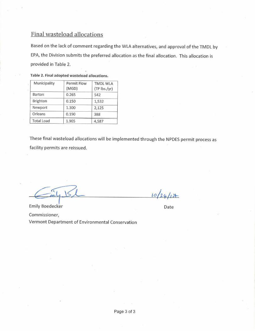

1
Marks, Daniel B.
From: Bates, Jamie <[email protected]>
Sent: Tuesday, February 2, 2021 1:45 PM
To: Auster, Jennifer; Marks, Daniel B.; Martinez Cazon, Hugo; harries, jonathan - RD, Montpelier, VT; Reilly, John D.; Brighton
Cc: Polaczyk, Amy
Subject: RE: [External] RE: Draft RPD Monitoring proposed for Brighton WWTF
Meant to remove that. The TP in the table below was solely based on the TP VWQS criteria -- not the LM TMDL. Please use values reflected in the LM TMDL for
the design criteria.
--Jamie
Due to the coronavirus (COVID-19) we are taking additional safety measures to protect our employees and customers and are now working remotely while focusing on keeping our normal business
processes fully functional. Please communicate with our staff electronically or via phone to the greatest extent possible since our processing of postal mail may be slowed during this period. You may
now submit permit applications, compliance reports and fee payments through our new online form to expedite its receipt and review:
https://anronline.vermont.gov/?formtag=WSMD_Intake.
Division staff contact information can be found online here: https://dec.vermont.gov/watershed/contacts.
Thank you for your patience during this challenging time. We wish you and your family the best.
Jamie Bates | Direct Discharge Analyst (she/her)
Vermont Department of Environmental Conservation
Watershed Management Division, Wastewater Management Program
Davis Building 3rd Floor, 1 National Life Drive | Montpelier, VT 05620-3522
802-490-6183 work cell | www.watershedmanagement.vermont.gov
From: Auster, Jennifer <[email protected]>
Sent: Tuesday, February 2, 2021 1:36 PM
To: Bates, Jamie <[email protected]>; Marks, Daniel B. <[email protected]>; Martinez Cazon, Hugo <[email protected]>;
harries, jonathan - RD, Montpelier, VT <[email protected]>; Reilly, John D. <[email protected]>; Brighton <[email protected]>
Appendix 3-2 - VWQS Likely Permit Limits
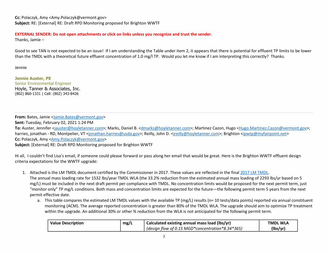
2
Cc: Polaczyk, Amy <[email protected]>
Subject: RE: [External] RE: Draft RPD Monitoring proposed for Brighton WWTF
EXTERNAL SENDER: Do not open attachments or click on links unless you recognize and trust the sender.
Thanks, Jamie –
Good to see TAN is not expected to be an issue! If I am understanding the Table under item 2, it appears that there is potential for effluent TP limits to be lower
than the TMDL with a theoretical future effluent concentration of 1.0 mg/l TP. Would you let me know if I am interpreting this correctly? Thanks.
Jennie
Jennie Auster, PE
Senior Environmental Engineer
Hoyle, Tanner & Associates, Inc. (802) 860-1331 | Cell: (802) 343-8426
From: Bates, Jamie <[email protected]>
Sent: Tuesday, February 02, 2021 1:24 PM
To: Auster, Jennifer <[email protected]>; Marks, Daniel B. <[email protected]>; Martinez Cazon, Hugo <[email protected]>;
harries, jonathan - RD, Montpelier, VT <[email protected]>; Reilly, John D. <[email protected]>; Brighton <[email protected]>
Cc: Polaczyk, Amy <[email protected]>
Subject: [External] RE: Draft RPD Monitoring proposed for Brighton WWTF
Hi all, I couldn’t find Lisa’s email, if someone could please forward or pass along her email that would be great. Here is the Brighton WWTF effluent design
criteria expectations for the WWTF upgrade:
1. Attached is the LM TMDL document certified by the Commissioner in 2017. These values are reflected in the final 2017 LM TMDL.
The annual mass loading rate for 1532 lbs/year TMDL WLA (the 33.2% reduction from the estimated annual mass loading of 2293 lbs/yr based on 5
mg/L) must be included in the next draft permit per compliance with TMDL. No concentration limits would be proposed for the next permit term, just
“monitor only” TP mg/L conditions. Both mass and concentration limits are expected for the future—the following permit term 5 years from the next
permit effective date.
a. This table compares the estimated LM TMDL values with the available TP (mg/L) results (n= 10 tests/data points) reported via annual constituent
monitoring (ACM). The average reported concentration is greater than 80% of the TMDL WLA. The upgrade should aim to optimize TP treatment
within the upgrade. An additional 30% or other % reduction from the WLA is not anticipated for the following permit term.
Value Description mg/L Calculated existing annual mass load (lbs/yr)
(design flow of 0.15 MGD*concentration*8.34*365)
TMDL WLA
(lbs/yr)
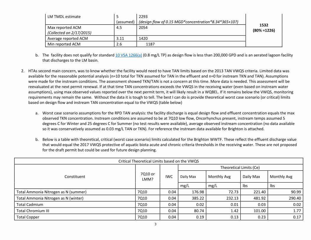
3
LM TMDL estimate 5
(assumed)
2293
(design flow of 0.15 MGD*concentration*8.34*365+10?) 1532
(80% =1226)
Max reported ACM
(Collected on 2/17/2015)
4.5 2054
Average reported ACM 3.11 1420
Min reported ACM 2.6 1187
b. The facility does not qualify for standard 10 VSA 1266(a) (0.8 mg/L TP) as design flow is less than 200,000 GPD and is an aerated lagoon facility
that discharges to the LM basin.
2. HTAs second main concern, was to know whether the facility would need to have TAN limits based on the 2013 TAN VWQS criteria. Limited data was
available for the reasonable potential analysis (n=10 total for TKN assumed for TAN in the effluent and n=0 for instream TKN and TAN). Assumptions
were made for the instream conditions. The assessment showed TKN/TAN is not a concern at this time. More data is needed. This assessment will be
reevaluated at the next permit renewal. If at that time TAN concentrations exceeds the VWQS in the receiving water (even based on instream water
assumptions), using max observed values reported over the next permit term, it will likely result in a WQBEL. If it remains below the VWQS, monitoring
requirements may remain the same. Without the data it is tough to tell. The best I can do is provide theoretical worst case scenario (or critical) limits
based on design flow and instream TAN concentration equal to the VWQS (table below)
a. Worst case scenario assumptions for the RPD TAN analysis: the facility discharge is equal design flow and effluent concentration equals the max
observed TKN concentration. Instream conditions are assumed to be at 7Q10 low flow, Oncorhynchus present, instream temps assumed 5
degrees C for Winter and 25 degrees C for Summer (no test results were available), average observed instream concentration (no data available
so it was conservatively assumed as 0.03 mg/L TAN or TKN). For reference the instream data available for Brighton is attached.
b. Below is a table with theoretical, critical (worst case scenario) limits calculated for the Brighton WWTF. These reflect the effluent discharge value
that would equal the 2017 VWQS protective of aquatic biota acute and chronic criteria thresholds in the receiving water. These are not proposed
for the draft permit but could be used for future design planning.
Critical Theoretical Limits based on the VWQS
Constituent 7Q10 or
LMM? IWC
Theoretical Limits (Ce)
Daily Max Monthly Avg Daily Max Monthly Avg
mg/L mg/L lbs lbs
Total Ammonia Nitrogen as N (summer) 7Q10 0.04 176.98 72.73 221.40 90.99
Total Ammonia Nitrogen as N (winter) 7Q10 0.04 385.22 232.13 481.92 290.40
Total Cadmium 7Q10 0.04 0.02 0.01 0.03 0.02
Total Chromium III 7Q10 0.04 80.74 1.42 101.00 1.77
Total Copper 7Q10 0.04 0.19 0.13 0.23 0.17
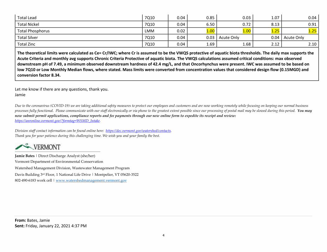
4
Total Lead 7Q10 0.04 0.85 0.03 1.07 0.04
Total Nickel 7Q10 0.04 6.50 0.72 8.13 0.91
Total Phosphorus LMM 0.02 1.00 1.00 1.25 1.25
Total Silver 7Q10 0.04 0.03 Acute Only 0.04 Acute Only
Total Zinc 7Q10 0.04 1.69 1.68 2.12 2.10
The theoretical limits were calculated as Ce= Cr/IWC; where Cr is assumed to be the VWQS protective of aquatic biota thresholds. The daily max supports the
Acute Criteria and monthly avg supports Chronic Criteria Protective of aquatic biota. The VWQS calculations assumed critical conditions: max observed
downstream pH of 7.49, a minimum observed downstream hardness of 42.4 mg/L, and that Oncorhynchus were present. IWC was assumed to be based on
low 7Q10 or Low Monthly Median flows, where stated. Mass limits were converted from concentration values that considered design flow (0.15MGD) and
conversion factor 8.34.
Let me know if there are any questions, thank you.
Jamie
Due to the coronavirus (COVID-19) we are taking additional safety measures to protect our employees and customers and are now working remotely while focusing on keeping our normal business
processes fully functional. Please communicate with our staff electronically or via phone to the greatest extent possible since our processing of postal mail may be slowed during this period. You may
now submit permit applications, compliance reports and fee payments through our new online form to expedite its receipt and review:
https://anronline.vermont.gov/?formtag=WSMD_Intake.
Division staff contact information can be found online here: https://dec.vermont.gov/watershed/contacts.
Thank you for your patience during this challenging time. We wish you and your family the best.
Jamie Bates | Direct Discharge Analyst (she/her)
Vermont Department of Environmental Conservation
Watershed Management Division, Wastewater Management Program
Davis Building 3rd Floor, 1 National Life Drive | Montpelier, VT 05620-3522
802-490-6183 work cell | www.watershedmanagement.vermont.gov
From: Bates, Jamie
Sent: Friday, January 22, 2021 4:37 PM
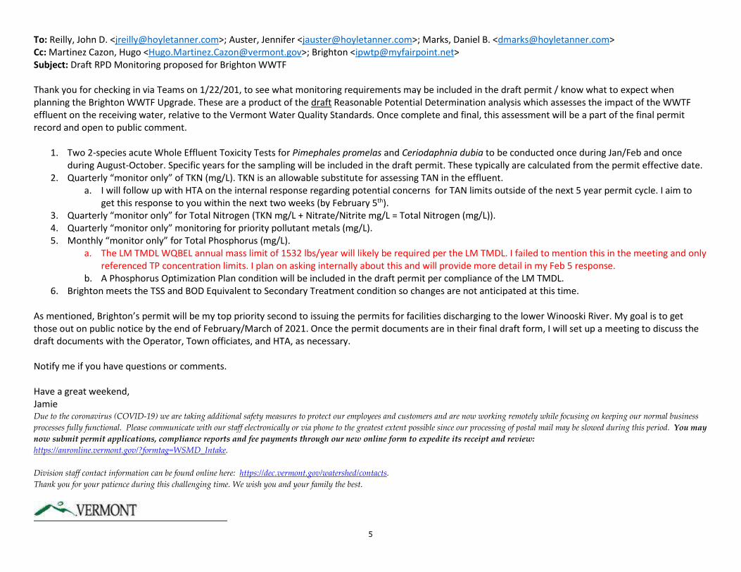
5
To: Reilly, John D. <[email protected]>; Auster, Jennifer <[email protected]>; Marks, Daniel B. <[email protected]>
Cc: Martinez Cazon, Hugo <[email protected]>; Brighton <[email protected]>
Subject: Draft RPD Monitoring proposed for Brighton WWTF
Thank you for checking in via Teams on 1/22/201, to see what monitoring requirements may be included in the draft permit / know what to expect when
planning the Brighton WWTF Upgrade. These are a product of the draft Reasonable Potential Determination analysis which assesses the impact of the WWTF
effluent on the receiving water, relative to the Vermont Water Quality Standards. Once complete and final, this assessment will be a part of the final permit
record and open to public comment.
1. Two 2-species acute Whole Effluent Toxicity Tests for Pimephales promelas and Ceriodaphnia dubia to be conducted once during Jan/Feb and once
during August-October. Specific years for the sampling will be included in the draft permit. These typically are calculated from the permit effective date.
2. Quarterly “monitor only” of TKN (mg/L). TKN is an allowable substitute for assessing TAN in the effluent.
a. I will follow up with HTA on the internal response regarding potential concerns for TAN limits outside of the next 5 year permit cycle. I aim to
get this response to you within the next two weeks (by February 5th).
3. Quarterly “monitor only” for Total Nitrogen (TKN mg/L + Nitrate/Nitrite mg/L = Total Nitrogen (mg/L)).
4. Quarterly “monitor only” monitoring for priority pollutant metals (mg/L).
5. Monthly “monitor only” for Total Phosphorus (mg/L).
a. The LM TMDL WQBEL annual mass limit of 1532 lbs/year will likely be required per the LM TMDL. I failed to mention this in the meeting and only
referenced TP concentration limits. I plan on asking internally about this and will provide more detail in my Feb 5 response.
b. A Phosphorus Optimization Plan condition will be included in the draft permit per compliance of the LM TMDL.
6. Brighton meets the TSS and BOD Equivalent to Secondary Treatment condition so changes are not anticipated at this time.
As mentioned, Brighton’s permit will be my top priority second to issuing the permits for facilities discharging to the lower Winooski River. My goal is to get
those out on public notice by the end of February/March of 2021. Once the permit documents are in their final draft form, I will set up a meeting to discuss the
draft documents with the Operator, Town officiates, and HTA, as necessary.
Notify me if you have questions or comments.
Have a great weekend,
Jamie
Due to the coronavirus (COVID-19) we are taking additional safety measures to protect our employees and customers and are now working remotely while focusing on keeping our normal business
processes fully functional. Please communicate with our staff electronically or via phone to the greatest extent possible since our processing of postal mail may be slowed during this period. You may
now submit permit applications, compliance reports and fee payments through our new online form to expedite its receipt and review:
https://anronline.vermont.gov/?formtag=WSMD_Intake.
Division staff contact information can be found online here: https://dec.vermont.gov/watershed/contacts.
Thank you for your patience during this challenging time. We wish you and your family the best.

6
Jamie Bates | Direct Discharge Analyst (she/her)
Vermont Department of Environmental Conservation
Watershed Management Division, Wastewater Management Program
Davis Building 3rd Floor, 1 National Life Drive | Montpelier, VT 05620-3522
802-490-6183 work cell | www.watershedmanagement.vermont.gov
CAUTION: This email originated from outside of the organization. Do not click links or open attachments unless you recognize the sender and know the content is safe.

State of Vermont
Vermont Population Projections – 2010 - 2030
August, 2013
Produced by: Ken Jones, Ph.D., Economic Research Analyst
Vermont Agency of Commerce and Community Development and
Lilly Schwarz, Community Based Learning Intern Montpelier High School
This project was developed with the assistance and oversight of a committee of State Agency representatives. The Committee reviewed the methodology and results leading to the final figures presented in this report.
Population Projection Review Committee
Glenn Bailey, Vermont Agency of Education Mathew Barewicz, Vermont Department of Labor Sarah Lindberg, Vermont Department of Financial Regulation Michael Moser, University of Vermont, Center for Rural Studies Michael Nyland-Funke, Vermont Department of Health
Appendix 3-3 - Vermont Population Projections

Vermont Population Projections – 2010 - 2030
How are Population Projections developed?
Vermont’s population projections are based on an age cohort model (defined age groupings such as: 35-39 year-olds) using US Census data as the basis for calculations. Mortality, birth rate and migration rate data from 1990-2010 are factors used to develop the projections.
In general, an age cohort projection model starts with the population total for a particular age group at a given point in time. The Census bureau reports most age cohorts in 5 year groups and thus, five year groups are used in this model. At the end of a ten year period, the population for an age cohort is equal to the beginning population total minus the mortality and plus or minus the migration during the ten year period. For example,
In year 2000, according to the US census, Vermont’s 25-29 age cohort population was 34,182. Ten years later, in year 2010, Vermont’s 35-39 age cohort population was 36,358 - according to Census reporting. Between 2000 and 2010, about 50 people in that age cohort died (0.15% mortality rate over the ten year period). By taking into account the population increase and mortality rate for the the age cohort, the migration rate can be calculated. Migration = 36,358 – 34,182 + 50
= 2226 or 6.51% of the 2000 five year age cohort “Projecting” into the future, would suggest that the 2020 population of 35-39 year olds will equal the 2010 population of 25-29 year olds (35,441) minus mortality (again, about .15%) plus the 6.51% net migration rate. 2020 projected population of 35-39 year olds = 37,700 Migration
The migration rate for the 2010 to 2020 and 2020 to 2030 decades could be similar to the migration rate for the 2000 to 2010 period or the 1990 to 2000 period. These different migration assumptions are the basis for the two sets of projections presented in this report – Scenario A and Scenario B. In Vermont, there is a relationship between the national economy and the direction and magnitude of migration. During the 1990s (Scenario A), the national economy was generally healthier than during the 2000s (Scenario B) and Vermont saw greater rates of net in-migration. As a result, Scenario A using 1990s migration rates generally, show higher populations than Scenario B using the migration rates of the 2000s.
Mortality
The mortality rates for age cohorts greater than 50 years old continue to decrease. For the population projections, we use mortality rates that continue the decline. For younger populations, the mortality rate is leveling off and the mortality rates used for the projection do not have the same proportional decreases that other age cohorts exhibit.
Births
The number of children born during the projection period requires the use of age specific birth rates. The Vermont Department of Health publishes county and age-specific birth rates each year in its Vital Statistics publication. In Vermont, each county is witnessing decreases in the birth rates for teenage women. Birth rates for women in their 20s and early 30s are relatively more stable, while the birth rates for women in older age cohorts continue to increase. As with the mortality rates, these Vermont population projections assume a continuation in the trend in birth rates seen for the past twenty years to provide birth rates for each age cohort into the next twenty years. Unlike mortality, the birth rates in Vermont vary significantly for each county. Therefore, the county projections use county-specific birth rates for each age cohort.
In order to complete the projections for children born during the projection period, there are three steps. The first step is to complete the population projections for females in each county using statewide mortality rates and county and age specific migration rates based on 1990s and 2000s Census data. The second step is to apply the age and county specific birth rates to each projected female age cohort resulting in the number of births during the time period. The final step is to review the migration rates for young children during the 1990s and 2000s and apply those migration rates to the number of births projected from Steps One and Two.
Normalizing the county and town projections
For all age cohorts, a state projection is completed in addition to one for each county. Because the statistical validity of a projection is greater with larger numbers, the state projection serves as a base against which the county projections are normalized. In other words, for any age cohort, the state projected total is compared against the total of each county cohort. Any differences are normalized by reducing or increasing county figures proportionally to the population size of that cohort in each county. For example, the age 40-44 state population is projected to be 35,561 when assuming the migration pattern of the 2000s. The sum of the county projections for that cohort is 35,570. For consistency, the county population numbers for that cohort are decreased proportionally to result in a county total equal to the state projected figure.
Town and City projections
The county projections are the basis for determining town and city level projections. As with the county migration rates, the changes in the population for each town that took place in 2000-2010 and 1990 – 2000 combined with the projected changes in county numbers result in an equation to project town populations. Specifically,
2020 Town projected figure = Town population in 2010 + (50% of the rate of town population change from 2000-2010) + (25% of the rate of town population change from 1990 – 2000) + (25% of the rate of county population change from 2000-2010)
2030 Town projected figure = Town population in 2020 + (35% the rate of town population change from 2000-2010)+(15% of the rate of town population change from 1990 – 2000) + (50% of the rate of county population change from 2000-2010)
Similar to normalizing county age cohort figures to correspond to the state projections, town populations are either increased or decreased to assure that the sum of the town populations in a county equal the county population.
Caveats when considering the Vermont Population Projections
Projections, not predictions
Projections assume that conditions that occurred in the past will continue into the future. For these projections, there are assumptions about mortality rates (continuing a downward trajectory for the next 20 years), birth rates and two sets of assumptions about migration rates. Events may alter the conditions that led to population changes in the past 20 years and those events will affect the changes in population. Examples of changes that are not predicted for these estimates:
• Changes in the birth rate from social changes different than what has occurred in the past 20 years
• Changes in health care practices or epidemics that could affect mortality rates • Changing economic conditions that result in shifts in national (internal) migration • Changes in national immigration policies
Census populations, not the actual number of inhabitants at a given time
Many individuals, particularly those that are retired and those attending colleges and universities have more than one home. The Census Bureau does not have a requirement that individuals determine their residency with a particular set of standards and does not allow any individual to split their residence to multiple towns or states. The residence as of April 1, in the
year the Census is conducted is a standard upon which many people determine their census filing “home”.
In Vermont, individuals that reside in other states such as “snow bird” destinations in the southern United States may not file their Census return from Vermont and yet may be registered to vote in Vermont, hold a Vermont driver’s license, pay taxes or even live the majority of the year in Vermont. Because the Census does not capture the true nature of these residents, the projections may give a misleading estimate on how many individuals reside in a particular community during different times of the year.
Statistical limitations
When working with relatively small population sizes, data can be susceptible to fluctuations that may not represent trends, but rather individual, non-replicable events. The margin of error for any statistical calculation increases as the size of the population decreases These small numbers are evident in some of the small county age cohort projections as well as small town populations.

Vermont 2010 Census Count Projections by Town, 2020, 2030 - Scenario A
Town2010
Census 2020%change
from 2010 2030%change
from 2010
Essex CountyBLOOMFIELD 221 192 -13.1% 166 -24.9%BRIGHTON 1,222 1,069 -12.5% 932 -23.7%BRUNSWICK 112 112 0.0% 106 -5.4%CANAAN 972 855 -12.0% 745 -23.4%CONCORD 1,235 1,199 -2.9% 1,116 -9.6%EAST HAVEN 290 274 -5.5% 251 -13.4%GRANBY 88 84 -4.5% 77 -12.5%GUILDHALL 261 240 -8.0% 216 -17.2%LEMINGTON 104 97 -6.7% 88 -15.4%LUNENBURG 1,302 1,248 -4.1% 1,151 -11.6%MAIDSTONE 208 281 35.1% 339 63.0%NORTON 169 152 -10.1% 133 -21.3%VICTORY 62 61 -1.6% 56 -9.7%AVERILL 24 46 91.7% 73 204.2%AVERY'S GORE 0 0 0.0% 0 0.0%FERDINAND 32 33 3.1% 32 0.0%LEWIS 0 0 0.0% 0 0.0%WARNER'S GRANT 0 0 0.0% 0 0.0%WARREN'S GORE 4 6 50.0% 8 100.0%
County Total 6,306 5,949 -5.7% 5,489 -13.0%
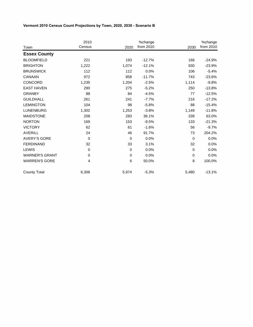
Vermont 2010 Census Count Projections by Town, 2020, 2030 - Scenario B
Town2010
Census 2020%change
from 2010 2030%change
from 2010
Essex CountyBLOOMFIELD 221 193 -12.7% 166 -24.9%BRIGHTON 1,222 1,074 -12.1% 930 -23.9%BRUNSWICK 112 112 0.0% 106 -5.4%CANAAN 972 858 -11.7% 743 -23.6%CONCORD 1,235 1,204 -2.5% 1,114 -9.8%EAST HAVEN 290 275 -5.2% 250 -13.8%GRANBY 88 84 -4.5% 77 -12.5%GUILDHALL 261 241 -7.7% 216 -17.2%LEMINGTON 104 98 -5.8% 88 -15.4%LUNENBURG 1,302 1,253 -3.8% 1,149 -11.8%MAIDSTONE 208 283 36.1% 339 63.0%NORTON 169 153 -9.5% 133 -21.3%VICTORY 62 61 -1.6% 56 -9.7%AVERILL 24 46 91.7% 73 204.2%AVERY'S GORE 0 0 0.0% 0 0.0%FERDINAND 32 33 3.1% 32 0.0%LEWIS 0 0 0.0% 0 0.0%WARNER'S GRANT 0 0 0.0% 0 0.0%WARREN'S GORE 4 6 50.0% 8 100.0%
County Total 6,306 5,974 -5.3% 5,480 -13.1%
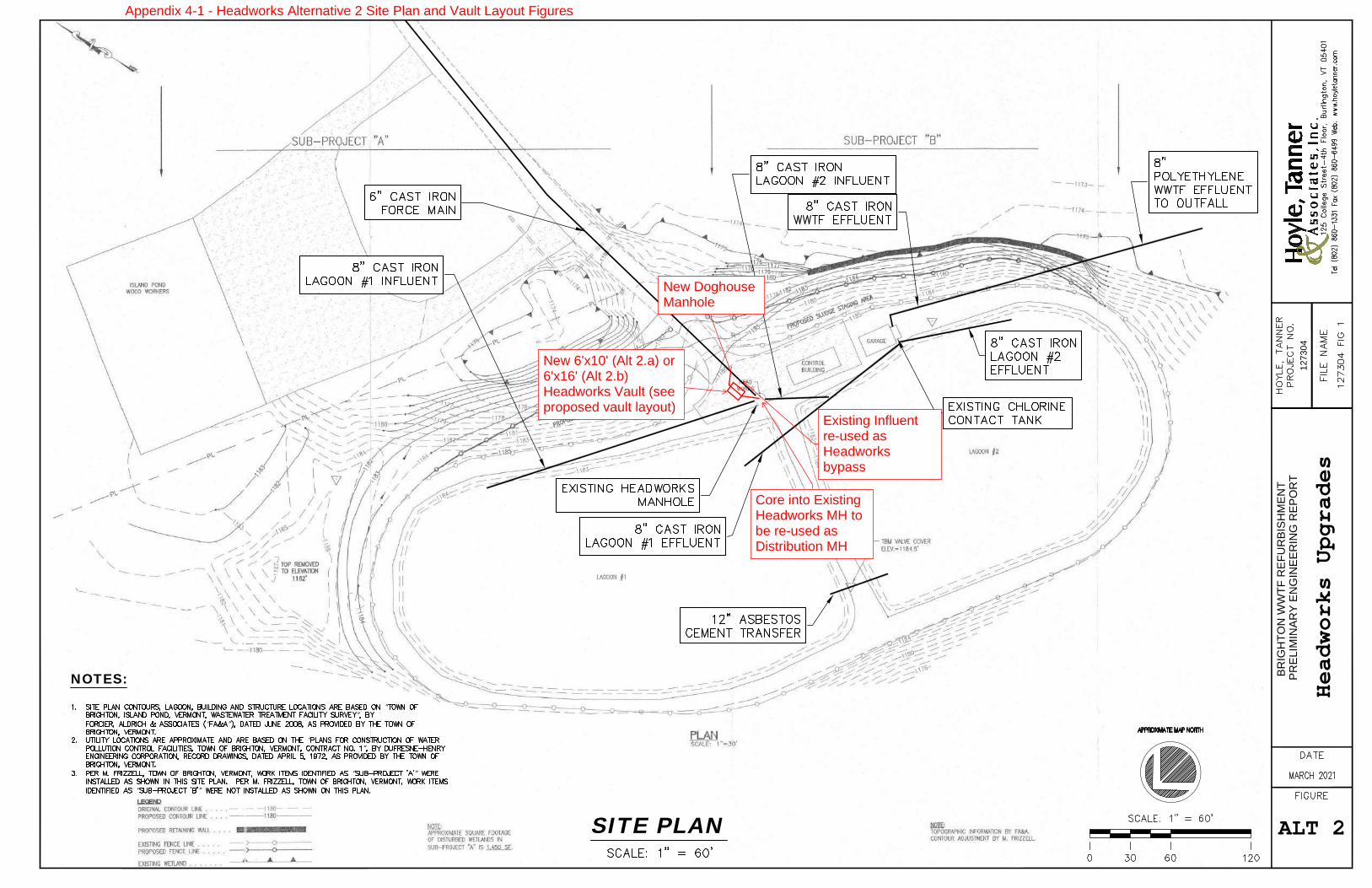
PREL
IMIN
ARY
ENG
INEE
RIN
G R
EPO
RT
BRIG
HTO
N W
WTF
REF
UR
BISH
MEN
T
1273
04
SIT
E P
LAN
1SITE PLAN
NOTES:
“”
“ ”
“”
“ ”
“ ”
He
ad
wo
rks
Up
gra
de
s
ALT 2
New DoghouseManhole
New 6'x10' (Alt 2.a) or6'x16' (Alt 2.b)Headworks Vault (seeproposed vault layout)
Existing Influentre-used asHeadworksbypass
Core into ExistingHeadworks MH tobe re-used asDistribution MH
Appendix 4-1 - Headworks Alternative 2 Site Plan and Vault Layout Figures
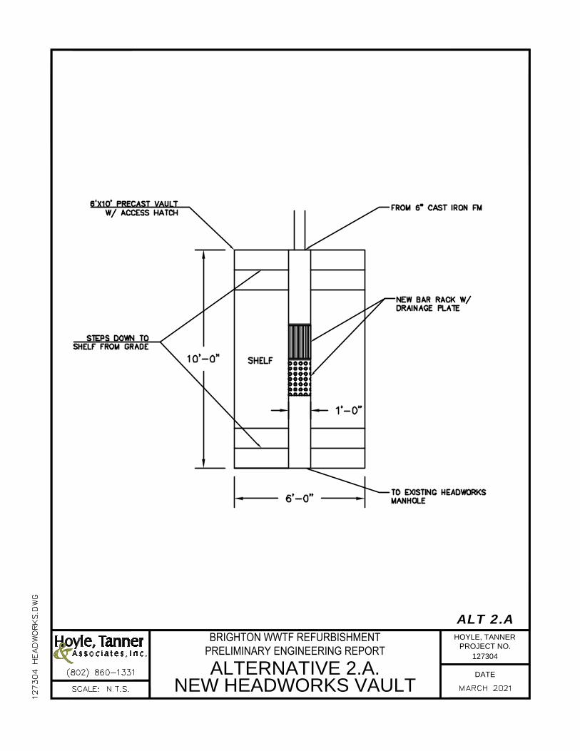
BRIGHTON WWTF REFURBISHMENTPRELIMINARY ENGINEERING REPORTALTERNATIVE 2.A.
NEW HEADWORKS VAULTDATE
127304
ALT 2.AHOYLE, TANNER
PROJECT NO.
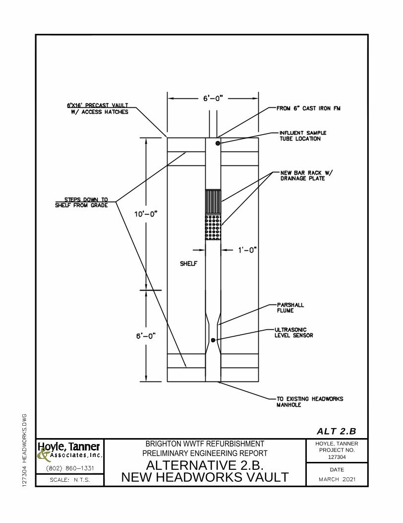
BRIGHTON WWTF REFURBISHMENTPRELIMINARY ENGINEERING REPORTALTERNATIVE 2.B.
NEW HEADWORKS VAULTDATE
127304
ALT 2.BHOYLE, TANNER
PROJECT NO.
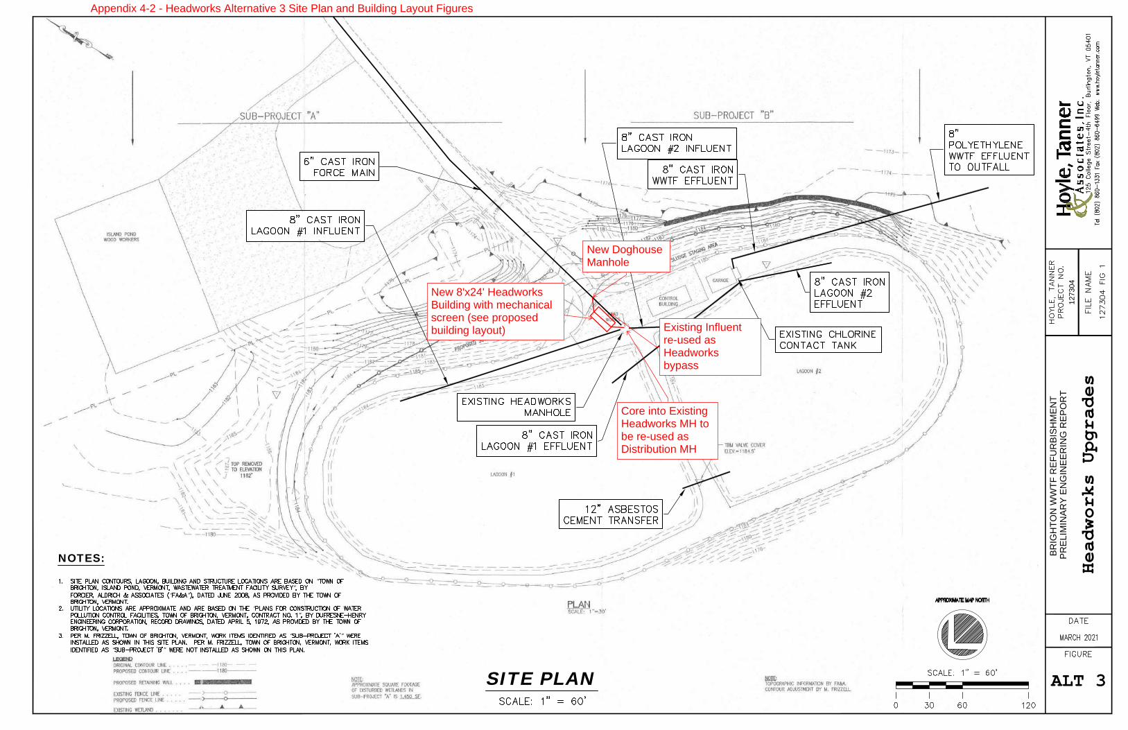
PREL
IMIN
ARY
ENG
INEE
RIN
G R
EPO
RT
BRIG
HTO
N W
WTF
REF
UR
BISH
MEN
T
1273
04
SIT
E P
LAN
1SITE PLAN
NOTES:
“”
“ ”
“”
“ ”
“ ”
He
ad
wo
rks
Up
gra
de
s
ALT 3
New DoghouseManhole
New 8'x24' HeadworksBuilding with mechanicalscreen (see proposedbuilding layout) Existing Influent
re-used asHeadworksbypass
Core into ExistingHeadworks MH tobe re-used asDistribution MH
Appendix 4-2 - Headworks Alternative 3 Site Plan and Building Layout Figures
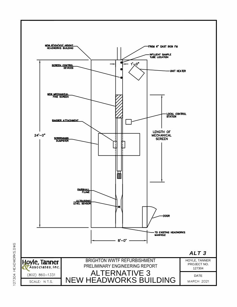
BRIGHTON WWTF REFURBISHMENTPRELIMINARY ENGINEERING REPORT
ALTERNATIVE 3NEW HEADWORKS BUILDING
DATE
127304
ALT 3HOYLE, TANNER
PROJECT NO.
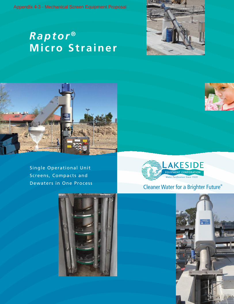
Raptor ® Mic ro S t ra iner
Single Operational Unit
Screens, Compacts and
Dewaters in One Process
Appendix 4-3 - Mechanical Screen Equipment Proposal
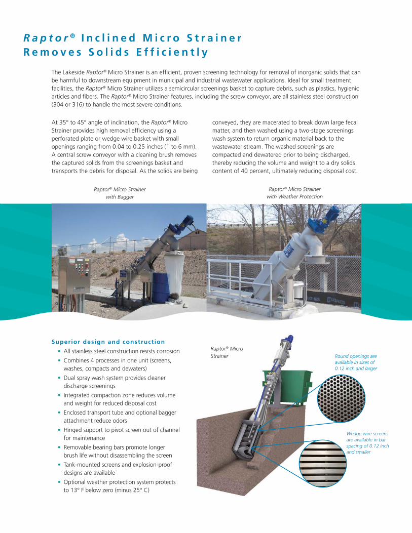
Round openings are available in sizes of 0.12 inch and larger
Wedge wire screens are available in bar spacing of 0.12 inch and smaller
Raptor® Micro Strainer
2
Raptor® Micro Strainer with Bagger
R a p t o r ® I n c l i n e d M i c r o S t r a i n e rR e m o v e s S o l i d s E f f i c i e n t l y
Raptor® Micro Strainer with Weather Protection
The Lakeside Raptor® Micro Strainer is an efficient, proven screening technology for removal of inorganic solids that can be harmful to downstream equipment in municipal and industrial wastewater applications. Ideal for small treatment facilities, the Raptor® Micro Strainer utilizes a semicircular screenings basket to capture debris, such as plastics, hygienic articles and fibers. The Raptor® Micro Strainer features, including the screw conveyor, are all stainless steel construction (304 or 316) to handle the most severe conditions.
At 35° to 45° angle of inclination, the Raptor® Micro Strainer provides high removal efficiency using a perforated plate or wedge wire basket with small openings ranging from 0.04 to 0.25 inches (1 to 6 mm). A central screw conveyor with a cleaning brush removes the captured solids from the screenings basket and transports the debris for disposal. As the solids are being
conveyed, they are macerated to break down large fecal matter, and then washed using a two-stage screenings wash system to return organic material back to the wastewater stream. The washed screenings are compacted and dewatered prior to being discharged, thereby reducing the volume and weight to a dry solids content of 40 percent, ultimately reducing disposal cost.
Superior design and construction
• All stainless steel construction resists corrosion
• Combines 4 processes in one unit (screens, washes, compacts and dewaters)
• Dual spray wash system provides cleaner discharge screenings
• Integrated compaction zone reduces volume and weight for reduced disposal cost
• Enclosed transport tube and optional bagger attachment reduce odors
• Hinged support to pivot screen out of channel for maintenance
• Removable bearing bars promote longer brush life without disassembling the screen
• Tank-mounted screens and explosion-proof designs are available
• Optional weather protection system protects to 13° F below zero (minus 25° C)
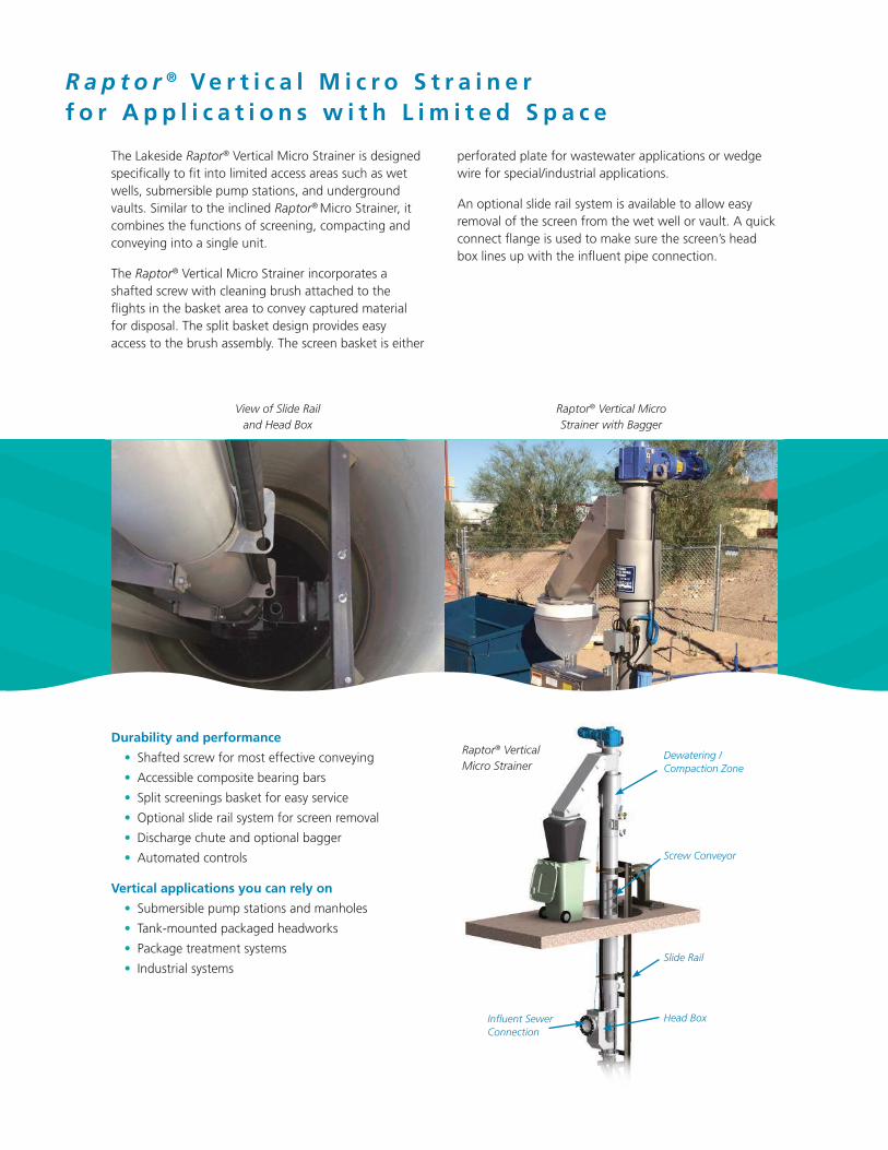
View of Slide Rail and Head Box
Raptor® Vertical Micro Strainer with Bagger
Dewatering / Compaction Zone
Screw Conveyor
Slide Rail
Head BoxInfluent Sewer Connection
Raptor® Vertical Micro Strainer
R a p t o r ® V e r t i c a l M i c r o S t r a i n e rf o r A p p l i c a t i o n s w i t h L i m i t e d S p a c e
The Lakeside Raptor® Vertical Micro Strainer is designed specifically to fit into limited access areas such as wet wells, submersible pump stations, and underground vaults. Similar to the inclined Raptor® Micro Strainer, it combines the functions of screening, compacting and conveying into a single unit.
The Raptor® Vertical Micro Strainer incorporates a shafted screw with cleaning brush attached to the flights in the basket area to convey captured material for disposal. The split basket design provides easy access to the brush assembly. The screen basket is either
perforated plate for wastewater applications or wedge wire for special/industrial applications.
An optional slide rail system is available to allow easy removal of the screen from the wet well or vault. A quick connect flange is used to make sure the screen’s head box lines up with the influent pipe connection.
Durability and performance
• Shafted screw for most effective conveying
• Accessible composite bearing bars
• Split screenings basket for easy service
• Optional slide rail system for screen removal
• Discharge chute and optional bagger
• Automated controls
Vertical applications you can rely on
• Submersible pump stations and manholes
• Tank-mounted packaged headworks
• Package treatment systems
• Industrial systems
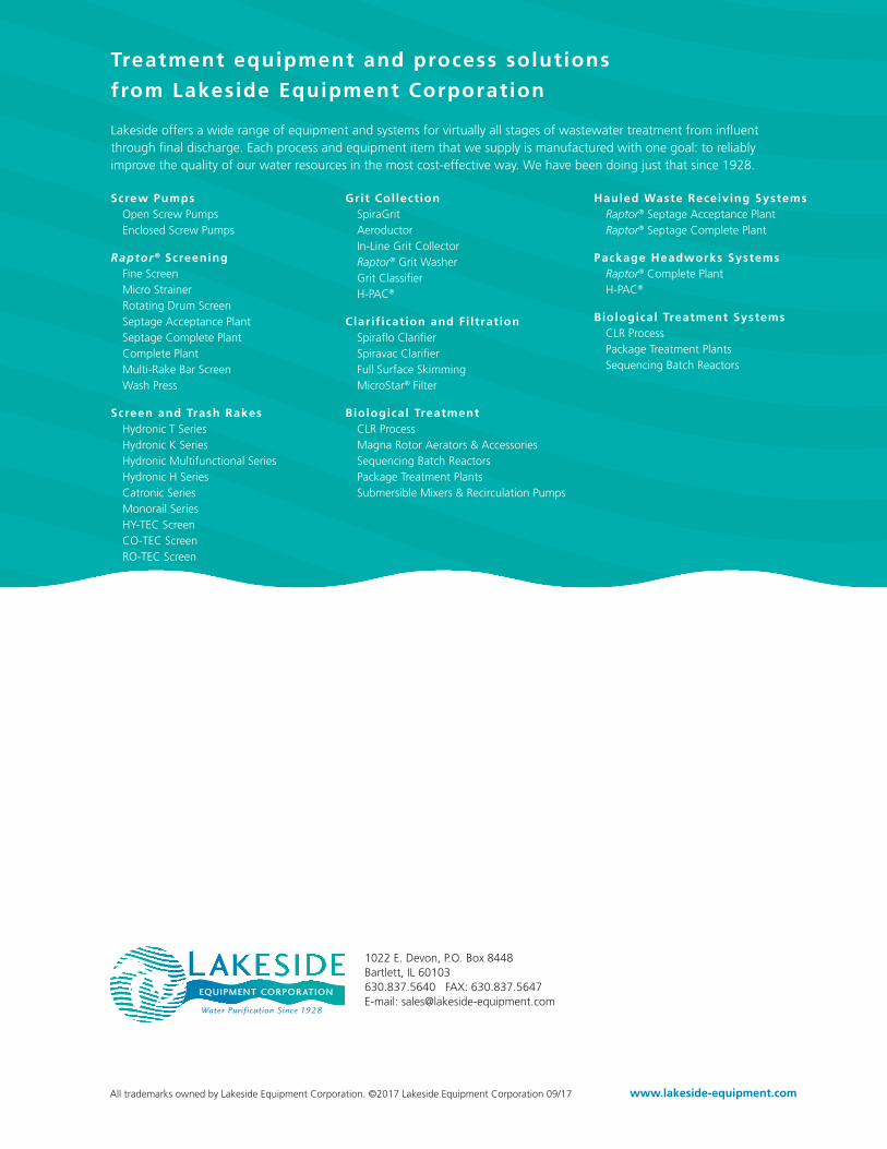
1022 E. Devon, P.O. Box 8448Bartlett, IL 60103630.837.5640 FAX: 630.837.5647E-mail: [email protected]
Treatment equipment and process solutions
from Lakeside Equipment Corporation
Lakeside offers a wide range of equipment and systems for virtually all stages of wastewater treatment from influent through final discharge. Each process and equipment item that we supply is manufactured with one goal: to reliably improve the quality of our water resources in the most cost-effective way. We have been doing just that since 1928.
Grit Collection SpiraGrit Aeroductor In-Line Grit Collector Raptor® Grit Washer Grit Classifier H-PAC®
Clarif ication and Fi ltration Spiraflo Clarifier Spiravac Clarifier Full Surface Skimming MicroStar® Filter
Biological Treatment CLR Process Magna Rotor Aerators & Accessories Sequencing Batch Reactors Package Treatment Plants Submersible Mixers & Recirculation Pumps
Screw Pumps Open Screw Pumps Enclosed Screw Pumps
Raptor® Screening Fine Screen Micro Strainer Rotating Drum Screen Septage Acceptance Plant Septage Complete Plant Complete Plant Multi-Rake Bar Screen Wash Press
Screen and Trash Rakes Hydronic T Series Hydronic K Series Hydronic Multifunctional Series Hydronic H Series Catronic Series Monorail Series HY-TEC Screen CO-TEC Screen RO-TEC Screen
Hauled Waste Receiving Systems Raptor® Septage Acceptance Plant Raptor® Septage Complete Plant
Package Headworks Systems Raptor® Complete Plant H-PAC®
Biological Treatment Systems CLR Process Package Treatment Plants Sequencing Batch Reactors
All trademarks owned by Lakeside Equipment Corporation. ©2017 Lakeside Equipment Corporation 09/17 www.lakeside-equipment.com
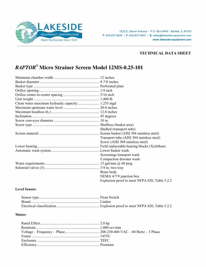
TECHNICAL DATA SHEET
RAPTOR® Micro Strainer Screen Model 12MS-0.25-101
Minimum chamber width ................................................. 12 inches Basket diameter ................................................................ 9-7/8 inches Basket type ....................................................................... Perforated plate Orifice opening ................................................................. 1/4 inch Orifice center-to-center spacing ....................................... 5/16 inch Unit weight ....................................................................... 1,400 lb Clean water maximum hydraulic capacity ........................ 1.255 mgd Maximum upstream water level ....................................... 20.0 inches Maximum headloss (hv) .................................................... 12.0 inches Inclination ......................................................................... 45 degrees
Screw conveyor diameter ................................................. 10 in. Screw type ........................................................................ Shaftless (basket area) Shafted (transport tube) Screen material ................................................................. Screen basket (AISI 304 stainless steel) Transport tube (AISI 304 stainless steel) Screw (AISI 304 stainless steel) Lower bearing ................................................................... Field replaceable bearing blocks (Xylethon) Automatic wash system .................................................... Lower basket wash
Screenings transport wash Compaction dewater wash
Water requirements ........................................................... 15 gal/min @ 60 psig Solenoid valves (3) ........................................................... 3/4 in. two-way Brass body NEMA 4/7/9 junction box Explosion proof to meet NFPA 820, Table 5.2.2 Level Sensor:
Sensor type ................................................................. Float Switch Brand .......................................................................... Linden Electrical classification .............................................. Explosion proof to meet NFPA 820, Table 5.2.2
Motor:
Rated Effect ................................................................ 2.0 hp Rotations .................................................................... 1,800 rev/min Voltage – Frequency – Phase ..................................... 208-230-460 VAC – 60 Hertz – 3 Phase Frame ......................................................................... 145TC Enclosure .................................................................... TEFC Efficiency ................................................................... Premium
1022 E. Devon Avenue l P.O. Box 8448 l Bartlett, IL 60103
T: 630-837-5640 l F: 630-837-5647 l E: [email protected]
www.lakeside-equipment.com
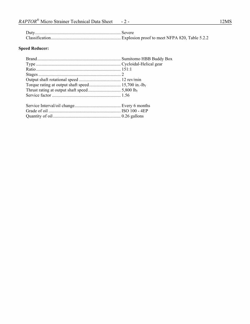
RAPTOR® Micro Strainer Technical Data Sheet - 2 - 12MS
Duty ............................................................................ Severe Classification .............................................................. Explosion proof to meet NFPA 820, Table 5.2.2
Speed Reducer:
Brand .......................................................................... Sumitomo HBB Buddy Box Type ........................................................................... Cycloidal-Helical gear Ratio ........................................................................... 151:1 Stages ......................................................................... 2 Output shaft rotational speed ..................................... 12 rev/min Torque rating at output shaft speed ............................ 15,700 in.-lbf Thrust rating at output shaft speed ............................. 5,800 lbf Service factor ............................................................. 1.56 Service Interval/oil change ......................................... Every 6 months Grade of oil ................................................................ ISO 100 - 4EP Quantity of oil ............................................................ 0.26 gallons
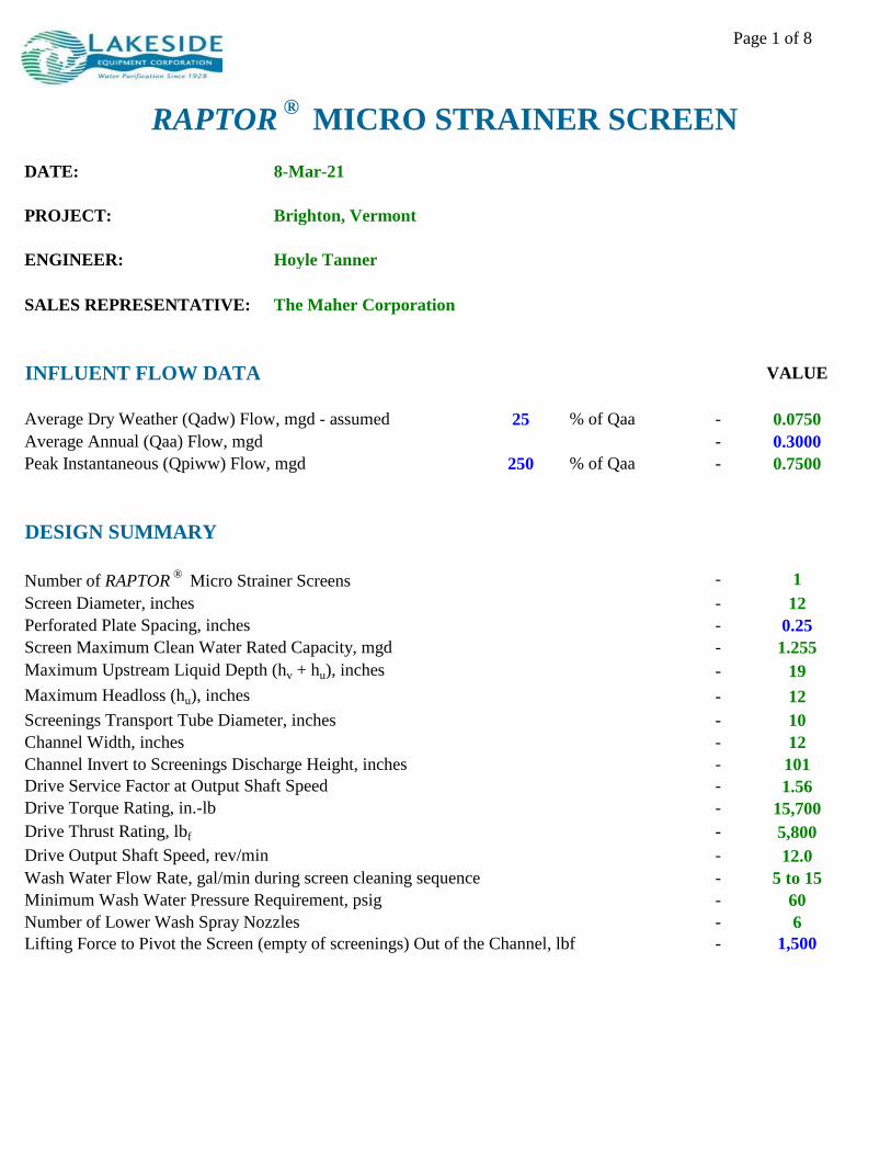
Page 1 of 8
RAPTOR®
MICRO STRAINER SCREEN
DATE: 8-Mar-21
PROJECT: Brighton, Vermont
ENGINEER: Hoyle Tanner
SALES REPRESENTATIVE: The Maher Corporation
INFLUENT FLOW DATA VALUE
Average Dry Weather (Qadw) Flow, mgd - assumed 25 % of Qaa - 0.0750
Average Annual (Qaa) Flow, mgd - 0.3000
Peak Instantaneous (Qpiww) Flow, mgd 250 % of Qaa - 0.7500
DESIGN SUMMARY
Number of RAPTOR®
Micro Strainer Screens - 1
Screen Diameter, inches - 12
Perforated Plate Spacing, inches - 0.25
Screen Maximum Clean Water Rated Capacity, mgd - 1.255
Maximum Upstream Liquid Depth (hv + hu), inches - 19
Maximum Headloss (hu), inches - 12
Screenings Transport Tube Diameter, inches - 10
Channel Width, inches - 12
Channel Invert to Screenings Discharge Height, inches - 101
Drive Service Factor at Output Shaft Speed - 1.56
Drive Torque Rating, in.-lb - 15,700
Drive Thrust Rating, lbf - 5,800
Drive Output Shaft Speed, rev/min - 12.0
Wash Water Flow Rate, gal/min during screen cleaning sequence - 5 to 15
Minimum Wash Water Pressure Requirement, psig - 60
Number of Lower Wash Spray Nozzles - 6
Lifting Force to Pivot the Screen (empty of screenings) Out of the Channel, lbf - 1,500
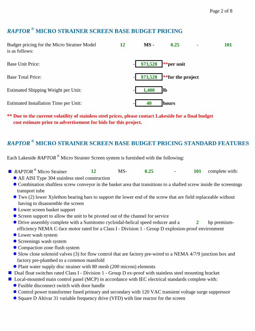
Page 2 of 8
RAPTOR® MICRO STRAINER SCREEN BASE BUDGET PRICING
Budget pricing for the Micro Strainer Model 12 MS - 0.25 - 101
is as follows:
Base Unit Price: - $73,528 **per unit
Base Total Price: - $73,528 **for the project
Estimated Shipping Weight per Unit: - 1,400 lb
Estimated Installation Time per Unit: - 40 hours
** Due to the current volatility of stainless steel prices, please contact Lakeside for a final budget
cost estimate prior to advertisement for bids for this project.
RAPTOR® MICRO STRAINER SCREEN BASE BUDGET PRICING STANDARD FEATURES
Each Lakeside RAPTOR® Micro Strainer Screen system is furnished with the following:
n RAPTOR® Micro Strainer 12 MS- 0.25 - 101 complete with:
l All AISI Type 304 stainless steel construction
l Combination shaftless screw conveyor in the basket area that transitions to a shafted screw inside the screenings
transport tube
l Two (2) lower Xylethon bearing bars to support the lower end of the screw that are field replaceable without
having to disassemble the screen
l Lower screen basket support
l Screen support to allow the unit to be pivoted out of the channel for service
l Drive assembly complete with a Sumitomo cycloidal-helical speed reducer and a 2 hp premium-
efficiency NEMA C-face motor rated for a Class I - Division 1 - Group D explosion-proof environment
l Lower wash system
l Screenings wash system
l Compaction zone flush system
l Slow close solenoid valves (3) for flow control that are factory pre-wired to a NEMA 4/7/9 junction box and
factory pre-plumbed to a common manifold
l Plant water supply disc strainer with 80 mesh (200 micron) elements
n Dual float switches rated Class I - Division 1 - Group D ex-proof with stainless steel mounting bracket
n Local-mounted main control panel (MCP) in accordance with IEC electrical standards complete with:
l Fusible disconnect switch with door handle
l Control power transformer fused primary and secondary with 120 VAC transient voltage surge suppressor
l Square D Altivar 31 variable frequency drive (VFD) with line reactor for the screen
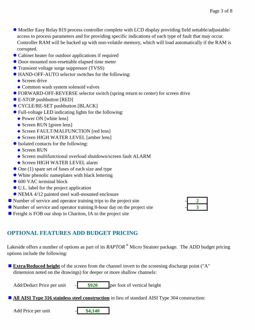
Page 3 of 8
l Moeller Easy Relay 819 process controller complete with LCD display providing field settable/adjustable/
access to process parameters and for providing specific indications of each type of fault that may occur.
Controller RAM will be backed up with non-volatile memory, which will load automatically if the RAM is
corrupted.
l Cabinet heater for outdoor applications if required
l Door-mounted non-resettable elapsed time meter
l Transient voltage surge suppressor (TVSS)
l HAND-OFF-AUTO selector switches for the following:
u Screen drive
u Common wash system solenoid valves
l FORWARD-OFF-REVERSE selector switch (spring return to center) for screen drive
l E-STOP pushbutton [RED]
l CYCLE/RE-SET pushbutton [BLACK]
l Full-voltage LED indicating lights for the following:
u Power ON [white lens]
u Screen RUN [green lens]
u Screen FAULT/MALFUNCTION [red lens]
u Screen HIGH WATER LEVEL [amber lens]
l Isolated contacts for the following:
u Screen RUN
u Screen multifunctional overload shutdown/screen fault ALARM
u Screen HIGH WATER LEVEL alarm
l One (1) spare set of fuses of each size and type
l White phenolic nameplates with black lettering
l 600 VAC terminal block
l U.L. label for the project application
l NEMA 4/12 painted steel wall-mounted enclosure
n Number of service and operator training trips to the project site - 2
n Number of service and operator training 8-hour day on the project site - 3
n Freight is FOB our shop in Chariton, IA to the project site
OPTIONAL FEATURES ADD BUDGET PRICING
Lakeside offers a number of options as part of its RAPTOR® Micro Strainer package. The ADD budget pricing
options include the following:
n Extra/Reduced height of the screen from the channel invert to the screening discharge point ("A"
dimension noted on the drawings) for deeper or more shallow channels:
Add/Deduct Price per unit - $920 per foot of vertical height
n All AISI Type 316 stainless steel construction in lieu of standard AISI Type 304 construction:
Add Price per unit - $4,140
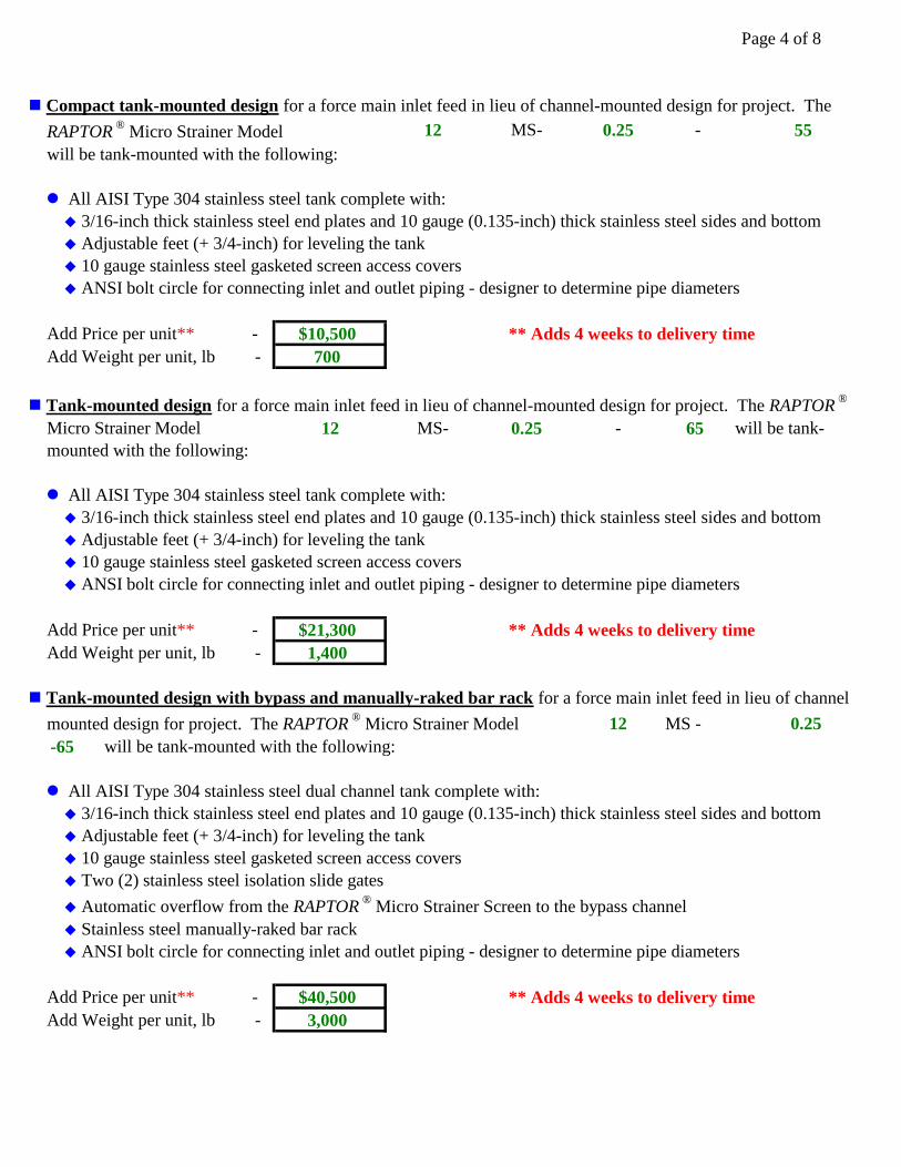
Page 4 of 8
n Compact tank-mounted design for a force main inlet feed in lieu of channel-mounted design for project. The
RAPTOR® Micro Strainer Model 12 MS- 0.25 - 55
will be tank-mounted with the following:
l All AISI Type 304 stainless steel tank complete with:
u 3/16-inch thick stainless steel end plates and 10 gauge (0.135-inch) thick stainless steel sides and bottom
u Adjustable feet (+ 3/4-inch) for leveling the tank
u 10 gauge stainless steel gasketed screen access covers
u ANSI bolt circle for connecting inlet and outlet piping - designer to determine pipe diameters
Add Price per unit** - $10,500 ** Adds 4 weeks to delivery time
Add Weight per unit, lb - 700
n Tank-mounted design for a force main inlet feed in lieu of channel-mounted design for project. The RAPTOR®
Micro Strainer Model 12 MS- 0.25 - 65 will be tank-
mounted with the following:
l All AISI Type 304 stainless steel tank complete with:
u 3/16-inch thick stainless steel end plates and 10 gauge (0.135-inch) thick stainless steel sides and bottom
u Adjustable feet (+ 3/4-inch) for leveling the tank
u 10 gauge stainless steel gasketed screen access covers
u ANSI bolt circle for connecting inlet and outlet piping - designer to determine pipe diameters
Add Price per unit** - $21,300 ** Adds 4 weeks to delivery time
Add Weight per unit, lb - 1,400
n Tank-mounted design with bypass and manually-raked bar rack for a force main inlet feed in lieu of channel
mounted design for project. The RAPTOR® Micro Strainer Model 12 MS - 0.25
-65 will be tank-mounted with the following:
l All AISI Type 304 stainless steel dual channel tank complete with:
u 3/16-inch thick stainless steel end plates and 10 gauge (0.135-inch) thick stainless steel sides and bottom
u Adjustable feet (+ 3/4-inch) for leveling the tank
u 10 gauge stainless steel gasketed screen access covers
u Two (2) stainless steel isolation slide gates
u Automatic overflow from the RAPTOR® Micro Strainer Screen to the bypass channel
u Stainless steel manually-raked bar rack
u ANSI bolt circle for connecting inlet and outlet piping - designer to determine pipe diameters
Add Price per unit** - $40,500 ** Adds 4 weeks to delivery time
Add Weight per unit, lb - 3,000
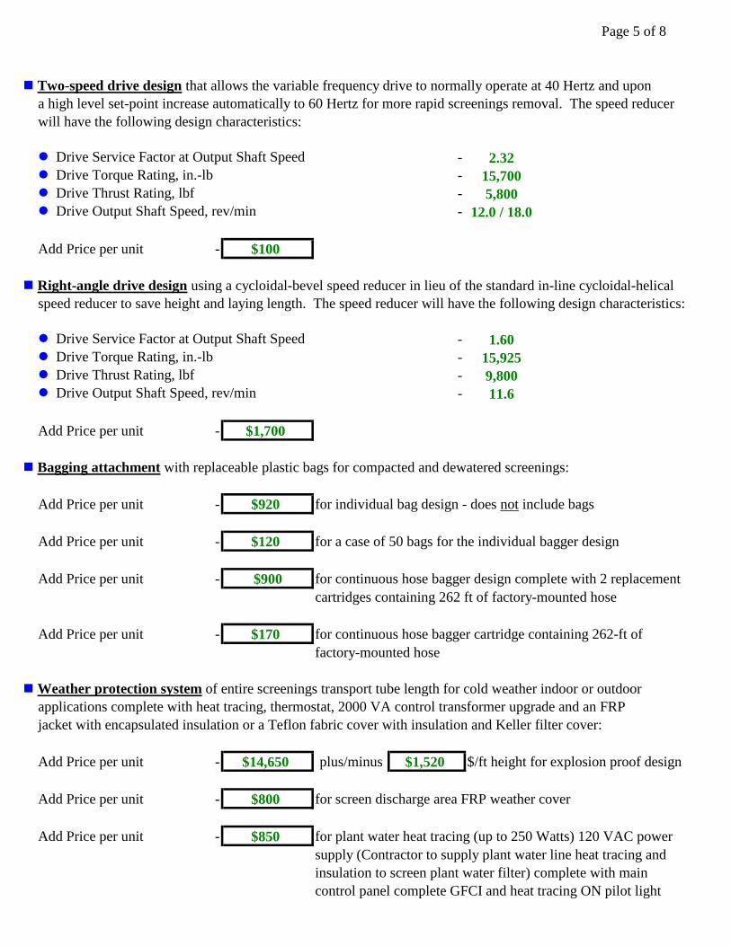
Page 5 of 8
n Two-speed drive design that allows the variable frequency drive to normally operate at 40 Hertz and upon
a high level set-point increase automatically to 60 Hertz for more rapid screenings removal. The speed reducer
will have the following design characteristics:
l Drive Service Factor at Output Shaft Speed - 2.32
l Drive Torque Rating, in.-lb - 15,700
l Drive Thrust Rating, lbf - 5,800
l Drive Output Shaft Speed, rev/min - 12.0 / 18.0
Add Price per unit - $100
n Right-angle drive design using a cycloidal-bevel speed reducer in lieu of the standard in-line cycloidal-helical
speed reducer to save height and laying length. The speed reducer will have the following design characteristics:
l Drive Service Factor at Output Shaft Speed - 1.60
l Drive Torque Rating, in.-lb - 15,925
l Drive Thrust Rating, lbf - 9,800
l Drive Output Shaft Speed, rev/min - 11.6
Add Price per unit - $1,700
n Bagging attachment with replaceable plastic bags for compacted and dewatered screenings:
Add Price per unit - $920 for individual bag design - does not include bags
Add Price per unit - $120 for a case of 50 bags for the individual bagger design
Add Price per unit - $900 for continuous hose bagger design complete with 2 replacement
cartridges containing 262 ft of factory-mounted hose
Add Price per unit - $170 for continuous hose bagger cartridge containing 262-ft of
factory-mounted hose
n Weather protection system of entire screenings transport tube length for cold weather indoor or outdoor
applications complete with heat tracing, thermostat, 2000 VA control transformer upgrade and an FRP
jacket with encapsulated insulation or a Teflon fabric cover with insulation and Keller filter cover:
Add Price per unit - $14,650 plus/minus $1,520 $/ft height for explosion proof design
Add Price per unit - $800 for screen discharge area FRP weather cover
Add Price per unit - $850 for plant water heat tracing (up to 250 Watts) 120 VAC power
supply (Contractor to supply plant water line heat tracing and
insulation to screen plant water filter) complete with main
control panel complete GFCI and heat tracing ON pilot light
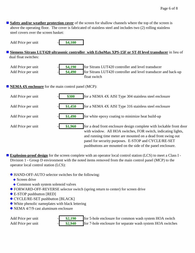
Page 6 of 8
n Safety and/or weather protection cover of the screen for shallow channels where the top of the screen is
above the operating floor. The cover is fabricated of stainless steel and includes two (2) rolling stainless
steel covers over the screen basket:
Add Price per unit - $4,100
n Siemens Sitrans LUT420 ultrasonic controller with EchoMax XPS-15F or ST-H level transducer in lieu of
dual float switches:
Add Price per unit - $4,190 for Sitrans LUT420 controller and level transducer
Add Price per unit - $4,490 for Sitrans LUT420 controller and level transducer and back-up
float switch
n NEMA 4X enclosure for the main control panel (MCP):
Add Price per unit - $300 for a NEMA 4X AISI Type 304 stainless steel enclosure
Add Price per unit - $1,450 for a NEMA 4X AISI Type 316 stainless steel enclosure
Add Price per unit - $1,490 for white epoxy coating to minimize heat build-up
Add Price per unit - $1,960 for a dead front enclosure design complete with lockable front door
with window. All HOA switches, FOR switch, indicating lights,
and running time meter are mounted on a dead front swing out
panel for security purposes. E-STOP and CYCLE/RE-SET
pushbuttons are mounted on the side of the panel enclosure.
n Explosion-proof design for the screen complete with an operator local control station (LCS) to meet a Class I -
Division 1 - Group D environment with the noted items removed from the main control panel (MCP) to the
operator local control station (LCS):
l HAND-OFF-AUTO selector switches for the following:
u Screen drive
u Common wash system solenoid valves
l FORWARD-OFF-REVERSE selector switch (spring return to center) for screen drive
l E-STOP pushbutton [RED]
l CYCLE/RE-SET pushbutton [BLACK]
l White phenolic nameplates with black lettering
l NEMA 4/7/9 cast aluminum enclosure
Add Price per unit - $2,190 for 5-hole enclosure for common wash system HOA switch
Add Price per unit - $2,940 for 7-hole enclosure for separate wash system HOA switches
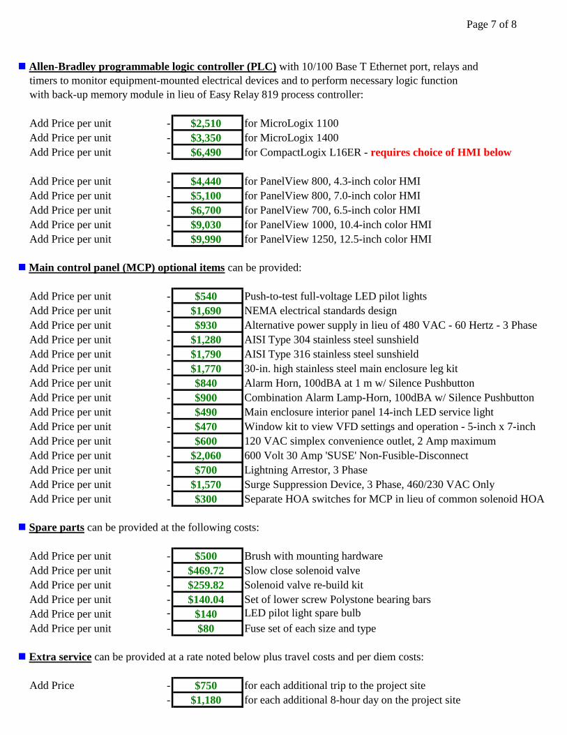
Page 7 of 8
n Allen-Bradley programmable logic controller (PLC) with 10/100 Base T Ethernet port, relays and
timers to monitor equipment-mounted electrical devices and to perform necessary logic function
with back-up memory module in lieu of Easy Relay 819 process controller:
Add Price per unit - $2,510 for MicroLogix 1100
Add Price per unit - $3,350 for MicroLogix 1400
Add Price per unit - $6,490 for CompactLogix L16ER - requires choice of HMI below
Add Price per unit - $4,440 for PanelView 800, 4.3-inch color HMI
Add Price per unit - $5,100 for PanelView 800, 7.0-inch color HMI
Add Price per unit - $6,700 for PanelView 700, 6.5-inch color HMI
Add Price per unit - $9,030 for PanelView 1000, 10.4-inch color HMI
Add Price per unit - $9,990 for PanelView 1250, 12.5-inch color HMI
n Main control panel (MCP) optional items can be provided:
Add Price per unit - $540 Push-to-test full-voltage LED pilot lights
Add Price per unit - $1,690 NEMA electrical standards design
Add Price per unit - $930 Alternative power supply in lieu of 480 VAC - 60 Hertz - 3 Phase
Add Price per unit - $1,280 AISI Type 304 stainless steel sunshield
Add Price per unit - $1,790 AISI Type 316 stainless steel sunshield
Add Price per unit - $1,770 30-in. high stainless steel main enclosure leg kit
Add Price per unit - $840 Alarm Horn, 100dBA at 1 m w/ Silence Pushbutton
Add Price per unit - $900 Combination Alarm Lamp-Horn, 100dBA w/ Silence Pushbutton
Add Price per unit - $490 Main enclosure interior panel 14-inch LED service light
Add Price per unit - $470 Window kit to view VFD settings and operation - 5-inch x 7-inch
Add Price per unit - $600 120 VAC simplex convenience outlet, 2 Amp maximum
Add Price per unit - $2,060 600 Volt 30 Amp 'SUSE' Non-Fusible-Disconnect
Add Price per unit - $700 Lightning Arrestor, 3 Phase
Add Price per unit - $1,570 Surge Suppression Device, 3 Phase, 460/230 VAC Only
Add Price per unit - $300 Separate HOA switches for MCP in lieu of common solenoid HOA
n Spare parts can be provided at the following costs:
Add Price per unit - $500 Brush with mounting hardware
Add Price per unit - $469.72 Slow close solenoid valve
Add Price per unit - $259.82 Solenoid valve re-build kit
Add Price per unit - $140.04 Set of lower screw Polystone bearing bars
Add Price per unit - $140 LED pilot light spare bulb
Add Price per unit - $80 Fuse set of each size and type
n Extra service can be provided at a rate noted below plus travel costs and per diem costs:
Add Price - $750 for each additional trip to the project site
- $1,180 for each additional 8-hour day on the project site

Page 8 of 8
RAPTOR® MICRO STRAINER SCREEN DRAWINGS AND FABRICATION TIMES
The RAPTOR® Micro Strainer will require the following times to complete our contractual obligations:
n Shop Drawing Time after receipt of fully-executed purchase order: - 6 to 8 weeks
n Fabrication Time after shop drawing approval and release to our shop: - 18 to 22 weeks
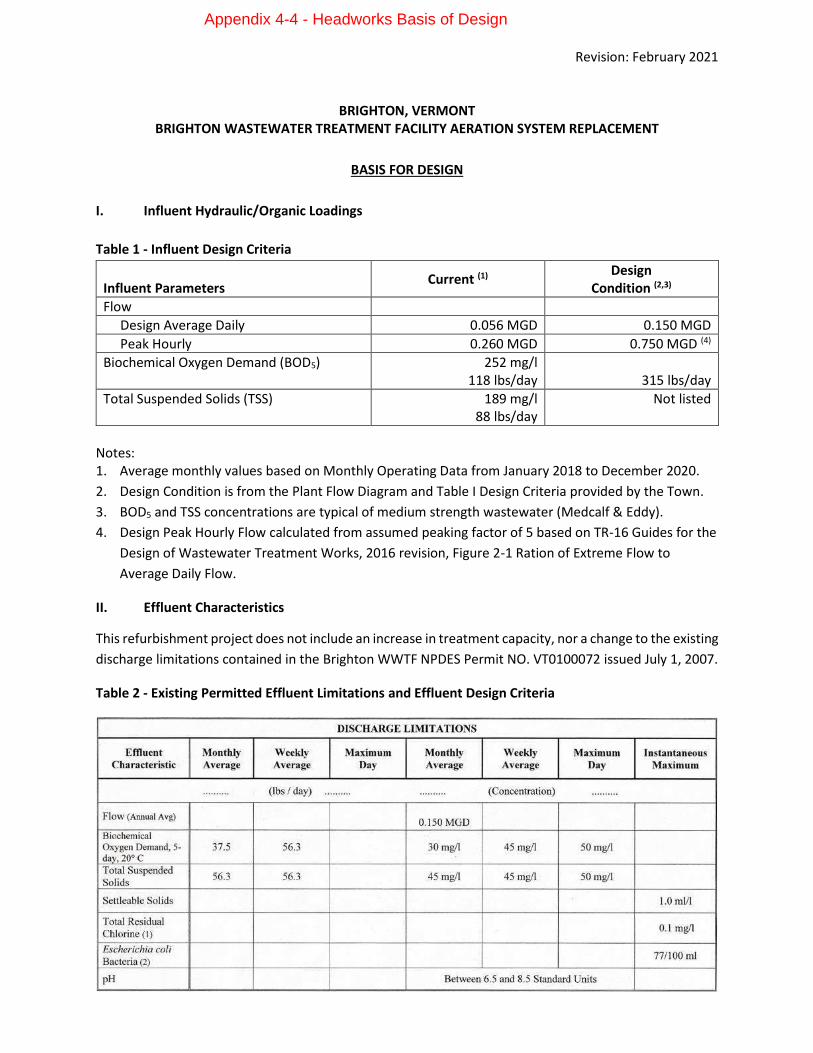
Revision: February 2021
BRIGHTON, VERMONT BRIGHTON WASTEWATER TREATMENT FACILITY AERATION SYSTEM REPLACEMENT
BASIS FOR DESIGN
I. Influent Hydraulic/Organic Loadings
Table 1 - Influent Design Criteria
Influent Parameters
Current (1) Design Condition (2,3)
Flow
Design Average Daily 0.056 MGD 0.150 MGD
Peak Hourly 0.260 MGD 0.750 MGD (4)
Biochemical Oxygen Demand (BOD5) 252 mg/l 118 lbs/day
315 lbs/day
Total Suspended Solids (TSS) 189 mg/l 88 lbs/day
Not listed
Notes: 1. Average monthly values based on Monthly Operating Data from January 2018 to December 2020.
2. Design Condition is from the Plant Flow Diagram and Table I Design Criteria provided by the Town.
3. BOD5 and TSS concentrations are typical of medium strength wastewater (Medcalf & Eddy).
4. Design Peak Hourly Flow calculated from assumed peaking factor of 5 based on TR-16 Guides for the
Design of Wastewater Treatment Works, 2016 revision, Figure 2-1 Ration of Extreme Flow to
Average Daily Flow.
II. Effluent Characteristics
This refurbishment project does not include an increase in treatment capacity, nor a change to the existing
discharge limitations contained in the Brighton WWTF NPDES Permit NO. VT0100072 issued July 1, 2007.
Table 2 - Existing Permitted Effluent Limitations and Effluent Design Criteria
Appendix 4-4 - Headworks Basis of Design
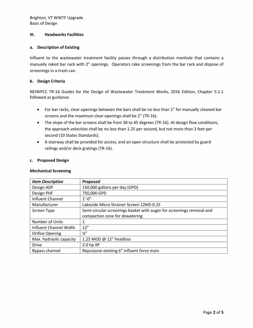
Brighton, VT WWTF Upgrade Basis of Design
Page 2 of 5
III. Headworks Facilities
a. Description of Existing
Influent to the wastewater treatment facility passes through a distribution manhole that contains a
manually raked bar rack with 2” openings. Operators rake screenings from the bar rack and dispose of
screenings in a trash can.
b. Design Criteria
NEIWPCC TR-16 Guides for the Design of Wastewater Treatment Works, 2016 Edition, Chapter 5:1.1 followed as guidance.
• For bar racks, clear openings between the bars shall be no less than 1” for manually cleaned bar
screens and the maximum clear openings shall be 2” (TR-16).
• The slope of the bar screens shall be from 30 to 45 degrees (TR-16). At design flow conditions,
the approach velocities shall be no less than 1.25 per second, but not more than 3 feet per
second (10 States Standards).
• A stairway shall be provided for access, and an open structure shall be protected by guard
railings and/or deck gratings (TR-16).
c. Proposed Design
Mechanical Screening
Item Description Proposed
Design ADF 150,000 gallons per day (GPD)
Design PHF 750,000 GPD
Influent Channel 1’-0”
Manufacturer Lakeside Micro Strainer Screen 12MS-0.25
Screen Type Semi-circular screenings basket with auger for screenings removal and compaction zone for dewatering
Number of Units 1
Influent Channel Width 12”
Orifice Opening ¼”
Max. hydraulic capacity 1.25 MGD @ 12” headloss
Drive 2.0 hp XP
Bypass channel Repurpose existing 6” influent force main
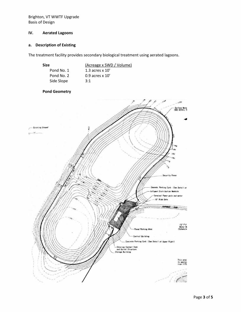
Brighton, VT WWTF Upgrade Basis of Design
Page 3 of 5
IV. Aerated Lagoons
a. Description of Existing
The treatment facility provides secondary biological treatment using aerated lagoons.
Size (Acreage x SWD / Volume) Pond No. 1 1.3 acres x 10’ Pond No. 2 0.9 acres x 10’ Side Slope 3:1
Pond Geometry
Brighton, VT WWTF Upgrade Basis of Design
Page 4 of 5
Capacity Pond No. 1 3.0 MGals Pond No. 2 2.2 MGals Detention Time 35 days at 150,000 gpd (both lagoons)
b. Design Criteria
NEIWPCC TR-16 Guides for the Design of Wastewater Treatment Works, 2016 Edition, Chapter 6.5.2.2.2: Minimum D.O. 2 mg/L O2 Requirements: Minimum 2 lb O2 per lb BOD applied Design 3 lb O2 per lb BOD applied
c. Proposed Design
Item Description Proposed
Manufacturer Nexom/EDI OPTAER Lagoon Aeration System
Design Flow 150,000 gallons per day
Influent BOD5 252 mg/l (315 lbs./day)
Influent TSS 181 mg/l (235 lbs./day)
Effluent BOD5 <30 mg/l
Effluent TSS <45 mg/l
Mixing Cell 1 – partial mix Cell 2 – partial mix / settling
Diffusers Cell 1 – 35 H3-4 diffusers Cell 2 – 6 H3-4 diffusers Total – 41 H3-4 diffusers
Air Requirement 12 SCFM per diffuser Total = 492 SCFM
Discharge pressure 7.4 psig
Blowers Aerzen GM 15L (1 duty, 1 standby = 2 total)
Motor rating 30 HP, VFD drives
Electrical service 3 phase, 230/480V
Brighton, VT WWTF Upgrade Basis of Design
Page 5 of 5
V. Disinfection Systems
a. Description of Existing
Existing disinfection system is a single chlorine contact tank (CCT). Liquid sodium hypochlorite is applied
to the outlet structure immediately upstream of the CCT. The single CCT channel does provide
appropriate contact time (30 minutes detention at peak flows), however it does not meet guidelines for
redundancy. Dechlorination chemical (liquid sodium bisulfite) is applied at the weir box / outlet of the
CCT channel.
b. Design Criteria
NEIWPCC TR-16 Guides for the Design of Wastewater Treatment Works, 2016 Edition, Chapter 8.3.3 followed as guidance.
• Contact time of 30 minutes at design peak flow rate;
• Minimum length-to-width ratio of 40:1;
• Width-to-depth ratio of 1:1; and
• Even flow distribution
c. Proposed Design
Item Description Existing Proposed Design Requirements
Number of Cells 1 2 2 minimum
CCT Design Flow (PHF) 0.15 MGD 0.75 MGD 0.75 MGD
Total Volume 4,595 gallons 31,500 gallons 31,500 gallons
Detention Time @
Design Flow
44 minutes 30 minutes 30 minutes
Liquid Depth 7 feet 7 feet 8 feet maximum
Length to Width Ratio 2:1 48:1 40:1 minimum
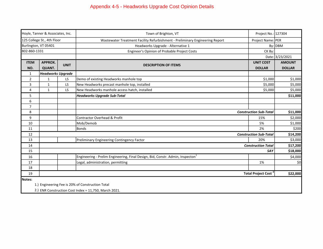
Town of Brighton, VT Project No.: 127304
Wastewater Treatment Facility Refurbishment - Preliminary Engineering Report Project Name: PER
Headworks Upgrade - Alternative 1 By: DBM
Engineer's Opinion of Probable Project Costs CK By:
Date: 3/23/2021
ITEM APPROX. UNIT COST AMOUNT
NO. QUANT. DOLLAR DOLLAR
1 Headworks Upgrade
2 1 LS Demo of existing Headworks manhole top $1,000 $1,000
3 1 LS New Headworks precast manhole top, installed $5,000 $5,000
4 1 LS New Headworks manhole access hatch, installed $5,000 $5,000
5 Headworks Upgrade Sub-Total $11,000
6
7
8 $11,000
9 Contractor Overhead & Profit 15% $2,000
10 Mob/Demob 5% $1,000
11 Bonds 2% $200
12 $14,200
13 Preliminary Engineering Contingency Factor 20% $3,000
14 $17,200
15 SAY $18,000
16 Engineering - Prelim Engineering, Final Design, Bid, Constr. Admin, Inspecton1
$4,000
17 Legal, administration, permitting 1% $0
18
19 $22,000
Notes:
1.)
2.) ENR Construction Cost Index = 11,750, March 2021.
Engineering Fee is 20% of Construction Total
Hoyle, Tanner & Associates, Inc.
125 College St., 4th Floor
Burlington, VT 05401
802-860-1331
UNIT DESCRIPTION OF ITEMS
Construction Sub-Total
Construction Sub-Total
Construction Total
Total Project Cost 2
Appendix 4-5 - Headworks Upgrade Cost Opinion Details
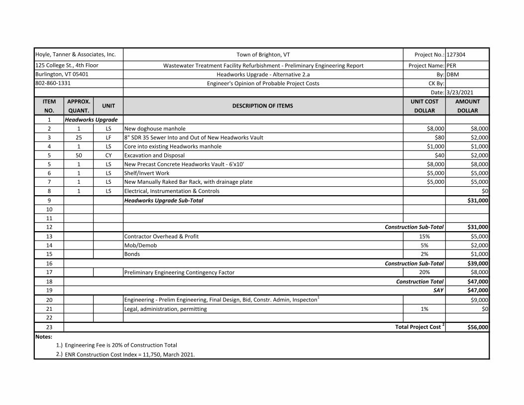
Town of Brighton, VT Project No.: 127304
Wastewater Treatment Facility Refurbishment - Preliminary Engineering Report Project Name: PER
Headworks Upgrade - Alternative 2.a By: DBM
Engineer's Opinion of Probable Project Costs CK By:
Date: 3/23/2021
ITEM APPROX. UNIT COST AMOUNT
NO. QUANT. DOLLAR DOLLAR
1 Headworks Upgrade
2 1 LS New doghouse manhole $8,000 $8,000
3 25 LF 8" SDR 35 Sewer Into and Out of New Headworks Vault $80 $2,000
4 1 LS Core into existing Headworks manhole $1,000 $1,000
5 50 CY Excavation and Disposal $40 $2,000
5 1 LS New Precast Concrete Headworks Vault - 6'x10' $8,000 $8,000
6 1 LS Shelf/Invert Work $5,000 $5,000
7 1 LS New Manually Raked Bar Rack, with drainage plate $5,000 $5,000
8 1 LS Electrical, Instrumentation & Controls $0
9 Headworks Upgrade Sub-Total $31,000
10
11
12 $31,000
13 Contractor Overhead & Profit 15% $5,000
14 Mob/Demob 5% $2,000
15 Bonds 2% $1,000
16 $39,000
17 Preliminary Engineering Contingency Factor 20% $8,000
18 $47,000
19 SAY $47,000
20 Engineering - Prelim Engineering, Final Design, Bid, Constr. Admin, Inspecton1
$9,000
21 Legal, administration, permitting 1% $0
22
23 $56,000
Notes:
1.)
2.) ENR Construction Cost Index = 11,750, March 2021.
Engineering Fee is 20% of Construction Total
Hoyle, Tanner & Associates, Inc.
125 College St., 4th Floor
Burlington, VT 05401
802-860-1331
UNIT DESCRIPTION OF ITEMS
Construction Sub-Total
Construction Sub-Total
Construction Total
Total Project Cost 2
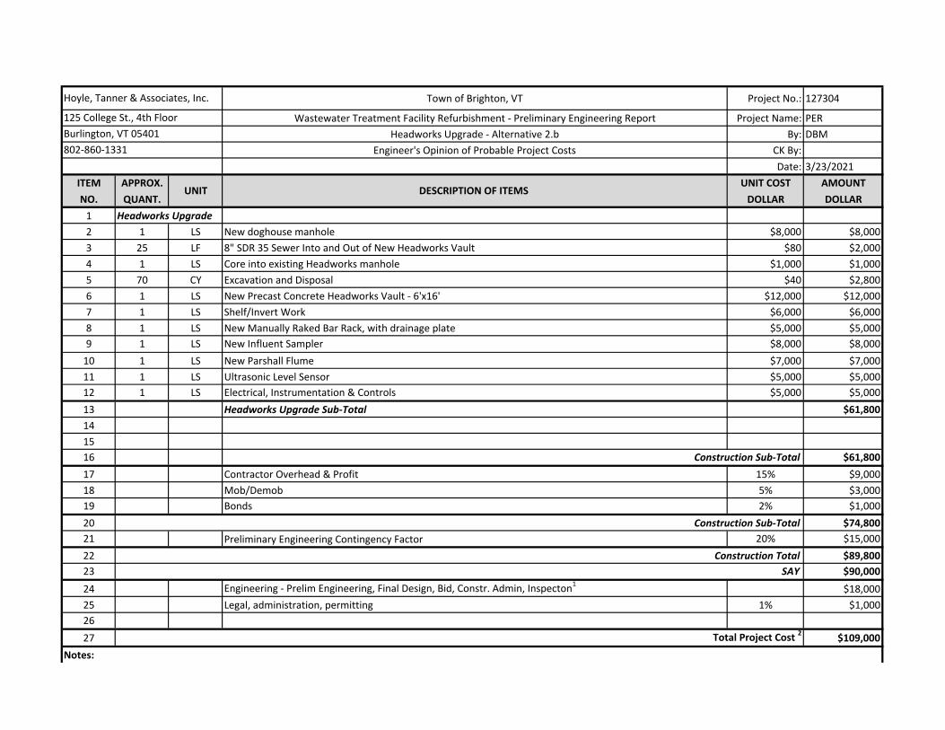
Town of Brighton, VT Project No.: 127304
Wastewater Treatment Facility Refurbishment - Preliminary Engineering Report Project Name: PER
Headworks Upgrade - Alternative 2.b By: DBM
Engineer's Opinion of Probable Project Costs CK By:
Date: 3/23/2021
ITEM APPROX. UNIT COST AMOUNT
NO. QUANT. DOLLAR DOLLAR
1 Headworks Upgrade
2 1 LS New doghouse manhole $8,000 $8,000
3 25 LF 8" SDR 35 Sewer Into and Out of New Headworks Vault $80 $2,000
4 1 LS Core into existing Headworks manhole $1,000 $1,000
5 70 CY Excavation and Disposal $40 $2,800
6 1 LS New Precast Concrete Headworks Vault - 6'x16' $12,000 $12,000
7 1 LS Shelf/Invert Work $6,000 $6,000
8 1 LS New Manually Raked Bar Rack, with drainage plate $5,000 $5,000
9 1 LS New Influent Sampler $8,000 $8,000
10 1 LS New Parshall Flume $7,000 $7,000
11 1 LS Ultrasonic Level Sensor $5,000 $5,000
12 1 LS Electrical, Instrumentation & Controls $5,000 $5,000
13 Headworks Upgrade Sub-Total $61,800
14
15
16 $61,800
17 Contractor Overhead & Profit 15% $9,000
18 Mob/Demob 5% $3,000
19 Bonds 2% $1,000
20 $74,800
21 Preliminary Engineering Contingency Factor 20% $15,000
22 $89,800
23 SAY $90,000
24 Engineering - Prelim Engineering, Final Design, Bid, Constr. Admin, Inspecton1
$18,000
25 Legal, administration, permitting 1% $1,000
26
27 $109,000
Notes:
Hoyle, Tanner & Associates, Inc.
125 College St., 4th Floor
Burlington, VT 05401
802-860-1331
UNIT DESCRIPTION OF ITEMS
Construction Sub-Total
Construction Sub-Total
Construction Total
Total Project Cost 2
1.)
2.) ENR Construction Cost Index = 11,750, March 2021.
Engineering Fee is 20% of Construction Total
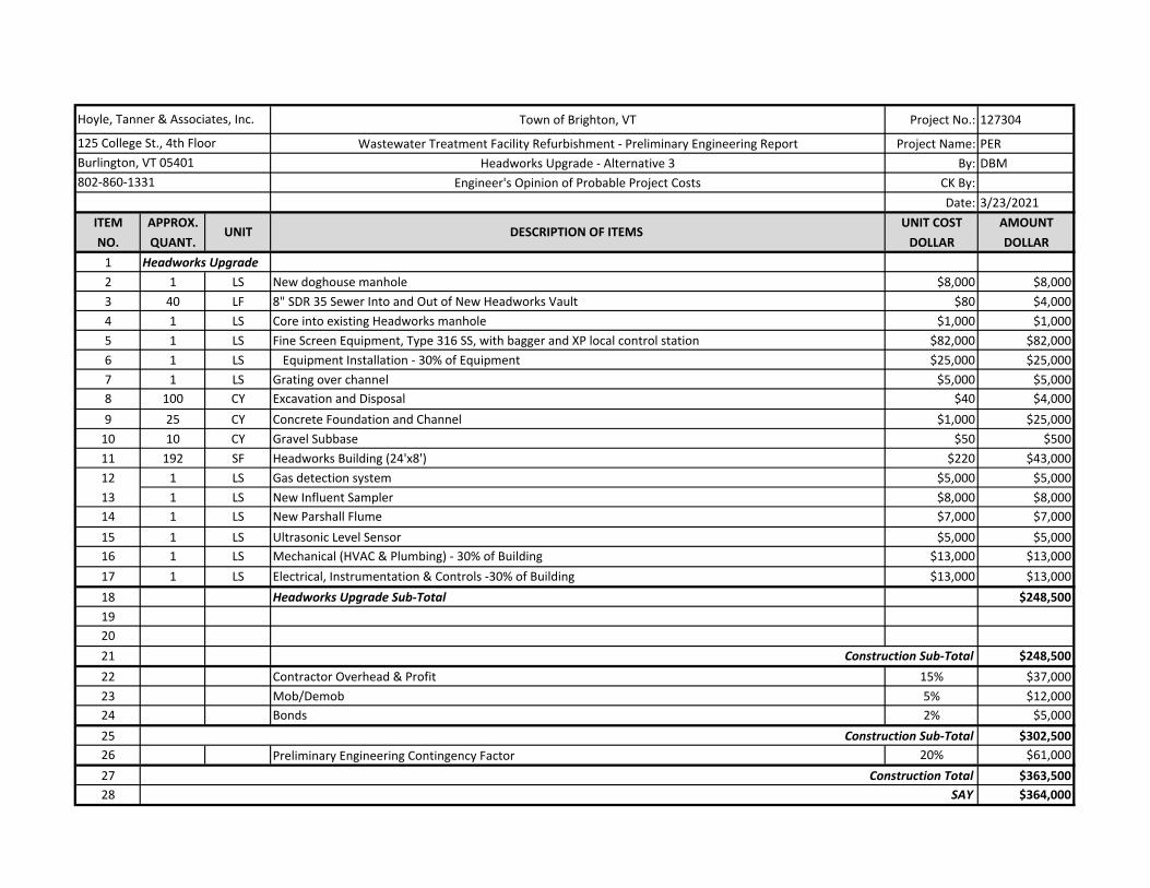
Town of Brighton, VT Project No.: 127304
Wastewater Treatment Facility Refurbishment - Preliminary Engineering Report Project Name: PER
Headworks Upgrade - Alternative 3 By: DBM
Engineer's Opinion of Probable Project Costs CK By:
Date: 3/23/2021
ITEM APPROX. UNIT COST AMOUNT
NO. QUANT. DOLLAR DOLLAR
1 Headworks Upgrade
2 1 LS New doghouse manhole $8,000 $8,000
3 40 LF 8" SDR 35 Sewer Into and Out of New Headworks Vault $80 $4,000
4 1 LS Core into existing Headworks manhole $1,000 $1,000
5 1 LS Fine Screen Equipment, Type 316 SS, with bagger and XP local control station $82,000 $82,000
6 1 LS Equipment Installation - 30% of Equipment $25,000 $25,000
7 1 LS Grating over channel $5,000 $5,000
8 100 CY Excavation and Disposal $40 $4,000
9 25 CY Concrete Foundation and Channel $1,000 $25,000
10 10 CY Gravel Subbase $50 $500
11 192 SF Headworks Building (24'x8') $220 $43,000
12 1 LS Gas detection system $5,000 $5,000
13 1 LS New Influent Sampler $8,000 $8,000
14 1 LS New Parshall Flume $7,000 $7,000
15 1 LS Ultrasonic Level Sensor $5,000 $5,000
16 1 LS Mechanical (HVAC & Plumbing) - 30% of Building $13,000 $13,000
17 1 LS Electrical, Instrumentation & Controls -30% of Building $13,000 $13,000
18 Headworks Upgrade Sub-Total $248,500
19
20
21 $248,500
22 Contractor Overhead & Profit 15% $37,000
23 Mob/Demob 5% $12,000
24 Bonds 2% $5,000
25 $302,500
26 Preliminary Engineering Contingency Factor 20% $61,000
27 $363,500
28 SAY $364,000
Hoyle, Tanner & Associates, Inc.
125 College St., 4th Floor
Burlington, VT 05401
802-860-1331
UNIT DESCRIPTION OF ITEMS
Construction Sub-Total
Construction Sub-Total
Construction Total
29 Engineering - Prelim Engineering, Final Design, Bid, Constr. Admin, Inspecton1
$73,000
30 Legal, administration, permitting 1% $4,000
31
32 $441,000
Notes:
1.)
2.) ENR Construction Cost Index = 11,750, March 2021.
Engineering Fee is 20% of Construction Total
Total Project Cost 2

Preliminary Proposal for Design, Supply and Installation of the Wastewater Treatment System Upgraded with March 5, 2021
BRIGHTON, VT
Appendix 4-6 - Lagoon Alternative 1 Equipment Manufacturer Proposal
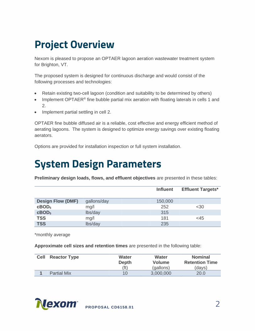
PROPOSAL CD6158.01 2
Project Overview Nexom is pleased to propose an OPTAER lagoon aeration wastewater treatment system
for Brighton, VT.
The proposed system is designed for continuous discharge and would consist of the
following processes and technologies:
• Retain existing two-cell lagoon (condition and suitability to be determined by others)
• Implement OPTAER® fine bubble partial mix aeration with floating laterals in cells 1 and
2.
• Implement partial settling in cell 2.
OPTAER fine bubble diffused air is a reliable, cost effective and energy efficient method of
aerating lagoons. The system is designed to optimize energy savings over existing floating
aerators.
Options are provided for installation inspection or full system installation.
System Design Parameters Preliminary design loads, flows, and effluent objectives are presented in these tables:
*monthly average
Approximate cell sizes and retention times are presented in the following table:
Cell Reactor Type Water Depth
(ft)
Water Volume (gallons)
Nominal Retention Time
(days)
1 Partial Mix 10 3,000,000 20.0
Influent Effluent Targets*
Design Flow (DMF) gallons/day 150,000
cBOD5 mg/l 252 <30
cBOD5 lbs/day 315
TSS mg/l 181 <45
TSS lbs/day 235
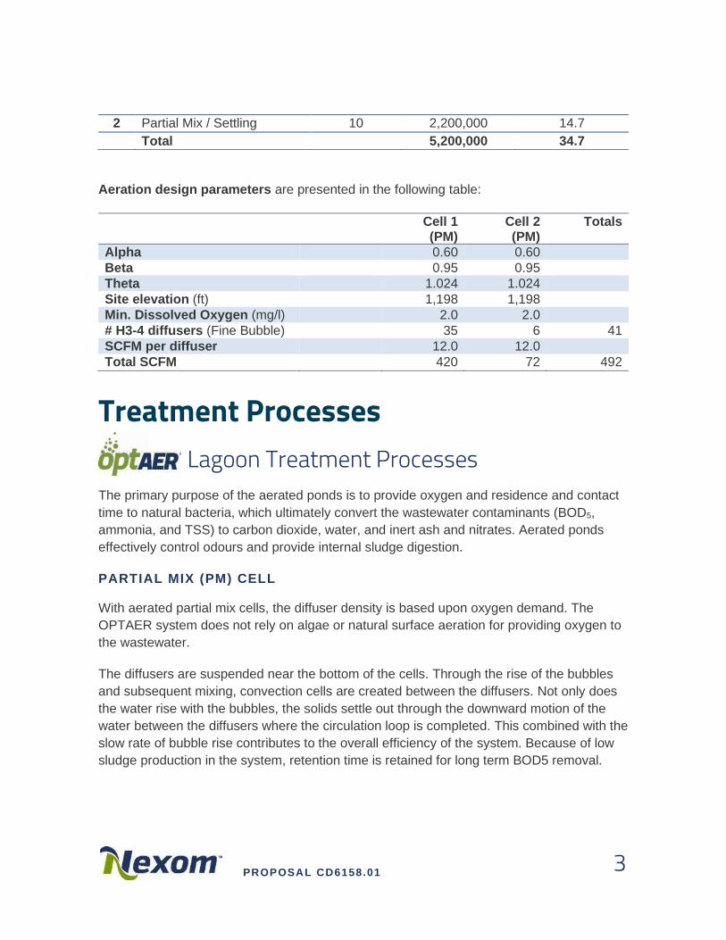
PROPOSAL CD6158.01 3
2 Partial Mix / Settling 10 2,200,000 14.7
Total 5,200,000 34.7
Aeration design parameters are presented in the following table:
Cell 1
(PM) Cell 2 (PM)
Totals
Alpha 0.60 0.60
Beta 0.95 0.95
Theta 1.024 1.024
Site elevation (ft) 1,198 1,198
Min. Dissolved Oxygen (mg/l) 2.0 2.0
# H3-4 diffusers (Fine Bubble) 35 6 41
SCFM per diffuser 12.0 12.0
Total SCFM 420 72 492
Treatment Processes Lagoon Treatment Processes The primary purpose of the aerated ponds is to provide oxygen and residence and contact
time to natural bacteria, which ultimately convert the wastewater contaminants (BOD5,
ammonia, and TSS) to carbon dioxide, water, and inert ash and nitrates. Aerated ponds
effectively control odours and provide internal sludge digestion.
PARTIAL MIX (PM) CELL
With aerated partial mix cells, the diffuser density is based upon oxygen demand. The
OPTAER system does not rely on algae or natural surface aeration for providing oxygen to
the wastewater.
The diffusers are suspended near the bottom of the cells. Through the rise of the bubbles
and subsequent mixing, convection cells are created between the diffusers. Not only does
the water rise with the bubbles, the solids settle out through the downward motion of the
water between the diffusers where the circulation loop is completed. This combined with the
slow rate of bubble rise contributes to the overall efficiency of the system. Because of low
sludge production in the system, retention time is retained for long term BOD5 removal.
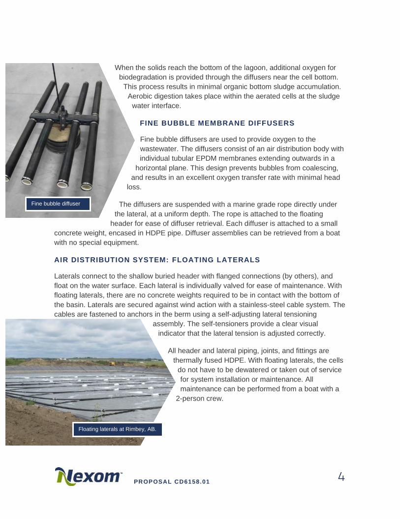
PROPOSAL CD6158.01 4
When the solids reach the bottom of the lagoon, additional oxygen for
biodegradation is provided through the diffusers near the cell bottom.
This process results in minimal organic bottom sludge accumulation.
Aerobic digestion takes place within the aerated cells at the sludge
water interface.
FINE BUBBLE MEMBRANE DIFFUSERS
Fine bubble diffusers are used to provide oxygen to the
wastewater. The diffusers consist of an air distribution body with
individual tubular EPDM membranes extending outwards in a
horizontal plane. This design prevents bubbles from coalescing,
and results in an excellent oxygen transfer rate with minimal head
loss.
The diffusers are suspended with a marine grade rope directly under
the lateral, at a uniform depth. The rope is attached to the floating
header for ease of diffuser retrieval. Each diffuser is attached to a small
concrete weight, encased in HDPE pipe. Diffuser assemblies can be retrieved from a boat
with no special equipment.
AIR DISTRIBUTION SYSTEM: FLOATING LATERALS
Laterals connect to the shallow buried header with flanged connections (by others), and
float on the water surface. Each lateral is individually valved for ease of maintenance. With
floating laterals, there are no concrete weights required to be in contact with the bottom of
the basin. Laterals are secured against wind action with a stainless-steel cable system. The
cables are fastened to anchors in the berm using a self-adjusting lateral tensioning
assembly. The self-tensioners provide a clear visual
indicator that the lateral tension is adjusted correctly.
All header and lateral piping, joints, and fittings are
thermally fused HDPE. With floating laterals, the cells
do not have to be dewatered or taken out of service
for system installation or maintenance. All
maintenance can be performed from a boat with a
2-person crew.
Fine bubble diffuser
Floating laterals at Rimbey, AB.
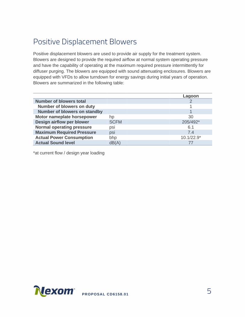
PROPOSAL CD6158.01 5
Positive Displacement Blowers Positive displacement blowers are used to provide air supply for the treatment system.
Blowers are designed to provide the required airflow at normal system operating pressure
and have the capability of operating at the maximum required pressure intermittently for
diffuser purging. The blowers are equipped with sound attenuating enclosures. Blowers are
equipped with VFDs to allow turndown for energy savings during initial years of operation.
Blowers are summarized in the following table:
*at current flow / design year loading
Lagoon
Number of blowers total 2
Number of blowers on duty 1 Number of blowers on standby 1
Motor nameplate horsepower hp 30
Design airflow per blower SCFM 205/492*
Normal operating pressure psi 6.1
Maximum Required Pressure psi 7.4
Actual Power Consumption bhp 10.1/22.9*
Actual Sound level dB(A) 77
PROPOSAL CD6158.01 6
Operation & Maintenance Anticipated O&M costs can be broken down into the following categories:
O&M Anticipated Costs at Full Buildout (150,000 gpd) Quantity Motor Power Annual Cost
bhp kW
Blowers 2
Normal Operating Conditions 1 22.9 17.1 $11,972 Filters, Oil and Belts - - - $245 Diffuser Membrane Replacement 164 $820
Total Operations & Maintenance $13,037
* Electrical Rate (estimated by Nexom): 0.08 $/kW-h
O&M Anticipated Costs at Current Flow (56,000 gpd) Quantity Motor Power Annual Cost
bhp kW
Blowers 2
Normal Operating Conditions 1 10.1 7.5 $5,280 Filters, Oil and Belts - - - $245 Diffuser Membrane Replacement 164 $820
Total Operations & Maintenance $6,145
* Electrical Rate (estimated by Nexom): 0.08 $/kW-h
The system will require one operator for approximately The system will require one operator
for approximately 15 minutes per day for routine inspection & maintenance.
Budgetary Capital Cost Included in the wastewater treatment system capital cost are:
• Nexom System Process Design
o CAD Drawings and specifications
• Equipment installation inspection/start-up/commissioning/training
• Operation and maintenance manuals
• Project Record Drawings

PROPOSAL CD6158.01 7
OPTAER® LAGOON AERATION SYSTEM:
• Floating lateral piping, feeder piping, fittings and lateral valves as required
• Diffuser assemblies complete with EPDM Membranes and pre-cast diffuser weights.
• Self-tensioning lateral assemblies and anchor posts.
AIR SUPPLY
• Two (2) 30 hp positive displacement blowers with sound attenuating enclosures
• Blower control panel with VFDs
BUDGETARY COST FOR THE OPTAER SUPPLY SCOPE:
$144,300 USD (Shipping allowed to jobsite, plus applicable taxes)
All prices are subject to final design review.
INSTALLATION:
In addition to the above scope:
• Mobilization
• Installation of in-water components
• Placement of blowers and control panel
• Concrete for anchor posts
BUDGETARY COST FOR THE OPTAER SCOPE WITH INSTALLATION:
$195,100 USD
All prices are subject to final design review.

PROPOSAL CD6158.01 8
Items Specifically Not Included: • Material offloading and secure on-site storage
• Installation of Nexom supplied equipment (installation is available as quoted)
• Removal of existing aeration equipment (available but outside the scope of this
proposal)
• Civil works including lagoon cells design and construction, liner, transport piping, inter-
cell piping, discharge piping, manholes, valves, access roads to site, site roads and
landscaping, lagoon desludging etc. if required
• HDPE shallow buried main header piping with flanged connections and manual blow-off
(main header supply is available but outside the scope of this proposal)
• Galvanized metal blower header and connection pipe (heat dissipation) (metal piping
supply is available but outside the scope of this proposal)
• Excavation and backfill for shallow buried aeration headers
• Building or upgrades to building
• Electrical hookup or electrical work, wiring of blowers and control panel
• Site Preparation and Restoration
Questions or Comments? Any questions or comments can be directed to:
Francis Bordeleau, P.Eng.
Regional Sales Manager
514∙970∙7511
Nexom
888-426-8180
5 Burks Way · Winnipeg MB · R5T 0C9
www.nexom.com
Brighton, VT
Preliminary Proposal
3/5/21
Preliminary Proposal
www.parkson.com Parkson Corporation Confidential 2
To: Date: 3/5/21
Company: From: Robert Rolette
Tel.: Tel.: 913-745-1234
cc: Chad Vore, Kevin Bunting, Brad Linsey
Subject: Parkson Biolac® Treatment System, Preliminary Design Proposal for
Brighton, VT
Thank you for your interest in Parkson's Biolac® Treatment System. Based upon the
data provided for this project, we developed the Biolac® design described in this
proposal. We believe that this Biolac® design not only provides the most cost effective
solution for this municipality, but also meets effluent quality requirements.
We look forward to working with you on this project. Should you have any questions
or need clarifications, please do not hesitate to contact me at (913) 745-1234. Thanks.
Sincerely,
PARKSON CORPORATION
An Axel Johnson, Inc. Company
Robert Rolette
Application Engineer
Preliminary Proposal
www.parkson.com Parkson Corporation Confidential 3
Table of Content
1. Design Basis ............................................................................................................. 4
1.1. Influent Specifications .................................................................................... 4
1.2. Selected Design Parameters ........................................................................... 5
2. System Description .................................................................................................. 5
3. System Components ................................................................................................ 6
3.1. Moving Aeration Chain System ...................................................................... 7
3.2. Diffuser Frame ................................................................................................ 8
3.3. Aeration Design .............................................................................................. 8
3.4. Biolac® Treatment System Preliminary Design Information .......................... 8
4. Equipment and Services Supplied ........................................................................... 9
5. Cost Estimate and Term .......................................................................................... 9
6. Supplemental Information and References .......................................................... 10
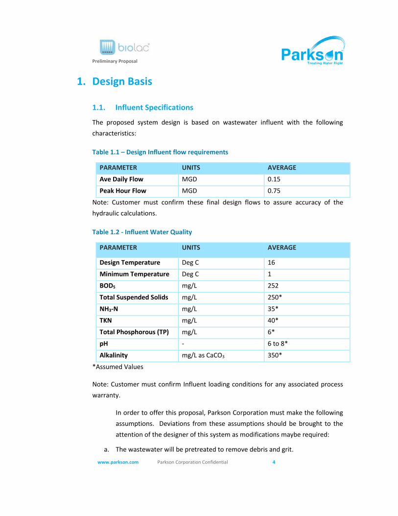
Preliminary Proposal
www.parkson.com Parkson Corporation Confidential 4
1. Design Basis
1.1. Influent Specifications
The proposed system design is based on wastewater influent with the following
characteristics:
Table 1.1 – Design Influent flow requirements
PARAMETER UNITS AVERAGE
Ave Daily Flow MGD 0.15
Peak Hour Flow MGD 0.75
Note: Customer must confirm these final design flows to assure accuracy of the
hydraulic calculations.
Table 1.2 - Influent Water Quality
PARAMETER UNITS AVERAGE
Design Temperature Deg C 16
Minimum Temperature Deg C 1
BOD5 mg/L 252
Total Suspended Solids mg/L 250*
NH3-N mg/L 35*
TKN mg/L 40*
Total Phosphorous (TP) mg/L 6*
pH - 6 to 8*
Alkalinity mg/L as CaCO3 350*
*Assumed Values
Note: Customer must confirm Influent loading conditions for any associated process
warranty.
In order to offer this proposal, Parkson Corporation must make the following
assumptions. Deviations from these assumptions should be brought to the
attention of the designer of this system as modifications maybe required:
a. The wastewater will be pretreated to remove debris and grit.
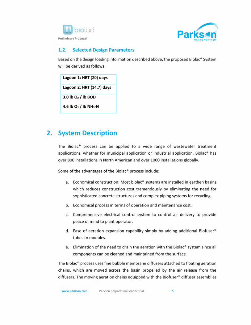
Preliminary Proposal
www.parkson.com Parkson Corporation Confidential 5
1.2. Selected Design Parameters
Based on the design loading information described above, the proposed Biolac® System
will be derived as follows:
Lagoon 1: HRT (20) days
Lagoon 2: HRT (14.7) days
3.0 lb O2 / lb BOD
4.6 lb O2 / lb NH3-N
2. System Description
The Biolac® process can be applied to a wide range of wastewater treatment
applications, whether for municipal application or industrial application. Biolac® has
over 800 installations in North American and over 1000 installations globally.
Some of the advantages of the Biolac® process include:
a. Economical construction: Most biolac® systems are installed in earthen basins
which reduces construction cost tremendously by eliminating the need for
sophisticated concrete structures and complex piping systems for recycling.
b. Economical process in terms of operation and maintenance cost.
c. Comprehensive electrical control system to control air delivery to provide
peace of mind to plant operator.
d. Ease of aeration expansion capability simply by adding additional Biofuser®
tubes to modules.
e. Elimination of the need to drain the aeration with the Biolac® system since all
components can be cleaned and maintained from the surface
The Biolac® process uses fine bubble membrane diffusers attached to floating aeration
chains, which are moved across the basin propelled by the air release from the
diffusers. The moving aeration chains equipped with the Biofuser® diffuser assemblies
Preliminary Proposal
www.parkson.com Parkson Corporation Confidential 6
provide efficient mixing of the basin contents as well as high oxygen transfer at low
energy usage.
The Biofuser® system does not have submerged aeration piping or any other
components to be installed, leveled, or secured on the basin floor. The BioFlex® chains
with BioFusers do not contact or harm the basin liner. Each BioFlex® chain can be
individually controlled by independent air valve providing excellent flexibility in fine-
tuning the system to meet the oxygen demand. Inspection and service of the BioFusers
is done quickly and easily without dewatering the basin, keeping maintenance costs
low and eliminating the need for redundant aeration basins. In case of cold climates,
the fine bubble diffusion beneath the water surface eliminates icing and minimizes
wastewater cooling.
Earthen basins can be used rather than expensive concrete tanks making this design
the lowest cost alternative available on the market.
3. System Components
The Biolac® aeration system for lagoon basins consists mainly of suspended aeration
chains, fine bubble diffusers, motorized and controlled air valves, blowers and
automatic electrical control system.
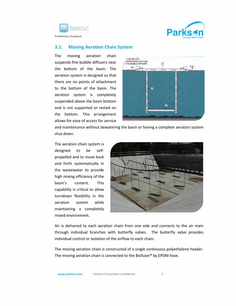
Preliminary Proposal
www.parkson.com Parkson Corporation Confidential 7
3.1. Moving Aeration Chain System
The moving aeration chain
suspends fine bubble diffusers near
the bottom of the basin. The
aeration system is designed so that
there are no points of attachment
to the bottom of the basin. The
aeration system is completely
suspended above the basin bottom
and is not supported or rested on
the bottom. This arrangement
allows for ease of access for service
and maintenance without dewatering the basin or having a complete aeration system
shut down.
The aeration chain system is
designed to be self-
propelled and to move back
and forth systematically in
the wastewater to provide
high mixing efficiency of the
basin’s content. This
capability is critical to allow
turndown flexibility in the
aeration system while
maintaining a completely
mixed environment.
Air is delivered to each aeration chain from one side and connects to the air main
through individual branches with butterfly valves. The butterfly valve provides
individual control or isolation of the airflow to each chain.
The moving aeration chain is constructed of a single continuous polyethylene header.
The moving aeration chain is connected to the Biofuser® by EPDM hose.
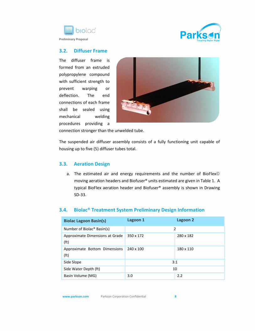
Preliminary Proposal
www.parkson.com Parkson Corporation Confidential 8
3.2. Diffuser Frame
The diffuser frame is
formed from an extruded
polypropylene compound
with sufficient strength to
prevent warping or
deflection. The end
connections of each frame
shall be sealed using
mechanical welding
procedures providing a
connection stronger than the unwelded tube.
The suspended air diffuser assembly consists of a fully functioning unit capable of
housing up to five (5) diffuser tubes total.
3.3. Aeration Design
a. The estimated air and energy requirements and the number of BioFlex©
moving aeration headers and Biofuser® units estimated are given in Table 1. A
typical BioFlex aeration header and Biofuser® assembly is shown in Drawing
SD-33.
3.4. Biolac® Treatment System Preliminary Design Information
Biolac Lagoon Basin(s) Lagoon 1 Lagoon 2
Number of Biolac® Basin(s) 2
Approximate Dimensions at Grade
(ft)
350 x 172 280 x 182
Approximate Bottom Dimensions
(ft)
240 x 100 180 x 110
Side Slope 3:1
Side Water Depth (ft) 10
Basin Volume (MG) 3.0 2.2
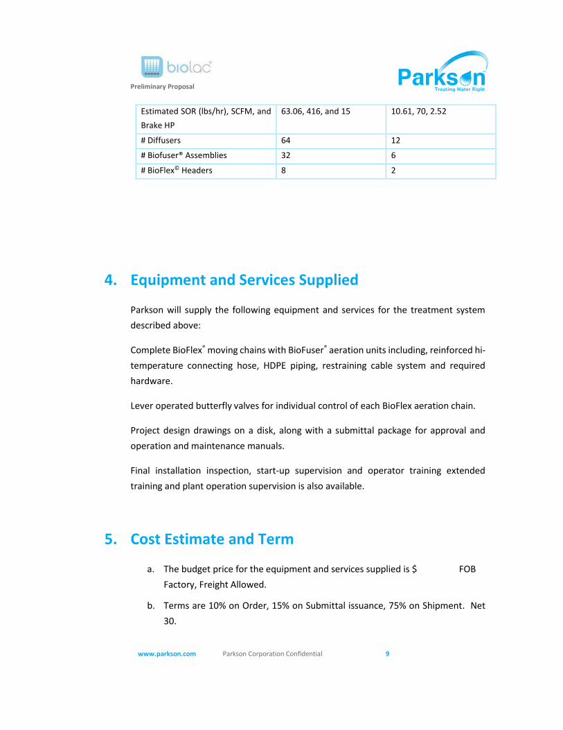
Preliminary Proposal
www.parkson.com Parkson Corporation Confidential 9
Estimated SOR (lbs/hr), SCFM, and
Brake HP
63.06, 416, and 15 10.61, 70, 2.52
# Diffusers 64 12
# Biofuser® Assemblies 32 6
# BioFlex© Headers 8 2
4. Equipment and Services Supplied
Parkson will supply the following equipment and services for the treatment system
described above:
Complete BioFlex® moving chains with BioFuser® aeration units including, reinforced hi-
temperature connecting hose, HDPE piping, restraining cable system and required
hardware.
Lever operated butterfly valves for individual control of each BioFlex aeration chain.
Project design drawings on a disk, along with a submittal package for approval and
operation and maintenance manuals.
Final installation inspection, start-up supervision and operator training extended
training and plant operation supervision is also available.
5. Cost Estimate and Term
a. The budget price for the equipment and services supplied is $ FOB
Factory, Freight Allowed.
b. Terms are 10% on Order, 15% on Submittal issuance, 75% on Shipment. Net
30.
Preliminary Proposal
www.parkson.com Parkson Corporation Confidential 10
c. Approval drawings-typically 6-8 weeks after receipt of written order.
d. Equipment Shipment - typically 16-20 weeks after complete release for
manufacture.
6. Supplemental Information and References
a. Typical Drawings
— SD-33 "BioFlex Moving Aeration Chain with Biofuser® Series 2002"
— SD-6 "Typical Moving Aeration Chain Connection"
— SD-7 "Anchor Post with Hook Detail"
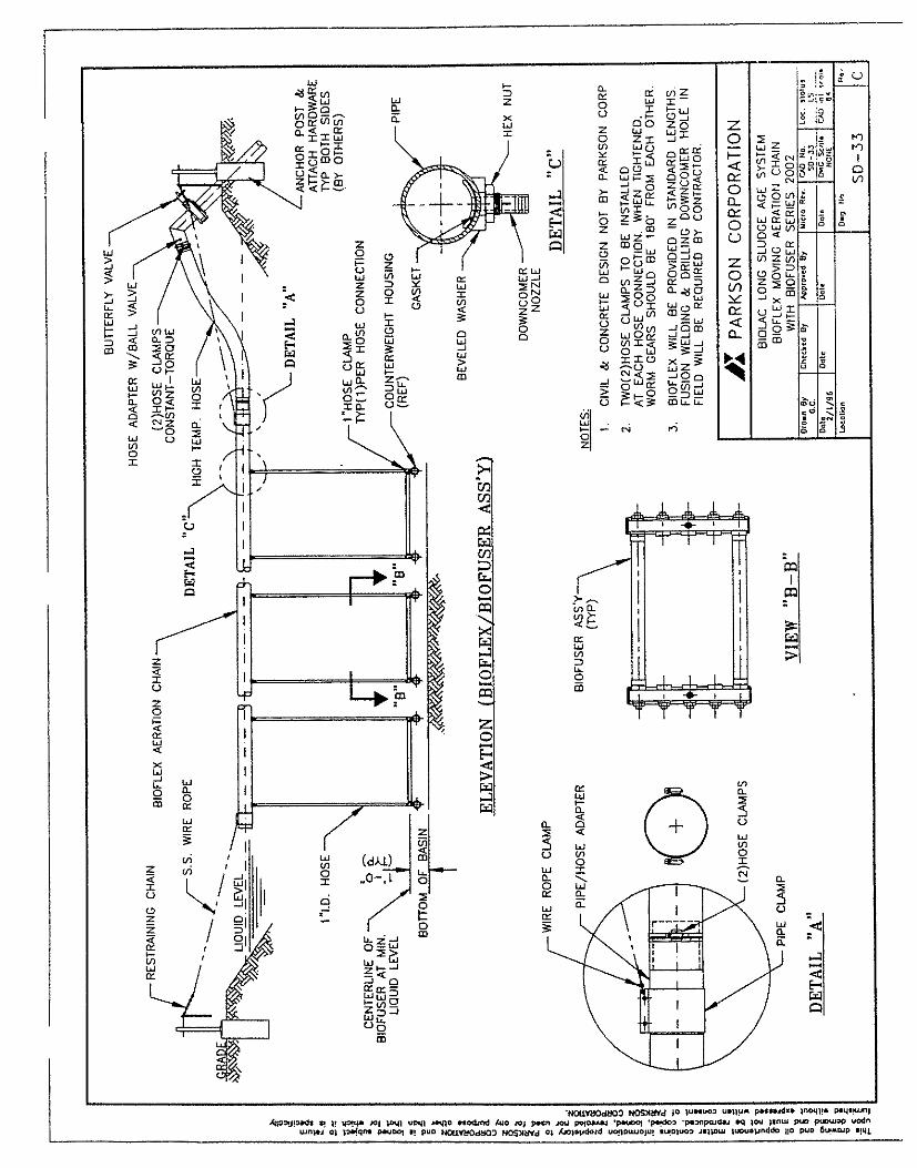
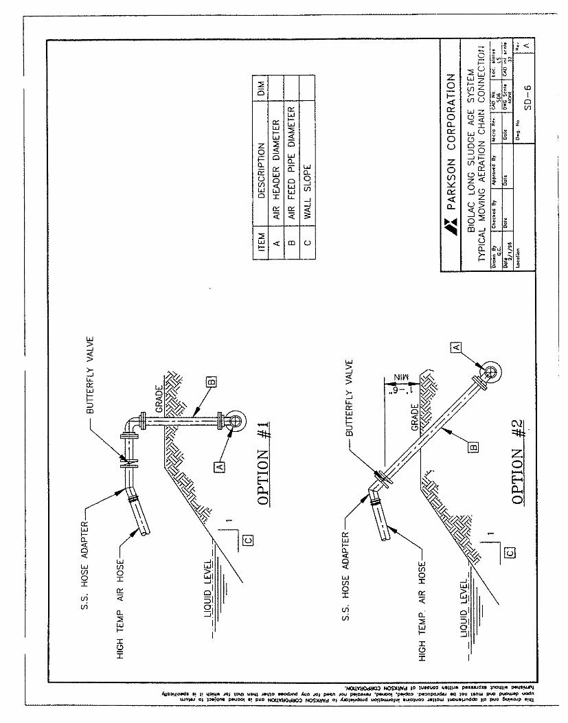
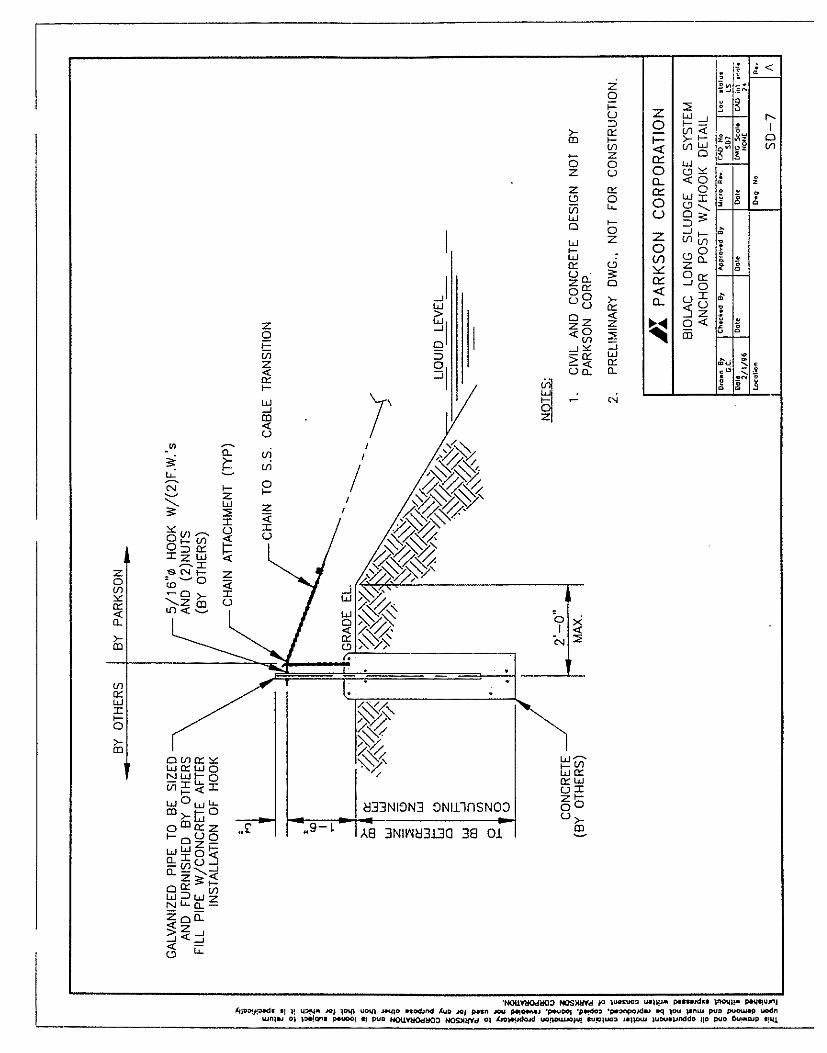
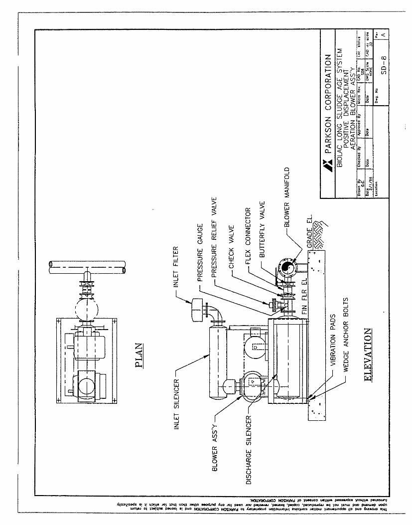
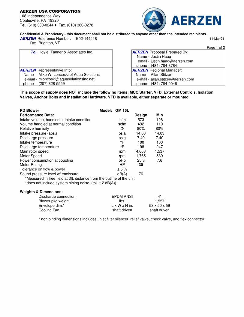
spacespaceAERZEN USA CORPORATION
108 Independence WayCoatesville, PA 19320
Tel. (610) 380-0244 ♦ Fax. (610) 380-0278spaceConfidential & Proprietary - this document shall not be distributed to anyone other than the intended recipients.
AERZEN Reference Number: E02-144418 11-Mar-21
Re: Brighton, VTspace Page 1 of 2
To: Hoyle, Tanner & Associates Inc. AERZEN Proposal Prepared By:Name - Justin Haag
email - [email protected] - (484) 784-6764
AERZEN Representative Info: AERZEN Regional Manager:Name - Name - Allan Stitzer
e-mail - e-mail - [email protected] - (207) 828-5559 phone - (484) 784-9046
space
space spaceModel: GM 15L
Performance Data: Design Min
Intake volume, handled at intake condition icfm 573 128Volume handled at normal condition scfm 492 110Relative humidity Φ 80% 80%
Intake pressure (abs.) psia 14.03 14.03Discharge pressure psig 7.40 7.40Intake temperature °F 100 100Discharge temperature °F 198 247Main rotor speed rpm 4,608 1,537Motor Speed rpm 1,765 589Power consumption at coupling bHp 25.3 7.6Motor Rating HP 30Tolerance on flow & power ± 5 %
Sound pressure level w/ enclosure dB(A) 76 *Measured in free field at 3ft. distance from the outline of the unit *does not include system piping noise (tol. ± 2 dB(A)).space spaceWeights & Dimensions:
space Discharge connection EPDM ANSI 4"space Blower pkg weight lbs. 1,557space Envelope dim.* L x W x H in. 53 x 50 x 59 space Cooling Fan shaft driven shaft drivenspacespace * non binding dimensions includes, inlet filter silencer, relief valve, check valve, and flex connector
This scope of supply does NOT include the following items: MCC Starter, VFD, External Controls, Isolation
Valves, Anchor Bolts and Installation Hardware. VFD is available, either separate or mounted.
PD Blower
Mike W. Loncoski of Aqua Solutions [email protected]
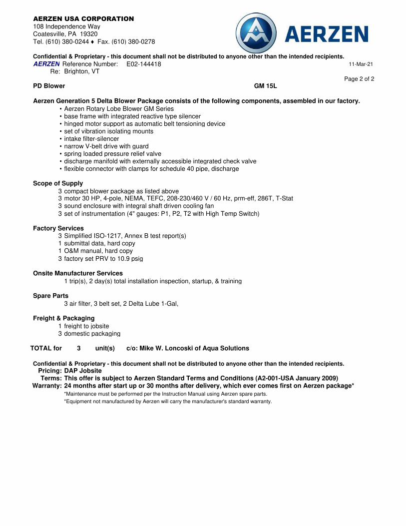
spacespaceAERZEN USA CORPORATION
108 Independence WayCoatesville, PA 19320
Tel. (610) 380-0244 ♦ Fax. (610) 380-0278spaceConfidential & Proprietary - this document shall not be distributed to anyone other than the intended recipients.
AERZEN Reference Number: E02-144418 11-Mar-21
Re: Brighton, VTspace space Page 2 of 2
PD Blower GM 15L
Aerzen Generation 5 Delta Blower Package consists of the following components, assembled in our factory.
• Aerzen Rotary Lobe Blower GM Series• base frame with integrated reactive type silencer• hinged motor support as automatic belt tensioning device• set of vibration isolating mounts• intake filter-silencer• narrow V-belt drive with guard• spring loaded pressure relief valve• discharge manifold with externally accessible integrated check valve• flexible connector with clamps for schedule 40 pipe, discharge
space spaceScope of Supply
3 compact blower package as listed above33 sound enclosure with integral shaft driven cooling fan
3
Factory Services3 Simplified ISO-1217, Annex B test report(s)1 submittal data, hard copy1 O&M manual, hard copy
3 factory set PRV to 10.9 psigspaceOnsite Manufacturer Services
1 trip(s), 2 day(s) total installation inspection, startup, & trainingspace spaceSpare Parts
spacespaceFreight & Packaging
1 freight to jobsite3 domestic packaging
TOTAL for 3 unit(s)
spaceConfidential & Proprietary - this document shall not be distributed to anyone other than the intended recipients.
Pricing: DAP JobsiteTerms: This offer is subject to Aerzen Standard Terms and Conditions (A2-001-USA January 2009)
Warranty: 24 months after start up or 30 months after delivery, which ever comes first on Aerzen package*
space *Maintenance must be performed per the Instruction Manual using Aerzen spare parts.
space *Equipment not manufactured by Aerzen will carry the manufacturer's standard warranty.
space
3 air filter, 3 belt set, 2 Delta Lube 1-Gal,
c/o: Mike W. Loncoski of Aqua Solutions
motor 30 HP, 4-pole, NEMA, TEFC, 208-230/460 V / 60 Hz, prm-eff, 286T, T-Stat
set of instrumentation (4" gauges: P1, P2, T2 with High Temp Switch)
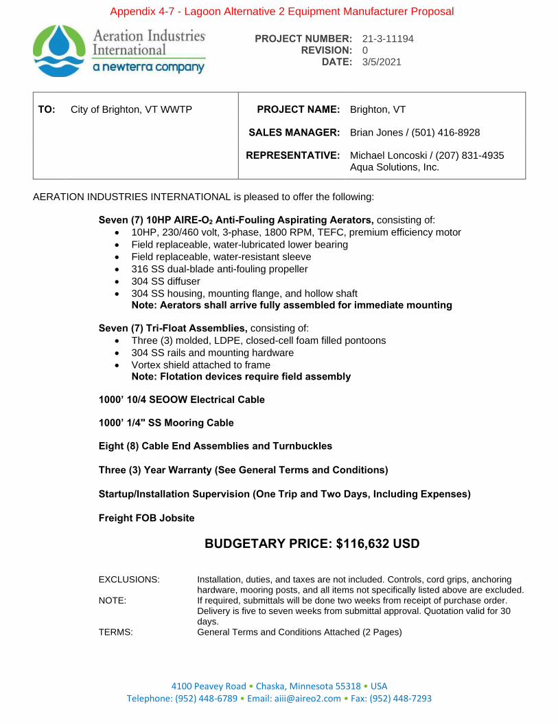
PROJECT NUMBER: REVISION:
21-3-11194 0
DATE: 3/5/2021
4100 Peavey Road • Chaska, Minnesota 55318 • USA
Telephone: (952) 448-6789 • Email: [email protected] • Fax: (952) 448-7293
TO: City of Brighton, VT WWTP PROJECT NAME: Brighton, VT
SALES MANAGER: Brian Jones / (501) 416-8928
REPRESENTATIVE: Michael Loncoski / (207) 831-4935 Aqua Solutions, Inc.
AERATION INDUSTRIES INTERNATIONAL is pleased to offer the following: Seven (7) 10HP AIRE-O2 Anti-Fouling Aspirating Aerators, consisting of:
• 10HP, 230/460 volt, 3-phase, 1800 RPM, TEFC, premium efficiency motor
• Field replaceable, water-lubricated lower bearing
• Field replaceable, water-resistant sleeve
• 316 SS dual-blade anti-fouling propeller
• 304 SS diffuser
• 304 SS housing, mounting flange, and hollow shaft Note: Aerators shall arrive fully assembled for immediate mounting
Seven (7) Tri-Float Assemblies, consisting of:
• Three (3) molded, LDPE, closed-cell foam filled pontoons
• 304 SS rails and mounting hardware
• Vortex shield attached to frame Note: Flotation devices require field assembly
1000’ 10/4 SEOOW Electrical Cable 1000’ 1/4" SS Mooring Cable Eight (8) Cable End Assemblies and Turnbuckles
Three (3) Year Warranty (See General Terms and Conditions)
Startup/Installation Supervision (One Trip and Two Days, Including Expenses)
Freight FOB Jobsite
BUDGETARY PRICE: $116,632 USD
EXCLUSIONS: Installation, duties, and taxes are not included. Controls, cord grips, anchoring hardware, mooring posts, and all items not specifically listed above are excluded.
NOTE: If required, submittals will be done two weeks from receipt of purchase order. Delivery is five to seven weeks from submittal approval. Quotation valid for 30 days.
TERMS: General Terms and Conditions Attached (2 Pages)
Appendix 4-7 - Lagoon Alternative 2 Equipment Manufacturer Proposal

Lagoon 1 Description
1 Flowrate = 0.150 MGD Input flowrate
2 Volume = 3.0 MG Input volume
3 BOD in = 252 mg/l Influent BOD
4 BOD out = 42 mg/l Design output BOD
5 NH4-N = 40 mg/l** Design ammonia or TKN removal
6 Other = mg/l
7 BOD net = 209.8 mg/l line 7 = (line 3) - (line 4)
8 BOD net = 262.5 lb/day line 8 = (line 7) x (line 1)/1000
9 NH4-N net = 50.0 lb/day line 9 = (line 5) x (line 1)/1000
10 Other = 0.0 lb/day line 10 = (line 6) x (line 1)/1000
ASSUMPTIONS11 O2 : BOD = 3 lb O2 / lb BOD Typically varies between 1 and 2
12 O2 : NH3-N= 4.6 lb O2 / lb NH4-N Typical value is 4.6
13 O2 : Other = lb O2 / lb Other Depends on species
O2 REQUIREMENT UNDER FIELD CONDITIONS (AOR)
14 O2 for BOD = 787.4 lb O2 / day line 14 = (line 11) x (line 8)
15 O2 for NH4-N = 230.2 lb O2 / day line 15 = (line 12) x (line 9)
16 O2 for Other = 0.0 lb O2 / day line 16 = (line 13) x (line 10)
17 AOR = 1017.6 lb O2 / day line 17 = (line 14) + (line 15) + (line 16)
18 AOR = 42.4 lb O2 / hour line 18 = (line 17) / (24)
CORRECTION FACTORS TO DETERMINE O2 REQUIREMENT UNDER STANDARD CONDITIONS (SOR)
19 Basin Temperature = 68oF Input maximum basin temperature
20 Elevation = 1200 ft above msl Input basin elevation
21 Cw = 2.0 mg/l Operating O 2 conc. of wastewater
22 a = 0.85 Mass transfer correction factor
23 b = 0.95 Saturation factor
24 Cs20 = 9.09 mg/l O 2 saturation conc. at 20 deg Celcius
25 t = 1.00 Temperature correction factor
26 W = 0.96 Altitude correction factor
27 Cs = 8.7 mg/l O 2 saturation conc. at field conditions
28 (Standardized) SOR = 72.2 lb O2 / hour
POWER REQUIREMENTS RECOMMENDATIONS
Unit Model Aspirator 10HP Unit Model Aspirator 10HP Number of Units 4Unit Output 18.0 lb O2 / hour
Power per Unit 10.0 hp Total Power 40.0 hp
OXYGEN OxygenSOR 72.2 lb O2 / hour
# of Units Required 4 NOTESTotal Output 72.0 lb O2 / hour
Total Oxygen Power 40.0 hp
MIXINGType of Mixing
Mixing Requirement 10.0 hp/MG
Mixing Power Required 30.0 hp
# of Units Required 3
Total Mixing Power 30.0 hp
Project Number: 21-3-11194
Aeration Industries' calculations for determining the aeration equipment required to fulfill the oxygen and/or mixing demand of biological wastewater treatment systemsNote: The methods and data presented here are intended for use by the designer to estimate the power
requirement for the oxygen demand using AIRE-O2 aeration equipment. This method is not intended to
cover every application. Questions can be answered by contacting AII at 952-448-6789
Project Name: Brighton, VT
Input Data (Blue Cells)
Basis of Design
Aeration Industries recommends the installation of four (4) 10HP aspirators
in Lagoon 1. This will ensure the partial mix requirment and oxygen
demand are met.
Ammonia concentration is assumed based on medium strength (Medcalf &
Eddy).
3 lbs O2 / lb BOD is provided as design criteria
Partial Mix Lagoon
Location: VermontUnit Process: LagoonPrepared by: GRS
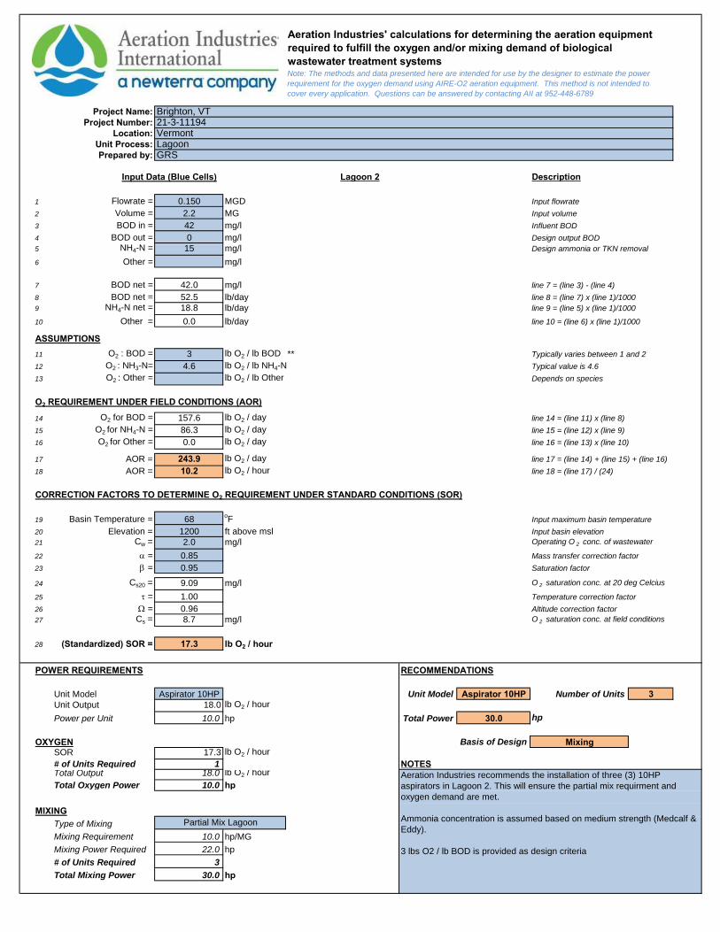
Lagoon 2 Description
1 Flowrate = 0.150 MGD Input flowrate
2 Volume = 2.2 MG Input volume
3 BOD in = 42 mg/l Influent BOD
4 BOD out = 0 mg/l Design output BOD
5 NH4-N = 15 mg/l Design ammonia or TKN removal
6 Other = mg/l
7 BOD net = 42.0 mg/l line 7 = (line 3) - (line 4)
8 BOD net = 52.5 lb/day line 8 = (line 7) x (line 1)/1000
9 NH4-N net = 18.8 lb/day line 9 = (line 5) x (line 1)/1000
10 Other = 0.0 lb/day line 10 = (line 6) x (line 1)/1000
ASSUMPTIONS11 O2 : BOD = 3 lb O2 / lb BOD ** Typically varies between 1 and 2
12 O2 : NH3-N= 4.6 lb O2 / lb NH4-N Typical value is 4.6
13 O2 : Other = lb O2 / lb Other Depends on species
O2 REQUIREMENT UNDER FIELD CONDITIONS (AOR)
14 O2 for BOD = 157.6 lb O2 / day line 14 = (line 11) x (line 8)
15 O2 for NH4-N = 86.3 lb O2 / day line 15 = (line 12) x (line 9)
16 O2 for Other = 0.0 lb O2 / day line 16 = (line 13) x (line 10)
17 AOR = 243.9 lb O2 / day line 17 = (line 14) + (line 15) + (line 16)
18 AOR = 10.2 lb O2 / hour line 18 = (line 17) / (24)
CORRECTION FACTORS TO DETERMINE O2 REQUIREMENT UNDER STANDARD CONDITIONS (SOR)
19 Basin Temperature = 68oF Input maximum basin temperature
20 Elevation = 1200 ft above msl Input basin elevation
21 Cw = 2.0 mg/l Operating O 2 conc. of wastewater
22 a = 0.85 Mass transfer correction factor
23 b = 0.95 Saturation factor
24 Cs20 = 9.09 mg/l O 2 saturation conc. at 20 deg Celcius
25 t = 1.00 Temperature correction factor
26 W = 0.96 Altitude correction factor
27 Cs = 8.7 mg/l O 2 saturation conc. at field conditions
28 (Standardized) SOR = 17.3 lb O2 / hour
POWER REQUIREMENTS RECOMMENDATIONS
Unit Model Aspirator 10HP Unit Model Aspirator 10HP Number of Units 3Unit Output 18.0 lb O2 / hour
Power per Unit 10.0 hp Total Power 30.0 hp
OXYGEN MixingSOR 17.3 lb O2 / hour
# of Units Required 1 NOTESTotal Output 18.0 lb O2 / hour
Total Oxygen Power 10.0 hp
MIXINGType of Mixing
Mixing Requirement 10.0 hp/MG
Mixing Power Required 22.0 hp
# of Units Required 3
Total Mixing Power 30.0 hp
Aeration Industries' calculations for determining the aeration equipment required to fulfill the oxygen and/or mixing demand of biological wastewater treatment systemsNote: The methods and data presented here are intended for use by the designer to estimate the power
requirement for the oxygen demand using AIRE-O2 aeration equipment. This method is not intended to
cover every application. Questions can be answered by contacting AII at 952-448-6789
Project Name: Brighton, VTProject Number: 21-3-11194
Location: VermontUnit Process: LagoonPrepared by: GRS
Input Data (Blue Cells)
Basis of Design
Aeration Industries recommends the installation of three (3) 10HP
aspirators in Lagoon 2. This will ensure the partial mix requirment and
oxygen demand are met.
Ammonia concentration is assumed based on medium strength (Medcalf &
Eddy).
3 lbs O2 / lb BOD is provided as design criteria
Partial Mix Lagoon
250'375'
A
B
C
DR
AW
IN
G S
TA
TU
S:
PR
OJE
CT
N
UM
BE
R:
RE
V:
SH
EE
TO
F
RE
V.
DA
TE
:B
Y:
DE
SC
RIP
TIO
N:
TIT
LE
:
CO
NC
EP
T
PR
OP
OS
AL
AP
PR
OV
AL
AS
-B
UILT
DR
AW
N B
Y:
DA
TE
:
CH
EC
KE
D B
Y:
DA
TE
:
Aeration Industries claim
s proprietary rights to
the m
aterial disclosed herein. T
his draw
ing is
issued for E
ngineering purposes only and m
ay
not be used to m
anufacture anything show
n
heron w
ithout w
ritten perm
ission.
© 2
01
1 A
era
tio
n In
du
strie
s In
t'l, L
LC
.
All R
ig
hts R
ese
rve
d.
DO
N
OT
S
CA
LE
D
RA
WIN
G
A1
3/5
/2
02
1G
RS
11
21
-3
-1
11
94
A1
BR
IG
HT
ON
, V
T
LA
GO
ON
A
ER
AT
IO
N
3/5
/2
02
1G
RS
RE
LE
AS
E O
F D
RA
WIN
G
LABEL EQUIPMENT QTY
A
10HP ASPIRATOR ON
3-FLT
7
B MOORING CABLE -
C
MOORING POST
(BY OTHERS)
8
BASIN INFORMATION
POND 1: 1.3 ACRES
POND 2: 0.9 ACRES
DEPTH: 10 FEET
SWD 3:1
UNIT REPRESENTATION
INSTALLATION NOTES:
STRUCTURAL ENGINEERING BY OTHERS.
DRAWING IS PRELIMINARY AND NOT FOR CONSTRUCTION.
CABLE LOAD AT 2% SLACK: 1,300 LBS
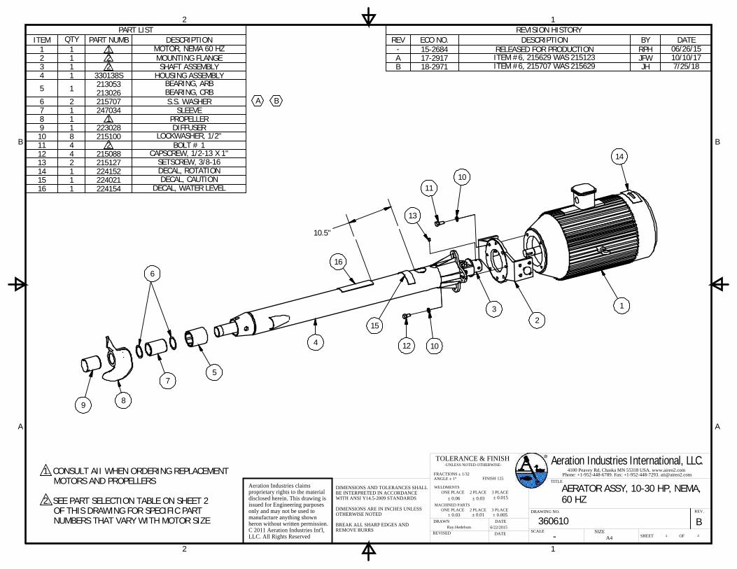
1
1
2
2
A A
B B
SCALE
DATE
DATEREVISED
DRAWN
Aeration Industries claimsproprietary rights to the materialdisclosed herein. This drawing isissued for Engineering purposesonly and may not be used tomanufacture anything shownheron without written permission.C 2011 Aeration Industries Int'l,LLC. All Rights Reserved
TITLE
DRAWING NO.
4100 Peavey Rd, Chaska MN 55318 USA. www.aireo2.comPhone: +1-952-448-6789. Fax: +1-952-448-7293. [email protected]
Aeration Industries International, LLC.
SHEET OF
REV.
SIZE-6/22/2015Ray.Hedelson
AERATOR ASSY, 10-30 HP, NEMA,60 HZ
360610A4 1
B2
± 0.015± 0.03
ANGLE ± 1°
-UNLESS NOTED OTHERWISE-
ONE PLACE 2 PLACE 3 PLACE
TOLERANCE & FINISH
FRACTIONS ± 1/32
WELDMENTS
± 0.06MACHINED PARTS
ONE PLACE 2 PLACE 3 PLACE± 0.03 ± 0.01 ± 0.005
FINISH 125
DIMENSIONS AND TOLERANCES SHALLBE INTERPRETED IN ACCORDANCEWITH ANSI Y14.5-2009 STANDARDS
DIMENSIONS ARE IN INCHES UNLESSOTHERWISE NOTED
BREAK ALL SHARP EDGES ANDREMOVE BURRS
REVISION HISTORYREV ECO NO. DESCRIPTION BY DATE
- 15-2684 RELEASED FOR PRODUCTION RPH 06/26/15A 17-2917 ITEM #6, 215629 WAS 215123 JFW 10/10/17B 18-2971 ITEM #6, 215707 WAS 215629 JH 7/25/18
1. CONSULT AII WHEN ORDERING REPLACEMENTMOTORS AND PROPELLERS
2. SEE PART SELECTION TABLE ON SHEET 2OF THIS DRAWING FOR SPECIFIC PARTNUMBERS THAT VARY WITH MOTOR SIZE
PART LISTITEM QTY PART NUMB DESCRIPTION
1 1 1 MOTOR, NEMA 60 HZ2 1 2 MOUNTING FLANGE3 1 2 SHAFT ASSEMBLY4 1 330138S HOUSING ASSEMBLY5 1 213053
213026BEARING, ARBBEARING, CRB
6 2 215707 S.S. WASHER7 1 247034 SLEEVE8 1 1 PROPELLER9 1 223028 DIFFUSER10 8 215100 LOCKWASHER, 1/2"11 4 2 BOLT # 112 4 215088 CAPSCREW, 1/2-13 X 1"13 2 215127 SETSCREW, 3/8-1614 1 224152 DECAL, ROTATION15 1 224021 DECAL, CAUTION16 1 224154 DECAL, WATER LEVEL
1
23
5
6
7
89
10
10
11
12
13
14
15
16
4
10.5"
A B
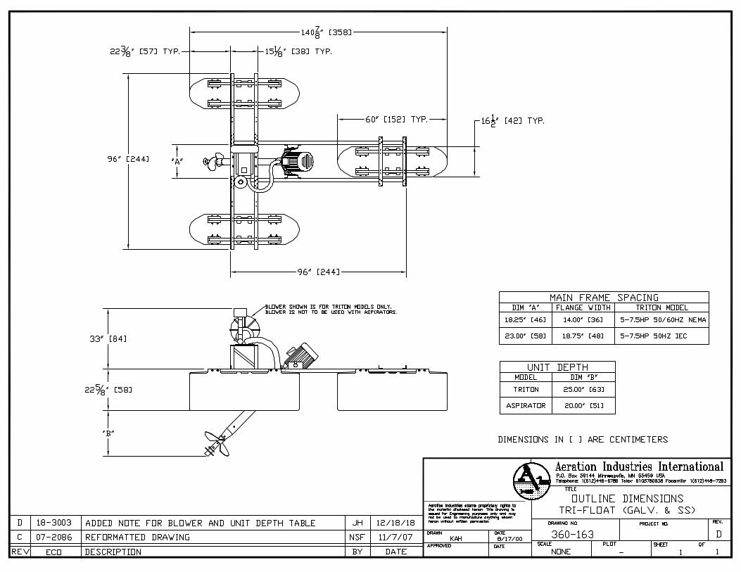
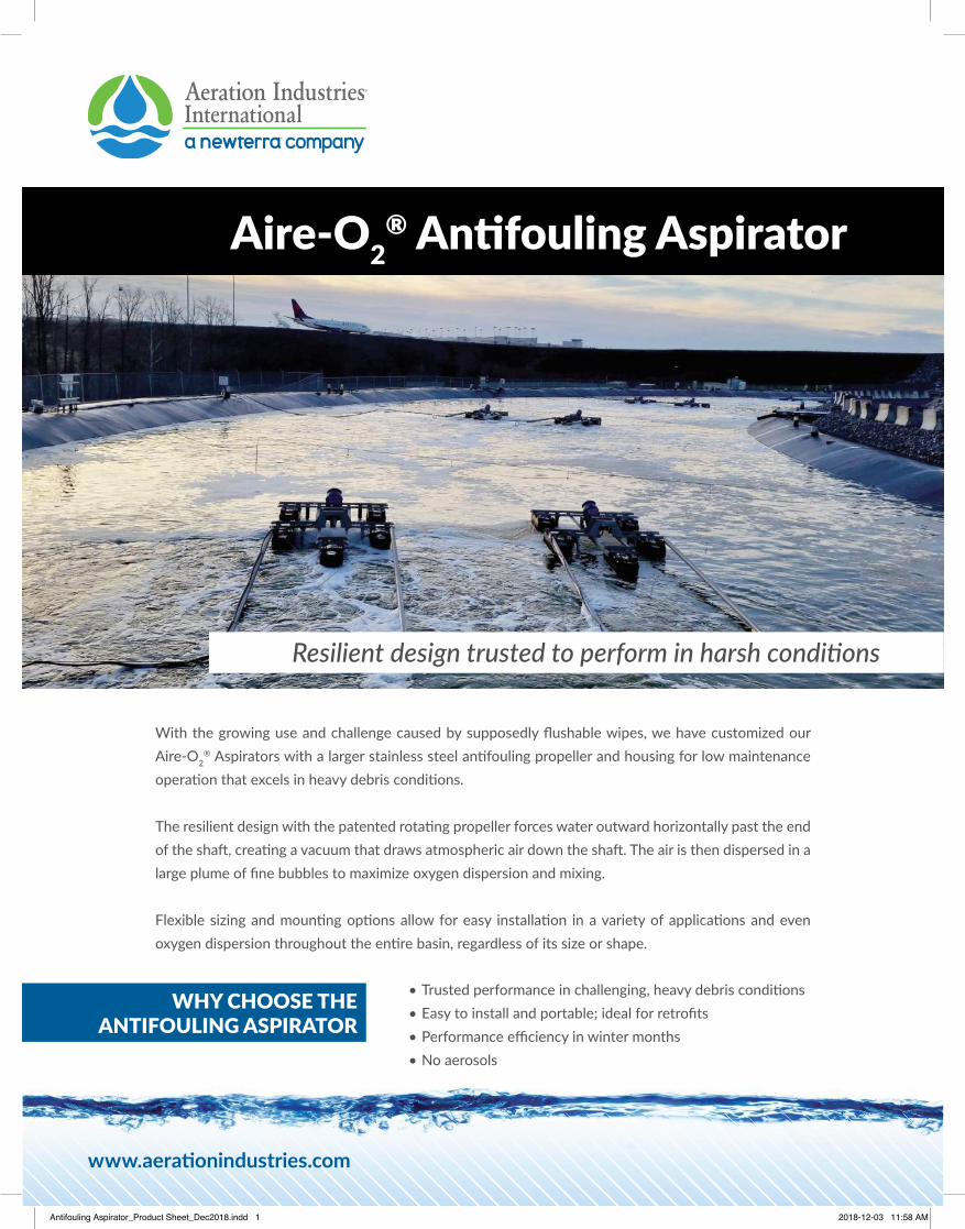
www.aerati onindustries.com
Aire-O2®
• • • • No aerosols
WHY CHOOSE THE ANTIFOULING ASPIRATOR
Antifouling Aspirator_Product Sheet_Dec2018.indd 1 2018-12-03 11:58 AM
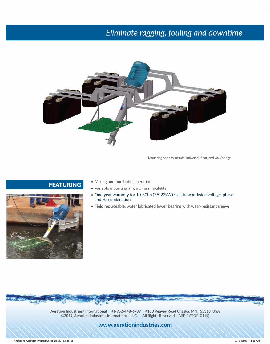
• • • Three-year warranty for 10-30hp (7.5-22kW) sizes in worldwide voltage, phase • Field replaceable, water lubricated lower bearing with wear-resistant sleeve
FEATURING
Aerati on Industries® Internati onal | +1-952-448-6789 | 4100 Peavey Road Chaska, MN, 55318 USA©2019, Aerati on Industries Internati onal, LLC. | All Rights Reserved. (ASPIRATOR-0119)
www.aerati onindustries.com
One-year warranty for 10-30hp (7.5-22kW) sizes in worldwide voltage, phase and Hz combinati ons
Antifouling Aspirator_Product Sheet_Dec2018.indd 2 2018-12-03 11:58 AM
AERATION INDUSTRIES INTERNATIONAL, LLC
General Terms and Conditions
1. Price. Published prices are subject to change without notice and shall not be binding on Seller until reduced to writing signed by Seller. All prices are F.O.B. Chaska, MN, and do not include transportation cost or charges relating to transportation, which costs and charges shall be solely the responsibility of Purchaser. Prices quoted include standard packing according to Seller’s specifications. Special packing requested by Purchaser, including packing for exports, shall be paid by the Purchaser as an additional charge.
2. Taxes. To the extent legally permissible, all present and future taxes, imposed by any Federal, State, Local or foreign authority, which Seller may be required to pay or collect upon or with reference to the sale, purchase, transportation, delivery, storage, use or consumption of goods or services, including taxes upon, or measured by the receipts therefrom, shall be paid by Purchaser. Amounts covered hereby shall be added to the price, or billed as a separate item as the law may require or as the Seller may determine. No offset against or reduction in price shall be allowed Purchaser by reason of taxes owed, paid or payable by Purchaser, or charged by Purchaser’s account.
3. Credit and Payment. Credit accounts will be opened only with firms or individuals approved by Seller’s Credit Department. Unless otherwise provided, in any case where delivery is made on credit, Purchaser shall have thirty (30) days from date of the invoice in which to make payment for the goods. Seller reserves the right at any time upon notice to Purchaser, to alter or suspend credit, or to change the credit terms provided herein, when in its sole opinion the financial condition of the Purchaser so warrants. In addition, the Seller may at any time, with or without notice to Purchaser, and at its option, suspend work and shipment under this contract if, in the Seller’s sole opinion, the financial condition of the Purchaser so warrants. In such cases, in addition to any other remedies herein, or by law provided, cash payment or satisfactory security from the Purchaser may be required by the Seller before credit is restored or Seller continues performance. If the Purchaser fails to make payment or fails to furnish security satisfactory to Seller, then Seller shall also have the right to enforce payment of the full contract price of the work completed and in process. Upon default by Purchaser in payment when due, Purchaser shall pay immediately to Seller the entire unpaid amounts for any and all shipments made to purchaser irrespective of the terms of said shipment and whether said shipments are made pursuant to this contract or any other contract of sale between Seller and Purchased, and Seller may withhold all subsequent shipments until the full account is settled. Acceptance by the Seller of less than full payment shall not be a waiver of any or its rights hereunder. The seller reserves the right, at its discretion, to charge up to 1½% per month for amounts not paid within stated terms.
4. Cancellation. Cancellation of orders once placed with and accepted by us can only be made by us. Should the Purchaser, due to change in design or other good and sufficient cause, desire to effect cancellation of the order, same will be accepted on the following basis:
Purchaser shall pay in full the costs of all material, dies, tools, patterns and fixtures provided for this order, that are on hand or for which we are obligated, together with all labor and other expense incurred in connection therewith. Invoices covering said costs shall be due and payable immediately upon our acceptance of cancellation.
5. Patents. To the best of our knowledge, the articles purchased hereunder do not infringe any Letters Patent granted to others by the United States of America or by any country foreign thereto. We do not assume any responsibility or liability for any claim of infringement brought against the Purchaser, its successors, assigns, customers or udders of its product. The Purchaser agrees to hold us harmless against any claim of infringement which arises out of compliance by us with specifications furnished by Purchaser.
6. Risk of Loss, Title. The risk of loss of the goods shall pass to the Purchaser as soon as they are deposited with the carrier for shipment to the Purchaser, but title to the goods shall remain in the seller until the purchase price therefore has been paid.
7. Shipment. All shipments shall be F.O.B. Chaska, MN, and the date of shipment shall be contingent upon the date of acceptance of Seller’s offer. Seller’s obligation with respect to shipments of the goods shall not extend beyond a) putting the goods in the possession of such a carrier and making such a contract for the transportation thereof as may be reasonable having regard to the nature of the good; b) obtaining and delivering within a reasonable time such documents as may be necessary for Purchaser to obtain possession of goods; and c) notifying the Purchaser of the shipment within a reasonable time. Seller shall have the right to ship all of the goods at one time or in portions from time to time within the time of shipment. This contract shall be deemed separable as to the goods sold. Purchaser may not refuse to accept any lot or portion of the goods shipped hereunder on the grounds that there has been a failure to ship any other lot or that goods in any other lot were nonconforming. Any such default by Seller will not substantially impair the value of this contract as a whole and will not constitute a breach of the contract as a whole. The goods shall be deemed to have been tendered to Purchaser when they have been deposited with the carrier.
8. Inspection and Acceptance. Purchaser shall have the right to inspect the goods upon receipt of them and shall have the opportunity, at that time, to run adequate tests to determine whether the goods shipped conform to the specification of this contract.
Purchaser shall recompense Seller, at the contract price, for all goods used in testing and Purchaser shall bear any expense incurred in the inspection of the goods used in testing, whether or not the goods are non‐conforming. Failure to inspect the goods or failure to notify the Seller in writing that the goods are nonconforming with ten (10) days of the receipt of the goods by Purchaser, shall constitute a waiver of Purchaser’s rights of inspection and rejection for nonconformity and shall be equivalent to an irrevocable acceptance of the goods by Purchaser. Acceptance – Unless we receive notification to the contrary promptly from you, we will consider the foregoing conditions as been acceptable to you.
9. Excuse in Seller’s Performance. This contract is subject to an the Seller shall not be responsible or liable for any delay directly or indirectly resulting from or contributed limitations on Seller’s production, capabilities, prompt settlement of all details relating to the materials covered by this proposal, and to delays due to fires, explosions, acts of God, strikes or other differences with workmen, shortage of utility, facility, components or labor, delay in transportation, breakdown or accident, war and acts of war, compliance with or other action taken to carry out the intent of purposes of any law or regulation, changes, or revisions, accidents or any other causes or contingencies not caused by Seller or other which Seller had no reasonable control. In the event that any one or more deliveries hereunder is suspended or delayed by reason of any one or more of the occurrences or contingencies aforesaid, any and all deliveries so suspended or delayed shall be made after such disabilities have ceased to exist, and nothing herein contained shall be construed as lessening in any event the full amount of goods herein purchased and sold, but only as deferring delivery and payment in the events and to the extent herein provided for. Neither shall any delay in shipment be considered as a default under this contract or give rise to any liability on the part of Seller for items of incidental, special consequential damage unless such delay was directly and proximately caused by the willful and wanton act of gross negligence of Seller. Acceptance of material on delivery shall constitute a waiver of any claims against seller for damages on accounts of delay.
10. Warranty. Seller warrants that it will, at its option, repair or replace the goods, or return the purchase price thereof, which are found to be defective in material or workmanship or not in conformity with the contract requirements provided that, within three (3) year of shipment thereof, Purchaser gives written notice of such defect to Seller, the Purchaser returns the goods to Seller at point of original manufacture, with transportation charges prepaid by Purchaser, and an examination by Seller discloses to its satisfaction the existence of such defect or nonconformity with the contract requirements. In no event shall Seller be liable for any incidentals, special or consequential damages resulting from said effects or nonconformity. This warranty specifically excludes all labor charges that could be incurred.
THE FOREGOING DOES NOT APPLY TO COMPONENTS WHERE WERE NOT MANUFACTURED BY SELLER, AND IS EXPRESSLY IN LIEU
OF OTHER WARRANTIES EXPRESSED OR IMPLIED, INCLUDING ANY WARRANTY OF MERCHANTABILITY OR OF FITNESS FOR A PARTICULAR PURPOSE OR USE. THERE ARE NO WARRANTIES WHICH EXTEND BEYOND THE FOREGOING, NO AGENT, EMPLOYEE OR REPRESENTATIVE OF THE SELLER HAS ANY AUTHORITY TO BIND THE SELLER TO ANY AFFIRMATION, REPRESENTATION OR WARRANTY CONCERNING THE GOODS SOLD UNDER THIS SALES CONTRACT, AND UNLESS AN AFFIRMATION, REPRESENTATION OR WARRANTY MADE BY AN AGENT EMPLOYEE OR REPRESENTATIVE IS SPECIFICALLY INCLUDED WITHIN THIS WRITTEN AGREEMENT, IT SHALL NOT BE ENFORCEABLE TY THE PURCHASER.
11. Remedies of Purchaser. If goods are tendered which do not conform with the specifications under the sales contract and these goods are rejected by Purchaser, Seller shall have the right to cure the tender by either correcting the goods or substituting conforming goods. In the event that such substituted goods fail to conform to the contract or in the event of any other breach or repudiation of this contract by Seller, Purchaser shall not be entitled to recover any incidental or consequential damages as those terms are defined in Section 2‐715 of the Minnesota Uniform Commercial Code and Purchaser’s right to damages shall be limited to the difference between the contract and the market price of the goods as provided in Section 2‐713 of the Minnesota Uniform Commercial Code. Purchaser shall not have the right to “cover” as provided in Section 2‐712 of the Minnesota Uniform commercial code nor any rights to recover damages for any loss resulting in the ordinary course of events from nonconformity of tender as contained in Section 2‐714(1) of the Minnesota Uniform Commercial Code.
12. Assignments. No right to interest in this contract shall be assigned by Purchaser, without the written permission of Seller, and no delegation of any obligation owned by Purchaser shall be made without permission of the Seller. Any attempted assignment of delegation shall be wholly void and totally ineffective for all purposed.
13. Alterations, Interpretations and Definitions. This contract shall be governed by the laws of Minnesota and is intended also as a complete and exclusive statement of the terms of their agreement. No course of prior dealings between the parties, and no usage of the trade shall be relevant to supplement or explain any term used in this contract. Acceptance or acquiescence to a course of performance rendered under this contract shall not be relevant to determine the meaning of this contract, even though the accepting or acquiescing party has knowledge of the nature of the performance and an opportunity for objection. Waiver by Seller of a breach by Purchaser of any provision of this contract shall not be deemed a waiver of future compliance therewith, and such provision shall remain in full force and effect. Any term used in this contract which is not defined herein shall have the same definition as that contained in the Minnesota Uniform Commercial Code.
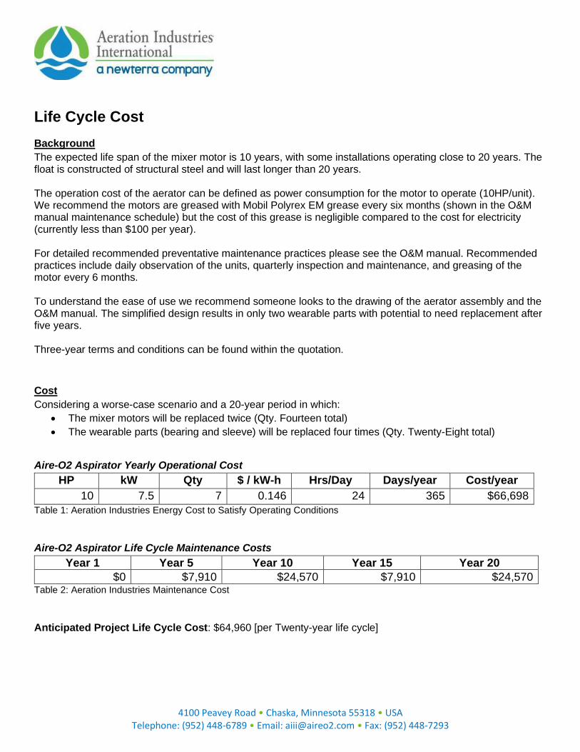
4100 Peavey Road • Chaska, Minnesota 55318 • USA
Telephone: (952) 448-6789 • Email: [email protected] • Fax: (952) 448-7293
Life Cycle Cost Background
The expected life span of the mixer motor is 10 years, with some installations operating close to 20 years. The float is constructed of structural steel and will last longer than 20 years. The operation cost of the aerator can be defined as power consumption for the motor to operate (10HP/unit). We recommend the motors are greased with Mobil Polyrex EM grease every six months (shown in the O&M manual maintenance schedule) but the cost of this grease is negligible compared to the cost for electricity (currently less than $100 per year). For detailed recommended preventative maintenance practices please see the O&M manual. Recommended practices include daily observation of the units, quarterly inspection and maintenance, and greasing of the motor every 6 months. To understand the ease of use we recommend someone looks to the drawing of the aerator assembly and the O&M manual. The simplified design results in only two wearable parts with potential to need replacement after five years. Three-year terms and conditions can be found within the quotation.
Cost
Considering a worse-case scenario and a 20-year period in which:
• The mixer motors will be replaced twice (Qty. Fourteen total)
• The wearable parts (bearing and sleeve) will be replaced four times (Qty. Twenty-Eight total)
Aire-O2 Aspirator Yearly Operational Cost
HP kW Qty $ / kW-h Hrs/Day Days/year Cost/year
10 7.5 7 0.146 24 365 $66,698
Table 1: Aeration Industries Energy Cost to Satisfy Operating Conditions
Aire-O2 Aspirator Life Cycle Maintenance Costs
Year 1 Year 5 Year 10 Year 15 Year 20
$0 $7,910 $24,570 $7,910 $24,570 Table 2: Aeration Industries Maintenance Cost
Anticipated Project Life Cycle Cost: $64,960 [per Twenty-year life cycle]
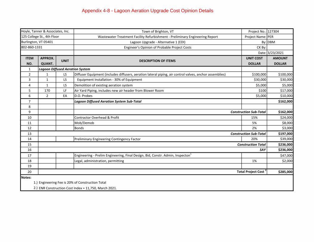
Town of Brighton, VT Project No.: 127304
Wastewater Treatment Facility Refurbishment - Preliminary Engineering Report Project Name: PER
Lagoon Upgrade - Alternative 1 (EDI) By: DBM
Engineer's Opinion of Probable Project Costs CK By:
Date: 3/23/2021
ITEM APPROX. UNIT COST AMOUNT
NO. QUANT. DOLLAR DOLLAR
1 Lagoon Diffused Aeration System
2 1 LS Diffuser Equipment (includes diffusers, aeration lateral piping, air control valves, anchor assemblies) $100,000 $100,000
3 1 LS Equipment Installation - 30% of Equipment $30,000 $30,000
4 1 LS Demolition of existing aeration system $5,000 $5,000
5 170 LF Air Yard Piping, includes new air header from Blower Room $100 $17,000
6 2 EA D.O. Probes $5,000 $10,000
7 Lagoon Diffused Aeration System Sub-Total $162,000
8
9 $162,000
10 Contractor Overhead & Profit 15% $24,000
11 Mob/Demob 5% $8,000
12 Bonds 2% $3,000
13 $197,000
14 Preliminary Engineering Contingency Factor 20% $39,000
15 $236,000
16 SAY $236,000
17 Engineering - Prelim Engineering, Final Design, Bid, Constr. Admin, Inspecton1
$47,000
18 Legal, administration, permitting 1% $2,000
19
20 $285,000
Notes:
1.)
2.) ENR Construction Cost Index = 11,750, March 2021.
Total Project Cost 2
Engineering Fee is 20% of Construction Total
DESCRIPTION OF ITEMS
Construction Sub-Total
Hoyle, Tanner & Associates, Inc.
125 College St., 4th Floor
Burlington, VT 05401
802-860-1331
UNIT
Construction Sub-Total
Construction Total
Appendix 4-8 - Lagoon Aeration Upgrade Cost Opinion Details
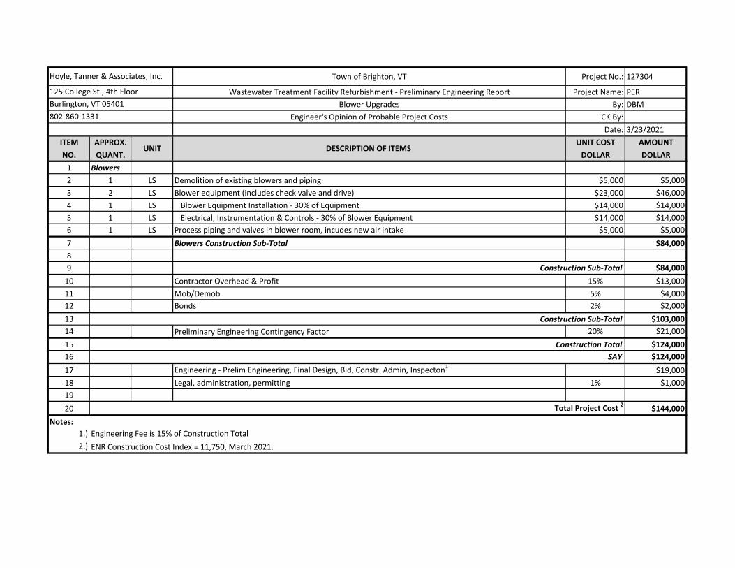
Town of Brighton, VT Project No.: 127304
Wastewater Treatment Facility Refurbishment - Preliminary Engineering Report Project Name: PER
Blower Upgrades By: DBM
Engineer's Opinion of Probable Project Costs CK By:
Date: 3/23/2021
ITEM APPROX. UNIT COST AMOUNT
NO. QUANT. DOLLAR DOLLAR
1 Blowers
2 1 LS Demolition of existing blowers and piping $5,000 $5,000
3 2 LS Blower equipment (includes check valve and drive) $23,000 $46,000
4 1 LS Blower Equipment Installation - 30% of Equipment $14,000 $14,000
5 1 LS Electrical, Instrumentation & Controls - 30% of Blower Equipment $14,000 $14,000
6 1 LS Process piping and valves in blower room, incudes new air intake $5,000 $5,000
7 Blowers Construction Sub-Total $84,000
8
9 $84,000
10 Contractor Overhead & Profit 15% $13,000
11 Mob/Demob 5% $4,000
12 Bonds 2% $2,000
13 $103,000
14 Preliminary Engineering Contingency Factor 20% $21,000
15 $124,000
16 SAY $124,000
17 Engineering - Prelim Engineering, Final Design, Bid, Constr. Admin, Inspecton1
$19,000
18 Legal, administration, permitting 1% $1,000
19
20 $144,000
Notes:
1.)
2.) ENR Construction Cost Index = 11,750, March 2021.
Engineering Fee is 15% of Construction Total
Hoyle, Tanner & Associates, Inc.
125 College St., 4th Floor
Burlington, VT 05401
802-860-1331
UNIT DESCRIPTION OF ITEMS
Construction Sub-Total
Construction Sub-Total
Construction Total
Total Project Cost 2
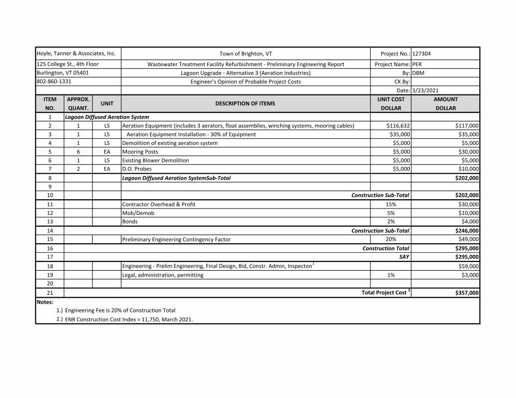
Town of Brighton, VT Project No.: 127304
Wastewater Treatment Facility Refurbishment - Preliminary Engineering Report Project Name: PER
Lagoon Upgrade - Alternative 3 (Aeration Industries) By: DBM
Engineer's Opinion of Probable Project Costs CK By:
Date: 3/23/2021
ITEM APPROX. UNIT COST AMOUNT
NO. QUANT. DOLLAR DOLLAR
1 Lagoon Diffused Aeration System
2 1 LS Aeration Equipment (includes 3 aerators, float assemblies, winching systems, mooring cables) $116,632 $117,000
3 1 LS Aeration Equipment Installation - 30% of Equipment $35,000 $35,000
4 1 LS Demolition of existing aeration system $5,000 $5,000
5 6 EA Mooring Posts $5,000 $30,000
6 1 LS Existing Blower Demolition $5,000 $5,000
7 2 EA D.O. Probes $5,000 $10,000
8 Lagoon Diffused Aeration SystemSub-Total $202,000
9
10 $202,000
11 Contractor Overhead & Profit 15% $30,000
12 Mob/Demob 5% $10,000
13 Bonds 2% $4,000
14 $246,000
15 Preliminary Engineering Contingency Factor 20% $49,000
16 $295,000
17 SAY $295,000
18 Engineering - Prelim Engineering, Final Design, Bid, Constr. Admin, Inspecton1
$59,000
19 Legal, administration, permitting 1% $3,000
20
21 $357,000
Notes:
1.)
2.) ENR Construction Cost Index = 11,750, March 2021.
Engineering Fee is 20% of Construction Total
Hoyle, Tanner & Associates, Inc.
125 College St., 4th Floor
Burlington, VT 05401
802-860-1331
UNIT DESCRIPTION OF ITEMS
Construction Sub-Total
Construction Sub-Total
Construction Total
Total Project Cost 2
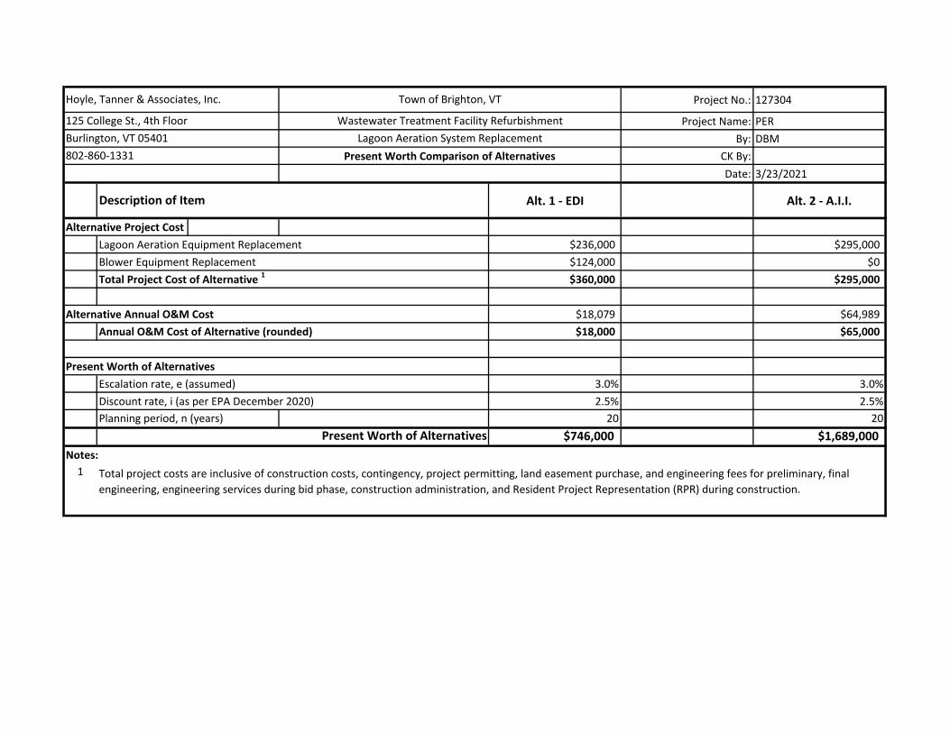
Project No.: 127304
Project Name: PER
By: DBM
CK By:
Date: 3/23/2021
Alt. 1 - EDI Alt. 2 - A.I.I.
Alternative Project Cost
Lagoon Aeration Equipment Replacement $236,000 $295,000
Blower Equipment Replacement $124,000 $0
$360,000 $295,000
$18,079 $64,989
$18,000 $65,000
Escalation rate, e (assumed) 3.0% 3.0%
Discount rate, i (as per EPA December 2020) 2.5% 2.5%
Planning period, n (years) 20 20
$746,000 $1,689,000
Notes:
1
Total Project Cost of Alternative 1
Description of Item
Town of Brighton, VTHoyle, Tanner & Associates, Inc.
125 College St., 4th Floor
Burlington, VT 05401
Wastewater Treatment Facility Refurbishment
Lagoon Aeration System Replacement
802-860-1331 Present Worth Comparison of Alternatives
Annual O&M Cost of Alternative (rounded)
Present Worth of Alternatives
Present Worth of Alternatives
Alternative Annual O&M Cost
Total project costs are inclusive of construction costs, contingency, project permitting, land easement purchase, and engineering fees for preliminary, final
engineering, engineering services during bid phase, construction administration, and Resident Project Representation (RPR) during construction.
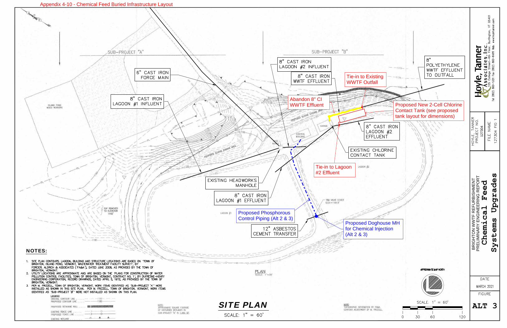
PREL
IMIN
ARY
ENG
INEE
RIN
G R
EPO
RT
BRIG
HTO
N W
WTF
REF
UR
BISH
MEN
T
1273
04
SIT
E P
LAN
1SITE PLAN
NOTES:
“”
“ ”
“”
“ ”
“ ”
Ch
em
ica
l Fe
ed
Sys
tem
s U
pgra
de
s
ALT 3
Proposed PhosphorousControl Piping (Alt 2 & 3)
Proposed Doghouse MHfor Chemical Injection (Alt 2 & 3)
Proposed New 2-Cell ChlorineContact Tank (see proposedtank layout for dimensions)
Tie-in to ExistingWWTF Outfall
Tie-in to Lagoon#2 Effluent
Abandon 8" CIWWTF Effluent
Appendix 4-10 - Chemical Feed Buried Infrastructure Layout
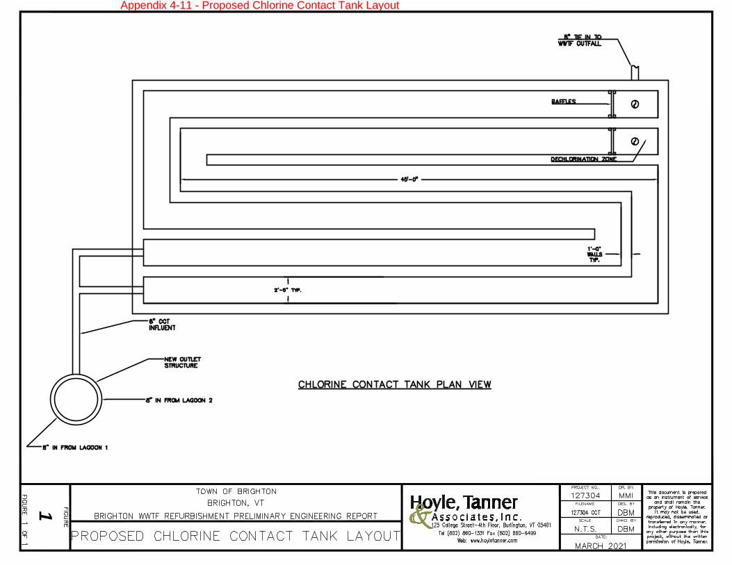
1
Appendix 4-11 - Proposed Chlorine Contact Tank Layout
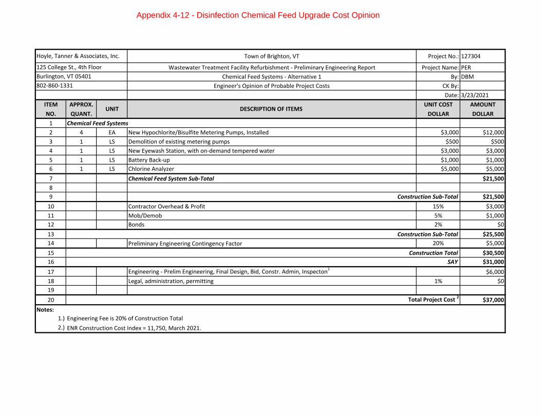
Town of Brighton, VT Project No.: 127304
Wastewater Treatment Facility Refurbishment - Preliminary Engineering Report Project Name: PER
Chemical Feed Systems - Alternative 1 By: DBM
Engineer's Opinion of Probable Project Costs CK By:
Date: 3/23/2021
ITEM APPROX. UNIT COST AMOUNT
NO. QUANT. DOLLAR DOLLAR
1 Chemical Feed Systems
2 4 EA New Hypochlorite/Bisulfite Metering Pumps, Installed $3,000 $12,000
3 1 LS Demolition of existing metering pumps $500 $500
4 1 LS New Eyewash Station, with on-demand tempered water $3,000 $3,000
5 1 LS Battery Back-up $1,000 $1,000
6 1 LS Chlorine Analyzer $5,000 $5,000
7 Chemical Feed System Sub-Total $21,500
8
9 $21,500
10 Contractor Overhead & Profit 15% $3,000
11 Mob/Demob 5% $1,000
12 Bonds 2% $0
13 $25,500
14 Preliminary Engineering Contingency Factor 20% $5,000
15 $30,500
16 SAY $31,000
17 Engineering - Prelim Engineering, Final Design, Bid, Constr. Admin, Inspecton1
$6,000
18 Legal, administration, permitting 1% $0
19
20 $37,000
Notes:
1.)
2.) ENR Construction Cost Index = 11,750, March 2021.
Hoyle, Tanner & Associates, Inc.
125 College St., 4th Floor
Burlington, VT 05401
802-860-1331
Construction Total
Total Project Cost 2
Engineering Fee is 20% of Construction Total
UNIT DESCRIPTION OF ITEMS
Construction Sub-Total
Construction Sub-Total
Appendix 4-12 - Disinfection Chemical Feed Upgrade Cost Opinion
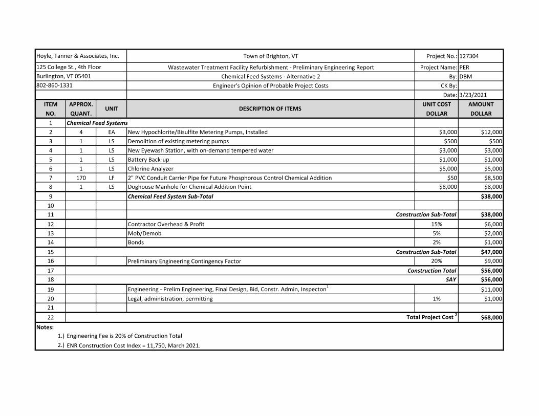
Town of Brighton, VT Project No.: 127304
Wastewater Treatment Facility Refurbishment - Preliminary Engineering Report Project Name: PER
Chemical Feed Systems - Alternative 2 By: DBM
Engineer's Opinion of Probable Project Costs CK By:
Date: 3/23/2021
ITEM APPROX. UNIT COST AMOUNT
NO. QUANT. DOLLAR DOLLAR
1 Chemical Feed Systems
2 4 EA New Hypochlorite/Bisulfite Metering Pumps, Installed $3,000 $12,000
3 1 LS Demolition of existing metering pumps $500 $500
4 1 LS New Eyewash Station, with on-demand tempered water $3,000 $3,000
5 1 LS Battery Back-up $1,000 $1,000
6 1 LS Chlorine Analyzer $5,000 $5,000
7 170 LF 2" PVC Conduit Carrier Pipe for Future Phosphorous Control Chemical Addition $50 $8,500
8 1 LS Doghouse Manhole for Chemical Addition Point $8,000 $8,000
9 Chemical Feed System Sub-Total $38,000
10
11 $38,000
12 Contractor Overhead & Profit 15% $6,000
13 Mob/Demob 5% $2,000
14 Bonds 2% $1,000
15 $47,000
16 Preliminary Engineering Contingency Factor 20% $9,000
17 $56,000
18 SAY $56,000
19 Engineering - Prelim Engineering, Final Design, Bid, Constr. Admin, Inspecton1
$11,000
20 Legal, administration, permitting 1% $1,000
21
22 $68,000
Notes:
1.)
2.) ENR Construction Cost Index = 11,750, March 2021.
Engineering Fee is 20% of Construction Total
Hoyle, Tanner & Associates, Inc.
125 College St., 4th Floor
Burlington, VT 05401
802-860-1331
UNIT DESCRIPTION OF ITEMS
Construction Sub-Total
Construction Sub-Total
Construction Total
Total Project Cost 2
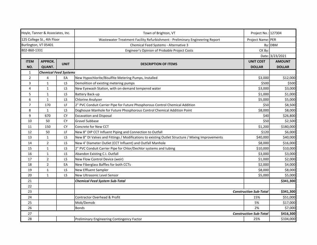
Town of Brighton, VT Project No.: 127304
Wastewater Treatment Facility Refurbishment - Preliminary Engineering Report Project Name: PER
Chemical Feed Systems - Alternative 3 By: DBM
Engineer's Opinion of Probable Project Costs CK By:
Date: 3/23/2021
ITEM APPROX. UNIT COST AMOUNT
NO. QUANT. DOLLAR DOLLAR
1 Chemical Feed Systems
2 4 EA New Hypochlorite/Bisulfite Metering Pumps, Installed $3,000 $12,000
3 1 LS Demolition of existing metering pumps $500 $500
4 1 LS New Eyewash Station, with on-demand tempered water $3,000 $3,000
5 1 LS Battery Back-up $1,000 $1,000
6 1 LS Chlorine Analyzer $5,000 $5,000
7 170 LF 2" PVC Conduit Carrier Pipe for Future Phosphorous Control Chemical Addition $50 $8,500
8 1 LS Doghouse Manhole for Future Phosphorous Control Chemical Addition Point $8,000 $8,000
9 670 CY Excavation and Disposal $40 $26,800
10 50 CY Gravel Subbase $50 $2,500
11 150 CY Concrete for New CCT $1,200 $180,000
12 50 LF New 8" DIP CCT Influent Piping and Connection to Outfall $120 $6,000
13 1 LS New 8" DI Valves and Fittings / Modifications to existing Outlet Structure / Mixing Improvements $40,000 $40,000
14 2 LS New 4' Diameter Outlet (CCT Influent) and Outfall Manhole $8,000 $16,000
15 1 LS 2" PVC Conduit Carrier Pipe for Chlor/Dechlor systems and tubing $10,000 $10,000
16 1 LS Abandon Existing C.I. Outfall $3,000 $3,000
17 2 LS New Flow Control Device (weir) $1,000 $2,000
18 2 EA New Fiberglass Baffles for both CCTs $2,000 $4,000
19 1 LS New Effluent Sampler $8,000 $8,000
20 1 LS New Ultrasonic Level Sensor $5,000 $5,000
21 Chemical Feed System Sub-Total $341,300
22
23 $341,300
24 Contractor Overhead & Profit 15% $51,000
25 Mob/Demob 5% $17,000
26 Bonds 2% $7,000
27 $416,300
28 Preliminary Engineering Contingency Factor 25% $104,000
Hoyle, Tanner & Associates, Inc.
125 College St., 4th Floor
Burlington, VT 05401
802-860-1331
UNIT DESCRIPTION OF ITEMS
Construction Sub-Total
Construction Sub-Total
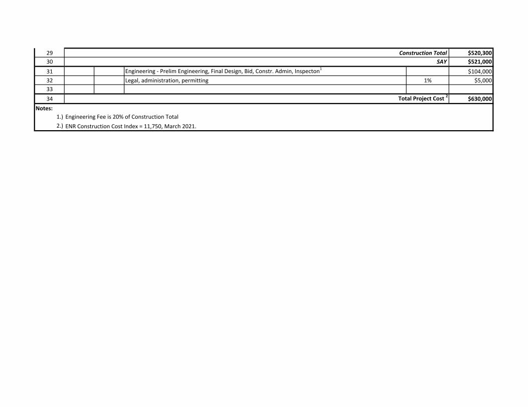
29 $520,300
30 SAY $521,000
31 Engineering - Prelim Engineering, Final Design, Bid, Constr. Admin, Inspecton1
$104,000
32 Legal, administration, permitting 1% $5,000
33
34 $630,000
Notes:
1.)
2.) ENR Construction Cost Index = 11,750, March 2021.
Engineering Fee is 20% of Construction Total
Construction Total
Total Project Cost 2
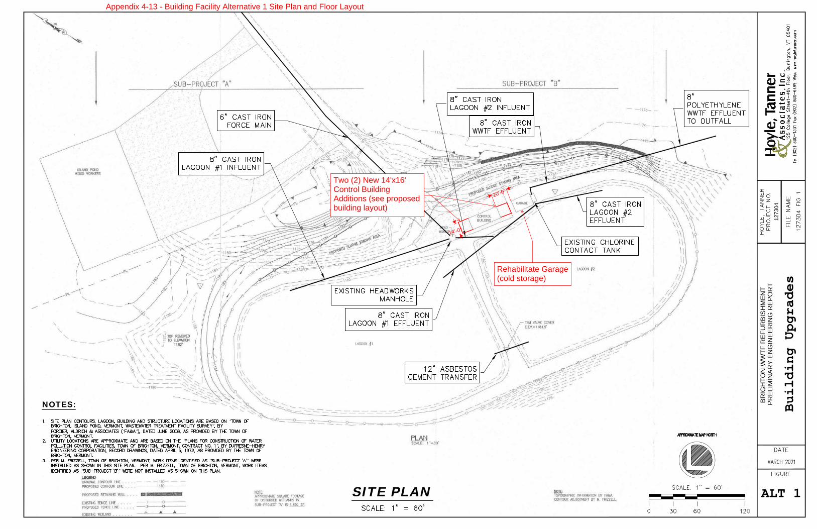
PREL
IMIN
ARY
ENG
INEE
RIN
G R
EPO
RT
BRIG
HTO
N W
WTF
REF
UR
BISH
MEN
T
1273
04
SIT
E P
LAN
1SITE PLAN
NOTES:
“”
“ ”
“”
“ ”
“ ”
Bu
ildin
g
Upg
rad
es
ALT 1
20'-0"
14'-0"
Two (2) New 14'x16'Control BuildingAdditions (see proposedbuilding layout)
Rehabilitate Garage(cold storage)
Appendix 4-13 - Building Facility Alternative 1 Site Plan and Floor Layout
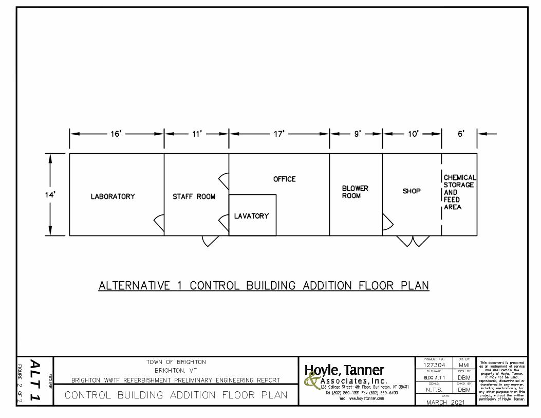
ALT
1
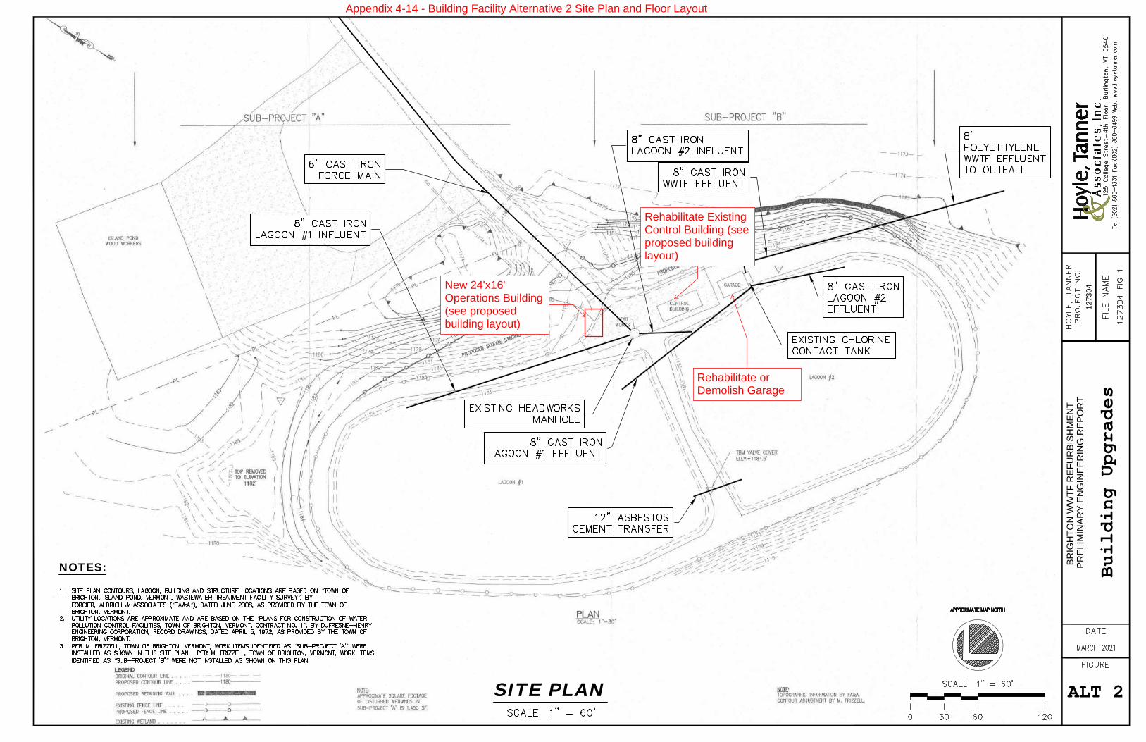
PREL
IMIN
ARY
ENG
INEE
RIN
G R
EPO
RT
BRIG
HTO
N W
WTF
REF
UR
BISH
MEN
T
1273
04
SIT
E P
LAN
1SITE PLAN
NOTES:
“”
“ ”
“”
“ ”
“ ”
Bu
ildin
g
Upg
rad
es
ALT 2
Rehabilitate orDemolish Garage
Rehabilitate ExistingControl Building (seeproposed buildinglayout)
New 24'x16'Operations Building(see proposedbuilding layout)
Appendix 4-14 - Building Facility Alternative 2 Site Plan and Floor Layout
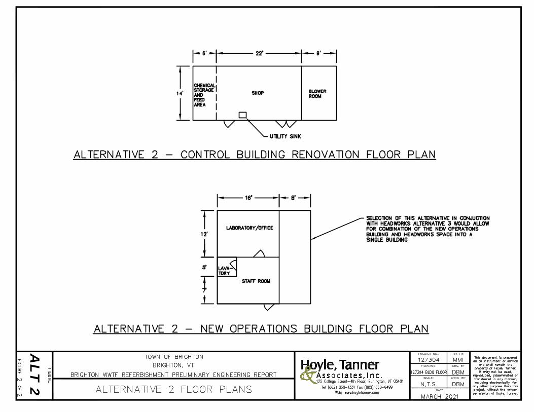
ALT
2
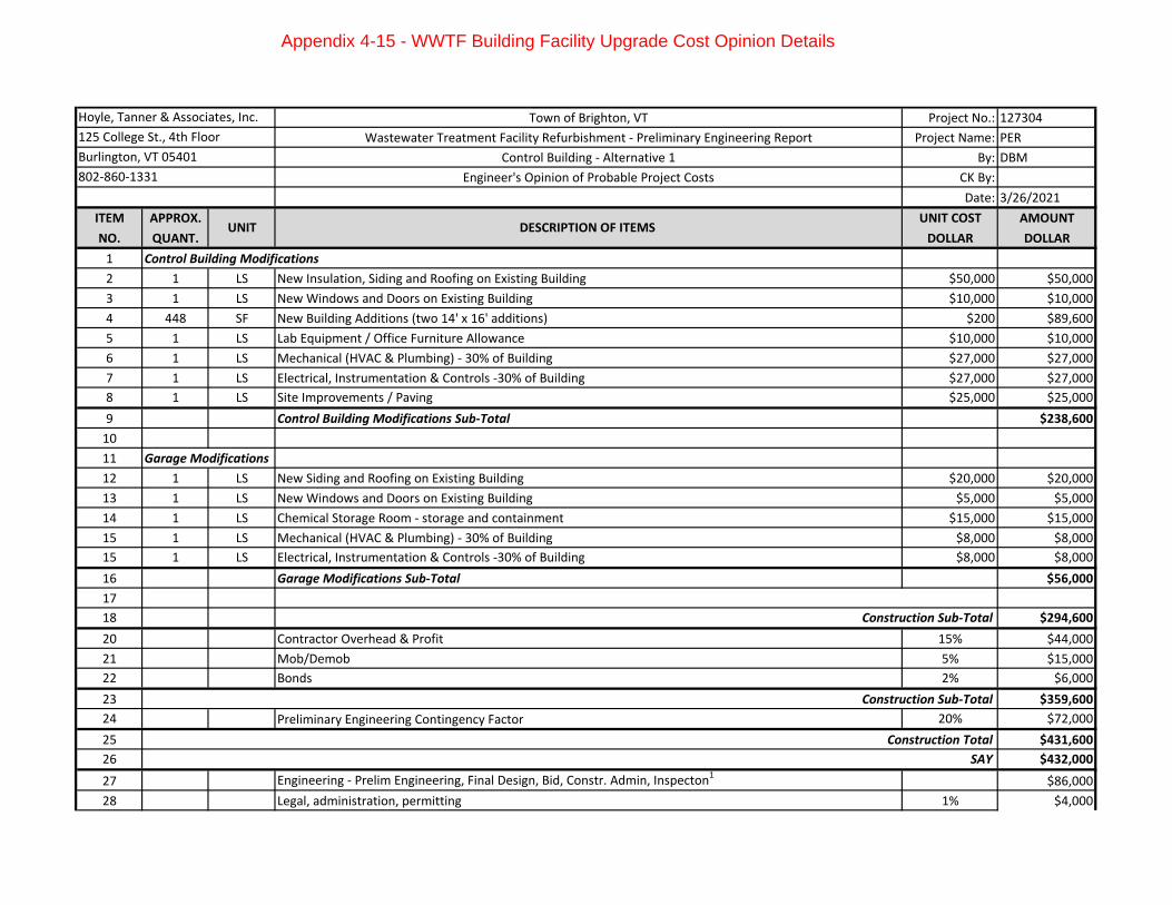
Town of Brighton, VT Project No.: 127304
Wastewater Treatment Facility Refurbishment - Preliminary Engineering Report Project Name: PER
Control Building - Alternative 1 By: DBM
Engineer's Opinion of Probable Project Costs CK By:
Date: 3/26/2021
ITEM APPROX. UNIT COST AMOUNT
NO. QUANT. DOLLAR DOLLAR
1 Control Building Modifications
2 1 LS New Insulation, Siding and Roofing on Existing Building $50,000 $50,000
3 1 LS New Windows and Doors on Existing Building $10,000 $10,000
4 448 SF New Building Additions (two 14' x 16' additions) $200 $89,600
5 1 LS Lab Equipment / Office Furniture Allowance $10,000 $10,000
6 1 LS Mechanical (HVAC & Plumbing) - 30% of Building $27,000 $27,000
7 1 LS Electrical, Instrumentation & Controls -30% of Building $27,000 $27,000
8 1 LS Site Improvements / Paving $25,000 $25,000
9 Control Building Modifications Sub-Total $238,600
10
11 Garage Modifications
12 1 LS New Siding and Roofing on Existing Building $20,000 $20,000
13 1 LS New Windows and Doors on Existing Building $5,000 $5,000
14 1 LS Chemical Storage Room - storage and containment $15,000 $15,000
15 1 LS Mechanical (HVAC & Plumbing) - 30% of Building $8,000 $8,000
15 1 LS Electrical, Instrumentation & Controls -30% of Building $8,000 $8,000
16 Garage Modifications Sub-Total $56,000
17
18 $294,600
20 Contractor Overhead & Profit 15% $44,000
21 Mob/Demob 5% $15,000
22 Bonds 2% $6,000
23 $359,600
24 Preliminary Engineering Contingency Factor 20% $72,000
25 $431,600
26 SAY $432,000
27 Engineering - Prelim Engineering, Final Design, Bid, Constr. Admin, Inspecton1
$86,000
28 Legal, administration, permitting 1% $4,000
Construction Total
Construction Sub-Total
Hoyle, Tanner & Associates, Inc.
125 College St., 4th Floor
Burlington, VT 05401
802-860-1331
UNIT DESCRIPTION OF ITEMS
Construction Sub-Total
Appendix 4-15 - WWTF Building Facility Upgrade Cost Opinion Details
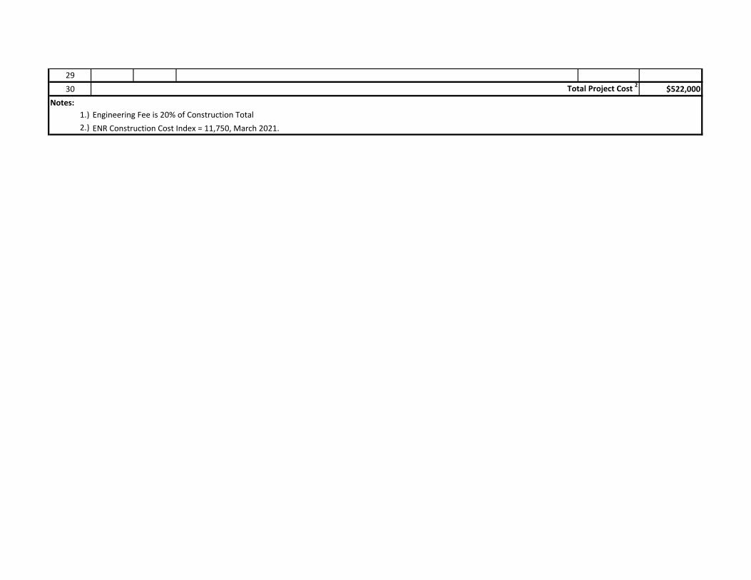
29
30 $522,000
Notes:
1.)
2.) ENR Construction Cost Index = 11,750, March 2021.
Total Project Cost 2
Engineering Fee is 20% of Construction Total
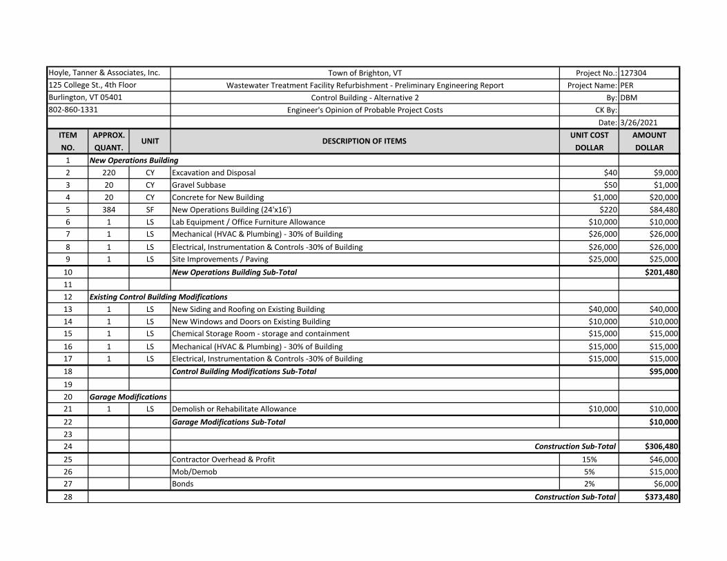
Town of Brighton, VT Project No.: 127304
Wastewater Treatment Facility Refurbishment - Preliminary Engineering Report Project Name: PER
Control Building - Alternative 2 By: DBM
Engineer's Opinion of Probable Project Costs CK By:
Date: 3/26/2021
ITEM APPROX. UNIT COST AMOUNT
NO. QUANT. DOLLAR DOLLAR
1 New Operations Building
2 220 CY Excavation and Disposal $40 $9,000
3 20 CY Gravel Subbase $50 $1,000
4 20 CY Concrete for New Building $1,000 $20,000
5 384 SF New Operations Building (24'x16') $220 $84,480
6 1 LS Lab Equipment / Office Furniture Allowance $10,000 $10,000
7 1 LS Mechanical (HVAC & Plumbing) - 30% of Building $26,000 $26,000
8 1 LS Electrical, Instrumentation & Controls -30% of Building $26,000 $26,000
9 1 LS Site Improvements / Paving $25,000 $25,000
10 New Operations Building Sub-Total $201,480
11
12 Existing Control Building Modifications
13 1 LS New Siding and Roofing on Existing Building $40,000 $40,000
14 1 LS New Windows and Doors on Existing Building $10,000 $10,000
15 1 LS Chemical Storage Room - storage and containment $15,000 $15,000
16 1 LS Mechanical (HVAC & Plumbing) - 30% of Building $15,000 $15,000
17 1 LS Electrical, Instrumentation & Controls -30% of Building $15,000 $15,000
18 Control Building Modifications Sub-Total $95,000
19
20 Garage Modifications
21 1 LS Demolish or Rehabilitate Allowance $10,000 $10,000
22 Garage Modifications Sub-Total $10,000
23
24 $306,480
25 Contractor Overhead & Profit 15% $46,000
26 Mob/Demob 5% $15,000
27 Bonds 2% $6,000
28 $373,480
Hoyle, Tanner & Associates, Inc.
125 College St., 4th Floor
Burlington, VT 05401
802-860-1331
UNIT DESCRIPTION OF ITEMS
Construction Sub-Total
Construction Sub-Total
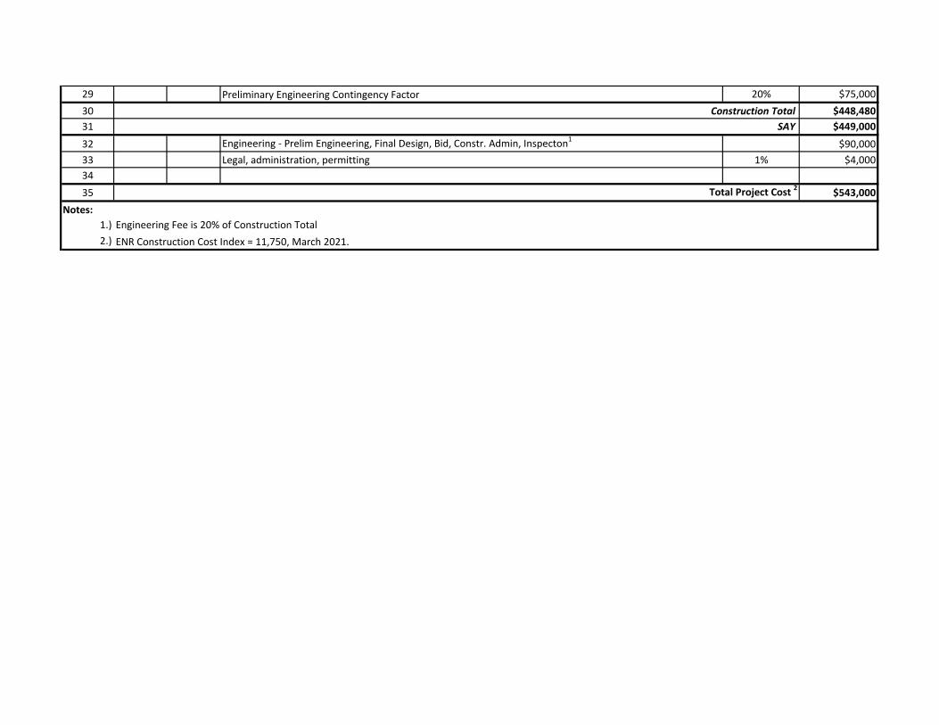
29 Preliminary Engineering Contingency Factor 20% $75,000
30 $448,480
31 SAY $449,000
32 Engineering - Prelim Engineering, Final Design, Bid, Constr. Admin, Inspecton1
$90,000
33 Legal, administration, permitting 1% $4,000
34
35 $543,000
Notes:
1.)
2.) ENR Construction Cost Index = 11,750, March 2021.
Engineering Fee is 20% of Construction Total
Construction Total
Total Project Cost 2
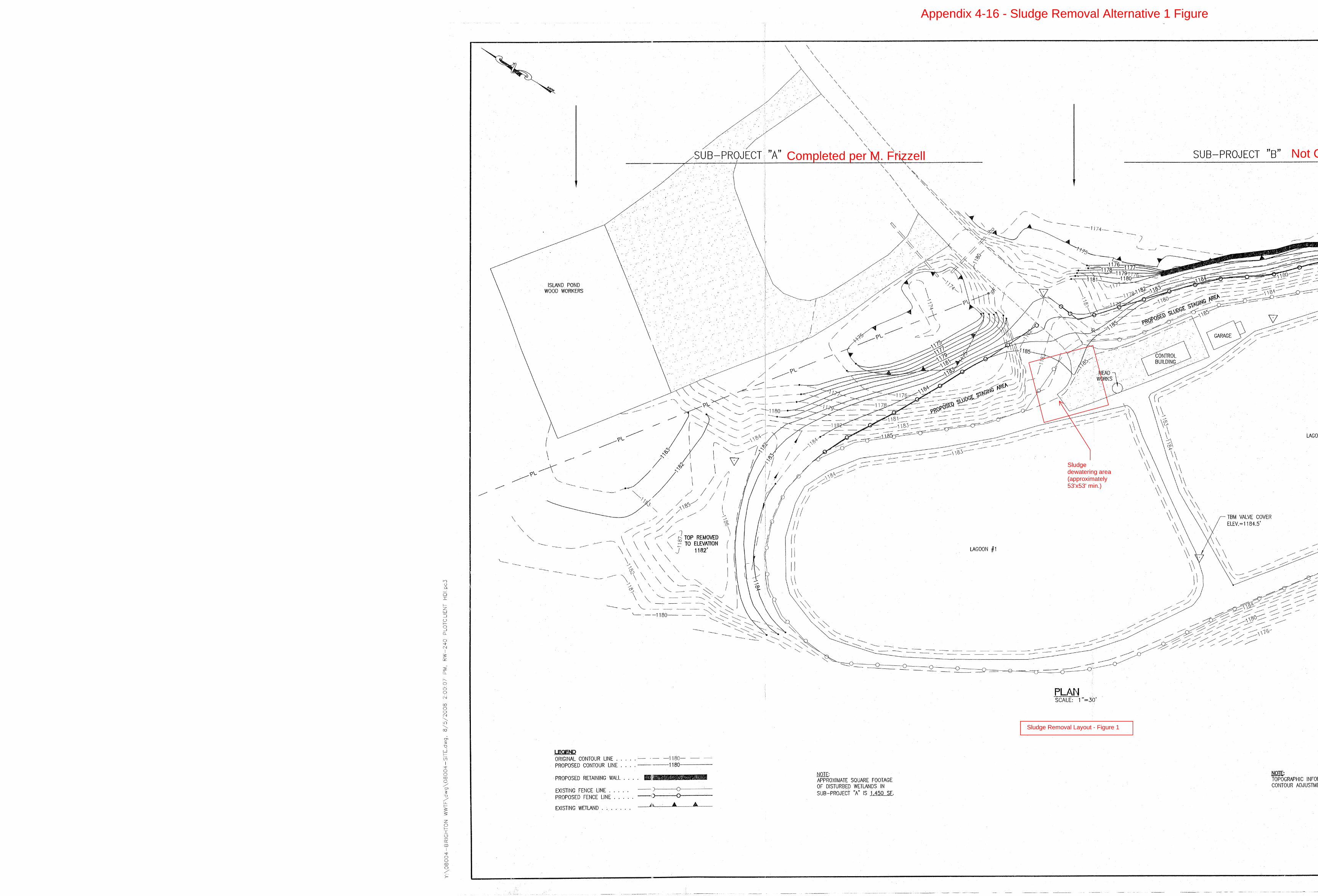
Completed per M. Frizzell Not Completed per M. Frizzell
Sludgedewatering area(approximately53'x53' min.)
Sludge Removal Layout - Figure 1
Appendix 4-16 - Sludge Removal Alternative 1 Figure
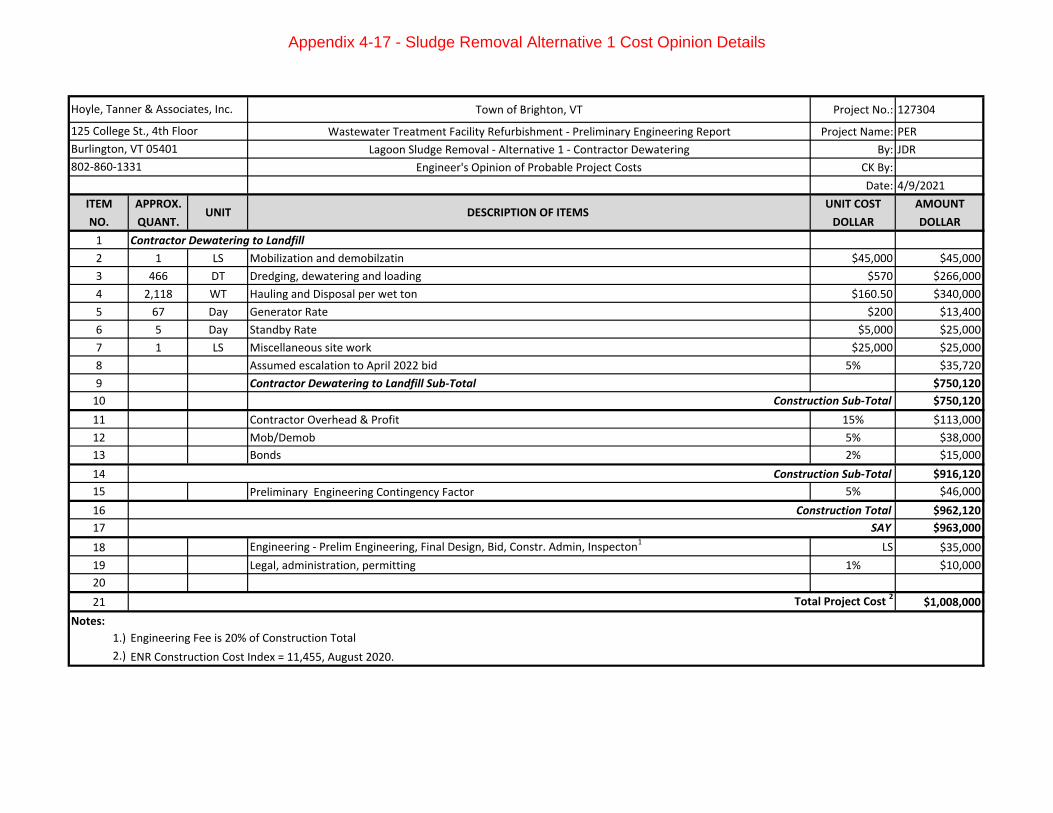
Town of Brighton, VT Project No.: 127304
Wastewater Treatment Facility Refurbishment - Preliminary Engineering Report Project Name: PER
Lagoon Sludge Removal - Alternative 1 - Contractor Dewatering By: JDR
Engineer's Opinion of Probable Project Costs CK By:
Date: 4/9/2021
ITEM APPROX. UNIT COST AMOUNT
NO. QUANT. DOLLAR DOLLAR
1 Contractor Dewatering to Landfill
2 1 LS Mobilization and demobilzatin $45,000 $45,000
3 466 DT Dredging, dewatering and loading $570 $266,000
4 2,118 WT Hauling and Disposal per wet ton $160.50 $340,000
5 67 Day Generator Rate $200 $13,400
6 5 Day Standby Rate $5,000 $25,000
7 1 LS Miscellaneous site work $25,000 $25,000
8 Assumed escalation to April 2022 bid 5% $35,720
9 Contractor Dewatering to Landfill Sub-Total $750,120
10 $750,120
11 Contractor Overhead & Profit 15% $113,000
12 Mob/Demob 5% $38,000
13 Bonds 2% $15,000
14 $916,120
15 Preliminary Engineering Contingency Factor 5% $46,000
16 $962,120
17 SAY $963,000
18 Engineering - Prelim Engineering, Final Design, Bid, Constr. Admin, Inspecton1
LS $35,000
19 Legal, administration, permitting 1% $10,000
20
21 $1,008,000
Notes:
1.)
2.) ENR Construction Cost Index = 11,455, August 2020.
Engineering Fee is 20% of Construction Total
Hoyle, Tanner & Associates, Inc.
125 College St., 4th Floor
Burlington, VT 05401
802-860-1331
UNIT DESCRIPTION OF ITEMS
Construction Sub-Total
Construction Sub-Total
Construction Total
Total Project Cost 2
Appendix 4-17 - Sludge Removal Alternative 1 Cost Opinion Details
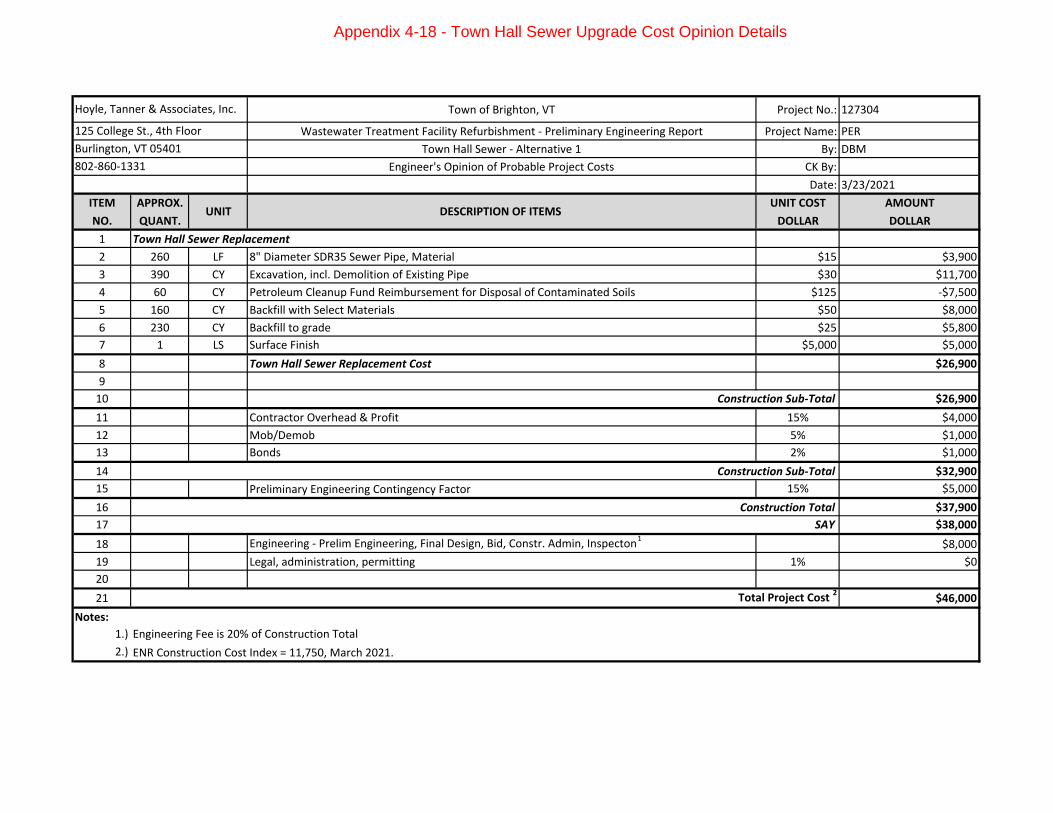
Town of Brighton, VT Project No.: 127304
Wastewater Treatment Facility Refurbishment - Preliminary Engineering Report Project Name: PER
Town Hall Sewer - Alternative 1 By: DBM
Engineer's Opinion of Probable Project Costs CK By:
Date: 3/23/2021
ITEM APPROX. UNIT COST AMOUNT
NO. QUANT. DOLLAR DOLLAR
1 Town Hall Sewer Replacement
2 260 LF 8" Diameter SDR35 Sewer Pipe, Material $15 $3,900
3 390 CY Excavation, incl. Demolition of Existing Pipe $30 $11,700
4 60 CY Petroleum Cleanup Fund Reimbursement for Disposal of Contaminated Soils $125 -$7,500
5 160 CY Backfill with Select Materials $50 $8,000
6 230 CY Backfill to grade $25 $5,800
7 1 LS Surface Finish $5,000 $5,000
8 Town Hall Sewer Replacement Cost $26,900
9
10 $26,900
11 Contractor Overhead & Profit 15% $4,000
12 Mob/Demob 5% $1,000
13 Bonds 2% $1,000
14 $32,900
15 Preliminary Engineering Contingency Factor 15% $5,000
16 $37,900
17 SAY $38,000
18 Engineering - Prelim Engineering, Final Design, Bid, Constr. Admin, Inspecton1
$8,000
19 Legal, administration, permitting 1% $0
20
21 $46,000
Notes:
1.)
2.) ENR Construction Cost Index = 11,750, March 2021.
Engineering Fee is 20% of Construction Total
Hoyle, Tanner & Associates, Inc.
125 College St., 4th Floor
Burlington, VT 05401
802-860-1331
UNIT DESCRIPTION OF ITEMS
Construction Sub-Total
Construction Sub-Total
Construction Total
Total Project Cost 2
Appendix 4-18 - Town Hall Sewer Upgrade Cost Opinion Details
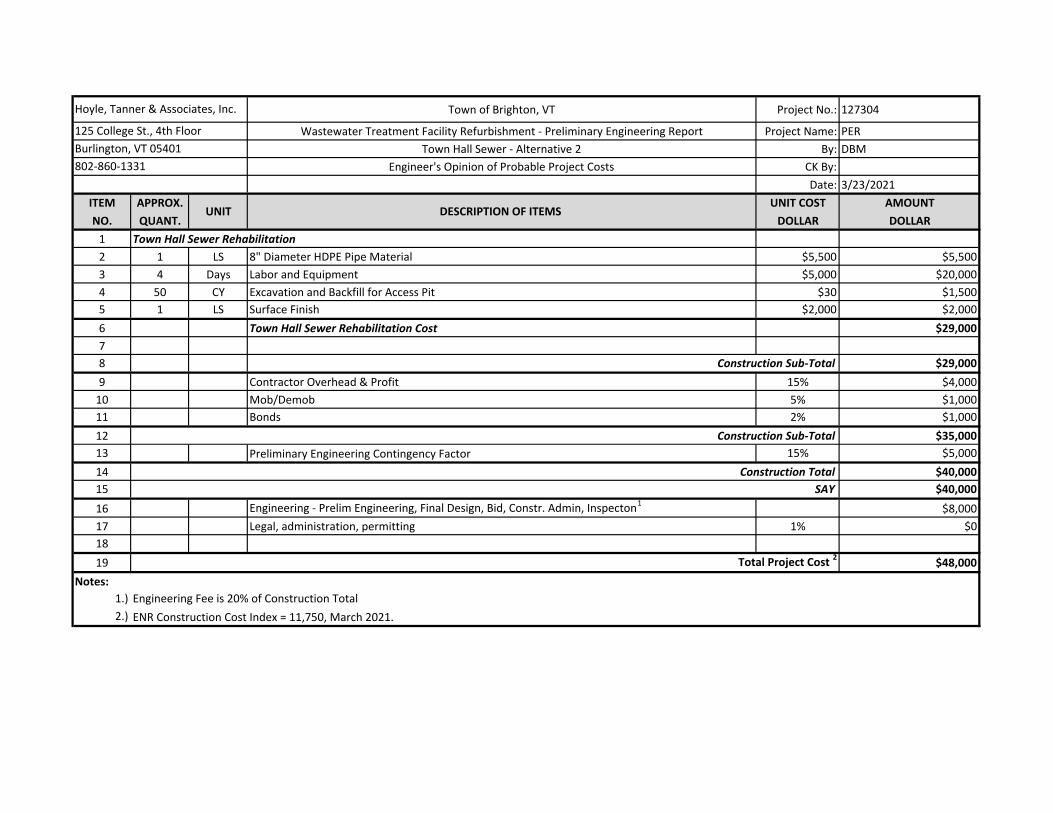
Town of Brighton, VT Project No.: 127304
Wastewater Treatment Facility Refurbishment - Preliminary Engineering Report Project Name: PER
Town Hall Sewer - Alternative 2 By: DBM
Engineer's Opinion of Probable Project Costs CK By:
Date: 3/23/2021
ITEM APPROX. UNIT COST AMOUNT
NO. QUANT. DOLLAR DOLLAR
1 Town Hall Sewer Rehabilitation
2 1 LS 8" Diameter HDPE Pipe Material $5,500 $5,500
3 4 Days Labor and Equipment $5,000 $20,000
4 50 CY Excavation and Backfill for Access Pit $30 $1,500
5 1 LS Surface Finish $2,000 $2,000
6 Town Hall Sewer Rehabilitation Cost $29,000
7
8 $29,000
9 Contractor Overhead & Profit 15% $4,000
10 Mob/Demob 5% $1,000
11 Bonds 2% $1,000
12 $35,000
13 Preliminary Engineering Contingency Factor 15% $5,000
14 $40,000
15 SAY $40,000
16 Engineering - Prelim Engineering, Final Design, Bid, Constr. Admin, Inspecton1
$8,000
17 Legal, administration, permitting 1% $0
18
19 $48,000
Notes:
1.)
2.) ENR Construction Cost Index = 11,750, March 2021.
Engineering Fee is 20% of Construction Total
Hoyle, Tanner & Associates, Inc.
125 College St., 4th Floor
Burlington, VT 05401
802-860-1331
UNIT DESCRIPTION OF ITEMS
Construction Sub-Total
Construction Sub-Total
Construction Total
Total Project Cost 2
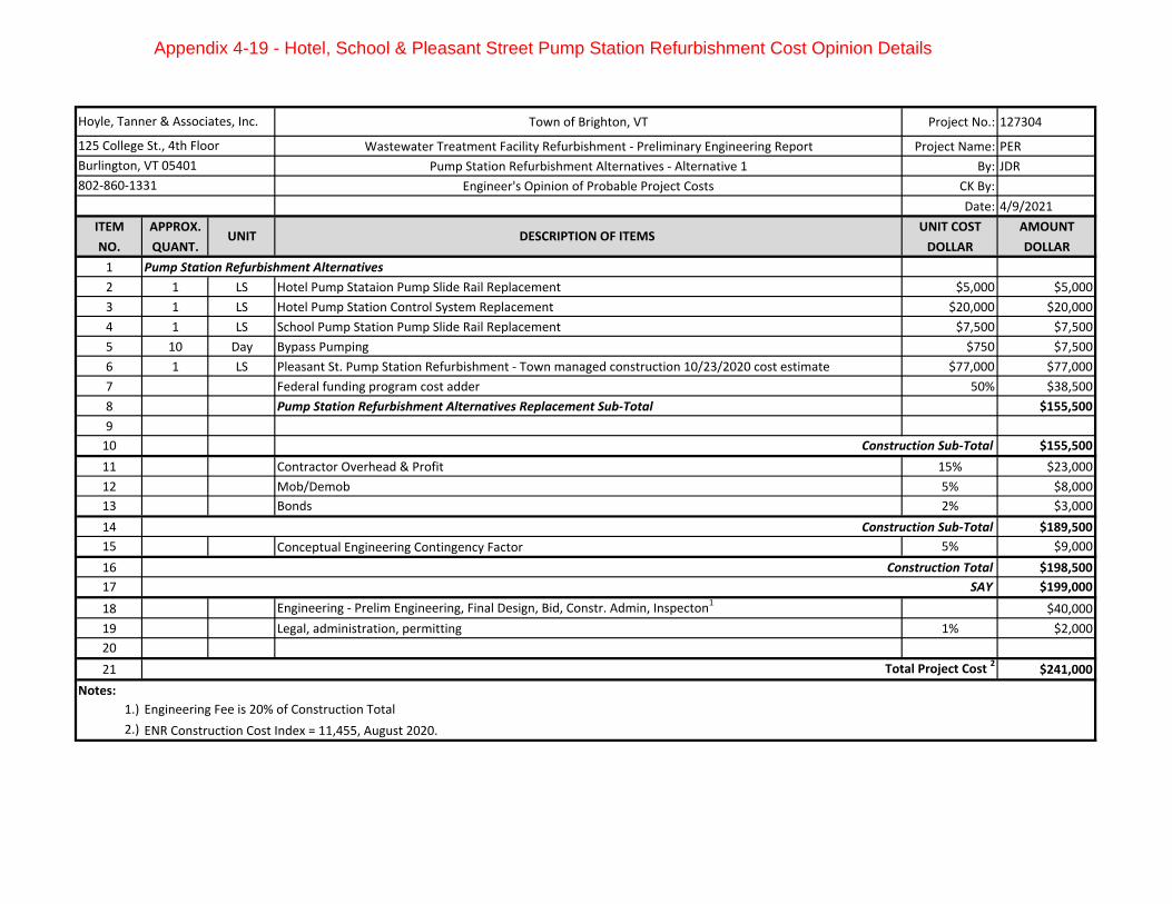
Town of Brighton, VT Project No.: 127304
Wastewater Treatment Facility Refurbishment - Preliminary Engineering Report Project Name: PER
Pump Station Refurbishment Alternatives - Alternative 1 By: JDR
Engineer's Opinion of Probable Project Costs CK By:
Date: 4/9/2021
ITEM APPROX. UNIT COST AMOUNT
NO. QUANT. DOLLAR DOLLAR
1 Pump Station Refurbishment Alternatives
2 1 LS Hotel Pump Stataion Pump Slide Rail Replacement $5,000 $5,000
3 1 LS Hotel Pump Station Control System Replacement $20,000 $20,000
4 1 LS School Pump Station Pump Slide Rail Replacement $7,500 $7,500
5 10 Day Bypass Pumping $750 $7,500
6 1 LS Pleasant St. Pump Station Refurbishment - Town managed construction 10/23/2020 cost estimate $77,000 $77,000
7 Federal funding program cost adder 50% $38,500
8 Pump Station Refurbishment Alternatives Replacement Sub-Total $155,500
9
10 $155,500
11 Contractor Overhead & Profit 15% $23,000
12 Mob/Demob 5% $8,000
13 Bonds 2% $3,000
14 $189,500
15 Conceptual Engineering Contingency Factor 5% $9,000
16 $198,500
17 SAY $199,000
18 Engineering - Prelim Engineering, Final Design, Bid, Constr. Admin, Inspecton1
$40,000
19 Legal, administration, permitting 1% $2,000
20
21 $241,000
Notes:
1.)
2.) ENR Construction Cost Index = 11,455, August 2020.
Engineering Fee is 20% of Construction Total
Hoyle, Tanner & Associates, Inc.
125 College St., 4th Floor
Burlington, VT 05401
802-860-1331
UNIT DESCRIPTION OF ITEMS
Construction Sub-Total
Construction Sub-Total
Construction Total
Total Project Cost 2
Appendix 4-19 - Hotel, School & Pleasant Street Pump Station Refurbishment Cost Opinion Details


