Embed Size (px)
Citation preview
C. R. Mecanique 340 (2012) 67–80
Contents lists available at SciVerse ScienceDirect
Comptes Rendus Mecanique
www.sciencedirect.com
Biomimetic flow control
Biomimetic spiroid winglets for lift and drag control
Joel E. Guerrero ∗, Dario Maestro, Alessandro Bottaro
University of Genoa, Department of Civil, Environmental and Architectural Engineering, DICAT, Via Montallegro 1, 16145 Genoa, Italy
a r t i c l e i n f o a b s t r a c t
Article history:
Available online 30 December 2011
Keywords:
Computational fluid mechanics
Spiroid winglets
Lift-induced drag
Drag reduction
Biomimetics
In aeronautical engineering, drag reduction constitutes a challenge and there is room for
improvement and innovative developments. The drag breakdown of a typical transport
aircraft shows that the lift-induced drag can amount to as much as 40% of the total drag
at cruise conditions and 80–90% of the total drag in take-off configuration. One way of
reducing lift-induced drag is by using wingtip devices. By applying biomimetic abstraction
of the principle behind a bird’s wingtip feathers, we study spiroid wingtips, which look
like an extended blended wingtip that bends upward by 360 degrees to form a large rigid
ribbon. The numerical investigation of such a wingtip device is described and preliminary
indications of its aerodynamic performance are provided.
2011 Académie des sciences. Published by Elsevier Masson SAS. All rights reserved.
1. Introduction
From an aerodynamicist’s point of view, the main motivation behind all wingtip devices is to reduce lift-induced drag.
Recently, aircraft manufacturers are under increasing pressure to improve efficiency due to rising operating costs and envi-
ronmental issues, and this has led to some innovative developments for reducing lift-induced drag. Several different types
of wingtip devices have been developed during this quest for efficiency and the selection of the wingtip device depends on
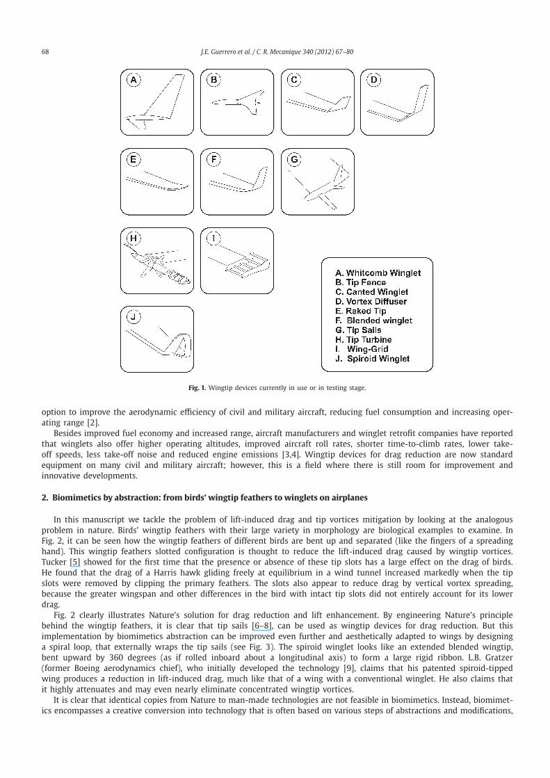
the specific situation and the airplane type. In Fig. 1, some of the wingtip devices that are currently in use or in a testing
stage are sketched.
The concept of winglets was originally developed in the late 1800s by British aerodynamicist F.W. Lancaster, who
patented the idea that a vertical surface (end plate) at the wingtip would reduce drag by controlling wingtip vortices [1].
Unfortunately, the concept never demonstrated its effectiveness, in practice because the increase in drag due to skin friction
and flow separation outweighed any lift-induced drag benefit.
After the cost of jet fuel skyrocketed in the 1973 oil crisis, airlines and aircraft manufacturers explored many ways to
reduce fuel consumption by improving the operating efficiency of their aircraft. R.T. Whitcomb, an engineer at NASA Langley
Research Center, inspired by an article in Science Magazine on the flight characteristics of soaring birds and their use of
tip feathers to control flight, continued on the quest to reduce cruise drag and improve aircraft performance and further
developed the concept of winglets in the late 1970s [2]. Whitcomb, designed a winglet using advanced airfoil concepts
integrated into a swept, tapered planform that would interact with the wingtip airflow to reduce drag.
Whitcomb’s analysis of flow phenomena at the tip showed that the airflow about the wingtip of the typical aircraft in
flight is characterized by a flow that is directed inward above the wingtip and a flow that is directed outward below the
wingtip. Whitcomb hypothesized that a vertical, properly cambered and angled surface above or below the tip could utilize
this cross flow tendency to reduce the strength of the trailing vortex and, thereby, reduce the lift-induced drag. In essence,
Whitcomb and his team provided the fundamental knowledge and design approach required for an extremely attractive
* Corresponding author.
E-mail address: [email protected] (J.E. Guerrero).
1631-0721/$ – see front matter 2011 Académie des sciences. Published by Elsevier Masson SAS. All rights reserved.
doi:10.1016/j.crme.2011.11.007
68 J.E. Guerrero et al. / C. R. Mecanique 340 (2012) 67–80
Fig. 1. Wingtip devices currently in use or in testing stage.
option to improve the aerodynamic efficiency of civil and military aircraft, reducing fuel consumption and increasing oper-
ating range [2].
Besides improved fuel economy and increased range, aircraft manufacturers and winglet retrofit companies have reported
that winglets also offer higher operating altitudes, improved aircraft roll rates, shorter time-to-climb rates, lower take-
off speeds, less take-off noise and reduced engine emissions [3,4]. Wingtip devices for drag reduction are now standard
equipment on many civil and military aircraft; however, this is a field where there is still room for improvement and
innovative developments.
2. Biomimetics by abstraction: from birds’ wingtip feathers to winglets on airplanes
In this manuscript we tackle the problem of lift-induced drag and tip vortices mitigation by looking at the analogous
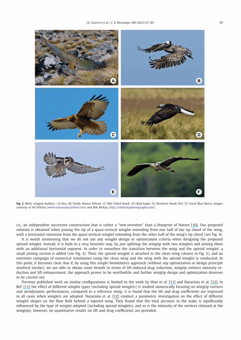
problem in nature. Birds’ wingtip feathers with their large variety in morphology are biological examples to examine. In
Fig. 2, it can be seen how the wingtip feathers of different birds are bent up and separated (like the fingers of a spreading
hand). This wingtip feathers slotted configuration is thought to reduce the lift-induced drag caused by wingtip vortices.
Tucker [5] showed for the first time that the presence or absence of these tip slots has a large effect on the drag of birds.
He found that the drag of a Harris hawk gliding freely at equilibrium in a wind tunnel increased markedly when the tip
slots were removed by clipping the primary feathers. The slots also appear to reduce drag by vertical vortex spreading,
because the greater wingspan and other differences in the bird with intact tip slots did not entirely account for its lower
drag.
Fig. 2 clearly illustrates Nature’s solution for drag reduction and lift enhancement. By engineering Nature’s principle
behind the wingtip feathers, it is clear that tip sails [6–8], can be used as wingtip devices for drag reduction. But this
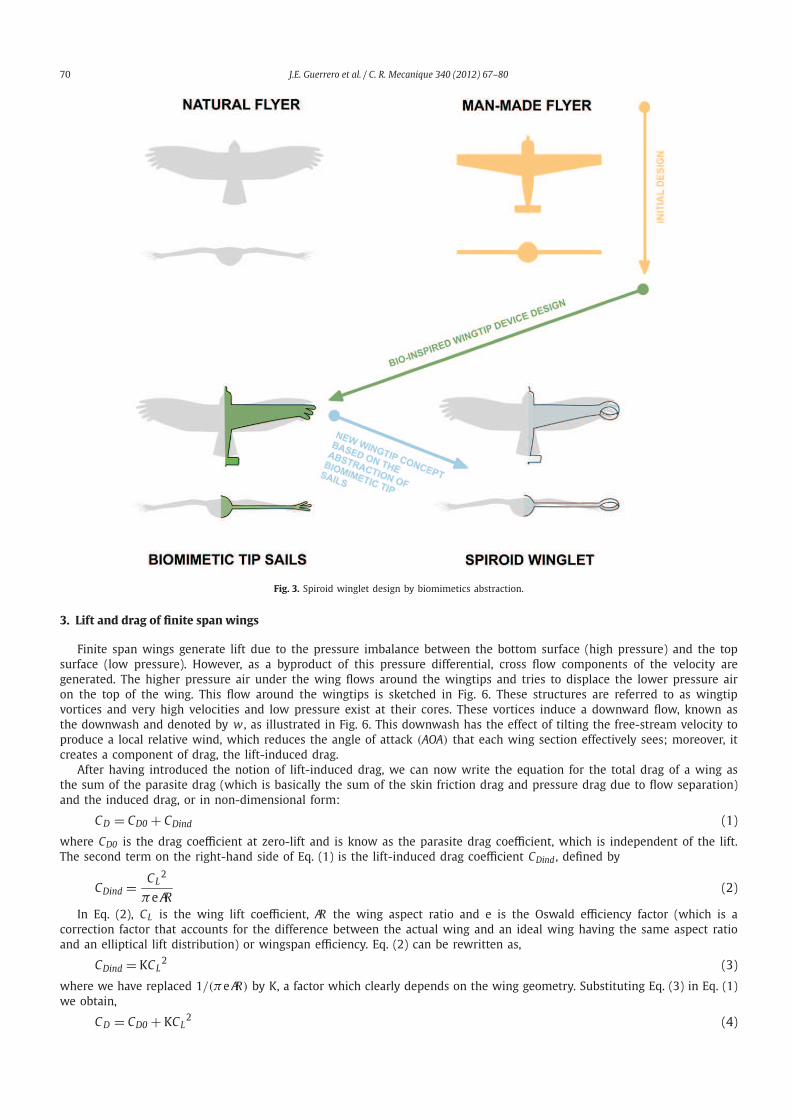
implementation by biomimetics abstraction can be improved even further and aesthetically adapted to wings by designing
a spiral loop, that externally wraps the tip sails (see Fig. 3). The spiroid winglet looks like an extended blended wingtip,
bent upward by 360 degrees (as if rolled inboard about a longitudinal axis) to form a large rigid ribbon. L.B. Gratzer
(former Boeing aerodynamics chief), who initially developed the technology [9], claims that his patented spiroid-tipped
wing produces a reduction in lift-induced drag, much like that of a wing with a conventional winglet. He also claims that
it highly attenuates and may even nearly eliminate concentrated wingtip vortices.
It is clear that identical copies from Nature to man-made technologies are not feasible in biomimetics. Instead, biomimet-
ics encompasses a creative conversion into technology that is often based on various steps of abstractions and modifications,
J.E. Guerrero et al. / C. R. Mecanique 340 (2012) 67–80 69
Fig. 2. Birds’ wingtip feathers. (A) Kea. (B) Pacific Brown Pelican. (C) Red Tailed Hawk. (D) Bald Eagle. (E) Northern Hawk Owl. (F) Great Blue Heron. Images
courtesy of Ad Wilson (www.naturespicsonline.com) and Rob McKay (http://robmckayphotography.com).
i.e., an independent successive construction that is rather a “new invention” than a blueprint of Nature [10]. Our proposed
solution is obtained when joining the tip of a quasi-vertical winglet extending from one half of the tip chord of the wing,
with a horizontal extension from the quasi-vertical winglet extending from the other half of the wing’s tip chord (see Fig. 4).
It is worth mentioning that we do not use any winglet design or optimization criteria when designing the proposed
spiroid winglet. Instead, it is built in a very heuristic way, by just splitting the wingtip with two winglets and joining them
with an additional horizontal segment. In order to smoothen the transition between the wing and the spiroid winglet, a
small joining section is added (see Fig. 4). Then, the spiroid winglet is attached to the clean wing (shown in Fig. 5), and an
extensive campaign of numerical simulations using the clean wing and the wing with the spiroid winglet is conducted. At
this point, it becomes clear that if, by using this simple biomimetics approach (without any optimization or design principle
involved insofar), we are able to obtain some benefit in terms of lift-induced drag reduction, wingtip vortices intensity re-
duction and lift enhancement, the approach proves to be worthwhile and further wingtip design and optimization deserves
to be carried out.
Previous published work on similar configurations is limited to the work by Wan et al. [11] and Nazarinia et al. [12]. In
Ref. [11] the effect of different winglet types (including spiroid winglets) is studied numerically focusing on wingtip vortices
and aerodynamic performances, compared to a reference wing; it is found that the lift and drag coefficients are improved
in all cases when winglets are adopted. Nazarinia et al. [12] conduct a parametric investigation on the effect of different
winglet shapes on the flow field behind a tapered wing. They found that the total pressure in the wake is significantly
influenced by the type of winglet adopted (including spiroid winglets), and so is the intensity of the vortices released at the
wingtips; however, no quantitative results on lift and drag coefficients are provided.
70 J.E. Guerrero et al. / C. R. Mecanique 340 (2012) 67–80
Fig. 3. Spiroid winglet design by biomimetics abstraction.
3. Lift and drag of finite span wings
Finite span wings generate lift due to the pressure imbalance between the bottom surface (high pressure) and the top
surface (low pressure). However, as a byproduct of this pressure differential, cross flow components of the velocity are
generated. The higher pressure air under the wing flows around the wingtips and tries to displace the lower pressure air
on the top of the wing. This flow around the wingtips is sketched in Fig. 6. These structures are referred to as wingtip
vortices and very high velocities and low pressure exist at their cores. These vortices induce a downward flow, known as
the downwash and denoted by w , as illustrated in Fig. 6. This downwash has the effect of tilting the free-stream velocity to
produce a local relative wind, which reduces the angle of attack (AOA) that each wing section effectively sees; moreover, it
creates a component of drag, the lift-induced drag.
After having introduced the notion of lift-induced drag, we can now write the equation for the total drag of a wing as
the sum of the parasite drag (which is basically the sum of the skin friction drag and pressure drag due to flow separation)
and the induced drag, or in non-dimensional form:
CD = CD0 + CDind (1)
where CD0 is the drag coefficient at zero-lift and is know as the parasite drag coefficient, which is independent of the lift.
The second term on the right-hand side of Eq. (1) is the lift-induced drag coefficient CDind , defined by
CDind =CL
2
πeAR(2)
In Eq. (2), CL is the wing lift coefficient, AR the wing aspect ratio and e is the Oswald efficiency factor (which is a
correction factor that accounts for the difference between the actual wing and an ideal wing having the same aspect ratio
and an elliptical lift distribution) or wingspan efficiency. Eq. (2) can be rewritten as,
CDind = KCL2 (3)
where we have replaced 1/(πeAR) by K, a factor which clearly depends on the wing geometry. Substituting Eq. (3) in Eq. (1)
we obtain,
CD = CD0 + KCL2 (4)
J.E. Guerrero et al. / C. R. Mecanique 340 (2012) 67–80 71
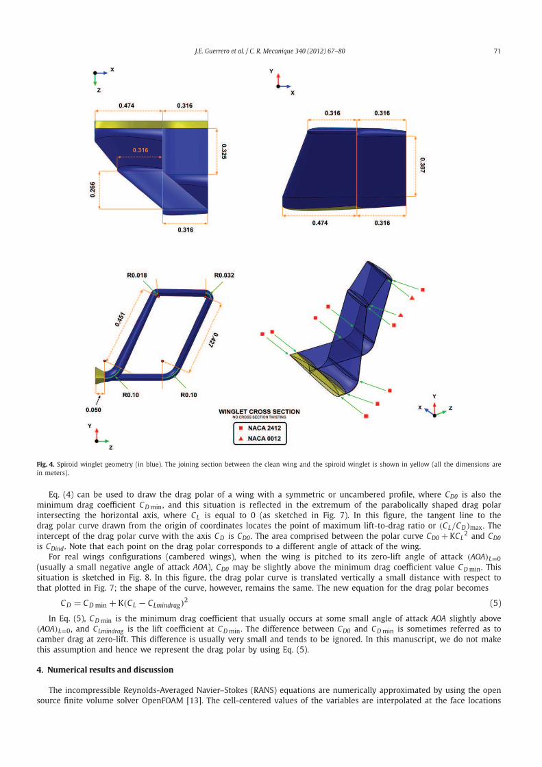
Fig. 4. Spiroid winglet geometry (in blue). The joining section between the clean wing and the spiroid winglet is shown in yellow (all the dimensions are
in meters).
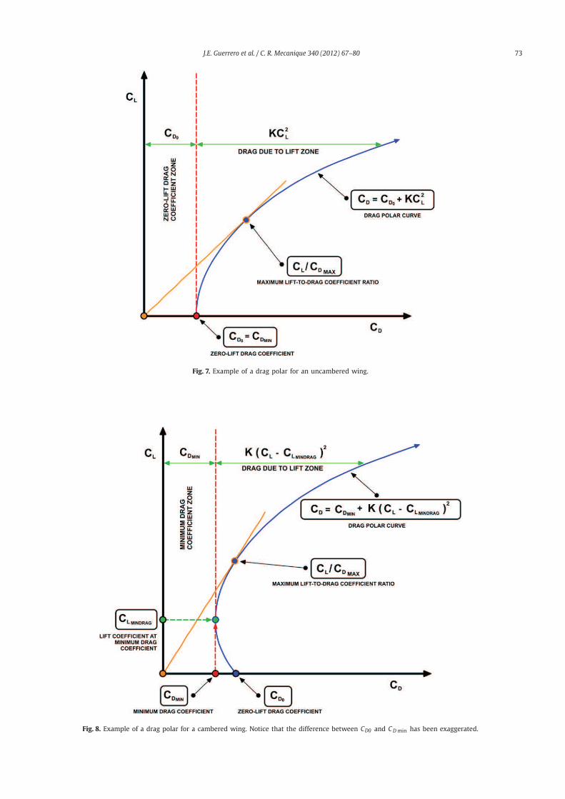
Eq. (4) can be used to draw the drag polar of a wing with a symmetric or uncambered profile, where CD0 is also the
minimum drag coefficient CDmin , and this situation is reflected in the extremum of the parabolically shaped drag polar
intersecting the horizontal axis, where CL is equal to 0 (as sketched in Fig. 7). In this figure, the tangent line to the
drag polar curve drawn from the origin of coordinates locates the point of maximum lift-to-drag ratio or (CL/CD)max . The
intercept of the drag polar curve with the axis CD is CD0 . The area comprised between the polar curve CD0 + KCL2 and CD0
is CDind . Note that each point on the drag polar corresponds to a different angle of attack of the wing.
For real wings configurations (cambered wings), when the wing is pitched to its zero-lift angle of attack (AOA)L=0
(usually a small negative angle of attack AOA), CD0 may be slightly above the minimum drag coefficient value CDmin . This
situation is sketched in Fig. 8. In this figure, the drag polar curve is translated vertically a small distance with respect to
that plotted in Fig. 7; the shape of the curve, however, remains the same. The new equation for the drag polar becomes
CD = CDmin + K(CL − CLmindrag)2 (5)
In Eq. (5), CDmin is the minimum drag coefficient that usually occurs at some small angle of attack AOA slightly above
(AOA)L=0 , and CLmindrag is the lift coefficient at CDmin . The difference between CD0 and CDmin is sometimes referred as to
camber drag at zero-lift. This difference is usually very small and tends to be ignored. In this manuscript, we do not make
this assumption and hence we represent the drag polar by using Eq. (5).
4. Numerical results and discussion
The incompressible Reynolds-Averaged Navier–Stokes (RANS) equations are numerically approximated by using the open
source finite volume solver OpenFOAM [13]. The cell-centered values of the variables are interpolated at the face locations
72 J.E. Guerrero et al. / C. R. Mecanique 340 (2012) 67–80
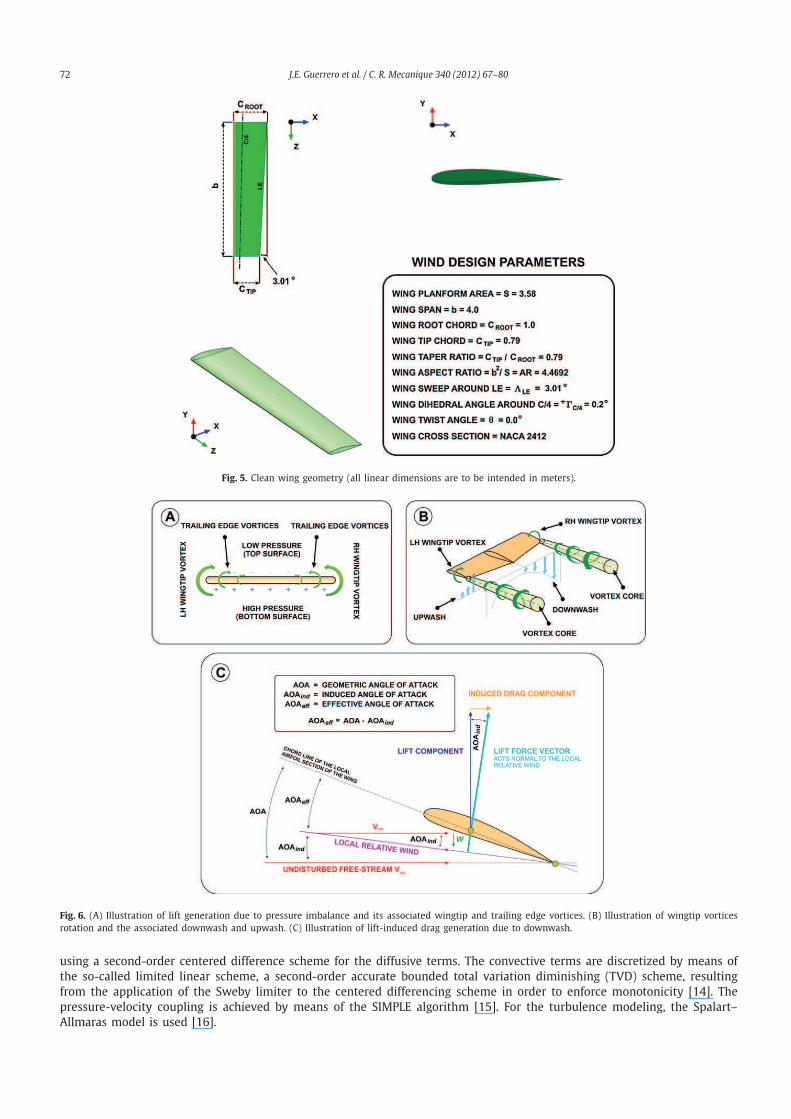
Fig. 5. Clean wing geometry (all linear dimensions are to be intended in meters).
Fig. 6. (A) Illustration of lift generation due to pressure imbalance and its associated wingtip and trailing edge vortices. (B) Illustration of wingtip vortices
rotation and the associated downwash and upwash. (C) Illustration of lift-induced drag generation due to downwash.
using a second-order centered difference scheme for the diffusive terms. The convective terms are discretized by means of
the so-called limited linear scheme, a second-order accurate bounded total variation diminishing (TVD) scheme, resulting
from the application of the Sweby limiter to the centered differencing scheme in order to enforce monotonicity [14]. The
pressure-velocity coupling is achieved by means of the SIMPLE algorithm [15]. For the turbulence modeling, the Spalart–
Allmaras model is used [16].
J.E. Guerrero et al. / C. R. Mecanique 340 (2012) 67–80 73
Fig. 7. Example of a drag polar for an uncambered wing.
Fig. 8. Example of a drag polar for a cambered wing. Notice that the difference between CD0 and CDmin has been exaggerated.
74 J.E. Guerrero et al. / C. R. Mecanique 340 (2012) 67–80
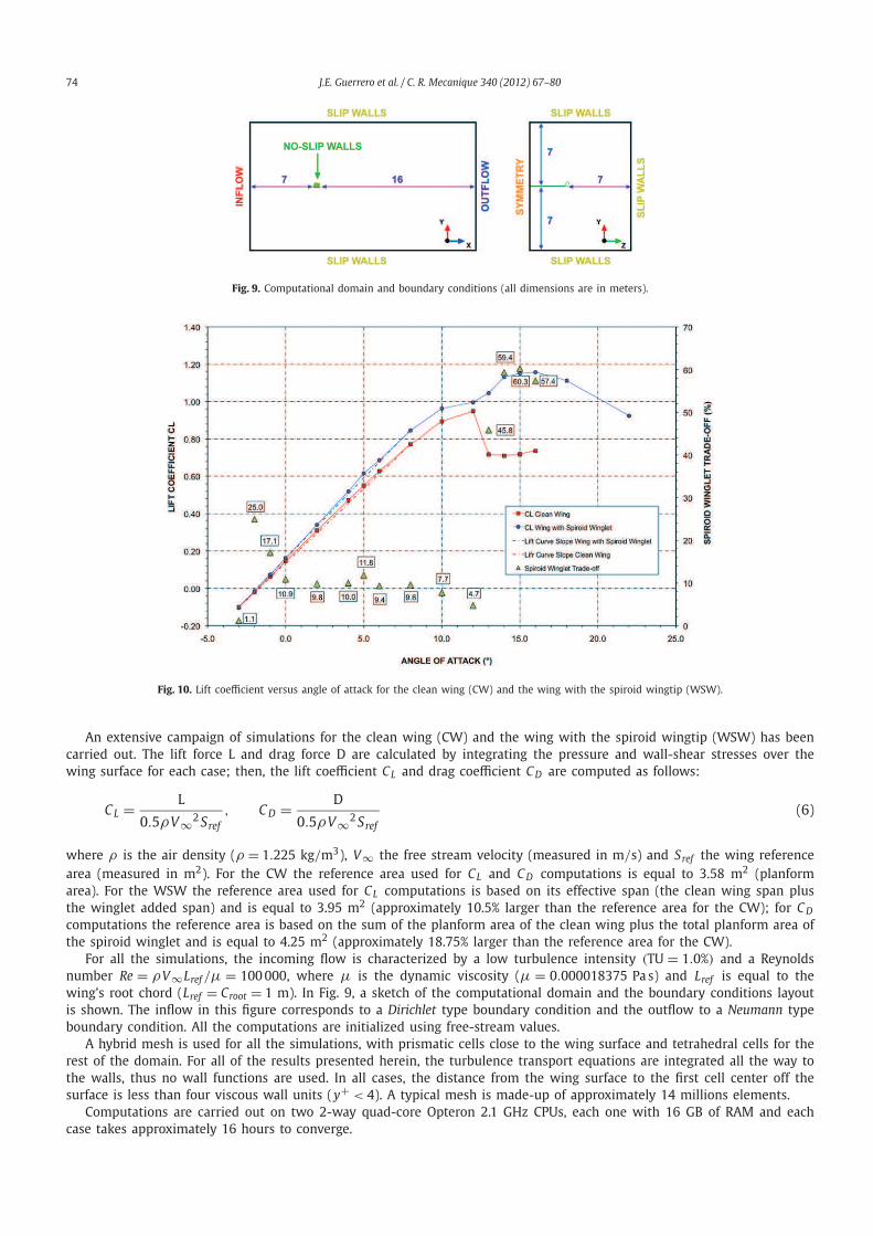
Fig. 9. Computational domain and boundary conditions (all dimensions are in meters).
Fig. 10. Lift coefficient versus angle of attack for the clean wing (CW) and the wing with the spiroid wingtip (WSW).
An extensive campaign of simulations for the clean wing (CW) and the wing with the spiroid wingtip (WSW) has been
carried out. The lift force L and drag force D are calculated by integrating the pressure and wall-shear stresses over the
wing surface for each case; then, the lift coefficient CL and drag coefficient CD are computed as follows:
CL =L
0.5ρV∞2Sref
, CD =D
0.5ρV∞2Sref
(6)
where ρ is the air density (ρ = 1.225 kg/m3), V∞ the free stream velocity (measured in m/s) and Sref the wing reference
area (measured in m2). For the CW the reference area used for CL and CD computations is equal to 3.58 m2 (planform
area). For the WSW the reference area used for CL computations is based on its effective span (the clean wing span plus
the winglet added span) and is equal to 3.95 m2 (approximately 10.5% larger than the reference area for the CW); for CD
computations the reference area is based on the sum of the planform area of the clean wing plus the total planform area of
the spiroid winglet and is equal to 4.25 m2 (approximately 18.75% larger than the reference area for the CW).
For all the simulations, the incoming flow is characterized by a low turbulence intensity (TU = 1.0%) and a Reynolds
number Re = ρV∞Lref /µ = 100000, where µ is the dynamic viscosity (µ = 0.000018375 Pa s) and Lref is equal to the
wing’s root chord (Lref = Croot = 1 m). In Fig. 9, a sketch of the computational domain and the boundary conditions layout
is shown. The inflow in this figure corresponds to a Dirichlet type boundary condition and the outflow to a Neumann type
boundary condition. All the computations are initialized using free-stream values.
A hybrid mesh is used for all the simulations, with prismatic cells close to the wing surface and tetrahedral cells for the
rest of the domain. For all of the results presented herein, the turbulence transport equations are integrated all the way to
the walls, thus no wall functions are used. In all cases, the distance from the wing surface to the first cell center off the
surface is less than four viscous wall units (y+ < 4). A typical mesh is made-up of approximately 14 millions elements.
Computations are carried out on two 2-way quad-core Opteron 2.1 GHz CPUs, each one with 16 GB of RAM and each
case takes approximately 16 hours to converge.
J.E. Guerrero et al. / C. R. Mecanique 340 (2012) 67–80 75
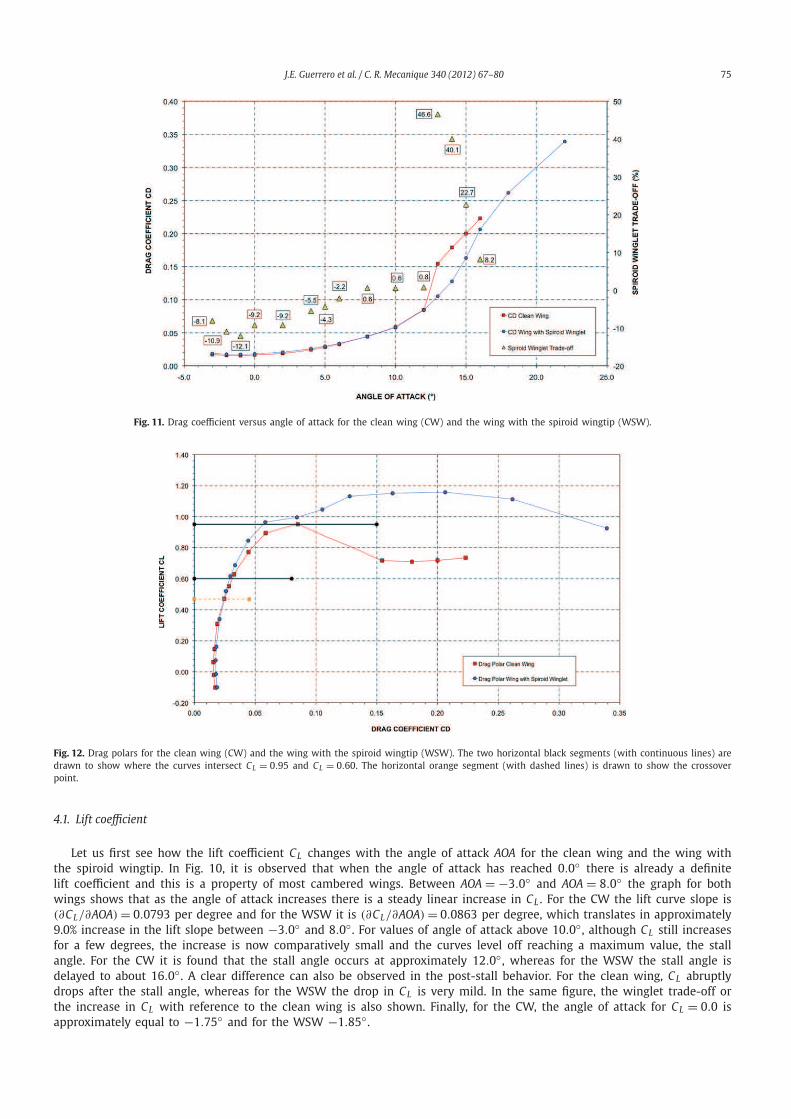
Fig. 11. Drag coefficient versus angle of attack for the clean wing (CW) and the wing with the spiroid wingtip (WSW).
Fig. 12. Drag polars for the clean wing (CW) and the wing with the spiroid wingtip (WSW). The two horizontal black segments (with continuous lines) are
drawn to show where the curves intersect CL = 0.95 and CL = 0.60. The horizontal orange segment (with dashed lines) is drawn to show the crossover
point.
4.1. Lift coefficient
Let us first see how the lift coefficient CL changes with the angle of attack AOA for the clean wing and the wing with
the spiroid wingtip. In Fig. 10, it is observed that when the angle of attack has reached 0.0◦ there is already a definite
lift coefficient and this is a property of most cambered wings. Between AOA = −3.0◦ and AOA = 8.0◦ the graph for both
wings shows that as the angle of attack increases there is a steady linear increase in CL . For the CW the lift curve slope is
(∂CL/∂AOA) = 0.0793 per degree and for the WSW it is (∂CL/∂AOA) = 0.0863 per degree, which translates in approximately
9.0% increase in the lift slope between −3.0◦ and 8.0◦ . For values of angle of attack above 10.0◦ , although CL still increases
for a few degrees, the increase is now comparatively small and the curves level off reaching a maximum value, the stall
angle. For the CW it is found that the stall angle occurs at approximately 12.0◦ , whereas for the WSW the stall angle is
delayed to about 16.0◦ . A clear difference can also be observed in the post-stall behavior. For the clean wing, CL abruptly
drops after the stall angle, whereas for the WSW the drop in CL is very mild. In the same figure, the winglet trade-off or
the increase in CL with reference to the clean wing is also shown. Finally, for the CW, the angle of attack for CL = 0.0 is
approximately equal to −1.75◦ and for the WSW −1.85◦ .
76 J.E. Guerrero et al. / C. R. Mecanique 340 (2012) 67–80
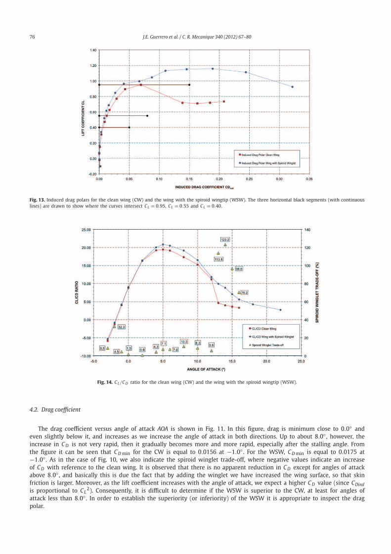
Fig. 13. Induced drag polars for the clean wing (CW) and the wing with the spiroid wingtip (WSW). The three horizontal black segments (with continuous
lines) are drawn to show where the curves intersect CL = 0.95, CL = 0.55 and CL = 0.40.
Fig. 14. CL/CD ratio for the clean wing (CW) and the wing with the spiroid wingtip (WSW).
4.2. Drag coefficient
The drag coefficient versus angle of attack AOA is shown in Fig. 11. In this figure, drag is minimum close to 0.0◦ and
even slightly below it, and increases as we increase the angle of attack in both directions. Up to about 8.0◦ , however, the
increase in CD is not very rapid, then it gradually becomes more and more rapid, especially after the stalling angle. From
the figure it can be seen that CDmin for the CW is equal to 0.0156 at −1.0◦ . For the WSW, CDmin is equal to 0.0175 at
−1.0◦ . As in the case of Fig. 10, we also indicate the spiroid winglet trade-off, where negative values indicate an increase
of CD with reference to the clean wing. It is observed that there is no apparent reduction in CD except for angles of attack
above 8.0◦ , and basically this is due the fact that by adding the winglet we have increased the wing surface, so that skin
friction is larger. Moreover, as the lift coefficient increases with the angle of attack, we expect a higher CD value (since CDind
is proportional to CL2). Consequently, it is difficult to determine if the WSW is superior to the CW, at least for angles of
attack less than 8.0◦ . In order to establish the superiority (or inferiority) of the WSW it is appropriate to inspect the drag
polar.
J.E. Guerrero et al. / C. R. Mecanique 340 (2012) 67–80 77
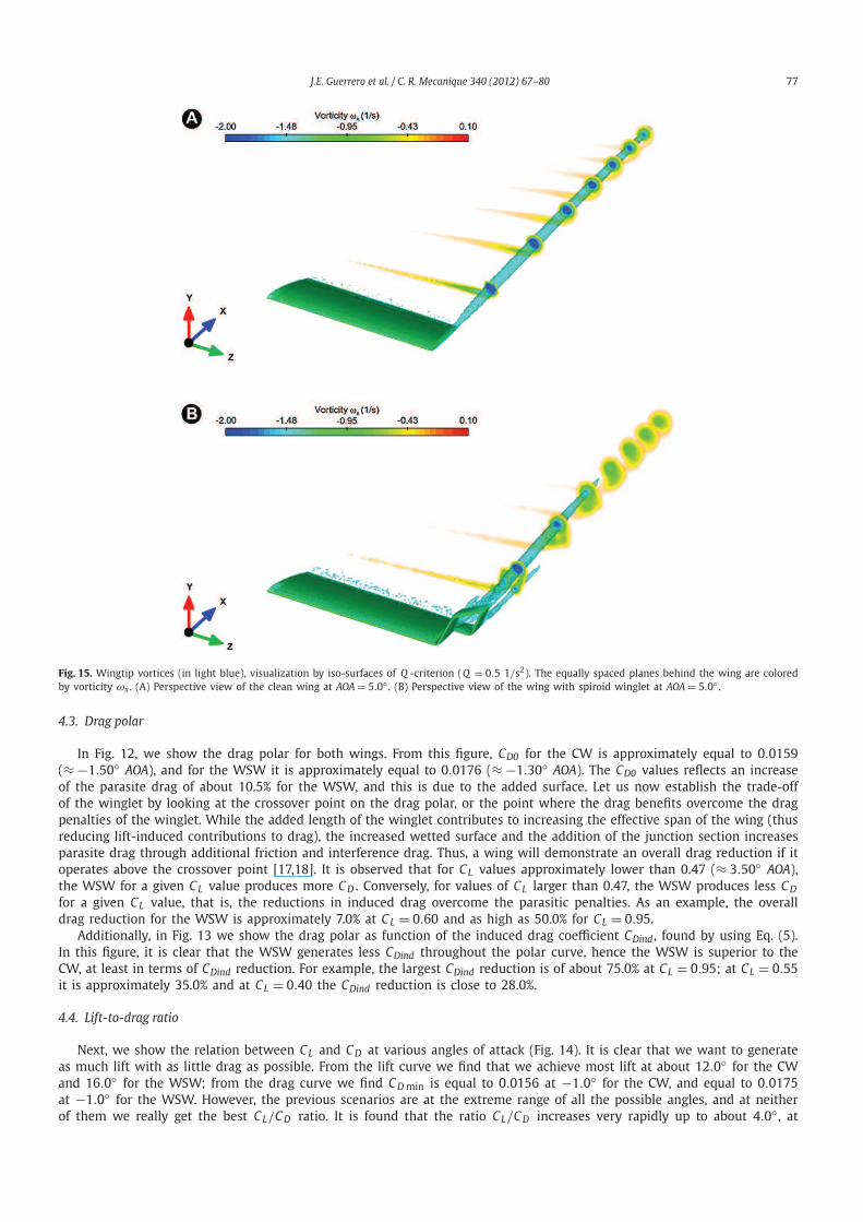
Fig. 15. Wingtip vortices (in light blue), visualization by iso-surfaces of Q -criterion (Q = 0.5 1/s2). The equally spaced planes behind the wing are colored
by vorticity ωx . (A) Perspective view of the clean wing at AOA = 5.0◦ . (B) Perspective view of the wing with spiroid winglet at AOA = 5.0◦ .
4.3. Drag polar
In Fig. 12, we show the drag polar for both wings. From this figure, CD0 for the CW is approximately equal to 0.0159
(≈ −1.50◦ AOA), and for the WSW it is approximately equal to 0.0176 (≈ −1.30◦ AOA). The CD0 values reflects an increase
of the parasite drag of about 10.5% for the WSW, and this is due to the added surface. Let us now establish the trade-off
of the winglet by looking at the crossover point on the drag polar, or the point where the drag benefits overcome the drag
penalties of the winglet. While the added length of the winglet contributes to increasing the effective span of the wing (thus
reducing lift-induced contributions to drag), the increased wetted surface and the addition of the junction section increases
parasite drag through additional friction and interference drag. Thus, a wing will demonstrate an overall drag reduction if it
operates above the crossover point [17,18]. It is observed that for CL values approximately lower than 0.47 (≈ 3.50◦ AOA),
the WSW for a given CL value produces more CD . Conversely, for values of CL larger than 0.47, the WSW produces less CD
for a given CL value, that is, the reductions in induced drag overcome the parasitic penalties. As an example, the overall
drag reduction for the WSW is approximately 7.0% at CL = 0.60 and as high as 50.0% for CL = 0.95.
Additionally, in Fig. 13 we show the drag polar as function of the induced drag coefficient CDind , found by using Eq. (5).
In this figure, it is clear that the WSW generates less CDind throughout the polar curve, hence the WSW is superior to the
CW, at least in terms of CDind reduction. For example, the largest CDind reduction is of about 75.0% at CL = 0.95; at CL = 0.55
it is approximately 35.0% and at CL = 0.40 the CDind reduction is close to 28.0%.
4.4. Lift-to-drag ratio
Next, we show the relation between CL and CD at various angles of attack (Fig. 14). It is clear that we want to generate
as much lift with as little drag as possible. From the lift curve we find that we achieve most lift at about 12.0◦ for the CW
and 16.0◦ for the WSW; from the drag curve we find CDmin is equal to 0.0156 at −1.0◦ for the CW, and equal to 0.0175
at −1.0◦ for the WSW. However, the previous scenarios are at the extreme range of all the possible angles, and at neither
of them we really get the best CL/CD ratio. It is found that the ratio CL/CD increases very rapidly up to about 4.0◦ , at
78 J.E. Guerrero et al. / C. R. Mecanique 340 (2012) 67–80
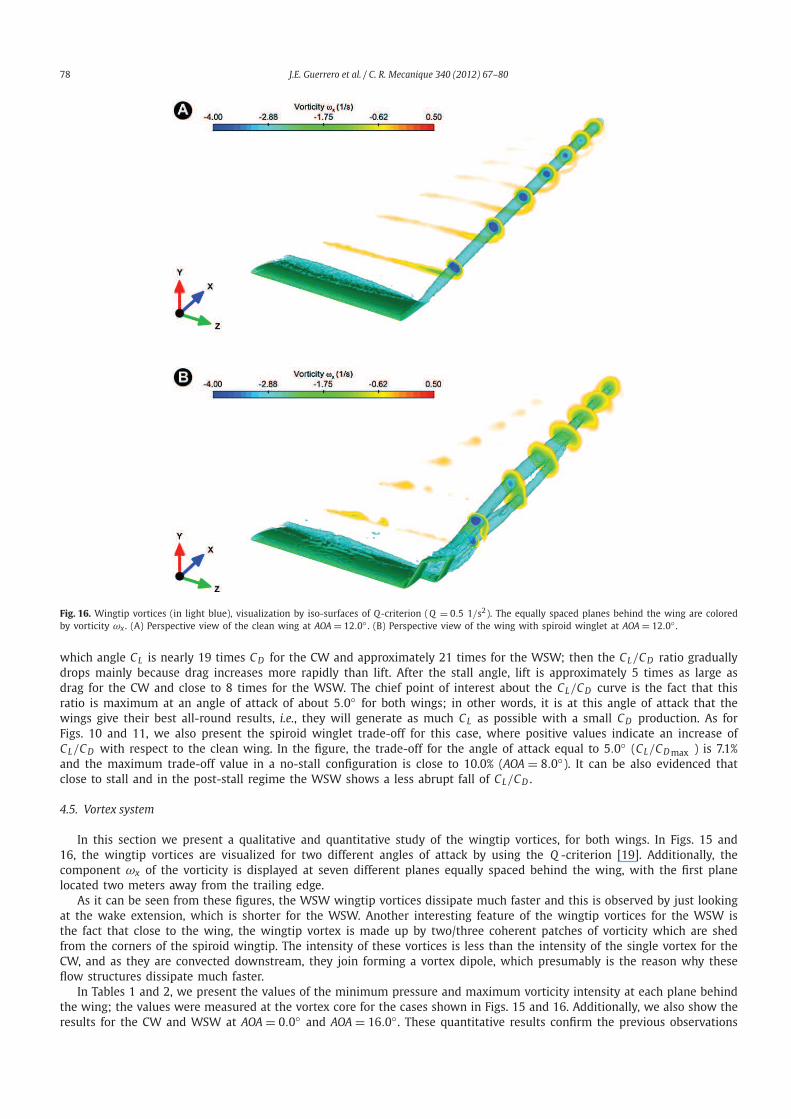
Fig. 16. Wingtip vortices (in light blue), visualization by iso-surfaces of Q-criterion (Q = 0.5 1/s2). The equally spaced planes behind the wing are colored
by vorticity ωx . (A) Perspective view of the clean wing at AOA = 12.0◦ . (B) Perspective view of the wing with spiroid winglet at AOA = 12.0◦ .
which angle CL is nearly 19 times CD for the CW and approximately 21 times for the WSW; then the CL/CD ratio gradually
drops mainly because drag increases more rapidly than lift. After the stall angle, lift is approximately 5 times as large as
drag for the CW and close to 8 times for the WSW. The chief point of interest about the CL/CD curve is the fact that this
ratio is maximum at an angle of attack of about 5.0◦ for both wings; in other words, it is at this angle of attack that the
wings give their best all-round results, i.e., they will generate as much CL as possible with a small CD production. As for
Figs. 10 and 11, we also present the spiroid winglet trade-off for this case, where positive values indicate an increase of
CL/CD with respect to the clean wing. In the figure, the trade-off for the angle of attack equal to 5.0◦ (CL/CDmax ) is 7.1%
and the maximum trade-off value in a no-stall configuration is close to 10.0% (AOA = 8.0◦). It can be also evidenced that
close to stall and in the post-stall regime the WSW shows a less abrupt fall of CL/CD .
4.5. Vortex system
In this section we present a qualitative and quantitative study of the wingtip vortices, for both wings. In Figs. 15 and
16, the wingtip vortices are visualized for two different angles of attack by using the Q -criterion [19]. Additionally, the
component ωx of the vorticity is displayed at seven different planes equally spaced behind the wing, with the first plane
located two meters away from the trailing edge.
As it can be seen from these figures, the WSW wingtip vortices dissipate much faster and this is observed by just looking
at the wake extension, which is shorter for the WSW. Another interesting feature of the wingtip vortices for the WSW is
the fact that close to the wing, the wingtip vortex is made up by two/three coherent patches of vorticity which are shed
from the corners of the spiroid wingtip. The intensity of these vortices is less than the intensity of the single vortex for the
CW, and as they are convected downstream, they join forming a vortex dipole, which presumably is the reason why these
flow structures dissipate much faster.
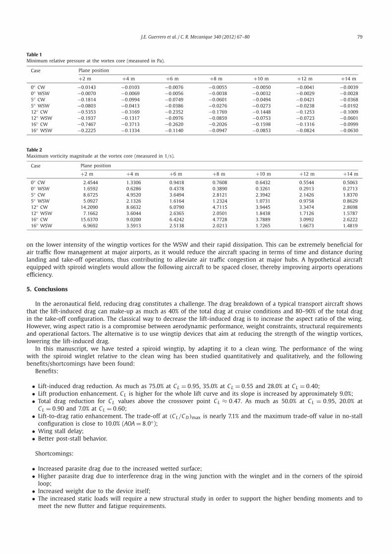
In Tables 1 and 2, we present the values of the minimum pressure and maximum vorticity intensity at each plane behind
the wing; the values were measured at the vortex core for the cases shown in Figs. 15 and 16. Additionally, we also show the
results for the CW and WSW at AOA = 0.0◦ and AOA = 16.0◦ . These quantitative results confirm the previous observations
J.E. Guerrero et al. / C. R. Mecanique 340 (2012) 67–80 79
Table 1
Minimum relative pressure at the vortex core (measured in Pa).
Case Plane position
+2 m +4 m +6 m +8 m +10 m +12 m +14 m
0◦ CW −0.0143 −0.0103 −0.0076 −0.0055 −0.0050 −0.0041 −0.0039
0◦ WSW −0.0070 −0.0069 −0.0056 −0.0038 −0.0032 −0.0029 −0.0028
5◦ CW −0.1814 −0.0994 −0.0749 −0.0601 −0.0494 −0.0421 −0.0368
5◦ WSW −0.0803 −0.0413 −0.0386 −0.0276 −0.0273 −0.0238 −0.0192
12◦ CW −0.5353 −0.3169 −0.2352 −0.1769 −0.1448 −0.1253 −0.1009
12◦ WSW −0.1937 −0.1317 −0.0976 −0.0859 −0.0753 −0.0723 −0.0601
16◦ CW −0.7467 −0.3713 −0.2620 −0.2026 −0.1598 −0.1316 −0.0999
16◦ WSW −0.2225 −0.1334 −0.1140 −0.0947 −0.0853 −0.0824 −0.0630
Table 2
Maximum vorticity magnitude at the vortex core (measured in 1/s).
Case Plane position
+2 m +4 m +6 m +8 m +10 m +12 m +14 m
0◦ CW 2.4544 1.3306 0.9418 0.7608 0.6432 0.5544 0.5063
0◦ WSW 1.6592 0.6286 0.4378 0.3890 0.3261 0.2913 0.2713
5◦ CW 8.6725 4.9520 3.6494 2.8121 2.3942 2.1426 1.8370
5◦ WSW 5.0927 2.1326 1.6164 1.2324 1.0731 0.9758 0.8629
12◦ CW 14.2090 8.6632 6.0790 4.7115 3.9445 3.3474 2.8698
12◦ WSW 7.1662 3.6044 2.6365 2.0501 1.8438 1.7126 1.5787
16◦ CW 15.6370 9.0200 6.4242 4.7728 3.7889 3.0992 2.6222
16◦ WSW 6.9692 3.5913 2.5138 2.0213 1.7265 1.6673 1.4819
on the lower intensity of the wingtip vortices for the WSW and their rapid dissipation. This can be extremely beneficial for
air traffic flow management at major airports, as it would reduce the aircraft spacing in terms of time and distance during
landing and take-off operations, thus contributing to alleviate air traffic congestion at major hubs. A hypothetical aircraft
equipped with spiroid winglets would allow the following aircraft to be spaced closer, thereby improving airports operations
efficiency.
5. Conclusions
In the aeronautical field, reducing drag constitutes a challenge. The drag breakdown of a typical transport aircraft shows
that the lift-induced drag can make-up as much as 40% of the total drag at cruise conditions and 80–90% of the total drag
in the take-off configuration. The classical way to decrease the lift-induced drag is to increase the aspect ratio of the wing.
However, wing aspect ratio is a compromise between aerodynamic performance, weight constraints, structural requirements
and operational factors. The alternative is to use wingtip devices that aim at reducing the strength of the wingtip vortices,
lowering the lift-induced drag.
In this manuscript, we have tested a spiroid wingtip, by adapting it to a clean wing. The performance of the wing
with the spiroid winglet relative to the clean wing has been studied quantitatively and qualitatively, and the following
benefits/shortcomings have been found:
Benefits:
• Lift-induced drag reduction. As much as 75.0% at CL = 0.95, 35.0% at CL = 0.55 and 28.0% at CL = 0.40;
• Lift production enhancement. CL is higher for the whole lift curve and its slope is increased by approximately 9.0%;
• Total drag reduction for CL values above the crossover point CL ≈ 0.47. As much as 50.0% at CL = 0.95, 20.0% at
CL = 0.90 and 7.0% at CL = 0.60;
• Lift-to-drag ratio enhancement. The trade-off at (CL/CD)max is nearly 7.1% and the maximum trade-off value in no-stall
configuration is close to 10.0% (AOA = 8.0◦);
• Wing stall delay;
• Better post-stall behavior.
Shortcomings:
• Increased parasite drag due to the increased wetted surface;
• Higher parasite drag due to interference drag in the wing junction with the winglet and in the corners of the spiroid
loop;
• Increased weight due to the device itself;
• The increased static loads will require a new structural study in order to support the higher bending moments and to
meet the new flutter and fatigue requirements.
80 J.E. Guerrero et al. / C. R. Mecanique 340 (2012) 67–80
Aside from the points raised above, a side benefit of the spiroid winglet used in this study is its ability to greatly
reduce the intensity of the wingtip vortices, which dissipate very fast. This can be extremely beneficial for air traffic flow
management at major airports, as it would reduce the aircraft spacing necessary to allow for wake vortex dissipation during
landing and take-off operations.
From an airplane manufacturer or operator point of view, the benefits outlined could translate into:
• Increased operating range;
• Improved take-off performance;
• Higher operating altitudes;
• Improved aircraft roll rates;
• Shorter time-to-climb rates;
• Less take-off noise;
• Increased cruise speed;
• Reduced engine emissions;
• Meet runaway and gate clearance with minimal added span and height;
• Reduced separation distances and improved safety during take-off and landing operations due to wake vortex turbulence
reduction.
It is clear that in order to achieve all of the previous assets and obtain the best trade-off between benefits and short-
comings, shape optimization studies of the spiroid winglet are required.
Acknowledgements
The use of the computing resources at CASPUR high-performance computing center was possible thanks to the HPC
Grant 2011. The use of the computing facilities at the high-performance computing center of the University of Stuttgart
was possible thanks to the support of the HPC-Europa2 project (project number 238398), with the support of the European
Community – Research Infrastructure Action of the FP7.
References
[1] J. Jupp, Wing aerodynamics and the science of compromise, Aeronautical Journal 105 (1053) (November 2001) 633–641.
[2] J.R. Chambers, Concept to reality: Contributions of the Langley Research Center to U.S. Civil Aircraft of the 1990s, NASA History Series, NASA SP-2003-
4529, 2003.
[3] Assessment of Wingtip Modifications to Increase the Fuel Efficiency of Air Force Aircraft, Committee on Assessment of Aircraft Winglets for Large
Aircraft Fuel Efficiency, Air Force Studies Board Division on Engineering and Physical Sciences, The National Academies Press, 2007.
[4] R. Faye, R. Laprete, M. Winter, Blended winglets, M. Aero, No. 17, Boeing, January 2002.
[5] V.A. Tucker, Drag reduction by wing tip slots in a gliding Harris Hawk, Parabuteo Unicinctus, J. Exp. Biol. 198 (1995) 775–781.
[6] A. Hossain, A. Rahman, A. Iqbal, M. Ariffin, M. Mazian, Drag analysis of an aircraft wing model with and without bird feather like winglet, Int. J. Aeros.
Mech. Eng. 6 (1) (2012) 8–13.
[7] J. Spillman, The use of wing tip sails to reduce vortex drag, Aeronaut. J. 82 (1978) 387–395.
[8] D.S. Miklosovic, Analytic and experimental investigation of dihedral configurations of three-winglet planforms, J. Fluids Eng. 130 (7) (July 2008)
0711103/1–0711103/10.
[9] L.B. Gratzer, Spiroid-tipped wing, U.S. Patent 5,102,068, 7 April 1992.
[10] I.C. Gebeshuber, M. Drack, An attempt to reveal synergies between biology and mechanical engineering, Proc. Inst. Mech. Eng. C J. Mech. Eng. 222 (7)
(2008) 1281–1287.
[11] T. Wan, H.-C. Chou, K.-W. Lien, Aerodynamic efficiency study of modern spiroid winglets, in: 25th Congress of International Council of the Aeronautical,
Sciences, September 2006, Germany, Paper ICAS 2006-3.7S.
[12] M. Nazarinia, M.R. Soltani, K. Ghorbanian, Experimental study of vortex shapes behind a wing equipped with different winglets, Journal of Aerospace
Science and Technology 3 (1) (2006) 1–15.
[13] OpenFOAM User Guide, OpenCFD Limited. Version 2.0.0, June 2011.
[14] P.K. Sweby, High resolution schemes using flux limiters for hyperbolic conservation laws, SIAM J. Numer. Anal. 21 (1984) 995–1011.
[15] J.H. Ferziger, M. Peric, Computational Methods for Fluid Dynamics, third edition, Springer-Verlag, Berlin, 2001.
[16] P.R. Spalart, S.R. Allmaras, A one-equation turbulence model for aerodynamic flows, AIAA Paper 92-0439-CP, 1992.
[17] R.T. Whitcomb, A design approach and selected wind-tunnel results at high subsonic speeds for wing-tip mounted winglets, NASA Technical Note,
NASA TN D-8260, July 1976.
[18] M.D. Maughmer, The design of winglets for high-performance sailplanes, AIAA Paper 2001-2406-CP, 2001.
[19] R. Haines, D. Kenwright, On the velocity gradient tensor and fluid feature extraction, AIAA Paper 1999-3288-CP, 1999.


