Embed Size (px)
Citation preview
Biomedical InstrumetationElectrical stimulation
prof.dr.sc. Ratko Magjarević
University of ZagrebFaculty of Electrical Engineering and
Computing
Electrical stimulation
• The effect of electric current on excitablecells and tissues:– muscle cells– nerve cells
• Suitable because it can be carried out with electrodes, and electrical parameters can be easily controlled
• What other possible modes of muscle and nerveexcitation do you know?
• What are the goals of the electrical excitation of tissues?
Electrical stimulation -sistematization
• By function
– Diagnostic
• Nerve conduction velocity, sensitivity ...
– Therapeutic
• rehabilitation, functional electrical stimulation of sceletal muscles, electrostimulation of heart (pacing), defibrillation …
• By duration of stimulation
– Temporary• short, periodically short-term (e.g. rehabilitation, defibrilation, suppressing pain,;
superficial or subcutaneous electrodes )
– Permanent
• maintenance of vital functions (heart, diaphragm), improving the quality of life (deep brain stimulation, "rate adaptive pacing," the suppression of pain ...) ; implantation of electrodes
• By setting of the stimulator :
– Outer (external)
– Installation (implantation)
Electrical stimulation -sistematization
• By the stimulated organ– Heart -> occasional or persistent irregular heartbeat,
cease, fibrilation
– Muscles -> enables movement (limb or diaphragm), the treatment of incontinence
– Brain and nervous system -> replacement or enhancement of sensation, the treatment of disease (epilepsy, hypertension) or symptoms (pain, tremors, breathing)
– Bones -> acceleration of bone healing
– Other organs
Clinical indications for el. stimulation
• Pain Management
• Muscle Strengthening
• Stimulation of degenerated muscle
• Wound care
• Fracture Healing
• Increase joint range of motion (ROM)
• Deliver Medication through the skin (Iontophoresis)
• Replace Orthotics
• Reduce spasm and spasticity
• Reduce scoliosis
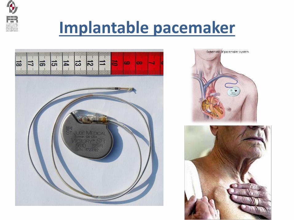
Implantable pacemaker
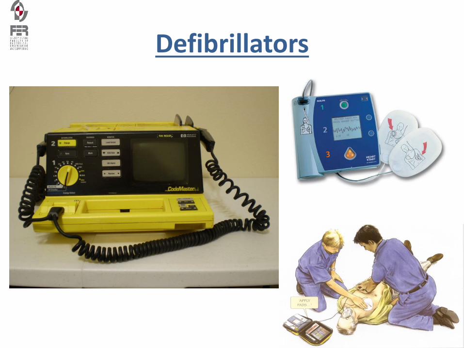
Defibrillators
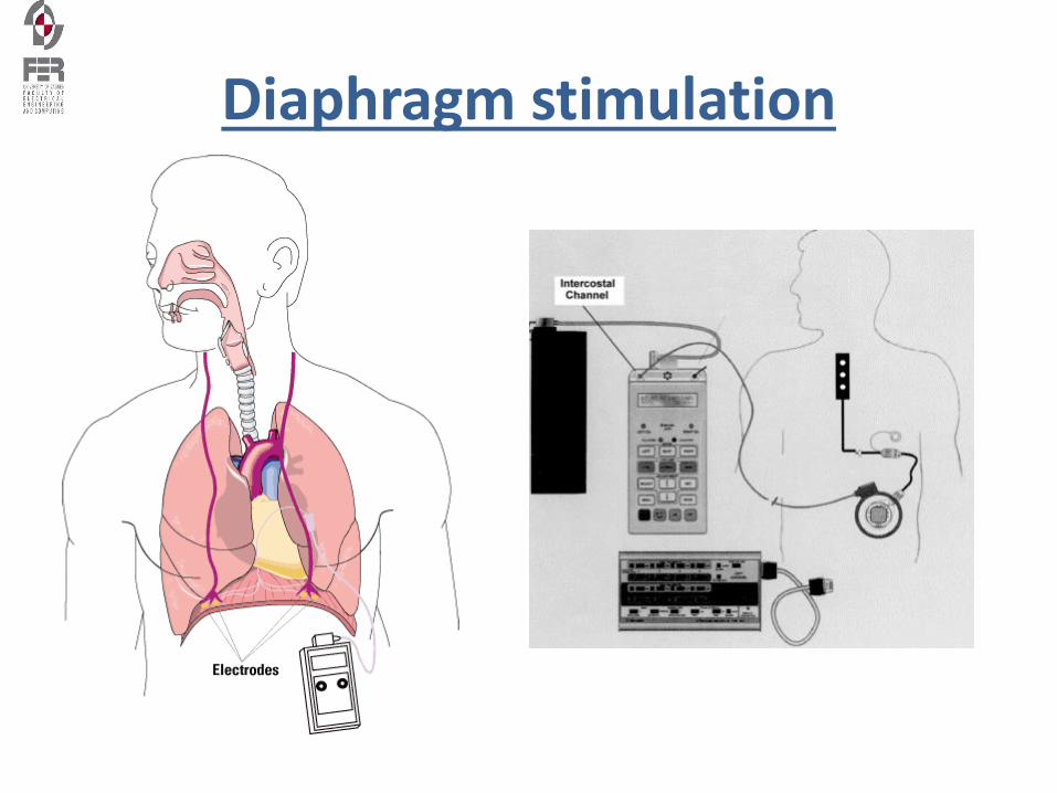
Diaphragm stimulation
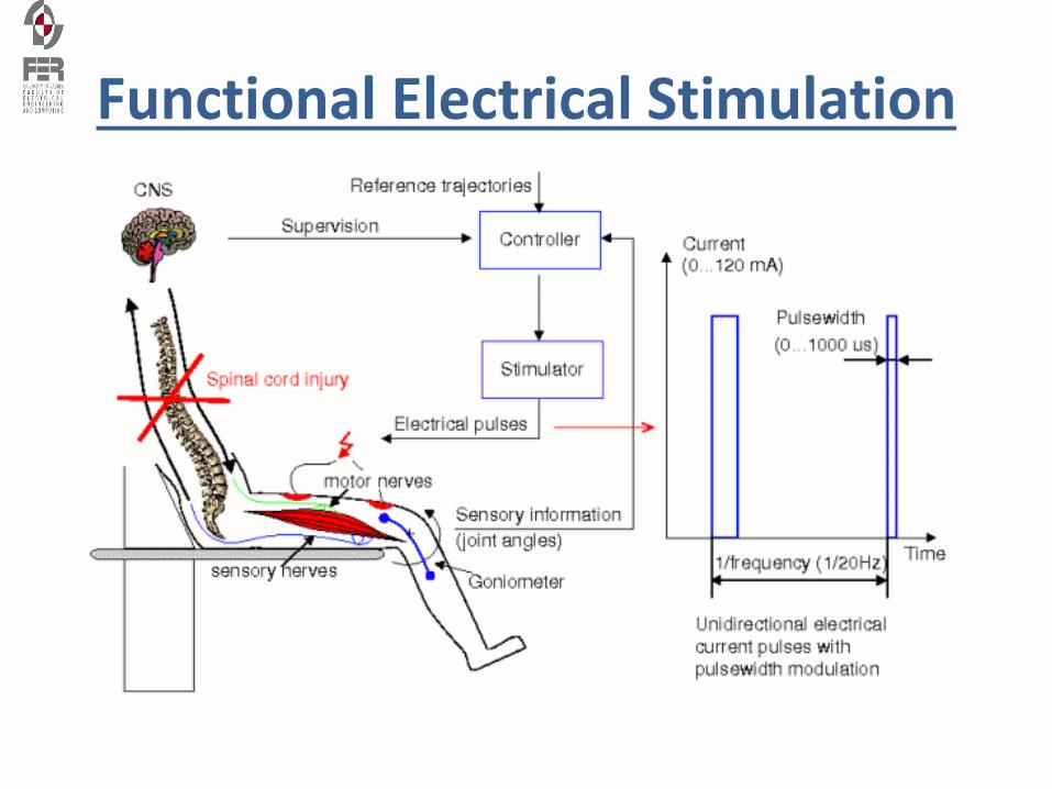
Functional Electrical Stimulation
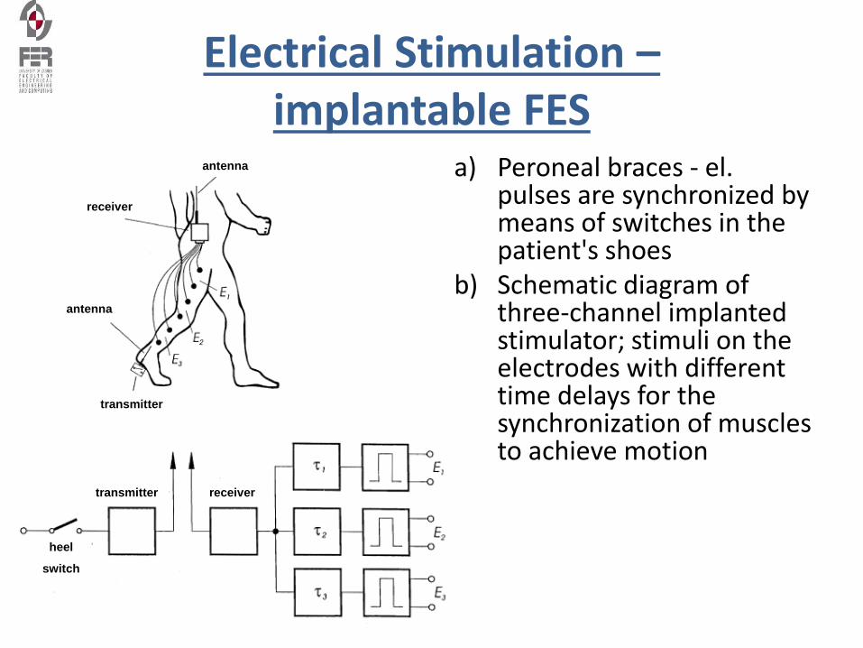
Electrical Stimulation –implantable FES
a) Peroneal braces - el. pulses are synchronized by means of switches in the patient's shoes
b) Schematic diagram of three-channel implanted stimulator; stimuli on theelectrodes with different time delays for the synchronization of muscles to achieve motion
antenna
receiver
antenna
transmitter
transmitter receiver
heel
switch
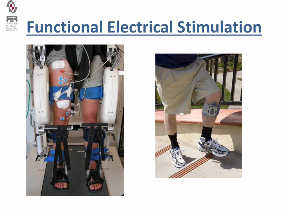
Functional Electrical Stimulation
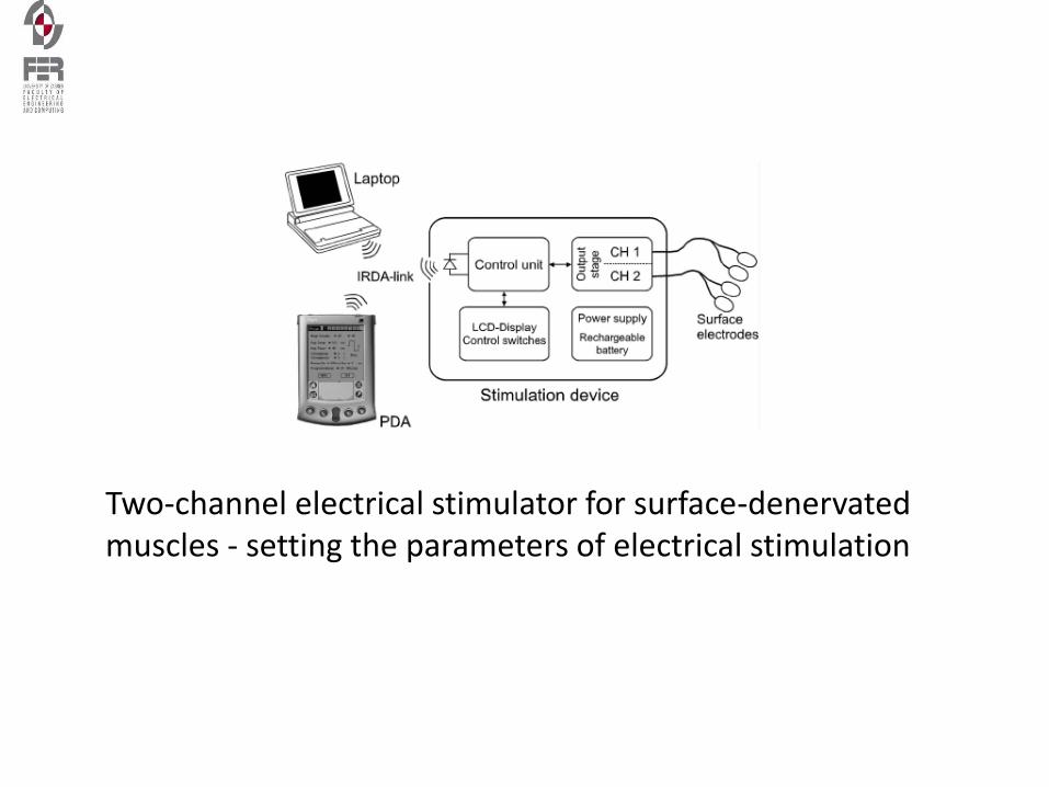
Two-channel electrical stimulator for surface-denervated muscles - setting the parameters of electrical stimulation
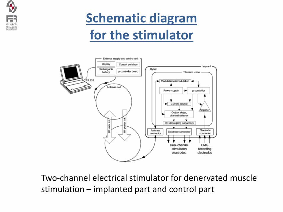
Schematic diagram for the stimulator
Two-channel electrical stimulator for denervated muscle stimulation – implanted part and control part
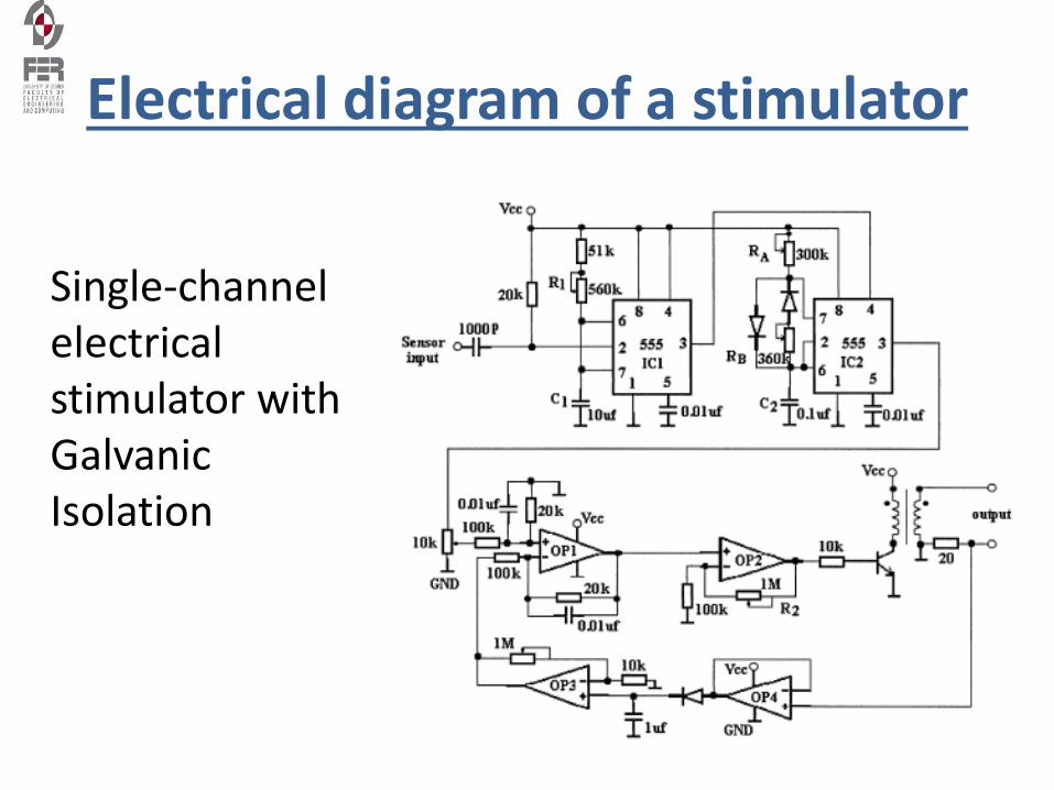
Electrical diagram of a stimulator
Single-channel electrical stimulator with Galvanic Isolation
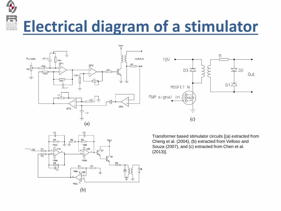
Electrical diagram of a stimulator
Transformer based stimulator circuits [(a) extracted from
Cheng et al. (2004), (b) extracted from Velloso and
Souza (2007), and (c) extracted from Chen et al.
(2013)].
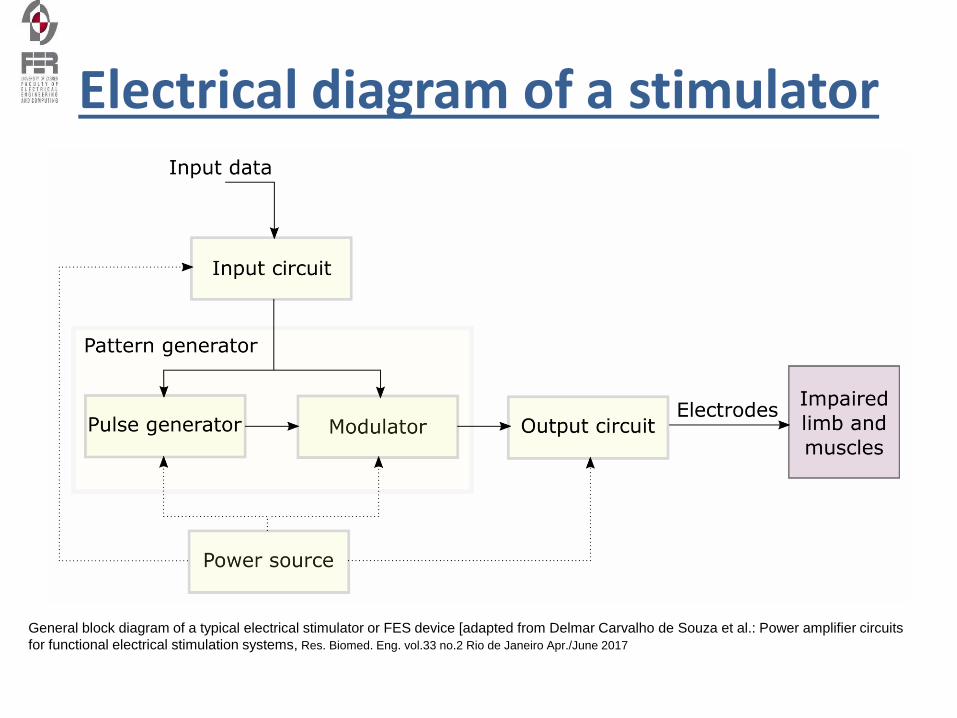
Electrical diagram of a stimulator
General block diagram of a typical electrical stimulator or FES device [adapted from Delmar Carvalho de Souza et al.: Power amplifier circuits
for functional electrical stimulation systems, Res. Biomed. Eng. vol.33 no.2 Rio de Janeiro Apr./June 2017
Types of Electrodes
• Metal Plate Electrodes - early version, limited sizes, required wet sponge conduction medium, difficult to secure in place
• Carbon - Impregnated Rubber Electrodes - degrade over time and become non-uniform with "hot spots", many shapes and sizes, rinse and dry after each use and replaced every 12 months to ensure conductivity.
• Self-Adhering or Single use Electrodes - flexible conductors, convenient application, no strapping or taping to keep in place, resealable bag for multiple uses, often high impendence, possibility of cross-contamination, used most frequently these days.
Electrode Size and Current Density• Current density is the concentration of current under an electrodes.
• Electrode surface area is inversely proportional to current flow. (Larger electrode = current is less dense as it is distributed over a larger area; the smaller the electrode, the more intense the same current becomes over a smaller area.
• Keep the electrode in proportion with size of body area being treated. If the electrode is too large for the area, there could be unwanted carryover to other surrounding structures; if too small, the current is too dense and may not be tolerated to elicit the desired response.
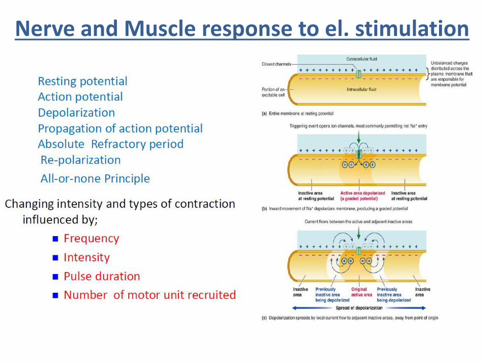
Nerve and Muscle response to el. stimulation
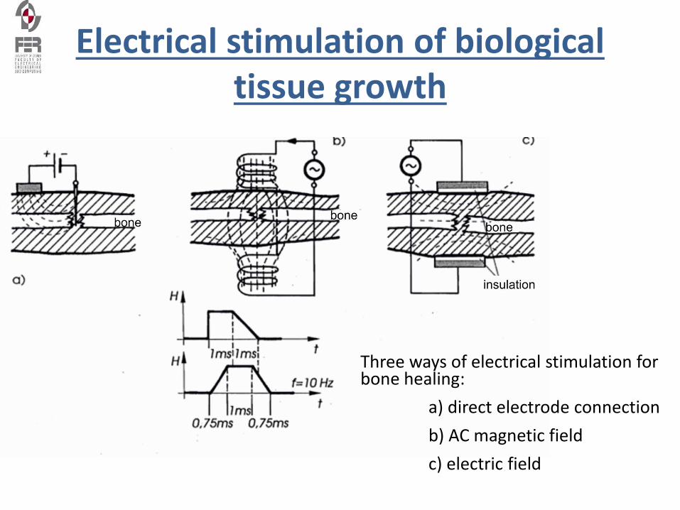
Electrical stimulation of biological tissue growth
Three ways of electrical stimulation for bone healing:
a) direct electrode connection
b) AC magnetic field
c) electric field
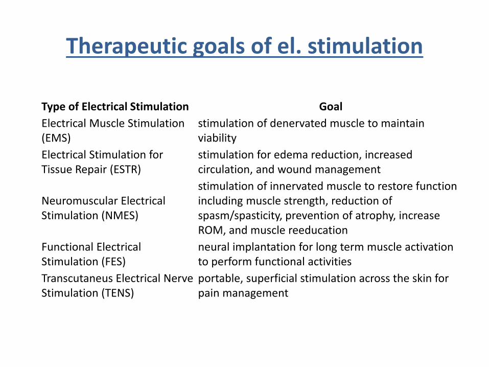
Therapeutic goals of el. stimulation
Type of Electrical Stimulation Goal
Electrical Muscle Stimulation (EMS)
stimulation of denervated muscle to maintain viability
Electrical Stimulation for Tissue Repair (ESTR)
stimulation for edema reduction, increased circulation, and wound management
Neuromuscular Electrical Stimulation (NMES)
stimulation of innervated muscle to restore function including muscle strength, reduction of spasm/spasticity, prevention of atrophy, increase ROM, and muscle reeducation
Functional Electrical Stimulation (FES)
neural implantation for long term muscle activation to perform functional activities
Transcutaneus Electrical Nerve Stimulation (TENS)
portable, superficial stimulation across the skin for pain management
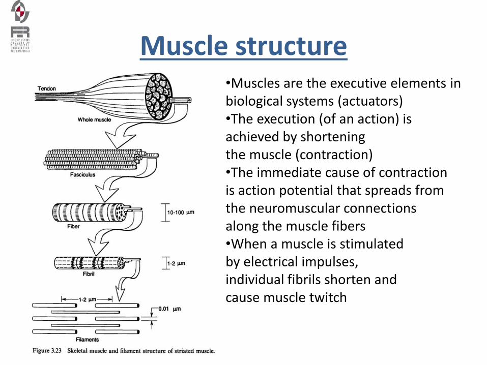
Muscle structure•Muscles are the executive elements in biological systems (actuators)•The execution (of an action) is achieved by shortening the muscle (contraction)•The immediate cause of contraction is action potential that spreads from the neuromuscular connections along the muscle fibers•When a muscle is stimulated by electrical impulses, individual fibrils shorten and cause muscle twitch
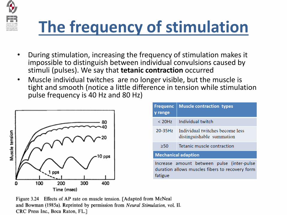
The frequency of stimulation
• During stimulation, increasing the frequency of stimulation makes it impossible to distinguish between individual convulsions caused by stimuli (pulses). We say that tetanic contraction occurred
• Muscle individual twitches are no longer visible, but the muscle is tight and smooth (notice a little difference in tension while stimulation pulse frequency is 40 Hz and 80 Hz)
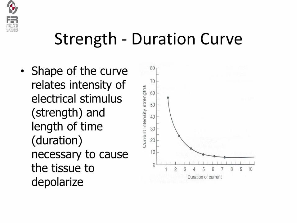
Strength - Duration Curve
• Shape of the curve relates intensity of electrical stimulus (strength) and length of time (duration) necessary to cause the tissue to depolarize
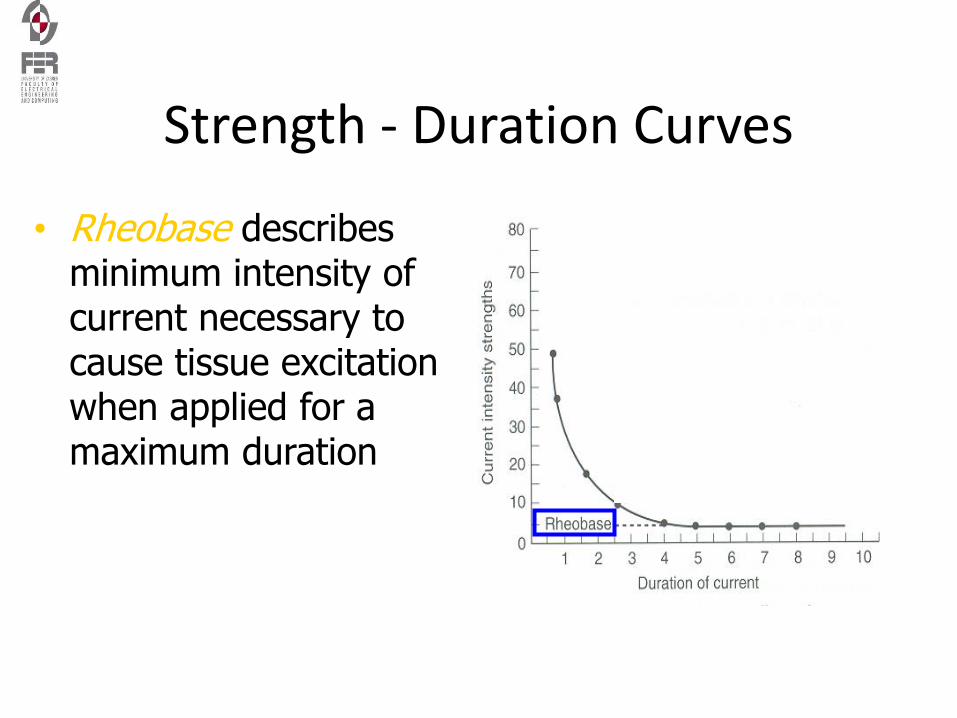
Strength - Duration Curves
• Rheobase describes minimum intensity of current necessary to cause tissue excitation when applied for a maximum duration
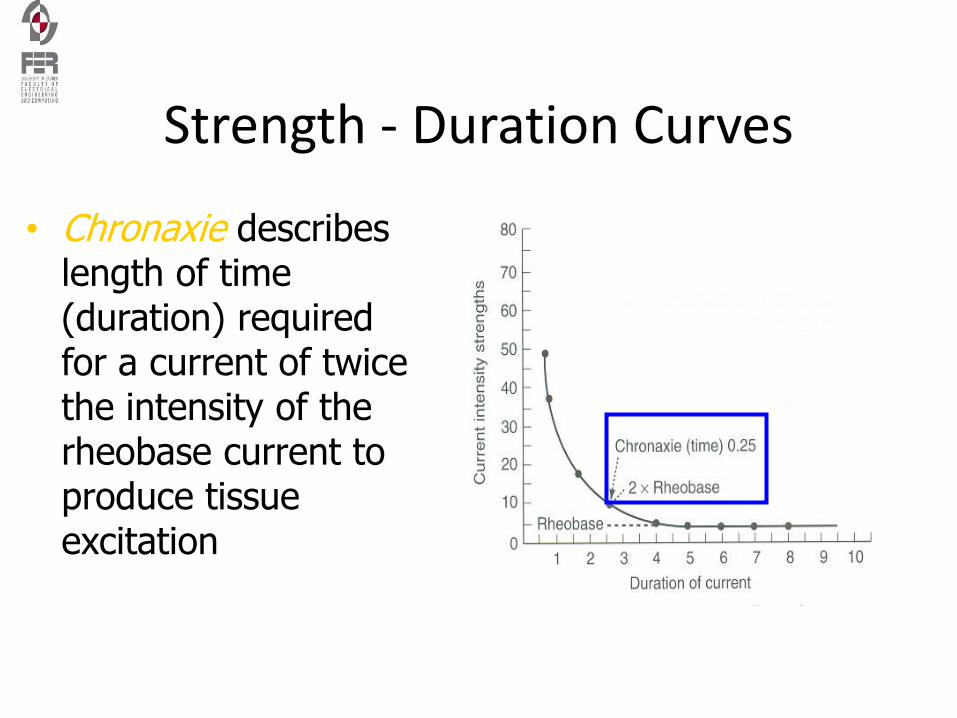
Strength - Duration Curves
• Chronaxie describes length of time (duration) required for a current of twice the intensity of the rheobase current to produce tissue excitation
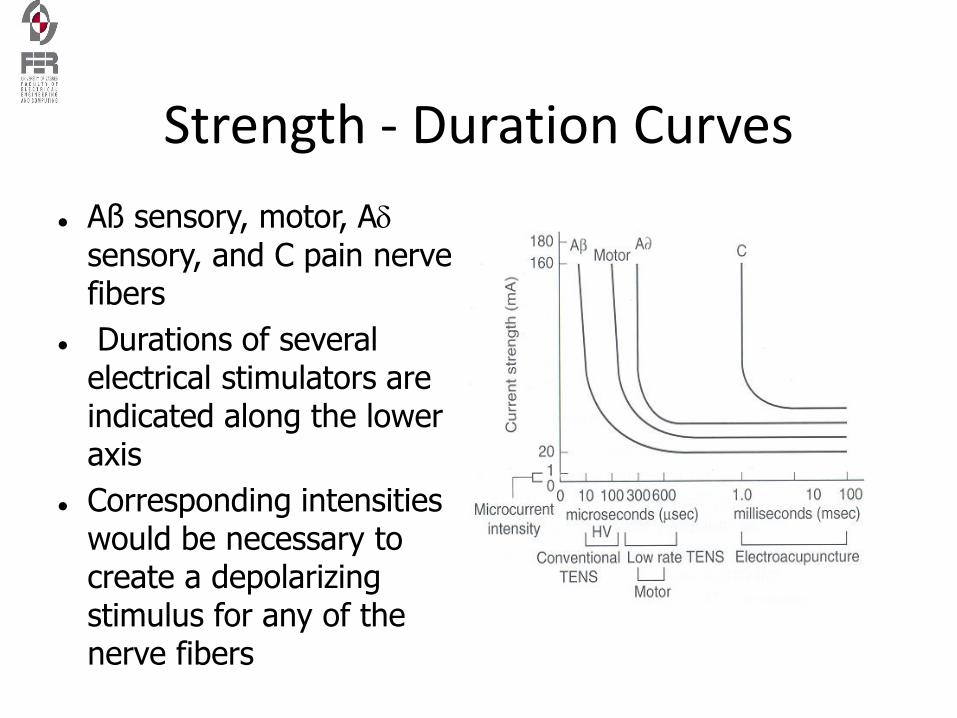
Strength - Duration Curves
Aß sensory, motor, Asensory, and C pain nerve fibers
Durations of several electrical stimulators are indicated along the lower axis
Corresponding intensities would be necessary to create a depolarizing stimulus for any of the nerve fibers
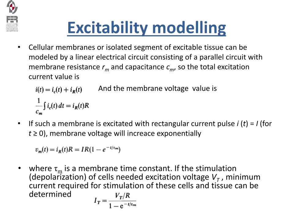
Excitability modelling• Cellular membranes or isolated segment of excitable tissue can be
modeled by a linear electrical circuit consisting of a parallel circuit with membrane resistance rm and capacitance cm, so the total excitation current value is
And the membrane voltage value is
• If such a membrane is excitated with rectangular current pulse i (t) = I (for t ≥ 0), membrane voltage will increace exponentially
• where τm is a membrane time constant. If the stimulation (depolarization) of cells needed excitation voltage VT , minimum current required for stimulation of these cells and tissue can be determined
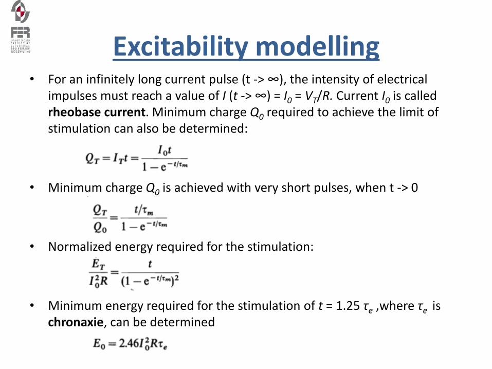
Excitability modelling• For an infinitely long current pulse (t -> ∞), the intensity of electrical
impulses must reach a value of I (t -> ∞) = I0 = VT/R. Current I0 is called rheobase current. Minimum charge Q0 required to achieve the limit of stimulation can also be determined:
• Minimum charge Q0 is achieved with very short pulses, when t -> 0
• Normalized energy required for the stimulation:
• Minimum energy required for the stimulation of t = 1.25 τe ,where τe is chronaxie, can be determined
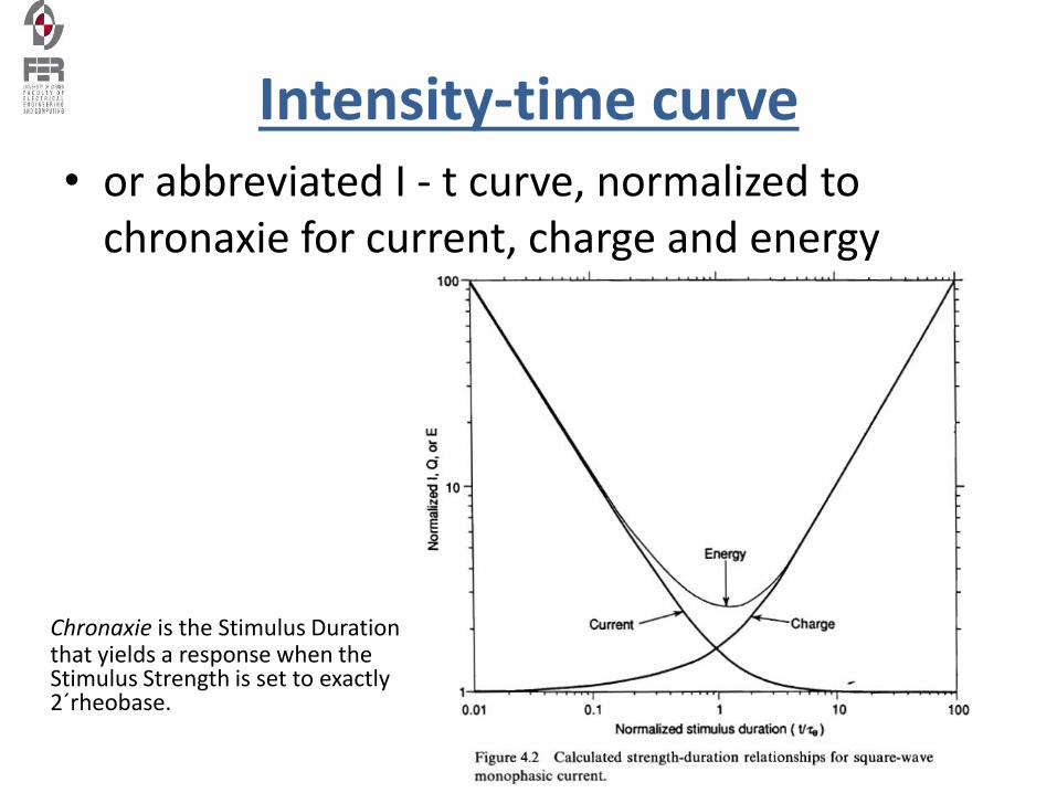
Intensity-time curve• or abbreviated I - t curve, normalized to
chronaxie for current, charge and energy
Chronaxie is the Stimulus Duration that yields a response when the Stimulus Strength is set to exactly 2´rheobase.
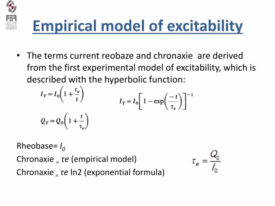
Empirical model of excitability
• The terms current reobaze and chronaxie are derived from the first experimental model of excitability, which is described with the hyperbolic function:
Rheobase= I0
Chronaxie = τe (empirical model)
Chronaxie = τe ln2 (exponential formula)
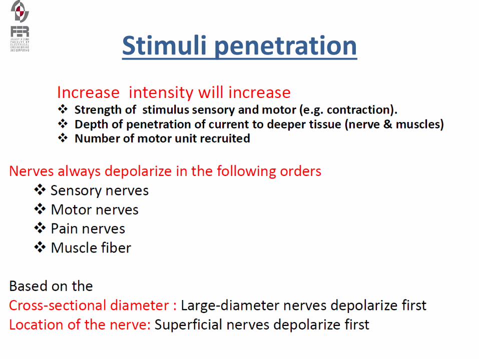
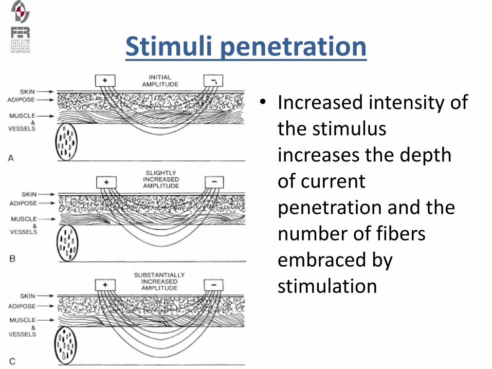
Stimuli penetration
Stimuli penetration
• Increased intensity of the stimulus increases the depth of current penetration and the number of fibers embraced by stimulation
Waveforms of stimuli
• Discussion:
– Why do we use precisely rectangular pulses to stimulate?
– Can you use any other stimulus waveforms?
Constant Current vs. Constant Voltage Stimulator
• Constant Current Stimulators produce a contant current independent of resistance encountered. The voltage adjusts to maintain constant current flow. The advantage of this type of of stimulator is to ensure a consistency physiologic response during the treatment. The negative is potential pain when the voltage increases to overcome resistance.
• Constant Voltage Stimulators, conversely, produce a constant voltage. The current adjusts to depending on changes in resistance. This unit is advantageous in preventing discomfort with changes in resistance, such as an electrode losing full contact, but quality of response can be decreased with these automatic resistance changes.
Basic waveforms in therapeutic electrical stimulation
• Direct Current (DC) or Galvanic
– Continuous unidirectional flow of charged particles with a duration of at least 1 second.
– One electrode is always the anode (+) and one is always the cathode (-) for the entire event.
– There is a build-up of charge since it is moving in one direction causing a strong chemical effect on the tissue under the electrode
• Alternating Current (AC)
– Uniterupted bidirectional flow of charged particles changing direction at least once per second.
– Electrodes continuously changes polarity each cycle, therefore no build-up of charge under the electrodes
– Often used in interferential or Russian commercial stimulators
• Pulsed Current (pulsed)
– Can be unidirectional (like DC) or bidirectional (like AC)
– Flow of charged particles stops periodically for less than 1 second before the next event
– Pulses can occur individually or in a series
Basic waveforms in therapeutic electrical stimulation
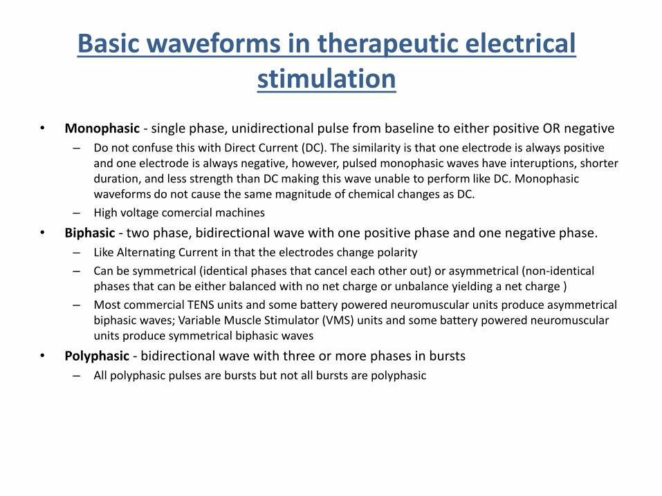
• Monophasic - single phase, unidirectional pulse from baseline to either positive OR negative
– Do not confuse this with Direct Current (DC). The similarity is that one electrode is always positive and one electrode is always negative, however, pulsed monophasic waves have interuptions, shorter duration, and less strength than DC making this wave unable to perform like DC. Monophasic waveforms do not cause the same magnitude of chemical changes as DC.
– High voltage comercial machines
• Biphasic - two phase, bidirectional wave with one positive phase and one negative phase.
– Like Alternating Current in that the electrodes change polarity
– Can be symmetrical (identical phases that cancel each other out) or asymmetrical (non-identical phases that can be either balanced with no net charge or unbalance yielding a net charge )
– Most commercial TENS units and some battery powered neuromuscular units produce asymmetrical biphasic waves; Variable Muscle Stimulator (VMS) units and some battery powered neuromuscular units produce symmetrical biphasic waves
• Polyphasic - bidirectional wave with three or more phases in bursts
– All polyphasic pulses are bursts but not all bursts are polyphasic
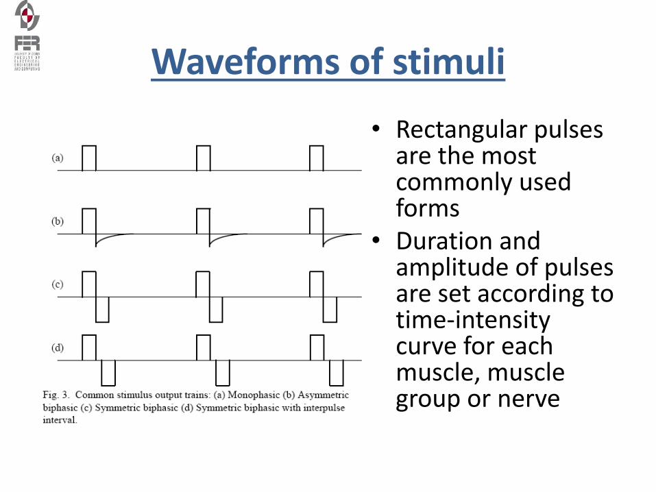
Waveforms of stimuli
• Rectangular pulsesare the most commonly used forms
• Duration and amplitude of pulses are set according totime-intensity curve for each muscle, muscle group or nerve
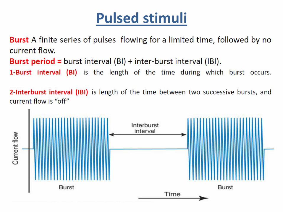
Pulsed stimuli
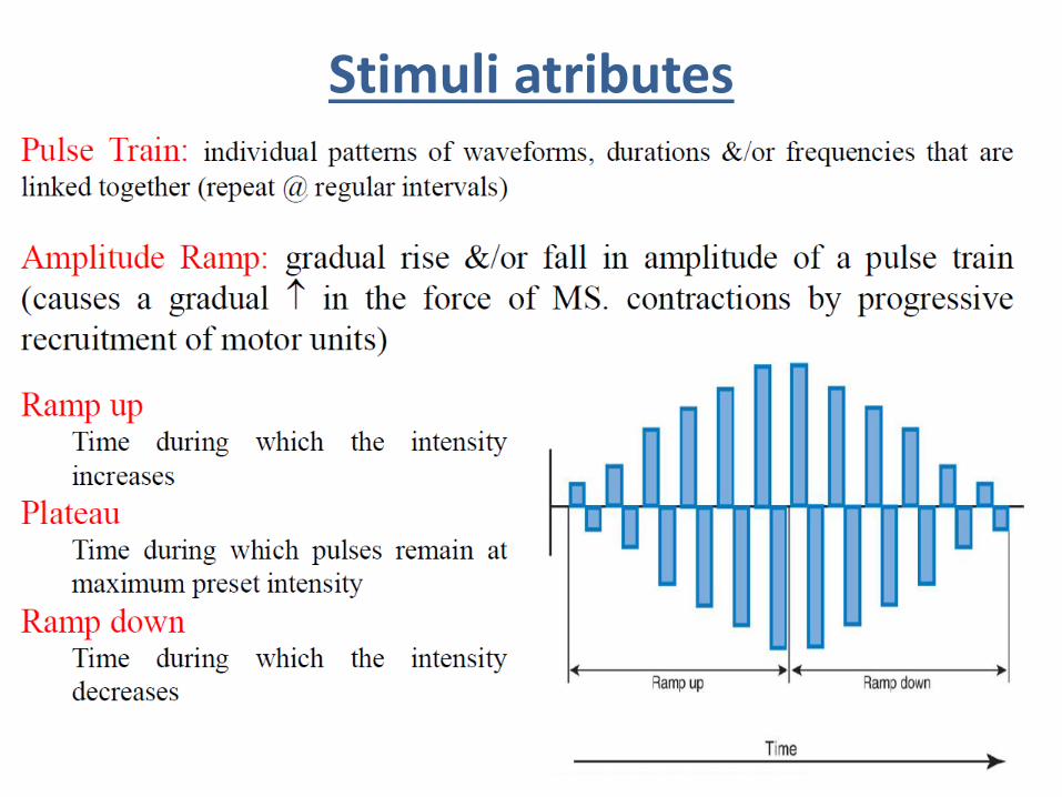
Stimuli atributes
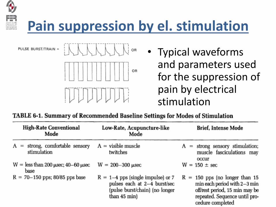
Pain suppression by el. stimulation
• Typical waveforms and parameters used for the suppression of pain by electrical stimulation
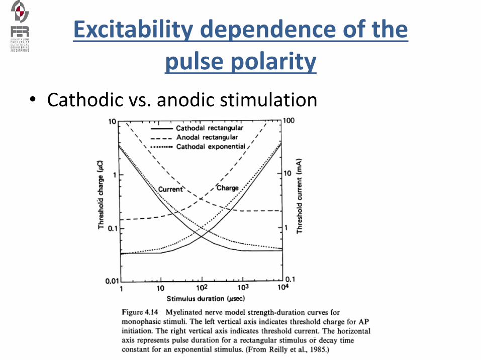
Excitability dependence of the pulse polarity
• Cathodic vs. anodic stimulation
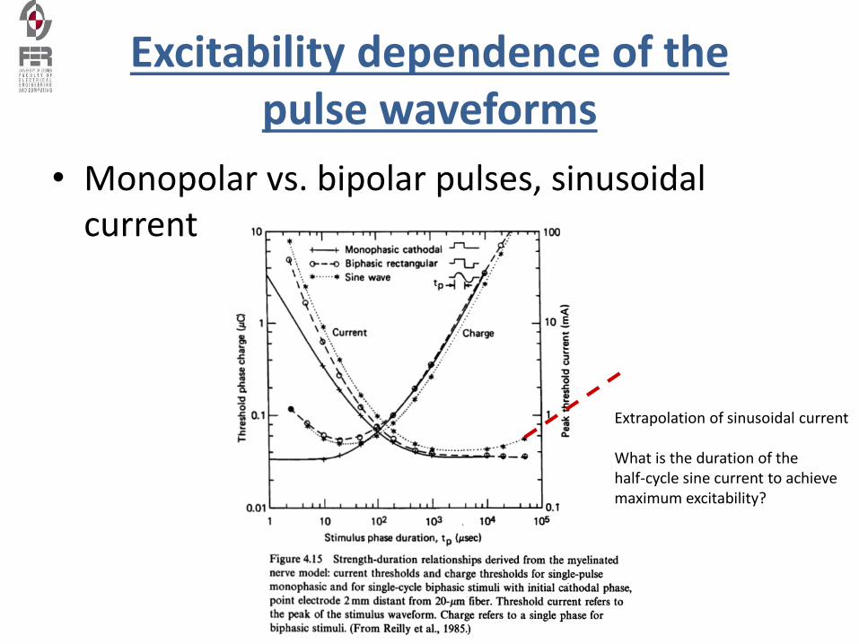
Excitability dependence of the pulse waveforms
• Monopolar vs. bipolar pulses, sinusoidal current
Extrapolation of sinusoidal current
What is the duration of the half-cycle sine current to achieve maximum excitability?
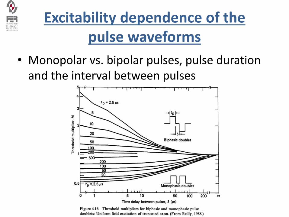
Excitability dependence of the pulse waveforms
• Monopolar vs. bipolar pulses, pulse duration and the interval between pulses
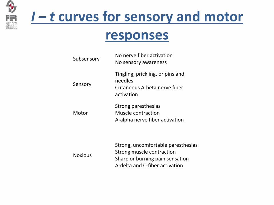
I – t curves for sensory and motor responses
SubsensoryNo nerve fiber activationNo sensory awareness
Sensory
Tingling, prickling, or pins and needlesCutaneous A-beta nerve fiber activation
MotorStrong paresthesiasMuscle contractionA-alpha nerve fiber activation
Noxious
Strong, uncomfortable paresthesiasStrong muscle contractionSharp or burning pain sensationA-delta and C-fiber activation
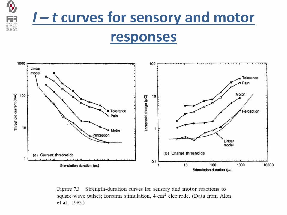
I – t curves for sensory and motor responses
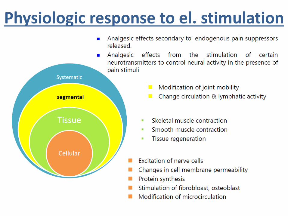
Physiologic response to el. stimulation
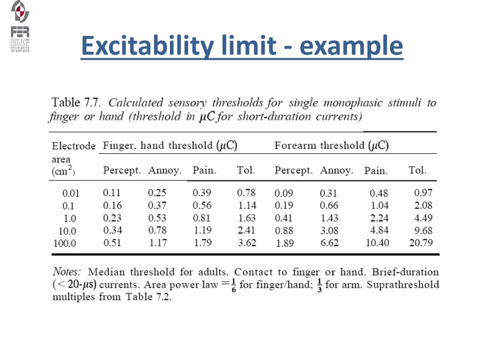
Excitability limit - example
Literature
• J. Malmivuo, R.Plonsey, Bioelectromagnetism, Oxford Press, 1995, www.bem.fi, chapter 21 (FES); chapter 23 (cardiac pacing); chapter 24 (defibrillation)
• J. Weber: Medical Instrumentation, Chapter 13, Therapeutic and Prosthetic Devices
• S. Hamid and R. Hayek, Role of electrical stimulation for rehabilitation and regeneration after spinal cord injury: anoverviewhttp://www.ncbi.nlm.nih.gov/pmc/articles/PMC2527422/
• Mayr W, Bijak M, Rafolt D, Sauermann S, Unger E, Lanmueller H: Basic design and construction of the ViennaFES implants - existing solutions and prospects for new generations of implants. Medical Engineering and Physics2001; 23: 53-60.
![Education in instrumentation and measurement: the information and communication technology trends [Instrumentation notes]](https://img.dokumen.tips/doc/110x75/63355377a25de9cc4a061fa8/education-in-instrumentation-and-measurement-the-information-and-communication.jpg)