Embed Size (px)
Citation preview
Belimo Damper Air Flow Linearizing Tutorial Rev 1
1
DAMPER AIR FLOW LINEARIZING TUTORIAL
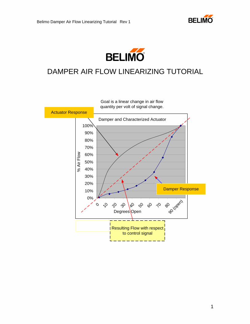
Damper and Characterized Actuator
0%
10%
20%
30%
40%
50%
60%
70%
80%
90%
100%
0 10 20 30 40 50 60 70 80
90 (o
pen)
Degrees Open
% A
ir Fl
ow
Damper Response
Actuator Response
Goal is a linear change in air flowquantity per volt of signal change.
Resulting Flow with respectto control signal
Belimo Damper Air Flow Linearizing Tutorial Rev 1
2
Contents
Introduction .......................................................................................................3 Problem Applications.........................................................................................4 System Self-Correction .....................................................................................5 Control Loop Tuning..........................................................................................6 Authority Concept..............................................................................................6 Summary of Damper Characterization Methods..............................................10 AMCA Figure Numbers – Geometric Set-ups..................................................10 The Danger in Over-Generalizing from Ducted to Other Geometries..............12 Linearizing Actuator and Damper Combination...............................................13 Review ............................................................................................................14
Appendix 1 Testing Results from ASHRAE RP1157.................................17
AMCA 5.1 Entrances ...................................................................................17 Louvered Entrances.....................................................................................18 AMCA Type 5.2 Exits...................................................................................19 Louvered Exits .............................................................................................20 AMCA 5.3 Ducted Type Applications...........................................................20 AMCA 5.3 Ducted Type Applications...........................................................21 AMCA 5.4 Plenum Entrances ......................................................................23 AMCA 5.5 Plenum Exits ..............................................................................24
Appendix 2 Estimating Authority ...................................................................25 Appendix 3 Estimating full open damper losses ...........................................26
Belimo Damper Air Flow Linearizing Tutorial Rev 1
3
Damper Air Flow Response
Introduction
Q
ROTATION
RA
EA orOA
TOTAL Q
ROTATION
EA orOA
TOTAL
Q
ROTATION
A )
C )
B)
At any given fan speed modulationof economizer dampers shouldallow flow quantity to remain nearconstant.
Figure 1 Problems and Design Goal
RA
TOTAL
Problems
Design Goal
Total quantity of air flow through a system.
In modulating dampers for air flow control a number of non-linearities are possible and must be defeated to gain accuracy. The applications here concentrate on the economizer section of air handlers, but the ideas can be applied to less complex arrangements of dampers also.
The goal is to present the concept of a programmable actuator and damper combination dependent on the geometry of the situation. Figure 1 shows the problems that sometimes exist and the design goal.
The exact shape of any damper curve depends on these main factors:
1. Action – opposed blade (OB) or parallel blade (PB). 2. Geometry – Entry, ducted, plenum, etc. 3. Authority – the amount of pressure loss within the damper itself compared
to the subsystem in which it is installed.
Belimo Damper Air Flow Linearizing Tutorial Rev 1
4
4. Presence of jackshafts and/or linkages which may or may not change the rotation of the blades with respect to the actuator rotation. The full open flow is not affected by linkages or jackshafts, nor by PB or OB use.
5. The entering flow profile – e.g., if near an elbow, most of the air can be moving thru the top area of the damper and flowing backwards in the bottom.
6. Free area ratio of the damper with respect to the duct or wall. This is an orifice effect where A1/A2 can have a significant effect. For small areas inside the damper, the application is similar to that of a wall.
Problem Applications
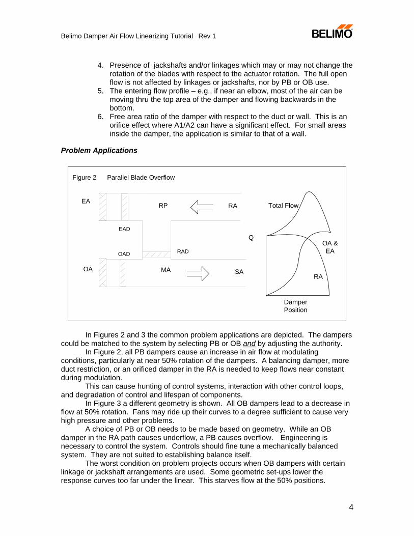
Figure 2 Parallel Blade Overflow
OA
EA
RADOAD
EAD
RA
SAMA
RP
RA
OA &EA
Total Flow
Q
DamperPosition
In Figures 2 and 3 the common problem applications are depicted. The dampers could be matched to the system by selecting PB or OB and by adjusting the authority. In Figure 2, all PB dampers cause an increase in air flow at modulating conditions, particularly at near 50% rotation of the dampers. A balancing damper, more duct restriction, or an orificed damper in the RA is needed to keep flows near constant during modulation. This can cause hunting of control systems, interaction with other control loops, and degradation of control and lifespan of components.
In Figure 3 a different geometry is shown. All OB dampers lead to a decrease in flow at 50% rotation. Fans may ride up their curves to a degree sufficient to cause very high pressure and other problems. A choice of PB or OB needs to be made based on geometry. While an OB damper in the RA path causes underflow, a PB causes overflow. Engineering is necessary to control the system. Controls should fine tune a mechanically balanced system. They are not suited to establishing balance itself. The worst condition on problem projects occurs when OB dampers with certain linkage or jackshaft arrangements are used. Some geometric set-ups lower the response curves too far under the linear. This starves flow at the 50% positions.
Belimo Damper Air Flow Linearizing Tutorial Rev 1
5
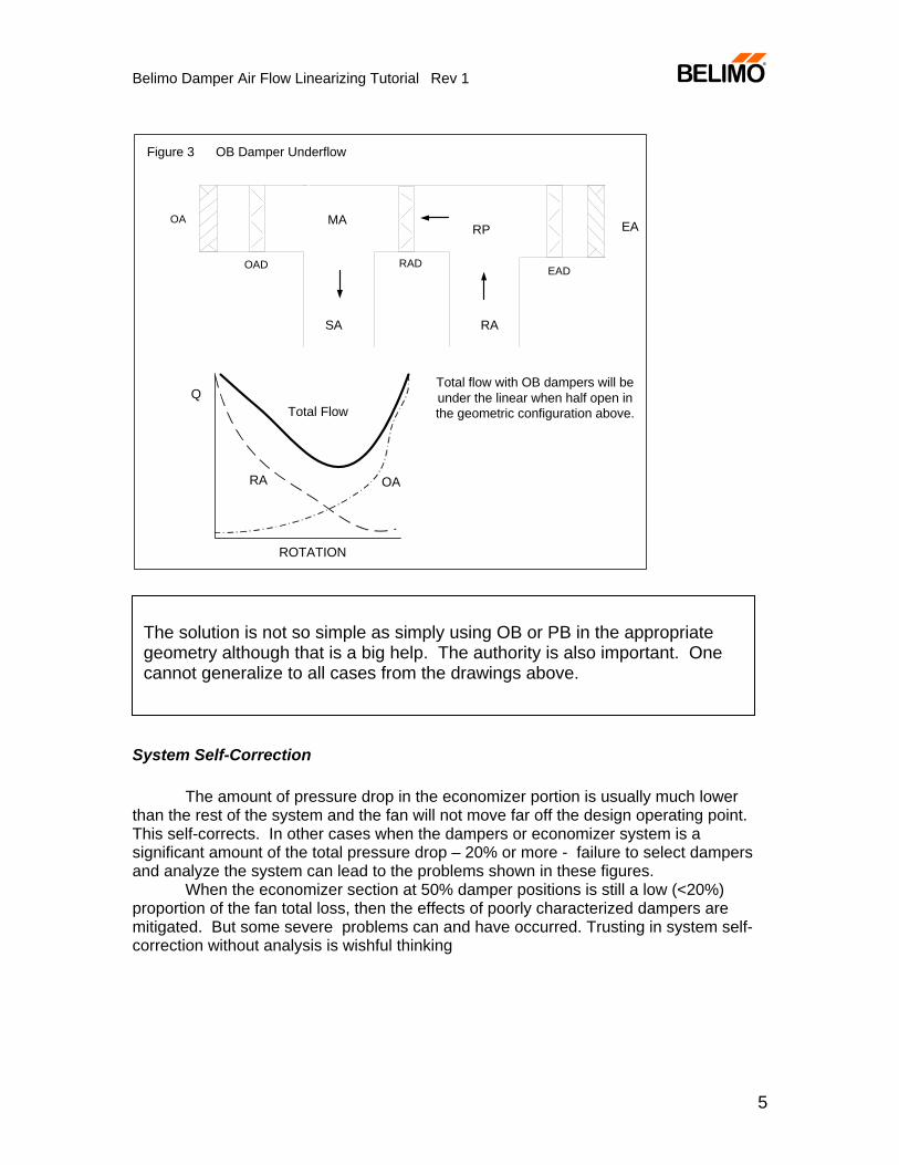
Figure 3 OB Damper Underflow
EA
EAD
RA
RP
RAD
OA
SA
MA
QTotal flow with OB dampers will beunder the linear when half open inthe geometric configuration above.
OAD
ROTATION
OARA
Total Flow
System Self-Correction
The amount of pressure drop in the economizer portion is usually much lower than the rest of the system and the fan will not move far off the design operating point. This self-corrects. In other cases when the dampers or economizer system is a significant amount of the total pressure drop – 20% or more - failure to select dampers and analyze the system can lead to the problems shown in these figures.
When the economizer section at 50% damper positions is still a low (<20%) proportion of the fan total loss, then the effects of poorly characterized dampers are mitigated. But some severe problems can and have occurred. Trusting in system self-correction without analysis is wishful thinking
The solution is not so simple as simply using OB or PB in the appropriate geometry although that is a big help. The authority is also important. One cannot generalize to all cases from the drawings above.
Belimo Damper Air Flow Linearizing Tutorial Rev 1
6
Control Loop Tuning
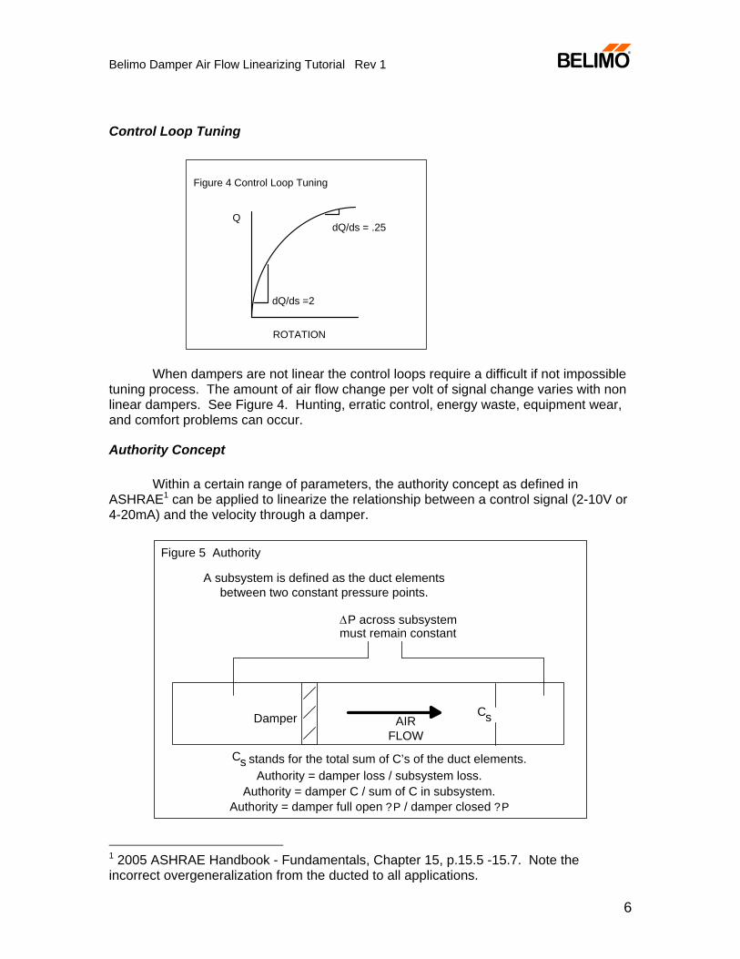
When dampers are not linear the control loops require a difficult if not impossible
tuning process. The amount of air flow change per volt of signal change varies with non linear dampers. See Figure 4. Hunting, erratic control, energy waste, equipment wear, and comfort problems can occur.
Authority Concept
Within a certain range of parameters, the authority concept as defined in ASHRAE1 can be applied to linearize the relationship between a control signal (2-10V or 4-20mA) and the velocity through a damper.
Authority = damper loss / subsystem loss.Authority = damper C / sum of C in subsystem.
Authority = damper full open ?P / damper closed ?P
AIRFLOW
ΔP across subsystemmust remain constant
Figure 5 Authority
Damper Cs
A subsystem is defined as the duct elementsbetween two constant pressure points.
Cs stands for the total sum of C’s of the duct elements.
1 2005 ASHRAE Handbook - Fundamentals, Chapter 15, p.15.5 -15.7. Note the incorrect overgeneralization from the ducted to all applications.
Q
ROTATION
dQ/ds =2
dQ/ds = .25
Figure 4 Control Loop Tuning
Belimo Damper Air Flow Linearizing Tutorial Rev 1
7
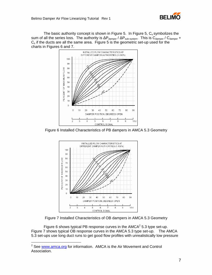
The basic authority concept is shown in Figure 5. In Figure 5, Cs symbolizes the sum of all the series loss. The authority is ΔPdamper / ΔPsub-system. This is Cdamper / Cdamper + Cs if the ducts are all the same area. Figure 5 is the geometric set-up used for the charts in Figures 6 and 7.
Figure 6 Installed Characteristics of PB dampers in AMCA 5.3 Geometry
Figure 7 Installed Characteristics of OB dampers in AMCA 5.3 Geometry
Figure 6 shows typical PB response curves in the AMCA2 5.3 type set-up.
Figure 7 shows typical OB response curves in the AMCA 5.3 type set-up. The AMCA 5.3 set-ups use long duct runs to get good flow profiles with unrealistically low pressure
2 See www.amca.org for information. AMCA is the Air Movement and Control Association.
Belimo Damper Air Flow Linearizing Tutorial Rev 1
8
drops as a result. For laboratory repeatability, good flow profiles are necessary. The authority curves do not take bad duct flow profiles into account. Examination of Figures 6 and 7 shows that a typical PB damper is linear at about 25% to 35% authority and a typical OB damper is roughly linear between 10% and 15% authority. These charts are based on tests on old style dampers used in the 1950’s and are not highly accurate. In addition, they are ducted only and one cannot generalize to other geometries.
This is a geometric application dependent issue. We cannot generalize from the ducted application to say, a plenum wall application.
Figure 6 Installed Characteristics of PB damper in AMCA 5.3 Geometry Interaction of airflows is another complication – as dampers are placed closer
together, the interactions affect the flows – for the most part, untested. The curves in Figures 6 and 7 are not as regular as shown and once thought, but
they show the tendency in the damper responses in the geometry tested. If the damper is the only pressure loss in a subsystem between two constant
pressure points, then it has an authority of 100%. If it has .25 in. w.c. in a system with 1 in. w.c., then it would have 25% authority.
Examination of the curves shows that if the authority is 100%, that the PB has a shallow equal percentage curve similar to the ball or butterfly valve. If an OB damper has 100% authority, then it has a deeper equal percentage curve similar to the Belimo characterized control valve or globe valve.
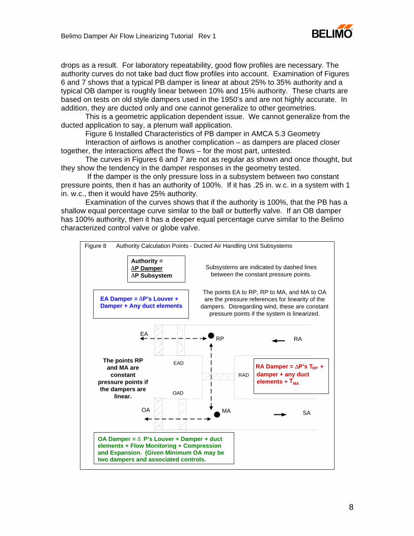
Figure 8 Authority Calculation Points - Ducted Air Handling Unit Subsystems
OA
EA
RAD
OAD
EAD
RA
SAMA
RP
OA Damper = Δ P’s Louver + Damper + ductelements + Flow Monitoring + Compressionand Expansion. (Given Minimum OA may betwo dampers and associated controls.
Authority =ΔP DamperΔP Subsystem
RA Damper = ΔP’s TRP +damper + any ductelements +
EA Damper = ΔP’s Louver +Damper + Any duct elements
The points EA to RP, RP to MA, and MA to OAare the pressure references for linearity of the
dampers. Disregarding wind, these are constantpressure points if the system is linearized.
The points RPand MA are
constantpressure points ifthe dampers are
linear.
Subsystems are indicated by dashed linesbetween the constant pressure points.
TMA
Belimo Damper Air Flow Linearizing Tutorial Rev 1
9
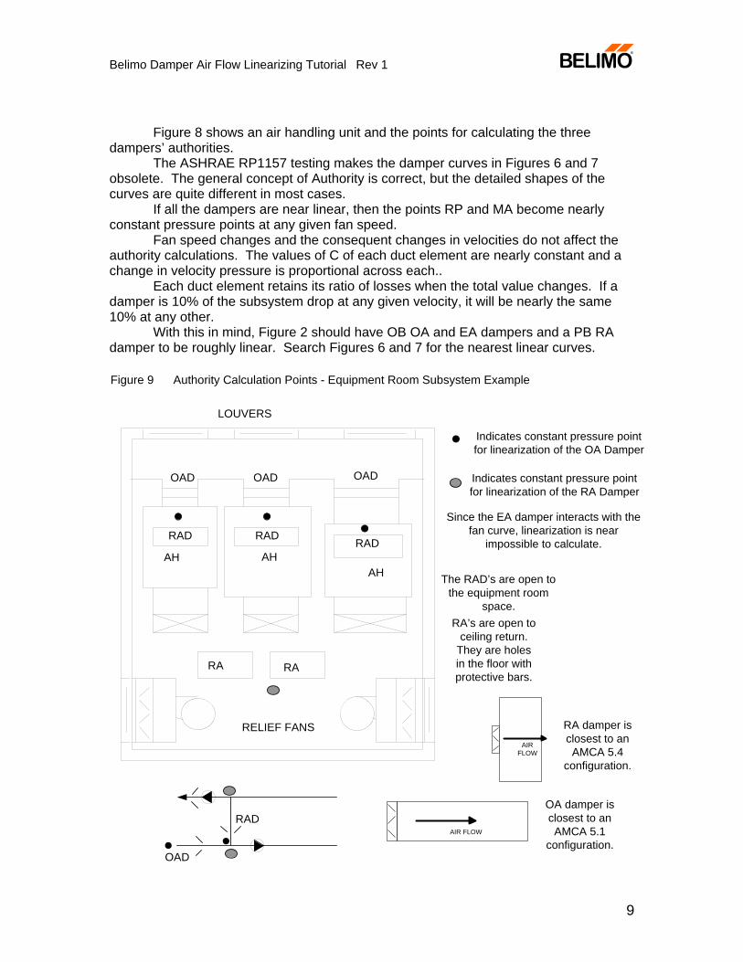
Figure 8 shows an air handling unit and the points for calculating the three
dampers’ authorities. The ASHRAE RP1157 testing makes the damper curves in Figures 6 and 7
obsolete. The general concept of Authority is correct, but the detailed shapes of the curves are quite different in most cases.
If all the dampers are near linear, then the points RP and MA become nearly constant pressure points at any given fan speed.
Fan speed changes and the consequent changes in velocities do not affect the authority calculations. The values of C of each duct element are nearly constant and a change in velocity pressure is proportional across each..
Each duct element retains its ratio of losses when the total value changes. If a damper is 10% of the subsystem drop at any given velocity, it will be nearly the same 10% at any other.
With this in mind, Figure 2 should have OB OA and EA dampers and a PB RA damper to be roughly linear. Search Figures 6 and 7 for the nearest linear curves.
LOUVERS
OAD
RAD RADRAD
OAD OAD
RA RA
RELIEF FANS
AH
The RAD’s are open tothe equipment room
space.RA’s are open to
ceiling return.They are holesin the floor withprotective bars.
Figure 9 Authority Calculation Points - Equipment Room Subsystem Example
AHAH
Indicates constant pressure pointfor linearization of the OA Damper
Indicates constant pressure pointfor linearization of the RA Damper
RAD
OAD
AIR FLOW
RA damper isclosest to anAMCA 5.4
configuration.
OA damper isclosest to anAMCA 5.1
configuration.
AIRFLOW
Since the EA damper interacts with thefan curve, linearization is near
impossible to calculate.
Belimo Damper Air Flow Linearizing Tutorial Rev 1
10
Figure 3 shows a more complex system. The full open damper with a 70-80% free area ratio has Copen = about 1. The recirculation damper and each of the T’s then has C =1. The authority of the damper is 33%. A PB is indicated. The EA and OA can use OB dampers since each approaches 10% authority given the louver drop.
We must be careful not to over-generalize here. The recirculation path is often convoluted due to space constraints and as its duct element pressure losses increase, an OB becomes the better choice.
Knowledge of the loss coefficients of the dampers and a hydraulic analysis of the duct system must be performed to arrive at the correct sizing and selection. One should also be aware of the variation in loss coefficients in the RP and MA tees. C varies with the percent of flow from 1 to 5 in some configurations.
Summary of Damper Characterization Methods
There are a number of methods of maintaining constant flow. Refer to the Dampers and Air Flow Control book at www.belimo.us (or www.belimo.ca) “AF Linearizing Actuator” for a free copy. Material in the book details the methods that are merely listed here.
The other methods are: 1. MIDPOINT LINEARIZATION 2. VAV FAN ADJUSTMENT 3. COMBINATION PARALLEL AND OPPOSED BLADE DAMPERS 4. AUTHORITY TOTALIZATION 5. MULTI-POINT COMMISSIONING AND SIGNAL CONDITIONING 6. SOFTWARE RANGE CONTROL 7. HARDWARE RANGE CONTROL 8. BLANKOFF LINEARIZATION 9. LINKAGE LINEARIZATION 10. FULLY CHARACTERIZED DAMPERS 11. MULTI STAGE DAMPER CONTROL 12. LINEARIZING ACTUATOR (Covered in this document.)
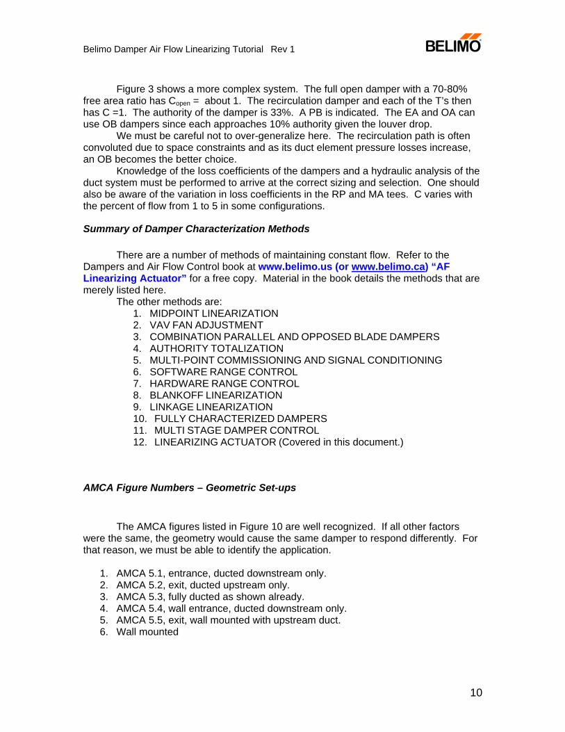
AMCA Figure Numbers – Geometric Set-ups
The AMCA figures listed in Figure 10 are well recognized. If all other factors
were the same, the geometry would cause the same damper to respond differently. For that reason, we must be able to identify the application.
1. AMCA 5.1, entrance, ducted downstream only. 2. AMCA 5.2, exit, ducted upstream only. 3. AMCA 5.3, fully ducted as shown already. 4. AMCA 5.4, wall entrance, ducted downstream only. 5. AMCA 5.5, exit, wall mounted with upstream duct. 6. Wall mounted
Belimo Damper Air Flow Linearizing Tutorial Rev 1
11
Ducted
5.25.15.3
Figure 10 Geometric Applications with AMCA Figure numbers
Walled
5.4 5.5Case
6
Any individual damperin the AH figures here
could be any of theAMCA figures
depending on thesituation.
Other geometrical effects existwhich are still untested.
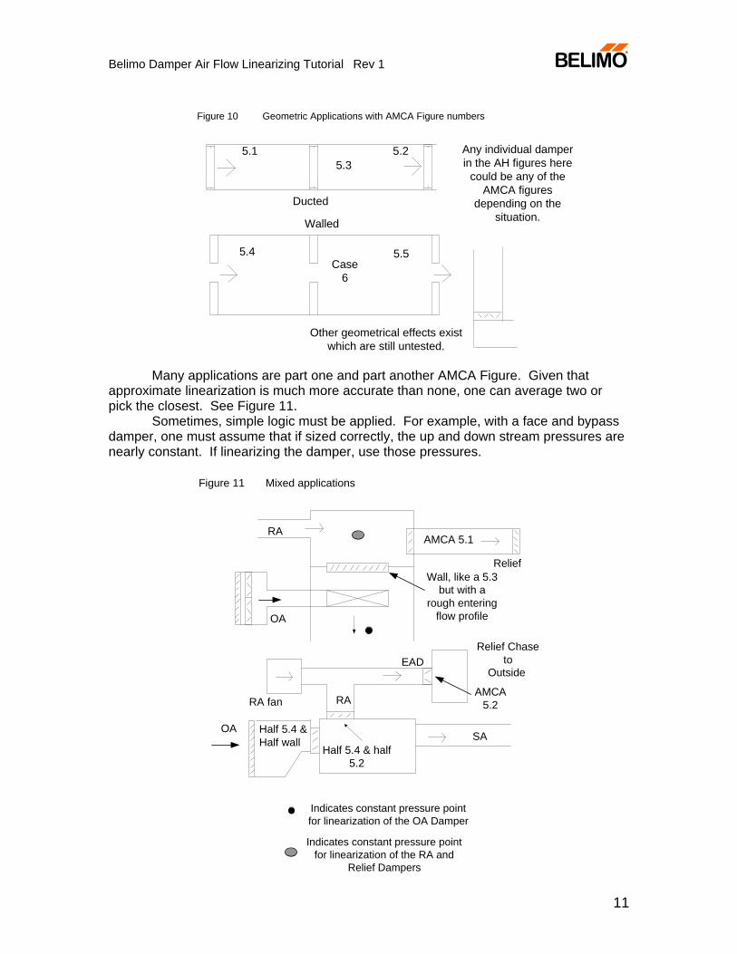
Many applications are part one and part another AMCA Figure. Given that approximate linearization is much more accurate than none, one can average two or pick the closest. See Figure 11. Sometimes, simple logic must be applied. For example, with a face and bypass damper, one must assume that if sized correctly, the up and down stream pressures are nearly constant. If linearizing the damper, use those pressures.
Figure 11 Mixed applications
AMCA 5.1
Wall, like a 5.3but with a
rough enteringflow profile
Relief
RA
OA
OA Half 5.4 &Half wall
RA fan
SA
Relief Chaseto
OutsideEAD
Half 5.4 & half5.2
RAAMCA
5.2
Indicates constant pressure pointfor linearization of the OA Damper
Indicates constant pressure pointfor linearization of the RA and
Relief Dampers
Belimo Damper Air Flow Linearizing Tutorial Rev 1
12
The Danger in Over-Generalizing from Ducted to Other Geometries
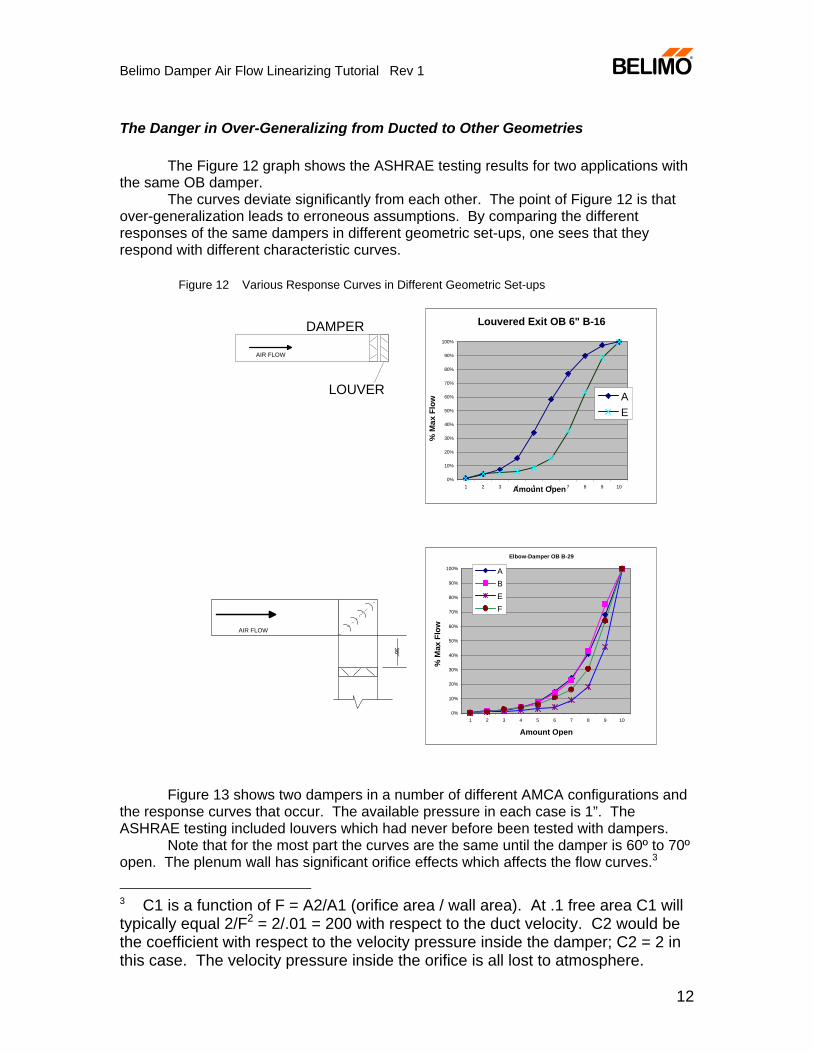
The Figure 12 graph shows the ASHRAE testing results for two applications with the same OB damper.
The curves deviate significantly from each other. The point of Figure 12 is that over-generalization leads to erroneous assumptions. By comparing the different responses of the same dampers in different geometric set-ups, one sees that they respond with different characteristic curves.
Figure 12 Various Response Curves in Different Geometric Set-ups
DAMPER
LOUVER
Louvered Exit OB 6" B-16
0%
10%
20%
30%
40%
50%
60%
70%
80%
90%
100%
1 2 3 4 5 6 7 8 9 10Amount Open
% M
ax F
low A
E
Elbow-Damper OB B-29
0%
10%
20%
30%
40%
50%
60%
70%
80%
90%
100%
1 2 3 4 5 6 7 8 9 10
Amount Open
% M
ax F
low
ABEF
36W X 48HAIR FLOW
36"
AIR FLOW
Figure 13 shows two dampers in a number of different AMCA configurations and the response curves that occur. The available pressure in each case is 1”. The ASHRAE testing included louvers which had never before been tested with dampers.
Note that for the most part the curves are the same until the damper is 60º to 70º open. The plenum wall has significant orifice effects which affects the flow curves.3
3 C1 is a function of F = A2/A1 (orifice area / wall area). At .1 free area C1 will typically equal 2/F2 = 2/.01 = 200 with respect to the duct velocity. C2 would be the coefficient with respect to the velocity pressure inside the damper; C2 = 2 in this case. The velocity pressure inside the orifice is all lost to atmosphere.
Belimo Damper Air Flow Linearizing Tutorial Rev 1
13
PB Absolute Velocities at 1" Pressure Drop
0
2000
4000
6000
8000
10000
12000
0 10 20 30 40 50 60 70 80
90 (o
pen)
Amount OpenAMCA 5.3 in Bold
Velo
city
A5.1 3V
A5.1 AF
A5.2 3V
A5.2 AF
A 5.3 3V
A5.3 AF
A5.3 AE 3V
A 5.4 3V
A5.4 AF
A5.5 3V
A5.5 AF
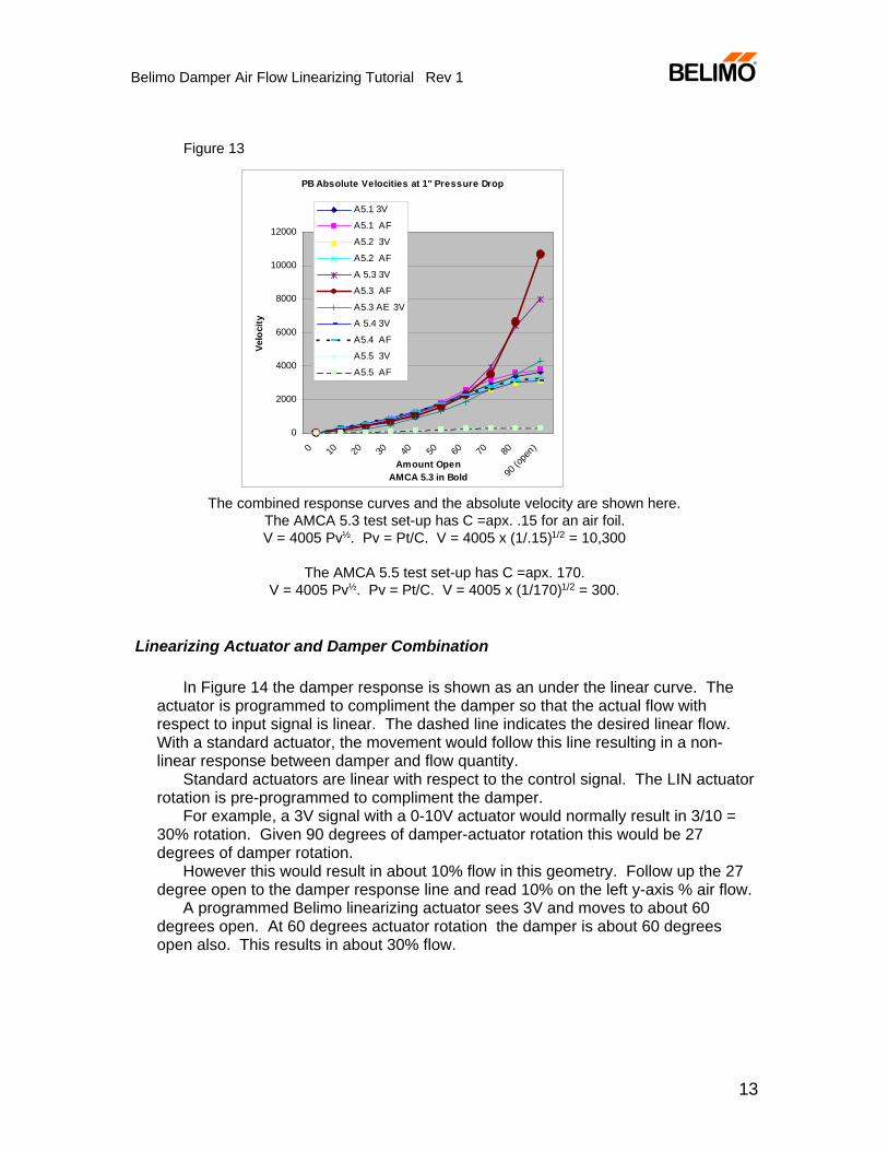
Figure 13
The combined response curves and the absolute velocity are shown here.The AMCA 5.3 test set-up has C =apx. .15 for an air foil.V = 4005 Pv½. Pv = Pt/C. V = 4005 x (1/.15)1/2 = 10,300
The AMCA 5.5 test set-up has C =apx. 170.V = 4005 Pv½. Pv = Pt/C. V = 4005 x (1/170)1/2 = 300.
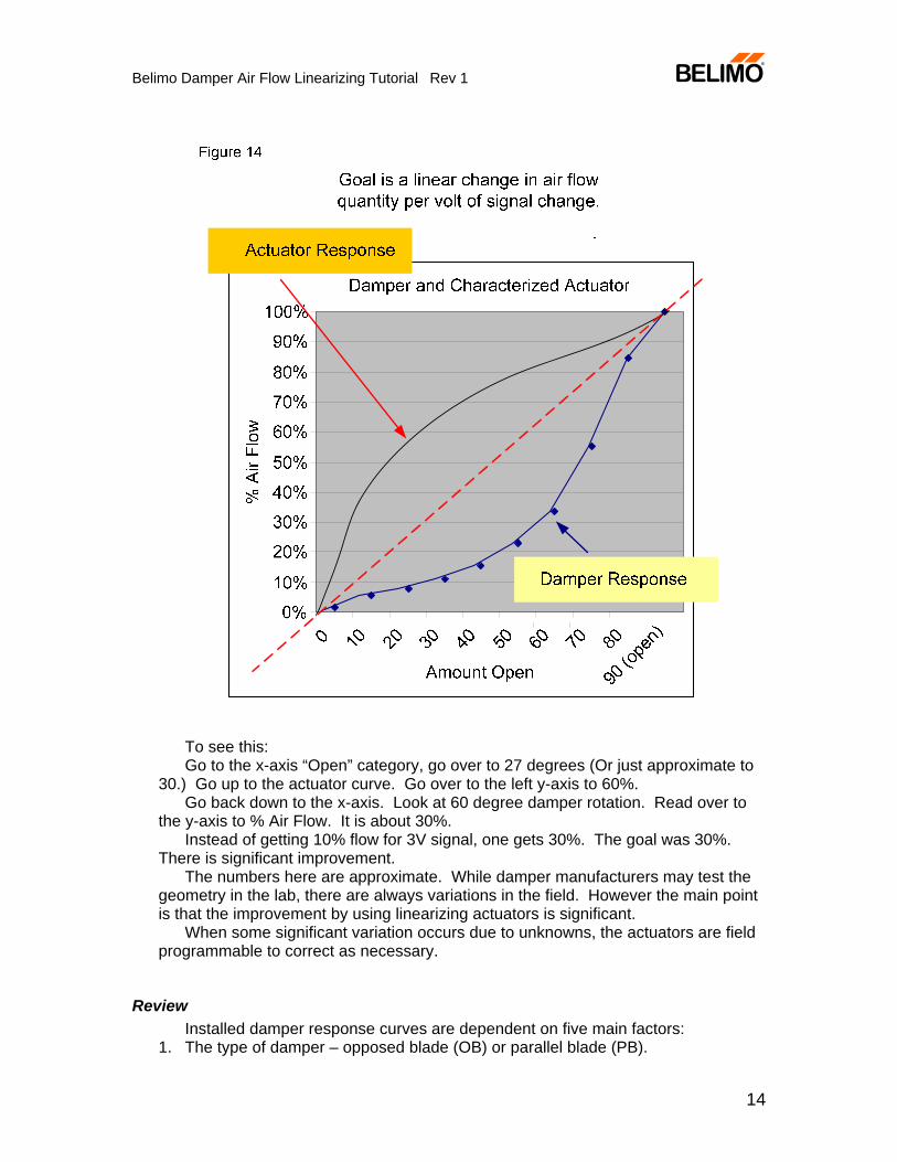
Linearizing Actuator and Damper Combination
In Figure 14 the damper response is shown as an under the linear curve. The actuator is programmed to compliment the damper so that the actual flow with respect to input signal is linear. The dashed line indicates the desired linear flow. With a standard actuator, the movement would follow this line resulting in a non-linear response between damper and flow quantity.
Standard actuators are linear with respect to the control signal. The LIN actuator rotation is pre-programmed to compliment the damper.
For example, a 3V signal with a 0-10V actuator would normally result in 3/10 = 30% rotation. Given 90 degrees of damper-actuator rotation this would be 27 degrees of damper rotation.
However this would result in about 10% flow in this geometry. Follow up the 27 degree open to the damper response line and read 10% on the left y-axis % air flow.
A programmed Belimo linearizing actuator sees 3V and moves to about 60 degrees open. At 60 degrees actuator rotation the damper is about 60 degrees open also. This results in about 30% flow.
Belimo Damper Air Flow Linearizing Tutorial Rev 1
14
To see this: Go to the x-axis “Open” category, go over to 27 degrees (Or just approximate to
30.) Go up to the actuator curve. Go over to the left y-axis to 60%. Go back down to the x-axis. Look at 60 degree damper rotation. Read over to
the y-axis to % Air Flow. It is about 30%. Instead of getting 10% flow for 3V signal, one gets 30%. The goal was 30%.
There is significant improvement. The numbers here are approximate. While damper manufacturers may test the
geometry in the lab, there are always variations in the field. However the main point is that the improvement by using linearizing actuators is significant.
When some significant variation occurs due to unknowns, the actuators are field programmable to correct as necessary.
Review Installed damper response curves are dependent on five main factors:
1. The type of damper – opposed blade (OB) or parallel blade (PB).
Belimo Damper Air Flow Linearizing Tutorial Rev 1
15
2. The geometric application – ducted, entrance or exit, plenum, wall mount. 3. Authority 4. Presence of jackshafts and/or linkages which may or may not change the
rotation of the blades with respect to the actuator rotation. If each individual damper is linearized, then the pairs are near linear and the total flow is near linear.
5. Flow profile of the entering air 6. Free area ratio of the damper with respect to the duct or wall.
The authority concept is dependent on the duct configuration. It is limited to fully ducted applications where the full open damper subsystem loss is less than 20% of the total fan loss.
AF24-LIN Belimo programmable linearizing actuator
To most accurately preprogram the actuator these must be defined: 1. OB or PB. 2. Application geometry.
Define the most similar AMCA Figure or case number.
3. Approximate Authority Statement of subsystem ΔP and damper ΔP for each damper is sufficient.
Verbal description is not acceptable since verbal pictures are too fuzzy. A
drawing is preferable. Do not apply wishful thinking.
4. Presence of Jackshafting or linkages.
Standard selection criteria must still be considered – static
pressure, velocity at full open, size of duct, temperature limits, vertical
or horizontal blades. These determine the damper model and the
torque required.
Belimo Damper Air Flow Linearizing Tutorial Rev 1
16
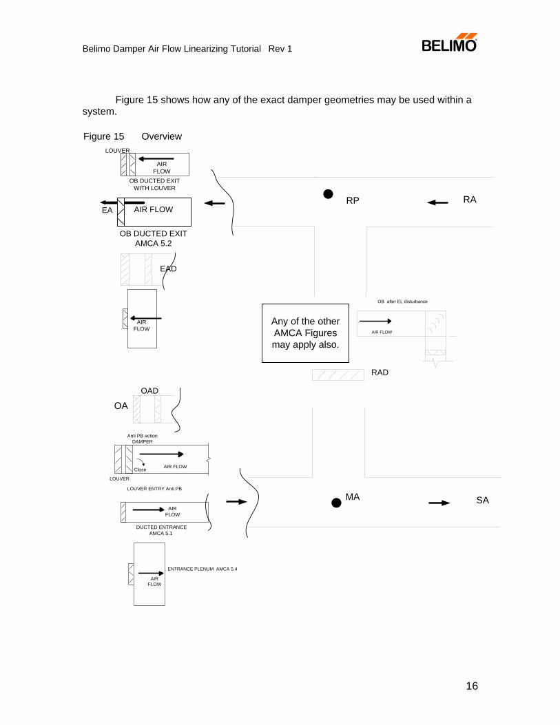
Figure 15 shows how any of the exact damper geometries may be used within a system.
DUCTED ENTRANCEAMCA 5.1
AIRFLOW
Anti PB actionDAMPER
LOUVER ENTRY Anti PB
AIR FLOW
LOUVER
Close
AIR FLOW
OB after EL disturbance
ENTRANCE PLENUM AMCA 5.4
SAMA
RARP
OB DUCTED EXITWITH LOUVER
AIRFLOW
LOUVER
Any of the otherAMCA Figuresmay apply also.
OB DUCTED EXITAMCA 5.2
AIR FLOWEA
EAD
AIRFLOW
OAOAD
AIRFLOW
RAD
Figure 15 Overview
Belimo Damper Air Flow Linearizing Tutorial Rev 1
17
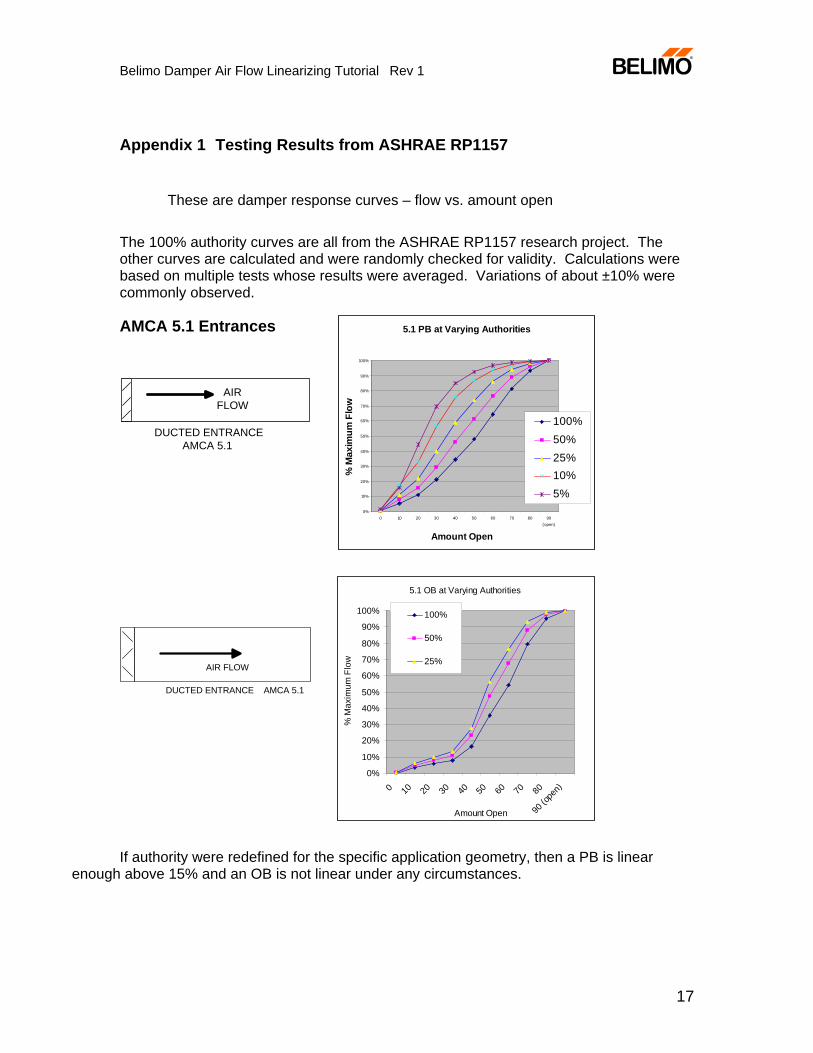
Appendix 1 Testing Results from ASHRAE RP1157
These are damper response curves – flow vs. amount open
The 100% authority curves are all from the ASHRAE RP1157 research project. The other curves are calculated and were randomly checked for validity. Calculations were based on multiple tests whose results were averaged. Variations of about ±10% were commonly observed.
AMCA 5.1 Entrances
If authority were redefined for the specific application geometry, then a PB is linear
enough above 15% and an OB is not linear under any circumstances.
5.1 OB at Varying Authorities
0%
10%
20%
30%
40%
50%
60%
70%
80%
90%
100%
0 10 20 30 40 50 60 70 80
90 (o
pen)
Amount Open
% M
axim
um F
low
100%
50%
25%
DUCTED ENTRANCE AMCA 5.1
AIR FLOW
5.1 PB at Varying Authorities
0%
10%
20%
30%
40%
50%
60%
70%
80%
90%
100%
0 10 20 30 40 50 60 70 80 90(open)
Amount Open
% M
axim
um F
low
100%50%25%10%5%
DUCTED ENTRANCEAMCA 5.1
AIRFLOW
Belimo Damper Air Flow Linearizing Tutorial Rev 1
18
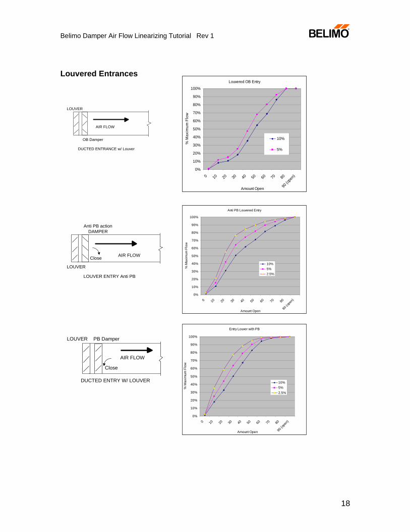
Louvered Entrances
Louvered OB Entry
0%
10%
20%
30%
40%
50%
60%
70%
80%
90%
100%
0 10 20 30 40 50 60 70 80
90 (o
pen)
Amount Open%
Max
imum
Flo
w
10%
5%
Anti PB Louvered Entry
0%
10%
20%
30%
40%
50%
60%
70%
80%
90%
100%
0 10 20 30 40 50 60 70 80
90 (o
pen)
Amount Open
% M
axim
um F
low
10%5%2.5%
Entry Louver with PB
0%
10%
20%
30%
40%
50%
60%
70%
80%
90%
100%
0 10 20 30 40 50 60 70 80
90 (o
pen)
Amount Open
% M
axim
um F
low
10%5%2.5%
DUCTED ENTRANCE w/ Louver
AIR FLOW
LOUVER
OB Damper
Anti PB actionDAMPER
LOUVER ENTRY Anti PB
AIR FLOW
LOUVER
Close
DUCTED ENTRY W/ LOUVER
AIR FLOW
LOUVER
Close
PB Damper
Belimo Damper Air Flow Linearizing Tutorial Rev 1
19
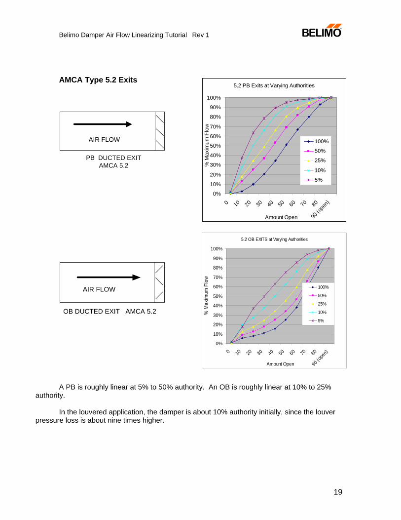
AMCA Type 5.2 Exits
PB DUCTED EXITAMCA 5.2
AIR FLOW
OB DUCTED EXIT AMCA 5.2
AIR FLOW
A PB is roughly linear at 5% to 50% authority. An OB is roughly linear at 10% to 25% authority. In the louvered application, the damper is about 10% authority initially, since the louver pressure loss is about nine times higher.
5.2 PB Exits at Varying Authorities
0%
10%
20%
30%
40%
50%
60%
70%
80%
90%
100%
0 10 20 30 40 50 60 70 80
90 (o
pen)
Amount Open
% M
axim
um F
low
100%
50%
25%
10%
5%
5.2 OB EXITS at Varying Authorities
0%
10%
20%
30%
40%
50%
60%
70%
80%
90%
100%
0 10 20 30 40 50 60 70 80
90 (o
pen)
Amount Open
% M
axim
um F
low
100%
50%
25%
10%
5%
Belimo Damper Air Flow Linearizing Tutorial Rev 1
20
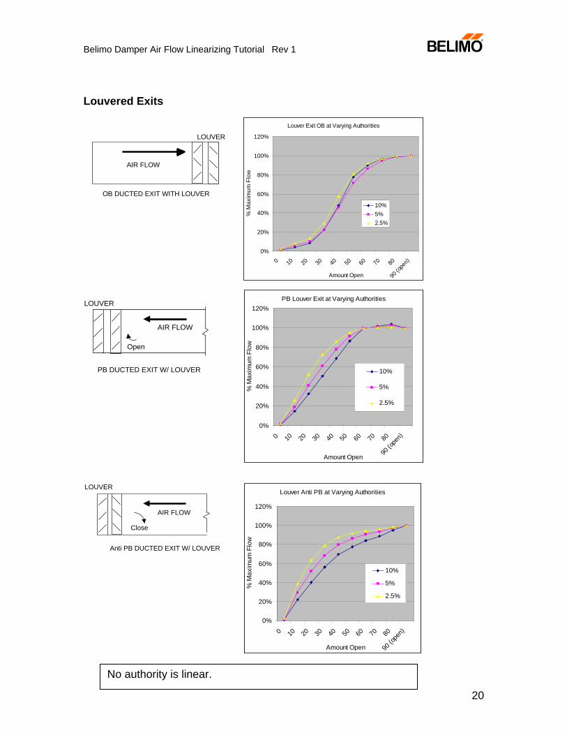
Louvered Exits
Louver Exit OB at Varying Authorities
0%
20%
40%
60%
80%
100%
120%
0 10 20 30 40 50 60 70 80
90 (o
pen)
Amount Open
% M
axim
um F
low
10%5%2.5%
PB Louver Exit at Varying Authorities
0%
20%
40%
60%
80%
100%
120%
0 10 20 30 40 50 60 70 80
90 (o
pen)
Amount Open
% M
axim
um F
low
10%
5%
2.5%
Louver Anti PB at Varying Authorities
0%
20%
40%
60%
80%
100%
120%
0 10 20 30 40 50 60 70 80
90 (o
pen)
Amount Open
% M
axim
um F
low
10%
5%
2.5%
OB DUCTED EXIT WITH LOUVER
AIR FLOW
LOUVER
PB DUCTED EXIT W/ LOUVER
AIR FLOW
LOUVER
Open
Anti PB DUCTED EXIT W/ LOUVER
AIR FLOW
LOUVER
Close
No authority is linear.
Belimo Damper Air Flow Linearizing Tutorial Rev 1
21
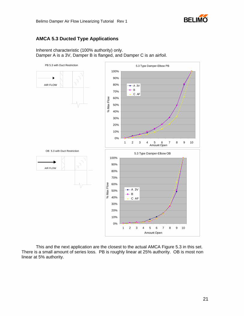
AMCA 5.3 Ducted Type Applications Inherent characteristic (100% authority) only. Damper A is a 3V, Damper B is flanged, and Damper C is an airfoil.
AIR FLOW
PB 5.3 with Duct Restriction
AIR FLOW
OB 5.3 with Duct Restriction
This and the next application are the closest to the actual AMCA Figure 5.3 in this set.
There is a small amount of series loss. PB is roughly linear at 25% authority. OB is most non linear at 5% authority.
5.3 Type Damper-Elbow PB
0%
10%
20%
30%
40%
50%
60%
70%
80%
90%
100%
1 2 3 4 5 6 7 8 9 10Amount Open
% M
ax F
low
A 3VBC AF
5.3 Type Damper-Elbow OB
0%
10%
20%
30%
40%
50%
60%
70%
80%
90%
100%
1 2 3 4 5 6 7 8 9 10Amount Open
% M
ax F
low
A 3VBC AF
Belimo Damper Air Flow Linearizing Tutorial Rev 1
22
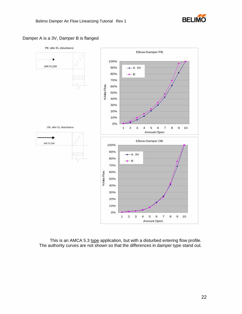
Damper A is a 3V, Damper B is flanged
AIR FLOW
PB after EL disturbance
AIR FLOW
OB after EL disturbance
This is an AMCA 5.3 type application, but with a disturbed entering flow profile.
The authority curves are not shown so that the differences in damper type stand out.
Elbow-Damper OB
0%
10%
20%
30%
40%
50%
60%
70%
80%
90%
100%
1 2 3 4 5 6 7 8 9 10Amount Open
% M
ax F
low
A 3V
B
Elbow-Damper PB
0%
10%
20%
30%
40%
50%
60%
70%
80%
90%
100%
1 2 3 4 5 6 7 8 9 10Amount Open
% M
ax F
low
A 3V
B
Belimo Damper Air Flow Linearizing Tutorial Rev 1
23
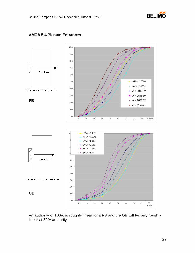
AMCA 5.4 Plenum Entrances
PB OB
An authority of 100% is roughly linear for a PB and the OB will be very roughly linear at 50% authority.
0%
10%
20%
30%
40%
50%
60%
70%
80%
90%
100%
0 10 20 30 40 50 60 70 80 90(open)
3V A = 100%
AF A = 100%
3V A = 50%
3V A = 25%
3V A = 10%
3V A = 5%
0%
10%
20%
30%
40%
50%
60%
70%
80%
90%
100%
0 10 20 30 40 50 60 70 80 90 (open)
AF at 100% 3V at 100% A = 50% 3V A = 25% 3V A = 10% 3V A = 5% 3V
Belimo Damper Air Flow Linearizing Tutorial Rev 1
24
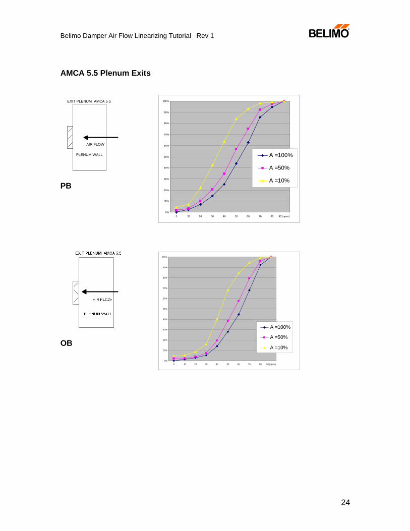
AMCA 5.5 Plenum Exits
EXIT PLENUM AMCA 5.5
AIR FLOW
PLENUM WALL
PB OB
0%
10%
20%
30%
40%
50%
60%
70%
80%
90%
100%
0 10 20 30 40 50 60 70 80 90 (open)
A =100%
A =50%
A =10%
0%
10%
20%
30%
40%
50%
60%
70%
80%
90%
100%
0 10 20 30 40 50 60 70 80 90 (open)
A =100%
A =50%
A =10%
Belimo Damper Air Flow Linearizing Tutorial Rev 1
25
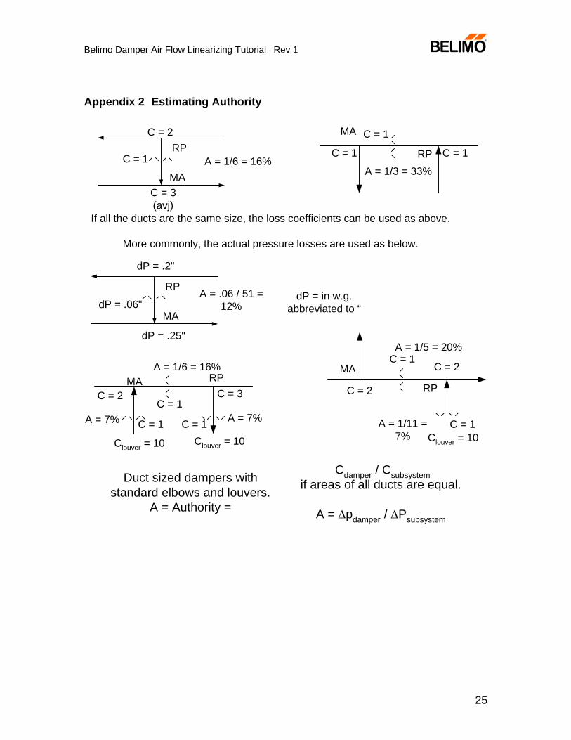
Appendix 2 Estimating Authority
C = 2
C = 1
C = 3(avj)
A = 1/6 = 16%
C = 1
A = 1/3 = 33%
C = 1 C = 1
C = 1
A = 1/6 = 16%
C = 2 C = 3
C = 1 C = 1
Clouver = 10 Clouver = 10
A = 7% A = 7%
C = 1A = 1/5 = 20%
C = 2
C = 2
C = 1Clouver = 10
A = 1/11 =7%
Duct sized dampers withstandard elbows and louvers.
A = Authority =
Cdamper / Csubsystemif areas of all ducts are equal.
A = Δpdamper / ΔPsubsystem
RP RP
RPRP
MA
If all the ducts are the same size, the loss coefficients can be used as above.
More commonly, the actual pressure losses are used as below.
dP = in w.g.abbreviated to “
A = .06 / 51 =12%
RP
MA
dP = .25"
dP = .06"
dP = .2"
MAMA
MA
Belimo Damper Air Flow Linearizing Tutorial Rev 1
26
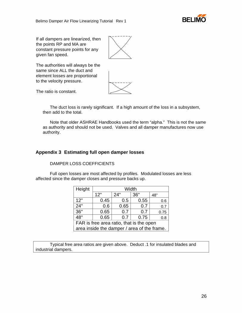
If all dampers are linearized, thenthe points RP and MA areconstant pressure points for anygiven fan speed.
The authorities will always be thesame since ALL the duct andelement losses are proportionalto the velocity pressure.
The ratio is constant.
The duct loss is rarely significant. If a high amount of the loss in a subsystem, then add to the total.
Note that older ASHRAE Handbooks used the term “alpha.” This is not the same
as authority and should not be used. Valves and all damper manufactures now use authority.
Appendix 3 Estimating full open damper losses
DAMPER LOSS COEFFICIENTS Full open losses are most affected by profiles. Modulated losses are less
affected since the damper closes and pressure backs up.
Height Width 12" 24" 36" 48" 12" 0.45 0.5 0.55 0.624" 0.6 0.65 0.7 0.736" 0.65 0.7 0.7 0.7548" 0.65 0.7 0.75 0.8FAR is free area ratio, that is the open area inside the damper / area of the frame.
Typical free area ratios are given above. Deduct .1 for insulated blades and
industrial dampers.
Belimo Damper Air Flow Linearizing Tutorial Rev 1
27
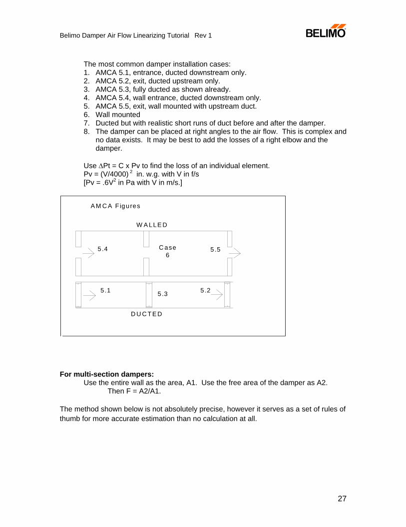
The most common damper installation cases: 1. AMCA 5.1, entrance, ducted downstream only. 2. AMCA 5.2, exit, ducted upstream only. 3. AMCA 5.3, fully ducted as shown already. 4. AMCA 5.4, wall entrance, ducted downstream only. 5. AMCA 5.5, exit, wall mounted with upstream duct. 6. Wall mounted 7. Ducted but with realistic short runs of duct before and after the damper. 8. The damper can be placed at right angles to the air flow. This is complex and
no data exists. It may be best to add the losses of a right elbow and the damper.
Use ΔPt = C x Pv to find the loss of an individual element. Pv = (V/4000) 2 in. w.g. with V in f/s
[Pv = .6V2 in Pa with V in m/s.]
W A LLE D
D U C TE D
5.4 5.5C ase6
A M C A F igures
5 .1 5 .25 .3
For multi-section dampers:
Use the entire wall as the area, A1. Use the free area of the damper as A2. Then F = A2/A1.
The method shown below is not absolutely precise, however it serves as a set of rules of thumb for more accurate estimation than no calculation at all.
Belimo Damper Air Flow Linearizing Tutorial Rev 1
28
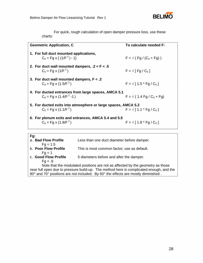
For quick, rough calculation of open damper pressure loss, use these charts:
Geometric Application, C To calculate needed F: 1. For full duct mounted applications, C0 = Fg x [ (1/F 2 ) - 1] F = √ ( Fg / (C0 + Fg) ) 2. For duct wall mounted dampers, .2 < F < .5 C0 = Fg x (1/F 2 ) F = √ [ Fg / C0 ] 3. For duct wall mounted dampers, F < .2 C0 = Fg x (1.5/F 2 ) F = √ [ 1.5 * Fg / C0 ] 4. For ducted entrances from large spaces, AMCA 5.1 C0 = Fg x (1.4/F 2 -1 ) F = √ ( 1.4 Fg / C0 + Fg) 5. For ducted exits into atmosphere or large spaces, AMCA 5.2 C0 = Fg x (1.1/F 2 ) F = √ [ 1.1 * Fg / C0 ] 6. For plenum exits and entrances, AMCA 5.4 and 5.5 C0 = Fg x (1.8/F 2 ) F = √ [ 1.8 * Fg / C0 ] Fg: a. Bad Flow Profile Less than one duct diameter before damper. Fg = 1.5 b. Poor Flow Profile This is most common factor; use as default. Fg = 1 c. Good Flow Profile 5 diameters before and after the damper. Fg = .6 Note that the modulated positions are not as affected by the geometry as those near full open due to pressure build-up. The method here is complicated enough, and the 80° and 70° positions are not included. By 60° the effects are mostly diminished .


