Embed Size (px)
Citation preview
, INSTRUCTION BOOK
FOR
B.\BCOCK RADIO CONTROT?}
RECEIYER FCR-3
AND: TRANSMITTER BCT-z
/ ir,i
Price ti2.(X)
Bobcock Rodio Engineering, lnc.7942Ytoodtey Ave. ' Van Nuys, Calif.
----q
INSTRUCTION BOOK
FOR
BABCOCK RADIO CONTROL
RECEIYER BCR.3
AND
TRANSMITTER BCT-2
Pricc $2.00
Bobcock Rodio Engineering, ln€.7942woodley Ave. . Van Nuys, Calif.
INSTRUCIION BOOK FOR RADIO
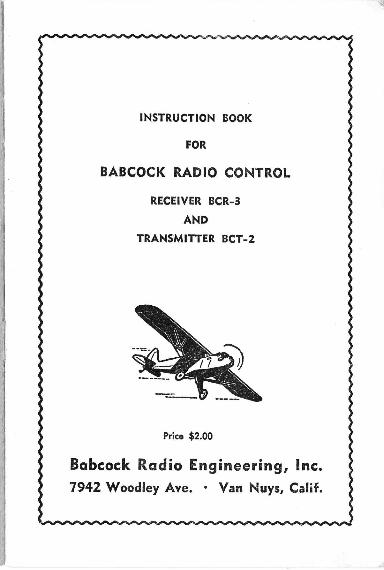
Tqble of Contents
lnfroduction
Ports qnd Moteriqls Required
Noles on Smoll Aircroft
Receiver lndollafion
Operotion of Trqnsmiller BCT-2
Technicql Dolo on BCR-3 Receiver
Technicol Doto on BCT-2 Tronsmifter
Porsible Troubles
Price Lisl
BCR-3 Receiver Wiring Diogrom
Receiver lnsfollotion Diogrom
BCT-2 Tronsmitter Wiring Diogrom
RECEIVER BCR-3 AND TRANSMITTER BCT.2
I ntroductionThis instruction book is in its second printing. Thousands
of these units are in service today and giving their ownersthe enjoyment of reliable trouble free performance. We urgeyou to follow the instructions carefully with particular refer.ence to bonding and careful workmanship in wirir-rg. If youdo have an accident or trouble of any kind the factory stands
ready to serve you.
Ports qnd Moteriol R.equired
Whether you know electronics and radio or not, you willfind the technical dissertation following the basic installationinstructions informative. To proceed with the receiver in,stallation, you will need:
1. A piece of #22 gauge bare tinned copper wireabout 5 feet long for the antenna and commonground (for bonding bus).
2. Some flexible #22 or 24 gauge insulated wirefor all connections and antenna (10 feet is morethan ample). Note: Seven colors are providedin the BCR,3 Installation Kit. (May also beused for antenna).
3. A good double pole single throw switch for turningon the "A" and "B" circuits: Note: We recommendthe slide switch in our installation kit. Other makesof slide switches have given vibration trouble. A goodtoggle switch (H €d H) is satisfactory.
4. A single circuit headphone jack.
5. Snap connectors for the "B" battery.6. Two battery boxes for medium sized fashlight
cells (if desired).
r0
12
l3
14
l5
't6
INSTRUCTION BOOK FOR RADIO CONTROT
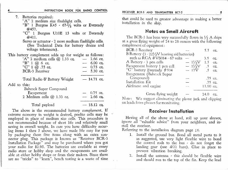
1. Batteries required:"A" 2 medium size flashlight cells.
Burgess K45 . 67.r/2 volts or Eveready#457.
"C'r 1 Burgess U10E 15 volts or Eveready#+tt.
Servo or actuator , 2 more medium flashlight cells.(See Technical Data for battery drains andvoltage tolerances).
This battery complement adds up for weight as follows:'A" 2 medium cells @ 1.33 oz. 2.66 oz."B"1@6o?. 6.00o2."C" I @ .75 oz. 0.75 oz.BCR,3 Receiver 5.30 oz.
RECEIVER BCR.3 AND TRANSMITTER BCT.2
that could be used to greater advantage in making a bettetinstallation in the ship,
Notes on Smqll AircroftThe BCR-3 has been very successfully flown in J/2 A ships
at a gross flying weight of 24 to 28 ounces with the following
5., oz.
3.5 oz.l.i oz..t oz..5 oz.
.7J oz.
.7 J oz.11.00 oz.
Total Radio U Battery WeightAdd to this:
Babcock Super CompoundEscapement
2 Medium cells @ 1.33 oz.
Total payload
complement of equipment :
BCR,3 RecciverB Battery G .22V2V hearing aid batteries)
such as RCA #VS084 , 67 voltsA Battery , 3 pen cells - IV;VEscapement battery I pen cell - 1Y2V"C" battery Evercady #104 - 1tVEscapement (Babcock Super
Conrpound)Installation KitAirframe and engine
Gross flying weight
- I4.7L oz.
0.7J oz.2.66 oZ.
- l3.LZ oz.
24.0 oz.
The above is the recommended battery complement. Ifextreme economy in weight is desired, penlite cells may beemployed in place of medium size cells. This procedure isnot recommended because of short life and relatively smallsaving in overall weight. In case you have difficulty secur,ing Items 1 thru 5 above, we have made life easy for youby packaging these five items along with an extra con'nector plug. This package is known as "Receiver BCR,3Installation Package" and rnay be purchased where you gotyour radio for $2.95. The batteries are available at everyradio store or hobby shop and the escapements are avail,able at either hobby shops or from their makers. Since thereare no "tricks" to "learn", bench testing is a waste of time
Note: We suggest eliminating the phone jack and clippingor.r leads f lom phoncs for monitr rring.
Receiver lnstsllotionHaving all of the above at hand, ro11 up your sleeves,
ignorc all "valuable advice" from your neighbors, and in,stall the receiver.Referring to the installation diagram page 15:
1. Install the ground bus. Bond all metal parts to itas suggested, use very light flexible wire to bondthe control rods to the bus , do not forget thelanding gear (use ft22 bare). Glue in place toprevent vibration breaking.
2. Install the antenna , this should be flexible wireand should run to the top of the fin. Keep the lead
INSTRUCTION BOOK FOR RADIO CONTROT
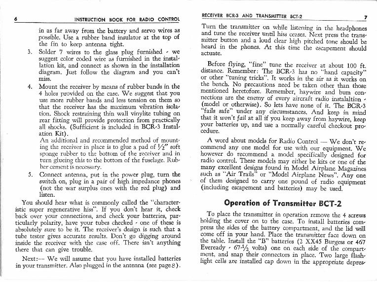
in as far away from the battery and servo wires aspossible. Use a rubber band insulator at the top ofthe fin to keep antenna tight.
3. Solder ? wires to the glass plug furnished , wesuggest color coded wire as furnished in the instal'lation kit, and connecf as shown in the installationdiagram. Just follow the diagram and you cantmiss.
4. Mount the receiver by means of rubber bands in the4 holes provided on the case. W'e suggest that youuse more rubber bands and less tension on them sothat the receiver has the maximum vibration isola,tion. Shock restraining thin wall vinylite tubing onrear fitting will provide protection from practicallyall shocks. (Sufficient is included in BCR,3 Instal,ation Kit).An additional and recommended method of mount,ing the receiver in place is to glue a pad of /2" softsponge rubber to the bottom of the receiver and inturn glueing this to the bottom of the fuselage. Rub,ber cement is necessary.
5. Connect antenna, put in the power plug, turn theswitch on, plug in a pair of high impedance phones(not the war surplus ones with the red plug) andlisten.
You should hear what is commonly called the "character,istic super regenerative hiss". If you don't hear it, checkback over your connections, and check your batteries, par,ticularly polarity, have your tubes checked , one of these isabsolutely sure to be it. The receiver's design is such that atube tester gives accurate results. Don't go digging aroundinside the receiver with the case off. There isn't anythingthere that can give trouble.
Next:- We will assume that you have installed batteriesin your transmitter. Also plugged in the antenna (see pageS).
RECEIVER BCR-3 AND TRANSMITTER BCT-2
Turn the transmitter on while listening in the headphonesand tune the receiver until hiss cea.ses. frext press the'trans,mitter buton and a loud clear high pitched io"" ,t o"ta L"heard in the phones. At this tirn'e ihe escapement shouldactuate.
_ Before flying, "fineo' tune the receiver at about 100 ft.distance. Remember: The BCR,3 has no ..hand
capacity';or other "tuning tricks". It works in the air as it w6rks onthe bench. No precautions need be taken other than thosementioned heretofore. Remember, haywire and bum con,nections are the enemy of every aircraft radio instalaltion ,(r_nodel or otherwise). So lets have none of it. The BCR,S"fails safe" under any circumstances. And keep in mindthat it won'.t fail at all'if you keep
"*"y fiot h"id;, l;;;your batteries up, and use a norirally iareful checkoui prd,cedure.
A word about models for Radio Control - We don't re,commend any one model for use with our equipment. Wehowever do recommend_ a model specifically'disigned forradio control. These models may eitlier be kits or oie of themany excellent d99ig3s fryqd -tq Model Airplane Magazinessuch as "Air Trails" or "Model Airplane News". Any onegf tlr"* designed to carry .one pound of radio
"q.rip-errt(including escapement and batteries) may be used. '
Operotion of Tronsmitter BCT-2To place the transmitter in operation remove the 4 screws
holding the cover on to the caie. To install batteries com,press the sides of the battery compartment, and the lid willcome off in your hand. Place the transmitter face down onthe table. Install the "B" batteries (2 XX45 Burgess or 467Eveready., 67./2.volts) one on each side of thle compart,gqnt, a.1d snap their _connectors in place. Two large fiash,light cells are installed cap down in the appropriate" depres,
INSTRUCTION BOOK FOR RADIO CONTROT RECEIVER BCR-3 AND TRANSMITTER BCT.2
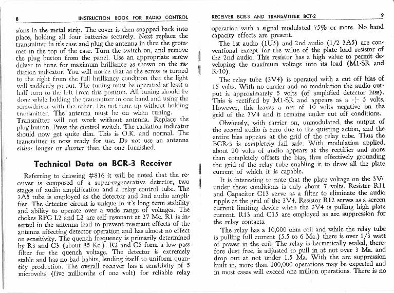
sions in the metal strip. The cover is then snapped back intoplace, holding all four batteries. securely. Next replace theiransmitter in-it's case and plug the antenna in thru the grom'met in the top of the case. Turn the switch on, and removethe plug button from the paqel, lJse an appropriatedriver ti tune for maximum brilliance as shown on the ra'diatr'on indicator. You will notice that as the screw is turnedto the right from the full brilliancy condition that the lightr,vill surideiily go out. The tuning nust Lre opcrated af least a
half turn to-tlie lefc frtxr this positiou. A11 tuning should be
done wtrjle holcling thc tranlmilter iu one hand and using.thcscrcwdriver v;ith ihe other. Do not tune up witirout holdingtransmitter. The antenna must be on when tuning.Transmitter will not work without antenna. Replace theplug button. Press the control switch. The radiation indicatorinoita now get quite dim. This is O.K. and normal' Thetransmitter is now ready for use. Do not use an antennaeither longer or shorter than the one furnished'
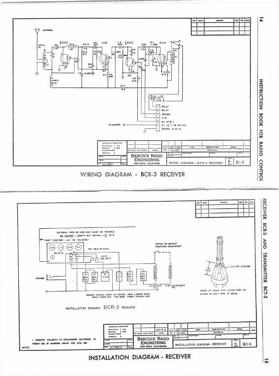
Technicql Doto on BCR-3 Receiver
Referring to drawing #816 it will be noted that the re'ceiver is composed of a super'regenerative detector, twostages of audio amplification
-and J relay control tube. The3A"5 tube is employed as the detector and 2nd audio ampli'fier. The detector circuit is unique in it's long term stabilityand ability to operate over a wide range of voltages. Thechokes RFC L2 and L3 are self resonant at 27 Mq Rl is in'serted in the antenna lead to prevent resonant effects of the
antenna affecting detector operation and has almost no effecton sensitivity. T[e quench fiequency is primarily determinedbv R3 and Cf ("bo,tt 85 Kc.). R2 and C5 form a low pass
filter for the quench voltage. The detector is - extremelystable and has no bad habits, lending itself to uniform quan'tity production. The overall receiver has a sensitiyity of 5
microvolts (five millionths of one volt) for reliable relay
operation with a signal modulated 75/o or more. No handcapacity effects are present.
The lst audio (1U5) and 2nd audio (I/2 3A5) are con'ventional except for the value of the plate load resistor ofthe 2nd audlo. This resistor has a higli value to permit de'veloping the maximum voltage into its toad (MI'SR andR.ro).
The relay tube (3V4) is operated with a cut off bias of15 volts. With no carrier and no modulation the audio out'put is approximately 5 volts (of amplified detector hiss).thit ir iectified by-Ml,SR and appears as a -l- 5 volts'However, this leaves a net of 10 volts negative -on thegrid of tire 3V4 and it remains under cut off conditions'
Obviously, with carrier on, uumodulated, the output ofthe second audio is zero due to the quieting action, and theentire bias appears at the grid of the relay tube. Thus theBCR,3 is comptetely fail safe. With modulation a-pplied,
about 20 volts-of audio appears at the rectifier and morethan completely offsets the bias, thus effectively--groundingthe grid of tnJ relay tube enabling it to draw all the platecuffent of which it is capable.
It is interesting to note that the plate voltage on the 3Vitrnder these conditions is only about 7 volts. Resister Rltand Capacitor C13 serve as a filtet to eliminate the audiorioole at the srid of the 3V4. Resistor R12 serves a$ a screen
.urr"nt limiting device when the 3V4 is pulling high platecurrent. R13 ;d C15 are employed as arc suppression forthe relay contacts.
The relay has a 10,000 ohm coil and while the relay tubeis pulling full current (5.5 to 6 Ma.) there is over-L/3 wattof
'po*ei in the coil. The relay is hermetically sealed, there'forl dust free, is adjusted to pull in at not over 3 Ma. anddrop out at not under 1.5 Ma. With the arc suppre-ssion
buiit in, more than 100,000 operations may be expected. and
in most cases will exceed one million operations' There is no
l
I
INSTRUCTION BOOK FOR RADIO CONTROT
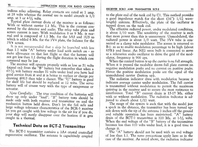
tedious relay -adjusting. Relay contacts are rated at 2 amo.at 26 volts whereas the normal use in model aircraft is li2amp. at 3 or 4.Vt volts.
,_Typical plate'iurrent drain of the receiver is as follows:With or without carrier r.r Ua. fi,isislh";;t;;;;sumed by the derector and.audio_. Td ,;hy i"U" pf"t" ""iscreen current is zero. With modulation g llr 9 M'a. i"
"or,*pl 1ni is compo_sed of 1.1 Ma. for the-3A5 anJ 1Ui;w_h_ich is added 6 Ma. for the 3V4 ptut", tir" b"l;;;" f"itf,"3V4 screen.
, It is not recommended that a ship be launched with lessthan 1.2 volrs "A" batery ""a.. tJ"a Ljii switch on . so
make allowance on that. list. flight_ so-thai it "-
U"li""y ,"ifinot get less tha! l.l during the filght duration in whicL casecommand may be lost .
, The receiver will operate properly with as low as 51 volts!:qTt on), trom the "B" battery bur remember thar when aot.y2 von battery reaches 52 volts under load you have hadgood service from it and it is better to replace or charge perdrawing-#815 than rake a chanc". tlr.;.-C;-battery is"g6oJfor shelf life but should be replaced
"i ti uottr. ffr. i*"battery will of course vary wiih tt L ifp" "f escapement oractuatof.
, Note Carcfully:- The true condition of the batteries willshow up. only.under "load". ..8" battery tests should bemaoe only wlth both receiver and transmitter on and themoduarion button held down. Oo"'t t"i-ih" f"il."i"
""Jlarge voltage rolerance characterisrics of irc-bCn,3 ;;*ir;;l:l I": get caughr with.low volrage in the air for if you do,I^".yjr:h_T
wrlt surely disappear over the horizon if it getscaught rn a thermal.
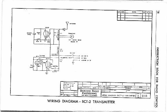
Technicsl DqtE on BCT-2 TronsmitterThe BCT,2 transmitter conrains a 3A4 crystal controlled
regenerative oscillator. The antenna is capaiitively ;;i;j
RECEIVER BCR.3 AND TRANSMITTER BCT-2
to the plate end of the tank coil by Cl. This method providesa good iinpedance match for the short (36") 1/12 wave,length) antenna. Effectively, the plate of the oscillator istapped down on the tank coil.
The effective radiated power, under modulated conditions,is about L/IO watt. The sensitivity of the receiver is suchthat more power than this is unnecessary. Unmodulated, theradiated power is abott 2/5 watt. The 3V4 tube is con,nected as a clamp tube modulator. The screen is returned toBf so as to enable modulation percentage to be high (about85/o) and linear. An NE2 neon bulb is connected to serveas a relaxation audio oscillator to drive the grid of the mod,ulator, frequency is 900 cps.
When the control button is up the carrier is on full strength.When it is pressed the modultor draws full plate current onnegative modulation peaks and no current on positive peaks.Hence the positive modulation peaks are the equal of theunmodulated carier (button up).
The radiation indicator dims with modulation because itindicates avetage carrier under modulation. The full carrieris transmitted without modulation to permit the maximumquieting in the receiver and to secure the most resistance tointerference. Total "B" current drain is 15,17 Ma. eitherwith or without modulation. The radiation indicator is ad,justed to absorb about l/LZ watt.
The range of the system is such that with the model justa speck in the distance, the transmitter has been turned up,side down with the tip of the antenna 3 inches off the groundand reliable operation has been maintained. "A" batterydrain of the BCT,2 transmitter is 320 Ma. at l,t/2 volts.When the end voltage of the "B" battery of the transmitterbecomes less than 110 volts under load, it is a good time tochange it.
The "A" battery should not be used with an end voltageof less than 1.1. The same precautions apply here as in thecase of the receiver. As noted above, the radiation indicator
INSIRUCTION BOOK FOR RADIO CONTROI
dims with modulation. If it goes out completely, it is prob,able that the oscillator is noi operatins d]ue to'insufficientplate
-voltage. This can readily be cheiked with a pair ofheadphones plugged into the receiver, in which case io tonewill be heard, merely the silence caused by radiation of thetransmitter carrier.
Possible TroublesThe ground bus is one of the most important of all instal,
lation considerations. Every case of trouble during earlyexperimental flights was traced to improper or inadequatebonding. This cannot be overemphasized. The need for bond,ing should not be construed as a weakness of design. It isnecessary only because of receiver sensitivity which is fargreat$ than any other available receiver which accounts forthe great range of this equipment with a low powered trans,mitter. ,
,
To check for the adequacy of bonding, follow steps below:
l. Turn receiver and transmitter on, plug in 'phones.
2. Tune for the silent condition of the receiver.
3. Bounce the model up and down, pound on thesides,
- top and bottom of the fuJelage. If any
scratching sound is heard in the h?adphonei,look for metal pieces of any kind which arerubbing causing the noise and bond them.
4. Start engine and observe effects of vibration withtransmitter both on and off. Escapement shouldnot actuate except by pulse of transmitter beingturned on and off.
5. It's now O.K. to fly.
RECEIVER BCR.3 AND TRANSMITTER BCT.2
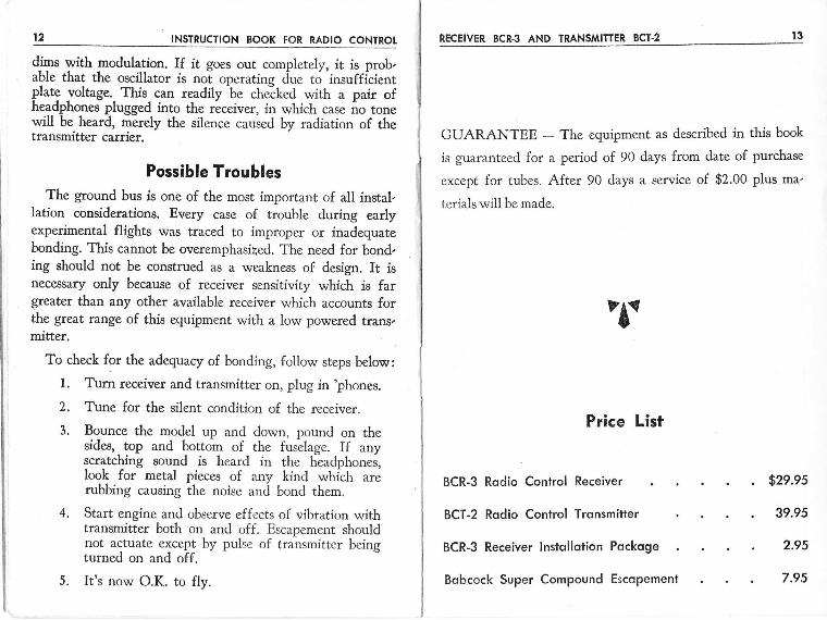
GUARANTEE - The equipment as described in this book
is guaranteed for a period of 90 days from date of purchase
except for tubes. After 90 days a service of $2.00 plus ma'
terials will be made.
t3
"tt
Price List
BCR-3 Rodio Conlrol Receiver
BCT-2 Rodio Control Trqnsmitter
BCR-3 Receiver lnstollotion Pockoge
Bobcock Super Compound Escopement
. $2e.e5
. 39.95
. 2.95
. 7.95
Bnecocr RRoroEne rnEEnrne
VAN NUYS. CAUFORNIA WIRING DIAGRAM- BCR.3 RECEIVER
WIRING DIAGRAM - BCR.3 RECEIVER
Fm(')rn
=lTlFEr)n
I(.t
zI
-lF
zU,
=-l{rTtntpf){Il9
Ar.rElllL- I(EEP A3 !lld{ ArO CLEIR A9 FoSSI&E
t{o ME- LEllorl{ Hor cRrrrc L-rf'ro e'
TTIIST TOG€TICR - MAY gE SOLD€R€O
sw|Tc{{ or{ Fllt{Ei@HPOI!{D ESCAPETIEII'
COli[rON GROUilO-8OxO T-O EilGFr'E, TA'iK' LAlOlxC-GtlRtsearo noos Elc. tz? aaR€ TI'rED cgPPER YrnE
INSTALLATION DRAWINO BCR'3 RECEIVER
OPf,SS IJP CAALE V'ITH LACING COED SO
STAAri Oll EACH WIRE lS EOttAL
r. oelfRrt ?ol,ls"t oF elclFE filt lrTl€REll ?o
tcnllt u! (' otrrfirF Cnqrr PcR Ol'e- 36
o[orci to.cx3
taFg& t 6aTCru T.€'ga$6 tolltaraar r a
Bnecocr RnotoENEINEERIT.IS
vArl llulE c^uFoRtll,t
INSTALLATION DIAGRAM - RECEIVER
DrxBatr tolr.^rcan6rq4: t/{UsllaL a .6alJigt rottoucuut !
WRING DIAGRAM. 8cT.2 TRANSIVIITTER
WIRING DIAGR.AM - BCT-2 TRANSMITTER