Embed Size (px)
Citation preview
Assembly Procedure
3 - 1
Assembly Procedure
Please follow the information provided in this section to perform the complete assembly procedure of the tablet pc. Be sure to use proper tools described before.
fter you have completed the previous chapter of complete disassembly, please follow this chapter to assemble the tablet pc back together. This chapter describes the procedures of the complete tablet pc assembly. In addition, in between procedures, the detailed assembly procedure of individual modules will be provided for your service
needs. The assembly procedure consists of the following steps:
• Touch Panel Module
• Motherboard Module
• Wireless LAN Module
• Thermal Fan Module
• 3G Card Module
• SSD Card Module
• Battery Module
• HD Video Decoder Module
• DIMM Module
• Camera Module
• Base Module
Chapter
3
A
Assembly Procedure
3 - 2
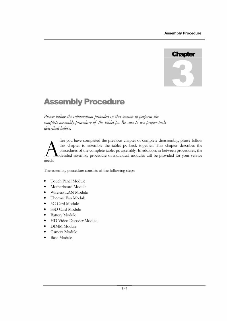
TOUCH PANEL Module The illustrations below show how to assemble and install the TOUCH PANEL module of the tablet pc.
TOUCH PANEL Module Assembly 1. Install the panel bracket and secure 4 screws(M2*3) on two LCD panel bracket.
2. Install LCD panel on the LCD back cover,then secure 7 screws (M2*3.5L) on LCD panel bracket. Stick the FPC on the foil as the picture show.
T O U C H P A N E L
M O D U L E
Assembly Procedure
3 - 3
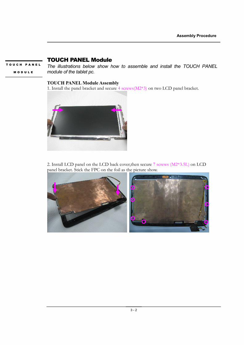
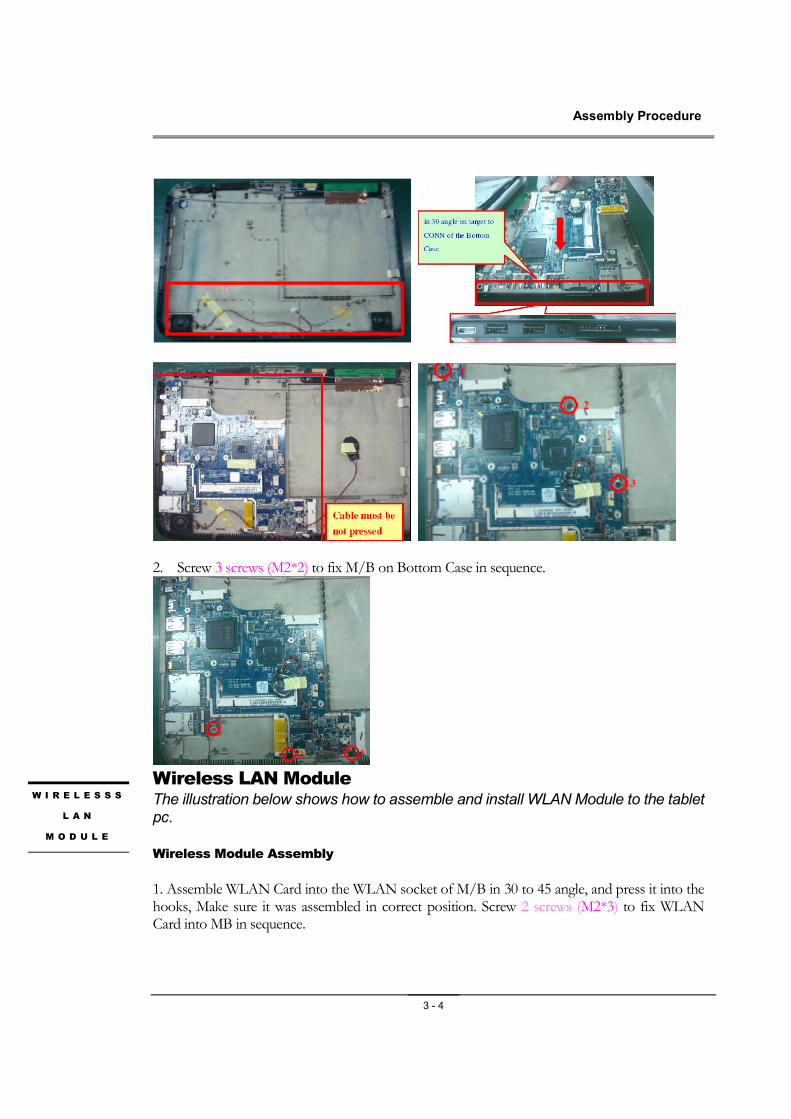
Motherboard Module The illustrations below show how to assemble and install the motherboard module of the tablet pc. Motherboard Module Assembly
1. Assemble MB into Bottom Case in 30 angle on target to CONN of the Bottom Case, and make sure screw holes must be targeted to BOSS. And secure 3 screws (M2*2) on the bottom case.
M O T H E R B O A R D
M O D U L E
Assembly Procedure
3 - 4
2. Screw 3 screws (M2*2) to fix M/B on Bottom Case in sequence.
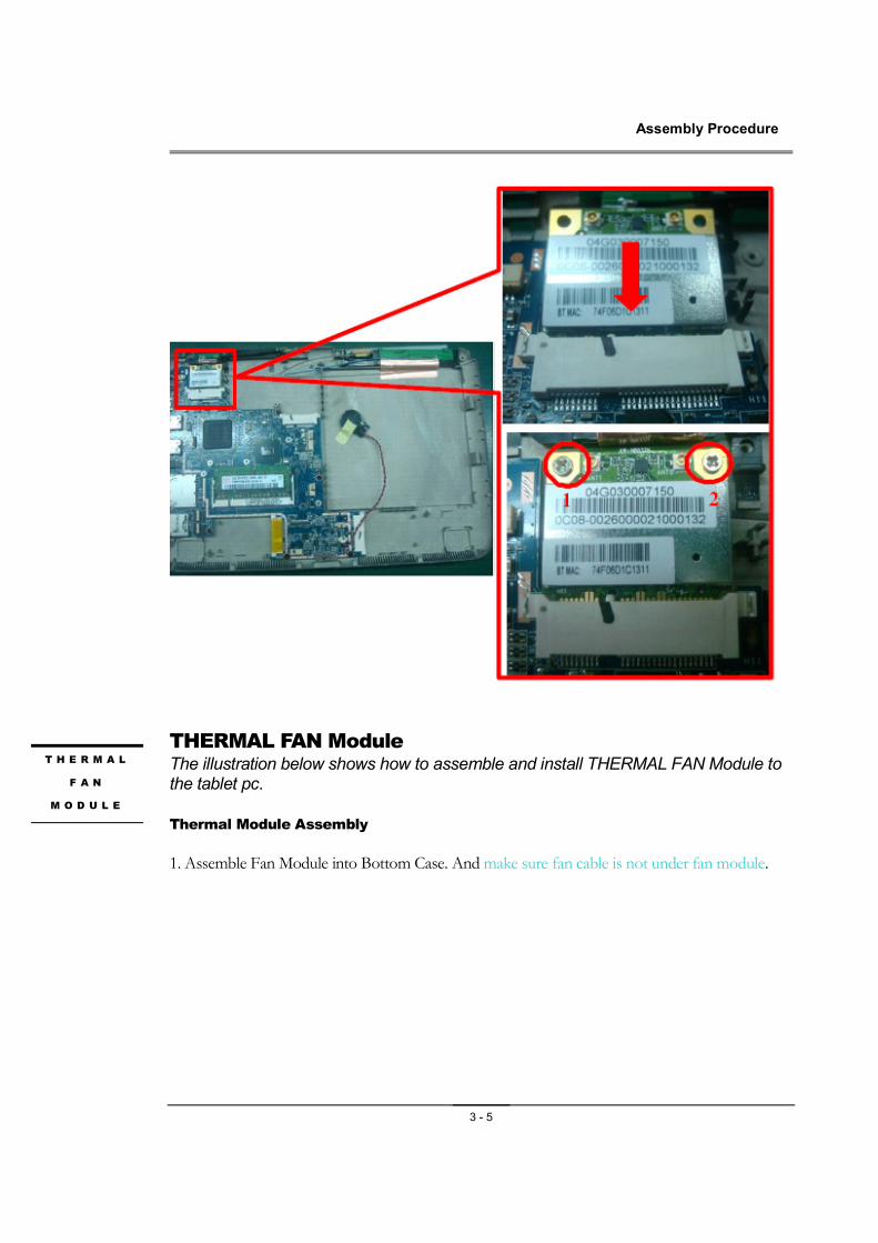
Wireless LAN Module The illustration below shows how to assemble and install WLAN Module to the tablet pc.
Wireless Module Assembly
1. Assemble WLAN Card into the WLAN socket of M/B in 30 to 45 angle, and press it into the hooks, Make sure it was assembled in correct position. Screw 2 screws (M2*3) to fix WLAN Card into MB in sequence.
W I R E L E S S S
L A N
M O D U L E
Assembly Procedure
3 - 5
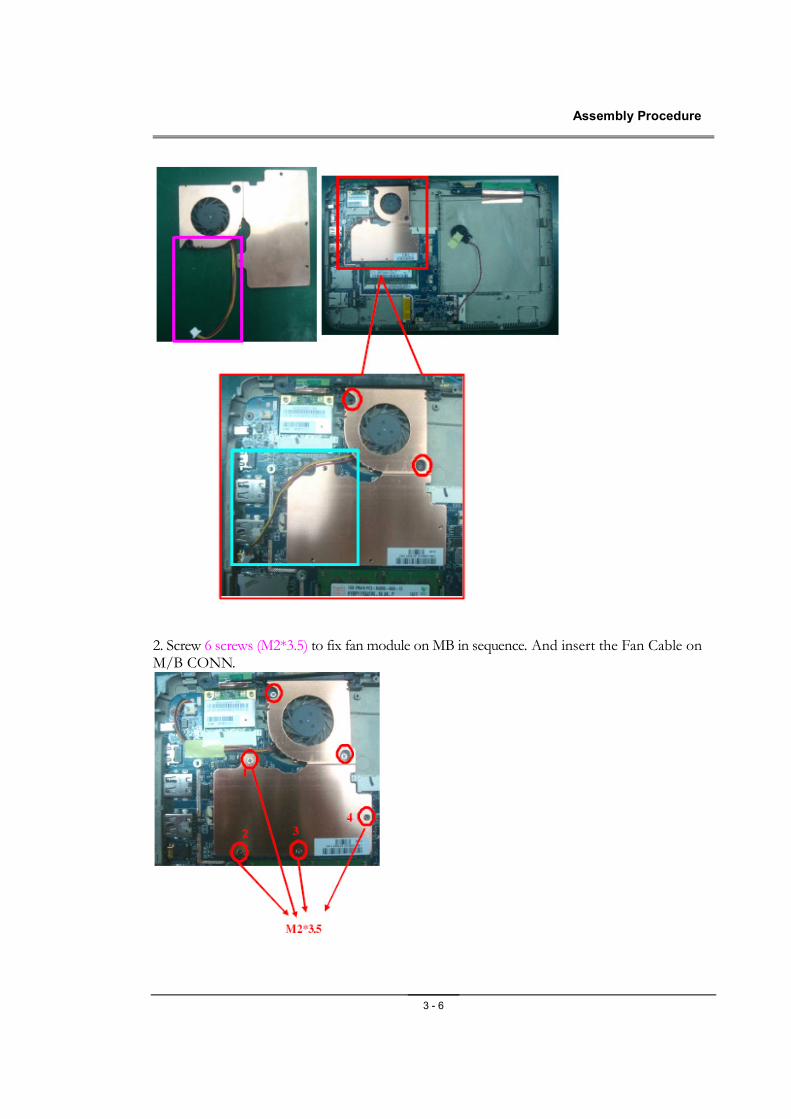
THERMAL FAN Module The illustration below shows how to assemble and install THERMAL FAN Module to the tablet pc.
Thermal Module Assembly
1. Assemble Fan Module into Bottom Case. And make sure fan cable is not under fan module.
T H E R M A L
F A N
M O D U L E
Assembly Procedure
3 - 6
2. Screw 6 screws (M2*3.5) to fix fan module on MB in sequence. And insert the Fan Cable on M/B CONN.
Assembly Procedure
3 - 7
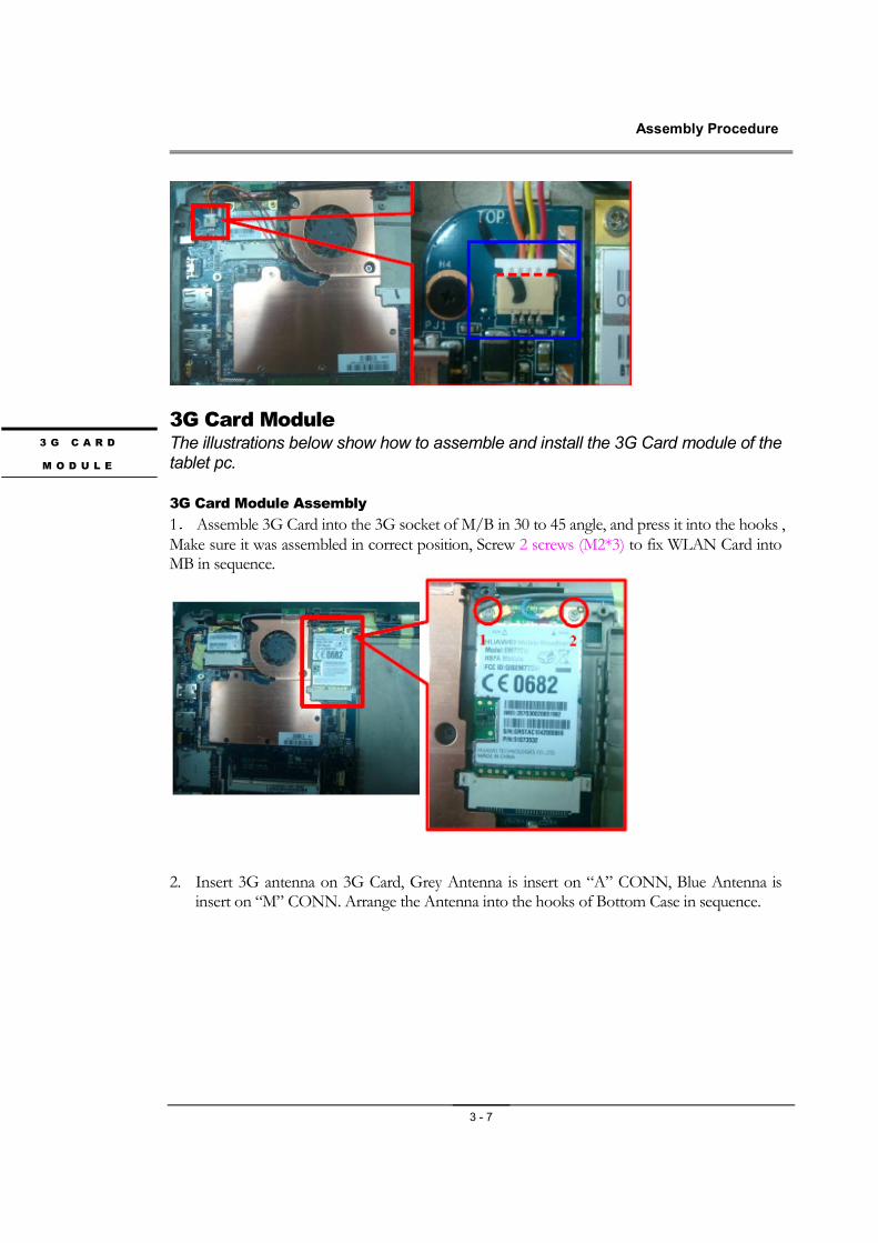
3G Card Module The illustrations below show how to assemble and install the 3G Card module of the tablet pc.
3G Card Module Assembly
1. Assemble 3G Card into the 3G socket of M/B in 30 to 45 angle, and press it into the hooks , Make sure it was assembled in correct position, Screw 2 screws (M2*3) to fix WLAN Card into MB in sequence.
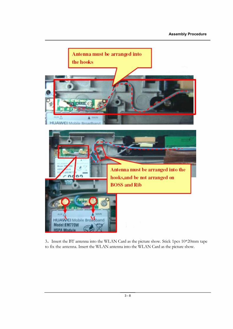
2. Insert 3G antenna on 3G Card, Grey Antenna is insert on “A” CONN, Blue Antenna is
insert on “M” CONN. Arrange the Antenna into the hooks of Bottom Case in sequence.
3 G C A R D
M O D U L E
Assembly Procedure
3 - 8
3.Insert the BT antenna into the WLAN Card as the picture show. Stick 1pcs 10*20mm tape to fix the antenna. Insert the WLAN antenna into the WLAN Card as the picture show.
Assembly Procedure
3 - 9
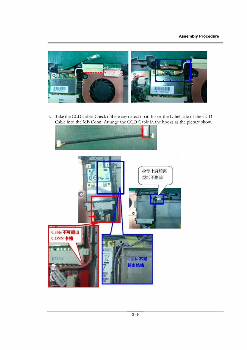
4. Take the CCD Cable, Check if there any defect on it. Insert the Label side of the CCD
Cable into the MB Conn. Arrange the CCD Cable in the hooks as the picture show.
Assembly Procedure
3 - 10
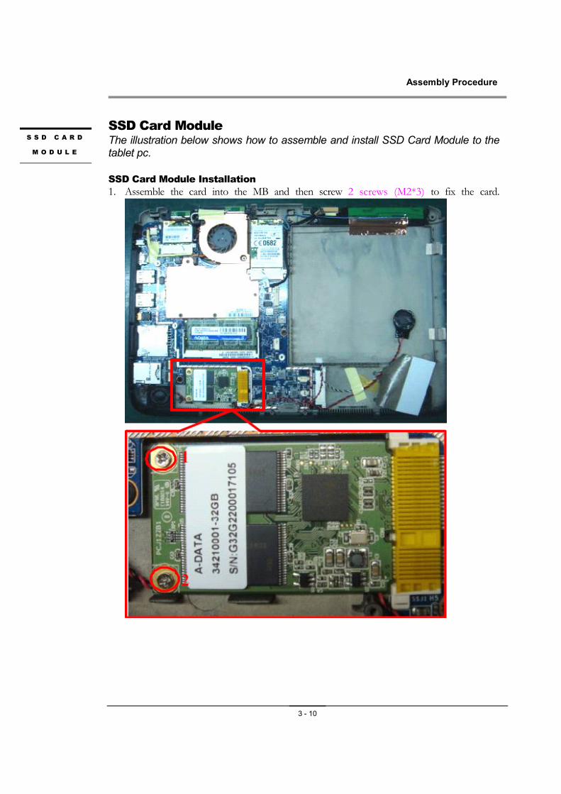
SSD Card Module The illustration below shows how to assemble and install SSD Card Module to the tablet pc.
SSD Card Module Installation
1. Assemble the card into the MB and then screw 2 screws (M2*3) to fix the card.
S S D C A R D
M O D U L E
Assembly Procedure
3 - 11
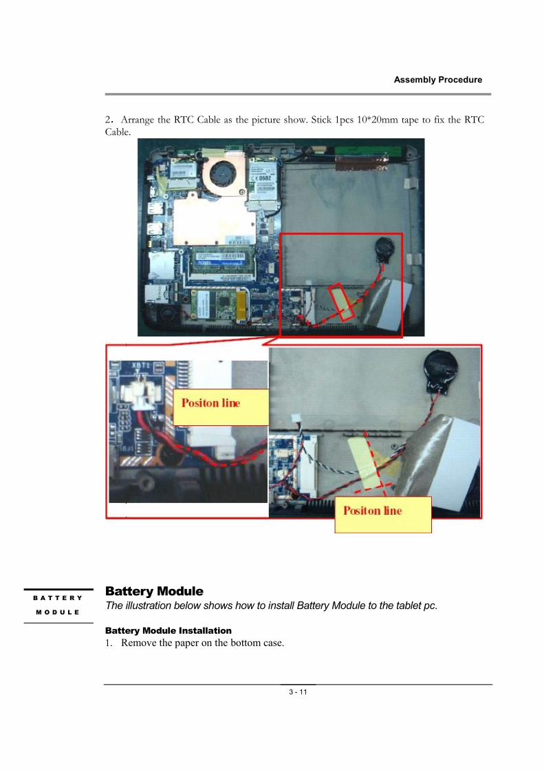
2.Arrange the RTC Cable as the picture show. Stick 1pcs 10*20mm tape to fix the RTC Cable.
Battery Module The illustration below shows how to install Battery Module to the tablet pc.
Battery Module Installation
1. Remove the paper on the bottom case.
B A T T E R Y
M O D U L E
Assembly Procedure
3 - 12
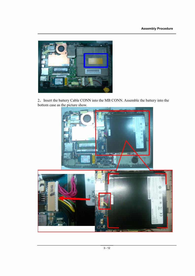
2.Insert the battery Cable CONN into the MB CONN. Assemble the battery into the
bottom case as the picture show.
Assembly Procedure
3 - 13
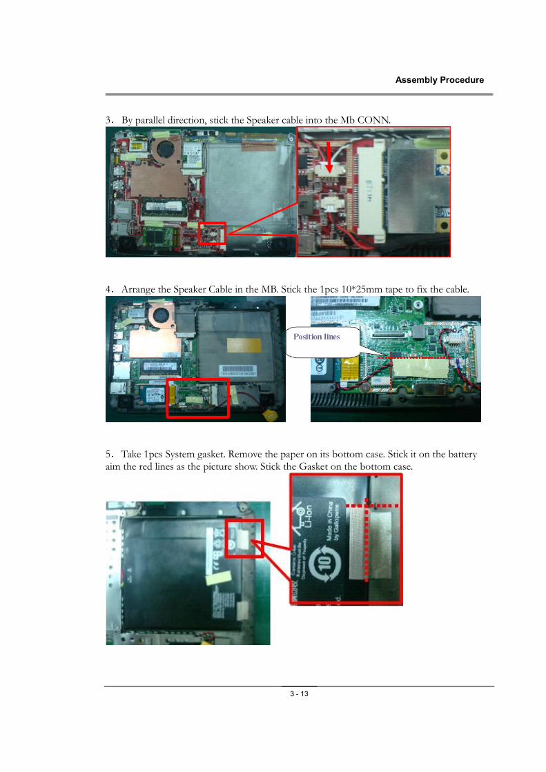
3. By parallel direction, stick the Speaker cable into the Mb CONN.
4.Arrange the Speaker Cable in the MB. Stick the 1pcs 10*25mm tape to fix the cable.
5.Take 1pcs System gasket. Remove the paper on its bottom case. Stick it on the battery aim the red lines as the picture show. Stick the Gasket on the bottom case.
Assembly Procedure
3 - 14
HD Video Decoder Module The illustration below shows how to install HD Video Decoder to the tablet pc.
HD Video Decoder Module Installation
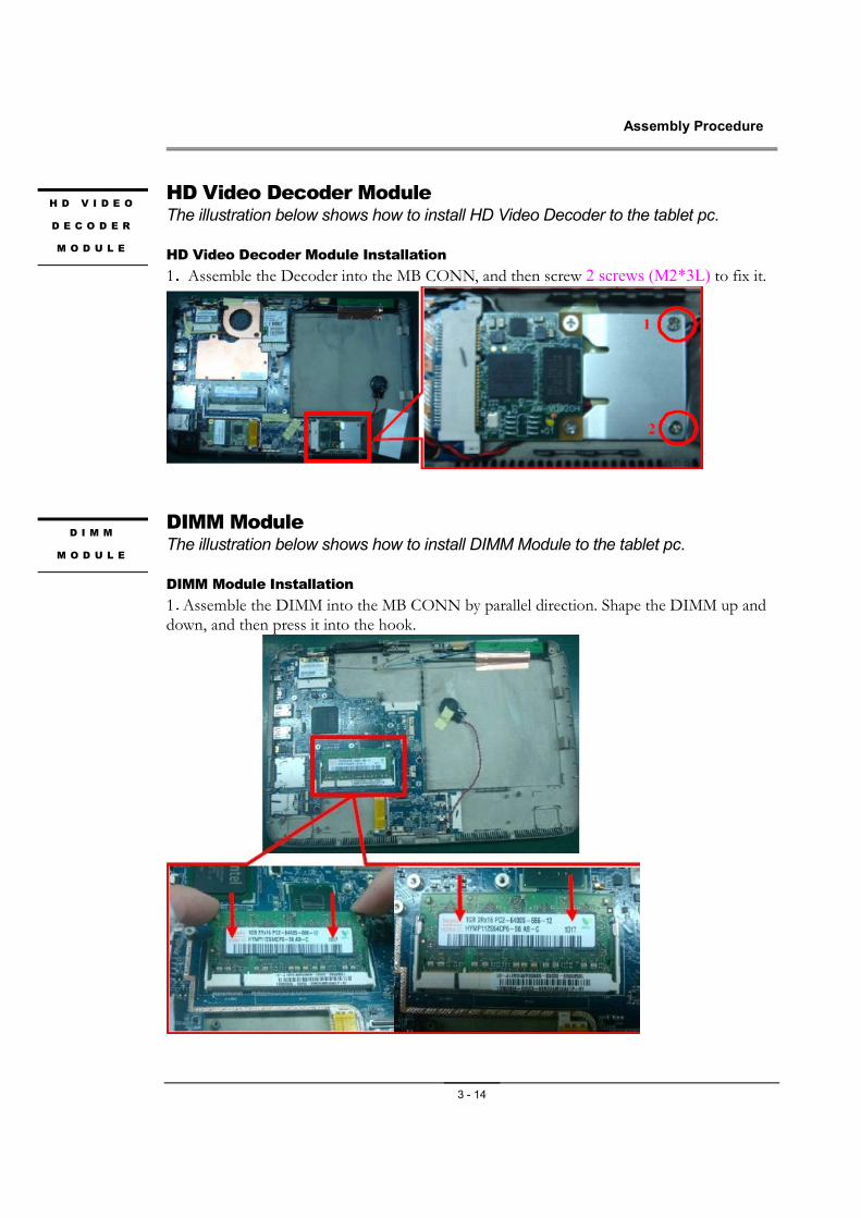
1.Assemble the Decoder into the MB CONN, and then screw 2 screws (M2*3L) to fix it.
DIMM Module The illustration below shows how to install DIMM Module to the tablet pc.
DIMM Module Installation
1.Assemble the DIMM into the MB CONN by parallel direction. Shape the DIMM up and down, and then press it into the hook.
H D V I D E O
D E C O D E R
M O D U L E
D I M M
M O D U L E
Assembly Procedure
3 - 15
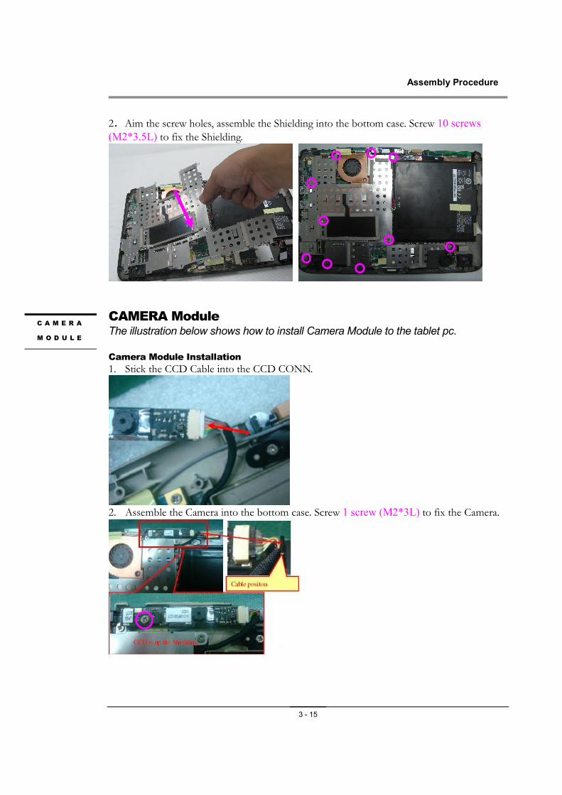
2.Aim the screw holes, assemble the Shielding into the bottom case. Screw 10 screws
(M2*3.5L) to fix the Shielding.
CAMERA Module The illustration below shows how to install Camera Module to the tablet pc.
Camera Module Installation
1. Stick the CCD Cable into the CCD CONN.
2. Assemble the Camera into the bottom case. Screw 1 screw (M2*3L) to fix the Camera.
C A M E R A
M O D U L E
Assembly Procedure
3 - 16
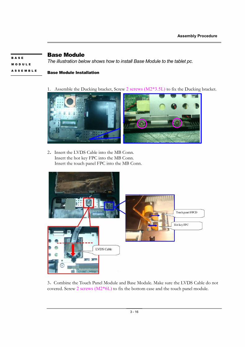
Base Module The illustration below shows how to install Base Module to the tablet pc.
Base Module Installation
1. Assemble the Ducking bracket, Screw 2 screws (M2*3.5L) to fix the Ducking bracket.
2.Insert the LVDS Cable into the MB Conn. Insert the hot key FPC into the MB Conn. Insert the touch panel FPC into the MB Conn.
3.Combine the Touch Panel Module and Base Module. Make sure the LVDS Cable do not covered. Screw 2 screws (M2*6L) to fix the bottom case and the touch panel module.
B A S E
M O D U L E
A S S E M B L E
Assembly Procedure
3 - 17
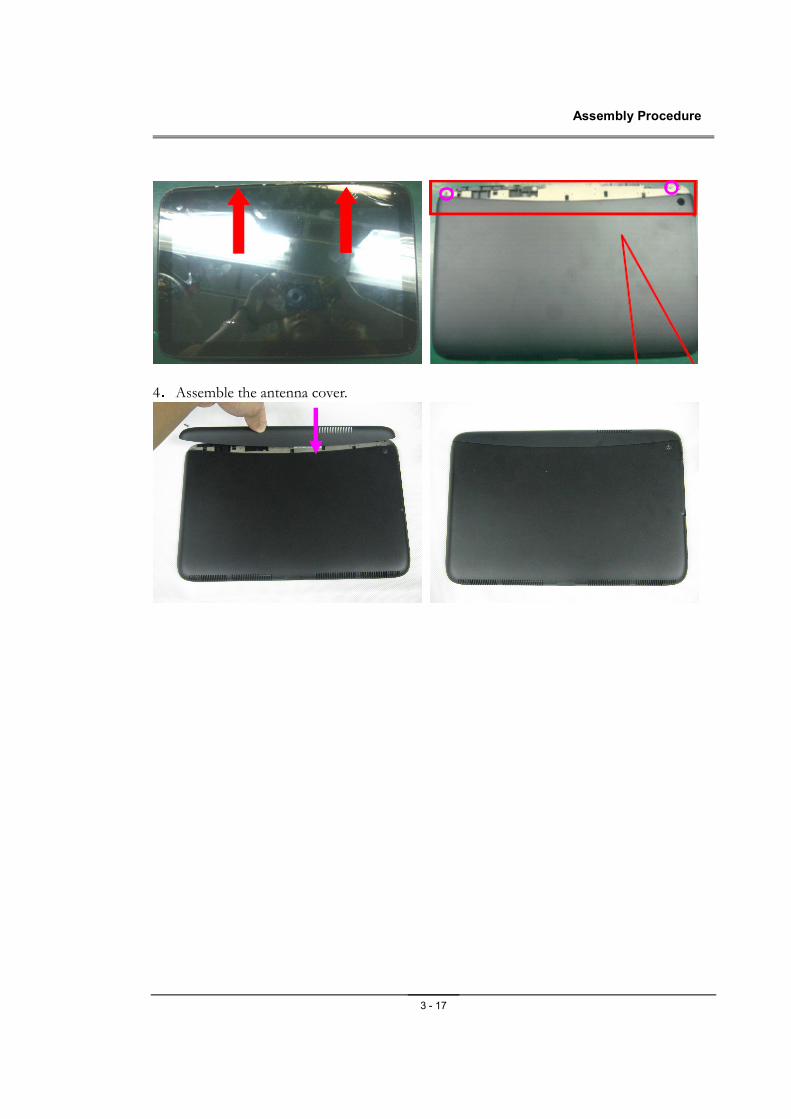
4.Assemble the antenna cover.