Embed Size (px)
Citation preview

1
American Institute of Aeronautics and Astronautics
ARINC 653 Based Time-Critical Application for European
SCARLETT Project.
Tomasz Rogalski1, Slawomir Samolej
2, Andrzej Tomczyk
3
Rzeszow University of Technology, ul. W. Pola 2, 39-959 Rzeszow, Poland
The SCAlable & ReconfigurabLe Electronics plaTforms and Tools project (SCARLETT) was started by European Commission to develop the concept of IMA 2G
Avionics. The paper mentions the main objectives of the SCARLET project and presents
a sample time-critical application developed for it. The time-critical application is an
ARINC 653 based and is a part of a distributed control system working in AFDX
network environment. Its task is to control an elevator’s actuator of a typical airliner.
The paper presents the structure of the application, its timing schedule, and dedicated
control algorithms and error detection mechanism built-in it. Selected application tests
conclude the paper.
Nomenclature
CPM = Core Processing Module
RDC = Remote Data Concentrator
REU = Remote Electronics Unit
IMA = Integrated Modular Avionic
DME = Distributed Modular Electronics
AFDX = Avionics Full DupleX
q = pitch rate
= pitch angle de = deflection of elevator
u = airspeed
= angle of attack h = altitude
I. Introduction
The Integrated Modular Avionic6 (IMA) concept has been introduced through the European funded research
projects PAMELA, NEVADA and VICTORIA. The result of the projects was so called first generation of IMA
(IMA1G) and was successfully implemented onboard A380, A400M and B787 aircrafts. The main achievement
of the IMA1G is a general change of modern airliner avionics construction paradigms. The previous federated
avionics architecture is being systematically replaced with fewer common processing modules, sharing the
necessary power supply and communication links. The current implementation of IMA covers a limited range of
aircraft functions but shows that it may bring a significant profits: the aircraft weight reduction and lower
maintenance costs.
The SCARLETT project4,Błąd! Nie można odnaleźć źródła odwołania.
is a natural continuation of abovementioned
projects. Its main aim is a definition of a scalable, reconfigurable fault-tolerant driven and secure new avionics
platform, namely DME: Distributed Modular Electronics. The new DME should provide:
Scalability, portability and adaptability,
Fault tolerance and reconfiguration capabilities,
A minimum number of types of standardised electronic modules,
1 PhD. Eng, Department of Avionics and Control Systems, ul. W. Pola 2 35-959 Rzeszow, Poland.
2 PhD. Eng, Department of Computer and Control Engineering, ul. W. Pola 2 35-959 Rzeszow, Poland.
3 DSc. Eng, Department of Avionics and Control Systems, ul. W. Pola 2 35-959 Rzeszow, Poland.

2
American Institute of Aeronautics and Astronautics
Support for the full range of avionics function.
The SCARLETT projectBłąd! Nie można odnaleźć źródła odwołania.
is an European enterprise joining 39 companies from
16 countries including large industrial companies, public research centres, industrial research centres,
universities, small and medium enterprises. One of the project partners is Rzeszow University of Technology
(RUT) Research Team (RUTRT).
This paper presents the current RUTRT’s contribution to the SCARLETT project. The RUTRT takes part in
a time critical application development and testing SCARLETT research path. Its task is to prepare a specific
hard real-time application that would be executed at several SCARLETT hardware modules. The application
should be a part of a control system and make it possible to evaluate whether DME units can be effectively used
as hard real-time applications platforms. The preliminary research results of RUTRT were published in7.
The next sections of the paper are organised as follows. Firstly the main SCARLETT DME units will be
shortly introduced. Secondly a Pitch Control Application (an illustrative example of the time-critical avionic
control system) developed by the RUTRT will be presented. The section will include decryptions of: system
specification, application implementation and built-in self testing procedures. The final part of the paper will
include our future research plans.
II. SCARLETT DME Units
According to SCARLETT philosophy the future avionics of airliners will consist of a set well-defined
hardware modules dedicated to a sets of avionic applications. The following types of hardware modules have
been defined in Ref. Błąd! Nie można odnaleźć źródła odwołania.:
1) AFDX3 - Avionics Full DupleX (AFDX) is a redundant Ethernet network and made reliable, developed
and standardized by the European industrialists of the avionics to equip A380 Airbus. It is about a
system intended to be used as support for the internal communications with the plane, and not with the
communications with outside. The internal communications are primarily the data exchanged between
the different components of the avionics.
2) AFDX Switch - Star coupler for AFDX network. Like Ethernet switches, AFDX switches provide
packets forwarding, they also have additional features to guarantee the timing and bandwidth allocation
of all the network, but they only use multicast addresses (Virtual Links).
3) CPM - The Core Processing Module offers a generic computation capability, an AFDX End System,
and a set of generic bus + housekeeping I/Os capability (Field Bus such as CAN or Flexray, Discrete
Inputs for pin-programming / servitudes and RS232 / 485 for maintenance in shop). The objective is to
suppress the A429 interfaces of the CPM and the adherence between the functional I/O and the
applications running on the CPM. As a start SCARLETT identify three types of CPM:
High Performance CPM,
Time Critical CPM,
Avionics Server Function CPM.
4) REU - Remote Electronics Unit is an electronics box dedicated to a function and geographically close to
this function. REU are not generic units and therefore not part of the IMA perimeter. However the
interfaces of REUs to the IMA world shall be standardised.
5) RDC - Remote Data Concentrator: equipment supporting the exchange of information between sensors /
actuators (digital, discrete and analogue data) and aircraft digital communication networks (ADCN).
The RDCs are located in pressurized areas close to sensors and effectors, which may be potentially
remote from the associated processing resources, then not in the avionics bay.
The abovementioned hardware modules should mainly communicate between each other using AFDX3. The
message format should follow ARINC 664 2 specification. The software modules executed on the hardware units
should be developed according ARINC 6531 specification.
III. RUTRT Research Objectives
In SCARLET project RUTRT was obliged to prepare a hard real-time application (time-critical application)
which parts would be distributed over several devices developed according DME paradigm. The SCERLETT

3
American Institute of Aeronautics and Astronautics
partners specified the following requirements for RUTRT’s application. An application demonstrates possibility
of the usage of SCARLETT philosophy to control an aircraft in the pitch control channel. The application
should demonstrate the possibility of the use of two synchronously working actuators deflecting elevator’s
surfaces. An external controller computes position of the elevator on the basics of flight parameters, pilot’s
inputs and, implemented control procedures. The application communicates with actuator’s controllers and units
collecting data from indicators by specially dedicated REU units connected to ADFX bus. The application
should be prepared for two kinds of hardware configurations. For the first hardware configuration (called the
Time Critical Demonstrator) the application should assess the possibility of correct execution of a distributed
hard real-time application loaded on the elements of the demonstrator. For the second one (called the
Reconfiguration and Maintenance Demonstrator) the application should be so called background application. It
should be possible to detect whether the control systems works correctly even if the reconfiguration of other
applications occurs or has recently occurred. Figure 1 shows an example RUTRT’s application distribution over
the SCARLETT hardware modules.
A part of the control application is executed on CPM module. Two other parts are allocated to two REUs.
The REUs are directly connected to actuators. The Pitch Control Application modules communicate via AFDX.
A. Control System Architecture
Practically, RUTRT’s Pitch Control
Application (RUTRT PCA) should control two
actuators (brushless motors) connected to a load
(an elevator). Each actuator is controlled by a
separate cascade of controllers as in fig. 2. The
actuator control system includes an internal
current control loop, a velocity control loop, and
a position control loop. Flight Control Algorithm
is a superior module that generates the position
demand signal for both control subsystems. To
adjust the dynamics of the flight control
application to the realistic values it includes a
real-time aircraft simulator that reflects a typical
airliner behaviour and produces reference signal
for Flight Control Algorithm module. The Flight
Control Algorithm module collects signals from
the aircraft simulator, pilot simulator and the
actuator and produces the position demand signal
for both actuator control subsystems.
B. Control Application Distribution Scenarios
CPM1
RU
T_
AP
P2
Actuator
REU1 REU2
AFDX1 AFDX2
RU
T_
AP
P3
RU
T_
AP
P1
Actuator
Figure 1. Example RUTRT’s application distribution.

4
American Institute of Aeronautics and Astronautics
One of the SCALLET programme goals is evaluation of quality of distributed control applications where
some parts of the application are hosed on a different devices. Therefore the RUTRT’s Pitch Control
Application was developed having in mind the possibility of distribution of some its parts on separate hardware
modules. Figure 2 shows the elaborated control application distribution variants. In the first variant
(CPM1_2+REU1_2+REU2_2) Pilot, Aircraft, Flight Control Algorithm, and two position controllers are hosted
on CPM module, whereas velocity control algorithms are hosted on separate REUs. In the second variant
((CPM1_1+REU1_1+REU2_1)) the CPM module executes the superior part of the control system (Pilot, Flight
Control Algorithm, and Aircraft) and both position and velocity controllers are hosted on REUs.
IV. RUTRT’s Pitch Control Application Implementation
The main goals of the RUTRT’s Pitch Control Application software development were as follows:
1) Position controller must be movable. It should be possible to host it both on CPM or REU hardware
modules.
2) Communication data must be adjusted to both external (inter-module) and internal (intra-module) data
exchange.
3) Some verification procedures should be built-in the application software. They should give the
information about the quality of control system and the correctness of system structure.
RUTRT’s Pitch Control Application was developed according ARINC 653P1-2 specification1. The final
source code was prepared in two variants: for VxWorks 6535,8,9,10,Błąd! Nie można odnaleźć źródła odwołania.
and for
PikeOSBłąd! Nie można odnaleźć źródła odwołania.
operating systems. Data packages that are sent between partitions are
prepared according ARINC 664P7 requirements2.
A. Pitch Control Application Structure
The released variant of RUT Flight Control Application was a VxWorks 653 and PikeOS based real-time
simulator of complete system. Figure 3 includes its structure. The simulator consists of four ARINC 653
partitions. P1, P2, and P3 are main software modules that RUTRT had to provide. P4 partition includes software
real-time simulators of SCALETT REU modules. The software emulation of REU modules made it possible to
develop the RUTRT’s application independently of the hardware module that was under development.
REU2_2
REU1_2CPM1_2
REU2_1
REU1_1CPM1_1
PIDpos err PID+-
spd err torq dem
Motor
Controller
and DriveMcurrent
Gear
Box and
Sensors
motor spd
curr spd
Load
curr pos
pos dem spd dem+-
Flight
Control
Algorithm
curr pos
Pilot
Aircraft curr pos
PIDpos err PID+-
spd err torq dem
Motor
Controller
and DriveMcurrent
Gear
Box and
Sensors
motor spd
curr spd
Load
curr pos
spd dem+-
curr pos
pos dem
curr pos
Figure 2. Control system architecture.
Figure 1. Magnetization as a function of applied field. Figure captions should be bold and justified,
with a period and a single tab (no hyphen or other character) between the figure number and the figure
description.

5
American Institute of Aeronautics and Astronautics
The first (P1) partition includes some real-time simulators of pilot and aircraft. It also includes Flight
Control Algorithm (FCA) block that collects signals from pilot, aircraft and actuator modules and produces the
desired pitch angle signals for controllers. The
last module built-in the P1 partition is Error
Estimator. It makes it possible to monitor both
communication channels and the quality of
control during the system run-time. This module
will be presented in detail in next sections. Error
Estimator, Pilot, Aircraft and FCA modules are
separate real-time tasks. The second (P2)
partition includes the first position controller
algorithm (CPx1) running as a separate real-
time task. Identically, the third (P3) partition
includes the second position control algorithm
(CPx2). The fourth (P4) partition includes 2
real-time REU simulators: the velocity
controllers modules joined with actuators
attached to the first (CVx1+Actu1) and the
second (CVx2+Actu2) control loops.
For the intra-partition communication
ARINC 653 blackboards were applied, whereas
the inter-partition communication is based on
ARINC 653 sampling ports and channels.
Figure 3 includes both ARINC 653 port names and communication channels names referenced in the next part
FCA
Pilot
Aircraft
PS
th_q
Error Estimator
1 4 7
VFx_ED1
PD1
ERR
P1: simpc_part1
CPx1
8 9 10
PD
VFx_ED1
VDx1
CVx1 Actu1
14 15
Vx1
VFx1
VFx_ED1
VDx1
C51
C52
C31
C1
C7
CPx2
11 12 13
PD2
VFx_ED2
VDx2
CVx2 Actu2
16 17
VDx2
Vx2
VFx2
VFx_ED2
6
PD2
C2
5
C61
C62
C41
VFx_ED2
ERR
2 3
PD1
PD2
VDx2
VDx1
C32
C42
P2: simpc_part2 P3: simpc_part3 P4: simpc_part4
Port names:
1: ERR_OUTPUT
2: VDx1_INPUT
3: VDx2_INPUT
4: VFx_ED1_INPUT
5: VFx_ED2_INPUT
6: PD2_OUTPUT
7: PD1_OUTPUT
8: PD1_INPUT
9: VFx_ED1_INPUT
10: VDx1_OUTPUT
11: PD2_INPUT
12: VFx_ED2_INPUT
13: VDx2_OUTPUT
14: VDx1_INPUT
15: VFx_ED1_OUTPUT
16: VDx2_INPUT
17: VFx_ED2_OUTPUT
Channels:
C1: P1:PD1_OUTPUT -> P2:PD1_INPUT
C2: P1:PD2_OUTPUT -> P3:PD2_INPUT
C31: P2:VDx1_OUTPUT -> P4:VDx1_INPUT
C32: P2:VDx1_OUTPUT -> P1:VDx1_INPUT
C41: P3:VDx2_OUTPUT -> P4:VDx2_INPUT
C41: P3:VDx2_OUTPUT -> P1:VDx2_INPUT
C51: P4:VFx_ED1_OUTPUT -> P2:VFx_ED1_INPUT
C52: P4:VFx_ED1_OUTPUT ->P1:VFx_ED1_INPUT
C61: P4:VFx_ED2_OUTPUT -> P3:VFx_ED2_INPUT
C61: P4:VFx_ED2_OUTPUT -> P1:VFx_ED2_INPUT
C7: P1:ERR_OUTPUT -> P1:ERR_INPUT (NULL_PORT)
SIMULATOR STRUCTURE
Figure 3. Pitch Control Application structure.
Figure 4. RUTRT PCA partition timing

6
American Institute of Aeronautics and Astronautics
of this paper. The same port and channel names were encoded in the application XML configuration file created
according to ARINC 653 specification.
B. Application Timing
RUTRT’s Pitch Control Application was developed to fulfil the timing constraints shown in fig. 4.
Application major frame and partition windows were defined according to ARINC 653 specification and
encoded in the application XML configuration file. The timing constraints for each of partitions were derived
from project partners and make it possible to develop properly executing digital Pitch Control System for typical
airliners. Moreover other partitions with third-party software will be executed on the same CPM module.
C. Built-in quality of application procedures
According to system’s requirements the RUTRT’s Pitch Control Application should provide a set of test
procedures informing the user about the quality of the system before or at the runtime. Therefore the following
extensions of the basic control system have been applied.
1) Separate error (ERR) port was included in P1 partition structure.
2) New Error Estimator function block was introduced in P1 partition.
3) It has been decided that the quality of service control system’s subsystems would be run simultaneously
with the control procedures.
4) The quality of service procedures has been divided into two subsystems:
a. Channel connection detector that permanently monitors the channels of the system and
informs whether all the links are properly connected. This subsystem gives the guarantee that
all system components send and receive data from the proper ports and software modules.
b. Control system error detector that signals to the system operator that the quality of control is
below the assumed acceptable level. It may suggest some problems with communication or
control system’s parameters should be refined to compensate delays in the communication.
Channel connection detector checks whether all channels are configured according to the assumed structure.
During the runtime of the application, apart from control application data, a separate set of values is sent via the
channels. Some additional procedures included in RUTRT’s application control blocks make it possible to
detect whether the application’s ports receive data from the assumed sources. The detector makes it also
possible to reveal data transmission faults. It produces a 16-bit word, where each bit value means the correctness
of the related channel. If the bit value equals 0 the channel works properly, on the other hand the channel is
badly established or the function block connected to the channel produces incorrectly formulated data packages.
Control System Error Detector is a piece of software implemented into P1 partition. Figure 5 presents
location of the Error Detector in the general scheme of the application. Its task is to monitor quality of control
realised by monitored control channel. The algorithm of the error detector works according to schema presented
in figure 6. Symbols and abbreviations located on this figure mean:
PD – desired position of the elevator,
ED – measured position of the elevator,
VFx – measured velocity of the elevator (actuator output),
Filter – low-pass filter,
Err_1 – signalling of the actuator angular velocity oscillations,
Err_2 – signalling of the elevator position error,
cVFx – estimated value of the elevator angular acceleration,
cerr_E – estimated value of the elevator position error,
CVFxgr – angular acceleration threshold value,
cerr_Egr –elevator position error threshold value.

7
American Institute of Aeronautics and Astronautics
Error estimator’s task is to indicate which actuator control system operation cases do not meet assumed
expectations. It is assumed that the incorrect operation is caused by data transmission delay using AFDX
network, or by the damage of control system elements that produce unacceptable errors of elevator’s movement.
Therefore, the control system should be insensitive to standard transport delays. In order to examine the effect of
signals transport delays in AFDX network on control system operation, control system properties should be
chosen in such a way that, the real delay values in data transfer would cause a indictable change in elevator
deflection control quality.
Two diagnostic methods were used:
1) Detection the actuator angular velocity oscillations (Err_1).
2) Signalisation the elevator’s position error that exceed the assumed threshold value (Err_2).
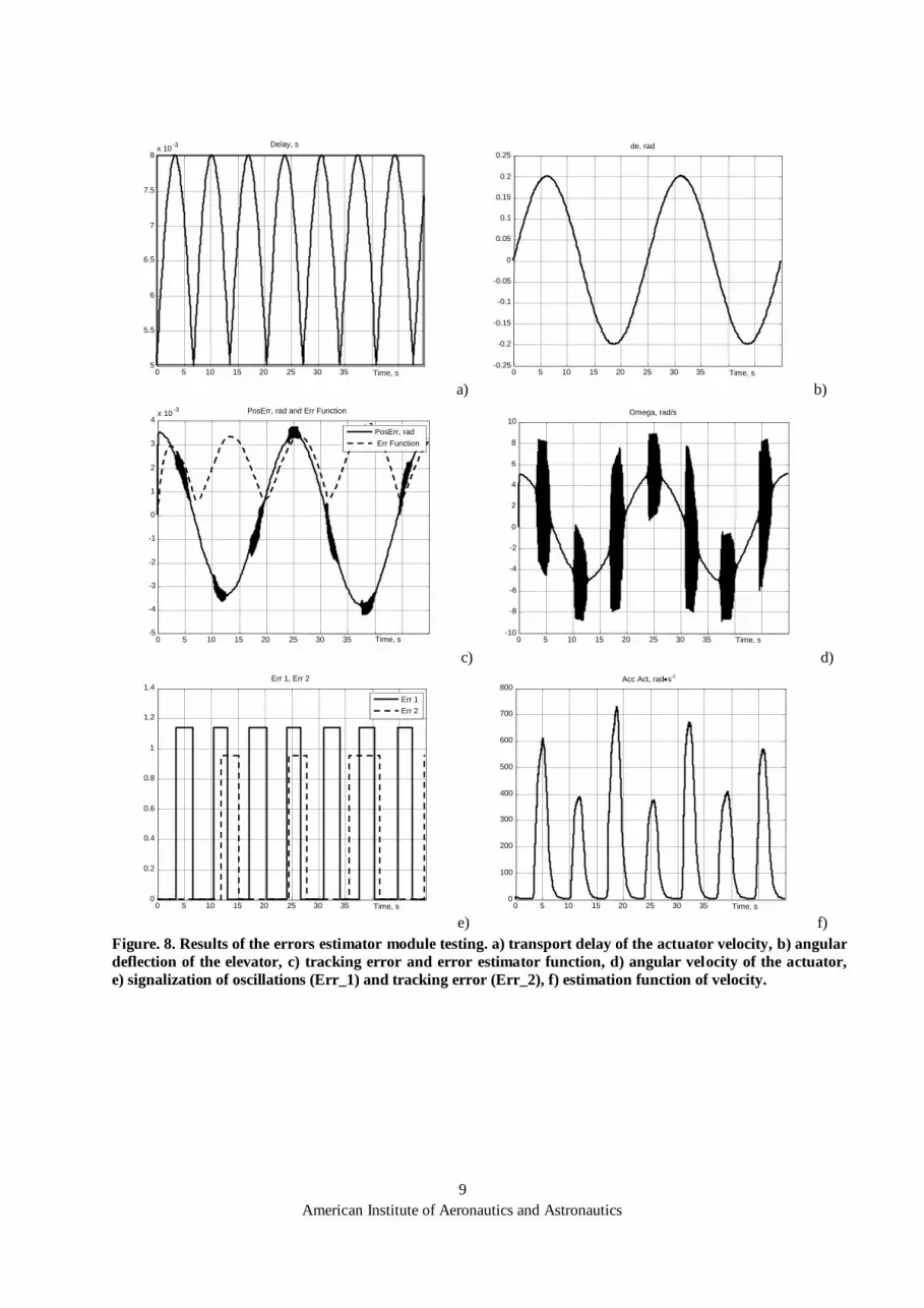
Properties of the errors estimator module has been tested using MATLAB-Simulink package. The diagnostic
was carried out as it is illustrated in fig.7 and fig.8.
Figure 7 presents the general simulation scheme. The actuator and the elevator assumed as a real integral
term are controlled by PID controller. The feedback signals of the elevator position and its angular velocity are
delayed in the Delay Generator module of about a value that represents the transport delay of AFDX network.
Oscillation detection in the control system depends on average absolute value of the actuator angular
acceleration and comparing it with the assumed threshold value (Err_1). Tracking error detection depends on the
comparison of absolute value of the deviation between desired and measured value of the elevator deflection
angle and the assumed threshold value (Err_2).
For the operator the most important is value of ERR signal produced by error estimator (fig.5). It clearly
informs the operator about quality of control loop. In general, 0 informs that the control loop works correctly.
Values between 1 and 3, include any errors of the monitored control loop (Table1).
Supplementary signals cVFx
and cerr_E (fig. 6) can be used for
scaling of errors estimates and
applied as an elevator control
system "quality indexes".
For the given actuator
properties, PID controller’s
parameters should be chosen in such
a way that the assumed control
system sensitivity to delays bigger
than the allowable ones
will be reached. Figure
8 illustrates the
operation of the
diagnostic system for
an exemplary
configuration of
elevator control system.
Transport delay is
modeled in 5-8 ms interval (Fig. 8a) and a periodic sinusoidal elevator deflection is introduced (Fig. 8b). Figure
8c presents the tracking error and the value of the function that is used to evaluate tracking quality. In figure 8e,
signal Err_2 takes the value “true” when the tracking error is bigger than 0.003 rd. Figure.8d presents the
angular velocity of the actuator while, Fig. 8f presents control quality evaluation function. Signal Err_1 in fig.
8e takes the value “true” when the transport delay of feedback signals exceeds 7.7ms.
Threshold values are set arbitrary on the basics of experiments ant expert knowledge. They must be
readjusted for real-hardware tests
0/1 |x| VFx
ED
|x| Filter Tf_E
PD err_E
bFx Filter Tf_V
Err_1
cVFx
cerr_E
cVFxgr
cerr_Egr
_
_
_
+
+
+
cerr_E
cVFx
dx/d
t
0/1 Err_2
Figure 5. Algorithm of the errors estimator
Signal name Signal
value
Signal interpretation
ERR 0
1
2
3
Control system works correctly
Deflection velocity oscillations exist
Tracking error exists
Tracking error and control system oscillations exist
Table 1. Control system error detector signals interpretation.

8
American Institute of Aeronautics and Astronautics
The application controls two actuators moving the elevator simultaneously so there are two error detectors
implemented into the application in fact. One for each of elevator’s control channel. They produce ERR1 and
ERR2 signals respectively. If both ERR1 and ERR2 are zeros the entire system works properly. Else some
errors exists and can be decoded on the basics of Table 1.
omega
deltadelay
d9
d1 d
U1
U
Transfer Fcn 3
1
s+1
Transfer Fcn 2
1
.5s+1
Signal
Generator
Relay 1
Relay
Position _Controller
output
desired
actual
derivative
PI controller d
Pos_Err
Input
Err_2
Err_1
Derivative
du /dt
Delay _Generator
In1
In2
Out1
Out2
delay
Add 2
Add
Actuator +Elevator
spd(in lim )
spd(in ) speed (out )
position (out )
Actuator
Acc_Act
Abs4
|u|
Abs3
|u|
Figure 6. MATLAB-Simulink scheme for diagnostic module testing.
9
American Institute of Aeronautics and Astronautics
0 5 10 15 20 25 30 35 5
5.5
6
6.5
7
7.5
8 x 10 -3 Delay, s
Time, s a)
0 5 10 15 20 25 30 35 -0.25
-0.2 -0.15
-0.1 -0.05
0
0.05 0.1
0.15 0.2
0.25 de, rad
Time, s b)
0 5 10 15 20 25 30 35 -5
-4
-3
-2
-1
0
1
2
3
4 x 10 -3 PosErr, rad and Err Function
PosErr, rad Err Function
Time, s c)
0 5 10 15 20 25 30 35 -10
-8 -6
-4 -2 0
2 4 6 8
10 Omega, rad/s
Time, s d)
0 5 10 15 20 25 30 35 0
0.2
0.4
0.6
0.8
1
1.2
1.4 Err 1, Err 2
Err 1 Err 2
Time, s e)
0 5 10 15 20 25 30 35 0
100
200
300
400
500
600
700
800 Acc Act, rads-2
Time, s f)
Figure. 8. Results of the errors estimator module testing. a) transport delay of the actuator velocity, b) angular
deflection of the elevator, c) tracking error and error estimator function, d) angular velocity of the actuator,
e) signalization of oscillations (Err_1) and tracking error (Err_2), f) estimation function of velocity.

10
American Institute of Aeronautics and Astronautics
V. Application tests
Two stages of RUTRT Pitch Control Application (RUTRT PCA) tests were conducted. The first groups of
tests assessed the application from the control engineering point of view. The second stage of test covered
testing of so called self-test procedures built-in the RUT PCA.
A. Pitch Control Application Evaluation
RUTRT’s task in SARLETT project was to prepare time critical application indeed to download to one of
CPMs provided by other SCARLETS partners. Application’s goal is to work in AFDX environment and control
actuators using data incoming from the network. To guarantee more realistic test conditions the actuator’s
controllers software was put into simulated flight control system application environment. To adjust the
dynamics of the flight control application to the realistic values it includes a real-time aircraft simulator that
reflects a typical airliner dynamics and produces reference signal for Flight Control Algorithm module.
Simulations uses model of longitudinal dynamics of DC-8 airplane flying at the speed of 251[m/s] at flight
level 330. Step responses for elevator step input (e=1 [deg]) of the model described in the state spaces by vector
x, state matrix A and B presents Figure 9.
q
w
u
x
0
57.4
55.10
0
0100
033.10351.00025.0
02.251806.00735.0
81.90043.0014.0
BA (1)
Simulation tests was performed with the use of simple model of the actuator deflecting elevator’s surface. Its
dynamics defines formula(2).
][85.0
][05.0
]/[28/25.0
)12()(
22
sT
radVK
sTsTs
KsG e
u
(2)
The preliminary tests of the
RUTRT Pitch Control Application
concerned typical properties of the
whole control system. The complete
real-time control system simulator was
executed and states of its state
variables were collected and assessed
form the control engineering point of
view. Typical test scenario looked as
follows.
The application controlling actuators were connected to software modules simulating pilot’s control and
aircraft’s dynamics. Pilot’s control (fig. 10) is interpreted inside FCA module and translated into desired
aircraft’s pitch angle (compare fig. 2). FCA module also uses simulated pitch angle regulator to control flight of
the simulated plane with the use of tested control channel of actuators.
0 2 4 6 8 10 -1.4
-1.2
-1
-0.8
-0.6
-0.4
-0.2
0
Time, s
pitch rate, deg/s
0 2 4 6 8 10 -4
-3.5
-3
-2.5
-2
-1.5
-1
-0.5
0
Time, s
pitch angle, deg
0 100 200 300 400 500 600 700 800 900 -20 -15 -10 -5 0
Time, s
long time response (pitch angle, deg)
Figure 9. Plane’s model responses to elevator step input.

11
American Institute of Aeronautics and Astronautics
Test of applications consists of two steps. The first step of tests involved simulations of properly working
system. Values of flight parameters satisfied desired control precision. Figure 11 presents sample time graphs of
pitch angle and pitch rate responses of the simulated
model of plane to pilot’s control signal depicted in fig .10
recognised as good enough.
During those simulations the programmed controller
of actuator working with simulated model of actuator
guaranteed the position of elevator matched desired
position of elevator calculated by FCA module good
enough (according to expert’s opinion). Figure 12
presents desired (calculated by FCA module) position of
elevator and position of simulated elevator’s mechanism
controlled by controller implemented in the application.
Graphs from figure 13 present sample errors values in
control process satisfying desired control precision. Final
error’s value (ERR) produced by error estimator is zero.
Values of variables informing about elevator’s position
error and actuator’s angular velocity oscillations error are in ranges recognised as proper ones. Ranges of
acceptable values of these errors are set arbitrary on the basics of experiments and areas follow: 0.05 for
elevator’s position error and 0.3 for actuator’s angular velocity oscillations error (fig. 13).
0 2 4 6 8 10 12 14 16 -0.2
-0.1
0
0.1
0.2
0.3
0.4
0.5 Pilot`s control normed to the range [-1 to 1]
Time, s
Figure 10. Pilot’s control programmed in tests
0 2 4 6 8 10 12 14 16 -4
-2
0
2
4
6
8
10 Pitch angle, deg
Time, s a)
0 2 4 6 8 10 12 14 16 -6
-4
-2
0
2
4
6 Pitch rate, deg/s
Time, s b)
Figure 11. Flight parameters of simulated model of plane, a) pitch angle, b) pitch rate.
0 2 4 6 8 10 12 14 16 -0.2
-0.15
-0.1
-0.05
0
0.05
0.1
0.15
0.2 Elev. position [-1 to 1] normed
time, s
Real position Desired position
Figure 12. The time domain graph of desired
and final positions of the elevator.

12
American Institute of Aeronautics and Astronautics
B. Build-in self test subsystems evaluation
The RUTRT Pitch Control Application was developed as a self testing system that during its runtime checks
both its communication configuration and its quality of control.
The channel connection detector subsystem of the application permanently monitors all the channels
existing in the application and produces 16-bit word that reports the channel’s state. The values of subsequent
bits in the word reflect the relevant channels state. If a relevant bit value is 0 the channel is recognised as
properly working. If a relevant bit equals 0, the channel is incorrectly established or physically destroyed. The
channel connection detector subsystem was tested in details during long-term tests of the RUT PCA. All the
possible channels malfunctions were emulated and properly detected.
The control system error detector subsystem of the application permanently calculates the quality of the
control system by collecting all the possible control state variables and assessing their values according the
algorithm described section III C. The subsystem tests were conducted simultaneously with the long-term
RUTRT PCA execution tests. Typical test scenario looked as follows.
The group of tests consisted of a set of simulations of broken down actuator system. Figures below (fig.14,
fig. 15, fig. 16) present results of sample tests of when the actuator’s control channel was degraded - 0.1 [s] time
delay was modelled in this control channel. That time the control precision was not recognised as good enough
0 2 4 6 8 10 12 14 16 0
0.05
0.1
0.15
0.2
0.25
0.3
0.35 Position and oscillation Error
Time, s
Oscillation error Position error
Position error threshold r level (0.05)
Oscillation error threshold level (0.3)
a)
0 2 4 6 8 10 12 14 16 -1 -0.8 -0.6 -0.4 -0.2
0 0.2 0.4 0.6 0.8
1 Final Error
Time, s b)
Figure 13. Errors signalised by Error estimator module, a) values of position and oscillation errors, b) Final
error’s value.
0 2 4 6 8 10 12 14 16 -4
-2
0
2
4
6
8
10 Pitch angle, deg
Time, s a)
0 2 4 6 8 10 12 14 16 -10
-8
-6
-4
-2
0
2
4
6 Pitch rate, deg/s
Time, s b)
Figure 14. Flight parameters of simulated model of plane, a) pitch angle, b) pitch rate. – broken down control
channel

13
American Institute of Aeronautics and Astronautics
(fig.14, fig.15), because of existing oscillations.
Moreover the position of simulated elevator didn’t
match desired elevator’s position -calculated by FCA
algorithm (fig. 15).
According to expectations due to the control
system quality lowered below assumed values the
control system error detector produced the error
signal.
VI. Conclusions and Future Research
The paper reports RUTRT contributions to European Community SCARLETT project. At the current state
of the development RUTRT PCA the software quality was evaluated by conducting a set of real-time
simulations. The results of simulations presented in sections IV and V prove that software modules may execute
according to system specification. Moreover the built-in test procedures may effectively detect errors on both
communication and quality of control system levels.
Currently, the preliminary application test are performed on the target hardware platforms (CPM and REU).
Final tests are planed during spring and summer of year 2011.
Acknowledgments
Programme SCARLETT and research reported in the paper are founded by 7th
European Framework Project.
The part of hardware components applied in the research published in this paper was founded by European
Union Operational Programme - Development of Eastern Poland, project no. POPW.01.03.00-18-012/09.
References. 1. Avionics Application Software Standard Interface Part 1-2, ARINC Specification 653p1-2, 2005. 2. Aircraft Data Network Part 7 - Avionics Full Duplex Switched Ethernet (AFDX) Network, ARINC Specification
664p7 2005. 3. “AFDX: The Next Generation Interconnect for Avionics Subsystems”, Avionics Magazine Tech. Report, 2008.
0 2 4 6 8 10 12 14 16 -0.3
-0.2
-0.1
0
0.1
0.2
0.3
0.4 Elev. position and velocity [-1 to 1] normed
Time, s
Real position Desired position
Figure 15. The time domain graph of desired and
produced positions of the elevator- . broken down
control channel..
0 5 10 15 20 25 0
0.1
0.2
0.3
0.4
0.5
0.6
0.7 Position and oscillation Error
Oscillation error Position error
Oscillation error threshold level (0.3)
Position error threshold level (0.05)
Time, s a)
0 2 4 6 8 10 12 14 16 0
0.5
1
1.5
2
2.5
3 Final Error
Time, s b)
Figure 15. Errors produced by Error estimator module - broken down control channel a) values of position and
oscillation errors, b) Final error’s value.

14
American Institute of Aeronautics and Astronautics
4. Bieber, P., Noulard, E., Pagetti C., Planche T., Vialard F., “Preliminary Design of Future Reconfigurable IMA
Platforms”, ACM SIGBED Review - Special Issue on the 2nd International Workshop on Adaptive and Reconfigurable Embedded Systems (APRES'09), Volume 6 Issue 3, October 2009.
5. Parkinson P., Kinnan L., “Safety-Critical Software Development for Integrated Modular Avionics”, Wind River
White Paper, 2007. 6. Ramsey J. W., “Integrated Modular Avionics: Less is More Approaches to IMA will save weight, improve reliability
of A380 and B787 avionics”, Avionics Magazine, 2007
http://www.aviationtoday.com/av/categories/commercial/8420.html. 7. Samolej S., Tomczyk A., Pieniążek J., Kopecki G., Rogalski T., Rolka T., “VxWorks 653 based Pitch Control
System Prototype”, Real-Time Systems, Development Methods and Applications of Real-Time Systems, Trybus L, Samolej S. eds., WKŁ 2010, (in. Polish).
8. VxWorks 653 Configuration and Build Guide 2.2, Wind River Systems, Inc. 2007. 9. VxWorks 653 Configuration and Build Reference, 2.2, Wind River Systems, Inc. 2007. 10. VxWorks 653 Programmer's Guide 2.2, Wind River Systems, Inc. 2007. 11. http://www.scarlettproject.eu 12. http://www.windriver.com/ 13. http://www.sysgo.com/

![Erratum to “Superconformal tensor calculus and matter couplings in six dimensions”:[Nucl. Phys. B 264 (1986) 653]](https://img.dokumen.tips/doc/110x75/634a6c5f913672970c08863e/erratum-to-superconformal-tensor-calculus-and-matter-couplings-in-six-dimensionsnucl.jpg)


