Embed Size (px)
Citation preview
Chapter 1
INTRODUCTION
1.1 A Brief Introduction
RADAR is an object detection system which uses radio
waves to determine the range, altitude, direction, or
speed of objects. Radar systems come in a variety of
sizes and have different performance specifications. Some
radar systems are used for air-traffic control at
airports and others are used for long range surveillance
and early-warning systems. A radar system is the heart of
a missile guidance system. Small portable radar systems
that can be maintained and operated by one person are
available as well as systems that occupy several large
rooms.
Radar was secretly developed by several nations before
and during World War II. The term RADAR itself, not the
actual development, was coined in 1940 by the United
States Navy as an acronym for radio Detection
and Ranging. The term radar has since entered English and
other languages as the common noun radar, losing all
capitalization.
The modern uses of radar are highly diverse, including
air traffic control, radar astronomy, air-defense
systems, antimissile systems; marine radars to locate1
landmarks and other ships; aircraft anti-collision
systems; ocean surveillance systems, outer space
surveillance and rendezvous systems; meteorological
precipitation monitoring; altimetry and flight control
systems; guided missile target locating systems; and
ground-penetrating radar for geological observations.
High tech radar systems are associated with digital
signal processing and are capable of extracting useful
information from very high noise levels.
1.2 Organization of the Report
The report is divided into four chapters. Chapter 1
gives a brief introduction of the project covered. It
contains the basics of a RADAR and the other tools and
components used for completion of this project.
Chapter 2 aims at the literature survey of the project
consisting of the basic idea of the project, and how we
got the idea to make this project, all the help like
websites, journals etc.
Chapter 3 covers the list of the components used in the
projects and how to use them.
2
Chapter 4 covers the implementation of the project like
boot loading to make own Arduino board, software used and
the problems faced during the course of action.
Finally, Chapter 5 deals with the present as well as the
future scope of the project, like how we can make use of
this project for the betterment of the mankind.
Chapter 2
3
LITERATURE SURVEY
2.1 ‘The Idea’
Army, Navy and the Air Force make use of this
technology. The use of such technology has been seen
recently in the self parking car systems launched by
AUDI, FORD etc. And even the upcoming driverless cars by
Google like Prius and Lexus.
The project made by us can be used in any systems the
customer may want to use like in a car, a bicycle or
anything else. The use of Arduino [1] in the project
provides even more flexibility of usage of the above-said
module according to the requirements.
The idea of making an Ultrasonic RADAR came as a part of
a study carried out on the working and mechanism of
“Automobiles of Future”. Also, being students of ECE, we
have always been curious about the latest ongoing
technology in the world like Arduino, Raspberry Pi,
Beagle-Bone boards etc. An hence this time we were able
to get a hold of one of the Arduino boards, Arduino UNO
R3. So, knowing about the power and vast processing
capabilities of the Arduino, we thought of making it big
and a day to day application specific module that can be
used and configured easily at any place and by anyone.
4
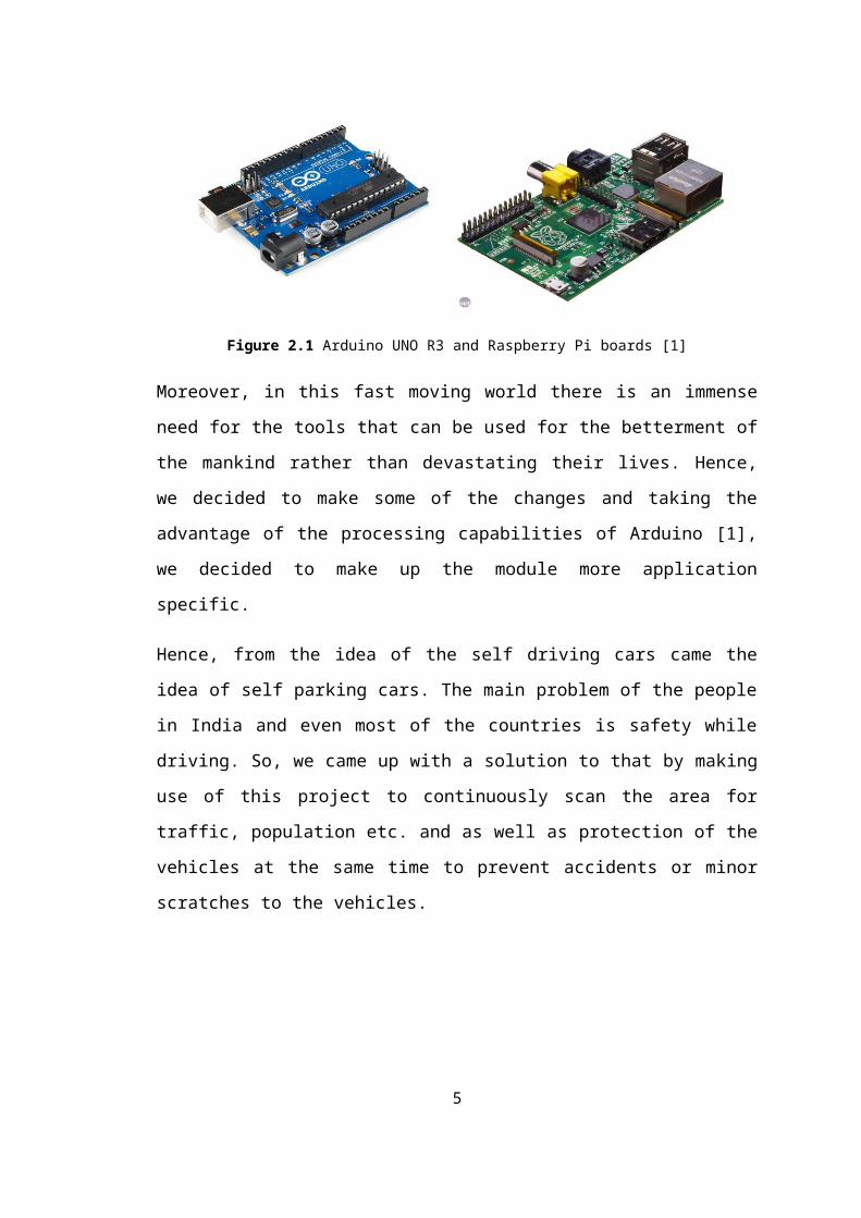
Figure 2.1 Arduino UNO R3 and Raspberry Pi boards [1]
Moreover, in this fast moving world there is an immense
need for the tools that can be used for the betterment of
the mankind rather than devastating their lives. Hence,
we decided to make some of the changes and taking the
advantage of the processing capabilities of Arduino [1],
we decided to make up the module more application
specific.
Hence, from the idea of the self driving cars came the
idea of self parking cars. The main problem of the people
in India and even most of the countries is safety while
driving. So, we came up with a solution to that by making
use of this project to continuously scan the area for
traffic, population etc. and as well as protection of the
vehicles at the same time to prevent accidents or minor
scratches to the vehicles.
5
Chapter 3
INTRODUCTION TO THE COMPONENTS USED
3.1 Introduction to Arduino Uno
The Arduino Uno is a microcontroller board based on
the ATmega328. It has 14 digital Input /Output pins (of
which 6 can be used as PWM outputs), 6 analog inputs, a
16MHz ceramic resonator, USB connection, a power jack, an6
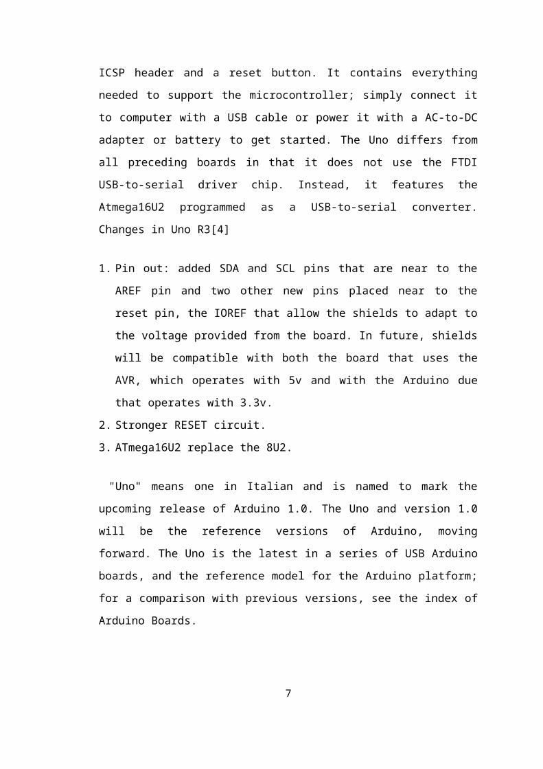
ICSP header and a reset button. It contains everything
needed to support the microcontroller; simply connect it
to computer with a USB cable or power it with a AC-to-DC
adapter or battery to get started. The Uno differs from
all preceding boards in that it does not use the FTDI
USB-to-serial driver chip. Instead, it features the
Atmega16U2 programmed as a USB-to-serial converter.
Changes in Uno R3[4]
1. Pin out: added SDA and SCL pins that are near to the
AREF pin and two other new pins placed near to the
reset pin, the IOREF that allow the shields to adapt to
the voltage provided from the board. In future, shields
will be compatible with both the board that uses the
AVR, which operates with 5v and with the Arduino due
that operates with 3.3v.
2. Stronger RESET circuit.
3. ATmega16U2 replace the 8U2.
"Uno" means one in Italian and is named to mark the
upcoming release of Arduino 1.0. The Uno and version 1.0
will be the reference versions of Arduino, moving
forward. The Uno is the latest in a series of USB Arduino
boards, and the reference model for the Arduino platform;
for a comparison with previous versions, see the index of
Arduino Boards.
7
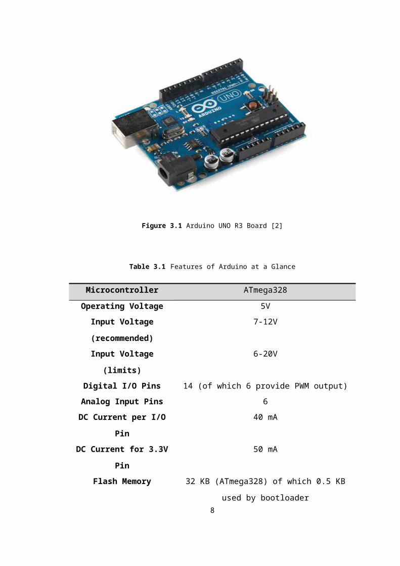
Figure 3.1 Arduino UNO R3 Board [2]
Table 3.1 Features of Arduino at a Glance
Microcontroller ATmega328Operating Voltage 5V
Input Voltage
(recommended)
7-12V
Input Voltage
(limits)
6-20V
Digital I/O Pins 14 (of which 6 provide PWM output)Analog Input Pins 6DC Current per I/O
Pin
40 mA
DC Current for 3.3V
Pin
50 mA
Flash Memory 32 KB (ATmega328) of which 0.5 KB
used by bootloader8
SRAM 2 KB (ATmega328)EEPROM 1 KB (ATmega328)
Clock Speed 16 MHz
3.2 AVR ATmega328
The ATmega328 is a single chip micro-
controller created by Atmel and belongs to the mega
AVR series. The high-performance Atmel 8-bit AVR RISC-
based microcontroller combines 32 KB ISP flash memory
with read-while-write capabilities, 1 KB EEPROM,
2 KB SRAM, 23 general purpose I/O lines, 32 general
purpose working registers, three flexible
timer/counters with compare modes, internal and
external interrupts, serial programmable usart, a byte-
oriented 2-wire serial interface, spi serial-port, a 6-
channel 10 bit Analog to Digital converter (8-
channels)in tqfp and qfn/mlf packages),programmable
watchdog timer with internal oscillator and five software
selectable power saving modes. The device operates
between 1.8-5.5 volts. By executing powerful instructions
in a single clock cycle, the device achieves throughputs
approaching 1 MIPS per MHz, balancing power consumption
and processing speed.[5]
9
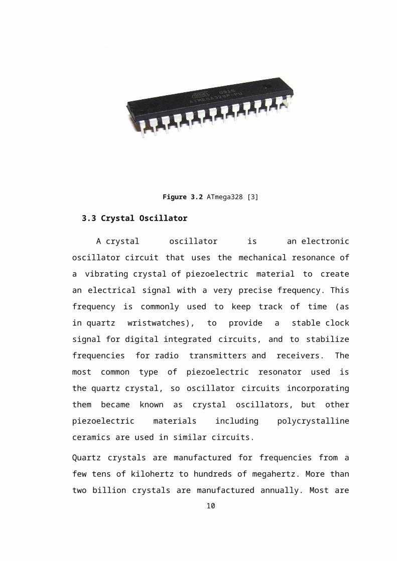
Figure 3.2 ATmega328 [3]
3.3 Crystal Oscillator
A crystal oscillator is an electronic
oscillator circuit that uses the mechanical resonance of
a vibrating crystal of piezoelectric material to create
an electrical signal with a very precise frequency. This
frequency is commonly used to keep track of time (as
in quartz wristwatches), to provide a stable clock
signal for digital integrated circuits, and to stabilize
frequencies for radio transmitters and receivers. The
most common type of piezoelectric resonator used is
the quartz crystal, so oscillator circuits incorporating
them became known as crystal oscillators, but other
piezoelectric materials including polycrystalline
ceramics are used in similar circuits.
Quartz crystals are manufactured for frequencies from a
few tens of kilohertz to hundreds of megahertz. More than
two billion crystals are manufactured annually. Most are10
used for consumer devices such
as wristwatches, clocks, radios, computers, and cell
phones. Quartz crystals are also found inside test and
measurement equipment, such as counters, signal
generators, and oscilloscopes.
Figure 3.3 Crystal Oscillator (16 MHz) [4]
3.4 Servo Motor
A servomotor is a rotary actuator that allows for
precise control of angular position, velocity and
acceleration. It consists of a suitable motor coupled to
a sensor for position feedback. It also requires a
relatively sophisticated controller, often a dedicated
module designed specifically for use with servomotors.
Servomotors are not a different class of motor, on the
basis of fundamental operating principle, but
uses servomechanism to achieve closed loop control with a
generic open loop motor.
Servomotors are used in applications such
as robotics, CNC machinery or automated manufacturing.
11
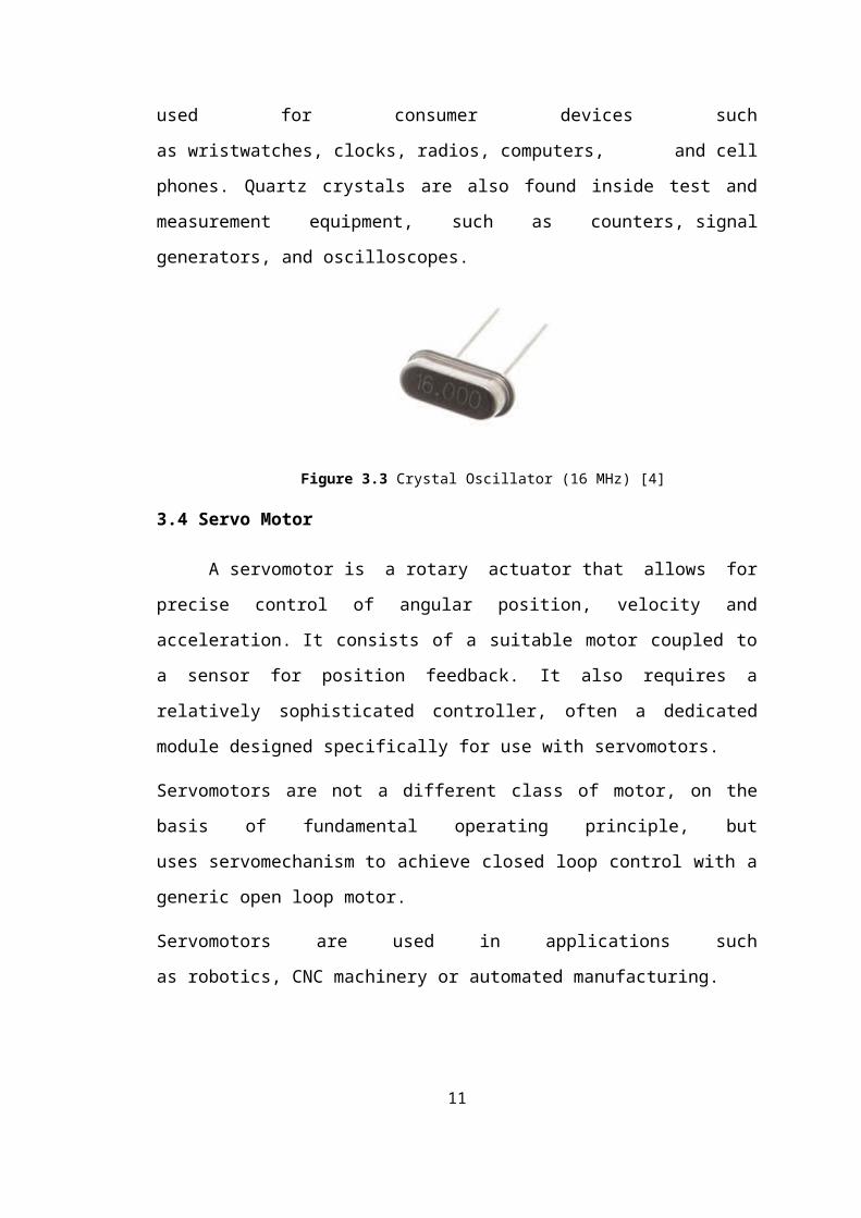
Figure 3.4 Servo Motor [5]
3.5 Voltage Regulator
A voltage regulator is an electrical regulator
designed to automatically maintain a constant voltage
level.
With the exception of shunt regulators, all modern
electronic voltage regulators operate by comparing the
actual output voltage to some internal fixed reference
voltage. Any difference is amplified and used to control
the regulation element. This forms a negative feedback
servo control loop. If the output voltage is too low, the
regulation element is commanded to produce a higher
voltage
The 78XX series of three-terminal positive regulator are
available in the TO-220/D-PAK package and with several
fixed output voltages, making them useful in a wide range
of applications. Each type employs internal current
limiting, thermal shut down and safe operating area
protection, making it essentially indestructible. If
adequate heat sinking is provided, they can deliver over
1A output current. Although designed primarily as fixed
12
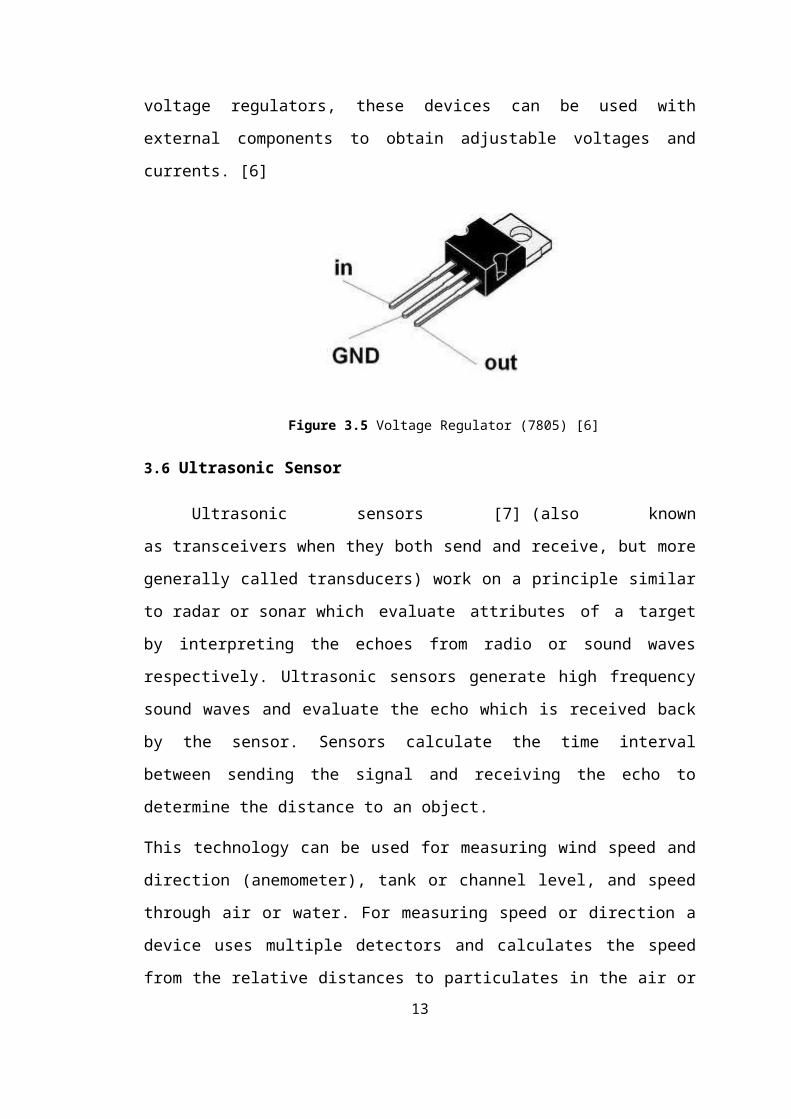
voltage regulators, these devices can be used with
external components to obtain adjustable voltages and
currents. [6]
Figure 3.5 Voltage Regulator (7805) [6]
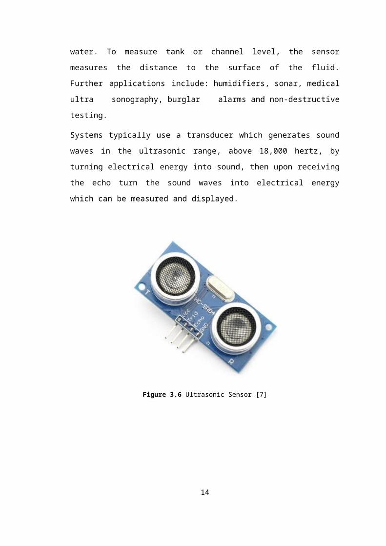
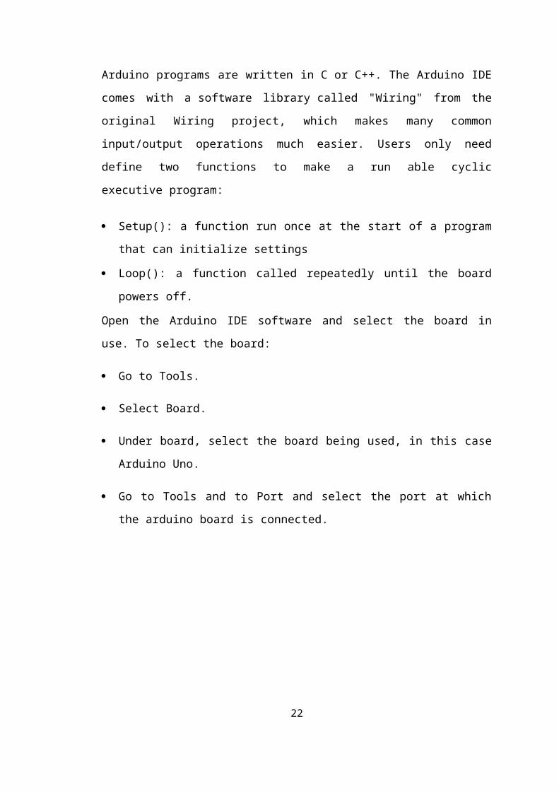
3.6 Ultrasonic Sensor
Ultrasonic sensors [7] (also known
as transceivers when they both send and receive, but more
generally called transducers) work on a principle similar
to radar or sonar which evaluate attributes of a target
by interpreting the echoes from radio or sound waves
respectively. Ultrasonic sensors generate high frequency
sound waves and evaluate the echo which is received back
by the sensor. Sensors calculate the time interval
between sending the signal and receiving the echo to
determine the distance to an object.
This technology can be used for measuring wind speed and
direction (anemometer), tank or channel level, and speed
through air or water. For measuring speed or direction a
device uses multiple detectors and calculates the speed
from the relative distances to particulates in the air or13
water. To measure tank or channel level, the sensor
measures the distance to the surface of the fluid.
Further applications include: humidifiers, sonar, medical
ultra sonography, burglar alarms and non-destructive
testing.
Systems typically use a transducer which generates sound
waves in the ultrasonic range, above 18,000 hertz, by
turning electrical energy into sound, then upon receiving
the echo turn the sound waves into electrical energy
which can be measured and displayed.
Figure 3.6 Ultrasonic Sensor [7]
14
Chapter 4
PRACTICAL IMPLEMENTATION
4.1 Making own Arduino Uno Board/Boot Loading the
ATmega328
Since, we believe in learning by doing. So, we decided
to make our own arduino board instead of using the
readymade board. So, the steps required to make an
arduino board [8] are as follows:
15
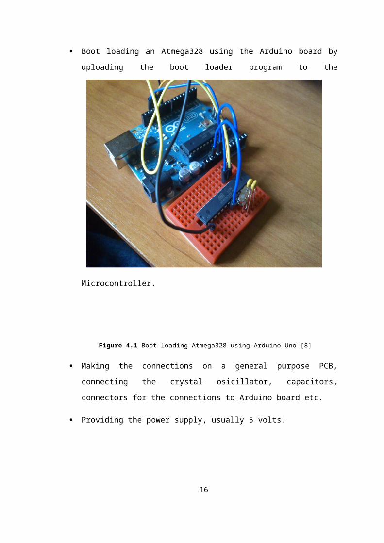
Boot loading an Atmega328 using the Arduino board by
uploading the boot loader program to the
Microcontroller.
Figure 4.1 Boot loading Atmega328 using Arduino Uno [8]
Making the connections on a general purpose PCB,
connecting the crystal osicillator, capacitors,
connectors for the connections to Arduino board etc.
Providing the power supply, usually 5 volts.
16
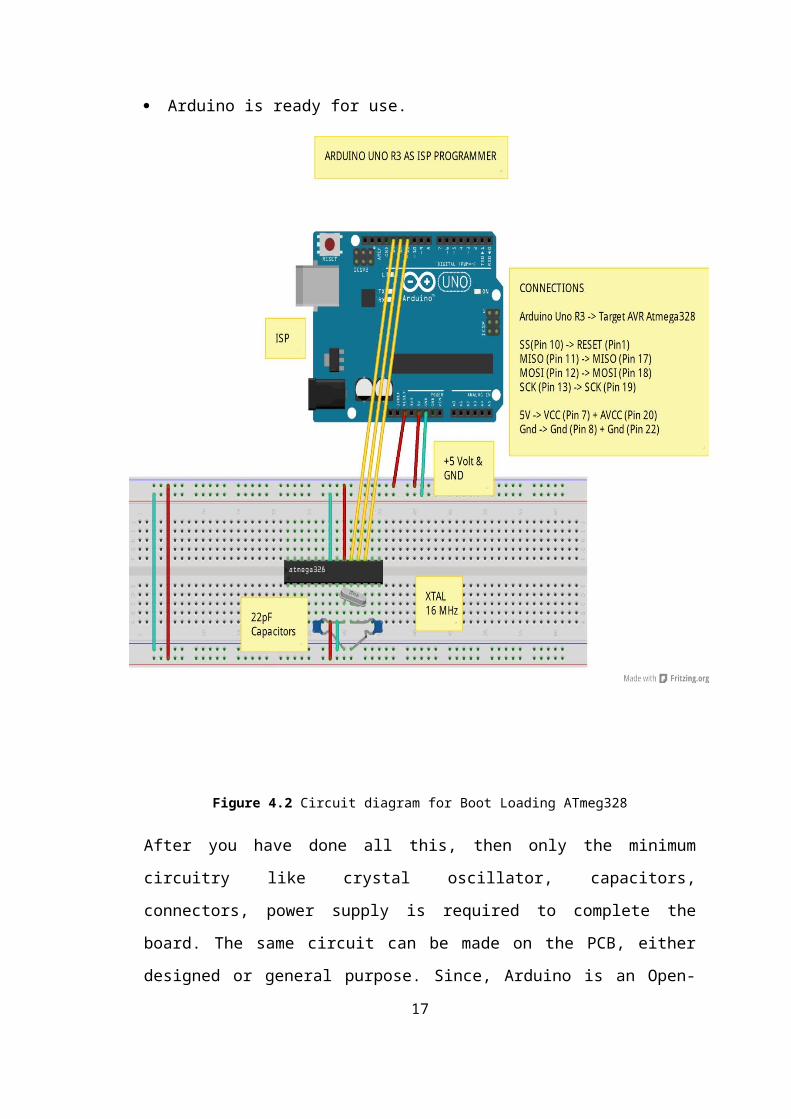
Arduino is ready for use.
Figure 4.2 Circuit diagram for Boot Loading ATmeg328
After you have done all this, then only the minimum
circuitry like crystal oscillator, capacitors,
connectors, power supply is required to complete the
board. The same circuit can be made on the PCB, either
designed or general purpose. Since, Arduino is an Open-
17
Source. Hence, it is easy to make and can have any
enhancements as per the requirements.
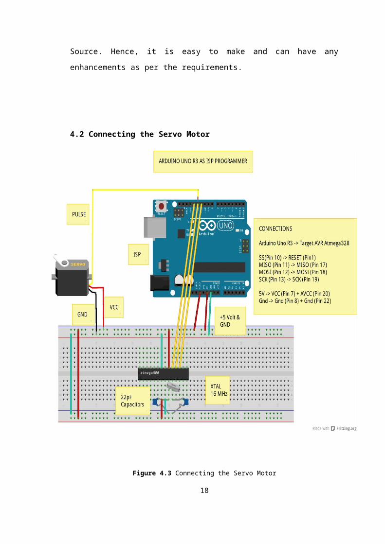
4.2 Connecting the Servo Motor
Figure 4.3 Connecting the Servo Motor
18
A servomotor is a rotary actuator that allows for
precise control of angular position, velocity and
acceleration.
A normal servo motor has three terminals:
1.VCC
2. GND
3. PULSE
A servo motor works at normally 4.8 to 6 volts. Gnd is
provided by connecting it to the Ground of the Arduino.
The total time for a servo motor pulse is usually 20ms.
To move it to one end of say 0 degree angle, a 1ms pulse
is used and to move it to other end i.e 180 degree, a 2ms
pulse is applied. Hence, according to this to move the
axis of the servo motor to the center, a pulse of time
1.5 ms should be applied. For this, the pulse wire of the
servo motor is connected to the Arduino that provides the
digital pulses for pulse width modulation of the pulse.
Hence, by programming for a particular pulse interval the
servo motor can be controlled easily.
4.3 Connecting the Ultrasonic Sensor
An Ultrasonic Sensor consists of three wires. One
for Vcc, second for Gnd and the third for pulse signal.
The ultrasonic sensor is mounted on the servo motor
and both of them further connected to the Arduino board.
The ultrasonic sensor uses the reflection principle for19
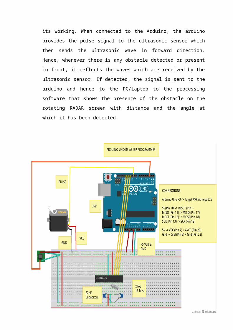
its working. When connected to the Arduino, the arduino
provides the pulse signal to the ultrasonic sensor which
then sends the ultrasonic wave in forward direction.
Hence, whenever there is any obstacle detected or present
in front, it reflects the waves which are received by the
ultrasonic sensor. If detected, the signal is sent to the
arduino and hence to the PC/laptop to the processing
software that shows the presence of the obstacle on the
rotating RADAR screen with distance and the angle at
which it has been detected.
20
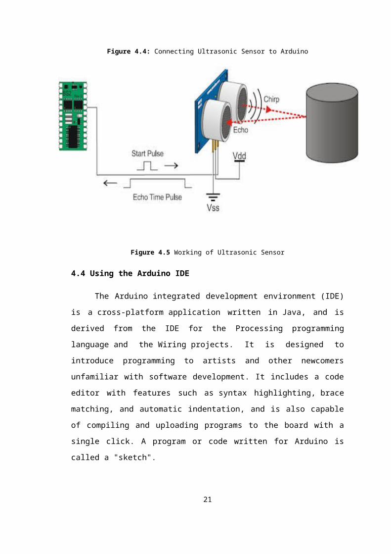
Figure 4.4: Connecting Ultrasonic Sensor to Arduino
Figure 4.5 Working of Ultrasonic Sensor
4.4 Using the Arduino IDE
The Arduino integrated development environment (IDE)
is a cross-platform application written in Java, and is
derived from the IDE for the Processing programming
language and the Wiring projects. It is designed to
introduce programming to artists and other newcomers
unfamiliar with software development. It includes a code
editor with features such as syntax highlighting, brace
matching, and automatic indentation, and is also capable
of compiling and uploading programs to the board with a
single click. A program or code written for Arduino is
called a "sketch".
21
Arduino programs are written in C or C++. The Arduino IDE
comes with a software library called "Wiring" from the
original Wiring project, which makes many common
input/output operations much easier. Users only need
define two functions to make a run able cyclic
executive program:
Setup(): a function run once at the start of a program
that can initialize settings
Loop(): a function called repeatedly until the board
powers off.
Open the Arduino IDE software and select the board in
use. To select the board:
Go to Tools.
Select Board.
Under board, select the board being used, in this case
Arduino Uno.
Go to Tools and to Port and select the port at which
the arduino board is connected.
22
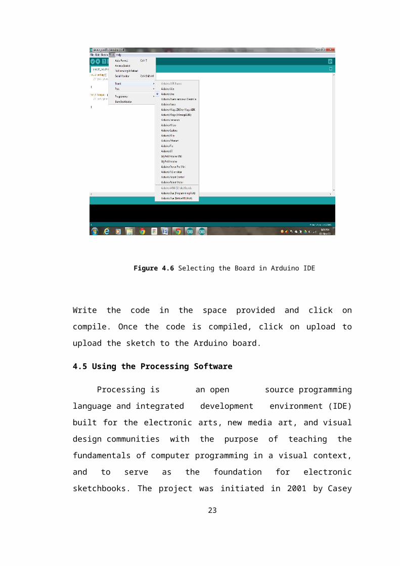
Figure 4.6 Selecting the Board in Arduino IDE
Write the code in the space provided and click on
compile. Once the code is compiled, click on upload to
upload the sketch to the Arduino board.
4.5 Using the Processing Software
Processing is an open source programming
language and integrated development environment (IDE)
built for the electronic arts, new media art, and visual
design communities with the purpose of teaching the
fundamentals of computer programming in a visual context,
and to serve as the foundation for electronic
sketchbooks. The project was initiated in 2001 by Casey
23
Reas and Benjamin Fry, both formerly of the Aesthetics
and Computation Group at the MIT Media Lab. One of the
stated aims of Processing is to act as a tool to get non-
programmers started with programming, through the instant
gratification of visual feedback. The language builds on
the Java language, but uses a simplified syntax and
graphics programming model.
Figure 4.7 Processing Software (Version 2.0)
4.6 Problems Faced
Since, electronic components when used to form any
circuit require some amount of troubleshooting to make
the circuit work according to our expectations. In our
24
project, there were some problems that we had to deal
with.
4.6.1 Making own Arduino board
The Arduino boards are available readily in the
electronics market, but we decided to make our own
Arduino board instead of buying one. So, the first
problem was where to start from to achieve this goal.
Since, all parts on an arduino board are SMD’s, so we had
to find a way to replace the SMD’s with DIP IC’s and
also had to make an AVR programmer in order to pursue our
further work. Hence, it took us some days to determine
and plan our course of action.
After that we had to boot load the AVR chip so as to make
it compatible with the Arduino IDE software. Hence, we
had to find a way to boot load the Arduino using the AVR
programmer. It took us a long time to make the AVR
programmer by researching on the type of communication
and architecture of the AVR as it is not as same as a
8051 microcontroller.
4.6.2 Communicating with Arduino through PC
Another major problem related to the Arduino board was
the communication with it from PC. Since, we require RS-
232 to TTL conversion for the communication, so we tried
some methods:
25
1. Firstly we used the MAX-232 IC to communicate with
the Arduino as with the 8051 but due to large voltage
drop and mismatch in the speed, it failed to
communicate.
2. Next, we tried to use a dedicated AVR as USB to
Serial converter as in the original arduino board, the
difference being DIP AVR used by us instead of the SMD
Mega16U2 controller. But, unfortunately we were unable
to communicate through it.
3. At last we had no other choice but to complete the
project in time by using the FTDI FT-232R chip for USB
to Serial conversion. Finally IT WORKED!!!
4.6.3 Programming the Arduino to display the RADAR
screen
The next part of the project was to be able to
display the RADAR screen. For this we used VB.NET to form
the RADAR screen but interfacing it with the Arduino
input was a little bit of a problem and not synchronized
with the Arduino input. After a lot of trials, we came to
know about the Processing software (Version 2.0). So, we
had to go through a lot of programs to finally program it
to form the RADAR screen.
26
Chapter 5
PRESENT AND FUTURE SCOPE OF PROJECT
The idea of making an Ultrasonic RADAR appeared to
us while viewing the technology used in defense, be it
Army, Navy or Air Force and now even used in the
automobiles employing features like automatic/driverless
parking systems, accident prevention during driving etc.
The applications of such have been seen recently in the
self parking car systems launched by AUDI, FORD etc. And
even the upcoming driverless cars by Google like Prius
and Lexus.
The project made by us can be used in any systems you may
want to use like in a car, a bicycle or anything else.
The use of Arduino in the project provides the
flexibility of usage of the above-said module according
to the requirements.
27
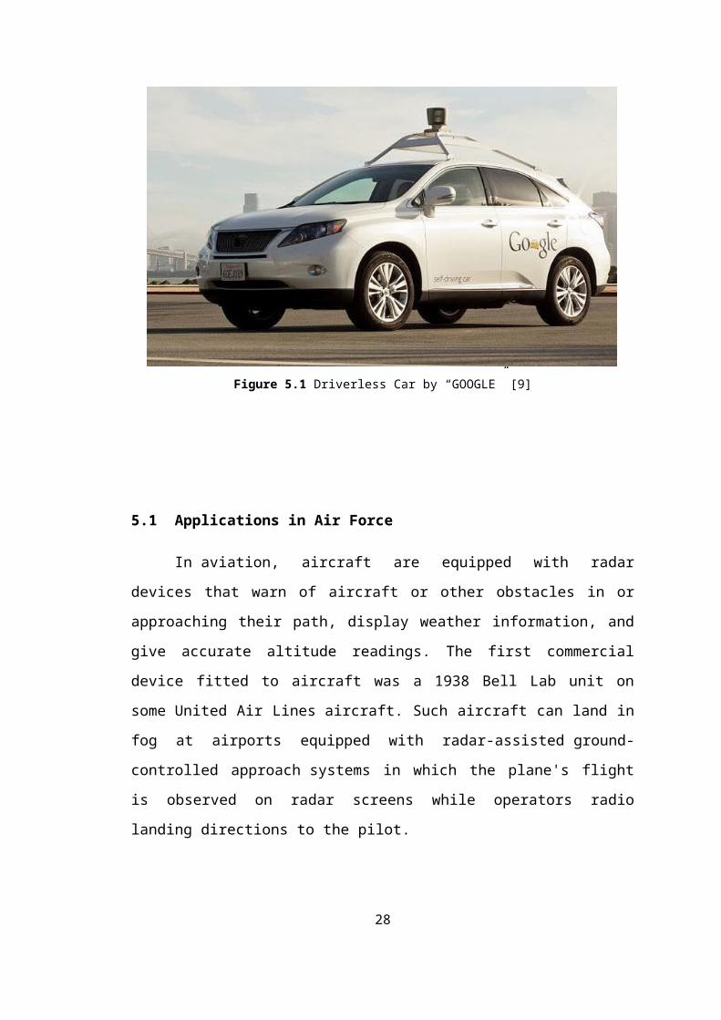
Figure 5.1 Driverless Car by “GOOGLE” [9]
5.1 Applications in Air Force
In aviation, aircraft are equipped with radar
devices that warn of aircraft or other obstacles in or
approaching their path, display weather information, and
give accurate altitude readings. The first commercial
device fitted to aircraft was a 1938 Bell Lab unit on
some United Air Lines aircraft. Such aircraft can land in
fog at airports equipped with radar-assisted ground-
controlled approach systems in which the plane's flight
is observed on radar screens while operators radio
landing directions to the pilot.
28
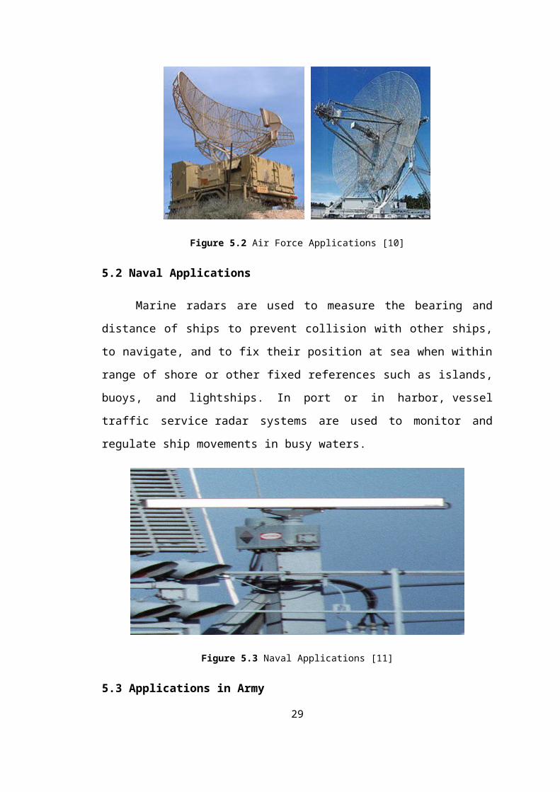
Figure 5.2 Air Force Applications [10]
5.2 Naval Applications
Marine radars are used to measure the bearing and
distance of ships to prevent collision with other ships,
to navigate, and to fix their position at sea when within
range of shore or other fixed references such as islands,
buoys, and lightships. In port or in harbor, vessel
traffic service radar systems are used to monitor and
regulate ship movements in busy waters.
Figure 5.3 Naval Applications [11]
5.3 Applications in Army
29
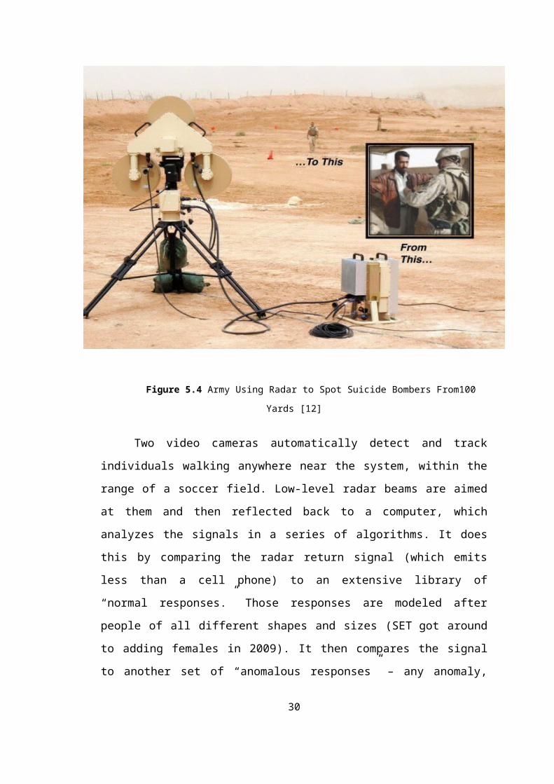
Figure 5.4 Army Using Radar to Spot Suicide Bombers From100
Yards [12]
Two video cameras automatically detect and track
individuals walking anywhere near the system, within the
range of a soccer field. Low-level radar beams are aimed
at them and then reflected back to a computer, which
analyzes the signals in a series of algorithms. It does
this by comparing the radar return signal (which emits
less than a cell phone) to an extensive library of
“normal responses.” Those responses are modeled after
people of all different shapes and sizes (SET got around
to adding females in 2009). It then compares the signal
to another set of “anomalous responses” – any anomaly,
30
and horns go off. Literally, when the computer detects a
threat, it shows a red symbol and sounds a horn. No
threat and the symbol turns green, greeting the operators
with a pleasant piano riff.
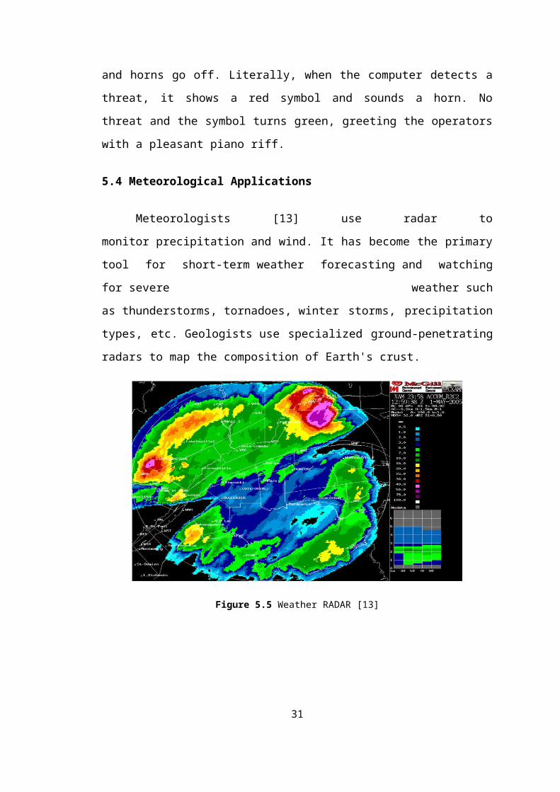
5.4 Meteorological Applications
Meteorologists [13] use radar to
monitor precipitation and wind. It has become the primary
tool for short-term weather forecasting and watching
for severe weather such
as thunderstorms, tornadoes, winter storms, precipitation
types, etc. Geologists use specialized ground-penetrating
radars to map the composition of Earth's crust.
Figure 5.5 Weather RADAR [13]
31
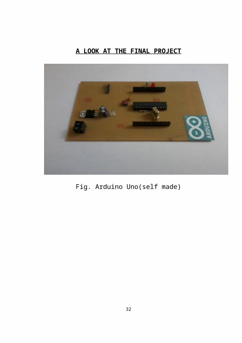
A LOOK AT THE FINAL PROJECT
Fig. Arduino Uno(self made)
32
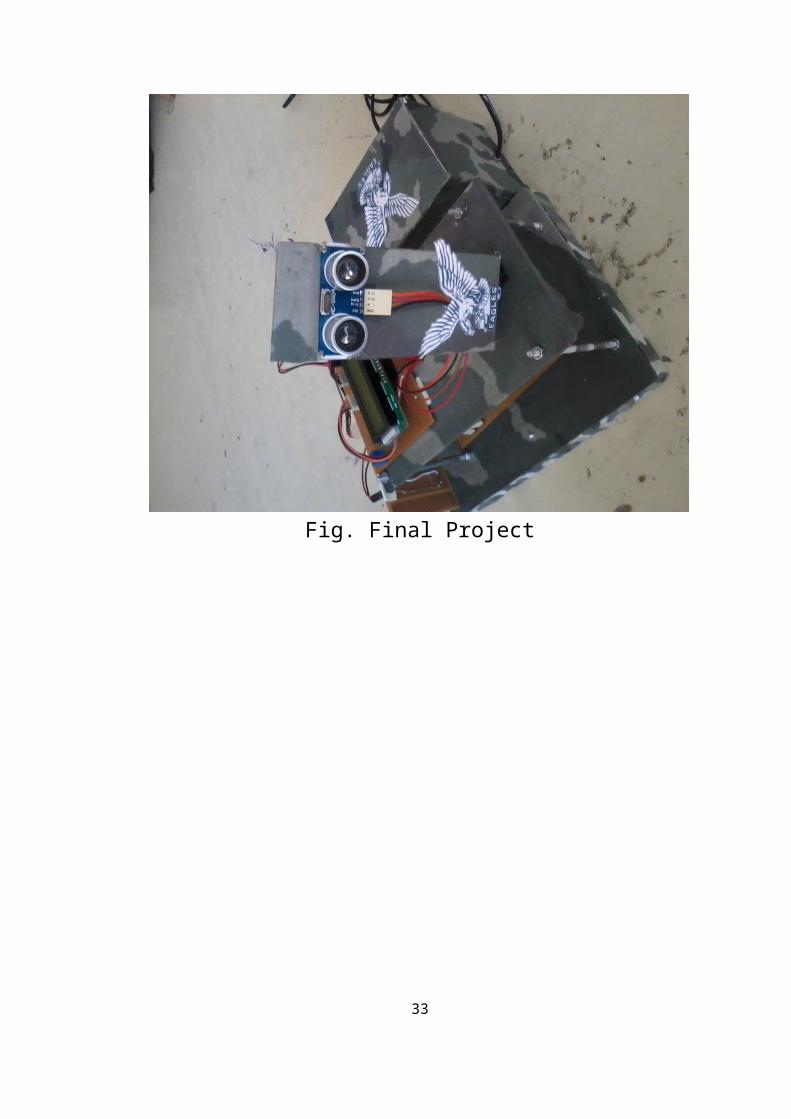
Fig. Final Project
33
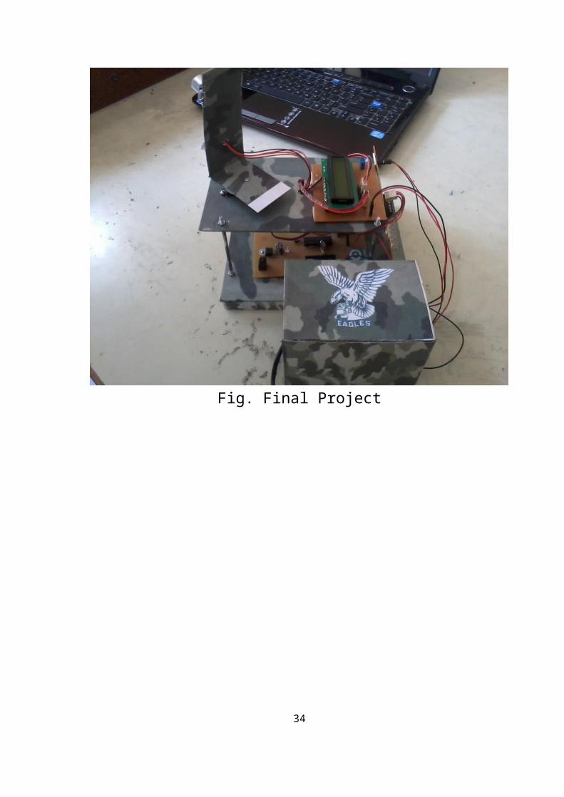
Fig. Final Project
34
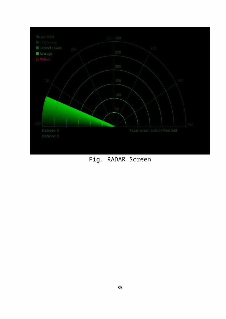
Fig. RADAR Screen
35
REFERENCES
[1] http://www.arduino.cc/
[2] http://www.arduinoproducts .cc/
[3] http://www.atmel.com/atmega328/
[4] http://en.wikipedia.org/wiki/File:16MHZ_Crystal.jpg
[5]http://www.google.co.in/imgres?imgurl=http://
www.electrosome.com/wp-
content/uploads/2012/06/ServoMotor.gif&imgrefurl=http:
//www.electrosome.com/tag/servomotor/
&h=405&w=458&sz=67&tbnid=rcdlwDVt_x0DdM:&tbnh=100&tbnw
=113&zoom=1&usg=__6J2h0ZocdoSMrS1qgK1I2qpTQSI=&docid=l
EfbDrEzDBfzbM&sa=X&ei=a_OKUvTbD8O5rgeYv4DoDQ&ved=0CDwQ
9QE
[6] http//:www.sproboticworks.com/ic%20pin
%20configuration/7805/Pinout.jpg/
[7] http://www.sproboticworks.com/ic%ultrasonicsensor
%20pinout.jpg
[8] http://www.instructables.com/id/ ATMega328-using-
Arduino-/
36
[9]
http://www.motherjones.com/files/blog_google_driverless_c
ar.jpg
[10]
http://www.google.co.in/imgres/Radar_antenna.jpg&w=546&h=
697&ei=wuuK
[11]
http://www.radomes.org/museum/photos/equip/ANSPS17.jpg
[12] http://www.wired.com/dangerroom/2011/07/ suicide-
bombers-from-100-yards/
[13]
http://upload.wikimedia.org/wikipedia/commons/Radaraccumu
lationseng.png
[14] http://arduino.cc/en/Tutorial/BarGraph/
[15] http://arduino.cc/en/Tutorial/LiquidCrystal/
[16] http://fritzing.org/
37


