Embed Size (px)
Citation preview
Abstract—Since radix-10 arithmetic has been gaining renewed importance over the last few years, high performance decimal systems and techniques are highly demanded. In this paper, a modification of the CORDIC method for decimal arithmetic is proposed so as to improve calculations. The algorithm works with BCD operands and no conversion to binary is needed. A significant reduction in the number of iterations in comparison to the original decimal CORDIC method is achieved. The experiments showing the advantages of the new method are described. Also, the results with regard to delay obtained by means of an FPGA implementation of the method are shown.
I. INTRODUCTION Numbers are commonly expressed by human beings
using decimal representation; as a consequence, in the early days of computing, most of the first computers worked with decimal operands [1]. Due to the greater simplicity of binary arithmetic unit and the compactness of binary numbers, decimal arithmetic fell into disuse and for many years it has been difficult to find new proposals of radix 10-based computers. This fact has finally led to a preponderance of binary systems over decimal ones. In spite of that, some examples of decimal architectures can be found, such as Hewlett Packard [2], Texas Instruments [3] and Casio calculators, and some others [4].
In recent years, a renewed interest in decimal arithmetic computing has arisen, since it is essential for many applications. For instance, financial calculations are carried out using decimal arithmetic, as binary operations often imply rounding up or down the results when working with fractional operands. Several studies involving financial and business-oriented applications have revealed that 55% of the numerical data contained in commercial databases are in decimal format [5]. The need for high precision engineering and manufacturing systems is also essential in CAD/CAM. When defining a radix-10 magnitude for an object, the internal use of radix-2 usually implies loss of precision, since the equivalent binary number is likely to have an infinite amount of fractional digits. On the other hand, there are currently optic and magnetic sensors which directly provide the output in BCD format, so that the user can easily monitor the evolution of certain magnitudes and detect any errors [6]. The same happens with some types of actuators
which use ISO-ASCII as the code for inputting data to the manufacturing process [7].
Proof of the importance recently given to decimal representation is the fact that even the IEEE 854 standard uses a radix-independent generalization of IEEE 754 and supports decimal floating point operations [8] [9]. Recently the IBM z900 microprocessor has been developed [10], with a decimal arithmetic unit. Furthermore, the European Commission specifies a certain number of decimal digits for calculating currency conversions [11].
CORDIC (COordinate Rotation Digital Computer) is a relevant method to approximate mathematical functions [12]. It works as an iterative algorithm for approximating rotation of a two-dimensional vector using only add and shift operations. CORDIC is particularly suited to hardware implementations due to its simplicity. Originally, CORDIC was applied to binary arithmetic, but later its application was proposed for decimal data [13] [14].
In this paper, a new CORDIC method for decimal operands is proposed, based on the use of decimal arithmetic and on the selection of adequate angles so as to reduce the number of iterations required to obtain a suitable precision. In section II, both binary and decimal CORDIC are reviewed. In section III, the new decimal CORDIC method is proposed. An architecture carried out on FPGA is proposed throughout section IV and the results of a series of experiments with regard to precision and the required number of stages are showed. Finally, in section V, conclusions are given.
II. REVIEWING THE CORDIC METHOD
A. Reviewing the binary CORDIC method Rotating a 2D point (x, y) through an angle θ can be
directly performed by means of the following equations:
xR = x cos θ − y sin θ (1) yR = x sin θ + y cos θ (2)
The above equations involve a high computational cost
due to the fact that some products and also the values of cos θ and sin θ must be calculated.
CORDIC was developed by Volder [12] for computing the rotation of a 2D vector of circular coordinates expressed
Architecture Implementation of an improved Decimal CORDIC Method
Jose-Luis Sanchez, Higinio Mora, Jeronimo Mora, and Antonio Jimeno Computer Technology Department, University of Alicante, Spain
{sanchez, hmora, jeronimo, jimeno}@dtic.ua.es
95978-1-4244-2658-4/08/$25.00 ©2008 IEEE
Authorized licensed use limited to: IEEE Xplore. Downloaded on January 30, 2009 at 03:44 from IEEE Xplore. Restrictions apply.
as binary numbers, exclusively using addition and shift operations. Walther [15] extended the method to hyperbolic and linear coordinates. CORDIC works in two different modes. In rotation mode, a vector (x0, y0) is rotated through an angle θ in order to obtain a new vector (xn, yn). The overall rotation is divided into micro-rotation such that, in micro-rotation j, an angle αj = tan-1(2-j) is added to or subtracted from the remaining angle θj. In this way, this angle approaches zero. In vectoring mode, the vector (x0, y0) is progressively rotated towards the x-axis by means of angles such as those previously mentioned, so that the component y approaches 0. As a result, the sum of all the angles applied gives the angle of vector (x0, y0) towards the x-axis, whereas the final component xn is the vector magnitude. The algorithm is based on the following equations:
xj+1 = xj – m σj yj 2-d(j) (3a) yj+1 = yj + σj xj 2-d(j) (3b) zj+1 = zj – wd(j) (3c)
The variable σj determines the direction of micro-rotation
j. In vectoring mode, σj is equal to 1 if yj is negative, and σj is equal to -1 otherwise. The values for m, d(j) and wd(j) are shown in Table 1, whereas Table 2 shows the results provided by the algorithm with regard to the type of coordinates [16]. With slight variations on the operands, additional functions can be calculated such as ln(x), x1/2, and some others. The elementary angles αj must fulfil the following condition:
0,ααα 1
≥+∑+=
≤ jn
n
jkjj (4)
With regard to the elementary angles chosen for circular
coordinates, convergence is guaranteed since the following property is accomplished:
0)2(tan)2(tan , 1
11 ≥≤ ∑+=
−−−− jn
jk
kj (5)
When working with hyperbolic coordinates, carrying out each micro-rotation only once is not sufficient. Indeed, convergence can be achieved by repeating certain iterations,
as shown in Table 1. In iteration j, a scaling factor is added to the new
coordinates (xj, yj). This factor is given by the following expression:
-jjm mK 2 1, += (6)
The coordinates obtained after the last iteration have to
be compensated by multiplying them by Km-1, taking into
account that Km results from the following product:
jmmj
KK ∏= , (7)
Several methods to avoid performing the final product by
Km-1 and carry out the scaling compensation in parallel with
each of the iterations have been proposed [17]-[21].
B. Reviewing the decimal CORDIC method The CORDIC method is flexible and simple, so it is
suitable for environments in which a small number of hardware resources are available. One of these environments is that of portable calculators [2]. However, these devices usually work with numbers in decimal format and, therefore, binary CORDIC cannot be directly used. In [13] and [22] the use of CORDIC for BCD operands is proposed. The modification of the method, focusing on the case of circular coordinates, is expressed by the following equations:
xj+1 = xj – σj yj 10-j (8) yj+1 = yj + σj xj 10-j (9) zj+1 = zj – tan-1(10-j) (10)
The drawback of this decimal CORDIC method lies on
the relation between any two consecutive elementary angles in the form tan-1(10-j). The relation between any two consecutive angles in the form tan-1(2-j) is approximately 2. This fact facilitates convergence in binary CORDIC, as expressed in (5). However, in the case of decimal representation, each angle is approximately 10 times smaller than the previous one, so convergence of the method cannot be directly guaranteed. According to decimal CORDIC, each iteration but the initial one must be repeated 9 times so as to
Table 1. Parameters for Different Coordinate Type.
Type d(j) wd(j) m Circular j tan-1 (2-j) 1
Hyperbolic j – k, k is the largest
integer such that 3k+1 + 2k - 1 ≤ 2j
tanh-1 (2-j) -1
Linear j 2-j 0
Table 2. Results for Different Coordinate Type
Type Results on vectoring
Circular xn = K1(x02 + y0
2)1/2
zn = z0 + tan-1(y0/x0)
Hyperbolic xn = K-1(x0
2 - y02)1/2
yn = 0
zn = z0 + tanh-1(y0/x0)
Linear xn = x0
yn = 0
zn = z0 - y0/x0
96
Authorized licensed use limited to: IEEE Xplore. Downloaded on January 30, 2009 at 03:44 from IEEE Xplore. Restrictions apply.
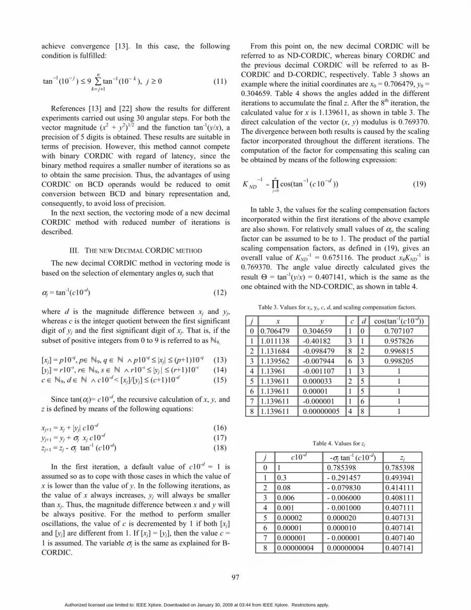
Table 3. Values for xj, yj, c, d, and scaling compensation factors.
j x y c d cos(tan-1(c10-d)) 0 0.706479 0.304659 1 0 0.707107 1 1.011138 -0.40182 3 1 0.957826 2 1.131684 -0.098479 8 2 0.996815 3 1.139562 -0.007944 6 3 0.998205 4 1.13961 -0.001107 1 3 1 5 1.139611 0.000033 2 5 1 6 1.139611 0.00001 1 5 1 7 1.139611 -0.000001 1 6 1 8 1.139611 0.00000005 4 8 1
achieve convergence [13]. In this case, the following condition is fulfilled:
∑+=
−−−− ≥≤n
jk
kj j1
11 0 ),10(tan9)10(tan (11)
References [13] and [22] show the results for different
experiments carried out using 30 angular steps. For both the vector magnitude (x2 + y2)1/2 and the function tan-1(y/x), a precision of 5 digits is obtained. These results are suitable in terms of precision. However, this method cannot compete with binary CORDIC with regard of latency, since the binary method requires a smaller number of iterations so as to obtain the same precision. Thus, the advantages of using CORDIC on BCD operands would be reduced to omit conversion between BCD and binary representation and, consequently, to avoid loss of precision.
In the next section, the vectoring mode of a new decimal CORDIC method with reduced number of iterations is described.
III. THE NEW DECIMAL CORDIC METHOD The new decimal CORDIC method in vectoring mode is
based on the selection of elementary angles αj such that
αj = tan-1(c10-d) (12)
where d is the magnitude difference between xj and yj, whereas c is the integer quotient between the first significant digit of yj and the first significant digit of xj. That is, if the subset of positive integers from 0 to 9 is referred to as ℕ9, [xj] = p10-q, p∈ ℕ9, q ∈ ℕ ∧ p10-q ≤ |xj| ≤ (p+1)10-q (13) [yj] = r10-s, r∈ ℕ9, s ∈ ℕ ∧ r10-s ≤ |yj | ≤ (r+1)10-s (14) c ∈ ℕ9, d ∈ ℕ ∧ c10-d < [xj]/[yj] ≤ (c+1)10-d (15)
Since tan(αj)= c10-d, the recursive calculation of x, y, and
z is defined by means of the following equations:
xj+1 = xj + |yj| c10-d (16) yj+1 = yj + σj xj c10-d (17) zj+1 = zj - σj tan-1 (c10-d) (18)
In the first iteration, a default value of c10-d = 1 is
assumed so as to cope with those cases in which the value of x is lower than the value of y. In the following iterations, as the value of x always increases, yj will always be smaller than xj. Thus, the magnitude difference between x and y will be always positive. For the method to perform smaller oscillations, the value of c is decremented by 1 if both [xj] and [yj] are different from 1. If [xj] = [yj], then the value c = 1 is assumed. The variable σj is the same as explained for B-CORDIC.
From this point on, the new decimal CORDIC will be referred to as ND-CORDIC, whereas binary CORDIC and the previous decimal CORDIC will be referred to as B-CORDIC and D-CORDIC, respectively. Table 3 shows an example where the initial coordinates are x0 = 0.706479, y0 = 0.304659. Table 4 shows the angles added in the different iterations to accumulate the final z. After the 8th iteration, the calculated value for x is 1.139611, as shown in table 3. The direct calculation of the vector (x, y) modulus is 0.769370. The divergence between both results is caused by the scaling factor incorporated throughout the different iterations. The computation of the factor for compensating this scaling can be obtained by means of the following expression:
∏=
−−=
− n
j
dND cK
0))10 (cos(tan 11
(19)
In table 3, the values for the scaling compensation factors
incorporated within the first iterations of the above example are also shown. For relatively small values of αj, the scaling factor can be assumed to be to 1. The product of the partial scaling compensation factors, as defined in (19), gives an overall value of KND
-1 = 0.675116. The product x8KND-1 is
0.769370. The angle value directly calculated gives the result Θ = tan-1(y/x) = 0.407141, which is the same as the one obtained with the ND-CORDIC, as shown in table 4.
Table 4. Values for zj
j c10-d -σj tan-1 (c10-d) zj 0 1 0.785398 0.785398 1 0.3 - 0.291457 0.493941 2 0.08 - 0.079830 0.414111 3 0.006 - 0.006000 0.408111 4 0.001 - 0.001000 0.407111 5 0.00002 0.000020 0.407131 6 0.00001 0.000010 0.407141 7 0.000001 - 0.000001 0.407140 8 0.00000004 0.00000004 0.407141
97
Authorized licensed use limited to: IEEE Xplore. Downloaded on January 30, 2009 at 03:44 from IEEE Xplore. Restrictions apply.

yj
αj - Calculator
BCD X3 Adder
xj
Register x Register y
Register z
zj
LUTx cos(atan(αj ))
LUTαj x cos(atan(αj))
LUTatan(αj)
LUTy cos(atan(αj ))
LUTαj y cos(atan(αj ))
eαj & mαj
BCD X3 Adder
BCD X3 Adder
yj+1xj+1 zj+1
Fig. 1. The architecture for a single ND-CORDIC iteration.
The scale factor compensation by means of multiplication should be avoided due to the high computational cost of this operation. In B-CORDIC, compensation without products is easy to perform due to the fact that the scale factor is a constant [12]. In ND-CORDIC this factor varies depending on the different angles chosen through the method iterations.
A technique based on LUT (Look-Up Tables) can be used which allows the compensation to be performed on each iteration. Equations (16) and (17) can be modified so as to include the compensation, which results in the following expression, where the superscript C indicates that the coordinates are scaling-compensated: xj+1
C = (xj + |yj| c10-d) cos(tan-1(c10-d)) (20) yj+1
C = (yj + σj xj c10-d) cos(tan-1(c10-d)) (21)
Taking into account (12), the above equations can be rewritten in the following way: xj+1
C = xj cos(αj) + |yj| c10-d cos(αj) (22) yj+1
C = yj cos(αj) + σj xj c10-d cos(αj) (23)
In equations (22) and (23), four terms appear: tx,0 = xj cos(αj) (24) ty,0 = yj cos(αj) (25) tx,1 = c10-d yj cos(αj) (26) ty,1 = c10-d xj cos(αj) (27)
The proposed compensation technique consists in storing the above four terms in four independent blocks of LUT. The entries for each block of LUT consist of the one-digit mantissa c and the exponent d , and also the value of xj or yj. If each term was stored on a single LUT, the size of each LUT would be excessive. For instance, when a precision of 6 fractional digits is required, then 24 bits are needed for each coordinate, 4 for indicating the mantissa c, and 3 for indicating the exponent d (1 to 8). Thus, the size of a monolithic LUT for each term would be 24·6 + 4 + 3 · 4 · 6 = 6144 MBytes. Instead, much smaller LUT can be used. If the different BCD X3 digits of xj are considered, the term tx,0 can be expressed as: tx,0 = (xj[5] xj[4] xj[3] xj[2] xj[1] xj[0]) cos(αj) (28)
Therefore, each small LUT will receive as inputs the value of a single digit of the coordinate, the mantissa c and the exponent d . For 6 fractional digits, the size of each LUT would be 24 + 3 + 4 · 4 · 6 = 6 KB. Since 6 fractional digits and four terms must be considered, the overall memory size would be 6 KB · 6 · 4 = 144 KB. In this case, 6 LUT would constitute the storage block for tx,0, other 6 LUT would compound the LUT block for tx,1, and so on.
IV. DECIMAL CORDIC ARCHITECTURE
A. Some Details on the Architecture Implementation Addition on BCD operands is more complex than binary
addition since the sum of two BCD digits must be corrected adding the value 6 to this sum if it is greater than 9. BCD Excess 3 (BCD X3) representation allows decimal addition and subtraction to be more efficiently performed, since only two 4-bit binary adders are required for each pair of digits. The final result is directly obtained in BCD X3. More detailed information on BCD X3 adders can be found in [13]. Conversions from BCD to BCD X3 and from BCD X3 to BCD both require only 10 gates distributed throughout 3 level. Therefore, the use of BCD X3 is proposed since addition, subtraction, and other operations are simpler than for BCD. The overall architecture for each one of the iterations of the proposed ND-CORDIC is shown in Fig 1. The αj-calculator extracts the exponent and mantissa from zj
so as to address the LUT.
B. Experiments on Precision Different tests were carried out so as to make a complete
comparison with regard to precision between B-CORDIC, D-CORDIC, and the ND-CORDIC proposed in this work. Values within the range [0, 1) were chosen for the (x, y) coordinates. Original data were represented in BCD with 6 fractional digits. For D-CORDIC and ND-CORDIC, a conversion stage from BCD to BCD X3 was included, whereas for B-CORDIC the BCD operands were converted into binary numbers. In any case, 28-bit operands were considered. The experiments were aimed at comparing the number of iterations required for each method so as to achieve suitable precision.
A benchmark of 1000 random points (x, y) was selected so as to calculate the angle of vector (x, y) towards the x-
98
Authorized licensed use limited to: IEEE Xplore. Downloaded on January 30, 2009 at 03:44 from IEEE Xplore. Restrictions apply.
1,00E-06
1,00E-05
1,00E-04
1,00E-03
1,00E-02
1,00E-01
1,00E+00
1,00E+01
1 2 3 4 5 6 7 8
Error (%)
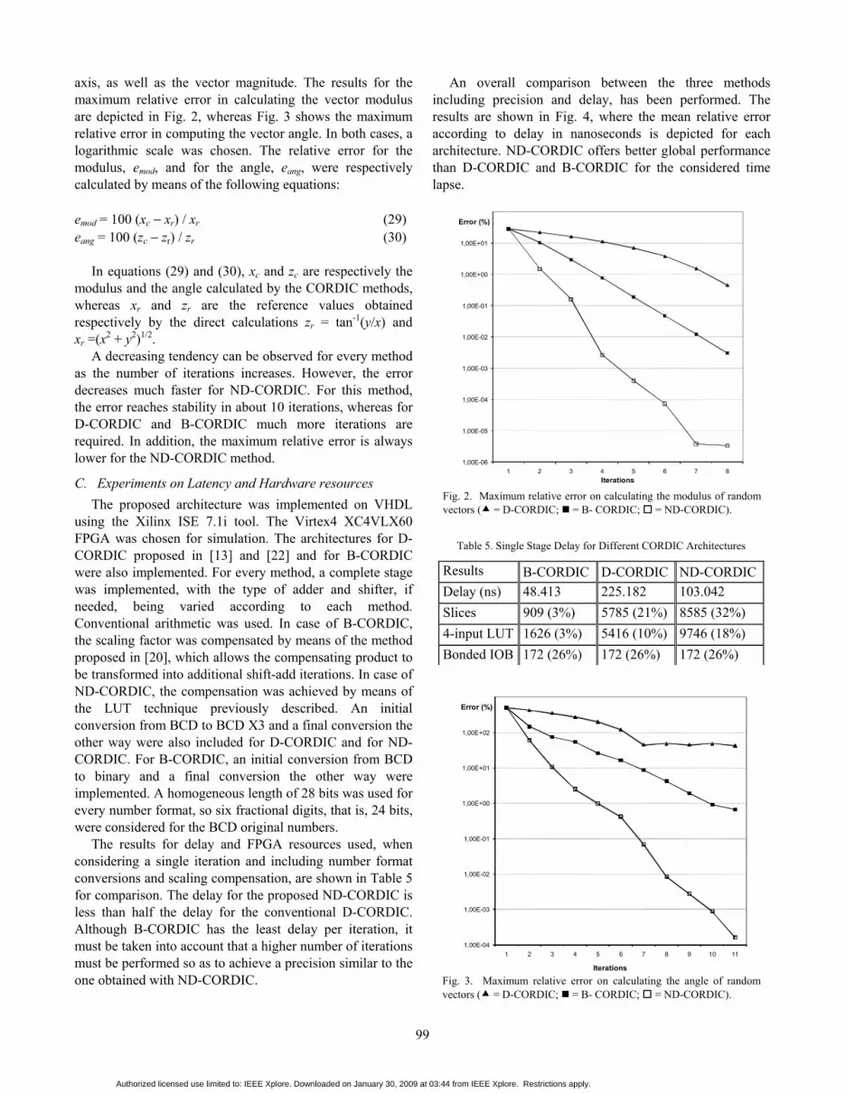
Iterations Fig. 2. Maximum relative error on calculating the modulus of random vectors ( = D-CORDIC; = B- CORDIC; = ND-CORDIC).
axis, as well as the vector magnitude. The results for the maximum relative error in calculating the vector modulus are depicted in Fig. 2, whereas Fig. 3 shows the maximum relative error in computing the vector angle. In both cases, a logarithmic scale was chosen. The relative error for the modulus, emod, and for the angle, eang, were respectively calculated by means of the following equations:
emod = 100 (xc − xr) / xr (29) eang = 100 (zc − zr) / zr (30)
In equations (29) and (30), xc and zc are respectively the
modulus and the angle calculated by the CORDIC methods, whereas xr and zr are the reference values obtained respectively by the direct calculations zr = tan-1(y/x) and xr =(x2 + y2)1/2.
A decreasing tendency can be observed for every method as the number of iterations increases. However, the error decreases much faster for ND-CORDIC. For this method, the error reaches stability in about 10 iterations, whereas for D-CORDIC and B-CORDIC much more iterations are required. In addition, the maximum relative error is always lower for the ND-CORDIC method.
C. Experiments on Latency and Hardware resources The proposed architecture was implemented on VHDL
using the Xilinx ISE 7.1i tool. The Virtex4 XC4VLX60 FPGA was chosen for simulation. The architectures for D-CORDIC proposed in [13] and [22] and for B-CORDIC were also implemented. For every method, a complete stage was implemented, with the type of adder and shifter, if needed, being varied according to each method. Conventional arithmetic was used. In case of B-CORDIC, the scaling factor was compensated by means of the method proposed in [20], which allows the compensating product to be transformed into additional shift-add iterations. In case of ND-CORDIC, the compensation was achieved by means of the LUT technique previously described. An initial conversion from BCD to BCD X3 and a final conversion the other way were also included for D-CORDIC and for ND-CORDIC. For B-CORDIC, an initial conversion from BCD to binary and a final conversion the other way were implemented. A homogeneous length of 28 bits was used for every number format, so six fractional digits, that is, 24 bits, were considered for the BCD original numbers.
The results for delay and FPGA resources used, when considering a single iteration and including number format conversions and scaling compensation, are shown in Table 5 for comparison. The delay for the proposed ND-CORDIC is less than half the delay for the conventional D-CORDIC. Although B-CORDIC has the least delay per iteration, it must be taken into account that a higher number of iterations must be performed so as to achieve a precision similar to the one obtained with ND-CORDIC.
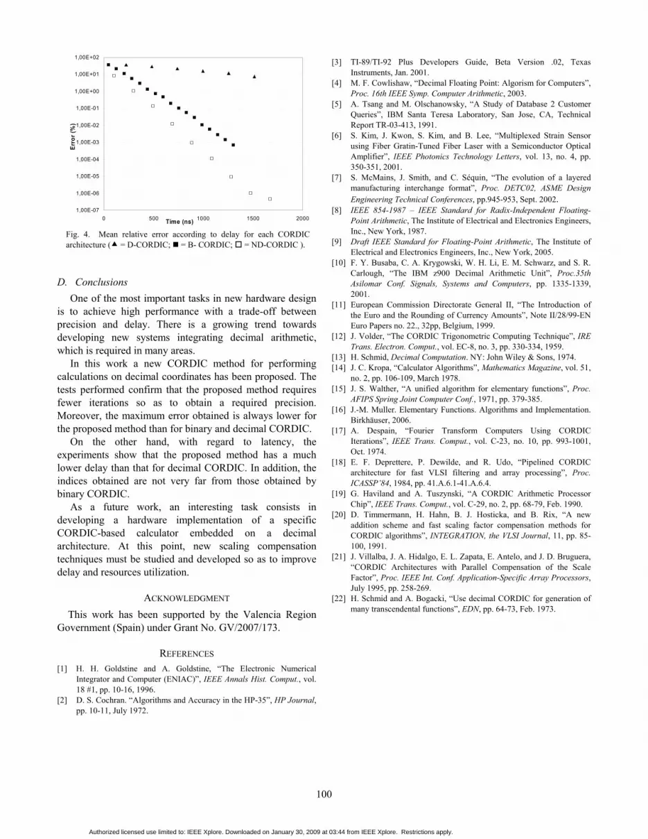
An overall comparison between the three methods including precision and delay, has been performed. The results are shown in Fig. 4, where the mean relative error according to delay in nanoseconds is depicted for each architecture. ND-CORDIC offers better global performance than D-CORDIC and B-CORDIC for the considered time lapse.
1,00E-04
1,00E-03
1,00E-02
1,00E-01
1,00E+00
1,00E+01
1,00E+02
1 2 3 4 5 6 7 8 9 10 11
Error (%)
Iterations Fig. 3. Maximum relative error on calculating the angle of random vectors ( = D-CORDIC; = B- CORDIC; = ND-CORDIC).
Table 5. Single Stage Delay for Different CORDIC Architectures
Results B-CORDIC D-CORDIC ND-CORDICDelay (ns) 48.413 225.182 103.042 Slices 909 (3%) 5785 (21%) 8585 (32%) 4-input LUT 1626 (3%) 5416 (10%) 9746 (18%) Bonded IOB 172 (26%) 172 (26%) 172 (26%)
99
Authorized licensed use limited to: IEEE Xplore. Downloaded on January 30, 2009 at 03:44 from IEEE Xplore. Restrictions apply.
D. Conclusions One of the most important tasks in new hardware design
is to achieve high performance with a trade-off between precision and delay. There is a growing trend towards developing new systems integrating decimal arithmetic, which is required in many areas.
In this work a new CORDIC method for performing calculations on decimal coordinates has been proposed. The tests performed confirm that the proposed method requires fewer iterations so as to obtain a required precision. Moreover, the maximum error obtained is always lower for the proposed method than for binary and decimal CORDIC.
On the other hand, with regard to latency, the experiments show that the proposed method has a much lower delay than that for decimal CORDIC. In addition, the indices obtained are not very far from those obtained by binary CORDIC.
As a future work, an interesting task consists in developing a hardware implementation of a specific CORDIC-based calculator embedded on a decimal architecture. At this point, new scaling compensation techniques must be studied and developed so as to improve delay and resources utilization.
ACKNOWLEDGMENT This work has been supported by the Valencia Region
Government (Spain) under Grant No. GV/2007/173.
REFERENCES [1] H. H. Goldstine and A. Goldstine, “The Electronic Numerical
Integrator and Computer (ENIAC)”, IEEE Annals Hist. Comput., vol. 18 #1, pp. 10-16, 1996.
[2] D. S. Cochran. “Algorithms and Accuracy in the HP-35”, HP Journal, pp. 10-11, July 1972.
[3] TI-89/TI-92 Plus Developers Guide, Beta Version .02, Texas Instruments, Jan. 2001.
[4] M. F. Cowlishaw, “Decimal Floating Point: Algorism for Computers”, Proc. 16th IEEE Symp. Computer Arithmetic, 2003.
[5] A. Tsang and M. Olschanowsky, “A Study of Database 2 Customer Queries”, IBM Santa Teresa Laboratory, San Jose, CA, Technical Report TR-03-413, 1991.
[6] S. Kim, J. Kwon, S. Kim, and B. Lee, “Multiplexed Strain Sensor using Fiber Gratin-Tuned Fiber Laser with a Semiconductor Optical Amplifier”, IEEE Photonics Technology Letters, vol. 13, no. 4, pp. 350-351, 2001.
[7] S. McMains, J. Smith, and C. Séquin, “The evolution of a layered manufacturing interchange format”, Proc. DETC02, ASME Design Engineering Technical Conferences, pp.945-953, Sept. 2002.
[8] IEEE 854-1987 – IEEE Standard for Radix-Independent Floating-Point Arithmetic, The Institute of Electrical and Electronics Engineers, Inc., New York, 1987.
[9] Draft IEEE Standard for Floating-Point Arithmetic, The Institute of Electrical and Electronics Engineers, Inc., New York, 2005.
[10] F. Y. Busaba, C. A. Krygowski, W. H. Li, E. M. Schwarz, and S. R. Carlough, “The IBM z900 Decimal Arithmetic Unit”, Proc.35th Asilomar Conf. Signals, Systems and Computers, pp. 1335-1339, 2001.
[11] European Commission Directorate General II, “The Introduction of the Euro and the Rounding of Currency Amounts”, Note II/28/99-EN Euro Papers no. 22., 32pp, Belgium, 1999.
[12] J. Volder, “The CORDIC Trigonometric Computing Technique”, IRE Trans. Electron. Comput., vol. EC-8, no. 3, pp. 330-334, 1959.
[13] H. Schmid, Decimal Computation. NY: John Wiley & Sons, 1974. [14] J. C. Kropa, “Calculator Algorithms”, Mathematics Magazine, vol. 51,
no. 2, pp. 106-109, March 1978. [15] J. S. Walther, “A unified algorithm for elementary functions”, Proc.
AFIPS Spring Joint Computer Conf., 1971, pp. 379-385. [16] J.-M. Muller. Elementary Functions. Algorithms and Implementation.
Birkhäuser, 2006. [17] A. Despain, “Fourier Transform Computers Using CORDIC
Iterations”, IEEE Trans. Comput., vol. C-23, no. 10, pp. 993-1001, Oct. 1974.
[18] E. F. Deprettere, P. Dewilde, and R. Udo, “Pipelined CORDIC architecture for fast VLSI filtering and array processing”, Proc. ICASSP’84, 1984, pp. 41.A.6.1-41.A.6.4.
[19] G. Haviland and A. Tuszynski, “A CORDIC Arithmetic Processor Chip”, IEEE Trans. Comput., vol. C-29, no. 2, pp. 68-79, Feb. 1990.
[20] D. Timmermann, H. Hahn, B. J. Hosticka, and B. Rix, “A new addition scheme and fast scaling factor compensation methods for CORDIC algorithms”, INTEGRATION, the VLSI Journal, 11, pp. 85-100, 1991.
[21] J. Villalba, J. A. Hidalgo, E. L. Zapata, E. Antelo, and J. D. Bruguera, “CORDIC Architectures with Parallel Compensation of the Scale Factor”, Proc. IEEE Int. Conf. Application-Specific Array Processors, July 1995, pp. 258-269.
[22] H. Schmid and A. Bogacki, “Use decimal CORDIC for generation of many transcendental functions”, EDN, pp. 64-73, Feb. 1973.
1,00E-07
1,00E-06
1,00E-05
1,00E-04
1,00E-03
1,00E-02
1,00E-01
1,00E+00
1,00E+01
1,00E+02
0 500 1000 1500 2000Tíme (ns)
Erro
r (%
)
Fig. 4. Mean relative error according to delay for each CORDIC architecture ( = D-CORDIC; = B- CORDIC; = ND-CORDIC ).
100
Authorized licensed use limited to: IEEE Xplore. Downloaded on January 30, 2009 at 03:44 from IEEE Xplore. Restrictions apply.


