Embed Size (px)
Citation preview
THE AMERICAN SOCIETY OF MECHANICAL ENGINEERS345 E. 47th St., New York, N.Y. 10017
The Society shall not be responsible for statements or opinions advanced in papers or discussion at meetings of the 95GT37Society or of its DMsions or Sections, or printed in its publications, Discussion is printed only if the paper is published - -In an ASME Journal. Authorization to photocopy material for internal or personal use under circumstance notfalling within the fair use provisions of the Copyright Act is granted by ASME to libraries and other users registered withthe Copyright Clearance Center (CCC) Transactional Reporting Service provided that the base fee of $0.30 per pageis paid directly to the CCC, 27 Congress Street, Salem MA 01970. Requests for special permission or bulk reproductionshould be addressed to the ASME Technical Publishing Department.
Copyright C 1995 by ASME All Rights Reserved Printed in U.S.A.
APPLICATIONS OF ACCURATE ISENTROPICEXPONENT DETERMINATION FOR FUEL
GAS MEASUREMENT
David J PackAGntaGas
Perth Western AustraliaAustralia
Terry J EdwardsDerek Fawcett
Murdoch UniversityMurdoch Western Australia
Australia
ABSTRACT
This paper discusses the determinationand application of the isentropic exponent tothe various thermodynamic processes foundin a high pressure natural gas transmissionsystem.
Increasing demands for more precisemeasurement of natural gas, coupled withthe need for greater efficiency andaccountability of transportation andprocessing operations had led to ourresearch and development efforts into themore precise measurement of gas flow, andthe determination of gas thermodynamicproperties including isentropic exponent.
The isentropic exponent has manyapplications, some of which include:
• the determination of the expansion factore, for calcuation of flow using an orifice orventuri type meter;
• the volumetric efficiency in a reciprocatingcompressor;
• the determination of the compressionhead for a centrigual compressor;
• the engine power required for the set givenconditions for gas compressor;
• the calculation of discharge temperatures forcompressors; and
• the direct measurement of gas density.
As can be appreciated, the application of anincorrect value for the isentropic exponentrepresents an error in the parameterdetermined. For large volume gas flows, thiscan translate into a significant cost penalty.
NOMENCLATURE
K = calibration constant of spoolL = speed of sound factorN = temperature constant of spoolP = measured pressureR = gas constantT = absolute temperatureZ = compressibility factor
c = speed of soundd = diameter of the orificek = isentropic exponentr = characteristic dimensions of vibration
spool
Presented at the International Gas Turbine and Aeroengine Congress & ExpositionHouston, Texas - June 5-8,1995
This paper has been accepted for publication in the Transactions of the ASMEDiscussion of it will be accepted at ASME Headquarters until September 30,1995Downloaded From: http://proceedings.asmedigitalcollection.asme.org/ on 05/09/2016 Terms of Use: http://www.asme.org/about-asme/terms-of-use
t = measured period of time
a = flow coefficiente = expansion coefficientrt = efficiencyp = density
Subscriptscp = isobaric heat capacityc, = isochoric heat capacitydo = calibration constant of spoolP i = upstream absolute pressureP 2 = downstream absolute pressureT 1 = inlet absolute temperatureT2 = discharge absolute temperatureTcai = calibration temperaturet o = periodic time of spool in vacuum at
calibrated temperaturea P = pressure differential
Superscriptsd ot = corrected valve of d o
t oI = corrected value of t o
R , = speed of sound correction to density
THE PIPELINE SYSTEM
AlintaGas in conjunction with MurdochUniversity, both in Perth, Western Australia,have, through a number of co-operativeresearch programs, been active in pursuing abetter appreciation of the properties of thenatural gases transported in the Dampier toBunbury high pressure transmission pipeline.This pipeline currently delivers over 90% of themarket requirements for natural gas in WesternAustralia.
The Dampier to Bunbury pipeline has a totallength of approximately 1,540 kilometres.Several laterals add a further 334 kilometres ofpipeline. Natural gas is sourced from fourindependent supplies providing an averagedaily throughput of about 460TJ or 11.5 millionsm3 . Custody transfer metering occurs alongthe length of the pipeline through some 36meter stations. Metering pressures can rangefrom 6 bar to 84 bar, gas temperatures fromnear 0'C to over 40C, and gas densities from6kg/m3 to 76kg/m3. Mass and energy are the
metering parameters used. Turbine meters areexclusively used for volume flow within thepipeline system, however, the major gas selleruses a dual run, orifice plate equipped,metering system. Vibrating spooldensitometers are utilised for the measurementof gas density at major custody transferstations. Gas quality information is derivedfrom on-line gas chromatograph systems.
A recent enhancement program has added afurther six compressor units, bringing the totalnumber of compressors on the pipeline toeleven. These compressors are situatedapproximately 130km apart, over eight sites.The first compressor station, which has a singleunit, is situated some 130km south of Dampier.
Description of Facilities
As the majority of the population, and henceindustry, is situated in the south west of theState, the majority of meter stations are on thesouthern section of the pipeline, that is, fromapproximately the 1,340km point southward.
The meter stations vary in size according tothroughput, including turndown requirements.The stations generally have at least two meterruns, one of which is dedicated as a master orstandby run. Turbine meters range in size from50mm to 300mm diameter, all being ANSI class600. Dedicated flow computers are used oneach meter station run, with gas quality,pressure, temperature, density and flowinformation downloaded to derive mass andenergy flow rates.
To have good representational measurementof density, continuous measurement at actualpipeline conditions is essential. This is whydensitometers are used at all major custodytransfer meter stations. The densitometermeasuring principle is based on the change inthe natural frequency of an oscillating element,the natural frequency of the oscillating bodydiminishes as the density increases.Densitometers are measuring instruments ofthe second order, that is, if a meaningfulreading is to be obtained, then some type ofcalibration scale must be assigned to theinstrument. Therefore, the accuracy of readingis very dependent on the quality of calibration.
Downloaded From: http://proceedings.asmedigitalcollection.asme.org/ on 05/09/2016 Terms of Use: http://www.asme.org/about-asme/terms-of-use
Ideally, the densitometer should becalibrated at conditions identical to normaloperations and using the same gas as thetest medium. Therefore, the isentropicexponent at the operating conditions needsto be known with high accuracy. With themajor gas supplier metering gas into thepipeline system, via orifice plates, AlintaGasis directly interested in the performance ofthis metering system, as it presents thelargest single flow and hence the potential tobe a significant contributor to the verycomplex issue of system unaccounted forgas.
The pipeline gas turbine driven compressorsets are sourced of two separatemanufacturers. The first installed units,which were commissioned during themid-1980s, use the LM500 gas turbine,which is a compact, high performance unitderived from the General Electric TF34turbofan. This gas turbine, of which five arein service on the pipeline, is in the 3,000 to6,000 shaft horsepower class. The recentenhancement of the pipeline has seen thecommissioning of six larger units, whichconsist of a Solar C505U centrifugal gascompressor and a Mars gas turbine.
Like the LM500, the Mars turbine engine isa two-shaft, variable speed, axial flow design.For the Solar Mars units, all performancecurves are based on a ratio of specific heatsof 1.279.
Pipeline Applications for Isentropic Exponent
Within the referenced pipeline system, theisentropic exponent applies to a number ofprocesses. As already discussed, it appliesto:
(a) The densitometer densitydetermination. The meter run flowcomputer calculates the live densityfrom the following relationship:
p = 2d .- (t - to') [1 + K (t - to')]to' 2to'
whereto = to + N(T - Tcal)
do' = do (1 - r -)(ct)2
C2 = kPL
P
(b) Calculation of flow using an orifice plate
i) for volume flow rate
Qv = a E 1 nd2 2APP
ii) alternatively for mass flow rate
Qm=ae 4 nd 2 2D p P
The expansion factor E for a gas is givenby:
E = 1 - [0.41 + 0.35p`j e PkP
where d(3 = p (D = i.d. of pipe)
(c) Calculation of expansion factor E forventuri or nozzle
P ? P k-1( 1 P`) [(kk1)1 P1 [1 PZ ) k
2
[ 1 - p4 (2)k1
( 1 - P2)P i P,
3
Downloaded From: http://proceedings.asmedigitalcollection.asme.org/ on 05/09/2016 Terms of Use: http://www.asme.org/about-asme/terms-of-use
(d) Calculation of compressor head, H,compression power, and dischargetemperature for adiabatic process.When reasonable accuracy is required,the below equations (1) can be used:
P k -1
H = ZRT (kk1) I(P2 ) k_ - i1
From this value of H, the compressionpower can be calculated. Thedischarge temperature can becalculated from:
k=1
ETactual = T1 [(Pi ) k -1 ] /*ti
As can be seen from the above sets ofequations, which is by no meansexhaustive, the isentropic exponent canbe found in a variety of applications fora gas pipeline system.
THE THERMODYNAMIC PROCESS
This section of the paper defines a numberof thermodynamic processes and discussesthe definition and application of thecommonly applied classification of gases.
Whilst it is true to say that there is not agas that strictly obeys the well knownBoyle's and Charles' gas laws, some gasesat low pressure, and generally of simple orsingle composition, will obey these gas lawswith good approximation. However, in thetransportation and metering processes ofnatural gas at transmission pipelineconditions, the gas deviates from the gaslaw conditions because of gascompressibility. This is due to the elevatedpressures and the presence of heavierhydrocarbons in the gas.
These conditions have led to the conceptsof an ideal gas and a real gas. Someauthors (2) add a third category, that of aperfect gas. However our discussion will belimited to the concept of an ideal and real
gas.
During the compression, pressure regulationand metering processes in a high pressurepipeline system, the gas is changing itscondition or state. The understanding of thesechanges, which are known as thermodynamicconditions, are very important for the mostefficient and economic design, operation andprecise measurement of required parameters.Three of these thermodynamic states will bediscussed. They are the :
adiabatic process,isentropic process, andpolytropic process.
For an adiabatic process, there is no heattransfer to or from the system. An isentropicprocess is one of constant entropy. It is anadiabatic process which is internally reversible.Therefore, an isentropic process is adiabatic,but an adiabatic process is not necessarilyisentropic. The third process, that ofpolytropic, is one in which work is done on orby the gas and therefore there is some heatflow.
This now leads to the question why are we sointerested in the isentropic state? This isbecause, from the given definition, this type ofprocess leads to the maximum output, orminimum input, for pipeline systems such asgas turbines and compressors, and alsopresents the optimum performance for thereferenced measurement devices. It is statedthat the 'internally reversible process can beused as a standard to which all real processesmay be compared, whether applied to a closedor open system' (3). Therefore, we use theisentropic process as the performance indicatorstandard for the defined real processes.
Calculating the Thermodynamic Quantities
The equation of state for an ideal gas can bewritten as
PV = RT -(i)
If a deviation factor is applied, such ascompressibility, then equation (i) can beexpressed as
Downloaded From: http://proceedings.asmedigitalcollection.asme.org/ on 05/09/2016 Terms of Use: http://www.asme.org/about-asme/terms-of-use
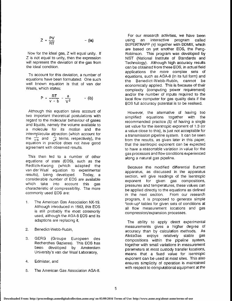
Z RPvT - (ia)
Now for the ideal gas, Z will equal unity. IfZ is not equal to unity, then the expressionwill represent the deviation of the gas fromthe ideal condition.
To account for this deviation, a number ofequations have been formulated. One suchwell known equation is that of van derWaals, which states:
_ RT a (.P v-bV2 - ib)
Although this equation takes account oftwo important theoretical postulations withregard to the molecular behaviour of gasesand liquids, namely the volume available toa molecule for its motion and theintermolecular attraction (which account forthe ^_b and terms, respectively), theequation in practice does not have goodagreement with observed results.
This then led to a number of otherequations of state (EOS), such as theRedlich-Kwong (which adapted thevan der Waal equation to experimentalresults), being developed. Today, aconsiderable number of EOS are availablewhich take into account this gascharacteristic of compressibility. The morecommonly used EOS are:
1. The American Gas Association NX-19.Although introduced in 1963, this EOSis still probably the most commonlyused, although the AGA-8 EOS and itsadaptions are replacing it,
2. Benedict-Webb-Rubin,
3. GERG (Groupe Europeen desRecherches Gazieres). This EOS hasbeen developed by AmsterdamUniversity's van der Waal Laboratory,
4. Edmister, and
5. The American Gas Association AGA-8.
For our research activities, we have beenusing an interactive program calledSUPERTRAPP (4) together with DDMIX, whichare based on yet another EOS, the Peng-Robinson. This program was developed byNIST (National Institute of Standards andTechnology). Although high accuracy resultscan be obtained from these EOS, in actual fieldapplications the more complex sets ofequations, such as AGA-8 (in its full form) andthe Benedict-Webb-Rubin, cannot beeconomically applied. This is because of theircomplexity (computing power requirement)and/or the number of inputs required to thelocal flow computer for gas quality data if theEOS full accuracy potential is to be realised.
However, the alternative of having toosimplified equations together with therecommended practice (5) of having a singleset value for the isentropic exponent of 1.3 (ora value close to this), is just not acceptable fora transmission pipeline system. It can be seenfrom the results, as given later in this paper,that the isentropic exponent can be expectedto have a reasonable variation in value for thegas processes and flow conditions experiencedalong a natural gas pipeline.
Because the modified differential Burnettapparatus, as discussed in the apparatussection, will give readings of the isentropicexponent for given gas compositions,pressures and temperatures, these values canbe applied directly to the equations as definedin the next section. From our researchprogram, it is proposed to generate simple'look-up tables for given sets of conditions atall flow measurement locations and gascompression/expansion processes.
The ability to apply direct experimentalmeasurements gives a higher degree ofaccuracy than by calculation methods. AsAlintaGas enjoys relatively stable gascompositions within the pipeline system,together with small variations in measurementparameters at most custody transfer locations,means that a fixed value for isentropicexponent can be used at most sites. This alsoensures simplicity of operation is maintainedwith respect to computational equipment at the
Downloaded From: http://proceedings.asmedigitalcollection.asme.org/ on 05/09/2016 Terms of Use: http://www.asme.org/about-asme/terms-of-use
more remote locations.
The Isentropic Exponents
For an ideal gas, the ratio of specific heatsis given by y = 2
cvwhere Op = isobaric heat capacity,
andCv = isochoric heat capacity.
This ratio is of little use outside the dynamicsof an ideal gas.
It is worth noting that although the ratio ofspecific heats and isentropic exponent arewidely used and important thermodynamicproperties, these parameters are unfortunatelynot represented by universal scientific symbols.
For the discussion in this paper, the ratio ofspecific heat a is represented by the symboly and is generally limited to a perfect gasscenario, whereas the isentropic exponent isrepresented by the symbol k.
It is important to appreciate that for a real gasthe ratio of specific heat and the isentropicexponent are not one and the same thing.
As already discussed, natural gas in apipeline system can be subject to a number ofprocesses. Some of the basic processes willnow be discussed in order to obtain anappreciation of the relationship of the morecommon gas parameters to the isentropicexponent:
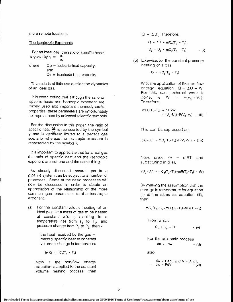
(a) For the constant volume heating of anideal gas, let a mass of gas m be heatedat constant volume, resulting in atemperature rise from T 1 to T2, andpressure change from P 1 to P2 , then -
the heat received by the gas =mass x specific heat at constantvolume x change in temperature
le Q = mC„(T2 - T 1 )
Now if the non-flow energyequation is applied to the constantvolume heating process, then
0 = AU.. Therefore,
Q = AU = mC^,(T2 - T,)
U 2 - U, = mC„(T2 - T 1 ) - (ii)
(b) Likewise, for the constant pressureheating of a gas
Q = mCP (T2 - T 1 )
With the application of the non-flowenergy equation Q = AU + W.For this case external work isdone, ie W = P(V 2 - V 1 ).Therefore,
mC 2 (T2 -T,) = oU ,W= (U 2 -U 1 )4-P(V2 -V 1 ) - (iii)
This can be expressed as:
(U2 -U 1 ) = mC o (T2 -T,)-P(V2 -V,) - (ilia)
Now, since PV = mRT, andsubstituting in (iiia),
(U2 -U 1 ) = mC P(T2 -T,)-mR(T2 -T 1 ) - (iv)
By making the assumption that thechange in temperature for equation(ii) is the same as equation (iii),then
mC(T2 -T,) =m C p(f2 -T,) -m R (T2 -T 1 )
From which
C=C o -R -(v)
For the adiabatic processdu = -dw - (vi)
also
dw = PAdL and V = A x Ldw = PdV - (vii)
6
Downloaded From: http://proceedings.asmedigitalcollection.asme.org/ on 05/09/2016 Terms of Use: http://www.asme.org/about-asme/terms-of-use
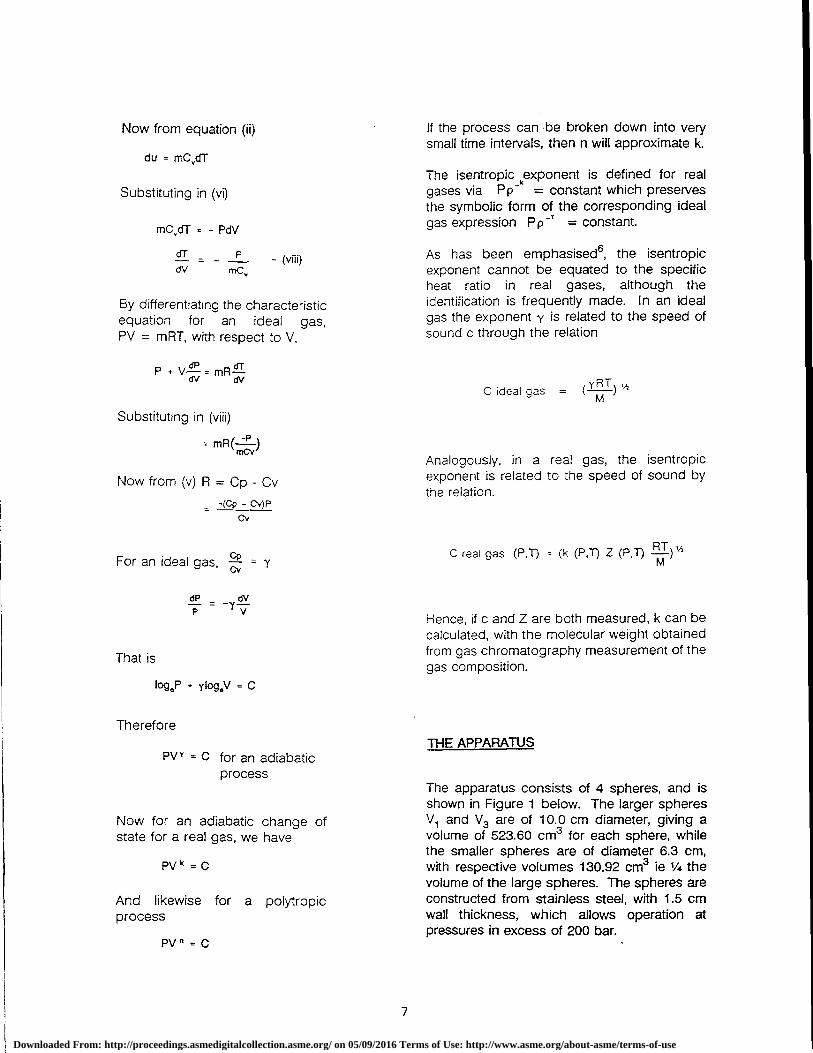
Now from equation (ii) If the process can. be broken down into verysmall time intervals, then n will approximate k.
du = mCdT
The isentropic kexponent is defined for realSubstituting in (vi) gases via Pp - = constant which preserves
the symbolic form of the corresponding ideal
mC,dT = - PdV gas expression Pp -T = constant.
dr _ _ P(
viii)As has been emphasised s, the isentropic
dV mc, exponent cannot be equated to the specificheat ratio in real gases, although the
By differentiating the characteristic identification is frequently made. In an idealequation for an ideal gas, gas the exponent y is related to the speed ofPV = mRT, with respect to V, sound c through the relation
P.VL'=mR'
C ideal gas = ( YT )M ½
Substituting in (viii)
= mR( )mCv
Analogously, in a real gas, the isentropic
Now from (v) R = Op - Cv exponent is related to the speed of sound bythe relation.
(CP - C\')P_Cv
Cp C real gas (PT) = (k (P,T) Z (PT) RT ) "^For an ideal gas, C = Y M
dP _ dVP -Y v Hence, if c and Z are both measured, k can be
calculated, with the molecular weight obtained
That is from gas chromatography measurement of thegas composition.
logeP - Ylog8V = C
ThereforeTHE APPARATUS
PV 1 = C for an adiabaticprocess
The apparatus consists of 4 spheres, and isshown in Figure 1 below. The larger spheres
Now for an adiabatic change of V1 and V3 are of 10.0 cm diameter, giving astate for a real gas, we have volume of 523.60 cm3 for each sphere, while
the smaller spheres are of diameter 6.3 cm,
PV k = C with respective volumes 130.92 cm3 ie 1/4 thevolume of the large spheres. The spheres are
And likewise for a polytropic constructed from stainless steel, with 1.5 cmprocess wall thickness, which allows operation at
pressures in excess of 200 bar.PV = C
7
Downloaded From: http://proceedings.asmedigitalcollection.asme.org/ on 05/09/2016 Terms of Use: http://www.asme.org/about-asme/terms-of-use
DIFFERENTIALPRESSURE GAUGE
ACOUSTIC qTRANSDUCERS
/ 3
SP-ERE I SPHERE 2 1 SPHERE 4
SPHERE 3
2 T 23 16
22
7 QZ4 ?82
VACUUM/GASBAND U NC
ABSOLUTE SYSTEM, 50l ATION CHA,mBEP P RE,SS URE
GAUGE
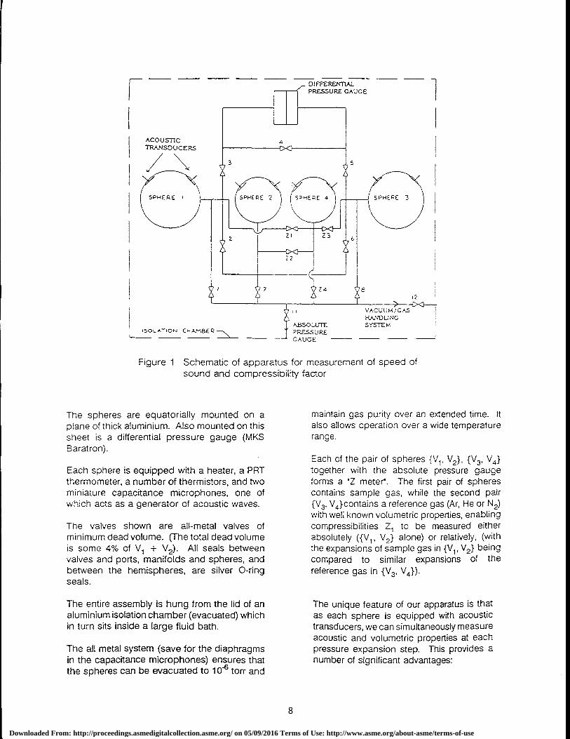
Figure 1 Schematic of apparatus for measurement of speed ofsound and compressibility factor
The spheres are equatorially mounted on aplane of thick aluminium. Also mounted on thissheet is a differential pressure gauge (MKSBaratron).
Each sphere is equipped with a heater, a PRTthermometer, a number of thermistors, and twominiature capacitance microphones, one ofwhich acts as a generator of acoustic waves.
The valves shown are all-metal valves ofminimum dead volume. (The total dead volumeis some 4% of V 1 + V2). All seals betweenvalves and ports, manifolds and spheres, andbetween the hemispheres, are silver O-ringseals.
The entire assembly is hung from the lid of analuminium isolation chamber (evacuated) whichin turn sits inside a large fluid bath.
The all metal system (save for the diaphragmsin the capacitance microphones) ensures thatthe spheres can be evacuated to 106 torr and
maintain gas purity over an extended time. Italso allows operation over a wide temperaturerange.
Each of the pair of spheres {V 1 , V2}, {V3 , V4 }
together with the absolute pressure gaugeforms a 'Z meter. The first pair of spherescontains sample gas, while the second pair{V3 , V4 }contains a reference gas (Ar, He or N 2)
with well known volumetric properties, enablingcompressibilities Z 1 to be measured eitherabsolutely ({V 1 , V2} alone) or relatively, (withthe expansions of sample gas in {V i , V2} beingcompared to similar expansions of thereference gas in {V 3 , V4 }).
The unique feature of our apparatus is thatas each sphere is equipped with acoustictransducers, we can simultaneously measureacoustic and volumetric properties at eachpressure expansion step. This provides anumber of significant advantages:
8
Downloaded From: http://proceedings.asmedigitalcollection.asme.org/ on 05/09/2016 Terms of Use: http://www.asme.org/about-asme/terms-of-use
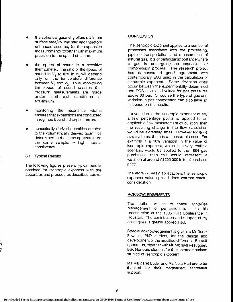
• the spherical geometry offers minimumsurface area/volume ratio and thereforeenhanced accuracy for the expansionmeasurements, together with maximumprecision in the speed of sound.
• the speed of sound is a sensitivethermometer: the ratio of the speed ofsound in V 1 to that in V2 will dependonly on the temperature differencebetween V 1 and V2. Thus, monitoringthe speed of sound ensures thatpressure measurements are madeunder isothermal conditions atequilibrium.
• monitoring the resonance widthsensures that expansions are conductedin regimes free of adsorption errors.
• acoustically derived quantities are tiedto the volumetrically derived quantitiesdetermined in the same apparatus, onthe same sample, — high internalconsistency.
3.1 Typical Results
The following figures present typical resultsobtained for isentropic exponent with theapparatus and procedures described above.
CONCLUSION
The isentropic exponent applies to a number ofprocesses associated with the processing,pipeline transportation, and measurement ofnatural gas. It is of particular importance wherea gas is undergoing an expansion orcompression process. The research projecthas demonstrated good agreement withcontemporary EOS used in the calculation ofisentropic exponent. Some deviation doesoccur between the experimentally determinedand EOS calculated values for gas pressuresabove 60 bar. Of course the type of gas andvariation in gas composition can also have aninfluence on the results.
If a variation in the isentropic exponent of saya few percentage points is applied to anapplicable flow measurement calculation, thenthe resulting change in the flow calculationwould be extremely small. However for largeflow systems, there is a measurable cost. Forexample if a 10% variation in the value ofisentropic exponent, which is a very realisticscenario, would be applied to the 1994 gaspurchases, then this would represent avariation of around A$200,000 in total purchaseprice.
Therefore in certain applications, the isentropicexponent value applied does warrant carefulconsideration.
ACKNOWLEDGEMENTS
The author wishes to thank AlintaGasManagement for permission to make thispresentation at the 1995 IGTI Conference inHouston. The contribution and support of mycolleagues is greatly appreciated.
Special acknowledgement is given to Mr DerekFawcett, PhD student, for the design anddevelopment of the modified differential Burnettapparatus, together with Mr Michael Resuggan,BSc Honours student, for their intercomparisonstudies of isentropic exponent.
Ms Margaret Butler and Ms Nola Hart are to bethanked for their magnificent secretarialsupport.
9
Downloaded From: http://proceedings.asmedigitalcollection.asme.org/ on 05/09/2016 Terms of Use: http://www.asme.org/about-asme/terms-of-use
1.65
1.601-zwzOa-xwUa-0Hzw
1.55
1.50
ExpI!°
Pressure(Bar)
ExperimentalkZ
DDMIXko
Deviation%
SCRAPPks
Deviation%
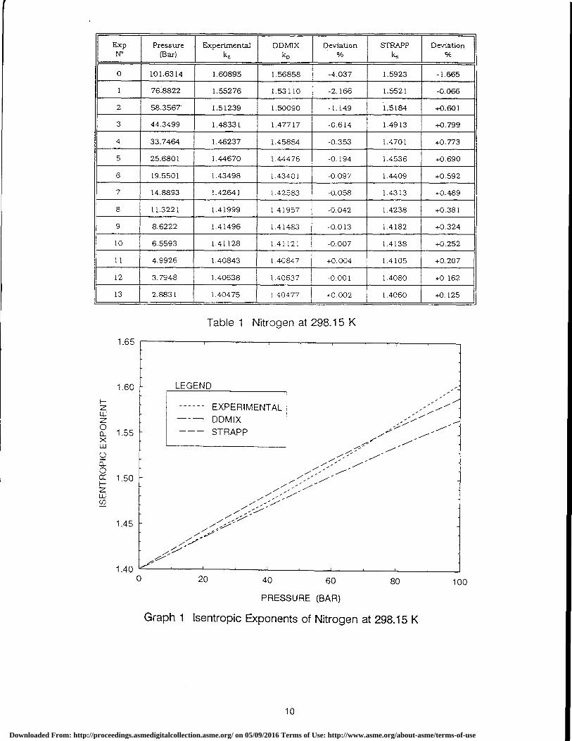
0 101.6314 1.60895 1.56858 -4.037 1.5923 -1.665
1 76.8822 1.55276 1.53110 -2.166 1.5521 -0.066
2 58.3567 1.51239 1.50090 -1.149 1.5184 +0.601
3 44.3499 1.48331 1.47717 -0.614 1.4913 +0.799
4 33.7464 1.46237 1.45884 -0.353 1.4701 +0.773
5 25.6801 1.44670 1.44476 -0.194 1.4536 +0.690
6 19.5501 1.43498 1.43401 -0.097 1.4409 +0.592
7 14.8893 1.42641 1.42583 -0.058 1.4313 +0.489
8 11.3221 1.41999 1.41957 -0.042 1.4238 +0.381
9 8.6222 1.41496 1.41483 -0.013 1.4182 +0.324
10 6.5593 1.41128 1.41121 -0.007 1.4138 +0.252
11 4.9926 1.40843 1.40847 +0.004 1.4105 +0.207
12 3.7948 1.40638 1.40637 -0.001 1.4080 +0.162
13 2.8831 1 .40475 ! .40477 +0.002 1.4060 +0. 125
Table 1 Nitrogen at 298.15 K
LEGEND
------ EXPERIMENTAL- - DDMIX--- STRAPP
1.45
1.400 20 40 60 80
100
PRESSURE (BAR)
Graph 1 Isentropic Exponents of Nitrogen at 298.15 K
10
Downloaded From: http://proceedings.asmedigitalcollection.asme.org/ on 05/09/2016 Terms of Use: http://www.asme.org/about-asme/terms-of-use
ExpN°
Pressure(Bar)
ExperimentalkZ
DDMIXkp
Deviation%
STRAPPkcs
Deviation%
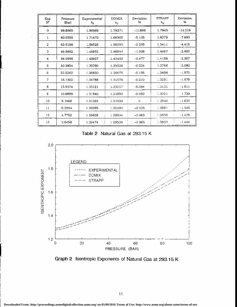
0 99.8865 1.90969 1.79271 -11.698 1.7645 -14.519
1 80.0255 1.71470 1.66365 -5.105 1.6379 -7.680
2 63.5188 1.58528 1.56293 -2.235 1.5411 -4.418
3 49.9892 1.49852 1.48844 -1.008 1.4687 -2.982
4 39.0999 1.43927 1.43450 -0.477 1.4156 -2.367
5 30.3854 1.39760 1.39526 -0.234 1.3768 -2.080
6 23.5202 1.36830 1.36675 -0.155 1.3486 -1.970
7 18.1303 1.34788 1.34578 -0.210 1.3281 -1.978
8 13.9374 1.33121 1.33037 -0.084 1.3131 -1.811
9 10.6899 1.31940 1.31890 -0.050 1.3021 -1.730
10 8.1868 1.31033 1.31033 0 1.2940 -1.633
11 6.2594 1.30355 1.30390 +0.035 1.2881 -1.545
12 4.7752 1.29839 1.29904 +0.065 1.2836 -1.479
13 3.6458 1.29474 1.29539 +0.065 1.2803 - 1.444
Table 2 Natural Gas at 293-15 K
2.0
F- 1.8zwz00XW0 1.600F-zW
1.4
LEGEND
------ EXPERIMENTAL- - DDMIX --- STRAPP '
j
j^ i^
1.20 20 40 60 80
100
PRESSURE (BAR)
Graph 2 Isentropic Exponents of Natural Gas at 293.15 K
11
Downloaded From: http://proceedings.asmedigitalcollection.asme.org/ on 05/09/2016 Terms of Use: http://www.asme.org/about-asme/terms-of-use
5
0
z0H
> -5w0
-10
AD
0
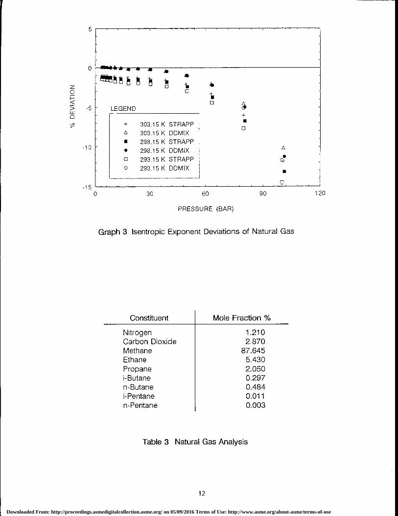
LEGEND
+ 303.15 K STRAPP oA 303.15 K DDMIX■ 298.15 K STRAPP• 298.15 K DDMIX0 293.15 K STRAPP •0 293.15 K DDMIX •
o .
0 30 60 90
PRESSURE (BAR)
Graph 3 Isentropic Exponent Deviations of Natural Gas
Constituent I Mole Fraction %
Nitrogen 1.210Carbon Dioxide 2.870Methane 87.645Ethane 5.430Propane 2.050i-Butane 0.297n-Butane 0.484i-Pentane 0.011n-Pentane 0.003
Table 3 Natural Gas Analysis
icv
12
Downloaded From: http://proceedings.asmedigitalcollection.asme.org/ on 05/09/2016 Terms of Use: http://www.asme.org/about-asme/terms-of-use
REFERENCES
1. Gas Processors Suppliers Association1980SI Engineering Data BookCentrifugal Compressors andExpanders, p5-6
2. Miller RW, 1983 Flow MeasurementEngineering Handbook2nd Edition McGraw-Hill PublishingCompany
3. Wark K, 1977, ThermodynamicsMcGraw-Hill Book Company, New York,p292
4. NIST Standard Reference Database 4:1992Thermophysical properties ofhydrocarbon mixtures SUPERTRAPP,National Institute of Standards andTechnology, Gaithersburg
5. International Organisation forStandardisation, 1980, ISO 5167,Measurement of fluid flow by means oforifice plates, nozzles and venturi tubesinserted in circular cross sectionconduits running full, ISO 5167, Geneva
6. D J Pack and T J EdwardsImprovements in Flow MeasurementUncertainty for a Natural GasTransmission SystemProc Flomeko 93, ed Park andKinghorn, Seoul 1993
13
Downloaded From: http://proceedings.asmedigitalcollection.asme.org/ on 05/09/2016 Terms of Use: http://www.asme.org/about-asme/terms-of-use


