Embed Size (px)
Citation preview
This article was downloaded by: [Hong Kong Polytechnic University]On: 04 July 2014, At: 00:59Publisher: Taylor & FrancisInforma Ltd Registered in England and Wales Registered Number: 1072954 Registered office: MortimerHouse, 37-41 Mortimer Street, London W1T 3JH, UK
The Journal of The Textile InstitutePublication details, including instructions for authors and subscription information:http://www.tandfonline.com/loi/tjti20
Application of warp-knitted spacer fabrics in carseatsX. Ye a , R. Fangueiro b , H. Hu a & M. de Araújo aa College of Textiles, Donghua University , Shanghai, People's Republic of Chinab School of Engineering , University of Minho , Guimaraes, PortugalPublished online: 19 Jan 2009.
To cite this article: X. Ye , R. Fangueiro , H. Hu & M. de Araújo (2007) Application of warp-knitted spacer fabrics in carseats, The Journal of The Textile Institute, 98:4, 337-344, DOI: 10.1080/00405000701489677
To link to this article: http://dx.doi.org/10.1080/00405000701489677
PLEASE SCROLL DOWN FOR ARTICLE
Taylor & Francis makes every effort to ensure the accuracy of all the information (the “Content”) containedin the publications on our platform. However, Taylor & Francis, our agents, and our licensors make norepresentations or warranties whatsoever as to the accuracy, completeness, or suitability for any purpose ofthe Content. Any opinions and views expressed in this publication are the opinions and views of the authors,and are not the views of or endorsed by Taylor & Francis. The accuracy of the Content should not be reliedupon and should be independently verified with primary sources of information. Taylor and Francis shallnot be liable for any losses, actions, claims, proceedings, demands, costs, expenses, damages, and otherliabilities whatsoever or howsoever caused arising directly or indirectly in connection with, in relation to orarising out of the use of the Content.
This article may be used for research, teaching, and private study purposes. Any substantial or systematicreproduction, redistribution, reselling, loan, sub-licensing, systematic supply, or distribution in anyform to anyone is expressly forbidden. Terms & Conditions of access and use can be found at http://www.tandfonline.com/page/terms-and-conditions
Application of warp-knitted spacer fabricsin car seats
Date Submitted 30 March 2006, Date Accepted 8 September 2006 doi:10.1080/00405000701489677
X. Ye1, R. Fangueiro2, H. Hu1and M. de Araujo2
1College of Textiles, Donghua University, Shanghai, People’s Republic of China2School of Engineering, University of Minho, Guimaraes, Portugal
Abstract: Polyurethane foam is commonly used as padding in car seats despite some problems concern-ing comfort and recycling. Compared with polyurethane foam, textile seat padding is easier to recycle; sotextile padding is a good candidate to substitute foam padding as regulations on recycling have becomemore stringent on car manufacturers. With the available textile option, warp-knitted spacer fabricsare likely a good substitute for polyurethane foam as padding in car seats. Warp-knitted spacer fabricstructures can be designed to be quite flexible in a variety of thicknesses. Warp-knitted spacer fabricscan be very resilient and may display good breathing properties. The current work presents a study onthe application of warp-knitted spacer fabrics as cushion in car seats. The results show that, relatively topolyurethane foam, warp-knitted spacer fabrics demonstrate better recovery to compression, thermalproperties and breathability. Furthermore, warp-knitted spacer fabrics retain their original thicknessfor longer time and can be easily recycled.
Key words: Spacer fabric, compression property, pressure relief, thermal property
INTRODUCTION
In a new product development, designers must pay in-creased attention to environmental issues. In the motorcarindustry, materials recycling have become a very impor-tant requirement. Fabrics and carpets inside cars are oftencomposed of several layers of different materials, usuallya polyester fabric laminated to a soft polyurethane foambacking by an adhesive. This type of construction makesdisassembling virtually impossible, and the combinationof different polymer chemistries for the fabric and back-ing makes recycling of the assembly extremely difficult.Furthermore, there is effluent emission from the flame-bonding process, which is used to combine the differentlayers. As a result, the use of polyurethane foam in carinteriors is environmentally hazardous both in terms ofproduction and recycling (Wilkens, 1993).
Apart from the environmental issues, today’s car seatsmust fulfil a multiplicity of demands. They must have
Corresponding author:M. D. de AraujoDepartment of Textile EngineeringUniversity of Minho4800-058 Guimaraes, PortugalTel: +351253510291; Fax: +351253510293E-mail: [email protected]
an attractive design, stringent mechanical properties fordurability and offer protection to passengers during anaccident. Car seats must be comfortable too. This com-fort must include both the mechanical support that theseat gives to the body as well as good climatic conditions,which are paramount for a driver’s performance. Climaticcomfort means good thermoregulation, which can balancethe body’s energy and offer good microclimate around thehuman skin. Studies have been conducted to measure thedriver’s rectal temperature with different types of car seats.With car seats offering good thermoregulation, after severalhours of driving, the subject can still stay in the comfort re-gion, i.e. below 37.5◦C even in warm temperatures (25◦C).On the other hand, some types of seats, which offer poorclimatic comfort, will make the driver feel uncomfortablywarm very quickly, as the rectal temperature rises to 37.5◦Cin approximately 40 min. After 2 h, the rectal temperaturemay rise to 38.2◦C, which is the limit of endurable strainfor a normal person. Driving in such an uncomfortableseat, the driver must have a break; otherwise, he may havean accident caused by impaired physical and mental stress(Umbach, 2000).
In recent years, the use of technical textiles has grownvery fast. These fibrous materials, which have a varietyof technical end uses, may also substitute some conven-tional materials with advantage in specific applications(Heide, 2000). Warp-knitted spacer fabrics belong to thisclass, and they are very interesting structures due to their
Copyright C© 2007 The Textile Institute 337 TJTI 2007 Vol. 98 No. 4 pp. 337–343
Dow
nloa
ded
by [
Hon
g K
ong
Poly
tech
nic
Uni
vers
ity]
at 0
0:59
04
July
201
4
X. Ye, R. Fangueiro, H. Hu and M. de Araujo
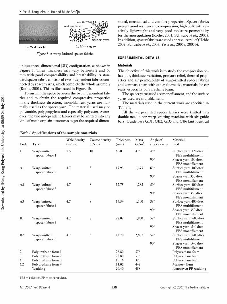
Figure 1 A warp-knitted spacer fabric.
unique three-dimensional (3D) configuration, as shown inFigure 1. Their thickness may vary between 2 and 60mm with good compressibility and breathability. A stan-dard spacer fabric consists of two independent fabrics con-nected by spacer yarns, which complete the whole assembly(Rothe, 2001). This is illustrated in Figure 1b.
To sustain the space between the two independent fab-rics and to obtain the required compressive propertiesin the thickness direction, monofilament yarns are nor-mally used as the spacer yarn. The material used may bepolyamide, polypropylene and especially polyester. More-over, the two independent fabrics may be knitted into anykind of mesh or plain structures to get the required dimen-
Table 1 Specifications of the sample materials
Wale density Course density Thickness Mass Angle of MaterialCode Type (w/cm) (c/cm) (mm) (g/m2) spacer yarns used
1 Warp-knitted 7.5 10 6.50 476 45◦ Surface yarn 120 dtexspacer fabric 1 PES multifilament
90◦ Spacer yarn 100 dtexPES monofilament
A1 Warp-knitted 4.7 8 17.93 1,375 63◦ Surface yarn 400 dtexspacer fabric 2 PES multifilament
90◦ Spacer yarn 350 dtexPES monofilament
A2 Warp-knitted 4.7 8 17.75 1,285 50◦ Surface yarn 400 dtexspacer fabric 3 PES multifilament
90◦ Spacer yarn 350 dtexPES monofilament
A3 Warp-knitted 4.7 8 17.54 1,100 38◦ Surface yarn 400 dtexspacer fabric 4 PES multifilament
90◦ Spacer yarn 350 dtexPES monofilament
B1 Warp-knitted 4.7 8 28.02 1,950 52◦ Surface yarn: 600 dtexspacer fabric 5 PES multifilament
90◦ Spacer yarn: 540 dtexPES monofilament
B2 Warp-knitted 4.7 8 43.70 2,867 52◦ Surface yarn: 600 dtexspacer fabric 6 PES multifilament
90◦ Spacer yarn: 540 dtexPES monofilament
2 Polyurethane foam 1 28.80 576 Polyurethane foam3 Polyurethane foam 2 28.80 576 Polyurethane foamC1 Polyurethane foam 3 16.16 323 Polyurethane foamC2 Polyurethane foam 4 14.05 442 Memory foam4 Wadding 20.40 458 Nonwoven PP wadding
PES = polyester. PP = polypropylene.
sional, mechanical and comfort properties. Spacer fabricspresent good resilience to compression, high bulk with rel-atively lightweight and very good moisture permeabilityfor thermoregulation (Rothe, 2001; Schwabe et al., 2005).In addition, spacer fabrics are good at pressure relief (Heide2002; Schwabe et al., 2005; Ye et al., 2005a, 2005b).
EXPERIMENTAL DETAILS
Materials
The objective of this work is to study the compression be-haviour, thickness variation, pressure relief, thermal prop-erties and air permeability of warp-knitted spacer fabricsand compare them with other alternative materials for carseats, especially polyurethane foam.
The spacer yarns used are monofilament, and the surfaceyarns used are multifilament.
The materials used in the current work are specified inTable 1.
All the warp-knitted spacer fabrics were knitted in adouble needle-bar warp-knitting machine with six guidebars. Guide bars GB1, GB2, GB5 and GB6 knit identical
338TJTI 2007 Vol. 98 No. 4 Copyright C© 2007 The Textile Institute
Dow
nloa
ded
by [
Hon
g K
ong
Poly
tech
nic
Uni
vers
ity]
at 0
0:59
04
July
201
4
Application of warp-knitted spacer fabrics in car seats
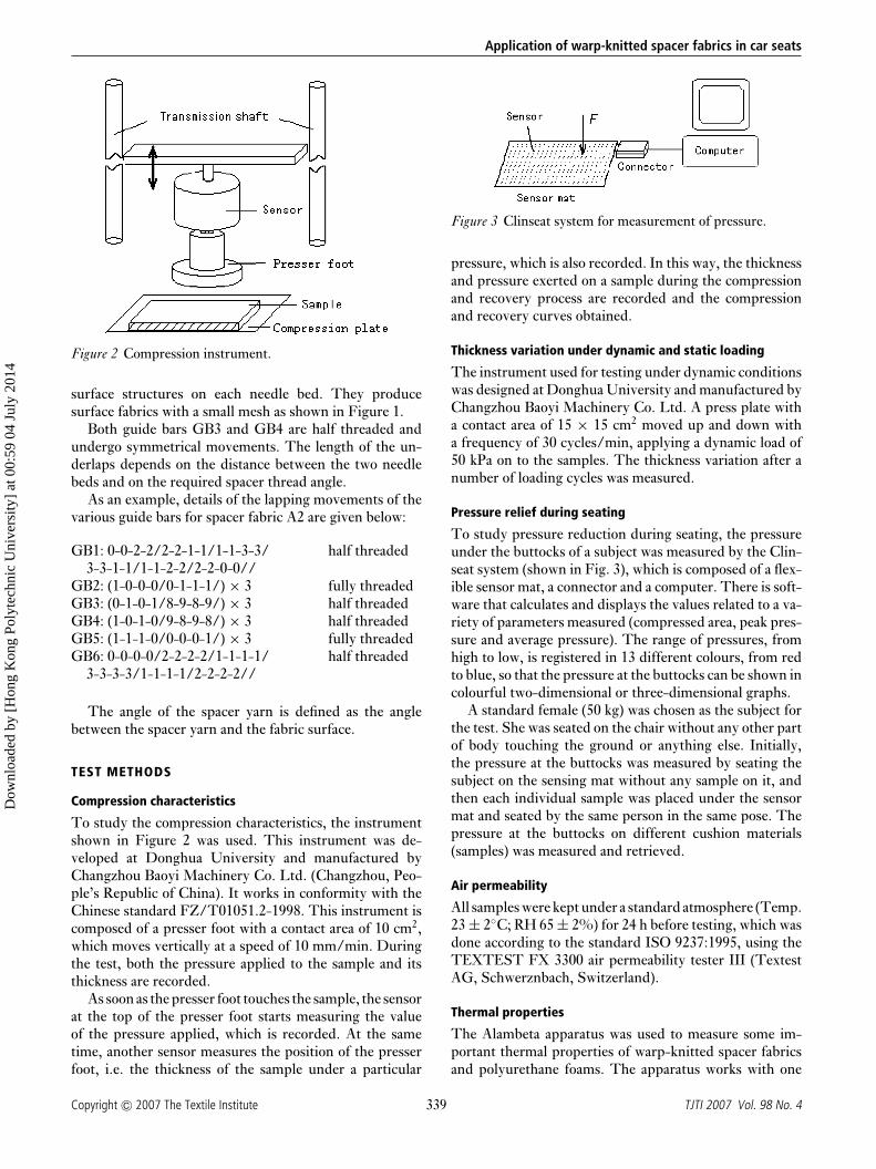
Figure 2 Compression instrument.
surface structures on each needle bed. They producesurface fabrics with a small mesh as shown in Figure 1.
Both guide bars GB3 and GB4 are half threaded andundergo symmetrical movements. The length of the un-derlaps depends on the distance between the two needlebeds and on the required spacer thread angle.
As an example, details of the lapping movements of thevarious guide bars for spacer fabric A2 are given below:
GB1: 0-0-2-2/2-2-1-1/1-1-3-3/ half threaded3-3-1-1/1-1-2-2/2-2-0-0//
GB2: (1-0-0-0/0-1-1-1/) × 3 fully threadedGB3: (0-1-0-1/8-9-8-9/) × 3 half threadedGB4: (1-0-1-0/9-8-9-8/) × 3 half threadedGB5: (1-1-1-0/0-0-0-1/) × 3 fully threadedGB6: 0-0-0-0/2-2-2-2/1-1-1-1/ half threaded
3-3-3-3/1-1-1-1/2-2-2-2//
The angle of the spacer yarn is defined as the anglebetween the spacer yarn and the fabric surface.
TEST METHODS
Compression characteristics
To study the compression characteristics, the instrumentshown in Figure 2 was used. This instrument was de-veloped at Donghua University and manufactured byChangzhou Baoyi Machinery Co. Ltd. (Changzhou, Peo-ple’s Republic of China). It works in conformity with theChinese standard FZ/T01051.2-1998. This instrument iscomposed of a presser foot with a contact area of 10 cm2,which moves vertically at a speed of 10 mm/min. Duringthe test, both the pressure applied to the sample and itsthickness are recorded.
As soon as the presser foot touches the sample, the sensorat the top of the presser foot starts measuring the valueof the pressure applied, which is recorded. At the sametime, another sensor measures the position of the presserfoot, i.e. the thickness of the sample under a particular
Figure 3 Clinseat system for measurement of pressure.
pressure, which is also recorded. In this way, the thicknessand pressure exerted on a sample during the compressionand recovery process are recorded and the compressionand recovery curves obtained.
Thickness variation under dynamic and static loading
The instrument used for testing under dynamic conditionswas designed at Donghua University and manufactured byChangzhou Baoyi Machinery Co. Ltd. A press plate witha contact area of 15 × 15 cm2 moved up and down witha frequency of 30 cycles/min, applying a dynamic load of50 kPa on to the samples. The thickness variation after anumber of loading cycles was measured.
Pressure relief during seating
To study pressure reduction during seating, the pressureunder the buttocks of a subject was measured by the Clin-seat system (shown in Fig. 3), which is composed of a flex-ible sensor mat, a connector and a computer. There is soft-ware that calculates and displays the values related to a va-riety of parameters measured (compressed area, peak pres-sure and average pressure). The range of pressures, fromhigh to low, is registered in 13 different colours, from redto blue, so that the pressure at the buttocks can be shown incolourful two-dimensional or three-dimensional graphs.
A standard female (50 kg) was chosen as the subject forthe test. She was seated on the chair without any other partof body touching the ground or anything else. Initially,the pressure at the buttocks was measured by seating thesubject on the sensing mat without any sample on it, andthen each individual sample was placed under the sensormat and seated by the same person in the same pose. Thepressure at the buttocks on different cushion materials(samples) was measured and retrieved.
Air permeability
All samples were kept under a standard atmosphere (Temp.23 ± 2◦C; RH 65 ± 2%) for 24 h before testing, which wasdone according to the standard ISO 9237:1995, using theTEXTEST FX 3300 air permeability tester III (TextestAG, Schwerznbach, Switzerland).
Thermal properties
The Alambeta apparatus was used to measure some im-portant thermal properties of warp-knitted spacer fabricsand polyurethane foams. The apparatus works with one
339Copyright C© 2007 The Textile Institute TJTI 2007 Vol. 98 No. 4
Dow
nloa
ded
by [
Hon
g K
ong
Poly
tech
nic
Uni
vers
ity]
at 0
0:59
04
July
201
4
X. Ye, R. Fangueiro, H. Hu and M. de Araujo
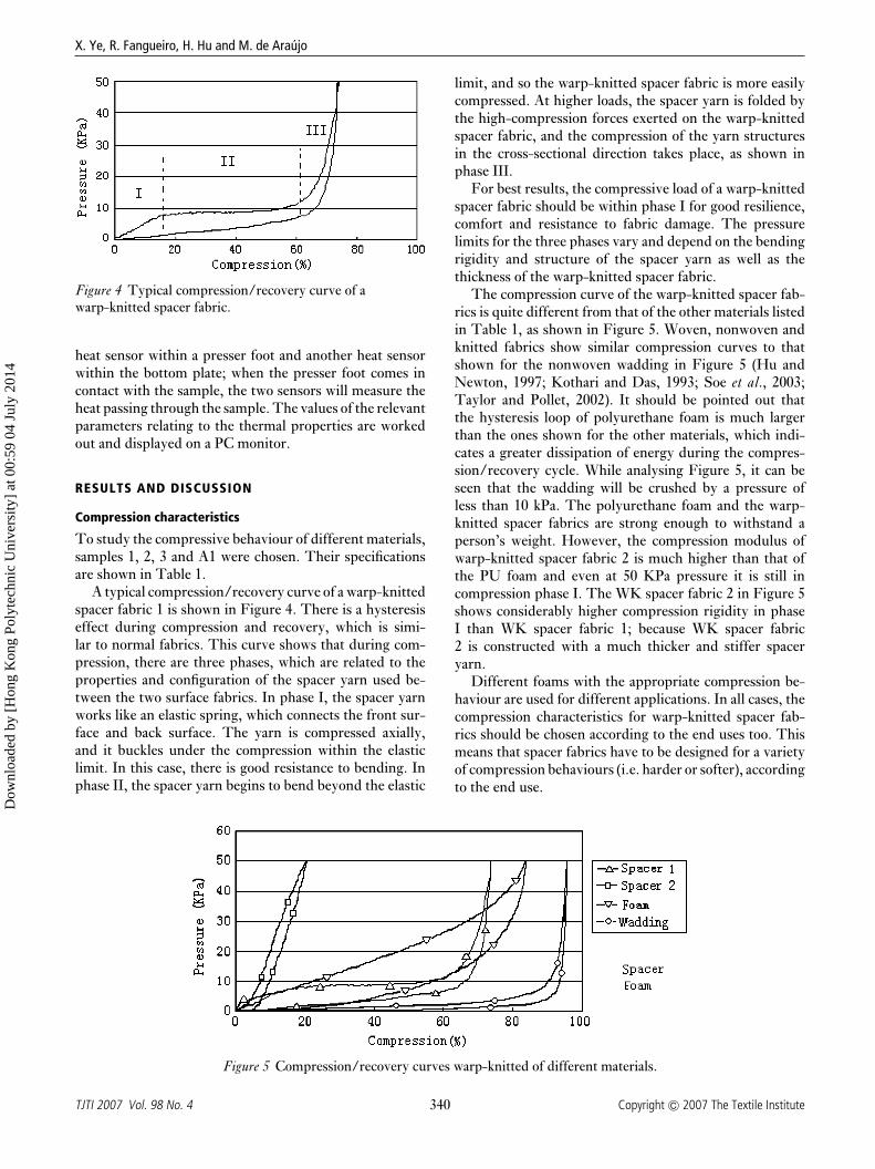
Figure 4 Typical compression/recovery curve of awarp-knitted spacer fabric.
heat sensor within a presser foot and another heat sensorwithin the bottom plate; when the presser foot comes incontact with the sample, the two sensors will measure theheat passing through the sample. The values of the relevantparameters relating to the thermal properties are workedout and displayed on a PC monitor.
RESULTS AND DISCUSSION
Compression characteristics
To study the compressive behaviour of different materials,samples 1, 2, 3 and A1 were chosen. Their specificationsare shown in Table 1.
A typical compression/recovery curve of a warp-knittedspacer fabric 1 is shown in Figure 4. There is a hysteresiseffect during compression and recovery, which is simi-lar to normal fabrics. This curve shows that during com-pression, there are three phases, which are related to theproperties and configuration of the spacer yarn used be-tween the two surface fabrics. In phase I, the spacer yarnworks like an elastic spring, which connects the front sur-face and back surface. The yarn is compressed axially,and it buckles under the compression within the elasticlimit. In this case, there is good resistance to bending. Inphase II, the spacer yarn begins to bend beyond the elastic
Figure 5 Compression/recovery curves warp-knitted of different materials.
limit, and so the warp-knitted spacer fabric is more easilycompressed. At higher loads, the spacer yarn is folded bythe high-compression forces exerted on the warp-knittedspacer fabric, and the compression of the yarn structuresin the cross-sectional direction takes place, as shown inphase III.
For best results, the compressive load of a warp-knittedspacer fabric should be within phase I for good resilience,comfort and resistance to fabric damage. The pressurelimits for the three phases vary and depend on the bendingrigidity and structure of the spacer yarn as well as thethickness of the warp-knitted spacer fabric.
The compression curve of the warp-knitted spacer fab-rics is quite different from that of the other materials listedin Table 1, as shown in Figure 5. Woven, nonwoven andknitted fabrics show similar compression curves to thatshown for the nonwoven wadding in Figure 5 (Hu andNewton, 1997; Kothari and Das, 1993; Soe et al., 2003;Taylor and Pollet, 2002). It should be pointed out thatthe hysteresis loop of polyurethane foam is much largerthan the ones shown for the other materials, which indi-cates a greater dissipation of energy during the compres-sion/recovery cycle. While analysing Figure 5, it can beseen that the wadding will be crushed by a pressure ofless than 10 kPa. The polyurethane foam and the warp-knitted spacer fabrics are strong enough to withstand aperson’s weight. However, the compression modulus ofwarp-knitted spacer fabric 2 is much higher than that ofthe PU foam and even at 50 KPa pressure it is still incompression phase I. The WK spacer fabric 2 in Figure 5shows considerably higher compression rigidity in phaseI than WK spacer fabric 1; because WK spacer fabric2 is constructed with a much thicker and stiffer spaceryarn.
Different foams with the appropriate compression be-haviour are used for different applications. In all cases, thecompression characteristics for warp-knitted spacer fab-rics should be chosen according to the end uses too. Thismeans that spacer fabrics have to be designed for a varietyof compression behaviours (i.e. harder or softer), accordingto the end use.
340TJTI 2007 Vol. 98 No. 4 Copyright C© 2007 The Textile Institute
Dow
nloa
ded
by [
Hon
g K
ong
Poly
tech
nic
Uni
vers
ity]
at 0
0:59
04
July
201
4
Application of warp-knitted spacer fabrics in car seats
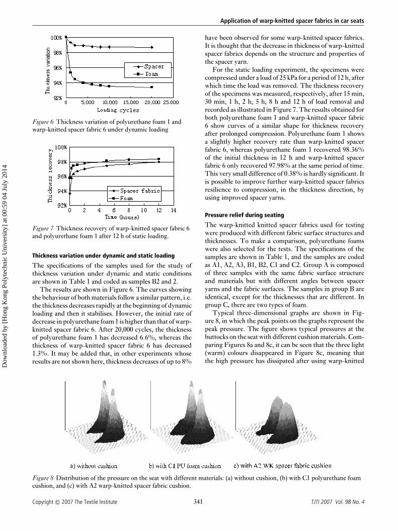
Figure 6 Thickness variation of polyurethane foam 1 andwarp-knitted spacer fabric 6 under dynamic loading
Figure 7 Thickness recovery of warp-knitted spacer fabric 6and polyurethane foam 1 after 12 h of static loading.
Thickness variation under dynamic and static loading
The specifications of the samples used for the study ofthickness variation under dynamic and static conditionsare shown in Table 1 and coded as samples B2 and 2.
The results are shown in Figure 6. The curves showingthe behaviour of both materials follow a similar pattern, i.e.the thickness decreases rapidly at the beginning of dynamicloading and then it stabilises. However, the initial rate ofdecrease in polyurethane foam 1 is higher than that of warp-knitted spacer fabric 6. After 20,000 cycles, the thicknessof polyurethane foam 1 has decreased 6.6%, whereas thethickness of warp-knitted spacer fabric 6 has decreased1.3%. It may be added that, in other experiments whoseresults are not shown here, thickness decreases of up to 8%
Figure 8 Distribution of the pressure on the seat with different materials: (a) without cushion, (b) with C1 polyurethane foamcushion, and (c) with A2 warp-knitted spacer fabric cushion.
have been observed for some warp-knitted spacer fabrics.It is thought that the decrease in thickness of warp-knittedspacer fabrics depends on the structure and properties ofthe spacer yarn.
For the static loading experiment, the specimens werecompressed under a load of 25 kPa for a period of 12 h, afterwhich time the load was removed. The thickness recoveryof the specimens was measured, respectively, after 15 min,30 min, 1 h, 2 h, 5 h, 8 h and 12 h of load removal andrecorded as illustrated in Figure 7. The results obtained forboth polyurethane foam 1 and warp-knitted spacer fabric6 show curves of a similar shape for thickness recoveryafter prolonged compression. Polyurethane foam 1 showsa slightly higher recovery rate than warp-knitted spacerfabric 6, whereas polyurethane foam 1 recovered 98.36%of the initial thickness in 12 h and warp-knitted spacerfabric 6 only recovered 97.98% at the same period of time.This very small difference of 0.38% is hardly significant. Itis possible to improve further warp-knitted spacer fabricsresilience to compression, in the thickness direction, byusing improved spacer yarns.
Pressure relief during seating
The warp-knitted knitted spacer fabrics used for testingwere produced with different fabric surface structures andthicknesses. To make a comparison, polyurethane foamswere also selected for the tests. The specifications of thesamples are shown in Table 1, and the samples are codedas A1, A2, A3, B1, B2, C1 and C2. Group A is composedof three samples with the same fabric surface structureand materials but with different angles between spaceryarns and the fabric surfaces. The samples in group B areidentical, except for the thicknesses that are different. Ingroup C, there are two types of foam.
Typical three-dimensional graphs are shown in Fig-ure 8, in which the peak points on the graphs represent thepeak pressure. The figure shows typical pressures at thebuttocks on the seat with different cushion materials. Com-paring Figures 8a and 8c, it can be seen that the three light(warm) colours disappeared in Figure 8c, meaning thatthe high pressure has dissipated after using warp-knitted
341Copyright C© 2007 The Textile Institute TJTI 2007 Vol. 98 No. 4
Dow
nloa
ded
by [
Hon
g K
ong
Poly
tech
nic
Uni
vers
ity]
at 0
0:59
04
July
201
4
X. Ye, R. Fangueiro, H. Hu and M. de Araujo
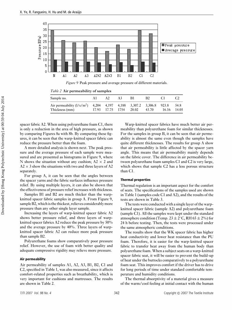
Figure 9 Peak pressure and average pressure of different materials.
Table 2 Air permeability of samples
Sample no. A1 A2 A3 B1 B2 C1 C2
Air permeability (l/s/m2) 4,204 4,197 4,188 3,307.2 3,306.8 923.8 54.8Thickness (mm) 17.93 17.75 1754 28.02 43.70 16.16 14.05
spacer fabric A2. When using polyurethane foam C1, thereis only a reduction in the area of high pressure, as shownby comparing Figures 8a with 8b. By comparing these fig-ures, it can be seen that the warp-knitted spacer fabric canreduce the pressure better than the foam.
A more detailed analysis is shown next. The peak pres-sure and the average pressure of each sample were mea-sured and are presented as histograms in Figure 9, whereN shows the situation without any cushion; A2 × 2 andA2 × 3 show the situations with two and three layers of A2separately.
For group A, it can be seen that the angles betweenthe spacer yarns and the fabric surfaces influence pressurerelief. By using multiple layers, it can also be shown thatthe effectiveness of pressure relief increases with thickness.
Samples B1 and B2 are much thicker than the warp-knitted spacer fabric samples in group A. From Figure 9,sample B2, which is the thickest, relieves considerably morepressure than any other single layer sample.
Increasing the layers of warp-knitted spacer fabric A2shows better pressure relief, and three layers of warp-knitted spacer fabrics A2 reduce the peak pressure by 50%and the average pressure by 40%. Three layers of warp-knitted spacer fabric A2 can reduce more peak pressurethan sample B2.
Polyurethane foams show comparatively poor pressurerelief. However, the use of foam with better quality andadequate compressive rigidity may relieve more pressure.
Air permeability
Air permeability of samples A1, A2, A3, B1, B2, C1 andC2, specified in Table 1, was also measured, since it affectscomfort-related properties such as breathability, which isvery important for cushions and mattresses. The resultsare shown in Table 2.
Warp-knitted spacer fabrics have much better air per-meability than polyurethane foam for similar thicknesses.For the samples in group B, it can be seen that air perme-ability is almost the same even though the samples havequite different thicknesses. The results for group A showthat air permeability is little affected by the spacer yarnangle. This means that air permeability mainly dependson the fabric cover. The difference in air permeability be-tween polyurethane foam samples C1 and C2 is very large,which shows that sample C2 has a less porous structurethan C1.
Thermal properties
Thermal regulation is an important aspect for the comfortof seats. The specifications of the samples used are shownin Table 1 (samples code C1 and A2), and the results of thetests are shown in Table 3.
The tests were conducted with a single layer of the warp-knitted spacer fabric (sample A2) and polyurethane foam(sample C1). All the samples were kept under the standardatmosphere condition (Temp. 23 ± 2◦C, RH 65 ± 2%) for24 h before testing. Then, the tests were processed underthe same atmospheric conditions.
The results show that the WK spacer fabric has higherheat conductivity and lower heat resistance than the PUfoam. Therefore, it is easier for the warp-knitted spacerfabric to transfer heat away from the human body thanpolyurethane foam. When a subject seats on a warp-knittedspacer fabric seat, it will be easier to prevent the build-upof heat under the buttocks comparatively to a polyurethanefoam seat. This improves comfort if the driver has to drivefor long periods of time under standard comfortable tem-perature and humidity conditions.
The thermal absorptivity of a material gives a measureof the warm/cool feeling at initial contact with the human
342TJTI 2007 Vol. 98 No. 4 Copyright C© 2007 The Textile Institute
Dow
nloa
ded
by [
Hon
g K
ong
Poly
tech
nic
Uni
vers
ity]
at 0
0:59
04
July
201
4
Application of warp-knitted spacer fabrics in car seats
Table 3 Thermal properties of polyurethane foam and warp-knitted spacerfabrics
Thermal Thermal absorptivityThickness conductivity (heat absorption Heat resistance R
Sample h (mm) λ (w/m K) × 10−3 capacity) b (w s1/2/m2 K) (m2 K/w) × 10−3
C1 16.16 90.30 41.30 221.30A2 17.75 108.00 90.30 141.50
body. In this context, warp-knitted spacer fabrics have acooler feeling than polyurethane foam fabrics, as thermalabsorptivity of the former is higher in all cases. This maybe beneficial when the subject initially sits in warm climaticconditions.
CONCLUSIONS
Warp-knitted spacer fabrics have compression propertiesdifferent from those of normal fabrics because of the spaceryarn. Warp-knitted spacer fabrics show very good lin-ear elastic compressibility in the first compression phase,which is of great interest for seats. The limit of the firstcompression phase varies with the bending rigidity andstructure of the spacer yarn and with the thickness of thefabric. In this context, it is easy to design adequate WKspacer fabrics with suitable compression characteristic foruse in car seats.
Furthermore, warp-knitted spacer fabrics are better atreducing peak pressure than polyurethane foam. Usingthicker warp-knitted spacer fabrics with appropriate spaceryarn structure and material, pressure can be much re-duced. Since there are limits to the thickness of warp-knitted spacer fabrics, several layers may be used to gethigher thicknesses and increased pressure relief. Car seatswith cushions of the warp-knitted spacer fabric are bet-ter at reducing peak pressures than seat cushions frompolyurethane foam. In this context, the former will makedrivers feel more comfortable.
Air permeability of warp-knitted spacer fabrics is muchbetter than polyurethane foams. Air permeability dependson the structure of the warp-knitted spacer fabrics. There-fore, these fabrics are more breathable substrates for carseats than polyurethane foam ones.
Warp-knitted spacer fabrics have higher thermal con-ductivity and lower thermal resistance than polyurethanefoams. Therefore, warp-knitted spacer fabrics can transferheat more effectively away from the driver’s body and sothese fabrics have better thermoregulation properties thanpolyurethane foams for warm climatic conditions. Warp-knitted spacer fabrics have good and comparable stabilityon thickness with polyurethane foams.
Generally speaking, car seat cushions made of warp-knitted spacer fabrics can offer good mechanical supportand physical comfort to the driver’s body. These fabrics are
stronger than polyurethane foams, can be used for longerperiods of time and can even be reused with new seatscovers. Therefore, these fabrics used for seats are easier torecycle than polyurethane foam ones.
ACKNOWLEDGMENT
The authors wish to thank the European Commission forawarding research funds under the EU Asia-Link Programand the University of Minho (Portugal) and Donghua Uni-versity (People’s Republic of China) for providing researchfacilities. The authors also want to thank Quzhou FulianWarp Knitting Co., Ltd. (Quanzhou, People’s Republicof China) for supplying the spacer fabrics used in thisstudy.
REFERENCES
H, M., 2000. Spacer fabric with specific protectivecharacteristics, Melliand-Textilberichte, 6, E124– E 125.
H, M., 2002. Development of functional warp knitted spacerfabrics as operating table covers, Melliand-Textilberichte, 6,411–442.
H, J. and N, A., 1997. Low-load lateral compressionalbehaviour of woven fabrics, J. Text. Inst., 88(3), 242–254.
K, V. K. and D, A., 1993. The compressional behaviourof spunbonded nowoven fabrics, J. Text. Inst., 84(1), 16–30.
R, D., 2001. Warp knitted spacer fabric—design andapplication fields, Knitting Technol., 4, 14–16.
S, D., M, U. and B, V. T., 2005.Development of textiles for or coverings and pads,Melliand-Textilberichte, 6, E95–E96.
S, A. K., M, T., T, M. and N, M., 2003.Compression of plain knitted fabrics predicted from yarnproperties and fabric geometry, Text. Res. J., 73(10), 861–866.
T, P. M. and P, D. M., 2002. Static low-load lateralcompression of fabric, Text. Res. J., 72(11), 983–990.
U, K. H., 2000. Physiological comfort on car seats,Kettenwirk-Praxis, 34(1), 9–12.
W, C., 1993. Raschel knitted spacer fabrics,Kettenwirk-Praxis, 27(3), 59–63.
Y, X., F, R. and H, H., 2005a. Behaviour of spacerknitted fabrics used as cushions. In 4th Central EuropeanConference, 7–9 September 2005, Liberec, Czech Republic.
Y, X., H, H. and F, X., 2005b. An experimental investigationon the properties of the spacer knitted fabrics for pressurereduction, Res. J. Text. Apparel, 9(3), 52–57.
343Copyright C© 2007 The Textile Institute TJTI 2007 Vol. 98 No. 4
Dow
nloa
ded
by [
Hon
g K
ong
Poly
tech
nic
Uni
vers
ity]
at 0
0:59
04
July
201
4
344TJTI 2007 Vol. 98 No. 4 Copyright C© 2007 The Textile Institute
Dow
nloa
ded
by [
Hon
g K
ong
Poly
tech
nic
Uni
vers
ity]
at 0
0:59
04
July
201
4


