Embed Size (px)
Citation preview
AOS-CX 10.06 Diagnostics andSupportability Guide6300, 6400 Switch Series
Part Number: 5200-7689Published: November 2020Edition: 1

© Copyright 2020 Hewlett Packard Enterprise Development LP
NoticesThe information contained herein is subject to change without notice. The only warranties for HewlettPackard Enterprise products and services are set forth in the express warranty statements accompanyingsuch products and services. Nothing herein should be construed as constituting an additional warranty.Hewlett Packard Enterprise shall not be liable for technical or editorial errors or omissions contained herein.
Confidential computer software. Valid license from Hewlett Packard Enterprise required for possession, use,or copying. Consistent with FAR 12.211 and 12.212, Commercial Computer Software, Computer SoftwareDocumentation, and Technical Data for Commercial Items are licensed to the U.S. Government undervendor's standard commercial license.
Links to third-party websites take you outside the Hewlett Packard Enterprise website. Hewlett PackardEnterprise has no control over and is not responsible for information outside the Hewlett Packard Enterprisewebsite.
AcknowledgmentsBluetooth® is a trademark owned by its proprietor and used by Hewlett Packard Enterprise under license.

Chapter 1 About this document...................................................................... 8Applicable products........................................................................................................................................8Latest version available online......................................................................................................................8Command syntax notation conventions..................................................................................................... 8About the examples....................................................................................................................................... 9Identifying switch ports and interfaces .................................................................................................... 10Identifying modular switch components ..................................................................................................10
Chapter 2 Debug logging................................................................................. 11Overview........................................................................................................................................................11Debug logging............................................................................................................................................... 11
clear debug buffer.................................................................................................................... 11debug {all | <MODULE-NAME>}................................................................................................12debug db...........................................................................................................................................13debug destination...................................................................................................................... 15show debug...................................................................................................................................... 16show debug buffer...................................................................................................................... 17show debug buffer vsf............................................................................................................. 18show debug destination........................................................................................................... 19
Chapter 3 Log rotation.....................................................................................20Overview........................................................................................................................................................20Changing the size of the log rotation file...................................................................................................20Changing the time frequency for log rotation.......................................................................................... 20Identifying a remote host for receiving rotated log files......................................................................... 21Log rotation paths........................................................................................................................................ 21Management of rotated log files................................................................................................................ 21Remote transfer of rotated log files...........................................................................................................21Verifying the log rotation parameters........................................................................................................22Resetting the size of the log rotation file...................................................................................................22Resetting the time frequency to daily........................................................................................................ 22Resetting the remote host for receiving rotated log files........................................................................22Log rotation not occurring immediately after reaching threshold.........................................................23Log files not transferred remotely..............................................................................................................23Log rotation not occurring regardless of period value.......................................................................... 24Log rotation commands.............................................................................................................................. 24
logrotate maxsize...................................................................................................................... 24logrotate period.........................................................................................................................25logrotate target.........................................................................................................................26show logrotate............................................................................................................................. 27
Chapter 4 Switch system and hardware commands................................28bluetooth disable..................................................................................................................................28bluetooth enable.................................................................................................................................... 28clear events............................................................................................................................................. 29clear ip errors...................................................................................................................................... 30
Contents
Contents 3

domain-name............................................................................................................................................... 30hostname...................................................................................................................................................... 31led locator............................................................................................................................................... 32module admin-state............................................................................................................................... 32module product-number.........................................................................................................................33show bluetooth........................................................................................................................................ 35show boot-history..................................................................................................................................36show capacities...................................................................................................................................... 38show capacities-status...................................................................................................................... 39show core-dump........................................................................................................................................ 40show domain-name.................................................................................................................................... 42show environment fan........................................................................................................................... 43show environment led........................................................................................................................... 45show environment power-consumption........................................................................................... 46show environment power-supply.......................................................................................................47show environment temperature.........................................................................................................48show events............................................................................................................................................... 50show fabric............................................................................................................................................... 53show hostname...........................................................................................................................................54show images............................................................................................................................................... 55show ip errors........................................................................................................................................ 56show module............................................................................................................................................... 58show running-config............................................................................................................................. 60show running-config current-context......................................................................................... 63show startup-config............................................................................................................................. 64show system............................................................................................................................................... 65show system resource-utilization................................................................................................67show tech....................................................................................................................................................68show usb...................................................................................................................................................... 69show version............................................................................................................................................. 70system resource-utilization poll-interval............................................................................71top cpu........................................................................................................................................................ 71top memory..................................................................................................................................................72usb................................................................................................................................................................. 72usb mount/unmount..................................................................................................................................73
Chapter 5 Event logs.........................................................................................75Showing and clearing events...................................................................................................................... 75
Chapter 6 Cable Diagnostics...........................................................................76Overview........................................................................................................................................................76Cable diagnostics tests................................................................................................................................ 76Cable diagnostic command.........................................................................................................................77
diag cable-diagnostic............................................................................................................. 77
Chapter 7 Supportability copy....................................................................... 79Overview........................................................................................................................................................79Supportability copy commands..................................................................................................................79
copy command-output.................................................................................................................. 79copy core-dump [<MEMBER/SLOT>] daemon......................................................................... 80copy core-dump [<MEMBER/SLOT>] kernel......................................................................... 81copy core-dump [<MEMBER/SLOT>] kernel <STORAGE-URL>..........................................82
4 AOS-CX 10.06 Diagnostics and Supportability Guide

copy core-dump vsf member daemon.....................................................................................82copy core-dump vsf member kernel.....................................................................................83copy diag-dump feature <FEATURE>.....................................................................................84copy diag-dump local-file.................................................................................................... 85copy diag-dump vsf member local-file............................................................................86copy show-tech feature........................................................................................................... 87copy show-tech local-file.................................................................................................... 88copy show-tech vsf member local-file............................................................................89copy support-files.................................................................................................................... 90copy support-files vsf member........................................................................................... 91copy support-log.........................................................................................................................92copy support-log vsf member................................................................................................93
Chapter 8 Traceroute....................................................................................... 95Overview........................................................................................................................................................95Traceroute commands.................................................................................................................................95
traceroute...................................................................................................................................... 95traceroute6.................................................................................................................................... 97
Chapter 9 Ping................................................................................................... 99Overview........................................................................................................................................................99Ping commands............................................................................................................................................ 99
ping....................................................................................................................................................99ping6 ............................................................................................................................................. 104
Troubleshooting......................................................................................................................................... 107Operation not permitted................................................................................................................107Network is unreachable................................................................................................................. 107Destination Host Unreachable...................................................................................................... 108
Chapter 10 Remote syslog............................................................................ 109Remote syslog commands........................................................................................................................ 109
logging...........................................................................................................................................109logging facility.......................................................................................................................111logging persistent-storage................................................................................................ 111
Chapter 11 Runtime diagnostics................................................................. 113Overview......................................................................................................................................................113Runtime diagnostic commands................................................................................................................113
diagnostic monitor.................................................................................................................. 113diag on-demand........................................................................................................................... 114show diagnostic.........................................................................................................................115show diagnostic events......................................................................................................... 118
Chapter 12 Service OS....................................................................................120Overview......................................................................................................................................................120Service OS CLI login....................................................................................................................................120Service OS user accounts.......................................................................................................................... 121Service OS boot menu............................................................................................................................... 121Console configuration................................................................................................................................122AOS-CX boot................................................................................................................................................122
Contents 5

File system access...................................................................................................................................... 123Service OS mount failure...........................................................................................................................124Service OS CLI command list.................................................................................................................... 124Service OS CLI features and limitations...................................................................................................125Service OS CLI commands.........................................................................................................................125
boot..................................................................................................................................................125cat....................................................................................................................................................126cd path...........................................................................................................................................126config-clear................................................................................................................................127cp...................................................................................................................................................... 127du...................................................................................................................................................... 128erase zeroize............................................................................................................................. 130exit..................................................................................................................................................131format............................................................................................................................................. 131identify.........................................................................................................................................132ip...................................................................................................................................................... 132ls...................................................................................................................................................... 133md5sum............................................................................................................................................. 135mkdir............................................................................................................................................... 136mount............................................................................................................................................... 137mv...................................................................................................................................................... 137password.........................................................................................................................................138ping..................................................................................................................................................138pwd....................................................................................................................................................139reboot............................................................................................................................................. 139rm...................................................................................................................................................... 140rmdir............................................................................................................................................... 140secure-mode..................................................................................................................................141sh...................................................................................................................................................... 142umount............................................................................................................................................. 143update............................................................................................................................................. 143tftp..................................................................................................................................................144version...........................................................................................................................................145
Chapter 13 In-System Programming.......................................................... 147In-System Programming Overview...........................................................................................................147Show tech command list for the ISP feature........................................................................................ 147In-System Programming commands....................................................................................................... 147
clear update-log.......................................................................................................................147show needed-updates................................................................................................................147
Chapter 14 Selftest......................................................................................... 149Overview......................................................................................................................................................149Selftest commands.................................................................................................................................... 149
fastboot.........................................................................................................................................149show selftest ........................................................................................................................... 151
Chapter 15 Zeroization.................................................................................. 155Overview......................................................................................................................................................155Zeroization commands..............................................................................................................................155
erase all zeroize.................................................................................................................... 155
6 AOS-CX 10.06 Diagnostics and Supportability Guide
Chapter 16 Terminal Monitor.......................................................................157Overview......................................................................................................................................................157Terminal monitor commands................................................................................................................... 157
terminal-monitor {notify | severity | filter}..................................................... 157show terminal-monitor........................................................................................................... 158
Chapter 17 Troubleshooting Web UI and REST API access issues........ 159HTTP 404 error when accessing the switch URL.................................................................................... 159HTTP 401 error "Login failed: session limit reached"............................................................................ 159
Chapter 18 Support and other resources..................................................161Accessing Aruba Support.......................................................................................................................... 161Accessing updates......................................................................................................................................161Warranty information................................................................................................................................ 162Regulatory information............................................................................................................................. 162Documentation feedback..........................................................................................................................162
Contents 7

This document describes features of the AOS-CX network operating system. It is intended for administratorsresponsible for installing, configuring, and managing Aruba switches on a network.
Applicable productsThis document applies to the following products:
• Aruba 6300 Switch Series ( JL658A, JL659A, JL660A, JL661A, JL662A, JL663A, JL664A, JL665A, JL666A, JL667A,JL668A, JL762A)
• Aruba 6400 Switch Series ( JL741A, R0X26A, R0X27A, R0X29A, R0X30A)
Latest version available onlineUpdates to this document can occur after initial publication. For the latest versions of productdocumentation, see the links provided in Support and other resources.
Command syntax notation conventionsConvention Usage
example-text Identifies commands and their options and operands, code examples,filenames, pathnames, and output displayed in a command window.Items that appear like the example text in the previous column are to beentered exactly as shown and are required unless enclosed in brackets([ ]).
example-text In code and screen examples, indicates text entered by a user.
Any of the following:
• <example-text>
• <example-text>• example-text
• example-text
Identifies a placeholder—such as a parameter or a variable—that youmust substitute with an actual value in a command or in code:
• For output formats where italic text cannot be displayed, variablesare enclosed in angle brackets (< >). Substitute the text—includingthe enclosing angle brackets—with an actual value.
• For output formats where italic text can be displayed, variables mightor might not be enclosed in angle brackets. Substitute the textincluding the enclosing angle brackets, if any, with an actual value.
| Vertical bar. A logical OR that separates multiple items from which youcan choose only one.
Any spaces that are on either side of the vertical bar are included forreadability and are not a required part of the command syntax.
Table Continued
Chapter 1About this document
8 AOS-CX 10.06 Diagnostics and Supportability Guide
Convention Usage
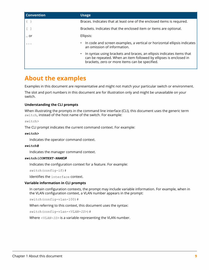
{ } Braces. Indicates that at least one of the enclosed items is required.
[ ] Brackets. Indicates that the enclosed item or items are optional.
… or
...
Ellipsis:
• In code and screen examples, a vertical or horizontal ellipsis indicatesan omission of information.
• In syntax using brackets and braces, an ellipsis indicates items thatcan be repeated. When an item followed by ellipses is enclosed inbrackets, zero or more items can be specified.
About the examplesExamples in this document are representative and might not match your particular switch or environment.
The slot and port numbers in this document are for illustration only and might be unavailable on yourswitch.
Understanding the CLI prompts
When illustrating the prompts in the command line interface (CLI), this document uses the generic termswitch, instead of the host name of the switch. For example:
switch>The CLI prompt indicates the current command context. For example:
switch>Indicates the operator command context.
switch#Indicates the manager command context.
switch(CONTEXT-NAME)#
Indicates the configuration context for a feature. For example:
switch(config-if)#Identifies the interface context.
Variable information in CLI prompts
In certain configuration contexts, the prompt may include variable information. For example, when inthe VLAN configuration context, a VLAN number appears in the prompt:
switch(config-vlan-100)#When referring to this context, this document uses the syntax:
switch(config-vlan-<VLAN-ID>)#Where <VLAN-ID> is a variable representing the VLAN number.
Chapter 1 About this document 9

Identifying switch ports and interfacesPhysical ports on the switch and their corresponding logical software interfaces are identified using theformat:
member/slot/port
On the 6300 Switch Series
• member: Member number of the switch in a Virtual Switching Framework (VSF) stack. Range: 1 to 10. Theprimary switch is always member 1. If the switch is not a member of a VSF stack, then member is 1.
• slot: Line module number. Always 1.
• port: Physical number of a port on a line module.
For example, the logical interface 1/1/4 in software is associated with physical port 4 in slot 1 on member 1.
On the 6400 Switch Series
• member: Always 1. VSF is not supported on this switch.
• slot: Specifies physical location of a module in the switch chassis.
◦ Management modules are on the front of the switch in slots 1/1 and 1/2.
◦ Line modules are on the front of the switch starting in slot 1/3.
• port: Physical number of a port on a line module.
For example, the logical interface 1/3/4 in software is associated with physical port 4 in slot 3 on member 1.
Identifying modular switch components• Power supplies are on the front of the switch behind the bezel above the management modules. Power
supplies are labeled in software in the format: member/power supply:
◦ member: 1.
◦ power supply: 1 to 4.
• Fans are on the rear of the switch and are labeled in software as: member/tray/fan:
◦ member: 1.
◦ tray: 1 to 4.
◦ fan: 1 to 4.
• Fabric modules are not labeled on the switch but are labeled in software in the format: member/module:
◦ member: 1.
◦ member: 1 or 2.
• The display module on the rear of the switch is not labeled with a member or slot number.
10 AOS-CX 10.06 Diagnostics and Supportability Guide
OverviewThe debug logging framework provides an improved, customizable, and conditional logging framework withfeature and entity based filtering options. Debug logging is a verbose, on-demand logging mechanism whichcustomers and support can enable in order to obtain more information that will assist with troubleshooting.
Each debug logging event has both a Severity and a Module. Customers/support are required to enable agiven Module in order to have those events logged. The log operation is not run when a Module is notenabled. All debug log events classified with a Severity of Error and above will always be logged. Thisensures that both support and customers will be able to see these important events even when theirrespective debug log Module isn’t enabled.
NOTE: Debug logging is disabled by default.
Debug loggingclear debug bufferSyntax
clear debug buffer
Description
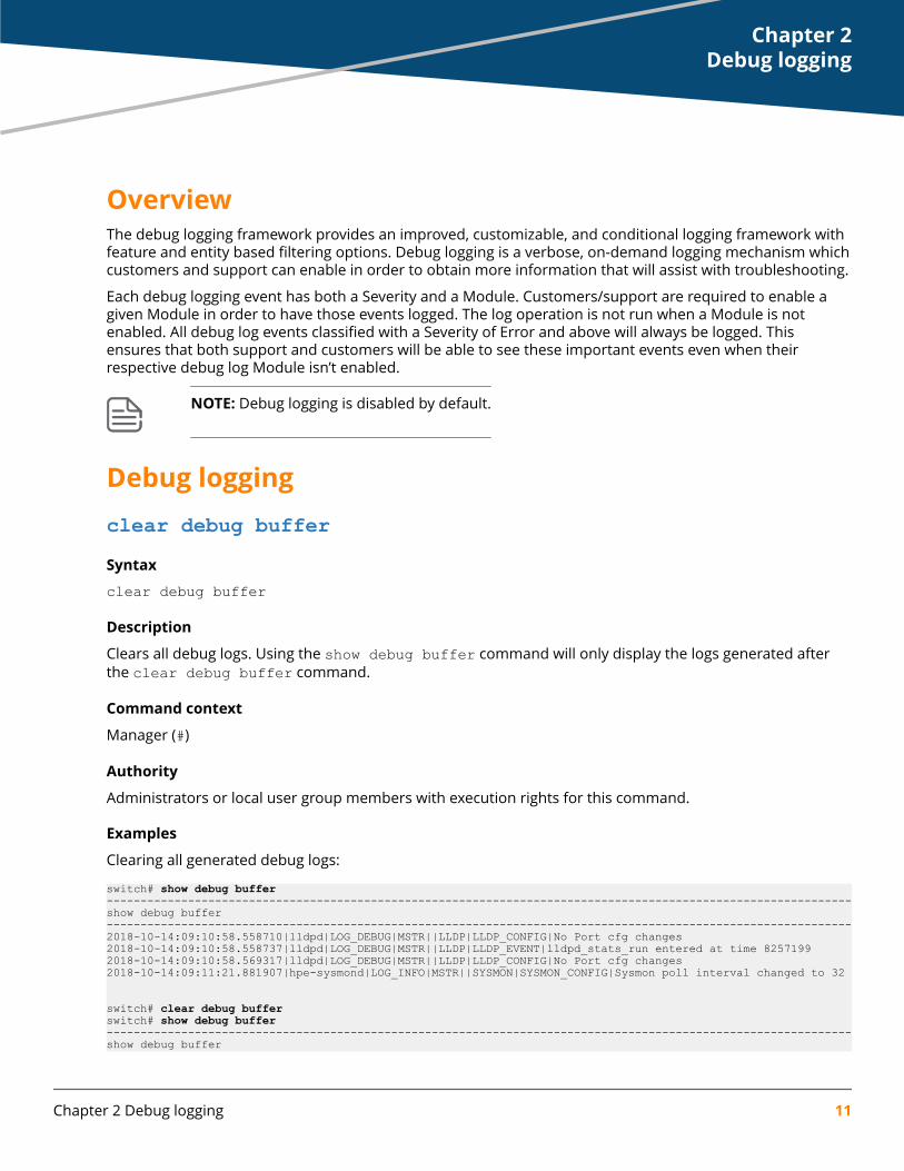
Clears all debug logs. Using the show debug buffer command will only display the logs generated afterthe clear debug buffer command.
Command context
Manager (#)
Authority
Administrators or local user group members with execution rights for this command.
Examples
Clearing all generated debug logs:
switch# show debug buffer--------------------------------------------------------------------------------------------------------------show debug buffer--------------------------------------------------------------------------------------------------------------2018-10-14:09:10:58.558710|lldpd|LOG_DEBUG|MSTR||LLDP|LLDP_CONFIG|No Port cfg changes2018-10-14:09:10:58.558737|lldpd|LOG_DEBUG|MSTR||LLDP|LLDP_EVENT|lldpd_stats_run entered at time 82571992018-10-14:09:10:58.569317|lldpd|LOG_DEBUG|MSTR||LLDP|LLDP_CONFIG|No Port cfg changes2018-10-14:09:11:21.881907|hpe-sysmond|LOG_INFO|MSTR||SYSMON|SYSMON_CONFIG|Sysmon poll interval changed to 32
switch# clear debug bufferswitch# show debug buffer--------------------------------------------------------------------------------------------------------------show debug buffer
Chapter 2Debug logging
Chapter 2 Debug logging 11

--------------------------------------------------------------------------------------------------------------2018-10-14:09:13:24.481407|hpe-sysmond|LOG_INFO|MSTR||SYSMON|SYSMON_CONFIG|Sysmon poll interval changed to 51
debug {all | <MODULE-NAME>}Syntax
debug {all | <MODULE-NAME>} [<SUBMODULE-NAME>] [severity (emer|crit|alert|err|notice|warning|info|debug)] {port <PORT-NAME> | vlan <VLAN-ID> | ip <IP-ADDRESS> | mac <MAC-ADDRESS> | vrf <VRF-NAME> | instance <INSTANCE-ID>}
no debug {all | <MODULE-NAME>} [<SUBMODULE-NAME>] {port | vlan | ip | mac | vrf | instance}
Description
Enables debug logging for modules or submodules by name, with optional filtering by specific criteria.
The no form of this command disables debug logging.
Command context
Manager (#)
Parametersall
Enables debug logging for all modules.
<MODULE-NAME>
Enables debug logging for a specific module. For a list of supported modules, enter the debug commandfollowed by a space and a question mark (?).
<SUBMODULE-NAME>
Enables debug logging for a specific submodule. For a list of supported submodules, enter the debug<MODULE-NAME> command followed by a space and a question mark (?).
severity (emer|crit|alert|err|notice|warning|info|debug)Selects the minimum severity log level for the destination. If a severity is not provided, the default loglevel is debug. Optional.
emerSpecifies storage of debug logs with a severity level of emergency only.
critSpecifies storage of debug logs with severity level of critical and above.
alertSpecifies storage of debug logs with severity level of alert and above.
errSpecifies storage of debug logs with severity level of error and above.
noticeSpecifies storage of debug logs with severity level of notice and above.
warningSpecifies storage of debug logs with severity level of warning and above.
12 AOS-CX 10.06 Diagnostics and Supportability Guide
infoSpecifies storage of debug logs with severity level of info and above.
debugSpecifies storage of debug logs with severity level of debug (default).
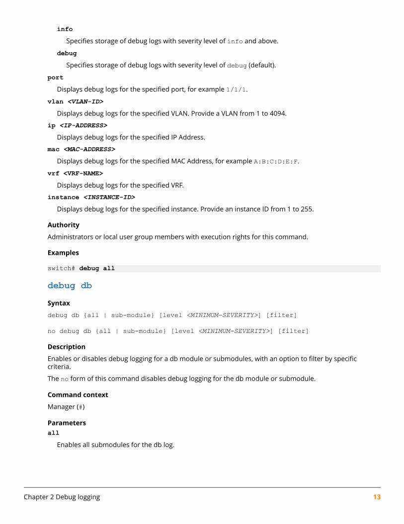
portDisplays debug logs for the specified port, for example 1/1/1.
vlan <VLAN-ID>Displays debug logs for the specified VLAN. Provide a VLAN from 1 to 4094.
ip <IP-ADDRESS>Displays debug logs for the specified IP Address.
mac <MAC-ADDRESS>Displays debug logs for the specified MAC Address, for example A:B:C:D:E:F.
vrf <VRF-NAME>Displays debug logs for the specified VRF.
instance <INSTANCE-ID>Displays debug logs for the specified instance. Provide an instance ID from 1 to 255.
Authority
Administrators or local user group members with execution rights for this command.
Examples
switch# debug all
debug dbSyntax
debug db {all | sub-module} [level <MINIMUM-SEVERITY>] [filter]
no debug db {all | sub-module} [level <MINIMUM-SEVERITY>] [filter]
Description
Enables or disables debug logging for a db module or submodules, with an option to filter by specificcriteria.
The no form of this command disables debug logging for the db module or submodule.
Command context
Manager (#)
Parametersall
Enables all submodules for the db log.
Chapter 2 Debug logging 13

sub-moduleEnables debug logging for supported submodules. Specify rx or tx debug logs.
filterSpecifies supported filters for the db log. Specify table, column, or client. Optional
severity (emer|crit|alert|err|notice|warning|info|debug)Selects the minimum severity log level for the destination. If a severity is not provided, the default loglevel is debug. Optional.
emerSpecifies storage of debug logs with a severity level of emergency only.
critSpecifies storage of debug logs with severity level of critical and above.
alertSpecifies storage of debug logs with severity level of alert and above.
errSpecifies storage of debug logs with severity level of error and above.
noticeSpecifies storage of debug logs with severity level of notice and above.
warningSpecifies storage of debug logs with severity level of warning and above.
infoSpecifies storage of debug logs with severity level of info and above.
debugSpecifies storage of debug logs with severity level of debug (default).
Authority
Administrators or local user group members with execution rights for this command.
Usage
DBlog is a high performance, configuration, and state database server logging infrastructure where a usercan log the transactions which are sent or received by clients to the configuration and state database server.It can be enabled through the CLI and REST, and also supports filters where a user can filter out logs on thebasis of table, column, or client. It is helpful for debugging when the user wants to debug an issue with aparticular client, table, or column combination. It is not enabled by default. A combination of filters can alsobe applied to filter out messages based on table, column, and client.
There are three submodules for the "db" module:
1. all: When All is enabled, no filters are applied to any of the debug logs, even if other submodules areconfigured with filters.
2. tx: If enabled, only the replies and notifications sent out for the initial and incremental updates arelogged.
3. rx: If enabled, only the transactions sent to the configuration and state database server are logged.
14 AOS-CX 10.06 Diagnostics and Supportability Guide

The keyword all may be used to enable or disable debug logging for all sub-modules. Also a combinationof filters can be used to filter the message types.
If the table or client filter is applied, then the messages belonging to this specific table or client will belogged. The column filter can also be applied to further filter messages on a table, providing a mechanism tofilter messages on a column. The table and client filter can be used in combination or separately, butcolumn can only be used in conjunction with table.
Examples
Configuring all submodules with severity debug:
switch# debug db all severity debugConfiguring the tx submodule with table Interface filter and severity debug:
switch# debug db tx table Interface severity debugConfiguring the rx submodule with table Interface column statistics filter and severity debug:
switch# debug db rx table Interface column statistics severity debugDisabling the rx submodule:
switch# no debug db rxDisabling the tx submodule table Interface:
switch# no debug db tx table Interface
debug destinationSyntaxdebug destination {syslog | file | console | buffer} [severity (emer|crit|alert|err|notice|warning|info|debug)]
no debug destination {syslog | file | console}
Description
Sets the destination for debug logs and the minimum severity level for each destination
The no form of this command unsets the destination for debug logs.
Command context
Manager (#)
Parameters{syslog | file | console | buffer}
Selects the destination to store debug logs. Required.
syslogSpecifies that the debug logs are stored in the syslog.
fileSpecifies that debug logs are stored in file.
consoleSpecifies that debug logs are stored in console.
Chapter 2 Debug logging 15

bufferSpecifies that debug logs are stored in buffer (default).
severity (emer|crit|alert|err|notice|warning|info|debug)Selects the minimum severity log level for the destination. If a severity is not provided, the default loglevel isdebug. Optional.
emerSpecifies storage of debug logs with a severity level of emergency only.
critSpecifies storage of debug logs with severity level of critical and above.
alertSpecifies storage of debug logs with severity level of alert and above.
errSpecifies storage of debug logs with severity level of error and above.
noticeSpecifies storage of debug logs with severity level of notice and above.
warningSpecifies storage of debug logs with severity level of warning and above.
infoSpecifies storage of debug logs with severity level of info and above.
debugSpecifies storage of debug logs with severity level of debug (default).
Authority
Administrators or local user group members with execution rights for this command.
Usage
Events that have a severity equal to or higher than the configured severity level are stored in the designateddestination. The product defaults to buffer for destination and debug as a severity level.
Examples
switch# debug destination syslog severity alert
switch# debug destination console severity info
switch# debug destination file severity warning
switch# debug destination buffer severity err
show debugSyntax
show debug [vsx-peer]
16 AOS-CX 10.06 Diagnostics and Supportability Guide

Description
Displays the enabled debug types.
Command context
Manager (#)
Parameters[vsx-peer]
Shows the output from the VSX peer switch. If the switches do not have the VSX configuration or the ISLis down, the output from the VSX peer switch is not displayed. This parameter is available on switchesthat support VSX.
Authority
Administrators or local user group members with execution rights for this command.
Examples
switch# show debug--------------------------------------------------------------------------------module sub_module severity vlan port ip mac instance vrf
---------------------------------------------------------------------------------all all err 1 1/1/1 10.0.0.1 1a:2b:3c:4d:5e:6f 2 abcd
show debug bufferSyntaxshow debug buffer [module <MODULE-NAME> | severity (emer|crit|alert|err|notice|warning|info|debug)]
Description
Displays debug logs stored in the specified debug buffer with optional filtering by module or severity.
Command context
Manager (#)
Parameters<MODULE-NAME>
Filters debug logs displayed by the specified module name.
severity (emer|crit|alert|err|notice|warning|info|debug)Displays debug logs with a specified severity level. Defaults todebug. Optional.
emerDisplays debug logs with a severity level of emergency only.
critDisplays debug logs with a severity level of critical and above.
alertDisplays debug logs with a severity level of alert and above.
Chapter 2 Debug logging 17

errSpecifies storage of debug logs with severity level of error and above.
noticeSpecifies storage of debug logs with severity level of notice and above.
warningDisplays debug logs with a severity level of warning and above.
infoDisplays debug logs with a severity level of info and above.
debugDisplays debug logs with a severity level of debug (default).
Authority
Administrators or local user group members with execution rights for this command.
Examples
switch# show debug buffer
------------------------------------------------------------------------------show debug buffer------------------------------------------------------------------------------2017-03-06:06:51:15.089967|hpe-sysmond|SYSMON|SYSMON_CONFIG|LOG_INFO|Sysmon poll interval changed to 20
show debug buffer vsfSyntax
NOTE: Applicable for 6300 switches only.
show debug buffer vsf [member <MEMBER-ID>] [{master | standby}]
Description
Displays VSF member debug logs stored in the debug buffer, with an option to filter by VSF member androle.
Command context
Manager (#)
Parameters<MEMBER-ID>
Displays debug logs for the specified member-id. Optional. Range: 1-10.
masterDisplay debug logs for the VSF master.
standbyDisplay debug logs for the VSF standby.
Authority
Administrators or local user group members with execution rights for this command.
18 AOS-CX 10.06 Diagnostics and Supportability Guide
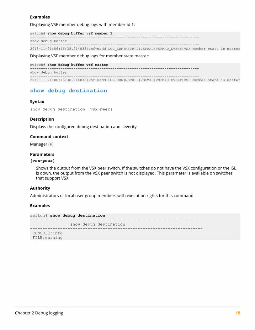
Examples
Displaying VSF member debug logs with member-id 1:
switch# show debug buffer vsf member 1------------------------------------------------------------------------------show debug buffer------------------------------------------------------------------------------2018-11-21:06:16:38.214838|vsf-madd|LOG_ERR|MSTR|1|VSFMAD|VSFMAD_EVENT|VSF Member state is master
Displaying VSF member debug logs for member state master:
switch# show debug buffer vsf master------------------------------------------------------------------------------show debug buffer------------------------------------------------------------------------------2018-11-21:06:16:38.214838|vsf-madd|LOG_ERR|MSTR|1|VSFMAD|VSFMAD_EVENT|VSF Member state is master
show debug destinationSyntax
show debug destination [vsx-peer]
Description
Displays the configured debug destination and severity.
Command context
Manager (#)
Parameters[vsx-peer]
Shows the output from the VSX peer switch. If the switches do not have the VSX configuration or the ISLis down, the output from the VSX peer switch is not displayed. This parameter is available on switchesthat support VSX.
Authority
Administrators or local user group members with execution rights for this command.
Examples
switch# show debug destination--------------------------------------------------------------------- show debug destination--------------------------------------------------------------------- CONSOLE:info FILE:warning
Chapter 2 Debug logging 19

OverviewLog rotation provides an ability for a system administrator to systematically rotate and archive any log filesproduced by the system. Log rotation reduces the disk space requirement of an operating system. Thefeature uses the Linux log-rotate utility for log rotation. Log rotation rotates and compresses the log fileseither based on size and/or period. Rotated log files are stored locally or transferred to the remotedestination using Trivial File Transfer Protocol (TFTP).
By default the log rotation feature rotates the log files daily. If the maximum file size exceeds 100 MB, logrotation is also triggered. Whichever condition occurs first (period or size) triggers the log rotation.
Changing the size of the log rotation fileBy default, the product rotates the log files when the maximum file size exceeds 100 MB. When the size ofthe log file exceeds the configured value, the rotation is triggered for that particular log file. Log rotationdoes not occur immediately after the maximum file size for the log file is reached since the cron job runswith an hourly periodicity.
logrotate maxsize <10-200 MB>If you are planning to transfer the log rotation file by TFTP, set the log rotation file to no more than 32 MB.
Prerequisites
You must be in the configuration context:
switch(config)#
Changing the time frequency for log rotationBy default, the product rotates the log files daily. Enter the command at the configuration context in the CLI.
Prerequisites
You must be in the configuration context:
switch(config)#
Procedure
At the configuration context, enter:
logrotate period {daily | hourly | weekly | monthly }daily: Rotates the log files daily. It is the default option.
hourly: Rotates the log files hourly.
weekly: Rotates the log files every week.
monthly: Rotates the log files every month.
Example command
Chapter 3Log rotation
20 AOS-CX 10.06 Diagnostics and Supportability Guide

switch(config)# logrotate period weekly
Identifying a remote host for receiving rotated log filesYou can send the rotated log files to a specified remote host Universal Resource Identifier (URI) by using theTFTP protocol. If no URI is specified, the rotated and compressed log files are stored locally in /var/log/.Only the TFTP protocol is supported for remote transfer, and the log rotation file cannot be more than 32MB. Use the Linux TFTP command to transfer the file. Rotated log files are removed from the localpath /var/log/ when it is moved to TFTP server.
Prerequisites
You must be in the configuration context:
switch(config)#
Procedure
Provide the target IP address (IPv4 or IPv6) at the configuration context in the CLI:
switch(config)# logrotate target {tftp://A.B.C.D | tftp://X:X::X:X}
IPv4 Example
switch(config)# logrotate target tftp://192.168.1.132IPv6 Example
switch(config)# logrotate target tftp://2001:db8:0:1::128
Log rotation pathsOnly logs stored in the following files are rotated:
• Event logs stored in the /var/log/event.log file.
• Authentication logs stored in the /var/log/auth.log file.
• Audit logs stored in the /var/log/audit/audit.log file
Management of rotated log filesRotated log files are compressed and stored locally in /var/log/, regardless of the remote hostconfiguration. Rotated log files are stored with respective time extension to the granularity of hour in theformat file1–YYYYMMDDHH.gz (for example, messages-2015080715.gz). Rotated log files are replacedwhen the number of old rotated log files exceeds three. The newly rotated log file replaces the oldestrotated log file.
Remote transfer of rotated log filesOnly the TFTP protocol is supported for remote transfer, and both IPv4 and IPv6 addresses are supported.
Only newly rotated log files are transferred to the remote host during the log rotation. Previously rotated logfiles are not transferred. After a file is successfully transferred, it is removed from the switch local path.
Chapter 3 Log rotation 21
Packet level failures with TFTP are handled in the protocol itself. With each TFTP session failure, TFTP retriesthe file transfer three times. Retries have a timeout of five seconds.
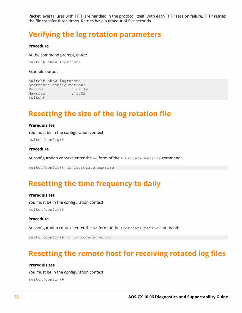
Verifying the log rotation parametersProcedure
At the command prompt, enter:
switch# show logrotate
Example output
switch# show logrotateLogrotate configurations :Period : dailyMaxsize : 10MBswitch#
Resetting the size of the log rotation filePrerequisites
You must be in the configuration context:
switch(config)#
Procedure
At configuration context, enter the no form of the logrotate maxsize command:
switch(config)# no logrotate maxsize
Resetting the time frequency to dailyPrerequisites
You must be in the configuration context:
switch(config)#
Procedure
At configuration context, enter the no form of the logrotate period command:
switch(config)# no logrotate period
Resetting the remote host for receiving rotated log filesPrerequisites
You must be in the configuration context:
switch(config)#
22 AOS-CX 10.06 Diagnostics and Supportability Guide

Procedure
At configuration context, enter the no form of the logrotate target command:
switch(config)# no logrotate target
Example:
switch(config)# logrotate target tftp://1.1.1.1switch(config)# do show logrotateLogrotate configurations :Period : dailyMaxsize : 10MBTarget : tftp://1.1.1.1switch(config)# no logrotate targetswitch(config)# do show logrotateLogrotate configurations :Period : dailyMaxsize : 10MBswitch(config)#
Log rotation not occurring immediately after reachingthresholdSymptom
Log rotation does not occur immediately after the maximum file size for the log file is reached.
Cause
The log rotation checks the size of the file on the first minute of every hour. If the maximum file size isreached in the meantime, the log rotation does not occur until the next hourly check of the file size.
Action
Log rotation is working as designed. The log rotation feature is designed to check the file size on an hourlybasis.
Log files not transferred remotelySymptom
Rotated log files are not transferred to a remote host.
Cause
• The remote host might not be reachable.
• The TFTP server on the remote host might not have sufficient privileges for file creation.
Chapter 3 Log rotation 23

Action
1. Verify that the remote host is reachable.
2. Ensure that the TFTP server is configured with the required file creation permissions.
3. For example, on the TFTPD-HPA server, change the configuration file in /etc/default/tftpd-hpa toinclude -c in TFTP_OPTIONS. (for example, TFTP_OPTIONS="--secure -c.).
Log rotation not occurring regardless of period valueSymptom
Log rotation is not happening regardless of the period value.
Cause
Log files are not rotated when they are empty files (the log file size is zero).
Action
Log rotation occurs when the log file size is greater than zero.
Log rotation commandslogrotate maxsizeSyntax
logrotate maxsize <MAX-SIZE>
no logrotate maxsize
Description
Specifies the maximum allowed log file size.
The no form of this command resets the size of the log file to the default (100 MB).
Command context
config
Parameters<MAX-SIZE>
Specifies the allowed size the log file can reach before it is compressed and stored locally or transferredto a remote host. The size is a value in the range of 10- 200 MB, and it cannot exceed 32 MB fortransferred files.
Authority
Administrators or local user group members with execution rights for this command.
Usage
A log file that exceeds either the configured <MAX-SIZE> value or the logrotate period , triggers rotationfor that log file. Log rotation occurs during the next hourly maintenance cycle.
24 AOS-CX 10.06 Diagnostics and Supportability Guide

Logs are stored locally (event logs in the /var/log/event.log file, and authentication logs inthe /var/log/auth.log file) or transferred to the configured remote destination target using TFTP.
Examples
switch(config)# logrotate maxsize 32
switch(config)# no logrotate maxsize
logrotate periodSyntax
logrotate period {daily | hourly | monthly | weekly}
no logrotate period
Description
Sets the rotate period for the event logs, stored in the /var/log/event.log file, and authentication logs,stored in the /var/log/auth.log file. Defaults to daily.
A log file that exceeds either the logrotate <MAX-SIZE> value or the logrotate period (whicheverhappens first), triggers rotation for that log file.
The no form of this command resets the log rotation period to the default.
Command context
config
Parametersdaily
Rotates log files on a daily basis (default) at 1:00 am local time.
hourlyRotates log files every hour at the first second of the hour.
monthlyRotates log files monthly on the first day of the month.
weeklyRotates log files once a week on Sunday.
Authority
Administrators or local user group members with execution rights for this command.
Examples
switch(config)# logrotate period weekly
Chapter 3 Log rotation 25

logrotate targetSyntax
logrotate target {tftp://<IPV4_ADDR> | tftp://<IPV6_ADDR>}
no logrotate target
Description
Specifies the target remote host Universal Resource Identifier (URI) using TFTP protocol to allow transfer ofrotated and compressed files to a remote target. Rotated log files are stored locally (event logs inthe /var/log/event.log file, and authentication logs in the /var/log/auth.log file) or transferred tothe configured remote destination target.
The no form of this command resets the target to the default, which stores the rotated and compressed logfiles locally in /var/log/ .
Command context
config
Parameters<IPV4_ADDR>
Specifies an IPv4 IP Address location for log file storage.
<IPV6_ADDR>Specifies an IPv6 IP Address location for log file storage.
Authority
Administrators or local user group members with execution rights for this command.
Usage
To transfer rotated log files remotely, use the TFTP protocol only, and make sure that the rotated log file isless than 32 MB in size. Use the Linux TFTP command to transfer the file. The rotated log file is removedfrom the local path/var/log/ when the log file is moved to a TFTP server.
Examples
Setting an IPv4 target:
switch(config)# logrotate target tftp://192.168.1.132Setting an IPv6 target:
switch(config)# logrotate target tftp://2001:db8:0:1::128Removing a logrotate target :
switch(config)# logrotate target tftp://1.1.1.1 switch(config)# do show logrotate Logrotate configurations : Period : daily Maxsize : 10MB Target : tftp://1.1.1.1
switch(config)# no logrotate target switch(config)# do show logrotate Logrotate configurations :
26 AOS-CX 10.06 Diagnostics and Supportability Guide

Period : daily Maxsize : 10MB
switch(config)#
show logrotateSyntax
show logrotate [vsx-peer]
Description
Displays logrotate configuration details.
Command context
Manager (#)
Parameters[vsx-peer]
Shows the output from the VSX peer switch. If the switches do not have the VSX configuration or the ISLis down, the output from the VSX peer switch is not displayed. This parameter is available on switchesthat support VSX.
Authority
Administrators or local user group members with execution rights for this command.
Examples
switch# show logrotateLogrotate configurations :Period : dailyMaxsize : 100MBswitch#
Chapter 3 Log rotation 27

bluetooth disableSyntax
bluetooth disable
no bluetooth disable
Description
Disables the Bluetooth feature on the switch. The Bluetooth feature includes both Bluetooth Classic andBluetooth Low Energy (BLE). Bluetooth is enabled by default.
The no form of this command enables the Bluetooth feature on the switch.
Command context
config
Authority
Administrators or local user group members with execution rights for this command.
Example
Disabling Bluetooth on the switch. <XXXX> is the switch platform and <NNNNNNNNNN> is the deviceidentifier.
switch(config)# bluetooth disableswitch# show bluetoothEnabled : NoDevice name : <XXXX>-<NNNNNNNNNN>
switch(config)# show running-config...bluetooth disabled...
bluetooth enableSyntax
bluetooth enable
no bluetooth enable
Description
This command enables the Bluetooth feature on the switch. The Bluetooth feature includes both BluetoothClassic and Bluetooth Low Energy (BLE).
Default: Bluetooth is enabled by default.
Chapter 4Switch system and hardware commands
28 AOS-CX 10.06 Diagnostics and Supportability Guide
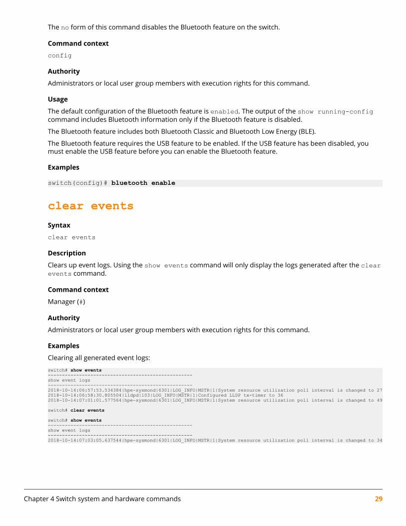
The no form of this command disables the Bluetooth feature on the switch.
Command context
config
Authority
Administrators or local user group members with execution rights for this command.
Usage
The default configuration of the Bluetooth feature is enabled. The output of the show running-configcommand includes Bluetooth information only if the Bluetooth feature is disabled.
The Bluetooth feature includes both Bluetooth Classic and Bluetooth Low Energy (BLE).
The Bluetooth feature requires the USB feature to be enabled. If the USB feature has been disabled, youmust enable the USB feature before you can enable the Bluetooth feature.
Examples
switch(config)# bluetooth enable
clear eventsSyntax
clear events
Description
Clears up event logs. Using the show events command will only display the logs generated after the clearevents command.
Command context
Manager (#)
Authority
Administrators or local user group members with execution rights for this command.
Examples
Clearing all generated event logs:
switch# show events---------------------------------------------------show event logs---------------------------------------------------2018-10-14:06:57:53.534384|hpe-sysmond|6301|LOG_INFO|MSTR|1|System resource utilization poll interval is changed to 272018-10-14:06:58:30.805504|lldpd|103|LOG_INFO|MSTR|1|Configured LLDP tx-timer to 362018-10-14:07:01:01.577564|hpe-sysmond|6301|LOG_INFO|MSTR|1|System resource utilization poll interval is changed to 49
switch# clear events
switch# show events---------------------------------------------------show event logs---------------------------------------------------2018-10-14:07:03:05.637544|hpe-sysmond|6301|LOG_INFO|MSTR|1|System resource utilization poll interval is changed to 34
Chapter 4 Switch system and hardware commands 29

clear ip errorsSyntax
clear ip errors
Description
Clears all IP error statistics.
Command context
Manager (#)
Authority
Administrators or local user group members with execution rights for this command.
Example
Clearing and showing ip errors:
switch# clear ip errorsswitch# show ip errors----------------------------------Drop reason Packets----------------------------------Malformed packets 0IP address errors 0...
domain-nameSyntax
domain-name <NAME>
no domain-name [<NAME>]
Description
Specifies the domain name of the switch.
The no form of this command sets the domain name to the default, which is no domain name.
Command context
config
Parameters<NAME>
Specifies the domain name to be assigned to the switch. The first character of the name must be a letteror a number. Length: 1 to 32 characters.
Authority
Administrators or local user group members with execution rights for this command.
30 AOS-CX 10.06 Diagnostics and Supportability Guide

Examples
Setting and showing the domain name:
switch# show domain-name
switch# configswitch(config)# domain-name example.comswitch(config)# show domain-nameexample.comswitch(config)#Setting the domain name to the default value:
switch(config)# no domain-nameswitch(config)# show domain-name
switch(config)#
hostnameSyntax
hostname <HOSTNAME>
no hostname [<HOSTNAME>]
Description
Sets the host name of the switch.
The no form of this command sets the host name to the default value, which is switch.
Command context
config
Parameters<HOSTNAME>
Specifies the host name. The first character of the host name must be a letter or a number. Length: 1 to32 characters. Default: switch
Authority
Administrators or local user group members with execution rights for this command.
Examples
Setting and showing the host name:
switch# show hostnameswitchswitch# configswitch(config)# hostname myswitchmyswitch(config)# show hostnamemyswitchSetting the host name to the default value:
Chapter 4 Switch system and hardware commands 31

myswitch(config)# no hostnameswitch(config)#
led locatorSyntax
led locator {on | off | flashing}
Description
Sets the state of the locator LED to on, off (default), or flashing.
Command context
Manager (#)
Parameterson
Turns on the LED.
offTurns off the LED, which is the default value.
flashingSets the LED to blink on and off repeatedly.
Authority
Administrators or local user group members with execution rights for this command.
Example
Setting the state of the locator LED:
switch# led locator flashing
module admin-stateSyntax
module <SLOT-ID> admin-state {diagnostic | down | up} Not supported on the 6300 Switch Series.
Description
Sets the administrative state of the specified line module.
Command context
config
32 AOS-CX 10.06 Diagnostics and Supportability Guide

Parameters<SLOT-ID>
Specifies the member and slot of the module. For example, to specify the module in member 1, slot 3,enter the following:
1/3admin-state {diagnostic | down | up}
Selects the administrative state in which to put the specified module:diagnostic
Selects the diagnostic administrative state. Network traffic does not pass through the module.
downSelects the down administrative state. Network traffic does not pass through the module.
upSelects the up administrative state. The line module is fully operational. The up state is the defaultadministrative state.
Authority
Administrators or local user group members with execution rights for this command.
Example
Setting the administrative state of the module in slot 1/3 to down:
switch(config)# module 1/3 admin-state down
module product-numberSyntax
module <SLOT-ID> product-number [<PRODUCT-NUM>]
no module <SLOT-ID>Not supported on the 6300 Switch Series.
Description
Changes the configuration of the switch to indicate that the specified member and slot number contains, orwill contain, a line module.
The no form of this command removes the line module and its interfaces from the configuration. If there isa line module installed in the slot, the line module is powered off and then powered on.
Command context
config
Parameters<SLOT-ID>
Specifies the member and slot in the form m/s, where m is the member number, and s is the slotnumber.
Chapter 4 Switch system and hardware commands 33

<PRODUCT-NUM>
Specifies the product number of the line module. For example: JL363AIf there is a line module installed in the slot when you execute this command, <PRODUCT-NUM> isoptional. The switch reads the product number information from the module that is installed in the slot.
If there is no line module installed in the slot when you execute this command, <PRODUCT-NUM> isrequired.
Authority
Administrators or local user group members with execution rights for this command.
Usage
The default configuration associated with a line module slot is:
• There is no module product number or interface configuration information associated with the slot. Theslot is available for the installation with any supported line module.
• The Admin State is Up (which is the default value for Admin State).
To add a line module to the configuration, you must use the module command either before or after youinstall the physical module.
If you execute the module command after you install a line module in an empty slot, you can omit the<PRODUCT-NUM> variable. The switch reads the product information from the installed module.
If the module is not installed in the slot when you execute the module command, you must specify a valuefor the <PRODUCT-NUM> variable:
• The switch validates the product number of the module against the slot number you specify to ensurethat the right type of module is configured for the specified slot.
For example, the switch returns an error if you specify the product number of a line module for a slotreserved for management modules.
• You can configure the line module interfaces before the line module is installed.
When you install the physical line module in a preconfigured slot, the following actions occur:
• If a product number was specified in the command and it matches the product number of the installedmodule, the switch initializes the module.
• If a product number was specified in the command and the product number of the module does notmatch what was specified, the module device initialization fails.
The no form of the command removes the line module and its interfaces from the configuration andrestores the line module slot to the default configuration.
If there is a line module installed in the slot when you execute the no form of the command, the commandalso powers off and then powers on the module. Traffic passing through the line module is stopped.Management sessions connected through the line module are also affected.
If the slot associated with the line module is in the default configuration, you can remove the module fromthe chassis without disrupting the operation of the switch.
Examples
Configuring slot 1/1 for future installation of a line module:
34 AOS-CX 10.06 Diagnostics and Supportability Guide

switch(config)# module 1/1 product-number jl363aConfiguring a line module that is already installed in slot 1/1:
switch(config)# module 1/1 product-numberAttempting to configure slot 1/1 for the future installation of a line module without specifying the productnumber (returned error shown):
switch(config)# module 1/1 product-numberLine module '1/4' is not physically available. Please provide the productnumber to preconfigure the line module.Removing a module from the configuration:
switch(config)# no module 1/1This command will power cycle the specified line module and restore its defaultconfiguration. Any traffic passing through the line module will be interrupted.Management sessions connected through the line module will be affected. Itmight take a few minutes to complete this operation.
Do you want to continue (y/n)? yswitch(config)#
show bluetoothSyntax
show bluetooth
Description
Shows general status information about the Bluetooth wireless management feature on the switch.
Command context
Operator (>) or Manager (#)
Authority
Operators or Administrators or local user group members with execution rights for this command.Operators can execute this command from the operator context (>) only.
Usage
This command shows status information about the following:
• The USB Bluetooth adapter
• Clients connected using Bluetooth
• The switch Bluetooth feature.
The output of the show running-config command includes Bluetooth information only if the Bluetoothfeature is disabled.
The device name given to the switch includes the switch serial number to uniquely identify the switch whilepairing with a mobile device.
The management IP address is a private network address created for managing the switch through aBluetooth connection.
Chapter 4 Switch system and hardware commands 35
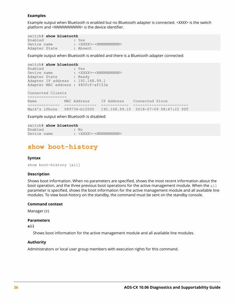
Examples
Example output when Bluetooth is enabled but no Bluetooth adapter is connected. <XXXX> is the switchplatform and <NNNNNNNNNN> is the device identifier.
switch# show bluetoothEnabled : YesDevice name : <XXXX>-<NNNNNNNNNN>Adapter State : AbsentExample output when Bluetooth is enabled and there is a Bluetooth adapter connected:
switch# show bluetoothEnabled : YesDevice name : <XXXX>-<NNNNNNNNNN>Adapter State : ReadyAdapter IP address : 192.168.99.1Adapter MAC address : 480fcf-af153a
Connected Clients-----------------Name MAC Address IP Address Connected Since-------------- -------------- ------------ ------------------------Mark's iPhone 089734-b12000 192.168.99.10 2018-07-09 08:47:22 PDTExample output when Bluetooth is disabled:
switch# show bluetoothEnabled : NoDevice name : <XXXX>-<NNNNNNNNNN>
show boot-historySyntax
show boot-history [all]
Description
Shows boot information. When no parameters are specified, shows the most recent information about theboot operation, and the three previous boot operations for the active management module. When the allparameter is specified, shows the boot information for the active management module and all available linemodules. To view boot-history on the standby, the command must be sent on the standby console.
Command context
Manager (#)
Parametersall
Shows boot information for the active management module and all available line modules.
Authority
Administrators or local user group members with execution rights for this command.
36 AOS-CX 10.06 Diagnostics and Supportability Guide

Usage
This command displays the boot-index, boot-ID, and up time in seconds for the current boot. If there is aprevious boot, it displays boot-index, boot-ID, reboot time (based on the time zone configured in the system)and reboot reasons. Previous boot information is displayed in reverse chronological order.
IndexThe position of the boot in the history file. Range: 0 to3.
Boot IDA unique ID for the boot . A system-generated 128-bit string.
Current Boot, up for <SECONDS> seconds
For the current boot, the show boot-history command shows the number of seconds the modulehas been running on the current software.
Timestamp boot reason
For previous boot operations, the show boot-history command shows the time at which theoperation occurred and the reason for the boot. The reason for the boot is one of the following values:
<DAEMON-NAME> crashThe daemon identified by <DAEMON-NAME> caused the module to boot.
Kernel crashThe operating system software associated with the module caused the module to boot.
Reboot requested through databaseThe reboot occurred because of a request made through the CLI or other API.
Uncontrolled rebootThe reason for the reboot is not known.
Examples
Showing the boot history of the active management module:
switch# show boot-historyManagement module=================
Index : 3Boot ID : f1bf071bdd04492bbf8439c6e479d612Current Boot, up for 22 hrs 12 mins 22 secs
Index : 2Boot ID : edfa2d6598d24e989668306c4a56a06d07 Aug 18 16:28:01 : Reboot requested through database
Index : 1Boot ID : 0bda8d0361df4a7e8e3acdc1dba5caad07 Aug 18 14:08:46 : Reboot requested through database
Index : 0Boot ID : 23da2b0e26d048d7b3f4b6721b69c11007 Aug 18 13:00:46 : Reboot requested through database switch#Showing the boot history of the active management module and all line modules:
Chapter 4 Switch system and hardware commands 37

switch# show boot-history allManagement module=================
Index : 3Boot ID : f1bf071bdd04492bbf8439c6e479d612Current Boot, up for 22 hrs 12 mins 22 secs
Index : 2Boot ID : edfa2d6598d24e989668306c4a56a06d07 Aug 18 16:28:01 : Reboot requested through database
Index : 1Boot ID : 0bda8d0361df4a7e8e3acdc1dba5caad07 Aug 18 14:08:46 : Reboot requested through database
Index : 0Boot ID : 23da2b0e26d048d7b3f4b6721b69c11007 Aug 18 13:00:46 : Reboot requested through database
Line module 1/1=================Index : 310 Aug 17 12:45:46 : dune_agent crashed...
show capacitiesSyntax
show capacities <FEATURE> [vsx-peer]
Description
Shows system capacities and their values for all features or a specific feature.
Command context
Manager (#)
Parameters<FEATURE>
Specifies a feature. For example, aaa or vrrp.
[vsx-peer]Shows the output from the VSX peer switch. If the switches do not have the VSX configuration or the ISLis down, the output from the VSX peer switch is not displayed. This parameter is available on switchesthat support VSX.
Authority
Administrators or local user group members with execution rights for this command.
Usage
Capacities are expressed in user-understandable terms. Thus they may not map to a specific hardware orsoftware resource or component. They are not intended to define a feature exhaustively.
38 AOS-CX 10.06 Diagnostics and Supportability Guide
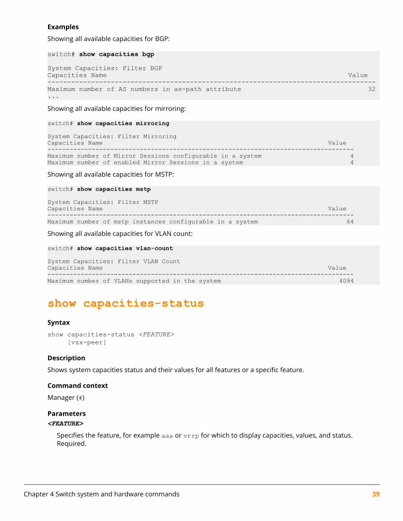
Examples
Showing all available capacities for BGP:
switch# show capacities bgp
System Capacities: Filter BGPCapacities Name Value-----------------------------------------------------------------------------------Maximum number of AS numbers in as-path attribute 32...Showing all available capacities for mirroring:
switch# show capacities mirroring
System Capacities: Filter MirroringCapacities Name Value-----------------------------------------------------------------------------------Maximum number of Mirror Sessions configurable in a system 4Maximum number of enabled Mirror Sessions in a system 4 Showing all available capacities for MSTP:
switch# show capacities mstp
System Capacities: Filter MSTPCapacities Name Value-----------------------------------------------------------------------------------Maximum number of mstp instances configurable in a system 64 Showing all available capacities for VLAN count:
switch# show capacities vlan-count
System Capacities: Filter VLAN CountCapacities Name Value-----------------------------------------------------------------------------------Maximum number of VLANs supported in the system 4094
show capacities-statusSyntax
show capacities-status <FEATURE> [vsx-peer]
Description
Shows system capacities status and their values for all features or a specific feature.
Command context
Manager (#)
Parameters<FEATURE>
Specifies the feature, for example aaa or vrrp for which to display capacities, values, and status.Required.
Chapter 4 Switch system and hardware commands 39
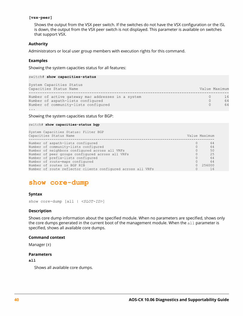
[vsx-peer]Shows the output from the VSX peer switch. If the switches do not have the VSX configuration or the ISLis down, the output from the VSX peer switch is not displayed. This parameter is available on switchesthat support VSX.
Authority
Administrators or local user group members with execution rights for this command.
Examples
Showing the system capacities status for all features:
switch# show capacities-status
System Capacities StatusCapacities Status Name Value Maximum-----------------------------------------------------------------------------------------Number of active gateway mac addresses in a system 0 16Number of aspath-lists configured 0 64Number of community-lists configured 0 64...Showing the system capacities status for BGP:
switch# show capacities-status bgp
System Capacities Status: Filter BGPCapacities Status Name Value Maximum-----------------------------------------------------------------------------------------Number of aspath-lists configured 0 64Number of community-lists configured 0 64Number of neighbors configured across all VRFs 0 50Number of peer groups configured across all VRFs 0 25Number of prefix-lists configured 0 64Number of route-maps configured 0 64Number of routes in BGP RIB 0 256000Number of route reflector clients configured across all VRFs 0 16
show core-dumpSyntax
show core-dump [all | <SLOT-ID>]
Description
Shows core dump information about the specified module. When no parameters are specified, shows onlythe core dumps generated in the current boot of the management module. When the all parameter isspecified, shows all available core dumps.
Command context
Manager (#)
Parametersall
Shows all available core dumps.
40 AOS-CX 10.06 Diagnostics and Supportability Guide
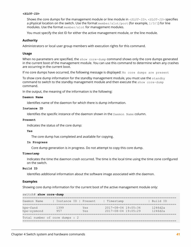
<SLOT-ID>
Shows the core dumps for the management module or line module in <SLOT-ID>. <SLOT-ID> specifiesa physical location on the switch. Use the format member/slot/port (for example, 1/3/1) for linemodules. Use the format member/slot for management modules.
You must specify the slot ID for either the active management module, or the line module.
Authority
Administrators or local user group members with execution rights for this command.
Usage
When no parameters are specified, the show core-dump command shows only the core dumps generatedin the current boot of the management module. You can use this command to determine when any crashesare occurring in the current boot.
If no core dumps have occurred, the following message is displayed: No core dumps are presentTo show core dump information for the standby management module, you must use the standbycommand to switch to the standby management module and then execute the show core-dumpcommand.
In the output, the meaning of the information is the following:
Daemon NameIdentifies name of the daemon for which there is dump information.
Instance IDIdentifies the specific instance of the daemon shown in the Daemon Name column.
PresentIndicates the status of the core dump:
YesThe core dump has completed and available for copying.
In ProgressCore dump generation is in progress. Do not attempt to copy this core dump.
TimestampIndicates the time the daemon crash occurred. The time is the local time using the time zone configuredon the switch.
Build IDIdentifies additional information about the software image associated with the daemon.
Examples
Showing core dump information for the current boot of the active management module only:
switch# show core-dump==================================================================================Daemon Name | Instance ID | Present | Timestamp | Build ID==================================================================================hpe-fand 1399 Yes 2017-08-04 19:05:34 1246d2ahpe-sysmond 957 Yes 2017-08-04 19:05:29 1246d2a==================================================================================Total number of core dumps : 2==================================================================================
Chapter 4 Switch system and hardware commands 41
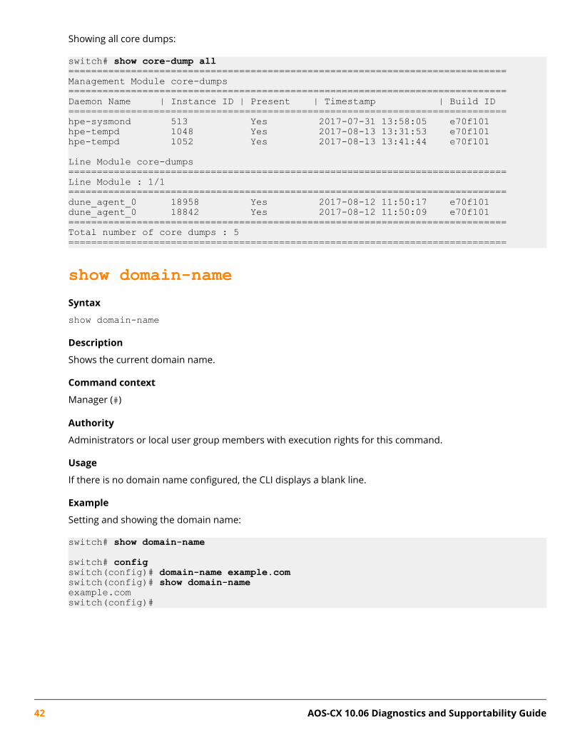
Showing all core dumps:
switch# show core-dump all=============================================================================Management Module core-dumps=============================================================================Daemon Name | Instance ID | Present | Timestamp | Build ID=============================================================================hpe-sysmond 513 Yes 2017-07-31 13:58:05 e70f101hpe-tempd 1048 Yes 2017-08-13 13:31:53 e70f101hpe-tempd 1052 Yes 2017-08-13 13:41:44 e70f101
Line Module core-dumps=============================================================================Line Module : 1/1=============================================================================dune_agent_0 18958 Yes 2017-08-12 11:50:17 e70f101dune_agent_0 18842 Yes 2017-08-12 11:50:09 e70f101=============================================================================Total number of core dumps : 5=============================================================================
show domain-nameSyntax
show domain-name
Description
Shows the current domain name.
Command context
Manager (#)
Authority
Administrators or local user group members with execution rights for this command.
Usage
If there is no domain name configured, the CLI displays a blank line.
Example
Setting and showing the domain name:
switch# show domain-name
switch# configswitch(config)# domain-name example.comswitch(config)# show domain-nameexample.comswitch(config)#
42 AOS-CX 10.06 Diagnostics and Supportability Guide

show environment fanSyntax
show environment fan [vsf | vsx-peer]
Description
Shows the status information for all fans and fan trays (if present) in the system.
Command context
Manager (#)
Parametersvsf
Shows output from the VSF member-id on switches that support VSF.
[vsx-peer]Shows the output from the VSX peer switch. If the switches do not have the VSX configuration or the ISLis down, the output from the VSX peer switch is not displayed. This parameter is available on switchesthat support VSX.
Authority
Operators or Administrators or local user group members with execution rights for this command.Operators can execute this command from the operator context (>) only.
Usage
For fan trays, Status is one of the following values:
readyThe fan tray is operating normally.
faultThe fan tray is in a fault event. The status of the fan tray does not indicate the status of fans.
emptyThe fan tray is not installed in the system.
For fans:
Speed
Indicates the relative speed of the fan based on the nominal speed range of the fan. Values are:
SlowThe fan is running at less than 25% of its maximum speed.
NormalThe fan is running at 25-49% of its maximum speed.
MediumThe fan is running at 50-74% of its maximum speed.
FastThe fan is running at 75-99% of its maximum speed.
Chapter 4 Switch system and hardware commands 43

MaxThe fan is running at 100% of its maximum speed.
N/AThe fan is not installed.
Direction
The direction of airflow through the fan. Values are:
front-to-backAir flows from the front of the system to the back of the system.
N/AThe fan is not installed.
Status
Fan status. Values are:
uninitializedThe fan has not completed initialization.
okThe fan is operating normally.
faultThe fan is in a fault state.
emptyThe fan is not installed.
Examples
Showing output for systems with fan trays for 6400 switch series:
switch# show environment fanFan tray information------------------------------------------------------------------------------Mbr/Tray Description Status Serial Number Fans------------------------------------------------------------------------------1/1 R0X32A Aruba 6400 Fan Tray ready SG9ZKJL7JW 41/2 R0X32A Aruba 6400 Fan Tray ready SG9ZKJL7GL 41/3 R0X32A Aruba 6400 Fan Tray ready SG9ZKJL78L 41/4 R0X32A Aruba 6400 Fan Tray ready SG9ZKJL7GJ 4Fan information---------------------------------------------------------------------------Mbr/Tray/Fan Product Serial Number Speed Direction Status RPM Name---------------------------------------------------------------------------1/1/1 N/A N/A slow front-to-back ok 53711/1/2 N/A N/A slow front-to-back ok 53201/1/3 N/A N/A slow front-to-back ok 53281/1/4 N/A N/A slow front-to-back ok 52561/2/1 N/A N/A slow front-to-back ok 53711/2/2 N/A N/A slow front-to-back ok 53491/2/3 N/A N/A slow front-to-back ok 52921/2/4 N/A N/A slow front-to-back ok 53491/3/1 N/A N/A slow front-to-back ok 53131/3/2 N/A N/A slow front-to-back ok 53711/3/3 N/A N/A slow front-to-back ok 5379
44 AOS-CX 10.06 Diagnostics and Supportability Guide

1/3/4 N/A N/A slow front-to-back ok 53791/4/1 N/A N/A slow front-to-back ok 53131/4/2 N/A N/A slow front-to-back ok 52991/4/3 N/A N/A slow front-to-back ok 52851/4/4 N/A N/A slow front-to-back ok 5371Showing output for a system without a fan tray:
switch# show environment fan
Fan information---------------------------------------------------------------Fan Serial Number Speed Direction Status RPM---------------------------------------------------------------1 SGXXXXXXXXXX slow front-to-back ok 60002 SGXXXXXXXXXX normal front-to-back ok 80003 SGXXXXXXXXXX medium front-to-back ok 110004 SGXXXXXXXXXX fast front-to-back ok 140005 SGXXXXXXXXXX max front-to-back fault 165006 N/A N/A N/A empty ...
show environment ledSyntax
show environment led [vsf <MEMBER-ID>| vsx-peer]
Description
Shows state and status information for all the configurable LEDs in the system.
Command context
Operator (>) or Manager (#)
Parametersvsf <MEMBER-ID>
Shows output from the specified VSF member-id on switches that support VSF.
[vsx-peer]Shows the output from the VSX peer switch. If the switches do not have the VSX configuration or the ISLis down, the output from the VSX peer switch is not displayed. This parameter is available on switchesthat support VSX.
Authority
Operators or Administrators or local user group members with execution rights for this command.Operators can execute this command from the operator context (>) only.
Example
Showing state and status for LED for 6300 or 6400 switch series:
switch# show environment ledMbr/Name State Status-------------------------------1/locator off ok
Chapter 4 Switch system and hardware commands 45

show environment power-consumptionSyntax
show environment power-consumption [vsx-peer]Not supported on the 6300 Switch Series.
Description
Shows the power being consumed by each management module, line card, and fabric card subsystem, andshows power consumption for the entire chassis.
Command context
Operator (>) or Manager (#)
Parameters[vsx-peer]
Shows the output from the VSX peer switch. If the switches do not have the VSX configuration or the ISLis down, the output from the VSX peer switch is not displayed. This parameter is available on switchesthat support VSX.
Authority
Operators or Administrators or local user group members with execution rights for this command.Operators can execute this command from the operator context (>) only.
Usage
This command is only applicable to systems that support power consumption readings.
The power consumption values are updated once every minute.
The output of this command includes the following information:
Name
Shows the member number and slot number of the management module, line module, or fabric cardmodule.
Type
Shows the type of module installed at the location specified by Name.
Description
Shows the product name and brief description of the module.
Usage
Shows the instantaneous power consumption of the module. Power consumption is shown in Watts.
Module Total Power Usage
Shows the total power consumption of all the modules listed. Power consumption is shown in Watts.
Chassis Total Power Usage
Shows the total instantaneous power consumed by the entire chassis, including modules andcomponents that do not support individual power reporting. Power consumption is shown in Watts.
Chassis Total Power Available
Shows the total amount of power, in Watts, that can be supplied to the chassis.
46 AOS-CX 10.06 Diagnostics and Supportability Guide

Chassis Total Power Allocated
Shows total power, in Watts, that is allocated to powering the chassis and its installed modules.
Chassis Total Power Unallocated
Shows the total amount of power, in Watts, that has not been allocated to powering the chassis or itsinstalled modules. This power can be used for additional hardware you install in the chassis.
Example
Showing the power consumption for an Aruba 6400 switch:
switch> show environment power-consumption PowerName Type Description Usage------------------------------------------------------------------------------1/1 management-module R0X31A 6400 Management Module 18 W1/2 management-module 0 W1/3 line-card-module 0 W1/4 line-card-module R0X39A 6400 48p 1GbE CL4 PoE 4SFP56 Mod 54 W1/5 line-card-module 0 W1/6 line-card-module R0X39A 6400 48p 1GbE CL4 PoE 4SFP56 Mod 56 W1/7 line-card-module R0X39A 6400 48p 1GbE CL4 PoE 4SFP56 Mod 51 W1/1 fabric-card-module R0X24A 6405 Chassis 71 W Module Total Power Usage 250 WChassis Total Power Usage 294 W Chassis Total Power Available 1800 W
show environment power-supplySyntax
show environment power-supply [vsf | vsx-peer]
Description
Shows status information about all power supplies in the switch.
Command context
Operator (>) or Manager (#)
Parametersvsf
Shows output from the VSF member-id on switches that support VSF.
[vsx-peer]Shows the output from the VSX peer switch. If the switches do not have the VSX configuration or the ISLis down, the output from the VSX peer switch is not displayed. This parameter is available on switchesthat support VSX.
Authority
Operators or Administrators or local user group members with execution rights for this command.Operators can execute this command from the operator context (>) only.
Chapter 4 Switch system and hardware commands 47

Usage
The following information is provided for each power supply:
Mbr/PSU
Shows the member and slot number of the power supply.
Product Number
Shows the product number of the power supply.
Serial Number
Shows the serial number of the power supply, which uniquely identifies the power supply.
PSU Status
The status of the power supply. Values are:
OKPower supply is operating normally.
OK*Power supply is operating normally, but it is the only power supply in the chassis. One power supplyis not sufficient to supply full power to the switch. When this value is shown, the output of thecommand also shows a message at the end of the displayed data.
AbsentNo power supply is installed in the specified slot.
Input faultThe power supply has a fault condition on its input.
Output faultThe power supply has a fault condition on its output.
WarningThe power supply is not operating normally.
Wattage Maximum
Shows the maximum amount of wattage that the power supply can provide.
Example
Showing the output when only one power supply is installed in an Aruba 6400 switch chassis:
switch# show environment power-supply Product Serial PSU WattageMbr/PSU Number Number Status Maximum--------------------------------------------------------------1/1 R0X36A CN91KMM2H3 OK 30001/2 N/A N/A Absent 01/3 N/A N/A Absent 01/4 N/A N/A Absent 0
show environment temperatureSyntax
show environment temperature [detail] [vsf | vsx-peer]
48 AOS-CX 10.06 Diagnostics and Supportability Guide

Description
Shows the temperature information from sensors in the switch that affect fan control.
Command context
Operator (>) or Manager (#)
Parametersdetail
Shows detailed information from each temperature sensor.
vsfShows output from the VSF member-id on switches that support VSF.
[vsx-peer]Shows the output from the VSX peer switch. If the switches do not have the VSX configuration or the ISLis down, the output from the VSX peer switch is not displayed. This parameter is available on switchesthat support VSX.
Authority
Operators or Administrators or local user group members with execution rights for this command.Operators can execute this command from the operator context (>) only.
Usage
Temperatures are shown in Celsius.
Valid values for status are the following:
normalSensor is within nominal temperature range.
minLowest temperature from this sensor.
maxHighest temperature from this sensor.
low_criticalLowest threshold temperature for this sensor.
criticalHighest threshold temperature for this sensor.
faultFault event for this sensor.
emergencyOver temperature event for this sensor.
Examples
Showing current temperature information for a 6300 switch:
switch# show environment temperatureTemperature information------------------------------------------------------------------------------
Chapter 4 Switch system and hardware commands 49

CurrentMbr/Slot-Sensor Module Type temperature Status------------------------------------------------------------------------------1/1-PHY-01-04 line-card-module 45.00 C normal1/1-PHY-05-08 line-card-module 45.00 C normal1/1-PHY-09-12 line-card-module 46.00 C normal1/1-PHY-13-16 line-card-module 47.00 C normal1/1-PHY-17-20 line-card-module 47.00 C normal1/1-PHY-21-24 line-card-module 50.00 C normal1/1-PHY-25-28 line-card-module 45.00 C normal1/1-PHY-29-32 line-card-module 47.00 C normal1/1-PHY-33-36 line-card-module 48.00 C normal1/1-PHY-37-40 line-card-module 47.00 C normal1/1-PHY-41-44 line-card-module 48.00 C normal1/1-PHY-45-48 line-card-module 49.00 C normal1/1-Switch-ASIC-Internal line-card-module 56.25 C normal
1/1-CPU-Zone-0 management-module 50.00 C normal1/1-CPU-Zone-1 management-module 50.00 C normal1/1-CPU-Zone-2 management-module 50.00 C normal1/1-CPU-Zone-3 management-module 51.00 C normal1/1-CPU-Zone-4 management-module 51.00 C normal1/1-CPU-diode management-module 53.12 C normal1/1-DDR management-module 45.25 C normal1/1-Inlet-Air management-module 24.88 C normal1/1-MB-IBC management-module 45.62 C normal1/1-Switch-ASIC-diode management-module 58.06 C normalShowing detailed temperature information for a 6300 switch:
switch# show environment temperature detailDetailed temperature information----------------------------------------------------------------Mbr/Slot-Sensor : 1/1-PHY-01-04Module Type : line-card-moduleModule Description : JL659A 6300M 48SR5 CL6 PoE 4SFP56 SwchStatus : normalFan-state : normalCurrent temperature : 45.00 CMinimum temperature : 41.00 CMaximum temperature : 50.00 C
Mbr/Slot-Sensor : 1/1-PHY-05-08Module Type : line-card-moduleModule Description : JL659A 6300M 48SR5 CL6 PoE 4SFP56 SwchStatus : normalFan-state : normalCurrent temperature : 45.00 CMinimum temperature : 41.00 CMaximum temperature : 50.00 C
...
show eventsSyntax
show events [ -e <EVENT-ID> | -s {alert | crit | debug | emer | err | info | notice | warn} | -r | -a | -i <MEMBER/SLOT> | -n <count> | -m {active | standby} |
50 AOS-CX 10.06 Diagnostics and Supportability Guide
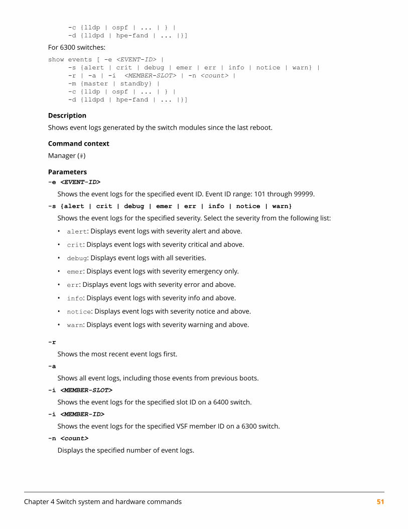
-c {lldp | ospf | ... | } | -d {lldpd | hpe-fand | ... |}]For 6300 switches:
show events [ -e <EVENT-ID> | -s {alert | crit | debug | emer | err | info | notice | warn} | -r | -a | -i <MEMBER-SLOT> | -n <count> | -m {master | standby} | -c {lldp | ospf | ... | } | -d {lldpd | hpe-fand | ... |}]
Description
Shows event logs generated by the switch modules since the last reboot.
Command context
Manager (#)
Parameters-e <EVENT-ID>
Shows the event logs for the specified event ID. Event ID range: 101 through 99999.
-s {alert | crit | debug | emer | err | info | notice | warn}Shows the event logs for the specified severity. Select the severity from the following list:
• alert: Displays event logs with severity alert and above.
• crit: Displays event logs with severity critical and above.
• debug: Displays event logs with all severities.
• emer: Displays event logs with severity emergency only.
• err: Displays event logs with severity error and above.
• info: Displays event logs with severity info and above.
• notice: Displays event logs with severity notice and above.
• warn: Displays event logs with severity warning and above.
-rShows the most recent event logs first.
-aShows all event logs, including those events from previous boots.
-i <MEMBER-SLOT>Shows the event logs for the specified slot ID on a 6400 switch.
-i <MEMBER-ID>Shows the event logs for the specified VSF member ID on a 6300 switch.
-n <count>Displays the specified number of event logs.
Chapter 4 Switch system and hardware commands 51

-m {active | standby}Shows the event logs for the specified management card role on an 8400 or 6400 switch. Selecting activedisplays the event log for the AMM management card role and standby displays event logs for the SMMmanagement card role.
-m {master | standby}Shows the event logs for the specified role on a 6200 or 6300 switch. Selecting master displays the eventlog for the VSF master role and standby displays event logs for the VSF standby role.
-c {lldp | ospf | ... | }Shows the event logs for the specified event category. Enter show event -c for a full listing ofsupported categories with descriptions.
-d {lldpd | hpe-fand | ... |}Shows the event logs for the specified process. Enter show event -d for a full listing of supporteddaemons with descriptions.
Authority
Auditors or Administrators or local user group members with execution rights for this command. Auditorscan execute this command from the auditor context (auditor>) only.
Examples
Showing event logs:
switch# show events ---------------------------------------------------show event logs---------------------------------------------------2016-12-01:12:37:31.733551|lacpd|15007|INFO|AMM|1|LACP system ID set to 70:72:cf:51:50:7c2016-12-01:12:37:31.734541|intfd|4001|INFO|AMM|1|Interface port_admin set to up for bridge_normal interface2016-12-01:12:37:32.583256|switchd|24002|ERR|AMM|1|Failed to create VLAN 1 in Hardware
Showing the most recent event logs first:
switch# show events -r---------------------------------------------------show event logs---------------------------------------------------2016-12-01:12:37:32.583256|switchd|24002|ERR|AMM|1|Failed to create VLAN 1 in Hardware2016-12-01:12:37:31.734541|intfd|4001|INFO|AMM|1|Interface port_admin set to up for bridge_normal interface2016-12-01:12:37:31.733551|lacpd|15007|INFO|AMM|1|LACP system ID set to 70:72:cf:51:50:7c
Showing all event logs:
switch# show events -a---------------------------------------------------show event logs---------------------------------------------------2016-12-01:12:37:31.733551|lacpd|15007|INFO|AMM|1|LACP system ID set to 70:72:cf:51:50:7c2016-12-01:12:37:31.734541|intfd|4001|INFO|AMM|1|Interface port_admin set to up for bridge_normal interface2016-12-01:12:37:32.583256|switchd|24002|ERR|AMM|1|Failed to create VLAN 1 in Hardware
Showing event logs related to the DHCP relay agent:
switch# show events -c dhcp-relay2016-05-31:06:26:27.363923|hpe-relay|110001|LOG_INFO|DHCP Relay Enabled2016-05-31:07:08:51.351755|hpe-relay|110002|LOG_INFO|DHCP Relay DisabledShowing event logs related to the DHCPv6 relay agent:
switch# show events -c dhcpv6-relay2016-05-31:06:26:27.363923|hpe-relay|109001|LOG_INFO|DHCPv6 Relay Enabled2016-05-31:07:08:51.351755|hpe-relay|109002|LOG_INFO|DHCPv6 Relay DisabledShowing event logs related to IRDP:
52 AOS-CX 10.06 Diagnostics and Supportability Guide

switch# switch# show events -c irdp2016-05-31:06:26:27.363923|hpe-rdiscd|111001|LOG_INFO|IRDP enabled on interface %s2016-05-31:07:08:51.351755|hpe-rdiscd|111002|LOG_INFO|IRDP disabled on interface %sShowing event logs related to LACP:
switch# show events -c lacp---------------------------------------------------show event logs---------------------------------------------------2016-12-01:12:37:31.733551|lacpd|15007|INFO|AMM|1|LACP system ID set to 70:72:cf:51:50:7cShowing event logs as per the specified management card role for a switch:switch# show events -m master---------------------------------------------------show event logs ---------------------------------------------------2020-04-22T05:36:13.348594+00:00 6300 lldpd[3055]: Event|109|LOG_INFO|MSTR|1|Configured LLDP tx-delay to 22020-04-22T05:36:14.430166+00:00 6300 vrfmgrd[3053]: Event|5401|LOG_INFO|MSTR|1|Created a vrf entity b1721d27-41c2-485d-9bae-2cfcbc9bd13d2020-04-22T05:36:14.942597+00:00 6300 vrfmgrd[3053]: Event|5401|LOG_INFO|MSTR|1|Created a vrf entity 5eb532c9-5b4d-4d83-b34a-db24ae542d4e
Showing event logs as per the specified slot ID:switch# show events -i 1---------------------------------------------------Event logs from current boot ---------------------------------------------------2020-04-22T05:36:14.430166+00:00 6300 vrfmgrd[3053]: Event|5401|LOG_INFO|MSTR|1|Created a vrf entity b1721d27-41c2-485d-9bae-2cfcbc9bd13d2020-04-22T05:36:14.942597+00:00 6300 vrfmgrd[3053]: Event|5401|LOG_INFO|MSTR|1|Created a vrf entity 5eb532c9-5b4d-4d83-b34a-db24ae542d4e2020-04-22T05:36:15.886252+00:00 6300 vsfd[710]: Event|9903|LOG_INFO|MSTR|1|Master 1 boot complete
Showing event logs as per the specified process:
switch# show events -d lacpd---------------------------------------------------show event logs---------------------------------------------------2016-12-01:12:37:31.733551|lacpd|15007|INFO|AMM|1|LACP system ID set to 70:72:cf:51:50:7cDisplaying the specified number of event logs:
switch# show events -n 5---------------------------------------------------show event logs---------------------------------------------------2018-03-21:06:12:15.500603|arpmgrd|6101|LOG_INFO|AMM|-|ARPMGRD daemon has started2018-03-21:06:12:17.734405|lldpd|109|LOG_INFO|AMM|-|Configured LLDP tx-delay to 22018-03-21:06:12:17.740517|lacpd|1307|LOG_INFO|AMM|-|LACP system ID set to 70:72:cf:d4:34:422018-03-21:06:12:17.743491|vrfmgrd|5401|LOG_INFO|AMM|-|Created a vrf entity 42cc3df7-1113-412f-b5cb-e8227b8c22f22018-03-21:06:12:17.904008|vrfmgrd|5401|LOG_INFO|AMM|-|Created a vrf entity 4409133e-2071-4ab8-adfe-f9662c06b889
show fabricSyntax
show fabric [<SLOT-ID>] [vsx-peer]Not supported on the 6300 Switch Series.
Description
Shows information about the installed fabrics.
Command context
Operator (>) or Manager (#)
Chapter 4 Switch system and hardware commands 53
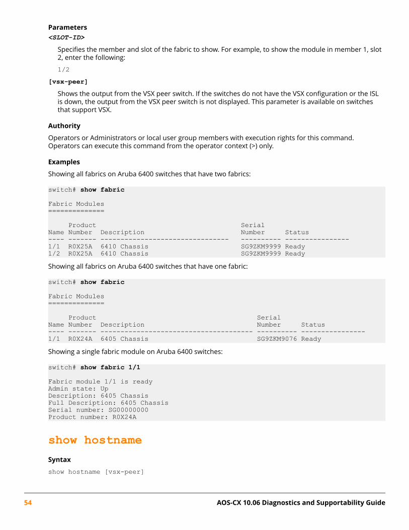
Parameters<SLOT-ID>
Specifies the member and slot of the fabric to show. For example, to show the module in member 1, slot2, enter the following:
1/2[vsx-peer]
Shows the output from the VSX peer switch. If the switches do not have the VSX configuration or the ISLis down, the output from the VSX peer switch is not displayed. This parameter is available on switchesthat support VSX.
Authority
Operators or Administrators or local user group members with execution rights for this command.Operators can execute this command from the operator context (>) only.
Examples
Showing all fabrics on Aruba 6400 switches that have two fabrics:
switch# show fabric
Fabric Modules==============
Product SerialName Number Description Number Status---- ------- -------------------------------- ---------- ----------------1/1 R0X25A 6410 Chassis SG9ZKM9999 Ready1/2 R0X25A 6410 Chassis SG9ZKM9999 ReadyShowing all fabrics on Aruba 6400 switches that have one fabric:
switch# show fabric
Fabric Modules==============
Product SerialName Number Description Number Status---- ------- -------------------------------------- ---------- ----------------1/1 R0X24A 6405 Chassis SG9ZKM9076 ReadyShowing a single fabric module on Aruba 6400 switches:
switch# show fabric 1/1
Fabric module 1/1 is readyAdmin state: UpDescription: 6405 ChassisFull Description: 6405 ChassisSerial number: SG00000000Product number: R0X24A
show hostnameSyntax
show hostname [vsx-peer]
54 AOS-CX 10.06 Diagnostics and Supportability Guide
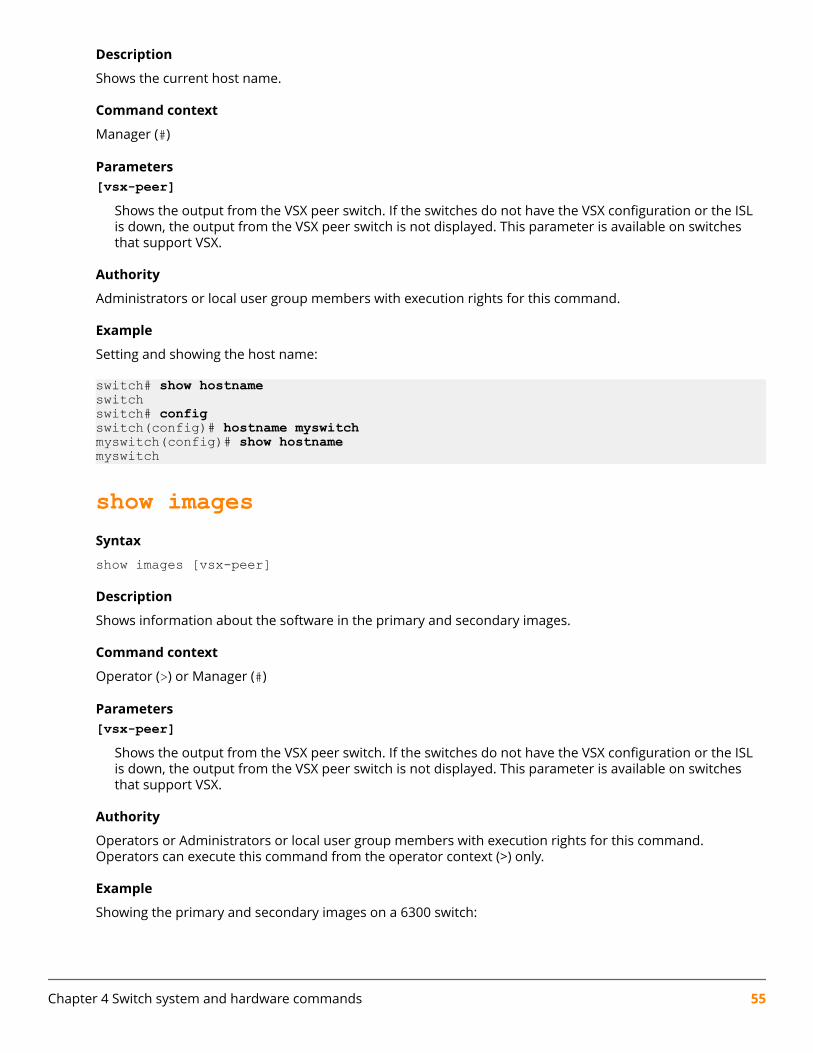
Description
Shows the current host name.
Command context
Manager (#)
Parameters[vsx-peer]
Shows the output from the VSX peer switch. If the switches do not have the VSX configuration or the ISLis down, the output from the VSX peer switch is not displayed. This parameter is available on switchesthat support VSX.
Authority
Administrators or local user group members with execution rights for this command.
Example
Setting and showing the host name:
switch# show hostnameswitchswitch# configswitch(config)# hostname myswitchmyswitch(config)# show hostnamemyswitch
show imagesSyntax
show images [vsx-peer]
Description
Shows information about the software in the primary and secondary images.
Command context
Operator (>) or Manager (#)
Parameters[vsx-peer]
Shows the output from the VSX peer switch. If the switches do not have the VSX configuration or the ISLis down, the output from the VSX peer switch is not displayed. This parameter is available on switchesthat support VSX.
Authority
Operators or Administrators or local user group members with execution rights for this command.Operators can execute this command from the operator context (>) only.
Example
Showing the primary and secondary images on a 6300 switch:
Chapter 4 Switch system and hardware commands 55
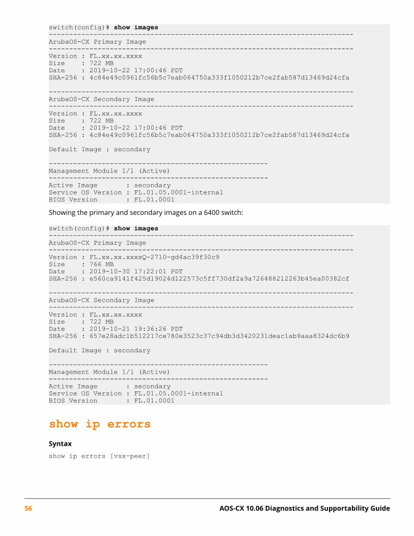
switch(config)# show images---------------------------------------------------------------------------ArubaOS-CX Primary Image---------------------------------------------------------------------------Version : FL.xx.xx.xxxxSize : 722 MBDate : 2019-10-22 17:00:46 PDTSHA-256 : 4c84e49c0961fc56b5c7eab064750a333f1050212b7ce2fab587d13469d24cfa
---------------------------------------------------------------------------ArubaOS-CX Secondary Image---------------------------------------------------------------------------Version : FL.xx.xx.xxxxSize : 722 MBDate : 2019-10-22 17:00:46 PDTSHA-256 : 4c84e49c0961fc56b5c7eab064750a333f1050212b7ce2fab587d13469d24cfa
Default Image : secondary
------------------------------------------------------Management Module 1/1 (Active)------------------------------------------------------Active Image : secondaryService OS Version : FL.01.05.0001-internalBIOS Version : FL.01.0001Showing the primary and secondary images on a 6400 switch:
switch(config)# show images---------------------------------------------------------------------------ArubaOS-CX Primary Image---------------------------------------------------------------------------Version : FL.xx.xx.xxxxQ-2710-gd4ac39f30c9Size : 766 MBDate : 2019-10-30 17:22:01 PDTSHA-256 : e560ca9141f425d19024d122573c5ff730df2a9a726488212263b45ea00382cf
---------------------------------------------------------------------------ArubaOS-CX Secondary Image---------------------------------------------------------------------------Version : FL.xx.xx.xxxxSize : 722 MBDate : 2019-10-21 19:36:26 PDTSHA-256 : 657e28adc1b512217ce780e3523c37c94db3d3420231deac1ab9aaa8324dc6b9
Default Image : secondary
------------------------------------------------------Management Module 1/1 (Active)------------------------------------------------------Active Image : secondaryService OS Version : FL.01.05.0001-internalBIOS Version : FL.01.0001
show ip errorsSyntax
show ip errors [vsx-peer]
56 AOS-CX 10.06 Diagnostics and Supportability Guide

Description
Shows IP error statistics for packets received by the switch since the switch was last booted.
Command context
Operator (>) or Manager (#)
Parameters[vsx-peer]
Shows the output from the VSX peer switch. If the switches do not have the VSX configuration or the ISLis down, the output from the VSX peer switch is not displayed. This parameter is available on switchesthat support VSX.
Authority
Operators or Administrators or local user group members with execution rights for this command.Operators can execute this command from the operator context (>) only.
Usage
IP error info about received packets is collected from each active line card on the switch and is preservedduring failover events. Error counts are cleared when the switch is rebooted.
Drop reasons are the following:
Malformed packet
The packet does not conform to TCP/IP protocol standards such as packet length or internet headerlength.
A large number of malformed packets can indicate that there are hardware malfunctions such as loosecables, network card malfunctions, or that a DOS (denial of service) attack is occurring.
IP address error
The packet has an error in the destination or source IP address. Examples of IP address errors includethe following:
• The source IP address and destination IP address are the same.
• There is no destination IP address.
• The source IP address is a multicast IP address.
• The forwarding header of an IPv6 address is empty.
• There is no source IP address for an IPv6 packet.
Invalid TTLs
The TTL (time to live) value of the packet reached zero. The packet was discarded because it traversedthe maximum number of hops permitted by the TTL value.
TTLs are used to prevent packets from being circulated on the network endlessly.
Example
Showing ip error statistics for packets received by the switch:
switch# show ip errors----------------------------------Drop reason Packets----------------------------------
Chapter 4 Switch system and hardware commands 57
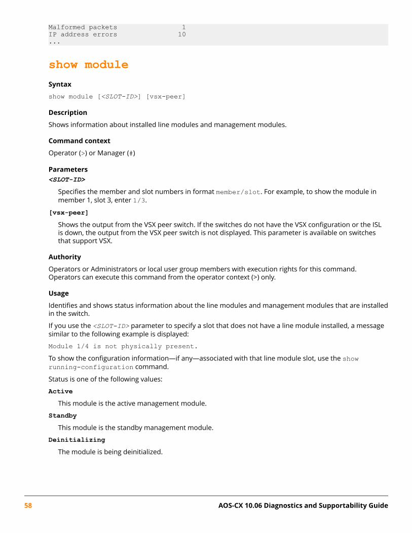
Malformed packets 1IP address errors 10...
show moduleSyntax
show module [<SLOT-ID>] [vsx-peer]
Description
Shows information about installed line modules and management modules.
Command context
Operator (>) or Manager (#)
Parameters<SLOT-ID>
Specifies the member and slot numbers in format member/slot. For example, to show the module inmember 1, slot 3, enter 1/3.
[vsx-peer]Shows the output from the VSX peer switch. If the switches do not have the VSX configuration or the ISLis down, the output from the VSX peer switch is not displayed. This parameter is available on switchesthat support VSX.
Authority
Operators or Administrators or local user group members with execution rights for this command.Operators can execute this command from the operator context (>) only.
Usage
Identifies and shows status information about the line modules and management modules that are installedin the switch.
If you use the <SLOT-ID> parameter to specify a slot that does not have a line module installed, a messagesimilar to the following example is displayed:
Module 1/4 is not physically present.To show the configuration information—if any—associated with that line module slot, use the showrunning-configuration command.
Status is one of the following values:
ActiveThis module is the active management module.
StandbyThis module is the standby management module.
DeinitializingThe module is being deinitialized.
58 AOS-CX 10.06 Diagnostics and Supportability Guide

DiagnosticThe module is in a state used for troubleshooting.
DownThe module is physically present but is powered down.
EmptyThe module hardware is not installed in the chassis.
FailedThe module has experienced an error and failed.
FailoverThis module is a fabric module or a line module, and it is in the process of connecting to the new activemanagement module during a management module failover event.
InitializingThe module is being initialized.
PresentThe module hardware is installed in the chassis.
ReadyThe module is available for use.
UpdatingA firmware update is being applied to the module.
Examples
Showing all installed modules (Aruba 6300 switch):
switch(config)# show module
Management Modules==================
Product SerialName Number Description Number Status---- ------- -------------------------------------- ---------- ----------------1/1 JL659A 6300M 48SR5 CL6 PoE 4SFP56 Swch ID9ZKHN090 Active (local)
Line Modules============
Product SerialName Number Description Number Status---- ------- -------------------------------------- ---------- ----------------1/1 JL659A 6300M 48SR5 CL6 PoE 4SFP56 Swch ID9ZKHN090 ReadyShowing a line module (Aruba 6400 switch):
switch# show module 1/3
Line module 1/3 is ready Admin state: Up Description: 6400 24p 10GT 4SFP56 Mod Full Description: 6400 24-port 10GBASE-T and 4-port SFP56 Module Serial number: SG9ZKMS045
Chapter 4 Switch system and hardware commands 59

Product number: R0X42A Power priority: 128Showing a slot that does not contain a line module:
switch(config)# show module 1/3Module 1/3 is not physically present
show running-configSyntax
show running-config [<FEATURE>] [all] [vsx-peer]
Description
Shows the current nondefault configuration running on the switch. No user information is displayed.
Command context
Manager (#)
Parameters<FEATURE>
Specifies the name of a feature. For a list of feature names, enter the show running-configcommand, followed by a space, followed by a question mark (?). When the json parameter is used, thevsx-peer parameter is not applicable.
all
Shows all default values for the current running configuration.
[vsx-peer]Shows the output from the VSX peer switch. If the switches do not have the VSX configuration or the ISLis down, the output from the VSX peer switch is not displayed. This parameter is available on switchesthat support VSX.
Authority
Administrators or local user group members with execution rights for this command.
Examples
Showing the current running configuration:
switch> show running-configCurrent configuration:!!Version ArubaOS-CX 10.0X.XXXX!lldp enablelinecard-module LC1 part-number JL363Avrf green!!!!!!aaa authentication login default local
60 AOS-CX 10.06 Diagnostics and Supportability Guide

aaa authorization commands default none!!!!router ospf 1 vrf green area 0.0.0.0router pim vrf green enable rp-address 30.0.0.4vlan 1 no shutdownvlan 20 no shutdownvlan 30 no shutdowninterface 1/1/1 no shutdown no routing vlan access 30interface 1/1/32 no shutdown no routing vlan access 20interface bridge_normal-1 no shutdowninterface bridge_normal-2 no shutdowninterface vlan20 no shutdown vrf attach green ip address 20.0.0.44/24 ip ospf 1 area 0.0.0.0 ip pim-sparse enable
interface vlan30 no shutdown vrf attach green ip address 30.0.0.44/24 ip ospf 1 area 0.0.0.0 ip pim-sparse enable
ip pim-sparse hello-interval 100Showing the current running configuration in json format:
switch> show running-config jsonRunning-configuration in JSON:{ "Monitoring_Policy_Script": { "system_resource_monitor_mm1.1.0": { "Monitoring_Policy_Instance": { "system_resource_monitor_mm1.1.0/system_resource_monitor_mm1.1.0.default": { "name": "system_resource_monitor_mm1.1.0.default", "origin": "system", "parameters_values": { "long_term_high_threshold": "70", "long_term_normal_threshold": "60", "long_term_time_period": "480", "medium_term_high_threshold": "80", "medium_term_normal_threshold": "60", "medium_term_time_period": "120", "short_term_high_threshold": "90", "short_term_normal_threshold": "80", "short_term_time_period": "5" }
Chapter 4 Switch system and hardware commands 61

} },............Show the current running configuration without default values:
switch(config)# show running-configCurrent configuration:!!Version ArubaOS-CX Virtual.10.04.0000-6523-gbb15c03~dirtyled locator on!!!!!!!!!vlan 1switch(config)# show running-config allCurrent configuration:!!Version ArubaOS-CX Virtual.10.04.0000-6523-gbb15c03~dirtyled locator on!!!!!!!!!vlan 1switch(config)#Show the current running configuration with default values:
switch(config)# snmp-server vrf mgmtswitch(config)# show running-configCurrent configuration:!!Version ArubaOS-CX Virtual.10.04.0000-6523-gbb15c03~dirtyled locator on!!!!snmp-server vrf mgmt!!!!!vlan 1switch(config)#switch(config)#switch(config)# show running-config allCurrent configuration:!
62 AOS-CX 10.06 Diagnostics and Supportability Guide

!Version ArubaOS-CX Virtual.10.04.0000-6523-gbb15c03~dirtyled locator on!!!!snmp-server vrf mgmtsnmp-server agent-port 161snmp-server community public!!!!!vlan 1switch(config)#
show running-config current-contextSyntax
show running-config current-context
Description
Shows the current non-default configuration running on the switch in the current command context.
Command context
config or a child of config. See Usage.
Authority
Administrators or local user group members with execution rights for this command.
Usage
You can enter this command from the following configuration contexts:
• Any child of the global configuration (config) context. If the child context has instances—such asinterfaces—you can enter the command in the context of a specific instance.
Support for this command is provided for one level below the config context. For example, entering thiscommand for a child of a child of the config context not supported.
If you enter the command on a child of the config context, the current configuration of that context andthe children of that context are displayed.
• The global configuration (config) context.
If you enter this command in the global configuration (config) context, it shows the runningconfiguration of the entire switch. Use the show running-configuration command instead.
Examples
On the 6400 Switch Series, interface identification differs.
Showing the running configuration for the current interface:
switch(config-if)# show running-config current-contextinterface 1/1/1 vsx-sync qos vlans
Chapter 4 Switch system and hardware commands 63
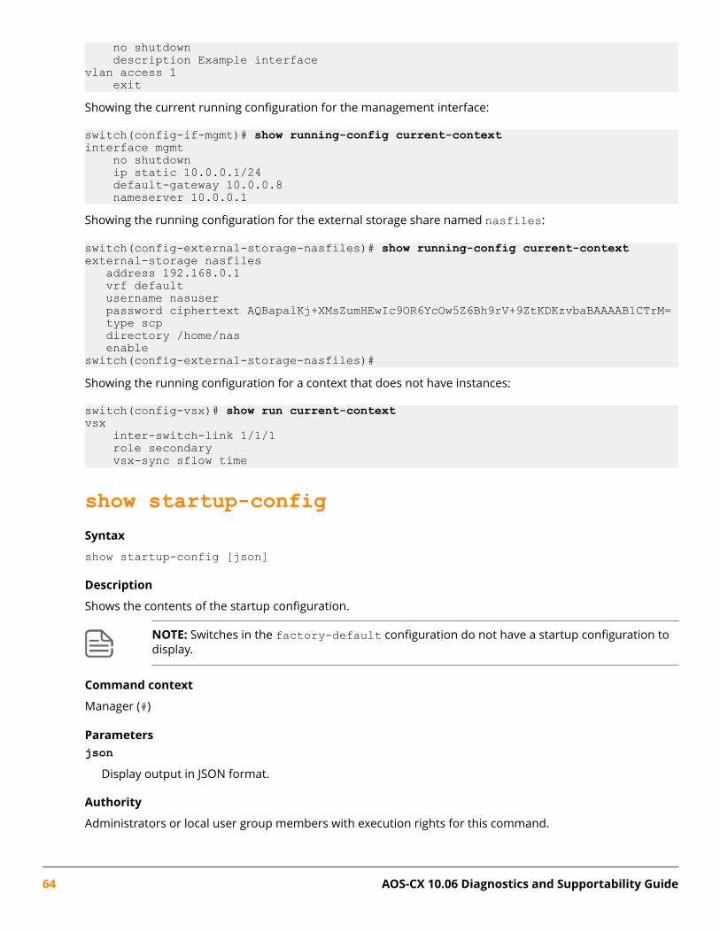
no shutdown description Example interface vlan access 1 exitShowing the current running configuration for the management interface:
switch(config-if-mgmt)# show running-config current-contextinterface mgmt no shutdown ip static 10.0.0.1/24 default-gateway 10.0.0.8 nameserver 10.0.0.1Showing the running configuration for the external storage share named nasfiles:
switch(config-external-storage-nasfiles)# show running-config current-context external-storage nasfiles address 192.168.0.1 vrf default username nasuser password ciphertext AQBapalKj+XMsZumHEwIc9OR6YcOw5Z6Bh9rV+9ZtKDKzvbaBAAAAB1CTrM= type scp directory /home/nas enableswitch(config-external-storage-nasfiles)#Showing the running configuration for a context that does not have instances:
switch(config-vsx)# show run current-context vsx inter-switch-link 1/1/1 role secondary vsx-sync sflow time
show startup-configSyntax
show startup-config [json]
Description
Shows the contents of the startup configuration.
NOTE: Switches in the factory-default configuration do not have a startup configuration todisplay.
Command context
Manager (#)
Parametersjson
Display output in JSON format.
Authority
Administrators or local user group members with execution rights for this command.
64 AOS-CX 10.06 Diagnostics and Supportability Guide

Examples
Showing the startup-configuration in non-JSON format for a 6300 switch:
switch(config)# show startup-configStartup configuration:!!Version ArubaOS-CX FL.xx.xx.xxxx!export-password: defaulthostname BLDG01-F1user admin group administrators password ciphertext AQBapWl8I2ZunZ43NE/8KlbQ7zYC4gTT6uSFYi6n6wyY9PdBYgAAACONCR/3+AcNvzRBch0DoG7W9z84LpJA+6C9SKfNwCqi5/nUPk/ZOvN91/EQXvPNkHtBtQWyYZqfkebbEH78VWRHfWZjApv4II9qmQfxpA79wEvzshdzZmuAKrmuser ateam group administrators password ciphertext AQBapcPqMXoF+H10NKrqAedXLvlSRwf4wUEL22hXGD6ZBhicYgAAAGsbh70DKg1u+Ze1wxgmDXjkGO3bseYiR3LKQg66vrfrqR/M3oLlliPdZDnq9XMMvCL+7jBbYhYes8+uDxuSTh8kdkd/qj3lo5FUuC5fENgCjU0YI1l7qtU+YEnsj!!!!radius-server host 10.10.10.15!radius dyn-authorization enablessh server vrf defaultssh server vrf mgmt!!!!!router ospf 1 router-id 1.63.63.1 area 0.0.0.0vlan 1vlan 66 name vlan66vlan 67 name vlan67vlan 999 name vlan999vlan 4000spanning-treeinterface mgmt no shutdown ip static 10.6.9.15/24 default-gateway 10.6.9.1
Showing the startup-configuration in JSON format:
switch# show startup-config jsonStartup configuration:{ "AAA_Server_Group": { "local": { "group_name": "local" }, "none": { "group_name": "none" } },...
show systemSyntax
show system [vsx-peer]
Chapter 4 Switch system and hardware commands 65

Description
Shows general status information about the system.
Command context
Operator (>) or Manager (#)
[vsx-peer]Shows the output from the VSX peer switch. If the switches do not have the VSX configuration or the ISLis down, the output from the VSX peer switch is not displayed. This parameter is available on switchesthat support VSX.
Authority
Operators or Administrators or local user group members with execution rights for this command.Operators can execute this command from the operator context (>) only.
Usage
CPU utilization represents the average utilization across all the CPU cores.
System Contact, System Location, and System Description can be set with the snmp-server command.
Examples
Showing system information on a 6300 switch:
switch(config)# show systemHostname : switchSystem Description : FL.10.xx.xxxxxSystem Contact :System Location :
Vendor : ArubaProduct Name : JL659A 6300M 48SR5 CL6 PoE 4SFP56 SwchChassis Serial Nbr : ID9ZKHN090Base MAC Address : 9020c2-245080ArubaOS-CX Version : FL.10.xx.xxxx
Time Zone : UTC
Up Time : 5 days, 15 hours, 33 minutesCPU Util (%) : 21Memory Usage (%) : 19Showing system information om a 6400 switch:
switch(config)# show systemHostname : switchSystem Description : FL.10.xx.xxxxxSystem Contact :System Location :
Vendor : ArubaProduct Name : R0X24A 6405 ChassisChassis Serial Nbr : SG9ZKM7206Base MAC Address : 9020c2-dc4700ArubaOS-CX Version : FL.10.xx.xxxxx
Time Zone : UTC
Up Time : 32 minutesCPU Util (%) : 3
66 AOS-CX 10.06 Diagnostics and Supportability Guide

Memory Usage (%) : 10BLDG02-F3(config)#
show system resource-utilizationSyntax
show system resource-utilization [daemon <DAEMON-NAME> | module <SLOT-ID>] [vsx-peer]
Description
Shows information about the usage of system resources such as CPU, memory, and open file descriptors.
Command context
Manager (#)
Parametersdaemon <DAEMON-NAME>
Shows the filtered resource utilization data for the process specified by <DAEMON-NAME> only.
NOTE: For a list of daemons that log events, enter show events -d ? from a switchprompt in the manager (#) context.
module <SLOT-ID>Shows the filtered resource utilization data for the line module specified by <SLOT-ID> only.
[vsx-peer]Shows the output from the VSX peer switch. If the switches do not have the VSX configuration or the ISLis down, the output from the VSX peer switch is not displayed. This parameter is available on switchesthat support VSX.
Authority
Administrators or local user group members with execution rights for this command.
Examples
Showing all system resource utilization data:
switch# show system resource-utilizationSystem Resources:Processes: 70CPU usage(%): 20 Memory usage(%): 25 Open FD's: 1024
Process CPU Usage(%) Memory Usage(%) Open FD's-----------------------------------------------------------------------pmd 2 1 14hpe-sysmond 1 2 11hpe-mgmdd 0 1 5...Showing the resource utilization data for the pmd process:
switch# show system resource-utilization daemon pmdProcess CPU Usage Memory Usage Open FD's
Chapter 4 Switch system and hardware commands 67

-----------------------------------------------------------------------pmd 2 1 14Showing resource utilization data when system resource utilization polling is disabled:
switch# show system resource-utilizationSystem resource utilization data poll is currently disabledShowing resource utilization data for a line module:
switch# show system resource-utilization module 1/1System Resource utilization for line card module: 1/1CPU usage(%): 0Memory usage(%): 35Open FD's: 512
show techSyntax
show tech [basic | <FEATURE>] [local-file]
Description
Shows detailed information about switch features by automatically running the show commands associatedwith the feature. If no parameters are specified, the show tech command shows information about allswitch features. Technical support personnel use the output from this command for troubleshooting.
Command context
Manager (#)
Parametersbasic
Specifies showing a basic set of information.
<FEATURE>
Specifies the name of a feature. For a list of feature names, enter the show tech command, followed bya space, followed by a question mark (?).
local-fileShows the output of the show tech command to a local text file.
Authority
Administrators or local user group members with execution rights for this command.
Usage
To terminate the output of the show tech command, enter Ctrl+C.
If the command was not terminated with Ctrl+C, at the end of the output, the show tech command showsthe following:
• The time consumed to execute the command.
• The list of failed show commands, if any.
68 AOS-CX 10.06 Diagnostics and Supportability Guide

To get a copy of the local text file content created with the show tech command that is used with the local-file parameter, use the copy show-tech local-file command.
Example
Showing the basic set of system information:
switch# show tech basic=============================================================Show Tech executed on Wed Sep 6 16:50:37 2017==========================================================================================================================[Begin] Feature basic=============================================================
*******************************Command : show core-dump all*******************************no core dumps are present
...=============================================================[End] Feature basic=============================================================
=============================================================1 show tech command failed=============================================================Failed command: 1. show boot-history=============================================================Show tech took 3.000000 seconds for executionDirecting the output of the show tech basic command to the local text file:
switch# show tech basic local-fileShow Tech output stored in local-file. Please use 'copy show-tech local-file'to copy-out this file.
show usbSyntaxshow usb
Description
Shows the USB port configuration and mount settings.
Command context
Operator (>) or Manager (#)
Parameters[vsx-peer]
Shows the output from the VSX peer switch. If the switches do not have the VSX configuration or the ISLis down, the output from the VSX peer switch is not displayed. This parameter is available on switchesthat support VSX.
Chapter 4 Switch system and hardware commands 69

Authority
Operators or Administrators or local user group members with execution rights for this command.Operators can execute this command from the operator context (>) only.
Examples
If USB has not been enabled:
switch> show usbEnabled: NoMounted: NoIf USB has been enabled, but no device has been mounted:
switch> show usbEnabled: YesMounted: NoIf USB has been enabled and a device mounted:
switch> show usbEnabled: YesMounted: Yes
show versionSyntax
show version [vsx-peer]
Description
Shows version information about the network operating system software, service operating systemsoftware, and BIOS.
Command context
Operator (>) or Manager (#)
Parameters[vsx-peer]
Shows the output from the VSX peer switch. If the switches do not have the VSX configuration or the ISLis down, the output from the VSX peer switch is not displayed. This parameter is available on switchesthat support VSX.
Authority
Operators or Administrators or local user group members with execution rights for this command.Operators can execute this command from the operator context (>) only.
Example
Showing version information for a 6300 switch:
switch(config)# show version-----------------------------------------------------------------------------ArubaOS-CX(c) Copyright 2017-2020 Hewlett Packard Enterprise Development LP-----------------------------------------------------------------------------
70 AOS-CX 10.06 Diagnostics and Supportability Guide

Version : FL.xx.xx.xxxxBuild Date : 2020-10-22 17:00:46 PDTBuild ID : ArubaOS-CX:FL.xx.xx.xxxx:85c3c2f3d59e:201910222335Build SHA : 85c3c2f3d59ec8318ba97178fad387aecb671b33Active Image : secondary
Service OS Version : FL.01.05.0001-internalBIOS Version : FL.01.0001
system resource-utilization poll-intervalSyntax
system resource-utilization poll-interval <SECONDS>
Description
Configures the polling interval for system resource information collection and recording such as CPU andmemory usage.
Command context
config
Parameters<SECONDS>
Specifies the poll interval in seconds. Range: 10-3600. Default: 10.
Authority
Administrators or local user group members with execution rights for this command.
Example
Configuring the system resource utilization poll interval:
switch(config)# system resource-utilization poll-interval 20
top cpuSyntax
top cpu
Description
Shows CPU utilization information.
Command context
Manager (#)
Authority
Operators or Administrators or local user group members with execution rights for this command.Operators can execute this command from the operator context (>) only.
Chapter 4 Switch system and hardware commands 71
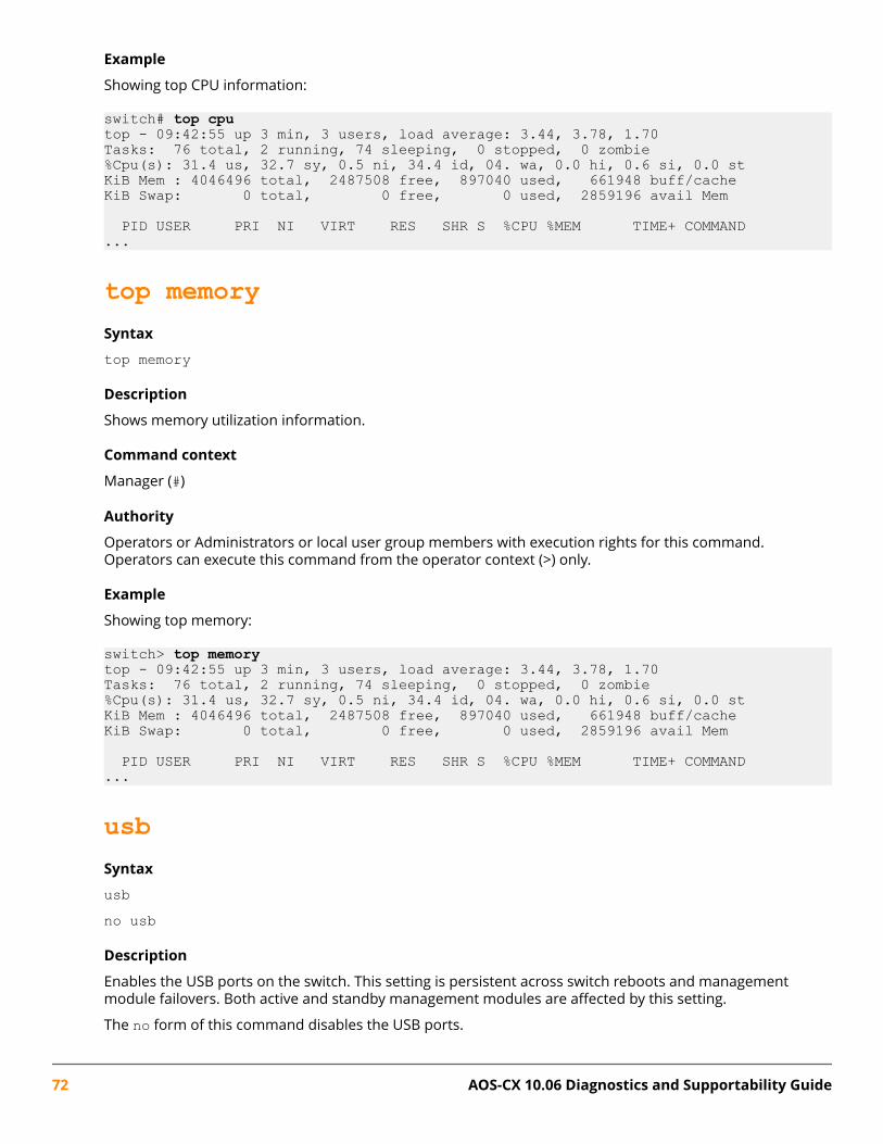
Example
Showing top CPU information:
switch# top cputop - 09:42:55 up 3 min, 3 users, load average: 3.44, 3.78, 1.70Tasks: 76 total, 2 running, 74 sleeping, 0 stopped, 0 zombie%Cpu(s): 31.4 us, 32.7 sy, 0.5 ni, 34.4 id, 04. wa, 0.0 hi, 0.6 si, 0.0 stKiB Mem : 4046496 total, 2487508 free, 897040 used, 661948 buff/cacheKiB Swap: 0 total, 0 free, 0 used, 2859196 avail Mem
PID USER PRI NI VIRT RES SHR S %CPU %MEM TIME+ COMMAND...
top memorySyntax
top memory
Description
Shows memory utilization information.
Command context
Manager (#)
Authority
Operators or Administrators or local user group members with execution rights for this command.Operators can execute this command from the operator context (>) only.
Example
Showing top memory:
switch> top memorytop - 09:42:55 up 3 min, 3 users, load average: 3.44, 3.78, 1.70Tasks: 76 total, 2 running, 74 sleeping, 0 stopped, 0 zombie%Cpu(s): 31.4 us, 32.7 sy, 0.5 ni, 34.4 id, 04. wa, 0.0 hi, 0.6 si, 0.0 stKiB Mem : 4046496 total, 2487508 free, 897040 used, 661948 buff/cacheKiB Swap: 0 total, 0 free, 0 used, 2859196 avail Mem
PID USER PRI NI VIRT RES SHR S %CPU %MEM TIME+ COMMAND...
usbSyntax
usbno usb
Description
Enables the USB ports on the switch. This setting is persistent across switch reboots and managementmodule failovers. Both active and standby management modules are affected by this setting.
The no form of this command disables the USB ports.
72 AOS-CX 10.06 Diagnostics and Supportability Guide

Command context
config
Authority
Administrators or local user group members with execution rights for this command.
Example
Enabling USB ports:
switch(config)# usbDisabling USB ports when a USB drive is mounted:
switch(config)# no usb
usb mount/unmountSyntax
usb {mount | unmount}
Description
Enables or disables a USB drive in a USB port.
Command context
Manager (#)
Parametersmount
Enables the inserted USB drive.
unmountDisables the inserted USB drive in preparation for removal.
Authority
Administrators or local user group members with execution rights for this command.
Usage
If USB has been enabled in the configuration, the USB port on the active management module is availablefor mounting a USB drive. The USB port on the standby management module is not available.
An inserted USB drive must be mounted each time the switch boots or fails over to a different managementmodule.
A USB drive must be unmounted before removal.
The supported USB file system formats are FAT16 and FAT32.
Examples
Mounting a USB drive in the USB port of the active management module:
Chapter 4 Switch system and hardware commands 73
switch# usb mount Unmounting a USB drive:
switch# usb unmount
74 AOS-CX 10.06 Diagnostics and Supportability Guide
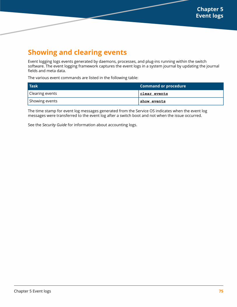
Showing and clearing eventsEvent logging logs events generated by daemons, processes, and plug-ins running within the switchsoftware. The event logging framework captures the event logs in a system journal by updating the journalfields and meta data.
The various event commands are listed in the following table:
Task Command or procedure
Clearing events clear eventsShowing events show events
The time stamp for event log messages generated from the Service OS indicates when the event logmessages were transferred to the event log after a switch boot and not when the issue occurred.
See the Security Guide for information about accounting logs.
Chapter 5Event logs
Chapter 5 Event logs 75

OverviewThe Time-Domain Reflectometer (TDR) feature helps characterize and locate cable faults in the twisted wirepairs. TDR involves showing a reflection at any impedance change within the cable when a low voltage pulseis sent into the cable. TDR measures the time between release and return of the low voltage pulse from anyreflections. The distance to the reflection can be calculated by measuring the time and the transmissionvelocity of the pulse.
TDR or Cable Diagnostics is a port feature supported on some switches running ArubaOS-CX software. TDRis used to detect cable faults on 1GbT, 2.5G-SmartRate, 5G-SmartRate, and 10G-SmartRate (only applicablefor 6400 switch) ports.
How TDR works on ArubaOS-CX platforms
The implementation of TDR in ArubaOS-CX platforms is dependent on the physical layer chips (PHYs) thatare part of the front-end network ports hardware. ArubaOS-CX switches activate TDR on the PHY when auser enters the diag cable-diagnostic command. The switch waits for the report about TDRmeasurements from the PHY. The switch then reads the results and reports the values to the user.
Cable diagnostics testsNOTE: The cable diagnostics test will bring down the link, which will take more time to completethe test.
The TDR cable diagnostic test allows an operator to test twisted pair cables for faults without physicallydisconnecting the cables from the switch. It helps in troubleshooting connectivity or monitoringperformance on one or more switch ports.
The diag cable-diagnostic command can be used to run cable diagnostic tests and display the testresults.
The following table provides the cable status messages and their descriptions.
Status Meaning
good The MDI pair is good.
open The MDI pair is not terminated with a link partner or has an open circuit.
short The MDI pair is shorted within itself (intra-short).
inter_short The MDI pair is shorted with another pair (inter-short).
high_impedance The MDI pair has high-impedance mismatch and is not guaranteed to linkup.
low_impedance The MDI pair has low-impedance mismatch and is not guaranteed to linkup.
failed The MDI pair has failed the cable diagnostic test.
The following table provides the possible cable diagnostic failure reasons for port types.
Chapter 6Cable Diagnostics
76 AOS-CX 10.06 Diagnostics and Supportability Guide

Port Type Reasons
1GbT Interface is busy, or link partner is not configured for auto-negotiation, or link partner isbusy establishing the link.
2.5G-SmartRate Interface is busy.
5G-SmartRate Interface is busy.
The following table provides the cable length accuracy for port types.
Port Type Reasons
1GbT When diagnostic status is "good", cable length is reported within +/-10m.
2.5G-SmartRate When diagnostic status is "good", cable length is not reported (0m).
5G-SmartRate When diagnostic status is "good", cable length is not reported (0m).
The following table provides the distance to fault accuracy for port types.
Port Type Reasons
1GbT When diagnostic status is not "good" or "failed", distance to fault is reported within+/-5m.
2.5G-SmartRate When diagnostic status is not "good" or "failed", distance to fault is reported within+/-5m.
5G-SmartRate When diagnostic status is not "good" or "failed", distance to fault is reported within+/-5m.
Cable diagnostic commanddiag cable-diagnosticSyntax
diag cable-diagnostic <IF-NAME>
Description
Runs a cable diagnostic test on an interface.
Command context
Manager (#)
ParametersIF-NAME
Specifies the name of the interface.
Authority
Administrators or local user group members with execution rights for this command.
Examples
On the 6400 Switch Series, interface identification differs.
Chapter 6 Cable Diagnostics 77

Running a cable diagnostic test on interfaces:
switch# diag cable-diagnostic 1/1/1This command will cause a loss of link on the port under test and will takeseveral seconds to complete.Continue (y/n)? y
MDI Cable Distance MDIInterface Pair Status to Fault Mode (Meters)----------------------------------------------1/1/1 1-2 good 5 mdi 3-6 good 5 mdi 4-5 good 5 mdi 7-8 open 3
switch# diag cable-diagnostic 1/1/2This command will cause a loss of link on the port under test and will takeseveral seconds to complete.Continue (y/n)? y
MDI Cable Distance MDIInterface Pair Status to Fault Mode (Meters)----------------------------------------------1/1/2 1-2 good 5 mdix 3-6 good 5 mdix 4-5 short 1 7-8 good 5 mdix
NOTE:
• Running a cable diagnostic test will result in a brief interruption in connectivity on all testedports.
• If a good cable is used on the SmartRate ports, the Distance to Fault (Meters) value is 0.
78 AOS-CX 10.06 Diagnostics and Supportability Guide

OverviewTo effectively diagnose various issues arising at the switch, different types of data are copied out using copycommands for further analysis.
Use the copy core-dump command to copy the core-dump of a daemon crash.
Use the copy show-tech command to capture the status of the feature.
If there is feature misbehavior, use the copy support-files feature command to copy all featurerelated information for further analysis. Additionally use copy support-log and copy diag-dump to copyinformation that helps to analyze the internal behavior of a feature/daemon.
Use copy command-output to copy any show command's output to remote destinations or USB storage.
These files can be copied to a remote destination using sftp/tftp, additionally they can also be stored in theUSB storage.
Supportability copy commandscopy command-outputSyntax
copy command-output "<COMMAND>" {<STORAGE-URL> | <REMOTE-URL> [vrf <VRF-NAME>]}
Description
Copies the specified command output using TFTP, SFTP, or USB.
Command context
Manager (#)
Parameters<COMMAND>
Specifies the command from which you want to obtain its output. Required.
NOTE: Users with auditor rights can specify these two commands only:
show accounting logshow events
{<STORAGE-URL> | <REMOTE-URL> [vrf <VRF-NAME>]}Select either the storage URL or the remote URL for the destination of the copied command output.Required.
<STORAGE-URL>
Specifies the USB to copy command output.
Chapter 7Supportability copy
Chapter 7 Supportability copy 79

Syntax: {usb}:/<FILE><REMOTE-URL>
Specifies the URL to copy the command output.
Syntax: {tftp:// | sftp://<USER>@}{<IP> | <HOST>}[:<PORT>][;blocksize=<VAL>]/<FILE>
vrf <VRF-NAME>Specifies the VRF name. The default VRF name is default. Optional.
Authority
Auditors or Administrators or local user group members with execution rights for this command. Auditorscan execute this command from the auditor context (auditor>) only.
Examples
Copying the output from the show events command to a remote URL:
switch# copy command-output "show events" tftp://10.100.0.12/fileCopying the output from the show tech command to a remote URL with a VRF named mgmt:
switch# copy command-output "show tech" tftp://10.100.0.12/file vrf mgmtCopying the output from the show events command to a file named events on a USB drive:
switch# copy command-output "show events" usb:/events
copy core-dump [<MEMBER/SLOT>] daemonSyntaxcopy core-dump [<MEMBER/SLOT>] daemon <DAEMON-NAME>[:<INSTANCE-ID>] <REMOTE-URL> [vrf <VRF-NAME>]
Description
Copies the core-dump from the specified daemon using TFTP, SFTP, or USB.
Command context
Manager (#)
Parameters<MEMBER/SLOT>
Specifies the slot ID on an 8400 or 6400 switch. Optional.
Syntax: Slot number for line (1/1-1/4, 1/7-1/10) MM(1/5 or 1/6)
<DAEMON-NAME>
Specifies the name of the daemon. Required.
[:<INSTANCE-ID>]Specifies the instance of the daemon core dump. Optional.
<REMOTE_URL>
Specifies the remote destination URL. Required. The syntax of the URL is the following:
80 AOS-CX 10.06 Diagnostics and Supportability Guide

Syntax: {tftp:// | sftp://<USER>@}{<IP> | <HOST>}[:<PORT>][;blocksize=<VAL>]/<FILE>vrf <VRF-NAME>
Specifies the VRF name. If no VRF name is provided, the VRF named default is used. Optional.
Authority
Administrators or local user group members with execution rights for this command.
Examples
Copying the core dump from daemon ops-vland to a remote URL with a VRF named mgmt:
switch# copy core-dump daemon ops-vland sftp://[email protected]/vland_coredump.xz vrf mgmt Copying the core dump from daemon ops-switchd to a USB drive:
switch# copy core-dump daemon ops-switchd usb:/switchdCopying the core dump with slot ID 1/1 from daemon hpe-sysmond to a remote URL:
switch# copy core-dump 1/1 daemon hpe-sysmond sftp://[email protected]/core.hpe-sysmond.xz vrf mgmt
Copying the core dump from the hpe-config process to a USB drive:
switch# copy core-dump daemon hpe-config usb:/config_core
copy core-dump [<MEMBER/SLOT>] kernelSyntax
copy core-dump [<MEMBER/SLOT>] kernel <REMOTE-URL> [vrf <VRF-NAME>]
Description
Copies a kernel core dump using TFTP or SFTP.
Command context
Manager (#)
Parameters<MEMBER/SLOT>
Specifies the slot ID on an 8400 or 6400 switch. Optional.
Syntax: Slot number for line (1/1-1/4, 1/7-1/10) MM(1/5 or 1/6)
<REMOTE-URL>
Specifies the URL to copy the command output. Required.
Syntax: {tftp:// | sftp://<USER>@}{<IP> | <HOST>}[:<PORT>][;blocksize=<VAL>]/<FILE>vrf <VRF-NAME>
Specifies the VRF name. The default VRF name is default. Optional.
Authority
Administrators or local user group members with execution rights for this command.
Chapter 7 Supportability copy 81

Examples
Copying the kernel core dump to the URL:
switch# copy core-dump kernel tftp://10.100.0.12/kernel_dump.tar.gzCopying the kernel core dump to the URL with the VRF named mgmt:
switch# copy core-dump kernel tftp://10.100.0.12/kernel_dump.tar.gz vrf mgmtCopying the kernel core dump from slot ID 1/1 to the URL with the VRF named mgmt:
switch# copy core-dump 1/1 kernel sftp://[email protected]/kernel_dump.tar.gz vrf mgmt
copy core-dump [<MEMBER/SLOT>] kernel <STORAGE-URL>Syntax
copy core-dump [<MEMBER/SLOT>] kernel <STORAGE-URL>
Description
Copies the kernel core dump to a USB drive.
Command context
Manager (#)
Parameters<MEMBER/SLOT>
Specifies the slot ID. Optional.
Syntax: Slot number for line (1/1-1/4, 1/7-1/10) MM(1/5 or 1/6)
<STORAGE-URL>
Specifies the USB to copy command output. Required.
Syntax: {usb}:/<FILE>
Authority
Administrators or local user group members with execution rights for this command.
Examples
Copying the kernel core dump to a USB drive:
switch# copy core-dump kernel ops-switchd usb:/kernel.tar.gz
copy core-dump vsf member daemonSyntax
copy core-dump vsf member <MEMBER-ID> daemon [<DAEMON-NAME> | <DAEMON-NAME>:<INSTANCE-ID>] <REMOTE-URL> [vrf <VRF-NAME>]
copy core-dump vsf member <MEMBER-ID> daemon [<DAEMON-NAME> | <DAEMON-NAME>:<INSTANCE-ID>] <STORAGE-URL>
82 AOS-CX 10.06 Diagnostics and Supportability Guide

NOTE: Applicable for 6300 switches only.
Description
Copies the core-dump from the specified daemon using TFTP, SFTP or USB.
Command context
Manager (#)
Parametersvsf member <MEMBER-ID>
Specifies the member-id of the VSF member. Optional.
<DAEMON-NAME>
Specifies the name of the daemon. Required.
[:<INSTANCE-ID>]Specifies the instance of the daemon core dump. Optional.
<REMOTE_URL>
Specifies the remote destination URL. Required. The syntax of the URL is the following:
Syntax: {tftp:// | sftp://<USER>@}{<IP> | <HOST>}[:<PORT>][;blocksize=<VAL>]/<FILE>vrf <VRF-NAME>
Specifies the VRF name. If no VRF name is provided, the VRF named default is used. Optional.
<STORAGE-URL>
Specifies the USB to copy command output. Required.
Syntax: {usb}:/<FILE>
Authority
Administrators or local user group members with execution rights for this command.
Examples
Copying the core dump from daemon hpe-sysmond to a remote URL with a VRF named mgmt:
switch# copy core-dump vsf member 1 daemon hpe-sysmond sftp://[email protected]/sysmon.xz vrf mgmt
copy core-dump vsf member kernelSyntax
copy core-dump vsf member <MEMBER-ID> kernel <REMOTE-URL> [vrf <VRF-NAME>]
copy core-dump vsf member <MEMBER-ID> kernel <STORAGE-URL>
NOTE: Applicable for 6300 switches only.
Description
Copies the kernel core-dump using TFTP, SFTP or USB.
Chapter 7 Supportability copy 83
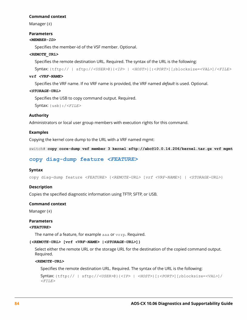
Command context
Manager (#)
Parameters<MEMBER-ID>
Specifies the member-id of the VSF member. Optional.
<REMOTE_URL>
Specifies the remote destination URL. Required. The syntax of the URL is the following:
Syntax: {tftp:// | sftp://<USER>@}{<IP> | <HOST>}[:<PORT>][;blocksize=<VAL>]/<FILE>vrf <VRF-NAME>
Specifies the VRF name. If no VRF name is provided, the VRF named default is used. Optional.
<STORAGE-URL>
Specifies the USB to copy command output. Required.
Syntax: {usb}:/<FILE>
Authority
Administrators or local user group members with execution rights for this command.
Examples
Copying the kernel core dump to the URL with a VRF named mgmt:
switch# copy core-dump vsf member 3 kernel sftp://[email protected]/kernel.tar.gz vrf mgmt
copy diag-dump feature <FEATURE>Syntax
copy diag-dump feature <FEATURE> {<REMOTE-URL> [vrf <VRF-NAME>] | <STORAGE-URL>}
Description
Copies the specified diagnostic information using TFTP, SFTP, or USB.
Command context
Manager (#)
Parameters<FEATURE>
The name of a feature, for example aaa or vrrp. Required.
{<REMOTE-URL> [vrf <VRF-NAME> |<STORAGE-URL>]}Select either the remote URL or the storage URL for the destination of the copied command output.Required.
<REMOTE-URL>
Specifies the remote destination URL. Required. The syntax of the URL is the following:
Syntax: {tftp:// | sftp://<USER>@}{<IP> | <HOST>}[:<PORT>][;blocksize=<VAL>]/<FILE>
84 AOS-CX 10.06 Diagnostics and Supportability Guide

vrf <VRF-NAME>Specifies the VRF name. If no VRF name is provided, the VRF named default is used. Optional.
<STORAGE-URL>
Specifies the USB to copy command output. Required.
Syntax: {usb}:/<FILE>
Authority
Administrators or local user group members with execution rights for this command.
Examples
Copying the output from the aaa feature to a remote URL with a specified VRF:
switch# copy diag-dump feature aaa tftp://10.100.0.12/diagdump.txt vrf mgmt Copying the output from the vrrp feature to a USB drive:
switch# copy diag-dump feature vrrp usb:/diagdump.txt
copy diag-dump local-fileSyntax
copy diag-dump local-file {<REMOTE-URL> [vrf <VRF-NAME>] | <STORAGE-URL>}
Description
Copies the diagnostic information stored in a local file using TFTP, SFTP, or USB.
Command context
Manager (#)
Parameters{<REMOTE-URL> [vrf <VRF-NAME>] |<STORAGE-URL>}
Select either the storage URL or the remote URL for the destination of the copied command output.Required.
<REMOTE-URL>
Specifies the URL to copy the command output.
Syntax: {tftp:// | sftp://<USER>@}{<IP> | <HOST>}[:<PORT>][;blocksize=<VAL>]/<FILE>
vrf <VRF-NAME>Specifies the VRF name. The default VRF name is default. Optional.
<STORAGE-URL>
Specifies the USB to copy command output.
Syntax: {usb}:/<FILE>
Authority
Administrators or local user group members with execution rights for this command.
Chapter 7 Supportability copy 85
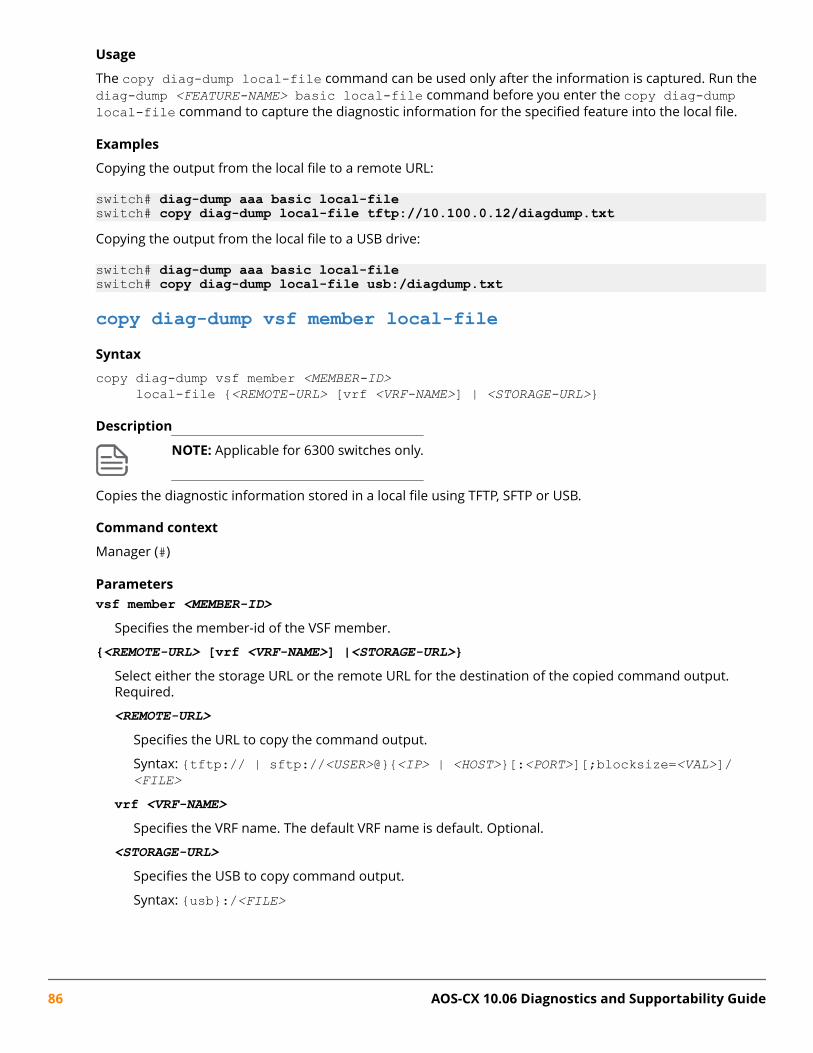
Usage
The copy diag-dump local-file command can be used only after the information is captured. Run thediag-dump <FEATURE-NAME> basic local-file command before you enter the copy diag-dumplocal-file command to capture the diagnostic information for the specified feature into the local file.
Examples
Copying the output from the local file to a remote URL:
switch# diag-dump aaa basic local-fileswitch# copy diag-dump local-file tftp://10.100.0.12/diagdump.txtCopying the output from the local file to a USB drive:
switch# diag-dump aaa basic local-fileswitch# copy diag-dump local-file usb:/diagdump.txt
copy diag-dump vsf member local-fileSyntax
copy diag-dump vsf member <MEMBER-ID> local-file {<REMOTE-URL> [vrf <VRF-NAME>] | <STORAGE-URL>}
Description
NOTE: Applicable for 6300 switches only.
Copies the diagnostic information stored in a local file using TFTP, SFTP or USB.
Command context
Manager (#)
Parametersvsf member <MEMBER-ID>
Specifies the member-id of the VSF member.
{<REMOTE-URL> [vrf <VRF-NAME>] |<STORAGE-URL>}Select either the storage URL or the remote URL for the destination of the copied command output.Required.
<REMOTE-URL>
Specifies the URL to copy the command output.
Syntax: {tftp:// | sftp://<USER>@}{<IP> | <HOST>}[:<PORT>][;blocksize=<VAL>]/<FILE>
vrf <VRF-NAME>Specifies the VRF name. The default VRF name is default. Optional.
<STORAGE-URL>
Specifies the USB to copy command output.
Syntax: {usb}:/<FILE>
86 AOS-CX 10.06 Diagnostics and Supportability Guide

Authority
Administrators or local user group members with execution rights for this command.
Usage
The copy diag-dump local-file command can be used only after the information is captured. Run thediag-dump <FEATURE-NAME> basic local-file command before you enter the copy diag-dumplocal-file command to capture the diagnostic information for the specified feature into the local file.
Examples
Copying the output from the local file to a remote URL:
switch# diag-dump aaa basic local-fileswitch# copy diag-dump vsf member 2 local-file tftp://10.100.0.12/diagdump.txt
copy show-tech featureSyntax
copy show-tech feature <FEATURE> {<REMOTE-URL> [vrf <VRF-NAME>] | <STORAGE-URL>}
Description
Copies show tech output using TFTP, SFTP, and USB.
Command context
Manager (#)
Parameters{<REMOTE-URL> [vrf <VRF-NAME> | <STORAGE-URL>]}
Select either the remote URL or the storage URL for the destination of the copied command output.Required.
<REMOTE-URL>
Specifies the URL to copy the command output. Required.
Syntax: {tftp:// | sftp://<USER>@}{<IP> | <HOST>}[:<PORT>][;blocksize=<VAL>]/<FILE>
vrf <VRF-NAME>Specifies the VRF name. The default VRF name is default. Optional.
<STORAGE-URL>
Specifies the USB to copy command output. Required.
Syntax: {usb}:/<FILE>
Authority
Administrators or local user group members with execution rights for this command.
Example
Copying show tech output of the aaa feature using SFTP:
switch# copy show-tech feature aaa sftp://[email protected]/file.txt vrf mgmtCopying show tech output of the config feature using SFTP on the mgmt VRF:
Chapter 7 Supportability copy 87
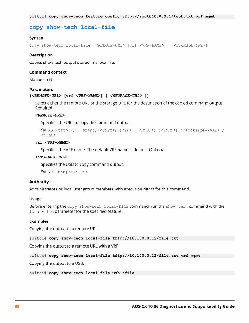
switch# copy show-tech feature config sftp://[email protected]/tech.txt vrf mgmt
copy show-tech local-fileSyntax
copy show-tech local-file {<REMOTE-URL> [vrf <VRF-NAME>] | <STORAGE-URL>}
Description
Copies show tech output stored in a local file.
Command context
Manager (#)
Parameters{<REMOTE-URL> [vrf <VRF-NAME>] | <STORAGE-URL> ]}
Select either the remote URL or the storage URL for the destination of the copied command output.Required.
<REMOTE-URL>
Specifies the URL to copy the command output.
Syntax: {tftp:// | sftp://<USER>@}{<IP> | <HOST>}[:<PORT>][;blocksize=<VAL>]/<FILE>
vrf <VRF-NAME>Specifies the VRF name. The default VRF name is default. Optional.
<STORAGE-URL>
Specifies the USB to copy command output.
Syntax: {usb}:/<FILE>
Authority
Administrators or local user group members with execution rights for this command.
Usage
Before entering the copy show-tech local-file command, run the show tech command with thelocal-file parameter for the specified feature.
Examples
Copying the output to a remote URL:
switch# copy show-tech local-file tftp://10.100.0.12/file.txtCopying the output to a remote URL with a VRF:
switch# copy show-tech local-file tftp://10.100.0.12/file.txt vrf mgmtCopying the output to a USB:
switch# copy show-tech local-file usb:/file
88 AOS-CX 10.06 Diagnostics and Supportability Guide

copy show-tech vsf member local-fileSyntaxcopy show-tech vsf member <MEMBER-ID> local-file {<REMOTE-URL> [vrf <VRF-NAME>] | <STORAGE-URL>}
Description
NOTE: Applicable for 6300 switches only.
Copies show tech output stored in a local file.
Command context
Manager (#)
Parametersvsf member <MEMBER-ID>
Specifies the member-id of the VSF member.
{<REMOTE-URL> [vrf <VRF-NAME>] | <STORAGE-URL> ]}Select either the remote URL or the storage URL for the destination of the copied command output.Required.
<REMOTE-URL>
Specifies the URL to copy the command output.
Syntax: {tftp:// | sftp://<USER>@}{<IP> | <HOST>}[:<PORT>][;blocksize=<VAL>]/<FILE>
vrf <VRF-NAME>Specifies the VRF name. The default VRF name is default. Optional.
<STORAGE-URL>
Specifies the USB to copy command output.
Syntax: {usb}:/<FILE>
Authority
Administrators or local user group members with execution rights for this command.
Usage
Before entering the copy show-tech local-file command, run the show tech command with thelocal-file parameter for the specified feature.
Examples
Copying the output to a remote URL with a VRF:
switch# copy show-tech vsf member 2 local-file tftp://10.100.0.12/showtech.txt vrf mgmtCopying the output to a USB:
switch# copy show-tech vsf member 2 local-file usb:/file
Chapter 7 Supportability copy 89

copy support-filesSyntaxcopy support-files [feature <FEATURE_NAME> | previous-boot | module <MEMBER/SLOT> | standby | all] {<REMOTE-URL> [vrf <VRF-NAME>] | <STORAGE-URL>}
Description
Copies a set of support files using TFTP, SFTP, or USB.
NOTE: This command does not support TFTP transfer on 6300 switches.
Command context
Manager (#)
Parameters<FEATURE-NAME>
The feature name, for example, aaa.
<MEMBER/SLOT>
Specifies the slot ID on 8400 or 6400 switches. Optional.
Syntax: Slot number for line (1/1-1/4, 1/7-1/10) MM(1/5 or 1/6)
{<REMOTE-URL> [vrf <VRF-NAME> | <STORAGE-URL>]}Select either the remote URL or the storage URL for the destination of the copied command output.Required.
<REMOTE-URL>
Specifies the URL to copy the command output.
Syntax: {tftp:// | sftp://<USER>@}{<IP> | <HOST>}[:<PORT>][;blocksize=<VAL>]/<FILE>
vrf <VRF-NAME>
Specifies the VRF name. The default VRF name is default. Optional.
<STORAGE-URL>
Specifies the USB to copy command output.
Syntax: {usb}:/<FILE>
Usage
If feature name is not provided, the command collects generic system-specific support information. If afeature name is provided, the command collects feature-specific support information.
Authority
Administrators or local user group members with execution rights for this command.
Examples
Copying the support files to a remote URL:
switch# copy support-files tftp://10.100.0.12/file.tar.gz
90 AOS-CX 10.06 Diagnostics and Supportability Guide
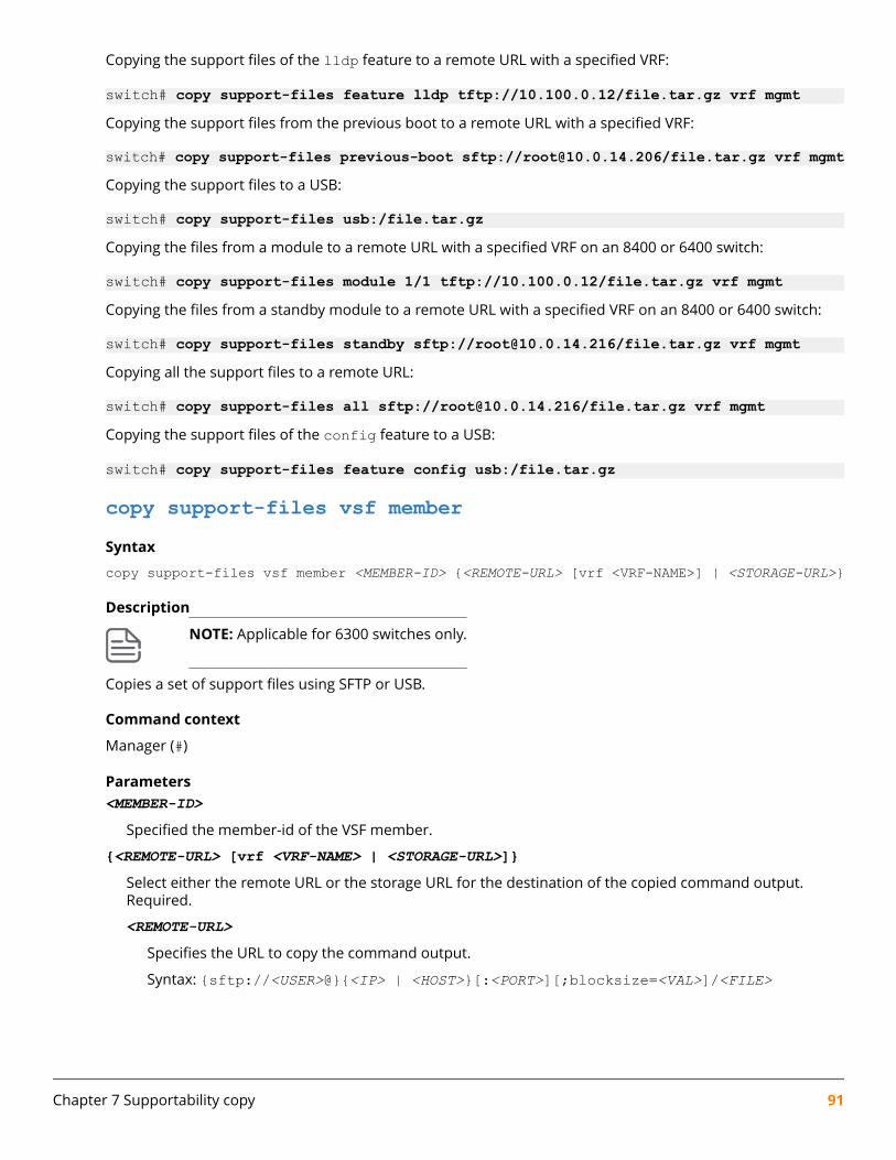
Copying the support files of the lldp feature to a remote URL with a specified VRF:
switch# copy support-files feature lldp tftp://10.100.0.12/file.tar.gz vrf mgmtCopying the support files from the previous boot to a remote URL with a specified VRF:
switch# copy support-files previous-boot sftp://[email protected]/file.tar.gz vrf mgmtCopying the support files to a USB:
switch# copy support-files usb:/file.tar.gzCopying the files from a module to a remote URL with a specified VRF on an 8400 or 6400 switch:
switch# copy support-files module 1/1 tftp://10.100.0.12/file.tar.gz vrf mgmtCopying the files from a standby module to a remote URL with a specified VRF on an 8400 or 6400 switch:
switch# copy support-files standby sftp://[email protected]/file.tar.gz vrf mgmtCopying all the support files to a remote URL:
switch# copy support-files all sftp://[email protected]/file.tar.gz vrf mgmtCopying the support files of the config feature to a USB:
switch# copy support-files feature config usb:/file.tar.gz
copy support-files vsf memberSyntax
copy support-files vsf member <MEMBER-ID> {<REMOTE-URL> [vrf <VRF-NAME>] | <STORAGE-URL>}
Description
NOTE: Applicable for 6300 switches only.
Copies a set of support files using SFTP or USB.
Command context
Manager (#)
Parameters<MEMBER-ID>
Specified the member-id of the VSF member.
{<REMOTE-URL> [vrf <VRF-NAME> | <STORAGE-URL>]}Select either the remote URL or the storage URL for the destination of the copied command output.Required.
<REMOTE-URL>
Specifies the URL to copy the command output.
Syntax: {sftp://<USER>@}{<IP> | <HOST>}[:<PORT>][;blocksize=<VAL>]/<FILE>
Chapter 7 Supportability copy 91

vrf <VRF-NAME>
Specifies the VRF name. The default VRF name is default. Optional.
<STORAGE-URL>
Specifies the USB to copy command output.
Syntax: {usb}:/<FILE>
Usage
If feature name is not provided, the command collects generic system-specific support information. If afeature name is provided, the command collects feature-specific support information.
Authority
Administrators or local user group members with execution rights for this command.
Examples
Copying the support files to a USB:
switch# copy support-files vsf member 2 usb:/file.tar.gzCopying all the support files to a remote URL with a specified VRF:
switch# copy support-files vsf member 2 sftp://10.100.0.12/support_files_dir_path/ vrf mgmt
copy support-logSyntaxcopy support-log <DAEMON-NAME> [<MEMBER/SLOT>] {<STORAGE-URL> | <REMOTE-URL> [vrf <VRF-NAME>]}
Description
Copies the specified support log for a daemon TFTP, SFTP, or USB.
Command context
Manager (#)
Parameters<MEMBER/SLOT>
Specifies the slot ID on an 8400 or 6400 switch. Optional.
Syntax: Slot number for line (1/1-1/4, 1/7-1/10) MM(1/5 or 1/6)
<DAEMON-NAME>
Specifies the name of the daemon. Required.
{<STORAGE-URL> | <REMOTE-URL> [vrf <VRF-NAME>]}Selects either the storage URL or the remote URL for the destination of the copied command output.Required.
<STORAGE-URL>
Specifies the USB to copy command output.
Syntax: {usb}:/<FILE>
92 AOS-CX 10.06 Diagnostics and Supportability Guide
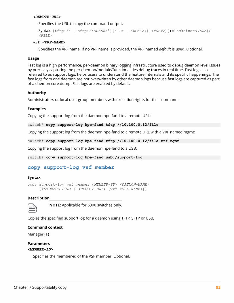
<REMOTE-URL>
Specifies the URL to copy the command output.
Syntax: {tftp:// | sftp://<USER>@}{<IP> | <HOST>}[:<PORT>][;blocksize=<VAL>]/<FILE>
vrf <VRF-NAME>Specifies the VRF name. If no VRF name is provided, the VRF named default is used. Optional.
Usage
Fast log is a high performance, per-daemon binary logging infrastructure used to debug daemon level issuesby precisely capturing the per daemon/module/functionalities debug traces in real time. Fast log, alsoreferred to as support logs, helps users to understand the feature internals and its specific happenings. Thefast logs from one daemon are not overwritten by other daemon logs because fast logs are captured as partof a daemon core dump. Fast logs are enabled by default.
Authority
Administrators or local user group members with execution rights for this command.
Examples
Copying the support log from the daemon hpe-fand to a remote URL:
switch# copy support-log hpe-fand tftp://10.100.0.12/fileCopying the support log from the daemon hpe-fand to a remote URL with a VRF named mgmt:
switch# copy support-log hpe-fand tftp://10.100.0.12/file vrf mgmtCopying the support log from the daemon hpe-fand to a USB:
switch# copy support-log hpe-fand usb:/support-log
copy support-log vsf memberSyntax
copy support-log vsf member <MEMBER-ID> <DAEMON-NAME> {<STORAGE-URL> | <REMOTE-URL> [vrf <VRF-NAME>]}
Description
NOTE: Applicable for 6300 switches only.
Copies the specified support log for a daemon using TFTP, SFTP or USB.
Command context
Manager (#)
Parameters<MEMBER-ID>
Specifies the member-id of the VSF member. Optional.
Chapter 7 Supportability copy 93

<DAEMON-NAME>
Specifies the name of the daemon. Required.
{<STORAGE-URL> | <REMOTE-URL> [vrf <VRF-NAME>]}Selects either the storage URL or the remote URL for the destination of the copied command output.Required.
<STORAGE-URL>
Specifies the USB to copy command output.
Syntax: {usb}:/<FILE><REMOTE-URL>
Specifies the URL to copy the command output.
Syntax: {tftp:// | sftp://<USER>@}{<IP> | <HOST>}[:<PORT>][;blocksize=<VAL>]/<FILE>
vrf <VRF-NAME>Specifies the VRF name. If no VRF name is provided, the VRF named default is used. Optional.
Usage
Fast log is a high performance, per-daemon binary logging infrastructure used to debug daemon level issuesby precisely capturing the per daemon/module/functionalities debug traces in real time. Fast log, alsoreferred to as support logs, helps users to understand the feature internals and its specific happenings. Thefast logs from one daemon are not overwritten by other daemon logs because fast logs are captured as partof a daemon core dump. Fast logs are enabled by default.
Authority
Administrators or local user group members with execution rights for this command.
Examples
Copying the support log from the daemon hpe-fand to a remote URL with a VRF named mgmt:
switch# copy support-log vsf member 2 hpe-fand tftp://10.100.0.12/file vrf mgmtCopying the support log from the daemon hpe-fand to a USB:
switch# copy support-log vsf member 2 hpe-fand usb:/support-log
94 AOS-CX 10.06 Diagnostics and Supportability Guide
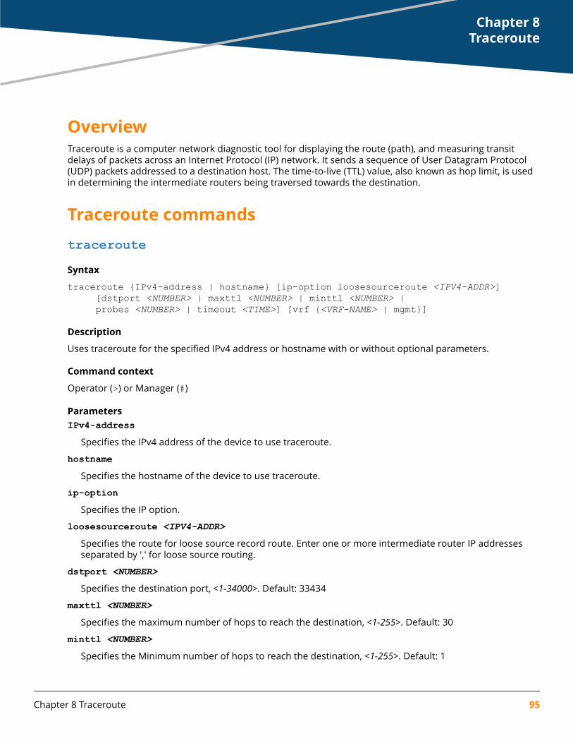
OverviewTraceroute is a computer network diagnostic tool for displaying the route (path), and measuring transitdelays of packets across an Internet Protocol (IP) network. It sends a sequence of User Datagram Protocol(UDP) packets addressed to a destination host. The time-to-live (TTL) value, also known as hop limit, is usedin determining the intermediate routers being traversed towards the destination.
Traceroute commandstracerouteSyntax
traceroute {IPv4-address | hostname} [ip-option loosesourceroute <IPV4-ADDR>] [dstport <NUMBER> | maxttl <NUMBER> | minttl <NUMBER> | probes <NUMBER> | timeout <TIME>] [vrf {<VRF-NAME> | mgmt}]
Description
Uses traceroute for the specified IPv4 address or hostname with or without optional parameters.
Command context
Operator (>) or Manager (#)
ParametersIPv4-address
Specifies the IPv4 address of the device to use traceroute.
hostnameSpecifies the hostname of the device to use traceroute.
ip-optionSpecifies the IP option.
loosesourceroute <IPV4-ADDR>Specifies the route for loose source record route. Enter one or more intermediate router IP addressesseparated by ',' for loose source routing.
dstport <NUMBER>Specifies the destination port, <1-34000>. Default: 33434
maxttl <NUMBER>Specifies the maximum number of hops to reach the destination, <1-255>. Default: 30
minttl <NUMBER>Specifies the Minimum number of hops to reach the destination, <1-255>. Default: 1
Chapter 8Traceroute
Chapter 8 Traceroute 95

probes <NUMBER>Specifies the number of probes, <1-5>. Default: 3
timeout <TIME>Specifies the traceroute timeout in seconds, <1-60>. Default: 3 seconds
vrf <VRF-NAME>Specifies the virtual routing and forwarding (VRF) to use, <VRF-NAME>.
mgmtSpecifies use of the management interface.
Authority
Operators or Administrators or local user group members with execution rights for this command.Operators can execute this command from the operator context (>) only.
Usage
Traceroute is a computer network diagnostic tool for displaying the route (path), and measuring transitdelays of packets across an Internet Protocol (IP) network. It sends a sequence of User Datagram Protocol(UDP) packets addressed to a destination host. The time-to-live (TTL) value, also known as hop limit, is usedin determining the intermediate routers being traversed towards the destination.
Examples
switch# traceroute 10.0.10.1traceroute to 10.0.10.1 (10.0.10.1) , 1 hops min, 30 hops max, 3 sec. timeout, 3 probes 1 10.0.40.2 0.002ms 0.002ms 0.001ms 2 10.0.30.1 0.002ms 0.001ms 0.001ms 3 10.0.10.1 0.001ms 0.002ms 0.002ms
switch# traceroute localhosttraceroute to localhost (127.0.0.1), 1 hops min, 30 hops max, 3 sec. timeout, 3 probes 1 127.0.0.1 0.018ms 0.006ms 0.003ms
switch# traceroute 10.0.10.1 maxttl 20traceroute to 10.0.10.1 (10.0.10.1) , 1 hops min, 20 hops max, 3 sec. timeout, 3 probes 1 10.0.40.2 0.002ms 0.002ms 0.001ms 2 10.0.30.1 0.002ms 0.001ms 0.001ms 3 10.0.10.1 0.001ms 0.002ms 0.002ms
switch# traceroute 10.0.10.1 minttl 1traceroute to 10.0.10.1 (10.0.10.1) , 1 hops min, 30 hops max, 3 sec. timeout, 3 probes 1 10.0.40.2 0.002ms 0.002ms 0.001ms 2 10.0.30.1 0.002ms 0.001ms 0.001ms 3 10.0.10.1 0.001ms 0.002ms 0.002ms
switch# traceroute 10.0.10.1 dstport 33434traceroute to 10.0.10.1 (10.0.10.1) , 1 hops min, 30 hops max, 3 sec. timeout, 3 probes 1 10.0.40.2 0.002ms 0.002ms 0.001ms 2 10.0.30.1 0.002ms 0.001ms 0.001ms 3 10.0.10.1 0.001ms 0.002ms 0.002ms
switch# traceroute 10.0.10.1 probes 2traceroute to 10.0.10.1 (10.0.10.1) , 1 hops min, 30 hops max, 3 sec. timeout, 2 probes 1 10.0.40.2 0.002ms 0.002ms 2 10.0.30.1 0.002ms 0.001ms 3 10.0.10.1 0.001ms 0.002ms
switch# traceroute 10.0.10.1 timeout 5traceroute to 10.0.10.1 (10.0.10.1) , 1 hops min, 30 hops max, 5 sec. timeout, 3 probes 1 10.0.40.2 0.002ms 0.002ms 0.001ms 2 10.0.30.1 0.002ms 0.001ms 0.001ms 3 10.0.10.1 0.001ms 0.002ms 0.002ms
switch# traceroute localhost vrf redtraceroute to localhost (127.0.0.1), 1 hops min, 30 hops max, 3 sec. timeout, 3 probes 1 127.0.0.1 0.003ms 0.002ms 0.001ms
switch# traceroute localhost mgmttraceroute to localhost (127.0.0.1), 1 hops min, 30 hops max, 3 sec. timeout, 3 probes 1 127.0.0.1 0.018ms 0.006ms 0.003ms
switch# traceroute 10.0.10.1 maxttl 20 timeout 5 minttl 1 probes 3 dstport 33434
96 AOS-CX 10.06 Diagnostics and Supportability Guide
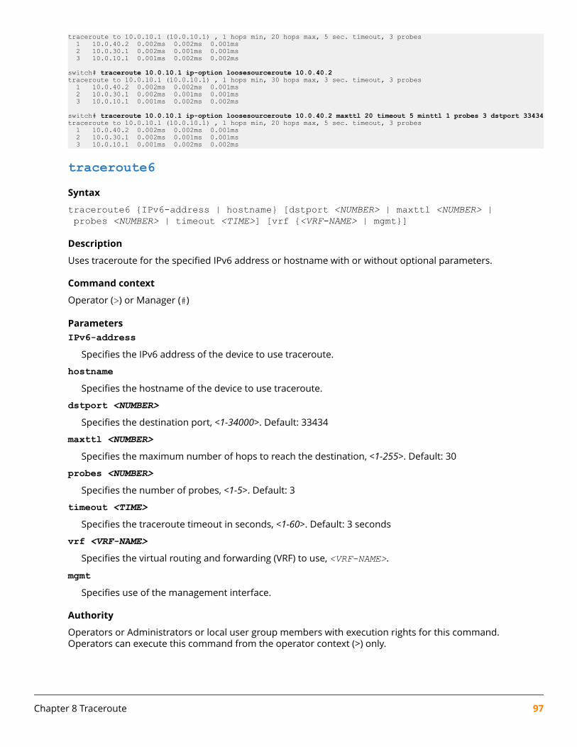
traceroute to 10.0.10.1 (10.0.10.1) , 1 hops min, 20 hops max, 5 sec. timeout, 3 probes 1 10.0.40.2 0.002ms 0.002ms 0.001ms 2 10.0.30.1 0.002ms 0.001ms 0.001ms 3 10.0.10.1 0.001ms 0.002ms 0.002ms
switch# traceroute 10.0.10.1 ip-option loosesourceroute 10.0.40.2traceroute to 10.0.10.1 (10.0.10.1) , 1 hops min, 30 hops max, 3 sec. timeout, 3 probes 1 10.0.40.2 0.002ms 0.002ms 0.001ms 2 10.0.30.1 0.002ms 0.001ms 0.001ms 3 10.0.10.1 0.001ms 0.002ms 0.002ms
switch# traceroute 10.0.10.1 ip-option loosesourceroute 10.0.40.2 maxttl 20 timeout 5 minttl 1 probes 3 dstport 33434traceroute to 10.0.10.1 (10.0.10.1) , 1 hops min, 20 hops max, 5 sec. timeout, 3 probes 1 10.0.40.2 0.002ms 0.002ms 0.001ms 2 10.0.30.1 0.002ms 0.001ms 0.001ms 3 10.0.10.1 0.001ms 0.002ms 0.002ms
traceroute6Syntax
traceroute6 {IPv6-address | hostname} [dstport <NUMBER> | maxttl <NUMBER> | probes <NUMBER> | timeout <TIME>] [vrf {<VRF-NAME> | mgmt}]
Description
Uses traceroute for the specified IPv6 address or hostname with or without optional parameters.
Command context
Operator (>) or Manager (#)
ParametersIPv6-address
Specifies the IPv6 address of the device to use traceroute.
hostnameSpecifies the hostname of the device to use traceroute.
dstport <NUMBER>Specifies the destination port, <1-34000>. Default: 33434
maxttl <NUMBER>Specifies the maximum number of hops to reach the destination, <1-255>. Default: 30
probes <NUMBER>Specifies the number of probes, <1-5>. Default: 3
timeout <TIME>Specifies the traceroute timeout in seconds, <1-60>. Default: 3 seconds
vrf <VRF-NAME>Specifies the virtual routing and forwarding (VRF) to use, <VRF-NAME>.
mgmtSpecifies use of the management interface.
Authority
Operators or Administrators or local user group members with execution rights for this command.Operators can execute this command from the operator context (>) only.
Chapter 8 Traceroute 97

Usage
Traceroute is a computer network diagnostic tool for displaying the route (path), and measuring transitdelays of packets across an Internet Protocol (IP) network. It sends a sequence of User Datagram Protocol(UDP) packets addressed to a destination host. The time-to-live (TTL) value, also known as hop limit, is usedin determining the intermediate routers being traversed towards the destination.
Examples
switch# traceroute6 0:0::0:1traceroute to 0:0::0:1 (::1) from ::1, 30 hops max, 3 sec. timeout, 3 probes, 24 byte packets 1 localhost (::1) 0.117 ms 0.032 ms 0.021 ms
switch# traceroute6 localhosttraceroute to localhost (::1) from ::1, 30 hops max, 3 sec. timeout, 3 probes, 24 byte packets 1 localhost (::1) 0.089 ms 0.03 ms 0.014 ms
switch# traceroute6 0:0::0:1 maxttl 30traceroute to 0:0::0:1 (::1) from ::1, 30 hops max, 3 sec. timeout, 3 probes, 24 byte packets 1 localhost (::1) 0.117 ms 0.032 ms 0.021 ms
switch# traceroute6 0:0::0:1 dsrport 33434traceroute to 0:0::0:1 (::1) from ::1, 30 hops max, 3 sec. timeout, 3 probes, 24 byte packets 1 localhost (::1) 0.117 ms 0.032 ms 0.021 ms
switch# traceroute6 0:0::0:1 probes 2traceroute to 0:0::0:1 (::1) from ::1, 30 hops max, 3 sec. timeout, 2 probes, 24 byte packets 1 localhost (::1) 0.117 ms 0.032 ms
switch# traceroute6 0:0::0:1 timeout 3traceroute to 0:0::0:1 (::1) from ::1, 30 hops max, 3 sec. timeout, 3 probes, 24 byte packets 1 localhost (::1) 0.117 ms 0.032 ms 0.021 ms
switch# traceroute6 localhost vrf redtraceroute to localhost (::1) from ::1, 30 hops max, 3 sec. timeout, 3 probes, 24 byte packets 1 localhost (::1) 0.077 ms 0.051 ms 0.054 ms
switch# traceroute6 localhost mgmttraceroute to localhost (::1) from ::1, 30 hops max, 3 sec. timeout, 3 probes, 24 byte packets 1 localhost (::1) 0.089 ms 0.03 ms 0.014 ms
switch# traceroute6 0:0::0:1 maxttl 30 timeout 3 probes 3 dstport 33434traceroute to 0:0::0:1 (::1) from ::1, 30 hops max, 3 sec. timeout, 3 probes, 24 byte packets 1 localhost (::1) 0.117 ms 0.032 ms 0.021 ms
98 AOS-CX 10.06 Diagnostics and Supportability Guide
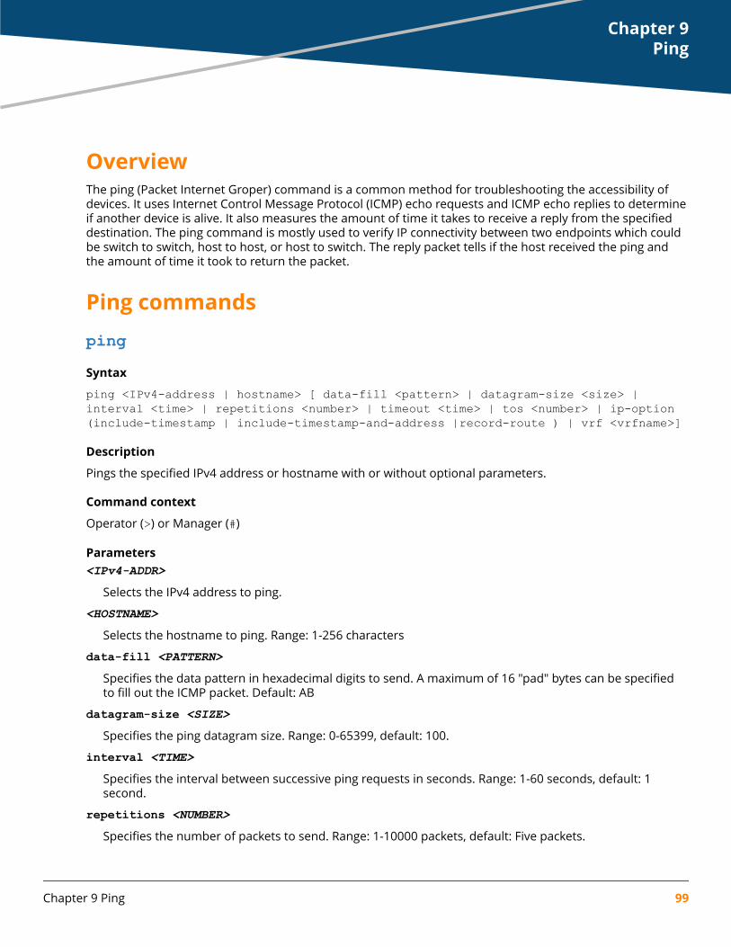
OverviewThe ping (Packet Internet Groper) command is a common method for troubleshooting the accessibility ofdevices. It uses Internet Control Message Protocol (ICMP) echo requests and ICMP echo replies to determineif another device is alive. It also measures the amount of time it takes to receive a reply from the specifieddestination. The ping command is mostly used to verify IP connectivity between two endpoints which couldbe switch to switch, host to host, or host to switch. The reply packet tells if the host received the ping andthe amount of time it took to return the packet.
Ping commandspingSyntax
ping <IPv4-address | hostname> [ data-fill <pattern> | datagram-size <size> | interval <time> | repetitions <number> | timeout <time> | tos <number> | ip-option (include-timestamp | include-timestamp-and-address |record-route ) | vrf <vrfname>]
Description
Pings the specified IPv4 address or hostname with or without optional parameters.
Command context
Operator (>) or Manager (#)
Parameters<IPv4-ADDR>
Selects the IPv4 address to ping.
<HOSTNAME>
Selects the hostname to ping. Range: 1-256 characters
data-fill <PATTERN>Specifies the data pattern in hexadecimal digits to send. A maximum of 16 "pad" bytes can be specifiedto fill out the ICMP packet. Default: AB
datagram-size <SIZE>Specifies the ping datagram size. Range: 0-65399, default: 100.
interval <TIME>Specifies the interval between successive ping requests in seconds. Range: 1-60 seconds, default: 1second.
repetitions <NUMBER>Specifies the number of packets to send. Range: 1-10000 packets, default: Five packets.
Chapter 9Ping
Chapter 9 Ping 99

timeout <TIME>Specifies the ping timeout in seconds. Range: 1-60 seconds, default: 2 seconds.
tos <NUMBER>Specifies the IP Type of Service to be used in Ping request. Range: 0-255
ip-option [include-timestamp | include-timestamp-and-address | record-route]Specifies an IP option (record-route or timestamp option).
include-timestampSpecifies the intermediate router time stamp.
include-timestamp-and-addressSpecifies the intermediate router time stamp and IP address.
record-routeSpecifies the intermediate router addresses.
vrf <VRF-NAME>Specifies the virtual routing and forwarding (VRF) to use. When VRF option is not given, the default VRF isused.
Authority
Operators or Administrators or local user group members with execution rights for this command.Operators can execute this command from the operator context (>) only.
Examples
Pinging an IPv4 address:
switch# ping 10.0.0.0PING 10.0.0.0 (10.0.0.0) 100(128) bytes of data.108 bytes from 10.0.0.0: icmp_seq=1 ttl=64 time=0.035 ms108 bytes from 10.0.0.0: icmp_seq=2 ttl=64 time=0.034 ms108 bytes from 10.0.0.0: icmp_seq=3 ttl=64 time=0.034 ms108 bytes from 10.0.0.0: icmp_seq=4 ttl=64 time=0.034 ms108 bytes from 10.0.0.0: icmp_seq=5 ttl=64 time=0.033 ms
--- 10.0.0.0 ping statistics ---5 packets transmitted, 5 received, 0% packet loss, time 3999msrtt min/avg/max/mdev = 0.033/0.034/0.035/0.000 msPinging the localhost:
switch# ping localhostPING localhost (127.0.0.1) 100(128) bytes of data.108 bytes from localhost (127.0.0.1): icmp_seq=1 ttl=64 time=0.060 ms108 bytes from localhost (127.0.0.1): icmp_seq=2 ttl=64 time=0.035 ms108 bytes from localhost (127.0.0.1): icmp_seq=3 ttl=64 time=0.043 ms108 bytes from localhost (127.0.0.1): icmp_seq=4 ttl=64 time=0.041 ms108 bytes from localhost (127.0.0.1): icmp_seq=5 ttl=64 time=0.034 ms
--- localhost ping statistics ---5 packets transmitted, 5 received, 0% packet loss, time 3998msrtt min/avg/max/mdev = 0.034/0.042/0.060/0.011 msPinging a server with a data pattern:
100 AOS-CX 10.06 Diagnostics and Supportability Guide

switch# ping 10.0.0.2 data-fill 1234123412341234acde123456789012PATTERN: 0x1234123412341234acde123456789012PING 10.0.0.2 (10.0.0.2) 100(128) bytes of data.108 bytes from 10.0.0.2: icmp_seq=1 ttl=64 time=0.207 ms108 bytes from 10.0.0.2: icmp_seq=2 ttl=64 time=0.187 ms108 bytes from 10.0.0.2: icmp_seq=3 ttl=64 time=0.225 ms108 bytes from 10.0.0.2: icmp_seq=4 ttl=64 time=0.197 ms108 bytes from 10.0.0.2: icmp_seq=5 ttl=64 time=0.210 ms
--- 10.0.0.2 ping statistics ---5 packets transmitted, 5 received, 0% packet loss, time 3999msrtt min/avg/max/mdev = 0.187/0.205/0.225/0.015 msPinging a server with a datagram size:
switch# ping 10.0.0.0 datagram-size 200PING 10.0.0.0 (10.0.0.0) 200(228) bytes of data.208 bytes from 10.0.0.0: icmp_seq=1 ttl=64 time=0.202 ms208 bytes from 10.0.0.0: icmp_seq=2 ttl=64 time=0.194 ms208 bytes from 10.0.0.0: icmp_seq=3 ttl=64 time=0.201 ms208 bytes from 10.0.0.0: icmp_seq=4 ttl=64 time=0.200 ms208 bytes from 10.0.0.0: icmp_seq=5 ttl=64 time=0.186 ms
--- 10.0.0.0 ping statistics ---5 packets transmitted, 5 received, 0% packet loss, time 4000msrtt min/avg/max/mdev = 0.186/0.196/0.202/0.016 msPinging a server with an interval specified:
switch# ping 9.0.0.2 interval 2PING 9.0.0.2 (9.0.0.2) 100(128) bytes of data.108 bytes from 9.0.0.2: icmp_seq=1 ttl=64 time=0.199 ms108 bytes from 9.0.0.2: icmp_seq=2 ttl=64 time=0.192 ms108 bytes from 9.0.0.2: icmp_seq=3 ttl=64 time=0.208 ms108 bytes from 9.0.0.2: icmp_seq=4 ttl=64 time=0.182 ms108 bytes from 9.0.0.2: icmp_seq=5 ttl=64 time=0.194 ms
--- 9.0.0.2 ping statistics ---5 packets transmitted, 5 received, 0% packet loss, time 7999msrtt min/avg/max/mdev = 0.182/0.195/0.208/0.008 msPinging a server with a specified number of packets to send:
switch# ping 9.0.0.2 repetitions 10PING 9.0.0.2 (9.0.0.2) 100(128) bytes of data.108 bytes from 9.0.0.2: icmp_seq=1 ttl=64 time=0.213 ms108 bytes from 9.0.0.2: icmp_seq=2 ttl=64 time=0.204 ms108 bytes from 9.0.0.2: icmp_seq=3 ttl=64 time=0.201 ms108 bytes from 9.0.0.2: icmp_seq=4 ttl=64 time=0.184 ms108 bytes from 9.0.0.2: icmp_seq=5 ttl=64 time=0.202 ms108 bytes from 9.0.0.2: icmp_seq=6 ttl=64 time=0.184 ms108 bytes from 9.0.0.2: icmp_seq=7 ttl=64 time=0.193 ms108 bytes from 9.0.0.2: icmp_seq=8 ttl=64 time=0.196 ms108 bytes from 9.0.0.2: icmp_seq=9 ttl=64 time=0.193 ms108 bytes from 9.0.0.2: icmp_seq=10 ttl=64 time=0.200 ms
--- 9.0.0.2 ping statistics ---10 packets transmitted, 10 received, 0% packet loss, time 8999msrtt min/avg/max/mdev = 0.184/0.197/0.213/0.008 msPinging a server with a specified timeout:
switch# ping 9.0.0.2 timeout 3PING 9.0.0.2 (9.0.0.2) 100(128) bytes of data.
Chapter 9 Ping 101
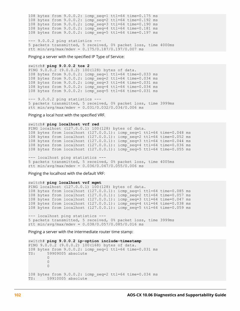
108 bytes from 9.0.0.2: icmp_seq=1 ttl=64 time=0.175 ms108 bytes from 9.0.0.2: icmp_seq=2 ttl=64 time=0.192 ms108 bytes from 9.0.0.2: icmp_seq=3 ttl=64 time=0.190 ms108 bytes from 9.0.0.2: icmp_seq=4 ttl=64 time=0.181 ms108 bytes from 9.0.0.2: icmp_seq=5 ttl=64 time=0.197 ms
--- 9.0.0.2 ping statistics ---5 packets transmitted, 5 received, 0% packet loss, time 4000msrtt min/avg/max/mdev = 0.175/0.187/0.197/0.007 msPinging a server with the specified IP Type of Service:
switch# ping 9.0.0.2 tos 2PING 9.0.0.2 (9.0.0.2) 100(128) bytes of data.108 bytes from 9.0.0.2: icmp_seq=1 ttl=64 time=0.033 ms108 bytes from 9.0.0.2: icmp_seq=2 ttl=64 time=0.034 ms108 bytes from 9.0.0.2: icmp_seq=3 ttl=64 time=0.031 ms108 bytes from 9.0.0.2: icmp_seq=4 ttl=64 time=0.034 ms108 bytes from 9.0.0.2: icmp_seq=5 ttl=64 time=0.031 ms
--- 9.0.0.2 ping statistics ---5 packets transmitted, 5 received, 0% packet loss, time 3999msrtt min/avg/max/mdev = 0.031/0.032/0.034/0.006 msPinging a local host with the specified VRF.
switch# ping localhost vrf redPING localhost (127.0.0.1) 100(128) bytes of data.108 bytes from localhost (127.0.0.1): icmp_seq=1 ttl=64 time=0.048 ms108 bytes from localhost (127.0.0.1): icmp_seq=2 ttl=64 time=0.052 ms108 bytes from localhost (127.0.0.1): icmp_seq=3 ttl=64 time=0.044 ms108 bytes from localhost (127.0.0.1): icmp_seq=4 ttl=64 time=0.036 ms108 bytes from localhost (127.0.0.1): icmp_seq=5 ttl=64 time=0.055 ms
--- localhost ping statistics ---5 packets transmitted, 5 received, 0% packet loss, time 4005msrtt min/avg/max/mdev = 0.036/0.047/0.055/0.006 msPinging the localhost with the default VRF:
switch# ping localhost vrf mgmtPING localhost (127.0.0.1) 100(128) bytes of data.108 bytes from localhost (127.0.0.1): icmp_seq=1 ttl=64 time=0.085 ms108 bytes from localhost (127.0.0.1): icmp_seq=2 ttl=64 time=0.057 ms108 bytes from localhost (127.0.0.1): icmp_seq=3 ttl=64 time=0.047 ms108 bytes from localhost (127.0.0.1): icmp_seq=4 ttl=64 time=0.038 ms108 bytes from localhost (127.0.0.1): icmp_seq=5 ttl=64 time=0.059 ms
--- localhost ping statistics ---5 packets transmitted, 5 received, 0% packet loss, time 3999msrtt min/avg/max/mdev = 0.038/0.057/0.085/0.016 msPinging a server with the intermediate router time stamp:
switch# ping 9.0.0.2 ip-option include-timestampPING 9.0.0.2 (9.0.0.2) 100(168) bytes of data.108 bytes from 9.0.0.2: icmp_seq=1 ttl=64 time=0.031 msTS: 59909005 absolute 0 0 0
108 bytes from 9.0.0.2: icmp_seq=2 ttl=64 time=0.034 msTS: 59910005 absolute
102 AOS-CX 10.06 Diagnostics and Supportability Guide
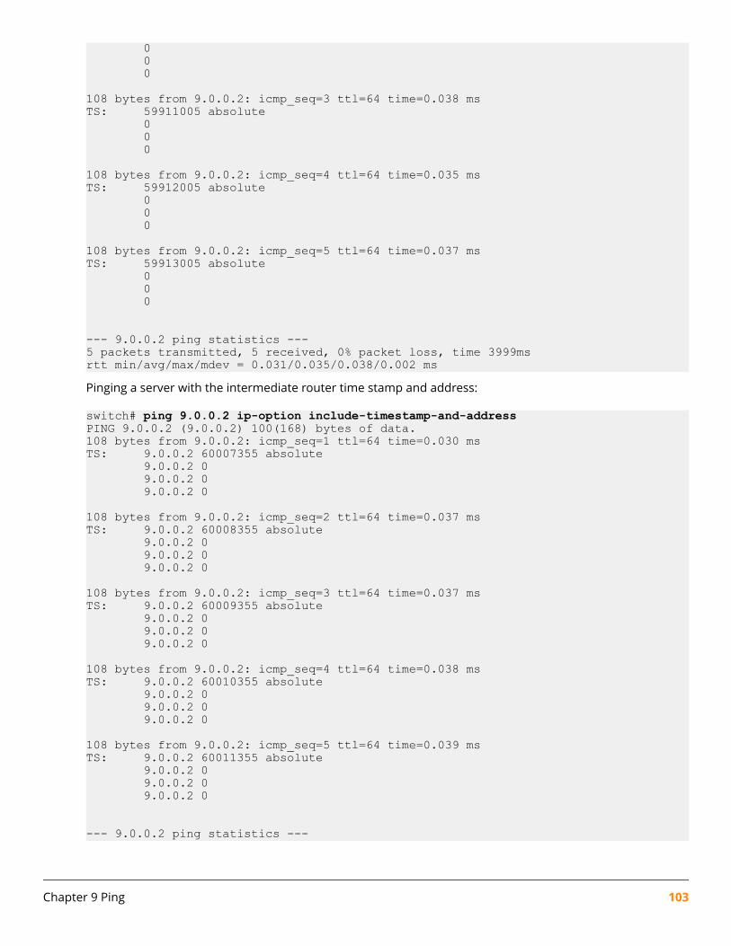
0 0 0
108 bytes from 9.0.0.2: icmp_seq=3 ttl=64 time=0.038 msTS: 59911005 absolute 0 0 0
108 bytes from 9.0.0.2: icmp_seq=4 ttl=64 time=0.035 msTS: 59912005 absolute 0 0 0
108 bytes from 9.0.0.2: icmp_seq=5 ttl=64 time=0.037 msTS: 59913005 absolute 0 0 0
--- 9.0.0.2 ping statistics ---5 packets transmitted, 5 received, 0% packet loss, time 3999msrtt min/avg/max/mdev = 0.031/0.035/0.038/0.002 msPinging a server with the intermediate router time stamp and address:
switch# ping 9.0.0.2 ip-option include-timestamp-and-addressPING 9.0.0.2 (9.0.0.2) 100(168) bytes of data.108 bytes from 9.0.0.2: icmp_seq=1 ttl=64 time=0.030 msTS: 9.0.0.2 60007355 absolute 9.0.0.2 0 9.0.0.2 0 9.0.0.2 0
108 bytes from 9.0.0.2: icmp_seq=2 ttl=64 time=0.037 msTS: 9.0.0.2 60008355 absolute 9.0.0.2 0 9.0.0.2 0 9.0.0.2 0
108 bytes from 9.0.0.2: icmp_seq=3 ttl=64 time=0.037 msTS: 9.0.0.2 60009355 absolute 9.0.0.2 0 9.0.0.2 0 9.0.0.2 0
108 bytes from 9.0.0.2: icmp_seq=4 ttl=64 time=0.038 msTS: 9.0.0.2 60010355 absolute 9.0.0.2 0 9.0.0.2 0 9.0.0.2 0
108 bytes from 9.0.0.2: icmp_seq=5 ttl=64 time=0.039 msTS: 9.0.0.2 60011355 absolute 9.0.0.2 0 9.0.0.2 0 9.0.0.2 0
--- 9.0.0.2 ping statistics ---
Chapter 9 Ping 103

5 packets transmitted, 5 received, 0% packet loss, time 3999msrtt min/avg/max/mdev = 0.030/0.036/0.039/0.005 msPinging a server with the intermediate router address:
switch# ping 9.0.0.2 ip-option record-routePING 9.0.0.2 (9.0.0.2) 100(168) bytes of data.108 bytes from 9.0.0.2: icmp_seq=1 ttl=64 time=0.034 msRR: 9.0.0.2 9.0.0.2 9.0.0.2 9.0.0.2
108 bytes from 9.0.0.2: icmp_seq=2 ttl=64 time=0.038 ms (same route)108 bytes from 9.0.0.2: icmp_seq=3 ttl=64 time=0.036 ms (same route)108 bytes from 9.0.0.2: icmp_seq=4 ttl=64 time=0.037 ms (same route)108 bytes from 9.0.0.2: icmp_seq=5 ttl=64 time=0.035 ms (same route)
--- 9.0.0.2 ping statistics ---5 packets transmitted, 5 received, 0% packet loss, time 3999msrtt min/avg/max/mdev = 0.034/0.036/0.038/0.001 ms
ping6Syntax
ping6 {<IPv6-ADDR> | <HOSTNAME>} [data-fill <PATTERN> | datagram-size <SIZE> | interval <TIME> | repetitions <NUMBER> | timeout <TIME> | vrrp <VRID> | vrf <VRF-NAME>]
Description
Pings the specified IPv6 address or hostname with or without optional parameters. The VRRP option isprovided to self-ping the configured link-local address on the VRRP group.
Command context
Operator (>) or Manager (#)
ParametersIPv6-ADDR
Selects the IPv6 address to ping.
HOSTNAMESelects the hostname to ping. Range: 1-256 characters
data-fill <PATTERN>Specifies the data pattern in hexadecimal digits to send. A maximum of 16 "pad" bytes can be specifiedto fill out the ICMP packet. Default: AB
datagram-size <SIZE>Specifies the ping datagram size. Range: 0-65399, default: 100.
interval <TIME>Specifies the interval between successive ping requests in seconds. Range: 1-60 seconds, default: 1second.
repetitions <NUMBER>Specifies the number of packets to send. Range: 1-10000 packets, default: Five packets.
104 AOS-CX 10.06 Diagnostics and Supportability Guide
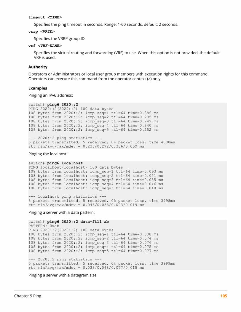
timeout <TIME>Specifies the ping timeout in seconds. Range: 1-60 seconds, default: 2 seconds.
vrrp <VRID>Specifies the VRRP group ID.
vrf <VRF-NAME>Specifies the virtual routing and forwarding (VRF) to use. When this option is not provided, the defaultVRF is used.
Authority
Operators or Administrators or local user group members with execution rights for this command.Operators can execute this command from the operator context (>) only.
Examples
Pinging an IPv6 address:
switch# ping6 2020::2PING 2020::2(2020::2) 100 data bytes108 bytes from 2020::2: icmp_seq=1 ttl=64 time=0.386 ms108 bytes from 2020::2: icmp_seq=2 ttl=64 time=0.235 ms108 bytes from 2020::2: icmp_seq=3 ttl=64 time=0.249 ms108 bytes from 2020::2: icmp_seq=4 ttl=64 time=0.240 ms108 bytes from 2020::2: icmp_seq=5 ttl=64 time=0.252 ms
--- 2020::2 ping statistics ---5 packets transmitted, 5 received, 0% packet loss, time 4000msrtt min/avg/max/mdev = 0.235/0.272/0.386/0.059 msPinging the localhost:
switch# ping6 localhostPING localhost(localhost) 100 data bytes108 bytes from localhost: icmp_seq=1 ttl=64 time=0.093 ms108 bytes from localhost: icmp_seq=2 ttl=64 time=0.051 ms108 bytes from localhost: icmp_seq=3 ttl=64 time=0.055 ms108 bytes from localhost: icmp_seq=4 ttl=64 time=0.046 ms108 bytes from localhost: icmp_seq=5 ttl=64 time=0.048 ms
--- localhost ping statistics ---5 packets transmitted, 5 received, 0% packet loss, time 3998msrtt min/avg/max/mdev = 0.046/0.058/0.093/0.019 msPinging a server with a data pattern:
switch# ping6 2020::2 data-fill abPATTERN: 0xabPING 2020::2(2020::2) 100 data bytes108 bytes from 2020::2: icmp_seq=1 ttl=64 time=0.038 ms108 bytes from 2020::2: icmp_seq=2 ttl=64 time=0.074 ms108 bytes from 2020::2: icmp_seq=3 ttl=64 time=0.076 ms108 bytes from 2020::2: icmp_seq=4 ttl=64 time=0.075 ms108 bytes from 2020::2: icmp_seq=5 ttl=64 time=0.077 ms
--- 2020::2 ping statistics ---5 packets transmitted, 5 received, 0% packet loss, time 3999msrtt min/avg/max/mdev = 0.038/0.068/0.077/0.015 msPinging a server with a datagram size:
Chapter 9 Ping 105
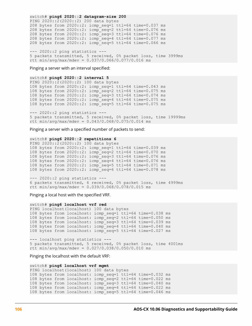
switch# ping6 2020::2 datagram-size 200PING 2020::2(2020::2) 200 data bytes208 bytes from 2020::2: icmp_seq=1 ttl=64 time=0.037 ms208 bytes from 2020::2: icmp_seq=2 ttl=64 time=0.076 ms208 bytes from 2020::2: icmp_seq=3 ttl=64 time=0.076 ms208 bytes from 2020::2: icmp_seq=4 ttl=64 time=0.077 ms208 bytes from 2020::2: icmp_seq=5 ttl=64 time=0.066 ms
--- 2020::2 ping statistics ---5 packets transmitted, 5 received, 0% packet loss, time 3999msrtt min/avg/max/mdev = 0.037/0.066/0.077/0.016 msPinging a server with an interval specified:
switch# ping6 2020::2 interval 5PING 2020::2(2020::2) 100 data bytes108 bytes from 2020::2: icmp_seq=1 ttl=64 time=0.043 ms108 bytes from 2020::2: icmp_seq=2 ttl=64 time=0.075 ms108 bytes from 2020::2: icmp_seq=3 ttl=64 time=0.074 ms108 bytes from 2020::2: icmp_seq=4 ttl=64 time=0.075 ms108 bytes from 2020::2: icmp_seq=5 ttl=64 time=0.075 ms
--- 2020::2 ping statistics ---5 packets transmitted, 5 received, 0% packet loss, time 19999msrtt min/avg/max/mdev = 0.043/0.068/0.075/0.014 msPinging a server with a specified number of packets to send:
switch# ping6 2020::2 repetitions 6PING 2020::2(2020::2) 100 data bytes108 bytes from 2020::2: icmp_seq=1 ttl=64 time=0.039 ms108 bytes from 2020::2: icmp_seq=2 ttl=64 time=0.070 ms108 bytes from 2020::2: icmp_seq=3 ttl=64 time=0.076 ms108 bytes from 2020::2: icmp_seq=4 ttl=64 time=0.076 ms108 bytes from 2020::2: icmp_seq=5 ttl=64 time=0.071 ms108 bytes from 2020::2: icmp_seq=6 ttl=64 time=0.078 ms
--- 2020::2 ping statistics ---6 packets transmitted, 6 received, 0% packet loss, time 4999msrtt min/avg/max/mdev = 0.039/0.068/0.078/0.015 msPinging a local host with the specified VRF.
switch# ping6 localhost vrf redPING localhost(localhost) 100 data bytes108 bytes from localhost: icmp_seq=1 ttl=64 time=0.038 ms108 bytes from localhost: icmp_seq=2 ttl=64 time=0.050 ms108 bytes from localhost: icmp_seq=3 ttl=64 time=0.039 ms108 bytes from localhost: icmp_seq=4 ttl=64 time=0.040 ms108 bytes from localhost: icmp_seq=5 ttl=64 time=0.027 ms
--- localhost ping statistics ---5 packets transmitted, 5 received, 0% packet loss, time 4001msrtt min/avg/max/mdev = 0.027/0.038/0.050/0.010 msPinging the localhost with the default VRF:
switch# ping6 localhost vrf mgmtPING localhost(localhost) 100 data bytes108 bytes from localhost: icmp_seq=1 ttl=64 time=0.032 ms108 bytes from localhost: icmp_seq=2 ttl=64 time=0.022 ms108 bytes from localhost: icmp_seq=3 ttl=64 time=0.040 ms108 bytes from localhost: icmp_seq=4 ttl=64 time=0.022 ms108 bytes from localhost: icmp_seq=5 ttl=64 time=0.046 ms
106 AOS-CX 10.06 Diagnostics and Supportability Guide

--- localhost ping statistics ---5 packets transmitted, 5 received, 0% packet loss, time 3998msrtt min/avg/max/mdev = 0.022/0.032/0.046/0.010 ms
TroubleshootingOperation not permitted
Symptom
The switch displays an operation not permitted message when a user attempts to send a ping request.
Example:
switch# ping 100.1.2.10PING 100.1.2.10 (100.1.2.10) 100(128) bytes of dataping: sendmsg: Operation not permittedping: sendmsg: Operation not permittedping: sendmsg: Operation not permittedping: sendmsg: Operation not permittedping: sendmsg: Operation not permitted
--- 100.1.2.10 ping statistics ---5 packets transmitted, 0 received, 100% packet loss, time 4000ms
Cause
When an ACL is applied to the Control Plane, sending a ping request may be denied. If the ping packetmatches a drop entry in the ACL, applying a Control Plane may block traffic sent from the switch CLI pingcommand.
When this situation occurs, the following error message is displayed: ping: sendmsg: Operation notpermitted. The message indicates that the ICMP echo request packet has not been sent and is blocked bythe Control Plane ACL.
When this message is not displayed, the ping request packet has been sent correctly. A ping failure in thiscase represents a failure to receive the ICMP echo reply packet.
NOTE: This message may also be displayed on 8400/8320/8325 series switches when an egressACL is applied and is blocking the ping.
Action
1. Modify the ACL to allow the ping traffic.
2. Unapply the ACL from egress (8400/8320/8325 switches) or Control Plane.
3. Ping a destination which is not matched by the ACL. For example, if the ACL is blocking traffic based ondestination IP. Depending on the ACL content, this might not always be possible like when the ACL blocksall ICMP packets.
Network is unreachable
Symptom
User receives a "network is unreachable" message on sending a ping request.
Chapter 9 Ping 107

Cause
The ping packet did not get sent, because the switch cannot find an interface with a route that leads to thedestination for one of the following reasons:
• A configuration error, such as an interface having an incorrect IP address or subnet defined.
• DHCP having failed to assign an address at all.
• The user meant to ping out the management vrf, but forgot to add vrf mgmt to the ping command.
Action
Adjust the switch configuration to ensure that a route to the destination network exists.
Destination Host Unreachable
Symptom
User receives a Destination host unreachable message on sending a ping request.
Cause
This issue typically indicates that the host is down or otherwise not returning ICMP echo requests. It is alsopossible that an intermediate network hop is dropping the packets.
Action
Investigate whether an intermediate hop is not returning pings by using the traceroute command. Checkthe intermediate hop, and then the endpoint. If the destination is another Aruba switch, it is possible thatIngress ACLs on that switch are blocking ping packets. In such cases, the configuration option on thedestination switch should be examined.
108 AOS-CX 10.06 Diagnostics and Supportability Guide

Remote syslog enables the forwarding of syslog messages to the remote syslog server. The feature supportsa maximum of four remote syslog servers. Only one configuration per remote syslog server is allowed. Theremote syslog server supports TCP and UDP transport protocols and TLS to establish a connection. Inaddition to forwarding logs to the remote server, they can also be preserved in local storage.
Remote syslog commandsloggingSyntax
logging {<IPV4-ADDR> | <IPV6-ADDR> | <HOSTNAME>} [udp [<PORT-NUM>] | tcp [<PORT-NUM>]| tls [<PORT-NUM>]] [include-auditable-events] [severity <LEVEL>] [vrf <VRF-NAME>]logging {<IPV4-ADDR> | <IPV6-ADDR> | <HOSTNAME>} [tls [<PORT-NUM>]] [auth-mode {certificate|subject-name}] [legacy-tls-renegotiation] [include-auditable-events] [severity <LEVEL>] [vrf <VRF-NAME>]no logging {<IPV4-ADDR> | <IPV6-ADDR> | <HOSTNAME>}
Description
Enables syslog forwarding to a remote syslog server.
The no form of this command disables syslog forwarding to a remote syslog server.
Command context
config
Parameters{<IPV4-ADDR> | <IPV6-ADDR> | <HOSTNAME>}
Selects the IPv4 address, IPv6 address, or host name of the remote syslog server. Required.[udp [<PORT-NUM>] | tcp [<PORT-NUM> | tls [<PORT-NUM>]]
Specifies the UDP port, TCP port, or TLS port of the remote syslog server to receive the forwarded syslogmessages.
udp [<PORT-NUM>]Range: 1 to 65535. Default: 514
tcp [<PORT-NUM>]Range: 1 to 65535. Default: 1470
tls [<PORT-NUM>]Range: 1 to 65535. Default: 6514
Chapter 10Remote syslog
Chapter 10 Remote syslog 109
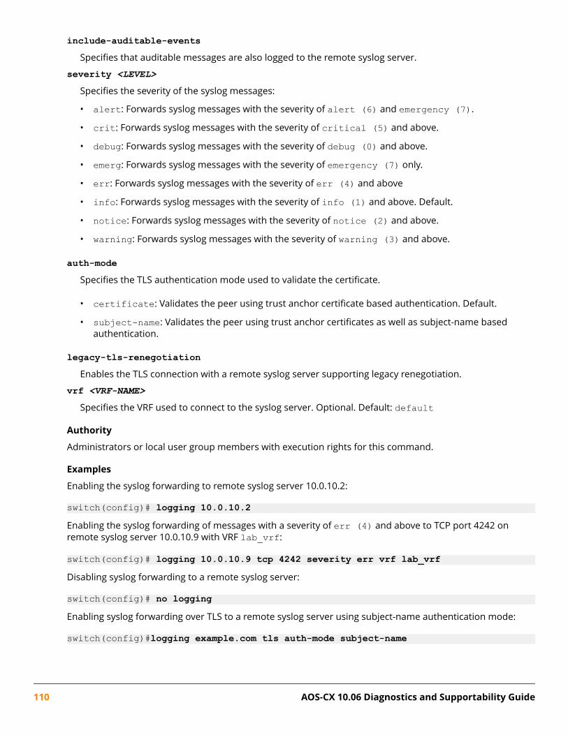
include-auditable-eventsSpecifies that auditable messages are also logged to the remote syslog server.
severity <LEVEL>Specifies the severity of the syslog messages:
• alert: Forwards syslog messages with the severity of alert (6) and emergency (7).
• crit: Forwards syslog messages with the severity of critical (5) and above.
• debug: Forwards syslog messages with the severity of debug (0) and above.
• emerg: Forwards syslog messages with the severity of emergency (7) only.
• err: Forwards syslog messages with the severity of err (4) and above
• info: Forwards syslog messages with the severity of info (1) and above. Default.
• notice: Forwards syslog messages with the severity of notice (2) and above.
• warning: Forwards syslog messages with the severity of warning (3) and above.
auth-modeSpecifies the TLS authentication mode used to validate the certificate.
• certificate: Validates the peer using trust anchor certificate based authentication. Default.
• subject-name: Validates the peer using trust anchor certificates as well as subject-name basedauthentication.
legacy-tls-renegotiationEnables the TLS connection with a remote syslog server supporting legacy renegotiation.
vrf <VRF-NAME>Specifies the VRF used to connect to the syslog server. Optional. Default: default
Authority
Administrators or local user group members with execution rights for this command.
Examples
Enabling the syslog forwarding to remote syslog server 10.0.10.2:
switch(config)# logging 10.0.10.2Enabling the syslog forwarding of messages with a severity of err (4) and above to TCP port 4242 onremote syslog server 10.0.10.9 with VRF lab_vrf:
switch(config)# logging 10.0.10.9 tcp 4242 severity err vrf lab_vrfDisabling syslog forwarding to a remote syslog server:
switch(config)# no loggingEnabling syslog forwarding over TLS to a remote syslog server using subject-name authentication mode:
switch(config)#logging example.com tls auth-mode subject-name
110 AOS-CX 10.06 Diagnostics and Supportability Guide

logging facilitySyntax
logging facility {local0 | local1 | local2 | local3 | local4 | local5 | local6 | local7}no logging facility
Description
Sets the logging facility to be used for remote syslog messages. Default: local7The no form of this command disables the logging facility to be used for remote syslog messages.
Command context
config
Parameters{local0 | local1 | local2 | local3 | local4 | local5 | local6 | local7}
Selects the logging facility to be used for remote syslog messages. Required.
Specifies the severity of the syslog messages:
• local0• local1• local2• local3• local4• local5• local6• local7
Authority
Administrators or local user group members with execution rights for this command.
Examples
Sets the local5 logging facility to be used for remote syslog messages:
switch(config)# logging facility local5
logging persistent-storageSyntax
logging persistent-storage [severity {alert|crit|debug|emerg|err|info|notice|warning}]no logging persistent-storage
Description
Enables or disables storage of logs in storage. Only logs of the specified severity and above will be preservedin the storage.
Chapter 10 Remote syslog 111
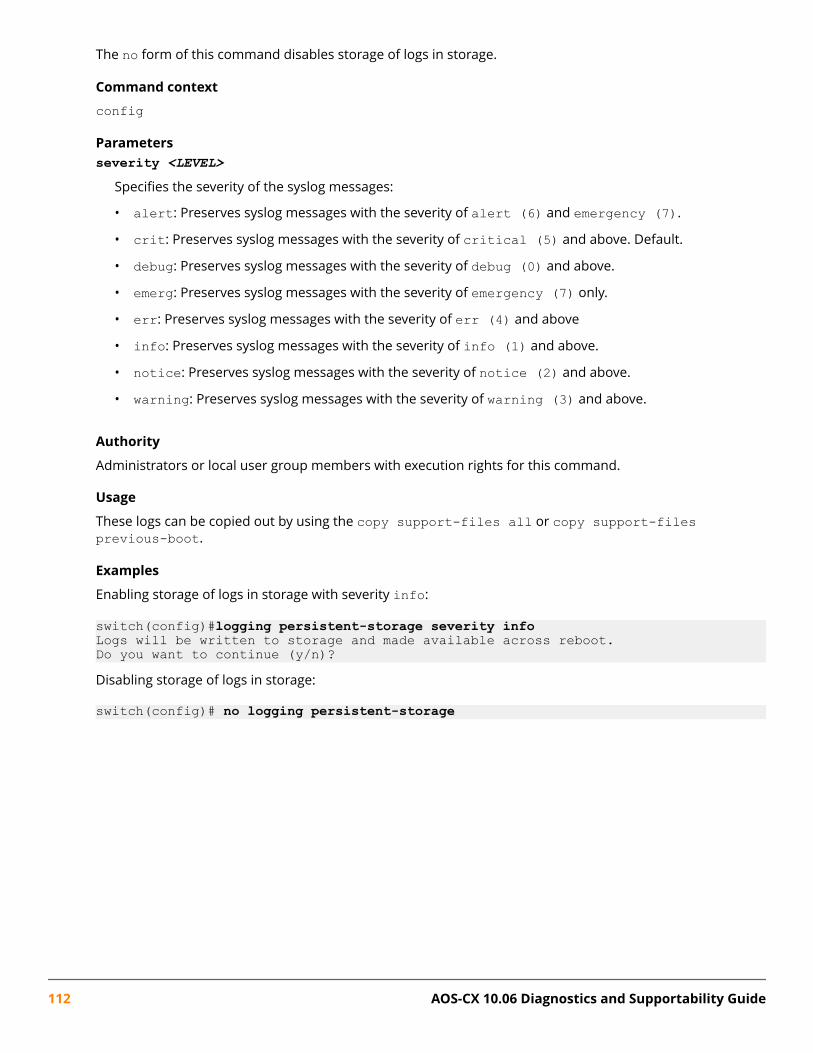
The no form of this command disables storage of logs in storage.
Command context
config
Parametersseverity <LEVEL>
Specifies the severity of the syslog messages:
• alert: Preserves syslog messages with the severity of alert (6) and emergency (7).
• crit: Preserves syslog messages with the severity of critical (5) and above. Default.
• debug: Preserves syslog messages with the severity of debug (0) and above.
• emerg: Preserves syslog messages with the severity of emergency (7) only.
• err: Preserves syslog messages with the severity of err (4) and above
• info: Preserves syslog messages with the severity of info (1) and above.
• notice: Preserves syslog messages with the severity of notice (2) and above.
• warning: Preserves syslog messages with the severity of warning (3) and above.
Authority
Administrators or local user group members with execution rights for this command.
Usage
These logs can be copied out by using the copy support-files all or copy support-filesprevious-boot.
Examples
Enabling storage of logs in storage with severity info:
switch(config)#logging persistent-storage severity infoLogs will be written to storage and made available across reboot.Do you want to continue (y/n)?Disabling storage of logs in storage:
switch(config)# no logging persistent-storage
112 AOS-CX 10.06 Diagnostics and Supportability Guide

OverviewRun Time diagnostics framework is intended to monitor and validate the health of different hardwarecomponents present in the system. It uses a set of safe hardware diagnostics test cases to validate thehealth of different hardware components. These diagnostics test cases are run periodically at everypredetermined interval. Additionally, these hardware diagnostics test cases can be run on demand.
Runtime diagnostic commandsdiagnostic monitorSyntax
diagnostic monitor {fan-tray | line-module | management-module} [<SLOT-ID>]
no diagnostic monitor {fan-tray | line-module | management-module} [<SLOT-ID>]For 6400 switches only:
diagnostic monitor {fabric <SLOT-ID>}
no diagnostic monitor {fabric <SLOT-ID>}
Description
Enables runtime diagnostics for all modules or for a specified module. This feature is enabled by default forall modules.
The no form of this command disables runtime diagnostics for all modules or for a specified module.
Command context
config
Parametersfan-tray
Specifies the enabling of diagnostic monitoring specific to a fan tray.
line-moduleSpecifies the enabling of diagnostic monitoring specific to a line module.
management-moduleSpecifies the enabling of diagnostic monitoring specific to a management module.
<SLOT-ID>
Specifies the slot ID of a module. Format: member/slot.
Authority
Administrators or local user group members with execution rights for this command.
Chapter 11Runtime diagnostics
Chapter 11 Runtime diagnostics 113

Usage
When no parameters are used in the command (diagnostic monitor or no diagnostic monitor), thecommand applies to all modules. This command impacts the diagnostics that run periodically. It does notaffect on-demand diagnostics.
Example
Enabling runtime diagnostics for a specified module:
switch(config)# diagnostic monitor management-module 1/5
diag on-demandSyntax
diag on-demand {fan-tray | line-module | management-module} [<SLOT-ID>]For 6400 switches only:
diag on-demand {fabric <SLOT-ID>}
Description
Runs the diagnostic tests for all modules or for a specified module.
Command context
Manager (#)
Parameters[fan-tray | line-module | management-module]
Selects the options for enabling or disabling runtime diagnostics for a specific module.
fan-traySpecifies the enabling of diagnostic monitoring specific to a fan tray.
line-moduleSpecifies the enabling of diagnostic monitoring specific to a line module.
management-moduleSpecifies the enabling of diagnostic monitoring specific to a management module.
<SLOT-ID>
Specifies the member/slot for management modules (1/1 or 1/2), line modules (1/3-1/7, 1/8-1/12), fantrays (1/1-1/3), and fabric modules (1/1-1/2) on a 6400 switch.
Specifies the member/slot for management modules (1/1), line modules (1/1), and fan trays (1/1-1/2) ona 6300 switch.
Authority
Administrators or local user group members with execution rights for this command.
Usage
When no parameters are used in the command (diag on-demand), the command applies to all modules.
Examples
Running diagnostic tests for all modules on a 6300 switch:
114 AOS-CX 10.06 Diagnostics and Supportability Guide

switch# diag on-demandFetching Test results. Please wait ...
Module ID Diagnostics Success Performed-------------------- ----- ----------- -------FanTray 1/2 1 100%FanTray 1/1 1 100%LineModule 1/1 13 100%ManagementModule 1/1 13 100%Running diagnostic tests for a specific module on a 6300 switch:
switch# diag on-demand management-module 1/1Performing diagnostic tests. Please wait ...Fetching Test results. Please wait ...
Module ID Diagnostics Success Performed-------------------- ----- ----------- -------ManagementModule 1/1 13 100%Running diagnostic tests for all modules on a 6400 switch:
switch# diag on-demandFetching Test results. Please wait ...
Module ID Diagnostics Success Performed-------------------- ----- ----------- -------FanTray 1/2 2 100%LineModule 1/3 24 100%ManagementModule 1/1 19 100%LineModule 1/7 12 100%Fabric 1/1 6 100%LineModule 1/5 24 100%LineModule 1/4 24 100%FanTray 1/1 2 100%LineModule 1/6 24 100%Running diagnostic tests for a specific module on a 6400 switch:
switch# diag on-demand management-module Performing diagnostic tests. Please wait ...Fetching Test results. Please wait ...
Module ID Diagnostics Success Performed-------------------- ----- ----------- -------ManagementModule 1/1 19 100%
show diagnosticSyntax
show diagnostic {fan-tray | line-module | management-module} [<SLOT-ID>] {brief | detail} [vsx-peer]
Description
Displays the diagnostic test results for all modules or for a specified module.
Chapter 11 Runtime diagnostics 115

Command context
Manager (#)
Parameters[fan-tray | line-module | management-module]
Selects the options for enabling or disabling runtime diagnostics for a specific module.
fan-traySpecifies the enabling of diagnostic monitoring specific to a fan tray.
line-moduleSpecifies the enabling of diagnostic monitoring specific to a line module.
management-moduleSpecifies the enabling of diagnostic monitoring specific to a management module.
<SLOT-ID>
Specifies the member/slot for management modules (1/1), line modules (1/1), and fan trays (1/1-1/2) ona 6300 switch.
[vsx-peer]Shows the output from the VSX peer switch. If the switches do not have the VSX configuration or the ISLis down, the output from the VSX peer switch is not displayed. This parameter is available on switchesthat support VSX.
Authority
Administrators or local user group members with execution rights for this command.
Usage
When no parameters are used in the command (show diagnostic), the command applies to all modules.
Example
Showing diagnostic test results in brief format for all modules on a 6300 switch:
switch# show diagnostic briefModule ID Diagnostics Success Performed-------------------- ----- ----------- -------ManagementModule 1/1 13 100%LineModule 1/1 13 100%FanTray 1/1 1 100%FanTray 1/2 1 100%Showing diagnostic test results in brief format for a specified module on a 6300 switch:
switch# show diagnostic line-module brief
Module ID Diagnostics Success Performed-------------------- ----- ----------- -------LineModule 1/1 13 100%Showing diagnostic test results in detail format for all modules on a 6300 switch:switch# show diagnostic detail
Module : ManagementModule 1/1
116 AOS-CX 10.06 Diagnostics and Supportability Guide
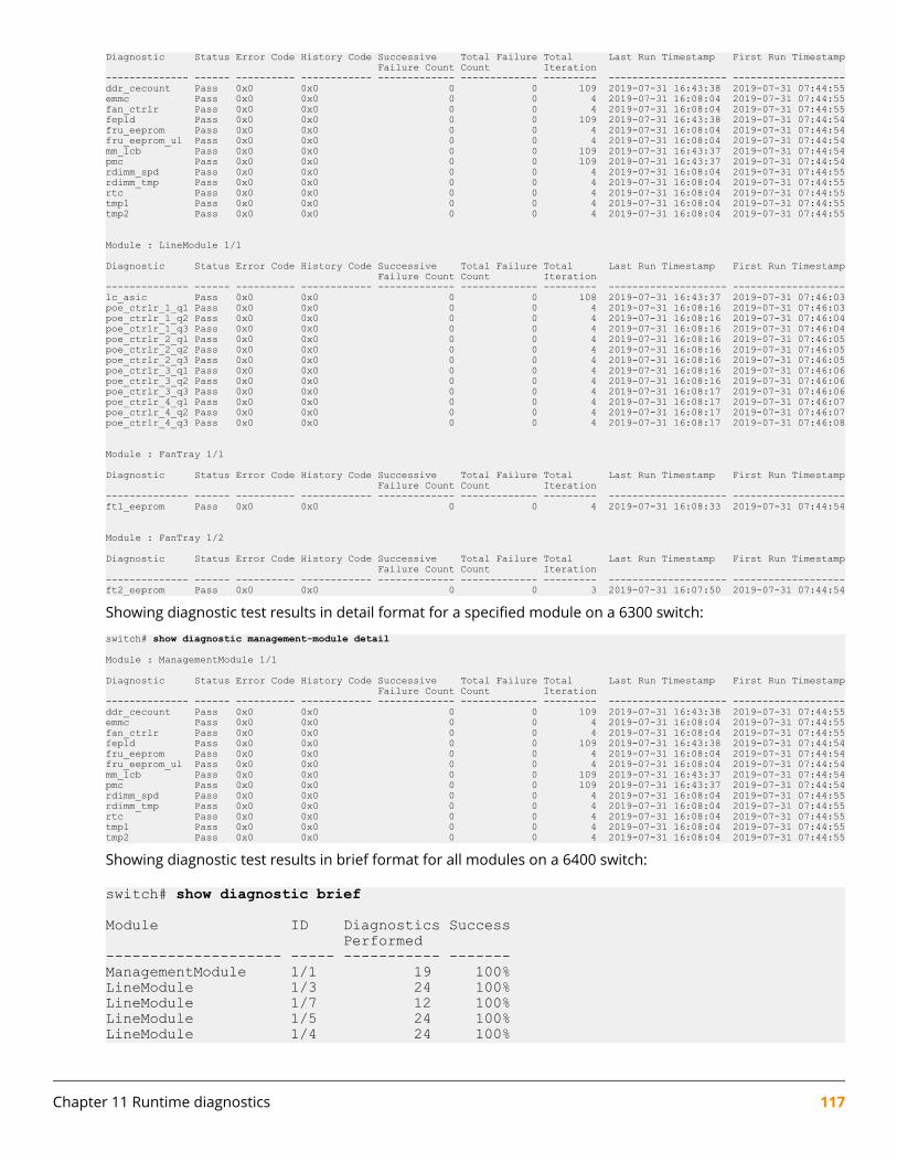
Diagnostic Status Error Code History Code Successive Total Failure Total Last Run Timestamp First Run Timestamp Failure Count Count Iteration-------------- ------ ---------- ------------ ------------- ------------- --------- -------------------- -------------------ddr_cecount Pass 0x0 0x0 0 0 109 2019-07-31 16:43:38 2019-07-31 07:44:55emmc Pass 0x0 0x0 0 0 4 2019-07-31 16:08:04 2019-07-31 07:44:55fan_ctrlr Pass 0x0 0x0 0 0 4 2019-07-31 16:08:04 2019-07-31 07:44:55fepld Pass 0x0 0x0 0 0 109 2019-07-31 16:43:38 2019-07-31 07:44:54fru_eeprom Pass 0x0 0x0 0 0 4 2019-07-31 16:08:04 2019-07-31 07:44:54fru_eeprom_ul Pass 0x0 0x0 0 0 4 2019-07-31 16:08:04 2019-07-31 07:44:54mm_lcb Pass 0x0 0x0 0 0 109 2019-07-31 16:43:37 2019-07-31 07:44:54pmc Pass 0x0 0x0 0 0 109 2019-07-31 16:43:37 2019-07-31 07:44:54rdimm_spd Pass 0x0 0x0 0 0 4 2019-07-31 16:08:04 2019-07-31 07:44:55rdimm_tmp Pass 0x0 0x0 0 0 4 2019-07-31 16:08:04 2019-07-31 07:44:55rtc Pass 0x0 0x0 0 0 4 2019-07-31 16:08:04 2019-07-31 07:44:55tmp1 Pass 0x0 0x0 0 0 4 2019-07-31 16:08:04 2019-07-31 07:44:55tmp2 Pass 0x0 0x0 0 0 4 2019-07-31 16:08:04 2019-07-31 07:44:55
Module : LineModule 1/1
Diagnostic Status Error Code History Code Successive Total Failure Total Last Run Timestamp First Run Timestamp Failure Count Count Iteration-------------- ------ ---------- ------------ ------------- ------------- --------- -------------------- -------------------lc_asic Pass 0x0 0x0 0 0 108 2019-07-31 16:43:37 2019-07-31 07:46:03poe_ctrlr_1_q1 Pass 0x0 0x0 0 0 4 2019-07-31 16:08:16 2019-07-31 07:46:03poe_ctrlr_1_q2 Pass 0x0 0x0 0 0 4 2019-07-31 16:08:16 2019-07-31 07:46:04poe_ctrlr_1_q3 Pass 0x0 0x0 0 0 4 2019-07-31 16:08:16 2019-07-31 07:46:04poe_ctrlr_2_q1 Pass 0x0 0x0 0 0 4 2019-07-31 16:08:16 2019-07-31 07:46:05poe_ctrlr_2_q2 Pass 0x0 0x0 0 0 4 2019-07-31 16:08:16 2019-07-31 07:46:05poe_ctrlr_2_q3 Pass 0x0 0x0 0 0 4 2019-07-31 16:08:16 2019-07-31 07:46:05poe_ctrlr_3_q1 Pass 0x0 0x0 0 0 4 2019-07-31 16:08:16 2019-07-31 07:46:06poe_ctrlr_3_q2 Pass 0x0 0x0 0 0 4 2019-07-31 16:08:16 2019-07-31 07:46:06poe_ctrlr_3_q3 Pass 0x0 0x0 0 0 4 2019-07-31 16:08:17 2019-07-31 07:46:06poe_ctrlr_4_q1 Pass 0x0 0x0 0 0 4 2019-07-31 16:08:17 2019-07-31 07:46:07poe_ctrlr_4_q2 Pass 0x0 0x0 0 0 4 2019-07-31 16:08:17 2019-07-31 07:46:07poe_ctrlr_4_q3 Pass 0x0 0x0 0 0 4 2019-07-31 16:08:17 2019-07-31 07:46:08
Module : FanTray 1/1
Diagnostic Status Error Code History Code Successive Total Failure Total Last Run Timestamp First Run Timestamp Failure Count Count Iteration-------------- ------ ---------- ------------ ------------- ------------- --------- -------------------- -------------------ft1_eeprom Pass 0x0 0x0 0 0 4 2019-07-31 16:08:33 2019-07-31 07:44:54
Module : FanTray 1/2
Diagnostic Status Error Code History Code Successive Total Failure Total Last Run Timestamp First Run Timestamp Failure Count Count Iteration-------------- ------ ---------- ------------ ------------- ------------- --------- -------------------- -------------------ft2_eeprom Pass 0x0 0x0 0 0 3 2019-07-31 16:07:50 2019-07-31 07:44:54
Showing diagnostic test results in detail format for a specified module on a 6300 switch:switch# show diagnostic management-module detail
Module : ManagementModule 1/1
Diagnostic Status Error Code History Code Successive Total Failure Total Last Run Timestamp First Run Timestamp Failure Count Count Iteration-------------- ------ ---------- ------------ ------------- ------------- --------- -------------------- -------------------ddr_cecount Pass 0x0 0x0 0 0 109 2019-07-31 16:43:38 2019-07-31 07:44:55emmc Pass 0x0 0x0 0 0 4 2019-07-31 16:08:04 2019-07-31 07:44:55fan_ctrlr Pass 0x0 0x0 0 0 4 2019-07-31 16:08:04 2019-07-31 07:44:55fepld Pass 0x0 0x0 0 0 109 2019-07-31 16:43:38 2019-07-31 07:44:54fru_eeprom Pass 0x0 0x0 0 0 4 2019-07-31 16:08:04 2019-07-31 07:44:54fru_eeprom_ul Pass 0x0 0x0 0 0 4 2019-07-31 16:08:04 2019-07-31 07:44:54mm_lcb Pass 0x0 0x0 0 0 109 2019-07-31 16:43:37 2019-07-31 07:44:54pmc Pass 0x0 0x0 0 0 109 2019-07-31 16:43:37 2019-07-31 07:44:54rdimm_spd Pass 0x0 0x0 0 0 4 2019-07-31 16:08:04 2019-07-31 07:44:55rdimm_tmp Pass 0x0 0x0 0 0 4 2019-07-31 16:08:04 2019-07-31 07:44:55rtc Pass 0x0 0x0 0 0 4 2019-07-31 16:08:04 2019-07-31 07:44:55tmp1 Pass 0x0 0x0 0 0 4 2019-07-31 16:08:04 2019-07-31 07:44:55tmp2 Pass 0x0 0x0 0 0 4 2019-07-31 16:08:04 2019-07-31 07:44:55
Showing diagnostic test results in brief format for all modules on a 6400 switch:
switch# show diagnostic brief
Module ID Diagnostics Success Performed-------------------- ----- ----------- -------ManagementModule 1/1 19 100%LineModule 1/3 24 100%LineModule 1/7 12 100%LineModule 1/5 24 100%LineModule 1/4 24 100%
Chapter 11 Runtime diagnostics 117

LineModule 1/6 24 100%Fabric 1/1 6 100%FanTray 1/2 2 100%FanTray 1/1 2 100%Showing diagnostic test results in brief format for a specified module on a 6400 switch:
switch# show diagnostic management-module brief
Module ID Diagnostics Success Performed-------------------- ----- ----------- -------ManagementModule 1/1 19 100%Showing diagnostic test results in detail format for a specified module on a 6400 switch:
switch# show diagnostic management-module detail
Module : ManagementModule 1/1
Diagnostic Status Error Code History Code Successive Total Failure Total Last Run Timestp Failure Count Count Iteration-------------- ------ ---------- ------------ ------------- ------------- --------- ----------------curr_sensor Pass 0x0 0x0 0 0 2 2019-10-14 00:25ddr_cecount Pass 0x0 0x0 0 0 34 2019-10-14 01:26eeprom Pass 0x0 0x0 0 0 2 2019-10-14 00:25eeprom_ul Pass 0x0 0x0 0 0 2 2019-10-14 00:25emmc Pass 0x0 0x0 0 0 2 2019-10-14 00:26icbbp Pass 0x0 0x0 0 0 34 2019-10-14 01:24icbx Pass 0x0 0x0 0 0 34 2019-10-14 01:25ledpld Pass 0x0 0x0 0 0 34 2019-10-14 01:24mm_mcb Pass 0x0 0x0 0 0 34 2019-10-14 01:24psu1 Pass 0x0 0x0 0 0 2 2019-10-14 00:27psu1_eeprom Pass 0x0 0x0 0 0 2 2019-10-14 00:26psu2 Pass 0x0 0x0 0 0 2 2019-10-14 00:27psu2_eeprom Pass 0x0 0x0 0 0 2 2019-10-14 00:27rdimm_spd Pass 0x0 0x0 0 0 2 2019-10-14 00:26rdimm_tmp Pass 0x0 0x0 0 0 2 2019-10-14 00:26rtc Pass 0x0 0x0 0 0 2 2019-10-14 00:26tmp1 Pass 0x0 0x0 0 0 2 2019-10-14 00:25tmp2 Pass 0x0 0x0 0 0 2 2019-10-14 00:25tmp3 Pass 0x0 0x0 0 0 2 2019-10-14 00:25
show diagnostic eventsSyntax
show diagnostic events
Description
Displays the diagnostic related event logs.
Authority
Administrators or local user group members with execution rights for this command.
Example
Showing diagnostic related event logs:
switch# show diagnostic events2019-08-07:17:19:21.214532|hhmd|106001|ERR|Diagnostic mm_mcbe failed with error code 0x380 on management module 1/52019-08-07:17:19:21.214554|hhmd|106001|ERR|Diagnostic pmc failed with error code 0x4 on management module 1/52019-08-07:17:19:21.215532|hhmd|106001|ERR|Diagnostic ledpld failed with error code 0x4 on management module 1/5
118 AOS-CX 10.06 Diagnostics and Supportability Guide

2019-08-07:17:19:21.353221|hhmd|106001|ERR|Diagnostic mm_mcbe failed with error code 0x380 on management module 1/52019-08-07:17:19:21.354421|hhmd|106001|ERR|Diagnostic pmc failed with error code 0x4 on management module 1/52019-08-07:17:19:21.453221|hhmd|106001|ERR|Diagnostic ledpld failed with error code 0x4 on management module 1/5Showing diagnostic related event logs (Output from a 6400 switch):
switch# show diagnostic events ---------------------------------------------------Event logs from current boot ---------------------------------------------------2019-10-17T20:27:04.066486+00:00 6405 hhmd[9237]: Event|3002|LOG_ERR|LC|1/6|Diagnostic brd_tmp1 failed with error code 0x1000000 on line card 42019-10-17T20:27:04.102968+00:00 6405 hhmd[9237]: Event|3002|LOG_ERR|LC|1/3|Diagnostic brd_tmp1 failed with error code 0x1000000 on line card 12019-10-17T20:27:04.117467+00:00 6405 hhmd[9237]: Event|3002|LOG_ERR|LC|1/5|Diagnostic brd_tmp1 failed with error code 0x1000000 on line card 32019-10-17T20:27:04.210276+00:00 6405 hhmd[9237]: Event|3002|LOG_ERR|LC|1/4|Diagnostic brd_tmp1 failed with error code 0x1000000 on line card 22019-10-17T20:27:04.212133+00:00 6405 hhmd[9237]: Event|3002|LOG_ERR|LC|1/7|Diagnostic brd_tmp1 failed with error code 0x1000000 on line card 5
Chapter 11 Runtime diagnostics 119

OverviewService OS is an operating system that the customer only uses to fix filesystem corruption, download andupdate firmware, and other support related issues. HPE Service OS is a Linux distribution that acts as astandalone bootloader and recovery OS for AOS-CX-based switches. It is only accessible if the user isconsoled into the switch. The main high level features provided include:
• Access to file system partitions for retrieval of logs, coredumps, and configuration for supportabilitypurposes.
• Filesystem utilities to format and partition a corrupted storage disk.
• Management interface networking with TFTP to download and update a product image.
• Ability to boot primary and secondary firmware images (.SWI file) on the storage disk.
• Support for clearing the AOS-CX startup-config.
• Ability to not only clear the admin password for AOS-CX, but also change it in SVOS.
• Ability to set the secure mode to enhanced or standard.
This document covers the customer CLI commands available in Service OS, as well as a few non-CLI features.
Service OS CLI loginDescription
If the user enters 0 at the boot menu prompt, they will be presented with a Service OS CLI login prompt. Theuser must enter the login account "admin" to log in. By default, Service OS does not require a password.
To reboot without logging in, enter reboot as the login user name.
There are two additional login accounts that execute a command without requiring a password: reboot andzeroize. Enter the login account reboot to reboot the management module and zeroize to initiate azeroization process. The zeroize user account helps a user reset the admin user account's password.
Example
ServiceOS GT.01.01.0001 switch ttyS0
To reboot without logging in, enter 'reboot' as the login user name.
switch login: admin
Hewlett Packard EnterpriseSVOS>```
```ServiceOS GT.01.01.0001 switch ttyS0
Chapter 12Service OS
120 AOS-CX 10.06 Diagnostics and Supportability Guide

To reboot without logging in, enter 'reboot' as the login user name.
switch login: reboot
Hewlett Packard Enterprisereboot: Restarting system```
```ServiceOS login: zeroizeThis will securely erase all customer data, including passwords, andreset the switch to factory defaults.This action requires proof of physical access via a USB drive. * Create a FAT32 formatted USB drive * Create a file in the root directory of the USB drive named zeroize.txt * Type the following serial number into the zeroize.txt file: 772632X1830018 * Insert the USB drive into the target module * Confirm the following prompt to continue
Continue (y/n)? y############################WARNING############################This will securely erase all customer data and reset the switchto factory defaults. This will initiate a reboot and render theswitch unavailable until the zeroization is complete.This should take several minutes to one hour to complete.############################WARNING############################
Continue (y/n)? y
reboot: Restarting system
Service OS user accountsService OS provides a single admin login account. By default, no password is required to log in. Service OSwill require a password if the Service OS admin user account password feature is enabled. This setting canbe enabled or disabled in AOS-CX.
Service OS boot menuDescription
On boot, the user is presented with a Service OS version banner with version, build date, build time, build ID,and SHA strings.
The user is then shown the boot image profiles.
• Enter 0 to boot the Service OS login CLI.
• Enter 1 to boot the primary firmware image.
• Enter 2 to boot the secondary firmware image.
• If no input is given within 5 seconds, the default boot profile is selected. Alternatively, press Enter toselect the default boot profile.
The image selected by the user during boot is a run-time decision only and will not persist across reboots.The default image can be configured using the boot set-default command.
Chapter 12 Service OS 121

Example
ServiceOS Information: Version: GT.01.01.0001 Build Date: 2017-07-19 14:52:31 PDT Build ID: ServiceOS:GT.01.01.0001:461519208911:201707191452 SHA: 46151920891195cdb2267ea6889a3c6cbc3d4193
Boot Profiles:
0. Service OS Console1. Primary Software Image [XL.01.01.0001]2. Secondary Software Image [XL.01.01.0002]
Select profile(primary):
NOTE: The (primary) string in the boot menu displays the default boot profile that will bebooted after the timeout period. This string will change to (secondary) or (Service OS)depending on the current default boot option.
Console configurationDuring boot, Service OS communicates with the RJ45 serial console with a baud rate of 115200. There is nooption to change the baud rate during boot.
Additionally, if a USB console is connected to the management module console port, input will automaticallybe switched over to use the USB console. Automatic switching to USB is consistent with the AOS-CX USBconsole behavior.
NOTE: Console output always displays on both the RJ45 console port and the USB console port.
AOS-CX bootDescription
After the user has input a boot profile selection at the boot menu or the 5-second selection timeout hasexpired, Service OS will boot an AOS-CX image.
Service OS displays the following boot strings embedded in the product image header:
• Image name
• Image version
• Build ID
• Build date
Service OS will then present status and boot the image.
Example
Booting primary software image...Verifying Image...Image Info:
Name: ArubaOS-CX
122 AOS-CX 10.06 Diagnostics and Supportability Guide

Version: XL.01.01.0001 Build Id: ArubaOS-CX:XL.01.01.0001:1a36111da4e0:201707171452 Build Date: 2017-07-17 14:52:27 PDT
Extracting Image...Loading Image...Done.kexec: Starting new kernel
File system accessDescription
When the user logs in to the Service OS CLI, they are presented with a limited file system. The user can usestandard file system commands of cd, ls, and pwd to view and move through the file system.
On login, the user is first placed in the /home directory:
(C) Copyright 2017 Hewlett Packard Enterprise Development LP
RESTRICTED RIGHTS LEGENDConfidential computer software. Valid license from Hewlett Packard EnterpriseDevelopment LP required for possession, use or copying. Consistent with FAR12.211 and 12.212, Commercial Computer Software, Computer SoftwareDocumentation, and Technical Data for Commercial Items are licensed to theU.S. Government under vendor's standard commercial license.
To reboot without logging in, enter 'reboot' as the login user name.
ServiceOS login: adminSVOS> pwd/homeSVOS>The home directory and the USB device (/mnt/usb and any sub directory) are the only writable directoriesavailable. These directories can be used as a staging location for downloading product images using TFTP. /home can also be used as temporary storage before copying files from the management module throughTFTP or USB. Any changes made to /home will not persist across reboots or after booting an AOS-CX image.
The root / directory displays viewable directories:
SVOS> ls /bin coredump lib mnt selftestcli home logs nosSVOS>The directories coredump, selftest, nos, and logs each provide the user access to an SSD partition mount.The user may read, but not write any file on these partitions.
These mount points allow the user to copy files on the SSD to a USB storage device or upload files usingTFTP. Copying files from the SSD is intended to be used under the guidance of a support engineer (to uploadlogs or coredumps to HPE support).
USB storage device access is provided through the mount at /mnt/usb.
The remaining directories in the root file system bin, cli, and lib are not intended to be used by thecustomer.
Chapter 12 Service OS 123

Service OS mount failureDescription
If the SSD is detected as missing or any of the partitions could not be mounted, Service OS will force theuser to boot to the Service OS console and display an error message indicating that recovery should beattempted using the format command.
Example
(C) Copyright 2017 Hewlett Packard Enterprise Development LP
RESTRICTED RIGHTS LEGENDConfidential computer software. Valid license from Hewlett Packard EnterpriseDevelopment LP required for possession, use or copying. Consistent with FAR12.211 and 12.212, Commercial Computer Software, Computer SoftwareDocumentation, and Technical Data for Commercial Items are licensed to theU.S. Government under vendor's standard commercial license.
To reboot without logging in, enter 'reboot' as the login user name.
Error, Could not mount the primary storage device. This may be due to filesystem or device corruption. Please attempt to recover using the "format" command.
ServiceOS login:
Service OS CLI command listDescription
After login to Service OS CLI, the user may enter the commands help or ? to get a full list of commands and aterse description for each command. The user may also enter <command> followed by --help to get moredetailed help and usage for a specific command.
Example
SVOS> ?Available Commands:
? - Display help screen cd - Change the working directory pwd - Print the current working directory help - Display help screen boot - Boot a product imageconfig-clear - Clears the startup-config erase - Securely erase storage devices on the management module format - Formats and partitions the primary storage device identify - Prints hardware identification information ip - Sets the OOBM Port Network Configuration mount - Mount a storage device ping - Send ICMP ECHO_REQUEST to network hosts (IPv4) reboot - Reboots the Management Module password - Set the admin account password secure-mode - Sets or retrieves the secure mode setting sh - Launch support shell umount - Unmounts a storage device update - Update a product image version - Prints ServiceOS release version information cat - Prints files to stdout
124 AOS-CX 10.06 Diagnostics and Supportability Guide

cp - Copy files and directories du - Estimate file space usage ls - List directory contents md5sum - Compute and check md5 message digest mkdir - Make directories mv - Move (rename) files rm - Remove files or directories rmdir - Remove empty directories tftp - Allows transfer of files to/from a remote machine exit - Logout
Enter '<command> --help' for more info
Service OS CLI features and limitationsDescription
The Service OS CLI provides basic shell functionality that allows you to execute commands and passarguments to those commands only. The following features are not available:
• Input/output redirection (<, >, >>)
• Job control (&, fg, bg)
• Process piping (|)
• File globbing (\*)
NOTE: Even though the Service OS CLI does not provide file globbing capabilities, somecommands may provide this functionality internally. An example is the ls command.
The following common features are available:
• Command history (Up Arrow) and search (Ctrl-R)
• Tab completion for file and folder names (not CLI commands)
• Command abort using Ctrl-C
Service OS CLI commandsbootSyntax
boot
Description
Presents you with the boot menu prompt. You can then specify which boot profile: primary, secondary, orService OS console.
Command context
Service OS (SVOS>)
Authority
Administrators or local user group members with execution rights for this command.
Chapter 12 Service OS 125

Example
Presenting the boot menu prompt:
SVOS> boot
ServiceOS Information: Version: GT.01.01.0005 Build Date: 2017-07-19 14:52:31 PDT Build ID: ServiceOS:GT.01.01.0001:461519208911:201707191452 SHA: 46151920891195cdb2267ea6889a3c6cbc3d4193
Boot Profiles:
0. Service OS Console1. Primary Software Image [XL.01.01.0001]2. Secondary Software Image [XL.01.01.0001]
Select profile(primary):
catSyntax
cat <FILENAME/DIRECTORY-NAME>
Description
Prints the contents of a file to the console. The Service OS does not allow command output redirection, sothis command is only useful for reading short text files.
Command context
Service OS (SVOS>)
Parameters<FILENAME/DIRECTORY-NAME>
Shows the contents of the specified file or directory.
Authority
Administrators or local user group members with execution rights for this command.
Example
Showing the contents of /nos/hosts:
SVOS> cat /nos/hosts127.0.0.1 localhost.localdomain localhost
SVOS>
cd pathSyntax
cd path
Description
Changes the current working directory.
126 AOS-CX 10.06 Diagnostics and Supportability Guide

Command context
Service OS (SVOS>)
Authority
Administrators or local user group members with execution rights for this command.
Example
Changing the current working directory:
cd /
config-clearSyntax
config-clear
Description
Configures the switch to set all configuration settings to factory default when the switch is restarted. Thenext time the switch starts, the current startup-config is renamed to startup-config-fixme, and anew startup-config is created with factory default settings.
NOTE: Using this command is not the same as performing zeroization, which securely erasesthe entire primary storage and other devices, and not just the configuration.
Command context
Service OS (SVOS>)
Authority
Administrators or local user group members with execution rights for this command.
Example
Configuring the system to clear the switch configuration:
SVOS> config-clear
The switch configuration will be cleared.
Continue (y/n)? yThe system has been configured to clear the startup-config on the nextboot. Please execute the 'boot' command to complete this action.SVOS>
cpSyntaxcp [options] <SOURCE-FILENAME/SOURCE-DIRECTORY> <DESTINATION-FLENAME/DESTINATION-DIRECTORY>
Description
Copies files or directories.
Chapter 12 Service OS 127
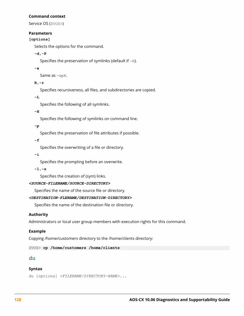
Command context
Service OS (SVOS>)
Parameters[options]
Selects the options for the command.
-d,-PSpecifies the preservation of symlinks (default if -R).
-aSame as -dpR.
R,-rSpecifies recursiveness, all files, and subdirectories are copied.
-LSpecifies the following of all symlinks.
-HSpecifies the following of symlinks on command line.
-pSpecifies the preservation of file attributes if possible.
-fSpecifies the overwriting of a file or directory.
-iSpecifies the prompting before an overwrite.
-l,-sSpecifies the creation of (sym) links.
<SOURCE-FILENAME/SOURCE-DIRECTORY>
Specifies the name of the source file or directory.
<DESTINATION-FLENAME/DESTINATION-DIRECTORY>
Specifies the name of the destination file or directory.
Authority
Administrators or local user group members with execution rights for this command.
Example
Copying /home/customers directory to the /home/clients directory:
SVOS> cp /home/customers /home/clients
duSyntax
du [options] <FILENAME/DIRECTORY-NAME>...
128 AOS-CX 10.06 Diagnostics and Supportability Guide

Description
Shows estimated disk space used for each file or directory or both.
Command context
Service OS (SVOS>)
Parameters[options]
Selects the options for the command.
-aShow file sizes.
-LShows all symlinks.
-HShows symlinks on a command line.
-d, NShows limited output to directories (and files with -a) of depth less than N.
-cShows the total disk space usage of all files or directories or both.
-lShows the count sizes if hard linked.
-sShows only a total for each argument.
-xDoes not show directories on different file systems.
-hShow sizes in human readable format (1K, 243M, and 2G).
-mShow sizes in megabytes.
-kShow sizes in kilobytes (default).
<FILENAME/DIRECTORY-NAME>
Specifies the file or directory or both for displaying a size estimate.
Authority
Administrators or local user group members with execution rights for this command.
Example
Estimating disk space for the /nos directory:
SVOS> du -ah /nos196.4M /nos/primary.swi
Chapter 12 Service OS 129
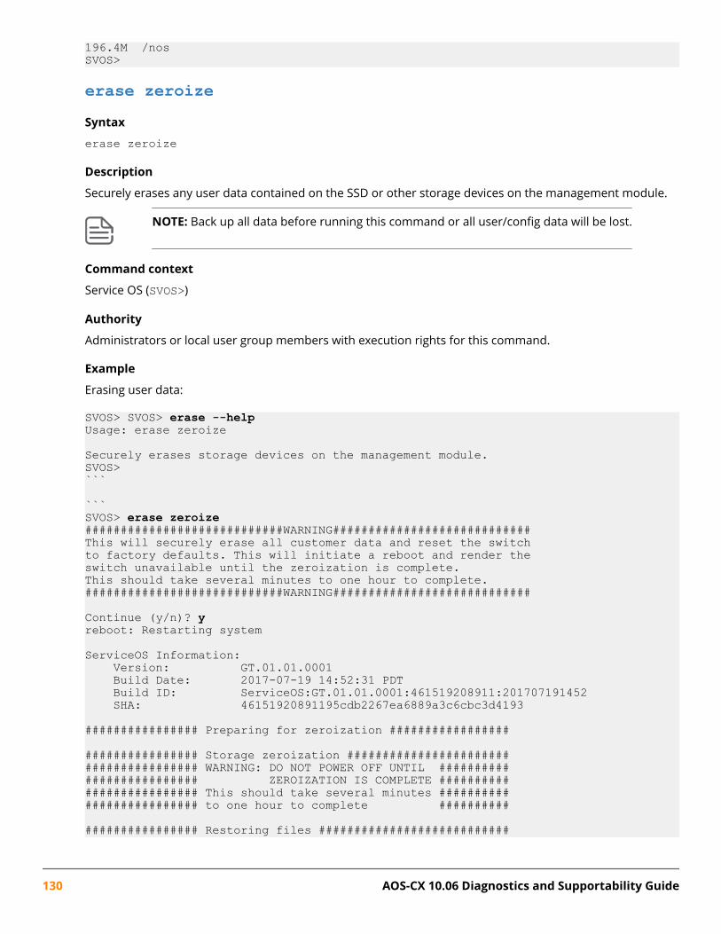
196.4M /nosSVOS>
erase zeroizeSyntax
erase zeroize
Description
Securely erases any user data contained on the SSD or other storage devices on the management module.
NOTE: Back up all data before running this command or all user/config data will be lost.
Command context
Service OS (SVOS>)
Authority
Administrators or local user group members with execution rights for this command.
Example
Erasing user data:
SVOS> SVOS> erase --helpUsage: erase zeroize
Securely erases storage devices on the management module.SVOS>```
```SVOS> erase zeroize############################WARNING############################This will securely erase all customer data and reset the switchto factory defaults. This will initiate a reboot and render theswitch unavailable until the zeroization is complete.This should take several minutes to one hour to complete.############################WARNING############################
Continue (y/n)? yreboot: Restarting system
ServiceOS Information: Version: GT.01.01.0001 Build Date: 2017-07-19 14:52:31 PDT Build ID: ServiceOS:GT.01.01.0001:461519208911:201707191452 SHA: 46151920891195cdb2267ea6889a3c6cbc3d4193
################ Preparing for zeroization #################
################ Storage zeroization ####################################### WARNING: DO NOT POWER OFF UNTIL ########################## ZEROIZATION IS COMPLETE ########################## This should take several minutes ########################## to one hour to complete ##########
################ Restoring files ###########################
130 AOS-CX 10.06 Diagnostics and Supportability Guide

exitSyntax
exit
Description
Logs the user out from the SVOS> prompt.
Command context
Service OS (SVOS>)
Authority
Administrators or local user group members with execution rights for this command.
Example
Loging the user out from the SVOS> prompt:
SVOS> exit
(C) Copyright 2017 Hewlett Packard Enterprise Development LP
RESTRICTED RIGHTS LEGENDConfidential computer software. Valid license from Hewlett Packard EnterpriseDevelopment LP required for possession, use or copying. Consistent with FAR12.211 and 12.212, Commercial Computer Software, Computer SoftwareDocumentation, and Technical Data for Commercial Items are licensed to theU.S. Government under vendor's standard commercial license.
To reboot without logging in, enter 'reboot' as the login user name.
ServiceOS login:
formatSyntax
format
Description
Configures the primary storage device with the correct partition and file system formatting. This commandremoves all pre-existing data on the primary storage device.
Command context
Service OS (SVOS>)
Authority
Administrators or local user group members with execution rights for this command.
Example
Configuring the primary storage device with the correct partition and file system formatting:
SVOS> format##################WARNING####################
Chapter 12 Service OS 131

The following action will cause all data onthe primary storage device to be lost. Afterformatting has completed, a reboot will beinitiated to complete storage initialization.##################WARNING####################
Continue? (y/n): y
Working...This may take a few minutes...
identifySyntax
identify
Description
Command context
Service OS (SVOS>)
Authority
Administrators or local user group members with execution rights for this command.
Example
Output from a 6400/6300 switch:
SVOS> identifymc svos_primary : FL.01.05.0001mc svos_secondary : FL.01.05.0001mc uboot_single : FL.01.0001mc uboot_capsule : FL.01.0001mc pmc_single : 0x4mc pmc_primary : 0x4mc pmc_secondary : 0x4mc mcb_single : 0x6mc mcb_primary : 0x6mc mcb_secondary : 0x6mc mcb_factory : 0x3mc ledpld_single : 0x4mc ledpld_primary : 0x4mc ledpld_secondary : 0x4mc tpm : 0x102420E
ipSyntax
ip {show | dhcp | disable | addr <ADDR-NETMASK-GATEWAY>}
Description
Shows or configures the port with a static IP address (IPv4 only) or enables the DHCP client on the port. Anaddress is set only if a DHCP server is available to provide one.
Command context
Service OS (SVOS>)
132 AOS-CX 10.06 Diagnostics and Supportability Guide

Parameters{show | dhcp | disable | addr <ADDR-NETMASK-GATEWAY>}
Selects the options for the OOBM port.
showShows the OOBM port.
dhcpConfigures the port with a DHCP address.
disableDisables the OOBM port.
addr <addr netmask gateway>Configures the port with a static IP address (IPv4 only). Specify address, netmask, and gateway asA.B.C.D.
Authority
Administrators or local user group members with execution rights for this command.
Example
Configuring the port with a DHCP IP address:
SVOS> ip dhcpSVOS> ip showInterface : Link UpIP Address : 10.0.26.17Subnet Mask: 255.255.252.0Gateway : 10.0.24.1
SVOS> ip disableSVOS> ip showInterface : DisabledSVOS>
lsSyntax
ls [<OPTIONS>] [<FILE-NME>]
Description
This command lists directory contents.
Command context
Service OS (SVOS>)
Parameters<OPTIONS>
Specifies options for the command.
-1Shows one-column output.
Chapter 12 Service OS 133

-aShows entries which start with a period (.).
-AShows output similar to -a, but excludes a period (.) and a double period (..).
-CShows output list by columns.
-xShows output list by lines.
-dShows listing of directory entries instead of contents
-LFollows symlinks.
-HFollows symlinks on the command line.
-RRecurse.
-pAppends a slash (/) to directory entries.
-FAppends an indicator to entries. An indicator can be as an asterisk (*) or slash (/) or equal sign (=) orat sign (@) or pipe (|).
-lShows the output in a long listing format.
-iShows the list inode numbers.
-nShows a list of numeric UIDs and GIDs instead of names.
-sShows a list of allocated blocks.
-eShows in one column a list with the full date and time.
-hShows list sizes in human readable format (1K, 243M, 2G) with a one-column output.
-rShows in one column a sort in reverse order.
-SShows in one column a sort by size.
134 AOS-CX 10.06 Diagnostics and Supportability Guide

-XShows in the output sort by extension.
-vShows in one column a sort by version.
-cWith -l, it shows a sort in one column by ctime.
-tWith -l, it shows a sort by mtime.
-uWith -l, sort by atime.
-cWith -l, it shows a sort in one column by ctime.
-w <N>Assumes that the terminal has the number of columns wide as specified by <N>.
--color[={always | never | auto}]Controls color in the output.
<FILE-NAME>
Specifies the name of the file to list.
Authority
Administrators or local user group members with execution rights for this command.
Example
Listing directory contents:
SVOS> ls -la /nosdrwxr-xr-x 3 0 0 4096 Nov 21 03:19 .drwxr-xr-x 11 0 0 220 Nov 21 03:21 ..drwx------ 2 0 0 16384 Nov 21 03:20 lost+found-rwxr-xr-x 1 0 0 205957424 Nov 21 03:19 primary.swiSVOS>
md5sumSyntax
md5sum [-c | -s | -w] [<FILE-NAME>]
Description
This command computes and checks the MD5 message digest.
Command context
Service OS (SVOS>)
Chapter 12 Service OS 135

Parameters[-c | -s | -w]
Selects the options for the command.
-cSpecifies to check the sums against the list in files.
-sSpecifies not output anything, status code shows success.
-wSpecifies to warn about improperly formatted checksum lines.
<FILE-NAME>
Specifies the file name to run the checksum against.
Authority
Administrators or local user group members with execution rights for this command.
Example
Computing and checking the MD5 message digest for /nos/primary.swi:
SVOS> md5sum /nos/primary.swi93ffc89e7ec357854704d8e450c4b7ab /nos/primary.swiSVOS>
mkdirSyntax
mkdir [-m | -p] [<DIRECTORY-NAME>]
Description
This command makes directories.
Command context
Service OS (SVOS>)
Parameters[-m | -p]
Specifies the options for the command.
-mSpecifies the mode.
-pSpecifies to make parent directories as needed with no errors for pre-existing directories.
<DIRECTORY-NAME>
Specifies the directory to create.
Authority
Administrators or local user group members with execution rights for this command.
136 AOS-CX 10.06 Diagnostics and Supportability Guide

Example
Making the dir directory:
SVOS> mkdir dir
mountSyntax
mount <DEVICE>
Description
This command mounts the SSD partitions to the following locations: /coredump, /logs, /nos, /selftest,and mounts the USB device to /mnt/usb.
Users can mount USB flash drives formatted as either FAT16 or FAT32 with a single partition.
Command context
Service OS (SVOS>)
Parameters<DEVICE>
Specifies the device to be mounted. Supported device options include all and usb.
Authority
Administrators or local user group members with execution rights for this command.
Examples
Mounting all of the SSD partitions:
SVOS> mount allSVOS> mount usb
mvSyntax
mv [-f | -i | -n] <TARGET-DIRECTORY>
Description
This command moves (renames) files.
Command context
Service OS (SVOS>)
Parameters-f
Specifies not to prompt before overwriting.
-iSpecifies to prompt before overwriting.
Chapter 12 Service OS 137

-nSpecifies to not overwrite an existing file.
Authority
Administrators or local user group members with execution rights for this command.
Example
Moving the file named myfile:
SVOS> mv myfile
passwordSyntax
password
Description
Sets the admin user account password for both Service OS and AOS-CX once the user boots into AOS-CX andsaves the configuration. This will overwrite the previous password if one exists. User input is masked withasterisks.
This command is not available if enhanced secure mode is set.
Command context
Service OS (SVOS>)
Authority
Administrators or local user group members with execution rights for this command.
Example
Setting the admin account password:
SVOS> passwordEnter password:********Confirm password:********SVOS>
pingSyntax
ping <HOST-IP-ADDRESS>
Description
Pings network hosts for debug purposes.
Command context
Service OS (SVOS>)
138 AOS-CX 10.06 Diagnostics and Supportability Guide

Parameters<HOST-IP-ADDRESS>
Specifies the host IP address.
Authority
Administrators or local user group members with execution rights for this command.
Example
Pinging a network host:
SVOS> ping 10.0.8.10PING 10.0.8.10 (10.0.8.10): 56 data bytes64 bytes from 10.0.8.10: seq=0 ttl=63 time=3.496 ms64 bytes from 10.0.8.10: seq=1 ttl=63 time=0.367 ms64 bytes from 10.0.8.10: seq=2 ttl=63 time=0.380 ms64 bytes from 10.0.8.10: seq=3 ttl=63 time=0.282 ms64 bytes from 10.0.8.10: seq=4 ttl=63 time=0.669 ms^C--- 10.0.8.10 ping statistics ---5 packets transmitted, 5 packets received, 0% packet lossround-trip min/avg/max = 0.282/1.038/3.496 msSVOS>
pwdSyntax
pwd
Description
Displays the current working directory.
Command context
Service OS (SVOS>)
Authority
Administrators or local user group members with execution rights for this command.
Example
Displaying the current working directory:
SVOS> pwd/homeSVOS>
rebootSyntax
reboot
Description
Reboots the Management Module.
Chapter 12 Service OS 139

Command context
Service OS (SVOS>)
Authority
Administrators or local user group members with execution rights for this command.
Example
Rebooting the management module:
SVOS> rebootreboot: Restarting system
rmSyntax
rm [-f | -i | -R | -r] <FILE-NAME>
Description
Removes files or directories.
Command context
Service OS (SVOS>)
Parameters[-f | -i | -R | -r]
Selects the options for removing files or directories.
-fNever prompt before removing files or directories.
-iAlways prompt before removing files or directories.
-R | -rRecursive.
Authority
Administrators or local user group members with execution rights for this command.
Example
Removing the file named foo:
SVOS> rm foo
rmdirSyntax
rmdir [-p] <DIRECTORY-NAME>
140 AOS-CX 10.06 Diagnostics and Supportability Guide
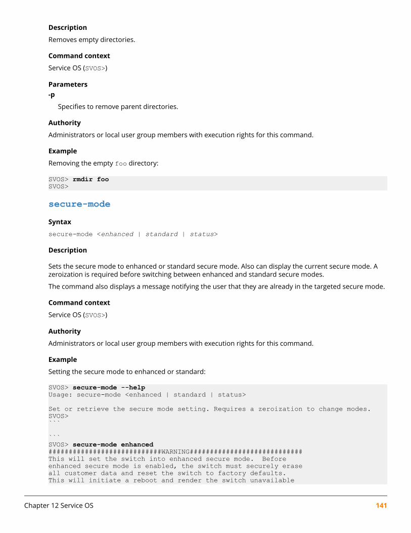
Description
Removes empty directories.
Command context
Service OS (SVOS>)
Parameters-p
Specifies to remove parent directories.
Authority
Administrators or local user group members with execution rights for this command.
Example
Removing the empty foo directory:
SVOS> rmdir fooSVOS>
secure-modeSyntax
secure-mode <enhanced | standard | status>
Description
Sets the secure mode to enhanced or standard secure mode. Also can display the current secure mode. Azeroization is required before switching between enhanced and standard secure modes.
The command also displays a message notifying the user that they are already in the targeted secure mode.
Command context
Service OS (SVOS>)
Authority
Administrators or local user group members with execution rights for this command.
Example
Setting the secure mode to enhanced or standard:
SVOS> secure-mode --helpUsage: secure-mode <enhanced | standard | status>
Set or retrieve the secure mode setting. Requires a zeroization to change modes.SVOS>```
```SVOS> secure-mode enhanced############################WARNING############################This will set the switch into enhanced secure mode. Beforeenhanced secure mode is enabled, the switch must securely eraseall customer data and reset the switch to factory defaults.This will initiate a reboot and render the switch unavailable
Chapter 12 Service OS 141

until the zeroization is complete.This should take several minutes to one hour to complete.############################WARNING############################
Continue (y/n)? yreboot: Restarting system
```
```SVOS> secure-mode standard############################WARNING############################This will set the switch into standard secure mode. Beforestandard secure mode is enabled, the switch must securely eraseall customer data and reset the switch to factory defaults.This will initiate a reboot and render the switch unavailableuntil the zeroization is complete.This should take several minutes to one hour to complete.############################WARNING############################
Continue (y/n)? yreboot: Restarting system
```
```SVOS> secure-mode standard############################WARNING############################Secure mode is already set to standard. Setting it again willrepeat the zeroization process. The switch must securely eraseall customer data and reset the switch to factory defaults.This will initiate a reboot and render the switch unavailableuntil the zeroization is complete.This should take several minutes to one hour to complete.############################WARNING############################
Continue (y/n)? yreboot: Restarting system
```
```SVOS> secure-mode statusenhanced secure mode is set.SVOS>
shSyntax
sh
Description
Launches a bash shell for support purposes. To quit bash, enter exit.
This command is not available if enhanced secure mode is set.
Command context
Service OS (SVOS>)
142 AOS-CX 10.06 Diagnostics and Supportability Guide

Authority
Administrators or local user group members with execution rights for this command.
Example
Launching a bash shell:
SVOS> shswitch:/cli/fs/home#
umountSyntax
umount <DEVICE>
Description
Unmounts the SSD partitions mounted to the following locations: /coredump, /logs, /nos, /selftest,and unmounts the USB device mounted to /mnt/usb.
Command context
Service OS (SVOS>)
Parameters<DEVICE>
Specifies the device to be unmounted. Supported device options include all and usb.
Authority
Administrators or local user group members with execution rights for this command.
Examples
Unmounting all devices:
SVOS> umount allSVOS> umount usbUnmounting a USB device:
SVOS> umount allSVOS> umount usb
updateSyntax
update {primary | secondary} <IMAGE>
Description
Verifies and installs a product image. The user can select the primary or secondary boot profile to updateand the location of the file.
Command context
Service OS (SVOS>)
Chapter 12 Service OS 143
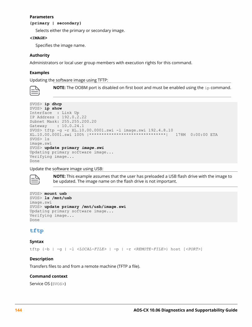
Parameters{primary | secondary}
Selects either the primary or secondary image.
<IMAGE>
Specifies the image name.
Authority
Administrators or local user group members with execution rights for this command.
Examples
Updating the software image using TFTP:
NOTE: The OOBM port is disabled on first boot and must be enabled using the ip command.
SVOS> ip dhcpSVOS> ip showInterface : Link UpIP Address : 192.0.2.22Subnet Mask: 255.255.200.20Gateway : 10.0.24.1SVOS> tftp -g -r XL.10.00.0001.swi -l image.swi 192.4.8.10XL.10.00.0001.swi 100% |*******************************| 178M 0:00:00 ETASVOS> lsimage.swiSVOS> update primary image.swiUpdating primary software image...Verifying image...DoneUpdate the software image using USB:
NOTE: This example assumes that the user has preloaded a USB flash drive with the image tobe updated. The image name on the flash drive is not important.
SVOS> mount usbSVOS> ls /mnt/usbimage.swiSVOS> update primary /mnt/usb/image.swiUpdating primary software image...Verifying image...Done
tftpSyntax
tftp {-b | -g | -l <LOCAL-FILE> | -p | -r <REMOTE-FILE>} host [<PORT>]
Description
Transfers files to and from a remote machine (TFTP a file).
Command context
Service OS (SVOS>)
144 AOS-CX 10.06 Diagnostics and Supportability Guide
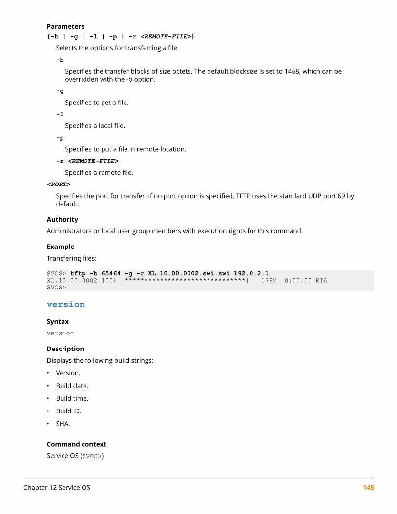
Parameters{-b | -g | -l | -p | -r <REMOTE-FILE>}
Selects the options for transferring a file.
-bSpecifies the transfer blocks of size octets. The default blocksize is set to 1468, which can beoverridden with the -b option.
-gSpecifies to get a file.
-lSpecifies a local file.
-pSpecifies to put a file in remote location.
-r <REMOTE-FILE>Specifies a remote file.
<PORT>
Specifies the port for transfer. If no port option is specified, TFTP uses the standard UDP port 69 bydefault.
Authority
Administrators or local user group members with execution rights for this command.
Example
Transfering files:
SVOS> tftp -b 65464 -g -r XL.10.00.0002.swi.swi 192.0.2.1XL.10.00.0002 100% |*******************************| 178M 0:00:00 ETASVOS>
versionSyntax
version
Description
Displays the following build strings:
• Version.
• Build date.
• Build time.
• Build ID.
• SHA.
Command context
Service OS (SVOS>)
Chapter 12 Service OS 145

Authority
Administrators or local user group members with execution rights for this command.
Example
Displaying version build strings:
SVOS> versionServiceOS Information: Version: GT.01.01.0001 Build Date: 2017-07-19 14:52:31 PDT Build ID: ServiceOS:GT.01.01.0001:461519208911:201707191452 SHA: 46151920891195cdb2267ea6889a3c6cbc3d4193SVOS>
146 AOS-CX 10.06 Diagnostics and Supportability Guide
In-System Programming OverviewThe ISP (In-System Programming) feature provides an automated way to roll out updates to variousprogrammable devices in an AOS-CX network switch, after the product has shipped. ISP is intended to runautomatically either at boot time or as new modules are inserted into the chassis at runtime.
Show tech command list for the ISP featureTask Command
Displaying versions of all present programmable devices. show tech isp
Displaying stored log files from any ISP updates on thesystem.
show tech update-log
See the Command-Line Interface Guide for additional information about the show tech commands.
In-System Programming commandsclear update-logSyntax
clear update-log
Description
Clears stored log files of any In-System Programming updates on the system.
Command context
Manager (#)
Authority
Administrators or local user group members with execution rights for this command.
show needed-updatesSyntax
show needed-updates [next-boot [primary|secondary]]
Description
Displays whether any programmable devices are in need of an update.
Chapter 13In-System Programming
Chapter 13 In-System Programming 147

Without the next-boot parameter, this command displays needed updates relative to the currentlyrunning AOS-CX image.
With the next-boot parameter, this command displays needed updates relative to an AOS-CX image file inthe persistent storage of the switch, which might be different from the currently running image. If either theprimary or secondary parameter is specified, this command queries that specific AOS-CX image file.Otherwise, it queries the default AOS-CX image file as set by the most recent boot system or boot set-default command.
Command context
Manager (#)
Authority
Administrators or local user group members with execution rights for this command.
148 AOS-CX 10.06 Diagnostics and Supportability Guide

OverviewDiagnostics involve four important sub-categories.
• Boot-up Diagnostics (Power On Selftest aka POST)
• Run-time Diagnostics (Hardware Health Monitoring)
• Online Diagnostics
• Offline Diagnostics
Power On Self Test (POST) is the first task which verifies the hardware functionality of various modulesduring boot-up. Based on the criticality of the test, the selftest module decides whether to go ahead with theboot-up sequence of a particular subsystem or interface during a POST failure.
POST comprises of the following:
• Memory BISTs (Built-in Self Test)
This is to verify the memory block(s) present in the module and involves both internal and externalmemories.
The memory tables are critical for proper functionality of the system, so any failures in these tests willresult in the corresponding subsystem to be marked as "Failed" and thus that subsystem will not beavailable for use.
• Front-end Port Loopback tests
This is to verify the physical port front-end interface.
These tests check if a particular interface can function properly. A test failure would mean that theparticular interface is marked as "Failed" and thus it would become unavailable for use.
This test is run when "no fastboot" is configured.
Selftest commandsfastbootSyntax
fastboot
no fastboot
Description
Enables fastboot for the system.
The no form of this command disables fastboot for the system.
Chapter 14Selftest
Chapter 14 Selftest 149

Command context
config
Authority
Administrators or local user group members with execution rights for this command.
Usage
When fastboot is enabled, most tests under a Power On Self Test (POST) are skipped. By default, fastboot isenabled.
After disabling fastboot, save switch configurations and then reboot for POST to run. POST verifies thehardware functionality of various modules during boot-up. Based on the criticality of the test, the selftestmodule decides whether to go ahead with the boot-up sequence of a particular subsystem or interfaceduring a POST failure.
POST runs memory built-in selftest (BISTs) and front-end port loopback tests. Memory BISTs verify theinternal and external memory blocks present in the module. The memory tables are critical for properfunctionality of the system so any failures in these tests results in the corresponding subsystem to bemarked as "Failed" and thus that subsystem is not available for use.
Front-end port loopback tests verify the physical port front-end interface. These tests check if a particularinterface can function properly. A test failure means that a particular interface has been marked as "Failed"and is now unavailable for use.
On 6300 and 6400 switches, the line-module and fabric-module selftest is run regardless of fastboot setting.The interface selftest is only run when fastboot is disabled.
Examples
Enabling fastboot:
switch# configure terminalswitch(config)# fastbootswitch(config)# endswitch# show running-configCurrent configuration:!!Version ArubaOS-CX XL.10.00.0002module 1/1 product-number jl363a!!!!!!!vlan 1interface 1/1/1 no shutdownDisabling fastboot:
switch# configure terminalswitch(config)# no fastbootswitch(config)# endswitch(config)# write memConfiguration changes will take time to process, please be patient.switch# show running-configCurrent configuration:!!Version ArubaOS-CX XL.10.00.0002
150 AOS-CX 10.06 Diagnostics and Supportability Guide

module 1/1 product-number jl363a!!!no fastboot!!!!vlan 1interface 1/1/1 no shutdown
show selftestSyntax
show selftest [brief] [vsx-peer]show selftest line-module <SLOT-ID>show selftest line-module <SLOT-ID> interface [brief] [vsx-peer]show selftest interface [<PORT-NUM>] [vsx-peer]For 8400 and 6400 switches only:
show selftest {line-module | fabric-module} [<SLOT-ID>] [brief] [vsx-peer]
Description
Displays selftest results.
Command context
Manager (#)
Parameters[brief]
Shows the selftest results as a brief description. Default.line-module
Shows the selftest results for a line module.
fabric-moduleShows the selftest results for a fabric module. Applicable only for 8400 and 6400 switches.
<SLOT-ID>Shows the selftest results for the slot ID of the line or fabric module.
<PORT-NUM>Shows the selftest results for the port number.
[vsx-peer]Shows the output from the VSX peer switch. If the switches do not have the VSX configuration or the ISLis down, the output from the VSX peer switch is not displayed.
Authority
Operators or Administrators or local user group members with execution rights for this command.Operators can execute this command from the operator context (>) only.
Examples
Displaying the output when fastboot is disabled on an 8400 or a 6400 switch:
Chapter 14 Selftest 151

switch# show selftestName Id Status ErrorCode LastRunTime---------- ---- -------------- ---------- -------------------LineModule 1/1 passed 0x0 2016-10-15 10:10:09LineModule 1/2 failed 0x09 2016-10-15 10:10:56Fabric 1/1 passed 0x0 2016-10-15 10:10:09Fabric 1/2 failed 0x1E 2016-10-15 10:10:56
switch# show selftest line-moduleName Id Status ErrorCode LastRunTime---------- ---- -------------- --------- -------------------LineModule 1/1 passed 0x0 2016-10-15 10:10:09LineModule 1/2 failed 0x09 2016-10-15 10:10:56
switch# show selftest fabric-moduleName Id Status ErrorCode LastRunTime------ -------- -------------- --------- -------------------Fabric 1/1 passed 0x0 2016-10-15 10:10:09Fabric 1/2 failed 0x1E 2016-10-15 10:10:56
switch# show selftest fabric-module 1/2Name Id Status ErrorCode LastRunTime------ -------- -------------- --------- -------------------Fabric 1/2 failed 0x11 2016-10-15 10:10:56
switch# show selftest line-module 1/10Name Id Status ErrorCode LastRunTime---------- ---- -------------- --------- -------------------LineModule 1/10 failed 0x1A 2016-10-15 10:10:56
switch# show selftest interface 1/2/2Name Status ErrorCode LastRunTime------- -------------- --------- -------------------1/2/2 passed 0x0 2016-11-19 05:10:11
switch# show selftest line-module 1/3 interfaceName Status ErrorCode LastRunTime------- -------------- --------- -------------------1/3/1 passed 0x0 2016-11-19 05:10:111/3/2 passed 0x0 2016-11-19 05:10:111/3/3 passed 0x0 2016-11-19 05:10:111/3/31 failed 0x20 2016-11-19 05:10:11Displaying the output when fastboot is disabled on an 8320 or a 6300 switch:
switch# show selftest interface Name Status ErrorCode LastRunTime ---------- ----------------- ---------------- ------------------- 1/1/2 skipped 0x0 1/1/44 skipped 0x0 1/1/46 skipped 0x0
152 AOS-CX 10.06 Diagnostics and Supportability Guide
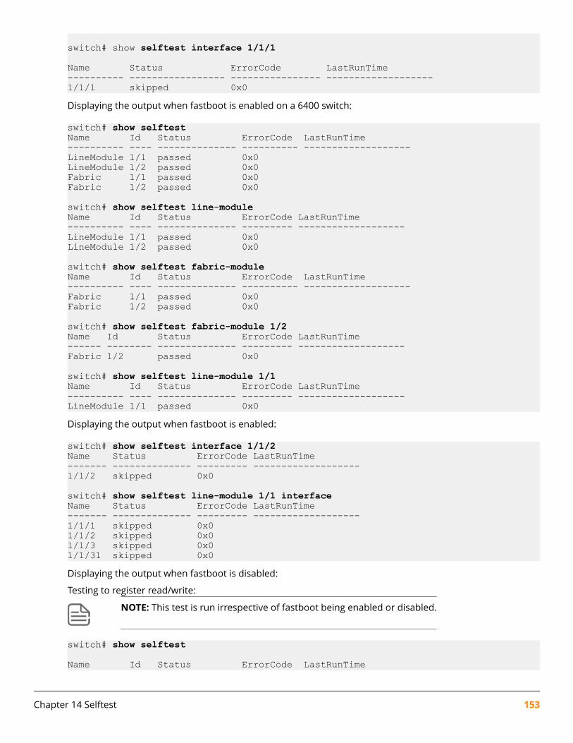
switch# show selftest interface 1/1/1
Name Status ErrorCode LastRunTime---------- ----------------- ---------------- -------------------1/1/1 skipped 0x0Displaying the output when fastboot is enabled on a 6400 switch:
switch# show selftestName Id Status ErrorCode LastRunTime---------- ---- -------------- ---------- -------------------LineModule 1/1 passed 0x0LineModule 1/2 passed 0x0Fabric 1/1 passed 0x0Fabric 1/2 passed 0x0
switch# show selftest line-moduleName Id Status ErrorCode LastRunTime---------- ---- -------------- --------- -------------------LineModule 1/1 passed 0x0LineModule 1/2 passed 0x0
switch# show selftest fabric-moduleName Id Status ErrorCode LastRunTime---------- ---- -------------- ---------- -------------------Fabric 1/1 passed 0x0Fabric 1/2 passed 0x0
switch# show selftest fabric-module 1/2Name Id Status ErrorCode LastRunTime------ -------- -------------- --------- -------------------Fabric 1/2 passed 0x0
switch# show selftest line-module 1/1Name Id Status ErrorCode LastRunTime---------- ---- -------------- --------- -------------------LineModule 1/1 passed 0x0Displaying the output when fastboot is enabled:
switch# show selftest interface 1/1/2Name Status ErrorCode LastRunTime------- -------------- --------- -------------------1/1/2 skipped 0x0
switch# show selftest line-module 1/1 interfaceName Status ErrorCode LastRunTime------- -------------- --------- -------------------1/1/1 skipped 0x01/1/2 skipped 0x01/1/3 skipped 0x01/1/31 skipped 0x0Displaying the output when fastboot is disabled:
Testing to register read/write:
NOTE: This test is run irrespective of fastboot being enabled or disabled.
switch# show selftest
Name Id Status ErrorCode LastRunTime
Chapter 14 Selftest 153

---------- ---- -------------- ---------- -------------------LineModule 1/1 passed 0x0 2018-02-16 18:15:53
154 AOS-CX 10.06 Diagnostics and Supportability Guide

OverviewDevice zeroization lets you remove all user files from flash storage, including solid-state drives (SSDs). Userfiles cannot be retrieved after the zeroization is complete.
NOTE: Zeroization can occur in both AOS-CX and Service OS. This section covers zeroization andAOS-CX. For information about zeroization and Support OS, see erase zeroize.
Zeroization preserves the primary and secondary software images on the SSD. Zeroization also preservesmanufacturing information.
The sensitive user files stored on an SSD or SPI flash/EEPROM storage or both include:
• Switch configurations.
• System generated private keys.
• User installed private keys.
• Admin/operator password files.
NOTE: For more information on password requirements, see Password requirements in theSecurity Guide.
Zeroization commandserase all zeroizeSyntax
erase all zeroize
Description
Restores the switch to its factory default configuration. You will be prompted before the procedure starts.Once complete, the switch will restart from the primary image with factory default settings.
NOTE: Back up all data before running this command as all configuration settings will be lost.
Command context
Manager (#)
Authority
Administrators or local user group members with execution rights for this command.
Chapter 15Zeroization
Chapter 15 Zeroization 155

Example
Restoring the switch to factory default configuration:
switch# erase all zeroizeThis will securely erase all customer data and reset the switchto factory defaults. This will initiate a reboot and render theswitch unavailable until the zeroization is complete.This should take several minutes to one hour to complete.Continue (y/n)? yThe system is going down for zeroization.
...
################ Preparing for zeroization #################
################ Storage zeroization ####################################### WARNING: DO NOT POWER OFF UNTIL ########################## ZEROIZATION IS COMPLETE ########################## This should take several minutes ########################## to one hour to complete ##########
################ Restoring files ###########################
...
We'd like to keep you up to date about: * Software feature updates * New product announcements * Special eventsPlease register your products now at: https://asp.arubanetworks.com
switch login: adminPassword:
Please configure the 'admin' user account password.Enter new password: *****Confirm new password: *****
156 AOS-CX 10.06 Diagnostics and Supportability Guide

OverviewThe terminal monitor is used to display selective logs dynamically on the VTYSH session. When the terminalmonitor feature is enabled on the switch, it displays only the live or active logs. These logs are displayed onlyon the SSH session. If required, you can enable the terminal monitoring on multiple sessions.
It is important to monitor the logs dynamically while debugging, so that you can co-relate the issues. Thelogs can be filtered by type (event or debug), severity, or keyword. The terminal monitor runs in synchronousmode, where the user enters any command, the log display pauses until the command execution iscomplete. This ensures that the logs will not appear in between other CLI outputs or while the user is typing.
NOTE: Terminal monitoring is not persistent. If the SSH session is terminated, the terminalmonitor is no longer valid. In the new SSH session, you need to run the command again.
Terminal monitor commandsterminal-monitor {notify | severity | filter}Syntax
terminal-monitor {notify <event|debug|all> | severity <level> | filter keyword}
no terminal-monitor
Description
Enables the terminal monitor feature in the SSH session. It display all debug log or event log or both debugand event log messages. Terminal monitoring can be filtered with the severity options or with the help ofkeywords. Enabling terminal monitor without options displays both debug and event log with a severityerror.
The no form of this command disables the terminal monitor configuration.
Parametersnotify <event|debug|all>
Specifies the type of log notification.
• Event: Displays the event log messages.
• Debug: Displays the debug log messages.
• All: Displays both event and debug log messages.
severity <level>Specifies the severity level for the logs. The different severity levels are emergency, critical, error(default), warning, notice, information, alert, and debug (shows all severities).
Chapter 16Terminal Monitor
Chapter 16 Terminal Monitor 157
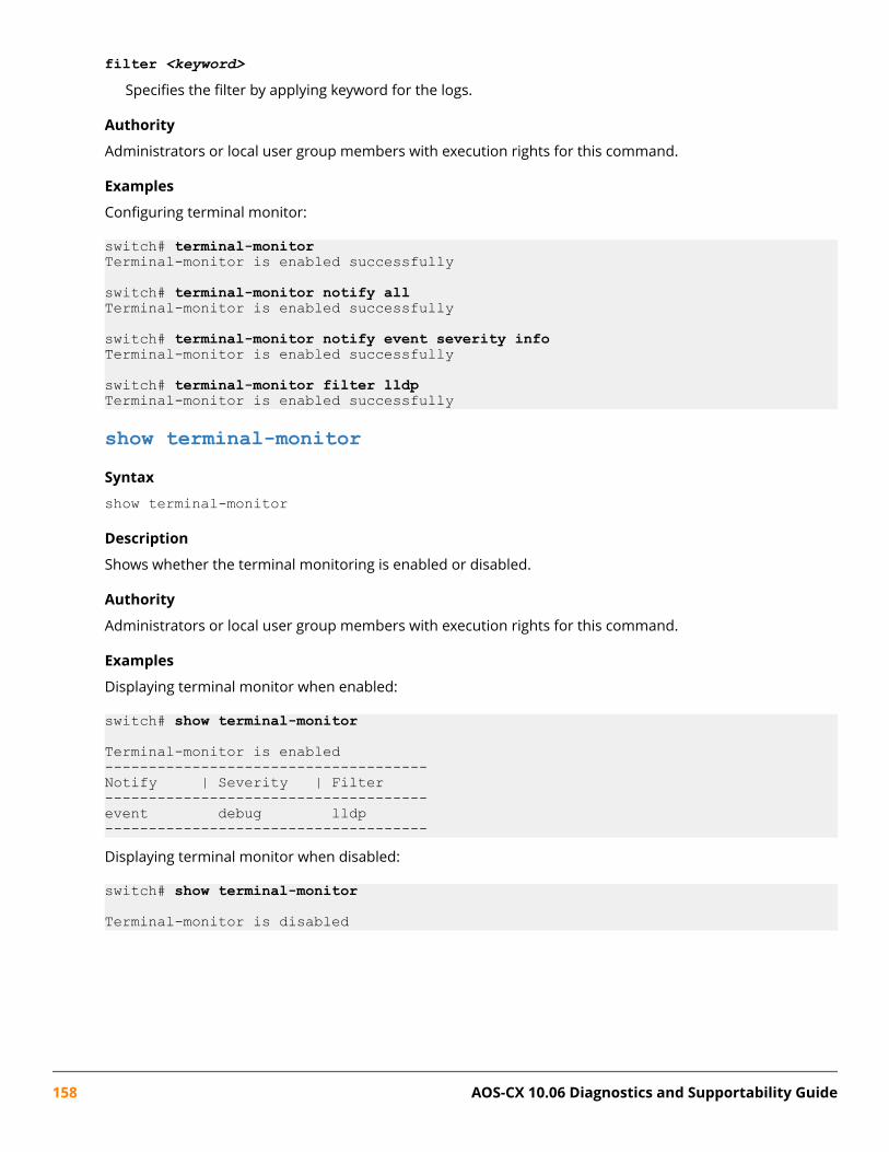
filter <keyword>Specifies the filter by applying keyword for the logs.
Authority
Administrators or local user group members with execution rights for this command.
Examples
Configuring terminal monitor:
switch# terminal-monitorTerminal-monitor is enabled successfully
switch# terminal-monitor notify allTerminal-monitor is enabled successfully
switch# terminal-monitor notify event severity infoTerminal-monitor is enabled successfully
switch# terminal-monitor filter lldpTerminal-monitor is enabled successfully
show terminal-monitorSyntax
show terminal-monitor
Description
Shows whether the terminal monitoring is enabled or disabled.
Authority
Administrators or local user group members with execution rights for this command.
Examples
Displaying terminal monitor when enabled:
switch# show terminal-monitor
Terminal-monitor is enabled-------------------------------------Notify | Severity | Filter-------------------------------------event debug lldp-------------------------------------Displaying terminal monitor when disabled:
switch# show terminal-monitor
Terminal-monitor is disabled
158 AOS-CX 10.06 Diagnostics and Supportability Guide

HTTP 404 error when accessing the switch URLSymptom
The switch is operational and you are using the correct URL for the switch, but attempts to access the RESTAPI or Web UI result in an HTTP 404 "Page not found" error.
Cause
REST API access is not enabled on the VRF that corresponds to the access port you are using. For example,you are attempting to access the REST API or Web UI from the management (OOBM) port, and access is notenabled on the mgmt VRF.
Action
Use the https-server vrf command to enable REST API access on the specified VRF.
For example:
switch(config)# https-server vrf mgmt
HTTP 401 error "Login failed: session limit reached"Symptom
A REST request or Web UI login attempt returns response code 401 and the response body contains thefollowing text string:
Login failed: session limit reached
Cause
A user attempted to log into the REST API or the Web UI, but that user already has the maximum number ofconcurrent (six) sessions running.
Action
1. Log out from one of the existing sessions.
Browsers share a single session cookie across multiple tabs or even windows. However, scripts that POSTto the login resource and later do not POST to the logout resource can easily create the maximumnumber of concurrent sessions.
2. If the session cookie is lost and it is not possible to log out of the session, then wait for the session idletime limit to expire.
When the session idle timeout expires, the session is terminated automatically.
3. If it is required to stop all HTTPS sessions on the switch instead of waiting for the session idle time limit toexpire, you can stop all HTTPS sessions using the https-server session close all command.
Chapter 17Troubleshooting Web UI and REST API access issues
Chapter 17 Troubleshooting Web UI and REST API access issues 159
This command stops and starts the hpe-restd service, so using this command affects all existing RESTsessions, Web UI sessions, and real-time notification subscriptions.
160 AOS-CX 10.06 Diagnostics and Supportability Guide

Accessing Aruba SupportAruba Support Services https://www.arubanetworks.com/support-services/
Aruba Support Portal https://asp.arubanetworks.com/
North America telephone 1-800-943-4526 (US & Canada Toll-Free Number)
+1-408-754-1200 (Primary - Toll Number)
+1-650-385-6582 (Backup - Toll Number - Use only when all othernumbers are not working)
International telephone https://www.arubanetworks.com/support-services/contact-support/
Be sure to collect the following information before contacting Support:
• Technical support registration number (if applicable)
• Product name, model or version, and serial number
• Operating system name and version
• Firmware version
• Error messages
• Product-specific reports and logs
• Add-on products or components
• Third-party products or components
Other useful sites
Other websites that can be used to find information:
Airheads social forums andKnowledge Base
https://community.arubanetworks.com/
Software licensing https://lms.arubanetworks.com/
End-of-Life information https://www.arubanetworks.com/support-services/end-of-life/
Aruba software anddocumentation
https://asp.arubanetworks.com/downloads
Accessing updatesTo download product updates:
Chapter 18Support and other resources
Chapter 18 Support and other resources 161

Aruba Support Portalhttps://asp.arubanetworks.com/downloads
If you are unable to find your product in the Aruba Support Portal, you may need to search My Networking,where older networking products can be found:
My Networkinghttps://www.hpe.com/networking/support
To view and update your entitlements, and to link your contracts and warranties with your profile, go to theHewlett Packard Enterprise Support Center More Information on Access to Support Materials page:
https://support.hpe.com/portal/site/hpsc/aae/home/
IMPORTANT: Access to some updates might require product entitlement when accessedthrough the Hewlett Packard Enterprise Support Center. You must have an HP Passport set upwith relevant entitlements.
Some software products provide a mechanism for accessing software updates through the productinterface. Review your product documentation to identify the recommended software update method.
To subscribe to eNewsletters and alerts:
https://asp.arubanetworks.com/notifications/subscriptions (requires an active Aruba Support Portal(ASP) account to manage subscriptions). Security notices are viewable without an ASP account.
Warranty informationTo view warranty information for your product, go to https://www.arubanetworks.com/support-services/product-warranties/.
Regulatory informationTo view the regulatory information for your product, view the Safety and Compliance Information for Server,Storage, Power, Networking, and Rack Products, available at https://www.hpe.com/support/Safety-Compliance-EnterpriseProducts
Additional regulatory information
Aruba is committed to providing our customers with information about the chemical substances in ourproducts as needed to comply with legal requirements, environmental data (company programs, productrecycling, energy efficiency), and safety information and compliance data, (RoHS and WEEE). For moreinformation, see https://www.arubanetworks.com/company/about-us/environmental-citizenship/.
Documentation feedbackAruba is committed to providing documentation that meets your needs. To help us improve thedocumentation, send any errors, suggestions, or comments to Documentation Feedback ([email protected]). When submitting your feedback, include the document title, part number, edition,and publication date located on the front cover of the document. For online help content, include theproduct name, product version, help edition, and publication date located on the legal notices page.
162 AOS-CX 10.06 Diagnostics and Supportability Guide


