Embed Size (px)
Citation preview

AOP/WG/4−WP/10 Agenda Item 4
INTERNATIONAL CIVIL AVIATION ORGANIZATION
THE FOURTH MEETING OF THE AERODROMES OPERATIONS AND
PLANNING – WORKING GROUP (AOP/WG/4)
Bangkok, Thailand, 23 to 25 May 2016
Agenda Item 4: Provision of AOP in the Asia/Pacific Region
AMENDMENT 13 TO ANNEX 14,
VOLUME I — AERODROME DESIGN AND OPERATIONS
(Presented by the Secretariat)
SUMMARY
This Paper provides information on the new Amendment 13 to Annex 14, Volume I –
Aerodrome Design and Operations. The Amendment Proposal concerns: a) the Autonomous
Runway Incursion Warning System (ARIWS); b) visual aids for navigation and aerodrome
design; c) enhanced global reporting format for assessing and reporting runway surface
conditions; and d) design and operations of aerodromes, including the publication of Runway
End Safety Area (RESA).
This paper relates to Strategic Objectives:
A: Safety – Enhance global civil aviation safety
B: Air Navigation Capacity and Efficiency – Increase Capacity and improve efficiency of
the global civil aviation system E: Environmental Protection – Minimize the adverse environmental effects of civil
aviation activities Action by the Meeting is at Para 3 to this Working Paper.
1. INTRODUCTION
1.1 The Amendment 13 to the Aerodromes – Aerodrome Design and Operations (Annex
14, Volume I to the Convention on International Civil Aviation) was adopted by the ICAO Council at
the fifth meeting of its 207th Session on 22
nd February 2016. The Amendment and Resolution of
adoption are available as attachments to the electronic version of State Letter AN 4/1.2.26-16/19
dated 5 April 2016 on the ICAO NET (http://portal.icao.int). Placed at Attachment A to this
Working Paper.
1.2 The Council prescribed 11 July 2016 as the date on which the Amendment will
become effective, and a applicability date of 10 November 2016 for the elements concerning ARIWS,
visual aids for navigation, aerodrome design and operations including publication of RESA, and 5
November 2020 for the element concerning an enhanced global reporting format for assessing and
reporting runway surface conditions would be suitable for the implementation of these provisions.
AOP/WG/4−WP/10 Agenda Item 4
2
1.3 The Amendment 13 to Annex 14, Volume I arise from: a) the recommendations of
the third meeting of the Aerodromes Panel (AP/3) regarding the Autonomous Runway Incursion
Warning System (ARIWS); b) recommendations of the first meeting of the Aerodrome Design and
Operations Panel (ADOP/1) relating to visual aids for navigation and aerodrome design; c) proposals
by the ADOP Friction Task Force relating to the use of an enhanced global reporting format for
assessing and reporting runway surface conditions; and d) recommendations of the third meeting of
the Aerodromes Panel (AP/3) relating to the design and operations of aerodromes, including the
publication of Runway End Safety Area (RESA).
2. DISCUSSION
2.1 Amendment 13 to Annex 14, Volume I contains a package of proposals related to
aerodrome design and operations as outlined in the Global Aviation Safety Plan and Global Air
Navigation Plan and is intended to improve safety and efficiency performance at and in the vicinity of
aerodromes. The Amendment concerns the following: a) The Autonomous Runway Incursion
Warning System (ARIWS); b) visual aids for navigation and aerodrome design; c) enhanced global
reporting format for assessing and reporting runway surface conditions; and d) design and operations
of aerodromes, including the publication of Runway End Safety Area (RESA) and arresting system in
AIP.
3. ACTION BY THE MEETING
3.1 The Meeting is invited to:
a) Urge States to notify ICAO before 11 July 2016 if there is any part of the
adopted Standards and Recommended Practices (SARPs) amendments in
Amendment 13 concerning which the States wishes to register disapproval;
[Note: only statements of disapproval need to be registered.];
b) urge States to notify ICAO using the Electronic Filing of Differences System
before 10 October 2016 any differences that will exist on 10 November 2016
between the national regulations or practices and the provisions of the whole of
Annex 14, Volume I as amended by all amendments up to and including
Amendment 13 and thereafter of any further differences that may arise; and
c) Urge States to provide the date or dates by which their Administration will have
complied with the provisions of the whole of Annex 14, Volume I, as amended
by all amendments up to and including Amendment 13.
— — — — — — — —

Tel.: +1 514-954-6717
Ref.: AN 4/1.2.26-16/19 5 April 2016
Subject: Adoption of Amendment 13 to Annex 14,
Volume I
Action required: a) Notify any disapproval before
11 July 2016; b) Notify any differences and compliance
before 10 October 2016 and 5 October 2020; c) Consider
the use of the Electronic Filing of Differences (EFOD)
System for notification of differences and compliance
Sir/Madam,
1. I have the honour to inform you that Amendment 13 to the International Standards and
Recommended Practices, Aerodromes — Aerodrome Design and Operations (Annex 14, Volume I to the
Convention on International Civil Aviation) was adopted by the Council at the fifth meeting of its
207th Session on 22 February 2016. Copies of the Amendment and the Resolution of Adoption are
available as attachments to the electronic version of this State letter on the ICAO-NET
(http://portal.icao.int) where you can access all other relevant documentation.
2. When adopting the amendment, the Council prescribed 11 July 2016 as the date on which
it will become effective, except for any part concerning which a majority of Contracting States have
registered their disapproval before that date. In addition, the Council resolved that Amendment 13, to the
extent it becomes effective, will become applicable on 10 November 2016 (Amendment 13-A refers),
except for provisions relating to an enhanced global reporting format for assessing and reporting runway
surface conditions which will become applicable on 5 November 2020 (Amendment 13-B refers).
3. Amendment 13 arises from:
a) recommendations of the third meeting of the Aerodromes Panel (AP/3) regarding the
autonomous runway incursion warning system (ARIWS);
b) recommendations of the first meeting of the Aerodrome Design and Operations Panel
(ADOP/1) relating to visual aids for navigation and aerodrome design;
999 Robert-Bourassa Boulevard
Montréal, Quebec
Canada H3C 5H7
Tel.: +1 514 954-8219-
Fax: +1 514 954-6077-
Email: [email protected]
www.icao.int
International
Civil Aviation
Organization
Organisation
de l’aviation civile
internationale
Organización
de Aviación Civil
Internacional
Международная
организация
гражданской
авиации
- 2 -
c) proposals by the ADOP Friction Task Force relating to the use of an enhanced global
reporting format for assessing and reporting runway surface conditions; and
d) recommendations of the third meeting of the Aerodromes Panel (AP/3) relating to the
design and operations of aerodromes, including the publication of runway end safety
area (RESA).
4. The amendment concerning the autonomous runway incursion warning system (ARIWS)
addresses the need for harmonization of procedures for all aerodromes and types of systems when they
are installed. It is a complex system and its implementation needs to be balanced against other means with
due consideration given to efficiency of the mitigation, efficiency of operations, costs and human factors
aspects. There is no obligation or recommendation within the provisions to install such a system; the
installation of such a system at an aerodrome would only be concluded following an assessment of the
runway incursion risk at that aerodrome.
5. The amendment concerning visual aids arising from ADOP/1 clarifies or modifies
Annex 14, Volume I provisions: the proposal related to the runway holding position marking clarifying
two existing figures; the proposal to replace the taxiway intersection marking by the more appropriate
intermediate holding position marking; the use of T-VASIS and AT-VASIS for discontinuation as of
1 January 2020; and the proposed amendment on lower case “m” providing specification which is
currently lacking in Annex 14, Volume I.
6. The amendment concerning aerodrome design arising from ADOP/1 formally classifies
the prepared areas under paragraphs 3.4.11 and 3.4.12, Annex 14, Volume I as the blast pad. The notes
amending paragraphs 3.4.6 and 3.4.16 allow aerodrome operators located in tropical climates or those that
receive large volumes of annual rainfall to use open-air water conveyances as a means to remove
excessive rainfall from ponding on/near the runway.
7. The amendment concerning enhanced global reporting format for assessing and reporting
runway surface conditions is designed to report runway surface conditions in a standardized manner such
that flight crew are able to accurately determine aeroplane take-off and landing performance, resulting in
a global reduction in runway excursion incidents/accidents. The proposal provides a solution to a long
outstanding issue of relating aeroplane performance to runway state information in a more objective way.
8. When implementing the provisions concerning the enhanced global reporting format, it is
essential that these changes are made in close coordination with those to Annex 3 — Meteorological
Service for International Air Navigation, Annex 6 — Operation of Aircraft, Part I — International
Commercial Air Transport — Aeroplanes and Part II — International General Aviation — Aeroplanes,
Annex 8 — Airworthiness of Aircraft, Annex 15 — Aeronautical Information Services, Procedures for
Air Navigation Services — Air Traffic Management (PANS-ATM, Doc 4444) and the Procedures for Air
Navigation Services — Aerodromes (PANS-Aerodromes, Doc 9981).
9. The amendment concerning design and operations arising from AP/3, inter alia, reduces
taxiway separation distances which will significantly improve efficiency and reduce construction costs for
many airports in different parts of the world. In relation to elements of the amendment regarding runway
end safety area (RESA) and arresting systems, it should be noted that relevant data needs to be gathered,
described and promulgated in the Aeronautical Information Publication (AIP).
10. The subjects are given in the amendment to the Foreword of Annex 14, Volume I, a copy
of which is in Attachment A.
- 3 -
11. At the fifth meeting of its 204th Session, the Council requested that States, when being
advised of the adoption of an Annex amendment, be provided with information on implementation and
available guidance material, as well as an impact assessment. This is presented for your information in
Attachments F and G, respectively.
12. In conformity with the Resolution of Adoption, may I request:
a) that before 11 July 2016 you inform me if there is any part of the adopted Standards
and Recommended Practices (SARPs) amendments in Amendment 13 (i.e.
Amendments 13-A and 13-B) concerning which your Government wishes to register
disapproval, using the form in Attachment B for this purpose. Please note that only
statements of disapproval need be registered and if you do not reply it will be
assumed that you do not disapprove of the amendment;
b) that before 10 October 20161 you inform me of the following, using the Electronic
Filing of Differences (EFOD) System or the form in Attachments C and D for this
purpose:
1) any differences that will exist on 10 November 20162 between the national
regulations or practices of your Government and the provisions of the whole of
Annex 14, Volume I, as amended by all amendments up to and including
Amendment 13, and thereafter of any further differences that may arise; and
2) the date or dates by which your Government will have complied with the
provisions of the whole of Annex 14, Volume I, as amended by all amendments
up to and including Amendment 13.
13. With reference to the request in paragraph 12 a) above, it should be noted that a
registration of disapproval of Amendment 13 or any part of it in accordance with Article 90 of the
Convention does not constitute a notification of differences under Article 38 of the Convention. To
comply with the latter provision, a separate statement is necessary if any differences do exist, as requested
in paragraph 12 b) 1). It is recalled in this respect that international Standards in Annexes have a
conditional binding force, to the extent that the State or States concerned have not notified any difference
thereto under Article 38 of the Convention.
14. With reference to the request in paragraph 12 b) above, it also should be noted that the
ICAO Assembly, at its 38th Session (24 September to 4 October 2013), resolved that Member States
should be encouraged to use the EFOD System when notifying differences (Resolution A38-11 refers).
The EFOD System is currently available on the Universal Safety Oversight Audit Programme (USOAP)
restricted website (http://www.icao.int/usoap) which is accessible by all Member States. You are invited
to consider using this for notification of compliance and differences.
15. Guidance on the determination and reporting of differences is given in the Note on the
Notification of Differences in Attachment E.
16. Please note that a detailed repetition of previously notified differences, if they continue to
apply, may be avoided by stating the current validity of such differences.
1 5 October 2020 for enhanced global reporting format provisions for assessing and reporting runway surface conditions. 2 5 November 2020 for enhanced global reporting format provisions for assessing and reporting runway surface conditions.
- 4 -
17. I would appreciate it if you would also send a copy of your notifications, referred to in
paragraph 12 b) above, to the ICAO Regional Office accredited to your Government.
18. As soon as practicable after the amendment becomes effective, on 11 July 2016,
replacement pages incorporating Amendments 13-A and 13-B will be forwarded to you.
19. Please note that the time between the effective date and the applicability date of
5 November 2020 for Amendment 13-B is longer than usual due to the nature and complexity of the
proposals.
Accept, Sir/Madam, the assurances of my highest consideration.
Fang Liu
Secretary General
Enclosures:
A — Amendment to the Foreword of Annex 14, Volume I
B — Form on notification of disapproval of all or part of
Amendment 13 to Annex 14, Volume I
C — Form on notification of compliance with or differences
from Annex 14, Volume I, Amendment 13-A
D — Form on notification of compliance with or differences
from Annex 14, Volume I, Amendment 13-B
E — Note on the Notification of Differences
F — Implementation task list and outline of guidance material in
relation to Amendment 13 to Annex 14, Volume I
G — Impact assessment in relation to Amendment 13 to
Annex 14, Volume I

ATTACHMENT A to State letter AN 4/1.2.26-16/19
AMENDMENT TO THE FOREWORD OF ANNEX 14, VOLUME I
Add the following at the end of Table A:
Amendment Source(s) Subject
Adopted/Approved
Effective
Applicable
13-A Third meeting of the
Aerodromes Panel (AP/3)
First meeting of the
Aerodrome Design and
Operations Panel
(ADOP/1)
Definitions of arresting system, autonomous runway incursion warning system (ARIWS), foreign object debris (FOD); description of arresting system; storm water conveyances on runway and taxiway strips; blast pads; clearance for straight and curved portions of code C taxiways; reduced taxiway and taxilane separation distances; clearance distances on aircraft stands; taxiway design guidance for prevention of runway incursions; flashing characteristics and colour specifications for LEDs; clarification on light intensity distribution; marking and lighting of wind turbines over 150 m height; location criteria for PAPI obstacle protection surface; mandatory instruction and information markings; ARIWS; prevention and installation of devices for FOD; guidance material on runway surface unevenness, ARIWS, taxiway design for minimizing potential for runway incursions and aerodrome mapping data.
22 February 2016
11 July 2016
10 November 2016
Amendment Source(s) Subject
Adopted/Approved
Effective
Applicable
13-B Third meeting of the
Aerodromes Panel (AP/3)
developed by the Friction
Task Force
Enhanced global reporting format for assessing and reporting runway surface condition.
22 February 2016
11 July 2016
5 November 2020
— — — — — — — —

ATTACHMENT B to State letter AN 4/1.2.26-16/19
NOTIFICATION OF DISAPPROVAL OF ALL OR PART OF
AMENDMENT 13 TO ANNEX 14, VOLUME I
To: The Secretary General
International Civil Aviation Organization
999 Boulevard Robert-Bourassa
Montréal, Quebec
Canada H3C 5H7
(State) hereby wishes to disapprove the following parts of
Amendment 13 to Annex 14, Volume I:
Signature Date
NOTES
1) If you wish to disapprove all or part of Amendment 13 (i.e. 13-A and 13-B) to Annex 14, Volume I,
please dispatch this notification of disapproval to reach ICAO Headquarters by 11 July 2016. If it has
not been received by that date it will be assumed that you do not disapprove of the amendment. If
you approve of all parts of Amendment 13 it is not necessary to return this notification of
disapproval.
2) This notification should not be considered a notification of compliance with or differences from
Annex 14, Volume I. Separate notifications on this are necessary. (See Attachments C and D.)
3) Please use extra sheets as required.
— — — — — — — —

ATTACHMENT C to State letter AN 4/1.2.26-16/19
NOTIFICATION OF COMPLIANCE WITH OR DIFFERENCES FROM
ANNEX 14, VOLUME I
(Including all amendments up to and including Amendment 13-A)
To: The Secretary General
International Civil Aviation Organization
999 Boulevard Robert-Bourassa
Montréal, Quebec
Canada H3C 5H7
1. No differences will exist on between the national
regulations and/or practices of (State) and the provisions
of Annex 14, Volume I, including all amendments up to and including Amendment 13-A.
2. The following differences will exist on between the
regulations and/or practices of (State) and the provisions
of Annex 14, Volume I, including Amendment 13-A (Please see Note 2) below.)
a) Annex Provision
(Please give exact
paragraph reference)
b) Details of Difference
(Please describe the difference
clearly and concisely)
c) Remarks
(Please indicate reasons
for the difference)
(Please use extra sheets as required)
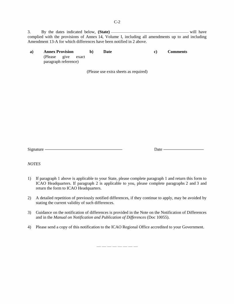
C-2
3. By the dates indicated below, (State) will have
complied with the provisions of Annex 14, Volume I, including all amendments up to and including
Amendment 13-A for which differences have been notified in 2 above.
a) Annex Provision b) Date c) Comments
(Please give exact
paragraph reference)
(Please use extra sheets as required)
Signature Date
NOTES
1) If paragraph 1 above is applicable to your State, please complete paragraph 1 and return this form to
ICAO Headquarters. If paragraph 2 is applicable to you, please complete paragraphs 2 and 3 and
return the form to ICAO Headquarters.
2) A detailed repetition of previously notified differences, if they continue to apply, may be avoided by
stating the current validity of such differences.
3) Guidance on the notification of differences is provided in the Note on the Notification of Differences
and in the Manual on Notification and Publication of Differences (Doc 10055).
4) Please send a copy of this notification to the ICAO Regional Office accredited to your Government.
— — — — — — — —
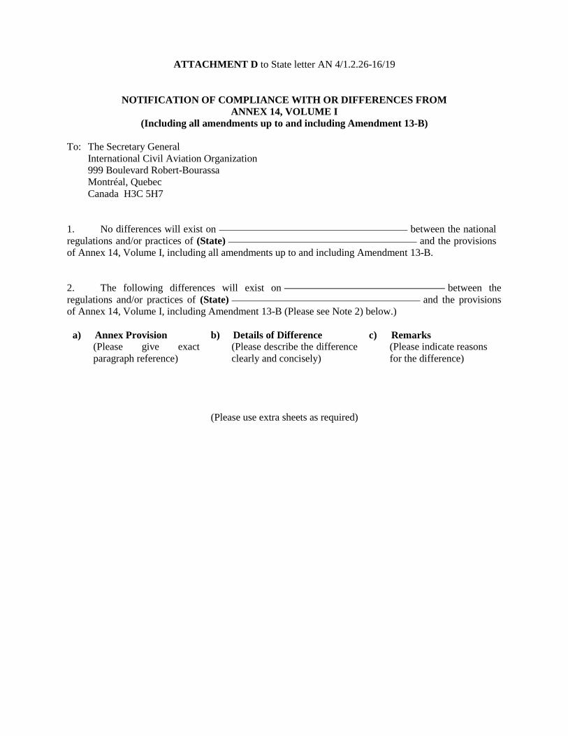
ATTACHMENT D to State letter AN 4/1.2.26-16/19
NOTIFICATION OF COMPLIANCE WITH OR DIFFERENCES FROM
ANNEX 14, VOLUME I
(Including all amendments up to and including Amendment 13-B)
To: The Secretary General
International Civil Aviation Organization
999 Boulevard Robert-Bourassa
Montréal, Quebec
Canada H3C 5H7
1. No differences will exist on between the national
regulations and/or practices of (State) and the provisions
of Annex 14, Volume I, including all amendments up to and including Amendment 13-B.
2. The following differences will exist on between the
regulations and/or practices of (State) and the provisions
of Annex 14, Volume I, including Amendment 13-B (Please see Note 2) below.)
a) Annex Provision
(Please give exact
paragraph reference)
b) Details of Difference
(Please describe the difference
clearly and concisely)
c) Remarks
(Please indicate reasons
for the difference)
(Please use extra sheets as required)
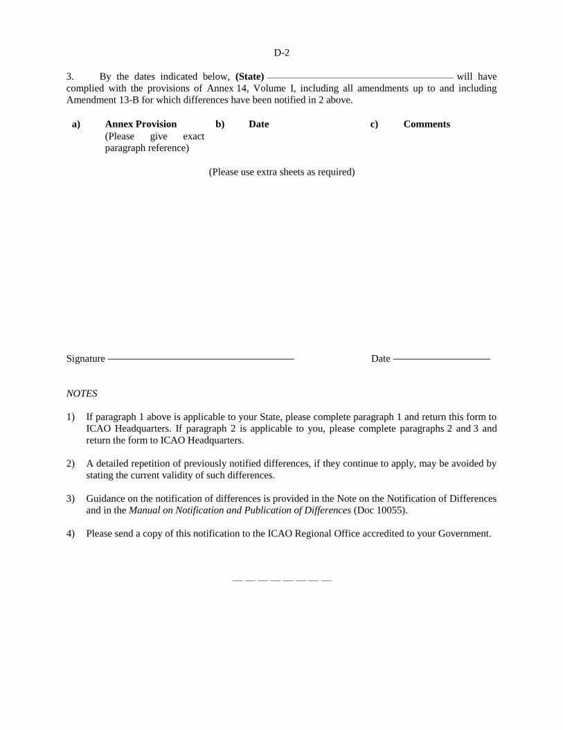
D-2
3. By the dates indicated below, (State) will have
complied with the provisions of Annex 14, Volume I, including all amendments up to and including
Amendment 13-B for which differences have been notified in 2 above.
a) Annex Provision b) Date c) Comments
(Please give exact
paragraph reference)
(Please use extra sheets as required)
Signature Date
NOTES
1) If paragraph 1 above is applicable to your State, please complete paragraph 1 and return this form to
ICAO Headquarters. If paragraph 2 is applicable to you, please complete paragraphs 2 and 3 and
return the form to ICAO Headquarters.
2) A detailed repetition of previously notified differences, if they continue to apply, may be avoided by
stating the current validity of such differences.
3) Guidance on the notification of differences is provided in the Note on the Notification of Differences
and in the Manual on Notification and Publication of Differences (Doc 10055).
4) Please send a copy of this notification to the ICAO Regional Office accredited to your Government.
— — — — — — — —

ATTACHMENT E to State letter AN 4/1.2.26-16/19
NOTE ON THE NOTIFICATION OF DIFFERENCES
(Prepared and issued in accordance with instructions of the Council)
1. Introduction
1.1 Article 38 of the Convention on International Civil Aviation (“Convention”) requires that
a Contracting State notify ICAO any time it does not comply with a Standard in all respects, it does not
bring its regulations or practices into full accord with any Standard, or it adopts regulations or practices
differing in any particular respect from the Standard.
1.2 The Assembly and the Council, when reviewing the notification of differences by
Contracting States in compliance with Article 38 of the Convention, have repeatedly noted that the
timeliness and currency of such notifications is not entirely satisfactory. Therefore, this note is issued to
reiterate the primary purpose of Article 38 of the Convention and to facilitate the determination and
notification of differences.
1.3 The primary purpose of the notification of differences is to promote safety, regularity and
efficiency in air navigation by ensuring that governmental and other agencies, including operators and
service providers, concerned with international civil aviation are made aware of all national regulations
and practices in so far as they differ from those prescribed in the Standards contained in Annexes to the
Convention.
1.4 Contracting States are, therefore, requested to give particular attention to the notification
of differences with respect to Standards in all Annexes, as described in paragraph 4 b) 1) of the
Resolution of Adoption.
1.5 Although differences from Recommended Practices are not notifiable under Article 38 of
the Convention, the Assembly has urged Contracting States to extend the above considerations to
Recommended Practices contained in Annexes to the Convention, as well.
2. Notification of differences from Standards and Recommended Practices (SARPs)
2. 1 Guidance to Contracting States in the notification of differences to Standards and
Recommended Practices (SARPs) can only be given in very general terms. Contracting States are further
reminded that compliance with SARPs generally extends beyond the issuance of national regulations and
requires establishment of practical arrangements for implementation, such as the provision of facilities,
personnel and equipment and effective enforcement mechanisms. Contracting States should take those
elements into account when determining their compliance and differences. The following categories of
differences are provided as a guide in determining whether a notifiable difference exists:
a) A Contracting State’s requirement is more exacting or exceeds a SARP
(Category A). This category applies when the national regulation and practices are
more demanding than the corresponding SARP, or impose an obligation within the
scope of the Annex which is not covered by the SARP. This is of particular
importance where a Contracting State requires a higher standard which affects the
operation of aircraft of other Contracting States in and above its territory;
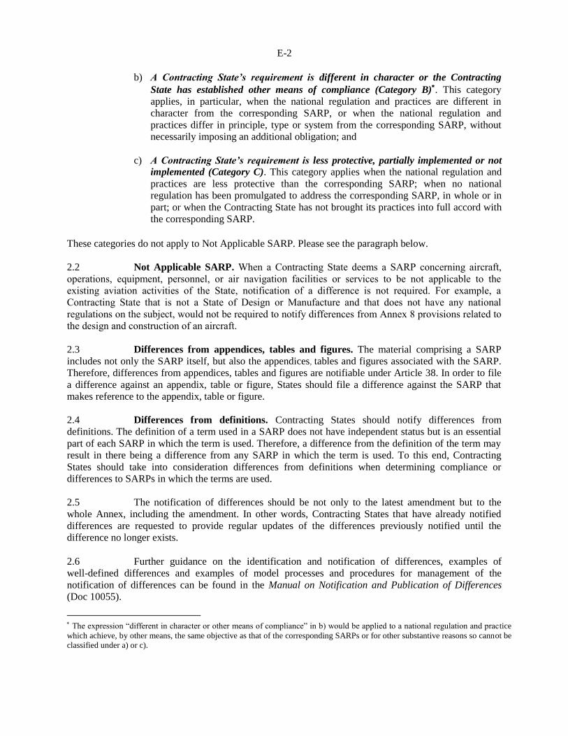
E-2
b) A Contracting State’s requirement is different in character or the Contracting
State has established other means of compliance (Category B). This category
applies, in particular, when the national regulation and practices are different in
character from the corresponding SARP, or when the national regulation and
practices differ in principle, type or system from the corresponding SARP, without
necessarily imposing an additional obligation; and
c) A Contracting State’s requirement is less protective, partially implemented or not
implemented (Category C). This category applies when the national regulation and
practices are less protective than the corresponding SARP; when no national
regulation has been promulgated to address the corresponding SARP, in whole or in
part; or when the Contracting State has not brought its practices into full accord with
the corresponding SARP.
These categories do not apply to Not Applicable SARP. Please see the paragraph below.
2.2 Not Applicable SARP. When a Contracting State deems a SARP concerning aircraft,
operations, equipment, personnel, or air navigation facilities or services to be not applicable to the
existing aviation activities of the State, notification of a difference is not required. For example, a
Contracting State that is not a State of Design or Manufacture and that does not have any national
regulations on the subject, would not be required to notify differences from Annex 8 provisions related to
the design and construction of an aircraft.
2.3 Differences from appendices, tables and figures. The material comprising a SARP
includes not only the SARP itself, but also the appendices, tables and figures associated with the SARP.
Therefore, differences from appendices, tables and figures are notifiable under Article 38. In order to file
a difference against an appendix, table or figure, States should file a difference against the SARP that
makes reference to the appendix, table or figure.
2.4 Differences from definitions. Contracting States should notify differences from
definitions. The definition of a term used in a SARP does not have independent status but is an essential
part of each SARP in which the term is used. Therefore, a difference from the definition of the term may
result in there being a difference from any SARP in which the term is used. To this end, Contracting
States should take into consideration differences from definitions when determining compliance or
differences to SARPs in which the terms are used.
2.5 The notification of differences should be not only to the latest amendment but to the
whole Annex, including the amendment. In other words, Contracting States that have already notified
differences are requested to provide regular updates of the differences previously notified until the
difference no longer exists.
2.6 Further guidance on the identification and notification of differences, examples of
well-defined differences and examples of model processes and procedures for management of the
notification of differences can be found in the Manual on Notification and Publication of Differences
(Doc 10055).
The expression “different in character or other means of compliance” in b) would be applied to a national regulation and practice
which achieve, by other means, the same objective as that of the corresponding SARPs or for other substantive reasons so cannot be
classified under a) or c).
E-3
3. Form of notification of differences
3.1 Differences can be notified:
a) by sending to ICAO Headquarters a form on notification of compliance or
differences; or
b) through the Electronic Filing of Differences (EFOD) System at www.icao.int/usoap.
3.2 When notifying differences, the following information should be provided:
a) the number of the paragraph or subparagraph which contains the SARP to which the
difference relates;
b) the reasons why the State does not comply with the SARP, or considers it necessary
to adopt different regulations or practices;
c) a clear and concise description of the difference; and
d) intentions for future compliance and any date by which your Government plans to
confirm compliance with and remove its difference from the SARP for which the
difference has been notified.
3.3 The differences notified will be made available to other Contracting States, normally in
the terms used by the Contracting State when making the notification. In the interest of making the
information as useful as possible, Contracting States are requested to ensure that:
a) statements be as clear and concise as possible and be confined to essential points;
b) the provision of extracts from national regulations not be considered as sufficient to
satisfy the obligation to notify differences; and
c) general comments, unclear acronyms and references be avoided.
— — — — — — — —
This applies only when the notification is made under 3.1 a).

ATTACHMENT F to State letter AN 4/1.2.26-16/19
IMPLEMENTATION TASK LIST AND OUTLINE OF GUIDANCE MATERIAL
IN RELATION TO AMENDMENT 13 TO ANNEX 14, VOLUME I
1. IMPLEMENTATION TASK LIST
1.1 Essential steps to be followed by a State in order to implement the proposed amendment
to Annex 14, Volume I:
a) identification of the rule-making process necessary to transpose the new ICAO
provisions into national regulations;
b) establishment of a national implementation plan that takes into account the new ICAO
provisions;
c) conduct a gap analysis between the new ICAO provisions and national framework;
d) drafting of the necessary modifications to the national regulations;
e) official adoption of the national regulations and means of compliance;
f) notification of differences, if any, to ICAO;
g) implementation of the new national regulations by aerodrome operators;
h) modification of the oversight framework according to the new national regulations;
i) oversight by the State of the implementation of regulations; and
j) publication of differences, if any, in the State’s AIP.
1.2 With respect to the implementation of the enhanced global reporting format, attention
should be paid to the need for every stakeholder to make the necessary adjustments in their management
and operational procedures, including provision of the necessary training programmes prior to
implementation. The implementation of the GRF involves several stakeholders ie. regulators, aerodrome
operators, relevant ANSPs, aircraft manufacturers, airlines and pilots. The establishment of a GRF
Implementation Team (GRFIT) is encouraged to ensure proper planning and coordination at the State
and/or regional level. Suitable ICAO guidance will be made available and a number of regional
workshops will be organized to facilitate implementation.
1.3 The autonomous runway incursion warning system (ARIWS) has been installed in
several States worldwide. However, it should be noted that there is no obligation or recommendation
within the provisions to install such a system; the installation of such a system at an aerodrome would
only be undertaken following an assessment of the runway incursion risk at that aerodrome. Suitable
ICAO guidance material will be made available in November 2016 and consideration will be given to
holding ARIWS workshops in the future should the need arise.
F-2
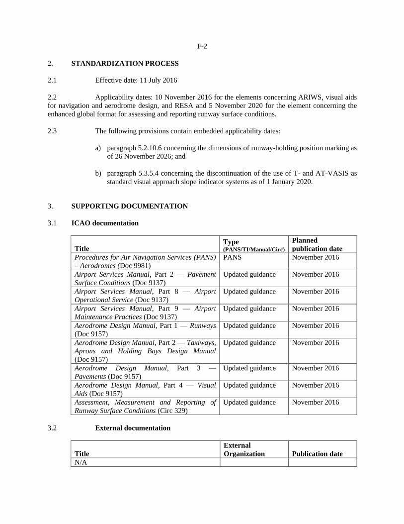
2. STANDARDIZATION PROCESS
2.1 Effective date: 11 July 2016
2.2 Applicability dates: 10 November 2016 for the elements concerning ARIWS, visual aids
for navigation and aerodrome design, and RESA and 5 November 2020 for the element concerning the
enhanced global format for assessing and reporting runway surface conditions.
2.3 The following provisions contain embedded applicability dates:
a) paragraph 5.2.10.6 concerning the dimensions of runway-holding position marking as
of 26 November 2026; and
b) paragraph 5.3.5.4 concerning the discontinuation of the use of T- and AT-VASIS as
standard visual approach slope indicator systems as of 1 January 2020.
3. SUPPORTING DOCUMENTATION
3.1 ICAO documentation
Title Type (PANS/TI/Manual/Circ)
Planned
publication date
Procedures for Air Navigation Services (PANS)
– Aerodromes (Doc 9981)
PANS November 2016
Airport Services Manual, Part 2 — Pavement
Surface Conditions (Doc 9137)
Updated guidance November 2016
Airport Services Manual, Part 8 — Airport
Operational Service (Doc 9137)
Updated guidance November 2016
Airport Services Manual, Part 9 — Airport
Maintenance Practices (Doc 9137)
Updated guidance November 2016
Aerodrome Design Manual, Part 1 — Runways
(Doc 9157)
Updated guidance November 2016
Aerodrome Design Manual, Part 2 — Taxiways,
Aprons and Holding Bays Design Manual
(Doc 9157)
Updated guidance November 2016
Aerodrome Design Manual, Part 3 —
Pavements (Doc 9157)
Updated guidance November 2016
Aerodrome Design Manual, Part 4 — Visual
Aids (Doc 9157)
Updated guidance November 2016
Assessment, Measurement and Reporting of
Runway Surface Conditions (Circ 329)
Updated guidance November 2016
3.2 External documentation
Title
External
Organization Publication date
N/A
F-3
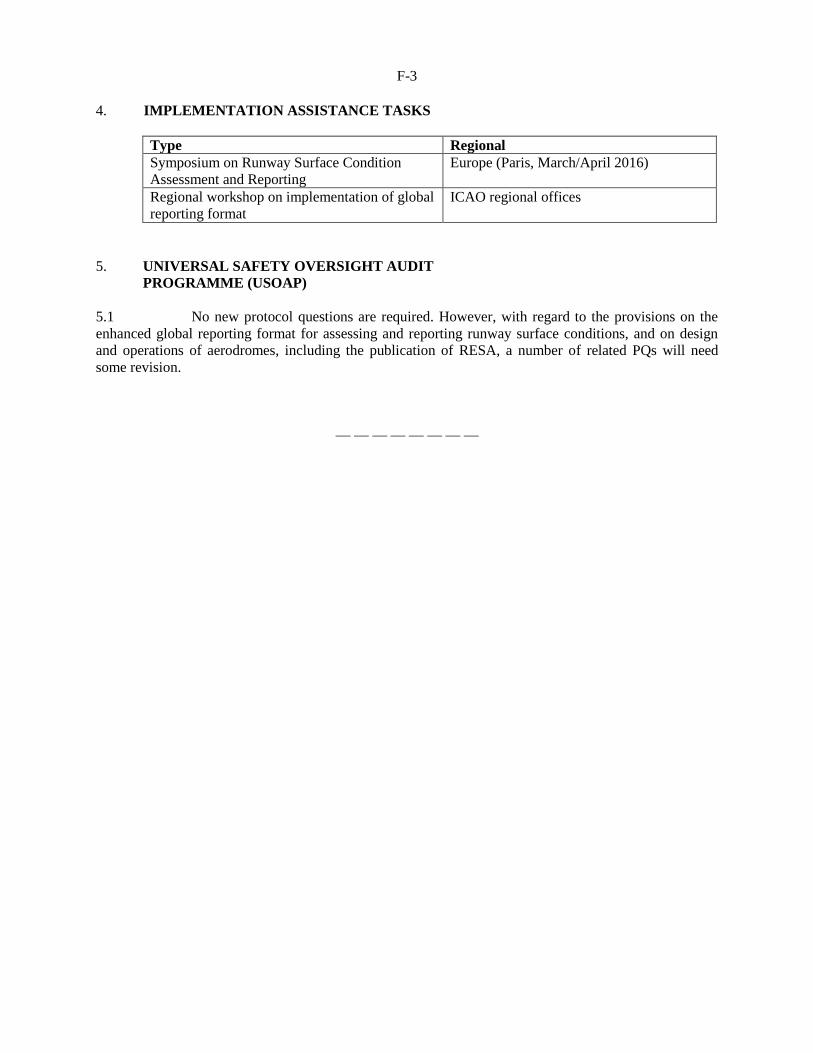
4. IMPLEMENTATION ASSISTANCE TASKS
Type Regional
Symposium on Runway Surface Condition
Assessment and Reporting
Europe (Paris, March/April 2016)
Regional workshop on implementation of global
reporting format
ICAO regional offices
5. UNIVERSAL SAFETY OVERSIGHT AUDIT
PROGRAMME (USOAP)
5.1 No new protocol questions are required. However, with regard to the provisions on the
enhanced global reporting format for assessing and reporting runway surface conditions, and on design
and operations of aerodromes, including the publication of RESA, a number of related PQs will need
some revision.
— — — — — — — —
ATTACHMENT G to State letter AN 4/1.2.26-16/19
IMPACT ASSESSMENT IN RELATION TO AMENDMENT 13 TO
ANNEX 14, VOLUME I
1. INTRODUCTION
1.1 Amendment 13 to Annex 14, Volume I contains a package of proposals related to
aerodrome design and operations as outlined in the Global Air Navigation Plan (GANP) and the
Global Aviation Safety Plan (GASP) and is intended to improve safety and efficiency performance at
and in the vicinity of aerodromes.
2. IMPACT ASSESSMENT
Autonomous runway incursion warning system (ARIWS)
2.1.1 Safety impact: The ARIWS concept has been designed for reduction of the prevalence and
consequences of runway incursions for specific cases where it has been decided to install the system.
2.1.2 Financial impact: The present cost of implementing an ARIWS is large but limited to a
small amount of aerodromes where it has been decided to install the system. It will be justified by the
local assessment.
2.1.3 Security impact: Nil.
2.1.4 Environmental impact: ARIWS does not contain any new procedures that may have an
impact on environmental targets. The impact is limited to the installation and operation of the visual
aids and systems.
2.1.5 Efficiency impact: ARIWS provisions have been developed to minimize the impact on
normal operations.
2.1.6 Expected implementation time: Some aerodromes in certain States have already
implemented the system. For those that are planning to install such a system, the implementation time
will depend on the complexity of the system based on their assessment.
Visual aids for navigation and aerodrome design
2.2.1 Safety impact: The proposed amendments are expected to improve aerodrome safety by
providing better and enhanced specifications concerning aerodrome visual aids and design
requirements. In particular, the provisions concerning storm water conveyances will permit aerodrome
operators located in tropical climates or those that receive large volumes of annual rainfall to use open-
air water conveyances as a means to remove excessive rainfall from ponding on/near the runway,
thereby enhancing the safety of aircraft operations.
G-2
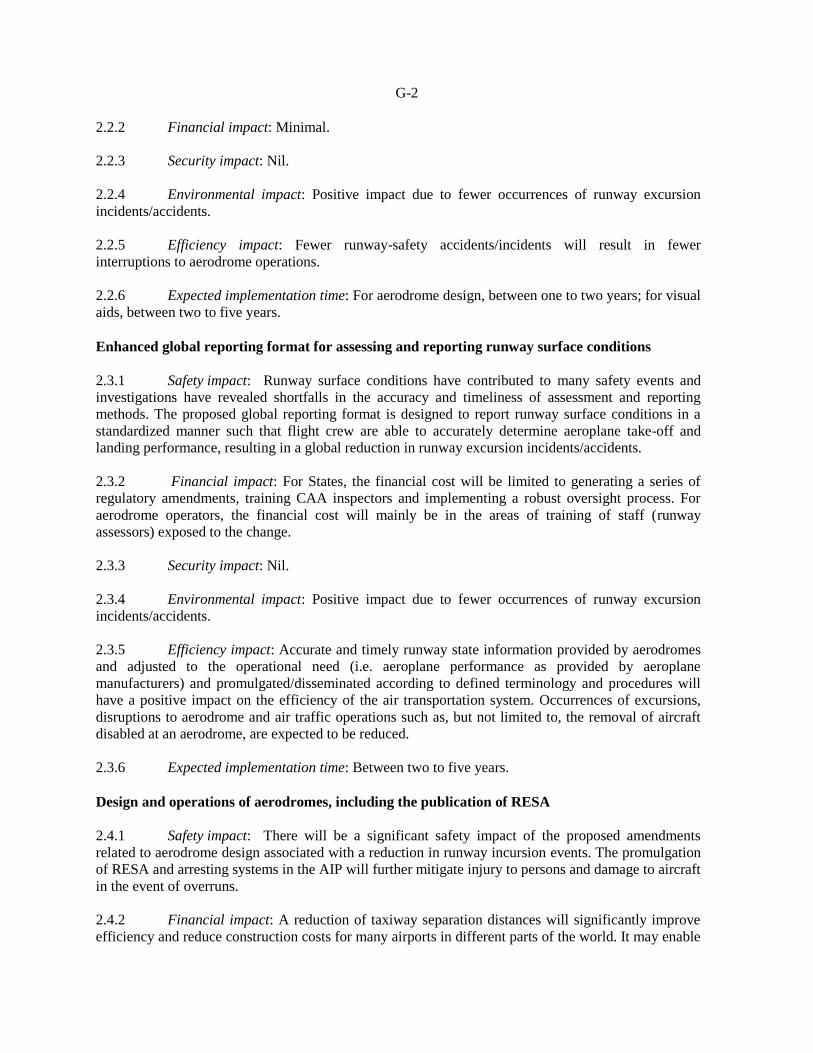
2.2.2 Financial impact: Minimal.
2.2.3 Security impact: Nil.
2.2.4 Environmental impact: Positive impact due to fewer occurrences of runway excursion
incidents/accidents.
2.2.5 Efficiency impact: Fewer runway-safety accidents/incidents will result in fewer
interruptions to aerodrome operations.
2.2.6 Expected implementation time: For aerodrome design, between one to two years; for visual
aids, between two to five years.
Enhanced global reporting format for assessing and reporting runway surface conditions
2.3.1 Safety impact: Runway surface conditions have contributed to many safety events and
investigations have revealed shortfalls in the accuracy and timeliness of assessment and reporting
methods. The proposed global reporting format is designed to report runway surface conditions in a
standardized manner such that flight crew are able to accurately determine aeroplane take-off and
landing performance, resulting in a global reduction in runway excursion incidents/accidents.
2.3.2 Financial impact: For States, the financial cost will be limited to generating a series of
regulatory amendments, training CAA inspectors and implementing a robust oversight process. For
aerodrome operators, the financial cost will mainly be in the areas of training of staff (runway
assessors) exposed to the change.
2.3.3 Security impact: Nil.
2.3.4 Environmental impact: Positive impact due to fewer occurrences of runway excursion
incidents/accidents.
2.3.5 Efficiency impact: Accurate and timely runway state information provided by aerodromes
and adjusted to the operational need (i.e. aeroplane performance as provided by aeroplane
manufacturers) and promulgated/disseminated according to defined terminology and procedures will
have a positive impact on the efficiency of the air transportation system. Occurrences of excursions,
disruptions to aerodrome and air traffic operations such as, but not limited to, the removal of aircraft
disabled at an aerodrome, are expected to be reduced.
2.3.6 Expected implementation time: Between two to five years.
Design and operations of aerodromes, including the publication of RESA
2.4.1 Safety impact: There will be a significant safety impact of the proposed amendments
related to aerodrome design associated with a reduction in runway incursion events. The promulgation
of RESA and arresting systems in the AIP will further mitigate injury to persons and damage to aircraft
in the event of overruns.
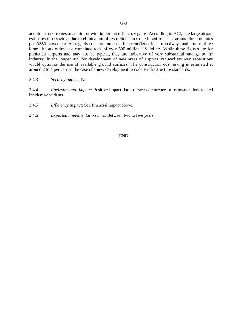
2.4.2 Financial impact: A reduction of taxiway separation distances will significantly improve
efficiency and reduce construction costs for many airports in different parts of the world. It may enable
G-3
additional taxi routes at an airport with important efficiency gains. According to ACI, one large airport
estimates time savings due to elimination of restrictions on Code F taxi routes at around three minutes
per A380 movement. As regards construction costs for reconfigurations of taxiways and aprons, three
large airports estimate a combined total of over 500 million US dollars. While these figures are for
particular airports and may not be typical, they are indicative of very substantial savings to the
industry. In the longer run, for development of new areas of airports, reduced taxiway separations
would optimize the use of available ground surfaces. The construction cost saving is estimated at
around 2 to 4 per cent in the case of a new development to code F infrastructure standards.
2.4.3 Security impact: Nil.
2.4.4 Environmental impact: Positive impact due to fewer occurrences of runway-safety related
incidents/accidents.
2.4.5 Efficiency impact: See financial impact above.
2.4.6 Expected implementation time: Between two to five years.
— END —

AMENDMENT No. 13-A
TO THE
INTERNATIONAL STANDARDS
AND RECOMMENDED PRACTICES
AERODROMES
ANNEX 14
TO THE CONVENTION ON INTERNATIONAL CIVIL AVIATION
VOLUME I —
AERODROME DESIGN AND OPERATIONS
The amendment to Annex 14, Volume I contained in this document was adopted
by the Council of ICAO on 22 February 2016. Such parts of this amendment as
have not been disapproved by more than half of the total number of Contracting
States on or before 11 July 2016 will become effective on that date and will
become applicable on 10 November 2016 as specified in the Resolution of
Adoption. (State letter AN 4/1.2.26-16/19 refers.)
FEBRUARY 2016
INTERNATIONAL CIVIL AVIATION ORGANIZATION

AMENDMENT 13 TO THE INTERNATIONAL STANDARDS AND
RECOMMENDED PRACTICES
ANNEX 14 — AERODROMES VOLUME I — AERODROME DESIGN AND OPERATIONS
RESOLUTION OF ADOPTION
The Council Acting in accordance with the Convention on International Civil Aviation, and particularly with the provisions of Articles 37, 54 and 90 thereof, 1. Hereby adopts on 22 February 2016 Amendment 13 to the International Standards and Recommended Practices contained in the document entitled International Standards and Recommended Practices, Aerodromes — Aerodrome Design and Operations which for convenience is designated Annex 14, Volume I to the Convention; 2. Prescribes 11 July 2016 as the date upon which the said amendment shall become effective, except for any part thereof in respect of which a majority of the Contracting States have registered their disapproval with the Council before that date; 3. Resolves that the said amendment or such parts thereof as have become effective shall become applicable on 10 November 2016
1;
4. Requests the Secretary General:
a) to notify each Contracting State immediately of the above action and immediately after 11 July 2016 of those parts of the amendment which have become effective;
b) to request each Contracting State:
1) to notify the Organization (in accordance with the obligation imposed by Article 38 of the Convention) of the differences that will exist on 10 November 2016
1 between its national regulations or practices and the
provisions of the Standards in the Annex as hereby amended, such notification to be made before 10 October 2016
2, and thereafter to notify the Organization of
any further differences that arise;
2) to notify the Organization before 10 October 20162 of the date or dates by which
it will have complied with the provisions of the Standards in the Annex as hereby amended;
c) to invite each Contracting State to notify additionally any differences between its own practices and those established by the Recommended Practices following the procedure specified in subparagraph b) above with respect to differences from Standards.
— — — — — — — —
1 5 November 2020 for definitions on runway condition assessment matrix (RCAM), runway condition code (RWYCC), runway
condition report (RCR), runway surface conditions(s), slush, snow (on the ground); paragraphs 2.9.2 to 2.9.12, 10.2.3 to 10.2.8,
10.3.1, 10.3.4, 10.3.5, Attachment A, Sections 6 and 7. 2 5 October 2020 for definitions on runway condition assessment matrix (RCAM), runway condition code (RWYCC), runway
condition report (RCR), runway surface conditions(s), slush, snow (on the ground); paragraphs 2.9.2 to 2.9.12, 10.2.3 to 10.2.8,
10.3.1, 10.3.4, 10.3.5, Attachment A, Sections 6 and 7.
2
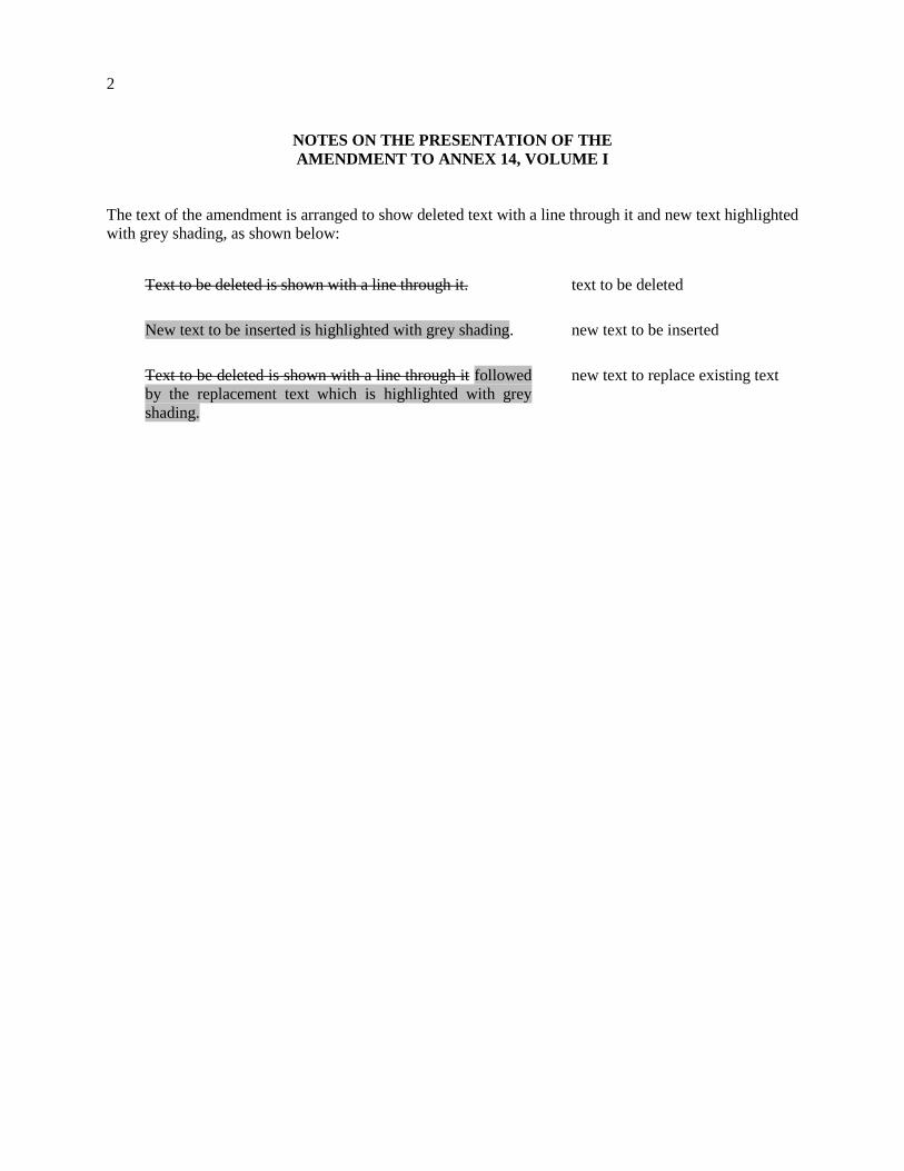
NOTES ON THE PRESENTATION OF THE
AMENDMENT TO ANNEX 14, VOLUME I
The text of the amendment is arranged to show deleted text with a line through it and new text highlighted
with grey shading, as shown below:
Text to be deleted is shown with a line through it.
text to be deleted
New text to be inserted is highlighted with grey shading.
new text to be inserted
Text to be deleted is shown with a line through it followed
by the replacement text which is highlighted with grey
shading.
new text to replace existing text
3
TEXT OF AMENDMENT 13-A
TO THE
INTERNATIONAL STANDARDS
AND RECOMMENDED PRACTICES
AERODROMES
ANNEX 14
TO THE CONVENTION ON INTERNATIONAL CIVIL AVIATION
VOLUME I
AERODROME DESIGN AND OPERATIONS
. . .
CHAPTER 1. GENERAL
1.1 Definitions
. . .
Apron management service. A service provided to regulate the activities and the movement of aircraft
and vehicles on an apron.
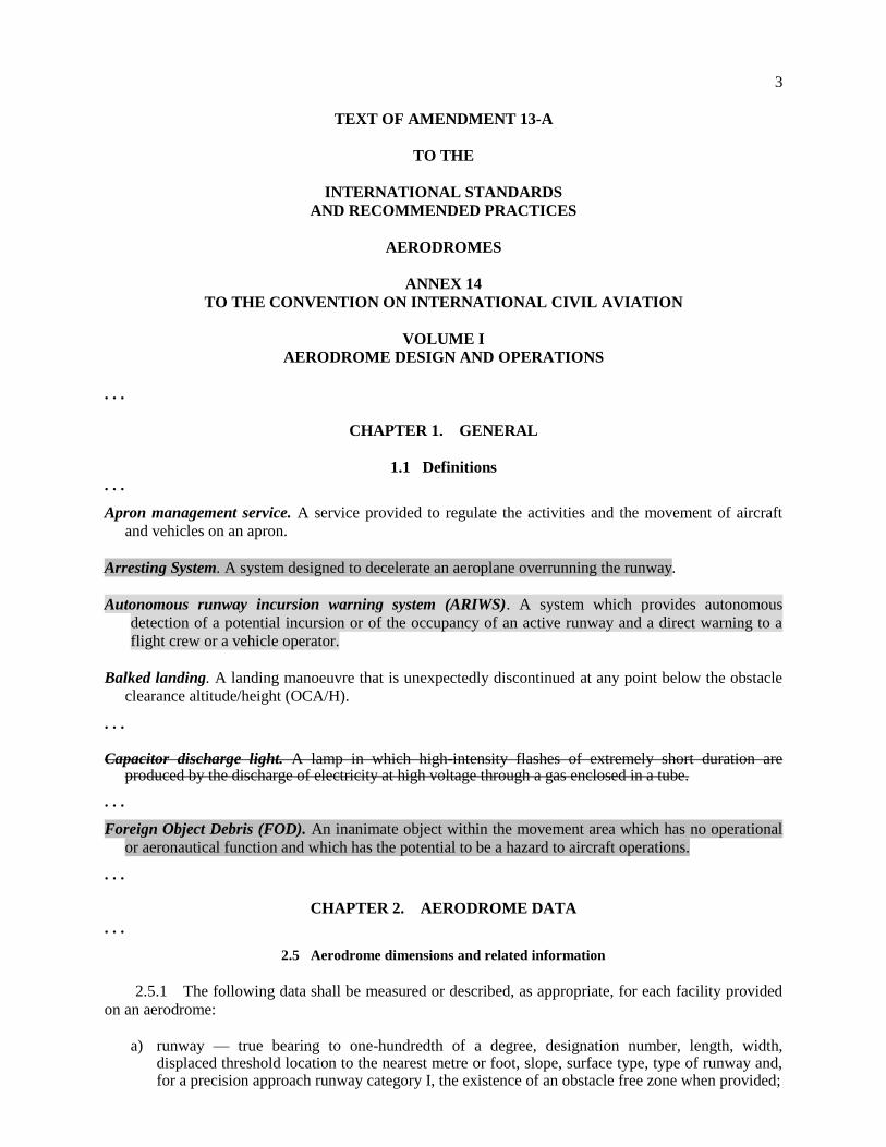
Arresting System. A system designed to decelerate an aeroplane overrunning the runway.
Autonomous runway incursion warning system (ARIWS). A system which provides autonomous
detection of a potential incursion or of the occupancy of an active runway and a direct warning to a
flight crew or a vehicle operator.
Balked landing. A landing manoeuvre that is unexpectedly discontinued at any point below the obstacle
clearance altitude/height (OCA/H).
. . . Capacitor discharge light. A lamp in which high-intensity flashes of extremely short duration are
produced by the discharge of electricity at high voltage through a gas enclosed in a tube.
. . .
Foreign Object Debris (FOD). An inanimate object within the movement area which has no operational
or aeronautical function and which has the potential to be a hazard to aircraft operations.
. . .
CHAPTER 2. AERODROME DATA
. . .
2.5 Aerodrome dimensions and related information
2.5.1 The following data shall be measured or described, as appropriate, for each facility provided
on an aerodrome:
a) runway — true bearing to one-hundredth of a degree, designation number, length, width,
displaced threshold location to the nearest metre or foot, slope, surface type, type of runway and, for a precision approach runway category I, the existence of an obstacle free zone when provided;
4
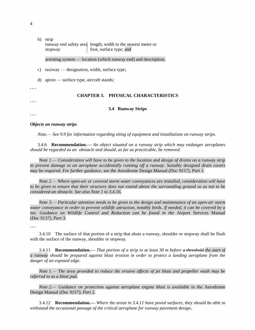
b) strip runway end safety area length, width to the nearest metre or stopway foot, surface type; and
arresting system — location (which runway end) and description; c) taxiway — designation, width, surface type; d) apron — surface type, aircraft stands;
. . .
CHAPTER 3. PHYSICAL CHARACTERISTICS
. . .
3.4 Runway Strips
. . .
Objects on runway strips Note.— See 9.9 for information regarding siting of equipment and installations on runway strips.
3.4.6 Recommendation.— An object situated on a runway strip which may endanger aeroplanes should be regarded as an obstacle and should, as far as practicable, be removed.
Note 1.— Consideration will have to be given to the location and design of drains on a runway strip
to prevent damage to an aeroplane accidentally running off a runway. Suitably designed drain covers
may be required. For further guidance, see the Aerodrome Design Manual (Doc 9157), Part 1.
Note 2.— Where open-air or covered storm water conveyances are installed, consideration will have
to be given to ensure that their structure does not extend above the surrounding ground so as not to be
considered an obstacle. See also Note 1 to 3.4.16.
Note 3.— Particular attention needs to be given to the design and maintenance of an open-air storm
water conveyance in order to prevent wildlife attraction, notably birds. If needed, it can be covered by a
net. Guidance on Wildlife Control and Reduction can be found in the Airport Services Manual
(Doc 9137), Part 3.
. . .
3.4.10 The surface of that portion of a strip that abuts a runway, shoulder or stopway shall be flush
with the surface of the runway, shoulder or stopway.
3.4.11 Recommendation.— That portion of a strip to at least 30 m before a threshold the start of
a runway should be prepared against blast erosion in order to protect a landing aeroplane from the
danger of an exposed edge.
Note 1.— The area provided to reduce the erosive effects of jet blast and propeller wash may be
referred to as a blast pad.
Note 2.— Guidance on protection against aeroplane engine blast is available in the Aerodrome
Design Manual (Doc 9157), Part 2.
3.4.12 Recommendation.— Where the areas in 3.4.11 have paved surfaces, they should be able to
withstand the occasional passage of the critical aeroplane for runway pavement design.
5
Note .— The area adjacent to the end of a runway may be referred to as a blast pad.
. . .
3.4.15 Transverse slopes
. . .
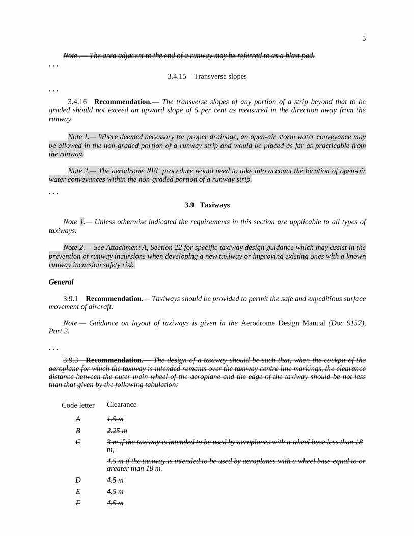
3.4.16 Recommendation.— The transverse slopes of any portion of a strip beyond that to be
graded should not exceed an upward slope of 5 per cent as measured in the direction away from the
runway.
Note 1.— Where deemed necessary for proper drainage, an open-air storm water conveyance may
be allowed in the non-graded portion of a runway strip and would be placed as far as practicable from
the runway.
Note 2.— The aerodrome RFF procedure would need to take into account the location of open-air
water conveyances within the non-graded portion of a runway strip.
. . .
3.9 Taxiways
Note 1.— Unless otherwise indicated the requirements in this section are applicable to all types of
taxiways.
Note 2.— See Attachment A, Section 22 for specific taxiway design guidance which may assist in the
prevention of runway incursions when developing a new taxiway or improving existing ones with a known
runway incursion safety risk.
General
3.9.1 Recommendation.— Taxiways should be provided to permit the safe and expeditious surface movement of aircraft.
Note.— Guidance on layout of taxiways is given in the Aerodrome Design Manual (Doc 9157), Part 2. . . .
3.9.3 Recommendation.— The design of a taxiway should be such that, when the cockpit of the aeroplane for which the taxiway is intended remains over the taxiway centre line markings, the clearance distance between the outer main wheel of the aeroplane and the edge of the taxiway should be not less than that given by the following tabulation:
Code letter Clearance
A 1.5 m
B 2.25 m
C 3 m if the taxiway is intended to be used by aeroplanes with a wheel base less than 18 m;
4.5 m if the taxiway is intended to be used by aeroplanes with a wheel base equal to or greater than 18 m.
D 4.5 m
E 4.5 m
F 4.5 m
6
Note 1.— Wheel base means the distance from the nose gear to the geometric centre of the main
gear.
Note 2.— Where the code letter is F and the traffic density is high, a wheel-to-edge clearance
greater than 4.5 m may be provided to permit higher taxiing speeds.
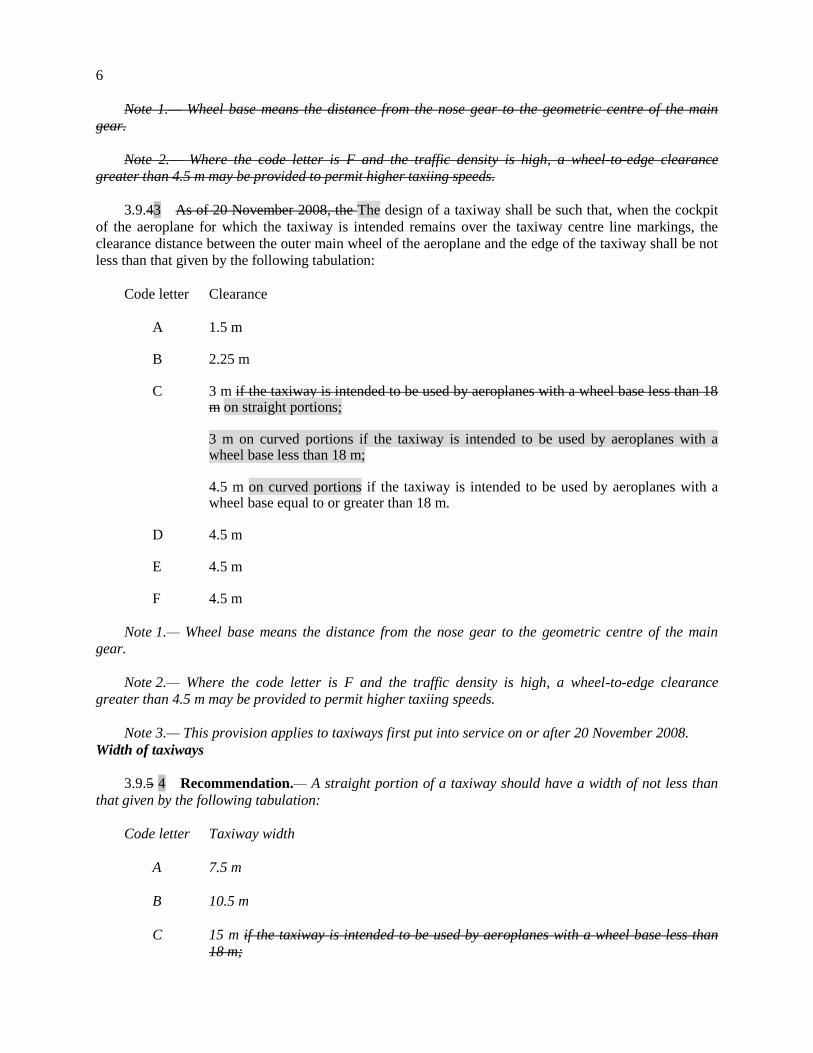
3.9.43 As of 20 November 2008, the The design of a taxiway shall be such that, when the cockpit
of the aeroplane for which the taxiway is intended remains over the taxiway centre line markings, the
clearance distance between the outer main wheel of the aeroplane and the edge of the taxiway shall be not
less than that given by the following tabulation:
Code letter Clearance
A 1.5 m B 2.25 m
C 3 m if the taxiway is intended to be used by aeroplanes with a wheel base less than 18
m on straight portions;
3 m on curved portions if the taxiway is intended to be used by aeroplanes with a wheel base less than 18 m;
4.5 m on curved portions if the taxiway is intended to be used by aeroplanes with a
wheel base equal to or greater than 18 m. D 4.5 m E 4.5 m F 4.5 m
Note 1.— Wheel base means the distance from the nose gear to the geometric centre of the main
gear.
Note 2.— Where the code letter is F and the traffic density is high, a wheel-to-edge clearance
greater than 4.5 m may be provided to permit higher taxiing speeds.
Note 3.— This provision applies to taxiways first put into service on or after 20 November 2008.
Width of taxiways
3.9.5 4 Recommendation.— A straight portion of a taxiway should have a width of not less than
that given by the following tabulation:
Code letter Taxiway width
A 7.5 m
B 10.5 m
C 15 m if the taxiway is intended to be used by aeroplanes with a wheel base less than
18 m;

7
18 m if the taxiway is intended to be used by aeroplanes with a wheel base equal to or
greater than 18 m
D 18 m if the taxiway is intended to be used by aeroplanes with an outer main gear
wheel span of less than 9 m;
23 m if the taxiway is intended to be used by aeroplanes with an outer main gear
wheel span equal to or greater than 9 m.
E 23 m
F 25 m
Editorial Note.— Renumber subsequent paragraphs and the associated references to those paragraphs
in the relevant figures, accordingly.
. . .
Figure 3.2. Taxiway curve
Taxiway
width
(see 3.9.5 4)
Minimum wheel
clearance (see 3.9.6 5)
3.9.6 5).

8
Table 3-1 Taxiway minimum separation distances
Code letter
Distance between taxiway centre line and runway centre line (metres)
Taxiway centre line to taxiway centre line (metres)
Taxiway, other than
aircraft stand taxilane,
centre line to object (metres)
Aircraft stand taxilane
centre line to object (metres)
Instrument runways Code number
Non-instrument runways
Code number
Aircraft stand
taxilane centre line
to aircraft stand taxilane
centre line
1 2 3 4 1 2 3 4 (metres)
(1) (2) (3) (4) (5) (6) (7) (8) (9) (10) (11) (12) (13) (12)
A 82.5 82.5 – – 37.5 47.5 – – 23 (23.75) 15.5 (16.25) 19.5 12
B 87 87 – – 42 52 – – 32 (33.5) 20 (21.5) 28.5 16.5
C – – 168 – – – 93 – 44 26 40.5 22.5 (24.5)
D – – 176 176 – – 101 101 63 (66.5) 37 (40.5) 59.5 33.5 (36)
E – – – 182.5 – – – 107.5 76 (80) 43.5 (47.5) 72.5 40 (42.5)
F – – – 190 – – – 115 91 (97.5) 51 (57.5) 87.5 47.5 (50.5)
. . .
3.11 Taxiway strips
Objects on taxiway strips
Note.— See 9.9 for information regarding siting of equipment and installations on taxiway strips.
3.11.3 Recommendation.— The taxiway strip should provide an area clear of objects which may
endanger taxiing aeroplanes.
Note 1. — Consideration will have to be given to the location and design of drains on a taxiway
strip to prevent damage to an aeroplane accidentally running off a taxiway. Suitably designed drain
covers may be required. For further guidance, see the Aerodrome Design Manual (Doc 9157), Part 2.
Note 2.— Where open-air or covered storm water conveyances are installed, consideration will
have to be given to ensure that their structure do not extend above the surrounding ground so as not to be
considered an obstacle. See also Note 1 to 3.11.6.
Note 3.— Particular attention needs to be given to the design and maintenance of an open-air
storm water conveyance in order to prevent wildlife attraction, notably birds. If needed, it can be covered
by a net. Guidance on Wildlife Control and Reduction can be found in the Airport Services Manual
(Doc 9137), Part 3.
. . .
Slopes on taxiway strips
. . .
9
3.11.6 Recommendation.— The transverse slopes on any portion of a taxiway strip beyond that
to be graded should not exceed an upward or downward slope of 5 per cent as measured in the direction
away from the taxiway.
Note 1.— Where deemed necessary for proper drainage, an open-air storm water conveyance may
be allowed in the non-graded portion of a taxiway strip and would be placed as far as practicable from
the taxiway.
Note 2.— The aerodrome RFF procedure would need to take into account the location of open-air
storm water conveyances within the non-graded portion of a taxiway strip.
. . .
3.13 Aprons
. . .
Clearance distances on aircraft stands
3.13.6 Recommendation.— An aircraft stand should provide the following minimum clearances
between an aircraft using entering or exiting the stand and any adjacent building, aircraft on another
stand and other objects:
Code letter Clearance
A 3 m
B 3 m
C 4.5 m
D 7.5 m
E 7.5 m
F 7.5 m
When special circumstances so warrant, these clearances may be reduced at a nose-in aircraft stand,
where the code letter is D, E or F:
a) between the terminal, including any fixed passenger bridge, and the nose of an aircraft; and
b) over any portion of the stand provided with azimuth guidance by a visual docking guidance
system.
Note.— On aprons, consideration also has to be given to the provision of service roads and to
manoeuvring and storage area for ground equipment (see the Aerodrome Design Manual (Doc 9157),
Part 2, for guidance on storage of ground equipment).
. . .
10
CHAPTER 5. VISUAL AIDS FOR NAVIGATION
. . .
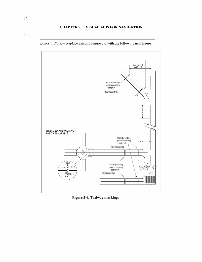
Editorial Note.— Replace existing Figure 5-6 with the following new figure.
Figure 5-6. Taxiway markings
(See Figure 5-8)
(See Figure 5-8)
(See Figure 5-8)
11
5.2.10 Runway-holding position marking
. . .
5.2.10.4 The runway-holding position marking displayed at a runway-holding position established
in accordance with 3.12.3 shall be as shown in Figure 5-6, pattern A.
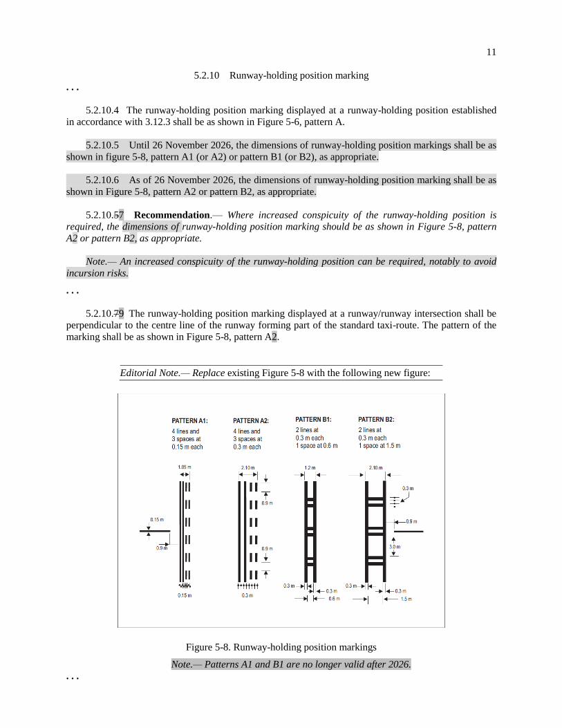
5.2.10.5 Until 26 November 2026, the dimensions of runway-holding position markings shall be as
shown in figure 5-8, pattern A1 (or A2) or pattern B1 (or B2), as appropriate.
5.2.10.6 As of 26 November 2026, the dimensions of runway-holding position marking shall be as
shown in Figure 5-8, pattern A2 or pattern B2, as appropriate.
5.2.10.57 Recommendation.— Where increased conspicuity of the runway-holding position is
required, the dimensions of runway-holding position marking should be as shown in Figure 5-8, pattern
A2 or pattern B2, as appropriate.
Note.— An increased conspicuity of the runway-holding position can be required, notably to avoid
incursion risks.
. . .
5.2.10.79 The runway-holding position marking displayed at a runway/runway intersection shall be
perpendicular to the centre line of the runway forming part of the standard taxi-route. The pattern of the
marking shall be as shown in Figure 5-8, pattern A2.
Editorial Note.— Replace existing Figure 5-8 with the following new figure:
Figure 5-8. Runway-holding position markings
Note.— Patterns A1 and B1 are no longer valid after 2026.
. . .
12
5.3 Lights . . .
5.3.4 Approach lighting systems
. . .
Precision approach category I lighting system
. . .
Characteristics
. . .
5.3.4.17 Recommendation.— If the centre line consists of barrettes as described in 5.3.4.14 b) or
5.3.4.15 b), each barrette should be supplemented by a capacitor discharge flashing light, except where
such lighting is considered unnecessary taking into account the characteristics of the system and the
nature of the meteorological conditions.
5.3.4.18 Each capacitor discharge flashing light as described in 5.3.4.17 shall be flashed twice a
second in sequence, beginning with the outermost light and progressing toward the threshold to the
innermost light of the system. The design of the electrical circuit shall be such that these lights can be
operated independently of the other lights of the approach lighting system.
. . .
Precision approach category II and III lighting system Characteristics
. . .
5.3.4.34 Recommendation.— If the centre line beyond 300 m from the threshold consists of
barrettes as described in 5.3.4.31 a) or 5.3.4.32 a), each barrette beyond 300 m should be supplemented
by a capacitor discharge flashing light, except where such lighting is considered unnecessary taking into
account the characteristics of the system and the nature of the meteorological conditions.
5.3.4.35 Each capacitor discharge flashing light as described in 5.3.4.34 shall be flashed twice a
second in sequence, beginning with the outermost light and progressing toward the threshold to the
innermost light of the system. The design of the electrical circuit shall be such that these lights can be
operated independently of the other lights of the approach lighting system.
. . .
5.3.5 Visual approach slope indicator system
. . .
5.3.5.2 The standard visual approach slope indicator systems shall consist of the following:
. . .
5.3.5.3 PAPI, T-VASIS or AT-VASIS shall be provided where the code number is 3 or 4 when one
or more of the conditions specified in 5.3.5.1 exist.
5.3.5.4 Recommendation.— As of 1 January 2020, the use of T-VASIS and AT-VASIS as standard
visual approach slope indicator systems should be discontinued.
Editorial Note.— Renumber subsequent paragraphs.
13
. . .
5.3.5.45 Where an aeronautical study indicates that an existing object extending above an obstacle
protection surface (OPS) could adversely affect the safety of operations of aeroplanes one or more of the
following measures shall be taken:
a) remove the object;
b) a) suitably raise the approach slope of the system;
c) b) reduce the azimuth spread of the system so that the object is outside the confines of the beam;
d) c) displace the axis of the system and its associated obstacle protection surface by no more than
5°;
d) suitably displace the threshold; and
e) where d) is found to be impracticable, suitably displace the system upwind of the threshold to
provide an increase in threshold crossing height equal to the height of the object penetration. such
that the object no longer penetrates the OPS.
Note 1.— Guidance on this issue is contained in the Aerodrome Design Manual (Doc 9157), Part 4.
Note 2.— The displacement of the system upwind of the threshold reduces the operational landing
distance.
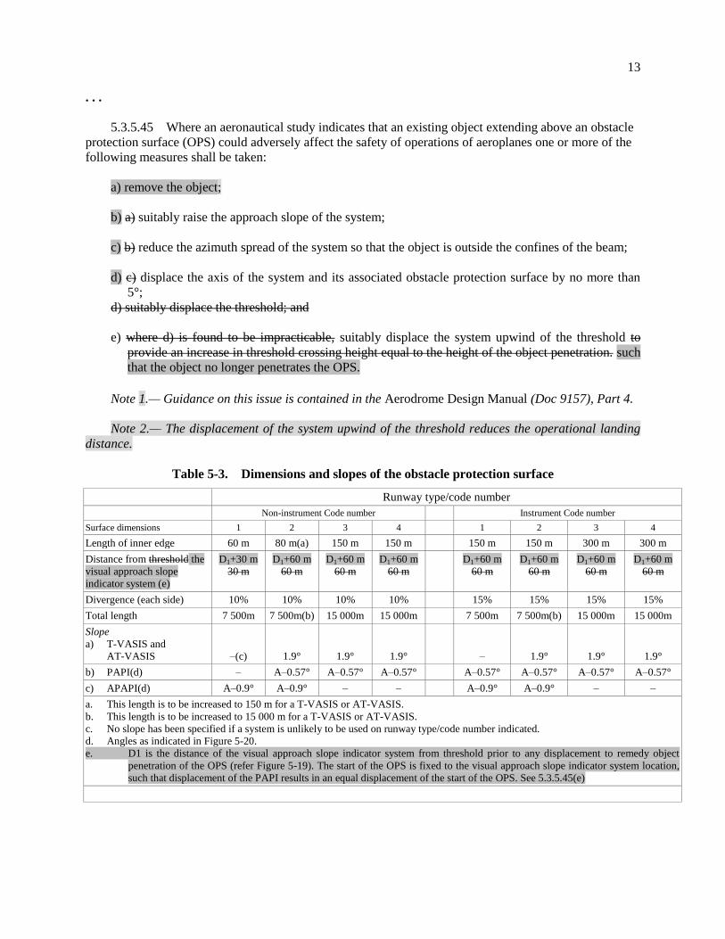
Table 5-3. Dimensions and slopes of the obstacle protection surface
Runway type/code number
Non-instrument Code number Instrument Code number
Surface dimensions 1 2 3 4 1 2 3 4
Length of inner edge 60 m 80 m(a) 150 m 150 m 150 m 150 m 300 m 300 m
Distance from threshold the
visual approach slope
indicator system (e)
D1+30 m
30 m
D1+60 m
60 m
D1+60 m
60 m
D1+60 m
60 m
D1+60 m
60 m
D1+60 m
60 m
D1+60 m
60 m
D1+60 m
60 m
Divergence (each side) 10% 10% 10% 10% 15% 15% 15% 15%
Total length 7 500m 7 500m(b) 15 000m 15 000m 7 500m 7 500m(b) 15 000m 15 000m
Slope
a) T-VASIS and
AT-VASIS –(c) 1.9° 1.9° 1.9° – 1.9° 1.9° 1.9°
b) PAPI(d) – A–0.57° A–0.57° A–0.57° A–0.57° A–0.57° A–0.57° A–0.57°
c) APAPI(d) A–0.9° A–0.9° – – A–0.9° A–0.9° – –
a. This length is to be increased to 150 m for a T-VASIS or AT-VASIS.
b. This length is to be increased to 15 000 m for a T-VASIS or AT-VASIS.
c. No slope has been specified if a system is unlikely to be used on runway type/code number indicated.
d. Angles as indicated in Figure 5-20.
e. D1 is the distance of the visual approach slope indicator system from threshold prior to any displacement to remedy object
penetration of the OPS (refer Figure 5-19). The start of the OPS is fixed to the visual approach slope indicator system location,
such that displacement of the PAPI results in an equal displacement of the start of the OPS. See 5.3.5.45(e)
14
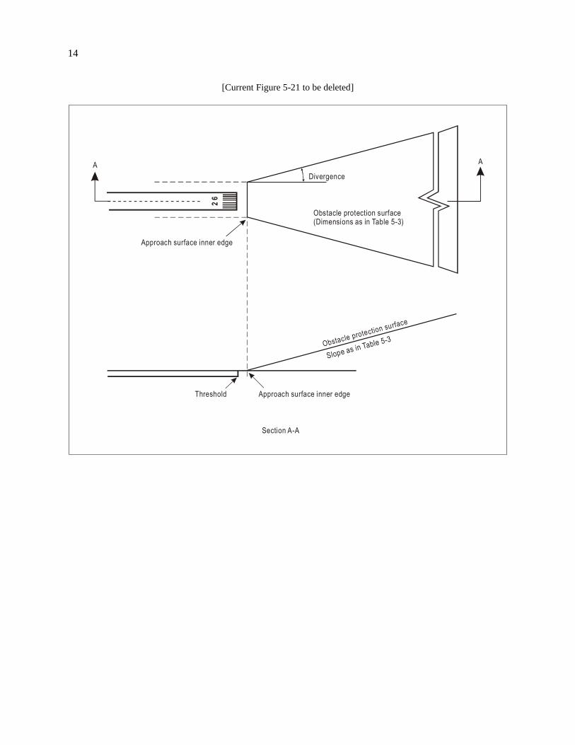
[Current Figure 5-21 to be deleted]
Divergence
Obstacle protection surface(Dimensions as in Table 5-3)
Approach surface inner edge
Obstacle protection surface
Slope as in Table 5-3
Approach surface inner edgeThreshold
Section A-A
26
A A
15
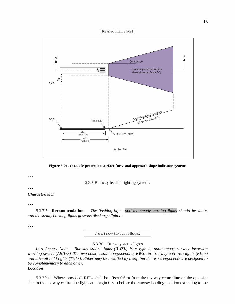
[Revised Figure 5-21]
Figure 5-21. Obstacle protection surface for visual approach slope indicator systems
. . .
5.3.7 Runway lead-in lighting systems
. . .
Characteristics
. . .
5.3.7.5 Recommendation.— The flashing lights and the steady burning lights should be white,
and the steady burning lights gaseous discharge lights.
. . .
Insert new text as follows:
5.3.30 Runway status lights
Introductory Note.— Runway status lights (RWSL) is a type of autonomous runway incursion
warning system (ARIWS). The two basic visual components of RWSL are runway entrance lights (RELs)
and take-off hold lights (THLs). Either may be installed by itself, but the two components are designed to
be complementary to each other.
Location
5.3.30.1 Where provided, RELs shall be offset 0.6 m from the taxiway centre line on the opposite
side to the taxiway centre line lights and begin 0.6 m before the runway-holding position extending to the

16
edge of the runway. An additional single light shall be placed on the runway 0.6 m from the runway
centre line and aligned with the last two taxiway RELs.
Note.— Where two or more runway-holding positions are provided, the runway-holding position
referred is that closest to the runway.
5.3.30.2 RELs shall consist of at least five light units and shall be spaced at a minimum of 3.8 m
and a maximum of 15.2 m longitudinally, depending upon the taxiway length involved, except for a
single light installed near the runway centre line.
5.3.30.3 Where provided, THLs shall be offset 1.8 m on each side of the runway centre line lights
and extend, in pairs, starting at a point 115 m from the beginning of the runway and, thereafter, every
30 m for at least 450 m.
Note.— Additional THLs may be similarly provided at the starting point of the take-off roll.
Characteristics
5.3.30.4 Where provided, RELs shall consist of a single line of fixed in pavement lights showing
red in the direction of aircraft approaching the runway.
5.3.30.5 RELs shall illuminate as an array at each taxiway/runway intersection where they are
installed less than 2 seconds after the system determines a warning is needed.
5.3.30.6 Intensity and beam spread of RELs shall be in accordance with the specifications of
Appendix 2, Figures A2-12 and A2-14.
Note.— Consideration for reduced beam width may be required for some REL lights at acute angled
runway/taxiway intersections to ensure the RELs are not visible to aircraft on the runway.
5.3.30.7 Where provided, THLs shall consist of two rows of fixed in pavement lights showing
red facing the aircraft taking off.
5.3.30.8 THLs shall illuminate as an array on the runway less than 2 seconds after the system
determines a warning is needed.
5.3.30.9 Intensity and beam spread of THLs shall be in accordance with the specifications of
Appendix 2, Figure A2-x.
5.3.30.10 Recommendation.— RELs and THLs should be automated to the extent that the only
control over each system will be to disable one or both systems.
End of new text.
. . .
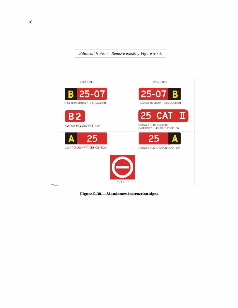
5.4.2 Mandatory instruction signs
Note.— See Figure 5-30 for pictorial representation of mandatory instruction signs and Figure 5-32
for examples of locating signs at taxiway/runway intersections.
. . .
17
Characteristics
. . .
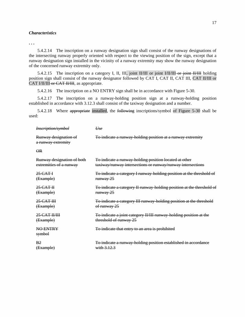
5.4.2.14 The inscription on a runway designation sign shall consist of the runway designations of
the intersecting runway properly oriented with respect to the viewing position of the sign, except that a
runway designation sign installed in the vicinity of a runway extremity may show the runway designation
of the concerned runway extremity only.
5.4.2.15 The inscription on a category I, II, III, joint II/III or joint I/II/III or joint II/III holding
position sign shall consist of the runway designator followed by CAT I, CAT II, CAT III, CAT II/III or
CAT I/II/III or CAT II/III, as appropriate.
5.4.2.16 The inscription on a NO ENTRY sign shall be in accordance with Figure 5-30.
5.4.2.17 The inscription on a runway-holding position sign at a runway-holding position
established in accordance with 3.12.3 shall consist of the taxiway designation and a number.
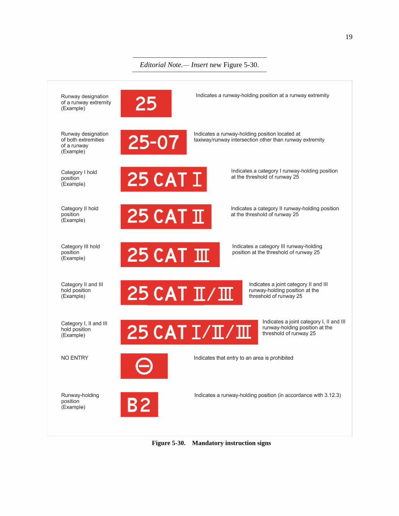
5.4.2.18 Where appropriate installed, the following inscriptions/symbol of Figure 5-30 shall be
used:
Inscription/symbol Use
Runway designation of
a runway extremity
To indicate a runway-holding position at a runway extremity
OR
Runway designation of both
extremities of a runway
To indicate a runway-holding position located at other
taxiway/runway intersections or runway/runway intersections
25 CAT I
(Example)
To indicate a category I runway-holding position at the threshold of
runway 25
25 CAT II
(Example)
To indicate a category II runway-holding position at the threshold of
runway 25
25 CAT III
(Example)
To indicate a category III runway-holding position at the threshold
of runway 25
25 CAT II/III
(Example)
To indicate a joint category II/III runway-holding position at the
threshold of runway 25
NO ENTRY
symbol
To indicate that entry to an area is prohibited
B2
(Example)
To indicate a runway-holding position established in accordance
with 3.12.3
18
Editorial Note.— Remove existing Figure 5-30.
Figure 5-30. Mandatory instruction signs
19
Editorial Note.— Insert new Figure 5-30.
Figure 5-30. Mandatory instruction signs
20
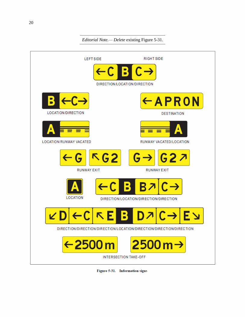
Editorial Note.— Delete existing Figure 5-31.
21
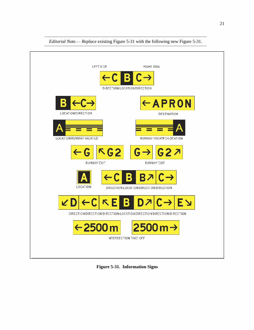
Editorial Note.— Replace existing Figure 5-31 with the following new Figure 5-31.
Figure 5-31. Information Signs
22
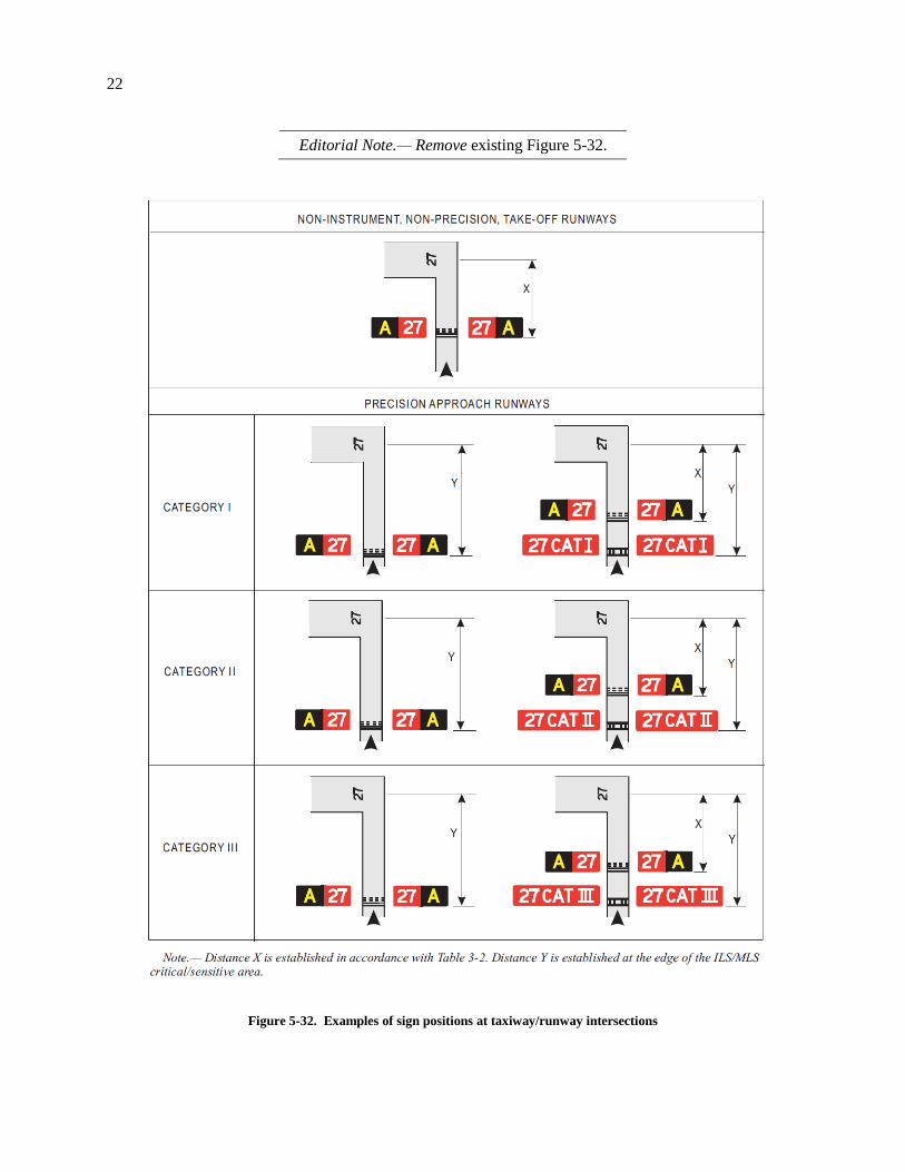
Editorial Note.— Remove existing Figure 5-32.
Figure 5-32. Examples of sign positions at taxiway/runway intersections
23
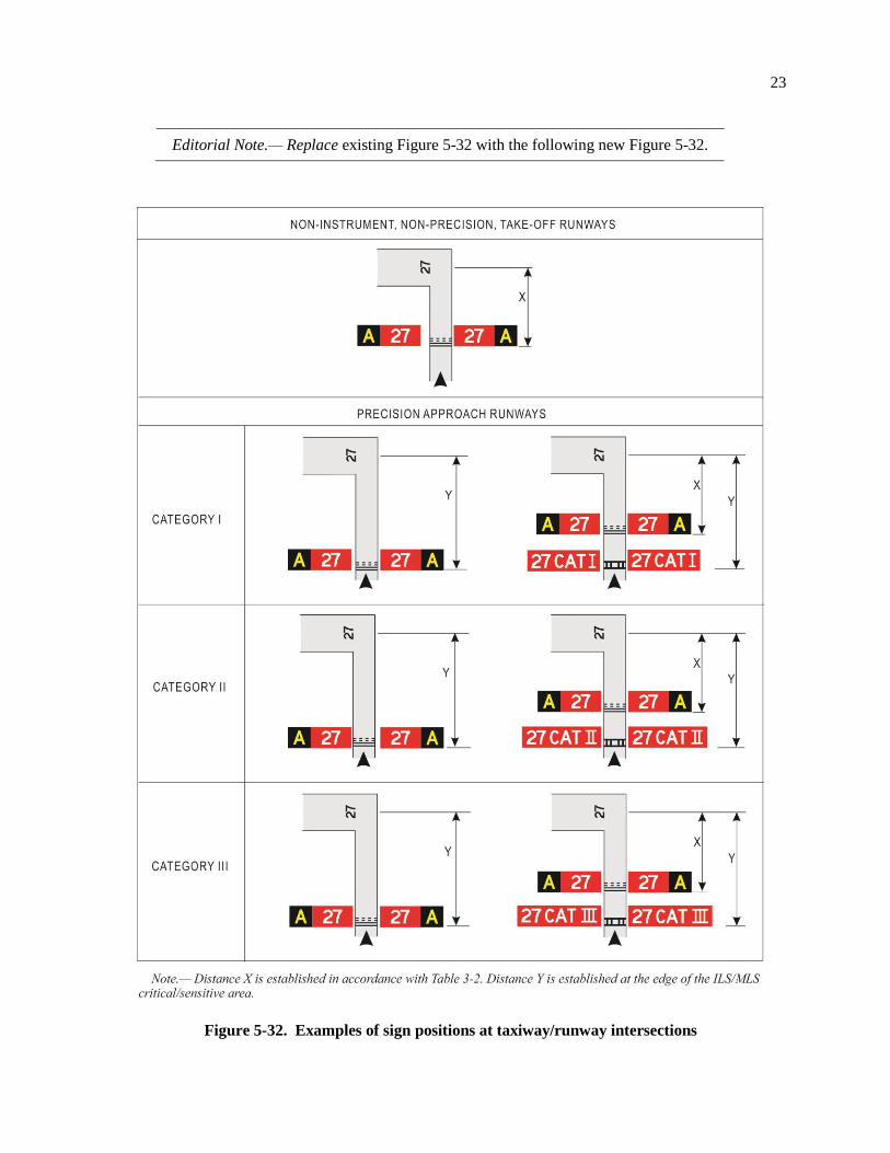
Editorial Note.— Replace existing Figure 5-32 with the following new Figure 5-32.
Figure 5-32. Examples of sign positions at taxiway/runway intersections
24
5.4.3 Information sign
. . .
5.4.3.15 At a taxiway intersection, information signs shall be located prior to the intersection and in
line with the taxiway intersection intermediate holding position marking. Where there is no taxiway
intersection intermediate holding position marking, the signs shall be installed at least 60 m from the
centre line of the intersecting taxiway where the code number is 3 or 4, and at least 40 m where the code
number is 1 or 2.
. . .
CHAPTER 6. VISUAL AIDS FOR DENOTING OBSTACLES
. . .
6.2 Marking and/or lighting of objects
6.2.1 General
. . .
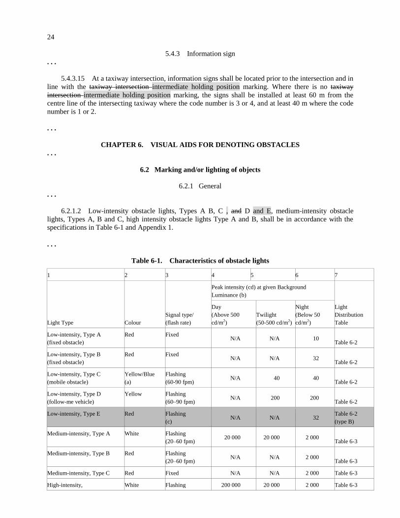
6.2.1.2 Low-intensity obstacle lights, Types A B, C , and D and E, medium-intensity obstacle
lights, Types A, B and C, high intensity obstacle lights Type A and B, shall be in accordance with the
specifications in Table 6-1 and Appendix 1.
. . .
Table 6-1. Characteristics of obstacle lights
1 2 3 4 5 6 7
Light Type Colour
Signal type/
(flash rate)
Peak intensity (cd) at given Background
Luminance (b)
Light
Distribution
Table
Day
(Above 500
cd/m2)
Twilight
(50-500 cd/m2)
Night
(Below 50
cd/m2)
Low-intensity, Type A
(fixed obstacle)
Red Fixed N/A N/A 10
Table 6-2
Low-intensity, Type B
(fixed obstacle)
Red Fixed N/A N/A 32
Table 6-2
Low-intensity, Type C
(mobile obstacle)
Yellow/Blue
(a)
Flashing
(60-90 fpm) N/A 40 40
Table 6-2
Low-intensity, Type D
(follow-me vehicle)
Yellow Flashing
(60–90 fpm) N/A 200 200
Table 6-2
Low-intensity, Type E Red Flashing
(c) N/A N/A 32
Table 6-2
(type B)
Medium-intensity, Type A White Flashing
(20–60 fpm) 20 000 20 000 2 000
Table 6-3
Medium-intensity, Type B Red Flashing
(20–60 fpm) N/A N/A 2 000
Table 6-3
Medium-intensity, Type C Red Fixed N/A N/A 2 000 Table 6-3
High-intensity, White Flashing 200 000 20 000 2 000 Table 6-3
25
Type A (40–60 fpm)
High-intensity,
Type B
White Flashing
(40–60 fpm) 100 000 20 000 2 000
Table 6-3
a) See 6.2.2.6.
b) For flashing lights, effective intensity as determined in accordance with the Aerodrome Design Manual (Doc 9157), Part 4.
c) For wind turbine application, to flash at the same rate as the lighting on the nacelle.
. . .
6.2.4 Wind turbines
6.2.4.1 A wind turbine shall be marked and/or lighted if it is determined to be an obstacle.
Note 1.— Additional lighting or markings may be provided where in the opinion of the State such
lighting or markings are deemed necessary.
Note 2.— See 4.3.1 and 4.3.2.
Markings
6.2.4.1 A wind turbine shall be marked and/or lighted if it is determined to be an obstacle.
Note.— See 4.3.1 and 4.3.2.
6.2.4.2 Recommendation.— The rotor blades, nacelle and upper 2/3 of the supporting mast of
wind turbines should be painted white, unless otherwise indicated by an aeronautical study.
Lighting
6.2.4.3 Recommendation.— When lighting is deemed necessary, medium-intensity obstacle lights
should be used. Iin the case of a wind farm, i.e. a group of two or more wind turbines, it the wind farm
should be regarded as an extensive object and the lights should be installed:
a) to identify the perimeter of the wind farm;
b) respecting the maximum spacing, in accordance with 6.2.3.15, between the lights along the
perimeter, unless a dedicated assessment shows that a greater spacing can be used;
c) so that, where flashing lights are used, they flash simultaneously throughout the wind farm; and
d) so that, within a wind farm, any wind turbines of significantly higher elevation are also identified
wherever they are located.; and
e) at locations prescribed in a), b) and d), respecting the following criteria:
i) for wind turbines of less than 150 m in overall height (hub height plus vertical blade height),
medium intensity lighting on the nacelle should be provided;
ii) for wind turbines from 150 m to 315 m in overall height, in addition to the medium intensity
light installed on the nacelle, a second light serving as an alternate should be provided in case
of failure of the operating light. The lights should be installed to assure that the output of
either light is not blocked by the other; and
iii) in addition, for wind turbines from 150 m to 315 m in overall height, an intermediate level at
half the nacelle height of at least 3 low intensity Type E lights, as specified in 6.2.1.3 should
26
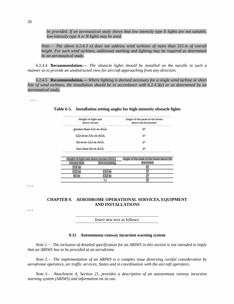
be provided. If an aeronautical study shows that low intensity type E lights are not suitable,
low-intensity type A or B lights may be used.
Note.— The above 6.2.4.3 e) does not address wind turbines of more than 315 m of overall
height. For such wind turbines, additional marking and lighting may be required as determined
by an aeronautical study.
6.2.4.4 Recommendation.— The obstacle lights should be installed on the nacelle in such a
manner as to provide an unobstructed view for aircraft approaching from any direction.
6.2.4.5 Recommendation.— Where lighting is deemed necessary for a single wind turbine or short
line of wind turbines, the installation should be in accordance with 6.2.4.3(e) or as determined by an
aeronautical study.
. . .
Table 6-5. Installation setting angles for high-intensity obstacle lights
Height of light unit above terrain
Angle of the peak of the beam above the horizontal
greater than 151 m AGL 0°
122 m to 151 m AGL 1°
92 m to 122 m AGL 2°
less than 92 m AGL 3°
Height of light unit above terrain (AGL) Angle of the peak of the beam above the
horizontal Greater than Not exceeding
151 m 0°
122 m 151 m 1°
92 m 122 m 2°
92 3°
. . .
CHAPTER 9. AERODROME OPERATIONAL SERVICES, EQUIPMENT
AND INSTALLATIONS
. . .
Insert new text as follows:
9.12 Autonomous runway incursion warning system
Note 1.— The inclusion of detailed specification for an ARIWS in this section is not intended to imply
that an ARIWS has to be provided at an aerodrome.
Note 2.— The implementation of an ARIWS is a complex issue deserving careful consideration by
aerodrome operators, air traffic services, States and in coordination with the aircraft operators.
Note 3.— Attachment A, Section 21, provides a description of an autonomous runway incursion
warning system (ARIWS) and information on its use.
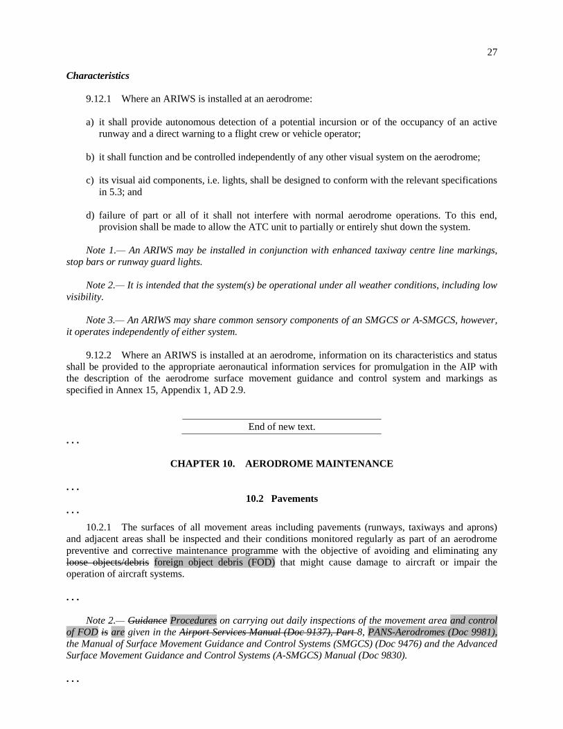
27
Characteristics
9.12.1 Where an ARIWS is installed at an aerodrome:
a) it shall provide autonomous detection of a potential incursion or of the occupancy of an active
runway and a direct warning to a flight crew or vehicle operator;
b) it shall function and be controlled independently of any other visual system on the aerodrome;
c) its visual aid components, i.e. lights, shall be designed to conform with the relevant specifications
in 5.3; and
d) failure of part or all of it shall not interfere with normal aerodrome operations. To this end,
provision shall be made to allow the ATC unit to partially or entirely shut down the system.
Note 1.— An ARIWS may be installed in conjunction with enhanced taxiway centre line markings,
stop bars or runway guard lights.
Note 2.— It is intended that the system(s) be operational under all weather conditions, including low
visibility.
Note 3.— An ARIWS may share common sensory components of an SMGCS or A-SMGCS, however,
it operates independently of either system.
9.12.2 Where an ARIWS is installed at an aerodrome, information on its characteristics and status
shall be provided to the appropriate aeronautical information services for promulgation in the AIP with
the description of the aerodrome surface movement guidance and control system and markings as
specified in Annex 15, Appendix 1, AD 2.9.
End of new text.
. . .
CHAPTER 10. AERODROME MAINTENANCE
. . .
10.2 Pavements
. . .
10.2.1 The surfaces of all movement areas including pavements (runways, taxiways and aprons)
and adjacent areas shall be inspected and their conditions monitored regularly as part of an aerodrome
preventive and corrective maintenance programme with the objective of avoiding and eliminating any
loose objects/debris foreign object debris (FOD) that might cause damage to aircraft or impair the
operation of aircraft systems.
. . .
Note 2.— Guidance Procedures on carrying out daily inspections of the movement area and control
of FOD is are given in the Airport Services Manual (Doc 9137), Part 8, PANS-Aerodromes (Doc 9981),
the Manual of Surface Movement Guidance and Control Systems (SMGCS) (Doc 9476) and the Advanced
Surface Movement Guidance and Control Systems (A-SMGCS) Manual (Doc 9830).
. . .
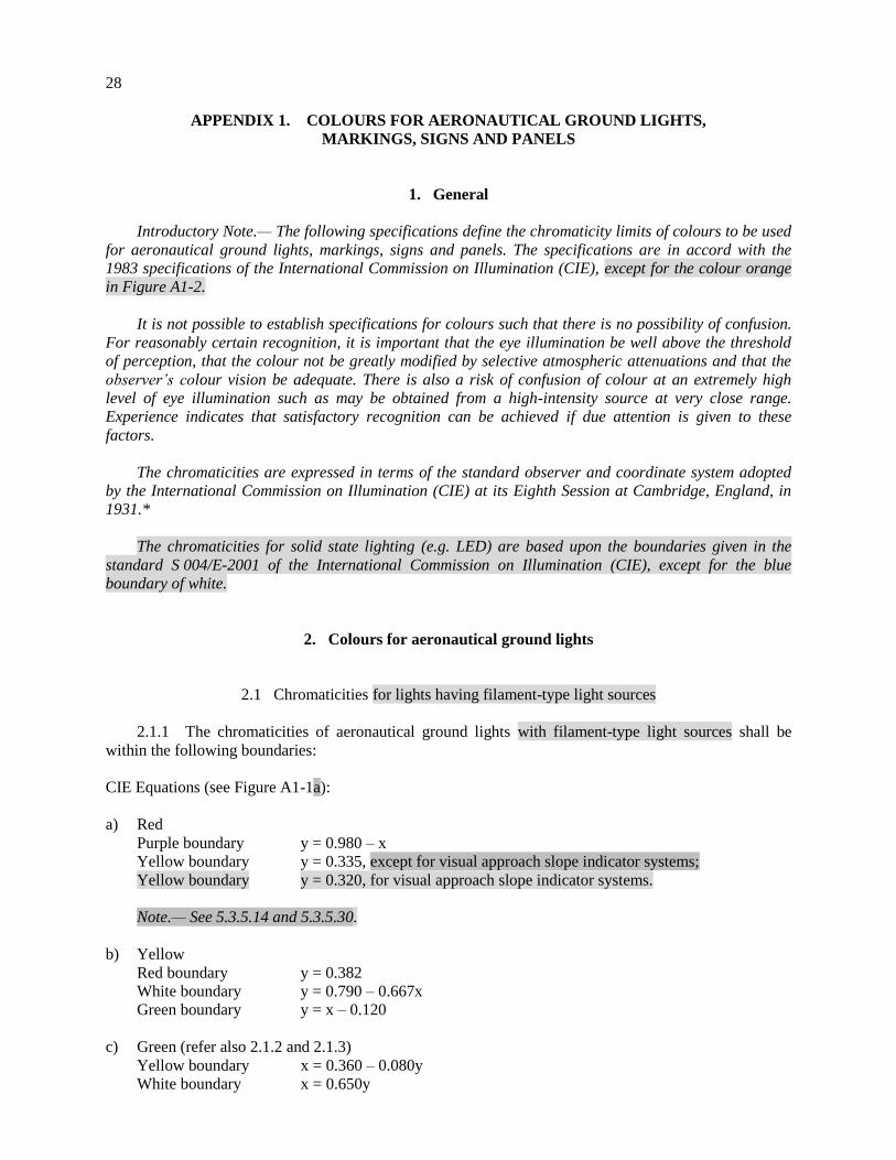
28
APPENDIX 1. COLOURS FOR AERONAUTICAL GROUND LIGHTS,
MARKINGS, SIGNS AND PANELS
1. General
Introductory Note.— The following specifications define the chromaticity limits of colours to be used
for aeronautical ground lights, markings, signs and panels. The specifications are in accord with the
1983 specifications of the International Commission on Illumination (CIE), except for the colour orange
in Figure A12.
It is not possible to establish specifications for colours such that there is no possibility of confusion.
For reasonably certain recognition, it is important that the eye illumination be well above the threshold
of perception, that the colour not be greatly modified by selective atmospheric attenuations and that the
observer’s colour vision be adequate. There is also a risk of confusion of colour at an extremely high
level of eye illumination such as may be obtained from a high-intensity source at very close range.
Experience indicates that satisfactory recognition can be achieved if due attention is given to these
factors.
The chromaticities are expressed in terms of the standard observer and coordinate system adopted
by the International Commission on Illumination (CIE) at its Eighth Session at Cambridge, England, in
1931.*
The chromaticities for solid state lighting (e.g. LED) are based upon the boundaries given in the
standard S 004/E-2001 of the International Commission on Illumination (CIE), except for the blue
boundary of white.
2. Colours for aeronautical ground lights
2.1 Chromaticities for lights having filament-type light sources
2.1.1 The chromaticities of aeronautical ground lights with filament-type light sources shall be
within the following boundaries:
CIE Equations (see Figure A1-1a):
a) Red
Purple boundary y = 0.980 – x
Yellow boundary y = 0.335, except for visual approach slope indicator systems;
Yellow boundary y = 0.320, for visual approach slope indicator systems.
Note.— See 5.3.5.14 and 5.3.5.30.
b) Yellow
Red boundary y = 0.382
White boundary y = 0.790 – 0.667x
Green boundary y = x – 0.120
c) Green (refer also 2.1.2 and 2.1.3)
Yellow boundary x = 0.360 – 0.080y
White boundary x = 0.650y
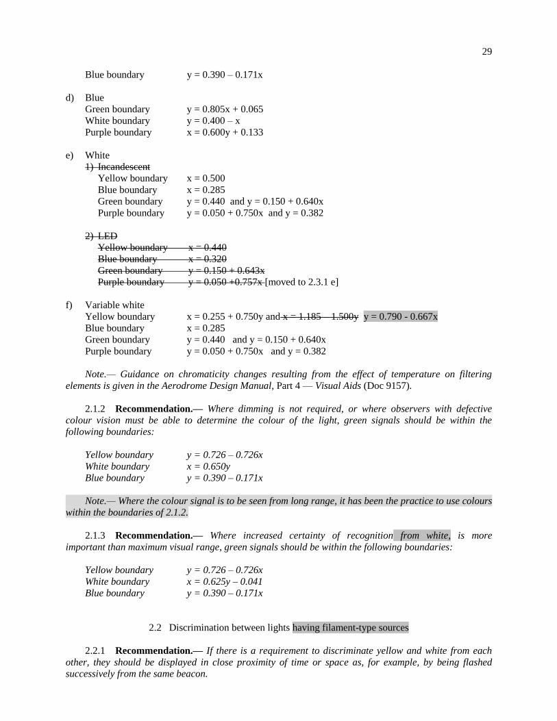
29
Blue boundary y = 0.390 – 0.171x
d) Blue
Green boundary y = 0.805x + 0.065
White boundary y = 0.400 – x
Purple boundary x = 0.600y + 0.133
e) White
1) Incandescent
Yellow boundary x = 0.500
Blue boundary x = 0.285
Green boundary y = 0.440 and y = 0.150 + 0.640x
Purple boundary y = 0.050 + 0.750x and y = 0.382
2) LED
Yellow boundary x = 0.440
Blue boundary x = 0.320
Green boundary y = 0.150 + 0.643x
Purple boundary y = 0.050 +0.757x [moved to 2.3.1 e]
f) Variable white
Yellow boundary x = 0.255 + 0.750y and x = 1.185 – 1.500y y = 0.790 - 0.667x
Blue boundary x = 0.285
Green boundary y = 0.440 and y = 0.150 + 0.640x
Purple boundary y = 0.050 + 0.750x and y = 0.382
Note.— Guidance on chromaticity changes resulting from the effect of temperature on filtering
elements is given in the Aerodrome Design Manual, Part 4 — Visual Aids (Doc 9157).
2.1.2 Recommendation.— Where dimming is not required, or where observers with defective
colour vision must be able to determine the colour of the light, green signals should be within the
following boundaries:
Yellow boundary y = 0.726 – 0.726x
White boundary x = 0.650y
Blue boundary y = 0.390 – 0.171x
Note.— Where the colour signal is to be seen from long range, it has been the practice to use colours
within the boundaries of 2.1.2.
2.1.3 Recommendation.— Where increased certainty of recognition from white, is more
important than maximum visual range, green signals should be within the following boundaries:
Yellow boundary y = 0.726 – 0.726x
White boundary x = 0.625y – 0.041
Blue boundary y = 0.390 – 0.171x
2.2 Discrimination between lights having filament-type sources
2.2.1 Recommendation.— If there is a requirement to discriminate yellow and white from each
other, they should be displayed in close proximity of time or space as, for example, by being flashed
successively from the same beacon.
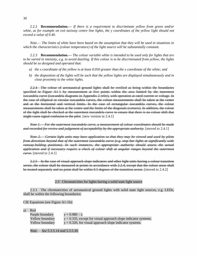
30
2.2.2 Recommendation.— If there is a requirement to discriminate yellow from green and/or
white, as for example on exit taxiway centre line lights, the y coordinates of the yellow light should not
exceed a value of 0.40.
Note.— The limits of white have been based on the assumption that they will be used in situations in
which the characteristics (colour temperature) of the light source will be substantially constant.
2.2.3 Recommendation.— The colour variable white is intended to be used only for lights that are
to be varied in intensity, e.g. to avoid dazzling. If this colour is to be discriminated from yellow, the lights
should be so designed and operated that:
a) the x coordinate of the yellow is at least 0.050 greater than the x coordinate of the white; and
b) the disposition of the lights will be such that the yellow lights are displayed simultaneously and in
close proximity to the white lights.
2.2.4 The colour of aeronautical ground lights shall be verified as being within the boundaries
specified in Figure A1-1 by measurement at five points within the area limited by the innermost
isocandela curve (isocandela diagrams in Appendix 2 refer), with operation at rated current or voltage. In
the case of elliptical or circular isocandela curves, the colour measurements shall be taken at the centre
and at the horizontal and vertical limits. In the case of rectangular isocandela curves, the colour
measurements shall be taken at the centre and the limits of the diagonals (corners). In addition, the colour
of the light shall be checked at the outermost isocandela curve to ensure that there is no colour shift that
might cause signal confusion to the pilot. [new version in 2.4.1]
Note 1.— For the outermost isocandela curve, a measurement of colour coordinates should be made
and recorded for review and judgement of acceptability by the appropriate authority. [moved to 2.4.1]
Note 2.— Certain light units may have application so that they may be viewed and used by pilots
from directions beyond that of the outermost isocandela curve (e.g. stop bar lights at significantly wide
runway-holding positions). In such instances, the appropriate authority should assess the actual
application and if necessary require a check of colour shift at angular ranges beyond the outermost
curve. [moved to 2.4.1]
2.2.5 In the case of visual approach slope indicators and other light units having a colour transition
sector, the colour shall be measured at points in accordance with 2.2.4, except that the colour areas shall
be treated separately and no point shall be within 0.5 degrees of the transition sector. [moved to 2.4.2]
2.3 Chromaticities for lights having a solid state light source
2.3.1 The chromaticities of aeronautical ground lights with solid state light sources, e.g. LEDs,
shall be within the following boundaries:
CIE Equations (see Figure A1-1b):
a) Red
Purple boundary y = 0.980 – x
Yellow boundary y = 0.335, except for visual approach slope indicator systems;
Yellow boundary y = 0.320, for visual approach slope indicator systems.
Note.— See 5.3.5.14 and 5.3.5.30.
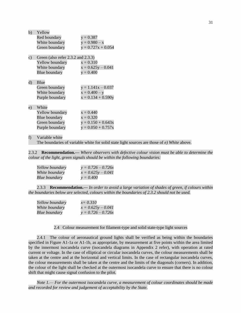
31
b) Yellow
Red boundary y = 0.387
White boundary y = 0.980 – x
Green boundary y = 0.727x + 0.054
c) Green (also refer 2.3.2 and 2.3.3)
Yellow boundary x = 0.310
White boundary x = 0.625y – 0.041
Blue boundary y = 0.400
d) Blue
Green boundary y = 1.141x – 0.037
White boundary x = 0.400 – y
Purple boundary x = 0.134 + 0.590y
e) White
Yellow boundary x = 0.440
Blue boundary x = 0.320
Green boundary y = 0.150 + 0.643x
Purple boundary y = 0.050 + 0.757x
f) Variable white
The boundaries of variable white for solid state light sources are those of e) White above.
2.3.2 Recommendation.— Where observers with defective colour vision must be able to determine the
colour of the light, green signals should be within the following boundaries:
Yellow boundary y = 0.726 – 0.726x
White boundary x = 0.625y – 0.041
Blue boundary y = 0.400
2.3.3 Recommendation.— In order to avoid a large variation of shades of green, if colours within
the boundaries below are selected, colours within the boundaries of 2.3.2 should not be used.
Yellow boundary x= 0.310
White boundary x = 0.625y – 0.041
Blue boundary y = 0.726 – 0.726x
2.4 Colour measurement for filament-type and solid state-type light sources
2.4.1 The colour of aeronautical ground lights shall be verified as being within the boundaries
specified in Figure A1-1a or A1-1b, as appropriate, by measurement at five points within the area limited
by the innermost isocandela curve (isocandela diagrams in Appendix 2 refer), with operation at rated
current or voltage. In the case of elliptical or circular isocandela curves, the colour measurements shall be
taken at the centre and at the horizontal and vertical limits. In the case of rectangular isocandela curves,
the colour measurements shall be taken at the centre and the limits of the diagonals (corners). In addition,
the colour of the light shall be checked at the outermost isocandela curve to ensure that there is no colour
shift that might cause signal confusion to the pilot.
Note 1.— For the outermost isocandela curve, a measurement of colour coordinates should be made
and recorded for review and judgement of acceptability by the State.

32
Note 2.— Certain light units may have application so that they may be viewed and used by pilots
from directions beyond that of the outermost isocandela curve (e.g. stop bar lights at significantly wide
runway-holding positions). In such instances, the State should assess the actual application and if
necessary require a check of colour shift at angular ranges beyond the outermost curve.
2.4.2 In the case of visual approach slope indicator systems and other light units having a colour
transition sector, the colour shall be measured at points in accordance with 2.4.1, except that the colour
areas shall be treated separately and no point shall be within 0.5 degrees of the transition sector.
Figure A1-1a. Colours for aeronautical ground lights (filament-type lamps)
Editorial Note.— This figure is identical to the existing Figure A1-1 but for the marking “y=0.320” for
the red area, which has been displayed explicitly.
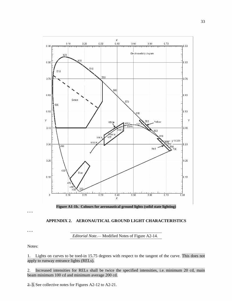
33
Figure A1-1b. Colours for aeronautical ground lights (solid state lighting)
. . .
APPENDIX 2. AERONAUTICAL GROUND LIGHT CHARACTERISTICS
. . .
Editorial Note.— Modified Notes of Figure A2-14.
Notes:
1. Lights on curves to be toed-in 15.75 degrees with respect to the tangent of the curve. This does not
apply to runway entrance lights (RELs).
2. Increased intensities for RELs shall be twice the specified intensities, i.e. minimum 20 cd, main
beam minimum 100 cd and minimum average 200 cd.
2. 3. See collective notes for Figures A2-12 to A2-21.
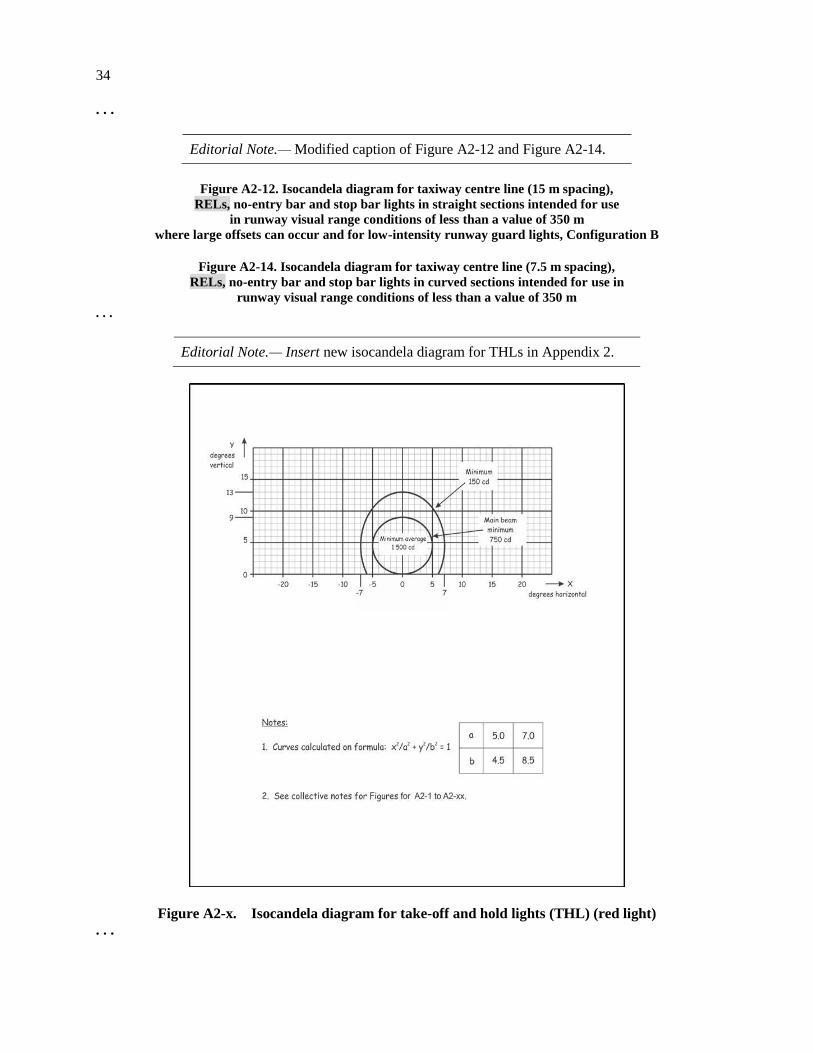
34
. . .
Editorial Note.— Modified caption of Figure A2-12 and Figure A2-14.
Figure A2-12. Isocandela diagram for taxiway centre line (15 m spacing),
RELs, no-entry bar and stop bar lights in straight sections intended for use
in runway visual range conditions of less than a value of 350 m
where large offsets can occur and for low-intensity runway guard lights, Configuration B
Figure A2-14. Isocandela diagram for taxiway centre line (7.5 m spacing),
RELs, no-entry bar and stop bar lights in curved sections intended for use in
runway visual range conditions of less than a value of 350 m
. . .
Editorial Note.— Insert new isocandela diagram for THLs in Appendix 2.
Figure A2-x. Isocandela diagram for take-off and hold lights (THL) (red light)
. . .
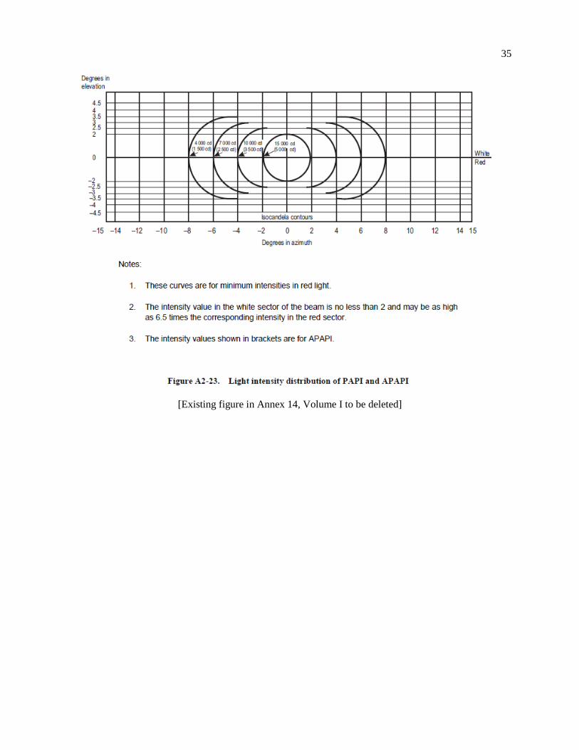
35
[Existing figure in Annex 14, Volume I to be deleted]
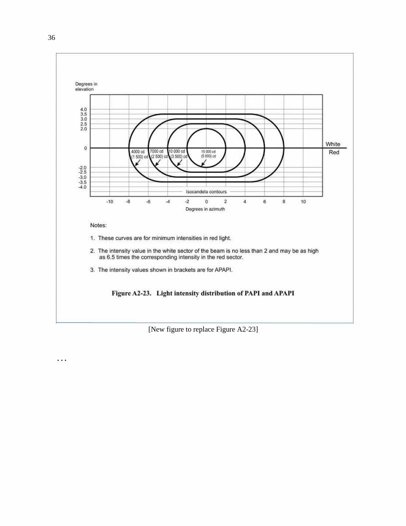
36
[New figure to replace Figure A2-23]
. . .
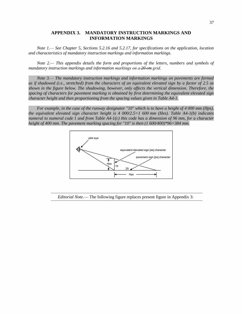
37
APPENDIX 3. MANDATORY INSTRUCTION MARKINGS AND
INFORMATION MARKINGS
Note 1.— See Chapter 5, Sections 5.2.16 and 5.2.17, for specifications on the application, location
and characteristics of mandatory instruction markings and information markings.
Note 2.— This appendix details the form and proportions of the letters, numbers and symbols of
mandatory instruction markings and information markings on a 20 cm grid.
Note 3.— The mandatory instruction markings and information markings on pavements are formed
as if shadowed (i.e., stretched) from the characters of an equivalent elevated sign by a factor of 2.5 as
shown in the figure below. The shadowing, however, only affects the vertical dimension. Therefore, the
spacing of characters for pavement marking is obtained by first determining the equivalent elevated sign
character height and then proportioning from the spacing values given in Table A41.
For example, in the case of the runway designator "10" which is to have a height of 4 000 mm (Hps),
the equivalent elevated sign character height is 4 000/2.5=1 600 mm (Hes). Table A4-1(b) indicates
numeral to numeral code 1 and from Table A4-1(c) this code has a dimension of 96 mm, for a character
height of 400 mm. The pavement marking spacing for "10" is then (1 600/400)*96=384 mm.
Editorial Note.— The following figure replaces present figure in Appendix 3:
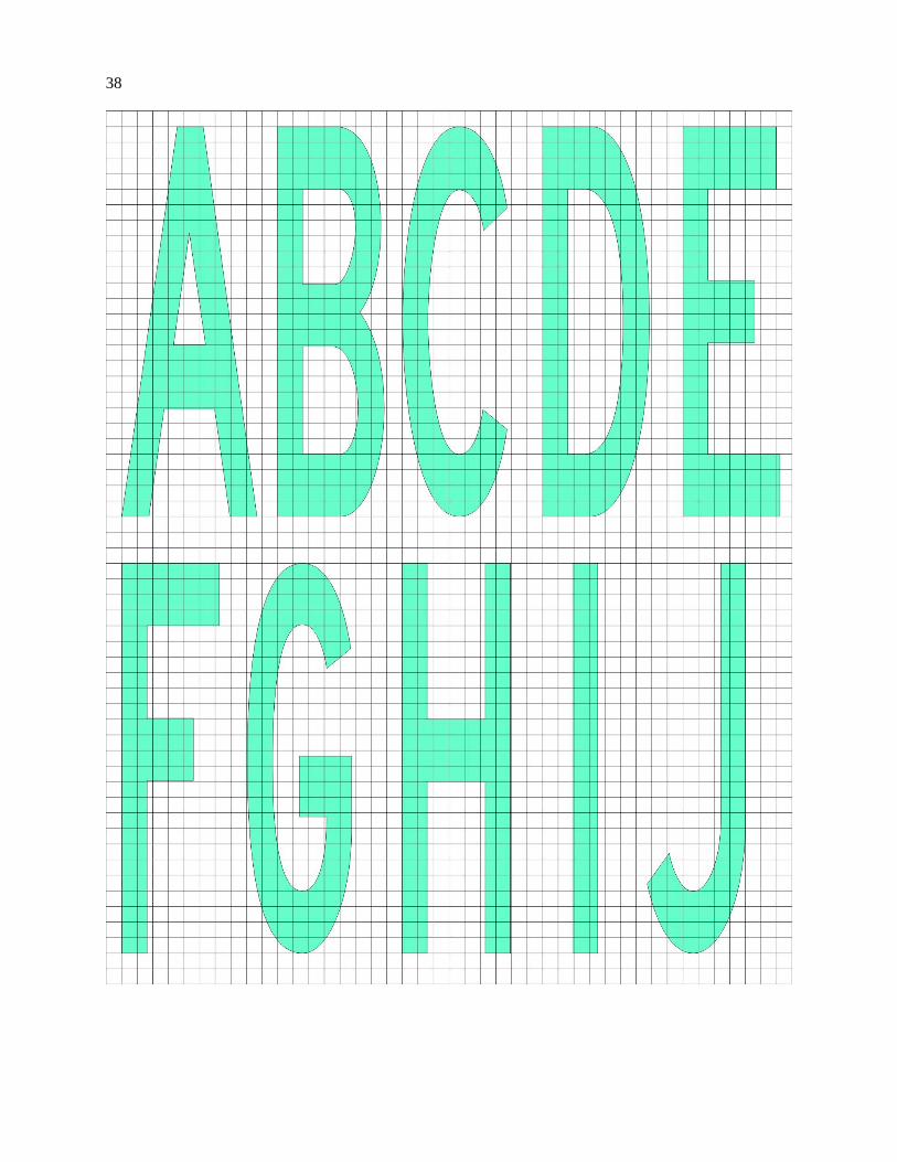
38
39
40
41
. . .
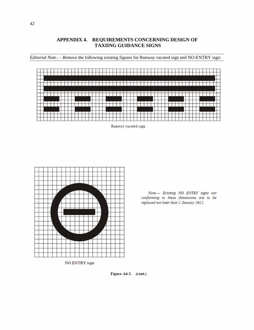
42
APPENDIX 4. REQUIREMENTS CONCERNING DESIGN OF
TAXIING GUIDANCE SIGNS
Editorial Note.— Remove the following existing figures for Runway vacated sign and NO-ENTRY sign:
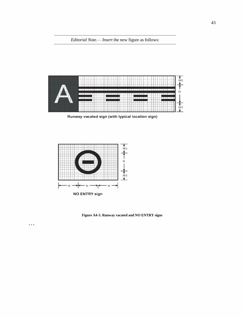
43
Editorial Note.— Insert the new figure as follows:
Figure A4-3. Runway vacated and NO ENTRY signs
. . .
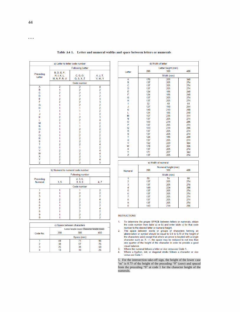
44
. . .
Letter height (mm) Character height (mm)
5. For the intersection take-off sign, the height of the lower case
“m” is 0.75 of the height of the preceding “0” (zero) and spaced
from the preceding “0” at code 1 for the character height of the
numerals.
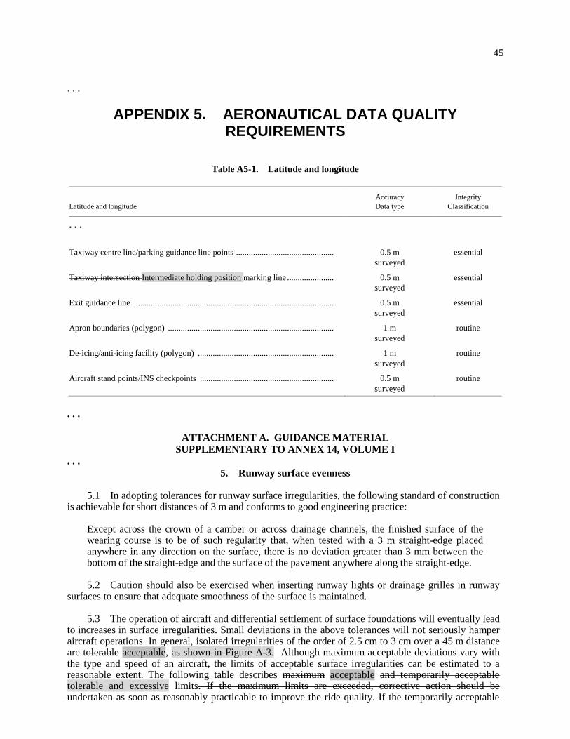
45
. . .
APPENDIX 5. AERONAUTICAL DATA QUALITY REQUIREMENTS
Table A5-1. Latitude and longitude
Latitude and longitude
Accuracy
Data type
Integrity
Classification
. . .
Taxiway centre line/parking guidance line points .............................................. 0.5 m
surveyed
essential
Taxiway intersection Intermediate holding position marking line ...................... 0.5 m
surveyed
essential
Exit guidance line .............................................................................................. 0.5 m
surveyed
essential
Apron boundaries (polygon) .............................................................................. 1 m
surveyed
routine
De-icing/anti-icing facility (polygon) ................................................................ 1 m
surveyed
routine
Aircraft stand points/INS checkpoints ............................................................... 0.5 m
surveyed
routine
. . .
ATTACHMENT A. GUIDANCE MATERIAL
SUPPLEMENTARY TO ANNEX 14, VOLUME I
. . .
5. Runway surface evenness 5.1 In adopting tolerances for runway surface irregularities, the following standard of construction is achievable for short distances of 3 m and conforms to good engineering practice:
Except across the crown of a camber or across drainage channels, the finished surface of the wearing course is to be of such regularity that, when tested with a 3 m straight-edge placed anywhere in any direction on the surface, there is no deviation greater than 3 mm between the bottom of the straight-edge and the surface of the pavement anywhere along the straight-edge.
5.2 Caution should also be exercised when inserting runway lights or drainage grilles in runway surfaces to ensure that adequate smoothness of the surface is maintained. 5.3 The operation of aircraft and differential settlement of surface foundations will eventually lead to increases in surface irregularities. Small deviations in the above tolerances will not seriously hamper aircraft operations. In general, isolated irregularities of the order of 2.5 cm to 3 cm over a 45 m distance are tolerable acceptable, as shown in Figure A-3. Although maximum acceptable deviations vary with the type and speed of an aircraft, the limits of acceptable surface irregularities can be estimated to a reasonable extent. The following table describes maximum acceptable and temporarily acceptable tolerable and excessive limits. If the maximum limits are exceeded, corrective action should be undertaken as soon as reasonably practicable to improve the ride quality. If the temporarily acceptable
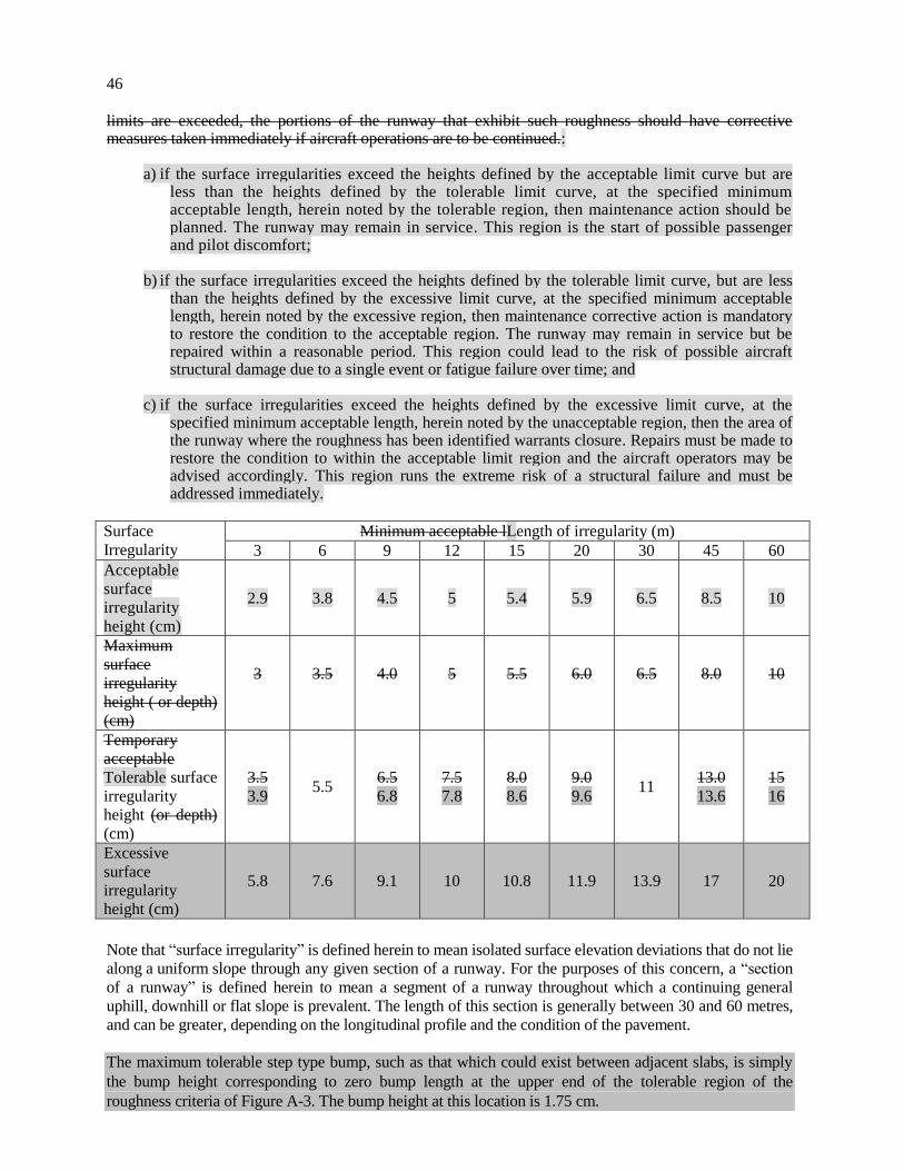
46
limits are exceeded, the portions of the runway that exhibit such roughness should have corrective measures taken immediately if aircraft operations are to be continued.:
a) if the surface irregularities exceed the heights defined by the acceptable limit curve but are less than the heights defined by the tolerable limit curve, at the specified minimum acceptable length, herein noted by the tolerable region, then maintenance action should be planned. The runway may remain in service. This region is the start of possible passenger and pilot discomfort;
b) if the surface irregularities exceed the heights defined by the tolerable limit curve, but are less
than the heights defined by the excessive limit curve, at the specified minimum acceptable length, herein noted by the excessive region, then maintenance corrective action is mandatory to restore the condition to the acceptable region. The runway may remain in service but be repaired within a reasonable period. This region could lead to the risk of possible aircraft structural damage due to a single event or fatigue failure over time; and
c) if the surface irregularities exceed the heights defined by the excessive limit curve, at the
specified minimum acceptable length, herein noted by the unacceptable region, then the area of the runway where the roughness has been identified warrants closure. Repairs must be made to restore the condition to within the acceptable limit region and the aircraft operators may be advised accordingly. This region runs the extreme risk of a structural failure and must be addressed immediately.
Surface
Irregularity
Minimum acceptable lLength of irregularity (m)
3 6 9 12 15 20 30 45 60
Acceptable
surface
irregularity
height (cm)
2.9 3.8 4.5 5 5.4 5.9 6.5 8.5 10
Maximum
surface
irregularity
height ( or depth)
(cm)
3
3.5
4.0
5
5.5
6.0
6.5
8.0
10
Temporary
acceptable
Tolerable surface
irregularity
height (or depth)
(cm)
3.5
3.9 5.5
6.5
6.8
7.5
7.8
8.0
8.6
9.0
9.6 11
13.0
13.6
15
16
Excessive
surface
irregularity
height (cm)
5.8 7.6 9.1 10 10.8 11.9 13.9 17 20
Note that “surface irregularity” is defined herein to mean isolated surface elevation deviations that do not lie
along a uniform slope through any given section of a runway. For the purposes of this concern, a “section
of a runway” is defined herein to mean a segment of a runway throughout which a continuing general
uphill, downhill or flat slope is prevalent. The length of this section is generally between 30 and 60 metres,
and can be greater, depending on the longitudinal profile and the condition of the pavement.
The maximum tolerable step type bump, such as that which could exist between adjacent slabs, is simply
the bump height corresponding to zero bump length at the upper end of the tolerable region of the
roughness criteria of Figure A-3. The bump height at this location is 1.75 cm.
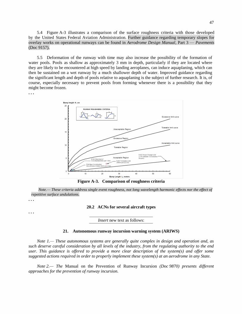
47
5.4 Figure A-3 illustrates a comparison of the surface roughness criteria with those developed
by the United States Federal Aviation Administration. Further guidance regarding temporary slopes for
overlay works on operational runways can be found in Aerodrome Design Manual, Part 3 — Pavements
(Doc 9157).
5.5 Deformation of the runway with time may also increase the possibility of the formation of
water pools. Pools as shallow as approximately 3 mm in depth, particularly if they are located where
they are likely to be encountered at high speed by landing aeroplanes, can induce aquaplaning, which can
then be sustained on a wet runway by a much shallower depth of water. Improved guidance regarding
the significant length and depth of pools relative to aquaplaning is the subject of further research. It is, of
course, especially necessary to prevent pools from forming whenever there is a possibility that they
might become frozen.
. . .
Figure A-3. Comparison of roughness criteria
Note.— These criteria address single event roughness, not long wavelength harmonic effects nor the effect of
repetitive surface undulations.
. . .
20.2 ACNs for several aircraft types
. . .
Insert new text as follows:
21. Autonomous runway incursion warning system (ARIWS)
Note 1.— These autonomous systems are generally quite complex in design and operation and, as
such deserve careful consideration by all levels of the industry, from the regulating authority to the end
user. This guidance is offered to provide a more clear description of the system(s) and offer some
suggested actions required in order to properly implement these system(s) at an aerodrome in any State.
Note 2.— The Manual on the Prevention of Runway Incursion (Doc 9870) presents different
approaches for the prevention of runway incursion.
48
21.1 General description
21.1.1 The operation of an ARIWS is based upon a surveillance system which monitors the actual
situation on a runway and automatically returns this information to warning lights at the runway (take-off)
thresholds and entrances. When an aircraft is departing from a runway (rolling) or arriving at a runway
(short final), red warning lights at the entrances will illuminate, indicating that it is unsafe to enter or
cross the runway. When an aircraft is aligned on the runway for take-off and another aircraft or vehicle
enters or crosses the runway, red warning lights will illuminate at the threshold area, indicating that it is
unsafe to start the take-off roll.
21.1.2 In general, an ARIWS consists of an independent surveillance system (primary radar,
multilateration, specialized cameras, dedicated radar, etc.) and a warning system in the form of extra
airfield lighting systems connected through a processor which generates alerts independent from ATC
directly to the flight crews and vehicle operators.
21.1.3 An ARIWS does not require circuit interleaving, secondary power supply or operational
connection to other visual aid systems.
21.1.4 In practice, not every entrance or threshold needs to be equipped with warning lights. Each aerodrome will have to assess its needs individually depending on the characteristics of the aerodrome. There are several systems developed offering the same or similar functionality.
21.2 Flight crew actions 21.2.1 It is of critical importance that flight crews understand the warning being transmitted by the ARIWS system. Warnings are provided in near real-time, directly to the flight crew because there is no time for “relay” types of communications. In other words, a conflict warning generated to ATS which must then interpret the warning, evaluate the situation and communicate to the aircraft in question, would result in several seconds being taken up where each second is critical in the ability to stop the aircraft safely, and prevent a potential collision. Pilots are presented with a globally consistent signal which means “STOP IMMEDIATELY” and must be taught to react accordingly. Likewise, pilots receiving an ATS clearance to take-off or cross a runway, and seeing the red light array, must STOP and advise ATS that they aborted/stopped because of the red lights. Again, the criticality of the timeline involved is so tight that there is no room for misinterpretation of the signal. It is of utmost importance that the visual signal be consistent around the world. 21.2.2 It must also be stressed that the extinguishing of the red lights does not, in itself, indicate a clearance to proceed. That clearance is still required from air traffic control. The absence of red warning lights only means that potential conflicts have not been detected. 21.2.3 In the event that a system becomes unserviceable, one of two things will occur. If the system fails in the extinguished condition, then no procedural changes need to be accomplished. The only thing that will happen is the loss of the automatic, independent warning system. Both ATS operations and flight crew procedures (in response to ATS clearances) will remain unchanged. 21.2.4 Procedures should be developed to address the circumstance where the system fails in the illuminated condition. It will be up to the ATS and/or aerodrome operator to establish those procedures depending on their own circumstances. It must be remembered that flight crews are instructed to “STOP” at all red lights. If the affected portion of the system, or the entire system is shut off, the situation is reverted to the extinguished scenario described in 21.2.3 above.
49
21.3 Aerodromes
21.3.1 An ARIWS does not have to be provided at all aerodromes. An aerodrome considering the installation of such a system may wish to assess its needs individually, depending on traffic levels, aerodrome geometry, ground taxi patterns, etc. Local user groups such as the Local Runway Safety Team (LRST) can be of assistance in this process. Also, not every runway or taxiway needs to be equipped with the lighting array(s) and not every installation requires a comprehensive ground surveillance system to feed information to the conflict detection computer. 21.3.2 Although there may be local specific requirements, some basic system requirements are applicable to all ARIWS:
a) the control system and energy power supply of the system must be independent from any other system in use at the aerodrome, especially the other parts of the lighting system;
b) the system must operate independently from ATS communications; c) the system must provide a globally accepted visual signal that is consistent and instantly
understood by crews; and d) local procedures should be developed in the case of malfunction or failure of a portion of, or the
entire system.
21.4 Air traffic services 21.4.1 The ARIWS is designed to be complementary to normal ATS functions, providing warnings to flight crews and vehicle operators when some conflict has been unintentionally created or missed during normal aerodrome operations. The ARIWS will provide a direct warning when, for example, ground control or tower (local) control has provided a clearance to hold short of a runway but the flight crew or vehicle operator has “missed” the hold short portion of their clearance and tower has issued a take-off or landing clearance to that same runway, and the non-read back by the flight crew or vehicle operator was missed by air traffic control. 21.4.2 In the case where a clearance has been issued and a crew reports a non-compliance due to “red lights”, or aborting because of “red lights”, then it is imperative that the controller assess the situation and provide additional instructions as necessary. It may well be that the system has generated a false warning or that the potential incursion no longer exists; however, it may also be a valid warning. In any case, additional instructions and/or a new clearance need to be provided. In a case where the system has failed, then procedures will need to be put into place as described in 21.2.3 and 21.2.4 above. In no case should the illumination of the ARIWS be dismissed without confirmation that, in fact, there is no conflict. It is worth noting that there have been numerous incidents avoided at aerodromes with such systems installed. It is also worth noting that there have been false warnings as well, usually as a result of the calibration of the warning software, but in any case, a confirmation of the potential conflict existence or non-existence must be done. 21.4.3 While many installations may have a visual or audio warning available to ATS personnel, it is in no way intended that ATS personnel be required to actively monitor the system. Such warnings may assist ATS personnel in quickly assessing the conflict in the event of a warning and help them to provide appropriate further instructions, but the ARIWS should not play an active part in the normal functioning of any ATS facility. 21.4.4 Each aerodrome where the system is installed will develop procedures depending upon their unique situation. Again, it must be stressed that under no circumstances should pilots or operators be instructed to “cross the red lights”. As indicated previously, the use of local runway safety teams can greatly assist in this development process.
50
21.5 Promulgation of information
21.5.1 Information on the characteristics and status of an ARIWS at an aerodrome are promulgated in the AIP section AD 2.9 and its status updated as necessary through NOTAM or ATIS in compliance with Annex 14, Volume I, 2.9.1. 21.5.2 Aircraft operators are to ensure that flight crews documentation include procedures regarding ARIWS and appropriate guidance information, in compliance with Annex 6, Part I. 21.5.3 Aerodromes may provide additional sources of guidance on operations and procedures for their personnel, aircraft operators, ATS and third parties personnel who may have to deal with an ARIWS.
22. Taxiway design guidance for minimizing the potential for runway incursions
22.1 Good aerodrome design practices can reduce the potential for runway incursions while maintaining operating efficiency and capacity. The following taxiway design guidance may be considered to be part of a runway incursion prevention programme as a means to ensure that runway incursion aspects are addressed during the design phase for new runways and taxiways. Within this focused guidance, the prime considerations are to limit the number of aircraft or vehicles entering or crossing a runway, provide pilots with enhanced unobstructed views of the entire runway, and correct taxiways identified as hot spots as far as possible. 22.2 The centre line of an entrance taxiway should be perpendicular to the runway centre line, where possible. This design principle provides pilots with an unobstructed view of the entire runway, in both directions, to confirm that the runway and approach are clear of conflicting traffic before proceeding towards the runway. Where the taxiway angle is such that a clear unobstructed view, in both directions, is not possible, consideration should be given to providing a perpendicular portion of the taxiway immediately adjacent to the runway to allow for a full visual scan by the pilots prior to entering or crossing a runway. 22.3 For taxiways intersecting with runways, avoid designing taxiways wider than recommended in Annex 14. This design principle offers improved recognition of the location of the runway holding position and the accompanying sign, marking, and lighting visual cues. 22.4 Existing taxiways wider than recommended in Annex 14, can be rectified by painting taxi side stripe markings to the recommended width. As far as practicable, it is preferable to redesign such locations properly rather than to repaint such locations. 22.5 Multi-taxiway entrances to a runway should be parallel to each other and should be distinctly separated by an unpaved area. This design principle allows each runway holding location an earthen area for the proper placement of accompanying sign, marking, and lighting visual cues at each runway holding position. Moreover, the design principle eliminates the needless costs of building unusable pavement and as well as the costs for painting taxiway edge markings to indicate such unusable pavement. In general, excess paved areas at runway holding positions reduce the effectiveness of sign, marking, and lighting visual cues. 22.6 Build taxiways that cross a runway as a single straight taxiway. Avoid dividing the taxiway into two after crossing the runway. This design principle avoids constructing “Y-shaped” taxiways known to present risk of runway incursions. 22.7 If possible, avoid building taxiways that enter at the mid-runway location. This design principle helps to reduce the collision risks at the most hazardous locations (high energy location) because normally departing aircraft have too much energy to stop, but not enough speed to take-off, before colliding with another errant aircraft or vehicle.
51
22.8 Provide clear separation of pavement between a rapid exit taxiway and other non-rapid taxiways entering or crossing a runway. This design principle avoids two taxiways from overlapping each other to create an excessive paved area that would confuse pilots entering a runway. 22.9 Avoid the placement of different pavement materials (asphalt and cement concrete) at or near the vicinity of the runway holding position, as far as practicable. This design principle avoids creating visual confusion as to the actual location of the runway holding position. 22.10 Perimeter taxiways. Many aerodromes have more than one runway, notably paired parallel runways (two runways on one side of the terminal), which creates a difficult problem in that either on arrival or departure an aircraft is required to cross a runway. Under such a configuration, the safety objective here is to avoid or at least keep to a minimum the number of runway crossings. This safety objective may be achieved by constructing a “perimeter taxiway”. A perimeter taxiway is a taxi route that goes around the end of a runway, enabling arrival aircraft (when landings are on outer runway of a pair) to get to the terminal or departure aircraft (when departures are on outer runway of a pair) to get to the runway without either crossing a runway, or conflicting with a departing or approaching aircraft. 22.11 A perimeter taxiway would be designed according to the following criteria:
a) Sufficient space is required between the landing threshold and the taxiway centre line where it crosses under the approach path, to enable the critical taxiing aircraft to pass under the approach without penetrating any approach surface.
b) The jet blast impact of aircraft taking off should be considered in consultation with aircraft
manufacturers; the extent of take-off thrust should be evaluated when determining the location of a perimeter taxiway.
c) The requirement for a runway end safety area, as well as possible interference with landing
systems and other navigation aids should also be taken into account. For example, in the case of an Instrument Landing System, the perimeter taxiway should be located behind the localiser antenna, not between the localiser antenna and the runway, due to the potential for severe Instrument Landing System disturbance, noting that this is harder to achieve as the distance between the localizer and the runway increases.
d) Human factors issues should also be taken into account. Appropriate measures should be put in
place to assist pilots to distinguish between aircraft that are crossing the runway and those that are safely on a perimeter taxiway.
23. Aerodrome mapping data
23.1 Introduction Chapter 2, 2.1.2 and 2.1.3, contain provisions related to the provision of aerodrome mapping data. The aerodrome mapping data features are collected and made available to the aeronautical information services for aerodromes designated by States with consideration of the intended applications. These applications are closely tied to an identified need and operational use where the application of the data would provide a safety benefit or could be used as mitigation to a safety concern.
23.2 Applications 23.2.1 Aerodrome mapping data include aerodrome geographic information that support applications which improve the user’s situational awareness or supplement surface navigation, thereby increasing safety margins and operational efficiency. With appropriate data element accuracy, these data
52
sets support collaborative decision making, common situational awareness, and aerodrome guidance applications. The data sets are intended to be used in the following air navigation applications: a) on-board positioning and route awareness including moving maps with own aircraft position,
surface guidance and navigation;
b) traffic awareness including surveillance and runway incursion detection and alerting (such as respectively in A-SMGCS levels 1 and 2);
c) ground positioning and route awareness including situational displays with aircraft and vehicles
position and taxi route, surface guidance and navigation (such as A-SMGCS levels 3 and 4); d) facilitation of aerodrome-related aeronautical information, including NOTAMs; e) resource and aerodrome facility management; and f) aeronautical chart production. 23.2.2 The data may also be used in other applications such as training / flight simulators and on-board or ground enhanced vision systems (EVS), synthetic vision systems (SVS) and combined vision systems (CVS).
23.3 Determination of aerodromes to be considered for collection of aerodrome mapping data features
23.3.1 In order to determine which aerodromes may make use of applications requiring the collection of aerodrome mapping data features, the following aerodrome characteristics may be considered:
- safety risks at the aerodrome ; - visibility conditions ; - aerodrome layout ; and - traffic density.
Note.— Further guidance on aerodrome mapping data can be found in Doc 9137, Airport Services Manual, Part 8 — Airport Operational Service.
End of new text
— END —
AMENDMENT No. 13-B
TO THE
INTERNATIONAL STANDARDS
AND RECOMMENDED PRACTICES
AERODROMES
ANNEX 14
TO THE CONVENTION ON INTERNATIONAL CIVIL AVIATION
VOLUME I —
AERODROME DESIGN AND OPERATIONS
The amendment to Annex 14, Volume I contained in this document was adopted
by the Council of ICAO on 22 February 2016. Such parts of this amendment as
have not been disapproved by more than half of the total number of Contracting
States on or before 11 July 2016 will become effective on that date and will
become applicable on 5 November 2020 as specified in the Resolution of
Adoption. (State letter AN 4/1.2.26-16/19 refers.)
FEBRUARY 2016
INTERNATIONAL CIVIL AVIATION ORGANIZATION

AMENDMENT 13 TO THE INTERNATIONAL STANDARDS AND
RECOMMENDED PRACTICES
ANNEX 14 — AERODROMES VOLUME I — AERODROME DESIGN AND OPERATIONS
RESOLUTION OF ADOPTION
The Council Acting in accordance with the Convention on International Civil Aviation, and particularly with the provisions of Articles 37, 54 and 90 thereof, 1. Hereby adopts on 22 February 2016 Amendment 13 to the International Standards and Recommended Practices contained in the document entitled International Standards and Recommended Practices, Aerodromes — Aerodrome Design and Operations which for convenience is designated Annex 14, Volume I to the Convention; 2. Prescribes 11 July 2016 as the date upon which the said amendment shall become effective, except for any part thereof in respect of which a majority of the Contracting States have registered their disapproval with the Council before that date; 3. Resolves that the said amendment or such parts thereof as have become effective shall become applicable on 10 November 2016
1;
4. Requests the Secretary General:
a) to notify each Contracting State immediately of the above action and immediately after 11 July 2016 of those parts of the amendment which have become effective;
b) to request each Contracting State:
1) to notify the Organization (in accordance with the obligation imposed by Article 38 of the Convention) of the differences that will exist on 10 November 2016
1 between its national regulations or practices and the
provisions of the Standards in the Annex as hereby amended, such notification to be made before 10 October 2016
2, and thereafter to notify the Organization of
any further differences that arise;
2) to notify the Organization before 10 October 20162 of the date or dates by which
it will have complied with the provisions of the Standards in the Annex as hereby amended;
c) to invite each Contracting State to notify additionally any differences between its own practices and those established by the Recommended Practices, following the procedure specified in subparagraph b) above with respect to differences from Standards.
— — — — — — — —
1 5 November 2020 for definitions on runway condition assessment matrix (RCAM), runway condition code (RWYCC), runway
condition report (RCR), runway surface conditions(s), slush, snow (on the ground); paragraphs 2.9.2 to 2.9.12, 10.2.3 to 10.2.8,
10.3.1, 10.3.4, 10.3.5, Attachment A, Sections 6 and 7. 2 5 October 2020 for definitions on runway condition assessment matrix (RCAM), runway condition code (RWYCC), runway
condition report (RCR), runway surface conditions(s), slush, snow (on the ground); paragraphs 2.9.2 to 2.9.12, 10.2.3 to 10.2.8,
10.3.1, 10.3.4, 10.3.5, Attachment A, Sections 6 and 7.
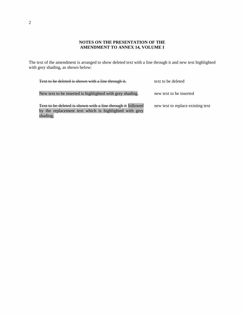
2
NOTES ON THE PRESENTATION OF THE
AMENDMENT TO ANNEX 14, VOLUME I
The text of the amendment is arranged to show deleted text with a line through it and new text highlighted
with grey shading, as shown below:
Text to be deleted is shown with a line through it.
text to be deleted
New text to be inserted is highlighted with grey shading.
new text to be inserted
Text to be deleted is shown with a line through it followed
by the replacement text which is highlighted with grey
shading.
new text to replace existing text
3
TEXT OF AMENDMENT 13-B
TO THE
INTERNATIONAL STANDARDS
AND RECOMMENDED PRACTICES
AERODROMES
ANNEX 14
TO THE CONVENTION ON INTERNATIONAL CIVIL AVIATION
VOLUME I
AERODROME DESIGN AND OPERATIONS
. . .
CHAPTER 1. GENERAL
1.1 Definitions
. . .
Runway. A defined rectangular area on a land aerodrome prepared for the landing and take-off of
aircraft.
Runway condition assessment matrix (RCAM). A matrix allowing the assessment of the runway
condition code, using associated procedures, from a set of observed runway surface condition(s) and
pilot report of braking action.
Runway condition code (RWYCC). A number describing the runway surface condition to be used in the
runway condition report.
Note.— The purpose of the runway condition code is to permit an operational aeroplane performance
calculation by the flight crew. Procedures for the determination of the runway condition code are
described in the PANS-Aerodromes (Doc 9981).
Runway condition report (RCR). A comprehensive standardized report relating to runway surface
conditions and its effect on the aeroplane landing and take-off performance.
. . .
Runway surface condition(s). A description of the condition(s) of the runway surface used in the runway
condition report which establishes the basis for the determination of the runway condition code for
aeroplane performance purposes.
Note 1.— The runway surface conditions used in the runway condition report establish the
performance requirements between the aerodrome operator, aeroplane manufacturer and aeroplane
operator.
Note 2.— Aircraft de-icing chemicals and other contaminants are also reported but are not included
in the list of runway surface condition descriptors because their effect on runway surface friction
characteristics and the runway condition code cannot be evaluated in a standardized manner.
4
Note 3.— Procedures on determining runway surface conditions are available in the
PANS-Aerodromes (Doc 9981).
a) Dry runway. A runway is considered dry if its surface is free of visible moisture and not
contaminated within the area intended to be used.
b) Wet runway. The runway surface is covered by any visible dampness or water up to and including
3 mm deep within the intended area of use.
c) Slippery wet runway. A wet runway where the surface friction characteristics of a significant
portion of the runway has been determined to be degraded.
d) Contaminated runway. A runway is contaminated when a significant portion of the runway surface
area (whether in isolated areas or not) within the length and width being used is covered by one or
more of the substances listed in the runway surface condition descriptors.
Note.— Procedures on determination of contaminant coverage on runway is available in the
PANS-Aerodromes (Doc 9981).
e) Runway surface condition descriptors. One of the following elements on the surface of the runway:
Note.— The descriptions for e) i) to e) viii), below, are used solely in the context of the runway
condition report and are not intended to supersede or replace any existing WMO definitions.
i) Compacted snow. Snow that has been compacted into a solid mass such that aeroplane tires, at
operating pressures and loadings, will run on the surface without significant further
compaction or rutting of the surface.
ii) Dry snow. Snow from which a snowball cannot readily be made.
iii) Frost. Frost consists of ice crystals formed from airborne moisture on a surface whose
temperature is below freezing. Frost differs from ice in that the frost crystals grow
independently and therefore have a more granular texture.
Note 1.— Below freezing refers to air temperature equal to or less than the freezing point of
water (0 degree Celcius).
Note 2.— Under certain conditions frost can cause the surface to become very slippery and it
is then reported appropriately as reduced braking action.
iv) Ice. Water that has frozen or compacted snow that has transitioned into ice, in cold and dry
conditions.
v) Slush. Snow that is so water saturated that water will drain from it when a handful is picked up
or will splatter if stepped on forcefully.
vi) Standing water. Water of depth greater than 3 mm.
Note.— Running water of depth greater than 3 mm is reported as standing water by
convention.
vii) Wet ice. Ice with water on top of it or ice that is melting.
5
Note.— Freezing precipitation can lead to runway conditions associated with wet ice from
an aeroplane performance point of view. Wet ice can cause the surface to become very
slippery. It is then reported appropriately as reduced braking action in line with procedures in
the PANS-Aerodromes (Doc 9981).
viii) Wet snow. Snow that contains enough water content to be able to make a well-compacted,
solid snowball, but water will not squeeze out.
. . .
Runway visual range (RVR). The range over which the pilot of an aircraft on the centre line of a runway
can see the runway surface markings or the lights delineating the runway or identifying its centre line.
. . .
Signal area. An area on an aerodrome used for the display of ground signals.
Slush. Water-saturated snow which with a heel-and-toe slap-down motion against the ground will be
displaced with a splatter; specific gravity: 0.5 up to 0.8.
Note.— Combinations of ice, snow and/or standing water may, especially when rain, rain and snow,
or snow is falling, produce substances with specific gravities in excess of 0.8. These substances, due to
their high water/ice content, will have a transparent rather than a cloudy appearance and, at the higher
specific gravities, will be readily distinguishable from slush.
Snow (on the ground).
a) Dry snow. Snow which can be blown if loose or, if compacted by hand, will fall apart again upon
release; specific gravity: up to but not including 0.35.
b) Wet snow. Snow which, if compacted by hand, will stick together and tend to or form a snowball;
specific gravity: 0.35 up to but not including 0.5.
c) Compacted snow. Snow which has been compressed into a solid mass that resists further
compression and will hold together or break up into lumps if picked up; specific gravity: 0.5 and
over.
Station declination. An alignment variation between the zero degree radial of a VOR and true north,
determined at the time the VOR station is calibrated.
. . .
CHAPTER 2. AERODROME DATA
. . .
2.9 Condition of the movement area and related facilities
2.9.1 Information on the condition of the movement area and the operational status of related
facilities shall be provided to the appropriate aeronautical information services units, and similar
information of operational significance to the air traffic services units, to enable those units to provide the
necessary information to arriving and departing aircraft. The information shall be kept up to date and
changes in conditions reported without delay.
Note.— Nature, format and conditions of the information to be provided are specified in Annex 15
and PANS-ATM (Doc 4444).
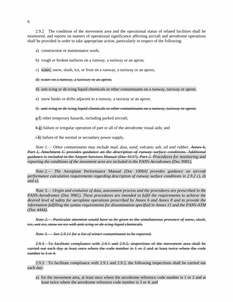
6
2.9.2 The condition of the movement area and the operational status of related facilities shall be
monitored, and reports on matters of operational significance affecting aircraft and aerodrome operations
shall be provided in order to take appropriate action, particularly in respect of the following:
a) construction or maintenance work;
b) rough or broken surfaces on a runway, a taxiway or an apron;
c) water, snow, slush, ice, or frost on a runway, a taxiway or an apron;
d) water on a runway, a taxiway or an apron;
d) anti-icing or de-icing liquid chemicals or other contaminants on a runway, taxiway or apron;
e) snow banks or drifts adjacent to a runway, a taxiway or an apron;
f) anti-icing or de-icing liquid chemicals or other contaminants on a runway, taxiway or apron;
g f) other temporary hazards, including parked aircraft;
h g) failure or irregular operation of part or all of the aerodrome visual aids; and
i h) failure of the normal or secondary power supply.
Note 1.— Other contaminants may include mud, dust, sand, volcanic ash, oil and rubber. Annex 6,
Part I, Attachment C provides guidance on the description of runway surface conditions. Additional
guidance is included in the Airport Services Manual (Doc 9137), Part 2. Procedures for monitoring and
reporting the conditions of the movement area are included in the PANS-Aerodromes (Doc 9981).
Note 2.— The Aeroplane Performance Manual (Doc 10064) provides guidance on aircraft
performance calculation requirements regarding description of runway surface conditions in 2.9.2 c), d)
and e).
Note 3.— Origin and evolution of data, assessment process and the procedures are prescribed in the
PANS-Aerodromes (Doc 9981). These procedures are intended to fulfil the requirements to achieve the
desired level of safety for aeroplane operations prescribed by Annex 6 and Annex 8 and to provide the
information fulfilling the syntax requirements for dissemination specified in Annex 15 and the PANS-ATM
(Doc 4444).
Note 2.— Particular attention would have to be given to the simultaneous presence of snow, slush,
ice, wet ice, snow on ice with anti-icing or de-icing liquid chemicals.
Note 3. — See 2.9.11 for a list of winter contaminants to be reported.
2.9.3 To facilitate compliance with 2.9.1 and 2.9.2, inspections of the movement area shall be
carried out each day at least once where the code number is 1 or 2 and at least twice where the code
number is 3 or 4.
2.9.3 To facilitate compliance with 2.9.1 and 2.9.2, the following inspections shall be carried out
each day:
a) for the movement area, at least once where the aerodrome reference code number is 1 or 2 and at
least twice where the aerodrome reference code number is 3 or 4; and
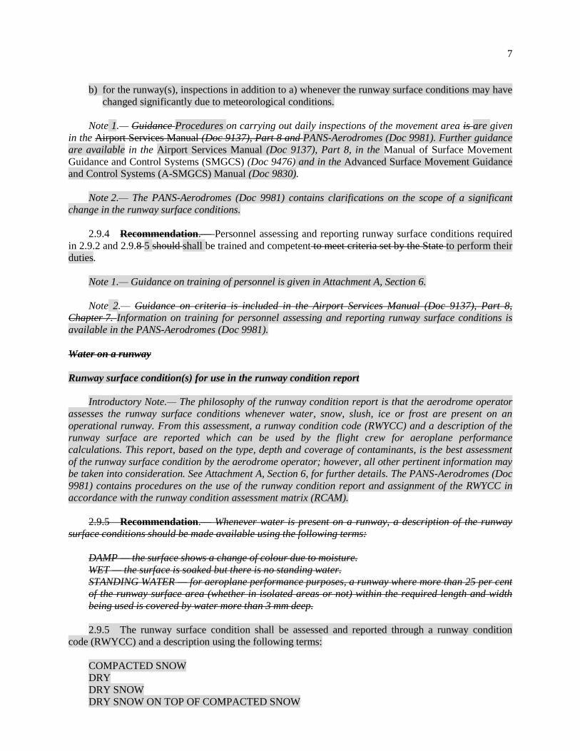
7
b) for the runway(s), inspections in addition to a) whenever the runway surface conditions may have
changed significantly due to meteorological conditions.
Note 1.— Guidance Procedures on carrying out daily inspections of the movement area is are given
in the Airport Services Manual (Doc 9137), Part 8 and PANS-Aerodromes (Doc 9981). Further guidance
are available in the Airport Services Manual (Doc 9137), Part 8, in the Manual of Surface Movement
Guidance and Control Systems (SMGCS) (Doc 9476) and in the Advanced Surface Movement Guidance
and Control Systems (A-SMGCS) Manual (Doc 9830).
Note 2.— The PANS-Aerodromes (Doc 9981) contains clarifications on the scope of a significant
change in the runway surface conditions.
2.9.4 Recommendation.— Personnel assessing and reporting runway surface conditions required
in 2.9.2 and 2.9.8 5 should shall be trained and competent to meet criteria set by the State to perform their
duties.
Note 1.— Guidance on training of personnel is given in Attachment A, Section 6.
Note 2.— Guidance on criteria is included in the Airport Services Manual (Doc 9137), Part 8,
Chapter 7. Information on training for personnel assessing and reporting runway surface conditions is
available in the PANS-Aerodromes (Doc 9981).
Water on a runway
Runway surface condition(s) for use in the runway condition report
Introductory Note.— The philosophy of the runway condition report is that the aerodrome operator
assesses the runway surface conditions whenever water, snow, slush, ice or frost are present on an
operational runway. From this assessment, a runway condition code (RWYCC) and a description of the
runway surface are reported which can be used by the flight crew for aeroplane performance
calculations. This report, based on the type, depth and coverage of contaminants, is the best assessment
of the runway surface condition by the aerodrome operator; however, all other pertinent information may
be taken into consideration. See Attachment A, Section 6, for further details. The PANS-Aerodromes (Doc
9981) contains procedures on the use of the runway condition report and assignment of the RWYCC in
accordance with the runway condition assessment matrix (RCAM).
2.9.5 Recommendation.— Whenever water is present on a runway, a description of the runway
surface conditions should be made available using the following terms:
DAMP — the surface shows a change of colour due to moisture.
WET — the surface is soaked but there is no standing water.
STANDING WATER — for aeroplane performance purposes, a runway where more than 25 per cent
of the runway surface area (whether in isolated areas or not) within the required length and width
being used is covered by water more than 3 mm deep.
2.9.5 The runway surface condition shall be assessed and reported through a runway condition
code (RWYCC) and a description using the following terms:
COMPACTED SNOW
DRY
DRY SNOW
DRY SNOW ON TOP OF COMPACTED SNOW
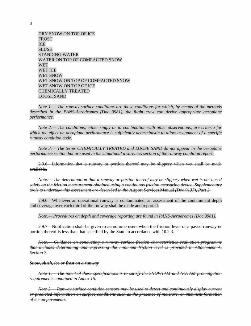
8
DRY SNOW ON TOP OF ICE
FROST
ICE
SLUSH
STANDING WATER
WATER ON TOP OF COMPACTED SNOW
WET
WET ICE
WET SNOW
WET SNOW ON TOP OF COMPACTED SNOW
WET SNOW ON TOP OF ICE
CHEMICALLY TREATED
LOOSE SAND
Note 1.— The runway surface conditions are those conditions for which, by means of the methods
described in the PANS-Aerodromes (Doc 9981), the flight crew can derive appropriate aeroplane
performance.
Note 2.— The conditions, either singly or in combination with other observations, are criteria for
which the effect on aeroplane performance is sufficiently deterministic to allow assignment of a specific
runway condition code.
Note 3.— The terms CHEMICALLY TREATED and LOOSE SAND do not appear in the aeroplane
performance section but are used in the situational awareness section of the runway condition report.
2.9.6 Information that a runway or portion thereof may be slippery when wet shall be made
available.
Note.— The determination that a runway or portion thereof may be slippery when wet is not based
solely on the friction measurement obtained using a continuous friction measuring device. Supplementary
tools to undertake this assessment are described in the Airport Services Manual (Doc 9137), Part 2.
2.9.6 Whenever an operational runway is contaminated, an assessment of the contaminant depth
and coverage over each third of the runway shall be made and reported.
Note.— Procedures on depth and coverage reporting are found in PANS-Aerodromes (Doc 9981).
2.9.7 Notification shall be given to aerodrome users when the friction level of a paved runway or
portion thereof is less than that specified by the State in accordance with 10.2.3.
Note.— Guidance on conducting a runway surface friction characteristics evaluation programme
that includes determining and expressing the minimum friction level is provided in Attachment A,
Section 7.
Snow, slush, ice or frost on a runway
Note 1.— The intent of these specifications is to satisfy the SNOWTAM and NOTAM promulgation
requirements contained in Annex 15.
Note 2.— Runway surface condition sensors may be used to detect and continuously display current
or predicted information on surface conditions such as the presence of moisture, or imminent formation
of ice on pavements.
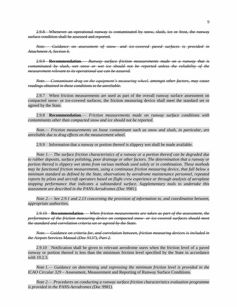
9
2.9.8 Whenever an operational runway is contaminated by snow, slush, ice or frost, the runway
surface condition shall be assessed and reported.
Note.— Guidance on assessment of snow- and ice-covered paved surfaces is provided in
Attachment A, Section 6.
2.9.9 Recommendation.— Runway surface friction measurements made on a runway that is
contaminated by slush, wet snow or wet ice should not be reported unless the reliability of the
measurement relevant to its operational use can be assured.
Note.— Contaminant drag on the equipment’s measuring wheel, amongst other factors, may cause
readings obtained in these conditions to be unreliable.
2.9.7 When friction measurements are used as part of the overall runway surface assessment on
compacted snow- or ice-covered surfaces, the friction measuring device shall meet the standard set or
agreed by the State.
2.9.8 Recommendation.— Friction measurements made on runway surface conditions with
contaminants other than compacted snow and ice should not be reported.
Note.— Friction measurements on loose contaminant such as snow and slush, in particular, are
unreliable due to drag effects on the measurement wheel.
2.9.9 Information that a runway or portion thereof is slippery wet shall be made available.
Note 1.— The surface friction characteristics of a runway or a portion thereof can be degraded due
to rubber deposits, surface polishing, poor drainage or other factors. The determination that a runway or
portion thereof is slippery wet stems from various methods used solely or in combination. These methods
may be functional friction measurements, using a continuous friction measuring device, that fall below a
minimum standard as defined by the State, observations by aerodrome maintenance personnel, repeated
reports by pilots and aircraft operators based on flight crew experience or through analysis of aeroplane
stopping performance that indicates a substandard surface. Supplementary tools to undertake this
assessment are described in the PANS-Aerodromes (Doc 9981).
Note 2.— See 2.9.1 and 2.13 concerning the provision of information to, and coordination between,
appropriate authorities.
2.9.10 Recommendation.— When friction measurements are taken as part of the assessment, the
performance of the friction measuring device on compacted snow- or ice-covered surfaces should meet
the standard and correlation criteria set or agreed by the State.
Note.— Guidance on criteria for, and correlation between, friction measuring devices is included in
the Airport Services Manual (Doc 9137), Part 2.
2.9.10 Notification shall be given to relevant aerodrome users when the friction level of a paved
runway or portion thereof is less than the minimum friction level specified by the State in accordance
with 10.2.3.
Note 1.— Guidance on determining and expressing the minimum friction level is provided in the
ICAO Circular 329 – Assessment, Measurement and Reporting of Runway Surface Conditions.
Note 2.— Procedures on conducting a runway surface friction characteristics evaluation programme
is provided in the PANS-Aerodromes (Doc 9981).
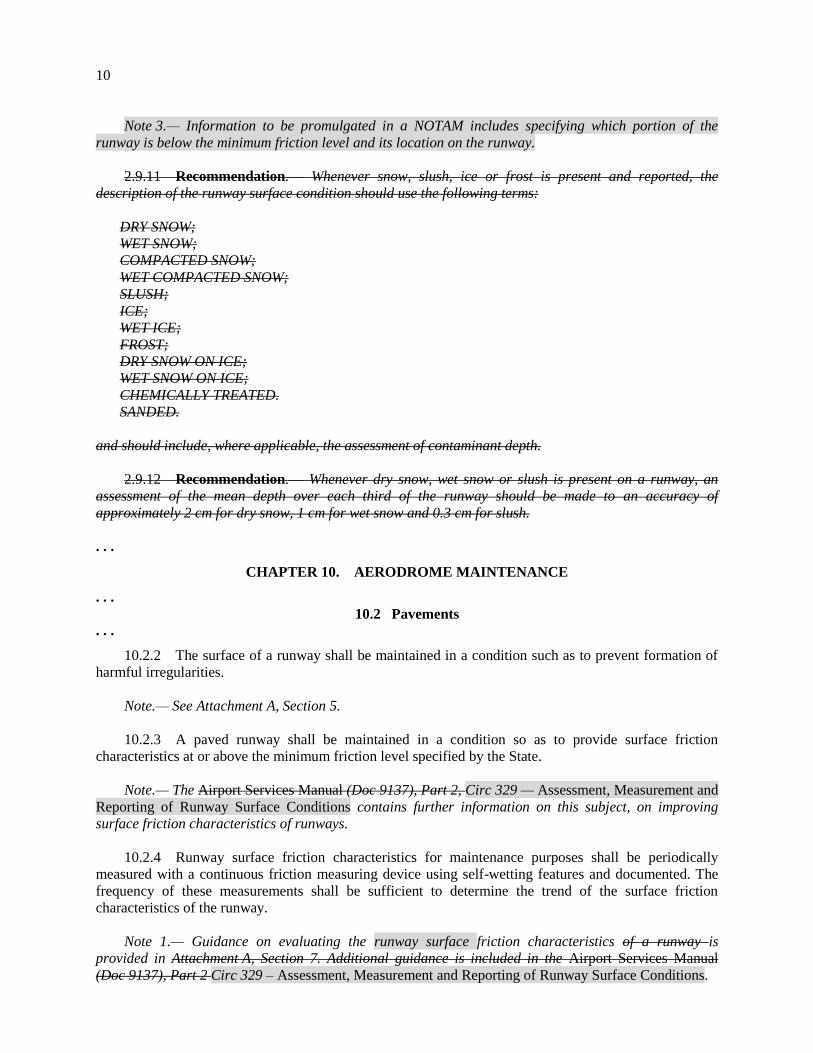
10
Note 3.— Information to be promulgated in a NOTAM includes specifying which portion of the
runway is below the minimum friction level and its location on the runway.
2.9.11 Recommendation.— Whenever snow, slush, ice or frost is present and reported, the
description of the runway surface condition should use the following terms:
DRY SNOW;
WET SNOW;
COMPACTED SNOW;
WET COMPACTED SNOW;
SLUSH;
ICE;
WET ICE;
FROST;
DRY SNOW ON ICE;
WET SNOW ON ICE;
CHEMICALLY TREATED.
SANDED.
and should include, where applicable, the assessment of contaminant depth.
2.9.12 Recommendation.— Whenever dry snow, wet snow or slush is present on a runway, an
assessment of the mean depth over each third of the runway should be made to an accuracy of
approximately 2 cm for dry snow, 1 cm for wet snow and 0.3 cm for slush.
. . .
CHAPTER 10. AERODROME MAINTENANCE
. . .
10.2 Pavements
. . .
10.2.2 The surface of a runway shall be maintained in a condition such as to prevent formation of
harmful irregularities.
Note.— See Attachment A, Section 5.
10.2.3 A paved runway shall be maintained in a condition so as to provide surface friction
characteristics at or above the minimum friction level specified by the State.
Note.— The Airport Services Manual (Doc 9137), Part 2, Circ 329 — Assessment, Measurement and
Reporting of Runway Surface Conditions contains further information on this subject, on improving
surface friction characteristics of runways.
10.2.4 Runway surface friction characteristics for maintenance purposes shall be periodically
measured with a continuous friction measuring device using self-wetting features and documented. The
frequency of these measurements shall be sufficient to determine the trend of the surface friction
characteristics of the runway.
Note 1.— Guidance on evaluating the runway surface friction characteristics of a runway is
provided in Attachment A, Section 7. Additional guidance is included in the Airport Services Manual
(Doc 9137), Part 2 Circ 329 – Assessment, Measurement and Reporting of Runway Surface Conditions.
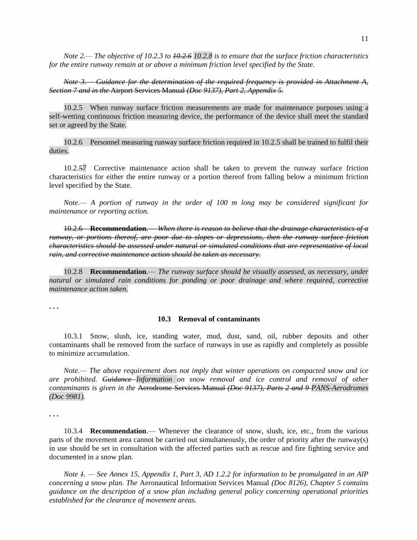
11
Note 2.— The objective of 10.2.3 to 10.2.6 10.2.8 is to ensure that the surface friction characteristics
for the entire runway remain at or above a minimum friction level specified by the State.
Note 3.— Guidance for the determination of the required frequency is provided in Attachment A,
Section 7 and in the Airport Services Manual (Doc 9137), Part 2, Appendix 5.
10.2.5 When runway surface friction measurements are made for maintenance purposes using a
self-wetting continuous friction measuring device, the performance of the device shall meet the standard
set or agreed by the State.
10.2.6 Personnel measuring runway surface friction required in 10.2.5 shall be trained to fulfil their
duties.
10.2.57 Corrective maintenance action shall be taken to prevent the runway surface friction
characteristics for either the entire runway or a portion thereof from falling below a minimum friction
level specified by the State.
Note.— A portion of runway in the order of 100 m long may be considered significant for
maintenance or reporting action.
10.2.6 Recommendation.— When there is reason to believe that the drainage characteristics of a
runway, or portions thereof, are poor due to slopes or depressions, then the runway surface friction
characteristics should be assessed under natural or simulated conditions that are representative of local
rain, and corrective maintenance action should be taken as necessary.
10.2.8 Recommendation.— The runway surface should be visually assessed, as necessary, under
natural or simulated rain conditions for ponding or poor drainage and where required, corrective
maintenance action taken.
. . .
10.3 Removal of contaminants
10.3.1 Snow, slush, ice, standing water, mud, dust, sand, oil, rubber deposits and other
contaminants shall be removed from the surface of runways in use as rapidly and completely as possible
to minimize accumulation.
Note.— The above requirement does not imply that winter operations on compacted snow and ice
are prohibited. Guidance Information on snow removal and ice control and removal of other
contaminants is given in the Aerodrome Services Manual (Doc 9137), Parts 2 and 9 PANS-Aerodromes
(Doc 9981).
. . .
10.3.4 Recommendation.— Whenever the clearance of snow, slush, ice, etc., from the various
parts of the movement area cannot be carried out simultaneously, the order of priority after the runway(s)
in use should be set in consultation with the affected parties such as rescue and fire fighting service and
documented in a snow plan.
Note 1. — See Annex 15, Appendix 1, Part 3, AD 1.2.2 for information to be promulgated in an AIP
concerning a snow plan. The Aeronautical Information Services Manual (Doc 8126), Chapter 5 contains
guidance on the description of a snow plan including general policy concerning operational priorities
established for the clearance of movement areas.
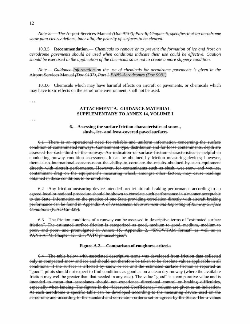
12
Note 2. — The Airport Services Manual (Doc 9137), Part 8, Chapter 6, specifies that an aerodrome
snow plan clearly defines, inter alia, the priority of surfaces to be cleared.
10.3.5 Recommendation.— Chemicals to remove or to prevent the formation of ice and frost on
aerodrome pavements should be used when conditions indicate their use could be effective. Caution
should be exercised in the application of the chemicals so as not to create a more slippery condition.
Note.— Guidance Information on the use of chemicals for aerodrome pavements is given in the
Airport Services Manual (Doc 9137), Part 2 PANS-Aerodromes (Doc 9981).
10.3.6 Chemicals which may have harmful effects on aircraft or pavements, or chemicals which
may have toxic effects on the aerodrome environment, shall not be used.
. . .
ATTACHMENT A. GUIDANCE MATERIAL
SUPPLEMENTARY TO ANNEX 14, VOLUME I
. . .
6. Assessing the surface friction characteristics of snow-,
slush-, ice- and frost-covered paved surfaces
6.1 There is an operational need for reliable and uniform information concerning the surface
condition of contaminated runways. Contaminant type, distribution and for loose contaminants, depth are
assessed for each third of the runway. An indication of surface friction characteristics is helpful in
conducting runway condition assessment. It can be obtained by friction measuring devices; however,
there is no international consensus on the ability to correlate the results obtained by such equipment
directly with aircraft performance. However, for contaminants such as slush, wet snow and wet ice,
contaminant drag on the equipment’s measuring wheel, amongst other factors, may cause readings
obtained in these conditions to be unreliable.
6.2 Any friction measuring device intended predict aircraft braking performance according to an
agreed local or national procedure should be shown to correlate such performance in a manner acceptable
to the State. Information on the practice of one State providing correlation directly with aircraft braking
performance can be found in Appendix A of Assessment, Measurement and Reporting of Runway Surface
Conditions (ICAO Cir 329).
6.3 The friction conditions of a runway can be assessed in descriptive terms of “estimated surface
friction”. The estimated surface friction is categorized as good, medium to good, medium, medium to
poor, and poor, and promulgated in Annex 15, Appendix 2, “SNOWTAM format” as well as in
PANS-ATM, Chapter 12, 12.3, “ATC phraseologies”.
Figure A-3. Comparison of roughness criteria
6.4 The table below with associated descriptive terms was developed from friction data collected
only in compacted snow and ice and should not therefore be taken to be absolute values applicable in all
conditions. If the surface is affected by snow or ice and the estimated surface friction is reported as
“good”, pilots should not expect to find conditions as good as on a clean dry runway (where the available
friction may well be greater than that needed in any case). The value “good” is a comparative value and is
intended to mean that aeroplanes should not experience directional control or braking difficulties,
especially when landing. The figures in the “Measured Coefficient μ” column are given as an indication.
At each aerodrome a specific table can be developed according to the measuring device used on the
aerodrome and according to the standard and correlation criteria set or agreed by the State. The μ values
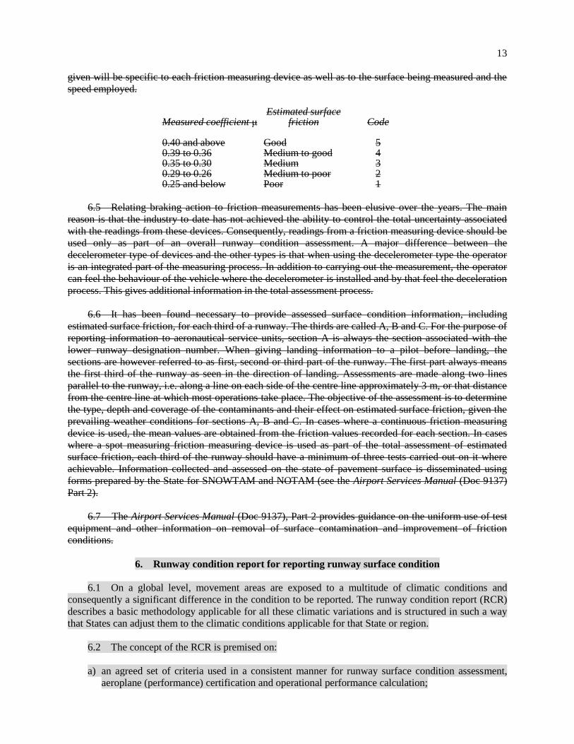
13
given will be specific to each friction measuring device as well as to the surface being measured and the
speed employed.
Measured coefficient μ Estimated surface
friction Code 0.40 and above Good 5 0.39 to 0.36 Medium to good 4 0.35 to 0.30 Medium 3 0.29 to 0.26 Medium to poor 2 0.25 and below Poor 1
6.5 Relating braking action to friction measurements has been elusive over the years. The main
reason is that the industry to date has not achieved the ability to control the total uncertainty associated
with the readings from these devices. Consequently, readings from a friction measuring device should be
used only as part of an overall runway condition assessment. A major difference between the
decelerometer type of devices and the other types is that when using the decelerometer type the operator
is an integrated part of the measuring process. In addition to carrying out the measurement, the operator
can feel the behaviour of the vehicle where the decelerometer is installed and by that feel the deceleration
process. This gives additional information in the total assessment process.
6.6 It has been found necessary to provide assessed surface condition information, including
estimated surface friction, for each third of a runway. The thirds are called A, B and C. For the purpose of
reporting information to aeronautical service units, section A is always the section associated with the
lower runway designation number. When giving landing information to a pilot before landing, the
sections are however referred to as first, second or third part of the runway. The first part always means
the first third of the runway as seen in the direction of landing. Assessments are made along two lines
parallel to the runway, i.e. along a line on each side of the centre line approximately 3 m, or that distance
from the centre line at which most operations take place. The objective of the assessment is to determine
the type, depth and coverage of the contaminants and their effect on estimated surface friction, given the
prevailing weather conditions for sections A, B and C. In cases where a continuous friction measuring
device is used, the mean values are obtained from the friction values recorded for each section. In cases
where a spot measuring friction measuring device is used as part of the total assessment of estimated
surface friction, each third of the runway should have a minimum of three tests carried out on it where
achievable. Information collected and assessed on the state of pavement surface is disseminated using
forms prepared by the State for SNOWTAM and NOTAM (see the Airport Services Manual (Doc 9137)
Part 2).
6.7 The Airport Services Manual (Doc 9137), Part 2 provides guidance on the uniform use of test
equipment and other information on removal of surface contamination and improvement of friction
conditions.
6. Runway condition report for reporting runway surface condition
6.1 On a global level, movement areas are exposed to a multitude of climatic conditions and
consequently a significant difference in the condition to be reported. The runway condition report (RCR)
describes a basic methodology applicable for all these climatic variations and is structured in such a way
that States can adjust them to the climatic conditions applicable for that State or region.
6.2 The concept of the RCR is premised on:
a) an agreed set of criteria used in a consistent manner for runway surface condition assessment,
aeroplane (performance) certification and operational performance calculation;
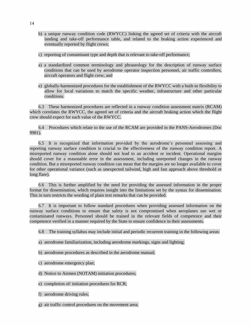
14
b) a unique runway condition code (RWYCC) linking the agreed set of criteria with the aircraft
landing and take-off performance table, and related to the braking action experienced and
eventually reported by flight crews;
c) reporting of contaminant type and depth that is relevant to take-off performance;
a) a standardized common terminology and phraseology for the description of runway surface
conditions that can be used by aerodrome operator inspection personnel, air traffic controllers,
aircraft operators and flight crew; and
e) globally-harmonized procedures for the establishment of the RWYCC with a built-in flexibility to
allow for local variations to match the specific weather, infrastructure and other particular
conditions.
6.3 These harmonized procedures are reflected in a runway condition assessment matrix (RCAM)
which correlates the RWYCC, the agreed set of criteria and the aircraft braking action which the flight
crew should expect for each value of the RWYCC.
6.4 Procedures which relate to the use of the RCAM are provided in the PANS-Aerodromes (Doc
9981).
6.5 It is recognized that information provided by the aerodrome’s personnel assessing and
reporting runway surface condition is crucial to the effectiveness of the runway condition report. A
misreported runway condition alone should not lead to an accident or incident. Operational margins
should cover for a reasonable error in the assessment, including unreported changes in the runway
condition. But a misreported runway condition can mean that the margins are no longer available to cover
for other operational variance (such as unexpected tailwind, high and fast approach above threshold or
long flare).
6.6 This is further amplified by the need for providing the assessed information in the proper
format for dissemination, which requires insight into the limitations set by the syntax for dissemination.
This in turn restricts the wording of plain text remarks that can be provided.
6.7 It is important to follow standard procedures when providing assessed information on the
runway surface conditions to ensure that safety is not compromised when aeroplanes use wet or
contaminated runways. Personnel should be trained in the relevant fields of competence and their
competence verified in a manner required by the State to ensure confidence in their assessments.
6.8 The training syllabus may include initial and periodic recurrent training in the following areas:
a) aerodrome familiarization, including aerodrome markings, signs and lighting;
b) aerodrome procedures as described in the aerodrome manual;
c) aerodrome emergency plan;
d) Notice to Airmen (NOTAM) initiation procedures;
e) completion of/ initiation procedures for RCR;
f) aerodrome driving rules;
g) air traffic control procedures on the movement area;
15
h) radiotelephone operating procedures;
i) phraseology used in aerodrome control, including the ICAO spelling alphabet;
j) aerodrome inspection procedures and techniques;
k) type of runway contaminants and reporting;
l) assessment and reporting of runway surface friction characteristics;
m) use of runway friction measurement device;
n) calibration and maintenance of runway friction measurement device;
o) awareness of uncertainties related to l) and m); and
p) low visibility procedures.
7. Determination of surface friction characteristics
for construction and maintenance purposes
Note.— The guidance in this section involves the functional measurement of friction-related aspects
related to runway construction and maintenance. Excluded from this section is the operational, as
opposed to functional, measurement of friction for contaminated runways. However, the devices used for
functional measurement could also be used for operational measurement, but in the latter case, the
figures given in Airport Services Manual (Doc 9137), Part 2, Table 3-1 are not relevant.
7.1 The surface friction characteristics of a paved runway should be:
a) assessed to verify the surface friction characteristics of new or resurfaced paved runways
(Chapter 3, 3.1.25); and
b) assessed periodically in order to determine the slipperiness of paved runways (Chapter 10,
10.2.4).
7.2 The condition of a runway pavement is generally assessed under dry conditions using a self-
wetting continuous friction measuring device. Evaluation tests of runway surface friction characteristics
are made on clean surfaces of the runway when first constructed or after resurfacing.
7.3 Friction tests of existing surface conditions are taken periodically in order to avoid falling
below the minimum friction level specified by the State. When the friction of any portion of a runway is
found to be below this value, then such information is promulgated in a NOTAM specifying which
portion of the runway is below the minimum friction level and its location on the runway. A corrective
maintenance action must be initiated without delay. Friction measurements are taken at time intervals that
will ensure the identification of runways in need of maintenance or of special surface treatment before
their condition becomes serious. The time intervals and mean frequency of measurements depend on
factors such as: aircraft type and frequency of usage, climatic conditions, pavement type, and pavement
service and maintenance requirements.
7.4 Friction measurements of existing, new or resurfaced runways are made with a continuous
friction measuring device provided with a smooth tread tire. The device should use self-wetting features
to allow measurements of the surface friction characteristics to be made at a water depth of 1 mm.
16
7.5 When it is suspected that the surface friction characteristics of a runway may be reduced
because of poor drainage, owing to inadequate slopes or depressions, then an additional measurement is
made, but this time under natural conditions representative of a local rain. This measurement differs from
the previous one in that water depths in the poorly cleared areas are normally greater in a local rain
condition. The measurement results are thus more apt to identify problem areas having low friction values
that could induce aquaplaning than the previous test. If circumstances do not permit measurements to be
conducted during natural conditions representative of a rain, then this condition may be simulated. (See
section 8.)
7.6 When conducting friction tests using a self-wetting continuous friction measuring device, it is
important to note that, unlike compacted snow and ice conditions, in which there is very limited variation
of the friction coefficient with speed, a wet runway produces a drop in friction with an increase in speed.
However, as the speed increases, the rate at which the friction is reduced becomes less. Among the factors
affecting the friction coefficient between the tire and the runway surface, texture is particularly important.
If the runway has a good macro-texture allowing the water to escape beneath the tire, then the friction
value will be less affected by speed. Conversely, a low macro-texture surface will produce a larger drop
in friction with increase in speed.
7.7 Annex 14, Volume I, requires States to specify a minimum friction level below which
corrective maintenance action should be taken. As criteria for surface friction characteristics of new or
resurfaced runway surfaces and its maintenance planning, the State can establish a maintenance planning
level below which appropriate corrective maintenance action should be initiated to improve the friction.
The Airport Services Manual (Doc 9137), Part 2, provides guidance on establishing maintenance planning
and minimum friction levels for runway surfaces in use.
. . .
— END —


