Embed Size (px)
Citation preview
ANSI/ASHRAE Standard 62.1-2019(Supersedes ANSI/ASHRAE Standard 62.1-2016)
Includes ANSI/ASHRAE addenda listed in Appendix O
Ventilationfor Acceptable
Indoor Air Quality
See Appendix O for approval dates by ASHRAE and the American National Standards Institute.
This Standard is under continuous maintenance by a Standing Standard Project Committee (SSPC) for which the StandardsCommittee has established a documented program for regular publication of addenda or revisions, including procedures fortimely, documented, consensus action on requests for change to any part of the Standard. Instructions for how to submit achange can be found on the ASHRAE® website (www.ashrae.org/continuous-maintenance).
The latest edition of an ASHRAE Standard may be purchased from the ASHRAE website (www.ashrae.org) or fromASHRAE Customer Service, 1791 Tullie Circle, NE, Atlanta, GA 30329-2305. E-mail: [email protected]. Fax: 678-539-2129. Telephone: 404-636-8400 (worldwide), or toll free 1-800-527-4723 (for orders in US and Canada). For reprint per-mission, go to www.ashrae.org/permissions.
© 2019 ASHRAE ISSN 1041-2336
Copyrighted material licensed to Timothy Self on 2020-04-02 for licensee's use only. All rights reserved. No further reproduction or distribution is permitted. Distributed by Techstreet for ASHRAE, www.techstreet.com
ASHRAE Standing Standard Project Committee 62.1Cognizant TC: 4.3, Ventilation Requirements and Infiltration
SPLS Liaison: Karl L. PetermanASHRAE Staff Liaison: Mark Weber
Jennifer A. Isenbeck, Chair (2019), Co-Vice-Chair (2017–2019)Hoy R. Bohanon, Jr., Chair (2016–2019)
Wayne R. Thomann, Vice-Chair (2019), Co-Vice-Chair (2017–2019)
Nick H. Agopian Henry W. Ernst, Jr. Meghan K. McNulty Dennis A. StankeHugo Aguilar Richard B. Fox Maria A. Menchaca Brandan Erica StewartWilliam P. Bahnfleth Enrica Galasso Christopher O. Muller Drayton P. StottCharlene W. Bayer Elliott Gall John Nelson, Jr. Richard TaftRobin M. Bristol Enrique T. Gonzalez Lisa C. Ng Dean T. TompkinsLance R. Brown Gregg Gress Laura G. Petrillo-Groh David VigueTina M. Brueckner Brian J. Hafendorfer Daniel C. Pettway Ted WayneBrendon J. Burley Nathan L. Ho Heather L. Platt Gulledge Josiah WileyMark P. Buttner Elliott Horner Stephen Ray Scott D. WilliamsJordan D. Clark Eli P. Howard, III Daniel J. Redmond Donald Weekes, Jr.Leonard A. Damiano Zalmie Hussein Tom Rice Runming YaoAbdel K. Darwich Jennifer Kane Chandra Sekhar Marwa ZaatariHelen D. Davis Paul J. Kitchens Charles J. SeyfferJames E. Dennison Lauren MacGowens Abhinav ShuklaPaul L. Doppel Stephany I. Mason Jeffrey K. Smith
ASHRAE STANDARDS COMMITTEE 2019–2020
Wayne H. Stoppelmoor, Jr., Chair Susanna S. Hanson Lawrence J. SchoenDrury B. Crawley, Vice-Chair Rick M. Heiden Steven C. SillEls Baert Jonathan Humble Richard T. SwierczynaCharles S. Barnaby Srinivas Katipamula Christian R. TaberNiels Bidstrup Essam E. Khalil Russell C. TharpRobert B. Burkhead Kwang Woo Kim Adrienne G. ThomleThomas E. Cappellin Larry Kouma Michael W. WoodfordDouglas D. Fick Cesar L. Lim Craig P. WrayMichael W. Gallagher Karl L. Peterman Jaap Hogeling, BOD ExOWalter T. Grondzik Erick A. Phelps Malcolm D. Knight, CO
Steven C. Ferguson, Senior Manager of Standards
SPECIAL NOTEThis American National Standard (ANS) is a national voluntary consensus Standard developed under the auspices of ASHRAE. Consensus is defined by the AmericanNational Standards Institute (ANSI), of which ASHRAE is a member and which has approved this Standard as an ANS, as “substantial agreement reached by directlyand materially affected interest categories. This signifies the concurrence of more than a simple majority, but not necessarily unanimity. Consensus requires that allviews and objections be considered, and that an effort be made toward their resolution.” Compliance with this Standard is voluntary until and unless a legal jurisdictionmakes compliance mandatory through legislation.
ASHRAE obtains consensus through participation of its national and international members, associated societies, and public review.ASHRAE Standards are prepared by a Project Committee appointed specifically for the purpose of writing the Standard. The Project Committee Chair and
Vice-Chair must be members of ASHRAE; while other committee members may or may not be ASHRAE members, all must be technically qualified in the subjectarea of the Standard. Every effort is made to balance the concerned interests on all Project Committees.
The Senior Manager of Standards of ASHRAE should be contacted fora. interpretation of the contents of this Standard,b. participation in the next review of the Standard,c. offering constructive criticism for improving the Standard, ord. permission to reprint portions of the Standard.
DISCLAIMERASHRAE uses its best efforts to promulgate Standards and Guidelines for the benefit of the public in light of available information and accepted industry practices.However, ASHRAE does not guarantee, certify, or assure the safety or performance of any products, components, or systems tested, installed, or operated inaccordance with ASHRAE’s Standards or Guidelines or that any tests conducted under its Standards or Guidelines will be nonhazardous or free from risk.
ASHRAE INDUSTRIAL ADVERTISING POLICY ON STANDARDSASHRAE Standards and Guidelines are established to assist industry and the public by offering a uniform method of testing for rating purposes, by suggesting safepractices in designing and installing equipment, by providing proper definitions of this equipment, and by providing other information that may serve to guide theindustry. The creation of ASHRAE Standards and Guidelines is determined by the need for them, and conformance to them is completely voluntary.In referring to this Standard or Guideline and in marking of equipment and in advertising, no claim shall be made, either stated or implied, that the product has been approved by ASHRAE.
Copyrighted material licensed to Timothy Self on 2020-04-02 for licensee's use only. All rights reserved. No further reproduction or distribution is permitted. Distributed by Techstreet for ASHRAE, www.techstreet.com
CONTENTS
ANSI/ASHRAE Standard 62.1-2019Ventilation for Acceptable Indoor Air Quality
SECTION PAGE
Foreword .....................................................................................................................................................................2
1 Purpose.............................................................................................................................................................2
2 Scope ................................................................................................................................................................3
3 Definitions .........................................................................................................................................................3
4 Outdoor Air Quality............................................................................................................................................6
5 Systems and Equipment ...................................................................................................................................7
6 Procedures......................................................................................................................................................15
7 Construction and System Start-Up..................................................................................................................30
8 Operations and Maintenance ..........................................................................................................................31
9 Normative References ....................................................................................................................................34
Normative Appendix A: Multiple-Zone System Ventilation Efficiency: Alternative Procedure ...............................36
Normative Appendix B: Separation of Exhaust Outlets and Outdoor Air Intakes..................................................40
Normative Appendix C: Zone Air Distribution Effectiveness: Alternate Procedures..............................................43
Informative Appendix D: Information on Selected National Standards and Guidelines forPM10, PM2.5, and Ozone .................................................................................................................45
Informative Appendix E: Acceptable Mass Balance Equations for Use with the IAQ Procedure ..........................47
Informative Appendix F: Simplified Ventilation Rate Calculation for Multiple-Zone Recirculating SystemsServing Only Specified Occupancy Categories in Existing Buildings ...............................................49
Informative Appendix G: Application .....................................................................................................................51
Informative Appendix H: Documentation...............................................................................................................53
Informative Appendix I: Rate Rationale.................................................................................................................56
Informative Appendix J: Information on Natural Ventilation ..................................................................................64
Informative Appendix K: Compliance ....................................................................................................................67
Informative Appendix L: Ventilation Rate Check Table .........................................................................................71
Informative Appendix M: Informative References .................................................................................................75
Informative Appendix N: Indoor Air Quality Procedure (IAQP)..............................................................................76
Informative Appendix O: Addenda Description Information ..................................................................................81
© 2019 ASHRAE1791 Tullie Circle NE · Atlanta, GA 30329 · www.ashrae.org · All rights reserved.
ASHRAE is a registered trademark of the American Society of Heating, Refrigerating and Air-Conditioning Engineers, Inc.ANSI is a registered trademark of the American National Standards Institute.
Copyrighted material licensed to Timothy Self on 2020-04-02 for licensee's use only. All rights reserved. No further reproduction or distribution is permitted. Distributed by Techstreet for ASHRAE, www.techstreet.com
Copyrighted material licensed to Timothy Self on 2020-04-02 for licensee's use only. All rights reserved. No further reproduction or distribution is permitted. Distributed by Techstreet for ASHRAE, www.techstreet.com
(This foreword is not part of this standard. It is merely informative and does not containrequirements necessary for conformance to the standard. It has not been processedaccording to the ANSI requirements for a standard and may contain material that hasnot been subject to public review or a consensus process. Unresolved objectors on infor-mative material are not offered the right to appeal at ASHRAE or ANSI.)
FOREWORD
Standard 62.1 has undergone key changes over the years, reflecting the ever-expanding body ofknowledge, experience, and research related to ventilation and air quality. While the purposeof the standard remains unchanged—to specify minimum ventilation rates and other measuresintended to provide indoor air quality (IAQ) that is acceptable to human occupants and thatminimizes adverse health effects—the means of achieving this goal have evolved.
In its first edition, the standard adopted a prescriptive approach to ventilation by specifyingboth minimum and recommended outdoor airflow rates to obtain acceptable indoor air qualityfor a variety of indoor spaces. In 1981, the standard reduced minimum outdoor airflow ratesand introduced an alternative performance-based approach, the IAQ Procedure, which allowedfor the calculation of the amount of outdoor air necessary to maintain the levels of indoor aircontaminants below recommended limits. In 2004—the last time the standard was revised in itsentirety—the IAQ Procedure was modified to improve enforceability, but more significantly theVentilation Rate Procedure was modified, changing both the minimum outdoor airflow rates andthe procedures for calculating both zone-level and system-level outdoor airflow rates. Today,the standard includes three procedures for ventilation design: the IAQ Procedure, the Ventila-tion Rate Procedure, and the Natural Ventilation Procedure.
The following are among significant changes made in the 2019 edition of the standard:
• The scope is changed to remove commentary and to more specifically identify occupanciespreviously not covered.
• Informative tables of ventilation rates per unit area are included for checking existing build-ings and design of new buildings.
• The Ventilation Rate Procedure is modified with a new simplified version for determining Evand a more robust option for determining values of Ez.
• The Natural Ventilation Procedure is significantly modified to provide a more accurate calcu-lation methodology and also define the process for designing an engineered system.
• Natural ventilation now requires considering the quality of the outdoor air and interactionof the outdoor air with mechanically cooled spaces.
• Air-cleaning devices that generate ozone are prohibited.• Humidity control requirements are now expressed as dew point and not as relative humidity.• The standard now defers to ANSI Z9.5 on ventilation for laboratories handling hazardous
materials.• Patient care spaces in the scope of ASHRAE/ASHE Standard 170 now follow the require-
ments of Standard 170; ancillary spaces not previously classified have been added.
For more specific information on these and other changes made to the standard, refer toInformative Appendix O.
Standard 62.1 is updated on a regular basis using ASHRAE's continuous maintenanceprocedures. Addenda are publicly reviewed, approved by ASHRAE and ANSI, and posted onthe ASHRAE website. Change proposals can be submitted online at www.ashrae.org/continu-ous-maintenance. The project committee for Standard 62.1 takes formal action on all changeproposals received.
1. PURPOSE
1.1 The purpose of this standard is to specify minimum ventilation rates and other measuresintended to provide indoor air quality (IAQ) that is acceptable to human occupants and thatminimizes adverse health effects. 1.2 This standard is intended for regulatory application to new buildings, additions to existingbuildings, and those changes to existing buildings that are identified in the body of the standard.1.3 This standard is intended to be used to guide the improvement of IAQ in existing buildings.
2 ANSI/ASHRAE Standard 62.1-2019
Copyrighted material licensed to Timothy Self on 2020-04-02 for licensee's use only. All rights reserved. No further reproduction or distribution is permitted. Distributed by Techstreet for ASHRAE, www.techstreet.com
2. SCOPE
2.1 This standard applies to spaces intended for human occupancy within buildings exceptthose within dwelling units in residential occupancies in which occupants are nontransient.
2.2 This standard defines requirements for ventilation and air-cleaning system design, instal-lation, commissioning, and operation and maintenance.
2.3 In addition to ventilation, this standard contains requirements related to certain contami-nants and contaminant sources, including outdoor air, construction processes, moisture, andbiological growth.
2.4 This standard does not prescribe specific ventilation rate requirements for the following:
a. Spaces that contain smoking or that do not meet the requirements in the standard for sepa-ration from spaces that contain smoking
b. Patient care areas not listed in this standardc. Laboratories with hazardous materials
3. DEFINITIONS
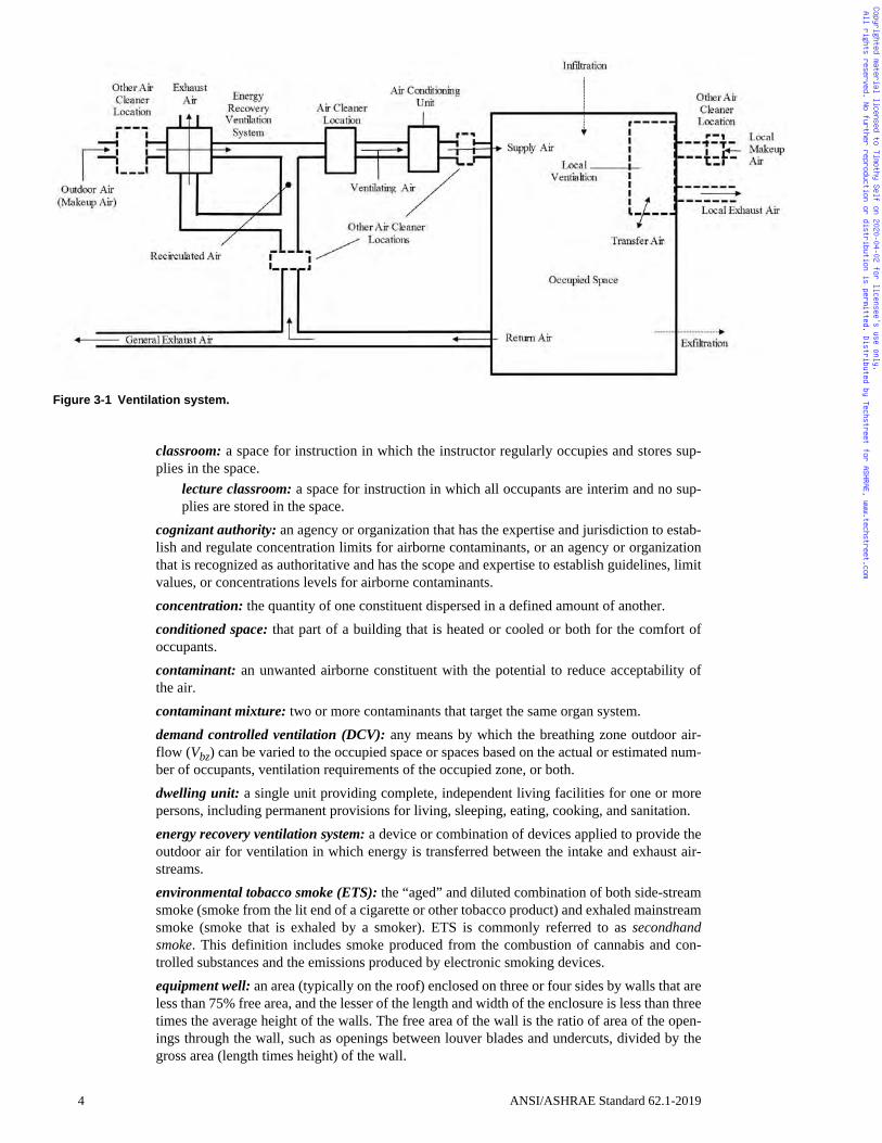
3.1 Terminology (See Figure 3-1)
acceptable indoor air quality (IAQ): air in which there are no known contaminants at harmfulconcentrations, as determined by cognizant authorities, and with which a substantial majority(80% or more) of the people exposed do not express dissatisfaction.
air:ambient air: the air surrounding a building; the source of outdoor air brought into abuilding.cool air: air whose temperature is less than the average space temperature.exhaust air: air removed from a space and discharged to outside the building by means ofmechanical or natural ventilation systems.indoor air: the air in an enclosed occupiable space.makeup air: any combination of outdoor and transfer air intended to replace exhaust airand exfiltration. outdoor air: ambient air and ambient air that enters a building through a ventilation sys-tem, through intentional openings for natural ventilation, or by infiltration. primary air: air supplied to the ventilation zone prior to mixing with any locally recircu-lated air.recirculated air: air removed from a space and reused as supply air. return air: air removed from a space to be recirculated or exhausted. supply air: air delivered by mechanical or natural ventilation to a space and composed ofany combination of outdoor air, recirculated air, or transfer air. transfer air: air moved from one indoor space to another. ventilation air: that portion of supply air that is outdoor air plus any recirculated air thathas been treated for the purpose of maintaining acceptable IAQ. warm air: air whose temperature is greater than the average space temperature.
air-cleaning system: a device or combination of devices applied to reduce the concentrationof airborne contaminants such as microorganisms, dusts, fumes, respirable particles, otherparticulate matter, gases, vapors, or any combination thereof.
air conditioning: the process of treating air to meet the requirements of a conditioned spaceby controlling its temperature, humidity, cleanliness, and distribution.
breathing zone: the region within an occupied space between planes 3 and 72 in. (75 and1800 mm) above the floor and more than 2 ft (600 mm) from the walls or fixed air-condition-ing equipment.
ceiling return: air removed from the space more than 4.5 ft (1.4 m) above the floor.
ceiling supply: air supplied to the space more than 4.5 ft (1.4 m) above the floor.
ANSI/ASHRAE Standard 62.1-2019 3
Copyrighted material licensed to Timothy Self on 2020-04-02 for licensee's use only. All rights reserved. No further reproduction or distribution is permitted. Distributed by Techstreet for ASHRAE, www.techstreet.com
classroom: a space for instruction in which the instructor regularly occupies and stores sup-plies in the space.
lecture classroom: a space for instruction in which all occupants are interim and no sup-plies are stored in the space.
cognizant authority: an agency or organization that has the expertise and jurisdiction to estab-lish and regulate concentration limits for airborne contaminants, or an agency or organizationthat is recognized as authoritative and has the scope and expertise to establish guidelines, limitvalues, or concentrations levels for airborne contaminants.concentration: the quantity of one constituent dispersed in a defined amount of another. conditioned space: that part of a building that is heated or cooled or both for the comfort ofoccupants. contaminant: an unwanted airborne constituent with the potential to reduce acceptability ofthe air. contaminant mixture: two or more contaminants that target the same organ system.demand controlled ventilation (DCV): any means by which the breathing zone outdoor air-flow (Vbz) can be varied to the occupied space or spaces based on the actual or estimated num-ber of occupants, ventilation requirements of the occupied zone, or both.dwelling unit: a single unit providing complete, independent living facilities for one or morepersons, including permanent provisions for living, sleeping, eating, cooking, and sanitation.energy recovery ventilation system: a device or combination of devices applied to provide theoutdoor air for ventilation in which energy is transferred between the intake and exhaust air-streams. environmental tobacco smoke (ETS): the “aged” and diluted combination of both side-streamsmoke (smoke from the lit end of a cigarette or other tobacco product) and exhaled mainstreamsmoke (smoke that is exhaled by a smoker). ETS is commonly referred to as secondhandsmoke. This definition includes smoke produced from the combustion of cannabis and con-trolled substances and the emissions produced by electronic smoking devices.equipment well: an area (typically on the roof) enclosed on three or four sides by walls that areless than 75% free area, and the lesser of the length and width of the enclosure is less than threetimes the average height of the walls. The free area of the wall is the ratio of area of the open-ings through the wall, such as openings between louver blades and undercuts, divided by thegross area (length times height) of the wall.
Figure 3-1 Ventilation system.
4 ANSI/ASHRAE Standard 62.1-2019
Copyrighted material licensed to Timothy Self on 2020-04-02 for licensee's use only. All rights reserved. No further reproduction or distribution is permitted. Distributed by Techstreet for ASHRAE, www.techstreet.com
ETS area: spaces where smoking is permitted, as well as those spaces not separated fromspaces where smoking is permitted in accordance with the requirements of Section 5 in thisstandard.
ETS-free area: an area where no smoking occurs and that is separated from ETS areas accord-ing to the requirements of this standard. (Informative Note: A no-smoking area is not neces-sarily an ETS-free area.)
exfiltration: uncontrolled outward air leakage from conditioned spaces through unintentionalopenings in ceilings, floors, and walls to unconditioned spaces or the outdoors caused by pres-sure differences across these openings due to wind, inside-outside temperature differences(stack effect), and imbalances between outdoor and exhaust airflow rates.
floor return: air removed from the space less than 4.5 ft (1.4 m) above the floor.
floor supply: air supplied to the space less than 4.5 ft (1.4m) above the floor.
hazardous materials: any biological, chemical, radiological, or physical item or agent that hasthe potential to cause harm to humans, animals, or the environment, either by itself or throughinteraction with other factors. Hazardous chemicals are any chemicals that are classified as ahealth hazard or simple asphyxiant, in accordance with the Hazard Communication Standard(29 CFR 1910.1200), and any other particularly hazardous substances, including select carcin-ogens, reproductive toxins, and substances that have a high degree of acute toxicity. Hazardousbiological agents are any pathogenic, allergenic, or toxigenic microorganisms, includingBSL2-4 agents as defined in the National Institute for Health’s Biosafety in Microbiologicaland Biomedical Laboratories.
imaging room, Class 1: imaging rooms that meet the criterion of Class 1 as per the FGI Guide-lines for Design and Construction of Outpatient Facilities, Table 2.1-5.6.2.5.1.3.
industrial space: an indoor environment where the primary activity is production or manufac-turing processes.
infiltration: uncontrolled inward air leakage to conditioned spaces through unintentional open-ings in ceilings, floors, and walls from unconditioned spaces or the outdoors caused by thesame pressure differences that induce exfiltration.
mechanical ventilation: ventilation provided by mechanically powered equipment such asmotor-driven fans and blowers but not by devices such as wind-driven turbine ventilators andmechanically operated windows.
microorganism: a microscopic organism, especially a bacterium, fungus, or protozoan.
natural ventilation: ventilation provided by thermal, wind, or diffusion effects through doors,windows, or other intentional openings in the building.
net occupiable area: the floor area of an occupiable space defined by the inside surfaces of itswalls but excluding shafts, column enclosures, and other permanently enclosed, inaccessible,and unoccupiable areas. Obstructions in the space, such as furnishings, display or storageracks, and other obstructions, whether temporary or permanent, are considered to be part of thenet occupiable area.
nontransient: occupancy of a dwelling unit or sleeping unit for more than 30 days.
occupant sensor: a device such as a motion detector or a captive key system that detects thepresence of one or more persons within a space.
occupiable space: an enclosed space intended for human activities excluding spaces that areintended to be occupied occasionally and for short periods of time, such as storage rooms,equipment rooms, and emergency exitways.
occupied mode: when a zone is scheduled to be occupied.
occupied standby mode: when a zone is scheduled to be occupied and an occupant sensor indi-cates zero population within the zone.
odor: a quality of gases, liquids, or particles that stimulates the olfactory organ.
openable area: the net free area of an opening.
ANSI/ASHRAE Standard 62.1-2019 5
Copyrighted material licensed to Timothy Self on 2020-04-02 for licensee's use only. All rights reserved. No further reproduction or distribution is permitted. Distributed by Techstreet for ASHRAE, www.techstreet.com
patient care area: an area used primarily for the provision of clinical care to patients. Suchcare includes monitoring, evaluation, and treatment services.
readily accessible: capable of being reached quickly for operation without requiring personnelto climb over or remove obstacles or to resort to the use of unsafe climbing aids such as tablesor chairs.residential occupancies: occupancies that are not classified as institutional by the authorityhaving jurisdiction (AHJ) and that contain permanent provisions for sleeping.
sleeping unit: a room or space in which people sleep that includes permanent provisions forliving, eating, and either sanitation or kitchen facilities but not both. Such rooms and spacesthat are also part of a dwelling unit are not sleeping units.
stratified air distribution system: a device or combination of devices applied to provide a strat-ified thermal and pollutant distribution within a zone.
unoccupied mode: when a zone is not scheduled to be occupied.
unusual source: an item or activity that could create or emit contaminants that occurs rarelywithin an occupancy category.
ventilation: the process of supplying air to or removing air from a space for the purpose ofcontrolling air contaminant levels, humidity, or temperature within the space.ventilation zone: any indoor area that requires ventilation and comprises one or more spaceswith the same occupancy category (see Table 6-1), occupant density, zone air distributioneffectiveness (see Section 6.2.1.2), and design zone primary airflow (see Section 6.2.4.3.2 andNormative Appendix A) per unit area. (Informative Note: A ventilation zone is not necessarilyan independent thermal control zone; however, spaces that can be combined for load calcula-tion purposes can often be combined into a single zone for ventilation calculations purposes.)
volume, space: the total volume of an occupiable space enclosed by the building envelope, plusthat of any spaces permanently open to the occupiable space, such as a ceiling attic used as aceiling return plenum.
zone air distribution effectiveness: the ratio of the change of contaminant concentrationbetween the air supply and air exhaust to the change of contaminant concentration between theair supply and the breathing zone.
4. OUTDOOR AIR QUALITY
Outdoor air quality shall be investigated in accordance with Sections 4.1 and 4.2 prior to com-pletion of ventilation system design. The results of this investigation shall be documented inaccordance with Section 4.3.
4.1 Regional Air Quality. The status of compliance with national ambient air quality stan-dards shall be determined for the geographic area of the building site.
4.1.1 In the United States, compliance status shall be either in “attainment” or “nonattain-ment” with the National Ambient Air Quality Standards (NAAQS). In the United States, areaswith no U.S. Environmental Protection Agency (USEPA) compliance status designation shallbe considered “attainment” areas.
Informative Notes: 1. The NAAQS are shown in Table D-1 of Informative Appendix D.2. The USEPA list of nonattainment areas can be found at www.epa.gov/green-book.3. Air quality data collected at outdoor monitors across the U.S. can be found at
www.epa.gov/outdoor-air-quality-data.4. Internet links to detailed information on the NAAQS and contaminant levels for
other select counties and regions can be found in Informative Appendix D.
4.2 Local Air Quality. An observational survey of the building site and its immediate sur-roundings shall be conducted during hours the building is expected to be normally occupied toidentify local contaminants from surrounding facilities that will be of concern if allowed toenter the building.
4.3 Documentation. Documentation of the outdoor air quality investigation shall be reviewedwith building owners or their representative and shall include the following as a minimum:
6 ANSI/ASHRAE Standard 62.1-2019
Copyrighted material licensed to Timothy Self on 2020-04-02 for licensee's use only. All rights reserved. No further reproduction or distribution is permitted. Distributed by Techstreet for ASHRAE, www.techstreet.com
a. Regional air quality compliance statusb. Local survey information
1. Date of observations2. Time of observations3. Site description4. Description of facilities on site and on adjoining properties5. Observation of odors or irritants6. Observation of visible plumes or visible air contaminants7. Description of sources of vehicle exhaust on site and on adjoining properties8. Identification of potential contaminant sources on the site and from adjoining proper-
ties, including any that operate only seasonallyc. Conclusion regarding the acceptability of outdoor air quality and the information support-
ing the conclusion
5. SYSTEMS AND EQUIPMENT
5.1 Ventilation Air Distribution. Ventilating systems shall be designed in accordance withthe requirements of the following subsections.
5.1.1 Designing for Air Balancing. Ventilation air distribution systems shall be providedthat allow field verification of outdoor air intake flow (Vot) during operation.
5.1.1.1 Designing for Varying Loads and Operating Conditions. The ventilation air dis-tribution system for variable air volume (VAV) and multispeed constant air volume (CAV) appli-cations shall be provided with means to adjust the system to achieve at least the minimumventilation airflow as required by Section 6 under any load condition or dynamic reset condition.
5.1.2 Plenum Systems. When the ceiling or floor plenum is used both to recirculate returnair and to distribute ventilation air to ceiling-mounted or floor-mounted terminal units, the sys-tem shall be engineered such that each space is provided with its required minimum ventilationairflow.
Informative Note: Systems with direct connection of ventilation air ducts to terminal units,for example, comply with this requirement.
5.1.3 Documentation. The design documents shall specify minimum requirements for airbalance testing or reference applicable national standards for measuring and balancing airflow.The design documentation shall state assumptions that were made in the design with respect toventilation rates and air distribution.
5.2 Exhaust Duct Location5.2.1 Exhaust ducts that convey Class 4 air shall be negatively pressurized relative to ducts,
plenums, or occupiable spaces through which the ducts pass. 5.2.2 Exhaust ducts under positive pressure that convey Class 2 or Class 3 air shall not
extend through ducts, plenums, or occupiable spaces other than the space from which theexhaust air is drawn.
Exception to 5.2.2: Exhaust ducts conveying Class 2 air and exhaust ducts conveying airfrom residential kitchen hoods that are sealed in accordance with SMACNA Seal Class A.
5.3 Ventilation System Controls. Mechanical ventilation systems shall include controls inaccordance with the following subsections.
5.3.1 All systems shall be provided with manual or automatic controls to maintain not lessthan the outdoor air intake flow (Vot) required by Section 6 under all load conditions ordynamic reset conditions.
5.3.2 Systems with fans supplying variable primary air (Vps) shall be provided with anycombination of control equipment, methods, or devices to maintain no less than the outdoor airintake flow (Vot) required for compliance with Section 5.3.1.
5.4 Airstream Surfaces. All airstream surfaces in equipment and ducts in the HVAC systemshall be designed and constructed in accordance with the requirements of the following sub-sections.
ANSI/ASHRAE Standard 62.1-2019 7
Copyrighted material licensed to Timothy Self on 2020-04-02 for licensee's use only. All rights reserved. No further reproduction or distribution is permitted. Distributed by Techstreet for ASHRAE, www.techstreet.com
5.4.1 Resistance to Mold Growth. Material surfaces shall be determined to be resistant tomold growth in accordance with a standardized test method, such as the mold growth andhumidity test in UL 181, ASTM C1338, or ASTM D3273.
Exception to 5.4.1: Sheet metal surfaces and metal fasteners.Informative Note: Even with this resistance, any airstream surface that is continuously wet-
ted is still subject to microbial growth.5.4.2 Resistance to Erosion. Airstream surface materials shall be evaluated in accordance
with the erosion test in UL 181 and shall not break away, crack, peel, flake off, or show evi-dence of delamination or continued erosion under test conditions.
Exception to 5.4.2: Sheet metal surfaces and metal fasteners.
5.5 Outdoor Air Intakes. Ventilation system outdoor air intakes shall be designed in accor-dance with the following subsections.
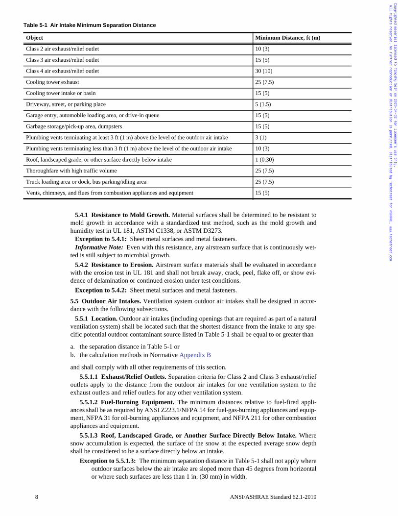
5.5.1 Location. Outdoor air intakes (including openings that are required as part of a naturalventilation system) shall be located such that the shortest distance from the intake to any spe-cific potential outdoor contaminant source listed in Table 5-1 shall be equal to or greater than
a. the separation distance in Table 5-1 orb. the calculation methods in Normative Appendix B
and shall comply with all other requirements of this section.5.5.1.1 Exhaust/Relief Outlets. Separation criteria for Class 2 and Class 3 exhaust/relief
outlets apply to the distance from the outdoor air intakes for one ventilation system to theexhaust outlets and relief outlets for any other ventilation system.
5.5.1.2 Fuel-Burning Equipment. The minimum distances relative to fuel-fired appli-ances shall be as required by ANSI Z223.1/NFPA 54 for fuel-gas-burning appliances and equip-ment, NFPA 31 for oil-burning appliances and equipment, and NFPA 211 for other combustionappliances and equipment.
5.5.1.3 Roof, Landscaped Grade, or Another Surface Directly Below Intake. Wheresnow accumulation is expected, the surface of the snow at the expected average snow depthshall be considered to be a surface directly below an intake.
Exception to 5.5.1.3: The minimum separation distance in Table 5-1 shall not apply whereoutdoor surfaces below the air intake are sloped more than 45 degrees from horizontalor where such surfaces are less than 1 in. (30 mm) in width.
Table 5-1 Air Intake Minimum Separation Distance
Object Minimum Distance, ft (m)
Class 2 air exhaust/relief outlet 10 (3)
Class 3 air exhaust/relief outlet 15 (5)
Class 4 air exhaust/relief outlet 30 (10)
Cooling tower exhaust 25 (7.5)
Cooling tower intake or basin 15 (5)
Driveway, street, or parking place 5 (1.5)
Garage entry, automobile loading area, or drive-in queue 15 (5)
Garbage storage/pick-up area, dumpsters 15 (5)
Plumbing vents terminating at least 3 ft (1 m) above the level of the outdoor air intake 3 (1)
Plumbing vents terminating less than 3 ft (1 m) above the level of the outdoor air intake 10 (3)
Roof, landscaped grade, or other surface directly below intake 1 (0.30)
Thoroughfare with high traffic volume 25 (7.5)
Truck loading area or dock, bus parking/idling area 25 (7.5)
Vents, chimneys, and flues from combustion appliances and equipment 15 (5)
8 ANSI/ASHRAE Standard 62.1-2019
Copyrighted material licensed to Timothy Self on 2020-04-02 for licensee's use only. All rights reserved. No further reproduction or distribution is permitted. Distributed by Techstreet for ASHRAE, www.techstreet.com
5.5.1.4 Laboratory Exhaust. Separation criteria for fume hood exhaust shall be in com-pliance with ANSI/AIHA Z9.5.
5.5.2 Rain Entrainment. Outdoor air intakes that are part of the mechanical ventilation sys-tem shall be designed to manage rain entrainment in accordance with one or more of the fol-lowing:
a. Limit water penetration through the intake to 0.07 oz/ft2·h (21.5 g/m2·h) of inlet area whentested using the rain test apparatus described in UL 1995, Section 58.
b. Select louvers that limit water penetration to a maximum of 0.01 oz/ft2 (3 g/m2) of louverfree area at the maximum intake velocity. This water penetration rate shall be determinedfor a minimum 15 minute test duration when subjected to a water flow rate of 0.25 gal/min(16 mL/s) as described under the water penetration test in AMCA 500-L or equivalent.Manage the water that penetrates the louver by providing a drainage area or moistureremoval devices.
c. Select louvers that restrict wind-driven rain penetration to less than 2.36 oz/ft2·h (721 g/m2·h) when subjected to a simulated rainfall of 3 in. (75 mm) per hour and a 29 mph (13 m/s) wind velocity at the design outdoor air intake rate with the air velocity calculated basedon the louver face area. (Informative Note: This performance corresponds to Class A (99%effectiveness) when rated according to AMCA 511 and tested per AMCA 500-L.)
d. Use rain hoods sized for no more than 500 fpm (2.5 m/s) face velocity with a downward-facing intake such that all intake air passes upward through a horizontal plane that inter-sects the solid surfaces of the hood before entering the system.
e. Manage the water that penetrates the intake opening by providing a drainage area or mois-ture removal devices.
5.5.3 Rain Intrusion. Air-handling and distribution equipment mounted outdoors shall bedesigned to prevent rain intrusion into the airstream when tested at design airflow and with noairflow, using the rain test apparatus described in UL 1995, Section 58.
5.5.4 Snow Entrainment. Where climate dictates, outdoor air intakes that are part of themechanical ventilation system shall be designed as follows to manage water from snow that isblown or drawn into the system:
a. Access doors to permit cleaning of wetted surfaces shall be provided.b. Outdoor air ductwork or plenums shall pitch to drains designed in accordance with the
requirements of Section 5.12.
5.5.5 Bird Screens. Outdoor air intakes shall include a screening device designed to preventpenetration by a 0.5 in. (13 mm) diameter probe. The screening device material shall be corro-sion resistant. The screening device shall be located, or other measures shall be taken, to pre-vent bird nesting within the outdoor air intake.
Informative Note: Any horizontal surface may be subject to bird nesting.
5.6 Local Capture of Contaminants. The discharge from noncombustion equipment thatcaptures the contaminants generated by the equipment shall be ducted directly to the outdoors.Exception to 5.6: Equipment specifically designed for discharge indoors in accordance with
the manufacturer recommendations.
5.7 Ozone Generating Devices. The use of ozone generating devices shall comply with thefollowing sections.Exception to 5.7: Electronic devices used exclusively for the operation of HVAC equipment
and controls.
Informative Note: Ozone generation is expected from ozone generators, corona dischargetechnology, some ultraviolet lights, electronic devices that create chemical reactions within thesystem, and some devices using a high voltage (>480 V). Motors and relays are examples ofelectronic devices that would be exempt.
5.7.1 Air-Cleaning Devices. Air-cleaning devices shall be listed and labeled in accordancewith UL 2998.
Informative Note: The use of devices not intended for air cleaning with the potential to gen-erate ozone should be avoided.
ANSI/ASHRAE Standard 62.1-2019 9
Copyrighted material licensed to Timothy Self on 2020-04-02 for licensee's use only. All rights reserved. No further reproduction or distribution is permitted. Distributed by Techstreet for ASHRAE, www.techstreet.com
5.7.2 Ultraviolet Devices. Ultraviolet generating devices in supply air or spaces shall nottransmit 185 nm wavelengths.
Informative Note: Ultraviolet devices used in treatment of closed water systems may pro-duce 185 nm wavelengths, which may generate ozone.
5.8 Combustion Air. Fuel-burning appliances, both vented and unvented, shall be providedwith air for combustion and removal of combustion products in accordance with manufacturerinstructions. Products of combustion from vented appliances shall be vented directly outdoors.
5.9 Particulate Matter Removal. Particulate matter filters or air cleaners having either
a. a MERV of not less than 8 where rated in accordance with ASHRAE Standard 52.2 or b. the minimum efficiency within ISO ePM10 where rated in accordance with ISO 16890
shall be provided upstream of all cooling coils or other devices with wetted surfaces throughwhich air is supplied to an occupiable space.Exception to 5.9: Cooling coils that are designed, controlled, and operated to provide sensible
cooling only.
5.10 Maximum Indoor Air Dew Point in Mechanically Cooled Buildings. Buildings orspaces equipped with or served by mechanical cooling equipment shall be provided with dehu-midification components and controls that limit the indoor humidity to a maximum dew pointof 60°F (15°C) during both occupied and unoccupied hours whenever the outdoor air dewpoint is above 60°F (15°C). The dew-point limit shall not be exceeded when system perfor-mance is analyzed with outdoor air at the dehumidification design condition (that is, designdew point and mean coincident dry-bulb temperatures) and with the space interior loads (bothsensible and latent) at cooling design values and space solar loads at zero.Exceptions to 5.10:
1. Buildings or spaces that are neither equipped with nor served by mechanical coolingequipment.
2. Buildings or spaces equipped with materials, assemblies, coatings, and furnishings thatresist microbial growth and that are not damaged by continuously high indoor air dewpoints.
3. During overnight unoccupied periods not exceeding 12 hours, the 60°F (15°C) dew-point limit shall not apply, provided that indoor relative humidity does not exceed 65%at any time during those hours.
Informative Notes: 1. Examples of spaces are shower rooms, swimming pool enclosures, kitchens, spa
rooms, or semicooled warehouse spaces that contain stored contents that are notdamaged by continuously high indoor air dew points or microbial growth.
2. This requirement reduces the risk of microbial growth in buildings and their intersti-tial spaces because it limits the mass of indoor water vapor that can condense or beabsorbed into mechanically cooled surfaces. The dew-point limit is explicitlyextended to unoccupied hours because of the extensive public record of moldgrowth in schools, apartments, dormitories, and public buildings that are intermit-tently cooled during unoccupied hours when the outdoor air dew point is above60°F (15°C).
5.11 Building Exfiltration. Ventilation systems for a building equipped with or served bymechanical cooling equipment shall be designed such that the total building outdoor air intakeequals or exceeds the total building exhaust under all load and dynamic reset conditions.
Exceptions to 5.11:
1. Where an imbalance is required by process considerations and approved by theauthority having jurisdiction (AHJ), such as in certain industrial facilities.
2. When outdoor air dry-bulb temperature is below the indoor space dew-point designtemperature.
Informative Note: Although individual zones within a building may be neutral or negativewith respect to outdoors or to other zones, net positive mechanical intake airflow for the build-ing as a whole reduces infiltration of untreated outdoor air.
10 ANSI/ASHRAE Standard 62.1-2019
Copyrighted material licensed to Timothy Self on 2020-04-02 for licensee's use only. All rights reserved. No further reproduction or distribution is permitted. Distributed by Techstreet for ASHRAE, www.techstreet.com
5.12 Drain Pans. Drain pans, including their outlets and seals, shall be designed and con-structed in accordance with this section.
5.12.1 Drain Pan Slope. Pans intended to collect and drain liquid water shall be sloped atleast 0.125 in./ft (10 mm/m) from the horizontal toward the drain outlet or shall be otherwisedesigned such that water drains freely from the pan whether the fan is ON or OFF.
5.12.2 Drain Outlet. The drain pan outlet shall be located at the lowest point(s) of the drainpan and shall be sized to preclude drain pan overflow under any normally expected operatingcondition.
5.12.3 Drain Seal. For configurations that result in negative static pressure at the drain panrelative to the drain outlet (such as a draw-through unit), the drain line shall include a P-trap orother sealing device designed to maintain a seal against ingestion of ambient air, while allow-ing complete drainage of the drain pan under any normally expected operating condition,whether the fan is ON or OFF.
5.12.4 Pan Size. The drain pan shall be located under the water producing device. Drain panwidth shall be sized to collect water droplets across the entire width of the water producingdevice or assembly. For horizontal airflow configurations, the drain pan length shall begin atthe leading face or edge of the water producing device or assembly and extend downstreamfrom the leaving face or edge to a distance of either
a. one half of the installed vertical dimension of the water producing device or assembly orb. as necessary to limit water droplet carryover beyond the drain pan to 0.0044 oz/ft2
(1.5 mL/m2) of face area per hour under peak sensible and peak dew-point design condi-tions, accounting for both latent load and coil face velocity.
5.13 Finned-Tube Coils and Heat Exchangers5.13.1 Drain Pans. A drain pan, in accordance with Section 5.12, shall be provided beneath
all dehumidifying cooling-coil assemblies and all condensate producing heat exchangers.5.13.2 Finned-Tube-Coil Selection for Cleaning. Individual finned-tube coils or multiple
finned-tube coils in series without intervening access spaces of at least 18 in. (457 mm) shallbe selected to result in no more than 0.75 in. of water (187 Pa) combined dry-coil pressure dropat 500 fpm (2.54 m/s) face velocity.5.14 Humidifiers and Water Spray Systems. Steam and direct-evaporative humidifiers, airwashers, direct-evaporative coolers, and other water spray systems shall be designed in accor-dance with this section.
5.14.1 Water Quality. Water purity shall meet or exceed potable water standards at the pointwhere it enters the ventilation system, space, or water vapor generator. Water vapor generatedshall contain no chemical additives other than those chemicals in a potable water system.
Exceptions to 5.14.1: 1. Water spray systems that use chemical additives that meet NSF/ANSI Standard 60,
Drinking Water Treatment Chemicals—Health Effects.2. Boiler water additives that meet the requirements of 21 CFR 173.310, Secondary
Direct Food Additives Permitted In Food For Human Consumption, and include auto-mated dosing devices.
5.14.2 Obstructions. Air cleaners or ductwork obstructions, such as turning vanes, volumedampers, and duct offsets greater than 15 degrees, that are installed downstream of humidifiersor water spray systems shall be located a distance equal to or greater than the absorption dis-tance recommended by the humidifier or water spray system manufacturer.
Exception 5.14.2: Equipment such as eliminators, coils, or evaporative media shall be per-mitted to be located within the absorption distance recommended by the manufacturer,provided a drain pan complying with the requirements of Section 5.12 is used to captureand remove any water that drops out of the airstream due to impingement on theseobstructions.
5.15 Access for Inspection, Cleaning, and Maintenance5.15.1 Equipment Clearance. Ventilation equipment shall be installed with working space
that will allow for inspection and routine maintenance, including filter replacement and fanbelt adjustment and replacement.
ANSI/ASHRAE Standard 62.1-2019 11
Copyrighted material licensed to Timothy Self on 2020-04-02 for licensee's use only. All rights reserved. No further reproduction or distribution is permitted. Distributed by Techstreet for ASHRAE, www.techstreet.com
5.15.2 Ventilation Equipment Access. Access doors, panels, or other means shall be pro-vided and sized to allow unobstructed access for inspection, maintenance, and calibration of allventilation system components for which routine inspection, maintenance, or calibration isnecessary. Ventilation system components include air-handling units, fan-coil units, water-source heat pumps, other terminal units, controllers, and sensors.
5.15.3 Air Distribution System. Access doors, panels, or other means shall be provided inventilation equipment, ductwork, and plenums, located and sized to allow convenient andunobstructed access for inspection, cleaning, and routine maintenance of the following:
a. Outdoor air intake areaways or plenumsb. Mixed-air plenumsc. Upstream surface of each heating, cooling, and heat-recovery coil or coil assembly having
a total of four rows or fewerd. Both upstream and downstream surface of each heating, cooling, and heat-recovery coil
having a total of more than four rows, and air washers, evaporative coolers, heat wheels,and other heat exchangers
e. Air cleanersf. Drain pans and drain sealsg. Fansh. Humidifiers
5.16 Building Envelope and Interior Surfaces. The building envelope and interior surfaceswithin the building envelope shall be designed in accordance with the following subsections.
5.16.1 Building Envelope. The building envelope, including roofs, walls, fenestration sys-tems, and foundations, shall comply with the following:
a. A weather barrier or other means shall be provided to prevent liquid-water penetration intothe envelope. Exception to 5.16.1(a): When the envelope is engineered to allow incidental water pene-
tration to occur without resulting in damage to the envelope construction.b. An appropriately placed vapor retarder or other means shall be provided to limit water
vapor diffusion to prevent condensation on cold surfaces within the envelope. Exception to 5.16.1(b): When the envelope is engineered to manage incidental condensa-
tion without resulting in damage to the envelope construction.c. Exterior joints, seams, or penetrations in the building envelope that are pathways for air
leakage shall be caulked, gasketed, weather stripped, provided with a continuous air bar-rier, or otherwise sealed to limit infiltration through the envelope to reduce uncontrolledentry of outdoor air moisture and pollutants.
Informative Note: In localities where soils contain high concentrations of radon or other soil-gas contaminants, the AHJ might impose additional measures such as subslab depressurization.
5.16.2 Condensation on Interior Surfaces. Pipes, ducts, and other surfaces within the build-ing whose surface temperatures are expected to fall below the surrounding dew-point tempera-ture shall be insulated. The insulation system thermal resistance and material characteristics shallprevent condensate from forming on the exposed surface and within the insulating material.
Exception to 5.16.2: Where condensate will wet only surfaces that will be managed to pre-vent or control mold growth. A management plan must be submitted along with thedesign specifying design assumptions and limits of the plan. The plan must be providedto the owner.
5.17 Buildings with Attached Parking Garages. In order to limit the entry of vehicularexhaust into occupiable spaces, buildings with attached parking garages shall be designed to
a. maintain the garage pressure at or below the pressure of the adjacent occupiable spaces,b. use a vestibule to provide an airlock between the garage and the adjacent occupiable spaces,
orc. otherwise limit migration of air from the attached parking garage into the adjacent occupia-
ble spaces of the building in a manner acceptable to the AHJ.
5.18 Air Classification and Recirculation. Air shall be classified, and its recirculation shallbe limited in accordance with the following subsections.
12 ANSI/ASHRAE Standard 62.1-2019
Copyrighted material licensed to Timothy Self on 2020-04-02 for licensee's use only. All rights reserved. No further reproduction or distribution is permitted. Distributed by Techstreet for ASHRAE, www.techstreet.com
5.18.1 Classification. Air (return, transfer, or exhaust air) leaving each space or location shallbe designated at an expected air-quality classification not less than that shown in Table 6-1, 6-2,or 6-3 or as approved by the AHJ. Air leaving spaces or locations that are not listed in Table 6-1,6-2, or 6-3 shall be designated with the same classification as air from the most similar space orlocation listed in terms of occupant activities and building construction.
Exception to 5.18.1: Air from spaces where environmental tobacco smoke (ETS) is present.(Classification of air from spaces where ETS is present is not addressed. Spaces that areexpected to include ETS do not have a classification listed in Table 6-1.)
Informative Note: Classifications in Tables 6-1, 6-2, and 6-3 are based on relative contami-nant concentration using the following subjective criteria:
1. Class 1: Air with low contaminant concentration, low sensory-irritation intensity,and inoffensive odor.
2. Class 2: Air with moderate contaminant concentration, mild sensory-irritation inten-sity, or mildly offensive odors. (Class 2 air also includes air that is not necessarilyharmful or objectionable but that is inappropriate for transfer or recirculation tospaces used for different purposes.)
3. Class 3: Air with significant contaminant concentration, significant sensory-irritationintensity, or offensive odor.
4. Class 4: Air with highly objectionable fumes or gases or with potentially dangerousparticles, bioaerosols, or gases, at concentrations high enough to be considered asharmful.
5.18.2 Redesignation5.18.2.1 Air Cleaning. If air leaving a space or location passes through an air-cleaning
system, redesignation of the cleaned air to a cleaner classification shall be permitted per thefollowing requirements:
a. Class 2 air where based on the subjective criteria in the informative note for Section5.18.1 and where approved by the AHJ.
b. Class 3 and Class 4 air when all requirements of Sections 6.3.1 through 6.3.4 are followed.
5.18.2.2 Transfer. A mixture of air that has been transferred through or returned fromspaces or locations with different air classes shall be redesignated with the highest classifica-tion among the air classes mixed.
Informative Note: For example, mixed return air to a common system serving both a Class 1space and a Class 2 space is designated as Class 2 air.
5.18.2.3 Ancillary Spaces. Redesignation of Class 1 air to Class 2 air shall be permittedfor Class 1 spaces that are ancillary to Class 2 spaces.
Informative Note: For example, an office within a restaurant might be designated as a spaceancillary to a Class 2 space, thus enabling the office to receive Class 2 air.
5.18.3 Recirculation Limitations. When the Ventilation Rate Procedure of Section 6 is usedto determine ventilation airflow values, recirculation of air shall be limited in accordance withthe requirements of this section.
5.18.3.1 Class 1 Air. Recirculation or transfer of Class 1 air to any space shall be permitted.5.18.3.2 Class 2 Air
5.18.3.2.1 Recirculation of Class 2 air within the space of origin shall be permitted.5.18.3.2.2 Recirculation or transfer of Class 2 air to other Class 2 or Class 3 spaces shall
be permitted, provided that the other spaces are used for the same or similar purpose or taskand involve the same or similar pollutant sources as the Class 2 space.
5.18.3.2.3 Transfer of Class 2 air to toilet rooms shall be permitted.5.18.3.2.4 Recirculation or transfer of Class 2 air to Class 4 spaces shall be permitted.5.18.3.2.5 Class 2 air shall not be recirculated or transferred to Class 1 spaces.Exception to 5.18.3.2.5: When using any energy recovery device, recirculation from leak-
age, carryover, or transfer from the exhaust side of the energy recovery device is per-mitted. Recirculated Class 2 air shall not exceed 10% of the outdoor air intake flow.
5.18.3.3 Class 3 Air5.18.3.3.1 Recirculation of Class 3 air within the space of origin shall be permitted.
ANSI/ASHRAE Standard 62.1-2019 13
Copyrighted material licensed to Timothy Self on 2020-04-02 for licensee's use only. All rights reserved. No further reproduction or distribution is permitted. Distributed by Techstreet for ASHRAE, www.techstreet.com
5.18.3.3.2 Class 3 air shall not be recirculated or transferred to any other space.Exception to 5.18.3.3.2: When using any energy recovery device, recirculation from
leakage, carryover, or transfer from the exhaust side of the energy recovery device ispermitted. Recirculated Class 3 air shall not exceed 5% of the outdoor air intake flow.
5.18.3.4 Class 4 Air. Class 4 air shall not be recirculated or transferred to any space orrecirculated within the space of origin.
5.18.4 Documentation. Design documentation shall indicate the justification for classificationof air from any occupancy category, airstream, or location not listed in Table 6-1, 6-2, or 6-3.
5.19 Requirements for Buildings Containing ETS Areas and ETS-Free Areas. Therequirements of this section must be met when a building contains both ETS areas and ETS-free areas. Such buildings shall be constructed and operated in accordance with Sections 5.19.1through 5.19.8. This section does not purport to achieve acceptable IAQ in ETS areas.
5.19.1 Classification. All spaces shall be classified as either ETS-free areas or ETS areas.5.19.2 Pressurization. ETS-free areas shall be at a positive pressure with respect to any
adjacent or connected ETS areas. Exceptions to 5.19.2:
1. Dwelling units, including hotel and motel guestrooms, and adjacent properties underdifferent ownership with separation walls that are structurally independent and thatcontain no openings. This exception shall apply only whena. the separation walls are constructed as smoke barriers in accordance with the
requirements of applicable standards; b. the separation walls include an air barrier consisting of a continuous membrane or
surface treatment in the separation wall that has documented resistance to air leak-age—continuity of the barrier shall be maintained at openings for pipes, ducts, andother conduits and at points where the barrier meets the outside walls and otherbarriers; and
c. interior corridors common to ETS and ETS-free areas are mechanically suppliedwith outdoor air at the rate of 0.1 cfm/ft2 (0.5 L/s·m2).
2. Adjacent spaces otherwise required to be held at negative pressure and posted withsigns due to the presence of hazardous or flammable materials or vapors.
Informative Note: Examples of methods for demonstrating relative pressure include engi-neering analysis, pressure differential measurement, and airflow measurement.
5.19.3 Separation. Solid walls, floors, ceilings, and doors equipped with automatic closingmechanisms shall separate ETS areas from ETS-free areas.
Exception to 5.19.3: Openings without doors are permitted in the separation where engi-neered systems are designed to provide airflow from ETS-free areas into ETS areas, not-withstanding eddies that may occur in the immediate vicinity of the boundary betweenthe ETS and ETS-free areas and reverse flow that may occur due to short-term condi-tions such as wind gusts.
Informative Note: Examples of methods for demonstrating air motion are engineering anal-ysis and the use of a directional airflow indicator at representative locations in the opening,such as on 1 ft (0.3 m) centers or at locations required for duct traverses in standard testing andbalancing procedures, such as those described in ASHRAE Standard 111.
5.19.4 Transfer Air. When air is transferred from ETS-free areas to ETS areas, the transferairflow rate shall be maintained regardless of whether operable doors or windows betweenETS-free and ETS areas are opened or closed. Acceptable means of doing so include fixedopenings in doors, walls, or floors, transfer grilles, transfer ducts, or unducted air plenums withair pressure differentials in compliance with Section 5.19.2.
5.19.5 Recirculation. Air-handling and natural ventilation systems shall not recirculate ortransfer air from an ETS area to an ETS-free area.
5.19.6 Exhaust Systems. Exhaust or relief air from an ETS area shall be discharged suchthat none of the air is recirculated back into any ETS-free area.
14 ANSI/ASHRAE Standard 62.1-2019
Copyrighted material licensed to Timothy Self on 2020-04-02 for licensee's use only. All rights reserved. No further reproduction or distribution is permitted. Distributed by Techstreet for ASHRAE, www.techstreet.com
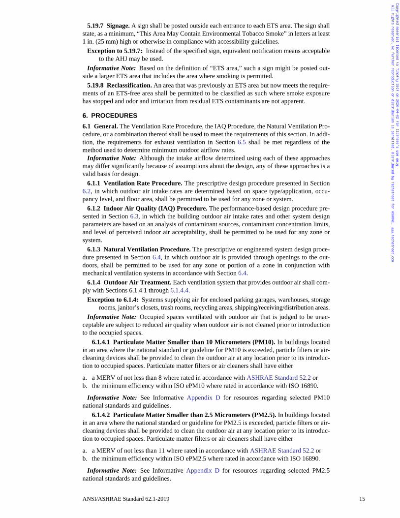
5.19.7 Signage. A sign shall be posted outside each entrance to each ETS area. The sign shallstate, as a minimum, “This Area May Contain Environmental Tobacco Smoke” in letters at least1 in. (25 mm) high or otherwise in compliance with accessibility guidelines.
Exception to 5.19.7: Instead of the specified sign, equivalent notification means acceptableto the AHJ may be used.
Informative Note: Based on the definition of “ETS area,” such a sign might be posted out-side a larger ETS area that includes the area where smoking is permitted.
5.19.8 Reclassification. An area that was previously an ETS area but now meets the require-ments of an ETS-free area shall be permitted to be classified as such where smoke exposurehas stopped and odor and irritation from residual ETS contaminants are not apparent.
6. PROCEDURES
6.1 General. The Ventilation Rate Procedure, the IAQ Procedure, the Natural Ventilation Pro-cedure, or a combination thereof shall be used to meet the requirements of this section. In addi-tion, the requirements for exhaust ventilation in Section 6.5 shall be met regardless of themethod used to determine minimum outdoor airflow rates.
Informative Note: Although the intake airflow determined using each of these approachesmay differ significantly because of assumptions about the design, any of these approaches is avalid basis for design.
6.1.1 Ventilation Rate Procedure. The prescriptive design procedure presented in Section6.2, in which outdoor air intake rates are determined based on space type/application, occu-pancy level, and floor area, shall be permitted to be used for any zone or system.
6.1.2 Indoor Air Quality (IAQ) Procedure. The performance-based design procedure pre-sented in Section 6.3, in which the building outdoor air intake rates and other system designparameters are based on an analysis of contaminant sources, contaminant concentration limits,and level of perceived indoor air acceptability, shall be permitted to be used for any zone orsystem.
6.1.3 Natural Ventilation Procedure. The prescriptive or engineered system design proce-dure presented in Section 6.4, in which outdoor air is provided through openings to the out-doors, shall be permitted to be used for any zone or portion of a zone in conjunction withmechanical ventilation systems in accordance with Section 6.4.
6.1.4 Outdoor Air Treatment. Each ventilation system that provides outdoor air shall com-ply with Sections 6.1.4.1 through 6.1.4.4.
Exception to 6.1.4: Systems supplying air for enclosed parking garages, warehouses, storagerooms, janitor’s closets, trash rooms, recycling areas, shipping/receiving/distribution areas.
Informative Note: Occupied spaces ventilated with outdoor air that is judged to be unac-ceptable are subject to reduced air quality when outdoor air is not cleaned prior to introductionto the occupied spaces.
6.1.4.1 Particulate Matter Smaller than 10 Micrometers (PM10). In buildings locatedin an area where the national standard or guideline for PM10 is exceeded, particle filters or air-cleaning devices shall be provided to clean the outdoor air at any location prior to its introduc-tion to occupied spaces. Particulate matter filters or air cleaners shall have either
a. a MERV of not less than 8 where rated in accordance with ASHRAE Standard 52.2 orb. the minimum efficiency within ISO ePM10 where rated in accordance with ISO 16890.
Informative Note: See Informative Appendix D for resources regarding selected PM10national standards and guidelines.
6.1.4.2 Particulate Matter Smaller than 2.5 Micrometers (PM2.5). In buildings locatedin an area where the national standard or guideline for PM2.5 is exceeded, particle filters or air-cleaning devices shall be provided to clean the outdoor air at any location prior to its introduc-tion to occupied spaces. Particulate matter filters or air cleaners shall have either
a. a MERV of not less than 11 where rated in accordance with ASHRAE Standard 52.2 orb. the minimum efficiency within ISO ePM2.5 where rated in accordance with ISO 16890.
Informative Note: See Informative Appendix D for resources regarding selected PM2.5national standards and guidelines.
ANSI/ASHRAE Standard 62.1-2019 15
Copyrighted material licensed to Timothy Self on 2020-04-02 for licensee's use only. All rights reserved. No further reproduction or distribution is permitted. Distributed by Techstreet for ASHRAE, www.techstreet.com
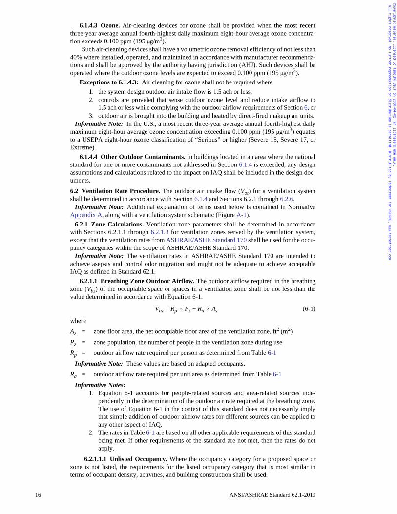
6.1.4.3 Ozone. Air-cleaning devices for ozone shall be provided when the most recentthree-year average annual fourth-highest daily maximum eight-hour average ozone concentra-tion exceeds 0.100 ppm (195 μg/m3).
Such air-cleaning devices shall have a volumetric ozone removal efficiency of not less than40% where installed, operated, and maintained in accordance with manufacturer recommenda-tions and shall be approved by the authority having jurisdiction (AHJ). Such devices shall beoperated where the outdoor ozone levels are expected to exceed 0.100 ppm (195 μg/m3).
Exceptions to 6.1.4.3: Air cleaning for ozone shall not be required where1. the system design outdoor air intake flow is 1.5 ach or less,2. controls are provided that sense outdoor ozone level and reduce intake airflow to
1.5 ach or less while complying with the outdoor airflow requirements of Section 6, or3. outdoor air is brought into the building and heated by direct-fired makeup air units.
Informative Note: In the U.S., a most recent three-year average annual fourth-highest dailymaximum eight-hour average ozone concentration exceeding 0.100 ppm (195 μg/m3) equatesto a USEPA eight-hour ozone classification of “Serious” or higher (Severe 15, Severe 17, orExtreme).
6.1.4.4 Other Outdoor Contaminants. In buildings located in an area where the nationalstandard for one or more contaminants not addressed in Section 6.1.4 is exceeded, any designassumptions and calculations related to the impact on IAQ shall be included in the design doc-uments.
6.2 Ventilation Rate Procedure. The outdoor air intake flow (Vot) for a ventilation systemshall be determined in accordance with Section 6.1.4 and Sections 6.2.1 through 6.2.6.
Informative Note: Additional explanation of terms used below is contained in NormativeAppendix A, along with a ventilation system schematic (Figure A-1).
6.2.1 Zone Calculations. Ventilation zone parameters shall be determined in accordancewith Sections 6.2.1.1 through 6.2.1.3 for ventilation zones served by the ventilation system,except that the ventilation rates from ASHRAE/ASHE Standard 170 shall be used for the occu-pancy categories within the scope of ASHRAE/ASHE Standard 170.
Informative Note: The ventilation rates in ASHRAE/ASHE Standard 170 are intended toachieve asepsis and control odor migration and might not be adequate to achieve acceptableIAQ as defined in Standard 62.1.
6.2.1.1 Breathing Zone Outdoor Airflow. The outdoor airflow required in the breathingzone (Vbz) of the occupiable space or spaces in a ventilation zone shall be not less than thevalue determined in accordance with Equation 6-1.
Vbz = Rp × Pz + Ra × Az (6-1)
where
Az = zone floor area, the net occupiable floor area of the ventilation zone, ft2 (m2)
Pz = zone population, the number of people in the ventilation zone during use
Rp = outdoor airflow rate required per person as determined from Table 6-1
Informative Note: These values are based on adapted occupants.
Ra = outdoor airflow rate required per unit area as determined from Table 6-1
Informative Notes: 1. Equation 6-1 accounts for people-related sources and area-related sources inde-
pendently in the determination of the outdoor air rate required at the breathing zone.The use of Equation 6-1 in the context of this standard does not necessarily implythat simple addition of outdoor airflow rates for different sources can be applied toany other aspect of IAQ.
2. The rates in Table 6-1 are based on all other applicable requirements of this standardbeing met. If other requirements of the standard are not met, then the rates do notapply.
6.2.1.1.1 Unlisted Occupancy. Where the occupancy category for a proposed space orzone is not listed, the requirements for the listed occupancy category that is most similar interms of occupant density, activities, and building construction shall be used.
16 ANSI/ASHRAE Standard 62.1-2019
Copyrighted material licensed to Timothy Self on 2020-04-02 for licensee's use only. All rights reserved. No further reproduction or distribution is permitted. Distributed by Techstreet for ASHRAE, www.techstreet.com
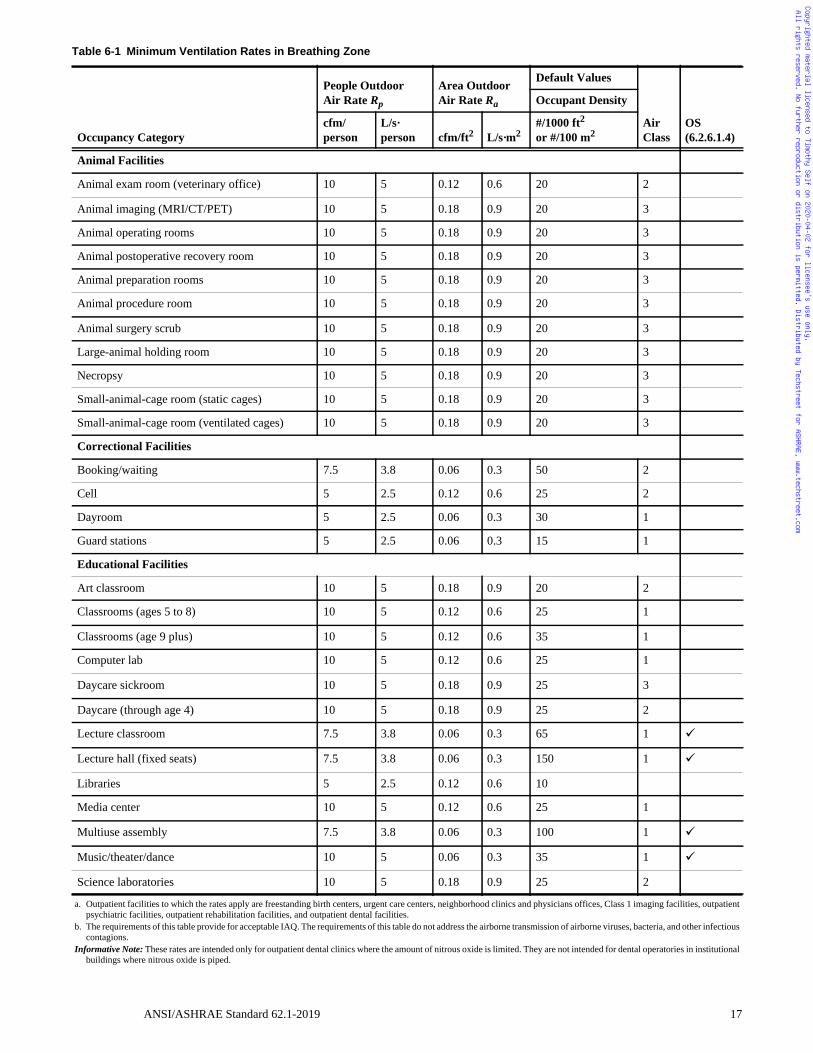
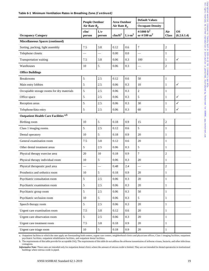
Table 6-1 Minimum Ventilation Rates in Breathing Zone
Occupancy Category
People Outdoor Air Rate Rp
Area Outdoor Air Rate Ra
Default Values
Air Class
OS(6.2.6.1.4)
Occupant Density
cfm/person
L/s·person cfm/ft2 L/s·m2
#/1000 ft2
or #/100 m2
Animal Facilities
Animal exam room (veterinary office) 10 5 0.12 0.6 20 2
Animal imaging (MRI/CT/PET) 10 5 0.18 0.9 20 3
Animal operating rooms 10 5 0.18 0.9 20 3
Animal postoperative recovery room 10 5 0.18 0.9 20 3
Animal preparation rooms 10 5 0.18 0.9 20 3
Animal procedure room 10 5 0.18 0.9 20 3
Animal surgery scrub 10 5 0.18 0.9 20 3
Large-animal holding room 10 5 0.18 0.9 20 3
Necropsy 10 5 0.18 0.9 20 3
Small-animal-cage room (static cages) 10 5 0.18 0.9 20 3
Small-animal-cage room (ventilated cages) 10 5 0.18 0.9 20 3
Correctional Facilities
Booking/waiting 7.5 3.8 0.06 0.3 50 2
Cell 5 2.5 0.12 0.6 25 2
Dayroom 5 2.5 0.06 0.3 30 1
Guard stations 5 2.5 0.06 0.3 15 1
Educational Facilities
Art classroom 10 5 0.18 0.9 20 2
Classrooms (ages 5 to 8) 10 5 0.12 0.6 25 1
Classrooms (age 9 plus) 10 5 0.12 0.6 35 1
Computer lab 10 5 0.12 0.6 25 1
Daycare sickroom 10 5 0.18 0.9 25 3
Daycare (through age 4) 10 5 0.18 0.9 25 2
Lecture classroom 7.5 3.8 0.06 0.3 65 1
Lecture hall (fixed seats) 7.5 3.8 0.06 0.3 150 1
Libraries 5 2.5 0.12 0.6 10
Media center 10 5 0.12 0.6 25 1
Multiuse assembly 7.5 3.8 0.06 0.3 100 1
Music/theater/dance 10 5 0.06 0.3 35 1
Science laboratories 10 5 0.18 0.9 25 2
a. Outpatient facilities to which the rates apply are freestanding birth centers, urgent care centers, neighborhood clinics and physicians offices, Class 1 imaging facilities, outpatientpsychiatric facilities, outpatient rehabilitation facilities, and outpatient dental facilities.
b. The requirements of this table provide for acceptable IAQ. The requirements of this table do not address the airborne transmission of airborne viruses, bacteria, and other infectiouscontagions.
Informative Note: These rates are intended only for outpatient dental clinics where the amount of nitrous oxide is limited. They are not intended for dental operatories in institutionalbuildings where nitrous oxide is piped.
ANSI/ASHRAE Standard 62.1-2019 17
Copyrighted material licensed to Timothy Self on 2020-04-02 for licensee's use only. All rights reserved. No further reproduction or distribution is permitted. Distributed by Techstreet for ASHRAE, www.techstreet.com
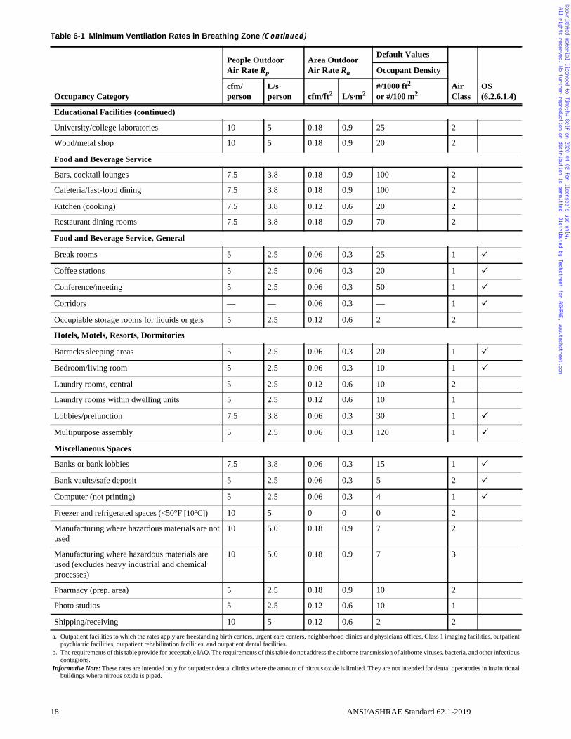
Educational Facilities (continued)
University/college laboratories 10 5 0.18 0.9 25 2
Wood/metal shop 10 5 0.18 0.9 20 2
Food and Beverage Service
Bars, cocktail lounges 7.5 3.8 0.18 0.9 100 2
Cafeteria/fast-food dining 7.5 3.8 0.18 0.9 100 2
Kitchen (cooking) 7.5 3.8 0.12 0.6 20 2
Restaurant dining rooms 7.5 3.8 0.18 0.9 70 2
Food and Beverage Service, General
Break rooms 5 2.5 0.06 0.3 25 1
Coffee stations 5 2.5 0.06 0.3 20 1
Conference/meeting 5 2.5 0.06 0.3 50 1
Corridors — — 0.06 0.3 — 1
Occupiable storage rooms for liquids or gels 5 2.5 0.12 0.6 2 2
Hotels, Motels, Resorts, Dormitories
Barracks sleeping areas 5 2.5 0.06 0.3 20 1
Bedroom/living room 5 2.5 0.06 0.3 10 1
Laundry rooms, central 5 2.5 0.12 0.6 10 2
Laundry rooms within dwelling units 5 2.5 0.12 0.6 10 1
Lobbies/prefunction 7.5 3.8 0.06 0.3 30 1
Multipurpose assembly 5 2.5 0.06 0.3 120 1
Miscellaneous Spaces
Banks or bank lobbies 7.5 3.8 0.06 0.3 15 1
Bank vaults/safe deposit 5 2.5 0.06 0.3 5 2
Computer (not printing) 5 2.5 0.06 0.3 4 1
Freezer and refrigerated spaces (<50°F [10°C]) 10 5 0 0 0 2
Manufacturing where hazardous materials are not used
10 5.0 0.18 0.9 7 2
Manufacturing where hazardous materials are used (excludes heavy industrial and chemical processes)
10 5.0 0.18 0.9 7 3
Pharmacy (prep. area) 5 2.5 0.18 0.9 10 2
Photo studios 5 2.5 0.12 0.6 10 1
Shipping/receiving 10 5 0.12 0.6 2 2
Table 6-1 Minimum Ventilation Rates in Breathing Zone (Continued)
Occupancy Category
People Outdoor Air Rate Rp
Area Outdoor Air Rate Ra
Default Values
Air Class
OS(6.2.6.1.4)
Occupant Density
cfm/person
L/s·person cfm/ft2 L/s·m2
#/1000 ft2
or #/100 m2
a. Outpatient facilities to which the rates apply are freestanding birth centers, urgent care centers, neighborhood clinics and physicians offices, Class 1 imaging facilities, outpatientpsychiatric facilities, outpatient rehabilitation facilities, and outpatient dental facilities.
b. The requirements of this table provide for acceptable IAQ. The requirements of this table do not address the airborne transmission of airborne viruses, bacteria, and other infectiouscontagions.
Informative Note: These rates are intended only for outpatient dental clinics where the amount of nitrous oxide is limited. They are not intended for dental operatories in institutionalbuildings where nitrous oxide is piped.
18 ANSI/ASHRAE Standard 62.1-2019
Copyrighted material licensed to Timothy Self on 2020-04-02 for licensee's use only. All rights reserved. No further reproduction or distribution is permitted. Distributed by Techstreet for ASHRAE, www.techstreet.com
Miscellaneous Spaces (continued)
Sorting, packing, light assembly 7.5 3.8 0.12 0.6 7 2
Telephone closets — — 0.00 0.0 — 1
Transportation waiting 7.5 3.8 0.06 0.3 100 1
Warehouses 10 5 0.06 0.3 — 2
Office Buildings
Breakrooms 5 2.5 0.12 0.6 50 1
Main entry lobbies 5 2.5 0.06 0.3 10 1
Occupiable storage rooms for dry materials 5 2.5 0.06 0.3 2 1
Office space 5 2.5 0.06 0.3 5 1
Reception areas 5 2.5 0.06 0.3 30 1
Telephone/data entry 5 2.5 0.06 0.3 60 1
Outpatient Health Care Facilities a,b
Birthing room 10 5 0.18 0.9 15 2
Class 1 imaging rooms 5 2.5 0.12 0.6 5 1
Dental operatory 10 5 0.18 0.9 20 1
General examination room 7.5 3.8 0.12 0.6 20 1
Other dental treatment areas 5 2.5 0.06 0.3 5 1
Physical therapy exercise area 20 10 0.18 0.9 7 2
Physical therapy individual room 10 5 0.06 0.3 20 1
Physical therapeutic pool area — — 0.48 2.4 — 2
Prosthetics and orthotics room 10 5 0.18 0.9 20 1
Psychiatric consultation room 5 2.5 0.06 0.3 20 1
Psychiatric examination room 5 2.5 0.06 0.3 20 1
Psychiatric group room 5 2.5 0.06 0.3 50 1
Psychiatric seclusion room 10 5 0.06 0.3 5 1
Speech therapy room 5 2.5 0.06 0.3 20 1
Urgent care examination room 7.5 3.8 0.12 0.6 20 1
Urgent care observation room 5 2.5 0.06 0.3 20 1
Urgent care treatment room 7.5 3.8 0.18 0.9 20 1
Urgent care triage room 10 5 0.18 0.9 20 1
Table 6-1 Minimum Ventilation Rates in Breathing Zone (Continued)
Occupancy Category
People Outdoor Air Rate Rp
Area Outdoor Air Rate Ra
Default Values
Air Class
OS(6.2.6.1.4)
Occupant Density
cfm/person
L/s·person cfm/ft2 L/s·m2
#/1000 ft2
or #/100 m2
a. Outpatient facilities to which the rates apply are freestanding birth centers, urgent care centers, neighborhood clinics and physicians offices, Class 1 imaging facilities, outpatientpsychiatric facilities, outpatient rehabilitation facilities, and outpatient dental facilities.
b. The requirements of this table provide for acceptable IAQ. The requirements of this table do not address the airborne transmission of airborne viruses, bacteria, and other infectiouscontagions.
Informative Note: These rates are intended only for outpatient dental clinics where the amount of nitrous oxide is limited. They are not intended for dental operatories in institutionalbuildings where nitrous oxide is piped.
ANSI/ASHRAE Standard 62.1-2019 19
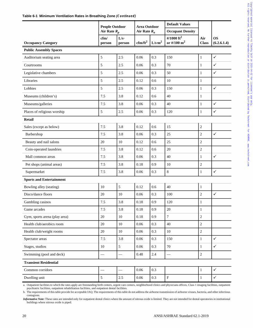
Copyrighted material licensed to Timothy Self on 2020-04-02 for licensee's use only. All rights reserved. No further reproduction or distribution is permitted. Distributed by Techstreet for ASHRAE, www.techstreet.com
Public Assembly Spaces
Auditorium seating area 5 2.5 0.06 0.3 150 1
Courtrooms 5 2.5 0.06 0.3 70 1
Legislative chambers 5 2.5 0.06 0.3 50 1
Libraries 5 2.5 0.12 0.6 10 1
Lobbies 5 2.5 0.06 0.3 150 1
Museums (children’s) 7.5 3.8 0.12 0.6 40 1
Museums/galleries 7.5 3.8 0.06 0.3 40 1
Places of religious worship 5 2.5 0.06 0.3 120 1
Retail
Sales (except as below) 7.5 3.8 0.12 0.6 15 2
Barbershop 7.5 3.8 0.06 0.3 25 2
Beauty and nail salons 20 10 0.12 0.6 25 2
Coin-operated laundries 7.5 3.8 0.12 0.6 20 2
Mall common areas 7.5 3.8 0.06 0.3 40 1
Pet shops (animal areas) 7.5 3.8 0.18 0.9 10 2
Supermarket 7.5 3.8 0.06 0.3 8 1
Sports and Entertainment
Bowling alley (seating) 10 5 0.12 0.6 40 1
Disco/dance floors 20 10 0.06 0.3 100 2
Gambling casinos 7.5 3.8 0.18 0.9 120 1
Game arcades 7.5 3.8 0.18 0.9 20 1
Gym, sports arena (play area) 20 10 0.18 0.9 7 2
Health club/aerobics room 20 10 0.06 0.3 40 2
Health club/weight rooms 20 10 0.06 0.3 10 2
Spectator areas 7.5 3.8 0.06 0.3 150 1
Stages, studios 10 5 0.06 0.3 70 1
Swimming (pool and deck) — — 0.48 2.4 — 2
Transient Residential
Common corridors — — 0.06 0.3 1
Dwelling unit 5 2.5 0.06 0.3 F 1
Table 6-1 Minimum Ventilation Rates in Breathing Zone (Continued)
Occupancy Category
People Outdoor Air Rate Rp
Area Outdoor Air Rate Ra
Default Values
Air Class
OS(6.2.6.1.4)
Occupant Density
cfm/person
L/s·person cfm/ft2 L/s·m2
#/1000 ft2
or #/100 m2
a. Outpatient facilities to which the rates apply are freestanding birth centers, urgent care centers, neighborhood clinics and physicians offices, Class 1 imaging facilities, outpatientpsychiatric facilities, outpatient rehabilitation facilities, and outpatient dental facilities.
b. The requirements of this table provide for acceptable IAQ. The requirements of this table do not address the airborne transmission of airborne viruses, bacteria, and other infectiouscontagions.
Informative Note: These rates are intended only for outpatient dental clinics where the amount of nitrous oxide is limited. They are not intended for dental operatories in institutionalbuildings where nitrous oxide is piped.
20 ANSI/ASHRAE Standard 62.1-2019
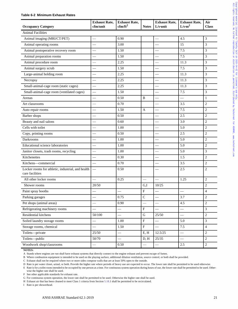
Copyrighted material licensed to Timothy Self on 2020-04-02 for licensee's use only. All rights reserved. No further reproduction or distribution is permitted. Distributed by Techstreet for ASHRAE, www.techstreet.com
Table 6-2 Minimum Exhaust Rates
Occupancy CategoryExhaust Rate, cfm/unit
Exhaust Rate, cfm/ft2 Notes
Exhaust Rate,L/s·unit
Exhaust Rate, L/s·m2
Air Class
Animal Facilities
Animal imaging (MRI/CT/PET) — 0.90 — 4.5 3
Animal operating rooms — 3.00 — 15 3
Animal postoperative recovery room — 1.50 — 7.5 3
Animal preparation rooms — 1.50 — 7.5 3
Animal procedure room — 2.25 — 11.3 3
Animal surgery scrub — 1.50 — 7.5 3
Large-animal holding room — 2.25 — 11.3 3
Necropsy — 2.25 — 11.3 3
Small-animal-cage room (static cages) — 2.25 — 11.3 3
Small-animal-cage room (ventilated cages) — 1.50 — 7.5 3
Arenas — 0.50 B — — 1
Art classrooms — 0.70 — 3.5 2
Auto repair rooms — 1.50 A — 7.5 2
Barber shops — 0.50 — 2.5 2
Beauty and nail salons — 0.60 — 3.0 2
Cells with toilet — 1.00 — 5.0 2
Copy, printing rooms — 0.50 — 2.5 2
Darkrooms — 1.00 — 5.0 2
Educational science laboratories — 1.00 — 5.0 2
Janitor closets, trash rooms, recycling — 1.00 — 5.0 3
Kitchenettes — 0.30 — 1.5 2
Kitchens—commercial — 0.70 — 3.5 2
Locker rooms for athletic, industrial, and health care facilities
— 0.50 — 2.5 2
All other locker rooms — 0.25 — — 1.25 2
Shower rooms 20/50 G,I 10/25 2
Paint spray booths — — F — — 4
Parking garages — 0.75 C — 3.7 2
Pet shops (animal areas) — 0.90 — — 4.5 2
Refrigerating machinery rooms — — F — — 3
Residential kitchens 50/100 — G 25/50 — 2
Soiled laundry storage rooms — 1.00 F — 5.0 3
Storage rooms, chemical — 1.50 F — 7.5 4
Toilets—private 25/50 — E, H 12.5/25 — 2
Toilets—public 50/70 — D, H 25/35 — 2
Woodwork shop/classrooms — 0.50 — — 2.5 2NOTES:A Stands where engines are run shall have exhaust systems that directly connect to the engine exhaust and prevent escape of fumes.B Where combustion equipment is intended to be used on the playing surface, additional dilution ventilation, source control, or both shall be provided.C Exhaust shall not be required where two or more sides compose walls that are at least 50% open to the outside.D Rate is per water closet, urinal, or both. Provide the higher rate where periods of heavy use are expected to occur. The lower rate shall be permitted to be used otherwise.E Rate is for a toilet room intended to be occupied by one person at a time. For continuous system operation during hours of use, the lower rate shall be permitted to be used. Other-
wise the higher rate shall be used.F See other applicable standards for exhaust rate.G For continuous system operation, the lower rate shall be permitted to be used. Otherwise the higher rate shall be used.H Exhaust air that has been cleaned to meet Class 1 criteria from Section 5.18.1 shall be permitted to be recirculated.I Rate is per showerhead.
ANSI/ASHRAE Standard 62.1-2019 21
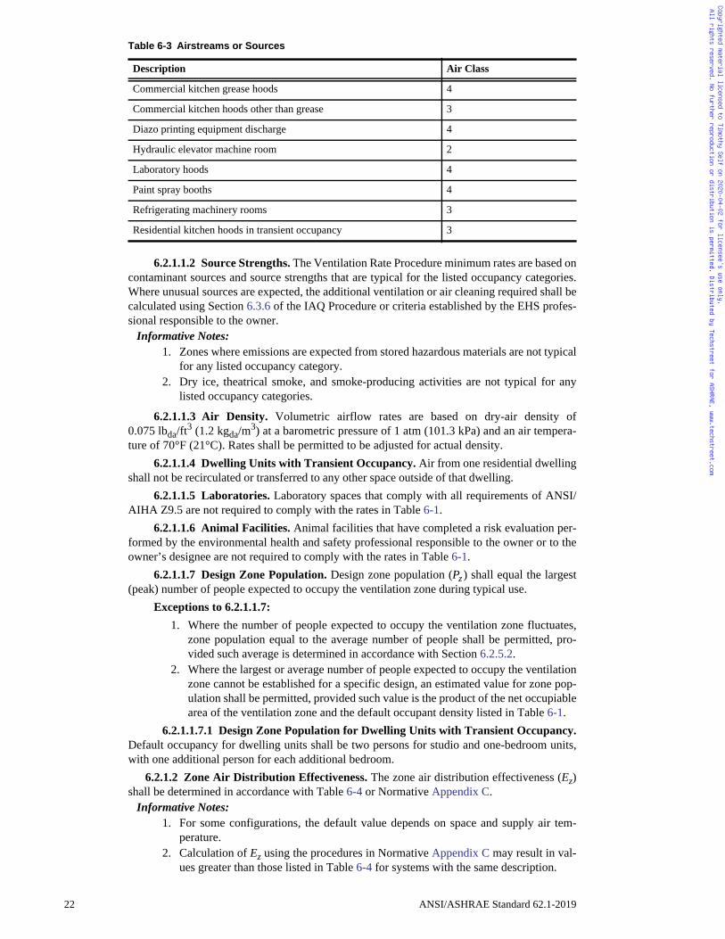
Copyrighted material licensed to Timothy Self on 2020-04-02 for licensee's use only. All rights reserved. No further reproduction or distribution is permitted. Distributed by Techstreet for ASHRAE, www.techstreet.com
6.2.1.1.2 Source Strengths. The Ventilation Rate Procedure minimum rates are based oncontaminant sources and source strengths that are typical for the listed occupancy categories.Where unusual sources are expected, the additional ventilation or air cleaning required shall becalculated using Section 6.3.6 of the IAQ Procedure or criteria established by the EHS profes-sional responsible to the owner.
Informative Notes: 1. Zones where emissions are expected from stored hazardous materials are not typical
for any listed occupancy category. 2. Dry ice, theatrical smoke, and smoke-producing activities are not typical for any
listed occupancy categories.
6.2.1.1.3 Air Density. Volumetric airflow rates are based on dry-air density of0.075 lbda/ft
3 (1.2 kgda/m3) at a barometric pressure of 1 atm (101.3 kPa) and an air tempera-
ture of 70°F (21°C). Rates shall be permitted to be adjusted for actual density. 6.2.1.1.4 Dwelling Units with Transient Occupancy. Air from one residential dwelling
shall not be recirculated or transferred to any other space outside of that dwelling.6.2.1.1.5 Laboratories. Laboratory spaces that comply with all requirements of ANSI/
AIHA Z9.5 are not required to comply with the rates in Table 6-1.6.2.1.1.6 Animal Facilities. Animal facilities that have completed a risk evaluation per-
formed by the environmental health and safety professional responsible to the owner or to theowner’s designee are not required to comply with the rates in Table 6-1.
6.2.1.1.7 Design Zone Population. Design zone population (Pz ) shall equal the largest(peak) number of people expected to occupy the ventilation zone during typical use.
Exceptions to 6.2.1.1.7: 1. Where the number of people expected to occupy the ventilation zone fluctuates,
zone population equal to the average number of people shall be permitted, pro-vided such average is determined in accordance with Section 6.2.5.2.
2. Where the largest or average number of people expected to occupy the ventilationzone cannot be established for a specific design, an estimated value for zone pop-ulation shall be permitted, provided such value is the product of the net occupiablearea of the ventilation zone and the default occupant density listed in Table 6-1.
6.2.1.1.7.1 Design Zone Population for Dwelling Units with Transient Occupancy.Default occupancy for dwelling units shall be two persons for studio and one-bedroom units,with one additional person for each additional bedroom.
6.2.1.2 Zone Air Distribution Effectiveness. The zone air distribution effectiveness (Ez)shall be determined in accordance with Table 6-4 or Normative Appendix C.
Informative Notes: 1. For some configurations, the default value depends on space and supply air tem-
perature.2. Calculation of Ez using the procedures in Normative Appendix C may result in val-
ues greater than those listed in Table 6-4 for systems with the same description.
Table 6-3 Airstreams or Sources
Description Air Class
Commercial kitchen grease hoods 4
Commercial kitchen hoods other than grease 3
Diazo printing equipment discharge 4
Hydraulic elevator machine room 2
Laboratory hoods 4
Paint spray booths 4
Refrigerating machinery rooms 3
Residential kitchen hoods in transient occupancy 3
22 ANSI/ASHRAE Standard 62.1-2019
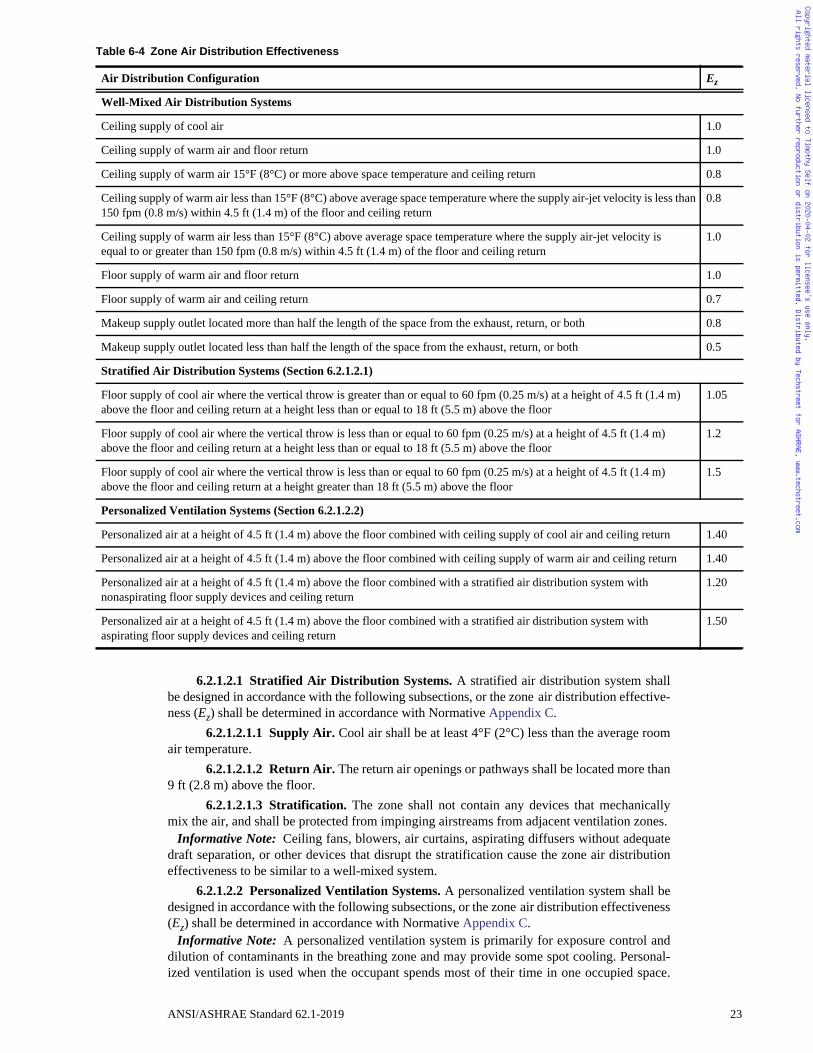
Ez
1.0
1.0
0.8
an 0.8
1.0
1.0
0.7
0.8
0.5
1.05
1.2
1.5
1.40
1.40
1.20
1.50
Copyrighted material licensed to Timothy Self on 2020-04-02 for licensee's use only. All rights reserved. No further reproduction or distribution is permitted. Distributed by Techstreet for ASHRAE, www.techstreet.com
6.2.1.2.1 Stratified Air Distribution Systems. A stratified air distribution system shallbe designed in accordance with the following subsections, or the zone air distribution effective-ness (Ez) shall be determined in accordance with Normative Appendix C.
6.2.1.2.1.1 Supply Air. Cool air shall be at least 4°F (2°C) less than the average roomair temperature.
6.2.1.2.1.2 Return Air. The return air openings or pathways shall be located more than9 ft (2.8 m) above the floor.
6.2.1.2.1.3 Stratification. The zone shall not contain any devices that mechanicallymix the air, and shall be protected from impinging airstreams from adjacent ventilation zones.
Informative Note: Ceiling fans, blowers, air curtains, aspirating diffusers without adequatedraft separation, or other devices that disrupt the stratification cause the zone air distributioneffectiveness to be similar to a well-mixed system.
6.2.1.2.2 Personalized Ventilation Systems. A personalized ventilation system shall bedesigned in accordance with the following subsections, or the zone air distribution effectiveness(Ez) shall be determined in accordance with Normative Appendix C.
Informative Note: A personalized ventilation system is primarily for exposure control anddilution of contaminants in the breathing zone and may provide some spot cooling. Personal-ized ventilation is used when the occupant spends most of their time in one occupied space.
Table 6-4 Zone Air Distribution Effectiveness
Air Distribution Configuration
Well-Mixed Air Distribution Systems
Ceiling supply of cool air
Ceiling supply of warm air and floor return
Ceiling supply of warm air 15°F (8°C) or more above space temperature and ceiling return
Ceiling supply of warm air less than 15°F (8°C) above average space temperature where the supply air-jet velocity is less th150 fpm (0.8 m/s) within 4.5 ft (1.4 m) of the floor and ceiling return
Ceiling supply of warm air less than 15°F (8°C) above average space temperature where the supply air-jet velocity is equal to or greater than 150 fpm (0.8 m/s) within 4.5 ft (1.4 m) of the floor and ceiling return
Floor supply of warm air and floor return
Floor supply of warm air and ceiling return
Makeup supply outlet located more than half the length of the space from the exhaust, return, or both
Makeup supply outlet located less than half the length of the space from the exhaust, return, or both
Stratified Air Distribution Systems (Section 6.2.1.2.1)
Floor supply of cool air where the vertical throw is greater than or equal to 60 fpm (0.25 m/s) at a height of 4.5 ft (1.4 m)above the floor and ceiling return at a height less than or equal to 18 ft (5.5 m) above the floor
Floor supply of cool air where the vertical throw is less than or equal to 60 fpm (0.25 m/s) at a height of 4.5 ft (1.4 m)above the floor and ceiling return at a height less than or equal to 18 ft (5.5 m) above the floor
Floor supply of cool air where the vertical throw is less than or equal to 60 fpm (0.25 m/s) at a height of 4.5 ft (1.4 m)above the floor and ceiling return at a height greater than 18 ft (5.5 m) above the floor
Personalized Ventilation Systems (Section 6.2.1.2.2)
Personalized air at a height of 4.5 ft (1.4 m) above the floor combined with ceiling supply of cool air and ceiling return
Personalized air at a height of 4.5 ft (1.4 m) above the floor combined with ceiling supply of warm air and ceiling return
Personalized air at a height of 4.5 ft (1.4 m) above the floor combined with a stratified air distribution system with nonaspirating floor supply devices and ceiling return
Personalized air at a height of 4.5 ft (1.4 m) above the floor combined with a stratified air distribution system with aspirating floor supply devices and ceiling return
ANSI/ASHRAE Standard 62.1-2019 23
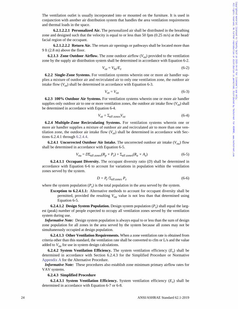
Copyrighted material licensed to Timothy Self on 2020-04-02 for licensee's use only. All rights reserved. No further reproduction or distribution is permitted. Distributed by Techstreet for ASHRAE, www.techstreet.com
The ventilation outlet is usually incorporated into or mounted on the furniture. It is used inconjunction with another air distribution system that handles the area ventilation requirementsand thermal loads in the space.
6.2.1.2.2.1 Personalized Air. The personalized air shall be distributed in the breathingzone and designed such that the velocity is equal to or less than 50 fpm (0.25 m/s) at the head/facial region of the occupant.
6.2.1.2.2.2 Return Air. The return air openings or pathways shall be located more than9 ft (2.8 m) above the floor.
6.2.1.3 Zone Outdoor Airflow. The zone outdoor airflow (Voz) provided to the ventilationzone by the supply air distribution system shall be determined in accordance with Equation 6-2.
Voz = Vbz/Ez (6-2)
6.2.2 Single-Zone Systems. For ventilation systems wherein one or more air handler sup-plies a mixture of outdoor air and recirculated air to only one ventilation zone, the outdoor airintake flow (Vot) shall be determined in accordance with Equation 6-3.
Vot = Voz (6-3)
6.2.3 100% Outdoor Air Systems. For ventilation systems wherein one or more air handlersupplies only outdoor air to one or more ventilation zones, the outdoor air intake flow (Vot) shallbe determined in accordance with Equation 6-4.
Vot = all zonesVoz (6-4)
6.2.4 Multiple-Zone Recirculating Systems. For ventilation systems wherein one ormore air handler supplies a mixture of outdoor air and recirculated air to more than one ven-tilation zone, the outdoor air intake flow (Vot) shall be determined in accordance with Sec-tions 6.2.4.1 through 6.2.4.4.
6.2.4.1 Uncorrected Outdoor Air Intake. The uncorrected outdoor air intake (Vou) flowshall be determined in accordance with Equation 6-5.
Vou = Dall zones(Rp × Pz) + all zones(Ra × Az) (6-5)
6.2.4.1.1 Occupant Diversity. The occupant diversity ratio (D) shall be determined inaccordance with Equation 6-6 to account for variations in population within the ventilationzones served by the system.
D = Ps /all zones Pz (6-6)
where the system population (Ps) is the total population in the area served by the system. Exception to 6.2.4.1.1: Alternative methods to account for occupant diversity shall be
permitted, provided the resulting Vou value is not less than that determined usingEquation 6-5.
6.2.4.1.2 Design System Population. Design system population (Ps) shall equal the larg-est (peak) number of people expected to occupy all ventilation zones served by the ventilationsystem during use.
Informative Note: Design system population is always equal to or less than the sum of designzone population for all zones in the area served by the system because all zones may not besimultaneously occupied at design population.
6.2.4.1.3 Other Ventilation Requirements. When a zone ventilation rate is obtained fromcriteria other than this standard, the ventilation rate shall be converted to cfm or L/s and the valueadded to Vou for use in system design calculations.
6.2.4.2 System Ventilation Efficiency. The system ventilation efficiency (Ev) shall bedetermined in accordance with Section 6.2.4.3 for the Simplified Procedure or NormativeAppendix A for the Alternative Procedure.
Informative Note: These procedures also establish zone minimum primary airflow rates forVAV systems.
6.2.4.3 Simplified Procedure6.2.4.3.1 System Ventilation Efficiency. System ventilation efficiency (Ev) shall be
determined in accordance with Equation 6-7 or 6-8.
24 ANSI/ASHRAE Standard 62.1-2019
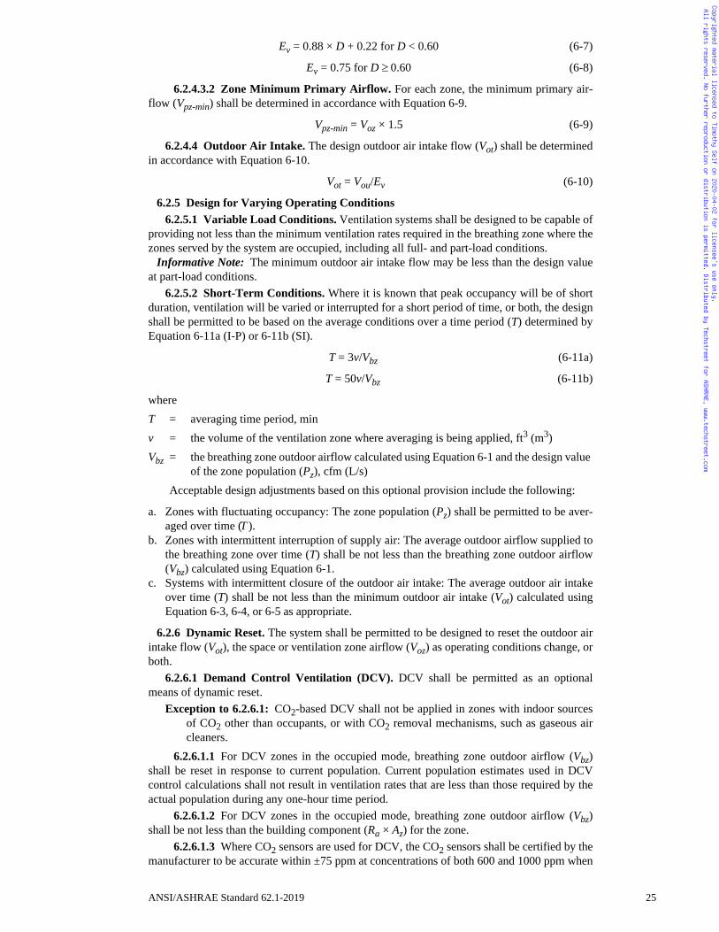
Copyrighted material licensed to Timothy Self on 2020-04-02 for licensee's use only. All rights reserved. No further reproduction or distribution is permitted. Distributed by Techstreet for ASHRAE, www.techstreet.com
Ev = 0.88 × D + 0.22 for D < 0.60 (6-7)
Ev = 0.75 for D 0.60 (6-8)
6.2.4.3.2 Zone Minimum Primary Airflow. For each zone, the minimum primary air-flow (Vpz-min) shall be determined in accordance with Equation 6-9.
Vpz-min = Voz × 1.5 (6-9)
6.2.4.4 Outdoor Air Intake. The design outdoor air intake flow (Vot) shall be determinedin accordance with Equation 6-10.
Vot = Vou/Ev (6-10)
6.2.5 Design for Varying Operating Conditions6.2.5.1 Variable Load Conditions. Ventilation systems shall be designed to be capable of
providing not less than the minimum ventilation rates required in the breathing zone where thezones served by the system are occupied, including all full- and part-load conditions.
Informative Note: The minimum outdoor air intake flow may be less than the design valueat part-load conditions.
6.2.5.2 Short-Term Conditions. Where it is known that peak occupancy will be of shortduration, ventilation will be varied or interrupted for a short period of time, or both, the designshall be permitted to be based on the average conditions over a time period (T) determined byEquation 6-11a (I-P) or 6-11b (SI).
T = 3v/Vbz (6-11a)
T = 50v/Vbz (6-11b)
whereT = averaging time period, minv = the volume of the ventilation zone where averaging is being applied, ft3 (m3)Vbz = the breathing zone outdoor airflow calculated using Equation 6-1 and the design value
of the zone population (Pz), cfm (L/s)Acceptable design adjustments based on this optional provision include the following:
a. Zones with fluctuating occupancy: The zone population (Pz) shall be permitted to be aver-aged over time (T ).
b. Zones with intermittent interruption of supply air: The average outdoor airflow supplied tothe breathing zone over time (T) shall be not less than the breathing zone outdoor airflow(Vbz) calculated using Equation 6-1.
c. Systems with intermittent closure of the outdoor air intake: The average outdoor air intakeover time (T) shall be not less than the minimum outdoor air intake (Vot) calculated usingEquation 6-3, 6-4, or 6-5 as appropriate.
6.2.6 Dynamic Reset. The system shall be permitted to be designed to reset the outdoor airintake flow (Vot), the space or ventilation zone airflow (Voz) as operating conditions change, orboth.
6.2.6.1 Demand Control Ventilation (DCV). DCV shall be permitted as an optionalmeans of dynamic reset.
Exception to 6.2.6.1: CO2-based DCV shall not be applied in zones with indoor sourcesof CO2 other than occupants, or with CO2 removal mechanisms, such as gaseous aircleaners.
6.2.6.1.1 For DCV zones in the occupied mode, breathing zone outdoor airflow (Vbz)shall be reset in response to current population. Current population estimates used in DCVcontrol calculations shall not result in ventilation rates that are less than those required by theactual population during any one-hour time period.
6.2.6.1.2 For DCV zones in the occupied mode, breathing zone outdoor airflow (Vbz)shall be not less than the building component (Ra × Az) for the zone.
6.2.6.1.3 Where CO2 sensors are used for DCV, the CO2 sensors shall be certified by themanufacturer to be accurate within ±75 ppm at concentrations of both 600 and 1000 ppm when
ANSI/ASHRAE Standard 62.1-2019 25
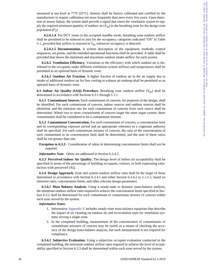
Copyrighted material licensed to Timothy Self on 2020-04-02 for licensee's use only. All rights reserved. No further reproduction or distribution is permitted. Distributed by Techstreet for ASHRAE, www.techstreet.com
measured at sea level at 77°F (25°C). Sensors shall be factory calibrated and certified by themanufacturer to require calibration not more frequently than once every five years. Upon detec-tion of sensor failure, the system shall provide a signal that resets the ventilation system to sup-ply the required minimum quantity of outdoor air (Vbz) to the breathing zone for the design zonepopulation (Pz).
6.2.6.1.4 For DCV zones in the occupied standby mode, breathing zone outdoor airflowshall be permitted to be reduced to zero for the occupancy categories indicated “OS” in Table6-1, provided that airflow is restored to Vbz whenever occupancy is detected.
6.2.6.1.5 Documentation. A written description of the equipment, methods, controlsequences, set points, and the intended operational functions shall be provided. A table shall beprovided that shows the minimum and maximum outdoor intake airflow for each system.
6.2.6.2 Ventilation Efficiency. Variations in the efficiency with which outdoor air is dis-tributed to the occupants under different ventilation system airflows and temperatures shall bepermitted as an optional basis of dynamic reset.
6.2.6.3 Outdoor Air Fraction. A higher fraction of outdoor air in the air supply due tointake of additional outdoor air for free cooling or exhaust air makeup shall be permitted as anoptional basis of dynamic reset.
6.3 Indoor Air Quality (IAQ) Procedure. Breathing zone outdoor airflow (Vbz) shall bedetermined in accordance with Sections 6.3.1 through 6.3.5.
6.3.1 Contaminant Sources. Each contaminant of concern, for purposes of the design, shallbe identified. For each contaminant of concern, indoor sources and outdoor sources shall beidentified, and the emission rate for each contaminant of concern from each source shall bedetermined. Where two or more contaminants of concern target the same organ system, thesecontaminants shall be considered to be a contaminant mixture.
6.3.2 Contaminant Concentration. For each contaminant of concern, a concentration limitand its corresponding exposure period and an appropriate reference to a cognizant authorityshall be specified. For each contaminant mixture of concern, the ratio of the concentration ofeach contaminant to its concentration limit shall be determined, and the sum of these ratiosshall be not greater than one.
Exception to 6.3.2: Consideration of odors in determining concentration limits shall not berequired.
Informative Note: Odors are addressed in Section 6.3.4.2.6.3.3 Perceived Indoor Air Quality. The design level of indoor air acceptability shall be
specified in terms of the percentage of building occupants, visitors, or both expressing satis-faction with perceived IAQ.
6.3.4 Design Approach. Zone and system outdoor airflow rates shall be the larger of thosedetermined in accordance with Section 6.3.4.1 and either Section 6.3.4.2 or 6.3.4.3, based onemission rates, concentration limits, and other relevant design parameters.
6.3.4.1 Mass Balance Analysis. Using a steady-state or dynamic mass-balance analysis,the minimum outdoor airflow rates required to achieve the concentration limits specified in Sec-tion 6.3.2 shall be determined for each contaminant or contaminant mixture of concern withineach zone served by the system.
Informative Notes: 1. Informative Appendix E includes steady-state mass-balance equations that describe
the impact of air cleaning on outdoor air and recirculation rates for ventilation sys-tems serving a single zone.
2. In the completed building, measurement of the concentration of contaminants orcontaminant mixtures of concern may be useful as a means of checking the accu-racy of the design mass-balance analysis, but such measurement is not required forcompliance.
6.3.4.2 Subjective Evaluation. Using a subjective occupant evaluation conducted in thecompleted building, the minimum outdoor airflow rates required to achieve the level of accept-ability specified in Section 6.3.3 shall be determined within each zone served by the system.
26 ANSI/ASHRAE Standard 62.1-2019
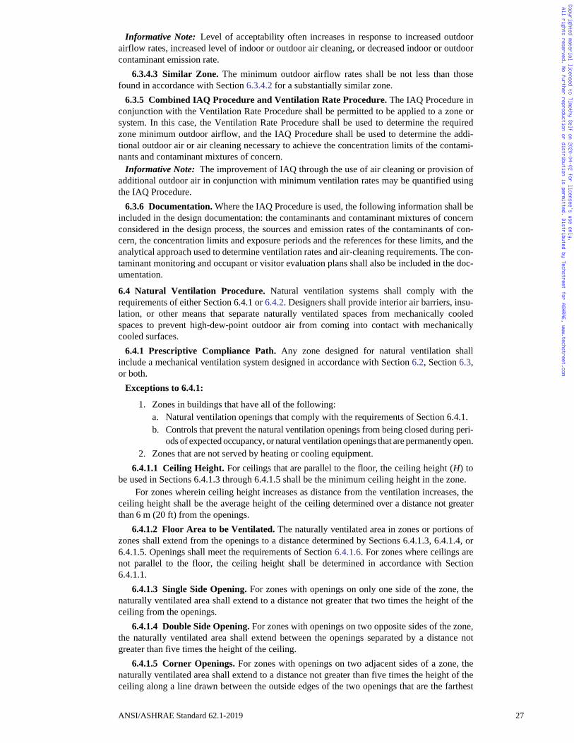
Copyrighted material licensed to Timothy Self on 2020-04-02 for licensee's use only. All rights reserved. No further reproduction or distribution is permitted. Distributed by Techstreet for ASHRAE, www.techstreet.com
Informative Note: Level of acceptability often increases in response to increased outdoorairflow rates, increased level of indoor or outdoor air cleaning, or decreased indoor or outdoorcontaminant emission rate.
6.3.4.3 Similar Zone. The minimum outdoor airflow rates shall be not less than thosefound in accordance with Section 6.3.4.2 for a substantially similar zone.
6.3.5 Combined IAQ Procedure and Ventilation Rate Procedure. The IAQ Procedure inconjunction with the Ventilation Rate Procedure shall be permitted to be applied to a zone orsystem. In this case, the Ventilation Rate Procedure shall be used to determine the requiredzone minimum outdoor airflow, and the IAQ Procedure shall be used to determine the addi-tional outdoor air or air cleaning necessary to achieve the concentration limits of the contami-nants and contaminant mixtures of concern.
Informative Note: The improvement of IAQ through the use of air cleaning or provision ofadditional outdoor air in conjunction with minimum ventilation rates may be quantified usingthe IAQ Procedure.
6.3.6 Documentation. Where the IAQ Procedure is used, the following information shall beincluded in the design documentation: the contaminants and contaminant mixtures of concernconsidered in the design process, the sources and emission rates of the contaminants of con-cern, the concentration limits and exposure periods and the references for these limits, and theanalytical approach used to determine ventilation rates and air-cleaning requirements. The con-taminant monitoring and occupant or visitor evaluation plans shall also be included in the doc-umentation.
6.4 Natural Ventilation Procedure. Natural ventilation systems shall comply with therequirements of either Section 6.4.1 or 6.4.2. Designers shall provide interior air barriers, insu-lation, or other means that separate naturally ventilated spaces from mechanically cooledspaces to prevent high-dew-point outdoor air from coming into contact with mechanicallycooled surfaces.
6.4.1 Prescriptive Compliance Path. Any zone designed for natural ventilation shallinclude a mechanical ventilation system designed in accordance with Section 6.2, Section 6.3,or both.
Exceptions to 6.4.1:
1. Zones in buildings that have all of the following: a. Natural ventilation openings that comply with the requirements of Section 6.4.1.b. Controls that prevent the natural ventilation openings from being closed during peri-
ods of expected occupancy, or natural ventilation openings that are permanently open.2. Zones that are not served by heating or cooling equipment.
6.4.1.1 Ceiling Height. For ceilings that are parallel to the floor, the ceiling height (H) tobe used in Sections 6.4.1.3 through 6.4.1.5 shall be the minimum ceiling height in the zone.
For zones wherein ceiling height increases as distance from the ventilation increases, theceiling height shall be the average height of the ceiling determined over a distance not greaterthan 6 m (20 ft) from the openings.
6.4.1.2 Floor Area to be Ventilated. The naturally ventilated area in zones or portions ofzones shall extend from the openings to a distance determined by Sections 6.4.1.3, 6.4.1.4, or6.4.1.5. Openings shall meet the requirements of Section 6.4.1.6. For zones where ceilings arenot parallel to the floor, the ceiling height shall be determined in accordance with Section6.4.1.1.
6.4.1.3 Single Side Opening. For zones with openings on only one side of the zone, thenaturally ventilated area shall extend to a distance not greater that two times the height of theceiling from the openings.
6.4.1.4 Double Side Opening. For zones with openings on two opposite sides of the zone,the naturally ventilated area shall extend between the openings separated by a distance notgreater than five times the height of the ceiling.
6.4.1.5 Corner Openings. For zones with openings on two adjacent sides of a zone, thenaturally ventilated area shall extend to a distance not greater than five times the height of theceiling along a line drawn between the outside edges of the two openings that are the farthest
ANSI/ASHRAE Standard 62.1-2019 27
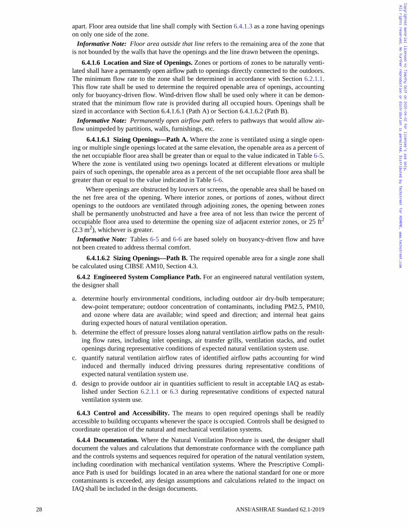
Copyrighted material licensed to Timothy Self on 2020-04-02 for licensee's use only. All rights reserved. No further reproduction or distribution is permitted. Distributed by Techstreet for ASHRAE, www.techstreet.com
apart. Floor area outside that line shall comply with Section 6.4.1.3 as a zone having openingson only one side of the zone.
Informative Note: Floor area outside that line refers to the remaining area of the zone thatis not bounded by the walls that have the openings and the line drawn between the openings.
6.4.1.6 Location and Size of Openings. Zones or portions of zones to be naturally venti-lated shall have a permanently open airflow path to openings directly connected to the outdoors.The minimum flow rate to the zone shall be determined in accordance with Section 6.2.1.1.This flow rate shall be used to determine the required openable area of openings, accountingonly for buoyancy-driven flow. Wind-driven flow shall be used only where it can be demon-strated that the minimum flow rate is provided during all occupied hours. Openings shall besized in accordance with Section 6.4.1.6.1 (Path A) or Section 6.4.1.6.2 (Path B).
Informative Note: Permanently open airflow path refers to pathways that would allow air-flow unimpeded by partitions, walls, furnishings, etc.
6.4.1.6.1 Sizing Openings—Path A. Where the zone is ventilated using a single open-ing or multiple single openings located at the same elevation, the openable area as a percent ofthe net occupiable floor area shall be greater than or equal to the value indicated in Table 6-5.Where the zone is ventilated using two openings located at different elevations or multiplepairs of such openings, the openable area as a percent of the net occupiable floor area shall begreater than or equal to the value indicated in Table 6-6.
Where openings are obstructed by louvers or screens, the openable area shall be based onthe net free area of the opening. Where interior zones, or portions of zones, without directopenings to the outdoors are ventilated through adjoining zones, the opening between zonesshall be permanently unobstructed and have a free area of not less than twice the percent ofoccupiable floor area used to determine the opening size of adjacent exterior zones, or 25 ft2(2.3 m2), whichever is greater.
Informative Note: Tables 6-5 and 6-6 are based solely on buoyancy-driven flow and havenot been created to address thermal comfort.
6.4.1.6.2 Sizing Openings—Path B. The required openable area for a single zone shallbe calculated using CIBSE AM10, Section 4.3.
6.4.2 Engineered System Compliance Path. For an engineered natural ventilation system,the designer shall
a. determine hourly environmental conditions, including outdoor air dry-bulb temperature;dew-point temperature; outdoor concentration of contaminants, including PM2.5, PM10,and ozone where data are available; wind speed and direction; and internal heat gainsduring expected hours of natural ventilation operation.
b. determine the effect of pressure losses along natural ventilation airflow paths on the result-ing flow rates, including inlet openings, air transfer grills, ventilation stacks, and outletopenings during representative conditions of expected natural ventilation system use.
c. quantify natural ventilation airflow rates of identified airflow paths accounting for windinduced and thermally induced driving pressures during representative conditions ofexpected natural ventilation system use.
d. design to provide outdoor air in quantities sufficient to result in acceptable IAQ as estab-lished under Section 6.2.1.1 or 6.3 during representative conditions of expected naturalventilation system use.
6.4.3 Control and Accessibility. The means to open required openings shall be readilyaccessible to building occupants whenever the space is occupied. Controls shall be designed tocoordinate operation of the natural and mechanical ventilation systems.
6.4.4 Documentation. Where the Natural Ventilation Procedure is used, the designer shalldocument the values and calculations that demonstrate conformance with the compliance pathand the controls systems and sequences required for operation of the natural ventilation system,including coordination with mechanical ventilation systems. Where the Prescriptive Compli-ance Path is used for buildings located in an area where the national standard for one or morecontaminants is exceeded, any design assumptions and calculations related to the impact onIAQ shall be included in the design documents.
28 ANSI/ASHRAE Standard 62.1-2019
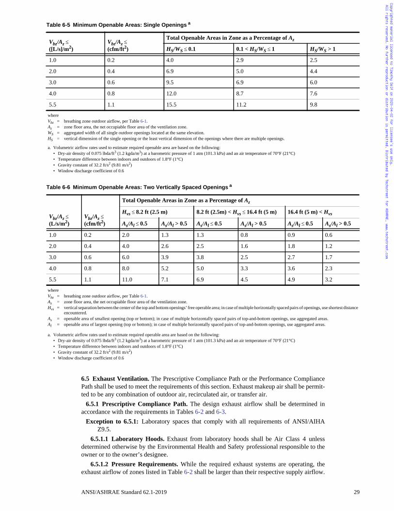
1
/Al > 0.5
ortest distance
Copyrighted material licensed to Timothy Self on 2020-04-02 for licensee's use only. All rights reserved. No further reproduction or distribution is permitted. Distributed by Techstreet for ASHRAE, www.techstreet.com
6.5 Exhaust Ventilation. The Prescriptive Compliance Path or the Performance CompliancePath shall be used to meet the requirements of this section. Exhaust makeup air shall be permit-ted to be any combination of outdoor air, recirculated air, or transfer air.
6.5.1 Prescriptive Compliance Path. The design exhaust airflow shall be determined inaccordance with the requirements in Tables 6-2 and 6-3.
Exception to 6.5.1: Laboratory spaces that comply with all requirements of ANSI/AIHAZ9.5.
6.5.1.1 Laboratory Hoods. Exhaust from laboratory hoods shall be Air Class 4 unlessdetermined otherwise by the Environmental Health and Safety professional responsible to theowner or to the owner’s designee.
6.5.1.2 Pressure Requirements. While the required exhaust systems are operating, theexhaust airflow of zones listed in Table 6-2 shall be larger than their respective supply airflow.
Table 6-5 Minimum Openable Areas: Single Openings a
Vbz/Az ([L/s]/m2)
Vbz/Az (cfm/ft2)
Total Openable Areas in Zone as a Percentage of Az
HS/WS 0.1 0.1 < HS/WS 1 HS/WS >
1.0 0.2 4.0 2.9 2.5
2.0 0.4 6.9 5.0 4.4
3.0 0.6 9.5 6.9 6.0
4.0 0.8 12.0 8.7 7.6
5.5 1.1 15.5 11.2 9.8
whereVbz = breathing zone outdoor airflow, per Table 6-1.Az = zone floor area, the net occupiable floor area of the ventilation zone.WS = aggregated width of all single outdoor openings located at the same elevation.HS = vertical dimension of the single opening or the least vertical dimension of the openings where there are multiple openings.
a. Volumetric airflow rates used to estimate required openable area are based on the following:• Dry-air density of 0.075 lbda/ft3 (1.2 kgda/m3) at a barometric pressure of 1 atm (101.3 kPa) and an air temperature of 70°F (21°C) • Temperature difference between indoors and outdoors of 1.8°F (1°C)• Gravity constant of 32.2 ft/s2 (9.81 m/s2)• Window discharge coefficient of 0.6
Table 6-6 Minimum Openable Areas: Two Vertically Spaced Openings a
Vbz/Az (L/s/m2)
Vbz/Az (cfm/ft2)
Total Openable Areas in Zone as a Percentage of Az
Hvs 8.2 ft (2.5 m) 8.2 ft (2.5m) < Hvs 16.4 ft (5 m) 16.4 ft (5 m) < Hvs
As/Al 0.5 As/Al > 0.5 As/Al 0.5 As/Al > 0.5 As/Al 0.5 As
1.0 0.2 2.0 1.3 1.3 0.8 0.9 0.6
2.0 0.4 4.0 2.6 2.5 1.6 1.8 1.2
3.0 0.6 6.0 3.9 3.8 2.5 2.7 1.7
4.0 0.8 8.0 5.2 5.0 3.3 3.6 2.3
5.5 1.1 11.0 7.1 6.9 4.5 4.9 3.2
whereVbz = breathing zone outdoor airflow, per Table 6-1.Az = zone floor area, the net occupiable floor area of the ventilation zone.Hvs = vertical separation between the center of the top and bottom openings’ free operable area; in case of multiple horizontally spaced pairs of openings, use sh
encountered.As = openable area of smallest opening (top or bottom); in case of multiple horizontally spaced pairs of top-and-bottom openings, use aggregated areas.Al = openable area of largest opening (top or bottom); in case of multiple horizontally spaced pairs of top-and-bottom openings, use aggregated areas.
a. Volumetric airflow rates used to estimate required operable area are based on the following:• Dry-air density of 0.075 lbda/ft3 (1.2 kgda/m3) at a barometric pressure of 1 atm (101.3 kPa) and an air temperature of 70°F (21°C) • Temperature difference between indoors and outdoors of 1.8°F (1°C)• Gravity constant of 32.2 ft/s2 (9.81 m/s2)• Window discharge coefficient of 0.6
ANSI/ASHRAE Standard 62.1-2019 29
Copyrighted material licensed to Timothy Self on 2020-04-02 for licensee's use only. All rights reserved. No further reproduction or distribution is permitted. Distributed by Techstreet for ASHRAE, www.techstreet.com
If zones listed in Table 6-2 are adjacent, the difference between the exhaust and the supply air-flow shall be larger for the zone with the higher number class of air.
Exception to 6.5.1.2: Where airflow offset requirements are established by the Environ-mental Health and Safety professional responsible to the owner or owner’s designee.
Informative Notes: 1. Exhaust systems are required for any occupancy category listed in Table 6-2.2. Where intermittent operation is allowed in Table 6-2, exhaust equipment is intended
to be operated when the space is in use.6.5.2 Performance Compliance Path. The exhaust airflow shall be determined in accor-
dance with the following subsections.6.5.2.1 Contaminant Sources. Contaminants or mixtures of concern for purposes of the
design shall be identified. For each contaminant or mixture of concern, indoor sources (occu-pants, materials, activities, and processes) and outdoor sources shall be identified, and theemission rate for each contaminant of concern from each source shall be determined.
6.5.2.2 Contaminant Concentration. For each contaminant of concern, a concentrationlimit and its corresponding exposure period and an appropriate reference to a cognizant author-ity shall be specified.
6.5.2.3 Monitoring and control systems shall be provided to automatically detect contami-nant levels of concern and modulate exhaust airflow such that contaminant levels are main-tained at not greater than the specified contaminant concentration limits.6.6 Design Documentation Procedures. Design criteria and assumptions shall be docu-mented and made available for operation of the system after installation. See Sections 4.3,5.1.3, 5.18.4, 6.2.6.1.5, 6.3.6, and 6.4.4 regarding assumptions to be detailed in the documen-tation.
7. CONSTRUCTION AND SYSTEM START-UP
7.1 Construction Phase7.1.1 Application. The requirements of this section apply to ventilation systems and the
spaces they serve in new buildings and additions to or alterations in existing buildings.7.1.2 Filters. Systems designed with particle filters shall not be operated without filters in
place.7.1.3 Protection of Materials. When recommended by the manufacturer, building materials
shall be protected from rain and other sources of moisture by appropriate in-transit and on-siteprocedures. Porous materials with visible microbial growth shall not be installed. Nonporousmaterials with visible microbial growth shall be decontaminated.
7.1.4 Protection of Occupied Areas7.1.4.1 Application. The requirements of Section 7.1.4 apply when construction requires
a building permit and entails sanding, cutting, grinding, or other activities that generate sig-nificant amounts of airborne particles or procedures that generate significant amounts of gas-eous contaminants.
7.1.4.2 Protective Measures. Measures shall be employed to reduce the migration of con-struction-generated contaminants to occupied areas.
Informative Note: Examples of acceptable measures include, but are not limited to, sealingthe construction area using temporary walls or plastic sheathing, exhausting the constructionarea, or pressurizing contiguous occupied areas.
7.1.5 Air Duct System Construction. Air duct systems shall be constructed in accordancewith the following standards, as applicable:
a. The following sections of ANSI/SMACNA 006, HVAC Duct Construction Standards—Metal and Flexible:
• Section S1.9 of Section 1.3.1, “Duct Construction and Installation Standards”• Section 7.4, “Installation Standards for Rectangular Ducts Using Flexible Liner”• Section 3.5, “Duct Installation Standards”• Section 3.6, “Specification for Joining and Attaching Flexible Duct”• Section 3.7, “Specification for Supporting Flexible Duct”
30 ANSI/ASHRAE Standard 62.1-2019
Copyrighted material licensed to Timothy Self on 2020-04-02 for licensee's use only. All rights reserved. No further reproduction or distribution is permitted. Distributed by Techstreet for ASHRAE, www.techstreet.com
• Sections S6.1, S6.3, S6.4, and S6.5 of Section 9.1, “Casing and Plenum ConstructionStandards”
b. All sections of SMACNA’s Fibrous Glass Duct Construction Standardsc. NFPA 90A, Standard for the Installation of Air-Conditioning and Ventilating Systemsd. NFPA 90B, Standard for the Installation of Warm Air Heating and Air-Conditioning Sys-
tems
7.2 System Start-Up7.2.1 Application. The requirements of this section apply to the following ventilation sys-
tems:
a. Newly installed air-handling systemsb. Existing air-handling systems undergoing supply air or outdoor airflow reduction (Only the
requirements of Section 7.2.2 shall apply to these altered systems.)c. Existing air-handling distribution systems undergoing alterations affecting more than 25%
of the floor area served by the systems (Only the requirements of Section 7.2.2 shall applyto these altered systems.)
7.2.2 Air Balancing and Verification of Outdoor Air Performance. Ventilation systemsshall be balanced in accordance with ASHRAE Standard 111 or another applicable nationalstandards so as to verify conformance with the total outdoor airflow requirements of this stan-dard (Vot).
7.2.3 Testing of Drain Pans. To minimize conditions of water stagnation that may result inmicrobial growth, drain pans shall be field tested under operating conditions that are the mostrestrictive to condensate flow to demonstrate proper drainage.
Exception to 7.2.3: Field testing of drain pans is not required if units with factory-installeddrain pans have been certified (attested in writing) by the manufacturer for proper drain-age when installed as recommended.
Informative Note: Above conditions usually occur at full fan airflow for draw-through fansand minimum fan airflow for blow-through fans.
7.2.4 Ventilation System Start-Up. Ventilation air distribution systems shall be clean ofdirt and debris.
7.2.5 Outdoor Air Dampers. Prior to occupancy, each ventilation system shall be tested todemonstrate that outdoor air dampers operate in accordance with the system design.
7.2.6 Documentation. The following ventilation system documentation shall be provided tothe building owner or his/her designee, retained within the building, and made available to thebuilding operating personnel:
a. An operations and maintenance manual describing basic data relating to the operation andmaintenance of ventilation systems and equipment as installed
b. HVAC controls information consisting of diagrams, schematics, control sequence narra-tives, and maintenance and/or calibration information
c. An air balance report documenting the work performed for Section 7.2.2d. Construction drawings of record, control drawings, and final design drawingse. Design criteria and assumptions
8. OPERATIONS AND MAINTENANCE
8.1 General8.1.1 Application. The requirements of this section apply to buildings and their ventilation
systems and their components constructed or renovated after the adoption date of this section.8.1.2 Building Alterations or Change of Use. When buildings are altered or when changes
in building use, occupant category, significant change in occupant density, or other changesinconsistent with system design assumptions are made, the ventilation system design, opera-tion, and maintenance shall be reevaluated and the operations and maintenance (O&M) manualupdated as necessary.8.2 O&M Manual. An O&M manual, either written or electronic, shall be developed andmaintained on site or in a centrally accessible location for the working life of the applicableventilation system equipment or components. This manual shall be updated as necessary. The
ANSI/ASHRAE Standard 62.1-2019 31
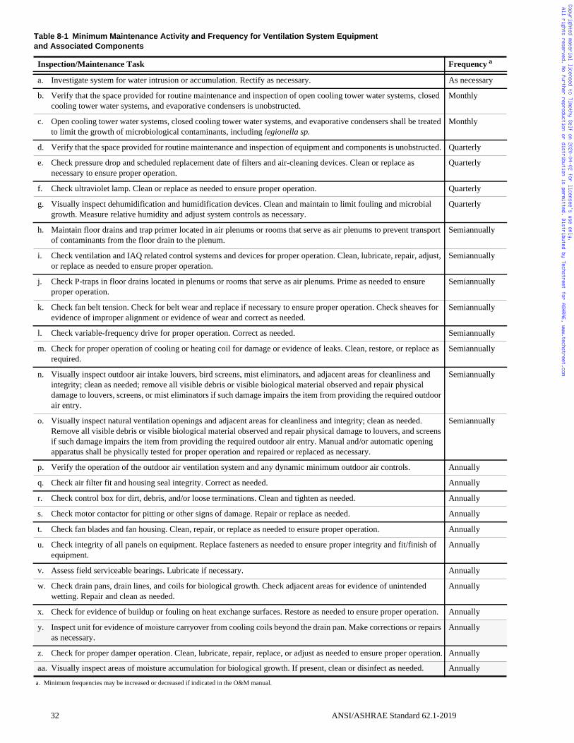
uency a
cessary
hly
hly
terly
terly
terly
terly
annually
annually
annually
annually
annually
annually
annually
annually
ally
ally
ally
ally
ally
ally
ally
ally
ally
ally
ally
ally
Copyrighted material licensed to Timothy Self on 2020-04-02 for licensee's use only. All rights reserved. No further reproduction or distribution is permitted. Distributed by Techstreet for ASHRAE, www.techstreet.com
Table 8-1 Minimum Maintenance Activity and Frequency for Ventilation System Equipmentand Associated Components
Inspection/Maintenance Task Freq
a. Investigate system for water intrusion or accumulation. Rectify as necessary. As ne
b. Verify that the space provided for routine maintenance and inspection of open cooling tower water systems, closed cooling tower water systems, and evaporative condensers is unobstructed.
Mont
c. Open cooling tower water systems, closed cooling tower water systems, and evaporative condensers shall be treated to limit the growth of microbiological contaminants, including legionella sp.
Mont
d. Verify that the space provided for routine maintenance and inspection of equipment and components is unobstructed. Quar
e. Check pressure drop and scheduled replacement date of filters and air-cleaning devices. Clean or replace as necessary to ensure proper operation.
Quar
f. Check ultraviolet lamp. Clean or replace as needed to ensure proper operation. Quar
g. Visually inspect dehumidification and humidification devices. Clean and maintain to limit fouling and microbial growth. Measure relative humidity and adjust system controls as necessary.
Quar
h. Maintain floor drains and trap primer located in air plenums or rooms that serve as air plenums to prevent transport of contaminants from the floor drain to the plenum.
Semi
i. Check ventilation and IAQ related control systems and devices for proper operation. Clean, lubricate, repair, adjust, or replace as needed to ensure proper operation.
Semi
j. Check P-traps in floor drains located in plenums or rooms that serve as air plenums. Prime as needed to ensure proper operation.
Semi
k. Check fan belt tension. Check for belt wear and replace if necessary to ensure proper operation. Check sheaves for evidence of improper alignment or evidence of wear and correct as needed.
Semi
l. Check variable-frequency drive for proper operation. Correct as needed. Semi
m. Check for proper operation of cooling or heating coil for damage or evidence of leaks. Clean, restore, or replace as required.
Semi
n. Visually inspect outdoor air intake louvers, bird screens, mist eliminators, and adjacent areas for cleanliness and integrity; clean as needed; remove all visible debris or visible biological material observed and repair physical damage to louvers, screens, or mist eliminators if such damage impairs the item from providing the required outdoor air entry.
Semi
o. Visually inspect natural ventilation openings and adjacent areas for cleanliness and integrity; clean as needed. Remove all visible debris or visible biological material observed and repair physical damage to louvers, and screens if such damage impairs the item from providing the required outdoor air entry. Manual and/or automatic opening apparatus shall be physically tested for proper operation and repaired or replaced as necessary.
Semi
p. Verify the operation of the outdoor air ventilation system and any dynamic minimum outdoor air controls. Annu
q. Check air filter fit and housing seal integrity. Correct as needed. Annu
r. Check control box for dirt, debris, and/or loose terminations. Clean and tighten as needed. Annu
s. Check motor contactor for pitting or other signs of damage. Repair or replace as needed. Annu
t. Check fan blades and fan housing. Clean, repair, or replace as needed to ensure proper operation. Annu
u. Check integrity of all panels on equipment. Replace fasteners as needed to ensure proper integrity and fit/finish of equipment.
Annu
v. Assess field serviceable bearings. Lubricate if necessary. Annu
w. Check drain pans, drain lines, and coils for biological growth. Check adjacent areas for evidence of unintended wetting. Repair and clean as needed.
Annu
x. Check for evidence of buildup or fouling on heat exchange surfaces. Restore as needed to ensure proper operation. Annu
y. Inspect unit for evidence of moisture carryover from cooling coils beyond the drain pan. Make corrections or repairs as necessary.
Annu
z. Check for proper damper operation. Clean, lubricate, repair, replace, or adjust as needed to ensure proper operation. Annu
aa. Visually inspect areas of moisture accumulation for biological growth. If present, clean or disinfect as needed. Annu
a. Minimum frequencies may be increased or decreased if indicated in the O&M manual.
32 ANSI/ASHRAE Standard 62.1-2019
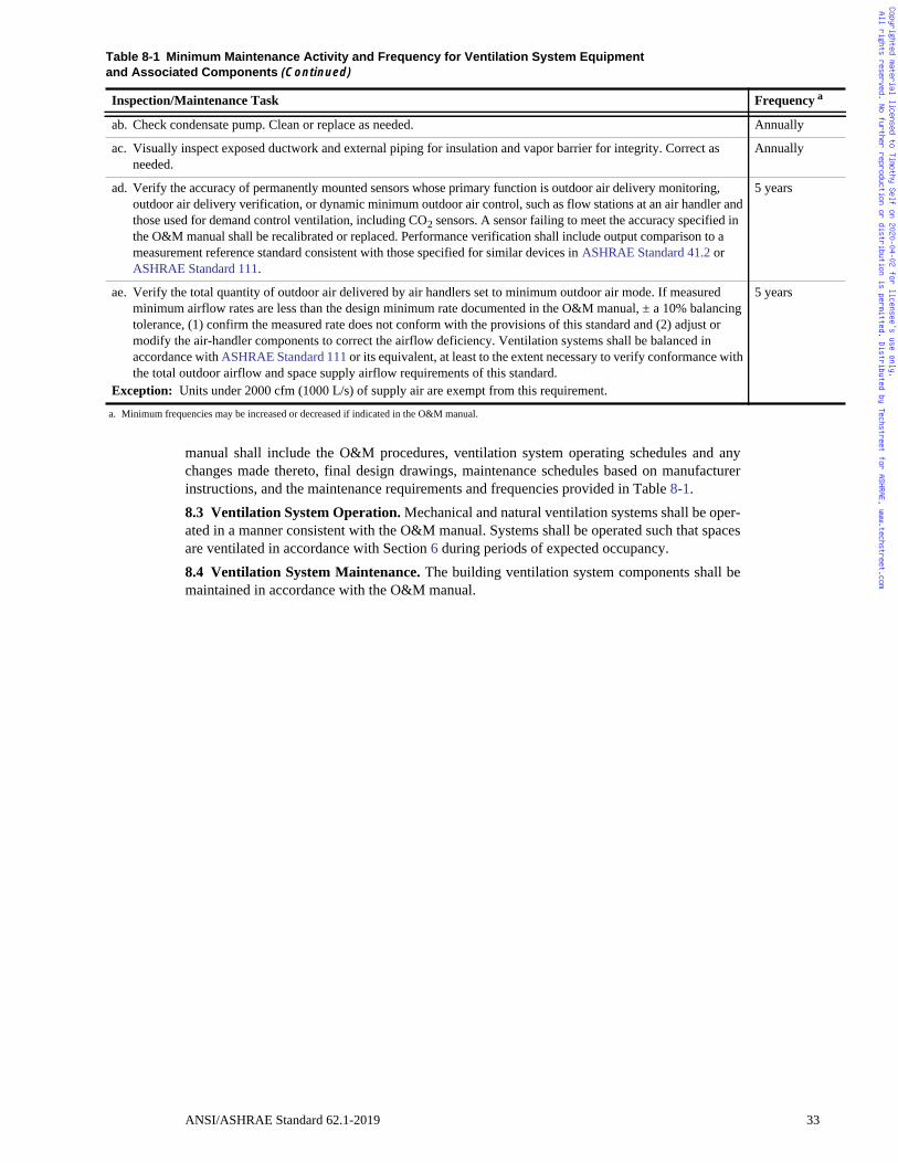
Annually
Annually
5 years
5 years
Frequency a
Copyrighted material licensed to Timothy Self on 2020-04-02 for licensee's use only. All rights reserved. No further reproduction or distribution is permitted. Distributed by Techstreet for ASHRAE, www.techstreet.com
manual shall include the O&M procedures, ventilation system operating schedules and anychanges made thereto, final design drawings, maintenance schedules based on manufacturerinstructions, and the maintenance requirements and frequencies provided in Table 8-1.8.3 Ventilation System Operation. Mechanical and natural ventilation systems shall be oper-ated in a manner consistent with the O&M manual. Systems shall be operated such that spacesare ventilated in accordance with Section 6 during periods of expected occupancy.8.4 Ventilation System Maintenance. The building ventilation system components shall bemaintained in accordance with the O&M manual.
ab. Check condensate pump. Clean or replace as needed.
ac. Visually inspect exposed ductwork and external piping for insulation and vapor barrier for integrity. Correct as needed.
ad. Verify the accuracy of permanently mounted sensors whose primary function is outdoor air delivery monitoring, outdoor air delivery verification, or dynamic minimum outdoor air control, such as flow stations at an air handler and those used for demand control ventilation, including CO2 sensors. A sensor failing to meet the accuracy specified in the O&M manual shall be recalibrated or replaced. Performance verification shall include output comparison to a measurement reference standard consistent with those specified for similar devices in ASHRAE Standard 41.2 or ASHRAE Standard 111.
ae. Verify the total quantity of outdoor air delivered by air handlers set to minimum outdoor air mode. If measured minimum airflow rates are less than the design minimum rate documented in the O&M manual, ± a 10% balancing tolerance, (1) confirm the measured rate does not conform with the provisions of this standard and (2) adjust or modify the air-handler components to correct the airflow deficiency. Ventilation systems shall be balanced in accordance with ASHRAE Standard 111 or its equivalent, at least to the extent necessary to verify conformance with the total outdoor airflow and space supply airflow requirements of this standard.
Exception: Units under 2000 cfm (1000 L/s) of supply air are exempt from this requirement.
Table 8-1 Minimum Maintenance Activity and Frequency for Ventilation System Equipmentand Associated Components (Continued)
Inspection/Maintenance Task
a. Minimum frequencies may be increased or decreased if indicated in the O&M manual.
ANSI/ASHRAE Standard 62.1-2019 33
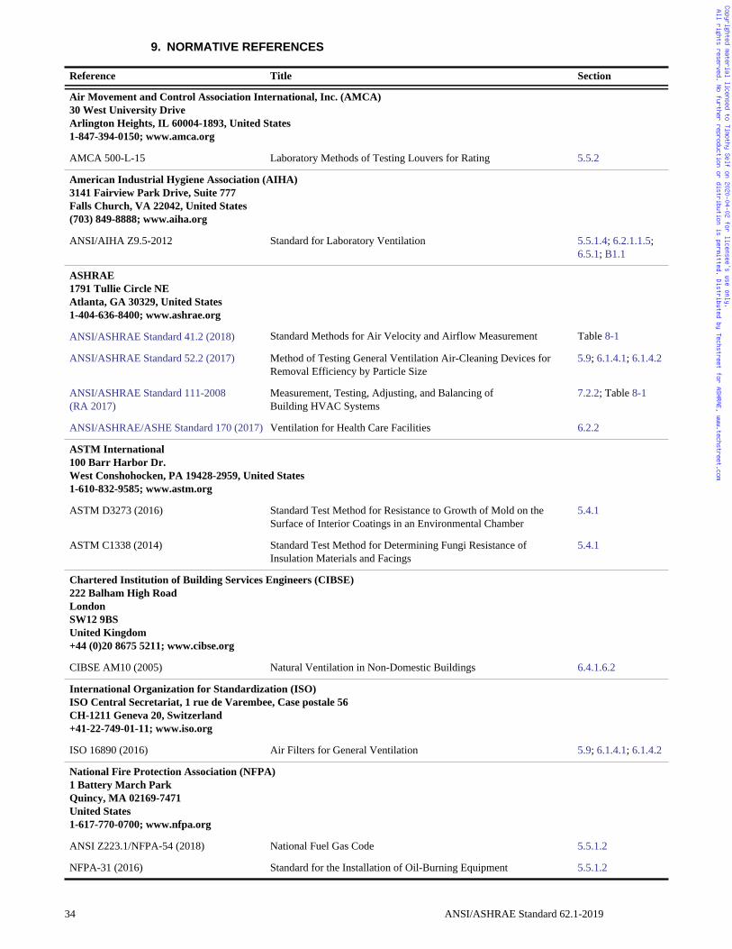
Copyrighted material licensed to Timothy Self on 2020-04-02 for licensee's use only. All rights reserved. No further reproduction or distribution is permitted. Distributed by Techstreet for ASHRAE, www.techstreet.com
9. NORMATIVE REFERENCES
Reference Title Section
Air Movement and Control Association International, Inc. (AMCA)30 West University DriveArlington Heights, IL 60004-1893, United States1-847-394-0150; www.amca.org
AMCA 500-L-15 Laboratory Methods of Testing Louvers for Rating 5.5.2
American Industrial Hygiene Association (AIHA)3141 Fairview Park Drive, Suite 777 Falls Church, VA 22042, United States(703) 849-8888; www.aiha.org
ANSI/AIHA Z9.5-2012 Standard for Laboratory Ventilation 5.5.1.4; 6.2.1.1.5; 6.5.1; B1.1
ASHRAE1791 Tullie Circle NEAtlanta, GA 30329, United States1-404-636-8400; www.ashrae.org
ANSI/ASHRAE Standard 41.2 (2018) Standard Methods for Air Velocity and Airflow Measurement Table 8-1
ANSI/ASHRAE Standard 52.2 (2017) Method of Testing General Ventilation Air-Cleaning Devices for Removal Efficiency by Particle Size
5.9; 6.1.4.1; 6.1.4.2
ANSI/ASHRAE Standard 111-2008(RA 2017)
Measurement, Testing, Adjusting, and Balancing of Building HVAC Systems
7.2.2; Table 8-1
ANSI/ASHRAE/ASHE Standard 170 (2017) Ventilation for Health Care Facilities 6.2.2
ASTM International100 Barr Harbor Dr.West Conshohocken, PA 19428-2959, United States1-610-832-9585; www.astm.org
ASTM D3273 (2016) Standard Test Method for Resistance to Growth of Mold on the Surface of Interior Coatings in an Environmental Chamber
5.4.1
ASTM C1338 (2014) Standard Test Method for Determining Fungi Resistance of Insulation Materials and Facings
5.4.1
Chartered Institution of Building Services Engineers (CIBSE)222 Balham High RoadLondonSW12 9BSUnited Kingdom+44 (0)20 8675 5211; www.cibse.org
CIBSE AM10 (2005) Natural Ventilation in Non-Domestic Buildings 6.4.1.6.2
International Organization for Standardization (ISO)ISO Central Secretariat, 1 rue de Varembee, Case postale 56CH-1211 Geneva 20, Switzerland+41-22-749-01-11; www.iso.org
ISO 16890 (2016) Air Filters for General Ventilation 5.9; 6.1.4.1; 6.1.4.2
National Fire Protection Association (NFPA)1 Battery March ParkQuincy, MA 02169-7471United States1-617-770-0700; www.nfpa.org
ANSI Z223.1/NFPA-54 (2018) National Fuel Gas Code 5.5.1.2
NFPA-31 (2016) Standard for the Installation of Oil-Burning Equipment 5.5.1.2
34 ANSI/ASHRAE Standard 62.1-2019
Copyrighted material licensed to Timothy Self on 2020-04-02 for licensee's use only. All rights reserved. No further reproduction or distribution is permitted. Distributed by Techstreet for ASHRAE, www.techstreet.com
NFPA-45 (2015) Standard on Fire Protection for Laboratories Using Chemicals B1.1
NFPA-90A (2018) Standard for the Installation of Air-Conditioning and Ventilating Systems
7.1.5
NFPA-90B (2018) Standard for the Installation of Warm Air Heating and Air-Conditioning Systems
7.1.5
NFPA-211 (2019) Standard for Chimneys, Fireplaces, Vents, and Solid Fuel-Burning Appliances
5.5.1.2
NSF International789 Dixboro RoadAnn Arbor, MI 48105, United States734-769-8010; www.nsf.org; [email protected]
NSF/ANSI 60 (2016) Drinking Water Treatment Chemicals—Health Effects 5.14.1
Sheet Metal and Air Conditioning Contractors National Association (SMACNA)4201 Lafayette Center DriveChantilly, VA 20151, Unites States1-703-803-2980
Fibrous Glass Duct Construction Standards, 7th Edition (2003) 7.1.5
ANSI/SMACNA 006 (2006) HVAC Duct Construction Standards—Metal and Flexible, 3rd Edition 7.1.5
ANSI/SMACNA 016 (2012) HVAC Air Duct Leakage Test Manual, 2nd Edition 5.2.2
Underwriters Laboratories Inc. (UL)333 Pfingsten RoadNorthbrook, IL 60062, United States847-272-8800; www.ul.com; [email protected]
UL 181 (2013) Factory-Made Air Ducts and Air Connectors, 11th Edition 5.4.1; 5.4.2
UL 1995 (2015) Heating and Cooling Equipment, 5th Edition 5.5.2; 5.5.3
UL 2998 (2016) Environmental Claim Validation Procedure (ECVP) for Zero Ozone Emissions from Air Cleaners
5.7.1
U.S. Government Printing Office (USGPO)732 North Capitol St. NWWashington, DC 20401202-512-1800; www.gpo.gov
21 CFR 173.310 (2018) Secondary Direct Food Additives Permitted in Food for Human Consumption—Boiler Water Additives
5.14.1
40 CFR 50 (2018) National Primary and Secondary Ambient Air Quality Standards 4.1.1; 6.1.4.1; 6.1.4.2
Reference Title Section
ANSI/ASHRAE Standard 62.1-2019 35
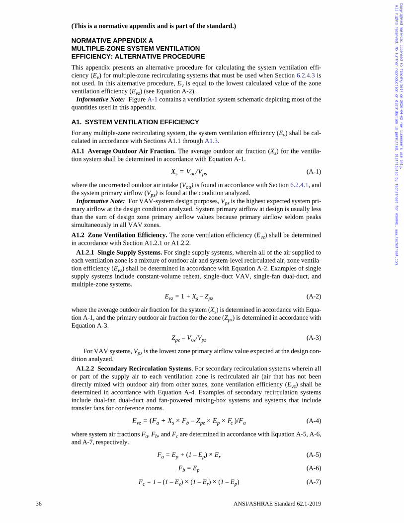
Copyrighted material licensed to Timothy Self on 2020-04-02 for licensee's use only. All rights reserved. No further reproduction or distribution is permitted. Distributed by Techstreet for ASHRAE, www.techstreet.com
(This is a normative appendix and is part of the standard.)
NORMATIVE APPENDIX AMULTIPLE-ZONE SYSTEM VENTILATIONEFFICIENCY: ALTERNATIVE PROCEDURE
This appendix presents an alternative procedure for calculating the system ventilation effi-ciency (Ev) for multiple-zone recirculating systems that must be used when Section 6.2.4.3 isnot used. In this alternative procedure, Ev is equal to the lowest calculated value of the zoneventilation efficiency (Evz) (see Equation A-2).
Informative Note: Figure A-1 contains a ventilation system schematic depicting most of thequantities used in this appendix.
A1. SYSTEM VENTILATION EFFICIENCY
For any multiple-zone recirculating system, the system ventilation efficiency (Ev) shall be cal-culated in accordance with Sections A1.1 through A1.3.A1.1 Average Outdoor Air Fraction. The average outdoor air fraction (Xs) for the ventila-tion system shall be determined in accordance with Equation A-1.
Xs = Vou/Vps (A-1)
where the uncorrected outdoor air intake (Vou) is found in accordance with Section 6.2.4.1, andthe system primary airflow (Vps) is found at the condition analyzed.
Informative Note: For VAV-system design purposes, Vps is the highest expected system pri-mary airflow at the design condition analyzed. System primary airflow at design is usually lessthan the sum of design zone primary airflow values because primary airflow seldom peakssimultaneously in all VAV zones.A1.2 Zone Ventilation Efficiency. The zone ventilation efficiency (Evz) shall be determinedin accordance with Section A1.2.1 or A1.2.2.
A1.2.1 Single Supply Systems. For single supply systems, wherein all of the air supplied toeach ventilation zone is a mixture of outdoor air and system-level recirculated air, zone ventila-tion efficiency (Evz) shall be determined in accordance with Equation A-2. Examples of singlesupply systems include constant-volume reheat, single-duct VAV, single-fan dual-duct, andmultiple-zone systems.
Evz = 1 + Xs – Zpz (A-2)
where the average outdoor air fraction for the system (Xs) is determined in accordance with Equa-tion A-1, and the primary outdoor air fraction for the zone (Zpz) is determined in accordance withEquation A-3.
Zpz = Voz/Vpz (A-3)
For VAV systems, Vpz is the lowest zone primary airflow value expected at the design con-dition analyzed.
A1.2.2 Secondary Recirculation Systems. For secondary recirculation systems wherein allor part of the supply air to each ventilation zone is recirculated air (air that has not beendirectly mixed with outdoor air) from other zones, zone ventilation efficiency (Evz) shall bedetermined in accordance with Equation A-4. Examples of secondary recirculation systemsinclude dual-fan dual-duct and fan-powered mixing-box systems and systems that includetransfer fans for conference rooms.
Evz = (Fa + Xs × Fb – Zpz × Ep × Fc )/Fa (A-4)
where system air fractions Fa, Fb, and Fc are determined in accordance with Equation A-5, A-6,and A-7, respectively.
Fa = Ep + (1 – Ep) × Er (A-5)
Fb = Ep (A-6)
Fc = 1 – (1 – Ez) × (1 – Er) × (1 – Ep) (A-7)
36 ANSI/ASHRAE Standard 62.1-2019
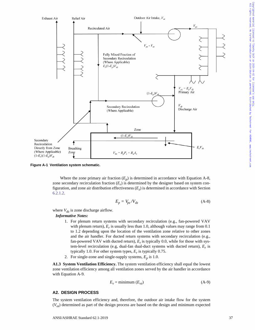
Copyrighted material licensed to Timothy Self on 2020-04-02 for licensee's use only. All rights reserved. No further reproduction or distribution is permitted. Distributed by Techstreet for ASHRAE, www.techstreet.com
Where the zone primary air fraction (Ep) is determined in accordance with Equation A-8,zone secondary recirculation fraction (Er) is determined by the designer based on system con-figuration, and zone air distribution effectiveness (Ez) is determined in accordance with Section6.2.1.2.
Ep = Vpz /Vdz (A-8)
where Vdz is zone discharge airflow.Informative Notes:
1. For plenum return systems with secondary recirculation (e.g., fan-powered VAVwith plenum return), Er is usually less than 1.0, although values may range from 0.1to 1.2 depending upon the location of the ventilation zone relative to other zonesand the air handler. For ducted return systems with secondary recirculation (e.g.,fan-powered VAV with ducted return), Er is typically 0.0, while for those with sys-tem-level recirculation (e.g, dual-fan dual-duct systems with ducted return), Er istypically 1.0. For other system types, Er is typically 0.75.
2. For single-zone and single-supply systems, Ep is 1.0.
A1.3 System Ventilation Efficiency. The system ventilation efficiency shall equal the lowestzone ventilation efficiency among all ventilation zones served by the air handler in accordancewith Equation A-9.
Ev = minimum (Evz) (A-9)
A2. DESIGN PROCESS
The system ventilation efficiency and, therefore, the outdoor air intake flow for the system(Vot) determined as part of the design process are based on the design and minimum expected
Figure A-1 Ventilation system schematic.
ANSI/ASHRAE Standard 62.1-2019 37
Copyrighted material licensed to Timothy Self on 2020-04-02 for licensee's use only. All rights reserved. No further reproduction or distribution is permitted. Distributed by Techstreet for ASHRAE, www.techstreet.com
supply airflows to individual ventilation zones as well as the design outdoor air requirements tothe zones. For VAV system design purposes, zone ventilation efficiency (Evz) for each ventila-tion zone shall be found using the minimum expected zone primary airflow (Vpz) and using thehighest expected system primary airflow (Vps) at the design condition analyzed.
Informative Note: Increasing the zone supply airflow values during the design process, par-ticularly to the critical zones requiring the highest fraction of outdoor air, reduces the systemoutdoor air intake flow requirement determined in the calculation.A2.1 Selecting Zones for Calculation. Zone ventilation efficiency (Evz) shall be calculatedfor all ventilation zones. Exception to A2.1: Because system ventilation efficiency (Ev) is determined by the minimum
value of the zone ventilation efficiency (Evz) in accordance with Equation A-9, calculationof Evz is not required for any ventilation zone that has an Evz value that is equal to or largerthan that of the ventilation zone for which a calculation has been made.
Informative Note: The value of Evz for a ventilation zone will be equal to or larger than thatfor another ventilation zone if all of the following are true relative to the other ventilation zone:
a. Floor area per occupant (Az/Pz) is no lower.b. Minimum zone discharge airflow rate per unit area (Vdz/Az) is no lower.c. Primary air fraction (Ep) is no lower.d. Zone air distribution effectiveness (Ez) is no lower.e. Area outdoor air rate (Ra) is no higher.f. People outdoor air rate (Rp) is no higher.
A3. SYMBOLS
Az zone floor area: the net occupiable floor area of the ventilation zone, ft2 (m2).
D occupant diversity: the ratio of the system population to the sum of the zone populations.
Ep primary air fraction: the fraction of primary air in the discharge air to the ventilation zone.
Er secondary recirculation fraction: in systems with secondary recirculation of return air, the fraction of secondary recirculated air to the zone that is representative of average system return air rather than air directly recirculated from the zone.
Ev system ventilation efficiency: the efficiency with which the system distributes air from the outdoor air intake to the breathing zone in the ventilation-critical zone, which requires the largest fraction of outdoor air in the primary airstream.
Evz zone ventilation efficiency: the efficiency with which the system distributes air from the outdoor air intake to the breathing zone in any particular ventilation zone.
Ez zone air distribution effectiveness: a measure of the effectiveness of supply air distribution to the breathing zone. Ez is determined in accordance with Section 6.2.1.2 or Normative Appendix C.
Fa supply air fraction: the fraction of supply air to the ventilation zone that includes sources of air from outside the zone.
Fb mixed-air fraction: the fraction of supply air to the ventilation zone from fully mixed primary air.
Fc outdoor air fraction: the fraction of outdoor air to the ventilation zone that includes sources of air from outside the zone.
Ps system population: the simultaneous number of occupants in the area served by the ventilation system.
Pz zone population: see Section 6.2.1.1.
Ra area outdoor air rate: see Section 6.2.1.1.
Rp people outdoor air rate: see Section 6.2.1.1.
Vbz breathing zone outdoor airflow: see Section 6.2.1.1.
Vdz zone discharge airflow: the expected discharge (supply) airflow to the zone that includes primary airflow and secondary recirculated airflow, cfm (L/s).
38 ANSI/ASHRAE Standard 62.1-2019
Copyrighted material licensed to Timothy Self on 2020-04-02 for licensee's use only. All rights reserved. No further reproduction or distribution is permitted. Distributed by Techstreet for ASHRAE, www.techstreet.com
Vot outdoor air intake flow: see Sections 6.2.2, 6.2.3, and 6.2.4.4.Vou uncorrected outdoor air intake: see Section 6.2.4.1.Voz zone outdoor airflow: see Section 6.2.1.3.Vps system primary airflow: the total primary airflow supplied to all zones served by the
system from the air-handling unit at which the outdoor air intake is located.Vpz zone primary airflow: the zone primary airflow to the ventilation zone, including outdoor
air and recirculated air.Xs average outdoor air fraction: at the primary air handler, the fraction of outdoor air intake
flow in the system primary airflow. Zpz primary outdoor air fraction: the outdoor air fraction required in the primary air supplied
to the ventilation zone prior to the introduction of any secondary recirculation air.
ANSI/ASHRAE Standard 62.1-2019 39
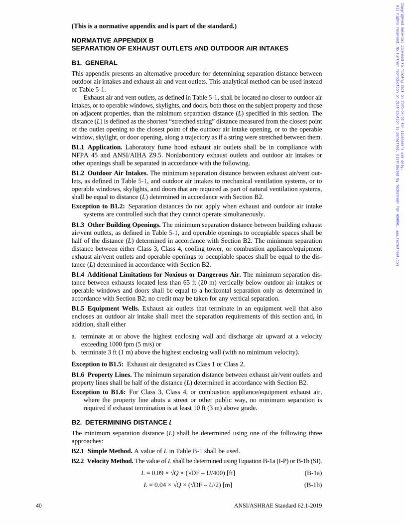
Copyrighted material licensed to Timothy Self on 2020-04-02 for licensee's use only. All rights reserved. No further reproduction or distribution is permitted. Distributed by Techstreet for ASHRAE, www.techstreet.com
(This is a normative appendix and is part of the standard.)
NORMATIVE APPENDIX BSEPARATION OF EXHAUST OUTLETS AND OUTDOOR AIR INTAKES
B1. GENERAL
This appendix presents an alternative procedure for determining separation distance betweenoutdoor air intakes and exhaust air and vent outlets. This analytical method can be used insteadof Table 5-1.
Exhaust air and vent outlets, as defined in Table 5-1, shall be located no closer to outdoor airintakes, or to operable windows, skylights, and doors, both those on the subject property and thoseon adjacent properties, than the minimum separation distance (L) specified in this section. Thedistance (L) is defined as the shortest “stretched string” distance measured from the closest pointof the outlet opening to the closest point of the outdoor air intake opening, or to the operablewindow, skylight, or door opening, along a trajectory as if a string were stretched between them.B1.1 Application. Laboratory fume hood exhaust air outlets shall be in compliance withNFPA 45 and ANSI/AIHA Z9.5. Nonlaboratory exhaust outlets and outdoor air intakes orother openings shall be separated in accordance with the following. B1.2 Outdoor Air Intakes. The minimum separation distance between exhaust air/vent out-lets, as defined in Table 5-1, and outdoor air intakes to mechanical ventilation systems, or tooperable windows, skylights, and doors that are required as part of natural ventilation systems,shall be equal to distance (L) determined in accordance with Section B2. Exception to B1.2: Separation distances do not apply when exhaust and outdoor air intake
systems are controlled such that they cannot operate simultaneously. B1.3 Other Building Openings. The minimum separation distance between building exhaustair/vent outlets, as defined in Table 5-1, and operable openings to occupiable spaces shall behalf of the distance (L) determined in accordance with Section B2. The minimum separationdistance between either Class 3, Class 4, cooling tower, or combustion appliance/equipmentexhaust air/vent outlets and operable openings to occupiable spaces shall be equal to the dis-tance (L) determined in accordance with Section B2.B1.4 Additional Limitations for Noxious or Dangerous Air. The minimum separation dis-tance between exhausts located less than 65 ft (20 m) vertically below outdoor air intakes oroperable windows and doors shall be equal to a horizontal separation only as determined inaccordance with Section B2; no credit may be taken for any vertical separation.B1.5 Equipment Wells. Exhaust air outlets that terminate in an equipment well that alsoencloses an outdoor air intake shall meet the separation requirements of this section and, inaddition, shall either
a. terminate at or above the highest enclosing wall and discharge air upward at a velocityexceeding 1000 fpm (5 m/s) or
b. terminate 3 ft (1 m) above the highest enclosing wall (with no minimum velocity).
Exception to B1.5: Exhaust air designated as Class 1 or Class 2.B1.6 Property Lines. The minimum separation distance between exhaust air/vent outlets andproperty lines shall be half of the distance (L) determined in accordance with Section B2.Exception to B1.6: For Class 3, Class 4, or combustion appliance/equipment exhaust air,
where the property line abuts a street or other public way, no minimum separation isrequired if exhaust termination is at least 10 ft (3 m) above grade.
B2. DETERMINING DISTANCE L
The minimum separation distance (L) shall be determined using one of the following threeapproaches:B2.1 Simple Method. A value of L in Table B-1 shall be used.B2.2 Velocity Method. The value of L shall be determined using Equation B-1a (I-P) or B-1b (SI).
L = 0.09 × Q × (DF – U/400) [ft] (B-1a)
L = 0.04 × Q × (DF – U/2) [m] (B-1b)
40 ANSI/ASHRAE Standard 62.1-2019
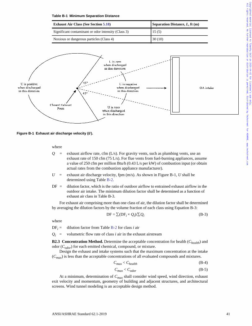
Figure
Copyrighted material licensed to Timothy Self on 2020-04-02 for licensee's use only. All rights reserved. No further reproduction or distribution is permitted. Distributed by Techstreet for ASHRAE, www.techstreet.com
whereQ = exhaust airflow rate, cfm (L/s). For gravity vents, such as plumbing vents, use an
exhaust rate of 150 cfm (75 L/s). For flue vents from fuel-burning appliances, assume a value of 250 cfm per million Btu/h (0.43 L/s per kW) of combustion input (or obtain actual rates from the combustion appliance manufacturer).
U = exhaust air discharge velocity, fpm (m/s). As shown in Figure B-1, U shall be determined using Table B-2.
DF = dilution factor, which is the ratio of outdoor airflow to entrained exhaust airflow in the outdoor air intake. The minimum dilution factor shall be determined as a function of exhaust air class in Table B-3.
For exhaust air comprising more than one class of air, the dilution factor shall be determinedby averaging the dilution factors by the volume fraction of each class using Equation B-3:
DF = (DFi × Qi)/Qi (B-3)whereDFi = dilution factor from Table B-2 for class i airQi = volumetric flow rate of class i air in the exhaust airstream
B2.3 Concentration Method. Determine the acceptable concentration for health (Chealth) andodor (Codor) for each emitted chemical, compound, or mixture.
Design the exhaust and intake systems such that the maximum concentration at the intake(Cmax) is less than the acceptable concentrations of all evaluated compounds and mixtures.
Cmax < Chealth (B-4)
Cmax < Codor (B-5)
At a minimum, determination of Cmax shall consider wind speed, wind direction, exhaustexit velocity and momentum, geometry of building and adjacent structures, and architecturalscreens. Wind tunnel modeling is an acceptable design method.
Table B-1 Minimum Separation Distance
Exhaust Air Class (See Section 5.18) Separation Distance, L, ft (m)
Significant contaminant or odor intensity (Class 3) 15 (5)
Noxious or dangerous particles (Class 4) 30 (10)
B-1 Exhaust air discharge velocity (U).
ANSI/ASHRAE Standard 62.1-2019 41
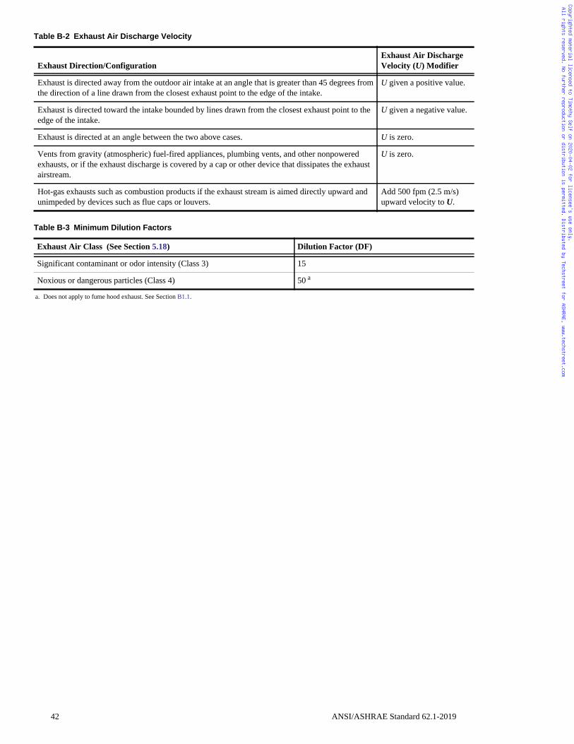
.
Copyrighted material licensed to Timothy Self on 2020-04-02 for licensee's use only. All rights reserved. No further reproduction or distribution is permitted. Distributed by Techstreet for ASHRAE, www.techstreet.com
Table B-2 Exhaust Air Discharge Velocity
Exhaust Direction/ConfigurationExhaust Air DischargeVelocity (U) Modifier
Exhaust is directed away from the outdoor air intake at an angle that is greater than 45 degrees from the direction of a line drawn from the closest exhaust point to the edge of the intake.
U given a positive value.
Exhaust is directed toward the intake bounded by lines drawn from the closest exhaust point to the edge of the intake.
U given a negative value
Exhaust is directed at an angle between the two above cases. U is zero.
Vents from gravity (atmospheric) fuel-fired appliances, plumbing vents, and other nonpowered exhausts, or if the exhaust discharge is covered by a cap or other device that dissipates the exhaust airstream.
U is zero.
Hot-gas exhausts such as combustion products if the exhaust stream is aimed directly upward and unimpeded by devices such as flue caps or louvers.
Add 500 fpm (2.5 m/s) upward velocity to U.
Table B-3 Minimum Dilution Factors
Exhaust Air Class (See Section 5.18) Dilution Factor (DF)
Significant contaminant or odor intensity (Class 3) 15
Noxious or dangerous particles (Class 4) 50 a
a. Does not apply to fume hood exhaust. See Section B1.1.
42 ANSI/ASHRAE Standard 62.1-2019
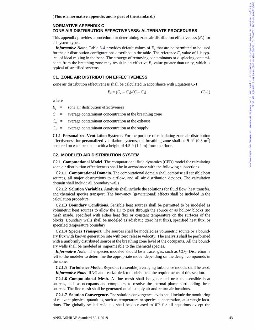
Copyrighted material licensed to Timothy Self on 2020-04-02 for licensee's use only. All rights reserved. No further reproduction or distribution is permitted. Distributed by Techstreet for ASHRAE, www.techstreet.com
(This is a normative appendix and is part of the standard.)
NORMATIVE APPENDIX CZONE AIR DISTRIBUTION EFFECTIVENESS: ALTERNATE PROCEDURES
This appendix provides a procedure for determining zone air distribution effectiveness (Ez) forall system types.
Informative Note: Table 6-4 provides default values of Ez that are be permitted to be usedfor the air distribution configurations described in the table. The reference Ez value of 1 is typ-ical of ideal mixing in the zone. The strategy of removing contaminants or displacing contami-nants from the breathing zone may result in an effective Ez value greater than unity, which istypical of stratified systems.
C1. ZONE AIR DISTRIBUTION EFFECTIVENESS
Zone air distribution effectiveness shall be calculated in accordance with Equation C-1:
Ez = (Ce – Cs)/(C – Cs) (C-1)
where
Ez = zone air distribution effectiveness
C = average contaminant concentration at the breathing zone
Ce = average contaminant concentration at the exhaust
Cs = average contaminant concentration at the supply
C1.1 Personalized Ventilation Systems. For the purpose of calculating zone air distributioneffectiveness for personalized ventilation systems, the breathing zone shall be 9 ft2 (0.8 m2)centered on each occupant with a height of 4.5 ft (1.4 m) from the floor.
C2. MODELED AIR DISTRIBUTION SYSTEM
C2.1 Computational Model. The computational fluid dynamics (CFD) model for calculatingzone air distribution effectiveness shall be in accordance with the following subsections.
C2.1.1 Computational Domain. The computational domain shall comprise all sensible heatsources, all major obstructions to airflow, and all air distribution devices. The calculationdomain shall include all boundary walls.
C2.1.2 Solution Variables. Analysis shall include the solutions for fluid flow, heat transfer,and chemical species transport. The buoyancy (gravitational) effects shall be included in thecalculation procedure.
C2.1.3 Boundary Conditions. Sensible heat sources shall be permitted to be modeled asvolumetric heat sources to allow the air to pass through the source or as hollow blocks (nomesh inside) specified with either heat flux or constant temperature on the surfaces of theblocks. Boundary walls shall be modeled as adiabatic (zero heat flux), specified heat flux, orspecified temperature boundary.
C2.1.4 Species Transport. The sources shall be modeled as volumetric source or a bound-ary flux with known generation rate with zero release velocity. The analysis shall be performedwith a uniformly distributed source at the breathing zone level of the occupants. All the bound-ary walls shall be modeled as impermeable to the chemical species.
Informative Note: The species modeled should be a tracer gas, such as CO2. Discretion isleft to the modeler to determine the appropriate model depending on the design compounds inthe zone.
C2.1.5 Turbulence Model. Reynolds (ensemble) averaging turbulence models shall be used.Informative Note: RNG and realizable k- models meet the requirements of this section.C2.1.6 Computational Mesh. A fine mesh shall be generated near the sensible heat
sources, such as occupants and computers, to resolve the thermal plume surrounding thesesources. The fine mesh shall be generated on all supply air and return air locations.
C2.1.7 Solution Convergence. The solution convergence levels shall include the monitoringof relevant physical quantities, such as temperature or species concentration, at strategic loca-tions. The globally scaled residuals shall be decreased to10–3 for all equations except the
ANSI/ASHRAE Standard 62.1-2019 43
Copyrighted material licensed to Timothy Self on 2020-04-02 for licensee's use only. All rights reserved. No further reproduction or distribution is permitted. Distributed by Techstreet for ASHRAE, www.techstreet.com
energy and species equations, for which the residuals shall be decreased to 10–7. The mass andenergy balance shall be calculated up to at least four (4) decimal places.
Informative Note: Review of the thermal comfort of occupants in the computational modelmay be desirable.C2.2 Zone Air Distribution Effectiveness. Zone air distribution effectiveness (Ez) shall becomputed in accordance with Equation C-1 for each computational cell in the breathing zone.The zone air distribution effectiveness (Ez) of the system shall be the average value of the zoneair distribution effectiveness of each computational cell within the breathing zone. The analysisshall be performed for both summer cooling conditions and winter heating conditions.
Informative Note: Validation of the computational model with physical measurementsduring design can improve the accuracy of the computational model and the zone air distribu-tion effectiveness of the system. Field measurements could also be performed post buildingoccupancy to verify zone air distribution effectiveness.
44 ANSI/ASHRAE Standard 62.1-2019
Copyrighted material licensed to Timothy Self on 2020-04-02 for licensee's use only. All rights reserved. No further reproduction or distribution is permitted. Distributed by Techstreet for ASHRAE, www.techstreet.com
(This appendix is not part of this standard. It is merely informative and does not containrequirements necessary for conformance to the standard. It has not been processedaccording to the ANSI requirements for a standard and may contain material that hasnot been subject to public review or a consensus process. Unresolved objectors on infor-mative material are not offered the right to appeal at ASHRAE or ANSI.)
INFORMATIVE APPENDIX DINFORMATION ON SELECTED NATIONAL STANDARDSAND GUIDELINES FOR PM10, PM2.5, AND OZONE
Standard 62.1, Section 4, requires that the status of compliance with National Ambient AirQuality Standards (NAAQS) shall be determined for the geographical area of the building site.Table D-1 is a representative table presenting the NAAQS information for the United States.Links to detailed information on the ambient air quality standards and contaminant levels forother select counties and regions are as follows:
• U.S. National Ambient Air Quality Standards (NAAQS): www.epa.gov/green-book andwww.epa.gov/criteria-air-pollutants/naaqs-table
• Canadian Ambient Air Quality Standards: www.ccme.ca/en/current_priorities/air/caaqs.html
• Hong Kong Air Quality Objectives: www.epd.gov.hk/epd/english/environmentinhk/air/air_quality_objectives/air_quality_objectives.html
• Singapore Air quality Targets: www.nea.gov.sg/our-services/pollution-control/air-pollution/air-quality
• European Commission Air Quality Standards: ec.europa.eu/environment/air/quality/stan-dards.htm
• Brazil Air Quality Standards: transportpolicy.net/index.php?title=Brazil:_Air_Quality_-Standards
• World Health Organization (WHO) Air Quality Guideline Values: www.who.int/mediacen-tre/factsheets/fs313/en
The Clean Air Act (www.epa.gov/clean-air-act-overview), which was last amended in1990, requires the U.S. Environmental Protection Agency (USEPA) to set national ambient airquality standards (40 CFR part 50) for pollutants considered harmful to public health and theenvironment. The Clean Air Act identifies two types of national ambient air quality standards.Primary standards provide public health protection, including protecting the health of “sensi-tive” populations, such as asthmatics, children, and the elderly. Secondary standards providepublic welfare protection, including protection against decreased visibility and damage to ani-mals, crops, vegetation, and buildings.
USEPA has set NAAQS for six principal pollutants, which are called “criteria” air pollut-ants (www.epa.gov/criteria-air-pollutants). Periodically, the standards are reviewed and may berevised. The current standards are listed in Table D-1. Units of measure for the standards areparts per million (ppm) by volume, parts per billion (ppb) by volume, and micrograms percubic metre of air (μg/m3).
ANSI/ASHRAE Standard 62.1-2019 45
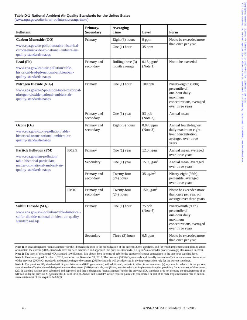
ore
ed
t -
ed
ed
ore ars
ed
ore
ttainct.
tion
onerrentf anon-
Copyrighted material licensed to Timothy Self on 2020-04-02 for licensee's use only. All rights reserved. No further reproduction or distribution is permitted. Distributed by Techstreet for ASHRAE, www.techstreet.com
Table D-1 National Ambient Air Quality Standards for the Unites States(www.epa.gov/criteria-air-pollutants/naaqs-table)
PollutantPrimary/Secondary
Averaging Time Level Form
Carbon Monoxide (CO)
www.epa.gov/co-pollution/table-historical-carbon-monoxide-co-national-ambient-air-quality-standards-naaqs
Primary Eight (8) hours 9 ppm Not to be exceeded mthan once per year
One (1) hour 35 ppm
Lead (Pb)
www.epa.gov/lead-air-pollution/table-historical-lead-pb-national-ambient-air-quality-standards-naaqs
Primary andsecondary
Rolling three (3) month average
0.15 μg/m3
(Note 1)Not to be exceeded
Nitrogen Dioxide (NO2)
www.epa.gov/no2-pollution/table-historical-nitrogen-dioxide-national-ambient-air-quality-standards-naaqs
Primary One (1) hour 100 ppb Ninety-eighth (98th) percentile of one-hour daily maximum concentrations, averagover three years
Primary andsecondary
One (1) year 53 ppb(Note 2)
Annual mean
Ozone (O3)
www.epa.gov/ozone-pollution/table-historical-ozone-national-ambient-air-quality-standards-naaqs
Primary andsecondary
Eight (8) hours 0.070 ppm(Note 3)
Annual fourth-highesdaily maximum eighthour concentration, averaged over three years
Particle Pollution (PM)
www.epa.gov/pm-pollution/table-historical-particulate-matter-pm-national-ambient-air-quality-standards-naaqs
PM2.5 Primary One (1) year 12.0 μg/m3 Annual mean, averagover three years
Secondary One (1) year 15.0 μg/m3 Annual mean, averagover three years
Primary andsecondary
Twenty-four(24) hours
35 μg/m3 Ninety-eight (98th) percentile, averaged over three years
PM10 Primary andsecondary
Twenty-four(24) hours
150 μg/m3 Not to be exceeded mthan once per year onaverage over three ye
Sulfur Dioxide (SO2)
www.epa.gov/so2-pollution/table-historical-sulfur-dioxide-national-ambient-air-quality-standards-naaqs
Primary One (1) hour 75 ppb(Note 4)
Ninety-ninth (99th) percentile of one-hour daily maximum concentrations, averagover three years
Secondary Three (3) hours 0.5 ppm Not to be exceeded mthan once per year
Note 1: In areas designated “nonattainment” for the Pb standards prior to the promulgation of the current (2008) standards, and for which implementation plans to aor maintain the current (2008) standards have not been submitted and approved, the previous standards (1.5 μg/m3 as a calendar quarter average) also remain in effeNote 2: The level of the annual NO2 standard is 0.053 ppm. It is shown here in terms of ppb for the purpose of clearer comparison to the one-hour standard level.Note 3: Final rule signed October 1, 2015, and effective December 28, 2015. The previous (2008) O3 standards additionally remain in effect in some areas. Revocaof the previous (2008) O3 standards and transitioning to the current (2015) standards will be addressed in the implementation rule for the current standards. Note 4: The previous SO2 standards (0.14 ppm 24-hour and 0.03 ppm annual) will additionally remain in effect in certain areas: (a) any area for which it is not yetyear since the effective date of designation under the current (2010) standards, and (b) any area for which an implementation plan providing for attainment of the cu(2010) standard has not been submitted and approved and that is designated “nonattainment” under the previous SO2 standards or is not meeting the requirements oSIP call under the previous SO2 standards (40 CFR 50.4[3). An SIP call is an EPA action requiring a state to resubmit all or part of its State Implementation Plan to demstrate attainment of the required NAAQS.
46 ANSI/ASHRAE Standard 62.1-2019
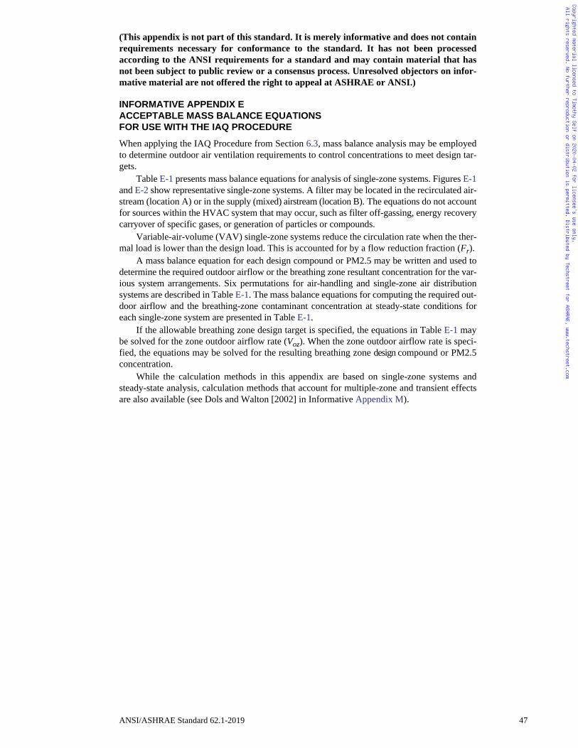
Copyrighted material licensed to Timothy Self on 2020-04-02 for licensee's use only. All rights reserved. No further reproduction or distribution is permitted. Distributed by Techstreet for ASHRAE, www.techstreet.com
(This appendix is not part of this standard. It is merely informative and does not containrequirements necessary for conformance to the standard. It has not been processedaccording to the ANSI requirements for a standard and may contain material that hasnot been subject to public review or a consensus process. Unresolved objectors on infor-mative material are not offered the right to appeal at ASHRAE or ANSI.)
INFORMATIVE APPENDIX EACCEPTABLE MASS BALANCE EQUATIONSFOR USE WITH THE IAQ PROCEDURE
When applying the IAQ Procedure from Section 6.3, mass balance analysis may be employedto determine outdoor air ventilation requirements to control concentrations to meet design tar-gets.
Table E-1 presents mass balance equations for analysis of single-zone systems. Figures E-1and E-2 show representative single-zone systems. A filter may be located in the recirculated air-stream (location A) or in the supply (mixed) airstream (location B). The equations do not accountfor sources within the HVAC system that may occur, such as filter off-gassing, energy recoverycarryover of specific gases, or generation of particles or compounds.
Variable-air-volume (VAV) single-zone systems reduce the circulation rate when the ther-mal load is lower than the design load. This is accounted for by a flow reduction fraction (Fr).
A mass balance equation for each design compound or PM2.5 may be written and used todetermine the required outdoor airflow or the breathing zone resultant concentration for the var-ious system arrangements. Six permutations for air-handling and single-zone air distributionsystems are described in Table E-1. The mass balance equations for computing the required out-door airflow and the breathing-zone contaminant concentration at steady-state conditions foreach single-zone system are presented in Table E-1.
If the allowable breathing zone design target is specified, the equations in Table E-1 maybe solved for the zone outdoor airflow rate (Voz). When the zone outdoor airflow rate is speci-fied, the equations may be solved for the resulting breathing zone design compound or PM2.5concentration.
While the calculation methods in this appendix are based on single-zone systems andsteady-state analysis, calculation methods that account for multiple-zone and transient effectsare also available (see Dols and Walton [2002] in Informative Appendix M).
ANSI/ASHRAE Standard 62.1-2019 47
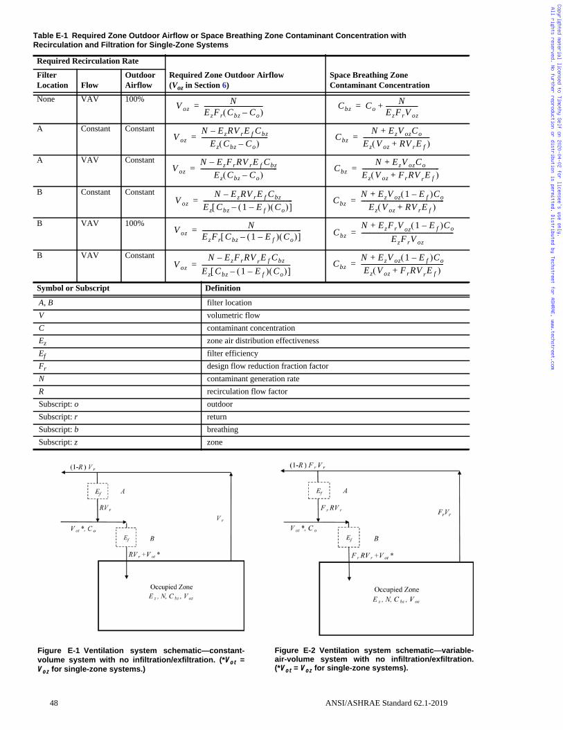
ble-tion.
Copyrighted material licensed to Timothy Self on 2020-04-02 for licensee's use only. All rights reserved. No further reproduction or distribution is permitted. Distributed by Techstreet for ASHRAE, www.techstreet.com
Table E-1 Required Zone Outdoor Airflow or Space Breathing Zone Contaminant Concentration withRecirculation and Filtration for Single-Zone Systems
Required Recirculation Rate
Required Zone Outdoor Airflow(Voz in Section 6)
Space Breathing ZoneContaminant Concentration
FilterLocation Flow
OutdoorAirflow
None VAV 100%
A Constant Constant
A VAV Constant
B Constant Constant
B VAV 100%
B VAV Constant
Symbol or Subscript Definition
A, B filter locationV volumetric flowC contaminant concentrationEz zone air distribution effectivenessEf filter efficiencyFr design flow reduction fraction factorN contaminant generation rateR recirculation flow factorSubscript: o outdoorSubscript: r returnSubscript: b breathingSubscript: z zone
V ozN
EzFr Cbz Co– --------------------------------------= Cbz Co
NEzFrV oz---------------------+=
V ozN EzRV rE f Cbz–
Ez Cbz Co– -------------------------------------------= Cbz
N EzV ozCo+
Ez V oz RV rE f+ -------------------------------------------=
V ozN EzFrRV rE f Cbz–
Ez Cbz Co– --------------------------------------------------= Cbz
N EzV ozCo+
Ez V oz FrRV rE f+ --------------------------------------------------=
V ozN EzRV rE f Cbz–
Ez Cbz 1 E f– Co – ----------------------------------------------------------= Cbz
N EzV oz 1 E f– Co+
Ez V oz RV rE f+ ------------------------------------------------------=
V ozN
EzFr Cbz 1 E f– Co – ----------------------------------------------------------------= Cbz
N EzFrV oz 1 E f– Co+
EzFrV oz------------------------------------------------------------=
V ozN EzFrRV rE f Cbz–
Ez Cbz 1 E f– Co – ----------------------------------------------------------= Cbz
N EzV oz 1 E f– Co+
Ez V oz FrRV rE f+ ------------------------------------------------------=
Figure E-1 Ventilation system schematic—constant-volume system with no infiltration/exfiltration. (*Vot =Voz for single-zone systems.)
Figure E-2 Ventilation system schematic—variaair-volume system with no infiltration/exfiltra(*Vot = Voz for single-zone systems).
48 ANSI/ASHRAE Standard 62.1-2019
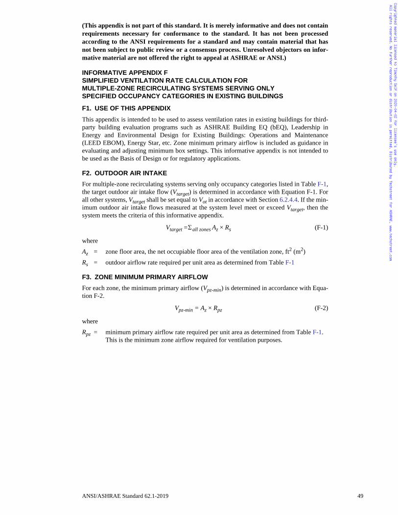
Copyrighted material licensed to Timothy Self on 2020-04-02 for licensee's use only. All rights reserved. No further reproduction or distribution is permitted. Distributed by Techstreet for ASHRAE, www.techstreet.com
(This appendix is not part of this standard. It is merely informative and does not containrequirements necessary for conformance to the standard. It has not been processedaccording to the ANSI requirements for a standard and may contain material that hasnot been subject to public review or a consensus process. Unresolved objectors on infor-mative material are not offered the right to appeal at ASHRAE or ANSI.)
INFORMATIVE APPENDIX FSIMPLIFIED VENTILATION RATE CALCULATION FORMULTIPLE-ZONE RECIRCULATING SYSTEMS SERVING ONLYSPECIFIED OCCUPANCY CATEGORIES IN EXISTING BUILDINGS
F1. USE OF THIS APPENDIX
This appendix is intended to be used to assess ventilation rates in existing buildings for third-party building evaluation programs such as ASHRAE Building EQ (bEQ), Leadership inEnergy and Environmental Design for Existing Buildings: Operations and Maintenance(LEED EBOM), Energy Star, etc. Zone minimum primary airflow is included as guidance inevaluating and adjusting minimum box settings. This informative appendix is not intended tobe used as the Basis of Design or for regulatory applications.
F2. OUTDOOR AIR INTAKE
For multiple-zone recirculating systems serving only occupancy categories listed in Table F-1,the target outdoor air intake flow (Vtarget) is determined in accordance with Equation F-1. Forall other systems, Vtarget shall be set equal to Vot in accordance with Section 6.2.4.4. If the min-imum outdoor air intake flows measured at the system level meet or exceed Vtarget, then thesystem meets the criteria of this informative appendix.
Vtarget = all zones Az × Rs (F-1)
where
Az = zone floor area, the net occupiable floor area of the ventilation zone, ft2 (m2)
Rs = outdoor airflow rate required per unit area as determined from Table F-1
F3. ZONE MINIMUM PRIMARY AIRFLOW
For each zone, the minimum primary airflow (Vpz-min) is determined in accordance with Equa-tion F-2.
Vpz-min = Az × Rpz (F-2)
where
Rpz = minimum primary airflow rate required per unit area as determined from Table F-1. This is the minimum zone airflow required for ventilation purposes.
ANSI/ASHRAE Standard 62.1-2019 49
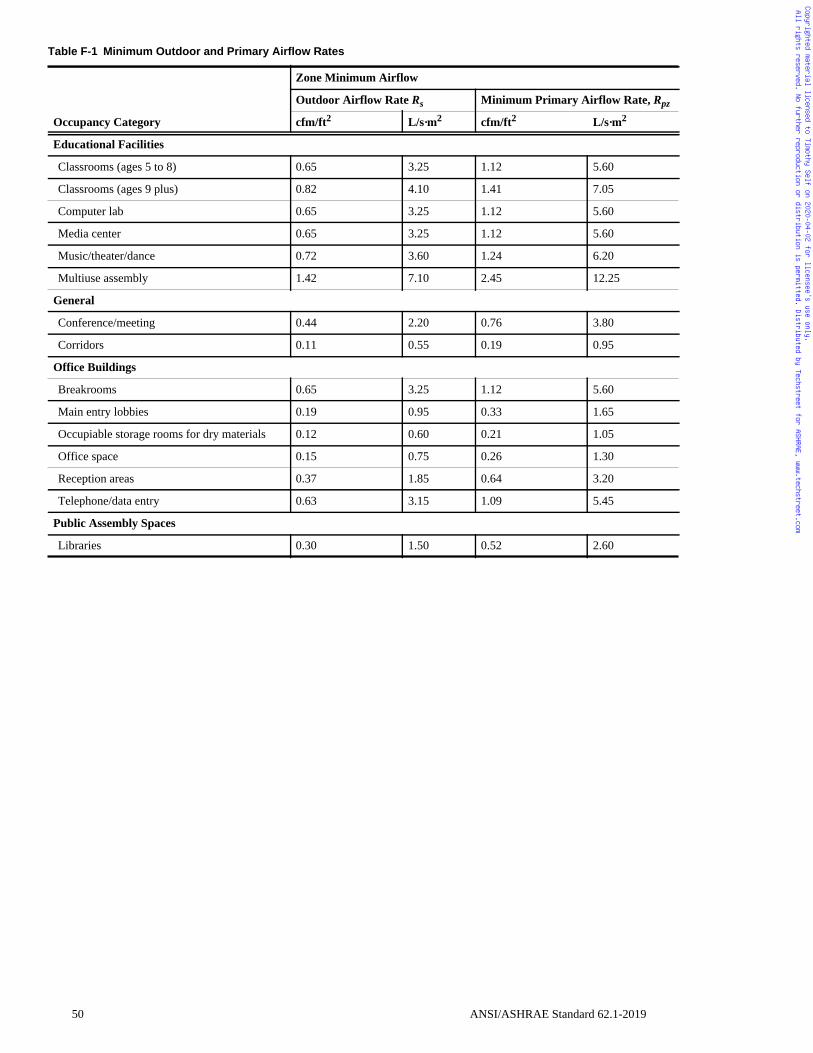
pz
Copyrighted material licensed to Timothy Self on 2020-04-02 for licensee's use only. All rights reserved. No further reproduction or distribution is permitted. Distributed by Techstreet for ASHRAE, www.techstreet.com
Table F-1 Minimum Outdoor and Primary Airflow Rates
Occupancy Category
Zone Minimum Airflow
Outdoor Airflow Rate Rs Minimum Primary Airflow Rate, R
cfm/ft2 L/s·m2 cfm/ft2 L/s·m2
Educational Facilities
Classrooms (ages 5 to 8) 0.65 3.25 1.12 5.60
Classrooms (ages 9 plus) 0.82 4.10 1.41 7.05
Computer lab 0.65 3.25 1.12 5.60
Media center 0.65 3.25 1.12 5.60
Music/theater/dance 0.72 3.60 1.24 6.20
Multiuse assembly 1.42 7.10 2.45 12.25
General
Conference/meeting 0.44 2.20 0.76 3.80
Corridors 0.11 0.55 0.19 0.95
Office Buildings
Breakrooms 0.65 3.25 1.12 5.60
Main entry lobbies 0.19 0.95 0.33 1.65
Occupiable storage rooms for dry materials 0.12 0.60 0.21 1.05
Office space 0.15 0.75 0.26 1.30
Reception areas 0.37 1.85 0.64 3.20
Telephone/data entry 0.63 3.15 1.09 5.45
Public Assembly Spaces
Libraries 0.30 1.50 0.52 2.60
50 ANSI/ASHRAE Standard 62.1-2019
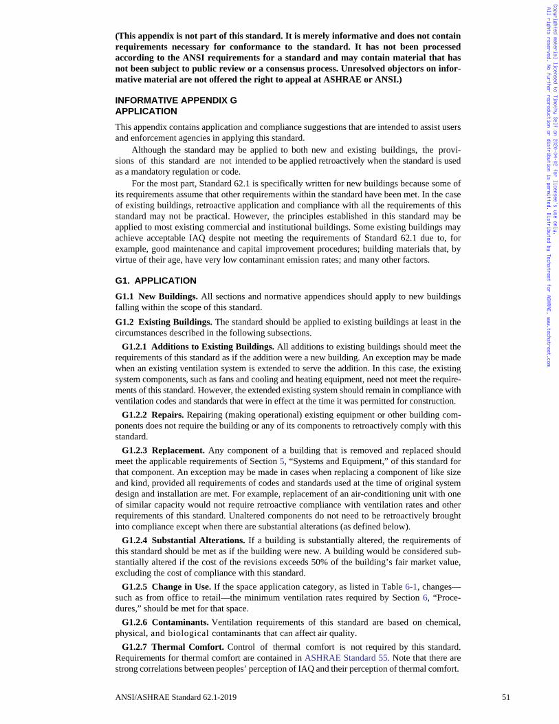
Copyrighted material licensed to Timothy Self on 2020-04-02 for licensee's use only. All rights reserved. No further reproduction or distribution is permitted. Distributed by Techstreet for ASHRAE, www.techstreet.com
(This appendix is not part of this standard. It is merely informative and does not containrequirements necessary for conformance to the standard. It has not been processedaccording to the ANSI requirements for a standard and may contain material that hasnot been subject to public review or a consensus process. Unresolved objectors on infor-mative material are not offered the right to appeal at ASHRAE or ANSI.)
INFORMATIVE APPENDIX GAPPLICATION
This appendix contains application and compliance suggestions that are intended to assist usersand enforcement agencies in applying this standard.
Although the standard may be applied to both new and existing buildings, the provi-sions of this standard are not intended to be applied retroactively when the standard is usedas a mandatory regulation or code.
For the most part, Standard 62.1 is specifically written for new buildings because some ofits requirements assume that other requirements within the standard have been met. In the caseof existing buildings, retroactive application and compliance with all the requirements of thisstandard may not be practical. However, the principles established in this standard may beapplied to most existing commercial and institutional buildings. Some existing buildings mayachieve acceptable IAQ despite not meeting the requirements of Standard 62.1 due to, forexample, good maintenance and capital improvement procedures; building materials that, byvirtue of their age, have very low contaminant emission rates; and many other factors.
G1. APPLICATION
G1.1 New Buildings. All sections and normative appendices should apply to new buildingsfalling within the scope of this standard.G1.2 Existing Buildings. The standard should be applied to existing buildings at least in thecircumstances described in the following subsections.
G1.2.1 Additions to Existing Buildings. All additions to existing buildings should meet therequirements of this standard as if the addition were a new building. An exception may be madewhen an existing ventilation system is extended to serve the addition. In this case, the existingsystem components, such as fans and cooling and heating equipment, need not meet the require-ments of this standard. However, the extended existing system should remain in compliance withventilation codes and standards that were in effect at the time it was permitted for construction.
G1.2.2 Repairs. Repairing (making operational) existing equipment or other building com-ponents does not require the building or any of its components to retroactively comply with thisstandard.
G1.2.3 Replacement. Any component of a building that is removed and replaced shouldmeet the applicable requirements of Section 5, “Systems and Equipment,” of this standard forthat component. An exception may be made in cases when replacing a component of like sizeand kind, provided all requirements of codes and standards used at the time of original systemdesign and installation are met. For example, replacement of an air-conditioning unit with oneof similar capacity would not require retroactive compliance with ventilation rates and otherrequirements of this standard. Unaltered components do not need to be retroactively broughtinto compliance except when there are substantial alterations (as defined below).
G1.2.4 Substantial Alterations. If a building is substantially altered, the requirements ofthis standard should be met as if the building were new. A building would be considered sub-stantially altered if the cost of the revisions exceeds 50% of the building’s fair market value,excluding the cost of compliance with this standard.
G1.2.5 Change in Use. If the space application category, as listed in Table 6-1, changes—such as from office to retail—the minimum ventilation rates required by Section 6, “Proce-dures,” should be met for that space.
G1.2.6 Contaminants. Ventilation requirements of this standard are based on chemical,physical, and biological contaminants that can affect air quality.
G1.2.7 Thermal Comfort. Control of thermal comfort is not required by this standard.Requirements for thermal comfort are contained in ASHRAE Standard 55. Note that there arestrong correlations between peoples’ perception of IAQ and their perception of thermal comfort.
ANSI/ASHRAE Standard 62.1-2019 51
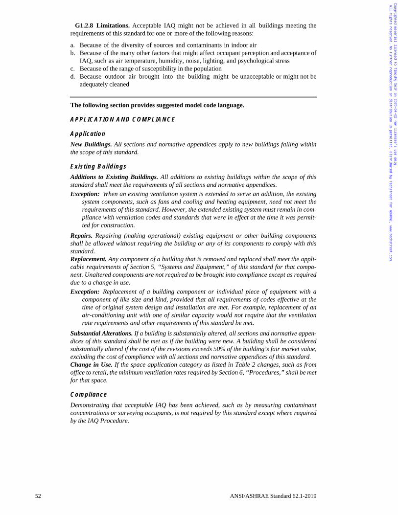
Copyrighted material licensed to Timothy Self on 2020-04-02 for licensee's use only. All rights reserved. No further reproduction or distribution is permitted. Distributed by Techstreet for ASHRAE, www.techstreet.com
G1.2.8 Limitations. Acceptable IAQ might not be achieved in all buildings meeting therequirements of this standard for one or more of the following reasons:
a. Because of the diversity of sources and contaminants in indoor airb. Because of the many other factors that might affect occupant perception and acceptance of
IAQ, such as air temperature, humidity, noise, lighting, and psychological stressc. Because of the range of susceptibility in the populationd. Because outdoor air brought into the building might be unacceptable or might not be
adequately cleaned
The following section provides suggested model code language.
APPLICATION AND COMPLIANCE
Application
New Buildings. All sections and normative appendices apply to new buildings falling withinthe scope of this standard.
Existing Buildings
Additions to Existing Buildings. All additions to existing buildings within the scope of thisstandard shall meet the requirements of all sections and normative appendices.Exception: When an existing ventilation system is extended to serve an addition, the existing
system components, such as fans and cooling and heating equipment, need not meet therequirements of this standard. However, the extended existing system must remain in com-pliance with ventilation codes and standards that were in effect at the time it was permit-ted for construction.
Repairs. Repairing (making operational) existing equipment or other building componentsshall be allowed without requiring the building or any of its components to comply with thisstandard.Replacement. Any component of a building that is removed and replaced shall meet the appli-cable requirements of Section 5, “Systems and Equipment,” of this standard for that compo-nent. Unaltered components are not required to be brought into compliance except as requireddue to a change in use.Exception: Replacement of a building component or individual piece of equipment with a
component of like size and kind, provided that all requirements of codes effective at thetime of original system design and installation are met. For example, replacement of anair-conditioning unit with one of similar capacity would not require that the ventilationrate requirements and other requirements of this standard be met.
Substantial Alterations. If a building is substantially altered, all sections and normative appen-dices of this standard shall be met as if the building were new. A building shall be consideredsubstantially altered if the cost of the revisions exceeds 50% of the building’s fair market value,excluding the cost of compliance with all sections and normative appendices of this standard.Change in Use. If the space application category as listed in Table 2 changes, such as fromoffice to retail, the minimum ventilation rates required by Section 6, “Procedures,” shall be metfor that space.
Compliance
Demonstrating that acceptable IAQ has been achieved, such as by measuring contaminantconcentrations or surveying occupants, is not required by this standard except where requiredby the IAQ Procedure.
52 ANSI/ASHRAE Standard 62.1-2019
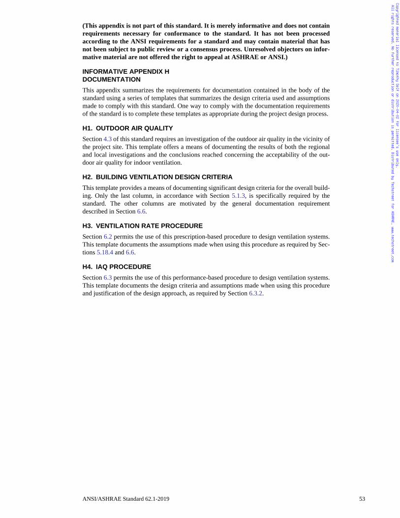
Copyrighted material licensed to Timothy Self on 2020-04-02 for licensee's use only. All rights reserved. No further reproduction or distribution is permitted. Distributed by Techstreet for ASHRAE, www.techstreet.com
(This appendix is not part of this standard. It is merely informative and does not containrequirements necessary for conformance to the standard. It has not been processedaccording to the ANSI requirements for a standard and may contain material that hasnot been subject to public review or a consensus process. Unresolved objectors on infor-mative material are not offered the right to appeal at ASHRAE or ANSI.)
INFORMATIVE APPENDIX HDOCUMENTATION
This appendix summarizes the requirements for documentation contained in the body of thestandard using a series of templates that summarizes the design criteria used and assumptionsmade to comply with this standard. One way to comply with the documentation requirementsof the standard is to complete these templates as appropriate during the project design process.
H1. OUTDOOR AIR QUALITY
Section 4.3 of this standard requires an investigation of the outdoor air quality in the vicinity ofthe project site. This template offers a means of documenting the results of both the regionaland local investigations and the conclusions reached concerning the acceptability of the out-door air quality for indoor ventilation.
H2. BUILDING VENTILATION DESIGN CRITERIA
This template provides a means of documenting significant design criteria for the overall build-ing. Only the last column, in accordance with Section 5.1.3, is specifically required by thestandard. The other columns are motivated by the general documentation requirementdescribed in Section 6.6.
H3. VENTILATION RATE PROCEDURE
Section 6.2 permits the use of this prescription-based procedure to design ventilation systems.This template documents the assumptions made when using this procedure as required by Sec-tions 5.18.4 and 6.6.
H4. IAQ PROCEDURE
Section 6.3 permits the use of this performance-based procedure to design ventilation systems.This template documents the design criteria and assumptions made when using this procedureand justification of the design approach, as required by Section 6.3.2.
ANSI/ASHRAE Standard 62.1-2019 53
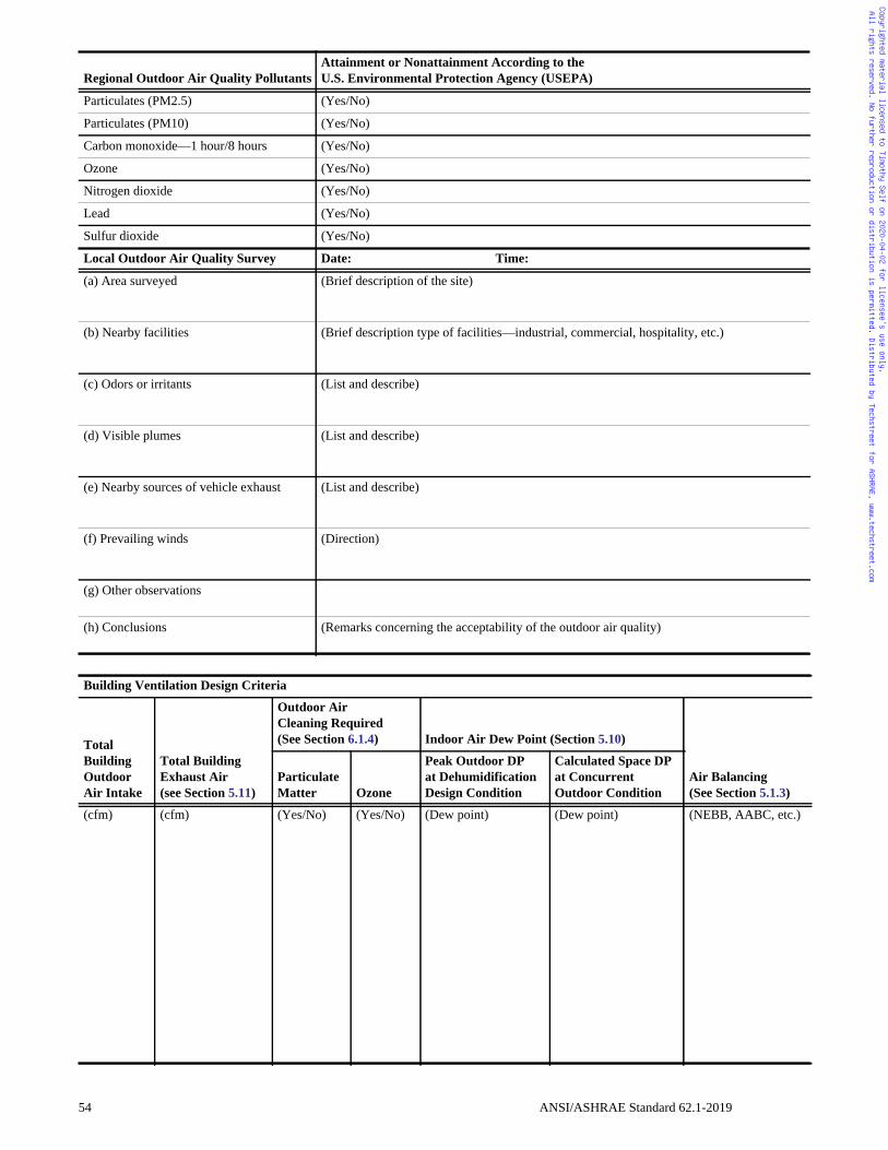
Copyrighted material licensed to Timothy Self on 2020-04-02 for licensee's use only. All rights reserved. No further reproduction or distribution is permitted. Distributed by Techstreet for ASHRAE, www.techstreet.com
Regional Outdoor Air Quality PollutantsAttainment or Nonattainment According to the U.S. Environmental Protection Agency (USEPA)
Particulates (PM2.5) (Yes/No)
Particulates (PM10) (Yes/No)
Carbon monoxide—1 hour/8 hours (Yes/No)
Ozone (Yes/No)
Nitrogen dioxide (Yes/No)
Lead (Yes/No)
Sulfur dioxide (Yes/No)
Local Outdoor Air Quality Survey Date: Time:
(a) Area surveyed (Brief description of the site)
(b) Nearby facilities (Brief description type of facilities—industrial, commercial, hospitality, etc.)
(c) Odors or irritants (List and describe)
(d) Visible plumes (List and describe)
(e) Nearby sources of vehicle exhaust (List and describe)
(f) Prevailing winds (Direction)
(g) Other observations
(h) Conclusions (Remarks concerning the acceptability of the outdoor air quality)
Building Ventilation Design Criteria
Total Building OutdoorAir Intake
Total Building Exhaust Air (see Section 5.11)
Outdoor AirCleaning Required(See Section 6.1.4) Indoor Air Dew Point (Section 5.10)
Air Balancing(See Section 5.1.3)
Particulate Matter Ozone
Peak Outdoor DPat Dehumidification Design Condition
Calculated Space DP at Concurrent Outdoor Condition
(cfm) (cfm) (Yes/No) (Yes/No) (Dew point) (Dew point) (NEBB, AABC, etc.)
54 ANSI/ASHRAE Standard 62.1-2019
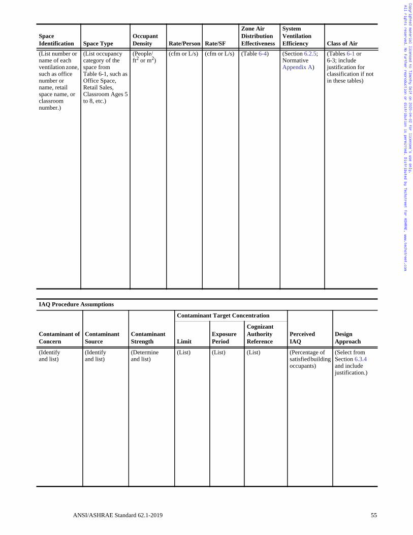
Copyrighted material licensed to Timothy Self on 2020-04-02 for licensee's use only. All rights reserved. No further reproduction or distribution is permitted. Distributed by Techstreet for ASHRAE, www.techstreet.com
Space Identification Space Type
Occupant Density Rate/Person Rate/SF
Zone Air Distribution Effectiveness
System Ventilation Efficiency Class of Air
(List number or name of each ventilation zone, such as office number or name, retail space name, or classroom number.)
(List occupancy category of the space from Table 6-1, such as Office Space, Retail Sales, Classroom Ages 5 to 8, etc.)
(People/ft2 or m2)
(cfm or L/s) (cfm or L/s) (Table 6-4) (Section 6.2.5; Normative Appendix A)
(Tables 6-1 or6-3; include justification for classification if not in these tables)
IAQ Procedure Assumptions
Contaminant of Concern
Contaminant Source
Contaminant Strength
Contaminant Target Concentration
Perceived IAQ
Design ApproachLimit
Exposure Period
Cognizant Authority Reference
(Identify and list)
(Identifyand list)
(Determine and list)
(List) (List) (List) (Percentage of satisfied building occupants)
(Select from Section 6.3.4 and includejustification.)
ANSI/ASHRAE Standard 62.1-2019 55
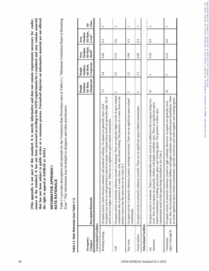
56
Copyrighted material licensed to Timothy Self on 2020-04-02 for licensee's use only. All rights reserved. No further reproduction or distribution is permitted. Distributed by Techstreet for ASHRAE, www.techstreet.com
(Thi
s ap
pend
ix i
s no
t pa
rt o
f th
is st
anda
rd.
It i
s m
erel
y in
form
ativ
e an
d do
es n
ot c
onta
in r
equi
rem
ents
nec
essa
ry f
or c
onfo
r-m
ance
to
the
stan
dard
. It
has
not
bee
n pr
oces
sed
acco
rdin
g to
the A
NSI
requ
irem
ents
for a
stan
dard
and
may
con
tain
mat
eria
lth
at h
as n
ot b
een
subj
ect
to p
ublic
rev
iew
or
a co
nsen
sus
proc
ess.
Unr
esol
ved
obje
ctor
s on
info
rmat
ive
mat
eria
l are
not
offe
red
the
righ
t to
appe
al a
t ASH
RA
E or
AN
SI.)
INF
OR
MA
TIV
EA
PP
EN
DIX
IR
AT
ER
AT
ION
AL
E
Tabl
e I-
1 pr
ovid
es d
escr
iptio
n an
d ra
tiona
le fo
r the
Ven
tilat
ion
Rat
e Pr
oced
ure
rate
s in
Tabl
e 6-
1, “
Min
imum
Ven
tilat
ion
Rat
es in
Bre
athi
ngZo
ne.”
Thi
s inf
orm
atio
n m
ay b
e he
lpfu
l to
desi
gner
s and
oth
er p
ract
ition
ers.
Tab
leI-
1R
ate
Rat
ion
ale
(see
Tab
le6-
1)
Occ
upan
cy
Cat
egor
yD
escr
iptio
n/R
atio
nale
Peop
le
Out
door
Air
Rat
e,cf
m/p
erso
n
Peop
le
Out
door
Air
Rat
e,L
/s/p
erso
n
Are
aO
utdo
orA
ir R
ate,
cfm
/ft2
Are
aO
utdo
orA
ir R
ate,
L
/s·m
2A
irC
lass
Cor
rect
iona
l Fac
ilitie
s
Boo
king
/wai
ting
Occ
upan
t act
ivity
var
ies b
etw
een
sede
ntar
y an
d m
oder
ate
wal
king
. Occ
upan
ts a
re g
ener
ally
mor
e vo
cal.
Occ
upan
ts m
ay n
ot b
e as
wel
l-gro
omed
as t
ypic
al o
ccup
ants
. Occ
upan
t stre
ss le
vels
are
gen
eral
ly h
igh.
All
of
whi
ch re
sult
in h
ighe
r met
abol
ic ra
tes.
Ther
e ar
e no
sign
ifica
nt sp
ace-
rela
ted
cont
amin
ants
.
7.5
3.8
0.06
0.3
2
Cel
l O
ccup
ant a
ctiv
ity is
prim
arily
sede
ntar
y (s
eate
d or
slee
ping
). Th
ere
are
typi
cally
hig
her l
evel
s of s
pace
-rel
ated
co
ntam
inan
ts d
ue to
pre
senc
e of
a w
ater
clo
set,
sink
, and
stor
ed c
loth
ing.
The
pre
senc
e of
a w
ater
clo
set i
s the
pr
imar
y re
ason
why
this
spac
e ha
s an
Air
Cla
ss o
f 2.
52.
50.
120.
62
Day
room
O
ccup
ant a
ctiv
ity is
prim
arily
sede
ntar
y (s
eate
d, w
atch
ing
tele
visi
on).
Ther
e ar
e no
sign
ifica
nt sp
ace-
rela
ted
cont
amin
ants
.5
2.5
0.06
0.3
1
Gua
rd st
atio
ns
Occ
upan
t act
ivity
is p
rimar
ily se
dent
ary
(sea
ted)
. The
re a
re n
o si
gnifi
cant
spac
e-re
late
d co
ntam
inan
ts.
52.
50.
060.
31
Edu
catio
nal F
acili
ties
Art
clas
sroo
m
Occ
upan
t act
ivity
is m
oder
ate.
The
re is
con
side
rabl
e ae
robi
c ac
tivity
in a
dditi
on to
the
occu
pant
s bei
ng v
ery
voca
l. A
lso,
the
occu
pant
s are
prim
arily
chi
ldre
n w
ith h
ighe
r met
abol
ic ra
tes.
Ther
e ar
e si
gnifi
cant
spac
e-re
late
d co
ntam
inan
ts, i
nclu
ding
ope
n pa
ints
, glu
es, a
nd c
lean
ing
agen
ts. T
he p
rese
nce
of th
ese
open
co
ntam
inan
ts re
sult
in th
is sp
ace
bein
g cl
assi
fied
as A
ir C
lass
2.
105
0.18
0.9
2
Cla
ssro
oms
(age
s 5 th
roug
h 8)
O
ccup
ant a
ctiv
ity is
prim
arily
sede
ntar
y (s
eate
d or
ligh
t wal
king
). H
owev
er, o
ccup
ants
are
gen
eral
ly m
ore
voca
l. A
lso,
the o
ccup
ants
are p
rimar
ily ch
ildre
n w
ith h
ighe
r met
abol
ic ra
tes a
nd o
ften
mor
e bio
efflu
ents
. The
re
are
som
e si
gnifi
cant
spac
e-re
late
d co
ntam
inan
ts, t
ypic
ally
stor
ed a
rts-a
nd-c
rafts
supp
lies a
nd c
lean
ing
agen
ts.
105
0.12
0.6
1
ANSI/ASHRAE Standard 62.1-2019
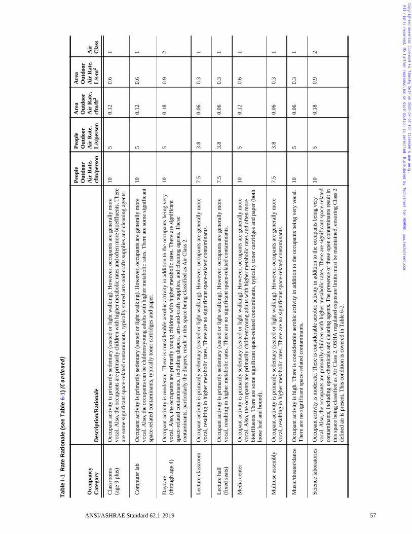
Copyrighted material licensed to Timothy Self on 2020-04-02 for licensee's use only. All rights reserved. No further reproduction or distribution is permitted. Distributed by Techstreet for ASHRAE, www.techstreet.com
Cla
ssro
oms
(age
9 p
lus)
O
ccup
ant a
ctiv
ity is
prim
arily
sede
ntar
y (s
eate
d or
ligh
t wal
king
). H
owev
er, o
ccup
ants
are
gen
eral
ly m
ore
voca
l. A
lso,
the o
ccup
ants
are p
rimar
ily ch
ildre
n w
ith h
ighe
r met
abol
ic ra
tes a
nd o
ften
mor
e bio
efflu
ents
. The
re
are
som
e si
gnifi
cant
spac
e-re
late
d co
ntam
inan
ts, t
ypic
ally
stor
ed a
rts-a
nd-c
rafts
supp
lies a
nd c
lean
ing
agen
ts.
105
0.12
0.6
1
Com
pute
r lab
O
ccup
ant a
ctiv
ity is
prim
arily
sede
ntar
y (s
eate
d or
ligh
t wal
king
). H
owev
er, o
ccup
ants
are
gen
eral
ly m
ore
voca
l. A
lso,
the
occu
pant
s can
be
child
ren/
youn
g ad
ults
with
hig
her m
etab
olic
rate
s. Th
ere
are
som
e si
gnifi
cant
sp
ace-
rela
ted
cont
amin
ants
, typ
ical
ly to
ner c
artri
dges
and
pap
er.
105
0.12
0.6
1
Day
care
(thro
ugh
age
4)
Occ
upan
t act
ivity
is m
oder
ate.
The
re is
con
side
rabl
e ae
robi
c ac
tivity
in a
dditi
on to
the
occu
pant
s bei
ng v
ery
voca
l. A
lso,
the
occu
pant
s are
prim
arily
you
ng c
hild
ren
with
hig
her m
etab
olic
rate
s. Th
ere
are
sign
ifica
nt
spac
e-re
late
d co
ntam
inan
ts, i
nclu
ding
dia
pers
, arts
-and
-cra
fts su
pplie
s, an
d cl
eani
ng a
gent
s. Th
ese
cont
amin
ants
, par
ticul
arly
the
diap
ers,
resu
lt in
this
spac
e be
ing
clas
sifie
d as
Air
Cla
ss 2
.
105
0.18
0.9
2
Lect
ure
clas
sroo
m
Occ
upan
t act
ivity
is p
rimar
ily se
dent
ary
(sea
ted
or li
ght w
alki
ng).
How
ever
, occ
upan
ts a
re g
ener
ally
mor
e vo
cal,
resu
lting
in h
ighe
r met
abol
ic ra
tes.
Ther
e ar
e no
sign
ifica
nt sp
ace-
rela
ted
cont
amin
ants
.7.
53.
80.
060.
31
Lect
ure
hall
(fix
ed se
ats)
O
ccup
ant a
ctiv
ity is
prim
arily
sede
ntar
y (s
eate
d or
ligh
t wal
king
). H
owev
er, o
ccup
ants
are
gen
eral
ly m
ore
voca
l, re
sulti
ng in
hig
her m
etab
olic
rate
s. Th
ere
are
no si
gnifi
cant
spac
e-re
late
d co
ntam
inan
ts.
7.5
3.8
0.06
0.3
1
Med
ia c
ente
r O
ccup
ant a
ctiv
ity is
prim
arily
sede
ntar
y (s
eate
d or
ligh
t wal
king
). H
owev
er, o
ccup
ants
are
gen
eral
ly m
ore
voca
l. A
lso,
the
occu
pant
s are
prim
arily
chi
ldre
n/yo
ung
adul
ts w
ith h
ighe
r met
abol
ic ra
tes a
nd o
ften
mor
e bi
oeff
luen
ts. T
here
are
som
e si
gnifi
cant
spac
e-re
late
d co
ntam
inan
ts, t
ypic
ally
tone
r car
tridg
es a
nd p
aper
(bot
h lo
ose
leaf
and
bou
nd).
105
0.12
0.6
1
Mul
tiuse
ass
embl
y O
ccup
ant a
ctiv
ity is
prim
arily
sede
ntar
y (s
eate
d or
ligh
t wal
king
). H
owev
er, o
ccup
ants
are
gen
eral
ly m
ore
voca
l, re
sulti
ng in
hig
her m
etab
olic
rate
s. Th
ere
are
no si
gnifi
cant
spac
e-re
late
d co
ntam
inan
ts.
7.5
3.8
0.06
0.3
1
Mus
ic/th
eate
r/dan
ce
Occ
upan
t act
ivity
is h
igh.
The
re is
con
side
rabl
e ae
robi
c ac
tivity
in a
dditi
on to
the
occu
pant
s bei
ng v
ery
voca
l. Th
ere
are
no si
gnifi
cant
spac
e-re
late
d co
ntam
inan
ts.
105
0.06
0.3
1
Scie
nce
labo
rato
ries
Occ
upan
t act
ivity
is m
oder
ate.
The
re is
con
side
rabl
e ae
robi
c ac
tivity
in a
dditi
on to
the
occu
pant
s bei
ng v
ery
voca
l. A
lso,
the
occu
pant
s are
prim
arily
chi
ldre
n w
ith h
ighe
r met
abol
ic ra
tes.
Ther
e ar
e si
gnifi
cant
spac
e-re
late
d co
ntam
inan
ts, i
nclu
ding
ope
n ch
emic
als a
nd c
lean
ing
agen
ts. T
he p
rese
nce
of th
ese
open
con
tam
inan
ts re
sult
in
this
spac
e be
ing
clas
sifie
d as
Air
Cla
ss 2
. OSH
A re
gula
ted
expo
sure
lim
its m
ust b
e m
aint
aine
d, e
nsur
ing
Cla
ss 2
de
fined
air
is p
rese
nt. T
his c
ondi
tion
is c
over
ed in
Tab
le 6
-2.
105
0.18
0.9
2
Tab
leI-
1R
ate
Rat
ion
ale
(see
Tab
le6-
1)(C
on
tin
ued
)
Occ
upan
cy
Cat
egor
yD
escr
iptio
n/R
atio
nale
Peop
le
Out
door
Air
Rat
e,cf
m/p
erso
n
Peop
le
Out
door
Air
Rat
e,L
/s/p
erso
n
Are
aO
utdo
orA
ir R
ate,
cfm
/ft2
Are
aO
utdo
orA
ir R
ate,
L
/s·m
2A
irC
lass
ANSI/ASHRAE Standard 62.1-2019 57
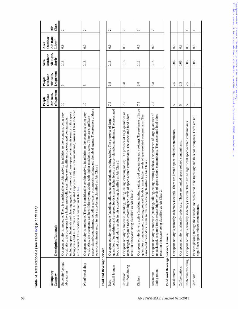
58
Copyrighted material licensed to Timothy Self on 2020-04-02 for licensee's use only. All rights reserved. No further reproduction or distribution is permitted. Distributed by Techstreet for ASHRAE, www.techstreet.com
Uni
vers
ity/c
olle
ge
labo
rato
ries
Occ
upan
t act
ivity
is m
oder
ate.
The
re is
con
side
rabl
e ae
robi
c ac
tivity
in a
dditi
on to
the
occu
pant
s bei
ng v
ery
voca
l. A
lso,
the
occu
pant
s hav
e hi
gher
met
abol
ic ra
tes.
Ther
e ar
e si
gnifi
cant
spac
e-re
late
d co
ntam
inan
ts,
incl
udin
g op
en c
hem
ical
s and
cle
anin
g ag
ents
. The
pre
senc
e of
thes
e op
en c
onta
min
ants
resu
lts in
this
spac
e be
ing
clas
sifie
d as
Air
Cla
ss 2
. OSH
A re
gula
ted
expo
sure
lim
its m
ust b
e m
aint
aine
d, e
nsur
ing
Cla
ss 2
def
ined
ai
r is p
rese
nt. T
his c
ondi
tion
is c
over
ed in
Tab
le 6
-2.
105
0.18
0.9
2
Woo
d/m
etal
shop
O
ccup
ant a
ctiv
ity is
mod
erat
e. T
here
is c
onsi
dera
ble
aero
bic
activ
ity in
add
ition
to th
e oc
cupa
nts b
eing
ver
y vo
cal.
Als
o, th
e oc
cupa
nts c
an b
e ch
ildre
n/yo
ung
adul
ts w
ith h
ighe
r met
abol
ic ra
tes.
Ther
e ar
e si
gnifi
cant
sp
ace-
rela
ted
cont
amin
ants
, inc
ludi
ng sa
wdu
st, o
ils, m
etal
shav
ings
, and
chem
ical
agen
ts. T
he p
rese
nce o
f the
se
open
con
tam
inan
ts re
sult
in th
is sp
ace
bein
g cl
assi
fied
as A
ir C
lass
2.
105
0.18
0.9
2
Food
and
Bev
erag
e Se
rvic
e
Bar
s, co
ckta
il lo
unge
s O
ccup
ant a
ctiv
ity is
mod
erat
e (s
tand
ing,
talk
ing,
eat
ing/
drin
king
, wai
ting
tabl
es).
The
pres
ence
of l
arge
qu
antit
ies o
f ope
n dr
inks
and
prep
ared
food
s cre
ates
hig
her l
evel
s of s
pace
-rel
ated
cont
amin
ants
. The
asso
ciat
ed
food
and
drin
k od
ors r
esul
ts in
this
spac
e be
ing
clas
sifie
d as
Air
Cla
ss 2
.
7.5
3.8
0.18
0.9
2
Caf
eter
ia/
fast
-foo
d di
ning
O
ccup
ant a
ctiv
ity is
mod
erat
e (s
tand
ing,
talk
ing,
eat
ing,
cle
anin
g ta
bles
). Th
e pr
esen
ce o
f lar
ge q
uant
ities
of
unpa
ckag
ed, p
repa
red
food
s cre
ates
hig
her l
evel
s of s
pace
-rel
ated
con
tam
inan
ts. T
he a
ssoc
iate
d fo
od o
dors
re
sult
in th
is sp
ace
bein
g cl
assi
fied
as A
ir C
lass
2.
7.5
3.8
0.18
0.9
2
Kitc
hen
Occ
upan
t act
ivity
is v
ery
activ
e (w
alki
ng, t
alki
ng, e
atin
g, fo
od p
repa
ratio
n an
d co
okin
g). T
he p
rese
nce
of la
rge
quan
titie
s of u
npac
kage
d, c
ooki
ng p
repa
red
food
s cre
ates
hig
her l
evel
s of s
pace
-rel
ated
con
tam
inan
ts. T
he
asso
ciat
ed fo
od o
dors
resu
lts in
this
spac
e be
ing
clas
sifie
d as
Air
Cla
ss 2
.
7.5
3.8
0.12
0.6
2
Res
taur
ant
dini
ng ro
oms
Occ
upan
t act
ivity
is m
oder
ate
(sta
ndin
g, ta
lkin
g, e
atin
g, w
aitin
g ta
bles
). Th
e pr
esen
ce o
f lar
ge q
uant
ities
of
unpa
ckag
ed, p
repa
red
food
s cre
ates
hig
her l
evel
s of s
pace
-rel
ated
con
tam
inan
ts. T
he a
ssoc
iate
d fo
od o
dors
re
sult
in th
is sp
ace
bein
g cl
assi
fied
as A
ir C
lass
2.
7.5
3.8
0.18
0.9
2
Food
and
Bev
erag
e Se
rvic
e, G
ener
al
Bre
ak ro
oms
Occ
upan
t act
ivity
is p
rimar
ily se
dent
ary
(sea
ted)
. The
re a
re li
mite
d sp
ace-
rela
ted
cont
amin
ants
.5
2.5
0.06
0.3
Cof
fee
stat
ions
Occ
upan
t act
ivity
is p
rimar
ily se
dent
ary.
The
re a
re li
mite
d sp
ace-
rela
ted
cont
amin
ants
.5
2.5
0.06
0.3
Con
fere
nce/
mee
ting
Occ
upan
t act
ivity
is p
rimar
ily se
dent
ary
(sea
ted)
. The
re a
re n
o si
gnifi
cant
spac
e-re
late
d co
ntam
inan
ts.
52.
50.
060.
31
Cor
ridor
s Pe
rson
s pas
sing
thro
ugh
the
corr
idor
are
con
side
red
to b
e tra
nsito
ry a
nd th
us n
ot o
ccup
ants
. The
re a
re n
o si
gnifi
cant
spac
e-re
late
d co
ntam
inan
ts.
——
0.06
0.3
1
Tab
leI-
1R
ate
Rat
ion
ale
(see
Tab
le6-
1)(C
on
tin
ued
)
Occ
upan
cy
Cat
egor
yD
escr
iptio
n/R
atio
nale
Peop
le
Out
door
Air
Rat
e,cf
m/p
erso
n
Peop
le
Out
door
Air
Rat
e,L
/s/p
erso
n
Are
aO
utdo
orA
ir R
ate,
cfm
/ft2
Are
aO
utdo
orA
ir R
ate,
L
/s·m
2A
irC
lass
ANSI/ASHRAE Standard 62.1-2019
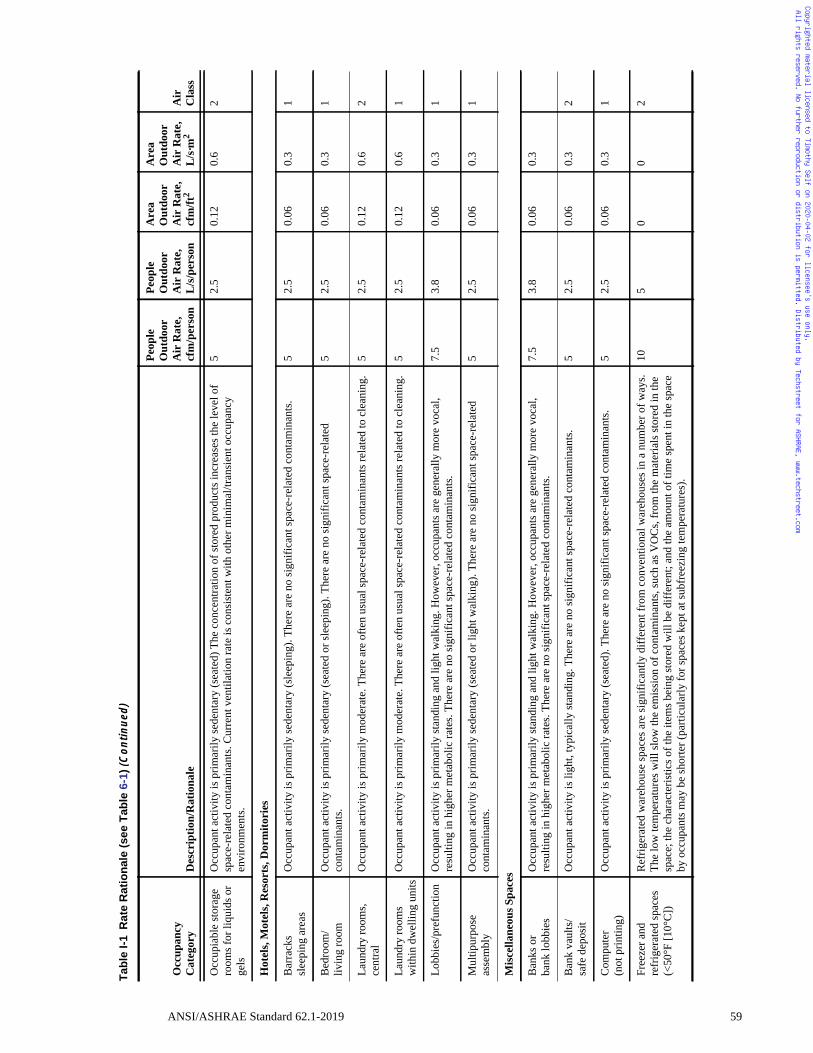
Copyrighted material licensed to Timothy Self on 2020-04-02 for licensee's use only. All rights reserved. No further reproduction or distribution is permitted. Distributed by Techstreet for ASHRAE, www.techstreet.com
Occ
upia
ble
stor
age
room
s for
liqu
ids o
r ge
ls
Occ
upan
t act
ivity
is p
rimar
ily se
dent
ary
(sea
ted)
The
con
cent
ratio
n of
stor
ed p
rodu
cts i
ncre
ases
the
leve
l of
spac
e-re
late
d co
ntam
inan
ts. C
urre
nt v
entil
atio
n ra
te is
con
sist
ent w
ith o
ther
min
imal
/tran
sien
t occ
upan
cy
envi
ronm
ents
.
52.
50.
120.
62
Hot
els,
Mot
els,
Res
orts
, Dor
mito
ries
Bar
rack
ssl
eepi
ng a
reas
O
ccup
ant a
ctiv
ity is
prim
arily
sede
ntar
y (s
leep
ing)
. The
re a
re n
o si
gnifi
cant
spac
e-re
late
d co
ntam
inan
ts.
52.
50.
060.
31
Bed
room
/liv
ing
room
O
ccup
ant a
ctiv
ity is
prim
arily
sede
ntar
y (s
eate
d or
slee
ping
). Th
ere
are
no si
gnifi
cant
spac
e-re
late
d co
ntam
inan
ts.
52.
50.
060.
31
Laun
dry
room
s, ce
ntra
lO
ccup
ant a
ctiv
ity is
prim
arily
mod
erat
e. T
here
are
ofte
n us
ual s
pace
-rel
ated
con
tam
inan
ts re
late
d to
cle
anin
g.5
2.5
0.12
0.6
2
Laun
dry
room
s w
ithin
dw
ellin
g un
itsO
ccup
ant a
ctiv
ity is
prim
arily
mod
erat
e. T
here
are
ofte
n us
ual s
pace
-rel
ated
con
tam
inan
ts re
late
d to
cle
anin
g.5
2.5
0.12
0.6
1
Lobb
ies/
pref
unct
ion
Occ
upan
t act
ivity
is p
rimar
ily st
andi
ng a
nd li
ght w
alki
ng. H
owev
er, o
ccup
ants
are
gen
eral
ly m
ore
voca
l, re
sulti
ng in
hig
her m
etab
olic
rate
s. Th
ere
are
no si
gnifi
cant
spac
e-re
late
d co
ntam
inan
ts.
7.5
3.8
0.06
0.3
1
Mul
tipur
pose
as
sem
bly
Occ
upan
t act
ivity
is p
rimar
ily se
dent
ary
(sea
ted
or li
ght w
alki
ng).
Ther
e ar
e no
sign
ifica
nt sp
ace-
rela
ted
cont
amin
ants
.5
2.5
0.06
0.3
1
Mis
cella
neou
s Spa
ces
Ban
ks o
rba
nk lo
bbie
sO
ccup
ant a
ctiv
ity is
prim
arily
stan
ding
and
ligh
t wal
king
. How
ever
, occ
upan
ts a
re g
ener
ally
mor
e vo
cal,
resu
lting
in h
ighe
r met
abol
ic ra
tes.
Ther
e ar
e no
sign
ifica
nt sp
ace-
rela
ted
cont
amin
ants
.7.
53.
80.
060.
3
Ban
k va
ults
/sa
fe d
epos
it O
ccup
ant a
ctiv
ity is
ligh
t, ty
pica
lly st
andi
ng. T
here
are
no
sign
ifica
nt sp
ace-
rela
ted
cont
amin
ants
. 5
2.5
0.06
0.3
2
Com
pute
r(n
ot p
rintin
g)
Occ
upan
t act
ivity
is p
rimar
ily se
dent
ary
(sea
ted)
. The
re a
re n
o si
gnifi
cant
spac
e-re
late
d co
ntam
inan
ts.
52.
50.
060.
31
Free
zer a
nd
refr
iger
ated
spac
es
(<50
°F [1
0°C
])
Ref
riger
ated
war
ehou
se sp
aces
are
sign
ifica
ntly
diff
eren
t fro
m c
onve
ntio
nal w
areh
ouse
s in
a nu
mbe
r of w
ays.
The
low
tem
pera
ture
s will
slow
the
emis
sion
of c
onta
min
ants
, suc
h as
VO
Cs,
from
the
mat
eria
ls st
ored
in th
e sp
ace;
the
char
acte
ristic
s of t
he it
ems b
eing
stor
ed w
ill b
e di
ffer
ent;
and
the
amou
nt o
f tim
e sp
ent i
n th
e sp
ace
by o
ccup
ants
may
be
shor
ter (
parti
cula
rly fo
r spa
ces k
ept a
t sub
free
zing
tem
pera
ture
s).
105
00
2
Tab
leI-
1R
ate
Rat
ion
ale
(see
Tab
le6-
1)(C
on
tin
ued
)
Occ
upan
cy
Cat
egor
yD
escr
iptio
n/R
atio
nale
Peop
le
Out
door
Air
Rat
e,cf
m/p
erso
n
Peop
le
Out
door
Air
Rat
e,L
/s/p
erso
n
Are
aO
utdo
orA
ir R
ate,
cfm
/ft2
Are
aO
utdo
orA
ir R
ate,
L
/s·m
2A
irC
lass
ANSI/ASHRAE Standard 62.1-2019 59
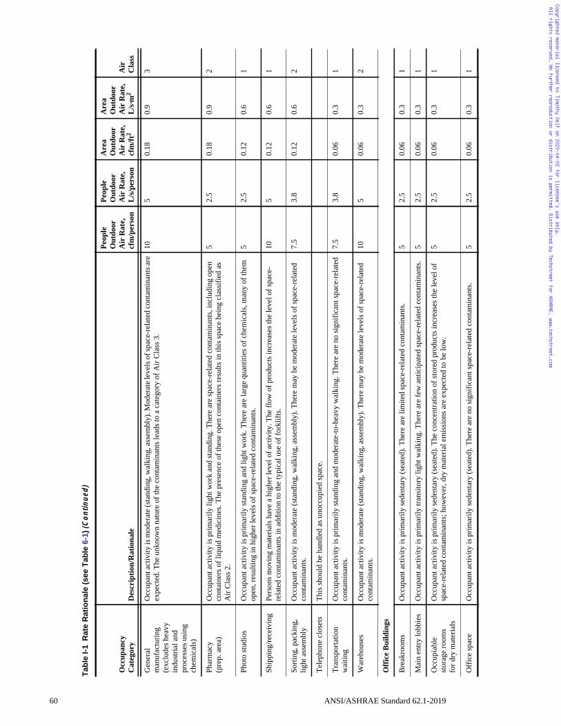
60
Copyrighted material licensed to Timothy Self on 2020-04-02 for licensee's use only. All rights reserved. No further reproduction or distribution is permitted. Distributed by Techstreet for ASHRAE, www.techstreet.com
Gen
eral
m
anuf
actu
ring
(exc
lude
s hea
vy
indu
stria
l and
pr
oces
ses u
sing
ch
emic
als)
Occ
upan
t act
ivity
is m
oder
ate (
stan
ding
, wal
king
, ass
embl
y). M
oder
ate l
evel
s of s
pace
-rel
ated
cont
amin
ants
are
expe
cted
. The
unk
now
n na
ture
of t
he c
onta
min
ants
lead
s to
a ca
tego
ry o
f Air
Cla
ss 3
.10
50.
180.
93
Phar
mac
y(p
rep.
are
a)
Occ
upan
t act
ivity
is p
rimar
ily li
ght w
ork
and
stan
ding
. The
re a
re sp
ace-
rela
ted
cont
amin
ants
, inc
ludi
ng o
pen
cont
aine
rs o
f liq
uid
med
icin
es. T
he p
rese
nce
of th
ese
open
con
tain
ers r
esul
ts in
this
spac
e be
ing
clas
sifie
d as
A
ir C
lass
2.
52.
50.
180.
92
Phot
o st
udio
s O
ccup
ant a
ctiv
ity is
prim
arily
stan
ding
and
ligh
t wor
k. T
here
are
larg
e qu
antit
ies o
f che
mic
als,
man
y of
them
op
en, r
esul
ting
in h
ighe
r lev
els o
f spa
ce-r
elat
ed c
onta
min
ants
.5
2.5
0.12
0.6
1
Ship
ping
/rece
ivin
g Pe
rson
s mov
ing
mat
eria
ls h
ave
a hi
gher
leve
l of a
ctiv
ity. T
he fl
ow o
f pro
duct
s inc
reas
es th
e le
vel o
f spa
ce-
rela
ted
cont
amin
ants
in a
dditi
on to
the
typi
cal u
se o
f for
klift
s. 10
50.
120.
61
Sorti
ng, p
acki
ng,
light
ass
embl
yO
ccup
ant a
ctiv
ity is
mod
erat
e (s
tand
ing,
wal
king
, ass
embl
y). T
here
may
be
mod
erat
e le
vels
of s
pace
-rel
ated
co
ntam
inan
ts.
7.5
3.8
0.12
0.6
2
Tele
phon
e cl
oset
sTh
is sh
ould
be
hand
led
as u
nocc
upie
d sp
ace.
Tran
spor
tatio
n w
aitin
g O
ccup
ant a
ctiv
ity is
prim
arily
stan
ding
and
mod
erat
e-to
-hea
vy w
alki
ng. T
here
are
no
sign
ifica
nt sp
ace-
rela
ted
cont
amin
ants
.7.
53.
80.
060.
31
War
ehou
ses
Occ
upan
t act
ivity
is m
oder
ate
(sta
ndin
g, w
alki
ng, a
ssem
bly)
. The
re m
ay b
e m
oder
ate
leve
ls o
f spa
ce-r
elat
ed
cont
amin
ants
. 10
50.
060.
32
Offi
ce B
uild
ings
Bre
akro
oms
Occ
upan
t act
ivity
is p
rimar
ily se
dent
ary
(sea
ted)
. The
re a
re li
mite
d sp
ace-
rela
ted
cont
amin
ants
. 5
2.5
0.06
0.3
1
Mai
n en
try lo
bbie
s O
ccup
ant a
ctiv
ity is
prim
arily
tran
sito
ry li
ght w
alki
ng. T
here
are
few
ant
icip
ated
spac
e-re
late
d co
ntam
inan
ts.
52.
50.
060.
31
Occ
upia
ble
stor
age
room
sfo
r dry
mat
eria
ls
Occ
upan
t act
ivity
is p
rimar
ily se
dent
ary
(sea
ted)
. The
con
cent
ratio
n of
stor
ed p
rodu
cts i
ncre
ases
the
leve
l of
spac
e-re
late
d co
ntam
inan
ts; h
owev
er, d
ry m
ater
ial e
mis
sion
s are
exp
ecte
d to
be
low
.5
2.5
0.06
0.3
1
Off
ice
spac
e O
ccup
ant a
ctiv
ity is
prim
arily
sede
ntar
y (s
eate
d). T
here
are
no
sign
ifica
nt sp
ace-
rela
ted
cont
amin
ants
.5
2.5
0.06
0.3
1
Tab
leI-
1R
ate
Rat
ion
ale
(see
Tab
le6-
1)(C
on
tin
ued
)
Occ
upan
cy
Cat
egor
yD
escr
iptio
n/R
atio
nale
Peop
le
Out
door
Air
Rat
e,cf
m/p
erso
n
Peop
le
Out
door
Air
Rat
e,L
/s/p
erso
n
Are
aO
utdo
orA
ir R
ate,
cfm
/ft2
Are
aO
utdo
orA
ir R
ate,
L
/s·m
2A
irC
lass
ANSI/ASHRAE Standard 62.1-2019
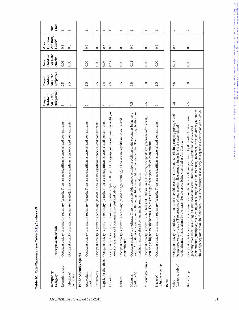
Copyrighted material licensed to Timothy Self on 2020-04-02 for licensee's use only. All rights reserved. No further reproduction or distribution is permitted. Distributed by Techstreet for ASHRAE, www.techstreet.com
Rec
eptio
n ar
eas
Occ
upan
t act
ivity
is p
rimar
ily se
dent
ary
(sea
ted)
. The
re a
re n
o si
gnifi
cant
spac
e-re
late
d co
ntam
inan
ts.
52.
50.
060.
31
Tele
phon
e/da
ta e
ntry
O
ccup
ant a
ctiv
ity is
prim
arily
sede
ntar
y (s
eate
d). T
here
are
no
sign
ifica
nt sp
ace-
rela
ted
cont
amin
ants
.5
2.5
0.06
0.3
1
Publ
ic A
ssem
bly
Spac
es
Aud
itoriu
mse
atin
g ar
ea
Occ
upan
t act
ivity
is p
rimar
ily se
dent
ary
(sea
ted)
. The
re a
re n
o si
gnifi
cant
spac
e-re
late
d co
ntam
inan
ts.
52.
50.
060.
31
Cou
rtroo
ms
Occ
upan
t act
ivity
is p
rimar
ily se
dent
ary
(sea
ted)
. The
re a
re n
o si
gnifi
cant
spac
e-re
late
d co
ntam
inan
ts.
52.
50.
060.
31
Legi
slat
ive c
ham
bers
O
ccup
ant a
ctiv
ity is
prim
arily
sede
ntar
y (s
eate
d). T
here
are
no
sign
ifica
nt sp
ace-
rela
ted
cont
amin
ants
.5
2.5
0.06
0.3
1
Libr
arie
s O
ccup
ant a
ctiv
ity is
prim
arily
sede
ntar
y (s
eate
d or
ligh
t wal
king
). Th
e la
rge
quan
titie
s of b
ooks
cre
ate
high
er
leve
ls o
f spa
ce-r
elat
ed c
onta
min
ants
(dus
t and
odo
rs).
52.
50.
120.
61
Lobb
ies
Occ
upan
t act
ivity
is p
rimar
ily se
dent
ary
(sea
ted
or li
ght w
alki
ng).
Ther
e ar
e no
sign
ifica
nt sp
ace-
rela
ted
cont
amin
ants
.5
2.5
0.06
0.3
1
Mus
eum
s (c
hild
ren’
s)
Occ
upan
t act
ivity
is m
oder
ate.
The
re is
con
side
rabl
e ae
robi
c ac
tivity
in a
dditi
on to
the
occu
pant
s bei
ng v
ery
voca
l. A
lso,
the
occu
pant
s are
typi
cally
you
ng c
hild
ren
with
hig
her m
etab
olic
rate
s. Th
ere
are
typi
cally
som
e si
gnifi
cant
spac
e-re
late
d co
ntam
inan
ts, s
uch
as fo
od a
nd d
rink.
7.5
3.8
0.12
0.6
1
Mus
eum
s/ga
llerie
s O
ccup
ant a
ctiv
ity is
prim
arily
stan
ding
and
ligh
t wal
king
. How
ever
, occ
upan
ts a
re g
ener
ally
mor
e vo
cal,
resu
lting
in h
ighe
r met
abol
ic ra
tes.
Ther
e ar
e no
sign
ifica
nt sp
ace-
rela
ted
cont
amin
ants
.7.
53.
80.
060.
31
Plac
es o
fre
ligio
us w
orsh
ip
Occ
upan
t act
ivity
is p
rimar
ily se
dent
ary
(sea
ted)
. The
re a
re n
o si
gnifi
cant
spac
e-re
late
d co
ntam
inan
ts.
52.
50.
060.
31
Ret
ail
Sale
s(e
xcep
t as b
elow
) O
ccup
ant a
ctiv
ity is
mod
erat
e. T
here
is c
onsi
dera
ble
occu
pant
mov
emen
t, in
clud
ing
carr
ying
pac
kage
s and
be
ing
mor
e vo
cally
act
ive.
The
pre
senc
e of
new
mer
chan
dise
cre
ates
hig
her l
evel
s of s
pace
-rel
ated
co
ntam
inan
ts. T
his i
s prim
arily
the
reas
on fo
r the
spac
e be
ing
clas
sifie
d as
Air
Cla
ss 2
.
7.5
3.8
0.12
0.6
2
Bar
ber s
hop
Occ
upan
t act
ivity
is p
rimar
ily se
dent
ary,
with
mod
erat
e w
ork
bein
g pe
rfor
med
by
the
staf
f. O
ccup
ants
are
ge
nera
lly m
ore
voca
l, re
sulti
ng in
hig
her m
etab
olic
rate
s. Th
ere
are
som
e si
gnifi
cant
spac
e-re
late
d co
ntam
inan
ts (s
ham
poos
, dis
infe
ctin
g ag
ents
, hig
h le
vels
of h
uman
hai
r). H
owev
er, t
hese
are
dire
ctly
rela
ted
to
the
occu
panc
y ra
ther
than
the
floor
are
a. T
his i
s the
prim
ary
reas
on w
hy th
is sp
ace
is c
lass
ified
as A
ir C
lass
2.
7.5
3.8
0.06
0.3
2
Tab
leI-
1R
ate
Rat
ion
ale
(see
Tab
le6-
1)(C
on
tin
ued
)
Occ
upan
cy
Cat
egor
yD
escr
iptio
n/R
atio
nale
Peop
le
Out
door
Air
Rat
e,cf
m/p
erso
n
Peop
le
Out
door
Air
Rat
e,L
/s/p
erso
n
Are
aO
utdo
orA
ir R
ate,
cfm
/ft2
Are
aO
utdo
orA
ir R
ate,
L
/s·m
2A
irC
lass
ANSI/ASHRAE Standard 62.1-2019 61
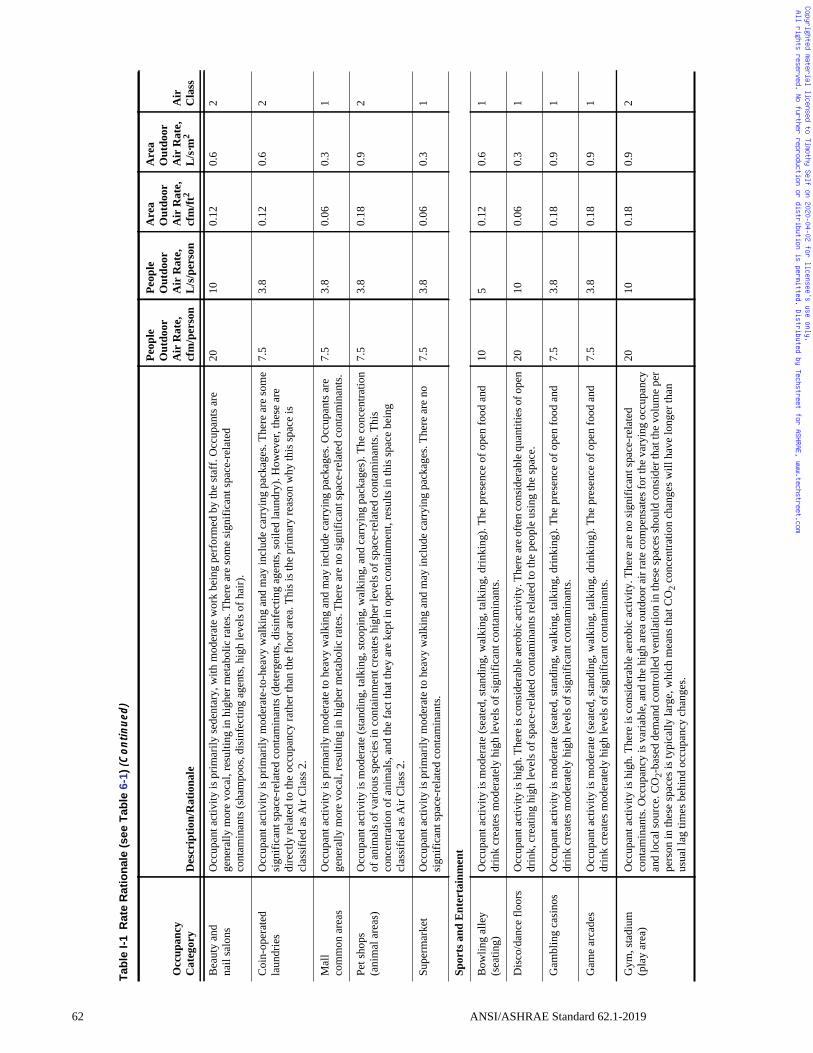
62
Copyrighted material licensed to Timothy Self on 2020-04-02 for licensee's use only. All rights reserved. No further reproduction or distribution is permitted. Distributed by Techstreet for ASHRAE, www.techstreet.com
Bea
uty
and
nail
salo
ns
Occ
upan
t act
ivity
is p
rimar
ily se
dent
ary,
with
mod
erat
e w
ork
bein
g pe
rfor
med
by
the
staf
f. O
ccup
ants
are
ge
nera
lly m
ore
voca
l, re
sulti
ng in
hig
her m
etab
olic
rate
s. Th
ere
are
som
e si
gnifi
cant
spac
e-re
late
d co
ntam
inan
ts (s
ham
poos
, dis
infe
ctin
g ag
ents
, hig
h le
vels
of h
air)
.
2010
0.12
0.6
2
Coi
n-op
erat
ed
laun
drie
s O
ccup
ant a
ctiv
ity is
prim
arily
mod
erat
e-to
-hea
vy w
alki
ng a
nd m
ay in
clud
e ca
rryi
ng p
acka
ges.
Ther
e ar
e so
me
sign
ifica
nt sp
ace-
rela
ted
cont
amin
ants
(det
erge
nts,
disi
nfec
ting
agen
ts, s
oile
d la
undr
y). H
owev
er, t
hese
are
di
rect
ly re
late
d to
the
occu
panc
y ra
ther
than
the
floor
are
a. T
his i
s the
prim
ary
reas
on w
hy th
is sp
ace
is
clas
sifie
d as
Air
Cla
ss 2
.
7.5
3.8
0.12
0.6
2
Mal
lco
mm
on a
reas
O
ccup
ant a
ctiv
ity is
prim
arily
mod
erat
e to
hea
vy w
alki
ng a
nd m
ay in
clud
e ca
rryi
ng p
acka
ges.
Occ
upan
ts a
re
gene
rally
mor
e vo
cal,
resu
lting
in h
ighe
r met
abol
ic ra
tes.
Ther
e ar
e no
sign
ifica
nt sp
ace-
rela
ted
cont
amin
ants
.7.
53.
80.
060.
31
Pet s
hops
(ani
mal
are
as)
Occ
upan
t act
ivity
is m
oder
ate
(sta
ndin
g, ta
lkin
g, st
oopi
ng, w
alki
ng, a
nd c
arry
ing
pack
ages
). Th
e co
ncen
tratio
n of
ani
mal
s of v
ario
us sp
ecie
s in
cont
ainm
ent c
reat
es h
ighe
r lev
els o
f spa
ce-r
elat
ed c
onta
min
ants
. Thi
s co
ncen
tratio
n of
ani
mal
s, an
d th
e fa
ct th
at th
ey a
re k
ept i
n op
en c
onta
inm
ent,
resu
lts in
this
spac
e be
ing
clas
sifie
d as
Air
Cla
ss 2
.
7.5
3.8
0.18
0.9
2
Supe
rmar
ket
Occ
upan
t act
ivity
is p
rimar
ily m
oder
ate
to h
eavy
wal
king
and
may
incl
ude
carr
ying
pac
kage
s. Th
ere
are
no
sign
ifica
nt sp
ace-
rela
ted
cont
amin
ants
.7.
53.
80.
060.
31
Spor
ts a
nd E
nter
tain
men
t
Bow
ling
alle
y (s
eatin
g)
Occ
upan
t act
ivity
is m
oder
ate
(sea
ted,
stan
ding
, wal
king
, tal
king
, drin
king
). Th
e pr
esen
ce o
f ope
n fo
od a
nd
drin
k cr
eate
s mod
erat
ely
high
leve
ls o
f sig
nific
ant c
onta
min
ants
.10
50.
120.
61
Dis
co/d
ance
floo
rs
Occ
upan
t act
ivity
is h
igh.
The
re is
cons
ider
able
aero
bic a
ctiv
ity. T
here
are o
ften
cons
ider
able
qua
ntiti
es o
f ope
n dr
ink,
cre
atin
g hi
gh le
vels
of s
pace
-rel
ated
con
tam
inan
ts re
late
d to
the
peop
le u
sing
the
spac
e.
2010
0.06
0.3
1
Gam
blin
g ca
sino
s O
ccup
ant a
ctiv
ity is
mod
erat
e (s
eate
d, st
andi
ng, w
alki
ng, t
alki
ng, d
rinki
ng).
The
pres
ence
of o
pen
food
and
dr
ink
crea
tes m
oder
atel
y hi
gh le
vels
of s
igni
fican
t con
tam
inan
ts.
7.5
3.8
0.18
0.9
1
Gam
e ar
cade
s O
ccup
ant a
ctiv
ity is
mod
erat
e (s
eate
d, st
andi
ng, w
alki
ng, t
alki
ng, d
rinki
ng).
The
pres
ence
of o
pen
food
and
dr
ink
crea
tes m
oder
atel
y hi
gh le
vels
of s
igni
fican
t con
tam
inan
ts.
7.5
3.8
0.18
0.9
1
Gym
, sta
dium
(pla
y ar
ea)
Occ
upan
t act
ivity
is h
igh.
The
re is
con
side
rabl
e ae
robi
c ac
tivity
. The
re a
re n
o si
gnifi
cant
spac
e-re
late
d co
ntam
inan
ts. O
ccup
ancy
is v
aria
ble,
and
the
high
are
a ou
tdoo
r air
rate
com
pens
ates
for t
he v
aryi
ng o
ccup
ancy
an
d lo
cal s
ourc
e. C
O2-
base
d de
man
d co
ntro
lled
vent
ilatio
n in
thes
e sp
aces
shou
ld c
onsi
der t
hat t
he v
olum
e pe
r pe
rson
in th
ese
spac
es is
typi
cally
larg
e, w
hich
mea
ns th
at C
O2 c
once
ntra
tion
chan
ges w
ill h
ave
long
er th
an
usua
l lag
tim
es b
ehin
d oc
cupa
ncy
chan
ges.
2010
0.18
0.9
2
Tab
leI-
1R
ate
Rat
ion
ale
(see
Tab
le6-
1)(C
on
tin
ued
)
Occ
upan
cy
Cat
egor
yD
escr
iptio
n/R
atio
nale
Peop
le
Out
door
Air
Rat
e,cf
m/p
erso
n
Peop
le
Out
door
Air
Rat
e,L
/s/p
erso
n
Are
aO
utdo
orA
ir R
ate,
cfm
/ft2
Are
aO
utdo
orA
ir R
ate,
L
/s·m
2A
irC
lass
ANSI/ASHRAE Standard 62.1-2019
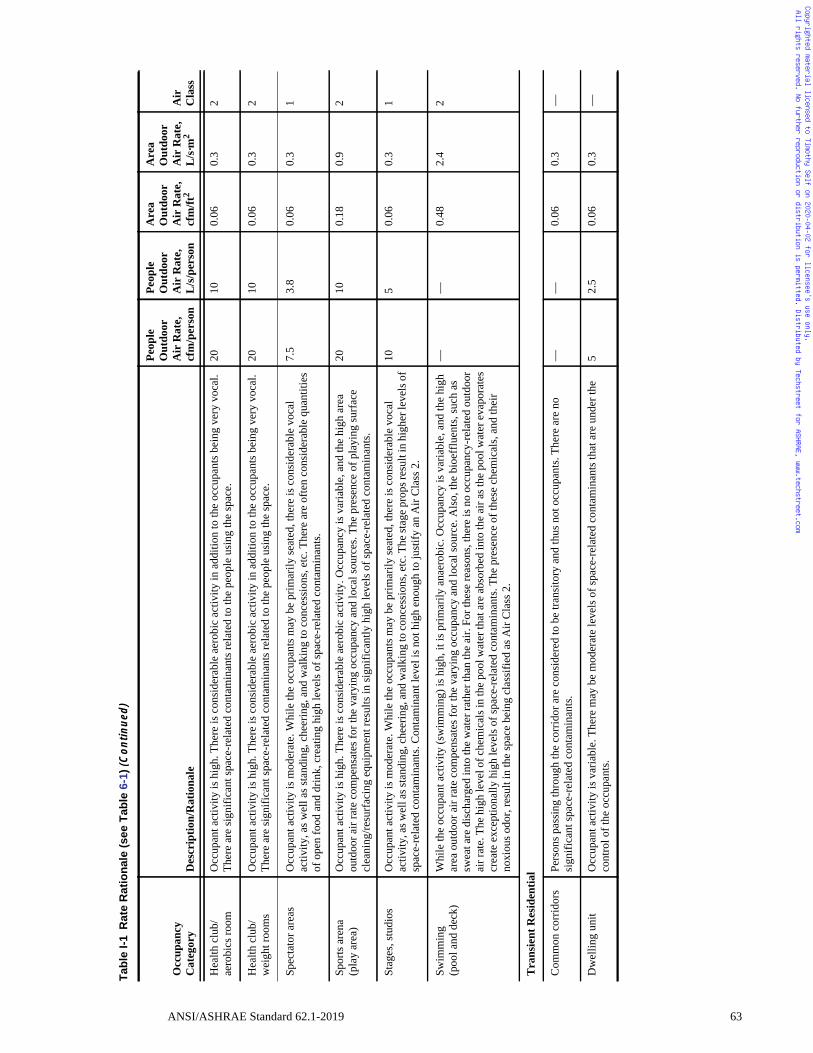
Copyrighted material licensed to Timothy Self on 2020-04-02 for licensee's use only. All rights reserved. No further reproduction or distribution is permitted. Distributed by Techstreet for ASHRAE, www.techstreet.com
Hea
lth c
lub/
aero
bics
room
O
ccup
ant a
ctiv
ity is
hig
h. T
here
is c
onsi
dera
ble
aero
bic
activ
ity in
add
ition
to th
e oc
cupa
nts b
eing
ver
y vo
cal.
Ther
e ar
e si
gnifi
cant
spac
e-re
late
d co
ntam
inan
ts re
late
d to
the
peop
le u
sing
the
spac
e.
2010
0.06
0.3
2
Hea
lth c
lub/
wei
ght r
oom
s O
ccup
ant a
ctiv
ity is
hig
h. T
here
is c
onsi
dera
ble
aero
bic
activ
ity in
add
ition
to th
e oc
cupa
nts b
eing
ver
y vo
cal.
Ther
e ar
e si
gnifi
cant
spac
e-re
late
d co
ntam
inan
ts re
late
d to
the
peop
le u
sing
the
spac
e.
2010
0.06
0.3
2
Spec
tato
r are
as
Occ
upan
t act
ivity
is m
oder
ate.
Whi
le th
e oc
cupa
nts m
ay b
e pr
imar
ily se
ated
, the
re is
con
side
rabl
e vo
cal
activ
ity, a
s wel
l as s
tand
ing,
che
erin
g, a
nd w
alki
ng to
con
cess
ions
, etc
. The
re a
re o
ften
cons
ider
able
qua
ntiti
es
of o
pen
food
and
drin
k, c
reat
ing
high
leve
ls o
f spa
ce-r
elat
ed c
onta
min
ants
.
7.5
3.8
0.06
0.3
1
Spor
ts a
rena
(pla
y ar
ea)
Occ
upan
t act
ivity
is h
igh.
The
re is
con
side
rabl
e ae
robi
c ac
tivity
. Occ
upan
cy is
var
iabl
e, a
nd th
e hi
gh a
rea
outd
oor a
ir ra
te c
ompe
nsat
es fo
r the
var
ying
occ
upan
cy a
nd lo
cal s
ourc
es. T
he p
rese
nce
of p
layi
ng su
rfac
e cl
eani
ng/re
surf
acin
g eq
uipm
ent r
esul
ts in
sign
ifica
ntly
hig
h le
vels
of s
pace
-rel
ated
con
tam
inan
ts.
2010
0.18
0.9
2
Stag
es, s
tudi
os
Occ
upan
t act
ivity
is m
oder
ate.
Whi
le th
e oc
cupa
nts m
ay b
e pr
imar
ily se
ated
, the
re is
con
side
rabl
e vo
cal
activ
ity, a
s wel
l as s
tand
ing,
che
erin
g, a
nd w
alki
ng to
con
cess
ions
, etc
. The
stag
e pr
ops r
esul
t in
high
er le
vels
of
spac
e-re
late
d co
ntam
inan
ts. C
onta
min
ant l
evel
is n
ot h
igh
enou
gh to
just
ify a
n A
ir C
lass
2.
105
0.06
0.3
1
Swim
min
g(p
ool a
nd d
eck)
W
hile
the
occu
pant
act
ivity
(sw
imm
ing)
is h
igh,
it is
prim
arily
ana
erob
ic. O
ccup
ancy
is v
aria
ble,
and
the
high
ar
ea o
utdo
or a
ir ra
te c
ompe
nsat
es fo
r the
var
ying
occ
upan
cy a
nd lo
cal s
ourc
e. A
lso,
the
bioe
fflu
ents
, suc
h as
sw
eat a
re d
isch
arge
d in
to th
e w
ater
rath
er th
an th
e ai
r. Fo
r the
se re
ason
s, th
ere
is n
o oc
cupa
ncy-
rela
ted
outd
oor
air r
ate.
The
hig
h le
vel o
f che
mic
als i
n th
e po
ol w
ater
that
are
abs
orbe
d in
to th
e ai
r as t
he p
ool w
ater
eva
pora
tes
crea
te e
xcep
tiona
lly h
igh
leve
ls o
f spa
ce-r
elat
ed c
onta
min
ants
. The
pre
senc
e of
thes
e ch
emic
als,
and
thei
r no
xiou
s odo
r, re
sult
in th
e sp
ace
bein
g cl
assi
fied
as A
ir C
lass
2.
——
0.48
2.4
2
Tra
nsie
nt R
esid
entia
l
Com
mon
cor
ridor
sPe
rson
s pas
sing
thro
ugh
the
corr
idor
are
con
side
red
to b
e tra
nsito
ry a
nd th
us n
ot o
ccup
ants
. The
re a
re n
o si
gnifi
cant
spac
e-re
late
d co
ntam
inan
ts.
——
0.06
0.3
—
Dw
ellin
g un
itO
ccup
ant a
ctiv
ity is
var
iabl
e. T
here
may
be
mod
erat
e le
vels
of s
pace
-rel
ated
con
tam
inan
ts th
at a
re u
nder
the
cont
rol o
f the
occ
upan
ts.
52.
50.
060.
3—
Tab
leI-
1R
ate
Rat
ion
ale
(see
Tab
le6-
1)(C
on
tin
ued
)
Occ
upan
cy
Cat
egor
yD
escr
iptio
n/R
atio
nale
Peop
le
Out
door
Air
Rat
e,cf
m/p
erso
n
Peop
le
Out
door
Air
Rat
e,L
/s/p
erso
n
Are
aO
utdo
orA
ir R
ate,
cfm
/ft2
Are
aO
utdo
orA
ir R
ate,
L
/s·m
2A
irC
lass
ANSI/ASHRAE Standard 62.1-2019 63
Copyrighted material licensed to Timothy Self on 2020-04-02 for licensee's use only. All rights reserved. No further reproduction or distribution is permitted. Distributed by Techstreet for ASHRAE, www.techstreet.com
(This appendix is not part of this standard. It is merely informative and does not con-tain requirements necessary for conformance to the standard. It has not been pro-cessed according to the ANSI requirements for a standard and may contain materialthat has not been subject to public review or a consensus process. Unresolved objec-tors on informative material are not offered the right to appeal at ASHRAE or ANSI.)
INFORMATIVE APPENDIX JINFORMATION ON NATURAL VENTILATION
J1. OUTDOOR AIR QUALITY DATA
Outdoor air quality data may be considered valid if it is demonstrated that the data are bothphysically representative and spatially representative.
Physically representative data accurately reflect the air quality conditions at the monitor-ing station from which they are derived. Data are considered physically representative if theyare obtained from
a. reports of historical levels of air pollutants published by the relevant local, regional, or fed-eral entity with statutory responsibility for collecting and reporting air quality informationin accordance with applicable air quality regulations, or
b. an on-site monitoring campaign that is verifiably comparable to local, regional, or federalguidelines and methods for demonstration of compliance with applicable air quality regula-tions.
Spatially representative data are collected from a monitoring site that may differ from theproposed project location but is informative of the air quality conditions at the proposed projectlocation. Data may be considered spatially representative if they are
c. the same as those used by the entity charged with demonstrating regulatory compliance forthe geographic region that includes the proposed project location, or
d. derived from an on-site monitoring campaign that also meets the requirement stated by cri-teria (b) of this annotation.
J2. NATURAL VENTILATION RATE
When calculating the ventilation rate, specific path(s) of the intended airflow passage must firstbe determined along with flow directions. There are two driving forces for natural ventilation:buoyancy and wind. The two driving forces can work cooperatively or competitively based onthe environmental conditions of wind speed, direction, indoor/outdoor air/surface tempera-tures, as well as the intentional airflow path and mechanisms.
a. In the case of an engineered natural ventilation system that results in multiple flow scenar-ios, each must be examined and considered separately.
b. Specific pressure-based calculation of natural ventilation flow rate is documented inASHRAE Handbook—Fundamentals, Chapter 16, Section 6:1. Buoyancy-induced airflow can be calculated following Equation 38.2. Wind-driven airflow can be calculated following Equation 37.3. The overall pressure (driven by both wind and stack effect) converted to resulting pres-
sure difference between openings can found in Equation 36.For obtaining wind-driven pressure, several methods are available:
a. ASHRAE Handbook—Fundamentals, Chapter 24, provides a method to convert wind speedand direction into pressure coefficients that can be used to determine wind-driven pressure.
b. CIBSE AM10, Chapter 4, provides a method to account for wind-driven ventilation andoutlines specific challenges to it in Section 4.4.1.
c. If the building has undergone wind tunnel test for structural stress, the same test can pro-vide detailed pressure coefficients.
d. Outdoor airflow simulation (such as computational-fluid-dynamics-based simulation) canbe used to obtain the specific flow condition at the intended openings.
For intended openings that are large, such as open atrium or open balcony, and/or when theflow path is not well defined, such as when only single or single-side openings are available, thepressure-based method can be invalid, and outdoor-indoor linked simulation should be used.
64 ANSI/ASHRAE Standard 62.1-2019
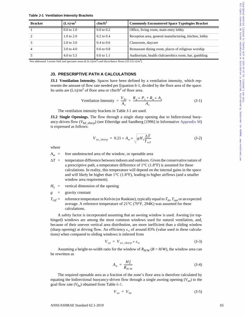
t
y
g
Copyrighted material licensed to Timothy Self on 2020-04-02 for licensee's use only. All rights reserved. No further reproduction or distribution is permitted. Distributed by Techstreet for ASHRAE, www.techstreet.com
J3. PRESCRIPTIVE PATH A CALCULATIONS
J3.1 Ventilation Intensity. Spaces have been defined by a ventilation intensity, which rep-resents the amount of flow rate needed per Equation 6-1, divided by the floor area of the space.Its units are (L/s)/m2 of floor area or cfm/ft2 of floor area.
(J-1)
The ventilation intensity brackets in Table J-1 are used.J3.2 Single Openings. The flow through a single sharp opening due to bidirectional buoy-ancy-driven flow (Vbd_sharp) (see Etheridge and Sandberg [1996] in Informative Appendix M)is expressed as follows:
(J-2)
whereAw = free unobstructed area of the window, or openable areaT = temperature difference between indoors and outdoors. Given the conservative nature of
a prescriptive path, a temperature difference of 1°C (1.8°F) is assumed for these calculations. In reality, this temperature will depend on the internal gains in the space and will likely be higher than 1°C (1.8°F), leading to higher airflows (and a smaller window area requirement).
Hs = vertical dimension of the openingg = gravity constantTref = reference temperature in Kelvin (or Rankine), typically equal to Tin, Tout or an expected
average. A reference temperature of 21°C (70°F, 294K) was assumed for these calculations.
A safety factor is incorporated assuming that an awning window is used. Awning (or top-hinged) windows are among the most common windows used for natural ventilation, and,because of their uneven vertical area distribution, are more inefficient than a sliding window(sharp opening) at driving flow. An efficiency v of around 83% (value used in these calcula-tions) when compared to sliding windows is inferred from
(J-3)
Assuming a height-to-width ratio for the window of RH/W (R = H/W), the window area canbe rewritten as
(J-4)
The required openable area as a fraction of the zone’s floor area is therefore calculated byequating the bidirectional buoyancy-driven flow through a single awning opening (Vso) to thegoal flow rate (Vbz) obtained from Table 6-1.
(J-5)
Table J-1 Ventilation Intensity Brackets
Bracket (L/s)·m2 cfm/ft2 Commonly Encountered Space Typologies Bracke
1 0.0 to 1.0 0.0 to 0.2 Office, living room, main entry lobby
2 1.0 to 2.0 0.2 to 0.4 Reception area, general manufacturing, kitchen, lobb
3 2.0 to 3.0 0.4 to 0.6 Classroom, daycare
4 3.0 to 4.0 0.6 to 0.8 Restaurant dining room, places of religious worship
5 4.0 to 5.5 0.6 to 1.1 Auditorium, health club/aerobics room, bar, gamblinNot addressed: Lecture Hall and spectator areas (6 [L/s])/m2) and disco/dance floors (10.3 [L/s]/m2)
Ventilation IntensityV bzAz
--------R p Pz Ra Az+
Az-------------------------------------------= =
V so_sharp 0.21 Aw gH sTT ref----------=
V so V so_sharp w=
AwH S
2
RH /W-------------=
V so V bz=
ANSI/ASHRAE Standard 62.1-2019 65
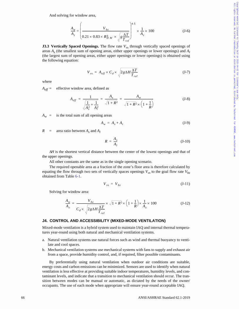
Copyrighted material licensed to Timothy Self on 2020-04-02 for licensee's use only. All rights reserved. No further reproduction or distribution is permitted. Distributed by Techstreet for ASHRAE, www.techstreet.com
And solving for window area,
(J-6)
J3.3 Vertically Spaced Openings. The flow rate Vvs through vertically spaced openings ofareas As (the smallest sum of opening areas, either upper openings or lower openings) and Al(the largest sum of opening areas, either upper openings or lower openings) is obtained usingthe following equation:
(J-7)
where
Aeff = effective window area, defined as
(J-8)
Aw = is the total sum of all opening areas
(J-9)
R = area ratio between As and Al
(J-10)
H is the shortest vertical distance between the center of the lowest openings and that ofthe upper openings.
All other constants are the same as in the single opening scenario. The required openable area as a fraction of the zone’s floor area is therefore calculated by
equating the flow through two sets of vertically spaces openings Vvs to the goal flow rate Vbzobtained from Table 6-1.
(J-11)
Solving for window area:
(J-12)
J4. CONTROL AND ACCESSIBILITY (MIXED-MODE VENTILATION)
Mixed-mode ventilation is a hybrid system used to maintain IAQ and internal thermal tempera-tures year-round using both natural and mechanical ventilation systems.
a. Natural ventilation systems use natural forces such as wind and thermal buoyancy to venti-late and cool spaces.
b. Mechanical ventilation systems use mechanical systems with fans to supply and exhaust airfrom a space, provide humidity control, and, if required, filter possible contaminants.
By preferentially using natural ventilation when outdoor air conditions are suitable,energy costs and carbon emissions can be minimized. Sensors are used to identify when naturalventilation is less effective at providing suitable indoor temperatures, humidity levels, and con-taminant levels, and indicate that a transition to mechanical ventilation should occur. The tran-sition between modes can be manual or automatic, as dictated by the needs of the owner/occupants. The use of each mode when appropriate will ensure year-round acceptable IAQ.
AwAz-------
V bz
0.21 0.83 RH W4 g T
T ref----------
------------------------------------------------------------------------
4 5
= 1Az----- 100
V vs Aeff Cd 2gH TT ref----------=
Aeff1
1As
2------ 1
Al2
------+
------------------------As
1 R2+-------------------
Aw
1 R2+ 1 1R---+
---------------------------------------------= = =
Aw As At+=
RAsAl-----=
V vs V bz=
AwAz-------
V bz
Cd 2gH TT ref----------
------------------------------------------- 1 R2+ 1 1R---+
1Az----- 100=
66 ANSI/ASHRAE Standard 62.1-2019
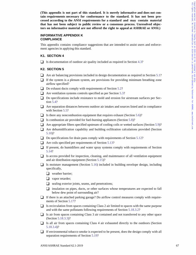
Copyrighted material licensed to Timothy Self on 2020-04-02 for licensee's use only. All rights reserved. No further reproduction or distribution is permitted. Distributed by Techstreet for ASHRAE, www.techstreet.com
(This appendix is not part of this standard. It is merely informative and does not con-tain requirements necessary for conformance to the standard. It has not been pro-cessed according to the ANSI requirements for a standard and may contain materialthat has not been subject to public review or a consensus process. Unresolved objec-tors on informative material are not offered the right to appeal at ASHRAE or ANSI.)
INFORMATIVE APPENDIX KCOMPLIANCE
This appendix contains compliance suggestions that are intended to assist users and enforce-ment agencies in applying this standard.
K1. SECTION 4
� Is documentation of outdoor air quality included as required in Section 4.3?
K2. SECTION 5
� Are air balancing provisions included in design documentation as required in Section 5.1?� If the system is a plenum system, are provisions for providing minimum breathing zone
airflow specified?� Do exhaust ducts comply with requirements of Section 5.2?� Are ventilation systems controls specified as per Section 5.3?� Do specifications include resistance to mold and erosion for airstream surfaces per Sec-
tion 5.4?� Are separation distances between outdoor air intakes and sources listed and in compliance
with Section 5.5?� Is there any noncombustion equipment that requires exhaust (Section 5.6)?� Is combustion air provided for fuel-burning appliances (Section 5.8)?� Are appropriate filters specified upstream of cooling coils or wetted surfaces (Section 5.9)?� Are dehumidification capability and building exfiltration calculations provided (Section
5.10)?� Do specifications for drain pans comply with requirements of Section 5.12?� Are coils specified per requirements of Section 5.13?� If present, do humidifiers and water spray systems comply with requirements of Section
5.14?� Is access provided for inspection, cleaning, and maintenance of all ventilation equipment
and air distribution equipment (Section 5.15)?� Is moisture management (Section 5.16) included in building envelope design, including
specifically,� weather barrier;� vapor retarder;� sealing exterior joints, seams, and penetrations;� insulation on pipes, ducts, or other surfaces whose temperatures are expected to fall
below dew point of surrounding air?� If there is an attached parking garage? Do airflow control measures comply with require-
ments of Section 5.17?� Is recirculation from spaces containing Class 2 air limited to spaces with the same purpose
and with the same pollutants following requirements of Section 5.18.3.2?� Is air from spaces containing Class 3 air contained and not transferred to any other space
(Section 5.18.3.3)?� Is all air from spaces containing Class 4 air exhausted directly to the outdoors (Section
5.18.3.4)?� If environmental tobacco smoke is expected to be present, does the design comply with all
separation requirements of Section 5.19?
ANSI/ASHRAE Standard 62.1-2019 67
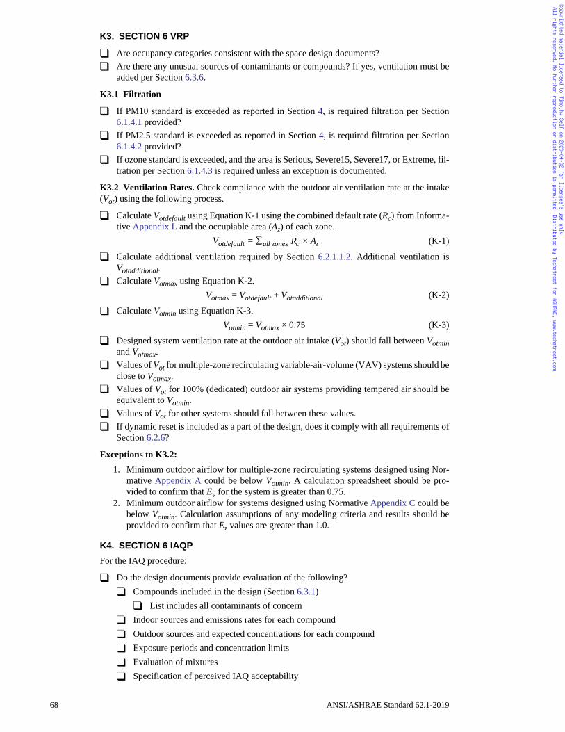
Copyrighted material licensed to Timothy Self on 2020-04-02 for licensee's use only. All rights reserved. No further reproduction or distribution is permitted. Distributed by Techstreet for ASHRAE, www.techstreet.com
K3. SECTION 6 VRP
� Are occupancy categories consistent with the space design documents?� Are there any unusual sources of contaminants or compounds? If yes, ventilation must be
added per Section 6.3.6.
K3.1 Filtration
� If PM10 standard is exceeded as reported in Section 4, is required filtration per Section6.1.4.1 provided?
� If PM2.5 standard is exceeded as reported in Section 4, is required filtration per Section6.1.4.2 provided?
� If ozone standard is exceeded, and the area is Serious, Severe15, Severe17, or Extreme, fil-tration per Section 6.1.4.3 is required unless an exception is documented.
K3.2 Ventilation Rates. Check compliance with the outdoor air ventilation rate at the intake(Vot) using the following process.
� Calculate Votdefault using Equation K-1 using the combined default rate (Rc) from Informa-tive Appendix L and the occupiable area (Az) of each zone.
Votdefault = all zones Rc × Az (K-1)
� Calculate additional ventilation required by Section 6.2.1.1.2. Additional ventilation isVotadditional.
� Calculate Votmax using Equation K-2.Votmax = Votdefault + Votadditional (K-2)
� Calculate Votmin using Equation K-3.Votmin = Votmax × 0.75 (K-3)
� Designed system ventilation rate at the outdoor air intake (Vot) should fall between Votminand Votmax.
� Values of Vot for multiple-zone recirculating variable-air-volume (VAV) systems should beclose to Votmax.
� Values of Vot for 100% (dedicated) outdoor air systems providing tempered air should beequivalent to Votmin.
� Values of Vot for other systems should fall between these values.� If dynamic reset is included as a part of the design, does it comply with all requirements of
Section 6.2.6?
Exceptions to K3.2: 1. Minimum outdoor airflow for multiple-zone recirculating systems designed using Nor-
mative Appendix A could be below Votmin. A calculation spreadsheet should be pro-vided to confirm that Ev for the system is greater than 0.75.
2. Minimum outdoor airflow for systems designed using Normative Appendix C could bebelow Votmin. Calculation assumptions of any modeling criteria and results should beprovided to confirm that Ez values are greater than 1.0.
K4. SECTION 6 IAQP
For the IAQ procedure:
� Do the design documents provide evaluation of the following?� Compounds included in the design (Section 6.3.1)
� List includes all contaminants of concern� Indoor sources and emissions rates for each compound� Outdoor sources and expected concentrations for each compound� Exposure periods and concentration limits� Evaluation of mixtures� Specification of perceived IAQ acceptability
68 ANSI/ASHRAE Standard 62.1-2019
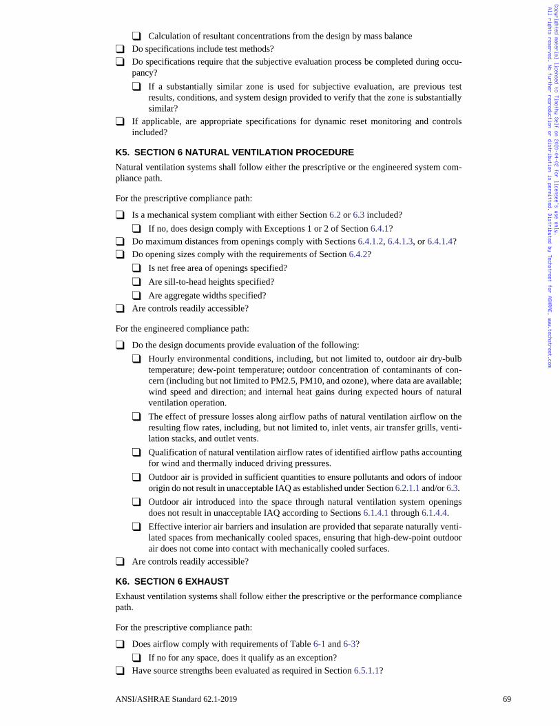
Copyrighted material licensed to Timothy Self on 2020-04-02 for licensee's use only. All rights reserved. No further reproduction or distribution is permitted. Distributed by Techstreet for ASHRAE, www.techstreet.com
� Calculation of resultant concentrations from the design by mass balance� Do specifications include test methods?� Do specifications require that the subjective evaluation process be completed during occu-
pancy?� If a substantially similar zone is used for subjective evaluation, are previous test
results, conditions, and system design provided to verify that the zone is substantiallysimilar?
� If applicable, are appropriate specifications for dynamic reset monitoring and controlsincluded?
K5. SECTION 6 NATURAL VENTILATION PROCEDURE
Natural ventilation systems shall follow either the prescriptive or the engineered system com-pliance path.
For the prescriptive compliance path:
� Is a mechanical system compliant with either Section 6.2 or 6.3 included?� If no, does design comply with Exceptions 1 or 2 of Section 6.4.1?
� Do maximum distances from openings comply with Sections 6.4.1.2, 6.4.1.3, or 6.4.1.4?� Do opening sizes comply with the requirements of Section 6.4.2?
� Is net free area of openings specified?� Are sill-to-head heights specified?� Are aggregate widths specified?
� Are controls readily accessible?
For the engineered compliance path:
� Do the design documents provide evaluation of the following:� Hourly environmental conditions, including, but not limited to, outdoor air dry-bulb
temperature; dew-point temperature; outdoor concentration of contaminants of con-cern (including but not limited to PM2.5, PM10, and ozone), where data are available;wind speed and direction; and internal heat gains during expected hours of naturalventilation operation.
� The effect of pressure losses along airflow paths of natural ventilation airflow on theresulting flow rates, including, but not limited to, inlet vents, air transfer grills, venti-lation stacks, and outlet vents.
� Qualification of natural ventilation airflow rates of identified airflow paths accountingfor wind and thermally induced driving pressures.
� Outdoor air is provided in sufficient quantities to ensure pollutants and odors of indoororigin do not result in unacceptable IAQ as established under Section 6.2.1.1 and/or 6.3.
� Outdoor air introduced into the space through natural ventilation system openingsdoes not result in unacceptable IAQ according to Sections 6.1.4.1 through 6.1.4.4.
� Effective interior air barriers and insulation are provided that separate naturally venti-lated spaces from mechanically cooled spaces, ensuring that high-dew-point outdoorair does not come into contact with mechanically cooled surfaces.
� Are controls readily accessible?
K6. SECTION 6 EXHAUST
Exhaust ventilation systems shall follow either the prescriptive or the performance compliancepath.
For the prescriptive compliance path:
� Does airflow comply with requirements of Table 6-1 and 6-3?� If no for any space, does it qualify as an exception?
� Have source strengths been evaluated as required in Section 6.5.1.1?
ANSI/ASHRAE Standard 62.1-2019 69
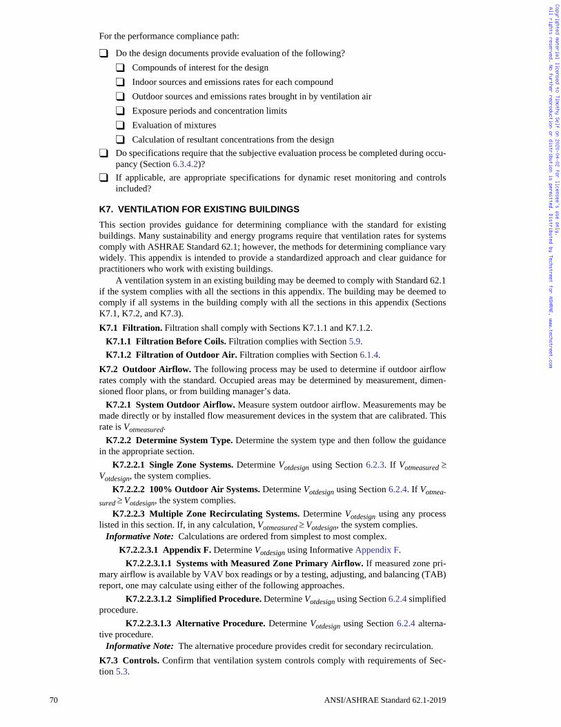
Copyrighted material licensed to Timothy Self on 2020-04-02 for licensee's use only. All rights reserved. No further reproduction or distribution is permitted. Distributed by Techstreet for ASHRAE, www.techstreet.com
For the performance compliance path:
� Do the design documents provide evaluation of the following?� Compounds of interest for the design� Indoor sources and emissions rates for each compound� Outdoor sources and emissions rates brought in by ventilation air� Exposure periods and concentration limits� Evaluation of mixtures� Calculation of resultant concentrations from the design
� Do specifications require that the subjective evaluation process be completed during occu-pancy (Section 6.3.4.2)?
� If applicable, are appropriate specifications for dynamic reset monitoring and controlsincluded?
K7. VENTILATION FOR EXISTING BUILDINGS
This section provides guidance for determining compliance with the standard for existingbuildings. Many sustainability and energy programs require that ventilation rates for systemscomply with ASHRAE Standard 62.1; however, the methods for determining compliance varywidely. This appendix is intended to provide a standardized approach and clear guidance forpractitioners who work with existing buildings.
A ventilation system in an existing building may be deemed to comply with Standard 62.1if the system complies with all the sections in this appendix. The building may be deemed tocomply if all systems in the building comply with all the sections in this appendix (SectionsK7.1, K7.2, and K7.3).K7.1 Filtration. Filtration shall comply with Sections K7.1.1 and K7.1.2.
K7.1.1 Filtration Before Coils. Filtration complies with Section 5.9.K7.1.2 Filtration of Outdoor Air. Filtration complies with Section 6.1.4.
K7.2 Outdoor Airflow. The following process may be used to determine if outdoor airflowrates comply with the standard. Occupied areas may be determined by measurement, dimen-sioned floor plans, or from building manager’s data.
K7.2.1 System Outdoor Airflow. Measure system outdoor airflow. Measurements may bemade directly or by installed flow measurement devices in the system that are calibrated. Thisrate is Votmeasured.
K7.2.2 Determine System Type. Determine the system type and then follow the guidancein the appropriate section.
K7.2.2.1 Single Zone Systems. Determine Votdesign using Section 6.2.3. If Votmeasured Votdesign, the system complies.
K7.2.2.2 100% Outdoor Air Systems. Determine Votdesign using Section 6.2.4. If Votmea-sured Votdesign, the system complies.
K7.2.2.3 Multiple Zone Recirculating Systems. Determine Votdesign using any processlisted in this section. If, in any calculation, Votmeasured Votdesign, the system complies.
Informative Note: Calculations are ordered from simplest to most complex.K7.2.2.3.1 Appendix F. Determine Votdesign using Informative Appendix F.
K7.2.2.3.1.1 Systems with Measured Zone Primary Airflow. If measured zone pri-mary airflow is available by VAV box readings or by a testing, adjusting, and balancing (TAB)report, one may calculate using either of the following approaches.
K7.2.2.3.1.2 Simplified Procedure. Determine Votdesign using Section 6.2.4 simplifiedprocedure.
K7.2.2.3.1.3 Alternative Procedure. Determine Votdesign using Section 6.2.4 alterna-tive procedure.
Informative Note: The alternative procedure provides credit for secondary recirculation.K7.3 Controls. Confirm that ventilation system controls comply with requirements of Sec-tion 5.3.
70 ANSI/ASHRAE Standard 62.1-2019
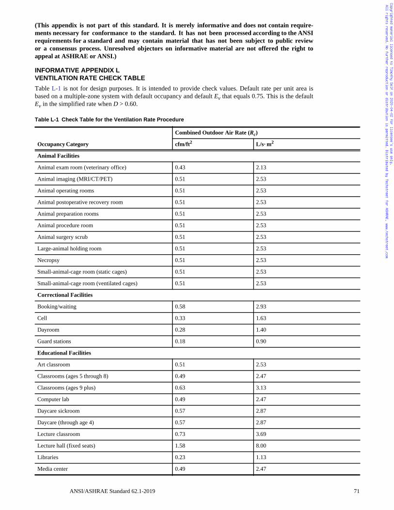
Copyrighted material licensed to Timothy Self on 2020-04-02 for licensee's use only. All rights reserved. No further reproduction or distribution is permitted. Distributed by Techstreet for ASHRAE, www.techstreet.com
(This appendix is not part of this standard. It is merely informative and does not contain require-ments necessary for conformance to the standard. It has not been processed according to the ANSIrequirements for a standard and may contain material that has not been subject to public reviewor a consensus process. Unresolved objectors on informative material are not offered the right toappeal at ASHRAE or ANSI.)
INFORMATIVE APPENDIX LVENTILATION RATE CHECK TABLE
Table L-1 is not for design purposes. It is intended to provide check values. Default rate per unit area isbased on a multiple-zone system with default occupancy and default Ev that equals 0.75. This is the defaultEv in the simplified rate when D > 0.60.
Table L-1 Check Table for the Ventilation Rate Procedure
Occupancy Category
Combined Outdoor Air Rate (Rc)
cfm/ft2 L/s· m2
Animal Facilities
Animal exam room (veterinary office) 0.43 2.13
Animal imaging (MRI/CT/PET) 0.51 2.53
Animal operating rooms 0.51 2.53
Animal postoperative recovery room 0.51 2.53
Animal preparation rooms 0.51 2.53
Animal procedure room 0.51 2.53
Animal surgery scrub 0.51 2.53
Large-animal holding room 0.51 2.53
Necropsy 0.51 2.53
Small-animal-cage room (static cages) 0.51 2.53
Small-animal-cage room (ventilated cages) 0.51 2.53
Correctional Facilities
Booking/waiting 0.58 2.93
Cell 0.33 1.63
Dayroom 0.28 1.40
Guard stations 0.18 0.90
Educational Facilities
Art classroom 0.51 2.53
Classrooms (ages 5 through 8) 0.49 2.47
Classrooms (ages 9 plus) 0.63 3.13
Computer lab 0.49 2.47
Daycare sickroom 0.57 2.87
Daycare (through age 4) 0.57 2.87
Lecture classroom 0.73 3.69
Lecture hall (fixed seats) 1.58 8.00
Libraries 0.23 1.13
Media center 0.49 2.47
ANSI/ASHRAE Standard 62.1-2019 71
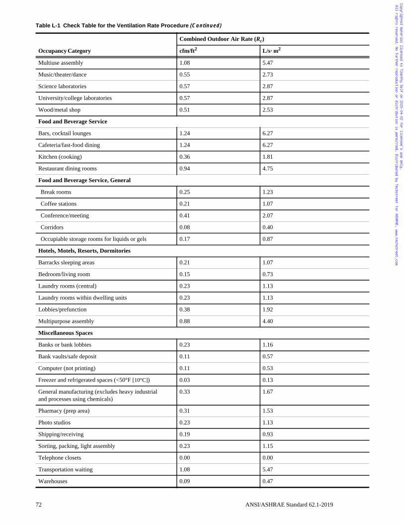
Copyrighted material licensed to Timothy Self on 2020-04-02 for licensee's use only. All rights reserved. No further reproduction or distribution is permitted. Distributed by Techstreet for ASHRAE, www.techstreet.com
Multiuse assembly 1.08 5.47
Music/theater/dance 0.55 2.73
Science laboratories 0.57 2.87
University/college laboratories 0.57 2.87
Wood/metal shop 0.51 2.53
Food and Beverage Service
Bars, cocktail lounges 1.24 6.27
Cafeteria/fast-food dining 1.24 6.27
Kitchen (cooking) 0.36 1.81
Restaurant dining rooms 0.94 4.75
Food and Beverage Service, General
Break rooms 0.25 1.23
Coffee stations 0.21 1.07
Conference/meeting 0.41 2.07
Corridors 0.08 0.40
Occupiable storage rooms for liquids or gels 0.17 0.87
Hotels, Motels, Resorts, Dormitories
Barracks sleeping areas 0.21 1.07
Bedroom/living room 0.15 0.73
Laundry rooms (central) 0.23 1.13
Laundry rooms within dwelling units 0.23 1.13
Lobbies/prefunction 0.38 1.92
Multipurpose assembly 0.88 4.40
Miscellaneous Spaces
Banks or bank lobbies 0.23 1.16
Bank vaults/safe deposit 0.11 0.57
Computer (not printing) 0.11 0.53
Freezer and refrigerated spaces (<50°F [10°C]) 0.03 0.13
General manufacturing (excludes heavy industrialand processes using chemicals)
0.33 1.67
Pharmacy (prep area) 0.31 1.53
Photo studios 0.23 1.13
Shipping/receiving 0.19 0.93
Sorting, packing, light assembly 0.23 1.15
Telephone closets 0.00 0.00
Transportation waiting 1.08 5.47
Warehouses 0.09 0.47
Table L-1 Check Table for the Ventilation Rate Procedure (Continued)
Occupancy Category
Combined Outdoor Air Rate (Rc)
cfm/ft2 L/s· m2
72 ANSI/ASHRAE Standard 62.1-2019
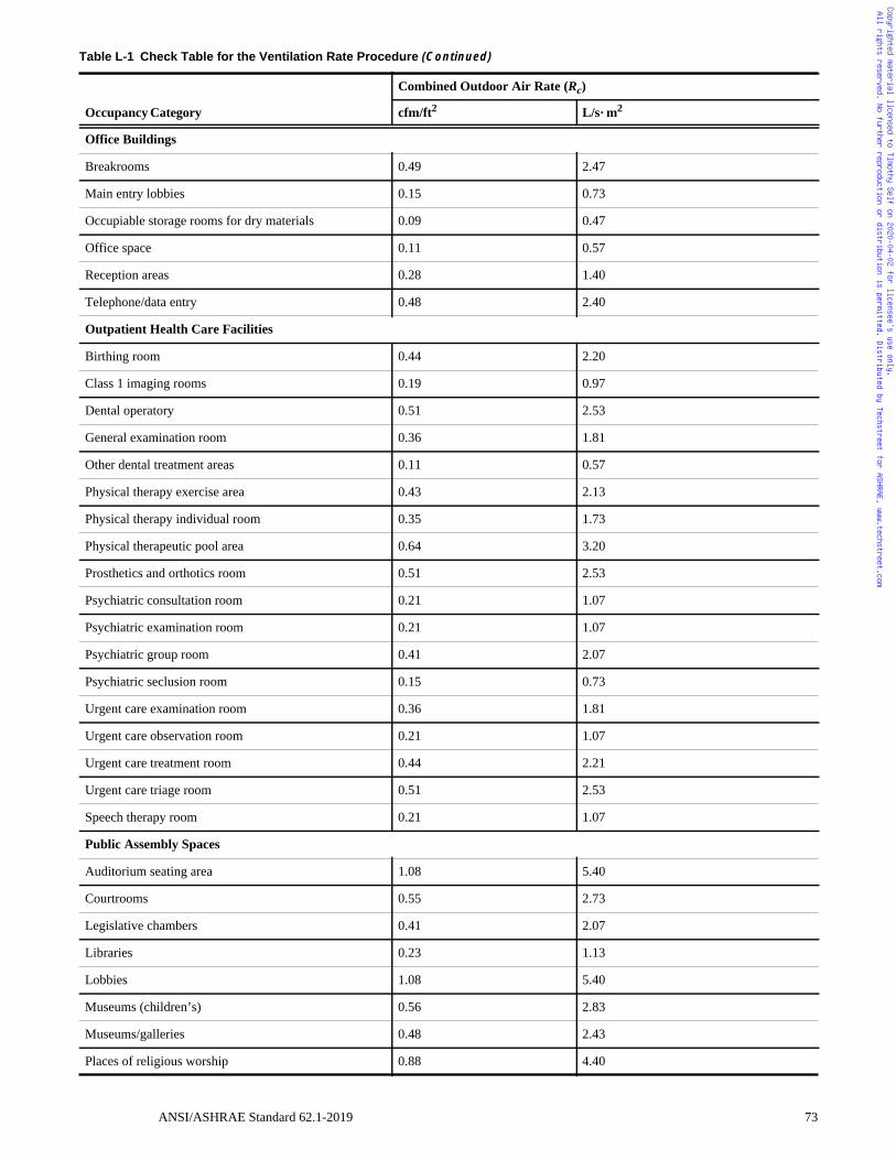
Copyrighted material licensed to Timothy Self on 2020-04-02 for licensee's use only. All rights reserved. No further reproduction or distribution is permitted. Distributed by Techstreet for ASHRAE, www.techstreet.com
Office Buildings
Breakrooms 0.49 2.47
Main entry lobbies 0.15 0.73
Occupiable storage rooms for dry materials 0.09 0.47
Office space 0.11 0.57
Reception areas 0.28 1.40
Telephone/data entry 0.48 2.40
Outpatient Health Care Facilities
Birthing room 0.44 2.20
Class 1 imaging rooms 0.19 0.97
Dental operatory 0.51 2.53
General examination room 0.36 1.81
Other dental treatment areas 0.11 0.57
Physical therapy exercise area 0.43 2.13
Physical therapy individual room 0.35 1.73
Physical therapeutic pool area 0.64 3.20
Prosthetics and orthotics room 0.51 2.53
Psychiatric consultation room 0.21 1.07
Psychiatric examination room 0.21 1.07
Psychiatric group room 0.41 2.07
Psychiatric seclusion room 0.15 0.73
Urgent care examination room 0.36 1.81
Urgent care observation room 0.21 1.07
Urgent care treatment room 0.44 2.21
Urgent care triage room 0.51 2.53
Speech therapy room 0.21 1.07
Public Assembly Spaces
Auditorium seating area 1.08 5.40
Courtrooms 0.55 2.73
Legislative chambers 0.41 2.07
Libraries 0.23 1.13
Lobbies 1.08 5.40
Museums (children’s) 0.56 2.83
Museums/galleries 0.48 2.43
Places of religious worship 0.88 4.40
Table L-1 Check Table for the Ventilation Rate Procedure (Continued)
Occupancy Category
Combined Outdoor Air Rate (Rc)
cfm/ft2 L/s· m2
ANSI/ASHRAE Standard 62.1-2019 73
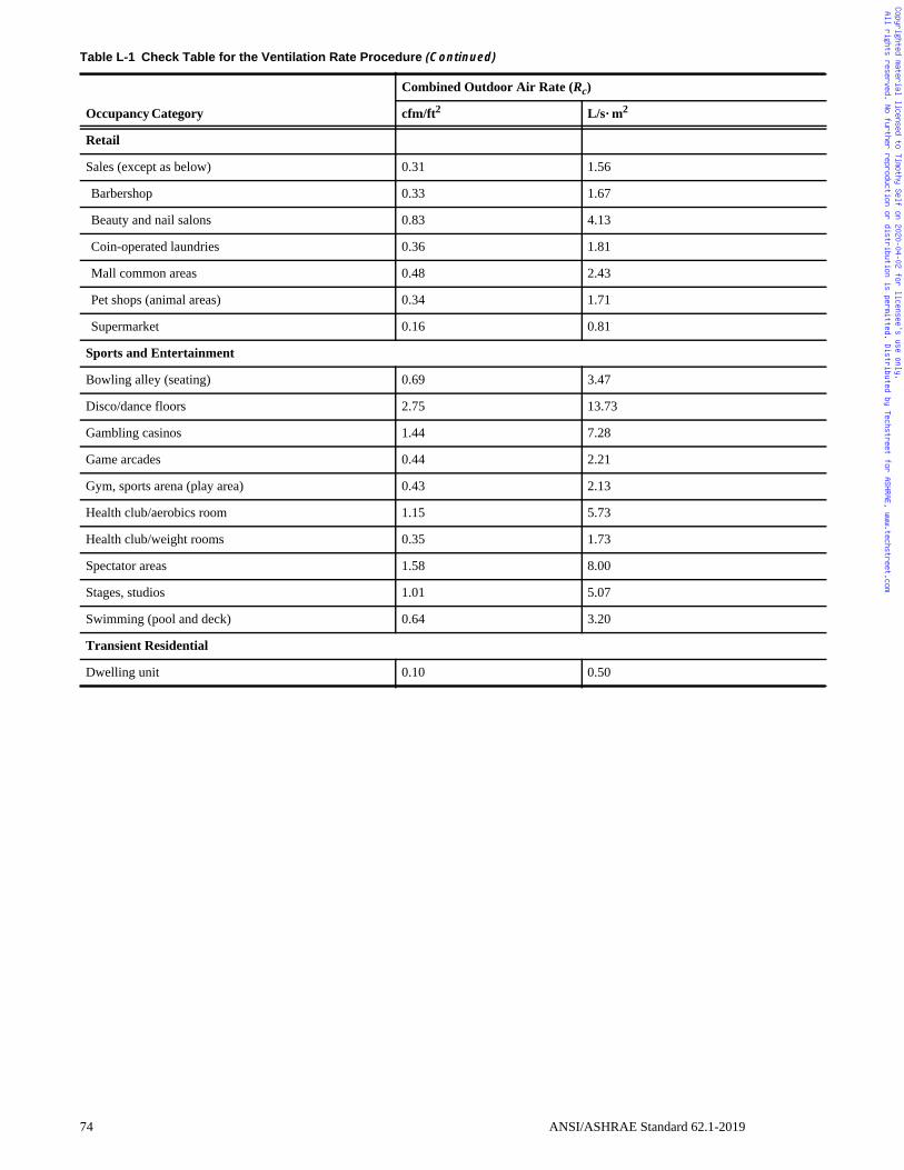
Copyrighted material licensed to Timothy Self on 2020-04-02 for licensee's use only. All rights reserved. No further reproduction or distribution is permitted. Distributed by Techstreet for ASHRAE, www.techstreet.com
Retail
Sales (except as below) 0.31 1.56
Barbershop 0.33 1.67
Beauty and nail salons 0.83 4.13
Coin-operated laundries 0.36 1.81
Mall common areas 0.48 2.43
Pet shops (animal areas) 0.34 1.71
Supermarket 0.16 0.81
Sports and Entertainment
Bowling alley (seating) 0.69 3.47
Disco/dance floors 2.75 13.73
Gambling casinos 1.44 7.28
Game arcades 0.44 2.21
Gym, sports arena (play area) 0.43 2.13
Health club/aerobics room 1.15 5.73
Health club/weight rooms 0.35 1.73
Spectator areas 1.58 8.00
Stages, studios 1.01 5.07
Swimming (pool and deck) 0.64 3.20
Transient Residential
Dwelling unit 0.10 0.50
Table L-1 Check Table for the Ventilation Rate Procedure (Continued)
Occupancy Category
Combined Outdoor Air Rate (Rc)
cfm/ft2 L/s· m2
74 ANSI/ASHRAE Standard 62.1-2019
n
dix J
dix C
dix C
dix J
dix J
dix J
dix N
dix E
Copyrighted material licensed to Timothy Self on 2020-04-02 for licensee's use only. All rights reserved. No further reproduction or distribution is permitted. Distributed by Techstreet for ASHRAE, www.techstreet.com
(This appendix is not part of this standard. It is merely informative and does not containrequirements necessary for conformance to the standard. It has not been processedaccording to the ANSI requirements for a standard and may contain material that hasnot been subject to public review or a consensus process. Unresolved objectors on infor-mative material are not offered the right to appeal at ASHRAE or ANSI.)
INFORMATIVE APPENDIX MINFORMATIVE REFERENCES
Reference Title Sectio
Air Movement and Control Association International (AMCA)30 W University Dr.Arlington Heights, IL 60004(847) 394-0150; www.amca.org
AMCA 511 (Rev. 2016) Certified Ratings Program—Product Rating Manual for Air Control Devices 5.5.2
ASHRAE1791 Tullie Circle NEAtlanta, GA 30329(800) 527-4723; www.ashrae.org
2017 ASHRAE Handbook—Fundamentals Appen
ASHRAE RP-1009 (2001) Simplified Diffuser Boundary Conditions for Numerical Room Airflow Models Appen
ASHRAE RP-1373 (2009) Air Distribution Effectiveness with Stratified Air Distribution Systems Appen
ASHRAE Standard 55 (2017) Thermal Environmental Conditions for Human Occupancy G1.2.7
Chartered Institution of Building Services Engineers (CIBSE)222 Balham High RoadLondonSW12 9BSUnited Kingdom+44 (0)20 8675 5211; www.cibse.org
CIBSE AM10 (2005) Natural Ventilation in Non-Domestic Buildings Appen
Wiley & Sons
Etheridge, D.W., andM. Sandberg (1996)
Building Ventilation: Theory and Measurement, Vol. 50 Appen
Energy and Buildings 65:516–22
von Grabe, J. (2013) Flow resistance for different types of windows in the case of buoyancy ventilation Appen
International Journal of Environmental Research and Public Health 11(11):11753-71.
Ahn, J.H., J.E. Szulejko, K.H. Kim, Y.H. Kim, and B.W. Kim (2014)
Odor and VOC emissions from pan frying of mackerel at three stages: Raw, well-done, and charred
Appen
National Institute of Standards and Technology (NIST)100 Bureau Dr.,Gaithersburg, MD 20899(301) 975-2000; www.nist.gov
Dols, W.S., and G.N. Walton(2002)
CONTAMW 2.0 User Manual Appen
ANSI/ASHRAE Standard 62.1-2019 75
Copyrighted material licensed to Timothy Self on 2020-04-02 for licensee's use only. All rights reserved. No further reproduction or distribution is permitted. Distributed by Techstreet for ASHRAE, www.techstreet.com
(This appendix is not part of this standard. It is merely informative and does not con-tain requirements necessary for conformance to the standard. It has not been pro-cessed according to the ANSI requirements for a standard and may contain materialthat has not been subject to public review or a consensus process. Unresolved objec-tors on informative material are not offered the right to appeal at ASHRAE or ANSI.)
INFORMATIVE APPENDIX NINDOOR AIR QUALITY PROCEDURE (IAQP)
N1. SUMMARY OF SELECTED AIR QUALITY GUIDELINES
If the Indoor Air Quality Procedure (IAQP) is used, acceptable indoor concentrations limits areneeded for design compounds (DCs) and particles. When using this procedure, these concen-tration limits need to be referenced from a cognizant authority as defined in the standard. Atpresent, no single organization develops acceptable concentrations limits for all substances inindoor air, nor are limits available for all potential DCs or particles.
Cognizant authorities, such as USEPA, California EPA, and the Committee for HealthRelated Evaluation of Building Products (AgBB) publish concentration limits for compounds,many of which may be present in the indoor environment. Compounds included in the IAQPdesign need to be included if data were judged sufficient to indicate a compound was likely tobe found in buildings at concentrations that were a substantial fraction of the proposed designtarget (DT). The goal is not to include every possible compound that may appear in indoor air,but rather sufficient numbers of compounds, and diversity thereof, such that control of thecompounds is anticipated to result in air quality that meets the standard’s definition of “accept-able.”
A summary of considerations is presented below:
a. Is a compound expected to be present in indoor air with reasonable frequency at concentra-tions relevant to (but not necessarily above) the DT? Specifically, the design outdoor airflow rate (Voz) and design features will be controlled by the compounds with the highestemission rates and lowest targets (taking mixtures into account); thus, compounds with lowconcentrations and high targets will have little or no impact on the calculated Voz.
b. Is there a DT that has been proposed by a cognizant authority?c. Does it seem reasonable to expect that product emissions rates may be available for the pro-
posed compound?d. It there an established sampling and analytical method for the proposed compound?
Occupational exposure limits (e.g., permissible exposure limits and threshold limit values)are not appropriate as DTs, as they are not established for acceptable indoor air quality or fortypical commercial buildings. In general, they were developed for industrial applications eval-uating effects of substances on healthy adult male workers.
N2. GUIDELINE FOR EMISSION RATES
Several published peer-reviewed papers provide a reference for design teams to use to compilereasonable DC emission rates. A nonexhaustive list of peer-reviewed papers is shown in Sec-tion N4. In addition, there are multiple established certification programs that include empiri-cal measures of emission rates for construction materials as well as finishes, furniture andequipment intended for indoor use. These include third-party programs as well as industrytrade association programs and programs in support of government regulations (e.g., the AgBBevaluation scheme used in Germany and parts of Europe, Blue Angel, BIFMA, Green Label,France A+, CDPH Standard Method for testing and evaluation of VOC emissions [CDPH Sec-tion 01350], Greenguard, SCS Indoor Advantage Gold, and Floorscore). Engineers may usethe emission rates for the specific materials that a designer is including or considering for use.The IAQP (Section 6.3) requires that emission rates must consider DCs emitted by occupantsand their activities, by materials, and by specific sources within the occupied spaces and intro-duced into the building with outdoor air.
N3. SUBJECTIVE EVALUATION
Section 6.3.4.2 requires that an occupant survey be conducted. Many subjective evaluationapproaches have been used with varying degrees of success. The following is an example ofan evaluation approach that focuses on adapted occupants:
76 ANSI/ASHRAE Standard 62.1-2019
Copyrighted material licensed to Timothy Self on 2020-04-02 for licensee's use only. All rights reserved. No further reproduction or distribution is permitted. Distributed by Techstreet for ASHRAE, www.techstreet.com
a. After the building is completed and substantially occupied, provide all occupants with anelectronic or written of survey questions, including, “Do you perceive the air quality inyour environment to be acceptable or unacceptable?”
b. Anonymous surveys with neutrally framed questions provide the best responses.c. When conducting an evaluation of adapted occupants, respondents must record their per-
ception of zone air quality after 30 minutes residency in the occupied zone.d. All occupants should be surveyed, if possible. Otherwise, at least 50% of typical occu-
pancy, or 300, whichever is less, should be randomly selected.e. A minimum 30% response rate from those surveyed is desirable. Each zone must be sur-
veyed per requirements of Section 6.3. The subjective evaluation validates the acceptabil-ity of indoor air if 80% of respondents in the area do not express dissatisfaction. TheCenter for the Built Environment at UC Berkeley has developed a survey that includesIAQ questions and may be a useful template.
N4. BIBLIOGRAPHY
Ahn, J.H., J.E. Szulejko, K.H. Kim, Y.H. Kim, and B.W. Kim. 2014. Odor and VOC emissionsfrom pan frying of mackerel at three stages: Raw, well-done, and charred. InternationalJournal of Environmental Research and Public Health 11(11):11753–71.
Apte, M.G. 2013. Final Report: Balancing energy conservation and occupant needs in ventila-tion rate standards for Big Box stores in California: Predicted indoor air quality andenergy consumption using a matrix of ventilation scenarios. LBNL Paper LBNL-5551E,Lawrence Berkeley National Laboratory, University of California, Berkeley.
Assadi, A.A., J. Palau, A. Bouzaza, J. Penya-Roja, V. Martinez-Soriac, and D. Wolbert. 2014.Abatement of 3-methylbutanal and trimethylamine with combined plasma and photocatal-ysis in a continuous planar reactor. Journal of Photochemistry and Photobiology A: Chem-istry 282:1–8.
Barro, R., J. Regueiro, M. Llompart, C. Garcia-Jares. 2009. Analysis of industrial contami-nants in indoor air: Part 1. Volatile organic compounds, carbonyl compounds, polycyclicaromatic hydrocarbons and polychlorinated biphenyls. Journal of Chromatography A1216(3):540–66.
Batterman, S, F.C. Su, S. Li, B. Mukherjee, and C. Jia. 2014. Personal exposure to mixtures ofvolatile organic compounds: modeling and further analysis of the RIOPA data. Researchreport (Health Effects Institute). 181:3–63.
Bi, X.H., G.Y. Sheng, Y.L. Feng, J.M. Fu, and J.X. Xie. 2005. Gas- and particulate-phase spe-cific tracer and toxic organic compounds in environmental tobacco smoke. Chemosphere61(10):1512–22.
Boraphech, P., and P. Thiravetyan. 2015. Removal of trimethylamine (fishy odor) by C-3 andCAM plants. Environmental Science and Pollution Research 22(15):11543–57.
Bradman, A., F. Gaspar, R. Castorina, J. Williams, T. Hoang, and P.L. Jenkins. 2017. Support-ing Information: Formaldehyde and acetaldehyde exposure and risk characterization inCalifornia early childhood education environments. Indoor Air 27(1):104–113.
CDPH. 2006. Long-term building air measurements for volatile organic compounds includingaldehydes at a California five-building sustainable office complex, (Vol. 1/2 and 2/2).Report #CA/DHS/EHLB/R-172. California Department of Public Health, Sacramento, CA.
Chan, W.R., S. Cohn, M. Sidheswaran, D.P. Sullivan, and W.J. Fisk. 2015. Contaminant levels,source strengths, and ventilation rates in California retail stores. Indoor Air 25(4):381–92.
Choo, C.P., and J. Jalaludin. 2015. An overview of indoor air quality and its impact on respira-tory health among Malaysian school-aged children. Reviews on Environmental Health30(1):9–18.
Claeson, A.S., M. Sandstrom, A.L. Sunesson. 2007. Volatile organic compounds (VOCs) emit-ted from materials collected from buildings affected by microorganisms. Journal of Envi-ronmental Monitoring 9(3):240–5.
Cometto-Muniz, J.E., and M.H. Abraham 2015. Compilation and analysis of types and con-centrations of airborne chemicals measured in various indoor and outdoor human environ-ments. Chemosphere 127:70–86.
Cometto-Muniz, J.E., and W.S. Cain. 1992. Sensory irritation. Relation to indoor air pollution.Annals of the New York Academy of Sciences 641:137–51.
ANSI/ASHRAE Standard 62.1-2019 77
Copyrighted material licensed to Timothy Self on 2020-04-02 for licensee's use only. All rights reserved. No further reproduction or distribution is permitted. Distributed by Techstreet for ASHRAE, www.techstreet.com
Dodson, R.E., J.I. Levy, E.A. Houseman, J.D. Spengler, and D.H. Bennett. 2009. Evaluatingmethods for predicting indoor residential volatile organic compound concentration distri-butions. Journal of Exposure Science and Environmental Epidemiology 19(7):682–93.
Dutton, S.M. 2014. Evaluation of the indoor air quality procedure for use in retail buildings.LBNL Paper LBNL-6079E, Lawrence Berkeley National Laboratory, University of Cali-fornia, Berkeley, CA.
Fenske, J.D., and S.E. Paulson. 1999. Human breath emissions of VOCs. Journal of the Airand Waste Management Association 49(5):594–8.
Fischer, M.L., D. Littlejohn, M.M. Lunden, N.J. Brown. 2003. Automated measurements ofammonia and nitric acid in indoor and outdoor air. Environmental Science and Technology37(10):2114–9.
Godwin, C, and S. Batterman. 2007. Indoor air quality in Michigan schools. Indoor Air17(2):109–21.
Harrison, R.M., J.M. Delgado-Saborit, S.J. Baker, N. Aquilina, C. Meddings, and S. Harrad.2009. Measurement and modeling of exposure to selected air toxics for health effects stud-ies and verification by biomarkers. Research report (Health Effects Institute) 143:3-96,Discussion 7–100.
Hau, K.M., D.W. Connell, and B.J. Richardson. 2000. Use of partition models in setting healthguidelines for volatile organic compounds. Regulatory Toxicology and Pharmacology31(1):22–9.
Hau, K.M., D.W. Connell, and B.J. Richardson. 2000. Use of partition models to evaluateguidelines for mixtures of volatile organic compounds. Regulatory Toxicology and Phar-macology 32(1):36–41.
Hodgson, A.T., and H. Levin. 2003. Volatile organic compounds in indoor air: A review ofconcentrations measured in North America since 1990. Report No. LBNL-51715, Law-rence Berkely National Laboratory, Berkeley, CA.
Hotchi, T., A.T. Hodgson, and W.J. Fisk. 2006. Indoor air quality impacts of a peak load shed-ding strategy for a large retail building. LBL Contract No. 500-03-026, PIER DemandResponse Research Center, Lawrence Berkeley National Laboratory, Berkeley, CA.
Ilacqua, V., O. Hänninen, N. Kuenzli, and M.F. Jantunen. 2007. Intake fraction distributions forindoor VOC sources in five European cities. Indoor Air 17(5):372–83.
Kinney, P.L., S.N. Chillrud, S. Ramstrom, J. Ross, and J.D. Spengler. 2002. Exposures to mul-tiple air toxics in New York City. Environmental Health Perspectives 110:539–46.
Lamorena, R.B., and W. Lee. 2008. Influence of ozone concentration and temperature on ultra-fine particle and gaseous volatile organic compound formations generated during theozone-initiated reactions with emitted terpenes from a car air freshener. Journal of Haz-ardous Materials 158(2-3):471–7.
Lee, S.C., S. Lam, and H.K. Fai. 2001. Characterization of VOCs, ozone, and PM10 emissionsfrom office equipment in an environmental chamber. Building and Environment36(7):837–42.
Lindgren, T. 2010. A case of indoor air pollution of ammonia emitted from concrete in a newlybuilt office in Beijing. Building and Environment 45(3):596–600.
Lioy, P.J., Z. Fan, J. Zhang, P. Georgopoulos, S.W. Wang, and P. Ohman-Strickland. 2011. Per-sonal and ambient exposures to air toxics in Camden, New Jersey. Research report (HealthEffects Institute) (160):3–127, Discussion 9–51.
Liu W, Zhang J, Zhang L, Turpin BJ, Weisel CP, Morandi MT, et al. Estimating contributionsof indoor and outdoor sources to indoor carbonyl concentrations in three urban areas of theUnited States. Atmospheric Environment. 2006;40(12):2202-14.
Nagda, N.L., and H.E. Rector. 2003. A critical review of reported air concentrations of organiccompounds in aircraft cabins. Indoor Air 13(3):292–301.
Nazaroff, W.W., and C.J. Weschler. 2004. Cleaning products and air fresheners: exposure toprimary and secondary air pollutants. Atmospheric Environment 38(18):2841–65.
Norback, D., and G. Wieslander. 2002. Biomarkers and chemosensory irritations. InternationalArchives Of Occupational And Environmental Health 75(5):298–304.
Ohura, T., T. Amagai, X. Shen, S. Li, P. Zhang, and L. Zhu. 2009. Comparative study on indoorair quality in Japan and China: Characteristics of residential indoor and outdoor VOCs.Atmospheric Environment 43(40):6352–9.
78 ANSI/ASHRAE Standard 62.1-2019
Copyrighted material licensed to Timothy Self on 2020-04-02 for licensee's use only. All rights reserved. No further reproduction or distribution is permitted. Distributed by Techstreet for ASHRAE, www.techstreet.com
Oikawa, D., W. Takeuchi, S. Murata, K. Takahashi, and Y. Sekine. 2012. Measurement of con-centrations of thioglycolic acid, dithiodiglycolic acid and ammonia in indoor air of abeauty salon. Journal of Occupational Health. 54(5):370–5.
Pant, P., S.K. Guttikunda, and R.E. Peltier. 2016. Exposure to particulate matter in India: Asynthesis of findings and future directions. Environmental Research 147:480–96.
Park, J.S., and K. Ikeda. 2006. Variations of formaldehyde and VOC levels during 3 years innew and older homes. Indoor Air 16(2):129–35.
Repace, J.L., J.N. Hyde, and D. Brugge. 2006. Air pollution in Boston bars before and after asmoking ban. BMC Public Health 6:266.
Roda, C., I. Kousignian, C. Guihenneuc-Jouyaux, C. Dassonville, I. Nicolis, and J. Just. 2011.Formaldehyde exposure and lower respiratory infections in infants: Findings from thePARIS cohort study. Environmental Health Perspectives. 119(11):1653–8.
Rohr, A.C. 2013. The health significance of gas- and particle-phase terpene oxidation prod-ucts: a review. Environment international. 60:145-62.
Saha, C.K., G.Q. Zhang, P. Kai, and B. Bjerg. 2010. Effects of a partial pit ventilation systemon indoor air quality and ammonia emission from a fattening pig room. Biosystems Engi-neering 105(3):279–87.
Salonen, H.J., A.L. Pasanen, S.K. Lappalainen, H.M. Riuttala, T.M. Tuomi, and P.O Pasanen.2009. Airborne concentrations of volatile organic compounds, formaldehyde and ammo-nia in Finnish office buildings with suspected indoor air problems. Journal of Occupa-tional and Environmental Hygiene 6(3):200–9.
Santarsiero, A., S. Fuselli, A. Piermattei, R. Morlino, G. De Blasio, and M. De Felice. 2009.Investigation of indoor air volatile organic compounds concentration levels in dental set-tings and some related methodological issues. Annali dell'Istituto superiore di sanita45(1):87–98.
Sarigiannis, D.A., S.P. Karakitsios, A. Gotti, I.L. Liakos, and A. Katsoyiannis. 2011. Exposureto major volatile organic compounds and carbonyls in European indoor environments andassociated health risk. Environment International 37(4):743–65.
Sax, S.N., D.H. Bennett, S.N. Chillrud, P.L. Kinney, and J.D. Spengler. 2004. Differences insource emission rates of volatile organic compounds in inner-city residences of New YorkCity and Los Angeles. Journal of Exposure Analysis and Environmental Epidemiology14:S95–S109.
Schripp, T., S. Langer, and T. Salthammer. 2012. Interaction of ozone with wooden buildingproducts, treated wood samples and exotic wood species. Atmospheric Environment54:365–72.
Siegel, J.A., J. Srebric, N. Crain, E. Nirlo, M. Zaatari, and A. Hoisington. 2012. Ventilationand indoor air quality in retail stores (RP-1596). HVAC&R Research 20(2).
Smith, T.J., M.E. Davis, J.E. Hart, A. Blicharz, F. Laden, and E. Garshick. 2012. Potential airtoxics hot spots in truck terminals and cabs. Research report (Health Effects Institute)(172):5–82.
Tham, K.W., M.S. Zuraimi, and S.C. Sekhar. 2004. Emission modelling and validation ofVOCs’ source strengths in air-conditioned office premises. Environment International.30(8):1075–88.
Vainiotalo, S., V. Vaananen, and R. Vaaranrinta. 2008. Measurement of 16 volatile organiccompounds in restaurant air contaminated with environmental tobacco smoke. Environ-mental Research 108(3):280–8.
Wang, S., H.M. Ang, and M.O. Tade. 2007. Volatile organic compounds in indoor environmentand photocatalytic oxidation: state of the art. Environment International 33(5):694–705.
Wang, T.C. 1975. A study of bioeffluents in a college classroom. ASHRAE transactions81(1):1–12.
Weisel, C.P. 2002. Assessing exposure to air toxics relative to asthma. Environmental HealthPerspectives 110 Suppl. 4:527–37.
Winkle, M.R., and P.A. Scheff. 2001. Volatile organic compounds, polycyclic aromatic hydro-carbons and elements in the air of ten urban homes. Indoor Air 11(1):49–64.
Wolkoff, P. 2013. Indoor air pollutants in office environments: Assessment of comfort, health,and performance. International Journal of Hygiene and Environmental Health216(4):371–94.
ANSI/ASHRAE Standard 62.1-2019 79
Copyrighted material licensed to Timothy Self on 2020-04-02 for licensee's use only. All rights reserved. No further reproduction or distribution is permitted. Distributed by Techstreet for ASHRAE, www.techstreet.com
Wolkoff, P., C.K. Wilkins, P.A. Clausen, and G.D. Nielsen. 2006. Organic compounds in officeenvironments—Sensory irritation, odor, measurements and the role of reactive chemistry.Indoor Air 16(1):7–19.
Wu, X.M., M.G. Apte, R. Maddalena, and D.H. Bennett. 2011. Volatile organic compounds insmall- and medium-sized commercial buildings in California. Environmental Science andTechnology 45(20):9075–83.
Zaatari, M., and J. Siegel. 2014. Particle characterization in retail environments: Concentra-tions, sources, and removal mechanisms. Indoor Air 24(4):350–61.
Zhu, J., R. Newhook, L. Marro, and C.C. Chan. 2005. Selected volatile organic compounds inresidential air in the city of Ottawa, Canada. Environmental Science and Technology39(11):3964–71.
80 ANSI/ASHRAE Standard 62.1-2019
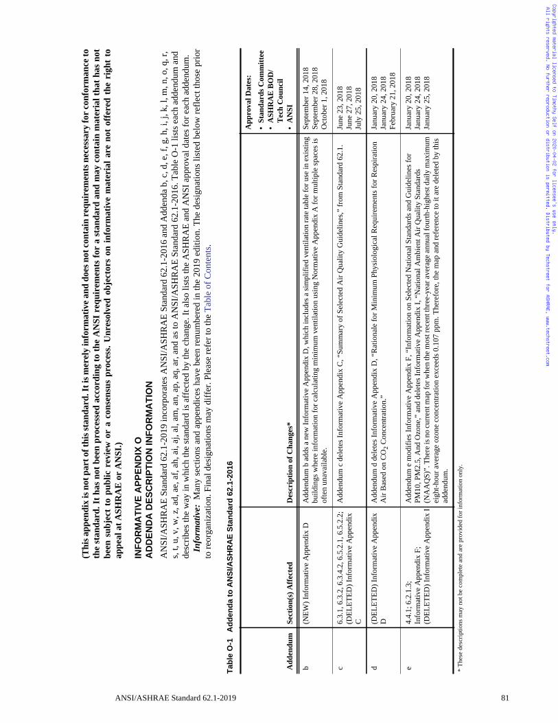
Copyrighted material licensed to Timothy Self on 2020-04-02 for licensee's use only. All rights reserved. No further reproduction or distribution is permitted. Distributed by Techstreet for ASHRAE, www.techstreet.com
(Thi
s app
endi
x is
not
par
t of t
his s
tand
ard.
It is
mer
ely
info
rmat
ive a
nd d
oes n
ot co
ntai
n re
quir
emen
ts n
eces
sary
for c
onfo
rman
ce to
the
stan
dard
. It h
as n
ot b
een
proc
esse
d ac
cord
ing
to th
e A
NSI
req
uire
men
ts fo
r a
stan
dard
and
may
con
tain
mat
eria
l tha
t has
not
been
sub
ject
to
publ
ic r
evie
w o
r a
cons
ensu
s pr
oces
s. U
nres
olve
d ob
ject
ors
on in
form
ativ
e m
ater
ial a
re n
ot o
ffere
d th
e ri
ght
toap
peal
at A
SHR
AE
or
AN
SI.)
INF
OR
MA
TIV
EA
PP
EN
DIX
OA
DD
EN
DA
DE
SC
RIP
TIO
NIN
FO
RM
AT
ION
AN
SI/A
SHR
AE
Stan
dard
62.
1-20
19 in
corp
orat
es A
NSI
/ASH
RA
E St
anda
rd 6
2.1-
2016
and
Add
enda
b, c
, d, e
, f, g
, h, i
, j, k
, l, m
, n, o
, q, r
, s,
t, u,
v, w
, z, a
d, a
e, a
f, ah
, ai,
aj, a
l, am
, an,
ap,
aq,
ar,
and
as to
AN
SI/A
SHR
AE
Stan
dard
62.
1-20
16. T
able
O-1
list
s eac
h ad
dend
um a
nd
desc
ribes
the
way
in w
hich
the
stan
dard
is a
ffec
ted
by th
e ch
ange
. It a
lso
lists
the
ASH
RA
E an
d A
NSI
app
rova
l dat
es fo
r eac
h ad
dend
um.
Info
rmat
ive:
Man
y se
ctio
ns a
nd a
ppen
dice
s ha
ve b
een
renu
mbe
red
in th
e 20
19 e
ditio
n. T
he d
esig
natio
ns li
sted
bel
ow re
flect
thos
e pr
ior
to re
orga
niza
tion.
Fin
al d
esig
natio
ns m
ay d
iffer
. Ple
ase
refe
r to
the
Tabl
e of
Con
tent
s.
Tab
leO
-1A
dd
end
ato
AN
SI/A
SH
RA
ES
tan
dar
d62
.1-2
016
Add
endu
mSe
ctio
n(s)
Affe
cted
Des
crip
tion
of C
hang
es*
App
rova
l Dat
es:
•St
anda
rds C
omm
ittee
•A
SHR
AE
BO
D/
Tec
h C
ounc
il•
AN
SI
b(N
EW) I
nfor
mat
ive
App
endi
x D
A
dden
dum
b a
dds a
new
Info
rmat
ive
App
endi
x D
, whi
ch in
clud
es a
sim
plifi
ed v
entil
atio
n ra
te ta
ble
for u
se in
exi
stin
g bu
ildin
gs w
here
info
rmat
ion
for c
alcu
latin
g m
inim
um v
entil
atio
n us
ing
Nor
mat
ive
App
endi
x A
for m
ultip
le sp
aces
is
ofte
n un
avai
labl
e.
Sept
embe
r 14,
201
8Se
ptem
ber 2
8, 2
018
Oct
ober
1, 2
018
c6.
3.1,
6.3
.2, 6
.3.4
.2, 6
.5.2
.1, 6
.5.2
.2;
(DEL
ETED
) Inf
orm
ativ
e A
ppen
dix
C
Add
endu
m c
del
etes
Info
rmat
ive
App
endi
x C
, “Su
mm
ary
of S
elec
ted
Air
Qua
lity
Gui
delin
es,”
from
Sta
ndar
d 62
.1.
June
23,
201
8Ju
ne 2
7, 2
018
July
25,
201
8
d(D
ELET
ED) I
nfor
mat
ive
App
endi
x D
Add
endu
m d
del
etes
Info
rmat
ive
App
endi
x D
, “R
atio
nale
for M
inim
um P
hysi
olog
ical
Req
uire
men
ts fo
r Res
pira
tion
Air
Bas
ed o
n C
O2 C
once
ntra
tion.
”Ja
nuar
y 20
, 201
8Ja
nuar
y 24
, 201
8Fe
brua
ry 2
1, 2
018
e4.
4.1;
6.2
.1.3
; In
form
ativ
e A
ppen
dix
F;(D
ELET
ED) I
nfor
mat
ive
App
endi
x I
Add
endu
m e
mod
ifies
Info
rmat
ive
App
endi
x F,
“In
form
atio
n on
Sel
ecte
d N
atio
nal S
tand
ards
and
Gui
delin
es fo
r PM
10, P
M2.
5, A
nd O
zone
,” a
nd d
elet
es In
form
ativ
e A
ppen
dix
I, “N
atio
nal A
mbi
ent A
ir Q
ualit
y St
anda
rds
(NA
AQ
S)”.
The
re is
no
curr
ent m
ap fo
r whe
n th
e mos
t rec
ent t
hree
-yea
r ave
rage
annu
al fo
urth
-hig
hest
dai
ly m
axim
um
eigh
t-hou
r ave
rage
ozo
ne c
once
ntra
tion
exce
eds 0
.107
ppm
. The
refo
re, t
he m
ap a
nd re
fere
nce
to it
are
del
eted
by
this
ad
dend
um.
Janu
ary
20, 2
018
Janu
ary
24, 2
018
Janu
ary
25, 2
018
* Th
ese
desc
riptio
ns m
ay n
ot b
e co
mpl
ete
and
are
prov
ided
for i
nfor
mat
ion
only
.
ANSI/ASHRAE Standard 62.1-2019 81
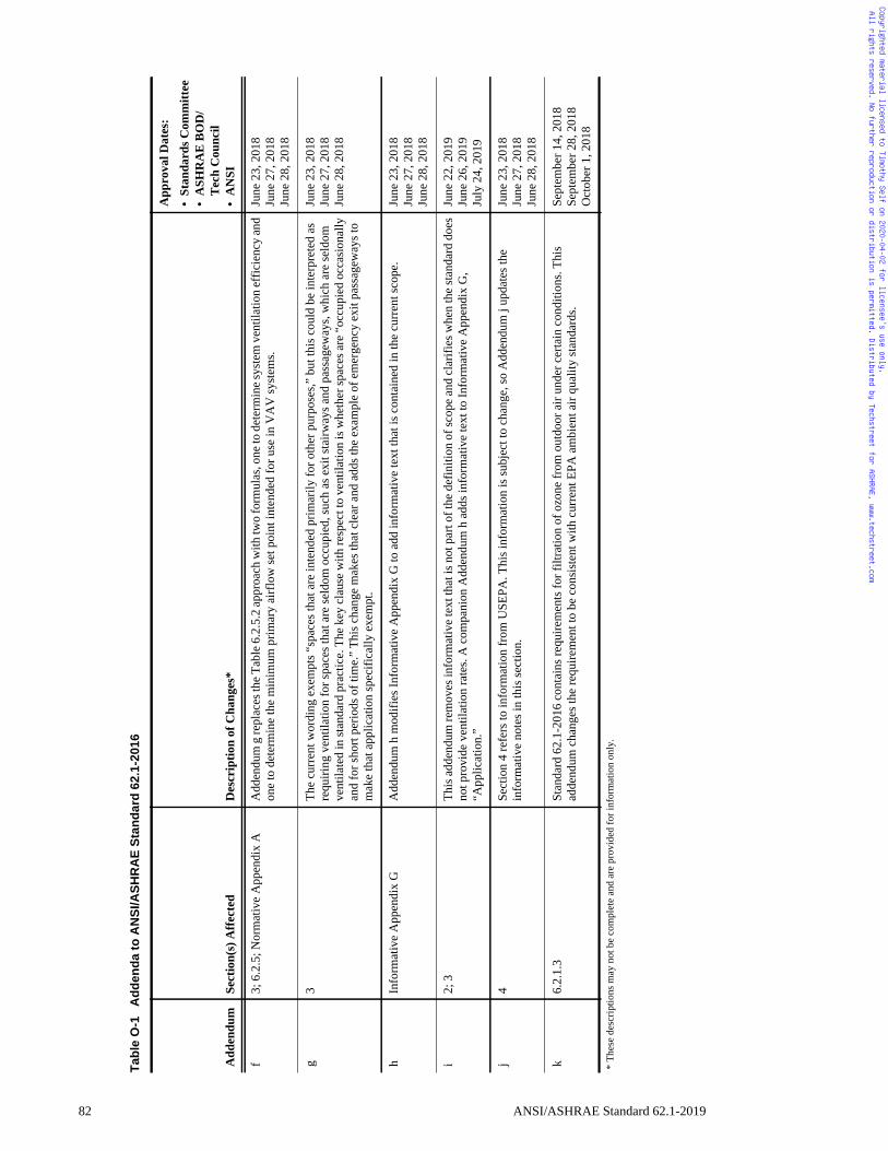
82
Copyrighted material licensed to Timothy Self on 2020-04-02 for licensee's use only. All rights reserved. No further reproduction or distribution is permitted. Distributed by Techstreet for ASHRAE, www.techstreet.com
f3;
6.2
.5; N
orm
ativ
e A
ppen
dix
AA
dden
dum
g re
plac
es th
e Tab
le 6
.2.5
.2 ap
proa
ch w
ith tw
o fo
rmul
as, o
ne to
det
erm
ine s
yste
m v
entil
atio
n ef
ficie
ncy
and
one
to d
eter
min
e th
e m
inim
um p
rimar
y ai
rflo
w se
t poi
nt in
tend
ed fo
r use
in V
AV
syst
ems.
June
23,
201
8Ju
ne 2
7, 2
018
June
28,
201
8
g3
The
curr
ent w
ordi
ng e
xem
pts “
spac
es th
at a
re in
tend
ed p
rimar
ily fo
r oth
er p
urpo
ses,”
but
this
cou
ld b
e in
terp
rete
d as
re
quiri
ng v
entil
atio
n fo
r spa
ces t
hat a
re se
ldom
occ
upie
d, su
ch a
s exi
t sta
irway
s and
pas
sage
way
s, w
hich
are
seld
om
vent
ilate
d in
stan
dard
pra
ctic
e. T
he k
ey c
laus
e w
ith re
spec
t to
vent
ilatio
n is
whe
ther
spac
es a
re “
occu
pied
occ
asio
nally
an
d fo
r sho
rt pe
riods
of t
ime.
” Th
is c
hang
e m
akes
that
cle
ar a
nd a
dds t
he e
xam
ple
of e
mer
genc
y ex
it pa
ssag
eway
s to
mak
e th
at a
pplic
atio
n sp
ecifi
cally
exe
mpt
.
June
23,
201
8Ju
ne 2
7, 2
018
June
28,
201
8
hIn
form
ativ
e A
ppen
dix
GA
dden
dum
h m
odifi
es In
form
ativ
e A
ppen
dix
G to
add
info
rmat
ive
text
that
is c
onta
ined
in th
e cu
rren
t sco
pe.
June
23,
201
8Ju
ne 2
7, 2
018
June
28,
201
8
i2;
3Th
is a
dden
dum
rem
oves
info
rmat
ive
text
that
is n
ot p
art o
f the
def
initi
on o
f sco
pe a
nd c
larif
ies w
hen
the
stan
dard
doe
s no
t pro
vide
ven
tilat
ion
rate
s. A
com
pani
on A
dden
dum
h a
dds i
nfor
mat
ive
text
to In
form
ativ
e A
ppen
dix
G,
“App
licat
ion.
”
June
22,
201
9Ju
ne 2
6, 2
019
July
24,
201
9
j4
Sect
ion
4 re
fers
to in
form
atio
n fr
om U
SEPA
. Thi
s inf
orm
atio
n is
subj
ect t
o ch
ange
, so
Add
endu
m j
upda
tes t
he
info
rmat
ive
note
s in
this
sect
ion.
June
23,
201
8Ju
ne 2
7, 2
018
June
28,
201
8
k6.
2.1.
3St
anda
rd 6
2.1-
2016
con
tain
s req
uire
men
ts fo
r filt
ratio
n of
ozo
ne fr
om o
utdo
or a
ir un
der c
erta
in c
ondi
tions
. Thi
s ad
dend
um c
hang
es th
e re
quire
men
t to
be c
onsi
sten
t with
cur
rent
EPA
am
bien
t air
qual
ity st
anda
rds.
Sept
embe
r 14,
201
8Se
ptem
ber 2
8, 2
018
Oct
ober
1, 2
018
Tab
leO
-1A
dd
end
ato
AN
SI/A
SH
RA
ES
tan
dar
d62
.1-2
016
Add
endu
mSe
ctio
n(s)
Affe
cted
Des
crip
tion
of C
hang
es*
App
rova
l Dat
es:
•St
anda
rds C
omm
ittee
•A
SHR
AE
BO
D/
Tec
h C
ounc
il•
AN
SI
* Th
ese
desc
riptio
ns m
ay n
ot b
e co
mpl
ete
and
are
prov
ided
for i
nfor
mat
ion
only
.
ANSI/ASHRAE Standard 62.1-2019
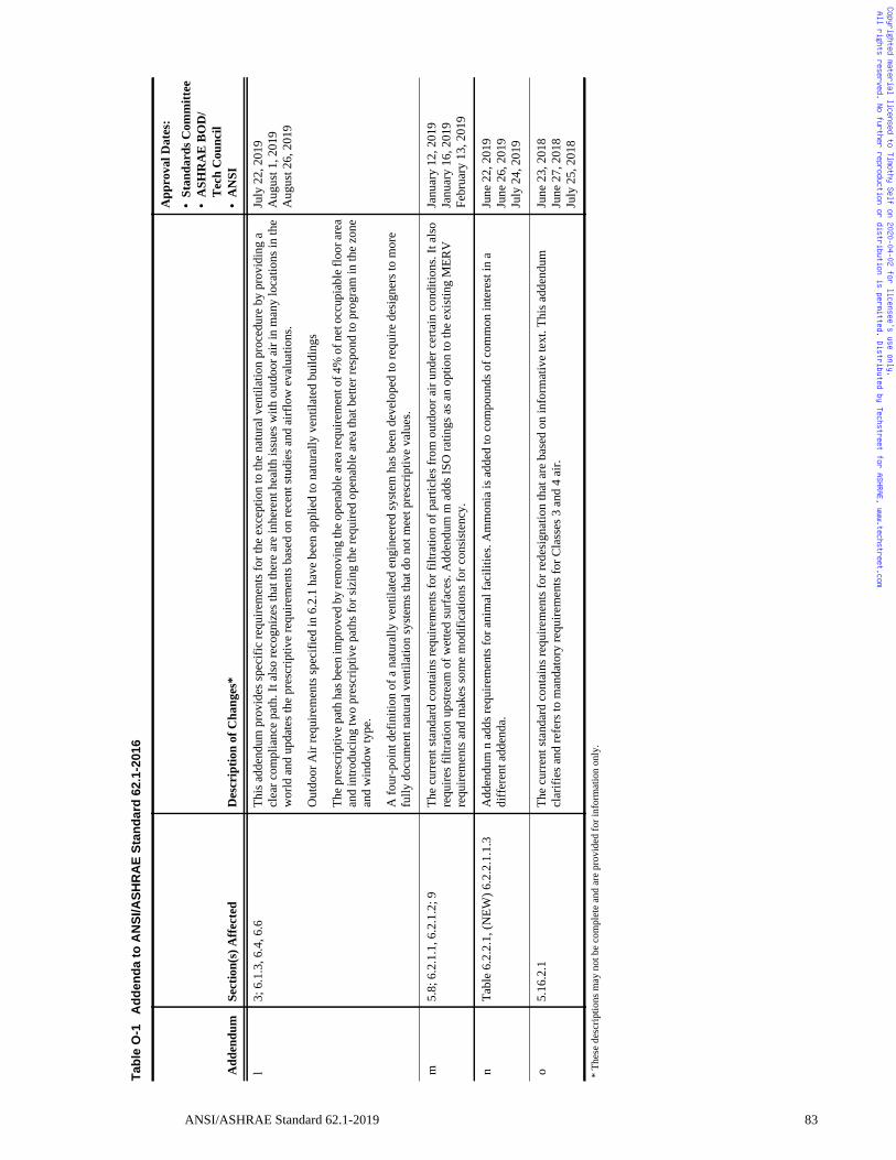
Copyrighted material licensed to Timothy Self on 2020-04-02 for licensee's use only. All rights reserved. No further reproduction or distribution is permitted. Distributed by Techstreet for ASHRAE, www.techstreet.com
l3;
6.1
.3, 6
.4, 6
.6Th
is a
dden
dum
pro
vide
s spe
cific
requ
irem
ents
for t
he e
xcep
tion
to th
e na
tura
l ven
tilat
ion
proc
edur
e by
pro
vidi
ng a
cl
ear c
ompl
ianc
e pa
th. I
t als
o re
cogn
izes
that
ther
e ar
e in
here
nt h
ealth
issu
es w
ith o
utdo
or a
ir in
man
y lo
catio
ns in
the
wor
ld a
nd u
pdat
es th
e pr
escr
iptiv
e re
quire
men
ts b
ased
on
rece
nt st
udie
s and
airf
low
eva
luat
ions
.
Out
door
Air
requ
irem
ents
spec
ified
in 6
.2.1
hav
e be
en a
pplie
d to
nat
ural
ly v
entil
ated
bui
ldin
gs
The
pres
crip
tive
path
has
bee
n im
prov
ed b
y re
mov
ing
the
open
able
are
a re
quire
men
t of 4
% o
f net
occ
upia
ble
floor
are
a an
d in
trodu
cing
two
pres
crip
tive
path
s for
sizi
ng th
e re
quire
d op
enab
le a
rea
that
bet
ter r
espo
nd to
pro
gram
in th
e zo
ne
and
win
dow
type
.
A fo
ur-p
oint
def
initi
on o
f a n
atur
ally
ven
tilat
ed e
ngin
eere
d sy
stem
has
bee
n de
velo
ped
to re
quire
des
igne
rs to
mor
e fu
lly d
ocum
ent n
atur
al v
entil
atio
n sy
stem
s tha
t do
not m
eet p
resc
riptiv
e va
lues
.
July
22,
201
9A
ugus
t 1, 2
019
Aug
ust 2
6, 2
019
m5.
8; 6
.2.1
.1, 6
.2.1
.2; 9
The
curr
ent s
tand
ard
cont
ains
requ
irem
ents
for f
iltra
tion
of p
artic
les f
rom
out
door
air
unde
r cer
tain
con
ditio
ns. I
t als
o re
quire
s filt
ratio
n up
stre
am o
f wet
ted
surf
aces
. Add
endu
m m
add
s ISO
ratin
gs a
s an
optio
n to
the
exis
ting
MER
V
requ
irem
ents
and
mak
es so
me
mod
ifica
tions
for c
onsi
sten
cy.
Janu
ary
12, 2
019
Janu
ary
16, 2
019
Febr
uary
13,
201
9
nTa
ble
6.2.
2.1,
(NEW
) 6.2
.2.1
.1.3
A
dden
dum
n a
dds r
equi
rem
ents
for a
nim
al fa
cilit
ies.
Am
mon
ia is
add
ed to
com
poun
ds o
f com
mon
inte
rest
in a
di
ffer
ent a
dden
da.
June
22,
201
9Ju
ne 2
6, 2
019
July
24,
201
9
o5.
16.2
.1Th
e cu
rren
t sta
ndar
d co
ntai
ns re
quire
men
ts fo
r red
esig
natio
n th
at a
re b
ased
on
info
rmat
ive
text
. Thi
s add
endu
m
clar
ifies
and
refe
rs to
man
dato
ry re
quire
men
ts fo
r Cla
sses
3 a
nd 4
air.
June
23,
201
8Ju
ne 2
7, 2
018
July
25,
201
8
Tab
leO
-1A
dd
end
ato
AN
SI/A
SH
RA
ES
tan
dar
d62
.1-2
016
Add
endu
mSe
ctio
n(s)
Affe
cted
Des
crip
tion
of C
hang
es*
App
rova
l Dat
es:
•St
anda
rds C
omm
ittee
•A
SHR
AE
BO
D/
Tec
h C
ounc
il•
AN
SI
* Th
ese
desc
riptio
ns m
ay n
ot b
e co
mpl
ete
and
are
prov
ided
for i
nfor
mat
ion
only
.
ANSI/ASHRAE Standard 62.1-2019 83
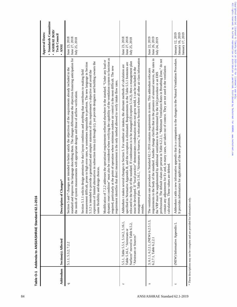
84
Copyrighted material licensed to Timothy Self on 2020-04-02 for licensee's use only. All rights reserved. No further reproduction or distribution is permitted. Distributed by Techstreet for ASHRAE, www.techstreet.com
q5.
1.1;
5.3
.2; 7
.2.2
Sect
ion
5 an
d 7
chan
ges a
re in
tend
ed to
bet
ter s
atis
fy th
e ob
ject
ives
of t
he re
quire
men
ts a
lread
y in
clud
ed in
the
stan
dard
and
impr
ove
the
lang
uage
des
crib
ing
them
. The
cha
nges
diff
eren
tiate
the
obje
ctiv
es fo
ster
ing
antic
ipat
ion
for
the
need
s of s
yste
m m
easu
rem
ents
with
app
ropr
iate
des
igns
and
thos
e of
airf
low
ver
ifica
tion.
Sect
ion
5.1.
1 so
licits
des
ign
atte
ntio
n fo
r duc
t lay
out c
ondi
tions
and
any
thin
g th
at c
ontri
bute
s to
mak
ing
field
m
easu
rem
ent d
iffic
ult,
pron
e to
hig
h er
ror r
ates
, or s
omet
imes
impo
ssib
le to
per
form
. The
new
lang
uage
in S
ectio
n 5.
3.2
is in
tend
ed to
pro
vide
a g
ener
aliz
ed a
nd si
mpl
er st
atem
ent o
f thi
s req
uire
men
t’s o
bjec
tive
and
avoi
d th
e ex
pres
sion
of l
imite
d al
tern
ativ
es in
subs
ectio
n ite
ms (
a) th
roug
h (c
), ye
t pro
vide
des
igne
rs a
nd b
uild
ing
owne
rs th
e sa
me
flexi
bilit
y an
d de
sign
cho
ices
.
Mod
ifica
tion
of 7
.2.2
add
ress
es th
e op
erat
iona
l req
uire
men
ts re
flect
ed e
lsew
here
in th
e st
anda
rd. “
Und
er a
ny lo
ad o
r dy
nam
ic re
set c
ondi
tion”
mus
t als
o be
con
side
red
whe
n ve
rifyi
ng th
e ca
pabi
lity
of th
e ve
ntila
tion
syst
em to
func
tion
as
requ
ired,
par
ticul
arly
at t
he p
oint
of o
pera
tion
whe
re m
inim
um o
utdo
or a
ir co
ntro
l is t
he m
ost d
iffic
ult.
The
new
re
quire
men
t ide
ntifi
es th
at d
irect
mea
sure
men
t is t
he o
nly
met
hod
allo
wed
to v
erify
inta
ke fl
ow ra
tes.
June
23,
201
8Ju
ne 2
7, 2
018
July
25,
201
8
r5.
5.1,
Tab
le 5
.5.1
, 5.1
4.2,
5.1
6.1,
Ta
ble
5.16
.1, “
Airs
tream
or
Surf
aces
” m
oved
to T
able
6.5
.2,
“Airs
tream
or S
ourc
es”
Add
endu
m r
mak
es se
vera
l cha
nges
to S
ectio
n 5.
For
out
door
air
inta
kes,
the
alte
rnat
e m
etho
ds o
f cal
cula
tion
are
spec
ified
in N
orm
ativ
e A
ppen
dix
B, a
nd th
e ex
cept
ion
is e
limin
ated
. Req
uire
men
ts in
the
Tabl
e 5.
5.1
foot
note
s are
re
loca
ted
to th
e bo
dy o
f the
stan
dard
. If c
onde
nsat
ion
is to
be
man
aged
(Exc
eptio
n 5.
14.2
), th
en a
man
agem
ent p
lan
mus
t be
deve
lope
d. If
“lo
cal p
ract
ice”
dem
onst
rate
s con
dens
atio
n do
es n
ot g
row
mol
d, it
can
be
incl
uded
in th
e m
anag
emen
t pla
n. T
able
5.1
6.1,
“A
irstre
ams o
r Sou
rces
,” is
relo
cate
d to
Sec
tion
6 w
here
all
othe
r air
clas
s inf
orm
atio
n re
side
s.
June
23,
201
8Ju
ne 2
7, 2
018
July
25,
201
8
s3;
6.1
.1, 6
.2.2
.1, (
NEW
) 6.2
.5.1
.3,
6.2.
7.1,
Tab
le 6
.2.2
.1Th
e ve
ntila
tion
rate
pro
cedu
re in
Sta
ndar
d 62
.1-2
016
cont
ains
requ
irem
ents
in n
otes
. Thi
s add
endu
m re
loca
tes
requ
irem
ents
to th
e bo
dy o
f the
stan
dard
. Ano
ther
cha
nge
clar
ifies
that
in th
e pr
esen
ce o
f unu
sual
sour
ces,
the
rate
s in
the
VR
P m
ust b
e su
pple
men
ted
by a
dditi
onal
ven
tilat
ion
to b
e de
term
ined
by
the
IAQ
pro
cedu
re o
r an
EHS
prof
essi
onal
. The
def
ault
valu
es p
er p
erso
n in
Tab
le 6
.2.2
.1, “
Min
imum
Ven
tilat
ion
Rat
es in
Bre
athi
ng Z
one,
” do
not
co
ntai
n an
y ad
just
men
ts fo
r Ev
and,
in m
any
case
s, ar
e ta
ken
out o
f con
text
. The
y ar
e no
t use
d in
the
vent
ilatio
n ca
lcul
atio
ns. T
hese
val
ues a
re d
elet
ed.
June
22,
201
9Ju
ne 2
6, 2
019
July
24,
201
9
t(N
EW) I
nfor
mat
ive
App
endi
x L
Add
endu
m t
adds
a n
ew in
form
ativ
e ap
pend
ix th
at is
a c
ompa
nion
to th
e ch
ange
s to
the
Nat
ural
Ven
tilat
ion
Proc
edur
e.
It pr
ovid
es in
form
atio
n fo
r app
licat
ion
of th
e ne
w p
roce
dure
.Ja
nuar
y 12
, 201
9Ja
nuar
y 16
, 201
9Ja
nuar
y 17
, 201
9
Tab
leO
-1A
dd
end
ato
AN
SI/A
SH
RA
ES
tan
dar
d62
.1-2
016
Add
endu
mSe
ctio
n(s)
Affe
cted
Des
crip
tion
of C
hang
es*
App
rova
l Dat
es:
•St
anda
rds C
omm
ittee
•A
SHR
AE
BO
D/
Tec
h C
ounc
il•
AN
SI
* Th
ese
desc
riptio
ns m
ay n
ot b
e co
mpl
ete
and
are
prov
ided
for i
nfor
mat
ion
only
.
ANSI/ASHRAE Standard 62.1-2019
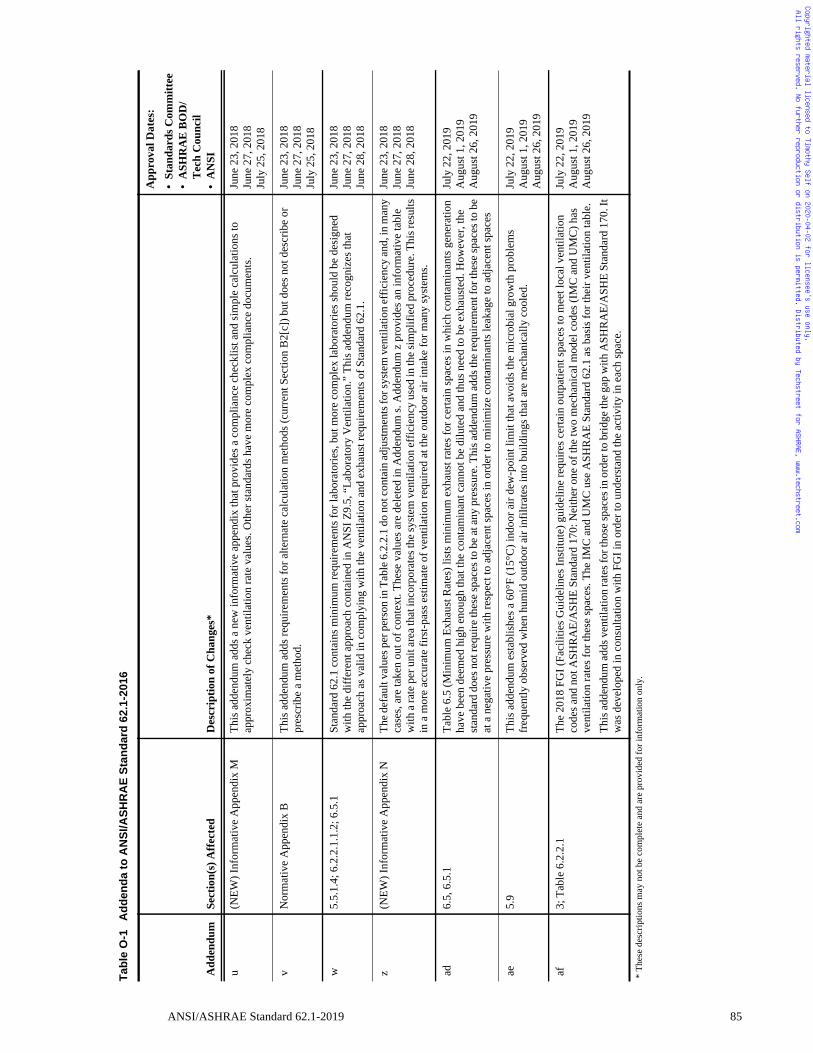
Copyrighted material licensed to Timothy Self on 2020-04-02 for licensee's use only. All rights reserved. No further reproduction or distribution is permitted. Distributed by Techstreet for ASHRAE, www.techstreet.com
u(N
EW) I
nfor
mat
ive
App
endi
x M
This
add
endu
m a
dds a
new
info
rmat
ive
appe
ndix
that
pro
vide
s a c
ompl
ianc
e ch
eckl
ist a
nd si
mpl
e ca
lcul
atio
ns to
ap
prox
imat
ely
chec
k ve
ntila
tion
rate
val
ues.
Oth
er st
anda
rds h
ave
mor
e co
mpl
ex c
ompl
ianc
e do
cum
ents
.Ju
ne 2
3, 2
018
June
27,
201
8Ju
ly 2
5, 2
018
vN
orm
ativ
e A
ppen
dix
BTh
is a
dden
dum
add
s req
uire
men
ts fo
r alte
rnat
e ca
lcul
atio
n m
etho
ds (c
urre
nt S
ectio
n B
2[c]
) but
doe
s not
des
crib
e or
pr
escr
ibe
a m
etho
d.Ju
ne 2
3, 2
018
June
27,
201
8Ju
ly 2
5, 2
018
w5.
5.1.
4; 6
.2.2
.1.1
.2; 6
.5.1
Stan
dard
62.
1 co
ntai
ns m
inim
um re
quire
men
ts fo
r lab
orat
orie
s, bu
t mor
e co
mpl
ex la
bora
torie
s sho
uld
be d
esig
ned
with
the
diff
eren
t app
roac
h co
ntai
ned
in A
NSI
Z9.
5, “
Labo
rato
ry V
entil
atio
n.”
This
add
endu
m re
cogn
izes
that
ap
proa
ch a
s val
id in
com
plyi
ng w
ith th
e ve
ntila
tion
and
exha
ust r
equi
rem
ents
of S
tand
ard
62.1
.
June
23,
201
8Ju
ne 2
7, 2
018
June
28,
201
8
z(N
EW) I
nfor
mat
ive
App
endi
x N
The d
efau
lt va
lues
per
per
son
in T
able
6.2
.2.1
do
not c
onta
in ad
just
men
ts fo
r sys
tem
ven
tilat
ion
effic
ienc
y an
d, in
man
y ca
ses,
are
take
n ou
t of c
onte
xt. T
hese
val
ues a
re d
elet
ed in
Add
endu
m s.
Add
endu
m z
pro
vide
s an
info
rmat
ive
tabl
e w
ith a
rate
per
uni
t are
a tha
t inc
orpo
rate
s the
syst
em v
entil
atio
n ef
ficie
ncy
used
in th
e sim
plifi
ed p
roce
dure
. Thi
s res
ults
in
a m
ore
accu
rate
firs
t-pas
s est
imat
e of
ven
tilat
ion
requ
ired
at th
e ou
tdoo
r air
inta
ke fo
r man
y sy
stem
s.
June
23,
201
8Ju
ne 2
7, 2
018
June
28,
201
8
ad6.
5, 6
.5.1
Tabl
e 6.
5 (M
inim
um E
xhau
st R
ates
) lis
ts m
inim
um e
xhau
st ra
tes f
or c
erta
in sp
aces
in w
hich
con
tam
inan
ts g
ener
atio
n ha
ve b
een
deem
ed h
igh
enou
gh th
at th
e co
ntam
inan
t can
not b
e di
lute
d an
d th
us n
eed
to b
e ex
haus
ted.
How
ever
, the
st
anda
rd d
oes n
ot re
quire
thes
e sp
aces
to b
e at
any
pre
ssur
e. T
his a
dden
dum
add
s the
requ
irem
ent f
or th
ese
spac
es to
be
at a
neg
ativ
e pr
essu
re w
ith re
spec
t to
adja
cent
spac
es in
ord
er to
min
imiz
e co
ntam
inan
ts le
akag
e to
adj
acen
t spa
ces
July
22,
201
9A
ugus
t 1, 2
019
Aug
ust 2
6, 2
019
ae5.
9Th
is a
dden
dum
est
ablis
hes a
60°
F (1
5°C
) ind
oor a
ir de
w-p
oint
lim
it th
at a
void
s the
mic
robi
al g
row
th p
robl
ems
freq
uent
ly o
bser
ved
whe
n hu
mid
out
door
air
infil
trate
s int
o bu
ildin
gs th
at a
re m
echa
nica
lly c
oole
d.
July
22,
201
9A
ugus
t 1, 2
019
Aug
ust 2
6, 2
019
af3;
Tab
le 6
.2.2
.1Th
e 20
18 F
GI (
Faci
litie
s Gui
delin
es In
stitu
te) g
uide
line
requ
ires c
erta
in o
utpa
tient
spac
es to
mee
t loc
al v
entil
atio
n co
des a
nd n
ot A
SHR
AE/
ASH
E St
anda
rd 1
70: N
eith
er o
ne o
f the
two
mec
hani
cal m
odel
cod
es (I
MC
and
UM
C) h
as
vent
ilatio
n ra
tes f
or th
ese
spac
es. T
he IM
C a
nd U
MC
use
ASH
RA
E St
anda
rd 6
2.1
as b
asis
for t
heir
vent
ilatio
n ta
ble.
This
add
endu
m a
dds v
entil
atio
n ra
tes f
or th
ose
spac
es in
ord
er to
brid
ge th
e ga
p w
ith A
SHR
AE/
ASH
E St
anda
rd 1
70. I
t w
as d
evel
oped
in c
onsu
ltatio
n w
ith F
GI i
n or
der t
o un
ders
tand
the
activ
ity in
eac
h sp
ace.
July
22,
201
9A
ugus
t 1, 2
019
Aug
ust 2
6, 2
019
Tab
leO
-1A
dd
end
ato
AN
SI/A
SH
RA
ES
tan
dar
d62
.1-2
016
Add
endu
mSe
ctio
n(s)
Affe
cted
Des
crip
tion
of C
hang
es*
App
rova
l Dat
es:
•St
anda
rds C
omm
ittee
•A
SHR
AE
BO
D/
Tec
h C
ounc
il•
AN
SI
* Th
ese
desc
riptio
ns m
ay n
ot b
e co
mpl
ete
and
are
prov
ided
for i
nfor
mat
ion
only
.
ANSI/ASHRAE Standard 62.1-2019 85
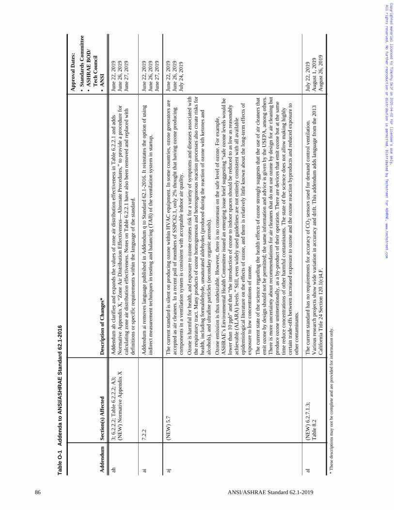
86
Copyrighted material licensed to Timothy Self on 2020-04-02 for licensee's use only. All rights reserved. No further reproduction or distribution is permitted. Distributed by Techstreet for ASHRAE, www.techstreet.com
ah3;
6.2
.2.2
; Tab
le 6
.2.2
.2; A
3;
(NEW
) Nor
mat
ive
App
endi
x X
Add
endu
m a
h cl
arifi
es a
nd e
xpan
ds th
e va
lues
of z
one
air d
istri
butio
n ef
fect
iven
ess i
n Ta
ble
6.2.
2.1
and
adds
N
orm
ativ
e A
ppen
dix
X, “
Zone
Air
Dis
tribu
tion
Effe
ctiv
enes
s—A
ltern
ate
Proc
edur
es,”
to p
rovi
de a
pro
cedu
re fo
r ca
lcul
atin
g zo
ne a
ir di
strib
utio
n ef
fect
iven
ess.
Not
es o
n Ta
ble
6.2.
2.1
have
als
o be
en re
mov
ed a
nd re
plac
ed w
ith
defin
ition
s or s
peci
fic re
quire
men
ts w
ithin
the
lang
uage
of t
he st
anda
rd.
June
22,
201
9Ju
ne 2
6, 2
019
June
27,
201
9
ai7.
2.2
Add
endu
m a
i rem
oves
lang
uage
pub
lishe
d in
Add
endu
m q
to S
tand
ard
62.1
-201
6. It
rein
stat
es th
e op
tion
of u
sing
in
dire
ct m
easu
rem
ent t
echn
ique
s in
test
ing
and
bala
ncin
g (T
AB
) of t
he v
entil
atio
n sy
stem
in st
artu
p.Ju
ne 2
2, 2
019
June
26,
201
9Ju
ne 2
7, 2
019
aj(N
EW) 5
.7Th
e cu
rren
t sta
ndar
d is
sile
nt o
n pr
oduc
ing
ozon
e w
ithin
HV
AC
equ
ipm
ent.
In so
me
coun
tries
, ozo
ne g
ener
ator
s are
ac
cept
ed a
s air
clea
ners
. In
a re
cent
pol
l of m
embe
rs o
f SSP
C62
.1, o
nly
2% th
ough
t tha
t hav
ing
ozon
e pr
oduc
ing
com
pone
nts i
n a
vent
ilatio
n sy
stem
is c
onsi
sten
t with
acc
epta
ble
indo
or a
ir qu
ality
.O
zone
is h
arm
ful f
or h
ealth
, and
exp
osur
e to
ozo
ne c
reat
es ri
sk fo
r a v
arie
ty o
f sym
ptom
s and
dis
ease
s ass
ocia
ted
with
th
e re
spira
tory
trac
t. M
any
prod
ucts
of o
zone
hom
ogen
eous
and
het
erog
eneo
us re
actio
n pr
oces
ses a
lso
crea
te ri
sks f
or
heal
th, i
nclu
ding
form
alde
hyde
, uns
atur
ated
ald
ehyd
es (p
rodu
ced
durin
g th
e re
actio
n of
ozo
ne w
ith k
eton
es a
nd
alco
hols
), an
d ul
trafin
e pa
rticl
es (s
econ
dary
org
anic
aer
osol
s).
Ozo
ne e
mis
sion
is th
us u
ndes
irabl
e. H
owev
er, t
here
is n
o co
nsen
sus o
n th
e sa
fe le
vel o
f ozo
ne. F
or e
xam
ple,
A
SHR
AE’
s Env
ironm
enta
l Hea
lth C
omm
ittee
issu
ed a
n em
ergi
ng is
sue
brie
f sug
gest
ing
“saf
e oz
one
leve
ls w
ould
be
low
er th
an 1
0 pp
b” a
nd th
at “
the
intro
duct
ion
of o
zone
to in
door
spac
es sh
ould
be
redu
ced
to a
s low
as r
easo
nabl
y ac
hiev
able
(ALA
RA
) lev
els.”
Stil
l, ev
en w
idel
y us
ed g
uide
lines
are
not
ent
irely
con
sist
ent w
ith a
ll av
aila
ble
epid
emio
logi
cal l
itera
ture
on
the
effe
cts o
f ozo
ne, a
nd th
ere
is re
lativ
ely
little
kno
wn
abou
t the
long
-term
eff
ects
of
expo
sure
to lo
w c
once
ntra
tions
of o
zone
.Th
e cu
rren
t sta
te o
f the
scie
nce
rega
rdin
g th
e he
alth
eff
ects
of o
zone
stro
ngly
sugg
ests
that
the
use
of a
ir cl
eane
rs th
at
emit
ozon
e by
des
ign
shou
ld n
ot b
e pe
rmitt
ed; t
he sa
me
info
rmat
ion
and
advi
ce is
giv
en b
y th
e U
SEPA
, am
ong
othe
rs.
Ther
e is
mor
e un
certa
inty
abo
ut re
com
men
datio
ns fo
r air
clea
ners
that
do
not u
se o
zone
by
desi
gn fo
r air
clea
ning
but
pr
oduc
e oz
one
unin
tent
iona
lly, a
s a b
y-pr
oduc
t of t
heir
oper
atio
n. T
here
are
dev
ices
that
em
it oz
one
but a
t the
sam
e tim
e re
duce
con
cent
ratio
ns o
f oth
er h
arm
ful c
onta
min
ants
. The
stat
e of
the
scie
nce
does
not
allo
w m
akin
g hi
ghly
ce
rtain
trad
e-of
fs b
etw
een
incr
ease
d ex
posu
re to
ozo
ne a
nd th
e oz
one
reac
tion
bypr
oduc
ts a
nd re
duce
d ex
posu
re to
ot
her c
onta
min
ants
.
June
22,
201
9Ju
ne 2
6, 2
019
July
24,
201
9
al(N
EW) 6
.2.7
.1.3
;Ta
ble
8.2
The
curr
ent s
tand
ard
has n
o re
quire
men
ts fo
r acc
urac
y of
CO
2 sen
sors
use
d fo
r dem
and
cont
rol v
entil
atio
n.V
ario
us re
sear
ch p
roje
cts s
how
wid
e va
riatio
n in
acc
urac
y an
d dr
ift. T
his a
dden
dum
add
s lan
guag
e fr
om th
e 20
13
Cal
iforn
ia T
itle
24 S
ectio
n 12
0.1(
c)4.
F.
July
22,
201
9A
ugus
t 1, 2
019
Aug
ust 2
6, 2
019
Tab
leO
-1A
dd
end
ato
AN
SI/A
SH
RA
ES
tan
dar
d62
.1-2
016
Add
endu
mSe
ctio
n(s)
Affe
cted
Des
crip
tion
of C
hang
es*
App
rova
l Dat
es:
•St
anda
rds C
omm
ittee
•A
SHR
AE
BO
D/
Tec
h C
ounc
il•
AN
SI
* Th
ese
desc
riptio
ns m
ay n
ot b
e co
mpl
ete
and
are
prov
ided
for i
nfor
mat
ion
only
.
ANSI/ASHRAE Standard 62.1-2019
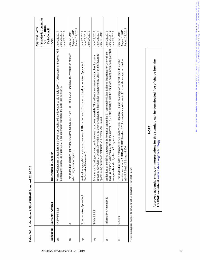
Copyrighted material licensed to Timothy Self on 2020-04-02 for licensee's use only. All rights reserved. No further reproduction or distribution is permitted. Distributed by Techstreet for ASHRAE, www.techstreet.com
am(N
EW) 6
.5.1
.1W
hen
Add
endu
m r
to S
tand
ard
62.1
-201
6 w
as p
ublis
hed,
the f
ootn
ote t
o ol
d Ta
ble 5
.16.
1, “A
irstre
ams o
r Sou
rces
,” d
id
not t
rans
fer t
o ne
w th
e Ta
ble
6.5.
2. T
his a
dden
dum
rein
stat
es th
e no
te in
to S
ectio
n 6.
June
22,
201
9Ju
ne 2
6, 2
019
June
27,
201
9
an3
This
add
endu
m c
larif
ies t
hat c
olle
ge c
lass
room
s may
use
Not
e H
in T
able
6.2
.2.1
and
hav
e th
e ve
ntila
tion
shut
off
w
hen
they
are
uno
ccup
ied.
Ju
ly 2
2, 2
019
Aug
ust 1
, 201
9A
ugus
t 26,
201
9
ap9;
Info
rmat
ive
App
endi
x J
Add
endu
m a
p up
date
s pub
licat
ion
date
s and
UR
Is in
Sec
tion
9, “
Ref
eren
ces,”
and
Info
rmat
ive
App
endi
x J,
“Inf
orm
ativ
e R
efer
ence
s.”Ju
ne 2
2, 2
019
June
26,
201
9Ju
ne 2
7, 2
019
aqTa
ble
6.2.
2.1
Man
y m
anuf
actu
ring
occu
panc
ies d
o no
t use
haz
ardo
us m
ater
ials
. Thi
s add
endu
m c
hang
es th
e ai
r cla
ss fo
r tho
se
spac
es to
Air
Cla
ss 2
, whi
ch a
llow
s the
air
to b
e re
circ
ulat
ed to
oth
er si
mila
r man
ufac
turin
g ar
eas.
Man
ufac
turin
g sp
aces
usi
ng h
azar
dous
mat
eria
ls w
ill re
mai
n A
ir C
lass
3.
June
22,
201
9Ju
ne 2
6, 2
019
July
24,
201
9
arIn
form
ativ
e A
ppen
dix
EA
dden
dum
ar m
odifi
es la
ngua
ge in
Info
rmat
ive
App
endi
x E,
“A
ccep
tabl
e M
ass B
alan
ce E
quat
ions
for U
se w
ith th
e IA
Q P
roce
dure
,” to
be
cons
iste
nt w
ith th
e cu
rren
t IA
QP.
It a
lso
clar
ifies
that
the
equa
tions
do
not i
nclu
de a
ny p
oten
tial
com
poun
ds a
dded
by
the
HV
AC
syst
em.
June
22,
201
9Ju
ne 2
6, 2
019
June
27,
201
9
as6.
2.2;
9Th
is a
dden
dum
add
s a re
fere
nce
to A
SHR
AE/
ASH
E St
anda
rd 1
70 a
nd a
n ex
cept
ion
to d
irect
use
rs to
use
the
vent
ilatio
n ra
tes i
n A
SHR
AE/
ASH
E St
anda
rd 1
70 fo
r ase
psis
and
odo
r con
trol f
or h
ealth
care
spac
es li
sted
in
ASH
RA
E/A
SHE
Stan
dard
170
.
July
22,
201
9A
ugus
t 1, 2
019
Aug
ust 2
6, 2
019
NO
TE
Ap
pro
ved
add
end
a,er
rata
,or
inte
rpre
tati
on
sfo
rth
isst
and
ard
can
be
do
wn
load
edfr
eeo
fch
arg
efr
om
the
AS
HR
AE
web
site
atw
ww
.ash
rae.
org
/tec
hn
olo
gy.
Tab
leO
-1A
dd
end
ato
AN
SI/A
SH
RA
ES
tan
dar
d62
.1-2
016
Add
endu
mSe
ctio
n(s)
Affe
cted
Des
crip
tion
of C
hang
es*
App
rova
l Dat
es:
•St
anda
rds C
omm
ittee
•A
SHR
AE
BO
D/
Tec
h C
ounc
il•
AN
SI
* Th
ese
desc
riptio
ns m
ay n
ot b
e co
mpl
ete
and
are
prov
ided
for i
nfor
mat
ion
only
.
ANSI/ASHRAE Standard 62.1-2019 87
Copyrighted material licensed to Timothy Self on 2020-04-02 for licensee's use only. All rights reserved. No further reproduction or distribution is permitted. Distributed by Techstreet for ASHRAE, www.techstreet.com
POLICY STATEMENT DEFINING ASHRAE’S CONCERNFOR THE ENVIRONMENTAL IMPACT OF ITS ACTIVITIES
ASHRAE is concerned with the impact of its members’ activities on both the indoor and outdoor environment.ASHRAE’s members will strive to minimize any possible deleterious effect on the indoor and outdoor environment ofthe systems and components in their responsibility while maximizing the beneficial effects these systems provide,consistent with accepted Standards and the practical state of the art.
ASHRAE’s short-range goal is to ensure that the systems and components within its scope do not impact theindoor and outdoor environment to a greater extent than specified by the Standards and Guidelines as established byitself and other responsible bodies.
As an ongoing goal, ASHRAE will, through its Standards Committee and extensive Technical Committee structure,continue to generate up-to-date Standards and Guidelines where appropriate and adopt, recommend, and promotethose new and revised Standards developed by other responsible organizations.
Through its Handbook, appropriate chapters will contain up-to-date Standards and design considerations as thematerial is systematically revised.
ASHRAE will take the lead with respect to dissemination of environmental information of its primary interest andwill seek out and disseminate information from other responsible organizations that is pertinent, as guides to updatingStandards and Guidelines.
The effects of the design and selection of equipment and systems will be considered within the scope of thesystem’s intended use and expected misuse. The disposal of hazardous materials, if any, will also be considered.
ASHRAE’s primary concern for environmental impact will be at the site where equipment within ASHRAE’s scopeoperates. However, energy source selection and the possible environmental impact due to the energy source andenergy transportation will be considered where possible. Recommendations concerning energy source selectionshould be made by its members.
Copyrighted material licensed to Timothy Self on 2020-04-02 for licensee's use only. All rights reserved. No further reproduction or distribution is permitted. Distributed by Techstreet for ASHRAE, www.techstreet.com
ASHRAE · 1791 Tullie Circle NE · Atlanta, GA 30329 · www.ashrae.org
Product code: 86170 10/19
About ASHRAE
Founded in 1894, ASHRAE is a global professional society committed to serve humanity by advancing the arts andsciences of heating, ventilation, air conditioning, refrigeration, and their allied fields.
As an industry leader in research, standards writing, publishing, certification, and continuing education, ASHRAEand its members are dedicated to promoting a healthy and sustainable built environment for all, through strategicpartnerships with organizations in the HVAC&R community and across related industries.
To stay current with this and other ASHRAE Standards and Guidelines, visit www.ashrae.org/standards, andconnect on LinkedIn, Facebook, Twitter, and YouTube.
Visit the ASHRAE Bookstore
ASHRAE offers its Standards and Guidelines in print, as immediately downloadable PDFs, and via ASHRAE DigitalCollections, which provides online access with automatic updates as well as historical versions of publications.Selected Standards and Guidelines are also offered in redline versions that indicate the changes made between theactive Standard or Guideline and its previous version. For more information, visit the Standards and Guidelinessection of the ASHRAE Bookstore at www.ashrae.org/bookstore.
IMPORTANT NOTICES ABOUT THIS STANDARD
To ensure that you have all of the approved addenda, errata, and interpretations for thisStandard, visit www.ashrae.org/standards to download them free of charge.
Addenda, errata, and interpretations for ASHRAE Standards and Guidelines are nolonger distributed with copies of the Standards and Guidelines. ASHRAE providesthese addenda, errata, and interpretations only in electronic form to promotemore sustainable use of resources.
Copyrighted material licensed to Timothy Self on 2020-04-02 for licensee's use only. All rights reserved. No further reproduction or distribution is permitted. Distributed by Techstreet for ASHRAE, www.techstreet.com


