Embed Size (px)
Citation preview
�����������������
Citation: Salgado-López, C.;
Apiñaniz, J.I.; Henares, J.L.;
Pérez-Hernández, J.A.; de Luis, D.;
Volpe, L.; Gatti, G. Angular-Resolved
Thomson Parabola Spectrometer for
Laser-Driven Ion Accelerators.
Sensors 2022, 22, 3239. https://
doi.org/10.3390/s22093239
Academic Editor: Bruno Goncalves
Received: 29 March 2022
Accepted: 21 April 2022
Published: 22 April 2022
Publisher’s Note: MDPI stays neutral
with regard to jurisdictional claims in
published maps and institutional affil-
iations.
Copyright: © 2022 by the authors.
Licensee MDPI, Basel, Switzerland.
This article is an open access article
distributed under the terms and
conditions of the Creative Commons
Attribution (CC BY) license (https://
creativecommons.org/licenses/by/
4.0/).
sensors
Article
Angular-Resolved Thomson Parabola Spectrometer forLaser-Driven Ion AcceleratorsCarlos Salgado-López * , Jon Imanol Apiñaniz, José Luis Henares , José Antonio Pérez-Hernández ,Diego de Luis , Luca Volpe and Giancarlo Gatti
Centro de Láseres Pulsados (CLPU), Edificio M5, Parque Científico USAL, C/Adaja, 8,37185 Villamayor, Salamanca, Spain; [email protected] (J.I.A.); [email protected] (J.L.H.);[email protected] (J.A.P.-H.); [email protected] (D.d.L.); [email protected] (L.V.); [email protected] (G.G.)* Correspondence: [email protected]
Abstract: This article reports the development, construction, and experimental test of an angle-resolved Thomson parabola (TP) spectrometer for laser-accelerated multi-MeV ion beams in order todistinguish between ionic species with different charge-to-mass ratio. High repetition rate (HHR)compatibility is guaranteed by the use of a microchannel plate (MCP) as active particle detector. Theangular resolving power, which is achieved due to an array of entrance pinholes, can be simplyadjusted by modifying the geometry of the experiment and/or the pinhole array itself. The analysisprocedure allows for different ion traces to cross on the detector plane, which greatly enhancesthe flexibility and capabilities of the detector. A full characterization of the TP magnetic field isimplemented into a relativistic code developed for the trajectory calculation of each pinhole beamlet.We describe the first test of the spectrometer at the 1 PW VEGA 3 laser facility at CLPU, Salamanca(Spain), where up to 15 MeV protons and carbon ions from a 3µm laser-irradiated Al foil are detected.
Keywords: plama diagnostics; charged-particle spectroscopy; ion beams; instrumentation
1. Introduction
Since the advent of the chirped pulse amplification (CPA) technology [1], the rangeof accessible intensities on focus for ultra-bright, short-pulse lasers has increased signifi-cantly, reaching current values above 1022 W/cm2 [2]. Such enhancement has paved theway for laser-based particle accelerators, mainly for ions [3,4] and electrons [5]; however,acceleration schemes have been also demonstrated for positrons [6] and neutrons [7].
The range of applications of the accelerated beams is quite rich, profiting from thelow-emittance and ultrashort duration (and high peak current) of the generated particlebeams, well-fitted characteristics for applications. Specifically, since the demonstrationof collimation and monochromatisation of laser-driven multi-MeV ion beams [8,9], theirpotential employments, such as ultrafast proton probing [10–13], isochoric heating of denseplasmas [14], fast ignition of inertial confinement fusion reactions [15], material science [16],and medical purposes [17,18], have attained plenty of attention [19].
The compactness and costs of high-power laser facilities are important advantageswhen compared to conventional radio frequency acceleration facilities, as well as thereduced size of the radio protection requirements. Most of the potential industrial ap-plications of these sources require a high time-averaged particle flux, which stresses theimportance of developing high-repetition-rate (HRR) laser sources, targetry instrumenta-tion [20], and diagnostics.
One of the key diagnostics for ion acceleration investigation are the Thomson parabolaspectrometers, first developed by Thomson in 1907 [21], i.e., in-line diagnostics whichcan rate the particles depending on their energy, momentum, and charge-to-mass ra-tio [22]. The element of the spectrometer sensible to particles can be either a passivedetector—for instance, imaging plates (IPs) or a CR39 nuclear track detector [23], which
Sensors 2022, 22, 3239. https://doi.org/10.3390/s22093239 https://www.mdpi.com/journal/sensors
Sensors 2022, 22, 3239 2 of 13
require post-processing to retrieve data, or an active one -microchannel-plate [24]—or plas-tic scintillators [25], well fitted for HRR operation, due to their ability to perform on-linemeasurements for every single laser shot. The main drawback of an ordinary TP is theincapability of deconvolving the angular distribution of the measured beam, as only aparticular angle of the beam (with an insignificant angular spread) is measured, as theparticles measured have to cross a pinhole. This fact also makes this detector speciallysensitive to alignment.
Tracing the angular-resolved spectrum of the ions is a vital milestone in the study of thebeam properties. For instance, from this kind of work, we have learnt that the most widelyused laser-driven ion acceleration mechanism, target normal sheath acceleration (TNSA) [3,4],normally achieved by the ultra-bright laser irradiation of thin metallic films, is able to emitextraordinarily laminar, low-emittance beams from the rear surface of the target [26],coming from a source with a diameter size as big as a few hundred micrometers [10]and a total beam divergence angle around 20◦. Potential applications benefit from thetransport properties of these laminar beams, which have proven to be suitable whenfocused to millimetre-sized spots [27,28]. While increasing the resolution of the diagnosticsresponsible for measuring the ion phase space, new beam features have been discovered,such as the beam pointing deviation from the target normal for certain laser and targetconditions [29–31]. Tomography-like measurements have also shown that there is a differentsource size and divergence for each ion energy [32–36]. Non-laminar ion acceleration hasalso been demonstrated when triggering plasma instabilities under specific circumstances,for instance due to the generation of a preplasma prior to the laser interaction with thetarget [37–39] or the use of ultrathin (nanometric-thick) film targets in the radiation pressureacceleration scheme (RPA) [40,41].
In order to retrieve angular-resolved spectral information about the beam, radiochromicfilm (RCF) or scintillator stacks are practical diagnostic tools [25,42], typically yieldinga discretized spectrum of ∆E ≈ 1 MeV, which is much coarser when compared to thecontinuous spectral TP resolution [22]. Moreover, these diagnostics cannot discriminatebetween different q/m ionic species. This fact is compensated in some experimental layoutsby the combination of perforated RCF stacks and TPs [43]; thus, part of the beam reachesthe latter. Despite yielding complementary information, this method is limited in spectralresolution for most parts of the beam.
In this work, we present a multi-pinhole Thomson parabola spectrometer, whichcombines sharp spectral/angular precision, besides the ionic species sorting capability.Furthermore, the use of a MCP detector device allows for single-shot HRR acquisition.Section 2 describes the basic operation principle of the detector and depicts its physicalproperties and parameters. The experimental layout where the detector was tested and theanalysed results are presented in Section 3.
2. Materials and Methods2.1. Thomson Parabola Design and Operation
The Thomson parabola works according to magnetic and electric sector spectrome-ter principles. The entrance pinhole selects a beamlet composed by ions with a specificcharge-to-mass ratio q/m, with q = Ze. The ion charge is deflected by parallel (or antipar-allel) magnetic B and electric E fields of length l2. The initial velocity of the particles isperpendicular to the field lines; thus, the deflection directions of the two fields are mutuallyorthogonal, allowing species separation (by electric field, in x-axis) and energy separation(mostly by magnetic field, in y-axis) after some propagation distance l3. The ions aremeasured on a two-dimensional spatially resolved particle-sensitive detector; in our case, aMCP. In the small deflection approximation sin(θ) ≈ θ, considering perfectly sharp andhomogeneous fields and nonrelativistic particle energies, the deviation coordinates at thedetector plane caused by the Lorentz force are given by
x =qEl2l32Ekin
, (1)
Sensors 2022, 22, 3239 3 of 13
y =qBl2l3√2mEkin
, (2)
where Ekin is the kinetic energy of the ion. When combinating (1) and (2), we obtain theparabolic equation
y2 =qm
B2l2l3E
x. (3)
Ions with the same charge-to-mass ratio will reach the same parabolic trace on the de-tector plane; meanwhile, their position along the trace will define their energy. Photons arenot deflected by the fields and travel straightly through the source–pinhole axis and impactthe MCP, providing the zero deflection reference (used for spectrum data interpretation).
The ultimate energy resolution of the TP depends on the spatial separation of thedifferent energies at the active area of the detector (which depends on the magnetic fieldstrength B, its length l2 and the distance to MCP l3) and on the capability of the system toresolve this separation (which depends on the magnification of the imaging system collect-ing MCP signal and on the trace thickness δ). In the considered approximation, δ (whichis inversely proportional to the spectrometer resolution) is given by the setup geometryand the pinhole diameter d, similarly as in a pinhole camera, as δ = d + (s + d)L′/L, whereL is the distance from source to pinhole, L′ = l1 + l2 + l3 is the distance from pinhole todetector, and s is the source size [44].
Several concept modifications have been proposed to improve the basic functioningof TPs, such as a tunable magnetic dipole [45] or electromagnets [24] for adaptable energyresolution, exotic electrode geometry (trapezoidal or wedged) [45–47] for extended retrievalof lower part of the spectrum, transient electric field for time-gated measurement of thebeam [48], designs with two in-line entrance pinholes for spatially resolved measurementsof the ion source [36], or simultaneous measurements of ion and electron [49] or plasma-emitted extreme ultraviolet radiation spectra [50].
2.2. Multi-Pinhole Thomson Parabola Spectrometer
Here, we propose a modification of the basic TP design, consisting on the substitutionof the pinhole by a horizontal array of pinholes. This array chops the incoming cone of par-ticles in several beamlets which are simultaneously detected. In this way, we can measurethe different angles adding angularly resolved spectral information. Similar strategies werealready proposed [32–36,51–55] in most of the cases, dismissing the electric field for charge-to-mass ratio inspections, as the authors claim to accelerate a single ion species (protons).Some references [56] showed the possibility of joining different ion diagnostics in orderto have extended information about the beam, but lacking ion discrimination capabilityat different subtended angles. A few works have proposed [45] or demonstrated [57] anabsolute capability of angular spectral-q/m resolution, but with strong limitations in theavailable species to be investigated, as well as their subtended angles, due to data analysisconstraints. In order to facilitate the spectrum retrieval, they managed to avoid crossingtraces from neighbouring beamlets at the detector plane.
We propose a more general multi-pinhole TP spectrometer, including the use of electricand magnetic fields for identifying different q/m ions, angular selection of beamlets, anda more generic post-processing method, which does not limit the available ion species tobe investigated.
In the case shown here, three pinholes of d = 200µm, separated by a = 3 mm andaligned along the x-axis (electric deflection direction, see Figure 1), were drilled into a W1 mm-thick 25 mm-diameter plate. A copper nosepiece was designed to easily exchangebetween these substrates, with different pinhole array combinations with pre-set align-ment orientations. A B = 0.4 T, l2 = 75 mm long permanent dipole magnet is locatedl1 = 13.5 mm after the pinholes. The direction of the magnetic field (−x) deflects the ionsupwards (+y). Magnets are attached to an iron yoke, leaving a gap between poles of 16 mm,on-axis with respect to the central pinhole. Two thin copper electrodes are placed overthe magnet poles. A variable voltage difference can be applied between electrodes, up to
Sensors 2022, 22, 3239 4 of 13
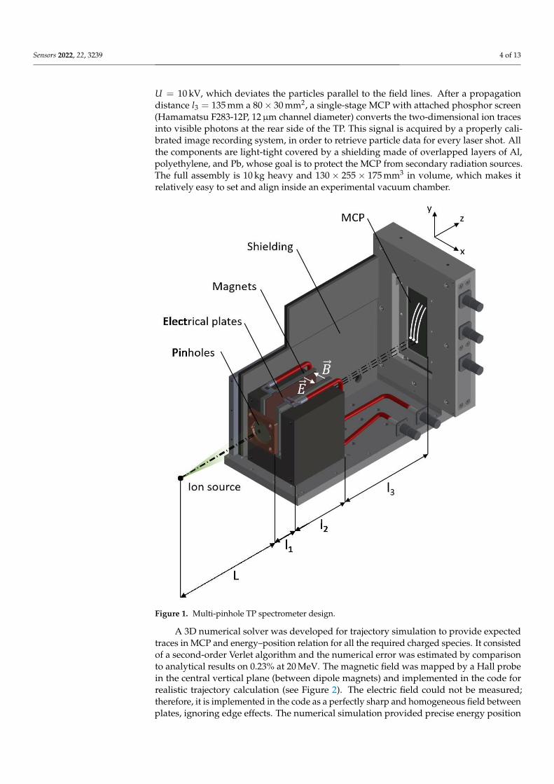
U = 10 kV, which deviates the particles parallel to the field lines. After a propagationdistance l3 = 135 mm a 80× 30 mm2, a single-stage MCP with attached phosphor screen(Hamamatsu F283-12P, 12µm channel diameter) converts the two-dimensional ion tracesinto visible photons at the rear side of the TP. This signal is acquired by a properly cali-brated image recording system, in order to retrieve particle data for every laser shot. Allthe components are light-tight covered by a shielding made of overlapped layers of Al,polyethylene, and Pb, whose goal is to protect the MCP from secondary radiation sources.The full assembly is 10 kg heavy and 130× 255× 175 mm3 in volume, which makes itrelatively easy to set and align inside an experimental vacuum chamber.
Figure 1. Multi-pinhole TP spectrometer design.
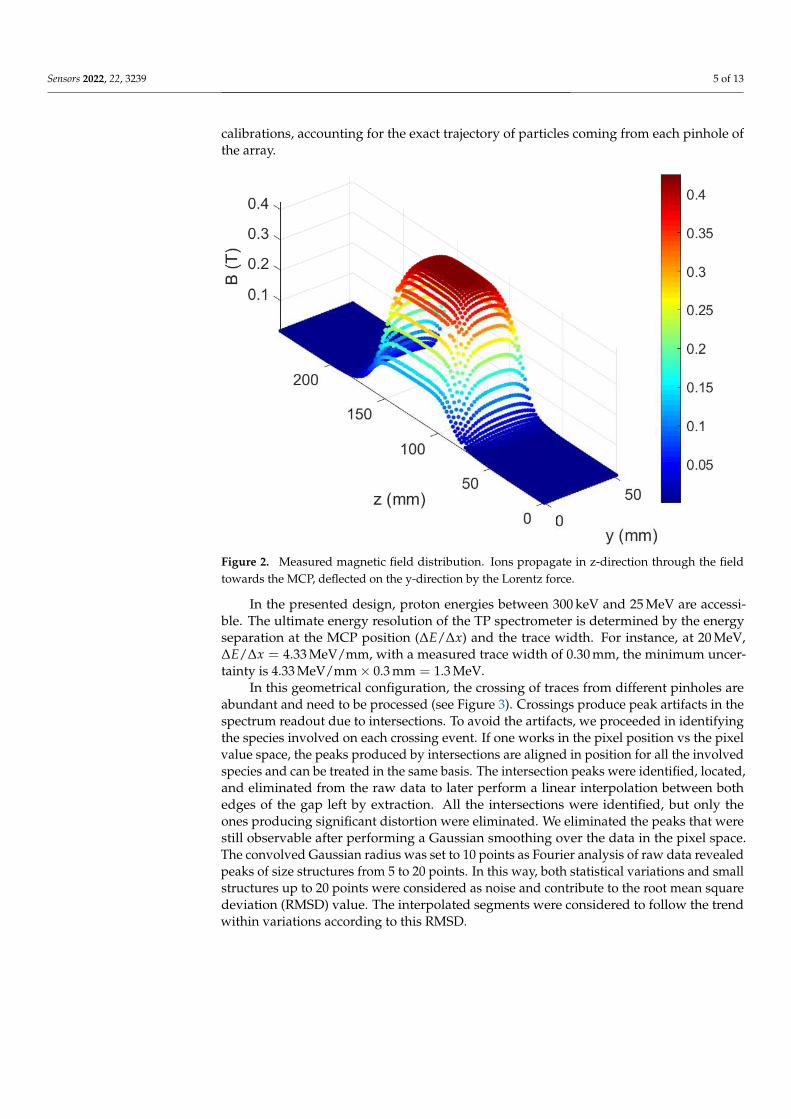
A 3D numerical solver was developed for trajectory simulation to provide expectedtraces in MCP and energy–position relation for all the required charged species. It consistedof a second-order Verlet algorithm and the numerical error was estimated by comparisonto analytical results on 0.23% at 20 MeV. The magnetic field was mapped by a Hall probein the central vertical plane (between dipole magnets) and implemented in the code forrealistic trajectory calculation (see Figure 2). The electric field could not be measured;therefore, it is implemented in the code as a perfectly sharp and homogeneous field betweenplates, ignoring edge effects. The numerical simulation provided precise energy position
Sensors 2022, 22, 3239 5 of 13
calibrations, accounting for the exact trajectory of particles coming from each pinhole ofthe array.
Figure 2. Measured magnetic field distribution. Ions propagate in z-direction through the fieldtowards the MCP, deflected on the y-direction by the Lorentz force.
In the presented design, proton energies between 300 keV and 25 MeV are accessi-ble. The ultimate energy resolution of the TP spectrometer is determined by the energyseparation at the MCP position (∆E/∆x) and the trace width. For instance, at 20 MeV,∆E/∆x = 4.33 MeV/mm, with a measured trace width of 0.30 mm, the minimum uncer-tainty is 4.33 MeV/mm× 0.3 mm = 1.3 MeV.
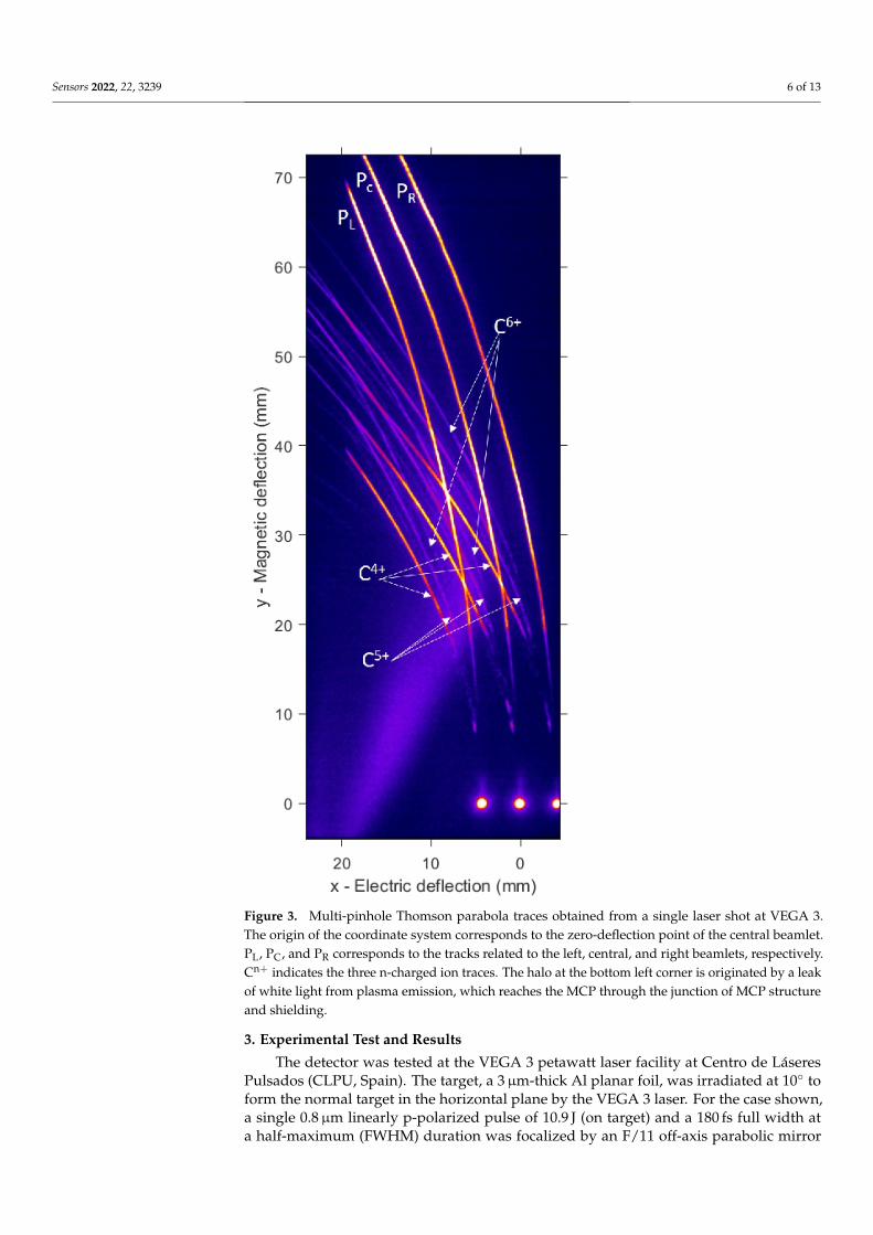
In this geometrical configuration, the crossing of traces from different pinholes areabundant and need to be processed (see Figure 3). Crossings produce peak artifacts in thespectrum readout due to intersections. To avoid the artifacts, we proceeded in identifyingthe species involved on each crossing event. If one works in the pixel position vs the pixelvalue space, the peaks produced by intersections are aligned in position for all the involvedspecies and can be treated in the same basis. The intersection peaks were identified, located,and eliminated from the raw data to later perform a linear interpolation between bothedges of the gap left by extraction. All the intersections were identified, but only theones producing significant distortion were eliminated. We eliminated the peaks that werestill observable after performing a Gaussian smoothing over the data in the pixel space.The convolved Gaussian radius was set to 10 points as Fourier analysis of raw data revealedpeaks of size structures from 5 to 20 points. In this way, both statistical variations and smallstructures up to 20 points were considered as noise and contribute to the root mean squaredeviation (RMSD) value. The interpolated segments were considered to follow the trendwithin variations according to this RMSD.
Sensors 2022, 22, 3239 6 of 13
Figure 3. Multi-pinhole Thomson parabola traces obtained from a single laser shot at VEGA 3.The origin of the coordinate system corresponds to the zero-deflection point of the central beamlet.PL, PC, and PR corresponds to the tracks related to the left, central, and right beamlets, respectively.Cn+ indicates the three n-charged ion traces. The halo at the bottom left corner is originated by a leakof white light from plasma emission, which reaches the MCP through the junction of MCP structureand shielding.
3. Experimental Test and Results
The detector was tested at the VEGA 3 petawatt laser facility at Centro de LáseresPulsados (CLPU, Spain). The target, a 3µm-thick Al planar foil, was irradiated at 10◦ toform the normal target in the horizontal plane by the VEGA 3 laser. For the case shown,a single 0.8µm linearly p-polarized pulse of 10.9 J (on target) and a 180 fs full width ata half-maximum (FWHM) duration was focalized by an F/11 off-axis parabolic mirror

Sensors 2022, 22, 3239 7 of 13
onto a 9.7µm FWHM spot, containing 20% of the pulse energy, yielding an averagedintensity of 1.7× 10¹⁹ W/cm2 inside the FWHM and resulting in the acceleration of ionsfrom the contamination layer on the target rear surface, rich in H and C atoms, by theTNSA mechanism. As a side effect, ultraviolet and X-rays photons are generated duringthe laser–plasma interaction, which can define the non-deflected axis of the detector.
The TP spectrometer was carefully aligned so the central pinhole was exactly facingthe interaction point in the normal direction of the target surface at a distance L = 508 mm.The electrode plates were fed with a voltage difference of U = 10, 000 V. The photons fromthe phosphor screen were collected by an imaging system consisting of an objective (NikonAF-S NIKKOR 18–105 mm 1:3.5–5.6G ED) with adaptable focal length range of 18–105 mmand a Blackfly PGE-23S6M-C CMOS optical camera of 1920× 1200 pixels with a laterialsize of 5.86µm. The system was set up to an ultimate magnification of 0.0854 at the detectorplane (14.57 pixels/mm), which was calibrated thanks to a laser machined pattern in theobject plane, next to the MCP. For the detection distance L, the choice of pinhole separationa = 3 mm keeps a reasonably separation of the three traces group, occupying as much aspossible the MCP surface. Figure 3 shows the raw traces acquired in a single laser shot.
It is important to note that the source-to-detector distance L in the setup prepared ismuch larger than the source size s (typically a few hundred of micrometers in diameter).The magnification of the pinhole camera effect on the detector plane is barely enough todistinguish spatial effects of the source, therefore considering a point-like source for analysismeans. The examined angles in this case are 0 and ±α, being α = tan−1(a/L) = 0.3◦.
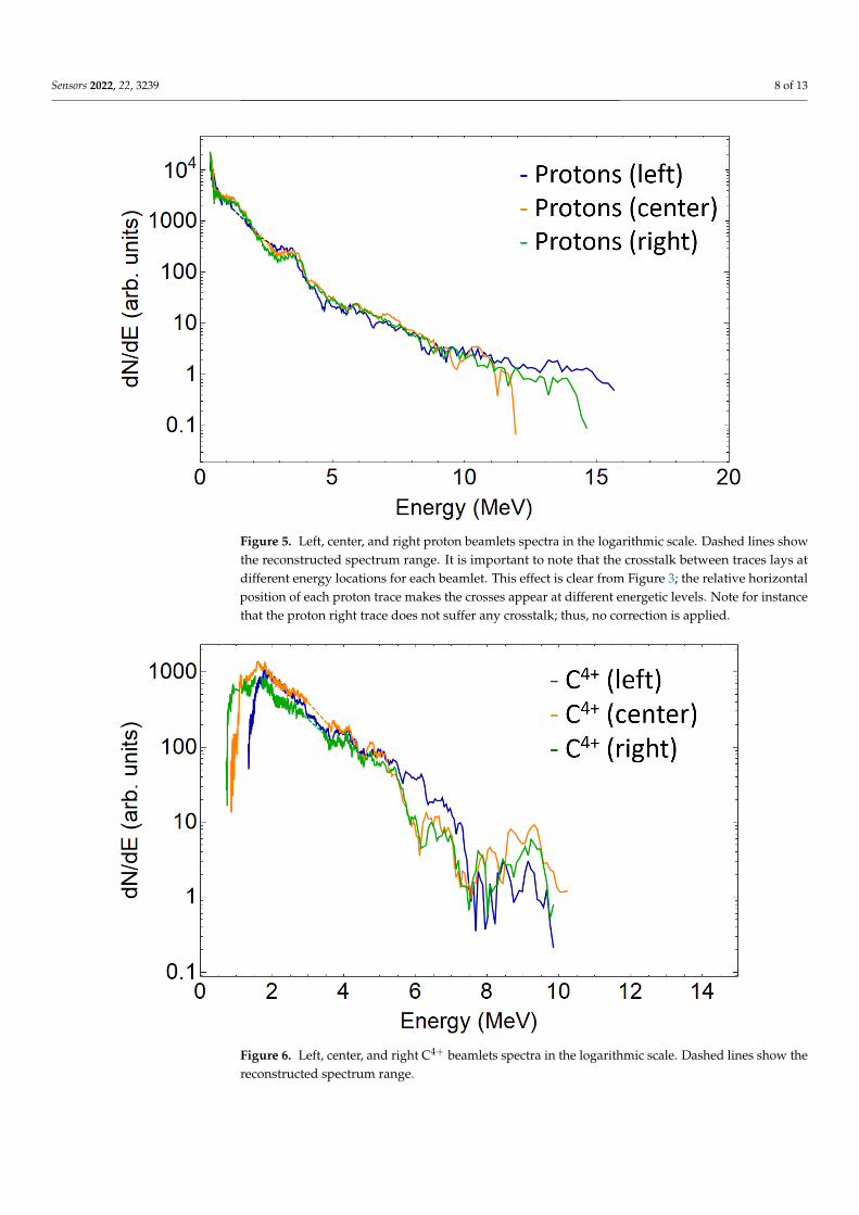
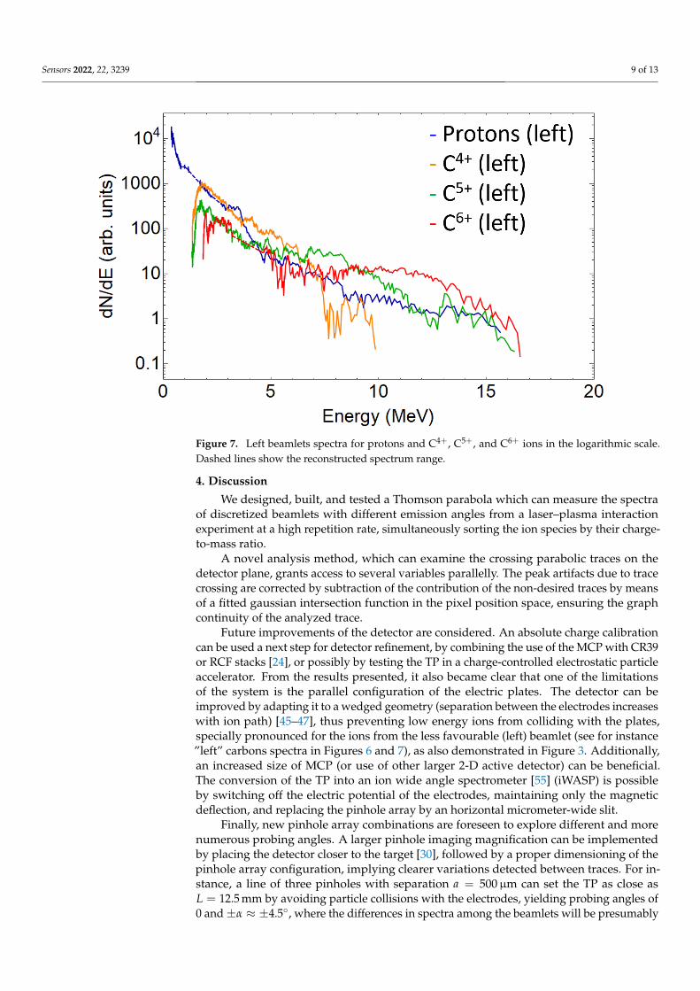
A single beamlet proton spectrum is plotted in Figure 4, together with the traces inter-sections signal peaks, which are considered measurement artifacts and removed. Figure 5shows the three spectra retrieved from the three analysed proton traces. As expected, dueto the small difference of the angles probed when compared to the typical TNSA beamdivergence (around 20◦), all spectra are similar. This is also true for the carbon ions (seeFigure 6). For sake of comparison, different ion species from the same pinhole are plottedin Figure 7. The RMSD was calculated from raw data with respect to smoothed data andsome example values are 8310 (a.u.) for left trace protons and 655 (a.u.) for C4+ left.
Figure 4. Left trace proton spectrum in logarithmic scale. Blue: corrected spectrum. Red: samespectrum showing the peaks subtracted, corresponding to trace crosses. Several representative errorbars are plotted, picturing the estimated energy resolution.
Sensors 2022, 22, 3239 8 of 13
Figure 5. Left, center, and right proton beamlets spectra in the logarithmic scale. Dashed lines showthe reconstructed spectrum range. It is important to note that the crosstalk between traces lays atdifferent energy locations for each beamlet. This effect is clear from Figure 3; the relative horizontalposition of each proton trace makes the crosses appear at different energetic levels. Note for instancethat the proton right trace does not suffer any crosstalk; thus, no correction is applied.
Figure 6. Left, center, and right C4+ beamlets spectra in the logarithmic scale. Dashed lines show thereconstructed spectrum range.
Sensors 2022, 22, 3239 9 of 13
Figure 7. Left beamlets spectra for protons and C4+, C5+, and C6+ ions in the logarithmic scale.Dashed lines show the reconstructed spectrum range.
4. Discussion
We designed, built, and tested a Thomson parabola which can measure the spectraof discretized beamlets with different emission angles from a laser–plasma interactionexperiment at a high repetition rate, simultaneously sorting the ion species by their charge-to-mass ratio.
A novel analysis method, which can examine the crossing parabolic traces on thedetector plane, grants access to several variables parallelly. The peak artifacts due to tracecrossing are corrected by subtraction of the contribution of the non-desired traces by meansof a fitted gaussian intersection function in the pixel position space, ensuring the graphcontinuity of the analyzed trace.
Future improvements of the detector are considered. An absolute charge calibrationcan be used a next step for detector refinement, by combining the use of the MCP with CR39or RCF stacks [24], or possibly by testing the TP in a charge-controlled electrostatic particleaccelerator. From the results presented, it also became clear that one of the limitationsof the system is the parallel configuration of the electric plates. The detector can beimproved by adapting it to a wedged geometry (separation between the electrodes increaseswith ion path) [45–47], thus preventing low energy ions from colliding with the plates,specially pronounced for the ions from the less favourable (left) beamlet (see for instance”left” carbons spectra in Figures 6 and 7), as also demonstrated in Figure 3. Additionally,an increased size of MCP (or use of other larger 2-D active detector) can be beneficial.The conversion of the TP into an ion wide angle spectrometer [55] (iWASP) is possibleby switching off the electric potential of the electrodes, maintaining only the magneticdeflection, and replacing the pinhole array by an horizontal micrometer-wide slit.
Finally, new pinhole array combinations are foreseen to explore different and morenumerous probing angles. A larger pinhole imaging magnification can be implementedby placing the detector closer to the target [30], followed by a proper dimensioning of thepinhole array configuration, implying clearer variations detected between traces. For in-stance, a line of three pinholes with separation a = 500µm can set the TP as close asL = 12.5 mm by avoiding particle collisions with the electrodes, yielding probing angles of0 and±α ≈ ±4.5◦, where the differences in spectra among the beamlets will be presumably

Sensors 2022, 22, 3239 10 of 13
noticeable. Moreover, each pinhole can apply an imaging magnification of L′/L ≈ 18,which will considerably enhance the spatial resolution. Considering high laminar beams,this high magnification imaging mode should be sufficient to resolve changes on the tar-get emission coordinates and beam pointing variations as a function of energy for eachbeamlet [30,33–35], therefore granting a beam emittance characterization. This increasedmagnification can cause a cost of loss of energy resolution. An estimation of the resolu-tion in the worst case scenario of a pure non-laminar beam provides a value of ±3.5 MeVat 15 MeV. However, a large percentage of laminarity is expected at these energies toreduce the trace thickness and increase the resolution. In any case, the observation ofhow laminarity depends on energy is itself an important achievement, and this type ofsetup can provide a direct measurement of it. On the other hand, it seems possible toapply the multi-pinhole TP to diagnose energy (and species) laser-generated ion beamlines.In such a case, the detector field configuration can be adapted in order to comprise anadequate range of energies, therefore improving the energy resolution considerably. Allthese possibilities show the potential interest of such kind of detectors for beam analysisof novel acceleration mechanisms under research, such as collisionless shock acceleration(CSA) [58] or RPA [40,41,59], as well as for measurements of transported ion beamlines,well fitted for applications.
Author Contributions: Conceptualization, C.S.-L., J.I.A., J.L.H. and G.G.; methodology, C.S.-L., J.I.A.,J.L.H. and J.A.P.-H.; software, C.S.-L. and J.I.A.; validation, C.S.-L., J.I.A., J.L.H., J.A.P.-H. and L.V.;formal analysis, C.S.-L., J.I.A., J.L.H. and J.A.P.-H.; investigation, C.S.-L., J.I.A. and G.G.; resources,D.d.L.; data curation, C.S.-L.; writing—original draft preparation, C.S.-L.; writing—review andediting, C.S.-L., J.I.A., J.L.H. and L.V; visualization, C.S.-L., J.I.A. and D.d.L.; supervision, L.V. andG.G. All authors have read and agreed to the published version of the manuscript.
Funding: The research leading to these results has received funding from LASERLAB-EUROPE V(Grant Agreement No. 871124, European Union Horizon 2020 research and innovation program),and from IMPULSE (Grant Agreement No. 871161, European Union Horizon 2020 research and inno-vation program). Support from Equipment Grant No. EQC2018-005230-P, Unidad de InvestigaciónConsolidada 167 from Junta de Castilla y León and Junta de Castilla y León (Grant No. CLP263P20),are acknowledged.
Institutional Review Board Statement: Not applicable.
Informed Consent Statement: Not applicable.
Data Availability Statement: Not applicable.
Acknowledgments: We thank all the staff of CLPU involved in the experiment where the spectrome-ter was tested, including the technical area, the radio protection department, and the engineeringsection. Special mention should be made for the scientific division personnel collaborating in the ex-perimental campaign and D. Arana who machined several pieces of the detector at CLPU workshop.
Conflicts of Interest: The authors declare no conflict of interest.
AbbreviationsThe following abbreviations are used in this manuscript:
TP Thomson parabolaHHR High repetition rateMCP Microchannel plateCPA Chirped pulse amplificationIP Imaging plateTNSA Target normal sheath accelerationRPA Radiation pressure accelerationRCF Radiochromic filmFWHM Full width at half-maximumiWASP Ion-wide angle spectrometerCSA Collisionless shock acceleration
Sensors 2022, 22, 3239 11 of 13
References1. Strickland, D.; Mourou, G. Compression of amplified chirped optical pulses. Opt. Commun. 1985, 55, 447–449. [CrossRef]2. Yoon, J.W.; Kim, Y.G.; Choi, I.W.; Sung, J.H.; Lee, H.W.; Lee, S.K.; Nam, C.H. Realization of laser intensity over 1023W/cm2.
Optica 2021, 8, 630–635. [CrossRef]3. Daido, H.; Nishiuchi, M.; Pirozhkov, A.S. Review of laser-driven ion sources and their applications. Rep. Prog. Phys. 2012,
75, 056401. [CrossRef] [PubMed]4. Macchi, A.; Borghesi, M.; Passoni, M. Ion acceleration by superintense laser-plasma interaction. Rev. Mod. Phys. 2013, 85, 751–793.
[CrossRef]5. Esarey, E.; Schroeder, C.B.; Leemans, W.P. Physics of laser-driven plasma-based electron accelerators. Rev. Mod. Phys. 2009,
81, 1229–1285. [CrossRef]6. Chen, H.; Wilks, S.C.; Meyerhofer, D.D.; Bonlie, J.; Chen, C.D.; Chen, S.N.; Courtois, C.; Elberson, L.; Gregori, G.; Kruer, W.; et al.
Relativistic Quasimonoenergetic Positron Jets from Intense Laser-Solid Interactions. Phys. Rev. Lett. 2010, 105, 015003. [CrossRef]7. Roth, M.; Jung, D.; Falk, K.; Guler, N.; Deppert, O.; Devlin, M.; Favalli, A.; Fernandez, J.; Gautier, D.; Geissel, M.; et al. Bright
Laser-Driven Neutron Source Based on the Relativistic Transparency of Solids. Phys. Rev. Lett. 2013, 110, 044802. [CrossRef]8. Ter-Avetisyan, S.; Schnürer, M.; Polster, R.; Nickles, P.; Sandner, W. First demonstration of collimation and monochromatisation of
a laser accelerated proton burst. Laser Part. Beams 2008, 26, 637–642. [CrossRef]9. Toncian, T.; Borghesi, M.; Fuchs, J.; d’Humières, E.; Antici, P.; Audebert, P.; Brambrink, E.; Cecchetti, C.A.; Pipahl, A.;
Romagnani, L.; et al. Ultrafast Laser-Driven Microlens to Focus and Energy-Select Mega-Electron Volt Protons. Science 2006,312, 410–413. [CrossRef]
10. Borghesi, M.; Mackinnon, A.J.; Campbell, D.H.; Hicks, D.G.; Kar, S.; Patel, P.K.; Price, D.; Romagnani, L.; Schiavi, A.; Willi, O.Multi-MeV Proton Source Investigations in Ultraintense Laser-Foil Interactions. Phys. Rev. Lett. 2004, 92, 055003. [CrossRef]
11. Santos, J.J.; Bailly-Grandvaux, M.; Giuffrida, L.; Forestier-Colleoni, P.; Fujioka, S.; Zhang, Z.; Korneev, P.; Bouillaud, R.; Dorard, S.;Batani, D.; et al. Laser-driven platform for generation and characterization of strong quasi-static magnetic fields. New J. Phys.2015, 17, 083051. [CrossRef]
12. Apiñaniz, J.I.; Malko, S.; Fedosejevs, R.; Cayzac, W.; Vaisseau, X.; De Luis, D.; Gatti, G.; McGuffey, C.; Bailly-Grandvaux, M.;Bhutwala, K.; et al. A quasi-monoenergetic short time duration compact proton source for probing high energy density states ofmatter. Sci. Rep. 2021, 11, 6881. [CrossRef] [PubMed]
13. Malko, S.; Cayzac, W.; Ospina-Bohorquez, V.; Bhutwala, K.; Bailly-Grandvaux, M.; McGuffey, C.; Fedosejevs, R.; Vaisseau, X.;Tauschwitz, A.; Aginako, J.A.; et al. Proton stopping measurements at low velocity in warm dense carbon. Nat. Commun. 2017.[CrossRef]
14. Patel, P.K.; Mackinnon, A.J.; Key, M.H.; Cowan, T.E.; Foord, M.E.; Allen, M.; Price, D.F.; Ruhl, H.; Springer, P.T.; Stephens, R.Isochoric Heating of Solid-Density Matter with an Ultrafast Proton Beam. Phys. Rev. Lett. 2003, 91, 125004. [CrossRef]
15. Roth, M.; Cowan, T.E.; Key, M.H.; Hatchett, S.P.; Brown, C.; Fountain, W.; Johnson, J.; Pennington, D.M.; Snavely, R.A.; Wilks, S.C.;et al. Fast Ignition by Intense Laser-Accelerated Proton Beams. Phys. Rev. Lett. 2001, 86, 436–439. [CrossRef]
16. Mirani, F.; Maffini, A.; Casamichiela, F.; Pazzaglia, A.; Formenti, A.; Dellasega, D.; Russo, V.; Vavassori, D.; Bortot, D.;Huault, M.; et al. Integrated quantitative PIXE analysis and EDX spectroscopy using a laser-driven particle source. Sci. Adv.2021, 7, eabc8660. [CrossRef]
17. Spencer, I.; Ledingham, K.; Singhal, R.; McCanny, T.; McKenna, P.; Clark, E.; Krushelnick, K.; Zepf, M.; Beg, F.; Tatarakis, M.; et al.Laser generation of proton beams for the production of short-lived positron emitting radioisotopes. Nucl. Instrum. Methods Phys.Res. Sect. B 2001, 183, 449–458. [CrossRef]
18. Ledingham, K.W.; Bolton, P.R.; Shikazono, N.; Ma, C.M. Towards Laser Driven Hadron Cancer Radiotherapy: A Review ofProgress. Appl. Sci. 2014, 4, 402–443. [CrossRef]
19. Volpe, L.; Fedosejevs, R.; Gatti, G.; Pérez-Hernández, J.A.; Méndez, C.; Apiñaniz, J.; Vaisseau, X.; Salgado, C.; Huault, M.;Malko, S.; et al. Generation of high energy laser-driven electron and proton sources with the 200 TW system VEGA 2 at theCentro de Laseres Pulsados. High Power Laser Sci. Eng. 2019, 7, e25. [CrossRef]
20. Puyuelo Valdes, P.; de Luis, D.; Hernandez, J.; Apiñaniz, J.; Curcio, A.; Henares, J.L.; Huault, M.; Perez-Hernandez, J.A.; Roso, L.;Gatti, G.; et al. Implementation of a thin, flat water target capable of high-repetition-rate MeV-range proton acceleration in ahigh-power laser at the CLPU. Plasma Phys. Control. Fusion 2022, accepted. [CrossRef]
21. Thomson, J. XLVII. On rays of positive electricity. Lond. Edinb. Dublin Philos. Mag. Sci. 1907, 13, 561–575. [CrossRef]22. Bolton, P.R.; Borghesi, M.; Brenner, C.; Carroll, D.C.; De Martinis, C.; Fiorini, F.; Flacco, A.; Floquet, V.; Fuchs, J.; Gallegos, P.; et al.
Instrumentation for diagnostics and control of laser-accelerated proton (ion) beams. Phys. Medica 2014, 30, 255–270. [CrossRef][PubMed]
23. Cobble, J.A.; Flippo, K.A.; Offermann, D.T.; Lopez, F.E.; Oertel, J.A.; Mastrosimone, D.; Letzring, S.A.; Sinenian, N. High-resolutionThomson parabola for ion analysis. Rev. Sci. Instrum. 2011, 82, 113504. [CrossRef] [PubMed]
24. Harres, K.; Schollmeier, M.; Brambrink, E.; Audebert, P.; Blaževic, A.; Flippo, K.; Gautier, D.C.; Geißel, M.; Hegelich, B.M.;Nürnberg, F.; et al. Development and calibration of a Thomson parabola with microchannel plate for the detection of laser-accelerated MeV ions. Rev. Sci. Instrum. 2008, 79, 093306. [CrossRef] [PubMed]
Sensors 2022, 22, 3239 12 of 13
25. Huault, M.; De Luis, D.; Apiñaniz, J.I.; De Marco, M.; Salgado, C.; Gordillo, N.; Gutiérrez Neira, C.; Pérez-Hernández, J.A.;Fedosejevs, R.; Gatti, G.; et al. A 2D scintillator-based proton detector for high repetition rate experiments. High Power Laser Sci.Eng. 2019, 7, e60. [CrossRef]
26. Cowan, T.E.; Fuchs, J.; Ruhl, H.; Kemp, A.; Audebert, P.; Roth, M.; Stephens, R.; Barton, I.; Blazevic, A.; Brambrink, E.; et al.Ultralow Emittance, Multi-MeV Proton Beams from a Laser Virtual-Cathode Plasma Accelerator. Phys. Rev. Lett. 2004, 92, 204801.[CrossRef]
27. Brack, F.E.; Kroll, F.; Gaus, L.; Bernert, C.; Beyreuther, E.; Cowan, T.E.; Karsch, L.; Kraft, S.; Kunz-Schughart, L.A.; Lessmann,E.; et al. Spectral and spatial shaping of laser-driven proton beams using a pulsed high-field magnet beamline. Sci. Rep. 2020,10, 9118. [CrossRef]
28. Milluzzo, G.; Petringa, G.; Catalano, R.; Cirrone, G.A. Handling and dosimetry of laser-driven ion beams for applications. Eur.Phys. J. Plus. 2021, 136, 1170. [CrossRef]
29. Lindau, F.; Lundh, O.; Persson, A.; McKenna, P.; Osvay, K.; Batani, D.; Wahlström, C.G. Laser-Accelerated Protons withEnergy-Dependent Beam Direction. Phys. Rev. Lett. 2005, 95, 175002. [CrossRef]
30. Schreiber, J.; Ter-Avetisyan, S.; Risse, E.; Kalachnikov, M.P.; Nickles, P.V.; Sandner, W.; Schramm, U.; Habs, D.; Witte, J.; Schnürer,M. Pointing of laser-accelerated proton beams. Phys. Plasmas 2006, 13, 033111. [CrossRef]
31. Nakamura, T.; Mima, K.; Ter-Avetisyan, S.; Schnürer, M.; Sokollik, T.; Nickles, P.V.; Sandner, W. Lateral movement of alaser-accelerated proton source on the target’s rear surface. Phys. Rev. E 2008, 77, 036407. [CrossRef]
32. Chen, H.; Hazi, A.U.; van Maren, R.; Chen, S.N.; Fuchs, J.; Gauthier, M.; Le Pape, S.; Rygg, J.R.; Shepherd, R. An imaging protonspectrometer for short-pulse laser plasma experiments. Rev. Sci. Instrum. 2010, 81, 10D314. [CrossRef] [PubMed]
33. Ter-Avetisyan, S.; Schnürer, M.; Nickles, P.V.; Sandner, W.; Nakamura, T.; Mima, K. Correlation of spectral, spatial, and angularcharacteristics of an ultrashort laser driven proton source. Phys. Plasmas 2009, 16, 043108. [CrossRef]
34. Ter-Avetisyan, S.; Borghesi, M.; Schnürer, M.; Nickles, P.V.; Sandner, W.; Andreev, A.A.; Nakamura, T.; Mima, K. Characterizationand control of ion sources from ultra-short high-intensity laser–foil interaction. Plasma Phys. Control. Fusion 2009, 51, 124046.[CrossRef]
35. Ter-Avetisyan, S.; Schnürer, M.; Nickles, P.V.; Sandner, W.; Borghesi, M.; Nakamura, T.; Mima, K. Tomography of an ultrafast laserdriven proton source. Phys. Plasmas 2010, 17, 063101. [CrossRef]
36. Ter-Avetisyan, S.; Romagnani, L.; Borghesi, M.; Schnürer, M.; Nickles, P. Ion diagnostics for laser plasma experiments. Nucl.Instrum. Methods Phys. Res. Sect. A Accel. Spectrometers Detect. Assoc. Equip. 2010, 623, 709–711. [CrossRef]
37. Göde, S.; Rödel, C.; Zeil, K.; Mishra, R.; Gauthier, M.; Brack, F.E.; Kluge, T.; MacDonald, M.J.; Metzkes, J.; Obst, L.; et al.Relativistic Electron Streaming Instabilities Modulate Proton Beams Accelerated in Laser-Plasma Interactions. Phys. Rev. Lett.2017, 118, 194801. [CrossRef]
38. Scott, G.G.; Brenner, C.M.; Bagnoud, V.; Clarke, R.J.; Gonzalez-Izquierdo, B.; Green, J.S.; Heathcote, R.I.; Powell, H.W.; Rusby, D.R.;Zielbauer, B.; et al. Diagnosis of Weibel instability evolution in the rear surface density scale lengths of laser solid interactions viaproton acceleration. New J. Phys. 2017, 19, 043010. [CrossRef]
39. Qin, C.Y.; Zhang, H.; Li, S.; Zhai, S.H.; Li, A.X.; Qian, J.Y.; Gui, J.Y.; Wu, F.X.; Zhang, Z.X.; Xu, Y.; et al. Mapping non-laminarproton acceleration in laser-driven target normal sheath field. High Power Laser Sci. Eng. 2022, 10, e2. [CrossRef]
40. Palmer, C.A.J.; Schreiber, J.; Nagel, S.R.; Dover, N.P.; Bellei, C.; Beg, F.N.; Bott, S.; Clarke, R.J.; Dangor, A.E.; Hassan, S.M.; et al.Rayleigh-Taylor Instability of an Ultrathin Foil Accelerated by the Radiation Pressure of an Intense Laser. Phys. Rev. Lett. 2012,108, 225002. [CrossRef]
41. Gonzalez-Izquierdo, B.; King, M.; Gray, R.; et al.. Towards optical polarization control of laser-driven proton acceleration in foilsundergoing relativistic transparency. Nat. Commun. 2016, 7, 12891. [CrossRef] [PubMed]
42. Nürnberg, F.; Schollmeier, M.; Brambrink, E.; Blaževic, A.; Carroll, D.C.; Flippo, K.; Gautier, D.C.; Geißel, M.; Harres, K.;Hegelich, B.M.; et al. Radiochromic film imaging spectroscopy of laser-accelerated proton beams. Rev. Sci. Instrum. 2009,80, 033301. [CrossRef] [PubMed]
43. Flippo, K.; Hegelich, B.; Albright, B.; Yin, L.; Gautier, D.; Letzring, S.; Schollmeier, M.; Schreiber, J.; Schulze, R.; Fernandez, J.; et al.Laser-driven ion accelerators: Spectral control, monoenergetic ions and new acceleration mechanisms. Laser Part. Beams 2007,25, 3–8. [CrossRef]
44. Rajeev, R.; Rishad, K.P.M.; Trivikram, T.M.; Narayanan, V.; Krishnamurthy, M. A Thomson parabola ion imaging spectrometerdesigned to probe relativistic intensity ionization dynamics of nanoclusters. Rev. Sci. Instrum. 2011, 82, 083303. [CrossRef]
45. Kojima, S.; Inoue, S.; Dinh, T.H.; Hasegawa, N.; Mori, M.; Sakaki, H.; Yamamoto, Y.; Sasaki, T.; Shiokawa, K.; Kondo, K.; et al.Compact Thomson parabola spectrometer with variability of energy range and measurability of angular distribution for low-energy laser-driven accelerated ions. Rev. Sci. Instrum. 2020, 91, 053305. [CrossRef]
46. Carroll, D.; Brummitt, P.; Neely, D.; Lindau, F.; Lundh, O.; Wahlström, C.G.; McKenna, P. A modified Thomson parabolaspectrometer for high resolution multi-MeV ion measurements—Application to laser-driven ion acceleration. Nucl. Instrum.Methods Phys. Res. Sect. A Accel. Spectrometers Detect. Assoc. Equip. 2010, 620, 23–27. [CrossRef]
47. Gwynne, D.; Kar, S.; Doria, D.; Ahmed, H.; Cerchez, M.; Fernandez, J.; Gray, R.J.; Green, J.S.; Hanton, F.; MacLellan, D.A.; et al.Modified Thomson spectrometer design for high energy, multi-species ion sources. Rev. Sci. Instrum. 2014, 85, 033304. [CrossRef]
48. Ter-Avetisyan, S.; Schnürer, M.; Nickles, P.V. Time resolved corpuscular diagnostics of plasmas produced with high-intensityfemtosecond laser pulses. J. Phys. Appl. Phys. 2005, 38, 863–867. [CrossRef]
Sensors 2022, 22, 3239 13 of 13
49. Ter-Avetisyan, S.; Schnürer, M.; Busch, S.; Risse, E.; Nickles, P.V.; Sandner, W. Spectral Dips in Ion Emission Emerging fromUltrashort Laser-Driven Plasmas. Phys. Rev. Lett. 2004, 93, 155006. [CrossRef]
50. Ter-Avetisyan, S.; Ramakrishna, B.; Doria, D.; Sarri, G.; Zepf, M.; Borghesi, M.; Ehrentraut, L.; Stiel, H.; Steinke, S.; Priebe, G.;et al. Complementary ion and extreme ultra-violet spectrometer for laser-plasma diagnosis. Rev. Sci. Instrum. 2009, 80, 103302.[CrossRef]
51. Sokollik, T.; Schnürer, M.; Ter-Avetisyan, S.; Nickles, P.V.; Risse, E.; Kalashnikov, M.; Sandner, W.; Priebe, G.; Amin, M.;Toncian, T.; et al. Transient electric fields in laser plasmas observed by proton streak deflectometry. Appl. Phys. Lett. 2008,92, 091503. [CrossRef]
52. Ter–Avetisyan, S.; Schnürer, M.; Nickles, P.V.; Sokollik, T.; Risse, E.; Kalashnikov, M.; Sandner, W.; Priebe, G. The Thomsondeflectometer: A novel use of the Thomson spectrometer as a transient field and plasma diagnostic. Rev. Sci. Instrum. 2008,79, 033303. [CrossRef] [PubMed]
53. Zheng, Y.; Su, L.N.; Liu, M.; Liu, B.C.; Shen, Z.W.; Fan, H.T.; Li, Y.T.; Chen, L.M.; Lu, X.; Ma, J.L.; et al. Note: A new angle-resolvedproton energy spectrometer. Rev. Sci. Instrum. 2013, 84, 096103. [CrossRef]
54. Yang, S.; Yuan, X.; Fang, Y.; Ge, X.; Deng, Y.; Wei, W.; Gao, J.; Fu, F.; Jiang, T.; Liao, G.; et al. A two-dimensional angular-resolvedproton spectrometer. Rev. Sci. Instrum. 2016, 87, 103301. [CrossRef]
55. Jung, D.; Hörlein, R.; Gautier, D.C.; Letzring, S.; Kiefer, D.; Allinger, K.; Albright, B.J.; Shah, R.; Palaniyappan, S.; Yin, L.; et al. Anovel high resolution ion wide angle spectrometer. Rev. Sci. Instrum. 2011, 82, 043301. [CrossRef] [PubMed]
56. Senje, L.; Yeung, M.; Aurand, B.; Kuschel, S.; Rödel, C.; Wagner, F.; Li, K.; Dromey, B.; Bagnoud, V.; Neumayer, P.; et al. Diagnosticsfor studies of novel laser ion acceleration mechanisms. Rev. Sci. Instrum. 2014, 85, 113302. [CrossRef] [PubMed]
57. Zhang, Y.; Zhang, Z.; Zhu, B.; Jiang, W.; Cheng, L.; Zhao, L.; Zhang, X.; Zhao, X.; Yuan, X.; Tong, B.; et al. An angular-resolvedmulti-channel Thomson parabola spectrometer for laser-driven ion measurement. Rev. Sci. Instrum. 2018, 89, 093302. [CrossRef]
58. Fiuza, F.; Stockem, A.; Boella, E.; Fonseca, R.A.; Silva, L.O.; Haberberger, D.; Tochitsky, S.; Gong, C.; Mori, W.B.; Joshi, C.Laser-Driven Shock Acceleration of Monoenergetic Ion Beams. Phys. Rev. Lett. 2012, 109, 215001. [CrossRef]
59. Macchi, A.; Cattani, F.; Liseykina, T.V.; Cornolti, F. Laser Acceleration of Ion Bunches at the Front Surface of Overdense Plasmas.Phys. Rev. Lett. 2005, 94, 165003. [CrossRef]