Embed Size (px)
Citation preview
ANALYSING THE ACQUISITION AND TRACKING IN GPS
TRANSEIVER USING SDR AND KALMAN FILTER
N.R. Raajan*1, G.MadhuPriya1, K.S.Lavanya1, S.Raghavi1, S.Greeta1, V.S. Ramya
Lakshmi1,K.Hariharan2
1School of Electrical & Electronics Engineering, SASTRA Deemed University, Thanjavur, India.
2School of Computing, SASTRA Deemed University, Thanjavur, India.
[email protected],[email protected],
[email protected],[email protected], [email protected],
Abstract
In order to overcome the challenges due to operating environment a flexible configurable soft
GPS is designed using MATLAB. The algorithm consists of acquisition and tracking. In the early
stage the RF signal received from the satellite are down converted to intermediate frequency
signals which are further digitized by ADC which is fed as input to the SDR. In acquisition the
visibility of the satellites are analyzed and the navigational message bits are XOR’ed with the
PRN code. PRN code is unique for each satellite in the geostationary orbit. Due to the atomic
density variation in ionosphere there is a change in the doppler shift which affects the actual
positioning of the satellite. The tracking corrects the doppler shift by means of Kalman filter
algorithm.
Keywords: ADC, SDR, PRN code, Acquisition, Tracking, Kalman filter.
International Journal of Pure and Applied MathematicsVolume 119 No. 12 2018, 16391-16402ISSN: 1314-3395 (on-line version)url: http://www.ijpam.euSpecial Issue ijpam.eu
16391
1 Introduction
The antenna receives the signal transmitted from the GPS satellites. Radio frequency
(RF) is the input signal which is amplified to get amplitude and the frequency in properly and a
desired output frequency is obtained by converting. The output signal is digitized by using an
analog-to-digital converter (ADC) which is given as input to Software Defined Radio. The
receiver uses the hardware of antenna, RF and ADC. After digitizing the signal it get processed
with SDR. Acquisition means to find the visibility of a certain satellite. The tracking is used to
find the navigation data’s phase transition. The subframes and navigation data are obtained from
the navigation data’s phase transition. Navigation data gives Ephemeris data and pseudo ranges.
Satellite positions can be obtained from the ephemeris data. Hardware collects the digitized data
and the software finds the user position is discussed. Scintillation in ionosphere results in 20dB
and a corresponding phase jitter is introduced. The PLL loop reduces the carrier lock threshold
by greater than 1dB in relation with arctangent and Costas detector. The variable loop of
bandwidth in Kalman filter reduces the carrier threshold greater than 7dB compared to the loop
of constant bandwidth Kalman filter mitigates receiver noise and adapts the loop bandwidth to
CNR. Hence PLL slip is avoided resulting in a considerable increase in CNR and doppler shift
correction takes place.
2 Methodology
satellite navigation systems are processed on the basis of channelized structure. In this
signal acquisition is carried out by acquisition and tracking is shown for both PLL and Kalman
filter based PLL.
A. Acquisition
The geostationary orbit consists of 24 satellites. The acquisition detects the visibility of
the satellites in order to know which satellite transmits the data. Each satellite has an unique code
sequence given, to know from which satellite signal is coming from. First is to generate replica
of code for that code phase should be known to remove it in tracking part from incoming signal.
Then carrier phase should be determined, here Doppler shift affects the frequency. So this
frequency should be detected and corrected. Acquisition can be carried out with two algorithm
both of parallel search acquisition with frequency space search algorithm and code phase search
algorithm. Comparing proposed code phase search algorithm and frequency space search
algorithm, proposed algorithm is convenient. In parallel frequency space search algorithm,
incoming signal is correlated with the Pseudo Random Noise sequence and using fast Fourier
transform Function step search is performed. But 1023 search steps are required. In Parallel
code phase search Algorithm only 41 steps are performed. Cross correlation between incoming
signal and PRN sequence is replaced for the code length steps multiplication with incoming
signal which is shown in Fig .
International Journal of Pure and Applied Mathematics Special Issue
16392
The PRN code is generated by DFT in frequency domain which generates sinusoidal signals for
base conversion. The raw data is mixed to the baseband data and transformed to frequency
domain. Conversion to time domain via IDFT takes place and the results are recorded. If all the
frequency bins are tested then PRN code phase, carrier frequency and magnitude of maximum
peak are found. At the receiver end the PRN code is extracted and refinement in frequency
estimation is done via DFT. The acquisition metrics are computed and the results are recorded.
In parallel code phase search algorithm, the incoming signal is compounded by a code which is
locally generated. The compounded signal results in the generation of the H(amplitude) signal
and a 90◦ phase-shifted version of the signal generates the P(phase) signal. The H and P signals
in combination forms a complex input signal y(n) = H(n)+ jP(n) to the DFT function. Frequency
is transformed in the generated Pseudo Random Noise code and the resultant data is complex
combinatorial.
B. Tracking
Function of tracking is to correct the doppler effect/shift occurring in the operating
environment. It tracks the GPS signals which is being allocated to each channel. The following
parameter are to be considered: the front end recorded signal, channel structure, sinusoidal C/A
code tables. The block in front end processes the samples and results in two structures: Results of
tracking and an updation in channel structure.
International Journal of Pure and Applied Mathematics Special Issue
16393
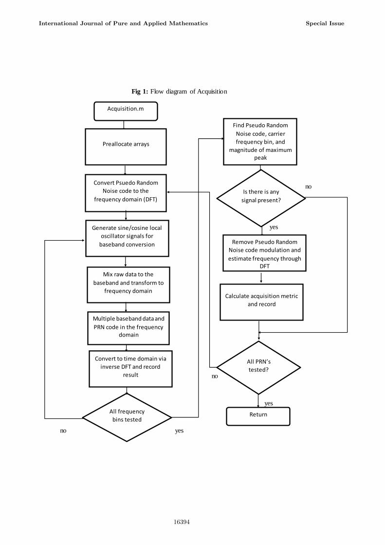
Fig 1: Flow diagram of Acquisition
no
yes
no
yes
no yes
Acquisition.m
Find Pseudo Random
Noise code, carrier
frequency bin, and
magnitude of maximum peak
Preallocate arrays
Is there is any
signal present?
Convert Psuedo Random
Noise code to the
frequency domain (DFT)
Generate sine/cosine local
oscillator signals for
baseband conversion Remove Pseudo Random
Noise code modulation and
estimate frequency through DFT
Mix raw data to the
baseband and transform to
frequency domain Calculate acquisition metric
and record
Multiple baseband data and
PRN code in the frequency domain
All PRN’s
tested?
Convert to time domain via
inverse DFT and record
result
All frequency
bins tested Return
International Journal of Pure and Applied Mathematics Special Issue
16394
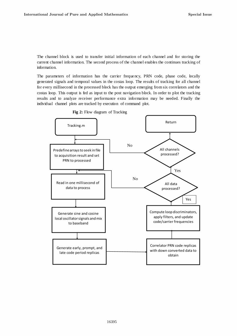
The channel block is used to transfer initial information of each channel and for storing the
current channel information. The second process of the channel enables the continues tracking of
information.
The parameters of information has the carrier frequency, PRN code, phase code, locally
generated signals and temporal values in the costas loop. The results of tracking for all channel
for every millisecond in the processed block has the output emerging from six correlators and the
costas loop. This output is fed as input to the post navigation block. In order to plot the tracking
results and to analyze receiver performance extra information may be needed. Finally the
individual channel plots are tracked by execution of command plot.
Fig 2: Flow diagram of Tracking
No
Yes
No
Return Tracking.m
All channels processed?
Predefine arrays to seek in file
to acquisition result and set
PRN to processed
All data processed?
Read in one millisecond of
data to process
Yes
Compute loop discriminators,
apply filters, and update code/carrier frequencies
Generate sine and cosine
local oscillator signals and mix to baseband
Correlator PRN code replicas
with down converted data to obtain
Generate early, prompt, and late code period replicas
International Journal of Pure and Applied Mathematics Special Issue
16395
Post Navigation is used to find transitions in bit and track preamble location. Hence bit values
are obtained and ephemeris data are decoded by extracting information from sub frames. The
position is computed and pseudo range code calculation is done by changing appropriate receiver
setting.
C. PLL based on Kalman filter
In Ionosphere, due to the atomic density variation the incoming satellite signal through
the atmosphere has a medium undergoes diffraction which causes and interference in the
electromagnetic wave. The random variations in amplitude and phase of the GPS signal takes
place. This process is called as scintillation which is most commonly found in equatorial region.
The effects of scintillation leads to signal fading, decrease in CNR, increase in the doppler effect
leads to lock or slip loss. The multipath propagation causes considerable attenuation of the
signal coming from the satellite. The reason we need to alleviate scintillation is that the
ionospheric error is predominantly high compared to the errors such as orbital error, troposphere
error, receiver noise and satellite clock. In order to overcome the above problem we replace loop
filter with Kalman filter. The circuit of Kalman filter is shown in fig 3
Fig 3: Circuit of the Kalman filter
n
The scintillation causes 20dB fading and a phase jitter which pauses rapid power fading and
carrier phase variation. In the ionosphere there are several uncertainties and few can be removed
using a dual frequency technique. The other abnormalities are the ionospheric plasma anomalies.
The free electrons and ions present in the ionosphere recombines causing heavy attenuation.
Replacing GPS L1 phase track by means of Kalman overcomes these abnormalities. Kalman
filter is the linear recursive filter that has both the prediction and updation mechanism for the
errors occurring due to introduction of doppler shift.
Prediction in time step i and
the co-variance corresponding to step i of the state
Previous state at time step i-1
Time step I observations
correction in time step i and
the co-variance corresponding to step i of the state
International Journal of Pure and Applied Mathematics Special Issue
16396
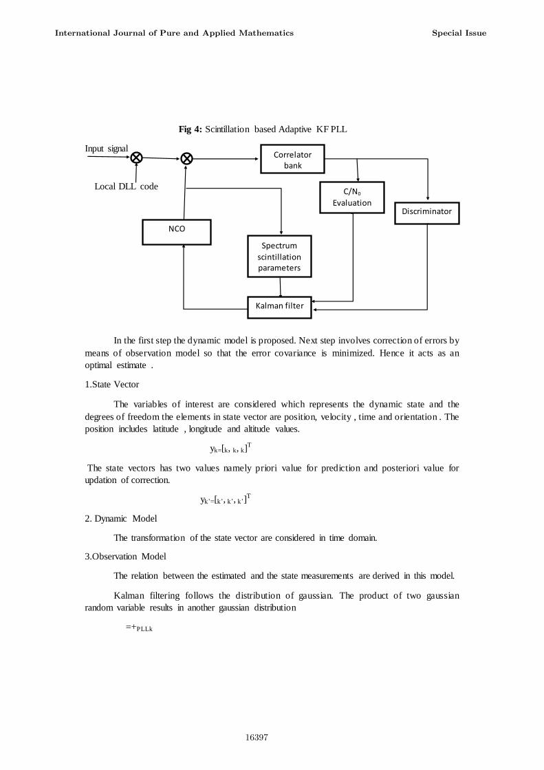
Fig 4: Scintillation based Adaptive KF PLL
Input signal
Local DLL code
In the first step the dynamic model is proposed. Next step involves correction of errors by
means of observation model so that the error covariance is minimized. Hence it acts as an
optimal estimate .
1.State Vector
The variables of interest are considered which represents the dynamic state and the
degrees of freedom the elements in state vector are position, velocity , time and orientation . The
position includes latitude , longitude and altitude values.
yk=[k, k, k]T
The state vectors has two values namely priori value for prediction and posteriori value for
updation of correction.
yk’=[k’, k’, k’]T
2. Dynamic Model
The transformation of the state vector are considered in time domain.
3.Observation Model
The relation between the estimated and the state measurements are derived in this model.
Kalman filtering follows the distribution of gaussian. The product of two gaussian
random variable results in another gaussian distribution
=+PLLk
Correlator bank
C/N0
Evaluation
NCO
Discriminator
Spectrum
scintillation parameters
Kalman filter
International Journal of Pure and Applied Mathematics Special Issue
16397
The final equation is given by
=+L
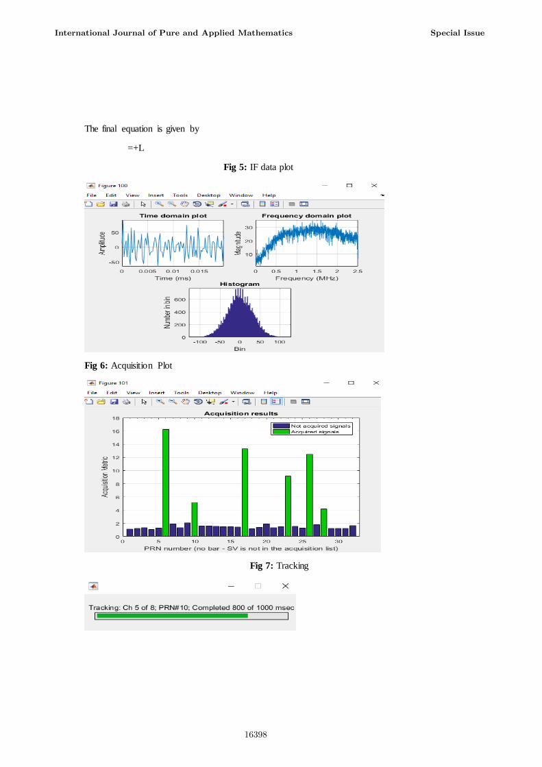
Fig 5: IF data plot
Fig 6: Acquisition Plot
Fig 7: Tracking
International Journal of Pure and Applied Mathematics Special Issue
16398
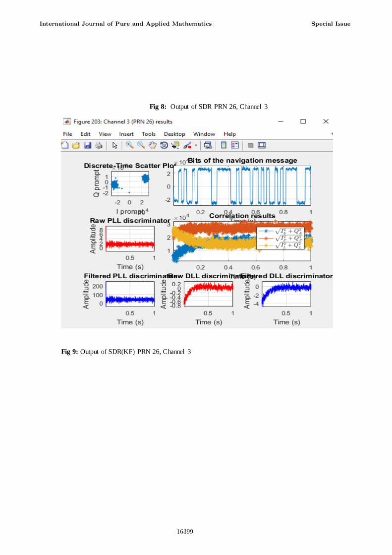
Fig 8: Output of SDR PRN 26, Channel 3
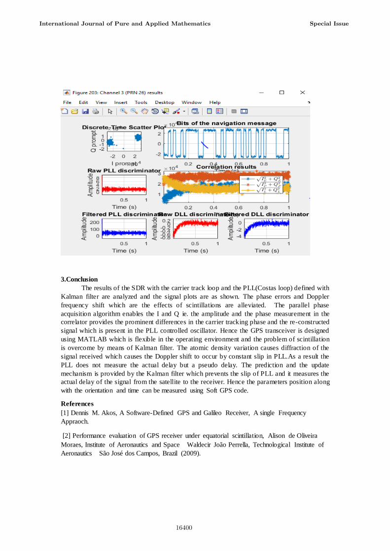
Fig 9: Output of SDR(KF) PRN 26, Channel 3
International Journal of Pure and Applied Mathematics Special Issue
16399
3.Conclusion
The results of the SDR with the carrier track loop and the PLL(Costas loop) defined with
Kalman filter are analyzed and the signal plots are as shown. The phase errors and Doppler
frequency shift which are the effects of scintillations are alleviated. The parallel phase
acquisition algorithm enables the I and Q ie. the amplitude and the phase measurement in the
correlator provides the prominent differences in the carrier tracking phase and the re-constructed
signal which is present in the PLL controlled oscillator. Hence the GPS transceiver is designed
using MATLAB which is flexible in the operating environment and the problem of scintillation
is overcome by means of Kalman filter. The atomic density variation causes diffraction of the
signal received which causes the Doppler shift to occur by constant slip in PLL.As a result the
PLL does not measure the actual delay but a pseudo delay. The prediction and the update
mechanism is provided by the Kalman filter which prevents the slip of PLL and it measures the
actual delay of the signal from the satellite to the receiver. Hence the parameters position along
with the orientation and time can be measured using Soft GPS code.
References
[1] Dennis M. Akos, A Software-Defined GPS and Galileo Receiver, A single Frequency
Appraoch.
[2] Performance evaluation of GPS receiver under equatorial scintillation, Alison de Oliveira
Moraes, Institute of Aeronautics and Space Waldecir João Perrella, Technological Institute of
Aeronautics São José dos Campos, Brazil (2009).
International Journal of Pure and Applied Mathematics Special Issue
16400
[3] Zaher M. Kassas, Jahshan Bhatti, and Todd E. Humphreys, A Graphical Approach to GPS
Software-Defined Receiver Implementation. 978-1-4799-0248-4/13/$31.00 ©2013 IEEE
[4 ]Li Weiqiang,Yang Dongkai,Li Mingli,Zhang Shanqi. Design and Experiments of GNSSR
Receiver System for Remote Sensing. Journal of Wuhan University (Information Science
Edition).2011,36(10)�024-1028
[5] M.N. Sadiku and C.M. Akujoubi, “Software defined radio: A brief overview,” IEEE
Potentials, vol. 23, no. 5, pp. 14 15, October/November 2004.
[6] A. Ahmed, H. J. Strangeways, and S. Boussakta, Software-based Receiver Approach for
Acquiring GPS Signals using Block Repetition Method. 978-1-4799-6529-8/14/$31.00 ©2014
IEEE .
[7] C. Macabiau, V. Barreau, J.J. Valette, G. Artaud, L. Ries, “Kalman Filter Based Robust
GNSS Signal Tracking Algorithm in Presence of Ionospheric Scintillations”, ION GNSS 2012,
in press. Y. Beniguel, “GISM user manual”, 2010.
[8] Mark L. Psiaki, Todd E. Humphreys, Alessandro P. Cerruti, Steven P. Powell, and Paul M.
Kintner,, Tracking L1 C/A and L2C Signals through Ionospheric Scintillations, Cornell
University, Ithaca, N.Y., 14853-7501.
[9] G. Bishop, S. Basu, K. Groves, Phillips. “Upcoming Ionospheric Impacts on GPS at Solar
Max What Do We Know/What Do We Need?”, ION GPS 1996. P. Doherty, S. Delay, C.
Vallardes, J. Klobuchar, “Ionospheric Scintillation Effects in the Equatorial and Auroral
Regions”, ION GNSS 2000, Salt Lake City, Utah, 662–671, 2000.
[10] P. Henkel, K. Giger and C. Günther, "Multi-Carrier Vector Phase Locked loop for Robust
Carrier Tracking ". In: Proc. of European Navigation Conference (ENC), 2008-25-04, Toulouse,
France.
[11] K.S.Priyanka, 2G.Ravikumar FAKE BIOMETRIC DETECTION APPLIED TO IRIS,
FINGERPRINT, AND FACE RECOGNITION BY USING IMAGE QUALITY ASSESSMENT
International Journal of Innovations in Scientific and ISSN: 2347-9728(print) Engineering Research
(IJISER)
International Journal of Pure and Applied Mathematics Special Issue
16401

16402


