Embed Size (px)
Citation preview

2007 Argentine Congress on Computer Science (Congreso Argentino en Ciencias de la Computación - CACIC 2007)
An Overview of MPLS Technology: Quality of Service and Traffic Engineering
Rubén J. Fusario, E. Carrara and J. Mon
Departamento Sistemas, Facultad Regional Buenos Aires, Universidad Tecnológica Nacional, Buenos Aires, Argentina
[email protected], [email protected], [email protected],
and
Antonio Ricardo Castro Lechtaler Universidad de Buenos Aires and Departamento Sistemas, Facultad Regional Buenos Aires,
Universidad Tecnológica Nacional, Buenos Aires, Argentina [email protected]
and
Carlos García Garino
Carrera Redes y Telecomunicaciones, ITU and Facultad de Ingeniería Universidad Nacional de Cuyo; Mendoza, Provincia de Mendoza
Abstract This paper provides an overview of Multi-Protocol Label Switching Technology (MPLS). Distinc-tive issues are presented as well as Quality of Service (QoS). Traffic Engineering (TE) features are discussed. It also describes current network trends where Internet Protocol (IP) is the predominant technology and points out the advantages of MPLS for data, voice, and video information transport. Keywords: Multi Protocol Label Switching, QoS, Traffic Engineering 1. INTRODUCTION. IP is currently the most widely used network protocol. It is designed on the so called best-effort idea and is non-connection oriented. The protocol has been successfully used. However, some shortcomings arise when IP Networks have to transport voice and video data. In these cases, lack of bandwidth, low latency, and loss of packages become important issues that need to be addressed. Different technologies have been suggested to circumvent the cited problems. Quality of Services (QoS) based in standards like Differentiated Services (DiffServ) [1] and Integrated Services (Int-Serv) [2] are among the most suitable ones. Asynchronous Transfer Mode (ATM) [3] has been widely used as a backbone technology by carriers but it’s difficult to extend it to enhance network capillarity. In the last few years, Multi Protocol Label Switch (MPLS) [4-7] emerges as a promising technology. In this sense, QoS and Traffic Engineering (TE) [8-10] are capable of superseding IP Networks when MPLS is used.
XIII Congreso Argentino de Ciencias de la Computación¯¯¯¯¯¯¯¯¯¯¯¯¯¯¯¯¯¯¯¯¯¯¯¯¯¯¯¯¯¯¯¯¯¯¯¯¯¯¯¯¯¯¯¯¯¯¯¯¯¯¯¯¯¯¯¯¯¯¯¯¯¯¯¯¯¯¯¯¯¯¯¯¯
II Workshop de Arquitecturas, Redes y Sistemas Operativos_________________________________________________________________________
23

QoS guarantees that a given data flow related to a specific application, such as VoIP, Video Confer-ence, critical applications, and so on, has a differential treatment over standard traffic. In this way, each data flow is managed according to specific application requirements. Traffic Engineering is a process that optimizes network resources. In order to achieve this objective, traffic flow is distributed in an independent way of standard layer 3 routing protocols. Resource op-timization here means that different paths are assigned for different incoming protocols according to their distinctive features, instead of assigning the shortest path or the most economical route, for in-stance. In section 2, QoS technologies used for network deployment are discussed. MPLS is introduced in section 3. Distinctive features are described in proper subsections before presenting examples in section 4. Conclusions are provided in section 5. 2. QoS PROCUREMENT QoS issues on IP networks are addressed in subsection 2.1 and QoS strategies are discussed in sub-section 2.2 2.1 Quality of Service on IP Networks Providing service quality is an important necessity whenever network overload is present. To do so, certain mechanisms should be present to supply preferential treatment to specific packages from to-tal traffic. This process would not be necessary if the network were to be oversized. Agreements with providers must be established to ensure the range of certain parameters to bring about service quality. Service Level Agreement (SLA) establishes the QoS parameter values agreed upon between client and provider. Availability; Data Package Loss; Bandwidth; Delay and Jitter can be cited among the most important parameters Availability denotes the percentage of time (usually in annual or monthly terms) that the provider ensures service availability, i.e., the server will be operative. Usual values: 99.7% - 99.9% Data Package Loss account for the maximum quantity of lost data packages, considering hired bandwidth. Usual values are 0.1%. The provider guarantees the client a certain bandwidth within its network. Usual Values: 5 Mbps. Average two-way package delay between origin and destination are generically denoted as Delay and its variation as Jitter. Usual Values for Delay and Jitter are 50 mseg and +/-10mseg, respec-tively. Delay is originated by the nature of the environment (the different media in which data goes through), as well as by the quantity of hops between origin and destination. Jitter, on the other hand, results from the gridlock of data packages remaining in queue without being dispatched or having to take alternate routes to arrive to destination.
XIII Congreso Argentino de Ciencias de la Computación¯¯¯¯¯¯¯¯¯¯¯¯¯¯¯¯¯¯¯¯¯¯¯¯¯¯¯¯¯¯¯¯¯¯¯¯¯¯¯¯¯¯¯¯¯¯¯¯¯¯¯¯¯¯¯¯¯¯¯¯¯¯¯¯¯¯¯¯¯¯¯¯¯
II Workshop de Arquitecturas, Redes y Sistemas Operativos_________________________________________________________________________
24

2.2 QoS Strategies.
Two possible strategies give specific data packages preferential treatment from the rest of the traf-fic: Reservation and Priority
Reservation denotes the case when communications capacity is reserved for exclusive use. Reserva-tion should be carried out in every router up to destination, requiring a reservation protocol. Routers must keep traffic information. However, package identification is not necessary. Assurances are provided. The standard used in this strategy is Integrated Services (IntServ) [2]. Priority is the case when packages are marked according to specific characteristics such as origin, destination, port, and so on. These features allow routers to grant preferential treatment. It is a sta-tistical treatment and thus cannot provide full guarantees. 3. MPLS DESCRIPTION. The most widely used method to forward IP packages is based on IP head analysis, specifically, in the destination address field. It consists of a layer 3 search through an algorithm aiming to attain the next hop. This expensive process needs to be performed in every router between origin and destina-tion. In practice, different technologies have been suggested. In this work, the recent MPLS [4-9] case is discussed. An introductory overview of the technology is introduced in subsection 3.1. Then MPLS fundamentals, processing, and TE [10-12] issues are addressed in subsections 3.1, 3.2 and 3.3, re-spectively. The architecture of MPLS networks is described in subsection 3.4. 3.1 Introduction to MPLS Capabilities and Infrastructure. It was pointed out in the introduction that multimedia traffic requires QoS not available in IP net-work infrastructure. In practice, different approaches have been followed to provide some extent QoS capabilities both for LAN and WAN infrastructure. These cases are used to introduce MPLS technology before discussing fundamentals, as well as QoS and TE issues in the following subsec-tions. Ethernet networks dominate LAN technologies. Several enhancements have been successfully ap-plied in practice after the original, shared network, ruled by the IEEE 802.3 standard. It could be ar-gued that Fast Ethernet and Switched Ethernet are the more remarkable ones [13]. However, QoS was still an option until VLANs [14] were introduced in practice. Tagged frames were introduced in IEEE 802.1q which include some weak QoS capabilities. Other distinctive features are layer 2 forwarding packets. In the case of VLAN’s, frame switching can be based on VLAN’s tags, distinguishing core and out of core areas. Border switches add/eliminate tags from incoming/outcoming packages to communicate with legacy Ethernet infrastructure. The migration from original to the switched VLAN’s case requires updating of switching hubs but wiring practically remains unchanged, as well as upper layers are unaffected. Up to some extent,
XIII Congreso Argentino de Ciencias de la Computación¯¯¯¯¯¯¯¯¯¯¯¯¯¯¯¯¯¯¯¯¯¯¯¯¯¯¯¯¯¯¯¯¯¯¯¯¯¯¯¯¯¯¯¯¯¯¯¯¯¯¯¯¯¯¯¯¯¯¯¯¯¯¯¯¯¯¯¯¯¯¯¯¯
II Workshop de Arquitecturas, Redes y Sistemas Operativos_________________________________________________________________________
25

VLANs can be considered like a local technology that incorporates several WAN features like full duplex links, switched circuits or layer 2 forwarding. In the case of WANs, ATM networks consider QoS as a native feature. Moreover, the aware reader will recognize traffic categories like CBR, VBE-rt, ABR, UBR, and so on. Specifically designed, High Speed switched circuits and small size cells guarantee a high speed QoS featured technology. However, ATM is rather expensive and has been used in practice only for backbones. Main carrier network infrastructure still relies on classical IP links that lack any QoS capabilities but could become problematic when managing multimedia traffic. In this context, MPLS becomes a bridge between high speed QoS featured links and legacy infrastructure. From a conceptual point of view, standard frames are enhanced (see table 1) similar to 802.1q ones for the case of the Ethernet. The added information is considered to forward packages to destina-tion. Consequently, new capabilities are added to MPLS aware router that forward packages based on a layer 2/layer 3 combination criteria. In his paper, Stallings details MPLS label inclusion in frames of different technologies. [5] Based on MPLS information, different types of traffic can be forwarded according to their nature. In this sense, voice and video data have priority over batch frames like e-mail or regular internet traffic. While WAN network links remain unchanged, routing equipment has to be properly up-dated; for instance, in the VLAN’s case. MPLS technology has the advantage to be designed for WAN infrastructure and the capability to be deployed over traditional links like IP, Frame Relay, and ATM. SONET and so on, as shown in fig-ure 1. Given the QoS capabilities of MPLS, practically any kind of services can be transported us-ing this technology as indicated in figure 1.
Figure 1: MPLS services and infrastructure In summary, MPLS allows carriers to ensure traffic QoS levels proper of ATM links, but deployed, in this case, over legacy technologies like IP or Frame Relay. Consequently, carriers take advantage of their large IP/Frame Relay infrastructure, offering high capillarity to their networks. The added
XIII Congreso Argentino de Ciencias de la Computación¯¯¯¯¯¯¯¯¯¯¯¯¯¯¯¯¯¯¯¯¯¯¯¯¯¯¯¯¯¯¯¯¯¯¯¯¯¯¯¯¯¯¯¯¯¯¯¯¯¯¯¯¯¯¯¯¯¯¯¯¯¯¯¯¯¯¯¯¯¯¯¯¯
II Workshop de Arquitecturas, Redes y Sistemas Operativos_________________________________________________________________________
26

value in this case is the QoS offered by MPLS equipment. The approach of MPLS from a concep-tual point of view presents some loose analogies to the VLAN’s case. 3.2 MPLS Fundamentals MPLS is a new architecture fostering the use of labels to combine the layer 2 forwarding benefits with those of the layer 3 routing techniques. The labels are assigned to packages to be transported through package or cell based networks and the forwarding mechanism takes place with a label ex-change. In table 1 can be seen an example of MPLS labels.
Table 1: MPLS Frame This architecture is multi-protocol because it can be assigned to any layer 3 network protocol. How-ever, the main focus is to use it on IP networks. The MPLS architecture can be modeled in two main components: Forwarding and Control [4]: Forwarding Component is used to do the forwarding task based on labels which are inserted, re-placed, and removed through this module. Insertion and removal are performed at the border nodes according to a database known as Forwarding Information Base (FIB). Replacement is performed on the central nodes according to a database known as Label Forwarding Information Base (LFIB). Control Component deals with the gathering, maintenance and distribution of the necessary infor-mation to make decisions about forwarding. The information is stored in an additional database known as Label Information Base (LIB). From this database and the routing tables the FIB and LFIB are created. MPLS nodes must run at least one routing protocol (BGP, OSPF, and others) to maintain the rout-ing table and exchange information with other network nodes. The routing table allows MPLS nodes to determine who their neighbors are to exchange label in-formation, following known sub-networks. These sub-networks are registered in the routing table. The label exchange is accomplished through a protocol such as Label Distribution Protocol (LDP). 3.3 Data Forwarding 3.3.1 IP Data Forwarding
A data package whose network layer protocol is oriented to no-connection must travel from one node to another. Each node must make a forwarding decision independently. This decision is taken
XIII Congreso Argentino de Ciencias de la Computación¯¯¯¯¯¯¯¯¯¯¯¯¯¯¯¯¯¯¯¯¯¯¯¯¯¯¯¯¯¯¯¯¯¯¯¯¯¯¯¯¯¯¯¯¯¯¯¯¯¯¯¯¯¯¯¯¯¯¯¯¯¯¯¯¯¯¯¯¯¯¯¯¯
II Workshop de Arquitecturas, Redes y Sistemas Operativos_________________________________________________________________________
27

through an analysis of the package head with a network layer algorithm. At this point, it is impor-tant to introduce the concept of Forwarding Equivalence Classes (FEC). A FEC describe a group of packages that are classified and forwarded in the same way. Consequently all the packages that be-long to the same FEC follow the same path.
Two processes divide the next-hop (or node) choice in the path:
• The first process partitions the entire traffic of possible packages n an FEC set. • The second process associates each FEC with the next hop or node; i.e., it selects a particular
hop for each package group which compose FEC. In the case of conventional IP networks, when analyzing heads, a group of packages is assigned to a specific FEC. Afterwards, each FEC is mapped to the next hop, but throughout the path, each router re-examines the packages and assigns another FEC. It is an effective process, although inefficient if required processing time for each package in every node is considered. 3.3.2 MPLS Data Forwarding In the case of MPLS, a package is assigned to a FEC as soon as it enters the domain of a MPLS network through the allocation of a label. In the next hop, it is exchanged to a new one and sent to the next hop. The entire forwarding procedure, within the domain of the MPLS network, is carried out with these labels, avoiding the analysis of the entire package. It can be used in packages as well as cells. Standard routing techniques like Internet Gateway Protocols (IGP) are still necessary in or-der to exchange the information required to set up and update the MPLS database. The path followed by packages in an MPLS cloud is denoted as Label Switch Path (LSP). Label Switch Routers (LSR) manage the creation, replacement and interchange of labels. A diagram of a MPLS network is shown in figure 3. The allocation process of a FEC is carried out with an Edge-LSR which performs a network level search (checking with FIB) upon receiving a package to identify the IP address of the next hop. If it detects that the next hop is accomplished through an interphase connected to the MPLS net-work, it performs a search in the FIB, obtaining a label associated to the destination network prefix. It inserts a label between the layer 2 head and the layer 3 package. It will then dispatch the package through the appropriate interphase. The label exchange process is carried out in the intermediate LSR nodes, which upon reception of the labeled package, will search in their LFIB, the new label, and the corresponding interphase to that FEC. Afterwards, they will dispatch the resulting interphase with the new label replacing the previous one. The label extraction process is carried out by an outgoing Edge-LSR. Upon reception of a labeled package from an MPLS device, the Edge-LSR searches in its LFIB the new label and corresponding interphase to that FEC. Upon detecting that the new label does not exist, as it belongs to an inter-phase connected to a no-MPLS device, it extracts the label and performs a search at the network layer level (looking up in the FIB) to identify the next hop IP address and dispatches to the appro-priate interphase. LSPs are unidirectional. Thus, return traffic from a specific FEC is carried out on a different LSP.
XIII Congreso Argentino de Ciencias de la Computación¯¯¯¯¯¯¯¯¯¯¯¯¯¯¯¯¯¯¯¯¯¯¯¯¯¯¯¯¯¯¯¯¯¯¯¯¯¯¯¯¯¯¯¯¯¯¯¯¯¯¯¯¯¯¯¯¯¯¯¯¯¯¯¯¯¯¯¯¯¯¯¯¯
II Workshop de Arquitecturas, Redes y Sistemas Operativos_________________________________________________________________________
28
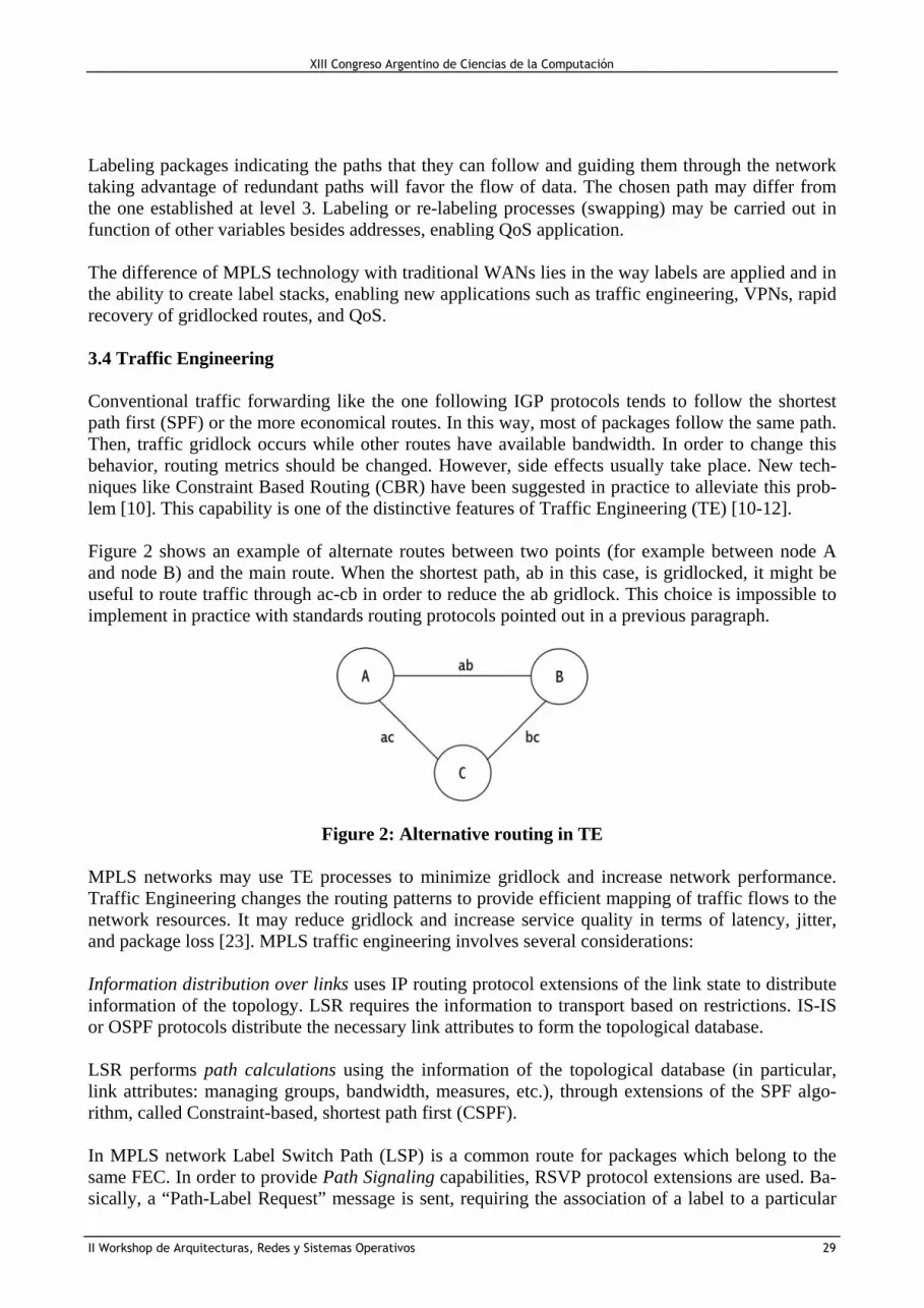
Labeling packages indicating the paths that they can follow and guiding them through the network taking advantage of redundant paths will favor the flow of data. The chosen path may differ from the one established at level 3. Labeling or re-labeling processes (swapping) may be carried out in function of other variables besides addresses, enabling QoS application. The difference of MPLS technology with traditional WANs lies in the way labels are applied and in the ability to create label stacks, enabling new applications such as traffic engineering, VPNs, rapid recovery of gridlocked routes, and QoS. 3.4 Traffic Engineering Conventional traffic forwarding like the one following IGP protocols tends to follow the shortest path first (SPF) or the more economical routes. In this way, most of packages follow the same path. Then, traffic gridlock occurs while other routes have available bandwidth. In order to change this behavior, routing metrics should be changed. However, side effects usually take place. New tech-niques like Constraint Based Routing (CBR) have been suggested in practice to alleviate this prob-lem [10]. This capability is one of the distinctive features of Traffic Engineering (TE) [10-12]. Figure 2 shows an example of alternate routes between two points (for example between node A and node B) and the main route. When the shortest path, ab in this case, is gridlocked, it might be useful to route traffic through ac-cb in order to reduce the ab gridlock. This choice is impossible to implement in practice with standards routing protocols pointed out in a previous paragraph.
Figure 2: Alternative routing in TE MPLS networks may use TE processes to minimize gridlock and increase network performance. Traffic Engineering changes the routing patterns to provide efficient mapping of traffic flows to the network resources. It may reduce gridlock and increase service quality in terms of latency, jitter, and package loss [23]. MPLS traffic engineering involves several considerations: Information distribution over links uses IP routing protocol extensions of the link state to distribute information of the topology. LSR requires the information to transport based on restrictions. IS-IS or OSPF protocols distribute the necessary link attributes to form the topological database. LSR performs path calculations using the information of the topological database (in particular, link attributes: managing groups, bandwidth, measures, etc.), through extensions of the SPF algo-rithm, called Constraint-based, shortest path first (CSPF). In MPLS network Label Switch Path (LSP) is a common route for packages which belong to the same FEC. In order to provide Path Signaling capabilities, RSVP protocol extensions are used. Ba-sically, a “Path-Label Request” message is sent, requiring the association of a label to a particular
XIII Congreso Argentino de Ciencias de la Computación¯¯¯¯¯¯¯¯¯¯¯¯¯¯¯¯¯¯¯¯¯¯¯¯¯¯¯¯¯¯¯¯¯¯¯¯¯¯¯¯¯¯¯¯¯¯¯¯¯¯¯¯¯¯¯¯¯¯¯¯¯¯¯¯¯¯¯¯¯¯¯¯¯
II Workshop de Arquitecturas, Redes y Sistemas Operativos_________________________________________________________________________
29

path in each hop. Each node, beginning from destination, after receiving a message, distributes the labels to the closest node towards the origin using a RESV – Label message. At first, LDP exten-sions were used for the signaling (CR-LDP); but in 2002 IETF favored RSVPTE as MPLS TE sig-naling protocol. Finally, it is necessary to provide Traffic Selection to define which packages are assigned to a par-ticular LSP formed by related labels. TE LSP traffic must enter the first LSP node through a selec-tion process which might be dynamic, static, type-based or content-based. 3.5 MPLS Architecture with QoS and TE
A typical MPLS architecture is depicted in figure 3. Customer and Provider Edge equipments, CE and PE respectively, as well as LSP are shown in the diagram. CE (Customer Edge) commands package labeling performed in the field’s origin IP address, desti-nation IP address, priority, protocol, port of origin, port of destination, and so on. The information is gathered from the analysis of the IP head and the transported datagram (TCP, UDP, etc.). The la-bel, shown in Table 1, is represented over a 3 bit priority with 8 possible codes (23). In DiffServ ar-chitecture, the field ToS is redefined in the field DS which contains the sub-field DSCP (Differenti-ated Services Code point), unifying the priority 3 bits D, T, and R, with 64 possible codes (26). The use of a 6-byte DSCP is purposeless considering that the EXP field from the MPLS head also has 3 bits.
Figure 3: MPLS with QoS and TE Network Diagram The data packages leave the CE with a new priority value in the field ToS and are directed to the next hop (PE – Provider Edge), whose address was obtained through the level 3 routing table loo-kup.
XIII Congreso Argentino de Ciencias de la Computación¯¯¯¯¯¯¯¯¯¯¯¯¯¯¯¯¯¯¯¯¯¯¯¯¯¯¯¯¯¯¯¯¯¯¯¯¯¯¯¯¯¯¯¯¯¯¯¯¯¯¯¯¯¯¯¯¯¯¯¯¯¯¯¯¯¯¯¯¯¯¯¯¯
II Workshop de Arquitecturas, Redes y Sistemas Operativos_________________________________________________________________________
30

PE receives No-MPLS packages through the interphase connected to CE. Given that it is an Edge-LSR, it performs a layer 3 lookup, a FIB search, and identifies the label as well as the departure in-terphase – see section 3, MPLS Architecture, Processing. Afterwards, it classifies the packages and deposits them in the departure queues associated to the selected interphase (shaping). In P nodes (Provider – Belonging to the Core), packages can be labeled or reclassified. In the case of existing alternate paths to a same destination, the associated interphase to each path can treat their queues differently. 4. EXAMPLES. In this section, different MPLS applications are shown in order to present some practical implemen-tations. The bandwidth requirement are computed in the example of subsection 4.1 and a VPN de-ployment is discussed in subsection 4.2 4.1 LAN Bandwidth requirements The following steps are followed: 4.1.1. Design and install switched Ethernet LANs in the different sites of the corporative network. The following requirements are mandatory:
a. The ANSI/EIA/TIA 568 standards must be followed. b. A domain server has to be installed at each site. An e-mail server can be optionally included.
4.1.2. Interconnect the different sites using an IP/MPLS transport network like a corporate back-bone. A carrier provides the technology and links necessary to deploy the IP/MPLS facilities. 4.1.3. LAN's Bandwidth requirements are previously computed to allow for a proper Carrier design of the corporate backbone. From authors' experience, 10 kbps should be added for each PC (consid-ering Internet and corporate applications); 25 kbps are advisable for each VOIP channel. If video-conference facilities are to be included, additional 256 kbps should be added. In this way, for a 20 PC site plus two VOIP channels as well as a videoconference link, the computed bandwidth is ap-proximately 512 kbps. 4.2 VPN over MPLS deployment The diagram in figure 4 shows a corporate WAN that is connected to Internet and has different re-mote VPN links. In the graph, the IP/MPLS backbone provided by the Carrier can be seen. Different sites where one or more LAN’s are available (Fast Ethernet or GigaEthernet generally) are connected thorough a CE (Customer Edge) that is in charge to tag the packages as has been explained in the previous sec-tion. Users properly authorized can access the backbone. VPN’s links are established in between user’s site and the access router to the IP/MPLS corporate backbone. In this way, Internet infrastructure can be used in order to set up secure connections.
XIII Congreso Argentino de Ciencias de la Computación¯¯¯¯¯¯¯¯¯¯¯¯¯¯¯¯¯¯¯¯¯¯¯¯¯¯¯¯¯¯¯¯¯¯¯¯¯¯¯¯¯¯¯¯¯¯¯¯¯¯¯¯¯¯¯¯¯¯¯¯¯¯¯¯¯¯¯¯¯¯¯¯¯
II Workshop de Arquitecturas, Redes y Sistemas Operativos_________________________________________________________________________
31

Figure 4: Example of IP/MPLS deployment. Usually the corporation requires the Carrier the desired bandwidth. In turns, this bandwidth can be classified according QoS necessities. For instance, given 1 Mbps access 30 % are guaranteed for VoIP purposes, 40 % for critical mission traffic and the remaining bandwidth is available for inter-net and e-mail traffic. 5. MPLS IN ARGENTINA. The most important carriers in Argentina currently offer IP/MPLS links to their customers [15]. Generally, when international connection is available the parameters under control are:
• National latency • International latency • Loss of packages • Service availability • Bandwidth reserve in order to manage traffic peaks without QoS degradation.
Different kinds of links are available in order to cover a wide range of customer requirements. The last category offer the so called Best Effort traffic, generally devised for Internet access as well as batch and offline transmission data like e-mail. No guarantees are provided for availability, la-tency, jitter and loss of packages. This category can be encompassed in traditional IP traffic; conse-quently, data packages are immediately discarded in case of network gridlock. Better traffic qualities assure a reasonable good QoS for corporate as well as high priority traffic like application connections, SNA traffic, database queries and so on.
XIII Congreso Argentino de Ciencias de la Computación¯¯¯¯¯¯¯¯¯¯¯¯¯¯¯¯¯¯¯¯¯¯¯¯¯¯¯¯¯¯¯¯¯¯¯¯¯¯¯¯¯¯¯¯¯¯¯¯¯¯¯¯¯¯¯¯¯¯¯¯¯¯¯¯¯¯¯¯¯¯¯¯¯
II Workshop de Arquitecturas, Redes y Sistemas Operativos_________________________________________________________________________
32

Finally, the higher ranked links are designed for high priority QoS links devoted for voice and video transmissions. This kind of traffic admits very low latency and jitter. Consequently this transmis-sion has the highest priority. These capabilities are possible due to the network intelligence offered by MPLS technology which allows carriers to provide customer bandwidth while QoS is properly assured. Other advantages are the rather large PoP all over the country as well as the commercial agreements with international carriers in order to deploy international corporate networks. This kind of tech-nologies were offered initially for large carriers to offer national and last mile MPLS connections to corporations that own MPLS networks all over the world. Currently, the discussed advantages like VPN’s and QoS offered by MPLS permit national carriers to add value to classical IP links. 6. CONCLUSION. MPLS is the last step in the evolution of multilevel commutation technologies (or IP commutation). The basic idea of partitioning the data batch (through and algorithm of label exchange) from the standard IP routing procedures has approached levels 3 and 2 with the resulting benefit of enhanced performance and architectural flexibility. On the other hand, the fact that MPLS can work on any distribution technology –not only ATM in-frastructures– will enable significantly the migration to the next generation of optic internet, bridg-ing the distance between IP network level and fiber. MPLS grants IP providers the opportunity to offer new services which are attainable with the cur-rent IP routing techniques (most commonly limited to direct by destination address). Besides ena-bling IP traffic engineering, MPLS allows to maintain service classes and can withstand with great efficiency VPNs creation. Consequently, MPLS is a great promise and hope to sustain the current rate of internet growth. 7. ACKNOWLEDGEMENTS. The financial support provided by Agencia Nacional para la Promoción Científica y Tecnológica and CITEFA (Project PICTO 11-0821, Préstamo BID 1726 OC-AR) is gratefully acknowledged. REFERENCES. [1] Blake, S.; Black, D.; Carlson, M.; Davies, E.; Wang, Z.; Weiss, W. An Architecture for Differ-entiated Services. RFC 2475. 1998. [2] Braden Ed. A Resource Reservation Protocol (RSVP). RFC 2205. 1997. [3] Stallings. W. Data and Computers Communications - 8th Edition. Prentice Hall. 2007. [4] Rosen E. Multiprotocol Label Switching Architecture. RFC 3031. January 2001. [5] Rosen E. MPLS Label Stack Encoding, RFC 3032, January 2001. [6] Pepelnjak, I., Guichard, J. MPLS and VPN Architectures. Cisco Press. 2001. [7] Black, U. MPLS and Label Switching Networks. Prentice Hall. 2001.
XIII Congreso Argentino de Ciencias de la Computación¯¯¯¯¯¯¯¯¯¯¯¯¯¯¯¯¯¯¯¯¯¯¯¯¯¯¯¯¯¯¯¯¯¯¯¯¯¯¯¯¯¯¯¯¯¯¯¯¯¯¯¯¯¯¯¯¯¯¯¯¯¯¯¯¯¯¯¯¯¯¯¯¯
II Workshop de Arquitecturas, Redes y Sistemas Operativos_________________________________________________________________________
33

[8] Stallings, W. MPLS. The Internet Protocol Journal, 2-14, Vol. 4, N. 3, 2001. Available at www.cisco.com/ijp. [9] Canalis, M.S. MPLS “Multiprotocol Label Switching. Una tecnología de backbone para el siglo XXI. Jornadas de Informática del Noroeste Argentino. JINEA 2002. UNNE. 2002. [10] Xiao X. Traffic Engineering with MPLS in the Internet Network, 28-33, Vol. 14, N. 2, Mar/Apr 2000. IEEE, Doi 10.1109/65.826369. [11] Awduche D. Requirements for Traffic Engineering over MPLS. RFC 2702. September 1999. [12] Alvarez, S. MPLS TE Technology Overview chapter 2 in QoS for IP/MPLS Networks. Cisco Press. 2006. [13] Spurgeon, C. E. Ethernet, the Definitive Guide. O'Reilly. 2000. [14] Seifert, R. The Switch Book. John Wiley. 2000. [15] Carrara E., Mon J., Fusaro R. Sistemas Emergentes para la Transmisión de Datos. Redes MPLS con Calidad de Servicio. Facultad de Informática, Ciencias de la Comunicación y Técnicas Especiales - Universidad de Morón. 2007.
XIII Congreso Argentino de Ciencias de la Computación¯¯¯¯¯¯¯¯¯¯¯¯¯¯¯¯¯¯¯¯¯¯¯¯¯¯¯¯¯¯¯¯¯¯¯¯¯¯¯¯¯¯¯¯¯¯¯¯¯¯¯¯¯¯¯¯¯¯¯¯¯¯¯¯¯¯¯¯¯¯¯¯¯
II Workshop de Arquitecturas, Redes y Sistemas Operativos_________________________________________________________________________
34


