Embed Size (px)
Citation preview
AN EXPERT SYSTEM TO DIAGNOSE QUALITY PROBLEMS IN THE
CONTINUOUS CASTING OF STEEL BILLETS
by
SUNIL KUMAR
B.Tech. ( Metallurgical Engineering ) Banaras Hindu University, India, 1987
A THESIS SUBMITTED IN PARTIAL FULFILMENT OF
THE REQUIREMENTS FOR THE DEGREE OF
MASTER OF APPLIED SCIENCE
in
THE FACULTY OF GRADUATE STUDIES
Department of Metals and Materials Engineering
We accept this thesis as conforming
to the required standard
THE UNIVERSITY OF BRITISH COLUMBIA
October 1991
© Sunil Kumar, 1991
In presenting this thesis in partial fulfilment of the requirements for an advanced
degree at the University of British Columbia, I agree that the Library shall make it
freely available for reference and study. I further agree that permission for extensive
copying of this thesis for scholarly purposes may be granted by the head of my
department or by his or her representatives. It is understood that copying or
publication of this thesis for financial gain shall not be allowed without my written
permission.
(Signature)
Department of titE TAG S & 1.0 A 7-CIQ. is^(^2 N 6)
The University of British ColumbiaVancouver, Canada
Date^ / 9 c?/
DE-6 (2/88)
ABSTRACT
Quality problems, such as cracks, rhomboidity and breakouts are often observed in
continuously cast steel billets. Although information is available in the literature on the causes
of, and solutions to, these problems, the transfer of this knowledge to operating personnel is
not always an easy task. To address this issue, an expert system has been developed.
The important features of knowledge engineering an expert system to diagnose quality
problems in the continuous casting of steel billets are described in this thesis. The process used
to extract knowledge from the Experts, the experiments employed to represent knowledge in
different ways, the strategies adopted to accumulate evidence and the methodologies to present
coherent recommendations to both experienced and inexperienced operating personnel are
discussed.
Expertise was derived from diverse sources. On the one hand fundamental knowledge
about heat transfer, solidification and mechanical behaviour of steel was applied to identify the
origin of a quality problem in the process; on the other, heuristic knowledge associated with
billet characteristics, machine design and operating factors was required to focus on the problem
causes. Integration of these two different types of knowledge was essential in developing a useful
system.
From the Experts' viewpoint, this exercise provided them with a formal representation of
their knowledge to solve quality problems and identified new areas for future research. Moreover,
the Experts actually generated new ideas about the domain which previously were unrecognized.
For the users, this system serves two important functions - as a diagnostic tool for analysing
quality problems and as a teaching tool for new operating personnel.
ii
TABLE OF CONTENTS
ABSTRACT ^ ii
TABLE OF CONTENTS ^ iii
LIST OF TABLES^ vii
LIST OF FIGURES ^ viii
LIST OF SYMBOLS^ x
ACKNOWLEDGEMENTS^ xi
CHAPTER 1 INTRODUCTION^ 1
CHAPTER 2 SCOPE AND OBJECTIVES ^ 3
CHAPTER 3 EXPERT SYSTEMS TECHNOLOGY^ 5
3.1 Expert Systems - An overview ^ 5
3.2 The Development Process^ 6
CHAPTER 4 KNOWLEDGE DOMAIN - Part I ^ 12
4.1 Billet Casting Machine ^ 12
4.2 Fundamental Knowledge on Billet Casting ^ 15
4.2.1 Heat Transfer^ 15
4.2.1.1 Mould Heat Transfer ^ 15
4.2.1.2 Spray Heat Transfer^ 19
4.2.1.3 Heat-transfer Mathematical Model^ 21
4.2.2 Mechanical Properties of Steel^ 21
4.2.3 Stress Generation during the Casting Process^ 25
iii
4.2.4 Solidification of Steel^ 27
4.2.5 Operating Parameters ^ 30
4.2.5.1 Mould^ 30
4.2.5.1.1 Mould Distortion^ 30
4.2.5.1.2 Mould Taper^ 39
4.2.5.1.3 Mould Oscillation ^ 40
4.2.5.1.4 Mould Lubrication ^ 42
4.2.5.2 Sprays ^ 44
4.2.5.3 Liquid steel ^ 47
4.2.5.4 Pinch-rolls ^ 48
CHAPTER 5 KNOWLEDGE DOMAIN - Part II ^ 49
5.1 Specificity Issues ^ 49
5.2 Quality Problems ^ 51
5.2.1 Cracks^ 51
5.2.1.1 Internal Cracks^ 53
5.2.1.1.1 Off-Corner Cracks ^ 55
5.2.1.1.2 Midway Cracks ^ 61
5.2.1.1.3 Diagonal Cracks^ 64
5.2.1.1.4 Centreline Cracks^ 66
5.2.1.1.5 Pinch-roll Cracks ^ 68
5.2.1.2 Surface Cracks^ 69
5.2.1.2.1 Transverse Cracks (and depressions) ^ 69
5.2.1.2.2 Longitudinal Midface Cracks ^ 75
5.2.1.2.3 Longitudinal Corner Cracks^ 76
iv

5.2.1.2.4 Craze Cracks ^ 79
5.2.2 Rhomboidity ^ 81
5.2.3 Breakouts^ 85
5.3 Other Observations ^ 88
CHAPTER 6 KNOWLEDGE ENGINEERING ^ 91
6.1 Knowledge Acquisition ^ 91
6.1.1 Identification/Definition of Problem Domain^ 91
6.1.2 Background Knowledge on Continuous Casting ^ 91
6.1.3 Expert System Development^ 92
6.2 Knowledge Representation ^ 100
6.2.1 Knowledge units^ 100
6.2.1.1 Keyword Triplets ^ 102
6.2.1.2 Rules ^ 104
6.2.1.3 Procedures ^ 105
6.2.1.4 Meta-knowledge ^ 105
6.2.2 Search Techniques and Conflict Resolution ^ 107
6.2.3 Information used in the analysis^ 109
6.2.4 A novel inferencing strategy for the analysis of midway cracks ^ 111
6.3 Structure Of The Expert System ^ 115
6.4 Justification of Knowledge Engineering Decisions ^ 117
CHAPTER 7 TESTING AND EVALUATION OF THE EXPERT SYSTEM^ 123
7.1 Evaluation Procedure ^ 123
7.2 System Operation - Results of the feedback^ 124
v

7.3 Analysis of User Feedback ^ 127
7.3.1 System's Successes ^ 127
7.3.2 System's Drawbacks ^ 129
7.3.3 Areas of Future Expansion ^ 130
7.4 Implementation Of Feedback^ 131
CHAPTER 8 CONSULTATION SESSIONS - CASE STUDIES^ 133
CHAPTER 9 SUMMARY AND CONCLUSIONS^ 146
REFERENCES ^ 148
APPENDIX A^ 156
APPENDIX B^ 157
APPENDIX C^ 158
APPENDIX D^ 168
APPENDIX E^ 174
GLOSSARY^ 178
vi
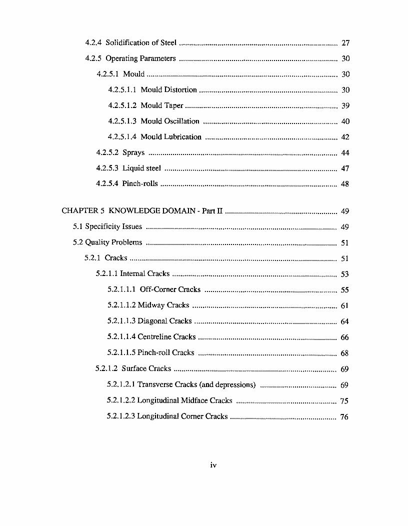
LIST OF TABLES
Table 5.1^Internal Cracks in Billet Casting. ^54
Table 5.2^Midway Cracks in Billet Casting. ^55
Table 5.3^Surface Cracks in Billet Casting. ^70
Table 5.4^Rhomboidity Problem in Billet Casting. ^81
Table 5.5^Breakout Problem in Billet Casting. ^86
Table 6.1^Initial scheme proposed by the Experts to analyse midwaycracks originating in the radiation zone. ^93
Table 6.2^Procedural knowledge units : Library functions inCOMDALE/X used for system development.
^106
Table 7.1^Feedback implementation strategy. ^132
Table 8.1^Final report. ^138
vii
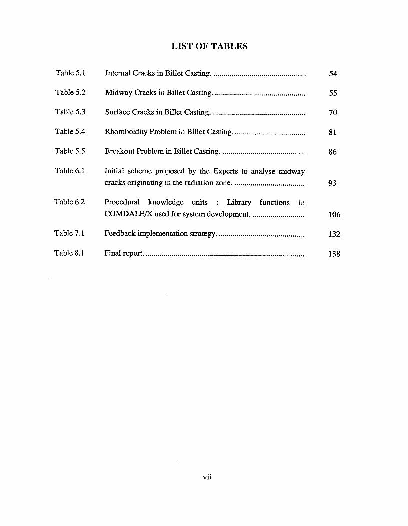
LIST OF FIGURES
Fig. 3.1^Stages in expert system development. ^9
Fig. 4.1^A schematic diagram of a billet casting machine. ^12
Fig. 4.2^Billet casting mould [67] ^14
Fig. 4.3^Schematic representation of thermal resistance encountered in themould [15]. ^16
Fig. 4.4^Mould heat-fluxes for various steel grades [19]. ^18
Fig. 4.5^Variation of heat transfer coefficient versus billet surfacetemperature [23]. ^20
Fig. 4.6^Schematic representation of temperature zones of reduced hotductility of steel related to embrittling mechanisms [42]. ^22
Fig. 4.7^Mechanism of oscillation mark formation [19]. ^41
Fig. 5.1^Schematic diagram of a rhomboid billet showing various types ofcracks. ^52
Fig. 5.2^Transverse section of a billet showing off-corner internal cracks.^56
Fig. 5.3^Schematic diagram showing generation of an internal crack due tobulging of the billet shell and a hinging action in the off-cornerregion [73]. ^58
Fig. 5.4^Schematic diagram illustrating the mechanism generatingoff-corner internal cracks due to bulging and hinging of the shell^59[68].
Fig. 5.5^Transverse section of a billet showing midway cracks. ^62
Fig. 5.6^Transverse section of a billet showing centreline cracks. ^67
viii
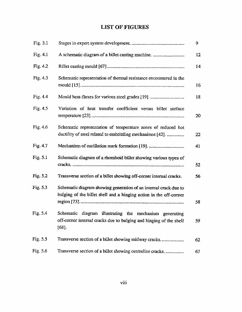
Fig. 5.7^Photograph of a billet showing transverse depressions. ^71
Fig. 5.8^Longitudinal section of a billet showing an internal crack below adepression ^73
Fig. 5.9^Schematic diagram showing the formation of transversedepressions and cracks due to sticking or binding in the mould [20].^74
Fig. 5.10^Schematic diagram showing the formation of subsurface,longitudinal crack on diagonal at obtuse-angle corners of rhomboidbillet [22].
^78
Fig. 5.11^Photograph of craze cracks. ^80
Fig. 5.12^Schematic diagram showing a billet with non-uniform shellthickness being distorted into rhomboid shape by spray cooling
[64• ^
83
Fig. 6.1^A typical output of the mathematical model showing predicted solidshell thickness and billet surface temperature profiles. ^96
Fig. 6.2^Scheme for diagnosing quality problems requiring detailed mouldand/or spray analysis. ^98
Fig. 6.3^A general outline of mould-related factors contributing to qualityproblems in billet casting. ^99
Fig. 6.4^Knowledge units available in COMDALE/X Development Tool.^101
Fig. 6.5^A schematic diagram illustrating the calculation of degree of beliefin a spray-related tensile strain problem from belief in high reheatin the radiation zone, high temperature and composition problems.^113
Fig. 6.6^A schematic diagram illustrating the calculation of final belief in aspray-related tensile strain problem following the detection of amould disorder. ^114
Fig. 6.7^A flow-sheet representing the structure of the expert system ^116
ix

LIST OF SYMBOLS
tN^Negative strip time ( s )
n^3.142
f^Oscillation frequency ( Hz )
v,^Casting speed ( m/s )
S^Oscillation stroke length ( m )

ACKNOWLEDGEMENTS
I would like to express my sincere gratitude to my supervisors Dr. Keith Brimacombe, Dr.
Indira Samarasekera and Dr. John Meech, for providing excellent guidance, valuable help and
encouragement throughout this work. It was indeed an intellectually stimulating experience for
me.
This work would not have been possible without the knowledge acquired by researchers in
the field of continuous casting. I take this opportunity to thank all the individuals who contributed
to this knowledge base. During the development, I had useful discussions with Ian Bakshi, Sanjay
Chandra, Neil Walker and Bob Hapke. I thank them all. I am also grateful to Harold Ng for
preparing the photographs used in this thesis.
I am greatly indebted to Stelco Steel, Ivaco Rolling Mills, Slater Steel, Sidbec-Dosco Inc.,
Courtice Steel, Western Steel, Hatch Associates and the Natural Sciences and Engineering
Research Council of Canada for support of this study. Gratitude also is expressed to Comdale
Technologies Inc. for their assistance with the software.
I am grateful to Dr. Amit Chatterjee, Assistant General Manager (Research), Tata Steel,
for his support and encouragement. Sanjay Chandra and his family need special thanks for hosting
me and helping me settle down comfortably in Vancouver. The two years were exciting thanks
to the company of fellow graduate students at UBC and excellent room-mates at home. Lastly,
I would like to thank my parents, for supporting my decision to pursue higher studies in Canada.
xi
CHAPTER 1 INTRODUCTION
The continuous casting of billets, slabs and blooms has been accepted worldwide by
steelmakers in favour of the traditional ingot (casting and rolling) route. Today, emphasis on
quality control is a prerequisite in the competitive environment to meet customer specifications
and to reduce operating costs. The goal of high quality cannot be realized, however, without
knowledgeable operating and maintenance personnel who understand their casting system.
Similarly, the expertise these individuals possess should be considered invaluable and a method
to retain and transfer this expertise within an organization can be of great advantage.
There has been significant research into the process control of billet casting which has
related operating parameters to quality problems. Although well-documented in the literature,
transfer of this fundamental knowledge to operating personnel has been difficult despite the fact
that numerous short courses on the subject have been given. There is a need then, for an expert
system to guide operators in analysing quality-related problems and to provide them with a ready
source of fundamental knowledge related to the operation of the casting machine
This thesis describes such a system that has been developed with this purpose in mind. It
is a diagnostic tool for analysing quality problems in continuously cast steel billets, specifically
designed for use by operating personnel. The interface provided by the development tool,
COMDALE/X, helps a user with explanations of terminology in the system, justification of
questions asked and mapping of the strategy followed to arrive at final conclusions and
recommendations. In this way, the system is able to train inexperienced operators.
1

The thesis consists of nine chapters. Chapter 2 outlines the scope and objectives of the
project. Chapter 3 presents a brief overview of expert systems technology. Chapter 4 reviews
the fundamental knowledge required to analyse quality problems in billet casting. The types of
problems (cracks, rhomboidity and breakouts) are described in Chapter 5 with emphasis on
mechanisms of formation and influencing factors. Chapter 6 deals with the major stages of
knowledge engineering involved in the development of this system - knowledge acquisition and
representation; the structure of the expert system is described and benefits of the knowledge
engineering methodology are outlined. This chapter also justifies various decisions made during
structuring and coding of the system. Chapter 7 describes the procedure used to evaluate the
expert system and the results of this exercise. Chapter 8 presents several case studies and discusses
the consultation sessions. Chapter 9 presents the final conclusions and recommendations for
future work.
2
CHAPTER 2 SCOPE AND OBJECTIVES
This research work was undertaken to develop an expert system to meet the following
objectives:
[1] diagnosing quality problems in billet casting - cracks, shape defects and breakouts; and
[2] training less experienced operating personnel
The knowledge domain used to build the expert system has been generated over two decades
of research work and industrial experience in this field.
Domain Experts^J.K.BrimacombeI.V.Samarasekera
Knowledge Engineers^S.KumarJ.A.Meech
System Development Tool^COMDALE/X - version 3.0Comdale Technologies Inc.833, The Queensway,Toronto, Ontario,Canada M8Z 5Z1
The steps followed to achieve the above objectives are outlined below:
(a) The knowledge base was reviewed and a practical understanding of the problem domain
was established. Numerous consultation sessions with the Experts were held during the
development of the system.
3
(b) The knowledge base was structured. Flow-charts of the analysis schemes were constructed
at various stages and modified as recommended by the Experts.
(c) Coding of the knowledge was done using COMDALE/X as the development tool.
(d) A two-dimensional heat-transfer mathematical model for billet solidification was
developed to predict billet solid shell thickness and surface reheat temperature profiles.
The alternating direction implicit fmite-difference method was used to solve the unsteady
state heat-conduction equation.
(e) The expert system was evaluated at five Canadian steel companies.
The main driving force for this project was the need to ease the transfer of Experts'
knowledge to the industries. A system was desired that could be used as a consultant by the users
for solving quality problems in billet casting. The initial development focussed on the major
quality problems in billet casting- cracks, rhomboidity and breakouts.
4

CHAPTER 3 EXPERT SYSTEMS TECHNOLOGY
3.1 Expert Systems - An overview
Expert Systems evolved from the field of Artificial Intelligence (A.I.) when researchers
realized the power of "expert" or "knowledge-based" systems in solving problems. An Expert
System is a computer program that embodies human knowledge and understanding about a
particular domain and uses this information to simulate human thought processes in the analysis
of a problem for end-users [1]. It consists of equations, models, rules of thumb, do's and
don'ts, etc., all based on expert's knowledge required for solving a particular problem.
Expert Systems are preferred over conventional computer programs for three main
reasons:
* Knowledge is separated from the inference mechanism whereas in conventional programs
data and reasoning are integrated.
* Both quantitative and qualitative information can be handled; conventional programs can
handle only quantitative information.
* Incomplete and uncertain data can be accommodated in the operation whereas conventional
programs simply cannot function without all the facts.
Expert Systems are classified on the basis of the performed task. The major classes are
interpretation, diagnosis, monitoring, prediction, design, planning, and control [2].
5
3.2 The Development Process
The power of Expert Systems derives from the knowledge they possess, not from the
particular formalisms and inference schemes they employ [3]. Three main reasons can be
identified for the need to focus on knowledge as the primary component in the development
process [2]:
• Many problems do not have well-defined algorithmic solutions. Planning, reasoning and
diagnosis are examples where the solutions can be extremely complex making it difficult
to define precisely a rigorous scheme for analysis.
• Human experts have achieved tremendous success with their knowledge in solving
problems. If a computer program can be designed that utilizes the problem-solving abilities
of the experts, then it is possible to attain high performance levels in making decisions
comparable to the experts, with the help of computers. A number of systems based on
expert knowledge have proven to be very successful [2]. These areas include mineral
prospecting [4], medical diagnosis [3, 5 - 8] and computer configuration [9].
• Expert knowledge is often a scarce resource and its capture can be of great benefit to an
organization or a group. Once this knowledge has been extracted from the experts and the
information stored in a computer, lesser experts or novices can have easy access to it.
This enhances transfer of high-level knowledge to users who require it.
Researchers in the field of expert system development have coined the term "knowledge
engineering" to describe their activities and the title "knowledge engineer" for a worker involved
in this area. Knowledge engineering investigates methodologies and techniques necessary to
code expert knowledge (or expertise) into computer programs for solving problems. The
expertise generally consists of knowledge and skills needed for solving problems related to a
6
particular domain. Knowledge is made up of two kinds: fundamental and experiential [2].
Fundamental knowledge consists of published information, facts and theories in textbooks and
journals. Experiential knowledge is possessed by the human experts and involves "heuristics"
- largely comprised of "rules-of-thumb" or "do's" and "don'ts". This knowledge enables human
experts to make intelligent guesses, wherever necessary, and to deal effectively with
incomplete, incorrect or conflicting information during problem solving. An important task
in knowledge engineering is to integrate these two very diverse sources of expertise.
In addition to expert knowledge, these systems have two other important components:
an inference engine and a user interface. The inference engine is the thinking part of the expert
system. It consists of an interpreter to apply the rules in the knowledge base, a scheduler to
control the order of rule processing, a knowledge accumulator to adjust belief in previous
conclusions when new data become known, and a justifier to rationalize and explain the system's
behaviour [2].
The user interface allows communication between the user and the computer. The user
can ask "why" a question is being asked or may need to know more about some fact in the
knowledge base. In addition, when the final conclusions are presented, there may be a need
to obtain justification for each piece of advice. With the help of this facility, expert systems
can help in the training of an inexperienced user. There are numerous ways in which data can
be requested: simple Boolean Yes/No, multiple choice selections, numerical inputs, string
inputs, mutually exclusive concepts or form-field inputs. The different techniques must be
carefully chosen to ease the process of data input for different types of users. Similarly, the
style of data-output presentation must be flexible. Some data must be presented as text messages
and others as icons or graphs. The ability to customize output reports is an important feature
of a truly intelligent system.
7
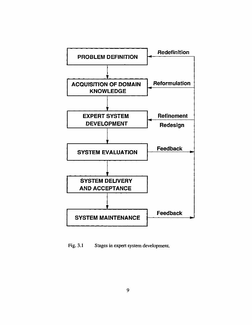
Stages in Expert System Development
The development of expert systems can be broken down into the following principal
stages: definition of problem domain, acquisition of background knowldege about the domain,
development of the expert system, testing and evaluation, delivery and acceptance, and system
maintenance. Figure 3.1 shows the different stages involved and the various linkages.
Definition of Problem Domain: During this stage a problem is identified and its scope is defined.
In addition, participants (experts, knowledge engineer and end-users) are also identified.
Acquisition of Domain Knowledge: This involves the extraction of experts' knowledge. The
experts and the knowledge engineers identify key concepts, relationships and information-flow
patterns needed for problem solving. Subtasks, strategies and constraints involved in the
analysis are also outlined.
Development of the Expert System: Important decisions related to knowledge representation
are made during this stage. A programming language or development tool/shell is selected for
the project and evaluated. The knowledge acquired is programmed into the computer and a
prototype system is developed. The knowledge base is refined and expanded.
Testing and Evaluation : Expert Systems, like any other conventional software, has to be
tested for accuracy and user-friendliness. In fact, the need for validation is much greater in
the case of expert systems since they are based on far less certain theories such as heuristics
and rules of thumb, all of which have been utilized in problem solving but were never subjected
to any detailed examination. Expert systems are evaluated by the Knowledge Engineers, the
Domain Experts and the Users. During development, the system is constantly reviewed and
tested by the Knowledge Engineers. Evaluation by the Domain Experts determine the accuracy
8
YSYSTEM EVALUATION
SYSTEM DELIVERYAND ACCEPTANCE
SYSTEM MAINTENANCE
Feedback
Feedback
PROBLEM DEFINITION
yACQUISITION OF DOMAIN
KNOWLEDGE
Redefinition
Reformulation
^EXPERT SYSTEM^Refinement
^DEVELOPMENT^Redesign
Fig. 3.1^Stages in expert system development.
9

of the knowledge used and the advice/conclusions provided by the system whereas those by
the users helps to assess the system with respect to its user-friendliness, efficiency, speed and
reliability.
Delivery and Acceptance : The system is delivered to the users and installed for actual use.
User groups examine and test the system, often discovering "failures" or "bugs" or "areas of
improvement" to be modified by the developers.
System Maintenance : The system is updated and modified according to the future requirements.
New knowledge is added as required.
There are no clear-cut boundaries between the above stages, which are closely linked
and heavily dependent on each other. The term, "knowledge acquisition", is used by workers
in this area to characterize the complex processes involved in the development process.
Knowledge acquisition has been defined as the transfer and transformation of problem-solving
expertise from some knowledge source to a computer program [2]. It is an iterative process
where each of the above stages interact with each other. The knowledge engineer redesigns,
reformats, reformulates and refines the system in an on-going, never-ending process. Figure
3.1 shows the different stages and the various interactions involved. The last two stages are
concerned with installation of the system at the place of the user and its maintenance. It must
be noted that once the system is put into practice by the users, the process may or may not
continue in the maintenance mode.
Knowledge representation methods
Knowledge representation involves the development of structures that assist in coding
knowledge into the system so that intelligent behaviour is exhibited. The main knowledge
10
items used in this expert system can be grouped into "structural", "procedural", "external" and
"meta-knowledge" [10]. Structural knowledge consists of rules (statements and procedures),
and facts (classes, objects and their description). These units provide the various links among
different knowledge elements as the system searches for final conclusions. Procedural
knowledge units are employed to direct the inferencing process for a number of
knowledge-specific tasks. External knowledge provides an interface for the system to interact
with external programs. Meta-knowledge or "knowledge about knowledge" gives useful and
appropriate explanations and justifications to the users. Some workers in this field, for example
Turban [11], use the term "meta-knowledge" to distinguish rule structures that help direct the
thought process from rules that deal specifically about the domain. In this work, the term
"procedural knowledge" is used for this while "meta-knowledge" is reserved for describing
user-support information supplied by the system to assist users.
Future trends
Expert systems technology is expanding rapidly and numerous applications have been
developed in the last decade. Commercialization of expert system development tools has further
enhanced the growth of this technology. Future advancements include development of
automated methods for knowledge acquisition and of learning systems (neural networks). These
improvements will considerably ease the knowledge engineering process.
11
TUNDISH
MOULD
4 SPRAYS
L^W
7^PINCH-ROLLS^SHEAR/TORCH
IL
CHAPTER 4 KNOWLEDGE DOMAIN - Part I
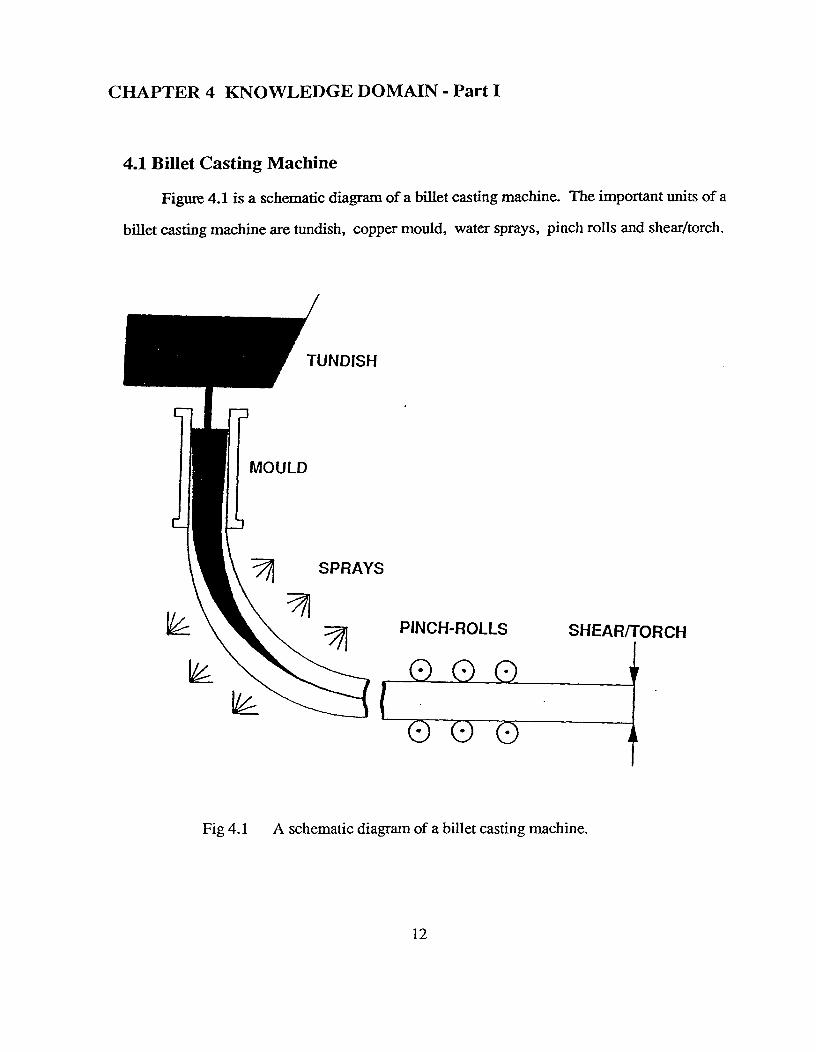
4.1 Billet Casting Machine
Figure 4.1 is a schematic diagram of a billet casting machine. The important units of a
billet casting machine are tundish, copper mould, water sprays, pinch rolls and shear/torch.
Fig 4.1 A schematic diagram of a billet casting machine.
12
Tundish - Molten steel from the steelmaking shop is brought to the casting shop in a refractory
lined ladle. Steel from the ladle is transferred to another vessel called a "tundish" which is an
important unit in the casting machine. Apart from acting as a reservoir of liquid steel, it helps
in controlling metal flow and also in floating out inclusions. Details have been published earlier
[12 - 14].
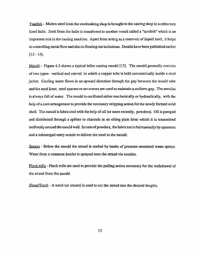
Mould - Figure 4.2 shows a typical billet casting mould [15]. The mould generally consists
of two types- vertical and curved in which a copper tube is held concentrically inside a steel
jacket. Cooling water flows in an upward direction through the gap between the mould tube
and the steel liner, steel spacers or set screws are used to maintain a uniform gap. The annulus
is always full of water. The mould is oscillated either mechanically or hydraulically, with the
help of a cam arrangement to provide the necessary stripping action for the newly formed solid
shell. The mould is lubricated with the help of oil (or more recently, powders). Oil is pumped
and distributed through a splitter to channels in an oiling plate from which it is transmitted
uniformly around the mould wall. In case of powders, the lubricant is fed manually by operators
and a submerged entry nozzle to deliver the steel to the mould.
Sprays - Below the mould the strand is cooled by banks of pressure-atomized water sprays.
Water from a common header is sprayed onto the strand via nozzles.
Pinch rolls - Pinch rolls are used to provide the pulling action necessary for the withdrawal of
the strand from the mould.
,Shear/Torch - A torch (or shears) is used to cut the strand into the desired lengths.
13
i Mould2 Steel jacket
3 Housing
4 Support plate
5 Lubricator plate
6 Cover plate7 Water channel
Fig 4.2 Billet casting mould [67].
14
4.2 Fundamental Knowledge of Billet Casting
In billet casting, the generation of quality problems stems from the nature of the process
where rapid cooling of the steel results in steep temperature gradients in the solid shell that
change rapidly and generate thermal strains as the shell differentially expands or contracts.
These problems have been linked unequivocally to the operation and design of the casting
machine and also to the mechanical behaviour of steel at continuous casting temperatures.
Therefore, at the heart of most quality problems in this process is the nature of cooling (intensity
and uniformity) and at the same time, the mould/shell interaction.
The analysis of quality problems in billet casting, like in any other process, requires a
thorough understanding of the fundamental principles governing it. In this case, it is essential
to study the basics of heat transfer, mechanical properties of steel at high temperatures, sources
of stress generation in the machine (thermal and mechanical), and solidification of the steel
[121 Once possible mechanisms are identified, links between quality problems and related
operating and/or design variables can be established. Then, these quality problems can be
eliminated by altering related process parameters or design conditions, identified as important
in the analysis.
4.2.1 Heat Transfer
4.2.1.1 Mould Heat Transfer
In the mould, heat is transferred from the liquid steel to the cooling water through
four media namely, the solidfying shell, the air gap between the mould and the strand,
15

the mould wall, and the mould / cooling water interface.
Figure 4.3 is a schematic representation of the thermal resistance encountered in the
mould [15]. The air gap constitutes the largest resistance to heat flow [16]. In the upper
region of the mould, conduction through the air gap constitutes nearly 84 percent of the
total and is the dominant mode of heat transfer whereas in the lower part of the mould,
conduction through the solid shell is the major component [15]. The amount of heat
extracted is inversely proportional to the width in each case, in accordance with Fourier's
Law.
I^1^1I^1^I1^I^II^I^1I waterI^I^II^I^I1I^11^i^II I
gap
Fig 4.3 Schematic representation of thermal resistance encountered in the mould[l 5].
16
The mould/shell air gap is a complex function of design and operating variables
namely, shell shrinkage, mould distortion, oscillation marks and ferro static pressure.
The gap also varies in width in both the longitudinal and transverse directions [17]. Thus,
it is difficult to predict the width of the air gap accurately as a function of distance below
the meniscus. For these reasons, measurement of heat-transfer boundary conditions at
the mould/billet interface is necessary. The heat fluxes at the billet/mould interface have
been calculated from time-averaged responses of thermocouples embedded in the mould
wall a set distance away from the hot face during normal casting [18]. Details about the
scheme of calculation of the heat-extraction profiles for single- and double-tapered mould
tubes have been published earlier [19 - 22]. In addition, heat transfer in the mould is
extremely sensitive to the shape of the copper tube which during operation changes due
to differential heating and expansion. Samarasekera et al.[22], with the aid of a finite
element stress-strain model, have studied the thermo-mechanical behaviour of the mould
during operation.
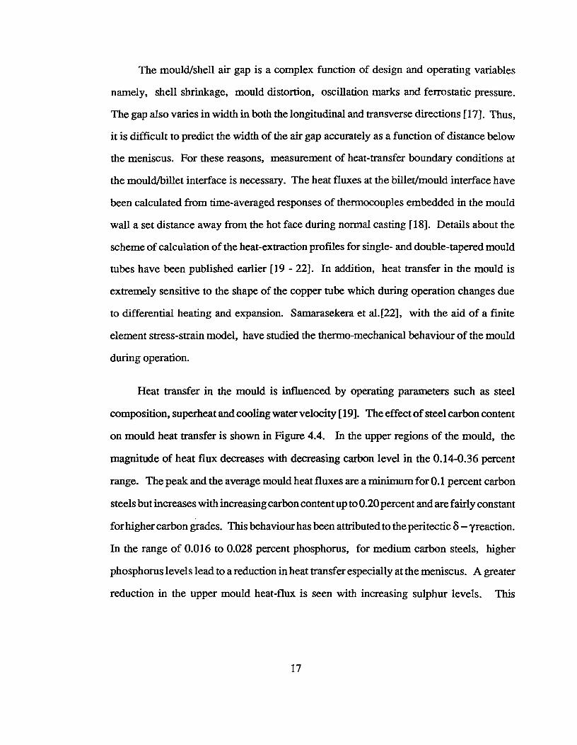
Heat transfer in the mould is influenced by operating parameters such as steel
composition, superheat and cooling water velocity [19]. The effect of steel carbon content
on mould heat transfer is shown in Figure 4.4. In the upper regions of the mould, the
magnitude of heat flux decreases with decreasing carbon level in the 0.14-0.36 percent
range. The peak and the average mould heat fluxes are a minimum for 0.1 percent carbon
steels but increases with increasing carbon content up to 0.20 percent and are fairly constant
for higher carbon grades. This behaviour has been attributed to the peritectic 8 — yreaction.
In the range of 0.016 to 0.028 percent phosphorus, for medium carbon steels, higher
phosphorus levels lead to a reduction in heat transfer especially at the meniscus. A greater
reduction in the upper mould heat-flux is seen with increasing sulphur levels. This
17

150050^00^50^100
Time ( s)
5000
se., No C(V
P(%)
L44LK)
SIto
SoMI
ATra
K.(m/s1
VImAr41
— 24268 014 0020 0 55 0039 014 19 9 7 2 4
- - -^24259 046 0024 O51 0033 042 (28) 92 49— - 242481 028 0022 100 0036 0 48 (27) 93 23
— 24254 036 0026 086 0028 012 (32) 9 7 21
3000
41
-Z-r 2000
1000
4
200
behaviour is attributed to the deleterious effect of sulphur and phosphorus on the
mechanical properties of steel which influences the resistance of the steel to deformation
close to the meniscus during mould oscillation.
Fig 4.4 Axial profiles of mould heat flux for various steel grades [19].
18
The effect of mould cooling water velocity is quite significant [19]. For low carbon
grades, the magnitude of peak heat flux is maximum at a water velocity of 4.0 m/s whereas
for medium carbon ranges, the peak is observed to be a maximum at a velocity of 5.0 m/s.
Heat transfer in the mould is also a strong function of oscillation parameters [19].
In the upper part of the mould, the presence of oscillation marks on the billet surface
influences the width of the mould/shell air gap. Hence, deep oscillation marks reduce
heat extraction considerably in the mould. Also, varying depths of oscillation marks
across the billet surface leads to non-uniform heat transfer conditions in the mould.
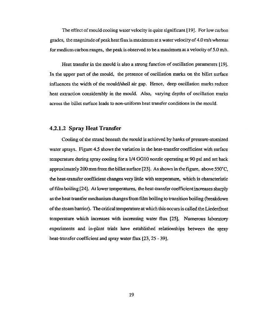
4.2.1.2 Spray Heat Transfer
Cooling of the strand beneath the mould is achieved by banks of pressure-atomized
water sprays. Figure 4.5 shows the variation in the heat-transfer coefficient with surface
temperature during spray cooling for a 1/4 GG10 nozzle operating at 90 psi and set back
approximately 200 nun from the billet surface [23]. As shown in the figure, above 550°C,
the heat-transfer coefficient changes very little with temperature, which is characteristic
of film boiling [24]. At lower temperatures, the heat-transfer coefficient increases sharply
as the heat transfer mechanism changes from film boiling to transition boiling (breakdown
of the steam barrier). The critical temperature at which this occurs is called the Liedenfrost
temperature which increases with increasing water flux [25]. Numerous laboratory
experiments and in-plant trials have established relationships between the spray
heat-transfer coefficient and spray water flux [23, 25 - 39].
19
j„,..........,**N..
.2
.•
1.0
Critical Temperature
..""ll'4'Nfir•r •fririr*"4re"..411...w**1....*•••P
Nozzle - 1,4 GG 10Spray Distance - 8 In.
Spray Pressure - 90 psig
oo1^I^
J200^400^600^800^1000 1200 1400 1600 1800 2000
SURFACE TEMPERATURE, uF
Fig 4.5 Variation of heat transfer coefficient with billet surface temperature [23].
20
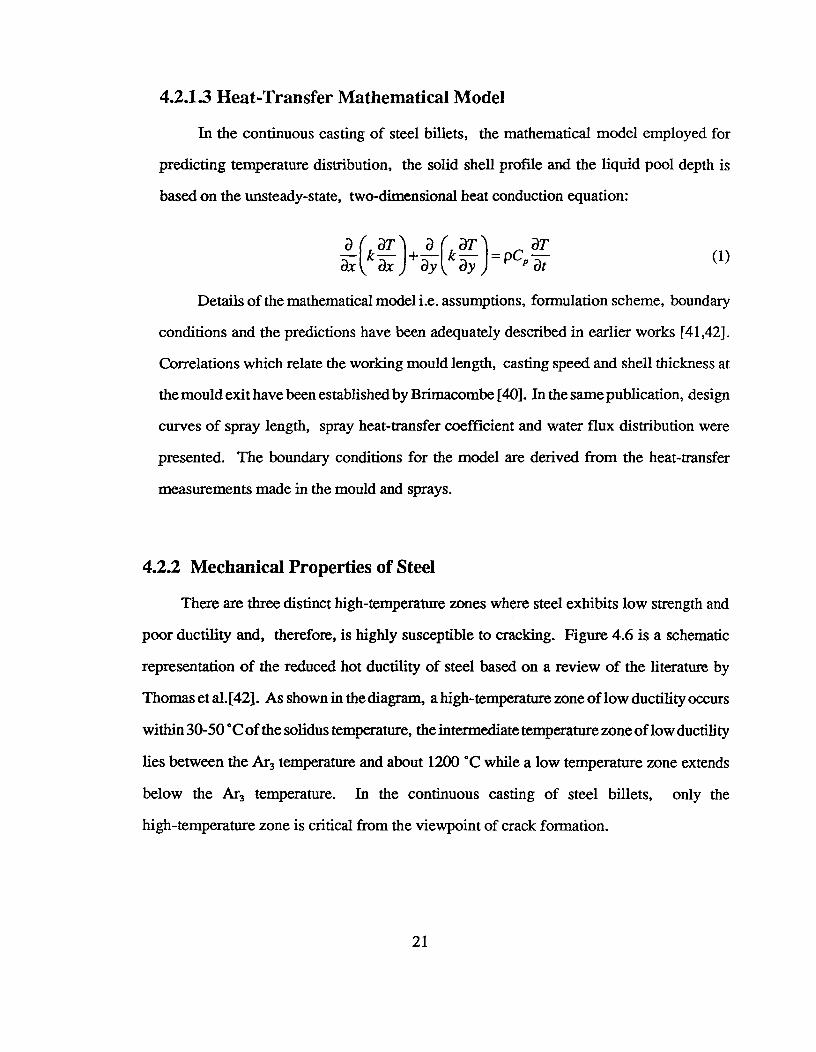
4.2.1.3 Heat-Transfer Mathematical Model
In the continuous casting of steel billets, the mathematical model employed for
predicting temperature distribution, the solid shell profile and the liquid pool depth is
based on the unsteady-state, two-dimensional heat conduction equation:
a ( aT) a (al aTk ax + =pCpaT (1)
Details of the mathematical model i.e. assumptions, formulation scheme, boundary
conditions and the predictions have been adequately described in earlier works [41,42].
Correlations which relate the working mould length, casting speed and shell thickness at
the mould exit have been established by Brimacombe [40]. In the same publication, design
curves of spray length, spray heat-transfer coefficient and water flux distribution were
presented. The boundary conditions for the model are derived from the heat-transfer
measurements made in the mould and sprays.
4.2.2 Mechanical Properties of Steel
There are three distinct high-temperature zones where steel exhibits low strength and
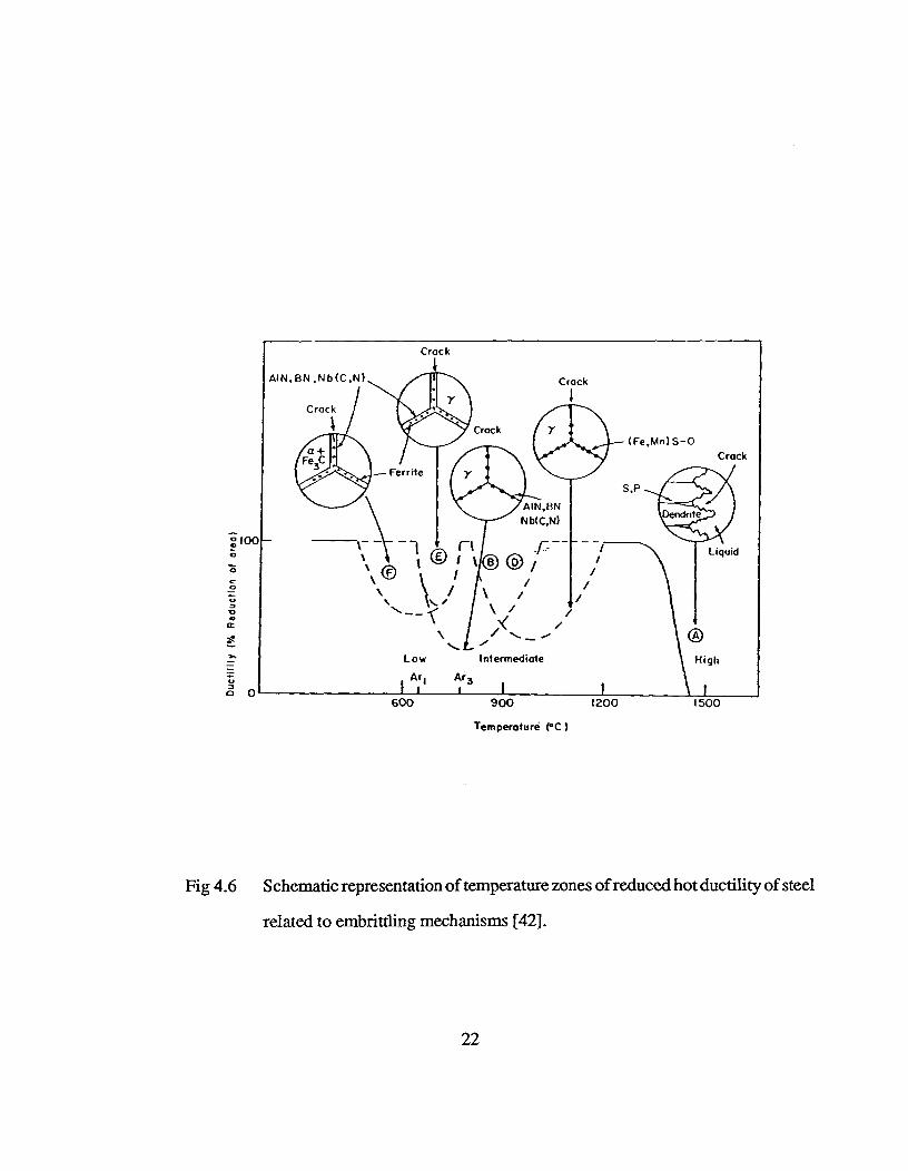
poor ductility and, therefore, is highly susceptible to cracking. Figure 4.6 is a schematic
representation of the reduced hot ductility of steel based on a review of the literature by
Thomas et al. [42]. As shown in the diagram, a high-temperature zone of low ductility occurs
within 30-50 °C of the solidus temperature, the intermediate temperature zone of low ductility
lies between the Ar3 temperature and about 1200 °C while a low temperature zone extends
below the Ar3 temperature. In the continuous casting of steel billets, only the
high-temperature zone is critical from the viewpoint of crack formation.
21
Crock
600^
900^
1200^
1500
Temperature (°C)
Fig 4.6 Schematic representation of temperature zones of reduced hot ductility of steel
related to embrittling mechanisms [42].
22
High Temperature Zone : 1340 °C to Solidus
At temperatures well above 1340 °C, there is significant deterioration of the strength
and ductility of steel. In a review conducted by Brimacombe and Sorimachi [43], strength
data measured at various strain rates in four different studies were extrapolated to a common
strain rate of 10-3 s"' (commonly obtained in the continuous casting process) and were
compared. The strain-to-fracture of steel in the high temperature zone of low ductility appears
to be of the order of 0.20 to 0.30 percent according to Vom Ende and Vogt [44].
The low strength and poor ductility of steel close to the solidification front is due to
the presence of liquid films in the interdendritic regions which remain molten until
temperatures well below the solidus are reached [45]. These liquid films are rich in solutes
such as sulphur and phosphorus which have segregation coefficients (CJC 1) less than unity.
Scanning electron micrographs of the interior surface of a crack that originated close to the
solidus temperature have shown a smooth surface, with no signs of solid fracture, indicating
the presence of a liquid film at the time of crack formation [46].
Effect of Phosphorus : Sopher [47] studied the influence of phosphorus on fracture strength
and ductility of SAE 4340 steel at different temperatures. It was found that steel with a
phosphorus concentration of 0.039 percent has drastically reduced strength and ductility as
compared to steel containing 0.017 percent phosphorus.
Effect of sulphur : The effect of sulphur on the strain-to-fracture and the UTS of steel near
the solidus temperature was studied by Morozenskii et al.[48]. Two points can be noted from
their study. Firstly, the presence of sulphur in steel adversely affects both strain-to-fracture
and the UTS; and secondly, an increase in Mn/S ratio in steel improves the strain to fracture
but has no significant effect on the UTS. Similar results were obtained by Kinoshita and
23
Kuroki [49] in another study related to steel at 1350 °C. This study also investigated the
effect of Mn concentration on the proportion of MnS and the FeS in sulphide inclusions. It
was shown that FeS content decreased with increasing Mn concentration. The authors also
found that in 0.2 percent C steel, for Mn concentrations less than 0.7 percent, sulphides
have a tendency to exist in liquid form below the solidification temperature of 1480 °C. A
Mn/S ratio greater than 20 is effective in minimizing the cracking tendency by preventing
the liquid film formation [48].
Effect of carbon : The effect of carbon on mechanical properties was studied by Morozenskii
et al.[48]. The strain-to-fracture, S E , and its plastic component, 5,1„stic , were found to be
minimum for steel containing 0.17 to 0.20 percent C. Similar results were reported by
Guessier and Castro [50].
Effect of tin and copper : Increased contents of Sn[51] and Cu[52,53] deleteriously affect
the ductility of steel. This behaviour is attributed to the presence of the above mentioned
low-melting impurities at the grain boundaries. Failure occurs due to liquid metal
embrittlement.
The high temperature zone of low ductility has also been examined by numerous other
authors [55 - 60]. It has been established that this zone of low ductility is operative at
temperatures within 30 to 70°C of the solidus temperature, and the associated
strain-to-fracture is virtually zero [61]. Thus, the presence of even a small tensile strain in
the solidfying shell in this temperature region will initiate a crack which will propagate
outward from the solidification front between dendrites.
24

4.2.3 Stress Generation during the Casting Process
During the casting process, the strand is subjected to varying thermal conditions and
changing mechanical loading which generate stresses and strain in the strand. In order for
a crack to originate at a given location, two conditions must be present [12]:
(i) the stress must be tensile in nature
(ii) the fracture strain must be exceeded
Thermal Stresses/Strains - The rapid rate of cooling in continuous casting, results in steep
temperature gradients in the solid shell that can change rapidly and generate thermal strains
as the shell expands or contracts differentially. Thermal stresses can be generated either
when free expansion or contraction of the material is constrained or when the thermal gradient
in the material is non-linear and changing [12]. In the continuous casting of steel, the thermal
stress condition in the strand can be approximated to that of a generalized plane-strain
condition [12]. In the process, there is some allowance for expansion in the casting direction
which helps minimize generation of longitudinal stresses and strains. Further, thermal
gradients in the longitudinal direction are quite small and unlikely to cause any cracking.
Thus, transverse cracks, which require a longitudinal stress component, simply cannot
originate due to adverse thermal gradients in the billet but instead are generated mechanically.
In the transverse plane however, conditions are present which generate high thermal
stresses. The free thermal expansion is restrained and also the temperature gradients are
steep and frequently non-linear [12]. In addition, sudden changes in heat extraction rates,
which could occur at the boundary between any two consecutive cooling zones, may cause
the thermal gradients to shift, particularly at the surface; the resulting expansion or
25
contraction of this region also generates stresses in the transverse plane. If this strain is
tensile in nature and its value exceeds the strain-to-fracture in a zone of low ductility,
particularly close to the solidification front, then longitudinal cracks may form.
Reheating of the surface of the billet below the mould or the sprays causes expansion
of the surface layers which imposes tensile stresses at the solidification front where the steel
has the lowest ductility [62]. Non-uniform cooling in the mould and the sprays imposes
tensile stresses at the obtuse angle corners or off-corners regions of billets [22,61]. Also,
during binding at the corners of the billet in the mould, excessive cooling at some locations
of a face may cause localized tension [12].
Van Drunen et al.[46] have suggested another source of thermal stress generation. At
the point of complete solidification, when the final trace of latent heat has been extracted
from the centre region, the drop in centreline temperature is considerably more rapid than
the decrease in surface temperature with the result that the central region contracts more than
the surface. The centre, however, is constrained from contraction by the surrounding colder
steel and is therefore, put into tension. Depending on the magnitude of the stress and the
strength of the steel, centreline cracks may form. Segregation of elements in the central
region of the billet adversely affects the strength and ductility of steel and increases the
susceptibility to cracking.
Mechanical Stresses - Sticking in the mould due to inadequate lubrication and/or oscillation
conditions or binding of the strand in the mould due to excessive taper, imposes resistance
to smooth withdrawal of the strand. This generates axial tensile stresses and strains that
concentrate on locally thin regions of the shell and may cause transverse depressions with
transverse cracks [20]. The nature of this transverse crack, whether it appears as an internal
26
crack or a surface crack, depends on the magnitude of the stress and the shell thickness at
that location. If the taper is insufficient in the lower portion of the mould, bulging of the
solid shell can occur and may lead to hinging of the strand at the off-corner sites which
generates a tensile strain at the solidification front and internal cracks [63]. Straightening
or bending operations, when carried out on a section with a liquid centre or when the centre
is solid but within 50 to 70 °C of the solidus temperature, may also lead to the generation
of a tensile stress at the solidification front [43]. Tensile stresses are also generated when
excessive pinch-roll pressures are applied on the strand with a liquid core [43].
4.2.4 Solidification of Steel
In continuous casting, two aspects of solidification are important from the viewpoint
of quality: cast structure (columnar / equiaxed) and the nature of shell growth around the
liquid pool.
Cast Structure - Cast structure influences internal crack formation and macrosegregation.
Dahl and Hengstenberg have proposed a mechanism of crack formation based on dendritic
separation in the columnar zone [63]. The columnar structure is more susceptible to crack
formation as compared to the equiaxed structure because it provides an easy path for crack
propagation. There are a number of operating parameters that influence the size of the central
equiaxed zone relative to that of the surrounding columnar zone in a continuously cast billets.
These factors are superheat, steel composition, section size, casting speed and machine
design (straight or curved mould-tubes).
Effect of superheat: The effect of superheat (usually measured in the tundish) on the cast
structure was investigated by Van Drunen et. al. [46]. It was found that the columnar zone
27
is favoured at the expense of the equiaxed zone with increasing steel temperature (liquidus
+ superheat). A superheat level of 30 °C or below is desired to maximize the equiaxed
structure which makes the strand more resistant to cracking and minimizes macrosegregation.
Effect of carbon conteni : The effect of carbon content on the length of the columnar zone
in a continuously cast billet has been examined by Bommaraju et al.[64]. Equiaxed structure
is favoured in the medium-carbon range of 0.17 to 0.38 percent carbon. Increasing the
phosphorus content from 0.008 to 0.02 percent in 0.13 to 0.20 percent C steel also causes
the columnar zone to shrink [64].
effect of section size : A large section size favours the growth of an equiaxed zone [12].
Hence, crack formation by dendritic separation in the columnar zone is less likely to be
serious as compared to smaller sizes.
Effect of machine design : The design of the casting machine (i.e. straight or curved) also
influences the cast structure. Van Drunen et al.[46] observed that the length of the columnar
zone adjacent to the inner-radius face was greater than that adjacent to the outside-radius
face. Lait et al.[65] postulated that this non-symmetrical structure results from the settling
of crystallites (dendritic debris) against the solidification front advancing from the outside
radius face. In this way, the crystallites interfere and prevent further growth of the columnar
grains. On the other hand, the columnar structure adjacent to the inside radius experiences
unimpeded growth.
Solid Shell Formation - The initial shell growth in the mould is governed by the mould
heat-flux distribution. Watanabe et al.[16] observed that in the upper part of the mould, the
mould/shell air gap constitutes a large fraction of the total thermal resistance encountered.
Thus, the nature of shell growth in the upper part of the mould is largely dependent on the
28
dynamics of air gap formation. Hence, variables influencing air-gap formation, and therefore
the heat-transfer in the mould, directly impact on the nature of shell growth. In the lower
part of the mould and further down the casting machine, after a reasonable amount of
solidification has occurred, conduction of heat through the solid steel shell is critical in
controlling heat transfer and solid shell formation [15].
Two aspects of solid shell formation that are important from the viewpoint of billet
quality, are the magnitude of the shell thickness and the uniformity of the shell around the
liquid core [12]. The solid shell at the mould exit must be strong enough to counteract the
ferrostatic pressure exerted by the liquid core. If the shell thickness is inadequate and the
mould taper insufficient, bulging of the solid shell in the mould may occur [64]. Bulging
can also occur near the mould exit, before the spray zone, if the shell is thin. In an adverse
situation, a thin shell at the mould exit may be incapable of withstanding the ferrostatic
pressure and could rupture. Breakouts can also occur if there is a local reduction in shell
thickness due to surface depressions, cracks or deep oscillation marks. Therefore, uniformity
of the shell around the liquid core is also a critical parameter for quality and operations.
Non-uniform shell thickness may result from deep and non-uniform oscillation marks,
wrinkling of the surface especially in low-carbon grades, or the presence of surface
depressions. Singh and Blazek [66] showed the influence of the carbon content of steel on
the uniformity of shell growth. Non-uniformly deep oscillation marks on the billet surface
locally reduce the heat-extraction rate in the mould, relative to other areas around the
periphery of the billet, as a result of an increased air gap width [64]. Thus, the billet leaves
the mould with a non-uniform shell. The severity of this non-uniformity depends on the
extent of variation in the heat-extraction rate around the billet periphery in the mould. Links
will be established later between this event and rhomboidity.
29
4.2.5 Operating Parameters
4.2.5.1 Mould
Mould/shell interaction at the meniscus is by far the most important phenomenon
occurring in the mould as it directly impacts on the formation of oscillation marks which
affect the width of the mould/shell air-gap and, hence, influence the mould heat-extraction
[19]. Mould/shell interaction away from the meniscus is also important because it
influences binding in the mould which occurs whenever the size of the billet exceeds the
mould tube dimensions. A mould/shell gap that is too large, is also not desirable. In the
upper part of the mould, a large mould/shell gap leads to significant reduction in the heat
extraction capability of the mould while in the lower part of the mould, coupled with a
thin solid shell, it causes bulging and cracking at off-corner locations [64].
4.2.5.1.1 Mould Distortion
Mould-tube distortion affects the shape of the mould during operation and is
directly linked to the thermo-mechanical behaviour of the mould [21]. As shown in
Figure 4.4, the heat flux is a maximum very close to the meniscus due to the small air
gap across which heat flows essentially by conduction. Below the meniscus, the heat
flux falls as the gap increases in width due to steel shrinkage. The second maximum
seen in the mould heat-flux profile is due to mould distortion [19]. Above the meniscus
where the steel does not contact the mould, the heat flux declines rapidly and causes
relatively steep temperature gradients to be set up in the axial as well as the
through-thickness direction in the mould wall.
30
In the study by Samarasekera and Brimacombe [22], it was found that although
the maximum heat flux is at the meniscus, the peak temperature is not. The maximum
temperature is observed at a location slightly below the meniscus. This behaviour is
attributed to significant heat conduction vertically up the mould wall. The axial
temperature distribution observed in the mould determines the expansion of the
mould-tube. The hottest region of the mould wall expands the most and causes bulging
of the mould tube. The peak bulge in the mould appears about 75 mm below the meniscus.
As a result, the mould has a negative taper above the peak bulge and a positive taper
below the maximum distortion point. The second peak in the mould heat-flux profile,
according to S amarasekera and Brimacombe, is due to twisting of the mould as a result
of non-uniform mould tube support [22].
Classification of Mould Distortion - Profiles of distance between opposite faces for a
large number of used moulds were examined by Brimacombe et al.[67]. Used moulds
were classified into three main categories based on the extent of permanent deformation
observed:
Minimal distortion : In this category, moulds exhibited relatively little distortion in the
meniscus area. Small permanent deformation, less than 0.50 mm or less between the
opposite faces, was observed. It was found that these moulds were operated with deep
meniscus levels, high water velocities and good water quality.
Outward bulging near the meniscus : Moulds in this group exhibited an outward bulge
toward the water channel, very close to the meniscus region. Permanent distortion was
within 0.50 mm and 2.00 mm between the opposite faces; the constrained sides were
deformed more than the unconstrained sides because the former are constrained against
31
expansion and undergo greater plastic strains, and therefore have larger permanent
distortion. These moulds had been operated with shallow meniscus levels, poor water
quality or low water velocity.
Abnormal / severe distortion : In this case, moulds showed permanent deformation
which exceeded a value of 2.0 mm between opposite faces. This strongly indicated
problems such as poor water quality, low water velocity, shallow meniscus and poor
centering of the mould tube in the liner.
Regular distortion measurements of both new and used mould tubes is important
in the analysis of mould disorders. Measurements made on used moulds reflect the
nature of operating parameters employed in the process whereas, checks on the
dimensions of new moulds are necessary to ensure that mould-tube specifications are
being met.
Factors Influencing Mould Distortion
(i) Cooling Water Quality : Water quality strongly influences the thermal field and the
distortion of the mould-tube. This is linked to the deposition of scale from the cooling
water on to the cold face of the mould-tube. The presence of a layer of scale introduces
a large resistance to heat flow which raises the mould temperature [21]. It is clear that
even with a relatively thin layer of deposit, the local cold-face temperature is hotter
than the hot-face temperature in the absence of scale [21]. Fouling nearly doubles the
bulging of the mould-tube below the meniscus from 0.20 mm to 0.35 mm [21].
The presence of scale deposits on the cold face of the mould is a clear indication
of poor water quality. The severity of fouling was quantified by Brimacombe et al.[67]
32

with an index, F, which was defined on the basis of the ratio of the deposit length, 1,
to the effective mould length, L. The higher the value of F, the poorer is the water
quality.
Poor water quality may be due to a high hardness level in the cooling water or
due to the presence of corrosion products, oil, grease or as a result of biological fouling
stemming from algae and moss. Inferences on the source of the contamination may be
drawn from the colour and properties of the scale deposit. A red deposit, similar to
rust, suggests oxide of iron and corrosion in the water delivery system. A black deposit
may be due to magnetite (Fe304) or carbonaceous matter such as oil, grease or biological
matter. The presence of iron oxide suggests corrosion in the water delivery system while
carbon-rich matter indicates petroleum products or biological fouling. With the help of
chemical analysis, it is possible to distinguish between the two contaminants. In
addition, if the loss on ignition of the scale deposit is large, the scale is expected to be
rich in carbon. The black deposit can be tested with an ordinary magnet to check for
Fe304. A light-coloured scale deposit suggests excessive hardness in the cooling water.
(ii) Cooling Water Velocity : Cooling water velocity is directly linked to the thermal
distortion of the mould [21]. A high water velocity is recommended to prevent
uncontrolled nucleate boiling in the cooling channel. It has been shown that nucleate
boiling, which occurs on the hottest region of the mould very close to the meniscus,
could be both asynchronous and intermittent. Water velocity in excess of 12 m/s is
required to prevent boiling [68]. In addition, it is also important that the mould cooling
water velocity is uniform around the periphery of the mould.
33

(ii) Mould-Tube Alignment and Tolerances : It is not only important to maintain a high
cooling water velocity but also a uniform water flow around the periphery of the mould.
If the flow is non-uniform then one or more walls of the mould may operate hotter than
the others and cause non-uniform distortion of the mould tube which in turn may lead
to uneven shell growth in the billet. Hence, it is essential to ensure that the width of
the annulus between the steel jacket and the mould tube, through which the cooling
water flows, is constant around the mould periphery.
The water gap is typically 4.8 mm (3/16 inch), although some plants employ gaps
of 3.2 mm (1/8 inch). It is important to maintain a close tolerance on the outside
dimensions of the water jacket due to the small width of the water gap [68]. For example,
in the case of 4.8 mm wide gaps, a loss of dimension of 1 mm can change the water
velocity by up to 20 percent. In addition, the tolerances on the outside dimension of
the mould wall and the inside dimension of the water jacket are also important. Typically
values for each is about 0.5 mm. On its own, this may give rise to a variation of 1.0
mm on different faces. In addition, the mould tube could translate a further 1 mm from
the concentric position. because of the tolerances on the support plates and flanges. In
the worst case, the water gap may differ by as much as 2 mm (roughly 40 percent of
gap width) between the opposite faces of the mould. Local increase in the gap width
may also occur due to non-uniform distortion or bulging or misalignment or even
off-centring of the mould tube. An increase in the gap width leads to local reduction in
water velocity which causes a marked increase in the mould temperature [21].
Frequently, at the corners of the water jacket, the gap is not equal to the gap at
the midface [68]. This occurs when the jacket has square corners which is typical of
jackets fabricated from steel plates which are welded at the corners. When the two are
34

assembled, the water gap in the corners is larger than that in the midface [68]. A larger
gap at the corners leads to a reduction in the resistance to water flow through it. This
causes the water to flow preferentially up the corners thereby reducing the water velocity
on the faces. A large gap at the corners may also isolate one face from another leading
to severe non-uniformity in the heat transfer conditions around the mould periphery
[68].
The material of the water jacket is also important [68]. A mild steel jacket corrodes
easily and affects the tolerances. A material, such as stainless steel, that is resistant to
corrosion is desired to maintain the dimenional integrity of the water jacket during the
operation.
(iii) Mould-wall Thickness : Thick mould walls give rise to a smaller negative taper at
the meniscus [68]. This is because thicker walls have larger thermal gradients and hence
bending of the wall is a significant mode of deformation. Thus, the midface bows
inwards relative to the corners at the meniscus. The effect of thick wall mould tubes
have been observed on the depth of oscillation marks [68]. It has been found that thicker
walled tubes generate shallower oscillation marks as compared to thinner ones. This is
expected because smaller negative taper of the thick wall tube at the meniscus results
in reduced mould/shell interaction during negative strip. A thick wall mould tube also
enhances heat transfer in the meniscus region [68]. It was found that the heat flux to
the thick wall tube is greater and remains at a higher level close to the meniscus as
compared to thin wall tube. The rapid drop in the heat extraction rate for the thin wall
tube is associated with greater negative taper which leads to quicker formation of a wider
mould/shell gap below the meniscus. A thicker mould wall is desired even for small
35
billets. From the viewpoint of mould distortion, wall thickness must be greater than
one-tenth of the largest dimension of the billet cross-section and should not be less than
12.5 mm.
(iv) Mould-Copper : The selection of a copper grade for the mould-tube depends on
three critical parameters, namely, thermal conductivity, yield stress and softening
resistance [68]. A high thermal conductivity is required to minimize mould temperatures
and resulting thermal distortion. A high yield stress and an adequate softening resistance
are necessary to minimize permanent distortion of the mould tube.
Pure copper is better than other metals for the mould owing to its high thermal
conductivity. Unfortunately, it lacks the softening resistance and cannot maintain its
shape at peak operating temperatures for more than one or two heats. Therefore, it is
necessary to use an alloy of copper having high yield strength and good softening
resistance.
DHP-122, a phosphorus deoxidized, high residual phosphorus copper with only
a small residual silver content, is commonly used as a mould material for billet casting.
It has adequate softening resistance and does not undergo plastic deformation early in
the campaign. The phosphorus content should be greater than 0.03 percent to ensure
good softening resistance.
DLP-120 is a phosphorus-deoxidized, low residual phosphorus grade of copper.
The phosphorus content is below 0.005 percent and hence its softening resistance is
lower than that of DHP-122 grade. However, a silver content greater than 0.1 percent
enhances the softening resistance of the alloy.
36
The STP grade is a tough-pitch alloy containing some silver. It lacks adequate
softening resistance required to maintan its shape at peak operating temperatures for
more than one or two heats, a behaviour very similar to that of pure copper.
Copper-Silver alloys with a silver content exceeding 0.10 percent is frequently
used as a mould material. Adequate silver content is necessary to ensure a good softening
resistance.
New alloys of copper containing elements such as chromium, zirconium, nickel
and aluminum are also being introduced as mould materials [68]. The alloying elements
such as chromium, nickel and aluminium strengthen the copper by solid solution
hardening, whereas zirconium is a precipitation hardening agent. These elements
improve the softening resistance as well as the yield strength of the copper beyond that
of phosphorus and silver. These alloys substantially improve the mould life. However,
it is important to ensure that the thermal conductivity of the alloy is greater than 80
percent of pure copper. Three conditions are essential in a mould material:
* Thermal conductivity > 300 W/m°C
(W/m°C) (80 percent of pure copper or more)
* Half-softening point (°C) > 350 °C
* Yield stress ( MPa ) > 250 MPa at 20 °C
An alloy satisfying the above conditions is unlikely to contribute to mould
distortion provided that the cooling water velocity exceeds 12 m/s, cooling water quality
is controlled carefully and the metal level is at least 100 mm below the top of the mould.
37
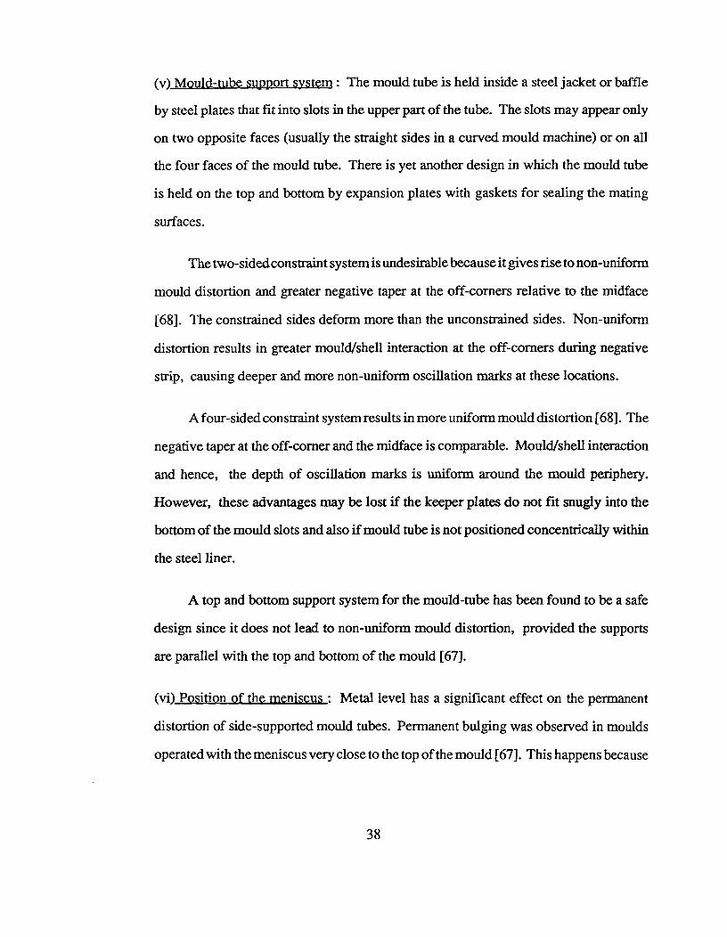
(v) Mould-tube support system : The mould tube is held inside a steel jacket or baffle
by steel plates that fit into slots in the upper part of the tube. The slots may appear only
on two opposite faces (usually the straight sides in a curved mould machine) or on all
the four faces of the mould tube. There is yet another design in which the mould tube
is held on the top and bottom by expansion plates with gaskets for sealing the mating
surfaces.
The two-sided constraint system is undesirable because it gives rise to non-uniform
mould distortion and greater negative taper at the off-corners relative to the midface
[68]. The constrained sides deform more than the unconstrained sides. Non-uniform
distortion results in greater mould/shell interaction at the off-corners during negative
strip, causing deeper and more non-uniform oscillation marks at these locations.
A four-sided constraint system results in more uniform mould distortion [68]. The
negative taper at the off-corner and the midface is comparable. Mould/shell interaction
and hence, the depth of oscillation marks is uniform around the mould periphery.
However, these advantages may be lost if the keeper plates do not fit snugly into the
bottom of the mould slots and also if mould tube is not positioned concentrically within
the steel liner.
A top and bottom support system for the mould-tube has been found to be a safe
design since it does not lead to non-uniform mould distortion, provided the supports
are parallel with the top and bottom of the mould [67].
(vi) Position of the meniscus : Metal level has a significant effect on the permanent
distortion of side-supported mould tubes. Permanent bulging was observed in moulds
operated with the meniscus very close to the top of the mould [67]. This happens because
38

the point of maximum expansion of the mould tube which is very near the meniscus
comes closer to the support plates which oppose the outward movement. Hence, the
stresses in the mould wall are large.
The metal level and the type of mould support system are closely related especially
in the generation of mould distortion. A metal level which is closer than 100 mm to the
top of the mould is likely to create adverse conditions for mould distortion in the case
of both two-sided and four-sided mould constraint systems. Hence, in moulds having
a side-supported system, the distance of the meniscus from the top of the mould is
critical and must not be less than 100 mm. However, in the case of moulds with a top
and bottom support system this is not a criterion and therefore operating with shallow
meniscus levels is less likely to be a serious concern.
4.2.5.1.2 Mould Taper
Dippenaar et al.[69] have found that a single taper of 0.6 to 0.7 % per metre is
inadequate to compensate for shrinkage of the cooling steel and gives rise to a large
mould/shell air gap. Also, it is insufficient to counter the development of negative taper
and resulting mould/shell interaction. A double tapered mould, with an upper taper of
3.5 to 4.0 % per m and a lower taper of 0.5 % per m, is considered to be better than a
single tapered mould. The advantages of a double tapered mould has been discussed
in earlier publications [68,69]. Recent work at UBC has examined the use of multiple
tapered moulds. Taper calculations have been made for different carbon grades [70].
Caution must be exercised in employing multiple tapered mould tubes since the
mould heat-flux profile and billet shrinkage profile are strongly dependent on casting
39
speed, mould-tube distortion and metal level. Since the upper taper is based on a
constant residence time between the meniscus and the break-point to the next taper, it
is mandatory to control the above mentioned parameters when using multiple tapered
mould tubes.
4.2.5.1.3 Mould Oscillation
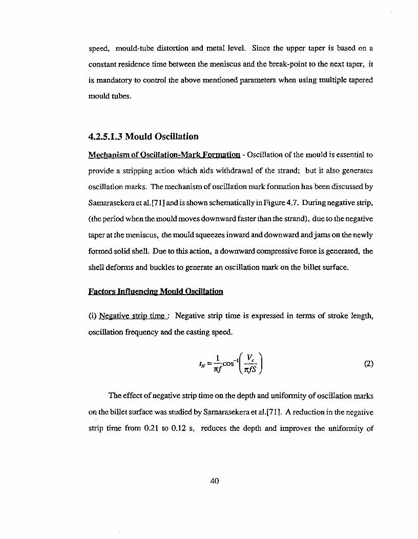
Mechanism of Oscillation-Mark Formation - Oscillation of the mould is essential to
provide a stripping action which aids withdrawal of the strand; but it also generates
oscillation marks. The mechanism of oscillation mark formation has been discussed by
Samarasekera et al.[71] and is shown schematically in Figure 4.7. During negative strip,
(the period when the mould moves downward faster than the strand), due to the negative
taper at the meniscus, the mould squeezes inward and downward and jams on the newly
formed solid shell. Due to this action, a downward compressive force is generated, the
shell deforms and buckles to generate an oscillation mark on the billet surface.
Factors Influencing Mould Oscillation
(i) Negative strip time : Negative strip time is expressed in terms of stroke length,
oscillation frequency and the casting speed.
k=-- cos —I.
itfS(2)
The effect of negative strip time on the depth and uniformity of oscillation marks
on the billet surface was studied by Samarasekera et al. [71]. A reduction in the negative
strip time from 0.21 to 0.12 s, reduces the depth and improves the uniformity of
40
oscillation marks on the billet surface. The average depth of oscillation marks and the
difference in their depth between the midface and the off-corner has been shown to
increase with increasing negative strip time. By reducing the time of this mechanical
interaction, it is possible to decrease the depth and improve the uniformity of oscillation
marks. On the other hand, operating with extremely low negative strip time causes
sticking of the strand in the mould. An optimum range for negative strip time to minimize
sticking as well as problems related to deep and non-uniform oscillation marks is 0.12
to 0.15 seconds.
Fig 4.7 Mechanism of oscillation mark formation [19].
41
(ii) Mould Lead : Mould lead is the downward displacement of the mould relative to
that of the strand during negative strip. It is related to negative strip time, oscillation
frequency, stroke length and the casting speed by the following mathematical formula:
MouldLead = S sin(nftN) — VCtN (3)
The stripping action appears to be related to the mould lead generated during the
oscillation of the mould. Operating with small mould leads increases the tendency of
sticking in the mould. The stripping action improves as the displacement of the mould
during negative strip time is increased.
(iii) Other variables : In addition to negative strip time and mould lead, stroke length
and oscillation frequency must be within specified limits. The desired range for the
stroke is 9 to 16 mm. The upper limit imposed on oscillation frequency is around 4 Hz.
and is based on vibration problems (of the structures) encountered at higher frequencies.
Also, the oscillation frequency should not be linked to casting speed. Regular
maintenance of the oscillation system is necessary to avoid wobbling and vibration of
the oscillation system.
4.2.5.1.4 Mould Lubrication
Lubrication in the mould is necessary to prevent sticking of the steel to the mould
wall at the meniscus. Sticking hinders smooth withdrawal of the strand from the mould
and leads to the generation of quality problems in billet casting.
42

Factors Influencing Mould Lubrication
(i) Oil - flow and distribution : Insufficient lubrication increases the tendency for
sticking. On the other hand excessive supply of oil for lubrication leads to entrapment
of hydrogen and pinhole formation in the billet. Thus, it is extremely important to have
the proper amount of oil in the mould. Flow rates within 0.10 to 0.20 ml of oil per min
per mm of mould tube inside perimeter are considered to be an optimum range.
In addition, the oil must be uniformly distributed around the mould periphery.
Regular checks on the distribution of oil are necessary. A simple experiment can be
done on a cold mould when casting is not in progress to assess the adequacy of the oil
distribution system. Oil is allowed to flow down the inside mould wall and is collected
in containers placed below each face at the bottom of the mould tube. The volume of
oil collected in each container is compared. A difference exceeding 10 percent is
considered to be unsatisfactory.
(ii) Oil - Physical Properties : Viscosity, boiling point and flash point of the lubricant
are important parameters. Oil viscosity determines the resistance to oil flow down the
mould wall. A high flash point of oil is desired to prevent the oil from burning off before
reaching the metal level. Similarly, the boiling point of oil must also be high such that
the oil does not vapourize before reaching the metal level. Flash point and boiling point
greater than 300 °C are considered to be adequate provided there are no scale deposits
on the cold face of the mould. If scale deposits are present on the cold face of the mould,
the mould operates hotter than normal and therefore, the lubricating oil vaporizes or
burns before reaching the metal level. In this situation, the mould lubrication is likely
to be poor.
43

(iii) Cleanliness of oil distribution system : Regular cleaning is essential to prevent
blockage of oil-distribution slots. Blockage of these slots disturbs the flow and
distribution of oil.
(iv) Removal of oil-pyrolysis products from the meniscus : The meniscus is the most
important region of the mould from the viewpoint of heat extraction and initial
solidification. If there is a build up of oil pyrolysis products at the meniscus during the
process, the debris interferes with heat transfer and introduces non-uniformity in the
rates of heat extraction. Cleaning of this area is therefore essential and can be done in
two stages. Firstly, the solid loose oil particles and residual oil are removed with a rag
soaked in solvent. Secondly, the mould surface is rubbed with emery paper to remove
adherent materials and uncover the chromium layer on the mould surface.
4.2.5.2 Sprays
From the viewpoint of quality products, an ideal spray cooling operation is one that
generates minimum surface reheat, provides uniform cooling conditions around the billet
periphery and ensures a high solidification rate.
(i) Spray Design and Operation : The important parameters are spray length, specific
water flow, water pressure, nozzle configuration, nozzle positions and stand-off distances
from the strand.
Reheating is minimized by preventing sharp reduction in heat extraction rates as the
billet moves from one cooling zone to another. Therefore, the cooling rate in the upper
portions of the sprays must match the heat flux at the mould exit, and the gap between
the mould and the sprays must be as small as possible. The presence of a large gap may
44
cause a significant rebound in the billet surface temperature. In addition, the presence of
support rolls at the mould exit hinders cooling of the billet and may cause the surface to
reheat. At the exit, the spray cooling rate must be comparable to the radiative heat flux.
The spray water flux must be reduced with axial distance to minimize drastic transitions
in the cooling conditions.
Brimacombe et al.[62] proposed a methodology for spray design by combining the
understanding of the origin of thermal stresses with a mathematical model capable of
simulating the thermal history of steel (profiles of solid shell thickness and surface
temperature profiles along with the prediction of liquid pool depth). Based on experience,
it is felt that surface reheating of the billet can be minimized by operating with a specific
water flow less than 1.0 litre per kg of steel cast and a spray length greater than 3 m. The
optimum operating conditions can be obtained with the help of the mathematical model
which takes into account cooling in the mould, casting speed, section size and grade of
steel being cast.
The significance of nozzle configuration has been discussed by many authors.
Brimacombe et al.[62] have outlined the methodology of translating the distribution of
spray heat-transfer coefficients into a spray water flux distribution which can be linked to
the operating spray-nozzle variables. In this study, the authors maintained the surface
temperature at 1100 °C and predicted the heat transfer coefficients required to achieve this
condition. Higher values of heat transfer coefficients are required for the central regions
of the face in the upper spray zone than towards the bottom. Cooling requirements decrease
towards the corners because of the effect of two-dimensional heat flow. The coefficients
45

are smaller for the lower regions of the sprays because the rate of conduction of heat to
the surface is lower due to increased thickness of the solid shell. The effect of the spray
length on the magnitude of reheating of the billet surface was also investigated.
The stand-off distance, which is the distance of the spray nozzles from the billet
surface, is important. The distance must be such that the edge of the water sprays coincide
with the billet corners. In addition, the alignment of the nozzles must ensure uniform
cooling around the billet. The distance between the nozzles in each spray zone is dictated
by the need to maintain a uniform water-flux over the entire spray length. Mizikar [23]
has shown that the water flux between two sprays is about 20 to 30 percent greater than
the algebraic sum of the individual contributions of each nozzle. The calculation was
based on the knowledge about water flux resulting from overlapping spray patterns. Spray
pressure and spray angle are other variables that influence the spray water flux. During
the operation the pressure drop over each header must be small as compared to that through
each nozzle. Therefore, careful manipulation of the spray variables is necessary to optimize
the spray heat flux profile for each zone. Brimacombe et al. [62] have evaluated numerous
empirical correlations for different spray configurations proposed by various workers.
Van Drunen et al. [46] proposed that a sudden decrease in the centreline temperature
at the point of complete solidification generates stresses and strains that can give rise to
centreline cracks. The mathematical model is used to predict the location of the point of
complete solidification and the amount of cooling required to suppress the stress
generation.
(ii) Spray Maintenance : Regular maintenance of the spray cooling system is necessary to
eliminate problems such as blocked or bent spray nozzles and also issues related to the
46
alignment of the spray nozzles. The blockage of spray nozzles due to poor spray water
quality not only introduces non-uniformity in the cooling conditions but also can cause
surface reheating of the billet. Bent or damaged spray nozzles also disturb the uniformity
in the cooling conditions around the billet and thus generates rhomboidity and diagonal
cracks. The only remedy in this situation is the immediate replacement of the damaged
spray nozzles. However, while replacing, care must be taken to ensure that the new
nozzle selected is appropriate for that location to avoid non-uniformity in the cooling
conditions.
4.2.53 Liquid steel
The important parameters from the viewpoint of billet quality are the high
temperature strength of the steel and its cast structure. The high temperature strength of
steel is related to Mn/S ratio in the steel. The severity of cracking problem reduces as the
Mn/S ratio is increased above 25 [64].
The cast structure is linked to the steel superheat. The formation of columnar
structure is favoured at high superheat levels. A columnar structure is undesirable since
it provides easy paths for crack propagation. Hence, operation with low superheat levels,
preferably below 25 °C, is recommended provided the flowability of steel is not adversely
affected. The influence of higher superheat levels is more significant in low and high
carbon steels as compared to the medium carbon grades [64].
The presence of low-melting impurities such as copper, tin, antimony, etc. which
cause liquid-metal embrittlement is not desired. Copper is by far the most commonly
47
found contaminant in liquid steel. Copper levels greater than 0.2 percent are considered
to be undesirable. Nickel in steel is beneficial and a Ni/Cu ratio of 1.0 minimizes the
severity of this problem [72].
4.2.5.4 Pinch-rolls
The pinch rolls provide the necessary withdrawal action during casting. The
important parameters for the pinch rolls are the magnitude of pressure exerted on the strand
and also the point of application. The pressure exerted on the strand is based on the force
needed to pull the strand. However, if this pressure is excessive, it can generate tensile
strains close to the solidification front, and cause internal cracks.
48

CHAPTER 5 KNOWLEDGE DOMAIN - Part II
Analysis of Cracks, Rhomboidity and Breakouts in Billet Casting
5.1 Specific Issues
A particular quality problem may be strand- or grade-specific, may occur at specific
times during a heat and may also have a specific orientation. These trends provide important
information about the causes of the problem that help identify related operating parameters.
(a) Quality problem is predominant on certain specific strands : If a quality problem is
predominant on certain specific strands as compared to the others, then the problem is likely
to be influenced by factors that differ from one strand to another. Assuming the same design
and operating parameters for all the strands, factors that could differ are those related to
maintenance of the casting machine - mould, sprays and other accessories. Improper tolerances,
misaligned mould tube, presence of scratch or gouge marks on the mould wall, wobbling
oscillation system and plugged oil distribution slots are some of the major mould-related
maintenence issues. For the sprays, the condition of the nozzles (blockage or any physical
damage) as well as the overall alignment with respect to the strand are important. When the
quality problem(s) are more frequent on the inboard strands as compared to the outer ones, the
problem is likely related to the condition of the metal stream flowing into the mould. Thus,
design and operation of the tundish are critical.
On the other hand, if the quality problem appears on all the strands, then operating
variables which are common to all the strands such as liquid steel quality, cooling water quality
and design parameters are likely to be the cause of the problem.
49
(b) Quality problem is predominant at certain specific locations on the strand: When a quality
problem appears on some specific region (corners or midface) of the billet, strong
non-uniformity in the operating conditions in the mould around the billet periphery, is
suggested. Non-uniformity may exist in the heat-extraction rate, lubrication and mould
distortion. The presence of dark and bright patches on the billet surface is a clear indication
of non-uniform cooling.
(c) Quality problem is predominant at a specific orientation: A quality problem may appear
at a specific orientation more frequently as compared to the others. This is related to non-uniform
cooling conditions arising from some abnormal operating conditions of a permanent nature
such as misalignment or mould distortion that does not vary with time. On the other hand,
when its orientation changes with time, the governing phenomena is transient in nature.
Intermittent boiling in the cooling water jacket which varies with time, is likely to be the cause
of the problem.
(d) Quality problem is predominant at a specific time in the heat: Depending on its cause, a
quality problem may occur more frequently at some specific time in the heat. The higher
frequency of the problem in the initial stage of a heat could be related to excessive steel superheat
or to poor start-up practice - improper linkage between the dummy bar and the steel strand.
Faulty engagement drastically reduces the negative strip time (sometime the stripping action
may be totally be absent) and can lead to sticking of the solid shell in the mould.
Higher superheat favours the formation of a columnar structure in the billet. If the
frequency of the problem, especially internal cracks, is higher in the initial stage of heats, it
possible that high superheat may be responsible. In addition, with thermal stratification of the
steel in the ladle, it is also possible to have higher superheat levels at the end of heats and
50
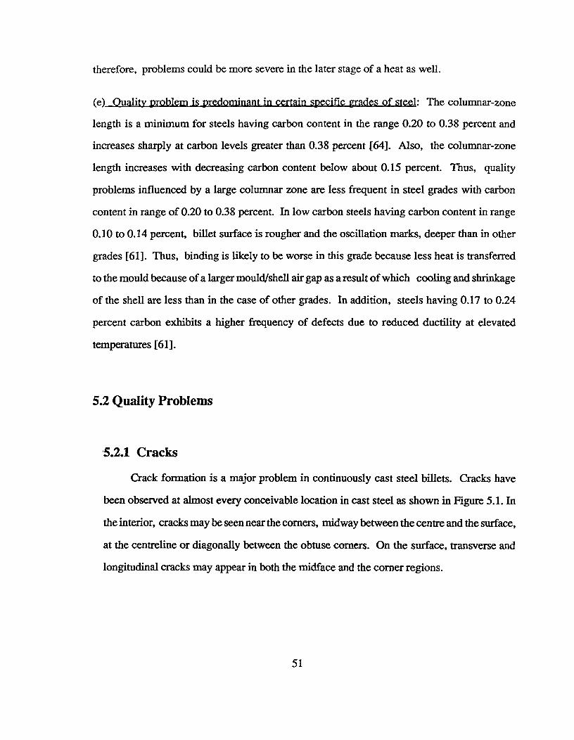
therefore, problems could be more severe in the later stage of a heat as well.
(e) Ouality problem is predominant in certain specific grades of steel: The columnar-zone
length is a minimum for steels having carbon content in the range 0.20 to 0.38 percent and
increases sharply at carbon levels greater than 0.38 percent [64]. Also, the columnar-zone
length increases with decreasing carbon content below about 0.15 percent. Thus, quality
problems influenced by a large columnar zone are less frequent in steel grades with carbon
content in range of 0.20 to 0.38 percent. In low carbon steels having carbon content in range
0.10 to 0.14 percent, billet surface is rougher and the oscillation marks, deeper than in other
grades [61]. Thus, binding is likely to be worse in this grade because less heat is transferred
to the mould because of a larger mould/shell air gap as a result of which cooling and shrinkage
of the shell are less than in the case of other grades. In addition, steels having 0.17 to 0.24
percent carbon exhibits a higher frequency of defects due to reduced ductility at elevated
temperatures [61].
5.2 Quality Problems
5.2.1 Cracks
Crack formation is a major problem in continuously cast steel billets. Cracks have
been observed at almost every conceivable location in cast steel as shown in Figure 5.1. In
the interior, cracks may be seen near the corners, midway between the centre and the surface,
at the centreline or diagonally between the obtuse corners. On the surface, transverse and
longitudinal cracks may appear in both the midface and the corner regions.
51
TRANSVERSE MIDFACE CRACK
RHOMBOIDBILLET
LONGITUDINAL MIDFACE CRACK
CRAZE CRACKSTRANSVERSE CORNER
CRACK
LONGITUDINALCORNER CRACK
DIAGONALCRACK
CENTRELINE CRACKMIDWAY CRACKSPINCH-ROLL CRACKS
OFF-CORNER INTERNAL CRACKS
Fig. 5.1^Schematic diagram of a rhomboid billet showing various types of cracks.
52
Another kind of surface cracking problem is craze cracks which are linked to high
copper levels in steel. The surface cracks pose a more serious problem than the internal
cracks because, they do not reweld during rolling and the crack surfaces oxidize giving rise
to oxide-rich seams in the rolled products. The internal cracks can also be a problem
particularly if during rolling, they do not close leaving voids in the steel products. The
mechanism for the formation of different cracks has been established in numerous studies,
most of which were reviewed by Brimacombe and Sorimachi [43]. Off-corner cracks were
studied by Brimacombe et al.[73] and Bommaraju et al.[64].
5.2.1.1 Internal Cracks
The internal cracks result from high tensile strains and stresses acting on regions of
the solid shell that are in the high temperature zone of low strength and ductility. They
are influenced by sulphur and phosphorus content of steel and the superheat level. Van
Drunen et al.[46] showed that the internal cracks are hot tears that initiate close to the
solidification front. Hence, the depth of the outer tip of an internal crack from the billet
surface directly reflects the local shell thickness at the time of its formation. On comparing
this with the solid shell thickness profile predicted by the heat-transfer mathematical model
for billet solidification, it is possible to ascertain where in the machine the crack originated.
The orientation of the crack gives the direction of tensile stress causing it as this stress is
normal to the direction of crack orientation.
The internal cracking problems in billet casting have been summarized in Tables
5.1 and 5.2.
53
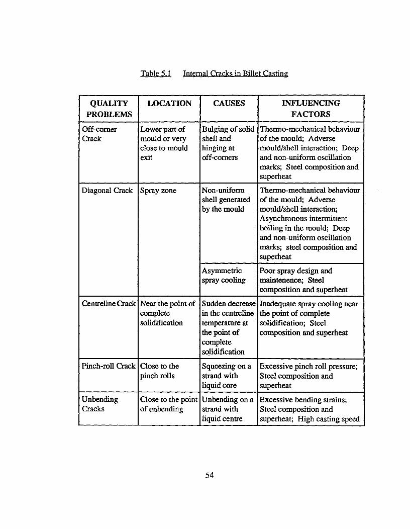
Table 5.1 Internalaacksasug'n
QUALITYPROBLEMS
LOCATION CAUSES INFLUENCINGFACTORS
Off-cornerCrack
Lower part ofmould or veryclose to mouldexit
Bulging of solidshell andhinging atoff-corners
Thermo-mechanical behaviourof the mould; Adversemould/shell interaction; Deepand non-uniform oscillationmarks; Steel composition andsuperheat
Diagonal Crack Spray zone Non-uniformshell generatedby the mould
Thermo-mechanical behaviourof the mould; Adversemould/shell interaction;Asynchronous intermittentboiling in the mould; Deepand non-uniform oscillationmarks; steel composition andsuperheat
Asymmetricspray cooling
Poor spray design andmaintenence; Steelcomposition and superheat
Centreline Crack Near the point ofcompletesolidification
Sudden decreasein the centrelinetemperature atthe point ofcompletesolidification
Inadequate spray cooling nearthe point of completesolidification; Steelcomposition and superheat
Pinch-roll Crack Close to thepinch rolls
Squeezing on astrand withliquid core
Excessive pinch roll pressure;Steel composition andsuperheat
UnbendingCracks
Close to the pointof unbending
Unbending on astrand withliquid centre
Excessive bending strains;Steel composition andsuperheat; High casting speed
54
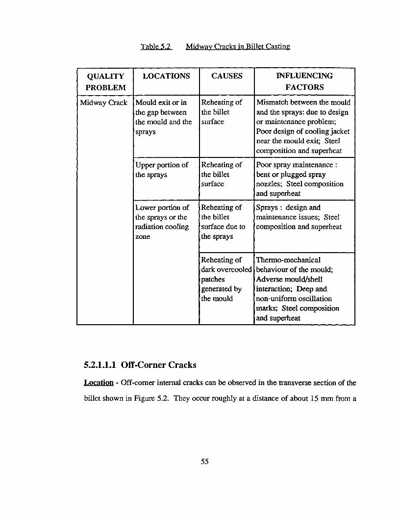
Table 5.2^Midway Cracks in Billet Casting
QUALITYPROBLEM
LOCATIONS CAUSES INFLUENCINGFACTORS
Midway Crack Mould exit or inthe gap betweenthe mould and thesprays
Reheating ofthe billetsurface
Mismatch between the mouldand the sprays: due to designor maintenance problem;Poor design of cooling jacketnear the mould exit; Steelcomposition and superheat
Upper portion ofthe sprays
Reheating ofthe billetsurface
Poor spray maintenance :bent or plugged spraynozzles; Steel compositionand superheat
Lower portion ofthe sprays or theradiation coolingzone
Reheating ofthe billetsurface due tothe sprays
Sprays : design andmaintenance issues; Steelcomposition and superheat
Reheating ofdark overcooledpatchesgenerated bythe mould
Thermo-mechanicalbehaviour of the mould;Adverse mould/shellinteraction; Deep andnon-uniform oscillationmarks; Steel compositionand superheat
5.2.1.1.1 Off-Corner Cracks
Location - Off-corner internal cracks can be observed in the transverse section of the
billet shown in Figure 5.2. They occur roughly at a distance of about 15 mm from a
55
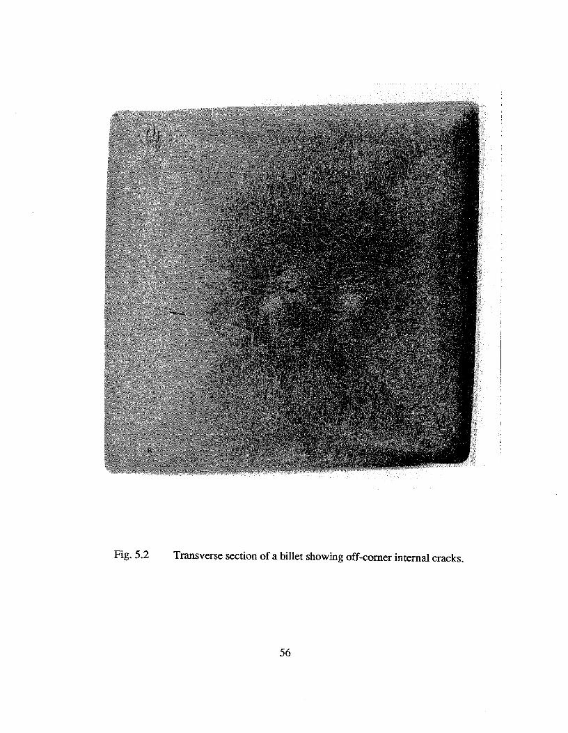
Fig. 5.2^Transverse section of a billet showing off-corner internal cracks.
56

given corner and 4 to 6 mm from the surface. These cracks appear randomly on any
one, or several, of the eight off-corner sites. The cracks may be seen together with
surface depressions and deep oscillation marks.
Mechanism of off-corner crack formation - The position of the outer tip of an
off-corner crack indicates whether the crack formed in the lower part of the mould or
near the mould exit. Brimacombe et al. [67] postulated that off-corner internal cracks
are generated by bulging of a given face of the billet in the lower part of the mould. It
was also proposed that bulging of the solid shell may not extend to the corner but can
hinge about the off-corner region. This hinging action generates a tensile strain at the
solidification front and leads to off-corner cracks. A schematic diagram illustrating this
mechanism is shown in Figure 5.3. Very often, the outer tips of the off-corner cracks
overlap with white bands. This suggests that both phenomena originate at the same time
as bulging of the shell. The bulging of the shell disturbs the interdendritic liquid and
creates these white bands [64].
Bommaraju et al.[64] linked the generation of off-corner cracks to the depth and
the uniformity of oscillation marks on the billet surface. In another study, Samarasekera
et al.[71] observed that the oscillation marks at the off-corner locations were deeper
than at the midface. Deep oscillation marks in the off-corner regions locally reduce the
heat extraction rate and the shell growth as the billet passes through the mould. In the
lower part of the mould where the mould/shell gap is large and the billet contraction
has virtually stopped, bulging can occur, particularly on faces having thin and weak
shells in the off-corner regions. The resultant hinging action then generates tensile
strains
57
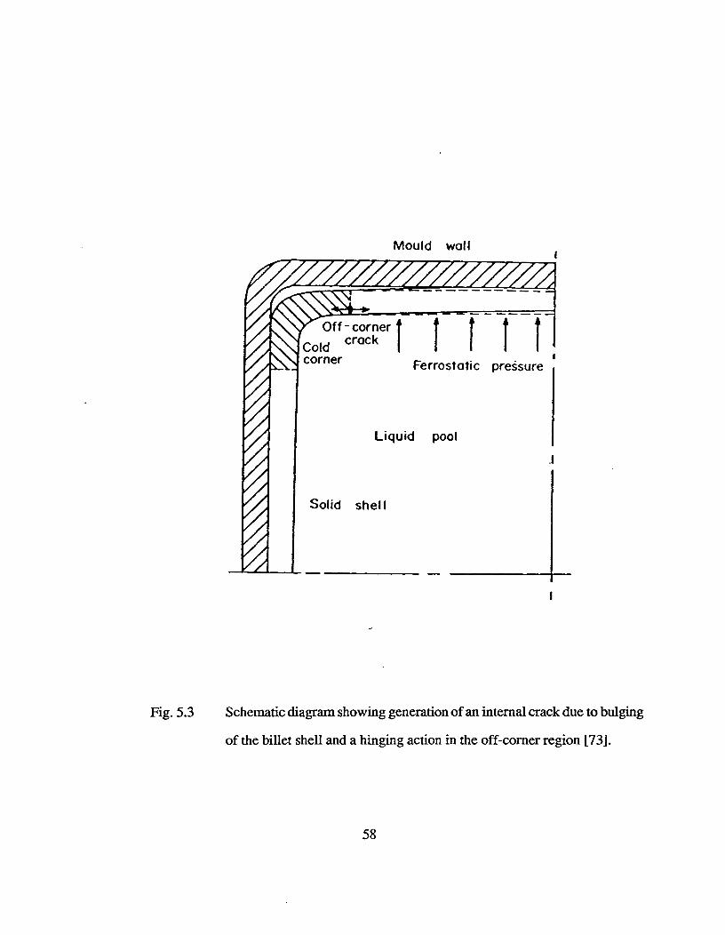
Coldcorner^Fe rrostati c preSsure
Liquid pool
Off - cornercrack (II
Solid shel l
Mould wall
Fig. 5.3^Schematic diagram showing generation of an internal crack due to bulging
of the billet shell and a hinging action in the off-corner region [73].
58
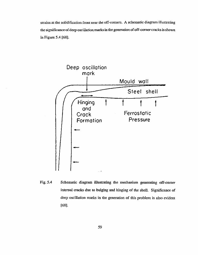
Mould wall
Hingingand
CrackFormation
.111.■••••
tFerrostatic
Pressure
strains at the solidification front near the off-corners. A schematic diagram illustrating
the significance of deep oscillation marks in the generation of off-corner cracks is shown
in Figure 5.4 [681
Deep oscillationmark
Fig. 5.4 Schematic diagram illustrating the mechanism generating off-corner
internal cracks due to bulging and hinging of the shell. Significance of
deep oscillation marks in the generation of this problem is also evident
[68].
59
Factors influencing ner cracking problem - Off-corner cracks result from
bulging of the solid shell. Hence, factors that increase the mould/shell gap will influence
bulging and affect the cracking problem. Off-corner cracking is also linked to the
formation of oscillation marks. Therefore, any variable that influences the moulcYshell
interaction near the meniscus will directly impact on the nature of oscillation marks,
and the cracks.
Mould taper that does not follow the billet shrinkage profile leads to a large
mould/shell gap which may cause a thin shell to bulge. Bulging is exacerbated by
thermally generated reverse taper and wear in the lower part of the mould. At the mould
exit, if the solid shell is thin and weak, bulging can occur. This can be prevented by
increasing the water flux in the upper sprays which will cool the strand and increase the
solid shell thickness. The formation of deep oscillation marks is linked in a complex
way to the thermo-mechanical behaviour of the mould tube during the process [71]. The
distortion of the mould (both elastic and plastic) together with the lubrication conditions
and the oscillation characteristics, govern the mould/shell interaction near the meniscus
and influence the nature of oscillation marks - depth and uniformity across the billet
surface. Off-corner cracks were randomly seen on the eight off-corner sites [64]. This
observation suggests that bulging of the shell is not localized to a single face. The
behaviour may be due to intermittent boiling in the mould cooling jacket, wobbling of
the mould system, poor setting of the foot-rolls or misalignment of the casting machine.
Casting speed is important as it influences the solid shell thickness. Increasing the
casting speed reduces the shell thickness in the mould, thereby exacerbating the tendency
for bulging of the shell. Since, the cracking phenomena is linked to dendritic separation,
a low Mn/S ratio will increases the severity of this problem [64].
60
5.2.1.1.2 Midway Cracks
Location - Midway cracks are also called radial streaks, halfway cracks and ghost lines.
They can be seen in the transverse section of the billet shown in Figure 5.5. They appear
as dark lines running normal to a given face in a region midway between the surface
and the centreline. As described earlier, the distance of the outer tip of the crack from
the billet surface can be utilized to determine where in the machine the crack formed.
It can occur close to the mould exit, in the gap between the mould and the sprays, in
the spray zone or in the radiation cooling zone.
Mechanism of midway crack formation - Midway cracks are caused by reheating of
the surface of the strand which causes the billet surface to expand [47]. This expansion
imposes a tensile strain on the interior, hotter regions of the solid shell which being
weaker, may crack. The stress distribution that results from reheating was calculated
using finite-element analysis by Grill et al.[74]. The stress distribution in the billet
clearly indicated relatively large tensile stresses parallel to the wide face near the
solidification front. In an another study, Brimacombe and Sorimachi [43] found that
the location of the high stress region corresponds closely to that of midway cracks seen
in the billet. Van Drunen et al.[46] postulated that midway cracks are hot tears which
form in the high temperature zone of low ductility. An examination of the inside surface
of an open midway crack viewed with a scanning electron microscope showed smooth
dendrite branches with no signs of deformation. This suggests the presence of a liquid
during the dendritic separation. This liquid is rich in sulphur and other elements with
a positive segregation coefficient.
61

Fig. 5.5^Transverse section of a billet showing midway cracks.
62
E Actors influencing midway cracks - Three conditions appear necessary for midway
crack formation: excessive reheating of the billet surface, the presence of a long
columnar zone and a low Mn/S ratio in the steel. Reheating of the billet surface generates
tensile stresses acting on the solid steel close to the solidification front. A columnar
structure provides easy paths for crack propagation. The Mn/S ratio directly impacts
on the high temperature strength and ductility of steel and the formation of liquid film
between the dendrites.
Surface reheating occurs when the billet experiences a sudden reduction in the
heat extraction rate after a period of excessive cooling. This may happen at the mould
exit, in the spray zone or at the end of the sprays. Reheating in the radiation cooling
zone occurs due to spray- and/or mould- related issues. If spray cooling is excessive
over a short length, the billet experiences a sudden reduction in the heat extraction rate
as it exits the sprays and enters the radiant cooling zone.
A reheating problem in the radiation zone has its origin in the mould if the billet
leaving the mould has dark and bright patches. The dark patches cool very rapidly in
the spray zone due to nucleate boiling. When the billet enters the radiation cooling zone,
these over-cooled regions on the billet surface begin to reheat excessively leading to
midway cracks. These patches indicate non-uniform cooling in the mould which is
related to the thermo-mechanical behaviour of the mould during operation. Hence,
factors related to mould distortion, oscillation mark formation, taper and lubrication
are important.
Reheating can occur near the mould exit if the distance of the first spray nozzle
from the bottom of the mould is large or if there is a mismatch between the heat fluxes
63
at the bottom of the mould and the first spray zone. Therefore, spray cooling at the
mould exit and the position of the first spray nozzle are critical parameters. When the
mould cooling jacket does not extend to the bottom of the mould, a drastic reduction
in the heat extraction rate is likely to occur.
Maintenance issues contribute to reheating if the spray nozzles are bent or blocked
as a result of which there is a sudden reduction in the heat extraction rate. Midway
cracks in the upper spray region occur due to this problem. This conclusion follows
from the logic that the mathematical model assumes ideal spray conditions and therefore
cannot predict a high reheat for the upper spray zone. The only cause, for the midway
cracks in this region are issues related to maintenance. Similarly, if midway cracks are
seen in the region between the mould and the sprays and if the reheat predicted by the
model for this zone is not high, it is very likely that issues related to spray maintenance
are a problem.
Factors such as superheat and carbon content of steel, machine design (straight
vs curved mould design) and section size are critical parameters influencing the columnar
structure in the billet. The presence of a sulphur-rich liquid film between the dendrites
leads to easy separation of the dendritic arms. A Mn/S ratio greater than 25 minimizes
the cracking problem by preventing the formation of a liquid film.
5.2.1.1.3 Diagonal Cracks
Location - Diagonal cracks run between the obtuse corners of a rhomboid section [43].
Sometimes these cracks may grow outwards towards the corners of the billet to form
longitudinal cracks depending on the magnitude of the strain and the thickness of the
64
solid shell.
Mechanism of diagonal crack formation - When two adjacent faces of a billet cool
more rapidly than the others, the billet contracts and generates a diagonal strain between
the colder faces. If this strain is large, the billet distorts and take on a rhomboid shape
with an acute angle between the colder faces and an obtuse angle between the hotter
ones. A crack may then initiate near the solidification front at right angles to the strain
axis which runs along the diagonal joining the obtuse angled corners.
Factors influencing diagonal cracks - Diagonal cracks result from the distortion of
the billet due to unsymmetrical cooling. This is an extreme case of rhomboidity and its
presence clearly indicates severe asymmetric cooling in the sprays and/or the mould.
Diagonal cracks are linked to mould cooling but the sprays are also definitely involved.
Non-uniform shell growth in the mould generates cracking strains along the diagonal
joining the hotter corners, even with a perfectly aligned and a uniform spray cooling
system.
Cooling conditions in the mould are very important from the viewpoint of shell
growth. The thermo-mechanical behaviour of the mould which influences the mould
shell interaction, directly impacts on the uniformity of heat extraction rates around the
billet periphery. Asynchronous intermittent boiling in the mould is also an important
phenomena leads to varying shell thickness around the billet periphery. Thus,
mould-distortion, oscillation, lubrication and taper are critical. The design tolerances
of the mould tube, liners (baffle-tubes) and support system are important since they
influence the augment of the mould-tube.
65
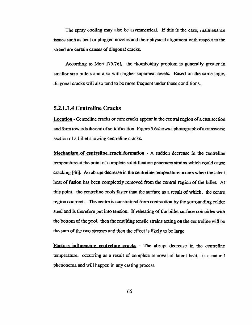
The spray cooling may also be asymmetrical. If this is the case, maintenance
issues such as bent or plugged nozzles and their physical alignment with respect to the
strand are certain causes of diagonal cracks.
According to Mori [75,76], the rhomboidity problem is generally greater in
smaller size billets and also with higher superheat levels. Based on the same logic,
diagonal cracks will also tend to be more frequent under these conditions.
5.2.1.1.4 Centreline Cracks
location - Centreline cracks or core cracks appear in the central region of a cast section
and form towards the end of solidification. Figure 5.6 shows a photograph of a transverse
section of a billet showing centreline cracks.
Mechanism of centreline crack formation - A sudden decrease in the centreline
temperature at the point of complete solidification generates strains which could cause
cracking [46]. An abrupt decrease in the centreline temperature occurs when the latent
heat of fusion has been completely removed from the central region of the billet. At
this point, the centreline cools faster than the surface as a result of which, the centre
region contracts. The centre is constrained from contraction by the surrounding colder
steel and is therefore put into tension. If reheating of the billet surface coincides with
the bottom of the pool, then the resulting tensile strains acting on the centreline will be
the sum of the two stresses and then the effect is likely to be large.
factors influencing centreline cracks - The abrupt decrease in the centreline
temperature, occurring as a result of complete removal of latent heat, is a natural
phenonema and will happen in any casting process.
66
Fig. 5.6^Transverse section of a billet showing centreline cracks.
67

The severity of this problem, however, can be reduced by minimizing the
difference in the cooling rates between the surface and the centre. Brovman et al.r77]
suggested that centreline cracks could be suppressed by applying spray cooling at the
point of complete solidification.
When surface reheating coincides with the point of complete solidification, it is
first necessary to isolate the two phenonema and then take appropriate steps to eliminate
them. Reheating can be suppressed, as was suggested for midway cracking, by adequate
spray design and also by eliminating the dark and bright patches on the billet surface at
the mould exit. Spray design to minimize the stresses below the liquid pool has been
studied by Grill et al.f78J.
5.2.1.1.5 Pinch-roll Cracks
Location - Pinch roll cracks can be seen on a sulphurprint of a longitudinal or a transverse
section of a billet. They are very similar to midway cracks in their appearance except
that they always appear normal to the faces parallel to the axis of the pinch-rolls.
Mechanism of pinch-roll crack formation - The application of excessive pinch-roll
pressure on a strand having a liquid core or with its centreline above 1340 °C, causes
cracking by dendritic separation in the high temperature zone of low ductility [43].
factors influencing pinch-rolls cracks - The positioning of the pinch-rolls is a critical
factor from the viewpoint of crack formation as it is necessary to avoid squeezing on a
liquid centre. A safe location for the pinch-rolls can be predicted based on the model
calculation of liquid pool depth. The cracking severity depends on the magnitude of
the pressure exerted by the pinch-rolls on the liquid core. Therefore, reduction of the
68

roll pressure decreases the tensile stresses and hence minimizes cracking. Like any
internal cracks, pinch-roll cracks are hot tears and therefore are influenced by the extent
of the columnar structure and also by the high temperature mechanical properties of
steel. Hence, superheat and steel composition are important.
5.2.1.2 Surface Cracks
Surface cracks discussed in this section include transverse cracks (and depressions),
longitudinal midface and corner cracks and craze cracks. A summary of these cracks are
provided in Table 5.3.
5.2.1.2.1 Transverse Cracks (and depressions)
mcation - Transverse cracks are usually seen at the midface or near the corners on the
billet surface. Figure 5.7 is a photograph of a billet showing transverse depressions.
Transverse depressions may or may not have a crack at their base. In the case of a
depression without a surface crack, if a longitudinal section of the billet across the
depression is observed, an internal crack will be seen below the depression. Figure 5.8
is a photograph of a longitudinal section of a billet across a depression showing an
internal crack below it.
Mechanism of transverse crack (and depression) formation - Samarasekera and
Brimacombe [20] postulated that transverse cracks and depressions originate in the
mould. Due to sticking or binding of the billet in the mould, the withdrawal system
mechanically pulls the strand. The pulling action imposes a longitudinal tensile stress
on the shell as a result of which a transverse crack can form close to the solidification
69
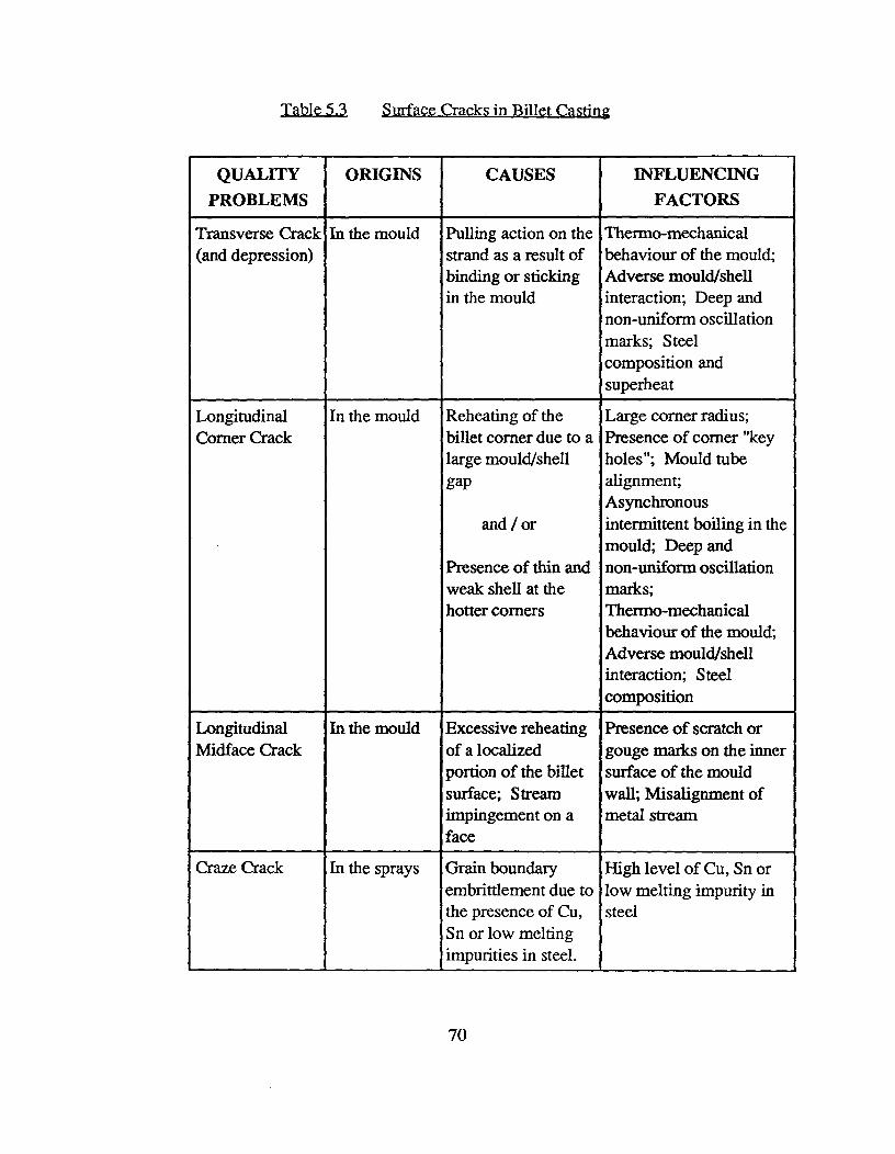
Table 5.3^Surface Cracks in Billet Casting
QUALITYPROBLEMS
ORIGINS CAUSES INFLUENCINGFACTORS
Transverse Crack(and depression)
In the mould Pulling action on thestrand as a result ofbinding or stickingin the mould
Thermo-mechanicalbehaviour of the mould;Adverse mould/shellinteraction; Deep andnon-uniform oscillationmarks; Steelcomposition andsuperheat
LongitudinalCorner Crack
In the mould Reheating of thebillet corner due to alarge mould/shellgap
and / or
Presence of thin andweak shell at thehotter corners
Large corner radius;Presence of corner "keyholes"; Mould tubealignment;Asynchronousintermittent boiling in themould; Deep andnon-uniform oscillationmarks;Thermo-mechanicalbehaviour of the mould;Adverse mould/shellinteraction; Steelcomposition
LongitudinalMidface Crack
In the mould Excessive reheatingof a localizedportion of the billetsurface; Streamimpingement on aface
Presence of scratch orgouge marks on the innersurface of the mouldwall; Misalignment ofmetal stream
Craze Crack In the sprays Grain boundaryembrittlement due tothe presence of Cu,Sn or low meltingimpurities in steel.
High level of Cu, Sn orlow melting impurity insteel
70
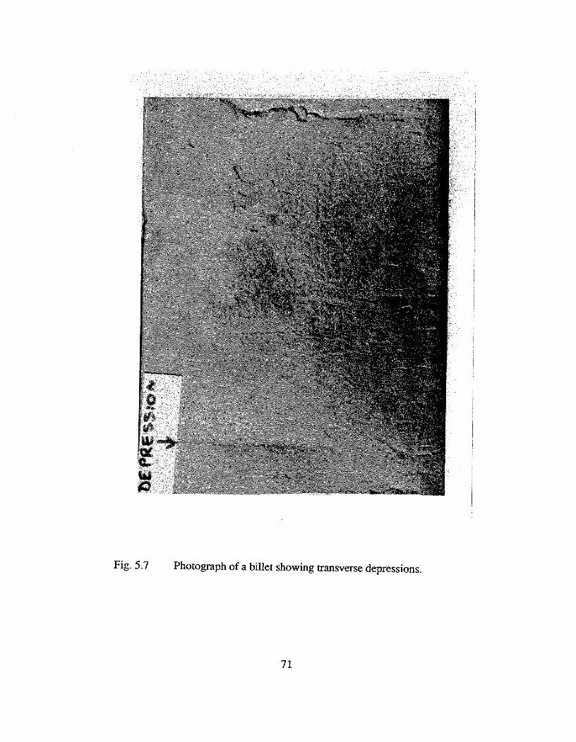
Fig. 5.7^Photograph of a billet showing transverse depressions.
71
front where the ductility is extremely small. The surface of the billet is in the temperature
range 1150 to 1430°C and therefore has a high ductility [42,43]. Depending on the
magnitude of the stress, the solid shell may flow plastically and form a depression on
the billet surface. This mechanism is similar to necking in tensile testing. Figure 5.9
is a schematic diagram illustrating this mechanism. The internal crack, depending on
the solid shell thickness at the time of its formation, as well as the extent of necking,
may penetrate to the surface.
Transverse crack formation is linked to the nature of oscillation marks. In an
earlier study [64], it was found that the obtuse angle corners of rhomboid billets have
deeper oscillation marks than the acute angled corners. This suggests that the
obtuse-angled corners are hotter than the acute angled corners due to lower heat transfer
arising from a larger mould/shell gap. The colder corners having shallower oscillation
marks tend to be in closest contact with the mould. The billet can bind in the mould at
these corners and develop large axial stresses during the withdrawal of the strand.
Depending on the magnitude of the force, transverse cracks may form at these corners.
Factors influencing transverse cracks (and depressions) - Transverse defects are
linked to sticking and/or binding of the billet in the mould. They are also related to the
nature of the oscillation marks. Hence, the thermo-mechanical behaviour of the mould
and the mould/shell interaction at the meniscus as well as away from it are critical.
Hence, design and operating variables influencing mould distortion, lubrication,
oscillation characteristics and taper are important parameters.
72
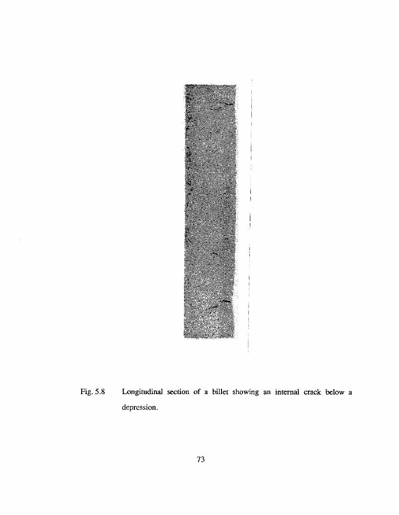
Fig. 5.8^Longitudinal section of a billet showing an internal crack below a
depression.
73
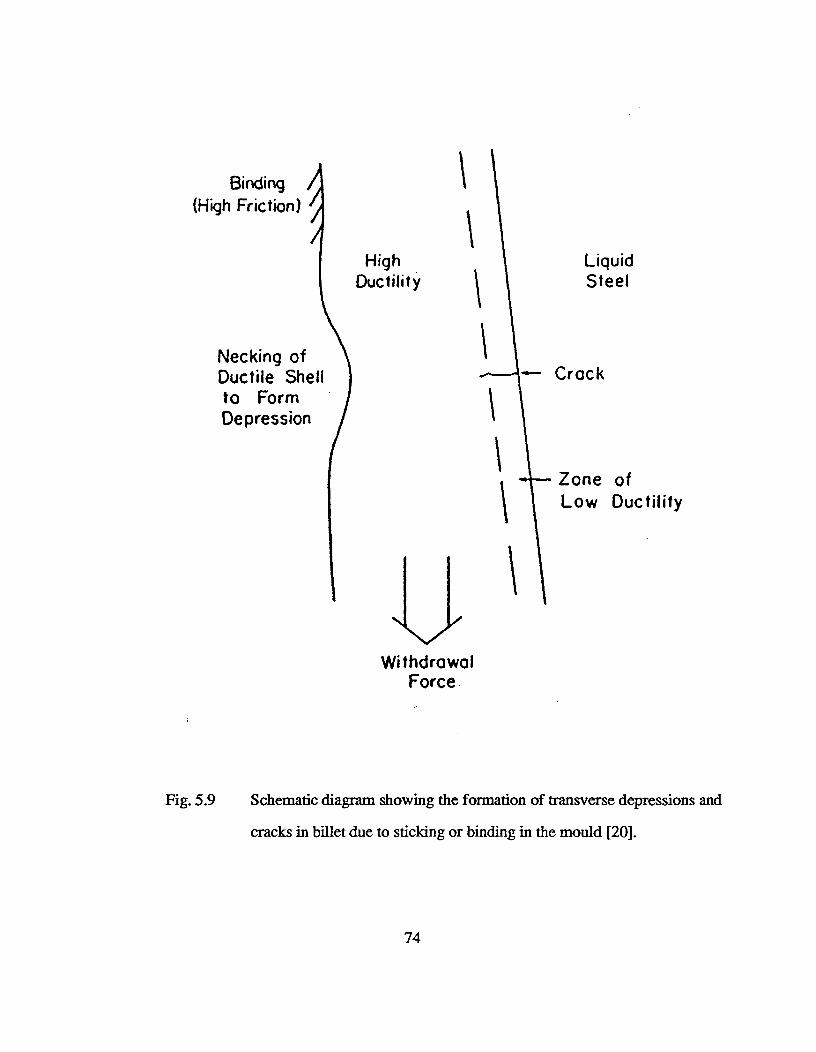
Binding(High Friction)
HighDuctility
LiquidSteel
— CrackNecking ofDuctile Shellto FormDepression
Zone ofLow Ductility
N./
WithdrawalForce
Fig. 5.9^Schematic diagram showing the formation of transverse depressions and
cracks in billet due to sticking or binding in the mould [20].
74
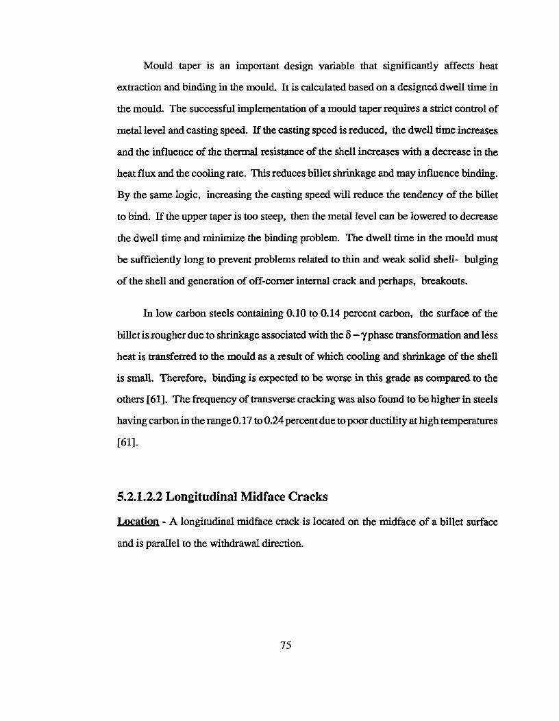
Mould taper is an important design variable that significantly affects heat
extraction and binding in the mould. It is calculated based on a designed dwell time in
the mould. The successful implementation of a mould taper requires a strict control of
metal level and casting speed. If the casting speed is reduced, the dwell time increases
and the influence of the thermal resistance of the shell increases with a decrease in the
heat flux and the cooling rate. This reduces billet shrinkage and may influence binding.
By the same logic, increasing the casting speed will reduce the tendency of the billet
to bind. If the upper taper is too steep, then the metal level can be lowered to decrease
the dwell time and minimize the binding problem. The dwell time in the mould must
be sufficiently long to prevent problems related to thin and weak solid shell- bulging
of the shell and generation of off-corner internal crack and perhaps, breakouts.
In low carbon steels containing 0.10 to 0.14 percent carbon, the surface of the
billet is rougher due to shrinkage associated with the 8 — ?phase transformation and less
heat is transferred to the mould as a result of which cooling and shrinkage of the shell
is small. Therefore, binding is expected to be worse in this grade as compared to the
others [61]. The frequency of transverse cracking was also found to be higher in steels
having carbon in the range 0.17 to 0.24 percent due to poor ductility at high temperatures
[61].
5.2.1.2.2 Longitudinal Midface Cracks
Location - A longitudinal midface crack is located on the midface of a billet surface
and is parallel to the withdrawal direction.
75
Mechanism of longitudinal midface crack formation - The mechanism of longitudinal
midface cracking problem in billet casting is related to the presence of some scratch or
gouge marks on the mould wall which locally increases the mould/shell gap adjacent
to it. This leads to a drastic drop in the heat extraction rate over a small localized region
on the billet surface. This area reheats and expands as the surface temperature approaches
the high temperature zone of low ductility. The colder steel surrounding it prevents this
expansion and results in the generation of tensile stresses at the solidification front which
ultimately leads to cracking. Longitudinal midface cracks tends to form more easily
where the air-gap resistance dominates the heat extraction rate (i.e. near the meniscus).
Longitudinal midface cracks can also form due to stream impingement on a face due to
cocked or misaligned stream.
Factors influencing longitudinal midface cracks - Scratches, gouge marks or any
defect present on the inside wall of the mould that increase the air gap resistance over
a localized area on the billet surface will influence the formation of longitudinal midface
crack. Misalignment of the metal stream is also an important issue.
5.2.1.2.3 Longitudinal Corner Cracks
Location - These cracks directly appear on the hotter, obtuse corners of the billet.
Mechanism of longitudinal corner crack formation - Longitudinal corner cracking
originates in the mould. Two mechanisms have been proposed for this problem. The
first mechanism is based on the formation of a large mould/shell gap near the corners
which forces the billet surface to reheat to temperatures approaching the high
temperature zone of low ductility. The tensile stresses generated due to thermal
76
shrinkage and ferrostatic pressure lead to cracking if the ductility of steel above 1340°C
is exceeded [79 - 81]. Figure 5.10 is a schematic diagram illustrating this mechanism
of formation of longitudinal corner cracks. The second mechanism is linked to
rhomboidity and thus, to the formation of oscillation marks on the billet surface [61].
It was observed that corners with deeper oscillation marks are hotter at the mould exit.
The presence of deep oscillation marks lead to the formation of a large mould/shell air
gap which reduced the rates of heat extraction and solidification.
Therefore, at the hotter corners, the shell tends to be thin and weak. Further,
contraction of the cooling faces generates tensile strains in the transverse direction.
Depending on the magnitude of this strain, cracks may initiate near the solidification
front and penetrate the solid shell as a longitudinal corner crack.
Factors influencing longitudinal corner cracks - Longitudinal corner cracking has
been observed in moulds with large corner radius, usually more than 4 mm. Sometimes
key-hole effects at the mould corners can also generate conditions for the formation of
longitudinal corner cracks. Asynchronous intermittent boiling in the cooling water
channel can also generate longitudinal corner cracks on the billet surface as it leads to
rhomboid mould distortion, which varies with time as boiling events change
asynchronously on different faces and causes non-symmetrical cooling of the billet due
to the changing air-gap width [22]. In addition, since the longitudinal corner crack is
also linked to the nature of oscillation marks on the billet surface, its formation is related
to the thermo-mechanical behaviour of the mould and to the nature of mould/shell
interaction. Factors related to the mould (distortion, oscillation, lubrication and taper)
are critical.
77
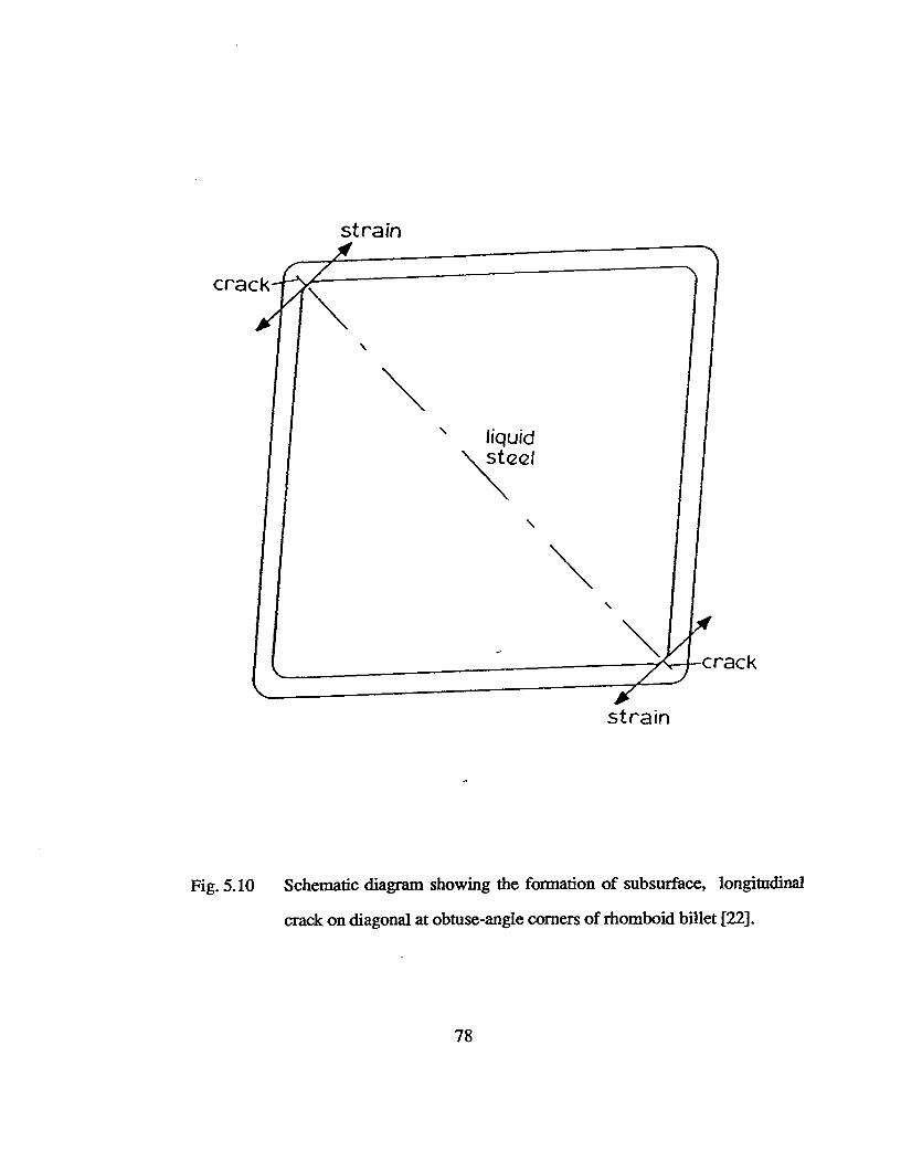
strain
strain
Fig. 5.10 Schematic diagram showing the formation of subsurface, longitudinal
crack on diagonal at obtuse-angle corners of rhomboid billet [22].
78

5.2.1.2.4 Craze Cracks
Craze cracks appear as a fine interwoven network of cracks as shown in Figure
5.11. These are caused by grain boundary embrittlement. It is difficult to spot craze
cracks on the billet surface during normal inspection. However, etching of the surface
with a hot acid can reveal the presence of craze cracks. Craze cracks appear as fine
striations on final rolled products such as wire-rods and ribbed-bars.
It is believed that craze cracks are related to the presence of impurities with low
melting point such as copper, tin and antimony in the steel. The mechanism of craze
cracking, though not well established, appears to be linked in some way to the
enrichment of the low melting point elements as a result of surface oxidation of the billet
[72]. The high temperature oxidation of steel results in the formation of iron oxide
scales. Copper being nobler than iron remains unoxidized and is concentrated at the
steel/oxide interface [82]. Since the oxidation rate of iron is high and the time for back
diffusion of copper is insufficient, the solubility of copper in austenite is exceeded. A
molten copper-rich phase forms at the scale/steel interface and penetrates into cracks at
the surface and along the grain boundaries [82]. In the sprays, cooling of the billet
results in thermal strains which generate cracks along the grain boundaries embrittled
by the molten phase.
It has been observed that the presence of nickel in the steel reduces the frequency
of craze cracking. Copper levels below 0.2 percent [72] or Ni/Cu ratio greater than 1.0
are helpful in reducing the severity of this problem [82]. Two theories have been
proposed for the beneficial role of nickel in steels containing copper [82]. The first is
related to the fact that nickel increases the solubility of copper in austenite. The second
79
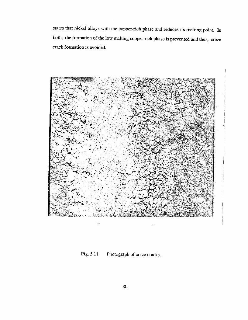
1
states that nickel alloys with the copper-rich phase and reduces its melting point. In
both, the formation of the low melting copper-rich phase is prevented and thus, craze
crack formation is avoided.
Fig. 5.11^Photograph of craze cracks.
80

5.2.2 Rhomboidity
Severely rhomboid billets pose problems in pusher-type reheat furnaces and also during
rolling where the corners may fold over and generate seams in the final product. In square
billets, the term "off-squareness" is often used whereas in rounds, this problem is called
"ovality". The difference between the lengths of the two diagonals is a measure of the severity
of this problem. In rounds, the difference between the longest and the shortest diameters is
used to indicate ovality. An upper limit imposed by the rolling mills for this difference is in
the region of 6 mm. Table 5.4 is a summary of rhomboidity- mechanisms and influencing
factors.
Table 5.4^Rhomboidity Problem in Billet Casting.
QUALITYPROBLEM
ORIGINS CAUSES INFLUENCINGFACTORS
Rhomboidity In the mould Non-uniform shell Thermo-mechanicaland/or the generated in the behaviour of mould;sprays mould
..
Adverse mould/shellinteraction; Asynchronousintermittent boiling in themould; Deep andnon-uniform oscillationmarks; Mould-tubealignment; Steel superheat
In the sprays Asymmetric spraycooling
Poor spray design andmaintenence; Steelsuperheat
Mechanism of rhomboidity - The mechanism for the generation of rhomboidity, like
off-corner cracking involves oscillation mark formation and non-uniform heat extraction in
81
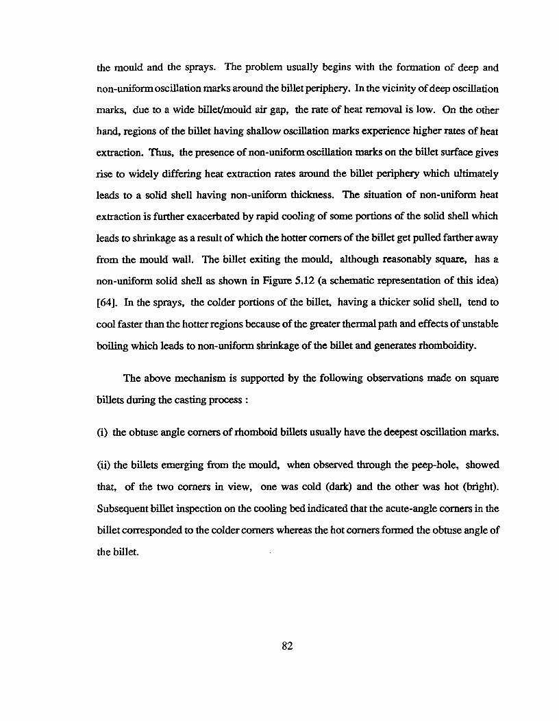
the mould and the sprays. The problem usually begins with the formation of deep and
non-uniform oscillation marks around the billet periphery. In the vicinity of deep oscillation
marks, due to a wide billet/mould air gap, the rate of heat removal is low. On the other
hand, regions of the billet having shallow oscillation marks experience higher rates of heat
extraction. Thus, the presence of non-uniform oscillation marks on the billet surface gives
rise to widely differing heat extraction rates around the billet periphery which ultimately
leads to a solid shell having non-uniform thickness. The situation of non-uniform heat
extraction is further exacerbated by rapid cooling of some portions of the solid shell which
leads to shrinkage as a result of which the hotter corners of the billet get pulled farther away
from the mould wall. The billet exiting the mould, although reasonably square, has a
non-uniform solid shell as shown in Figure 5.12 (a schematic representation of this idea)
[64]. In the sprays, the colder portions of the billet, having a thicker solid shell, tend to
cool faster than the hotter regions because of the greater thermal path and effects of unstable
boiling which leads to non-uniform shrinkage of the billet and generates rhomboidity.
The above mechanism is supported by the following observations made on square
billets during the casting process :
(i) the obtuse angle corners of rhomboid billets usually have the deepest oscillation marks.
(ii) the billets emerging from the mould, when observed through the peep-hole, showed
that, of the two corners in view, one was cold (dark) and the other was hot (bright).
Subsequent billet inspection on the cooling bed indicated that the acute-angle corners in the
billet corresponded to the colder corners whereas the hot corners formed the obtuse angle of
the billet.
82
.■•^■.."^ ■
..0"^ ■I'^ ■
5%,,,^ ."-.....
■...."■
'Nei
UpperSprays
Off-squarebillet containingoff-cornerinternal cracks
Fig. 5.12 Schematic diagram showing a billet with non-uniform shell thickness being
distorted into rhomoid shape by spray cooling [64].
83

Asynchronous intermittent boiling in the cooling water channel has also been linked
to the generation of rhomboidity in the billet [22]. It is proposed that mould distortion varies
with time as the boiling events change asynchronously on different faces and causes
non-symmetrical cooling of the billet due to the changing air-gap width. The orientation and
severity of rhomboidity varies during the heat due to this phenomenon and so, supports the
above mechanism. Further, this observation is useful as it can be used to distinguish
rhomboidity due to asynchronous intermittent boiling from that caused by other factors such
as machine alignment, wobbly mould oscillation, or poor spray cooling. In the absence of
any mould effects, rhomboidity must be caused by asymmetric spray cooling.
Factors influencing rhomboidity - Since rhomboidity is linked to deep and non-uniform
oscillation marks on the billet surface, factors related to the thermo-mechanical behaviour
of the mould and the nature of mould/shell interaction are critical. Hence, mould distortion,
taper, oscillation characteristics and lubrication parameters are important. Factors such as
tolerances with respect to the water gap, mould tube alignment and the nature of the mould
constraint system also need special attention.
Even though the mould generates rhomboidity, the difference between the lengths of
billet diagonals at the mould exit is small. This is expected since the rhomboidity in the billet
at the mould exit cannot exceed the rhomboidity of the mould. The degree of rhomboidity
can then increase significantly as the billet moves through the spray cooling zone. However,
the contribution of the mould to generate a non-uniform shell and therefore rhomboidity, is
quite significant. Hence, mould parameters (operating, design and maintenance) are
extremely critical. When rhomboidity is caused by asynchronous intermittent boiling and
mould-distortion, simple suppression of the boiling phenomena can help to minimize the
84

problem. In this case, factors influencing asynchronous boiling such as cooling water
velocity, non-uniform scale deposition on the cold wall of the mould, surface roughness
and mould design parameters such as wall thickness and support system are critical.
Spray cooling influences rhomboidity in two ways. First, it acts on the non-uniform
shell generated by the mould and further aggravates non-uniformg heat extraction, uneven
shell growth and the rhomboidity problem. Thus, when the mould effects are present, the
sprays influence rhomboidity under all circumstances- whether symmetric or asymmetric.
However, when the spray cooling is symmetric, the mould is the only cause of rhomboidity.
Second, in the absence of any adverse mould effects, asymmetric spray cooling gives rise
to rhomboidity. Non-uniform spray cooling is usually a maintenance problem and occurs
due to plugged or bent nozzles and poorly positioned spray risers.
5.2.3 Breakouts
Breakouts occur when there is a rupture of the solid shell as a result of which molten
metal flows out. This is a serious problem as it not only hampers productivity but is also a
hazard. Table 5.5 is a summary of factors influencing breakouts.
Mechanism of breakouts - Breakouts are linked to the presence of a thin and weak solid
steel shell at the mould exit. The shell may be thin at localized regions or all around the
billet periphery. The presence of cracks may also lead to breakouts, particularly if the cracks
act as stress concentration sites and aid the rupture of the shell.
The mechanism by which thin shells are generated over localized regions in the billet
is based on the formation of a large mould/billet air gap that reduces the rate of heat extraction
and retards the shell growth. These thin regions of the shell tend to be hotter as compared
85
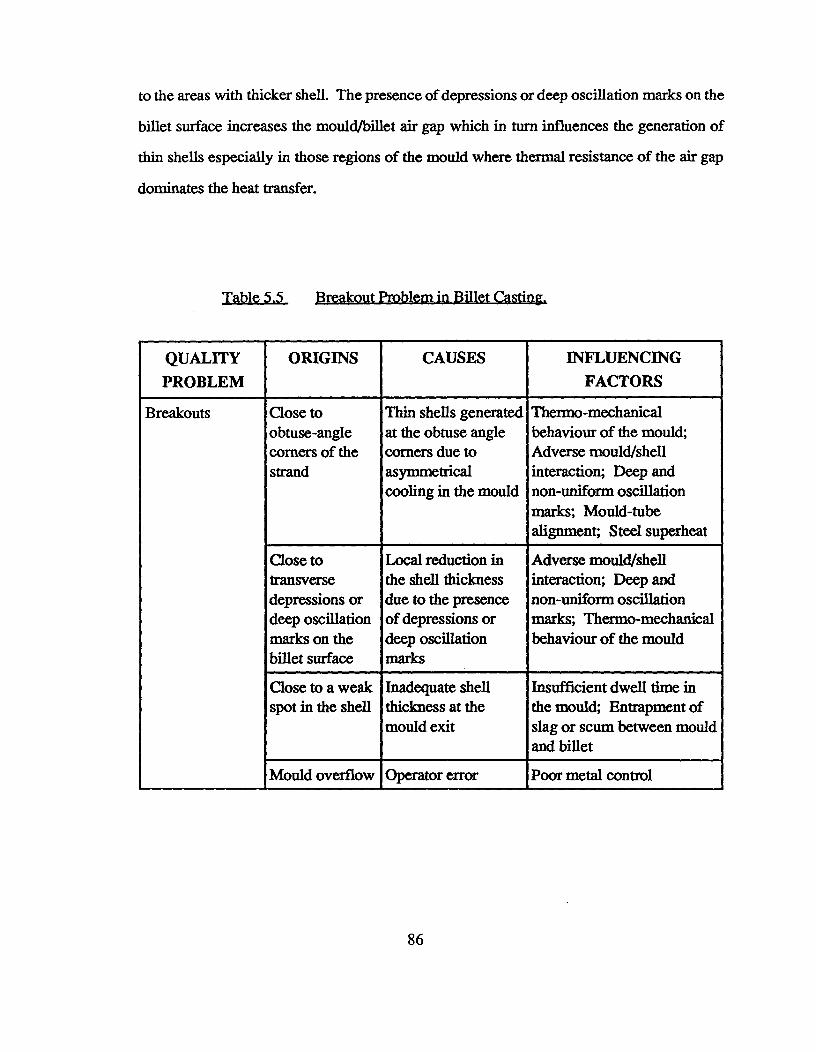
to the areas with thicker shell. The presence of depressions or deep oscillation marks on the
billet surface increases the mould/billet air gap which in turn influences the generation of
thin shells especially in those regions of the mould where thermal resistance of the air gap
dominates the heat transfer.
Table 5.5^$reakout Problem in Billet Casting.
QUALITYPROBLEM
ORIGINS CAUSES INFLUENCINGFACTORS
Breakouts Close toobtuse-anglecorners of thestrand
Thin shells generatedat the obtuse anglecorners due toasymmetricalcooling in the mould
Thermo-mechanicalbehaviour of the mould;Adverse mould/shellinteraction; Deep andnon-uniform oscillationmarks; Mould-tubealignment; Steel superheat
Close totransversedepressions ordeep oscillationmarks on thebillet surface
Local reduction inthe shell thicknessdue to the presenceof depressions ordeep oscillationmarks
Adverse mould/shellinteraction; Deep andnon-uniform oscillationmarks; Thermo-mechanicalbehaviour of the mould
Close to a weakspot in the shell
Inadequate shellthickness at themould exit
Insufficient dwell time inthe mould; Entrapment ofslag or scum between mouldand billet
Mould overflow Operator error Poor metal control
86

Breakouts in billet casting have been evaluated by Samarasekera and Brimacombe
[83]. The results of this study indicate that breakouts occur close to transverse depressions
(with cracks) and also very close to the obtuse corners which are hotter and have a thinner
solid shell. This finding supports the above mechanism quite adequately.
Breakouts have also been related to the entrapment of a scum between the steel and
the mould-wall. This leads to the formation of an extremely thin shell adjacent to it. Once
outside the mould system, it is possible that this region of the shell may rupture and cause
breakouts. Mould-overflow which is mainly an operator error may also cause breakouts.
Factors influencing breakouts - Breakouts are directly linked to the nature of shell growth
which are further related to the characteristics of the oscillation marks. The formation of
oscillation marks is related to the thermo-mechanical behaviour of the mould and to the
nature of mould/shell interaction. In the above study, Samarasekera and Brimacombe [83]
related breakouts to sticking in the mould, caused by poor mould lubrication, which results
in the formation of transverse depressions (and cracks) and also to non-uniform cooling
which cause the development of hot and thin corners. Therefore, factors influencing mould
distortion, taper, lubrication parameters and oscillation characteristics are important issues.
Factors causing breakouts can be identified by examining the breakout shells. When
breakouts occurs close to transverse depressions (with cracks), it suggests strong linkages
with the mechanisms involving transverse depressions. Hence, sticking in the mould due
to poor lubrication or due to poor stripping action are important. In other situations when
breakouts occurs close to the obtuse-angled corners, non-uniform cooling becomes a key
issue. Non-uniform cooling arises from mould-tube misalignment, poor tolerances or design
87
parameters. It can also be related to deep and non-uniform oscillation marks. Higaki et
al.[84] suggested that in billet casting, breakouts can be minimized by effective lubrication
and by maintaining proper mould alignment.
The dwell time in the mould is an important parameter which must be selected so that
the shell thickness at the bottom of the mould is sufficient to counter the ferrostatic pressure
exerted by the liquid core. Dean [85] has emphasized the importance of using an optimum
mould length. This is because a mould that is too short will result in a thin shell, whereas
excessively long moulds give rise to a higher frequency of breakouts from corners, through
cracks which occur during resetting by the roller apron. The dwell time in the mould can be
also be controlled by changing the position of the metal level or by changing the casting
speed. Metal level fluctuations, by influencing mould lubrication, dwell time and casting
speed, indirectly affect the nature of oscillation marks and therefore, breakout problems.
Proper metal level control has been proposed to minimize breakouts [84,86].
5.3 Other Observations
Observations made during casting can be used to focus the diagnosis, verify predictions
from the mathematical model and also keep a check on conflicting inputs provided for analysis.
Thus, they provide a means to integrate two kinds of, very diverse, expertise: fundamental
knowledge about the casting process and operating experience in the plant.
(a) Dark and bright patches on the billet surface at the mould exit : In the case of rhomboidity,
the billet emerging from the mould has bright and dark corners. The bright corners which are
thin and hot, become the obtuse-angled corners of the rhomboid billet. On the other hand, the
dark corners are colder and form the acute-angled corners. This indicates varying amounts of
88
solidification, due to non-uniform cooling around the billet periphery. Non-uniform cooling
conditions arise due to misaligned mould tube and/or non-uniform mould distortion. It could
also be related to non-uniform oscillation marks- deeper oscillation marks at the hotter corners.
In addition, the presence of dark and bright patches on the billet surface at mould exit can lead
to the formation of midway cracks. The dark patches which are overcooled regions on the billet
surface, tend to cool very rapidly in the spray zone due to nucleate boiling and later, reheat
excessively in the radiation zone.
(b) Scale deposits on the cold face of the mould : The presence of scale deposits on the cold
face of the mould wall indicates that the cooling water is contaminated. The colour of these
deposits is indicative of the nature of contamination. The uniformity of scale deposits around
the mould periphery is a check for misalignment and can be employed to assess the nature of
the cooling.
(c) Change in billet colour in the radiation zone : A change in the billet colour from dark red
in the spray zone to bright red in the radiation zone, is indicative of reheating of the billet
surface and is very likely to cause midway cracks in the billet. This information can be used
to verify the magnitude of reheat predicted by the mathematical model.
(d) Breakout shell : Breakouts can occur close to transverse depressions, cracks, deep
oscillation marks, laps, slag patches and even thin and hot billet corners. Examination of
breakout shells can be used to infer about the possible cause(s) of breakout.
(e) Condition of metal stream flowing into the mould : A ropey metal stream leads to excessive
gas entrainment in the liquid steel. In the mould, these gases escape from the metal surface
89
as bubbles creating turbulence and therefore, metal level variation. This is also indicative of
some deficiency in the tundish design with regards to controlling flow of metal to the inboard
and the outboard strands.
(f) Distribution of pinholes on the billet surface : The presence of more pinholes in some regions
of the billet as compared to others indicates hydrogen pick-up due to excessive lubricating oil
on that face. If this problem was related to liquid steel, it would have resulted in a uniform
distribution of pinholes on the billet surface. A deficiency in the lubrication system is indicative.
(g) Position of chromium layer discolouration in a used mould : This indicates the position of
the meniscus during the operation. This information can be used to cross check the metal level
during the operation and can be used to assess the efficiency of the metal level control system
in use.
90
CHAPTER 6 KNOWLEDGE ENGINEERING
6.1 Knowledge Acquisition
Knowledge acquisition consisted of four principal stages: identification/definition of the
problem, acquisition of background knowledge on continuous casting, development of the
expert system and testing and validation in the field. The system has not been put into actual
use and therefore the last two stages described in Chapter 3 are not applicable at the present
moment.
6.1.1 Identification/Definition of Problem Domain
The problem identification stage was driven by the experts who wanted a system to
help transfer their knowledge to industry. The experts defined the problem domain and the
need for an expert system to diagnose quality problems in continuously cast steel billets and
to train less experienced operating personnel. It was envisaged that the system could be used
as a consultant by users and so provide the experts with more time for other activities. Thus,
the problem modality was well-defined and the experts were ready and willing to participate
in the development process.
6.1.2 Background Knowledge on Continuous Casting
The experts provided the knowledge engineers with literature on continuous casting
of steel billets - operations, design and product quality. One of the knowledge engineers
attended a short course provided by the experts and their colleagues in Vancouver. This
established a practical understanding of the problem domain and helped considerably in
91
subsequent discussions with the experts during development. Buchanan et al. [2] have pointed
out that communication problems during knowledge acquisition can be severe when the
knowledge engineer has far less knowledge about the domain than the experts. In this work,
adequate steps were taken to ensure that this was not an issue.
An outline of quality problems, comprising the origin of defects, their causes of
formation and suggested remedies for prevention was prepared by the Knowledge Engineers.
This preliminary categorization have been summarized in Tables 5.1 to 5.5. Although these
tables contain the major elements of the knowledge domain, the methodology for diagnosis
is much more complex than a simple "look-up" table. With a desire for a system possessing
human-like thought and communication processes, considerable efforts was expended to
structure the actual approach used by the Experts in the analysis of quality problems.
6.1.3 Expert System Development
The problem domain consisting of cracks (internal and surface), rhomboidity and
breakouts was initially broken down into individual modules- each of which could be worked
on independently. Accordingly, the development process began with an examination of
midway cracking as this problem was considered to be simple and well-understood. The
Experts initiated the knowledge acquisition process by identifying that midway cracks were
caused by reheating of the billet surface. The focus then, was aimed at analysing spray-related
issues that are less complex than mould disorders. It quickly became apparent, however,
that poor mould operation could also contribute to midway cracks. In the end, midway
cracking turned out to be the most complicated problem from the viewpoint of diagnosis and
knowledge representation.
92
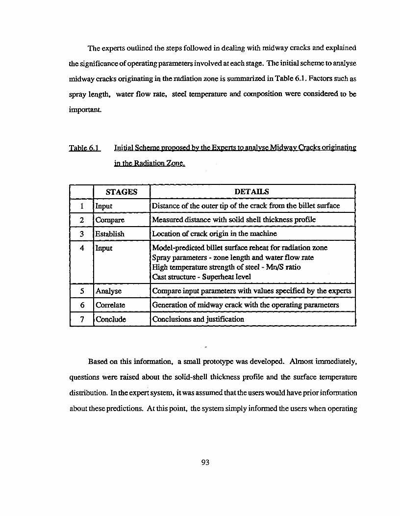
The experts outlined the steps followed in dealing with midway cracks and explained
the significance of operating parameters involved at each stage. The initial scheme to analyse
midway cracks originating in the radiation zone is summarized in Table 6.1. Factors such as
spray length, water flow rate, steel temperature and composition were considered to be
important.
Table 6.1 h
in the Radiation Zone.
STAGES DETAILS
1 Input Distance of the outer tip of the crack from the billet surface
2 Compare Measured distance with solid shell thickness profile
3 Establish Location of crack origin in the machine
4 Input Model-predicted billet surface reheat for radiation zoneSpray parameters - zone length and water flow rateHigh temperature strength of steel - Mn/S ratioCast structure - Superheat level
5 Analyse Compare input parameters with values specified by the experts
6 Correlate Generation of midway crack with the operating parameters
7 Conclude Conclusions and justification
Based on this information, a small prototype was developed. Almost immediately,
questions were raised about the solid-shell thickness profile and the surface temperature
distribution. In the expert system, it was assumed that the users would have prior information
about these predictions. At this point, the system simply informed the users when operating
93
parameters were high, low, or acceptable, and therefore, its usefulness was nothing more
than a check-list with input based on intuition rather than measurements or analysis. Thus,
the first stage of implementation was not very successful.
The knowledge base was reviewed and emphasis was re-focused on the consultation
process used to deal with a client rather than the actual details of the data. The system was
modified to provide conclusions and suggest remedial actions in the same way as the experts.
The knowledge base was re-structured to facilitate examination of all parameters in the
analysis. In addition, information for the users was incorporated into the system in the form
of explanations, screen-messages and rule-descriptions, using the user-interface facilities
of COMDALE/X. This approach was acceptable to the experts.
At this stage, the expert system was capable of handling only typical situations which
cause midway cracks to form - high reheat, high superheat and poor strength at high
temperature. The Experts were consulted on other situations where midway cracks might
be seen such as; when both spray and steel parameters were satisfactory, when only steel
parameters were satisfactory and when only spray parameters were satisfactory. The Experts
felt that it was impossible for midway cracks to form when both spray and steel parameters
were satisfactory. However, when a problem related to steel quality was evident but spray
parameters were satisfactory, the Experts believed that reheating must be related to a mould
disorder. Under these circumstances, the presence of dark and bright patches on the billet
surface at the mould exit would confirm a mould-related problem. These overcooled regions
can reheat excessively in the radiation zone, leading to midway cracks. Therefore, a major
expansion in the system was necessary to include knowledge dealing with mould
parameters (distortion, oscillation, taper and lubrication).
94
It was pointed out that the Users would not be in a position to predict surface reheat
levels and the solid shell thickness profile. A heat-transfer mathematical model for billet
solidification was developed to predict these profiles. The model uses operating parameters
as inputs and predicts solid shell thickness and maximum reheat temperatures at key locations
in the casting machine. The details about the mathematical model have been discussed earlier.
A typical output profile for a test situation is shown in Figure 6.1. Here, one-quarter of the
billet section was modelled using a 30 x 30 mesh and a time increment of 0.10 second.
Until this stage, the focus was on midway cracks originating in the radiation zone.
But these cracks can also originate in the spray zone and in the region between the mould
and the sprays (submould). It is difficult to visualize the origin of midway cracks in the spray
zone because cooling rates in this region are high and therefore, the billet surface is unlikely
to reheat. If midway cracks do originate in the spray zone, the Experts surmised that the
only factor which could influence surface reheating is poor spray maintenance- damaged or
blocked spray nozzles. The system was expanded to include the above situations. This
completed the prototype for midway cracks and the next problem was selected for
development.
It was pointed out by the Knowledge Engineer that more than one quality problem
might be observed at the same time. This meant that the plan to have a separate module for
each problem was inappropriate. There was need for a general strategy to handle any
combination of quality problems.
95
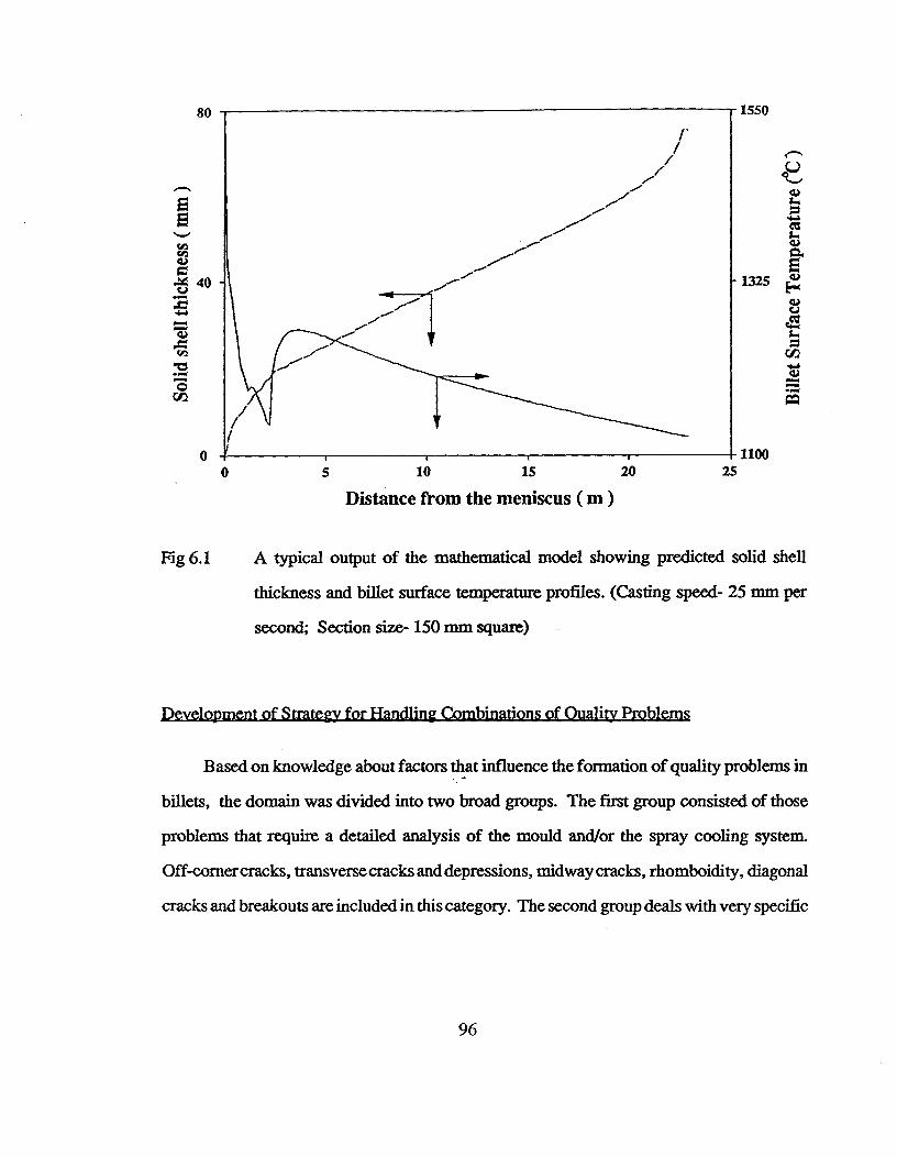
80
0
1-/
1550
1325
11000^5^10^15^20
Distance from the meniscus ( m )25
Fig 6.1^A typical output of the mathematical model showing predicted solid shell
thickness and billet surface temperature profiles. (Casting speed- 25 mm per
second; Section size- 150 mm square)
Development of Strategy for Handling Combinations of Quality Problems
Based on knowledge about factors that influence the formation of quality problems in
billets, the domain was divided into two broad groups. The first group consisted of those
problems that require a detailed analysis of the mould and/or the spray cooling system.
Off-corner cracks, transverse cracks and depressions, midway cracks, rhomboidity, diagonal
cracks and breakouts are included in this category. The second group deals with very specific
96
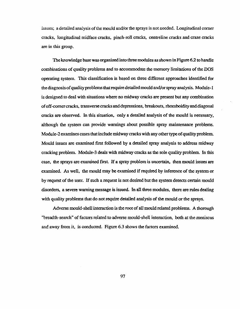
issues; a detailed analysis of the mould and/or the sprays is not needed. Longitudinal corner
cracks, longitudinal midface cracks, pinch-roll cracks, centreline cracks and craze cracks
are in this group.
The knowledge base was organized into three modules as shown in Figure 6.2 to handle
combinations of quality problems and to accommodate the memory limitations of the DOS
operating system. This classification is based on three different approaches identified for
the diagnosis of quality problems that require detailed mould and/or spray analysis. Module-1
is designed to deal with situations where no midway cracks are present but any combination
of off-corner cracks, transverse cracks and depressions, breakouts, rhomboidity and diagonal
cracks are observed. In this situation, only a detailed analysis of the mould is necessary,
although the system can provide warnings about possible spray maintenance problems.
Module-2 examines cases that include midway cracks with any other type of quality problem.
Mould issues are examined first followed by a detailed spray analysis to address midway
cracking problem. Module-3 deals with midway cracks as the sole quality problem. In this
case, the sprays are examined first. If a spray problem is uncertain, then mould issues are
examined. As well, the mould may be examined if required by inference of the system or
by request of the user. If such a request is not desired but the system detects certain mould
disorders, a severe warning message is issued. In all three modules, there are rules dealing
with quality problems that do not require detailed analysis of the mould or the sprays.
Adverse mould-shell interaction is the root of all mould related problems. A thorough
"breadth-search" of factors related to adverse mould-shell interaction, both at the meniscus
and away from it, is conducted. Figure 6.3 shows the factors examined.
97
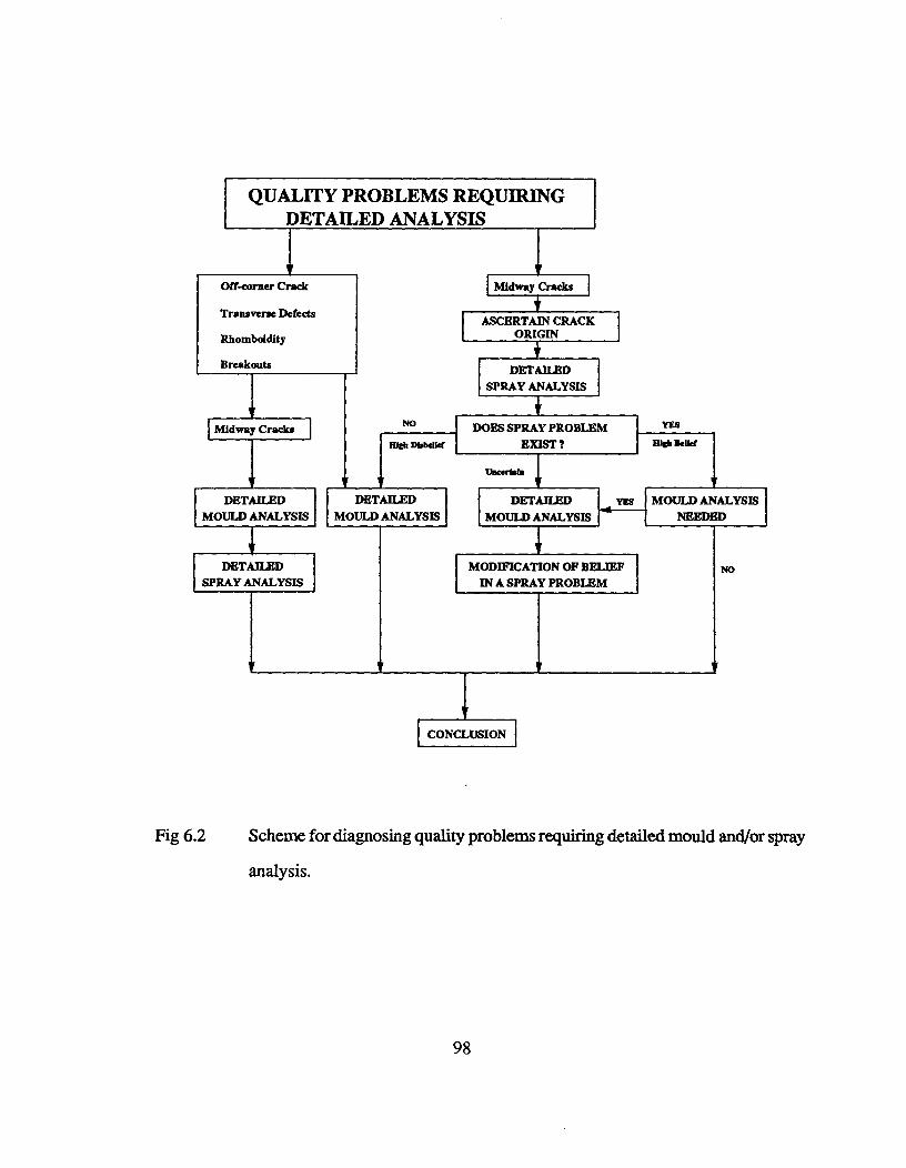
Midway Cracks
NO YES
illeb BeliefHigh Disbelief
Vacertale
DOES SPRAY PROBLEMEXIST ?
QUALITY PROBLEMS REQUIRINGDETAILED ANALYSIS
ASCERTAIN CRACKORIGIN
DETAILEDSPRAY ANALYSIS
Off-corner Crack
Transverse Defects
Rhomboidity
Breakouts
Midway Cracks
DETAILED DETAILED DETAILED MOULD ANALYSISMOULD ANALYSIS MOULD ANALYSIS MOULD ANALYSIS NEEDED
DETAILED MODIFICATION OF BELIEFSPRAY ANALYSIS IN A SPRAY PROBLEM
I CONCLUSION
Fig 6.2^Scheme for diagnosing quality problems requiring detailed mould and/or spray
analysis.
98
AWAY FROMMENISCUS
MOULD TAPER
ADVERSE MOULD-SHELLINTERACTION
AT MENISCUS
OSCILLATIONCHARACTERISTICS
MOULD DISTORTION
1: Cooling Water Velocity2: Cooling Water Quality3: Mould Tube Alignment4: Type of Mould Constraint5: Mould Wall Thickness6: Position of Metal Level7: Mould Copper8: Mould Design Tolerances
1: 011 Flowrate2: 011 Distribution3: OU-Phydcal Properties4: OU System Cleanliness5: Cleanliness ((Meniscus
Region6: Mould Cooling Water
Temperature
1: Negative Strip Time2: Mould Lead3: Nature of Oscillation Marks4: Metal Level Variation
MOULD LUBRICATION
Fig 6.3^A general outline of mould-related factors contributing to quality problems in
billet casting.
The important issues are mould-tube distortion, oscillation characteristics, mould
lubrication and taper. Mould-tube distortion is related to cooling water quality and velocity,
the nature of the mould constraint system, copper composition, wall thickness, metal level,
tube alignment and design tolerances [68]. The analysis of oscillation characteristics involves
evaluation of negative strip time, mould lead and the nature of oscillation marks - depth
and uniformity across the billet surface. Important parameters dealing with lubrication in
99
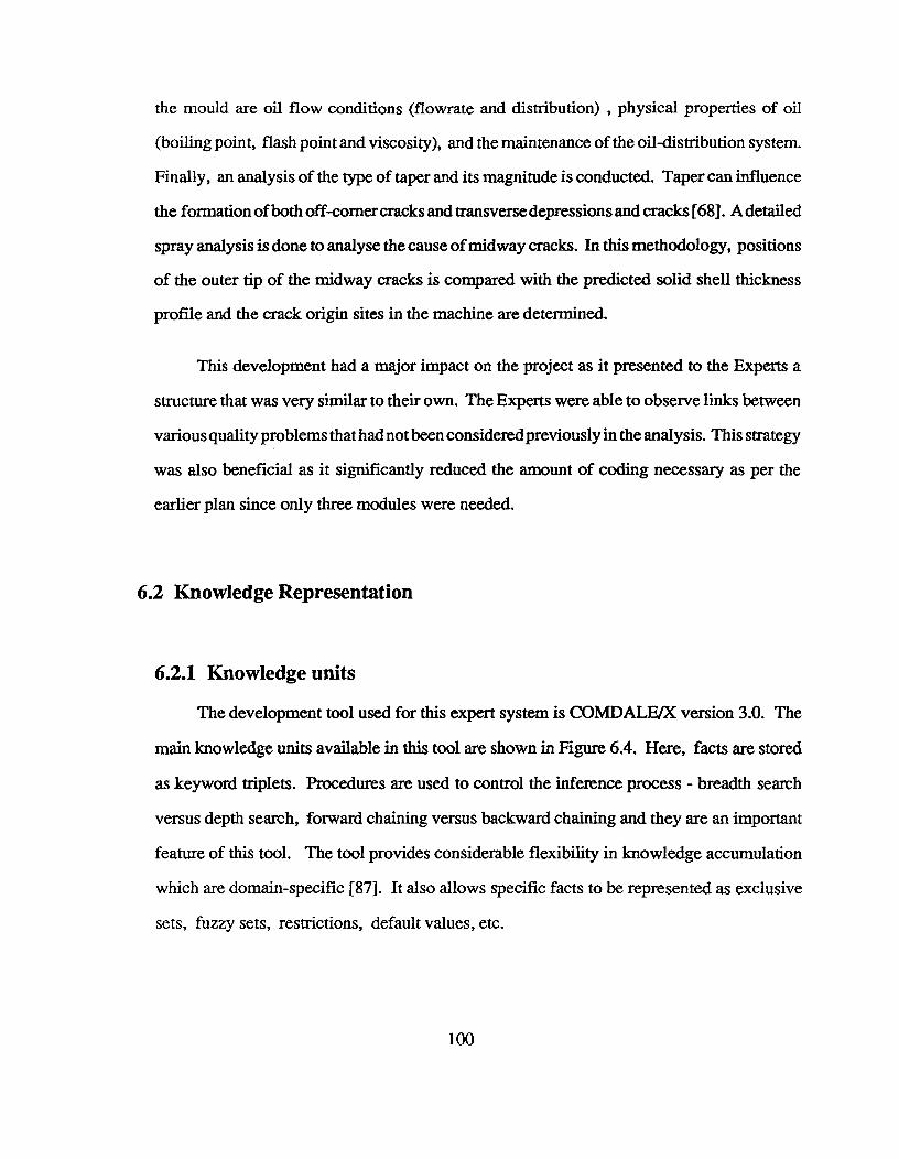
the mould are oil flow conditions (flowrate and distribution) , physical properties of oil
(boiling point, flash point and viscosity), and the maintenance of the oil-distribution system.
Finally, an analysis of the type of taper and its magnitude is conducted. Taper can influence
the formation of both off-corner cracks and transverse depressions and cracks [68]. A detailed
spray analysis is done to analyse the cause of midway cracks. In this methodology, positions
of the outer tip of the midway cracks is compared with the predicted solid shell thickness
profile and the crack origin sites in the machine are determined.
This development had a major impact on the project as it presented to the Experts a
structure that was very similar to their own. The Experts were able to observe links between
various quality problems that had not been considered previously in the analysis. This strategy
was also beneficial as it significantly reduced the amount of coding necessary as per the
earlier plan since only three modules were needed.
6.2 Knowledge Representation
6.2.1 Knowledge units
The development tool used for this expert system is COMDALE/X version 3.0. The
main knowledge units available in this tool are shown in Figure 6.4. Here, facts are stored
as keyword triplets. Procedures are used to control the inference process - breadth search
versus depth search, forward chaining versus backward chaining and they are an important
feature of this tool. The tool provides considerable flexibility in knowledge accumulation
which are domain-specific [87]. It also allows specific facts to be represented as exclusive
sets, fuzzy sets, restrictions, default values, etc.
100
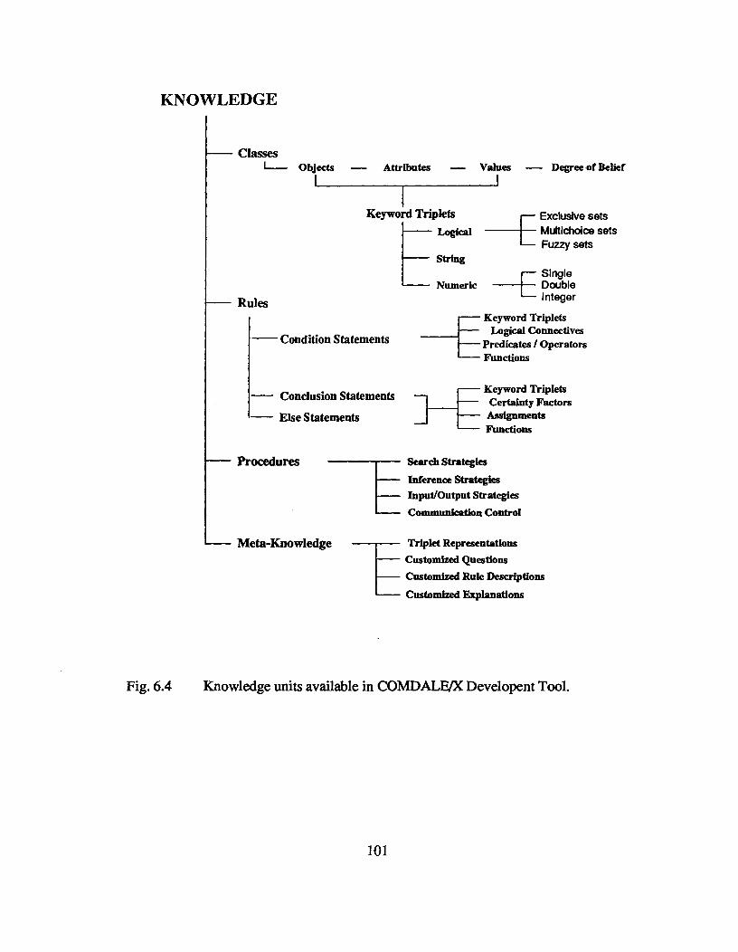
KNOWLEDGE
ClassesI--- Objects — Attributes — Values — Degree of Belief
Keyword Triplets^ Logical
StringE Exclusive sets^ Multichoice sets
Fuzzy sets
Numeric
Rules
— Condition Statements
— Else Statements— Conclusion Statements
E Single Double
Integer
Keyword TripletsLogical Connectives
Predicates / OperatorsFunctions
Keyword TripletsCertainty FactorsAssignmentsFunctions
Procedures
Meta-Knowledge
Search StrategiesInference StrategiesInput/Output StrategiesCommunication Control
Triplet RepresentationsCustomized QuestionsCustomized Rule Descriptions
Customized Explanations
Fig. 6.4^Knowledge units available in COMDALE/X Developent Tool.
101

6.2.1.1 Keyword Triplets
A keyword triplet combines an object together with a particular attribute and value.
Objects are physical entities in the real world such as sprays for cooling the billet. Objects
have attributes which describe properties or characteristics such as "length" and "flow"
for sprays. A value is attached to the object-attribute pair such as "short" and "satisfactory"
for "spray length". Classes represent hierarchical relationships between objects. All
objects in a class automatically inherit the attributes of that class. Examples of Keyword
triplets are as follows:
OBJECT ATTRIBUTE VALUEspray^length^shortspray^length^satisfactoryspray^flow^excessivespray^flow^satisfactory
A degree of certainty, which is a number ranging from 0 to 100, is attached to each
keyword-triplet and this number determines whether the keyword triplet is significant or
not at this stage of instantiation. Initially, the degree of certainty of the keyword triplet
is "not known". When information about a keyword-triplet is needed but the degree of
certainty is "not known", the system is forced to search through rules in the knowledge
base. Keyword triplets together with degrees of certainty fonn the fundamental basis for
representing knowledge as well as providing a driving force for the system in its search
for knowledge during system-execution.
Mutually Exclusive Sets: In the knowledge base, there are numerous keyword-triplets
which have common states of an Object's Attribute.
102
For example, the following keyword triplets describe different materials used as
mould material:
mould^copper^Pure Coppermould^copper^DHP_122mould^copper^DLP 120mould^copper^Copper Silver Alloymould^copper^STP_Grademould^copper^Cr Zr Coppermould^copper^Special Alloysmould^copper^Other Grades
Here, when one value has been instantiated with definite certainty, there is no need
to search for the degree of certainty of the other possibilities. This is prevented in the
system by defining these keyword-triplets as mutually exclusive sets. By doing this, the
remaining keyword-triplets in the set are automatically assigned a certainty of 0.
Fuzzy sets: There are occasions, when keyword-triplets with common object-attribute
pairs, but different values, are not mutually exclusive. Also, there can be a need to allow
flexibility in defining multiple sets with varying degree of certainty depending upon a
numerical value assigned to the keyword triplet. For example, three keyword-triplets are
set up to characterize the negative strip time based on the operating parameters :
calculated negative strip time^high
calculated negative strip_time^okay
calculated negative strip_time^low
Each numerical negative strip time value is assigned a membership percentage in
each of these sets which is further interpreted as the degree of certainty of the respective
103
keyword-triplet. Fuzzy sets have been created to represent extremely subjective concepts
in the knowledge base. The fuzzy sets in the knowledge base have been defined based on
the experts' definition of the subjective concepts. The advantage of fuzzy sets is that it
allows the knowledge engineer to program the entire set of conditions, associated with
the subjective concept, using a much reduced rule set.
6.2.1.2 Rules
In COMDALE/X, keyword triplets are linked through rules. A rule is a statement
composed of a premise and a conclusion. A rule may contain more than one premise and
conclusion statement. Each condition of a premise or conclusion consists of a
keyword-triplet in which the attribute and value are separated by a predicate function. For
example:
IF^midway_crack origin^IS^radiant zone
AND^radiant model reheat^IS^high_
AND^billet colour^MIGHT BE bright red
THEN radiant zone model reheat^IS^high CF = 100 #
When a rule is fired, the inference engine examines each condition in the premise
to establish the "degree of truth" about each statement. The degree of truth is calculated
as a function of the degree of certainty of the keyword-triplet and the predicate function
being used. After examining all the conditions in the premise, a net degree of truth is
determined. The product of net degree of truth and the certainty factor associated with
each statement of the rule conclusion is assigned to the degree of certainty of the
keyword-triplet in the conclusion of the rule. COMDALE/X also has the facility to
104

establish complex mathematical relationships between the degrees of truth of each premise
statement and the degree of belief in a conclusion fact. This unit is known as an "inference"
knowledge unit.
6.2.1.3 Procedures
Procedures refer to instructions which perform special functions during the execution
of the expert system. These are similar to conventional programming where the sequence
of tasks to be performed, as is the case with batch-processing, can be controlled through
a series of statements. Table 6.2 is a list of library functions of COMDALE/X that were
used in developing this system and the tasks each perform.
6.2.1.4 Meta-knowledge
Meta-knowledge or knowledge about facts have been extensively used in the
knowledge base with the purpose of providing technical assistance as well as training to
the users. The user interface feature of COMDALE/X, which provides features like
customized questions, rule descriptions and explanations, have been extensively employed
in the knowledge base. An example of each related to the presence of dark and bright
patches on the billet surface at the mould exit is given in the following paragraphs.
Customized Question : In the analysis of midway cracks, before the examination of
mould-related factors, the system asks the user whether any dark patches are seen on the
billet surface at the mould exit. The customized question posed by the system is:
Do you see any dark patches on the billet surface as it comes out of the mould?
105
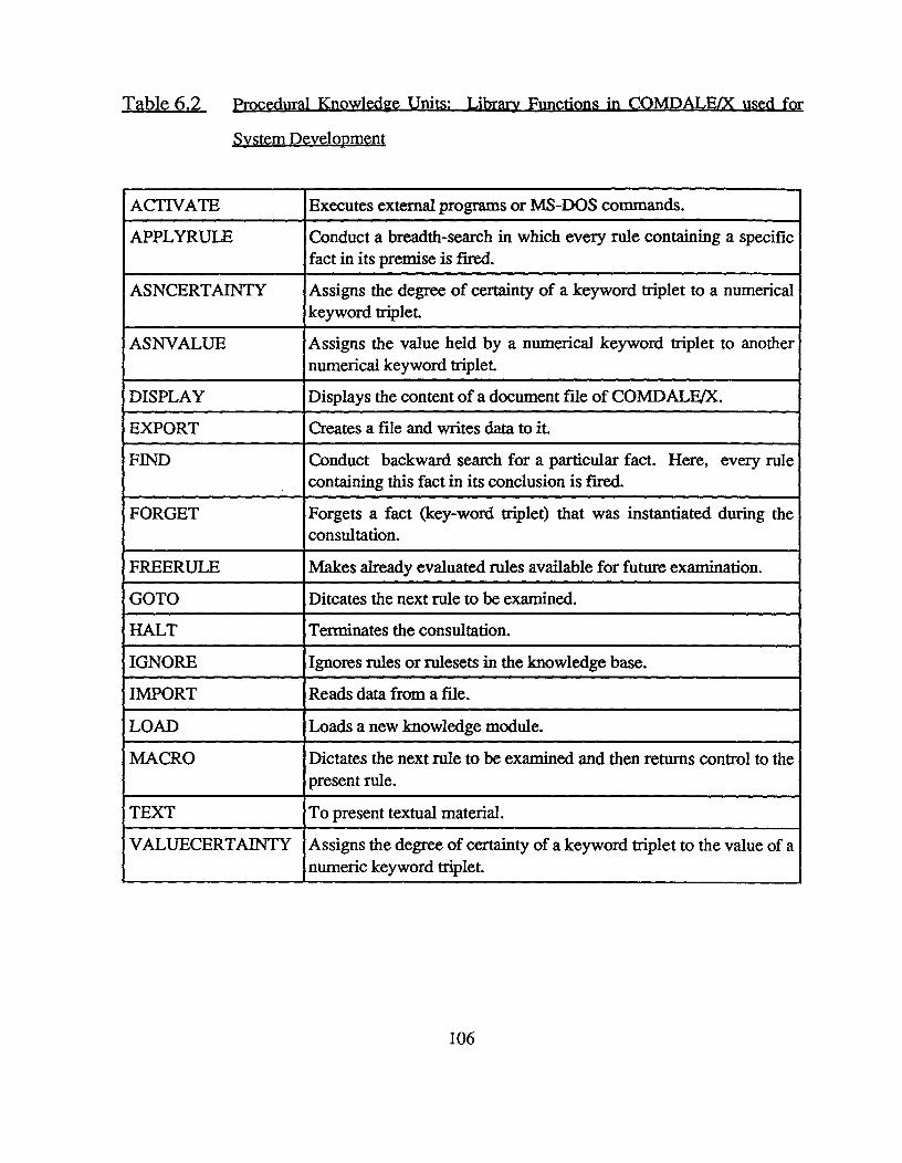
Table 6.2 procedural Knowledge Units: Library Functions in COMDALE/X used for
System Development
ACTIVATE Executes external programs or MS-DOS commands.
APPLYRULE Conduct a breadth-search in which every rule containing a specificfact in its premise is fired.
ASNCERTAINTY Assigns the degree of certainty of a keyword triplet to a numericalkeyword triplet.
AS NVALUE Assigns the value held by a numerical keyword triplet to anothernumerical keyword triplet.
DISPLAY Displays the content of a document file of COMDALE/X.
EXPORT Creates a file and writes data to it.
FIND Conduct backward search for a particular fact. Here, every rulecontaining this fact in its conclusion is fired.
FORGET Forgets a fact (key-word triplet) that was instantiated during theconsultation.
FREERULE Makes already evaluated rules available for future examination.
GOTO Ditcates the next rule to be examined.
HALT Terminates the consultation.
IGNORE Ignores rules or rulesets in the knowledge base.
IMPORT Reads data from a file.
LOAD Loads a new knowledge module.
MACRO Dictates the next rule to be examined and then returns control to thepresent rule.
TEXT To present textual material.
VALUECERTAINTY Assigns the degree of certainty of a keyword triplet to the value of anumeric keyword triplet.
106
Customized Explanation : The user may request information on dark patches before
answering the above question. The customized explanation facility of the system provides
the user with a text message containing knowledge about this subject:
These are dark regions present on the billet surface as the billet exits the mould. They are
dark because of excessive localized cooling in the mould as a result of a mould disorder.
Their presence suggests that there are problems in the mould cooling system. These dark
patches cool very rapidly in the spray zone due to nucleate boiling. When the billet enters
the radiation cooling zone, these over-cooled regions on the billet surface begin to reheat
excessively leading to midway cracks. It should be noted then, that poorly designed sprays
are not the only source of midway cracks.
Customized Rule description : The customized rule description has been used to provide
the user an explanation of "why" a particular question is being asked. This is the english
version of the rule currently being examined by the system. In response to a "why" from
the user for the above question related to the presence of dark patches, the following text
message is presented:
If dark patches are seen on the billet surface as it leaves the mould, then an adverse
mould-shell interaction is confirmed.
6.2.2 Search Techniques and Conflict Resolution
By default, COMDALE/X uses a forward chaining depth-first strategy that allows
backward-chaining to interrupt the search for a fmal conclusion whenever sub-goal
information is required. However, the tool allows backward-chaining and breadth-search
control strategies to occur from rule conclusions through the use of library functions such as
107
"FIND" and "APPLYRULE". A breadth search has been used for the analysis of
mould-related parameters, where all possible factors such as distortion, taper, oscillation
and lubrication need to be examined to arrive at the correct diagnosis. A backward-chaining
approach has been selected to modify belief in a spray-related problem for midway cracks
based on reheat temperature, superheat and high temperature strength of steel.
The accuracy of the heat-transfer model is limited only by certain assumptions made
about the physical characteristics of the casting machine and the associated cooling
conditions. For example, significant blockage of spray nozzles could lead to localized
reheating when the model is suggesting no reheating. Mould design and operating factors
could also contribute to reheating in the radiation zone by producing a non-uniform solid
shell in the billet. These non-uniformly cooled regions appear as dark and bright patches on
the billet surface at the mould exit. As pointed out earlier, these dark patches reheat
significantly in the radiation cooling zone. The model cannot predict reheating in these
situations.
Measurement estimates and the large subjectivity associated with visual observations
puts increased doubt on the reliability of these sources of information. Therefore, facts
obtained in these ways are cross-checked by the system wherever possible. When
contradictions do occur, the system resolves them in a manner comparable to the experts.
An example is the conclusion reached about the severity of a rhomboidity problem. At the
start of the consultation, the expert system asks the user to select his choice ("yes" or "no")
from a list of quality problem(s) present in the billet. Let's say, the user said "no" to
rhomboidity as well as "no" to diagonal cracks. The system verifies these inputs by asking
the user to enter the difference in the lengths of billet diagonals. If the user enters a value
which is large as per the experts' definition, the system concludes that rhomboidity is severe.
108
entered a small value for the difference in the lengths of billet diagonals, the system informs
the user that rhomboidity is severe and that the measurements is incorrect. This is done
because the presence of diagonal cracks in the billet is directly indicative of a severe
rhomboidity problem.
The following example illustrates a conflicting situation encountered during knowledge
processing and the approach adopted for its resolution. Let's assume that the midway crack
origin corresponds to the upper part of the spray cooling zone. This clearly suggests reheating
of the billet surface in this zone. However, the model does not predict excessive reheating
for this region because it is assumed that all parameters are satisfactory. This prediction
therefore does not conform to the conditions prevalent in the operation. This situation is
resolved by concluding that spray nozzles, particularly those lying on the same side of the
billet as the crack, are plugged or damaged and that the cooling is insufficient.
6.2.3 Information used in the analysis
There are three different sources of information used by the system namely; user-input,
calculations from external programs and facts inferred from rules in the knowledge base.
Information from users : Users enter the majority of data through an external program. This
information relates to the operating parameters such as steel composition, casting
temperature, casting speed, oscillation frequency, oscillation stroke, billet dimensions,
mould cooling water flow rate, spray cooling water flow rate and lubrication oil flow rate.
Other parameters such as machine radius, position of spray nozzles and pinch-roll/shear
from the mould exit, mould parameters - length, metal level, corner radius, wall thickness,
water channel gap, type of copper and nature of constraints, spray length and physical
109
properties of lubrication oil are also included. In addition, during the consultation, the
system requests observations needed for the analysis. The user is asked about the presence
of dark and bright patches on the billet surface at the mould exit, colour change in the billet
in the radiation cooling zone and nature of scale deposits - severity and colour. Questions
are asked about measurements such as mould tube distortion, mould cooling water velocity
and oil distribution. This data provide the main source of information for the expert system.
Also, users are asked to examine a macro-etched transverse section or a sulphur print of a
billet and enter information about the outer tip position of any internal cracks seen.
Calculated information : The heat-transfer finite-difference model calculates solid shell
thickness profile and billet surface reheat temperature. It is impossible for the users to provide
an estimate of these prediction. The mathematical model, with the help of additional
subroutines, also calculates mould cooling water velocity (linear) based on mould-design
and cooling water flow rate (volumetric), negative strip time, mould lead and specific spray
water flow rate. This program creates a data-file which interfaces with the expert system.
Inferred information : During consultation, the system concludes about facts based on rules
in the knowledge base. For example, deep and non-uniform oscillation marks are inferred
from knowledge about the uniformity of the solid shell around the billet periphery. The
presence of off-corner cracks and also dark and bright patches on the billet at the mould exit
also suggests that the oscillation marks are deep and non-uniform. Frequently, off-corner
cracks have been found together with deep oscillation marks. In case, the system is unable
to infer about "deep and non-uniform oscillation marks", it asks the user for measurements
of the oscillation marks and then tries to conclude about "deep and non-uniform oscillation
marks" based on the Experts' definition of "deep" and "non-uniform".
110
6.2.4 A novel inferencing strategy for the analysis of midway cracks
The appearance of midway cracks in a billet suggests that solid steel close to the
solid-liquid interface has been subjected to stresses and strains during processing. The
generation of such stress is frequently due to reheating of the strand surface due to a sudden
reduction in heat extraction. Reheating causes surface expansion and imposes a tensile strain
in the interior region of the solid shell, which is weak and brittle at temperatures within 50°C
of the solidus temperature [42]. The level of reheat determines the amount of stress generated
and therefore the intensity of a cracking problem. It is assumed therefore that belief in a high
stress level is equivalent to the degree of belief in a "high" reheat. Belief in a "high" reheat
level is determined by defining a fuzzy set for the adjective "high":
Radiation Zone Reheat Temperature (°C) 0 50 75 100 150
Degree of belief in a high reheat (%) 0 25 50 75 100
It is known that a low Mn/S ratio and a high superheat are two operating factors that
can aggravate the cracking susceptibility of steel when the reheat is high [40]. Although the
presence of a high stress level is mandatory for crack formation, problems with composition
and superheat can lead to cracking at lower stress levels and at lower reheat levels. On their
own, superheat and composition problems are not of concern since cracks cannot initiate in
the absence of a stress.
Figure 6.5 depicts how belief in a high stress level is inferred. In the methodology
adopted, belief in a composition and/or superheat problem must be higher than belief in a
high reheat in order to increase belief in a stress problem when a high reheat "might" exist.
If a high reheat "might not" be present, then belief in a stress problem can only be increased
111
if the composition or superheat problems are known with a certainty greater than 50 percent.
Thus, when the fact "reheat temperature is high" is true or false with equal certainty (degree
of belief = 50 percent) the absolute presence of one or both of these problems will increase
belief in a stress problem to 70 or 90 percent respectively.
Belief in a spray-related problem may be affected when a mould problem is also
identified. If the system discovers a mould problem, belief in a spray-related problem will
be reduced, provided belief in the mould-related problem is greater than belief in the
spray-related problem. Thus, when the fact "midway cracking problem is spray-related" is
true or false with equal certainty (degree of belief = 50 percent) the absolute presence of a
mould-related problem will reduce belief in a spray related problem to 30 percent. Figure
6.6 illustrates this reduction in belief in a spray problem when a mould problem is identified
with 100 percent certainty.
When there is uncertainty associated with the fact "reheat temperature is high", the
absolute presence of problems associated with both superheat and high temperature strength,
cannot increase belief in a spray related stress problem to 100 percent. This is logical since
"a high reheat temperature" is known with less than full certainty and the modified belief in
a spray-related stress problem must reflect this uncertainty. Thus, when there is equal
uncertainty about the fact "reheat temperature is high" being true or false (degree of belief
= 50 percent), the maximum possible belief is 90 percent. Using the same logic, the absolute
presence of either problem ( high superheat or poor high temperature strength of steel ) will
increase belief in a spray-related stress problem to 70 percent. Similarly, when the fact
"midway cracking problem is mould-related" is true with a 100 percent certainty, belief in
spray related problem is reduced to 30 percent.
112

100
//
//
B
A /---___- — —
,...__..^--- ..--
...- -7
-----_----^..------ --,.- --
...----
/ I/ /
/ I-/ /
// /^,t..
/ /1
// /
/ // 1
/ // /
/ / OCD - Only Reheat/ /
/ / "OR"OBD - Composition^Superheat Problem/ / OAD - Composition "AND" Superheat Problem
////
//.
0^ 50^
100
BELIEF IN HIGH REHEAT DUE TO THE SPRAYS ( % )
Fig 6.5^A schematic diagram illustrating the calculation of degree of belief in a
spray-related tensile strain problem from belief in high reheat in the radiation
zone, high superheat and composition problems.
D
113
//
//
//
////
,/
//,/
t ./
. .
B . .
/
.
A...-"
■OBC-NohloWdProbkm
■ .."'
... OAC-NloWdProblem
■■
C
0^ 50^ 100
INITIAL BELIEF IN SPRAY-RELATED STRAIN PROBLEM ( % )
Fig 6.6^A schematic diagram illustrating the calculation of fmal belief in a spray-related
tensile strain problem following the detection of a mould disorder.
114
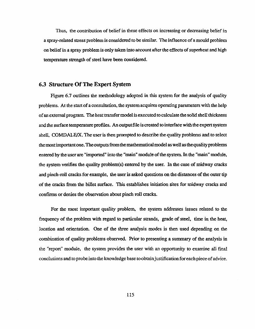
Thus, the contribution of belief in these effects on increasing or decreasing belief in
a spray-related stress problem is considered to be similar. The influence of a mould problem
on belief in a spray problem is only taken into account after the effects of superheat and high
temperature strength of steel have been considered.
6.3 Structure Of The Expert System
Figure 6.7 outlines the methodology adopted in this system for the analysis of quality
problems. At the start of a consultation, the system acquires operating parameters with the help
of an external program. The heat transfer model is executed to calculate the solid shell thickness
and the surface temperature profiles. An output file is created to interface with the expert system
shell, COMDALE/X. The user is then prompted to describe the quality problems and to select
the most important one. The outputs from the mathematical model as well as the quality problems
entered by the user are "imported" into the "main" module of the system. In the "main" module,
the system verifies the quality problem(s) entered by the user. In the case of midway cracks
and pinch-roll cracks for example, the user is asked questions on the distances of the outer tip
of the cracks from the billet surface. This establishes initiation sites for midway cracks and
confirms or denies the observation about pinch roll cracks.
For the most important quality problem, the system addresses issues related to the
frequency of the problem with regard to particular strands, grade of steel, time in the heat,
location and orientation. One of the three analysis modes is then used depending on the
combination of quality problems observed. Prior to presenting a summary of the analysis in
the "report" module, the system provides the user with an opportunity to examine all final
conclusions and to probe into the knowledge base to obtain justification for each piece of advice.
115
OPERATING PARAMETERSINPUT
HEAT TRANSFERMODEL
QUALITY PROBLEMSINPUT
MAIN MODULE
Analysis of specificity associatedwith the most important problem
I
1 MODULE 1 I 1 MODULE 2 I I MODULE 3
I REPORT I
Fig 6.7 A flow-sheet representing the structure of the expert system.
116
The following are some of the highlights of this system:
* RULES
Main Module 310Module - 1 300Module - 2 384Module - 3 362Report Module 94
* KEYWORD TRIPLETS 552
* FUZZY-SETS 68
* MUTUAL-SETS 9
* EXPLANATIONS 73
* QUESTIONS 73
* INPUT DATA ELEMENTS 44
* DISPLAY FILE PAGES 271 pages in 10 files
* FINAL CONCLUSIONS 6 ( 30 )
* EXTERNAL PROGRAMS 3
- Data Input- Quality Problem Input- Heat Transfer Model for Billet Solidification
6.4 Justification of Knowledge Engineering Decisions
During the development of the expert system, various decisions concerning knowledge
engineering were made to accommodate constraints related to computer software
(COMDALE/X version-3.0 and the operating system, MS-DOS version-4.01) and the
complexities involved in the analysis of quality problems. Wherever possible, the input of the
117
user is tested for consistency and correctness. Sometimes, this is irritating for the users. For
example, one user pointed out that the system always asked for the difference in the lengths
of the diagonals, irrespective of whether a rhomboidity problem was selected or not.
(a) Due to the large size of this knowledge base and also the memory limitations imposed by
the operating system, it was decided to break the knowledge base into five modules, four for
analysis and one for report-generation. The details about these modules have been discussed
earlier. The modules are linked to each other through data-files. There exists a potential problem
during justification of the final conclusions - it is difficult to chain back for a particular fact
present in a different module. At this point, the system ends the justification process by issuing
a statement saying "information was imported from data file". Thus, a complete justification
is not possible with the approach taken in constructing this system.
(b) A batch-file has been used to provide connections between the various programs used in
this expert system because of memory restrictions. Due to memory limitations, it was not
possible to "ACTIVATE" external programs from within the knowledge base and also it was
difficult to "LOAD" one module from another. Batch-processing also allowed the users to
"REDO" a consultation with a new set of input data and quality problems.
(c) According to the Experts, mould parameters are linked to each other in a complex manner
and therefore, when a quality problem is mould-related, all parameters need to be analysed.
Therefore, decision was made to adopt a "breadth-search" strategy for mould analysis using a
COMDALE/X function, "APPLYRULE". This slows down the consultation considerably
since this function examines all rules dealing with a particular keyword triplet, whether
successful or not. However, with the help of "IGNORE-RULE and RANGE" functions, it
118
was possible to enhance speed of the consultation to a great extent. Here, once a rule in a
rule-set is successful, all remaining rules are ignored. However, if no rule is fired, then all
possible members of the set must be exhausted during the search.
(d)In the case of a midway crack analysis, the system examines the possibility of a mould
disorders even when there exists a high belief in a spray problem. The user is asked about the
presence of dark and bright patches on the billet surface at the mould exit. If the response is
"no", the system asks if the user wishes to go through a detailed mould analysis. There is a
large emphasis on the mould because the experts strongly believe that mould issues must also
be considered. In fact, when the user does not want to go through the mould analysis, the
system issues a warning message- "be forewarned - a mould analysis may be essential for
complete diagnosis of the problem cause".
(e)During the development, it was decided to transfer all the "TEXT-MESSAGES" in the
knowledge base into external "DISPLAY-FILES". This was beneficial because it enhanced
the speed of the compilation process. Maintenance of the knowledge base was easier since
corrections to the text could be made independently of the knowledge base. However, the
justification feature (how the system found out about certain facts presented in the text-message)
associated with "TEXT-MESSAGES" was lost. The "DISPLAY-FILE" does not allow the
users to have immediate justification.
(f) The system summarizes its final conclusions under one or more of the following:
* Quality problem is mould-related
* Quality problem is spray-related
* Quality problem is related to steel
119

* Quality problem is related to pinch-rolls
* Abnormality in certain operating parameters is present
* Additional information is needed
This approach was taken to prevent cluttering of the conclusions. A user can justify each
of them as usual.
The following is the rule structure used for the conclusion "quality problem is
mould-related":
RULE 289
IF^mould problem is due to distortion
OR^mould taper is a potential problem
OR^mould problem is related to oscillation system
OR^mould problem is related to lubrication system
OR^metal level control in the mould is a problem
OR^longitudinal midface crack is mould-related
OR^longitudinal corner crack is mould-related
THEN quality problem is mould-related cf=100
(g) In the above approach, a fmal conclusion is made up of different facts, some of which may
or may not be instantiated during the consultation. In case, a particular fact is not instantiated
by the system, the fact is "considered to be "unknown". During justification, the system
indicates that the "degree of certainty of the fact is "unknown". This information is not required
during justification and therefore required elimination. In order to do this, additional rules
120
were created to "FORGET" these facts before the final conclusions were presented. Since, the
number of such facts was large, the knowledge base increased in size. This also slowed down
the consultation process.
(h) In addition, in this approach of summarizing final conclusions, all facts associated with
the conclusion have been given equal weightage. This is again based on the complexities
associated with mould analysis and also on the Experts' view that all mould parameters must
be within limits for good operation.
(i) In the inference strategy for midway crack analysis, upper limits of 70 and 90 percent and
lower limit of 30 percent were arbitrarily selected. This may need some refining based on
users' feedback. In addition, the variation is assumed to be linear - an asymptotic variation
may be better, although the author believes this to be only of academic interest.
(j) Reheat predicted by the mathematical model for the radiation zone is verified based on users'
observation of billet colour. There are two conflicting situations encountered and they are
resolved as follows:
* When the model predicts a high reheat and no colour change is observed, the degree
of belief in high reheat is reduced by a factor of 0.90.
When the model does not predict a high reheat and a colour change is observed, the
degree of belief in high reheat is increased from high disbelief (below 50 percent) to 80
percent.
Again, these limits are arbitrary and only reflect the decision of the Experts and their approach.
121
(k) At the end of the consultation, important points in the analysis are summarized dynamically
in a report where values of concerned operating parameter are listed and compared with those
recommended by the Experts. Against each parameter, comments of the Experts are provided.
Comments have been created with the help of embedded keyword triplets. These keyword
triplets are strings which are instantiated during the consultation process. In the end, these
triplets are "EXPORTED" to a data-file which is subsequently "IMPORTED" by the report
module.
For creating the report, a "WRITE" function was used. This function was developed at
UBC and linked to the inference engine of COMDALE/X. It creates an ASCII file into which
concerned information is written. With the help of another external program, this ASCII file
is displayed. This program also provides user-friendly features such as, "quit", "page-up" and
"page-down".
122
CHAPTER 7 TESTING AND EVALUATION OF THE EXPERT SYSTEM
7.1 Evaluation Procedure
In this work, the system was evaluated in two stages: informal evaluation by the
Knowledge Engineers and the Domain Experts and a formal evaluation by the End-users.
(a) Informal Evaluation: This stage formed an integral part of the knowledge acquisition and
representation where the system's performance was continuously assessed by the Experts and
the Knowledge Engineers. Recommendations and feed-back were incorporated immediately
into the system.
(b)Formal Evaluation: At a later stage in the development, the system was installed at several
Canadian steel companies for formal evaluation. The procedure followed was:
(i) Five Canadian steel companies were selected. The operating personnel in these plants
were willing to participate in the evaluation process.
(ii) A list of operating parameters for input needed in the analysis (as shown in Appendix-A)
was prepared and despatched to the users before evaluation. This provided the operators
with sufficient time for collecting data. A list of basic computer (hardware/software)
requirements necessary for the implementation of the system was also sent to them.
The list is provided in Appendix-B.
(iii)^One of the Knowledge Engineers installed the system in each of the companies. A
brief demonstration of the system was presented to the operating personnel.
123
(iv) One person was identified in each company for co-ordinating the evaluation process.
The Knowledge Engineer explained the features of the system in detail. The system
was consulted for quality problems using operating plant data.
(v) Preliminary feedback was obtained at this stage. Errors in the computer code were
discovered and corrected immediately. A summary report (shown in Appendix-C) was
prepared by the Knowledge Engineer.
(vi) A questionaire was distributed to the Users for providing detailed feedback after using
the system for a longer period. Completed questionaire were obtained from three
companies. The responses/comments obtained from them have been summarized in
Appendix-D.
(vii) The feedback obtained was analysed and decisions for implementation were made by
the Experts and the Knowledge Engineers.
7.2 System Operation - Results of the feedback
This section summarizes feedback associated with various aspects of the expert system
based on the preliminary feedback and those provided in the questionaire.
(a) Operating Parameter - Input Module
* This module serves its purpose of providing a way to enter data quite adequately. However,
some Users found it a little slow to operate as only one parameter can be changed at a
time. In addition, the units assigned to these parameters do not match with those used in
the plant.
124
• The terminology used is easy to follow for the "educated" Users such as metallurgists or
process-control engineers. But there may be a problem with operators on the shop-floor.
The Users feel that they are aware of the role of each input in the analysis and that the data
is available easily.
• Even though additional information on measurement techniques is adequate, some Users
feel the need to include a glossary of terms used in the casting business.
(b) Quality Problem - Input Module
* The terms used in this module are easy to understand. However, Users also feel the need
to have some background information on quality problems in the cast product.
* There is a need to include more quality problems in the list such as laps, bleeds, centreline
segregation.
* There is no problem in handling the issue of selecting the most important problem.
(c) Mathematical Model
* Additional information is needed on the mathematical model- formulation of governing
equations, underlying assumptions and its role in the analysis of quality problems in billet
casting.
• One User felt that the time-delay associated with the model was significant. However,
other did not find this issue to be a problem.
* The output format is satisfactory. However, Users feel that graphical outputs of the model
predictions will be more useful.
* One user pointed out that the shell thickness predicted by the model did not match with
those measured in the billet (based on his judgement). There exists doubts about the
125

boundary conditions used in the model. The Users pointed out that the spray configuration
as well as the mould heat-flux differs from plant to plant and this must be accounted for
in the model.
(d) Customized Questions. Explanations and Rule Description
* Questions asked by the system and associated rule-descriptions and explanations are clear
and easy to follow.
* The technical level of information provided through the customized explanations and
rule-descriptions is adequate. However, there still exists a need to account for different
user expertise-levels in these presentations.
* The customized features of COMDALE/X have a great potential in training novices.
* No discrepancy was noted in the information provided through the customized explanations
and rule-descriptions. The Users agreed with the contents.
(e) System's Recommendations
* The recommendations are accurate, complete, clear and easy to understand. They are
easy to implement. (one User was neutral).
* No discrepancy was encountered in the recommendations provided. The Users agreed
with these recommendations. (one User did not answer questions related to discrepancy
and disagreement)
* In addition, the Users feel the need to know about other potential problems which may
start coming up based on the existing operating conditions.
(f) System's Final Conclusions and Justification
* Final conclusions are complete, clear and easy to understand (one User was neutral).
* The justification scheme is useful, clear and easy to understand (one User was neutral).
126
* The justification feature is a potential training tool for novices.
* The logic adopted by the system for analysis was mostly satisfactory. Only one deficiency
was pointed out. The explanations provided by the system for transverse depression in
AISI 1018 grade steel was found to be inadequate by one User.
(g) Consultation Session
* The system is adequate at diagnosing and for training. However, some Users feel that its
operation may be a little complicated for personnel on shop-floor. This may hamper the
issue of training these operators.
* The consultation sessions were found to be long for some cases.
* The system informs the Users about its course of action at each stage in the analysis.
Changes in the system's thought process are smooth. Thus, the User is aware of the
analysis procedure and this feature of the system makes it very easy to understand.
* Report is useful, satisfactory and complete.
* Problems related to insufficient computer memory were encountered.
* One of the Users disagreed with the approach adopted for concluding about a severe
rhomboidity problem. His comment was, "rhomboidity is always a problem". The experts
pointed out that their definition of rhomboidity is satisfactory.
73 Analysis of User Feedback
7.3.1 System's Successes
(a) The system proved to be successful in linking dominant problems at several sites with
expected causes. Some examples are as follows:
127
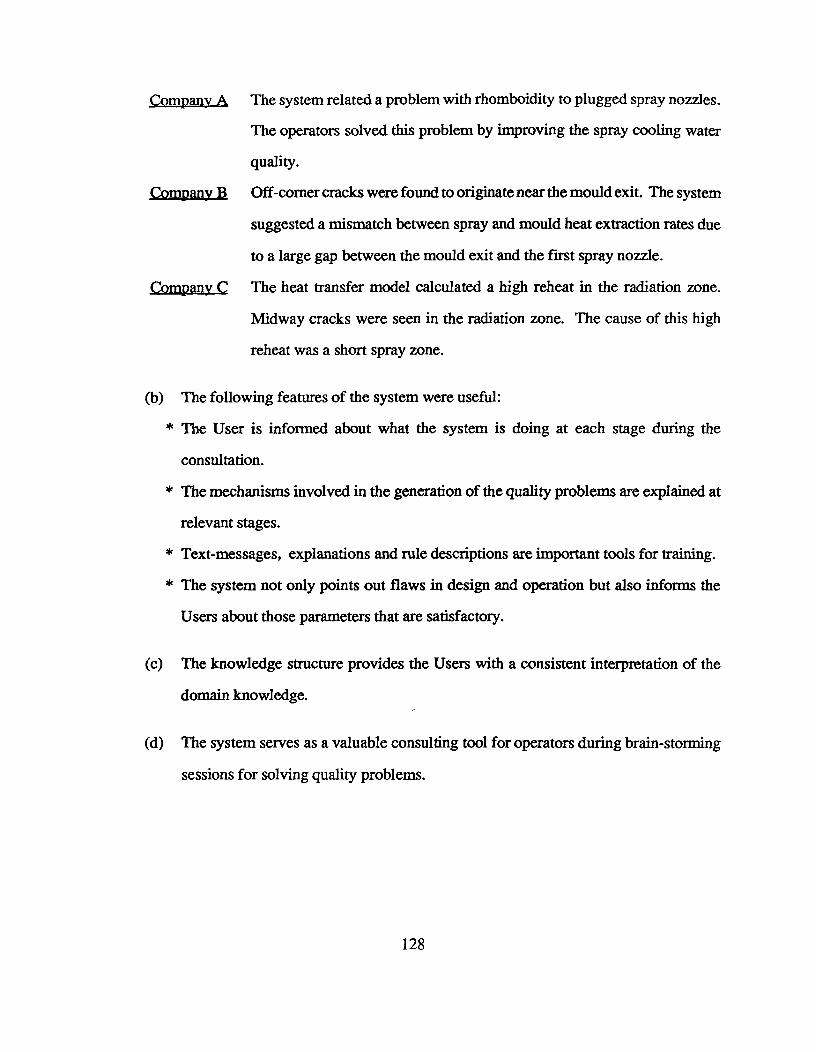
Company A The system related a problem with rhomboidity to plugged spray nozzles.
The operators solved this problem by improving the spray cooling water
quality.
Company B Off-corner cracks were found to originate near the mould exit. The system
suggested a mismatch between spray and mould heat extraction rates due
to a large gap between the mould exit and the first spray nozzle.
Company The heat transfer model calculated a high reheat in the radiation zone.
Midway cracks were seen in the radiation zone. The cause of this high
reheat was a short spray zone.
(b) The following features of the system were useful:
* The User is informed about what the system is doing at each stage during the
consultation.
* The mechanisms involved in the generation of the quality problems are explained at
relevant stages.
* Text-messages, explanations and rule descriptions are important tools for training.
* The system not only points out flaws in design and operation but also informs the
Users about those parameters that are satisfactory.
(c) The knowledge structure provides the Users with a consistent interpretation of the
domain knowledge.
(d) The system serves as a valuable consulting tool for operators during brain-storming
sessions for solving quality problems.
128
7.3.2 System's Drawbacks
(a) During an analysis on transverse depressions (and cracks), the system reached the
limit of its knowledge. When consulted, the Experts explained that the problem was
related to the effects of oscillation frequency on heat-transfer in the mould (a recent
finding). Expansion of the knowledge base is necessary to include this knowledge.
(b) It was pointed out that the system cannot be used for day-to-day quality-problem
because of the approach adopted. Some of the recommendations require large scale
modification to the operation. However, inexperienced operators can use it for
learning the subject.
(c) There is a need to recognize different levels of expertise among the possible Users
since the system considers all the Users to be the same.
(d) There are severe computer memory limits imposed by COMDALE/X version-3.0 and
MS-DOS version-4.01. Hence, expansion of the knowledge base under the present
constraints is difficult.
* RAM (computer memory) available for application is around 580 Kb. The size of
the inference engine "COMDX.EXE" is about 385 Kb. The knowledge base can only
be expanded to 160 to 170 Kb. Problems of memory are encountered when MS-DOS
commands are activated from within the COMDX program.
* External programs such as "DATA-INPUT' program or the "HEAT-TRANSFER
MODEL" are difficult to "LOAD" from within the COMDX program because of their
large size.
(e) Errors in the code- omission, misprints, incorrect units, etc. were present. These
were corrected.
129
(f) At the present moment, the system is incapable of handling different spray
configurations. The inputs to the mathematical model are number of spray zones,
zone length and water flow rate. As well, the data-base of mould heat-flux for different
casting conditions is not complete.
(g) The Users found the data input stage to be very cumbersome.
(h) The units assigned to operating parameters in the data-input module does not match
with those followed in the plant. The Users are uncomfortable with this. The major
problem in most plant is the inconsistency in the use of unit-systems, FPS, METRIC
or SI.
(i) The system does not attract the attention of the Users. As a starting point, the focus
of this project was the knowledge base. Efforts will have to be made to enhance the
user-interface.
733 Areas of Future Expansion
(a) Expansion of the present knowledge base is needed to include centreline segregation,
laps, bleeds, blowholes and pinholes.
(b) There is a need to enhance the user-interface such as graphical output profiles of billet
surface temperature and solid shell thickness.
(c) Mould heat-transfer boundary conditions are not available for different companies.
The system uses a general heat-flux profile. Also, the system does not take into
130
account the effects of oscillation frequency on mould-heat transfer (recent findings).
Data base of heat-fluxes for different grades, casting speeds, oscillation frequencies
and mould-taper has to be developed.
(d) There is a need to recognize different expertise levels for the Users while presenting
explanations, rule-descriptions or text-messages.
7.4 Implementation Of Feedback
Due to the constraints, a decision has been made to change to a newer version of
COMDALE/X-version-5.00. Important features of this new tool are as follows:
COMDALE/X version 5.0
* Runs under WINDOWS/3 environment which is easy-to-use and does not have memory
limitations.
* Handles different expertise levels for the Users.
* Has a form-generator which can considerably ease the data-input process.
* Hypertext is an inherent feature of this environment which can enhance the presentation
of "help", "text-messages" and "display-files".
* Has enhanced graphics features, much better than the previous version.
* The multi-tasking feature of WINDOWS/3 can be utilized to reduce waiting time during
the execution of the mathematical model.
131

* There are also new features for the developer:
- Incremental Compiler
- Rule and Class Editors
- Rule and Class Browsers
- Dynamic Objects
implementation Scheme
The decisions made to implement the feedback are summarized in Table 7.1.
Table 7.1^Feedback Implementation Strategy
FEEDBACK COMMENTS
* Include other quality problems The knowledge base will be expanded andmodified to include these problems.
* Enhance user-friendliness andgraphics.
Will be implemented in version 5.0 ofCOMDALE/X.
* Need to recognize different userlevels
Will be implemented in version 5.0 ofCOMDALE/X.
* Ease data input process Use of form generator provided in version 5.0 ofCOMDALE/X will be useful. Also,explanations will be provided for each inputparameter.
* Add spray configurations in themathematical model
Mathematical model will be expanded to includea subroutine dealing with spray configuration.
* Establish boundary conditions forthe mathematical model
Data bases will be created for a variety ofconditions and for each company throughindustrial trials.
132

CHAPTER 8 CONSULTATION SESSIONS - CASE STUDIES
In this chapter, three cases have been presented to highlight the consultation process. The
operating parameters for the three cases have been provided in Appendix E. After data input, the
heat transfer model for billet solidification is activated to calculate shell thickness and billet surface
temperature profiles. With the help of an additional subroutine in this program, mould cooling
water velocity, negative strip time and mould lead are calculated. The outputs are written to a
data file which is subsequently acquired by the expert system module. At this stage, quality
problems are selected by the user from a list.
CASE 1 Midway Cracks
Let's assume midway cracks were seen in the billet (at depths between 22 to 25 mm from
the surface of a 150 mm square billet). No other problem was indicated by the user. The system
begins the consultation by presenting the following predictions of the mathematical model:
Solid Shell Thicknesses Maximum Reheat Temperatures
Mould exit = 7 mm Submould = 25 °C
Spray entry = 9 mm Radiation zone = 158 °C
Spray midpoint = 12 mm
Spray exit = 18 mm
Pinch roll = 31 mm
The user did not select rhomboidity. The system verifies this information by requesting
the difference in the lengths of the two diagonals. The following is the dialogue that takes place
between the system and the user.
133

System The difference in the length of the diagonals of the billet is a measure of rhomboidity.
What is the difference in the length of the two diagonals in mm?
User Why are you asking me this question?
System You have indicated that the billet is not rhomboid. This suggests that rhomboidity is
not a problem. However, if the difference between the lengths of the two diagonals is
large, then a rhomboidity problem is confirmed.
User Please explain the meaning of this question.
System The presence of rhomboidity indicates that the heat extraction rates are not uniform
on all foursides of the billet. Non-uniform heat removal suggests that oscillation marks
are probably unevenly deep. We can confirm rhomboidity from the difference in the
length of the two diagonals. A difference greater than 6 mm is unacceptable to the
rolling mills. A difference greater than 4 mm strongly suggests problems related to
non uniform cooling.
User The difference between the lengths of the diagonals is 2 mm.
Thus, rhomboidity is not a problem. The session continues with a series of questions to
establish the location of cracks in the casting machine. Since the outer tips of the midway cracks
are located between 20 to 25 mm from the surface of the billet, the system concludes that these
cracks originated in the radiation zone. The system also cross-checks the observation about
pinch-roll cracks. It confirms that pinch-roll cracks are truly absent since no cracks originated at
depths between 28 mm to 34 mm from the billet surface. Since midway cracking is the only
134
quality problem, specific issues related to midway crack(s) are analysed. These include
observations about the frequency of the problem with respect to strand location, time in the heat
and steel grade.
To confirm belief in high reheat as predicted by the model, the system looks for information
on the colour of the billet.
System A change in the colour of the billet from red ( in the sprays ) to bright red ( in the
radiation cooling zone ), if observed, will help confirm or deny the belief in a high
radiation zone reheat as per the model prediction. Colour change should be observed
if reheating is severe. Do you see any such colour change?
User No
Since a colour change was not observed, the system reduces its degree of belief in the
model-predicted high reheat from 100 percent to 90 percent. The following message warning
the user of this contradiction is generated to suggest that the input data may be faulty.
System Our belief that the radiation zone reheat is high based on the model prediction is 100
percent. Since you did not observe a colour change in the billet in the radiation zone,
the model prediction is not confirmed. Belief in a high radiation zone reheat must be
reduced to 90 percent.
The belief in a strain problem is then modified based on the presence of a composition
problem or a superheat problem as shown in Figure 6.5. The system examines the sprays first
since belief in a spray-related strain problem is high. Spray parameters include spray length and
specific spray water flow. The levels of these are assessed with comments and recommendations
presented by the system as follows:
135
Radiant Zone Reheat is 160 °C
Spray Water flow is 127 litre water / kg steel.
Spray Length^is 2.07 m.
We are 91 percent sure that faulty sprays have generated a high stress level. This is due to
problems with the spray water parameters. We are 100 percent sure that the spray flow is excessive
and 69 percent certain that the spray zone is short.
RECOMMENDATIONS:
1. Reduce the specific spray water flow to 1.0 liters/kg of steel produced.
2. The length of the spray zone should be increased to at least 5 m.
Even though a problem related to the sprays was present, the system still examines the
possibility of a mould disorder. The system inquires about the presence of dark and bright patches
on the billet at the mould exit. Let's say that no such patches were seen. The system then asks
if the user wishes to go through a detailed mould analysis. Let's say the answer is "no". A detailed
mould-analysis is not done. However, the following warning is presented.
Dark patches were not seen on the billet surface at the exit of the mould. Since you do not want
to conduct a detailed mould analysis, we will not examine the mould parameters. However, BE
FOREWARNED - a mould analysis may be essential for complete diagnosis of the problem cause.
The analysis is then complete and the system presents the following final conclusions for
justification:
* Quality Problem is Spray-related.
* Quality Problem is Related to Steel Parameters.
Let's evaluate the conclusion related to steel parameters.
136

Quality problem is related to steel parameters because of a rule that states..
Quality problem related to steel parameters can occur if problems exist with superheat and/or
steel composition.
And it is known that..
1.It appears that high temperature strength of steel is poor
2. I am certain that a large columnar zone is present
Let's examine reasons for a large columnar zone.
I am certain that a large columnar zone is present because of a rule that states..
A high superheat leads to an enlarged columnar zone which provides an easy path for crack
propagation. The effect of superheat is more pronounced in high and low carbon grade steels
as compared with medium carbon grades.
And it is known that..
1.I am certain that cast superheat is high
2. Cast grade is high carbon.
Let's see why cast superheat is high.
I am certain that cast superheat is high because cast superheat = 33 r and a high superheat
level is described by the following fuzzy set:
Superheat (°C) 5 10 15 20 25 30 35 40
Degree of belief (%) 0 5 10 45 80 90 95 100
137
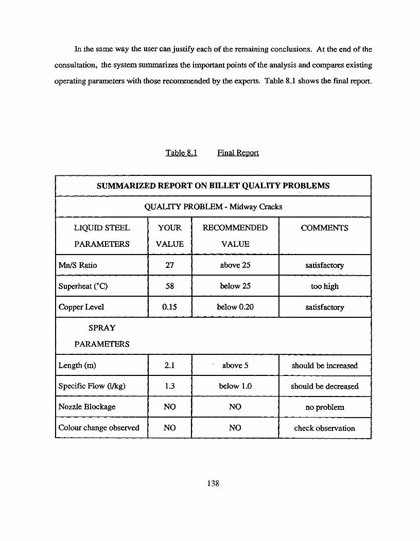
In the same way the user can justify each of the remaining conclusions. At the end of the
consultation, the system summarizes the important points of the analysis and compares existing
operating parameters with those recommended by the experts. Table 8.1 shows the final report.
Table 8.1^Final Report
SUMMARIZED REPORT ON BILLET QUALITY PROBLEMS
QUALITY PROBLEM - Midway Cracks
LIQUID STEEL
PARAMETERS
YOUR
VALUE
RECOMMENDED
VALUE
COMMENTS
Mn/S Ratio 27 above 25 satisfactory
Superheat (°C) 58 below 25 too high
Copper Level 0.15 below 0.20 satisfactory
SPRAY
PARAMETERS
Length (m) 2.1 above 5 should be increased
Specific Flow (1/kg) 1.3 below 1.0 should be decreased
Nozzle Blockage NO NO no problem
Colour change observed NO NO check observation
138
CASE 2 Off-corner cracks and Transverse defects (cracks and depressions).
Most Important Problem : Transverse Depressions
The system begins the analysis by presenting the model predictions. The system then verifies
the information about rhomboidity. Let's say the difference in the lengths of the diagonals is 5
mm. The following warning message informing the user about a severe rhomboidity problem is
presented.
You did not observe rhomboidity in the billet. However, the difference in the lengths of the
diagonals is 5 nun. We are 75 percent sure that this is large. This strongly suggests that the billet
is rhomboid and the problem is severe.
Please note : RHOMBOIDITY PROBLEM IS SEVERE !!
The system then includes rhomboidity in the list of quality problems to be analysed. Since
transverse depression is the most important quality problem, specific issues related to it are
analysed. The following message is presented before the start of the consultation.
You have selected TRANSVERSE DEFECTS as the most important important quality problem.
Pertinent observations ( i.e. if the transverse cracks andl or depressions occur more on some
specific occasions ) provide important clues related to its formation. Some of these are as follows:
If the transverse cracks andl or depressions are predominant :
* on some specific strand(s)
* on some specific region(s) of the billet
* in some specific grades
* at some specific time in the heats
System Do you see transverse defects on all the strands?
139
User^No
System Are the transverse defects more on the inboard strands as compared to the outboard
strands?
User^Yes
System Are the transverse defects more frequent in certain specific regions on the billet
surface?
User^No
System You indicated that the transverse defect is present on the inboard strands. You also
indicated that it does not appear on some specific portions of the billet surface. We
feel that this problem is affected strongly by the following factors:
1. Metal level variation
2. Mould-tube alignment
3. Mould lubrication
These factors will be analysed now.
System Would you describe the surface of the metal stream flowing into the mould as being
"ropey" or "rough"?
User^Yes
System WARNING : Metal level variation is significant !!
You have observed that the condition of the metal stream coming out of the tundish is
rough. It is certain that this could be leading to excessive gas entrainment in the
liquid steel. In the mould, these gases escape from the liquid pool surface as bubbles
140

creating turbulence and metal level variation. The situation is worse in the absence
of an adequate tundish design for flow control.
We advise you to localize turbulence from the ladle stream by the use of dams and
weirs in the tundish. We strongly re commend water modelling of the tundish to establish
optimum tundish design.
System Let's examine issues related to mould-tube misalignment. Misalignment of the mould
tube can be deduced from the following:
1. Uniformity of scale deposits on the cold face of the mould
2. Cooling water velocity measurements
System Is the scale deposits seen on the cold face of the mould?
User^Yes
System Would you describe the scale deposits as extensive?
User^Yes
System Is the scale uniformly deposited on all faces of the mould?
User^No
System Non-uniform scale deposits indicate that the water gap around the mould periphery
is not constant and this leads to non-uniform cooling water velocity. The water gap
may differ by 1 mm or more around the mould periphery due to poor tolerances on the
outside dimensions of the mould wall and the inside dimensions of the water jacket or
141
due to poor tolerances on the mould assembly, especially support plates, which result
in non-concentricity of the mould tube in the baffle. We are certain that the tolerances
of the mould assembly are inadequate.
The system continues the consultation and examines the following aspects of mould
lubrication system:
* Lubrication oil flow and distribution in the mould
* Lubrication oil physical properties
* Cleanliness of the oil slot system
* Cleanliness of the meniscus region in the mould
System Are the transverse defects more frequent in the initial stage of the heats?
User^Yes
System Does the frequency of transverse defects reduce after the dummy bar has crossed the
pinch-rolls?
User^Yes
System You have indicated that this problem appeared more in the initial stage of the heat as
compared to the other parts of the casting cycle. It could be related to poor start-up
practice. We feel that the higher frequency of defects in the initial stage of the heat,
might be due to the dummy bar practice. Since the frequency of transverse defects
reduces considerably after the dummy bar has crossed the pinch-rolls, it is certain
that this problem is related to the dummy bar practice. Our experience has shown that
the transverse defects may also be related to poor casting speed control at the beginning
of the heats.
142
The system conducts a detailed analysis of the mould system to ascertain the causes of the
quality problems observed. Other issues related to the mould (distortion, oscillation and taper)
are analysed in detail. Spray maintenance issues as well as steel quality parameters are also
examined. In addition, for off-corner cracks, the following analysis is also done:
System Please let me know whether the outer tip of any of the off-corner cracks is close to 7.0
mm from the billet surface so that we can establish whether there exists a problem
near the mould exit.
User^Yes
System Off-corner crack depth, when compared with the model predictions, suggests that
bulging of the solid shell occurred in the last stages of mould cooling or just at the
start of the sprays. It is very likely that one or more of the following factors may also
be contributing to off-corner cracks:
* Wear in the lower part of the mould
* Distortion in the lower part of the mould
* Mould cooling jacket arrangement
* Insufficient spray cooling at the mould exit
The above issues are analysed. The analysis ends with the following final conclusions:
* Quality Problem is Mould-Related
* Quality Problem is Spray-Related
* Quality Problem is Related to Steel
* Abnormality in Certain Operating Parameters is Present
* Additional Information is Needed
143
Justification can be obtained for each of the above conclusions. The system ends the
consultation by presenting the summarized report.
CASE 3 Craze Cracks
Only craze cracks were seen. The system considers this problem to be the most important
problem. The following is the consultation:
System Do you see craze cracks on all the strands?
User^No
System You indicated that craze cracking problem occurs on certain specific strands. Since
this is a steel related issue, it is very unlikely that your observation is correct. We
strongly feel that the problem is present on the other strands as well. Please examine
the billets from other strands once again.
We will now examine steel quality parameters.
System The copper levels in the steel is 030 percent. This is high.
The ratio of Ni/Cu is 033. This is low.
You may reduce the severity of this problem by reducing the level of copper in the steel
to below 020 percent or by increasing the Ni/Cu ratio in steel to more than 1.0.
The consultation is over. The following final conclusion is presented by the system:
* Quality Problem is Related to Steel
Justification can be obtained for this conclusion in the usual manner. The system then
generates the final report.
144

The system is capable of analysing other problems occuring in any combinations. The
above examples exhibit that the analysis procedure can be very straightforward and short or
extremely detailed and long. The nature of the analysis solely depends on the kinds of problems
being analysed.
145

CHAPTER 9 SUMMARY AND CONCLUSIONS
An expert system has been developed to guide operators in analysing quality-related
problems and in providing them with a ready source of knowledge related to the operation of the
casting machine.
Outcomes of Knowledge Engineering
Knowledge engineering this expert system was beneficial in many ways. Fundamental and
heuristic knowledge required for problem solving were integrated during system development.
This exercise lead to a formal representation of the Experts' knowledge which had a major impact
on the problem domain. A structure evolved that was very similar to that of the Experts and was
easy to understand and explain to others. It provided the users with a consistent interpretation of
the domain knowledge.
A new classification scheme for quality problems in billet casting was developed. The
problems are divided into groups; those that have complex origins and those where very specific
issues need to be examined. With this strategy, all combinations have been handled.
A new knowledge link was established between mould cooling water quality and mould
lubrication. When scale deposits are present on the cold face of the mould, the mould operates
hotter than normal and therefore, the lubricating oil vaporizes or burns before reaching the metal
level. In this situation, mould lubrication is likely to be poor.
146
A novel inferencing strategy was developed in the analysis of midway cracks to integrate
the influence of important parameters such as surface reheat temperature, steel superheat and
composition. The effect of mould disorders on belief in a spray-related strain problem was also
included in this scheme.
Future Work
The knowledge base will be modified to a WINDOWS/3 environment. User-feedback
related to expansion of the problem domain, enhancement of user-interface and refining of the
knowledge base will be incorporated into the system. Future efforts will also examine the
application of this knowledge base to a real-time on-line monitoring and process-control system.
By providing this assistance to the quality-control process, significant improvements in
productivity and product quality are likely to occur.
147
REFERENCES
1^COMDALE/X version 3.0- Users' Manual, Comdale Technologies Inc., Toronto,
Canada.
2^F.Hayes-Roth et al. : Building Expert Systems. Reading, Massachusetts, USA:
Addison-Wesley, 1983.
3^E.A.Feigenbaum: Proceedings of the International Joint Conference on Artificial
Intelligence, vol.5, 1977, pp.1014-1029.
4^J.Gaschnig: Proceedings of the National Conference of the American Association
for Artificial Intelligence, von, 1980, pp.295-297.
5^E.H.Shortliffe: Computer-based Medical Consultation - MYCIN, New York,
American Elsevier, 1976.
6^H.E.Pople: Proceedings of International Joint Conference on Artificial
Intelligence, vol.5, 1977, pp.1030-1037.
7^R.K.Lindsay et al.: The Dendral Project, New York, McGraw-Hill, 1980.
8^S.M.Weiss and C.A.Kulikowski: Proceedings of International Joint Conference
on Artificial Intelligence, vol.6, 1979, pp.942-947.
9^J.M.McDetmott: Proceedings of the National Conference of the American
Association for Artificial Intelligence, void , 1980, pp.269-271.
10^J.A.Meech: Minerals Engineering, vol.3, 1990, pp.129-136.
148
11^E.Turban: Decision Support and Expert Systems, New York, NY, Macmillian,
1988.
12^J.K.Brimacombe and I.V.Samarasekera: Proceedings of Indo-US Workshop on
Principles of Solidification and Materials Processing, Hyderabad, India, January
1988, Oxford and IBH Publishing Company, New Delhi, India, pp.179-222.
13^A.W.Cramb and M.Byrne: Iron and Steel Maker, May 1986, pp.27-36.
14^A.Mclean: Proceedings of 1988 AIME Steelmaking Conference, Toronto,
Canada, pp.3-23.
15^I.V.Samarasekera and J.K.Brimacombe: International Metals Review., 1978,
vol.23, No 6, pp.286-300.
16^S. Watanaba et al.: Tetsu-to-Hagne, 1972, Vol. 58, pp.S393-S394.
17^A.Grill et al.: Metallurgical Transactions, 1976, Vol.7B, No.2, pp.177-189.
18^J.K.Brimacombe et al.: ISS Transactions, 1984, Vol.5, pp.71-78.
19^I.V.Samarasekera et al.: ISS Transactions, 1984, Vol.5, pp.79-94.
20^I.V.Samarasekera and J.K.Brimacombe: W.O.Philbrook Memorial Symposium
Proceedings, 1988, AIME Steelmaking Conference, Toronto, Canada.
21^I.V.Samarasekera and J.K.Brimacombe: Canadian Metallurgical Quarterly,
1979, Vol. 18, pp.251-266.
149
22^I.V.Samarasekera and J.K.Brimacombe: Ironmmaldng and Steelmaking, 1982,
Vol. 9, pp.1-15.
23^E.Mizikar: Iron and Steel Engineer, 1970, Vol.47, pp.53-60.
24^F.Kreith: Principles of Heat Transfer, 3rd Ed., Intext Educational Publishers,
1976.
25^C.J.Hoogendorn and R.den Hond: 5th Int. Heat Transfer Conf., Paper B 3.12,
Tokyo, 1974.
26^R.Jeschar et al.: Steelmaking Proceedings, ISS, Warrendale, PA, 1986, Vol.69,
pp.511-521.
27^M.Mitusutsuka: Tetsu-to-Hagane, 1968, Vol. 54, pp.1457-1471.
28^H.Junk: Neue Heutte, 1972, Vol.17, pp.13-18 [HB Trans'. No.8740 ].
29^H. Muller and R.Jeschar: Arch. Eisenhuttenwes, 1973, Vol. 44, pp.598-594.
30^R.Alberny et al.: Circulaire d'Informatio-techniques, 1973, Vol.3, No.315,
pp.763-776.
31^R.Alberny: Committee of European Communities, Luxembourg, 1977, Voll,
IPC Science and Technology Press, pp.278-335.
32^Y.Sugitani et al.: Tetsu-to-Hagane, 1973, Vol.59, pp.S388-S389.
33^M.Ishiguro et al.: Tetsu-to-Hagane, 1974, Vol.60, pp.S464-S465 [HB Trans'.
No. 8753 ].
150
34^T.Kawakazu et al.: Tetsu-to-Hagane, 1974, Vol.60, pp.S 103-S 104 [[HB Transl.
No. 9319 J.
35^P.Nilles et al.: Proceedings of Open Hearth Conference, Chicago, ISS-AIME,
1978, Vol.61, pp.399-410.
36^E.Bolle and J.C.Moureau: International Conference on Heat and Mass Transfer
Metallurgical Processes, Dubrovnikm, Yugoslavia, 1979.
37^E.Bolle and J.C.Moureau: Proceedings of Two Phase Flows and Heat Transfer,
NATO Advanced Study Institute, 1976, Vol.III, pp.1327-1346.
38^K. Sasaki et al.: Tetsu-to-Hagane, 1979, Vol.65, pp.90-96.
39^S.G.Hibbins and J.K.Brimacombe: ISS Transactions, 1983, Vol.3, pp.37-51.
40^J.K.Brimacombe: Canadian Metallurgical Quarterly., 1976, Vol.15, pp.163-175.
41^S.Kumar: Unpublished Report, UBC, 1989.
42^B.G.Thomas et al.: ISS Transactions., 1986, Vol.7, pp.7-18.
43^J.K.Brimacombe and K.Sorimachi: Metallurgical Transactions B, 1977, Vol.8B,
pp.489-505.
44^H.Vom Ende and G.Vogt: Journal of Iron and Steel Institute, 1972, Vol.210,
pp.889-894.
45^C.J.Adams: Open Hearth Proceedings, 1971, Vol.54, pp.290-302.
46^G. Van Drunen et al.: Ironmaldng and Steelmaking, 1975, Vol.2, pp.125-133.
151
47^R.P.Sopher: Welding Journal, 1958, Vol.37, pp.481S-492S.
48^L.I.Morozensldi et al.: Stal, 1965, No.4, pp.272-276.
49^T.Kinoshita and S.Kuroki: Imono, 1972, Vol.44, pp.1080-1089.
50^A.Gueussier and R.Castro: Revue Met., 1960, Vol.57, pp.117-134.
51^E.T.Stephenson: Journal of Metals, 1974, Vol.20, No.3, pp.48-51.
52^R.Cooper and T.H.Burns: Metals Eng Quart., August 1974, pp.41-44.
53^L.Ericson: Scandinavian Journal of Metallurgy, Vol.6, No.3, 1977, pp.116-124.
54^K.Kinoshita et al.: Tetsu-to-Hagane, 1976, Vol.62, No.S505, pp.43/1-26
55^F.Weinberg: Metallurgical Transactions B, 1979, Vol.10B, pp.219-227.
56^J.Miyazaki et al.: 100 th ISU Meeting, October 1980, No.S806.
57^U.K.Bhattacharya et al.: Transactions AFS, 1952, Vol.60, pp.675-686.
58^C.F.Christopher: Transactions AFS, 1956, Vol.64, pp.293-310.
59^H.F.Bishop et al.: Transactions AFS, 1957, Vol.65, pp.247-258.
60^H.C.Suzuki et al.: 100th ISIJ Meeting, October 1980, No.S805
61^J.K.Brimacombe et al.: Steelmaking Proceedings, ISS, Warrendale, PA, 1986,
Vol.69, pp.409-423.
152
62^J.K.Brimacombe et al.: Steelmaking Proceedings, NOH-BOF Conference,
ISS-AIMS, Warrendale, PA, 1980, Vol.63, pp.235-252.
63^W.Dahl and H.Hengstenberg: Z. Meta11k, 1969, Vol.60, pp.340-350.
64^R. Bommaraju et al.: ISS Transactions, 1984, Vol.5, pp.95-105.
65^J.E.Lait and J.K.Brimacombe: ISS Transactions, 1982, Vol.1, pp.1-13.
66^S.N.Singh and K.E.Blazek: Open Hearth Proceedings, AIME, 1976, Vol.59,
pp•264-283.
67^J.K.Brimacombe et al.: ISS Transactions, Vol.1, 1982, pp.29-40.
68^J.K.Brimacombe et al.: Proceedings of 69th Steelmaking Conference, 5th
Inemational Iron & Steel Congress, April, 1986, Washington D.C., USA.
69^R.J.Dippenaar et al.: Electric Furnace Conference Proceedings, Atlanta, Vol.43,
1985.
70^The Centre for Metallurgical Process Engineering, UBC, Vancouver, B.C.,
Canada. Unpublished work.
71^I.V.Samarasekera et al.: Proceedings of International Symposium on Continuous
Casting of Billets, Vancouver, Canada, CIM, 1985, pp.33-58.
72^R.Hapke: Private Communication.
73^J.K.Brimacombe et al.: Canadian Metallurgical Quarterly., 1980, Vol.19,
pp•215-227.
153
74^A.Grill et al.: Ironmaking and Steelmaking, 1976, Vol.3, pp.38-47.
75^H.Mori: Tetsu-to-Hagane, 1972, Vol.58, pp.1511-1534 [HB Transl. No.9000-
76^H.Mori: Tetsu-to-Hagane, 1974, Vol.60, pp.784-806 [HB Transl. No. 9355 -
I&II].
77^M.Ya.Brovman: Stal Eng., 1967, Vol.1, p.26.
78^A.Grill et al.: Ironmaking and Steelmaking, 1976, No.1, pp.38-47.
79^I.V.Samarasekera and J.K.Brimacombe: Proceedings of 3rd PTD Conference on
Applications of Mathematical and Physical Models in Iron and Steel Industries,
ISS -AIME, 1982, pp.76-91.
80^I.V.Samarasekera and J.K.Brimacombe: Metallurgical Transactions B, Vol.13B,
1982, pp.105-116.
81^I.V.Samarasekera and J.K.Brimacombe: Proceedings of 2nd PTD Conference on
Continuous Casting of Steel, ISS-AIME, 1981, pp.2-21.
82^G.L.Fisher: Journal of Iron and Steel Institute, July 1969, pp.1010-1016.
83^I.V.S amarasekera and J.K.Brimacombe: Report to Stelco Edmonton Steel Works,
unpublished work, 1987.
84^T.Higaki et al.: Continuous Casting of Steel, 1977, London, The Metals Society,
pp.177-181.
154

85^C.W.Dean: Open Hearth Proceedings, AIME, 1974, Vol.57, pp.253-257.
86^H.Ichikawa et al.: Continuous Casting of Steel, 1977, London, The Metals
Society, pp.304-308.
87^J.A.Meech: Processing Complex Ores, R.Rao and G.Dobby (Eds.), London,
Pergamon Press, 1989, pp.575-585.
155

APPENDIX A - OPERATING PARAMETERS REQUIRED IN THE ANALYSIS
* Steel Composition
* Pouring Temperature (three times in the heat)
* Section Size
* Casting Speed (minimum, maximum and average values)
* Mould Design (length, wall thickness, corner radius, type of constraint, taper, width of
cooling channel)
* Mould Copper (type, chemical composition, thermal conductivity, half-softening point,
yield strength)
* Mould Operation (metal level, cooling water flow rate, cooling water quality- hardness)
* Mould Oscillation (stroke length and frequency- minimum, maximum and average values)
* Mould Lubrication (oil flow rate, physical properties of oil- flash point, boiling point and
viscosity)
* Spray Parameters (number of spray zones, zone length, water flow rate in each zone and
water temperature)
156
APPENDIX B - EXPERT SYSTEM REQUIREMENTS
1. HARDWARE AND SOFTWARE REQUIREMENTS
- IBM PC 386 with MS-DOS ver 3.3- 640 Kb RAM- Free hard disk space - not less than 5.0 Mb
2. USERS REQUIREMENTS
- Familiarity with computers ( IBM-PC )- Little knowledge about metallurgical terminologies employed in casting- Some knowledge about the continuous casting process
3. RECOMMENDED USERS
- At least three different levels of operating personnel- An inexperienced operator - to assess training capabilities
APPENDIX C
PRELIMINARY REPORT ON USERS' FEEDBACK
158
1. COMPANY A1. Hardware / Software :- 1st computer^(a)^286 COMPAQ machine
(b) Operating system : MS-DOS version 3.30(c) High density disk drive (51/4") was not available
(d) High density disk drive (31/2") was not available(e) Expert system program could not be loaded
2nd computer^(a)^High density disk drive (51/4") was available
(b) High density disk drive (31/2") was not available(c) Operating system : MS-DOS version 3.20(d) Expert system program was loaded and started(e) Math co-processor was not installed in the computer and therefore
it was not possible to run FORTRAN programs because of floatingpoint error arising due to the absence of a math co-processor -programs were compiled for machines having math co-processor.
(0^FORTRAN programs were re-compiled for a machine with no mathco-processor. The system was restarted. The mathematical modeltook about 20 -25 minutes to run compared to 5 to 50 seconds forconventional machines with a co-processor.
(g) In addition, version 3.20 of DOS did not support the "CALL"function used in the batch file.
(h) Manuals for the computer were not available and therefore it wasnot possible to ascertain the type of the machine being used.
Based on the above experience, the following requirements (hardware and software) for runningthe EXPERT SYSTEM using COMDALE/X version 3.0, have been identified as mandatory:(i) IBM-PC - 386 or 286 with math co-processor(ii) MS-DOS version 3.30 or above(iii) 640 kb of RAM(iv) Hard-disk space of 5.0 Mb or more
2. Error(s) in the code : (a)^Unit of metal level in the mould was being incorrectly reported. This was pointed out by
the operating personnel and was later corrected.3. Quality problem analysis : (a) The expert system was demonstrated to the operating personnel using the TOSHIBA 286
machine.(b) A "TEST" file was created and used as an example for the demonstration. The program
was run with quality problems : transverse depression, rhomboidity and centreline cracks.
159
(c) Transverse section of the billet was not available and therefore it was impossible to identifyinternal cracks in the billet.
(d) It is impossible to observe dark and bright patches on the billet surface as it comes out ofthe mould because of design restrictions.
(e) The expert system suggested that rhomboidity problem could be due to blocked nozzlesas a result of poor spray water quality. It was immediately pointed out by the operatorsthat they had problems of blocked spray nozzles and they minimized rhomboidity problemby incorporating chemical treatment for their spray cooling water.
(f) The expert system highlighted the mechanism of formation of transverse depressions andcentreline cracks. This information was useful to the operating personnel in learning aboutthe source of the problem.
(g) The operating personnel felt that centreline segregation problems must be included in thelist.
(h) In general, measurements of mould tube distortion, oscillation mark depths, coolingwater velocity, oil distribution and the chemical analysis of the scale deposits were notavailable. In some cases, lack of the above information could be a potential threat tosuccessful analysis.
160
2. COMPANY B1. Hardware / Software :-(a) A 386-computer with a math co-processor and MS-DOS version 3.30 was available. There
was no problem during the installation of the expert system program.(b) Option for exiting in the middle of a consultation session was not available in the expert
system. Thus, the user could exit only at the end of the session by selecting the option"STOP". The operator requested this option. It was incorporated through the batch filebut there was a memory problem (due to insufficient memory) while "ACTIVATING" the"COPY" command in COMDALE/X. This problem was later solved by modifying the"CONFIG.SYS" file (to increase available memory).
2. Error(s) in the code : (a)^Missing Fuzzy sets:^
•
position_of^chromium_layer_discolouration^closeto_the_mould_top
* distortion in_the_lower_part_of the_mould large3. Quality_problem analysis : (a) The term "distance of the first spray nozzle from the mould exit" was not very clear to the
operating personnel. Although this distance was 7 cm, the spray water reached pointsvery close to the mould exit and therefore the actual gap between the mould and the spraywas negligible. This term needs to be modified in the data input program. This point willbe taken care of in the mathematical model by including a spray-configuration subroutine.
(b) The mathematical model does not take into account the spray configuration - gap betweenthe spray zones, nozzle types and the stand-off distance. It is necessary to incorporatethis in the model to be more accurate. The operators were doubtful about the calculationof heat transfer coefficient for the spray.
(c)^Units employed in the expert system:• preferred units for shell thickness- mm• conversion for SUS (unit for oil viscosity) was not available• in general, users felt that they must be comfortable with the units employed in the
expert system- English, SI or even mixed. It is very inconvenient to switch fromthe units commonly used to SI or to any others.
(d)^Nb needs to be included in the list of elements in the steel composition. Also, the effectof Nb on the high temperature ductility of steel is to be included in the knowledge base,particularly with an emphasis on the generation of transverse corner cracks.
(e) It is assumed in the expert system that mechanisms involved in the generation of transversecracks (midface and corner) are the same and therefore are treated in the same way.However, the operators felt that transverse midface and corner cracks arise due to differentreasons. Expert's view on this issue is required. Are the operators correct ?
(f) In the expert system, the recommended value for superheat is below 25°C. The operatorsfelt that this is "too low" and therefore, not a practical recommendation. According tothem, it is very difficult to cast steel with a superheat of 25-30°C. In company B, superheatlevels were generally in the range 50-80°C. Therefore, a need exists to re-examine thedefinition of "high" superheat. The Experts' resolved this issue by saying that theirdefinition of "high" superheat is correct and a redefinition is not necessary.
161

(g) Here again, it is difficult to observe dark and bright patches on the billet surface as itcomes out of the mould. It is possible that in some situations the subsequent analysisstrategy may critically depend on this information. Therefore, ways must be devised toget around this problem.
(h) Some of the measurements are available in the database and very often these are used asanswers to questions in the analysis. In some cases, it is possible that these may notcorrelate with the quality problems in question. Thus, it is necessary to ensure that thedata corresponds to the actual situation. The Experts pointed out that they also face thisproblem.
(i) In the expert system, metal level variation in the mould has been related only to thecondition of the metal stream. It was pointed out by the operating personnel that anotherimportant factor that could be added to this is metal level control system - bad signal. Thispoint will be emphasized through a text message.
(j) Water velocity measurement data was not available. Operators felt that most companieswill not have this facility for regular process control. The Experts felt that this option muststay in the knowledge base.
162
3. COMPANY C1. Hardware / Software :-(a) 386-computer with math co-processor and MS-DOS version 3.30. There was no problem
in the installation of the expert system program.(b) Operator printed the report file. There were some errors in the report generator. These
were corrected immediately.1 Error(s) in the code : (a) IGNORE RANGE or RULE statements were missing. The system became unstable at the
cross-over point (fuzzy set for large and small distortion cross over at 0.2 mm distortion).This was corrected by incorporating IGNORE RANGE/RULE statements in the concernedrules.
(b) A misprint was discovered in one keyword triplet - "boiling problempresent_in_the_mould" was printed as "boiling problem persent_in_the_mould". This wasnoticed during the justification session.
3. Quality problem analysis : (a) The model predicted a high reheat in the radiation zone. Midway cracks were seen in the
radiation zone. A direct correlation was observed. Mn:S ratio was also low and thesuperheat was high. This was pointed out by the expert system. A sulphur print havingmidway cracks were observed. The above prediction was verified - midway crack in theradiation zone.
(b) Frequency of midway cracks were usually higher at the end of heats as compared to therest. According to the operators, this happened because the withdrawal rate increasedsubstantially at the end of heats - purpose to finish off fast. The superheat at the end ofthe heat was the same as the start. No correlation could be established between thefrequency of the problem and the superheat level. Does this mean that the problem ismould related - reheating associated with dark patches ?
(c) Superheat at the start and the end of heats were lower than that in the middle. This was ageneral observation in all the plants. The effect of thermal stratification in the ladle wasnot very obvious. In addition, the superheat at the start and the end were valid for smallertime as compared to the superheat in the middle of the heats which covered a larger period.
(d) The problem of transverse depression (and cracks) was analysed. The permanent moulddistortion was 0.2 mm (50 percent sure that this is small based on the fuzzy set for "small").Dark patches were not seen. According to the expert system, distortion was not a problemand therefore analysis of parameters related to mould distortion was not necessary.Oscillation parameters- mould lead (5-7 mm) and negative strip time (0.16-0.17 s) weresatisfactory. Oil flow was satisfactory. No jerking was observed. Oil distribution wasmeasured and was uniform. Meniscus area and the oil distribution slot were cleanedregularly. Double taper was used. Oscillation marks were not deep (visual). Everythingseemed to be satisfactory. The only other reason could be improper taper. The expertsystem reached its limit.
163
(e) The definition of severe rhomboidity - a difference of 4 mm or more between the lengthof the two diagonals is considered to be a problem. Is this range valid for larger sectionsizes such as 190 mm 9 Is there a need of a factor say (DIFFERNCE/SECTIONSIZE)that takes into account section size as well ?
The Experts said that the present definition of "large" rhomboidity is satisfctory.(f) The heat-flux profile used for the mould was general and not specific to the steel company
"C". There were some doubts in the minds of the operating personnel about the heat fluxprofile being used. It was later pointed out to them that this was an assumption in themodel. It was also clarified that mathematical model was a heat transfer solidificationmodel using finite difference formulations and that its prediction was much better than akt" model for shell thickness profile. This was appreciated by them. It is necessary toinform the users about the formulation scheme.It was again pointed out by the users that the mathematical model does not take into accountthe spray configuration - gap between the spray zones, nozzle types and the stand-offdistance. It is therefore necessary to incorporate this in the model to be more accurate.Knowledge about the width of oil slot has not been incorporated in the expert system. Theusers wanted to about its significance.There is a need to refine the definition of "high" and "okay" superheat level based onpractical limitations.There is a need to incorporate the effects of Nb and B on the severity of cracking - transversecracks.Craze cracks are not a problem. No complaints from the company "C". Is it because theyare not aware of the problem and also how to locate them in the billet - etching techniqueused by R. Hapke at UBC ?The knowledge related to taper has to be incorporated in the system and also the strategyin a situation where large mould distortion has been measured or inferred. If moulddistortion is a problem, how would one handle the taper issue ?
164
4. COMPANY D1. Hardware / Software : (a)^286-computer with math co-processor and MS-DOS version 3.30 was available. There
was no problem in the installation of the expert system program.2. Errors) in the code :-(a)^The system was demonstrated to the operating staff. No errors were noticed.3. Quality problem analysis : (a) Operating parameters were not easily available. Completed data sheet was not available.
The operators did not have sufficient time to spare.(b) The spray parameters (zone length and flow) were not clearly known to the operators. It
may be necessary to provide the users with some help on converting spray pressures toflow based on some data base on spray nozzles -type and configuration.
(c) A consultation session involving transverse depressions and cracks was demonstratedusing the limited data available from company "D". Problem related to dummy bar practicewas identified by the expert system - analysis of specificity issues.
(d) The users agreed that there was a lot of information in the expert system. They wereinterested in the information.
165

$, COMPANY E1. Hardware / Software : (a)^286-computer with math co-processor and MS-DOS version 3.30 was available. There
was no problem in the installation of the expert system program.2. Error(s) in the code :-(a)^The system was demonstrated to the operating staff. No errors were noticed.3. Quality problem analysis : (a) Eventhough there are three strands, only two may be used at a given time. There is a need
to include a question on "number of strands in operation".(b) There was some problems in the model predicted shell thickness for high carbon grades
(carbon > 1.0 percent) - model predicted a small shell. It was later discovered that the database did not have the heat-flux for this carbon range. The heat-flux being used may notbe valid. Also, large mushy-zone associated with these grades was influencing theprediction. Data-base of heat-fluxes for different grades will be developed for each plant.
(c) Distortion measurements involves checking the distance between two opposite faces. Thisobviously does not take into account twist. The operators did not observe any correlationbetween distortion measurements and mould-related quality problems.
(d) Problems such as laps and bleeds needs to be included.
166
GENERAL COMMENTS1^The system will be useful during "brain-storming" sessions for trouble-shooting quality
problems. Because of the "general" nature of the knowledge base, the system is unlikelyto be successful in day-to-day problem solving.
2^English language will be a problem in non-english speaking areas.3^Computer literacy is very low in the steel companies. This may be a potential problem.
One way to reduce this threat is to increase the user-friendliness of the system.4^The system should attract the users - like computer games. Version 5.0 of Comdale/X
will handle part of this problem.5^Graphical images must be introduced - pictures of shell thickness and temperature profiles
should appear on the screen dynamically while the mathematical model is running.6^According to the officials, users particularly on the shop floor will use the system during
coffee breaks and some other free time. This may be a potential problem from the viewpointof teaching/training. The company must incorporate training schemes or encourage theusers on the shop floor.
7^The text message provided at various stages during the consultation must take into accountthe expertise/level of the users. This is important because the system appears to be a"TEACHER" all the time and a lot of information is supplied at inappropriate places/time.The system treats all the users in the same way. This aspect of different levels of userswill be dealt with in the version 5.0 of Comdale/X.
8^The "JUSTIFICATION" feature of the expert system, though useful, did not interest theusers very much. The main concern of users was to solve the problem quickly. However,the elimination of this feature is not a consideration.
9^It is not easy to establish the limit for "high pinch-roll pressure". Usually, it is limited bythe force required to pull the billet out of the mould. Operators do not control this parameter.Hence, it is very difficult to judge this parameter. One of the operators suggested that byexamining the deformation due to the pinch rolls - comparing the billet size at the mouldexit with the final cold billet dimension, it is possible to conclude about the pinch rollpressure. In case of pinch-roll cracks, the expert system recommends a decrease inpinch-roll Pressure. What happens if the pinch pressure is at the lowest set-point ?
10^Some operators suggested that rhomboidity can also be minimized by increasing the spraywater flow. This point has not been included in the recommendation.
11^One user felt that the concepts highlighted in the expert system made sense to him becausehe had attended the Casting Course in Vancouver. It may be necessary to give a shortcourse in the concerned company not only on the expert system but also on continuouscasting during the installation. An overview on continuous casting will get them started.The concepts in the expert system will be easy to follow after this "start-up".
167
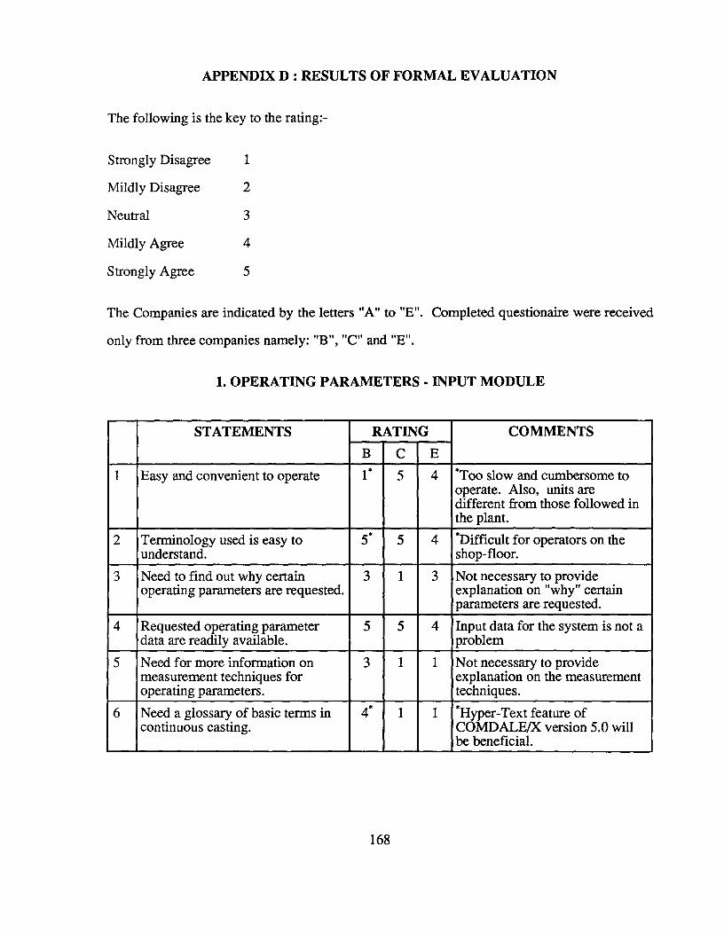
APPENDIX D : RESULTS OF FORMAL EVALUATION
The following is the key to the rating:-
Strongly Disagree 1
Mildly Disagree 2
Neutral 3
Mildly Agree 4
Strongly Agree 5
The Companies are indicated by the letters "A" to "E". Completed questionaire were received
only from three companies namely: "B", "C" and "E".
1. OPERATING PARAMETERS - INPUT MODULE
STATEMENTS RATING COMMENTSB C E
1 Easy and convenient to operate 1* 5 4 *Too slow and cumbersome tooperate. Also, units aredifferent from those followed inthe plant.
2 Terminology used is easy tounderstand.
5* 5 4 *Difficult for operators on theshop-floor.
3 Need to find out why certainoperating parameters are requested.
3 1 3 Not necessary to provideexplanation on "why" certainparameters are requested.
4 Requested operating parameterdata are readily available.
5 5 4 Input data for the system is not aproblem
5 Need for more information onmeasurement techniques foroperating parameters.
3 1 1 Not necessary to provideexplanation on the measurementtechniques.
6 Need a glossary of basic terms incontinuous casting.
4* 1 1 *Hyper-Text feature ofCOMDALE/X version 5.0 willbe beneficial.
168
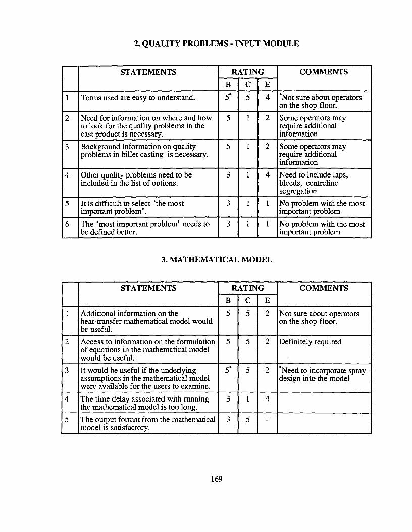
2. QUALITY PROBLEMS - INPUT MODULE
STATEMENTS RATING COMMENTSB C E
1 Terms used are easy to understand. 5* 5 4 *Not sure about operatorson the shop-floor.
2 Need for information on where and howto look for the quality problems in thecast product is necessary.
5 1 2 Some operators mayrequire additionalinformation
3 Background information on qualityproblems in billet casting is necessary.
5 1 2 Some operators mayrequire additionalinformation
4 Other quality problems need to beincluded in the list of options.
3 1 4 Need to include laps,bleeds, centrelinesegregation.
5 It is difficult to select "the mostimportant problem".
3 1 1 No problem with the mostimportant problem
6 The "most important problem" needs tobe defined better.
3 1 1 No problem with the mostimportant problem
3. MATHEMATICAL MODEL
STATEMENTS RATING COMMENTSB C E
1 Additional information on theheat-transfer mathematical model wouldbe useful.
5 5 2 Not sure about operatorson the shop-floor.
2 Access to information on the formulationof equations in the mathematical modelwould be useful.
5 5 2 Definitely required
3 It would be useful if the underlyingassumptions in the mathematical modelwere available for the users to examine.
5* 5 2 *Need to incorporate spraydesign into the model
4 The time delay associated with runningthe mathematical model is too long.
3 1 4
5 The output format from the mathematicalmodel is satisfactory.
3 5 -
169
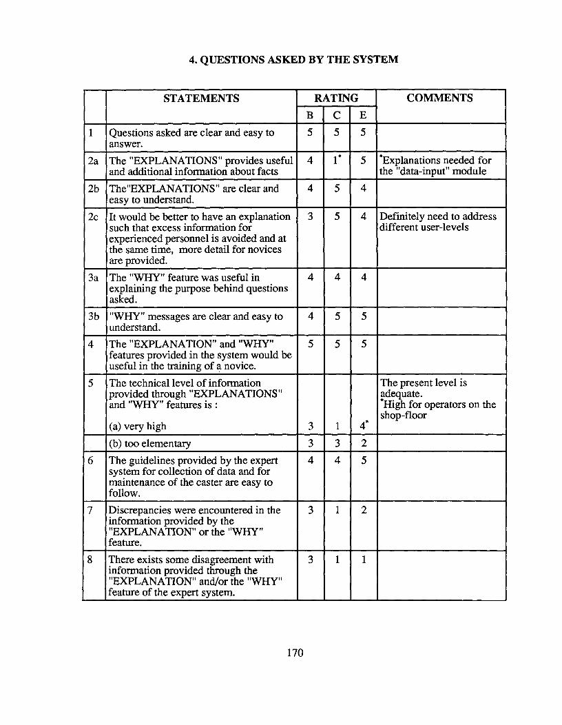
4. QUESTIONS ASKED BY THE SYSTEM
STATEMENTS RATING COMMENTSB C E
1 Questions asked are clear and easy toanswer.
5 5 5
2a The "EXPLANATIONS" provides usefuland additional information about facts
4 1 * 5 *Explanations needed forthe "data-input" module
2b The"EXPLANATIONS" are clear andeasy to understand.
4 5 4
2c It would be better to have an explanationsuch that excess information forexperienced personnel is avoided and atthe same time, more detail for novicesare provided.
3 5 4 Definitely need to addressdifferent user-levels
3a The "WHY" feature was useful inexplaining the purpose behind questionsasked.
4 4 4
3b "WHY" messages are clear and easy tounderstand.
4 5 5
4 The "EXPLANATION" and "WHY"features provided in the system would beuseful in the training of a novice.
5 5 5
5 The technical level of informationprovided through "EXPLANATIONS"and "WHY" features is :
(a) very high 3 1 4*
The present level isadequate.*High for operators on theshop-floor
(b) too elementary 3 3 26 The guidelines provided by the expert
system for collection of data and formaintenance of the caster are easy tofollow.
4 4 5
7 Discrepancies were encountered in theinformation provided by the"EXPLANATION" or the "WHY"feature.
3 1 2
8 There exists some disagreement withinformation provided through the"EXPLANATION" and/or the "WHY"feature of the expert system.
3 1 1
170
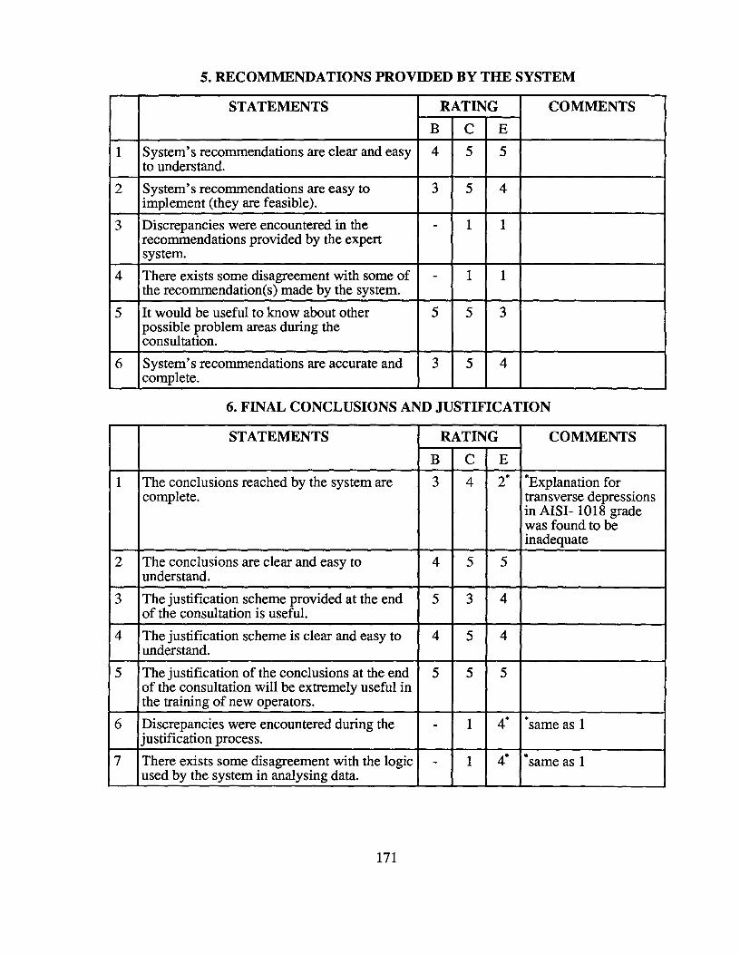
5. RECOMMENDATIONS PROVIDED BY THE SYSTEM
STATEMENTS RATING COMMENTSE
1 System's recommendations are clear and easyto understand.
4 5 5
2 System's recommendations are easy toimplement (they are feasible).
3 5 4
3 Discrepancies were encountered in therecommendations provided by the expertsystem.
- 1 1
4 There exists some disagreement with some ofthe recommendation(s) made by the system.
- 1 1
5 It would be useful to know about otherpossible problem areas during theconsultation.
5 5 3
6 System's recommendations are accurate andcomplete.
3 5 4
6. FINAL CONCLUSIONS AND JUSTIFICATION
STATEMENTS RATING COMMENTSB C E
1 The conclusions reached by the system arecomplete.
3 4 2* *Explanation fortransverse depressionsin AISI- 1018 gradewas found to beinadequate
2 The conclusions are clear and easy tounderstand.
4 5 5
3 The justification scheme provided at the endof the consultation is useful.
5 3 4
4 The justification scheme is clear and easy tounderstand.
4 5 4
5 The justification of the conclusions at the endof the consultation will be extremely useful inthe training of new operators.
5 5 5
6 Discrepancies were encountered during thejustification process.
- 1 4* *same as 1
7 There exists some disagreement with the logicused by the system in analysing data.
- 1 4* *same as 1
171
7. CONSULTATION SESSION
STATEMENTS RATING COMMENTSB C E
1 The consultation session is too long. 4 1 4 Session is too long forsome cases
2 The system is adequate at diagnosingquality problems.
4 4 4* *Updating of knowledge isneeded
3 The system is adequate for trainingoperating personnel.
5* 5 4 *May be complicated foroperators on shop-floor
4 System instabilities were encounteredduring the consultation.
51 1 52 'Problems related toinsufficient memory2Problem related tocorrupted files
5 The ability of the system to handleconflicting information or input issatisfactory.
- 2* 4 *Rhomboidity is always aproblem. For a largesection size (190 mm), 4-5mm is large as per thepresent definition
6 The system informs the user about whatit is doing at different stages of theanalysis.
5 5 4
7 Changes in the system's thought process,during the analysis, are smooth andcomfortable.
4 5 2* *Sometimes difficult tounderstand why certainmodules are loaded.
8 The final report generated by the systemis satisfactory and complete
4 5 5
9 The information contained in the report isadequately summarized.
3 5 5
10 There is a need to include some moreinformation in the report.
- 1 2
11 A computer print-out of the report forrecord purposes would be useful.
5 5 4 Report can be printed out -feature already exists
172
8. SYSTEM OPERATION
STATEMENTS RATING COMMENTSB C E
1 The system is easy and convenient tolearn and operate.
21,2 5 22 'Need more places to exitfrom the program;2Not sure about operators;easy for metallurgists
2 The user interface provided byCOMDALE/X is sufficiently "friendly".
4 5 1 * *Not very easy foroperators with nocomputer background
3 System problems were encounteredduring the consultation session(s).
1 52 'Problems related toinsufficient memory;Need explanations forerror messages2Problems related toboundary conditions usedin the model
173

APPENDIX E : OPERATING PARAMETERS FOR CASE STUDIES
1. Steel Composition
CASE "A" CASE "B" CASE "C"
Carbon 0.40 0.17 0.51
Manganese 0.80 0.80 0.88
Sulphur 0.03 0.030 0.035
Phosphorus 0.02 0.010 0.010
Copper 0.15 0.14 0.30
Nickel 0.12 0.07 0.10
Silicon 0.30 0.22 0.25
Molybdenum 0.04 0.02 0.02
Chromium 0.12 0.12 0.12
Aluminium 0.001 0.001 0.001
Titanium 0.001 0.001 0.001
Vanadium 0.001 0.001 0.001
174
Unit CASE "A" CASE "B" CASE "C"
Section size mm 150 x 150 150 x 150 150 x 150
Pouring Temperature(start of heat)
°C 1560 1580 1548
Pouring Temperature(middle of heat)
°C 1550 1570 1540
Pouring Temperature(end of heat)
°C 1540 1560 1532
Casting Speed (min) mm/s 25.4 25.4 25.4Oscillation Frequency Hz 2.33 2.33 2.33
Casting Speed (max) mm/s 42.3 42.3 42.3Oscillation Frequency Hz 2.67 2.67 2.67
Casting Speed (avg) mm/s 31.8 31.8 31.8Oscillation Frequency Hz 2.50 2.50 2.50
Oscillation Stroke mm 12.7 12.7 12.7
175
3. Mould Parameters
Units CASE "A" CASE "B" CASE "C"
Mould length mm 740 740 740
Metal level mm 125 125 125
Corner radius mm 3.175 3.175 3.175
Type of constraint 4-sided 2-sided 4-sided
Gap of cooling waterchannel
mm 3.175 3.175 3.175
Cooling water flow rate m3/s 0.0395 0.0300 0.0395
Oil flow rate mVs 1.33 1.25 1.33
Oil- boiling point °C 240 240 240
Oil- flash point °C 320 300 320
Oil- viscosity Poiseat
25°C
0.50 0.60 0.50
176
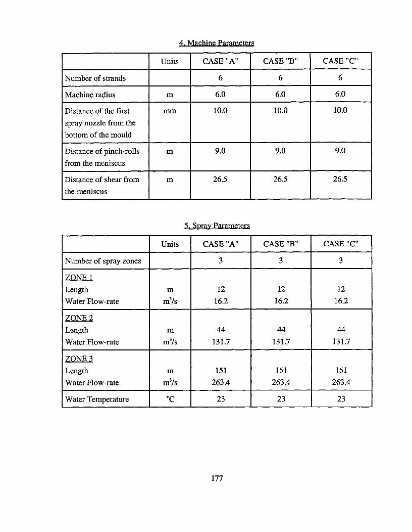
4. Machine Parameters
Units CASE "A" CASE "B" CASE "C"
Number of strands 6 6 6
Machine radius m 6.0 6.0 6.0
Distance of the firstspray nozzle from thebottom of the mould
mm 10.0 10.0 10.0
Distance of pinch-rollsfrom the meniscus
m 9.0 9.0 9.0
Distance of shear fromthe meniscus
m 26.5 26.5 26.5
5. Spray Parameters
Units CASE "A" CASE "B" CASE "C"
Number of spray zones 3 3 3
ZONE 1Length m 12 12 12Water Flow-rate m3/s 16.2 16.2 16.2
ZONE 2Length m 44 44 44Water Flow-rate m3/s 131.7 131.7 131.7
ZONE 3Length m 151 151 151Water Flow-rate m3/s 263.4 263.4 263.4
Water Temperature °C 23 23 23
177

GLOSSARY
Algorithm A step-by-step approach for solving a problem with the help of a precisely defined
group of rules or processes that leads to a desired output from a given set of inputs.
Arc The lines interconnecting nodes in a search tree.
Artificial Intelligence (AI) The branch of computer science that is devoted to the study of how
computers can be used to simulate or duplicate functions of the human brain. It deals with
hardware and software techniques that make it appear as though a computer is thinking,
reasoning, making decisions, storing or retrieving knowledge, solving problems, and
learning.
Backtracking A technique used in tree searches by which the system works backwards from a
failed objective or an incorrect result in order to examine unexplored alternatives. It is
simply the process of backing up to a point where a previous choice point was made in a
computation and then trying again.
Backward Chaining A "goal-driven" method of reasoning technique used in tree searches. It
starts with a given goal and works backwards, examining facts and rules that support the
desired outcome. It is also called "expectation driven", top-down reasoning" and "backward
reasoning".
Belief A hypothesis about some unobservable situation; a measure of the believer's confidence
in an uncertain proposition.
Blind Search A general search technique that does not utilize any knowledge or heuristics to
help accelerate or simplify the search process. Thus, it is a time-consuming process that
attempts to exhaust all possibilities in searching instead of relying upon information that
can help narrow down the search.
178

Breadth-First Search A search strategy where all the nodes on one level of the search tree are
examined before any of the nodes of the next lower level.
Certainty Factor A number ranging from 0 to 100 percent that indicates the possibility that a
conclusion reached by the system is true. It is also the degree of belief of a domain expert
about a conclusion being true when the premise of a rule is evaluated with a net degree of
truth of 100 percent.
Class A grouping of similar objects in a hierarchical and schematic manner.
Cognition The process of knowing.
Confidence Level A number lying in the range of 0 to 100 percent which represents a threshold
value that must be overcome in order for a rule to be successful. If a keyword triplet is to
be utilized in forward chaining or to be displayed as a final conclusion, its degree of belief
must exceed the confidence level.
Conflict Resolution (of rules) The priority-ordering process which is employed by an inferencing
system to decide which rule to recognize or "fire" when more than one rule's IF statement(s)
matches the current focus of the system.
Consultation System A general term used for expert and knowledge-based systems that provide
advice or diagnose problems.
Control (of expert systems) Any procedure, explicit or implicit, that determines the overall
order of problem-solving activities; the temporal organization of subprocesses.
Control Strategy A method of reasoning in a search space such as forward- or backward-chaining,
depth- or breadth-first search etc..
Data Base Information stored in a computer.
179

Data Driven Data-directed inferencing strategy used in tree searches.
Decisions Tree A graphical structure of nodes and arcs that presents alternative paths for various
decisions or outcomes.
Declarative Knowledge Information about objects, events or situations in the form of facts.
Default Values A value given to a symbol or variable automatically when no other value is
defined by the programmer or user.
Degree of Belief A measure of the believer's confidence in an uncertain proposition.
Degree of Certainty A number in the range of 0 to 100 percent that represents the truth about
the value of a keyword triplet. True equals 100 percent while False is 0 percent.
Depth-First Search A search strategy that explores each branch of a search tree to its full vertical
length. It is a general search technique that is used when no guiding information is available.
Here, each branch is searched for a solution and if none is found, a new branch is searched
to its depth. This procedure is carried on until a solution is found.
Domain A field of knowledge or expertise; a problem area of interest in expert systems
application.
Domain Expert A person with expertise in the domain in which the expert system is being
developed.
DOS Disk Operating System for IBM-compatible machines.
Expertise The set of capabilities that underlies the high performance of human experts, including
extensive domain knowledge, heuristic rules that simplify and improve approaches to
problem solving, metaknowledge and metacognition, and compiled forms of behaviour
that afford economy in skilled performance.
180
Expert System A computer program that embodies facts, knowledge, rules of thumb, and other
elements of heuristic expertise in a particular domain and then uses this information to
imitate the human thought process to solve a problem.
Explanation Facility That part of an expert system which explains why a question is being asked
or how the system reached a particular conclusion.
Fact A proposition or datum whose validity is accepted.
Firing a Rule Initiating the action specified by a rule if the conditions are met.
Focus The keyword triplet being used by the system in its forward chaining search strategy or
the keyword triplet being looked for by the system in its backward chaining search strategy.
Forward Chaining A problem-solving technique used in production and rule-based systems in
which conclusions are drawn or decisions are made by starting with known facts. A search
procedure or reasoning process that uses known facts to produce new facts and to reach a
final conclusion. It is also known as "data driven" and "inductive " or "antecedent reasoning".
Frame A knowledge representation scheme that associates one or more features with an object
in terms of various slots and particular slot values (similar to classes).
Fuzzy Logic A well defined reasoning system that is based on the use of fuzzy sets rather than
binary values associated with the traditional on/off logic. The development of fuzzy logic
was pioneered by L.Zadeh at The University of California at Berkeley in the 1960's.
Fuzzy Reasoning A method of dealing with inexact or imprecise information. It involves
techniques for avoiding complexities when dealing with subjective information or poorly
understood processes. It is a method of determining an adequate solution from imprecise
information.
181
Fuzzy Set A mapping of discrete numerical concepts into a set of ranking numbers that describe
membership in a particular concept or the degree of belief of a particular linguistic
expression.
Goal Driven A method of reasoning that begins with the goal or a conclusion and works backwards
through the rules and facts of a knowledge base searching for the path that will achieve the
desired goal.
Heuristic Consists of empirical information, rules of thumb, tricks, procedural tips and other
experiential knowledge that help to guide, limit, and speed up the search process. Anything
that helps a human or a computer to discover or learn.
Hierarchy A ranked or graded series of persons or things; a body of knowledge or information
organized into successive ranks or grades. Most hierarchies can be illustrated with the use
of tree graphs.
High-Level Language A programming language in which the instructions are closer to natural
language or algebraic notations than to machine language.
IF-THEN The form of rules used in many AI systems, programs and expert systems; a conditional
rule in which a certain action is taken only if some condition is satisfied; decision-making
tests that initiate an action if a specific condition is met.
Inference The process of drawing a conclusion from given evidence; to reach a decision by
reasoning. Different types of evidence associations may produce different degrees of belief
in a particular conclusion.
Inference Engine The "thinking part" or the "brain" of an expert system that actually performs
the reasoning function; that part of an AI program which analyses the information or
knowledge base using rules to make decisions or reach conclusions.
182

Instantiation Applied to a keyword triplet when the degree of certainty of a keyword triplet is
known.
Intelligence The ability to acquire and apply knowledge through thought and reason.
Interface That portion of a computer system or program that links two other portions of the
system and then allows them to communicate; a portion of a computer program that
interfaces with both the computer user and the remainder of the program or system.
Keyword Triplet Consists of an object-attribute-value combination. An object is an actual or
conceptual entity. Attributes are properties associated with objects. Each attribute can take
on different values.
Knowledge Understanding, awareness, or familiarity acquired through education or experience;
anything that has been learned, perceived, discovered, inferred, and understood.
Knowledge Acquisition The term used by workers in the area of expert systems to characterize
the complex activities involved in the development process. It is defined as the transfer
and transformation of problem-solving expertise from some knowledge source to a computer
program.
Knowledge Base That part of an expert system that is made up of data, rules, inferences, and
procedures organized into frames, blackboard, semantic networks, scripts, rules, and
other formats; the assembly of all the information and knowledge of a specific domain that
forms the basis of an intelligent computer system.
Knowledge-Based Systems Al programs that use a knowledge base as their source for problem
solving in a particular field of interest.
183
Knowledge Engineer A person who designs and builds expert systems; computer science or
AI specialist who acquire knowledge from all sources including human experts and organize
it into a knowledge base.
Knowledge Engineering The process of acquiring and formatting knowledge to form a
knowledge base.
Knowledge Representation A vocabulary and syntax of symbols and conventions used to
describe and present knowledge and information; the structure and organization of
information (or knowledge) used to solve a problem.
Learning The process of improving performance by changing or control.
LISP Acronym for List Processor. The most widely used AI programming language developed
by John McCarthy at MIT in the 1950's.
Logic A system of reasoning based on the study of propositions and their analysis in making
deductions; a system developed by philosophers and mathematicians for the process of
making inferences and facts.
Logical Connectives The words "AND" and "OR" that are used to link conditions in rules.
Meta A prefix of a term that designates a self-reference to the given term.
Meta-Knowledge Knowledge about knowledge.
Net Degree of Truth A number in the range of 0 to 100 percent that represents the degree of
belief that the premise of any rule is true. This number is ascertained by combining the
degrees of truth of each condition statement, and depends on the logical connectives (AND,
OR) used to combine condition statements. "ANDing" will assign the minimum degree
of truth while "ORing" will assign the maximum.
184

Path A route through a search tree.
Predicate A statement about the subject of a proposition. An assertion that denotes the
relationship among two or more objects or elements.
Premise The condition or the "IF" part of an "IF-THEN" rule.
Problem Solving The purpose of most AI programs. This includes the process of answering a
question, seeking a solution to an issue, resolving a conflict, and making a decision.
Procedural Knowledge Information about the course of action.
Production Rule An IF-THEN rule.
PROLOG Acronym for Programming in Logic; an AI language that was developed in France
using the concepts of predicate calculus.
Reasoning The mental process of drawing conclusions from facts, observations, or hypotheses;
making inferences from arguments.
Rule A regulation or statement defining a particular conduct, habit, or behaviour; in AI, a
two-part direction consisting of a condition and a consequent action. An IF-THEN rule
states that if a given condition is true, then a specific action should be taken.
Rule-Based Any program or system that uses a set of rules to draw conclusions, make decisions,
and solve problems.
Rule of Thumb A heuristic, principle, technique, trick, or method often used to simplify,
accelerate, or facilitate a process; a technique that does not always work or that is not
always accurate.
Ruleset A collection of rules that constitute a module of heuristic knowledge.
185
Search The basic process involved in AI applications; to explore or examine in order to discover
or learn something; to seek a particular object or goal.
Search Tree A graph that looks like an inverted tree and is used to illustrate the search of all the
various alternatives in a search space; a hierarchical structure showing all the goals and
subgoals (nodes) interconnected by arcs discovered during the search process.
Shell An expert system generator; a software package that allows the users to create an expert
system without programming
Software A collection of programs and routines that support the operation of the computer system.
Thinking The process of thought or reasoning; to formulate mentally, decide, judge, consider,
and otherwise reflect upon a subject.
Tool A software package, such as an expert system shell, that makes it easier to create other
softwares; includes high level languages such as LISP and PROLOG.
Top-Down Reasoning A structured method of working backward from a desired goal to
determine subgoals and a path through the search tree that will yield a suitable solution to
a problem.
Uncertainty In the context of expert systems, it refers to an intermediate truth value. Many
expert systems can accommodate uncertainty, i.e. they allow the users to indicate their
degree of belief in a concept.
User A computer operator.
User-Friendly The term used to describe a facility designed to make interaction with a computer
system easy and comfortable for the user.
186
User-Interface That portion of a computer program which communicates with the operator; a
portion of the program that accepts inputs and generates outputs with such techniques as
natural language and menus.
REFERENCES
Course notes on "Expert System for Metallurgists", 1989, The University of British Columbia,
Vancouver, B.C, Canada.
E.Turban, Decision Support and Expert Systems, 1990, Macmillan Publishing Company, New
York, NY, USA.
Building Expert Systems, Eds.F.A.Hayes-Roth, D.A.Waterman, D.B.Lenat, 1983,
Addison-Wesley Publishing Company Inc., Reading, MA, USA.
187