Embed Size (px)
Citation preview
AMR Code Simulations of Turbulent Combustion in Confined and Unconfined SDF Explosions
Allen L. Kuhl Lawrence Livermore National Laboratory
(LLNL), Livermore, CA [email protected]
John B. Bell and Vincent E. Beckner Lawrence Berkeley National Laboratory (LBL),
Berkeley, CA {jbbell, vebeckner}@lbl.gov
Abstract
A heterogeneous continuum model is proposed to describe the dispersion and combustion of an aluminum particle cloud in an explosion. It combines the gas-dynamic conservation laws for the gas phase with a continuum model for the dispersed phase, as formulated by Nigmatulin. Inter-phase mass, momentum and energy exchange are prescribed by phenomenological models. It incorporates a combustion model based on the mass conservation laws for fuel, air and products; source/sink terms are treated in the fast-chemistry limit appropriate for such gasdynamic fields, along with a model for mass transfer from the particle phase to the gas. The model takes into account both the afterburning of the detonation products of the booster with air, and the combustion of the Al particles with air. The model equations were integrated by high-order Godunov schemes for both the gas and particle phases. Numerical simulations of the explosion fields from 1.5-g Shock-Dispersed-Fuel (SDF) charge in a 6.6 liter calorimeter were used to validate the combustion model. Then the model was applied to 10-kg Al-SDF explosions in a vented two-room structure and in an unconfined height-of-burst explosion. Computed pressure histories are in reasonable (but not perfect) agreement with measured waveforms. Differences are caused by physical-chemical kinetic effects of particle combustion which induce ignition delays in the initial reactive blast wave and quenching of reactions at late times. Current simulations give initial insights into such modeling issues. 1. Introduction Laboratory experiments have been performed with 1.5-gram Shock-Dispersed-Fuel (SDF) charges[1]. The charge consisted of a 0.5-g PETN booster surrounded by 1-g of flake Aluminum (Al) powder. The SDF charge was placed at the center of a bomb calorimeter.
Detonation of the booster disperses the fuel, ignites it, and induces an exothermic energy release via a turbulent combustion process. Over-pressure histories in air were considerably larger than those measured in nitrogen atmospheres; impulses histories show factors of 2 to 4 increase due to Al-air combustion. At the 2007 HPCMP Users Group Conference, we reported on numerical simulations of those experiments that were performed with our two-phase, three-dimensional (3D) AMR code[2]. Here we study the flow fields created by confined and un-confined SDF explosions at the 10-kg scale. In particular, we consider an SDF charge consisting of 3.6-kg spherical C4 booster surrounded by 6.4-kg of flake Al powder. The charge was detonated 122 cm above a concrete pad instrumented with static pressure gages. Described here are numerical simulations of the explosion field performed with our three-dimensional (3D) adaptive mesh refinement (AMR) code. The combustion model treats the flow field as a dilute heterogeneous continuum—with separate conservation laws for each phase—and interaction terms that allow the phases to exchange mass, momentum and energy via phenomenological laws[3]. A unique feature of the model is that a high-order Godunov algorithm is used not only for the gas phase, but also for the particle phase. This provides an accurate solution of the governing hyperbolic conservation laws that is devoid of artificial effects of numerical diffusion. The system of equations is closed by a quadratic Equation of State (EOS) model that specifies the thermodynamic states of the combustion fields. Results of the AMR code simulations of the 10 kg-SDF explosions will be described and compared with experimental results.
2009 DoD High Performance Computing Modernization Program Users Group Conference
978-0-7695-3946-1 2010
U.S. Government Work Not Protected by U.S. Copyright
DOI 10.1109/HPCMP-UGC.2009.24
135
2. Model 2.1. Conservation Laws The Model is based on the Eulerian multi-phase conservation laws for a dilute heterogeneous continuum[3,4]. We model the evolution of the gas phase combustion fields in the limit of large Reynolds and Peclet numbers, where effects of molecular diffusion and heat conduction are negligible. The flow field is governed by the gas-dynamic conservation laws: Mass: ( )t s∂ ρ ρ σ+∇⋅ =u (1)
Momentum: ( )t s sp f∂ ρ ρ σ+∇ ⋅ + = −u uu v (2)
Energy: ( )t s s s sE E p q E f∂ ρ ρ σ+∇ ⋅ + = − + − ⋅u u v (3)
where ρ, p, u represent the gas density, pressure and specific internal energy, u is the gas velocity vector, and E≡u+u⋅u/2 denotes the total energy of the gas phase. Source terms on the right hand side take into account: mass addition to gas phase due to particle burning ( sσ ), particle drag (ḟs), and heat losses ( )sq . We treat the particle phase as a Eulerian continuum field[3,4]. We consider the dilute limit, devoid of particle-particle interactions, so that the pressure and sound speed of the particle phase are zero. We model the evolution of particle phase mass, momentum and energy fields by the conservation laws of continuum mechanics for heterogeneous media: Mass: t sσ σ σ∂ +∇ ⋅ = −v (4)
Momentum: t s sfσ σ σ∂ +∇ ⋅ = − +v vv v (5)
Energy: t s s s s s sE E q E fσ σ σ∂ +∇ ⋅ = − + ⋅v v (6)
where σ and v represent the particle-phase density and velocity and Es≡CsTs denotes the energy of the particle phase. 2.2. Interactions The inter-phase interaction terms for mass, momentum, and heat take the form as described by Khasainov et al. (2005):
Mass Exchange:0
3 (1 0.276 Re ) /
s melt
s
s s s melt
T T
t T Tσ
σ
<=
− + ≥
⎧⎪⎨⎪⎩
: (7)
Momentum Exchange: (3 / 4 ) ( )s s s Df d Cρσ ρ= − −u v u v (8)
Heat Exchange: 4 4(6 / ) ( ) / ( )s s s s s Boltz sq d Nu T T d T Tσ ρ λ εσ⎡ ⎤= − + −⎣ ⎦ (9)
Burning Law: 20s st Kd= (10)
where 24 / Re 4.4 / Re 0.42D s sC = + + , Re /s sdρ μ= −u v
, and 2 0.6 Pr ResNu = + . Here, we assume the mass transfer from particles to continuum occurs as the melting point of Al and we view the Al in the continuum phase as a micro-mist of Al droplets in velocity and thermal equilibrium with the gas, but does not contribute to pressure. An additional phase change is included at the vaporization temperature of Al, at which point it becomes a gas and contributes to the gas pressure. 2.3. Combustion We consider three fuels: C4 detonation products (F1), Aluminum (F2), and gaseous hydrocarbon (F3), along with their corresponding combustion products: C4-air (P1), Al-air (P2), and CH-air (P3). (Al is assumed to only burn in the continuum phase.) We consider global combustion of fuel Fk with air (A) producing equilibrium combustion products Pk: k kF A P+ ⇒ ( )1, 2 or 3k = (11)
The mass fractions Yk of the components are governed by the following conservation laws: Fuel-k: 2t Fk Fk k k kY Y s∂ ρ ρ δ σ+∇⋅ =− +u (12)
Air: t A A k kk
Y Y s∂ ρ ρ α+∇⋅ = −∑u (13)
Products-k: (1 )t Pk Pk k kk
Y Y s∂ ρ ρ α+∇⋅ = +∑u (14)
Fuel and air are consumed in stoichiometric proportions: αkA/Fk. In the above, ṡk represents the global kinetics sink term. In this work, we use the fast-chemistry limit that is consistent with the inviscid gas-dynamic model Eqns. 1–3, so whenever fuel and air enter a computational cell, they are consumed in one time step. Here δk2 represents the Kronecker delta (δk2=0 if k≠2 and δk2=1 if k=2) and takes into account the mass transfer of Al from the particle phase Eqn. 4 to the gas phase. 2.4. Equations of State The thermodynamic states encountered during SDF explosions have been analyzed in by Kuhl and Khasainov[5]. The loci of states of component c in the specific internal energy-temperature (u−T) plane are fit with quadratic functions of temperature:
2( )c c c cu T a T b T c= + + (15)
For cells containing a mixture of components, the mixture energy also satisfies a quadratic form:
2( )m c c m m m m mcu T Y u a T b T c= = + +∑ (16)
136
Given the mixture specific internal energy um, the mixture temperature can be evaluated by:
2[ 4 ( )] / 2m m m m m m mT b b a c u a= − + − − (17)
using mixture coefficients as defined by:
, , , m c c m c c m c c m c cc c c ca Y a b Y b c Y c R Y R= = = =∑ ∑ ∑ ∑ (18)
For pure cells, the pressure of a component is calculated from the perfect gas relation pcρcRcTc, or from the JWL function in the detonation products gases[4]. In mixed cells, the pressure is calculated from the mixture temperature by the “law of additive pressures”:
( , )m c m mcp p V T=∑ (19)
where pc(Vm,Tm) denotes the pressure of component c if it existed alone at Vm and Tm. 2.5. Numerical Methods The governing Eqns. 1–6 and 12–14 are integrated with high-resolution upwind methods that represent high-order generalizations of Godunov’s method. The algorithm for gas phase conservation laws is based on an efficient Riemann solver for gas-dynamics first developed by Colella and Glaz[6]. The algorithm for the particle phase conservation laws is based on a Riemann solver for two-phase flows developed by Collins et al.[7]. Source terms are treated with operator splitting methods. Being based on Riemann solvers, information propagates along characteristics at the correct wave speeds, and they incorporate nonlinear wave interactions within the cell during the time step. These Godunov schemes have been incorporated into the embedded boundary adaptive mesh refinement (AMR) algorithm of Pember et al.[8] that allows us to focus computational effort in complex regions of the flow. In this AMR approach, regions to be refined are organized into rectangular patches, with 100’s to 1,000’s of grid-points per patch. AMR is also used to refine turbulent mixing regions; by successive refinements, we are able to capture the energy-bearing scales of the turbulence on the computational grid. In this way, we are able to compute the effects of turbulent mixing without resorting to explicit turbulence modeling. This is consistent with the Monotone Integrated Large-Eddy Simulation (MILES) approach of Boris[9–11]. A comprehensive review of implicit Large-Eddy Simulation (iLES) methods may be found in Grinstein et al.[12]. A verification of the ability of our Godunov scheme to replicate the Kolmogorov spectrum of turbulent flows has been demonstrated by Aspden et al.[13]. The scheme’s ability to follow vorticity intensification during transition to turbulent flow is described by Bell and Marcus[14]. The scheme has also
been used to predict transition in Kelvin-Helmholz shear layers; computed mean and second-moment profiles are found to be in good agreement with measured profiles[15]. 3. Results We used the 3D two-phase AMR code to simulate the explosion of a 1.5-g Al-SDF charge (0.5-g spherical PETN booster+1-g flake Al) and the ensuing turbulent combustion with air in calorimeter A (right circular cylinder: D=20 cm, L=21, cm and V=6.6 liters). Computed pressure histories at R=5 cm on the lid of the vessel are compared with pressure measurements in Figure 1. The computed waveform (black curve) is similar to the experiment in air (red curve). Both curves are considerably larger than the experimental data for the Al-SDF explosion in nitrogen (blue curve). Such comparisons illustrate the dramatic effect that combustion has on chamber pressures for SDF explosions. Evolution of the computed component masses (Al, PETN, air, Al-air products, PETN-air products) are presented in Figure 2. By 3 ms, more than 95% of the Al fuel and 90% of the PETN detonation products have been consumed by combustion. Next, we performed 3D simulations of a 10-kg Al-SDF explosion in a vented two-room structure. The charge consisted of a 3.3-kg spherical C-4 booster surrounded by 6.7-kg of flake Al. Room dimensions were: X=457 cm by Y=366 cm in plan-form by Z=244 cm in height, with a volume of 40.8 m3. The charge was detonated in the center of room 1 at mid-height (z=122 cm). The fuel loading (i.e., chamber volume/fuel mass) was similar to the fuel loading of calorimeter A: 4.4 liters/g. Visualization of the temperature field at different times during the simulation is presented in Plate 1 (plan view cross-section at mid-height z=122 cm). Explosion of the booster accelerates the Al fuel into a thin shell just behind the shock (Frame 1). Temperatures are high enough to ignite the Al particles (red denotes 4,300 K). Shock reflections from the walls, floor, and ceiling breakup the fuel shell (Frames 2 and 3), leading to intense turbulent combustion, which fills the first room by 2.7 ms (Frame 4). A variety of mixing scales are evident. Figure 3 depicts the pressure histories at ground zero (on the ceiling directly above the charge) for the 10-kg Al-SDF explosion in the two-room structure. The computed waveform (black curve) is narrower and has a higher peak than the measured waveform (red curve). Perhaps the numerical simulation burns faster and is less dissipative than the experiment; also, the measurement system used an eighth-order Bessel filter, which will broaden the waveform and lower its peak. Nevertheless, both waveforms are much larger than the waveform for the C-4 booster charge (blue curve)—thereby
137
demonstrating that a reactive blast wave is formed during the initial charge expansion (Figure 3a). At later times, the computed and measured waveforms are quite similar (Figure 3b). Next, 3D simulations of an unconfined 10-kg Al-SDF explosion at a height of burst (HOB) of 122 cm were performed. A cross-sectional view of the computed temperature field at 30 ms is presented in Plate 2. Red corresponds to a temperature of 4,300K, and illustrates where Al-air combustion is occurring within the explosion cloud. A variety of mixing scales are evident. 4. Conclusions A heterogeneous continuum model of Al particle combustion in explosions is proposed. It is based on the underlying assumption that the combustion rate is limited by rate that fuel (Al and/or booster detonation products gases) are brought together with air by turbulent mixing. This represents the fast-chemistry limit for such reacting flows. We have shown this to be valid for gas phase combustion in explosions (e.g., afterburning of TNT detonation products with air). However, particle combustion introduces new characteristic scales (particle diameter, particle size distribution, surface coating, etc.) that can induce ignition delays due to physical-chemical kinetic effects not found in gaseous systems. Such kinetic effects could be important in the ignition of the reactive blast wave at early times, and in quenching of the reactions by mixing with air at late times. We plan to explore the importance of kinetic-effects modeling by performing simulations Al-SDF combustion in explosions at the 1.5-g scale (six different chamber experiments) and at the 10-kg scale (confined and unconfined field tests). The results shown give initial insights into this process. Acknowledgments This work performed under the auspices of the US Department of Energy by Lawrence Livermore National Laboratory under Contract DE-AC52-07NA27344. The work at Lawrence Berkeley National Laboratory was performed under US Department of Energy under Contract No. DE-AC02-05CH11231. This work was sponsored by the Defense Threat Reduction Agency under IACRO’s 08-4399l and 09-45091; Dr. William Wilson, DTRA/CXWJ, is the contract monitor; his support is greatly appreciated. References 1. Kuhl, A.L. and H. Reichenbach, “Combustion effects in confined explosions.” Proceedings of the Combustion Institute, 32 (2009), pp. 2291–2298, 2008.
2. Bell, J.B., V.E. Beckner, and A.L. Kuhl, “Simulation of enhanced explosive devices in chambers and tunnels (plenary lecture).” DoD High Performance Computing Users Group Conference 2007 (HPCMP-UGC 2007) 0-7695-3088-5/07 IEEE, 5 pages, 2007. 3. Kuhl, A.L., J.B. Bell, and V.E. Beckner, “Heterogeneous continuum model of Aluminum particle combustion in explosions.” Fizika Goreniya i Vzryva, 2009 (in press). 4. Nigmatulin, R.I., Dynamics of Multi-Phase Flows, Vol. 1, Moscow, Nauka, 464 pp, 1987. 5. Kuhl, A.L. and B. Khasainov, “Quadratic model of thermodynamic states in SDF explosions.” Energetic Materials: 38th Int. Conf. ICT, pp. 143.1–143.11, 2007. 6. Colella, P. and H. Glaz, “Efficient solution algorithms for the Riemann problem for real gases.” J Comp. Phys., 59, pp. 264–289, 1985. 7. Collins, P., R.E. Ferguson, K. Chien, A.L. Kuhl, J. Krispin, and H. M. Glaz, “Simulation of shock-induced dusty gas flows using various models.” AIAA 94-2309, 1994. 8. Pember, R.B., J.B. Bell, P. Colella, W.Y. Crutchfield, and M.L. Welcome, “An Adaptive Cartesian Grid Method for Unsteady Compressible Flow in Irregular Regions.” J. Comp. Phys., 120:2, pp. 278–304, 1995. 9. Boris, J.P., “On large eddy simulations using sub-grid turbulence models.” Wither Turbulence? Turbulence at the Crossroads, ed. J.L. Lumley, Lecture Notes in Physics, 257, Springer-Verlag, Berlin, pp. 344–353, 1989. 10. Boris, J.P., F.F.Grinstein, E.S. Oran, and R.L. Kolbe, “New insights into large eddy simulation.” Fluid Dynamics Research, 10, pp. 199–228, 1992. 11. Oran, E.S. and J.P. Boris, Numerical Simulation of Reactive Flow, 2nd Ed., Cambridge University Press, Cambridge, UK, 529 pp, 2001. (vid. esp. § 12-4: Monotone-Integrated Large-Eddy Simulation, pp. 473–487). 12. Grinstein, F.F., L.G. Margolin, and W.J. Rider, Editors, Implicit Large-Eddy Simulation: Computing Turbulent Fluid Dynamics, Cambridge University Press, 546 pp, 2007. 13. Aspden, A.J., N. Nikiforakis, S.B. Dalziel, and J.B. Bell, “Analysis of implicit LES methods.” Comm. Applied Mathematics and Computational Science, 3, pp.103–126, 2008. 14. Bell, J. B. & Marcus, D. L., Vorticity intensification and transition to turbulence in the three-dimensional Euler equations, Comm. Math. Phys. 147, pp 371–394, 1992. 15 Chien, K.-Y., R.E. Ferguson, A.L. Kuhl, H.M. Glaz, and P. Colella, “Inviscid dynamics of two-dimensional shear layers.” Comp. Fluid Dynamics, 5, pp. 59–80, 1995.
138
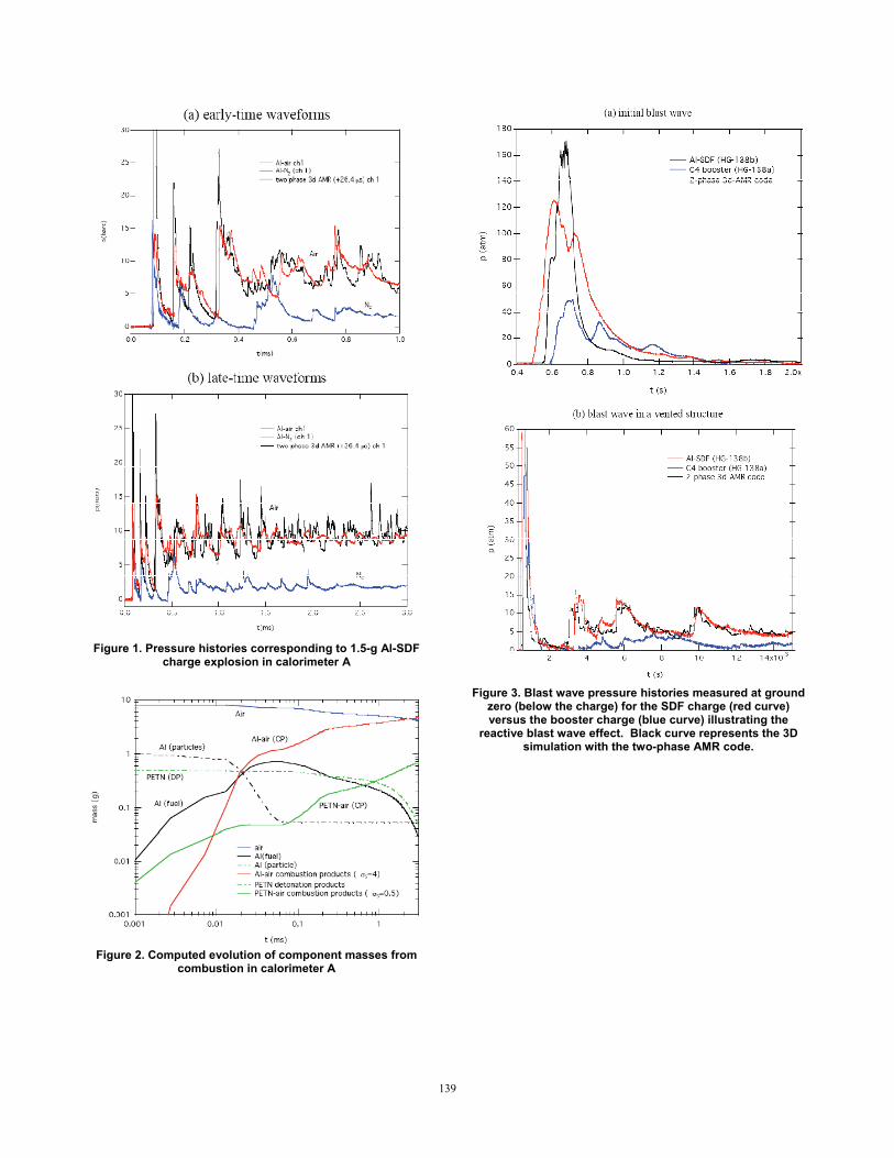
Figure 1. Pressure histories corresponding to 1.5-g Al-SDF
charge explosion in calorimeter A
Figure 2. Computed evolution of component masses from
combustion in calorimeter A
Figure 3. Blast wave pressure histories measured at ground
zero (below the charge) for the SDF charge (red curve) versus the booster charge (blue curve) illustrating the
reactive blast wave effect. Black curve represents the 3D simulation with the two-phase AMR code.
139
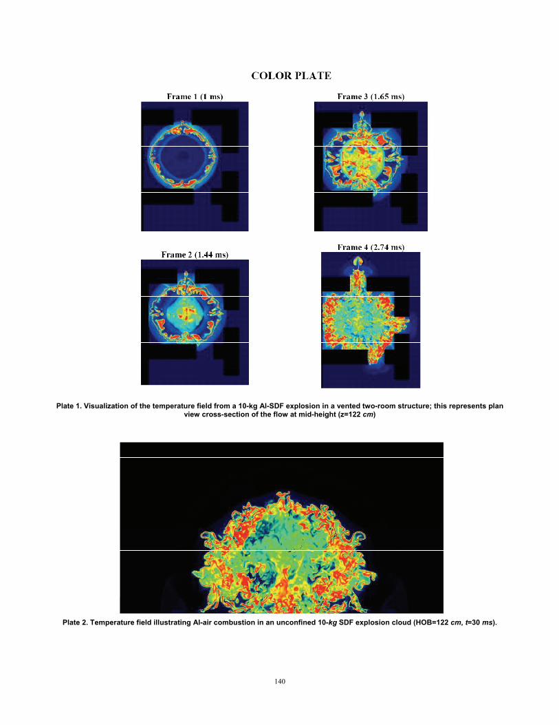
Plate 1. Visualization of the temperature field from a 10-kg Al-SDF explosion in a vented two-room structure; this represents plan
view cross-section of the flow at mid-height (z=122 cm)
Plate 2. Temperature field illustrating Al-air combustion in an unconfined 10-kg SDF explosion cloud (HOB=122 cm, t=30 ms).
140


