Embed Size (px)
Citation preview
Alumina-silica hollow microspheres in
metallo-ceramic matrix composite
A. Shishkin1
V. Mironovs 1, V. Zemchenkov 1, A. Korjakins1, I. Hussainova 2
1
1 Riga Technical University (Latvia)2Tallinn University of Technology (Estonia)
CellMat 2014Dresden 22. October 2014
Riga Technical University
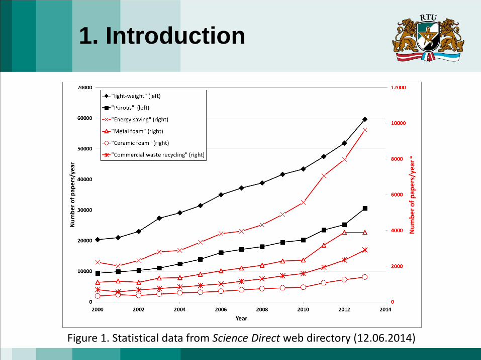
Figure 1. Statistical data from Science Direct web directory (12.06.2014)
1. Introduction
3
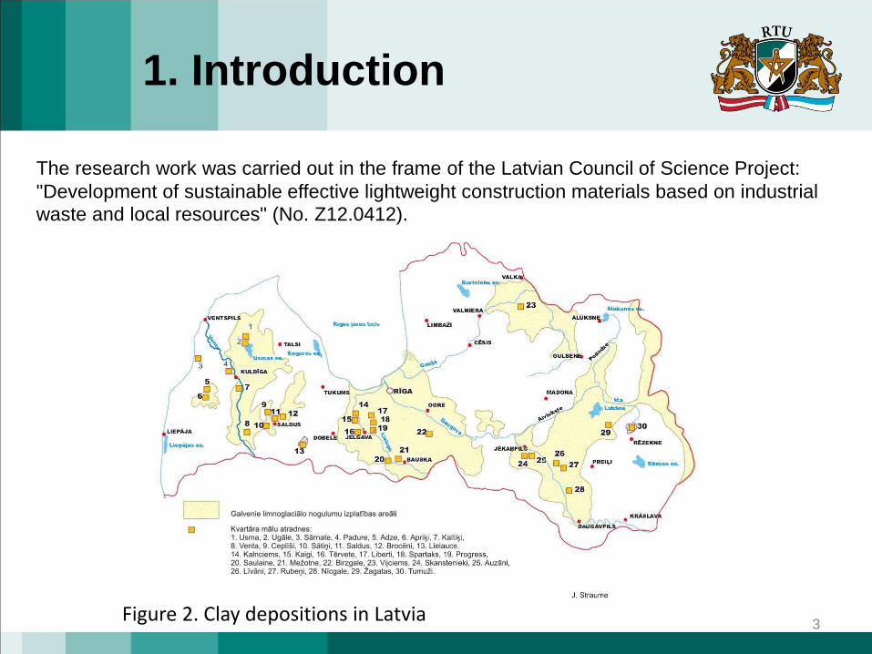
The research work was carried out in the frame of the Latvian Council of Science Project:
"Development of sustainable effective lightweight construction materials based on industrial
waste and local resources" (No. Z12.0412).
1. Introduction
Figure 2. Clay depositions in Latvia
1. Introduction
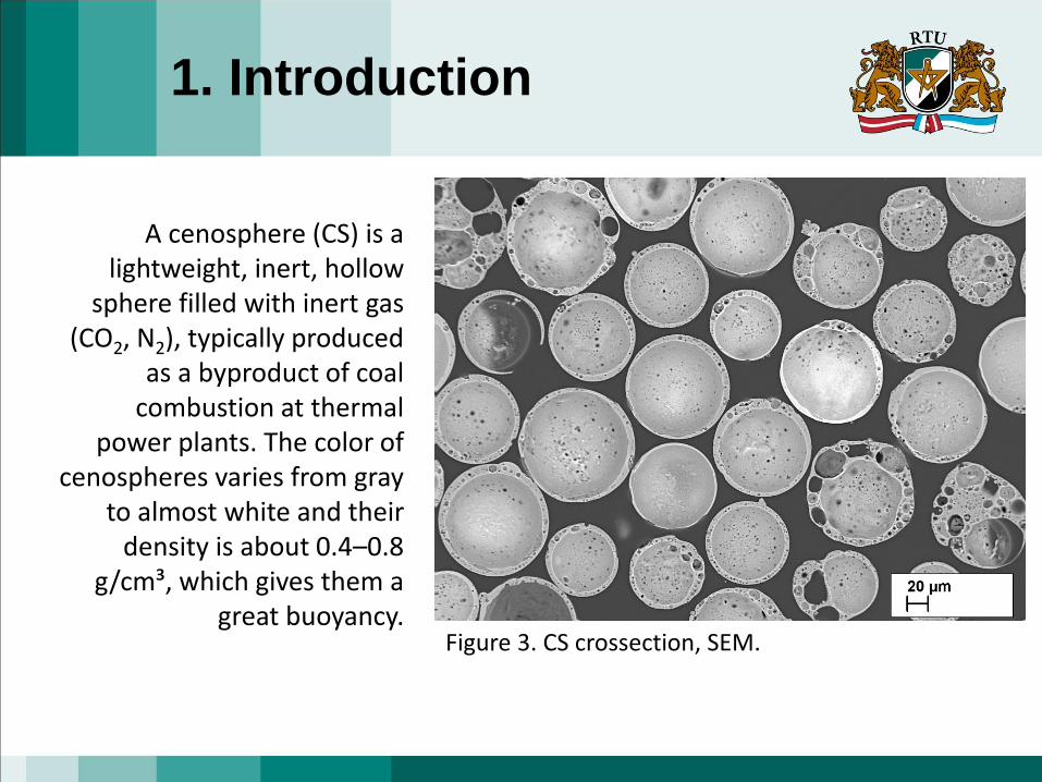
A cenosphere (CS) is a lightweight, inert, hollow
sphere filled with inert gas (CO2, N2), typically produced
as a byproduct of coal combustion at thermal
power plants. The color of cenospheres varies from gray
to almost white and their density is about 0.4–0.8
g/cm³, which gives them a great buoyancy.
Figure 3. CS crossection, SEM.
5
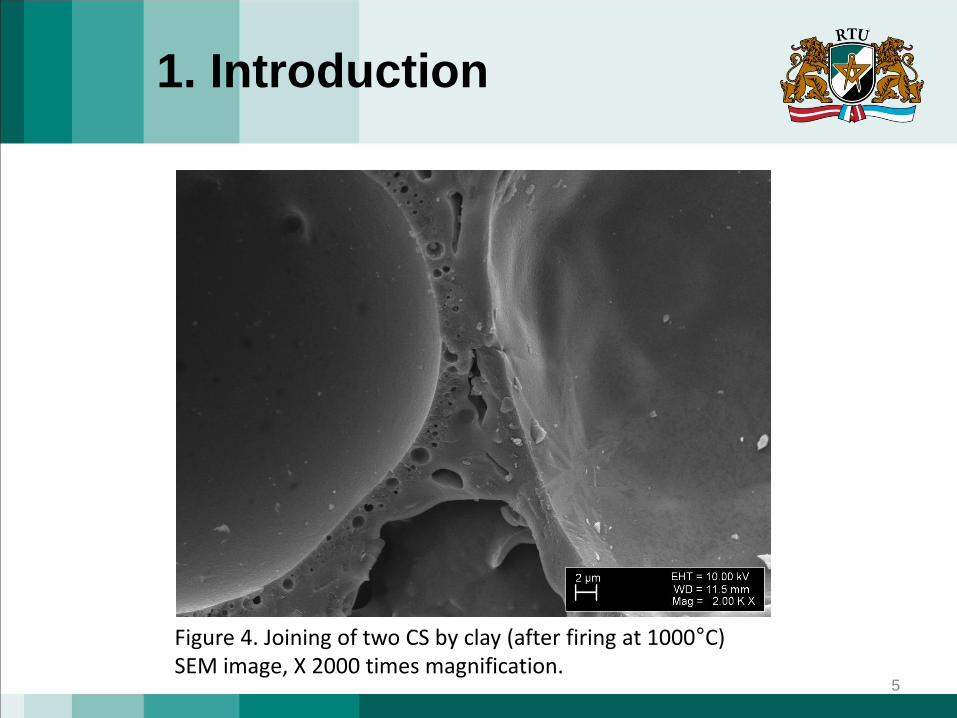
Figure 4. Joining of two CS by clay (after firing at 1000°C)SEM image, X 2000 times magnification.
1. Introduction
6
2. Materials and Methods
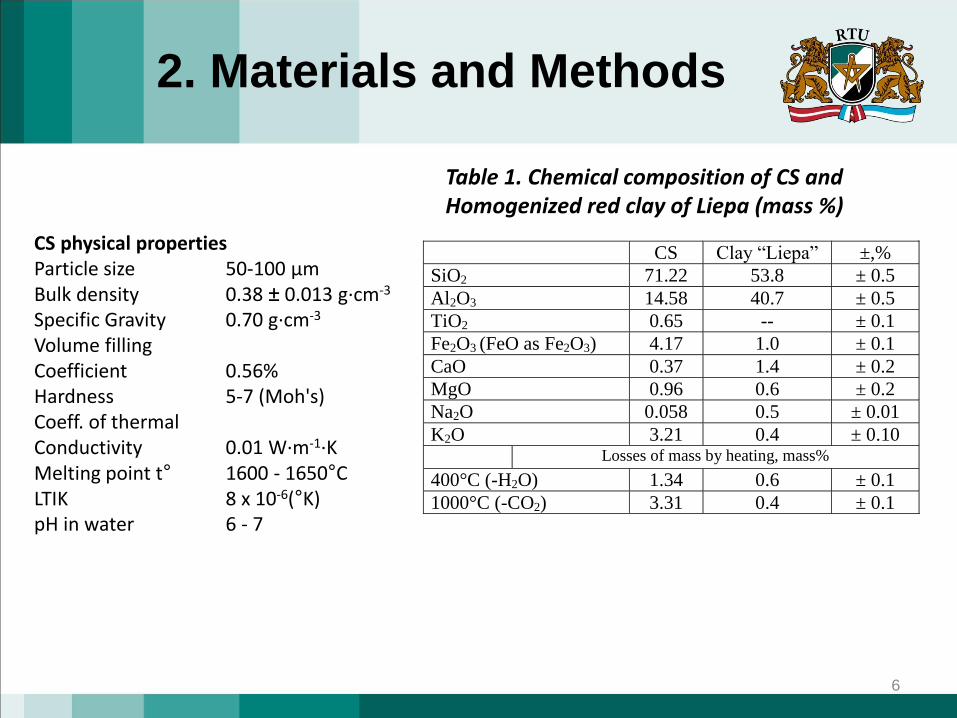
CS physical propertiesParticle size 50-100 µm Bulk density 0.38 ± 0.013 g·cm-3
Specific Gravity 0.70 g·cm-3
Volume fillingCoefficient 0.56%Hardness 5-7 (Moh's)Coeff. of thermalConductivity 0.01 W·m-1·KMelting point t° 1600 - 1650°C LTIK 8 x 10⁻⁶(°K) pH in water 6 - 7
CS Clay “Liepa” ±,%
SiO2 71.22 53.8 ± 0.5
Al2O3 14.58 40.7 ± 0.5
TiO2 0.65 -- ± 0.1
Fe2O3 (FeO as Fe2O3) 4.17 1.0 ± 0.1
CaO 0.37 1.4 ± 0.2
MgO 0.96 0.6 ± 0.2
Na2O 0.058 0.5 ± 0.01
K2O 3.21 0.4 ± 0.10
Losses of mass by heating, mass%
400°C (-H2O) 1.34 0.6 ± 0.1
1000°C (-CO2) 3.31 0.4 ± 0.1
Table 1. Chemical composition of CS andHomogenized red clay of Liepa (mass %)
7
2. Materials and Methods
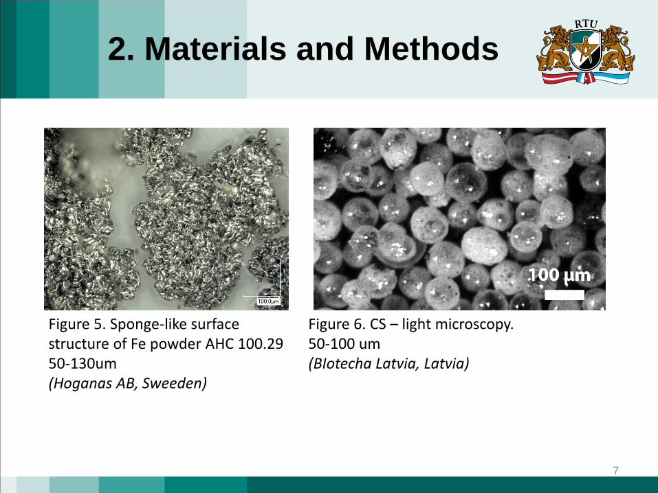
Figure 5. Sponge-like surfacestructure of Fe powder AHC 100.2950-130um(Hoganas AB, Sweeden)
Figure 6. CS – light microscopy.50-100 um(BIotecha Latvia, Latvia)
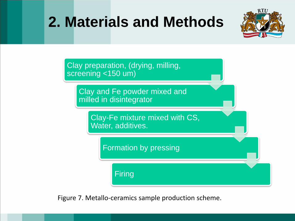
Figure 7. Metallo-ceramics sample production scheme.
Clay preparation, (drying, milling, screening <150 um)
Clay and Fe powder mixed and milled in disintegrator
Clay-Fe mixture mixed with CS, Water, additives.
Formation by pressing
Firing
2. Materials and Methods
9
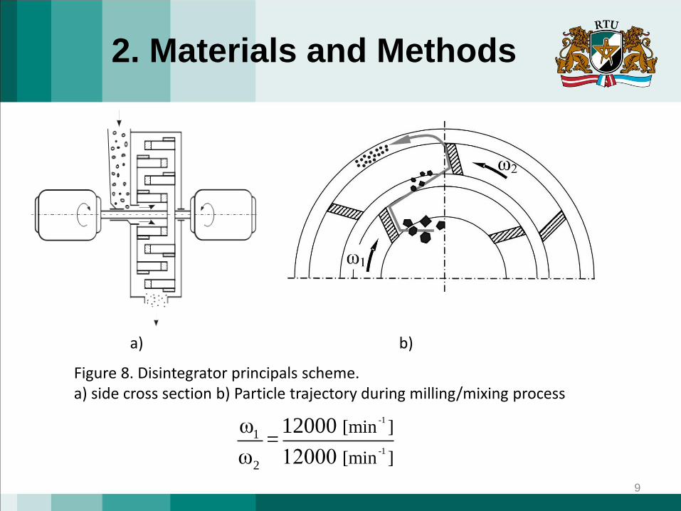
Figure 8. Disintegrator principals scheme.a) side cross section b) Particle trajectory during milling/mixing process
-1
-1
1
2
[min ]
[min ]
ω 12000 =
ω 12000
2. Materials and Methods
a) b)
10
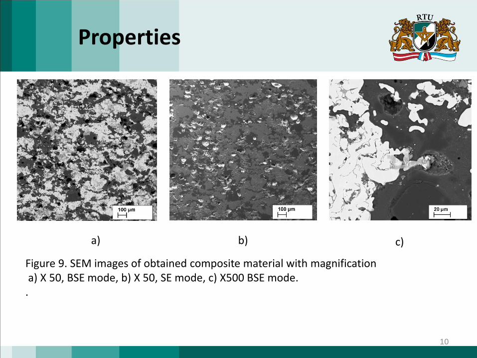
Figure 9. SEM images of obtained composite material with magnificationa) X 50, BSE mode, b) X 50, SE mode, c) X500 BSE mode.
.
a) b) c)
Properties
11
Properties
12
PropertiesUltrasonic testing
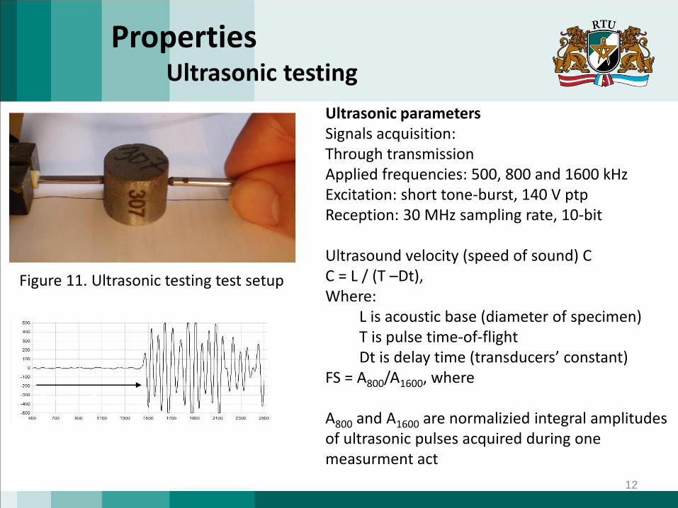
Figure 11. Ultrasonic testing test setup
Ultrasonic parametersSignals acquisition:Through transmission Applied frequencies: 500, 800 and 1600 kHzExcitation: short tone-burst, 140 V ptp Reception: 30 MHz sampling rate, 10-bit
Ultrasound velocity (speed of sound) CC = L / (T –Dt),Where:
L is acoustic base (diameter of specimen)T is pulse time-of-flightDt is delay time (transducers’ constant)
FS = A800/A1600, where
A800 and A1600 are normalizied integral amplitudesof ultrasonic pulses acquired during onemeasurment act
Time of flight T
13
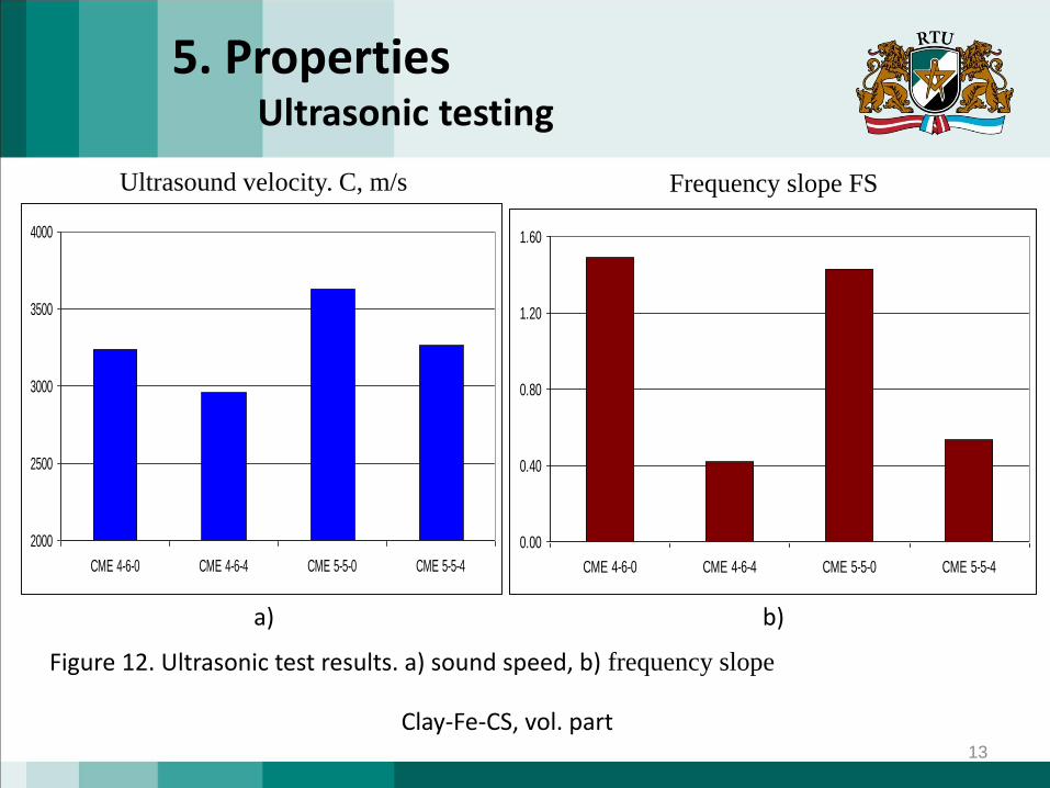
5. PropertiesUltrasonic testing
Figure 12. Ultrasonic test results. a) sound speed, b) frequency slope
2000
2500
3000
3500
4000
CME 4-6-0 CME 4-6-4 CME 5-5-0 CME 5-5-4
Ultrasound velocity. C, m/s
0.00
0.40
0.80
1.20
1.60
CME 4-6-0 CME 4-6-4 CME 5-5-0 CME 5-5-4
Frequency slope FS
a) b)
Clay-Fe-CS, vol. part
14
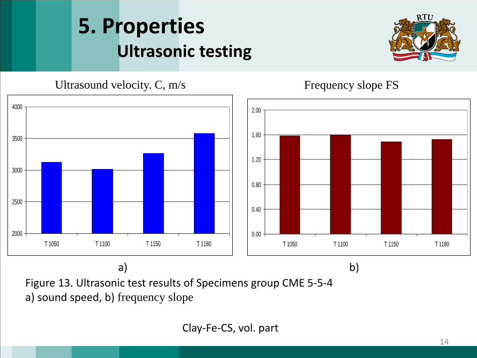
5. PropertiesUltrasonic testing
Ultrasound velocity. C, m/s Frequency slope FS
2000
2500
3000
3500
4000
T 1050 T 1100 T 1150 T 1180
0.00
0.40
0.80
1.20
1.60
2.00
T 1050 T 1100 T 1150 T 1180
a) b)
Clay-Fe-CS, vol. part
Figure 13. Ultrasonic test results of Specimens group CME 5-5-4a) sound speed, b) frequency slope
15
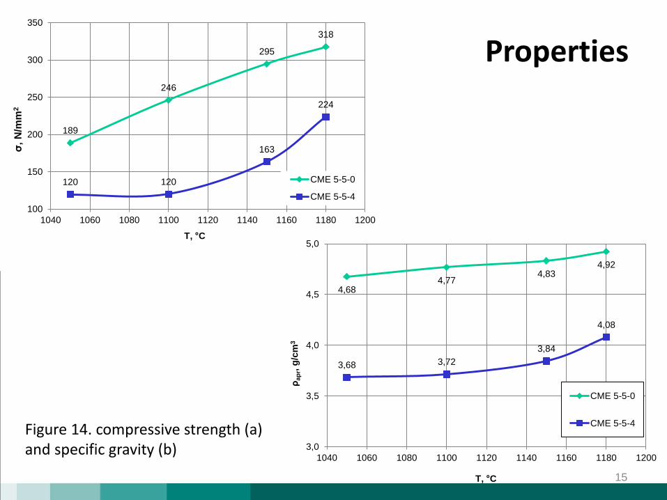
Properties
Figure 14. compressive strength (a) and specific gravity (b)
189
246
295
318
120 120
163
224
100
150
200
250
300
350
1040 1060 1080 1100 1120 1140 1160 1180 1200
σ, N
/mm
2
T, °C
CME 5-5-0
CME 5-5-4
4,684,77
4,834,92
3,68 3,72
3,84
4,08
3,0
3,5
4,0
4,5
5,0
1040 1060 1080 1100 1120 1140 1160 1180 1200
ρap
r, g
/cm
3
T, °C
CME 5-5-0
CME 5-5-4
16
Conclusion
• Fe/cenosphere, with natural clay as binder, syntactic foam obtained via powder metallurgy route.• Noted, that compressive strength and specific gravity are increases in linear dependence in lac of CS, but exponential in case of using CS in composition.• CS using in composition gives significant – up to 75% Frequency slope and up to 10 % sound velocity.Sample of composite material with
17
Thank you for your attention!


