Embed Size (px)
Citation preview
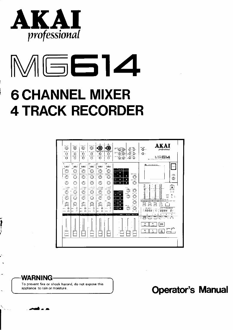
AKÀIpvofessiona[
MEEI46CHANNEL MIXER4TRACK RECORDER
It(
I
@-ô--ô
ô"
-9:o
@-ô""6"
@'
:i):o
@æ@"ô-
@-ô-l...---.t@l
ÀKÀI@ - professioua[
@.
".".". Mtr""Et"4
i'
L)
oo..; tr
-6
@r
t,,,,,.:F
oop"
"6, o!!! o
lr-t,-"let,.,.",,"....lolc1,"t*le1..,,..--,
loo
.": ;6!tr
?" ..
rô
@
o-6
@/ô
.,.: ;6'o
t::E-rO.
@
@
É(ô
@
o,ll tr
@
@"Tô
@@o@
o@@
Eo
mlftt mltfil Ëflf -l l[ Hl 'ï'ï':
fil fll ,[] fl ,3,t:.--'
Ë Ë'Ë'Ë Ëffififfi
| @ieif ; qllLg )
o @
op"
!5" tr!1' tr
@
_o"é^os.tr
o9
!4. E
"""tr
À ÀÀü
E5lËlËlijliî rr I
t ---T--:t T:;lI -" il ,* I 1..-,1
"-*.. #:9"T------l----:--- T,-;--l "l-':; I r-r-r
To prevent fire or shock hazard, do not expose thisappliance to rain or moisture.
-.Ê--l
Operator's Manua!
T
T
Warning
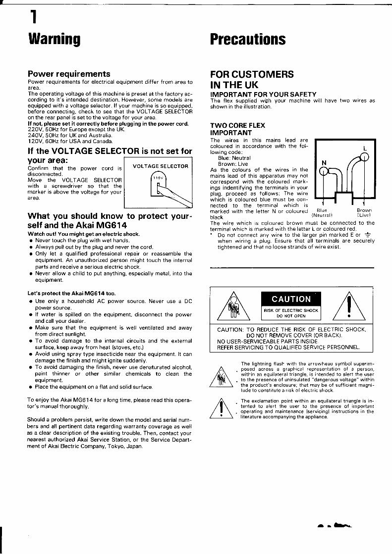
Power requirementsPower requirements for electrical equipment differ from area toarea.The operating voltage of this machine is preset at the factory ac-cording to it's intended destination. However, some models areequipped with a voltage selector. lf your machine is so equipped,before connecting, check to see that the VOLTAGE SELECTORon the rear panel is set to the voltage for your area.lf not, please set it correctly before plugging in the power cord.22OY,SOHz for Europe except the UK.24OY, SOHz for UK and Australia.1 20V, 60Hz for USA and Canada.
lf the VOLTAGE SELECTOR is not set foryour area:Confirm that the power cord isdisconnected.Move the VOLTAGE SELECIORwith a screwdriver so that themarker is above the voltage for yourarea.
VOLTAGE SELECTOR
1 10V
What you should know to protect your-self and the Akai MG614Watch out! You might get an electric shock.o Never touch the plug with wet hands.o Always pull out by the plug and never the cord.o Only let a qualified professional repair or reassemble the
equipment. An unauthorized person might touch the internalparts and receive a serious electric shock.
o Never allow a child to put anything, especially metal, into theequipment.
Let's protect the Akai MG614 too.o Use only a household AC power source. Never use a DC
power source.o lf water is spilled on the equipment, disconnect the power
and call your dealer.o Make sure that the equipment is well ventilated and away
from direct sunlight.o To avoid damage to the internal circuits and the external
surface, keep away from heat (stoves, etc.)o Avoid using spray type insecticide near the equipment. lt can
damage the finish and might ignite suddenly.o To avoid damaging the finish, never use denaturated alcohol,
paint thinner or other similar chemicals to clean theequipment.
o Place the equipment on a flat and solid surface.
To enjoy the Akai MG61 4 for a long time, please read this opera-tor's manual thoroughly.
Should a problem persist, write down the model and serial num-bers and all pertinent data regarding warranty coverage as wellas a clear description of the existing trouble. Then, contact yournearest authorized Akai Service Station, or the Service Depart-ment of Akai Electric Company, Tokyo, Japan.
Precautions
FOR CUSTOMERSIN THE UKIMPORTANT FOR YOUR SAFETYThe flex supplied wiJh your machine will have two wires asshown in the illustration.
TWO CORE FLEX!MPORTANTThe wires in this mains lead arecoloured in accordance with the fol-lowing code:
Blue: NeutralBrown:Live
As the colours of the wires in themains lead of this apparatus may notcorrespond with the coloured mark-ings indentifying the terminals in yourplug, proceed as follows: The wirewhich is coloured blue must be con-nected to the terminal which ismarked with the letter N or colouredblack.
Blue Brown(Neutral) (Live)
The wire which is coloured brown must be connected to theterminal which is marked with the letter L or coloured red.' Do not connect any wire to the larger pin marked E or È
when wiring a plug. Ensure that all terminals are securelytightened and that no loose strands of wire exist.
The lightning flash with the arrowhead symbol superim-posed across a graphical representation oT a person,within an equilateral triangle, is intended to alert the userto the presence of uninsulated "dangerous voltage" withinthe product's enclosure; that may be of sufficient magni-tude to constitute a risk of electric shock.
The exclamation point within an equilateral triangle is in-tented to alert the user to the presence of importantoperating and maintenance (servicing) instructions in theliterature accompanying the appliance.
RISK OF ELECTRIC SHOCKDO NOT OPEN
CAUIION: TO REDUCE IHE RISK OF ELECTRIC SHOCK,DO NOT REMOVE COVER (OR BACK).
NO USER-SERVICEABLE PARTS INSIDE.REFER SERVICING TO OUALIFIED SERVICE PERSONNEL.
r rlr-
Features
The MG614 is a 6 channel mixer combined in a compact designwith a 4 track/multi-track recorder using compact cassettetapes.
o There is no need to connect the mixer and the recorder.o The REC TRACK/BUS selector function makes it possible to
connect any mixer channel output to any track and record.Ping-pong recording between tracks is also possible withsimple button operation.
o FM recording and playback of tape synchro signals is possibleusing a sequencer or rhythm machine. The signals are record-ed on track 1 along with the audio signals, so the full fourtracks can be used for recording and playback of audiosignals, making synchronized operation with a sequencer orrhythm machine possible.
o dbx noise reduction. This system provides an extremely highreduction effect (30 * 4OdB), and can be used for eitherregular recording or ping-pong recording between trackswithout losing the dynamic range of the recording source.
o Two speeds: HIGH (9.5cm/sec) and LOW (4.75cm/sec). Pitchcontrol function for varying the tape speed by -r 1O%.
o Auto memory system for increased operability of the searchand repeat playback functions.
o Handy functions for improved multi-layer recordingoperability, including rehearsal mode and auto monitor.
o lnput modules for channels 5 and 6 equipped with transfor-merless balanced mike inputs using XLR-type cannon plugs.
o Each input module is equipped for accessory send/receive, soeffectors can be used for each channel and track.
o Double total effect send/receive for monaural, stereo, ormultiple effect loop configurations.
o Monitor selector making it possible to easily monitor thetrack, bus, total effect receive, and master level separately.
o Track monitor mixer with pan-pot for stereo-image trackmonitoring. The mixer output can also be connected to themaster line.
o AUX inputs (stereo) can be connected to the master and buslines.
o 4 track direct playback output.o Punch-in/punch-out is possible using a foot switch.
Table of Gontents
Warning and Precautions . . .
FeaturesBlock DiagramControls
lnput Modules (1 - 6)Bus/Master/Monitor ModulesJack PanelRecorder/Meter Section
ConnectionsMulti-Layer Recording
Track-to-Track Ping-Pong Multi-Layer Recording . . .
Monitor SystemRecording and PlaybackBasicPlayback.....Tracking Down .
Ping-Pong RecordingApplications of Tracking Out . . .
Connection of Eff ectorsMemory SystemPunch-ln/Punch -Out Recordin gTape SynchronizationMaintenance/Troubleshooting .
Level DiagramSpecifications .....
1
235618o
11
121315161819202122232627282930
A-.
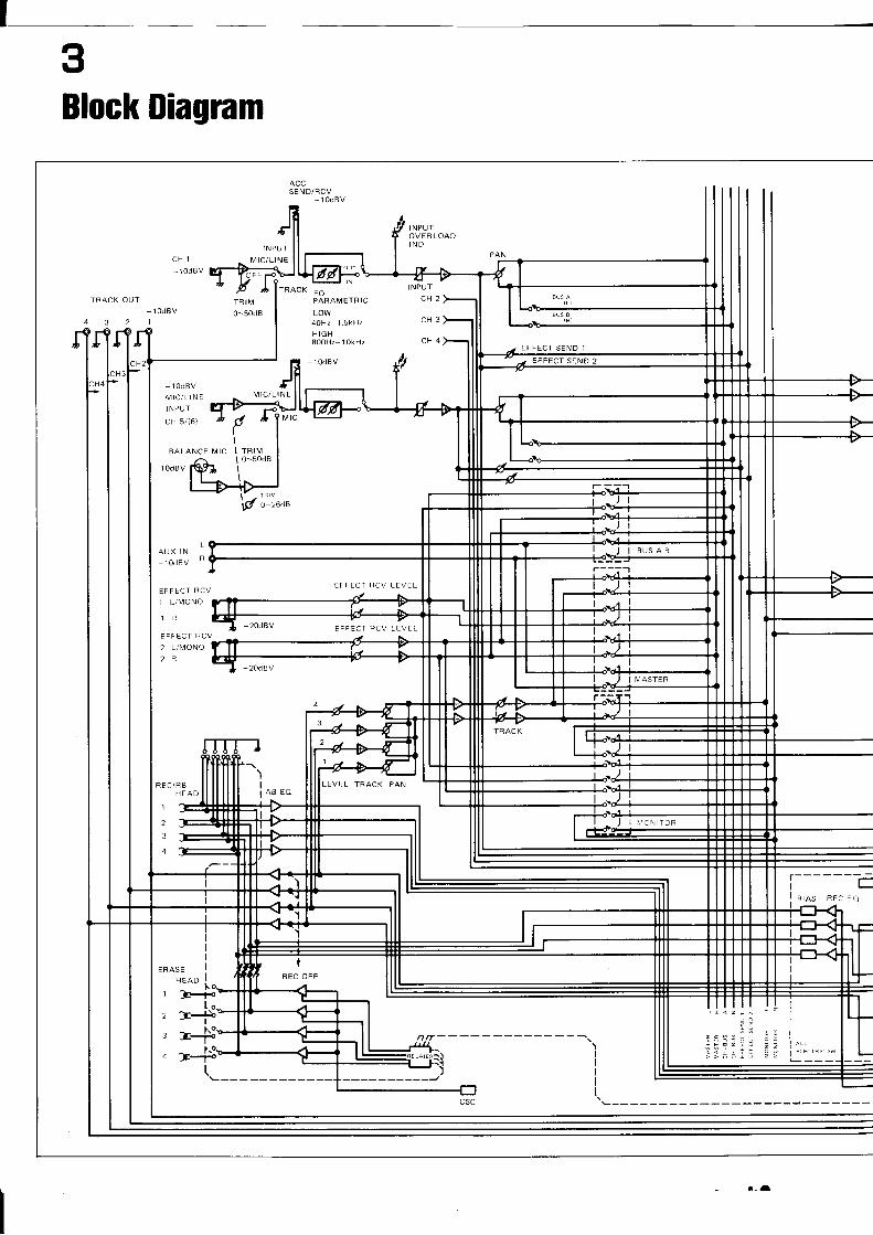
Block Diagram
TRACK OUT TRIM0-50d8
1 OdBV
MIC/LINEI NPUT
cH 5/(6)
TRACK EOPARAMETRIC
LOW40Hz 1.5kHz
H IGH800H2 l0kHz
-10dBV
BALANCE I!1IC
1 OdBV
LAUX IN
rodBV "
MIC/LINE
,20dBV
EFFECT RCV
1 L/MONO
EFFECT RCV
2 L/MONO2R
EFFECT RCV LEVEL
FFFECT RCV LEVEL
20dav
REC/RBH FAD
1
2
3
4
l-l-I sres aec eo
REC OFF
I
I
I
I
t
EFFECT SEND 1
EFFECT S
IÀ,4ASTER
EVEL TRACK PAN
I ,.ro\ ToR
I
I
I
I
I arL
a--
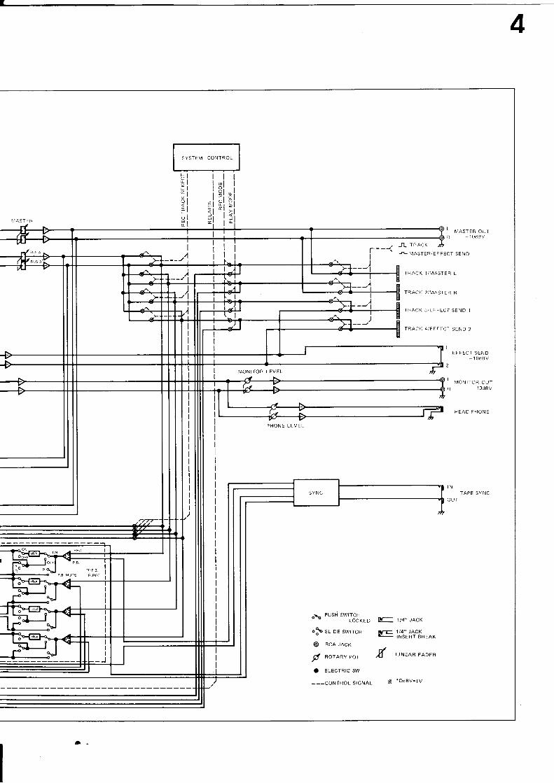
SYSTEM CONTROL
I,4ASTER
t.tülür
ZiÈtolËt
I
J-L TRACK
N- i t4" JA}K
lrE 1/4" JACK
-
iNSERT BREAK
,il LINEAR FADER
X +OdBV=1V
 N,'IASTER/EFFECT SEND
L vlsreR outR 1 OdBV
I
EFFECI SEND1 OdBV
2
L ,olrtlo* oulR 10dBV
HEAD PHONE
TAPE SYNC
TRACK 1/N4ASTER L
TRACK 2/MASIER R
IRACK 3/EFFECT SEND 1
TRACK 4/EFFECl SEND 2
MÔNITOR LEVEL
PHONE LEVEL
IN
OUT
oao PUSH T*'JSNoro
op srroe swrrcH
@ RCA JACK
y' aoraav eor
C ELECTRIC SW
---CONTROL SIGNAL
I
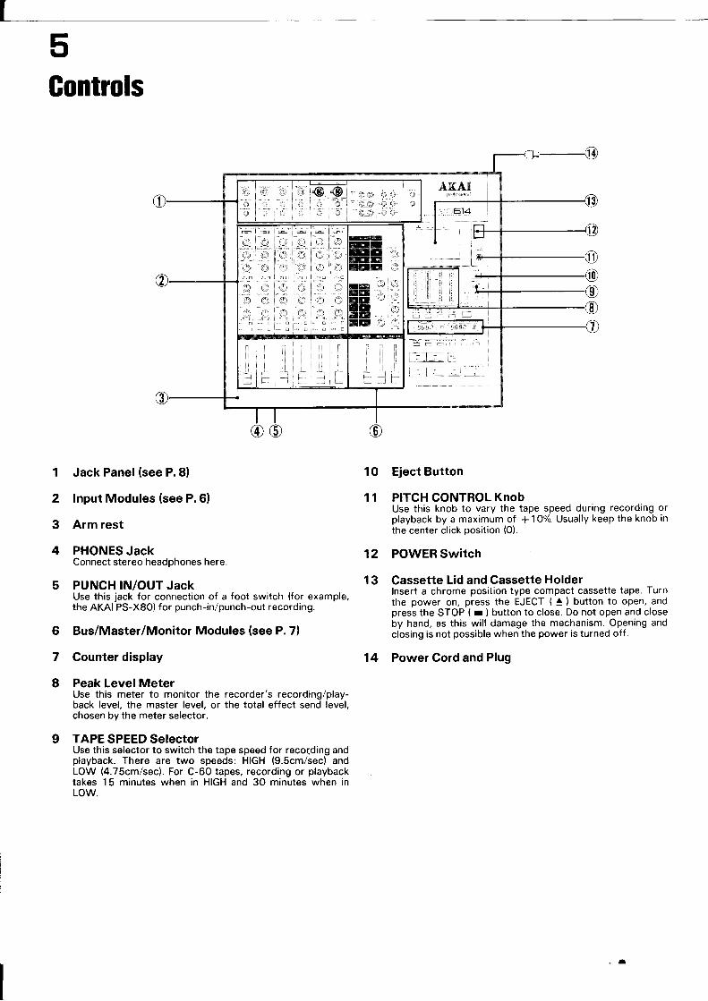
Gontrols
2
3
4
Jack Panel (see P.8)
!nput Modules (see P.6)
Arm rest
PHONES JackConnect stereo headphones here.
PUNCH IN/OUT JacKUse this jack for connection of a foot switch (for example,the AKAI PS-X8O) for punch-in/punch-out recording.
Bus/Master/Monitor Modules (see P. 7)
Counter display
Peak LevelMeterUse this meter to monitor the recorder's recording/play-back level, the master level, or the total effect send level,chosen by the meter selector.
TAPE SPEED SelectorUse this selector to switch the tape speed for reco;ding andplayback. There are two speeds: HIGH (9.Scm/sec) andLOW (4.75cm/sec). For C-60 tapes, recording or playbacktakes 15 minutes when in HIGH and 30 minutes when inLOW.
Eject Button
PITCH CONTROL KnobUse this knob to vary the tape speed during recording orplayback by a maximum of + 1O%. Usually keep the knob inthe center click position (0).
POWER Switch
Cassette Lid and Cassette Holderlnsert a chrome position type compact cassette tape. Turnthe power on, press the EJECT ( ) button to open, andpress the STOP ( r ) button to close. Do not open and closeby hand, as this will damage the mechanism. Opening andclosing is not possible when the power is turned off .
Power Cord and PIug
10
11
12
13
6
I
I
14
t
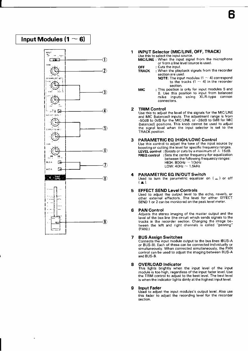
lnput Modules (1 - 6)
3
INPUT Selector (MlC/LlNE, OFF, TRACK)Use this to select the input source.MIC/LINE : When the input signal from the microphone
or from a line level source is used.OFF : Cuts the inPut.TRACK : When the playback signals from the recorder
section are used.NOTE: The input modules (1 - 4) correspond
to the tracks (1 - 4) in the recordersection.
MIC : This position is only for input modules 5 and6. Use this position to input from balancedmike inputs using XLR-tyPe cannonconnectors.
TRIM ControlUse this to adjust the level of the signals for the MIC/LINEand MIC (balanced) inputs. The adjustment range is from-SOdB to OdB for the MIC/LINE, or -26d8 to OdB for MIC(balanced) positions. This knob cannot be used to adjustthe signal level when the input selector is set to theTRACK position.
PARAMETRTC EO (HIGH/LOW) ControlUse this control to adjust the tone of the input source byboosting or cutting the level for specific frequency ranges.LEVEL control : Boosts or cuts by a maximum of -r 1 SdB.FREO control : Sets the center frequency for equalization
between the following frequency ranges:HIGH: SOOHz - lOkHzLOW: 4OHz - 1.5kHz
PARAMETRIC EO !N/OUT SwitchUsed to turn the parametric equalizer on (
- ) or off(r).EFFECT SEND Level ControlsUsed to adjust the output level to the echo, reverb, orother external effectors. The level for either EFFECT
SEND 1 or 2 can be monitored on the peak level meter.
PAN ControlAdjusts the stereo imaging of the master output and thelevel of the bus line (the circuit which sends signals to thetracks in the recorder section. Changing the image be-tween the left and right channels is called "panning"(PAN).}
BUS Assign SwitchesConnects thé input module output to the bus lines (BUS-Aor BUS-B). Each of these can be connected individually orsimultaneously. When connected simultaneously, the PANcontrol can be used to adjust the imaging between BUS-Aand BUS-8.
OVERLOAD !ndicatorThis lights brightly when the input level of the inputmodule is too high, regardless of the input fader level. Usethe TRIM control to adjust to the best level. The best levelis when the indicator lights dimly at the highest input level.
lnput FaderUsed to adjust the input modules's output level. Also usethis fader to adjust the recording level for the recordersection.
4
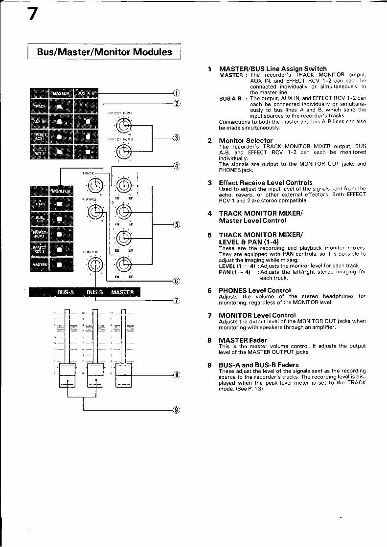
Bus/Master/Monitor Modu les
4
5
1 MASTER/BUS Line Assign SwitchMASTER : The recorder's TRACK MONITOR output,
AUX lN, and EFFECT RCV 1-2 can each beconnected individually or simultaneously tothe master line.
BUS A-B : The output, AUX lN, and EFFECT RCV 1-2 caneach be connected individually or simultane-ously to bus lines A and B, which send theinput sources to the recorder's tracks.
Connections to both the master and bus A-B lines can alsobe made simultaneously.
2 Monitor SelectorThe recorder's TRACK MONITOR MIXER output, BUSA-B, and EFFECT RCV 1-2 can each be monitoredindividually.The signals are output to the MONITOR OUT jacks andPHONES jack.
3 Effect Receive LevelControlsUsed to adjust the input level of the signals sent from theecho, reverb, or other external effectors. Both EFFECÏRCV 1 and 2 are stereo compatible.
TRACK MONTTOR MIXER/Master LevelControl
TRACK MONITOR MIXER/LEVEL E PAN (1.4)These are the recording and playback monitor mixersThey are equipped with PAN controls, so it rs possible toadjust the imaging while mixing.LEVEL (1 - 4l : Ad.iusts the monitor level f or each track.PAN (1 -- 4) :Adjusts the left/right stereo imaging for
each track.
PHONES LevelControlAdjusts the volume of the stereo headphones formonitoring, regardless of the MONITOR level.
MONITOR LevelControlAdjusts the output level of the MONIIOR OUT jacks whenmonitoring with speakers through an amplifier.
MASTER FaderThis is the master volume control. lt adjusts the outputlevel of the MASTER OUTPUï jacks.
BUS-A and BUS-B FadersThese adjust the level of the signals sent as the recordingsource to the recorder's tracks. The recording level is dis-played when the peak level meter is set to the IRACKmode. (See P. 13)
6
7
8
I
Jack Panel
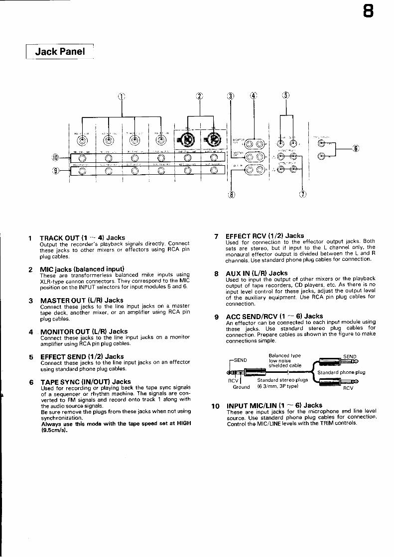
TRACK OUT (1 - 4) JacksOutput the recorder's playback signals directly. Connectthese jacks to other mixers or effectors using RCA pinplug cables.
MIC jacks (balanced input)These- are transformerless balanced mike inputs usingXLR-type cannon connectors. They correspond to the MICposition on the INPUT selectors for input modules 5 and 6.
MASTER OUT (L/R) JacksConnect these jacks to the line input jacks on a mastertape deck, anoiher mixer, or an amplifier using RCA pinplug cables.
MONITOR OUT (L/R) JacksConnect these jacks to the line input jacks on a monitoramplifier using RCA pin plug cables.
EFFECT SEND (1/2} JACKSConnect these jacks to the line input jacks on an effectorusing standard phone plug cables.
TAPE SYNC (IN/OUT} JACKSUsed for recording or playing back the tape sync signalsof a sequencer or rhythm machine. The signals are con-verted to FM signals and record onto track 1 along withthe audio source signals.Be sure remove the plugs f rom these jacks when not usingsynch ronization.Always use this mode with the tape speed set at HIGH(9.Scm/sl.
EFFECT RCV (1/2) JacksUsed for connection to the effector output jacks. Bothsets are stereo, but if input to the L channel only, themonaural effector output is divided between the L and R
channels. Use standard phone plug cables for connection'
AUX lN (L/R) JacksUsed to input the output of other mixers or the playbackoutput of iape recorders, CD players, etc. As there is noinput level control for these jacks, adjust th.e output leveloi the auxiliary equipment. Use RCA pin plug cables forconnection.
ACC SEND/RCV (1 --- 6) JacksAn effector can be connected to each input module usingthese jacks. Use standard stereo plug cables forconneciion. Prepare cables as shown in the figure to makeconnections simPle.
8
3
4
6
9
RCV
Ground
Balanced typelow noiseshielded cable
Standard stereo plugs(6.3/mm, 3P type)
Standard phone Plug
RCV
10 INPUT MtC/LlN (1 - 6)JacksThese are input jacks for the microphone- and line levelsource. Use btandard phone plug cables for connection.Control the MIC/LINE levels with the TRIM controls.
00

Recorder/M eter Section
Peak Level MeterUse the METER select button to monitor the recording/playback level, master level (L/R), and effect send level(1 /2t.TRACK : To monitor the recorder's
recording/playback level.MASTER/EFFECT SEND : To monitor the master and
effect send levels.Red LEDs indicate the operation modes.
REC TRACK/BUS Select ButtonsNormally used to select the tracks for recording.When the button is pressed, the "REC" LED for the corre-sponding track flashes. Now press the REC PAUSE( l.l ) button then the PLAY ( - ) button, and recordingwill start. When recording starts, the "REC" LED stopéflashing and remains lit.lf the REC TRACK/BUS select button is pressed again, the"REC" LED turns off and that track will be set to the play-back mode.These buttons are also used as switches to connectBUS-A and BUS-B to the various tracks when performingping-pong recording using the bus lines.
TAPE COUNTERDisplays the amount of tape transport from "0000" to"9999". The counter is reset to "0000" when the tape isejected and when the power is turned off.
MEMORY COUNTERDisplays the TAPE COUNTER value at the point at whichthe memory buttons (MEMO 1 - MEMO 3) and CApTUREb'ltJg! are pressed. When the MEMO O button is pressed,"0000" is displayed.
MEMORY CLEAR ButtonClears the TAPE COUNIER values set by pressing theMEMO 1 - MEMO 3 and CAPTURE buttons. When thisbutton is pressed, "CLr" is displayed on the MEMORYCOUNTER and all values stored in the memory are cleared.
MEMO 0 ButtonThe value of "0OOO" is preset in the memory for thisbutton, and the IAPE COUNIER value cannot be stored. lnother words, this button is used exclusively for recall, tosearch for the ïAPE COUNTER's "0000" position or torecall the position for repeat playback.
REW(<<)ButtonUsed to rewind the tape.
F-FWD (>> ) ButtonUsed to fast-forward the tape.
STOP(rlButtonUsed to stop playback.Also use this button to close the cassette holder.
PLAY (> ) ButtonNormally used for tape playback.Also used with the REC PAUSE ( l.l ) button to start thetape during recording and punch-in/punch-out recording.
dbx IN/OUT ButtonlN when the green LED is lit.Provides playback sound with noiseless and with no loss inthe source's dynamic range.Always use this dbx lN mode with the tape speed set atHIGH (9.5cm/s).
6
2
8
I
10
4 11
1712
18
SHIFT ButtonWhen the REC TRACK/BUS select buttons are pressedwhile this button is depressed, the "REC" LED for the cor-responding track lights and the "A" or "B" LED lights. ("A"lights after the first time, "8" after the second, and "REC"and "A" or "8" turn off after the third.)When A is lit: BUS-A is connected to the corresponding
track.When B is lit: BUS-B is connected to the corresponding
track.When both A and B are off, all tracks are connected to thecorresponding input modules.
CAPTURE ButtonThe TAPE COUNTER value at the point at which thisbutton is pressed is stored in the memory and displayedon the MEMORY COUTNER. Each time this button ispressed the stored TAPE COUNTER value is renewed.
MEMO NO. DisplayDisplays the number from O to 3 of the memory buttonwhich has been pressed. When the CAPTURE button ispressed, "C" is displayed.
MEMOl -MEMO3ButtonsThese buttons can be used for memorising the tape loca-tion where you wish to re-locate again.When one of these buttons is pressed while the tape ismoving after the memory has been cleared, the number ofthat button is displayed on the MEMO NO. display. TheTAPE COUNTER value at that point is displayed on theMEMORY COUNTER, and that value is stored in thememory. The values stored at MEMO 1 through MEMO 3can be cleared individually by using the MEMO buttonswith the MEMORY CLEAR button.This button is also used for the repeat playback andsearch functions.
REPEAT ButtonPress this button for repeat playback. With the MG614, itis possible to repeat the sections between two MEMObutton values or one MEMO button value and the CAP-TURE button value.
Itl
MEMORY SEARCH ButtonPress this button to search backward or forward for theTAPE COUNTER positions stored with the memory but-tons and the CAPTURE button. When searching iscompleted, the unit is set to the stop mode and tape trans-port stops.
REHEARSAL ButtonWhen this button is pressed, the red LED lights and theunit is set to the rehearsal mode. ln this mode, the tapemoves in the recording mode but is actually not recorded.Use this especially for rehearsal for punch-in/punch-outrecording. When pressed again, the red LED turns off andthe rehearsal mode is cleared.
AUTO MONlTORButtonThis is a function for monitoring recording or playback onthe recorder. When on, the red LED is lit.ON : All tracks are set to the playback mode and playback
monitor is possible if the PLAY ( > ) button ispressed, even if the "REC" LED are flashing for alltracks.Also, during recording, recording is monitored onlyfor the track or tracks whose "REC" LED is flashing,and playback is monitored on the other tracks.
OFF: Recording is monitored only for the track or trackswhose "REC" LED is flashing, and playback is moni-tored on the other tracks, even during playback.
REC PAUSE (tor ) SuffenNormally press this button during recording. Whenpressed, the red LED will light and the green LED for thePLAY ( > ) button will flash. The unit is now in the recordpause mode and the tape will not move. (For instructionson recording, see P. 16.)
13
14
15
19
20
16
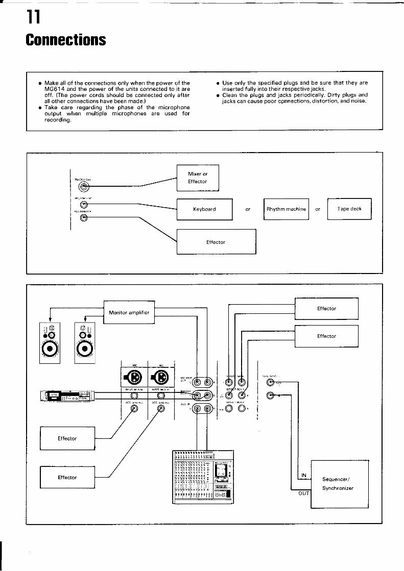
IIGonnections
l*-^,",",*;l .rl-,,,"";l
Sequencer/
Synchronizer
o Make all of the connections only when the power of theMG614 and the power of the units connected to it areoff. (The power cords should be connected only afterall other connections have been made.)
o Take care regarding the phase of the microphoneoutput when multiple microphones are used forrecording.
o Use only the specified plugs and be sure that they areinserted fully into their respective jacks.
o Clean the plugs and jacks periodically. Dirty plugs andjacks can cause poor connections, distortion, and noise.
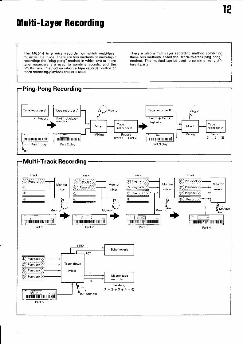
I2Multi-layer Recording
Multi-Track Recording
The MG614 is a mixer/recorder on which multi-layermusic can be made. There are two methods of multi-layerrecording: the "ping-pong" method in which two or moretape recorders are used to combine sounds, and the"multi-track" method on which a tape recorder with 4 ormore recording/playback tracks is used.
There is also a multi-layer recording method combiningthese two methods, called the "track-to-track ping-pong"method. Ihis method can be used to combine many dif-ferent parts.
Part 2 play
Tape recorder B
+
(1 +2+3)Part 3 play
Track
Part 1
Track
Part 2
Track Track
Paft 4
Part 5
t3
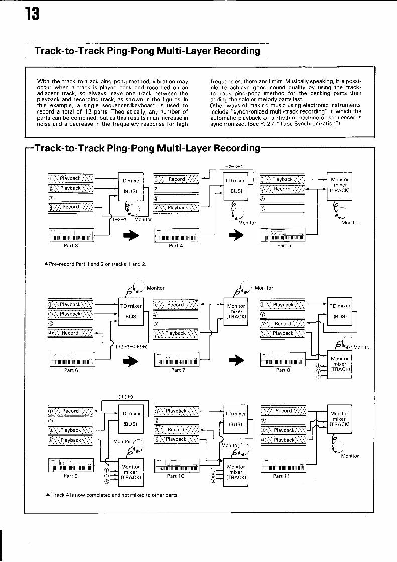
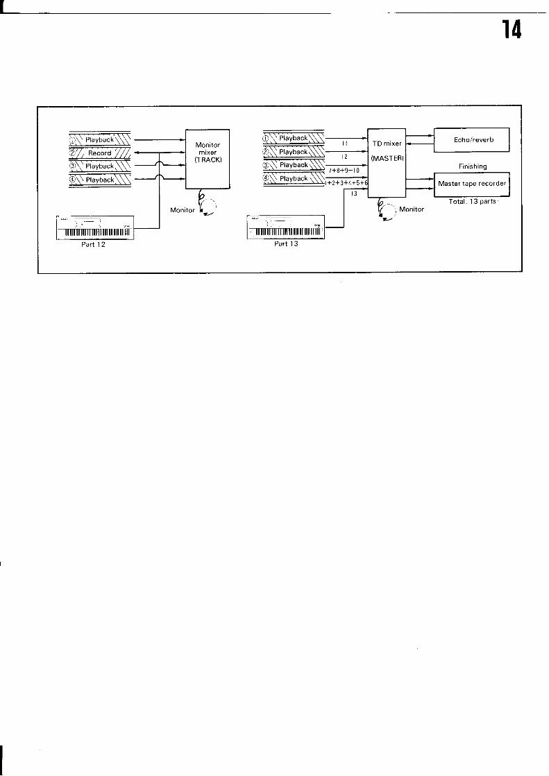
Track-to-Track Ping-Pong Multi-Layer Recording
Track-to-Track Ping-Pong Multi-Layer Recording
With the track-to-track ping-pong method, vibration mayoccur when a track is played back and recorded on anadjacent track, so always leave one track between theplayback and recording track, as shown in the figures. lnthis example, a single sequencer/keyboard is used torecord a total of 13 parts. Iheoretically, any number ofparts can be combined, but as this results in an increase innoise and a decrease in the frequency response for high
frequencies, there are limits. Musically speaking, it is possi-ble to achieve good sound quality by using the track-to-track ping-pong method for the backing parts thenadding the solo or melody parts last.Other ways of making music using electronic instrumentsinclude "synchronized multi-track recording" in which theautomatic playback of a rhythm machine or sequencer issynchronized. (See P. 27, "Tape Synchronization")
l+2+3+4
Monitor
+
ffi;., =
ow.-,bi"k§\
Part 4
66-.4.N(
A Pre-record Part 1 and 2 on tracks 1 and 2.
0 "+N@;;-;----------' -@/ , Record'/ /,
6§PJr-ryb*kN
TMonitor
Part 5Part 3
Part 7Part 6
7+8+9
Part 1 1
À Track 4 is now completed and not mixed to other parts.
II4
6§flrryb*tNT-æi-,T-O§Pt.yb""r.Nô§Prryb""k§\
Part 12
TD mixer
(MASTER)
Master tape recorder
Part 1 3
I5
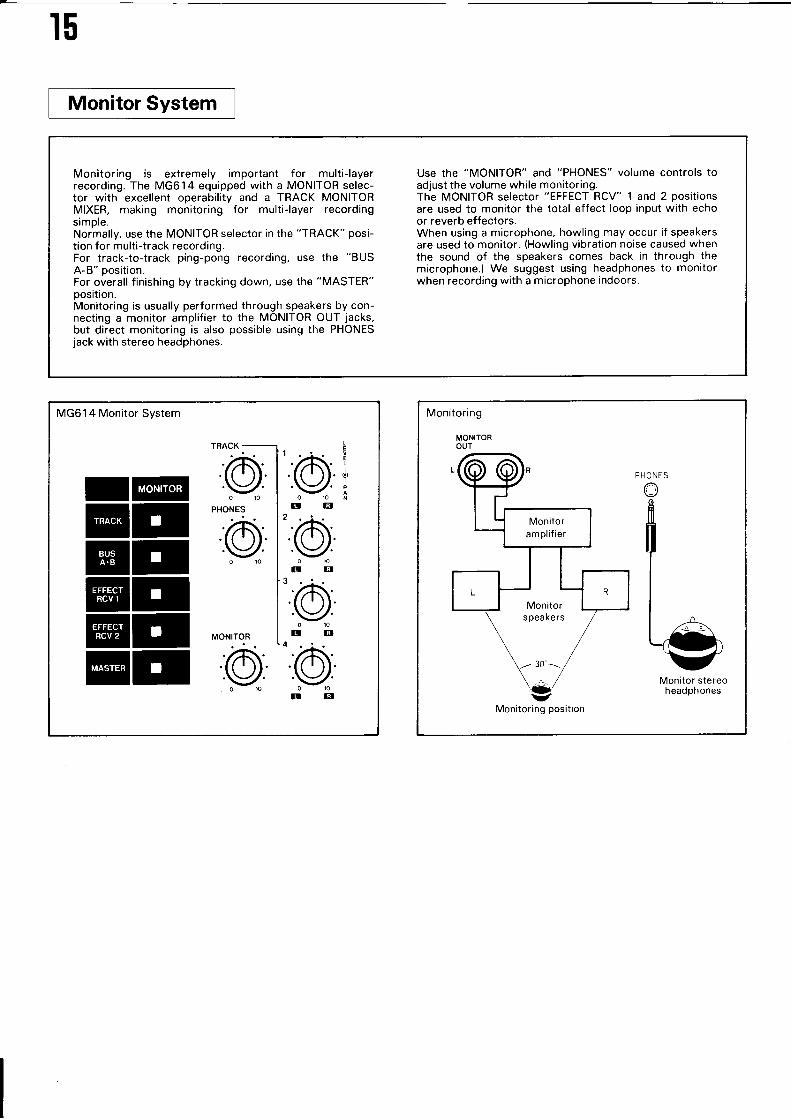
Monitoring is extremely important for multi-layerrecording. The MG614 equipped with a MONITOR selec-tor with excellent operability and a TRACK MONITORMIXER, making monitoring for multi-layer recordingsimple.Normally, use the MONITOR selector in the "TRACK" posi-tion for multi-track recording.For track-to-track ping-pong recording, use the "BUSA-B" position.For overall finishing by tracking down, use the "MASÏER"position.Monitoring is usually performed through speakers by con-necting a monitor amplifier to the MONITOR OUT jacks,but direct monitoring is also possible using the PHONESjack with stereo headphones.
Use the "MONITOR" and "PHONES" volume controls toadjust the volume while monitoring.The MONITOR selector "EFFECT RCV" 1 and 2 positionsare used to monitor the total effect loop input with echoor reverb effectors.When using a microphone, howling may occur if speakersare used to monitor. (Howling vibration noise caused whenthe sound of the speakers comes back in through themicrophone.) We suggest using headphones to monitorwhen recording with a microphone indoors.
MG61 4 Monitor System
I@ETET@r@rET
TRACK
-:@PHONES
@
o
PHONES
Monitor stereoheadphones
Monitoring position
Recording
Recording and Playhack
I@M INPUT MIC/LINE
@I sorrce
1
2
I6
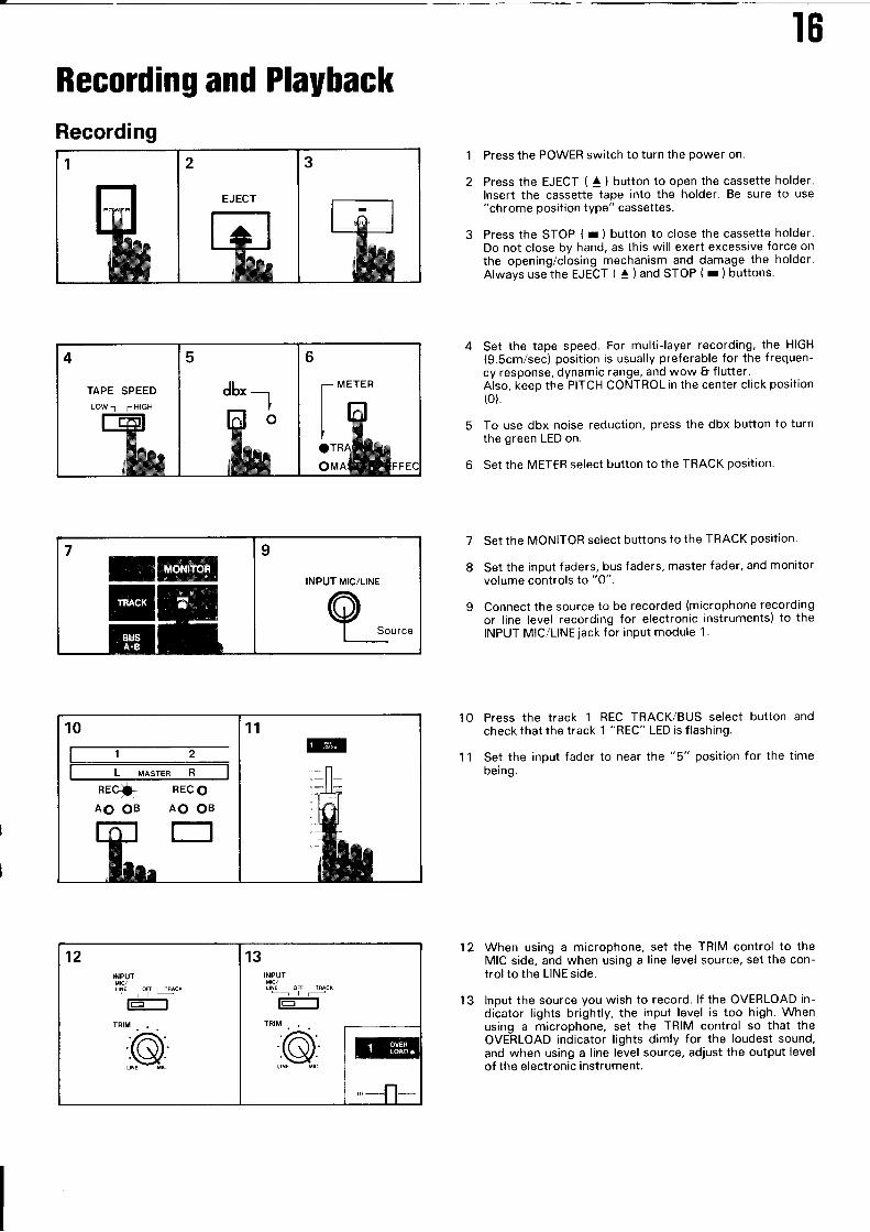
Press the POWER switch to turn the power on.
Press the EJECT ( a ) button to open the cassette holder.lnsert the cassette tape into the holder. Be sure to use"chrome position type" cassettes.
Press the STOP ( r ) button to close the cassette holder.Do not close by hand, as this will exert excessive force onthe opening/closing mechanism and damage the holder.Always usethe EJECT ( ^ ) and STOP ( r ) buttons.
Set the tape speed. For multi-layer recording, the HIGH(9.Scm/sec) position is usually preferable for the frequen-cy response, dynamic range, and wow I flutter.Also, keep the PITCH CONTROL in the center click position(o).
To use dbx noise reduction, press the dbx button to turnthe green LED on.
6 Set the METER select button to the TRACK position.
Set the MONITOR select buttons to the TRACK position.
Set the input faders, bus faders, master fader, and monitorvolume controls to "0".
Connect the source to be recorded (microphone recordingor line level recording for electronic instruments) to theINPUT MIC/LINE jack for input module 1 .
7
I
1 1 Set thebeing.
1 O Press the track 1
check that the trackREC TRACK/BUS select button and1 "REC" LED is flashing.
to near the "5" position for the time
12
input fader
When using a microphone, set the TRIM control to theMIC side, and when using a line level source, set the con-trol to the LINE side.
lnput the source you wish to record. lf the OVERLOAD in-dicator lights brightly, the input level is too high. Whenusing a microphone, set the TRIM control so that theOVERLOAD indicator lights dimly for the loudest sound,and when using a line level source, adjust the output levelof the electronic instrument.
['E-l,-oLOMAU
TAPE SPEED
LOW-1 6HIGH
REC OAO OB
E]AO OB
INPUT
i',§l rnacx'-l--.-t-]
TRIM...
@
INPUT
LINE OFF TÊACK
-t-t-]TRIM
13
17
14
15
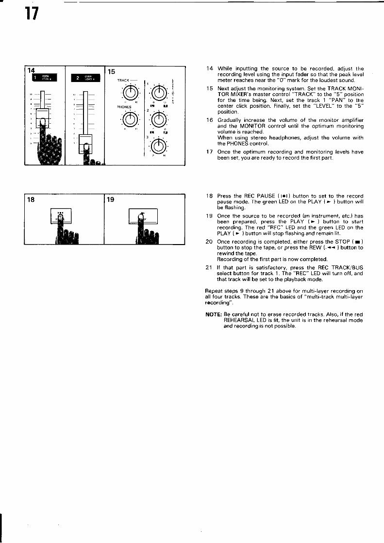
While inputting the source to be recorded, adjust therecording level using the input fader so that the peak levelmeter reaches near the "0" mark for the loudest sound.
Next adjust the monitoring system. Set the TRACK MONI-TOB MIXER's master control "TRACK" to the "5" positionfor the time being. Next, set the track 1 "PAN" to thecenter click position. Finally, set the "LEVEL" to the "5"position.
Gradually increase the volume of the monitor amplifierand the MONITOR control until the optimum monitoringvolume is reached.When using stereo headphones, adjust the volume withthe PHONES control.
Once the optimum recording and monitoring levels havebeen set, you are ready to record the first part.
'l I Press the REC PAUSE ( tot) button to set to the recordpause mode. The green LED on the PLAY (> ) button willbe flashing.
1 9 Once the source to be recorded (an instrument, etc.) hasbeen prepared, press the PLAY (. ) button to startrecording. The red "REC" LED and the green LED on thePLAY ( > ) button will stop flashing and remain lit.
2O Once recording is completed, either press the STOP ( r )
button to stop the tape, or press the REW (.<< ) button torewind the tape.Recording of the first part is now completed.
21 lf that part is satisfactory, press the REC TRACK/BUSselect button for track 1. The "REC" LED will turn off, andthat track will be set to the playback mode.
Repeat steps 9 through 21 above for multi-layer recording onall four tracks. ïhese are the basics of "multi-track multi-layerrecording".
NOTE: Be careful not to erase recorded tracks. Also, if the redREHEARSAL LED is lit, the unit is in the rehearsal modeand recording is not possible.
16
17
r
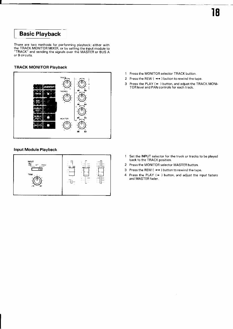
Basic Playback
There are two methods for performing playback: either withthe TRACK MONITOR MIXER, or by setting the input module to"TRACK" and sending the signals over the MASTER or BUS Aor B circuits.
TRACK MONITOR Playback
mr
I8
1 Press the MONITOR selector TRACK button.
2 Press the REW ( -- ) button to rewind the tape.
3 Press the PLAY ( ' ) button, and adjust the TRACK MONI-TOR level and PAN controls for each track.
1 Set the INPUT selector for the track or tracks to be playedback to the TRACK position.
2 Press the MONITOR selector MASTER button.
3 Press the REW ( << ) button to rewind the tape.
4 Press the PLAY ( > ) button, and adjust the input fadersand MASTER fader.
lnput Module Playback
INPUT
OFF IRÂCi.-]riJt-r
:o=ll: :-ll= ;-l=
rËH
I9
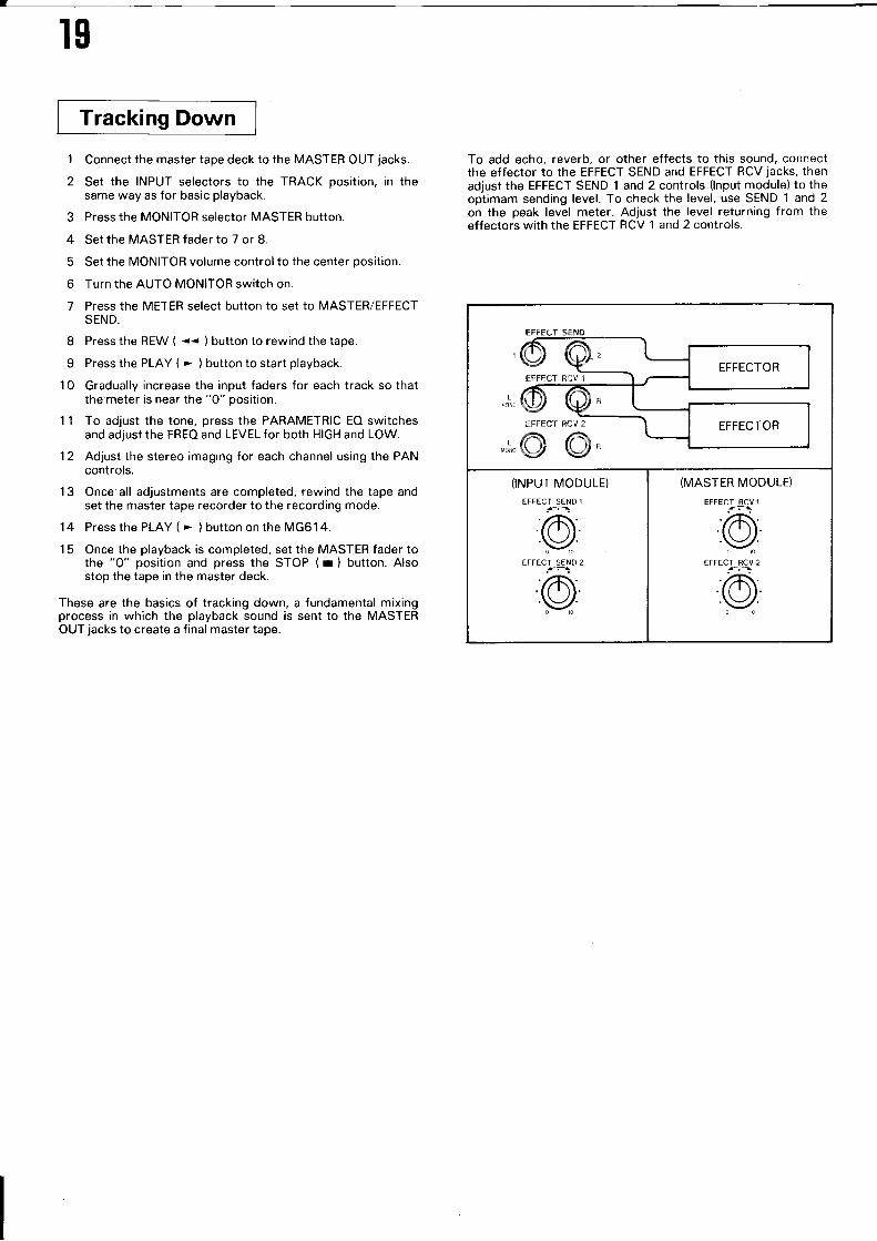
Tracking Down
1 Connect the master tape deck to the MASTER OUT jacks.
2 Set the INPUT selectors to the TRACK position, in thesame way as for basic playback.
3 Press the MONITOR selector MASTER button.
4 Set the MASïER fader to 7 or 8.
5 Set the MONITOR volume control to the center position.
6 Turn the AUTO MONIïOR switch on.
7 Press the METER select button to set to MASTER/EFFECTSEND.
I Press the REW ( << ) button to rewind the tape.
9 Press the PLAY ( . ) button to start playback.
1 0 Gradually increase the input faders for each track so thatthe meter is near the "0" position.
11 To adjust the tone, press the PARAMETRIC EO switchesand adjust the FREO and LEVEL for both HIGH and LOW.
12 Adjust the stereo imaging for each channel using the PANcontrols.
13 Once all adjustments are completed, rewind the tape andset the master tape recorder to the recording mode.
14 Pressthe PLAY ( - ) button onthe MG614.
15 Once the playback is completed, set the MASTER fader tothe "0" position and press the STOP ( r ) button. Alsostop the tape in the master deck.
These are the basics of tracking down, a fundamental mixingprocess in which the playback sound is sent to the MASTEROUT jacks to create a final master tape.
To add echo, reverb, or other effects to this sound, connectthe effector to the EFFECT SEND and EFFECT RCV jacks, thenadjust the EFFECT SEND 1 and 2 controls (lnput module) to theoptimam sending level. To check the level, use SEND 1 and 2on the peak level meter. Adjust the level returning from theeffectors with the EFFECT RCV 1 and 2 controls.
(INPUT MODULE)
EFFECT SEND 1
@»EFFECT SEND 2
fr-:
@»
(MASTER MODULE)
EFFECT RCV 1
c»EFFECT 8CJ 2
@»
20
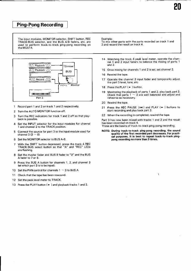
Ping-Pong Recording
The input modules, MONITOR selector, SHIFT button, RECTRACK/BUS selector, and the BUS A/B faders, etc. areused to perform track-to-track ping-pong recording onthe MG614.
Example:To mix other parts with the parts recorded on track 1 and2 and record the result on track 4.
Part 3
1 Record part 1 and 2 on track 'l and 2 respectively.
2 Turn the AUTO MONITOR function off.
3 Turn the REC indicators for track 1 and 2 off so that play-back is possible.
4 Set the INPUT selector for the input modules for channel1 and channel 2 to the TRACK position.
5 Connect the source for part 3 to the input module used forchannel3(3-6).
6 Set the MONITOR selector to BUS A-8.
7 With the SHIFT button depressed, press the track 4 RECTRACK/BUS select button so that "A" and "REC" LEDsare flashing.
8 Set the master fader and BUS B fader to "0" and the BUSAfader to 7 or 8.
9 Press the BUS A button for channels 1, 2, and channel 3ht which part 3 is to be input).
1O Setthe PAN control for channels 1 - 3 to BUS A.
1 1 Check that the tape has been rewound.
12 Set the peak level meter to TRACK.
1 3 Press the PLAY button ( > ) and playback tracks 1 and 2.
Watching the track 4 peak level meter, operate the chan-nel 1 and 2 input faders to balance the mixing of parts 1
and 2.
Once mixing for channels 1 and 2 is set, set channel 3.
Rewind the tape.
Operate the channel 3 input fader and temporarily adjustthe part 3 level, tone, etc.
Pressthe PLAY ( > ) button.
Monitoring the playback of parts 1 and 2, play back part 3.Check that parts 1 - 3 are well balanced and adjust andrehearse as necessary.
20 Rewind the tape.
21 Press the REC PAUSE ( tol ) and PLAY ( > ) buttons tostart recording and play back part 3.
22 When the recording is completed, rewind the tape.
Part 3 has now been mixed with tracks 1 and2and the resulthas been recorded on track 4.These are the basics of track-to-track ping-pong recording.
NOTE: During track-to-track ping-pong recording, the soundquality of the first recorded part decreases. For practi-cal purposes, it is best to repeat track-to-track ping-pong recording no more than 3 times,
14
15
't6
17
18
19
2t
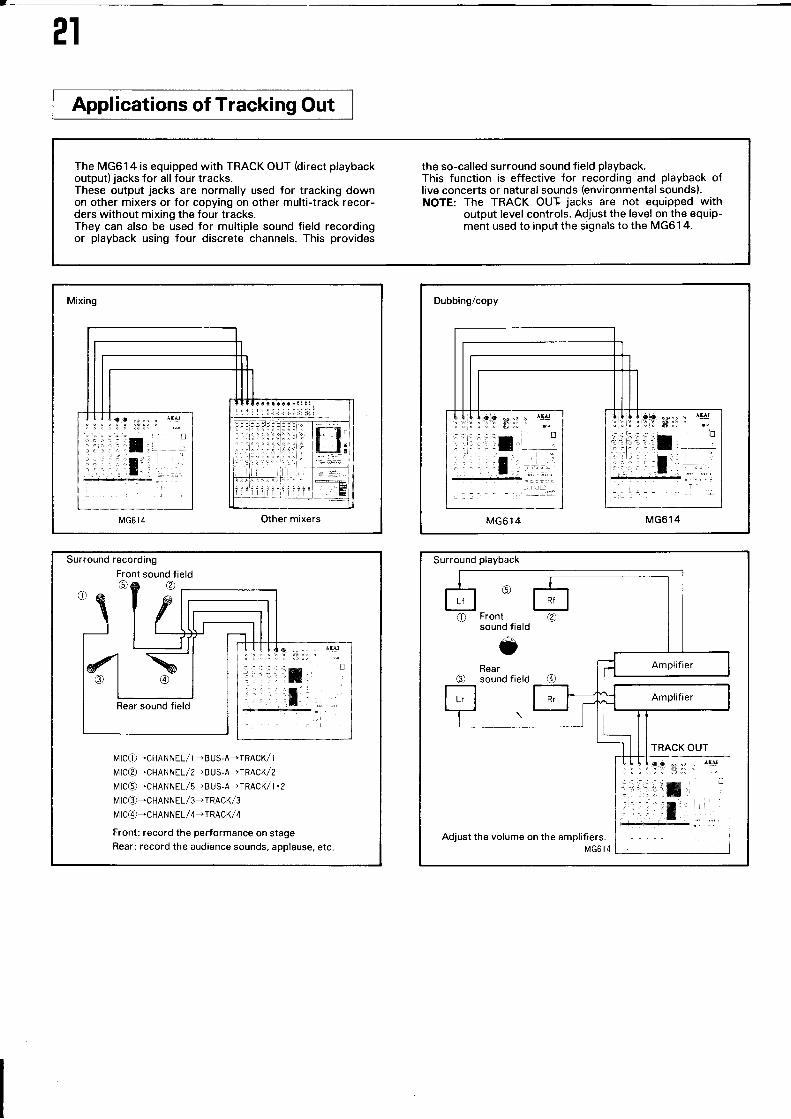
The MG614 is equipped with TRACK OUT (direct playbackoutput) jacks for all four tracks.These output jacks are normally used for tracking downon other mixers or for copying on other multi-track recor-ders without mixing the four tracks.They can also be used for multiple sound field recordingor playback using four discrete channels. This provides
the so-called surround sound field playback.This function is effective for recording and playback oflive concerts or natural sounds (environmental sounds).NOTE: The TRACK OUI jacks are not equipped with
output level controls. Adjust the level on the equip-ment used to input the signals to the MG61 4.
Mixing
MG6l4 Other mixers
,rêâraaaaar:ïi
I I I laa o+,,. Àf4l
:'ii,:rf l- ill I ,,,.lt.l Li1 titl'1
!!:ii! 'Ët
Dubbing/copy
MG614 MG614
Surround recording
MICO-CHANNEL/ I -BUS.A-TRACK/ I
N4 I C@-CHAN N E L / 2. BUS. A. I R ACK / 2
N4ICO-CHANNEL/5- B US.A-TRACK/ I .2
IÿICO'CHANNEL /3.TRACK/3MIC@'CHANNEL/4,TRACK/4
Front: record the performance on stageRear: record the audience sounds, applause, etc
Surround playback
Adjust the volume on the amplifiers
o
Frontsound field
oRearsound field
??
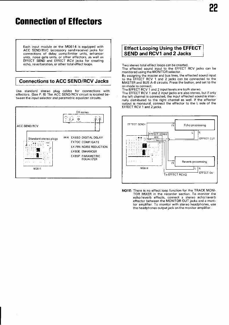
Gonnection of EÎIectors
Each input module on the MG614 is equipped withACC SEND/RVC (accessory send/receive) jacks forconnections of delay comp/limiter units, enhancerunits, noise gate units, or other effectors, as well asEFFECT SEND and EFFECT RCV jacks for creatingecho, reverberation, or other total effect loops.
Connections to ACC SEND/RCV Jacks
Use standard stereo plug cables for connections witheffectors. (See P. 8) The ACC SEND/RCV circuit is located be-tween the input selector and parametric equalizer circuits.
Effect Looping Using the EFFECTSEND and RCV1 and 2 Jacks
Two stereo total effect loops can be created.The effected sound input to the EFFECT RCV jacks can bemonitored using the MONITOR selector.By assigning the master and bus lines, the effected sound inputto the EFFECT RCV 'l and 2 jacks ban be connected to theMASTER and BUS A-B circuits. Press the button, and set to theon mode to connect.The EFFECT RCV 1 and 2 input levels are both stereo.The EFFECT RCV 1 and 2 input jacks are also stereo, but if onlythe left channel is connected, the input effected sound is inter-nally distributed to the right channel as well. lf the effectoroutput is monaural, connect the effector to the L side of theEFFECT RCV 1 and 2 jacks.
EFFECT SEND I
To EFFECT RCV2
NOTE: There is no effect loop function for the TRACK MONI-TOR MIXER in the recorder section. To monitor theecho/reverb effects, connect a stereo echo/reverbeffector between the MONITOR OUI jacks and a moni-tor amplifier. To monitor with stereo headphones, usethe headphones output jack on the monitor amplifier.
EX series
r\4G6 t4
ACC SEND/RCV
Standard stereo plugs AKAI EX65D DIGITAL DELAY
EXTOC COMP/GATE
EX75N NOISE REDUCTION
EXSOE ENHANCER
EX85P PARAMETRICEOUALIZER
23
Memory Systems
The MG614 is equipped with an auto memory systemsearching and repeat playback between up to 5 parts.
Resetting
To reset the tape counter to "0000", either turn off the powerswitch then turn it back on or use the MEMORY CLEAR andMEMO 0 buttons.Also, the counter is reset if the cassette is ejected.
Setting the Memory
With the MG614 auto memory system, the values of the tapecounter indicating the amount of tape transport are stored forsearching and for repeat playback.The tape counter values can be stored either by using the CAP-IURE button or by using the MEMO 1 through MEMO 3buttons.
Using the CAPTURE Button1 Set the tape to the record or playback mode.
2 When the value you wish to store in the memory isreached, press the CAPTURE button. The value at thepoint at which the CAPTURE button was pressed is dis-played on the memory counter and "C" is displayed atMEMO NO.
3 The stored value is renewed and the first value is clearedeach time the CAPTURE button is pressed.
for Using the MEMO I - 3 Buttons1 Set the tape to the record or playback mode.
2 When the first value you wish to store in the memory is
reached, press the MEMO 1 button. The value at the pointat which the button was pressed is displayed on thememory counter and " 1 " is displayed at MEMO NO.
3 When the second value you wish to store in the memory rs
reached, press the MEMO 2 button. ïhe value at the pointat which the button was pressed is displayed on thememory counter and "2" is displayed at MEMO NO.
4 When the third value you wish to store in the memory isreached, press the MEMO 3 button. The value at the pointat which the button was pressed is displayed on thememory counter and "3" is displayed at MEMO NO.
NOTE: lt is not possible to store values in the memory usingthe MEMO O button. This is exclusively for recalling thepreset "0OOO" value.
CAPTURE
MEMORY COUNTER MEMO NO.
û tal tr
llolololC: I r-t I rrt] | I--] I r-t I

?4
Clearing the Memory
Use the following procedure to clear/renew the values storedat MEMO 1 through MEMO 3.
To clear all values, press the MEMORY CLEAR button then theMEMO 1 through 3 buttons in order, and finally press theMEMORY CLEAR button once again.
To renew the values:1 Press the MEMORY CLEAR button. "CLr" will be displayed
on the memory counter and the MEMO 1 - MEMO 3 LEDswill flash.
2 Press the memory button you wish to clear. The LED forthat button will turn off.
Press the MEMORY CLEAR button again. The memorycounter will display "0000", and that memory is cleared.
Rewind the tape to the "O0OO" position.
Set the tape to the record or playback mode.
When the value you wish to replace in the memory isreached, press the memory button whose red LED is off.The value at the point at which the button was pressed isdisplayed on the memory counter and the new value hasbeen stored in the memory.
NOTE: lf the MEMO O button is pressed after the MEMORYCLEAR button has been pressed, the tape counter willbe reset to "0000". Conversely, this function can beused to return the counter to "0000" at any desiredposition.
Memory Searching
The memory search function operates simply by pressing theMEMORY SEARCH button.1 Press the memory button (MEMO 0 - 3) for which you
wish to search. The value stored in the memory will be dis-played on the MEMORY COUNTER and the memorybutton number at MEMO NO.
MEMO 1 | "rro", couNrFa vEMo \o
ü835 i
2 Press the MEMORY SEARCH button. The tape will fast-forward or rewind and stop at the position stored in thememory.
3 lf the PLAY button is pressed after the MEMORY SEARCHbutton has been pressed, the tape will automatically beginplayback after it is fast-forwarded or rewound.
4
5
6
EüMEMORY
lolololrï=tiîr

E-
25
0000
MEiÿO 0
02 50
t4E[r0 I
0500
MENIO 2
0750
N,lE[/0 3
I 000
CAIURE
Repeat Playback
The MG614 is equipped with a repeat function for continuousplayback between any two points.
1 Use the MEMO 1 through MEMO 3 buttons to specify thesections you wish to repeat.
Section 1 Section 2 Section 3 Section 4
Repeat playback is also possible between any two pointsstored at the MEMO 0 -- MEMO 3 and CAPTURE buttons.When using the CAPTURE button, be sure to set the desiredvalues for the MEMO 1 - MEMO 3 buttons first.
1 Set the tape to the playback mode.
2 When the point at which you wish to begin or end repeatplayback is reached, press the CAPTURE button.
CAPTURE
3 Press the REPEAT button. The tape will automatically windto the position stored in the memory with the CAPTUREbutton then resume playback.
REPEAT
4 Press one of the memory buttons (MEMO 0 ^- MEMO 3).The LED for that button will flash, and repeat playback willbegin.
o
ïEilô-f
2 To repeat between "0000" andMEMORY SEARCH button and windat which the repeat will begin.
"O25O", press thethe tape to the point
MEMO O
3 Press the REPEAT button. The tape will start moving in theplayback mode. When the MEMO 1 button is pressed, theLED flashes and section 1 is played back repeatedly.
oloREPEAÎ I MEMO I
4 To cancel repeat playback, press either the STOP or theREPEAT button.
o
REPEAT
26
t.
1
2
3
4
5
6
Punch -ln/ Punch-Out Recording
The MG61 4 is equipped for the following punch-in/punch-outoperations:
l. Punch-in/out using theREC/PLAY button
l!. Punch-in/out using a foot switch
Punch-ln/Out Using the REC/PLAY ButtonConnect the source to the input module corresponding tothe track on which you wish to perform punch-in/punch-out recording.
Set the MONITOR selector to TRACK.
Turn the AUTO MONITOR on (the red LED will light).
Press the REC TRACK/BUS select button for the track onwhich you wish to perform punch-in/punch-out recordingso that the "REC" LED is flashing.
Set the METER selector to TRACK.
Press the PLAY ( > ) button to start the tape. Use theAUTO MONITOR function to monitor the playback of thetrack whose "REC" LED is flashing.To adjust the volume or tone of the new source, turn theAUTO MONITOR off. Only the track whose "REC" LED isflashing will be the source monitor, and the playback onthe tape is monitored for the other tracks.Once the source has been prepared, turn the AUTO MONI-TOR back on.
After rewinding the tape, press the PLAY ( > ) buttonagain.
To rehearse the timing for punch-in/punch-out recording,press the REHEARSAL button.
When the position at which you want to punch in isreached, press the REC PAUSE ( lol ) button with thePLAY ( > ) button depressed. The sound for the othertracks and for the punch-in source can be monitored. lf inthe rehearsal mode, the sound will not be recorded.
When the position at which you want to punch out isreached, press the PLAY ( > ) button, making sure thatthe timing is precise. When punch-in/punch-out recordingis completed, press the REC TRACK/BUS selector buttonwhose "REC" LED is flashing to clear the recording mode.
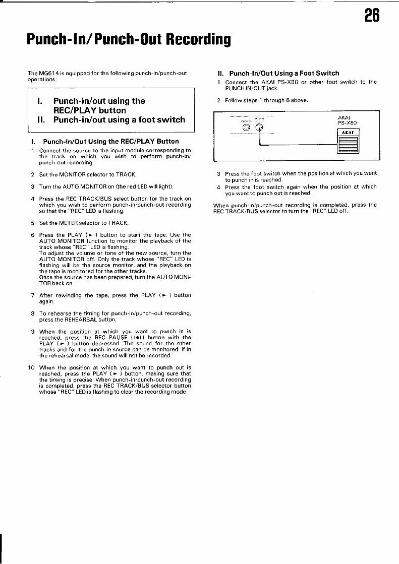
ll. Punch-ln/Out Using a Foot Switch1 Connect the AKAI PS-X80 or other foot switch to the
PUNCH lN/OUT jack.
2 Follow steps 1 through 8 above.
3 Press the foot switch when the position at which you wantto punch in is reached.
4 Press the foot switch again when the position at whichyou want to punch out is reached.
When punch-in/punch-out recording is completed, press theREC TRACK/BUS selector to turn the "REC" LED off.
10
?7
Tape Sync
"Tape Sync" is important for multi-layer recording of theautomatic playback of rhythm machines, sequencers, orother electronic instruments.This MG614 is equipped with revolutionary TAPE SYNClN/OUT jacks.Tape sync consists of converting the "tape sync signals"sent from a rhythm machine or sequencer into recordingsignals with a center frequency o't 23kïz, recording these
signals onto track 1 along with the audio signals, returningthese signals to tape sync signals upon synchronizedplayback, and sending them to the tape sync input of therhythm machine or sequencer.W'hen plugs are inserted into the TAPE SYNC IN/OUTjacks, the unit is automatically set to the tape sync mode.Âlways use this mode with the tape speed set at HIGH(9.5cm/sec).
3
4
Recording Tape Sync Signalslnput the tape sync signals from a rhythm machine orsequencer to the TAPE SYNC lN jacks.
Connect the source you wish to record to input modulechannel 1. As tape sync signals are used, all frequenciesabove 9kHz are filtered out, so use a source with frequen-cies as low as possible (a bass part for example).
dbx can be set to either in or out.
The recording level for the tape sync signals is setautomatically.
5 Make sure the recording level of the source to be recordedis not above the red zone on the peak level meter.lf recorded at a higher level, the tape sync signals will alsobe distorted, resulting in miscounts upon synchronizedplayback.Be especially careful when recording in dbx.
NOTES:When playing back a tape on which a sync signal hasbeen recorded, the TAPE SYNC IN/OUT jacks mustremain connected.
Playback of Tape Sync Signals1 Connect the TAPE SYNC OUT jack to the tape sync signal
input jack on the rhythm machine or sequencer.
2 The MG61 4 TAPE SYNC OUT level is of 1 .4Vp-p.The levels may not match depending on the type ofrhythm machine or sequencer. lf this is the case, consultwith the manufacturer.
NOTES:1 When not using tape sync signals, be sure to disconnect
the plugs from the IAPE SYNC IN/OUT jacks. lf the plugsare inserted, the high frequencies for track 1 will be fil-tered out as if they were tape sync signals.
2 When using tape sync signals, always set the tape speedto HIGH (9.5cm,sec).
3 Use as high a quality tape as possible.
4 lf the heads are dirty, problems in synchronization mayoccur. Make sure to clean the heads before recording andplayback.
5 Problems in synchronization may occur if the tape syncsignals are copied, so do not perform track-to-track ping-pong recording for track 1 on which the tape sync signalsare recorded.
6 Notify an AKAI office if there are problems in the syn-chronization using the IAPE SYNC IN/OUT jacks with a
rhythm machine or sequencer , Also, if this should happen,connect the tape sync signals to the input module channel1 and record and playback on track 1.
7 Set the recording level for recording tape sync signalsfrom the input module onto track 1 so that the bar on thepeak level meter reaches - 14 -- - 8. (The optimum leveldepends on the rhythm machine or sequencer you areusing.) ln this case, a slight amount of crosstalk may beproduced when track 2 is played back. lf this shouldhappen, the only thing to do is to not record anything ontrack 2 and only use tracks 3 and 4. Thus, we recommendusing the TAPE SYNC lN/OUT jacks.
Maintenance
The following maintenance procedure should be carried outeach time before the MG614 is used in order to keep it in opti-mum operating condition.The places where the tape comes into contact with (heads,capstan, pinch roller, loading roller, tape guide and tensionarm) become dirty with magnetic particles from the tape andfine dust. Magnetization is also liable to occur after extendeduse. This is caused by small amounts of residual magnetismwhich remain in the core of the heads. Magnetization causes a
decrease in the signal level at high ranges and increases noise.Magnetization is also liable to occur on other metallic partssuch as the capstan, tape guide and tension arm.
CleaningBe sure to remove the cassette tape before opening the main-tenance cover.Soak the cotton swabs of the tape deck with cleaning liquids ofthe CK-310 cleaning kit (sold separately). Carefully clean theheads, pinch roller, loading roller, tape guide, and capstan.Note:Use the cleaning liquid specified for the respective parts. Thepinch roller and loading roller are cleaned with the cleaningliquid specified for rubber parts.
DemagnetizationBe sure to turn off the power of the MG614.We recommend separately sold head demagnetezers.Bring the head demagnetizer about 5O to 60 cm from theheads and turn on the power of the demagnetizer. Bring thedemagnetizer near the parts to be demagnetized and slowlyraise and lower it while gradually increasing the distance of thedemagnetizer from the unit. Turn the power of the demagneti-zer off when it is about 50 to 60 cm away from the heads.
28
Cleaning the panelsDust and dirt can be wiped off with a soft dry cloth. lf thepanels are very dirty, a soft cloth moistened with a dish wash-ing liquid or neutral cleanser can be used. Never use volatileliquids such as thinners, benzine, or chemically treated cleaningcloths, as these will damage the clear acrylic surface of the FL
display and the cabinet finish.
Cleaning of jacks and plugsDirty plugs and jacks lead to increased resistance, noise, anddistortion. Periodically use electric contact cleaner to clean theplugs and jacks.
2g
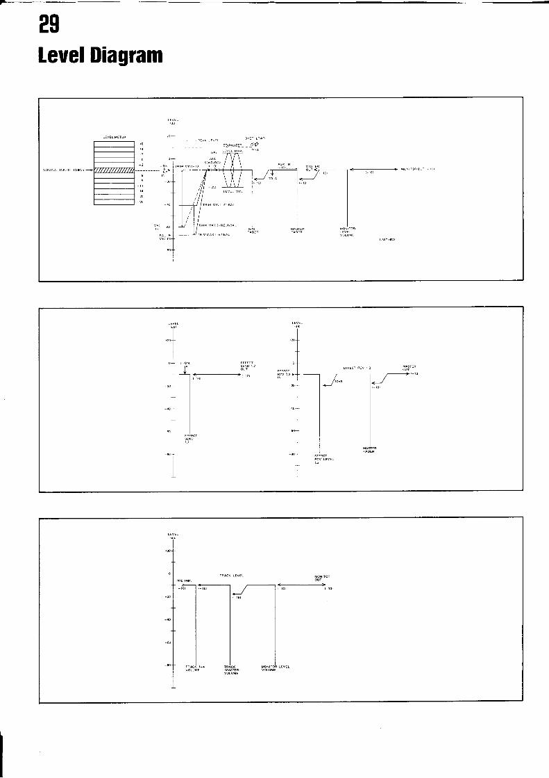
Leuel Diagram
TO+ FBOM
l -t-;;-----------------------,,,"1 I
I
,"tlI
-+II',
-1I
+I
30
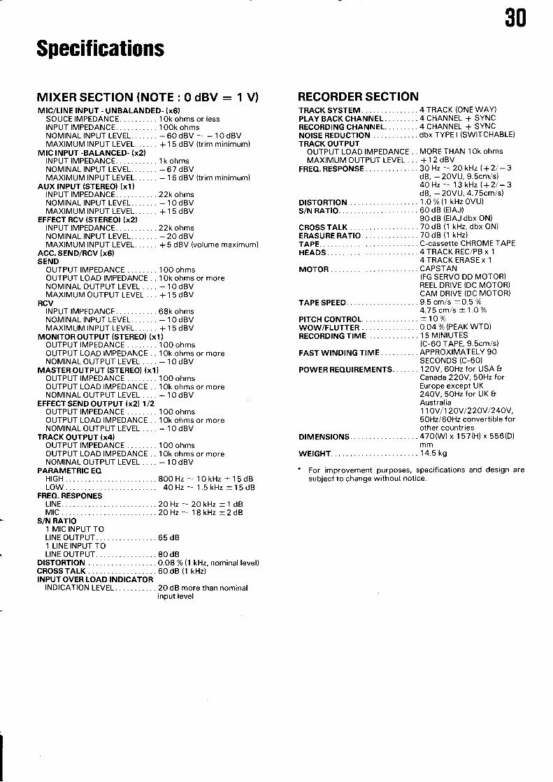
Specifications
MIXERSECTION (NOTE : 0 dBV - I V)MIC/LINE INPUT - UNBALANDED- (x6)
SOUCE IMPEDANCE. . . 1 0k ohms or lessINPUT IMPEDANCE. . . . 'l OOk ohmsNOMINAL INPUT LEVEL. 60 dBV -- _ 1O dBVMAXIMUM INPUT LEVEL...... +15 dBV (trim minimum)
MIC !NPUT -BALANCED- (x2lINPUTIMPEDANCE.. ..1kohmsNOMINAL INPUT LEVEL. 67 dBVMAXIMUM INPUT LEVEL. 16 dBV (trim minimum)
AUx INPUT (STEREO) (x1)INPUTIMPEDANCE.. ..22kohmsNOMINAL INPUT LEVEL. 1O dBVMAXIMUM INPUT LEVEL.... .. + 1 5 dBV
EFFECT RCV (STEREO) (x2)INPUTIMPEDANCE.. ..22kohmsNOMINAL INPUT LEVEL. 20 dBVMAXIMUM INPUT LEVEL.. .. +5 dBV (volume maximum)
ACC. SEND/RCV (x6)SEND
OUïPUT IMPEDANCE . 100 ohmsOUTPUT LOAD IMPEDANCE . . 1Ok ohms or moreNOMINAL OUTPUT LEVEL . . . . _.IOdBVMAXIMUM OUTPUT LEVEL ... +1 5 dBV
RCVINPUTIMPEDANCE.. ..68kohmsNOMINAL INPUT LEVEL. 1O dBVMAXIMUM INPUT LEVEL...... +1 5 dBV
MONITOR OUTPUT (STEREO} (x1 )
OUTPUT IMPEDANCE . 100 ohmsOUTPUT LOAD IMPEDANCE . . 1Ok ohms or moreNOMINALOUTPUT LEVEL .... _ IOdBV
MASTER OUTPUT (STEREO) (x1)OUTPUT IMPEDANCE . 1OO ohmsOUIPUT LOAD IMPEDANCE . . 1Ok ohms or moreNOMINAL OUTPUT LEVEL . ... - IOdBV
EFFECT SEND OUTPUT lx2l 1/2OUIPUT IMPEDANCE . 100 ohmsOUTPUT LOAD IMPEDANCE . . 10k ohms or moreNOMINALOUTPUT LEVEL .... _ IOdBV
TRACK OUTPUT (x4)OUTPUT IMPEDANCE . 100 ohmsOUTPUT LOAD IMPEDANCE . . 1Ok ohms or moreNOMINAL OUTPUT LEVEL . . . . _ IOdBV
PARAMETRIC EOHIGH.. .80OHz - 10kHz +15d8LOW.. 4OHz-1.5kHz+15d8
FREO. RESPONESLINE... .2OHz - 20 kHz :t 1 dBMlC... .2QHz-18kHzl:2dB
S/N RATIO
RECORDER SECTIONTRACK SYSTEM . 4 TRACK (ONE WAY)PLAYBACKCHANNEL ..4CHANNEL + SYNCRECORDINGCHANNEL. .4CHANNEL+SYNCNOISEREDUCTION .. ...dbxTYPEl (SWITCHABLE)TRACK OUTPUT
OUTPUT LOAD IMPEDANCE . . MORE THAN 10k ohmsMAXIMUM OUTPUT LEVEL ... +12dBV
FREO.RESPONSE... ....30 Hz - 2OkHz(+21-3dB, - 2OVU, 9.5cm/s)4OHz - 13k{z (+21-3dB, - 2OVU, 4.75cm/s)
DISTORTTON ....1.0%(1 kHzOVU)s/N RATTO. ......60dB (EIAJ)
90 dB (EIAJ dbx ON)CROSSTALK . .. . 70dB (1 kHz, dbx ON)ERASURERATIO. 70dB (1 kHz)TAPE.. ... C-cassette CHROMEÏAPEHEADS ...4TRACK REC/PB x 1
4 TRACK ERASE x 1
MOTOR ,. CAPSTAN(FG SERVO DD MOTOR)REEL DRIVE (DC MOTOR)CAM DRIVE (DC MOTOR)9.5 cm/s * O.5 %4.75 cm/s + 1.O%+ 10%O.O4o/o (PEAK WTD)15 MINIUTES
TAPE SPEED.
PITCHCONTROL....,WOW/FLUTTER ....RECORDING TIME .
(C-60 TAPE, 9.Scm/s)FAST WINDING TIME . . . APPROXIMATELY 90
SECONDS (C-60)POWERREOUIREMENTS..... .. 12OV,60Hz for USAe
Canada 22OY,5OHzforEurope except UK24OV,5OHz for UK IAustralia1',tov 1120v 1220v 1240v,50Hz/6OHz convertible forother countries
DIMENSTONS ..470(W)x 157(H)x 556(D)mm
WEIGHT. . 14.5 kg
- For improvement purposes, specifications and design aresubject to change without notice.
1 MIC INPUT TOLINE OUTPUT . . 65 dB1 LINE INPUT TOLINE OUTPUT . . 80 dB
DrsToRTroN ....o.08%(1CROSSTALKINPUT OVER LOAD INDICATOR
INDICATION LEVEL.
60 dB (1
20 dB more than nominalinput level
kHz, nominal level)kHz)
PIease read the following insert to the MG 614 Operator's Manual concerning tapesynchronization.
How to Record Tape Sync Signals1" lnput the tape sync signal frorn the rhythm machine,
sequencer or other electronic musical device to theMG6 i 4's TAPE §YNC lN jack.
2. Connect the source you wish to record to the inputmodule's CHANNEL 1 jack. All signals above 1O kHz arecut in order to handle the tape sync signal, so the sourcesignal for this channel rnust be in the middle or lowerranges (for example, the bass part).
How to Play Eack Tape Sync Signal1 . Connect the TAPE SYNC OUT jack to the input jack for the
tape sync signal [.leing produced by the rhythm machine,sequencer, or other electronic musical device.
2. The MG 6 1 4's TAPE SYNC OUT level is (1 .4 Vp-p)
3.
4.
Set dbx to lN.
Be sure to set the source's recording level so that thepeak level meter's 0 dB level (the lowest point on the redLED) does not light uP.Recording overlhe proper level can cause distortion in thetape synCsignal and miscounts during synchronized play.
Tape synchronization is important for multitrack recordingusing the autoplay functions of rhythm machines,sequencers, and other electronic musical devices.However, the MG 614 is equipped with a revolutionaryTape Sync IN/OUT function that converts the tape syncsignals output by the abovementioned types of electronicmusical devices into an FM signal centered on 23 kHz. Thissignal is recorded with the track 1 audio signal (up to 10kHz) and, during synchronized performance, converts thesignal back to the tape sync signal originally output by theelectronic musical instrument and sends this signal to theinstrument's tape sync input.The MG 614 automatically sets the optimum recordinglevel for the tape sync signal. However, because this signalis added to the tape recoi'ding of the audio signal, distor-
tion can occur in the recording when the audio signal'sinput level is high. Furthermore, the normal tape sync func-tion can fail to operate due to the presence of distortionelements when the adjacent track's input level is high.The FM signal uses a frequency band higher than thatused by the audio signal, so please use a high-quality tapeto minimize dropouts and other undesirable effects.The MG 614 automatically switches to tape sync modewhenever the TAPE SYNC IN/OUT plug is inserted. Low-pass filters are connected {at 1O kHz for track 1,13 kHzfor track 2, 3 and 4) to ensure reliable tape syncoperation. Always set the tape speed to HIGH (9.5 cm/s)and be sure to set dbx to lN for noise prevention,
1. During playback and recording in which no tape syncsignal is used, be sure to remove the plug from theTAPE SYNC lN/OUT jack. lf the plug is left in, the lowpass filter for each track will automatically cut out allof the higher sounds.
2. lf the synchronization is not accurate, please checkthe following points.a. Are the heads dirty?b. Are there any tape dropouts? Are you using a high-
quality tape?c. ls the recording level for track 1 too high ?
d. Try lowering the track 2 recording level a bit.lf your rhythm machine, sequencer, or other electron-ic musica! device still produces inaccuratesynchronization, please contact Akai's ElectronicMusical lnstruments division. ln such cases, pleaseconnect the tape sync signal to CHANNEL 1 of theinput module and record and playback the signal ontrack 1.
3" When recording or playing back a tape sync signal ontrack 1 while using CHANNEL 1 on the input module,
try to record syne signal in as low a range as possiblein order to avoid tape sync signal cross talk (leakage)from the next track. (Note: the optimum level differsdepending on the peak level meter reading within the
- 14 to -B range and the type of rhythm machine,or other electronic musical device used.)ln such cases as this, some small amount of crosstalkmay occur on track 2. Nothing is recorded as a guardband on track 2 and nothing can be done for recordingon tracks other than tracks 3 and 4.
lf the tape sync signal is dubbed or copied, the syn-cronization will not be accurate. Iherefore, please dointertrack ping pong recording for track 1 when track1 receives the tape sync signal. (lt is possible to doping pong from track 1 to other tracks.)
Before playing back tapes upon which sync signalshave been recorded, be sure not to remove the plugfrom the TAPE SYNC IN/OUT jack. (You may hear theFM carrier as noise during playback.)
5.

ÀKÀIAKAI ELECTRIC CO., LTD.
1 2- 1 4, z-chone, Higashi' Koi iYa,Ohta-ku, Tokyo, Japan
Printed in lapan@610927D1 611006-01


